*** START OF THE PROJECT GUTENBERG EBOOK 49675 ***
The cover image was created by the transcriber and is placed in the public domain.
[Pg i]
THE THOUGHT IS IN THE QUESTION THE INFORMATION IS IN THE ANSWER
HAWKINS
ELECTRICAL GUIDE
NUMBER
FIVE
QUESTIONS
ANSWERS
&
ILLUSTRATIONS
A PROGRESSIVE COURSE OF STUDY
FOR ENGINEERS, ELECTRICIANS, STUDENTS
AND THOSE DESIRING TO ACQUIRE A
WORKING KNOWLEDGE OF
ELECTRICITY AND ITS APPLICATIONS
A PRACTICAL TREATISE
 by
by
HAWKINS AND STAFF

THEO. AUDEL & CO. 72 FIFTH AVE. NEW YORK.
[Pg ii]
COPYRIGHTED, 1914,
BY
THEO. AUDEL & CO.,
New York.
Printed in the United States.
[Pg iii]
TABLE OF CONTENTS
GUIDE NO. 5.
| ALTERNATING CURRENTS |
997 to 1,066 |
| The word
"alternating"—advantages of
alternating current—direct current apparatus;
alternating current apparatus—disadvantages
of alternating current—alternating
current principles—the
sine—application and construction of the sine
curve—illustrated definitions:
cycle, alternation, amplitude, period, periodicity,
frequency—commercial frequencies—advantages
of low frequency—phase—phase
difference—phase displacement—synchronism—"in
phase"—curves illustrating "in phase" and "out of
phase"—illustrated definitions:
in phase; in quadrature, current leading; in quadrature,
current lagging; in opposition—maximum
volts and amperes—average volts
and amperes—elementary alternator developing one
average volt—virtual volts and
amperes—effective volts and
amperes—relation between shape of wave and form
factor—wave form—oscillograph wave
form records—what determines wave form—effect
of one coil per phase per pole—single phase
current; hydraulic analogy—two
phase current; hydraulic analogy—two
phase current distribution—three
phase current; hydraulic analogy;
distribution—inductance—the
henry—inductive and non-inductive
coils—hydraulic analogy of inductance—inductance
coil calculations—ohmic value of
inductance—capacity:
hydraulic analogy—the farad—specific inductive
capacity—condenser connections—ohmic
value of capacity—lag and
lead—mechanical analogy of lag—lag
measurement—steam engine analogy of current flow at zero
pressure—reactance—examples—choking
coil—impedance
curve—resonance—critical
frequency—skin effect.[Pg iv] |
| ALTERNATING CURRENT DIAGRAMS |
1,067 to 1,100 |
| Definitions: impressed
pressure, active pressure, self-induction pressure,
reverse pressure of self-induction—rate
of change in current strength—properties
of right angle triangles—equations of the
right triangle—representation of forces by
wires—parallelogram of forces; the
resultant—circuits containing resistance
and inductance—graphical method of obtaining
the impressed pressure—equations for ohmic drop
and reactance drop—examples—diagram
for impedance, angle of lag, etc.—circuits
containing resistance and capacity—capacity
in series, and in parallel—amount of lead—action
of condenser—the condenser pressure—capacity
pressure—equation for impedance—- examples and
diagrams—circuits containing resistance,
inductance, and capacity—impedance
equation—examples and diagrams—equation for
impressed pressure—examples and diagrams. |
| THE POWER FACTOR |
1,101 to 1,124 |
| Definition of power factor—true
watts—- apparent watts—ferry boat
analogy of power factor—limits of power
factor—effect of lag or lead—how
to obtain the power curve—nature of the
power curve—synchronism of current and pressure;
power factor unity—case of
synchronism of current and pressure with power factor less
than unity—steam engine analogy
of power factor—"wattless current;" power
factor zero—examples of phase difference
nearly 90 degrees—mechanical analogy of wattless
current—why the power factor is equal to cos
φ—graphical method of obtaining the
active component—examples and diagrams—effect
of capacity—diagrams illustrating why the power
factor is unity when there is no resultant
reactance in the circuit—usual value of power
factor—power factor test—how
alternators are rated; kva.—curves illustrating
power factor—how to keep the power factor
high—why power factor is important in station
operation—wattmeter method of three phase power
measurement. |
| ALTERNATORS |
1,125 to 1,186 |
| Uses of alternators—classes
of alternator—single phase
alternators; essential features; width
of armature coils—[Pg v]elementary
single phase alternator—polyphase
alternators—uses for two and three phase
current—elementary three phase alternator—starting
difficulty with single phase motors—six and twelve
phase windings—belt or chain driven
alternators—sub-base and ratchet device for
tightening the belt—horse power transmitted by
belts—best speeds for belts—advantages
of chain drive; objections—direct connected
alternator—"direct connected" and
"direct coupled" units—revolving armature
alternators; their uses—revolving
field alternators—marine view showing
that motion is purely a relative matter—essential
parts of revolving field alternator—the terms
"stator" and "rotor"—inductor alternators:
classes, use, defects—hunting or surging in
alternators—amortisseur
windings—monocyclic
alternators—diagram of
connections—teaser coil—armature
reaction—distortion of field—strengthening
and weakening effects—superpositions of
fields—three phase reactions—magnetic
leakage—field excitation of
alternators—self-excited alternator—direct
connected exciter—gear driven exciters—slow
speed alternators—fly
wheel alternators—high
speed alternators—water
wheel alternators—construction
of rotor—turbine driven
alternators—construction—step
bearing—alternators of exceptional
character—asynchronous alternators—image
current alternators—extra high frequency
alternators—self-exciting image current alternators. |
| CONSTRUCTION OF ALTERNATORS |
1,187 to 1,266 |
| Essential parts of an
alternator—field magnets—methods
of excitation: self-excited, separately excited,
compositely excited—magneto—construction
of stationary magnets—revolving field—slip
rings—spider for large alternator—provision
for shifting armature to give access to
field—armatures—core
construction—advantages of slotted
core armatures—armature
windings—classification:
revolving and stationary windings—half coil and whole
coil windings—concentrated or uni-coil
winding; features; waveform—distributed
or multi-coil windings: breadth of coil, partial and fully
distributed coils—the Kapp coefficient—general
equation for voltage—wire, strap, and bar
windings—condition, governing type of inductor—coil
covering—single and double layer multi-wire inductors
and methods of placing them[Pg vi] on the
core—insulation—core
stamping—single and multi-slot windings—-
arrangement in slot of two layer bar winding—table
of relative effectiveness of windings—single
phase windings—advantage of half coil
winding—two phase windings—shape
of coil ends—three phase windings—shape
of coil ends—kind of coil used with three phase
windings—grouping of phases—two
phase star connection—two phase
mesh connection—three phase star
connection—winding diagrams with star and Δ
connections—three phase Δ connection—three
phase winding with "short" coils—three phase lap
winding star connection—three phase wave winding
star connection—output of star and delta
connected alternators—gramme ring
armatures showing three phase star and mesh connections
with direction of currents in the coils—features
of star connection—characteristics of delta
connection—proper ends to connect to star
point—determination of path and value of
currents in delta connection—points to be noted
with Y connection—diagram of
Y connection with return wire—chain
or basket winding—skew winding—fed-in
winding—imbricated winding—spiral
winding—mummified winding—shuttle
winding—creeping winding—turbine alternator
winding: how the high voltage is obtained with so few
poles; table of frequency and revolutions—turbine
alternator construction—form of armature
generally used—two pole radial slot field—parallel
slot field—difficulty experienced with revolving
armatures—how the field design is modified to reduce
centrifugal force—examples of revolving fields. |
[Pg 997]
CHAPTER XLVI
ALTERNATING CURRENTS
The word "alternating" is used with a large number of
electrical and magnetic quantities to denote that their magnitudes
vary continuously, passing repeatedly through a definite
cycle of values in a definite interval of time.
As applied to the flow of electricity, an alternating current may
be defined as: A current which reverses its direction in a periodic
manner, rising from zero to maximum strength, returning to zero,
and then going through similar variations in strength in the opposite
direction; these changes comprise the cycle which is repeated
with great rapidity.
The properties of alternating currents are more complex than those
of continuous currents, and their behavior more difficult to predict.
This arises from the fact that the magnetic effects are of far more
importance than those of steady currents. With the latter the magnetic
effect is constant, and has no reactive influence on the current
when the latter is once established. The lines of force, however, produced
by alternating currents are changing as rapidly as the current itself,
and they thus induce electric pressures in neighboring circuits, and
even in adjacent parts of the same circuit. This inductive influence in
alternating currents renders their action very different from that of
continuous current.
Ques. What are the advantages of alternating current
over direct current?
Ans. The reduced cost of transmission by use of high voltages
and transformers, greater simplicity of generators and motors,[Pg 998]
facility of transforming from one voltage to another (either
higher or lower) for different purposes.
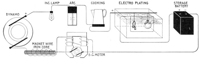
Figs. 1,206 to 1,212.—Apparatus which operates successfully on a direct current circuit. The direct current will operate incandescent
lamps, arc lamps, electric heating apparatus, electro-plating and typing bath, direct current motors; charge storage
batteries, produce electro-chemical action. It will flow through a straight wire or just as freely through the same wire when
wound over an iron bar.
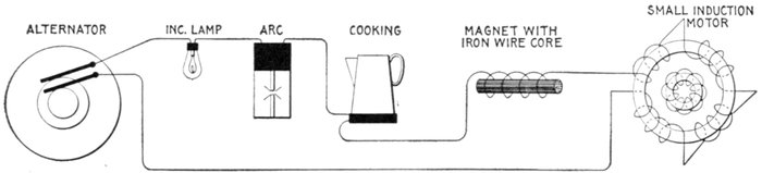
Figs. 1,213 to 1,217.—Apparatus which operates successfully on an alternating circuit. The alternating current will operate incandescent
lamps, arc lamps, electric heating apparatus, alternating current motors. It will flow through a straight wire with
slightly increased retarding effect, but if the wire be wound on an iron bar its strength is greatly reduced.
[Pg 999]
The size of wire needed to transmit a given amount of electrical energy
(watts) with a given percentage of drop, being inversely proportional
to the square of the voltage employed, the great saving in copper by the use
of alternating current at high pressure must be apparent. This advantage
can be realized either by a saving in the weight of wire required, or by
transmitting the current to a greater distance with the same weight of
copper.
In alternating current electric lighting, the primary voltage is usually
at least 1,000 and often 2,000 to 10,000 volts.
Ques. Why is alternating current used instead of
direct current on constant pressure lighting circuits?
Ans. It is due to the greater ease with which the current
can be transformed from higher to lower pressures.
Ques. How is this accomplished?
Ans. By means of simple transformers, consisting merely
of two or more coils of wire wound upon an iron core.
Since there are no moving parts, the attention required and the likelihood
of the apparatus getting out of order are small. The apparatus
necessary for direct current consists of a motor dynamo set which is
considerably more costly than a transformer and not so efficient.
Ques. What are some of the disadvantages of alternating
current?
Ans. The high pressure at which it is used renders it dangerous,
and requires more efficient insulation; alternating current
cannot be used for such purposes as electro-plating, charging
storage batteries, etc.
[Pg 1000]
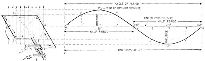
Fig. 1,218.—Application and construction of the sine curve. The sine curve is a wavelike curve used to represent the changes
in strength and direction of an alternating current. At the left of the figure is shown an elementary alternator, consisting
of a loop of wire ABCD, whose ends are attached to the ring F, and shaft G, being arranged to revolve in a uniform magnetic
field, as indicated by the vertical arrows representing magnetic lines at equidistances. The alternating current induced in
the loop is carried to the external circuit through the brushes M and S. The loop, as shown, is in its horizontal position at
right angles to the magnetic field. The dotted circle indicates the circular path described by AB or CD during the revolution
of the loop. Now, as the loop rotates, the induced electric pressure will vary in such a manner that its intensity at any
point of the rotation is proportional to the sine of the angle corresponding to that point. Hence, on the horizontal line which passes
through the center of the dotted circle, take any length as 08, and divide into any number of equal parts representing fractions
of a revolution, as 0°, 90°, 180°, etc. Erect perpendiculars at these points, and from the corresponding points on the dotted
circle project lines (parallel to 08) to the perpendiculars; these intersections give points, on the sine curve, for instance,
through 2 at the 90° point of the revolution of the loop, and projecting over to the corresponding perpendicular gives 2'2,
whose length is proportional to the electric pressure at that point. In like manner other points are obtained, and the
curved line through them will represent the variation in the electric pressure for all points of the revolution. At 90° the
pressure is at a maximum, hence by using a pressure scale such that the length of the perpendicular 2'2 for 90° will measure
the maximum pressure, the length of the perpendicular at any other point will represent the actual pressure at that point.
The curve lies above the horizontal axis during the first half of the revolution and below it during the second half, which
indicates that the current flows in one direction for a half revolution, and in the opposite direction during the remainder of
the revolution.
[Pg 1001]
Alternating Current Principles.—In the operation of a
direct current generator or dynamo, as explained in Chapter
XIII, alternating currents are generated in the armature winding
and are changed into direct current by the action of the commutator.
It was therefore necessary in that chapter, in presenting
the basic principles of the dynamo, to explain the
generation of alternating currents at length, and the graphic
method of representing the alternating current cycle by the
sine curve. In order to avoid unnecessary repetition, the reader
should carefully review the above mentioned chapter before
continuing further. The diagram fig. 168, showing the construction
and application of the sine curve to the alternating
current, is however for convenience here shown enlarged (fig. 1,218).
In the diagram the various
alternating current terms
are graphically defined.
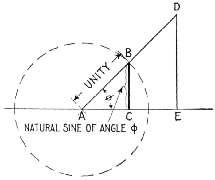
Fig. 1,219—Diagram illustrating the sine of an angle. In order to understand the sine curve,
it is necessary to know the meaning of the sine of an angle. This is defined as the ratio
of the perpendicular let fall from any point in one side of the angle to the other side divided
by the hypotenuse of the triangle thus formed. For instance, in the diagram, let AD
and AE be the two sides of the angle φ, and DE a perpendicular let fall from any point
D of the side AD to the other side AE. Then, the sine of the angle (written sin φ) = DE ÷ AD.
It is evident that if the perpendicular be let fall at a unit's distance from the
apex A, as at B,
This line BC is called the natural sine of the angle, and its values for different angles are given
in the table on page 451.
[Pg 1002]
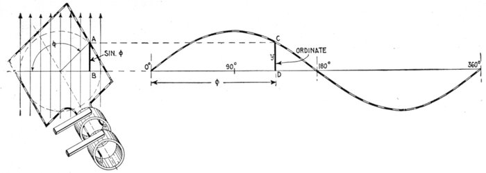
Fig. 1,220.—Diagram illustrating the equation of the sine curve: y = sin φ.
y is any ordinate, and φ, the angle which the coil makes with the
horizontal line, corresponding to the particular value of y taken.
The alternating current,
as has been explained,
rises from zero to a maximum,
falls to zero, reverses
its direction, attains a maximum
in the new direction,
and again returns to zero;
this comprises the cycle.
This series of changes
can best be represented by
a curve, whose abscissæ
represent time, or degrees
of armature rotation, and
whose ordinates, either
current or pressure. The
curve usually chosen for
this purpose is the sine
curve, as shown in fig.
1,218, because it closely
agrees with that given by
most alternators.
The equation of the sine
curve is
y = sin φ
in which y is any ordinate,
and φ, the angle of the
corresponding position of
the coil in which the current
is being generated as
illustrated in fig. 1,220.
[Pg 1003]
Ques. What is an alternation?
Ans. The changes which the current undergoes in rising
from zero to maximum pressure and returning back to zero;
that is, a single positive or negative "wave" or half period, as
shown in fig. 1,221.
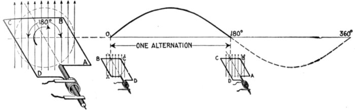
Fig. 1,221.—Diagram showing one alternation of the current in which the latter varies from zero
to maximum and back to zero while the generating loop ABCD makes one half revolution.
Ques. What is the amplitude of the current?
Ans. The greatest value of the current strength attained
during the cycle.
The foregoing definitions are also illustrated in fig. 1,218.
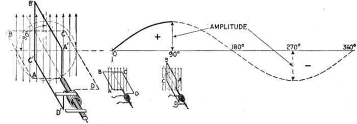
Fig. 1,222.—Diagram illustrating amplitude of the current. The current reaches its amplitude
or maximum value in one quarter period from its point of zero value, as, for instance, while
the generating loop moves from position ABCD to A'B'C'D'. At three-quarter revolution,
the current reaches its maximum value in the opposite direction.
[Pg 1004]
Ques. Define the term "period."
Ans. This is the time of one cycle of the alternating current.
Ques. What is periodicity?
Ans. A term sometimes used for frequency.
Frequency.—If a slowly varying alternating current be passed
through an incandescent lamp, the filament will be seen to vary
in brightness, following the change of current strength. If,
however, the alternations take place more rapidly than about
50 to 60 per second, the eye cannot follow the variations and the
lamp appears to burn steadily. Hence it is important to consider
the rate at which the alternations take place, or as it is called,
the frequency, which is defined as: the number of cycles per second.
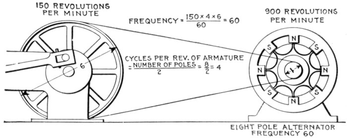
Fig. 1,223.—Diagram of alternator and engine, illustrating frequency. The frequency or
cycles per second is equal to the revolution of armature per second multiplied by one-half the
number of poles per phase. In the figure the armature makes 6 revolutions to one of the
engine; one-half the number of poles = 8 ÷ 2 = 4, hence frequency = (150 × 4 × 6) ÷ 60
= 60. The expression in the parenthesis gives the cycles per minute, and dividing by 60,
the cycles per second.
In a two pole machine, the frequency is the same as the number
of revolutions per second, but in multipolar machines, it is
greater in proportion to the number of pairs of poles per phase.
[Pg 1005]
Thus, in an 8 pole machine, there will be four cycles per revolution.
If the speed be 900 revolutions per minute, the frequency is
The symbol ~ is read "cycles per second."
Ques. What frequencies are used in commercial
machines?
Ans. The two standard frequencies are 25 and 60 cycles.
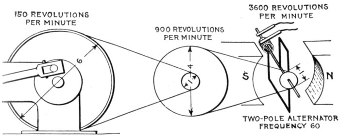
Fig. 1,224—Diagram answering the question: Why are alternators always built multipolar?
They are made multipolar because it is desirable that the frequency be high. It is evident
from the figure that to obtain high frequency would require too many revolutions of the
armature of a bipolar machine for mechanical safety—especially in large alternators.
Moreover a double reduction gear in most cases would be necessary, adding complication
to the drive. Comparing the above illustration with fig. 1,223, shows plainly the reason
for multipolar construction.
Ques. For what service are these frequencies adapted?
Ans. The 25 cycle frequency is used for conversion to direct
current, for alternating current railways, and for machines of
large size; the 60 cycle frequency is used for general distribution
for lighting and power.
The frequency of 40 cycles, which once was introduced as a compromise
between 25 and 60 has been found not desirable, as it is somewhat
low for general distribution, and higher than desirable for conversion
to direct current.
[Pg 1006]
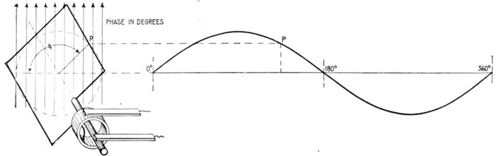
Fig. 1,225.—Diagram illustrating "phase." In wave, vibratory, and simple harmonic motion, phase may be defined as: the
portion of one complete vibration, measured either in angle or in time, that any moving point has executed.
Ques. What are
the advantages of
low frequency?
Ans. The number of
revolutions of the rotor
is correspondingly low;
arc lamps can be more
readily operated; better
pressure regulation;
small motors such as
fan motors can be operated
more easily from
the circuit.
Phase.—As applied
to an alternating current,
phase denotes the
angle turned through by
the generating element
reckoned from a given
instant. Phase is usually
measured in degrees
from the initial position
of zero generation.
If in the diagram fig.
1,225, the elementary
armature or loop be the
generating element, and
the curve at the right
be the sine curve representing
the current,
then the phase of any
point p will be the angle φ
or angle moved through
from the horizontal line,
the starting point.
[Pg 1007]
Ques. What is phase difference?
Ans. The angle between the phases of two or more alternating
current quantities as measured in degrees.
Ques. What is phase displacement?
Ans. A change of phase of an alternating pressure or current.
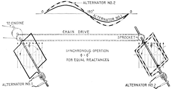
Figs. 1,226 and 1,227.—Diagram and sine curves illustrating synchronism. If two alternators,
with coils in parallel planes, be made to rotate at the same speed by connecting
them with chain drive or equivalent means, they will then be "in synchronism" that is,
the alternating pressure or current in one will vary in step with that in the other. In
other words, the cycles of one take place with the same frequency and at the same time
as the cycles of the other as indicated by the curves, fig. 1,226. It should be noted that
the maximum values are not necessarily the same but the maximum and zero values
must occur at the same time in both machines, and the maximum value must be of the
same sign. If the waves be distorted the maximum values may not occur simultaneously.
See fig. 1,348.
Synchronism.—This term may be defined as: the simultaneous
occurrence of any two events. Thus two alternating currents
or pressures are said to be "in synchronism" when they
have the same frequency and are in phase.
Ques. What does the expression "in phase" mean?
Ans. Two alternating quantities are said to be in phase,
when there is no phase difference between; that is when the
angle of phase difference equals zero.
[Pg 1008]
Thus the current is said to be in phase with the pressure when it
neither lags nor leads, as in fig. 1,228.
A rotating cylinder, or the movement of an index or trailing arm is
brought into synchronism with another rotating cylinder or another
index or trailing arm, not only when the two are moving with exactly
the same speed, but when in addition they are simultaneously moving
over similar portions of their respective paths.
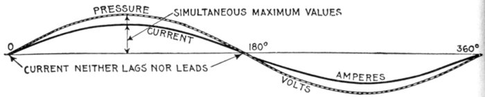
Fig. 1,228—Pressure and current curves illustrating the term "in phase." The current
is said to be in phase with the pressure when it neither lags nor leads.
When there is phase difference, as between current and
pressure, they are said to be "out of phase" the phase difference
being measured as in fig. 1,229 by the angle φ.
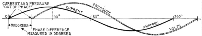
Fig. 1,229—Pressure and current curves illustrating the term "out of phase." The current
is said to be out of phase with the pressure when it either lags or leads, that is when the
current is not in synchronism with the pressure. In practice the current and pressure
are nearly always out of phase.
When the phase difference is 90° as in fig. 1,231 or 1,232, the two
alternating quantities are said to be in quadrature; when it is 180°, as
in fig. 1,233, they are said to be in opposition.
When they are in quadrature, one is at a maximum when the other
is at zero; when they are in opposition, one reaches a positive maximum
when the other reaches a negative minimum, being at each instant
opposite in sign.
Ques. What is a departure from synchronism called?
Ans. Loss of synchronism.
[Pg 1009]
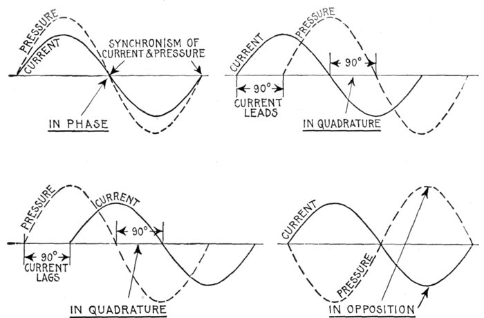
Figs. 1,230 to 1,233.—Curves showing some phase relations between current and pressure. Fig. 1,230, synchronism of current
and pressure, expressed by the term "in phase," meaning simultaneous zero values, and simultaneous maximum values of the
same sign; fig. 1,231, in quadrature, current leading 90°; fig. 1,232 in quadrature, current lagging 90°; fig. 1,233, in opposition,
meaning that the phase different between current and pressure is 180°.
[Pg 1010]
Maximum Volts and Amperes.—In the operation of an
alternator, the pressure and strength of the current are continually
rising, falling and reversing. During each cycle there
are two points at which the pressure or current reaches its
greatest value, being known as the maximum value. This
maximum value is not used to any great extent, but it shows the
maximum to which the pressure rises, and hence, the greatest
strain to which the insulation of the alternator is subjected.
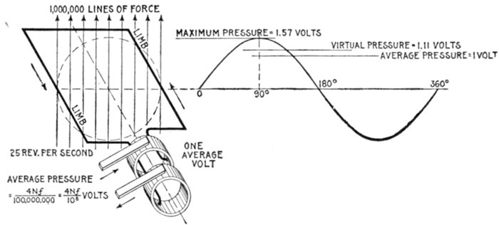
Fig. 1,234.—Elementary alternator developing one average volt. If the loop make one revolution
per second, and the maximum number of lines of force embraced by the loop in the
position shown (the zero position) be denoted by N, then each limb will cut 2N lines per
second, because it cuts every line during the right sweep and again during the left
sweep. Hence each limb develops an average pressure of 2N units (C.G.S. units),
and as both limbs are connected in series, the total pressure is 4N units per revolution.
Now, if the loop make f revolutions per second instead of only one, then f times as many
lines will be cut per second, and the average pressure will be 4N f units. Since the C.G.S.
unit of pressure is so extremely small, a much greater practical unit called the volt is used,
which is equal to 100,000,000, or 108 C.G.S. units is employed. Hence average voltage =
4Nf ÷ 108. The value of N in actual machines is very high, being several million lines
of force. The illustration shows one set of conditions necessary to generate one average
volt. The maximum pressure developed is 1 ÷ .637 = 1.57 volts; virtual pressure =
1.57 × .707 = 1.11 volts.
Average Volts and Amperes.—Since the sine curve is used
to represent the alternating current, the average value may be
defined as: the average of all the ordinates of the curve for one-half
of a cycle.
[Pg 1011]
Ques. Of what use is the average value?
Ans. It is used in some calculations but, like the maximum
value, not very often. The relation between the average and
virtual value is of importance as it gives the form factor.
Virtual Volts and Amperes.—The virtual[1] value of an
alternating pressure or current is equivalent to that of a direct
pressure or current which would produce the same effect; those
effects of the pressure and current are taken which are not
affected by rapid changes in direction and strength,—in the
case of pressure, the reading of an electrostatic voltmeter, and
in the case of current, the heating effect.
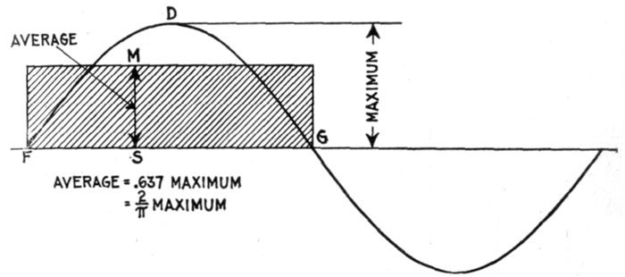
Fig. 1,235.—Maximum and average values of the sine curve. The average value of the sine
curve is represented by an ordinate MS of such length that when multiplied by the base
line FG, will give a rectangle MFSG whose area is equal to that included between the curve
and base line FDGS.
[Pg 1012]
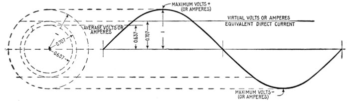
Fig. 1,236.—Diagram illustrating "virtual" volts and amperes. The word virtual is defined as: Being in essence or effect, not in
fact; not actual, but equivalent, so far as effect is concerned. As applied to the alternating current, it denotes an imaginary direct
current of such value as will produce an effect equivalent to that of the alternating current. Thus, a virtual pressure of 1,000
volts is one that would produce the same deflection in an electrostatic voltmeter as a direct pressure of 1,000 volts: a virtual
current of 10 amperes is that current which would produce the same heating effect as a direct current of 10 amperes. Both
pressure and current vary continually above and below the virtual values in alternating current circuits. Distinction should
be made between the virtual and "effective" values of an alternating current. See fig. 1,237. The word effective is commonly
used erroneously for virtual. See note page 1,011.
The attraction (or repulsion)
in electrostatic
voltmeters is proportional
to the square of the volts.
The readings which
these instruments give, if
first calibrated by using
steady currents, are not
true means, but are the
square roots of the means of
the squares.
Now the mean of the
squares of the sine (taken
over either one quadrant or
a whole circle) is ½; hence
the square root of mean
square value of the sine
functions is obtained by
multiplying their maximum
value by 1 ÷ √2, or by
0.707.
The arithmetical mean
of the values of the sine,
however, is 0.637. Hence
an alternating current, if it
obey the sine law, will produce
a heating effect greater
than that of a steady current
of the same average
strength, by the ratio of
0.707 to 0.637; that is,
about 1.11 times greater.
If a Cardew voltmeter
be placed on an alternating
circuit in which the volts
are oscillating between
maxima of +100 and -100
volts, it will read 70.7 volts,
though the arithmetical
mean is really only 63.7;
and 70.7 steady volts would
be required to produce an
equal reading.
[Pg 1013]
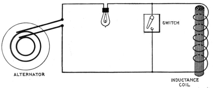
Fig. 1,237.—Diagram illustrating virtual and effective pressure. If the coil be short circuited
by the switch and a constant virtual pressure be impressed on the circuit, the whole of
the impressed pressure will be effective in causing current to flow around the circuit.
In this case the virtual and effective pressures will be equal. If the coil be switched into
circuit, the reverse pressure due to self induction will oppose the virtual pressure; hence, the
effective pressure (which is the difference between the virtual and reverse pressures) will
be reduced, the virtual or impressed pressure remaining constant all the time. A virtual
current is that indicated by an ammeter regardless of the phase relation between current and
pressure. An effective current is that indicated by an ammeter when the current is in phase
with the pressure. In practice, the current is hardly ever in phase with the pressure, usually
lagging, though sometimes leading in phase. Now the greater this phase difference, either
way, the less is the power of a given virtual current to do work. With respect to this
feature, effective current may be defined as: that proportion of a given virtual current which
can do useful work. If there be no phase difference, then effective current is equal to
virtual current.
The matter may be looked at in a different way. If an alternating
current is to produce in a given wire the same amount of effect as a
continuous current of 100 amperes, since the alternating current goes
down to zero twice in each period, it is clear that it must at some point
in the period rise to a maximum greater than 100 amperes. How much
greater must the maximum be? The answer is that, if it undulate
up and down with a pure wave form, its maximum must be √2 times
as great as the virtual mean; or conversely the virtual amperes will
be equal to the maximum divided by √2. In fact, to produce equal
effect, the equivalent direct current will be a kind of mean between the
maximum and the zero value of the alternating current; but it must
not be the arithmetical mean, nor the geometrical mean, nor the harmonic
mean, but the quadratic mean; that is, it will be the square root
of the mean of the squares of all the instantaneous values between zero
and maximum.
Effective Volts and Amperes.—Virtual pressure, although
already explained, may be further defined as the pressure
impressed on a circuit. Now, in nearly all circuits the impressed[Pg 1014]
or virtual pressure meets with an opposing pressure due to
inductance and hence the effective pressure is something less
than the virtual, being defined as that pressure which is
available for driving electricity around the circuit, or for doing
work. The difference between virtual and effective pressure is
illustrated in fig. 1,237.
Ques. Does a given alternating voltage affect the
insulation of the circuit differently than a direct pressure
of the same value?
Ans. It puts more strain on the insulation in the same
proportion as the maximum pressure exceeds the virtual pressure.
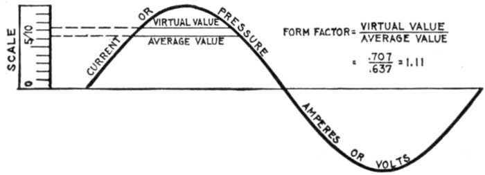
Fig. 1,238.—Current or pressure curve illustrating form factor. It is simply the virtual value
divided by the average value. For a sine wave the virtual value is 1 / √2 times the maximum, and
the average is 2 / π times the maximum, so that the form factor is π/2√2 or 1.11. The induction
wave which generates an alternating pressure wave has a maximum value proportional to
the area, that is, to the average value of the pressure wave. Hence the induction values
corresponding to two pressure waves whose virtual values are equal, will be inversely
proportional to their form factors. This is illustrated by the fact that a peaked wave
causes less hysteresis loss in a transformer core than a flat topped wave, owing to the
higher form factor of the peaked wave. See wave forms, figs. 1,245 to 1,248.
Form Factor.—This term was introduced by Fleming, and
denotes the ratio of the virtual value of an alternating wave to
the average value. That is
Ques. What does this indicate?
Ans. It gives the relative heating effects of alternating and
direct currents, as illustrated in figs. 1,239 and 1,240.
That is, the alternating current will have about 11 per cent. more heating
power than the direct current which is of the same average strength.
If an alternating current voltmeter be placed upon a circuit in which
the volts range from +100 to -100, it will read 70.7 volts, although
the arithmetical average, irrespective of + or-sign, is only 63.7 volts.
If the voltmeter be connected to a direct current circuit, the pressure
necessary to give the same reading would be 70.7 volts.
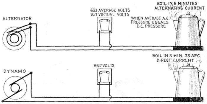
Figs. 1,239 and 1,240.—Relative heating effects of alternating and direct currents. If it takes
say five minutes to produce a certain heating effect with alternating current at say 63.7
average volts, it will take 33 seconds longer with direct current at the same pressure, that
is, the alternating current has about 11 per cent. more heating power than the direct current
of the same average pressure. The reader should be careful not to get a wrong conception
of the above; it does not mean that there is a saving by using alternating current.
When both voltmeters read the same, that is, when the virtual pressure of the alternating
current is the same as the direct current pressure, the heating effect is of course the same.
Ques. What is the relation between the shape of the
wave curve and the form factor?
Ans. The more peaked the wave, the greater the value of
its form factor.
A form factor of units would correspond to a rectangular wave; this
is the least possible value of the form factor, and one which is not
realized in commercial machines.
[Pg 1016]
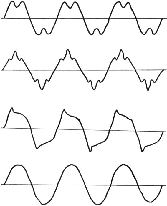
Figs. 1,241 to 1,244.—Various forms of pressure or current waves. Figs. 1,241 to 1,243 show
the general shape of the waves produced by some alternators used largely for lighting
work and having toothed armatures. The effect of the slots and shape of pole pieces is
here very marked. Fig. 1,244 shows a wave characteristic of large alternators designed
for power transmission and having multi-slot or distributed windings.
[Pg 1017]
Wave Form.—There is always more or less irregularity in
the shape of the current waves as met in practice, depending
upon the construction of the alternator.
The ideal wave curve is the so called true sine wave, and is
obtained with a rate of cutting of lines of force, by the armature
coils, equivalent to the swing of a pendulum, which increases
in speed from the end to the middle of the swing, decreasing at
the same rate after passing the center. This swing is expressed
in physics, as "simple harmonic motion".
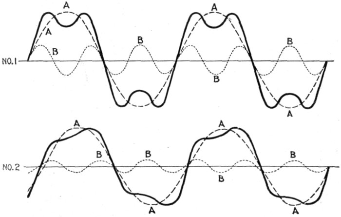
Figs. 1,245 and 1,246.—Resolution of complex curves into sine curves. The heavy curve can
be resolved into the simpler curves A and B shown in No. 1, the component curves A and
B have in the ratio of three to one; that is, curve B has three times as many periods per
second as curve A. All the curves, however, cross the zero line at the same time, and the
resultant curve, though curiously unlike either of them, has a certain symmetry. In No. 2
the component curves, besides having periods in the ratio of three to one, cross the zero
line at different points. The resultant curve produced is still less similar to its components,
and is curiously and unsymmetrically humped. At first sight it is difficult to believe that
such a curious curve could be resolved into two such simple and symmetrical ones. In
both figures the component curves are sine curves, and as the curves for sine and cosine
functions are exactly similar in form, the simplest supposition that can be made for the
variation of pressure or of current is that both follow a sine law.
[Pg 1018]
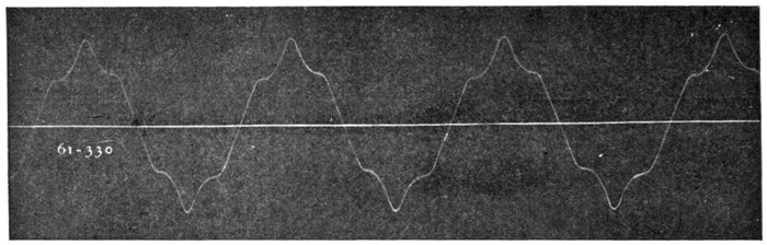
Fig. 1,247.—Reproduction of oscillograph record of wave form of alternator with one coil per phase per pole. Here
the so-called "super-imposed harmonic" is clearly indicated.
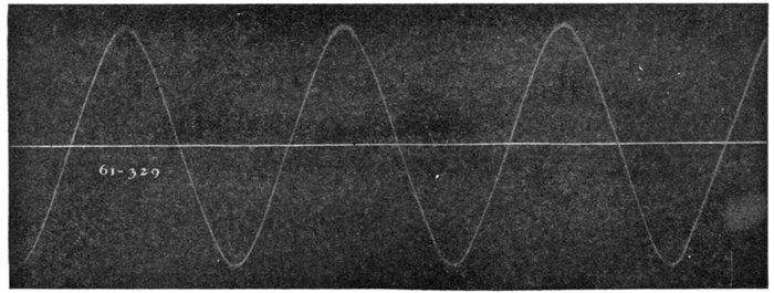
Fig. 1,248.—Reproduction of oscillograph record of Wagner alternator having three coils per phase per pole.
[Pg 1019]
The losses in all secondary apparatus are slightly lower with
the so called peaked form of wave. For the same virtual voltage,
however, the top of the peak will be much higher, thereby submitting
the insulation to that much greater strain. By reason
of the fact that the losses are less under such wave forms, many
manufacturers in submitting performance data on transformers
recite that the figures are for sine wave conditions, stating
further that if the transformers are to be operated in a circuit
more peaked than the sine wave, the losses will be less than
shown.
The slight saving in the losses of secondary apparatus, obtained
with a peaked wave, by no means compensates for the increased
insulation strains and an alternator having a true sine wave is
preferred.
Ques. What determines the form of the wave?
Ans. 1. The number of coils per phase per pole, 2, shape of
pole faces, 3, eddy currents in the pole pieces, and 4, the air gap.
Ques. What are the requirements for proper rate of
cutting of the lines of force?
Ans. It is necessary to have, as a minimum, two coils per
phase per pole in three phase work.
Ques. What is the effect of only one coil per phase per
pole?
Ans. The wave form will be distorted as shown in fig. 1,247.
Ques. What is the least number of coils per phase
per pole that should be used for two and three phase
alternators?
Ans. For three phase, two coils, and for two phase, three
coils, per phase per pole.
[Pg 1020]
Single or Monophase
Current.—This kind of
alternating current is generated
by an alternator
having a single winding on
its armature. Two wires, a
lead and return, are used
as in direct current.
An elementary diagram
showing the working principles
is illustrated in fig.
1,249, a similar hydraulic
cycle being shown in figs.
1,250 to 1,252.
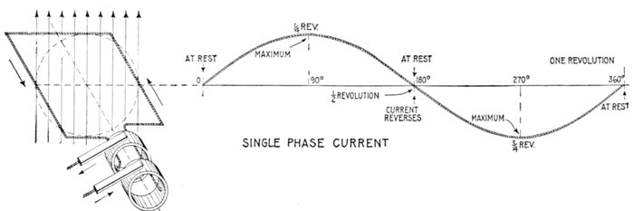
Fig. 1,249.—Elementary one loop alternator and sine curve illustrating single phase alternating current. There are three points
during the revolution at which there is no current: at 0° the position shown, 180°, and 360°; in other words, at the beginning,
middle point and end of the cycle. The current reaches a maximum at 90°, reverses at 180°, and reaches a maximum
in the reverse direction at 270°.
Two Phase Current.—In
most cases two phase
current actually consists of
two distinct single phase
currents flowing in separate
circuits. There is often no
electrical connection between
them; they are of
equal period and equal
amplitude, but differ in
phase by one quarter of a
period. With this phase
relation one of them will
be at a maximum when
the other is at zero. Two
phase current is illustrated[Pg 1021]
by sine curves in fig.
1,253, and by hydraulic
analogy in
figs. 1,254 and 1,255.
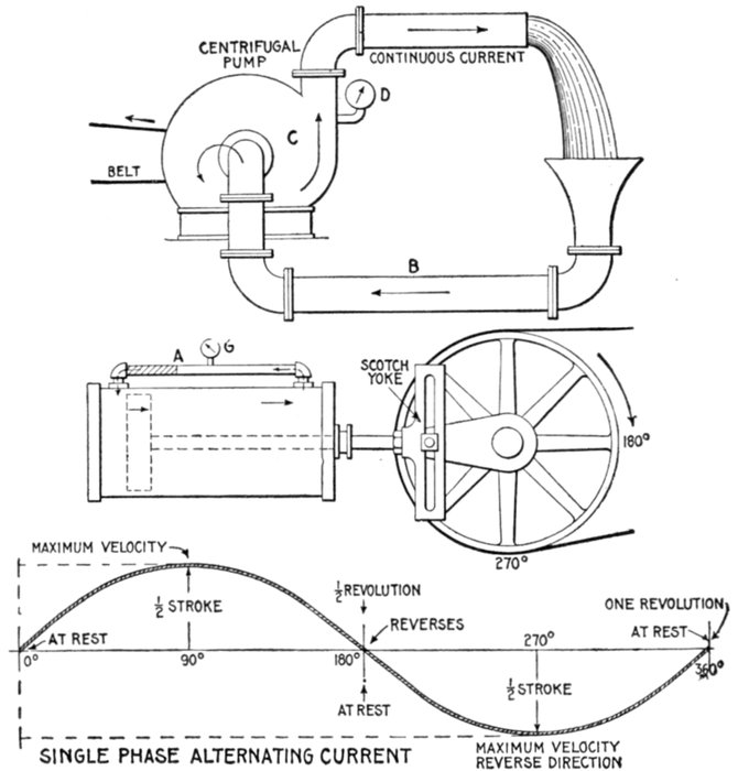
Figs. 1,250 to 1,252.—Hydraulic analogy illustrating the difference between direct (continuous)
and alternating current. In fig. 1,250 a centrifugal pump C forces water to the upper
pipe, from which it falls by gravity to the lower pipe B and re-enters the pump. The
current is continuous, always flowing in one direction, that is, it does not reverse its direction.
Similarly a direct electric current is constant in direction (does not reverse);
though not necessarily constant in value. A direct current, constant in both value and
direction as a result of constant pressure, is called "continuous" current. Similarly in
the figure the flow is constant, and a gauge D placed at any point will register a constant
pressure, hence the current may be called, in the electrical sense, "continuous." The
conditions in fig. 1,251 are quite different. The illustration represents a double acting
cylinder with the ends connected by a pipe A, and the piston driven by crank and Scotch
yoke as shown. In operation, if the cylinder and pipe be full of water, a current of water
will begin to flow through the pipe in the direction indicated as the piston begins its stroke,
increasing to maximum velocity at one-quarter revolution of the crank, decreasing and
coming to rest at one-half revolution, then reversing and reaching maximum velocity
in the reverse direction at three-quarter revolution, and coming to rest again at the end of
the return stroke. A pressure gauge at G will register a pressure which varies with the
current. Since the alternating electric current undergoes similar changes, the sine curve
will apply equally as well to the pump cycle as to the alternating current cycle.
[Pg 1022]
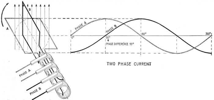
Fig. 1,253.—Elementary two loop alternator and sine curves, illustrating two phase
alternating current. If the loops be placed on the alternator armature at 90 magnetic
degrees, a single phase current will be generated in each of the windings, the
current in one winding being at its maximum value when the other is at zero. In
this case four transmission conductors are generally used, two for each separate
circuit, and the motors to which the current is led have a double winding corresponding
to that on the alternator armature.
If two identical
simple alternators
have their armature
shafts coupled in such
a manner, that when
a given armature coil
on one is directly
under a field pole, the
corresponding coil on
the other is midway
between two poles of
its field, the two currents
generated will
differ in phase by a
half alternation, and
will be two phase
current.
Ques. How must
an alternator be
constructed to
generate two phase
current?
Ans. It must have
two independent
windings, and these
must be so spaced
out that when the
volts generated in
one of the two phases
are at a maximum,
those generated in
the other are at zero.
[Pg 1023]
In other words, the windings, which must be alike, of an equal number
of turns, must be displaced along the armature by an angle corresponding
to one-quarter of a period, that is, to half the pole pitch.
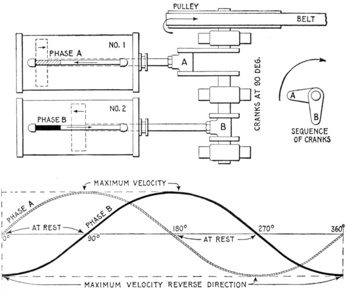
Figs. 1,254 and 1,255.—Hydraulic analogy illustrating two phase alternating current. In the
figure two cylinders, similar to the one in fig. 1,251, are shown, operated from one shaft
by crank and Scotch yoke drive. The cranks are at 90° as shown, and the cylinders and
connecting pipes full of water. In operation, the same cycle of water flow takes place as
in fig. 1,251. Since the cranks are at 90°, the second piston is one-half stroke behind the
first; the flow of water in No. 1 (phase A) is at a maximum when the flow in No. 2 (phase
B) comes to rest, the current conditions in both pipes for the entire cycle being represented
by the two sine curves whose phase difference is 90°. Comparing these curves with fig.
1,253, it will be seen that the water and electric current act in a similar manner.
The windings of the two phases must, of course, be kept separate,
hence the armature will have four terminals, or if it be a revolving
armature it will have four collector rings.
As must be evident the phase difference may be of any value between
0° and 360°, but in practice it is almost always made 90°.
[Pg 1024]
Ques. In what other way may two phase current be
generated?
Ans. By two single phase alternators coupled to one shaft.
Ques. How many wires are required for two phase
distribution?
Ans. A two phase system requires four lines for its distribution;
two lines for each phase as in fig. 1,253. It is possible, but
not advisable, to reduce the number to 3, by employing one
rather thicker line as a common return for each of the phases
as in fig. 1,256.
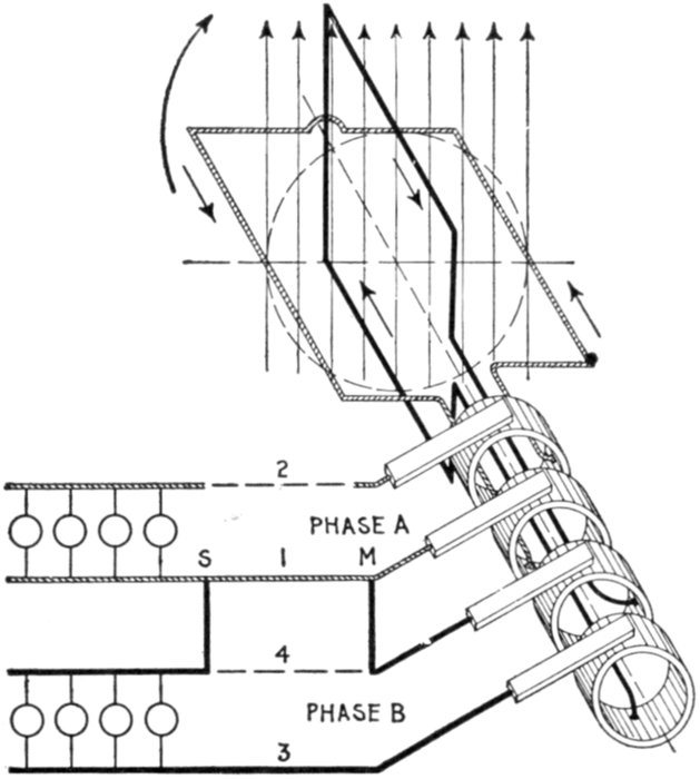
Fig. 1,256.—Diagram of three wire two phase current distribution. In order to save one wire
it is possible to use a common return conductor for both circuits, as shown, the dotted
portion of one wire 4 being eliminated by connecting across to 1 at M and S. For long
lines this is economical, but the interconnection of the circuits increases the chance
of trouble from grounds or short circuits. The current in the conductor will be the resultant
of the two currents, differing by 90° in phase.
[Pg 1025]
If this be done, the voltage between the A line and the B line will be
equal to √2 times the voltage in either phase, and the current in the
line used as common return will be √2 times as great as the current in
either line, assuming the two currents in the two phases to be equal.
Ques. In what other way may two phase current be
distributed?
Ans. The mid point of the windings of the two phases may
be united in the alternator at a common junction.
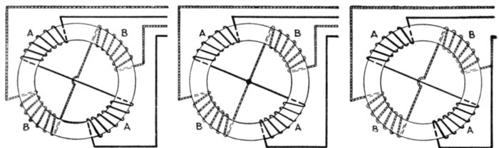
Figs. 1,257 to 1,259.—Various two phase armature connections. Fig. 1,257, two separate
circuit four collector ring arrangement; fig. 1,258, common middle connection, four
collector rings; fig. 1,259, circuit connected in armature for three collector rings. In the
figures the black winding represents phase A, and the light winding, phase B.
This is equivalent to making the machine into a four phase alternator
with half the voltage in each of the four phases, which will then be in
successive quadrature with each other.
Ques. How are two phase alternator armatures wound?
Ans. The two circuits may be separate, each having two
collector rings, as shown in fig. 1,257, or the two circuits may be
coupled at a common middle as in fig. 1,258, or the two circuits
may be coupled in the armature so that only three collector
rings are required as shown in fig. 1,259.
[Pg 1026]
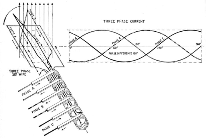
Fig. 1,260.—Elementary three loop alternator and sine curves, illustrating three phase alternating
current. If the loops be placed on the alternator armature at 120 magnetic degrees
from one another, the current in each will attain its maximum at a point one-third of a
cycle distant from the other two. The arrangement here shown gives three independent
single phase currents and requires six wires for their transmission. A better arrangement
and the one generally used is shown in fig. 1,261.
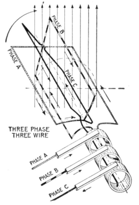
Fig. 1,261.—Elementary three wire three phase alternator. For the transmission of three
phase current, it is not customary to use six wires, as in fig. 1,260, instead, three ends
(one end of each of the loops) are brought together to a common connection as shown,
and the other ends, connected to the collector rings, giving only three wires for the
transmission of the current.
Three Phase Current.—A three phase current consists of
three alternating currents of equal frequency and amplitude,
but differing in phase from each other by one-third of a period.
Three phase current as represented by sine curves is shown in
fig. 1,260, and by hydraulic analogy in fig. 1,262. Inspection of the[Pg 1027]
figures will show that when any one of the currents is at its
maximum, the other two are of half their maximum value,
and are flowing in the opposite direction.
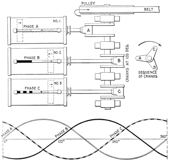
Figs. 1,262 and 1,263.—Hydraulic analogy illustrating three phase alternating current. Three
cylinders are here shown with pistons connected through Scotch yokes to cranks placed
120° apart. The same action takes place in each cylinder as in the preceding cases, the
only difference being the additional cylinder, and difference in phase relation.
Ques. How is three phase current generated?
Ans. It requires three equal windings on the alternator
armature, and they must be spaced out over its surface so as[Pg 1028]
to be successively ⅓ and ⅔ of the period (that is, of the double
pole pitch) apart from one another.
Ques. How many wires are used for three phase
distribution?
Ans. Either six wires or three wires.
Six wires, as in fig. 1,260, might be used where it is desired to supply
entirely independent circuits, or as is more usual only three wires are
used as shown in fig. 1,261. In this case it should be observed that if the
voltage generated in each one of the three phases separately E (virtual)
volts, the voltage generated between any two of the terminals will be
equal to √3 × E. Thus, if each of the three phases generate 100
volts, the voltage from the terminal of the A phase to that of the B
phase will be 173 volts.
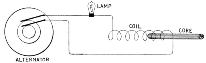
Fig. 1,264.—Experiment illustrating self-induction in an alternating current circuit. If an
incandescent lamp be connected in series with a coil made of one pound of No. 20 magnet
wire, and connected to the circuit, the current through the lamp will be decreased due to
the self-induction of the coil. If now an iron core be gradually pushed into the coil,
the self-induction will be greatly increased and the lamp will go out, thus showing the great
importance which self-induction plays in alternating current work.
Inductance.—Each time a direct current is started, stopped
or varied in strength, the magnetism changes, and induces or
tends to induce a pressure in the wire which always has a direction
opposing the pressure which originally produced the current.
This self-induced pressure tends to weaken the main current at
the start and prolong it when the circuit is opened.
The expression inductance is frequently used in the same sense as
coefficient of self-induction, which is a quantity pertaining to an electric[Pg 1029]
circuit depending on its geometrical form and the nature of the surrounding
medium.
If the direct current maintains the same strength and flow
steadily, there will be no variations in the magnetic field surrounding
the wire and no self-induction, consequently the only retarding
effect of the current will be the "ohmic resistance" of the wire.
If an alternating current be sent through a circuit, there will
be two retarding effects:
1. The ohmic resistance;
2. The spurious resistance.
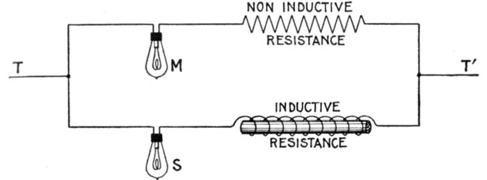
Fig. 1,265.—Non-inductive and inductive resistances. Two currents are shown joined in
parallel, one containing a lamp and non-inductive resistance, and the other a lamp and
inductive resistance. The two resistances being the same, a sufficient direct pressure
applied at T, T' will cause the lamps to light up equally. If, however, an alternating
pressure be applied, M will burn brightly, while S will give very little or no light because
of the effect of the inductance of the inductive resistance.
Ques. Upon what does the ohmic resistance depend?
Ans. Upon the length, cross sectional area and material of
the wire.
Ques. Upon what does the spurious resistance depend?
Ans. Upon the frequency of the alternating current, the
shape of the conductor, and nature of the surrounding medium.
[Pg 1030]
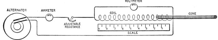
Fig. 1,266.—Inductance test, illustrating the self-induction of a coil which is gradually increased by moving an iron wire core
inch by inch into the coil. The current is kept constant with the adjustable resistance throughout the test and readings taken,
first without the iron core, and again when the core is put in the coil and moved to the 1, 2, 3, 4, etc., inch marks. By
plotting the voltmeter readings and the position of the iron core on section paper, a curve is obtained showing graphically
the effect of the self-induction. A curve of this kind is shown in fig. 1,302.
Ques. Define inductance.
Ans. It is the total magnetic flux
threading the circuit per unit current
which flows in the circuit, and which
produces the flux.
In this it must be understood that
if any portion of the flux thread the
circuit more than once, this portion
must be added in as many times as it
makes linkage.
Inductance, or the coefficient of self-induction
is the capacity which an
electric circuit has of producing induction
within itself.
Inductance is considered as the ratio
between the total induction through a
circuit to the current producing it.
Ques. What is the unit of inductance?
Ans. The henry.
Ques. Define the henry.
Ans. A coil has an inductance of
one henry when the product of the
number of lines enclosed by the coil
multiplied by the number of turns in
the coil, when a current of one ampere
is flowing in the coil, is equal to
100,000,000 or 108.
An inductance of one henry exists in
a circuit when a current changing at the
rate of one ampere per second induces a
pressure of one volt in the circuit.
[Pg 1031]
Ques. What is the henry called?
Ans. The coefficient of self-induction.
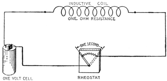
Fig. 1,267.—Diagram illustrating the henry. By definition: A circuit has an inductance of one
henry when a rate of change of current of one ampere per second induces a pressure of one
volt. In the diagram it is assumed that the internal resistance of the cell and resistance of
the connecting wires are zero.
The henry is the coefficient by which the time rate of change of the
current in the circuit must be multiplied, in order to give the pressure
of self-induction in the circuit.
The formula for the henry is as follows:
or
where
- L = coefficient of self induction in henrys;
- N = total number of lines of force threading a coil when the current is one ampere;
- T = number of turns of coil.
If a coil had a coefficient of self-induction of one henry, it would mean
that if the coil had one turn, one ampere would set up 100,000,000, or
108, lines through it.
[Pg 1032]
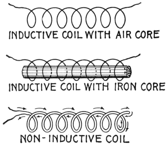
Figs. 1,268 to 1,270.—Various coils. The inductance effect, though perceptible in an air core
coil, fig. 1,268, may be greatly intensified by inserting a core made of numerous pieces
of iron wire, as in fig. 1,269. Fig. 1,270 shows a non-inductive coil. When wound in this
manner, a coil will have little or no inductance because each half of the coil neutralizes
the magnetic effect of the other. This coil, though non-inductive, will have "capacity."
It would be useless for solenoids or electromagnets, as it would have no magnetic field.
The henry[2] is too large a unit for use in practical computations,
which involves that the millihenry, or 1/1,000th
henry, is the accepted unit. In pole suspended lines the
inductance varies as the metallic resistance, the distance between
the wires on the cross arm and the number of cycles per second,
as indicated by accepted tables. Thus, for one mile of No.
8 B. & S. copper wire, with a resistance of 3,406 ohms, the coefficient
of self-induction with 6 inches between centers is .00153, and, with 12 inches, .00175.
[Pg 1033]
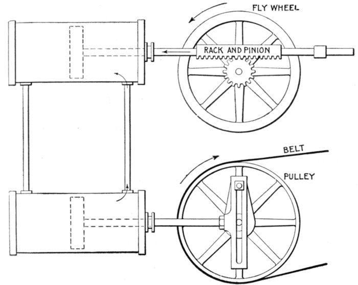
Fig. 1,271.—Hydraulic-mechanical analogy illustrating inductance in an alternating current circuit.
The two cylinders are connected at their ends by the vertical pipes, each being
provided with a piston and the system filled with water. Reciprocating motion is imparted
to the lower pulley by Scotch yoke connection with the drive pulley. The upper
piston is connected by rack and pinion gear with a fly wheel. In operation, the to and fro
movement of the lower piston produces an alternating flow of water in the upper cylinder
which causes the upper piston to move back and forth. The rack and pinion connection
with the fly wheel causes the latter to revolve first in one direction, then in the other, in
step with the upper piston. The inertia of the fly wheel causes it to resist any change
in its state, whether it be at rest or in motion, which is transmitted to the upper piston,
causing it to offer resistance to any change in its rate or direction of motion. Inductance
in the alternating current circuit has precisely the same effect, that is, it opposes any
change in the strength or direction of the current.
[Pg 1034]
Ques. How does the inductance of a coil vary with
respect to the core?
Ans. It is least with an air core; with an iron core, it is
greater in proportion to the permeability[3] of the iron.
The coefficient L for a given coil is a constant quantity so long as the
magnetic permeability of the material surrounding the coil does not
change. This is the case where the coil is surrounded by air. When
iron is present, the coefficient L is practically constant, provided the magnetism
is not forced too high.
In most cases arising in practice, the coefficient L may be considered
to be a constant quantity, just as the resistance R is usually considered
constant. The coefficient L of a coil or circuit is often spoken of as its
inductance.
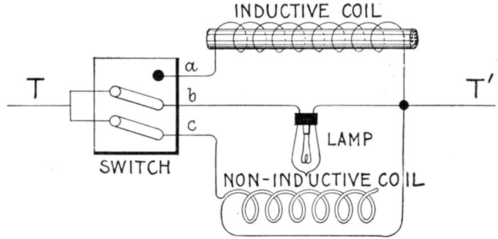
Fig. 1,272.—Experiment showing effect of inductive and non-inductive coils in alternating
current circuit. The apparatus is connected up as shown; by means of the switch, the
lamp may be placed in parallel with either the inductive or non-inductive coil. These
coils should have the same resistance. Pass an alternating current through the lamp
and non-inductive coil, of such strength that the lamp will be dimly lighted. Now turn
the switch so as to put the lamp and inductive coil in parallel and the lamp will burn
with increased brilliancy. The reason for this is because of the opposition offered
by the inductive coil to the current, less current is shunted from the lamp when
the inductive coil is in the circuit than when the non-inductive coil is in the circuit. That
is, each coil has the same ohmic resistance, but the inductive coil has in addition the
spurious resistance due to inductance, hence it shunts less current from the lamp than
does the non-inductive coil.
[Pg 1035]
Ques. Why is the iron core of an inductive coil made
with a number of small wires instead of one large rod?
Ans. It is laminated in order to reduce eddy currents and
consequent loss of energy, and to prevent excessive heating of
the core.
Ques. How does the number of turns of a coil affect
the inductance?
Ans. The inductance varies as the square of the turns.
That is, if the turns be doubled, the inductance becomes four times
as great.
The inductance of a coil is easily calculated from the following
formulæ:
L = 4π2r2n2 ÷ (l × 109) (1)
for a thin coil with air core, and
L = 4π2r2n2μ ÷ (l × 109) (2)
for a coil having an iron core. In the above formulæ:
- L = inductance in henrys;
- π = 3.1416;
- r = average radius of coil in centimeters;
- n = number of turns of wire in coil;
- μ = permeability of iron core;
- l = length of coil in centimeters.
EXAMPLE.—An air core coil has an average radius of 10 centimeters
and is 20 centimeters long, there being 500 turns, what is the
inductance?
Substituting these values in formula (1)
L = 4 × (3.1416)2 × 102 × 5002 ÷ (20 × 109) = .00494 henry
[Pg 1036]
Ques. Is the answer in the above example in the
customary form?
Ans. No; the henry being a very large unit, it is usual to
express inductance in thousandths of a henry, that is, in milli-henrys.
The answer then would be .04935 × 1,000 = 49.35 milli-henrys.
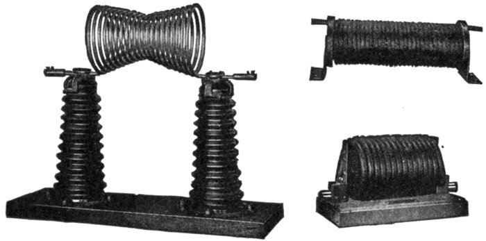
Figs. 1,273 to 1,275.—General Electric choke coils. Fig. 1,273, hour glass coil, 35,000 volts;
fig. 1,274, 4,600 volt coil; fig. 1,275, 6,600 volt coil. A choke coil is a coil with large
inductance and small resistance, used to impede alternating currents. The choke coil is
used extensively as an auxiliary to the lightning arrester. In this connection the
primary objects of the choke coil should be: 1, to hold back the lightning disturbance
from the transformer or generator until the lightning arrester discharges to earth.
If there be no lightning arrester the choke coil evidently cannot perform this function.
2, to lower the frequency of the oscillation so that whatever charge gets through the
choke coil will be of a frequency too low to cause a serious drop of pressure around the
first turns of the end coil in either generator or transformer. Another way of expressing
this is from the standpoint of wave front: a steep wave front piles up the pressure when
it meets an inductance. The second function of the choke coil is, then, to smooth out
the wave front of the surge. The principal electrical condition to be avoided is that of
resonance. The coil should be so arranged that if continual surges be set up in the
circuit, a resonant voltage due to the presence of the choke coil cannot build up at the
transformer or generator terminals. In the types shown above, the hour glass coil has
the following advantages on high voltages: 1, should there be any arcing between
adjacent turns the coils will re-insulate themselves, 2, they are mechanically strong, and
sagging is prevented by tapering the coils toward the center turns, 3, the insulating
supports can be best designed for the strains which they have to withstand. Choke
coils should not be used in connection with cable systems.
EXAMPLE.—An air core coil has an inductance of 50 milli-henrys;
if an iron core, having a permeability of 600 be inserted, what is the
inductance?
The inductance of the air core coil will be multiplied by the permeability
of the iron; the inductance then is increased to
50 × 600 = 30,000 milli-henrys, or 30 henrys.
[Pg 1037]
Ohmic Value of Inductance.—The rate of change of an
alternating current at any point expressed in degrees is equal
to the product of 2π multiplied by the frequency, the maximum
current, and the cosine of the angle of position θ; that is (using
symbols)
rate of change = 2πfImaxcos θ.
The numerical value of the rate of change is independent of
its positive or negative sign, so that the sign of the cos φ is
disregarded.
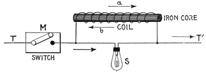
Fig. 1,276.—Inductance experiment with intermittent direct current. A lamp S is connected
in parallel with a coil of fairly fine wire having a removable iron core, and the terminals
T, T' connected to a source of direct current, a switch M being provided to interrupt the
current. The voltage of the current and resistance of the coil are of such values that when
a steady current is flowing, the lamp filament is just perceptibly red. At the instant of
making the circuit, the lamp will momentarily glow more brightly than when the current is
steady; on breaking the circuit the lamp will momentarily flash with great brightness. In the
first case, the reverse pressure, due to inductance, as indicated by arrow b, will momentarily
oppose the normal pressure in the coil, so that the voltage at the lamp will be momentarily
increased, and will consequently send a momentarily stronger current through the
lamp. On breaking the main circuit at M, the field of the coil will collapse, generating a
momentary much greater voltage than in the first instance, in the direction of arrow a,
the lamp will flash up brightly in consequence.
The period of greatest rate of change is that at which cos φ
has the greatest value, and the maximum value of a cosine is
when the arc has a value of zero degrees or of 180 degrees, its
value corresponding, being 1. (See fig. 1,037, page 1,068.)
The pressure due to inductance is equal to the product of the
rate of change by the inductance; that is, calling the inductance L,[Pg 1038]
the pressure due to it at the point of maximum value or
Emax = 2πfImax × L (1)
Now by Ohm's law
Emax = RImax (2)
for a current Imax, hence substituting equation (2) in equation (1)
RImax = 2πfImax × L
from which, dividing both sides by Imax, and using Xi for R
Xi = 2πfL (3)
which is the ohmic equivalent of inductance.

FIG. 1,277.—Diagram showing alternating circuit containing inductance. Formula for calculating
the ohmic value of inductance or "inductance reactance," is Xi = 2πfL in which
Xi = inductance reactance; π = 3.1416; f = frequency; L = inductance in henrys (not
milli-henrys). L = 15 milli-henrys = 15 ÷ 1000 = .015 henrys. Substituting, Xi = 2 ×
3.1416 × 100 × .015 = 9.42 ohms.
The frequency of a current being the number of periods or
waves per second, then, if T = the time of a period, the frequency[Pg 1039]
of a current may be obtained by dividing 1 second by the time
of a period; that is
substituting 1 / T for f in equation (3)
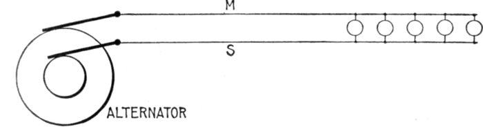
Fig. 1,278.—- Diagram illustrating effect of capacity in an alternating circuit. Considering its
action during one cycle of the current, the alternator first "pumps," say from M to S;
electricity will be heaped up, so to speak, on S, and a deficit left on M, that is, S will be
+ and M-. If the alternator be now suddenly stopped, there would be a momentary
return flow of electricity from S to M through the alternator. If the alternator go on
working, however, it is obvious that the electricity heaped up on S helps or increases the
flow when the alternator begins to pump from S to M in the second half of the cycle, and
when the alternator again reverses its pressure, the + charge on M flows round to S, and
helps the ordinary current. The above circuit is not strictly analogous to the insulated
plates of a condenser, but, as is verified in practice, that with a rapidly alternating pressure,
the condenser action is not perceptibly affected if the cables be connected across by
some non-inductive resistance as for instance incandescent lamps.
Capacity.—When an electric pressure is applied to a condenser,
the current plays in and out, charging the condenser in
alternate directions. As the current runs in at one side and out
at the other, the dielectric becomes charged, and tries to discharge
itself by setting up an opposing electric pressure. This
opposing pressure rises just as the charge increases.
A mechanical analogue is afforded by the bending of a spring,
as in fig. 1,279, which, as it is being bent, exerts an opposing force[Pg 1040]
equal to that applied, provided the latter do not exceed the
capacity of the spring.
Ques. What is the effect of capacity in an alternating
circuit?
Ans. It is exactly opposite to that of inductance, that is,
it assists the current to rise to its maximum value sooner than
it would otherwise.
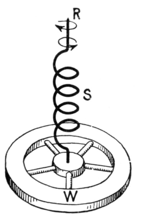
Fig. 1,279.—Mechanical analogy illustrating effect of capacity in an alternating circuit. If an
alternating twisting force be applied to the top R of the spring S, the action of the latter
may be taken to represent capacity, and the rotation of the wheel W, alternating current.
The twisting force (impressed pressure) must first be applied before the rotation of W
(current) will begin. The resiliency or rebounding effect of the spring will, in time, cause
the wheel W to move (amperes) in advance of the twisting force (voltage) thus representing
the current leading in phase.
Ques. Is it necessary to have a continuous metallic
circuit for an alternating current?
Ans. No, it is possible for an alternating current to flow
through a circuit which is divided at some point by insulating
material.
[Pg 1041]
Ques. How can the current flow under such condition?
Ans. Its flow depends on the capacity of the circuit and
accordingly a condenser may be inserted in the circuit as in
fig. 1,286, thus interposing an insulated gap, yet permitting an
alternating flow in the metallic portion of the circuit.
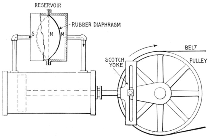
Fig. 1,280.—Hydraulic analogy illustrating capacity in an alternating current circuit. A
chamber containing a rubber diaphragm is connected to a double acting cylinder and the
system filled with water. In operation, as the piston moves, say to the left from the
center, the diaphragm is displaced from its neutral position N, and stretched to some
position M, in so doing offering increasing resistance to the flow of water. On the
return stroke the flow is reversed and is assisted by the diaphragm during the first half
of the stroke, and opposed during the second half. The diaphragm thus acts with the
flow of water one-half of the time and in opposition to it one-half of the time. This
corresponds to the electrical pressure at the terminals of a condenser connected in an
alternating current circuit, and it has a maximum value when the current is zero and a
zero value when the current is a maximum.
Ques. Name the unit of capacity and define it.
Ans. The unit of capacity is called the farad and its symbol is
C. A condenser is said to have a capacity of one farad if one
coulomb (that is, one ampere flowing one second), when stored[Pg 1042]
on the plates of the condenser will cause a pressure of one volt
across its terminals.
The farad being a very large unit, the capacities ordinarily encountered
in practice are expressed in millionths of a farad, that is, in microfarads--a
capacity equal to about three miles of an Atlantic cable.
It should be noted that the microfarad is used only for convenience,
and that in working out problems, capacity should
always be expressed in farads before substituting in formulæ,
because the farad is chosen with respect to the volt and ampere,
as above defined, and hence must be used in formulæ along with
these units.
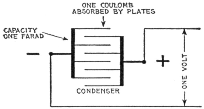
Fig. 1,281—Diagram illustrating a farad. A condenser is said to have a capacity of one
farad if it will absorb one coulomb of electricity when subjected to a pressure of one volt.
The farad is a very large unit, and accordingly the microfarad or one millionth of a farad
is often used, though this must be reduced to farads before substituting in formulæ.
For instance, a capacity of 8 microfarads as given in a problem would
be substituted in a formula as .000008 of a farad.
The charge Q forced into a condenser by a steady electric
pressure E is
Q = EC
in which
- Q = charge in coulombs;
- E = electric pressure in volts;
[Pg 1043]
- C = capacity of condenser in farads.
Ques. What is the material between the plates of a
condenser called?
Ans. The dielectric.
Ques. Upon what does the capacity of a condenser
depend?
Ans. It is proportional to the area of the plates, and inversely
proportional to the thickness of the dielectric between the
plates, a correction being required unless the thickness of dielectric
be very small as compared with the dimensions of the plates.
The capacity of a condenser is also proportional to the specific inductive
capacity of the dielectric between the plates of the condenser.
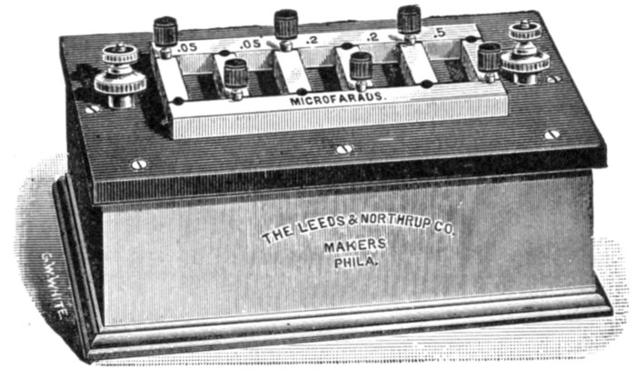
Fig. 1,282.—Condenser of one microfarad capacity. It is subdivided into five sections
of .5, .2, .2, .05 and .05 microfarad. The plates are mounted between and carried by lateral
brass bars which are fastened to a hard rubber top. Each pair of condenser terminals
is fastened to small binding posts mounted on hard rubber insulated posts.
Specific Inductive Capacity.—Faraday discovered that
different substances have different powers of carrying lines of
electric force. Thus the charge of two conductors having a
given difference of pressure between them depends on the medium
between them as well as on their size and shape. The number
indicating the magnitude of this property of the medium is
called its specific inductive capacity, or dielectric constant.
[Pg 1044]
The specific inductive capacity of air, which is nearly the same
as that of a vacuum, is taken as unity. In terms of this unit the
following are some typical values of the dielectric constant:
water 80, glass 6 to 10, mica 6.7, gutta-percha 3, India rubber
2.5, paraffin wax 2, ebonite 2.5, castor oil 4.8.
In underground cables for very high pressures, the insulation, if
homogeneous throughout, would have to be of very great thickness in
order to have sufficient dielectric strength. By employing material of
high specific inductive capacity close to the conductor, and material
of lower specific inductive capacity toward the outside, that is, by
grading the insulation, a considerably less total thickness affords equally
high dielectric strength.
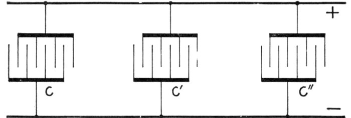
Fig. 1,283.—Parallel connection of condensers. Like terminals are joined together. The joint
capacity of such arrangement is equal to the sum of the respective capacities, that is C =
c + c' + c".
Ques. How are capacity tests usually made?
Ans. By the aid of standard condensers.
Ques. How are condensers connected?
Ans. They may be connected in parallel as in fig. 1,283, or
in series (cascade) as in fig. 1,284.
Condensers are now constructed so that the two methods of arranging
the plates may conveniently be combined in one condenser, thereby
obtaining a wider range of capacity.
[Pg 1045]
Ques. How may the capacity of a condenser, wire, or
cable be tested?
Ans. This may be done by the aid of a standard condenser,
trigger key, and an astatic or ballistic galvanometer.
In making the test, first obtain a "constant" by noting the deflection
d, due to the discharge of the standard condenser after a charge of, say,
10 seconds from a given voltage. Then discharge the other condenser,
wire, or cable through the galvanometer after 10 seconds charge, and
note the deflection d'. The capacity C' of the latter is then
in which C is the capacity of the standard condenser.
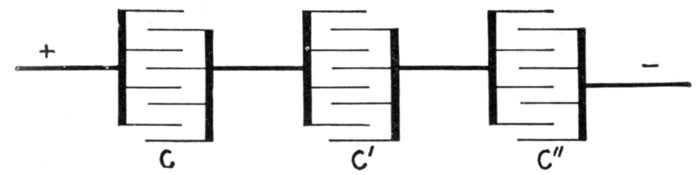
Fig. 1,284.—Series or cascade connection of condensers. Unlike terminals are joined together
as shown. The total capacity of such connection is equal to the reciprocal of the sum of
the reciprocals of the several capacities, that is, C = 1 ÷ (1 / c + 1 / c' + 1 / c")
Ohmic Value of Capacity.—The capacity of an alternating
current circuit is the measure of the amount of electricity held
by it when its terminals are at unit difference of pressure. Every
such circuit acts as a condenser.
If an alternating circuit, having no capacity, be opened, no
current can be produced in it, but if there be capacity at the
break, current may be produced as in fig. 1,286.
The action of capacity referred to the current wave is as
follows: As the wave starts from zero value and rises to its
maximum value, the current is due to the discharge of the[Pg 1046]
capacity, which would be represented by a condenser. In the
case of a sine current, the period required for the current to pass
from zero value to maximum is one-quarter of a cycle.
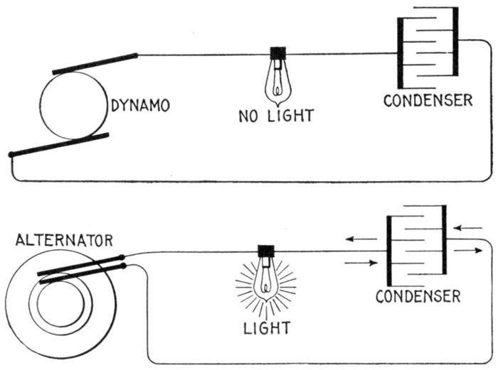
Figs. 1,285 and 1,286.—Diagrams showing effect of condenser in direct and alternating current
circuits. Each circuit contains an incandescent lamp and a condenser, one circuit connected
to a dynamo and the other to an alternator. Since the condenser interposes a gap
in the circuit, evidently in fig. 1,285 no current will flow. In the case of alternating current,
fig. 1,286, the condenser gap does not hinder the flow of current in the metallic
portion of the circuit. In fact the alternator produces a continual surging of electricity
backwards and forwards from the plates of the condenser around the metallic portion of
the circuit, similar to the surging of waves against a bulkhead which projects into the ocean.
It should be understood that the electric current ceases at the condenser, there being no
flow between the plates.
At the beginning of the cycle, the condenser is charged to the
maximum amount it receives in the operation of the circuit.
At the end of the quarter cycle when the current is of maximum
value, the condenser is completely discharged.
[Pg 1047]
The condenser now begins to receive a charge, and continues
to receive it during the next quarter of a cycle, the charge attaining
its maximum value when the current is of zero intensity.
Hence, the maximum charge of a condenser in an alternating
circuit is equal to the average value of the current multiplied
by the time of charge, which is one-quarter of a period, that is
maximum charge = average current × ¼ period (1)
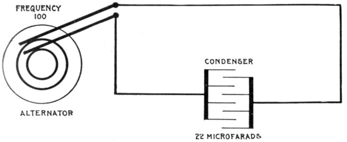
Fig. 1,287.—Diagram showing alternating circuit containing capacity. Formula for calculating
the ohmic value of capacity or "capacity reactance" is Xc = 1 ÷ 2πfC, in which Xc =
capacity reactance; π = 3.1416; f = frequency; C = capacity in farads (not microfarads).
22 microfarads = 22 ÷ 1,000,000 = .000022 farad. Substituting, Xc = 1 ÷
(2 × 3.1416 × 100 × .000022) = 72.4 ohms.
Since the time of a period = 1 ÷ frequency, the time of one-quarter
of a period is ¼ × (1 ÷ frequency), or
¼ period = ¼ f (2)
f, being the symbol for frequency. Substituting (2) in (1)
maximum charge = Iav × ¼f (3)
[Pg 1048]
The pressure of a condenser is equal to the quotient of the
charge divided by the capacity, that is
Substituting (3) in (4)
But, Iav = Imax × 2 / π, and substituting this value of Iav in
equation (5) gives
This last equation (6) represents the condenser pressure due
to capacity at the point of maximum value, which pressure is
opposed to the impressed pressure, that is, it is the maximum
reverse pressure due to capacity.
Now, since by Ohm's law
and as
it follows that 1 / (2πfC) is the ohmic value of capacity, that
is it expresses the resistance equivalent of capacity; using the
symbol Xc for capacity reactance
EXAMPLE.—What is the resistance equivalent of a 50 microfarad
condenser to an alternating current having a frequency of 100?
Substituting the given values in the expression for ohmic value
If the pressure of the supply be, say 100 volts, the current would
be 100 ÷ 31.8 = 3.14 amperes.
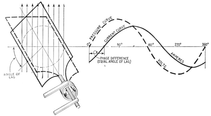
Fig. 1,288.—Pressure and current curves, illustrating lag. The effect of inductance in a circuit
is to retard the current cycle, that is to say, if the current and pressure be in phase, the
introduction of inductance will cause a phase difference, the current wave "lagging"
behind the pressure wave as shown. In other words, inductance causes the current wave,
indicated in the diagram by the solid curve, to lag behind the pressure wave, indicated by
the dotted curve. Following the curves starting from the left end of the horizontal line, it
will be noted that the current starts after the pressure starts and reverses after the pressure
reverses; that is, the current lags in phase behind the pressure, although the frequency of
both is the same.
Lag and Lead.—Alternating currents do not always keep in
step with the alternating volts impressed upon the circuit. If
there be inductance in the circuit, the current will lag; if there
be capacity, the current will lead in phase. For example, fig.
1,288, illustrates the lag due to inductance and fig. 1,289, the
lead due to capacity.
[Pg 1050]
Ques. What is lag?
Ans. Lag denotes the condition where the phase of one
alternating current quantity lags behind that of another. The
term is generally used in connection with the effect of inductance
in causing the current to lag behind the impressed pressure.
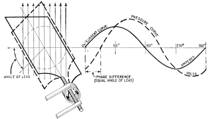
Fig. 1,289.—Pressure and current curves illustrating lead. The effect of capacity in a circuit
is to cause the current to rise to its maximum value sooner than it would otherwise do;
capacity produces an effect exactly the opposite of inductance. The phase relation
between current and pressure with current leading is shown graphically by the two armature
positions in full and dotted lines, corresponding respectively to current and pressure
at the beginning of the cycle.
Ques. How does inductance cause the current to lag
behind the pressure?
Ans. It tends to prevent changes in the strength of the
current. When two parts of a circuit are near each other, so
that one is in the magnetic field of the other, any change in the
strength of the current causes a corresponding change in the
magnetic field and sets up a reverse pressure in the other wire.
This induced pressure causes the current to reach its maximum value
a little later than the pressure, and also tends to prevent the current
diminishing in step with the pressure.
[Pg 1051]
Ques. What governs the amount of lag in an alternating
current?
Ans. It depends on the relative values of the various pressures
in the circuit, that is, upon the amount of resistance and
inductance which tends to cause lag, and the amount of capacity
in the circuit which tends to reduce lag and cause lead.
Ques. How is lag measured?
Ans. In degrees.
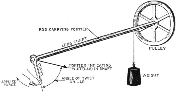
Fig. 1,290.—Mechanical analogy of lag. If at one end force be applied to turn a very long
shaft, having a loaded pulley at the other, the torsion thus produced in the shaft will
cause it to twist an appreciable amount which will cause the movement of the pulley to
lag behind that of the crank. This may be indicated by a rod attached to the pulley
and terminating in a pointer at the crank end, the rod being so placed that the pointer
registers with the crank when there is no torsion in the shaft. The angle made by the
pointer and crank when the load is thrown on, indicates the amount of lag which is
measured in degrees.
Thus, in fig. 1,288, the lag is indicated by the distance between the
beginning of the pressure curve and the beginning of the current curve,
and is in this case 45°.
Ques. What is the physical meaning of this?
Ans. In an actual alternator, of which fig. 1,288 is an elementary
diagram showing one coil, if the current lag, say 45°[Pg 1052]
behind the pressure, it means that the coil rotates 45° from its
position of zero induction before the current starts, as in fig. 1,288.
EXAMPLE I.—A circuit through which an alternating current is
passing has an inductance of 6 ohms and a resistance of 2.5 ohms. What
is the angle of lag?
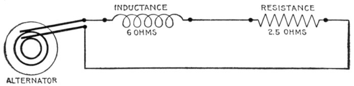
Fig. 1,291.—Diagram of circuit for example I.
Substituting these values in equation (1), page 1,053,
Referring to the table of natural sines and tangents on page 451 the
corresponding angle is approximately 67°.
EXAMPLE II.—A circuit has a resistance of 2.3 ohms and an inductance
of .0034 henry. If an alternating current having a frequency of
125 pass through it, what is the angle of lag?
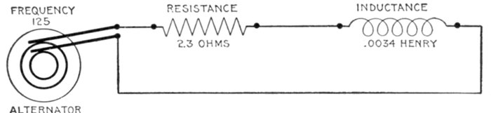
Fig. 1,292.—Diagram of circuit for example II.
Here the inductance is given as a fraction of a henry; this must be
reduced to ohms by substituting in equation (3), page 1,038, which
gives the ohmic value of the inductance; accordingly, substituting the
above given value in this equation
inductance in ohms or Xi = 2π × 125 × .0034 = 2.67
Substituting this result and the given resistance in equation (1),
page 1,053,
the nearest angle from table (page 451) is 49°.
[Pg 1053]
Ques. How great may the angle of lag be?
Ans. Anything up to 90°.
The angle of lag, indicated by the Greek letter φ(phi), is the angle
whose tangent is equal to the quotient of the inductance expressed in
ohms or "spurious resistance" divided by the ohmic resistance, that is
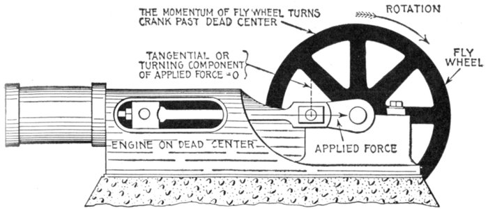
Fig. 1,293.—Steam engine analogy of current flow at zero pressure (see questions below).
When the engine has reached the dead center point the full steam pressure is acting on
the piston, the valve having opened an amount equal to its lead. The force applied at this
instant, indicated by the arrow is perpendicular to the crank pin circle, that is, the tangential
or turning component is equal to zero, hence there is no pressure tending to turn the
crank. The latter continues in motion past the dead center because of the momentum
previously acquired. Similarly, the electric current, which is here analogous to the moving
crank, continues in motion, though the pressure at some instants be zero, because it acts
as though it had weight, that is, it cannot be stopped or started instantly.
Ques. When an alternating current lags behind the
pressure, is there not a considerable current at times
when the pressure is zero?
Ans. Yes; such effect is illustrated by analogy in fig. 1,293.
Ques. What is the significance of this?
Ans. It does not mean that current could be obtained from
a circuit that showed no pressure when tested with a suitable
voltmeter, for no current would flow under such conditions.
However, in the flow of an alternating current, the pressure[Pg 1054]
varies from zero to maximum values many times each second,
and the instants of no pressure may be compared to the "dead
centers" of an engine at which points there is no pressure to
cause rotation of the crank, the crank being carried past these
points by the momentum of the fly wheel. Similarly the electric
current does not stop at the instant of no pressure because
of the "momentum" acquired at other parts of the cycle.
Ques. On long lines having considerable inductance,
how may the lag be reduced?
Ans. By introducing capacity into the circuit. In fact, the
current may be advanced so it will be in phase with the pressure
or even lead the latter, depending on the amount of capacity
introduced.
There has been some objection to the term lead as used in describing
the effect of capacity in an alternating circuit, principally on the ground
that such expressions as "lead of current," "lead in phase," etc., tend
to convey the idea that the effect precedes the cause, that is, the current
is in advance of the pressure producing it. There can, of course, be no
current until pressure has been applied, but if the circuit has capacity,
it will lead the pressure, and this peculiar behavior is best illustrated
by a mechanical analogy as has already been given.
Ques. What effect has lag or lead on the value of the
effective current?
Ans. As the angle of lag or lead increases, the value of the
effective as compared with the virtual current diminishes.
Reactance.—The term "reactance" means simply reaction.
It is used to express certain effects of the alternating current
other than that due to the ohmic resistance of the circuit.
Thus, inductance reactance means the reaction due to the spurious
resistance of inductance expressed in ohms; similarly, capacity
reactance, means the reaction due to capacity, expressed in ohms.[Pg 1055]
It should be noted that the term reactance, alone, that is, unqualified,
is generally understood to mean inductance reactance,
though ill advisedly so.
The resistance offered by a wire to the flow of a direct current
is expressed in ohms; this resistance remains constant whether
the wire be straight or coiled. If an alternating current flow
through the wire, there is in addition to the ordinary or "ohmic"
resistance of the wire, a "spurious" resistance arising from the
development of a reverse pressure due to induction, which is
more or less in value according as the wire be coiled or straight.
This spurious resistance as distinguished from the ohmic resistance
is called the reactance, and is expressed in ohms.
Reactance, may then be defined with respect to its usual
significance, that is, inductance reactance, as the component of the
impedance which when multiplied into the current, gives the
wattless component of the pressure.
Reactance is simply inductance measured in ohms.
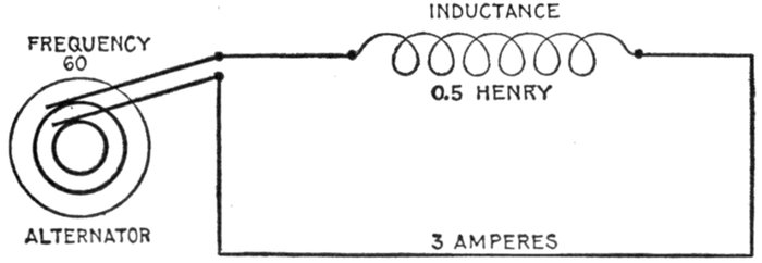
Fig. 1,294.—Diagram of the circuit for example I. Here the resistance is taken at zero,
but this would not be possible in practice, as all circuits contain more or less resistance
though it may be, in some cases, negligibly small.
EXAMPLE I.—An alternating current having a frequency of 60 is
passed through a coil whose inductance is .5 henry. What is the reactance?
Here f = 60 and L = .5; substituting these in formula for inductive
reactance,
Xi = 2πfL = 2 × 3.1416 × 60 × .5 = 188.5 ohms
[Pg 1056]
The quantity 2πfL or reactance being of the same nature as a resistance
is used in the same way as a resistance. Accordingly, since,
by Ohm's law
E = RI (1)
an expression may be obtained for the volts necessary to overcome
reactance by substituting in equation (1) the value of reactance given
above, thus
E = 2πfLI (2)
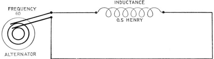
Fig. 1,295.—Diagram of circuit for example II. As in example I, resistance is disregarded.
EXAMPLE II.—How many volts are necessary to force a current of
3 amperes with frequency 60 through a coil whose inductance is .5
henry? Substituting in equation (2) the values here given
E = 2πfLI = 2π × 60 × .5 × 3 = 565 volts.
The foregoing example may serve to illustrate the difference in
behaviour of direct and alternating currents. As calculated, it
requires 565 volts to pass only 3 amperes of alternating current
through the coil on account of the considerable spurious resistance.
The ohmic resistance of a coil is very small, as compared
with the spurious resistance, say 2 ohms. Then by Ohm's law
I = E ÷ R = 565 ÷ 2 = 282.5 amperes.
Instances of this effect are commonly met with in connection with
transformers. Since the primary coil of a transformer has a high reactance,
very little current will flow when an alternating pressure is
applied. If the same transformer were placed in a direct current circuit[Pg 1057]
and the current turned on it would at once burn out, as very little
resistance would be offered and a large current would pass through the
winding.
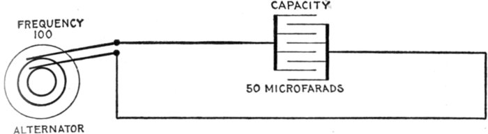
Fig. 1,296.—Diagram of circuit for example III.
EXAMPLE III.—In a circuit containing only capacity, what is the
reactance when current is supplied at a frequency of 100, and the
capacity is 50 microfarads?
capacity reactance, or
Impedance.—This term, strictly speaking, means the ratio
of any impressed pressure to the current which it produces in a
conductor. It may be further defined as the total opposition in
an electric circuit to the flow of an alternating current.
All power circuits for alternating current are calculated with
reference to impedance. The impedance may be called the
combination of:
- Ohmic resistance;
- Inductance reactance;
- Capacity reactance.
[Pg 1058]
The impedance of an inductive circuit which does not contain
capacity is equal to the square root of the sum of the squares of
the resistance and reactance, that is
impedance = √(resistance2 + reactance2) (1)
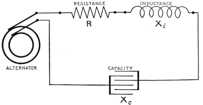
Fig. 1,297.—Diagram showing alternating circuit containing resistance, inductance, and capacity.
Formula for calculating the impedance of this circuit is Z = √(R2 + (Xi - Xc)2) in
which, Z = impedance; R = resistance; Xi = inductance reactance; Xc = capacity
reactance. Example: What is the impedance when R = 4, Xi = 94.2, and Xc = 72.4?
Substituting Z = √(42 + (94.2 - 72.4)2) = 22.2 ohms. Where the ohmic values of inductance
and capacity are given as in this example, the calculation of impedance is very
simple, but when inductance and capacity are given in milli-henrys and microfarads
respectively, it is necessary to first calculate their ohmic values as in figs. 1,295 and 1,296.
EXAMPLE I.—If an alternating pressure of 100 volts be impressed
on a coil of wire having a resistance of 6 ohms and inductance of 8 ohms,
what is the impedance of the circuit and how many amperes will flow
through the coil? In the example here given, 6 ohms is the resistance
and 8 ohms the reactance. Substituting these in equation (1)
Impedance = √(62 + 82) = √(100) = 10 ohms.
The current in amperes which will flow through the coil is, by Ohm's
law using impedance in the same way as resistance.
[Pg 1059]
The reactance is not always given but instead in some problems the
frequency of the current and inductance of the circuit. An expression
to fit such cases is obtained by substituting 2πfL for the reactance as
follows: (using symbols for impedance and resistance)
Z = √(R2 + (2πfL)2) (2)
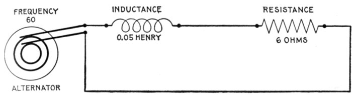
Fig. 1,298.—Diagram of circuit for example II.
EXAMPLE II.—If an alternating current, having a frequency of 60,
be impressed on a coil whose inductance is .05 henry and whose resistance
is 6 ohms, what is the impedance?
Here R = 6; f = 60, and L = .05; substituting these values in (2)
Z = √(62 + (2π × 60 × .05)2) = √(393) = 19.8 ohms.
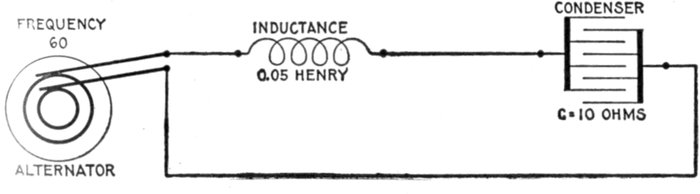
Fig. 1,299.—Diagram of circuit for example III.
EXAMPLE III.—If an alternating current, having a frequency of
60, be impressed on a circuit whose inductance is .05 henry, and whose
capacity reactance is 10 ohms, what is the impedance?
Xi = 2πfL = 2 × 3.1416 × 60 × .05 = 18.85 ohms
Z = Xi - Xc = 18.85 - 10 = 8.85 ohms
[Pg 1060]
When a circuit contains besides resistance, both inductance
and capacity, the formula for impedance as given in equation (1),
page 1,058, must be modified to include the reactance due to
capacity, because, as explained, inductive and capacity reactances
work in opposition to each other, in the sense that the reactance
of inductance acts in direct proportion to the quantity
2πfL, and the reactance of capacity in inverse proportion to the
quantity 2πfC. The net reactance due to both, when both
are in the circuit, is obtained by subtracting one from the other.
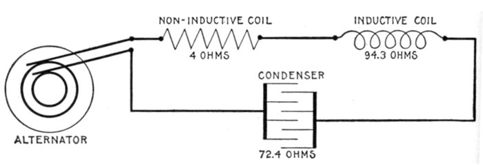
Fig. 1,300.—Diagram of circuit for example IV.
To properly estimate impedance then, in such circuits, the
following equation is used:
impedance = √(resistance2 + (inductance reactance - capacity reactance)2)
or using symbols,
Z = √(R2 + (Xi - Xc)2) (3)
EXAMPLE IV.—A current has a frequency of 100. It passes through
a circuit of 4 ohms resistance, of 150 milli-henrys inductance, and of 22
microfarads capacity. What is the impedance?
a. The ohmic resistance R, is 4 ohms.
b. The inductance reactance, or
Xi = 2πfL = 2 × 3.1416 × 100 × .15 = 94.3 ohms.
(note that 150 milli-henrys are reduced to .15 henry before substituting
in the above equation).
[Pg 1061]
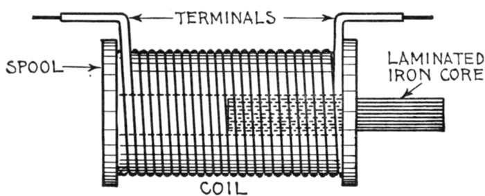
Fig. 1,301.—Simple choking coil. There is an important difference in the obstruction offered
to an alternating current by ordinary resistance and by reactance. Resistance obstructs
the current by dissipating its energy, which is converted into heat. Reactance obstructs
the current by setting up a reverse pressure, and so reduces the current in the circuit,
without wasting much energy, except by hysteresis in any iron magnetized. This may be
regarded as one of the advantages of alternating over direct current, for, by introducing
reactance into a circuit, the current may be cut down with comparatively little loss of
energy. This is generally done by increasing the inductance in a circuit, by means of
a device called variously a reactance coil, impedance coil, choking coil, or "choker." In the
figure is a coil of thick wire provided with a laminated iron core, which may be either
fixed or movable. In the first case, the inductance, and therefore also the reactance of the
coil, is invariable, with a given frequency. In the second case, the inductance and consequent
reactance may be respectively increased or diminished by inserting the core
farther within the coil or by withdrawing it, as was done in fig. 1,266, the results of
which are shown in fig. 1,302.
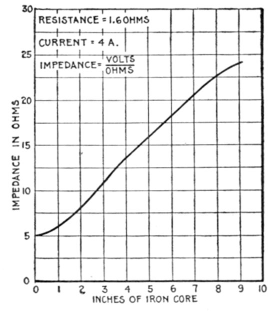
Fig. 1,302.—Impedance curve for coil with variable iron core. The impedance of an inductive
coil may be increased by moving an iron wire core into the coil. In making a test of this
kind, the current should be kept constant with an adjustable resistance, and voltmeter
readings taken, first without the iron core, and again with 1, 2, 3, 4, etc., inches of core
inserted in the coil. By plotting the voltmeter readings and the positions of the iron core
on section paper as above, the effect of inductance is clearly shown.
[Pg 1062]
c. The capacity reactance, or
(note that 22 microfarads are reduced to .000022 farad before substituting
in the formula. Why? See page 1,042).
Substituting values as calculated in equation (3), page 1,060.
Z = √(42 + (94.2 - 72.4)2) = √(491) = 22.2 ohms.
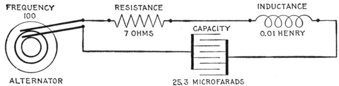
Fig. 1,303.—Diagram of a resonant circuit. A circuit is said to be resonant when the inductance
and capacity are in such proportion that the one neutralizes the other, the circuit
then acting as though it contained only resistance. In the above circuit Xi = 2πfL =
2 × 3.1416 × 100 × .01 = 6.28 ohms; Xc = 1 ÷ (2 × 3.1416 × 100 × .000253) = 6.28 ohms
whence the resultant reactance = Xi - Xc = 6.28 - 6.28 = 0 ohms. Z = √(R2 + (Xi - Xc)2)
= √(72 + 02) = 7 ohms.
Ques. Why is capacity reactance given a negative sign?
Ans. Because it reacts in opposition to inductance, that is
it tends to reduce the spurious resistance due to inductance.
In circuits having both inductance and capacity, the tangent of the
angle of lag or lead as the case may be is the algebraic sum of the two
reactances divided by resistance. If the sign be positive, it is an angle
of lag; if negative, of lead.
Resonance.—The effects of inductance and capacity, as already
explained, oppose each other. If inductance and capacity
be present in a circuit in such proportion that the effect of one
neutralizes that of the other, the circuit acts as though it were
purely non-inductive and is said to be in a state of resonance.
[Pg 1063]
For instance, in a circuit containing resistance, inductance, and
capacity, if the resistance be, say, 8 ohms, the inductance 30, and the
capacity 30, then the impedance is
√(82 + (302 - 302)) = √(82) = 8 ohms.
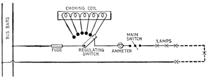
Fig. 1,304.—Application of a choking coil to a lighting circuit. The coil is divided into sections
with leads running to contacts similar to a rheostat. Each lamp is provided with an automatic
short-circuiting cutout, and should one, two, or more of them fail, a corresponding
number of sections of the choking apparatus is put in circuit to take the place of the broken
lamp or lamps, and thus keep the current constant. It must not be supposed that this arrangement
of lamps, etc. is a general one; it being adopted to suit certain special conditions.
The formula for inductance reactance is Xi = 2πfL, and for
capacity reactance, Xc = 1 ÷ (2πfC); accordingly if capacity
and inductance in a circuit be equal, that is, if the circuit be
resonant
from which
Ques. What does equation (1) show?
Ans. It indicates that by varying the frequency in the proper
way as by increasing or decreasing the speed of the alternator,
the circuit may be made resonant, this condition being obtained
when the frequency has the value indicated by equation (2).
[Pg 1064]
Ques. What is the mutual effect of inductance and
capacity?
Ans. One tends to neutralize the other.
Ques. What effect has resonance on the current?
Ans. It brings the current in phase with the impressed
pressure.
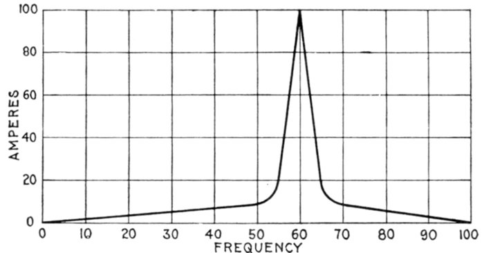
Fig. 1,305.—Curve showing variation of current by increasing the frequency in a circuit having
inductance and capacity. The curve serves to illustrate the "critical frequency" or frequency
producing the maximum current. The curve is obtained by plotting current values
corresponding to different frequencies, the pressure being kept constant.
It is very seldom that a circuit is thus balanced unless intentionally
brought about; when this condition exists, the effect is very marked, the
pressure rising excessively and bringing great strain upon the insulation
of the circuit.
Ques. Define "critical frequency."
Ans. In bringing a circuit to a state of resonance by increasing
the frequency, the current will increase with increasing
frequency until the critical frequency is reached, and then the
current will decrease in value for further increase of frequency.
The critical frequency occurs when the circuit reaches the
condition of resonance.
[Pg 1065]
Ques. How is the value of the current at the critical
frequency determined?
Ans. By the resistance of the circuit.
Skin Effect.—This is the tendency of alternating currents
to avoid the central portions of solid conductors and to flow or
pass mostly through the outer portions. The so-called skin
effect becomes more pronounced as the frequency is increased.
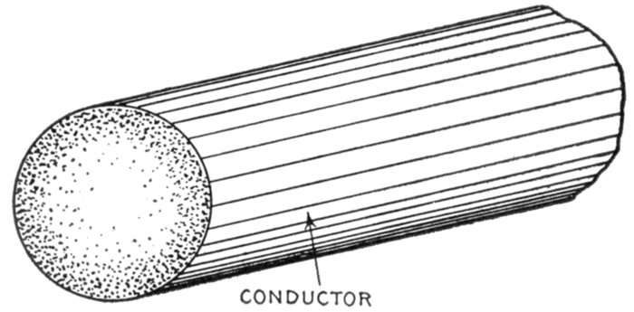
Fig. 1,306.—Section of conductor illustrating "skin effect" or tendency of the alternating
current to distribute itself unequally through the cross section of the conductor as shown
by the varied shading flowing most strongly in the outer portions of the conductor. For
this reason it has been proposed to use hollow or flat conductors instead of solid round
wires. However with frequency not exceeding 100 the skin effect is negligibly small in
copper conductors of the sizes usually employed. Where the conductor is large or the
frequency high the effect may be judged by the following examples calculated by Professor
J. J. Thomson: In the case of a copper conductor exposed to an electromotive force
making 100 periods per second at 1 centimetre from the surface, the maximum current
would be only .208 times that at the surface; at a depth of 2 centimetres it would be
only .043; and at a depth of 4 centimetres less than .002 part of the value at the
surface. If the frequency be a million per second the current at a depth of 1 millimetre
is less than one six-millionth part of its surface value. The case of an iron conductor is
even more remarkable. Taking the permeability at 100 and the frequency at 100 per
second the current at a depth of 1 millimetre is only .13 times the surface value; while
at a depth of 5 millimetres it is less than one twenty-thousandth part of its surface value.
The disturbance of current density may be looked upon as a self-induced eddy current in
the conductor. It necessarily results in an increase of ohmic loss; as compared with a
steady current: proportional to the square of the total current flowing and consequently
gives rise to an apparent increase of ohmic resistance. The coefficient of increase of resistance
depends upon the dimensions and the shape of the cross section, the frequency and
the specific resistance. A similar but distinct effect is experienced in conductors due to
the neighborhood of similar parallel currents. For example in a heavy multicore cable
the non-uniformity of current density in any core may be considered as partly due to eddy
currents induced by the currents in the neighboring cores and partly to the self-induced
eddy current. It is only the latter effect which should rightly be considered as comprised
under the term skin effect.
[Pg 1066]
Ques. What is the explanation of skin effect?
Ans. It is due to eddy currents induced in the conductor.
Consider the wire as being composed of several small insulated wires
placed closely together. Now when a current is started along these
separate wires, mutual induction will take place between them, giving
rise to momentary reverse pressures. Those wires which are nearer the
center, since they are completely surrounded by neighboring wires, will
clearly have stronger reverse pressures set up in them than those on or
near the outer surface, so that the current will meet less opposition
near the surface than at the center, and consequently the flow will be
greater in the outer portions.
Ques. What is the result of skin effect?
Ans. It results in an apparent increase of resistance.
The coefficient of increase of resistance depends upon the dimensions
and the shape of the cross section, the frequency, and the specific
resistance.
Hughes, about 1883, called attention to the fact that the resistance
of an iron telegraph wire was greater for rapid periodic currents than for
steady currents.
In 1888 Kelvin showed that when alternating currents at moderately
high frequency flow through massive conductors, the current is practically
confined to the skin, the interior portions being largely useless
for the purpose of conduction. The mathematical theory of the subject
has been developed by Kelvin, Heaviside, Rayleigh, and others.
[Pg 1067]
CHAPTER XLVII
ALTERNATING CURRENT DIAGRAMS
Whenever an alternating pressure is impressed on a circuit,
part of it is spent in overcoming the resistance, and the rest goes
to balance the reverse pressure due to self-induction.
The total pressure applied to the circuit is known as the
impressed pressure, as distinguished from that portion of it
called the active pressure which is used to overcome the resistance,
and that portion called the self-induction pressure used to
balance the reverse pressure of self-induction.
The intensity of the reverse pressure induced in a circuit due
to self-induction is proportional to the rate of change in the
current strength.
Thus a current, changing at the rate of one ampere per second, in
flowing through a coil having a coefficient of self-induction of one henry,
will induce a reverse pressure of one volt.
Ques. Describe how the rate of change in current
strength varies, and how this affects the reverse pressure.
Ans. The alternating current varies from zero to maximum
strength in one-quarter period, that is, in one-quarter revolution
of the generating loop or 90° as represented by the sine curve
in fig. 1,307. Now, during, say, the first 10 degrees of rotation
(from 0 to A), the current jumps from zero value to A', or 4[Pg 1068]
amperes, according to
the scale; during some
intermediate 10 degrees
of the quarter
revolution, as from B
to C, the current increases
from B' to C' or
2½ amperes, and during
another 10 degrees
as from D to E,
at the end of one-quarter
revolution
where the sine curve
reaches its amplitude,
it rises and falls ½
ampere. It is thus
seen that the rate of
change varies from a
maximum when the
current is least, to
zero when the current
is at its maximum.
Accordingly, the reverse
pressure of self-induction
being proportional
to the rate
of change in the current
strength, is greatest
when the current is
at zero value, and
zero when the current
is at its maximum.
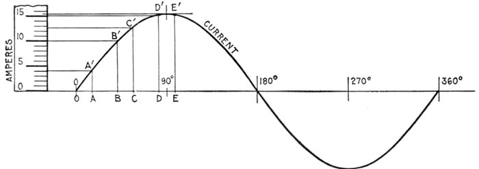
Fig. 1,307.—Sine curve showing that the rate of change in the strength of an alternating current is greatest when the current is least,
and zero when the current is at a maximum. This is evident from the diagram, since during say the first 10° as OA, the
current increases 4 amperes; during BC, 2½ amperes; during DE it rises and falls ½ ampere. The reverse pressure of
self-induction being proportional to the rate of change of the current, is a maximum when the current is zero, and zero
when the current is a maximum, giving a phase difference of 90° between reverse pressure of self-induction and current.
[Pg 1069]
This relation is shown by curves in fig. 1,308, and it should be noted
that the reverse pressure and current are 90° apart in phase. For this
reason many alternating current problems may be solved graphically
by the use of right angle triangles, the sides, drawn to some arbitrary
scale, to represent the quantities involved, such as resistance, reactance,
impedance, etc.
Properties of Right Angle Triangles.—In order to understand
the graphical method of solving alternating current problems,
it is necessary to know why certain relations exist between
the sides of a right angle triangle. For instance, in every right
angle triangle:
The square of the hypothenuse is equal to the sum of the squares
on the other two sides.
That is, condensing this statement into the form of an equation:
hypothenuse2 = base2 + altitude2 (1)
the horizontal side being called the base and the vertical side,
the altitude.
This may be called the equation of the right angle triangle.
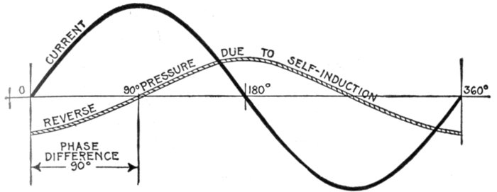
Fig. 1,308.—Sine curves showing phase relation between current and reverse pressure of self-induction.
This reverse pressure, being proportional to the rate of change in the current
strength, is greatest when the current is at zero value, and zero when the current is maximum,
and in phase is 90° behind the current.
[Pg 1070]
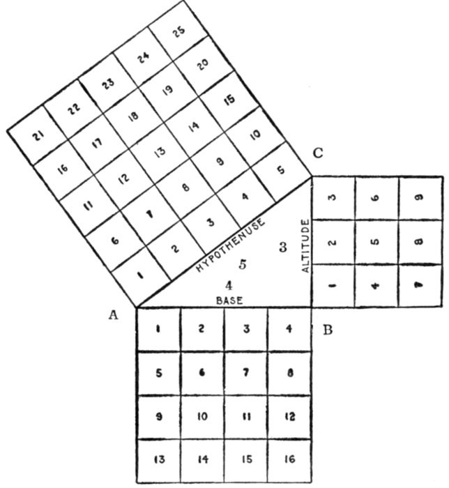
Fig. 1,309.—In a right angle triangle the square on the hypothenuse is equal to the sum of the
squares on the other two sides. That is: hypothenuse2 = base2 + altitude2. Draw AB, 4
inches long, and BC, 3 inches long and at right angles to AB. Join AC, which will be found
to be 5 inches long. From the diagram, it must be clear that the square on AC = sum of
squares on AB and BC; that is, 52 = 42 + 32. Further, 42 = 52 - 32; 32 = 52 - 42;
5 = √(42 + 32); 4 = √(52 - 32); 3 = √(52 - 42).
Ques. Why is the square of the hypothenuse of a
right angle triangle equal to the sum of the squares of
the other two sides?
Ans. This may be explained with the aid of fig. 1,309. Draw
a line AB, 4 inches in length and erect a perpendicular BC, 3
inches in height; connect A and C, giving the right angle
triangle ABC. It will be found that AC the hypothenuse of
this triangle is 5 inches long. If squares be constructed on all[Pg 1071]
three sides of the triangle, the square on the hypothenuse will
have an area of 25 sq. ins.; the square on the base, 16 sq. ins.,
and the square on the altitude, 9 sq. ins. Then from the figure
52 = 42 + 32, that is 25 = 16 + 9.
Repeating equation (1), it is evident from the figure that
that is,
25 = 16 + 9.
In the right angle triangle, the following relations also hold:
In working impedance problems, it is not the square of any of
the quantities which the sides of the triangle are used to represent
that is required, but the quantities themselves, that is, the sides.
Hence extracting the square root in equations (1), (2) and (3),
the following are obtained:
Representation of
Forces by Lines.—A
single force may be represented
in a drawing by
a straight line, 1, the
point of application of
the force being indicated
by an extremity of the
line, 2, the intensity of the
force by the length of the
line, and 3, the direction
of the force by the direction
of the line, an arrow
head being placed at an
extremity defining the
direction.
Thus in fig. 1,310, the
force necessary to balance the
thrust on the steam piston
may be represented by the
straight line f whose length
measured on any convenient
scale represents the intensity
of the force, and whose direction
represents the direction
of the force.
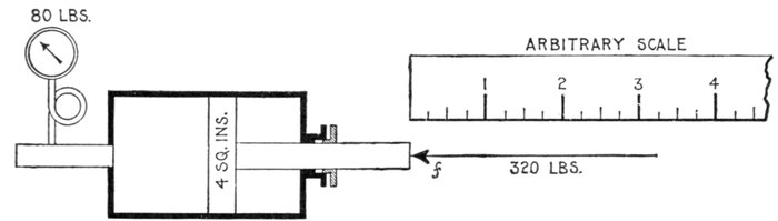
Fig. 1,310.—Diagram illustrating the representation of forces by straight lines. If 80 lbs. of steam be applied to a piston of
4 square inches area, the total pressure acting on the piston is 4 × 80 = 320 lbs. This may be balanced by an equal and
opposite force. To represent the latter by a line, select any convenient scale whose divisions represent any convenient
number of pounds—1, 3, 5 or, as here taken, 25 lbs. If the scale selected be divided into inches with ¼-inch divisions, then
each ¼ inch represents a force of 25 lbs.; or, as usually stated, 1" = 100 lbs. Strictly speaking 1" is equivalent to 100
lbs. Draw the line f = 3.2 ins., then its length represents the magnitude of the force or 320 lbs., that is, 3.2 × 100 = 320 lbs.
Composition of
Forces.—This is the operation
of finding a single
force whose effect is the same
as the combined effect of
two or more given forces.
The required force is
called the resultant of the
given forces.
[Pg 1073]
The composition of forces may be illustrated by the effect of
the wind and tide on a sailboat as in fig. 1,311. Supposing the
boat be acted upon by the wind so that in a given time, say half
an hour, it would be moved in the direction and a distance
represented by the line AB, and that in the same time the tide
would carry it from A to C. Now, lay down AB, to any convenient
scale, representing the effect of the wind, and AC that
of the tide, and draw BD equal and parallel to AC, and CD
equal and parallel to AB, then the diagonal AD will represent
the direction and distance the boat will move under the combined
effect of wind and tide.
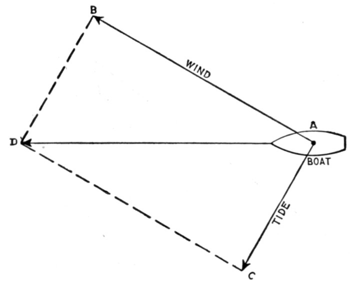
Fig. 1,311.—Parallelogram of forces for boat acted upon by both wind and tide.
Ques. In fig. 1,311 what is the line AD called?
Ans. The resultant, that is, it represents the actual movement
of the boat resulting from the combined forces of wind and tide.
[Pg 1074]
Ques. What are the forces, AB and AD in fig. 1,311,
represented by the sides of the parallelogram, and which
act upon a body to produce the resultant, called?
Ans. The components.
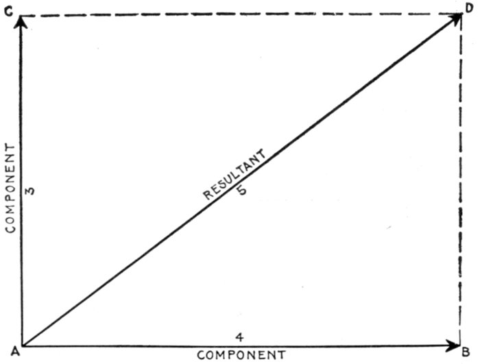
Fig. 1,312.—Parallelogram of forces; method of obtaining the resultant of two components
acting at right angles.
EXAMPLE.—Two forces, one of 3 lbs. and one of 4 lbs. act at a
point a in a body and at right angles, what is the resultant?
Take any convenient scale, say 1 in. = 1 lb., and lay off (fig. 1312.)
AB = 4 ins. = 4 lbs.; also, AC (at right angles to AB) = 3 ins. = 3 lbs.
Draw CD and BD parallel to AB and AC respectively, and join AD.
The line AD is the resultant of the components AB and AC, and when
measured on the same scale from which AB and AC were drawn will be
found to be 5 inches long, which represents 5 lbs. acting in the direction
AD.
Circuits containing Resistance and Inductance.—In
circuits of this kind where the impressed pressure encounters[Pg 1075]
both resistance and inductance, it may be looked upon as split
up into two components, as already explained, one of which is
necessary to overcome the resistance, and the other, the inductance.
That is, the impressed pressure is split up into
- 1. Active pressure, to overcome resistance;
- 2. Self-induction pressure to overcome inductance.
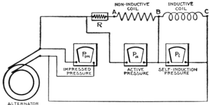
Fig. 1,313.—Diagram illustrating the active, and self-induction pressures, or the two components
of the impressed pressure in circuits containing resistance and inductance. The active
pressure is the volts required to overcome the resistance of the circuit. In the figure only
the portion from A to C is considered as having resistance (the rest being negligibly small)
except at R, a resistance equivalent to that of the inductive coil is inserted next to the
non-inductive coil, so Pa will give the total "ohmic drop" or active pressure, that is,
the pressure necessary to force any equivalent direct current from A to C. This active
pressure Pa or component of the impressed pressure is in phase with the current. The
other component or self-induction pressure Pi that is the reactance drop necessary to
overcome the reverse pressure of self-induction and is at right angles to the current and 90°
ahead of the current in phase. It is registered by a voltmeter between B and C, less the
pressure due to ohmic resistance of the inductive coil. The impressed pressure Pim then
or total pressure required to force electricity around the circuit not including the resistance
R, (which is removed from the circuit when the reading of the impressed pressure is taken),
is equal to the square root of the sum of the squares of the two components, that is, Pim =
√(Pa}2 + P_{i2).
The active pressure is in phase with the current.
The self induction pressure is at right angles to the current and 90
degrees ahead of the current in phase.
Ques. Why is the active pressure in phase with the
current?
Ans. The pressure used in overcoming resistance is from
Ohm's law, E = RI. Hence, when the current is zero, E is zero,
and when the current is a maximum E is a maximum. Hence,
that component of the impressed pressure necessary to overcome
the resistance must be in phase with the current.
[Pg 1076]
Ques. Why is this?
Ans. Since the reverse pressure of self induction is 90° behind
the current, the component of the impressed pressure necessary
to overcome the reverse pressure of self induction, being opposite
to this, will be represented as being 90° ahead of the current.
The distinction between the reverse pressure of self-induction, that
is, the induced pressure, and the pressure necessary to overcome self-induction
should be carefully noted. They are two equal and opposite
forces, that is, two balancing forces just as is shown in fig. 1,310. Here,
in analogy, the thrust of the piston may represent the induced pressure
and the equal and opposite force indicated by the arrow f, the component
of the impressed pressure necessary to balance the induced
pressure.
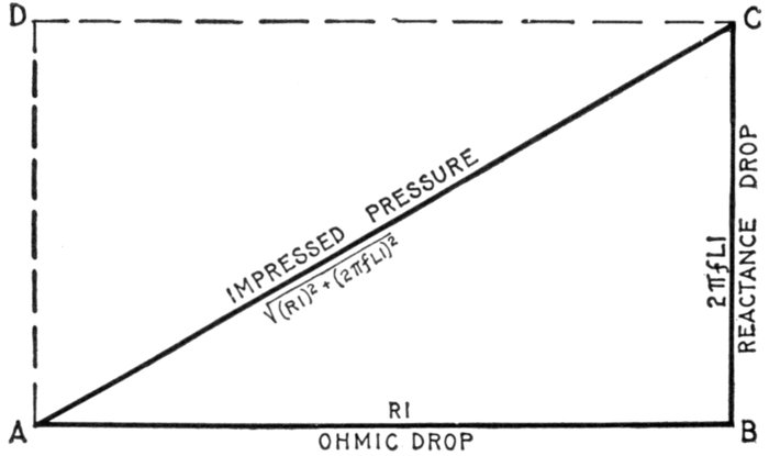
Fig. 1,314.—Graphical method of obtaining the impressed pressure in circuits containing resistance
and inductance, having given the ohmic drop, and reactance drop due to inductance.
With any convenient scale lay off AB = ohmic drop and erect the perpendicular BC =
reactance drop (using same scale). Join AC, whose length (measured with same scale)
will give the impressed pressure. Constructing a parallelogram with dotted lines AD
and CD, it is evident that AC is the resultant of the two components AB and BC, or its
equal AD.
The Active Pressure or "Ohmic Drop."—The component of the
impressed pressure necessary to overcome resistance, is from Ohm's law:
[Pg 1077]
active pressure = ohmic resistance × virtual current
that is
Ea = RoIv (1)
this is the "ohmic drop" and may be represented by a line AB, fig. 1,314
drawn to any convenient scale, as for instance, 1 in. = 10 volts.
The Self-induction Pressure or "Reactance Drop."—The
component of the impressed pressure necessary to overcome the induced
pressure, is from Ohm's law:
inductance pressure = inductance reactance × virtual current;
that is,
Ei = XiIv (2)
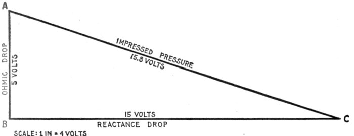
Fig. 1,315.—Diagram for impressed pressure on circuit containing 5 volts ohmic drop and
15 volts reactance drop.
Now the reactance Xi, that is the spurious resistance, is obtained
from the formula
Xi = 2πfL (3)
as explained on page 1,038, and in order to obtain the volts necessary to
overcome this spurious resistance, that is, the "reactance drop" as it
is called, the value of Xi in equation (3) must be substituted in equation
(2), giving
Ei = 2πfLI (4)
writing simply I for the virtual pressure.
Since the pressure impressed on a circuit is considered as made up
of two components, one in phase with the current and one at right angles
to the current, the component Ei or "reactance drop" as given in
equation (4) maybe represented by the line BC in fig. 1,314, at right
angles to AB, and of a length BC, measured with the same scale as was
measured AB, to correspond to the value indicated by equation (4).
[Pg 1078]
EXAMPLE.—In an alternating circuit, having an ohmic drop of
5 volts, and a reactance drop of 15 volts, what is the impressed pressure?
With a scale of say, ¼ inch = one volt, lay off, in fig. 1,315, AB = 5
volts = 1¼ in., and, at right angles to it, BC = 15 volts = 15/4 or 3¾ ins. Join
AC; this measures 3.95 inches, which is equivalent to 3.95 × 4 = 15.8
volts, the impressed pressure. By using good paper, such as bristol board, a
6H pencil, engineers' scale and triangles or square, such problems are
solved with precision. By calculation impressed pressure = √(52 + 152) = 15.8
volts. Note that the diagram is drawn with the side BC horizontal
instead of AB—simply to save space.
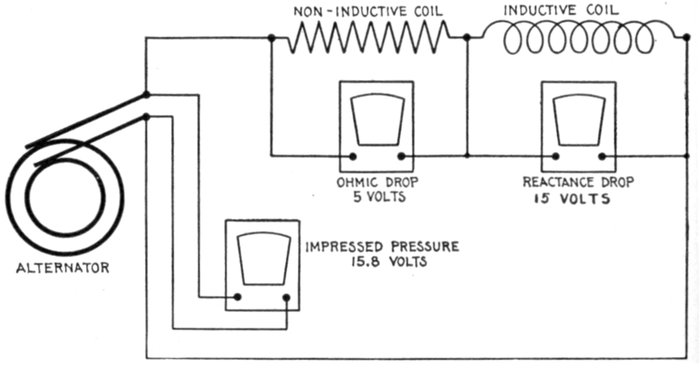
Fig. 1,316.—Diagram of circuit containing 5 volts ohmic drop, and 15 volts reactance drop.
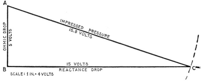
Fig. 1,317.—Diagram for obtaining reactance drop in circuit containing 5 volts ohmic drop,
and 15.8 volts impressed pressure.
[Pg 1079]
EXAMPLE.—In an alternating circuit, having an ohmic drop of 5
volts and an impressed pressure of 15.8 volts, what is the reactance drop?
In fig. 1,317, draw a horizontal line of indefinite length and at any
point B erect a perpendicular AB = 5 volts. With A as center and
radius of length equivalent to 15.8 volts, describe an arc cutting the
horizontal line at C. This gives BC, the reactance drop required, which
by measurement is 15 volts.
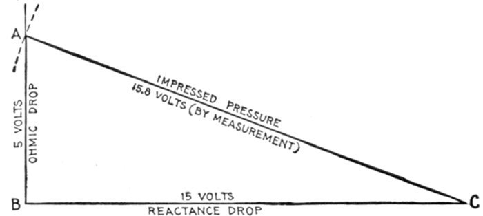
Fig. 1,318.—Diagram for obtaining ohmic drop in the circuit fig. 1,316 when impressed pressure
and reactance drop are given. Lay off BC to scale = reactance drop; draw AB at right
angle and of indefinite length; with C as center and radius of length = impressed pressure,
describe an arc cutting ohmic drop line at A, then AB = ohmic drop = 5 volts by
measurement.
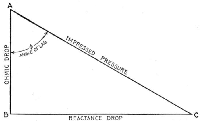
Fig. 1,319.—Graphical method of finding angle of lag when the ohmic drop and reactance
drop are given. The angle of lag φ, is that angle included between the impressed pressure
and the ohmic drop lines, that is, between AC and AB.
EXAMPLE.—An alternating current of 10 amperes having a frequency
of 60, is impressed on a circuit containing a resistance of 5 ohms and an
inductance of 15 milli-henrys. What is the impressed pressure?
The active pressure or ohmic drop is 5 × 10 = 50 volts.
[Pg 1080]
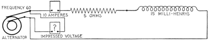
Fig. 1,320.—Diagram of circuit containing 5 ohms resistance, 15 milli-henrys inductance, with
3 ampere 60 frequency current.
The inductance reactance or Xi = is 2 × 3.1416 × 60 × .015 = 5.66 ohms.
Substituting this and the current value 10 amperes in the formula for
inductance pressure or reactance drop (equation 2 on page 1,077) gives
Ei = 5.65 × 10 = 56.5 volts.
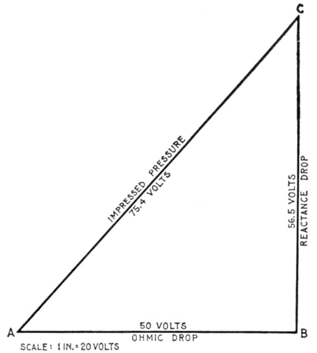
Fig. 1,321.—Diagram for impressed pressure on circuit containing 5 ohms resistance and
inductance of 15 milli-henrys, the current being 10 amperes with frequency of 60.
In fig. 1,321, lay off AB = 50 volts, and BC = 56.6 volts. Using a scale
of 20 volts to the inch gives AB = 2.5 ins., and BC = 2.83 ins. Joining
AC gives the impressed voltage, which by measurement is 75.4 volts.
[Pg 1081]
In some problems it is required to find the impedance of a
circuit in which the ohmic and spurious resistances are given.
This is done in a manner similar to finding the impressed pressure.
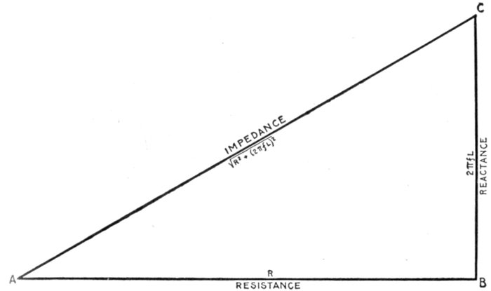
Fig. 1,322.—Graphical method of obtaining the impedance in circuits containing resistance and
inductance, having given the resistance and reactance, that is, the ohmic resistance and
spurious resistance. With any convenient scale lay off AB = resistance, and erect the
perpendicular BC = reactance (using the same scale); join AC, whose length (measured
with the same scale) will give the impedance.
Ohmic resistance and spurious resistance or inductance reactance
both tend to reduce an alternating current. Their
combined action or impedance is equal to the square root of
the sum of their squares, that is,
impedance = √(resistance2 + reactance2)
This relation is represented graphically by the side of a right
angle triangle as in fig. 1322, in which the hypothenuse corresponds
to the impedance, and the sides to the resistance and reactance.
EXAMPLE.—In a certain circuit the resistance is 4 ohms, and the
reactance 3 ohms. What is the impedance?
[Pg 1082]
In fig. 1,323, lay off, on any scale AB = 4 ohms and erect the perpendicular
BC = 3 ohms. Join AC, which gives the impedance, and which
is, measured with the same scale, 5 ohms.
EXAMPLE.—A coil of wire has a resistance of 20 ohms and an
inductance of 15 milli-henrys. What is its impedance for a current
having a frequency of 100?
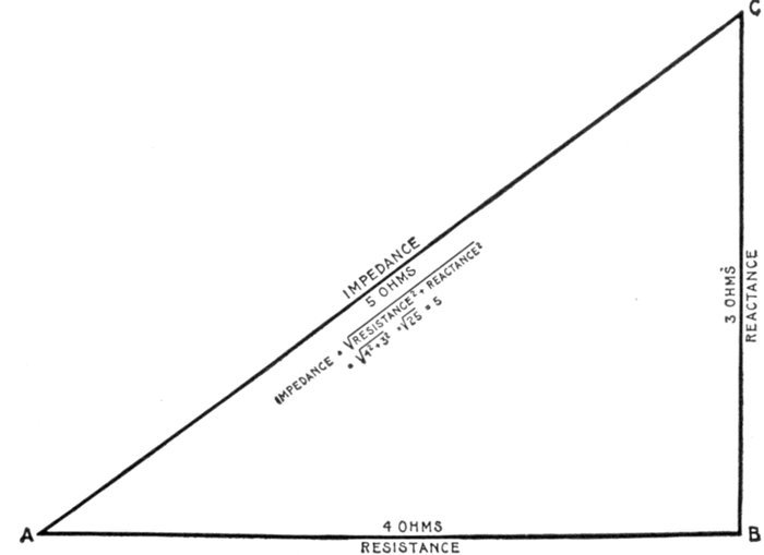
Fig. 1,323.—Diagram for obtaining the impedance of a circuit containing 4 ohms resistance
and 3 ohms reactance.
The ohmic value of the inductance, that is, the reactance is
2πfL = 2 × 3.1416 × 100 × .015 = 9.42 ohms.
In fig. 1,324, lay off, on any scale, AB = 20 ohms, and the perpendicular
BC to length = 9.42 ohms. Join AC, which gives the impedance, which
is, measured on the same scale, 22.1 ohms.
EXAMPLE.—What is the angle of lag in a circuit having a resistance
of 4 ohms and a reactance of 3 ohms?
Construct the impedance diagram in the usual way as in fig. 1,325,
then the angle included between the impedance and resistance lines
[Pg 1083](denoted by φ) is the angle of lag, that is, the angle BAC. By measurement
with a protractor it is 37 degrees. By calculation the tangent of the
angle of lag or
From the table on page 451, the angle is approximately 37°.
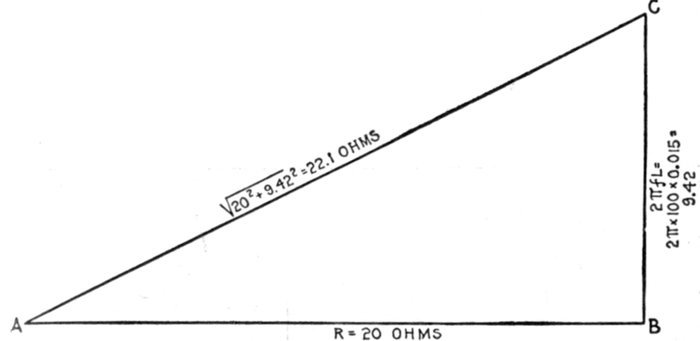
Fig. 1,324.—Diagram for impedance of circuit
containing 20 ohms resistance, and inductance
of 15 milli-henrys, when the frequency is 100.
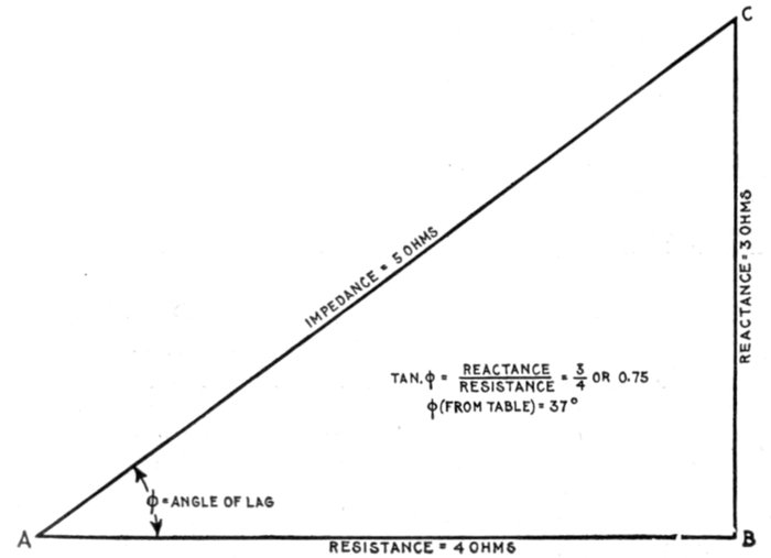
Fig. 1,325.—Diagram showing angle of lag for current
containing 4 ohms resistance and 3 ohms
reactance.
[Pg 1084]
Circuits containing Resistance and Capacity.—The
effect of capacity in an alternating current circuit is to cause the
current to lead the pressure, since the reaction of a condenser,
instead of tending to prolong the current, tends to drive it back.
Careful distinction should be made between capacity in
series with a circuit and capacity in parallel with a branch of a
circuit. The discussion here refers to capacity in series, which
means that the circuit is not continuous but the ends are joined
to a condenser, as shown at the right in fig. 1,326, so that no current
can flow except into and out of the condenser.
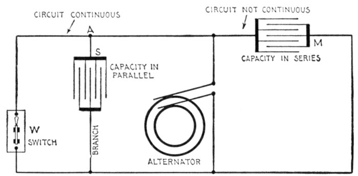
Fig. 1,326,—Circuit diagram illustrating the distinction between capacity in series and capacity
in parallel. The condition for capacity in series is that the circuit must be discontinuous
as at M; for capacity in parallel the main circuit must be continuous; this means that
the capacity must be inserted in a branch of the main circuit as at A. In the figure the
capacity S is connected in series with respect to the branch, that is, the branch is discontinuous,
but it is in parallel with respect to the main circuit, when the latter is continuous,
that is, when the switch W is closed. If W be opened, the main circuit becomes
discontinuous and S is changed from in parallel to in series connection.
Ques. In circuits containing resistance and capacity
upon what does the amount of lead depend?
Ans. Upon the relative values of the resistance and the
capacity reactance.
[Pg 1085]
Ques. Describe the action of a condenser when current
is applied.
Ans. When the current begins to flow into a condenser, that
is, when the flow is maximum, the back pressure set up by the
condenser (called the condenser pressure) is zero, and when the
flow finally becomes zero, the condenser pressure is a maximum.
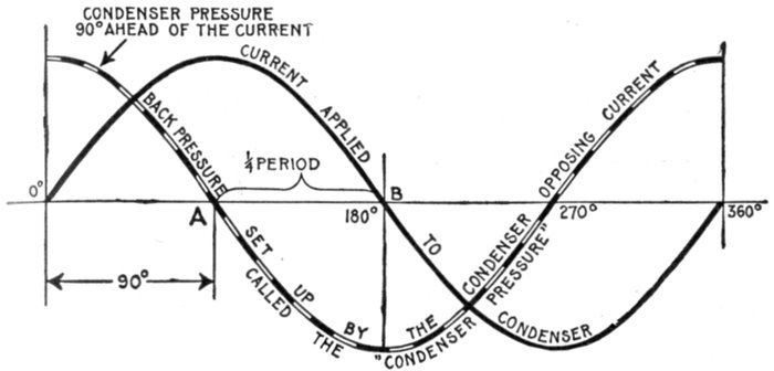
Fig. 1,327.—Current and pressure curves showing that the condenser pressure is 90° ahead
of the current. A current flowing into a condenser encounters a gradually increasing
pressure which opposes it, beginning from zero pressure when the current enters at maximum
flow and increasing to the same value as the current pressure, at which time the
current ceases to flow. Hence, since the current varies from zero to maximum in one
quarter period, or 90°, the phase difference between current and condenser pressure is 90°.
The condenser pressure reaching a positive maximum when the current starts from zero
on the positive wave, is 90° ahead of the current.
Ques. What does this indicate?
Ans. It shows that the phase difference between the wave
representing the condenser pressure and the current is 90°, as
illustrated in fig. 1,327.
Ques. Is the condenser pressure ahead or behind the
current and why?
Ans. It is ahead of the current. The condenser pressure,
when the condenser is discharged being zero, the current enters[Pg 1086]
at maximum velocity as at A in fig. 1,327, and gradually decreases
to zero as the condenser pressure rises to maximum at B,
this change taking place in one-quarter period. Thus the
condenser pressure, which opposes the current, being at a maximum
when the current begins its cycle is 90° ahead of the current,
as is more clearly seen in the last quarter of the cycle (fig. 1,327).
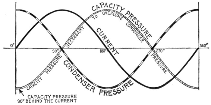
Fig. 1,328.—Current and pressure curves, showing phase relation between the current, condenser
pressure, and impressed or capacity pressure necessary to overcome the condenser
pressure. The capacity pressure, since it must overcome the condenser pressure, is
equal and opposite to the condenser pressure, that is, the phase difference is 180°. The
condenser pressure being 90° ahead of the current, the impressed pressure is 90° behind
the current.
Ques. What is the phase relation between the condenser
pressure and the pressure applied to the condenser
to overcome the condenser pressure?
Ans. The pressure applied to the condenser to overcome the
condenser pressure, or as it is called, the capacity pressure, must
be opposite to the condenser pressure, or 90° behind the current.
In circuits containing resistance and capacity, the total
pressure impressed on the circuit, or impressed pressure, as it is
called, is made up of two components:
[Pg 1087]
1. The active pressure, or pressure necessary to overcome
the resistance;
The active pressure is in phase with the current.
2. The capacity pressure, or pressure necessary to overcome
the condenser pressure,
The capacity pressure is 90 degrees behind the current.
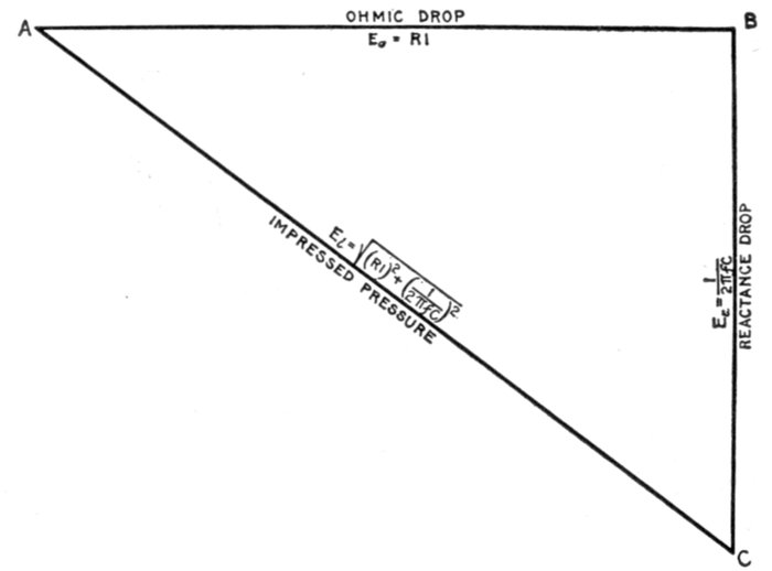
Fig. 1,329.—Graphical method of obtaining the impressed pressure in circuits containing
resistance and capacity, having given the ohmic drop and reactance drop due to capacity.
With any convenient scale, lay off AB = ohmic drop, and at right angles to AB draw
BC = reactance drop (using the same scale). Join AC, whose length (measured with the
same scale) will give the impressed pressure. The mathematical expressions for the three
quantities are given inside the triangle, and explained in the text.
Problems involving resistance and capacity are solved similarly
to those including resistance and inductance.
The Active Pressure or "Ohmic Drop."—This, as before explained
is represented, in fig. 1,329, by a line AB, which in magnitude equals,
by Ohm's law, the product of the resistance multiplied by the current,
that is,
Ea = RoIv (1)
[Pg 1088]
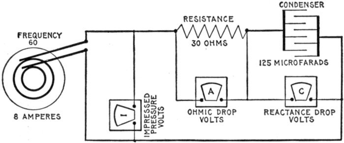
Fig. 1,330.—Diagram of circuit containing a resistance of 30 ohms and capacity of 125 microfarads.
The calculation for impressed pressure, ohmic drop, and reactance drop for a
current of 8 amperes at frequency 60 is given in the example on page 1,089, the diagram
for impressed pressure being given in fig. 1,331.
The Capacity Pressure or "Reactance Drop."—This component
of the impressed pressure, is, applying Ohm's law,
capacity pressure = capacity reactance × virtual current.
Ec = XcIv (2)
That is, the expression for capacity reactance Xc, that is, for the
value of capacity in ohms is, as explained on page 1,048,
Substituting this value of Xc in equation (2) and writing I for virtual current.
CAUTION—The reader should distinguish between the 1 (one) in (3) and the letter I in
(4); both look alike.
Since the capacity pressure is 90° behind the current, it is represented
in fig. 1,329, by a line BC, drawn downward, at right angles to AB, and
of a length corresponding to the capacity pressure, that is, to the reactance
drop.
The Impressed Pressure.—Having determined the ohmic and reactance
drops and represented them in the diagram, fig. 1,329, by lines
AB and BC respectively, a line AC joining A and C, will then be the
resultant of the two component pressures, that is, it will represent the
impressed pressure or total pressure applied to the circuit.
In the diagram it should be noted that the active pressure is called
the ohmic drop, and the capacity pressure, the reactance drop.
[Pg 1089]
EXAMPLE.—A circuit as shown in fig. 1,330 contains a resistance of
30 ohms, and a capacity of 125 microfarads. If an alternating current
of 8 amperes with frequency 60 be flowing in the circuit, what is the
ohmic drop, the reactance drop, and the impressed pressure?
The ohmic drop or active pressure is, substituting in formula (1) on
page 1,087,
Ea = 30 × 8 = 240 volts
which is the reading of voltmeter A in fig. 1,330.
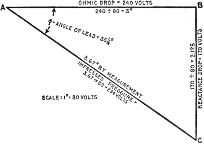
Fig. 1,331.—Diagram for obtaining the impressed pressure of the circuit shown in fig. 1,330.
The reactance drop or
in substituting, note that the capacity C of 125 microfarads is reduced
to .000125 farad.
Using a scale of say 1 inch = 80 volts, lay off in fig. 1,331, AB equal
to the ohmic drop of 240 volts; on this scale AB = 3 inches. Lay off
at right angles, BC = reactance drop = 170 volts = 2.125 inches. Join AC,
which gives the impressed voltage, (that is the reading of voltmeter I
in fig. 1,330,) which measures 294 volts.
By calculation, impressed pressure = √(2402 + 1702) = 294 volts.
[Pg 1090]
EXAMPLE.—In the circuit shown in fig. 1,330, what is the angle of
lead?
The tangent of the angle of lead is given by the quotient of the reactance
divided by the resistance of the circuit. That is,
The tangent is given a negative sign because lead is opposed to lag
and because the positive value is assigned to lag. Substituting in (1)
the angle corresponding is approximately 35¼° (see table page 451).
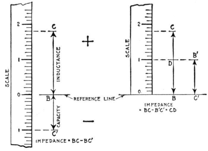
Figs. 1,332 and 1,333.—Diagrams for circuits containing inductance and capacity. Since
inductance and capacity act 180° apart, their reactances, or their ohmic drops may be
represented by oppositely directed lines. These may be drawn above and below a reference
line, as in fig. 1,332, and their algebraic sum taken, or both may be drawn on the
same side of the reference line and their difference in lengths, as CD, fig. 1,333, measured.
Recourse to a diagram for obtaining the resultant reactance in circuits containing inductance
and capacity is unnecessary as it is simply a matter of taking the difference of two quantities.
[Pg 1091]
Circuits Containing Inductance and Capacity.—The
effect of capacity in a circuit is exactly the opposite of inductance,
that is, one tends to neutralize the other. The method of
representing each graphically has been shown in the preceding
figures. Since they act oppositely, that is 180° apart, the
reactance due to each may be calculated and the values thus
found, represented by oppositely directed vertical lines: the
inductance resistance upward from a reference line, and the
capacity resistance downward from the same reference line.
The difference then is the resultant impedance. This method is
shown in fig. 1,332, but it is more conveniently done as in fig. 1,333.
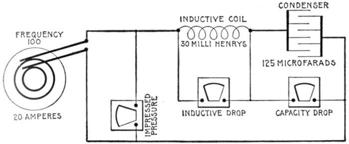
Fig. 1,334.—Diagram of circuit containing 30 milli-henrys inductance and 125 microfarads
capacity, with current of 20 amperes, 100 frequency.
EXAMPLE.—In a circuit, as in fig. 1,334, containing an inductance
of 30 milli-henrys and a capacity of 125 microfarads, how many volts
must be impressed on the circuit to produce a current of 20 amperes
having a frequency of 100.
The inductance reactance is
Xi = 2πfL = 2 × 3.1416 × 100 × .03 = 18.85 ohms.
Substituting this and the current value of 20 amperes in the formula
for inductance pressure
Ei = RiI = 18.85 × 20 = 377 volts.
[Pg 1092]
Reducing 125 microfarads to .000125 farad, and substituting in the
formula for capacity pressure
A diagram is unnecessary in obtaining the impressed pressure since
it is simply the difference between inductance pressure and capacity
pressure (the circuit being assumed to have no resistance), that is
impressed pressure = Ei - Ec = 377 - 255 = 122 volts.
EXAMPLE.—A circuit in which a current of 20 amperes is flowing
at a frequency of 100, has an inductance reactance of 18.25 ohms, and a
capacity of 125 microfarads. What is the impedance?
The reactance due to capacity is
The impedance of the circuit then is the difference between the two
reactances, that is impedance = inductance reactance - capacity reactance,
or
Z = Xi - Xc = 18.25 - 12.76 = 5.49 ohms.
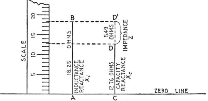
Fig. 1,335.—Impedance diagram for circuit (of above example) containing inductance and
capacity. With any convenient scale, erect a perpendicular AB = 18.25 ohms, and CD =
12.76 ohms. Continue CD by dotted line to D' so that CD' = AB, then DD' = AB - CD
= inductance reactance - capacity reactance, which is equal to the impedance. Expressed
by letters Z = Xi - Xc = DD', which by measurement = 5.49 ohms.
Circuits Containing Resistance, Inductance, and Capacity.—When
the three quantities resistance, inductance, and
capacity, are present in a circuit, the combined effect is easily[Pg 1093]
understood by remembering that inductance and capacity
always act oppositely, that is, they tend to neutralize each other.
Hence, in problems involving the three quantities, the resultant
of inductance and capacity is first obtained, which, together
with the resistance, is used in determining the final effect.
Capacity introduced into a circuit containing inductance
reduces the latter and if enough be introduced, inductance will
be neutralized, giving a resonant circuit which will act as though
only resistance were present.
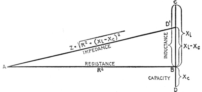
Fig. 1,336.—Impedance diagram for circuit containing resistance, inductance and capacity.
The symbols correspond to those used in equation (1) below. In constructing the diagram
from the given values, lay off AB = resistance; at B, draw a line at right angles, on which lay
off above the resistance line, BC = inductive reactance, and below, BD = capacity reactance,
then the resultant reactance = BC - BD = BD'. Join A and D', then AD' = impedance.
Ques. What is the expression for impedance of a circuit
containing resistance, inductance and capacity?
Ans. It is equal to the square root of the sum of the resistance
squared plus the square of inductance reactance minus capacity
reactance.
This is expressed plainer in the form of an equation as follows:
impedance = √(resistance2 + (inductance reactance - capacity reactance)2)
or, using symbols,
Z = √(R2 + (Xi - Xc)2) (1)
[Pg 1094]
Ques. If the capacity reactance be larger than the
inductance reactance, how does this affect the sign of
(Xi-Xc)2?
Ans. The sign of the resultant reactance of inductance and
capacity will be negative if capacity be the greater, but since in
the formula the reactance is squared, the sign will be positive.
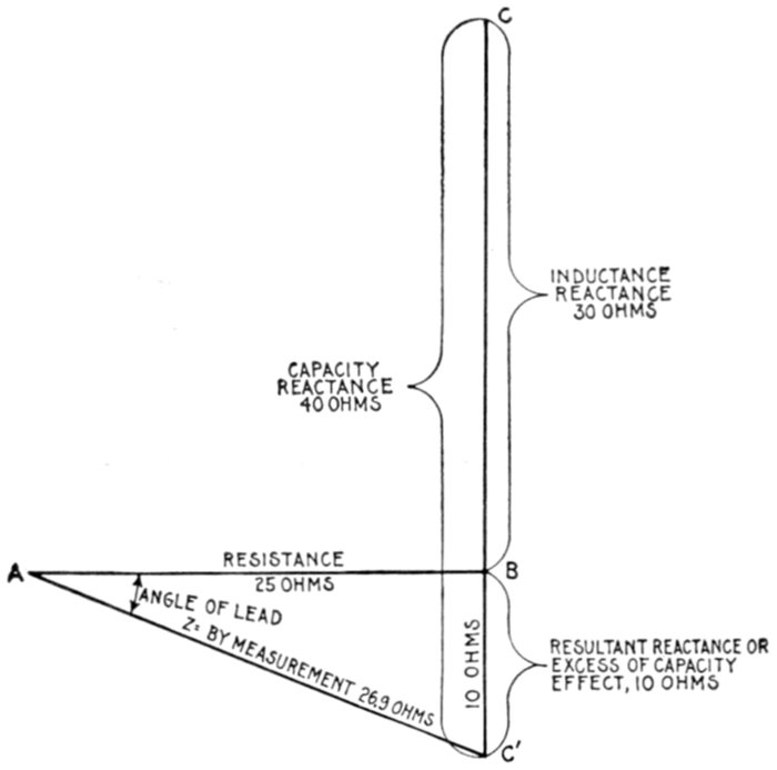
Fig. 1,337.—Impedance diagram of a circuit containing 25 ohms resistance, 30 ohms inductance,
and 40 ohms capacity. The resultant reactance being due to excess of capacity, the
impedance line AC' falls below the horizontal line AB, indicating that the current leads
pressure.
EXAMPLE.—What is the impedance in a circuit having 25 ohms
resistance, 30 ohms inductance reactance, and 40 ohms capacity reactance?
To solve this problem graphically, draw the line AB, in fig. 1,337,
equal to 25 ohms resistance, using any convenient scale.
At B draw upward at right angles BC = 30 ohms; draw from C downward
CC' = 40 ohms. This gives -BC' (= BC - CC') showing the capacity reactance
to be 10 ohms in excess of the inductance reactance. Such a
[Pg 1095]circuit is equivalent to one having no inductance but the same resistance
and 10 ohms capacity reactance.
The diagram is completed in the usual way by joining AC giving the
required impedance, which by measurement is 26.9 ohms.
By calculation, Z = √(252 + (30 - 40)2) = √(252 + (-10)2) = 26.9.
Form of Impedance Equation without Ohmic Values.—
Using the expressions 2πfL for inductance reactance and 1 / (2πfC)
for capacity reactance, and substituting in equation (1) on page
1,093 gives the following:
Z = √(R2 + (2πfL - 1 / (2πfC))2) (2)
which is the proper form of equation (1) to use in solving problems
in which the ohmic values of inductance and capacity must
be calculated.
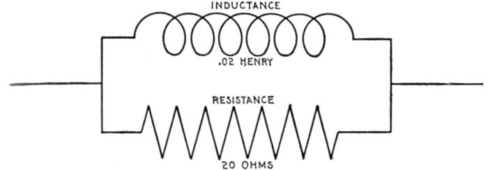
Fig. 1,338.—EXAMPLE: A resistance of 20 ohms and an inductance of .02 henry are connected
in parallel as in the diagram. What is the impedance, and how many volts are
required for 50 amperes, when the frequency is 78.6? SOLUTION: The time constants
are not alike, hence the geometric sum of the reciprocals must be taken as the reciprocal
of the required impedance. That is, the combined conductivity will be the hypothenuse
of the right triangle, of which the ohmic conductivity and the reactive conductivity are
the two sides, respectively. Accordingly: 1 / R = 1 / 20 = .05, and 1 / (2πfL) = 1 / 10 = .1, from which,
1 / R = √((1 / R1)2 + (1 / (2πfL))2) = .111. Whence Z = 1 / .111 = 9 ohms.
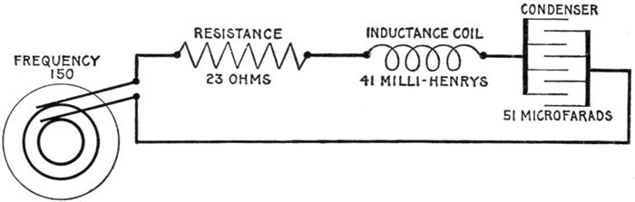
Fig. 1,339.—Diagram of circuit containing 23 ohms resistance, 41 milli-henrys inductance, and
51 microfarads capacity, with current supplied at a frequency of 150.
EXAMPLE.—A current has a frequency
of 150. It passes through a
circuit, as in fig. 1,339, of 23 ohms resistance,
of 41 milli-henrys inductance,
and of 51 microfarads capacity. What
is the impedance?
The inductance reactance or
Xi = 2πfL = 2 × 3.1416 × 150 × .041 = 38.64 ohms
(note that 41 milli-henrys are reduced
to .041 henry before substituting in the
above equation).
The capacity reactance, or
(note that 51 microfarads are reduced
to .000051 farad before substituting in
the above equation).
Substituting the values as calculated
for 2πfL and 1 / (2πfC) in equation (2)
Z = √(232 + (38.64 - 20.8)2) = 29.1 ohms.
To solve the problem graphically, lay
off in fig. 1,340, the line AB equal to 23
ohms resistance, using any convenient
scale. Draw upward and at right
angles to AB the line BC = 38.64 ohms
inductance reactance, and from C lay
off downward CC' = 20.8 ohms capacity
reactance. The resultant reactance[Pg 1097]
is BC' and being above the horizontal line AB shows that inductance
reactance is in excess of capacity reactance by the amount BC'. Join
AC' which gives the impedance sought, and which by measurement is
29.1 ohms.
In order to obtain the impressed pressure in circuits
containing resistance, inductance and reactance, an
equation similar to (2) on page 1,095 is used which is made up
from the following:
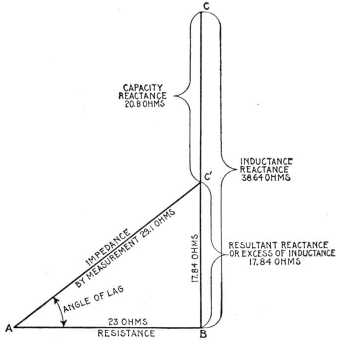
Fig. 1,340.—Impedance diagram for the circuit shown in fig. 1,339. Note that the resultant
reactance being due to excess of inductance, the impedance line AC' falls above the horizontal
line AB. This indicates that the current lags behind the pressure.
When all three quantities, resistance, inductance, and
capacity are present, the equation is as follows:
[Pg 1098]
Substituting in this last equation (6), the values given in (3),
(4) and (5)
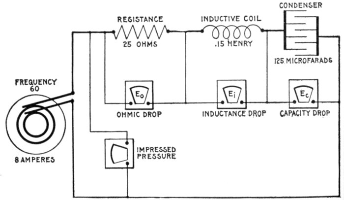
Fig. 1,341.—Diagram of circuit containing 25 ohms resistance, .15 henry inductance, and 125
microfarads capacity, with current of 8 amperes at 60 frequency.
Ques. What does the quantity under the square root
sign in equation (7) represent?
Ans. It is the impedance of a circuit possessing resistance,
inductance, and capacity.
[Pg 1099]
Ques. Why?
Ans. Because it is that quantity which multiplied by the
current gives the pressure, which is in accordance with Ohm's
law.
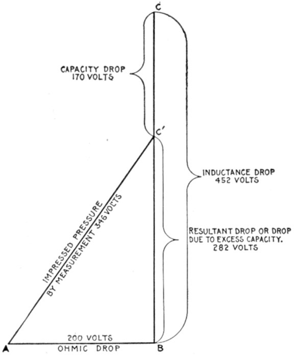
Fig. 1,342.—Diagram for finding the pressure necessary to be impressed on the circuit shown
in fig. 1,341, to produce a current of 8 amperes.
EXAMPLE.—An alternator is connected to a circuit having, as in
fig. 1,341, 25 ohms resistance, an inductance of .15 henry, and a capacity
of 125 microfarads. What pressure must be impressed on the circuit to
allow 8 amperes to flow at a frequency of 60?
The ohmic drop is
Eo = RI = 25 × 8 = 200 volts.
The inductance drop is
Ei = 2πfLI = 2 × 3.1416 × 60 × .15 × 8 = 452 volts
The capacity drop is
[Pg 1100]
Substituting the values thus found,
| impressed pressure |
= |
√(Eo2 + (Ei - Ec)2) |
|
= |
√(2002 + (452 - 170)2) |
|
= |
√(2002 + 2822) |
|
= |
√(119524) |
|
= |
345.7 volts. |
[Pg 1101]
CHAPTER XLVIII
THE POWER FACTOR
The determination of the power in a direct current circuit is
a simple matter since it is only necessary to multiply together the
volts and amperes to obtain the output in watts. In the case of
alternating current circuits, this holds true only when the current
is in phase with the pressure—a condition rarely found in practice.
When the current is not in phase with the pressure, the product
of volts and amperes as indicated by the voltmeter and ammeter
must be multiplied by a coefficient called the power factor in
order to obtain the true watts, or actual power available.
There are several ways of defining the power factor, any of
which requires some explanation. The power factor may be
defined as: The number of watts indicated by a wattmeter, divided
by the apparent watts, the latter being the watts as measured
by a voltmeter and ammeter.
The power factor may be expressed as being equal to
Ques. What are the true watts?
Ans. The watts as measured by a wattmeter.
[Pg 1102]
Ques. What are the apparent watts?
Ans. The watts obtained by multiplying together the simultaneous
voltmeter and ammeter readings.
Ques. What is usually meant by power factor?
Ans. The multiplier used with the apparent watts to determine
how much of the power supplied is available.
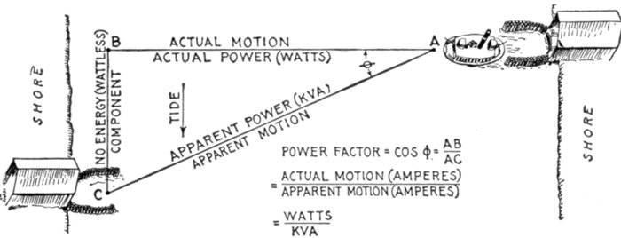
Fig. 1,343.—Marine analogy of power factor. A ferry boat in crossing a river to a slip C
would head for some point B up stream from C to allow for the effect of the tide. Under
such conditions the actual motion (referred to the water) would be from A to B, and the
apparent motion, from A to C. Accordingly, the energy expended in propelling the boat
from A to B in still water, will propel it from A to C when the tide is running in the direction
of the arrow. The effect of the tide is the same as that of inductance or capacity in
an alternating circuit, that is, it puts the applied force or thrust (impressed volts) out of
phase with the motion of the boat (amperes), this phase difference being indicated by the
angle BAC or φ. Now, work (watts) is the product of two factors, pressure (volts) and distance
(amperes); accordingly, the apparent work done in propelling the boat from A to C is
the product of the thrust of the paddle wheels multiplied by AC, which in analogy corresponds
to the product of voltmeter and ammeter readings at the alternator, called "kva." Actually,
however, the power is only applied from A to B, the boat being carried sidewise by the
tide, as it crosses, a distance BC which represents no energy expended by the paddle wheels.
In analogy, the actual power, expended in propelling boat from A to B corresponds to
the wattmeter reading in an alternating current power circuit. To obtain the actual
work done on the boat, the product of its apparent motion × thrust must be multiplied
by a coefficient or power factor because the thrust is applied at an angle to the apparent
motion, the power factor being equal to the cosine of this angle, (φ) or AB ÷ AC.
Similarly, when there is phase difference between pressure and alternating current, the
voltmeter and ammeter readings must be multiplied by the power factor or cos φ to give
the output of an alternator available for external work, the excess power indicated by
ammeter and voltmeter readings, performing no external work, but causing objectionable
heating of the alternator.
Ques. Upon what does the power factor depend?
Ans. Upon the relative amounts of resistance inductance and
capacity contained in the circuit.
[Pg 1103]
Ques. How does the power factor vary in value?
Ans. It varies from one to zero.
The power factor, as will be shown later, is equal to the cosine of the
angle of phase difference; its range then is from one to zero because
these are the limiting values of the cosine of an angle (neglecting the
+ or-sign).
Ques. What is the effect of lag or lead of the current
on the power factor?
Ans. It causes it to become less than one.
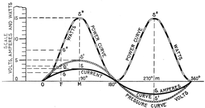
Fig. 1,344.—Method of drawing the power curve from the pressure and current curves. As
shown, the same scale is used for all curves. This as a rule, makes the power curve
inconveniently high, hence it is usually drawn to smaller scale as in fig. 1,345.
How to Obtain the Power Curve.—Since under any phase
condition, the power at any instant is equal to the product of the
pressure multiplied by the current at that instant, a curve may
be easily plotted from the pressure and current curves, giving the
instantaneous values of the power through a complete cycle.
In fig. 1,344, from the zero line of the current and pressure curves,
draw any ordinate as at F cutting the current curve at G and the pressure[Pg 1104]
curve at G'. The values for current and pressure at this point are from
the scale, 2 amperes and 3.7 volts. Since watts = amperes × volts, the
ordinate FG is to be multiplied by ordinate FG' that is,
2 × 3.7 = 7.4.
Project up through F the ordinate FG" = 7.4, and this will give one
point on the power curve.
Similarly at another point, say M, where the current and pressure
are maximum
giving S" another point on the curve. Obtaining several points in this
way the power curve is then drawn through them as shown.
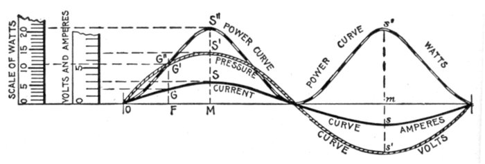
Fig. 1,345.—Usual method of drawing power curve from the pressure and current curves.
A smaller scale is employed for the power curve in order to reduce its height.
Ques. Why is the power curve positive in the second
half of the period when there are negative values of current
and pressure?
Ans. Because the product of two negative quantities is
positive.
Ques. Does fig. 1,344 represent the usual way of drawing
a power curve?
Ans. Since ordinates of the power curve are products of the
current and pressure ordinates, they will be of inconvenient[Pg 1105]
length if drawn to the same scale; it is therefore customary to
use a different scale for the power ordinates, as in fig. 1,345.
The illustration is lettered identical with fig. 1,344, with which it
should be compared.
Synchronism of Current and Pressure; Power Factor
Unity.—The current and pressure would be in phase as represented
in fig. 1,346 were it possible to have a circuit containing
resistance only. In actual practice all circuits contain at
least a small amount of reactance.
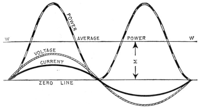
Fig. 1,346.—Synchronism of current and pressure. Power curve showing that the power
factor is unity. This is indicated by the fact that the power curve does not project
below the base or zero line.
A circuit supplying nothing but incandescent lamps comes
very nearly being all resistance, and may be so considered in
the discussion here. Fig. 1,347 illustrates a circuit containing
only resistance. In such a circuit the pressure and current
(as shown in fig. 1,346) pass through zero and through their
maximum values together.
[Pg 1106]
Multiplying instantaneous values of volts and amperes will
give the power curve, as before explained, whose average value
is half-way between the zero line and the maximum of the
curve; that part of the power curve above the line of average
power WW, exactly filling the open space below the line
WW. That is,
| average power |
= |
maximum power ÷ √2 |
|
= |
maximum voltage × maximum current |
|
|
|
√2 |
|
= |
virtual voltage × virtual current. |
This latter is simply the product of the voltmeter and ammeter
readings which gives the watts just the same as in direct current.
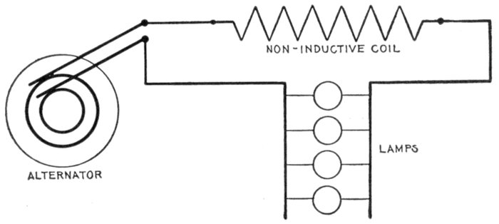
Fig. 1,347.—Diagram of circuit containing only resistance; in such a circuit the power factor
is unity.
Ques. What should be noticed about the power curve?
Ans. Its position with respect to the zero line; it lies wholly
above the zero line which denotes that all the power delivered to
the circuit except that dissipated by friction is useful, that is, the[Pg 1107]
power factor is unity. Hence, to keep the power factor as near
unity as possible is one of the chief problems in alternating current
distribution.
Ques. Can the power factor be less than unity if the
current and pressure be in phase?
Ans. Yes, if the waves of current and voltage be distorted
as in fig. 1,348.
Effect of Lag and Lead.—In an alternating circuit the
amount of power supplied depends on the phase relationship
of the current and pressure. As just explained, when there is
synchronism of current and pressure, that is, when they are in
phase (as in fig. 1,346) the power factor is unity, assuming no
distortion of current and pressure waves. In all other cases the
power factor is less than unity that is, the effect of lag or lead is
to make the power factor less than unity.
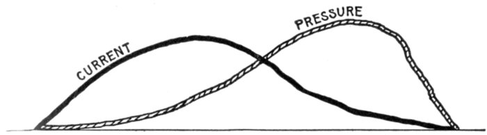
Fig. 1,348.—Case of synchronism of current and pressure with power factor less than unity.
Suppose the waves of current and voltage to be in phase, but distorted in form, and not
symmetrical, so that they do not run uniformly together, as shown in the figure. Then
the real power factor may not be unity, although indicated as such by the power factor
meter. However, the switchboard instruments are made to show the angle of lag as the
power factor, because the error due to wave distortion is generally too small to be considered.
[Pg 1108]
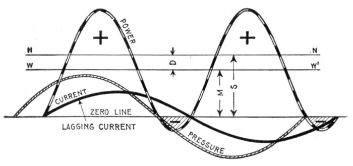
Fig. 1,349.—Effect of lag on the power factor. When the current lags behind the pressure
the power factor becomes less than unity. It will be seen that the power curve projects
below the zero line giving the shaded area which represents negative power which must
be subtracted from the + areas above the zero line to get the net power. In the figure
the line WW' is drawn at a height corresponding to the average power, and HN at a height
corresponding to the average power that would be developed if the current were in phase
with the pressure. The power factor then is represented by M ÷ S, and by inspection of
the figure it is seen that this is less than unity.
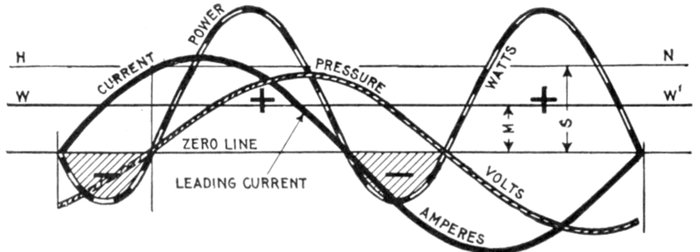
Fig. 1,350.—Effect of lead on the power factor. When the current is in advance of the pressure
the power factor becomes less than unity. The curve, as shown, projects below the
zero line, giving the shaded area which represents negative power which must be subtracted
from the + areas above the zero line to get the net power. As in fig. 1,349, the
line WW' at a height M represents the average power, and HN the average power for
synchronism of current and pressure. The power factor then is M ÷ S which is less
than unity.
[Pg 1109]
The effect of lag on the power factor may be illustrated by
fig. 1,349, in which the angle between the pressure and current,
or the angle of lag is taken as 40°, corresponding to a power
factor of .766. Plotting the power curve from the products
of instantaneous volts and amperes taken at various points, the
power curve is obtained, a portion of which lies below the horizontal
line. The significance of this is that at certain times, the
current is flowing in the opposite direction to that in which the
impressed pressure would send it. During this part of the period
conditions are reversed, and the power (indicated by the shaded
area), instead of being supplied by the source to the circuit, is
being supplied by the circuit to the source.
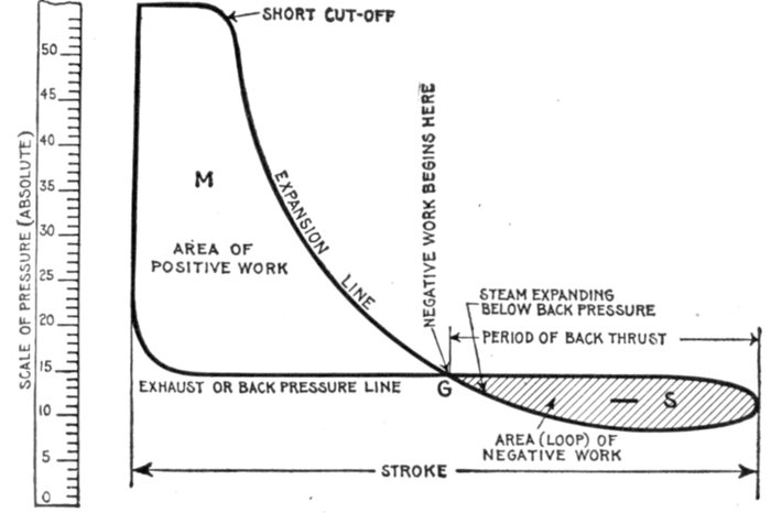
Fig. 1,351.—Steam engine analogy of power factor. The figure represents an indicator card
of an engine in which the steam distribution is such that the steam is expanded below
the back pressure line, that is below the pressure of the exhaust. This results in negative
work which must be overcome by the momentum or kinetic energy previously stored in
the fly wheel, and which is represented on the diagram by the shaded loop S. If the
exhaust valve had opened at G, the amount of work done during the revolution would be
represented by the area M, but continuing the expansion below the back pressure line,
the work done is M - S. This latter case as compared with the first when expansion
does not continue below the back pressure line gives an efficiency (power factor) of (M - S)
÷ M, the shaded area representing so much loss.
This condition is exactly analogous to the case of a steam engine,
expanding the steam below the back or exhaust pressure, a condition
sometimes caused by the action of the governor in considerably reducing[Pg 1110]
the cut off for very light load. An indicator diagram of such steam
distribution is shown in fig. 1,351. This gives a negative loop in the
diagram indicated by the shaded section.
It must be evident that the average pressure of the shaded loop portion
of the diagram must be subtracted from that of the other portion,
because during the expansion below the exhaust pressure line, the
back pressure is in excess of the forward pressure exerted on the piston
by the expanding steam, and the engine would accordingly reverse its
motion, were it not for the energy previously stored up in the fly wheel in
the form of momentum, which keeps the engine moving during this period
of back thrust. Evidently the shaded area must be subtracted from
the positive area to obtain the net work done during the stroke.
Hence following the analogy as far as possible if M work (watts) be
done during each revolution (cycle) when steam does not expand below
back pressure (when current and pressure are in phase), and S negative
work (negative watts) be done when steam expands below back pressure
(when there is lag), the efficiency (power factor) is (M - S) ÷ M.
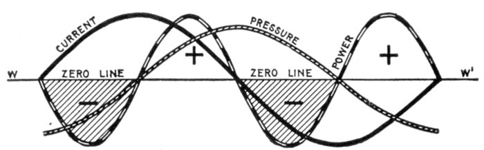
Fig. 1,352.—Power curve illustrating the so-called wattless current in which case the power
factor is zero. By noting that the curve projects equally on each side of the zero line,
the + power areas equal the negative power areas, hence the summation of these areas for
the period is zero, that is, the two + areas minus the two shaded areas equal zero. It
should be noted that the line of average power WW', which is visible in the other figures,
here coincides with the zero line, and the average power then is zero, since the positive
part above the zero line is equal to and offsets the negative (shaded) part below the line.
This is the case of "wattless" current and (considering a circuit with resistance so small
that it may be considered as zero) shows plainly the possibility of having full load current
and voltage on a circuit yet delivering no power, the current simply surging to and fro
without an actual transfer of power.
"Wattless Current;" Power Factor Zero.—When the
power factor is zero, it means that the phase difference between
the current and the pressure is 90°.
The term wattless current, as understood, does not indicate an
absence of electrical energy in the circuit; its elements are there,[Pg 1111]
but not in an available form for external work. The false power
due to the so called wattless current pulsates in and out of the
circuit without accomplishing any useful work.
An example of wattless current, showing that the power factor is zero
is illustrated in fig. 1,353. Here the angle of lag is 90°, that is, the current
is 90° behind the pressure.
The power curve is constructed from the current and pressure curves,
and, as shown in the diagram, it lies as much below the zero line
as above, that is, the two plus power areas which occur during each
period are equal to the two negative (shaded) power areas, showing
that the circuit returns as much energy as is sent out. Hence, the total
work done during each period is zero, indicating that although a current
be flowing, this current is not capable of doing external work.
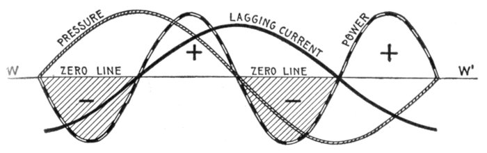
Fig. 1,353.—Example of wattless current showing that the power factor is zero when the
phase difference between current and pressure is 90°. For zero power factor the current
may lead 90° as in fig. 1,352, or lag 90° as here shown. Since the shaded or negative areas =
the plus areas, the average power (indicated by WW' which coincides with the zero line)
is zero, that is the circuit is carrying current under pressure yet delivering no power,
hence, the power factor is zero.
Ques. Is the condition as just described met with in
practice?
Ans. No.
Ques. Why not?
Ans. The condition just described involves that the circuit
have no resistance, all the load being reactance, but it is impossible
to have a circuit without some resistance, though the[Pg 1112]
resistance may be made very small in comparison to the reactance
so that a close approach to wattless current is possible.
Ques. Give some examples where the phase difference
is very nearly 90°.
Ans. If an alternator supplies current to a circuit having a very
small resistance and very large inductance, the current would
lag nearly 90° behind the pressure. The primary current of a
transformer working with its secondary on an open circuit is a
practical example of a current which represents very little energy.
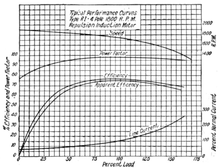
Fig. 1,354.—Performance curves of General Electric single phase repulsion induction motor.
Ques. When the phase difference between the current
and pressure is 90°, why is the current called "wattless"?
Ans. Because the product of such a current multiplied by the
pressure does not represent any watts expended.
A man lifting a weight, and then allowing it to descend the same
distance to its initial position, as shown in figs. 1,355 to 1,357, presents
a mechanical analogy of wattless current.
[Pg 1113]
Let the movement of the weight represent the current and the weight
the pressure. Then calling the weight 10 pounds (volts), and the
distance two feet (amperes). The work done by the man (alternator)
on the weight in lifting it is
10 pounds × 2 feet = 20 foot pounds (1)
(10 volts × 2 amperes = 20 watts.)
The work done on the man by the weight in forcing his hand down
as his muscles relax is
10 pounds × 2 feet = 20 foot pounds (2)
(10 volts × 2 amperes = 20 watts.)
From (1) and (2) it is seen that the work done by the man on the weight
is equal to the work done by the weight on the man, hence no useful work
has been accomplished; that is, the potential energy of the weight which
it originally possessed has not been increased.
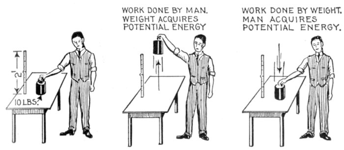
Figs. 1,355 to 1,357.—Mechanical analogy of wattless current. If a man lift a weight any
distance, as from the position of fig. 1,355 to position of fig. 1,356, he does a certain
amount of work on the weight giving it potential energy. When he lowers it to its
original position, as in fig. 1,357, the weight loses the potential energy previously
acquired, that is, it is given back to the man, the "system" (man and weight) having
returned to its original condition as in fig. 1,355. During such a cycle, the work done by
the man on the weight is equal to the work done by the weight on the man and no useful
external work has been accomplished.
Why the Power Factor is equal to Cos φ.—In the preceding
figures showing power curves for various phase relations
between current and pressure, the curves show the instantaneous
values of the fluctuating power, but what is of more importance,
is to determine the average power developed.
[Pg 1114]
When the current is in phase with the pressure, it is a simple
matter, because the power or
watts = amperes × volts
that is, the product of the ammeter and voltmeter readings will
give the power. However, the condition of synchronism of
current and pressure hardly ever exists in practice, there being
more or less phase difference.
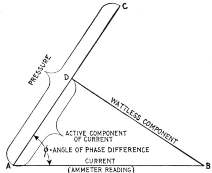
Fig. 1,358.—Method of obtaining the active component of the current; diagram illustrating why
the power factor is equal to cos φ. If AB and AC be respectively the given current
and pressure, or readings of the ammeter and voltmeter, and φ the angle of phase
difference between current and pressure, then drawing from B, BD perpendicular to AC
will give AD the active component. Now, true power = AC × AD, but AD = AB cos φ,
hence true power = AC × AB cos φ. Again, apparent power = AC × AB, and since
true power = apparent power × power factor, the power factor = cos φ.
When the current is not in phase with the pressure, it is considered
as made up of two components at right angles to each other.
1. The active component, in phase with the pressure;
2. The wattless component, at right angles to the pressure.
With phase difference between current and pressure the
product of ammeter and voltmeter readings do not give the true[Pg 1115]
power, and in order to obtain the latter, the active component
of the current in phase with the pressure must be considered,
that is,
true power = volts × active amperes (1)
The active component of the current is easily obtained graphically as
in fig. 1,358.
With any convenient scale draw AB equal to the current as given
or read on the ammeter, and AC, equal to the pressure, making the
angle φ between AB and AC equal to the phase difference between the
current and pressure.
From B, draw the line BD perpendicular to AC, then BD will be the
wattless component, and AD (measured with the same scale as was used
for AB) the active component of the current, or that component in
phase with the pressure.
Hence from equation (1)
true power = AC × AD (2)
Now in the right triangle ABD
from which
AD = AB cos φ (3)
Substituting this value of AD in equation (2) gives
true power = AC × AB cos φ (4)
Now the power factor may be defined as: that quantity by
which the apparent watts must be multiplied in order to give the
true power. That is
true power = apparent watts × power factor (5)
Comparing equations (4) and (5), AC × AB in (4) is equal to
the apparent watts, hence, the power factor in (5) is equal to
cos φ. That is, the power factor is numerically equal to the cosine
of the angle of phase difference between current and pressure.
[Pg 1116]
EXAMPLE I.—An alternator supplies a current of 200 amperes at a
pressure of 1,000 volts. If the phase difference between the current
and pressure be 30°, what is the true power developed?
In fig. 1,359, draw AB to scale, equal to 200 amperes, and draw AC
of indefinite length making an angle of 30° with AB. From B, draw
BD perpendicular to AC which gives AD, the active component, and
which measured with the same scale as was used in laying off AB, measures
173.2 amperes. The true power developed then is
true watts = 173.2 × 1,000 = 173.2 kw.
The true power may be calculated thus:
From the table cos 30° = .866, hence
true watts = 200 × 1,000 × .866 = 173.2 kw.
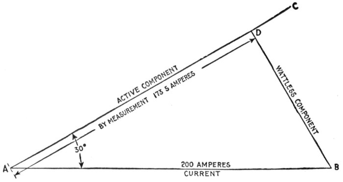
Fig. 1,359.—Diagram for obtaining the active component of the current in a circuit having
a current of 200 amperes and angle of lag of 30°.
EXAMPLE II.—If in an alternating current circuit, the voltmeter
and ammeter readings be 110 and 20 and the angle of lag 45°, what is
the apparent power and true power?
The apparent power is simply the product of the current and pressure
readings or
apparent power = 20 × 110 = 2,200 watts
The true power is the product of the apparent power multiplied by
the cosine of the angle of lag. Cos 45° = .707, hence
true power = 2,200 × .707 = 1,555.4 watts.
[Pg 1117]
Ques. Does the power factor apply to capacity reactance
in the same way as to inductance reactance?
Ans. Yes. The angles of lag and of lead, are from the
practical standpoint, treated as if they lay in the first quadrant
of the circle. Even the negative sign of the tangent φ when it
occurs is simply used to determine whether the angle be one of
lag or of lead, but in finding the value of the angle from a table
it is treated as a positive quantity.
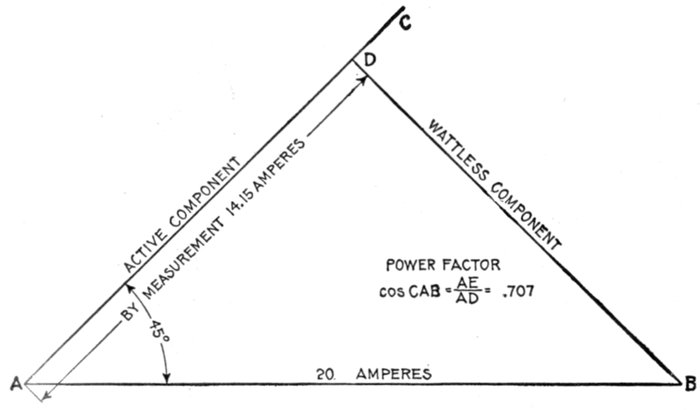
Fig. 1,360.—Diagram for obtaining the power factor for example II. With convenient scale,
lay off AB = 20 amperes. From A draw AC at 45° to AB, and from B, draw BD perpendicular
to AC. Then, the power factor which is equal to cosine of angle of lag, = AD ÷
AB = (by measurement) 14.15 ÷ 20 = .707.
Ques. In introducing capacity into a circuit to increase
the power factor what should be considered?
Ans. The cost and upkeep of the added apparatus as well
as the power lost in same.
[Pg 1118]
Ques. How is power lost in a condenser?
Ans. The loss is principally due to a phenomenon known as
dielectric hysteresis, which is somewhat analogous to magnetic
hysteresis. The rapidly alternating charges in a condenser placed
in an alternating circuit may be said to cause alternating polarization
of the dielectric, and consequent heating and loss of energy.
Ques. When is inductance introduced into a circuit
to increase the power factor?
Ans. When the phase difference is due to an excess of capacity.
EXAMPLE.—A circuit having a resistance of 3 ohms, and a resultant
reactance of 4 ohms, is connected to a 100 volt line. What is: 1, the
impedance, 2, the current, 3, the apparent power, 4, the angle of lag,
5, the power factor, and 6, the true power?
1. The impedance of the circuit.
2. The current.
current = volts ÷ impedance = 100 ÷ 5 = 20 amperes.
3. The apparent power.
apparent power = volts × amperes = 100 × 20 = 2,000 watts.
4. The tangent of the angle of lag.
tan φ = reactance ÷ resistance = 4 ÷ 3 = 1.33. From
table of natural tangents (page 451) φ = 53°.
5. The power factor.
The power factor is equal to the cosine of the angle of lag,
that is, power factor = cos 53° = .602 (from table).
6. The true power.
The true power is equal to the apparent watts multiplied by
the power factor, or
Ques. Prove that the power factor is unity when there
is no resultant reactance in a circuit.
Ans. When there is no reactance, tan φ which is equal to
reactance ÷ resistance becomes 0 ÷ R = 0. The angle φ[Pg 1119]
(the phase difference angle) whose tangent is 0 is the angle of
0 degrees. Hence, the power factor which is equal to cos φ =
cos 0° = 1.
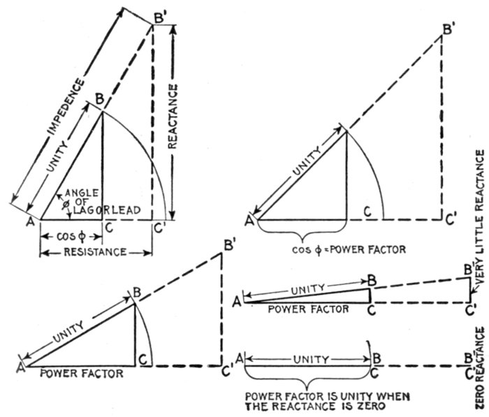
Figs. 1,361 to 1,365.—Diagrams illustrating why the power factor is unity or one when there
is no resultant reactance in the circuit, that is, when the circuit is resonant or has only
resistance. The power factor is equal to the cosine of the angle of lag (or lead). In the
figures this angle is BAC or φ and the value of the natural cosine AC gives the power
factor. By inspection of the figures, it is evident that decreasing the reactance decreases
the angle φ and increases cos φ or the power factor. The circular arc in each figure being
at unity distance from the center A, the power factor with decreasing reactance evidently
approaches unity as its limit, this limit being shown in fig. 1,365 where the reactance
B'C' = 0.
Ques. What is the usual value of the power factor in
practice?
Ans. Slightly less than one.
[Pg 1120]
Ques. Why is it desirable to keep the power factor
near unity?
Ans. Because with a low power factor, while the alternator
may be carrying its full load and operating at a moderate temperature,
the consumer is paying only for the actual watts which
are sent over the line to him.
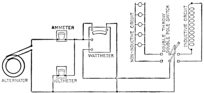
Fig. 1,366.—Diagram illustrating power factor test, when on non-inductive and inductive
circuits. The instruments are connected as shown and by means of the double throw
switch can be put on either the non-inductive or inductive circuit. First turn switch to
left so that current passes through the lamps; for illustration, the following readings are
assumed: ammeter 10, voltmeter 110, and wattmeter 1,100. The power factor then is
wattmeter reading ÷ volts × amperes = 1,100 actual watts ÷ 1,100 apparent watts = 1,
that is, on non-inductive circuit the power factor is unity. Now throwing the switch to the
right connecting instruments with the inductive circuits, then for illustration the following
readings may be assumed: ammeter 8, voltmeter 110, and wattmeter 684. Now, as
before, power factor = wattmeter reading ÷ volts × amperes = 684 ÷ (8 × 110) = 684
÷ 880 = .78.
For instance, if a large alternator supplying 1,000 kilowatts at 6,600
volts in a town where a number of induction motors are used on the
line be operating with a power factor of say .625 during a great portion
of the time, the switchboard instruments connected to the alternator will
give the following readings:
Voltmeter 6,600 volts; ammeter 242.4 amperes; power factor meter .625.
The apparent watts would equal 1,600,000 watts or 1,600 kilowatts,
which, if multiplied by the power factor .625 would give 100,000,000 watts
or 1,000 kilowatts which is the actual watts supplied. The alternator
and line must carry 242.4 amperes instead of 151 amperes and the difference
242.4 - 151 = 91.4 amperes represents a wattless current flowing in
the circuit which causes useless heating of the alternator.
[Pg 1121]
The mechanical power which is required to drive the alternator is equivalent
to the actual watts produced, since that portion of the current which
lags, is out of phase with the pressure and therefore requires no energy.
Ques. How are alternators rated by manufacturers in
order to avoid disputes?
Ans. They usually rate their alternators as producing so
many kilovolt amperes instead of kilowatts.
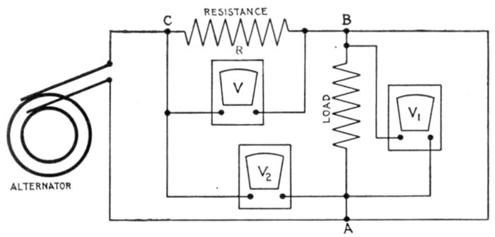
Fig. 1,367.—Ayrton and Sumpner method of alternating current power measurement. Three
voltmeters are required, and accordingly the method is sometimes called the three voltmeter
method. It is a good method where the voltage can be regulated to suit the load.
In the figure, let the non-inductive resistance R be placed in series with the load AB.
Measure the following voltages: V across the terminals of R, V1 across the load AB, and
V2 across both, that is from A to C. Then, true watts = (V22 - V12 - V2) ÷ 2R. The best
conditions are when V = V1, and, if R = ½ ohm, then W = V22 - V12 - V2.
Ques. What is a kilovolt ampere (kva)?
Ans. A unit of apparent power in an alternating current
circuit which is equal to one kilowatt when the power factor is
equal to one.
The machine mentioned on page 1,120 would be designed to carry 151
amperes without overheating and also carry slight overloads for short
periods. It would be rated as 6.6 kilo volts and 151 amperes which
would equal approximately 1,000 kilowatts when the power factor is
1 or unity, and it should operate without undue heating. Now the
lower the power factor becomes, the greater the heating trouble will
be in trying to produce the 1,000 actual kilowatts.
[Pg 1122]
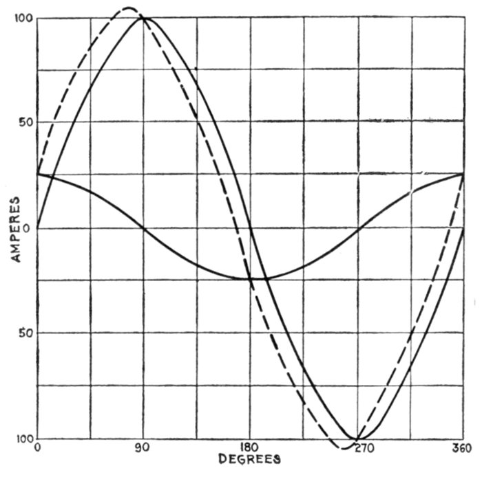
Fig. 1,368—Curves illustrating power factor. In a circuit having no capacity or inductance,
the power is given by the product of the respective readings of the voltmeter and ammeter,
as in the case of a direct current. In the case of a circuit having capacity or inductance,
this product is higher than the true value as found by a wattmeter, and is known as the
apparent watts. The ratio true watts ÷ apparent watts is known as the power factor. The
current flowing in an inductive circuit, such as the primary of a transformer, is really
made up of two components, as already explained, one of which (the load or active component),
is in phase with the pressure, while the other the magnetizing component, is at
right angles to it, that is, it attains its crest value when the other is at zero, and vice
versa. To illustrate, take a complete cycle divided into 360 degrees and lay out on it
the current required to correspond to a given load on the secondary of a transformer,
say a crest value of 100 amperes, and at right angles to this lay out the current required
for exciting the magnetic circuit of the transformer, giving A, merely for purposes of
illustration, a crest value of 25 amperes. Combining these curves, the dotted curve in
the figure is obtained and which represents the resultant current that would be indicated
by an ammeter placed in the primary circuit of the transformer. It will be noted that this
current attains its maximum at a point 14° 2´ later than the load current, giving the angle
of lag. Multiplying the apparent watts by the cosine of the angle of lag gives the true watts.
Now assuming the diagram to show the full load condition of the transformer, the angle
of lag being 14° 2´, the power factor at full load is .97 (.97 being the value of the natural
cosine of 14° 2´ as obtained from table, such as on page 451). With no external load on
the transformer, the load component of the current is that necessary to make up the core
losses. For instance, at 5 amperes, while the magnetizing current remains as before at
25 amperes, the angle of lag becomes 78° 41´ and the power factor .196. It is thus seen
that in transformers, induction motors, etc., the power factor is a function of the load.
[Pg 1123]
Ques. How can the power factor be kept high?
Ans. By carefully designing the motors and other apparatus
and even making changes in the field current of motors which
are already installed.
Ques. How is the power factor determined in station
operation?
Ans. Not by calculation, but by reading a meter which forms
one of the switchboard instruments.
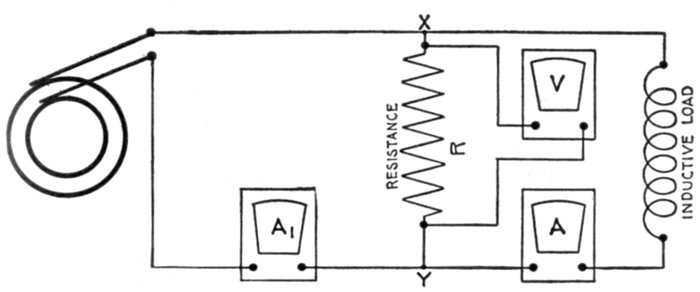
Fig. 1,368.—Fleming's combined voltmeter and ammeter method of measuring power in
alternating current circuits. It is quite accurate and enables instruments in use to be
checked. In the figure, R is a non-inductive resistance connected in shunt to the inductive
load. The voltmeter V measures the pressure across the resistance XY. A and A1 are ammeters
connected as shown. Then, true watts = (A12 - A2 - (V/R)2) × R / 2. If the volt
meter V take an appreciable amount of current, it may be tested as follows: disconnect
R and V at Y, and see that A and A1 are alike; then connect R and V at Y again, and
disconnect the load. A1 will equal current taken by R and V in parallel.
Ques. When is the power factor meter of importance
in station operation, and why?
Ans. When rotary converters are used on alternating current
lines for supplying direct currents and the sub-station operators
are kept busy adjusting the field rheostat of the rotary to maintain
a high power factor and prevent overheating of the alternators
during the time of day when there is the maximum demand
for current or the peak of the load.
[Pg 1124]
EXAMPLE.—An alternator delivers current at 800 volts pressure at
a frequency of 60, to a circuit of which the resistance is 75 ohms
and .25 henry.
Determine: a, the value of the current, b, angle of lag, c, apparent
watts, d, power factor, e, true power.
a. Value of current
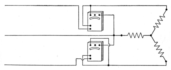
Fig. 1,369.—Wattmeter method of three phase power measurement. Two wattmeters are
required in unbalanced systems as shown in the illustration. The total power transmitted
is then the algebraic sum of the readings of the two wattmeters. If the power
factor be greater than .5, the power is the arithmetical sum, and if it be less than .5, the
power is the arithmetical difference of the readings.
[Pg 1125]
CHAPTER XLIX
ALTERNATORS
Use of Alternators.—The great increase in the application
of electricity for supplying power and for lighting purposes in
industry, commerce, and in the home, is due chiefly to the
economy of distribution of alternating current.
Direct current may be used to advantage in densely populated
districts, but where the load is scattered, it requires, on account
of its low voltage, too great an investment in distributing lines.
In such cases the alternator is used to advantage, for while commutators
can be built for collecting direct current up to 1,000
volts, alternators can be built up to 12,000 volts or more, and
this voltage increased, by step up transformers of high economy,
up to 75,000 or 100,000 volts. Since the copper cost is inversely
as the square of the voltage, the great advantage of alternating
current systems is clearly apparent.
The use of alternating current thus permits a large amount
of energy to be economically distributed over a wide area from
a single station, not only reducing the cost of the wiring, but
securing greater economy by the use of one large station, instead
of several small stations.
The higher voltages generated by alternators enables the transmission
of electrical energy to vastly greater distances than possible
by a direct current system, so that the energy from many
waterfalls that otherwise would go to waste may be utilized.
[Pg 1126]
Classes of Alternator.—There are various ways of classifying
alternators. They may be divided into groups, according to:
1, the nature of the current produced; 2, type of drive; 3,
method of construction; 4, field excitation; 5, service requirements,
etc.
From these several points of view, alternators then may be
classified:
1. With respect to the current, as:
- a. Single phase;
- b. Polyphase.
2. With respect to the type of drive, as:
- a. Belt or chain driven;
- b. Direct connected.
3. With respect to construction, as:
- a. Revolving armature;
- b. Revolving field;
- c. Inductor.
- Homopolar and heteropolar.
4. With respect to mode of field excitation, as:
- a. Self-exciting;
- b. Separately excited;
- Exciter direct connected, or gear driven.
- c. Compositely excited.
5. With respect to service requirements, as:
- a. Slow speed;
- b. Fly wheel;
- c. High speed;
- d. Water wheel type;
- e. Turbine driven.
[Pg 1127]
Single Phase Alternators.—As a general rule, when alternators
are employed for lighting circuits, the single phase machines
are preferable, as they are simpler in construction and
do not generate the unbalancing voltages often occurring in
polyphase work.
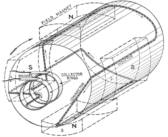
Fig. 1,370.—Elementary four pole single phase alternator. It has four "inductors" whose
pitch is the same as the pole pitch. They are connected in series and terminate at the
two collector rings as shown. The poles being alternate N and S, it is evident that there
will be two cycles of the current per revolution of the armature. For any number of
poles then the number of cycles equals the number of poles divided by two. Applying
Fleming's rule for induced currents, the direction of the current induced in the inductors
is easily found as indicated by the arrows. The field magnets are excited by coils supplied
with direct current, usually furnished from an external source; for simplicity this is not
shown. The magnets may be considered as of the permanent type.
Ques. What are the essential features of a single phase
alternator?
Ans. Fig. 1,370 shows an elementary single phase alternator.
It consists of an armature, with single phase winding, field[Pg 1128]
magnets, and two collector rings and brushes through which the
current generated in the armature passes to the external circuit.
Ques. In what respect do commercial machines differ
mostly from the elementary alternator shown in fig.
1,370, and why?
Ans. They have a large number of poles and inductors in
order to obtain the desired frequency, without excessive speed,
and electromagnets instead of permanent magnets.
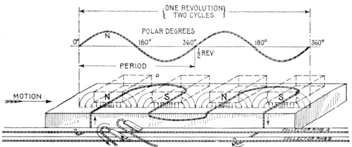
Fig. 1,371.—Developed view of elementary single phase four pole alternator and sine curve
showing the alternating current or pressure generated during one revolution. The armature
is here shown as a flat surface upon which a complete view of the winding is seen.
If M be any position of an inductor, by projecting up to the curve gives N, the corresponding
value of the current or pressure. Magnetic lines are shown at the poles representing
a field decreasing in intensity from a maximum at the center to zero at points half way
between the poles, this being the field condition corresponding to the sine form of wave.
In actual machines the variation from the sine curve is considerable in some alternators.
See figs. 1,247 and 1,248.
Ques. In actual machines, why must the magnet cores
be spaced out around the armature with considerable
distance between them?
Ans. In order to get the necessary field winding on the cores,
and also to prevent undue magnetic leakage taking place, laterally
from one limb to the next of opposite sign.
[Pg 1129]
Ques. Is there any gain in making the width of the
armature coils any greater than the pole pitch, and why?
Ans. No, because any additional width will not produce
more voltage, but on the contrary will increase the resistance
and inductance of the armature.

Fig. 1,372.—Elementary four pole two phase alternator. The winding consists of one inductor
per phase per pole, that is, four inductors per phase, the inductors of each phase being
connected in series by the "connectors" and terminating at the collector rings. This
arrangement requires four collector rings, giving two independent circuits. The pitch of
the inductors of each phase is equal to the pole pitch, and the phase difference is equal to
one-half the pole pitch, that is, phase B winding begins at B, a point half-way between
inductors A and A' of phase A winding. Hence when the current or pressure in phase A
is at a maximum, in the ideal case, when inductor A for instance is under the center of a
pole, the current or pressure in B is zero, because B is then half-way between the poles.
Polyphase Alternators.—A multiphase or polyphase alternator
is one which delivers two or more alternating currents
differing in phase by a definite amount.
[Pg 1130]
For example, if two armatures of the same number of turns each be
connected to a shaft at 90 degrees from each other and revolved in a
bipolar field, and each terminal be connected to a collector ring, two
separate alternating currents, differing in phase by 90 degrees, will be
delivered to the external circuit. Thus a two phase alternator will
deliver two currents differing in phase by one-quarter of a cycle, and
similarly a three phase alternator (the three armatures of which are
set 120 degrees from each other) will deliver three currents differing in
phase by one-third of a cycle.
In practice, instead of separate armatures for each phase, the several
windings are all placed on one armature and in such sequence that the
currents are generated with the desired phase difference between them
as shown in the elementary diagrams 1,372 and 1,373 for two phase
current, and figs. 1,374 and 1,375 for three phase current.
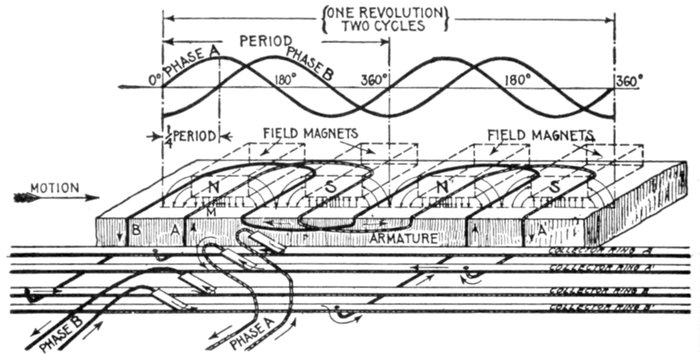
Fig. 1,373.—Developed view of elementary two phase four pole alternator and sine curves,
showing the alternating current or pressure generated during one revolution of the armature.
The complete winding for the three phases are here visible, the field magnets being
represented as transparent so that all of the inductors may be seen. By applying Fleming's
rule, as the inductors progress under the poles, the directions and reversals of current
are easily determined, as indicated by the sine curves. It will be seen from the curves
that four poles give two cycles per revolution. Inductors A, and B are lettered to
correspond with fig. 1,372, with which they should be compared.
Ques. What use is made of two and three phase
current?
Ans. They are employed rather for power purposes than for
lighting, but such systems are often installed for both services.
[Pg 1131]
Ques. How are they employed in each case?
Ans. For lighting purposes the phases are isolated in separate
circuits, that is, each is used as a single phase current. For
driving motors the circuits are combined.
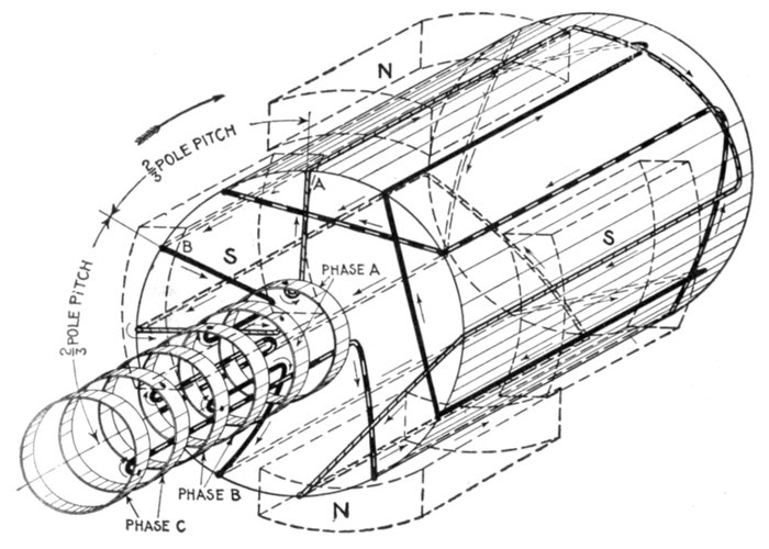
Fig. 1,374.—Elementary four pole three phase alternator. There are three sets of inductors,
each set connected in series and spaced on the drum with respect to each other two-thirds
pole pitch apart. As shown, six collector rings are used, but on actual three phase machines
only three rings are employed, as previously explained. The inductors have distinctive
coverings for the different phases. The arrows indicate the direction in which the induced
pressures tend to cause currents.
Ques. Why are they combined for power purposes?
Ans. On account of the difficulty encountered in starting
a motor with single phase current.
Ferarris, of Italy, in 1888 discovered the important principle of the
production of a rotating magnetic field by means of two or more
[Pg 1132]
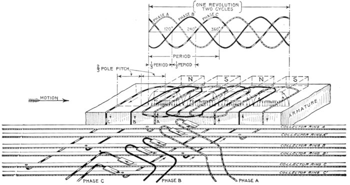
Fig. 1,375.—Elementary four pole three-phase alternator and sine curves showing current or pressure conditions for one revolution.
Six collector rings are shown giving three independent circuits. The pitch of the inductors for each phase is the same as
the pole pitch, and the phase difference is equal to two-thirds of the pole pitch, giving the sequence of current or pressure
waves as indicated by the sine curves. The waves follow each other at ⅓ period, that is, the phase difference is 120 degrees.
Inductors A, B, and C, the beginning of each phase winding, are lettered to correspond with fig. 1,374, with which they
should be compared.
[Pg 1133]
alternating currents displaced in phase from one another, and he thus
made possible by means of the induction motor, the use of polyphase
currents for power purposes.
Ques. What is the difficulty encountered in starting a
motor with single phase current?
Ans. A single phase current requires either a synchronous
motor to develop mechanical power from it, or a specially constructed
motor of dual type, the idea of which is to provide a
method of getting rotation by foreign means and then to throw
in the single phase current for power.
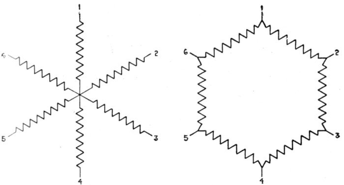
Fig. 1,376.—Diagram of six phase winding with star grouping, being equivalent to a three
phase winding in which the three phases are disconnected from each other and their
middle points united at a common junction.
Fig. 1,377.—Diagram of six phase winding with mesh grouping.
Six Phase and Twelve Phase Windings.—These are
required for the operation of rotary converters. The phase
difference in a six phase winding is 60 degrees and in a twelve[Pg 1134]
phase winding 30 degrees. A six phase winding can be made
out of a three phase winding by disconnecting the three phases
from each other, uniting their middle points at a common junction,
as shown by diagram fig. 1,376. This will give a star
grouping with six terminals.
In the case of a mesh grouping, each of the three phases must
be cut into two parts and then reconnected as shown in fig.
1,377.
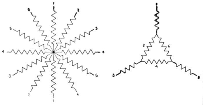
Fig. 1,378.—Diagram of twelve phase
winding star grouping.
Fig. 1,379.—Diagram of six phase
winding consisting of combination of
mesh and star grouping.
As the phase difference of a twelve phase winding is one-half
that of a six phase winding, the twelve phases may be regarded
as a star grouping of six pairs crossed at the middle point of each
pair as shown in fig. 1,378, or in mesh grouping for converters
they may be arranged as a twelve pointed polygon. They may
also be grouped as a combination of mesh and star as shown in
fig. 1,379, which, however, is not of general interest.
[Pg 1135]
Belt or Chain Driven Alternators.—The mode in which
power is transmitted to an alternator for the generation of current
is governed chiefly by conditions met with where the
machine is to be installed.
In many small power stations and isolated plants the use of
a belt drive is unavoidable. In some cases the prime mover
is already installed and cannot be conveniently arranged for
direct connection, in others the advantage to be gained by an
increase in speed more than compensates for the loss involved
in belt transmission.
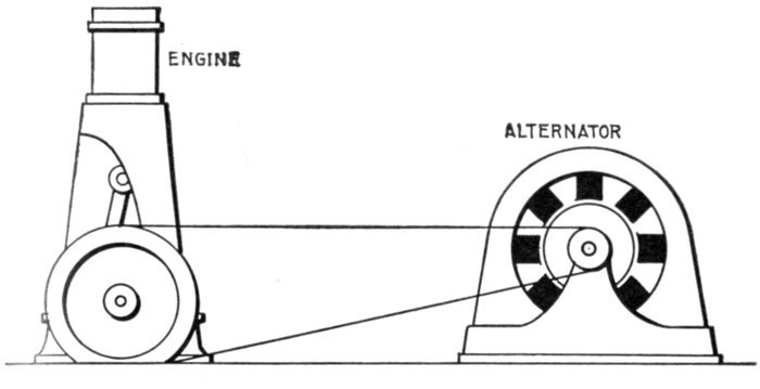
Fig. 1,380.—Belt-driven alternator. By use of a belt, any desired speed ratio is obtained,
enabling the use of a high speed alternator which, being smaller than one of slow speed, is
cheaper. It affords means of drive for line shaft and has other advantages, but requires
considerable space and is not a "positive" drive. Belting exerts a side pull which results
in friction and wear of bearings. Means for tightening the belt as shown in fig. 1,381,
or equivalent, must be provided.
There are many places where belted machines may be used
advantageously and economically. They are easily connected
to an existing source of power, as, for instance, a line shaft used
for driving other machinery, and for comparatively small installations
they are lower in first cost than direct connected[Pg 1136]
machines. Moreover, when connected to line shaft they are
run by the main engine which as a rule is more efficient than
a small engine direct connected.
Where there is sufficient room between pulley centers, a belt
is a satisfactory medium for power transmission, and one that
is largely used. It is important that there be liberal distance
between centers, especially in the case of generators or motors
belted to a medium or slow speed engine, because, owing to the
high speed of rotation of the electric machines, there is
considerable difference in their pulley diameters and the drive
pulley diameter; hence, if they were close together, the arc of
contact of the belt with the smaller pulley would be appreciably
reduced, thus diminishing the tractive power of the belt.
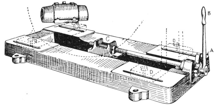
Fig. 1,381.—Sub-base and ratchet device for moving alternator to tighten belt. A ratchet A,
operated by lever B, works the block C by screw connection, causing it to move the block.
The latter, engaging with the frame, causes it to move, thus providing adjustment for belt.
After tightening belt, the bolts D, which pass through the slots in the sub-base, are tightened,
thus securing the machine firmly in position.
Ques. What provision should be made in the design of
an alternator to adapt it to belt drive?
Ans. Provision should be made for tightening the belt.
[Pg 1137]
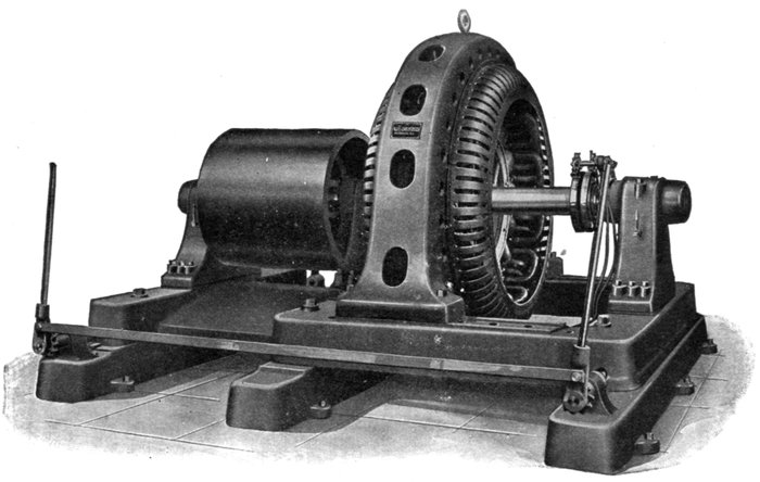
Fig. 1,382.—Allis-Chalmers pedestal type, belted alternator. The bearings are of the ring oiling form with large oil reservoirs.
The bearings have spherical seats and are self aligning.
[Pg 1138]
Ques. How is this done?
Ans. Sometimes by an idler pulley, but usually by mounting
the machine on a sub-base provided with slide rails, as in fig.
1,381, the belt being tightened by use of a ratchet screw which
moves the machine along the base.
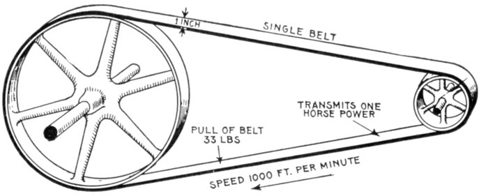
Fig. 1,383.—Diagram illustrating rule for horse power transmitted by belts. A single belt
travelling at a speed of 1,000 feet per minute will transmit one horse power; a double belt will
transmit twice that amount, assuming that the thickness of a double belt is twice that of a
single belt. This is conservative practice, and a belt so proportioned will do the work
in practically all cases. The above rule corresponds to a pull of 33 lbs. per inch of width.
Many designers proportion single belts for a pull of 45 lbs. For double belts of average
thickness, some writers say that the transmitting efficiency is to that of single belts as
10 is to 7. This should not be applied to the above rule for single belts, as it will give an
unnecessarily large belt.
Ques. Give a rule for obtaining the proper size of belt
to deliver a given horse power.
Ans. A single belt travelling at a speed of one thousand feet
per minute will transmit one horse power; a double belt will transmit
twice that amount.
This corresponds to a working strain of 33 lbs. per inch of width for
single belt, or 66 lbs. for double belt.
Many writers give as safe practice for single belts in good condition
a working tension of 45 lbs. per inch of width.
[Pg 1139]
Ques. What is the best speed for maximum belt
economy?
Ans. From 4,000 to 4,500 feet per minute.
EXAMPLE.—What is the proper size of double belt for an alternator
having a 16 inch pulley, and which requires 50 horse power to drive it
at 1,000 revolutions per minute full load?
The velocity of the belt is
Horse power transmitted per inch width of double belt at 4,188 feet
speed
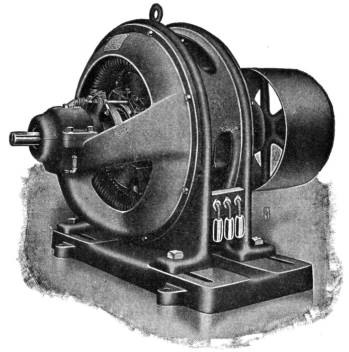
Fig. 1,384.—Fort Wayne revolving field belt driven alternator. It is designed for belted
exciter, having a shaft extension at the collector ring end for exciter driving pulley.
[Pg 1140]
Width of double belt for 50 horse power
50 ÷ 8.38 = 5.97, say 6 inch.
Ques. What are the advantages of chain drive?
Ans. The space required is much less than with belt drive,
as the distance between centers may be reduced to a minimum.
It is a positive drive, that is, there can be no slip. Less liability
of becoming detached, and, because it is not dependent on
frictional contact, the diameters of the sprockets may be much
less than pulley diameter for belt drive.
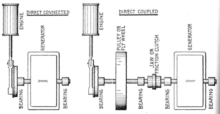
Figs. 1,385 and 1,386.—Diagram showing the distinction between direct connected and direct
coupled units. In a direct connected unit, fig. 1,385, the engine and generator are permanently
connected on one shaft, there being one bed plate upon which both are mounted.
An engine and generator are said to be direct coupled when each is independent, as in fig.
1,386 being connected solely by a jaw or friction clutch or equivalent at times when it is
desired to run the generator. At other times the generator may be disconnected and the
engine run to supply power for other purposes.
Ques. What are some objections?
Ans. A lubricant is required for satisfactory operation, which
causes more or less dirt to collect on the chain, requiring[Pg 1141]
frequent cleaning; climbing of teeth when links and teeth become
worn; noise and friction.
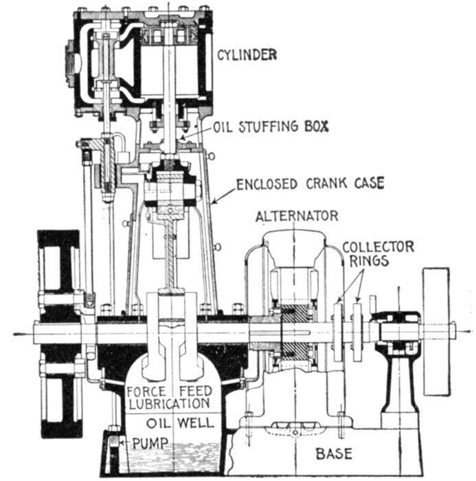
Fig. 1,387.—Engberg direct connected, or "engine type" alternator. In many places direct
connected units are used, owing to the great saving in floor space, convenience of operation,
and absence of belts.
Direct Connected Alternators.—There are a large number
of cases where economy of space is of prime importance, and to
meet this condition the alternator and engine are direct connected,
meaning, that there is no intermediate gearing such as
belt, chain, etc., between engine and alternator.
One difficulty encountered in the direct connection of engine and
alternator is the fact that the most desirable rotative speed of the engine
is less than that of the alternator. Accordingly a compromise is made
by raising the engine speed and lowering the alternator speed.
[Pg 1142]
The insistent demand for direct connected units in the small and
medium sizes, especially for direct current units, was the chief cause
resulting in the rapid and high development of what is known as the
"high speed automatic engine."
Increasing the engine speed means that more horse power is developed
for any given cylinder dimensions, while reducing the speed of the
generator involves that the machine must be larger for a given output,
and in the case of an alternator more poles are required to obtain a
given frequency, resulting in increased cost.
The compactness of the unit as a whole, simplicity, and general
advantages are usually so great as to more than offset any additional
cost of the generator.
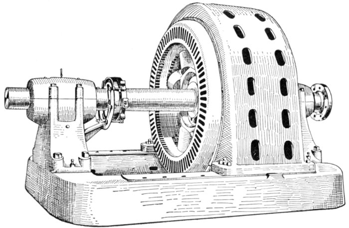
Fig. 1,388.—Crocker-Wheeler 2,000 kva. 2,400 volt coupled type alternator. The coupled
type of alternator is desirable for use with steam, gas, and oil engines, and water wheels
where it is inconvenient to mount the alternator on the engine shaft or to extend the
engine base to accommodate a bearing. This type consists of alternator complete with
shaft and bearings similar to belt type machines, but with bearings not necessary designed
for the side pull of belts.
Ques. What is the difference between a direct connected
and a direct coupled unit?
Ans. A direct connected unit comprises an engine and
generator permanently connected; direct coupling signifies that[Pg 1143]
engine and generator are each complete in itself, that is, having
two bearings, and are connected by some device such as friction
clutch, jaw clutch, or shaft coupling.
Revolving Armature Alternators.—This type of alternator
is one which has its parts arranged in a manner similar to a
dynamo, that is, the armature is mounted on a shaft so it can
revolve while the field magnets are attached to a circular frame
and arranged radially around the armature, as shown in fig.
1,389. It may be single or polyphase, belt driven, or direct
connected.
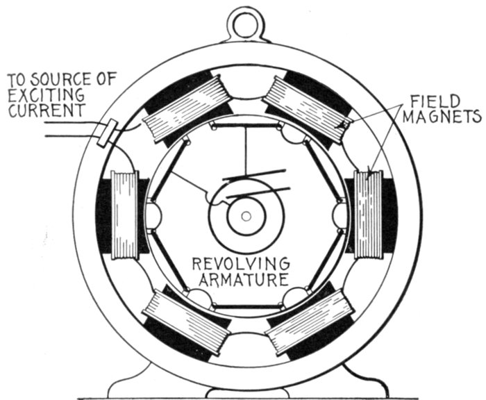
Fig. 1,389.—Revolving armature alternator. Revolving armatures are suitable for machines
generating current at comparatively low pressure, as no difficulty is experienced in collecting
such current. Revolving armature alternators are also suitable for small power
plants, isolated lighting plants, where medium or small size machines are required.
[Pg 1144]
Ques. When is the revolving type of armature used
and why?
Ans. It is used on machines of small size because the pressure
generated is comparatively low and the current transmitted
by the brushes small, no difficulty being experienced in collecting
such a current.
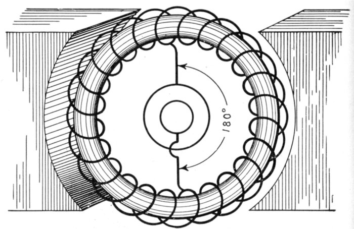
Fig. 1,390.—Ring wound dynamo arranged as alternator by replacing commutator with
collector rings connected to the winding at points 180° apart.
Ques. Could a dynamo be converted into an alternator?
Ans. Yes.
Ques. How can this be done?
Ans. By placing two collector rings on one end of the armature
and connecting these two rings to points in the armature
winding 180° apart, as shown in fig. 1,390.
[Pg 1145]
Ques. Would such arrangement as shown in fig. 1,390
make a desirable alternator?
Ans. No.
Alternating current windings are usually different from those used for
direct currents. One distinction is the fact that a simple open coil
winding may be, and often is, employed, but the chief difference is the
intermittent action of the inductors.
In a direct current Gramme ring winding a certain number of coils are
always active, while those in the space
between the pole pieces are not generating.
In this way a practically
steady pressure is produced by a large
fraction of the coils.
In the case of an alternator all of
the coils are either active or inactive
at one time. Hence, the winding
need cover only as much of the armature
as is covered by the pole pieces.
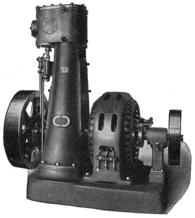
Fig. 1,391.—Engberg alternating current generating set; shown also in cross section in fig.
1,387. The set comprises a vertical engine and alternator, direct connected and placed
on one base. The lubrication system comprises an oil pump situated in the base of the
engine, pumping the oil from an oil reservoir up into a sight feed oil cup which leads to a
distributing oil trough on the inside of the engine frame, from here oil pipes lead to all
movable bearings, which are grooved to insure proper distribution of oil. The oil is
drained from bearings into the base, filtered and re-pumped. A water shed partition is
provided in the engine frame, preventing any water passing from the cylinder down into
the engine base and mixing with the oil, consequently leaving good, clean oil in the oil
reservoir at all times. The details of the lubrication system are shown in fig. 1,387.
[Pg 1146]
Revolving Field Alternators.—In generating an electric
current by causing an inductor to cut magnetic lines, it makes
no difference whether the cutting of the magnetic lines is effected
by moving an inductor across a magnetic field or moving the
magnetic field across the inductor.
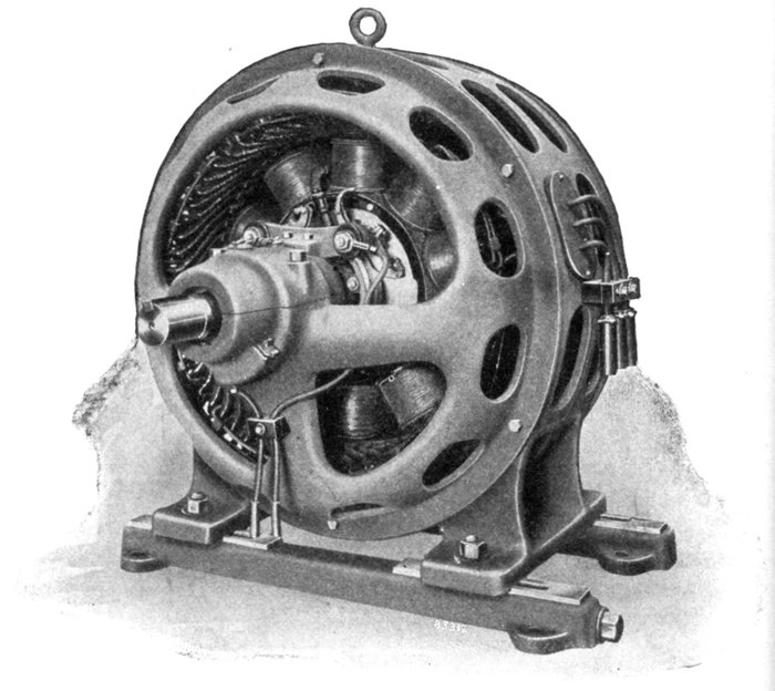
Fig. 1,392.—Allis-Chalmers revolving field self-contained belted type alternator.
Motion is purely a relative matter, that is, an object is
said to move when it changes its position with some other object
regarded as stationary; it may be moving with respect to a[Pg 1147]
second object, and at the same time be at rest with respect to
a third object. Thus, a dory has a speed of four miles per hour
in still water; if it be run up stream against a current flowing
four miles per hour it would move at that speed with respect
to the water, yet remain at rest with respect to the earth.
It must be evident then that motion, as stated, being a purely
relative matter, it makes no difference whether the armature
of a generator move with respect to the field magnets, or the
field magnets move with respect to the armature, so far as inducing
an electric current is concerned.
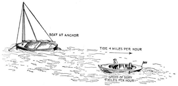
Fig. 1,393.—Marine view, showing that motion is purely a relative matter. In order that
there may be motion something must be regarded as being stationary. In the above illustration
a catboat is shown at anchor in a stream which is flowing at a rate of four miles
per hour in the direction of the arrow. The small dory running at a speed of four miles
per hour against the current is moving at that velocity relative to the current, yet is at a
standstill relative to the catboat. In this instance both catboat and dory are moving
with respect to the water if the latter be regarded as stationary. Again if the earth be
regarded as being stationary, the two boats are at rest and the water is moving relative
to the earth.
For alternators of medium and large size there are several
reasons why the armature should be stationary and the field
magnets revolve, as follows:
[Pg 1148]
1. By making the armature stationary, superior insulation
methods may be employed, enabling the generation of current
at very much higher voltage than in the revolving armature type.
2. Because the difficulty of taking current at very high pressures
from collector rings is avoided.
The field current only passes through the collector rings. Since the
field current is of low voltage and small in comparison with the main
current, small brushes are sufficient and sparking troubles are avoided.
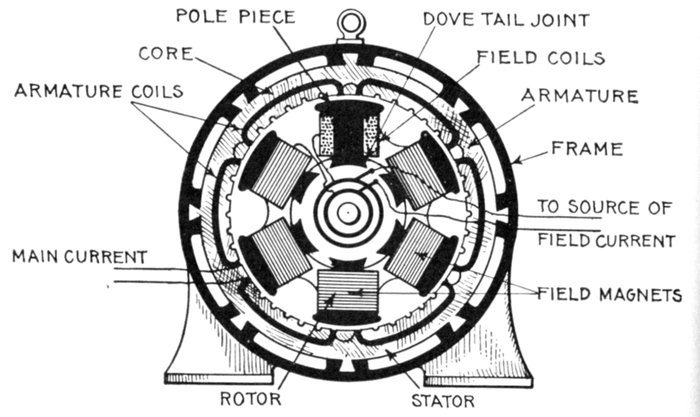
Fig. 1,394.—Diagram showing essential parts of a revolving field alternator and method of
joining the parts in assembling.
3. Only two collector rings are required.
4. The armature terminals, being stationary, may be enclosed
permanently so that no one can come in contact with them.
Ques. What names are usually applied to the armature
and field magnets with respect to which moves?
Ans. The "stator" and the "rotor."
[Pg 1149]
The terms armature and field magnets are to be preferred to such
expressions. An armature is an armature, no matter whether it move
or be fixed, and the same applies to the field magnets. There is no
good reason to apply other terms which do not define the parts.
Ques. Explain the
essential features of
a revolving field alternator.
Ans. The construction
of such alternators
is indicated in the
diagram, fig. 1,394.
Attached to the shaft
is a field core, which
carries the latter, consisting
of field coils
fitted on pole pieces
which are dovetailed
to the field core. The
armature is built into
the frame and surrounds
the magnets as
shown. The field current,
which is transmitted
to the magnets
by slip rings and
brushes, consists
of direct current
of comparatively low
pressure, obtained
from some external
source.
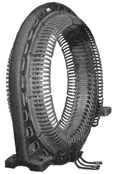
Fig. 1,395.—Western Electric stationary armature and
frame of engine driven alternator. It is of cast iron
and surrounds the laminated iron core in which the
armature windings are embedded. Heavy steel clamping
fingers hold the core punchings in place and numerous
ventilating ducts are provided in the core at
frequent intervals to allow free circulation of cool air.
The armature coils are form wound, insulated, and
retained in the core slots by means of wedges.
[Pg 1150]
Inductor Alternators.—In this class of alternator both
armature and field magnets are stationary, a current being
induced in the armature winding by the action of a so called
inductor in moving through the magnetic field so as to periodically
vary its intensity.
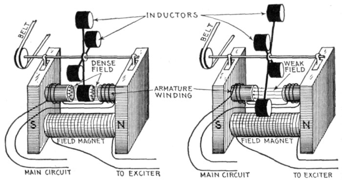
Figs. 1,396 and 1,397.—Elementary inductor alternator; diagram showing principle of
operation. It consists of a field magnet, at the polar extremities of which is an armature
winding both being stationary as shown. Inductors consisting of iron discs are arranged
on a shaft to rotate through the air gap of the magnet poles. Now in the rotation of the
inductors, when any one of them passes through the air gap as in fig. 1,396, the reluctance or
magnetic resistance of the air gap is greatly reduced, which causes a corresponding increase
in the number of magnetic lines passing through the armature winding. Again as
an inductor passes out of the air gap as in fig. 1,397, the number of magnetic lines is greatly
reduced; that is, when an inductor is in the air gap, the magnetic field is dense, and when
no inductor is in the gap, the field is weak; a variable flux is thus made to pass through the
armature winding, inducing current therein. The essential feature of the inductor alternator
is that iron only is revolving, and as the design is usually homopolar, the magnetic
flux in its field coils is not alternating, but undulating in character. Thus, with a given
maximum flux through each polar mass, the total number of armature turns required to
produce a given voltage is just twice that which is required in an alternator having an
alternating instead of an undulating flux through its field windings. The above and the
one shown in figs. 1,398 and 1,399 are examples of real inductor alternators, those shown in
the other cuts are simply so called inductor alternators, the distinction being that, as above,
the inductor constitutes no part of the field magnet.
Ques. What influence have the inductors on the field
flux?
Ans. They cause it to undulate; that is, the flux rises to a
maximum and falls to a minimum value, but does not reverse.
[Pg 1151]
Ques. How does this affect the design of the machine
as compared with other types of alternator?
Ans. With a given maximum magnetic flux through each
polar mass, the total number of armature turns necessary to
produce a given pressure is twice that which is required in an
alternator having an alternating flux through its armature
windings.
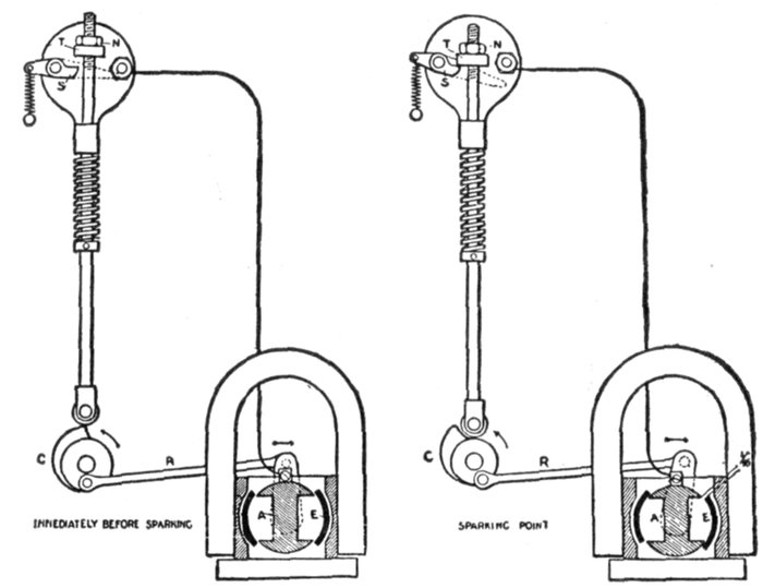
Figs. 1,398 and 1,399.—A low tension ignition system with an inductor magneto of the oscillating
type. The inductor E is rotated to and fro by means of a link R, one end of which
is attached to the inductor crank, and the other to the igniter cam C. Two views are
shown: immediately before and after sparking. S is the grounded electrode of the igniter;
T an adjustable hammer which is secured in position by a lock nut N.
Ques. Is the disadvantage due to the necessity of
doubling the number of armature turns compensated
in any way?
Ans. Yes, the magnetic flux is not reversed or entirely
changed in each cycle through the whole mass of iron in the[Pg 1152]
armature, the abrupt changes being largely confined to the
projections on the armature surface between the coils.
Ques. What benefit results from this peculiarity?
Ans. It enables the use of a very high magnetic flux density
in the armature without excessive core loss, and also the use of
a large flux without an excessive increase in the amount of
magnetic iron.
The use of a large flux permits a reduction in the number of armature
turns, thus compensating, more or less, for the disadvantage due to
the operation of only one-half of the armature coils at a time.
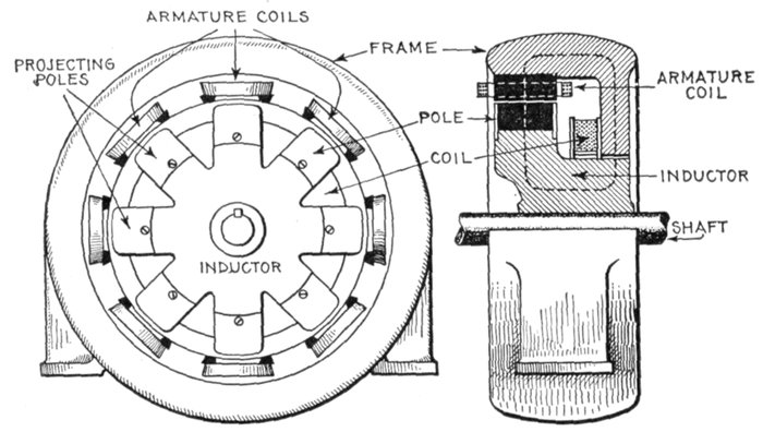
Figs. 1,400 and 1,401.—One form of inductor alternator. As shown, the frame carries the
stationary armature, which is of the slotted type. Inside of the armature is the revolving
inductor, provided with the projections built up of wrought iron or steel laminations.
The circular exciting coil is also stationary and encircles the inductor, thus setting up a
magnetic flux around the path indicated by the dotted line, fig. 1,401. The projecting
poles are all, therefore, of the same polarity, and as they revolve, the magnetic flux sweeps
over the coils. Although this arrangement does away with collector rings, the machines
are not so easily constructed as other types, especially in the large sizes. The magnetizing
coil becomes large and difficult to support in place, and would be hard to repair in
case of breakdown. Inductor alternators have become practically obsolete, except in
special cases, as inductor magnetos used for ignition and other purposes requiring a very
small size machine. The reasons for the type being displaced by other forms of alternator
are chiefly because only half as great a pressure is obtained by a flux of given amount,
as would be obtained in the ordinary type of machine. It is also more expensive to build
two armatures, to give the same power, than to build one armature. This type has still
other grave defects, among which may be mentioned enormous magnetic leakage, heavy
eddy current losses, inferior heat emissivity, and bad regulation.
[Pg 1153]
Classes of Inductor Alternator.—There are two classes
into which inductor alternators may be divided, based on the
mode of setting of their polar projections:
1. Homopolar machines;
2. Heteropolar machines.
Homopolar Inductor Alternators.—In this type the positive
polar projections of the inductors are set opposite the negative polar
projections as shown in fig. 1,402. When the polar projections are set
in this manner, the armature coils must be "staggered" or set displaced
along the circumference with respect to one another at a distance
equal to half the distance from the positive pole to the next positive pole.

Figs. 1,402 and 1,403.—Homopolar and heteropolar "inductors". Homopolar inductors have
their N and S poles opposite each other, while in the heteropolar type, they are "staggered"
as shown.
Heteropolar Inductor Alternators.—Machines of this class are
those in which the polar projections are themselves staggered, as shown
in fig. 1,403, and therefore, do not require the staggering of the armature
coils. In this case, a single armature of double width may be used, and
the rotating inductor then acts as a heteropolar magnet, or a magnet which
presents alternatively positive and negative poles to the armature,
instead of presenting a series of poles of the same polarity as in the case
of a homopolar magnet.
Use of Inductor Alternators.—Morday originally designed and
introduced inductor alternators in 1866. They are not the prevailing
type, as their field of application is comparatively narrow. They have
to be very carefully designed with regard to magnetic leakage in order[Pg 1154]
to prevent them being relatively too heavy and costly for their output,
and too defective with respect to their pressure regulation, other
defects being heavy eddy current losses and inferior heat conductance.
Hunting or Singing in Alternators.—Hunting is a term
applied to the state of two parallel connected alternators running
out of step, or not synchronously, that is, "see sawing." When
the current wave of an alternator is peaked and two machines
are operated in parallel it is very difficult to keep them in step,
that is in synchronism. Any difference in the phase relation
which is set up by the alternation will cause a local or synchronizing
current to flow between the two machines and at
times it becomes so great that they must be disconnected.
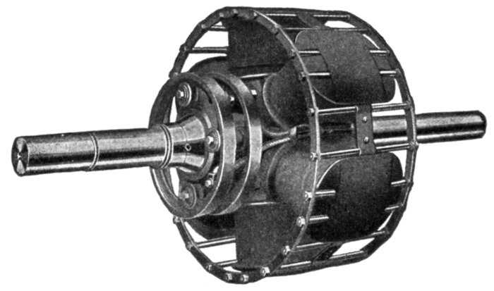
Fig. 1,404.—Revolving field of Fort Wayne alternator equipped with amortisseur winding.
The object of this winding is to check any tendency toward hunting when the alternator
is to be run as a synchronous motor, either for rotary condenser or power service. The
amortisseur winding consists of heavy copper bars, placed around and through the pole
faces and short circuited at the ends by heavy copper rings; it serves as a starting winding
to bring the rotor up to speed as an induction motor, and also serves as a damping
device to neutralize any tendency toward "hunting" caused by variation in speed of the
generator supplying the current.
Alternators which produce a smooth current wave and are
maintained at uniform speed by properly designed governors,[Pg 1155]
operate fairly well in parallel, but are not entirely free from
hunting, and other means are provided to overcome the difficulty.
When heavy copper flanges, called dampers, are put over the
polar projections or copper bars laid in grooves on the pole
face and short circuited by connecting rings (called amortisseur
winding), the powerful induced currents which are produced when
the alternators get out of step tend to quickly re-establish the
phase relation.
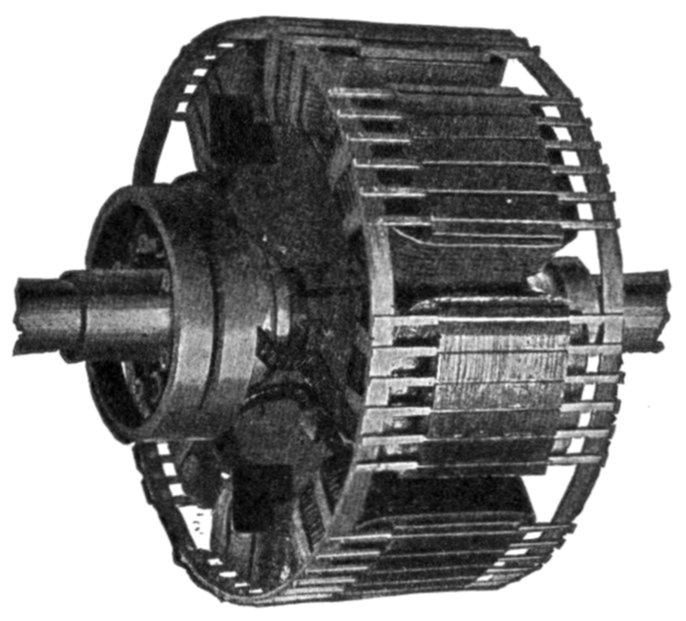
Fig. 1,405.—Westinghouse field with amortisseur or "damper" winding for 75 kva. and larger
belted alternators, which prevents hunting and reduces eddy currents in the pole pieces.
The copper bars of the amortisseur cage winding are arranged in partially closed slots in
the pole pieces.
Two examples of a field provided with amortisseur[4] winding
are shown in figs. 1,404 and 1,405.
[Pg 1156]
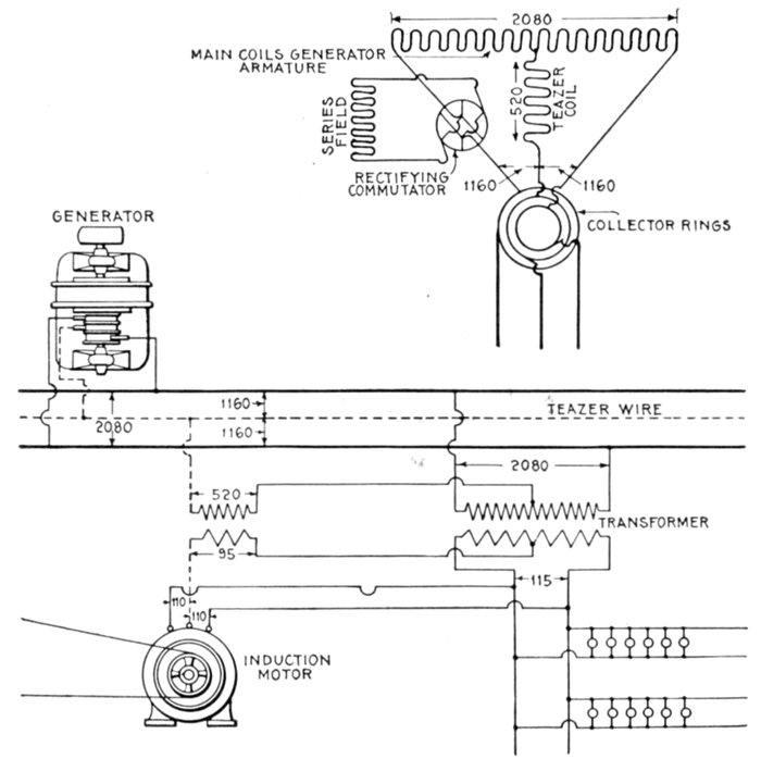
Fig. 1,406.—Diagram of monocyclic system, showing monocyclic armature and transformer
connections. The monocyclic system is a single phase system primarily intended for the
distribution of lights with an incidental load of motors. The lighting load is entirely
connected to one single phase circuit, and the motors are started and operated from this
circuit with the assistance of the teazer wire. The long coil indicates the main winding
of the armature, which is similar in its arrangement and size to the ordinary armature
winding of a single phase alternator. The short coil which connects at one end to the
middle point of the coil above mentioned, and at the other to a third collector ring is called
the "teazer" coil. Its use is to generate a pressure in quadrature with that of the main
coil. This pressure is combined with the main pressure of the alternator by transformers,
so as to give suitable phase relations for operating induction motors. In the diagram
the voltage has been assumed to be 2,080 volts, and the voltages marked to correspond
with the generated pressure. The coils of the alternator armature are connected, as
shown, to two main leads and to a teazer wire. Between each end of the main coil and the
end of the teazer coils, a resultant pressure is generated. These resultants are about
12 per cent. larger than half the main pressure. They also have a phase difference.
[Pg 1157]
Monocyclic Alternators.—This type of alternator was
designed prior to the introduction of the polyphase systems,
to overcome the difficulties encountered in the operation of single
phase alternators as motors. A single phase alternator will not
start from rest as a motor, but must first be started and brought
up to the proper speed before being connected with single phase
mains. This condition constituted a serious difficulty in all
cases where the motor had to be stopped and started at comparatively
frequent intervals.
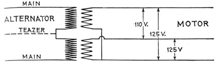
Fig. 1,407.—Monocyclic system diagram showing transformer connections.
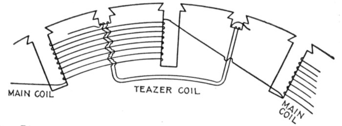
Fig. 1,408.—Diagram showing section of monocyclic alternator armature illustrating the
armature winding. The main coils are wound on every other tooth, and the teazer coils
are placed in quadrature with them, as shown.
The monocyclic alternator is a single phase machine provided
with an additional coil, called a teaser coil, wound in two phase
relationship with, and connected to the center of the main single[Pg 1158]
phase coil. It is provided with three collector rings; two for
the single phase coil, and one for the free end of the teaser coil.
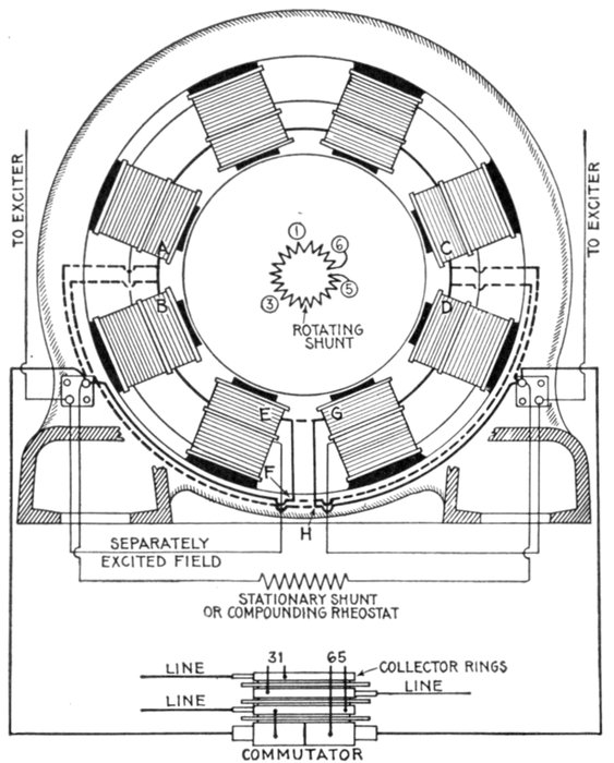
Fig. 1,409.—Diagram showing connections of General Electric Monocyclic alternator. For
2,300 volt machine, connect as shown by solid lines. For 1,150 volt machine, omit connections
A to B, C to D, E to F, and G to H, and connect as shown by dotted lines. The
armature of a standard monocyclic alternator rotates in a counter clockwise direction
facing the commutator. When the alternator is loaded, the voltage between the teazer
coil and the two terminals of the main coil may be different; therefore, it is necessary to
have the commutator connected in corresponding ends of the main coil. If the machine
has not been arranged for clockwise rotation, the following change in the connections on
the commutator-collector must be made if the machine is to be run in parallel with another.
Fig. 1,410 shows the connections of monocyclic alternators. In fig. 1,409, the studs on the
commutator-collector marked 1 and 6 are the terminals of the main coil. These should
be reversed. The numbers are stamped on the ends of the stud and may be seen with
the assistance of a mirror. By reference to this diagram it is a simple matter to trace out
the connections with a magneto, after the armature leads are disconnected and the brushes
raised.
[Pg 1159]
By this arrangement ordinary single phase incandescent
lighting can be accomplished by means of a single pair of wires
taken from the single phase coil. Where three phase motors
have to be operated, however, a third wire, called the power wire,
which is usually smaller than the main single phase wires is carried
to the point at which the motor is located, and by the use of two
suitably connected transformers three phase currents are obtained
from the combined single phase and power wires for
operating the motors.
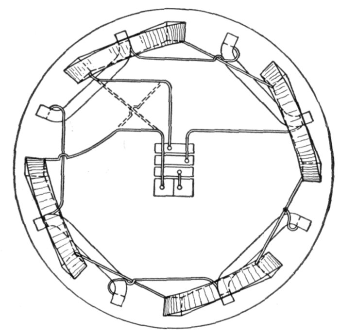
Fig. 1,410.—Diagram showing connections of General Electric monocyclic alternator. The
solid lines show standard connections for counter-clockwise rotation; the broken lines
show connection changed for clockwise rotation.
Fig. 1,406 shows the connections of the monocyclic system
and it is only necessary to carry the teaser wire into buildings
where motors are to be used.
[Pg 1160]
Armature Reaction.—Every conductor carrying a current
creates a magnetic field around itself, whether it be embedded
in iron or lie in air. Armature inductors, therefore, create
magnetic fluxes around themselves, and these fluxes will, in
part, interfere with the main flux from the poles of the field
magnet. The effect of these fluxes is:
1. To distort the field, or
2. To weaken the field.
These disturbing fluxes form, in part, stray fluxes linked around the
armature inductors tending to choke the armature current.
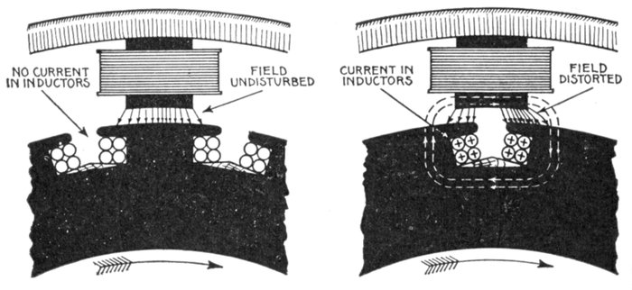
Figs. 1,411 and 1,412.—Section of armature and field showing distorting effect of armature
reaction on the field. When a coil is opposite a pole as in fig. 1,411, no current is flowing
(assuming no self induction) and the field is undisturbed, but, as the inductors pass under
a pole face as in fig. 1,412, current is induced in them, and lines of force are set up as indicated
by the dotted lines. This distorts the main field so that the lines of force are
crowded toward the forward part of the pole face as shown.
Ques. Explain how the field becomes distorted by
armature reaction.
Ans. Considering a slotted armature and analyzing the
electrical conditions as the inductors move past a pole piece, it
will be observed: 1, when the coil is in the position shown in[Pg 1161]
fig. 1,411, the current will be zero, assuming no armature self-induction,
consequently for this position the armature coil has
no disturbing effect upon the field set up by the field magnet;
2, when the inductors have moved under the pole face, as in
fig. 1,412, currents will be induced in them, and they will tend
to set up a magnetic field as indicated by the dotted lines, and
in direction, by the arrow heads. The effect of this field will be
to distort the main field, strengthening one side of the pole and
weakening the other side.
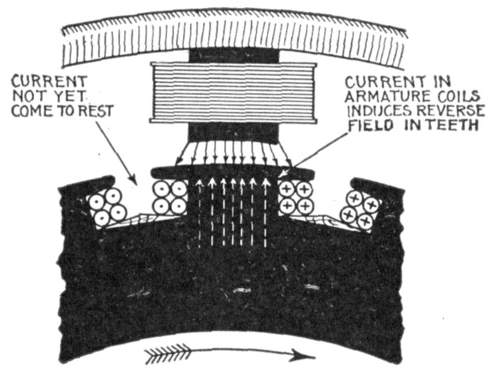
Fig. 1,413.—Section of armature and field showing weakening effect of armature reaction in
the field. Self-induction being present (as it almost always is), the current lags more or
less behind the pressure, so that when the coil is in the position of zero induction, as shown,
the current has not yet come to rest. Accordingly, lines of force (indicated by the dotted
lines) are set up by the current flowing through the coils which are in opposition to the
field, thus weakening the latter. The dots and crosses in inductor sections, have their
usual significance in defining the direction of current, representing respectively the heads
and tails of arrows.
Ques. Explain how the field becomes weakened by
armature reaction.
Ans. In all armatures there is more or less inductance
which causes the current to lag behind the pressure a corresponding
amount. Accordingly, the current does not stop flowing
at the same instant that the pressure becomes zero, therefore,
when the coil is in the position of zero pressure, as in fig. 1,413,[Pg 1162]
the current is still flowing and sets up a magnetic field which
opposes the main field as indicated by the dotted arrows, thus
weakening the main field.
Ques. In what kind of armature is this effect especially
pronounced?
Ans. In slotted armatures provided with coils of a large
number of turns.
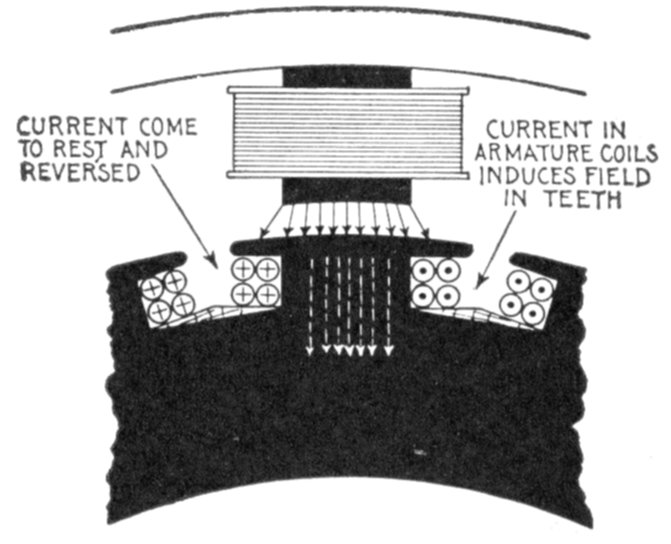
Fig. 1,414.—Section of armature and field showing strengthening effect of armature reaction when
the current leads the pressure. If the circuit contain an excess of capacity the current will
lead the pressure, so that when the coil is in the position of zero induction, as shown,
the current will have come to rest and reversed. Accordingly, lines of force (indicated by
the dotted lines) are set up by the current flowing through the coil and which are in the
same direction as the lines of force of the field, thus strengthening the latter.
Ques. What would be the effect if the current lead
the pressure?
Ans. It would tend to strengthen the field as shown in
fig. 1,414.
The value of the armature ampere turns which tend to distort and
to diminish or augment the effect of the ampere turns on the field
magnet is sometimes calculated as follows:
[Pg 1163]
in which
- A = armature ampere turns;
- I = current per phase;
- T = turns per pole per phase;
- P = number of phases;
- s = product of the distribution and pitch factors of the winding.
This value of ampere turns, combined at the proper phase angle with
the field ampere turns gives the value of the ampere turns available for
producing useful flux.
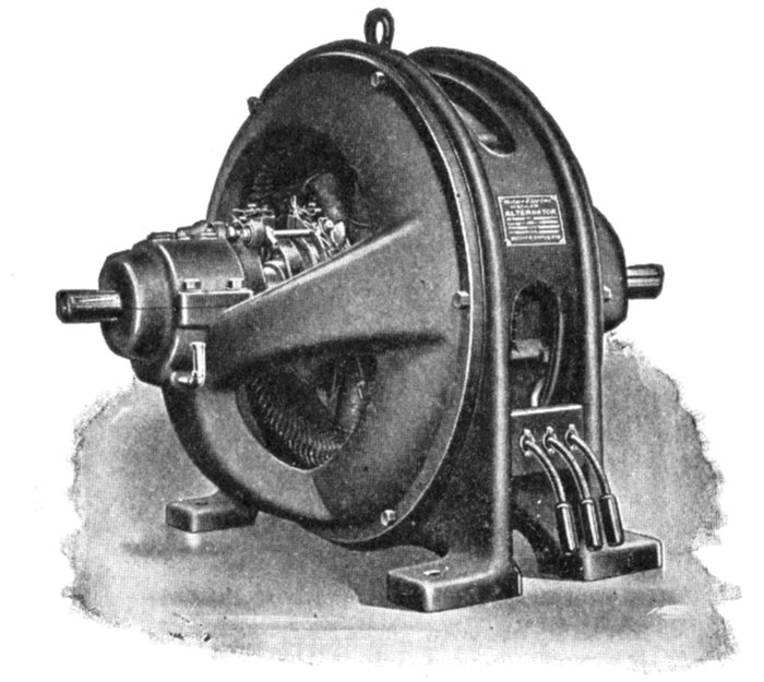
Fig. 1,415.—Fort Wayne separately excited belt driven alternator, a form adapted for installation
in small plants where low power factor is to be encountered. This condition exists
in a line where power is supplied to induction motors, transformers or other inductive
apparatus. The type here shown is built in sizes from 37½ kw. to 200 kw., 60 cycles, two
or three phases and voltages of 240, 480, 600, 1,150 or 2,300 volts. They may be operated
as single phase alternators by using two of the phases and may then be rated at 70 per cent.
of the polyphase rating. The field is excited by direct current at a pressure of 125 volts.
These alternators may be used as synchronous motors and for this duty are fitted with
amortisseur winding in the pole faces which does not interfere with their use as alternators.
Single Phase Reactions.—Unlike three phase currents, a single
phase current in an alternator armature produces a periodic disturbance
of the flux through the machine. In the magnet system this disturbance
is of twice the normal frequency, while in the armature core it is the
[Pg 1164]
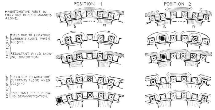
Figs. 1,416 to 1,425.—Diagrams illustrating superposition of fields. In the figures magnetic curves representing the effect of
the armature currents in several different cases are superposed upon the magnetic curves assumed to be due to the
field magnet. The uppermost line shows the primary field due to the exciting coils on the magnet poles. They are
shown passing into the armature teeth in two principal positions, where the middle of a pole is: 1, opposite a tooth, and
2, opposite a slot. In the second line is shown the field due to the armature currents assuming no lag, and that the
magnets are not excited. If there be no lag, the places of strongest current will be opposite the poles. As shown in
the right hand figure when the current in one phase C, is at its maximum, those in the other phases A and B will be of
half strength. In the left hand figure when the current in one phase B, is at its zero value, those in the other phases will
be of equal value, or 87 per cent. of the maximum. In the third line is shown the effect of superposing these fields due
to the current upon those due to the magnets as depicted in the first line. Inspection of this resultant field shows how
the armature current distorts the field without altering the total number of lines per pole. In the fourth and fifth lines
are shown the effects of a lagging current. A lag of 90° is assumed; and in that case the maximum current occurs in
any inductor one quarter period after the pole has passed, or at a distance of half a pole pitch behind the middle point
of the pole, as in the fourth line. When these armature fields are superposed on those of the magnets in the first line
the resultant fields are those depicted in the fifth line. On inspection it will be seen that in this case there is no distortion,
but a diminution of the flux from each pole, as the lines due to the armature currents, tending to pass through the pole
cores in the sense opposite to those of the primary magnetism, must be deducted from the total. The twelve lines per pole
are correspondingly reduced to eight; and, of these eight, four go astray constituting a leakage field. This illustrates the
effect of a lagging current in demagnetizing the field magnets and in increasing the dispersion.
[Pg 1165]
same as the normal frequency. In both cases the eddy currents which
are set up, produce a marked increase in the load losses, and thus tend
to give the machine a higher temperature rise on single phase loading.
Designers continue to be singularly heedless of these single phase
reactions, resulting in many cases of unsatisfactory single phase
alternators. Single phase reactions distort the wave form of the
machine.
Three Phase Reactions.—The action of the three phase currents
in an alternator is to produce a resultant field which is practically uniform,
and which revolves in synchronism with the field system. The
resultant three phase reaction, because of its uniformity, produces no
great increase in the load losses of the machine, the small additional
losses which are present being due to windings not being placed actually
in space at 120°, and to the local leakage in the teeth.
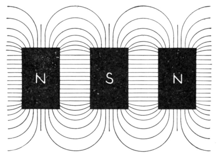
Fig. 1,426.—Diagram showing lateral field between adjacent poles.
Magnetic Leakage.—In the design of alternators the drop
of voltage on an inductive load is mainly dependent upon the
magnetic leakages, primary and secondary. They increase with
the load, and, what is of more importance, they increase with
the fall of the power factor of the circuit on which they may be
working. This is one reason why certain types of alternator,[Pg 1166]
though satisfactory on a lighting circuit, have proved themselves
unsatisfactory when applied to a load consisting chiefly
of motors.
The designer must know the various causes which contribute
to leakage and make proper allowance.
In general, to keep the leakage small, the pole cores should
be short, and of minimum surface, the pole shoes should not
have too wide a span nor be too thick, nor present needless
corners, and the axial length of the pole face and of the armature
core should not be too great in proportion to the diameter of the
working face.
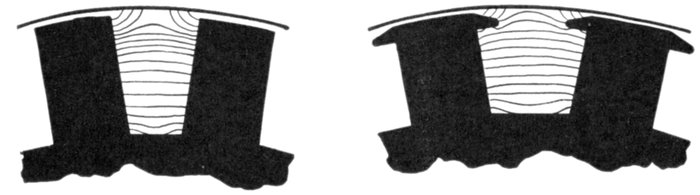
Figs. 1,427 and 1,428.—Diagram showing respectively the character of stray field between adjacent
straight poles, and between adjacent poles with shoes. Across the slightly V-shaped
spaces the stray field passes in lines that, save near the outer part, are nearly straight.
Quite straight they would not be, even were the sides parallel, because the difference of
magnetic pressure increases from the roots towards the pole ends. At the roots, where the
cores are attached to the yoke, the magnetic pressure difference is almost zero. It would
be exactly zero if there were not a perceptible reluctance offered by the joints and by the
metal of the yoke. The reluctance of the joint causes a few of the lines to take paths
through the air by a leakage which adds to the useful flux. At the tops of the cores there
is a difference of magnetic pressure equal to the sum of the ampere turns on the two
cores, tending to drive magnetic lines across. This difference of magnetic pressure increases
regularly all the way up the cores from root to top; hence, the average value may be taken
as equal to the ampere turns on one core. The stray field, therefore, will steadily increase
in density from the bottom upwards. In addition to this stray field between the pole
cores there is also a stray field between the projecting tips or edges of the pole shoes, as
shown in fig. 1,428. In some machines the dispersion due to the pole shoes is greater
than that between the flanks of the cores.
To keep the increase of leakage between no load and full load
from undue magnitude, it is required that armature reactions[Pg 1167]
shall be relatively small, that the peripheral density of the armature
current (ampere-conductors per inch) be not too great, and
that the pole cores be not too highly saturated when excited for
no load.
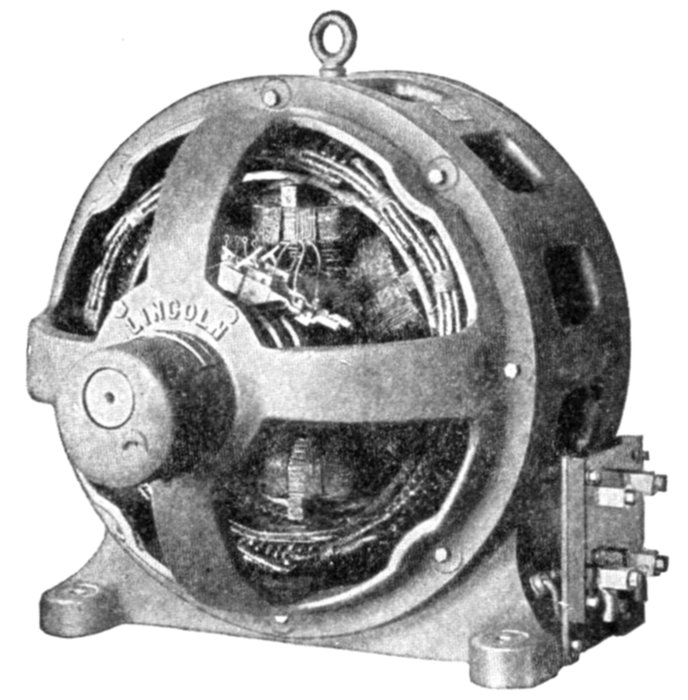
Fig. 1,429.—Lincoln revolving field alternator. The frame has openings for ventilation, the
fanning action of the pole pieces causing a current of air to pass not only over the end of
the windings, as is usual with other designs, but also through ventilating slots in the
windings themselves. The armature core laminations are annealed after punching and
before assembling to guard against the crystalizing effect of the punching. The armature
coils are form wound and insulated before being placed in the slot. There is also slot
insulation which is put in the slot previous to inserting the coil. When the winding is completed,
it is tested with a pressure of 4 to 10 times the normal voltage of the machine. The
bearings are self-aligning. The machine is normally designed to operate at a power factor
of approximately 70 per cent., which means that at that power factor, the armature and
fields at full load will heat equally. If it have a higher power factor than 70 per cent. it
means that the field windings will run considerably cooler than the armature windings
with full load. If the power factor be lower than this, it will mean that the field windings
will run hotter than the armature on full load; however, the machine is designed so that
harmful heating does not occur on full load with greater power factor than 40 per cent.
The general character of the stray field between adjacent poles
is shown in figs. 1,427 and 1,428 for straight poles and those
having shoes.
[Pg 1168]
Field Excitation of Alternators.—The fields of alternators
require a separate source of direct current for their excitation,
and this current should be preferably automatically controlled.
In the case of alternators that are not self exciting, the dynamo
which generates the field current is called the exciter.
The excitation of an alternator at its rated overload and .8 power
factor would not, in some cases, if controlled by hand, exceed 125 volts,
although, in order to make its armature voltage respond quickly to
changes in the load and speed, the excitation of its fields may at times be
momentarily varied by an automatic regulator between the limits of 70
and 140 volts.
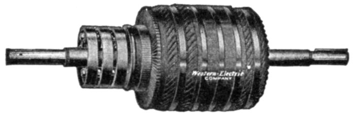
Fig. 1,430.—Western Electric armature for self-excited alternator. The main winding is placed
at the bottom of the slots, each coil being surrounded by an armour of horn fibre. The
exciter winding occupies a very small portion of the slot, being placed on top of the main
winding, and connected to the commutator immediately in front of the core and between
core and collector rings as shown.
The exciter should, in turn, respond at once to this demand upon its
armature, and experience has shown that to do this its shunt fields
must have sufficient margin at full load to deliver momentarily a
range from 25 to 160 volts at its armature terminals.
It is obvious from the above that an exciter suitable for use with an
automatic regulator must commutate successfully over a wide range in
voltage, and, if properly designed, have liberal margins in its shunt
fields and magnetic circuits.
Alternator fields designed for and operated at unity power factor
have often proved unsatisfactory when the machines were called upon
to deliver their rated kva. at .8 power factor or lower. This is due to
the increased field current required at the latter condition and results,
first, in the overheating of the fields and, second, in the necessity of
raising the direct current exciting voltage above 125 volts, which often
requires the purchase of new exciters.
[Pg 1169]
Ques. What is a self-excited alternator?
Ans. One whose armature has, in addition to the main
winding, another winding connected to a commutator for furnishing
direct field exciting current, as shown in fig. 1,430.
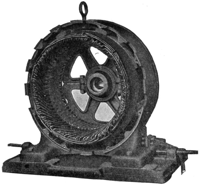
Fig. 1,431.—Frame, bed plate and armature winding for Westinghouse bracket bearing polyphase
alternator.
Ques. How is a direct connected exciter arranged?
Ans. The exciter armature is mounted on the shaft of the
alternator close to the spider hub, or in some cases at a distance
sufficient to permit a pedestal and bearing to be mounted between
the exciter and hub. In other designs the exciter is
placed between the bearing and hub.
[Pg 1170]
Figs. 1,432 and 1,433 are examples of direct connected exciter alternators,
in fig. 1,432 the exciter being placed between the field hub
and bearing, and in fig. 1,433, beyond the bearing.
Ques. What is the advantage of a direct connected
exciter?
Ans. Economy of space.
This is apparent by comparing figs. 1,432 and 1,433 with fig. 1,434,
which shows a belted exciter.
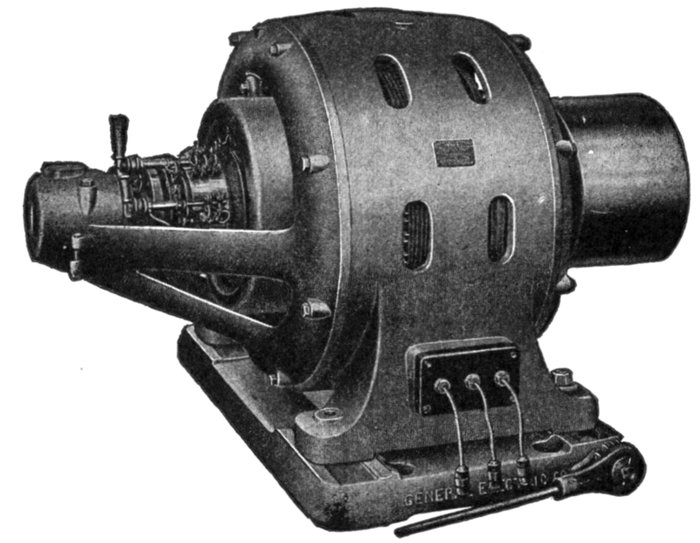
Fig. 1,432.—General Electric alternator with direct connected exciter mounted on shaft
between field hub and bearing. In the smaller sizes, the magnet frame is bolted to the
bearing bracket, but in the larger sizes special construction is used depending upon the
conditions to be met. The exciters are capable of furnishing the desired excitation for low
power factors.
Ques. What is the disadvantage of a direct connected
exciter?
Ans. It must run at the same speed as the alternator, which
is slower than desirable, hence the exciter must be larger for a[Pg 1171]
given output than the gear driven type, because the latter can be
run at high speed and accordingly be made proportionally
smaller.
Ques. What form of gear is generally used on gear
driven exciters?
Ans. Belt gear.
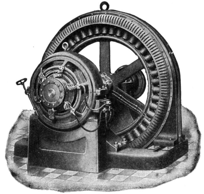
Fig. 1,433.—Fort Wayne alternator with direct connected exciter mounted on the field shaft
at such distance as to permit a pedestal and bearing to be mounted between the exciter
and revolving field. In the view, the bearing is hidden by the exciter, only the foot of the
pedestal being visible.
Ques. What are the advantages of gear driven exciters?
Ans. Being geared to run at high speed, they are smaller
and therefore less costly than direct connected exciters. In large[Pg 1172]
plants containing a number of alternators one exciter may be
used having sufficient capacity to excite all the alternators, and
which can be located at any convenient place.
Ques. What is the disadvantage of gear driven exciters?
Ans. The space occupied by the gear.
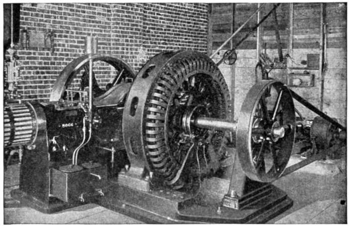
Fig. 1,434.—Diagram showing a Westinghouse 50 kva., 2,400 volt, three phase, 60 cycle
revolving field separately excited alternator direct connected to a steam engine. The
exciter is belted to the alternator shaft, the driving pulley being located outside the main
bearing. The small pulley on the exciter gives an indication of its high speed as compared
with that of the alternator.
In the case of a chain drive very little space is required, but for belts,
the drive generally used, there must be considerable distance between
centers for satisfactory transmission.
Slow Speed Alternators.—By slow speed is here understood
relatively slow speed, such as the usual speeds of reciprocating
engines. A slow speed alternator is one designed to run at a
speed slow enough that it may be direct connected to an engine.[Pg 1173]
Such alternators are of the revolving field type and a little consideration
will show that they must have a multiplicity of field
magnets to attain the required frequency.
In order that there be room for the magnets, the machine
evidently must be of large size, especially for high frequency.
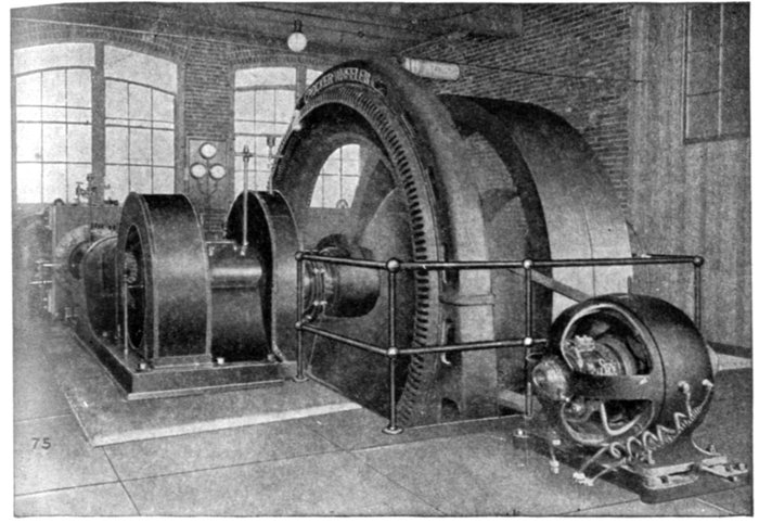
Fig. 1,435.—Crocker-Wheeler 350 kva., slow speed alternator direct connected to a Corliss
engine. In front is seen a belted exciter driven from a pulley on the main shaft between
the alternator and the large band wheel. The latter serves to give the additional fly wheel
effect needed for close speed regulation.
EXAMPLE.—How many field magnets are required on a two phase
alternator direct connected to an engine running 240 revolutions per
minute, for a frequency of 60?
An engine running 240 revolutions per minute will turn
240 ÷ 60 = 4 revolutions per second.
A frequency of 60 requires
60 ÷ 4 = 15 cycles per phase per revolution, or
15 × 2 = 30 poles per phase.[Pg 1174]
Hence for a two phase alternator the total number of poles required is
30 × 2 = 60.
It is thus seen that a considerable length of spider rim is required to
attach the numerous poles, the exact size depending upon their dimensions
and clearance.
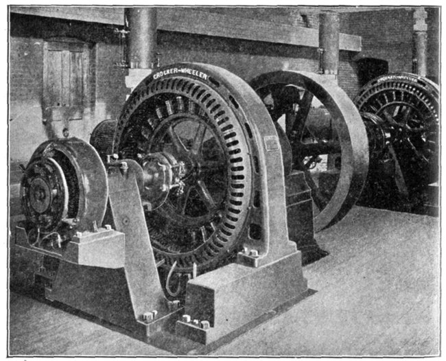
Fig. 1,436.—Three Crocker-Wheeler 75 kva., slow speed alternators direct connected to high
speed engines. The alternator is styled slow speed although connected to a high speed
engine, because what is considered high engine speed is slow speed for alternator operation.
The alternators have direct connected exciters which are plainly seen in the illustration
placed on an extension of bearing pedestal. Direct connected exciters on units of this kind
do not, as a rule, assume too bulky proportions, because of the high engine speed.
Fly Wheel Alternators.—The diameter of the revolving
fields on direct connected alternators of very large sizes becomes
so great that considerable fly wheel effect is obtained, although
the revolutions be low. By giving liberal thickness to the rim[Pg 1175]
of the spider, the rotor then answers the purpose of a fly wheel,
hence no separate fly wheel is required. In fact, the revolving
element resembles very closely an ordinary fly wheel with magnets
mounted on its rim, as illustrated in fig, 1,437.
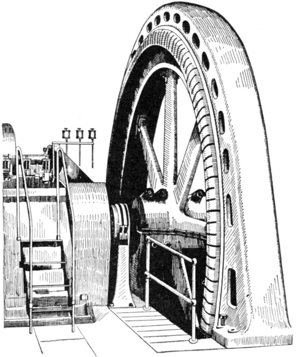
Fig. 1,437.—General Electric 48 pole 750 kw., three phase fly wheel type alternator. It runs
at a speed of 150 revolutions per minute, giving a frequency of 60 cycles per second and
a full load pressure of 2,300 volts. The slip rings and leads to the field winding are
clearly shown in the figure. The field magnets are mounted directly on the rim of the
spider, which resembles very closely a fly wheel, and which in fact it is—hence the name
"fly wheel alternator."
[Pg 1176]
High Speed Alternators.—Since alternators may be run at
speeds far in excess of desirable engine speeds, it must be evident
that both size and cost may be reduced by designing them
for high speed operation.
Since the desired velocity ratio or multiplication of speed is
so easily obtained by belt drive, that form of transmission is
generally used for high speed alternators, the chief objection
being the space required. Accordingly where economy of space
is not of prime importance, a high speed alternator is usually
installed, except in the large sizes where the conditions naturally
suggest a direct connected unit.
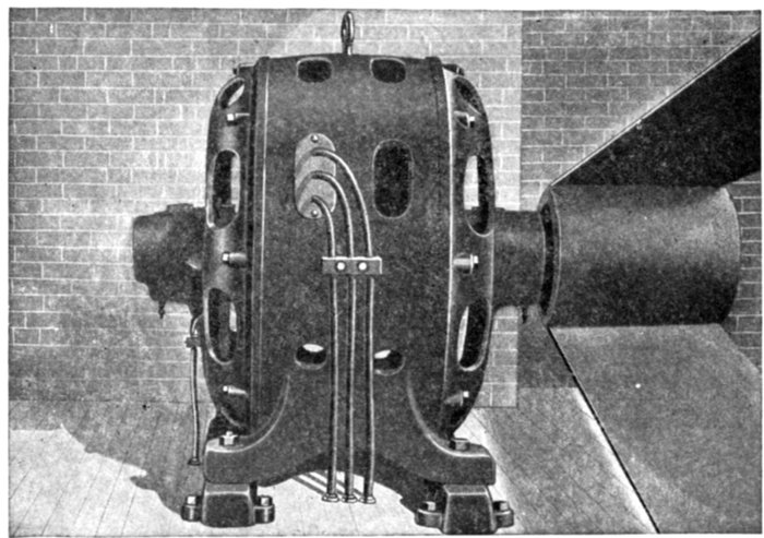
Fig. 1,438.—Allis-Chalmers high speed belted type alternator. The small pulley at the right
and the angle of the belt suggest the high speed at which such alternators are run, a 50
kva. machine turning 1,200 revolutions per minute.
An example of high speed alternator is shown in fig. 1,438. Machines
of this class run at speeds of 1,200 to 1,800 or more, according to size.
No one would think of connecting an alternator running at any such
speed direct to an engine, the necessary speed reduction proper for
engine operation being easily obtained by means of a belt drive.
[Pg 1177]
Water Wheel Alternators.—In order to meet most successfully
the requirements of the modern hydro-electric plant, the
alternators must combine those characteristics which result in
high electrical efficiency with a mechanical strength of the
moving elements which will insure uninterrupted service, and
an ample factor of safety when operating at the relatively high
speeds often used with this class of machine.
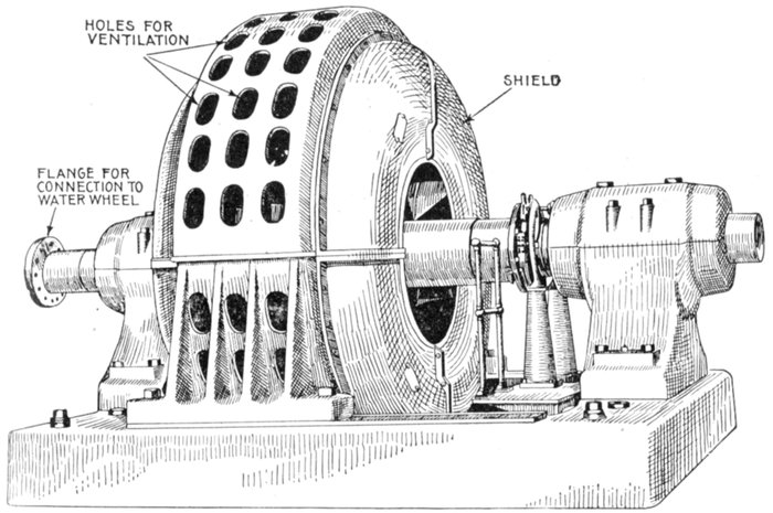
Fig. 1,439.—Allis-Chalmers 5,000 kva., 450 R. P. M., 6,600 volt, 60 cycle, 3 phase, horizontal
water wheel alternator. The shaft is extended for the reception of a flange coupling for
direct connection to water wheel. Owing to the wide range in output of the generating
units and also in the speed at which they must operate to suit varying conditions of head,
types of wheels used, and other features pertaining to water power developments, it has
been necessary to design a very complete line of machines for this work. The bearings
are of the ring oiling type with large oil reservoirs.
When selecting an alternator for water wheel operation a
careful analysis of the details of construction should be made in[Pg 1178]
order to determine the relative values which have been assigned
by the designers to the properties of the various materials used.
Such analysis will permit the selection of a type of machine best
adapted to the intended service and which possesses the required
characteristics of safety, durability and efficiency.
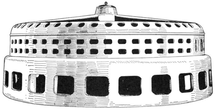
Fig. 1,440.—Stator of 500 k.w. Allis-Chalmers alternator for direct connection to vertical shaft
hydraulic turbine.
The large use of electric power transmitted by means of high
pressure alternating current has led to the development of a large
number of water powers and created a corresponding demand
for alternators suitable for direct connection to water wheels.
Ques. Name two forms of water wheel alternator.
Ans. Horizontal and vertical.
Examples of horizontal and vertical forms of water wheel alternator
are shown in figs. 1,439 and 1,440.
Ques. How should the rotor be designed?
Ans. It should be of very substantial construction.
[Pg 1179]
Ques. Why?
Ans. Because water wheel alternators are frequently required
to operate safely at speeds considerably in excess of normal.
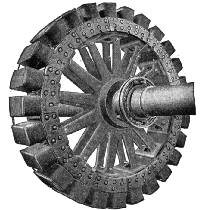
Fig. 1,441.—Allis-Chalmers revolving field for water wheel alternator. In this type of alternator
it is essential that the rotating part be designed to have a liberal factor of safety
not only at the ordinary operating speed, but also at speeds much in excess of normal.
Frequently machines are required to operate safely at a speed 50 to 75 per cent. in excess
of normal, so that there may be no danger in case the water wheel races. In most
machines the field spider is of steel cast in a single piece for the smaller alternators and in
two or more parts for the larger sizes. For alternators running at high peripheral speed,
the rim is built up of steel laminations supported by a cast steel spider; the latter serves
merely to rotate the rim, which is in itself able to withstand all stresses due to the high speed.
The field poles are laminated, being built up of steel punchings held between malleable
iron or bronze end plates, the latter being used on high speed machines. With but very
few exceptions the poles are attached by dovetail projections that fit into corresponding
slots. Steel tapered keys are driven in alongside the dovetails, and the pole pieces cannot
become loose. All field coils, except on a few of the smallest machines, are of edgewise
wound copper strip. This style of coil is essential for revolving field alternators where
the pressure on the insulation, due to centrifugal force, is so great that cotton insulation
on round wire will not stand. Current is led into the rings by means of carbon brushes,
the number of brushes being such that the current density at the rubbing contact is kept
within conservative limits. At least two brushes per ring are always provided so that
one can be removed for inspection without interrupting the exciting current. In large
machines the brush holder studs are mounted on a stand supported from the base; in
small alternators they are usually fastened to the cap of one of the bearing pedestals.
[Pg 1180]
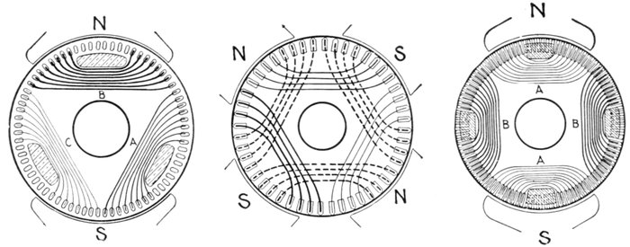
Figs. 1,442 to 1,444.—Diagram of turbine alternator windings for revolving armature. Fig. 1,442 illustrates a two pole
design in which all overlapping is avoided. It has 72 slots of which only 48 are filled, giving 8 slots per phase. The
projecting claws from the brass end shield which hold the coils in position are shown in section. Fig. 1,443 shows a four
pole design having 48 slots or 4 slots per phase per pole, the coils being made up of 8 inductors per slot taped together,
the end bends forming two ranges. Fig. 1,444 shows a two pole design for a two phase armature with 18 slots per pole per
phase. The core discs are spaced out as for 108 slots, but of these, 4 lots of 7 each are not stamped out, and 8 of those
stamped are left empty, so that there are 72 slots filled.
Ques. What
special provision
is made for cooling
the bearings?
Ans. They are
in some cases
water cooled.
Turbine
Driven Alternators.—Although
the principle of
operation of the
steam turbine
and that of the
reciprocating engine
are decidedly
unlike, the principle
of operation
of the high speed
turbine driven alternator
does not
differ from that
of generators designed
for being
driven by other
types of engine
or by water
wheels. There
are, therefore,
with the turbine
driven alternator
no new ideas for[Pg 1181]
the operator who is familiar with the older forms to acquire.
It must be obvious that the proportions of such extra high
speed machines must be very different from those permissible
in generators of much slower speeds.
Ques. How does a turbine rotor differ from the ordinary
construction?
Ans. It is made very small in diameter and unusually long.
Ques. Why?
Ans. To reduce vibration and centrifugal stresses.
Ques. What are the two classes of turbine driven
alternators?
Ans. They are classed as vertical or horizontal.
Ques. How do they compare?
Ans. The vertical type requires less floor space than the
horizontal design, and while a step bearing is necessary to carry
the weight of the moving element, there is very little friction
in the main bearings.
The horizontal machine, while it occupies more space, does not
require a step bearing.
Ques. Describe a step bearing.
Ans. It consists of two cylindrical cast iron plates bearing
upon each other and having a central recess between them into
which lubricating oil is forced under considerable pressure by
a steam or electrically driven pump, the oil passing up from
beneath.
Ques. What auxiliary is generally used in connection
with a step bearing?
Ans. A weighted accumulator is sometimes installed in
[Pg 1182]
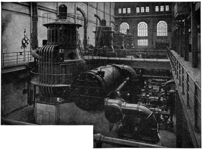
Fig. 1,445.—5,000 kw. Curtis turbine alternators installed
for the New York Central R. R. at Yonkers, N. Y. The
illustration shows also the auxiliary apparatus consisting
of condensers, vacuum augmenters, circulating
pumps, air pumps, etc. The augmenter of the first
machine is plainly seen between the condenser and
centrifugal circulating pump.
[Pg 1183]
connection with the oil pipe as a convenient device for governing
the step bearing pumps, and also as a safety device in case
the pumps fail.
Alternators of Exceptional Character.—There are a few types
of alternator less frequently encountered than those already described.
The essentials of such machines are here briefly given.
Asynchronous Alternators.—In these machines, the rotating
magnet, which, with definite poles, is replaced by a rotor having closed
circuits. In general construction, they are similar to asynchronous
induction motors having short circuited rotors; for these alternators,
when operating as motors, run at a speed slightly below synchronism
and act as generators when the speed is increased above that of synchronism.
Machines of this class are not self-exciting, but require an
alternating or polyphase current previously supplied to the mains to
which the stationary armature is connected.
Asynchronous alternators may be advantageously used in central
stations that may be required to sustain a very sudden increase of load.
In such cases, one or more asynchronous machines might be kept in
operation as a non-loaded motor at a speed just below synchronism
until its output as a generator is required; when by merely increasing
the speed of the engine it will be made to act as a generator, thus avoiding
the delays usually occurring before switching in a new alternator.
Image Current Alternators.—When the generated frequency of
alternators excited by low frequency currents is either the sum or the
difference of the excitation and rotation frequencies, any load current
flowing through the armature of the machine is exactly reproduced in
its field circuit. These reproduced currents are characteristic of all
types of asynchronous machines, and are called "image currents," as
they are actually the reflection from the load currents delivered by the
armature circuit.
As the exciter of a machine of this type carries "image currents"
proportional to the generated currents, its size must be proportional to
the capacity of the machine multiplied by the ratio of the excitation
and generated frequencies; therefore, in the commercial machines, the
excitation frequency is reduced to the minimum value possible; from
two to five cycles per second being suitable for convenient employment.
These machines as heretofore constructed are not self-exciting, but
as the principle of image current enables the construction of self-exciting
alternators, it will be of advantage to have a general understanding
of the separately excited machine under different conditions
of excitation.
[Pg 1184]
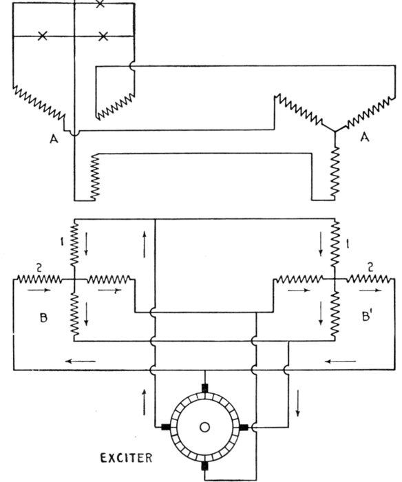
Fig. 1446.—Diagram of constant pressure image current alternator connections. The image
or reproduced currents are characteristic of all types of asynchronous machines, and are
called image currents because they are actually the reflection from the load currents delivered
by the armature circuit. The principle of operation is explained in the accompanying
text.
[Pg 1185]
When the generated frequency of the machine is equal to the difference
of the excitation and rotation frequencies, the magnetization of the
machine is higher under a non-inductive load than under no load. This
is principally due to the ohmic resistance of the field circuit, which
prevents the image current from entirely neutralizing the magnetomotive
force of the armature current. In other words, the result of the
magnetomotive force of the armature and image currents not only tends
to increase the no load magnetization of the machine at non-inductive
load, but depresses the original magnetization at inductive load, so
that the terminal voltage of the machine increases with non-inductive
load, and decreases with inductive load.
Again, the generated frequency is equal to the sum of the excitation
and rotation frequencies, the resistance of the field circuit reacts
positively; that is, it tends to decrease the magnetization, and consequently
the terminal voltage of the machine at both inductive and
non-inductive loads.
In the constant pressure machine, the two effects are combined and
opposed to one another.
The connections of two alternators with diphase excitation are shown
by fig. 1,446.
Extra High Frequency Alternators.—Alternators generating currents
having a frequency up to 10,000 or 15,000 cycles per second have
been proposed several times for special purposes, such as high frequency
experiments, etc. In 1902 Nikola Tesla proposed some forms of alternators
having a large number of small poles, which would generate
currents up to a frequency of 15,000 cycles per second.
Later, the Westinghouse Company constructed an experimental
machine of the inductor alternator type for generating currents
having a frequency of 10,000 cycles per second. This machine was
designed by Samms. It had 200 polar projections with a pole pitch
of only 0.25 inch, and a peripheral speed of 25,000 feet per minute.
The armature core was built up of steel ribbon 2 inches wide and 3 mils
thick. The armature had 400 slots with one wire per slot, and a bore of
about 25 inches. The air gap was only 0.03125 inch. On constant excitation
the voltage dropped from 150 volts at no-load to 123 volts with
an output of 8 amperes.
Self-Exciting Image Current Alternators.—The type of machine
described in the preceding paragraph can be made self-exciting by
connecting each pair of brushes, which collect the current from the
armature, with a field coil so located that the flux it produces will be
displaced by a predetermined angle depending on the number of phases
required, as shown by fig. 1,447. The direction of the residual magnetism
of the machine is shown by the arrows A, A.
[Pg 1186]
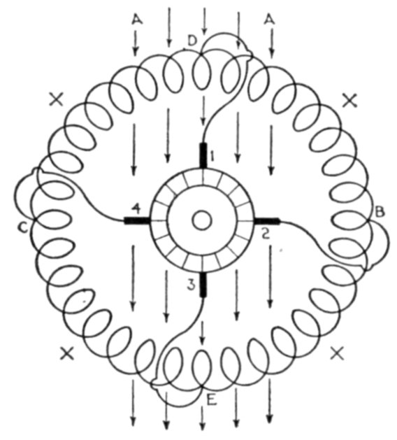
Fig. 1,447.—Diagram of connections of self-exciting image current alternator.
When the armature is rotated, a pressure will be generated between
the brushes 2 and 4, and a current will flow from C through the coils
XX to B, producing a flux through the armature at right angles to the
residual magnetism and establishing a resultant magnetic field between
D, B, and D, C. This field will generate a pressure between the brushes
1 and 3, and a current will flow D through XX to E in such a direction
that it will at first be opposed to the residual magnetism, and afterward
reverse the direction of the latter. At the moment the residual magnetism
becomes zero, the only magnetism left in the machine will be due
to the currents from the brushes 2 and 4, and their field combining with
the vertical reversed field will produce a resultant polar line between
B and E. As these operations are cyclic, they will recur at periodic
intervals, and the phenomena will become continuous. The negative
field thus set up in the air gap of the machine will cut the conductors
of the stator and will be cut by the conductors of the rotor in such a
manner that the electromotive forces generated between the brushes
of the armature will be equal and opposite to those between the terminals
of the stator.
[Pg 1187]
CHAPTER L
CONSTRUCTION OF ALTERNATORS
The construction of alternators follows much the same lines
as dynamos, especially in the case of machines of the revolving
armature type. Usually, however, more poles are provided than
on direct current machines, in order to obtain the required frequency
without being driven at excessive speed.
The essential parts of an alternator are:
- 1. Field magnets;
- 2. Armature;
- 3. Collector rings;
and in actual construction, in order that these necessary parts
may be retained in proper co-relation, and the machine operate
properly there must also be included:
- 4. Frame;
- 5. Bed plate;
- 6. Pulley.
Field Magnets.—The early forms of alternator were built
with permanently magnetized steel magnets, but these were
later discarded for electromagnets.
Alternators are built with three kinds of electromagnets,
classed according to the manner in which they are excited, the
machines being known as,
[Pg 1188]
- 1. Self-excited;
- 2. Separately excited;
- 3. Compositely excited.
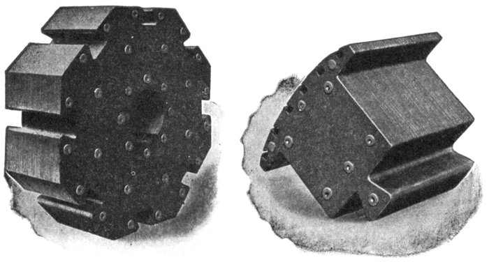
Figs. 1,448 and 1,449.—Westinghouse laminated hub and laminated pole piece for revolving
field having squirrel cage winding. Thin steel is used for the laminations of both hub
and pole piece; these are assembled and firmly riveted together under hydraulic pressure.
The laminations are of the same thickness in both hub and spider.
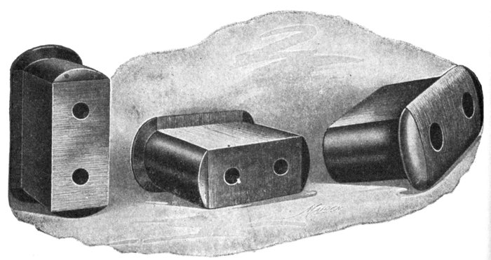
Figs. 1,450 to 1,452.—Views of Triumph pole pieces. These consist of laminated punchings
securely clamped between two cast steel end plates. The laminations are shaped with
polar horns or shoes as shown, and which serve to keep the field coils securely wedged in
position. In some designs the horns are separate. The two holes in each pole piece are
for through bolts which secure the pole piece and coil to the spider run. Dovetail joints
are sometimes used instead of through bolts, as in figs. 1,448 and 1,449.
[Pg 1189]
Ques. What is a self-excited alternator?
Ans. One in which the field magnets are excited by current
from one or more of the armature coils, or from a separate winding
(small in comparison with the main winding), the current being
transformed into direct current by passing it through a commutator.
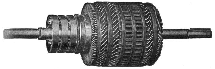
Fig. 1,453.—Fort Wayne armature for self-excited alternator. There are two independent
windings, one for the main current, and one for the exciting current. The winding for
the latter current occupies a very small amount of space, and is placed in the slots on top
the main winding. The commutator to which the exciter winding is connected, is located
between the collector rings and the core. It is of standard construction with end clamps
holding the bars in place on the insulated commutator drum. The armature coils are
form wound and the core is built of sheet steel laminations, annealed and japanned to
prevent hysteresis and eddy current losses. Ventilated openings are provided to allow a
free circulation of air both around the ends of the windings and through ducts in the
laminated core. The core is clamped by bolts between the flanges of the armature spider
which is keyed to the shaft. These flanges have cylindrical extensions with ribbed surfaces,
which form a support for the ends of the armature coils. The ribbed surfaces form air
passages from the core outward around the ends of the coils, thus ventilating both core
and coils.
Fig. 1,453 shows an armature of a self-excited machine, the exciting
current being generated in a separate winding and passed through a
commutator.
Ques. For what class of service are self-exciting alternators
used?
[Pg 1190]
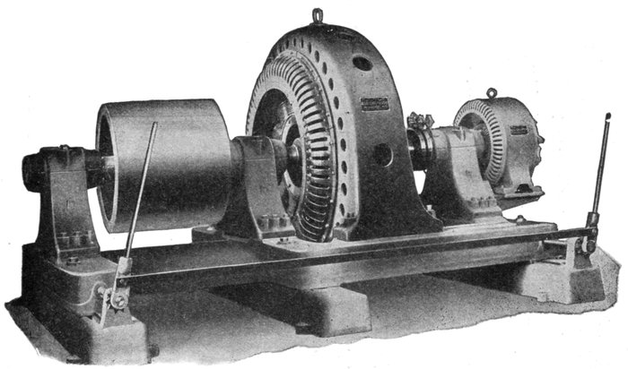
Fig. 1,454.—Allis-Chalmers three bearing type alternator with exciter direct connected. The bearing pedestals are bolted to a
substantial cast iron base having, in the large sizes, sufficient length to permit shifting frame sideways along the base to
give access to the field and armature coils. The field coils are designed for 120 volt excitation, and are wound edgewise
with copper strip. There is a liberal margin of field excitation to take care of overloads or for operation on loads of low
power factor. The regulating qualities are as good as can be obtained without making the machine unnecessarily large and
expensive. By regulation is meant the percentage rise in voltage when full load is thrown off, field excitation and speed
being held constant; the percentage is referred to normal full load voltage. An alternator with poor regulation will show
large variations in voltage with changes in load, the pressure falling whenever a load is thrown on and rising when it is
thrown off. These changes will be especially pronounced if the load be inductive. A badly designed alternator might show
very fair regulation on non-inductive load and yet be unable to give full voltage on inductive load.
[Pg 1191]
Ans. They are employed in small power plants and isolated
lighting plants where inductive loads are encountered.
Ques. What is a separately excited alternator?
Ans. One in which the field magnets are excited from a small
dynamo independently driven or driven by the alternator shaft,
either direct connected or by belt as shown in fig. 1,455.
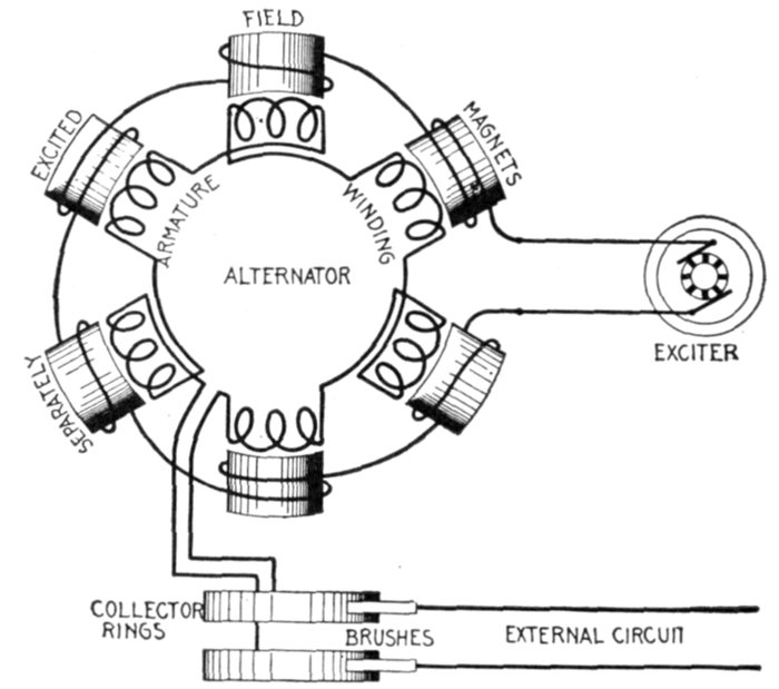
Fig. 1,455.—Diagram of separately excited alternator. The field winding is supplied with
direct current, usually at 125 volts pressure by a small dynamo called the "exciter." The
latter may be driven by independent power, or by belt connection with the main shaft,
and in some cases the exciter is directly connected to the alternator shaft.
Ques. What is a compositely excited alternator?
Ans. A composite alternator is similar to a compound wound
dynamo in that it has two field windings. In addition to the
regular field coils which carry the main magnetizing current from
the exciter, there is a second winding upon two or upon all of the[Pg 1192]
pole pieces, carrying a rectified current from the alternator which
strengthens the field to balance the losses in the machine, and
also if so desired, the losses on the line as shown in fig. 1,456.
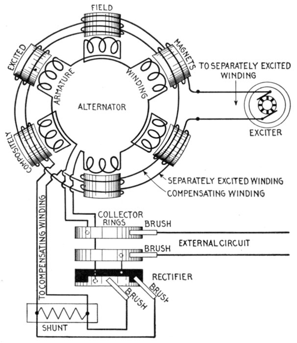
Fig. 1,456.—Diagram of compositely excited alternator. The current for exciting the field
magnets is obtained, partly from an exciter and partly from the windings of the alternator,
being transformed into direct current by the rectifier. The connections are as shown.
One end of the armature winding is connected to one of the collector rings; the other end,
to the light part of the rectifier, as shown, the solid black part of the rectifier being
connected to the other collector ring. Two brushes bear on adjacent teeth of the rectifier
and are connected to the compensating winding circuit across which is a shunt. These
connections are shown more clearly in fig. 1,457. In operation the separately excited
coils set up the magnetism necessary for the generation of the voltage at no load. The
main current coming from the armature is shunted, part going through the shunts and
the remainder around the compensating winding, furnishing the additional magnetism
necessary to supply the voltage to overcome the armature impedance. This composite
method of field excitation is very similar to that used on a compound wound dynamo.
As shown, both field windings encircle every pole, but in some machines the rectified
current will traverse a few poles only, the current from the exciter traversing the remainder.
[Pg 1193]
Ques. What is a magneto?
Ans. A special form of alternator having permanent magnets
for its field, and used chiefly to furnish current for gas engine
ignition and for telephone call bells.
Details of construction and operation are shown in figs. 1,458 to 1,461.
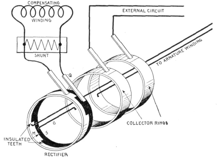
Fig. 1,457.—Diagram showing construction of rectifier and connections of compositely excited
alternator. The rectifier consists of two castings M and S with teeth which fit together
as shown, being insulated so they do not come in contact with each other. Every alternate
tooth being of the same casting is connected together, the same as though joined by a
conducting wire. There are as many teeth as there are poles. One end of the armature
winding is connected direct to one of the collector rings, while the other is connected to M of
the rectifier, the circuit being through brushes P and Q, the shunt, and compensating winding
to the other collector ring. The brushes P and Q contact with adjacent teeth, when one
is in contact with the solid black casting the other touches the light casting. The
principle of action is the same as a commutator, briefly: to reverse the connections terminating
at the brushes P and Q in synchronism with the reversals of the alternating
current induced in the armature winding, thus obtaining direct current for the compensating
field winding. The shunt resistance placed across the compensating winding circuit permits
adjusting the compounding of the machine to the circuit on which it is to work, since
by varying the resistance the percentage of the total current passing through the compensating
winding can be changed. It will be seen by tracing the path of the current for
each direction in the armature winding that while the rectifier causes the current to flow
in the same direction in the compensating field winding, it still remains alternating in the
external circuit.
[Pg 1194]
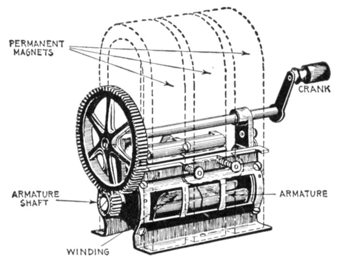
Fig. 1,458.—Connecticut magneto; view showing permanent magnets in dotted lines. It
consists of three permanent U shape magnets, between the poles of which is a shuttle type
armature. The latter is geared to a hand crank in sufficient velocity ratio to give the
desired speed without too rapid turning of the crank. This type of magneto is used to
generate current for operation of telephone call bells.
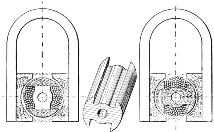
Figs. 1,459 to 1,461.—Diagram illustrating the operation of a magneto. The shuttle shaped
armature is wound from end to end with insulated wire, so that when rotated, a powerful
alternating current is produced in the windings by cutting the magnetic lines, whose varying
strength is shown by the shaded portions in the two views. When in the position shown
in the first diagram, the lines of force mostly converge at the top and bottom, finding a direct
path through the metal end flanges of the shuttle. When in the position shown in the
second diagram, the lines are converged so as to pass through the armature core. Fig.
1,460 shows detail of the armature core.
[Pg 1195]
Ques. What are the two principal types of field magnet?
Ans. Stationary and revolving.
Ques. What is the usual construction of stationary
field magnets?
Ans. Laminated pole pieces are used, each pole being made
up of a number of steel stampings riveted together and bolted or
preferably cast into the frame of the machine. The field coils are
machine wound and carefully insulated. After winding they
are taped to protect them from mechanical injury. Each coil is
then dipped in an insulating compound and afterwards baked
to render it impervious to moisture.
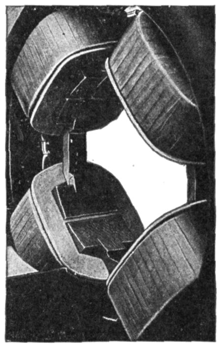
Fig. 1,462.—Stationary field of Fort Wayne multiphase revolving armature alternator; view
showing brass girds on pole pieces for synchronous motor operation. When designed
for this use the machine is provided with amortisseur winding on the poles. As shown in
the illustration this winding consists of a brass collar around the pole tip with a cross rib
integral with the collar, fitting in a slot in the pole face parallel to the shaft. This construction
assists in bringing the machine up to synchronous speed as an induction motor,
ordinarily checks any tendency toward hunting and does not in any way affect the operation
of the machine as an alternator. The main field winding should be connected through
switches on the field frame in order that the field circuit may be broken up to eliminate
any danger that might arise from induced voltage. It is not advisable to throw on a full
rated voltage and a compensator should, therefore, be provided to reduce the pressure.
[Pg 1196]

Fig. 1,463.—Triumph 36 pole fly wheel type revolving field. The spider has the form of a
fly wheel having spokes and rim to which the field magnets are attached by through bolts.
The field coils are of copper strap bent on end, the kind generally used on large machines.
The series connection of the coils is plainly shown, also the two cables leading via one of
the spokes to the slip rings.
[Pg 1197]
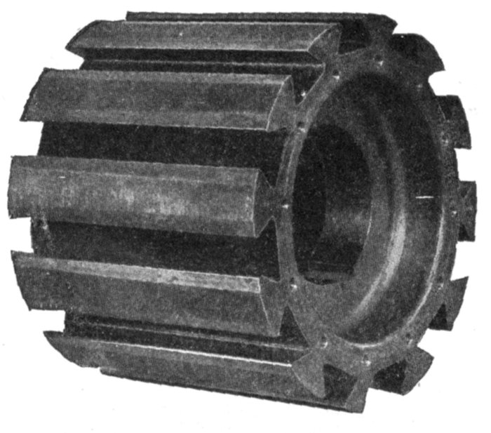
Fig. 1,464.—Wagner cast steel hub with dovetail
grooves for attaching the revolving field magnets.
Such construction is generally used on machines of
small and medium size.
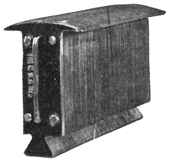
Fig. 1,465.—Wagner laminated pole piece with horns
stamped in one piece. The laminations are held
together between two end pieces by through rivets,
as shown.
Ques. Describe the
construction of a revolving
field.
Ans. The entire
structure or rotor consists
of a shaft, hub or
spider, field magnets and
slip rings. The magnet
poles consist of laminated
iron stampings
clamped in place by
means of through bolts
which, acting through
the agency of steel end
plates, force the laminated
stampings into a
uniform, rigid mass.
This mass is magnetically
subdivided into so
many small parts that
the heating effect of
eddy currents is reduced
to a minimum. The cores
are mounted upon a hub
or spider either by dovetail
construction or by
means of through bolts,
according to the centrifugal
force which they
must withstand in operation,
either method permitting
the easy removal
of any particular[Pg 1198]
field pole if necessary. The field coils are secured upon the
pole pieces either by horns in one piece with the laminations,
or separate and bolted. All the coils are connected in series,
cable leads connecting them to slip rings placed on the shaft.

Fig. 1,466.—Wagner revolving field of 300 kilowatt alternator during construction, illustrating
the method of attaching the field magnets to the hub by dovetail joints. After
the notched ends of the pole pieces are slid into the grooves in the hub, tapered keys,
which are plainly seen, are driven in, thus making a tight joint which will not shake loose.
Ques. What are slip rings?
Ans. Insulated rings mounted upon the alternator shaft to
receive direct current for the revolving field, as distinguished
from collector rings which collect the alternating currents
generated in an alternator of the revolving armature type.
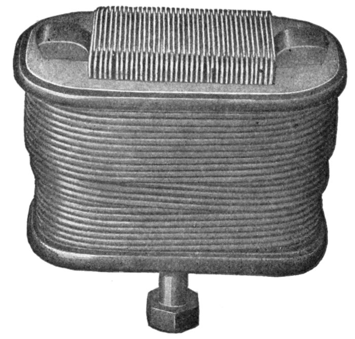
Fig. 1,467.—General Electric field coil, showing one
method of winding. In the smaller machines the
wire is wound on spools which are slipped over the
pole pieces, which are built of sheet iron, spreading at
the pole face so as to secure not only a wide polar arc
for the proper distribution of the magnetic flux, but
also to hold the field windings in place.
In construction provision is made for attaching the field winding
leads. The rings are usually made of cast iron and are supported[Pg 1199]
mechanically upon
the shaft, but are
insulated from it
and from one another.
The current is introduced
by means
of brushes as with a
commutator. Carbon
brushes are generally
used.
A good design of
slip ring should provide
for air circulation
underneath and
between the rings.
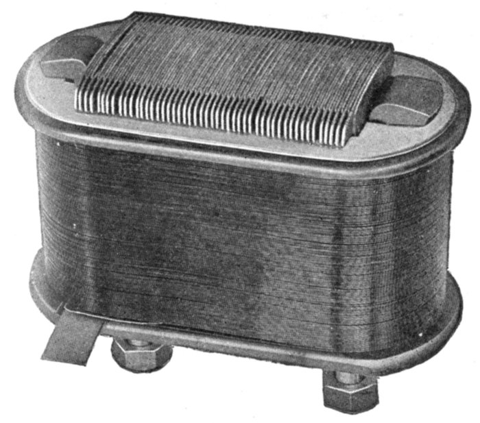
Fig. 1,468.—General Electric
field coil showing another
method of winding. The field
coils on the larger machines
consist of a single strip of flat
copper, wound on edge as
shown, so that the surface of
every turn is exposed to the
air for cooling. The flat sides
of the copper strip rest
against each other and the
entire coil forms a structure
of great solidity which can be
easily removed for inspection
and repair.
Ques. What
form of spider is
used on large alternators?
Ans. It is practically
the same form
as a fly wheel, consisting
of hub, spokes,
and rim to which the
magnets are bolted.
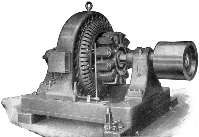
Fig. 1,469.—Allis-Chalmers 60 kva. belted two bearing alternator on base arranged so the armature can be shifted sideways as
shown, to give access to the field and armature coils.
[Pg 1201]
On alternators of the fly wheel type the spider rim is made of
sufficient weight to obtain full fly wheel effect, thus making a
separate fly wheel unnecessary.
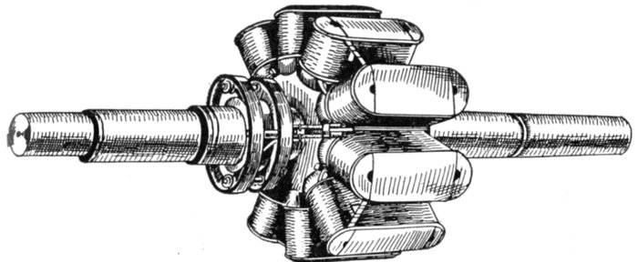
Fig. 1,470.—Revolving field of Fort Wayne 10 pole alternator. In construction, the cores
of the field poles are built up from punchings of laminated steel, and assembled under
considerable pressure between malleable iron or steel end plates and riveted together.
Substantial insulation is placed on the pole cores and over this is wound the field coils
of cotton covered wire. After the wire is in place, the completed poles are baked to expel
any moisture and are then treated with insulating varnish. They are then assembled
on a laminated spider, being held in place by dovetail joints made tight by the use of
taper keys. Special casting plates are finally fastened in place over the dove tails effectually
closing them. The assembly of the field is completed by the insertion of the shaft into
the field spider under heavy hydraulic pressure. All the coils are connected in series,
cable leads connecting them to slip rings placed on the shaft. Each slip ring is provided
with a double type brush holder, making it possible to clean brushes while the alternator
is in service, by simply removing one brush at a time.
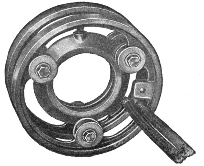
Fig. 1,471.—General Electric
slip rings; view showing
construction and attachment
of cable leads
to field winding. They
are so designed that all
surfaces of the rings have
easy access to the air, in
order to obtain good
ventilation. Slip rings,
through which current is
transmitted to a revolving
field, are to be distinguished
from collector
rings whose function it
is to "collect" or transmit
the alternating currents
induced in the
armature to the brushes.
[Pg 1202]
Armatures.—In construction, armatures for alternators are
similar to those employed on dynamos; they are in most cases
simpler than direct current armatures due to the smaller number
of coils, absence of commutator with its multi-connections, etc.
Alternator armatures may be classified in several ways:
1. With respect to operation, as
- a. Revolving;
- b. Stationary.
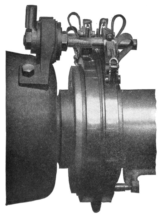
Fig. 1,472.—Allis-Chalmers
brush holder and slip
rings. The latter are
made of cast copper,
which the builders
claim to be more satisfactory
than cast iron.
On some of the large
low speed machines the
collector rings are split,
but on the majority of
alternators they are in
one piece. Current is led
into the rings by means
of carbon brushes, the
number of brushes being
such that the current
density at the rubbing
contact is kept
within conservative
limits. At least two
brushes per ring are
provided, so that one
can be removed for inspection
without interrupting
the exciting
current. In large machines
the brush holder
studs are mounted on
a stand supported from
the base; on small alternators
they are usually
fastened to the cap of
one of the bearing pedestals.
[Pg 1203]
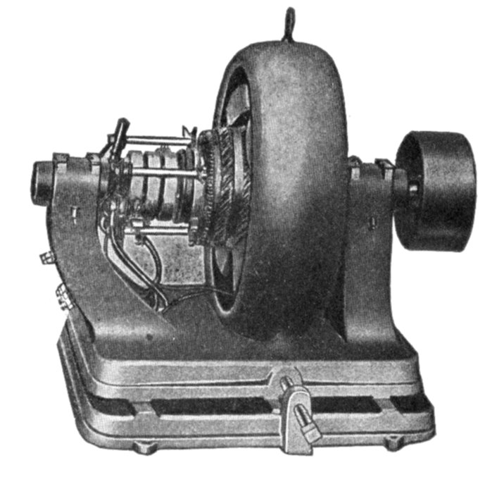
Fig. 1,473.—Fort Wayne multiphase
revolving armature alternator,
designed for use in
small power plants and isolated
lighting plants where inductive
loads are encountered. Built
for pressures of 120, 240, 480,
and 600 volts. These voltages
have been recommended by the
American Institute of Electrical
Engineers, and will cover the
needs of any set of conditions
ordinarily met with. These
standard voltages not only permit
economical distribution, but
they are such that no transformers
are necessary to reduce
the line pressure for ordinary
cases. For transmitting
power relatively long distances,
600 volts is usually employed.
Where there is a demand for
480 volt service, a 480 volt alternator
should be selected and
if lower voltages are also desired
an auto-transformer may be
furnished by means of which
240 volts can be obtained. When 120 volt circuits are necessary for lighting, etc., the
240 volt pressure can be still further reduced to 120 volts by means of another auto-transformer.
However, this double reduction will rarely be found necessary.
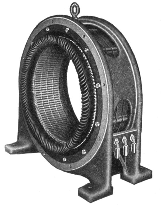
Fig. 1,474.—Western Electric stationary
armature. In this type of
armature, the core upon which the
winding is placed, is built into the
frame as shown, the core teeth projecting
inwardly like internal gear
teeth, forming a cylindrical chamber
for the revolving field. The core
is built up of iron, laminated and
japanned to prevent eddy currents
and hysteresis losses. The laminations
are rigidly bolted between
two heavy end plates. The armature
coils are of copper bar impregnated
with insulating compound.
They are held in the slots
by wedges which allow their ready
removal for inspection or repairs.
[Pg 1204]
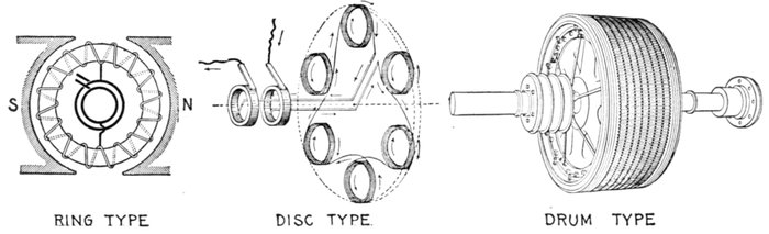
Figs. 1,474 to 1,477.—Various types of armature; fig. 1,474 ring armature; fig. 1,475 disc armature; fig. 1,476 drum armature.
The latter type is now almost universally used, the others being practically obsolete. A Gramme ring wound and connected
to collector rings as in fig. 1,474, will yield an alternating current. In a multipolar field, the ring will need multipolar connections
alternated at points corresponding to the pitch of the poles. Fig. 1,475 illustrates the so-called "Siemens" disc
armature. The armature coils are arranged around the periphery of a thin disc. The field magnets consist of two crowns
of fixed coils, with iron cores arranged so that their free poles are opposite one another. This type was created in 1878
by Herr von Hefner, engineer to Messrs. Siemens and Halske. Fig, 1,476 shows a modern drum armature of a three
phase machine. It is similar in appearance to a direct current armature except for the absence of the commutator and
its connections. The drum armature is the prevailing type.
2. With respect to
the core, as
- a. Ring;
- b. Disc;
- c. Drum.
Ring and disc armatures
are practically obsolete and
need not be further considered.
A ring armature
has the inherent defect that
the copper inside the ring
is inactive.
Disc armatures were employed
by Pacinotti in
1878, and afterwards
adopted by Brush in his
arc lighting dynamos.
The design failed for mechanical
reasons, but electrically
it is, in a sense, an
improvement upon the
Gramme ring, in that inductors
on both sides of
the ring are active, these
being connected together
by circumferential connectors
from pole to pole,
thus, corresponding to the
end connectors on modern
drum armatures.
3. With respect to
the core surface, as
- a. Smooth core;
- b. Slotted core.
In early dynamos the
armature windings were
placed upon an iron core
with a smooth surface. A
chief disadvantage of this
arrangement is that the
magnetic drag comes upon
the inductors and tends to
displace them around the
armature. To prevent
[Pg 1205]
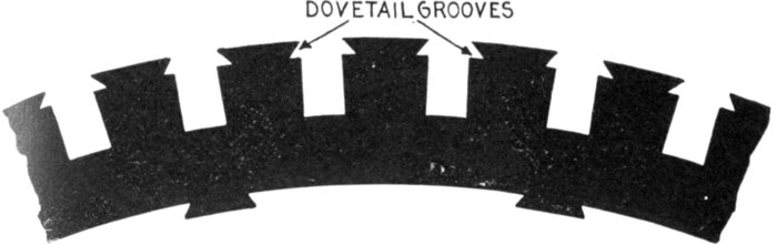
Fig. 1,478.—A style of disc largely used for armature cores. The teeth are provided with
dovetail grooves near the circumference. After the coil is inserted in a groove, a wooden
wedge is driven in the groove which encloses the coil and secures it firmly in position.
This obviates the necessity of bands to resist the centrifugal force acting on the inductors.
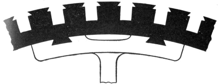
Fig. 1,479.—Large revolving armature construction with segmental discs dovetailed to spider
spokes.
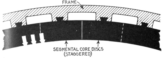
Fig. 1,480.—Construction of large stationary armature; view showing section of core and
frame. The core discs are in segments and are attached to the frame by dovetail joints
as shown. The joints are staggered in building up the core, that is, they are overlapped
so as not to unduly increase the reluctance of the magnetic circuit. Dovetail joints
obviate the use of through bolts which, if not insulated, are liable to give rise to eddy
currents by short circuiting the discs.
[Pg 1206]
this, projecting metal pieces called driving horns were fixed into the core so as to
take the pressure, but they proved unsatisfactory. This defect together with the
long air gap necessary in smooth core construction resulted in the type being displaced
by slotted core armatures.
A slotted core is one whose surface is provided with slots or teeth which carry
the inductors, as shown in the accompanying illustrations, and is the type almost
universally used. The inductors are laid in the slots, the sides and bottoms of which
are first carefully insulated by troughs of mica-canvas, micanite or other suitable
insulating material.
Ques. What are the advantages of slotted core armatures?
Ans. The teeth protect the inductors, retain them in place
against the electrical drag and centrifugal force, and the construction
permits a reduction of air gap to a minimum, thus reducing
the amount of copper required for the field.
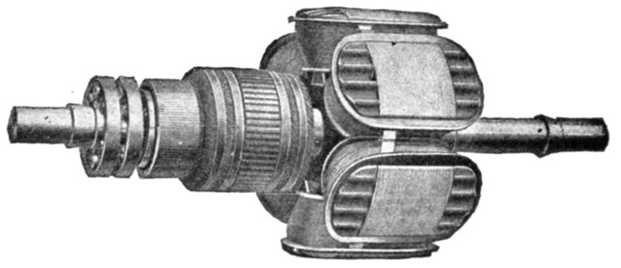
Fig. 1,481.—General Electric revolving field and exciter armature. This is an example of direct
connected exciter construction. In this arrangement the armature of the exciter is carried
on the alternator shaft at the end farthest from the pulley. In the smaller sizes the magnet
frame is bolted to the bearing bracket, but in the larger sizes special construction is used
depending upon the conditions to be met. On all alternators of standard design, the
field is built for 125 volts excitation and on account of the increased danger from induced
voltage, in case the machine is used as a synchronous motor, the builders consider any
higher voltage undesirable.
[Pg 1207]
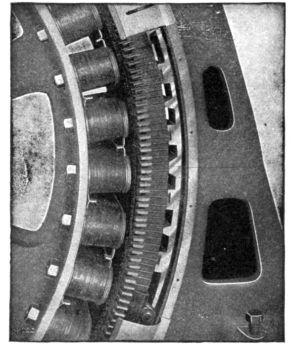
Fig. 1,482.—Section of General Electric Alternator showing method of dovetailing core laminations
to frame. The latter is made in two general styles, known as the box type and
skeleton type. The box type consists of a single casting for the smaller sizes, but for large
capacity alternators the frame castings are usually divided into upper and lower sections.
The skeleton type consists of two side castings between which substantial spacing
rods are set at regular intervals. The core consists of the usual sheet iron lamination
slotted and assembled; they are mounted on the inner periphery of the frame, making
lap joints (that is "staggered" as in fig. 1,480), each section being dovetailed to the frame.
Heavy clamping rings or end plates are mounted on both sides of the core by means of
bolts, and supporting fingers extend along the slot projections. The design is such as to
provide for air circulation as shown in figs. 1,483 and 1,484.
Armature Windings.—In general, the schemes for armature
windings for alternators are simpler than those for direct current
machines, as in the majority of cases the inductors are an even
multiple of the number of poles, and the groupings are usually
symmetrical with respect to each pole or each pair of poles. Furthermore,
as a general rule, all the inductors of any one phase are in
series with one another; therefore, there is only one circuit per
phase, and this is as it should be, since alternators are usually
required to generate high voltages. These general principles
establish the rule, that in the circuit in a single phase armature,
and in the individual circuits in a polyphase armature, the
winding is never re-entrant, but the circuits have definite endings
and beginnings. In exceptional cases, as those of polyphase
converters, re-entrant circuits are employed, and the armature
windings are so constructed that a commutator can be[Pg 1208]
connected to them exactly as in direct current machines.
These armatures are usually of the lap wound drum type.
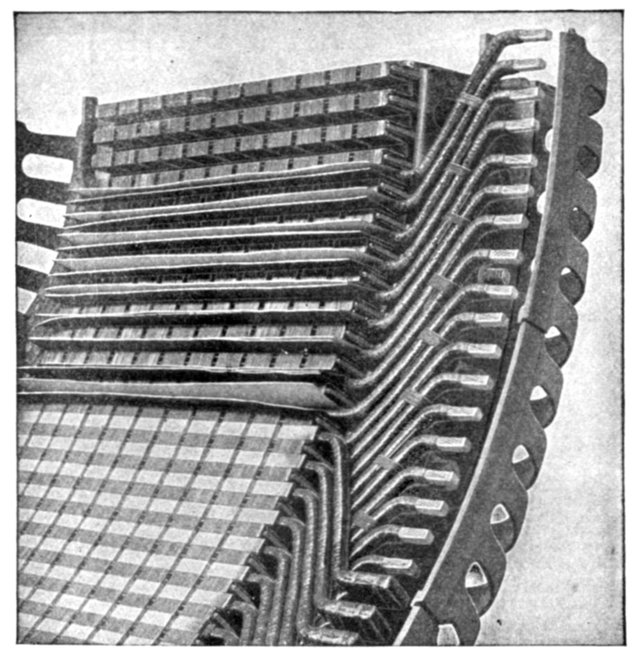
Fig. 1,483.—Section of General Electric alternator frame showing air ducts and supporting
fingers extending along the slot projections. The air circulation is provided for by means
of ducts formed by suitable spacing blocks inserted at intervals between the laminations,
as shown here and in fig. 1,484. The armature coils are form wound and designed so they
can be readily replaced in case of injury. They are taped and treated with an impregnating
compound, in the usual way, then inserted in the armature slots in an armour of
horn fibre and retaining wedges of wood are dovetailed into the slot walls.
Alternator windings are usually described in terms of the
number of slots per phase per pole. For instance, if the armature
of a 20 pole three phase machine have 300 slots, it has 15 slots
per pole or 5 slots per each phase per pole, and will be described
as a five slot winding. Therefore, in order to trace the connections
of a winding, it is necessary to consider the number of slots
per pole for any one phase on one of the following assumptions:[Pg 1209]
1, that each slot holds one inductor; 2, that there is one side
of a coil in each slot; and 3, that one side of a coil is subdivided
so as to permit of its distribution in two or more adjacent slots.
The voltage depends upon the number of inductors in a slot,
but the breadth coefficient and wave form are influenced by the
number of slots per pole, and not by the number of inductors
within the slots.
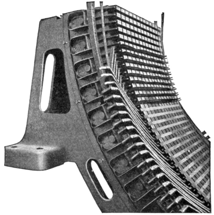
Fig. 1,484.—Section of General Electric stationary armature showing method of assembling
the coils. These are form wound and are held in the slots by suitable wedges, the open
slot construction permitting the use of form wound coils that can be easily removed and
replaced in case of damage. Where heavy windings project beyond the laminations, an
additional support is provided by means of an insulated metal ring, to which the outer
ends of the coils are fastened; the coils are thereby protected from mechanical displacement,
or distortion due to the magnetic disturbances caused by violent fluctuations of
the load or short circuits. The figure shows a section of a supporting ring of this type
and indicates the method of connecting the coils to it. In order to admit of the prompt
replacement of damaged coils, sufficient space is usually provided between the alternator
bearings to allow ample movement of the armature to permit of ready access to both armature
and field coils. Where space necessitates the use of a short shaft, access to the windings
may be had by disconnecting some of the coils and lifting the upper half of the armature.
[Pg 1210]
Classification of Windings.—The fact that alternators are
built in so many different types, gives rise to numerous kinds of
armature winding to meet the varied conditions of operation.
In dividing these forms of winding into distinctive groups, they
may be classified, according to several points of view, as follows:
1. With respect to the form of the armature, as:
- a. Revolving;
- b. Stationary.
2. With respect to the mode of progression, as:
- a. Lap winding;
- b. Wave winding.
3. With respect to the relation between number of poles
and number of coils, as:
- a. Half coil winding;
- b. Whole coil winding.
4. With respect to the number of slots, as:
- a. Concentrated or uni-coil winding;
- b. Distributed or multi-coil winding.
- Partially distributed;
- Fully distributed.
5. With respect to the form of the inductors, as:
- a. Wire winding;
- b. Strap winding;
- c. Bar winding.
6. With respect to the number of coils per phase per pole, as:
- a. One slot winding;
- b. Two slot winding;
- etc.
[Pg 1211]
7. With respect to the kind of current delivered, as:
- a. Single phase winding;
- b. Two phase winding;
- c. Three phase winding.
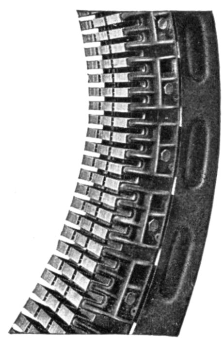
Fig. 1,485.—Section of Western Electric stationary armature core showing laminations clamped
in place, and ventilating ducts. The stator or stationary armature consists of soft iron
laminations assembled in the magnet frame with stator coils embedded in the core slots.
The laminations are punched separately and then carefully annealed to reduce hysteresis
losses. After annealing, a coat of japan is applied, effectively preventing the flow of eddy
currents in the assembled core. The frame is cast iron and of the box type construction.
The frames of the smaller sizes are cast in one piece, while frames of the larger sizes are
split to facilitate installation. Large openings are provided in the box type frame, in order
to improve the ventilation. The laminations are securely held in place in the frame by
heavy end rings and by steel clamping fingers which are firmly bolted to the frame. The
outer circumference of the core is dovetailed to the frame, and the inner circumference is
slotted to receive the windings. The alignment of the slots is insured by means of metal
wedges, and no filing is done on the slots, so that each lamination is always insulated from
the next one. Numerous ventilating ducts allow the free circulation of cool air through
and around the coils. The open slot construction is employed and the coils are fitted into
insulating troughs which offer excellent mechanical and electric protection. The coils
are held in place by suitable wedges.
8. With respect to the shape of the coil ends, as:
- a. Single range;
- b. Two range;
- etc.
[Pg 1212]
In addition to these several classes of winding, there are a
number of miscellaneous windings of which the following might
be mentioned:
- a. Chain or basket winding;
- b. Skew coil winding;
- c. Fed-in winding;
- d. Imbricated winding;
- e. Mummified winding;
- f. Spiral winding;
- g. Shuttle winding;
- h. Creeping winding;
- i. Turbine alternator winding.
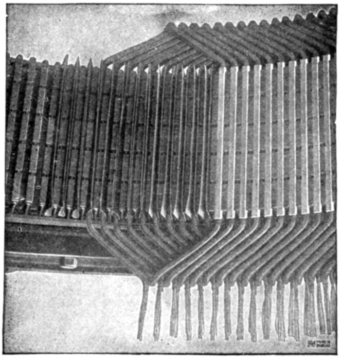
Fig. 1,486.—Method of assembling form wound coils. The picture shows a section of a General
Electric armature with part of the coils in place. A layer of insulating material is first
placed in the slots, before inserting the coils as seen at the left. When the coils are in place
and surrounded by this layer of insulating material the retaining wedges are inserted in the
notches, thus closing the slots and protecting the coils from mechanical injury. A few
wedges are seen in position at the right.
[Pg 1213]
Ques. Define a revolving and a stationary winding.
Ans. The words are self-defining; a winding is said to be
revolving or stationary according as the armature forms the
rotor or stator of the machine.
Ques. What is the significance of the terms lap and
wave as applied to alternator windings?
Ans. They have the same meaning as they do when applied
to dynamo windings.
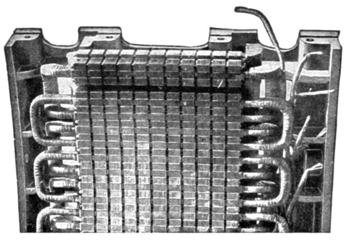
Fig. 1,487.—Section of General Electric stationary armature ventilating ducts and winding
in position.
These are described in detail in Chapter XVIII. Briefly a lap winding
is one composed of lap coils; a wave winding is one which roughly
resembles in its diagram, a section of waves.
Half Coil and Whole Coil Windings.—The distinction as
to whether the adjacent sides of consecutive coils are placed
together under one pole or whether they are separated a distance
equal to the pole pitch, gives rise to what is known as half coil
and whole coil windings.
[Pg 1214]
A half coil or hemitropic winding is one in which the coils
in any phase are situated opposite every other pole, that is, a
winding in which there is only one coil per phase per pair of
poles, as in fig. 1,488.
A whole coil winding is one in which there is one coil per phase
per pole, as in fig. 1,489, the whole (every one) of the poles
being subtended by coils.
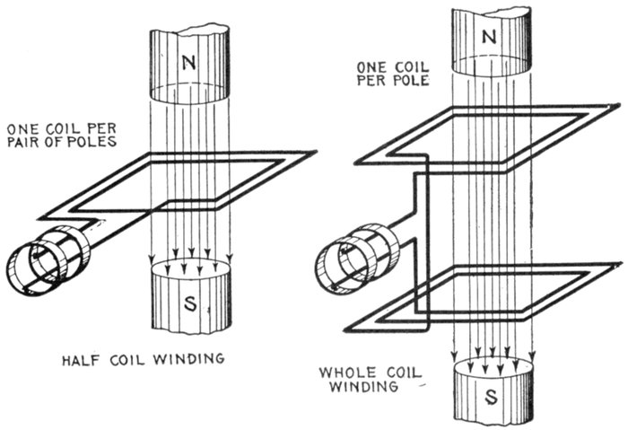
Figs. 1,488 and 1,489.—Elementary bipolar alternators with half coil and whole coil windings.
In a half coil winding there is one coil per phase per pair of poles; in a whole coil winding
there is one coil per phase per pole.
Concentrated or Uni-Coil Winding.—Fig. 1,492 shows
the simplest type of single phase winding. It is a one slot
winding and is sometimes called "monotooth" or "uni-coil"
winding. The surface of the armature is considered as divided
into a series of large teeth, one tooth to each pole, and each tooth
is wound with one coil, of one or more turns per pole. Since[Pg 1215]
all the turns of the coil are placed in single slots, the winding is
called "concentrated."
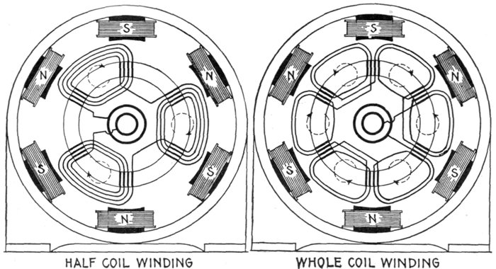
Fig. 1,490.—Multi-polar revolving armature alternator with half coil winding, shown in radially developed diagram to clearly
indicate the path of the winding. A half coil or hemitropic winding has a slightly higher reactance than a winding in which
two distinct coils are used in the same slot, one going forward and the other backward. The most usual three phase windings
are of the half coil type as the three sets of coils are equispaced over a pair of poles.
Fig. 1,491.—Multi-polar revolving armature alternator with whole coil winding shown in radially developed diagram to clearly
indicate the path of the winding.
[Pg 1216]
Ques. What are the features of concentrated windings?
Ans. Cheap construction, maximum voltage for a given
number of inductors. Concentrated windings have greater
armature reaction and inductance than other types hence the
terminal voltage of an alternator with concentrated winding
falls off more than with distributed winding when the current
output is increased. An alternator, therefore, does not have as
good regulation with concentrated winding as with distributed
winding.
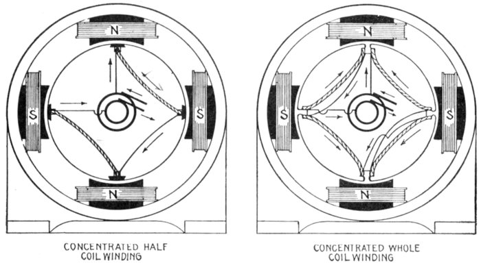
Figs. 1,492 and 1,493.—Concentrated windings. A concentrated winding is one in which the
armature has only one tooth per phase per pole, that is, the number of teeth equals the number
of poles. A concentrated winding of the half coil type has only one side of a coil in each
slot as in fig. 1,492. In the whole coil variety, each slot contains neighboring sides of
adjacent coils, as in fig. 1,493. In construction, wedges are generally used for retaining the
half coils, and with whole coils the teeth have projecting horns for this purpose.
Ques. What should be noted with respect to concentrated
windings?
Ans. A concentrated winding, though giving higher voltage[Pg 1217]
than the distributed type with no load, may give a lower voltage
than the latter at full load.
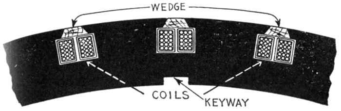
Fig. 1,494.—Laminated core with two coils in position; type of punchings used on some
machines having concentrated whole coil windings. The manner of assembling the coils
is shown in fig. 1,495.
Ques. What is the wave form with a concentrated
winding?
Ans. The pressure curve rises suddenly in value as the
armature slots pass under the pole pieces, and falls suddenly as
the armature slots recede from under the pole pieces.
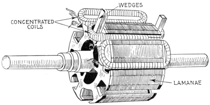
Fig. 1,495.—Westinghouse single phase concentrated coil armature; view showing method
of placing coils. The coils are machine wound on formers and after being taped, varnished
and baked, are spread out slightly so as to pass over the teeth and are then forced into
place in the deep slots by means of wooden wedges, being securely held in place by retaining
wedges, as shown in fig. 1,494.
[Pg 1218]
Distributed or Multi-Coil Windings.—Instead of winding
an armature so it will occupy only one slot per phase per pole,
it may be spread out so as to fill several slots per phase per pole.
This arrangement is called a distributed winding.
To illustrate, fig. 1,496 represents a coil of say fifteen turns. This
could be placed on an armature just as it is, in which case only one
slot would be required for each side, that is, two in all. In place of
this thick coil, the wire could be divided into several coils of a lesser
number of turns each, arranged as in fig. 1,497; it is then said to be
partially distributed, or it could be arranged as in fig. 1,498, when it is
said to be fully distributed.
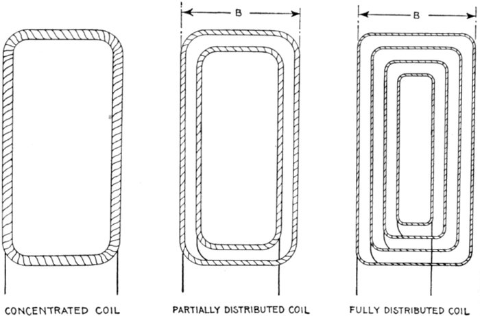
Figs. 1,496 to 1,498.—Alternator coils, showing difference between the concentrated, partially
distributed, and fully distributed forms. Fig. 1,496 shows a concentrated coil in which
all the wire is wound in one large coil; in the partially distributed type fig. 1,497, the
wire of fig. 1,496, is wound in two or more coils or "sections" connected as shown, leaving
some space inside not taken up by the subdivisions. In fig. 1,498 the wire of fig. 1,496 is
fully distributed, being wound in a series of coils, so that all the interior space is taken up
by the wire, that is to say, the spaces not occupied by the wire (the teeth when placed on
the armature) are of equal size.
[Pg 1219]
A partially distributed winding, then, is one, as in fig. 1,499,
in which the coil slots do not occupy all the circumference of the
armature; that is, the core teeth are not continuous.
A fully distributed winding is one in which the entire surface
of the core is taken up with slots, as in fig. 1,500.
Ques. In a distributed coil what is understood by the
breadth of the coil?
Ans. The distance between the two outer sides, as B in figs.
1,497 and 1,498.
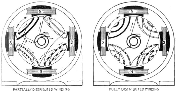
Fig. 1,499.—Partially distributed winding. Each coil unit is here divided into two concentric
coils of different dimensions and connected in series, as shown in detail in fig. 1,497. This
being a "whole coil" winding the several units are so connected that the winding of adjacent
units proceeds in opposite directions, that is, one coil is wound clockwise, and the
next counter clockwise, etc., so that the induced currents flow in a common direction as
indicated by the arrows for the position shown.
Fig. 1,500.—Fully distributed winding. In this type of winding each coil consists of so many
sub-coils that the winding occupies the entire surface of the armature core; that is, there
are no extensive spaces unoccupied, the spacing being uniform as shown.
Ques. How far is it advisable to spread distributed
coils of a single phase alternator?
Ans. There is not much advantage in reducing the interior[Pg 1220]
breadth much below that of the breadth of the pole faces, nor is
there much advantage in making the exterior breadth greater
than the pole pitch.
Undue spreading of distributed coils lowers the value of the Kapp
coefficient (later explained) by reducing the breadth coefficient and
makes necessary a larger number of inductors to obtain the same voltage.
The increase in the number of inductors causes more armature self-induction.
From this point of view, it would be preferable to concentrate
the winding in fewer slots that were closer together. This, however,
would accentuate the distorting and demagnetizing reactions of the
armature. Accordingly, between these two disadvantages a compromise
is made, as to the extent of distributing the coils and spacing of the
teeth, the proportions assigned being those which experience shows best
suited to the conditions of operation for which the machine is designed.
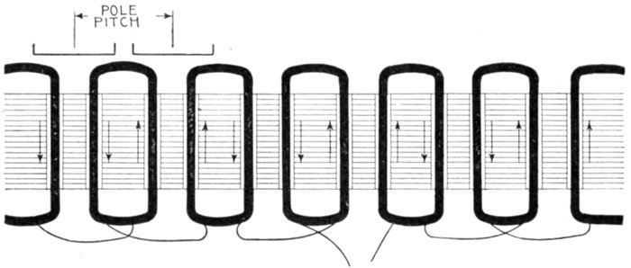
Fig. 1,501.—Developed diagram of single phase concentrated whole coil winding in two slot
stamping for six pole alternator. If the sides of adjacent whole coils be slightly separated
by placing the winding in a two slot stamping the electrical result will not differ materially
from the monotooth whole coil winding, but if the winding be hemitropic, as in fig. 1,502,
and has coils of two sizes as shown, it will be suitable for high voltages.
The Kapp Coefficient.—A volt or unit of electric pressure is
defined as the pressure induced by the cutting of 100,000,000 or
108 lines of force per second. In the operation of an alternator
the maximum pressure generated may be expressed by the
following equation:
[Pg 1221]
in which
- f = frequency;
- Z = number of inductors in series in any one magnetic circuit;
- N = magnetic flux, or total number of magnetic lines in one pole or in one magnetic circuit.
The maximum value of the pressure, as expressed in equation
(1), occurs when θ = 90°.
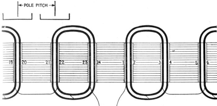
Fig. 1,502.—Developed diagram of single phase partially distributed half coil winding for
six pole alternator in two slot stamping, same as in fig. 1,501. In this arrangement the
direction of rotation is not reversed. It is a question as to how far the coils of a single-phase
armature may be spread with advantage. There is not much advantage in reducing
the interior breadth of the coils below that of the pole face, nor in widening the exterior
breadth beyond that of the pole pitch.
The virtual value of the volts is equal to the maximum value
divided by √2, or multiplied by ½ √2, hence,
This is usually taken as the fundamental equation in designing
alternators. It is, however, deduced on the assumptions that[Pg 1222]
the distribution of the magnetic flux follows a sine law, and that the
whole of the loops of active inductors in the armature circuit acts
simultaneously, that is to say, the winding is concentrated.
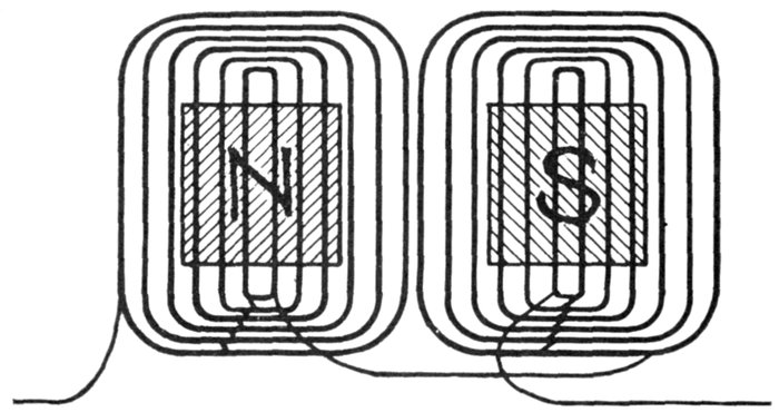
Fig. 1,503.—Developed diagram of single phase winding with fully distributed coils. As
explained, excessive spreading lowers the value of the "Kapp" coefficient, and consequently
the voltage; also the use of a larger number of inductors to obtain the same
voltage results in an increase of armature self-induction. On the other hand, if the winding
were concentrated in fewer slots and these slots were closer together, the result will be an
increase in distorting and demagnetizing reactions of the armature. Therefore, a compromise
between these two disadvantages must be made. The common practice is to wind
in two or three slots per pole per phase.

Fig. 1,504.—Allis-Chalmers lap wound coils forming a three slot distributed coil unit. In
construction, after the coils have been covered with insulating materials and treated with
insulating compound, the parts that lie in the slots are pressed to exact size in steam-heated
moulds. This runs the insulating material into all the small spaces in the coil,
excluding moisture and rendering the insulation firm and solid. The ends of the coils,
where they project beyond the slots, are heavily taped.
[Pg 1223]
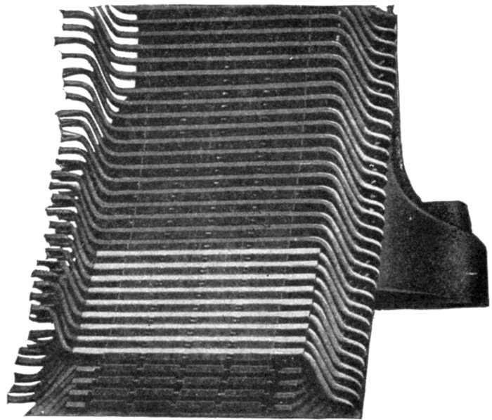
Fig. 1505.—Allis-Chalmers armature construction; view showing section of frame and two
layer winding.
In practice, the coils are often more or less distributed, that
is, they do not always subtend an exact pole pitch; moreover, the
flux distribution, which depends on the shaping and breadth
of the poles, is often quite different from a sine distribution.
Hence, the coefficient 2.22 in equation (2) is often departed from,
and in the general case equation (2) may be written
where k is a
number which
may have different
values,
according to
the construction
of the alternator.
This
number k is
called the
Kapp coefficient
because
its significance
was first pointed
out by Prof.
Gisbert Kapp.
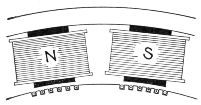
Figs. 1,506 and 1,507.—Effect of breadth of coils in distributed windings. In the section of the alternator shown in fig. 1,506 the
directions of the pressures induced as the armature rotates clockwise are represented by dots for those which act towards
the reader, and by crosses for those which act from the reader (the dots and crosses representing respectively the heads and
tails of arrows). Since the field is not uniform but maximum at the center and gradually weakening towards the extremities,
it is obvious that the maximum pressure is induced in any inductor as it passes the center of the pole, this variation being
indicated by the heavier dots and crosses toward the center. Now if a number of these inductors be connected up to form
a distributed coil as in fig. 1,507, the pressures induced in each will be added, but all the maximum pressure will not be
induced in all at the same time, hence the total pressure induced in the distributed coil is less than it would be if the coil
were concentrated as in fig. 1,509.
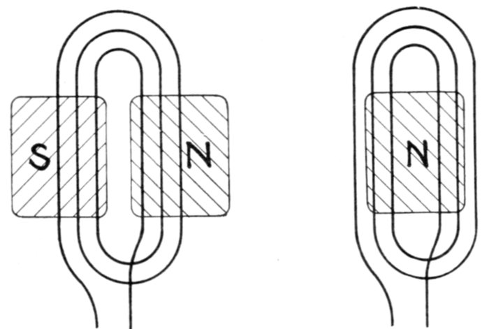
Fig. 1,508.—Diagram of distributed coil whose inner breadth is less than the breadth of the pole face, showing the disadvantage
of such arrangement. The pressures induced in the inner windings of such a coil are opposing each other at the instant
depicted, that is, while the inductors are under the pole face, such action of course being objectionable.
The value of
k is further influenced
by a
"breadth coefficient"
or
"winding factor."
The effect of
breadth in
distributed
windings is
illustrated in
figs. 1,506 to
1,508.
[Pg 1225]
Wire, Strap, and Bar Windings.—In the construction of
alternators, the windings may be of either wire, strap, or bar,
according to which is best suited for the conditions to be met.
Ques. What conditions principally govern the type of
inductor?
Ans. It depends chiefly upon the current to be carried and
the space in which the inductor is to be placed.
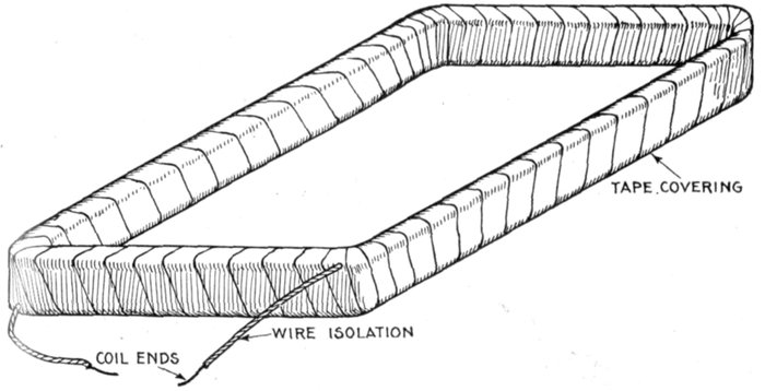
Fig. 1,509.—Simple form of alternator coil, consisting of numerous turns of insulated wire
wound around a form, then covered with a tape winding, varnished and baked.
Ques. What kind of inductors are used on machines
intended for high voltage and moderate current?
Ans. The winding is composed of what is called magnet wire,
with double or triple cotton insulation.
Ques. Where considerable cross section is required
how is a wire inductor arranged?
Ans. In order that the coil may be flexible several small
wires in multiple are used instead of a single large wire.
[Pg 1226]
Ques. How is the insulation arranged on inductors
of this kind?
Ans. Bare wire is used for the wires in parallel, insulation
being wrapped around them as in fig. 1,510.
This construction reduces the space occupied by the wires, and the
insulation serves to hold them in place.
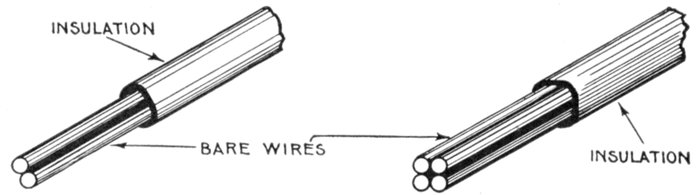
Figs. 1,510 and 1,511.—Multi-wire inductors. When the cross section of inductor necessary
to carry the current is large, the use of a single wire would present difficulties in winding
on account of its stiffness. Accordingly two or more smaller wires are used in parallel to
secure the required cross section. Bare wire is used and the several sections encased in
insulation as shown, the combination being more flexible than an equivalent single wire.
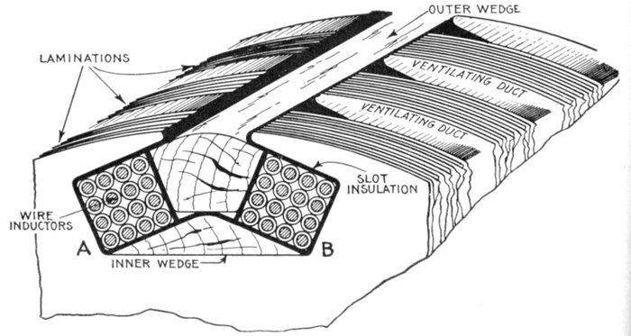
Fig. 1,512.—Two coil slot for whole coil winding. The slot has two recesses A and B for the reception
of separate coils. In assembling the winding, the inner wedge is first placed in
position and then the slot line with the insulating material. This usually consists of
alternate layers of mica and pressboard. The coils composed of several turns of wire
or copper strip are wound in place, and after covering with a layer of insulation, the outer
wedge is pushed in place to retain the inductors in position.
[Pg 1227]
Ques. What precaution is taken in insulating a wire
wound coil containing a large number of turns?
Ans. On account of the considerable difference of pressure
between layers, it is necessary to insulate each layer of turns as
well as the outside of the coil, as shown in fig. 1,513.
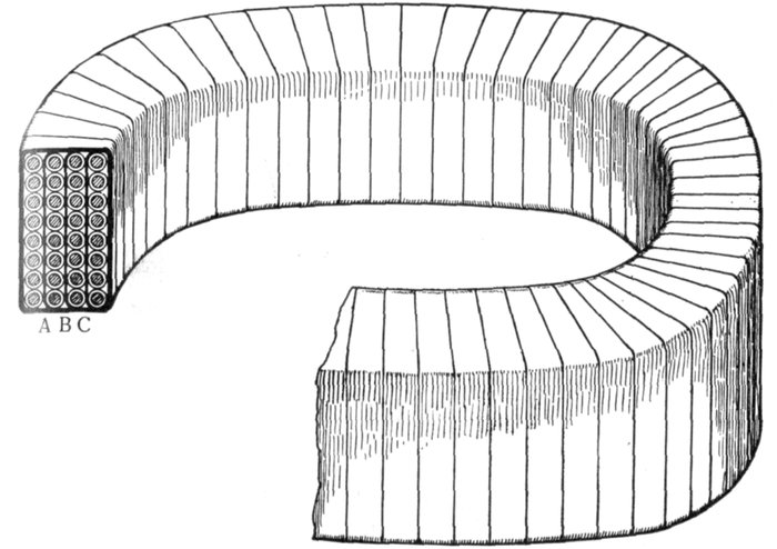
Fig. 1,513.—Method of winding a coil containing a large number of turns, when there is
considerable difference of pressure between the layers. In such cases to guard against
short circuits or breakdown of the insulation, each layer of turns is insulated from the
next layer by the insulating strips A, B, C, in addition to the regular insulation around
each wire. After the coil is made up it is wound with insulating tape, varnished and baked.
Ques. Do distributed coils require insulation between
the separate layers?
Ans. Since they are subdivided into several coils insulation
between layers is usually not necessary.
[Pg 1228]
Ques. How is a coil covered?
Ans. It is wound with a more or less heavy wrapping of tape
depending upon the voltage.
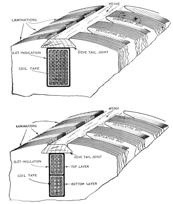
Figs. 1,514 and 1,515.—Single and double layer multi-wire inductors and methods of placing
them on the core. Here the term layer means unit, in fact each unit is made up of several
"layers" of wires. In fig. 1,514, where so many wires are bunched together in one unit,
each layer of turns is separated from those adjacent by insulating strips on account of the
considerable difference of pressure between layers. This insulation is not necessary in fig.
1,515 where there are two units or so called layers. In both cases the inductors are held
in place by wedges driven into dovetail grooves.
[Pg 1229]
Linen tape of good quality, treated with linseed oil, forms a desirable
covering. Where extra high insulation is required the tape may be
interleaved with sheet mica.
Ques. Is the insulation placed around the coils all
that is necessary?
Ans. The slots into which the coils are placed, are also
insulated.
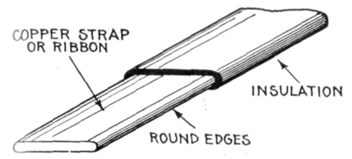
Fig. 1,516.—Copper strap or ribbon with insulation. These are generally from 1/32 to 1/16
inch thick with rounded edges as shown to avoid cutting the insulation.
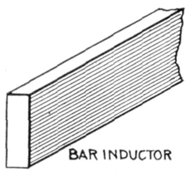
Fig. 1,517.—Bar inductor. Its shape enables putting the maximum cross section of copper into
the slot and is used to advantage on machines which generate large currents.
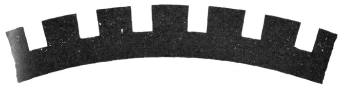
Fig. 1,518.—Style of armature core stamping used with bar wound machines. This construction,
since there are no indentations in the teeth for wedges, makes it necessary to
provide bands to hold the bars in place.
Ques. How are bar windings sometimes arranged?
Ans. In two layers, as in fig. 1,523.
[Pg 1230]
Single and Multi-Slot Windings.—These classifications
correspond to concentrated and distributed windings, previously
described. In usual modern practice, only two-thirds of the
total number of slots (assuming the spacing to be uniform)
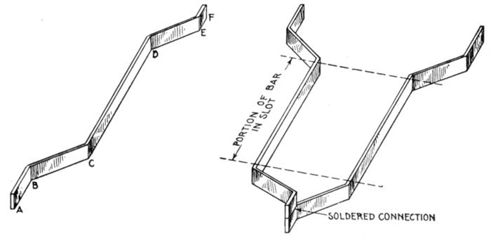
Figs. 1,519 and 1,520.—Bent bar inductor and method of connection with soldered joint.
Fig. 1,519 shows one bar and shape of bent ends. The portion from C to D is placed in the
slot; B to C and D to E, bent or connector sections; A to B and E to F, ends bent parallel
to slot for soldering. Fig. 1,520 shows two bar inductors connected.
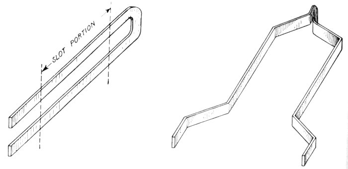
Figs. 1,521 and 1,522.—Method of avoiding a soldered joint at one end of a bar inductor by
using a bar of twice the length shown in fig. 1,519, and bending it into a long U form, as
in fig. 1,521, after which it is spread out forming two inductors, as in fig. 1,522.
[Pg 1231]
of a single phase armature are wound with coils. The reason
for this may be explained by aid of fig. 1,524, which shows an
armature with six slots per pole, four of which are wound.
Owing to the different positions of, say, coils A and B, there will
be a difference in phase between the pressure generated in them
and consequently the resultant pressure of the two coils joined
in series will be less than the sum of the pressure in each coil.
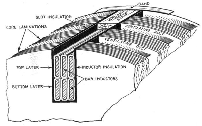
Fig. 1,523.—Arrangement in slot of two layer bar winding. With bar inductors, as must
be evident from the illustration, the maximum cross section of copper can be placed in a
slot of given dimension, hence a bar winding is used to advantage for alternators designed
to carry a large current. Bar inductors, on account of the shape of their ends, must be
placed in the slots from the top, because the bent ends do not admit of pushing them in.
Straight slots are therefore necessary, the inductors being held in place by wooden strips
and tie bands as shown.
Fig. 1,525 shows the pressure plotted out as vector quantities,
and the table which follows gives the relative effectiveness of
windings with various numbers of slots wound in series.
The figures in the last column of the table show that a large
increase in the weight of active material is required if the[Pg 1232]
inductors in a single phase machine are to be distributed over
more than two-thirds the pole pitch. Again, if much less than
two-thirds of the surface be wound, it is more difficult to provide
a sine wave of pressure.
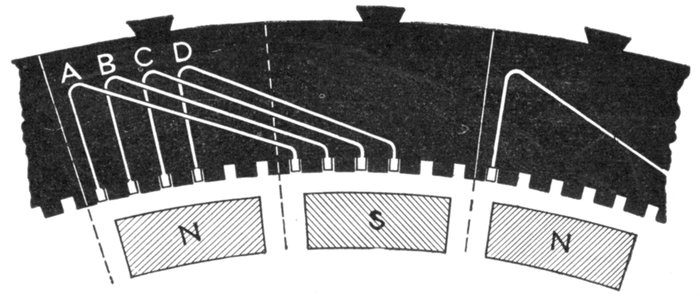
Fig. 1,524.—Diagram of single phase multi-coil or distributed winding to show characteristic
differences in action and construction from single coil or concentrated winding.
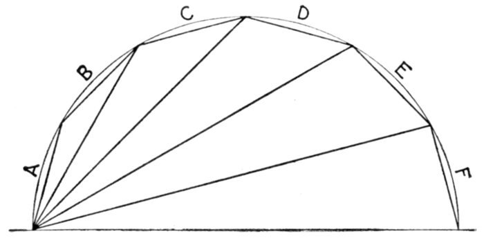
Fig. 1,525.—Vector diagram of pressures induced in the single phase multi-coil or distributed
winding shown in diagram in fig. 1,524.
[Pg 1233]
TABLE OF RELATIVE EFFECTIVENESS OF WINDINGS
| Slots wound in series |
Pressure across coils |
Winding coefficient |
Quantity of copper to produce same pressure |
| 1 |
1 |
1 |
1 |
| 2 |
1.93 |
.97 |
1.03 |
| 3 |
2.73 |
.91 |
1.10 |
| 4 |
3.34 |
.84 |
1.19 |
| 5 |
3.72 |
.74 |
1.35 |
| 6 |
3.86 |
.64 |
1.56 |
Ques. What other advantage besides obtaining a
sine wave is secured by distributing a coil?
Ans. There is less heating because of the better ventilation.
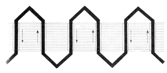
Fig. 1,526.—Developed diagram of a single phase monotooth or one slot bar winding; it is
suitable only for operation at low voltage.
Single Phase Windings.—There are various kinds of single
phase winding, such as, concentrated, distributed, hemitropic,
etc. Fig. 1,527 shows the simple type of single phase winding.
It is a "one slot" winding, that is, concentrated coils are used.
The armature has the same number of teeth as there are poles,
the concentrated coils being arranged as shown. In designing[Pg 1234]
such a winding, the machine, for example, may be required to
generate, say, 3,000 volts, frequency 45, revolutions 900 per
minute.
These conditions require 720 inductors in series in the armature
circuit, and as the armature is divided into six slots corresponding to
the six poles, there will be 120 inductors per slot, and the coil surrounding
each of the six teeth on the surface of the armature will consist of 60
turns. The connections must be such as to give alternate clockwise
and counter-clockwise winding proceeding around the armature.
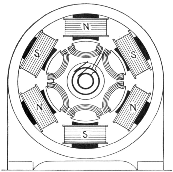
Fig. 1,527.—Diagram of six pole single phase revolving armature alternator, with monotooth
or concentrated whole coil winding. For 3,000 volts at 900 revolutions per minute, 120
inductors are required. And in the case of a concentrated or monotooth winding they
may be arranged in "whole coils" as above or in "half coils" (hemitropic) as in fig. 1,528.
Ques. In what other way could the inductors be
arranged in concentrated coils?
[Pg 1235]
Ans. They could be grouped in three coils of 120 turns each,
as shown in fig. 1,528.
When thus grouped the arrangement is called a hemitropic winding,
as previously explained.
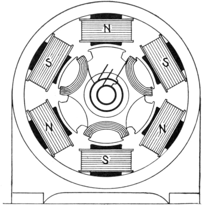
Fig. 1,528.—Diagram of six pole single phase alternator with concentrated half coil or hemitropic
winding of same capacity as in fig. 1,527. There are an equal number of inductors,
but in this case arranged in three instead of six coils. In this winding the direction of
winding is alternately reversed so that the induced pressures do not oppose one another.
Ques. What is the advantage, if any, of a half coil
winding?
Ans. In single phase machines a half coil winding is equivalent,
electrically, to a monotooth winding, and, therefore, is not
of any particular advantage; but in three phase machines, it has
a decided advantage, as in such, a concentrated winding yields
a higher pressure than a distributed winding.
[Pg 1236]
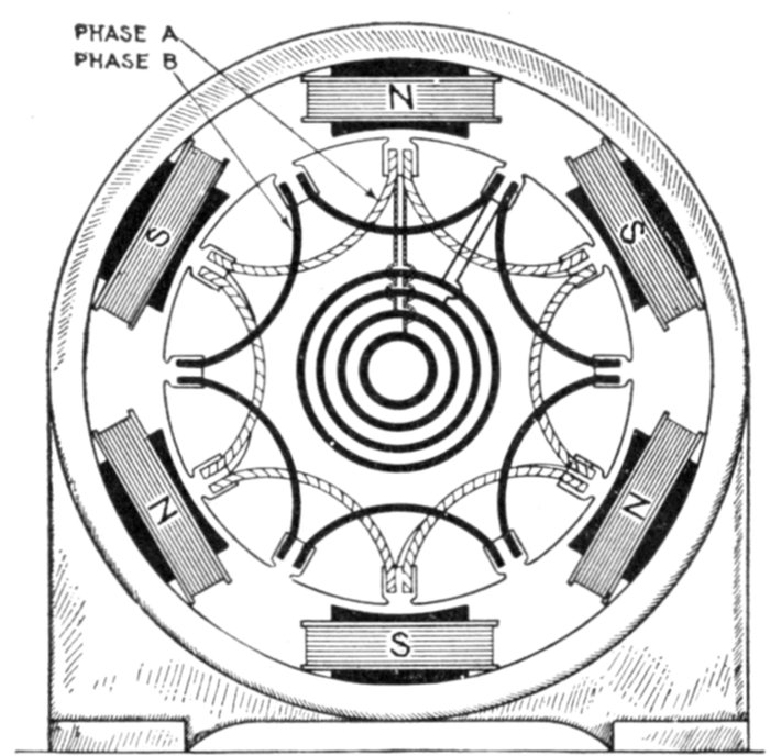
Fig. 1,529.—Two phase concentrated whole coil winding. In this style winding the total
number of slots is twice the number of poles, or one slot per pole per phase. It comprises
two windings identical with fig. 1,527, being spaced 90 polar degrees as shown. The two
circuits are independent, the windings terminating at the four collector rings.
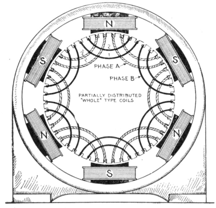
Fig. 1,530.—Two phase winding in two slots per pole per phase. This stamping distributes
the coils of each phase into two sections, as A and B. The coils are of the "whole" type
and with six poles the total number of slots is 4 × 6 = 24, uniformly spaced as shown.
[Pg 1237]
Two Phase Armature Windings.—This type of winding can
be made from any single phase winding by providing another set
of slots displaced along the surface of the armature to the extent
of one-half the pole pitch, placing therein a duplicate winding.
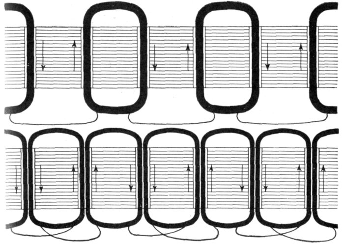
Figs. 1,531 and 1,532.—Developed diagram of the single phase monotooth windings shown
in figs. 1,527 and 1,528.
For instance: If the six pole monotooth, single phase winding, shown
in fig. 1,527, be thus duplicated, the result will be the one slot two-phase
winding shown in fig. 1,529, which will have twelve slots, and will require
four slip rings, or two rings for each phase.
By connecting up the two windings in series, the machines could be
used as a single phase, with an increase of voltage in the ratio of 1.41 to 1.
[Pg 1238]
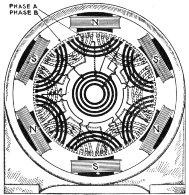
Fig. 1,533.—Two phase winding in three slots per pole per phase. The coils of each phase
are of the partially distributed type, each coil being made up of three sections as shown.
The direction of winding is alternately reversed.
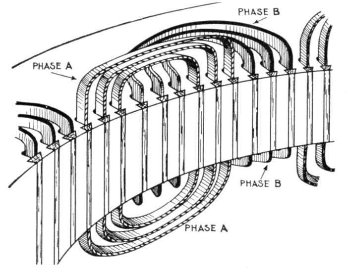
Fig. 1,534.—Section of two phase winding showing shaping of the coil ends. Every other
coil is flat, while the alternates have their ends bent down as shown. With respect to the
shaping of the coil ends, it is called a two range winding.
[Pg 1239]
Ques. How must the coils be constructed for two phase
windings?
Ans. They must be made of two different shapes, one bent
up out of the way of the other, as in fig. 1,534.
There are numerous kinds of two phase windings; the coils may be
concentrated or distributed, half coil or whole coil, etc. Fig. 1,530 shows
a two phase winding with four slots per pole, and fig. 1,533 one with
six slots per pole.
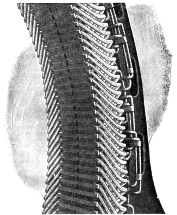
Fig. 1,535.—Section of Triumph armature showing method of arranging the three phase winding.
Three Phase Armature Windings.—On the same general
principle applicable to two phase windings, a three phase winding
can be made from any single phase winding, by placing three
identical single phase windings spaced out successively along the[Pg 1240]
surface of the armature at intervals equal to one-third and two-thirds,
respectively, of the double pole pitch, the unit in terms of
which the spacing is expressed, being that pitch, which corresponds
to one whole period.
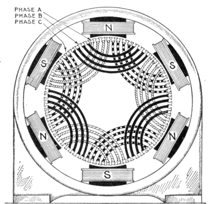
Fig. 1,536.—Three phase winding with distributed coils—wound in four slots per pole per
phase; diagram showing placement of the coils.
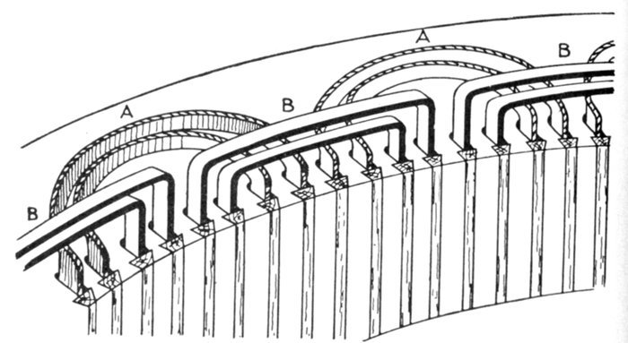
Fig. 1,537.—Treatment of coil ends in two phase, two range windings. In this arrangement
straight out (B) and bent up (A) coils are used which are placed on the armature
as is clearly shown in the illustration.
[Pg 1241]
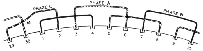
Fig. 1,538.—Three phase, 10 pole, 30 slot winding in two ranges. In this winding perfect
symmetry occurs after every four poles. Accordingly in the case of an odd number of
pairs of pole, one of the coils must necessarily be askew going from the inner to the outer
range as at M.
Each of the three individual windings must be concentrated
into narrow belts so as to leave sufficient space for the other
windings between them. This limits the breadth or space
occupied by the winding of any one phase to one-third of the
pole pitch.
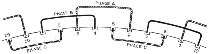
Fig. 1,539.—Three phase 10 pole 30 slot winding in three ranges. The coils of each phase are
alike, those of the A phase being all in the straight out range, those in the B phase, in a
bent up range, and those in the C phase in a bent down range. This arrangement has the
disadvantage, that by reason of the third range, the field magnet cannot be withdrawn.
This treatment of the coil ends is more clearly shown in fig. 1,540.
Ques. How are three phase coil ends treated?
Ans. They may be arranged in two ranges, as in fig. 1,538,
or in three ranges, as in fig. 1,539.
[Pg 1242]
Ques. What kind of coil must be used for three phase
windings in order that the ends may be arranged in only
two ranges?
Ans. Hemitropic or half coils; that is, the number of coil
per phase must be equal to one-half the number of pole.
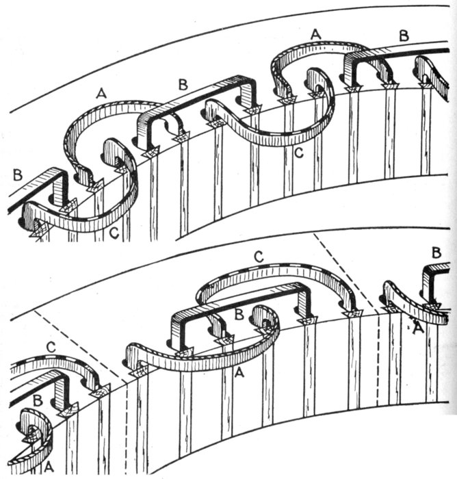
Figs. 1,540 and
1,541.—Treatment of coil
ends in three phase, three range
windings. Fig. 1,540, inadmissible
arrangement in which the field magnet
cannot be withdrawn; fig. 1,541, admissible arrangement
in which the armature segments can be
divided. This enables the top half of armature to be removed by disconnection
without unwinding any coil.
[Pg 1243]
Grouping of Phases.—In the preceding diagrams, the
general arrangement of the coils on the armature surface are
shown for the numerous classes of winding. In polyphase
alternators the separate windings of the various phases may
be grouped in two ways:
1. Star connection;
2. Mesh connection.
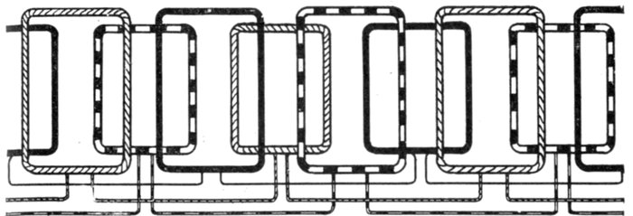
Fig. 1,542.—Three phase winding with half coils. The advantage of employing half coils is
that the ends may be arranged in two ranges as shown. There is one slot per phase per
pole, that is, total number of slots = 3 × number of poles.
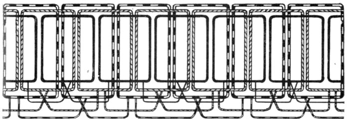
Fig. 1,543.—Three phase winding with whole coils. Two sides of adjacent coils come in one
slot. Number of coils per phase = number of poles per phase. Total number of slots = 3
multiplied by number of poles per phase. Whole coils require the ends arranged in three
ranges as indicated. The coils are concentrated.
Ques. Describe the two phase star connection.
Ans. In this method of grouping, the middle points of each
of the two phases are united to a common junction M, and the[Pg 1244]
four ends are brought out to four terminals a, a', b, b', as shown in
fig. 1,544, or in the case of revolving armatures, to four slip rings.
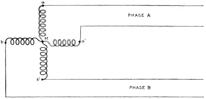
Fig. 1,544.—Diagram of two phase star grouping.
Ques. What does this arrangement give?
Ans. It is practically equivalent to a four phase system.
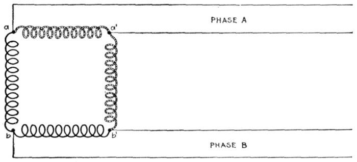
Fig. 1,545.—Diagram of two phase mesh grouping.
Ques. How is the two phase mesh connection arranged?
Ans. In this style of grouping, the two phases are divided[Pg 1245]
into two parts, and the four parts are connected up in cyclic
order, the end of one to the beginning of the next, so as to form a
square, the four corners of which are connected to the four
terminals a, b, a', b', as shown in fig. 1,545, or in the case of
revolving armatures, to four slip rings.
Ques. Describe a three phase star connection?
Ans. In three phase star grouping, one end of each of the
three circuits is brought to a common junction M, usually
insulated, and the three other ends are connected to three
terminals a, b, c, as shown in fig. 1,546, or in the case of revolving
armatures to three slip rings.
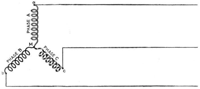
Fig. 1,546.—Diagram of three phase star grouping, commonly called Y grouping owing to its
resemblance of the letter Y. The current in each main is obviously equal to the current
in each phase winding, but the terminal pressure is the vector sum of the pressures in the
component phase windings, that is, √3 multiplied by the pressure in one phase.
Ques. What other name is given to this connection,
and why?
Ans. It is commonly called a Y connection or grouping
owing to the resemblance of its diagrammatic representation
to the letter Y.
[Pg 1246]
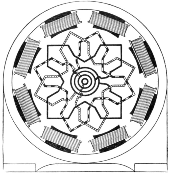
Fig. 1,547.—Radial diagram
of three phase,
one slot winding with
Y connection.
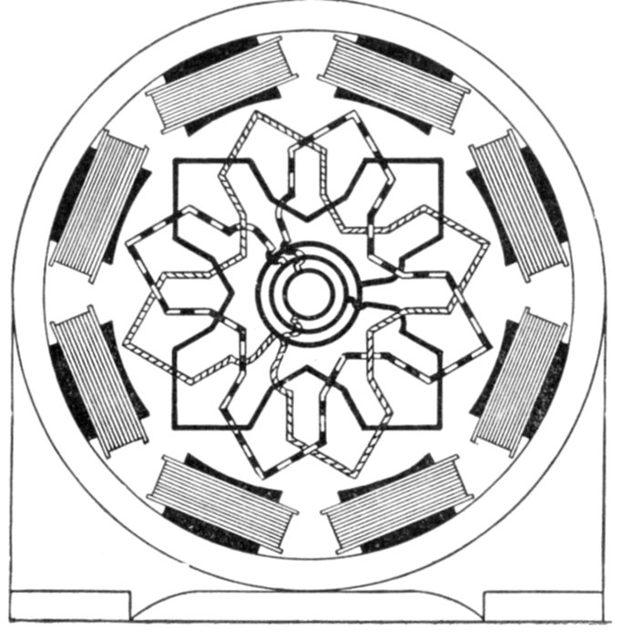
Fig. 1,548.—Radial diagram
of three phase
one slot winding with
delta connection.
[Pg 1247]
Ques. How is a three phase mesh connection arranged?
Ans. The three circuits are connected up together in the
form of a triangle, the three corners are connected to the three
terminals, a, b, c, as shown in fig. 1,549, or in the case of revolving
armatures to three slip rings.
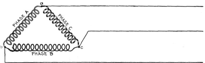
Fig. 1,549.—Diagram of three phase mesh grouping, commonly called delta grouping owing
to its resemblance to the Greek letter Δ. The voltage at the terminals is equal to the
voltage in one phase, and the current in each line is equal to the vector sum of the currents
in two phases, that is, it is equal to √3 multiplied by the current in one phase.
Ques. What other name is given to this style of connection,
and why?
Ans. It is commonly called a delta grouping on account of
the resemblance of its diagrammatic representation to the Greek
letter Δ.
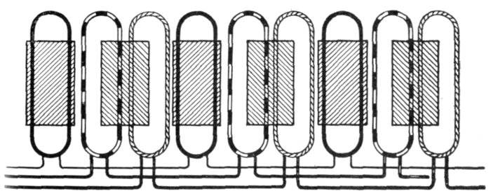
Fig. 1,550.—Three phase winding with short coils. The use of short coils as here shown, in
which the coil breadth = ⅔ pole pitch, avoids the necessity of overlapping.
[Pg 1248]
In polyphase working, it is evident that by the use of four equal
independent windings on the armature, connected to eight terminals or
slip rings, a two phase alternator can be built to supply currents of
equal voltage to four independent circuits. Likewise, by the use of
three equal independent windings, connected to six terminals or slip
rings, a three phase alternator can be made to supply three independent
circuits.
This is not the usual method employed in either case, however, as
the star grouping or mesh grouping methods of connection not only
gives the same results, but also, in star grouping, a greater plurality of
voltages for the same machine, and a higher voltage between its main
terminals.
Radial diagrams of the arrangement and connections of Y grouping
of lap windings and wave windings for three phase alternators are
shown by figs. 1,551 and 1,552.
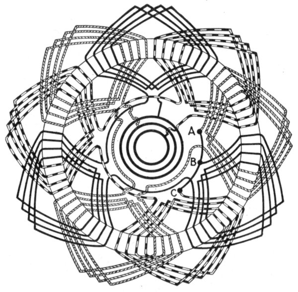
Fig. 1,551.—Radial diagram of three phase lap winding with star connection.
[Pg 1249]
Ques. In three phase star grouping, what is the point
where the phases join, called?
Ans. The star point.
Ques. In a three phase star connected alternator
what is the voltage between any two collector rings?
Ans. It is equal to the voltage generated per phase multiplied
by √3 or 1.732.
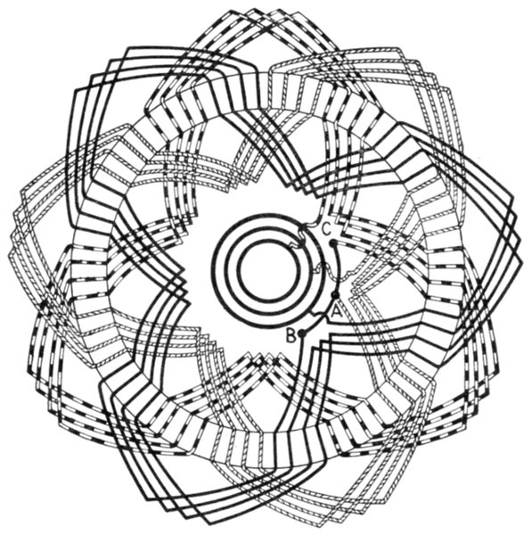
Fig. 1,552.—Radial diagram of three phase wave winding with star connection.
Ques. In a three phase star connected alternator
what is the value of the current in each line?
Ans. The same as the current in each phase winding.
[Pg 1250]
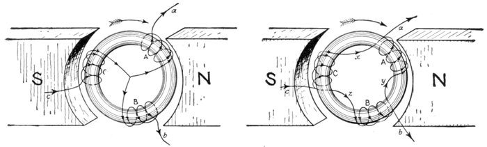
Figs. 1,553 and 1,554.—Gramme ring armatures showing three phase star and mesh connections, respectively, with direction
of currents in the coils. In the figures, the coils A, B, C, are spaced at equidistant positions on the ring core. The arrow
heads represent the directions of the induced pressures or currents for the position shown, the rotation being clockwise.
In coil A the pressure is increasing, in coil B it is diminishing, but is in the same direction as in A, whereas in coil C it is
also diminishing, but is in the opposite direction to what it is in coils A and B. As the rings rotate the three coils have
similar alternations of pressure induced in them, but differ in phase. If a, b and c be joined to collector rings three phase
currents can be supplied to the outer circuits. In fig. 1,553 at the instant represented a and b are giving their current to
their lines, while c is receiving from its line a current equal to the sum of a and b. In fig. 1,554, at the instant represented, the
currents sent out from a will be equal to the sum of the currents in x and y, and intermediate between them in phase. The
current from b will be equal to the difference of the currents in z and y, and of intermediate phase, while similarly the current
received by c will be equal to the sum of the currents in x and z.
Ques. What is
the value of the
total output in
watts of a star
connected alternator?
Ans. It is equal
to the sum of the
outputs of each of
the three phases.
When working on
a non-inductive
load, the total output
of a star connected
alternator
is equal to √3
multiplied by the
product of the line
current and line
voltage.
Ques. What
is the value of
the line voltage
in a three phase
delta connected
alternator?
Ans. It is equal
to the voltage
generated in each
phase.
[Pg 1251]
Ques. What is the value of the line current in a three
phase delta connected alternator?
Ans. It is equal to the current in each phase multiplied by √3.
Ques. What is the total output of a three phase delta
connected alternator working on a non-inductive load?
Ans. The total watts is equal to √3 multiplied by the product
of the line current and the line voltage.

Figs. 1,555 to 1,557.—Separate coils, and section of Allis-Chalmers alternator with coils in
place. Numerous openings are provided in the frame through which air currents, set
up by the revolving field, can pass freely and carry off heat. Shields are provided to
protect the armature coils where they project beyond the core. In assembling the core
spacing segments are placed at intervals to form ventilating ducts. After the coils have
been covered with insulating materials and treated with insulating compound, the parts
that are to lie in the slots are pressed to exact size in steam heated moulds. This runs
the insulating material into all the small spaces in the coil so as to exclude moisture, it
also makes the coil structure firm and solid. The projecting ends of the coils are heavily
taped, suitable supports being provided for the coil connections so that they cannot become
displaced on account of stresses due to short circuits or other causes. On high
pressure machines the armature terminals are arranged so that it is impossible for an
attendant to make accidental contact with them.
Ques. What are the features of the star connection?
Ans. It gives a higher line voltage than the delta connection
for the same pressure generated per phase, hence it is suited for
machines of high voltage and moderate current.
[Pg 1252]
The delta connection gives a lower line voltage than the star[5] connection
for the pressure generated per phase, and cuts down the current
in the inductors; since the inductors, on this account, may be reduced in
size, the delta connection is adapted to machines of large current output.
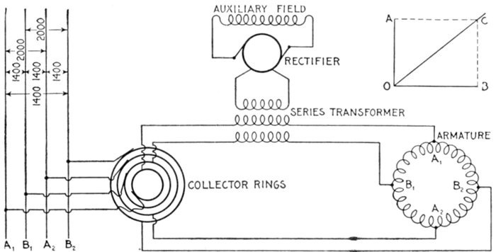
Fig. 1,558.—Diagram of Westinghouse two phase composite wound alternator, showing
connections between two phase armature and a single phase rectified and composite
field winding. The arrangement makes use of a series transformer, mounted on the
spokes of the armature. By means of this series transformer the voltage delivered to
the rectifying commutator and the fields is much less than that generated by the machine.
The armature of this machine is of the closed coil single winding type, all the armature
inductors being connected with each other to form a closed circuit which resembles to
a certain extent the ordinary drum winding of a multipolar direct current machine.
This winding is tapped out at two points per pole just as is the continuous winding of
a two phase rotary converter, these taps running to collector rings through which the
currents are delivered to the outside circuits. On account of this connection of both
phases to one winding there is a definite voltage set up between the inductors of phase
A, and of phase B, this voltage being shown by the figures given in the diagram. The
arrangement is adapted for two phase work by fitting the series transformer for the
auxiliary field excitation with two primaries connected respectively in one leg of each
of the two phases; thus the transformer is excited by two currents normally ¼ period
out of phase with each other. The result upon the secondary is a combination of the
effects of the two primary currents, the voltage delivered by the secondary being intermediate
in phase between those pressures which would be separately set up by the two
primaries. This combination effect is shown in the small diagram in the upper right
hand corner of the illustration. If OA be the effect set up in the secondary of the series
transformer by the primary current of phase A, and OB be the effect set up by the
primary current of phase B, OC represents in magnitude and phase relation the resultant
effect upon the secondary. It is readily seen that this resultant is not equal to the
arithmetical sum of the two components since, to a certain extent, they work at cross
purposes. However, if either one of them increase the resultant effect increases, although
not in exact proportion. If the load remain balanced, the two components remaining
equal to each other, the resultant OC varies in exact proportion to any changes in the
components. If the load become unbalanced, the resultant swings around more nearly
into phase with the larger load; thus if OB become greater, OA remaining the same,
OC swings around, becoming more nearly horizontal. This requires a readjustment of
the position of the brushes on the commutator to set them properly for minimum sparking,
an adjustment exactly similar to that required when the power factor of the load changes.
[Pg 1253]
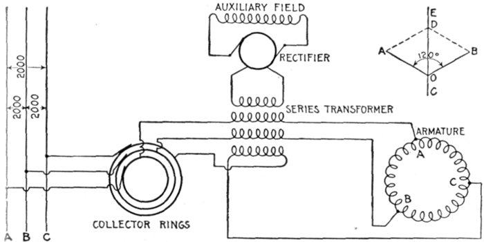
Fig. 1,559.—Diagram of Westinghouse three phase composite wound alternator. The armature
inductors are of the closed coil or delta connected type, but are tapped at three
points per pair or poles to the three collector rings. All three connections between the
armature coils and the collector rings run through primary circuits of the series transformer
within the armature, these three primaries each giving their own effect upon
the secondary. Since the resultant of three equal alternating electromotive forces 120°
apart is zero, so that some special arrangement must be adopted to make these electromotive
forces act with instead of against each other. The arrangement is a reversal
of the connections of one of the primaries of the series transformer. This is shown in
the case of the lowest primary indicated in the diagram. The combination of the effects
of the three primaries is again indicated in the small vector diagram in the upper right
hand corner. Here OA is the effect of one primary, OB that of another ⅓ of a period
displaced from the former in phase, and OC that which the third would exert were it
not reversed, but the reversal brings the effect of this third coil into the phase relation
OD, so that the three are only 60° apart. The combination of OA and OB is equal
to OC, which combined again with OD gives a resultant effect, OE. In this case, as
in the other, the effect upon the series field does not remain exactly proportional to the
load unless the latter is balanced; in fact, an increased current through the one leg represented
by OD, affects the series field as much as an equal increase in each of the other
legs put together. Practically, however, any increase of the load—distributed as it must
be in two legs at least—increases the field excitation so that proper regulation is secured.
Ques. How is the path and value of currents in a delta
connected armature determined?
Ans. Starting with the inductors of one phase opposite the
middle of the poles, assume the maximum current to be induced[Pg 1254]
at this moment; then but one-half of the same value of current
will be induced at the same moment in the other two phases,
and its path and value will best be shown by aid of fig. 1,560,
in which X may be taken as the middle collector ring, and the
maximum current to be flowing from X toward Z. It will be
seen that no current is coming in through the line Y, but part of
the current at Z will have been induced in the branches b and c.
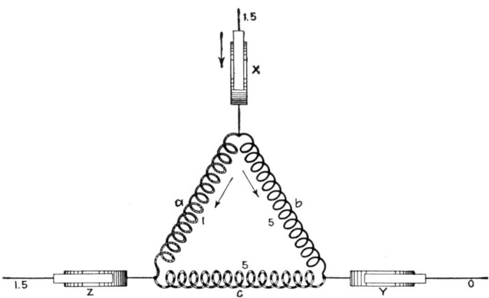
Fig. 1,560.—Diagram showing determination of path and value of current flowing in delta
connected armature.
Ques. Since most three phase windings can be connected
either Y or delta, what should be noted as to the
effects produced?
Ans. With the same winding, the delta connection will
stand 1.732 as much current as the Y connection, but will give
only 1 ÷ 1.732 or .577 as much voltage.
[Pg 1255]
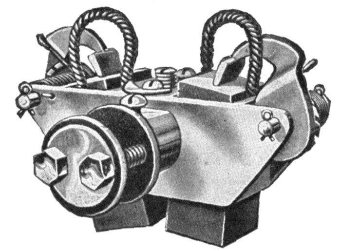
Fig. 1,561.—Triumph brushes and brush holder. The holder is of the box type provided with
an adjustable tension spring, making the brushes self-feeding. Each holder is carried on
insulated studs attached to a cast iron yoke which is mounted on the bearing.
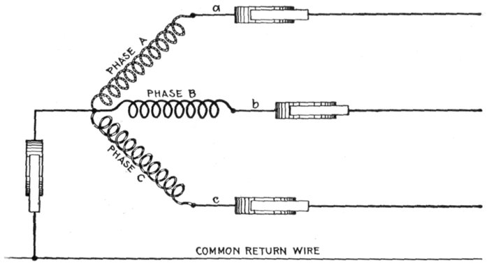
Fig. 1,562.—Diagram of Y connection with a common return wire. When the three lines
leading from a, b and c are equal in resistance and reactance, or in other words when the
system is balanced, the currents of the three phases are equal and are 120° apart in phase
(each current lagging behind its pressure by the same amount as the others) and their
sum is at each instant equal to zero. In this case the resultant current being equal to zero
there is no need of a common return wire. However, in some cases, where power is distributed
from transformers or three wire systems, the different branches are liable to
become unbalanced. Under such circumstances the common return wire is sometimes
used, being made large enough to take care of the maximum unbalancing that may occur
in operation. The return wire is used sometimes on alternators that furnish current
mostly for lighting work.
[Pg 1256]
Chain or Basket Winding.—One disadvantage in ordinary
two-range windings is that two or three separate shapes of coil
are required. The cost of making, winding, and supplying
spares would be less if one shape of coil could be made to do for
all phases. One way of accomplishing this is by the method of
chain winding, in which the two sides of each coil are made of
different lengths, as shown in fig. 1,563, and bent so that they
can lie behind one another.
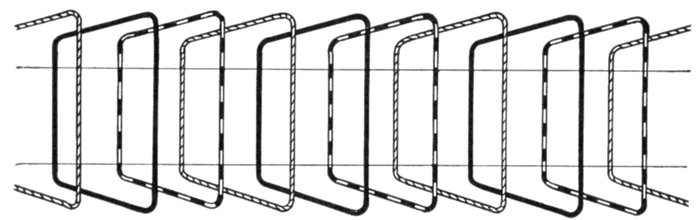
Fig. 1,563.—Diagram showing chain winding. In this method of winding the coils are all
similar with long and short sides. It obviates the extra cost of making coils of several different
shapes. The diagram represents a winding for one slot per pole per phase.
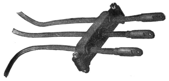
Fig. 1,564.—General Electric terminal board showing cables leading to three phase winding.
In the case of open slots the coils may be former wound and
afterwards wedged into their places.
In chain winding the adjacent coils link one another as in a
chain (hence, the name); the winding is similar to a skew coil[Pg 1257]
winding. This plan of winding is supposed to have some advantage
in keeping coils of different phases further separated
than the two range plan.
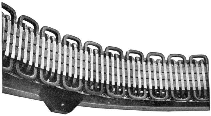
Fig. 1,565.—Section of armature winding of Allis-Chalmers 500 kw. three phase water wheel alternator. The coils
are of the concentrated "half" type. Each coil is completely insulated before being placed on the core and no
insulation is placed in the slot itself. The ends of the coils where they project beyond the slots are heavily taped.
Where necessary suitable supports are provided for the coil connections so that they cannot become displaced on
account of stresses due to short circuits or other causes. The winding is of the "chain" type. This is shown by
the way the coils are connected together at the right. The armature terminals are either provided with insulated
connectors or are led to a marble terminal board on which the terminals are so mounted and protected that
it is impossible for an attendant to make accidental contact with them. The position of the illustration would
indicate a horizontal alternator but the machine is of the vertical type; the lug on the right shows this, being
used for adjusting the alternator on the foundation.
[Pg 1258]
Skew Coil Winding.—In this type of winding the object is
to shape the coils so that all may be of one pattern. This is
accomplished by making the ends skew shape as shown in
figs. 1,566 to 1,568.
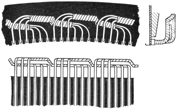
Figs. 1,566 to 1,568.—Views of a section of skew coil winding; so called on account of the
skew shape given to the coil ends in order that all the coils may be of one shape.
Fed-in Winding.—This name is given to a type of winding
possible with open or only partially closed slots, in which coils
previously formed are introduced, only a few inductors at a time
if necessary. They are inserted into the slots from the top, the
slot being provided with a lining of horn fibre or other suitable
material, which is finally closed over and secured in place by
means of a wedge, or by some other suitable means. An example
of a fed-in winding is shown in figs. 1,566 and 1,568.
[Pg 1259]
Imbricated Winding.—This is a species of spiral coil winding
in which the end connections are built up one above the
other, either in a radial, or in a horizontal direction.
The winding is used especially on the armatures of turbine
alternators and dynamos.
Spiral Winding.—This is a winding in which "spiral" coils,
as shown in fig. 1,569, are used. The spiral form of coil is very
extensively used for armature windings of alternators.
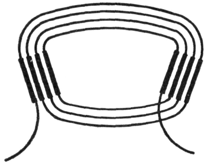
Fig. 1,569.—Diagram showing a spiral coil. This type of coil is one in which each successive
turn lies entirely within the previous turn, starting with the outermost turn of the coil.
The successive turns of a spiral coil are thus not of the same size, and are not overlapping
as in a "lap" coil.
Mummified Winding.—The word mummified as applied
to a winding is used to express the treatment the coils of the
winding receive in the making; that is, when a winding, after
being covered with tape or other absorbent material, is saturated
in an insulating compound and baked until the whole is solidified,
it is said to be mummified.
[Pg 1260]
Shuttle Winding.—This type of winding consists of a single
coil having a large number of turns, wound in two slots spaced
180° apart. It was originally used on Siemens' armature and is
now used on magnetos, as shown in figs. 1,459 to 1,461.
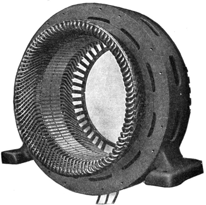
Fig. 1,570.—Frame and armature winding of Westinghouse pedestal bearing alternator.
Armature frames are of cast iron and ventilated. Interior transverse ribs strengthen
the frame and support the core laminations. The armature core is built up of annealed
and japanned punched laminations. Armature slots are open. Armature coils are form
wound, impregnated, and interchangeable; they are held in place with fiber wedges. Ventilating
spaces are provided at intervals in the armature core and also between all coil ends.
Creeping Winding.—Another species of winding, known as
a creeping winding is applicable to particular cases.
If three adjacent coils, each having a pitch of 120 electrical degrees,
be set side by side, they will occupy the same breadth as 4 poles, and,
by repetition, will serve for any machine having a multiple of 4 poles,
but cannot be used for machines with 6, 10 or 14 poles. Fig. 1,571
shows this example.
[Pg 1261]
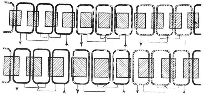
Figs. 1,571 and 1,572.—Diagram of creeping windings. Fig. 1,571, three coils subtending four poles; fig. 1,572, nine coils
subtending eight poles.
In the same way 9
coils, each of 160 electrical
degrees, will
occupy the same angular
breadth as 8 poles.
Further, 9 coils of
200 electrical degrees
will occupy the same
angular breadth as 10 poles.
Now of these 9 coils,
any three contiguous
ones are nearly in
phase, if wound alternately
clockwise and
counter-clockwise.
For the 8 pole machine,
the phase
difference between adjacent
coils is 20 degrees.
For the 10 pole
machine, the phase
difference is also 20
degrees.
The cosine of 20 degrees
is .9397, consequently,
if 3 adjacent
coils be united in series,
their joint pressure will
be 2.897 multiplied by
that of the middle one
of the three.
The 9 coils may
therefore be joined up
in three groups of 3
adjacent coils, for the
three phases.
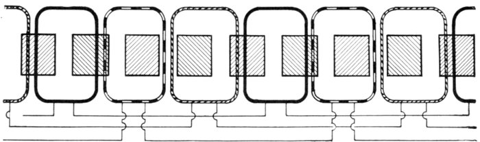
Fig. 1,573.—Developed diagram of creeping winding: nine coils subtending ten poles.
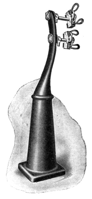
Fig. 1,574.—Triumph pedestal and brush rigging
for large revolving field alternators.
Carbon brushes are used, carried in box
type brush holders. The stand or pedestal
here shown is the kind used with the engine
and fly wheel types of alternator. The brush
studs are mounted on the stand in such a
manner that the brushes are easily accessible.
The latter carry only the low voltage direct
current necessary for exciting the field.
By repetition, the
same grouping will suit
for any machine having[Pg 1262]
a multiple of 8 or of 10 poles.
These two cases are illustrated in
figs. 1,572 and 1,573. In the figures,
the coils are represented as occupying
two slots each, but they might
be further distributed.
[Pg 1263]
Turbine Alternator Winding.—For the reason that steam
turbines run at so much higher speed than steam engines, the
construction of armatures and windings for alternators intended
to be direct connected to turbines must be quite different from
those driven by steam engines. Accordingly, in order that the
frequency be not too high, turbine driven alternators must have
very few poles—usually two or four, but rarely six.
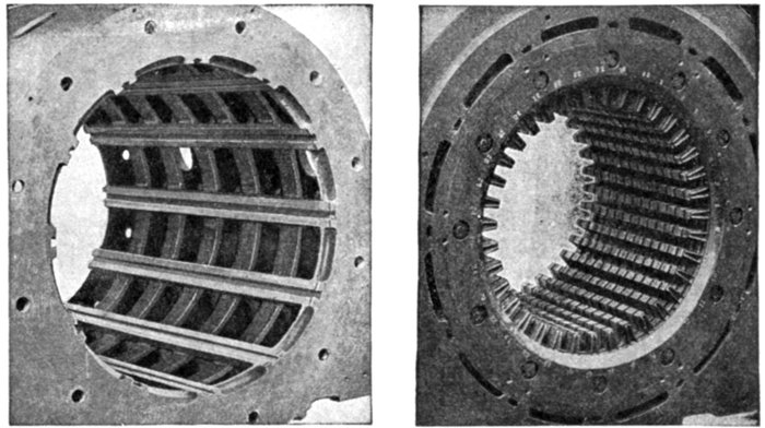
Figs. 1,575 and 1,576.—Westinghouse turbine alternator armature construction. Fig. 1,575.
View showing dovetail grooves in armature casting; fig. 1,576, laminæ assembled in
dovetail grooves of armature casting.
The following table will show the relation between the revolutions
and frequencies for the numbers of poles just designated.
TABLE OF FREQUENCY AND REVOLUTIONS
| Frequency |
Revolutions |
| 2 pole |
4 pole |
6 pole |
| 25 |
1,500 |
750 |
500 |
| 60 |
3,600 |
1,800 |
1,200 |
| 100 |
6,000 |
3,000 |
2,000 |
[Pg 1264]
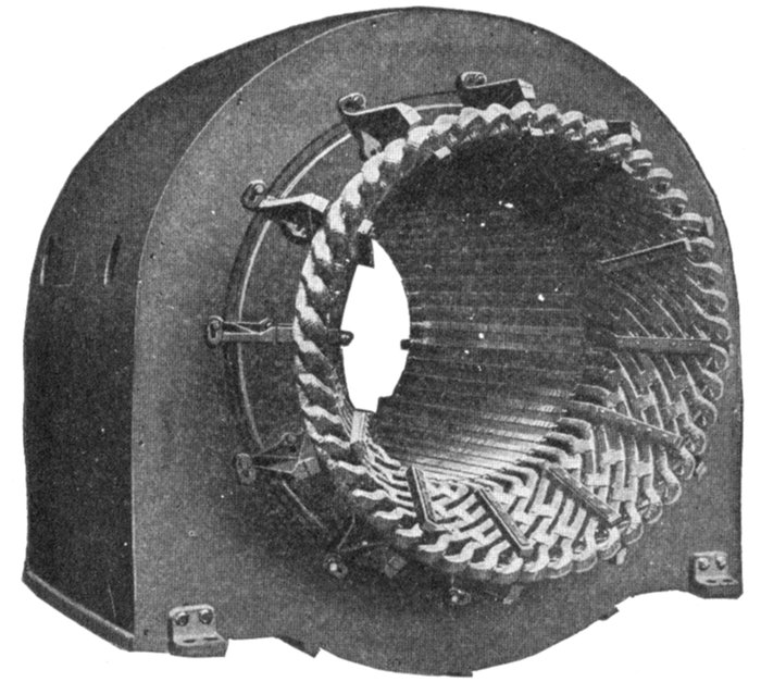
Fig. 1,577.—Armature
of Westinghouse turbine
alternator with
end bells removed
showing method of
bracing the coil ends.
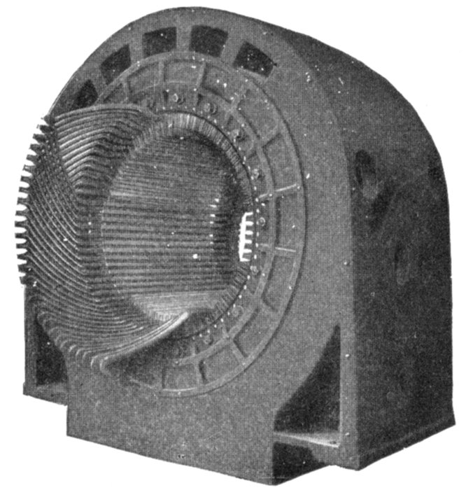
Fig. 1,578.—Stationary armature of
Westinghouse turbine alternator
with part of the winding in place.
Because of the small number of
coils in a turbine alternator as
compared with a slow speed machine
of the same kva. rating,
each coil carries a great amount
of power on large load, particularly
at times of short circuits or
grounds on the external circuit.
The "throw" of the coils is large,
leaving a considerable part of the
winding in the end turns unsupported
by the armature core. For
these reasons great stresses, which
are dangerous, if effective means
be not adopted to withstand them,
may exist between the coils. The
inductors are of such cross section
that they can be made rigid and
insulated satisfactorily. The end
turns are given a fan like form
as shown, affording ventilation
and effective bracing as shown in
fig. 1,577. Cord lashings are, except
in the smallest frames, used
only for holding in the small
spacing blocks between the coils.
They are not depended on to support
the coils. Malleable iron braces, hard maple blocks, and brass or steel bolts with brass
washers are used to withstand the mechanical stresses imposed on the armature coils by
external short circuits.
[Pg 1265]
From the table, it is evident that a large number of poles is
not permissible, considering the high speed at which the turbine
must be run.
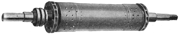
Fig. 1,579.—Two pole radial slot field. Radial slot fields are used on very small and very
large alternators. The field diameters are so small that the end turns of the winding
can be effectively bound into place, such binding being necessary with a radial slot
machine. The shaft and disc are a one piece forging of steel.
Ques. How is the high voltage obtained with so few
poles?
Ans. There must be either numerous inductors per slot
or numerous slots per pole.
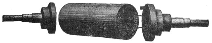
Figs. 1,580 to 1,582.—Westinghouse two pole parallel slot field with ends removed showing
construction. The parallel slot design of field construction is used in Westinghouse
machines up to 10,000 kva. capacity. In fig. 1,581, the large holes at the end near the
circumference of the cylinder are for the accommodation of the bolts that hold the bronze
end discs and stub shafts. In winding, the cylinder is mounted on a horizontal turntable
that rotates in a horizontal plane. The copper strap field coil winding is wound turn by
turn under pressure and strip insulation is wound in between. When completed the
turns are held rigidly in position with heavy brass wedges. An end disc made of bronze
holds the stub shaft and is bolted to each end of the steel center. When the leads are
attached to the collector rings the field is complete.
Ques. What form of armature is generally used?
Ans. A stationary armature.
Ques. What difficulty is experienced with revolving
armatures?
Ans. The centrifugal force being considerable on account[Pg 1266]
of the high speed, requires
specially strong
construction to resist
it, consequently closed
or nearly closed slots
must be used.
Ques. How is the
design of the rotor
modified so as to reduce
the centrifugal
force?
Ans. It is made long
and of small diameter.
Some examples of revolving
fields are shown
in figs. 1,579 to 1,584.
Figs. 1,577 and 1,578
show some construction
details of a stationary
armature of turbine
alternator.
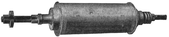
Fig. 1,583.—Westinghouse two pole parallel slot turbine alternator field.
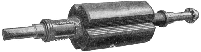
Fig. 1,584.—Westinghouse four pole parallel slot turbine alternator field.
[Pg 1267]
HAWKINS PRACTICAL LIBRARY OF
ELECTRICITY
IN HANDY POCKET FORMPRICE $1 EACH
They are not only the best, but the cheapest work published on Electricity.
Each number being complete in itself. Separate numbers sent postpaid to
any address on receipt of price. They are guaranteed in every way or
your money will be returned. Complete catalog of series will be mailed
free on request.
ELECTRICAL GUIDE, NO. 1
Containing the principles of Elementary Electricity, Magnetism,
Induction, Experiments, Dynamos, Electric Machinery.
ELECTRICAL GUIDE, NO. 2
The construction of Dynamos, Motors, Armatures, Armature
Windings, Installing of Dynamos.
ELECTRICAL GUIDE, NO. 3
Electrical Instruments, Testing, Practical Management of Dynamos
and Motors.
ELECTRICAL GUIDE, NO. 4
Distribution Systems, Wiring, Wiring Diagrams, Sign Flashers,
Storage Batteries.
ELECTRICAL GUIDE, NO. 5
Principles of Alternating Currents and Alternators.
ELECTRICAL GUIDE, NO. 6
Alternating Current Motors, Transformers, Converters, Rectifiers.
ELECTRICAL GUIDE, NO. 7
Alternating Current Systems, Circuit Breakers, Measuring Instruments.
ELECTRICAL GUIDE, NO. 8
Alternating Current Switch Boards, Wiring, Power Stations,
Installation and Operation.
ELECTRICAL GUIDE, NO. 9
Telephone, Telegraph, Wireless, Bells, Lighting, Railways.
ELECTRICAL GUIDE, NO. 10
Modern Practical Applications of Electricity and Ready Reference
Index of the 10 Numbers.
Theo. Audel & Co., Publishers.
72 FIFTH AVENUE,
NEW YORK
TRANSCRIBER'S NOTES
Silently corrected simple spelling, grammar, and typographical errors.
Retained anachronistic and non-standard spellings as printed.
*** END OF THE PROJECT GUTENBERG EBOOK 49675 ***