The cover image was created by the transcriber and is placed in the public domain.
The cover image was created by the transcriber and is placed in the public domain.
i
THE THOUGHT IS IN THE QUESTION THE INFORMATION IS IN THE ANSWER
THEO. AUDEL & CO. 72 FIFTH AVE. NEW YORK ii
COPYRIGHTED, 1914,
BY
THEO. AUDEL & CO.,
New York.
Printed in the United States.
iii
| DISTRIBUTION SYSTEMS | 697 to 720 |
|
|
| WIRES AND WIRE CALCULATION | 721 to 764 |
|
|
| INSIDE WIRING | 765 to 798 |
|
|
| OUTSIDE WIRING | 799 to 824 |
|
|
| UNDERGROUND WIRING | 825 to 844 |
|
|
| WIRING OF BUILDINGS | 845 to 864 |
vi |
|
| SIGN FLASHERS | 865 to 884 |
|
|
| LIGHTNING PROTECTION | 885 to 892 |
|
|
| STORAGE BATTERIES | 893 to 968 |
|
|
| STORAGE BATTERY SYSTEMS | 969 to 996 |
|
|
697
The selection of the system of transmission and distribution of electric energy from the generating plant to lamps, motors, and other devices, is governed mainly by the cost of the metallic conductors, which in many electrical installations, is a larger item than the cost of the generating plant itself. This is especially true in case of long distance transmission, while in those of the lighting plants, the cost of wiring is usually more expensive than that of the boilers, engines, and generators combined.
The principal distribution systems, are classed as:
1. Series;
2. Parallel;
3. Series-parallel;
4. Parallel-series.
Ques. What is the characteristic feature of each class?
Ans. In the series systems the current is constant, but the voltage varies. In the parallel systems, the voltage is constant, but the current varies.
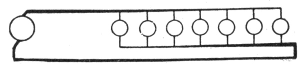
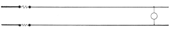
Series System of Distribution.—A series system affords the simplest arrangement of lamps, motors, or other devices supplied with electric energy. The connections of such a system 698 are shown in fig. 783. The current from the terminal of the dynamo passes through the lamps, L, L, L, L, one after the other and finally returns to the terminal. The current remains practically constant, but the voltage falls throughout the circuit in direct proportion to the resistance, and the difference in pressure between any two points in the circuit is equal to the current in amperes multiplied by the resistance in ohms included between them.
For example. Each open arc lamp requires about 50 volts. In the system shown in fig. 783, the pressure measured across the brushes of the dynamo is assumed to be 1,000 volts. As this current flows through the circuit 45 volts will be actually lost in each lamp, and as the drop on the line wire is usually about 10 per cent. of the total voltage, there will be a drop of 5 volts on the conductor between any two lamps. In the circuit shown, there are twenty lamps, therefore, the difference in pressure between either terminal of the dynamo and middle point A of the circuit will be 10 lamps × 50 volts = 500 volts. Likewise, the difference in pressure between any two points on the circuit will be equal to 50 volts multiplied by the number of lamps included between them.
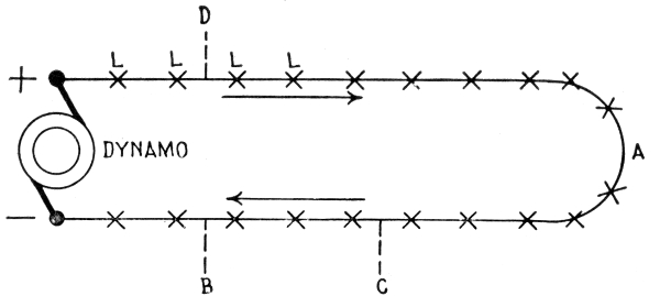
Fig. 783.—Series system of distribution. This is a constant current system, so called because the current remains practically constant. It is used chiefly for arc lighting.
Ques. Describe the danger in a series arc light system?
Ans. Since the total voltage of the system is equal to the sum of the volts consumed in all of the lamps, it is high enough to be dangerous to personal safety. 699
This is illustrated in fig. 783. If the line be grounded at B owing to defective insulation, the pressure of the circuit at that point will be zero, and therefore, a man standing on the ground could touch that point without receiving a shock, but if he should touch the line at the point C, he will receive a slight shock of 150 volts, as there are three lamps between the point C, and the ground connection B. Therefore, the danger of touching the circuit increases directly with the resistance between the point touched and the ground connection, so that if a man touch the circuit at the point D, he will receive a dangerous shock of 16 × 50 = 800 volts. In practice, sixty lamps are often placed on a single arc lighting circuit, so that its total pressure is about 3,000 volts, thus greatly increasing the danger of the system.
Ques. What is a constant current system?
Ans. The series system is a constant current system, and is so called because the current remains practically constant, while the voltage falls throughout the circuit in direct proportion to the resistance.
Ques. What are the principal applications of the series system?
Ans. For arc lighting, and telegraphic circuits.
Ques. What are the advantages of the series system?
Ans. In the case of telegraphic circuits only one wire is required, and for lighting and power transmission and distribution, only two wires; therefore, it is simpler and cheaper than any other system.
Ques. What is the disadvantage of the series system?
Ans. The danger due to the high voltage in installations such as arc lighting circuits.
Parallel System.—Parallel or multiple systems are usually more complicated than series systems, but since the voltage can be maintained nearly constant by various methods, practically all incandescent lamps, electric motors, and a large proportion of arc lamps are supplied by parallel systems. 700
The general principle of the parallel system is shown in fig. 784. With six lamps on the circuit, each requiring one-half ampere of current, at 110 volts, the dynamo will have to supply a current of 3 amperes at a pressure of 112 volts, and this current will flow through the circuit and distribute itself as shown on account of the lesser resistance of the wire relatively to that of the lamps. At the first lamp, the 3 amperes will divide, ½ ampere flowing through the lamp and the remaining 2½ amperes passing on to the next lamp and so on through the entire circuit. The reduction of pressure from 112 volts across the brushes to 110 volts at the last lamp is due to the resistance of the conducting wires.
Ques. What three effects are due to this drop in pressure?
Ans. 1, All the lamps or motors in the circuit receive a lower voltage than that at the dynamo, 2, some lamps or motors may receive a lower voltage than the others, and 3, the voltage at some lamps or motors may vary when the others are turned on or off.
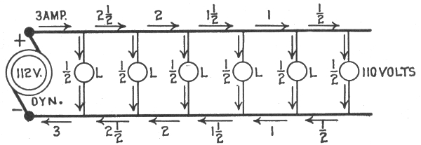
Fig. 784.—Parallel system of distribution. This is a constant voltage system and is used principally for incandescent lighting and electric motor circuits.
The first is the least harmful and may be counteracted by running the dynamo at a little higher voltage; but the second and third are very objectionable and difficult to overcome. They are counteracted successfully in practice, however, by various methods of regulation, the use of boosters, and the operation of dynamos in parallel.
Ques. What are the principal applications of parallel or constant pressure systems?
Ans. They are used on practically all incandescent lamp and electric motor circuits, and on some arc lamp circuits. 701
Ques. Why is it specially applicable to incandescent lamp circuits?
Ans. Incandescent lamps cannot be made to stand a pressure much over 220 volts, and therefore have to be operated on low voltage systems.
Ques. What is the principal disadvantage of a parallel system as compared with a series system?
Ans. The greater cost of the copper conductors.
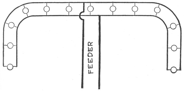
Fig. 785.—Arrangement of feeder and mains in parallel system. By locating the feeder at the electrical center, less copper is required for the mains. The cut does not show the fuses which in practice are placed at the junction of feeder and main.
Ques. What is the usual arrangement of parallel systems?
Ans. Conductors known as a feeder run out from the station, and connected to these are other conductors known as a main to which in turn the lamps or other devices are connected as shown in fig. 785.
Ques. In what two ways may feeders be connected?
Ans. They may be connected at the same end of the mains, known as parallel feeding, or they may be connected at the opposite end of the main, called anti-parallel feeding. 702
The main may be of uniform cross section throughout, or it may change in size so as to keep the current density approximately constant. The above condition gives rise to four possible combinations:
1. Cylindrical conductors parallel feeding, fig. 786;
2. Tapering conductors, parallel feeding, fig. 787;
3. Cylindrical conductors, anti-parallel feeding, fig. 788;
4. Tapering conductors, anti-parallel feeding, fig. 789.
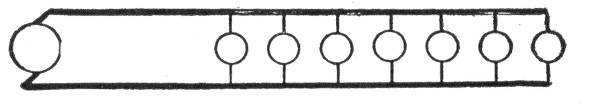
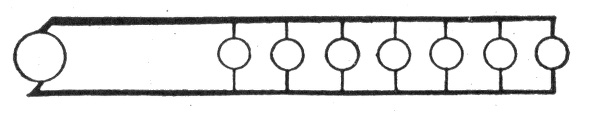
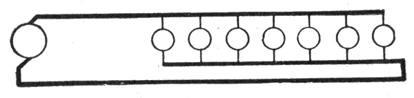
Figs. 786 to 789.—Various parallel systems. Fig. 786, cylindrical conductors parallel feeding; fig. 787, tapering conductors parallel feeding; fig. 788, cylindrical conductors anti-parallel feeding; fig. 789, tapering conductors anti-parallel feeding. The term "tapering" is here used to denote a conductor made up of lengths of wire, each length smaller than the preceding length, the object of such arrangement being to avoid a waste of copper by progressively diminishing the size of wire so that the relation between circular rails and amperes is kept approximately constant. In an anti-parallel system, the current is fed to the lamp from opposite ends of the system.
Series-Parallel System.—This is a combination of the series and parallel systems, and is arranged as indicated in fig. 790. Several lamps are arranged in parallel to form a group, and a number of such sets are connected in series, as shown. It is not necessary for the groups to be identical, provided they are all adapted to take the same current in amperes, which should be kept constant, and provided the lamps of each set agree in voltage. For example, on the ordinary 10-ampere arc circuit, one group 703 might consist of 5 lamps, each requiring 2 amperes at 50 volts; the next might be composed of 10 lamps, each taking 1 ampere at 100 volts, and so on.
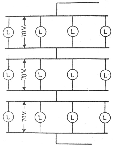
Fig. 790.—Series-parallel system of distribution. It consists of groups of parallel connected receptive devices, the groups being arranged in the circuit in series.
Parallel-Series System.—In this method of connection, one or more groups of lamp are connected in series and the groups in parallel as shown in fig. 791.
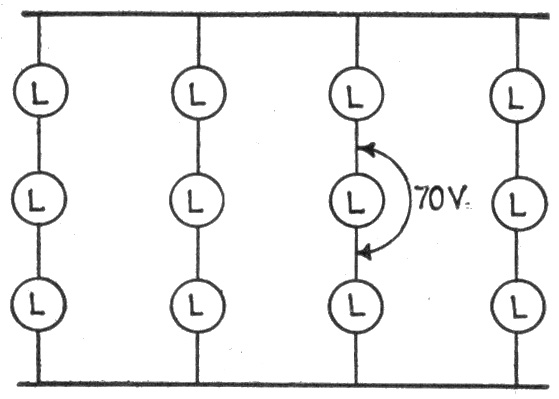
Fig. 791.—Parallel-series system of distribution. It consists of groups of series connected receptive devices, the groups being arranged in the circuit in parallel.
Ques. When is a parallel-series system used?
Ans. When it is desired to operate a number of lamps or motors on a line where voltage is several times that required to operate a single lamp or motor.
The parallel-series system is employed chiefly in the lighting circuit on electric traction lines; here, usually five 110 volt lamps are connected to the source of supply which has a pressure of 550 volts.
704
Center of Distribution.—It is important to determine the point at which the feeders should be attached to the mains in order to minimize the amount of copper required. The method employed is similar to that used in determining the best location of a power plant as regards amount of copper required. The center of distribution may be called the electrical center of gravity of the system, and is found by separately obtaining the center of gravity of straight sections and then determining the total resultant and point of application of this resultant of the straight sections.
Feeders (feeding cables or conductors) are run from the source of supply to the distributing centers, and, as these feeders are in many cases of considerable length, a substantial loss of pressure generally occurs in them. The pressure at the source of supply, however, is so regulated as to compensate for the drop in the feeders, and the pressure at the distributing centers is thus kept constant; or the same result is obtained by the use of regulating devices in the feeders. The essential condition in most systems is that the pressure at the distributing centers shall be kept practically constant, irrespective of the load.
Edison Three Wire System.—In electric lighting systems used up to about 1897, it was not considered practicable to use incandescent lamps requiring a pressure exceeding 120 volts. This limited the operating voltage of parallel systems, and necessitated the use of conductors of large size and weight, especially where the current had to be transmitted a considerable distance.
The effect of this limiting voltage is more apparent when it is clearly understood that the size of wire required to carry a current depends upon the amperes and not upon the volts.
A wire capable of carrying a current of 10 amperes at 20 volts, can carry 10 amperes at 20,000 volts or any other voltage. Therefore, since the amount of electric energy or power transmitted through a conductor is equal to the amperes multiplied by the volts, it is clear that by increasing the voltage, the power transmitting capacity of a current can be almost indefinitely increased without increasing the 705 size of the conducting wire. This is the reason why considerations of economy dictate the use of the highest voltages possible in long distance transmissions. The voltage of the current is determined, however, by the requirements of the apparatus to be operated.
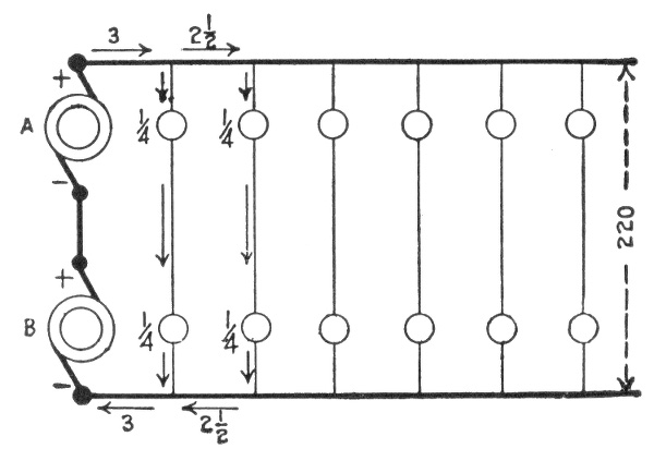
Incandescent lamps usually require a pressure of 110 volts, and the current required by a 16 candle power lamp at that voltage is about ½ ampere. Therefore if the lamp be designed for a pressure of 220 volts, the current will be reduced to ¼ ampere, and the same size of wire could be used to feed twice as many lamps.
Figs. 792 and 793.—Evolution of the three wire system. Fig. 792 shows two dynamos supplying two independent circuits. These may be connected in series as in fig. 793, thus operating the two circuits of fig. 792 with two wires instead of four. To balance the system in case of unequal loading, a third or neutral wire is used as shown in fig. 794.
The saving of copper is the sole merit of the three wire system, and the object which led to its invention was to effect this economy with the use of 110 volt lamps. 706
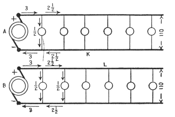
Principle of the Three Wire System.—In fig. 792, two dynamos A and B are shown supplying two independent incandescent lighting circuits, each circuit receiving 3 amperes of current at a pressure of 110 volts. It is evident that the dynamos could be connected with each other in series, and the lamps connected in series with two each, as shown in fig. 793, thus making the two wires K and L of the two independent circuits unnecessary, as the pressure will be increased to 220 volts while the current will remain at 3 amperes, and each lamp will require ¼ ampere.
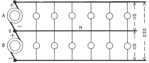
Fig. 794.—Balanced three wire system. The middle conductor, known as the neutral wire, keeps the system balanced in case of unequal loading, that is, a current will flow through it, to or from the dynamos, according to the preponderance of lamps on the one side or the other. These current conditions are shown in fig. 797.
The amount of copper saved will be 100 per cent., but this arrangement is open to the objection, that when one of the lamps is turned off, or burned out, its companion will also go out. This difficulty is avoided in the three wire system by running a third wire N, from the junction O, between the two dynamos, as shown in fig. 794, thus providing a supply or return conductor to any one of the lamps, and permitting any number of lamps to be disconnected without affecting those which remain. If the system be exactly balanced, no current will flow through the wire N, because the pressure toward the - terminal of the dynamo A, 707 will be equal to the pressure from the + terminal of dynamo B, thus neutralizing the pressure in the wire. For this reason the middle wire of a three wire system is called the neutral wire, and is usually indicated by the symbol O or ± the latter meaning that it is positive to the first wire and negative to the second. If the system be unbalanced, a current will flow through the neutral wire, to or from the dynamos, according to the preponderance of lamps in the upper or lower sets. When the number in the lower set is the greater, the current in the neutral wire will flow from the dynamos as shown in fig. 797, and toward the dynamos under the reverse condition.
In the case represented in fig. 797, there are five lamps in circuit, requiring 2½ amperes of current at a pressure of 110 volts. The two lamps in the upper set will require 1 ampere, and the three lamps in the lower set, 1½ amperes. Since a pressure of 110 volts can force only a current of one ampere through resistance of the two lamps in the upper set, it is evident, that the additional ½ ampere required by the three lamps in the lower set will have to be supplied through the neutral wire, as shown.
Balancing of Three Wire System.—In practice it is impossible to obtain an exactly balanced system, as the turning on and off of lamps as required results in a preponderance of lamps in the upper or lower sets, and furthermore, even when the number of lamps in the two sets are equal, they may be located irregularly, thereby causing the currents to flow for short distances in the neutral line. Therefore, the larger the number of lamps in the circuit, the easier it will be to keep the system in a balanced condition.
Copper Economy in Three Wire Systems.—Theoretically, the size of the neutral wire has to be only sufficient to carry the largest current that will pass through it. A large margin of safety, however, is allowed in practice so that its cross section 708 ranges from about one-third that of the outside line, in large central station systems, to the same as that of each outside line in small isolated systems.
If the neutral wire be made one-half the size of the outside conductor, as is usually the case in feeders, the amount of copper required is 5/16 of that necessary for the two wire system. For mains it is customary to make all three conductors the same size increasing the amount of copper to ⅜ of that required for the two wire system.
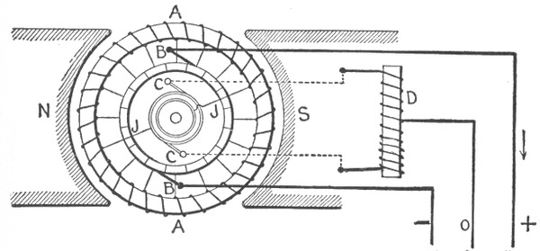
Fig. 795.—Dobrowolsky three wire system with self-induction coil. It consists of an ordinary direct current dynamo, the armature A and pole pieces N and S of which are shown. A self-induction coil D, is connected to two diametrically opposite points of the winding of the armature A. The coil D may be carried by and revolve with the armature; but in the construction represented, it is stationary, being connected to the armature winding through the brushes CC, rings and wires JJ. The middle point of the self-induction coil D, is connected to the neutral conductor O of the three wire system, the outside conductors + and - being supplied from the brushes BB in the usual manner. The pressure at the terminals of the coil D is alternating; hence the latter, on account of its self-induction, does not act as a short circuit to the armature. Furthermore, the inductances of the two halves of the coil D being equal, the pressure of the neutral wire O is kept midway between the pressures of the outside wires + and -. When the two sides of the system are unbalanced in load, the difference in current carried in one direction or the other by the neutral wire passes freely through the coil D, since the current is steady, or varies slowly, and is therefore unimpeded by the self-induction. It is evident that the ohmic resistance of D should be as low and its self-induction as high as possible, in order that the loss of energy and the difference in voltage on the two sides of the system shall be as small as possible under all conditions.
Modifications of the Three Wire System.—By the employment of suitable arrangements, it is possible to operate a three wire system with only one dynamo. Some of the various arrangements which have been used or proposed in this connection may be briefly mentioned as follows: 709
Three Wire Storage Battery System, in which a storage battery is connected between the two outside wires, and the pressure of the neutral wire varied to balance the system by shifting the point at which it is connected to the battery.
Three Wire Double Dynamo System, in which a double dynamo having two armature windings upon the same core, connected to two separate commutators, is used in the same manner as two separate dynamos connected in series.
Three Wire Bridge System, in which a resistance is connected across the two outside wires, and the neutral wire is brought to a point on the resistance through a movable switch. The pressures on the two sides of the circuit are equalized by adjusting the arm of the switch for any change of load.
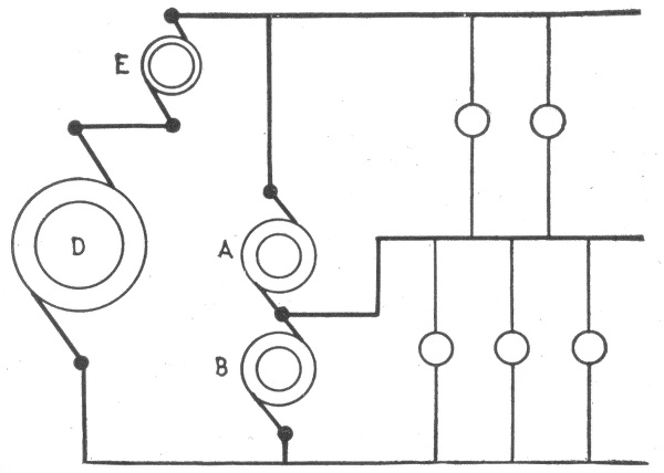
Fig. 796.—Three wire compensator system. A and B are the compensators or equalizers. They consist of auxiliary dynamos coupled together and connected to the system as shown. D is the main dynamo, and E, a booster.
Three Wire Three Brush Dynamo System, in which the neutral wire is connected to a third brush on the dynamo.
Dobrowolsky Three Wire System, in which a self-induction coil is connected to two diametrically opposite points of the armature of an ordinary direct current dynamo. The principle of this system is illustrated in fig. 795.
Three Wire Auxiliary Dynamo System, in which the neutral wire is connected to an auxiliary dynamo which supplies a pressure one-half as great as that of the main dynamo. The auxiliary dynamo is usually 710 belt driven by the main dynamo, and acts as a dynamo when the load is greater on the negative side of the circuit, and as a motor when the excess of load is on the positive side.
Three Wire Compensator System, in which two auxiliary dynamos A and B called compensators or equalizers, are coupled together and connected to the system as shown in fig. 796. Each compensator generates one-half as much pressure as the main dynamo D, and serves to equalize the pressure and the load, the compensator on the lightly loaded side operating as a motor and driving the other as a dynamo. When the system is exactly balanced, both compensators run as motors under no load, therefore, consume very little energy. In this arrangement only one booster E, is required for both sides of the system, as the compensators are connected to the outside wires at a point beyond the boosters, and therefore, sub-divide the increased difference of pressure equally between the two sides of the system.
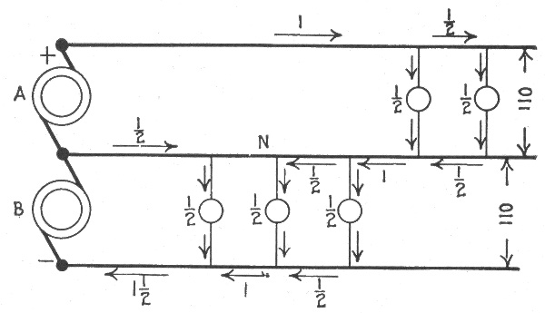
Fig. 797.—Three wire double dynamo system having two separate windings on the same core and separate commutators A and B as shown.
Extension of the Three Wire Principle.—In order to attain still greater economy in copper, the principles of the three wire system may be extended to include four, five, six, and seven wire systems. The comparative weights of copper required by such systems are as follows: 711
| Two | wire | system | 1.000 | |||||
| Three | " | " | all wires of equal size | .370 | ||||
| Three | " | " | neutral wire one-half size | .313 | ||||
| Four | " | " | all wires of equal size | .222 | ||||
| Five | " | " | " | " | " | " | " | .156 |
| Seven | " | " | " | " | " | " | " | .096 |
The four wire system requires about two-ninths as much copper, and the seven wire system about one-tenth as much copper, as an equivalent two wire system; but neither is desirable, as their operation involves too much inconvenience, too many unavoidable complications, and create a possibility of accident, which more than offsets the saving in copper.
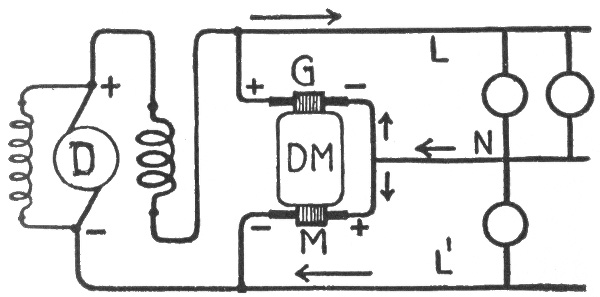
Fig. 798.—Diagram showing dynamotor connections when used as an equalizer in the three wire system. DM, dynamotor; G, generator side; M, motor side.
The Five Wire System.—This system is employed advantageously in many places in England and Europe, but has not as yet been introduced to any extent in America. It is very probable that in the future the three wire 440 volt system will be selected in preference to the five wire system.
Dynamotor.—This is a combination of dynamo and motor on the same shaft, one receiving current and the other delivering current, usually of different voltage, the motor being employed 712 to drive the dynamo with a pressure either higher or lower than that received at the motor terminals.
The dynamotor in the direct current circuit corresponds to the transformer in the alternating current circuit.
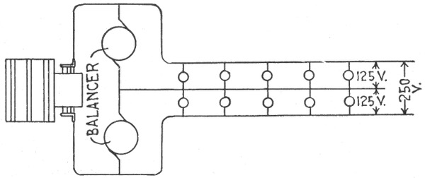
Fig. 799.—Diagram showing connections of balancing set in three wire one dynamo system. The set consists of a motor and dynamo connected, and its operation is practically the same as a dynamotor.
Ques. How is the dynamotor used as an equalizer in the three wire system?
Ans. When thus used, the machine is connected as in fig. 798. When both sides of the system are balanced, there will be no current in the neutral lead N, and a small current will pass through the two armature windings of the dynamotor in series, both armatures acting as motors. If the load on one side of the system become larger than the load on the other side, there will be a greater drop in the leads connected to the overloaded side and consequently a lower voltage will exist over the larger load than exists over the smaller load. The armature winding of the dynamotor connected to the higher voltage will act as a dynamo, whose pressure will tend to raise the voltage of the more heavily loaded side. 713
The direction of the currents in an unbalanced three wire system that is being supplied with energy from a main dynamo is shown in the figure. The commutator at G is connected to the dynamo winding of the dynamotor and is supplying current to the upper or larger load, and the lower commutator is connected to the motor winding of the dynamotor and is taking current from the lightly loaded side.
Motor-Dynamo or Balancing Set.—A balancing set or balancer consists of a motor mechanically connected to a dynamo used to balance a three wire system. The operation of such a combination is practically the same as the dynamotor just described. The balancer is connected as shown in fig. 799.
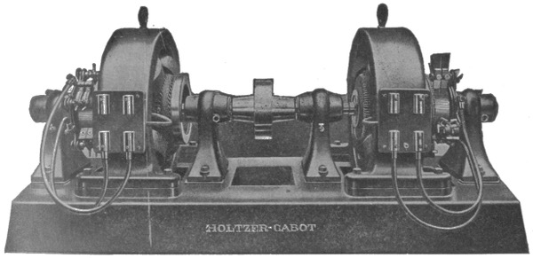
Fig. 800.—Holzer-Cabot type M motor-dynamo set. This combination is known as a booster, and is used to raise or lower the voltage on feeders. The motor is series wound and connected in series with one leg of the feeder. Thus, the voltage which the booster will add to the line will be directly in proportion to the current flowing in the feeder. The regulation is therefore automatic.
When an unbalanced load comes on, the voltage on the lightly loaded side rises and on the heavily loaded side drops. The machine on the light side then takes power from the line and runs as a motor driving the machine on the heavy side as a dynamo, supplying the extra current for that side. This action tends to bring the voltage back to normal and gives good regulation. 714
In some cases the field of each machine is connected to the opposite side of the system which gives a quicker action. This regulation is automatic and the set takes care of unbalanced loads in either direction without adjustment.
Balancing Coils.—Another method of balancing a three wire system which does away with any additional rotating machines makes use of balance coils.
Ques. Describe the type of dynamo used with balancing coils?
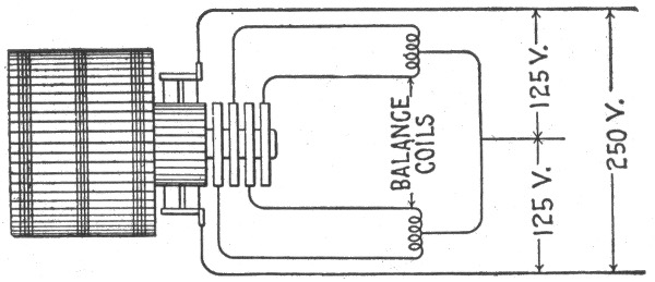
Fig. 801.—Diagram showing connections of balancing coil system. The dynamo used in this system is provided with both commutator and collector rings.
Ans. The regular two wire dynamo is used supplying power to the outside wires, but there are collector rings connected to the armature. These rings are much lighter than they would be for a converter as they carry only about ⅛ of the dynamo load. These rings being light are usually placed at the end of the commutator and are connected directly to the commutator bars.
Ques. How are the balancing coils constructed?
Ans. They are built of standard transformer parts, and are placed in cases similar to those of ordinary small transformers. 715
716 The coil has a straight continuous winding, both ends and a connection from the middle point of the winding being brought out of the case.
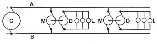
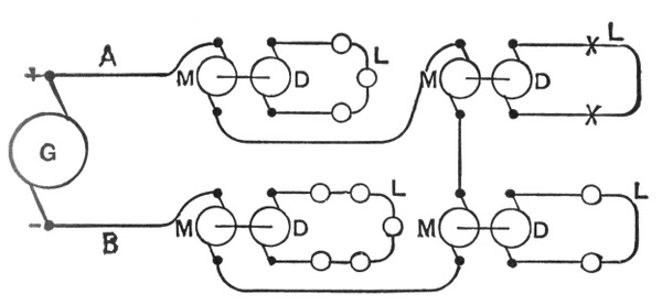
Figs 802 and 803.—Distribution by dynamo-motor sets. Fig. 802, sets in parallel; fig. 803, sets in series. In fig. 802, current produced by the main dynamo G, is carried to the machines by the conductors A and B to which the motor portions M are connected in parallel. These motors are provided with shunt wound field coils which may be connected to the primary or to the secondary circuit, consequently the machines run at a practically constant speed. The dynamo portions D of the transformers are connected to the secondary circuits which supply the lamps, etc., L, as indicated. The field magnets of these dynamos may also be fed by the main circuit AB, or they may be self-excited by shunt or compound winding. In fig. 803, the motors M are all connected in series with the main dynamo G, and the dynamo elements D of the transformers, connected to the lamps, etc., L. If the current be kept constant (the dynamo G having a regulator like a series arc dynamo), and the motors M are simple series wound machines, they will exert a certain torque, or turning effort, which will be constant. It follows, therefore, that if the dynamos D be also series wound, each will generate a certain current which will be constant. If lamps or other devices, designed for that particular current, be connected in series on the secondary circuits, the dynamos D will always maintain that current, no matter how many lamps there may be. When lamps are added, the resistance of the local circuit is raised, and the current in it decreases, so that the dynamo increases its speed until it generates sufficient pressure to produce practically the same current as before. Hence this constitutes a system which is self-regulating, when lamps, etc., are cut in or out of the secondary circuits. No harm results even if the secondary be short circuited, since only the normal current can be generated. But if the secondary circuit be opened, then the machine will race, and probably injure itself by centrifugal force, because the torque of the motor M has its full value, and there is no load upon the dynamos D. To guard against this danger, some automatic device should be provided to short circuit the field or armature of the motor when its speed or reverse voltage rises above a certain point.
Ques. How are the coils connected to the dynamo?
Ans. Two coils are used and are connected to the collector rings as shown in fig. 801, one coil across each phase. The connections from the middle points of the coils are connected together and to the neutral wire of the system.
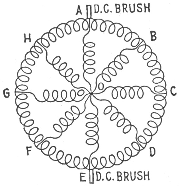
Fig. 804.—Diagram to show correctness of balancing coil connection. In the figure, AE, BF, CG, and DH represent the balance coil and its connection for different positions of the armature of a bipolar machine.
Ques. What is the action of the coils in equalizing the load?
Ans. On balanced load, the coils take a small alternating exciting current from the collector rings as any transformer does when connected to an alternating current line with its secondary open. When an unbalanced load comes on, the current in the neutral divides, half going to each coil. This enters the coil at the middle point and half flows each way through the coil and 717 the slip rings into the armature winding. The unbalanced current is thus fed back directly into the dynamo armature continuously.
The coils are small and can be placed back of the switchboard or below the floor, as they require no attention. The current flowing to each slip ring is 25% of the direct current in the neutral wire with the small exciting current taken by the coil added.
The coils are usually built to take care of current in the neutral equal to 25% of full load current of the dynamo with a voltage regulation not to exceed 2 per cent.
Ques. Upon what does the operation of the balancing coil system depend?
Ans. It depends on the following points: First, the impedance1 of the coils keeps the exciting current which they take from the collector rings down to a small value as it is alternating current. At the same time the current from the neutral wire flows through the four half coils in parallel, and being direct current is impeded only by the ohmic resistance of the coils, which is low, giving only a slight loss in the coils. The common point to which the neutral wire is connected must at all times be neutral to the - and + direct current brushes.
That this common point is at all times neutral is readily shown. Referring to fig. 804, let AE, BF, CG and DH represent the balance coil and its connection for different positions of the armature of a bipolar machine. Let O be the tap to the middle point of the winding.
Take the instant when the balance coil taps are directly under the direct current brushes as shown at position AE. It is evident that since the point O is the middle point of the coil, it is neutral between A and E. When the armature turns so that the balance coils take the position BF, the voltage drop between A and E may be divided into 4 parts, AB, BO, OF and FE. As in the first instance, O is neutral between the ends of the coil, and the voltage drop over OF equals that over OB.
Since the space AB includes the same number of armature coils as space FE and they are in fields of equal strength, the voltages across the two spaces will be equal, and the voltage over AB equals that over FE. Then adding equals: AB + BO = FE + FO and O is neutral between A and E as in the first case.
718
In the same way it can be shown that O is neutral between the direct current brushes for any position of the balance coil taps. One coil will operate the system, but two coils, giving four points spaced 90 electrical degrees apart, give better distribution of the current to the armature winding and better regulation of the voltage.
Boosters.—A booster may be defined as, a dynamo inserted in a circuit at a point when it is necessary to change the voltage. A booster is generally driven by a motor, the two armatures being directly coupled, although boosters are sometimes driven from the engine or line shaft.
Fig. 805.—Crocker Wheeler motor-dynamo set. There are numerous cases where such a combination is useful for furnishing a circuit with a voltage different from that of the main plant or with a voltage that can be varied independently. For storage battery charging and electrolytic work, where constant current is desirable, it forms a simple means of voltage regulation. Where a circuit of special voltage is required, the set not only supplies current at the desired pressure, but insulates the special circuit, which may be subject to more severe requirements than the main system. The advantage of the three wire distribution can be obtained from any two wire dynamo by means of a small rotary balancer or balancing transformer, which consists of two direct current machines of the same voltage, mechanically connected together with their armatures in series. Multiple voltage systems for speed regulation can also be obtained by a similar arrangement.
Ques. Explain the use of a booster?
Ans. When a number of feeders run out from a station, the longest and those carrying the heaviest loads will have so much 719 drop on the line that the pressure at distant points is too low. It is therefore necessary to raise the pressure to compensate for the drop and this is done by inserting a booster in the circuit.
It would not be economical to raise the voltage on all the lines by supplying current from the main dynamo at higher pressure, hence the voltage is raised only on the lines which need it by means of the booster working in series with the main dynamo.
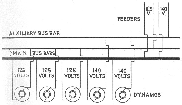
Fig. 806.—Diagram showing use of auxiliary bus bar. In order to avoid the necessity for boosters, some stations have an extra bus bar, which is kept at a higher pressure than the main bus, and to this are connected the feeders that have an extra large drop.
Ques. For what other service are boosters employed?
Ans. They are used in connection with storage battery plants for the purpose of raising the voltage of the bus bars to the pressure necessary for charging storage batteries.
Ques. What is an auxiliary bus bar?
Ans. An extra bus bar which is kept at higher pressure than the main bar. 720
Ques. What is the object of an auxiliary bus bar?
Ans. It is used in place of a booster as shown in fig. 806. One or more dynamos maintain the pressure between the auxiliary bar and the common negative bar. The feeders which need boosting are connected to the common negative bar and the auxiliary bar as shown. 721
The wireman who is called upon to plan and install a system of wiring will find it necessary first to have a knowledge of the various kinds of wire so as to select the one best suited for the work, and to be able to make simple calculations in order to determine the proper sizes of wire for the various circuits.
Wires are generally made of circular cross section. The process of manufacture consists in drawing the material through steel dies, when its properties permit this treatment. In the case of some substances, as for instance, tin and lead, difficulties arise in the drawing process, and these are therefore "squirted."
The metals most extensively used for wires are copper and iron; German silver, tin and lead are also employed, but only at points where it is desirable to have a comparatively high resistance in the circuit.
Copper Wire.—Copper is used in nearly all cases of wiring because it combines high electrical conductivity with good mechanical qualities and reasonable price. In conductivity it is only surpassed by silver, but the cost of the latter of course prohibits its use for wiring purposes.
Copper wire is used for electric light and power lines, for most telephone and some telegraph lines, and for all cases where low resistance is required at moderate cost.
Hard drawn copper wire is ductile, and has a high tensile strength; these properties allow it to be bent around corners and drawn through tubes without injury.
722
Pure annealed copper has a specific gravity of 8.89 at 60° Fahr. One cubic inch weighs .32 pound; its melting point is about 2,100° Fahr.
Good hard drawn copper has a tensile strength of about three times its own weight per mile length. Thus, a number 10 B. & S. gauge copper wire, weighing 166 lbs. per mile, will have a breaking strength equal to approximately 3 × 166 = 498 lbs.
Iron Wire.—This kind of wire is largely used for telegraph and telephone lines, although it is rapidly being replaced by copper in long lines.
There are three grades of iron wire:
1. Extra best best (E. B. B.) which has the highest conductivity and is the nearest to being uniform, in quality, being both tough and pliable;
2. Best best (B. B.), which varies more in quality, is not so tough, and is lower in conductivity. It is frequently sold as E. B. B.;
3. Best (B.), which is the poorest grade made, being more brittle, and lowest in conductivity. Iron wire should be well galvanized.
German Silver Wire.—German silver is an alloy consisting of 18 to 30% nickel, and the balance about four parts copper to one part zinc. It is very largely used as a resistance material in making resistance coils, and is sold in the form of wire, and strip. The resistance of this wire varies with its composition.
The resistance of the 18% alloy at 25° C. is 18 times that of copper, and of the 30% alloy about 28 times that of copper.
The safe carrying capacity of the wire in spirals in open air for continuous duty is such that the circular mils per ampere varies from about 1,500 in No. 10 wire to about 475 in No. 30. For intermittent duty the capacity is twice as great.
Standard of Copper Wire Resistance.—Matthiessen's standard for resistance of copper wire is as follows: A hard drawn copper wire one meter long, weighing one gramme, has a resistance of .1469 B. A. unit at 32° Fahr. Relative conducting 723 power: silver, 100; hard or un-annealed copper, 99.95; soft or annealed copper, 102.21.
A committee of the Am. Inst. Electrical Engineers recommends the following form of Matthiessen's standard, taking 8.89 as the specific gravity of pure copper: A soft copper wire one meter long and one millimeter in diameter has an electrical resistance of .02057 B. A. unit at 0°C.2 From this the resistance of a soft copper wire one foot long and .001 in. in diameter (mil-foot) is 9.72 B. A. units at 0°C.
For every degree Fahr., the resistance of copper wire increases .2222%. Thus a piece of copper wire having a resistance of 10 ohms at 32°, would have a resistance of 11.11 ohms at 82°.
| Pure silver | 100 | |
| Pure copper | 100 | |
| Alloy, ½ copper, ½ silver | 86 | .65 |
| Telephonic siliceous bronze | 35 | |
| Pure zinc | 29 | .9 |
| Brass with 35% zinc | 21 | .5 |
| Swedish iron | 16 | |
| Pure platinum | 10 | .6 |
| Copper with 10% nickel | 10 | .6 |
| Pure lead | 8 | .88 |
| Pure nickel | 7 | .89 |
| Phosphor-bronze, 10% tin | 3 | .88 |
Conductors.—Copper is used more than any other metal for transmitting electrical energy, and for interior wiring it is used exclusively. Copper conductors should be of the highest commercial conductivity, not less than 97%.
For conductors up to sizes as large as No. 8 B. & S. gauge, single conductors may be used, but for larger sizes the necessary conductivity should be obtained by conductors made up of strands of smaller wires. The size of these strands depend 724 upon the size of the conductors and the conditions under which they are to be used.
Where conductors are very large (as for instance dynamo leads), and where it is essential that they should be as flexible as possible, strands as small as No. 20 or 22 B. & S. gauge may be used.
Conductors for flexible cords, pendants, fixtures, etc., should also consist of very fine strands, so that they may be perfectly pliable and flexible.
The individual strands for instance, for a No. 16 B. & S. gauge flexible cord should be as fine as No. 30.
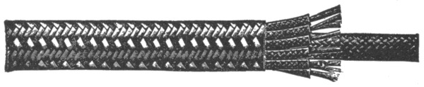
Fig. 807.—Elevator cable for annunciators. This type of cable is designed for connecting the movable elevator car with the signal buttons upon the different floors, and is constructed so as to secure strength and flexibility.
Covered Conductors.—For most conditions of service, wires are protected with an insulating covering. Wires used in interior circuits should have a covering which shall act both as an electrical insulator and as a mechanical protection. In some instances, however, the insulating qualities are of secondary importance.
The various forms of covering now in use commercially for wires are:
1. Rubber;
2. Weather proof;
3. Slow burning;
4. Slow burning weather proof;
5. Armoured.
725
Rubber Covered Conductors.—This class of conductor consists of a tinned copper wire with a rubber covering, protected by an outside braiding of cotton saturated with a preservative compound.
Ques. What are the advantages of rubber insulation for conductors?
Ans. It is waterproof, flexible, fairly strong, and has high insulating qualities.
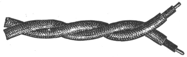
Fig. 808.—Rubber insulated telephone and telegraph wires. The inner coat of rubber should be free from sulphur or other substances liable to corrode the copper.
Ques. What are the disadvantages of rubber insulation?
Ans. It deteriorates more or less rapidly and is quickly injured by temperatures above 140° Fahr.
Ques. For what service are rubber covered conductors adapted?
Ans. For interior wiring.
Ques. Is pure rubber used?
Ans. No. The covering should be made from a compound containing from 20 to 35 per cent. of pure rubber.
It would be difficult to place pure rubber on a wire, and moreover a covering made of pure rubber would not be durable and would deteriorate very rapidly, particularly at temperatures above 120° Fahr. Accordingly, it is mixed with other materials, such as French chalk, silicate of magnesia, sulphur, red lead, etc.
726
Weather Proof Conductors.—In this class of conductor, the wire is protected from the weather by a waterproof covering, consisting usually of braided cotton of two or three thicknesses saturated with a moisture resisting insulating compound.
Ques. Where are weather proof conductors used?
Ans. In places subject to dampness, such as cellars, tunnels, open sheds, breweries, etc.
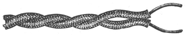
Fig. 809.—Twisted weather proof wires. The insulation consists of two or three thicknesses of braided cotton saturated with a moisture resisting insulating compound.
Ques. What are the advantages of weather proof conductors?
Ans. The insulation is cheap, very durable, and does not deteriorate unless exposed to high temperatures such as will melt the compound.
Ques. State the disadvantages.
Ans. The covering is more or less inflammable and is not very efficient as an insulator.
Ques. What precaution should be taken in using weather proof conductors?
Ans. On account of the inflammable character of the covering, care should be taken in wiring at points where any considerable number of conductors are brought together, or where there is much woodwork or other combustible material. 727
Ques. For what use are weather proof conductors especially adapted?
Ans. For outside wiring where moisture is certain and where fireproof quality is not necessary.
Obviously conductors of this class should not be used in conduits, nor in fact, in any way except exposed on glass or porcelain insulators.
Slow Burning Wire.—This class of conductor is defined as: one that will not carry fire. The covering consists of layers of cotton or other thread, all the interstices of which are filled with the fireproofing compound, or of material having equivalent fire resisting and insulating properties. The outer layer is braided and specially designed to withstand abrasion. The thickness of insulation must not be less than that required for slow burning weather proof wire and the outer surface must be finished smooth and hard.—Underwriters' requirements.
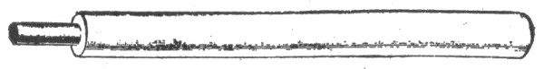
Fig. 810.—Slow burning wire, formerly known as Underwriter's Wire. The insulation is triple braided, saturated with a white fireproof compound. Solid conductor.
Ques. Where should slow burning wires be used?
Ans. In hot dry places, where ordinary insulations would be injured, and where wires are bunched, as on the back of a large switchboard or in a wire tower.
A slow burning covering is considered good enough when the wires are entirely on insulating supports. Its main object is to prevent the copper conductors coming into contact with each other or anything else.
728
Ques. What must be done before using weather proof wire?
Ans. Permission to use the wire must first be obtained from the local Inspection Department.
Slow Burning Weather Proof Wire.—The covering of this type wire is a combination of the underwriters and weather proof insulations. The fireproof coating comprises a little more than half of the total covering. When the fireproof coating is placed on the outside, the wire is called "slow burning weather proof."
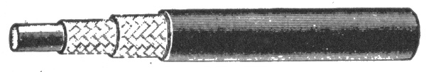
Fig. 811.—Slow burning weather proof wire. The insulation is composed of two braids thoroughly saturated with a fire proof composition, over which is a highly polished weather proof third braid. This wire was formerly known as "fire and weather proof" wire.
Ques. How does slow burning weather proof wire compare with weather proof wire?
Ans. It is less inflammable and less subject to softening under heat.
Ques. Where should slow burning weather proof wire be used?
Ans. In places where the wires are to be run exposed and where moisture resisting quality is desired, also where at the same time it is desirable to avoid an excess of inflammable covering.
Ques. How should it be installed?
Ans. It should be set on glass or porcelain insulators. 729
Miscellaneous Insulated Conductors
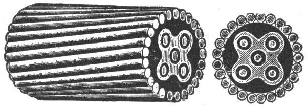
Fig. 812.—Armoured submarine cable. This type of cable is insulated with a rubber compound containing not less than 30% of pure Para rubber. The following specifications have been adapted by various telegraph companies and the United States Government for general use.
| No. of Conductors |
Gauge of Conductors (B. & S.) |
No. of Armour Wires |
Gauge of Armour Wires B. W. G. |
Outside Diameter (inch) |
Weight per 1,000 Feet |
|
|---|---|---|---|---|---|---|
| 1 | 14 | 12 | 8 | ⅞ | 1,150 | |
| 2 | 14 | 16 | 8 | 1 | 31/32 | 1,675 |
| 3 | 14 | 14 | 6 | 1¼ | 2,400 | |
| 4 | 14 | 16 | 6 | 1 | 5/16 | 2,750 |
| 5 | 14 | 19 | 6 | 1 | ⅜ | 3,100 |
| 6 | 14 | 21 | 6 | 1 | ½ | 3,500 |
| 7 | 14 | 21 | 6 | 1 | ½ | 3,600 |
| 10 | 14 | 22 | 4 | 1 | ⅞ | 4,600 |
NOTE.—The above specifications refer only to river and harbor cables. Ocean cables are of an entirely different character, and consist of "shore end," "intermediate" and "deep sea" types.
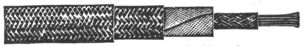
Fig. 813.—Gas engine ignition cable. This is a special cable made to stand the hard service necessary on automobiles. The conductor is composed of 36 strands of No. 27 tinned copper wire, equal to No. 14 in capacity, which gives it necessary flexibility. About this conductor are woven two layers of cotton thread. Over this are woven, in opposite directions, several layers of specially prepared tape which has been given two coatings of fine insulating varnish. Two strong braids of cotton form the outside covering, and each of these different braids is passed through a bath of insulating liquid and baked in a steam heated oven. With three layers of tape the cable will stand a test of 18,000 to 20,000 volts, and with five layers, 30,000 volts.
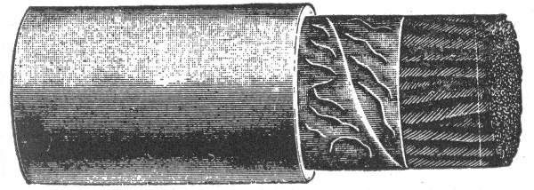
Fig. 814.—Paper insulated lead encased telephone cable.
730
Ques. For what service is slow burning weather proof wire not suited?
Ans. It is not adapted to outside work.
Safe Carrying Capacity of Wire.—All wires will heat when a current of electricity passes through them. The greater the current or the smaller the wire, the greater will be the heating effect. Large wires are heated comparatively more than small wires because the latter have a relatively greater radiating surface.
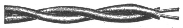
Fig. 815.—Pothead wires. The standard wire for pothead work is either No. 19, 20 or 22 B. & S. gauge, either single conductor or twisted pair, insulated to a diameter of 3/32 inch over rubber, without any outer braid or protection. In the case of twisted pairs one conductor is usually made of a differently colored rubber than the other, so as to distinguish between them.
The temperature of a wire increases approximately as the square of the current, and inversely as the cube of the diameter of the wire.
The elevation in temperature of a wire carrying a current represents so much lost energy.
From these considerations it must be clear that it is important not to overload conductors in order to secure efficient working, and to avoid risk of fire on inside installations.
The Board of Underwriters specifies that the carrying capacity of a conductor is safe when the wire will conduct a certain current without becoming painfully hot.
In the following table of carrying capacity, prepared by the underwriters, a wire is assumed to have a safe carrying capacity when its temperature is not increased by the given current over 30° Fahr. above that of the surrounding air.
731
| Brown and Sharpe Gauge |
Circular mils | Rubber insulation ——— Amperes |
Other insulations ——— Amperes |
|---|---|---|---|
| 18 | 1,624 | 3 | 5 |
| 16 | 2,583 | 6 | 8 |
| 14 | 4,107 | 12 | 16 |
| 12 | 6,530 | 17 | 23 |
| 10 | 10,380 | 24 | 32 |
| 8 | 16,510 | 33 | 46 |
| 6 | 26,250 | 46 | 65 |
| 5 | 33,100 | 54 | 77 |
| 4 | 41,740 | 65 | 92 |
| 3 | 52,630 | 76 | 110 |
| 2 | 66,370 | 90 | 131 |
| 1 | 83,690 | 107 | 156 |
| 0 | 105,500 | 127 | 185 |
| 00 | 133,100 | 150 | 220 |
| 000 | 167,800 | 177 | 262 |
| 0000 | 211,600 | 210 | 312 |
| 200,000 | 200 | 300 | |
| 300,000 | 270 | 400 | |
| 400,000 | 330 | 500 | |
| 500,000 | 390 | 590 | |
| 600,000 | 450 | 680 | |
| 700,000 | 500 | 760 | |
| 800,000 | 550 | 840 | |
| 900,000 | 600 | 920 | |
| 1,000,000 | 650 | 1,000 | |
| 1,100,000 | 690 | 1,080 | |
| 1,200,000 | 730 | 1,150 | |
| 1,300,000 | 770 | 1,220 | |
| 1,400,000 | 810 | 1,290 | |
| 1,500,000 | 850 | 1,360 | |
| 1,600,000 | 890 | 1,430 | |
| 1,700,000 | 930 | 1,490 | |
| 1,800,000 | 970 | 1,550 | |
| 1,900,000 | 1,010 | 1,610 | |
| 2,000,000 | 1,050 | 1,670 |
732
The lower limit is specified for rubber covered wires to prevent gradual deterioration of the high insulations by the heat of the wires, but not from fear of igniting the insulation. The question of drop is not taken into consideration in the table on page 731.
The carrying capacity of Nos. 16 and 18 B. & S. gauge wire is given, but no smaller than No. 14 is to be used, except as allowed under rules for fixture wiring.—Underwriters' Rules.
Circular Mils.—The unit of measurement in measuring the cross sectional area of wires is the circular mil; it is the area of a circle one mil (.001 in.) in diameter.
The area of a wire in circular mils is equal to the square of the diameter in mils.
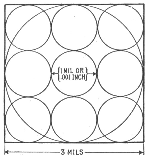
Fig. 816.—Diagram illustrating circular mils. The circular mil is used as a unit of cross sectional area in measuring wires. It is equal to the area of a circle .001 in. diameter; its value is .0000007854 square inch. In the figure the sum of the areas of the nine small circles equals the area of the large circle. This is evident from the following: Take the diameter of the small circles as unity, then the diameter of the large circle is three. Hence, the sum of the area of the small circles × (¼ π × 12) × 9 = .7854 × 9 = 7.0686; area of the large circle = ¼ π × 32 = .7854 × 9 = 7.0686. Therefore since the area of the large circle equals the sum of the areas of the small circles, the area of a wire in circular mils is equal to the square of its diameter expressed in mils.
Thus a wire 2 mils in diameter (.002 in.) has a cross sectional area of 2 × 2 = circular mils. Accordingly to obtain the area of a wire in circular mils, measure its diameter with a micrometer which reads directly in mils or thousandths of an inch, and square the reading.
The circular mil (abbreviated C.M.) applies to all round conductors, and has a value of .7854 times that of the square mil, that is, 1 circular mil = .7854 square mil. If the diameter be expressed as a fraction of an inch, as for instance 1/3 in., the circular mil area may be found 733 as follows: Reduce the fraction 1/3 to the decimal of an inch, multiply the result by 1,000 to express the diameter in mils, and square the diameter so expressed, thus: 1/3 = 1,000 ÷ 3 = .333. .333 × 1,000 = 333 mils; 333 × 333 = 110,889 circular mils.
The diameter of any wire may be found when its circular mil area is known by extracting the square root of the circular mil area.
Square Mils.—For measuring conductors of square or rectangular cross section, such as bus bars, copper ribbon, etc., the square mil is used. A square mil is the area of a square whose sides are one mil (.001 in. long) and is equal to .001 × .001 = .000001 square inch.
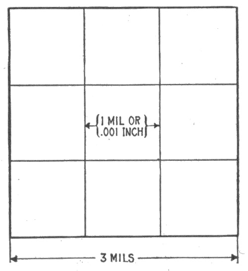
Fig. 817.—Diagram illustrating square mils. A square mil is a unit of area employed in measuring the areas of cross sections of square or rectangular conductors. It is equal to .000001 square inch. One square mil equals 1.2732 circular mils. The figure shows an area of nine square mils; this is equal to 9 × 1.2732 = 11.4588 circular mils.
EXAMPLE.—A copper ribbon for a field coil measures ⅝ inch by ⅛ inch. What is its area in square mils? What is its area in circular mils?
⅝ = .625 in., or 625 mils; ⅛ = .125 in., or 125 mils.
Area in square mils = 625 × 125 = 78,125.
Area in circular mils={78,125 ÷ .7854 }{or 78.125 × 1.2732} = 99,469.
734
Mil Foot.—This unit is used as a basis for computing the resistance of any given wire. A mil foot means a volume one mil in diameter and one foot long.
The resistance of a wire of commercially pure copper one mil in diameter and one foot long is taken as a standard in calculating the resistance of wires, and has been found to be equal to 10.79 ohms at 75° Fahr.
The calculation is made according to the following rule:
The resistance of a copper wire is equal to its length in feet, multiplied by the resistance of one mil foot (10.79 ohms) and divided by the number of circular mils, or the square of its diameter.
Expressed as a formula:
resistance in ohms = length of wire in ft. × 10.79 circular mils . . . . (1)
EXAMPLE. What is the resistance of a copper wire 1,500 feet long and having a transverse area of 10,381 circular mils?
Substituting these values in formula (1)
resistance= 1,500 × 10.79 10,381 =1.559 ohms.
The transverse area of a copper wire is found by multiplying the resistance of a mil foot (10.79) by its length in feet and dividing the result by its resistance in ohms.
This is obtained directly from the formula (1) by solving the equation for circular mils, thus:
circular mils = length of wire in ft. × 10.79 resistance in ohms . . . . (2) 735
EXAMPLE. What is the circular mil area of a wire 1,500 feet long and having a resistance of 1.559 ohms?
Substituting the values in equation (2)
circular mils = 1,500 × 10.79 1.559 = 10,381
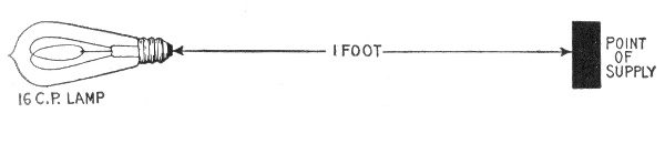
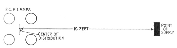
Figs. 818 and 819.—Diagrams illustrating the meaning of the term lamp foot, and how to apply it in calculating a circuit. As defined, one 16 candle power lamp at a distance of one foot from the fuse block or point of supply is called a lamp foot; this is equivalent to one 8 candle power lamp at a distance of 2 feet, or one 32 candle power lamp one-half foot from the fuse block. In fig. 819, there are four 8 candle power lamps, and the distance to center of distribution is 10 feet. The circuit then contains 4 ÷ 2 × 10 = 20 lamp feet.
Lamp Foot.—This unit facilitates laying out wiring and calculating the drop. A lamp foot is defined as one 16 candle power lamp at a distance of one foot from the point of supply. Accordingly the number of lamp feet in any circuit is equal to the number of 16 candle power lamps (or equivalent in other sizes) in the circuit multiplied by the distance in feet from the fuse block to the center of distribution.
When no point is specified, the feet are always measured from the supply point to the center of distribution. When other than 16 c.p. lamps are in the circuit they must be reduced to 16 c.p. lamps. Thus two 8 c.p. lamps would be counted one 16 c.p. lamp, one 32 c.p. lamp would be counted two 16 c.p. lamps, etc.
736
Ampere Foot.—From the foregoing explanation of lamp foot, the significance of ampere foot is easily understood—the two terms are in fact self-defining.
An ampere foot may be defined as the product of one ampere multiplied by one foot.
The unit ampere foot is used in figuring motor circuits or currents designed to carry a mixed load.
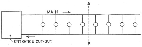
Fig. 820.—The center of distribution of a circuit coincides with the geometrical center of the group of lamps when the lamps are of uniform size and spaced equal distances apart. The center of distribution is here indicated by the dotted line A B.
The ampere feet of a main are found by multiplying the maximum load in amperes by the distance from the fuse block to the electrical center of the load.
Thus if the center of distribution be 50 feet from the fuse block and the maximum load is 9 amperes, the number of ampere feet is equal to 9 × 50 = 450.
Electrical Center of Distribution.—The electrical center of a circuit depends upon the distances between the lamps and the fuse block; also the relative sizes of the lamps.
It may be defined as the sum of the lamp feet for each section divided by the number of 16 candle power lamps in the circuit. 737
If the lamps be of uniform capacity, and placed at equal distances apart, the center of distribution will coincide with the geometrical center of the group of lamps. However, if the lamps vary in size, and be irregularly spaced, the electrical center will not coincide with the geometrical center unless the lamps be symmetrically arranged so as to compensate for the difference in sizes and spacing.
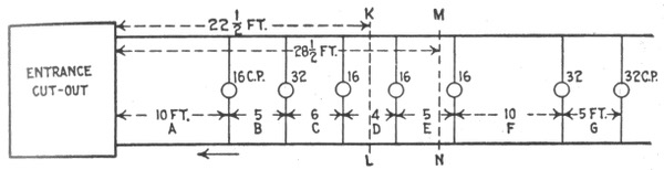
Fig. 821.—Diagram of an irregular circuit illustrating method of finding the center of distribution. Rule: Divide the sum of the lamp feet for each section by the number of 16 candle power lamps or equivalent in the circuit; the quotient gives the distance in feet from the fuse block to the center of distribution.
In such cases, as shown in fig. 821, the electrical center can be determined by adding together the lamp feet of the several sections A, B, C, etc., of the main and dividing the result by the 16 c.p. units. Thus the lamp feet of
Section A = 10 lamps × 10 feet = 100 " B = 9 " × 5 " = 45 " C = 7 " × 6 " = 42 " D = 6 " × 4 " = 24 " E = 5 " × 5 " = 25 " F = 4 " × 10 " = 40 " G = 2 " × 5 " = 10 which added together gives a total of 286 lamp feet. This when divided by the ten 16 c.p. units comprising four 16 c.p. lamps and three 32 c.p. lamps, gives a little over 28½ feet as the distance from the fuse block to the center of distribution, the position of which is shown by the line M N in fig. 821, while that of the geometrical center is shown by the line K L.
738
When the center of distribution is at a considerable distance from the supply circuit, and it becomes advisable to divide the wiring into two distinct elements—a feeder and one or more mains, the junction of the feeder and the mains should be located at the electrical center of the mains whenever possible. When this is done, it is obvious that the wire size of only one half the main needs to be calculated, as both halves of the main are identical.
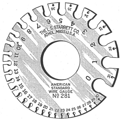
Fig. 822.—Brown and Sharpe (B. & S.), or American Standard wire gauge. This gauge was adopted by the brass manufacturers Jan., 1858. The cut is full size, and therefore, shows the actual sizes corresponding to the gauge numbers.
Wire Gauges.—For the purpose of facilitating the measurement of wire, a number of gauges have been designed by various wire manufacturing concerns. The principal gauges used in the United States are the American or Brown & Sharp's gauge; the English standard or Birmingham gauge; Washburn & Moen's 739 standard gauge; Imperial wire gauge; Stubs' steel wire gauge, and the U. S. Standard wire gauge.
The several gauges are here given with explanation of their use.
The American Standard or Brown and Sharp's Gauge.—This gauge is commonly designated as A. W. G. or B. & S., and has been adopted by brass manufacturers and is used mostly in measuring brass, copper, silver, German silver, and gold in both wire and plate.
Birmingham or Stub's Wire Gauge (B. W. G.).—Old English Standard and Iron Wire Gauge. Birmingham or Stubs' Iron Wire Gauge is not the same as Stubs' Steel Wire Gauge. A table of Stub's Steel Wire Gauge is given on page 741.
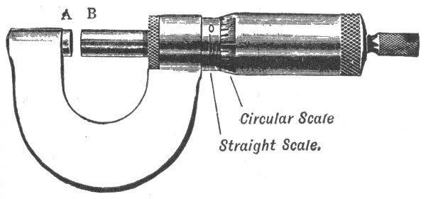
Fig. 823.—Micrometer screw gauge. It consists essentially of a screw whose thread is accurately turned to a pitch of some convenient fraction of an inch or centimetre. When the screw is screwed home, the surfaces of A and B meet, and the instrument should then read zero on both the straight and the circular scale. If this be not so, there is a zero error which must be either allowed for, or corrected by means of the screw provided for that purpose. If the former course be adopted, the reading of the instrument is taken when the faces A and B are in contact, and this number added to or subtracted from the final reading according to whether the error makes the wire apparently smaller or greater than its real size. The surfaces A and B are now screwed apart and then, after the wire to be measured (which should be clean and straight) has been introduced between them, they are screwed together to lightly grip the wire. If the gauge be screwed up too tightly the value of the measurement is destroyed, since a copper wire can easily be crushed, and in addition the accurate screw may be permanently damaged. To avoid the possibility of this happening, screw gauges are provided with a ratchet which prevents an excessive force being applied to the screw. If the pitch of the screw in the gauge be 1/20th of an inch, and the circular scale consist of 50 divisions, then for each revolution of the screw, the surface B will travel a distance equal to the pitch, that is 1/20th of an inch. The graduations on an instrument of this kind are generally 1/10th of an inch on the straight scale, with shorter lines to mark the half divisions. The thickness of a wire on the straight scale can therefore be read to the nearest 1/20th inch. Each division of the circular scale represents 1/50th of a revolution of the screw, which corresponds to a change in distance between A and B, of 1/50 of 1/20 = 1/1,000 in. If then the reading on the straight scale be 1 and on the circular scale 35, the distance between A and B is .1 + .035 = .135 inch.
740
Washburn and Moen's Standard Wire Gauge.—Commonly designated as W. & M. G. has been adopted by the U. S. Steel Corporation in making their wire.
New British Standard (N. B. S.).—British Imperial English Legal Standard and Standard Wire Gauge, and is variously abbreviated by S. W. G. and I. W. G.
Roebling Gauge.—Washburn Moen, American Steel & Wire Co.'s Iron Wire Gauge.
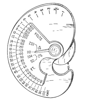
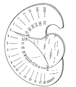
Figs. 824 and 825.—U. S. wireman's calculating gauge; views showing both sides. On the side shown in fig. 824, set the required number of feet on the small circle opposite the required number of amperes on the large circle, then set the small pointer at the required voltage and loss. Then on the other side (fig. 825) the large pointer will indicate the required size of wire in B. & S. gauge, and will also indicate the safe carrying capacity, while the wire may be gauged by slot A (fig. 824).
U. S. Standard Wire Gauge.—This gauge is used for measuring sheet and plate iron, and steel, by the U. S. Government in assessing duties, and in making requisitions for supplies.
Old English Standard Wire Gauge.—The old English gauge is the same as the Birmingham or Stubs' standard gauge, commonly designated as B. W. G. It is used chiefly for measuring sheet iron and steel, also soft steel and iron wire.
London Gauge.—Old English (not Old English Standard).
741
From the foregoing it is seen that great confusion exists with such a multiplicity of gauges and emphasizes the importance of specifying the gauge and of knowing what gauge to use.
In using the gauges known as Stubs' Gauges, there should be constantly borne in mind the difference between the Stubs' Iron Wire Gauge and the Stubs' Steel Wire Gauge. The Stubs' Iron Wire Gauge is the one commonly known as the English Standard Wire, or Birmingham Gauge and designates the Stubs' soft wire sizes. The Stubs' Steel Wire Gauge is the one that is used in measuring drawn steel wire or drill rods of Stubs' make and is also used by many makers of American drill rods.
| Letter. | Size of Letter in Decimals. |
No. of Wire Gauge. |
Size of Number in Decimals. |
No. of Wire Gauge. |
Size of Number in Decimals. |
No. of Wire Gauge. |
Size of Number in Decimals. |
|---|---|---|---|---|---|---|---|
| Z | .413 | 1 | .227 | 28 | .139 | 55 | .050 |
| Y | .404 | 2 | .219 | 29 | .134 | 56 | .045 |
| X | .397 | 3 | .212 | 30 | .127 | 57 | .042 |
| W | .386 | 4 | .207 | 31 | .120 | 58 | .041 |
| V | .377 | 5 | .204 | 32 | .115 | 59 | .040 |
| U | .368 | 6 | .201 | 33 | .112 | 60 | .039 |
| T | .358 | 7 | .199 | 34 | .110 | 61 | .038 |
| S | .348 | 8 | .197 | 35 | .108 | 62 | .037 |
| R | .339 | 9 | .194 | 36 | .106 | 63 | .036 |
| Q | .332 | 10 | .191 | 37 | .103 | 64 | .035 |
| P | .323 | 11 | .188 | 38 | .101 | 65 | .033 |
| O | .316 | 12 | .185 | 39 | .099 | 66 | .032 |
| N | .302 | 13 | .182 | 40 | .097 | 67 | .031 |
| M | .295 | 14 | .180 | 41 | .095 | 68 | .030 |
| L | .290 | 15 | .178 | 42 | .092 | 69 | .029 |
| K | .281 | 16 | .175 | 43 | .088 | 70 | .027 |
| J | .277 | 17 | .172 | 44 | .085 | 71 | .026 |
| I | .272 | 18 | .168 | 45 | .081 | 72 | .024 |
| H | .266 | 19 | .164 | 46 | .079 | 73 | .023 |
| G | .261 | 20 | .161 | 47 | .077 | 74 | .022 |
| F | .257 | 21 | .157 | 48 | .075 | 75 | .020 |
| E | .250 | 22 | .155 | 49 | .072 | 76 | .018 |
| D | .246 | 23 | .153 | 50 | .069 | 77 | .016 |
| C | .242 | 24 | .151 | 51 | .066 | 78 | .015 |
| B | .238 | 25 | .148 | 52 | .063 | 79 | .014 |
| A | .234 | 26 | .146 | 53 | .058 | 80 | .013 |
The following table gives the diameters, in decimal parts of an inch, of the various sizes of wire corresponding to the number of gauge numbers of the different standard wire gauges used in the United States. 742
| Number of Wire Gauge |
American, or Brown & Sharpe (B.&S.) |
Birmingham, or Brown & Sharpe (B. W. G.) |
Washburn & Moen Mfg. Co., Worcester, Mass. |
Trenton Iron Co., Trenton, N. J. |
G. W. Prentiss, Holyoke, Mass. |
Old English, From Brass Mfrs' List |
British Standard (S. W. G.) |
|---|---|---|---|---|---|---|---|
| 0000000 | .500 | ||||||
| 000000 | .460 | .464 | |||||
| 00000 | .430 | .450 | .432 | ||||
| 0000 | .46000 | .454 | .393 | .400 | .400 | ||
| 000 | .40964 | .425 | .362 | .360 | .3586 | .372 | |
| 00 | .36480 | .380 | .331 | .330 | .3282 | .348 | |
| 0 | .32486 | .340 | .307 | .305 | .2994 | .324 | |
| 1 | .28930 | .300 | .283 | .285 | .2777 | .300 | |
| 2 | .25763 | .284 | .263 | .265 | .2591 | .276 | |
| 3 | .22942 | .259 | .244 | .245 | .2401 | .252 | |
| 4 | .20431 | .238 | .225 | .225 | .2230 | .232 | |
| 5 | .18194 | .220 | .207 | .205 | .2047 | .212 | |
| 6 | .16202 | .203 | .192 | .190 | .1885 | .192 | |
| 7 | .14428 | .180 | .177 | .175 | .1758 | .176 | |
| 8 | .12849 | .165 | .162 | .160 | .1605 | .160 | |
| 9 | .11443 | .148 | .148 | .145 | .1471 | .144 | |
| 10 | .10189 | .134 | .135 | .130 | .1351 | .128 | |
| 11 | .090742 | .120 | .120 | .1175 | .1205 | .116 | |
| 12 | .080808 | .109 | .105 | .1050 | .1065 | .104 | |
| 13 | .071961 | .095 | .0920 | .0925 | .0928 | .0920 | |
| 14 | .064084 | .083 | .0800 | .0800 | .0816 | .08300 | .0800 |
| 15 | .057068 | .072 | .0720 | .0700 | .0726 | .07200 | .0720 |
| 16 | .050820 | .065 | .0630 | .0610 | .0627 | .06500 | .0640 |
| 17 | .045257 | .058 | .0540 | .0525 | .0546 | .05800 | .0560 |
| 18 | .040303 | .049 | .0470 | .0450 | .0478 | .04900 | .0480 |
| 19 | .035890 | .042 | .0410 | .0400 | .0411 | .04000 | .0400 |
| 20 | .031961 | .035 | .0350 | .0350 | .0351 | .03500 | .0360 |
| 21 | .028462 | .032 | .0320 | .0310 | .0321 | .03150 | .0320 |
| 22 | .025347 | .028 | .0280 | .0280 | .0290 | .02950 | .0280 |
| 23 | .022571 | .025 | .0250 | .0250 | .0261 | .02700 | .0240 |
| 24 | .020100 | .022 | .0230 | .0225 | .0231 | .02500 | .0220 |
| 25 | .017900 | .020 | .0200 | .0200 | .0212 | .02300 | .0200 |
| 26 | .015940 | .018 | .0180 | .0180 | .0194 | .02050 | .0180 |
| 27 | .014195 | .016 | .0170 | .0170 | .0182 | .01875 | .0164 |
| 28 | .012641 | .014 | .0160 | .0160 | .0170 | .01650 | .0148 |
| 29 | .011257 | .013 | .0150 | .0150 | .0163 | .01550 | .0136 |
| 30 | .010025 | .012 | .0140 | .0140 | .0156 | .01375 | .0124 |
| 31 | .008928 | .010 | .0130 | .0130 | .0146 | .01225 | .0116 |
| 32 | .007950 | .009 | .0120 | .0120 | .0136 | .01125 | .0108 |
| 33 | .007080 | .008 | .0110 | .0110 | .0130 | .01025 | .0100 |
| 34 | .006305 | .007 | .0100 | .0100 | .0118 | .00950 | .0092 |
| 35 | .005615 | .005 | .0095 | .0095 | .0109 | .00900 | .0084 |
| 36 | .005000 | .004 | .0090 | .0090 | .0100 | .00750 | .0076 |
| 37 | .004453 | .0085 | .0085 | .0095 | .00650 | .0068 | |
| 38 | .003965 | .0080 | .0080 | .0090 | .00575 | .0066 | |
| 39 | .003531 | .0075 | .0075 | .0083 | .00500 | .0052 | |
| 40 | .003145 | .0070 | .0070 | .0078 | .00450 | .0048 | |
| 41 | .0044 | ||||||
| 42 | .0040 |
NOTE.—The sizes of wire are ordinarily expressed by an arbitrary series of numbers. Unfortunately there are several independent numbering methods, so that it is always necessary to specify the method or wire gauge used. The above table gives the numbers and diameters in decimal parts of an inch for the various wire gauges in general use.
743
Wiring Terms.—The various members of a complex wiring installation are designated feeders, sub-feeders, mains, branches, and taps.
A feeder is a stretch of wiring to which no connection is made except at its two ends.
A sub-feeder is of the same class as a feeder, but is distinguished either by being one of two or more connecting links between the end of a single feeder and several distributing mains, or by constituting an extension of a feeder.
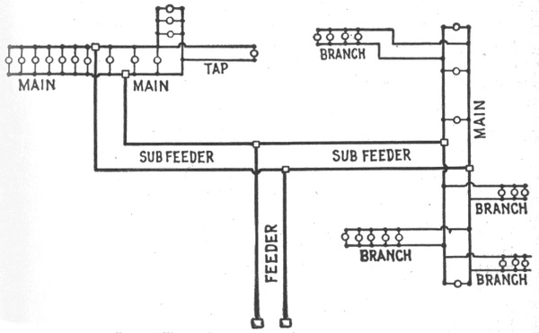
Fig. 826. Circuit diagram illustrating names of the various parts. A circuit may consist of the following parts as defined in the accompanying text: 1, feeder, 2, sub-feeders, 3, mains, 4, branches, 5, taps. It is well to clearly distinguish between these divisions because the terms are constantly used in wiring.
A main is a stretch of wiring supplied from one or more feeders or sub-feeders and distributing current to a number of taps, or else to a number of branches.
A branch distributes current among a number of lamps, etc.
A tap almost invariably delivers current to a single lamp or other device. 744
Reference to fig. 826 will make these definitions clearer. This diagram is intended merely to illustrate the above definitions and does not represent any special plan of wiring.

Figs. 827 and 828. Simplest forms of circuit, consisting of a main with one or more lamps at the end. The smallest size wire allowed (No. 14 B.&S. gauge) will generally be found amply large for such circuits. Note carefully the difference between a main and a branch by comparison with fig. 826. A main begins from a fuse block, while a branch is an offset from a main without any fuse block.
The simplest possible wiring installation is one in which a single lamp or compact cluster of lamps is located at the end of a main, as shown in figs. 827 and 828. In such cases calculations are almost always unnecessary, for the reason that No. 14 wire, the smallest size allowed by the underwriters, will supply several lamps at a long distance (as interior wiring goes) with a very moderate drop. For example, if the three lamps shown at the end of the main in fig. 828, be of 16 candle power each, and the voltage of the supply circuit be 110 volts, a main of No. 14 wire would supply the lamps at a distance of 135 feet from the fuse block with a drop of only 1 per cent.
When the lamps are strung along the main, however, as in fig. 826, it is sometimes necessary to choose the size of wire with regard to the drop, and in order to do this the main must be measured for either "ampere feet" or "lamp feet."
Wire Calculations.—The problem of calculating the size of wire will be presented here in as simple a form as possible, with explanation of the various steps so that any one can understand how the formula is derived.
In determining the size of wire, there are four known factors which enter into the calculation, viz.: 745
1. Length of circuit in feet;
2. Maximum current in amperes;
3. Drop or volts lost in the circuit, in % of the impressed voltage;
4. Heating effect of the current.
The calculation is based on the mil foot, which as previously explained, is a foot of copper wire one mil in diameter and whose resistance is equal to 10.79 ohms at 75° Fahr.
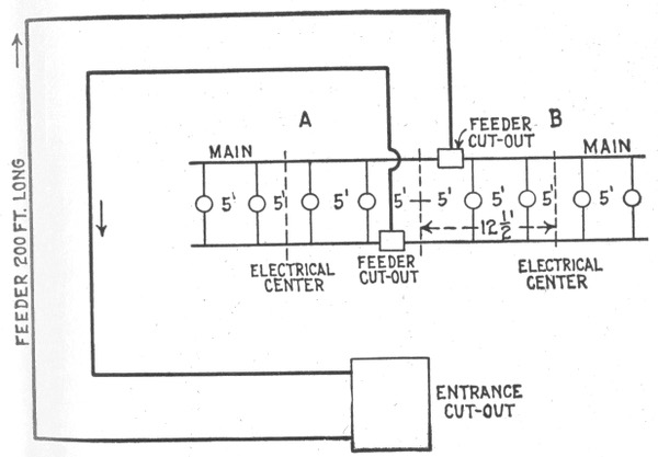
Fig. 829.—Wiring for lights requiring unusually long feeders.
The first step is to find an expression for the resistance of the wire which may be later substituted in Ohm's law formula. Accordingly, the resistance of any conductor is equal to its length in feet multiplied by its resistance per mil foot and the product divided by its area in circular mils, thus: 746
resistance in ohms = length in feet × resistance per mil foot circular mils
ohms = feet × 10.8 circular mils . . . . (1)
(calling the resistance per mil foot 10.8 instead of 10.79 to facilitate calculation).
Showing the maximum number of 16 candle power 110 to 240 volt lamps in parallel that may be carried by the various sizes of wire without violating the underwriters' rules.
| Wire size B. & S. gauge |
Amperes. | 3.1.watt lamps. | 3.5.watt lamps. | 4.watt lamps. | ||||
|---|---|---|---|---|---|---|---|---|
| At 110 volts. |
220 V. |
At 110 volts. |
220 V. |
220 V. |
230 V. |
240 V. |
||
| 0000 | 210 | 462 | 924 | 412 | 825 | 722 | 754 | 787 |
| 000 | 177 | 389 | 778 | 347 | 695 | 608 | 636 | 663 |
| 00 | 150 | 330 | 660 | 294 | 589 | 515 | 539 | 562 |
| 0 | 127 | 279 | 558 | 249 | 499 | 436 | 456 | 476 |
| 1 | 107 | 235 | 470 | 210 | 420 | 367 | 384 | 401 |
| 2 | 90 | 197 | 396 | 176 | 353 | 309 | 323 | 337 |
| 3 | 76 | 167 | 334 | 149 | 298 | 261 | 273 | 285 |
| 4 | 65 | 143 | 286 | 127 | 255 | 223 | 233 | 243 |
| 5 | 54 | 118 | 237 | 106 | 212 | 185 | 194 | 202 |
| 6 | 46 | 101 | 202 | 90 | 180 | 158 | 165 | 172 |
| 8 | 33 | 72 | 145 | 64 | 129 | 113 | 118 | 123 |
| 10 | 24 | 52 | 105 | 47 | 94 | 82 | 86 | 90 |
| 12 | 17 | 37 | 74 | 33 | 66 | 58 | 61 | 63 |
| 14 | 12 | 26 | 52 | 23½ | 47 | 41 | 43 | 45 |
| 163 | 6 | 13 | .. | 11 | .. | 20 | 21 | 22 |
Now, according to Ohm's law,
volts = amperes × ohms . . . . (2)
hence, substituting in (2) the value for the resistance in ohms, as obtained in (1):
volts = amperes × feet × 10.8 circular mils 747
or using the usual symbols
E = I × feet × 10.8 circular mils . . . . (3)
or expressed in words, formula (3) means that the volts lost or drop between the beginning and end of a circuit is equal to the current flowing through the circuit multiplied by the product of the conductors' length in feet multiplied by the resistance of one mil foot of wire, divided by the area of the conductor in circular mils.
Showing the maximum number of 16 candle power 120 to 240 volt lamps in parallel that may be carried by various sizes of weather proof wire without violating the underwriters' rules.
| Wire size B. & S. gauge |
Amperes. | 3.1.watt lamps. | 3.5.watt lamps. | 4.watt lamps. | ||||
|---|---|---|---|---|---|---|---|---|
| 110 V. |
220 V. |
110 V. |
220 V. |
220 V. |
230 V. |
240 V. |
||
| 0000 | 312 | 686 | 1372 | 612 | 1225 | 1072 | 1121 | 1170 |
| 000 | 262 | 576 | 1152 | 514 | 1029 | 900 | 941 | 982 |
| 00 | 220 | 484 | 968 | 432 | 864 | 756 | 790 | 825 |
| 0 | 185 | 407 | 814 | 363 | 726 | 636 | 665 | 693 |
| 1 | 156 | 343 | 686 | 306 | 612 | 536 | 560 | 585 |
| 2 | 131 | 288 | 576 | 257 | 514 | 450 | 470 | 491 |
| 3 | 220 | 242 | 484 | 216 | 432 | 378 | 395 | 412 |
| 4 | 92 | 202 | 404 | 180 | 361 | 316 | 330 | 345 |
| 5 | 77 | 169 | 338 | 151 | 302 | 264 | 276 | 288 |
| 6 | 65 | 143 | 286 | 127 | 255 | 223 | 233 | 243 |
| 8 | 46 | 101 | 202 | 90 | 180 | 158 | 165 | 172 |
| 10 | 32 | 70 | 140 | 62 | 125 | 110 | 115 | 120 |
| 12 | 23 | 50 | 101 | 45 | 90 | 79 | 82 | 86 |
| 14 | 16 | 35 | 70 | 31 | 62 | 55 | 57 | 60 |
Now, since the length of the circuit is given as the "run" or distance one way, that is, one half the total length of wire in the circuit, formula (3) must be multiplied by 2 to get the total drop, that is: 748
E = I × feet × 10.8 X 2 circular mills = I × feet × 21.6 circular mills . . . . (4)
Solving the last equation for the unknown quantity, the following equation is obtained for size of wire:
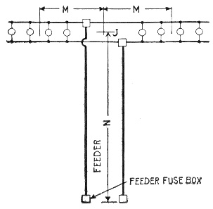
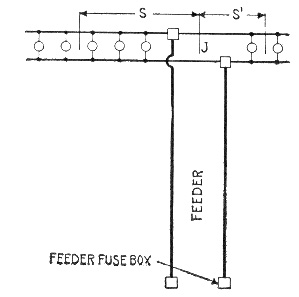
Figs. 830 and 831.—Symmetrical and unsymmetrical distribution. When a main is supplied by a feeder, the junction of the two, if practicable, is located at the electrical center of the main, as indicated in fig. 830, so that the distribution is symmetrical, that is, the ampere feet each way from the junction are the same. This is nearly always practicable in surface wiring, and when it is practiced it is only necessary to calculate the wire size for one-half of the main, as the other half is identical. In fig. 830 there are four lamps on each side of the junction, J; the center of each group is at a distance, M, so that the lamp feet in each half of the main are 5 × M. The lamp feet of the feeder would be 10 × N, N being the distance from the feeder fuse block to the junction, J. In concealed work, however, it does not always happen that a feeder can be made to join a main at its electrical center; when this is not practicable, each end of the main should be figured separately. In fig. 831, for instance, the main has five lamps on one side and two on the other, and the distances from the junction to the centers of the two groups are at unequal distances S and S'. If the distance S be 14 feet, and the lamps, 16 c. p., the lamp feet in the left hand main equals 5 × 14 = 70, while in the main to the right, taking S' at 10 feet, there are only 2 × 10 = 20 lamp feet. Hence what appears to be one continuous main in this case would have to be treated as two mains, and each part figured separately.
circular mils = I × feet × 21.6 E = amperes × feet × 21.6 "drop" . . . . (5)
The following practical example is given to illustrate the application of the formula just obtained: 749
EXAMPLE.—What size wire should be used on a 250 volt circuit to transmit a current of 200 amperes a distance of 350 feet to a center of distribution with a loss of three per cent. under full load?
The volts lost or drop is equal to 250 × .03 = 7.5 volts.
| Number of gauge B. & S. |
Diameter in mils |
Area in circular mils |
Weight in pounds | Resistance at 68° Fahr. | |||
|---|---|---|---|---|---|---|---|
| 1,000 feet | mile | Feet per pound |
1,000 Feet | mile | |||
| 0000 | 460 | 211,600 | 640.5 | 3,381 | 1.561 | .04893 | .2583 |
| 000 | 409.6 | 167,800 | 508 | 2,682 | 1.969 | .06170 | .3258 |
| 00 | 364.8 | 133,100 | 402.8 | 2,127 | 2.482 | .07780 | .4108 |
| 0 | 324.9 | 105,500 | 319.5 | 1,687 | 3.130 | .09811 | .5180 |
| 1 | 289.3 | 83,690 | 253.3 | 1,337 | 3.947 | .12370 | .6531 |
| 2 | 257.6 | 66,370 | 200.9 | 1,062 | 4.977 | .1560 | .8237 |
| 3 | 229.4 | 52,630 | 159.3 | 841.1 | 6.276 | .1967 | 1.0386 |
| 4 | 204.3 | 41,740 | 126.4 | 667.4 | 7.914 | .2480 | 1.3094 |
| 5 | 181.9 | 33,100 | 100.2 | 529.0 | 9.980 | .3128 | 1.6516 |
| 6 | 162.0 | 26,250 | 79.46 | 419.5 | 12.580 | .3944 | 2.0824 |
| 7 | 144.3 | 20,820 | 63.02 | 332.7 | 15.87 | .4973 | 2.6257 |
| 8 | 128.5 | 16,510 | 49.98 | 263.9 | 20.01 | .6271 | 3.3111 |
| 9 | 114.4 | 13,090 | 39.63 | 209.2 | 25.23 | .7908 | 4.1754 |
| 10 | 101.9 | 10,380 | 31.13 | 166.0 | 31.82 | .9972 | 5.2652 |
| 11 | 90.74 | 8,234 | 24.93 | 131.6 | 40.12 | 1.257 | 6.6370 |
| 12 | 80.81 | 6,530 | 19.77 | 104.4 | 50.59 | 1.586 | 8.374 |
| 13 | 71.96 | 5,178 | 15.68 | 82.79 | 63.79 | 2.000 | 10.560 |
| 14 | 64.08 | 4,107 | 12.43 | 65.63 | 80.44 | 2.521 | 13.311 |
| 15 | 57.07 | 3,257 | 9.858 | 52.05 | 101.4 | 3.179 | 16.785 |
| 16 | 50.82 | 2,583 | 7.818 | 41.28 | 127.9 | 4.009 | 21.168 |
| 17 | 45.26 | 2,048 | 6.200 | 32.74 | 161.3 | 5.055 | 26.690 |
| 18 | 40.30 | 1,624 | 4.917 | 25.96 | 203.4 | 6.374 | 33.655 |
| 19 | 35.89 | 1,288 | 3.899 | 20.59 | 256.5 | 8.038 | 42.440 |
| 20 | 31.96 | 1,022 | 3.092 | 16.33 | 323.4 | 10.14 | 15.340 |
Substituting the given value in formula (5)
circular mils = 350 × 200 × 21.6 7.5 = 201,600.
Diameter = 2 √201,600 = 449 circular mils or .449 in.
From the table (on page 731 or on page 742) the nearest (larger) size of wire is 0000 B. & S. gauge.4
750
| VOLTS | PERCENTAGE OF LOSS | |||||||||
|---|---|---|---|---|---|---|---|---|---|---|
| 2000 | 1.7 | 1.5 | 1.4 | 1.2 | 1.1 | 1.0 | 0.75 | 0.5 | ||
| 1000 | 3.4 | 2.9 | 2.7 | 2.4 | 2.2 | 2.0 | 1.5 | 1.0 | ||
| 500 | 6.5 | 5.7 | 6.2 | 4.8 | 4.3 | 3.9 | 2.9 | 2.0 | ||
| 220 | 13.7 | 12.0 | 11.0 | 10.3 | 9.3 | 8.3 | 6.5 | 4.4 | ||
| 110 | — | — | 20.0 | 18.5 | 17.0 | 15.4 | 12.0 | 8.4 | ||
| 52 | — | — | — | — | — | — | 22.4 | 16.1 | ||
| VOLTS | PERCENTAGE OF LOSS (continued) | |||||||||
| 2000 | 0.45 | 0.4 | 0.35 | 0.3 | 0.25 | 0.2 | 0.15 | 0.1 | 0.05 | |
| 1000 | 0.9 | 0.8 | 0.7 | 0.6 | 0.5 | 0.4 | 0.3 | 0.2 | 0.1 | |
| 500 | 1.8 | 1.6 | 1.4 | 1.2 | 1.0 | 0.8 | 0.6 | 0.4 | 0.2 | |
| 220 | 3.9 | 3.5 | 3.1 | 2.7 | 2.2 | 1.8 | 1.4 | 0.9 | 0.45 | |
| 110 | 7.6 | 6.8 | 6.0 | 5.2 | 4.4 | 3.5 | 2.7 | 1.8 | 0.9 | |
| 52 | 14.7 | 13.3 | 11.8 | 10.3 | 8.8 | 7.1 | 5.5 | 3.7 | 1.9 | |
| ACTUAL VOLTS LOST | ||||||||||
| Carrying Capacity Amperes. |
Size B. & S. |
35 | 30 | 27.5 | 25 | 22.5 | 20 | 15 | 10 | |
| 300 | 0000 | 345800 | 296400 | 271700 | 247000 | 222300 | 197600 | 148200 | 98800 | |
| 245 | 000 | 274400 | 235200 | 215600 | 196000 | 176400 | 156800 | 117600 | 78400 | |
| 215 | 00 | 217525 | 186450 | 170912 | 155375 | 139837 | 124300 | 93225 | 62150 | |
| 190 | 0 | 172550 | 147900 | 135575 | 123250 | 110925 | 98600 | 73950 | 49300 | |
| 160 | 1 | 136850 | 117300 | 107525 | 97750 | 87975 | 78200 | 58650 | 39100 | |
| 135 | 2 | 108500 | 93000 | 85250 | 77500 | 69750 | 62000 | 46500 | 31000 | |
| 115 | 3 | 86100 | 73800 | 67650 | 61500 | 55350 | 49200 | 36900 | 24600 | |
| 100 | 4 | 68250 | 58500 | 53625 | 48750 | 43875 | 39000 | 29250 | 19500 | |
| 90 | 5 | 54250 | 46500 | 42625 | 38750 | 34875 | 31000 | 23250 | 15500 | |
| 80 | 6 | 43050 | 36900 | 33825 | 30750 | 27675 | 24600 | 18450 | 12300 | |
| 60 | 8 | 26965 | 23130 | 21202 | 19275 | 17347 | 15420 | 11565 | 7710 | |
| 40 | 10 | 16975 | 14550 | 13337 | 12125 | 10912 | 9700 | 7275 | 4850 | |
| 30 | 12 | 10675 | 9150 | 8388 | 7625 | 6862 | 6100 | 4575 | 3050 | |
| 22 | 14 | 6720 | 5760 | 5280 | 4800 | 4320 | 3840 | 2880 | 1920 | |
| 55 | 16 | 4235 | 3630 | 3328 | 3025 | 2723 | 2420 | 1815 | 1210 | |
| ACTUAL VOLTS LOST (continued) | ||||||||||
| Carrying Capacity Amperes. |
Size B. & S. |
9 | 8 | 7 | 6 | 5 | 4 | 3 | 2 | 1 |
| 300 | 0000 | 88920 | 79040 | 69160 | 59280 | 49400 | 39520 | 29640 | 19760 | 9880 |
| 245 | 000 | 70560 | 62720 | 54880 | 47040 | 39200 | 31360 | 23520 | 15680 | 7840 |
| 215 | 00 | 55935 | 49720 | 43505 | 37290 | 31075 | 24860 | 18645 | 12430 | 6215 |
| 190 | 0 | 44370 | 39440 | 34510 | 29580 | 24650 | 19720 | 14790 | 9860 | 4930 |
| 160 | 1 | 35190 | 31280 | 27370 | 23460 | 19550 | 15640 | 11730 | 7820 | 3910 |
| 135 | 2 | 27900 | 24800 | 21700 | 18600 | 15500 | 12400 | 9300 | 6200 | 3100 |
| 115 | 3 | 22140 | 19680 | 17220 | 14760 | 12300 | 9840 | 7380 | 4920 | 2460 |
| 100 | 4 | 17550 | 15600 | 13650 | 11700 | 9750 | 7800 | 5850 | 3900 | 1950 |
| 90 | 5 | 13950 | 12400 | 10850 | 9300 | 7750 | 6200 | 4650 | 3100 | 1550 |
| 80 | 6 | 11070 | 9840 | 8610 | 7380 | 6150 | 4920 | 3690 | 2460 | 1230 |
| 60 | 8 | 6939 | 6168 | 5397 | 4626 | 3855 | 3084 | 2313 | 1542 | 771 |
| 40 | 10 | 4365 | 3880 | 3395 | 2910 | 2425 | 1940 | 1455 | 970 | 486 |
| 30 | 12 | 2745 | 2440 | 2135 | 1830 | 1525 | 1220 | 915 | 610 | 305 |
| 22 | 14 | 1728 | 1536 | 1344 | 1152 | 960 | 768 | 576 | 384 | 192 |
| 55 | 16 | 1089 | 968 | 847 | 726 | 605 | 484 | 363 | 242 | 121 |
RULE.—Multiply current in amperes by single distance and refer to the nearest corresponding number under column of actual volts lost, to find size of wire. 751 It should also be noted that the underwriters prohibit the use of wire smaller than No. 14 B. & S. gauge, except as allowed for fixture work and pendant cord.
| GAUGE B. & S. |
NUMBER OF WIRES | |||||||||||||
|---|---|---|---|---|---|---|---|---|---|---|---|---|---|---|
| 2 | 4 | 8 | 1 6 |
3 2 |
6 4 |
1 2 8 |
2 5 6 |
5 1 2 |
1 0 2 4 |
2 0 4 8 |
4 0 9 6 |
8 1 9 2 |
1 6 3 8 4 |
|
| 0000 | 0 | 3 | 6 | 9 | 12 | 15 | 18 | 21 | 24 | 27 | 30 | 33 | 36 | 39 |
| 000 | 1 | 4 | 7 | 10 | 13 | 16 | 19 | 22 | 25 | 28 | 31 | 34 | 37 | 40 |
| 00 | 2 | 5 | 8 | 11 | 14 | 17 | 20 | 23 | 26 | 29 | 32 | 35 | 38 | 0+6 |
| 0 | 3 | 6 | 9 | 12 | 15 | 18 | 21 | 24 | 27 | 30 | 33 | 36 | 39 | 1+7 |
| 1 | 4 | 7 | 10 | 13 | 16 | 19 | 22 | 25 | 28 | 31 | 34 | 37 | 40 | 2+8 |
| 2 | 5 | 8 | 11 | 14 | 17 | 20 | 23 | 26 | 29 | 32 | 35 | 38 | 3+9 | 4+6 |
| 3 | 6 | 9 | 12 | 15 | 18 | 21 | 24 | 27 | 30 | 33 | 36 | 39 | 4+10 | 5+7 |
| 4 | 7 | 10 | 13 | 16 | 19 | 22 | 25 | 28 | 31 | 34 | 37 | 40 | 5+11 | 6+8 |
| 5 | 8 | 11 | 14 | 17 | 20 | 23 | 26 | 29 | 32 | 35 | 38 | 6+12 | 7+9 | |
| 6 | 9 | 12 | 15 | 18 | 21 | 24 | 27 | 30 | 33 | 36 | 39 | 7+13 | 8+10 | |
| 7 | 10 | 13 | 16 | 19 | 22 | 25 | 28 | 31 | 34 | 37 | 40 | 8+14 | 9+11 | |
| 8 | 11 | 14 | 17 | 20 | 23 | 26 | 29 | 32 | 35 | 38 | 9+15 | 10+12 | ||
| 9 | 12 | 15 | 18 | 21 | 24 | 27 | 30 | 33 | 36 | 39 | 10+16 | 11+13 | ||
| 10 | 13 | 16 | 19 | 22 | 25 | 28 | 31 | 34 | 37 | 40 | 11+17 | 12+14 | ||
| 11 | 14 | 17 | 20 | 23 | 26 | 29 | 32 | 35 | 38 | 12+18 | 13+15 | |||
| 12 | 15 | 18 | 21 | 24 | 27 | 30 | 33 | 36 | 39 | 13+19 | 14+16 | |||
| 13 | 16 | 19 | 22 | 25 | 28 | 31 | 34 | 37 | 40 | 14+20 | 15+17 | |||
| 14 | 17 | 20 | 23 | 26 | 29 | 32 | 35 | 38 | 15+21 | 16+18 | ||||
| 15 | 18 | 21 | 24 | 27 | 30 | 33 | 36 | 39 | 16+22 | 17+19 | ||||
| 16 | 19 | 22 | 25 | 28 | 31 | 34 | 37 | 40 | 17+23 | 18+20 | ||||
| 17 | 20 | 23 | 26 | 29 | 32 | 35 | 38 | 18+24 | 19+21 | |||||
| 18 | 21 | 24 | 27 | 30 | 33 | 36 | 39 | 19+25 | 20+22 | |||||
| 19 | 22 | 25 | 28 | 31 | 34 | 37 | 40 | 20+26 | 21+23 | |||||
| 20 | 23 | 26 | 29 | 32 | 35 | 38 | 21+27 | 22+24 | ||||||
| 21 | 24 | 27 | 30 | 33 | 36 | 39 | 22+28 | 23+25 | ||||||
| 22 | 25 | 28 | 31 | 34 | 37 | 40 | 23+29 | 24+26 | ||||||
| 23 | 26 | 29 | 32 | 35 | 38 | 24+30 | 25+27 | |||||||
| 24 | 27 | 30 | 33 | 36 | 39 | 25+31 | 26+28 | |||||||
| 25 | 28 | 31 | 34 | 37 | 40 | 26+32 | 27+29 | |||||||
| 26 | 29 | 32 | 35 | 38 | 27+33 | 28+30 | ||||||||
| 27 | 30 | 33 | 36 | 39 | 28+34 | 29+31 | ||||||||
| 28 | 31 | 34 | 37 | 40 | 29+35 | 30+32 | ||||||||
| 29 | 32 | 35 | 38 | 30+36 | 31+33 | |||||||||
| 30 | 33 | 36 | 39 | 31+37 | 32+34 | |||||||||
| 31 | 34 | 37 | 40 | 32+38 | 33+35 | |||||||||
| 32 | 35 | 38 | 33+39 | 34+36 | ||||||||||
| 33 | 36 | 39 | 34+40 | 35+37 | ||||||||||
| 34 | 37 | 40 | 36+39 | |||||||||||
| 35 | 38 | 37+39 | ||||||||||||
| 36 | 39 | 38+40 | ||||||||||||
| 37 | 40 | |||||||||||||
Ques. If the calculated size of wire be larger than any in the table how is the required area obtained?
Ans. By using two or more smaller wires in parallel, whose combined area is equal to the required area.
To facilitate finding the equivalent sizes the above table of wire equivalents has been prepared.
752
Ques. How is the table of wire equivalents used?
Ans. To use the table, find in the vertical column at left the size of conductor desired; then follow along horizontally until the size of wire that is desired to use for the strands, and the corresponding number at top of column will give the number of strands of that size wire required.
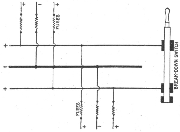
Fig. 832.—Break down switch for use on three wire circuit, enabling it to be operated break down fashion with the two outers connected together and the neutral wire serving as one side of the resultant two wire circuit. Such circuits must be figured as two wire installations of one half the three wire voltage. The size of the neutral wire of a three wire circuit depends on conditions of operation. Three wire circuits for occasional two wire working, must have a neutral wire whose cross section is equal to the combined cross sections of the two outer wires. This plan is useful for buildings supplied from a central station, as it will be satisfactory for two wire operation in emergencies, and for three wire, two phase or three phase distribution should the central station ultimately be changed over to either of those alternating current systems. The expense for the extra copper in the beginning will not be nearly so great as that entailed by a change in the wiring later on should developments require it. It is permissible, however, to make the cross section of the neutral wire smaller than that of each outer wire, if one be reasonably sure that there will never be any changes such as those just mentioned, and if the drop in the two outer wires do not exceed 1½ per cent. Under such conditions, it will be found a very good rule to calculate the neutral wire of a principal feeder for a maximum unbalancing of 25 per cent, that is, a condition under which the current in one outer wire will be 75 per cent of the current in the other one, the current in the neutral being 25 per cent of that in the heavier loaded outer wire.
Ques. What is the significance of the zig-zag line?
Ans. The figures below this line give the gauge numbers of two wires which will have the same conductivity as the corresponding conductor in left hand column. 753
TABLE OF CABLE CAPACITIES
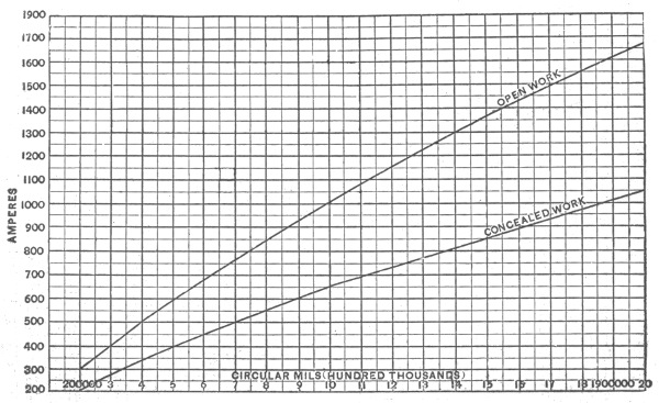
Fig. 833.—Diagram showing capacities of cables for both open and concealed work as allowed by the underwriters.
754
Incandescent Lamps on 660 Watt Circuits.—The standard incandescent lamp is rated as equivalent to the light given by 16 candles, and may consume, according to type and make, from 50 to 56 watts, or from 3.1 to 3.5 watts per candle power. Therefore, a 660 watt circuit will carry thirteen 16 candle power 49.6 watt lamps, or eleven 56 watt lamps.
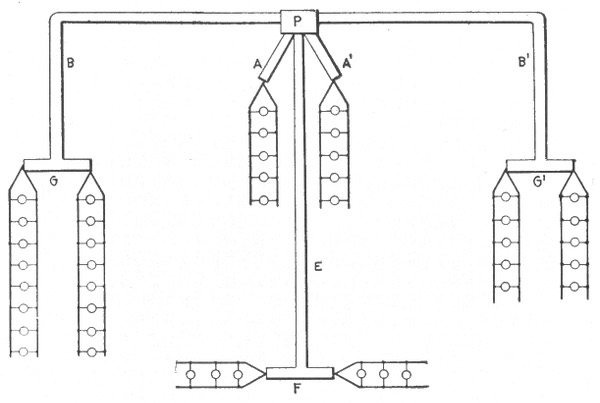
Fig. 834.—Diagram showing symmetrical and unsymmetrical distribution. The two 5 lamp centers are located at equal distances from the distributing pocket or cabinet, P, so that the sub-feeders, A and A', have equal values of lamp feet. The sub-feeders, B, B', have equal lengths, but as one supplies 10 lamps, and the other 16, the lamp feet are different, and each sub-feeder must therefore be figured separately. The main, G, should be considered as a part of the sub-feeder, B, in order to avoid the necessity for a fuse at the junction of the two. As it is symmetrically divided, only one-half of it would be considered. Thus, if the sub-feeder, B, were 50 feet long, and the main, G, 30 feet long, B would have 16 × 50 = 800 lamp feet and one-half of the main would have 8 × 15 = 120 lamp feet (assuming all 16 c. p. lamps). Hence 800 + 120 = 920 lamp feet should be taken as the load length and the proper size wire used for that figure, making the sub-feeder, B, of the same size as the main, G. The same procedure applies to the sub-feeder B' and main G'; also to the sub-feeder, E, and the main, F. The proper sizes of wire for the different circuits is easily found from the lamp feet table, after having calculated the lamp feet assigned the drop.
755
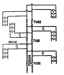
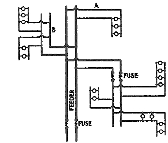
Figs. 835 and 836.—The "tree" and "modified tree" systems of wiring. The tree system consists of a feeder reducing in size and supplying mains for each floor, the general arrangement resembling the trunk and branches of a tree. Since fuses must be inserted on each floor where the size of the feeder is reduced, the system requires a large number of joints, and in the event of a fuse blowing it could not be quickly located. The tree system is not to be recommended, as it results in considerable drop, and at full load the lamps nearest the point of supply will either burn too brightly or those more remote will not give the rated candle power. In the modified tree system, fig. 836, the size of the feeder is not reduced. With this arrangement the losses are considerably reduced owing to the much smaller losses on the feeder between those centers farthest away from the point of supply.
The proper size of wire for a 660 watt circuit will depend upon the voltage for which the lamps are made. For example: a 16 candle power lamp which consumes 56 watts on 110 volt circuit will take, 56 ÷ 110 = .5 or ½ ampere of current, while the same lamp, if made for 220 volts, will take only 55 ÷ 220 = .25 or ¼ ampere. Therefore, eleven 16 candle power 56 watt lamps will require a current of 5½ amperes at 110 volts, or 2¾ amperes at 220 volts.
According to the laws of resistance, the resistance of a round wire is inversely proportional to the square of the diameter, and if the circuit be taken at 100 feet, and the allowable percentage of drop at 1 volt, then according to formula, (5) on page 748, the wire required for a circuit carrying eleven 16 candle power 56 watt 110 volt lamps, will have a cross sectional area of,
5.5 × 100 × 21.6 1 = 11,880 circular mils.
while the same number of lamps on a 220 volt circuit will require wire having a cross sectional area of,
2.75 × 100 × 21.6 1 = 5,940 circular mils. 756
In order to conform to the underwriters' requirements, No. 8. B. & S. gauge, wire must be used for the circuit carrying the 110 volt lamps, while No. 12, B. & S. wire, would be sufficient for the 220 volt circuit.
In the case shown in fig. 829, the branch circuits A and B are identical, each supplying four 16 candle power lamps requiring 3.5 watts per candle power at 110 volts or carrying a load of 4 × 16 × 3.5 = 224 watts, = 224 ÷ 110 = 2 amperes.
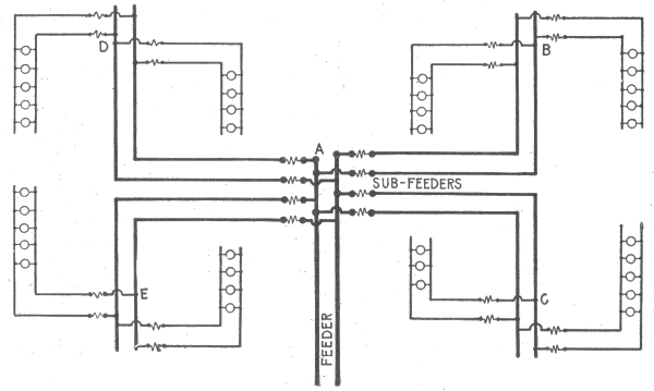
Fig. 837.—Distribution with sub-feeders (multi-center distribution). The feeder connects at a central point, A, with several sub-feeders which run to distributing centers, as at B, C, D, and E. With this arrangement, compound wound dynamos may be so designed that the pressure at A will remain nearly uniform for all loads. If, for instance, the wiring be proportioned for 2% drop, the dynamos may be over compounded to that extent, and the even illumination will compensate for the extra cost in the installation.
The distance from the feeder junction or cut out to the electrical center of each branch circuit is 12.5 feet. The compact area of distribution permits the reduction of the loss of volts to 1 per cent, or 110 × .01 = 1.1 volts "drop." Then substituting in formula (5) on page 748 the values for amperes, feet and drop as obtained above
2 × 25 × 21.6 1.1 = 981 circular mils,
or a value far below that of even No. 18 wire, B. & S. gauge (see table on page 731), but the smallest wire allowed by the underwriters for the mains A and B is No. 14, B. & S. gauge. 757
In calculating the size of wire for the feeders the total load must be considered. This is equal to eight 16 candle power lamps, requiring 3.5 watts per candle power at 110 volts = 8×16×3.5 = 448 watts = 4 amperes.
The distance from the entrance cut out to the feeder cut out is 200 feet. The drop should not be greater than 1.5 per cent. or 110×1.5 = 1.6 volts. Then,
4×200×21.6 1.6 = 10,800 circular mils
a value which indicates that No. 8 wire, B. & S. gauge, must be used for the feeders in order to keep the drop within the limit of predetermined value.
| Wire Nos. | 0 | 1 | 2 | 3 | 4 | 5 | 6 | 7 | 8 | 9 | 10 | 12 | 14 | 16 | 18 |
|---|---|---|---|---|---|---|---|---|---|---|---|---|---|---|---|
| Lamp | 52 v. | 300 | 260 | 200 | 160 | 130 | 100 | 80 | 65 | 50 | 38 | 24 | 15 | 9 | 6 |
| Feet | 110v. | 1,280 | 1,085 | 860 | 680 | 560 | 435 | 345 | 280 | 220 | 160 | 100 | 60 | 40 | 25 |
NOTE.—In using this table, it is only necessary to calculate the lamp feet of the tap and take the size of wire corresponding to the nearest greater number of lamp feet in the table. The lamp feet specified by this table should not be exceeded by more than 10 per cent. Thus, if a tap measure 108 lamp feet, in 110 volt lamps, No. 12 wire would be used. But if it measure 115 lamp feet, it would be advisable to use No, 10 wire.
Constant Voltage Arc Lamp Circuits.—The branch conductor should have a carrying capacity about fifty per cent. greater than the normal current required by the lamp, so as to provide for the heavy current required when the lamp is started. The underwriters prohibit the use of any size wire under No. 12 for parallel connected arc light circuits.
Constant Current Series Arc Lamp Circuits.—The wiring for series connected arc lamps should never be concealed nor encased unless requested by the electrical inspector. 758
For all interior wiring of this class, approved rubber covered wire should be used, and the wire should always be rigidly supported on porcelain or glass insulators which will hold the wires at a distance of at least one inch from the surface wired over. The wires on all circuits up to 750 volts, should be kept at least 4 inches from each other, and 8 inches apart on circuits of over 750 volts. No wires carrying a current having a pressure exceeding 3,500 volts should be carried into or over any building except central stations and sub-stations.
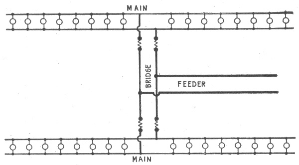
Fig. 838.—Diagram showing "bridge wiring." This method is used in the case of two parallel mains where one feeder is ample for both. The feeder is run to a central point as shown and connected to the two mains by a so called "bridge." The arrangement clearly gives good distribution and effects a saving in copper and labor, for if the bridge were omitted, two feeders would be necessary.
Wire Calculations for Motors.—The proper size of wire for a motor may be readily determined by means of the following formula:
circular mils = H.P. × 746 × D × 21.6 E × L × K . . . . (6)
in which
H.P. = horse power of motor;
746 = watts per H.P.;
D = length of motor circuit from fuse block to motor;
759
21.6 = ohms per foot run in circuit where wires are one mil in diameter;
E = voltage at the motor;
L = drop in percentage of the voltage at the motor;
K = efficiency of the motor expressed as a decimal.
The average values for K are about as follows: 1 H.P., .75; 3 H.P., .80; 5 H.P., .80; 10 H.P. and over, 90 per cent.
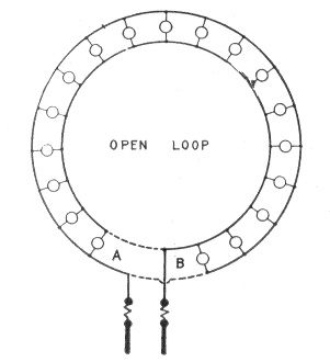
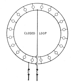
Figs. 839 and 840.—Wrong and right methods of loop wiring. In general, when a large percentage of loss is allowed with lamps at short distances, the size of wire, calculated simply in accordance with the resistance rules, will be found too small to carry the current safely. This fact is often overlooked, and even though wires may have been correctly calculated for a uniform percentage of loss, they will become painfully hot simply because the table of carrying capacity was not consulted. The cross connection of mains wherever possible, for the purpose of equalizing the pressure, will also often reduce the heating effects of the current. An example of this is shown in the above figures. A circle of lights was wired as in fig. 839, and after the current had been turned on, the wires of the circle became hot, and there was quite a perceptible difference of candle power between the lights near A and those near B. Investigation disclosed the fact that the loop, contrary to instructions, had been left open. A few inches of wire as shown in dotted lines remedied the fault. A better arrangement, however, is shown in fig. 840.
EXAMPLE.—What is the proper size of wire for a 10 H.P. motor, run at 220 volts, allowable drop 2 per cent. on 200 foot circuit.
Substituting the given values in the formula on page 758:
Circular mils = 10 × 746 × 200 × 21.6 220 × 4.4 × .9 = 36,991.
The nearest larger value to this result, in the table of carrying capacities of copper wire (page 731), is 41,740, corresponding to No. 4 wire, B. & S. gauge. 760
In all cases the size of the wire thus formed should be compared with that allowed by the underwriters for full load current of motor, plus 25 per cent. of that current, and if the size calculated happen to be smaller than the allowable size, it should be increased to the latter, otherwise it will not pass inspection.
| H. P. | Per Cent. Eff. | Watts Input | 50 Volts | 100 Volts | 220 Volts | 500 Volts |
|---|---|---|---|---|---|---|
| ¾ | 70 | 800 | 16 | 7 | 4 | 2 |
| 1½ | 70 | 1600 | 32 | 15 | 7 | 3 |
| 3 | 75 | 2980 | 60 | 27 | 14 | 6 |
| 5 | 80 | 4660 | 93 | 42 | 21 | 9 |
| 7½ | 85 | 6580 | 132 | 60 | 30 | 13 |
| 10 | 85 | 8780 | 176 | 80 | 40 | 18 |
| 15 | 85 | 13200 | 264 | 120 | 60 | 26 |
| 20 | 85 | 17600 | 352 | 160 | 80 | 35 |
| 25 | 85 | 21900 | 438 | 199 | 100 | 44 |
| 30 | 90 | 24900 | 498 | 226 | 113 | 50 |
| 40 | 90 | 33200 | 664 | 301 | 151 | 66 |
| 50 | 90 | 41400 | 828 | 376 | 188 | 83 |
| 60 | 90 | 49700 | 994 | 452 | 226 | 99 |
| 70 | 90 | 58000 | 1160 | 527 | 264 | 116 |
| 80 | 90 | 66300 | 1330 | 608 | 302 | 133 |
| 90 | 90 | 74600 | 1490 | 678 | 339 | 149 |
| 100 | 90 | 82900 | 1660 | 755 | 377 | 166 |
| 120 | 90 | 99500 | 1990 | 905 | 453 | 199 |
| 150 | 90 | 124000 | 2480 | 1130 | 564 | 248 |
| Appx. | Appx. | ||||||||
|---|---|---|---|---|---|---|---|---|---|
| K.W. | 125 Vs. | 250 Vs. | 500 Vs. | H.P. | K.W. | 125 Vs. | 250 Vs. | 500 Vs. | H.P. |
| 1. | 8 | 4 | 2 | 1.3 | 30. | 240 | 120 | 60 | 40. |
| 2. | 16 | 8 | 4 | 2.7 | 37.5 | 300 | 150 | 75 | 50. |
| 3. | 24 | 12 | 6 | 4.0 | 40. | 320 | 160 | 80 | 53. |
| 5. | 40 | 20 | 10 | 6.7 | 50. | 400 | 200 | 100 | 67. |
| 7.5 | 60 | 30 | 15 | 10. | 60. | 480 | 240 | 120 | 80. |
| 10. | 80 | 40 | 20 | 13. | 75. | 600 | 300 | 150 | 100. |
| 12.5 | 100 | 50 | 25 | 17. | 100. | 800 | 400 | 200 | 134. |
| 15. | 120 | 60 | 30 | 20. | 125. | 1000 | 500 | 250 | 167. |
| 20. | 160 | 80 | 40 | 27. | 150. | 1200 | 600 | 300 | 201. |
| 25. | 200 | 100 | 50 | 34. | 200. | 1600 | 800 | 400 | 268. |
To determine the current required for a motor, as for instance, the 10 H. P. motor under consideration, multiply the horsepower by 746, and divide the product by the voltage of the motor multiplied by its efficiency as follows: (10 × 746) ÷ (220 × .90) = 37.6 amperes. 761
This value increased by 25 per cent. of itself (37.6 × .25 = 9.4 amp.) is equal to 37.6 plus 9.4 = 47 amperes. In the table of carrying capacities of copper wire (page 731), 46 amperes is given as the allowable carrying capacity of No. 6, B. & S. gauge, rubber covered wire; therefore No. 5 wire must be used.
Calculations for Three Wire Circuit.—In all cases of interior conduit work, and in most cases of inside open work, the main feeders from a three wire source of supply are installed on the three wire plan, and the sub-feeders and distributing mains, on the two wire plan, except where the application of the method necessitates the use of unwieldy sizes.
In laying out sub-feeders and mains, the total load, under normal operating conditions, should be divided as nearly as possible into two equal parts, and one part connected on each side of the neutral part of the entrance cut out, or the neutral bus bar of the switch board or panel board in an isolated plant, thus making the load on each side of the neutral wire of the feeder as near equal as possible.
Fig. 841 shows a three wire panel board with connection for 12 mains; those shown in solid lines as A, B, C, etc., being connected between the neutral wire and the negative wire of the feeder, and those shown by dotted lines as G, H, I, etc., being connected between the neutral wire and the positive wire of the feeder. The total load consists of ninety-one 16 candle power lamps, which are so distributed that the positive wire of the feeder carries the current for 46 lamps, and the negative wire, 45 lamps, the neutral wire carrying the difference or current for 1 lamp.
The proper size of wire for the mains may be calculated as already explained, but in calculating the outer wires of the three wire feeder, the neutral wire should be disregarded and the outer wires connected as a two wire circuit carrying the total load of 91 lamps at the over all pressure of 220 volts. 762
EXAMPLE.—Ninety-one 16 candle power lamps consuming 3.1 watts per candle power at a pressure of 110 volts, will require a current of
16 × 3.1 × 91 110 = 41 amperes.
The distance from the entrance cut out to the main or feeder switch is 200 feet, then for a 2 per cent. drop, or a loss of 110×.02=2.2 volts, the cross sectional area of the wire will be,
41 amperes × 200 feet × 21.6 2.2 volts = 80,509 circular mils.
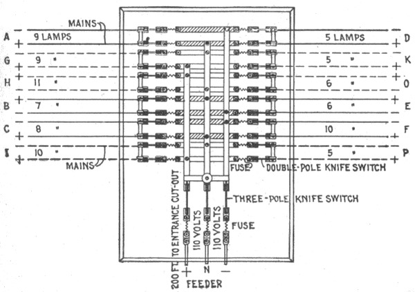
Fig. 841.—Three wire circuit panel board with connections for 12 mains. The wires shown in solid lines as A, B, C, etc., are connected between the neutral wire and the negative wire of the feeder, and those shown by dotted lines, as G, H, I, etc., are connected between the neutral wire and the positive wire of the feeder.
The joint resistance of the lamps on a three wire system, however, would be four times greater than on a two wire system; consequently the resistance of the outer wires of the feeder in this case will be four times greater for the same percentage of loss, and the cross sectional area of each of the outer wires will be, 80,509÷4=20,127 circular mils. According to the underwriters' rules, this value compels the use of No. 6 B. & S. gauge wire.
763
If the lamp voltage, 110 volts, be used, the two wire formula (5) given on page 748 must be modified to,
circular mils = amperes × feet × 21.6 drop × 4
but if an over all voltage, (that is, the voltage between the outer wires), of 220 volts be used, the two wire formula does not require any modification.
The proper size of wire may also be calculated by means of the formula
drop 2 × distance × amperes = resistance per foot . . . . (1)
Example.—If in calculating a three wire feeder, the over all voltage be 220 volts, the drop = 4.4 volts, twice the distance = 400 feet, and the current = 20.5 amperes, then,
4.4 volts 400 feet × 20.5 amperes = .0005365 ohms per foot.
In the table of the properties of copper wire which gives the resistance of various sizes of wire, it will be noted that at all of the given temperatures No. 8 wire has a resistance greater than the value just calculated, therefore, No. 6 B. & S. gauge wire should be used for the outer wires of the feeder. In the table the resistance is given per 1,000 feet, hence it is only necessary to move the decimal point to obtain the resistance per foot.
If the calculation be based on the lamp voltage, 110 volts, the formula (1) must be modified to
drop × 4 2 × distance × amperes = resistance . . . . (2)
In this case, drop = 2.2 volts, 2 × distance = 400 feet, and current = 41 amperes, then,
2.2 volts × 4 400 feet × 41 amp. = 8.8 16,400 = .005364 ohms. 764
Size of the Neutral Wire.—In three wire circuits, the size of the neutral wire will depend to a great extent upon operating conditions. In the case of installations which occasionally have to be worked as two wire systems, the cross section of the neutral wire should be equal to the combined cross section of the two outer wires.
For interior wiring which must pass inspection, the neutral wire must always be twice the size of one of the outside wires. However, for general distribution, if it be reasonably sure that the system will always be worked three wire and that the drop in the two outer wires does not exceed 1½ per cent., the cross section of the neutral wire may be made smaller than that of one of the outer wires. In such a case the size of the neutral wire may be calculated for a maximum unbalancing of 25 per cent., when the current in one of the outer wires is 75 per cent. of the current in the other outer wire.
For instance, suppose that in a balanced system, the total load on each of the outer wires of a feeder be 211 amperes, and that on account of certain operating conditions, this load has to be divided unequally so as to put 242 amperes on one of the outer wires, and 181 amperes on the other outer wire. In this case the neutral wire will carry 60 amperes, or 25 per cent. of the current carried by the heavier outer wire.
If the drop in the outer wires exceed 1½ per cent., the cross section of the neutral wire will have to be equal to or larger than that of each of the outer wires, otherwise the drop in the neutral wire will exceed ½ volt with an unbalancing of 25 per cent.
765
The term wiring is commonly understood to mean the methods employed in laying the conductors used for the transmission and distribution of electrical energy for lighting, power, and other purposes. Interior wiring, comprises the various methods of installing the conductors from the entrance devices in the walls or other parts of the buildings to the lamps, motors, and other electrical apparatus within the buildings.
The different methods of interior wiring may be conveniently grouped into the following general classes:
1. Open or exposed wiring;
2. Wires run in mouldings;
3. Concealed knob and tube wiring;
4. Rigid conduit wiring;
5. Flexible conduit wiring;
6. Armoured cable wiring.
Open or Exposed Wiring.—This method of wiring possesses the advantages of being cheap, durable and accessible. It is used a great deal in factories, mills and buildings where the unsightly appearance of the wires exposed on the walls or ceilings is of no consequence. 766
Ques. What kinds of wires are suitable for this method of wiring?
Ans. Either rubber covered or slow burning weather proof wire.
Rubber insulation should always be used where the wire is in a damp place, such as a cellar, and either weather proof or rubber insulation may be used to protect it against corrosive vapors.
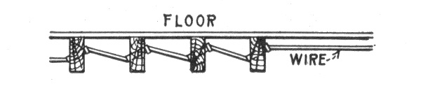
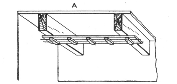
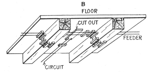
Figs. 842 to 844.—Open or exposed wiring. Fig. 842, wires passing through beams. The holes are bored at an angle and wire run through in zig-zag course. Porcelain tubes are used where the wire passes through beams; fig. 843, cleat work across beams, the cleats are carried by boards attached to the beams; fig. 844, method of carrying wires on cleats around beams.
Ques. How are the wires installed?
Ans. They are laid on some cornice, wainscoting, beam, or other architectural feature suitable for the purpose, by means of porcelain knobs and cleats, as shown in figs. 842 to 844. 767
Porcelain knobs should preferably be of the two piece type (fig. 863) in which the wire is carried between the upper and lower portions rather than being tied to a one piece knob with a tie wire as in fig. 860. Various porcelain knobs and cleats are shown in figs. 860 to 866.
Ques. What are the disadvantages of open wiring?
Ans. The wiring is not sufficiently protected from moisture, and the effects of fire which will destroy the insulation of the wires; it is also liable to mechanical injury.
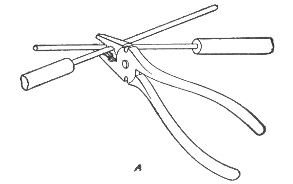
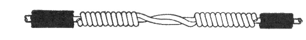
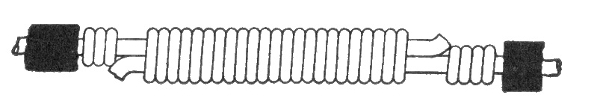
Figs. 845 to 847.—Splicing. Figs. 845 and 846, making a wire splice, and the twist completed; fig. 847, a wrapped joint on large wire. Splicing of wires or joining a branch to a main wire should always be made by twisting the wires together or twisting one wire around the other, so that the joint will be mechanically strong enough to carry all strain which may come upon it, without any soldering. The joint should then be carefully tinned and soldered in order to give good electrical contact and to avoid corrosion along the contact surface. Where wires are too large to be twisted together, the ends are given a short bend and the two wires wrapped firmly together with a smaller bare copper wire, after which the joint is thoroughly tinned and soldered, preferably by pouring hot solder over the joint. The joint is then insulated by wrapping it with two layers of pure rubber, and three layers of tape, sufficient to make the insulation thickness equal to that of the wire, after which the whole joint should be painted with water proof paint.
Ques. How far apart should the wires be placed?
Ans. When installed in dry places and for pressures below 300 volts, the insulators should separate the wires 2½ inches 768 from each other and ½ inch from the surface along which they pass. For voltages from 300 to 500, the wires should be separated four inches from each other and one inch from the surface along which they pass.
If the wiring be in a damp place, the wires should be at least one inch from the surface.
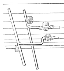
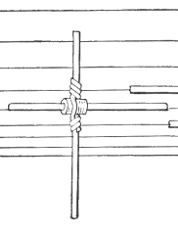
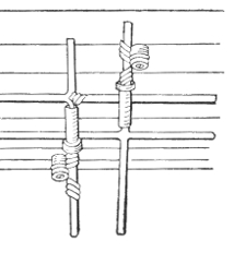
Figs. 848 to 850.—Crossing of wires. Where wires cross each other, tubes should be used except in case of large stiff wires as in fig. 848; here one wire may be bent down and carried under the other; fig. 849, short bushing strung on the wire—this method is usually unsatisfactory, especially where a large number of wires cross each other; fig. 850, wires crossing each other through tubes. Flexible tubing, such as circular loom may be used in crossing wires in dry locations. Insulators should always be provided where wires cross to support the wires, thus preventing the upper wires sagging and touching those below.
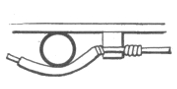
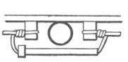
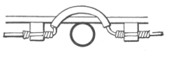
Figs. 851 to 853.—Methods of wiring across pipes. The wires should preferably run over rather than under the pipes. Fig. 851 shows crossing with circular loom, and fig. 852, one in which a tube is used. Both of these methods are satisfactory in the case of gas pipes, but for steam pipes or water pipes which are liable to leak or sweat and drip moisture, the crossing should be above as shown in fig. 853. On side walls where vertical wires run across horizontal water pipes, the latter should be enclosed and the moisture deflected to one side.
Ques. How should wires be protected when run vertically on walls?
Ans. They should be boxed in or run in a pipe as shown in fig. 854, the covering extending 6 feet above the floor. 769
When placed inside a box there should be a clearance of at least one inch around the wires; the box should be closed at the end as shown, and the wires protected where they enter the top with bushings. When the wires are placed in a pipe they should be first encased in a piece of flexible tubing that will extend from the insulator below the end of the pipe to the first one above it.
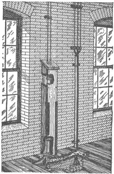
Fig. 854.—Methods employed in open wiring when run vertically on walls. Either a box casing or iron pipe should be used to protect the wires. The covering need only extend six feet above the floor.
Ques. What kind of incandescent lamp receptacle or wall socket is best adapted to exposed wiring?
Ans. One which does not have exposed contact ears, an approved form being shown in fig. 859.
Practical Points Relating to Exposed Wiring.—Some of the principal points which should be remembered in this connection, together with the methods which may be applied to special cases, may be briefly stated as follows: 770
1. In interior wiring no wires smaller than No. 14 B. & S. gauge should be used, except as allowed by the underwriters, and no more than 660 watts should be allowed to a circuit.
2. Tie wires should have an insulation equal to that of the conductors which they secure.
3. In all cases, whether the wires be run on knobs, split insulators, or cleats, the wires should be supported at intervals of at least 4½ feet, and if exposed to mechanical injury, the supporters should be placed at closer intervals.
4. Wires run on bare ceilings of low basements, especially where they are liable to injury, should be protected by two wooden guard strips as shown in fig. 858. The protective strips should be at least ⅞ inch in thickness and slightly higher than the knobs, insulators, or cleats. The two circuit wires should not be run closer than 6 inches apart, and wires run near water tanks must be rubber covered so as to render them moisture proof.
5. Cleats should be used for the wiring of stores, offices, or buildings having flat ceilings, provided the wiring is installed in dry locations.
6. When the installation is exposed to dampness or acid fumes such as those developed in stables, bakeries, etc., the wires should run on knobs or split insulators, and should be rubber covered.
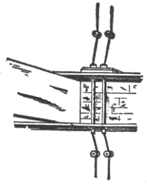
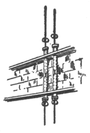
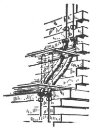
Figs. 855 to 857.—Methods of carrying wires through floors. In passing through floors (or walls) the wires often come in contact with concealed pipes or other grounded material, hence the only way they can be properly protected is by making the bushing continuous. This may consist of continuous porcelain tubes as shown in fig. 855, or short bushings may be arranged in iron pipes as in fig. 856. The method followed in case of an offset in the wall is shown in fig. 857. Sometimes the floor can be taken up and an iron conduit, properly bent, put in place, the wires being reinforced with flexible tubing. Another method is to attach the wires to insulators; in this case the floor must not be put down until the wiring has been examined by the inspector.
771
7. When wires are run at right angles to beams which are more than 4½ feet apart, a running board should be used and the wires cleated to it as shown in fig. 843. It is desirable, however, to avoid the use of running boards, whenever possible by running the wires parallel with the beams, thus reducing the cost of insulation.
8. In factories or other buildings of open mill construction, mains of No. 8 B. & S. gauge or larger wire, where they are not exposed to injury, may be placed about 6 inches apart and run from timber to timber, not breaking around, and may be supported at each timber only.
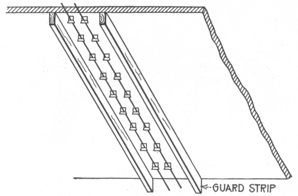
Fig. 858.—Method of protecting exposed wiring on low ceilings by two guard strips.

Fig. 859.—Receptacle suitable for use with open wiring, the requirement being that the contact ears should not be exposed.
772
9. The best location for feeders is on the walls. In dry buildings the fire and weather proof wire can be used with safety; but covered wire must be used on buildings subject to any form of dampness. In all cases where feeders are run on the walls, they should be protected from mechanical injury by boxings at least 6 feet high on each floor. If floor switches be used, they may be mounted on the front of the boxing. In such cases, the holes in the boxing through which the wires pass to the switches should be provided with porcelain bushings.
10. The rosettes, receptacles, sockets, snap switches, etc., used in connection with exposed wiring should conform in all respects to the standards specified by the underwriters.
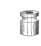
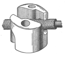
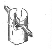
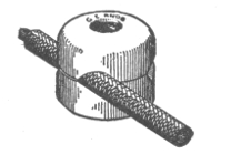
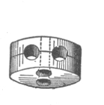
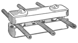
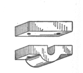
Figs. 860 to 866.—Various porcelain knobs and cleats. In open work various forms of these devices are used.
773
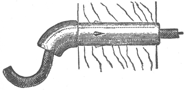
Fig. 867.—Porcelain tube for entrance of wire into a building. There must be a drip loop outside to drain off water, and the hole through which the conductor passes must be bushed with a non-combustible, non-absorptive insulating tube slanting downward toward the outside. The object of the inclination is to allow any water that might enter the tube to gravitate to the drip loop.
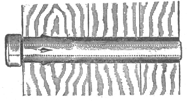
Fig. 868.—Interior bushing. Wires must be separated from contact with walls, floors, timbers or partitions through which they may pass by non-combustible, non-absorptive, insulating tubes, such as glass or porcelain, except at outlets where approved flexible tubing is required. Bushings must be long enough to bush the entire length of the hole in one continuous piece, or else the hole must first be bushed by a continuous water proof tube. This tube may be a conductor, such as iron pipe, but in that case an insulating bushing must be pushed into each end of it, extending far enough to keep the wire out of contact with the pipe.
Wires Run in Mouldings.—Wooden mouldings are extensively used in connection with the wiring of stores, factories and buildings. The advantages of this type of construction are: simplicity, cheapness, and accessibility, and when the moulding is run straight and accurately mitred it makes a neat job. Any class of wooden moulding wiring, however, is not sufficiently impervious to moisture to render it suitable for use in damp places, and it is liable to be crushed or punctured. Furthermore, it is naturally very combustible. These difficulties are overcome 774 to a certain extent by impregnating the moulding with some kind of moisture repellant, or by coating it both inside and out with water proof paint. Hardwood moulding should be used wherever possible, but soft wood moulding usually conforms much better to the wall line.
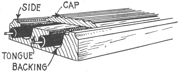
Fig. 869.—Standard wooden moulding for encasing wires. Wooden moulding must not be used in concealed or damp places, nor be placed directly against a brick wall where sweating may introduce moisture that may ultimately cause a short circuit. Wooden moulding for concealing electrical conductors is prohibited by ordinances in some cities.
Ques. For what conditions is wiring in mouldings suitable?
Ans. It is adapted to installations in which the wires have to be laid after the completion of the buildings.
Ques. Describe the moulding usually employed.
Ans. It is made of hardwood in two pieces, a backing and cap, so constructed as to thoroughly encase the wire.
It should provide a one-half inch tongue between the conductors and a solid backing which should not be less than three-eighths of an inch in thickness under the grooves; it should be able to give suitable protection from abrasion. 775
The inside of the moulding and the cap must have at least two coats of waterproof material, or else the whole moulding must be impregnated with moisture repellant.
Only one conductor is placed in a groove.
The backing is secured to the walls or ceilings by means of wire nails. The wires are then laid in the grooves and the capping put in place and fastened by small brads.
The wires should be continuous, and only rubber covered wire should be employed.
Wooden moulding is made in a great variety of size and design. The general appearance of this type of moulding being shown in fig. 869.
Ques. What other kind of moulding is used?
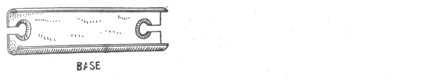

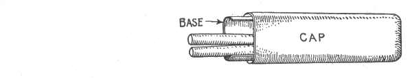
Figs. 870 to 872.—Metal moulding. An approved form consists, as shown, of two pieces: base (fig. 870), and cap (fig. 871), so formed as to snap together, the cap snapping over the base as in fig. 872. The entire moulding should be galvanized or coated with a rust preventive. When the base is held in place by screws or bolts from the inside surface, depressions must be provided so that the heads of the screws will be flush with the surface of the moulding.
Ans. Metal moulding, as shown in figs. 870 to 872.
Metal moulding is permitted on circuits requiring not more than 660 watts and where the pressure is not over 300 volts. Special fittings must 776 be used with this class of moulding so that it is continuous both mechanically and electrically. The moulding should be grounded. The installation rules are practically the same as those governing conduit work.
Ques. What is a kick box?
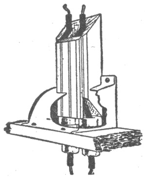
Fig. 873.—"Kick box;" a device used to protect wires encased in porcelain tubes where they pass through floors.
Ans. A fitting, as shown in fig. 873, for protecting wires at the points where they enter or emerge from the floor.
Ques. How is moulding work installed on brick or plaster walls which are liable to dampness?
Ans. A backing board must be put on before the moulding is used.
Ques. How should moulding be placed on a ceiling with respect to appearance?
Ans. The appearance is improved if the moulding be carried through to the side of the room, even if part of it be not used. This will give a neat and finished appearance to the ceiling as shown in fig. 874.
Moulding should always be run in as inconspicuous position as possible, and if it be necessary to run it on the open ceiling, it should be arranged so as to form regular panels. Often it can be run so as to 777 take the place of a picture moulding or as a part of the baseboard so that it becomes merely a part of the wooden trim of the building; and in certain cases it should be made of material to match the rest of the trim.
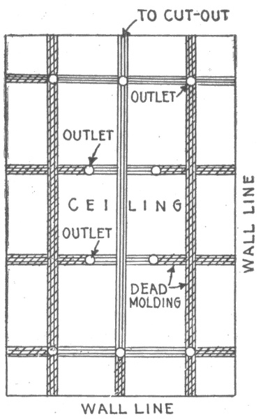
Fig. 874.—Treatment of moulding work on ceilings. All installations should be planned out so as to conform to symmetrical designs, as far as practicable with the proper distribution of the lights, etc., and all runs finished off, whenever necessary, by "dead" mouldings continued to the walls to improve the appearance. In the figure the sectioned portions show the location of the dead moulding. Sometimes, especially in the wiring of private houses the use of special moulding is necessary. In such cases the shape and kind of wood should match that of the finish or trim of the room, and the receptacles should be stained to match the moulding. When the moulding is run along the walls, the capping may be made to match the trim or the picture moulding already in place, thus giving an apparently concealed job. In this kind of work the feeders can be run through the spaces between the walls, and if flexible tubes such as circular loom or flexiduct be used, no splice box will be necessary where the system of wiring changes and single braided rubber wire may be used throughout.
Ques. What is the usual character of moulding work?
Ans. Usually, a certain part of the work will be run as concealed, that is, inside the partitions, the wires being "fished" from the moulding to the outlet.
Practical Points Relating to Wiring in Mouldings.—The following practical points will be found useful in the satisfactory execution of any class of wiring with wooden moulding: 778
1. Wooden moulding should never be concealed, and should not be used in damp places or in buildings subject to acid fumes, such as ice houses, breweries, or stables, etc.
2. Wooden moulding selected for use should be formed of good straight stock and free from knots, knot holes and other imperfections. The saving effected in the lower cost of second hand moulding does not compensate for the additional cost increase in its working.
3. When wooden moulding is used in connection with solid pipe or flexible tube conduit, an iron box or conduitlet must be installed where the system of wiring changes, as shown in fig. 875. The pipe conduit is secured to the box by means of lock nuts, with porcelain bushings or flexible tubes protecting the wires. In all cases the loom should run up to the moulding.
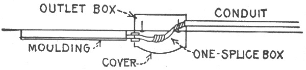
Fig. 875.—Method of tapping outlets for feeder circuits when wiring with wooden moulding.
Arc Light Wiring.—All wiring for high voltage arc lighting circuits should be done with rubber covered wire. The wires should be arranged to enter and leave the building through an approved double contact service switch which should close the main circuit and disconnect the wires in the building when turned "off" and be so constructed that they will be automatic in their action, not stopping between points when started and to prevent arcing between points under any circumstances, and should indicate plainly whether the current is "on" or "off." Never use snap switches for arc lighting circuits. All arc light wiring of this class should be in plain sight and never enclosed, except when required, and should be supported on porcelain or glass insulators which separate the wires at least one inch from the surface wired over. The wires should be kept rigidly at least eight inches apart, except, of course, within the lamp, hanger board or cut out box or switch. On side walls, the wiring should be protected from mechanical injury by a substantial boxing, retaining an air space of one inch around the conductors, closed at the top (the wires passing through bushed holes) and extending not less than seven feet from the floor. When crossing floor timbers in cellars or in rooms, where they are liable to be injured, wires should be attached by their insulating supports to the under side of a wooden strip not less than one-half an inch in thickness.
Arc Lamps on Low Pressure Service.—For this service there should be a cut out for each lamp or series of lamps. The branch conductors for such lamps should have a carrying capacity about 50 per cent. in excess of the normal current required by the lamp or lamps to provide for the extra current required when the lamps are started or should a carbon become stuck without over fusing the wires. If any resistance coils be necessary for adjustment or regulation, they should be enclosed in non-combustible material and be treated as sources of heat; it is preferable that such resistance coils be placed within the metal framework of the lamp itself. Incandescent lamps should never be used for resistance devices. These lamps should be provided with globes and spark arresters, as in the case of arc lamps on high voltage series circuits, except when the closed arc lamps are used. 779
4. Wooden moulding should never be run in elevator shafts, or shafts of any kind, and should never be run on the inner side of the outside walls of the buildings, as these locations are usually subject to dampness.
5. In laying out feeders it is usually cheaper to use iron conduit in a shaft, than to run moulding through the floor timbers.
6. When tapping outlets for feeder circuits, an iron outlet box with cover should be used, as shown in fig. 886. The one splice box is held up to the outlet box already installed by means of two long screws, and the loom is run right up to the moulding so as to leave no exposed wire.
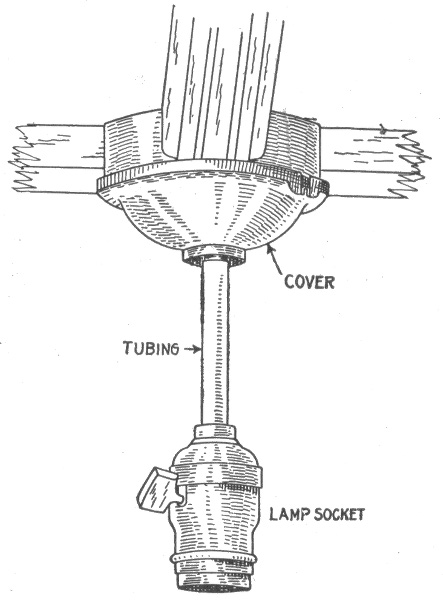
Fig. 876.—Circular fixture block for outlet from moulding work on ceiling.
7. Wherever fixture outlets are installed, a circular fixture block as shown in fig. 876 should be used, to give a good support for the fixture and to make a neat backing for the fixture canopy. The wires should be brought through the fixture without cutting and disfiguring the canopy.
780
Concealed Knob and Tube Wiring.—This method of wiring should be discouraged as far as possible, as it is subject to mechanical injury, is liable to interference from rats, mice, etc. As the wires run according to this method are liable to sag against beams, laths, etc., or are likely to be covered by shavings or other inflammable building material, a fire could easily result if the wires become overheated or short circuited.
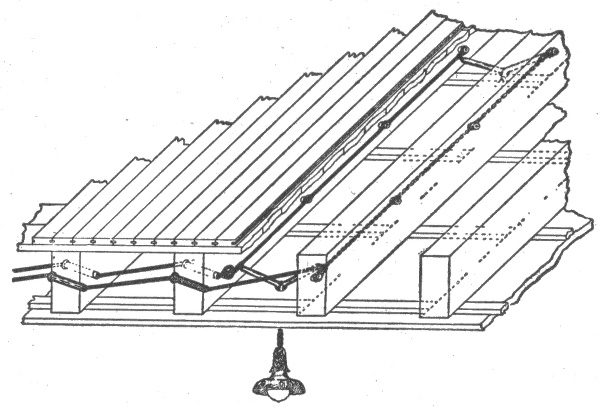
Fig. 877.—Concealed knob and tube wiring. The wires are carried on porcelain knobs attached to the beams. If run perpendicular to the beams, holes are bored in the latter and porcelain tubes with a shoulder at one end, inserted in the holes through which the wires pass. The knobs should support the wires at least one inch from the surface over which they run, and should not be spaced further than 4½ feet apart. The wires should be attached with tie wires having an insulation equal to that of the conductor which it secures to the knob. The use of split knobs does away with the necessity of using tie wires. The conductors must be at least 5 inches apart and it is better to support them on separate beams when possible. Each wire must be encased in a piece of flexible tube at all switches, outlets, etc., and this piece of tubing should be sufficiently long to extend from the last insulator and project at least one inch beyond the outlet.
Concealed knob and tube wiring is still allowed by the Underwriters, although many vigorous attempts have been made to have it abolished. Each of these attempts has met with strong opposition from electric light companies and contractors, especially in small villages and towns the argument being that it is the cheapest method of wiring, and if 781 forbidden, many places which are wired according to this method would not be wired at all, and the use of electricity would therefore be much restricted, if not entirely dispensed with in such communities. This argument, however, is only a temporary makeshift obstruction against progress, and in the near future, no doubt, concealed knob and tube wiring will be forbidden by the underwriters.
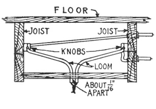
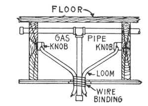
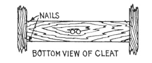
Figs. 878 to 880.—Methods of making fixture outlets in concealed knob and tube wiring. A cleat consisting of a piece of board at least ⅞ in. thick, should be nailed between the joists or studs into which the wood screws supporting the electrolier can be secured. Holes are then bored through the cleat, through which the flexible tubing can pass. With a combination gas and electric fixture as shown in fig. 879, no cleat is necessary, because the gas pipe supports the fixture. The flexible tubing should be wired to the gas pipe, to prevent displacement by artisans who have occasion to work around the outlet.
Ques. Describe the method of concealed knob and tube wiring.
Ans. It consists in running the wires concealed between the floor beams and studs of a building, knobs being used to support the wires when run parallel to the beams or studs, and porcelain tubes, when run at right angles through the beams, or studs as shown in fig. 877. 782
In this method of wiring, usually nothing need be disturbed on the first floor as the various outlets can be reached from the basement and from the second floor.
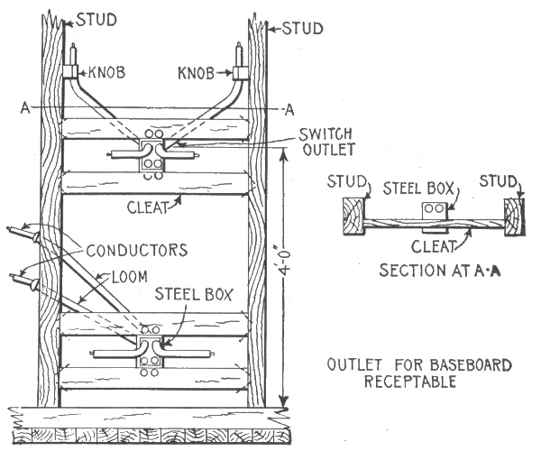
Fig. 881 and 882.—Arrangement of switch and receptacle outlets in knob and tube wiring. In wiring for switches, flexible tubing must be used on the conductor ends from the last porcelain support, as shown, the same as on conductor ends for other outlets. A pressed steel switch box should be used to encase each flush switch mechanism, even though it already be encased in porcelain. A ⅞ in. wood cleat or cleats are arranged to support the switch box. These wooden cleats should not be set out flush with the outer edges of the studs, but should be set about ⅜ in. back, as illustrated, to allow a space in which the plaster can take a "grip."
For instance, if it be necessary to make an outlet for the center fixture in the parlor, a strip of flooring can be removed from the floor above so as to expose the beams. Then the wireman can bore two holes through each of the beams, insert porcelain tubes therein, slip the wires through the outlet and replace the strip of flooring.
Various simple methods may be employed for carrying the wires to the outlets on the side walls. For example: a small hole can be made 783 784 in the wall, and the wire may be dropped through the spaces between the walls, or they may be pulled up from the basement by means of a cord lowered with a weight attached to its end. Outlets for switches and base receptacles may be provided for, in a similar manner.
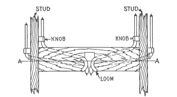

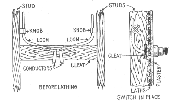
Figs. 883 and 884.—Elevation and sectional view showing arrangement of switch outlet in concealed knob and tube wiring.
Fig. 885.—Arrangement of surface switch in concealed knob and tube wiring. For a surface snap switch outlet, an iron box is not necessary, but a ⅞ in. cleat must be installed to hold the tubing in place and to provide a proper support for the screws that hold the switch. In wiring old buildings where supporting cleats were not provided back of the plaster, a ¾ in. wooden block or plate should be installed on the surface, to which the switch can be attached.
Ques. What are the advantages of concealed knob and tube wiring?
Ans. Its cheapness, especially in wiring completed buildings, and the absence of any wires or casings on the walls or ceilings.
Ques. What kind of wire must be used?
Ans. Wire having an approved rubber insulating covering.
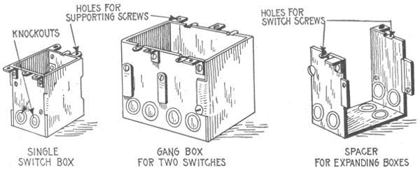
Figs. 886 to 888.—Switch boxes for concealed knob and tube wiring. These are for flush switches and are formed from sheet steel. A single switch box can be expanded for any number of switches, by using the proper number of spacers. Single and double switch boxes can be supplied already assembled and are used where feasible, because it is cheaper to buy them this way than to assemble them. Holes partially punched, which can be knocked out with a hammer blow, are provided in the sides and back through which the flexible conduit wire protection can be extended.
Rigid Conduit Wiring.—The installation of wires in conduits not only affords protection from mechanical injury, but also reduces the liability of a short circuit or ground on the wires producing an arc which would set fire to the surrounding material; the conduit being of sufficient thickness to blow a fuse before the arc can burn through the conduit. 785
Ques. Describe the unlined type of conduit.
Ans. It consists of an iron or steel pipe, similar in size, thickness, and in every other way to gas pipe, except that special precautions are taken to free it inside from scale or any irregularities; it is then coated inside with enamel, outside it is sometimes enameled and sometimes galvanized.
Ques. Describe the lined type of conduit.
Ans. It usually consists of a plain iron pipe lined with a tube of paper which has been treated with an asphaltic or similar compound; this paper tube is cemented or fastened to the inside of the iron pipe so that it forms practically an integral part of the same.
Ques. What are the advantages of unlined conduit?
Ans. It is cheaper, because having no lining a smaller size of conduit can be used for any given size of conductor; it is also 786 cheaper to install, as it can be bent, threaded, and cut more readily than the lined conduit. Wires may be more easily inserted and withdrawn as the inside is smoother than that of the lined conduit.
NOTE.—Conduits for inside wiring which are subject to inspection, must have an inside diameter of not less than ⅝ inch. They must be continuous from outlet to outlet or to junction bores, and must properly enter and be secured to all fittings, and the entire system be mechanically secured in position. In case of service connections and main wires, this involves running each conduit continuously into a main cut out cabinet or gutter surrounding the panel board as the case may be. Conduits must first be installed without the conductors, and be equipped at every outlet with an approved outlet box or plate. Outlet plates must not be used where it is practicable to install outlet bores. The outlet box or plate must be so installed that it will be flush with the finished surface, and if this surface be broken, it shall be repaired so that it will not show any gaps or open spaces around the edge of the outlet box or plate. In buildings already constructed where the conditions are such that neither outlet box nor plate can be installed, these appliances may be omitted by special permission, providing the conduit ends are bushed and secured. It is suggested that outlet boxes and fittings having conductive coatings be used in order to secure better electrical contact at all points throughout the conduit system. Metal conduits where they enter junction boxes, and at all other outlets, etc., must be provided with approved bushings or fastening plates, fitted so as to protect wire from abrasion, except when such protection is obtained by the use of approved nipples, properly fitted in boxes or devices. Conduits must have the metal of the conduit permanently and effectually grounded. Conduits and gas pipes must be securely fastened in metal outlet boxes so as to secure good electrical connections. If conduit, couplings, outlet boxes or fittings having protective coating of insulating material, such as enamel, be used, such coating must be thoroughly removed from threads of both couplings and conduit and from surfaces of boxes and fittings where the conduit is secured in order to obtain requisite good connection. Where boxes used for centers of distribution do not afford good electrical connection, the conduits must be joined around them by suitable bond wires. Where sections of metal conduit are installed without being fastened to the metal structure of buildings or grounded metal piping, they must be bonded together and joined to a permanent and efficient ground connection. Junction boxes must always be installed in such a manner as to be accessible. All elbows or bends must be so made that the conduit or lining of same will not be injured. The radius of the curve of the inner edge of any elbow must not be less than three and one-half inches. Must have not more than the equivalent of four quarter bends from outlet to outlet, the bends at the outlets not being counted.
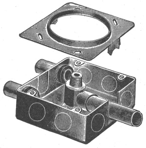
Fig. 889.—Conduit box showing arrangement for combination side outlet with open cover. Outlet or junction boxes are of two general types: 1, those which are made for a particular position and have a given number of outlets, and 2, those which have a variable number of outlets which are plugged with metal discs in such a manner that the latter can be knocked out by a slight blow of a hammer. The illustration shows a universal plugged steel conduit box, which can be used as a straight electric, or combination gas and electric, ceiling or side wall outlet, or for flush rotary or push button switches, or for flush receptacles. When rigid conduits are used, they are screwed to the outlets by means of lock nuts and washers. In the case of flexible conduits, the entering ends of the conduits are provided with clamp bushings which are secured to the outlet by means of lock nuts. All outlet boxes are fitted with covers of various designs, which permit their use for various types of construction such as ceiling and wall work in lath or plaster, fireproofing ceiling work, etc., while many designs of outlet plates and receptacle plates may be obtained from the supply houses to satisfy the requirement of any special case.
Ques. What are the disadvantages of the unlined conduit?
Ans. The Underwriters require the use of double braided conductors instead of single braided which are allowed for lined conduits. 787
Ques. Where may unlined conduits be used?
Ans. In buildings where the conduit is not liable to corrosive action.
Flexible Conduit Wiring.—Flexible conduits are used to advantage in many cases where rigid conduits would not be desirable. It is especially adapted to completed buildings where it is desired to install the wiring by "fishing" without greatly disturbing the walls, floors, or ceilings.
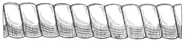
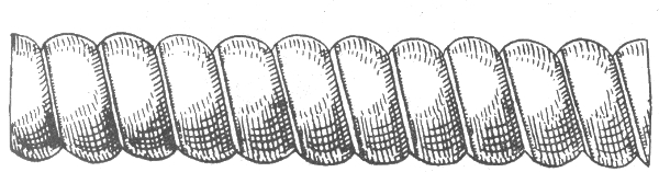
Figs. 890 and 891.—Greenfield flexible steel conduit; fig. 890 single strip type; fig. 891 double strip type. The former (fig. 890) is formed with a single strip of galvanized steel, interlocked and gasketed in such a manner as to be suitable for concrete construction. The double strip type (fig. 891) is constructed of a concave and convex steel strip, spirally wound upon each other in such a manner as to interlock their concave surfaces. Thus the convex surfaces of the two strips form respectively the outer and inner surfaces of the conduit. This construction insures a smooth interior surface, thus reducing the possibility of friction in the drawing in of conductors. A gasket is provided between the inner and outer strips rendering the conduit moisture proof. This form of flexible conduit is especially adapted to use where the wiring is installed after completion of building, because it is very flexible.
Ques. How is a flexible conduit installed by "fishing"?
Ans. It is "fished" under floors, in partitions between the floor and ceiling, by making pockets in the floors, walls or ceilings, say every 15 or 20 feet, and fishing through first a stiff metal wire called a "snake," and then attaching the conduit to same and pulling the conduit in place from pocket to pocket. 788
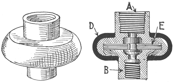
Fig. 892.—Insulating joint. This fitting is used in fixture work. The part A screws on to the gas pipe and B to the fixture. The parts are separated by insulating material E, and the outside of the joint is covered with moulded insulation D. In connecting fixtures to the wiring, all wires should be kept away from the gas pipe above the joint, but they may be bunched in below the insulating joint after the wires have been spliced, soldered, and taped. It is important to protect the gas pipe at this point. Insulating joints should be tested before being used.
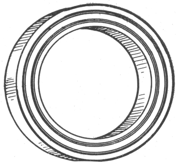
Fig. 893.—Canopy insulator. This fitting should be installed wherever there are metal ceilings against which the canopies of fixtures might come. The canopy is the brass cup shaped piece used at the top of fixtures to cover the joint, and is simply an insulating ring placed between the canopy and the ceiling. It is in contact with the fixture; hence, it is important that it be insulated from metal ceilings, or else all the benefits derived from an insulating joint will be lost.
789
Ques. How is the conduit fished on vertical runs?
Ans. A chain or weighted string is used which is dropped from the outlet to the floor and its lower end located by sound of the chain end or weight striking the floor.
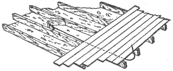
Fig. 894.—Section of flooring illustrating use of fishing hook. In fishing wires, punch a hole through the plastering at the required position, being careful that there is no studding at that place. Use a brad awl and cut the hole large enough to permit running of the wires. With a short length of small brass spring wire, push through the opening a few inches of number 19 double jack chain such as is used for general fishing purposes, first having connected the end of the chain with a piece of heavy linen thread. Run out the thread between the laths and the outside wall until the chain touches the floor beneath; move the thread and locate the chain by the sound; bore a hole through the baseboard or floor, as the case may be, toward the chain. Use a two or three foot German twist gimlet. With a small brass spring wire bent at the end in the shape of a hook, fish for the chain and draw it out. At the other end of the thread attach the wire and draw it through with the thread. Passing under the floor bore a second hole through the floor as near the other as possible. Run into this a piece of snake or fishing wire with a hook at the end, until it comes to an obstruction. Locate the obstruction by sound. In running wires under the flooring first carefully examine all parts and find the direction in which the beams and timbers run, and run the wires parallel with these. After locating the end of the fishing wire see if the obstruction be a timber; if so, find the center and bore from the middle diagonally through it in the direction of the fishing wire. Drop the jack chain and thread through the hole; fish for it and draw it through hole number 2; attach the insulated wire and draw it back. Starting hole number 3, bore hole number 4 diagonally through the timber in the direction in which the wire is to be run, making holes 3 and 4 form an inverted "V" through the timber. Run the fishing wire through hole number 4 until it meets an obstruction. If at the end of the room, bore through the floor, drop the chain, fish it out, attach wire and draw it home. Putty up holes after having finished the work, in case of hard finish, plug them up with wood. In lightly built houses it is often found easier to take off the moulding above the baseboard and run the wire under it. In such cases care should be taken to break off the old nails, as any attempt to drive them out would cause a bad break. In closets and around chimneys it is usually found easy to work. A "mouse" or lead weight attached to a string may often be dropped from the attic to the cellar ceiling through the space outside the chimney.
Ques. What is the difference between flexible conduit and flexible tubing?
Ans. Flexible conduits are made of metal while flexible tubing is non-metallic. 790
Ques. Describe a flexible conduit.
Ans. It is a continuous flexible steel tube composed of convex and concave metal strips, wound spirally upon each other in such a way as to interlock their concave surfaces.
Ques. What are the advantages of this form of flexible conduit?
Ans. It possesses considerable strength and can be obtained in long lengths (50 to 200 feet); elbow fittings are not required as the conduit may be bent to almost any radius. The fissures of the conduit provide some ventilation; this is an advantage in some places and a disadvantage in others.
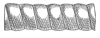
Figs. 895 to 897.—Greenfield flexible steel conduit and fish plug, showing method of insertion. Fish plugs are made for ⅜ inch, ½ inch, and ¾ inch conduit and are useful in drawing in the conduit in finished buildings where it is desired to fish it under doors or in partitions. After the conduit has been cut off square in the special vise, the fish plug may be screwed into the tube and the fish wire or drawing-in line should then be attached to the eyelet on the end of the plug.
Ques. In what places are flexible conduits not desirable?
Ans. In damp places.
Ques. Why?
Ans. Because of the fissures. 791
Practical Points Relating to Inside Conduit Wiring.—The following instructions apply to the installation of wiring in both rigid and flexible conduit:
1. All conduits should be made continuous from one junction or outlet box to another, or to the various fixtures. A conduit installation is made a complete system by the use of outlets, outlet boxes, switch or junction boxes, and panel boxes with doors and locks, which serve to thoroughly protect the circuit at all points.
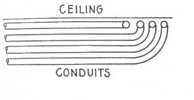
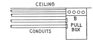
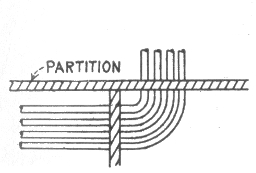
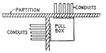
Figs. 898 to 901.—Pull boxes and their use in conduit work. A pull box is a convenient device used for the purpose of avoiding the disadvantages of having too many bends in one continuous line of conduit; too many bends will give trouble when the conductors are drawn in. Pull boxes are also useful in places where the arrangement of the conduit is such that trouble would be experienced in bending it to a fit, and also in the case of conduits which are first run on a side wall and then have to be carried across the ceiling at right angles to the wall. Fig. 898 shows an example of objectionable bends, and fig. 899, the method of overcoming the difficulty by the use of a pull box. It is evident that it would be impossible to make some of these bends so as to permit the drawing in of the conductors. This difficulty is overcome, as shown, by placing a pull box on the wall, with its top close to the ceiling. A board B, having the proper size holes for the conduits is fastened to the front of the box and close to the ceiling. After the conductors have been drawn into the conduits along the wall as far as the pull box, they can be readily pulled away from the box through the holes in the board into the corresponding conduit on the ceiling. Fig. 901, shows the use of a pull box in a case where it is necessary to run conduit through partitions at right angles to each other. Pull boxes can be designed to suit any condition liable to occur in practice, and when properly used will always save much time and labor. Locknuts should be placed on the ends of all conduits, both inside and outside the pull box in order to prevent their being displaced when drawing in the conductors. After all the conductors have been drawn into the conduit, all the outlets should be plugged up with wood or fibre plugs made in parts to fit around the wires and cables, and the outlets given a coating of some compound which will render the whole system air tight and moisture proof. A final test should then be made to ascertain that there are no grounds on the different parts of the wiring, and that the insulation comes up to the requirements of the underwriters. The metal of all conduits, and the sheathing of steel armoured cables should be effectually and permanently grounded.
792
2. In the installation of interior conduit wiring, the tubes are usually put in place as soon as the partitions of the buildings have been constructed. In non-fireproof buildings, the tubes are usually supported from the underside of the floor beams, but in fireproof buildings they are placed on top of the floor beams and under the floor as in fig. 902.
3. When conduit is used in damp places, lead encased wires should be used, and the wires drawn in very carefully so as to prevent any injury to the casings.
4. For wiring installations in buildings constructed entirely of reinforced concrete, the preliminary work should be laid out during the progress of the building operations so as to avoid, as much as possible, the necessity of drilling holes in the finished concrete work.
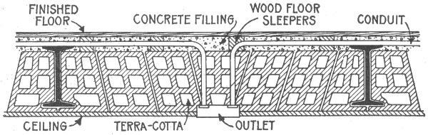
Fig. 902.—Method of installing conduits in fire proof buildings. The installation of the conduit includes the placing of all outlet boxes, and when this has been completed, the lathing or plastering work is executed, and after that is finished, the wire is pulled into the tubes, and the receptacles, switches, etc., put in position. The work of pulling in the wires may be greatly facilitated by the use of pull boxes as shown in figs. 899 and 901.
5. For concealed wiring, the location of all the outlets should be marked by sheet iron tubes large enough to hold the conduits. These tubes should be properly plugged, and set in the false work before the concrete is poured in. In a similar manner, threaded pieces of conduit of the proper size, should be placed in the false work for risers.
6. For exposed wiring on concrete walls and ceilings, suitable cast iron supports should be set in the moulds at regular intervals. When liberally used, these supports will also serve as good supports for other pipes.
7. Where a conduit line terminates on the outside of a building some suitable fitting such as a pipe cap should be used, as shown in fig. 903, to prevent the entrance of moisture into the conduit system. A variety of devices suitable for this purpose are available at supply houses; but those having porcelain covers which spread the wires the proper distance apart are the most satisfactory.
793
8. Where it is desirable or necessary to continue open wiring from conduits, or where the character of the wiring makes it necessary to bring the wires over from the conduit, as in an arc lamp, neat and safe work can be done by use of a suitable form of condulet as shown in fig. 904.
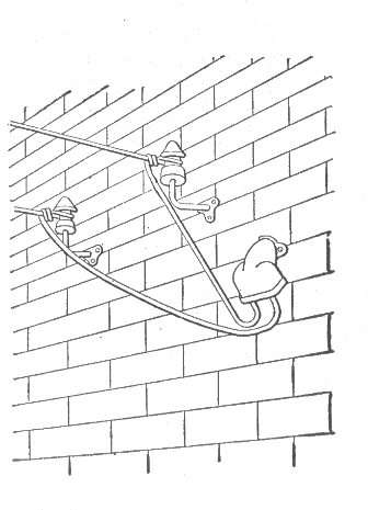
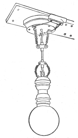
Fig. 903.—Service entrance to interior conduit system; showing method of preventing moisture reaching the interior of the conduit system.
Fig. 904.—Outlet to arc lamp from conduit by use of condulet. The wires are brought out from the conduit system at a distance of 2½ inches apart. Conduits are made in a great variety of design with interchangeable porcelain covers which render them adaptable to almost all cases requiring the installation of outlet boxes.
9. Where a conduit line terminates in a switch or panel box, the lining or casing of the panels should be of iron, and the conduit firmly secured to it so as to make good electrical contact. Vertical lines of conduit should be fastened to the wall or other supports in such a manner as to prevent the weight of the conduit coming on the panel box, and each length of conduit installed should be fastened so as to bear only its own weight. The best method of fastening conduit to brick walls is by the use of expansion bolts and screws. In the case of fire brick ceilings or other plastered walls, toggle bolts 794 should be used. When conduits are run on wooden or iron beams, various kinds of pipe hanger may be employed.
10. There are numerous devices on the market for bending conduit for the making of elbows, offsets, etc., but the majority possess the disadvantage that the conduit must be taken to them to be bent. In the case of the smaller sizes, this difficulty is avoided by the use of some form of conduit bender such as shown in figs. 910 and 911.
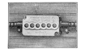
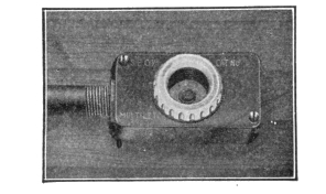
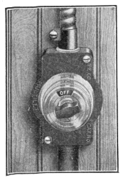
Figs. 905 to 909.—Sprague multilet covers. Fig. 905, six wire porcelain cover; 906, P & S. rec. cover; 907, cover for five ampere snap switch; 908, G. E. and P. & S. rec. cover; 909, cover for ten ampere snap switch.
11. In all cases, the interior diameter of the conduit installed should be amply sufficient to permit of the wires being drawn in easily, thus providing a substantial raceway for the conductors. The practice of pulling wires through conduit by means of a block and tackle is very objectionable. It is evident that if the wires be pulled in by the application of much force the insulation is very liable to become damaged; furthermore, much difficulty will be experienced in pulling them out again, especially in warm places where the heat tends to soften the lining of the conduit, and also the rubber covering of the wire. Powdered soapstone put in the pipe while the wires are being drawn in will lessen the friction and permit the wire to go in more readily.
795
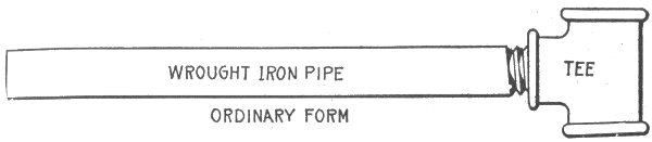
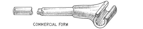
Fig. 910.—Ordinary form of hickey or conduit bender. It consists of a piece of one inch steam pipe about three feet long with a one-inch cast iron tee screwed onto one end of the pipe. This device is used as follows: the conduit to be bent is placed on the floor and the tee slipped over it. The workman then places one foot on the conduit close to the tee, and pulls the handle of the bender towards him. As the bending progresses, the workman should take care to continually move the bender away from himself, to prevent the buckling of the conduit.
Fig. 911.—Commercial form of hickey or conduit bender.
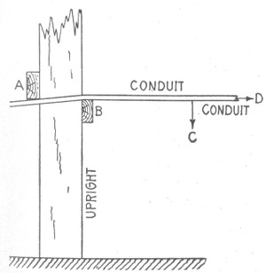
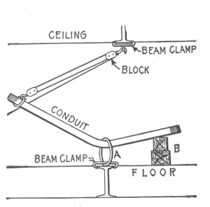
Figs. 912 and 913.—Methods of bending large conduits. A substantial support is necessary which may consist, as in fig. 912, of two pieces of 2 × 4 studding A and B securely fastened to an upright. The conduit is placed under the block A and over the block B, and then bent by a downward pressure exerted at C, the conduit in the meantime being gradually advanced in the direction D to give a curve of the required radius. The method shown in fig. 913, may be used wherever a ring A can be attached to a beam or girder by means of clamps or otherwise to serve as a support. In this case the conduit is slipped through the ring and placed on the top of blocking B. The bending is accomplished by means of a block and tackle rigged to an overhead beam as shown. Where ring supports cannot be arranged, the application of frame bending methods give the most satisfactory results.
796
Armoured Cable Wiring.—Where a conduit system cannot be conveniently installed, armoured cable is used. Armoured cable is made by winding steel strips over the insulated conductors, the latter being permanently retained inside the steel casing. Armoured cable is manufactured in long lengths, the actual lengths being determined by convenience in handling.
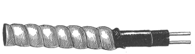
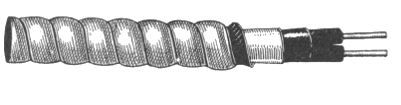
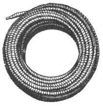
Figs. 914 and 915.—Greenfield flexible steel armoured conductors. The armour is composed of convex and concave galvanized metal strips, wound spirally upon each other and over the insulated conductors. A gasket is placed between the inner and outer metal strips, thus further rendering the conductor moisture proof.
Fig. 916.—Greenfield flexible steel armoured lead covered conductors for use in wet places, such as breweries, packing houses, cold storage buildings, coal breakers and the like, and for underground construction, in which classes of work these materials are being extensively and satisfactorily used.
Ques. What are the features of armoured cable?
Ans. It is flexible and the conductors are well protected from mechanical injury. While this form of wiring has not the advantage of the conduit system—namely, that the wires can be withdrawn and new wires inserted without disturbing the building in any way whatever—yet it has many of the advantages of the flexible steel conduit, and it has some additional advantages of its own. For example, in a building already erected, this cable can be fished between the floors and in the partition walls, where it would be impossible to install either rigid conduit or 797 798 flexible steel conduit without disturbing the floors or walls to an extent that would be objectionable.
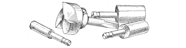

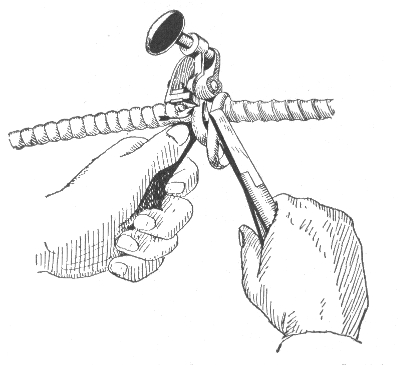
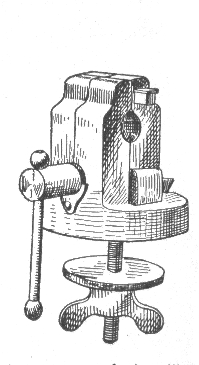
Figs. 917 to 920.—Greenfield flexible conduit tools. Special tools are necessary for installing this type of conduit. Fig. 917, universal reamer; fig. 918, bushing tool; fig. 919, cable armour cutter; fig. 920, vice for holding conduit. To remove cable armours, clamp the conductor firmly in the armour cutter and with a pair of cutting pliers back the armour off, one strip at a time, to the point of contact with the cutting edge of the tool. The vise for holding conduit takes all sizes. The conduit can be cut with an ordinary hacksaw. To protect the insulation against any possible injury while the wire is being drawn in, a soft metal bushing should be inserted in the end of the tube and secured permanently thereto by means of the bushing tool. The bushing provided for this purpose has an outside thread, which permits its being screwed into the end of the tube and then expanded by the use of the tool. The tool should always be used after the bushing has been screwed into the pipe, then the bushing tool should be inserted.
Ques. How should armoured cable be installed?
Ans. It should be continuous from outlet to outlet, without being spliced and installed on the loop system. Outlet boxes should be installed at all outlets, although, where this is impossible, outlet plates may be used under certain conditions. Clamps should be provided at all outlets, switch boxes, junction boxes, etc., to hold the cable in place, and also to serve as a means of grounding the steel sheathing.
Ques. Is armoured cable wiring expensive?
Ans. It is less expensive than the rigid conduit or the flexible steel conduit, but more expensive than cleat wiring or knob and tube wiring, and is strongly recommended in preference to the latter. 799
In the equipment of lighting and power plants, the cost of the outside wiring represents a considerable proportion of the total investment, sometimes costing more than the engines, boilers and dynamos.
A thorough knowledge of outside wiring is therefore necessary to properly proportion and install the wires so that the system will prove economical and safe.
Materials for Outside Conductors.—Copper wire is now considered to be the most suitable material not only for the transmission of current for electric light and power purposes, but also for telegraph and telephone lines, in place of the iron wire formerly employed.
Hard drawn copper wire is used in outside construction, because its tensile strength ranges from 60,000 to 70,000 pounds or about twice that of soft copper. This is desirable to withstand the stresses to which the wire is subjected which, in the case of long spans, are considerable.
The table on the next page gives the tensile strength, in pounds per square inch of cross section, hard drawn copper wire of various sizes B. & S. gauge. 800
The metal aluminum possesses certain advantages as a material for overhead wires. Its conductivity is about .6 that of copper. The specific gravity of aluminum is about 2.7, while that of copper is 8.89, so that a given volume of copper will weigh 3.3 times more than an equal volume of aluminum, and copper wire of given length and resistance would be about twice as heavy as an aluminum wire of equal length and resistance.
There are several disadvantages, such as, low tensile strength, high electro-positive quality of the metal, higher electrostatic capacity, etc.
| Size of wire B. & S. gauge |
Tensile strength, lbs. |
Size of wire B. & S. gauge |
Tensile strength, lbs. |
|---|---|---|---|
| 0000 | 9971 | 9 | 617 |
| 000 | 7907 | 10 | 489 |
| 00 | 6271 | 11 | 388 |
| 0 | 4973 | 12 | 307 |
| 1 | 3943 | 13 | 244 |
| 2 | 3127 | 14 | 193 |
| 3 | 2480 | 15 | 153 |
| 4 | 1967 | 16 | 133 |
| 5 | 1559 | 17 | 97 |
| 6 | 1237 | 18 | 77 |
| 7 | 980 | 19 | 161 |
| 8 | 778 | 20 | 48 |
Pole Lines.—In the majority of cases overhead conductors are supported by wooden poles. In tropical countries, however, such as India, Central America, etc., where wood is rapidly destroyed by the ravages of white ants and other insects, iron poles are almost exclusively used for telegraph, telephone, and other electric transmission lines. The form of iron pole generally adopted consists of tapering shells of sheet iron of convenient length, riveted together at their ends and set into cast iron base plates which are buried in the ground. 801


Figs. 921 to 929.—Pole construction tools. Fig. 921, long handled digging shovel; fig. 922, digging bar; fig. 923, crow and digging bar; fig. 924, tamping and digging bar; fig. 925, wood handle tamping bar; fig. 926, slick digging tool; fig. 927, post hole augur; fig. 928, carrying hook; fig. 929, tamping pick.
802
Wooden Poles.—On account of their size and straightness, various species of northern pine, cedar and cypress are especially suitable for large poles. Chestnut, which can be readily sawed and hewed is a very good material for smaller poles. Sawed redwood is extensively used in California.
Preservation of Wooden Poles.—The preservation of wooden poles employed in line work is a matter of importance. Decay of the pole at or near the soil line is caused primarily by various forms of bacteria or fungi, and in some cases by insects. Bacteria and fungi attack either dead or living timber. In the case of dead timber, such as that of poles, they attack the walls of the cells and cause the familiar rot or decay which eventually destroys the usefulness of the pole.
It is well known that the rapid multiplication or action of the bacteria and the growth of the fungi are induced by a certain per cent. of moisture and the heat of the sun, that is, the portion of the pole at or near the soil line is alternately moistened and dried. Therefore, in order to protect it against this action, it is necessary to sterilize the pole by the application of an antiseptic which will penetrate the pores of the wood.
Preservation Processes.—There are several processes which may be successfully employed for the preservation of poles or other exposed timber. The best known of these are the creosoting, burnettizing, kyanizing, carbolizing, and vulcanizing processes.
In England, creosoted poles showed no sign of decay at the end of 35 years of service. In the United States they have an average life of 22 years. In Europe impregnation with copper sulphate has been extensively used, but this impregnation must take place within a few days after cutting down the tree.
Uniformly good results have been obtained by impregnation with corrosive sublimate, involving simply immersion in the liquid from ten to fourteen days. German authorities state that the average life of such poles is about 17 years, compared with 14 years for natural or untreated poles.
The application of pitch and tar oftentimes results in more harm than good. It is authoritatively stated, however, that in Europe wooden 803 poles are effectively protected by painting them with tar up to about 2 feet above, and down to about 1½ feet below the soil line. The painted parts of the pole are then covered with a cloth which after being nailed to the pole, is also painted with tar. Finally a zinc plated sheet of iron painted on both sides with tar, is placed around the cloth and tightened to the pole.
The saving due to the use of sterilized poles is 40 per cent. of the cost of unsterilized poles. The comparison is made on the following basis: Cost of pole, $5 each; sterilizing, $1.25; renewal of sterilized pole in 24 years, unsterilized pole, in 12 years.
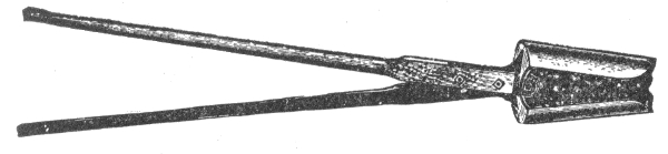
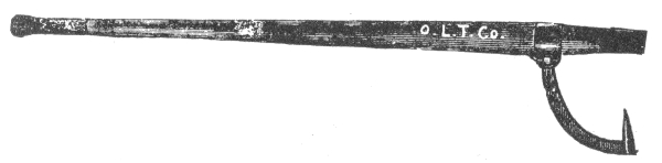
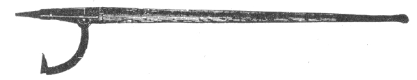
Figs. 930 to 932.—Pole line construction tools. Fig. 930, split wooden handle post hole auger; fig. 931, cant hook; fig. 932. socket peavey.
Methods of Setting Wooden Poles in Unsuitable Soil.—In places where salt is plentiful and cheap, such as the Great Salt Lake region in Utah, it has been found that the liberal use of salt mixed with the dirt filling tamped in around the foot of the pole is very effectual in preventing decay below the soil line.
Where poles have to be planted in low, swampy ground, or where the climatic conditions are such that timber decays rapidly, it has been found advantageous to place the poles in concrete settings. This method is extensively employed in various parts of the Southern States, square poles being placed in 804 settings about 7 feet deep and 3½ feet square. In very soft ground the employment of a concrete setting is sometimes impracticable. In such cases piles are driven deep into the soil, and the pole bolted to the part of the pile extending above the ground.
Reinforced Concrete Poles.—The strongest point in favor of concrete poles is their durability. Untreated wooden telephone and telegraph poles have to be replaced by new poles about every six or seven years, depending on the percentage of moisture in the soil, the drier the soil, the longer being the life of the pole. Concrete poles are not affected by soil conditions, and if properly made will last indefinitely.
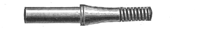
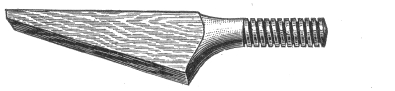
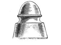
Figs. 933 to 935.—Glass insulator and insulator pin and bracket. The insulator here shown is of the pony double petticoat type. Insulator pins are used with cross arms, brackets are attached direct to the pole.
One form of reinforced concrete pole consists of a skeleton frame work of four corrugated iron rods covered with ordinary concrete. The pole is octagonal in shape, 30 feet long, and provided with mortises for cross arms, the latter being fastened in place by means of iron bolts. It is stated that they are less expensive than pine poles, and that each pole can be manufactured at the point on the line at which it is to be installed or planted.
In Canada, reinforced concrete poles are made square on account of the ease of making, and also on account of the steel economy permitted thereby. All poles are made at the point of erection. They are moulded in wooden forms, in a horizontal position, the top side being left open and finished with a trowel. The concrete is composed of one part of 805 Portland cement, two parts clean sharp sand, and four parts broken stone. A 35 foot pole for ordinary line work weighs about 2½ tons and a 50 foot pole about 5 tons.
Cross Arms.—The familiar cross arms for stringing wires are usually attached to the poles before they are erected. They are commonly made from yellow pine wood, generally 3¼ x 4¼ inches, and are freely coated with good mineral paint as a preservative. Attachment is made to the pole by cutting a gain one inch deep and of sufficient breadth to allow the longest side of the cross arm to fit accurately. It is then secured in place by a lag screw, with a square head, so that it may be driven into place with a wrench.
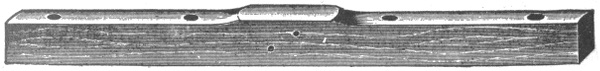
Fig. 936.—Cross arm which carries the insulator pins. The standard cross arm is 3¼ x 4¼ inches, double painted, and bored for 1½ inch pins and two ½ inch bolt holes. Telephone arms are 2¾ x 3¾ inch, bored for 1¼ inch pins and two ½ inch bolts.
The cross arm is further secured to the pole with braces. These are flat strips of wrought iron or low carbon steel, 30 inches long, ¼ inch thick and 1¼ inches wide, according to standard specifications. Holes are bored at points one inch from either end, one for attaching to the pole, the other for attaching to the cross arm; two braces forming a triangle with the cross arm for the base and with the apex at the point of connection to the pole. Like all other iron work used on pole lines, the braces are carefully "galvanized," so as to stand three immersions of one minute each in a saturated solution of copper sulphate without showing copper deposits, the color being black at the completion of the test. 806
Before the cross arm is set in place the gain is carefully painted with white lead. As it is important that cross arms on a line of poles, particularly when there are several on each pole, should be at equal distances from the ground as well as being uniformly spaced, it is necessary that some measuring instrument should be used to accomplish this. Such an instrument is the ordinary template, which is a length of board carrying a pointed block at one end, to correspond exactly with the top of the pole, and also cross cleats nailed at precisely the same intervals below it as it is proposed attaching the cross arms. The template, laid upon a pole, shows where to cut the gains.
In planting the poles it is customary to so arrange them that the cross arms on alternate poles shall face in opposite directions, for the purpose of equalizing the strain on the line. On curves, however, all cross arms are placed on the side of the pole facing the middle of the curve.
Ques. What provision is made for attachment of the wires?
Ans. The cross arms are bored with holes for the insertion of the insulator pins, which are made of locust wood and threaded at the upper end to receive the glass insulator.
The cross arm is made of such a length as to accommodate the number of pins to be inserted. An arm for two pins is made three feet long, according to the standard usually followed, with holes for the pins at center points three inches from either end and a space of 28 inches between them in the center.
Ques. How must electric light and power wires be placed when wired on telephone or telegraph poles?
Ans. They must not be put on the same cross arm with the telegraph, telephone, or similar wires, and when placed on the same pole with such wires the distance between the two inside pins of each cross arm must not be less than twenty-six inches. 807
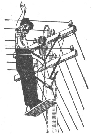
Fig. 937.—Portable platform with rigging as used by linemen in wiring and making repairs.
Poles for Light and Power Wires.—In selecting the style of pole necessary for a certain class of work, the conditions and circumstances should be considered. Poles may be divided into three classes, the size of wire to be carried being one of the important considerations.
First Class.—Main line of poles should range in length of from 30 to 35 feet with 6 inch tops. The height of trees, of course will have to be considered in many cases.
Second Class.—Town lighting by arc lights. All poles should have at least 6 inch tops. The corner poles should have 6½ inch tops, and wherever the cross arms are placed on a pole at different angles, the pole should have at least a 6½ inch top. A 30 foot pole is sufficiently long for the main line, but it would be advisable to place 35 foot poles on corners.
Third Class.—Where heavy wire, such as No. 00, is used for feeder wire, the poles should have at least 7 inch tops. Where mains are run on the same pole line the strain is somewhat lessened, and poles of smaller size will answer.
Cull Poles.—All poles that are smaller at the top than the sizes agreed upon, are troubled with dry rot, large knots and bumps, have more than one bend, or have a sweep of over twelve inches, should certainly be classed as cull poles. Specifications for electric light and power work should be, and in many cases are, much more severe than those required by telegraph lines. A cull pole, one of good material, is the best thing for a guy stub, and is frequently used for this purpose. A cedar pole is always preferable to any other, owing to the fact that it is very light in comparison to other timber, and is strong, durable, and very long lived.
Pole Setting.—In erecting poles, it seems to be the universal opinion of the best posted construction men that a pole should be set at least five feet in the ground, and six inches additional for every five feet additional length above thirty-five feet; also additional depths on corners. Wherever there is much moisture in the ground, it is of much value to paint or smear the butt ends of the pole with pitch or tar, allowing this to extend about two feet above the level of the ground. This protects the pole from rot at the base. The weakest part of the pole is just where it enters the ground. Never set poles further than 125 feet apart; 110 feet is good practice.
Painting.—When poles are to be painted, a dark olive green color should be chosen, in order that they may be as inconspicuous as possible. One coat of paint should be applied before pole is set, and one after pole is set. Tops should be pointed to shed water.
808
Spacing the Poles.—In general, the spacing of poles, like their dimensions, is regulated by the weight of the lines they are designed to carry—the heavier the lines the greater the number of poles. The spacing of poles also depends on their liability to injury from storms and wind in any given locality, and the nature of the service. Poles for a telephone line may be spaced twenty to fifty to the mile—that is, from about 260 to 100 feet apart.
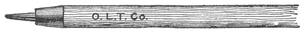
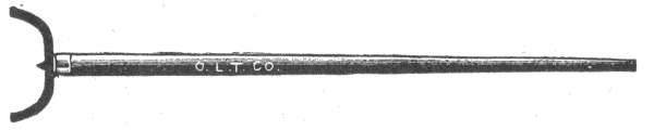
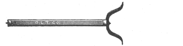
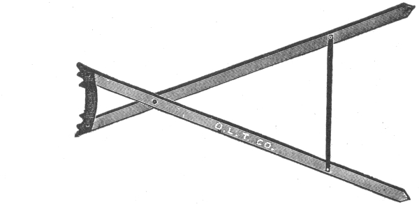
Figs. 938 to 941.—Pole line construction tools. Fig. 938, pike pole; fig. 939, raising fork; fig. 940, mule pole support; fig. 941, jenny pole support.
Erecting the Poles.—Since each pole on a properly constructed line is sawed to the right length and carefully shaped before it is finally inserted in the ground, it is necessary that 809 the holes be dug to as nearly the required depth as possible. Holes for poles are dug very little wider than their diameter at the butt, and the depth is usually computed according to the nature of the soil and the weight of the proposed line. Excavation, while sometimes accomplished with patent post hole augers, or even dynamite, is usually done with a long handled digging shovel, and the earth removed with a spoon shovel, such as is shown in fig. 921.
Fig. 942.—Guy anchor log in position.
Fig. 943.—Stombaugh guy anchor. It is made of cast iron and can be screwed into the ground like an auger.
Wherever required by the nature of the soil, a "grouting" or foundation of loose stones is formed in the bottom of the hole, and, in marshy or springy ground, a base of concrete and cement is laid, with filling of the same material around the pole, when raised.
Ques. How are the poles transported to the holes?
Ans. They are rolled or carried on hooks similar to those used for carrying blocks of ice, except for a long handle for lifting the load at either side. 810
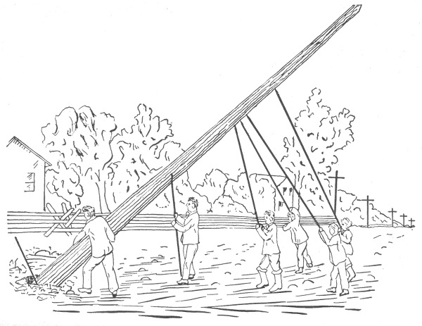
Fig. 944.—Method of raising a pole. When the pole has been properly placed, it is seized by several linemen. As soon as the top of the pole is raised high enough to permit the pikes to be thrust into the pole, it is then raised to a vertical position. At about 50° the butt end slides into the hole. The earth is then filled in around the pole and firmly tamped down. Eight or ten poles are about as many as can be set by the average gang in a day.
811
Ques. How are the poles raised and placed in the holes?
Ans. A piece of timber is inserted in the hole as a slide to prevent crumbling of the earth as the pole is slid into place. The end is raised by hand sufficiently to allow the "dead man," or pole hoist, to be placed beneath, and this is moved along regularly as the pole is lifted with pike poles, until it slides into place through the force of gravity.
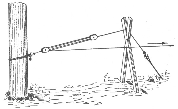
Fig. 945.—Method of pulling an anchor into place before the guy wire is fastened to the top of the pole, thus obviating the liability of pulling the pole out of plumb.
This accomplished, the pole is held in a perpendicular position by pikes in the hands of assistants, or planted in the ground around it, while the earth is carefully shoveled into the hole and thoroughly packed down with a tamper.
Guys for Poles.—Where poles are subject to severe strains which might throw them down and break the wires, guy cables are largely employed, these being attached near the top and secured either to the base of the next pole, to a suitable guy stub or post, or to a guy anchor, which is buried about eight feet in the earth and held down by stones and concrete. 812
Ques. Under what conditions is it necessary to guy poles?
Ans. They are guyed at corners in order to thoroughly secure the poles so that no strain may come on the cornerwise span. It is also necessary to guy a line where it is to be deflected from a straight path, as when rounding a hill, water course or railway curve, in order to neutralize the pull of the wires, tending to incline the poles toward the center on which the arc is described; also when descending a hill.
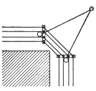
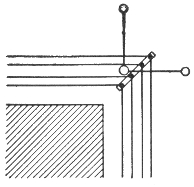
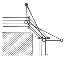
Figs. 946 to 948.—Methods of guying corner poles. The proper guying of corner and terminal poles is especially important; on corners and curves, the guys should be stronger and more frequent and should be placed on the outer side as shown in the diagrams.
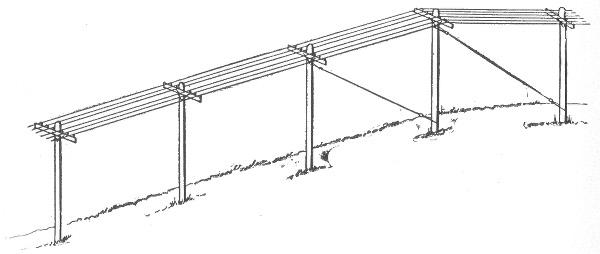
Fig. 949.—Head and foot guying of a pole line in descending a hill.
813
Guy Stubs and Anchor Logs.—In guying a line under such conditions, each pole is connected by a suitable cable to a guy post or "stub," or to an anchor log. Standard rules specify stubs between 18 and 25 feet, with exact limits as to circumference measures at the top and at a point 6 feet from the butt, according to the kind of wood used.
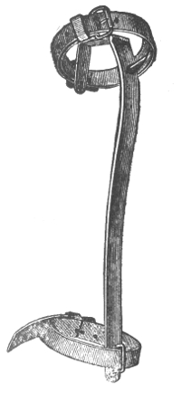
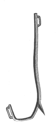
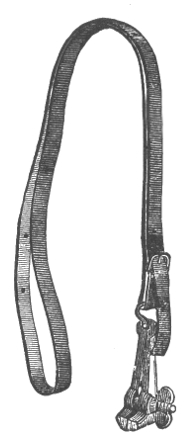
Figs. 950 to 952.—Lineman's tools. Figs. 950 and 951, Eastern pole climbers, with and without strap for attaching to legs; fig. 952, portable vise with strap for pulling up the slack in splicing.
Thus, guy stubs of cedar or juniper, either 18 or 25 feet in length, must have a circumference of 22 inches at the top and of 32 inches 6 feet from the butt; stubs of chestnut must measure 24 inches in the first, and 34 in the second, while those of cypress require 28 in the first, and in the second, 39 inches for an 18 foot length, and at least 41 for a 25 foot length. In planting guy stubs the same rules are followed as hold for poles, every means being adopted to promote security of construction except that the stub is raked or tilted against the strain on the guy cable.
814
Wiring the Line.—The erection and guying of the poles of a line as well as the attachment of the cross arms and the screwing on of the insulators are completed before the stringing of the line is begun. It is particularly essential that the pull on poles of a given line be accurately calculated, and that each one be guyed accordingly before the line is strung, in order to avoid the danger of an undue strain upon the wires in attempting to rectify the condition afterward. It is a good working rule that the wires should be subjected to no stress other than the weights of their own spans after they have been attached to the poles.
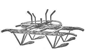
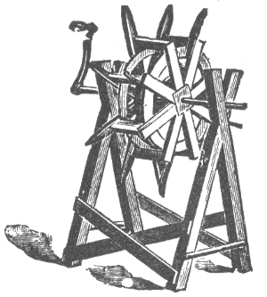
Figs. 953 and 954.—Pay out reels. Fig. 953, type used for telephone or telegraph work; fig. 954, type used for electric light work.
Ques. Describe how the wires are strung.
Ans. In stringing the lines, either one or the full number of wires may be put up at the same time. When one line only is to be strung, the operation consists simply in reeling the wire and running it off from a hand reel, such as is shown in fig. 953 or 954. At each pole the wire is drawn up to its place, pulled out to the desired tension, and attached to the insulator.
In the operation of stringing a number of lines at once, the method is different. The reels are placed at the beginning of a section, each wire being inserted and secured through a separate hole in a board, which is 815 perforated to correspond with the spacing of the insulators on the cross arms. A rope is then attached to this running board, which is drawn by a team of horses through the stretch to be wired, being lifted over each pole top in turn. When a certain length has thus been drawn out the wires are drawn to the required tension between each pair of poles and secured to the insulators.
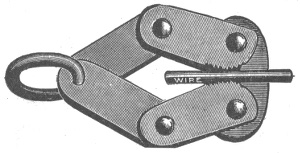
Fig. 955.—One form of "come along." The wire is inserted between jaws and is held fast when tension is applied to the ring.
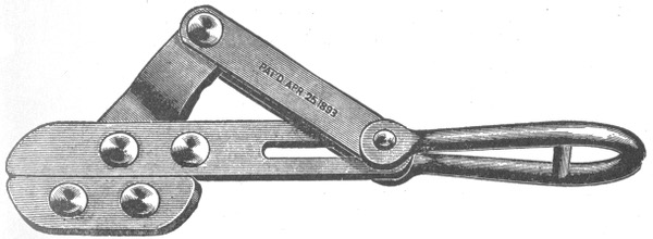
Fig. 956.—An improved form of "come along" or wire stretcher. The jaws which grip the wire are smooth and remain parallel in closing, thus the wire is not scratched or indented, as with circular jaws having teeth.
Ques. How much tension must be put upon the wires?
Ans. In applying tension to the wires as they are strung on the poles, it is the rule to allow some sag. The amount of sag to be allowed varies with different line hangers. 816
A typical case quoted by one or two authorities gives a sag of four inches at the center of each 130 foot span for a given size of wire, at a given temperature. A more general rule is to make the tension on a wire as it is drawn up between each pair of poles equal to one-third of its breaking weight. Thus No. 10 B.& S. gauge, would be drawn to about 163 pounds, and No. 12 to about 102 pounds. The temperature at the time of stringing and the distance between the poles are, however, important considerations in applying tension and allowing for sag. Thus, one construction company specifies a dip of 10 inches in summer and 8 inches in winter for spans of 130 feet, or 40 poles to the mile. Several authorities specify figures about as given in the above table for No. 14 iron or copper wire.
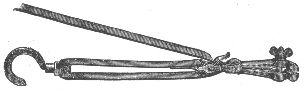
Fig. 957.—Wireman's "come along" with hook and tackle.
| Span in Feet |
Temperature Fahr. | ||
|---|---|---|---|
| 30° | 60° | 80° | |
| Sag in Inches | |||
| 75 | 1¾ | 2½ | 3⅛ |
| 100 | 3 | 4¼ | 5⅜ |
| 130 | 5⅛ | 7 | 8⅝ |
| 150 | 6¾ | 9 | 11¼ |
817
Ques. How is the wire drawn out?
Ans. In drawing out the wire, it is customary to use a wire clamp, or "come along." This tool is attached to a block and tackle, or drawn in by hand, and, as soon as the proper force has been applied, the wire is held, while the lineman secures it to the insulator.
Fig. 958.—Lineman's block and fall with "come alongs" for stretching wire and holding same when making splices.
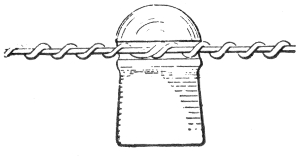
Figs. 959 and 960.—Approved method of attaching wire to an insulator; elevation and plan of insulator and tie. The line wire is first laid in the groove of the insulator, after which a short piece of the same size of wire is passed entirely around to hold it in place, then it is twisted to the line at either side with pliers.
Another contrivance for this purpose is the pole ratchet, by which the wire is drawn tight and held until attached to the pole.
818
Ques. How are the wires attached to the insulators?
Ans. An approved method is shown in figs. 959 and 960. Standard rules specify that all wires shall be tied to the side of the insulators toward the pole, except on the insulators next to the pole, where they are to be attached on the opposite side. On curves, however, it is required that all wires shall be arranged so that the strain shall be against the insulator and not on the wire.
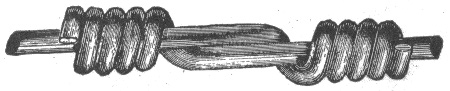
Fig. 961.—American wire joint. This is a simple method of connecting the ends of the sections of wire by tightly twisting the ends around each other for a few turns; it is the standard Western Union wire joint.

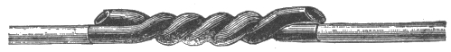
Figs. 962 and 963.—McIntire sleeve and sleeve joint. An approved method of making the joints of telephone lines is by the use of some form of sleeve, such as is shown in fig. 962. This consists of two copper tubes of the required length, and of sufficient inside diameter, to admit the ends of the wires to be joined, fitting tightly. The tubes are then gripped with a tool, shown in fig. 964, and twisted around one another, so that the wires are securely joined and locked, as shown in fig. 963.
Ques. How are the wires spliced?
Ans. There are several methods of splicing wires. Fig. 961 shows the American wire joint, and fig. 963 the McIntire sleeve joint. In making a joint, the two ends are gripped by come alongs and drawn up to the proper tension with tackle as shown in fig. 958. The joint is then made as shown in the illustrations. 819
Transpositions.—In some classes of circuit, as for instance telephone lines, the current is often seriously affected by electrostatic induction from other lines, and also from power circuits, owing to the fact that the surfaces of the wires form, as it were, so many charging plates of an electrical condenser, with the intervening air as the insulating layer or dielectric.
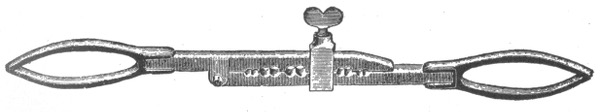
Fig. 964.—McIntyre's twisting clamp for wires 00 to 16 B. & S. gauge.
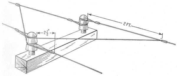
Fig. 965—Method of making a "transposition." This is usually done by means of transposition insulators, which are either double insulators, one being screwed to the pin above the other, or else such caps as are shown in fig. 967. Such insulators are intended to act as circuit breakers, the particular wire to be transposed being cut and "dead ended," or tied around, on both the upper and lower grooves of the cap. The free end of each length is then passed back and around the insulator and twisted, or sleeve jointed to the other limb of its own circuit.
The telephonic current changes the pressure of its own charging surface as frequently as it alternates, and this fact in itself is amply sufficient to account for a vast weakening of the current before it reaches its destination. The only practicable method 820 of overcoming this annoyance in pole lines is by the arrangement known as "transposition," which is, briefly, the practice of regularly shifting the relative position of the two limbs of each circuit as regards other wires in the same pole system, as shown in fig. 965.
For short lines and pole systems with only a few wires it is not necessary to transpose very frequently. On longer lines it has been found amply sufficient to transpose once every quarter mile; that is to say to change the relative position of the wires of the different circuits at posts situated about that distance apart. This does not mean, however, that each pair of wires is transposed so often, but that on ordinary sized systems, the transposition of some one circuit is amply sufficient to secure balanced relations and effectually counteract the effects of cross induction. It is a matter which must be carefully calculated and planned in each particular instance in order to secure the best advantages.
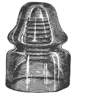
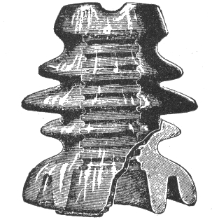
Fig. 966.—Telegraph and telephone line glass insulator.
Fig. 967.—Type of insulator used in making a transposition.
Insulators.—Glass and porcelain are employed almost universally for supporting overhead wires. Insulators made of these materials are superior to those made of other material such as 821 822 hard rubber, or various compounds of vegetable or mineral matter, with the exception perhaps of mica insulators used on the feeders of electric railway lines.
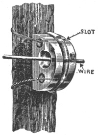
Fig. 968.—Tree insulator. This type of insulator is especially useful in connection with temporary or repair work, or where the wires pass through trees having numerous branches. The illustration shows a Cutler tree insulator lashed to the trunk of a tree. It is made of a single piece of glass, and is provided with a slot which the wire cannot leave accidentally. The back of the device is concave and provided with ribs which prevent sliding. It can be readily slipped over wires already in place, is available for electric light circuit, and will take wires up to ½ inch, in diameter.
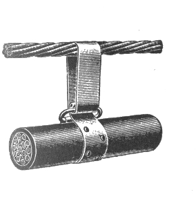
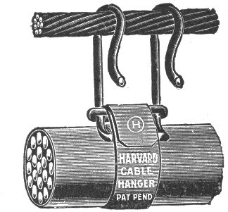
Figs. 969 and 970.—Overhead cable construction. In some cases, particularly on short lines exposed to inductive disturbances from power and other electrical circuits, it is usual to string the cables on poles such as usually carry the bare conducting wires. It is not necessary, however, to insulate the cable in any way; consequently it is merely hung to a supporting wire rope or cable, called the "messenger wire," being attached either with some form of hanger, such as is shown in figs. 969 and 970, or by loops of tarred marline. The marline is sometimes wound over the cable and messenger wire from a bobbin, but frequently it is merely wound on by hand. Cables used in such overhead construction consist of bundles of wires, the pairs twisted together. The size most often used is No. 19, B. & S., which is about .03589 inch in diameter, weighs 20.7 pounds, and has a specific resistance of about 8 ohms to the mile.
Glass insulators are generally used on low tension lines, and porcelain insulators on high tension lines, the latter type being usually stronger and less brittle. Porcelain is more expensive than glass, and its opacity prevents the detection of internal defects which would be readily observed through glass.
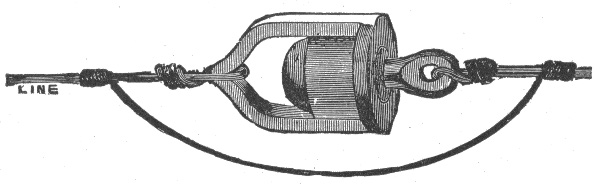
Fig. 971.—Clark's "antihum;" a device designed to prevent the humming of telegraph wires.
Ques. What is a petticoat insulator?
Ans. An insulator which has one, two or three deep flanges or "petticoats" around the base for the purpose of increasing the leakage path from the line to the pin.
Both glass and porcelain insulators may be the double or triple petticoat type which may be cast or moulded solid, or made in two or more parts which are subsequently cemented together.
Service Connections and Loops.—Whenever it is necessary to tap an overhead conductor for service connection, the method of connection will depend upon the character of the circuit. In the case of a parallel circuit, an extra insulator must be placed 823 824 on the cross arm so as to prevent the service main putting a side strain on the main line conductor. In the case of a series circuit the main line conductor is usually dead ended at the nearest pole and a loop taken to the point of service, as shown in fig. 972.
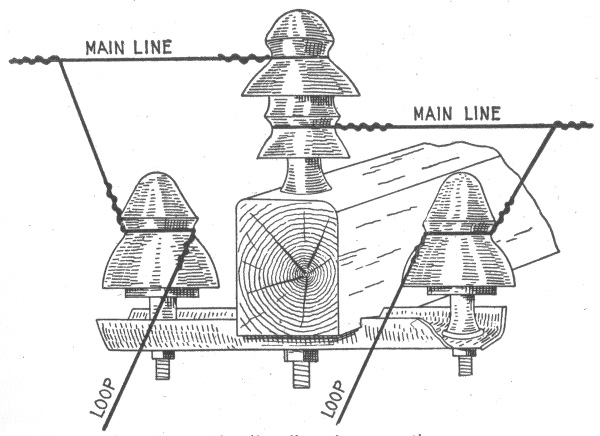
Fig. 972.—Method of making a series "loop" service connection.
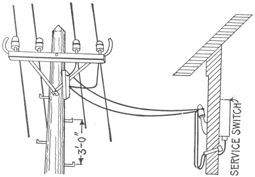
Fig. 973.—Parallel service connection. Service wires tapped to the main wires, are run to insulators on an auxiliary cross arm, thence to insulators on the side of the building, and through the drain tube to the service switch.
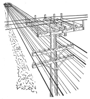
Fig. 974.—Joint pole crossing, showing wires of two lines crossing each other. Four guard wires (shown heavier than the others) extend for one span either side of the joint pole parallel to the wires of the lower circuits and protect them from contact in case of a break in the wires of the upper circuits. These guard wires are insulated. The minimum distance between high and low tension wires should be three feet. Five is better. The end guards, which prevent wires slipping off ends of cross arms and dropping on the lower wires, should extend about six inches above the level of transmission line.
Ques. What are service wires?
Ans. Wires which enter a building. 825
In large cities, the best method of running wires for all varieties of electrical power transmission is to place them underground. Many city authorities have made this method of wiring compulsory by law, because of the difficulty in approaching a burning building, the danger from crossed and falling wires, and the disfigurement of the streets where there is a network of overhead wires.
The expense of installing an underground system is very great in comparison with that of overhead construction, but the cost of maintenance is much less and the liability of interruption of service greatly reduced.
Underground Systems.—An underground system of electrical conductors is composed of three essential elements:
1. The conductor itself, which is almost invariably of copper;
2. The insulation, which is either in the form of a complete covering of insulating material, or simply insulated supporting points;
3. The tube or conduit, which constitutes the mechanical protection against the effects of the severe shocks, weather conditions, etc., to which the system is naturally exposed. 826
The various underground systems may be divided into three classes:
1. Lead encased cables laid directly in the ground;
2. Solid or built in systems;
3. Drawing in systems.
Ques. What may be said of the first mentioned construction?
Ans. Where cables are laid directly in the ground, the metallic covering, consisting usually of a lead tube, which is placed over the insulation is depended upon for mechanical protection. Such cables are largely used for short private lines and the first cost is less than that of the others, but in case of repairs it has to be dug up.
Ques. Describe the drawing in system.
Ans. In this construction the cables are drawn in after the conduits are built. The conduit of the drawing in system may consist of various forms of pipe or troughs of iron, earthenware, concrete, wood or fibre, while those of the solid or built in systems are composed of either iron tubes or concrete trenches.
Conduits.—The principal qualifications of a good conduit are freedom from disintegration by the action of fire, water, acids, alkalies, or electrolysis; second, a smooth interior surface so as to permit of the easy drawing in of the cables; and third, a design which will permit of its economical installation in crowded streets. There are numerous kinds of conduit of which may be mentioned:
1. Vitrified clay pipe conduits;
2. Vitrified clay or earthenware trough conduits;
827
3. Concrete duct conduits;
4. Wooden duct conduits;
5. Wooden built in conduits;
6. Wrought iron or steel pipe conduits;
7. Cast iron pipe and trough conduits;
8. Fibre conduits.
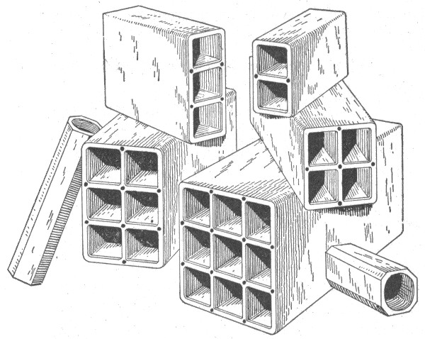
Fig. 975.—A few forms of vitrified clay pipe conduits; view showing single and multiplex types. The dimensions of each duct are about 3½ × 3½. The lengths vary from two to three feet.
Vitrified Clay Pipe Conduit.—Various forms of vitrified clay conduit appear to possess the qualifications, desirable in underground construction, to a higher degree than any other type. They are made in both single and multiple duct, as shown in fig. 975, the single type being about 3½ inches in diameter, or 3½ inches square, and 18 inches long. Multiple conduit is made in two, three, four, six and more sections, ranging from 2 to 3 feet in length. 828
Ques. For what conditions is the single conduit especially adapted?
Ans. It is most suitable for use where the sub-surface conditions are characterized by a great crowding of gas, water, and other pipes, as the conduits can be divided into several layers so as to cross over or under such pipes, and many other sub-surface obstructions which are present in the streets of large cities and towns.
Ques. What are the features of the multiple duct conduit?
Ans. It can be laid somewhat cheaper than the single duct type, especially in lines of about two to four ducts; it is, therefore, most suitable for use in outlying communities where the streets are comparatively free from many sub-surface obstructions.
Ques. How is the conduit laid?
Ans. In laying conduit, a trench is dug, usually sufficiently wide to allow the placing of three inches of concrete on each side of the ducts, and sufficiently deep to hold at least thirty inches of concrete on top of the upper layer of concrete forming the conduit, and to allow for three inches of concrete in the bottom. The trench is graded from some point near the middle of the block to the manhole at each intersection, or from one manhole to the next manhole, at a gradient not less than 2 inches to 100 feet.
Ques. How are single duct conduits laid?
Ans. The tiles of the several ducts are placed close together, and the joints plastered and filled with cement mortar consisting of one part of Portland cement to one part of sand. When the conduit is being laid, a wooden mandrel about four or five feet long, three inches in diameter, and carrying a leather or rubber 829 washer from three to eight inches larger at one end is drawn through each duct so as to draw out any particles of foreign matter or cement which may have become lodged in the joints, and also to insure good alignment of the tiles, as shown in fig. 977.
Single duct conduits are usually laid by bricklayers. This fact accounts for the somewhat greater cost of the single over the multiple conduit which is usually laid by ordinary laborers. One good brick-layer and helper, however, will lay from 200 to 300 feet of single duct conduit per hour.
Practically the same standard of construction is maintained on all conduit lines from two ducts up to twenty-five ducts, as many of the smaller lines may extend for miles into the outlying districts, and contain transmission lines of the maximum working voltage.
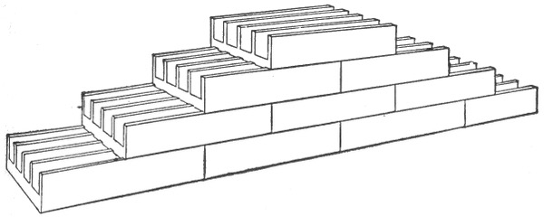
Fig. 976.—Vitrified clay or earthenware trough conduit; this type of conduit consists of troughs either simple or with partitions, the latter type being shown in the figure.
Vitrified Clay or Earthenware Trough Conduit.—It consists of troughs either simple or with partitions as shown in fig. 976. They are usually made in tiles 3 or 4 inches square for each compartment, with wall about one inch thick. The length of the tiles ranges from two to four feet. Each of the two foot form duct troughs weighs about 85 pounds. When laid complete, the top trough is covered with a sheet of mild steel, about No. 22 gauge, made to fit over the sides so as to hold it in position, and then covered over with concrete. 830
Joints in Multiple-duct Vitrified Clay Conduit.—In laying multiple duct earthenware conduit, the ducts or sections are centered by means of dowel pins inserted in the holes at each joint, which is then wrapped with a six inch strip of asphalted burlap, or damp cheese cloth, and coated with cement mortar as shown in fig. 978. Economy of space and labor constitutes the principal advantages derived from the use of multiple duct conduit.
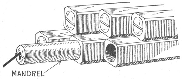
Fig. 977.—Method of laying single duct vitrified clay conduit. The tiles of the several ducts are placed close together as shown in the figure, and the joints plastered and filled with cement mortar consisting of one part Portland cement and one part sand.
Concrete Duct Conduits.—These are usually constructed by placing collapsible mandrels of wood or metal in a trench where the ducts are desired and then filling the trench with concrete. After the concrete has solidified, the mandrels are taken out in pieces, leaving continuous longitudinal holes which serve as ducts. Some builders produce a similar result by placing tubes of sheet iron or zinc in the concrete as it is being filled into the trench. These tubes have just enough strength to withstand the pressure to which they are subjected, and are, therefore, very thin and liable to be quickly destroyed by 831 corrosion, but the ducts formed by them will always remain unimpaired in the hardened mass of concrete.
Wooden Duct Conduits.—In this type of conduit, the ducts are formed of wooden pipe, troughing, or boxes, and constitute the simplest and cheapest form of conduit. A pipe conduit consists of pieces of wood about 4½ inches square, and three to six feet long, with a round hole about three inches in diameter bored through them longitudinally. As shown by fig. 979 a cylindrical projection is turned on one end of each section, which, when the conduit is laid fits into a corresponding recess in one end of the next section. The sections are usually laid in tiers, those of one tier breaking joint with those of the tiers above or below.
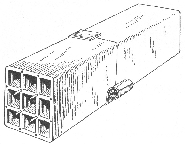
Fig. 978.—Method of laying multiple duct vitrified clay conduit. The sections are centered by the dowel pins shown in the cut.
832
The trough conduit consists of ducts about 3 inches square made of horizontal boards and vertical partitions, usually of yellow pine about one inch in thickness. This form of conduit can be laid in convenient lengths of 10 or 12 feet, or it can be built along continuously.
Ques. What is the objection to the use of wood for conduits?
Ans. The decay of the wood tends to form acid which corrodes the lead sheath of the cable.
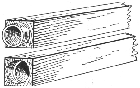
Fig. 979.—Wooden pipe type of conduit. It consists of pieces of wood about 4½ inches square, and three to six feet long, with a wide hole about three inches in diameter, bored through them longitudinally.
Ques. How can this be prevented?
Ans. The decay of the wood can be prevented to a certain extent by the application of sterilizing processes, thereby preserving it in fairly good condition for about ten to fifteen years.
Ques. For what service is wooden conduit best adapted?
Ans. For temporary installations which will be discontinued before the wood decays. 833
Wooden Built-in Conduits.—Within recent years several forms of wooden built-in conduit have been designed and successfully used for permanent work. They possess several advantages over any of the duct systems, the chief of which are high insulating quality, the capability of using bare wire and rods for underground conductors, and reduced cost. An approved form of wooden built-in conduit is shown in fig. 980.
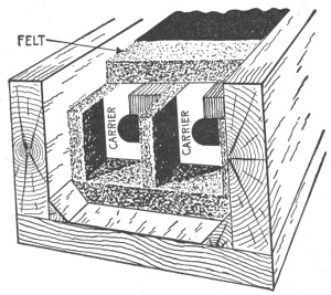
Fig. 980.—Perspective view of wooden built-in conduit. It consists of an outer rectangular casing of wood which is lined inside with impregnated felt.
Ques. How are wooden built-in conduits installed?
Ans. A wooden trough is laid in a trench about 18 inches deep. Porcelain carriers as shown in figs. 981 and 982 are placed in the trough at intervals of 4 to 5 feet, to act as bridgework for supporting the conductors. This bridgework is placed on and is surrounded by impregnated felt or similar material, and the spaces between the carriers, after the conductors have been placed in position on them, is filled with voltax, which hardens rapidly and forms a solid insulating material throughout the conduit. 834
Wrought Iron or Steel Pipe Conduits.—These are formed of pipes similar to gas or steam pipes, with screw or other connections. They are laid either simply in the earth, or in hydraulic cement, and are the strongest and one of the most satisfactory forms of underground conduit. An appropriate standard of this kind of work is shown in fig. 983.
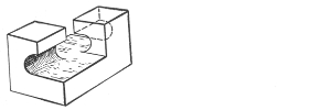
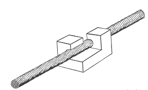
Figs. 981 and 982.—Porcelain bridgework or carriers for supporting underground conductors.
Ques. What is the ordinary method of construction?
Ans. A trench, the width of which will depend upon the number of pipes to be laid, is first dug in the ground, and after its bottom has been carefully leveled, is braced with side planking and filled to the depth of two to four inches with a layer of good concrete, consisting of two parts of Rosendale cement, three parts of sand, and five parts of broken stone capable of passing through a one and one-half inch mesh. This concrete is well secured in place and forms the bed for the lowermost layer 835 or tier of pipes. Ordinary wrought iron pipe is employed, in 20 foot lengths about three to four inches in diameter, depending upon the size and number of cables they are intended to carry. After the last tier of pipes have been put in place, and a layer of concrete from two to four inches placed over it, a layer of two inch yellow pine planking is laid over the whole.
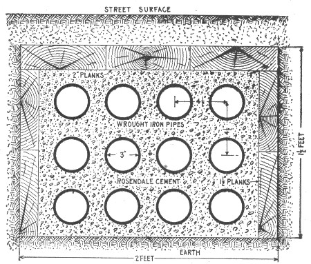
Fig. 983.—Cross section of wrought iron pipe conduit laid in hydraulic cement.
The pipe connections consist of a taper screw thread coupling which can be easily made up as the pipes are laid, and which forms a tight joint.
The pipes in each tier are usually laid from ½ to ¾ of their diameter apart, and when the first tier is in place, the spaces between and around the pipes are filled in with concrete which is carried up over the pipes to a depth of about one-half a diameter to form the bed for another tier of pipes.
Ques. What is the principal object of the top covering of planks.
Ans. To protect the conduit against the tools of workmen making later excavations. 836
Practical experience shows that workmen will dig through concrete without stopping to investigate as to the character of the obstruction, but under similar circumstances, will invariably turn away from wood.
Ques. How are the pipes treated before being laid?
Ans. They are dipped in tar to protect the outside surface from rust.
Ques. What is the most satisfactory form of lined iron pipe?
Ans. Pipe lined with cement. The internal surfaces of these pipes are usually covered with a lining of pure Rosendale cement about ⅝ inch thick and containing no sand. The internal surface of the cement lining does not offer much friction to the introduction or withdrawal of the conductors.
These pipes are laid in cement or concrete in the same manner as plain iron pipe, and are given a coating of tar on the outside to prevent rusting.
Cast Iron Pipe and Trough Conduit.—Cast iron pipe for underground conduits is similar to ordinary wrought iron pipe, except that it is thicker. The additional thickness is necessary to make the strength equal to that of wrought iron; it is therefore heavier to handle and more expensive.
Ques. Describe a cast iron trough conduit.
Ans. It consists of shallow troughs of cast iron in six foot lengths, laid directly in the earth so as to form a system of 837 continuous troughing in which the conductors are placed and then covered over by cast iron covers which are bolted to the trough.
Ques. What advantages does this form of conduit possess over the duct type?
Ans. First, the cables can be laid directly in place, thus eliminating any chance of injury during the process of drawing in, and second, the cables are easily accessible at any point by simply removing one or two of the sectional cast iron covers, thus permitting of their being readily inspected and repaired.
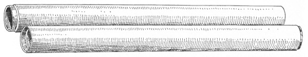
Fig. 984.—Fibre conduit. It consists of pipes made of wood pulp, having about the same thickness as cast iron pipe. Slip joint conduit for electrical subways is three inches inside diameter. The socket joints keep the lengths centered and make it easier to lay than a mere butt joint. It is laid in cement like iron pipe.
Branch connections can be made with greater facility than in the case of any duct system, so that it is especially suitable for distribution systems were it not for the fact that it is so expensive as to be practically prohibitive.
Fibre Conduits.—This form of conduit consists of pipes made of wood pulp impregnated with a bituminous preservative and insulating compound. These pipes are laid in concrete in a manner similar to iron pipe. Fibre conduits are made in sizes ranging from 1 inch to 4 inches in diameter and from 2½ to 5 feet in length, with walls ranging from ¼ to ½ inch in thickness. 838
Ques. Name the three types of fibre conduit.
Ans. The socket joint type, as shown in fig. 984, the sleeve type, fig. 985, and the screw joint type, fig. 986.
Ques. What is the usual method of laying the socket joint type of fibre conduit?
Ans. After the trench has been dug to the required width and depth, depending upon the number or pipes to be placed in a tier and the number of tiers, a bed of concrete about 3 inches deep is placed on the bottom and a line drawn on one side for the alignment of the first line of pipes. The other lines of pipe or ducts are laid parallel to the first line, and are separated from it and from each other by means of ¼ inch or ½ inch wooden or iron pegs. The pipes are well grouted and covered with a layer of concrete to the depth of ¼ or ½ inch, and the next tier laid in place in the same manner. When the final tier of pipes has been installed, it is covered with a layer of concrete about 2 to 3 inches deep.
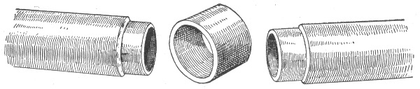
Fig. 985.—Sleeve joint type of fibre. Both the socket type (fig. 984), and the sleeve type here shown are easily aligned without the use of a mandrel.
Ques. What is done when it is necessary to cut a length of pipe to break joints, or to enter a manhole?
Ans. The remaining part of the length may be utilized by using a fibre conduit sleeve having an inside diameter ½ inch greater than the pipe being used on the system. 839
These sleeves are furnished by the manufacturers at a nominal charge per foot. They are about four inches in length and fit over the ends of the abutting pipes, so that they make tight joints and give perfect alignment.
Although its employment is not permitted where fireproof regulations are in force, fibre conduit is now being extensively used in other places, and is giving satisfactory service. It is not affected by moist earth and is impervious to the action of acids, alkalies, and gases. As it is not subject to expansion and contraction, leakage is practically eliminated, and since it is a very good insulator, troubles due to stray currents are reduced to a minimum. It is extremely light, comparatively non-breakable, and can be accurately laid at the rate of 12,000 duct feet per day by a gang of common laborers, consisting of two layers and three helpers.
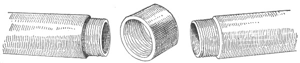
Fig. 986.—Screw joint type of fibre conduit. This method of connection will form a tight line and is suitable for running under the lawns of private houses and parks, under the streets of towns and villages, and in other places where the cost of building electric subways is prohibitive.
Edison Tube System.—Of the various built in or solid underground conduit systems other than those already described under wooden conduit systems, the most satisfactory are the Edison tube system, the Crompton naked conductor system, the Kennedy system, which is a modification of the Crompton and the Callender systems.
Ques. Describe the Edison tube system.
Ans. It consists of a series of iron tubes or pipes containing one or more copper conductors which are placed therein before each complete section or pipe leaves the factory, so that they only need to be joined together to form a continuous line of 840 underground conduit with conductors in place. The arrangement of wires and the details of the Edison tube system are shown in figs. 987 to 989.
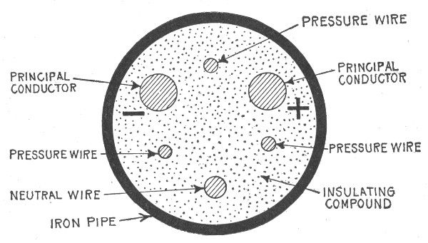
Fig. 987.—Cross section of Edison "feeder" tube. This runs from the power station to the centers of distribution, and contains two principal conductors and a smaller conductor to serve as a neutral wire, and also three insulated cables of seven strands of No. 19 B. W. G. wire each. These cables form independent circuits and enable the voltages at the distant end of the feeder to be read at the central station. For this reason they are commonly called pressure wires.
Underground Cables.—Electric light and power cables for use in conduit may be divided into two classes: moisture proof, and non-moisture proof, according to the character of the insulator. In the moisture proof cables, the insulation consists of some form of rubber, or of bitumen, and a metal sheath or covering, usually of lead, is provided to protect the cable from 841 mechanical or chemical injuries. The non-moisture proof cables are insulated with paper impregnated with oil, wax, or resinous compounds.
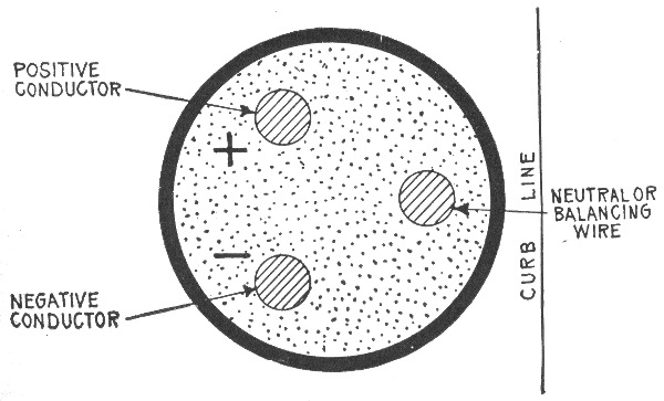
Fig. 988.—Cross section of Edison "main" tube. A number of these tubes, which radiate from the center of distribution and loop the ends of the feeders together, have three conductors of the same size. These tubes are placed in the ground so as to bring the positive and negative conductors on one side of the center of the tube, and the neutral conductor on the other side. The mains are always laid with the neutral conductor adjacent to the curb line, and for convenience this side of the tube is commonly called the inside. The feeders are always laid with the positive conductor on the right hand side, as shown in fig. 989.
Metal Sheaths on Underground Cables.—Metal sheaths are used on rubber covered cables to protect the insulating compounds from the deteriorating effects of electrolysis and various kinds of acids and gases which, under present methods of construction, are ever present in the underground conduits. It is a fact, however, that the lead sheath on a low tension cable, 842 which is used as one side of a grounded circuit, has been, in some cases the cause of, instead of, cure for electrolysis. The proper cure lies in the omission of the sheath altogether, but as this is not practical except in the case of very large conductors, the best thing that can be done is to interrupt the continuity of the sheath by some form of insulating joint.
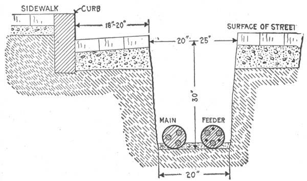
Fig. 989.—Method of laying Edison underground tube system. The tubes are laid in trenches about 30 inches deep and 20 inches wide at the bottom, each trench usually containing two lines of pipes—a main adjacent to the curb and a feeder on the outside. The copper rods forming the conductors are uniformly 20 feet, 4 inches in length and project from 2 to 3½ inches from each end of the pipes, which are connected together by means of coupling boxes. The coupling box usually employed consists of a two part egg shaped casting into which the ends of the pipes enter through water tight sleeves at the opposite ends of the oval. The projecting ends of the copper conductors are joined by short pieces of flexible cable with sockets on each end, which are drilled to fit easily over the conductor rods to which they are thoroughly soldered in order to make a perfect electrical joint. After the conductors have been thus properly connected the cover is bolted down on the lower half, and the whole of the interior of the box is filled with insulating compound through the small hole at the top of the cover, thereby completely insulating the copper conductors, the cable connectors, and the ends of the tubes. Finally, the hole in the cover is closed with a cast iron cap. These coupling boxes are also made in the form of tees for making branch connections, and in the form of elbows for turning corners, the ball ends attached to the tubes and the sockets into which they fit being designed to permit of variation in direction through an arc of 18 degrees on either side of the central position. Services or branches to the consumers' premises consist of short lengths of tube which tap the mains by means of three way or four way service boxes, the latter readily permitting the taking of two services from one joint. Services are never taken from the feeders, but the latter are brought to distributing boxes containing three copper rings to which the conductors are connected and branched out to one or more mains which are led out through fuses to supply the districts.
843
Pot Heads.—The upper end of a lateral cable is equipped with a discharge bell, which is commonly called a pot head. The purpose of a pot head is to hermetically seal the end of the cable and bring the conductors out in such a manner as to permit of their being conveniently connected to the primary service boxes.
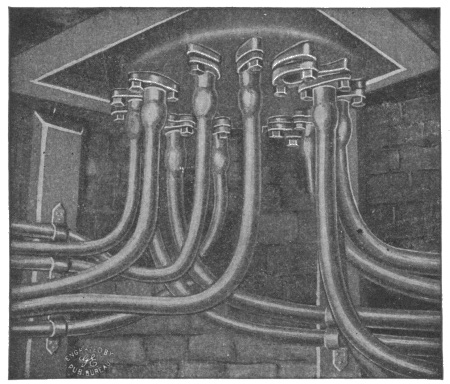
Fig. 990.—Bottom of General Electric manhole junction box; view from manhole interior. The cables enter the bottom of the box as shown through composition nozzles to which the lead sheathes are united by a wiped solder connection, forming a permanent water and gas tight joint. Stuffing boxes are sometimes substituted, doing away with the wiped joint, rendering the boxes suitable for use with unleaded or braided cables. The normal position of the distributing cables is in the upper ducts so that they may be brought to the junction box without crossing other lines. The entrance nozzles and seats are so arranged that all terminals are soldered to cables outside of box and any cable may be removed without disturbing any soldered joint. The wiped joints unite electrically the lead sheathes of all cables entering the box and by connecting a single earth bond to the shell of the box all cable sheathes are solidly grounded. Incombustible shields prevent the arc from a blown fuse making a ground connection to the shell or inner cover.
Ques. How are pot heads made?
Ans. They are usually made in three parts, the base being of cast brass, having a diameter depending upon the size of the conductors, with a hole in the lower end threaded within in such a manner as to make a tight fit on the cable. 844
Ques. How is a pot head connected to a cable?
Ans. After the cable has been bent in to the proper position, the brass base is slipped down over it with the larger end up, and then screwed down on the lead sheath. The threads cut down into the lead sheath to a distance of about ½ inch along the sheath, thus making an air tight connection without necessitating the making of a wiped joint.
The separate conductors are now bared of their insulation for a distance of about two inches, and then spliced to heavy rubber covered braided wire of sufficient length to reach the primary service boxes. The joints connecting these rubber covered wires and the cable conductors are spliced in the same manner as straight splices, the paper sleeves used being of sufficient diameter to be backed out of the way over the rubber insulation. When the splice is completed a brass shell threaded at one end to fit a female thread in the upper end of the brass base, is slipped over the end of the rubber covered wire and screwed into the base. A hood of sheet copper having the form of a quarter section of a ball is slipped over the top of the frame and its lower edge tracked in position below the horizontal shelf. This hood makes the pot head water, snow, and insect proof.
845
In laying out the circuits for a dwelling house, the cut out cabinets should be located first. In many houses only one cut out cabinet is necessary, but in large houses it is convenient to have one on each floor, with vertical mains running through them from the top to the bottom of the house.
If only one distributing point be used, it should be either in the cellar or attic and risers run to the different floors.
Ques. How should the distributing centers or cut out cabinets be located?
Ans. They should be installed near a partition that is so located as to make the running of risers easy, and should be on an inside wall to guard against dampness.
Ques. What instructions are usually given the electrician who does the wiring?
Ans. In many cases simply a plan showing the location and number of lights, from which he must figure out how to install them using the least amount of material and labor consistent with a good installation that will pass inspection. 846
Ques. What provision should be made in rooms where lamps are suspended from the ceiling?
Ans. A switch should be placed at a point where it will be convenient for any one entering to turn on the light.
Ques. Where are receptacles usually placed?
Ans. In the baseboard.
A receptacle is a convenient device which permits any one to connect a lamp to the electric lighting system by inserting a plug which is connected by flexible cord to the lamp.
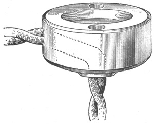
Fig. 991.—Ceiling button. If a lamp be needed not more than 3 feet from the direct line of the wires, it can be hung where required by means of a ceiling button, as shown in the figure, but the lamp cord must not be used to run lamps in this way more than two or three feet from the rosette.
Ques. What provision should be made in wiring a hallway?
Ans. The switching arrangement should be so designed that the lights may be turned on or off either from the hall or floor above.
Ques. What is this arrangement called?
Ans. A two way switch, as shown in fig. 992. 847
Ques. How can a two way switch be distinguished?
Ans. It has three binding screws, two on one end and one on the other.
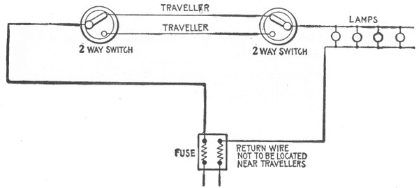
Fig. 992.—Two way lighting circuit permitting control from two points. This is the usual arrangement for hall when it is desired that the lights may be turned on or off from either floor. The circuit contains two two way switches connected by "travellers." From the diagram it is seen that the light may be controlled from either switch. It is a bad arrangement to have travellers and return wire located near each other, as it is possible by this method to connect two individual circuits together and possibly overload one of the two feed wires of each circuit. However, should each feed wire run to a fuse direct, without any other lamps than those contained in the three way circuit being connected, it is not objectionable and becomes a convenient method in many cases.
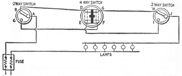
Fig. 993.—Four way lighting circuit, permitting control from three points. This arrangement consists of a four way switch connected between two two way switches as shown. In making the connections it should be noted that the travellers connecting one side of the four way switch to the two way switches should be crossed. On the opposite side of the four way switch, the connections are direct. For the various positions of the switches, the corresponding circuits through them are as follows: ABDGHJ—ABDEIJ—ACFGHJ—ACFEIJ.
848
Ques. How may a group of lights be controlled from three points?
Ans. By the use of a 4 way switch and two 2 way switches connected as shown in fig. 993.
Ques. Before laying out the wiring system for a building, what should be done?
Ans. It is necessary to ascertain whether power will be supplied from the central station, or whether a private plant is to be installed.
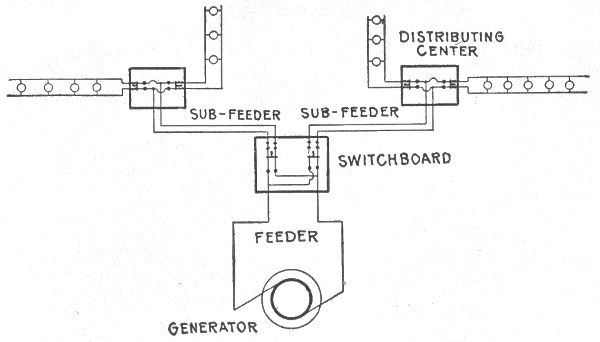
Fig. 994.—Two wire multiple system as used with isolated plant.
Ques. What wiring system should be used with a private or isolated plant?
Ans. The two wire multiple system as shown in fig. 994.
Ques. When the central station is to supply power as an auxiliary in case of break down, how should the connection be made?
Ans. The supply from the central station should be connected to the wiring system through a double throw switch, as in fig. 995, so that either source may be thrown into circuit. 849
Ques. How are the connections made when the auxiliary supply is brought in through a three wire system?
Ans. A double throw three pole switch is used as shown in fig. 995.
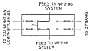
Fig. 995.—Double throw switch for use in isolated plants when auxiliary power is used from the central station in case of breakdown.
Ques. When power from an outside source only is to be used what must be determined before wiring?
Ans. The system of wiring of the supply. If a three wire system be used, the general arrangement will be as shown in fig. 997.
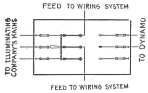
Fig. 996.—Double throw three pole switch for use in isolated plants where auxiliary power is brought in through three wire system. The side of the switch controlling the current is bridged as shown.
Ques. Would it be expensive to change a regular three wire system to a two wire system?
Ans. It would require the reinforcement of all mains and feeders by an additional wire. This wire would be connected 850 with the neutral wire so as to make the capacity of the neutral equal to the sum of the other two. If a three wire two wire system had been originally installed, no change in the wiring system would be necessary. The only change would be at the service end of the switchboard, and the doubling of the size of the center fuses.
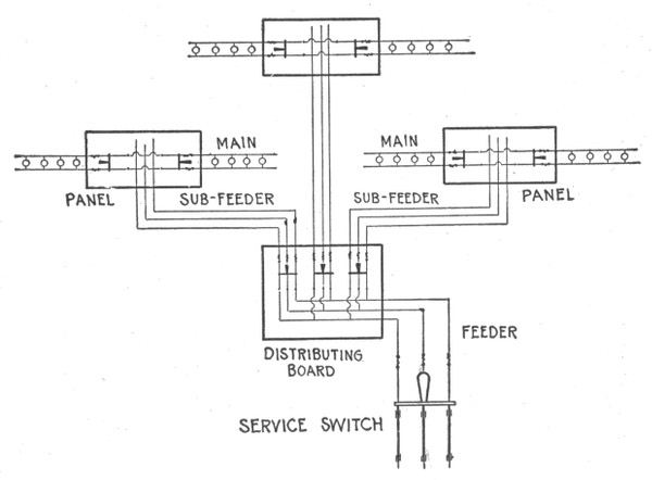
Fig. 997.—Three wire convertible, or three wire two wire system; used to advantage where power is supplied from an outside source and brought in through the three wire system. The only difference between the three wire convertible, and the straight three wire system is that the center, or neutral, wire of the mains and feeders should have a current capacity equal to the other two. The reason for this is that it allows the system to be readily changed over to a two wire system for use in connection with a private plant. It sometimes happens that after using power from the local electric illuminating company for some time, conditions arise which make it expedient for the owners to install a private electric plant. If a straight three wire system had been originally installed, the mains and the feeders when used on a two wire system would not be heavy enough by 25 per cent., as the neutral wire of a straight three wire system is the same in size as one of the two outer wires, and theoretically carries one-half the current or less.
851
Ques. Is a three wire system desirable with an isolated plant?
Ans. It is more expensive to install than one for a two wire system, as it is necessary to add a balancer in connection with a 240 volt dynamo. This balancer set should have one-tenth the capacity of the plant. Such an equipment has its advantages when 240 volt motors and 120 volt lamps are connected to the system. With this plant no changes in the motors are necessary, whereas in a straight 120 volt system, the motors would have to be changed from 240 to 120 volt machines.
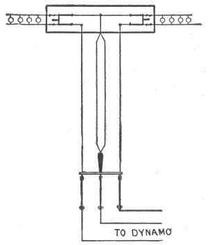
Fig. 998.—Diagram showing reinforcement of neutral wire necessary to change regular three wire system to two wire system. The capacity of the neutral wire must equal that of the sum of the two other wires.
Ques. After deciding on the system of wiring to be used, how should the electrician proceed with the work?
Ans. He should lay out the mains, feeders and branches of the wiring system. The outlets are first located and then the distributing centers. There is no fixed rule or plan by which to go, but the current density and source of supply are the main points to be considered in locating these centers. He must also 852 consider the construction of the building and select runways and shafts which provide easy runs for feeders.
Ques. How should panel boards be placed?
Ans. Panel boards in loft buildings or in any building requiring 8 to 10 circuits to a floor should be distributed one to a floor. In private houses it is sometimes advisable to install only one panel for the entire house. This is good practice for a three-story house not requiring over twelve circuits.
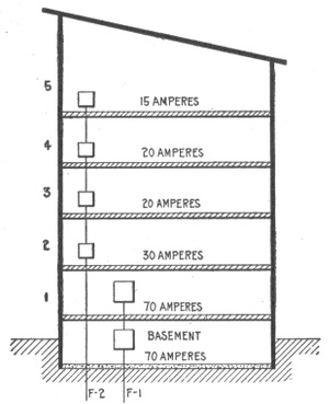
Fig. 999.—Diagram showing current required on each floor of building. A sketch of this kind is useful in laying out the feeder system. In the building here shown it will be seen that the basement and first floor require the most power. In such a case a feeder is run for these floors, and a sub-feeder from the basement to the first floor. It is not worth while to reduce the size of the sub-feeder unless the amount of current used on the sub-feeder be a small percentage of that used in the feeder. Another reason is that in changing the size of a wire, the underwriters require a fuse to be inserted. This makes it necessary to install a larger panel with larger trim, etc., and the consequent expense easily offsets any gain made by installing a smaller wire.
In a building covering a large area it is often advisable to install two panels or centers to a floor, with two sets of feeders. It is advisable to keep circuit lengths down to 100 feet or less, and the judicious laying out of circuit centers will save many feet of wiring.
853
Ques. How should the arrangement of feeders for a large building be determined?
Ans. A good method is to draw an elevation of the building as in fig. 999, and note on each floor the current requirements.
The best plan is to furnish a feeder for every floor, especially in large installations. In smaller installations one or two feeders are sometimes all that are required.
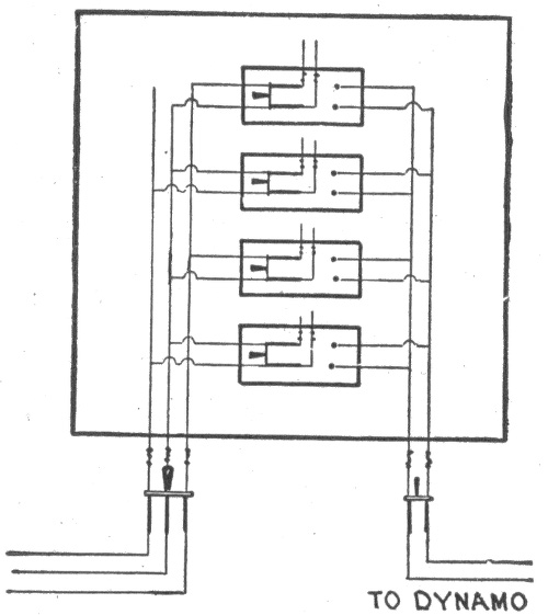
Fig. 1,000.—Diagram showing arrangement of switches in wiring system where provision is made that any circuit can be fed from an outside source in case of overload or accident.
Ques. How should feeders for motors be installed?
Ans. They should be independent of the lighting feeders.
Ques. What is the largest size of feeder that should be used?
Ans. Feeders requiring over 2 inch pipe should not be used. It is better to subdivide them, especially if there be many bends or offsets, since two inch pipe is about the limiting size for economical handling. 854
Ques. How should feeders be arranged?
Ans. They should radiate from a distributing panel, having a proper sized switch and fuse for each feeder.
If the system of wiring be such that auxiliary power is taken from a local lighting company, it is a good plan to have each circuit controlled by a double throw switch so that in case of overload any circuit can be fed from the illuminating company's mains as in fig. 1,000.
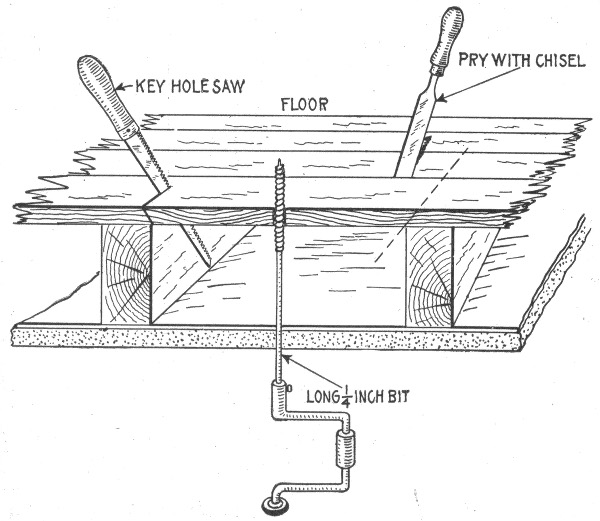
Fig. 1,001.—Sectional view showing method of cutting a pocket or opening in floor for the insertion of wires.
Ques. How should feeders and mains be run?
Ans. It is advisable to install them in iron pipe even though the circuit wires be run otherwise. Since the former carry the 855 main supply of current it is important to have them well protected as they usually run up side walls.
The underwriters make numerous restrictions against open or moulding work on brick walls and require good protection, and this is an additional reason for piping the mains and feeders.
Ques. How much load should be placed on the branch circuits?
Ans. In laying out the branch circuits, it is not good practice to use up the underwriters' circuit allowance of 660 watts.
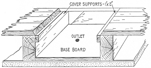
Fig. 1,002.—View of outlet pocket showing base board, and cover supports in position.
If a circuit be wired with the full allowance of lamps, no additions could be made without violating the underwriter's requirements.
Ques. If concealed wiring is to be installed in a finished building what should be done first?
Ans. The outlets should be marked on the ceilings and walls with a pencil cross at the spot, marking also the location of switches, etc. 856
Ques. If an outlet is to be placed at the center of a room, how is the center of the ceiling located?
Ans. It is first located on the floor, then transferred to the ceiling by means of a plumb bob.
Ques. What is the first operation in making a ceiling outlet?
Ans. A small hole is bored through the ceiling and the bit pushed up till it comes in contact with the flooring of the room above, this flooring is also bored, as in fig. 1,001.
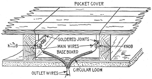
Fig. 1,003.—View of completed pocket and ceiling outlet showing method of bringing out the wires.
A long bit about ¼ inch in diameter and about 18 inches long is used. The hole bored in the floor above will show where to take up the board to install the wires.
Ques. How is a pocket opened above the hole bored for ceiling outlet?
Ans. One-quarter inch holes are bored to insert a keyhole saw through the joint between two boards at each end of the 857 pocket, and as near the beams as possible, then the board is cut at an angle as indicated in fig. 1,001. Having sawed across the board at both ends, it is pried out with a chisel as shown.
Ques. How are the holes bored through the beams for the tubes?
Ans. They are bored about two inches from the top with a 9/16 inch bit, slanting downward just enough to give clearance for the brace.
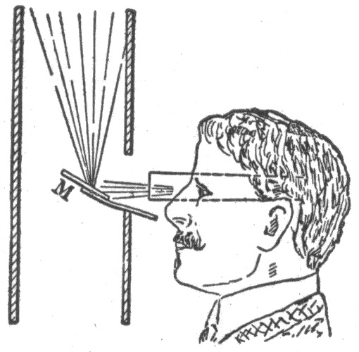
Fig. 1,004.—Device for examining partition interiors. A pocket flash lamp and a little mirror are the only apparatus required to inspect the interior of a wall or partition which would ordinarily be inaccessible. For fishing wires, retrieving cable and inspecting finished work, the lamp and mirror will be found most useful. The mirror has only to be introduced in the outlet hole in the wall, the flash lamp and eye being held behind it as illustrated. The mirror reflects the light of the lamp onto the place to be illuminated, at the same time reflecting the image back to the eye near the lamp. The usefulness of this little device is as great as its simplicity.
Ques. How are the knobs fastened?
Ans. Screws may be used but stout wire nails are satisfactory and are inserted with less labor.
Leather nail heads are slipped on the nails to protect the porcelain.
Ques. How is a ceiling outlet completed after the work has reached the stage shown in fig. 1,002?
Ans. A baseboard is next installed as in fig. 1,003 to have a secure hold for the screws used in fastening the fixtures. Two 858 holes are then bored diagonally with a 11/16 inch bit inserting the bit in the small hole bored in the ceiling as in fig. 1,001. The outlet wires are then tied around the knobs and the upper ends being bared and tapped on to the main wire. A piece of loom is slipped on each outlet wire after which it is thrust through the outlet as in fig. 1,003.
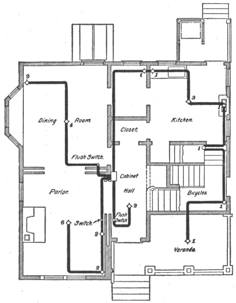
Fig. 1,005.—Plan showing one floor of a dwelling house wired with conduits. The numbers on the various outlets indicate the number of lamps supplied. The wiring is carried out on the loop system, and it will be noticed that no branches are taken off between outlets. Four circuits are used in order that there may not be more than ten lamps on any one circuit.
Ques. How are the mains secured to the knobs?
Ans. By taking a turn around the intermediate knobs and a dead end hitch at the end knobs, or they may be hitched at each knob. The main may be secured also by use of a tie wire. 859
Ques. What is the difference between a splice and a tap?
Ans. A splice is the joining of two wires at their ends; a tap is the joining of the end of one wire with an intermediate point of another wire.
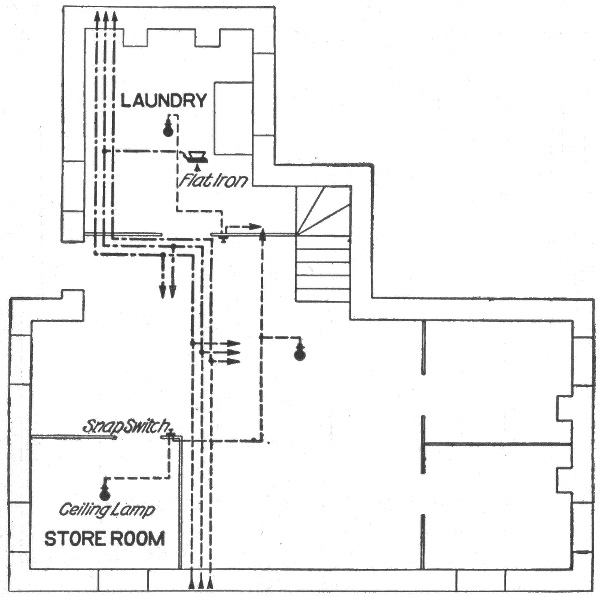
Fig. 1,006.—Wiring for heating appliances in two story house; plan of basement.
Ques. What precaution should be taken in making joints?
Ans. All wires joined together should be soldered as this insures good electrical contact.
Unsoldered wires are both unreliable and dangerous, since they will corrode from dampness, thus increasing the resistance of the joint so that it may become heated.
860
Ques. How should joints be finished after soldering?
Ans. They should be covered with rubber tape twisted tightly while it is hot. When the rubber has melted it will adhere to the joint and can be moulded with the fingers. Adhesive tape is then wound over the rubber, the insulation thus being made equal to that which was removed to unite the wires.
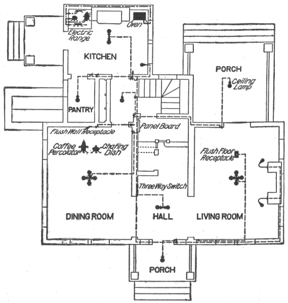
Fig. 1,007.—Wiring for heating appliances; plan of first floor.
Wiring for Heating Appliances.—There are now on the market a great number of heating appliances which absorb such small amounts of energy that they can be used readily on the lighting circuit. These appliances include the coffee percolator, 861 chafing dish, heating pad, small water heater, cigar lighter and many other miscellaneous devices. By adapting these smaller devices to the lighting circuit, not only is the cost of wiring decreased, but the convenience and cleanliness of the electrical system is secured.
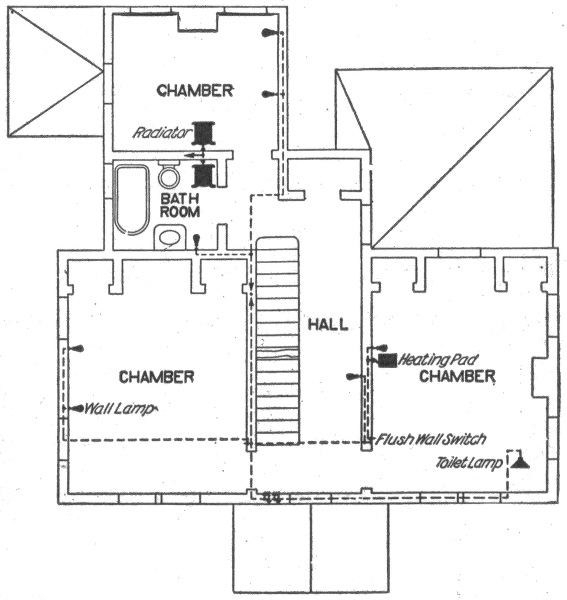
Fig. 1,008.—Wiring for heating appliances; plan of second floor.
The location of the outlets for the heating appliances is not of the least importance. For many purposes, the flush receptacle in the baseboard of the room answers many requirements. In other places, for instance, a receptacle placed beneath the bracket lamp in the bathroom upon the same circuit as the lamp, is very convenient as a connection for the electric shaving 862 mug or the massage motor. Similarly, a suitable outlet placed near the head of the bed is most convenient for operating a heating pad as it does not necessitate unscrewing a lamp at night.
The house illustrated in figs. 1,006 to 1,008 is an example of the use of a single electric heating circuit with a restricted use of the lighting circuit for heating purposes.
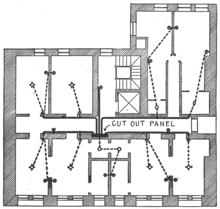
Fig. 1,009.—Diagram illustrating wiring with combination of moulding, flexible tubing or conduit in non-fireproof building, where wiring had not been originally installed. In such cases the moulding may be run in a cornice in the hall. When objectionable to have the work exposed in the rooms, taps may be made in the moulding opposite each room and the circuit extensions from the moulding to the center outlets in the rooms may be run in flexible conduit, fishing the wires from the moulding to the ceiling outlet. The use of wooden moulding in new buildings is not to be recommended for the reason that it is not usually fireproof, and it would be better to run the conductors concealed in some form of conduit; if the circuit work were installed at the time the building is erected, it would cost but little more than moulding, and would be much more substantial. In some cases, however, wooden moulding might be provided in a new building on the ceiling as a means of affording facilities for making connections to outlets over desks, tables, etc., where it would be impossible to locate the outlet exactly before the building was plastered. In such cases, the moulding could be installed on the ceiling at a distance of 18 to 24 inches from the walls, forming a rectangle on the ceiling.
863
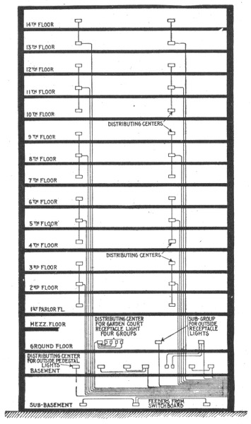
Fig. 1,010.—Feeder system for large hotel. The cellar, basement, and ground floors are supplied by separate feeders, because of the importance of having continuous and uninterrupted lighting service at these floors. The three distributing centers at the cellar are supplied by a single feeder. Three of the eight distributing centers at the basement floor serve to supply the outside lights, as described above. The distributing center for the outside street lamps is supplied by a separate feeder from the main switchboard. Five of the distributing centers at the basement floor serve for the basement lights only; they are fed by two separate feeders, one of which serves two centers and the other three centers as shown. Each of the three centers at the ground floor is supplied by a separate feeder. The upper floors, from the first to the fourteenth inclusive, are divided into two symmetrical sections. Each section has its own distributing center, and its own set of supply feeders. The feeder terminates at the middle center of a group of three, and is extended by mains to the corresponding centers at the floors immediately above and below. Each feeder from the first to the twelfth floor inclusive serves to supply three distributing centers.
864
As can be seen in the basement plan, the main supply circuit enters the basement and from this the heating circuit and lighting circuits branch, as shown by the arrows. The heating circuit runs direct to the basement laundry, a branch running to the flat iron. Connections are made with the kitchen on the first floor and with the dining room by branch circuits running through the partitions to the respective rooms. The heating circuit at the dining room is provided with flush wall receptacles, to which connection is made for the chafing dish and percolator.
In the kitchen the electric baking outfit is arranged as shown. This electric outfit is used for auxiliary cooking, such as a gas range would be, and the oven, placed by itself on the opposite side of the coal range, is controlled from the main table.
Upstairs the heating circuit, upon which the dining room appliances are operated, is extended to supply current to the electric luminous radiator, either in the chamber or bathroom.
The arrangements for the lighting circuits are shown in the figures. Landing and basement lights are controlled by three way switches to make them convenient.
In the living room a flush floor receptacle is installed so that the reading lamp, chafing dish or coffee percolator can be operated without necessitating the use of a long cord. A few of the electrical outlets suitable for the purposes mentioned are illustrated.
Where several heating circuits are used it is essential that an appliance taking a large current be not placed on the regular lighting circuit. To guard against this possibility, special receptacles should be installed, constructed for plugs which will not fit any other receptacle. 865
The devices used for giving the flashing and changeable effects to electric lights in any form are called "flashers." The mechanism may be constructed to flash a sign by spelling the words out, one letter at a time, flashing border lights around a window, changing colors in glass signs, or in fact in any way to attract the eye.
There are two advantages in favor of using a flasher: 1, it causes the passerby to look at the sign, and 2, reduces the cost of electricity, because the lamps are switched off periodically.
There are numerous kinds of flasher, and they may be classified, according to construction of the switch contacts, as:
1. Carbon type;
2. Brush type;
3. Knife type.
Again, with respect to operation or the electrical effects, they may be classified as
1. Simple on and off flashers;
2. High speed flashers;
3. Lightning flashers;
866
4. Script breakers;
5. Chaser flashers;
6. Thermo flashers;
7. Carriage calls;
8. Talking signs;
9. Electric clocks.
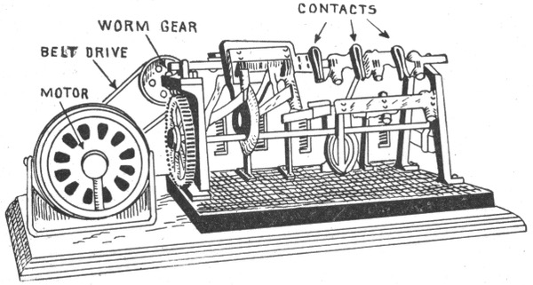
Fig. 1,011—Dull's carbon type flasher. This is a main line flasher; that is, it is set into the main wires instead of carrying down each circuit. The circuits are opened and closed on carbon contacts, reinforced with standard knife switches. The blades are opened and the current broken by gravity alone. Each switch can be made to hold the lights for any period from 18% to 81% of a revolution of the shaft. They can throw on the circuits progressively or all on and all off together. Again, the circuits may be closed progressively, remain on a few seconds, and then be opened progressively. No circuit or circuits can be closed more than once per revolution.
Carbon Flashers.—In this type of flasher, carbon breaks are provided, that is, the arc which is formed when the circuit is broken, falls on carbon, while metal switches are provided to carry the load. Thus the carbon gets the arc which prevents the switches burning, while the switches carry the load to prevent the carbons becoming heated and disintegrated. The carbons must be adjusted occasionally according to the load they are carrying. Carbon machines are made either double, triple, or series break. 867
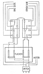
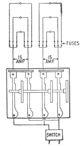
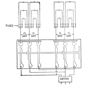
Figs. 1,012 to 1,014.—Wiring diagrams for Dull's carbon flashers. Fig. 1,012, usual method of wiring. The load is balanced by running the neutral wire around the machine, to the cut outs, breaking the outside "legs" only of a 220-110 volt system. While this method of wiring is entirely feasible, it is no harder on the contacts, and permits the use of a cheaper machine, but it is technically a violation of the underwriters' rules, which say that all circuits of more than 660 watts must be broken double pole. If the load be balanced there would be double pole break at 220 volts, and the lamps would be in series, but if the load be not exactly balanced, there would be single breaking to the extent of the amperes over the average balance. In other words, it is a double break and it is not according to circumstances, and the use of this machine wired as above is a matter that should be taken up with the local inspector before installing. Fig. 1.013, diagram for connecting a straight two wire carbon flasher on a two wire system. Fig. 1,014, diagram for connecting a straight three wire carbon flasher on a three wire system and breaking the neutral.
868
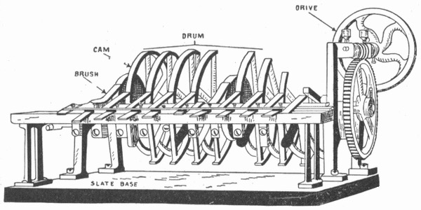
Fig. 1,015.—Reynolds' brush type flasher. The brush type, as its name indicates, is of brush construction and is limited to 5 amperes capacity on each switch. The cams constituting a drum are of heavy construction while the brushes are of fine copper several leaves thick. It is most commonly used for spelling signs, that is, for letter by letter flashing.
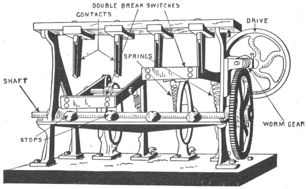
Fig. 1,016.—Reynolds' knife type of flasher with metal contacts. The construction is cheaper than the carbon type. It is mounted on a slate base, and is heavily built throughout. The switches are designed for 15 amperes capacity double break.
869
Brush Flashers.—These machines are provided with brush contacts. These bear on cams constituting a drum, and they are usually made of several strips of copper. Brush flashers are generally used for spelling out signs one letter at a time, or work of a similar nature.
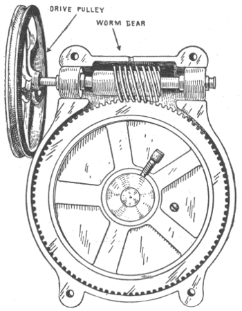
Fig. 1,017—Sign flasher transmission gearing. The view shows an oil tight gear case with cover plate removed. The gears are equipped with ball bearings and run in graphite grease. By means of the worm gear the large speed reduction necessary between the flasher shaft and motor is obtained without a multiplicity of gear wheels.
Knife Flashers.—This type of construction is cheaper than the carbon type. The switches are of the knife type with metal contacts. One manufacturer states that it is not advisable to build knife flashers for more than 15 amperes per double pole switch, as they cannot be depended upon to break a greater load for any length of time. 870
Simple On and Off Flashers.—These are used for flashing whole signs or heavy loads on and off. A flasher of this type consists essentially of a revolving double pole switch with reducing gear and connection to a small motor for operating same.
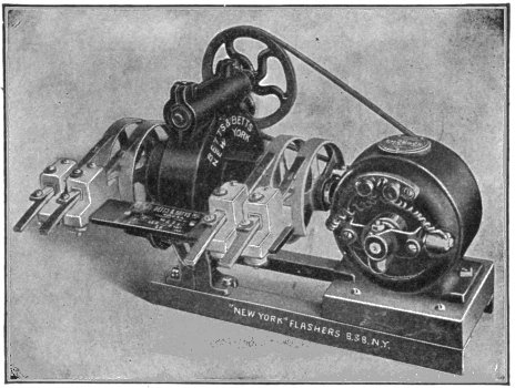
Fig. 1,018.—Simple on and off double pole flasher for "all on" or "all off" sign flashing. The machine is furnished with any number of switches ranging from 5 amperes up.
The machine may have only one switch or any number of switches. The connection to motor may be by belt or chain, or the motor may be directly connected to the worm gear.
Flash System of Gas Lighting—This system for simultaneously lighting a large number of gas burners, is used in large halls, churches, theatres, etc. Two sparking points, each insulated one from the other and from the burner, are arranged at each burner, so that a spark between the points passes through the jet of gas and ignites it. A number of sparking points and the secondary of an induction coil are connected in series. When the circuit through the primary of the induction coil is closed, sufficient pressure is induced in the secondary to cause sparks to jump across every jet in the series. Since the voltage is high, the wires must be installed with great precaution. The wire should be enclosed in glass tubing wherever it comes within less than 1¼ in. from the gas piping, except where purposely grounded. 871
High Speed Flashers.—Machines of this type are used for giving what is generally known as high speed effects, such as fountains, water, steam, smoke and fire effects, whirling borders, revolving wheels and work of a similar nature.
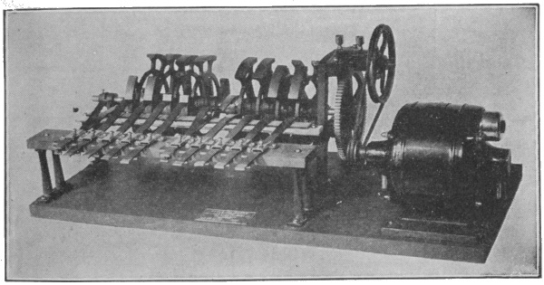
Fig. 1,019.—Dull's high speed flasher. It is mounted on a slate base 12 inches wide, the length being governed by the size of the machine. Motion is given to the rotary switches through worm and belt gearing. Iron cams are used, the current being taken therefrom by six-leaf brushes, provided with stiffeners. The wiring for the machine is simple; 4 c.p. lamps can be run on one wire. A border or ornament containing 160 lamps requires 12 wires between the sign and flasher. The flasher is made in 4 switch sizes only, viz.: No. 4, 8, 12, 16, etc. This is due to the fact that there are three parts of light to one of darkness.
Lightning Flashers.—These machines are for giving the appearance of a streak of lightning going across a display. There is very little expense attached to their operation, because not more than two-thirds of the lamps are turned on at one time, and this number for only about one-sixth of the time, as compared with the sign burning steadily.
Lightning strokes can be utilized in various ways, either alone or with other advertising pieces. Alone they can be placed along a cornice, across the front of a building, up and down the corners leading to a doorway, etc. They can be used in the center of a 872 873 874 sign with letters above and below. In this case, it is best to alternate the stroke with the letters, that is, flash the wording on and then off. As soon as it goes out, the stroke flies across in the darkness, then the wording comes up again, say six times a minute.
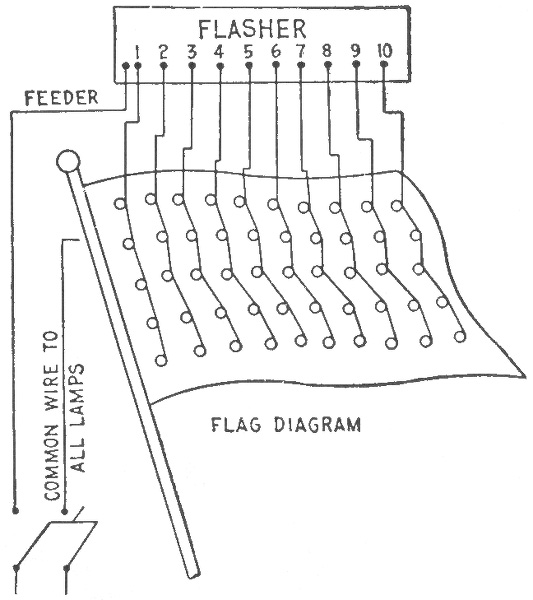
Fig. 1,020—Wiring diagram for flags. These may be wired for high speed flashers by gradually increasing the lamp centers between the vertical rows from the flag staff to the end.
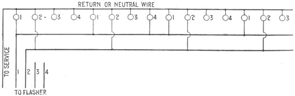
Fig. 1,021.—Diagram showing method of wiring for high speed effects on single lines. This wiring diagram would be carried out the same in the case of a travelling border, whether it be straight or otherwise. In the case of a fountain, begin numbering each stream at the bottom and carry out the same scheme to the end of that stream. When several streams are parallel, all the lamps may be connected in a row the same as though they were an individual lamp. Care should be taken not to get more than twenty No. 1 lamps on a circuit. Among the effects that may be obtained are a revolving wheel, a column of flame, and a straight travelling border with part of the No. 1 lamps from each effect to the same No. 1 wire, carry it back to any No. 1 switch on the machine, and the effect will come out right. For instance, in a flame effect with sixteen No. 1 lamps, four No. 1 lamps could be taken in the straight border, and put on the same wire, and the effect would come out right. The spacings for high speed effects vary, according to the size of the sign. Travelling borders around an ordinary sign 3 x 10 feet should have their lamps spaced about six inches apart. In a fountain fifteen feet high, the lamps should be spaced about nine inches apart.
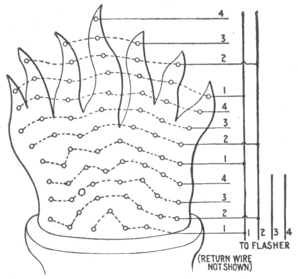
Fig. 1.022.—Method of wiring for a torch. This wiring diagram gives the correct method of wiring smoke, flames, steam, and water effects. It may be the flame in the top of a torch as here shown, liquid pouring out of a bottle, smoke rising from a cigar, or dust behind an automobile wheel. The only difference being in the direction each goes and the outline of the bank of lamps. Wire the lamps in unequal lines across; avoid any straight lines because it gives a mechanical effect which is not natural. If the effect be to rise, mark the lower row No. 1, the next row above No. 2, etc. Pick up all the No. 1 rows until there are twenty lamps, and attach them to No. 1 wire which will go back to any No. 1 switch on the machine. Do the same with the other numbers. Do not overload line as this will decrease the life of the contacts.
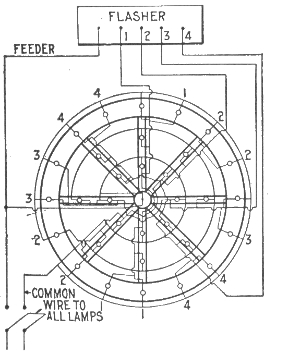
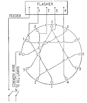
Figs. 1,023 and 1,024.—Wiring diagrams for high speeds. Where a high speed flasher is used on a spoked wheel containing more lamps in the rim than the number of spokes, the extra rim lamps must be connected to the spoke circuits, so that the number of rim circuits will equal the number of spokes; otherwise, the rim will appear to travel slower than the spokes.
In the case of a sign already in use, on the front of a building or over the sidewalk, a stroke can be placed leading to the sign from any point above. The flash goes down and when it hits the sign the latter lights up, holds a few seconds, goes out, and repeats about four times a minute.
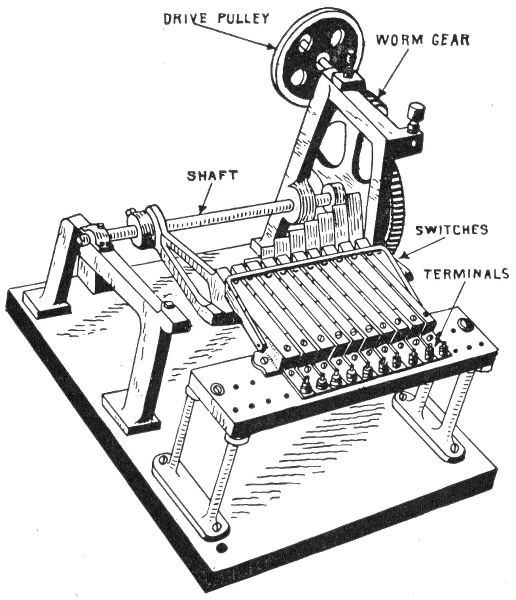
Fig. 1,025—Dull's lightning type flasher for giving the appearance of a streak of lightning going across a display.
Lightning flashes are not usually constructed for heavy loads, the one shown in fig. 1,025 being designed for two amperes. 875
Script Breakers.—Flashers of this type are used for breaking large script signs, one socket at a time; that is, each lamp is lighted one after another until all are on. After a few seconds they all go out simultaneously and repeat. This gives the appearance of an invisible hand, writing the name in the darkness, and is very effective. The result can be accomplished only with script, and to get the proper effect the smallest letter in a sign should be not less than two feet high; the larger the letter, the better the effect.
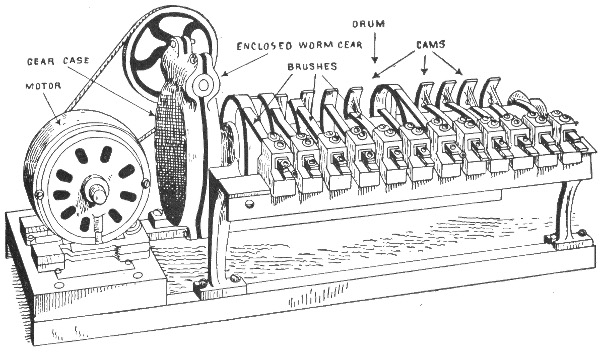
Fig. 1,026.—Betts' script breaker (brush type). This flasher is especially designed for spelling out signs one letter at a time, or work of a similar nature, The brushes for the revolving cam contacts are of copper, several leaves thick and provided with special brush holder to prevent loose contact and abnormal burning.
Script breakers are also used for fancy border signs of other kinds, and in order to produce these results, it is necessary that the return wire of every lamp go back to the flashers independently, which means a wire for each lamp. 876
Chaser Flashers.—This class of flasher is designed to operate signs whose lamps are arranged to give the effect of snakes chasing each other around the border. This peculiar effect is produced by having a separate wire and a separate switch on the flasher for each two lamps in the border, and the mechanism so arranged that when the tenth lamp is lighted (assuming the snake to be ten lamps long) the first lamp goes out; when the eleventh is lighted, the second goes out, etc., progressing in this way around the entire border.
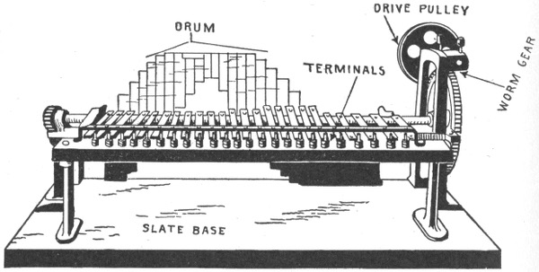
Fig. 1,027.—Reynolds chaser type of flasher, as used on electric signs whose lamps are arranged to give the effect of snakes chasing each other around the border of a sign.
In operation, the lamps are turned on and off so rapidly that it produces the effect of snakes.
It is not advisable to build these signs small nor cheaply, as in order to produce the desired effect, the curved path taken by the snake should cover at least 10 inches width, which would mean a total of 20 inches lateral space for the snake in addition to the electric letters in the center. In order to get the proper effect, the sign should be at least ten feet long.
877
Ques. Why are chaser signs expensive?
Ans. It is on account of the care required in their construction, large amount of wiring necessary and large flasher required.
A sign four by ten feet outside dimensions, would require in the neighborhood of 150 lamps in the border alone on each side. This would require a flasher with 75 switches and about 82 wires to run between the sign and flasher.
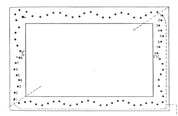
Fig. 1,028.—Chaser wiring diagram for two snakes. Draw a line diagonally through the sign (as shown in dotted line) so that one-half the total lamps will be on either side. Begin to number from one consecutively to the line. Over the line commence again at 1 and number as before. For three snakes, divide total lamps into three parts and number as before. In each case, connect all lamps of the same number to the same wire whether the sign be single or double face. The wire containing all the No. 1 lamps goes to the No. 1 switch on the flasher, and the remaining sets are connected similarly.
Ques. How are chaser signs worked?
Ans. There are several ways of operating these signs. The border is generally working continuously, while the center can be flashed or not, as may be desired. Flashing the wording 878 reduces the current expense, which offsets in a measure the extra cost of the sign.
The border, although working continuously consumes very little current.
Ques. What is the relative cost of a one snake sign as compared with a two snake sign?
Ans. One snake running around the border would cost twice as much for flasher and wiring as a two snake flasher.
Three snakes would cost about 25 per cent. less for flasher and wiring than for two snakes. The smaller the number of snakes travelling around the border at one time, the greater the expense of wiring and flasher.
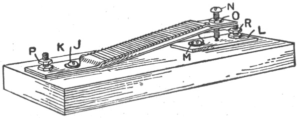
Fig. 1,029.—Thermo flasher. It consists of two metal strips, one of brass and the other of iron, about 5"x ½" x 1/32" each. The brass strip is provided with a winding of fine wire over asbestos and the two strips are connected to the base as shown. One terminal of the winding is connected to J, and the other end to M. At the end of the strips is a small contact screw N with locknut O, and below is a contact plate L, fastened to the base and terminal post R. The flasher is connected at P and R in series with the lamp it is to flash, and N adjusted so that it clears the plate about 1/32 inch when there is no current flowing in the winding. When the switch is turned on there will be a current through the lamp and winding in series. The brass strip will be heated more than the iron and it will expand more, thus forcing the point of the screw N down upon the brass plate, which will result in the winding about the brass strip being shorted and the full voltage will be impressed upon the lamp, and it will burn at normal candle power. When the coil is shorted there will of course be no current in its winding and the brass strip will cool down, the screw N will finally be drawn away from contact with the brass plate, and the winding again connected in series with the lamp. The lamp will apparently go out when the winding is in series with it, as the total resistance of the lamp and winding combined will not permit sufficient current to pass through the lamp to make its filament glow. The time the lamp is on and off may be varied to a certain extent by adjusting the screw N.
Ques. How many snakes should there be for best effect?
Ans. Two is considered best. Three may be used on some signs, but more than four would, in most cases, so crowd them as to spoil the effect entirely. 879
Thermo Flashers.—These flashers work on the thermo or heat expansion principle, that is, the movement of the contact points of the flasher necessary to open and close the circuit is obtained automatically by the alternate heating and cooling of the metal of the flasher, which causes it to expand and contract.
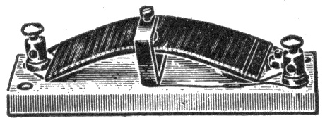
Fig. 1,030.—Thermal flasher. This simple flasher consists of a brass strip fixed at each end to a porcelain base and slightly arched upwards. The amount of this arching, however, is much less than is shown in the figure. The center of the strip carries a platinum contact on its upper surface, and opposite this is a platinum tipped contact screw which is carried in a brass angle piece fixed to the base. One terminal is fitted on one end of the strip, and the other is connected, through the angle piece, with the contact screw. The strip is wound from end to end with an insulated resistance wire, one end of this being soldered to the strip, and the other connected to the right hand terminal. When this device is switched into circuit with the lamps, the current first flows through the resistance, which cuts it down so much that the lamps are not visibly affected. The heat generated in the resistance causes the strip to curve still more, till at length contact is made, the resistance short circuited, and the lamps lighted.
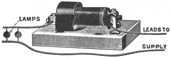
Fig. 1,031.—General Electric thermal flasher. It consists of a small brass cylinder fixed at its left hand end to one of the terminal blocks. The junction between the two is hidden by a portion of the cover, which is shown broken away. The right hand end of the cylinder carries a cross piece bearing a platinum contact; and opposite this is the platinum tip of a contact screw carried in the other terminal block. The cylinder is wound with a heating coil of manganin resistance wire, one end being soldered to the cylinder and the other to the right hand terminal. When the current is switched on, the coil and the cylinder warm up and the cylinder elongates sufficiently to make contact and light the lamps. The coil being then short circuited, it and the cylinder cool down, and contact is broken, whereupon the coil is put in circuit once more, and warms up again. In some sizes of this flasher, the contact gap is shunted by a small condenser fitted beneath the base. This helps to eliminate the sparking at the contacts.
Carriage Calls.—These are used to avoid the confusion and noise at the theatre, club house or department store when vehicles are called by a megaphone. 880
Fig. 1,032.—Monogram or unit for carriage call or talking sign. It consists of a collection of metal compartments each arranged to receive an incandescent lamp. The purpose of these compartments is to confine the light to a certain space, thus forming a clearly defined number or letter which can be read from a distance.
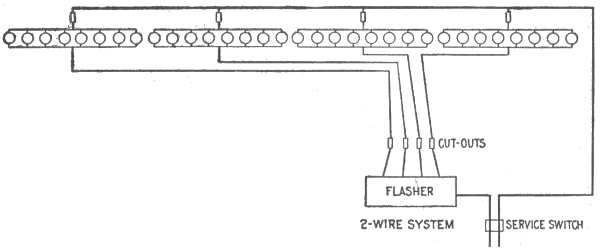
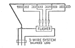
Fig. 1,033 and 1,034.—Wiring diagrams showing proper methods of wiring for illuminating a painted sign. The lamps are placed about one foot apart in an overhead inverted trough. They should project out in front of the sign one-half its width, but no sign should be more than eight feet wide, as ordinary 16 c.p. lamps will not carry any farther. Black and white paint only should be used. The lamps may be flashed on and off as a whole, saving one-half the current, or they can be flashed in different colors as desired. For flashing in colors, only red and amber should be used. No other colors, such as green, blue, etc., will give sufficient light to produce a good effect.
881
The call itself consists of two or more sheet steel boxes, one of which is shown in fig. 1,032, with incandescent lamps arranged in metal compartments in such order that any number may be produced by lighting the proper lamps.
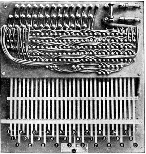
Fig. 1,035.—Operating keyboard for three number National carriage call. The keyboard here shown is designed to control a three number call, there being a row of keys for each monogram or unit of the call. Its dimensions are 4 inches deep, 18 inches wide and 19 inches long. The base is of slate. There are fourteen wires for each monogram and one return wire, coming out of the call.
The flashing of the number is controlled by a keyboard or switch which may be placed in any convenient location. When 882 883 the switch and call are connected together, any numeral may be flashed by pressing the corresponding key. The numeral automatically remains lighted until the releasing button is pressed.
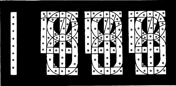
Fig. 1,036.—Clock monogram or electric sign clock, operated by the mechanism shown in fig. 1,037.
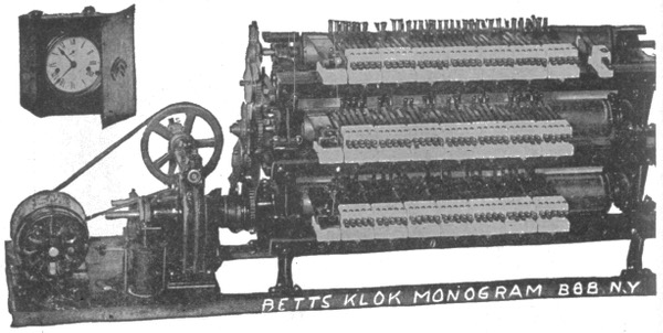
Fig. 1,037.—Betts' clock mechanism for operating electric monogram time flasher. The secondary mechanism consists of a three cylinder flasher and is controlled by a master clock which transmits an electric impulse through a relay switch one each minute. This flashes the time in figures on the monogram, viz.: 11.45, 11.46, 11.47, 11.48, etc. The first monogram to the left consists simply of a vertical row of lights representing the figure one. Each of the other monograms of metal compartments so arranged that any figure may be produced by lighting the proper combination of lamps.
Talking Signs.—This type of electric sign automatically flashes out in brilliant letters, different phrases or announcements. These are flashed out repeatedly and continuously during the operation of the sign and the changes follow each other without intermission of darkness.
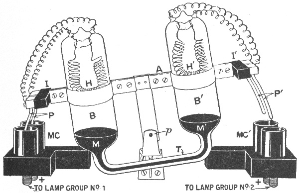
Fig. 1,038.—Two way thermal flasher. The moving portion consists of a rocking arm A pivoted at p, and carrying two sealed bulbs, B, B', whose bottoms are united by the tube T. Inside there is sufficient mercury M to fill T and the bottoms of the bulbs, the remainder containing air. At each end of A is fixed an insulating block I, I', carrying two contact prongs P and P', which are connected together at the top through heater wires H, H' sealed in the bulbs B and B' respectively. MC, MC' are pairs of mercury cups, the further one of each pair whose stud is marked +, being connected together to the positive pole of the circuit, while the front ones are joined up to the respective groups of lamps. The action is as follows: If the apparatus be in the position illustrated, when the circuit is closed at the time P is down, lamp group No. 1 will light up, the current passing through H on its way. The air in B consequently expands, and gradually forces the mercury down in B, along T, and up in B'. The arm A will gradually become horizontal, and will then overbalance, P being withdrawn from MC, and P' dipped into MC'. Lamp group No. 1 will consequently be extinguished and lamp group No. 2 lighted; H will cool down, and H' will warm up. Thus, in due course, A will be tilted the other way again.
The talking sign consists of any desired number of monograms or units, in each of which any letter or figure can be formed by 884 lighting certain combinations of incandescent lamps. A unit is shown in fig. 1,032. The lamps are controlled by a simple mechanical arrangement operated by a small motor. Any reading matter can be flashed by properly setting the mechanism.
The flashing of the letters or numerals in the monogram is controlled by commutators, one commutator being required for each monogram, except for a double faced sign where the corresponding monogram on each side is controlled by the same commutator. 885
A lightning arrester is an apparatus designed to provide a path by which lightning disturbances or other static discharges may pass to earth. Lightning arresters may be divided into three classes, according as their action depends upon the effects of:
1. Sharp points;
2. Air gaps;
3. Sharp turns.
Lightning Rods.—This form of arrester consists of a conducting rod or cable erected on the outside of a building and connected to earth, in order to afford protection from lightning by carrying the lightning discharge into the ground; or to prevent lightning by leading the electricity from the earth to the cloud without disturbance.
Ques. Why do lightning rods terminate in sharp points?
Ans. The action of the rod depends on the discharging effect of a sharp point as follows: When an electrically charged cloud approaches a building provided with a lightning rod, it induces an opposite charge in the earth and in the rod which is connected 886 to the earth. As soon as the charge on the point becomes strong enough to break apart the molecules of the air in front of it, a stream of electrified particles, opposite in sign to that of the charge on the cloud, passes from the neighborhood of the rod to the cloud and thus neutralizes the charge of the cloud.
Ques. How should a lightning rod be erected?
Ans. The conductor should be carried to all high points of the building it is to protect and should be well insulated from the latter and grounded in deep wet earth, independent of gas or water pipes. Sharp bends and corners should be avoided.
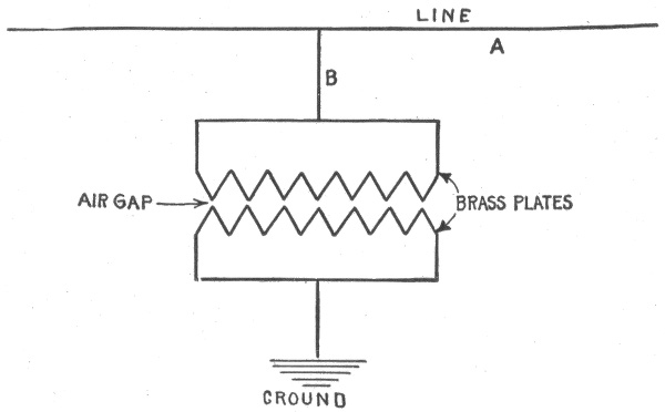
Fig. 1,039.—Diagram showing principle of air gap arrester: lightning discharges more readily at sharp points than along flat surfaces.
Ques. Why have lightning rods fallen into disfavor?
Ans. On account of numerous failures due to faulty installations, and non-maintenance of the rod in good condition, also because of the excessive prices charged by unscrupulous dealers for rods and their erection.
A lightning rod with defective insulation or broken ground connection is a danger rather than a protection.
887
Air Gap Arresters.—Many of the lightning arresters used for the protection of electrical apparatus depend upon the fact that lightning discharges will jump across air spaces that are good insulators for the regular working current, while they find difficulty in passing through circuits containing electromagnets.
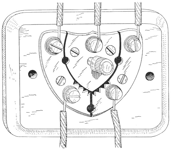
Fig. 1,040.—Union lightning arrester and ground wire switch for telegraph lines. Two line wires are attached to the two plates provided with points. The ground wire being connected to the third or central plate. The pin serves as a ground wire switch and cut out. This is a good form for short lines.
The principle of air gap arresters is illustrated in fig. 1,039. There are two brass plates slightly separated; one is connected to the line and the other is grounded. The air gap between the plates is very small and the resistance thus interposed, while sufficient to prevent the regular working current jumping across, is not great enough to interfere with a lightning discharge which readily jumps the gap and passes off to earth. 888
Ques. Why are teeth provided on the plates?
Ans. For the same reason that points are used on lightning rods. That is, when electricity at high pressure accumulates at such points the surrounding air is electrified and the charge escapes by means of the charged air particles.
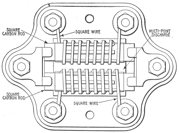
Fig. 1,041.—Mason multi-discharge lightning arrester. The construction of this arrester is based on the well known principle that lightning discharges more readily at points or angles than elsewhere. The wire is wound around square carbon rods, which are connected to the ground, the line being insulated from the rods by sheets of mica. The wire itself being square, instead of round, adds to the efficiency of the arrester, by increasing the number of points or angles.
Ques. For what kind of service is the form of arrester just described used?
Ans. It is suitable for telegraph and telephone lines where currents of very low voltage are employed.
Ques. Why is it not used on lines employing higher voltage, such as in electric light and power stations?
Ans. Current at high pressure would follow the lightning across the gap and establish an arc or continuous flame from 889 one plate to the other thus quickly destroying the plates and causing other more serious damage.
Ques. What provision is made to prevent the destruction of arresters by the line current?
Ans. Lightning arresters used on heavy duty circuits are designed to rupture the arc as soon as formed.
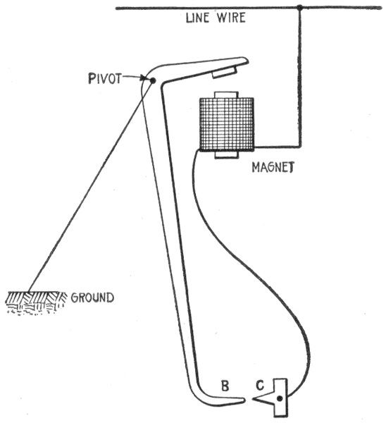
Fig. 1,042.—Diagram showing operation of variable gap arc breaker used on heavy duty lightning arresters. When a lightning discharge passes across the gap to earth, the dynamo current follows it and energizes the magnet M, which attracts the short arm of the double lever, thus quickly jerking the terminal B away from C. The wider air gap thus interposed between B and C greatly increases the resistance which breaks the arc.
Ques. How is this done?
Ans. There are several methods, of which may be mentioned the variable gap method described in fig. 1,042, and the magnetic blow out method shown in fig. 1,043.
Ques. Where should lightning arresters be placed?
Ans. They should be placed as near as possible to the point where wires enter a building, and in an easily accessible place away from combustible material. 890
Ques. What should be avoided in installing lightning arresters?
Ans. Kinks and sharp bends in the wire running from the outdoor lines to the arresters and from arresters to ground should be avoided as far as possible.
Ques. Why should kinks and sharp bends be avoided?
Ans. Because they offer resistance to the lightning discharge.
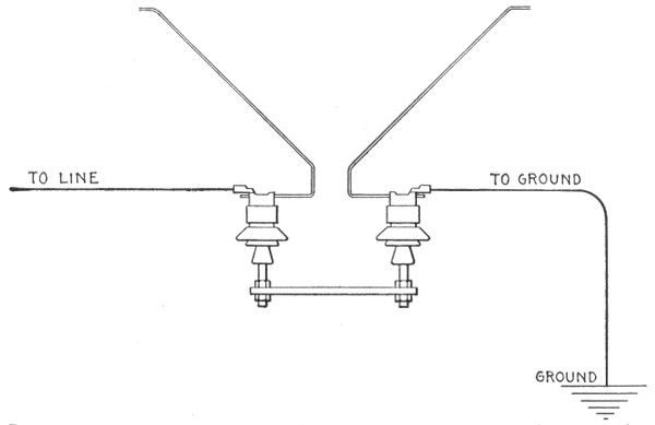
Fig. 1,043.—Horn type lightning arrester. In this type of arrester, two wires, after approaching within a short distance of one another, are bent divergently. These wires are supported on insulators. One of them is connected to the line to be protected and the other is earthed. The normal line pressure is insufficient to bridge the gap, even at its narrowest portion, but an extra high pressure whether due to lightning or to other disturbing phenomena, will bridge the gap at its narrowest point and establish a path to earth. When, however, the main current attempts to flow across, phenomena of electromagnetic repulsion force the arc upward along the horns, lengthening and attenuating it, until it finally becomes extinguished.
Ques. How should lightning arresters be grounded?
Ans. They should be connected to ground with No. 6 B. & S. gauge copper wire or larger. Gas pipes within a building must not be used for a ground connection. 891
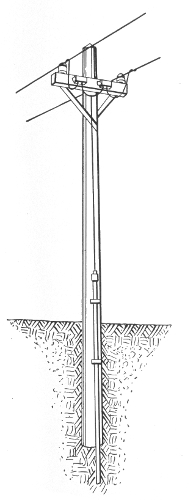
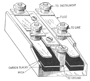
Fig. 1,044.—Ground connection for lightning arrester.
Fig. 1,045.—Carbon lightning arrester with fuses as used on telephone lines. The arrester consists of two blocks of carbon separated a small distance by a thin sheet of insulating mica, which is perforated with one or more holes; a high voltage charge on the line will jump through the hole in the mica from the carbon on the line side to the lower carbon, which is connected with the ground; the fuses protect the instruments against foreign currents which might damage, although not of sufficiently high pressure to jump to earth; sometimes the connections are reversed so that the fuse is between the line and the earth.
892
Ground connections may be made with a one inch galvanized iron pipe driven about 8 feet or until it reaches permanently moist earth, and extending at least 7 feet above ground. The ground wire should be securely soldered to a brass plug firmly screwed into the pipe, and both strongly stapled to the pole so there will be little danger of the connection being broken.
A good ground is important, as the efficiency of the protection would be impaired if the ground connection were poor. Wherever the earth is dry and a good ground cannot surely be obtained, an excavation 4 or 5 feet deep should be made, and after placing the copper ground plate or iron pipe in the hole, it should be filled with crushed coke or charcoal about pea size. This improves the electrical connection between pipe or plate and earth.
Ques. Does lightning often strike telephone or electric light lines?
Ans. No, the lines become charged to a high pressure by induction from lightning flashes or from the passing of clouds that are highly charged. 893
Introduction.—The practical development of the storage battery is comparatively recent, although a knowledge of the phenomena upon which its actions are based, dates back to 1801. In 1800, the year made memorable by Volta's discovery of the galvanic battery, Nicholson and Carlisle found that a current from Volta's cell could decompose water.
In 1801, Gautherot discovered that if two plates of platinum or silver, immersed in a suitable electrolyte, be connected to the terminals of an active primary cell and current be allowed to flow, a small current could be obtained on an outside circuit connecting these two electrodes as soon as the primary battery had been disconnected.
Erman found that the positive pole of such a cell, was the pole which had been connected to the positive pole of the battery.
In 1803, Ritter observed, with gold wire, the same phenomenon as Gautherot, and constructed the first secondary battery, by superposing plates of gold, separated by cloth discs, moistened with ammonia.
Volta, Davy, Marianini, and others added somewhat to the knowledge on the subject, and in 1837, Schoenbein found that peroxide of lead could be used in secondary batteries.
Sir William Grove next came forward with the discovery that metal plates, with a layer of oxide on them, acted better than the plain metallic plates, and Wheatstone and Siemens found still later that peroxide of lead was the best for such purposes.
In 1842, Grove constructed a gas battery, in which the electromotive force came from the oxygen and hydrogen evolved in the electrolysis of water acidulated with sulphuric acid. By means of fifty such cells, he obtained an arc light.
894
Michael Faraday, when electrolyzing a solution of lead acetate, found that peroxide was produced at the positive, and metallic lead at the negative pole, and in his "Experimental Researches," he comments on the high conductivity of lead peroxide, and its power of readily giving up its oxygen. Although he made no apparent use of this discovery, it may be considered as the next important step in the development of the storage battery.
According to Niblett, Wheatstone, de la Rue, and Niaudet were well aware that peroxide of lead was a powerful depolarizer, but nobody appears to have made use of this fact until 1860, when M. Gaston Plante constructed his well known cell with coiled plates. Plante's researches extended up to 1879, and practically determined the state of the art.
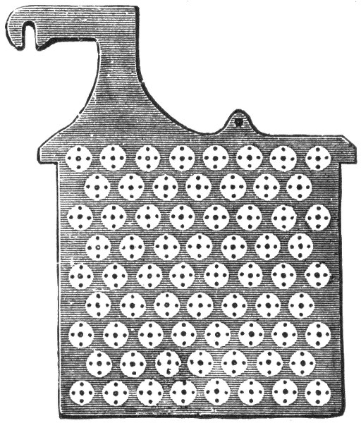
Fig. 1,046.—One plate or "grid" of a type of storage cell constructed by inserting buttons or ribbons of the proper chemical substances in perforations. Some such cells use crimped ribbons of metallic lead for inserting in the perforations, others pure red lead or other suitable material.
As to the theory at this time, it may be stated that Clerk Maxwell, although the leading electrician of his time, speaks of the storage battery as storing up a quantity of energy in a manner somewhat analogous to the ordinary condenser; hence the use of the word "accumulator" for storage battery.
In 1879, R. L. Metzer did away with the tedious forming process, by mechanically applying the active material. This important discovery was not, however, generally known, until 1881, when Camille Faure obtained important patents concerning the method of shortening the time of formation.
895
Charles F. Brush, working independently of either Faure or Metzer, arrived at the same result, and the United States courts have decided, after long litigation, that to him belongs the priority of invention in this country.
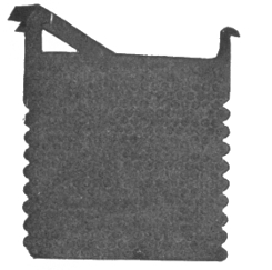
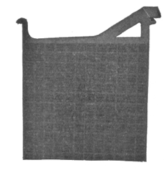
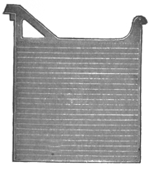
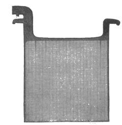
Figs. 1,047 to 1,050.—Electric Storage Battery Co. plates. Fig. 1,047, "Manchester" positive plate; fig. 1,048, box negative plate; fig. 1,049, "Tudor" positive plate; fig 1,050, pasted negative plate.
Ques. To what use is the storage battery sometimes put in electric lighting or power stations?
Ans. To carry the "peak" of the load; that excessive portion of the load which, for instance, in electric lighting stations 896 has to be carried only for two or three hours a day. To carry the entire load at minimum hours. To act as equalizer or reservoir. Also for equipment of annex or substations.
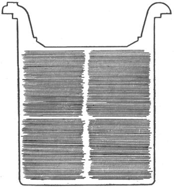
Fig. 1,051.—"Unformed" plate of one pattern of Gould storage cell. The particular plate shown has total outside dimensions of 6×6 inches. The clear outline of the grooves indicates absence of oxides, due to action of "forming" solutions, or charging current.
Theory of the Storage Battery.—The action of the storage battery is practically the same as that of the primary battery and it is subject to the same general laws. The cells of a storage battery are connected in the same way as primary cells, and when charged is capable of generating a current of electricity in a manner similar to that of a primary battery. It differs, however, from the primary battery in that it is capable of being recharged after exhaustion by passing an electric current through it in a 897 direction opposite to that of the current on discharge. This difference constitutes the principal advantage of the storage battery over the primary battery.
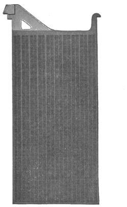
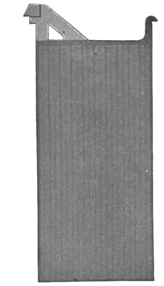
Figs. 1,052 and 1,053.—Electric Storage Battery Co., type H "exide" plates. This form of plate is used for large "stand by" batteries. Fig. 1,052, positive plate; fig. 1,053, negative plate.
Ques. Describe a storage cell.
Ans. A storage cell consists of plates or of grids in an electrolyte, of such a character that the electrical energy supplied to it is converted into chemical energy (a process called charging). The chemical energy can be reconverted into electrical energy (a process called discharging). 898
Ques. Describe the electrolyte generally used.
Ans. It consists of a weak solution of sulphuric acid which permits ready conduction of the current from the primary battery, the greater the proportion of acid within certain limits, the smaller the resistance offered.
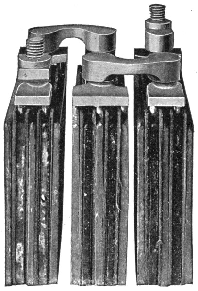
Fig. 1,054.—Elements of 6 volt 40 ampere hour "Aplco" portable (3 cell) storage battery. The grids are made from an alloy of lead and antimony; hard lead straps which are burned together, are used for joining the plates. Specially treated separators are used.
Ques. What is the effect of the current passing through the electrolyte?
Ans. It decomposes the water into oxygen and hydrogen; this is indicated by the formation of bubbles upon the exposed surfaces of both plates, these bubbles being formed by oxygen 899 gas on the plate connected to the positive pole of the primary battery, and hydrogen on the plate connected to the negative pole.
Because, however, the oxygen is unable to attack either platinum or silver under such conditions, the capacity of such a device to act as an electrical accumulator is practically limited to the point at which both plates are covered with bubbles. After this point the gases will begin to escape into the atmosphere.
Ques. What is the prime condition for operation of a storage battery?
Ans. The resistance of the electrolyte should be as low as possible in order that the current may pass freely and with full effect between the electrodes. If the resistance of the electrolyte be too small, the intensity of the current will cause the water to boil rather than to occasion the electrolytic effects noted above.
Ques. What happens when the charging current is discontinued, and the two electrodes joined by an outside wire?
Ans. A small current will flow through the outside circuit, being due to the recomposition of the acid and water solution. The process is in a very definite sense a reversal of that by which the current is generated in a primary cell.
Hydrogen collected upon the negative plate, which was the cathode, so long as the primary battery was in circuit, is given off to the liquid immediately surrounding it, uniting with its particles of oxygen and causing the hydrogen, in combination with them, to unite with the particles of oxygen next adjacent. The process is continued until the opposite positive plate is reached, when the oxygen collected there is finally combined with the surplus hydrogen, going to it from the surrounding solution.
This chemical process causes the current to emerge from the positive plate, which was the anode, so long as the primary battery was in circuit. The current thus produced will continue until the recomposition of the gases is complete; then ceasing because these gases, as before stated, do not combine with the metal of the electrodes.
900
Types of Storage Battery.—There are three classes of storage cell which are commercially important:
1. Plante cells;
2. Faure cells;
3. Alkaline cells.
According to construction secondary cells may be classified as follows:
1. Lead sulphuric acid cells;
2. Lead copper cells;
3. Lead zinc cells;
4. Alkaline zincate cells.
The lead sulphuric acid type includes all those cells belonging to the Plante and Faure groups.
Lead copper cells consist of sheets of metal coated with lead oxide, serving as the positive electrode, and copper plates for the negative electrodes. These plates are immersed in a solution of copper sulphate. Cells belonging to this class are not employed in commercial practice, being useful only for laboratory experiments.
Lead zinc cells are similar to the preceding type, but differ by having zinc for the negative electrode, and zinc sulphate for the electrolyte. The voltage of these cells is slightly higher than that of the ordinary cell, and their capacity per unit of total weight is high, but they are apt to lose their charge on open circuit, besides they possess most of the disadvantages of the Plante cells.
Alkaline zincate cells have copper for the positive, and iron for the negative electrode. The electrolyte is composed of sodium, or potassium, zincate. Cells of this type are used to some extent for traction purposes.
In addition to the above there are some special forms of cell which do not belong to the four preceding types.
Ques. Describe the Plante type.
Ans. In the Plante type the lead is chemically attacked and finally converted into lead peroxide, probably after it has gone through several intermediate changes. The plates are all formed as positive plates first and then all that are intended for negative plates are reversed, the peroxide being changed into sponge lead. 901
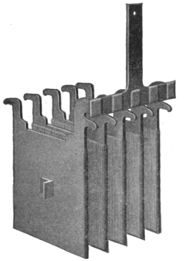
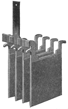
Figs. 1,055 and 1,056.—Willard plates; fig. 1,055, negative plates; fig. 1,056, positive plates. Both positive and negative plates are of the Planté type, made from one integral piece of rolled lead. These are grooved plates. The projections are tapered, that is, they are wider at the base than at the surface, for strength. The center web of each positive plate is tapered from the top of the plate downward to secure uniform distribution of the current all over the surface of the plate.
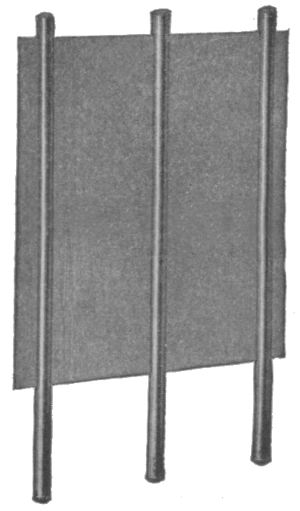
Fig. 1,057.—Wood separator for spacing the plates, as used in the Willard storage cells.
902
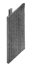
Fig. 1,058.—Positive plate.
Fig. 1,059.—Perforated rubber separator.
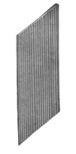
Fig. 1,060.—Wood separator.
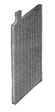
Fig. 1,061.—Negative plate.
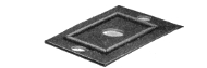
Fig. 1,062.—Hard rubber cover.
Fig. 1,063.—Vent plug.
Fig. 1,064.—Pillar connecting strap.
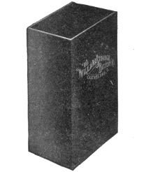
Fig. 1,065.—Hard rubber jar.
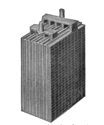
Fig. 1,066.—Complete element.
Figs. 1,058 to 1,066.—Parts of the Willard "Autex" automobile cells.
903
Ques. What is done to make the Plante plate more efficient?
Ans. The surfaces are finely subdivided, the following methods being those common: scoring, grooving, casting, laminating, pressing, and by the use of lead wool.
Ques. Describe the Faure or pasted type.
Ans. This form of plate is constructed by attaching the active material by some mechanical means to a grid proper. The active material first used for this purpose was red lead, which was reduced in a short time to lead peroxide when connected as the positive or anode, or to spongy metallic lead when connected as the cathode or negative, thus forming plates of the same chemical compound as in the Plante type.
The materials used at the present time by the manufacturers for making this paste are largely a secret with them, but in general they consist of pulverized lead or lead oxide mixed with some liquid to make a paste.
Ques. How do Faure plates compare with those of the Plante type?
Ans. They are usually lighter and have a higher capacity, but have a tendency to shed the material from the grid, thus making the battery useless.
Many ways have been tried for mechanically holding the active material on the grid, the general method involving a special design in the shape of the grid. Some of these designs are: 1, solid perforated sheets of lattice work; 2, corrugated and solid recess plates not perforated; 3, ribbed plates with projecting portions; 4, grid cast around active material; 5, lead envelopes, and 6, triangular troughs as horizontal ribs.
The Electrolyte.—Sulphuric acid is generally used as electrolyte; the acid should be made from sulphur and not from pyrites, as the latter is liable to contain injurious substances. 904
Ques. How is the electrolyte prepared?
Ans. One part of chemically pure concentrated sulphuric acid is mixed with several parts of water. The proportion of water differs with several types of cell from three to eight parts, as specified in the directions accompanying the cells.
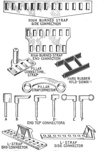
Figs. 1,067 to 1,079.—Willard connecting straps and connectors.
905
Ques. What test is necessary in preparing the electrolyte?
Ans. In mixing the water and acid, the hydrometer should be used to test the specific gravity6 of both the acid and the solution. The most suitable acid should show a specific gravity of about 1.760 or 66° Baumé.
Ques. In preparing the electrolyte, how should the water and acid be mixed?
Ans. The mixture should be made by pouring the acid slowly into the water, never the reverse. As cannot be too strongly stated, in mixing, the liquid should be stirred with a clean wooden stick, the acid being added to the water slowly; the latter is corrosive and will painfully burn the flesh.
Distilled or rain water should be used in preparing the electrolyte. When made, the solution should be allowed to cool for several hours or until its temperature is approximately that of the atmosphere (60 being the average). At this point it should have a specific gravity of about 1.200 or 25° Baumé. If the hydrometer show a higher reading, water may be added until the correct reading is obtained; if a lower reading, dilute acid may be added with similar intent.
The electrolyte should never be mixed in jars containing the battery plates, but preferably in stone vessels, specially prepared for the purpose. Furthermore, it should never be placed in the cell until perfectly cool.
Ques. What is the effect of mixing the acid and the water?
Ans. The mixture becomes hot.
Before using, the mixture should be allowed to cool.
906
Ques. What kind of a vessel should be used?
Ans. The vessel should be of glass, glazed earthenware, or lead.
Ques. At what density is the resistance of dilute sulfuric acid at a minimum?
Ans. At 1.260.
The percentage of concentrated sulphuric acid and of water per 100 parts of the electrolyte for various specific gravities is given by the following table:
| Sulphuric acid (Per cent.). |
Water (Per cent.). |
Specific gravity of Mixture. |
|---|---|---|
| 50 | 50 | 1.398 |
| 47 | 53 | 1.370 |
| 44 | 56 | 1.342 |
| 41 | 59 | 1.315 |
| 38 | 62 | 1.289 |
| 35 | 65 | 1.264 |
| 32 | 68 | 1.239 |
| 29 | 71 | 1.215 |
| 26 | 74 | 1.190 |
| 23 | 77 | 1.167 |
| 20 | 80 | 1.144 |
| 17 | 83 | 1.121 |
| 14 | 86 | 1.098 |
| 10 | 90 | 1.068 |
The electrolyte of the desired specific gravity may be purchased ready for use, but in cases where it is desirable to save freight, the acid may be diluted at the point of installation.
Ques. What is the effect of a deep containing vessel?
Ans. Parts of the plate surface may do more than their share of the work due to the difference in the density of the electrolyte at the top and bottom. The containing vessel should, therefore, 907 never be deeper than about 20 inches unless some artificial means of acid circulation be used.
Ques. What is the effect of changes in temperature on the electrolyte?
Ans. The resistance of the electrolyte is changed, being less for increase of temperature.
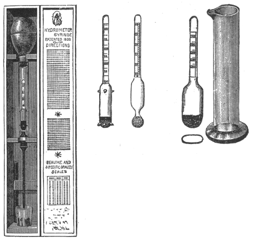
Figs. 1,080 to 1,084—Acid hydrometers for liquids heavier than water. Fig. 1,080, standard storage battery hydrometer with guiding points designed for "hydrometer syringe," shot bulb, with red line at 25 Baumé, 5 inches long, double scale 10 to 40 Baumé, 1.050 to 1.400 specific gravity. Fig. 1,081, plain hydrometer with shot bulb, 5 inches long, double scale 10 to 40 Baumé, 1.050 to 1.400 specific gravity. Figs. 1,082 and 1,083, hydrometer with small flat bulb, used in car lighting batteries, shot bulb, 4½ inches long, single scale, reading from 1.100 to 1.250 specific gravity. Fig. 1,084 jar for hydrometers.
Ques. How should the cells be filled?
Ans. Enough of the electrolyte should be poured into the jars to completely cover the plates, or to within about a half 908 inch of the top edge of the jar. Large cells should be filled by means of an acid proof pump and rubber hose.
Ques. What change takes place after filling the jars?
Ans. The specific gravity of the electrolyte will fall considerably, but will rise again when the battery is charged.
Ques. What may be said with respect to the density of the electrolyte?
Ans. It should never exceed 1.200 when the battery is fully charged.
Ques. How much electrolyte is used per 100 ampere hours battery capacity, on an 8 hour rating?
Ans. About ten pounds; in automobile batteries, about four pounds is sufficient.
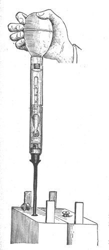
Fig. 1,085.—The hydrometer syringe; a convenient device for testing electric vehicle cells. By slightly compressing the bulb and inserting the slender tube through the vent hole in the cover of the cell sufficient acid may be drawn up to float the hydrometer within the large glass tube, and the reading can be made at once. The acid is returned to the cell by again compressing the bulb, and the reading of the next cell taken. The laborious and uncleanly method of drawing out sufficient acid by a syringe is thus avoided.
909
Ques. What may be said with respect to impurities in the electrolyte?
Ans. The electrolyte should be free from chlorine, nitrates, acetates, iron, copper, arsenic, mercury, and the slightest trace of platinum.
Mercury alone has no injurious effect unless it be present in sufficient quantity to amalgamate the plates, but in combination with any other metal, may cause local action.
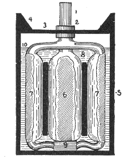
Figs. 1,086 to 1,089.—The "Champion" Accumulator; views showing parts and assembly. Fig. 1,086, empty plate; fig. 1,087, filled plate; fig. 1,088, complete element, small type; fig 1,089, cell assembled. The plates are of the envelope type and are made thick. The active material is held firmly in place by a covering of lead. A few thick plates are used instead of many thin ones.
The following tests should be made for impurities before the electrolyte is poured in the cells:
Chlorine.—To a small sample of the electrolyte add a few drops of silver solution (20 grains of silver dissolved in 1,000 cu. cm. of water). A white precipitate indicates chlorine.
Nitrates.—Place some of the electrolyte in a test tube, and add 10 grains of strong ferrous sulphate solution. Carefully pour down the side of the test tube a small amount of chemically pure concentrated sulphuric acid. A brown stratum between the electrolyte and the concentrated acid indicates the presence of nitric acid. 910
Acetic acid.—Neutralize the electrolyte with ammonia, then add ferric chloride. If the solution turns red, and is afterwards bleached by the addition of hydrochloric acid, acetic acid is present.
Iron.—Neutralize a sample of the electrolyte with ammonia; boil a small portion with hydrogen peroxide, and add ammonia or caustic potash solution until the mixture becomes alkaline. If a brownish red precipitate forms, it indicates iron.
Copper.—If copper be present, a bluish white precipitate will be formed when ammonia solution is added to the electrolyte.
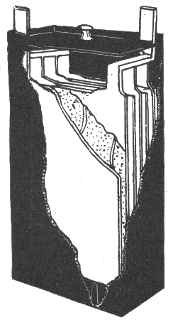
Fig. 1,090.—One cell of the Gould storage battery for electric vehicle use. According to the data given by the manufacturers, this cell, containing four negative and three positive plates, has a normal charging rate of 27 amperes; a distance rate of 22 amperes for four hours; a capacity of 81 ampere hours at 3 hours discharge, and of 90 ampere hours at 4 hours discharge. Forty such cells are generally used for an average light vehicle battery.
Mercury.—This is indicated by an olive green precipitate when a solution of potassium iodide is added to the electrolyte, or by a black precipitate when lime water is added.
Platinum.—A rough test for traces of platinum is made by pouring the electrolyte into a cell in which the battery plates are immersed. If gassing take place for some time on open circuit, it is an indication of the presence of platinum.
911
Ques. What should be done with old electrolyte?
Ans. When a battery is taken down the electrolyte may be saved and used when re-assembling the battery, providing great care be exercised when pouring it out of the jar, so as not to draw off with it any of the sediment. It should be stored in convenient receptacles, preferably carboys, which have been thoroughly washed and never used for any other purpose.
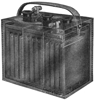
Fig. 1,091.—Phantom view of an "Exide" sparking or ignition battery. It contains three cells. In this type, the terminal lug has been designed to obviate the creeping of the electrolyte with its accompanying corrosion. The positive and negative terminals are for identification.
The electrolyte saved in this manner will not, however, be sufficient to refill the battery, and as some new electrolyte will be required, in general it is recommended that the old supply be thrown away and all new electrolyte (1.200 specific gravity) be used when re-assembling.
Voltage of a Secondary Cell.—This depends on the density of the electrolyte, the character of the electrodes and condition of the cell; it is independent of the size of the cell. 912
The voltage of a lead sulphuric acid cell when being charged is from 2 to 2.5 volts. While the cell is being discharged, it decreases from 2 to 1.7 volts. The voltage due to the density of the electrolyte may be calculated from the following formula:
V = 1.85 + .917 (S - s)
in which
V = voltage;
S = specific gravity of the electrotype;
s = specific gravity of water at the temperature of observation.
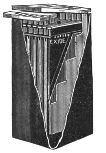
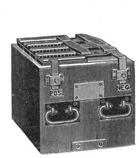
Fig. 1,092.—The Exide storage cell. The positive and negative plates are separated by thin sheets of perforated hard rubber, placed on both sides of each positive plate. The electrolyte and plates are contained in a hard rubber jar.
Fig. 1,093.—An Exide battery of five cells. The box which holds the cells is usually made of oak, properly reinforced, with the wood treated to render it acid proof. The terminals as shown, consist of metal castings attached to the side of the box and plainly marked.
Connection for Charging.—The dynamo cable connections may be made either before or after filling the cells. In making these connections great care should be taken to be sure that the positive terminal of the battery is connected to the positive lead of the dynamo, and that the negative terminal of the battery 913 is connected to the negative lead of the dynamo. In order to insure that the reverse connections are not made accidentally, the dynamo leads should be tested by a pole tester, and the positive and negative poles marked red and black respectively.
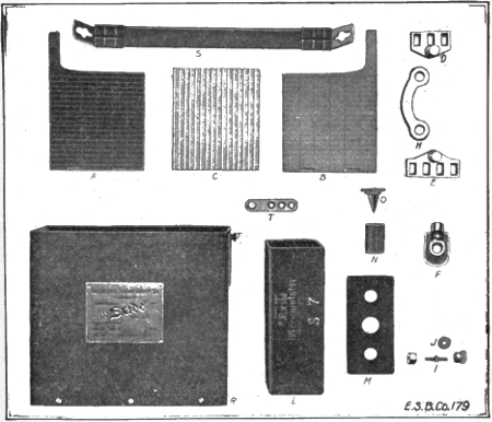
Figs. 1,094 to 1,109.—Parts of the "Exide" sparking battery. A, positive plate; B, negative plate; C, wood separator; D, positive strap; E, negative strap; F, terminal lug; H, connector; I, terminal bolt connector, stud, thumb nut and hexagonal nut; J, copper washer for bolt connector; L, hard rubber jar; M, hard rubber cover; N, hard rubber cylinder vent; O, vent plug for cylinder vent; R, wood case; S, strap handle; T, fitting for strap handle. The "Exide" sparking battery is also adapted for electric lighting of automobiles, for head lights, tail lights, side and interior lights.
The polarity of the dynamo wires being determined, they may be joined to the proper terminals by means of suitable clamps or by solder.
Wherever possible the dynamo should be of the direct current, shunt wound, or special compound type, but in cases where only alternating current can be obtained, suitable rectifiers or converters should be used for changing it to direct current. 914
Charging.—Before beginning to charge a storage battery, it should be gone over carefully, and any cell that is not up to the standard should be disconnected and put in working order before being replaced. In general, if the current used in charging be too large, it will waste energy by evolving an excess of heat and gas; if too small, an insulating deposit of white lead sulphate will be formed on the positive plate, thereby preventing the formation of the proper amount of lead peroxide.
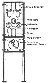
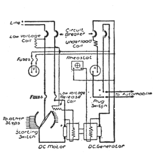
Figs. 1,110 and 1,111.—Switchboard and motor dynamo circuit connections for charging a battery from direct current mains.
Ques. How should a battery be charged for the first time?
Ans. It is essential that the current be allowed to enter at the positive pole at about one-half the usual charging rate prescribed, but after making sure that all necessary conditions have been fulfilled, it is possible to raise the rate to that prescribed by the manufacturers of the battery. 915
Ques. What is the usual period for charging a new battery?
Ans. With several of the best known makes of storage battery the prescribed period for the first charge varies between twenty and thirty hours.
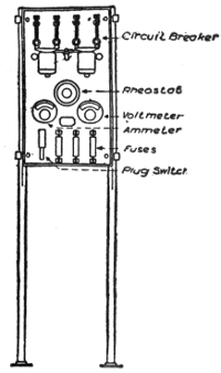
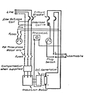
Figs. 1,112 and 1,113.—Switchboard and motor generator circuit connections for charging a battery from alternating current mains. The connections of a third wire are shown, for use in case a three phase circuit is available.
Ques. How is the electrolyte affected by the first charge?
Ans. A change of specific gravity occurs. The specific gravity should be about 1.200 when the solution is poured into the cells.
At the completion of the first charge, it should, on the same scale be about 1.225. If it be higher than this, water should be added to the solution until the proper figure is reached, if it be lower, dilute sulphuric acid should be added until the hydrometer registers 1.225.
At the first charging of a cell, when the pressure has reached the required limit, the cell should be discharged until the voltage has fallen to about two-thirds normal pressure, when the cell should again be recharged to the normal voltage (2.5 or 2.6 volts).
916
The manufacturers of a well known cell of the Plante genus prescribe for the first charge, half rate for four hours, after which the current may be increased to the normal power and continued for twenty hours successively.
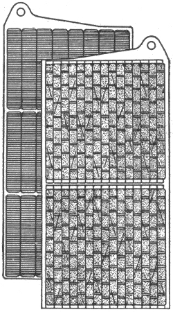
Fig. 1,114.—Plates of Edison storage battery. The positive or nickel plate consists of one or more perforated steel tubes, heavily nickel plated, filled with alternate layers of nickel hydroxide and pure metallic nickel in excessively thin flakes. The tube is drawn from a perforated ribbon of steel, nickel plated, and reinforced with eight steel bands, equidistant apart, which prevent the tube expanding away from and breaking contact with its contents. The tubes are flanged at both ends and held in perfect contact with a steel supporting frame or grid made of cold rolled steel, nickel plated. The negative or iron plate consists of a grid of cold rolled steel, nickel plated, holding a number of rectangular pockets filled with powdered iron oxide. These pockets are made up of very finely perforated steel, nickel plated. After the pockets are filled they are inserted in the grid and subjected to great pressure between dies which corrugate the surface of pockets and force them into good contact with the grid.
Ques. What strength of current should be used in charging a cell?
Ans. It should be in proportion to the ampere hour capacity of the cell. 917
Thus, as given by several manufacturers, the normal charging rate for a cell of 40 ampere hours should be five amperes, or one-eighth of its ampere hour rating in amperes of charging current.
Ques. What should be the voltage of the charging current before closing the charging circuit?
Ans. The voltage should be at least ten per cent. higher than the normal voltage of the battery when charged.
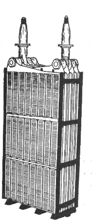
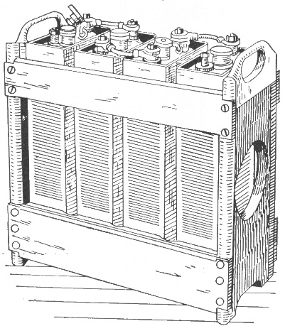
Fig. 1,115.—Complete element of Edison storage battery with insulators. After the plates are assembled into a complete element, narrow strips of treated hard rubber are inserted between the plates, thereby separating and insulating them from each other. The side insulator is provided with grooves that take the edges of the plates, thereby performing the dual function of separating the plates and insulating the complete elements from the steel container. At the ends of the element, that is between the outside negative plates and container, are inserted smooth sheets of hard rubber. At the bottom, the element rests upon a hard rubber rack or bridge, insulating the plates from the bottom of container.
Fig. 1,116.—Four Edison cells (type A-4) in wooden tray.
Ques. What indicates the completion of a charge?
Ans. When a cell is fully charged the electrolyte apparently boils and gives off gas freely. The completion of a charge may 918 be determined by the voltmeter, which will show whether the normal pressure has been attained.
Ques. How should the voltage be regulated during the first charge?
Ans. It should be allowed to rise somewhat above the point of normal pressure.
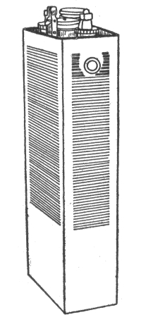 |
|
Fig. 1,117.—Cell of Edison storage battery. The jar or container is of nickel plated sheet steel with welded seams; the walls are corrugated to give strength. The cell cover, of sheet steel, has four mountings, two being pockets to contain stuffing boxes about the terminal posts. One of the other two is a separator which separates spray from the escaping gas while the battery is charging. The fourth mounting is for filling with electrolyte. The electrolyte consists of a 21% solution of potash in distilled water with a small per cent. of lithia. The density of the electrolyte does not change on charge or discharge.
Ques. How often should a battery be charged?
Ans. At least once in two weeks, even if the use be only slight in proportion to the output capacity.
In charging a storage battery, it is essential to remember the fact that the normal charging rate is in proportion to the voltage of the battery.
919
Thus, a 100 ampere hour battery, charged from a 110 volt circuit at the rate of ten amperes per hour, would require ten hours to charge, and would consume in that time an amount of electrical energy represented by the product of 110 (voltage) by 10 (amperes) which would give 1,100 watts, or 11/10 kw.
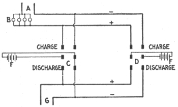
Fig. 1,118.—Diagram illustrating method of charging storage battery of stationary gas engine ignition system; the system is simple to install and will give satisfactory results. Two storage batteries are used, one being charged while the other is operating the sparking coil. Where charging current is available at the point where the batteries are used, the following diagram shows the system of connections, which can be easily followed, A represents the source of charging current and B the bank of lamps (or other resistance, such as an ordinary rheostat) sufficient to cut down the charging voltage to that required by the battery. C and D are two double pole double throw knife switches connected at their hinges to two batteries, E and F, each consisting of a group of cells. G represents the leads to the sparking coil terminals. From the diagram, it will readily be seen that by throwing the switches in opposite directions one battery will be charging while the other battery is discharging to the engine, thus giving a constant source of supply, and insuring that the spare battery will be full and ready for service by the time the other is discharged. The method of determining the necessary resistance for cutting down the line voltage for charging the battery is illustrated by the following example: If a battery require about 3 amperes for charging, how is this current obtained from a 110 volt circuit? Each 16 candle power carbon filament lamp in the lamp bank would give approximately 1/3 ampere with the cells in series in the lamp circuit. Therefore, 3 x 3 or 9 lamps should be used in parallel to give 3 amperes.
Ques. If in charging a battery, one or more of the cells do not boil at the completion of the charge, or fail to show the proper voltage, what should be done?
Ans. The charging must be continued until the cadmium test shows the required voltage, but if the prolonging of the charge be liable to damage the plates in the other cells, the defective cell or cells should be cut out of circuit when the battery discharges and then placed in circuit again when the battery is 920 recharged. If the desired result cannot be attained by this method, the plates which require additional charging may be charged in a separate cell.
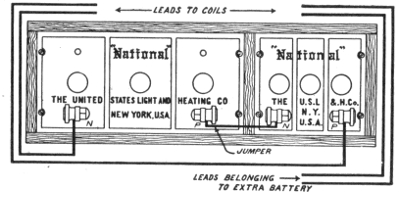
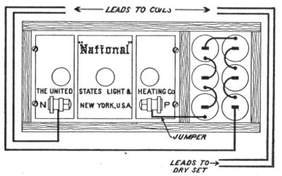
Figs. 1,119 and 1,120.—Emergency connections for weak ignition battery. It sometimes occurs through carelessness or neglect, that the storage battery is discharged so low that the engine explosion will not take place, and it is necessary to run somehow or other for a short time. In such cases the following suggestion may be followed: If there be two storage batteries, connect them in series. If there be one storage battery and a set of dry cells, connect the positive terminal of the storage battery to the negative or outside terminal of the dry cell; set and connect to the coil leads as if they were one battery. The above suggestions should only be followed in emergency, for it may injure the coils, and is harmful to the battery.
Ques. How is the cadmium test made?
Ans. A plate of cadmium is mounted in a hard rubber frame and immersed in the electrolyte. The test consists in taking voltage readings between the cadmium plate and the positive or negative plates of the cell. During charge the cadmium plate reads negative to the negative plate, until the cell is about full, 921 when the reading should be zero; the charge should be continued until the cadmium reads 0.2 volt positive to the negative while charging at the normal rate.
Ques. Name some portable instruments that should be provided for testing batteries.
Ans. 1, a hydrometer syringe (specific gravity tester); 2, an acid testing set (can be used instead of the syringe); 3, a low reading voltmeter; 4, suitable prods, and 5, a thermometer.
Ques. What precaution should be taken in charging a battery?
Ans. Care should be taken not to have a naked flame anywhere in its vicinity.
To either charge or discharge a battery at too rapid a rate involves the generation of heat. Thus, while this is not liable to result in a flame under usual conditions, the battery may take fire, if it be improperly connected or improperly used.
Ques. What is the effect of varying the charging current?
Ans. In charging a storage cell, particularly for the first time, a weaker current than that specified may be used with the same result, provided the prescribed duration of the charge be proportionally lengthened. The battery may also be occasionally charged beyond the prescribed voltage, ten or twenty per cent. overcharge effecting no injury, although if frequently repeated, it shortens the life of the battery.
Ques. What are the charge indications?
Ans. The state of the charge is not only indicated by the density of the electrolyte and the voltage of the cell, but also by the color of the plates, which is considered by many authorities as one of the best tests for ascertaining the condition of a battery. 922
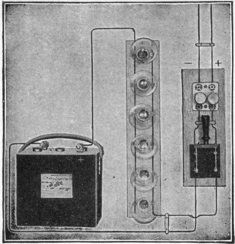
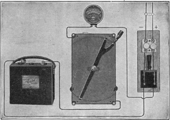
Figs. 1,121 and 1,122.—Two methods of charging from a direct current lighting system. The simplest method of charging is from
an incandescent light circuit, using lamps connected in parallel to reduce the voltage to that of the battery, the current being
adjusted by varying the number of lamps in circuit. The group of lamps is in series with the battery to be charged, and
the combination is connected across the circuit furnishing the current. If the charging source be a 110-120 volt circuit, and
the rate required be 6 amperes, twelve 16 c. p. or six 32 c. p. lamps, in parallel, and the group in series with the battery,
will give the desired charging rate, unless high efficiency lamps be used, when more will be required. In case a lower charging
rate, say 2 amperes be used, then a proportionately fewer number of lamps will be needed; but the length of time required
to complete the charge will be correspondingly increased. Instead of lamps, as in fig. 1,121, a rheostat is sometimes used, as
shown in fig 1,122. Its resistance should be such as to produce, when carrying the normal charging current, a drop in volts
equal to the difference between the pressure of the charging source and that of the battery to be charged; thus, if a battery
of three cells, giving 6 volts, is to be charged from a 110 volt circuit at a 6 ampere rate, the resistance would be, according
to Ohm's law,
(110 - 6) ÷ 6 = 17.3 ohms.
The carrying capacity of the rheostat should be slightly in excess of the current required for charging. An ammeter with
suitable scale should be inserted in the battery circuit to indicate the current. For charging more than one battery at a time
from a 110 volt circuit, the batteries should be connected in series (positive terminal of one battery to the negative of the
next, and so on). The charging rate should be that of the battery with the lowest rate. The resistance to be inserted will
be less than if only one battery is being charged; where lamp resistance is used, this means more lamps in parallel. Care
should be taken to remove each battery from the circuit as it becomes charged, inserting additional resistance to take its place.
923
Ques. What are the colors of the plates?
Ans. In the case of formed plates, and before the first charging, the positives are of a dark brown color with whitish or reddish gray spots, and the negatives are of a yellowish gray. The whitish or reddish gray spots on the positive plates are small particles of lead sulphate which have not been reduced to lead peroxide during the process of forming, and represent imperfect sulphation.
As a general rule, the first charging should be carried on until these spots completely disappear. After this the positive plates should be of a dark red or chocolate color at the end of the discharge, and of a wet slate or nearly black color when fully charged. A very small discharge is sufficient, however, to change them from black to the dark red or chocolate color.
If the battery has been discharged to a pressure lower than 1.8 volts, the white sulphate deposits will reappear, turning the dark red color to a grayish tint in patches or all over the face of the plate, or in the form of scales of a venetian red color.
The formation of these scales while charging indicates that the maximum charging current is too large and should be reduced until the scales or white deposits fall off or disappear, after which the current can be increased again.
During charging, the yellowish gray color of the negatives changes to a pale slate color which grows slightly darker at the completion of the charge. The color of the negatives always remains, however, much lighter than that of the positives.
Ques. How are the best results obtained in charging?
Ans. The rate of charge should be normal, except in cases of emergency. At such a rate, unless the constant voltage method be employed, the cell may be considered full when the voltmeter reads 2.5 volts during charge. The electrolyte should be kept at uniform density throughout the cell; when water is added, because of evaporation, it should be added by means of a funnel reaching to the bottom of the cell. Care should be taken never to add acid after evaporation; otherwise the electrolyte will be too heavy. Hydrometer readings should be taken regularly; 924 the reading is an excellent indication of the amount of charge in the battery. Hydrometer readings are useless, however, unless the precaution be taken to keep the electrolyte of uniform density.
Ques. What voltage should be used in charging?
Ans. At the beginning of the charge the voltage should be about 5 per cent. higher than the normal voltage of the battery, unless the latter has been overdischarged, in which case the difference of pressure should not exceed 2 per cent., otherwise the current might be too large.
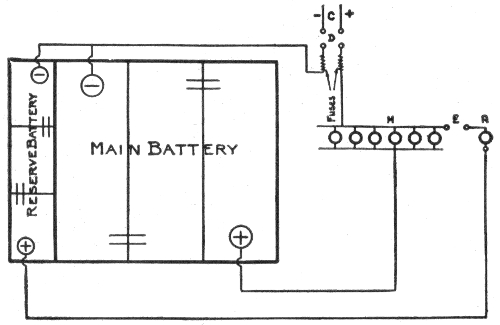
Fig. 1,123.—Diagram showing charging connections for "Exide" duplex sparking battery. C, charging source; D, double pole single throw switch; E, single pole single throw switch; M, lamp resistance "main" battery; R, lamp resistance "reserve" battery.
Ques. In what two ways may batteries be charged?
Ans. They may be charged either at constant current or at constant voltage.
Although the latter method is considered the better one by many authorities, it is a fact, nevertheless, that if the charging current be normal at the beginning of the charge, and no means be provided for keeping it constant, it will diminish as the charging progresses, thereby greatly increasing the length of the time required for charging, and resulting in serious injury to the plates.
925
Ques. How may the charging current be kept constant?
Ans. Its voltage should be gradually increased, first to about 10 or 15 per cent. above the voltage of the battery, and kept at that point nearly to the end of the charge, where in consequence of the rapid rise of pressure in the battery it might become necessary to increase the voltage of the current to 30 or 40 per cent. above the normal of the battery.
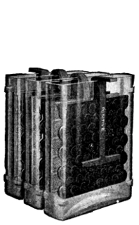
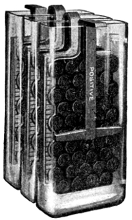
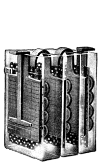
Figs. 1,124 to 1,126.—Electric Storage Battery Co. chloride cells. The voltage of cells of all capacities is slightly above 2 volts on open circuit, and during discharge at the 8 hour rate it varies from that point at the beginning to 1.75 volts at the end.
Ques. What tests should be made while charging?
Ans. Occasional voltage and cadmium readings of each cell should be taken for the purpose of ascertaining their condition and the behavior of the separate plates.
Ques. What tests should be made after charging?
Ans. Each cell should be tested with a low reading voltmeter and hydrometer about once a week. If any cell read low, it should be cut out and examined to see if any material has been 926 introduced which would cause a short circuit. If this trouble do not exist, the cell should be given an independent charge.
Charge Indications.—The state of the charge is not only indicated by the density of the electrolyte and the voltage of the cell, but also by the color of the plates, which is considered by many authorities as one of the best tests for ascertaining the condition of a battery.
In the case of formed plates, and before the first charging, the positives are of a dark brown color with whitish or reddish gray spots and the negatives are of a yellowish gray. The whitish or reddish gray spots on the positive plates are small particles of lead sulphate which have not been reduced to lead peroxide during the process of forming, and represent imperfect sulphation.
As a general rule the first charging should be carried on until these spots completely disappear. After this, the positive plates should be of a dark red or chocolate color at the end of a discharge and of a wet slate or nearly black color when fully charged. A very small discharge is sufficient, however, to change them from black to the dark red or chocolate color.
If the battery has been discharged to a pressure lower than 1.8 volts, the white sulphate deposits will reappear turning the dark red color to a grayish tint in patches or all over the surface of the plate, or in the form of scales of a venetian red color.
The formation of these scales during charging indicates that the maximum charging current is too large and should be reduced until the scales or white deposits fall off or disappear, after which the current can be increased again.
Ques. Describe the behavior of the electrolyte during discharge.
Ans. There is a definite change in the density of the electrolyte for a given amount of discharge.
The density of the electrolyte is, therefore, one of the best indications of the state of charge, provided, of course, no internal discharge due to local action takes place. If, when the cell is charged, it show a density 927 of 1.200, and when discharged 1.130, the difference .07 represents the total charge. If at any time the density be 1.165, then just one half the amount of capacity has been taken from the cell.
It is necessary to stir the electrolyte well, in order for these observations to be reliable.
If the discharge has taken place at a high rate, the cell must stand for an hour or more before the electrolyte will completely diffuse so that the density readings are correct.
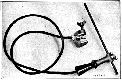
Fig. 1,127.—Electric Storage Battery Co., arc lead burning outfit. In assembling a storage battery element, a negative plate is laid down with a separator on it, then a positive plate, separator, negative plate, etc. The plates are so placed that all the lugs of the positive plates are on one side and all the lugs of the negative plates are on the other side. A strip, consisting of flat strips of lead or lead alloy, having rectangular openings in it of the same dimensions as the cross section of the lug of the plates, these openings being spaced to register with the lugs, is then placed over the plate lugs of the positive plates and a similar strap is placed over the lugs of the negative plates. The lugs are then burned into integral union with the straps.
Ques. Define the term "boiling."
Ans. Boiling means the rapid evolution of gas when a cell is nearly charged.
Ques. What causes boiling?
Ans. The amount of sulphate to be converted into peroxide becomes less and less as the charge progresses and the plates therefore become virtually smaller, so that the current becomes too large for the work demanded of it. The result is, that part of the current not actually used in the formation of peroxide decomposes the electrolyte into its constituent elements. 928
Ques. Why do the gases evolved produce a less milky appearance of the electrolyte when a battery has been in use for a considerable time?
Ans. The plates are better formed; consequently a larger charging current can be used without producing "boiling".
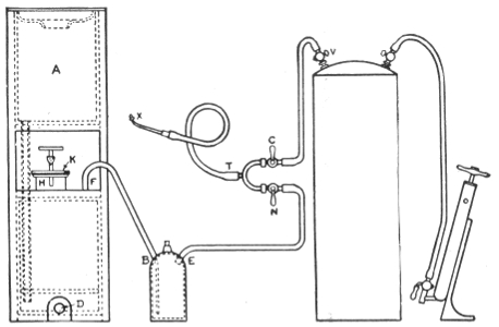
Fig. 1,128.—Hydrogen gas generator for lead burning. A complete lead burning outfit consists of the following parts: 1, hydrogen gas generator; 2, trap for cleaning the gas and for preventing the flame getting back in the generator; 3, air pump; 4, air tank; 5, blow pipe; 6, lead burner's mixing tee; 7, length of 150 feet 5/16 inch soft rubber tubing. When the generator is to be used for lead burning, connect up the different parts of the apparatus as shown. Fill the trap 2/3 full with water and be sure to connect the gas generator to the nipple on the bottle marked B. The stop cocks N and C must be closed. See that the rubber plug at D is secured in place. Put the required amount of zinc in the opening at H. (No. 1 generator requires: 15 lbs. zinc, 9 gals, water, 3 gal. vitriol. No. 2 generator requires: 20 lbs. zinc, 15 gals. water, 5 gals. vitriol). After putting in the zinc, add the water and then the sulphuric acid, and note that the water must always be put in before the acid. When making the connection be sure that there are no low points in the hose between E and N, as water is liable to accumulate at these low places, which will make the gas damp which is detrimental to the burning. If water get into the line, kink the hose between F and B, detach the hose at E and blow out the water with air by opening the cocks, N, C and V. The length of the hose between T and X must not be longer than five feet as the cocks N and C must always be within the reach of the man who is using the flame. When ready to use the flame, open N which allows the hydrogen gas to escape. Light the same with a match and adjust the air cock C until the desired flame is obtained. Different classes of work require different flames, which can be obtained by changing the tips and by varying the amount of gas and air with the cocks N and C. When the generator is laid up for the night, or when the charge is exhausted, pull the hose off at F and draw off the solution by removing the plug at D. The generator should then be thoroughly washed by pouring water in A.
929
Ques. What may be said of charging a battery as quickly as possible?
Ans. As a general rule, such a procedure should not be adopted unless the battery be thoroughly discharged.
Ques. What precaution should be taken?
Ans. The danger to be avoided in rapidly charging a cell is its tendency to heat.
Ques. What apparatus is necessary in charging a battery?
Ans. The battery may be charged from direct current mains having the proper voltage. A current as near uniform as possible is required, and existing conditions must be met in each separate case. Sometimes a motor dynamo set with a regulating switchboard is used. Such an apparatus consists of a direct current dynamo, driven direct from the shaft of a motor, which, in turn, is energized by current from the line circuit.
With a direct current on the line, a direct current dynamo may be used; but with an alternating current an induction motor is required. The speed of the motor is governed by a rheostat, and the output of the dynamo is thus regulated as desired.
Charging Through the Night.—If an electric vehicle, after a late evening run, is to be used in the morning, the battery may be charged during the night without an attendant being present; but in doing this great care must be taken not to excessively overcharge.
A careful estimate of the amount of current required should be made and the rate of charge based on this estimate.
If, say, 72 ampere hours be required to recharge, and the time available is nine hours, the average rate of charge must be 8 amperes.
If charging from a 110-volt circuit, the rate at the start should be about 10 amperes; if from a 500-volt circuit, about 9 amperes; as, in 930 charging from a source with constant voltage, such as a lightning or trolley circuit, the rate into the battery will fall as the charge progresses. This also applies if the charging be done from a mercury arc rectifier without attendance.
Ques. What precautions should be taken in charging a battery out of a vehicle?
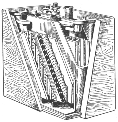
Fig. 1,129.—Interior view Northwestern storage battery. The positive plate is of double grid construction, and the negative plate consists of a special staggered grid. The separators used between the plates are hard rubber, ribbed on one side so as to prevent the positive plate from buckling. It is perforated so as to allow a free circulation of the electrolyte and to decrease the internal resistance. Rubber separators are better than the commonly used wood or paper separators because they prevent local action. The flat side of each separator is placed against a positive plate, preventing shedding or jolting of the active material of the plate. This checks deterioration. The jars are made of rubber composition; the walls are thick and the covers well fitted to avoid spilling the electrolyte. All Northwestern batteries are contained in rubber composition jars. The walls are thick and the covers fit tightly to prevent spilling the acid. A hard wood box, treated with a moisture repellant is used for the outer case. These batteries are made in any voltage desired, the ampere capacity ranging from 25 amp. hrs. to 300 amp. hrs.
Ans. When a battery is being overhauled, the cells must be connected together in series and to the charging source in 931 relatively the same manner as if they were in the vehicle; that is, the positive (+) terminal of one group of cells must be connected to the negative (-) terminal of the next group, and the two free terminals, one positive and the other negative, must be connected respectively to the positive and negative terminals of the charging circuit, but not until all of the groups have been connected in series. Great care must always be taken to have the polarities correct and the wire or cable for the connections of ample size to carry, without heating, the heaviest current used in charging.
Charging Small Cells.—For cells of the portable type, having capacities from 10 to 100 ampere hours, the normal charging and discharging rate should be about one-tenth the stated capacity, but the discharging rate may be increased to double this value, in case of necessity.
If the cells be provided with formed plates and not charged, the jars should be filled with the proper electrolyte, and then charged for at least 10 hours steady, or until they boil, then they may be discharged.
In the case of unformed plates, the charging should be from 30 to 40 hours, until the cells boil, and the plates assume their proper color.
Ques. How are small cells easily charged from 110 or 220 volt circuits?
Ans. This may be conveniently done by inserting in one of the charging leads an incandescent lamp which will pass the required quantity of current. If the current required be as large as 10 amperes, a suitable resistance or 10 lamps in parallel, each passing one ampere, may be used. Great care should be taken to see that the battery is connected properly. 932
Period of Charging a New Battery.—In the case of batteries provided with formed plates, the first charge should extend over a period of not less than 30 consecutive hours, without stopping, if possible, or for periods of not less than 10 hours a day for three consecutive days. The electrolyte will then commence to "boil" or "gas," assuming a milky appearance due to the ascending bubbles of gas. At this stage the density of the electrolyte as shown by the hydrometer placed in each cell should be at least 1.200; it is essential that the charging should be continued until every cell boils equally. From this point the charging should be prolonged until the pressure, as determined by a voltmeter or a cadmium tester, rises to about 2.55 volts.
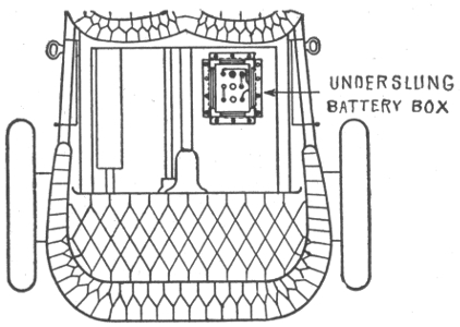
Fig. 1,130.—The Willard underslung battery box for automobiles. The general tendency in automobile design, is to keep everything off the running board as far as possible, and to get tool boxes, battery boxes, etc., placed somewhere under cover. To meet these conditions the box here illustrated is arranged so that it can be underslung beneath the rear footboard or supported on auxiliary cross members made of strap iron and attached to the side members of the chassis. It is usually suspended under the rear footboard or the rear seat. The box has a chemically treated wood lining to make it acid proof. The lining is so made that there is air space between the battery and the sides of the box, except at the corners. Ventilation is thus obtained and the battery kept dry. Accumulation of water or spilled electrolyte in the bottom of the box is prevented by grooves in the bottom board, extending downward from the corners to an outlet at the center of the board. The box is also fitted with rubber bushings in the holes where wire leaves the battery box.
933
The charging of unformed plates is similar in all respects to that of formed plates, except that the first charging should extend over a period of at least 70 consecutive hours without stopping, at the end of which time the plates should have the characteristic colors of those of a fully charged battery. If they do not, the charging should be prolonged and the cell tested for density of electrolyte, and voltage, as already described until the desired conditions are attained. Then the battery may be discharged and recharged.
It is probable that a total of 300 to 400 hours of charging with intervening discharges will be required to form the plates until they acquire a good color, and the density of the electrolyte becomes stable.
In regular charging, the rate should be rapid when the battery is nearly exhausted, but it should be greatly reduced at the end of the charge after passing the point of boiling. Charging at too low a rate is always injurious.
Ques. What may be said with respect to the capacity of a new battery?
Ans. A new battery will never give its full capacity till after about twenty discharges. During this time it should be given about 25% overcharge. After that, 10% overcharge, that is, 10% more charge than was taken out, will be sufficient for ordinary work.
High Charging Rates.—Occasionally it is desirable to charge a battery as quickly as possible. As a general rule, such a procedure should not be adopted unless the battery be thoroughly discharged, and not then, unless done by a person who thoroughly understands what he is about; battery makers will always furnish data and directions to meet emergencies.
In charging a battery at a high rate, the danger to be avoided is the tendency of the cells to heat. The troubles that might arise from this cause may be prevented by immediately reducing the current strength. The proper rate of charge for a given battery of cells may be thus discovered by experiment. A battery should never be charged at a high 934 rate unless it be completely exhausted, since it is a fact that the rate of charge that it will absorb is dependent upon the amount of energy already absorbed.
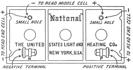
Fig. 1,131.—Instructions for taking voltage readings ("National" batteries). The batteries are made up of several cells, usually two or three, each cell representing approximately 2 volts when battery is on "open circuit" (neither charging nor discharging). It is sometimes advisable to take individual readings of the cells, both to determine on charge if all the cells be evenly charged, and also on discharge to be sure that the cells are evenly discharged. To do this, a low-reading voltmeter must be used with prods attached to the voltmeter leads that can be forced into the terminals so as to insure good contacts. To test the positive end cell, put the positive prod on the positive terminal of the battery and the negative prod into small hole back of positive terminal in hard rubber cover. Middle cell (in 6 volt, type "Y" batteries) is tested by inserting the positive prod in the small hole back of the positive terminal, and the negative prod in small hole back of negative terminal. In the 120 ampere hour, Auto type of battery, the middle cell is tested by inserting the positive prod in the small hole back of the positive terminal and the negative prod on the middle terminal. The negative end cell is tested by putting the negative prod on the negative terminal and the positive in the small hole in rubber cover back of the negative terminal. A charging cell at end of charge should read about 2.55 volts. A fully charged cell on open circuit should read about 2.1 volts. Since open circuit readings vary under different conditions, as to age, acid, etc., little significance should be attached to them. A discharged cell voltage will vary considerably with the many different coils, engines, etc., but in the majority of cases should read between 1.8 to 1.9 volts, while motor is in operation.
For rapid charging, when a battery has to be charged in four hours, the current should vary about as follows:
| 40 | per | cent. | of | total | 1st | hour |
| 25 | " | " | " | " | 2nd | " |
| 20 | " | " | " | " | 3rd | " |
| 15 | " | " | " | " | 4th | " |
For quick charging in three hours the rates should be: 50 per cent. 1st hour; 331/3 per cent. 2nd hour; 162/3 per cent. 3rd hour.
935
Mercury Arc Rectifier.—This is a device for obtaining direct current from alternating current for use in charging storage batteries. The transformation is obtained at a low cost, because the regulation is obtained from the alternating side of the rectifier, while the current comes from the direct current side.

Figs. 1,132 to 1,134.—Mercury arc rectifier outfit, or charging set. The cuts show front, rear, and side views of the rectifier, illustrating the arrangement on a panel, of the rectifier tube with its connection and operating devices.
The theory is as follows: In an exhaust tube having one or more mercury electrodes, ionized vapor is supplied by the negative electrode or cathode, when the latter is in a state of "excitation." This condition of excitation can be kept up only as long as there is current flowing toward the negative electrode.
If the direction of the voltage be reversed, so that the formerly negative electrode is now positive, the current ceases to flow, since in order to flow in the opposite direction it would require the formation of a new negative electrode, which can be accomplished only by special means. Therefore, the current is always flowing toward one electrode—the cathode, which is kept excited by the current itself. Such a tube would cease to operate on 936 alternating current voltage after half a cycle if some means were not provided to maintain a flow of current continuously towards the negative electrode.
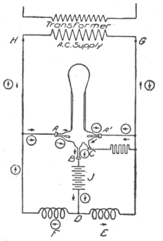
Fig. 1,135.—Elementary diagram of mercury arc rectifier connections. A, A´, graphite anodes; B, mercury cathode; C, small starting electrode; D, battery connection; E, and F reactance coils; G and H, transformer terminals; J, battery.
Ques. Describe the construction and operation of a mercury arc rectifier.
Ans. Fig. 1,135 is an elementary diagram of connections. The rectifier tube in an exhausted glass vessel in which are two graphite anodes A, A´, and one mercury cathode B. The small starting electrode C is connected to one side of the alternating circuit, through resistance; and by rocking the tube a slight arc is formed, which starts the operation of the rectifier tube. At 937 the instant the terminal H of the supply transformer is positive, the anode A is then positive, and the arc is free to flow between A and B. Following the direction of the arrow still further, the current passes through the battery J, through one-half of the main reactance coil E, and back to the negative terminal G of the transformer. When the impressed voltage falls below a value sufficient to maintain the arc against the reverse voltage of the arc and load, the reactance E, which heretofore has been charging, now discharges, the discharge current being in the same direction as formerly. This serves to maintain the arc in the rectifier tube until the voltage of the supply has passed through zero, reversed, and built up such a value as to cause the anode A to have a sufficiently positive value to start the arc between it and the cathode B. The discharge circuit of the reactance coil E is now through the arc A'B instead of through its former circuit. Consequently the arc A'B is now supplied with current, partly from the transformer, and partly from the reactance coil E. The new circuit from the transformer is indicated by the arrows enclosed in circles.
Ques. How is a mercury arc rectifier started?
Ans. A rectifier outfit with its starting devices, etc., is shown in figs. 1,132 to 1,134. To start the rectifier, close in order named line switch and circuit breaker; hold the starting switch in opposite position from normal; rock the tube gently by rectifier shaker. When the tube starts, as shown by greenish blue light, release starting switch and see that it goes back to normal position. Adjust the charging current by means of fine regulation switch on the left; or, if not sufficient, by one button of coarse regulation switch on the right. The regulating switch may have to be adjusted occasionally during charge, if it be desired to maintain the charging current approximately constant. 938
Capacity.—The unit of capacity of a storage cell is the ampere hour, that is, the ability to discharge one ampere continuously for one hour. For instance, a 100 ampere hour battery will give a continuous discharge of 12½ amperes for eight hours. It should theoretically give a discharge of 25 amperes continuously for four hours, or 50 amperes for two hours, but in reality, the ampere hour capacity decreases with an increase of discharge rate.
It requires, theoretically .135 ounces of metallic lead on either element reduced to sponge lead or to lead peroxide to produce one ampere hour; in practice, from four to six times this amount is required.
The reason for this is because it is impossible to reduce all the active material, to bring every particle in contact with the electrolyte, or to cause every part to be penetrated by the current.
Experiments show that from .5 to .8 ounces of sponge lead, and from .53 to .86 ounces of metallic lead converted into peroxide, are required on their respective elements to produce a discharge of one ampere hour at ordinary commercial rates.
The capacity increases with the temperature, being about one per cent. for each degree Fahr. increase in temperature.
Battery capacity depends on the size and number of plates; the quantity of active material present, and the quantity of electrolyte.
For an eight hour rate of discharge and 60 degrees temperature, the capacity of American batteries varies from 40 to 60 ampere hours per square foot of positive plate surface ( = 2 × number of positive plates in parallel × length × breadth).
The following table gives the variation of capacity for different rates of discharge: 939
| Discharge rate | Per cent of capacity at 8 hour rate |
|
|---|---|---|
| Plante | Faure | |
| 8 hour | 100% | 100% |
| 6 hour | 96% | 96% |
| 4 hour | 80% | 88% |
| 2 hour | 61% | 70% |
| 1 hour | 56% | 48% |
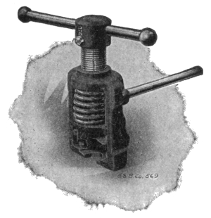
Fig. 1,136.—"Exide" connector puller for removing connectors.
Ques. How may the capacity of a battery be increased?
Ans. By mixing organic materials with the lead oxide, but any such mixture is always accompanied by a rapid deterioration of the plates.
Discharging.—In discharging a battery its voltage should never be allowed to fall below 1.8 volts, under load, thus leaving about 30 per cent. of the total capacity unused. The normal discharging current may be equal to the normal charging current, but a discharge equal to 3 or 4 times the normal may be given 940 941 without injury to the plates. Some types may be discharged at even six or seven times the normal rate. In such cases, however, the capacity will be reduced in the same proportion, as before explained in the paragraph dealing with battery capacities.
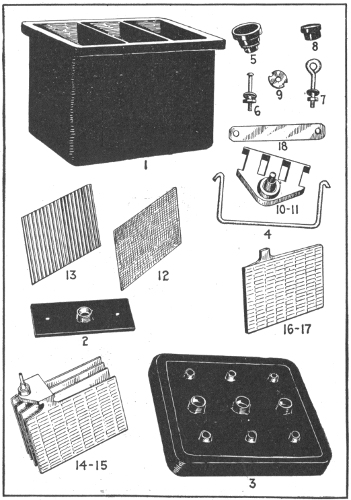
Figs. 1,137 to 1,151.—Parts of the Witherbee battery. 1, jar; 2, inside cover; 3, cover; 4, handle; 5, vent cap; 6, cover, screws, nuts and washers; 7, handle eyes, nuts and washers; 8, rubber covered nut; 9, spannernut; 10, plate strap for positive plates; 11, plate strap for negative plates; 12, rubber separator; 13, wood separator; 14, positive group of plates; 15, negative group of plates; 16, positive plate; 17, negative plate; 18, cell connector. An element consists of a complete set of plates bound together on strap, with wood and rubber separators for a single cell. Positive plates are brown, negative plates, gray.
Ques. What is the effect of discharging too rapidly?
Ans. It tends to break the plates, and in the case of pasted plates, a very sudden discharge will dislodge the paste.
Ques. How is the discharge capacity of a storage battery stated?
Ans. In ampere hours. This, unless otherwise specified, refers to its output of current at the eight hour rate. Most manufacturers of automobile batteries specify only the amperage of the discharge at three and four hours. Thus, at the eight hour rate, a cell which will discharge at ten amperes for eight hours is said to have a capacity of eighty ampere hours. It does not follow that eighty amperes would be secured if the cell were discharged in one hour. It is safe to say that not more than forty amperes would be the result with this rapid discharge.
As a general rule, the one hour discharge rate is four times that of the normal, or eight hour discharge, and considerations of economy and prudence suggest that it should never be exceeded, if, indeed, it ever be employed. The three hour discharge, which is normally twice that of the eight hour, is usually the highest that is prudent, while the four hour discharge is the one most often employed in vehicles for the average high speed riding.
Ques. What should be the maximum rate of discharge?
Ans. The one-hour rate; this when used, should not extend over fifteen or twenty minutes. In the case of regulating batteries a forty-five minute rate of discharge may be allowed for one or two minutes during great fluctuations of load. 942
Ques. How does the capacity decrease?
Ans. It decreases with the increase in current output.
An 80 ampere hour cell, capable of delivering 10 amperes for 8 hours, would, when discharged at 14 amperes, have a capacity of 70 ampere hours; when discharged at 20, its capacity would be 60; and when discharged at 40, its capacity will have decreased from 80 to 40 ampere hours.
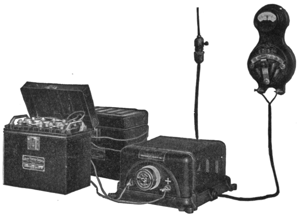
Fig. 1,152.—The Edison alternating current rectifier. It consists of an electro-mechanically operated valve which allows current waves of only one polarity to pass through it from the alternating current circuit to the battery which is to be charged. An indicating snap switch of the usual form controls the starting and stopping of the charging current. The rectifier gives any desired charging rate within its capacity. The illustration shows the rectifier connected up and charging an ignition battery of five Edison cells. The connections consist of the usual connecting cord and plug and a charging lead running from the plus side of the charging terminals on the rectifier to the plus pole of the battery, and another lead connecting the negative terminals as shown. In turning the snap switch to the "on" position, the proper charging current will flow into the battery. When charging is completed, the switch is turned to the "off" position and the battery leads disconnected.
Ques. What, in general, are the indications of the quantity of electricity remaining within a cell?
Ans. The voltage, and the density of the electrolyte. 943
Ques. What should be done after discharging?
Ans. Whenever possible the battery should be immediately charged.
The Battery Room.—Precautions should be taken to prevent any direct sunlight falling on the battery cells in glass jars, as the breakage of such jars due to unequal expansion of the different portions of the glass, is a source of constant trouble and danger.
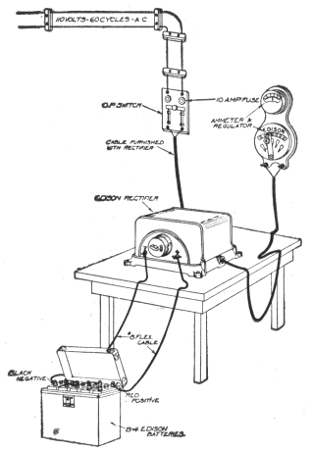
Fig. 1,153.—Permanent connections for Edison rectifier. As shown, the rectifier is connected to a small switch and cutout.
The exclusion of direct sunlight also tends to keep the evaporation of the electrolyte at a minimum. 944
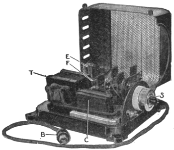
Fig. 1,154.—Edison Alternating Current rectifier; view with cover open showing parts. B, primary circuit cord; C, condenser; E, primary relay; F, secondary switch; S, alternating circuit switch; T, transformer.
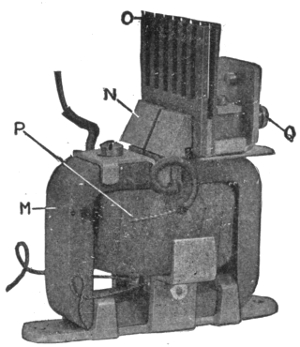
Fig. 1,155.—Vibrating unit of Edison alternating current rectifier. M, permanent magnet; N, carbon vibrating contact; O, comb radiator; P, primary circuit coil; Q, vibrator adjustment screw.
945
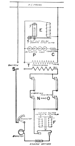
Fig. 1,156.—Elementary diagram of connections.
Operation of Edison Rectifier
The operation of the Edison rectifier may be explained as follows with the aid of figs. 1,154 to 1,156 (the parts being uniformly lettered in the figures): The primary circuit taken from the alternating current mains by the cord B, embraces the primary winding of the transformer T, a condenser C, and the coils P, of the vibrating units, fig. 1,155.
The secondary circuit from the transformer embraces the massive carbon and copper contacts (N and O, fig. 1,156) which pass only the positive waves of the alternating current, for charging batteries or other duty.
An ammeter and rheostat may be placed in this charging circuit if the current is to be varied, or a fixed connection may be substituted on the base of the rectifier if it is to be used for the maximum duty of 8 or 16 amperes.
The vibrating unit (fig. 1,155), which operates in a manner similar to the well known action of a polarized relay, includes a permanent magnet M; the coil in the primary circuit P; the vibrating armature of steel with removable carbon contact N; the stationary copper contact with comb top for heat radiation O, and the screw Q for adjusting the amplitude of the armature vibration.
The vibrating armature of each unit is divided into two parts, which gives flexibility, affords increased current capacity and minimizes sparking, the two leads shown being connected together in one circuit.
A primary relay and a secondary switch (E and F, figs. 1,154 and 1,156), close their contacts when current is flowing.
Upon failure of the main alternating current line they operate to open the charging circuit. A storage battery is thus prevented discharging through the rectifier.
Upon resumption of the main alternating current, the rectifier starts automatically.
946
Every battery room should be provided with a water tap and sink. The floor should be paved with vitrified brick, preferably blue or yellow in color, of diamond pattern and sloping in all directions toward suitable drains. A floor of this type can be easily washed by flooding with water, and its patterns tend to keep it dry under foot at all times. Wooden floors are rotted very quickly by acid spillings and by the spray.
The room should be kept absolutely clear of everything, which may be injured, by the sulphuric acid fumes and it should be well ventilated to insure the safety and good health of the attendants.
A battery, even at rest, gives off hydrogen which when diluted with air forms a mixture which is very liable to explode if brought in contact with any kind of flame. Unless proper ventilation be provided, the breaking of the connection when a current is flowing, or the lighting of a bare flame lamp in the battery room would be dangerous.
Battery Attendants and Workmen.—Those employed in setting up batteries are liable to suffer from soreness of hands and the destruction of clothing unless proper precautions be taken to prevent the same. In order to avoid these troubles, the boots should be painted with paraffine mixed with an equal quantity of beeswax.
The clothing should be of woolen material, which, unlike cotton, is practically unaffected by the acid. If cotton shirts be worn, they should be dipped in a strong solution of washing soda and then rough dried.
An apron of sacking, backed with flannel should be worn over all the other clothes. A bottle of strong ammonia should be 947 kept in the battery room at all times, and in case of an accidental splash of acid on the clothes, the immediate application of a small quantity of the ammonia, by means of the stopper, will at once neutralize the acid and prevent it burning a hole in the material. A pail containing water made strongly alkaline with washing soda should also be kept conveniently at hand during all operations in the battery room. The hands should be dipped occasionally in this water in order to prevent the skin smarting and becoming sore under the action of the acid.
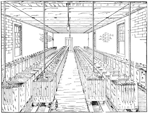
Fig. 1,157.—Interior of storage battery room showing arrangement of cells. A, are the cell insulators; B, wooden stringers; C, supporting pieces.
If a splash of acid should happen to enter the eye, it should be washed at once with clean water, warm water preferably, and then put one or two drops of olive oil into the eye. If olive oil be not immediately available, any kind of engine oil is better than none at all.
948
Points on Care and Management.—In setting up storage cells, they should be placed in as few tiers as possible, and in such a manner that the direct rays of the sun are not allowed to fall upon the cells. The rays of the sun are likely to crack the glass. This is probably due to the unequal expansion of the glass, for it has been found that jars which are carefully annealed never crack in this manner. Of course, the latter precaution does not apply to large batteries, where lead lined wooden tanks or solid lead boxes are used.
In installing plants where expert attendance is not to be had, it is well to place in the circuit two magnetic cut outs, one set for maximum current, and the other for minimum voltage, so that the battery cannot be discharged too low.
Ques. How should the cells be placed?
Ans. They should be placed as shown in fig. 1,151, on insulators A, resting on wooden stringers B, and supporting pieces C placed on the floor. The insulators are usually of glass or porcelain, which in certain patterns may be filled with oil, to insure better insulation as shown in figs. 1,165 and 1,166.
In setting up a battery, it should be remembered that plates deteriorate on standing exposed to the air. They should, therefore, be unpacked and set up immediately on arrival. When they are entirely connected up, they are ready for the addition of the electrolyte, and for the forming charge, which they should receive immediately.
Ques. How should the wooden stringers, shelves, cell boards, and trays be treated?
Ans. They should be thoroughly varnished to insure cleanliness as well as good insulation.
Outside of each cell and close to the mouth, melted paraffine should be applied by means of a brush, so as to form a band about an inch wide, for the purpose of preventing the electrolyte creeping over the top of the jar, wetting the outside, and thereby impairing the insulation.
949
Ques. What should be done to avoid waste of current by leakage?
Ans. Each cell of the battery must be thoroughly insulated.
Ques. What is the effect of verdigris which forms on the terminals?
Ans. It is a poor conductor and should therefore be removed and the terminals kept bright and clean to insure the proper flow of the current.
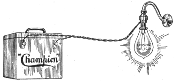
Fig. 1,158.—Charging "Champion" battery with charging plug. Where direct lighting current is available, recharging may be done by means of the charging plug. First insert the plug in a regular socket. Then screw a 50 c.p. lamp into the plug and turn on. To tell the positive from the negative, lay both wires on a small piece of red litmus or test paper moistened. The negative wire makes a mark on the paper. This wire must go to the negative post of battery. This will fully charge the "6-25-G" battery in 15 to 20 hours.
Ques. What precautions should be taken in unpacking cells?
Ans. The plates should be handled carefully. When they are sent out from the factory already built into sections, they 950 should be unpacked without disturbing a single plate. In all cases, every particle of packing, straw, hay and any chips and bits of parts should be carefully removed, and all the dust should be blown out of the spaces between the plates by means of a bellows or other similar device.
NOTE.—Champion directions for repairs. To replace broken jars in a battery remove the lid and lift out elements bodily. Empty the good jars with a syringe or by tilting the battery over. Never put the acid in any vessel except glass, stone or lead. Put new jars in place same as others and run melted paraffine around the edges. The wax must be broken off the elements that are to go into new jars and be poured on again. Fill the jars with acid to ¾" from tops. Melt the broken wax in a tin ladle and pour over the acid about ½" thick. Do not fill with wax to tops of jars. When the wax gets cold it will be found to have shrunk away from the edges of the jars. Fill up the opening with a little melted paraffine wax by means of a squirt can. Cut a small hole in the middle of the wax seal for a vent. Smear the brass posts and terminals and inside of case with vaseline to prevent creeping of the acid. The "6-25-G" requires one-half gallon of acid and the "6-50-G" one gallon.
Although such particles are good non-conductors, the action of the sulphuric acid electrolyte carbonizes them, giving them conducting properties which tend to produce leakage.
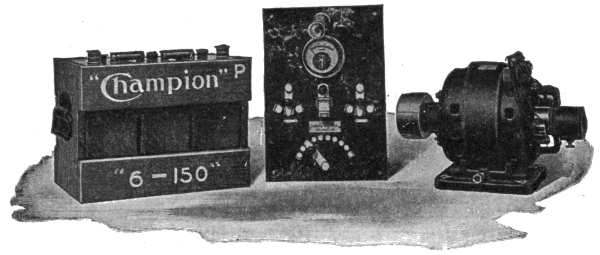
Figs. 1,159 to 1,161.—"Champion" electric light equipment designed especially for use on launches, yachts, and country residences. The outfit consists of three essential parts: 1, a dynamo run by belt from main engine; 2, a storage battery, and 3, a switchboard to regulate, measure and control the current.
Ques. How should the cells be assembled?
Ans. In placing the plates or plate sections in the containing jars or tanks, care should be taken to see that the supporting frame of paraffined wood bears evenly on the bottom of the jar. If they do not, wedges of paraffined wood should be placed under the frame, so as to distribute the weight of the section equally. Each section should be lowered gently into the jar until it rests fairly upon the frame, and care should be taken to see that none of the plates have shifted, and that the section is situated centrally in the jar, with a small clear space all around. 951
Ques. How should the cells be arranged?
Ans. They should be so placed that the battery attendant can see the edges of the plates and consequently the spaces between them at the same time.
Ques. Describe the method of connecting the cells.
Ans. This is accomplished by means of solder, bolts and nuts, or clamps, according to circumstances. The use of solder is not essential if there be a good surface of the lead strip of one cell in contact with that of the next, and provided these contact surfaces have been well cleaned. Usually, the ends of the lead strips are turned up so that the junction of two cells takes the form of an inverted T as shown in fig. 1,162.
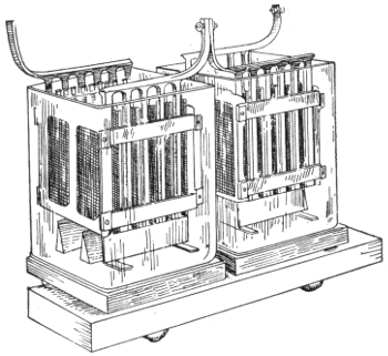
Fig. 1,162.—Two storage cells; view showing the inverted T form of connection.
Ques. What precaution should be taken in joining the terminals of the cells?
Ans. The contact at the junctions should be very thorough, otherwise they will become heated when a current is flowing, and 952 it is desirable that the connections should include as little lead strip in the circuit as possible, thereby reducing the amount of useless resistance.
Brass or gun metal clamps may be kept clean by brushing them over with melted paraffin after they have been screwed up tightly. When thus treated they serve to indicate points of bad contact by heat, generated at such points, when the current is flowing, softening the paraffin and changing its normal color. Vaseline and different kinds of anti-sulphuric acid varnishes, or preparations that are not attacked by the electrolyte, may also be used for this purpose. It is a good plan to color the varnish with vermillion or lamp black and paint the positive connections red and the negative connections black, and also other parts of the installation for distinguishing the polarities.
Cell Connections.—The cells may be connected together either in series or parallel, or in parallel-series or series-parallel combinations, according to the requirements, but in all cases it is best to use the simplest arrangement practicable.
For instance: if the cells employed in an installation requiring 110 volts, have only half the capacity required, and 55 cells give the desired voltage, then the number of cells must be increased to 110, and theoretically the required number of amperes hours at 110 volts may be obtained in one of two ways: 1, by connecting the cells in pairs in parallel and then coupling the pairs together in series, and 2, by arranging the 110 cells in two complete batteries of 55 cells each connected in series, then coupling the two batteries in parallel.
The first method is quite impracticable, however, as the slightest difference between the voltages of the two cells of any pair will result 953 in the one having the greater pressure discharging into the other, thereby causing the entire battery to quickly deteriorate.
NOTE.—To determine the positive wire. Without a voltmeter, the positive terminal of the charging circuit can be determined by attaching a piece of clean lead to each wire which is to be connected to the battery, and immersing them, without touching each other, in a glass or other insulating vessel containing water to which is added a drop or two of sulphuric acid. After the current has passed through the circuit for a short time, the positive lead will commence to discolor, and, if left long enough, will turn brown. Bubbles will arise from the two terminals immersed, the larger and more frequent ones being from the negative, the smaller ones from the positive.
NOTE.—Method of disconnecting "National" cells. There are two methods of disconnecting the cells employing link connectors. First a ⅝ inch bit or twist drill may be used, boring down into the top of the posts about ¼ inch. The link will then be loosened and can be removed. This leaves the link, as well as the post, in good condition for reburning. Second the link may be cut in the center. A flame should be played on the top of the post, at the same time grasping the end of the half link firmly with pliers. When the connection has become warmed (care being taken not to melt the lead) the half link can be twisted loose from the port. New links may be used if desired in re-assembling the cells. It is not necessary to remove the covers from the element, the links may be cut in the center and the plates removed from the jars without removing the links from the ports. The links can be afterwards reburned together in the center. When the cells are equipped with "T" or "L" straps, they should be cut apart with hack saw or chisel midway between the cells, and in re-assembling, burned together at this point.
Battery Troubles.—To successfully cope with faults in storage batteries, there are two requisites: 1, a thorough knowledge of the construction and principle of operation of the battery, and 2, a well ordered procedure in looking for the source of trouble. The faults which are usually encountered by those who operate storage batteries are here given.
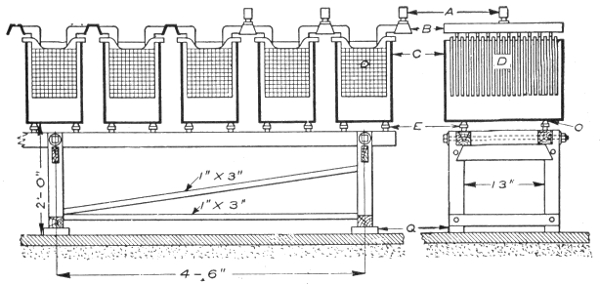
Fig. 1,163.—Arrangement of battery cells and stand. A, cable lugs; B, bus bars; C, glass tanks; D, plate; E, glass insulators; Q, vitrified brick; O, lead washers. Battery cells are set up on stands; the one shown being built for a 100 ampere battery. Larger sizes would, of course, require heavier stands, and if space be limited, the cells may be set in rows, one above the other. However, it is evidently much better to place the cells in single rows, where they will be convenient for inspection and repairs or any work that has to be done on them. There are several other ways of setting a battery, one of which is to place the stringers on the floor, on vitrified brick or some other insulator, and then place trays filled with sand on the stringers, setting the cells in the trays on glass insulators. The battery room should be dry, clean, well ventilated and free from metal work, also neither too hot nor too cold. Too high a temperature in the battery will shorten the life of the plates, and although there is no danger of the battery freezing, a low temperature, while it is maintained, reduces the capacity; otherwise cold has no ill effect on the battery. A good temperature for the battery room is about 60° F. A damp, dirty room is conductive to grounds and surface leakage, and there is danger of impurities getting into the cells. If the room be very damp the electrolyte may absorb enough moisture to cause the cells to overflow. Strong floors are necessary to support a battery, as one of a 100 ampere, 125 volt capacity weighs from 12 to 13 tons. A wood floor may be used, but a cement floor is better, and a glazed vitrified brick floor is better still. Wooden floors will rot quickly from the acid, which is sure to get onto it more or less; a cement floor will be disintegrated if too much acid get onto it. This kind of floor forms a first class ground if there be any chance for one; the glazed brick floor is not affected by the acid and is an insulator.
954
Short Circuiting.—A form of derangement that may occasionally affect storage batteries is short circuiting. It may be caused by some of the active material—if the cell be of the pasted variety—scaling off and dropping between the plates, or by an over collection of sediment in the bottom of the cell.
Should the operator suspect trouble with his battery he may discover a short circuited cell by the marked difference in color of the plates or of the specific gravity of the electrolyte, as compared with the other cells. No particular damage will be caused, if the trouble be discovered and removed before these symptoms become too marked.
If a foreign substance has become lodged between the plates, it may be removed by a wood or glass instrument.
If some of the active material has scaled off, it may be forced down to the bottom of the jar. If excessive sediment be found, the jar and plates should be washed carefully, and reassembled.
A cell that has been short circuited may be disconnected from the battery and charged and discharged several times separately which may remedy the trouble.
Ques. How are internal short circuits indicated?
Ans. Short circuits in a cell are indicated by short capacity, low voltage and low specific gravity, excessive heating and evaporation of the electrolyte.
Ques. How are internal short circuits located?
Ans. If the trouble cannot be located by the eye, the battery should be connected in series and discharged at the normal rate through suitable resistance. If a suitable rheostat be not available, a water resistance may be used.
This consists of a receptacle (which must not be of metal) filled with very weak acid solution, or with salt water in which are suspended two metal plates, which are connected by wires through an ammeter. The current may be regulated by altering the distance between the plates, or by varying the strength of the solution. As the discharge progresses the voltage will gradually decrease, and it should be frequently read at 955 the battery terminals; as soon as it shows a sudden drop, the voltage of each cell should be read with a low reading voltmeter.
While the readings are being taken, the discharge rate should be kept constant and the discharge continued until the majority of the cells read 1.70 volts; those reading less should be noted. The discharge should be followed by a charge until the cells which read 1.70 volts are up, then the low cells should be cut out, examined, and the trouble remedied.
Overdischarge: Buckling.—On account of unequal expansion of the two sides of a plate, or certain portions thereof, the strains thus set up may distort it and cause it to assume a buckled shape, that is, bent so one side is concave.
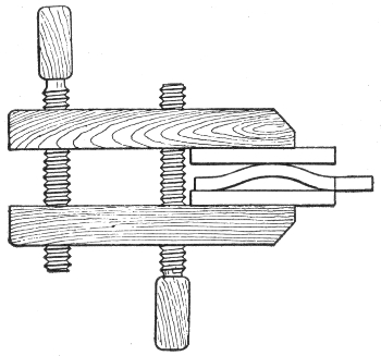
Fig. 1,164.—Method of straightening a buckled plate. Buckling is caused by the unequal expansion of the plates which is due to the sulphate lodging on the plates, thus preventing action taking place at that point; and by excessive charging. If the plates be not badly buckled, they can be placed between 2 boards and with a little pressure, can be straightened out.
Buckling is due always to over discharge on either the whole, or some portion of the plate. Occasional buckling may occur with too rapid charge and discharge.
Sulphation of Plates.—During discharge a storage cell deteriorates on account of the formation of lead sulphate over the surface of the plates. This lead sulphate is the product of the 956 chemical combination of active material with the electrolyte. It is a non-conductor, white in color and of greater volume, in proportion than the active material. When the discharge is over prolonged, sulphation is evidenced by the electrodes becoming lighter in color, because of the sulphate which lessens the active surface.
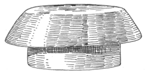
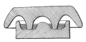
Figs. 1,165 and 1,166.—Oil Insulator; fig. 1,165, general view; fig. 1,166, sectional view. Whenever a number of open cells are in use, unless precautions be taken, electrical leakage between the cells invariably occurs. This leakage is due chiefly to the semi-conducting nature of the thin layer of moisture which frequently covers not only the glass containing cells, but the unimmersed parts of the elements, and even the shelves on which the cells rest. To prevent this waste of energy, the outside of the cells should occasionally be well cleaned and thoroughly dried. A little vaseline or tallow may then be rubbed over them to advantage. The shelves or supports for the cells, should either be well varnished or coated with paraffin wax. Electrical leakage is greatly reduced if each cell be mounted on a glass or earthenware insulator, as shown in the illustrations. The insulator here shown is in two parts and of a mushroom shape. The lower cup contains a small quantity of some non-evaporating oil, and as the conducted moisture cannot bridge across this, a nearly perfect insulating medium is obtained. These insulators are made in various sizes and may be obtained in earthenware or glass. Those made of glass are found to give the best results.
Ques. Name some causes of sulphation.
Ans. It is sometimes caused by a too weak or too strong acid solution, but more generally by continued over discharging, or too rapid discharging of the batteries, or by allowing them to remain uncharged for long periods of time.
Ques. What is the effect of sulphation?
Ans. It tends to cause shedding of the active material, buckling of plates, loss of capacity, increase of resistance and consequent reduction of efficiency, and increase of temperature with 957 flow of current. A sufficient amount of lead peroxide and sponge lead must be retained on the plates to reduce this resistance, otherwise the charging current cannot flow through the active material and regenerate the battery.
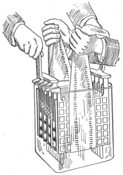
Fig. 1,167.—Illustrating method of placing plates in glass jars.
Ques. What should be done in case of sulphation?
Ans. Charge the battery below the maximum rate, necessarily prolonging the charge, until the plates assume the proper color. This is a tedious task, but it must not be hastened, as rapid charging will cause serious buckling.
NOTE.—How to destroy acid vapor in storage battery rooms: The best remedy is a good system of thorough and rapid ventilation; failing this the evil effect of the acid may be minimized by the fumes of a powerful alkali such as ammonia, which will readily combine with the sulphuric acid to form sulphate of ammonia, an inert and harmless salt. If the use of liquid ammonia be objectionable, the granulated carbonate of ammonia will do equally well. The ammonia fumes are best obtained by placing dilute ammonia in shallow dishes, so that an extensive evaporating surface is obtained. In the same way the corroding dew which is so frequently deposited on the lugs and connectors of storage battery elements may readily be neutralized by the application of a solution of ammonia, or even common washing soda. A good method of protecting metal work in battery rooms is to smear it over evenly with vaseline.
958
The charging should be done at low rates. Discharge should not be carried below 1.8 volts per cell, and the charging current should be stopped when each cell shows 2.4 volts.
If the plates be in a very bad condition, a little of the white sulphate deposit on each of the positive plates may be removed with a stick, thus exposing a part of the good surface to the action of the electrolyte.
If the positive plates cannot be restored to their proper color as directed, it is cheaper to replace them by a new set, rather than to attempt their recovery by means of reversals.
| Number of Plates per cell | 5 | 7 | 9 | 11 | |
|---|---|---|---|---|---|
| Discharge in amperes | {for 4 hours | 12 | 18 | 24 | 30 |
| {for 5 hours | 10¼ | 15¼ | 20½ | 25½ | |
| {for 6 hours | 9¼ | 13¾ | 18½ | 23 | |
| Ampere hour capacity | {at 4 hour rate | 48 | 72 | 96 | 120 |
| {at 5 hour rate | 51 | 76 | 102 | 127 | |
| {at 6 hour rate | 55 | 83 | 110 | 138 | |
| Outside measurements of rubber jar, in inches | {Length | 1⅞ | 2⅝ | 3⅜ | 43/16 |
| {Width | 55/16 | 55/16 | 55/16 | 55/16 | |
| {Height | 11¾ | 11¾ | 11¾ | 11¾ | |
| Weight of cell complete, in lbs | 14¼ | 19¼ | 24¼ | 29¾ | |
| Weight of electrolyte, in lbs | 1 | 2 | 3½ | 5 | |
Lack of Capacity.—This is usually due to the clogging of the pores in the plate with sulphate which is invisible because the surface of the plate is maintained in proper condition but the 959 interior portions of the active material have not been thoroughly reduced. To correct this condition, the battery should be given a prolonged overcharge at low current rates, say about one fourth the normal 8 hour charging rate.
NOTE.—Oxide of lead, litharge, or plumbic oxide is sometimes found native as lead ochre, and may be artificially made by heating the carbonate or nitrate. It is usually prepared on a larger scale by heating the lead in air. When the metal is only moderately heated, the oxide forms a yellow powder which is known as massicot, but at a higher temperature the oxide melts, and on cooling, it forms a brownish scaly mass, which is called flake litharge. The scaly pieces are afterwards ground between stones under water, forming buff or levegated litharge. The litharge of commerce often has a reddish yellow color, due to the presence of some of the red oxide of lead, and frequently from one to three per cent. of finely divided metallic lead is found mixed with it. When heated to dull redness litharge assumes a dark brown color, and becomes yellow again on cooling. At a bright red heat it fuses and readily attacks clay crucibles, forming silicate of lead. Litharge is a most powerful base, and has a strong tendency to form basic salts. Hot solution of alkalies, as potash or soda, readily dissolve it, and on cooling, it crystalizes out in the form of beautiful pink crystals.
Falling off in the capacity may be caused by a dry cell, due to a leaking jar; some or all of the cells may be in a state of incomplete charge, due to the battery having been run too low and not sufficiently charged; or the plates may be short circuited, either by the sediment (deposit in the bottom of the jar) getting up to the bottom of the plates or by something that has fallen into the cell.
|
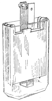
Fig. 1,168.—"American" cell. |
||||||||||||||||||||||||||||||||||||||||||||||||||||||||||||
Ques. What action takes place when a battery stands idle for some time?
Ans. It loses part of its charge, due to local losses in the cells.
Ques. How should batteries be treated, when used but occasionally?
Ans. If a battery is not to be used for several days, it should first be fully charged before standing; if it continue idle, a 960 freshening charge should be given every two weeks, continuing the charge when the cells begin to gas freely.
Ques. What should be done in case of lack of capacity?
Ans. If the current consumption be normal, there may be poor connections or trouble in the battery; there may be a dry cell, due to a leaking jar; some or all of the cells may be in a state of incomplete charge, due to the battery having been run too low and not sufficiently charged, or the plates may be short circuited, either by the sediment (deposit in the bottom of the jar) getting up to the bottom of the plates or by something that has fallen into the cell.
| Number of Plates | 7 | 9 | 11 | 13 | 15 | 17 | 19 | 21 | |
| Discharge in Amperes for 4 hours | 21 | 28 | 35 | 42 | 49 | 56 | 63 | 70 | |
| Outside Measurements Rubber Jars in inches. |
{Length | 2¾ | 3½ | 4¼ | 5 | 5¾ | 6½ | 7¼ | 8 |
| {Width | 6⅛ | 6⅛ | 6⅛ | 6⅛ | 6⅛ | 6⅛ | 6⅛ | 6⅛ | |
| {Height | 12⅜ | 12⅜ | 12⅜ | 12⅜ | 12⅜ | 12⅜ | 12⅜ | 12⅜ | |
| Weight in Pounds | {Element | 15¾ | 20¼ | 24¼ | 29¾ | 34 | 38½ | 43 | 47½ |
| {Electrolyte | 4½ | 5 | 5¾ | 6¼ | 7 | 7¾ | 8½ | 9¾ | |
| {Complete Cell | 22 | 28 | 34¼ | 40½ | 47 | 53¼ | 59½ | 66 | |
NOTE.—Peroxide of lead, pure oxide or plumbic dioxide is the true active material in all forms of lead storage cell. This lead salt is found native as the mineral plattnerite. It is a heavy lead ore, forming black, lustrous, six sided prisms. It may be prepared from the red oxide by boiling it in fine powder, with nitric acid diluted with five parts of water, or by treating the carbonate when suspended in water with a stream of chlorine gas, and then thoroughly washing and drying it. It is reduced to a lower oxide on heating or by exposure to bright sunlight. This salt readily imparts oxygen to other substances; it becomes heated to redness when thrown into sulphuric dioxide, and takes fire when triturated with sulphur—hence this oxide is a common ingredient in lucifer match composition. When used in primary or secondary batteries it readily imparts its oxygen to nascent hydrogen, forming water, and thus it acts as a powerful depolarizer. When robbed of its oxygen, it readily becomes reoxidized, if subjected to the action of nascent oxygen liberated by the electrolytic decomposition of water.
961
If the trouble cannot be located by the eye, connect the battery in series, and discharge it at the normal rate, through suitable resistance. If a suitable rheostat be not available, a water resistance may be used.
This consists of a receptacle (which must not be of metal) filled with very weak acid solution or salt water in which are suspended two metal plates, which are connected, by wires through an ammeter.
| Number of Plates | 7 | 9 | 11 | 13 | 15 | 17 | 19 | 21 | 23 | 25 | |
| Discharge in Amperes for 5 hours | 15¾ | 21 | 26¼ | 31½ | 36¾ | 42 | 47¼ | 52½ | 57¾ | 63 | |
| Outside Measurements Rubber Jars in in. | {Length | 129/32 | 27/16 | 331/32 | 3½ | 41/32 | 49/16 | 53/32 | 5⅜ | 65/32 | 611/16 |
| {Width | 6⅛ | 6⅛ | 6⅛ | 6⅛ | 6⅛ | 6⅛ | 6⅛ | 6⅛ | 6⅛ | 6⅛ | |
| {Height | 12⅜ | 12⅜ | 12⅜ | 12⅜ | 12⅜ | 12⅜ | 12⅜ | 12⅜ | 12⅜ | 12⅜ | |
| Weight in Pounds | {Element | 11½ | 14¾ | 18 | 21¼ | 24½ | 27¾ | 31 | 34¼ | 37¼ | 40½ |
| {Electrolyte | 2¼ | 2½ | 3 | 3¾ | 4¼ | 4¼ | 5½ | 6 | 6¾ | 7¼ | |
| {Comp. Cell | 15¾ | 20 | 24¼ | 28½ | 33¼ | 38 | 42 | 46¼ | 51½ | 56 | |
The current may be regulated by altering the distance between the plates or by varying the strength of the solution. As the discharge progresses, the voltage will gradually decrease and it should be frequently read at the battery terminals. When it shows a sudden drop, the voltage of each cell should be read with a low reading voltmeter.
While the readings are being taken, the discharge rate should be kept constant and the discharge continued until the majority of the cells read 1.70 volts; those reading less should be noted. The discharge should be followed by a charge until the cells which read 1.70 volts are up; then the low cells should be cut out, examined and the trouble remedied.
NOTE.—How to prevent lead poisoning. Workmen employed in the manufacture of lead or lead salts are always liable to lead poisoning, both by inhaling the dust and by contact of the materials with the hands. Various preventives for this have been employed, and of these, the most simple seems to be a careful washing of the hands in petroleum. It is said that three washings a day are sufficient to prevent all serious danger of poisoning. The benzole in the petroleum appears to scour the skin and remove the loose lead dust, and the fatty substance in the oil fills up the pores of the skin and prevents the absorption of the deleterious salts. The employment of petroleum has given such good results that it has been proposed to use this material as a guard against poisoning in other industries where the salts of copper or mercury are employed.
962
Ques. What causes low specific gravity when there are no short circuits?
Ans. 1, sloppage or a leaky jar (the loss having been replaced with water alone), 2, insufficient charge, 3, over discharge, or 4, a combination of these abuses. Any of these mean that there is acid in combination with the plates.
In this case the acid should be brought out into the electrolyte by a long charge at a quarter of the normal discharge rate.
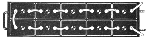
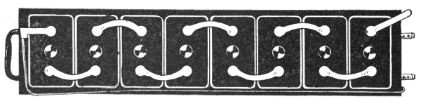
Figs. 1,169 and 1,170.—The "National" storage battery; views showing methods of assembling cells. Fig 1,169, end assembling; fig 1,170, side assembling.
Ques. How should weak cells be treated?
Ans. They should be grouped by themselves and charged as a separate battery, care being taken that the positive strap of one cell, is connected to the negative strap of the adjoining cell and 963 that the charging connections are properly made. If there be not sufficient resistance in the charging rheostat to reduce the current to the proper point, a water resistance should be used.
NOTE.—Pole testing paper. Make a thin solution of white starch and soak strips of thin white blotting paper in it, and set aside in a clean, dry place to dry. Dissolve ½ oz. of potassium iodide in one pint of water. Immerse the strips in the solution for a few seconds and again dry. This paper, when moistened and used in the usual way, turns violet at the positive pole.
While a cell is being treated, when possible, the cover should be removed (if sealed, the compound can be loosened by using a hot putty knife).
Figs. 1,171 to 1,177.—"National" battery bolt connector and parts. The connector is equipped with grease cups and antimonious lead washers.
Disconnecting Cells.—The best method of disconnecting cells assembled with pillar straps, for the purpose of replacing broken jars, cleaning or taking out of commission, is to use a five-eighth inch twist drill, in a carpenter's brace, boring down into the top of the pillar about one-quarter inch; then pull off the connector sleeve from the pillar. By following this method, all parts may be used again.
When cells are equipped with top straps, the straps should be cut with a sharp knife or chisel midway between the cells.
964
Taking Batteries out of Commission.—Where a battery is to be out of service for several months, and it is not convenient to give it the freshening charge every two weeks, it should be taken out of commission.
| Degrees Baume |
Specific Gravity |
Degrees Baume |
Specific Gravity |
Degrees Baume |
Specific Gravity |
Degrees Baume |
Specific Gravity |
|---|---|---|---|---|---|---|---|
| 0 | 1.000 | 17 | 1.133 | 34 | 1.306 | 51 | 1.542 |
| 1 | 1.007 | 18 | 1.142 | 35 | 1.318 | 52 | 1.559 |
| 2 | 1.014 | 19 | 1.151 | 36 | 1.330 | 53 | 1.576 |
| 3 | 1.021 | 20 | 1.160 | 37 | 1.342 | 54 | 1.593 |
| 4 | 1.028 | 21 | 1.169 | 38 | 1.355 | 55 | 1.611 |
| 5 | 1.036 | 22 | 1.179 | 39 | 1.368 | 56 | 1.629 |
| 6 | 1.043 | 23 | 1.188 | 40 | 1.381 | 57 | 1.648 |
| 7 | 1.051 | 24 | 1.198 | 41 | 1.394 | 58 | 1.666 |
| 8 | 1.058 | 25 | 1.208 | 42 | 1.408 | 59 | 1.686 |
| 9 | 1.066 | 26 | 1.218 | 43 | 1.421 | 60 | 1.707 |
| 10 | 1.074 | 27 | 1.229 | 44 | 1.436 | 61 | 1.726 |
| 11 | 1.082 | 28 | 1.239 | 45 | 1.450 | 62 | 1.747 |
| 12 | 1.090 | 29 | 1.250 | 46 | 1.465 | 63 | 1.768 |
| 13 | 1.098 | 30 | 1.261 | 47 | 1.479 | 64 | 1.790 |
| 14 | 1.107 | 31 | 1.272 | 48 | 1.495 | 65 | 1.812 |
| 15 | 1.115 | 32 | 1.283 | 49 | 1.510 | 66 | 1.835 |
| 16 | 1.124 | 33 | 1.295 | 50 | 1.526 |
NOTE.—The characteristic properties of concentrated sulphuric acid are very marked. Its freedom from odor, oily appearance, and its great weight, distinguish it from other liquids. The pure concentrated commercial acid has a density which usually reaches 1.842, and its boiling point is about 640° F. The absolutely pure acid is perfectly colorless, but usually even that used in laboratories has a peculiar grayish color, due to slight traces of organic matter. Sulphuric acid is exceedingly hydroscopic, and when exposed to the air it rapidly increases in bulk, owing to absorption of atmospheric moisture.
NOTE.—Clamps not made of metal similar to that of the connecting strips, frequently give trouble from the galvanic action due to the contact of dissimilar metals in the presence of moisture which causes the destruction of either the connecting strip or the clamp. Such troubles can be avoided by placing a thin strip of sheet zinc between the lead strip and the clamp. Under these circumstances the zinc will crumble away, and can be replaced without much inconvenience and very little expense, while the clamps and connecting strips will remain uninjured.
965
| Per cent. of Sulphuric Acid |
Specific Gravity |
Per cent. of Sulphuric Acid |
Specific Gravity |
|---|---|---|---|
| 100 | 1.842 | 23 | 1.167 |
| 40 | 1.306 | 22 | 1.159 |
| 31 | 1.231 | 21 | 1.151 |
| 30 | 1.223 | 20 | 1.144 |
| 29 | 1.215 | 19 | 1.136 |
| 28 | 1.206 | 18 | 1.129 |
| 27 | 1.198 | 17 | 1.121 |
| 26 | 1.190 | 16 | 1.116 |
| 25 | 1.172 | 15 | 1.106 |
| 24 | 1.174 | 14 | 1.098 |
Ques. Describe the method of taking a battery out of commission.
Ans. The battery is charged in the usual manner, until the specific gravity of the electrolyte of every cell has stopped rising over a period of one hour (if there be any low cells, due to short circuits or other cause, they should be put in condition before the charge is started, so that they will receive the full benefit of it). The cells may now be disconnected and covers and elements removed from the jars, (if sealed, the compound is loosened with a hot putty knife). The elements are placed on their sides with the plates slightly spread apart at the bottom, the separators withdrawn, and the positive and negative groups pulled apart. The electrolyte is washed off with a gentle stream of water and the plates allowed to drain and dry.7 966 The positive plates are ready to be put away. When dry, the negatives are completely immersed in electrolyte (of about 1.275 specific gravity), and allowed to soak for three or four hours. The jars may be used for this purpose. After rinsing and drying, they are ready to be put away; wash also the rubber separators.
Wood separators, after having been in service, will not stand much handling and had better be thrown away. If it be thought worth while to keep them, they must be immersed in water or weak electrolyte, and in re-assembling, the electrolyte must be put into the cells immediately, as wet wood separators must not stand exposed to the air.
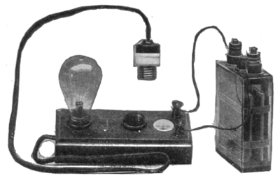
Fig. 1,178.—The "Witham" charging board, for charging from any electric outlet on a direct current system. The instrument shows the direction of the current, and the candle power of the lamps used as resistance indicates approximately the strength of the current passing. Operation: From any convenient electric light fitting remove one of the lamps, replacing it by the plug attached to the flexible cord. Screw the lamp into one of the sockets on the charging board. Connect a wire to each binding post, and before joining up to the battery, hold the ends of the two wires together. The lamp will then light up and the indicator needle will point to that binding post which must be connected to the positive (+) terminal of the battery. The other binding post must, of course, be connected to the negative (-) of the battery. The charging current can be increased by inserting another lamp into the second socket on the charging board and by using lamps of higher candle power. If, when the lamp lights up, the indicator needle do not point to one of the binding posts, but retain its position midway, then the current is an alternating one and will not charge the battery.
Ques. What precaution should be taken with the jars?
Ans. They should be thoroughly cleaned with fresh water, no sediment being allowed to remain. 967
Putting Batteries into Commission.—When re-assembling a battery, it should be treated in the same manner as if it were new and the regular instructions for assembling and putting a new battery into commission followed.
Cleaning Jars.—The jars should be thoroughly cleaned with fresh water, no sediment being allowed to remain.
| 8 | hour | rate | .05 | volt |
| 6 | " | " | .065 | " |
| 4 | " | " | .09 | " |
| 3 | " | " | .11 | " |
| 2 | " | " | .14 | " |
| 1½ | " | " | .18 | " |
| 1 | " | " | .21 | " |
Condensed Rules for the Proper Care of Batteries.—The following general instructions should be followed in the care and maintenance of batteries:
1. A battery must always be charged with "direct" current and in the right direction.
2. Be careful to charge at the proper rates and to give the right amount of charge; do not undercharge or overcharge to an excessive degree.
3. Do not bring a naked flame near the battery while charging or immediately afterwards. 968
4. Do not overdischarge.
5. Do not allow the battery to stand completely discharged.
6. Voltage readings should be taken only when the battery is charging or discharging; if taken when the battery is standing idle they are of little or no value.
7. Do not allow the battery temperature to exceed 110° Fahr.
8. Keep the electrolyte at the proper height above the top of the plates and at the proper specific gravity. Use only pure water to replace loss by evaporation. In preparing the electrolyte never pour water into the acid.
9. Keep the cells free from dirt and all foreign substances, both solid and liquid.
10. Keep the battery and all connections clean; keep all bolted connections tight.
11. If there be lack of capacity in a battery, due to low cells, do not delay in locating and bringing them back to condition.
12. Do not allow sediment to get up to the plates.
969
Storage batteries are used for many purposes, such as to supply current for electric vehicles, gas engine ignition, lighting, and in connection with power stations and distribution work.
The latter is an important field, the storage battery being used in connection with the power station for the following purposes:
1. To carry the peak load, during hours of maximum demand;
2. To carry the entire load during hours of minimum demand, or for a short time in case of emergency;
3. To act as an equalizer;
4. For regulation of load and voltage;
5. As compensation for feeder drop;
6. As a preventive against shut downs.
In almost every electric lighting plant there are long periods during the day and late at night when the number of lamps lighted is so small that it may not pay to run the generating machinery. In such cases, storage batteries may usually be used to advantage to aid in carrying the maximum load and to supply the entire current at minimum load as illustrated in fig. 1,179. In other words, batteries are substituted for a certain portion of the machinery plant or are used in place of the latter. 970
Ques. What provision must be made in power plants when storage batteries are not used?
Ans. The capacity of the generating machinery must be sufficient for the heaviest overloads which may occur, and it must be operated continuously for 24 hours a day in the majority of central stations supplying current for lighting and power.
Ques. What results are obtained with this method of working?
Ans. The engines working under very variable loads, not only operate at low efficiency, but are continually subjected to severe mechanical strains.
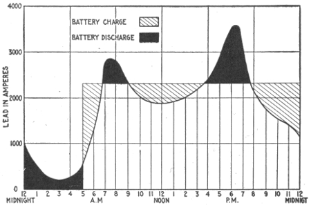
Fig. 1,179.—Load curve showing use of storage battery as an aid to the generating machinery. In the diagram, it is seen that the battery discharges at minimum and maximum loads and is charged at other times, the battery furnishing current for the entire minimum load and part of the maximum load.
Ques. How may greater efficiency be secured with steam engines under variable loads?
Ans. Judicious selection of the number and sizes of the engines enable them to be worked in most cases at a considerable fraction of their full capacity nearly all the time. 971
Ques. What further improvement is secured in most cases with the storage battery?
Ans. The plant is made more flexible, and the economy of the engines is increased by making their loads nearer uniform, and nearer to full capacity while they are running.
Ques. What is the effect of a battery connected in parallel with a dynamo, as in fig. 1,180?
Ans. It is not necessary for the dynamo to have a capacity exceeding that which is sufficient for the average daily load, at which it may be worked practically all the time.
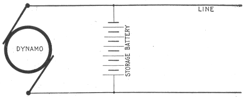
Fig. 1,180.—Storage battery connected in parallel with a dynamo. This arrangement enables the dynamo to be stopped for a considerable portion of the time, and thus save labor and attention. It also acts to prevent fluctuations as in a dynamo driven by a gas engine whose speed varies periodically because of the nature of its cycle of operation.
When the load is below the average, the dynamo charges the battery, and when the load rises above the average, during the hours of maximum demand, the battery discharges into the line in parallel with the dynamo. During the hours of minimum demand the engines may be shut down and the necessary current supplied from the battery alone, thus not only increasing the efficiency of the plant, but serving to maintain a steadier pressure under fluctuating loads.
Ques. What is understood by the expression "floating the battery on the line"?
Ans. A storage battery is said to float on a line when connected across the circuit at some distance from the power station, 972 so that a heavy load on the line, within the range of the battery influence, causes sufficient line drop to allow the battery to discharge, while with a light load on the line, the drop is small and the impressed voltage at the battery high enough to charge the battery. This usage is confined chiefly to electric railway service, where large voltage changes are permissible.
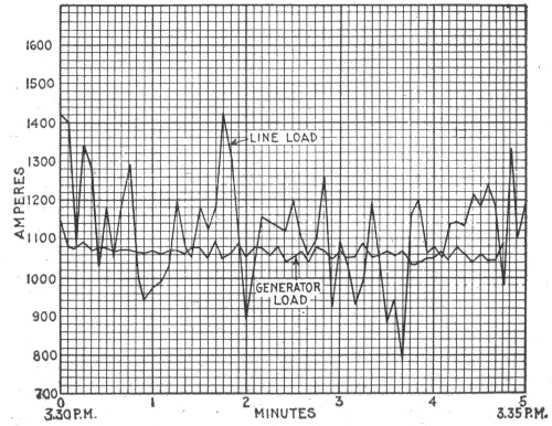
Fig. 1,181.—Diagram showing effect of storage battery in regulating the dynamo load in a combined railway and lighting plant. In this case the average and line loads are about equal and the battery covers the instantaneous fluctuations. It will be noted that while the line load fluctuations vary between 780 and 1,420 amperes, those of the dynamo load are kept at an average between 1,030 and 1,160 amperes.
Ques. When the battery is floated on the line, how may the amount of charge be made to approximately equal the amount of discharge?
Ans. By properly proportioning the number of cells in series.
Connections and Circuit Control Apparatus.—When a storage battery is used in an electric lighting plant, provision must be made for feeding the lamps, etc., from either the dynamo or battery separately, or from the two working in parallel, and it 973 should be possible to charge the battery at the same time the lamps are being supplied. To accomplish these results requires three switches, for the following connections:
1. To connect the lamps to the dynamo;
2. To connect the lamps to the battery;
3. To connect the battery to the dynamo.
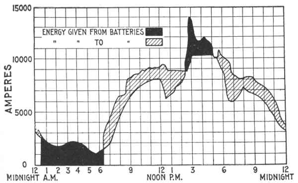
Fig. 1,182.—Diagram showing action of storage battery as a reservoir of reserve power. The figure shows an actual load curve from an Edison station for 24 hours. A sudden storm caused the load to be thrown on very quickly, the peak of the load being higher than usual.
In some plants, the first switch is omitted, because the lamps are always fed by the battery alone, the latter being charged during the day, when no lamps are in use.
It is desirable, however, to have all three switches in every plant in order to be able to supply lamps and charge the battery at any time.
In the battery circuit there should be an ammeter having a scale on both sides of zero, to show whether the battery is being 974 charged or discharged, as well as the value of the current. Another similar ammeter is required in the circuit between the dynamo and the battery, to show the direction and amount of current. A third ammeter is desirable in the lamp circuit, to show the total current supplied to the lamps, but it need only indicate on one side of zero, since the current there always flows in the same direction.
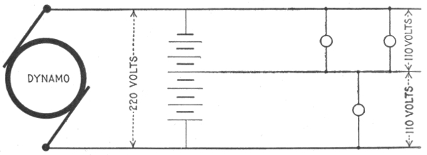
Fig. 1,183.—Diagram showing three wire system with one dynamo and storage battery. A 220 volt dynamo charges a storage battery of corresponding pressure, which in turn subdivides the pressure and supplies a three wire system, the neutral wire of which is connected to the middle point of the battery as shown.
A voltmeter is required with a three-way switch to connect it to the dynamo, battery or lamps, and a circuit breaker must be inserted in the battery circuit in order that it may be opened when the current becomes excessive.
A discriminating cut out or reverse current circuit breaker is required between the dynamo and the battery to open the circuit when the charging current falls below a certain value, and thus avoid any danger of the battery discharging through the dynamo, if from any cause the voltage of the latter drop below that of the battery. This completes the ordinary measuring and circuit controlling apparatus employed with storage batteries. 975
Methods of Control for Storage Batteries.—As the external voltage of a storage battery varies with the amount of charge it contains and with the direction of the current, it is necessary to employ some means for compensating this variation in order to maintain a constant voltage on the line supplied by the battery. The various devices used for this purpose are as follows:
1. Variable resistances;
2. End cell switches;
3. Reverse pressure cells;
4. Boosters.
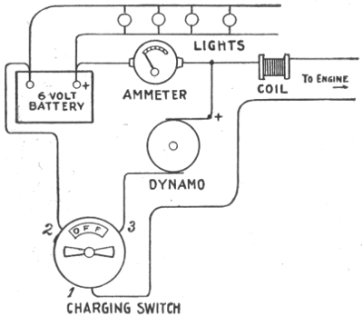
Fig. 1,184.—Diagram showing connections for ignition outfit. The charging switch has four indications—"Off," "Battery," "Dynamo" and "Charge." When engine is at rest switch is turned to "Off." The first turn brings it to "Battery," enabling the engine to be started. Next turn cuts battery off and puts "Dynamo" direct on engine. The next turn brings the switch to "Charge." Dynamo then charges the battery and surplus current is stored up. Next turn is "Off," which stops engine and disconnects battery from dynamo. Test the dynamo wires with test paper (negative makes mark). Put positive of dynamo to positive of battery. Dynamo should be regulated to charge at about four amperes.
The particular method selected will depend upon the size of the battery, the purpose for which it is used, the allowable limits pf current and voltage variations, the cost of the system, etc. 976
Variable Resistance.—Regulation by variable resistance may be used advantageously only with batteries of small capacity, and in small lighting plants such as those of yachts, where the space available for battery auxiliaries is limited, and where the cost of energy is so low that the loss of power in the resistance is not objectionable.
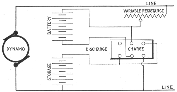
Fig. 1,185.—Variable resistance method of regulation for storage battery; diagram showing connections for charging two halves of a battery in parallel.
The connections for one of the simplest methods is shown in fig. 1,185. The battery is divided into two halves, which are connected in series for discharging and in parallel for charging. Since the voltage of each cell at the end of a discharge should not be lower than 1.8 volts, a battery intended for use on a 110 volt lighting circuit will require 110 ÷ 1.8 = 62 cells. The voltage necessary, however, for each cell at the end of a charge is about 2.6 volts, or a total of 2.6 × 62 = 161 volts for the battery, a value which is far above the line voltage. By dividing the battery into two halves and connecting them in parallel only 80.5 volts are 977 necessary for charging. The excess voltage of the line, 29.5 volts is taken up by the resistance, which also controls the output of the battery on discharge.
End Cell Switches.—These may be used to advantage in small installations where there is not demand for current during the day, or where the charging is done by means of boosters.
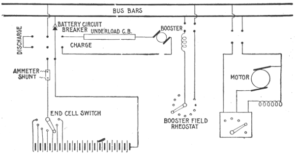
Fig. 1,186.—Diagram of connections of a battery equipment for a residential lighting plant. In the diagram the voltmeter and voltmeter connections have been omitted. The bus bars on the battery panel are connected directly to the bus bars on the dynamo panel. In this installation the dynamos are run during the afternoon on discharge, being regulated by means of an end cell switch. On charge, the pressure above that of the bus bars, required to bring all cells up to full charge, is supplied by means of a motor driven charging booster, the voltage at the armature being suitably varied by changing the field excitation.
Ques. What is an end cell switch?
Ans. A form of switch employed in connection with a storage battery in order to control the end cells for regulating the voltage.
Ques. Describe the construction of an end cell switch.
Ans. This is shown in fig. 1,187. The switch contact arm is made in two parts, A and B, which are insulated from each other 978 as shown, and connected with each other through the protective resistance R. The end cell contacts are so spaced that when the main current carrying part A of the switch arm is squarely on one end cell contact such as X, the part B, does not touch any other contact such as Y, but when the switch arm is advanced for cutting into circuit another end cell, the part B, reaches the contact Y before the part A, leaves the contact X, thus keeping the battery circuit closed, while the resistance R, limits the current in the short circuited cell at the instant the switch arm passes from one end cell contact to the next.
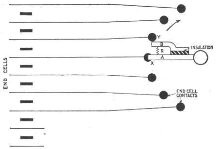
Fig. 1,187.—Diagram of end cell switch. This form of switch controls several cells at one end of a storage battery and is used for regulating the voltage. The requirement of an end cell switch is that in switching from one end cell contact to another, the discharging circuit must not be opened, neither must the moving arm touch one contact before leaving the one adjacent, since the joining of two contacts will short circuit the cells connected thereto. To accomplish this, the spacings of the two arms and contacts are such that when the main arm A is squarely on an end cell contact, the advance or auxiliary arm B touches no other contact, but in passing from one point to the next, the advance arm reaches the contact toward which it is moving before the main arm leaves its contact. The resistance X, between the two points prevents short circuiting, and the current to the main circuit is never broken.
Ques. How should the conductors joining the end cells to the end cell switch contacts be proportioned?
Ans. They must have the same sectional area as the conductors of the main circuit. 979
The reason for this is that when any end cell is in use, the conductor connecting it to the switch becomes a part of the main circuit. An allowance of 1,000 amperes per sq. in., when the battery is discharging at the two-hour rate, is considered good practice.
Ques. Describe some of the features of end cell switch construction.
Ans. Those of small capacity are made circular; the larger sizes are made horizontal in form, and both types may be either operated by hand or motor driven.
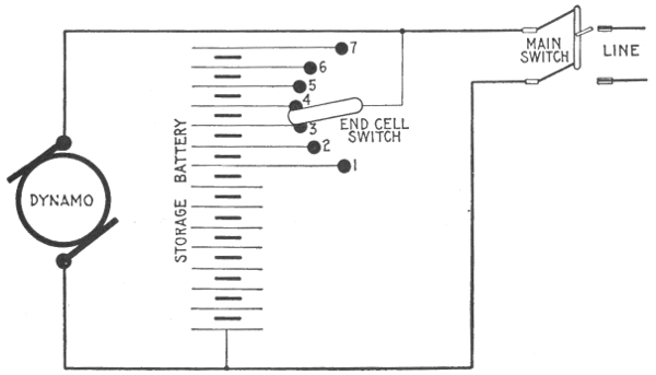
Fig. 1,188.—End cell switch control for storage battery; connections showing main line open when the battery is being charged.
Ques. Where are end cell switches of large capacity located?
Ans. Generally they are placed as near the battery room as possible to avoid the cost of running the heavy conductors, and when such switches are motor driven, the usual practice is to control their operation from the main switchboard. 980
In fig. 1,188 is shown the method of regulation with an end switch. The diagram shows the battery being charged with the main switch open, and the voltage of the dynamo raised to the charging pressure. During discharge the cells are connected in series, and as the voltage of each cell at the beginning of discharge is at least 2.1 volts, only 52 or 53 cells are required to give the desired pressure of 110 volts, but as the discharge continues, and the voltage of each cell decreases, the end cells, 1, 2, 3, 4, etc., are cut into circuit successively by means of the end cell switch, thereby adding to and compensating the drop in the total voltage until, at the end of discharge when the voltage of each cell has fallen to 1.8 volts, the entire 62 cells are in series to supply the required line pressure.
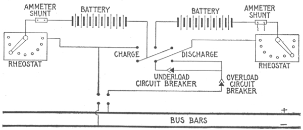
Fig. 1,189.—Diagram of connections arranged for charging battery in two parallel groups and discharging in series, the charge and discharge being controlled by variable resistances. In yacht lighting the limited space generally prohibits the use of a charging booster, and in such instances this method of charge and discharge control is the usual practice. In case the dynamo from which the battery is charged has sufficient range in voltage to charge all cells in series, a charging booster is not required, nor is it necessary to connect groups of cells in parallel, as the dynamo voltage may be varied as charge proceeds.
For a 110 volt circuit, the number of cells required is 110 ÷ 1.8 = 61, and the number in series when the battery begins to discharge is 110 ÷ 2.1 = 52. Hence, in a 110 volt circuit an arrangement must be provided whereby 61 - 52 = 9 cells may be cut out or switched in, one by one.
The number of end cells for any voltage may be obtained by the following formula:
Number of end cells = (E/1.8) - (E/2.1)
E = voltage of supply circuit;
1.8 = minimum voltage of cell during discharge;
2.1 = voltage of fully charged cell.
981
Reverse Pressure Cells.—These consist of unformed lead plates immersed in the ordinary electrolyte of dilute sulphuric acid. As they have no active material, they possess no capacity, but are capable of setting up an opposing pressure of about 2 volts each to the discharging current flowing through them, thereby cutting down the total voltage of the battery, so that the net voltage across the line depends on the number of reverse current cells in series in the battery circuit. As the voltage of the battery falls during discharge, the reverse pressure cells are cut out, successively, thus keeping the external or line voltage constant.
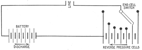
Fig. 1,190.—Regulation with reverse pressure cells. These cells are merely lead plates placed in an electrolyte of dilute sulphuric acid. They have no capacity but set up an opposing or reverse voltage of approximately 2 volts per cell if current be passed through them. In using these cells for controlling discharge, the total number of active cells in the battery will be the same as if the method of end cell control had been used. Reverse pressure cells represent an increase in equipment of about 8 per cent. or more. These cells, as shown, are connected in the circuit in opposition to the main battery, and conductors are run from each of them to points on a switch similar to an end cell switch. At the beginning of discharge, all the reverse cells are in circuit, acting in opposition to the main battery. As discharge proceeds and the battery voltage falls, the reverse cells are gradually cut out of circuit. The only advantage in this method of regulation is that the discharge throughout the battery is uniform, but this fact alone does not warrant such means of regulation on account of the additional expense involved, and the energy loss when discharging against reverse cells is the same as if resistance had been placed in the circuit.
It is obvious, that as these cells do not possess any capacity, the number of active cells required in the battery will be the same as when end cell control is employed. Therefore, the reverse pressure cells represent an increase in equipment, which 982 entails an additional expense of at least 8 per cent. For this reason, and also on account of the fact that the amount of energy lost in discharging against reverse pressure cells, is the same as when the resistance methods of controlling the discharge are employed, the use of cells for this purpose is now practically obsolete.
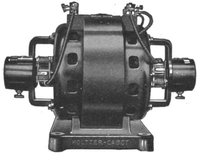
Fig. 1,191.—Holzer-Cabot dynamotor (type K). A dynamotor is a combination of dynamo and motor on the same shaft, one receiving current, usually of different voltage, the motor being employed to drive the dynamo with a pressure either higher or lower than that received at the motor terminals. A machine of the dynamotor form, with its windings exactly alike, is often used in three wire systems to balance or equalize the two halves of the circuit as in fig. 798.
Boosters.—In general, a booster may be defined as a dynamo inserted in series in a circuit, to change its voltage. It may be driven by an electric motor, in which case it is sometimes called a motor-booster. The function of a booster is to add to an electric pressure derived from another source.
For instance, if a storage battery be used in conjunction with one or more dynamos to supply current to an electric light installation, the battery cannot be charged from the machines which are feeding the lamps, because it requires a pressure higher than that required for the 983 lamps to complete the charge. A small dynamo is therefore connected in series, with the main machines and the battery, acting in conjunction with the former to provide the necessary pressure.
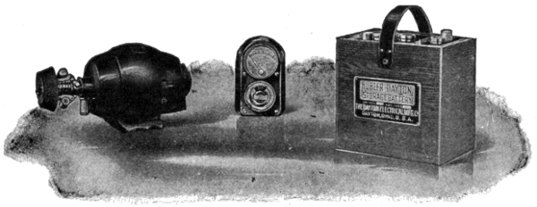
Fig. 1,192.—Dayton launch lighting outfit. It consists of an "Apple" dynamo, switchboard and storage battery. The dynamo is fitted with a bevel friction drive governor. The dynamo gives a three ampere charging rate on a six volt battery at its normal speed of 1,050 R. P. M. The switchboard is provided with a combination volt-ammeter which shows the voltage of the battery, the ampere charging rate of the dynamo and the ampere discharging rate of the battery. The automatic cut out in the back of the switchboard automatically severs the connections between the dynamo and the storage battery when the engine stops and so prevents the storage battery current running back through the dynamo when the dynamo is not generating current. A 6 volt, 60 ampere hour battery, consisting of 3 five plate units connected in series, is used with the size dynamo shown in the illustration.
The power for running such a dynamo is obtained in various ways. The dynamo or charging booster may be belt driven or arranged on an extension of the armature shaft of the main dynamo; again, it may consist of a single armature with a double winding (fig. 1,191), or a motor and dynamo coupled together on one bed plate as in figs. 800 and 805. Boosters may be divided into several classes as follows:
1. Series boosters;
2. Shunt boosters;
3. Compound boosters;
4. Differential boosters;
5. Constant current boosters;
6. Separately excited boosters.
Series Boosters.—The series booster acts so as to compound the battery, and tends to maintain a constant voltage on the line, whatever the load may be. Its operation depends on the fact 984 that the dynamo voltage must rise and fall with the load. It can, therefore, be used only with a shunt dynamo or its equivalent as the source of supply.
Ques. What use is made of the series booster system?
Ans. It is suited to power, but not to incandescent lighting purposes, being similar in operation to a floating battery. It is not extensively used as the other types give better service, under the same conditions.
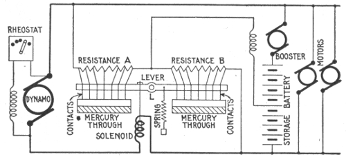
Fig. 1,193.—Diagram of Joseph Bijur's storage battery system (General Storage Battery Co.). The booster field winding has one terminal connected to the middle point of the battery and the other terminal, to the wire joining the resistances A and B. A lever, pivoted at L, carries at either end a number of contact points which dip into troughs of mercury when one end of the lever moves upward or downward. These points are connected to corresponding points on their respective resistances, and therefore all of the resistances connected to contact points which are immersed in the mercury are short circuited. The points are of various lengths, so that when the lever operates, they contact progressively with the mercury. If more of the A points than the B points be immersed in the mercury, the resistance of B is less than that of A, more sections of it being short circuited. Current will therefore flow from the middle point of the battery, through the booster field, and through B to the negative side of the system, exciting the booster field and producing a booster voltage to charge the battery. Again, if more of the A points be immersed, the A resistance becomes the smaller, and current then flows from the positive side of the system through resistance A, through the booster field to the middle point of the battery, the field excitation and the booster pressure produced being in a direction opposite to the first described, and tending to discharge the battery. When the resistances A and B are equal, there is no pressure to send current in either direction through the booster field coil. When the load on the external circuit is normal, the lever is in a horizontal position, A and B being equal, no current flows through the booster field hence, no current passes into or out of the battery. With increase of external load, the pull of the solenoid is strengthened by a small increase in dynamo current passing through the winding. This draws down the left end of the lever producing a current in the booster field such as to discharge the battery and assist the dynamo to supply the load demand. A decrease in external load is attended by a slight diminution in dynamo current, the solenoid is weakened and the pull of the spring predominates. This results in a downward movement of the right side of the lever causing excitation of the booster field to produce a pressure to send charge into the battery.
985
Ques. Describe some characteristics of the series booster.
Ans. It is automatic and adjusts its voltage to produce the proper ratio of charge or discharge with varying external load, and it also tends to maintain a constant voltage across the line, under all conditions of change in circuit.
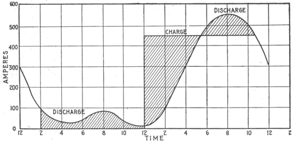
Fig. 1,194.—Load diagram, showing kind of service to which the shunt booster is adapted.
Shunt Boosters.—This type of machine is simply a shunt dynamo, having its armature circuit in series with the line from the main dynamo to the battery. A rheostat controls the field excitation. Its function is to send charge into the battery. It is used in plants where the battery is not designed to take up load fluctuations, but is in service only to carry the peak of the load, being charged during periods of light loads and discharged in parallel with the dynamo.
The shunt booster acts to increase the voltage applied to the battery so that the charging current will flow into the latter. 986
Ques. How is a battery used with a shunt booster proportioned?
Ans. Usually sufficient battery is provided to carry the entire load during the light load period.
Ques. Explain the use of the rheostat controlling the field excitation.
Ans. It is used to vary the booster voltage so as to hasten the charging of the battery if desired.
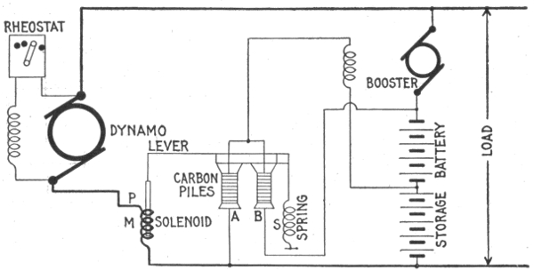
Fig. 1,195.—Entz' carbon pile booster system (Electric Storage Battery Co.). The booster field winding is connected at one end to the middle point of the battery. The other end is connected to the upper contact points of two carbon pile resistances, A and B. The lower end of A is connected to the negative side of the battery, and the corresponding end of B, to the positive side. This arrangement constitutes in effect a potentiometer. If the resistance of A be equal to that of B, there is no pressure in the booster field to establish current through it. The drop through A + B is equal to the total battery voltage, and if A = B, the drop from either side of the battery through A or B is one-half the total drop, hence the end of the booster field winding, connected to the upper ends of A and B is also at the pressure of the middle point of the battery which is likewise the pressure of the other side of the booster field coil. Accordingly when A = B, there can be no current through the coil. When the two resistances are unequal, there will be current through the booster field, its direction depending on which of the resistances is the less, and its magnitude will be proportional to the difference between the two resistances. Variations in the pressure on a carbon pile causes variations in its resistance and the solenoid, M, opposed by spring S, both pulling on lever L which rests on the two piles A and B, controls the relative resistances of the two piles to cause charge and discharge of the battery. The solenoid winding is in series with the dynamo circuit and when the load is normal, the spring pull is just equal to the magnet pull, and the resistance of A and B are equal. When external load varies, a small but proportional variation in the pull of P charges the relative resistances of the piles and the booster field is energized to produce a voltage to cause battery charge or discharge.
987
Ques. For what service is the shunt booster not suited?
Ans. It is not adapted to circuits where there are sudden fluctuations that are great compared with the capacity of the dynamo.
Ques. What is its action in changing from charge to discharge?
Ans. It is not automatic, the switching must be done by hand.
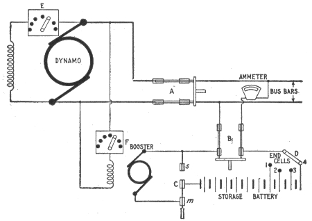
Fig. 1,196.—Diagram showing usual connections of a non-reversible shunt booster and battery system. In charging, the switches A and B are closed, and C put on contact m; the end cell switch D is put on the last contact. Part of the dynamo current will go into the line and part through the booster into the battery. The charging current is adjusted by the field rheostat E. To discharge, throw the end cell switch D to first contact; next turn switch C to contact s. The battery is then in parallel with the dynamo with all end cells cut out. As the voltage of the battery falls, end cells are cut in by the end cell switch D.
Ques. How may it be used reversibly?
Ans. It will give a pressure to assist the battery to discharge when excited from the bus bars and provided with a reversing rheostat.
In this case it will assist the battery to discharge when the direction of the field magnetization is changed. When so used, no end cells are necessary, but the booster must be run continuously during the entire period of discharge.
988
Ques. What should be the battery capacity on a 110 volt circuit with a reversible booster?
Ans. 56 cells will be sufficient.
The voltage to fully charge is 56 × 2.6 = 146, or 36 volts above dynamo voltage. Minimum voltage of discharge = 1.8 × 56 = 100 volts, or 10 volts less than that of the line. Hence, the booster need give only 36 volts maximum, and is required to add 10 volts to the battery voltage toward the end of battery discharge. In this case, the booster voltage is only 36/49 or about ¾ of that required in the preceding case; five cells less of battery are necessary and the end cell switches and leads are eliminated.
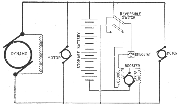
Fig. 1,197.—Diagram of compound booster connections.
The machine will be larger, however, than it would be if used only for charging, because the discharge current is unusually greater than that of charge, and the current carrying of the armature must be great enough to take care of the heaviest currents.
Compound Boosters.—These machines are used on railway and power circuits where there are great fluctuations in load, the battery acting to prevent excessive drop and to assist the generating machinery in carrying the load, relieving it from the strain of sudden rushes of current. 989
The connections are shown in the diagram fig. 1,197. Under ordinary working conditions, the shunt field of the booster creates an electric pressure in the same direction as that of the battery, tending to discharge it.
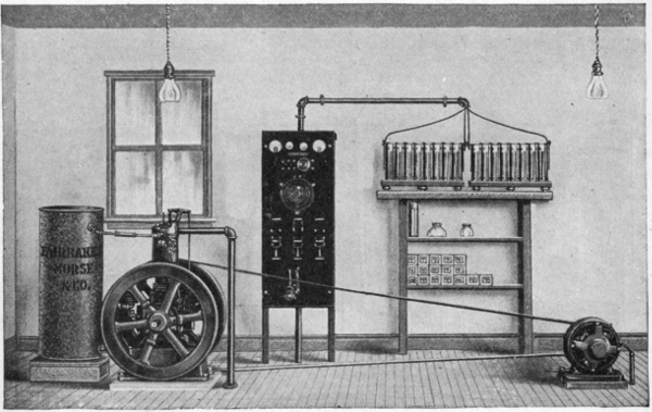
Fig. 1,198.—Fairbanks-Morse lighting outfit. The above cut illustrates a 2 horse power vertical special gasoline or kerosene oil engine belted to a .9 kw. compound wound 32 volt dynamo. It will supply a maximum of 42-20 watt, or 50-15 watt 32 volt Tungsten lamps and is built and balanced, so that current can be taken direct from the dynamo without flicker in the lights. The storage battery has 16 cells and a capacity of 4½ amperes for 7½ hours at 32 volts. This will supply seven 20 watt Tungsten lamps for 7½ hours, or nine 15 watt lamps for 7½ hours. The switchboard is arranged so as to give 24 hours service. It is customary to run the engine during most of the lighting period and to use the battery for lights late at night. If the whole number of lights be not used when the engine and dynamo are in operation, the surplus is used to charge the battery.
When no current is flowing into or out of the battery, the following relation exists:
Dynamo voltage = booster voltage + battery voltage
In this case the dynamo carries the whole external load. If the load increase, the dynamo voltage decreases, so that the 990 booster voltage + battery voltage is greater than the dynamo voltage, and the battery begins to discharge.
In discharging, the current passes through the series field of the booster and produces a proportional pressure acting with the shunt field to raise the voltage of the booster, thus increasing the battery discharge and shifting more of the load from the dynamo, until the system becomes balanced.
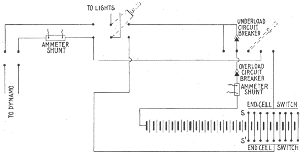
Fig. 1,199.—Diagram showing method of charging a storage battery at one voltage and supplying lights at a different voltage. As may be seen, two end cell switches are required. The voltage of the supply current is adjusted by the number of cells in series on switch S', while switch S is moved to cut out cells as they become fully charged. In this instance the end cells included between the contact arms of the two end cell switches must be of sufficient size to receive the charging current, plus the current to the supply circuit. If the battery can be charged at times when the dynamo is supplying no other load, only one end cell switch is required.
If the load on the external circuit be small, the dynamo voltage rises and current flows into the battery. In this case the series field acts against the shunt field and decreases the booster voltage so that the pressure at the dynamo is greater than booster and battery voltage combined, thus increasing the rate of charge of the battery until the load causes the dynamo voltage to drop to normal and the system is again balanced.
The battery and booster can be placed at the power house or where the greatest drop is likely to occur. As this system, like the series booster, depends for its action upon the drop of voltage with increase of load, it is only adapted to shunt wound dynamos. 991
From the foregoing description it will be seen that the compound booster is automatic within certain limits of battery charge. Any marked change of battery voltage will be followed by a corresponding change in dynamo current, unless the rheostat be manipulated to bring battery voltage + booster voltage back to normal.
While the theoretical dynamo current variation is small for a given change of load, there is always a sudden, momentary, current rush from the dynamo on increase of load, the duration of which is equal to the time lag of magnetization of the booster field.
Lights on a circuit with variable load will "wink" on sudden changes of load. In this respect the compound booster is not so satisfactory as the constant current booster, as in the latter all dynamo current passes through the series fields, which, by reason of their self-induction, oppose and check any sudden current rush, giving the booster field time to change its magnetization to the proper degree.
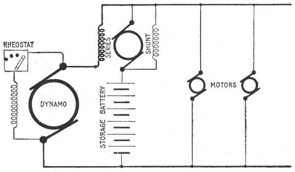
Fig. 1,200.—Diagram of connection of one form of differential booster. In operation, the dynamo current passes through the series winding of the booster, and the current in this winding is to remain practically constant. The shunt coil produces a field which opposes the field produced by the series coil, the resulting magnetization being, in direction and amount, the resultant of the two field strengths. The adjustments are so made that when the normal dynamo current is passing through the series coil, the shunt field just neutralizes its effect, and the resultant magnetization is zero. Since the open current voltage of the battery is equal to that of the system, neither charge nor discharge takes place. With increased demand on the line, the slight increase in dynamo current in the series coil overpowers the shunt field, and causes a pressure in the booster armature in such direction as to assist discharge. If the external load fall below the average demand, the current in the series coil decreases slightly so that the shunt field predominates, producing a booster armature pressure in a direction to assist charge. Although the voltage of the battery falls while discharging by an amount proportional to the outflowing current the increased excitation due to this current through the series coil is also proportional to it, and the booster voltage rises as that of the battery falls, their sum being always equal to that of the system. In other words, the booster serves to compound the battery for constant pressure.
992
Differential Boosters.—In this type of booster, a series coil energized from the main current, tends to discharge the battery, and a shunt coil, excited from the battery, tends to charge the cells. These two coils are opposed to one another, and the difference in their respective strengths represents the net strength available for boosting. In order to produce quicker reversal, additional compound coils are sometimes added.
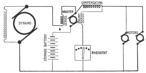
Fig. 1,201.—Diagram of differential booster system with compensating coil. In operation, the compensating field coil of the booster opposes the shunt coil and prevents the variation of the battery voltage disturbing the equilibrium of the system. If the battery pressure be lower than normal, it will not discharge rapidly enough to relieve the dynamo from overload fluctuations, unless the booster voltage be increased, and the dynamo will therefore have to supply a current greater than normal. If a current greater than normal flow through the compensating coil, the effect of the shunt coil opposed by the series coil is decreased, and the compensating coil, acting in the same direction as the series coil, causes a higher booster pressure tending to discharge the battery, and thus brings down the dynamo load to normal. Should the battery voltage be above its normal value, the battery would discharge too rapidly and carry more than its share of the load. In operating this system, the varying load must be beyond the booster equipment. The series and compensating coils may be temporarily short circuited so that the battery may be charged more rapidly.
Ques. For what service is the differential booster adapted?
Ans. It is suited to power and railway circuits where the load fluctuates widely and suddenly.
There are several varieties of this type of booster, and many patents have been issued covering the different methods of varying the voltage of the machine.
993
Constant Current Boosters.—In installations where it is desired to supply both an approximately constant load and a fluctuating load from the same dynamos (as for instance, in office buildings or hotels, where it is necessary to supply lights and elevators from the same source), the fluctuations in the power circuits must not interfere with the lighting circuits and to prevent this, two sets of bus bars are provided.
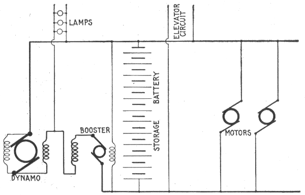
Fig. 1,202.—Diagram of non-reversible or constant current booster system. The booster armature and field are in series between one side of the lighting and power bus bars. A shunt field is also provided, which acts in opposition to the series field. This booster carries a practically unvarying current from the lighting to the power bus bars, regardless of the fluctuations of the external load, which current is equal to the average required by the fluctuating load. Except under abnormal conditions the shunt field always predominates giving a voltage which is added to that of the lighting bus bars, so that the voltage across the power busses is always higher than that across the lighting by an amount equal to the booster voltage. If an excessive load come on the power circuits, the increased excitation of the series coil, due to a slight increase in current from the lighting to the power bus bars, lowers the booster voltage and consequently reduces the voltage across the power bus bars. The battery discharges, furnishing an amount of current equal to the difference between that required by the load and the constant current through the booster. If the power load decrease below normal, the slight decrease in current in the booster series field increases the booster armature voltage and the excess current goes into the battery. The booster, therefore, does not in reality give a constant current, but by proper design the variation may be kept within a few per cent.
The dynamos are connected in the usual manner to one set of bus bars, and the lighting circuits are connected across these. 994
Across the other set of bars are connected the circuits supplying the fluctuating load, and the battery is also connected directly across these power bars.
The power bars are supplied with current from the lighting bars, a non-reversible or so called constant current booster being interposed between the two as shown in fig. 1,202. Since this permits only a constant current to pass from the lighting bus bars, the load on the dynamo does not vary, although the load on the power busses may vary widely.
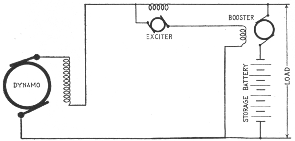
Fig. 1,203.—Hubbard's separately excited booster system (Gould Storage Battery Co.); diagram showing general arrangement.
Separately Excited Boosters.—In some forms of booster the field excitation is secured by a small exciting dynamo. An example of this class is shown in fig. 1,203. The exciter is provided with a single series coil, through which the station output 995 or a proportional part thereof passes. The armature of the exciter is connected to the exciting coil on the booster, and thence across the mains as shown.
NOTE.—Reversible boosters should be used where the average total current to the fluctuating load is greater than the battery discharge current, and where the pressure of the power bus bars must not fall off with increase in load. Electric railway and lighting plants having long feeders are examples of the systems to which reversible boosters are suited. Non-reversible boosters should be used where the average total load is less than the battery discharge current, and where a drop in the voltage of the power bus bars is of advantage. Examples of such plants are hotels or apartment houses where electric elevators are operated from the lighting dynamos. Boosters are usually driven by electric motors directly connected to them, though any form of driving power may be used.
With the average current passing through the field coil or the exciter, its armature generates a voltage which is equal to that of the system, and in opposition to it. These two opposing pressures balance, and no current flows in the booster field coils.
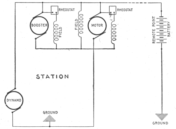
Fig. 1,204.—Battery system with regulation for long feeders, for installing where it is desirable to locate the battery at a point remote from the station and avoid any equipment requiring constant attention at the battery end. The compound wound motor, constant current booster is used and keeps constant the current flowing through the feeder, the battery taking up all load fluctuations.
With an increase in external load above the average, the tendency is for an increase to take place through the exciter series 996 coil, augmenting its field strength and consequently the exciter armature voltage. This latter now being higher than that of the line, causes current to flow in the booster field coil in such a direction as to produce a pressure in the booster armature which assists the battery to discharge, and is of a magnitude to compensate for the battery drop occasioned thereby.
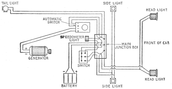
Fig. 1,205.—Diagram illustrating storage battery system, as applied to an automobile for lighting.
When the load decreases below the normal, the current in the exciter field is decreased, and its armature voltage falls below that of the system. Current will now flow in an opposite direction in the booster field coil, generating a voltage in the booster armature to assist charge. Since the exciter always generates a voltage in opposition to that of the line, this system is known commercially as the counter pressure system. 997
| HAWKINS PRACTICAL LIBRARY OF | |
| ELECTRICITY | |
| IN HANDY POCKET FORM | PRICE $1.00 EACH |
They are not only the best, but the cheapest work published on Electricity. The books are sold at $1 each. Each number being complete in itself. They are guaranteed in every way or your money will be returned. The new numbers will be supplied for $1 each, as published.
ELECTRICAL GUIDE, NO. 1
Containing the principles of Elementary Electricity, Magnetism, Induction, Experiments, Dynamos, Electric Machinery.
ELECTRICAL GUIDE, NO. 2
The construction of Dynamos, Motors, Armatures, Armature Windings, Installing of Dynamos.
ELECTRICAL GUIDE, NO. 3
Electrical Instruments, Testing, Practical Management of Dynamos and Motors.
ELECTRICAL GUIDE, NO. 4
Distribution Systems, Wiring, Wiring Diagrams, Sign Flashers, Storage Batteries.
ELECTRICAL GUIDE, NO. 5
Principles of Alternating Currents and Alternators.
ELECTRICAL GUIDE, NO. 6
Alternating Current Motors, Transformers, Converters, Rectifiers.
ELECTRICAL GUIDE, NO. 7
Alternating Current Systems, Circuit Breakers, Measuring Instruments.
ELECTRICAL GUIDE, NO. 8
Alternating Current Switch Boards, Wiring, Power Stations, Installation and Operation.
ELECTRICAL GUIDE, NO. 9
Telephone, Telegraph, Wireless, Bells, Lighting, Railways.
ELECTRICAL GUIDE, NO. 10
Modern Practical Applications of Electricity and Ready Reference Index of the 10 Numbers.
Theo. Audel & Co., Publishers 72 FIFTH AVENUE.
1 NOTE.—The term impedance means the total opposition in an electric circuit to the flow of an alternating current, being made up of the actual or ohmic resistance and the apparent resistance due to self-induction, or if the circuit contain also capacity, the resultant apparent resistance due to self-induction and capacity.
2 NOTE.—The international ohm ÷ B. A. ohm = 1 ÷ .9866. The B. A. ohm ÷ International ohm = 1 ÷ 1.0136. Hence, to reduce British Association ohms to International ohms, divide by 1.0136. or multiply by .9866.
3 This size can be used only in the shape of flexible cord.
4 CAUTION.—The size thus obtained should be compared with the table of carrying capacity of wires as given on page 731 to see if the wires would have to carry more than the allowable current.
5 NOTE.—In case a larger loss than any given in the table is required, proceed as follows:—Divide the ampere feet by 10 and then refer to column of Actual Volts Lost divided by 10, from which the size of wire is found as before.
6 NOTE.—Specific gravity is the weight of a given substance relative to an equal bulk of some other substance which is taken as a standard of comparison. Water is the standard for liquids. In the laboratory the specific gravity bottle is often used in determining the specific gravity of a liquid. The capacity of the bottle is 1,000 grains of pure water. When it is filled with spirits of wine and weighed in a balance (together with a counterpoise for the weight of the bottle, which of course is constant), it will weigh considerably less than 1,000 grains; in fact, the bottle will contain only about 917 grains of proof spirit; therefore, taking the specific gravity of water as unity, 1 or 1.000, the specific gravity of spirits of wine is 0.917. If, on the other hand, the bottle be filled with sulphuric acid, it will weigh about 1,850 grains; hence, the specific gravity of sulphuric acid is said to be 1.850. A more convenient method for the automobilist is by the use of the hydrometer.
7 NOTE.—If the active material in the negative plates extend beyond the ribs of the grid (the supporting frame), it should be at once pressed back into place, care being taken to prevent the plates drying before this is done. The most suitable and convenient method for pressing, is to place between the plates smooth boards of a thickness equal to the distance between the plates and then put the groups under pressure.
8 NOTE.—The voltage increase or decrease with change in current is practically constant in a given type of cell for any size of cell when the current is referred to a given time rate of charge or discharge; that is, the drop in a large cell or in a small cell, when each is discharged at its four, six or eight hour rate, will be the same. The drop varies somewhat for the condition of the battery charge. For batteries which are one-third discharged, the temperature 60° Fahr., and plates in good condition, the changes in pressure which may be expected between open circuit voltage and the voltage on charge or discharge are given in the above table.
Where possible, unicode characters are used. Some of the fractions do not have a unicode character which will cause some inconsistencies in the display.
Inconsistent spelling and hyphenation are as in the original.