Please see the Transcriber’s Notes at the end of this text.
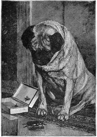
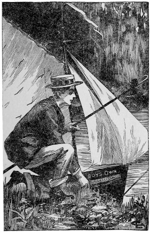
THE YOUNG TAXIDERMIST.—See page 298.
A Popular Encyclopædia for Boys
BY
Edited by G. A. HUTCHISON
WITH OVER SEVEN HUNDRED ILLUSTRATIONS
PHILADELPHIA:
J. B. LIPPINCOTT COMPANY.
1890.
In presenting to American youth this carefully-edited volume of home amusements, the publishers are happy in their belief that in the selection and treatment of the subjects chosen the Editor and the accomplished experts who have contributed to its pages have successfully combined, to a degree not commonly found in books prepared for the young, much sound scientific instruction and a large amount of that recreative amusement that seldom fails to awaken an interest both in the youthful mind and in the minds of “children of a larger growth.” In the language of the accomplished Editor, as expressed in his prefatory note to the English edition, the volume is “a veritable[6] recreative text-book, prepared by experts in their several subjects, and treated with sufficient amplitude of detail and thoroughness of exposition to render their respective contributions of very real and permanent educational value. Mere ‘rule of thumb’ is scrupulously avoided, and underlying principles are clearly and intelligently explained. The tyro is led on pleasantly step by step, and almost unconsciously learns many lessons that should stand him in good stead in the battle of life. The wealth of graphic illustrations—of clever pictures that really illustrate—is another and not, we think, the least noteworthy feature of the book.
“In the numerous and greatly diversified sections, it will be seen, the work is carefully graduated in the natural order—from the simpler to the more complex and difficult tasks. We have also endeavoured wherever practicable—as in the model-making chapters—to afford, by means of alternative plans, instructions likely to cause little or no tax upon the pocket, as well as some that necessarily involve more or less expenditure for tools and material. Thus, boys of all ages and conditions—at home or at school; with leisure and ample opportunities, or already closely engaged in the sterner duties of bread-winning; boys to whom a considerable preliminary outlay may be of trifling moment, and others who rarely have a shilling to spare,—may alike turn to the different chapters with the certainty of finding something for each, calculated to afford both pleasure and profit in those spare hours that are the gold-dust of time.
“It will be pretty generally admitted, we presume, that a pronounced characteristic of the age is the daily increasing attention given to Athletics and Technical Training.... This book seeks to give that class of instruction in the most attractive guise. The subjects in which boys naturally feel peculiar interest are skilfully treated by writers of proved capacity and aptitude for the task; and hence considerable space is devoted to those essentially boys’ topics that are not only of recreative value in themselves, but[7] incidentally afford invaluable training to eye and hand.... Nor is the moral and spiritual side of boy-nature overlooked. Games dominated by elements of ‘chance’ or ‘luck,’ as well as those of questionable or evil associations, are of course scrupulously ignored. But this negative claim to confidence is also supplemented by the positive influence exerted towards the building up of a true, robust Christian manhood. It were indeed a grievous thing if, while learning from this book how to use wisely many of the ingenious tools and contrivances described, any boy should neglect to learn how to control and direct to the most useful work in the service of God and of man the marvellous and complex machinery of his own moral and spiritual nature. To every reader, therefore, we make bold to speak that direct, manly word, that no true-hearted boy will resent. It is Dr. Cuyler, if we mistake not, who remarks that Samson builded better than he knew when he uttered his famous riddle, ‘Out of the eater came forth meat, and out of the strong came forth sweetness;’ for the pathway of life has many a lion in it, and our success and happiness depend not a little on the way we meet the foe. Thus Hedley Vicars encountered quite a shower of scoffs from his brother officers in the Crimean army when he was first converted. But he put his Bible on his table in his tent, and stood by his colours. Henceforth the lion was not only slain, but there was rich honey in the carcase when his religious influence became a power in his regiment. In the carcase of a slain temptation, also, millions besides Joseph have found delicious honey. ‘There is not a peril, or a trouble, or a spiritual foe of any kind but may be vanquished by the help of Samson’s God. Life’s sweetest enjoyments are gathered from the victories of faith. Out of slain lions come forth meat; out of conquered foes to the soul come its sweetest honeycombs. One of the joys of heaven will be the remembrance of victories won during our earthly conflicts.’ In Christ’s name and power, try it, boys!”
This volume will be followed by another, prepared on similar principles, devoted to outdoor sports and recreations; and the two, it is believed, will form a very complete encyclopædia of amusements adapted to the youth of all ages and circumstances.
J. B. Lippincott Company.
| PAGE | ||||
| PREFATORY NOTE | 5 | |||
| SECTION I. Gymnastics, Indian Clubs, Dumbbells, and Juggling with Balls. |
||||
| CHAPTER I.—Gymnastics. By a Member of the London Athletic Club. | ||||
| I.— | Preliminary Hints as to Dress, Diet, and Exercises without Apparatus | 19 | ||
| II.— | Exercises without Apparatus | 20 | ||
| Leg Movements | 21 | |||
| III.— | Exercises with Apparatus | 21 | ||
| The Horizontal Bar | 22 | |||
| Hanging on the Bar and the Walk | 22 | |||
| Breasting the Bar | 23 | |||
| The Short Circle | 23 | |||
| Getting on to the Bar | 24 | |||
| The Leg Swing (Backwards) | 24 | |||
| To Sit on the Bar | 25 | |||
| Sit Swing (Backward) | 26 | |||
| Hanging by the Legs | 27 | |||
| The Clear Circle | 27 | |||
| The Muscle Grind | 28 | |||
| Hanging by the Toes | 28 | |||
| The Hock Swing[10] | 28 | |||
| The Upstart | 29 | |||
| The Slow Pull-up | 29 | |||
| Horizontal (Back and Front) | 30 | |||
| The Splits | 30 | |||
| The Long Swing | 30 | |||
| Combinations | 31 | |||
| The Parallel Bars | 31 | |||
| Exercises | 32 | |||
| Vaulting Horse | 35 | |||
| Leg Spring | 36 | |||
| Horse Jumping | 37 | |||
| Saddle Vaulting | 37 | |||
| Flying over the Horse | 38 | |||
| The Hand-rings or Stirrups | 39 | |||
| Climbing | 41 | |||
| The Ladder | 42 | |||
| IV.— | How to make Gymnastic Apparatus. By Charles Spencer, Author of The Modern Gymnast, &c. | 42 | ||
| Horizontal Bar | 43 | |||
| Portable Horizontal Bar | 44 | |||
| Lawn Gymnasium | 45 | |||
| Portable Frame for Trapeze, Rings, or Swing | 46 | |||
| Jumping Stands | 47 | |||
| The Pan-Gymnasticon | 48 | |||
| Other Useful Apparatus | 48 | |||
| CHAPTER II.—Indian Clubs and How to use them. By a Member of the London Athletic Club | 50 | |||
| Weight of the Clubs | 51 | |||
| Hints as to Dress, etc. | 53 | |||
| Exercises for Light Clubs | 54 | |||
| Single or Heavy Club Exercise | 58 | |||
| CHAPTER III.—Dumbbells, and How to use them. By W. J. Gordon | 60 | |||
| CHAPTER IV.—Juggling with Balls. By a Practical Gymnast | 68 | |||
| The Vertical Fall | 69 | |||
| The Inside and Outside Falls | 70 | |||
| The Parallel Fall | 70 | |||
| The Outside and Inside Fall from Right Hand to Left | 70 | |||
| The Horizontal Pass | 71 | |||
| The Double Vertical Fall | 71 | |||
| The Double Inside Fall | 71 | |||
| The Triple Pass | 72 | |||
| The Triple Over and Under Pass | 73 | |||
| The Single Over and Double Under Pass | 73 | |||
| The Shower | 73 | |||
| The Triple Shower | 74 | |||
| The Quadruple Shower | 74 | |||
| The Fountain | 74 | |||
| The Double Fountain | 74 | |||
| The Double Fountain Change | 75 | |||
| SECTION II.[11] Model-making—Moving and Otherwise. |
||||
| CHAPTER V.—Some Simple Models for Beginners. | ||||
| I.— | How to Make a Boat with a Screw Propeller. By F. Chasemore | 79 | ||
| II.— | How to Make a small Marine Engine for a Boat four or five feet long. By Frank Chasemore | 81 | ||
| CHAPTER VI.—The American Dancing Nigger. By C. Stansfeld-Hicks | 94 | |||
| CHAPTER VII.—Moving Models, and How to Make Them; or, ‘Drop a Penny in the Box and the Model will Work.’ By Frank Chasemore | 97 | |||
| A Model Windmill | 97 | |||
| A Model Cutter Yacht | 101 | |||
| Dancing ‘Niggers’ | 104 | |||
| A Real Water-wheel | 106 | |||
| How to make a Cheap Clock | 109 | |||
| CHAPTER VIII.—How we Made a Christmas Ship. By C. Stansfeld-Hicks, Author of Yacht and Canoe Building, &c. &c. | 111 | |||
| CHAPTER IX.—Model Steam-Engines, and How to Make them. By Paul N. Hasluck, Author of Lathe-work, &c. | ||||
| I.— | Principles of the Steam-Engine | 117 | ||
| II.— | A Simple Toy Engine | 120 | ||
| III.— | Small Model Engines | 123 | ||
| IV.— | The Horizontal Engine | 127 | ||
| V.— | The Oscillating Engine | 131 | ||
| VI.— | Model Boilers and their Construction | 134 | ||
| CHAPTER X.—The Boy’s Own Model Launch Engine. By H. F. Hobden | 138 | |||
| CHAPTER XI.—The Boy’s Own Model Locomotive, and How to Build it. By H. F. Hobden | 144 | |||
| SECTION III. Games of Skill, etc. |
||||
| CHAPTER XII.—Chess—Single and Double, etc. | ||||
| I.— | Chess for Beginners.—By Herr Meyer | 165 | ||
| The Universal Notation | 165 | |||
| II.— | A New Chess Game—‘The Jubilee.’ By Herr Meyer | 171 | ||
| III.— | Another Jubilee Game | 172 | ||
| IV.— | The Game of Double Chess. By the late Captain Crawley and Herbert Mooney | 173 | ||
| Circular Chess | 180 | |||
| CHAPTER XIII.—Draughts. By the late Captain Crawley[12] | ||||
| I.— | All About the Game | 181 | ||
| II.— | The Losing Game | 190 | ||
| III.— | Polish Draughts | 191 | ||
| The Openings | 192 | |||
| CHAPTER XIV.—Solitaire. By the late Captain Crawley | 199 | |||
| CHAPTER XV.—Fox and Geese. By the late Captain Crawley | 202 | |||
| CHAPTER XVI.—Go-ban. By Herr Meyer | 204 | |||
| CHAPTER XVII.—The Malagasy Game of Fanòrona. By W. Montgomery | 208 | |||
| CHAPTER XVIII.—The American Puzzles | 212 | |||
| CHAPTER XIX.—Some Minor Games | ||||
| I.— | A New Indoor Game | 214 | ||
| II.— | Knuckle Bones. By Captain A. S. Harrison | 215 | ||
| SECTION IV. The Magic-Lantern, and all about it. |
||||
| CHAPTER XX.—The Magic Lantern and all about it. | ||||
| I.— | Pleasant Hours with the Magic Lantern. By A. A. Wood, F.C.S. | 219 | ||
| 1.— | All about Lanterns | 219 | ||
| 2.— | Various Kinds of Lanterns | 219 | ||
| 3.— | The Phantasmagoria Lantern | 220 | ||
| 4.— | The Euphaneron Lantern | 221 | ||
| 5.— | Dissolving Views | 223 | ||
| 6.— | The Lime-light | 224 | ||
| 7.— | Oxyhydrogen Jet | 226 | ||
| 8.— | The Gas and Gas-Bags | 227 | ||
| 9.— | Oxygen and Hydrogen | 228 | ||
| 10.— | Slide Painting, etc. | 229 | ||
| II.— | How to make a Cheap Magic Lantern. By Frank Chasemore | 231 | ||
| III.— | How to make the Slides for a Magic Lantern | 240 | ||
| IV.— | Revolving Slides for the Magic Lantern, without Rack-work. By F. Chasemore | 245 | ||
| V.— | Screen Frame for the Magic Lantern. By Frank Chasemore | 247 | ||
| VI.— | Magic Lantern for Opaque Slides. By W. J. Gordon | 250 | ||
| CHAPTER XXI.—How to make an Aphengescope, or Apparatus for exhibiting Photographs, Opaque Pictures, and Living Insects in the Magic Lantern. By Frank Chasemore | 252 | |||
| CHAPTER XXII.—Ingenious Adaptations for the Lantern. By W. J. Gordon | ||||
| I.— | Chromatropes and Paper Fireworks | 257 | ||
| II.— | The Lantern and the Kaleidoscope | 259 | ||
| III.— | The Lantern Praxinoscope | 260 | ||
| SECTION V.[13] How to Build Boats, Punts, Canoes, etc. |
||||
| CHAPTER XXIII.—The Building of the Swallow; or, How to Make a Boat. By E. Henry Davies, C.E. | 265 | |||
| CHAPTER XXIV.—How to Make a Canvas Canoe. By E. T. Littlewood, M.A. | 273 | |||
| CHAPTER XXV.—Canadian, Indian, Birch-Bark and other Light Canoes. By C. Stansfeld-Hicks. | ||||
| I.— | Canadian and Birch-Bark Canoes | 279 | ||
| II.— | Paper and other Typical Canoes | 283 | ||
| CHAPTER XXVI.—How to Build a Punt. By the Rev. Harry Jones, M.A. | 287 | |||
| CHAPTER XXVII.—Rafts and Catamarans, and How to Make them. By W. J. Gordon and W. W. L. Alden | 291 | |||
| SECTION VI. Pleasant and Profitable Occupations for Spare Hours. |
||||
| CHAPTER XXVIII.—Practical Hints on Taxidermy. By Lieut.-Colonel Cuthell | ||||
| I.— | Catching and Setting Butterflies | 299 | ||
| II.— | How to Cure and Set up a Bird’s Skin | 302 | ||
| III.— | On Preserving the Skins and Heads of Animals | 305 | ||
| CHAPTER XXIX.—Hints on Polishing Horn, Bone, Shells, Stones, Etc. By Gordon Stables, C.M., M.D., R.N. | 308 | |||
| CHAPTER XXX.—British Pebbles. By the Rev. A. N. Malan, M.A., F.G.S. | ||||
| I.— | The Pebbles and How to Find them | 314 | ||
| II.— | The Lapidary’s Bench | 320 | ||
| III.— | How to Polish a Pebble | 322 | ||
| IV.— | How to Cut a Pebble | 325 | ||
| A Postscript | 329 | |||
| CHAPTER XXXI.—Graphs and Graph-making. By Theodore Wood | 330 | |||
| CHAPTER XXXII.—Cryptograph, or Cipher. By a Naval Surgeon | 333 | |||
| CHAPTER XXXIII.—Hammock-making and Netting. | ||||
| I.— | Hammocks and Hammock-making | 337 | ||
| II.— | Netting, and How to Net | 339 | ||
| CHAPTER XXXIV.—A Perpetual Calendar. By Herr H. F. L. Meyer[14] | 342 | |||
| CHAPTER XXXV.—How to make a Sundial. By F. Chasemore | ||||
| I.— | The Horizontal Dial | 347 | ||
| II.— | The Equatorial Dial | 349 | ||
| Table of Minutes | 354 | |||
| CHAPTER XXXVI.—The Camera Obscura: How to make and use it. By Gordon Stables, C.M., M.D., R.N. | 355 | |||
| SECTION VII. The Boy’s Own Workshop. |
||||
| CHAPTER XXXVII.—Cardboard-Modelling and Wood Modelling. | ||||
| I.— | How the Reedham Boys make their Cardboard Models.—By the Head Master | 361 | ||
| II.— | A Home-Made Humming-Top | 374 | ||
| CHAPTER XXXVIII.—Artificial Wood: How to Make it and what to make of it. By the late Dr. Scoffern | 375 | |||
| CHAPTER XXXIX.—How to Make an Astronomical Telescope. By Frank Chasemore | 380 | |||
| CHAPTER XL.—The Kaleidoscope, and How to Make it. By W. J. Gordon | 385 | |||
| CHAPTER XLI.—How to Make a Portable Stage and Figures for the Living Marionettes. By F. Chasemore | 388 | |||
| CHAPTER XLII.—How to Make a Pantagraph | 391 | |||
| CHAPTER XLIII.—My Flagstaff, and How I Rigged it | 393 | |||
| CHAPTER XLIV.—How to Make a Pocket Compass and Timepiece. By F. Chasemore | 396 | |||
| CHAPTER XLV.—Wood-Working and Carving; or, Walking-Sticks and how to treat them | 398 | |||
| CHAPTER XLVI.—Cages and Hutches: and How to Make them. By Gordon Stables, C.M., M.D., R.N. | ||||
| I.— | The Tools and Materials—Useful Hints | 403 | ||
| II.— | Canary Breeding-cages, German and English | 405 | ||
| III.— | Nests and Nest-Boxes—The German method of Breeding—Hutches for Rabbits, Guinea-Pigs, Rats, and Squirrels | 408 | ||
| CHAPTER XLVII.—How to Make a Cage for White Mice. By W. G. Campbell | 410 | |||
| SECTION VIII.[15] Music and Musical Instruments and Toys.—How to Make Them and How to Play Them. |
||||
| CHAPTER XLVIII.—Musical Glasses and the Wood Harmonicon. | ||||
| I.— | The Glass Harmonicon | 417 | ||
| II.— | Musical Tumblers | 419 | ||
| III.— | A Wood Harmonicon | 420 | ||
| CHAPTER XLIX.—Æolian Harps, and How to Make Them | 422 | |||
| CHAPTER L.—The Penny Whistle, and How to Play it. By W. J. Gordon | 425 | |||
| SECTION IX. Electricity, and How to Use it in Play and Earnest. |
||||
| CHAPTER LI.—Curiosities of Electricity. By Dr. Arthur Stradling | 431 | |||
| CHAPTER LII.—The Leyden Jar, and How to Make it | 434 | |||
| CHAPTER LIII.—The Electrical Machine, and How to Make it | 437 | |||
| CHAPTER LIV.—A Storm in a Teacup | 443 | |||
| SECTION X. Conjurers and Conjuring—Ventriloquism and Spiritualism, etc. |
||||
| CHAPTER LV.—Mystery and Mummery; or, Houdin and the Arabs. By John Nevil Maskelyne, of the Egyptian Hall | 449 | |||
| CHAPTER LVI.—Ventriloquism, and How to Acquire the Art. By William Crompton | 454 | |||
| CHAPTER LVII.—Second Sight | 457 | |||
| CHAPTER LVIII.—Spiritualism at Home. By Dr. Stradling | 470 | |||
| SECTION XI.[16] Diversified Diversions. |
||||
| CHAPTER LIX.—Fire-Balloons and Gas-Balloons: How to Make and Use them. By the late Dr. Scoffern. | ||||
| I.— | The Principle of Ballooning | 481 | ||
| II.— | Fire-Balloons and their Construction | 483 | ||
| III.— | On Gases and Gas-Balloons | 491 | ||
| IV.— | How to prepare Hydrogen Gas | 492 | ||
| V.— | The Construction of the Balloon | 493 | ||
| CHAPTER LX.—Model Balloons and all about them. By a Professional Aëronaut and Balloon Maker | 497 | |||
| How to make a Model Balloon | 503 | |||
| The Netting | 506 | |||
| The Gas | 507 | |||
| Cost | 508 | |||
| CHAPTER LXI.—Smudgeography; or, How to Tell the Character by Handwriting | 509 | |||
| CHAPTER LXII.—The Ludion. By the late Dr. Scoffern | 512 | |||
| CHAPTER LXIII.—Mechanical and other Puzzles. | ||||
| I.— | Some Mechanical Puzzles. By F. Chasemore | 515 | ||
| II.— | Thought-Guessing | 516 | ||
| III.— | An Improved Ring-Puzzle. By Herr Meyer | 517 | ||
| IV.— | Aërial Rings | 518 | ||
| V.— | Bubble Blowing | 520 | ||
| VI.— | Marionettes | 521 | ||
| VII.— | Model Wrestlers | 522 | ||
| CHAPTER LXIV.—Keeping the Balance. By the Rev. T. S. Millington, M.A. | 524 | |||
THE BOY’S OWN BOOK
OF
INDOOR GAMES AND RECREATIONS.
That fine old Latin motto, ‘Mens sana in corpore sano’ (‘A vigorous mind in a sound body’), has stood the test of years, and happily its truth is day by day more forcibly asserting itself. The feeling is becoming general that body and mind ought to be developed to the utmost, for they are both gifts to us, divinely bestowed, and for the proper use of them we are responsible.
The benefits of judicious exercise to the human frame cannot be over-estimated. In these days of sedentary occupations, it becomes an absolute necessity, an antidote, in fact, to the labours of the brain. By its use the balance between mind and body is preserved.
Irrespective of the increased health that gymnastics impart, and the spring which they give to the mind, they possess one great advantage, namely, that they endow the gymnast with presence of mind in difficulties. In positions of danger how much better chance of escape those who have trained themselves to use their limbs will have over those who have not!
Foremost as we stand among nations, it is surprising that such indifference should have hitherto prevailed with regard to the development of the body. In many continental countries (Germany and Switzerland more especially) gymnastics form part of a boy’s education; here, at any rate until quite recently, they were indulged in only as an accessory, and often without the aid and direction of an experienced teacher. Boys are allowed to enter the gymnasium, make their own choice of apparatus (and they generally select that which requires the greatest skill), and, in imitation of some expert gymnast whose performances they have witnessed, attempt feats far beyond their strength, which can only be successfully accomplished after a systematic course of practice. The result is often positive injury, and always discouragement.
As in other things, there is no royal road to gymnastics. The learner must begin with simple and gentle exercises if he wishes to acquire a graceful and easy style, increasing them in difficulty in regular degree, according to his strength and progress. The extra time and trouble devoted to the simple exercises, in which lies the groundwork of the most ‘taking’ feats, will be acknowledged to[20] have been well expended, and the acquirement of a cool, easy, and elegant style will prove sufficient recompense for having assiduously practised them.
The best material for dress is undoubtedly white flannel. A pair of trousers made to fit the legs tolerably closely, with plenty of room in the seat (not ‘baggy,’ of course), a close-fitting ordinary under jersey, minus the sleeves (to give freedom to the arms), and a pair of canvas shoes without heels, are all that are necessary for wear during actual practice. Add to these a loose jacket of medium thickness to slip on during intervals of rest, and you have your costume complete.
Upon the question of wearing a belt opinions are divided. Many gymnasts approve of it, and assert that it affords them support; but our view, in which we are confirmed by medical authority, is that artificial support should be avoided. All that is necessary is that the trousers should be made to fit well over the hips, with a waistband about 21⁄2 in. in width, and a strap and buckle behind. Be sure that the flannel is well shrunk (by immersion in water for about thirty-six hours) previous to making up.
Before proceeding to describe the exercises, we have a word to say with regard to the time at which they can be most beneficially practised. Let it be a golden rule never to attempt work directly after a meal. The digestive organs require time to fulfil their functions, and exercise upon a full stomach only impairs and weakens them. Food should not be taken immediately after practice; a short time—say half an hour—should elapse before eating.
It is of importance that these directions should be observed, for with impaired digestion the muscles, instead of being strengthened and developed by exercise, are really weakened and reduced, in consequence of not having received the nourishment which digestion alone can extract from food.
Light practice before breakfast may be taken with advantage, but a dry biscuit or crust of bread should be eaten on rising.
No. 1. Place the heels together, toes pointing outwards, stand perfectly upright, as at attention, chest expanded. Raise the arms, and stretch them out in front, hands open, palms touching. Keeping the hands at the same level, throw them as far behind the back as you can. Do not bend the body. Continue this exercise until you feel you have had enough.
No. 2. Stand as before. Clench the hands and throw them out in front. Bring them back sharply to the sides, throw them out again, and continue.
No. 3. Again same position. Raise the fists to the shoulders, knuckles turned outwards, strike upwards. Bring the fists down again to the shoulders.
No. 4. Extend the arms at full length on each side, hands open, palms upwards. Bend from the elbow, bringing the tips of the fingers to the shoulders, then straighten out again. This is fine exercise for the biceps.
Now combine these four exercises, doing them in succession.
No. 5. Stand with the legs a little apart, toes pointing outwards. Arms straight, and hanging in front. Describe a circle in front of you with each hand, alternately keeping the fist shut and arms perfectly straight. First one way, the[21] hands going outwards, then the other coming inwards. Keep up this ‘windmill’ action for some time.
These extension exercises will give ease and pliancy to the arms and their joints.
No. 1. Place the hands on the hips, and stand upright, heels together. Raise each leg alternatively, as high as possible, straight out in front of you, toes pointed, leg perfectly still.
This should not be done too slowly, but with a slight swing, as in the act of kicking.
No. 2. In addition to the forward movement, swing the leg behind you, do not bend the body over, and mind your balance. Keep up this pendulum movement, first with one leg, then with the other, counting 1, 2, 3, 4. 1, leg out in front; 2, swing behind; 3, in front again; 4, foot to ground to first position; then do the same with the other leg.
No. 3. Stand as in No. 1, and throw each knee up alternately, endeavouring to strike the chest. Do not stoop forward. This exercise loosens the knee joints.
No. 4. When in the position described last, with the knee raised, throw the leg out in front, and straighten it before bringing the foot to the ground. This is part of No. 1.
No. 5. Stand as before. Now sink down slowly, as low as possible, raising the heels from the ground, knees bent at an angle, then rise again. Do this at least twenty times in succession. It will give it to you in the calves and thighs, but it is splendid exercise.
If you practise these exercises for about half an hour every day for a week you will be ready for the more advanced practice which we shall next describe.
The exercises described in the last section do not by any means exhaust the list of extension movements that can be practised. They are sufficient, however, to form a groundwork upon which the reader may begin. Many other exercises will readily suggest themselves to him during practice.
If he has a few friends who will join him in them, it will prove mutually advantageous, the exercises becoming much less monotonous by being performed in company. One should act as director, standing facing the others, and setting the exercises, counting aloud 1, 2, 3, 4, and so on.
This system is practised at all the large gymnasiums, the ‘Mass Exercise,’ as it is called, commencing the evening’s work, and forming a very pretty spectacle. This is notably the case at the German Gymnasium, King’s Cross, where frequently as many as 200 gymnasts, standing at arm’s length from each other and obedient to the word of command from the leader, who occupies a raised platform in front of them, go through the extensions in unison and perfect time. The effect is unique, and must be seen to be appreciated.
After having become accustomed to these movements, they may be practised with light dumb-bells.
The pupil having passed through the preliminaries, and moulded himself a little into shape, we now proceed to describe the exercises with apparatus. Those on the ‘horizontal bar’ being among the most strengthening of gymnastic performances, and perhaps also the most varied and attractive, we shall treat of them first.
Almost every boy is familiar with this apparatus, but for the benefit of the few who may be in ignorance, we give a drawing of it (Fig. 1).
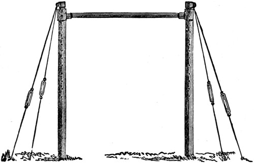
Fig. 1.
The bar or pole should be of ash, diameter 2 inches, length 6 feet. The more expensive bars have a steel core running through the middle, in which case the diameter can be reduced to 11⁄2 inches, and the length increased to 7 feet. This size is decidedly more pleasant for use, as a firmer grip can be obtained than on the thicker bars. The height of the bar from the ground of course varies according to that of the gymnast, who should be able to touch the lower side with both hands (the tips of the fingers) when standing raised on his toes. When hanging by the hands, the toes will then just clear the ground.
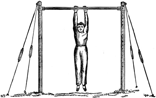
Fig. 2.
Having adjusted the apparatus to the proper height, begin by
Jump up and seize the bar with both hands, knuckles upwards, the thumbs on the same side as the fingers. Remember (with the exceptions mentioned later on)[23] never to grasp the bar as you would a broomstick, but hook the hand over it. Let the legs hang perfectly straight and together, toes pointed.
Now ‘walk’ with the hands from one end of the bar to the other, and back again. Keep the body steady and avoid swaying (Fig. 2).
Hang on the bar as before, and slowly draw yourself up, keeping the shoulders square, until the chest is level with the bar (Fig. 3).
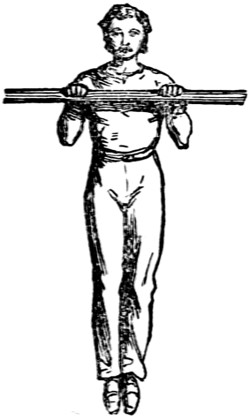
Fig. 3.
Then lower the body until the arms are quite straight again, draw up again, and continue to practise until you can accomplish it from eight to a dozen times in succession. When breasting the bar, repeat the walk in that position.
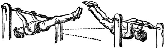
Fig. 4.
Now try swinging forward and backward, arms straight, increasing the height with each swing until the body assumes an almost horizontal position. When at the extent of the backward swing, the hands should be shifted slightly round the bar to recover the grip which the forward swing has lessened (Fig. 4).
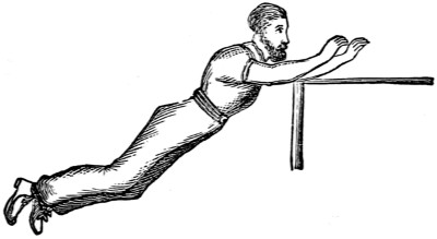
Fig. 4A.
Now in the backward swing release your hold of the bar and launch yourself away from it with a slight push and alight on your feet. This will accustom you to leaving the bar neatly and effectively (Fig. 4A).
Draw the chest up to the bar, throw the head well back, raising the legs at the same time (keep them straight), and get the toes over the front of the bar, pulling hard with the arms (Fig. 5). This will cause you to revolve half round the bar, and will bring you into position as in Fig. 6.
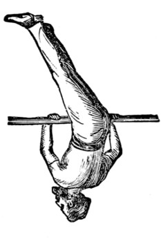
Fig. 5.
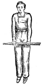
Fig. 6.
This is rather difficult to perform, and requires a deal of practice, but it is an indispensable exercise.
When in this position (Fig. 6) endeavour to revolve completely round the bar like a wheel on its axis. To do this you must throw the upper part of the body forward with a good swing, at the same time keeping the arms rigid, and giving yourself sufficient impetus to go round, coming up into the original position.
Get into position as in Fig. 3, then drop the right side of the body, simultaneously throwing the left leg over the bar as in Fig. 7, and swing the other leg which will have the effect of bringing you up over the bar. Endeavour to come up with the body upright, as in Fig. 8.
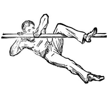
Fig. 7
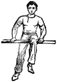
Fig. 8
You will experience some difficulty in doing this, and your first attempt will no doubt result in a mere scramble up, but persevere until success rewards your efforts.
There is another method you may try—viz., to bring the leg up through the hands, and, with a good swing, bring yourself up, as in Fig. 8.
One method is perhaps as good as the other, but neither can be neatly performed without continual practice.
When in position, as in Fig. 8, swing the right leg out behind, at the same time shifting the left leg backward until the bend of the knee catches the bar (Fig. 9).
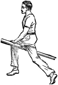
Fig. 9
Keep the arms straight, and throw the head back with a good swing, just enough to bring you round the bar into the original position. You must be careful in judging the swing, otherwise you will find that you cannot stop yourself, and will make a half turn too much. After a little practice you will be able to judge the first swing to a nicety, and come up with a good balance. Now do several turns without stopping, always remembering to finish above the bar.
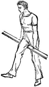
Fig. 10
For the forward leg swing, turn the hands the other way, leaning the weight of the body on the arms; throw the head forward, and, with one bold plunge,[25] keeping the body erect, and holding tightly on to the bar, make the revolution (Fig. 10).
Do not be content with accomplishing this with one leg only, but practise with right and left alternately.
The forward swing will tax your confidence more than the backward, but it is really not more difficult. You will, after a little practice, be able to make several revolutions in succession. This has a very dashing appearance.
This will prove rather difficult at first. Get on to the bar, as in Fig. 8, and preserving your balance, bring the hanging leg with a rapid movement over the bar into a sitting position. To effect this you must leave go of the bar with the right hand, resuming your grasp directly the leg has passed under your hand. You will now be in position as in Fig. 11.
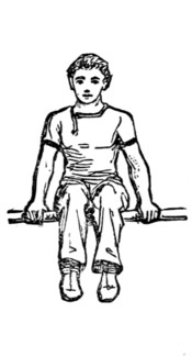
Fig. 11
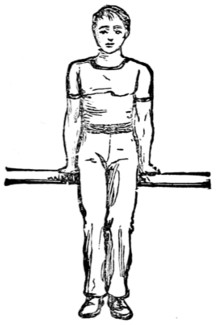
Fig. 12
This exercise really consists of balancing, and in your first attempts you will find a tendency to roll over backwards directly the leg reaches the level of the bar. Should you do so, however, you can quickly recover your position by the method described in ‘getting on to the bar.’
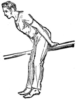
Fig. 13
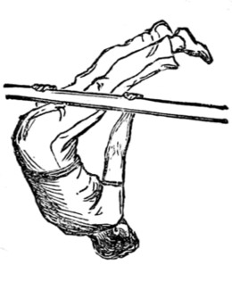
Fig. 14
There is another way of getting into the sitting position. Hang on as in Fig. 2, and doubling up, pass the legs through the arms (Fig. 14), straighten the body, as in Fig. 15, and draw yourself up until the posterior is a little above[26] the bar. You will then, with a slight bend of the body, roll over into position. You must keep the head well back, and pull hard with the arms.
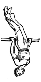
Fig. 15
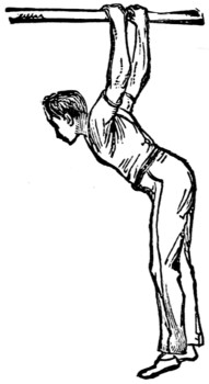
Fig. 16
A good exercise for the muscles of the back is to drop through when in position as in Fig. 14, to position as in Fig. 16, and back again to Fig. 2. Be careful to keep the legs straight while doing it. It is easy enough to effect with legs bent.
Having accomplished ‘sitting,’ accustom yourself to remaining in that position without holding the bar with the hands, balancing yourself with the bar under different parts of the leg.
This will prepare you for the
which is not unlike the leg swing, but very much more difficult, as greater strength is required, in consequence of the whole weight being thrown upon the arms.
Sitting on the bar as in Fig. 11, stiffen the arms, and launch yourself backwards with a good swing, holding the bar firmly with both hands, and go right round the bar with the impetus you have given yourself, resuming the position from which you started. As in the leg swing, you must judge the swing correctly, or else you will go round half a turn too much, or fail to give sufficient swing to come up at all. This will very likely be the case in your first few attempts, for you can hardly expect to accomplish the feat at once.
In attempting this exercise it is as well to have some one standing in front of the bar ready to catch you in the event of your not having given swing enough to balance yourself, in which case you will fall forward.
In the sit swing forward, starting is the important part. Raise the body as far from the bar as possible, the whole weight supported on the arms (Fig. 12), legs straight, chest thrown out. Now with a bold plunge forward you will go right round (that is after a time). The arms must be kept perfectly straight, as in Fig. 13, and the hands of course reversed as in the leg swing forward.
This feat requires more nerve than any we have yet described, and, as a natural accompaniment, more practice, but it will well repay any amount of perseverance.
Sit on the bar, then suddenly slide backwards and drop, catching yourself by your bent knees (Fig. 17).
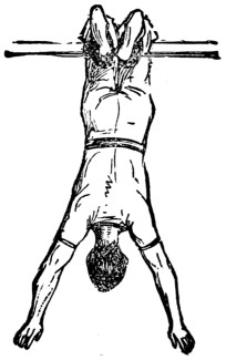
Fig. 17
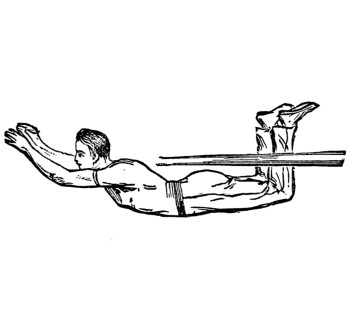
Fig. 18
You must be very careful not to communicate any swing to the body, but to drop quite straight, or off you will come. Having successfully acquired this exercise, you may now practise swinging by the legs, when as in Fig. 18, let go with your legs, and let them drop and come on your feet on the ground. This exercise had better be first practised on a bar sufficiently low to allow of your just touching with the tips of your fingers when hanging, in case you hold on too long, and so come on your hands and feet instead of on your feet only. A very little practice, however, will suffice to give you the knack of leaving go at the exact moment, and as this method of leaving the bar is often called into requisition at the end of a series of combined movements, it should be acquired perfectly.
We cannot too strongly advise our young friends who wish to become gymnasts to pay particular attention to the style in which they perform the exercises. Many a difficult feat is spoiled in appearance by the clumsy manner in which it is executed, and fails to elicit the admiration afforded to a much simpler movement gracefully performed.
This exercise is very difficult, and will necessitate a lot of practice. It differs from the ‘Short Circle’ already described in this important particular, viz., that the circle is performed without any part of the body touching the bar. You must commence by drawing the chest up to the bar from the hanging position, then throw the head back, and, raising the legs, and pulling hard with the arms, endeavour to bring the feet over the bar, describing, as it were, part of a circle. While the legs are passing round, straighten the arms, and you will come into position as in Fig. 19.
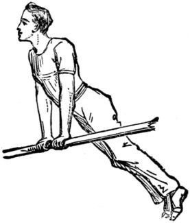
Fig. 19
Now revolve round the bar, keeping the arms rigid, and the body away from the bar. The whole weight of the body (which must be kept quite straight) will thus be thrown on the arms. Our readers must not be discouraged at the[28] nonsuccess that will attend their first efforts to accomplish this exercise, which, as we have before remarked, is a very difficult one, and requires a deal of practice before the knack can be acquired.
This, although not difficult to perform, is very showy, and frequently elicits greater applause from an audience than much more difficult feats. Get on to the bar in sitting position, as in Fig. 11, then slide down in front, at the same time putting the arms straight down behind you until the bar comes across the biceps; then communicate a swing to the body until you have acquired sufficient momentum to carry you completely round the bar. The ordinary way in which this feat is performed is with the head going forwards (Fig. 20). The other way (backwards) is more difficult.
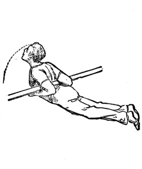
Fig. 20
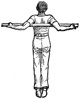
Fig. 21
It can be done in a third way, with the arms straight along the bar (Fig. 21).
This is easier than most people imagine. Whatever difficulty may be found will consist not so much in the actual sustaining of the weight of the body by the toes as in the task of getting the feet into position on the bar. We will suppose, however, that by this time the pupil will have mastered the short circle described on page 23, in which case he will find it easy enough to hitch the toes on the bar instead of bringing them over to complete the circle. This having been accomplished, nothing remains but to leave go with the hands and let the body drop slowly until hanging quite perpendicularly (Fig. 22).
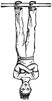
Fig. 22
In first attempting this, it is advisable to stretch out your arms, so as to be prepared in case you find your feet slipping off. To drop on to the hands is the easier way of leaving the bar from this position, but it is not the correct one, which is to draw the body up and resume your hold of the bar by the hands.
This is like the sit ‘swing backward,’ except that it is performed without holding the bar by the hands, which of course renders it very much more difficult.
Sit on the bar as far back as possible, and then launch yourself backwards with arms extended, holding tight with the legs, and, with a good swing, come right round the bar into sitting position from which you started (Fig. 23).
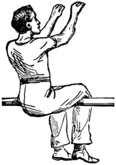
Fig. 23
Great demand will be made upon your store of confidence in the performance of this feat, but it well repays the practice involved, as it has a very dashing appearance, especially when several turns are done in succession, which you will be able to accomplish after a time.
This is an indispensable exercise, and one that will be frequently called into requisition by the gymnast as he becomes more advanced. It consists of getting on to the bar by a swing and a jerk, the peculiar nature of which it is rather difficult to describe. First hang by the hands, then bring the feet up to the bar and shoot them out sharply as far as possible (Fig. 24), at the same time pulling hard with the arms.
You will find, after a time, that this will have the effect of bringing you right up on to the bar as in Fig. 6.
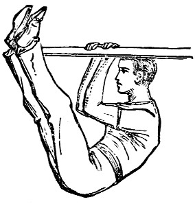
Fig. 24
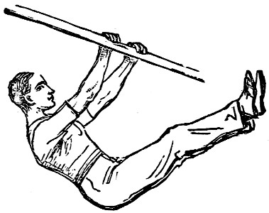
Fig. 25
The upstart can be performed without the swing, but the arms in this case must be kept perfectly straight. Raise the legs as before, then drop them suddenly and pull the body above the bar. To see the upstart once performed will do more towards teaching its acquirement than pages of explanation. It is purely a knack, which will come to you all at once, after, perhaps, numberless fruitless attempts (Fig. 25).
is another method of getting on to the bar, and is a feat of strength rather than of agility, great muscular power being necessary for its successful accomplishment.
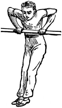
Fig. 26
It is performed by drawing the body up while hanging from the bar. The hands must be well over the bar—in fact, the wrists must rest there. In this exercise it is better to have the thumbs underneath (this is one of the exceptions referred to in page 22), as otherwise, when you come up, your hands may slip off. Fig. 26 shows the position midway.
This is the critical point, and all your strength will be required to get the rest of the way. By raising the elbows a little you will find you will get a greater purchase, and the raising of the legs will counterbalance the weight of the body and[30] bring it up. This exercise always meets with great applause, especially when done several times in succession, a feat that will task your powers to their utmost.
Another strength movement is the
It consists of supporting the body by the strength of the arms, as shown in Figs. 27, 28.
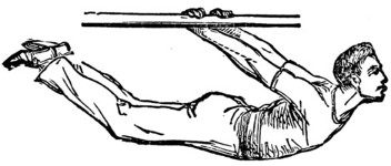
Fig. 27
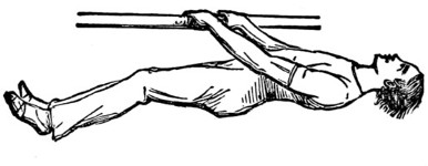
Fig. 28
This must first be practised on a bar reaching not higher than the waist. The feat is to clear the bar as shown in Fig. 29. Some amount of confidence will be required for the performance of this exercise, and there must be no hesitation in the matter, or over you will come on your nose. First practise jumping on to the bar, so as to touch with both feet inside the hands; then try outside, and, when you have become accustomed to this movement, you may make your attempt to go clean over. You must be careful to let go with the hands at the proper moment when in position shown in Fig. 29.
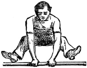
Fig. 29
The exercise is usually first acquired on the ‘horse’ (an apparatus which we shall describe in due course), and is much more difficult on the horizontal bar, but as it is a very pretty finish to a series of combined movements, we have introduced it here.
We should recommend your having some one standing in front of the bar when you commence to practise this movement, to catch you in case your feet do not quite clear.
This is perhaps the most difficult of all the exercises on the bar, and requires great strength and nerve for its accomplishment. There are very few gymnasts who can do it properly, which is not to be wondered at, considering the amount of practice that it involves. Only the advanced gymnasts, those who have completely mastered all the foregoing exercises (especially the clear circle, which is the preliminary to the long swing), should attempt it.
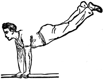
Fig. 30
Start from position as in Fig. 6, and raise the body up (Fig. 30), then descend[31] with a dashing swing (Fig. 31), bending the body backward, and just as you are underneath the bar throw the legs forward and the head back. This will have the effect of bringing you up above the bar. You must now bend the arms slightly, to bring you nearer the bar, over which you should come with the chest thrown out. This position is the most awkward part of the whole swing, for the hands will be found too far over the bar. To rectify this you must make what is known as the shift, which consists of making a rapid turn with the hands, bringing the palms on to the top of the bar, when you can straighten the arms (Fig. 32), ready for another circle.
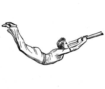
Fig. 31
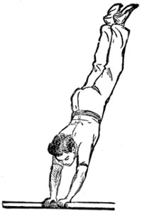
Fig. 32
The long swing can also be performed forward, but it is even more difficult than the one just described.
We have now shown most of the principal movements on the horizontal bar, a great many of which, when properly acquired singly, can be performed in combination. For instance—
Start with the short circle, throw the legs over the bar into sitting position, then sit swing backwards, leave go with the hands, two hock swing backwards, and off the bar on to your feet as in Fig. 18.
Again. Upstart, clear circle (three or four times) into sitting position, sit swing forward, change hands, and hock swing off.
A very dashing-looking feat is the upstart and splits in one movement. Care must be taken not to allow the body to touch the bar, or your impetus will be stopped just when it is required for clearing the bar.
This concludes the Horizontal Bar. We will now proceed to describe the exercises on the Parallel Bars.
The Parallel Bars are very simple in their structure. They consist of two bars, running side by side, supported by uprights at a sufficient height from the ground to allow the feet to swing clear. The width should not be more than eighteen inches; length about seven feet.
The exercises that can be performed upon this apparatus are various and attractive; some of them comparatively easy, the more advanced very difficult, and requiring great strength and skill in their execution.
Rise into position as in Fig. 33, and walk with the hands to the end of the bars, keeping the arms stiff, legs straight, and toes pointed. Now walk back again. Now proceed along the bars by a succession of jumps with the hands and back again.
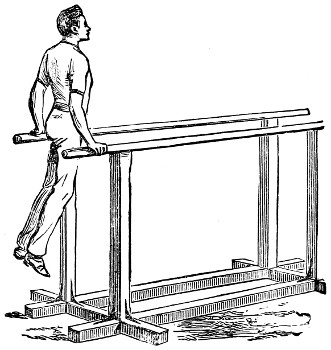
Fig. 33
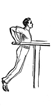
Fig. 34
Let the body sink down, as in Fig. 34, and hop along in that position forwards and backwards. Be careful to keep the body steady and legs straight.
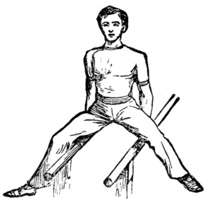
Fig. 35
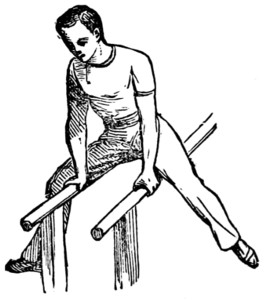
Fig. 36
Position as in Fig. 33. Now commence swinging the legs backwards and forwards. When accustomed to this movement, throw the legs over the bars in front of you (Fig. 35), then bring the hands to the front (Fig. 36), and bring the[33] legs over again between the bars into original position. Do this several times in succession, and vary the exercise by commencing with throwing the legs behind.
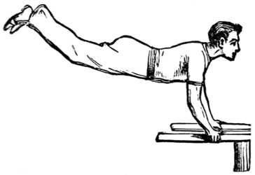
Fig. 37
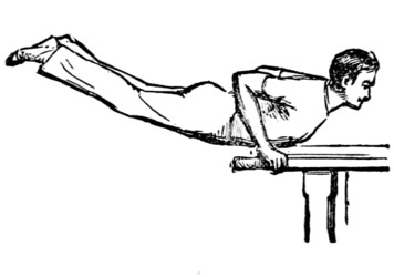
Fig. 38.
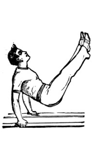
Fig. 39
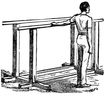
Fig. 40
The pumping movement is a splendid exercise for bringing out the muscles of the chest, and is performed as follows. Swing the body into a horizontal position, as in Fig. 37; then bend the arms and drop into Fig. 38. Swing the legs forward, and with the impulse this will give you come up into Fig. 39, and finish with a swing back into position from which the movement was commenced. In the backward ‘pump,’ commence from the position as shown in last figure, and drop with the backward swing. It is a pretty movement to combine the two—first forwards, then backwards, in alternate swings, and then to leave the bars by a side movement on to your feet, as in Fig. 40. This last movement is one of the neatest and easiest ways of leaving the bars, and can be done either forwards or backwards, and on right or left side.
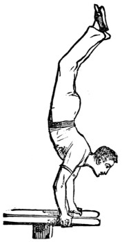
Fig. 41
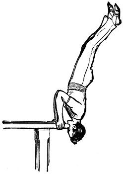
Fig. 42
After having fairly mastered the pumping movement, you will now be ready for attempting the hand-balance—an exceedingly effective exercise, and not very difficult to accomplish. Commence as for the backward pump, and, with an increased momentum, bring yourself up into a hand-balance (Fig. 41). This movement should be first practised at the end of the bars, as in the event of your overbalancing—a not unlikely contingency—you can save yourself by bending the[34] arms, as in Fig. 42. We should also recommend your having two friends to stand by you, one on each side of the bars, ready to catch you in case of a tumble. Having become proficient in the stationary balance, try to walk along the whole length of bars with the hands, still preserving the balance. This will be found none too easy, as directly one hand is moved forward the balance is altered, and there is a tendency to fall over. The correct method of leaving the bars after balancing is by means of the hand-spring, which is performed by bending the arms as in Fig. 42, and when in that position dropping the legs and pushing away from the bars with the arms; the result will be that you will alight on your feet after having turned a half-somersault. In practising this also you should have two friends ready to catch you, as your first few attempts are nearly certain to be unsuccessful.
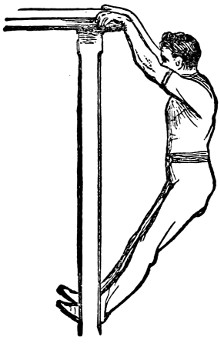
Fig. 43
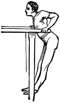
Fig. 44
The slow pull-up was described in our remarks on the Horizontal Bar, but upon the parallels it is much more difficult of execution. The movement is shown in Figs. 43 and 44. In starting, the hands should be placed well over the ends of the bars—the wrists, in fact, being over—then by sheer strength raise the body up to[35] Fig. 44. This is the awkward point, and all your exertion and power will be called upon to get right up with straight arms.
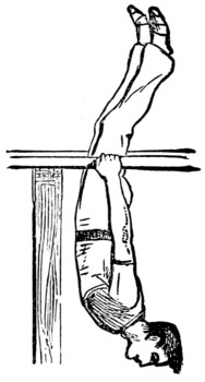
Fig. 45
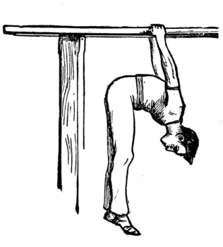
Fig. 46
The following exercise is also very similar to one described for the horizontal bar, but it is more difficult on the parallels. Stand between the bars, catch hold of them with the hands, and stoop down until the shoulders are level with the bars; then raise the legs—keeping them straight—until the body is in position, as in Fig. 45, when drop right over to Fig. 46; then back again, and continue the movement several times. This is splendid exercise for opening the chest and strengthening the muscles of the back.
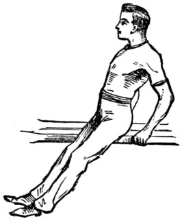
Fig. 47
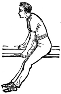
Fig. 48
Vaulting movements, when neatly performed, are very pretty, and should be commenced from the centre of and between the bars. Figs. 47 and 48 will convey the idea to our readers. A great many movements may be gone through while in this position, the necessary impetus being obtained by swinging the legs over the bars.
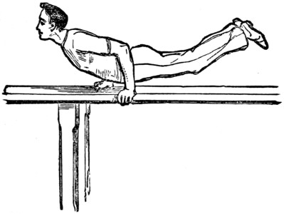
Fig. 49
Fig. 49 shows the most difficult of all the exercises upon the parallels. It is to make the head and shoulders counterbalance the legs, and to hold the body parallel with the bars by the arms. This is known by the name of ‘La Planche.’
We will now proceed to a description of the exercises on the
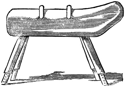
Fig. 50
The above sketch shows the apparatus (Fig. 50). The dimensions most convenient for use are 5 feet 10 inches to 6 feet in length, and about 16 inches[36] across the back; the height can be arranged as required. It will be seen from the illustration that the legs are telescopic, and can be lengthened or reduced at pleasure.
The two pommels in the centre are about 18 inches apart, and can be removed for certain exercises hereafter described. In that case, pommels level with the back of the horse are inserted to fill up the grooves. In performing a great many of the exercises it is necessary to have a wooden board about 3 feet square, rising in thickness from a feather edge to 3 inches, to be placed on the ground at the side or end of the horse, as the case may be, for the ‘take-off.’ This is not used as a spring-board. It should be solid, and made of deal.
The trunk of the horse is made of a solid piece of wood, and covered all over with cowhide. One end, as will be seen from the engraving, is raised, with a slight bend corresponding to the neck of the animal, which gives it its name.
Many of the exercises upon the horse are similar to those upon the parallels. Our readers can themselves recognise which they are; we shall therefore avoid recapitulation, and only describe those peculiar to the horse.
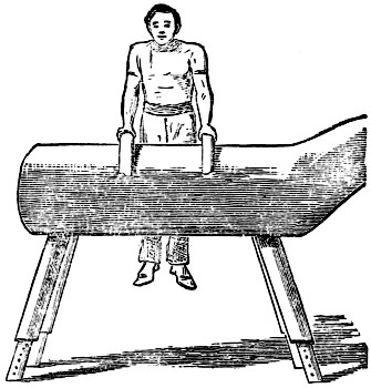
Fig. 51
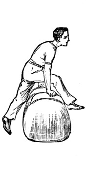
Fig. 52
Start by springing on to the horse with the hands one on each of the pommels, legs hanging straight (Fig. 51). Now swing the right leg over the horse in between the pommels (as in Fig. 52), momentarily relinquishing the hold of the right hand, and immediately the leg has passed resuming your hold; then the same with the left leg. This must be done without touching the horse with the foot, and the body must be supported by the arms the whole time. Then bring each leg back again into original position.
Now try the two movements at once—that is, while the one leg is being brought back the other is to be passed through forward. You will thus always have one leg on each side of the horse.
The next exercise is the—
Stand in front of the horse, hands on pommels, then spring up into the saddle[37] into a kneeling position (as in Fig. 53). Then, throwing the arms up, give a good spring forward, alighting on your feet the other side (Fig. 54). You will feel rather awkward at first in attempting the spring, as the legs seem to be glued to the saddle, but it is very easy after having once been accomplished.
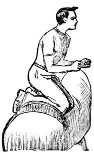
Fig. 53
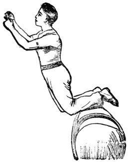
Fig. 54
Jumping exercises on the horse, when neatly performed, are very effective.
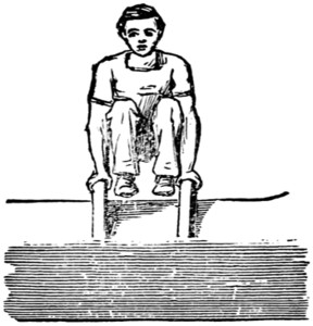
Fig. 55
Take a short run up to the board (described above), and jump—off both feet at once—over the back, passing the legs through the arms, and assisting yourself by the hands one on each pommel (Fig. 55).
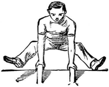
Fig. 56
When in this position shoot out the legs in front of you, and, leaving go of the pommels, come down neatly on the other side. Be careful to gather up the legs well when passing through, or you may catch your feet against the back of the horse, and come down on your nose. There are several forms of this exercise. Fig. 56 shows one of them.
It is rather more difficult than the last, from the legs passing outside the hands. A much greater spring is required to raise you high enough to pass over, and you must be careful to let go with the hands at the proper time, otherwise you will lose command of yourself and pitch forward on to the ground. In practising this movement we recommend your having a friend to stand in front of the horse, to catch you in case of such an emergency.
Get on to the horse as in Fig. 57, sitting across, outside the pommels, then catch[38] hold of the pommels as shown, and, throwing the whole weight of the body upon the arms, throw the legs right up, and, with a kind of twist, bring yourself round on to the horse the opposite side of the pommels, retaining your hold all the time. You will then face the opposite direction to the position from which you started. Practise the exercise from right to left, and vice versa.
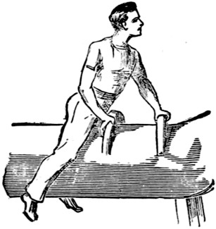
Fig. 57
There are many other forms of saddle-vaulting possible of practice, some of them very difficult, but it is not needful to describe them.
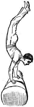
Fig. 58
The hand-balance was described in the chapter on the parallel bars. It is a little more difficult of execution on the horse. It is shown in Fig. 58.
The assistance of two friends in attempting this feat is desirable.
For these exercises the pommels must be removed, and the spaces filled up with the flush ones, as described already. The movement is not unlike leap-frog, as the spring is taken off the board, and you pitch on to your hands in the same manner. But there the similarity ends, for it is a very different matter clearing a boy’s back, from getting over the whole length of the horse.
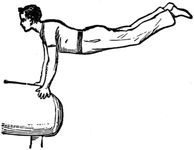
Fig. 59
Commence by placing the jumping-board about 3 feet from the largest end of the horse, then with a run and a spring pitch on to your hands, as in Fig. 59.
After practising this, move the board farther away and repeat; continue the exercise, each time measuring the distance, until you can pitch on to the ends from about 5 or 6 feet.
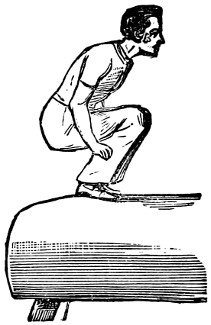
Fig. 60
Now jump up on to the end of the horse, as in Fig. 60, then plunge forwards on to the other end, pitching on to the hands, and clearing the horse, as in leap-frog, coming down safely on the ground in front.
This exercise must be done with dash and vigour. If you are half-hearted about it you will come to grief.
This simple apparatus consists of iron rings attached to two ropes suspended from a cross bar or from a ceiling, about seventeen or eighteen feet in length, and at a sufficient height from the ground to allow the feet to swing just clear. The rings or stirrups (the latter shape is the more convenient) should be covered with leather, and of a thickness affording a good grasp. The exercises that can be performed upon them are neither attractive nor various, but they are useful, and as no section on gymnastics would be complete without their introduction, we will proceed to describe them.
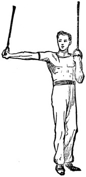
Fig. 61
Begin by drawing yourself up, as in Fig. 61, holding one ring close to the shoulder and the other extended at arm’s length. Now draw in the extended arm, at the same time straightening the other, and repeat the movement as long as you are able, first one arm straight, then the other. Keep the head erect, looking straight before you, not at either of the rings. Legs hanging close together, toes pointed.
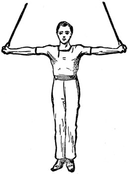
Fig. 62
Now try the slow pull up; this is not so difficult upon the rings as upon the horizontal bar. The wrist should be placed well over the rings, so as to get a good purchase. Then proceed as directed in the horizontal bar directions, and when you have drawn yourself quite up, straighten the arms and press them close to your sides. Now for a stiff one. When in this position gradually extend the arms apart, allowing the body to sink until the shoulders are nearly level with the rings (Fig. 62). Endeavour to keep in this position, supporting the body as long as possible, then lower yourself gradually, until you hang straight down again.
The back and forward ‘horizontals’ (also described in the horizontal bar) are very good exercises to practise on the rings.
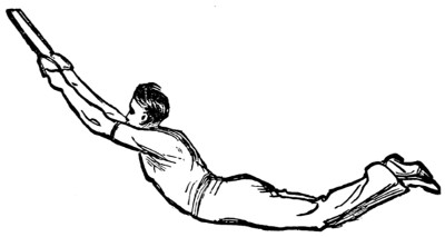
Fig. 63
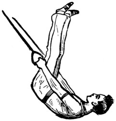
Fig. 64
Now for some swinging exercises. Take hold of the rings and with a few quick steps forward communicate a swing to the body, which increase by drawing yourself up in the forward swing, and when at its extent lowering yourself with a drop.[40] This will cause you to swing higher each time until your arms and legs are straight and nearly in a horizontal position, as in Fig. 63. When accustomed to this exercise, which should be practised until perfect confidence is attained, you may proceed to the following. Commence as before, and when at the end of the forward swing, draw up the legs over the head, as in Fig. 64, and immediately before commencing the backward swing shoot the legs out straight, and come back to position as in Fig. 63. Continue the movement half a dozen times.
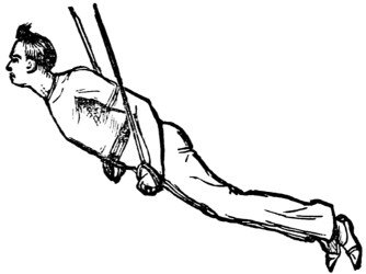
Fig. 65
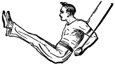
Fig. 66
Commence as before, and when at the end of the backward swing, suddenly contract the arms and raise yourself up into the rings, as in Fig. 65, and continue swinging in that position. In order to preserve your equilibrium you must bring the legs forward when beginning to descend, as in Fig. 66.
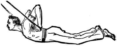
Fig. 67
Another variety of the swing is to support yourself on the rings, ‘grasshopper fashion’ (Fig. 67). A very pretty effect is produced by a combination of the different swings we have described. The order in which they are performed is immaterial, and may be left to the pleasure of the gymnast.
We will conclude our directions for the rings with a description of what is known as ‘dislocation.’
Hang from the rings and draw up the legs over the head, and drop over, as in Fig. 46 (Parallel Bars). Now instead of going back again, push the rings out and away from you on each side. The body, by its own weight, will drop through and[41] cause the arms to twist until you will find yourself hanging with straight arms in the position from which you started. The sensation you will experience when first the exercise is performed is (of course momentarily only) not unlike ‘dislocation,’ hence the name the exercise bears, but after a few successful attempts it is comparatively easy, and is a splendid means of opening the chest.
Although not generally looked upon as a gymnastic exercise, climbing the rope, pole, etc., is so essentially useful, and so likely to prove of service in an emergency, that we devote a few lines to describe the best and most effective method. Those who have never attempted to climb a rope can have but little idea of the severe nature of the exercise. Although unfortunately neglected, in favour of more showy feats by the majority of gymnasts, yet there are a few who make a speciality of it, and climb heights really marvellous. A few years ago, on the occasion of the German Gymnastic Society’s annual display at the Crystal Palace, one of the members ascended a rope from the floor to the extreme height of the centre transept. The arduous nature of the feat may be imagined when our readers are informed that a quarter of an hour was occupied in the ascent. The way of taking hold of the rope is shown in Fig. 68. The legs should now be drawn up and the knees and feet pressed against the rope, and the hands then shifted higher (Fig. 69).
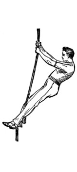
Fig. 68
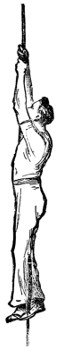
Fig. 69
Climbing by the hands only, ‘hand over hand,’ as it is called, is much more[42] difficult, and can only be performed to a limited height. Climbing the pole is more difficult, from the fact that it is unbending and thicker to grasp. Fig. 70 shows the position.
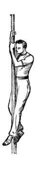
Fig. 70
In nearly every well-appointed gymnasium there are ladders, placed in horizontal or slanting positions, upon which a variety of easy but useful exercises may be performed. ‘Walking’ by the hands is shown on the horizontal ladder in Fig. 71. By moving the hands forward alternately, holding by the outside, you progress from one end to the other, and back again by reversing the movement.
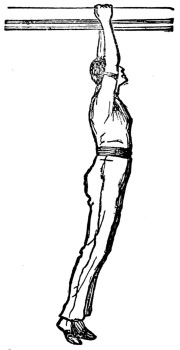
Fig. 71
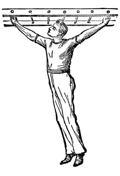
Fig. 72
In Fig. 72 another movement is shown, in which progression is made by a succession of ‘steps’ from round to round, first from one round to the next, and afterwards increasing the length of the step by missing four, five, or six rounds, as the length of reach will permit.
Comparatively few years ago bodily exercises were mostly confined to walking, running, and rowing; now, happily, it is an exception not to find some sort of gymnastic exercise desired by boys where apparatus is necessary. My object in this article is to tell as briefly and succinctly as possible, how any one, with a slight knowledge of carpentry, can make at home all that is requisite for a gymnasium, and that too at a comparatively small expense.
As you will, of course, require some tools, I will begin by supposing that you have the ordinary commonplace ones, but may mention that, as you will find the truth of the adage, ‘A bad workman finds fault with his tools,’ you must[43] not attempt to cross-cut a piece of timber with a rip saw, or split your wood by using a gimlet instead of a bradawl, blaming the tools, spoiling the wood and also your own temper.
Let us begin with the construction of the horizontal bar, as it is the simplest apparatus to make, and affords the greatest variety of exercises. There are several ways of forming the supports. We will take the two most suitable, one as a fixture and the other portable, to be used in a room or anywhere else desired.
With wooden uprights to fix in the ground (See next page, Fig. 1):
Tools.
Hand-saw (cross-cut).
Jack plane.
Spike gimlet (three-eighths of an inch).
Inch chisel.
Hammer.
Rule and Pencil.
| Materials. | s. | d. |
|---|---|---|
| 2 Yellow battens 14 ft. long, 7 in. by 21⁄2 in. at 31⁄2d. | 8 | 2 |
| 4 Struts, yellow, 4 ft. 6 in. long, 4 in. by 1 in. | 1 | 0 |
| 1 Bar 6 ft. long, 17⁄8 in. in diameter | 6 | 6 |
| 2 Pins 6 in. long, 3⁄8 of an inch in diameter, at 4d. | 0 | 8 |
| 20 nails 21⁄2 in. long | 0 | 4 |
| 2 lb. lead-colour paint, at 8d. | 1 | 4 |
| 1 lb. ultramarine blue | 1 | 0 |
| 19 | 0 |
The first thing to be done is to order your wood of the nearest timber-merchant. There are various kinds of fir-timber, and those mostly used are pine, spruce, and yellow deal. The latter is the best for our present purpose, as it is easy to work and will best stand the inclemency of the weather. I need scarcely tell you where to get the other materials, as most ironmongers and colourmen keep everything you may require in this way.
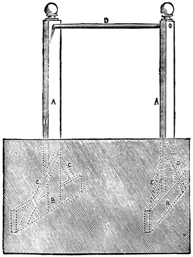
Fig. 1
Having all your materials and tools ready, saw 4 feet off your battens (A A), which will leave 10 feet for the uprights, and as 2 feet 6 inches have to be let into the ground, you will then have 7 feet 6 inches for the height of the bar, which is sufficient for all exercises. You will next fit the 4 feet-pieces (B B) into one end of the uprights by halving them in; this will form the sole-piece to which the struts (C C C C) are nailed. All this part, which goes underground, is left in its rough state; the 7 feet 6 inches above the ground will have to be planed over and the edges rounded off. The uprights can be either left plain or an ornamental turned top may be added. This is a matter of fancy.
Our bar is made of the best straight-grained ash, 6 feet long and 17⁄8 in. in diameter.
Before fixing, cover the knots with a little patent knotting, then paint the uprights all over with a coat of priming, another coat of lead colour and one of any finishing colour you prefer. Green will soon fade, blue will stand for years.
Tools.
Saw.
Jack plane.
Inch chisel.
Three-eighths-of-an-inch spike gimlet.
| Materials. | s. | d. |
|---|---|---|
| 4 Lengths of Yellow deal 8 ft. long, 41⁄2 in. by 11⁄2 in. | 5 | 0 |
| 2 Stakes 2 ft. 6 in. long, 3 in. square | 0 | 6 |
| 1 Bar, with iron core and screw-eyes, 6 ft. long | 10 | 0 |
| 2 Stay-ropes and toggles | 2 | 0 |
| 2 Stretcher irons | 1 | 0 |
| Size and Varnish | 1 | 0 |
| 19 | 6 |
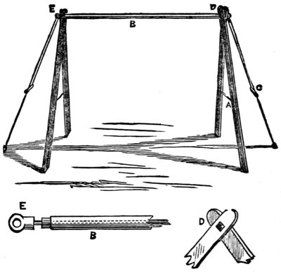
Fig. 2
This bar (Fig. 2), for its simplicity, portability, and strength, has a reputation for being one of the most useful kinds of apparatus made. Not only is it used for a bar, but children’s swings, hand-rings, and trapeze can be attached to it, as the supports can be spread out to allow the bar to stand at various heights by shifting the stretcher irons (A A) up and down. These irons, three-eighths of a inch in diameter, are cranked at each end—i.e., bent at right-angles—and fit into holes in the uprights about 3 inches apart.
There will be very little for you to make in this, viz., the four uprights. After you have planed these over and rounded the edges, mortice 11⁄4-in. square holes through two of the uprights (D), six inches from the top, and bore 3⁄4-in. round holes through the other two. This is to take the end of the bar (B).[45] The square part is to prevent the bar turning round when you swing on it. You will have to purchase the bar with iron core, as it would be impossible to make it without proper machinery.
Size and varnish the uprights with one coat of size and two of hard oak varnish. In fixing, you merely turn the screw-eye into the floor or stakes, and attach the stays (C C) to them.
with wooden uprights to fix in the ground.
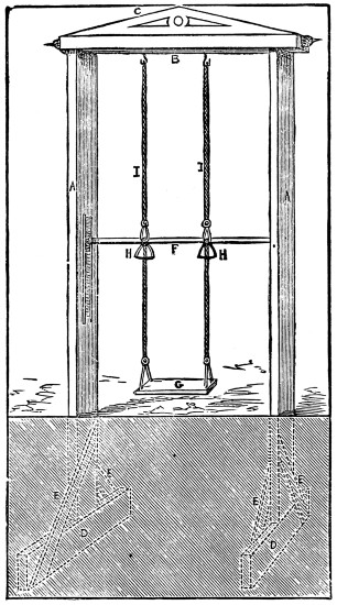
Fig. 3
Tools.—Same as for Horizontal Bar, Fig. 1.
| Materials. | s. | d. | |
|---|---|---|---|
| 2 Yellow battens 15 ft. long, 7 in. by 4 in., at 5d. | 12 | 6 | |
| 1 Yellow 14 ft. long, 7 in. by 21⁄2 in., at 31⁄2d. | 4 | 1 | |
| 4 Struts 5 ft. long, 4 ft. by 11⁄2 in. | 1 | 3 | |
| 4 Runners 3 ft. long, 2 in. by 2 in. | 1 | 0 | |
| 1 Ash bar 6 ft. long, 17⁄8 in. diameter, with 2-in. square ends | 6 | 6 | |
| 1 Facia board 6 ft. long, 6 in. by 1 in. | 0 | 6 | |
| 20 Nails 21⁄2 in. long | 0 | 4 | |
| 4 Spikes 4 in. long | 0 | 2 | |
| 16 Screws No. 16, 3 in. long | 0 | 8 | |
| 2 Pins 6 in. by 3⁄8 in. diameter | 0 | 8 | |
| 3 lb. lead-colour paint, at 8d. | 2 | 0 | |
| 11⁄2 lb. ultramarine blue, at 1s. | 1 | 6 | |
| £1 | 11 | 2 |
Fig. 3 represents the Lawn Gymnasium with some of its appendages. My object now is to show you how to construct the frame, and, of course, when that is done you can add whatever you like, as, for instance, climbing-rope or pole, hand-rings (H H), trapeze bar, foot or sitting swing (G), vaulting and horizontal bar (F), etc.
On referring to the quantities you will find there are two yellow battens[46] 15 ft. long; these form the uprights (A A); 3 feet has to go into the ground, leaving 12 feet for the height of the swing. The top (B), 7 feet in length, is cut off the 14-ft. length, the remaining 7 ft. is again cut in the centre to form the two sole-pieces (D D), 3 ft. 6 in. each; these are then halved into the bottom of the uprights in centre, and the struts (E E E E) nailed on as shown. The top can be either morticed on to the uprights or secured by strong iron brackets. The inch facia board (C) is nailed on the top for ornament, as are also the cornice pole-ends.
The 2-inch square runners are secured on the uprights with the 3-inch screws (four to each runner), 3 feet from the ground and 2 inches apart, leaving a groove or space between them for the ends of the bar to slide up and down. For vaulting purposes these runners have to be bored through with a 3⁄8-in. nose or spoon-bit (a gimlet would split the wood); the holes must be about three inches apart from the top to bottom, and are intended to take the 3⁄8-in. pin which is to support the bar.
The whole of the wood-work above ground must be planed, and the edges neatly rounded off. It is the custom to burn or char the surface of that part of the timber which has to be let into the ground, to prevent it from rotting, but a good coat of gas tar answers the purpose very well.
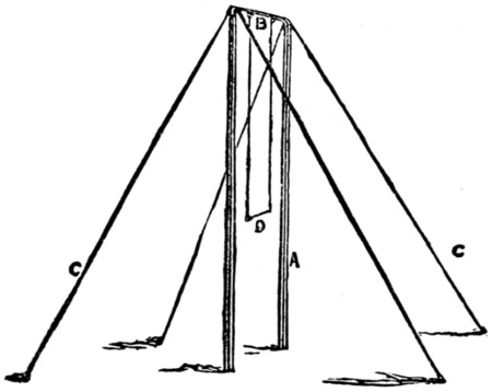
Fig. 4
| Materials. | s. | d. | |
|---|---|---|---|
| 2 Norway spars trimmed, 14 feet long, at 5s. | 10 | 0 | |
| 6 ft. 2 in. iron tube, at 71⁄2d. per foot | 3 | 9 | |
| 2 Elbows for iron tube, at 1s. 41⁄2d. | 2 | 9 | |
| 100 ft. 3⁄8 in. iron wire rope | 10 | 0 | |
| 1 Coupling Screw | 5 | 0 | |
| 4 Stakes 3 ft. 3 in. square | 1 | 4 | |
| £1 | 12 | 10 |
Fig. 4 represents a very simple way of forming the uprights for a swing. It consists of two scaffold poles, or more correctly speaking, Norway spars (the same as used for ladder-making when they have been sawn down the centre). They may be procured at any ladder-makers, with the bark taken off and properly trimmed. The top should be 2 in. in diameter, and the bottom 31⁄2 to 4 inches. The cross-piece (B) to which the ropes are fastened is formed of 2-in. gas barrel, i.e. iron tubing, and is measured by the calibre or inside diameter, therefore 2-inch gas tubes will measure about 21⁄2 inches outside diameter. The elbows, which are bought already screwed, would have to be fitted with iron staples riveted to them, to fasten the wire rope to, and two hooks also riveted through the tube, made of 1⁄2-in. diameter iron, 18 inches apart, for attaching the swing.
Cut the iron rope into four lengths of 25 ft. to form the stays (C C C C). One of these stays must be fitted with a coupling screw, for tightening the whole, when fixed. Most telegraph-posts are stayed in this manner; they would, therefore, be a good guide for you to see how the wire ropes are fastened.
The two uprights are not let into the ground; it is best to let them stand on some hard substance, such as a stone or a block of wood, to prevent their sinking when the stays are strained.
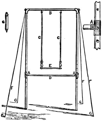
Fig. 5
The next illustration (Fig. 5) represents another method of constructing a portable frame. This has the advantage of the uprights being readily removed, as the whole consists of tube-iron. The Norway spars are here represented by two 14-feet lengths of 2-inch gas tube. If, however, the length be a difficulty, then get four 7-feet lengths of 2-inch gas tube, two of which may be screwed together to form one upright. The screwed sockets, by means of which the tubes are joined, are supplied with them. A horizontal bar (D) may be added by introducing the T pieces (A A), which should be 21⁄2 inches, to slide up and down the iron tube, and a hole drilled through the T piece and into the tube will enable it to be fixed at the requisite height.
The four stays (F F F F) and stakes (G G G G) just the same as described in Fig. 4.
Any gas-fitter would supply these tubes, but on the score of economy it is best to go to a wholesale house.
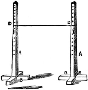
Fig. 6
Jumping stands are very simple in their construction, consisting of two pieces of square timber (A A) about 4 inches square, bolted to cross-piece (B B) (Fig. 6). In many instances they are merely sunk into the ground without any sole-pieces or struts.
For foot-jumping the stands average 6 feet in height, with three-eighths of an inch holes bored from top to 1 foot from bottom. They are painted and marked feet and inches. A line and sandbags (D D) rest on two pins inserted in the three-eighths-of-an-inch holes, so that should the foot catch in the act of jumping the line immediately falls off.
For pole-jumping the stands must be 12 feet high and strong in proportion, while in other respects they are the same as for foot-jumping.
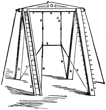
Fig. 7
This combination (Fig. 7) consists of a ladder-plank (A), two standing-planks (D D), and standing-ladder (B), all fourteen feet in length, which form the four supports to carry the cross-beam (E), ten feet long, to which may be suspended any apparatus you may wish. This is very similar to the Portable Horizontal Bar (Fig. 2), only carried out upon a large and more elaborate scale. If I were to describe its general construction, I should be merely recapitulating what has already been explained. This apparatus may be made any size, of course proportionately strong, G, G, H, H, and I, represent a bar with triangular ends stayed off to the bottom of the four uprights, which, when made tight, the bar becomes perfectly rigid, so that a trapeze bar may be converted into a horizontal bar if required.
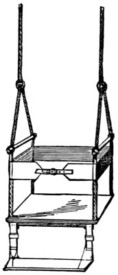
Fig. 8
Fig. 8 shows a safe and convenient form of swing.
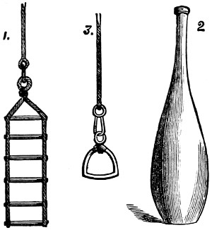
Fig. 9
Fig. 9, No. 1, represents a hand-ladder, used in pairs, in place of hand-rings. They are generally adopted in the German Gymnasia.
No. 3. Hand-stirrup, with spring or dog-stools. This shape is preferred to rings, as they command a much firmer grip to the hands.
No. 2. Indian Clubs. This illustration represents the best shape, and is the pattern now generally used.
Figs. 10 and 11 represent Dumb-bells and Bar-bells, with wrought-iron handles. They do not break so easily as if they were cast in one piece. It may be useful to know, when making patterns for dumb-bells, in order to ascertain the weight in metal when cast, that one pound of fir, say pine, is equivalent to about fourteen pounds of cast iron.
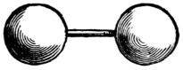
Fig. 10.
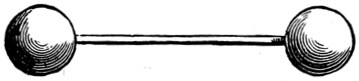
Fig. 11.
It is our object in this chapter to present to our readers full instructions for the use of the Indian clubs—instructions that, for completeness and thoroughness of illustration, have not before been approached in any work with which we are acquainted.
The origin of their introduction into Europe is not known with certainty, but it is said that we are indebted for them to a military officer who had seen them in use by the Persians. The movements that can be performed with the clubs are almost unlimited in their variety, and are amongst the most useful and beneficial of any gymnastic exercises, having the effect of increasing the muscular power of the shoulders and arms, strengthening the hands and wrists, opening the chest, and also possessing the advantage of rendering the user ambidextrous, or two-handed—that is, of making the left arm, shoulder, etc., as vigorous and able as the right, and developing equally both sides of the body.
If practised properly, the exercises are exceedingly pretty and graceful, and cause the performer to acquire a good carriage and deportment. Although in almost every gymnasium Indian clubs are now to be found, it is surprising how[51] seldom they are used, the pupils generally preferring to acquire proficiency in the more showy feats that other instruments—such as the horizontal and parallel bars—permit of their practising. But we would impress upon our readers that if they will only exercise a little patience and perseverance in acquiring the use of the clubs, they will find that no other gymnastic exercises can surpass them in grace and utility, and give such pleasure both to the performer and his audience.
The advantages of the clubs are many; amongst others—(1) they are inexpensive; (2) there is no danger attached to their use; (3) being portable, there is no fixing required—they can be used either in the open air or in a room; (4) their weight can be adapted to the age and strength of the user.
With regard to the price, they can be obtained of any wood-turner at about 4d. per pound (unpolished). We should certainly recommend the learner to purchase unpolished clubs, for in the course of practice he is sure to bruise them by knocking them together, and the damage shows more plainly upon a polished than an unpolished surface. But when he has become accustomed to the manipulation of the clubs, then he may obtain the more showy article, the cost of which is about 6d. per lb.
Of course, every boy will know that the clubs are made of wood. American elm is the best kind and mostly in use. Sometimes they are turned out of a lighter wood—such as deal—and are weighed to the required extent by molten lead being poured into a hole at the bottom of the club; but we must caution the would-be ‘clubbist’ against buying such an article, for the weight should not be concentrated at the bottom, but should be contained in the wood itself, which allows of the club being properly balanced, without which true grace and elegance can never be acquired.
We now come to a most important consideration—viz., the weight to be used, which should be in proportion to the strength and weight of the performer. It is[52] almost impossible to lay down any law upon the subject, but the following scale may be taken as a guide:—
| For a boy of | 10 | years old, | 21⁄2 | to | 3 | lb. | each club. |
| „ | 11 | „ | 31⁄2 | to | 4 | lb. | „ |
| „ | 12 | „ | 41⁄2 | to | 5 | lb. | „ |
| „ | 13 | „ | 51⁄2 | to | 6 | lb. | „ |
| „ | 14 | „ | 61⁄2 | to | 7 | lb. | „ |
| „ | 14 | and over | 71⁄2 | to | 8 | lb. | „ |
These figures refer only to the light clubs or dual exercises—that is, when a club is used in each hand. For the single or ‘heavy club’ exercises, of course, the weight can be increased, but of that we will treat later on.
Many of our readers may consider these weights ‘a mere nothing,’ and quite unworthy of their muscular powers. But it is a great mistake to suppose that the benefit to be obtained from Indian clubs is in proportion to their weight, and in the exertion required in manipulating them. On the contrary, the easier the exercise (within reasonable limits, of course), the better, for practice being then a pleasure, it can be sustained for a longer period, and by this means the muscles become gradually developed and subsequent fatigue is avoided.
We have said that the weight of the club should be in proportion to the weight of the user. We will justify this advice by an explanation. We will suppose that a boy twelve years of age weighs six stone, and another boy of the same age weighs six stone and seven pounds; the latter (presuming both boys’ muscular development to be about equal) could use a heavier pair of clubs than the former,[53] because he would have greater weight in his body to counterbalance the weight of the clubs.
In order to impress our readers with the correctness of this principle we would point out to them that, in performing exercises upon a fixed gymnastic apparatus (such as the horizontal bar), the gymnast has only to use muscular exertion proportionate to his bodily weight. If, however, he were to carry about him any weighty articles, or even wear a pair of heavy boots, he would experience a greater difficulty in performing the exercises, and perhaps fail altogether, and his exertions would soon produce fatigue. Therefore, do not be too ambitious in selecting your clubs, but be contented with the weights we have recommended, which, although they may appear small on paper, will be found quite heavy enough in practice. The writer, who has used the Indian clubs constantly for the last ten years, never has a pair of greater weight than eight pounds each.
The length of the clubs must be varied to the height of the performer. With the clubs standing on the ground and the hands hanging down, as in Fig. 1, there should be a space of about two inches between the handles and the tips of the fingers, so that it becomes necessary to stoop slightly in order to grasp the clubs. When swung round they should clear the tops of the toes by about two inches.
With regard to dress, the ordinary gymnastic suit is the most suitable. ‘The best material is undoubtedly white flannel. A pair of flannel trousers made to fit the legs tolerably closely, with plenty of room in the seat (not baggy, of course), a close-fitting ordinary under-jersey minus the sleeves (to give freedom to the arms), and a pair of canvas shoes without heels, are all that are necessary for wear during actual practice. Add to these a loose jacket of medium thickness to slip on during intervals of rest, and you have your costume complete.’
But for Indian club exercise a special costume is not indispensable—and here, again, their economy is manifested—and all that need be done is to divest oneself of coat, vest, and over-shirt, and practise in ordinary trousers, boots, and undershirt.
Before proceeding to describe the different exercises, we would impress upon the reader most emphatically that, in endeavouring to perfect himself in them, he should bear in mind that, performed gracefully, and with an easy, swinging motion, there is nothing prettier. On the other hand, a jerky and strained action spoils entirely not only the effect from a spectator’s point of view, but also neutralises the benefit that should accrue to the performer.
First Position (Fig. 1). Place the clubs upon the ground, one upon the right and one upon the left side, slightly in front—about level with the toes. Stand at attention, head erect, shoulders square. Then bend down, grasp the clubs, one in each hand, and raise them up until the hands are level with the shoulders, at the same time separating the legs and placing the feet apart, toes pointing outwards (as in Fig. 2).
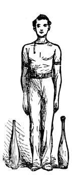
Fig. 1
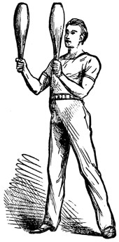
Fig. 2
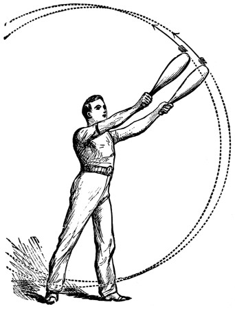
Fig. 3
You will then be in position to commence Exercise 1 (Fig. 3). Throw out the clubs to the right, and describe a complete circle with them in front of the body from the right to the left, keeping the arms perfectly straight and in a line with the clubs. As they describe the circle the body should be turned slightly in the same direction, and the head and eyes also should follow the course of the clubs from right to left. Continue this exercise at least a dozen times. Should you find any difficulty in accomplishing this with both clubs at once, try one at a time, first with the right hand and then with the left, or vice versâ.
Here we will take the opportunity of informing the learner that he should endeavour to identify himself, so to speak, with the clubs, and consider that they are parts of himself—continuations, in fact, of his own arms. The base of the club should always be kept in a straight line with the shoulder. By this means an equal distance is preserved between the two clubs; otherwise, should they be swung at an[55] angle, they must surely come into collision in the next exercise (and in many others to follow), in which one club travels in an opposite direction to the other.
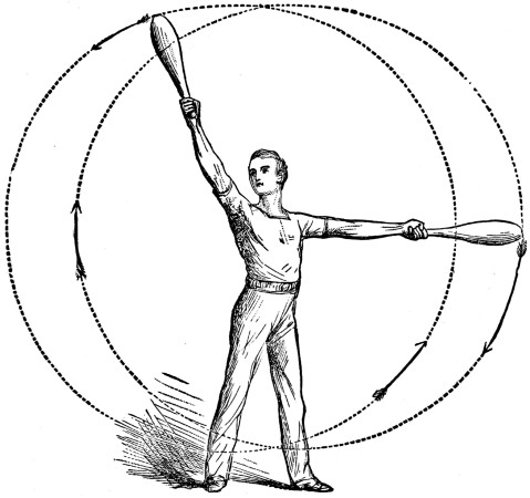
Fig. 4
Exercise 2 (Fig. 4).—Commence as before, and when both clubs are raised above the head, reverse the direction of the left one, and, instead of describing the circle from right to left, swing it from left to right, the right club at the same time continuing its original course. A glance at Fig. 4 will show the exercise; the dotted lines and arrows indicate the direction in which each club travels. In this exercise (and in many others to follow) the clubs cross twice in each circle; care must therefore be taken not to allow them to come into collision (which catastrophe can be easily avoided by following the directions just given—viz., to keep the base of each club in a straight line with each shoulder).
Exercise 3 (Fig. 5).—This is the same as No. 2 with an additional movement—viz., that when each club is raised in its turn above the head to its highest point, the circle is checked and the club dropped behind the head and made to describe a smaller circle in the rear of the shoulder, after completing which the larger circle is resumed. The dotted line in the illustration shows the course of the left club only, but the right club does the same thing in the opposite direction.
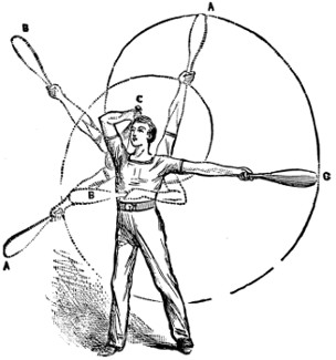
Fig. 5
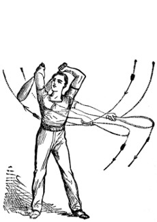
Fig. 6
Exercise 4 (Fig. 6).—Commence with Exercise 1, and when the clubs are raised above the head allow them to drop and make them describe a small circle behind the shoulders, then resume the larger circle on front of the body.
Exercise 5 (Fig. 7).—This is the first of the wrist ‘twists,’ and is a movement that will tax the power of the fore-arm rather severely. Start from the position shown in Fig. 2, and describe a circle with each club from the wrist in the direction[56] shown by the dotted lines and arrows. In practising this exercise, you will experience a tendency to drop the arms with the clubs, but you must endeavour to keep them in the position shown, making each wrist the centre of each circle.
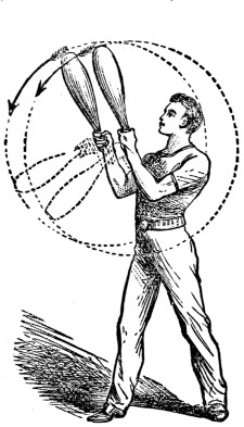
Fig. 7
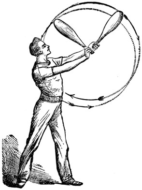
Fig. 8
Exercise 6 (Fig. 8).—Now for a twist in which each club describes a circle in an opposite direction. Again be careful to avoid a collision, and keep the wrists level and opposite each other.
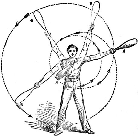
Fig. 9
Exercise 7 (Fig. 9).—This is rather difficult, but with a little perseverance you will be able to accomplish the movement, and as it is very pretty it is well worth the trouble. Carefully study the illustration and follow the course of the dotted lines (which show the direction of the right club only; the left club takes a corresponding course in the opposite direction). Keep the hand close up to the chest, almost touching it, in fact. You will observe that the club describes a small circle from the centre of the chest, and is then swung completely round at arm’s length to make the great circle.
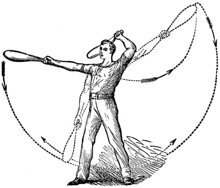
Fig. 10
Exercise 8 (Fig. 10).—This is a simple swing backwards and forwards, each club being swung alternately in front of the body and behind the head. When the right club is extended at arm’s length almost straight from the shoulder, the left club is passing behind the head and vice versâ.
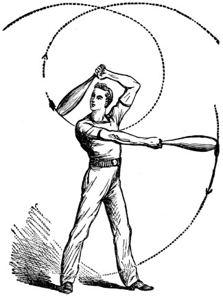
Fig. 11
Exercise 9 (Fig. 11).—This is exactly the reverse of Fig. 5. The illustration will show the movement.
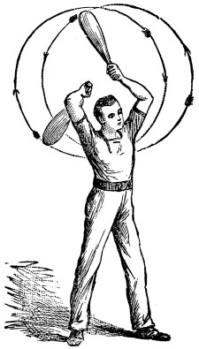
Fig. 12
Exercise 10 (Fig. 12).—This is very effective, and if performed rapidly and neatly is sure to elicit applause from an audience. It consists of circles behind the[57] head with each club, in the direction shown by the arrows, one club passing in a downward direction while the other is swinging up.
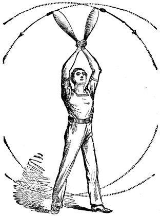
Fig. 13
Exercise 11 (Fig. 13).—This is not very difficult to perform. Keep the arms straight, and beware of a collision. The clubs are swung in a circle across and in front of the body, passing one another twice in their course—once when above the head (as in the figure) and again in front of the legs.
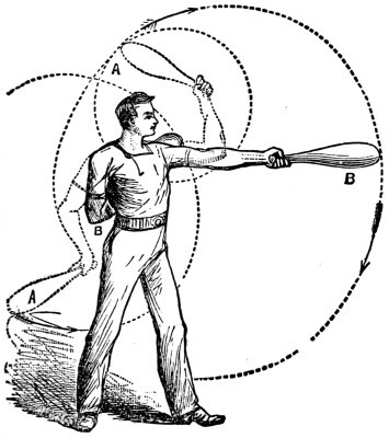
Fig. 14
Exercise 12 (Fig. 14).—Now this is difficult, and will take a long time to learn. It is a complication of Exercise 3. Commence with that, and, having got the clubs into a good swing, check the course of the right arm, slightly decrease the pace of the left arm, and throw the right club sharply behind the body, until the base rises a little above the left shoulder (see Fig.), then swing it back to A and B, and continue the original circle, all this time keeping the other club (the left) travelling in a circle, until it becomes its turn to effect the movement that the right one has just completed, and so on, first with the right club behind the body, and then with the left in front, and vice versâ. This is one of the best and prettiest exercises yet described, and will entail long and patient practice; but when thoroughly acquired it will well repay the perseverance expended upon it.
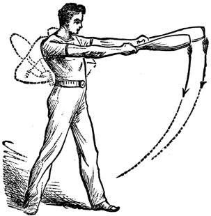
Fig. 15
Exercise 13 (Fig. 15).—Another difficult one. The clubs are swung downwards, parallel to each other, and then raised up behind the back (as shown by the dotted arms), then swung to the front again, and in a circle completely round at arms’ length. The left club executes exactly the same movement as the right in the last exercise (12), but with the right club in this the movement is different. The wrist should be twisted sharply downwards, and the club tucked under the right arm; its own weight will then carry it down behind the back, and up to a level and in a line with the right shoulder, reaching that position exactly at the same time as[58] the other club, and both will thus again be parallel, but on the opposite side of the body to that from which they started.
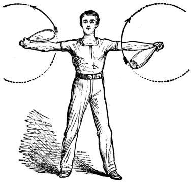
Fig. 16
Exercise 14 (Fig. 16).—This is purely wrist-work. The arms are extended straight out on each side, and the clubs passed alternately from the wrists in the front and rear of each arm, describing circles on either side. At the same time that one club is swinging round behind the right arm, the other is swinging in front of the left, and vice versâ. This exercise causes the wrists to become very pliable.
We have now completed our instructions for the ‘light clubs.’ The learner must, of course, acquire the different exercises separately, one by one, but when mastered they can be continued from one to another, making, when so combined, a very effective performance. The movements capable of performance with Indian clubs are almost without limit, but we need not here give further descriptions or illustrations. The performer will find, as he becomes accustomed to the use of the clubs, and attains proficiency in their manipulation, that other movements will suggest themselves, and he will be able perhaps to invent some new and intricate exercise.
Roughly speaking, the weight of a club to be used singly should be about the same as that of the pair the performer is accustomed to—i.e., a boy using two clubs weighing 6 lb. each should use one weighing just double. This will be found quite sufficient for sustained movements; if a heavier weight is adopted there is danger of over-exertion, and the exercise cannot be performed in a graceful and easy manner. We think the best shape for a heavy club is that shown in Fig. 17, which, our readers will observe, differs from the light clubs in having a ‘shoulder’ instead of a gradual slope from handle to base.
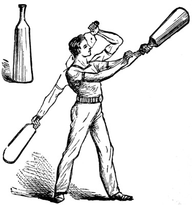
Fig. 17
All the exercises described above, with a few exceptions, can be performed[59] with a heavy club, but, of course, with only one hand at a time—the other hanging loosely down by the side (as in Fig. 1). When one arm becomes tired the club should be changed to the other (see Fig. 17), but without the movement of the club being stopped. The exceptions referred to are the wrist twists, which should not be attempted with a heavy club, the strain upon that part of the arm being too severe.
It was with considerable diffidence that the writer undertook the task of penning this chapter, feeling strongly the difficulty of explaining the numerous and intricate movements in words; but, with the aid of the artist’s graphic illustrations, he trusts that the directions will prove sufficiently clear to enable all readers who desire to become experts in the use of the Indian clubs to succeed fully in their endeavours.
In the previous chapter are given comprehensive instructions on Indian Clubs. The editor thus gave the clubs the preference, as they are in growing favour amongst gymnasts, and in regular gymnasia are fast driving out the ancient dumbbell, owing to their wonderful power of quickly opening the chest and squaring the shoulders. We say ‘ancient dumbbell’ advisedly, for it is at least two thousand years old. It was first introduced amongst us after being noticed on the Greek vases. The shape there given differed somewhat from that now in use, but there is no break in the chain. The oldest form was that of a pointed capital D, the curved line being the handle; afterwards, as shown on the vases, the athletes adopted the form (Fig. A) from which our present bells are derived. Curiously enough, these bells were used in springing and leaping, the power given by the weights being well known to the ancient as well as the modern records. Lawton’s standing wide jump of 12ft. 61⁄2in. in 1876 was done with dumbbells in his hand, and Howard’s flying jump on Chester Racecourse in 1854, when he cleared 29ft. 7in., was done from a block of wood, with a five-pound dumbbell in each of his hands, quite in the old[61] Greek style. However, it is not with the ancient, but the modern, practice that we have here to do. And we have no space to devote to archæology.

FIG. A.
In the first place, then, two pounds is quite heavy enough for any dumbbell, and under any circumstances no bell, even for a full-sized man, should exceed five pounds. Heavy bells of fifty or even a hundred pounds have been used, but they are now obsolete. For merely lifting purposes weight was all very well, but as soon as it was shown that health owed more to suppleness than rigidity, and exercises were designed in accordance with the new theory, heavy bells became simply impossible. When they were used by the very strong they were found to give one-sidedness, and by the weak they could not be worked with at all. Four pounds the pair is heavy enough for any boy, and most boys when they come to try the exercises will often wish that the bells were lighter. A word should be said as to price. Plain bells of cast iron cost from twopence to fourpence per pound; if covered with leather, and thereby made considerably more comfortable to the hand, the price is from fourpence to sixpence per pound. For two shillings a lad can get a pair of bells that will suit him in every way and last him a lifetime. The shape of the bells does not matter; the heads may be round or octagonal, according to fancy, but the handle should be thick enough to give a good grip, and it should be half an inch longer than the hand is wide.
Next, let it be clearly understood that dumbbell practice performed in a slovenly way does more harm than good. It is essential that the exercises be done in strict time, not jerkily, but quickly and accurately, as if to the word of command. When the bells are required to be raised together, they should go up together, not one[62] after the other. When they are required to go up alternately, they should go up alternately, at equal speed, the left as fast as the right; when they are to be held out in front together, they should be held out together, and change to the recovery as soon as the weaker arm begins to yield.
This brings us to our third caution. Never overtire yourself. Ten minutes is quite long enough to practise at a time. Take the exercises in the order in which they are given, advancing gradually from the easy to the difficult, succeeding as you go. Do not practise after much head-work, and do not attempt any of the exercises before or after a heavy meal, no matter how light the bells may be. The best time to practise is immediately after the morning bath, and the best costume to wear is that of the mermaid, or as near an approach to nothing as is consistent with decency. Of course in gymnasia special dresses are worn; but, as absolute freedom is required, the model dress of the gymnast should be easily stowable in a glove-box.
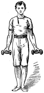
FIG. 1.
And now for the first exercise (Fig. 1). Stand at attention, holding a bell in each hand. Let the arms and legs be quite straight, the body upright, the heels close together, the toes well apart. Hold the bells so that a line through your hips would pass through the centre of each handle. Move the bells an inch from your legs, and twist them round, keeping your arms straight and working your wrists. Do this backwards and forwards with both bells ten times. Then twist the left bell ten times. Then twist the right ten times; then twist them both together five times; thirty-five twists altogether, counting each reversal of the hand as one, beginning with knuckles backwards, and ending with knuckles forwards.
For the second exercise, stand at attention and bend up your forearms only from the elbow, holding the bells out from your chest with the handles vertical and parallel. Now twist them ten times simultaneously, and then ten times with the left hand, ten times with the right, and five times together. Let your elbows be well back, pressing your sides all through this exercise.
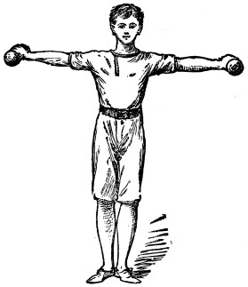
FIG. 2.
For the third exercise, begin at attention, raise your arms from your sides till they are level with your shoulders, forming one straight line with them (Fig. 2). Let your knuckles be on the top, and do the thirty-five twists as in the former exercises. The arms must be quite straight, and there must be no giving at the knees or bending at the waist.
These three exercises are quite enough for the first morning, even though the bells may be under two pounds apiece. Next time we can run through these three exercises quickly, and then try something rather more complicated.
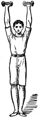
FIG. 3.
For the fourth exercise begin at attention, and keeping the elbows against the sides, double up your arms so as to bring the bells against your shoulders. Open your chest as far as you can, throw your shoulders well back, and while in this position take a long deep breath (Fig. 8). In fact, in every exercise take long free breaths as often as possible, so as to expand your chest from within as well as from without. Bring the bells up and down ten times both together. You are now ready for the fifth exercise, which consists in bringing the bells from attention up to the shoulders, as in the fourth exercise, and then thrusting them up straight overhead (Fig. 3). Hold them up as high as you can, keeping your feet on the ground and body erect. Then do the twists ten times together, ten times with the left, ten with the right, five together; then with ‘one’ to the shoulder, and ‘two’ to the hang, you recover your starting position.
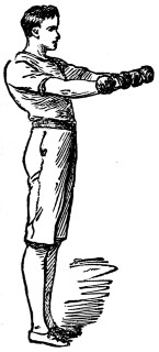
FIG. 4.
In the sixth exercise you bring the bells to the shoulder, and keeping your chest well open, thrust your arms, not overhead, but straight in front of you (Fig. 4), and again do the thirty-five twists. In the seventh (Fig. 12) you bring the bells to the shoulder and open your arms right and left, holding them out high and well back at[64] full length, then recovering to the shoulder, and then down. Then ‘up,’ ‘out,’ ‘in,’ ‘down’ again, and so on for ten times. Keep your shoulders well back during this exercise, and do not lose your uprightness! It is a most important and obviously good practice, should be done with care and regularity, and forms a fitting end to lesson number two.
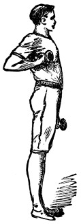
FIG. 5.
In our third batch we have said good-bye to the twists. For the eighth exercise stand at attention, bells to side as before, and always start from attention. Let this be understood, and it will save repetition. Bring the bells up under the armpits as far as you can get them (Fig. 5). Bring them up together ten times, then ten times with the left hand, ten times with the right, and five times together.
In the ninth exercise bring the bells up to the armpit, and then extend the arms right and left, starting with the bells brought up in front of the shoulder and reaching the same position as in exercise seven. Then bring the bells back to the armpits and recover. Do this ten times; that will be quite enough for the first trial.
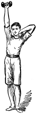
FIG. 6.
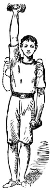
FIG. 7.
For number ten bring the bells to the armpits, and then take them up overhead as in exercise five. Up together ten times, then with the left and right alternately stroke for stroke ten times each (Fig. 7). Then try number eleven, in which the bells are brought to the armpits, then thrust up, brought down to the chest, and down to the hang—‘one,’ ‘two,’ ‘three,’ ‘four’—ten times together, ten times alternately. Then try number twelve (Fig. 6), in which the bells go to the armpits, then aloft, then down well back on to the tops of the shoulders, then extended with a sweep as in number seven, back to chest, and down—‘one,’ ‘two’ aloft, ‘three’ to shoulder, ‘four’ to the limit, ‘five’ to chest, ‘six’ down to hang.
For our fourth lesson we start as before, upright at attention, ready for the thirteenth exercise. Bring the bells to the armpits, and then aloft together, and then keeping them together, bring them down in front, with the arms and legs as straight as you can until you deposit them at your toes. Then lift them again to armpits, aloft, and down with a sweep to your toes, ten times in all, three motions in each.
Now for number fourteen. Lay the bells at the toes from aloft as in thirteen. Then make a full step to the rear with the left foot, the right foot following. Make a half turn to the right. Step to the front with the left foot, the left hand grasping the thighs just above the knee as the foot comes to the ground, the right arm extended in the line of the right leg. Next seize the bell with the right hand, keeping the lower limbs in position. Now lift the bell above the shoulder to the full extension of the arm, leaning strongly on the left knee and pressing the breast to the front during the ascent of the bell, the lower limbs to the knee, and the left arm forming a continuous line from foot to shoulder. Lower the bell, replace it, and recover. Then upright again, step to the rear, right half turn, step to the front with the right foot, and go through the same motions exactly, only with the other hand. Complete this exercise ten times with each hand.
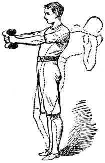
FIG. 8.
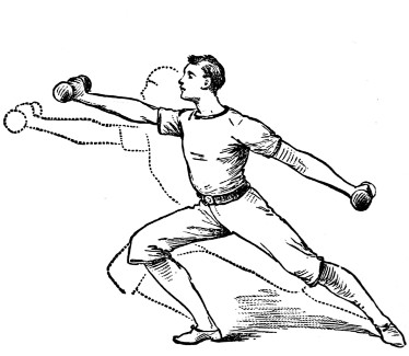
FIG. 9.
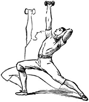
FIG. 10.
In number fifteen lay the bells at the toes, then stoop and recover them to the hang, then charge out, as it were, with the right foot, taking a good long step, and throwing out your arm to its full length as you do so (Fig. 9). Keep your left leg straight and your shoulders back, and double up your extended arm so as to bring the bell to the top of your shoulder. Move the bell backwards and forwards ten[66] times, and at each return sink towards the ground, bending as you straighten your arm. Then move as in Fig. 17. Then recover, strike out with the left leg and arm, and repeat all the motions (Fig. 18). In sixteen go through the same preliminaries, but instead of striking the hands straight out strike them aloft, sinking as the arm is extended (Fig. 10).
In the next group of exercises the bells are swung.
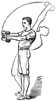
FIG. 11.
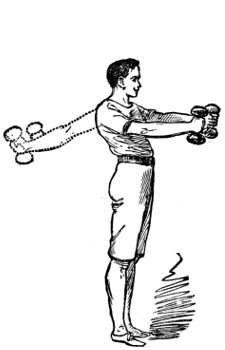
FIG. 12.
For number seventeen (Fig. 12) swing the bells up from the hang to the horizontal, and then round till they meet in front, ten times together, letting them fall each time to the side—one, ‘up,’ two ‘round,’ three ‘down.’ For number eighteen bring them to the front first, and then swing them round to the back and down. Keep the finger in front of the handle all through this exercise; do not twist the bells as they pass to the rear. In number nineteen (Fig. 11) swing to the front, then to the back at extension, then from extension swing overhead till the bells meet, then bring them down to the chest and so to the hang, five motions in all. Then step forward with the left foot and go through the same five motions. Then with the right foot advanced go through the same five motions. The object of all these exercises is, of course, to bring into play as many muscles as possible, giving each a turn in time. Whenever possible an exercise should always be done from the three positions—heels together, left foot forward, right foot forward.
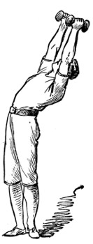
Fig. 13.
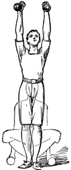
Fig. 14.
Now for our last group. Ready for number twenty (Fig. 13). Stand erect with bells at the side, bring them up to armpits and aloft, and holding them high in the air together twist your body round to the left as far as it will go, but do not move your legs. Then bring the bells to the chest and lift them simultaneously[67] and alternately thirty times as before, then turn your body to the right and do likewise. In twenty-one bring the bells to the chest, twist the body and strike out straight with them together and separately, first twisting to the left, then right. In twenty-two (Fig. 14) raise the bells overhead and sink to the floor, and with knees bent go through the ten first strokes. Then rise and down again and do the ten strokes with the left; then up and down again for the ten with the right.
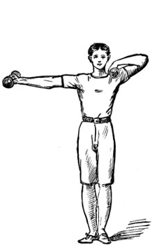
Fig. 15.
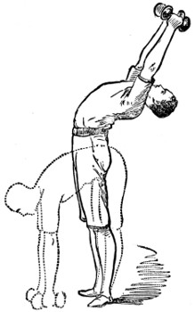
Fig. 16.
In twenty-three, as the body sinks the bells are brought to the chest and the arms are extended, moving round to the front horizontally, and brought to the chest again, much as in the act of rowing. This is a very tiring exercise, and at first makes itself felt in every joint in the body: ten times together is quite enough for the first day’s work. Twenty-four (Fig. 16) is an easy exercise, but a valuable one. Swing the bells aloft, and then bend backwards, letting the arms slowly open and extend backwards towards the ground; then bring them back aloft from behind without bending them, then bend in front, and lay the bells at your toes.
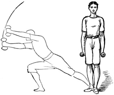
FIG. 17.
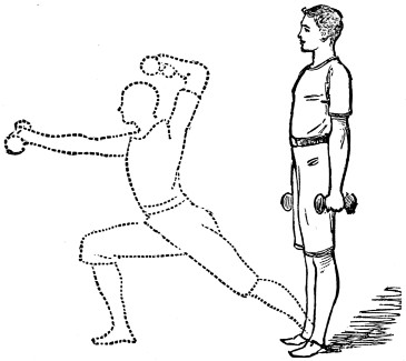
FIG. 18.
There are other exercises, but they are all, like many we have given, mere combinations easily invented by the proficient. The examples herein are quite enough to bring out the full powers of the dumbbell as a gymnastic appliance, and a steady practice of them for ten minutes a day after the morning tub, will not only set the student well up and shape him properly, but add an inch or so to his girth if not to his stature.
Juggling with balls, a pastime as pretty as it is entertaining, has also certain special advantages. In the first place, it is really an art, well worthy of the name, which may be easily acquired by members of either sex at any age, and it affords a gentle exercise which is extremely beneficial to the health.
In illustration of this, I may mention a fact which, some years ago, came under my personal notice. An artist friend of mine, finding that his health was giving way under the toil and the strain it was necessary for him to devote to his profession, asked me if I could recommend him some not too laborious exercise to which he might betake himself in the brief intervals of his work. Clubs and dumb-bells were too heavy, he said, and their use moreover rendered his hand unsteady, and so prevented his putting into his picture those delicate touches so necessary for success.
I suggested juggling with balls, as being an exercise less violent and equally healthy. He sprang at the idea, and after giving him some instructions I left him, and soon forgot all about the circumstance.
Several months afterwards I called on my friend at his studio, and, to my surprise and amusement, found him busy—not with his pencil, but with three juggling balls. ‘I’ve done it,’ he cried with great glee, as soon as he saw me; ‘I can shower three! Look!’ And thereupon he recommenced his operations, and soon convinced me that he had become an adept at his new pursuit; and he really seemed to be more pleased to have succeeded with the ‘shower’ than with his picture, which was shortly afterwards exhibited ‘on the line’ at the Royal Academy. That he was in good spirits you will have gathered from what I have just said, and you will readily believe that he could hardly have been so happy unless his health had been re-established.
Nor is the juggling with balls simply a healthy exercise. It must lead to useful, and it may (and often does) lead to very important results. The quickness of hand and eye acquired by the practice is not only valuable in cricket, football, and other sports, but also can hardly fail to prove serviceable in the sterner duties and emergencies of life. If space permitted I could relate many stories of articles, and even life, being saved by the dexterous catch of one who had practised juggling. I am generally called upon, when in a gymnasium, to stand close to any one who is about to try a new exercise, or one attended with risk, either on the horizontal or trapeze bar, in case of a slip; and I entirely attribute my quickness in catching to my proficiency in juggling, the hand being taught instantly to follow any movement the eye may detect.
This subject, useful as I have shown it to be, has, so far as I am aware, never been treated on in any English publication, although in France and in many other parts of the Continent juggling forms an important branch of physical education, and is much practised in the gymnasia.
You may very naturally suppose that it is almost impossible to teach anything of this kind on paper, but it must not be forgotten that in this, as in everything else in life, to ensure success it is necessary to make a good beginning. There is no royal road to learning, and unless a proper foundation be laid the castle will prove to be but visionary. So even on paper I can give you many valuable hints and much practical advice, without attention to which you will never become adepts in the art. You must not suppose, however, that I can make practised jugglers of you in a few lessons, nor must you be too anxious to play two or three balls before you have a perfect command over number one.
The first object to be aimed at is to procure the best sort of balls for your purpose. Of course, anything in the shape of a ball will do—oranges, for instance, tennis or raquet-balls, etc.—but the best are made of hollow brass, two inches in diameter, and these may be obtained at from ten to twelve shillings per set of four. They are made specially for the purpose, their hollowness giving them a lightness which a solid substance obviously cannot possess. It is indispensable that the balls should all be exactly the same weight, otherwise in the rapid passes—such as the ‘shower’ or ‘fountain,’ about to be described—the lighter would be thrown farther than the heavier, and the most skilful performer would fail to accomplish the feat.
Being satisfied with regard to the balls, we will now proceed to the First Practice, viz.,
that is, to throw a ball into the air so that it will descend to the exact point from which it was projected. You will find, at first, that when you have thrown the ball up into the air it will not drop back again into your hand, but you will have to follow its course in order to catch it. The first point to be gained, then, is to throw the ball so that it will drop into the hand which is ready to receive it, and this must be practised with both hands, as the left will have quite as much to do as the right. When you have thoroughly mastered this art, and can catch a ball with decision when thrown from three to four feet in height, you may proceed to the Second Practice, which is called—
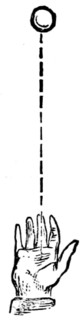
Fig. 1
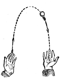
Fig. 2
What is required now is to throw the ball with the right hand so that it will describe a curve in the air and drop towards the left hand, as shown in Fig. 2; but, instead of catching it with the left, it must be caught with the right. This is the Inside Fall. Now throw the ball back in a similar way from left to right. This is called the Outside Fall. This, of course, sounds easy enough, as it is merely playing at catch-ball, but you will find it very difficult at first to throw the ball several times in succession without deviating from the same course, and this course is of the utmost importance, as, when you are playing two or three balls, unless they follow one another in the same course, the whole play will immediately become inextricable confusion, and they will all fall to the ground. Do not attempt at first to throw the ball higher than three feet, which, indeed, is the height generally required. When you are perfect with the right hand, practise the same play-motion with the left. Let me again impress upon you the necessity, if you would attain proficiency in the art, of using the left hand as much as the right in all these exercises. Without this success is impossible. We now come to the Third Practice, or—
This will be found rather more difficult than either of the former, because in this the arm, as well as the hand, will be constantly in motion. Throw the ball with the right hand, as in the Vertical Fall, keeping the hand in a line with the right shoulder. The moment it is caught, bring the right hand in a line with the left shoulder, throw the ball from that position and catch it, and vice versâ. Afterwards do the same with the left hand. Fig. 3 will show you the practice, the dotted lines representing the movements the ball should take. All these necessary, if somewhat tedious, rudiments of the science having been mastered, we will proceed to the Fourth Practice.
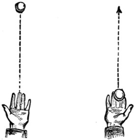
Fig. 3
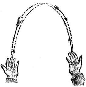
Fig. 4
In this exercise both hands are brought into play. The motion of the ball is precisely the same as in Fig. 2, but, instead of catching it with the same hand, you[71] must now pass it from one hand to the other. Practise this at first with the hands a very little distance apart, and do not throw the ball too high. As you improve, gradually increase the height, and move your hands away until they are about three feet distant from each other. Up to this time the ball has been forming a kind of hyperbole or arch in its course. Now, without altering the position of the hands, cause the ball gradually to lower its course until it is thrown in the Fifth Practice, which is called—
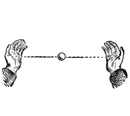
Fig. 5
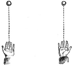
Fig. 6
This you will find quick work alike for eyes and hands, for, of course, the ball cannot be made to pass in a straight line from one hand to the other without giving it increased impetus and a considerable accession of speed. Gradually move your hands, at first closer to one another, and then farther apart. In fact, continue this exercise until your hands are as distant from each other as you can reach. This will be found excellent practice for the ‘shower’ at which we shall soon arrive. The Sixth Practice is
(as shown in Fig. 6). You will now take a ball in each hand, and commence by throwing that in the right hand vertically (as in Fig. 1), then that in the left in the same manner, alternately. Before the first ball has descended into the right hand, throw the second into the air with the left, so that the two balls shall be constantly in motion. You will now find the advantage of being proficient in the single vertical fall, as otherwise, your attention being distracted from the one ball to the other, you would probably not be able to catch either. Now practise throwing both balls up together, keeping your hands about two feet apart, and taking care that neither ball goes higher than the other. As the last practice was good for the ‘shower’ so you will see that the present will prepare you for the ‘fountain,’ the description of which will follow in due course. The Seventh Practice is termed
This is a repetition of the Outside and Inside Fall, but is performed with two balls at the same time and with both hands. In this exercise great care must be[72] taken to avoid a collision of the balls when they are in the act of passing. To ensure against such a calamity it is necessary that one ball—generally that from the right hand—should be projected slightly higher than the other (as in Fig. 7). This should be practised at various heights until something like perfect accuracy is arrived at, as all the following practices are founded, more or less, upon this very important exercise.
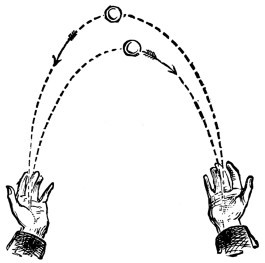
Fig. 7
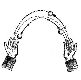
Fig. 8
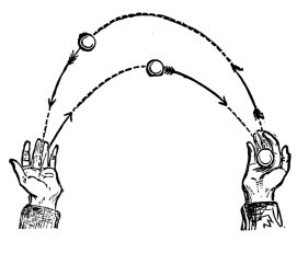
Fig. 9
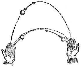
Fig. 10
The Eighth Practice is entitled
which must not be attempted until you have made perfect the last exercise. On referring to Fig. 8, you will see that this practice is nothing more than a repetition of the last, with the addition of a third ball. This third ball, however, will seem to you at first to be quite an interloper, and the greatest care must be taken in throwing all the balls regularly, otherwise they will go into a ‘confusion worse confounded.’ The eyes and the hands, however, being by this time pretty well trained, increased vigilance in the former and increased agility in the latter are all that is required to enable you to master the increased difficulty of the performance. The dotted lines indicate the proper direction in which the balls should be thrown,[73] showing how each ball should cross the course of the others without any of them coming into collision. We proceed at once to the Ninth Practice, which is called
This play is almost similar to the last, differing only in this—that, instead of the balls following each the course of the other, they are returned from the left to the right by the course indicated in the dotted lines in Fig. 8, forming an inner fall while the others are passing over them. The effect of the change is very pretty, and though it will perhaps be found somewhat more difficult, you are now becoming so skilful that difficulties will no doubt serve only to stimulate you to fresh exertion. The Tenth Practice is
This is another variation of the same play, in which the over ball is kept outside, whilst the under two are performing a double pass. In this practice you must keep the outside single ball well above the two that are passing underneath, as shown in the dotted lines in Fig. 10. Care must be taken, in this as in every other practice, to avoid collision between the balls. Practice, we know, makes perfect, and nothing but patient perseverance can be recommended to ensure success.
The Eleventh Practice brings us to one of the neatest, prettiest, and most effective feats in ball juggling. It is called
This, undoubtedly one of the most fascinating of all juggling feats, is an art easily acquired by so practised a juggler as you have now become. Take two balls, one in each hand, throw the one in the right hand into the air towards the left, as in Fig. 4, and while it is in the air, ‘pass’ the left-hand ball to the right hand, as in Fig. 5, and immediately throw it to follow the course of the first, continuing this play as quickly as possible, so that there may be one ball always in the air. You will find very little difficulty in showering two balls in this manner with one hand, as it is really nothing more than a Double Inside Fall (Fig. 2); in fact, some expert jugglers can shower three balls with one hand, but this is a very difficult feat, and the balls have to be thrown very high. You can make the attempt if you please,[74] but I do not wish to enter upon matters which may confuse and possibly dishearten you, and will ask you therefore to perfect yourselves in this feat before proceeding to the Twelfth Practice, viz.,
which is accomplished in the following manner. Take two balls in the right hand and one in the left. Throw one after the other in very quick succession in the direction of the Inside Fall (Fig. 2) with the right hand, and as each reaches the left hand, ‘pass’ it from the left to the right, as shown in Figs. 11 and 12, and continue the Shower as long as you please. From the swiftness of their motion, the balls appear to multiply, and your audience will almost be inclined to believe that you are playing with fifty balls, instead of with only three. When you are very expert in this you can proceed to the Thirteenth Practice,
or Grand Shower, as it is sometimes called. This is the same play as the last but with four balls, three of which must be held in the right and one in the left hand. It is hardly necessary to say that the difficulty is greatly increased, as the balls must be thrown much higher, so that there may be more space between them in order to allow time for the rapid passes. In all the Showers, but in this especially, it is advisable to keep the right hand a little higher than the left, as shown in Fig. 13. The Fourteenth Practice, which is the last of the present series, is
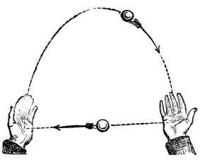
Fig. 11
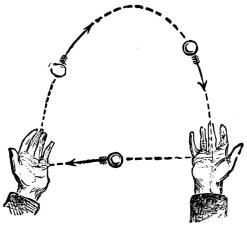
Fig. 12
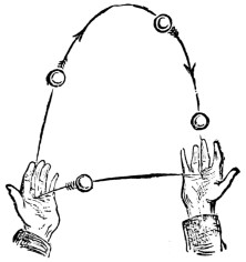
Fig. 13
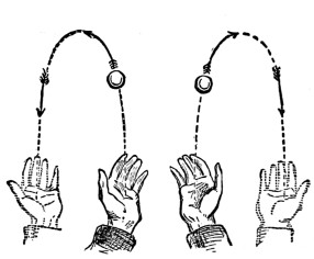
Fig. 14
This is the most difficult feat of all, as so much depends upon the precision with which the balls are delivered. Commence practising with two balls, and perform a Double Outside Fall with both hands (Fig. 14). You will find this sharp work for the eyes, as you will have to be looking at two places simultaneously as the balls descend. When you can play two balls well in this manner, you will find that
as described in Fig. 15, will not be difficult, as it is done in a ‘swing,’ as it is called, a motion of the body and arms which it is not possible to describe, but[75] which will come naturally to you as you acquire the art of juggling. The Fountain may be varied by a motion which is known as
Instead of throwing up the balls together, present them alternately, as shown in Fig. 16. This has a very pretty effect, and exactly represents the name given it.
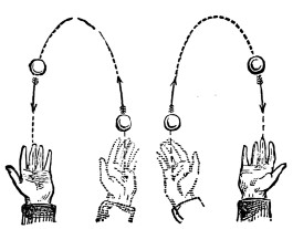
Fig. 15
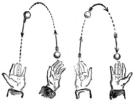
Fig. 16
Having now given you all the instruction in my power, it only remains for me to make one or two suggestions which I think will commend themselves to your intelligence. In the first place, I would advise you to practise over some soft material, on the lawn if possible, where the dropping of the balls can annoy no one; but if a lawn be not available, then over a sofa, or a bed, or a very soft rug or mat. You are certain to have many a mishap at starting, and I can conceive nothing in a small way more irritating than for a person seated in a room to be perpetually startled by the noise of balls falling overhead. Finally, let me impress upon you the fact that your success depends entirely upon yourselves. The teacher may show how the thing is to be done, but it is for the pupil to do it. Remember that ‘whatever is worth doing is worth doing well,’ and if you think it worth your while to learn the art of juggling, you must devote to it patience, perseverance, and practice. Without these you will never succeed. With them success is certain.
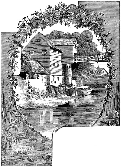
A Picturesque Model.—See p. 97.
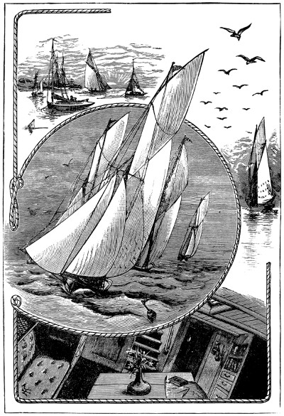
To make a model steamboat that will go is the ambition of most boys, but the high price of engine and boiler deters many from doing so. In this chapter instructions are given for making a model screw steamboat, the machinery for which every boy can make for himself, by the exercise of a little ingenuity, at a very trifling cost—which machinery, too, may be fitted into any boat, the rigging of which may have gone by the board off the dangerous coast of the duck-pond.
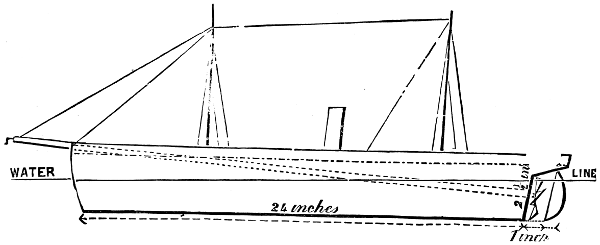
Fig. 1
First you must procure your boat; but if you should wish to make the boat yourself you will need no instructions from me, as several capital chapters on boat-building appear in another part of this volume. The only directions I need give are, that your craft shall be very light, and hollowed out as thin as possible, be twenty-four inches long, four inches wide at midships, and three and a half inches deep; the sternpost to be about an inch and a half within the stern, to be raking, and two and a half inches high, as marked in Fig. 1; a strip of lead one-eighth of an inch thick to be fastened along the bottom of the keel; the bows to be sharp, and the boat to have a clean run aft. When the boat is finished paint it, and when dry put it into water, and mark on the sternpost the height the water comes. Now you must bore a hole in the sternpost right through into the boat, in the direction of the top of the stem. This must be done with a red-hot wire; the hole is to be three-eighths of an inch across.
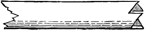
Fig. 2
The next thing to do is to get a brass tube from the gasfitter’s, or get a tinman to make you one of tin three-eighths of an inch inside measurement. This tube must be long enough to reach from the sternpost to three and a half inches beyond the top of the stem. Four inches from one end of this tube solder a strip half an inch[80] wide and one and three-quarter inches along, bending the middle of it half round the tube, and bending the ends outwards; punch a hole in each end of this strip; in this end of the tube cut four teeth like saw-teeth, one-eighth of an inch deep, like Fig. 2. Put this tube in the boat thus. Push the end, without the tin strip, through the hole in the sternpost from the inside of the boat, so that the tube is flush with the wood, and fasten the other end by driving tacks through the holes in the tin strip into the boat. Put some putty round the tube where it goes through the wood, to keep the water out. Now make the deck of board one-eighth of an inch thick, plane it, and fix it in its place by pins, leaving a gunwale of half an inch all round. Stop up with putty, and mark with a pencil the boards on the deck. Bore a hole near the stern one-sixteenth of an inch wide right through the deck and boat, coming out under the counter one inch from the sternpost. This is the rudder-hole. To make the rudder get a piece of brass wire one-sixteenth of an inch in diameter, and six inches long; cut your rudder out of tin, and solder it on to the wire, so that the heel of the rudder is flush with one end of the wire. Now push the other end up through the hole in the counter, and bend it down on to the deck; this will form the tiller, and, by pressing tightly on to the deck, will keep the rudder firm and in its place for steering.
Two inches abaft the middle of the deck cut a hole three-quarters of an inch in diameter for the chimney, which is a tube of tin three-quarters of an inch in diameter and four inches long. Bore two more holes in the deck three-eighths of an inch in diameter, one halfway between the stem and chimney, the other halfway between the rudder and chimney; these are for the masts, which are made of wood, and should stand about nine inches above deck; put a pin into the end of each mast,[81] and cut the head off, leaving about half an inch of the pin projecting; put the masts in their places, and the pins will keep them firm by being pushed into the bottom of the boat.
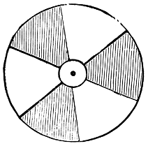
Fig. 3
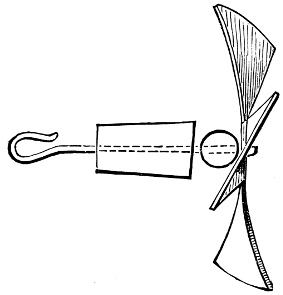
Fig. 4
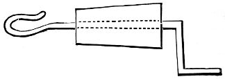
Fig. 5
Make the propeller out of a circular piece of stout tin two inches in diameter, cut as in Fig. 3. The dark parts are to be cut away. The projections are to be three-quarters of an inch long. Punch a hole one-sixteenth of an inch in the centre, and fix a piece of brass wire one-sixteenth of an inch, two inches long, in the hole, to form an axle for the propeller. Twist each of the fans of the screw out of the plane of the circle about a quarter of an inch, in the manner of the sails of a windmill, as in Fig. 4. Now make two little wooden plugs three-quarters of an inch long, and half an inch wide at one end, tapering to a quarter of an inch at the other. Bore a hole through each from end to end one-sixteenth of an inch wide. Take the propeller, and put a glass bead, that will fit easily, on the wire, and push the wire through one of the wooden plugs from the large end; bend the wire into a loop at the small end. Next take another piece of wire, two and a half inches long, and make a similar loop at one end, and put the other end through the other little plug, from the small end, and bend the wire into a handle (Fig. 5). Now the only thing we want is the power. This is a strip of strong elastic about three and a half feet long and a quarter of an inch wide; tie the ends together to make a band—a large stout elastic ring will do, or two smaller rings looped together. Fasten a string to the elastic, and pass the string through the tube in the boat, from the stern end; hook the loop on the propeller-wire into the elastic, and push the wooden plug into the tube so that the screw is clear of the rudder; draw the elastic, by the string, through the other end of the tube, and hook the wire in the other plug into it; take off the string and push the plug into its place. You must cut the plug away so that the handle can catch in the teeth cut in the tube. Now the boat is ready for use.
To use it wind up the elastic by the handle at the end of the tube, holding the screw firmly with the other hand. As soon as wound up enough set the rudder and put the boat into the water; release the screw, and the boat will go till the elastic is quite unwound. The distance it will travel will be regulated by the extent to which the elastic is wound up.
I have already described the method of making a small boat move through the water by means of an elastic band, which is simply twisted up and then released, but I have no doubt that many readers would like to possess a simple model boat to work by steam.
Such models can now be purchased at all shops where mechanical toys are sold, at prices varying from one shilling, the smallest, eight inches in length, to about twenty pounds, the largest, five feet in length. Although all these boats really go by steam, the application of the power is different in the different sizes.
The small boats are of course the simplest. In these the steam from the boiler is conducted through a short pipe to the sternpost of the boat, where by its pressure on the water in escaping it forces the boat along.
The next class have a further development of the application of steam-power. In the centre of the boat, close behind the boiler, is a fan-wheel, turning on an axle, which in the case of a paddle-boat carries the paddles, and in the case of a screw carries the propeller. The steam is conducted from the boiler through a short pipe to the front of the fan-wheel, which it blows round as it escapes.
The third class are the steamboats proper, varying in price from five shillings upwards. In these the steam-power is applied as in ordinary engines. The cheapest have one single-action oscillating cylinder, and the better sorts two double-action cylinders.
As the two first-mentioned classes are, after all, only imitations, I do not think it worth while to describe them; and of the third class I have chosen the largest to describe, as I think that if it is worth while making a model at all, it is worth while to make a good one, and the small engines take almost as much time to make, and quite as much care to fit, as the large ones, and unless they are well fitted the loss of power by friction and waste of steam is very great.
The engine here described is a model of a real screw-engine, with a pair of double-action oscillating cylinders, having reversing gear and boiler complete, ready to be put into the boat. It will be capable of driving a boat from four to five feet long, provided it is well hollowed out and that the engine is made and fitted with care, to reduce friction and waste of steam as much as possible.
In this section the exact dimensions of the several parts are given when possible, but, owing to small differences in the size of the cylinders, I am only able to approximate in some cases—in which cases, however, I have used the word ‘about,’ at the same time explaining how to obtain the exact measurements.
In all engines the most important parts are the cylinders, which must be well fitted. Boys who have a turning-lathe and the requisite practice in metal-turning can buy rough castings of all the parts of the engine for a few shillings and finish them up themselves. But as only a few of my readers may be so favoured, I will suppose that the cylinders are purchased ready for use. For these cylinders there is a great range in the prices quoted by different firms, the prices varying for the No. 4 cylinder from eight shillings at one firm to twelve shillings and sixpence at another. Messrs. Theobald and Co., of 20, Church Street, Kensington, quote the lowest prices to me, and have further consented to supply the No. 4 double-action oscillating cylinders for this engine at seven shillings each to any one mentioning this section.
The dimensions of these cylinders are three quarters of an inch in the diameter of the bore, and an inch and a half in the length of stroke—i.e., an inch and a half difference in the length the piston-rod projects from the top of the cylinder when in and out to its fullest.
Get a pair of these cylinders which have the steam-blocks, pivot-pillars, and screw-crossheads complete. Ask for the No. 4 double-action oscillating cylinders. When buying them see that the piston-rods work true, and not to one side; see also that the small indentations on the opposite sides to the steam ports are correctly drilled, so that when the cylinders are swung between the blocks and pivots they work true. To test this, place the block on its back on the table, and put the cylinder on it, with the pivot in the proper hole for it. Now turn the[83] cylinder round on the block and place a pin in the indentation, and if it is truly drilled the pin will not move; but if not, the point of the pin will describe a small circle. You can find out by this pin the exact spot where the pivot-hole ought to be drilled.
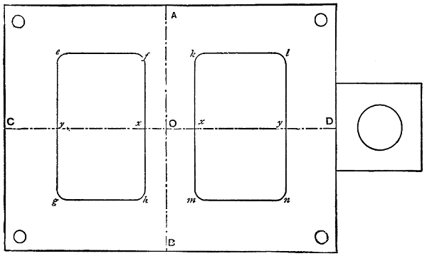
Fig. 1
We will now set to work at the construction of the engine, and the first thing to be done is to make the top plate (Fig. 1). For this get a small brass plate four inches long and three inches wide, and an eighth of an inch thick, with a projecting piece an inch and a quarter square at one end of it, as in the figure. Get two of these plates, as the second will be required for the bed-plate, but will not have the square projecting piece. Take the first of these plates and square it up, so that each corner is a right angle. Now proceed to mark it as in Fig. 1. Divide the large part lengthwise into two equal parts by the line C D, and crosswise, also into two equal parts by the line A B, these two lines intersecting in the point O. From this point mark off, each way along the lines O C and O D, the following distances. O to x a quarter of an inch, and x to y an inch and a quarter; and through these four points draw the lines e-g, f-h, k-m, and l-n, making them two inches long each, and projecting one inch on each side of the line C D. Join the points e-f, g-h, k-l, and m-n.
Cut out the two rectangles so formed carefully, so as not to injure the lines. This can be done easily by first drilling a small hole, about an eighth of an inch in diameter, near one corner, and then putting a fretwork saw through it and fixing it in the frame, and sawing the metal away just inside the lines. The saw must be kept well moistened with water. The corners can be left circular, which will add to the finish of the plate, and make the cutting with the saw easier.
After the holes are cut they must be finished quite up to the lines, but without injuring them, with a fine-cut flat file. Through each corner of the plate a hole must be drilled an eighth of an inch in diameter, and about an eighth of an inch[84] from the edges, as in Fig. 1. The top plate is now ready for mounting the cylinders on, which we will set about doing.
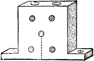
Fig. 2
Take the two steam-blocks (Fig. 2) and draw a pencil mark on each from the centre hole to the bottom, and at right angles to it (Fig. 2). Next place the two blocks back to back on the middle of the top plate, between the two large holes, so that the pencil marks coincide with the line C D, and so that the bottom edges of the faces coincide with the lines f-h and k-m. Be very careful in setting these blocks right. When in their places mark the top plate through the screw-holes in the projecting bases of each, and drill four holes straight down through the plate, making them a little smaller than the holes in the bases of the blocks. Now replace the blocks and fasten them there with two small screws each. These screws correspond with the size of the cylinders, and can be purchased by the dozen, together with taps, for each size, to make the thread in the holes with.
Next take the pivot-blocks and mark them with pencil, as the steam-blocks were marked, and put them on the line C D on the outer sides of the large holes, using the same care to get them properly centred along the line C D, and at right angles to it, and about an eighth of an inch from the lines e-g and l-n. Mark the screw-holes and drill them as before, and fasten the pillars in their places.
Now the cylinders can be hung. Unscrew the pivots about a quarter of an inch and place the cylinders in their places, with the spindles in the proper holes for them in the blocks. Now screw in the wire pivots till they catch in the indentations drilled for them in the sides of the cylinders. They will now swing freely between the blocks and pivots.
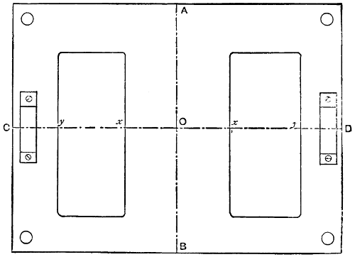
Fig. 3
Now to cut the bed-plate (Fig. 3). Take your second brass plate and divide it by the lines A B and C D as before. From the point O mark off each way along the line C D the distances five-eighths of an inch from O to x, and three-quarters of an inch from x to y. Through these points draw four lines two inches long, and[85] projecting one inch on each side of the line C D, and parallel to the line A B. Join the lines in pairs as before, and cut out the rectangles so formed. Finish up the edges, and bore a hole in each corner, as in the top plate. On the line A B, and half an inch from each end, bore two holes an eighth of an inch in diameter, and countersink them at the top, as in the figure.
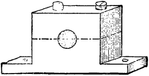
Fig. 4
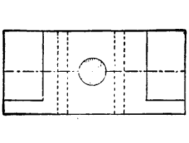
Fig. 5
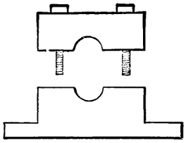
Fig. 6
Now the bearings for the crank-shaft must be made. Fig. 4 is a perspective view of one of these. Get two pieces of brass one inch long, half an inch wide, and a quarter of an inch thick, as Fig. 5. Along the face of each block draw a line, dividing it lengthwise into two equal parts, and in the centre of these lines drill a hole right through the brass one-eighth of an inch in diameter. Cut the brass away at the ends (as in Figs. 4 and 5), leaving the projecting pieces a quarter of an inch long and a little more than one-sixteenth of an inch thick. Through each of these flanges drill a hole, to screw the bearings to the bed-plate by. Drill two holes down through the top of the block, passing one on each side of the bearing-hole (as in Fig. 5, the dotted lines showing the positions of the holes). Drill a small hole through the top of the cap into the bearing-hole, for oiling purposes. Cut the block in two along the line passing through the middle of the bearing-hole with a stiff-backed saw. This will make the block as in Fig. 6, having a movable cap which can be fastened in its place with two screws. Screw these bearing-blocks in their places, one at each end of the bed-plate, using the same care to get them properly centred along the line C D and at right angles to it.
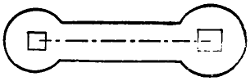
Fig. 7
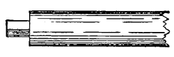
Fig. 8
We must now make the crank-shaft. This can be made with bent wire one-eighth of an inch thick. But when made in this way it very seldom works steadily and true. The best way is to build it up. You must get a piece of iron wire a quarter of an inch in diameter and about two feet long. Part of this will be required for the screw-shaft; straighten and smooth the wire and polish it up. Cut from the end three pieces, one an inch long, the second two inches long, and the third one and seven-eighths of an inch long. Next get four pieces of flat iron plate one-eighth of an inch thick, one inch long, and half an inch wide. Cut them into the shape shown in Fig. 7. The distance between the centres of the holes is to be a little less than three-quarters of an inch. The largest hole is one-eighth of an inch square, and the smallest hole a little less. The metal is to be left one-eighth of an inch wide round the holes. Take the shortest piece of iron wire and cut one end of it away, leaving a square pin and shoulder; the pin is to be three-sixteenths of an inch long, and one-eighth of an inch square (Fig. 8). Cut both ends of the two-inch piece and one end of the remaining piece in the same way. Counter-sink the largest holes in the plates (Fig. 7) and rivet them on the pins of the portions of the shaft, being careful that they are at right angles to the rods. The plates on the two-inch[86] piece must be at right angles to each other. The pins should fit very tightly in the holes, to make them firm when riveted.
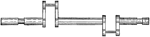
Fig. 9
Cut two pieces of iron wire one-eighth of an inch in diameter and five-eighths of an inch long, and at each end of each piece make a pin and shoulder to fit the small holes in the plates, leaving a full quarter of an inch of the wire between the pins untouched. Join the cranks together in pairs by riveting in these wires, being careful to keep the cranks at right angles to the shaft, and also to keep the several pieces of the shaft in the same straight line. Place the shaft on the bearing-blocks in the position it will occupy, with the cranks over the holes in the bed-plate and with the longest end to the after end of it. Mark on the shaft the position and thickness of the bearing-blocks, and cut the metal of the rods away in these places till it is reduced to one-eighth of an inch in thickness, so that it will work freely in the bearing-holes. The crank will now look like Fig. 9.

Fig. 10
The next step is to connect the top and bed-plates by four pillars. The length of these will depend on the length of the piston-rod. They must be made of four pieces of brass wire a quarter of an inch thick. Take one of the cylinders and a sheet of paper; on this paper draw a line about six inches long, and at one end mark the point A (Fig. 10). Push the piston-rod in as far as it will go, and push the pivot of the cylinder through the point A, and mark on the line the point B, exactly under the hole in the crosshead of the piston-rod. Now draw out the piston-rod as far as it will go, and mark the point C exactly under the hole as before. Bisect the portion of the line between B C in the point D, and measure the distance between A and D. Reduce this length by the distance the centre hole in the steam-blocks is from the lower edge, and add to it a quarter of an inch for the height of the centre of the bearing-block from the upper surface of the bed-plates, one-eighth of an inch for the thickness of the bed-plate, and a quarter of an inch for riveting.
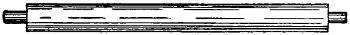
Fig. 11
This will give you the length of the pillars including the pins. File a pin and shoulder at each end, as in Fig. 11, making the pins one-eighth of an inch in diameter and a quarter of an inch long. Rivet a pillar firmly in each corner hole of the bed-plate, and put the top plate on the top ends of the pillars, and rivet them firmly in. Be careful that the pillars are upright. Rehang the cylinders and unscrew the caps of the crossheads. Fit the cranks into the holes in them and screw on the caps.
If the cylinders are made without screw-crossheads the pin of the cranks must be placed through the hole in the heads before riveting the cranks together. Unscrew the caps of the bearing-blocks, and put the crank-shaft into the bearing-holes, and screw on the caps again. Oil all bearings and parts that work together. Now you must get a heavy brass fly-wheel three inches in diameter, which can be purchased with the other things, and costs about two shillings. This wheel has a screw-bolt through one side of the centre block to fix it to the shaft by. Fix this wheel on the long end of the shaft by tightening the screw. It would be better to make a small hole in the shaft for the point of the screw to enter. The wheel must have two iron pins, about one inch long, in the face of it.
Now if all the fittings are well made and oiled, the engine ought to work easily and smoothly without noise if the fly-wheel is spun round.
Fig. 26 at the end of this section represents the engine as finished.
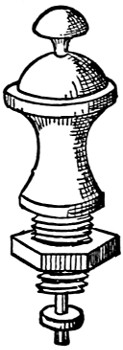
Fig. 12
We must now turn our attention to the boiler. For this you must obtain some sheet copper; get the size known as 12-lb. copper—that is, the sheet two feet by eight feet weighs 12 lb. You must also procure some copper tubing one-third of an inch in diameter. Get also the following articles; two brass gauge-taps, 1s. 3d. each; one steam-tap with union, 1s. 6d.; man-hole or water-filler, 1s. 6d.; spring safety-valve set to 30 lb. the inch, 1s. 4d. If these are not already fitted with screw-blocks get them so fitted when buying them. Fig. 12 represents the safety-valve with the screw-block.
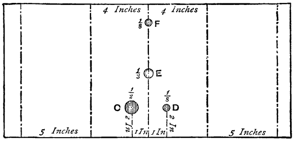
Fig. 13
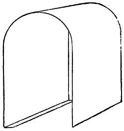
Fig. 14
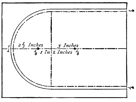
Fig. 15
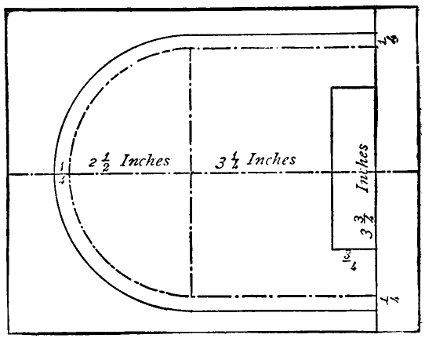
Fig. 16
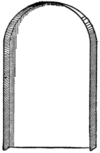
Fig. 17
Cut out of your copper a piece (Fig. 13) eighteen inches and three-quarters long and nine inches wide. Draw a line A B at right angles to the two long sides, and bisecting them. From A and B mark off the distances shown in the figure. Bore the holes, C, D, E, and F, the sizes marked, and in the places indicated. Bend the plate so that the middle eight inches form a semicircle with a radius of two and a half inches, and the five-inch parts are straight and five inches apart. Turn in the remaining half inch at each side to form a foot for the boiler to stand on. The copper will now be like Fig. 14, and will form the body of the boiler. Take two small sheets of copper eight inches long by six inches wide, and mark one as in Fig. 15 and the other as in Fig. 16. Cut them out carefully, and in Fig. 15 bore two holes one-eighth of an inch in diameter in the places marked. Turn up the edge all round the sides and circular portions of both plates, a quarter of an inch[88] wide, till it is at right angles to the other part of the plate, as in Fig. 17. Fit one of these pieces on each end of the boiler body, so that the turned-up edges of the ends fit outside the boiler body. The Fig. 16 is to fit over the end of the boiler that has the two holes in the top. Solder or braze the ends to the boiler body.
I should strongly recommend all the joints of the boiler being brazed, as in the event of the vessel steaming far from shore, the water running short, and the lamp still burning, it would melt the solder, and the boiler would fall to pieces, but if brazed it would not be injured if made red-hot. If you solder the parts together you can do it yourself from directions given in the section on the magic-lantern, but in soldering copper or brass together both surfaces of the joint must be first tinned over.
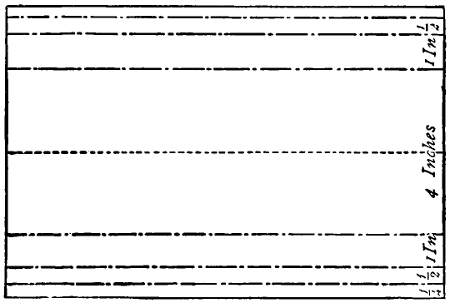
Fig. 18
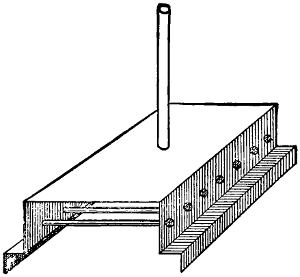
Fig. 19
If you decide to have the joints brazed you can get it done at the ironmonger’s, if you first cut out and fit the parts together and explain what you require. The floor of the boiler is made out of a piece of sheet copper nine inches long and seven and a half inches wide. Mark it as in Fig. 18. Bend it along the lines into the shape shown in Fig. 19. In the middle of the top make a hole one-third of an inch in diameter. Bore seven holes one-third of an inch in diameter along each of the sides and half way up. Cut a piece of the brass tube six and a half inches long, and braze one end of it into the hole in the top, as in Fig. 19. Cut seven pieces of the tube four and a half inches long each, and connect the holes on opposite sides by brazing the tubes across into the holes, as in the figure. Take the screw-block off the safety-valve and solder it over the hole marked D in Fig. 13 on the inside of the boiler. Solder the screw-block of the steam-tap inside over the hole marked F, and solder on the inside the two blocks of the gauge-taps over the holes in the end of the boiler. The block of the man-hole must be brazed on the outside over the hole C, Fig. 13.
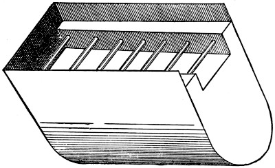
Fig. 20
Now fit the floor of the boiler in its place, passing the end of the tube, fastened to the top of it, through the hole marked E in the top of the boiler, and projecting about half an inch, and braze it in. Fig. 20 will show the position of the boiler floor. The top of it is to be two inches from the bottom of the sides. Braze it in firmly, being very careful to make all the joints steam-tight. Screw in the man-hole cover, safety-valve, steam-tap, and gauge-taps. On the top of the boiler and over[89] the projecting pipe solder a piece of brass tube seven inches long and an inch and a quarter in diameter, raking aft a little, for the funnel. Now the boiler is finished and ready to be connected with the engine. But before this can be done we must make the reversing-gear.
Procure a block of brass, three-quarters of an inch wide, one inch long, and half an inch high. Square this up true, and bore a hole right through it from top to bottom, three-sixteenths of an inch in diameter. With the end of a rat-tailed file taper the hole to a little more than a quarter of an inch at the top. Get a piece of brass rod a little more than a quarter of an inch thick, and file one end of it taper to fit the hole, and square off the bottom end of it, making the taper portion half an inch long. Smoothen this with fine glasspaper, and then oil it and dust over it some fine emery-powder, and put it in the hole in the block and grind the two together till they fit perfectly. Cut the taper portion off exactly the length of the depth of the block.
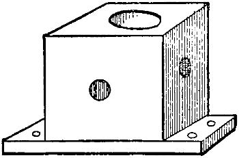
Fig. 21
Cut the brass away at the ends of the block, leaving a flange at the bottom, at each end, a quarter of an inch long and one-sixteenth of an inch thick, as in Fig. 21. In each flange bore two small holes, to screw it to the top plate by. Drill four holes,[90] one through each side of the block one-eighth of an inch in diameter, right into the centre hole and at right angles to each other, as in Fig. 21. Wipe the plug and hole quite clean from the oil and emery, and replace the plug. Put a needle-point into one of the side holes, and lying on the bottom of it and pressing against the plug. Turn the plug round in the socket. Now move the needle-point to the top of the hole and turn the plug round again.
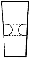
Fig. 22
Take out the plug, and there will be two lines one-eighth of an inch apart scratched all round it, as in Fig. 22. With a small round file cut two grooves opposite each other in the plug, by filing between the scratched lines, leaving the brass between them one-sixteenth of an inch or less thick, as seen in Fig. 22. Drill a hole one-eighth of an inch in diameter and a quarter of an inch deep down the top end of the plug, and another up the lower end, to fit one of your small screws. Be careful that neither of these holes enters the grooves.
Cut a small circular plate of copper seven-sixteenths of an inch in diameter, and drill a small hole in the middle of it. Give this plate two or three taps with a small hammer in the middle to hollow it a little. Put the plug in its place in the block, and turn it over and place the circular plate on the bottom, with the concave side to the plug, and fix it there with a screw. This will keep the plug from coming out of the block. Solder an iron wire one-eighth of an inch thick and six inches long into the hole in the top of the plug. Fasten the block on to the square projecting piece of the top plate, first cutting out of it a circular hole half an inch in diameter, to let the circular plate at the bottom of the plug drop into. The valve must now be connected with the steam-blocks. Take two pieces of steam-pipe three-sixteenths of an inch in diameter and an inch and a quarter long, and bend them the shape of Fig. 23, so that the distance apart of the ends is the same as from one hole in the top of one block to the corresponding hole in the other.
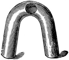
Fig. 23
Cut a hole in one side of the bent piece, as in Fig. 23, large enough for the end of another piece of the pipe to fit into when tapered a little. This piece is to be about three and a quarter inches long, and bent so as to pass from the steam-blocks round the cylinder to the hole in that side of the reversing-valve block. Fit the end of this pipe into the hole in the bent tube and braze it in the following way. Rub a small lump of borax on a moistened tile and rub the joint to be brazed with the mixture of borax and water. Cut a small piece of silver off a threepenny-piece about the size of a large pin-head, and put it on the joint. Now hold the end of the tube in the left hand, covered with a cloth, and with a blow-pipe direct the flame of a spirit-lamp or gas-jet on to the joint till it is red-hot, when the silver will melt and flow round the joint and fix it. If you cannot do this[91] yourself a jeweller or watchmaker will do it for you. Make two of these bent tubes with double ends, and solder them in their places, connecting the steam-blocks with the reversing-valve. You must enlarge the holes, to let the ends of the pipe in before soldering.
Bend a piece of steam-pipe, a quarter of an inch in diameter and eight inches long, so that about two inches of one end stands at right angles to the other part. The bend must be circular, or it will compress the pipe. Solder this end firmly into the front hole in the reversing-valve. Bend another piece of the pipe about the same length so as to go into the after hole of the valve and be parallel with the other pipe. On the top of the boiler solder a piece of pipe about six inches long; one end is to be bent up about one inch and inserted through a hole in the bottom of the funnel, and directed upwards inside, the other end is to project about one inch from the end of the boiler.
In the end of the steam-pipe solder the union of the steam-tap. Next make the stand for the engine and boiler. Make it out of a piece of deal eighteen inches long, five inches wide, and half an inch thick. Screw the bed-plate of the engine on one end of it, so that the after end of the plate is flush with the stand. The wood must be cut away under the square holes, to let the cranks work in. Screw two strips of copper at the other end, for the turned-in feet of the boiler to slide under. Put them so that the end of the boiler will be about three and a half inches from the fore end of the bed-plate. Put the boiler in its place, and bend the steam-pipe so that the union can be screwed to the steam-tap and the exhaust-pipe so that the end of it is opposite the projecting pipe from the boiler, and connect these two ends with a piece of indiarubber tubing.
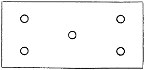
Fig. 24
The spirit-lamp must be in the shape of a closed box, made of sheet copper, four inches wide, eight inches long, and three quarters of an inch deep. In the top cut five holes, as in Fig. 24, a quarter of an inch in diameter. In these holes solder five tubes half an inch long, and projecting from the top a quarter of an inch. These are for the wicks. At the front end of the top solder a screw filling-tap. At this end solder also a piece of small pipe four inches long. This is to be bent so that it will stand upright outside the end of the boiler, and is to act as a vent, to prevent the spirit being forced too freely up the wicks. Fill the wick-holes tightly with cotton. Now fill the lamp half full of spirit. Pour hot water into the boiler till it just flows out of the top gauge-tap. See that all the taps are turned off. Light the lamp and put it under the boiler, and while steam is getting up oil the engine well with sewing-machine oil. In a short time the steam ought to be up and the engine at work. Try the reversing-gear and see if it acts properly. The engine ought to work smoothly and without noise, and the frame ought not to jar.
We must now make the screw propeller. The boat, which I suppose already made, is to be five feet long, ten inches wide, and eight inches deep, without the keel, and hollowed out to about a quarter of an inch thick at the gunwales and three-quarters of an inch thick at the bottom, and must be rather flat-bottomed, as steamships are, so that the inside at the bottom is five inches wide.
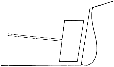
Fig. 25
Put the engine and boiler in the boat so that the boiler is a little abaft the middle. Cut away the dead wood of the stern to make a hole four inches high and two inches wide, as in Fig. 25. Bore a hole from the hole in the dead wood right through into the interior of the boat, as shown by the dotted lines in Fig. 25. This hole is to be directed to the centre of the fly-wheel of the engine. The shaft is made out of the quarter-inch wire. Cut a square pin and shoulder three-eighths of an inch long and an eighth of an inch square at one end of the shaft. Cut a piece of the same wire three and a half inches long and drill a square hole in the middle, and rivet it on the end of the shaft crosswise. In the hole in the stern of the boat you must fix a tube and stuffing-box, which may be got—together with the screw, which is to be a three-fanned one, measuring three inches across the fans—with the other things, of Messrs. Theobald and Co., and similar houses.
Put the shaft in its place inside the boat, with the cross-piece resting across the pins in the fly-wheel, about half way. Mark the end of the shaft so that it will project an inch and three-quarters, and cut it off there. The bearing must now be made out of a strip of brass one-sixteenth of an inch thick, three quarters of an inch wide, and two inches longer than the width of the inside of the boat. In the middle of this bore a hole a quarter of an inch in diameter, and bend one inch of each end at right angles to the other part. In each bent piece drill two small holes, to screw them to the sides of the boat by. Slip a piece of tubing, one inch long and of a size to fit tightly on the shaft, close up against the cross-piece. Put the shaft through the bearing and stuffing-box tube, and put the cross-piece on the pins in the fly-wheel, and screw the bearing to the boat, so that it is close against the tube on the shaft. The screw has a screw-bolt like the fly-wheel to fix it to the shaft by. Drill a small hole in the shaft for it, and put the screw on the end of the shaft and fix it by tightening the screw.
The deck of the boat must be cut the shape of the inside of the gunwales, out of quarter-inch board, and is to be fixed so that the gunwales are one inch high. It must have a hole cut in the middle to go over the boiler and pipes. A hole must also be cut over the engine, and one also in the front part of the deck large enough to admit your hand, to allow of your removing and lighting the lamp. These two holes ought to be covered by movable skylights. A hole must be bored in the deck just in front of the after-skylight for the wire from the reversing-valve to project about half an inch. A wire handle must be fixed by riveting to the end of this, and two pegs driven into the deck, one on each side, in front, to prevent the handle being turned too far to either side. It should only turn one quarter of the way round.
If you have followed these directions your boat ought to steam for two hours and a half without refilling the boiler; though the lamp would not burn all that time. But if you solder a short piece of tube a quarter of an inch in diameter into the front end of the lamp and quite at the bottom edge of it, and have a closed tin tank with a like tube to it in the front part of the boat, and this tank is filled with spirits, and connected to the lamp by a piece of india-rubber tubing joining the two tubes, the lamp will supply itself from the tank as it gets low. The spirit from the tank will not fill the lamp, but will just cover the hole of the tube and keep at that height so long as there is any spirit in the tank. Such an engine as here described would cost to purchase about £7 10s., and the boat with engine complete, quite double that sum.
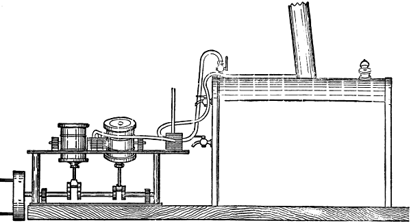
Fig. 26
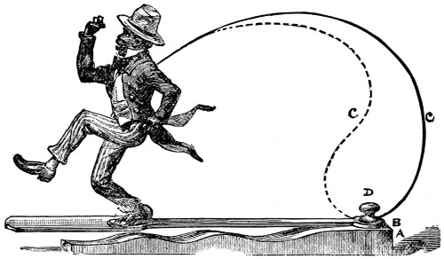
Fig. 1.
It is now some years since one evening at Christmas time I made one of a large family party assembled at the house of a relative. The evening had passed very pleasantly, and we were chatting together, and watching an arrangement which was being made in a recess behind a pair of curtains, before which was a small table. After some little time waiting in expectation, there suddenly appeared from between the curtains the agile gentleman who is portrayed at the head of this chapter. The operator, concealed (all but a portion of his arm) behind the curtains, placing the stand on the table, and cleverly manipulating the wire, caused the figure to dance in the most amusing and ridiculous manner, creating the greatest merriment. Afterwards, some lively jigs and reels being played on the piano, the figure footed it away, cleverly keeping time to the music.
Coming across the stand of the figure brought the memory of it to my mind, and I thought that making and working such a figure would be an amusing occupation for boys in the long winter evenings.
The nigger, when he first came out, was rather an expensive toy, and I have not latterly seen anything quite like it, but it is within the capabilities of any ingenious lad to make one for himself at a very small expense. The one I have described was about eight inches high, and had a proportionately-sized stand; but of course it can be made of any size, though a smaller one would be quite as troublesome to make, and not so funny. We will take the figure as being about the height described.
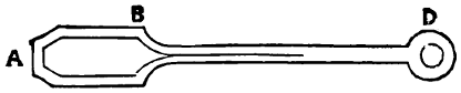
Fig. 2.
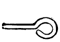
Fig. 3.
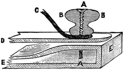
Fig. 4.—A Screw. B B Button. C Wire spring. D Spring-board. E E Stand.
The stand (A) is a piece of common deal about 13 in. long (for the figure eight inches high; if the figure is made larger or smaller all details will of course also be[95] proportionately more or less). The width of the stand is 23⁄4 in., and it is shaped as in the sketch. On top of the stand is a spring-board; this board is shaped as Fig. 2, rather less than 1⁄8 in. thick. From A to the shoulder at B is 6 in., and from B to the centre of the hole at D is 9 in., the whole length being therefore 15 in., and the spring-board in consequence projecting 4 in. beyond the end of the stand. At D on the stand is a button screwed to the stand, the screw passing through the hole in the spring-broad, and by tightening up the screw the spring-board can be made more or less rigid as required. The spring marked C C (which can be put in either way; the dotted line is perhaps the least effective way, as the greater the spring—within limits—the better) is made of steel or iron wire, one end being stuck into the back of the figure and the other being bent as in Fig. 3, and put under the button, the screw passing through all, as shown in Fig. 4.
The next thing is the figure. The head you must shape as fancy dictates, and[96] the result will be the criterion of your cleverness as a wood-carver. If you cannot manage to carve a head, you might buy one and stick it on, or make your figure out of a large Dutch doll.
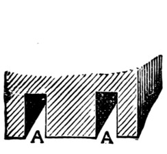
Fig. 5.
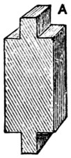
Fig. 6.
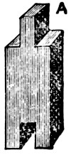
Fig. 7.
The head and body must be in one piece; the hat may be separate and glued on, or carved with the head, as you prefer. The trunk must terminate as in Fig. 5, to allow the legs to fit in and swing easily. The legs must be made in two pieces (Figs. 6 and 7).
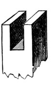
Fig. 8.
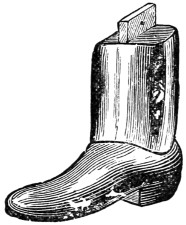
Fig. 9.
Figures 8 and 9 speak for themselves. The flanges must correspond of course with the slots, and a pin is run through to keep the leg in its place, while it is fitted loosely so as to swing. The lower part of the leg and boot should be made rather heavy, so as to come down with some force on the spring-board.
When you have made your figure you can dress him if you like, but the legs must be left free at the joints. Loose trousers of very light striped stuff can be fitted, but they must not come much below the knee. The figure may be painted a dark brown, the hat red or white, the boots of course black, and the stand green or blue picked out with black, but you must use your taste in these matters. When all is finished it is not difficult to make the gentleman dance; but still your spring-board must be tightened to the right pitch, and the spring wire bent so that the feet of the figure are just off the spring-board; then by slightly agitating the wire the nigger will commence to dance; and it will entirely depend on its owner’s tuneful ear whether he dances in time to the music or not.
Many a penny have I invested when, as a lad, visiting such places of amusement as the Crystal Palace, Polytechnic, London Crystal Palace, and Pantechnicon, in obedience to the entreaty forming the sub-title of this chapter, placed on the cases containing models and figures; and I yet very vividly remember the delight experienced from seeing the models start into motion. Indeed, even now, though arrived at man’s estate, I rarely miss dropping a penny into the coffer of any case containing a moving model when I chance to come across one.
Now these models, complicated as they may sometimes seem, can be easily made by any boy who can use his tools, and, as the construction and exhibition of them will afford great amusement, I propose in this chapter to give detailed practical instructions for making them.
The subjects I have chosen are a windmill, a yacht in full sail, a watermill with real water, dancing niggers, etc., so that there should be sufficient variety to suit all tastes and skill.
The windmill being the simplest in construction of the working models, we will take it first. The model, with the necessary pictorial background, is to be enclosed in a case, which will bear somewhere on the front of it the legend forming the title of this chapter, and the sails will go merrily round on dropping a penny into the box, thus practically illustrating the old song, ‘Money makes the mill to go.’ The cost of the whole model and case will be something under 8s. Now for the construction.
We will make the case first. For this get some half-inch deal board, 12 in. wide, and plane it smooth on both sides. Cut the pieces for the back, top, bottom, and sides, and square them up true. The dimensions of these pieces are as follows: the back, 20 in. long and 12 in. wide; the top and bottom pieces, 12 in. long and 10 in. wide; and the two side pieces are each 20 in. long and 10 in. wide.
Having cut and trued up these pieces, proceed to form them into a box by joining the edges by dovetailing, if you are skilful at cabinet-making, or get some friendly carpenter to do it for you, if you are not up to the work. If you cannot manage either to do it yourself or to get it done for you, the parts can be joined with glue and screws, but the side pieces will have to be cut one inch shorter than for dovetailing, in order that the top and bottom pieces may fit in flush with the back piece.
The front of the box is to be closed by a door, of which the upper 12 in. is of glass. Make the door out of a piece of half-inch board, 8 in. by 11 in. for the bottom piece, and fasten to each end a strip of wood 20 in. long and 1⁄2 in. square,[98] so that one end of each strip is flush with the lower edge of the board, leaving 12 in of each strip projecting beyond the upper edge.
These strips should have a groove 1⁄8 in. deep cut in them to hold the glass. This you had better get cut for you. Put your glass, which must be about 111⁄4 in. wide and 11 in. long, into the grooves, and the upper edge of it will be half an inch from the ends of the strips. Fasten it in by a cross-piece of wood 1⁄2 in. square and 11 in. long, glued and screwed to the two side strips.
If you prefer it, the glass can be put in the door after the manner of window-panes. In this case the side and top strips must have a rebate cut in them, and the top edge of the wooden portion served in the same way. You must choose for yourself which method you will adopt. Either will do, but the latter is perhaps the neater.
In the top of the right-hand end of the wooden portion cut a slot large enough to allow the necessary penny to pass freely. The door you will fasten to the box with two small brass hinges, and you must put a small brass hook on the other side of the box to keep it fastened. But it will be better if you do not hang the door till the inside arrangements are completed, for fear of breaking the glass.

Fig. 1.
Fig. 1 represents the case and model complete. Divide the interior of the box into two portions by a horizontal partition, fastened to the back and sides by glue and screws. The space below the partition is to be 7 in. deep. In the right of this space fit a cash drawer 9 in. long, 3 in. deep, and 3 in. wide, to hold the pennies. The side of this drawer nearest the machinery must have a slot cut in it for the starting lever (A, Fig. 3) to work in. The sides of the case are made of wood, so that the working of the model can only be seen from the front and so that the flow of pennies will be larger.
Paint the back of the inside of the case to represent a landscape, or a suitably[99] coloured picture can be pasted in, and serve the horizontal partition in the same manner to represent ground, blending the back and ground together in a natural manner. Paint also the top board to represent sky.
Make the mill out of wood or cardboard. It is to be 73⁄4 in. high, and the holes for the spindle carrying the sails 53⁄4 in. from the bottom. The sails are to be 91⁄2 in. across, and can be made of wood or cardboard, or, better still, wood cross-pieces with cardboard sails. Make the spindle of iron wire 1⁄8 in. in thickness. It should be about 31⁄2 in. long. Flatten one end of the wire and drive it into the centre point of the cross-pieces of the sails, being careful to keep it quite square and upright.
Pass the spindle through the holes in the back and front of the mill, and put a knob of sealing-wax on the end, to prevent it working out when the mill is at work. If the mill is made of cardboard, the inside must be strengthened with wood to support the spindle.
We will next turn our attention to the mechanism to set the mill in motion. Very few of my readers possess the tools and skill to use them necessary to cut and fit the wheels, and, as it would come very expensive to get them made specially, it will come very much cheaper to buy one of the cheap eight-day clocks, which will suit our purpose admirably. These can be procured at most of the suitable shops, and will cost about 5s. 6d.
Take the frame and works out of the clock case, and remove the pendulum and hands, as you will not require them. If you now turn round the spindle on which the minute hand fits, you will notice that, although the parts that carry the hands are in motion, the rest of the wheels are stationary. On examining these hand-turning wheels carefully, you will notice that the one carrying the minute hand is fixed on the central spindle by jambing only, and that it turns a small flat wheel which, in turn, gives motion to the wheel carrying the hour hand. This wheel is fixed to a tubular spindle, which fits over the spindle of the minute-hand wheel, which itself is tubular and jambs on the central spindle. Now, as you will not require this movement, take off the hour-hand wheel, and after removing the small[100] flat wheel, replace it and fasten it, together with the minute-hand wheel, to the central spindle with solder.
Some of the cheap clocks have the minute hand fixed direct to the central spindle, the hour wheel only being tubular. In this case the hour wheel and the spindle must be soldered together after the small flat wheel has been removed. As you will not require the escapement wheel, push on one side the small spring clip that presses on the end of the spindle, and it will drop out.
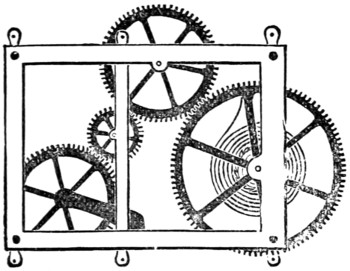
Fig. 2.
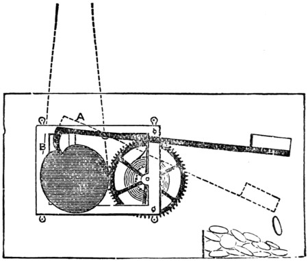
Fig. 3.
You will now want a pulley wheel (B, Fig. 3). One of the wooden sheaves used in Venetian blinds for the cords to run over will do very well indeed, or if you possess a lathe you can turn one for yourself. It should be 11⁄2 in. in diameter and 1⁄4 in. thick, having a small hole right through the centre, of a size to fit tightly on the hour spindle of your works. Fig. 2 represents the frame after the wheels not required have been removed. Fig. 3 represents the starting lever and pulley. This pulley must have a notch 1⁄4 in. deep cut in one rim, for the hook of the lever to fall into and stop the machinery. This pulley must not be more than 11⁄2 in. in diameter, or you will not be able to get at the winding-up pin.
The frame carrying the wheels must now be mounted in its place under the horizontal partition. For this purpose fasten with screws a block of wood to the floor board, or back of the case, in such a position that the front of the frame is about 51⁄2 in. from the front of the case, and so that the centre of the wooden wheel is about 4 in. from the horizontal partition, and immediately under the spindle carrying the sails of the mill. The horizontal partition must have a slot cut in it, inside the mill, for the connecting cord to pass. The frame is to be fastened to the supporting block by screws, but before doing this you must make the all-important starting and stopping lever.
Get a piece of iron wire 1⁄8 in. thick, and about 10 in. long. Flatten one end and bend down about half an inch of this end to form a hook, standing about at right angles to the length; place this hook in the notch of the wheel when it is a little beyond the centre of the pulley, as seen in the cut, and cut the wire to such a length that the other end of it will be about 1 in. from the side of the case, when the gear is in position. Drill a hole crosswise through the wire about 3 in. from the hook, and fasten a small wire to the gear-frame, standing at right angles to it, about 21⁄2 in., measured horizontally from the spindle of the pulley, and near the top. This is for the lever to turn on, as shown in the cut. At the free end of the lever solder a piece of tin bent up on three sides like a small tray, with the edge not bent at the extreme end. This tray or scoop should be about 11⁄2 in. square, and is to catch the penny as it is dropped in.
The hooked end of the lever must be weighted, to slightly outbalance the other part, so that the hook will drop into the notch in the pulley. The frame can now be put in its place and fixed to the block with screws. Bend the long end of the lever till the scoop is 31⁄2 in. from the under side of the partition. In bending the lever you must also see that the scoop is horizontal, or the penny will not remain in it long enough to start the gear. Now connect the spindle of the sails and the wooden pulley-wheel by passing a silk cord or fine string round both tightly, and knotting the ends together.
Now on winding up the spring and pressing down the lever the works will start[101] into motion and the sails will revolve. The speed can be regulated by placing the sails at such an angle that they will offer more or less resistance to the air.
The slot in the door for the insertion of the penny must be cut three-quarters of an inch below the upper edge of the wooden partition, and inside you must fasten a tin trough to conduct the penny to the scoop at the end of the lever. This trough must slope downwards to the edge of the scoop, or the penny will not fall into it, but remain just inside the hole.
The model is now complete, and works as follows: The spring having been wound up and the door closed, the works are kept from moving by the hook of the lever catching in the notch of the pulley, but on a penny being put into the hole, and sliding into the scoop at the other end of the lever, its weight presses down the scoop end and lifts the hooked end out of the notch in the pulley, which turns round, and continues to do so, carrying the sails of the mill round with it till the notch again comes under the hook, which (the penny having fallen out of the scoop into the drawer) falls into it and stops the machinery, giving one revolution of the pulley for a penny. The pulley being twelve times larger than the spindle of the sails, these will revolve twelve times each time the model is started. The model will work about 204 times each time it is wound up.
Having finished the windmill to your satisfaction, we will now turn our attention to the construction of a model requiring rather more complex machinery. This is shown at Fig. 4, and represents a cutter-yacht sailing on the port tack, on a lee shore; which, if carefully made, so as to produce the effect of the rolling and pitching of a real yacht upon a real sea, will catch many a penny.

Fig. 4.
The case is made exactly in the same manner as the former one, and has the same dimensions, but has no horizontal partition, only a cross-piece in the front, half an inch square.
The inside of the back you must paint to represent a cliff and sky, or you can paste a coloured picture of the same on it.
The yacht is to be 5 in. long, and is to be set in a sea of silk, which will be described further on. If you prefer it, a full-rigged ship can be substituted for the yacht. For the machinery you will require, as before, an eight-day clock movement, some brass wire, and three or four pulley-wheels. Fig. 5 shows the front view of the mechanism when complete, and Fig. 6 the end view of the same.
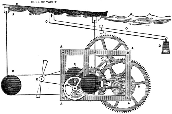
Fig. 5.
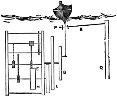
Fig. 6.
As was the case in preparing the works for the windmill, you will require to make some alteration in the wheels, but in this case, as the hour and minute movement will be required for the starting gear, the minute spindle only is to be soldered to the central spindle, and the small flat wheel retained in its place. The escapement wheel must also be retained. B (Fig. 5) is one of the wooden pulleys, 1 in. in diameter, fixed to the minute-hand spindle, and is in connection with another pulley-wheel of the same size (B), turning on a screw fixed in a block of wood fastened to the floor-board in such a position that the centres of the two pulleys are the same height from the floor and 41⁄2 in. apart. O is a lever of wire about 7 in. long, working on a pivot passing through it about 21⁄2 in. from the end C.[102] This end is connected with the keel of the boat, and the other end is weighted, to balance the boat.
Now take your boat, and at each end of the keel fix a small brass plate having a hole drilled in it (FF, Fig. 5), 41⁄2 in. apart, and fix another plate drilled in the same way at C, about 23⁄4 in. from the stem of the boat. Take two pieces of wire 5 in. long and bend one end of each into an eye and the other end into a hook, crosswise with regard to the eye, and hook a wire into each of the plates FF, on the keel of the boat, and connect the other ends with the pulleys B and B by two small brass screws passing into the fronts of BB, as shown in Fig. 5, and arrange the pulleys so that one of the pivots shall be up while the other is down.
Fig. 7.
All these joints and connections must work freely, although not loosely. The two pulleys, BB, you must connect with a cord passing round both. The pitch of the vessel is regulated by the distance the pivot screws are from the centres of the pulleys, which should be about half an inch. You must next make the regulating gear or fly E (Fig. 5). To do this you must take out the pin from the left-hand lower corner of the frame-plate and prise up the plate and take out the fourth wheel near R (Fig. 5), and on the spindle of it fix a pulley, which can be readily done in the following manner. Cut a small notch in one side of the hole in the centre of the pulley just large enough to admit a piece of your wire. Solder about half an inch of this wire along one side of the spindle about the middle of it, and force the pulley on to the spindle over this piece, and it will jamb lightly and be keyed to it. Fig. 7 will show you how to cut the hole in the pulley.
Now return the wheel to its place and re-fasten the frame-plate. Next you must make the fly E. Get a small brass pulley about 1⁄4 in. in diameter, and to it solder a strip of tin cut to the shape shown, but being wider in proportion at the ends, say 1 in. wide and 4 in. long. Twist the ends of this fly askew like the fans of a screw propeller, so that it will catch the wind in revolving. Now fix a block of wood to the bottom of the case and fix the fly to it by a small brass screw passing through its centre, so that it works freely and is 31⁄2 in. from the centre of the driving pulley R and level with it. Fasten a block of wood to the back of the case, in which you must fix the screw N (Fig. 5) for the lever O to pivot on. You must next make the starting gear. This is shown in Fig. 8.
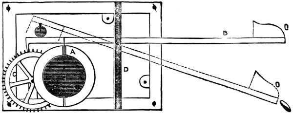
Fig. 8.
As we require the pulleys BB to revolve about twelve times, and as they are attached to the minute-hand spindle, the hour-hand spindle will revolve once. Therefore, on this spindle fix behind the pulley B, by soldering, a circular plate of tin or brass, a little larger than the pulley, and cut in one edge of it a slot a quarter-inch deep and one-eighth of an inch wide. Make your lever as before, but long enough for the hook to catch in the teeth of the wheel C, Fig. 8; and solder a piece of tin to the lever, to fall at the same time into the slot in the disc A, Fig. 8. This piece of tin must be long enough to keep the hook free of the teeth of the wheel C during the revolution of the disc A. The length of the other part of the lever is to be the same as for the windmill. Fig. 6 shows an end view of the machinery. K is a wire connecting the keel with the lever Q, and helps to give the rolling motion so suggestive to voyagers.
Fix your gear into the case in such a position that the keel of the boat will be 7 in. above the floor of the box, and bend the starting lever so that the scoop will be the same distance from the floor and front of the box as in the former case. You have now to make the sea. Get a piece of silk of the kind called Persian, dark green or ‘undecided’ blue, about 18 in. square, and in the middle of it cut a slit 6 in. long, and in this slit fasten the hull of the boat with glue, puckering up the silk, to form the waves on the sides of the vessel. Crumple the whole of the silk into miniature waves, and glue the edges round the edges of the case and to the strip of wood fastened across the front 7 in. from the floor. Touch the crests of the waves with white paint. The silk waves will rise and fall with the motion of the vessel, and appear themselves to be the cause of that motion. If the silk has a tendency to drop in, it can be supported by a floor-board, 7 in. from the bottom, with a hole cut in the centre 5 in. long and 2 in. wide for the boat to work in, and a slot cut for the wire K, Fig. 6. Be very careful that all the joints and connections work easily, or a jerky motion will be the result.
Wind up the works and drop in a penny, and the lever hook will be lifted out of the escapement wheel, and round will go the pulleys, causing the little ship to pitch and roll till the slot A comes round again, when down falls the lever hook and stops the movement. The pace of the movement can be regulated by the angle of the fans of the fly catching more or less air.
As the minute spindle revolves twelve times, the pulleys will revolve only once, which will give about seventeen revolutions each time of winding.
Fig. 9 is a view of a case of dancing ‘niggers,’ and is easily made. In the sketch the figures are one-third the real size.

Fig. 9.
The case measures 9 in. high, 7 in. wide, and 7 in. deep. The back forms a hinged door by which you can get at the gear. The slit for the penny is in the top, and near the right-hand back corner. The legs of the right-hand figure are both made separate from the body and jointed at the knees. They are fastened to the body by small pins, to allow of free working. This figure you must strengthen by glueing a piece of wood behind it 1 in. long, 1⁄2 in. wide, and 1⁄4 in. thick. The other figure has only the left leg moveable, and must not be jointed at the knee. Glue a strip of wood about 1⁄2 in. wide and 1⁄4 in. thick right up the back of this figure, and glue it to the floor board. The left leg must have a similar piece of wood glued behind it, and projecting 1⁄2 in. longer at the thigh end. Fix the leg to the body by a small pin, for it to work freely on, and in the piece of wood projecting fix, at right angles, a piece of wire about 2 in. long, and cut a curved slit in the background for this to work in, when the figure is about 1 in. from it.
This background you must make out of cardboard, and fix about 3 in. from the front of the case, which is glass. The background you can paint to any design you please, such as a street scene, or on the sands, and the floor to correspond.
Behind the right-hand figure cut a vertical slit in the background about 1⁄8 in. wide and 2 in. long, so that the centre of it comes opposite the centre of the figure when the feet are just touching the floor. Fix a piece of wire about 7 in. long into the centre of the figure behind, and at right angles to it, and bend this wire downwards at right angles about 2 in. from the figure. About 1 in. behind the background fix an upright block of wood, to come as high as the centre of the figure, and in front of it fix two small staples, one near the top, and the other about 2 in. lower, but directly under it. Into these slip the end of the wire attached to the figure, after passing it through the slot in the background. This will keep the figure in its place and allow of its moving up and down.
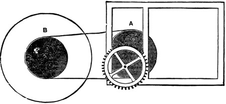
Fig. 10.
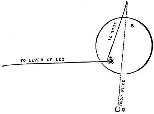
Fig. 11.
Prepare the works as for the yacht model, and also insert a pulley (A), as shown in Figs. 10 and 5. This is connected with another pulley (B, Fig. 10),[106] which is fixed to a block by a screw that is countersunk below the face of it, and to which is fastened by a small screw two wires working freely and passing one to the wire from the left-hand figure, and the other to the cross-piece of the wire from the right-hand one, and connected with them by the ends being bent into rings. From the cross wire to the figure to the right is also hung a drop wire with a small weight at the end, to help to pull it down. Fig. 11 will explain the fixing of this gear. A fly must be also fitted to the movement, to check the pace. This can be fixed to the pulley (B) or in front of the escapement wheel. The stopping motion is the same as in Fig. 8, but more slots may be cut in the disc, to regulate the length of time allowed for a penny.
The works you must fix behind the background so that the starting lever comes conveniently for the penny in its fall.
With these three examples of the necessary clockwork you will be able by the exercise of a little ingenuity and the power of contriving to make moving models of any subjects that may suggest themselves to you, such as the following: a steamboat with revolving paddle-wheels, cobbler mending shoes, soldiers marching, etc., etc.
I will now tell you how to make the model shown in Fig. 12, consisting of a water-mill working with real water, a small fountain in the middle, and children playing at see-saw in the background.

Fig. 12.
This model is worked with water-power only, and has no clockwork. The case you must make larger than in either of the former cases—24 in. high, 14 in. wide, and 14 in. deep; the height of the floor of the model from the bottom of the case 4 in., and the depth of the upper partition 4 in., the intermediate space closed by a glass door 16 in. by 14 in. The case must be made out of 1⁄2 in. stuff and well dovetailed together. In the right-hand bottom corner a drawer for the pennies[107] with a slot in front. The back or one of the sides should have a door in it, to get at the machinery, should it at any time require attending to.
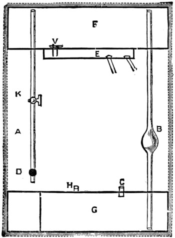
Fig. 13.
You must now make two zinc tanks, the top one air-tight, to occupy the whole of the upper space, the other also air-tight at first, to occupy the space left in the lower partition by the drawer. The top tank will be 13 in. by 13 in. by 31⁄2 in., and will have a small receiver, about 6 in. square by 1 in. deep, soldered to the bottom of it, and communication with it by a small hole, as shown in E, Fig. 13, about a quarter of an inch in diameter, and having also a small pipe passing from it to the outer air through the large tank. This pipe is not shown in the figure, but it is soldered to the top and bottom of the tank and the ends filed off flush. The zinc for the bottom and sides of the tanks can be cut out of one piece, as shown in Fig. 14. The edges of the tops should be turned over, to add strength. The soldering must be made air-tight. The background of the picture is a false back[108] inserted about 2 in. from the true one, behind which the pipes are placed connecting the vessels together, as shown in Fig. 13, which is a back view.
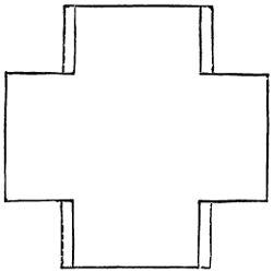
Fig. 14.
These pipes must be carefully soldered in. A is the air-pipe to supply reservoir F when in use; B is the pumping-pipe, in the middle of which is fixed an india-rubber force-ball, to be procured at any india-rubber shop, in which is a small pin-valve, to prevent the water flowing back. This pipe extends from the bottom of tank G to the top of tank F, leaving a space of about 1⁄8 in. between the ends of the pipes and the metal of the tanks. C is a small pipe by which the water from the basin of the fountain is run into G. E is the receiver into which water from F runs, and from which two pipes lead, one to the wheel of the mill, and the other to the fountain. K is a regulating tap, to govern the supply of air and regulate the amount of water passed into E. D is the stopcock connected with the starting lever, which is about 6 in. long and soldered to the handle of the tap. This tap must work easily, and yet be air-tight.
The lever must be counterweighted, to close the tap when the penny has fallen off the scoop at the end of the lever. H is a small pipe fixed in the top of the tank G to allow the air to pass out when the water is running into it through C. The basin of the fountain should be made of zinc, and fastened to the tube C, and the jet is formed of the end of a blow-pipe connected to the tube from E. The rockery you must form of cinders and paint them to a suitable colour. The mill-wheel should be made of zinc and painted, and the water from it conducted to the basin of the fountain. The other pipe from E you must conduct to a position suitable to set the wheel in motion.
The see-saw you must place so that it can be set in motion by the axle of the mill-wheel, which is carried out long enough under the rockery-bank to reach it, and has a cross-piece of wire soldered[109] to it at a point immediately under one of the figures, and which in revolving tips up one end of the board.
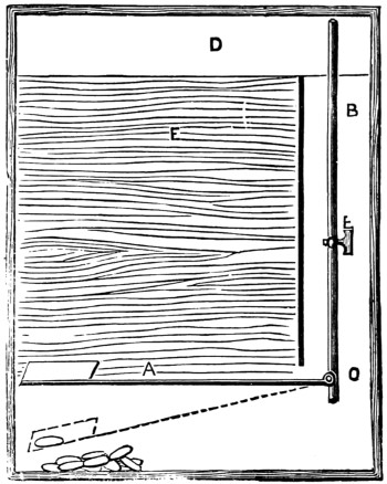
Fig. 15.
This end of the board is made, slightly heavier than the other, which will make it return to be again tipped up. We will now see how the model is worked. Pour water into the basin of the fountain till it is full, and open the starting lever as shown in Fig. 15. The bottom vessel will now be quite full. Now work the force-ball, which will pump the water out of G into F, the air rushing into G through the pipe H. As soon as the upper tank is full the starting lever is to be closed, and the model is ready to begin work. Now as F, Fig. 13, is an air-tight vessel, no water can run from F into E. But as soon as a coin is dropped into the scoop at the end of the lever A, Fig. 15, its weight presses it down and opens the cock D, which allows the air to be drawn into F, and consequently allows water to pass into E, Fig. 13.
The quantity of air allowed to pass is regulated by the extent to which K, Fig. 13, is opened. The water being in E, and this vessel communicating with the atmosphere through the pipe not shown in the Figs., the water falls into the two pipes, and is conducted by one to set the wheel in motion, and by the other to the fountain-jet, through which it issues and again falls into the basin, and thence again into G.
An ingenious and inexpensive timekeeper may be made by any boy for a few pence and a little labour. Buy a sheet of millboard, the thicker the better—size, 27 in. by 22 in.—cut off a strip 10 in. by 27 in., and shape it as shown in Fig. 16, the top part to be 10 in. square, and the lower 17 in. by 4 in. Next mark off the remainder of the millboard into three equal parts of 4 in. each, as shown in Fig. 17, then, with a straightedge and a sharp knife, cut half through the lines AA. This will form the two sides and back of the case. The funnel (B, Fig. 18) should be made of tin, with a square top to fit over the millboard, and have a very small aperture at the point; any tinman will make this for 3d. or 4d. The spindle (C, Fig. 18) must be 33⁄4 in. long, 31⁄2 in. deep in front, diminishing to 2 in. at back, have a screw-shaped groove from end to end, and work on a small spindle or axle, projecting 1 in. in front, for the hand to be connected to, and 1⁄2 an inch at rear. If the young horologist has not a lathe at his disposal, the spindle can be obtained from a turner for a few pence. The weight may be made of a piece of shaped stone, or of an empty stone ink-bottle, from the neck of which the cord passes over the bar (C), round the grooves of the spindle, and out of the hole (K). A small weight, such[110] as a bullet, must be fastened to the other end. A piece of canvas should be glued round the edges of the case, and the whole painted with a good coating of Brunswick black, over which any design may be made, either with gold lines, grotesque figures, or coloured pictures. The dial should be of white paper, 7 in. in diameter, and the hand cut out of the spare millboard and then gilded. Four small reels (E, Fig. 17), such as are used for silk, should be glued on the back, to keep the case from the wall, and a ring fastened to the top to hang it by.
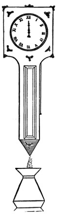
Fig. 16.
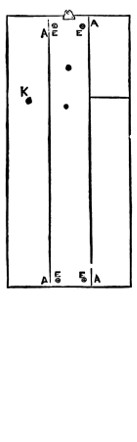
Fig. 17.
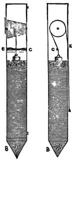
Fig. 18.
It is now ready for the motive power, which is obtained by the falling of sand, as in the hour-glass. The sand must be first well washed, dried, and sifted, to remove all stones, then poured through the case top to within two inches of the cross-bar (C, Fig. 18), the weight resting on the surface. As the sand runs through the funnel-point the weight will descend with it at the rate of about 1 in. per hour. The flow of sand will be perfectly equable from the time the case is filled until it is nearly empty, which is explained by the fact that the sand lies in a succession of conical heaps, only the first of which presses on the bottom, the others throwing their weight on the sides of the case. A gallon of sand will be more than sufficient to fill the cases, and as it falls it should be caught in a vase placed beneath for that purpose. In winding up the clock the inside weight must be raised to the cross-bar by pulling down the bullet end of the cord, and the sand poured through a paper funnel into the top of the case, care being taken to set the hand to the right hour. A clock of the dimensions here given will work for about twelve hours, but by lengthening the sand-box the working hours will be increased in proportion. It will save time and trouble to have a double supply of sand and two vases, and use them alternately. Of course one does not pretend that such a simple clock as this will keep accurate time.
‘What shall we do to amuse the boys?’ was the question asked at a friend’s house. ‘They are tired of Christmas trees, and it is so difficult to think of anything new.’
‘Well,’ I suggested, ‘why not have a Christmas ship?’
A Christmas ship! We never heard of such a thing! What is it?’
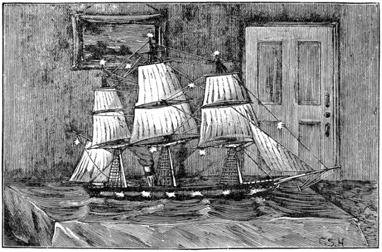
Fig. 1.—The Good Ship Santa Claus.
And this was the commencement of the planning and building of the vessel in question. To commence was a comparatively easy matter, but before she was finished and ready for her cargo the shipbuilders got rather weary. But you see they had to do everything for the first time, and with little or no previous experience. By attention to the details given in this chapter, those who go in for this Christmas ship will get on faster than we did, profiting by our experience, and not having to[112] retrace their steps and do things over again, which was often the case with us in our first attempt.
When all was finished, the ship, as she appeared in the library, was an extremely pretty sight, her long black hull illumined by the light from the open ports, through which was caught a glimpse of her main deck with its fittings. Around her extended a very realistic sea, ruffled in miniature waves, and far above, towering over the heads of the young people present, were her lofty masts with their complicated rigging. Some of the sails were set, while others were stowed on the yards. Deep down in her hold were most of the presents, while many others were suspended from her yards and rigging, which too were lighted up with small coloured lanterns.
Everything had been kept a profound secret until the library door was thrown open to the guests, and the Christmas ship, glowing with her illuminations and crammed full of presents, stood before them. Such was her capacity, that, although there were some thirty or forty young people ready and eager to plunder her, it was not until they had made three successive raids on the goods and cargo that the hold was declared to be empty, and even then in some of its recesses there still remained a few unappropriated gifts. And now to the details of her construction.
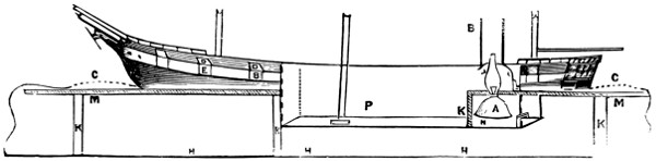
FIG 2
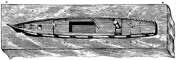
FIG 3
The first operation is to make the frame or stand. This is shown in Fig. 2 and Fig. 3, as well as in the sketch of the ship complete. It is marked H H H H in Fig. 3. The size of the stand will of course entirely depend on the size you intend making the ship, but it should be in about the same proportion to the hull of the vessel as is shown in the diagram (Fig. 2). If the ship is to be 5 ft. long and 3 ft. wide, the stand should be 8 ft. long. You will require two pieces of 11-in. deal plank, 3⁄4 in. thick, and a short piece about 3 ft. long, which will be used as follows. For the hold of the ship you must get a suitable box, which may be obtained from[113] the grocer. An old currant or biscuit box will do. We used a Florence oil case, which answered very well with the V end turned down and the bottom taken off (see Fig. 6). Fig. 7 shows the manner in which the boards for the stand are arranged round the box. A is the box, B an 11-in. board with a slot about 2 in. deep cut to fit the box. C is a similar board the other side, and D D are two filling pieces placed between the long boards to fill up the space left at either end of the box. A couple of cross pieces may be placed at the dotted lines to secure the frame together. The top of the box is left flush with the upper edge of the stand.
In Fig. 3 the dotted line shows the outline of the box. When the stand is made and put together, the simplest plan to adopt is to take any large packing case which the stand will cover, by about a foot at each end and a few inches at the sides, and nail the stand down on this case. A block of wood must then be put under where the box for the hold comes, of sufficient thickness to keep this box up just flush with the top of the stand, and when the block is nailed down the box can be screwed to it. No fastening will be necessary at the top, as the stand should fit all round it too closely to prevent it working. Care should be taken that there are no nails or splinters inside the box, or when the presents are being taken out some one’s fingers may suffer. It is a good plan to glue some smooth thick wrapping paper over the inside of the box after it is screwed down.
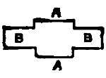
FIG 4A
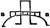
FIG 4
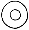
FIG 5
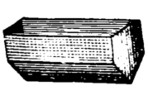
FIG 6
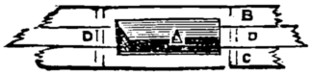
FIG 7
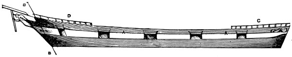
FIG 8
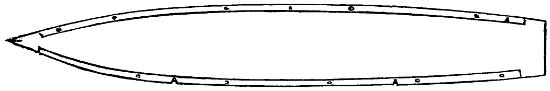
FIG 9
The sides of the ship, which are only the height of the vessel above water, can be made of thick cardboard. Millboard will do, but it cracks easily. The shape of the side having been cut out, a couple of lines must be marked within which the ports are to be cut. The lower edge of the port should be about two inches above the water-line, and the ports themselves two inches high and three wide, the whole height of the vessel’s side out of water amidships being about 61⁄2 inches (this is for a 5 ft. ship), while at the bow it will be an inch or so higher and half an inch at the stern (see Fig. 1). In cutting the ports you will find a sharp chisel the best tool to use, particularly if you are operating on thick millboard. When the ports are cut out the pieces of millboard cut away will do for port lids (see Fig. 10). A is the ship’s side, B the port lid, which is hinged on to the upper port sill by a piece of calico D D, glued on; C is the tricing line for raising or lowering the port. Fig. 9 shows the battens (A A). These are about an inch high and three-quarters thick; they are screwed down on the stand just inside the line the side of the ship will take, and serve to secure the lower part of the ship’s side by glue or screws; or another batten can be run outside the ship’s side—the two battens taking one side of the ship between them, and this is the stronger plan. The deck should be made of a stout piece of deal board, about three-quarter-inch; it must be strong, as it serves to bind the whole fabric together, and the sides are none too strong. This deck is the upper deck, the main deck being formed by that part of the stand inside the[114] vessel’s hull, and the main hatchway being the box. The deck must be placed just at the top of the line of ports (see A A in Fig. 8), so as to leave room between the two decks, and also to leave a bulwark all round the upper deck. The stern may be made of a piece of deal an inch thick, shaped as Fig. 11. Fig. 12 shows the section and the way the edges are bevelled off at A A. The bows can be fastened together by screws or glue, to a wedge-shaped piece of wood put between them (see Fig. 13). C is a triangular block of wood shaped to suit the vessel’s lines, B B the millboard sides, A is a piece of millboard or wood shaped as Fig. 14. The part A A goes between the sides which terminate at the line B B, shown in Fig. 8. The hook B is formed by a piece of wire inserted into the end of the knee of the head, and is used to hang a small figure for a figure-head. Those little plaster angels which have a small wire eye between the wings from which they are generally suspended by elastic, are the most suitable, as the wings fit on either side of the bowsprit, and the figure looks very well.
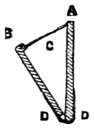 |
 |
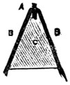 |
|
| Fig. 11. | |||
 |
|||
| FIG 10 | FIG 12 | FIG 13 | |
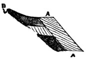 |
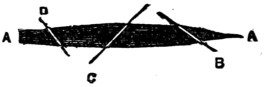 |
||
| FIG 14 | FIG 15 | ||
The most effective part of the affair has now to be described, and that is the way the hold is lighted up. Fig. 2 shows this. A is a common paraffin lamp, with say a three-quarter inch burner (though an inch is better); L is a tin reflector so fitted as to throw the light downward and forward toward the bow; at K is a strong partition to secure the lamp from being upset or damaged while the hold is being pulled about for presents; M M shows the line of the main deck, opening from which is the box P. The rays from this lamp light up the whole length forward of the main deck, and, if the ports are open, send a bright radiance from them through the room.
The upper deck must be fitted with a hatchway of sufficient size just over the box which constitutes the hold, and this hatchway must be so placed that every[115] part of the box can be reached through it even by a small child. The ports may be made to open and shut simultaneously by bringing all the tricing lines into one hauling part, which on being pulled hauls up all the ports at once. This is very effective if the ports fit well, as the room can be darkened, and the ports being suddenly hauled up, the whole interior of the ship is shown brightly illuminated.
The fittings for the lamp on the upper deck have next to be considered. The principal part is the funnel, which can be made of an old canister by cutting it down where soldered together, reducing it to the required diameter and boring holes along the lapping and lacing it together up the side. This is better than soldering, as the heat of the lamp cannot affect the joint. The lower ends of the tube are cut and opened out as at Fig. 4, and a kind of tin washer is cut out (Fig. 5), the inner circle just being large enough to slip over the funnel, but being stopped by the lower ends. The outside circumference of the washer must be large enough to cover these ends. By screwing the washer down on the upper deck, having previously slipped the funnel through it, the funnel is firmly fixed in position, the rake being determined by the way in which the lower ends are cut. To further steady the funnel and make a neat job, a small bridge is cut out of another tin canister or piece of sheet-tin or zinc, as at Fig. 4, B B. This may be made of any suitable width and pierced with a hole in the centre to pass it over the funnel; it is then bent down to the required curve, the ends joining the bulwarks and fitting in the upper deck. A light rail may be fitted, as shown in the elevation, or if the tin is cut as Fig. 4A the side pieces A A can be bent up to form a rail. This bridge may be painted with japan black, which can also be used for those parts of the vessel which require to be painted black.
The partition K (Fig. 2) must be made to remove, working in slides, so that the reservoir of the lamp, by taking off the chimney, can be got out for filling and trimming; the chimney is got off by pushing it up the funnel far enough to clear the lamp.
It will have a good effect if a poop and topgallant forecastle are fitted, as in Fig. 8. C is the poop and D the forecastle. These decks can be made of millboard, and light strips of wood are glued along inside the rail or bulwark, the top of which comes about half an inch short of the top of the rail. The small deck is then placed so as to rest on these strips; it can be fitted with a rail as shown, or not, as the builder decides.
The sea is made of green glazed calico, which must be large enough to cover the stand and hang over all round, touching the floor and concealing the rough stand and its supports. A long slit is made in the centre line of the calico, to pass it over the ship’s hull, and it is then glued along the ship’s sides before they are painted, care being taken that this is carefully done, no rucks or puckers being left. The waves are made by rolls of thin paper introduced here and there, under the calico and glued to the stand, and wherever a wave crest appears the calico is touched up with white paint, and if this is artistically done the effect is very good.
The sides of the ship are now painted black, and if the calico comes far up on the side, it must be painted over and considered as part of the vessel’s side; but along the water-line there should be a certain amount of undulation indicated by the paint, and at the bows and here and there along the side, a little white paint[116] must be put, to show the broken water and foam, while the vessel’s wake should also be indicated by lines of foam diverging at an angle from the course of the ship. Copper may be shown by a copper-red just at the bow and stern along the water, but all black will do very well. The streak containing the ports should be painted white, the outside of the ports black, and the inside red.
The rigging will now have attention. The masts may be made in only two pieces; the topmasts, topgallant masts, and royals being all in one. The lower masts should be rather stout, and can be made of common deal; they must be firmly stepped in blocks secured below for their reception, and the mainmast must be so placed as not to unduly interfere with the hold being got at. The rigging and spars and sails of a ship are given in full with diagrams in other articles in this volume, and need not be repeated here.
The character of the rigging and the number of sails set must depend on the ideas of the builder. The ship may be made at anchor, to save trouble, with all her sails stowed, and a good effect can be easily produced by furling the sails, as is the case with the lower yards in the first illustration. Any rough piece of canvas the proper size will do for this. The ends are made fast to the yardarms, the corners are then folded behind (away from the bows) to the middle of the sail, in order to make a bunt, and the sail rolled up and secured to the yard by lashings of thread or string.
To look well, the sail when stowed should be much larger in the roll at the middle and diminish off to nothing at the ends.
Those stays which it is intended to suspend lamps from should be of wire, and the topgallant yards, if used for a similar purpose, should also be of wire, and if the yardarms are used for this purpose short pieces of thick wire should be lashed to them.
When all is ready, to allow of free access to the hold without damaging the sails or rigging, it is best to brace the head yards sharp up and the main yards aback. This is shown in Fig. 15. By doing this a sufficient space is left on one side of the ship. A A is the fore-and-aft line of the vessel, B the fore yard, C main yard, showing the space B C. D is the mizen trimmed in the same way as the fore yard. The ship would then be ‘hove-to,’ which is an almost stationary position adopted when speaking another vessel or waiting for a boat, etc.—in this case for her Christmas visitors.
I do not think any explanation will be necessary as to the presents. The smaller ones, whatever they are, can be just mixed up together in the hold, and if there are any of a superior character, they can be very well fixed in various places in the rigging.
The Christmas ship in which I had a hand was well found in boats, anchors, cannon, etc., all of which were distributed among the boys of the party. In conclusion, I can only hope that, should you decide to build such a vessel, it may prove a source of amusement to yourselves and gratification to your friends, and no doubt very many will be only too anxious to learn when the good ship Santa Claus is likely to arrive.
This chapter is intended to fully describe the constructive details of miniature steam-engines. It is proposed to first give an idea of the general principles which govern steam-engines, and to explain the various characteristics and methods of constructing different types of engines. The boiler and its several fittings and attachments will be duly described, and then minute directions given for constructing engines with oscillating and slide-valve cylinders. Illustrations of both vertical and horizontal engines will be given, and also sketches in all cases where they will serve to explain more fully the meaning of the text.
This is a brief outline of the scope of the present chapter. Those readers who have acquired only slight manual dexterity in the use of tools will find little difficulty in making the engines illustrated, if the instructions given are carefully followed. In each case the minute details of the various processes incidental to our engineering work will be carefully described, so that those unacquainted with the mechanical arts will be able to comprehend the method of procedure.
Model engines, in every stage of manufacture, from the rough castings direct from the foundry to the complete, highly-finished working model, may now be purchased in nearly every town of importance throughout Great Britain. Though this trade is of but recent growth, its continual extension proves that model engines are objects of interest to a large number of the rising generation, and hence it is felt that information as to their manufacture will prove acceptable to very many readers.
It will be advisable to gain an insight into the principles which govern the action of a steam-engine, and to learn some of the technical peculiarities, before proceeding to attempt its manufacture. There are numerous text-books on the steam-engine, which may be studied with advantage, and which show the theoretical principles.
The modern engine, which now claims our attention, is the result of numerous successive improvements. The application of steam as a motive power was probably originally made by Hero, who, 150 B.C., constructed, or at least described, an Æolipile. This was a hollow sphere with hollow bent arms attached; when water placed inside the sphere was heated, and steam generated, it issued from the arms, and reacting on the air caused the sphere to rotate. A model of this, the primogenitor of the modern steam-engine, can be bought at many opticians’ shops for about one shilling.
The commencement of the eighteenth century began the first steps towards the development of the modern form of engine. Savery and Newcomen made improvements, which were perfected by James Watt, who was born at Glasgow in 1737. Amongst other valuable improvements he first contrived to convert the reciprocating motion into a rotary one by means of the crank. In the year 1800 Watt retired from business, leaving the steam-engine in much the same condition as we find it now. The application of steam-power for locomotion on both land and water followed, and now stationary, locomotive, and marine engines, driven by steam, are distributed all over the civilised world.
The varieties of model engines are in many cases indicated by their names. Stationary engines are intended to be fixed, as those used for driving machinery. Locomotives are those which are intended to travel by steam, and are self-moving. Marine engines are those used to propel ships. Of these three classes we shall deal only with the first and third in the present chapter. Locomotives are much more complicated in their construction, and consequently are more difficult to make.
Horizontal engines are those having the cylinder lying with its axis in a horizontal position. Vertical engines have the cylinder upright; sometimes they are designated by the latter adjective. Beam engines have an oscillating beam; one end is connected to the piston and the other to a rod which drives the crank. Cylinders are single-acting when the steam is admitted only at one end, and consequently with these the crank is only propelled during half of its rotation. Double-acting cylinders are provided with valves which admit the steam at each end of the cylinder alternately. Oscillating cylinders are fitted to oscillate with the motion of the crank, and the steam-valves are usually contrived to act by this oscillating motion. Slide-valve cylinders have a sliding valve, worked by a rod connected to an eccentric on the crank shaft, which opens the steam ports to alternately admit live steam and exhaust at both ends of the cylinder. Slide-valve cylinders are invariably double-acting.
Boilers, which are the vessels in which water is converted into steam, are usually described by their shape and position. They may be cylindrical, spherical, etc., and horizontal or vertical. The construction also forms a distinguishing characteristic. Tubes are usually inserted in the boiler to convey the heat from the fire. These tubes—which are more properly called flues, especially in large boilers—vary in number from one of large gauge to scores of small ones, thus naming the respective boilers single-flue or multiflue. It may be advisable to mention here that tubular boilers are those in which the water circulates in the tubes, and the fire impinges on the outer surface. When the fire operates inside the tube it is called a flue. A tube carries water; a flue carries flame and the volatile products of combustion.
Boilers, or steam generators, that are used to contain the water which, when converted into steam, drives the engine, require to be sufficiently strong to withstand an internal or bursting pressure. This pressure is very great in high-pressure engines, but in models it is generally very low, and seldom exceeds twenty pounds to the square inch. The evaporating capacity of the boiler is according to the requirements of the engine it has to supply. The resistance of the piston to the steam shows the pressure at which it should be supplied. Boilers are generally tested, by means of a[119] hydraulic pump, to stand a pressure at least double that at which it is intended to use them. It is unsafe to generate steam in any vessel that has not been properly tested. This fact cannot be too strongly impressed upon the mind of the reader.
Suppose a double-action cylinder, 1-inch bore and 2-inch stroke, is to make one hundred revolutions of the crank per minute, let us see how much steam will be wanted to drive it. The area of the piston is ·785 inch, and each revolution of the crank will require the cylinder to be filled twice—that is, one stroke in each direction. This will take a column of steam ·785 inch in diameter and 4 inches long for each revolution, or 314 cubic inches of steam per minute. If the speed is greater, the quantity of steam must be increased proportionately; and when running at the rate of one thousand revolutions per minute—a speed often attained—3,140 cubic inches of steam will be wanted to supply the cylinder. That is at the rate of about 100 cubic feet per hour.
The pressure of the steam has not yet been taken into account, but it obviously forms a most important factor in the calculation. Water in an open vessel boils at a temperature of 212° Fahr. Provided that the vessel allows the steam to escape freely, all the heat that can be applied will only generate steam at the same pressure, though it will escape faster. As the bubbles of steam ascend to the surface they escape, having only the pressure of the atmosphere to overcome. When water is confined in a closed vessel, like the boiler of a steam-engine, the temperature may be raised to considerably above the usual boiling-point. The heat is always proportionate to the pressure, and steam at a pressure of 120 lb. per square inch is equivalent to the heat represented by 345° Fahr.
A correct knowledge of the fact that pressure depends on temperature cannot be urged too strongly on the mind of the model engineer. In many model boilers it is quite impossible to raise the heat sufficiently to produce an adequate pressure. Boiling water at 212° Fahr. does not produce any available pressure of steam, it merely counterbalances the weight of the atmosphere, which is 15 lb. to the square inch. By increasing the heat, which can only be done in a closed vessel, available pressure is obtained. Thus 228° = 5 lb., 241° = 10 lb., 251° = 15 lb., and so on. The steam, and the water from which it is generated, and with which it remains in contact, have both the same temperature.
A cubic foot of water weighs 62·5 lb., and it will produce 882 cubic feet of steam, at a pressure of 15 lb. to the square inch above the normal atmospheric pressure; this is equal to a temperature of 251° Fahr. If the pressure is raised to 150 lb., which requires a temperature of 371°, only 187 cubic feet of steam will be produced. Steam is elastic, and hence the more it is compressed the greater will be its force. If one cubic inch of steam, at a pressure of 30 lb., is admitted into a cylinder, and the supply cut off when half filled, the steam will expand till it has filled the cavity, and in increasing its bulk twofold its force will diminish in inverse ratio. The pressure will therefore diminish to 15 lb. to the square inch. The expansive force of steam is always at work on the piston of the engine, and it varies in accordance with the arrangement of the valves.
Let us now trace the effect of the steam when admitted to the cylinder. When the governor valve is opened the steam flows along the pipe to the slide valve chest, and if one of the ports are open it reaches the cylinder. In traversing the[120] pipes which conduct it to the cylinder the steam is cooled considerably and its force diminished. In course of time the parts become heated to a certain extent, and then the loss of power is less. When the steam enters the cylinder it at once exerts a certain force on the piston. This has the effect of turning the crank shaft, and in due course the slide valve closes the steam inlet. Now the steam within the cylinder acts expansively, and continues to drive the crank shaft to the end of the stroke. Then the exhaust port is opened, and allows the spent or dead steam to escape. At the same time the inlet at the other end is opened and the live steam rushes in and exerts its full pressure on the piston, causing it to travel in the opposite direction. The opening and shutting of the steam ports is effected by an eccentric on the crank shaft. In treating of the construction of these parts, the relative sizes will be given and the correct motion explained.
The most simple form of toy engine is that illustrated herewith. It consists of a tin boiler, a single-action oscillating cylinder, and a fly-wheel. These parts are sold ready for putting together at a very low price, and a complete engine may be bought for a couple of shillings, though one of ‘superior make’ at twice that sum is by far a preferable investment.
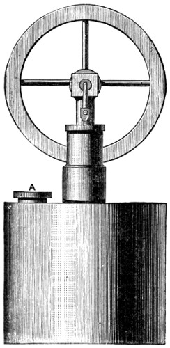
Fig. 1.
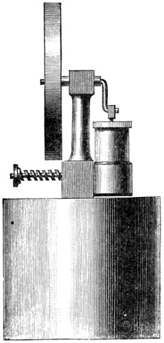
Fig. 2.
The drawing represents the most simple way of constructing a steam-engine, and, if the workmanship is fairly good, a working model will be produced. First is the boiler; a tin box 13⁄4 in. deep and 2 in. in diameter, will serve for this. The joint at the side should be made by folding the edges of metal over each other, and then soldering. The top and bottom are both soldered on their respective places, steam-tight, of course. The top of the boiler must be provided with small bosses of metal, soldered on the inner side, into which the pillar (Fig. 3) and the safety-valve (Fig. 5) are screwed.
The tin plate is not sufficiently thick to afford a hold for the thread on the pillar and valve. A disc of brass, say the size of a sixpence, and 1⁄8 in. thick, is soldered on the under side of the lid, and the holes, which are tapped to receive the pillar and valve, are bored and threaded before the lid is fixed. By this means a strong hold is secured for the fittings. The screw plug A (Fig. 1) is similarly provided for. When each piece is screwed into its place a little hemp or cotton, placed between the shoulder of the ‘fitting’ and the surface of the tin plate, will assist to ensure a steam-tight joint.
The standard or pillar is brass, about 2 in. long from end to end. Any form may be given to it, according to fancy, the one shown in Fig. 2 being perhaps as good as any. The lower part is circular, 1⁄2 in. in diameter, and it has a flat face on one side, against which the valve face of the cylinder works. Fig. 3 shows this. The centre of the pillar is bored up in the middle of the screwed part to meet one of the holes a b, it is immaterial which. The other hole is bored right through the pillar to the opposite side, and forms the exhaust port, the one communicating with the central hole in the pillar being the steam port. For the sake of distinction we will suppose that a is bored into the central hole, and b is bored through the pillar; then, when the pillar is screwed on to the boiler, and steam is generated, it issues from the port hole a.
The upper end of the pillar is bored through at right angles to the flat at the bottom (see Fig. 2). Through the top a piece of brass tubing about 5⁄8 in. long is fixed, generally by soldering; this is the bearing for the crank-shaft. The crank-shaft itself is a piece of steel wire bent to the form required. The fly-wheel is fixed to one end, and prevents the shaft coming out of the bearing, the bend of the arm serving the same purpose at the other end.
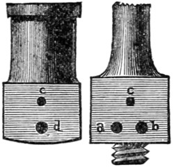
Fig. 3.
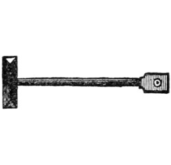
Fig. 4.
The cylinder itself is shown at Fig. 3, and also in Figs. 1 and 2. The piston, piston-rod, and bearing which fits the crank-pin are shown in Fig. 4. It will be evident that the dimensions of this engine are microscopic. The bore of the cylinder is 5⁄16 in., and the barrel itself is often made of triblet-drawn brass tube. The enlarged part at the bottom is a casting with a flat face, as shown in Fig. 3, on one side. Some makers use a casting for the entire cylinder, but the tube is perhaps the cheaper method of making. A piece of good tube is sufficiently accurate in the[122] bore for use as bought, so that the trouble of boring the cylinder is dispensed with. The base, for the tube to fit in, is bored to the external diameter, and the tube fixed with solder. The lid or cover is fixed only by being snapped on. Its object is only to guide the piston-rod.
A reference to Fig. 3 will show the working of the oscillating valve. The face of the pillar is shown on the right. On this, a is the hole from which the live steam issues, and b is the exhaust hole. These holes are technically called ports. The hole c is bored through the pillar, and takes the trunnion, or pin on which the cylinder oscillates. Fig. 2 shows this trunnion-pin prolonged and having a nut on the end. A spiral spring around the trunnion, between the nut and the pillar, keeps the valve face in close contact with the pillar face. Again, turning to Fig. 3, the holes in the cylinder on the left are:—c, into which the trunnion is screwed; and d, the steam-way.
When the cylinder is in the position shown in Figs. 1 and 2, the port-hole d (Fig. 3) is over the solid metal between the holes a and b. On turning the fly-wheel the crank draws the piston out very slightly and inclines the cylinder sideways, bringing the port d over a. The live steam from the boiler at once enters and forces the piston upwards, and on the crank reaching the highest point the cylinder is again vertical and the hole d is mid-way between a and b. The momentum of the fly-wheel carrying the crank round brings the hole d opposite b, and allows the steam to escape. There is no force to keep the engine going during this part of the time except the momentum of the fly-wheel. When the cylinder again inclines to the opposite side d comes over a, and force is again applied under the piston. This will keep the engine going.
The single-action oscillating cylinder, being supplied with steam at one end only, exerts power only during half the revolution of the crank. The return stroke is dependent entirely on the momentum of the fly-wheel, which also has to drive the steam out of the cylinder. Steam only acts in the lower part of the cylinder, and as there is no power tending to force off the cover, it may be simply snapped on like the lid of a pill-box. The piston, Fig. 4, has for its head a disc of brass, with a V-shaped groove in its edge. This is packed with hemp or lamp cotton, to make it fit the cylinder steam tight. The rod is a steel wire about 1⁄16 in. diameter; it is fixed in the piston by riveting, to save the trouble of screwing. The end of the rod has a small piece of brass fixed on to it which fits on the crank-pin.
The crank itself is all of one piece; a straight length forms the shaft; it is bent at right angles to form the throw, and a piece bent from this, parallel to the shaft, forms the pin. This is the most simple way of making a crank, and when large quantities are made the wire is bent upon a template. A better type of crank is made by using a steel rod for the shaft, a brass arm riveted on to it, and a steel pin riveted into that. In the portion of this chapter devoted to the horizontal engine will be found a more complete description of such a crank.
The safety-valve, Fig. 5, is very important as a safeguard in working. Though they are sometimes omitted, yet safety-valves are essential for security. They allow steam to escape from the boiler when the pressure exceeds a certain amount, and thus the danger of an explosion is removed. The valve illustrated in section has a spiral spring to keep the valve itself on its seat. This is effective when the power of the spring has been definitely gauged, but when the valves are put together haphazard no dependence can be placed on the pressure at which the valve will blow off.
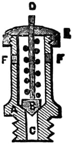
Fig. 5.
The body of the valve is A, shown in section. B is the valve itself, fitted to a rod, D; it rests on the conical seat of A, and is pressed down by the spiral spring within the barrel of A. The body is screwed into the boiler by the thread at the bottom, and the steam coming up the hole C presses on the under side of the valve B. When the pressure of the steam is sufficient to overcome the pressure of the spiral spring the valve is lifted and the steam escapes through the holes F F. The cover E is screwed on the body part and confines the spring; it has a hole through its centre to allow the valve-rod D to pass. Especial attention should always be given to the safety-valve when heat is to be applied to a boiler. See that the valve is not fixed to its seat or in any way confined, or an explosion may follow the want of care.
The engine shown by the illustrations is usually mounted on a three-legged stand, which raises it about two or three inches. A wire stand may be made according to fancy, or perhaps some contrivance may be improvised to support the boiler at a convenient height for applying the heat under it.
A small lamp burning methylated spirits—that is, spirits of wine—will supply the requisite heat. It should have a clean and dry wick of lamp cotton; the size of the flame may be regulated, to an extent, by the amount of wick which is drawn out. The lamp must not be quite filled with spirit—about two-thirds full will be ample—and thus the spirit will not be liable to overflow.
When charging the boiler it is best to use boiling water from a kettle. This will save the time which would be lost in heating cold water with the spirit lamp. The water is poured in through the water-plug hole, A, Fig. 1. The boiler must only be filled to a little over half way. The plug is screwed in again and the lamp put under; steam will be generated in due course, and if the fly-wheel is turned in the right direction by hand for a few turns the engine will presently work of its own accord.
It is scarcely necessary to say that the engine above described is of the most simple kind, and every unnecessary detail is omitted. I will now proceed to describe engines of a more elaborate character.
Small model engines are composed mainly of brass castings and of steel which requires no special forging for the purpose. The screws or bolts used to unite the parts are usually purchased in a finished state. Makers of these employ machinery which acts almost automatically, and the screws are sold at a very cheap rate. Larger models require special forgings for the crank shaft, and the castings employed are of iron, which is considerably cheaper than brass.
The castings are made from patterns which are counterparts of the object required. These are imbedded in sand, and leave a matrix, into which molten metal is poured, producing, on solidifying, a facsimile of the pattern. The operation is always carried out in a foundry, where the necessary furnaces and moulding appliances are at hand. The founders charge for the rough castings by weight, and they cost merely a trifle over the value of the metal. It is, however, necessary to supply the requisite patterns before a founder can proceed to do his part of the work.
All vendors of castings have patterns from which their castings are moulded, and of course they charge, in addition to a profit on the cost of the metal, something for the use of the patterns. The patterns for a founder’s use require certain modifications, which it is unnecessary to explain in detail. Some are made in two or more parts, with pins to hold them together. Some have projections affixed to them; these make prints in the mould to receive cores, which form holes in the casting. Those patterns which enter deeply into the moulding sand are made tapering, to draw out easily. In all cases they must be made sufficiently large to allow for shrinkage in the metal. Ordinary iron castings shrink about one-eighth of an inch to the foot; brass about half as much again. Pattern-makers use a ‘contraction-rule’ to work by; this is made longer than the standard measurement, and patterns made according to it are the correct size to allow for shrinkage.
From what has just been said it will be readily understood that vendors of castings charge various prices for their goods. Nor in every case is the quality in accordance with the price, and it is difficult to give the exact prices that should be paid for good castings. Speaking generally, the price is regulated by the weight, and the rate per pound is decided by the seller. In the catalogues issued by various firms will be found the prices charged. As an example of the difference, I notice that a certain size of bolts made by one firm are retailed by shopkeepers at rates varying from 33 to 200 per cent. profit; the same rule probably holds good in all other items.
Those readers who are not possessed of a lathe will not have the means of finishing the cylinders and some other parts which have to be turned. These can, however, be bought in various stages of completion, and the beginner who has only a screwdriver may now purchase the component parts, and, having screwed his engine together, he may claim some merit for his share in the erecting department.
Sets of castings quite finished and ready to be screwed together are now sold. These are generally of the cheaper class, and, tacked on cards, may be seen in the windows of opticians. The prices for the complete engine, with boiler, lamp, and all other parts, range from about five shillings upwards. A few words on the better type of partially finished parts.
These castings are more expensive than those quite rough, but they afford an opportunity of displaying considerable skill and judgment in completing them.
Boring the cylinders is the operation most likely to baffle the tyro. This is done by vendors of castings for about two shillings and sixpence for cylinders 1-in. bore. This charge includes turning the flanges ready to receive the covers, and also boring the steam-ways and cutting the port-holes. When all this has been[125] done it will be necessary to use a lathe to turn the covers for the cylinder, and also for making the piston. The cylinder may be purchased complete with the covers screwed on and the slide-valve fitted. One an inch in the bore costs half a guinea. Every piece of an engine may be bought separately in a finished state, so that they only require putting together, and when the young engineer has not the requisite tools for doing the work his best plan will be to purchase the finished parts.
A glance at an engine will show that nearly every part of it has been fashioned on a lathe. This tool is indispensable for all kinds of engineering work, but as it is somewhat costly it frequently occurs that tyros are compelled to forego its ownership and get the necessary turning executed by a professional latheman. Those readers who are happily possessed of the king of tools—or the father of mechanism, as the lathe has been aptly dubbed—will have the advantage of being able themselves to execute the work throughout.
A few particulars of the different kinds of engines which a beginner may make, will assist him in deciding as to the form and size best suited to his requirements. An idea of the general forms and peculiarities of engines may be gleaned from what has been already said. It is a matter entirely at the choice of the maker whether he will build a vertical or a horizontal engine—whether it shall have oscillating or slide-valve cylinders, and whether it shall be of microscopic dimensions or a powerful model. All these points are for the consideration of the constructor, and some hints will be of service to, and assist him in arriving at a useful result—that is, the production of a working model.
The dimensions of the cylinder to an extent indicates the power; the pressure of steam must also be considered. The friction in models is very great in proportion to their size, and hence the very small ones are often barely able to generate sufficient power to keep them going. The bore of the cylinder governs the area of the piston, and this multiplied by the pressure of steam and the length of stroke gives the power of the engine.
Let us compare the power of two small cylinders, one half-inch in bore and one-inch in stroke, the other one-inch bore and two-inch stroke. We will suppose the pressure of steam to be the same in both cases, viz., ten pounds to the square inch. Speaking off-hand, many tyros would be apt to say that one cylinder was twice the size of the other, and, as a natural deduction, twice the power. Comparison will at once show the fallacy of the idea.
The area of the half-inch cylinder is nearly two-tenths of a square inch, that of the other nearly eight-tenths. Thus we see that the larger one has four times the area; also the length of stroke is twice as much. According to the rule given above we find the power thus: 2⁄10 × 10 × 1 = 2, and 8⁄10 × 10 × 2 = 16. So that the power of the larger cylinder is precisely eight times that of the small one. In every case it is necessary to allow a certain percentage of the power to overcome friction. The smaller the engine the greater will be the percentage lost in friction. These simple facts will at once show that size is a most important consideration. If the friction in the small engine was two pounds, the power would not drive it, whereas if it were that much in the large one, there would still be fourteen pounds of available power.
A cylinder 13⁄8-inch bore and the same length of stroke, viz., 2 inches, would[126] give exactly double the power of the 1-inch bore cylinder just mentioned. If the bore was increased to 2 inches, the power would be exactly four times that of the 1-inch bore, the length of stroke and pressure of steam remaining the same.
The velocity of the piston also forms a factor in calculating the power, which is increased in the same proportion as the velocity. It will be readily understood that when the pressure of the steam is constant, the speed of the engine will depend on the amount of work it has to do. It must also be remembered that the pressure of steam against the piston is by no means necessarily the same as it is in the boiler. In passing from the boiler to the cylinder the steam pressure is always reduced, and the greater the distance, and more exposed or tortuous the steam-pipe, the greater will be the loss of pressure.
Every one knows that the power of steam-engines is given in ‘horse-power.’ This was a term originated by James Watt, and it is now universally adopted. The mechanical equivalent is a lifting power that will raise 33,000 pounds 1 foot high in one minute. On this estimate the power of an engine is calculated. The rule is this: Multiply the pressure on the piston by velocity per minute and divide by 33,000. The velocity of the piston is twice the length of stroke in feet multiplied by the number of revolutions per minute.
Let us calculate the horse-power of the 1 × 2 inch cylinder, already dealt with at a pressure of 10 pounds, the speed being 100 revolutions per minute. By the previous calculation we found that the pressure was 16 pounds. The velocity is 4⁄12 × 100 = 331⁄3 (feet). Multiply these together, 16 × 331⁄3 = 5331⁄3, and divide 533⁄33000 = ·016. That is, the engine is 16⁄1000 of a horse-power, or capable of raising 528 pounds 1 foot high in one minute. That is supposing all the power was available for duty. In large engines about 20 per cent. is allowed for friction, and in the model we must allow at least 50 per cent. This at once reduces the calculated power to half.
The power of an engine is the nominal, and the duty is the actual work that it will perform. When the horse-power of an engine is spoken of it must be taken in a qualified sense. By urging the furnace greater effect may be obtained, and by keeping the furnace low an effect less than the nominal power is produced. Duty is the term used to represent the amount of work absolutely done; it disregards the size of the engine, and simply inquires how much work is done by a given expenditure of fuel. True economy in working will add to the duty of an engine, whilst woful waste in no way affects the power.
In order to supply the requisite quantity of steam, boilers should evaporate at the rate of one cubic foot of water per hour per horse-power; that will produce 1700 cubic feet of free steam. The capacity of a boiler should be four or five times as much as the water it boils off per hour, and the steam space should be at least ten times as large as the consumption of steam at each stroke. The heating surface should be from fifteen to twenty square feet per horse-power. Many circumstances tend to modify these rules, but they maybe taken as fairly reliable.
Engines of the horizontal type are usually employed to furnish the power required to drive fixed machinery in factories. The construction is simple, and the form is adapted for fixing readily anywhere where a tolerably level foundation is to be found.
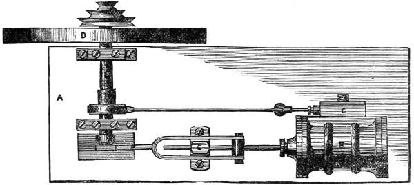
Fig. 1.
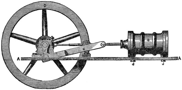
Fig. 2.
The several illustrations given herewith are drawn to scale, and they will show at a glance constructive details which could not well be explained in letterpress. Fig. 1 shows a plan view, and Fig. 2 an elevation of the complete engine. In both drawings the lettering is the same. The bed-plate A A is the foundation on which the parts of the engine are fixed. A piece of sheet brass is used for small models, but larger ones have cast-iron foundations. Cylinders 11⁄2 inches in the bore and[128] upwards are usually mounted on iron bed-plates, the saving in cost of metal being considerable when the castings are so large. Cast bed-plates have a moulded edge, which adds both to their strength and appearance. Sheet metal has to be mounted on columns sufficiently high to raise the fly-wheel above the ground-level.
The cylinder is shown in Figs. 1 and 2 at B; at C (in Fig. 1 only) is the steam-chest containing the slide-valve. D is the fly-wheel fixed on the shaft E, which has at its opposite end the crank F. The piston-rod is shown passing through a guide G fixed to the bed by two screws. The connecting-rod from the piston to the crank-pin is marked H. The eccentric is shown at I, and the rod from it to the steam-chest is the eccentric-rod. J J, Fig. 2 only, show two screws which fix the cylinder to the bed-plate. These references are sufficient to enable the inexperienced reader to identify the principal parts of the engine. By carefully studying the drawings the whole combination of the machine will be understood.
Each of the chief component parts which possess any intricacy of detail are shown on a much larger scale. The description of each one may be taken as generally applicable to engines of the type shown in Figs. 1 and 2. The dimensions are suited to the size known as ‘3⁄4-inch bore and 11⁄2-inch stroke.’ These measurements refer to the cylinder. It will not be difficult to modify any of the minor details to suit another size, whether it be larger or smaller.
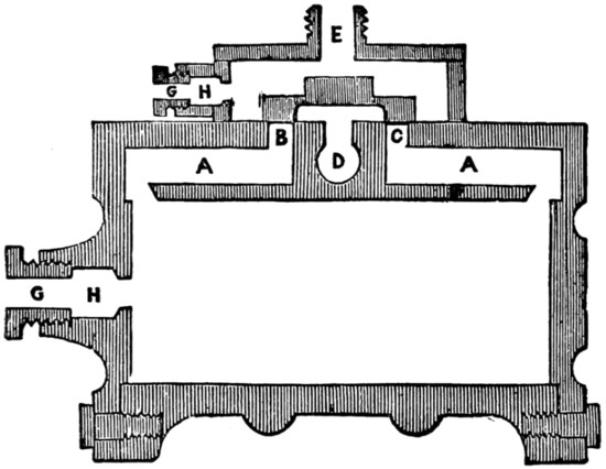
Fig. 3.
Fig. 4.
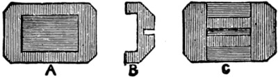
Fig. 5.
A section of the cylinder is shown in Fig. 3; the piston and its rod are absent, to prevent confusion of the parts. The cylinder with the covers on is 2 inches long and 13⁄8 inches diameter across the flanges. The bore is 3⁄4 inch and 15⁄8 inches (full) long. The face of the cylinder where the valve works is level with the diameter of the flanges. This face is shown at Fig. 4, where the size and position of each porthole may be seen. The rectangle represents the steam-chest itself, and the four small circles are the screw-holes in the valve-face for attaching the steam-chest.
Returning to Fig. 3, the steam-ways are shown at A A. These are drilled from the ends to meet the inlet ports B and C, which are closed by the slide-valve (see Fig. 5). The exhaust way is at D, and the port-hole communicating with it needs no special mention. The steam inlet is E; the threaded exterior is for attaching the[129] steam-pipe from the boiler. The glands and stuffing-boxes, for keeping the piston and valve-rod steam-tight, are shown in section. G G are the glands screwed into the castings; the parts bored out to receive the packings are marked H H. It will not be necessary to make special reference to the body of the cylinder, the covers, &c., as the reader will have become acquainted with these in the previous chapters.
By reference to Fig. 3 the passage of the steam may be traced. It enters at E, filling the steam chest, and as the valve is shown it could find no outlet. The valve on being moved would uncover one port, say B, and allow the steam to enter by the steam-way A, through the slot filed in the edge. When in the cylinder it would force the piston towards the bottom, the action of the eccentric meanwhile pushing the valve along and further opening B. When the piston had made half its stroke the valve would commence to close again, and by the time the end was reached the valve would be again in the position shown. The momentum of the fly-wheel would carry round the eccentric, and with it the valve would move so as to open the way from B to D, thus allowing the steam in the cylinder to escape. The port-hole C would also be opened to the live steam, which would then exert its pressure on the lower side of the piston. By the motion of the valve the steam is let into B and C alternately, and thus the reciprocating motion of the piston is maintained.
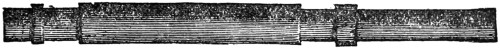
Fig. 6.
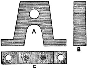
Fig. 7.
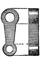
Fig. 8.
The slide-valve is shown at Fig. 5, where A is a view of the face. The centre is hollowed out, as shown at B of the section, to allow the steam to pass into the exhaust. The back is shown at C; the saw-cut receives the valve-rod, which is thinned down to fit it. The face of the valve, that is, all the outer part of A, is made perfectly flat, to fit steam-tight on the valve face of the cylinder. Contact is ensured by the pressure of the live steam in the steam-chest; this is always more than that of the exhaust.
The crank-shaft, marked E in Fig. 1, is shown alone full size at Fig. 6. This is a rod of round steel 1⁄4 inch in diameter, the total length is 31⁄8 inches. At the right-hand end it is reduced in size a length of 7⁄8 inch, to receive the fly-wheel and the driving pulley. These are generally screwed on to a thread cut on the shaft, but wedging is a more workmanlike way of securing driving wheels and pulleys. The two journals are to rest in the bearings shown at Fig. 7; the neck at the left-hand end is to receive the crank-arm. The collars on the shaft outside of each journal are of the widths shown. One of the bearings for the crank-shaft is shown at Fig. 7. A is a side view, B an edge view, and C a view from the top; in this the dotted lines represent the screw-heads. These bearings are usually brass castings; they are fixed on the bed-plate by two screws each, and the cap is also held on by two other screws.[130] Various designs may be obtained, but the one illustrated is as good as any. The thickness of the bearing is nearly 1⁄4 inch. The height must be precisely that which will bring the centre of the crank-shaft level with the centre of the piston-rod.
Fig. 8 is the crank-arm, giving an end and side view. It should be made of steel and fixed on the shaft by keying, though more often it is screwed on. The thickness is shown about 3⁄16; the shape may be according to fancy. The hole at the bottom is for the crank-pin, which is riveted in. The ‘throw’ of the crank is an important point, and it must never be so much that the piston touches the ends of the cylinder. In the present case the ‘throw,’ that is, the distance from the centre of the crank-shaft to the centre of the crank-pin, is 5⁄8 inch. This gives 11⁄4-inch stroke; there is plenty of space in the cylinder for another 3⁄16 inch, and possibly the nominal stroke, 11⁄2 inches, could be managed by using a thin piston-head. The crank-pin is shown at the top of Fig. 10.
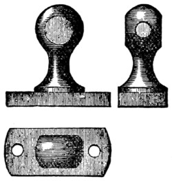
Fig. 9.
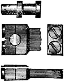
Fig. 10.
The guide-block, Fig. 9, serves to guide the piston-rod, and steadies it against the influence of the crank. The shape is shown by the illustrations. The hole for the piston-rod is bored on a level with the axis of the cylinder and the centre of the crank-shaft. The block is secured to the bed-plate by two screws, holes for which are shown in the top view.
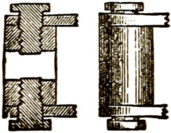
Fig. 11.
Fig. 10 shows the crank-pin and three views of the head of the connecting-rod. The crank-pin is steel, 3⁄16 inch diameter, turned down to 1⁄8 inch at the journal and at the neck, which is riveted into the arm (Fig. 8). The head of the rod is fitted with a cap, held by two screws, so that it may be placed over the crank-pin into the groove. The other end of the rod, which is forked, is shown at Fig. 11. Here a section and elevation are given; the round piece, called the cross-head, which receives the two screws (see section), is bored to fit the piston-rod, and it is clamped to this by the points of the screws shown. The sides of the fork are bored to fit freely over the threads of the screws, so that it may oscillate with the motion of the crank. The position of the cross-head on the piston is determined when the engine is together; it is placed so that the piston slides midway between the ends of the cylinder.
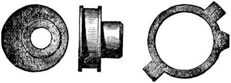
Fig. 12.
Fig. 12 shows the eccentric and the eccentric strap. The first is a piece of brass; the large circle has a groove turned in it to receive the strap, and the boss is eccentric, as shown in the left-hand figure. The amount of eccentricity is 1⁄16 inch,[131] which gives a travel of 1⁄8 inch to the slide-valve. These eccentrics are turned on a mandrel having double centres, one pair serving when turning the boss, and the other when turning the eccentric itself. A set-screw tapped through the boss serves to secure it on the crank-shaft.
The strap on the right of Fig. 12 is cast in the form shown, the centre is bored to fit the groove in the eccentric, and the strap then cut in halves through the lugs. These lugs serve to take screws, which hold the strap together. The projecting piece on the right is to receive the eccentric rod, which is screwed into the strap at this point.
This completes the description of the various parts of a model horizontal engine. A glance at Figs. 1 and 2 will show the relative position of each.
Herewith are drawings of an engine with an oscillating cylinder. This form of construction economises space and weight; it is also more simple than slide-valve cylinders. In all oscillating engines the cylinder is mounted on trunnions or gudgeons, so that it may swing to and fro through a small arc, and allow the piston-rod to follow the motion of the crank. No connecting-rod is required in this engine, the piston-rod being attached direct to the crank-pin.
The illustration shows an engine specially adapted for propelling a model boat. The entire machine is kept low down, which is generally necessary for small boats. The fly-wheel is shown much heavier than are those attached to toyshop engines, but it is not unnecessarily large. Experiments show that a weighty fly-wheel is required on an engine which has the constant drag of a screw propeller to overcome. This fact is ignored by some makers of engines, and I have known cases where a useless engine has been made effective by the substitution of a much heavier fly-wheel. (See page 132.)
The framework on which the cylinder is mounted, and which also generally serves to carry the bearings for the driving shaft, may be of almost any design. There is no set pattern for this purpose, and it rests with the designer to fashion his pattern according to fancy. The form shown possesses the essential characteristics. It is strong, yet light; there is a good base by which to secure the engine to the hull of the boat. Suitable provisions are made for the bearings of the crank-shaft, also for the valve-face and the cylinder trunnion. So long as these are provided for, the mere contour is of little importance.
Fig. 1 gives a side elevation, and Fig. 2 an end view of the same engine. The cylinder is 1 in. bore and 1 in. stroke. The length without covers is 11⁄2 in., that allows 1⁄4 in. for thickness of piston, 1⁄16 in. for each of the projections of the two covers, and the same distance left vacant at each end. The diameter of the cylinder across the flanges is 11⁄2 in., and a semicircular rib is shown in the middle. Each cover is held on by six hexagon-headed bolts, placed equidistant round it, tapped into the flange. These bolts are not shown in the lower cover.
The piston-rod is shown out from the cylinder to its fullest extent. The rod is of round steel 1⁄8 in. diameter. The crank-pin head is of brass screwed on to the end of the rod. Though shown as a solid piece, it would be better if this head[132] was cut across horizontally at the diameter of the crank-pin, and the cap secured by two screws. The crank-pin is marked E. It is steel riveted into the disc which forms the crank. A crank-arm would do equally well, and the disc is shown simply as illustrating a different plan. The disc F is fixed on the crank-shaft either by screwing, by a transverse pin, or by a key.
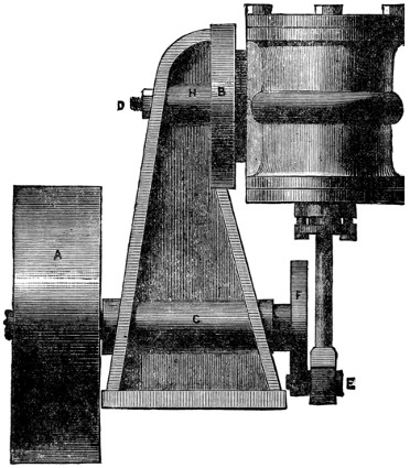
Fig. 1.
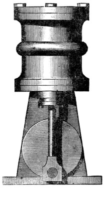
Fig. 2.
The crank-shaft is 1⁄4 in. steel, and should be turned smooth and parallel to fit the hole in the standard. This hole should also be smooth and parallel, which it will be if properly bored with a suitable tool. A long bearing has no more friction than a short one, though a contrary opinion seems to be prevalent. A small hole for supplying the oil necessary for lubrication should be made near the middle of this bearing. The same remarks apply to the bearing H through which the trunnion passes.
The fly-wheel is marked A in Fig. 1; it is cast-iron, 21⁄2 inches in diameter and 3⁄4 in. wide on the rim. The rim should be half an inch thick at least, and the boss[133] in the centre as wide as the rim. If bored fairly true, the casting need not be turned on its edge, though it will look better if bright. A small key should be used to fix the fly-wheel on the shaft. This latter, shown broken off in the drawing, projects slightly, and carries a small disc with two pins, which engage in a fork on the end of the propeller shaft and so drive it, and the screw is attached to its end.
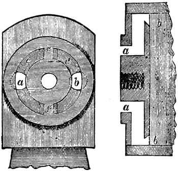
Fig. 3.
The valve-face of the standard, B, Fig. 1. must be made perfectly flat and at right angles to the boring for the crank-shaft C. Fig. 3 shows the face of this standard as it would be seen in Fig. 2 if the cylinder was removed. It is convenient to turn the valve-face in the lathe, and at the same time cut the circular groove, which, after being stopped by plugging at both top and bottom, forms the supply and exhaust ports respectively. The face may be made flat by filing when a lathe is not available, and the groove cut by means of a circular cutter. This is an annular bit with teeth on its edge, which cut a channel but do not touch the inner part.

Fig. 4.
Through the centre of the valve-face a hole is bored to receive the cylinder trunnion. This trunnion, Fig. 4, is a steel pin screwed into the valve-face of the cylinder (see Fig. 3, section of cylinder showing valve-face and steam-ways). The outer end is threaded for a nut, D; this has a washer beneath it, and keeps the cylinder close against the standard, with the faces of the valves held together steam-tight, yet so that the cylinder may oscillate freely. A spiral spring beneath the nut is sometimes used, but in good work the adjustment is made with a pair of lock-nuts. The hole through the standard must be perfectly at right angles to the face, and the trunnion in the cylinder must also be perpendicular to the valve-face, or the two faces cannot come together steam-tight.
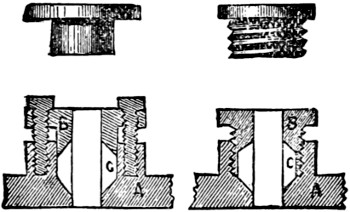
Fig. 5.
The stuffing-box, 1, of the piston is made with a gland drawn down on the packing by two screws. This arrangement is shown in section at Fig. 5. The method of fitting the gland, whether by screwing direct into the boss of the cylinder cover, as shown at the right in Fig. 5, or by screws tapped through the flange, as in the left-hand illustration, is quite optional. By referring to Fig. 5, the construction of the two forms of stuffing-boxes will be understood. The gland belonging to each is shown separate immediately above the sections. The same lettering is used in both. A is the cylinder cover, with the projecting boss into which the gland B is fitted. The space for the stuffing or packing is marked C. This is filled with lamp cotton, and when the gland is[134] screwed down the cotton is compressed, so that it makes a steam-tight fitting for the piston-rod to slide in. The hole for the piston-rod is shown through the centres of both sections. As before explained, the gland on the left is secured by two screws shown in the section; it is fitted into a plain cylindrical hole. The other gland is threaded to screw direct into the cylinder cover, which is tapped to receive it. The first method is the one always employed in large engines. The screwed gland has a milled edge, so that it may be turned with the thumb and finger.
The action of the valves in a double-action oscillating cylinder will be best explained by reference to Fig. 3. This shows the face of the standard and the section of the cylinder. There is a flat face to the cylinder, usually circular; this has the two steam-ways a, a, bored in it. These holes meet others, drilled from the ends of the cylinder, parallel with its bore, and conduct the steam to the ends of the cylinder through the passages at b, b. On the face of the standard are two holes a and b drilled from the back, one to receive the steam from the boiler, the other to take the exhaust pipe. These holes are not bored through, but communicate with the circular groove c, d. This groove is stopped at e and f. The cylinder is placed against the standard and held close to it, as shown in Fig. 1, by means of the trunnion illustrated by Fig. 4.
When the cylinder is vertical, as shown in Fig. 2, the port-holes are opposite the solid part of the face e and f. Suppose live steam issues from a and fills c, directly the cylinder is moved on one side and one of the port-holes comes over the groove e, the steam enters the cylinder and, pressing against the piston, compels the crank to revolve. By the same motion the other port is uncovered into d, and the dead steam escapes. When the cylinder again reaches a vertical position the steam-ports are again closed, but the momentum of the fly-wheel carries it over the dead centre, and then the positions of the ports are reversed. The one formerly over the exhaust now opens to the live steam and vice versâ. Thus the steam is admitted alternately at both sides of the piston, and so the engine continues to work.
A few words on model boilers and their construction will now be advisable. They have been mentioned several times incidentally in the course of these sections, but, [135]with the exception of the small tin boiler for the oscillating engine first described, particulars of their construction have been omitted. It is not an easy task making a steam boiler, and in most cases it will be found cheapest in the end to purchase ready made.
The materials most generally used are brass and copper; sometimes iron, or what amounts to the same thing, tin-plate, is employed. Brass or copper, from the ease with which they can be manipulated, are the best for a beginner to work on.
Brass can be bought in the form of tube of sufficient size for small models, and strong enough to stand the steam pressure. The edges of the bought tube are brazed together, and thus the joint is made nearly as strong as the other part. The tube is afterwards drawn, and, except from a slight discoloration, the joint is not noticeable.
Brass tube, from two inches to six inches in diameter, cut in lengths suited for boilers, is sold by most of the model engineers. The price of the tube ranges from about 2s. per foot for the small to about 10s. per foot for the large size; the short length necessary for a boiler being charged at about the same proportion. This is merely for the tubular body part of the boiler, and it may be placed vertically or horizontally as required.
The ends or flanges which have to be fitted on are extra pieces. Sometimes a plain disc of metal is fixed by soldering with pewter; but this plan should be strenuously avoided. The ends should at least be brazed on. It is best also to use discs with a rim round them to fit over the boiler tube. This gives a much stronger hold than is possible with a plain disc of sheet metal.
Castings used for the boiler ends must be quite free from any flaws, or the weak part will be apt to give way under the steam pressure. It is often advisable to use castings, which may be made of a shape exactly suited to certain requirements. An inverted cup-shaped casting for the lower end of a vertical boiler gives a good heating surface. A flue for the chimney must be put in it, and this goes up to the top end of the boiler, which may appropriately be dome-shaped.
The flue and both ends of the boiler should be brazed in their places, not soft-soldered. Some prefer to use silver solder for such purposes, and this is an excellent material. When the joints are made to fit properly, as they should do before soldering, only very little solder is required to unite the parts. Borax is used as the flux, both for the alloy employed in brazing and for silver solder. The heat required to flow these properly may be got from an ordinary gas jet, with the burner or nipple removed, using a common blow-pipe to urge the flame.
A horizontal boiler is frequently only a plain tube, with the ends soldered in, and supported on legs to raise it sufficiently to allow a lamp to be put underneath. The heat applied in this manner does not take effect as it should. The flame is deflected from the surface of the boiler, and, moreover, any breath of wind stirring will blow the flame aside. A plain saddle-shaped boiler is much better; in this form the heating surface is large, and the heat from the furnace is applied to it direct, and cannot well be deflected.
Flues or tubes are very desirable in any form of boiler, and one or the other should be used. The plain straight chimney put through the boiler is the most simple form of flue. If this is of spiral form, like a corkscrew, the effect is infinitely increased, because the heat, instead of ascending straight up through the vertical[136] tube, is met at every turn with a fresh surface of metal. In winding its way through a spiral tube, the heat is absorbed in a way quite unattainable when a straight tube is used. Several small tubes are of course better than one large one of the same area. By increasing the number of flues the cost of making a boiler is also increased, and it is to save expense that large flues are used.
Boilers for locomotives, which are required to make steam very fast, have an immense number of tubes running through them. The space between the tubes, which is occupied by the water, is often very small, and in fact the tubes are put as closely together as possible. As the heat rushes through them it is absorbed by the water in contact with the tube, and turns it into steam. The greater the heating surface the more readily is the steam generated.
Tubes are often put across the fire-grate; they are then called cross-tubes. Two, placed one above the other and crossing each other, will give a large amount of heating surface. By adding this simple contrivance to a vertical boiler with a straight flue it may be made to give off much more steam. One or two cross-tubes generally suffice to convert a useless boiler, that is, one that will not generate enough steam, into an effective one.
The fuel used to heat small boilers is generally spirits of wine. This is put in a suitable receptacle and burnt through a cotton wick. Several wicks are used in large boilers, and they are placed to heat the largest surface available. Spirit lamps are a source of danger if proper precautions are not taken. Unless there is a free outlet for the air within the lamp, it will be expanded by the heat and cause the spirit to rise too quickly in the wick. Sometimes it will overflow, and then it burns wherever it may be. Care must therefore be exercised in using spirit fuel. In model boats it occasionally happens that the spirit overflows, and the boat is all ablaze. An iron tea-tray, or some such utensil, should be used to stand the boiler on when the furnace is to be lighted.
Charcoal is a better fuel, when there is sufficient space in the fire-box to contain a supply. The waste steam from the cylinder must always be conveyed to the chimney and escape up it to make a draft through the fire. Without this it cannot be made to burn sufficiently fierce for the purpose. A charcoal fire will act very well, with a little attention, and except for the smallest engines it is always preferable to methylated spirit.
As it is not possible to give any adequate instructions on boiler-making in the limited space at my disposal, the above hints are chiefly intended for the guidance of purchasers.
A safety valve should always be fitted to a steam boiler. One of the spring valves has been illustrated in the chapter treating of the small oscillating engine. The lever safety valve is more certain in its action, especially in model work, and is better adapted for stationary purposes. A weighted lever is of no use to a locomotive or marine boiler, as the motion of travelling would disarrange the gear. The safety valve of every engine should be tested frequently, to make sure that it does not stick in its place and that all works perfectly free.
A glass gauge, by which the height of water may be seen at a glance, is frequently attached to boilers having any pretension to high-class workmanship. There is a good deal of work in a properly made gauge, and the cost is correspondingly[137] high. Two or three stop-cocks are required in a gauge, and these involve good workmanship, or they will not stand the pressure. Leaky taps are a sign of inferior work.
Gauge cocks are sometimes used instead of the water gauge just mentioned. These are plain taps with straight noses. Two are wanted on a boiler; they are screwed in, one at high-water and the other at low-water level. By turning on these taps it is easy to see whether the water is within these limits; but the precise height cannot be ascertained. The gauge-glass is therefore much preferable.
Whistles are fitted to boilers only as ornaments. They are quite useless as signals, except such as can be given by word of mouth, are not required in working model engines. These attachments are made to sound by allowing the steam to act as the breath does in common whistles.
Force-pumps are used to force water into the boiler to make up for that converted into steam, and conveyed through the cylinder. These pumps are actuated by an eccentric on the crank-shaft, and, at every revolution of the crank, throw a small quantity of water into the boiler. When we consider how much water is evaporated to make the quantity of steam used for each revolution of the cylinder, we may arrive at an idea of the work required of a force pump. Practically the water to be injected at each stroke is too small to be dealt with, unless a large cylinder has to be supplied. The only way to work a force pump for a model satisfactorily is by gearing, so that a stroke of the plunger is performed about once to each hundred revolutions of the crank.
A better plan for feeding small boilers is by hand. The force pump is attached to the boiler in the usual way, but not connected to the engine. The plunger is worked by a hand lever, and when it is seen that water is wanted in the boiler, a few strokes of the lever will suffice.
Governors are used to control the speed of the engine. Without any such contrivance the engine runs at a speed corresponding to the work it has to do. The heavier the load the slower the speed, and immediately that the load is decreased the speed increases. A governor consists of a pair of balls, which are attached to arms pivoted to an axis revolved by the engine. The faster the speed the greater is the centrifugal force of the balls, and by connecting these with a valve, called a throttle valve, in the steam pipe, the supply of steam is reduced as the speed increases. By this means a uniform rate of speed is attained, irrespective of the steam pressure or the duty demanded of the engine.
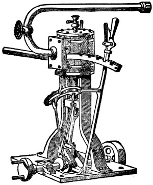
I propose in this chapter to give a few practical hints showing how to build a perfect model of an inverted-cylinder direct-action engine with link-motion reversing gear, like the sketch below, which represents a type in daily use on the river and sea. Such a model, having a fixed cylinder, has not the friction of other types, and therefore it gives more power, size for size, than an oscillating engine, and does not get so easily out of order.
You must of course have a lathe, which I will therefore suppose you to possess; but should there not be a slide-rest to it, you must get the cylinder bored by a professional turner, for which he will charge about two shillings, according to the size of your castings.
Let me first briefly explain the action of the steam in the engine by a diagram (Fig. 1, p. 139). The cylinder A is bolted into the standard, B; the ports or steam-passages are shown at C; and the slide-valve that allows the steam to pass alternately to each side of the piston is marked D, in its case F. G G are the stuffing-boxes, which have to be packed with lamp-cotton greased to make them steam-tight, H is the piston, with its rod finishing in a cross-head J, which is cut with a groove to slide up and down the standards to guide it and prevent the piston-rod being bent out of shape. K shows the connecting-rod, attached at its lower end to the crank L. M is one of the eccentrics working the slide-valve. N is the main shaft, resting on the plummer blocks O O, having a heavy fly-wheel at P and the coupler at Q. R is the top cylinder plate, drilled to screw in the grease-cock, of which I will presently give a drawing on an enlarged scale, S is the bed-plate, T the steam supply, and X the exhaust.
You will observe that the steam is coming in at the top of the cylinder, through the top port, as shown by the arrow, pressing the piston down and allowing the waste steam that has already raised the piston to escape through the lower port, and so into the exhaust. By that time the slide-valve is raised (by the eccentric) sufficiently to cut the steam off from the top port, which by that means is in its turn[139] put in communication with the exhaust, and allows the steam to pass out of the top part of the cylinder, whilst it admits it to the lower portion, and so on alternately.
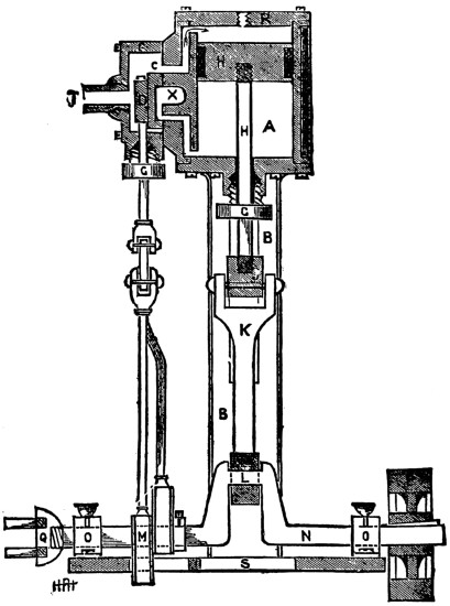
FIG 1
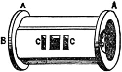
FIG 2
And now to the practical work. After having the cylinder bored, as already mentioned, get a piece of oak or other hard wood 11⁄2 inch square and about 6 inches long. Turn one end of it in the lathe, so that it fits the inside of cylinder, and drive it on. Then put it in the lathe again, and turn the flanges A (Fig. 2) down, and be very careful that they are quite true and square.
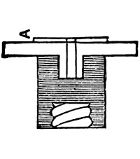
FIG 3
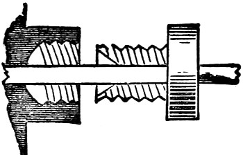
FIG 4
The top and bottom cylinder-covers, with the stuffing-box, come next. Screw a piece of hard wood on the end of your lathe mandrel, turn it down to about a quarter of an inch less in diameter than the flanges of your cylinder, make a small hole for the stuffing-box to be driven in, as in Fig. 3. You can now turn the edge and side—that next the cylinder. The projecting part A is to be the exact size of the diameter of cylinder. When this is done, take it out and place it in another chuck, and drill and turn the stuffing-box out, and screw it to receive the gland (Fig. 4).
Now chuck the top cover and turn it down to size. The piston is a casting, and has to be turned in the lathe to fit the cylinder, and a groove run round it to hold the greased cotton to make it steam-tight. Whilst in the lathe drill a hole in the centre, and tap it to receive the piston-rod, which you can make out of steel wire. Then pass one end through the stuffing-box on cylinder-cover and screw it on the cross-head J (Fig. 1), having first filed it up quite square and true and finished it off with emery. Now take the standards B (Fig. 1), and finish them up with a file in the same way, and be careful that the insides forming the guides for cross-heads are quite true. We can now make the lagging for cylinder. Get a piece of mahogany the length of the outside circumference of cylinder and the width of the distance between flanges of same. Then plane it down to about an eighth of an inch and score it with a penknife every eighth of an inch down its width; it will then bend round[140] the cylinder, and you can fasten it on by a couple of brass bands, screwing the ends down near the slide-valve case.
We will next tackle the steam-ports in the cylinder B (Fig. 2). They are simply two holes drilled side by side until they reach the openings C C (Fig. 2) in the casting; they must not be drilled any farther.
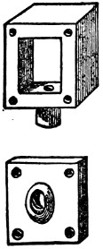
FIG 5
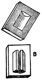
FIG 6
Now place the ends on cylinder and drill through them so as to screw them on to the flanges. The slide-valve case is a casting with separate lid (Fig. 5), and has to be faced up with a file, and four holes drilled through the lid and corners to screw on to the cylinder face. The boss on lid must now be drilled and tapped for steam-pipe to be screwed in.
The slide-valve itself is like Fig. 6, has a hollow cast in its face, and a small projection on the back (B), which you must make a narrow groove in with a saw, and file the end of the valve-rod down to fit it, as shown at C, Fig. 6.
The face of the cylinder and also of the slide-valve must now be made to work steam-tight by rubbing on a perfectly flat stone until true, and then putting some emery and oil on a board and working them up until they are quite true.
The eccentrics may now receive attention. They will require to be chucked twice, and the true centre marked. Do not drill it out yet, as the hole for the crank-shaft must not be in the centre, but half the travel of the slide valve from the centre. For instance, if the valve travelled one inch you would have to drill hole for shaft half an inch out of true centre of eccentric.
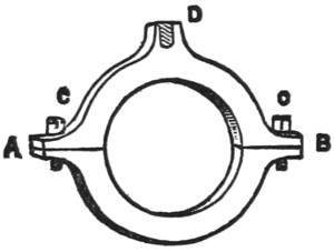
FIG 7
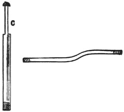
FIG 8
The straps (Fig. 7) have to be turned quite true to the size of the groove on eccentrics, then taken out of lathe and cut through line A B with a fine saw, and screwed together at C C. A hole has now to be drilled at D and tapped for the eccentric rods to be screwed into, one of which will have to be bent like Fig. 8, so as to allow it to work on to the quadrant. It is the neatest way to key the eccentrics on to the shaft with a small steel wedge.
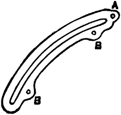
FIG 9
The quadrant (Fig. 9) is of brass, and will have to be finished up with a file and emery, and the holes A B B drilled through. The shaft ought to be turned up in the[141] lathe as well as the fly-wheel and coupler, with a slight groove sunk in where the plummer blocks support it, so as to take the thrust.
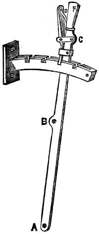
FIG 10
The reversing quadrant with the lever attached I have shown at Fig. 10. It is best cut out of brass. The notches are cut with a small file after the two pieces have been brazed together with a small piece an eighth of an inch thick between either end. It is then screwed on to the slide-valve case.
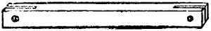
FIG 11
The lever is drilled at A, B, and C with small holes, and can be made of flat steel wire; A is for a pin to work into a joint or hinge on bed-plate. B is attached to the hole A (Fig. 9) by a small length of brass rod, so as to work easily. Cut with a slot at each end and then drill like Fig. 11.
The small spring D (Fig. 10) is to keep the ratchet down in place, and is best made from a watch-spring, and the handle F is turned out of some brass wire.
The different-size drills you will require can be easily made from various steel knitting-needles warmed, filed up to shape, and then tempered to a light-straw colour.
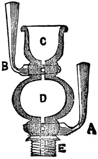
FIG 12
We now come to the grease or oil cocks, which I have mentioned before. They can be bought ready finished at most model shops, but for those who like to make[142] everything for themselves, this is the way to proceed. Fig. 12 is a section showing interior oil chamber that allows the cylinder to be oiled without stopping the engine by turning off cock A and opening cock B, then filling with oil; then shutting B and opening A allows the oil to descend into the cylinder and lubricate the surface.
Now for the method. Chuck a piece of brass wire about a quarter of an inch in diameter in the lathe, and turn up to external shape; then turn out cup C and drill through from end to end with fine drill; then enlarge chamber D with small bent graver, and take out of lathe and drill through at right angles to previous hole at A and B with larger drill; then put plugs of brass wire in and fit them with emery and oil; rivet over one end, and the other turn up into a handle. Then turn them in straight line with the oil-cup, and drill through with the small drill again. Tap the end E, and screw into cylinder cover, when it is finished.
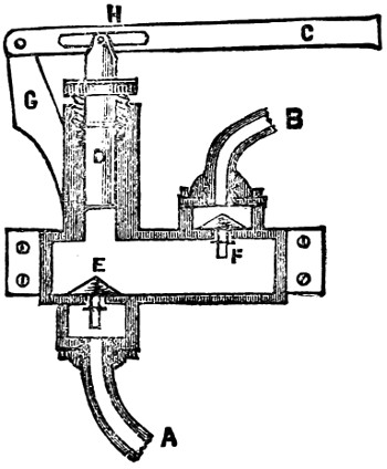
FIG 13
To keep the boiler full of water as the fire empties it by driving it off in steam, the usual thing is to use a force-pump worked by an eccentric on shaft; but, as the friction is excessive, it takes a great deal of power away from a model. It is best, therefore, to work it by a hand lever, and the pump may be screwed on to the side of boat, the suction A (Fig. 13) being led through the boat’s side and riveted over, and the supply B brazed into lower part of boiler. C is the lever, and D the plunger, which must be quite true, and turned up in the lathe; likewise the valves E and F and the stuffing-box tapped and drilled. It is best to work it up from a casting, and the outside smooth down with an old file. The projection G will then have to be drilled and the lever pivoted through, having first cut a slot at H to allow the lever to rise and fall.
I will now describe a method of making an injector, or machine for filling the boiler with water by the power of the steam alone, and not in connection with the engine.
The injector was an accidental discovery by a Mr. Gifford, and has now become a universal favourite on board both large and small craft, as it works splendidly without affecting the engine. So you can run the boiler up with water whilst the engine is at rest in harbour or otherwise. And another great advantage over pumps is that the steam, being mixed with the water, raises it in temperature to nearly boiling-point, and so is a great saving in fuel.
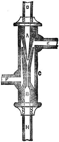
FIG 14
Fig. 14 is a section of the instrument as fit for model work, and if you will follow these instructions carefully it will act well.
It consists of three parts—the cone A, the cone B, and the casing C. The steam is admitted at D, and the water at E, the waste water overflows at F, and the hot steam and water is projected with great force into the boiler through the pipe H, which should be led to the bottom of boiler well below low-water mark, and it is quite imperative that the steam-pipe should come from top of boiler as so to get plenty of dry steam, and must not be tapped on to any other pipe.
The injector can be fastened to side of boat by brass band and screws, and the water-supply pipe brought through the side and riveted, as in the case with the pump. The injector will lift water several inches, but it always works better if the water can flow into it freely.
Now we will set to work at it. Take a piece of brass rod and chuck it in the lathe and turn two cones the shape of A and B (Fig. 15). Take them off the lathe[143] and drill A through as far as practicable, and finish with a small rhymer, having first made a small hole right through not larger than a knitting-needle; then tap the port C with an internal screw to take the steam-pipe, and turn a screw on the outside at D.
Now, with the rhymer bore out the conical hollow at E in B, and tap it outside at F and inside at G, in the same manner as the former cone; then drill a small hole right through from end to end, and a smaller one at right angles to the other right through at H. This communicates with the overflow, and takes off the water not carried into the boiler.
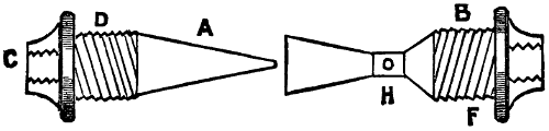
FIG 15
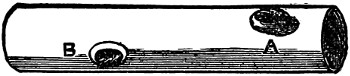
FIG 16
Next take a piece of brass tubing five-eighths of an inch in diameter, and turn a screw at each end inside (Fig. 16). The screws turned on the outside of the cones must be the correct size to fit these; then drill a hole at A, and screw in a small tube for water-supply with tap; then drill another at B for the waste water to escape by. Finally, screw in the cone A (Fig. 15) and attach it to the boiler by a pipe, and the nearer the boiler the better, as if the steam condenses before reaching the injector it will stop working. The steam-pipe must of course have a tap to cut off steam when not required.
We must now screw in the lower cone B (Fig. 15) until there is an annular space between the two cones not exceeding a sixteenth of an inch. Then screw in the small pipe at C (Fig. 15), and attach the other end into the boiler below the water-line, where it must have a stop-valve to prevent the water returning.
To start the injector, turn on the water-tap until it runs out of the overflow freely. Then turn on the steam full power, and the overflow will cease, or nearly so. Should it still drip at the overflow, reduce the water supply by the tap accordingly.
It requires carefulness and patience to make an injector, but when done, and working properly, there are few boys with a mechanical turn of mind who would not think themselves well repaid in watching and controlling its mimic action. They would then have an engine fit to show to their most critical friends, and one they might well be proud of; and I shall be content if I have helped in any way to contribute to their happiness.
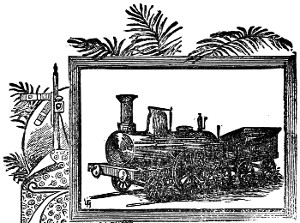
CHAPTER XI.—THE BOY’S OWN
MODEL LOCOMOTIVE, AND
HOW TO BUILD IT.
By H. F. Hobden.
CHAPTER XI.—THE BOY’S OWN
MODEL LOCOMOTIVE, AND
HOW TO BUILD IT.
By H. F. Hobden.
Those who class model engines as mere toys, and fit only to amuse the very youngest members of the human family, entirely forget the important place they hold in the estimation of inventors and those interested in mechanism as a means by which they can practically carry out their ideas, because models not only have the advantage of cheapness in construction as compared with the full-sized machine, but also the still greater advantage of being, from the small size and light weights of their parts, capable of construction by the inventor himself without having to employ strangers.
I suppose there is no taste more universal amongst boys, old as well as young, than that for mechanism and engineering. What boy does not feel interested in the models displayed in the various shop windows in our large towns, and what lad with any mechanical bent but has a longing to make one for himself and feels an intense pleasure in being able to do so? And it is with the intention of helping those who would like to build one, but have not the necessary knowledge, that I purpose to explain, as simply as possible, the best method of building model locomotives.
In previous pages of this volume, practical instructions by skilled writers have been given on model stationary engines of a simple make, and also on engines for steamboats, but of all models the locomotive has the greatest charm for most boys, and not unjustly so, as when well finished and carefully painted it has a very handsome appearance, and moreover has the additional charm of its locomotive power.
Those of my readers who have practically carried out the instructions in the previous chapters just referred to, have become, I have no doubt, by this time quite au fait in handling their tools and feel at home in their workshop; but for the benefit of those boys who have had no practical experience, let me give a word or two of advice before we begin our locomotive.
First then, with all engineering work, either large or small, great care must be taken to get the measurements perfectly correct in spacing out the various parts to be joined together, and do not think, because it is only a model you are making,[145] that any off-hand way will do, because you will find before the engine is half finished that great accuracy is necessary if you wish your model to be a working one.
A slight mistake in the measurements of a large engine will cause so much friction as to take half its power to overcome, and the same thing occurring in a model would stop it entirely.
Then with respect to any part you may require to solder, be careful always to make the brass or other metal you wish to unite quite hot. You will then get a good firm joint.
Do not just touch the metal with the soldering iron and then take it away. You might certainly stick the parts together slightly in that way, but they would be sure to come apart the first time they received a blow or any pressure was put on them.
Soldering on the best work should be used very seldom, and all the fastenings should be either done by riveting, screwing, or brazing; and I need hardly remark that no part of a boiler should be soldered which comes in direct contact with the flame of the lamp or furnace.
Brazing, with the exception of very small articles, is beyond the ordinary powers of an amateur.
Even to braze the seams of a model boiler requires a forge fire or very powerful gas-blast, which is too expensive for most boys to get; but small things, such as a broken slide, valve rod, etc., can be easily brazed by using a gas blow-pipe, and as it will cost you very little to make and will prove a useful tool for sweating in solder as well as brazing, I will briefly explain.
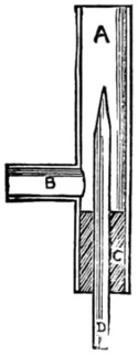
Fig. 1.
Fig. 1 is a section of the blow-pipe complete.
To make it, first get a small piece of brass tube (A) of about half an inch diameter and five inches long; drill a hole at two inches from one end, and insert a piece of gas tube (B) and solder it in place.
Next take a piece of glass tubing a quarter of an inch diameter and about seven inches long, hold one end in a gas flame, and when red-hot draw it out to a fine point, then file round and break off the tip, leaving a small hole.
Next squeeze a sound cork into the tube A as at C, and drill a quarter of an inch hole through its centre and insert the glass tube D, and the blow-pipe is finished. To use it you connect the pipe B with a gas bracket by a rubber tube, and the glass tube D must be fastened to a pair of bellows by means of another piece of rubber tubing; the bellows should have an air-bag attached, to enable you to keep a constant pressure up and prevent having a jerky flame.
When requiring to braze any article, bind the parts together with some very fine brass wire and cover it up with a little powdered borax and water, then lay the article on a piece of charcoal, and if it is necessary to preserve the temper of the steel you are about brazing, cut a potato in half and push each end of the steel rod into the halves, which will prevent the temperature of the rod getting too high.
When you have it all nicely fixed, turn on the gas and light your blow-pipe, immediately work the bellows with your foot, and by either pushing in the glass tube D, or drawing it slightly out, you can regulate the shape of the flame as required.
Then bring the flame to bear on the joint, well supplied with the borax, and soon you will find the brass wire melt and run into the joint like water. It must then be neatly filed up, and the join will be scarcely visible.
Having made this useful tool, I will mention a few others you should get before commencing work; they will not cost much.
A centre punch or pointed steel spike for marking metal for drilling, etc., and a small riveting hammer, three or four files of different degrees of fineness, a screw plate and taps, and also a small hand-drill with a set of drills to fit, will be most useful; and of course very little can be done without a good firm vice.
If you have a lathe, so much the better; it will enable you to save lots of odd coppers for turning various parts. Curves for bending metal on you can easily make from pieces of bar iron, holding them in the vice when working on them.
When you have your tools ready, the materials are required you intend working on, which will consist of several sheets of brass and copper, the castings and various-sized screws and bolts; and having got these all together, we can set to work on our locomotive.
I think it would be better to first give you directions for making a simple one of about fifteen inches, and then to proceed to a more perfect model after.
In a previous article you will find a description of the action of the steam in the cylinder, and although that is in a marine engine, the action is precisely the same in the cylinders of a locomotive, and you should therefore read the description carefully and thoroughly understand it; there is also given a method of turning the cylinders, and hence I shall not describe the process again, but consider that you already know sufficient about it, should you wish to make your cylinders in preference to buying them ready finished.
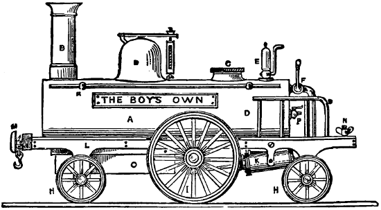
Fig. 2.
At the commencement of this chapter is a drawing of the model we are about to build in its finished condition, and Fig. 2 is a side view of the same, of which A is the boiler, B the chimney, C a screw head to fill boiler with water, D the steam chest with safety valve on top, E the whistle, F the steam tap to start the engine with, HH are the leading and trailing wheels, and I the driving ditto, K the cylinders, L the[147] frame, M the buffers, N a set thumb-screw to fasten a tender on by, O is the lamp, and P is a small tap, used to ascertain the quantity of water in the boiler. The handrails R and S complete it; and I think this is sufficiently clear for you to perfectly understand the general working arrangements of the model.
Locomotives, whether real or only model ones, can all be divided into three principal parts, viz., the carriage or framework, the engine or cylinders and parts connected with them, and the boiler, and we will now proceed to make each part in turn, beginning with the framework.
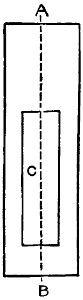
Fig. 3.
First take a sheet of brass for the bed-plate, about one-sixteenth of an inch thick, and cut it to an oblong shape, four inches wide by fourteen inches long, as in Fig. 3, and be very careful that the corners are right angles. This is to be hammered out quite flat and filed up smooth, and finished with emery cloth held round a flat piece of wood; you must also cut a hole in it for the boiler to rest in as at C, beginning half an inch from B and making the hole eleven inches long by one inch and a half wide, taking care it is quite central on the line AB, or you would get your engine lopsided, and you must take the same care in setting the chimney, steam dome, etc., as when not exactly central it gives a bad unsightly look to an otherwise well-finished model.
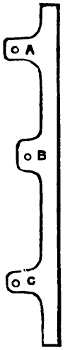
Fig. 4.
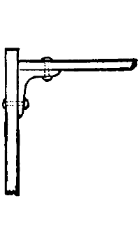
Fig. 5.
The next step is to cut out the side frames (Fig. 4), drilling holes at A B C for the axles to work in; you can finish both sides in the same way, and, turning the bed-plate upside down, fasten the frames on at a quarter of an inch from either side by small angle pieces, as in Fig. 5, or by soldering, which is much quicker. Then fasten by the same means a piece across each end about half an inch deep, and the frame is ready for the wheels.
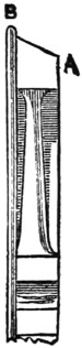
Fig. 6.
These can be had ready finished, but if you have the castings, they must be chucked in the lathe and the tires turned up to the form shown in Fig. 6. The small wheels should be about two and a half inches diameter and the driving wheels four inches. The rim B should project a little over one-sixteenth of an inch, and the rest of the edge should be bevelled off slightly as at A.
The spokes may then be filed up smooth, previously drilling out the centre hole for axle before removing it from the lathe.
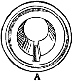
Fig. 7.
Great care must be taken to turn both the driving-wheels to exactly the same diameter, or one wheel would travel farther in a revolution than the other, and as they ought to be both fixed rigidly on to the crank shaft, the engine would never travel in a straight line, but would always run in a circle. You will require some steel wire for the axles, and can fasten them to the wheels by soldering or by cutting a slot with a fine file in the centre of wheel, as at A, Fig. 7; then filing a small portion of the ends of the axle flat, drive in a brass wedge made from a piece of wire, which will hold them together firmly.
The crank shaft or axle must be hammered up to shape, making it hot occasionally in the gas flame whilst working it.
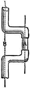
Fig. 8.
The cranks should be at right angles to each other, and the throw of the crank is to be half the distance of the cylinder stroke. For instance, say the cylinders are an inch and a half in stroke, the distance between A B (Fig. 8) will be three-quarters of an inch; you must then ease the size of crank at A, to prevent the piston knocking the cylinder ends.
The cylinders require such extreme care in turning that it is by far the best plan to buy them ready to put on your framework; and if you get a pair of oscillating ones three-quarters of an inch bore and about an inch and a half stroke, you will get sufficient power to drive your locomotive several miles an hour.
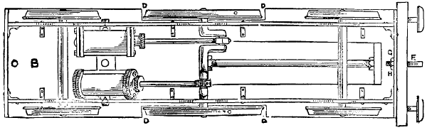
Fig. 9.
Fig. 9 shows you an underneath view of the framework and the position to place the cylinders in, which should be supported by a couple of lugs (A A) screwed to the bed-plate B which must have a piece cut out on either side to allow the driving-wheels (C) to work in, as at D, because, being larger than the others, they project beyond the top of the bed-plate, as shown in Fig. 2. You can now screw on by means of the hook F the buffer-beam, previously cut from a piece of mahogany, five inches long, half an inch thick, and one inch deep, nicely squared and sand-papered.
Drill a hole at G and pass the shank of hook through the beam and piece of brass in front of frame, and screw up tight with nut H.
The buffers can be properly turned up and fitted with springs, but that I will explain when making our more perfect model, and content ourselves now with a couple of brass flat-headed screws, such as are used in connections of electric batteries, and which form capital imitation buffers, one having to simply screw them[149] into the beam about one inch from either end, leaving them projecting about half an inch.
The framework is now sufficiently complete to be lacquered. First polish every part intended to be bright, carefully removing all traces of file-marks and any grease that may be on the work by a little acid; and after drying it place it on a sheet of iron held over the gas—or fire, if clear—until it is moderately warm. You can then apply the lacquer with a small brush, taking care not to go over any part more than once. The lacquer can be had at most model shops, and is cheaper to buy ready-made than to prepare yourself.
The spokes of the wheels should be painted; black-lined on green looks very well, and the ordinary tube oil-paint, mixed with a little mastic varnish, is the best to use.
The buffer-beam should be varnished, and the cylinders ought to have a coat of paint, leaving the cylinder-covers and the flanges bright.
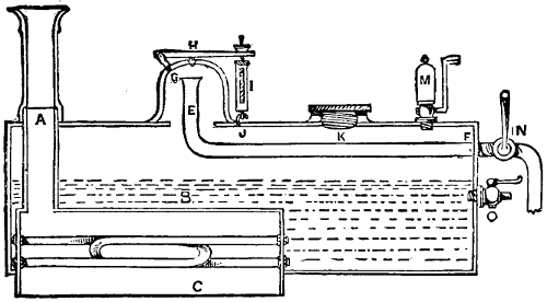
Fig. 10.
The frame may now be put aside to dry, covered up from dust by a paper box, whilst we proceed to make the boiler (Fig. 10).
This is a most important part of the locomotive, and is the cause of a great many failures and unsatisfactory working, even amongst the professionally-built models. I well remember how, when a lad at school, I fell deeply in love with a beautiful highly-polished brass locomotive of about the size we are now building, which was displayed in an optician’s window. Having made inquiries about the price, and got it reduced from to £5 to £4, with a promise to keep it for me, I set to work to save my pocket-money, and for some months rigidly abstained from all kinds of tarts and toys; and when finally the last shilling was saved which completed the amount, and I carried it—my first model—home in triumph, no boy was ever happier. But, oh! the bitter disappointment when, after getting up the steam and trying to start the engine, I found it would not work.
I was too young then to find out the reason, and the man who kept the shop, not being a practical mechanic, could give me no help, and although, after we had tried it together, he offered to take it back, I decided to keep it with a view to remedy the defect, if possible; but it was a long time before I found out that the fault lay in the boiler not being able to supply sufficient steam for the cylinders, in consequence of not having enough heating surface acted on by the lamp.
Since that day I have made numerous models, and have always taken precautions to avert such a difficulty, and although the method I am about to describe entails a little extra work, you will feel well repaid for the trouble when you find what a splendid head of steam can be kept up.
The boiler should be eleven inches long by three inches and a half in diameter, and you can buy copper tubing of that size which is very suitable for the job, or you can form it from a sheet of copper or brass bent to shape round a wooden roller, and either riveted or soldered together. You must then turn two circles of brass about an eighth of an inch thick for the ends, and polish the outside of each nicely.
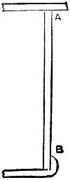
Fig. 11.
Then push them into either end of the boiler about an eighth of an inch from the edge, as in A (Fig. 11); they can now be soldered in place, and you will find your gas blow-pipe very useful here. The projecting flange should be hammered[150] down all round, like B (Fig. 11), which can also be sweated afterwards with solder, and finished off with a half-round file.
When filing solder or lead, only use an old worn file, as the soft metal soon fills up and spoils a good one, and although it can be melted out by heat, it is not advisable to do so.
You will now require to drill a hole at A (Fig. 10) for the chimney, which should be three-quarters of an inch in diameter. Then cut a slot in the bottom of the boiler six inches long by an inch and a half wide, commencing a quarter of an inch from the forward end of the boiler.
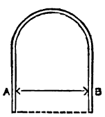
Fig. 12.
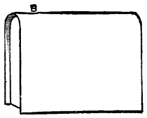
Fig. 13.
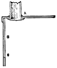
Fig. 14.
Now take a sheet of copper and cut a piece about six inches and a quarter long by six inches broad, and bend it over a wooden roller to the shape shown at Fig. 12, keeping it an inch and a half apart between A B. Cut also two other pieces of copper to the shape of your bent sheet (Fig. 12), and make it long enough to reach to the dotted line. These form the two ends, which may be placed an eighth of an inch from the edges, as in Fig. 13, and soldered in place, and the projecting rims turned over and sweated with solder from the outside in the same manner as you did to the boiler-ends in Fig. 11. Then drill a three-quarter-inch hole at B (Fig. 13) for the bottom of chimney-tube to go into, and cut a piece of three-quarter-inch brass tubing of sufficient length to pass out at top of boiler about half an inch, as shown at A (Fig. 10). You can then hammer out a rim or flange on the bottom end of chimney-tube, and push it up through the hole in the copper box and solder it in place from the top, as at A (Fig. 14).
Now drill a couple of small holes at each end of the box B C (Fig. 14); these should be rather more than an eighth of an inch in diameter, to allow an eighth of an inch tube to pass through.
Get two twelve-inch lengths of hard-drawn steam-piping of an eighth of an inch[151] in diameter, and with your screw-plate put a thread on each end of about half an inch in length, then drill some holes in any odd piece of brass plate, and with the screw-taps form eight nuts to fit the threads on the piping, and finish them up to shape with a file.
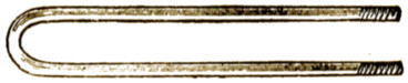
Fig. 15.
Then take the piping and bend it very gently, to prevent it cracking, round a bar of iron or handle of some tool held in the vice until it is of the form shown at Fig. 15. Do each one the same, and then mix a little turps with some white lead and smear each end where you have formed the screws, taking care not to get any into the tubes, and they might have a plug of paper put in temporarily to prevent it.
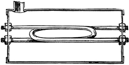
Fig. 16.
Now put a nut on at either end as far as the thread will allow it, and smearing a little white lead round the holes drilled in ends of box B C (Fig. 14), push the tubes in from the inside and screw up firmly with the remaining nuts in the position shown at Fig. 16. The inside nuts can then be tightened up with a spanner, and if you have carefully done this you will never be troubled with any leakage, no matter what pressure you may get in the boiler.
These tubes are immensely strong, and from their small size the water in them is raised quickly to a higher temperature than that contained in the rest of the boiler, causing a continual circulation to take place and a constant supply of steam to be formed.
The box can now be placed in the boiler through the slot cut in the bottom, taking care that the top of box is not more than half way up the boiler, as in B (Fig. 10). This will leave a portion projecting below the lower edge of boiler, like C. This part protects the flame of the lamp from being blown away by the draught caused by travelling along, which would cause you to lose steam. Solder it firmly in position from the outside, to prevent the flame touching any soldered portion. Also solder neatly round A (Fig. 10).
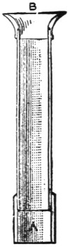
Fig. 17.
The chimney can be made from another piece of three-quarter brass tube. Chuck it in the lathe, and turn it up bright, and put a collar on it at A (Fig. 17) to allow it to push on to the piece of tube left projecting at A (Fig. 10).
The top of chimney, or bell-mouth, B (Fig. 17), will require turning in the lathe also, and fitting on neatly.
The steam-chest D (Fig. 10) is a brass casting you can turn up also, and after cutting a circular hole in top of boiler of about an inch in diameter it can be either screwed or soldered on, previously putting the steam-pipe E in position by drilling a hole at F, and after bending it as shown, pass it through at F and solder in place.
The top of pipe E should be about a quarter of an inch from top of inside of steam-chest.
Before soldering on the steam chest drill a couple of holes, as at G H (Fig. 10), one for the small lug G to be screwed into, which holds one end of the lever of the safety valve, and that at H should be drilled conical with a rhymer, and the valve H can be turned in the lathe, and afterwards ground to fit the hole with a little emery and water, by means of a slot cut across the top and worked round with a screw-driver.
The spring-case of safety-valve is easily made from a piece of the one-eighth of an inch brass tubing, and using some small, hard brass wire to form the spring of. When finished it should be hooked to the eye screwed into boiler at V.
The manhole, or screwhead, K, is used to refill the boiler by when it has steamed[152] low, and will require to be turned up to shape; and the bed L it screws into can be firmly soldered on the boiler, having first drilled a hole slightly larger than the diameter of the screw itself, which should be sufficiently large to allow an ordinary tin funnel to be used to refill by, and the screw ought to be large enough to hold a leather washer under the head to keep it steam-tight.
The whistle M will require a hole drilled for it to be screwed into, and that, as also the steam-tap N and water-tap O, can be bought cheap ready to put on, and is more satisfactory than making them yourself. But should you wish to do so, the method I have already described in Chapter X. of making an oil-cup applies equally to these.
The tap O should be screwed in at a slightly higher level than the top of box B, and when working the engine, should steam issue from it when turned on instead of water, you ought to immediately blow off steam by safety-valve H. Then unscrew K, and refill the boiler with water.
By this time the framework will no doubt be quite dry, and you can then clean and polish the boiler and attach it to the frame by a screw or solder at the forward end, and the steam-pipe N can be screwed on to the projecting piece of tube left at F, whilst you also screw a short length of pipe into the steam-box of engine through a hole in the bed-plate. Then bend it up to the steam-tap and solder them carefully in position; this will hold the after end of boiler firmly.
Go over every soldered joint to see if any small hole is left, and re-solder where necessary, as a hole in the boiler not larger than a pin’s point would prevent you getting any adequate pressure of steam, as the water would all blow out.
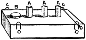
Fig. 18.
When so far complete, you can either lacquer or paint the boiler as suits your fancy, and whilst it is drying there will be time to make the lamp (Fig. 18).
It is simply an oblong box made of tin or any piece of thin metal you may have, and should be one inch and a quarter wide by five inches long, and about three-quarters of an inch deep. To make it, cut say a piece of tin four and a half inches by five inches, and bend it to shape, then solder the two edges together and cut two ends to fit. Push them in and solder in place.
Then cut three pieces of brass quarter-inch tubing into three quarter-inch lengths, drill holes in top of lamp and insert them, allowing about a quarter of an inch to project, as at A (Fig. 18); then solder them on four pieces of bent wire (C C C C), by which to hang the lamp by means of two wire pins run through them and small holes drilled in sides of projecting piece C (Fig. 10).
The screw-filler B (Fig. 18) will have to be soldered in also, and when complete the tubes A may be filled with cotton wick, and the lamp about three parts full of methylated spirit, which will give a clear smokeless flame.
You can now start your locomotive by filling the boiler about three parts full of hot water, and then hooking the lamp underneath; you will soon get a good pressure of steam up.
See that all the taps are turned off; and if there is no leakage from careless workmanship, you will find, on turning the steam-tap on, the locomotive will run beautifully, and will travel at great speed either on a smooth oil-cloth or wood floor.
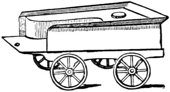
Fig. 19.
I will presently explain how to make a set of rails, on which she would run much quicker still; but for this engine, if you make a small tender of the shape shown at Fig. 19, and fasten it at any angle by the set-screw on the foot-plate of the engine shown at N (Fig. 2), the model will run in any sized circle you may wish, without lines, according to the angle at which you fix the tender to the engine.
Wooden coal trucks, etc., you can easily make to complete the train if you wish; but of course each one is an extra load for the engine to draw, and will prevent it going as quickly as when alone.
Tin is the best material to use for the tender, as no great strength is required; indeed, it should be made as light as possible. The wheels and axles you must finish in the same manner as those on the engine; and it could be made into a tank, to hold an extra supply of spirit, by soldering a piece of tin round the inside, and covering it in with another piece cut to shape, and fitted with a screw-nut to fill by, as shown in Fig. 18.
If you have carefully followed these simple directions, and also practically carried them out, you will be able, and no doubt anxious to try your constructive powers on a more complete model, and I will therefore endeavour to help you to do so.
Should you be able to draw, you will find it a great help if you carefully sketch out on a sheet of cartridge paper the locomotive to the exact size you intend building it.
You can then take all the measurements from it, which will prove to be a saving in time and trouble. Of course the larger you make the engine, the more expensive the castings and materials will be; but if you persevere in making the locomotive I am about to describe, you will have a model of real value to you, and which would probably cost fifty pounds to buy ready finished; and if you turn the wooden models for the castings yourself, and use sheet-iron for the framework, etc., where possible, the total expense will not be so very great.
Fig. 20 is a side view of the locomotive in its finished state, and we will begin to work at it in the same manner as in the former model, viz., with the framework; but as some of my readers may have a preference for some special type of engine other than the one drawn, they can easily build it from the following directions, and keeping the same proportion in size as in Fig. 20, which is drawn to 1⁄8-inch scale.
The entire length should be about three feet two inches, and the bed-plate thirty-five inches by nine inches wide. The driving-wheels are eight and a quarter inches in diameter, and the leading wheels five and a quarter inches, and about six and a half inch gauge, viz., the space between the lines on which the wheels run.
The cylinders should be one and three-quarter inch bore by two and a half inch stroke, which will give sufficient power to drive the engine at a high rate of speed, with 30 lb. to 50 lb. of steam. The boiler is twenty-eight inches long, including smoke-box, by five inches diameter.
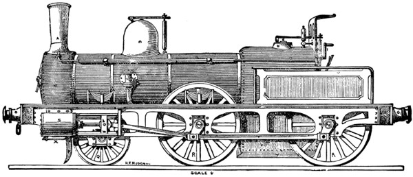
Fig. 20.
Fig. 20 enlarged (200 kB)
In Fig. 20 I have lettered the various parts, and it will be well to look over them carefully, as this engine differs materially from the previous model in its arrangement, being constructed exactly similar to a real engine.
A is the chimney, B steam-blast used to increase the intensity of the fire, and is worked by rod C running through the hollow handrail D, and ending in handle F. G the steam-dome and safety-valve is the same pattern as previously used, H extra safety-valve, worked from foot-plate; I steam-whistle, K wind-guard, L starting-lever, M smoke-box (with door), N O spring-buffers; P is the line-clearer, or wheel-guard; Q leading wheels, and R R driving ditto; S one of the cylinders, with piston-rod and guides bolted to frame, and showing double connecting rod at T T; U U are the springs which support the weight of the boiler, etc., on the axle-bearings; the spring on rear wheel does not show, being inside the safety-guard and handrail V. W is the back-pressure valve, through which the water is thrown by the force-pump into the boiler; and X is the blow-off tap to clear the model from all water after having used it; and Y shows the side of ash-pan.
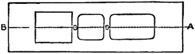
Fig. 21.
Now to commence making the framework. This should be made of one-eighth of an inch sheet-iron, squared up perfectly true and flat, and cut out as shown in Fig. 21, commencing four inches and a half from A, and leaving six inches at B, and cutting it six inches wide there by eight inches long, and continuing it four inches wide for the rest of the distance. Be careful to keep it quite central on the line A B, and leave two connecting strips one inch wide, as at C C.
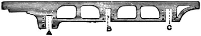
Fig. 22.
The side-frames come next. These must be much stronger, and quite different from those used in our previous model, and should be cut from the same eighth of an inch plate-iron to the shape shown in Fig. 22.
The centre of slot B is seventeen inches from one end, the centre of A ten inches from B, and centre of C thirteen inches from B.
In marking out work always measure from a fixed centre, for if you add one[155] measurement to another any slight inaccuracy gets increased with each fresh measurement, and you might finally get the different portions out of place.
The slots are each an inch and a quarter wide by two inches deep, leaving one inch of iron at top as shown. The ornamental spaces can then be cut out, which lightens it considerably without weakening it much.
The frames, after being smoothed up, can be fastened to the bed-plate in the manner described before by angle-irons or knees riveted on. Two end-pieces must also be prepared an inch deep, and the ends hammered square at right angles, and then riveted to the bed-plate and side-frames, as shown by the rivets in Fig. 20.
Then drill three holes in them about an inch and a half from either end, and one in centre by which to bolt on the buffer-beams by means of a couple of screws put in from the back.
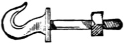
Fig. 23.
The buffer-beams should be mahogany, one inch wide, two inches deep, and ten inches long, squared nicely and sand-papered. A hook can then be made (Fig. 23), and, a hole being drilled in the centre of beam, you can pass the hook-stem through and into central hole of framework, and screw up tightly with nut at back, which will hold all firmly in place.
The buffers for this model must be made properly with springs to take the pressure, should you let it run into anything.
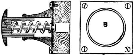
Fig. 24.
Turn out a wooden mould in the lathe and get four castings in brass made from it. Fig. 24 is an ordinary kind of buffer in general use, and, being in section, shows you the working arrangement of the spring, A is cast with a square base-plate two inches square, as in front view B, and is secured to buffer-beam by four flat-headed screws. The piece C must be turned true, and just the size to slide in and out A easily. Each part must be finished up in the lathe. A should be about an inch and a half long.
Drill a hole in beam to allow the head of pin to work in freely, and another hole in base-plate of buffer the size of pin, whose head prevents the spring forcing C entirely away from A.
The spring should be made of thick steel wire; the buffers can then be screwed on as just mentioned. The wheel-guard, or line-clearer P (Fig. 20), can next be cut out to shape and bolted on to frame, and should just clear the line by a quarter of an inch.
We will now proceed with the axle-bearings and springs U (Fig. 20). The wheels can be finished up in the same manner as previously described, so I need not say anything further about them.
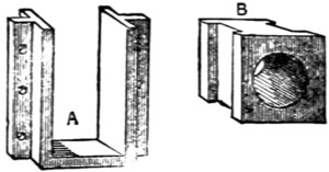
Fig. 25.
Make a wooden model like Fig. 25 and get six castings in brass made from it. They then must be filed up square and smooth and fitted into the slots cut at A B C (Fig. 22), and either screwed or riveted on by the side holes.
Before finally fixing them prepare six brass bearings (B, Fig. 25). They must fit exactly, and slide easily in the inner surface of A, and a hole is to be drilled centrally through each five-eighths of an inch in diameter. These take the axles, which in this model are all straight, and three-quarters of an inch in diameter, shouldered off to five-eighths for the bearings.
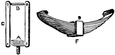
Fig. 26.
The springs next require attention. Four pieces of either sheet iron or brass are wanted in each support an inch and a half long by a quarter wide. A hole is to be drilled at either end, as shown at C in Fig. 26. A should be three-eighths of an inch wide, drilled through and a pin put in, and all riveted together loosely.
The spring is best made from clock-spring, and cut to shape as at D. The top-piece requires to be made hot with your blowpipe, and then the ends turned over to hold the pin B. Each piece of spring must be slightly shorter than the upper, and the ends nicely graduated off, and when ready held together by the brass band F, which has a small hole drilled at F to hold the end of pin by which the pressure is directed on to the axle-boxes, as shown in Fig. 20. A hole is also to be drilled in bed-plate over centre of each axle-box to allow pin to pass through, and also a smaller one an inch and a half on each side for the support A (Fig. 26) to screw into. They can all be fitted into position.
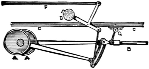
Fig. 27.
The cylinders come next, and should be, as previously mentioned, an inch and three-quarters bore by two and a half inch stroke. These should be of the fixed slide-valve pattern, with double eccentrics fitted on middle axle-shaft, and reversing-lever brought to quadrant on foot-plate, as I will show presently, and for the method of making them I will again refer you to my article on the Model Launch Engine, and will simply give you in Fig. 27 the modified form necessary to suit a locomotive, in [157]which A A are the eccentrics, B slide valve-rod, with guide G attached; C C the bed-plate, D the balance-weight, and F the rod leading to quadrant and lever on foot-plate. The cranks are put on outside the wheels and fastened by keys, as in Fig. 20.
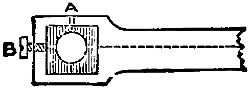
Fig. 28.
The connecting rods T should be cut to the form shown in Fig. 28, and the ends squared out and a brass bush filled in with a hole drilled from top (A) to oil by, and a set-screw B fitted to adjust the bearings perfectly.
Although these little things give extra work in fitting a model, they add considerably to its finish and lessen the friction.
If you wish to fit a force-pump, it should be placed centrally between the cylinders, and be worked by an eccentric on main shaft, but a pump on a model locomotive is of very slight use unless it is arranged to work by hand also.
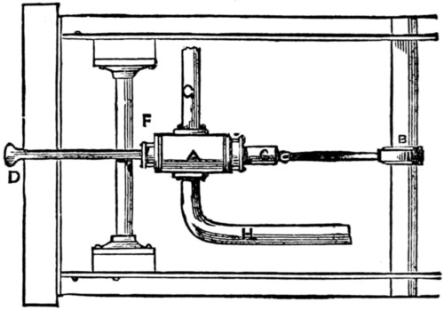
Fig. 29.
In Fig. 29 I have given a practical method of arranging one to be worked either way as desired. A is the pump, B the eccentric on main-shaft to work it by steam power; but when requiring to work the pump by hand, you have only to push up hook connection at C, which disconnects it from eccentric, and then by working the handle D, which is screwed into bottom of plunger C, the water is forced into boiler.
This pump is a little more troublesome to make, as it requires an extra stuffing-box at F, but it is very neat and useful, and the handle lying quite out of the way, does not spoil the appearance of the model.
G is the exhaust water-pipe bent up to the back pressure-valve on boiler, and H the supply-pipe carried on to rear of engine.
You will find two small blow-off cocks on each cylinder very handy to get rid of the condensed steam when starting the engine with cold cylinders, as without them the cylinders get choked, and you stand a good chance of getting scalded by the hot water being thrown up the chimney with considerable force.
The blow-off cocks can be connected with a tye-rod, and both worked from the foot-plate by a single handle.
The parts being all finished to your satisfaction, you should paint the bed-plate black, and side frames red, and when dry carefully line them black and white, and also pick out the rivets with black.
Of course individual taste has a great deal to do with the finish of a model, so I will leave it to you, merely suggesting you should get a fine lining tool to finish with, and when all is complete put it aside to dry whilst we proceed to build the boiler.
This will require the greatest care, but with due attention you will be able to turn it out well. Some sheet copper will be required one-eighth of an inch thick, and although this is more expensive than iron, it does not rust, and is more suitable for the work in hand.
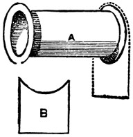
Fig. 30.
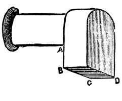
Fig. 31.
First cut a piece nineteen inches long by sixteen wide, and bend it round, forming a cylinder five inches in diameter; the lap must be closely riveted, and then the two ends hammered out into a flange outwards, leaving the body of boiler seventeen inches long, as in Fig. 30; B is the shape of piece to be next riveted on[158] at after end, then take another sheet nine inches wide, and hammer a half-inch flange round it so as to fit over the dotted line in A.
Then rivet them firmly together, and also another piece in after end.
It will now have the appearance of Fig. 31, and should be four and a half inches deep from A to B, and forming a copper box six inches wide from B to C, and eight inches from C to D.
Then rivet together another box to form the inner casing four and a half inches wide by six and a half inches long and nine inches deep.
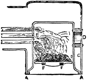
Fig. 32.
The bottom of this must be hammered outwards to the dimensions of BC CD, as shown in section Fig. 32 at AA. A hole is next to be cut out in the centre of rear plate, and also the rear part of inner casing which comes opposite to it, and one three-quarter inches by two and a half, forming an elliptical opening for the furnace door.
A casting of that shape and three-quarters of an inch thick, which is the distance between the inner and outer casing BC, must be procured and drilled with holes every three-eighths of an inch, and firmly riveted in position, as shown in section at D.
Two pins or lugs (FF) should project on either side of the inner surface to[159] support the fire-bars and ash-pan, and the bars should be made of cast-iron, and small enough to be got out easily by tilting up one side, and the bars ought to run lengthways of the engine.
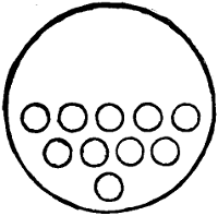
Fig. 33.
You next require some hard-drawn brass tubing three-quarters of an inch diameter, and must cut the pieces slightly over seventeen inches long, then drill ten holes in the inner plate as at E (Fig. 32), and in the position and arrangement shown in Fig. 33. These tubes should have a wire ring brazed on about a quarter of an inch from either end, and then being placed in their respective holes in tube plate, the projecting portion is to be beaded back with a flange, or you can fit them in as described previously (Fig. 16) by each being double-screwed and nutted. These tubes allow the smoke and flame to pass through from the furnace to the smoke-box (M Fig. 20), and so away up the chimney, and by the large surface they expose to the fire, help to raise steam very quickly.
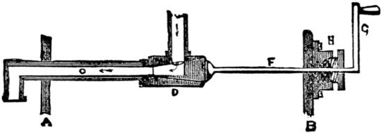
Fig. 34.
If you just add together the combined surfaces of these tubes, you will find there is more than two square feet of surface exposed and acted on by the fire, which enables the boiler, although small, to make steam rapidly. In some large engines three hundred tubes are fitted. The steam supply-pipe and regulating lever-handle should now be made and placed in position, and Fig. 34 shows the shape to make it.
A B are the front and rear plates of boiler, C is the supply pipe, bent with a screw end downwards after passing plate A, and then upwards into steam-dome, where it should be securely fastened by a cross-piece; D is the tap or valve, which can be turned on or off from the foot plate by means of the long rod F, ending in lever-handle G.
The rod must be fitted with a stuffing-box, the same as those used on the cylinders, and packed with cotton to prevent loss of steam by leakage; and when this is all firmly fixed, the forward end of the boiler can be furnished with tube-plate, riveted on and the tubes flanged over.
You should now take the boiler to a practical brazier and have it properly hard-brazed in every join and round each tube, and you might cut the hole for steam-dome and have it brazed on at the same time. If this is properly done you never need be in fear when the water runs low, as the boiler might get almost red-hot without injuring it much. Of course it is not advisable, as it would blister and spoil the appearance of the paint outside. This is a good opportunity to test the boiler before fitting it up, and you should fill it with water through a hole drilled in top of dome, and then fix on the test-pump, which you could borrow from any engineering-shop. If too far away from town to do that, you must make use of the force-pump attached to your model, and work it by hand, watching the pressure-gauge in the meanwhile. Test it to 100 lb. per square inch, which will be sufficient, as 50 lb. will be a fair working pressure. Should you have to test it with your own pump, the pressure-gauge will have to be bought then, as that is an article you cannot make yourself. A small gauge of Bourdon’s make, of an inch and a half diameter, will cost about twenty-five shillings, and although it may seem a rather high price for such a small thing, it is absolutely necessary to have it, as you could not tell what dangerous pressure you had raised in the boiler without it.
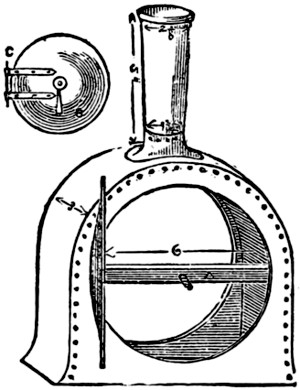
Fig. 35.
This being done, proceed to make the smoke-box, which should be three inches[160] deep, and of the same shape and dimensions shown in Fig. 35. This and the chimney can be made of iron, hammered up to shape and finished with a brass ring. The smoke-box can be screwed to the forward flange on boiler. The door is drawn open to show the amount of bulge it should be hammered to.
In the centre a hole should be drilled through which to pass the screw used to close it, which is attached to the loose bar A. The handle B is then screwed up tight.
The door is circular and must be large enough to overlap the opening about half an inch, and have a couple of bright iron or brass eyes (C) riveted on to form the hinge.
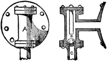
Fig. 36.
We can now make the back pressure-valve (Fig. 36). A is a front view, with plate by which it is bolted on to boiler, as at W (Fig. 20).
It is very simple to make, and consists of the casting A with the top and bottom covers, and the ball-valve B, which ought to be ground with a little emery-and-oil to fit perfectly. It acts in this manner. The water being forced up C from the pump, raises B and passes into the boiler. On the up-stroke of pump the pressure is removed from under B, and pressure of steam in boiler causes it to fall back and close opening entirely, preventing any water passing away from boiler. A small flange can be put on each outer side of boiler near furnace to support it on bed-plate level with smoke-box.
The boiler should now have a coating of flannel, cut to shape and wrapped round the body part, and a casing of sheet tin put over it and secured by brass bands, and small nuts underneath, as shown in Fig. 20.
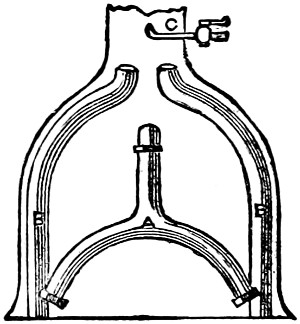
Fig. 37.
The steam supply-pipe can now be connected with the cylinders, and it should be made forked, as in Fig. 37. A leads from steam-pipe, and branches off to each cylinder, where it must be screwed up with white lead.
The exhaust-pipes (B B) should be of larger tubing, and bent round up the sides of smoke-box, so as to be out of the way when you require to clean the tubes. A small brass pipe (C) must also be passed through chimney, and bent upwards and fitted with tap, which should take steam from top of boiler, and be used as shown at D and F (Fig. 20). This helps to raise steam very quickly.
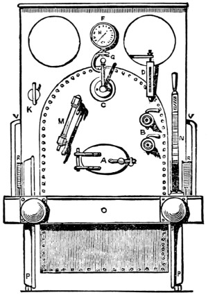
Fig. 38.
Fig. 38 is a rear view of the foot-plate, and shows the necessary fittings you must either make or buy to complete the model. The cocks you can manage easily, but the water-gauge is beyond most amateurs’ skill to turn out satisfactorily. A is the furnace-door, B two gauge-taps, C starting lever-handle, D spring-balance safety-valve, F wind-guard (with two look-out hobs), G steam-whistle handle, H pressure-gauge, K steam-blast handle, M glass water-gauge, N the quadrant and-lever for reversing the engine, O the rear buffer beam (with buffers), P the wheels showing axle, R R the springs for same, and V is the safety-guard rail on either side.
When these fittings are made, holes must be drilled in rear-plate for each, and then firmly screwed in place with white-lead: and the glass tube in water-gauge and the stuffing-box in gland of starting-lever should be packed with tallow and cotton wick.
The entire engine can now have another coat of paint.
The smoke-box chimney and rear-plate should be black, and the body any colour, according to fancy, leaving the brass bands bright.
When lined and quite dry it should have a coat of the best hard, clear varnish, and again be allowed to dry thoroughly before using it, which by this time, I have no doubt, you are anxious to do. Whilst it is drying you will have time to make the lines for it. And you should get some square bar-iron, cut it into six-foot lengths, if you wish the lines to be portable, and drill a hole in each end half an inch deep. They then can be joined end to end by a wire, pin, or plug.
The lines must be kept at a proper distance apart by being secured to pieces of wood placed transversely underneath by screws passing through holes drilled in the rails at about every six inches. You can then lay them down end to end and form a long line. If you want a circular line, each section must be bent to a portion of a circle; one of about thirty feet diameter is suitable for this model.
When finished, place the locomotive on them and get up steam. Fill the boiler with water by means of a funnel until you see it rise up three parts of the way in the glass water-gauge. Then see that all taps are turned off and light the fire. Charcoal forms the best fuel to use, as it gives a clear, hot fire, without smoke.
Try occasionally if you have any steam by lifting safety-valve, and when there is any turn on the blast-tap, which will soon draw up the fire, and you will presently see the pressure rise, and be indicated in the pressure-gauge.
When showing 30 lbs. of steam you might start her, turning on the cocks on cylinders until no more condensed steam issues from them. Then shut them off and turn on steam full power, and watch your model travel, gradually increasing its speed; and I hope you will have many pleasant hours’ enjoyment in running your locomotive and showing its action to your friends, which will well repay you for the time spent in building it.

ART AT PLAY.
[Here is a new use for eggs! All that is needed are a pen or pencil, a few eggs or egg-shells, a little artistic talent, with a few ‘ideas’ and there you are! If also furnished with a gum-pot, pair of scissors, and some paper, there need be no difficulty about the frills, etc.]


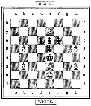
7 + 5 = 12 pieces.
White to play and mate in two (2) moves.
Beginners sometimes are apt to capture a superior man for an inferior one, and thereby forget the danger in which they leave their K, as the following moves show:—
| White. | Black. | |
|---|---|---|
| 1, | P d4 | P d5 |
| 2, | O f3 | N f5 |
| 3, | O c3 | P e6 |
| 4, | N g5 | O f6 |
| 5, | P e3 | N d6 |
| 6, | N d3 | N g6 |
| 7, | N g6: | P hg6: |
| 8, | K M | O c6 |
| 9, | L d3 | O b4 |
| 10, | L b5† | K e7 |
| 11, | L b7: | M b8 |
| 12, | L a7: | O C2: |
| 13, | O e5 | M b6 |
White threatened O c6†. If the N d6 had taken the O e5, White would have lost the M a1 for the O c2, but have won the O f6 for a P.
| 14, | M a c1 | O b4 |
| 15, | P a3 | O c6 |
If O a6, then O a4. The position is now interesting. If White would try L b6; then Black would win by N e5:. White should now play O c6:† and then P f4, but forgetting the danger at h2, plays
| 16, | O d5:† | P d5: |
| 17, | M c6: | N e5: |
| 18, | M b6: |
The P d4 ought to have taken the N e5. The position is now—
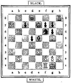
12 + 10 = 22 pieces.
Black to play and mate in six (6) moves.
| 18, | N h2:† | |
| 19, | K h1 | N d6† |
| 20, | K g1 | M h1† |
| 21, | K h1: | L h8† |
| 22, | N h6 | L h6:† |
| 23, | K g1 | L h2‡ |
The following diagram illustrates a mate in three moves, which the beginner should learn early, and which is obtained from the original position of the thirty-two pieces by the following eleven moves:—
| White. | Black. | |
|---|---|---|
| 1, | P e4 | P e5 |
| 2, | P f4 | P d6 |
| 3, | P d4 | P d4: |
| 4, | L d4: | O c6 |
| 5, | N b5 | O f6 |
| 6, | O c3 | O h5 |
| 7, | O f3 | L f6 |
| 8, | P e5 | P e5: |
| 9, | P e5: | L g6 |
| 10, | N d2 | L g2: |
| 11, | KM | L f3: |
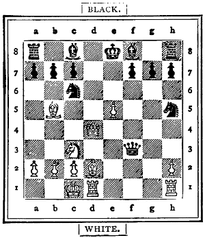
12 + 14 = 26 pieces.
White to play and mate in three (3) moves.
| 12, | L d8† | K d8: |
| 13, | N g5†† | K e8 |
| 14, | M d8‡ |
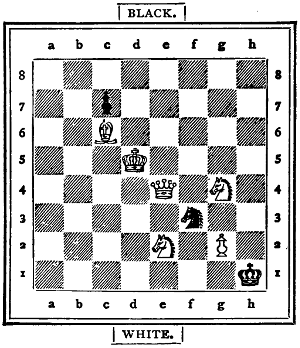
6 + 3 = 9 pieces.
White to play and mate in two (2) moves.
In the last two games we gave the first move to White, but will now give it to Black, and show another series of moves, which lead to a pretty termination.
| Black. | White. | |
|---|---|---|
| 1, | P e5 | P b3 |
| 2, | N c5 | N b2 |
| 3, | P d6 | P e3 |
| 4, | O f6 | O f3 |
| 5, | N g4 | O c3 |
| 6, | K M | N e2 |
| 7, | N f3: | P f3: |
It is better for White to take with the P than with the N, for the M h1 can move[167] to g1, and occupy the important g file, in which the black K stands.
| 8, | O c6 | M g1 |
| 9, | O e7 | O e4 |
| 10, | O e4: | P e4: |
| 11, | O g6 | P d4 |
| 12, | P d4: | P d4: |
| 13, | N b6 | P a4 |
| 14, | P c6 | N c4 |
| 15, | L h4 | L d3 |
| 16, | L h5 | K d2 |
| 17, | O h4 | P d5 |
White is now tempting Black to give the check with the O.
| 18, | O f3† | L f3: |
| 19, | L f3: |
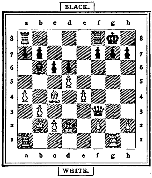
12 + 12 = 24 pieces.
White to play and mate in four (4) moves.
| 19, | M g7:† | |
| 20, | K h8 | M g8†† |
| 21, | K g8: | M g1† |
| 22, | L g2 | M g2:‡ |
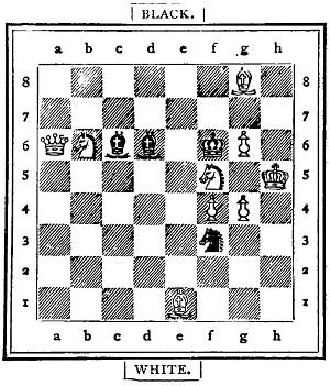
9 + 4 = 13 pieces.
White to play and mate in two (2) moves.

6 + 6 = 12 pieces.
White to play and mate in two (2) moves.
The following is the termination of a game played by Adolph Anderssen:—
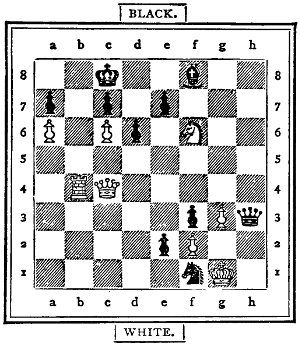
8 + 10 = 18 pieces.
White to play and mate in five (5) moves.
| Black. | White. | |
|---|---|---|
| 1, | L e6† | L e6: |
| 2, | O d7 (threatening a mate with the M at b8). |
|
| L d7: | ||
| 3, | M b8† | K b8: |
| 4, | P d7: | Any move. |
| 5, | P d8 L‡ | |
Problem No. 1.—1, P e8 O, any of four moves. 2, O d6 or f6, mate, accordingly.
Problem No. 2.—1, K c5, K g2: (or, Q, R, S, T, U). 2, L f3:‡.—(Q) O g1. 2, O g3‡.—(R) O h2. 2, O f2‡.—(S) O d2 or e1. 2, L h7‡.—(T) O g5 or h4. 2, L b1‡.—(U) O d4 or e5. 2, L b1 or h7‡.
White: K a6; L f5; M a5, h1; N g1, h5; O b8, d1; P b2, c2, d5, g6, h3. Black: K c4; L g8; M h4; N f1; O a3; P a4, b4, b6, g2. (13 + 9 = 22 pieces.) White gives mate in two moves.
White: K b7; L f4; M d8; N a2; P a3, e5. Black: K c5; M h5; N f7, g1; O a8; P a5, b5, c2, c7. (6 + 9 = 15 pieces.) White gives mate in two moves.
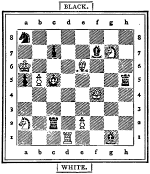
8 + 8 = 16 pieces.
White to play and mate in two (2) moves.
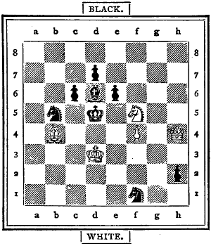
5 + 8 = 13 pieces.
White to play and mate in two (2) moves.
The following game was played, and the mate in eight moves announced by H. F. L. Meyer.
| White. | Black. | |
|---|---|---|
| 1, | P b4 | P e5 |
| 2, | N b2 | P d6 |
| 3, | P b5 | P a6 |
| 4, | P c4 | P b5: |
| 5, | P b5: | N e6 |
| 6, | P a4 | N e7 |
| 7, | P e3 | O f6 |
| 8, | O c3 | K M |
| 9, | O f3 | O b d7 |
| 10, | O g5 | P h6 |
| 11, | O e6: | P e6: |
| 12, | N c4 | P d5 |
| 13, | N b3 | O c5 |
| 14, | N c2 | P c6 |
| 15, | P d4 | O c d7 |
| 16, | P e5: | O e5: |
| 17, | O d5: |
White wins a P, but the move is really a bad one. He ought to have played K g1 M f1.
| 17, | O d5: | |
| 18, | N e5: | N b4† |
| 19, | K e2 |
The K could not well move to f1, for the O would have checked at e3, and then taken the L.
| 19, | L g5 | |
| 20, | N b2 |
The N might have moved to f4, but then the black L would have taken the P g2, and won. Indeed, White’s game is hopeless, as the following diagram and the solution show:—
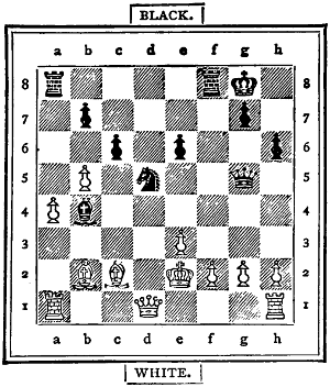
12 + 11 = 23 pieces.
Black to play and mate in eight (8) moves.
| 20, | M f2:† | |
| 21, | K f2: |
If K d3, the mate follows in three more moves by L e3:, O b6, and P c5.
| 21, | L e3:† | |
| 22, | K f1 | M f8† |
| 23, | N f5 | M f5:† |
| 24, | L f3 | M f3:† |
| 25, | P f3: | L f3:† |
| 26, | K g1 | N c5† |
| 27, | N d4 | N d4:‡ |
The openings and endings of games, which we have already explained, will assist a beginner in understanding the following observations.
Begin by moving the centre P’s (in the e and d, and also in the c and f files), then move the N’s to the fourth, third, or fifth squares, and the O’s to the third or second squares in the central files. Do not play the L too soon. Place the men so that[170] they protect one another, that they guard the K, and that they can easily attack the opponent’s men, especially the K. Always look out that your K is safe against checks, or, at any rate, against any that would be hurtful. Especially watch the vulnerable points f1 and f7. Do not play your K out early in the game, but try to move it together with one of the M’s, especially on the K’s side, in order that your officers may have freedom of action, and then you will in most cases do well to let the g and h P’s remain in their places. When, however, most of the officers (especially the L and the two N’s) have been exchanged, then you must generally bring your K forward to support your P’s, etc. Sometimes you can be patient with the KM movement, namely, wait for a favourable opportunity to perform it on the right or left. Move the long way when your opponent has taken the short one, and you are able to attack him with your officers and pawns. In rare cases you move your K freely into the second row, mostly to f2 (or, if black, to f7), and this especially for the purpose of uniting your two M’s.
Do not give check unless you see the necessity for it. Give an early check if thereby you can force the K to move and thus prevent the KM movement. Be mindful of discovered checks, in which, besides the L and the M, the N is often active.
When you see a good move try to discover a still better one.
Generally keep the L so that it may not be pinned by an M or an N, or be attacked when an O checks.
In covering a check from an N or an M it is in most cases best to interpose a piece of the same kind in order to prevent the piece being pinned for a long time: but when the L checks, then you should interpose your L only, when you cannot well attack it by interposing an inferior piece, or when you cannot protect yourself with an O.
Try to attack two or three men at once in order to capture one; by doing so endeavour especially to make an attack upon the two principal pieces, the K and the L. The fittest pieces for this are the L and the O, and sometimes the M.
Let your P’s protect one another, use them for attacking the officers, try to get them into open files, and avoid doubling them. Push them forward on the side on which your opponent has placed his K, unless you have your K on the same side and wish to keep it safe against checks. Sometimes you can with safety place your K before an adverse P.
Try to get an open file for your M’s, and according to circumstances to move one or both into your opponent’s second row. Moving both into one file or row is called doubling them. Try to clear your P’s away in those files in which you can attack the K with your M’s. When you advance a P, consider if your opponent will take it with his P or push his on.
Do not exchange pieces unless you obtain an advantage by doing it, but when you have an advantage, then do it as often as possible. Sometimes you can with advantage give an M for an N or an O.
If one of your men is attacked and you cannot defend it, then try to make a counter-attack, and always consider the subsequent moves. Do not always take a piece which is offered to you, but consider the consequences.
If your L and another officer (M, N, or O) be attacked, and you can save the former but not the latter, then you will do well, if you can, to give the L for two minor officers, and then save your officer.
When you have a passed P, try to preserve it and to protect it by P’s. A P in the sixth or seventh row well supported is generally worth an officer.
Towards the end of the game you must use your K as an attacking officer. Keep it from an adverse O, so that it cannot easily be checked—that is, so that it stands in the same diagonal with one square intervening.
When each of you is left with an N and two or three P’s, then the game, as a rule, is easily drawn if the N’s stand on squares of different colours. Your K should generally be kept on a square of a different colour from that on which the adverse N stands. Let your P’s and N protect one another if you are afraid of losing, but keep the P’s on squares of a different colour when you wish to prevent the adverse K from coming near them.
Do not exchange an N for an O indiscriminately, for an N can impede the march of P’s more readily than an O. And when the major officers are off, remember that two N’s are stronger than an N and an O, or two O’s. Prevent an isolation and doubling of your P’s, for two of them protect each other against the K if the topmost is a passed one and no officer left. You can often give your last officer for one or two P’s, for these latter may win, whilst a minor officer very rarely can. Two P’s in the sixth row win, in most cases, against an M.
Lastly, when you are about to give mate, be mindful of stalemate.
Each of the two players places alternately one of his sixteen men, beginning with the K, upon any square of his first three rows. The two N’s may, if preferred, be placed on the same colour. A check within the first sixteen moves must immediately be covered, and should it not be possible to cover, then the player checked has lost the game. When all the men are placed, then the moving and taking begin, the player whose turn it is to play having the move. The K M move, that is, castling, is not permitted. The pawns move, and take in passing. A white P in the first row, or a black P in the eighth row, can start by moving one, two, or three squares, or such a P may first move one square and afterwards one or two squares, but in his adversary’s territory only one square at a time. When moving two or three squares it can be taken in passing. A black P on g 8 moving to g 5 can be taken by white P’s standing on f5, f6, h5, or h6. When a P reaches the last square, then the player promotes it and chooses any one of the seven officers which is not on the board, but when all the officers are on, then it remains a P for ever.
The letters from K to P are used for the six kinds of pieces, thus:—

The first game of this kind was played in June, 1887, between H. F. L. Meyer (White) and J. Swyer (Black). It is a so-called diagonal game, because the K’s are placed diagonally opposite one another (on h1 and a8); it would have been a straight game if the black K had been placed on h8. Both players surrounded their K’s with the P’s, and thus made sure to be safe against checks for a long time. The moves are the following:—
| White. | Black. | |
|---|---|---|
| 1, | K h1 | K a8 |
| 2, | P g1 | P a7 |
| 3, | P g2 | P b7 |
| 4, | P h2 | P b8 |
| 5, | P f2 | P c8 |
| 6, | P h3 | M d6 |
| 7, | M e1 | M d8 |
| 8, | M e2 | P a6[172] |
| 9, | P f1 | P b6 |
| 10, | P f3 | P c7 |
| 11, | P g3 | P c6 |
| 12, | N b2 | N h8 |
| 13, | N a2 | N h7 |
| 14, | O d2 | O f7 |
| 15, | O e3 | O h6 |
| 16, | L c1 | L f8 |
The men are now placed thus:—
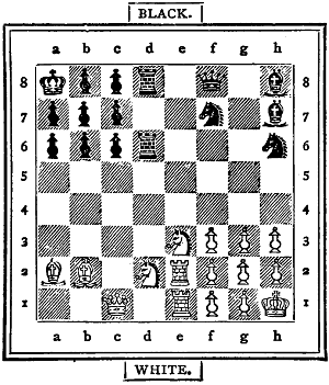
| 17, | N a3 | P c5 |
| 18, | O d c4 | P b5 |
| 19, | O d6:(a) | P d6 |
| 20, | O d5 | N d5 |
| 21, | M e3 | P c4 |
| 22, | P f4 | N d4 |
| 23, | M e7 | P c6 |
| 24, | O b4 | N f6 |
| 25, | M 7 e6 | N g7 |
| 26, | O d3: | P d3: |
| 27, | L d2 | P c5 |
| 28, | L d3: | P b4 |
| 29, | L d5 | O g8 |
| 30, | N c1 | O f h6 |
| 31, | P g4 | O f6 |
| 32, | L f3 | O h g8 |
| 33, | P g5 | O e8 (b) |
| 34, | N d5 | Resigns. (c) |
(a) Black thought he might give the M for the O, and work the P’s through.
(b) He loses time in moving the O’s. He ought to have prevented the attack on the P b7.
(c) It is now useless to defend b7, for if M d7, then M e8:, and if L f7, then M e7.
The two players, same as last mentioned, agree to play a so-called Pyramid Game, that is, to place the Kings on e1 and e8, and to place the eight Pawns around each in the shape of a pyramid. After these nine moves they proceeded to place the remaining officers as follows:—
| White. | Black. | |
|---|---|---|
| 10, | O d3 | M h8 |
| 11, | N f3 | O c7 |
| 12, | M a1 | O d6 |
| 13, | M a2 | L h7 |
| 14, | N c3 | N g7 |
| 15, | O b3 | M b8 |
| 16, | L b2 | N g6 |
The board now presents the following appearance:—
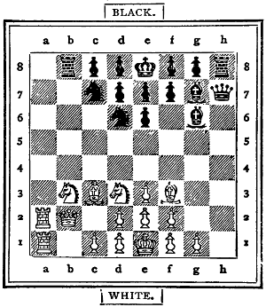
Now the moving and taking began thus:—
| 17, | N g7: | P g7: |
| 18, | O e5 | N e4 |
| 19, | P d3 | N f3: |
| 20, | O f3: | P f6 |
| 21, | P c4 | P e5 |
| 22, | L c3 | O e6 |
| 23, | M a5 | P e4 |
| 24, | O fd2 | L h1 |
| 25, | P g3 | M h2 |
| 26, | O e4: | O e4: |
| 27, | P e4: | L g1 |
| 28, | M f5 | O g5 |
| 29, | O d2 | P g6 |
| 30, | M f4 | O h3 |
| 31, | M f3 | O f2: |
| 32, | M a5 | O g4 |
| 33, | M g5 | P g5: |
| 34, | L g7 | O f6 |
If he had played P d6, there would have followed 35, L g6:†, K d7; 36, L f5†, K c7; 37, L g4:, etc.
| 35, | L g6:† | K f8 |
| 36, | M f6:† | P f6: |
| 37, | L f6:† | K e8 |
| 38, | L g6† | K e7 |
| 39, | L g7† | K d6 |
| 40, | P c5† |
and the game was a draw by perpetual check, for if K c7, then 41, L e5†, K b7; 42, L b2†, K c6; 43, L f6†, etc.
These two games show a remarkable variety in the arrangement of the pieces, and some beautiful new problems can be constructed in accordance with the placements and movements of the Pawns. Indeed, some ancient problems gave the impulse for the invention of this kind of game in June, 1874, when the first game of a similar arrangement was played between H. F. L. Meyer and H. J. C. Andrews. In 1874, however, the sixteen men were placed on the board all at once.
It seems an odd thing that in this prolific age of literature the most fascinating of all nineteenth-century games should lack a recognized authority as to its play. It is probably for this reason that Double Chess has so long a time languished in comparative obscurity, winning its way by slow degrees only into club and family circle.
No two strangers could be found to agree as to the rules which should govern its play, and the most imperative rule of all, namely, that of absolute silence, has been broken again and again with a royal disregard of all fine or penalty.
Time after time has it been our lot to sit over a foolish game where one’s partner would insist either in giving way to vocal bursts of impatience, or authoritatively insist upon a move which happened to chime in with his or her ideas. It must be confessed that the fair sex are most to blame in this matter. Though we are reluctant to upbraid them, we have no hesitation in saying that the infringement of this golden rule of silence is one of the fruitful sources of the hitherto unpopularity of the game.
How often have the writers waited in mute agony lest an exclamation of triumph or despair from their partners should reveal the imminent development of a well-planned scheme, and how they have plodded on, more from courtesy than any real interest, after such an event has taken place. We must insist that a heavy penalty for a breach of this golden rule should be rigidly enforced.
Let not the astute Single-chess player delude himself with the notion that he can march triumphantly to victory in this new[174] game. Save that the pieces move in the same manner (with one exception) as in Single Chess, there is no similarity between them, and we must say that the relative interest of the two games is in favour of the younger born. At any rate, the writers think so. Beginners grow weary of Double Chess because they find it occupies an unreasonable length of time. This is caused by the fact that they maintain a desultory kind of warfare, each one selecting an adversary and fighting him on his own account.
Double Chess Board.
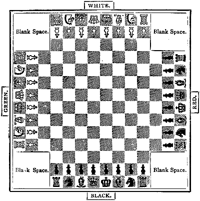
One hundred and sixty squares.
If the Double-chess player will remember that it is absolutely essential to watch his partner and second his moves, this state of things will speedily disappear. Those who wilfully neglect this may as well content themselves with Single Chess. No matter what their powers of calculation, they will never make decent Double-chess players.
Another imperative rule is always to make your attack to the right and defend on the left, taking care to guard your king against check by a double guard. These two rules will be referred to again at their proper time; but we cannot too strongly insist upon them, though, properly speaking, they have no place in the introductory remarks.
We have seen a very sensible and modest little brochure, by Captain George Hope Verney, which, unfortunately, is printed for private circulation only. We willingly bear testimony to its merits.
We must endeavour to combat the popular error that Double Chess is too[175] complicated for ordinary players. Any one acquainted with the moves and rules of ordinary chess can soon become a proficient, and as for the notion that it requires a great Single-chess player to make a good Double-chess-player, we must call attention, by way of analogy, to the fact that gamekeepers generally make wretched rifle-shots.
Exception must be taken to the name, ‘Four-handed Chess,’ given by some players to this game. Why not Four-brained Chess, or Four-person Chess, on the same principle? Must we call Single Chess Two-handed Chess? Double Chess let it be called, since it has exactly double the number of pieces engaged.
The diagram which we give will afford an accurate idea of the board used in the game of Double Chess.
It should consist of one hundred and sixty squares, twenty-four extra squares on each side of the central squares.
It is advisable to have the board to fold in two, the blanks on each corner being convenient for the reception of taken pieces, enabling players to see at a glance the amount of their own or their opponents’ losses.
Having placed the pieces on the board as shown in the diagram, taking care that the queens are on the same colour, the adversaries proceed to try for first move, an unquestionable advantage for eight moves.
This is done in the following manner: Red takes one of Black’s and one of his own pieces, and Black guesses, as in Single Chess. White and Green do the same. The conquerors then repeat, as in Single Chess. The victor has first move, and begins the attack, which should be directed towards his right-hand adversary.
His partner is now bound to remember that to him he must look for guidance, guessing at his plan of attack, and aiding him to the best of his ability.
Should the first mover decline to attack he will move on the left, say his king’s bishop’s knight to king’s bishop third for defence.
This will be sufficient warrant for his partner to make the attack and take the lead, as it is obvious that first mover wishes to follow instead of leading. In such an event, after the first round number one must look to number three for guidance.
The change is, at the best, a confession of weakness, and we cannot recommend its adoption, as in this game dash is most essential to success.
Each player makes a move in turn from right to left, and any player moving out of his turn (Rule 11) may be compelled to move the piece on which he has placed his hand, while his adversaries may also move out of their turn. The justice of this is obvious when one reflects that the mere indication of a piece may give a clue to the mover’s plan of attack or defence.
No consultation or suggestion of any kind is allowed as the game proceeds (Rules 1 and 11). Those who cannot restrain shuffling their feet, wriggling in their chairs, or grimacing over a certain move, had better be avoided as partners. Such a proceeding is more than undignified.
The pawns move only one square at a time, taking obliquely, as in Single Chess. When friendly pawns meet they leap over each other, and continue their progress until they reach partner’s king-row, when they return.
No object is gained in causing your pawn to reach your partner’s king-row, except that coming back it takes in reverse way.
It is therefore advisable when they meet to permit them to remain together for mutual protection, as in such position they command four squares-forward and backward.
Should pawns by repeated captures reach the adversary’s square, they become any pieces their player chooses to name, and such pieces cannot be taken except by a piece equivalent in rank, or by a king or queen (Rule 8).
As, however, it is next to impossible for a pawn to reach adversary’s square, seeing that it can only do so by repeatedly capturing antagonists, this advantage goes for very little.
A pawn on the return march should be marked by tying a piece of thread or a ring round its neck. But it will be found that but few, if any, pawns will have to be so treated, and this most likely will occur at the end of the game, when one or other of the kings is hard pressed, and the pawn is hastening to his assistance.
No player is allowed to expose either his own or his partner’s king to check, and, though he is not compelled to cover his partner’s check, it is advisable in most cases, when able to do so, as it will be found that when the king is checked by one adversary, the other will profit by it to obtain a piece and a position.
Bear in mind that in this game everything depends on mutual assistance and self-sacrifice. In nine cases out of ten the one who refuses to sacrifice in order to save his partner from checkmate brings speedy defeat on each.
Castling is not allowed; it is therefore advisable to get out one’s knights as soon as possible in order to give castles an opportunity of moving out of the way of a sudden combined attack.
Another advantage in getting out the knights is that their greatest value is at the beginning of the game.
Towards the end of the game, in consequence of the combined action of the pawns, and the distances to be traversed, a knight’s value is greatly reduced.
We have found it advantageous to exchange a knight for a bishop towards the middle of the game.
The great object of the game is by combined action to suddenly checkmate one adversary. His pieces, though not removed from the board, are then dead, and cannot return to life until the checkmate is removed.
They cannot be taken, but are practically useless, except as offering the shelter of inert matter to partner’s pieces.
One partner having been checkmated, the antagonists concentrate their attack upon the remaining one, with the enormous advantage of having two moves to his one!
Only, therefore, by making desperate sacrifices to release his partner from checkmate can the non-checkmated one hope to save the game, except his adversaries should stalemate him, when it is drawn.
While one is checkmated the adversaries may move in and out amongst his pieces with impunity, and should adversaries’ kings do so, they are not exposed to check, as the pieces are considered dead.
This is most important, as it enables the adversaries, having once secured checkmate, to render it permanent by pieces of lesser value, withdrawing important pieces to fight against remaining partner, who, although combating single-handed, may be numerically superior to both.
It is lawful to open adversary’s checkmate for the purpose of capturing any of his pieces, who by that means are returned to life. But it should be borne in mind that if in doing this stalemate is given, the game is drawn.
Though the adversary may at any time open checkmate, he cannot in the same move take a piece, but his partner may do so, and he may close the checkmate again at his discretion when it comes to his[177] turn. (See Rule 4.) The game is only won by both partners being checkmated.
A game is drawn when only one piece is left on the board, or when only pawns are left, as it is then impossible to secure a double checkmate.
But should each partner have a piece, or one of them two pieces, the game should be fought out, as, with the assistance of their kings, they may secure a double checkmate.
The adversaries have the forlorn hope of either taking one of their pieces—in which case the game is drawn—or of securing a stalemate.
This latter event, unlike the former case given, in which one was checkmated before the stalemate, will be a victory for them, as one king is free to move.
It is as well for beginners, having reached that stage of the game in which only two pieces are left, to declare the game drawn, with the honours of war attached to those with the two pieces left, as the game in that event will probably last long enough to tire out the patience of all engaged. Some ten years ago the writers sat from six o’clock in the evening until half-past four the following morning over a game which had dwindled down to the above-mentioned dimensions, and had all but given up the task as hopeless ere the desired result was obtained.
The pieces may range all over the board, as in Single Chess, and are equally at home in partners’ squares as in their own.
1. Absolute silence must be maintained. Should a player give vent to an exclamation of vexation when his partner is about to move a piece, the adversaries may claim a pawn from any of his squares which does not expose him to check.
2. A player checkmated may not indicate to his partner how to obtain his release.
3. No piece may be moved which will discover check to player or his partner.
4. No player can release his antagonist from checkmate by taking any of his pieces.
5. Any player may call attention to the fact that his partner’s queen is in check.
6. But his own being in check, he may not direct attention to that.
7. A king is not in check by any of his partner’s pieces.
8. A pawn-piece can only be taken by a piece of its own rank, or by king or queen.
9. A player putting his hand on a piece must play it. If he remove his hand, the move must be considered as completed.
10. Adversaries’ kings cannot stand next each other on adjoining squares.
11. Should a player play out of his turn, both his antagonists may play out of theirs, and they are allowed to ask each other which of them is desirous of moving first.
12. No piece may be removed from the board unless legally captured.
13. A pawn can only move one square at a time, and not two squares first move, as in Single Chess.
14. The game is only won when both partners are checkmated. Should it be relinquished before such an event, it is to be considered drawn.
15. A player may not move his checkmated partner’s pieces.
16. Antagonistic pawns may not leap over one another.
17. A player may not take a piece while his king is in check, except to release himself from check.
18. A king may not move out of check if by so doing he exposes his partner’s king to check.
19. With kings and one piece only remaining, or with pawns only, the game is drawn.
Never reproach your partner for having made a blunder. It is useless blowing up the groom after the horse is stolen; and as it is essential above all things that a cool head should be kept over this fascinating game, if your partner is inclined to be nervous, and you ‘nag’ at him, you may as well consider the game lost.
We remember an instance in America when a really good player, who had been wofully badgered by his partner for some blunders, remained for an hour and a half studying the board, lest he should make a false move and once more encounter his partner’s terrible sarcasm.
At the expiration of that period he arose without making the move, and vowed, as he could not see that which his partner deemed so important, he would never play another game of Double Chess. As far as our party was concerned, he kept his word, and thus a very enjoyable evening’s amusement was broken up.
It is almost needless to add, that while refraining from rousing your partner’s temper, it is equally important that you should control your own. It is very provoking to have a trap suddenly sprung upon you, thanks perhaps to your partner’s want of perspicuity, and lose an important piece just when you imagine you had a brilliant game in hand.
But however provoking this may be, getting angry will only make matters worse, for we defy an angry man to see two moves ahead. Keep cool, bow gracefully to the opposing storm, and wait with sweetness of temper for the turn of the tide.
Calmness and breeding are nowhere more requisite than at the Double-chess table. One cannot bully a stupid player into playing well, and the only thing to be done is to play the game rigorously, and give or take no more than the fixed rules require.
By adhering to this, all unpleasantness will be avoided, and this charming game will grow more and more in popularity. Should you unfortunately discover that constitutionally you are incapable of controlling your temper, abandon the game for ever. You will reap the reward of your self-denial in the knowledge that you will never again mar the pleasure of those whom Nature has cast in firmer mould.
Theoretical knowledge is of value, but practically it will be found more advantageous to play a straightforward game than to indulge in any scheme calculated for a great number of moves ahead. It is of the last importance that your partner should know what you are about, and aid you in your plans, else, despite your brilliant play, your airy fabric may vanish.
Therefore by all means choose such moves as will most readily lead him to divine your method of attack, bearing in mind that it is more important he should know it than that your adversaries should remain in ignorance of it.
Since the attack should invariably be made on the right-hand adversary, and the great danger is that you may be held in check by one foe while the other sweeps away your pieces, it is obvious that your left-hand defence must be of double strength, to prevent this result being obtained. Your knights in the early stages of the game will be found of value in this respect, and your bishops and queen should, as far as possible, be kept in readiness to swoop to your partner’s assistance, while he will be ready to aid you in a similar manner. Get out your castles as[179] speedily as possible, even if you sacrifice a pawn in doing so, as they are of more importance in this game than in Single Chess, and are not nearly so well protected in their original positions. Your queen is of far more value than in Single Chess, and to capture her the sacrifice of a castle and bishop is, in our opinion, not too great.
Great care must be exercised in her movements. Calculate well, ere you place her in position, that you cannot be checked in two moves, or you lose her to a certainty.
We place the relative value of the pieces in Double Chess in the following scale:—
| Queen | = | 10 |
| Castles | = | 6 |
| Red Bishop | = | 5 |
| White „ | = | 4 |
| Knights at beginning of game | = | 3 |
| Kni„ts a „ the end | = | 2 |
| Pawns | = | 1 |
although practically the last are of little value; certainly not half so valuable as in Single Chess.
Other players may place a slightly different value on the pieces, but this will in a great measure depend on their play. While some work the queen to death, others rely more on their other pieces—in our opinion the wisest play in the long run.
We have found a board of two-inch squares suit our purpose, and those which fold in the centre, leaving a blank in each corner, seem to us the handiest.
If bone black and white and red and green men cannot be obtained easily, the ordinary wooden black and yellow, and bone red and white, will answer the purpose just as well, but any turner will turn a double set for about two pounds.
Captain George Hope Verney says, in his Four-Handed Chess:—
‘I use two sets of Staunton men. One set is of black and yellow wood, and the other is of red and white bone.
‘The latter was made to order for me at the Civil Service Store in the Haymarket, at a cost of about eighteen shillings.’
The base of the king measures one and five-eighths of an inch, and is three and a half inches high.
First round—Black king’s pawn to king’s third; green ditto; white ditto; red ditto.
Second round—Black bishop takes red bishop; green queen takes black queen; white queen takes red queen; red king takes white queen.
Third round—Black king takes green queen; green moves queen’s pawn one, white king’s knight’s pawn one, red king’s knight to royal square.
Fourth round—Bishop takes knight’s pawn.
Thus at the beginning of the fourth round red and green find themselves obliged to put up with the loss of a bishop and pawn, and a strong attack, to be followed up by the knights, will be directed against red, who is severely crippled. Should green check black king, it will do him no good, as black king’s bishop is protected by white.
Red and green have drawn disaster upon themselves at the beginning of the game by imitating their opponents’ move, and black and white thus early starting with an advantage and well-defined attack, should win the game, since red has not only lost a piece and pawn, but also a move.
Should green check black king third[180] round, he will lose his bishop. Should he take white’s bishop, black will retreat without breaking square, as that would liberate red’s castle. He will thus save his partner a pawn.
A variation of the same opening will be for black second round to play his knight to bishop’s third, thence to castle four. If this opening is not seen through and frustrated before four moves, green loses his queen. But red can easily frustrate the design, or green king’s bishop’s knight to bishop’s third will suffice.
These two openings will suffice for the beginner; and our readers can now follow up the subject as far as they wish.
Of chess in the middle ages there were no less than fifty-four varieties—not gambits, but different ways of playing the game. To one of these, known as Double Chess, we have already devoted some pages; and we now give the variety known as Circular Chess, which was played on a board of the same pattern as the illustration, on which the pieces were arranged as shown, the line with the arrow-heads representing the edge of the board in the ordinary game, and the movements taking place right and left from it.
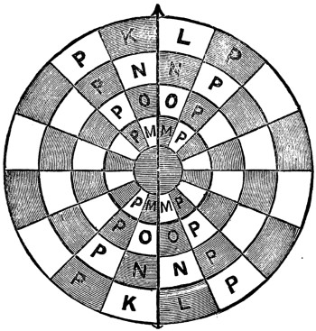
A pawn attaining this line is exchangeable for a piece, as in the common game, but it offers no barrier to the passage of the men. The moves are in all respects the same as in ordinary chess. The peculiarity of the shape, however, considerably reduces the importance of the bishops and increases that of the rooks and queens.
It has been said by one who has a right to express an opinion on the subject (Mr. Wylie, of Fife, the greatest player and analyst in Scotland) that Draughts is a more intricate and ingenious game than its proud rival, Chess, of higher antiquity and of more intellectual scope. So much so, that in a hundred years a man could not exhaust its varieties. Edgar Allan Poe, the author of The Raven, expresses a like opinion: ‘The higher powers of the reflective intellect are more decidedly tasked by the unostentatious game of Draughts, or chequers, than by all the elaborate frivolities of Chess.’
Without venturing to discriminate between the merits and claims of the two games—both of which I love—I purpose attempting to show my readers some of the prominent features of the ancient and honourable game of Draughts.
You are all, doubtless, acquainted with the form of the draught-board and men; with the fact that the game is played by two persons on a board of sixty-four squares, with twenty-four men, twelve of one colour and twelve of another. At starting, the men occupy the three rows of squares on opposite sides of the board. The men may be placed on either colour, but for convenience of notation it is usual to select the white squares. The moves of all the men are alike—diagonal from square to square, in an upward direction from the player. They take by passing over the captured man into a vacant square beyond. One, two, or more men can be taken by the same move, always providing that there is a vacant square to pass into at each jump. When a man has arrived at either of the four squares on the opposite side of the board he is crowned, and becomes a King. The crowning is a simple ceremony—merely placing one draughtman, of the same colour, on the top of the other. The kings have the power of moving forward and backward, one square at a time, diagonally. The object of the game is to capture all your opponent’s men, or so to block them in that they cannot move. The player who first accomplishes one of these ends wins the game.
One or two rules are absolute. The offered man must be taken, when the player says ‘Take,’ and a man touched must, if it can, be moved.
In placing the board for the game, the double corners must be at the right-hand of the player, which brings us at once to the
—the method by which the moves of a game or problem are recorded. It is not necessary to show a diagram of the Numbered Board if you remember the order of the figures. The first white square on the left hand, uppermost, is 1, and the rest go from left to right, horizontally, till we arrive at the last white square on the right, 32. In recording the moves[182] of a game we say 11 to 15, 24 to 19, and so on. A very little practice will make you sufficiently familiar with this easy system of notation, and soon enable you to play a game by memory without the board.
To show you the nature of a Problem, and the way to record its solution, I will append a diagram.
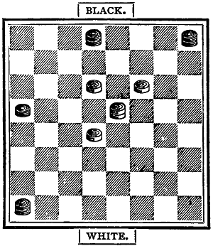
White to play and win in eight moves.
The difficulty here is the first move. That discovered, all the others follow as a matter of course. This is the solution:—
| White. | Black. | |||||
|---|---|---|---|---|---|---|
| 10 | to | 6 | 1 | 2 | to | 9 |
| 18 | to | 14 | 2 | 9 | to | 18 |
| 15 | to | 22 | 3 | 13 | to | 17 |
| 22 | to | 13 | 4 | 29 | to | 25 |
| 13 | to | 17 | 5 | 25 | to | 30 |
| 17 | to | 22 | 6 | 30 | to | 25 |
| 22 | to | 29 | 7 | 4 | to | 8 |
| 11 | to | 4 | 8 | |||
by which you will see that Black’s moves are all forced, and White wins the game.
Draughts is played in three ways: the Winning (and most usual) game, the Losing, and the Polish game. The last, not much practised in this country, is played on a larger board, and the men take backwards or forwards.
Draughts, as played in Great Britain and in all English-speaking countries, is governed by a few simple and easily-understood Rules, as follows:—
1. The board is to be placed with the double corner to the right hand of the player.
2. The choice of colour is determined by lot. After the first game the men are commonly changed.
3. Black has invariably the first move.
4. A man touched, except for the purpose of adjusting it, must be moved if there be an open square into which it can be moved.
5. A man moved over the angle of a square must, if it can, be moved to that square.
6. A man en prise must be taken; or if it be left untaken by accident, it may be ‘huffed’—that is, taken off the board by the adversary. The ‘huff’ is not a move, but the player insisting on it, huffs and moves.
7. Five minutes is the limit of time for considering a move; when a piece is en prise, one minute only is allowed. Penalty: loss of the game.
8. A false move must be replaced, and a legal move made.
9. A wrong man removed from the board can only be replaced by consent of the adversary.
10. When two kings only remain on the board, the game must be won in twenty moves on either side, or abandoned as drawn.
11. With three or more kings, or men, to two, the player with the weaker force may insist on the game being won within forty moves on each side, or be drawn. In each of these cases notice must be given by the player that he will count the moves.
12. When two or more men are taken at one coup, no man captured must be taken from the board till the combined move is completed.
13. A man moved up to the last row of squares on the other side must be immediately crowned; but the king cannot play till a move has been made on the other side.
Bye-laws.—No pointing over the board or obstruction to the adversary is allowed.—Matches, unless otherwise agreed, consist of an equal number of games.—All disputes to be decided by an umpire or other disinterested player.—Neither player is allowed, without the consent of his opponent, to leave the room during the progress of a game.—Any breach of the rules involves the loss of the game.
Above all, keep your temper!
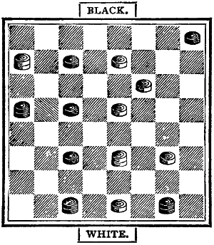
White to play and mate in seven moves.
A common practice with young players is to give man for man; but this is only advantageous when you are a piece ahead, and even then it is sometimes found difficult to win within the twenty moves allowed. There is, however, no secret in the matter. The player with two kings can always force a win if he knows how to set about it. From any part of the board he can, in about eight or nine moves, drive the single king into the double corner, and when he is there he wins in eight moves, thus:—
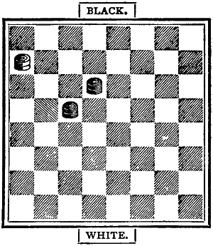
| Black. | White. | ||||
|---|---|---|---|---|---|
| 10 | to | 6 | 5 | to | 1 |
| 14 | to | 10 | 1 | to | 5 |
| 6 | to | 1 | 3 | to | 9 |
| 1 | to | 5 | 9 | to | 13 |
It is at this point the tyro generally makes a mistake. Instead of moving away, he presses on his adversary, and gives him a chance of escape. He must move into square 15, not into 14:—
| 10 | to | 15 | 13 | to | 17 |
| 15 | to | 18 | |||
Now whether White move into 13 or 21, he is equally pinned by the Black at 22.
Of course a like series of moves in the other double corner produces a like result.
In the above, and all the other diagrams, the Black men occupy the upper half of the board.
To show, however, the mischief of unscientific play, we will suppose the kings to have got into the following position, when Black, with the move, can do no more than effect a drawn game:—
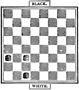
Here Black must give away a man. He must go to either square 17, 25, or 26. Let us suppose he moves to 26, White takes, and goes into square 31. Now, if Black go to 25 instead of 17, he loses the game in two moves. White moves to 26, and pins him on 22, in either the three squares to which he is compelled to go.
In ordinary circumstances, two kings to two must be a draw. Neither player can force the other out of the double line. Suppose, however, you can get the pieces into this position:—
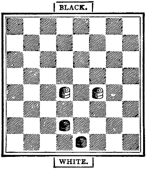
Black, with the move, wins by playing a king from 26 to 23, and taking two for one. Beware, in the position shown, that you do not move backward instead of forward. Should you do so, you may perhaps get into some such fix as this:—
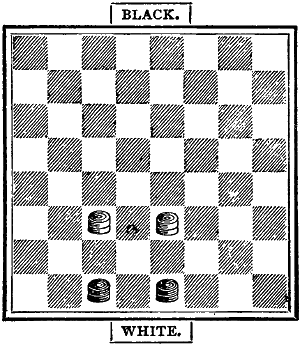
Black to play and lose. White to play and draw.
White must, moreover, be careful not to get his men into a line with a square between into which Black can move, technically known as ‘The Breeches.’
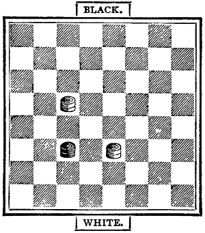
Black to play and draw.
This is a trap into which young players are very apt to fall. Beware of it. Had[185] White the move, he, of course, could easily win, either by fixing the Black king in a side square, or by the double-corner moves already shown.
When you are left with three kings to two, you must effect an exchange, or the game may be prolonged indefinitely. It is sometimes rather difficult to force an exchange, but it is not impossible if you go the right way to work. The possessor of the two kings commonly gets one in each double corner. The mode of attack in this case is to get your three kings into a line, so as to enable you to give king for king. However hard the other player tries he must eventually succumb. Take a common case. Place the kings on the board as in the diagram, the White on 32 and 5, the Black on 10, 18, and 19:—
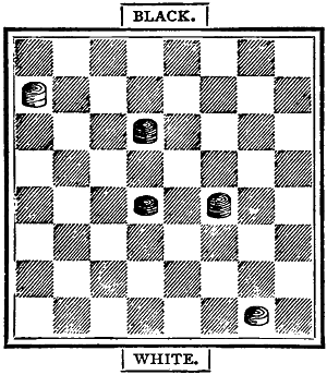
Black to play and win, or White to play and Black to win.
If Black play he moves into 6 or 24. White has the choice of two moves only, either of the double corners.
| Black. | White. | ||||
|---|---|---|---|---|---|
| 19 | to | 24 | 5 | to | 1 |
| 18 | to | 15 | 1 | to | 5 |
| 10 | to | 6 | |||
Now, whether White move from 5 to 1 or from 32 to 28, he must submit to an exchange, for Black backs up his king, takes one for one, and then wins in the usual way.
Suppose White has the move. He can only go into squares 1 or 32. Say he moves into 32; Black has only to go from 18 to 15, and what has his adversary left? Nothing but to submit to an exchange at the next move, after which the rest is easy, as already shown with two kings to one.
As a rule the player with the superior force must win, but in some positions it is very difficult to force an exchange. Take this:—
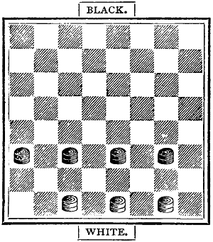
White, with the move, has but one square, 28, into which he can move. Black, with the move, would of course win by going into the same square, and soon compel an exchange. Suppose White move—
| White. | Black. | ||||
|---|---|---|---|---|---|
| 32 | to | 28 | 24 | to | 20 |
| 28 | to | 32 | 23 | to | 19 |
| 31 | to | 27 | 22 | to | 18 |
| 27 | to | 31 | |||
If he play 27 to 23 his adversary takes[186] from 18 to 27, and leaves himself after the exchanges with two kings to one. White prolongs the struggle by moving from 27 to 31, to which Black replies by playing
| 19 | to | 24 | ||||
| 32 | to | 27 | 24 | to | 28 | |
| 27 | to | 32 | 18 | to | 23 | |
| 31 | to | 27 | 23 | to | 26 | |
| 30 | to | 23 | 28 | to | 24 | |
| 27 | to | 31 | 24 | to | 27 | |
| 31 | to | 24 | 20 | to | 18 | , |
which leaves Black with two kings to one, when he wins in ten or twelve moves.
This last is an instructive position, as it shows how the greater force must conquer. Generally the same result happens in other and more vastly important contests. The game of Draughts, like the game of war, can only be successfully played by an intimate union of strategy and might.
If each player had equal skill, and each made the proper move, then the player who took the first move would win. This sentence sounds like a truism, but it is open to argument. Throughout every game it is important to know which of the two players ‘has the move’—that is, the power to fix his adversary man for man on every available square. The first moves of a game do not directly affect its final result, but when the men have become fewer and fewer, it is of the greatest consequence to know on which side lies the forcing power. To make this plain, place a white man on square 4, the top right-hand corner, and a black man on square 30, the second from the left in the lowermost row of squares. Black, having to play, moves from 30 to 26, and do what he may, White must be stopped at square 19. Try it. White, having to play first, cannot, on the contrary, prevent his opponent from making a king. This simply shows the theory of Having the Move.
To discover whether you Have the Move, several plans are at your service. The easiest is this: Count one for each man of both colours which stand on columns having a white square at the foot. If it is your turn, and the total of the addition be odd, you Have the Move; if it is your opponent’s turn to play, the move is with him.
Place the men as in the following diagram, and you will soon find that either colour moving first has the move, and therefore ought to win.
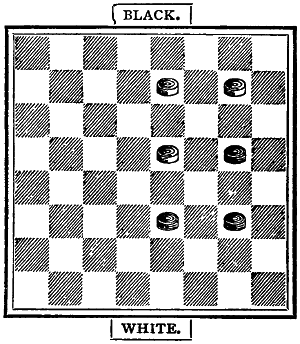
The Move.—Either colour to play first and Have the Move.
Another Plan, by some considered more certain, is this:—
If you desire to know if any one of your men has the move of any man on the other side, examine the position of both. If there is a black square on the right angle under his man you Have the Move. For instance, you have a black man on 30, and white has a man on 3. The right angle is the black square between 31 and 32. With your man on square 29 or 31 the right angle would be found on the[187] black squares on one or other side of the straight line below the white man, and he, therefore, would Have the Move. The value of this plan is that it holds good with any number of men.
A Third Plan.—Count the men and the squares. If the men are even and the squares are odd, or if the squares are even and the men odd, you Have the Move. With even men and even squares, and odd men and odd squares, the move is on the other side.
To apply this theory. When you have the move do not exchange, if you can avoid it, or you may lose the move. For example, place the men thus:
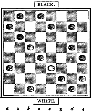
The Move.—White to play and win.
When all the men, both Black and White, on the lettered column (a, b, c, d,) are added up, the total is odd, and the side having to play Has the Move. If no men are on the lettered squares, then take the figured squares, 1, 2, 3, 4; but do not combine the two. Apply the theory to the above position. We find that there being 9, an odd number of men, on the lettered columns, White Has the Move, and having it, would win:
| White. | Black. | |||||
|---|---|---|---|---|---|---|
| 28 | to | 24 | —1— | 8 | to | 12 |
| 30 | to | 26 | —2— | 2 | to | 6 |
| 24 | to | 19 | —3— | 6 | to | 10 |
| 21 | to | 17 | —4— | 9 | to | 13 |
| 26 | to | 22 | —5— | 1 | to | 6 |
| 32 | to | 28 | —6— | 6 | to | 9 |
| 28 | to | 24 | —7— | |||
What, now, can Black do but play, and lose a man and the game? He has but two squares, 15 and 11, open to him. His defeat is decisive and complete.
Change man for man till only one capturing piece remains on the board. Suppose Black had men on squares 12 and 15, and White had men on 24 and 28. What should White do? Nothing more simple. He plays from 24 to 19. Black must take the offered piece and be taken, when his remaining man on 12 is fixed by the White on square 19.
A further example. Place the men thus:—
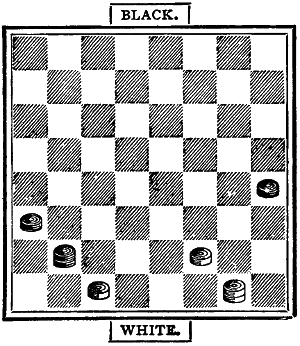
Regaining the Move.—White to play and win.
Here it would appear that Black must win. But White, playing first, forces a win.
| White. | Black. | ||||||||||
|---|---|---|---|---|---|---|---|---|---|---|---|
| 32 | to | 28 | — | 1 | — | King | 25 | to | 22 | ||
| 28 | to | 24 | — | 2 | — | 22 | to | 18 | |||
| 24 | to | 19 | — | 3 | — | 18 | to | 22 | |||
| 19 | to | 15 | — | 4 | — | 22 | to | 17 | |||
| 15 | to | 18 | — | 5 | — | 17 | to | 13 | |||
| 18 | to | 22 | — | 6 | — | 13 | to | 9 | |||
| 30 | to | 26 | — | 7 | — | 9 | to | 14 | |||
| 26 | to | 23 | — | 8 | — | 14 | to | 10 | |||
| 23 | to | 18 | — | 9 | — | 10 | to | 6 | |||
| 18 | to | 14 | — | 10 | — | 6 | to | 1 | |||
| 14 | to | 9 | — | 11 | — | 1 | to | 5 | |||
| 9 | to | 6 | — | 12 | — | 5 | to | 1 | |||
| 6 | to | 2 | King | — | 13 | — | 1 | to | 5 | ||
| 2 | to | 6 | — | 14 | — | 5 | to | 1 | |||
| 6 | to | 10 | — | 15 | — | 1 | to | 5 | |||
| 10 | to | 15 | — | 16 | — | 5 | to | 9 | |||
| 15 | to | 19 | — | 17 | — | 9 | to | 14 | |||
| 27 | to | 23 | — | 18 | — | 14 | to | 10 | |||
| 23 | to | 18 | — | 19 | — | 10 | to | 6 | |||
| 18 | to | 14 | — | 20 | — | 6 | to | 1 | |||
| 14 | to | 9 | — | 21 | — | 1 | to | 5 | |||
| 9 | to | 6 | — | 22 | — | 5 | to | 9 | |||
| 6 | to | 1 | King | — | 23 | — | 9 | to | 5 | ||
| 1 | to | 6 | — | 24 | — | 5 | to | 1 | |||
| 6 | to | 9 | — | 25 | — | 1 | to | 5 | |||
| 9 | to | 14 | — | 26 | — | 5 | to | 1 | |||
| 14 | to | 18 | — | 27 | — | 1 | to | 5 | |||
| 18 | to | 23 | — | 28 | — | 5 | to | 9 | |||
| 23 | to | 27 | — | 29 | — | 9 | to | 14 | |||
| 19 | to | 23 | — | 30 | — | 14 | to | 9 | |||
| 23 | to | 18 | — | 31 | — | 9 | to | 5 | |||
| 18 | to | 14 | — | 32 | — | 5 | to | 1 | |||
| 14 | to | 9 | — | 33 | — | 1 | to | 5 | |||
| 22 | to | 17 | — | 34 | — | 5 | to | 14 | |||
| 17 | to | 10 | — | 35 | — | 21 | to | 25 | |||
| 10 | to | 15 | — | 36 | — | 25 | to | 29 | King | ||
| 15 | to | 19 | — | 37 | — | 29 | to | 25 | |||
| 27 | to | 32 | — | 38 | — | 25 | to | 22 | |||
| 19 | to | 24 | — | 39 | — | 20 | to | 27 | |||
| 32 | to | 23 | — | 40 | — | 22 | to | 17 | |||
| 23 | to | 18 | — | 41 | — | 17 | to | 13 | |||
| 18 | to | 14 | , and wins next move. | ||||||||
The beginner who follows the moves of this game with an understanding brain, will learn more about the scientific theory of Draughts than he could acquire by a year of miscellaneous play.
As stated on page 182, the rules are few and simple. The explanations and remarks are in brackets.
1. The board is to be so placed as that the double corner is at the right hand of the player. [Some play on the white, and some on the black squares. For convenience of numbering the board and recording the moves, the white squares are now generally adopted.]
2. The choice of colour is determined by lot, and the men on either side are placed on the alternate squares in three lines immediately in front of the player. [The black or the white squares, as may be decided before starting.]
3. Black has the first move, and the men are changed with each game. [Thus giving in turn the first move to each player.]
4. The player who touches a man, except for the purpose of adjusting it, must move that man, if it can be legally moved.
5. A piece moved over the angle of a square must be moved to that square. [This is a newly-adopted law, to prevent the undecided mode of moving backward and forward adopted by some players.]
6. A man en prise must be taken if intimation be given by the player offering it. If by accident it is left untaken, the piece which should have taken it may be huffed. [It is at the option of the adversary to huff or let the offending piece remain.]
7. The player cannot stand the huff, when he is told to take a man, or men.
8. The huff is not a move; and after taking off the huffed piece, the player moves. [Thus ‘huff and move’ is a well-understood direction.]
9. A player taking one piece only when two or more can be legally taken, may[189] be huffed on the completion of his move.
10. When a piece is en prise it must be taken within a minute. [This is to prevent the delay in which some indulge.]
11. Five minutes is the limit of time for considering a move. The penalty for exceeding the time allowed is loss of the game. [This law applies more particularly to match games.]
12. A piece abandoned is a completed move. [In all games this law should be observed, as nothing is so annoying to an opponent as to be asked to allow a move to be amended.]
13. A false or illegal move must be rectified, or the game resigned; such move may be allowed to remain, at the option of the adversary. [By a false move is meant the moving backward, or sideways, or on to the wrong-colour square.]
14. If a player in the act of taking remove one of his own men from the board, it cannot be replaced, except by consent of the opponent.
15. When three or more kings are opposed to a weaker force, the game must, when the opponent gives notice to count, be won within forty moves, or abandoned as drawn.
16. When two kings are opposed to one, the game is to be declared drawn, unless the player with the stronger force win in twenty moves. [From any part of the board two kings can win against one in fifteen or sixteen moves.]
17. Notice must be given of the intention to count the moves. [Twenty or forty, as the case may be; one for the combined move of both colours.]
18. When several pieces can be taken in one continuous move, no piece may be taken up off the board until the move is completed. The player failing to take all the men may be huffed. [As in Rule 9.]
19. When a man arrives at a square in the last row on the opposite side of the board, he must be immediately crowned. But the king cannot move till the opposing player has made his move.
20. Kings can move backward or forward, one square at a time only; and, to take two or more pieces in one move, there must be a vacant square behind each individual piece.
21. Disputes are to be decided by an umpire, or a majority of the company.
22. Matches must consist, unless otherwise agreed, of an equal number of games. [The rules for regulating a match should be determined and stated in writing. An umpire should be appointed.]
23. During the progress of a game neither player is allowed to leave the room, except by permission of his opponent.
24. Pointing over the board, loud talk, or any other behaviour likely to annoy or confuse an adversary, if persisted in, forfeits the game.
25. No bystander is allowed to advise a player, or interfere with the progress of a game.
26. A breach of any of the above laws is punishable by the loss of the game, if in the opinion of the umpire such breach was intentional.
Play with better players than yourself. Observe the openings.
Look well over the board before making a move.
Never touch a man without moving it.
Leave off when your mind is fatigued, and never persist in playing when you stand but small chance of winning.
Waste no time in considering an inevitable move. Take the offered piece without hesitation or delay.
When you are a man ahead, exchange[190] as often as you can, but at the same time beware of man-traps and spring-guns.
Abandon a line of play the secret of which is discovered by your adversary; and when a piece must be lost, make no attempt to retain it. Sometimes it is safer to give up a man than to defend a weak position.
Make your kings as quickly as you can. Avoid all cramped positions. Back up your men in phalanx fashion:—
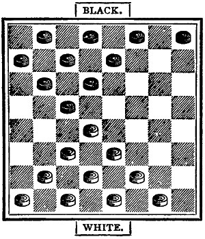
and move rather towards the centre than to the sides of the board. Be careful not to move out your men too soon from the safety of the back row.
Play with your head as well as with your fingers. Avoid banter and loud talk. Boast not of your victories. Win modestly, and lose with good temper. Punctuality is the politeness of kings. Courtesy is the grand characteristic of good draught-players.
There is a good deal of amusement and no little skill in the Losing Game. As its name denotes, this game is the reverse of Draughts proper. The object is to lose all your men; and he who accomplishes that object wins.
The whole or main secret of the Losing Game is to play towards the sides of the board, and to so arrange your men as to be able to give up two, three, or more at a single coup. After a little practice you will discover that even with a dozen men on the board against, say, two or three, you may win—that is, you may compel your adversary to take them all. Or with a single king you may take man after man, and then, at last, commit graceful suicide. Or you may compel a king to take several men. Much depends on Having the Move. Here, for instance, is a position in which a king is forced to take eight men and lose the game:—
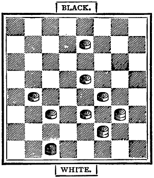
Black to move and White to win, or White to move and Black to win.
Black has only two squares into which he can go, and then he must allow White to give away his men one after the other. If White moves first, Black gains the opposition by losing his king, and wins the game.
In the next diagram, again, is a position in which White can compel a single Black man to take all his eleven pieces one after the other.
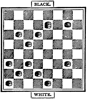
White to play and win.
White, moving upward, first gives his king, and then the man on 24, after which he offers the man on 31, which White must take and become a king. The remaining moves are simple, but White has to play carefully, or he may enable the Black king to sacrifice himself and win.
The Losing Game offers numerous opportunities for calculation and combination; but what we have shown is sufficient to enable young players to understand the theory. Excellence will come with practice and perseverance.
The Polish game is played on a board of a hundred squares, ten each way; but for all ordinary purposes the regular English board of sixty-four squares will do as well. The board is set in the usual way, with a double corner at the right hand of the players, no matter which colour be chosen.
Two great and essential differences exist between English and Polish Draughts. In the foreign game the men take backward and forward, one square at a time, as many pieces as are en prise, and the kings leap over any number of squares, wherever and whenever there is a piece to take. As, in our own game, a piece touched must be moved, and all the other rules of the English game are to be observed. On the Continent, where the game is much more common than with us, the crowned man is called a queen, just as the game itself is Damen, a game for ladies. With them, as with us, the White squares are usually chosen.
It is by exchanges that good players at Polish Draughts parry moves and prepare combinations. It is well to give man for man, or two for two. By that means the game is strengthened, and thus it often happens that a single man can confine several of his opponent’s pieces.
The lunette—the placing a man on a square between two men of the other side—is much more frequent in the Polish than in the English game. Look well to the position before you enter the lunette; and having entered it, before you decide on your move. It is often a snare, which the good player will try to avoid.
Concentrate your men towards the end of the game, for then the slightest error may be fatal.
Two, three, or more pieces may sometimes be advantageously sacrificed to obtain a king, which, in this game, is very powerful. Make your kings as soon as you can, and play them with judgment. With a king and a man against two or three kings, hesitate not to sacrifice your man, for the game may be almost as well defended by the king alone. Between equal players, the game often results in a draw; but there is no saying how nume[192]rous are the combinations which may lead to victory or its reverse.
It is not necessary to give the moves of a game, as, except for its two grand distinctions, Polish Draughts is similar to the English game.
Here, then, we have pretty well all that can be taught on paper respecting this branch of the game. The next step is How to Open a game with advantage. This I shall proceed briefly to show; and after that the excellence is to be acquired by practice alone. Draughts, in all its varieties, is an admirable game, inculcating patience, caution, tact, and scientific calculation. Those who would excel in its practice must be content to go slowly. There is no royal road to Draughts. Perseverance and failure are the parents of success.
Usually it is necessary to begin at the beginning; but in Draughts and Chess, as in other games of skill, players commence playing, and even attain some degree of aptness, before they actually conquer the alphabet, the science, of the several amusements. There is no great harm in this plan, however. Do we not all learn to talk before we know anything of grammar or orthography; to sing before we understand even the notation of music; to argue and discuss before we get even the haziest notion of logic? Of course we do. And then we naturally endeavour to go back to first principles, and so correct our mistakes by aid of rule and system.
I told you some pages back that there were various accepted openings to the game of Draughts—the Old Fourteenth, the Single Corner, the Laird and Lady, the Glasgow, the Whilter, and some fifty others. All the really safe, sound, and favourable openings, however, proceed from the five here named. The rest are well enough to know, but in practice they are risky and fantastical.
To properly understand what follows, it is necessary that you should so completely conquer the notation of draughts as to be able to follow the moves in your mind’s eye without seeing the board. This is not nearly so difficult as you may think. Number your board as in the diagram below, and place the men in the order of play.
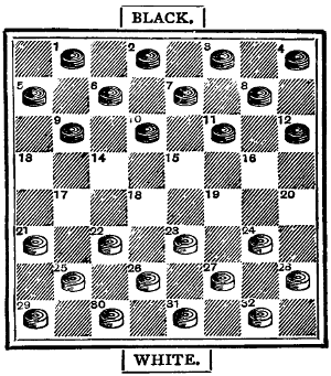
The Numbered Board, with the men placed in their order of play.
Here we have the Black men on the upper half of the board, though whether the White or the Black occupy that position the order of their moves is the same. The usual plan is for the Black to take the first move, and for the players to change the pieces with each game. By this method each player begins alternately, and always with the Black men. Our games will be so arranged, if you please.
Let us commence, then, with the best of the openings—
| Black. | White. | |||||||
|---|---|---|---|---|---|---|---|---|
| 11 | to | 15 | — | 1 | — | 23 | to | 19 |
| 8 | to | 11 | — | 2 | — | 22 | to | 17 |
| 4 | to | 8 | — | 3 | — | 17 | to | 13 |
These three moves on either side constitute the Old Fourteenth Opening. From this point, at which the game is perfectly even, spring many variations. The most common and accepted moves on each side are—
| 15 | to | 18 | — | 4 | — | 24 | to | 20 |
| 11 | to | 15 | — | 5 | — | 28 | to | 24 |
| 8 | to | 11 | — | 6 | — | 26 | to | 23 |
The following is now the position. Both sides are well placed, and the game, if played thoroughly, should end in a draw, with White for preference.
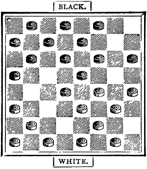
Black has now the choice of two moves. We will suppose that he defends his position by moving from 9 to 14.
The first double column gives the moves from the position in the diagram; six moves on each side having been made. The other columns show six variations. The star indicates the losing move in each case.
| 12 | 26 | * | 22 | 25 | 22 | ||||||||||||||||
| 13 | 9 | - | 14 | 9 | - | 14 | 18 | - | 25 | ||||||||||||
| 14 | 31 | 26 | 31 | - | 26 | 29 | 22 | ||||||||||||||
| 15 | 6 | - | 9 | 5 | - | 9 | 9 | - | 14 | ||||||||||||
| 16 | 13 | 6 | 26 | 23 | 27 | 23 | |||||||||||||||
| 17 | 2 | - | 9 | 1 | - | 5 | 6 | - | 9 | ||||||||||||
| 18 | 26 | 22 | 22 | 17 | 13 | 6 | |||||||||||||||
| 19 | 1 | - | 6 | 11 | 16 | 2 | - | 9 | |||||||||||||
| 20 | 32 | 28 | 20 | 11 | 22 | 17 | |||||||||||||||
| 21 | 3 | - | 8 | 7 | - | 16 | 15 | 18 | .. | .. | 9 | * | 13 | ||||||||
| 22 | 30 | 26 | 25 | 22 | 17 | 13 | 32 | 28 | 26 | 22 | |||||||||||
| 23 | 9 | - | 13 | 18 | - | 25 | 18 | - | 27 | 18 | - | 27 | 3 | - | 8 | .. | |||||
| 24 | 19 | 16 | 29 | 22 | 13 | 6 | 19 | 16 | 23 | 18 | |||||||||||
| 25 | 12 | - | 19 | 3 | - | 7 | 14 | - | 18 | 12 | - | 19 | 14 | - | 23 | ||||||
| 26 | 23 | 16 | 22 | 18 | 32 | 14 | 24 | 8 | 31 | - | 27 | ||||||||||
| 27 | 13 | - | 17 | 15 | - | 22 | 10 | - | 17 | 3 | - | 12 | 15 | - | 18 | 5 | * | 9 | |||
| 28 | 22 | 13 | 19 | 15 | 21 | 14 | 31 | 24 | 22 | 6 | 27 | 18 | |||||||||
| 29 | 8 | - | 12 | 10 | - | 28 | 1 | - | 17 | 9 | - | 13 | 13 | - | 22 | 1 | - | 5 | |||
| 30 | 24 | 19 | 17 | 3 | 26 | 22 | 26 | 22 | 27 | 18 | 30 | 26 | |||||||||
| 31 | 15 | - | 31 | 22 | - | 26 | 17 | - | 26 | 7 | - | 11 | 1 | - | 10 | 9 | - | 14 | |||
| 32 | 26 | 22 | 3 | 8 | 30 | * | 23 | 30 | * | 26 | 18 | 14 | 18 | 9 | |||||||
| 33 | 12 | - | 19 | 16 | - | 20 | 5 | - | 9 | 1 | - | 6 | 10 | - | 17 | 5 | - | 14 | |||
| 34 | 22 | 8 | 23 | 18 | 26 | 23 | 24 | * | 19 | 21 | 14 | 26 | 23 | ||||||||
| 35 | 14 | - | 17 | white wins. |
7 | - | 10 | 11 | - | 15 | 11 | - | 15 | 15 | - | 18 | |||||
| 36 | 21 | 14 | 31 | 26 | 24 | 19 | 28 | 24 | white wins. |
22 | 6 | ||||||||||
| 37 | 10 | 17 | 9 | - | 13 | 15 | - | 24 | 15 | - | 18 | 13 | - | 22 | |||||||
| 38 | 8 | 3 | 26 | 23 | 28 | 19 | 22 | 15 | 6 | 2 | |||||||||||
| 39 | 7 | - | 10 | 13 | - | 17 | 6 | - | 9 | 13 | - | 31 | 7 | - | 10 | ||||||
| 40 | 25 | 21 | 18 | 14 | 20 | 16 | 15 | 11 | 32 | 28 | |||||||||||
| 41 | 17 | - | 22 | 17 | - | 21 | 10 | - | 15 | 14 | - | 18 | 22 | - | 25 | ||||||
| 42 | 20 | 16 | 14 | 7 | 17 | 10 | 11 | 7 | 23 | 18 | |||||||||||
| 43 | 10 | - | 14 | 3 | - | 10 | 15 | - | 24 | 31 | - | 26 | 14 | - | 23 | ||||||
| 44 | 16 | 11 | 23 | 19 | 21 | 17 | 19 | 16 | |||||||||||||
| 45 | 31 | - | 26 | black wins. |
24 | - | 27 | 26 | - | 22 | |||||||||||
| 46 | 11 | 8 | 10 | 6 | 17 | 13 | white wins. |
||||||||||||||
| 27 | - | 31 | 18 | - | 23 | ||||||||||||||||
| 6 | 2 | 7 | 3 | ||||||||||||||||||
| draw. | black | black | |||||||||||||||||||
| wins. | wins. | ||||||||||||||||||||
If you play out these games carefully you will see that there is a reason for each move, and thus demonstrate that Draughts is a scientific game possessing no element of luck or chance.
The opening known as the Laird and Lady is a favourite with players north of the Tweed. Rare fine players at Draughts[194] are the Scotsmen. They carried the game across the Atlantic, where it is popularly known as Checquers, or, as the New Englanders spell it, Checkers.
The first two moves on each side in the Laird and Lady are the same as those in the Old Fourteenth.
| Black. | White. | |||||||
|---|---|---|---|---|---|---|---|---|
| 11 | to | 15 | — | 1 | — | 23 | to | 19 |
| 8 | to | 11 | — | 2 | — | 22 | to | 17 |
Then comes the variation which distinguishes it,
| 9 | to | 13 | — | 3 | — | 17 | to | 14 |
This Black follows on with a move which compels an exchange.
| 10 | to | 17 | — | 4 | — | 21 | to | 14 |
| 15 | to | 18 | — | 5 | — | 26 | to | 23 |
White’s last move supports the advanced man on square 14. Then Black proceeds with what at first sight seems a weak move:—
| 13 | to | 17 | — | 6 | — | 19 | to | 15 |
From this point the game is even, though the advantage would certainly seem to be on the side of the White. The following is the position at the point arrived at:—
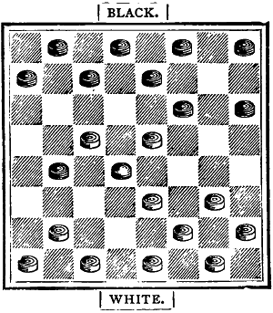
From this position there are almost endless variations. Drummond, a well-known writer and specialist, gives no fewer than thirty; and, generally, they end in favour of White, the second player—proving that this opening is hardly so good as the Old Fourteenth or the Single Corner, which may be considered the standard games of first-rate players.
We give the moves of a completed game in this opening, showing the moves from which the variations spring.
| Black. | White. | |||||||
|---|---|---|---|---|---|---|---|---|
| 11 | to | 15 | — | 1 | — | 23 | to | 19 |
| 8 | to | 11 | — | 2 | — | 22 | to | 17 |
| 9 | to | 13 | — | 3 | — | 17 | to | 14 |
| 10 | to | 17 | — | 4 | — | 21 | to | 14 |
| 6 | to | 10 | — | 5 | — | 25 | to | 21 |
| 10 | to | 17 | — | 6 | — | 21 | to | 14 |
| 15 | to | 18 | — | 7 | — | 29 | to | 25 |
| 11 | to | 16 | — | 8 | — | 19 | to | 15 |
| (or 1 to 6 | ||||||||
| 19 | to | 25 | ||||||
| 4 | to | 8 | ||||||
| 26 | to | 22, &c.) | ||||||
| 16 | to | 20 | — | 9 | — | 26 | to | 23 |
| (or 26 to 22) | ||||||||
| 1 | to | 6 | — | 10 | — | 31 | to | 26 |
| 13 | to | 17 | — | 11 | — | 15 | to | 10 |
| 6 | to | 15 | — | 12 | — | 23 | to | 19 |
| 4 | to | 8 | — | 13 | — | 19 | to | 10 |
| 8 | to | 11 | — | 14 | — | 24 | to | 19 |
| 11 | to | 16 | — | 15 | — | 26 | to | 22 |
| (or 11 to 15) | ||||||||
| 17 | to | 26 | — | 16 | — | 30 | to | 23 |
| 5 | to | 9 | — | 17 | — | 14 | to | 5 |
| 7 | to | 14 | — | 18 | — | 5 | to | 1 |
And White wins. Now try the variations indicated. Had Black at his fifteenth move gone from 11 to 15, the best he could have done would be to draw. See:—
| 11 | to | 15 | — | 15 | — | |||
| 12 | to | 19 | — | 16 | — | 19 | to | 16 |
| 20 | to | 27 | — | 17 | — | 27 | to | 24 |
| 7 | to | 11 | — | 18 | — | 32 | to | 16 |
| 2 | to | 11 | — | 19 | — | 16 | to | 7 |
| 18 | to | 25 | — | 20 | — | 25 | to | 22 |
| 15 | to | 18 | — | 21 | — | 30 | to | 21 |
| 11 | to | 16 | — | 22 | — | 10 | to | 6 |
And the game is drawn.
It may be useful, in this place, to give a
| Table of the Principal Openings. | |||||||||||||||
|---|---|---|---|---|---|---|---|---|---|---|---|---|---|---|---|
| Title. | 1st Move. |
2nd Move. |
3rd Move. |
4th Move. |
5th Move. |
||||||||||
| Double Corner | 9 | - | 14 | ||||||||||||
| Single Corner | 11 | - | 15 | 22 | - | 18 | |||||||||
| Ayrshire Lassie | 11 | - | 15 | 24 | - | 20 | |||||||||
| Second Double Corner | 11 | - | 15 | 24 | - | 19 | |||||||||
| Cross | 11 | - | 15 | 23 | - | 18 | |||||||||
| Whilter | 11 | - | 15 | 23 | - | 19 | 7 | - | 11 | ||||||
| Will o’ the Wisp | 11 | - | 15 | 23 | - | 19 | 9 | - | 13 | ||||||
| Dyke | 11 | - | 15 | 22 | - | 17 | 15 | - | 19 | ||||||
| Maid o’ the Mill | 11 | - | 15 | 22 | - | 17 | 15 | - | 18 | ||||||
| Defiance | 11 | - | 15 | 23 | - | 19 | 9 | - | 14 | 27 | - | 23 | |||
| Glasgow | 11 | - | 15 | 23 | - | 19 | 8 | - | 11 | 22 | - | 17 | 11 | - | 16 |
| Laird and Lady | 11 | - | 15 | 23 | - | 19 | 8 | - | 11 | 22 | - | 17 | 9 | - | 13 |
| Fife | 11 | - | 15 | 23 | - | 19 | 9 | - | 14 | 22 | - | 17 | 5 | - | 9 |
| Old Fourteenth | 11 | - | 15 | 23 | - | 19 | 8 | - | 11 | 22 | - | 17 | 4 | - | 8 |
Of these, some already named—Old Fourteenth, Laird and Lady, &c.—are the best for practice. We therefore present another set of games in the
As before, the key-game appears in the first double-column; and the variations spring from the point indicated. The moves are given consecutively; the first player going from 11 to 15; his opponent from 23 to 19, and so on to the end.
| GAME | 2 | 3 | 4 | 5 | 6 | 7 | |||||||||||||||
|---|---|---|---|---|---|---|---|---|---|---|---|---|---|---|---|---|---|---|---|---|---|
| 1 | 11 | - | 15 | ||||||||||||||||||
| 2 | 23 | 19 | |||||||||||||||||||
| 3 | 8 | - | 11 | ||||||||||||||||||
| 4 | 22 | - | 17 | ||||||||||||||||||
| 5 | 4 | - | 8 | ||||||||||||||||||
| 6 | 17 | 13 | 25 | 22 | |||||||||||||||||
| 7 | 15 | - | 18 | 15 | - | 18 | |||||||||||||||
| 8 | 24 | - | 20 | 22 | 15 | ||||||||||||||||
| 9 | 11 | - | 15 | 11 | - | 18 | |||||||||||||||
| 10 | 28 | 24 | 17 | 13 | |||||||||||||||||
| 11 | 8 | - | 11 | 7 | - | 11 | 9 | - | 14 | ||||||||||||
| 12 | 26 | 23 | 24 | 20 | 29 | 25 | |||||||||||||||
| 13 | 9 | - | 14 | 10 | * | 14 | 3 | * | 7 | 10 | - | 25 | |||||||||
| 14 | 31 | 26 | 29 | 25 | 29 | 25 | 19 | 10 | |||||||||||||
| 15 | 6 | - | 9 | 2 | - | 7 | 11 | - | 15 | 6 | - | 15 | |||||||||
| 16 | 13 | 6 | 26 | 23 | 26 | 23 | 26 | 23 | |||||||||||||
| 17 | 2 | - | 9 | 7 | - | 10 | 15 | - | 24 | 8 | - | 11 | |||||||||
| 18 | 26 | 22 | 21 | 17 | 20 | 19 | 30 | 26 | |||||||||||||
| 19 | 1 | - | 6 | 14 | - | 21 | 9 | - | 14 | 10 | * | 14 | 11 | * | 16 | ||||||
| 20 | 32 | 28 | 23 | 7 | 32 | 28 | 30 | 26 | 24 | 20 | |||||||||||
| 21 | 3 | - | 8 | 3 | - | 10 | 6 | - | 9 | 7 | - | 11 | 1 | - | 6 | 7 | * | 11 | |||
| 22 | 30 | 26 | 25 | 22 | 13 | 6 | 19 | 15 | 20 | 11 | 28 | 24 | |||||||||
| 23 | 9 | - | 13 | 9 | - | 14 | 2 | - | 9 | 2 | - | 7 | 7 | - | 16 | 3 | - | 7 | 2 | * | 6 |
| 24 | 19 | 16 | 22 | 17 | 30 | 26 | 26 | 22 | 26 | 22 | 24 | 19 | 24 | 19 | |||||||
| 25 | 12 | - | 19 | 11 | - | 15 | 1 | - | 6 | 12 | - | 16 | 2 | - | 7 | 15 | - | 24 | 15 | - | 24 |
| 26 | 23 | 16 | 27 | 23 | 26 | 22 | 22 | 17 | 22 | 17 | 26 | 22 | 26 | 22 | |||||||
| 27 | 13 | - | 17 | 15 | - | 24 | 7 | - | 11 | 7 | - | 10 | 7 | - | 10 | 11 | - | 15 | 11 | - | 15 |
| 28 | 22 | 13 | 28 | 19 | 22 | 15 | 32 | 28 | 23 | 19 | 20 | 11 | 20 | 11 | |||||||
| 29 | 8 | - | 12 | 8 | - | 11 | 11 | - | 18 | 10 | - | 26 | 16 | - | 23 | 7 | - | 16 | 24 | - | 28 |
| 30 | 24 | 19 | 31 | 26 | 31 | 26 | 31 | 15 | 25 | 22 | 27 | 11 | 11 | 8 | |||||||
| 31 | 15 | - | 31 | 11 | - | 15 | 9 | - | 13 | 11 | - | 18 | 18 | - | 25 | 8 | - | 27 | 12 | - | 16 |
| 32 | 26 | 22 | 32 | 28 | 26 | 22 | 17 | 10 | 27 | 2 | 32 | 23 | 22 | 17 | |||||||
| 33 | 12 | - | 19 | 3 | - | 12 | |||||||||||||||
| 34 | 22 | 8 | white wins. |
white wins. |
white wins. |
white wins. |
white wins. |
17 | 10 | ||||||||||||
| 35 | 14 | - | 17 | ||||||||||||||||||
| 36 | 21 | 14 | white wins. |
||||||||||||||||||
| 37 | 10 | - | 17 | ||||||||||||||||||
| 38 | 8 | 3 | |||||||||||||||||||
| 39 | 7 | - | 10 | ||||||||||||||||||
| 40 | 25 | 21 | |||||||||||||||||||
| 41 | 17 | - | 22 | ||||||||||||||||||
| 42 | 20 | 16 | |||||||||||||||||||
| 43 | 10 | - | 14 | ||||||||||||||||||
| 44 | 16 | 11 | |||||||||||||||||||
| 45 | 31 | - | 26 | ||||||||||||||||||
| 46 | 11 | - | 18 | ||||||||||||||||||
| draw. | |||||||||||||||||||||
As in the previous examples, the asterisk[196] shows the losing move. Young players should get this opening by heart. In the first game, you see, all that White can do is to draw; in the others he wins.
This a good and sound opening. Properly conducted, it gives the win to the first player. As in the Old Fourteenth and the Laird and Lady, the first move is from square 11 to square 15. The variation occurs in the second move, which is 22 to 18 instead of 22 to 19. Thus—
| 11 | to | 15 | — | 1 | — | 22 | to | 18 |
| 15 | to | 22 | — | 2 | — | 25 | to | 18 |
| 8 | to | 11 | — | 3 | — | 29 | to | 25 |
| 10 | to | 15 | — | 4 | — | 25 | to | 22 |
| 4 | to | 8 | — | 5 | — | 24 | to | 20 |
| 12 | to | 16 | — | 6 | — | 21 | to | 17 |
The position of the men is now as follows, without any great advantage on either side, with Black to move:—
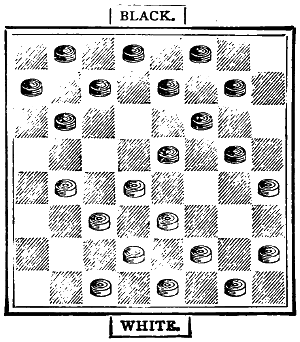
It will be well for the students to play out the game from this position.
Now let us take some variations most usual in this opening. The first game is played from the initial move, and the variations from the places marked. It will be easy for any two players with the Numbered Board before them to follow the moves.
| GAME | 2 | 3 | 4 | 5 | 6 | 7 | |||||||||||||||
|---|---|---|---|---|---|---|---|---|---|---|---|---|---|---|---|---|---|---|---|---|---|
| 1 | 11 | - | 15 | ||||||||||||||||||
| 2 | 22 | 18 | |||||||||||||||||||
| 3 | 15 | - | 22 | ||||||||||||||||||
| 4 | 25 | 18 | |||||||||||||||||||
| 5 | 8 | - | 11 | ||||||||||||||||||
| 6 | 29 | 25 | 10 | - | 14 | 9 | - | 13 | 9 | - | 14 | ||||||||||
| 7 | 4 | - | 8 | 24 | 19 | 24 | 19 | 24 | 20 | 18 | 9 | ||||||||||
| 8 | 25 | 22 | 16 | - | 20 | 11 | - | 16 | 1? | - | 16 | 5 | - | 14 | |||||||
| 9 | 12 | - | 16 | 11 | - | 16 | 28 | * | 24 | 27 | 24 | 27 | 24 | 24 | 19 | ||||||
| 10 | 24 | 20 | 24 | 20 | 7 | - | 11 | 16 | - | 20 | 8 | - | 12 | 11 | - | 15 | |||||
| 11 | 8 | - | 12 | 8 | - | 11 | 30 | 25 | 31 | 27 | 24 | 19 | 19 | 16 | |||||||
| 12 | 27 | 24 | 27 | 24 | 11 | - | 16 | 7 | - | 10 | 10 | - | 15 | 12 | - | 19 | |||||
| 13 | 10 | - | 14 | 9 | - | 13 | 18 | 15 | 19 | 15 | 19 | 10 | 23 | 16 | |||||||
| 14 | 24 | 19 | 24 | 19 | 9 | - | 14 | 10 | - | 19 | 6 | - | 15 | 14 | - | 18 | |||||
| 15 | 7 | - | 10 | 5 | - | 9 | 22 | 18 | 24 | 15 | 31 | 27 | 21 | 17 | |||||||
| 16 | 32 | 27 | 28 | 24 | 3 | - | 7 | 6 | - | 10 | 7 | - | 10 | 18 | - | 25 | |||||
| 17 | 9 | - | 13 | 10 | - | 15 | 18 | 9 | 15 | 6 | 27 | 24 | 30 | 21 | |||||||
| 18 | 18 | 9 | 19 | 10 | 5 | - | 14 | 1 | - | 10 | 2 | - | 7 | 6 | - | 9 | |||||
| 19 | 5 | - | 14 | 6 | - | 15 | 26 | 22 | 23 | 19 | 24 | 19 | 16 | 12 | |||||||
| 20 | 22 | 18 | 32 | 28 | 14 | - | 18 | 14 | - | 23 | 15 | - | 24 | 9 | - | 14 | |||||
| 21 | 1 | - | 5 | 16 | - | 19 | 23 | 14 | 27 | 18 | 28 | 19 | 27 | 23 | |||||||
| 22 | 18 | 9 | 23 | 16 | 16 | - | 23 | 8 | - | 11 | 10 | * | 14 | 8 | - | 12 | |||||
| 23 | 5 | - | 14 | 12 | - | 19 | 27 | 18 | 22 | 17 | 18 | 9 | 32 | 27 | |||||||
| 24 | 26 | 22 | 26 | 23 | 20 | - | 27 | 9 | - | 14 | 5 | - | 14 | 15 | - | 18 | |||||
| 25 | 13 | - | 17 | 19 | - | 26 | 32 | 23 | 18 | 9 | 22 | 18 | 17 | 13 | |||||||
| 26 | 22 | 13 | 30 | 23 | 10 | - | 26 | 5 | - | 14 | 1 | - | 5 | 1 | - | 6 | |||||
| 27 | 14 | - | 18 | 1 | - | 5 | 17 | 13 | 18 | 9 | 28 | 24 | |||||||||
| 28 | 23 | 7 | 24 | 19 | black wins. |
2 | - | 6 | 5 | - | 14 | 11 | - | 15 | |||||||
| 29 | 16 | - | 32 | 15 | - | 24 | 26 | 22 | 19 | 15 | 23 | 19 | |||||||||
| 30 | 30 | 26 | 28 | 19 | 20 | - | 24 | 11 | - | 27 | 7 | - | 11 | ||||||||
| 31 | 3 | - | 10 | 7 | - | 10 | 30 | * | 26 | 20 | 2 | 26 | 23 | ||||||||
| 32 | 21 | 17 | 31 | 27 | 12 | - | 16 | 27 | - | 31 | 18 | - | 22 | ||||||||
| 33 | 11 | - | 15 | 2 | - | 7 | 19 | * | 16 | 19 | 12 | 26 | 22 | 21 | 17 | ||||||
| 34 | 26 | 23 | 19 | 16 | 10 | - | 14 | 11 | - | 16 | 12 | - | 16 | 14 | - | 21 | |||||
| 35 | 2 | - | 7 | 10 | - | 15 | 16 | 7 | 28 | 19 | 2 | 6 | 23 | 18 | |||||||
| 36 | 31 | 27 | 16 | 12 | 3 | - | 10 | 16 | - | 30 | 16 | - | 19 | 11 | - | 16 | |||||
| 37 | 7 | 10 | 20 | 16 | 32 | 27 | 6 | 9 | |||||||||||||
| 38 | Draw | 20 | * | 16 | 2 | - | 7 | 30 | - | 26 | 14 | - | 17 | black wins. |
|||||||
| 39 | 11 | - | 20 | 16 | * | 12 | 22 | 17 | 21 | 14 | |||||||||||
| 40 | 18 | 11 | 14 | - | 17 | 26 | - | 22 | 19 | - | 23 | ||||||||||
| 41 | 10 | - | 14 | 21 | 14 | 27 | 23 | 22 | 18 | ||||||||||||
| 42 | 22 | 18 | 10 | - | 26 | 22 | - | 18 | 31 | - | 26 | ||||||||||
| 43 | 13 | - | 17 | 31 | 22 | 23 | 19 | 18 | 15 | ||||||||||||
| 44 | 18 | 15 | 7 | - | 10 | 18 | - | 15 | 26 | - | 22 | ||||||||||
| 45 | 17 | - | 22 | 12 | 8 | 19 | 16 | 14 | 10 | ||||||||||||
| 46 | 15 | 10 | 10 | - | 14 | 3 | - | 7 | 22 | 18 | |||||||||||
| 22 | - | 26 | 12 | 8 | |||||||||||||||||
| 10 | 6 | black wins. |
15 | - | 11 | white wins. |
|||||||||||||||
| 26 | - | 31 | |||||||||||||||||||
| 6 | 1 | black wins. |
|||||||||||||||||||
| black wins. |
|||||||||||||||||||||
The asterisk, in each case, shows the losing move. These games, however, by no means exhaust the variations in the Single Corner Game.
This mode of opening the game was, and is, a favourite one with Scottish players. It is a strong and sound game for the Black, beginning, like the Old Fourteenth, the Single Corner, and the Laird and Lady, with the move from square 11 to square 15. Presuming that Black always commences, the first moves are:—
| Black. | White. | |||||||
|---|---|---|---|---|---|---|---|---|
| 11 | to | 15 | — | 1 | — | 23 | to | 19 |
| 8 | to | 11 | — | 2 | — | 22 | to | 19 |
| 11 | to | 16 | — | 3 | — | |||
This third move of the Black is the variation which gives the Glasgow its special character. The move 4 to 8 instead of 11 to 16 would have been the Old Fourteenth. White’s safest reply is—
| 24 | to | 20 | ||||||
| 16 | to | 23 | — | 4 | — | 27 | to | 17 |
Had White replied with 26 to 19, he would have lost by his opponent playing 10 to 14. As it is, Black’s next move is forced:—
| 7 | to | 16 | — | 5 | — | 20 | to | 11 |
| 3 | to | 7 | — | 6 | — | 25 | to | 22 |
From this point the game is even, though certainly Black has the best position for attack and defence. The situation is shown in the diagram:—
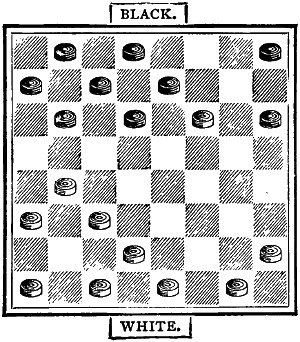
Black takes the man on square 11, which gives him a leading place on the board.
Instead of playing 25 to 22, many think that 28 to 24 is a better move. This, however, is open to question. Let us proceed with the game from the above point.
| 7 | to | 16 | — | 7 | — | 28 | to | 24 |
| 16 | to | 20 | — | 8 | — | 32 | to | 27 |
The last move of White gives him a certain advantage, but he must be careful not to move the man from square 24 to square 19, or Black by giving the man on 10 will win two for one. Black proceeds:—
| 12 | to | 16 | — | 9 | — | 30 | to | 25 |
If White had moved 27 to 23, he would have lost a man, for Black would have taken the piece on 24, and obliged his opponent to go from 31 to 24; and then, by moving into square 20, compelled White to go from 24 to 19, and have gained the exchange by giving the man on 10. Therefore 30 to 25 is the best.
| 4 | to | 8 | — | 10 | — | 26 | to | 23 | |
| 2 | to | 7 | — | 11 | — | 17 | to | 13 | 24 to 19 W. wins |
| 10 | to | 14 | — | 12 | — | 22 | to | 18 | |
| 7 | to | 11 | — | 13 | — | 24 | to | 19 | |
| 8 | to | 12 | — | 14 | — | 19 | to | 15 | 25 to 22 W. wins |
Black has now the choice of two moves.[198] Apparently he must lose a man, but by moving 16 to 19 he forces an exchange, which leaves him either even or a man ahead, according to White’s play. He moves from 16 to 19, and White may either take the man on 11 or the two men on 19 and 11.
| 16 | to | 19 | — | 15 | — | 23 | to | 7 | |
| 14 | to | 32 | — | 16 | — | 7 | to | 3 | |
| 20 | to | 24 | — | 17 | — | 15 | to | 11 | |
| 32 | to | 27 | — | 18 | — | 31 | to | 26 | |
| 24 | to | 28 | — | 19 | — | 11 | to | 7 | |
| 28 | to | 32 | — | 20 | — | 7 | to | 2 | |
| 12 | to | 16 | — | 21 | — | 3 | to | 8 | |
| 16 | to | 20 | — | 22 | — | 8 | to | 12 | |
| 27 | to | 24 | — | 23 | — | 12 | to | 16 | |
| 24 | to | 28 | — | 24 | — | 16 | to | 19 | |
| 32 | to | 27 | — | 25 | — | 26 | to | 22 | (forced, or Black gets the breeches and wins a man) |
| 27 | to | 24 | — | 26 | — | 19 | to | 23 | |
| 28 | to | 32 | — | 27 | — | 23 | to | 26 | |
| 24 | to | 27 | — | 28 | — | 26 | to | 23 | |
| 27 | to | 18 | — | 29 | — | 25 | to | 15 |
And the game assumes the following position:—
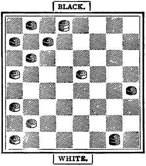
Which is to win? It is Black’s move.
This, like many others, is a modification of that best of all openings, the Old Fourteenth; the moves are—
| 11 | to | 15 | — | 1 | — | 23 | to | 19 |
| 7 | to | 11 | — | 2 | — | 22 | to | 17 |
This is the opening. It may proceed in many ways. The better, perhaps the best, plan is thus:—
| 9 | to | 14 | — | 3 | — | 25 | to | 22 |
| 11 | to | 16 | — | 4 | — | 26 | to | 23 |
| 5 | to | 9 | — | 5 | — | 17 | to | 13 |
Had Black moved 16 to 20, he would have lost a piece by his opponent playing 29 to 25—
| 3 | to | 7 | — | 6 | — | 29 | to | 25 |
which leaves the position thus:—
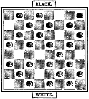
Black now usually plays from 1 to 5, and has a good sound strong game.
As a game for one player there is no superior to Solitaire. Apparently easy and simple, it is really intricate and scientific. Governed by a well-defined principle, chance forms no element of its practice. Like Chess and Draughts, it is entirely a mental and demonstrable game, full of variety, and affording ample scope, in its almost endless combinations, for the display of thought and ingenuity.
Solitaire is played on a board of thirty-three holes, in each of which a marble or glass ball is placed. Solitaire boards are made, but the game may be just as efficiently played on a properly marked piece of card-board, with draughtsmen or counters instead of marbles. This plan, indeed, is preferable to and cheaper than any other.
The method of play is as follows:—One marble is removed from its place, and then another is passed into the vacant hole. Take up the marble over which you jump, and continue to take piece after piece, always going in straight lines and never in diagonals, till you bring back the last marble from the hole whence the first was taken. One marble only can be taken at one jump; but, as in Draughts, you may proceed to play, and take, with the same marble, so long as there is a piece en prise with a vacant hole in the line behind it. The repetition of the figures will show the continued move of the piece.
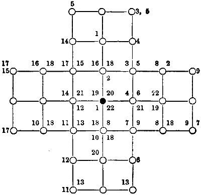
The Centre-hole Game.
There are other modes of playing Solitaire—as by indicating a special hole, distinct from the starting-place, in which to lodge the last marble, leaving two, three, or four marbles in a particular position, ending in the hole next the original one, and so on; but the above, the more usual plan, should be first learned. We will now give a diagram, and show you how to start from and return to the centre hole. Remove the centre marble. Jump from 1 in the upper limb to 1, the middle hole, taking 16-18. Go from 2 on the right limb of the diagram to 2 above the centre, taking 3-5. Proceed from hole to hole as indicated by the figures, and you will find that the last move will land the marble in the centre. Practise this till you can play[200] the Centre-hole Game without the use of the diagram. It looks easy enough; but just try it before you condemn Solitaire as mere child’s play.
Presuming you have familiarised yourselves with the principle of the game, I present another diagram:—
The Right-hand End Game.
Remove the marble from the upper right-hand corner hole and proceed as before, going from place to place, as shown by the figures on the diagram. Get this by heart, and play the game without the problem.
In this, one of the best positions, remove the left-hand upper marble, and play the game according to the plan in the diagram below. You will find this an easy game to remember.
The Left-hand End Game.
This may be altered by ending in any other hole. You should, however, thoroughly conquer the game as presented before you attempt any variation. It is not sufficient to play with the diagram before you. The problem is presented as a game to be learned, and once thoroughly learned, it is difficult to forget it.
The following is a pretty but somewhat[201] difficult position. It will be sufficient to give the diagram without remark other than this: Conquer it before you leave off, and do not be disheartened if you fail to succeed the first time you attempt it without the diagram.
The Upper Line Game.
You will understand that these positions given may be varied by starting from a similar place in either leg of the board. It is sufficient to mention this. To give players many variations would occupy too much space.
The Upper Centre-hole Game.
Here we have one of the most difficult and yet most interesting of positions. Proceed as before, taking care to learn the game so as to play without the numbered diagram. Remove the black marble.
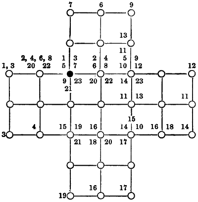
The Left-hand Upper Line Game.
Solitaire may also be played by two persons, the object of one of them being to defeat the other by contrary or opposite moves. Double Solitaire is, however, somewhat deficient in the one great element of all antagonistic games—variety.

I am not sure that this game was not played by the boys of ancient Greece and Rome; or perhaps even by boys in a yet earlier age of the world. At any rate, it is a very, very old game, of whose origin nothing whatever is known. Under these circumstances, it would be easy to gossip on for a page or two, and talk about anything likely to seem interesting; but it is pleasanter, and much more practical, to tell you how, with the assistance of our Solitaire-board, and some draughtsmen or counters of wood, bone, or metal, you may play it yourselves.
For Fox and Geese you need seventeen counters of one colour, to represent the Geese, and one counter of a different colour for the Fox. You prepare the board thus: place the Fox in the middle and the Geese in front, as in the diagram below.
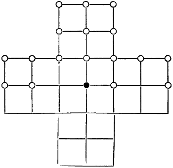
THE BOARD WITH THE PIECES SET FOR THE GAME.
Like Chess and Draughts, it is purely a game of strategy for two players. The usual plan is for each player to take the initiative in turn, the Fox in one game and the Geese in another. Unlike card games, it contains no element of chance or ‘luck.’
The whole motive of the game is for the Fox to catch the Geese, or for the Geese to drive the Fox into a corner from which he cannot escape. Properly played, the Geese, with the first move, must always win; but in this game, as in real life, the more cunning creature is not seldom successful.
The plan of the game is this. The Geese march forward only in straight lines, down or across; the Fox can move forward, backward, or sideways on the straight lines, not the diagonals. The Fox takes any Goose that may be en prise with a vacant space behind, as in Draughts; and so long as he can take, he continues his move. When he succeeds in following up and catching all the Geese, one after another, he wins. But the Geese, if they only go boldly to work, can drive him away. They must go forward as a phalanx with determination, filling each vacant spot, and leaving no loophole into which the enemy can jump or creep. All depends on united and determined action. United they conquer; separated they fall. When their number is reduced to six, it is impossible for them to confine the Fox. But there is no reason why it should be so reduced. Look at the diagram. If we call the upper left-[203]hand spot 1, and number the board horizontally to 33, at the lower right-hand corner, we shall soon see how the attack may be conducted. The Fox is in the centre; the Goose on either of the central junction lines can move without fear of capture, and the Fox must retreat. Having, say, moved 11 to 18, the Goose on 6 moves on to 11. The Fox is still without power to harm. The Geese proceed to go forward, and in this way ultimately force their enemy into a corner, or they may beguile him by offering a bait. Say the Goose on 15 moves to 16, the Fox must take him and lose his central position of attack. The Geese follow up their advantage; and, unless they commit some grievous error, they pin Master Reynard in a corner, whence he can by no means get out. The whole principle of the game is Advance. Go forward with the stronger force; fill up all vacancies. Directly a Goose moves on, back him up. Surround your enemy and compel him to retreat. As to the Fox, his tactics must be bold, yet cautious; determined, yet crafty; daring, yet subtle; adventurous, yet shrewd! Very like real life, is it not?
The game can be varied by placing the Fox on another spot; or by insisting on his catching all the Geese; by the latter taking the horizontal limits of the board only, or by offering odds, and so on; but the plan here given will be found ample in providing rational amusement for winter evenings. Less scientific, certainly, than Chess or Draughts, it affords abundant opportunities for thought and mental calculation.
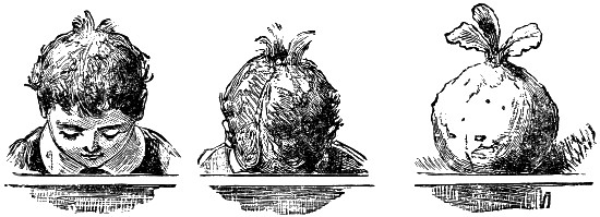
Singular transformation in a Boy who never used his Brains!
This game is of Japanese origin, and the name means Go = five, and Ban = board. It has, however, become gradually corrupted into ‘Go-bang,’ and thus it is now generally written.
In Japan it is played on a board of more than three hundred squares, but in Europe on boards of sixty-four squares (as in chess and draughts), or on larger boards. The Japanese have schools for the study and practice of the game, and divide the players into nine classes. A late account says that at present there is no player of the highest (the ninth) class living; but one of the eighth class, named Murase (in German spelling pronounced Moo-răh-sey), is editing a periodical, in which he publishes the theory of the openings, actual games, problems, poems, &c.
This game of Go (or game of five) is in China called Ki (= Kee), and was invented there about 2,000 years B.C. It is therefore older than chess. It was introduced into Japan about 1,100 years ago, and was there brought to higher perfection.
It is played by two persons. In Japan they use more than a hundred men on each side. If played on the chess-board, then generally one plays with twelve white men, the other with twelve black men. The aim of each player is to get five men in a line—i.e., five of his men close together in a straight line, either in row, a file, or a diagonal. In Japan each player tries to form a chain with his men around the others, etc.
The play is carried on thus:—The players decide as to first move; afterwards they begin alternately. The first player, say White, places a man on any of the sixty-four squares, then Black places a man on any of the remaining sixty-three squares: thereupon White puts down his second man on any unoccupied square, and so on until all the twenty-four men are placed. Now the moving begins. The first player moves one of his men to any of the next unoccupied squares, but must not leap over a man, and the second player proceeds in the same manner. So the play continues until one or the other succeeds in getting five men in a line.
Thus the play consists in placing and moving. If a player be not sufficiently attentive he can lose in the first part of the game. The moving may extend from two or three to any number, according to capacity of the players.
The game requires a great deal of watching, for the ‘Go,’ or ‘Five,’ can be made in any of four directions—horizontally, vertically, or on the right and left diagonals. There are eight lines for each of the two straight ways, and seven lines for each of the two diagonal ways; in all thirty lines. Four positions of the ‘five’ are possible in a row or a file, and as many in each of the longest diagonals, whilst the shortest diagonal permits of only one position, so that the number of all positions is 4 × 8 + 4 × 8 + 2 (4 + 3 + 3 + 2 + 2 + 1 + 1) = 96.
Many players prefer this game to draughts. It may also be played by four persons, taking partners as in ‘whist,’ when each player receives six men. Odds can be given in this game, a superior player having eleven against twelve men.
Whenever a player has three men in an open line the opponent must stop him, for should he get four, then the adversary could block him on only one end. This blocking, however, is not necessary if the second player can first make ‘five.’
The student will learn the method of playing from the games we shall give with explanations. The system of description is the International Chess Notation, as will be shown on the frame of the diagram to follow. The letters in brackets after the moves will refer to the explanatory notes.
The following two games were played between G. W. S. and H. F. L. M.:—
| White. | Black. | |||
|---|---|---|---|---|
| 1. | d4. | d5. | ||
| 2. | e4. | e5. | (i). | |
| 3. | f4. | c4. | (j). | |
| 4. | f5. | e6. | ||
| 5. | f7. | (k). | f6. | |
| 6. | g6. | d3. | ||
| 7. | g4. | h4. | ||
| 8. | g4. | g3. | ||
| 9. | e3. | d2. | ||
| 10. | c5. | f2. | (l). | |
| 11. | e2. | f3. | (m). | |
| 12. | b3. | g7. | (n). | |
The men are now placed as shown in this diagram:—
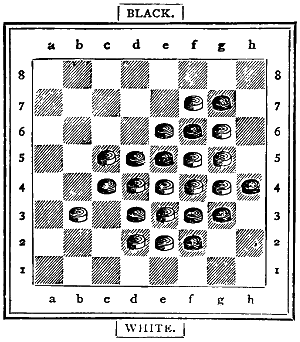
Now the moving begins:—
| White. | Black. | |
|---|---|---|
| 13. | b3 c3. | f2 e1 (o). |
| 14. | e2 f2. | d5 c6. |
| 15. | f2 e2 (p). | e1 d1. |
| 16. | c5 d5. | d1 c2. |
| 17. | d5 c5. | c2 b3. |
| 18. | f7 e7. | e5 d5. |
| 19. | e7 f7. | d2 c2 (q). |
| 20. | e2 d2. | g7 h6. |
| 21. | c3 b2. | c2 c1 (r). |
| 22. | g6 g7. | f6 g6. |
| 23. | g5 f6. | e6 e7. |
| 24. | g7 f8 = five. | |
Notes.
(i) Experience has shown that it is best to occupy the central squares, for the men then have the greatest freedom of action.
(j) This move is necessary, for if Black had placed the man on c5, White would have won by placing his next man on c4 or g4.
(k) He must block the line at a2 g8, just as well as Black must now block the f file.
(l) The last six moves were all forced for Black.
(m) A weak move, which places the black men awkwardly. He would have done better to place it on b3 in order to force the last white man to go to a2, and then Black could have placed his last on c3, and try to make a ‘five’ in the a5 e1 or the a6 f1 or the c file.
(n) Necessary, for if placed on b6 or a5, White would have won thus:—g6 g7, f6 g6, g5 f6, followed by g7 f8.
(o) Endeavouring to bring this man to the other side of the board.
(p) He is afraid of e1 e2.
(q) A bad move, for although he can block at h6, he can afterwards not stop the g or f file. Black should have tried to move from c6 to a2.
(r) Must. White now wins easily, even if e6 stood on e7, for g6 g7, e7 f8, f7 g8, f6 g6, f4 e5, g6 f6 (else f5 f6), f5 g6.
Between H. F. L. M. (White) and G. W. S. (Black).
| White. | Black. | |
|---|---|---|
| 1. | e4. | d5. |
| 2. | d3. | c4. |
| 3. | f5. | c2. |
| 4. | g6. | h7 (i). |
| 5. | e5. | e6. |
| 6. | b3. | e3. |
| 7. | d4. | c3. |
| 8. | c5. | f4. |
| 9. | d6. | d2. |
| 10. | g5. | e7. |
| 11. | g7. | e2. |
The position is now so interesting that we give it on a diagram.
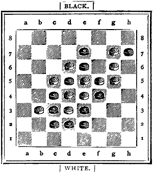
It appears at first sight that White might now place his last man on h8 and win. Black would then be obliged to place his last man on f6. White would continue f5 g4, and Black must answer h7 g8, and White would now win with e5 f5, followed by h8 h7, if Black could not play e7 f7 and come first in making ‘five’ in the diagonal a2 g8. To prevent these ‘five’ of Black, White would have to play g7 f7 (instead of e5 f5), and then Black would win easily by c3 b2, followed by e3 f2. White therefore must place his last man so that he can at once stop the approaching line of ‘five’ in the second row. He might place it on f2, but does better to put it on g3, and thus compel the last black man to go to g4. Therefore the game went on thus:
| White. | Black. | |
|---|---|---|
| 12. | g3. | g4. |
All the men are now well placed, and the moving can begin.
| 13. | g7 f7. | e3 f2. |
| 14. | b3 b2. | f4 f3. |
| 15. | g3 g2. | f2 g3. |
| 16. | g5 f4. | g3 h4. |
| 17. | g6 h5 (j). | g4 g5. |
| 18. | g2 g3 (k). | d5 c6. |
| 19. | h5 g4 (l). | f3 g2. |
| 20. | g4 f3. | e6 f6. |
| 21. | f7 e8. | e7 e6 (m). |
| 22. | e8 d7 (n). | e6 d5. |
| 23. | d7 c7 = five. |
Notes.
(i) These two moves of Black were compulsory.
(j) Must, because he cannot stop the line at d1.
(k) White now threatens to win by c5 c6 and on to c7.
(l) A good move to go on to h2.
(m) He ought to have played c6 d7, then the game might have proceeded thus: e8 d8, d7 c7; e4 d5, e7 d7; d6 c6, c4 b5; d3 c4, h4 g4; c5 b4, any; e5 e4 = five.
(n) There are now two lines for White, and only one can be stopped.
The third game between these two players had twenty-four moves, lasted about half an hour, and was won by the second player (M.). The fourth game lasted two hours, had seventy-five moves, and was won by the second player (S.).
Played between H. M. (White), and L. S. (Black).
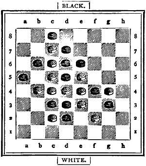
White to play, and win in five moves.
The white men are on the squares b4, c2, c4, c5, c6, c7, d4, e3, e4, e5, f2, and g4.
| White. | Black. | |
|---|---|---|
| 1. | g4—f3 | g3—g2 (a) |
| 2. | f3—e2 | d2—e1 |
| 3. | e3—d2 | a5—a4 (b) |
| 4. | b4—b3 | (any move). |
| 5. | b3—b2 = five. | |
Notes.
(a) He must prevent the man going from f3 over g2 to g1.—If he were to play g3—g4, White would answer e4—f5, and win in two more moves by making a ‘five’ in the diagonal a7 g1.
(b) Any other move would not prevent White from making ‘five’ in the second row, for Black must not move the man c3, as White would obtain ‘five’ (or even six) in the c file.
Nobody can very long reside in Madagascar, or in the central parts of it at any rate, without occasionally observing little companies of the natives bending eagerly over some mathematical-looking diagram rudely scratched on a roadside stone, or on the top of a rock, or, more roughly still, on the sun-baked clay of the wayside. If you look a little at the figure of the diagram, and consider the multiplicity of squares, diagonals, and adjacent parallelograms involved in it, you may think the people are discussing some Malagasy rider to one or other of the propositions in the Second Book of Euclid. Take the trouble to ask, however, and you will find that they are simply playing at their national game, the Fanòrona.
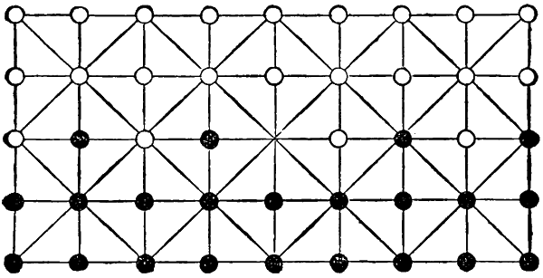
Diagram 1.
The fanòrona board is a rectangular parallelogram, divided into thirty-two equal spaces. Gather these, in your eye, into eight larger squares, containing four each; draw the diagonal lines in each of the eight, and the fanòrona figure is complete. Forty-four movable pieces are required for the game—twenty-two on each side.
With the Malagasy these are usually little pebbles and potsherds, or beans and berries. We, however, will call them the Black and the White pieces. The two players sit opposite each other, having the long sides of the fanòrona adjacent to them. The pieces are then arranged on the corners or angle-points; not on the squares, as in chess or draughts. There are five of these long lines on the board, each containing, of course, nine angle-points, and the pieces are thus arranged:
| Black: | First | Line | 1 | .. .. | 9 |
| Second | „ | 1 | .. .. | 9 | |
| White: | Fourth | „ | 1 | .. .. | 9 |
| Fifth | „ | 1 | .. .. | 9 |
The third, or central line, is occupied by the eight remaining pieces, placed alternately, thus:
| Black | 1, 3, 6, 8 |
| White | 2, 4, 7, 9 |
One point remains unoccupied, the central angle-point of the board, the fifth of the third line. This represents the royal seat in the public gatherings, but in the fanòrona game it is called the foibeny (‘navel’).
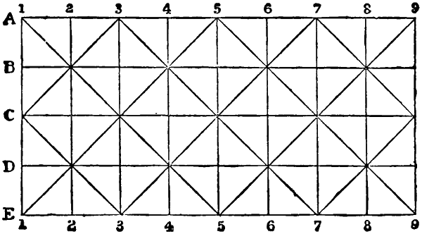
Diagram 2.
The object aimed at by each of the players is, as in draughts, to remove the whole of the adversary’s pieces from the board. But much caution is required, for we shall see that a few pieces well posted may easily annihilate more than four times their number in weaker situations; and, as in real warfare, even the very numbers of a force may sometimes prove their ruin. A few examples here will show the various ways in which the game may be opened, the manner in which the pieces are moved, and the adverse pieces captured. Let us suppose that the pieces are all placed, as just described above (see diagram 1). For convenience of description let the five lines on which the pieces are posted be called respectively A, B, C, D, E, instead of first line, second line, third line, etc. Any one of these letters, then, with a numeral appended, will be an easy reference to the piece that is to be moved, or to the vacant point to which a piece has to be removed, or to a hostile piece that has to be captured and removed from the board (see diagram 2). Then remember:
Firstly, that a piece may be moved in any direction,—forward, backwards, sideways, or diagonally to the first station in that direction, if such station be vacant.
Secondly, if there be now no other vacant station between the attacking piece just moved and the enemy’s pieces along that line, these, whatever their number, are captured at once, as far as they stand in unbroken order on the line attacked. If, however, a vacant position occurs in their line, or another hostile piece is among them, then only the piece or pieces nearest the assailant are captured.
Thirdly, the pieces of the enemy may be captured by a retreat as well as by an advance. A piece that has been standing in a station adjoining to some piece or pieces of the enemy may capture it or them by retreating one point along that line, if such point happen to be vacant. The limitation defined immediately above applies in this case also.
Fourthly, at the beginning of a game one move only is permitted to the first side. After that side has moved once, any piece that is moved is permitted to run amuck in the enemy’s lines, and go on as long as he finds foes to capture, provided (a) that he does not return immediately to[210] any point he has just left, and (b) he cannot take a foe behind him immediately after taking one in front of him, nor one on his right hand immediately after taking on his left hand, and vice versâ. ‘Don’t eat at both ends, like a leech,’ says the Malagasy proverb.
Let us suppose that White is going to move first at the commencement of a game. There is only one vacant point on the board into which he can move a piece, namely, the foibeny or central point, which we may term C5, as it is the fifth point of the third line. There are four white pieces, any one of which may be moved into the vacant post, those on C4, D4, D5, D6. If he advances D5 to C5, then he immediately captures Black’s pieces on B5 and A5. Black may now retaliate by withdrawing his piece on B6 to A5, thereby capturing White’s pieces on C7, D8, E9. White may now, in any one of several ways, inflict a series of severe strokes on the unfortunate Black. Thus, for example:
| D6, to | C7, | taking | B8, A9; then |
| „ | B6, | „ | A5; |
| „ | B5, | „ | B4, B3, B2, B1. |
Now the White piece must stop awhile, for although the Black piece at B7 is under his range, yet in taking it he would be transgressing the two laws mentioned above. He would have to return to B6, which he has just quitted, and he would be ‘eating at both ends like a leech,’ which is improper. But the Black piece on B7 may now very properly provide for his own safety and circumvent his assailant by advancing thus:
| B7, to | C7, | taking | D7, E7; then |
| „ | D6, | „ | E5; then |
| „ | D5, | „ | D4, D3, D2, D1; then |
| „ | E5, | „ | C5, B5. |
These moves are not given as examples of what the Malagasy would consider good play, but simply to show the modus operandi of the game.
If the game happens to terminate in a ‘draw,’ which is frequently the case, then the combat may be recommenced on the same terms, the other side now taking the first move. Should one of the players have been defeated, however, he is not allowed to play on the same footing as before, for the game must be altered in a kind of mocking condescension to his weakness. The new form of the game is called véla; the one who has conquered is the mpàmpihinam-béla (he who allows to graze at large). The defeated is hómam-béla (a poor sheep not to be molested for awhile in his pasture-ground). The véla game is opened by the vanquished, and the victor exposes such of his pieces as he chooses to surrender to his antagonist. These pieces may only be taken singly, and the generous conqueror refrains from taking any of his enemy’s pieces until he has parted with, one by one, seventeen of his own; then with the remaining five he begins his campaign against the undiminished forces of his antagonist. If he be a skilful player, however, he has managed meanwhile to occupy the fortress positions of the game, and the hosts of the enemy are probably huddled together in such situations that he will come down on them ‘like a wolf on the fold.’ If the hómam-béla is again defeated he is only allowed to play the véla form of the game until he has redeemed himself by a victory. Or he may choose to humiliate himself by openly confessing his inferiority, though, as one of my informants says, ‘few of the Malagasy are willing to do that.’ In ancient times grace was accorded to the beaten combatant on condition of his kneeling down before his conqueror and bleating like a sheep (mibàrarèoka), in confession of his weakness.
Here is a specimen of the véla game,[211] including the preliminary sacrificial moves by which Black gives up, one by one, the fated seventeen pieces. Then the time of reprisals comes, and the five survivors take the field, and give and take no quarter.
| Véla Game. | |||||||||||
|---|---|---|---|---|---|---|---|---|---|---|---|
| White. | Black. | ||||||||||
| 1. | C4 | to | C5 | takes | C6. | 1. | C3 | to | C4. | ||
| 2. | C5 | „ | C6 | „ | C4. | 2. | B4 | „ | C3. | ||
| 3. | D4 | „ | C5 | „ | B6. | 3. | A7 | „ | B6. | ||
| 4. | C5 | „ | B4 | „ | A3. | 4. | A8 | „ | A7. | ||
| 5. | D5 | „ | C5 | „ | B5. | 5. | A2 | „ | A3. | ||
| 6. | E5 | „ | D4 | „ | C3. | 6. | A9 | „ | A8. | ||
| 7. | C2 | „ | C3 | „ | C1. | 7. | A3 | „ | A2. | ||
| 8. | D2 | „ | C2 | „ | B2. | 8. | B1 | „ | B2. | ||
| 9. | B4 | „ | B5 | „ | B3. | 9. | A4 | „ | A3. | ||
| 10. | C3 | „ | B3 | „ | A3. | 10. | A2 | „ | A3. | ||
| 11. | D4 | „ | C3 | „ | B2. | 11. | A3 | „ | A2. | ||
| 12. | C2 | „ | B2 | „ | A2. | 12. | A8 | „ | A9. | ||
| 13. | B5 | „ | B4 | „ | B6. | 13. | A5 | „ | B6. | ||
| 14. | B4 | „ | B5 | „ | B6. | 14. | A7 | „ | B6. | ||
| 15. | B5 | „ | B4 | „ | B6. | 15. | B7 | „ | B6. | ||
| 16. | B4 | „ | B5 | „ | B6. | 16. | A9 | „ | A8. | ||
| 17. | C6 | „ | B6 | „ | A6. | 17. | Now begins Black’s attack. | ||||
| B8 | to | A7 | takes | C9; | |||||||
| „ | B7 | „ | C7, D7, E7. | ||||||||
| 18. | D9 | „ | C9 | „ | B9. | 18. | C8 | „ | B8 | „ | D1, E8. |
| „ | C7 | „ | D6; | ||||||||
| „ | D8 | „ | E9; | ||||||||
| „ | E7 | „ | C9; | ||||||||
| „ | D6 | „ | C5; | ||||||||
| „ | C6 | „ | E6; | ||||||||
| 19. | B6 | „ | A6 | „ | C6. | 19. | B7 | „ | B6 | „ | B5; |
| 20. | A6 | „ | A7 | „ | A8. | 20. | B6 | „ | C5 | „ | A7; |
| „ | C4 | „ | C3; | ||||||||
| „ | D4 | „ | E4; | ||||||||
| „ | C3 | „ | B2; | ||||||||
| „ | D2 | „ | E1; | ||||||||
| „ | C1 | „ | E3; | ||||||||
| „ | B1 | „ | D1; | ||||||||
| „ | B2 | „ | B3. | ||||||||
| 21. | D3 | „ | C3. | 21. | A1 | „ | A2. | ||||
| 22. | C3 | „ | D4 | „ | B2. | 22. | A2 | „ | A3. | ||
| 23. | E2 | „ | D2. | 23. | A3 | „ | B3. | ||||
| 24. | D2 | „ | C1 and wins. | ||||||||
These puzzles, known as the ‘Thirty-four Game’ and the ‘Fifteen Game,’ on their introduction amongst us some years ago, created general interest wherever tried. Both games are played on the same board. The ‘blocks’ may be readily made by any lad. They can be cut out of cork, wood, or other suitable material, and may be square or round in shape, the numerals being written on the upper side, thus—
Let us describe the ‘15’ game first. Place the blocks, numbered 1 to 15, on the board irregularly, and then, by sliding them about from square to square, but without removing them from the board, arrange them in the following order:—
This looks simple enough in theory, but to any uninitiated reader who may think it easy of accomplishment in practice, we need merely say, ‘Try it.’
The ‘34’ puzzle consists in arranging the blocks, numbered 1 to 16, so that they will add perpendicularly, horizontally, and from corner to corner; also in arranging the 4 in each corner, the four outside numbers of the two centre lines, and the four groups in each corner; in all, sixteen different ways, and each produce the same total—34.
The ‘15’ puzzle would appear to have been, on its coming to England a few years ago, strictly a new introduction, but the ‘34’ was not only tolerably well-known, but seems to have been familiar to the Arabs in the ninth century. The nature of the game we have already described.
Now a word on the ‘15’ game. A skilful writer has pointed out how, while with two figures only two different arrangements can be obtained, three figures can be placed in six different orders, viz.:—3 1 2—3 2 1; 1 3 2—2 3 1; 1 2 3—2 1 3. Then, while there are thus six different orders that can be produced with three figures, if a fourth figure be placed in every one of the four different positions with regard to these six orders, we shall have four times the different number of orders that can be had with three figures. In the same way by multiplying these twenty-four different orders by five we shall have the number to be obtained with five figures. The rule, therefore, to find the number of different orders that may be obtained with any number of figures is to multiply all the different numbers used by each other. Thus, with six figures there will be 720 different orders; with seven, 5,040; with eight, 40,320, and so forth until we come to fifteen, when it will be[213] found that the enormous number of 1,307,674,368,000 represents the different orders in which the fifteen numbers can be placed. This, of course, is the number of arrangements in which the cubes in the game of ‘15’ can be placed in the box. Let us consider how long it would take to test the solution of the different arrangements possible. Let us suppose that the cubes were worked to their consecutive or 15—14 order at the rate of one in every five minutes, which would, working day and night, be at the rate of about 105,000 arrangements a year. In this case it would take not less than twelve million years to test all the different arrangements!
The question now arises, whether out of this enormous number of different arrangements there are certain of them that cannot be shifted into the required consecutive order. The answer is, that exactly half of these arrangements are soluble, and the other half insoluble. The whole question turns upon the fact that in the arrangement of a certain number of figures in a row, otherwise than in consecutive order, the arrangement is made up either by an odd or an even number of transpositions. In the total number of different rows in which any given number of figures can be arranged, half of them will consist of rows containing an odd number, and the other half an even number of transpositions, just in the same way that in the numbers one to one hundred there are fifty odd and fifty even numbers. Take the case of six figures, 1, 2, 3, 4, 5, 6. If the first pair of figures is transposed the row will read 2, 1, 3, 4, 5, 6. In this row there is an odd number, namely, 1, of transpositions. If from this order the second pair is transposed the result will read 2, 1, 4, 3, 5, 6, and in this row there is an even number (2) of transpositions made from the original consecutive order. Suppose the last pair is transposed, the order will be 2, 1, 4, 3, 6, 5, and an odd number (3) of transpositions has been made. This may be continued until all the different rows possible have been worked, when it is evident that the first, third, fifth, etc., rows will each consist of an odd number of transpositions, while the intermediate rows will each contain an even number of transpositions.
Suppose we take the third row given above, 2, 1, 4, 3, 6, 5, this contains an odd number of transpositions. It is therefore impossible, by making an even number of transpositions each time, to bring 2, 1, 4, 3, 6, 5 to the original position of 1, 2, 3, 4, 5, 6, because it contains an odd number of transpositions, one of which will always remain, and cannot be eliminated by any even number of transpositions. Just in the same way we cannot, by the addition of even numbers, to any quantity or amount, to an odd number, produce an even number as the result. Every arrangement of a certain number of figures in a row contains therefore an odd or even number of transpositions which must be made before the figures can be brought into consecutive order, but it is immaterial whether these transpositions are made in such order as will the soonest produce the consecutive order, so long as they are made, and the number, whether odd or even, is noted.
By writing down a row of fifteen figures, and transposing two numbers each time, and noting whether an odd or even number of transpositions are required to produce the consecutive order, it can be ascertained whether the cubes, in this order, can or cannot be moved into the consecutive order. If the required number of transpositions is an odd number it will be impossible.
This is a good indoor game for boys, which I believe has not yet appeared in any form in England. It is a modification of one played by the students in Germany, but adapted to English words, and with a special arrangement of the figures, which the original game does not admit of, the words not being so suitable.
The above diagram is chalked on the floor, the figures being about one foot across and one foot apart. Then one player takes his place on the middle figure, facing Fig. 6. The other players then sing the old rhyme of the ‘Crooked Man’ to the ‘King Pippin Polka,’ known also as ‘My mother said,’ etc.
Then the player, with his feet together, jumps to No. 1, No. 2, etc., as the words ‘man,’ ‘mile,’ etc., are mentioned. He must not turn round, or put his feet outside the figures. The others keep time by clapping with their hands. If the player jumps to a wrong figure, or to one before it is sung, he pays a forfeit, especially for the last line.
The verse is then repeated to the second part of the tune, the player jumping to each figure before it is mentioned, and giving a second jump on it, before going to the next. The last line finishes off with a wild repetition of the figure, the player stepping from one figure to the next as fast as he can, finishing on No. 7 to the last word. The player must place both feet on Fig. 7 to the words ‘and they,’ then the right on Fig. 1, and so on, to the last one. The great difficulty in the last line is to get the left foot from Fig. 4 to Fig. 6 in time. This is done by passing the right foot behind the left, when moving it from Fig. 3 to Fig. 5, which will enable the player to finish without tying his legs in a knot. The words and the numbers of the figures for the player to jump to are here given (commencing on No. 7 and facing Fig. 6)—
The game is played with five bones, and the stages are as follows:—
1. Beginnings.—The five bones are gathered in the palm of the hand and thrown up, any number being caught on the back of the hand; they are then tossed up again, and caught in the palm. One is selected, thrown into the air, and one at a time the remainder picked up, while the one thrown is in the air. This must be caught and again thrown for the next bone. The bone thrown up is called the ‘dab,’ and must be caught clear, without touching any part of the person but the right hand under all circumstances of the game.
2. Ones.—The five bones are thrown on to the table, and the dab selected is thrown up, and the remainder are taken up, one by one, without touching any other bone.
3. Twos.—The same again, but two taken up for each throw of the dab.
4. Threes.—Three picked up, and then one.
5. Fours.—Four picked up.
In twos, threes, and fours, it is permitted by consent of the adversary to push the selected bones together while the dab is in the air. The touching of any other than the selected bones, or the failure to pick up the proper number, forfeits the turn.
6. Short Spans.—Two bones are placed on the table, each side of the left hand, one pair close to the thumb, the other pair at the tip of the little finger. Each pair must be taken up separately, without any pushing together.
7. Long Spans.—A bone is placed at the extremities of the thumb and little finger, stretched out to the widest. Another pair is put in the same way about six inches farther on the table. These pairs must be taken up without any touching together: any bone displaced may be put back again three times; failure on the third trial forfeits the turn.
8. Creek Mouse.—The five bones are tossed from the palm, and any number caught on the back of the hand; all but one are shaken off; the remainder are then gathered into the palm, without disturbing the one on the back, which is then tossed and caught in the palm, with the others.
9. Second Creek Mouse.—The five bones are tossed from the palm as before, and one is retained on the back. The remainder are taken one between each finger and thumb, the one on the back is then tossed and caught in the extended palm.
10. Bridges.—The hand is laid on the back on the table, the bones held between the fingers are then dropped in a row on the table. An arch is formed with the first finger and thumb of the left hand at about six inches from the left-hand bone of the four. They are then one by one[216] pushed through this bridge; when all are through the left hand is removed, and the four are taken up at one sweep. No touching together is allowed.
11. Cracks.—The bones are thrown on the table, and the four picked up one by one; the dab in falling and being caught to make a distinct crack on the one picked up.
12. No Cracks.—Same as before, but the dab must be caught without touching the other bone. The slightest sound forfeits the turn.
13. Exchanges.—The four bones are laid at the corners of a square, a full span on each side. The first bone is picked up from the lower right-hand corner, and at the next throw is exchanged for the one above. This is exchanged for the one at the top left-hand corner, this for the lower left, and that is placed at the point of starting. The bones are then taken up in diagonal pairs.
14. Everlastings.—The whole of the bones are tossed from the palms, and any number caught on the back. These are tossed from the back and caught in the palm; and any that have fallen in the first toss have to be picked up while the whole of the others are in the air, so that at one moment there may be four dabs and one to pick up. This task, as the name implies, approaches the everlasting.
The game is an excellent one for exercising and developing that perfect sympathy between the eye and the hand which is certain to be of great service in after life.
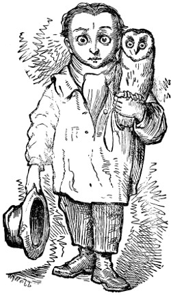
‘PLEASE, SIR, WILL YOU BUY AN OWL?’
1.—CONTEMPLATION.
2.—EXPECTATION.
3.—FRUSTRATION.
The magic-lantern is of very respectable antiquity. As early as the seventeenth century a Jesuit, named Kircher, had constructed one. He was not unwilling to excite the fears of the persons who witnessed the effects of his apparatus, and not only did he apply the word magic to his lantern, but when exhibiting it he had the darkened room divided into two compartments, in one of which was the lantern, and in the other the spectators. These gazed on the shadowy forms before them in amazement, and were unable to perceive how they were produced.
Kircher’s lantern consisted of a large wooden box, with a door on one side and an opening in front for the reception of a tube containing a magnifying lens. The light was obtained by means of an oil lamp with a polished brass reflector, the smoke of the lamp being conveyed away by a chimney in the top. The pictures exhibited were painted on long strips of glass, and were passed through a groove in the front tube, and although the effects thus obtained must have been of the most imperfect character, yet from their novelty they produced a most profound impression.
There are reasons to believe that the lantern was in use even earlier than the seventeenth century, and that the mysterious figures which the old astrologers produced in the smoke of their mystic fires were produced in the same way as Kircher’s, the smoke forming the screen. With this brief description of the history of the magic-lantern, we must be content. Our main business is to describe the construction and use of the lantern as manufactured now.
The magic-lantern, as now constructed, consists of a box or chamber of japanned tin-plate, with a lamp for the source of light, a large lens to converge the light, and a smaller lens to magnify the object to be exhibited. The large lens is called the condenser, and the smaller lens is designated the objective. Between the condenser and the objective, immediately in front of the former, an aperture is provided for the reception of the painted slide. This aperture is called the slide-holder. We may separate magic-lanterns into three great divisions, the distinguishing difference between them being the kind of light employed. In the first division the lamps are constructed to burn colza or sperm oil; in the second division a mineral oil (purified paraffin) takes the place of the sperm or colza oil; and in the third division some form of lime-light is employed. We will describe these varieties in order.
First, then, let us deal with the lanterns illuminated by a lamp burning colza or sperm oil. Of these lanterns there are two subdivisions, those whose condensing lenses are of a size suitable for exhibiting the standard slides (slides three and a quarter inches in diameter), called phantasmagoria lanterns, and lanterns of a smaller size, which may be described as toys, and for which but a very limited variety of slides can be obtained. We give an illustration (Fig. 1) of one of these small lanterns, from which it will be seen that the lamp is of very simple construction, and provided with a silvered reflector behind it. Magic-lanterns, the condensing lenses of which are from one and a half inch to two and a half inches in diameter, are calculated to produce discs of light from four feet to six feet in diameter. Such discs are usually obtained when the distance of the lantern from the screen is about one-third more than the desired diameter of the disc. Lanterns such as these are described, according to their size, by number, and include all from Nos. 1 to 6.
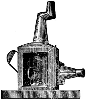
Fig. 1.
In preparing this lantern for use the lenses should be carefully cleaned with a soft cloth, and the lamp freshly trimmed. The cotton must be long enough to reach to the bottom of the lamp, and be freshly and evenly cut; the oil should be supplied to the lamp an hour before it is lighted, that the wick may become thoroughly saturated. The best oil to use is sperm oil in which camphor has been dissolved in the proportion of one ounce to one pint of oil. The object of the addition of the camphor is to increase the brilliancy of the light. If, however, sperm oil cannot be obtained, colza oil may be substituted, and this should be treated with camphor in the same way.
The room in which the exhibition is to take place should be entirely darkened, and a clean white screen or sheet hung up for the reception of the magnified pictures. The lantern is to be placed in front of the screen, upon a table or other suitable support, and at such a distance as will produce the required disc or circle of light.
The painted slide must be placed in the slide-holder upside down, and if the representation on the screen be not clear and sharp, the objective (the front lens) must be moved towards or away from the slide-holder, until the picture is well defined, or, as it is called, properly focused.
We have given a description of the simpler forms of the magic-lantern burning sperm or colza oil with a solid wick, and now we will explain the construction of that known as the phantasmagoria lantern. The term ‘phantasmagoria’ was originally applied to a lantern exhibition, in which the figures on the screen varied suddenly in their dimensions, seeming at one time as though they were rushing on to the spectators, and at another vanishing away in the distance. At present this name is used as the distinctive title of a particular form of magic-lantern, otherwise known as the ‘No. 8.’
In the phantasmagoria lantern the condenser consists of two lenses (usually a meniscus convex and a double convex) fitted into a brass cell and placed in the lantern with the concave side towards the lamp. The objective is also formed of two lenses fitted into a brass tube with a diaphragm in front. This tube slides into a brass jacket fixed in front of the lantern, and the lenses are placed in the tube with their convex sides towards the condenser.
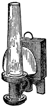
Fig. 2.
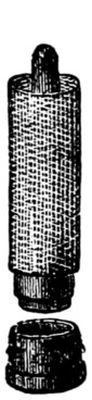
Fig. 3.
The lamp employed for illuminating the phantasmagoria lantern is the Argand fountain lamp, with hollow cylindrical wick (Fig. 2). In preparing this lamp for use, a new cotton should be fitted to it. To do this with facility the cotton should be put on to a taper-stick (Fig. 3), on to the base of which the brass wick-holder fits, the cotton can then be pushed on to the wick-holder without any difficulty. The wick-holder and wick are to be replaced in the lamp and screwed down to the bottom, and if there be any superfluous wick standing above the top of the lamp it is to be ignited and allowed to burn itself out. (This must be done before any oil is supplied to the lamp.) The wick being ready, the cistern at the back of the lamp is to be lifted out and inverted, and then filled with oil. The plug or valve which serves to close the orifice in the cistern through which the oil has been poured is to be pulled up and so held while the cistern is replaced in the lamp. The oil should be supplied to the lamp about half an hour before it is required for use, in order that the wick may be thoroughly saturated, and camphorated sperm oil is decidedly the best oil to be used in this lamp. When the lamp is first lighted the wick should be raised but a short distance above the tube that supports it, and after it is ignited all round, the lamp should be replaced in the lantern, the glass chimney (which is screwed on to a metal oxydator and gallery) placed on it, and the wick turned up as high as it will admit of without smoking. The lantern is then to be placed on the stand or table in front of the screen, at a distance of from nine to twelve feet off, a disc of six feet in diameter being obtained at the former distance, and eight feet diameter at the latter. After the lamp has been placed in the sliding tray provided for it at the bottom of the lantern, its position has to be adjusted. If the lamp be too near to the condenser, the centre of the disc will be darkened; if too far off, the margin of the disc will be obscured; the proper distance will be easily ascertained when the lamp is lighted and placed in the lantern.
The phantasmagoria lantern continued for some years to maintain its character as the best lamp-lit lantern ever made. And this might have still continued, but for the discovery that the art of photography could produce transparent slides suitable for the magic-lantern.
The necessity for a superior illuminating arrangement was at once experienced, and attention was given to the lamps that were fed with the mineral oils, instead of animal or vegetable oils. Although various forms of mineral oil lamps were tried, they were not successful, until Mr. L. Marcy, of Philadelphia, conceived the idea[222] of constructing a lantern sufficiently small to make one chamber serve as the lantern and the lamp. He used for his wick two flat cottons parallel to one another, with the tops almost in contact, and the edges of the wicks turned towards the condenser. This lamp he charged with mineral oil, and thus obtained an instrument surpassing anything of the kind previously constructed.
Since then many improvements have been made, each modification receiving a distinctive title. We have thus ‘The Silber Light,’ ‘The Triplexicon,’ ‘The Duplexicon,’ ‘The Refulgent,’ ‘The Euphaneron.’ It will not be necessary to explain each of them in detail, as they have many things in common, and it will suffice to describe ‘The Euphaneron,’ which is perhaps the best of the series.
The Euphaneron (that which shows well) differs in several important particulars from the phantasmagoria lantern. The body of the lantern (which serves to support the condenser and objective) is made of Russian plate iron, which neither rusts nor blisters. The condenser consists of two 4-in. lenses of the form we have already described, and the objective is a double achromatic combination. The outer lens of the objective, designated the ‘front lens,’ is in form a plano-convex lens. The inner lens, called the ‘back lens,’ consists of two separate lenses, one an unequi-convex lens, the other a meniscus-concave lens. This combination gives a beautifully-defined picture on the screen, with flatness of field and abundance of light.
The lamp is entirely distinct from the body, and will burn equally well either outside or inside the body of the lantern, the chimney being attached to the lamp and not to the body. The cistern of the lamp forms its base, and is filled with mineral oil. From the top of the cistern rise two rectangular tubes, sloping together as they rise; these contain the two wicks. The wicks do not stand parallel to each other, but form an acute angle with the base of the triangle towards the condenser, and this is the peculiarity that brings about the equal illumination of the disc. The wicks are raised and depressed by the action of two milled heads at the back of the lamp. Now, instead of surrounding the flames with a glass chimney, as is ordinarily the case, a metal combustion chamber is provided, and to this chamber the chimney is attached. The ends of the chamber are open, the front being closed by a glass plate, the back by a silvered reflector. Attempts have recently been made to add a third wick to this lamp, but they have not been very successful, the lantern being rendered very much hotter without affording a corresponding gain in brilliancy. The Euphaneron exhibits photographic slides in a most satisfactory manner on a disc 10 ft. in diameter. The disc is uniformly illuminated, and the picture well in focus all over the screen.
Directions for trimming the Euphaneron Lamp.—Remove the lamp from the lantern, carefully clean the front glass and the mirror. Turn back the combustion-chamber on its hinge, so as to expose the tops of the wicks. These should be cut quite smooth and straight, without any projecting filaments. The cistern should be nearly filled with the best mineral oil, and the wicks turned up a little way and lit. The combustion chamber should be now restored to its place, the lamp put into the lantern, and the chimney fixed on. The wicks should then be gradually raised as high as they will bear without smoking. In putting the oil into the lamp care should be taken not to spill any on the outside. The general directions already given for showing the pictures are then to be followed in using the Euphaneron.
The lanterns that we have hitherto been describing have been those capable of exhibiting single pictures only; we have now to explain the production of dissolving views.
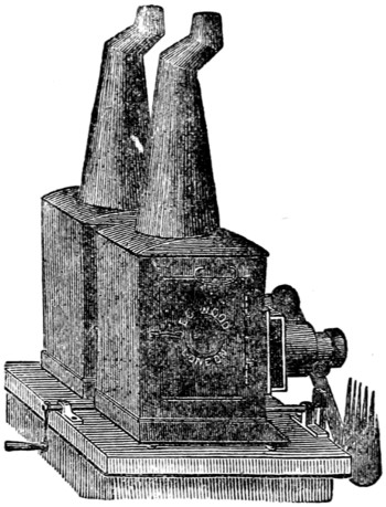
Fig. 4.
Dissolving views, as the name implies, is an exhibition of pictures in which there is a fading away of one and the appearance of another, as though the one picture grew out of the wreck of the other. To produce these results, two lanterns of similar size are required (see Fig. 4), together with some contrivance for diminishing the light forming the first picture, until that has quite faded away, simultaneously allowing that forming the second picture to fall upon the screen until this one has arrived at its complete intensity, and the first picture is no longer seen. This latter contrivance is known as the mechanical dissolver, and it consists of two serrated plates attached to a movable bar fixed to the front edge of the base upon which the lanterns are supported. These plates come immediately in front of the lanterns, and require to be so arranged that when the whole of the light from one lantern is seen on the screen, the light from the other is entirely stopped. By means of a rack and pinion motion, the plates can be moved simultaneously, and each lantern alternately closed and opened.
In order to make the discs of light produced by the two lanterns coincident, the lanterns must be slightly inclined towards each other.
There is another class of results obtained by the dissolving-views apparatus, which may be designated as the production of ‘composite’ pictures or ‘effects,’ as, for instance, a soldier is seen asleep by the watch-fire, he dreams, and the subjects of his dream appear, one after the other, on the screen, and then fade away. A ship is seen at sea; day turns into night; the moon rises; a violent storm comes on; the lightning flashes, and the ship is set on fire. A water-mill is shown with the stream running and the wheel revolving; a swan appears on the water and moves across the stream; night comes on, the wheel ceases to revolve, and the windows of the house are lit up; clouds flit across the sky; the moon rises—day returns, but the scene has changed to winter; the water is frozen, and its surface occupied by skaters, and a fall of snow takes place.
To produce such effects as these, both lanterns are required to be open at the same time, and the serrated plates forming the dissolver must be so contrived that the one which would otherwise obscure the fixed picture is turned aside, or removed altogether, and therefore only one lantern is alternately opened and closed. The foundation picture (the sleeping soldier, for example) is placed in[224] the lantern that remains constantly open, and to this the addition (the dream) are made with the second lantern.
For dissolving views proper, only two lanterns are required, and for the simpler form of effects two lanterns suffice; but for very complex pictures, three, four, or even five lanterns are required. Any two lanterns of equal size and power may be employed to produce dissolving views; but the phantasmagoria lantern is the smallest that can be advantageously used.
We have described the typical oil-lit lanterns, and now we shall explain the production of the lime-light in its two principal modifications of the ‘oxycalcium’ and the ‘oxyhydrogen’ light. The lime-light is obtained by intensely heating a piece of lime, in which condition it emits a most brilliant light. The lime is generally used in the form of a cylinder seven-eighths of an inch diameter and one and a quarter inch long, having a hole along its centre from end to end; these cylinders are sold in tin boxes, each containing twelve.
When a box containing lime cylinders has been opened, it is best to transfer the cylinders to a wide-mouth stoppered bottle, and keep the same in a dry place, as moisture causes the lime to crumble to dust. As the lime is only required to furnish some solid material capable of being rendered incandescent, many other substances can be used for this purpose—the best substitute, if lime cannot be obtained, being chalk.
The oxycalcium light requires for its production a large loose flame, a jet of oxygen gas, and a cylinder of lime. The two instruments now to be described—one known as the oxycalcium jet and the other as the oxycalcium lamp—fully realise these conditions, and although accomplishing the purpose in somewhat different ways, each form of instrument possesses some special advantage.
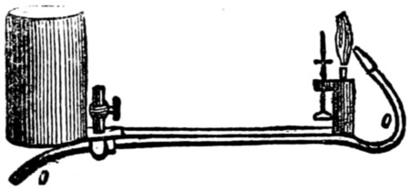
Fig. 5.
The oxycalcium lamp is represented at Fig. 5, and it consists of a vessel with an aperture in its base, is provided with a valve to close the same when needed, and is capable of holding about a half-pint of spirits of wine. This is called the cistern, and it is placed valve downwards into a second or outer cylinder rather deeper than itself. This operation opens the valve of the cistern, and allows a sufficiency of spirit to flow out so as to fill the space between the bottom of the cistern and the bottom of the outer cylinder. From this outer cylinder proceeds a long horizontal tube, terminating in a small chamber that holds the wick, and it is here that the lamp is lighted.
Behind the wick is a steel pin for holding the cylinder of lime, and in front of the wick is the small end of a bent tube (marked o o), carrying the oxygen gas. This oxygen gas tube passes along the under side of the tube connecting the outer cylinder with the wick chamber, and extending some little distance behind the[225] outer cylinder, there terminates in a tap. This tap is to be connected with the bag containing the oxygen gas by means of a flexible pipe.
In arranging the oxycalcium lamp for use the cistern should be filled with spirits of wine, and the wick cut off smooth. The lime cylinder is to be placed on the support, and the tap o connected with the bag containing the oxygen gas.
A weight equal to about 40 lb. or 50 lb. is to be placed on the bag, and the apparatus is ready for use. The lamp is to be lighted at the wick and the gas admitted by gradually turning the tap at the end of the tube o; the tap attached to the bag having been previously turned fully on. The oxygen gas now issues from the point of the tube in front of the flame and forces the flame against the lime, producing thus the oxycalcium light.
The quantity of gas admitted requires to be regulated to the size of the lamp flame, for if the gas be in excess, the lime will be cooled down and the light diminished. A similar loss of light will result from having too little gas; so that some attention will be required to enable the operator to adjust the apparatus satisfactorily.
The wick should be carefully put into the wick-holder in straight lengths, not twisted together, and not too tightly packed. A slight separation should be made in the top of the wick to allow the stream of gas to pass freely. The point of the jet should be about one-tenth of an inch below the top of the wick, and should not project into the wick. The wick should be kept up close to the point of the jet, and not be allowed to bend towards the lime cylinder.
The spirit to be used with the oxycalcium lamp is to be alcohol or the best methylated spirit; paraffin spirit will not do. It is best to renew the wick each time the lamp is used.
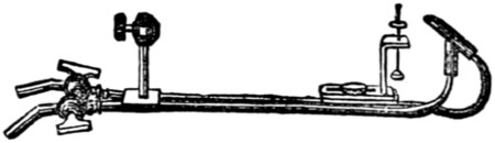
Fig. 6.
It is now necessary to describe the other form of oxycalcium light—the oxycalcium jet.
The oxycalcium jet is shown at Fig. 6, and it will be seen that the cistern and wick-holder required by the oxycalcium lamp are both dispensed with. There are, instead, two horizontal tubes lying side by side, each having a stopcock at one end, the other end of each tube being turned up, one—the hydrogen tube—at right angles and inserted into the stem of a sort of oblique T-shaped tube. The end of the other horizontal tube—the oxygen tube—is bent into a bow form, so that it may pass through the crosspiece of the oblique T-shaped tube before mentioned. The stopcock of the oxygen tube is to be connected with the bag containing the oxygen gas, and the stopcock of the hydrogen tube is to be attached by a flexible tube to any of the gas-fittings in the room where the apparatus is to be used. By this arrangement a stream of ordinary hydrogen or street gas will pass through the hydrogen tube into the oblique T-shaped tube, and will issue out at its open end, where it is to be lighted. This flame, by the action of the stream of oxygen issuing from the end of the oxygen tube, will be forced against the lime cylinder, and produce, as in the former case, the oxycalcium light. The same attention to the adjustment of the quantity of oxygen gas to the size of the hydrogen flame that was necessary for the oxycalcium lamp is equally needed with the oxycalcium jet, and by means of the two taps this can be managed with the greatest facility. It is usual[226] to drill a hole through the flat part of the key of the oxygen stopcock, so that it may be readily distinguished. It sometimes occurs that the gas-fittings from whence the supply of hydrogen is to be obtained have immovable nipples. In this case it will be found advantageous to connect, by means of a T-piece, two or even more of the nipples with the tube that is to convey the hydrogen to the jet; closing, of course, those that are not thus used.
It is obvious that in using the oxycalcium jet the operator is dependent for his flame upon a supply of the ordinary hydrogen or street gas, and therefore this modification of the oxycalcium apparatus cannot be employed in any place unprovided with the means of obtaining the same. The oxycalcium lamp, on the other hand, as it carries with it the means of producing the required flame, can be used anywhere. The light obtained by the oxycalcium arrangement, although not equal to the oxyhydrogen light, is admirably adapted for exhibitions on a moderate scale, and it requires only one gas-bag.
In both of the oxycalcium arrangements the lime cylinder does not need any alteration of position while in use. The proper distance between the oxygen jet and the surface of the lime varies from one-eighth of an inch to one-quarter of an inch.
Having explained the oxycalcium lamp and jet, we have now to describe the oxyhydrogen jet, by which the brightest form of lime-light is produced. The oxyhydrogen jet differs from those previously described in one important particular, viz. that the two gases are mingled together as gases before being ignited. Like the oxycalcium jet, it consists of two tubes lying side by side (see Fig. 7), having a tap at one end of each. The ends of these tubes are inserted into the base of a small chamber, from which proceeds a single curved tube, which rises up in front of the holder upon which the lime cylinder is placed. The end of this tube is contracted by a platinum point screwed into it, and this forms the jet. Two bags are required for this light, one containing hydrogen gas (common house gas will do), and the other bag filled with oxygen gas, and these bags are to be connected with the taps at the end of the jet by means of flexible tubes in the usual manner. The two gases are thus kept separate until they enter the chamber at the base of the curved pipe. This chamber is provided with layers of wire gauze, so as to facilitate the admixture of the gases, which eventually issue thoroughly mingled from the point of the jet. In this condition they are capable of being ignited, and as soon as the flame impinges on the lime cylinder a most intense light results.
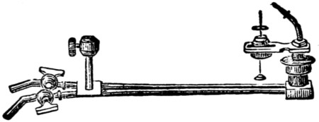
Fig. 7.
The lime-holder of the oxyhydrogen jet is made to slide, so as to be capable of being moved towards or away from the point of the jet. This adjustment is necessary to rectify any slight difference in the diameter of the lime cylinders, for, in order to obtain the full amount of light, the face of the lime cylinder requires to be brought as close to the point of the jet as it can be without being in contact with it. In addition to this movement, the stem on which the lime cylinder is supported is also made to revolve, in order to provide a fresh surface of lime to be presented to the[227] action of the flame. The heating power of the flame of the oxyhydrogen gases is so intense that a cavity is soon burnt in the face of the lime cylinder, and if this part of the cylinder were to be allowed to continue opposite to the jet, the light would be greatly diminished and the general effect marred. To provide against this, the stem of the lime-holder is made with a screw at its lower end, this screw working in a corresponding socket, so that by turning the stem of the lime-holder round on its axis a second motion in a perpendicular direction is also given to it. By this means the face of the lime passes before the point of the jet in a spiral direction, and consequently the same part of the lime cylinder is not brought a second time under the action of the flame. In order to facilitate the rotation of the lime cylinder, the screw is sometimes set in motion by clockwork; but the better plan is to turn the lime by means of a horizontal rod with bevel wheels.
Having described the various forms of apparatus constructed for producing the lime-light by means of oxygen and hydrogen gases, a few general observations will not be out of place. It should be borne in mind that oxygen gas is a supporter of combustion, and is neither explosive nor inflammable. The hydrogen gas will ignite, but will only do so in the presence of oxygen. With the oxycalcium lamp and oxycalcium jet, there is complete safety from explosion. In the oxyhydrogen jet there is also complete safety if care is taken not to fill up the hydrogen-bag with oxygen, and vice versâ. Such an admixture is explosive, and nothing can prevent an explosion when a light is applied. The contents of one bag will not pass into the other during an exhibition, and even if the weights were to fall off the bags, the only effect would be to put the light out.
Several times in describing the production of the lime-light reference has been made to gas-bags; and now we will explain more fully what they are. Gas-bags are usually made of stout india-rubber cloth, wedge-shaped, their length being half as much again as their width, and the base usually equal to their width. A tap is provided and attached to the apex of the bag, so as to allow of the admission and expulsion of the gas. In order to press out the gas from a filled bag, two boards are used. These boards are of similar dimensions to the bag, and being hinged together along one edge, can be separated to allow of the introduction of the inflated gas-bag. A projecting ledge is fixed on the outside of the upper board, about eight inches from its end, against which the weight required to press out the gas can rest. The weights should be square-shaped, and the most convenient size is a half-hundredweight. When two bags are required (as in the case of the oxyhydrogen light), the double pressure-board (Fig. 8) should be employed; the two bags are then placed one above the other, and one set of weights only is required instead of two sets. The[228] weight required to be used with a bag of eight feet capacity when employed for the oxycalcium lamp or jet should be about 56 lbs., but at least three times that amount should be placed on the bags for the production of the oxyhydrogen light.
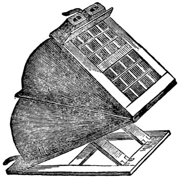
Fig. 8.
It is not desirable to keep either oxygen or hydrogen gas in india-rubber bags for any length of time. Oxygen can be kept for a few days or a week, but any hydrogen gas that may remain in the bag after an exhibition should be expelled before the bag is refilled. When two bags are in use, each should be marked; O on the oxygen bag, and H on the hydrogen bag; and the bags should not be used interchangeably; i.e., hydrogen gas should not be put into an oxygen bag, nor oxygen into the hydrogen bag. In arranging the apparatus, place the pressure boards and bags where they will not be meddled with. Let the weights be securely placed on the pressure boards, so that they may not slide or roll off during the exhibition. Do not on any account allow any one to stand upon or press the boards with his foot as a substitute for, or in addition to, the weights. The lime cylinder should be wiped clean from dust before it is put upon the holder, and it should be exposed to the flame of the lamp or simple hydrogen flame some minutes before the oxygen is turned on, so that it may not fracture when the light is being produced. When all arrangements are complete, the hydrogen should be turned on and lighted, and oxygen should be gradually turned on until the requisite degree of light is obtained. With the oxycalcium light some exhibitors use the compressed oxygen, the gas being compressed into an iron cylinder, and thus bags, boards, and weights are not needed. This arrangement has the advantage of portability, but the cylinders have to be filled by means of a steam pump—a thing not always to be obtained. When a cylinder is used it should be placed as close to the jet as possible, and the flow of gas must be regulated by the valve of the cylinder, and not by the tap of the jet.
The two gases, oxygen and hydrogen, required for the production of the lime-light need now some separate notice, as it often occurs that those who use these gases for dissolving-view exhibitions have to prepare the one—sometimes both—for themselves.
Oxygen gas is a simple elementary body, and is most extensively diffused throughout our earth. It is one of the constituents of the atmosphere surrounding our globe, and also of water, as well as of nearly all the substances known as acids. It has never yet been met in its separate or uncombined state, and therefore it can only be obtained by decomposing some substance of which it is a constituent.
The material most convenient for obtaining oxygen gas for lime-light purposes is chlorate of potassa. Two parts of this material (by weight) is mixed with one part of powered black oxide of manganese (this is known as ‘oxygen mixture’). The oxide of manganese does not supply any of the oxygen, but its presence facilitates the decomposition of the chlorate of potassa. The apparatus used for generating the gas is shown at Fig. 9. It consists of a copper or iron vessel (A), forming the retort or generator, a glass bottle-shaped vessel (B), which is the purifier, the two being connected together by a flexible tube. It will be seen that there are two tubes proceeding from the top of the purifier, one of which reaches nearly to the[229] bottom of the vessel, and the other only just enters into the top. The former, or long tube, is the tube by which the purifier is attached to the retort; the latter, or short tube, is that which connects the purifier with the bag.
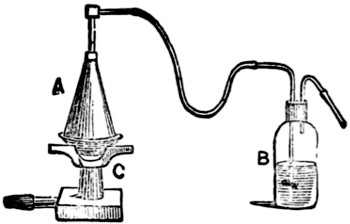
Fig. 9.
The method of charging the apparatus is as follows. Put into the retort about a pound and a half of oxygen mixture; pour into the purifier a sufficient quantity of water to about two-thirds fill it. Place the retort on a clear but not fierce fire, or over a gas furnace, and unite it to the long tube of the purifier (B). Attach the short pipe from the purifier to the gas-bag, and open all the taps, so that there may be a free passage-way from the retort to the bag. In a few minutes the gas will be given off, and will manifest itself by rising in bubbles through the water in the purifier. If a fierce fire be employed, the gas will be given off with undue rapidity and will pass through the purifier in volumes, so that it only becomes partially washed. A rapid but regular succession of gas is most to be desired. Should the gas come off with great violence, the retort should be lifted from the fire without disarranging the apparatus, and when the excessive rapidity is moderated it can be replaced. It is not, however, desirable to remove the retort from the fire if it can be avoided, for it not unfrequently happens that when the retort cools down, with only partially decomposed material in it, waste is the consequence, as it is not quite easy to re-establish the decomposing process. When the gas has entirely come off—which may be known by the cessation of the bubbles in the purifier—the top of the bag should be closed, the retort taken from the fire, detached from the purifier, and stood aside to cool. When cold, the residuum may be readily washed out with water, and when dry, the retort is ready for use again. The purifier should be emptied and washed out also. Always blow through the flexible tubes leading from the retort to the purifier, and wash out the metal tube of the retort in order to remove any solid material that may have been deposited there from the gas.
There has recently been manufactured a very neat oxygen gas-generator and gas-burner combined. The inventor proposes to prepare the oxygen in the room where the exhibition is taking place, and while using the lanterns. But as this apparatus would be very difficult to manipulate with, even by an experienced operator, it cannot be recommended for general use.
With regard to the hydrogen gas, it is always best to use the ordinary house gas, or if that cannot be obtained, to use the oxycalcium lamp, as the preparation of the pure hydrogen gas is troublesome, and not quite free from danger.
The preparation of magic-lantern slides for home use (although, perhaps, not equalling the bought ones in quality) is a great source of pleasure, and a few hints on this part of our subject will probably be acceptable. A number of very amusing slides may be made by cutting grotesque or other figures out of black paper, and pasting them on glass slips, and after the pictures are dry, giving a little detail by slashing the picture with a sharp penknife in places where needed. If these figures[230] be first drawn on tissue paper, coloured, and then cut out, the effect is still more pleasing. Or, if preferred, sheets of these figures in black can be bought, and thus the trouble of drawing them will be saved.
A very efficient set of astronomical slides may be constructed out of blackened cardboard with the aid of a few punches, some different-sized needles, and some of the coloured gelatine bon-bons. Having cut the card of a size suitable for the lantern, and marked on it a circle of the same diameter as the lantern condenser, prick holes in the card by aid of the needles, so as to represent the principal constellations and nebulæ, illustrations of which will be found in most works on astronomy. The relative positions of the planets may be shown by punching holes in the cardboard and covering them over with gelatine. When the holes are punched, the orbits may be traced by a very minute row of holes, pricked with a fine needle, the circles having first been marked with a pair of compasses.
For larger diagrams representing the planets singly, a sharp penknife and a pair of compasses would, combined with a steady hand, produce wonders.
The painting of magic-lantern slides on glass is a rather more difficult task, and some knowledge of the rules of the art of painting in general will be found most useful. The colours and brushes to be used are sold in boxes, and the number of colours can be readily increased by mixing. The following articles may be considered necessaries. Easel, glass to paint on, pencils, dabbers, etching-needles, fixing varnish, and the following colours: Blue, Nos. 1 and 2, crimson, amber, brown, mauve, black, light green, dark green, orange, purple, and scarlet. Having obtained these articles, proceed as follows. Make a drawing of the picture required, of the right size, on white paper, and place this under the glass upon which the picture is to be painted. The outline is then to be traced on the glass in Indian ink with a fine pen. This part of the work, however, can be dispensed with if the glasses be bought having pictures already outlined on them. If the subject of the picture be a landscape, the outlined glass is to be turned upside down, and the sky filled in first, commencing at the horizon with a pale tint, which is to be increased in density as the edge of the picture is approached. To remove any superfluous colour, a dabber is used.
When this colour has dried, the other parts of the picture are painted in succession with appropriate tints, warm tints being employed for the objects in the foreground, neutral or cool tints for the background.
This having been done, the picture has then to be coated with the fixing varnish, either using a brush or pouring it on as a photographer would do; or, when it has covered the surface, allowing it to run back into the bottle from one of the corners. The varnish is then allowed to dry, after which the picture is again to be examined, the shadows of the buildings and the trees are to be filled in, and the colour strengthened where the picture seems to need it. Snow and moonlight effects are produced chiefly by removing the colour in places by means of a knife and needle-point.
The rules given above apply also to the colouring of photographs for the magic lantern.
If you were to go to a shop to buy a lantern like the one I am going to describe, it would cost thirty-five shillings, but you will be able to make it for fourteen or fifteen. I will tell you what mine cost me, including the slides. The lantern cost me fifteen shillings.
| £ | s. | d. | |
|---|---|---|---|
| Lantern | 0 | 15 | 0 |
| Colours | 0 | 10 | 6 |
| Glass | 0 | 5 | 0 |
| Paper | 0 | 1 | 0 |
| Varnish | 0 | 1 | 0 |
| £1 | 12 | 6 |
With these colours and glass I have painted 250 slides, which to buy would cost two shillings each, and the cost of lantern and 250 slides would thus be:—
| £ | s. | d. | |
|---|---|---|---|
| Lantern | 1 | 16 | 0 |
| 250 slides at 2s. | 25 | 0 | 0 |
| 26 | 15 | 0 | |
| 1 | 12 | 6 | |
| £25 | 2 | 6 |
making a clear saving of £25.
Besides this, you have the double pleasure of making the lantern and painting the slides, and showing it as your own work. The picture shown by this lantern will be nine or ten feet in diameter, and will be large enough to show full-sized slides if you should at any time buy any. If you do buy, I should recommend the uncoloured photographs (1s. 6d. each), to be got at all shops where they sell lanterns. By making two of these lanterns you can use them for dissolving views, which is by far the best way to exhibit the slides. Many brilliant effects can be obtained with two lanterns that it would be impossible to do with a single lantern. I should certainly advise you to try this. Both lanterns can be made at the same time; the directions for one will do for both. But we must get on with our description.
First of all get a carpenter to cut you a deal board, free of knots, six feet six inches long, nine inches wide, and half an inch thick. This must be planed smooth on both sides. If you have a plane, do this yourself. Now with a fine saw cut four pieces off the board, each twelve inches long, and two pieces nine inches long.[232] These are to make the body of the lantern with. Take two of the long pieces and the two short pieces, and reduce the width to six inches. These will be the top, bottom, back, and front of the lantern. Now you must put the pieces together by dovetailing; or you had better get the carpenter to do this for you, as unless you are used to this work you would be sure to make a mess of it. Do not glue the pieces together yet. Take the piece of wood that is to serve for the top, and draw lines with a pencil from opposite corners, like Fig. 1. Now with a pair of compasses, open one inch and a half apart, put one point at the point where the two lines cross each other, and mark a circle with the other point. This circle must be cut out either with a keyhole saw or with a gouge, smoothing off with a rough file.
Fig. 1.
Fig. 3.
Fig. 2.
Now take the piece of wood that is to be used for the front of the lantern and draw a pencil line across it, two inches from the top end, and then cross the other part with pencil lines (Fig. 2), as you did the top, and with the compasses open an inch and three-quarters make a circle as before and cut it out. Now take the piece of wood to be used for the right side of the lantern and mark it thus (Fig. 3). Draw lines across each end two inches from the edges, and along the side one inch and a half from the edges. Cut out the middle portion evenly up to the lines. This will form the door, and if you have cut the piece out with a keyhole saw it will do to be fastened on with hinges. If not, you must make another piece for the door. Now, round the bottom of the two sides and back bore holes with a half-inch centrebit. These holes must be one inch and a half from the centre of the hole to the edge of the wood. Three in the back piece and four in each side will be enough. These holes are to supply air for the lamp. Now you will want some sheet tin to line the lantern with. This you must buy. Get two and a half sheets of thin, and two and a half of very stout. The thin will be threepence each, the stout sixpence each. Cut pieces from the thin tin to line the lantern with—two pieces eight inches by ten inches, two pieces five by eight, one piece five by ten, and one piece five by eleven. Punch holes all round each of these pieces. This can be done with the sharp end of a file. Put the tin in its place on the top, front, and right side, and mark on it, through the holes, their exact size, and cut the tin away a little larger than the holes. Now you can put the linings in their places and fasten on with small tacks. Those used by upholsterers are the best. The tin at sides, back, and front, is cut short, so as not to cover the holes at the bottom. The tin can be easily cut with a large pair of scissors. The door must be lined with tin. When all the parts are lined you[233] can glue the joints and put the body together, fastening with small brads. This can now be put on one side to dry and set firm, as we shall next set to work to make the stage and nozzle.
Before you can do so you must get your lenses and reflector. These will cost you more than any other part of the lantern twice over. The lenses will be 10s. 6d., and the reflector 2s. Ask for, or write for, a pair of lenses for No. 6A lantern, three and a half inches, and a four-inch reflector. First of all we must set the lenses. Take the largest, and cut a strip of thin tin half an inch wide, and long enough to go right round the lens and lap an eighth of an inch. The best way to measure this is with a piece of paper, cut into a strip and passed round the lens, and cut to the exact length of the circumference of it. Place this paper on your tin and cut the latter an eighth of an inch longer than the paper. You must now solder the ends of this strip of tin together to make a ring. To do this you must have a soldering bit, and as this is always useful you had better buy one.
Take a small piece of clean tin, put on it two or three drops of chloride of zinc, and in this put a small piece of solder. Put the bit in the fire to get hot—but not red-hot. When hot, rub the point with a file till it is bright, and put it on the solder, which will immediately flow and cover the point of the bit. This is called tinning the bit, and must always be done when the bit gets red-hot, as that burns off the tinning.
Put your bit in the fire to get hot, and while it is there bring the ends of the tin strip together so that they lap an eighth of an inch. Dip a camel-hair brush in the liquid and rub the joint between the lapping and an eighth of an inch outside. Put a small piece of solder at the top of the joint. Now if the bit be hot enough put it on the solder, and, as soon as it has melted it, draw it slowly along the joint, and the solder will flow after it and make a firm joint. In making joints like this, the parts of the tin lapping must touch each other closely. When the joint is cold, take a small hammer and turn in one edge all round a sixteenth of an inch. This will be easily done by gently tapping the edge with the hammer over a piece of wood, such as a toothpowder-box or ribbon-roller. In doing this you must be careful not to put the band out of the round. When this is done, put the lens inside, resting on the turned-in part. Now get a piece of brass wire a sixteenth of an inch thick, and about a quarter of an inch less in length than the tin strip was, and bend it into a ring, but do not fasten the ends together. Put the ring inside the band against the lens, and it will spring against the sides and hold the lens firmly in its place. This lens, with its setting, is to be placed inside the lantern in the large hole in the front of it, with the lens towards the back of the lantern.
Now we must set the other lens. Take a piece of the thin tin two and a half inches wide, and long enough to go round the lens and lap an eighth of an inch. In cutting this you must be careful to keep the sides and angles square, or it will not be true when made into a tube. Now get a roller for silks about an inch and a half thick and roll the tin round it to make a tube by bringing the shortest edges together. Be careful to make the tube nice and round and smooth; lap the edges an eighth of an inch, and solder them together as you did the other tube. Turn in one edge all round a sixteenth of an inch, put the lens inside, resting on the[234] turned-in part, and fix it with a wire ring. Now take a strip of tin an inch wide and long enough to go round this last tube and lap an eighth of an inch. Bring the edges together, lapping an eighth of an inch, and solder.
This is the tube to be fixed in the nozzle, for the front lens tube to slide in, to regulate the focus. Round this little tube, half an inch from the edge, mark a line.
 |
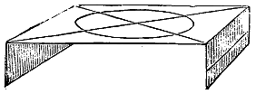 |
| Fig. 5. | |
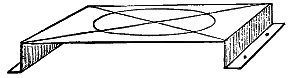 |
|
| Fig. 4. | Fig. 6. |
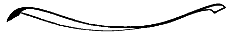 |
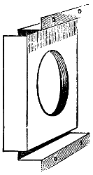 |
| Fig. 7. | |
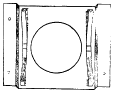 |
|
| Fig. 8. | Fig. 9. |
Now we will get on with the stage. For this you will use your stout tin. Take one of the plates and mark on it a piece five inches by eight, being very careful to make it quite square at the corners. Cut this piece of tin out. Now draw a line across each end at half an inch from the edge, and another line an inch and a half from the edge (Fig. 4). Cross the middle portion by lines drawn from opposite corners, and with your compasses mark a circle three inches and a half in diameter. Cut out this circular portion, being careful not to bend the plate; but if you do you must straighten it again with a piece of wood, bend the ends down along the inner line till they are at right angles with the other part of the plate (Fig. 5). Now bend the tin outwards along the other lines till it is at right angles to the other part (Fig. 6). Punch two holes about an eighth of an inch wide in each of the turned-out parts. These holes are to screw the stage to the lantern by. Next you must get two pieces of clock-spring about a quarter of an inch wide and four inches and seven-eighths long. Bend them into bows about an inch high, and turn the ends outwards a little (Fig. 7). Solder these into the inside of the stage by the middle at the top and bottom of the hole (Fig. 8). Cut another piece of tin seven inches and seven-eighths by seven inches and a quarter, and cut a circular hole in the middle four inches in diameter. Mark a line across each end an inch and an eighth from the edge, and bend the plate at right angles at each end.[235] This is to make the spring clip to hold the slides; it is put inside the stage, resting on the springs, and with the turned-out parts outside (Fig. 9).
In cutting the tin for the next part, you must be careful to keep the sides and angles square; also in bending it into a tube and soldering it. Mark out on your tin plate (stout tin) a piece eleven and a quarter inches long and four and one-eighth inches wide, turn this into a tube by bringing the shortest edges together round a bottle, lap them a quarter of an inch, and solder the joint; now very carefully turn out one edge all round, one-eighth of an inch, being careful not to disturb the round. This can be done against the edge of a flat-iron by gently tapping with your small hammer. Cut out a circular piece of tin three inches and a half in diameter, and in the centre cut out a circular hole exactly the size of the small tube the lens-tube slides in; pass this tube half way through this hole, and solder it in, being careful that it is squarely in; now put this piece into the end of the large tube, not the turned-out end, so that the side that is soldered is inwards, and solder this on the inside of the tube. Next solder this tube, which is the nozzle of the lantern, on to the outside of the stage, being careful that the holes in the stage and tube correspond. You had better strengthen the stage by soldering corner pieces in where the turn-out parts are (Fig. 10). Now the stage and nozzle is ready to be screwed into its place on the front of the lantern, being careful that the centre of the holes are all in the same straight line; but before screwing it on, all the tin visible must be blackened with dull black paint, which I will tell you how to make at the end of this section. The inside of the lantern must also be painted with this black paint, as well as the inside of the front lens-tube. In this tube there must be what is called a diaphragm. To make this, take a piece of thin tin an inch and a quarter wide, and long enough to go round the inside of the lens-tube; solder the edges together, and close the end with a circular piece of tin with a circular hole in the middle of it a little less than half an inch in diameter. Blacken this and push it into the tube, so that the little hole is about half-way in. The lens-tube is to be pushed into the nozzle with the lens inside. To make the chimney, take a piece of tin six inches wide and nine inches and three-quarters long, bend it into a tube, and lap a full eighth of an inch; solder up the joint; then cut four notches in the top about three-quarters of an inch deep (Fig. 11).
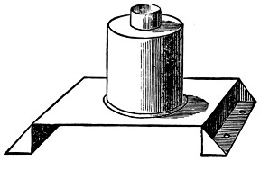
Fig. 10.
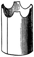
Fig. 11.
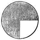
Fig. 12.
Now mark on a piece of tin a circle four inches and a quarter radius, or eight and a half inches wide; cut this circle out. Now cut out a quarter of the circle (Fig. 12), bring the cut edges together, lap them a little, and solder the joint, so that[236] it makes a small tin cone (Fig. 13). Put this on to the four points on the top of the chimney-tube, and solder those points into it securely, and your chimney will be finished and look like Fig. 14. This must be pushed into the hole at the top of the lantern.
Fig. 13.
Fig. 14.
Fig. 15.
Fig. 16.
Now for the lamp, and your lantern will be finished. You had better make this, as it would cost you 10s. 6d. to buy, and you have nearly all the materials required. Cut a piece of stout tin nine inches and three quarters long and three inches and three quarters broad; make it into a tube by joining the short edges together, lapping them a little, about an eighth of an inch, and soldering the joint. For the bottom cut a piece of tin round, the exact size to fit tightly into the tube; in the middle of this cut a circular hole three-quarters of an inch in diameter, solder this in the lamp so that it is half an inch from the bottom end, and then cut the half-inch that projects like you did the top of the chimney. Now make a tube of tin to fit the hole in the bottom, and long enough to come level with the top of the lamp; solder this up, and into its place in the lamp (Fig. 15). Next you must get a short piece of brass curtain-rod that will just fit tightly over this last tube and be the same length. In this brass tube you must cut a spiral slot, running from top to bottom, and going once round. The slot is to be cut quite through the brass (Fig. 16). The best way to do this is to cut a piece of wood, about eight inches long, and thick enough to fit very tightly in the brass tube; then with a sharp file make your cut. The cut is to be about one-sixteenth of an inch wide. Now push this brass tube on to the tube in the lamp, and fix it by pressing the brass in a little.
The next thing to make is the wick-carrier. Make a short tube of tin three-fourteenths of an inch long, and to fit easily over the brass tube; round the bottom of this short tube put a band of stout tin one-fourth of an inch wide; through this band drill a hole one-sixteenth of an inch, and solder a sixteenth-of-an-inch wire through it, so that it projects one-eighth of an inch inwards, and one-eighth of an inch outwards. This little wick-carrier must be notched with a penknife (Fig. 17), so that it is covered with little points directed downwards; these points are to catch in the wick and hold it firmly.
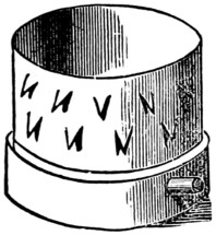
Fig. 17.
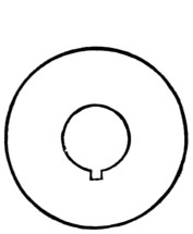
Fig. 18.
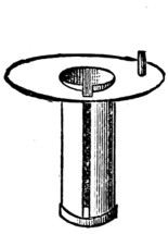
Fig. 19.
If this wick-carrier is put on the brass tube in the lamp, with the inside point in the spiral slot, as it descends it will turn to the left, and as it is lifted up it will turn to the right; consequently if it is turned to the right or left, it will ascend or descend, according to the way it is turned. To turn this wick-carrier we must have the following contrivance: Cut out a circular piece of stout tin that will fit easily into the lamp, and in the centre cut out a circular hole that will allow the wick-carrier to pass easily through it. At one side of this circular hole cut a little slot one-eighth of an inch each way (Fig. 18). Next make a tube of tin that will fit inside this hole, and will let the carrier pass freely up and down inside, but the edges of the tin must not be joined, but be an eighth of an inch apart. Solder this tube in its place in the circular tin, projecting through about a quarter of an inch, and so that the opening down the side of the tube corresponds with the square slot in the top. Solder a band of tin one-eighth of an inch wide all round the bottom of this tube to keep it firm (Fig. 19). Punch a hole in the top about a quarter of an inch from the edge, and fix a one-sixteenth wire in it about half an inch long.
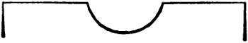
Fig. 20.
Put this tube over the brass tube, so that the slot at top corresponds with the top of the spiral slot. Put the wick-carrier in its place, with the inner point in the spiral, and the outer point in the slot in the tube; and by turning the top to right or left the wick-carrier will ascend or descend, and, when the wick is fixed to it, will raise or lower the wick. To turn this top something more is wanted—that is, a movable top to carry the lamp-glass; this can be made to turn the movable top to raise the wick-carrier. For this you must get a piece of sheet-brass or copper—brass will look best, but copper is easiest worked. Whichever you decide upon, it must be a circular piece three and a half inches in diameter, and less than one-sixteenth of an inch thick. This copper is to be worked into the shape of a felt hat, with a crown three-quarters of an inch high, and one and a half wide. To do this you must make a block of hard oak wood six inches square and three inches thick; cut a hole in the middle the shape and size of the crown of the hat; this is to be like half a ball (Fig. 20).
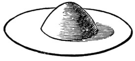
Fig. 21.
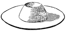
Fig. 22.
Now make another block two inches thick and six inches square, and bore a hole in each corner to screw the two blocks together by with four-inch screws. Make a hole right through the top block one inch and a half wide. Now make your copper red-hot and chill it in cold water—this will soften it; put it on the lower block with the centre of the copper exactly over the centre of the hole in the block, place the top block on the copper, and screw the two blocks together as tightly as you can. Now make a piece of oak three and a half inches long, and one inch and three-eighths thick, into a roller, and round one end. Put the rounded end in the[238] hole, resting on the copper, and strike it repeatedly with a heavy hammer or mallet. This will drive the copper into the hollow in the bottom block. You must make the copper soft by making it red-hot repeatedly, and you will find that it will be easily worked into the hollow. As soon as it is forced quite into the hollow in the lower block you must unscrew the two blocks and finish the fitting by hammering with a round-faced hammer. Your copper will now be like Fig. 21. Now you must file off the top of the crown, so as to make a hole at the top three-quarters of an inch in diameter, like Fig. 22.
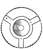
Fig. 23.
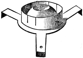
Fig. 24.
Next you must cut the brim like Fig. 23, making three projections three-eighths of an inch wide, and three-quarters of an inch long. Now one-sixteenth of an inch from the crown of the hat bore a hole one-sixteenth of an inch at the end of each projection. Bend the outer end of each projecting arm a little less than a quarter of an inch downwards, till it is at right angles to the other part. Make a ring of thin tin three-eighths of inch wide, and one inch and five-eighths in diameter; cut the bottom edge away, leaving three projecting points one-sixteenth of an inch wide and a quarter of an inch long, equidistant from each other, put these projections through the little holes round the crown of the hat, and bend them inwards underneath. This will hold the ring tightly in its place. Now put this hat on the top of the lamp, and mark on one of the arms the place where the iron wire in the movable lower top comes, and then bore in that arm a hole one-eighth of an inch in diameter, and put the top on, passing the upright wire through this hole. Your top will now be like Fig. 24. The ring is to hold the chimney, and should have four or five slits in it a quarter of an inch deep, to clip the glass.
Now solder a handle to your lamp. Make a ring of tin a quarter of an inch wide, and one inch and a quarter in diameter, and solder the two ends to the lamp.
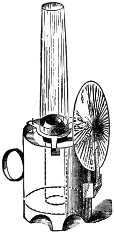
Fig. 25.
On the other side you must make the loop to hold the reflector. Take a piece of tin one inch wide and three inches long, and bend the ends at right angles to the middle, each end to be three-quarters of an inch long. Solder these ends to the front of the lamp. On the front of this piece of tin solder another an inch and a quarter long and three-quarters of an inch wide, soldering only the ends. This will be the loop to slip the hook on the back of the reflector in, and will keep it in its place. Your lamp is now quite finished, and will be as represented in Fig. 25. In fastening on this slip care must be taken to put it in such a position that when[239] the reflector is in its place the centre of the reflector will be one inch higher than the top of the lamp, that is, the cut crown of the hat.
When using the lantern the lamp must be placed under the chimney, and pieces of board put under it to bring the centre of the reflector opposite the centre of the lens.
Now put a wick in. These wicks are circular, and about three inches and a half long. When buying them, take your wick-carrier with you to get the right size. They should fit tightly over this. These wicks can be bought at the lantern-shops, and are one shilling or one-and-sixpence a dozen. Put oil in your lamp, about two-thirds full. Light your lamp and put it in the lantern. Put the chimney on, put the lenses in their proper places, and try the lantern. If it gives a clear, sharp disc on the wall your lantern is all right, and ready to show the slides. If the disc is cloudy or has dark patches, move the lamp about till you get it clear. Move the front lens till the end of the disc is sharp.
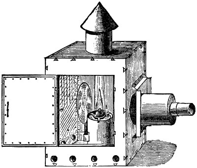
Fig. 26.
You can paint your lantern all over with black paint. Brunswick black is the best to do this with. It makes the tin parts look nice. If you prefer it, and I think it is far the best, you can make your lantern of mahogany instead of deal, and polish it, and blacken the tin parts only. Mahogany board can be got for this very little dearer than deal. If you were to solder a brass-wire ring round the outside of the edge of the tube that carries the front lens, it would make it stronger and easier to regulate the focus, besides giving it a more finished look. If the nozzle and focusing-tube were made altogether of this brass plate it would add to the finish.
A magic lantern without slides is not of much use. These slides cost a good deal to buy, the price, ranging from two shillings to a guinea, being regulated by the time and skill expended in their production. In this section I will tell you how to make your own slides at a small outlay for materials. The time and skill you must supply yourselves.
The materials required are—a glass-cutter; some strips of patent plate-glass four inches wide—the glass of the thickness called eleven-ounce glass; thin black paper, crystal varnish, turpentine, tubes of water-colours, three or four sizes of sable-hair pencils; a good-sized camel-hair brush, with the hair cut straight off half-way down, for varnishing; some glue, two or three small dabbers made of fine linen or kid stuffed with wool, a palette, an easel, and a penknife.
The colours required are opaque black, warm brown, blue, dark green, yellow, and crimson. The palette can be made of a piece of glass six inches square, with a piece of white paper pasted on the back.
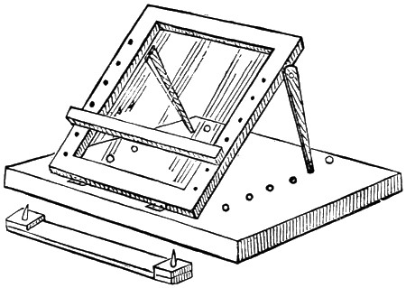
Fig. 1
The easel you can make for yourselves. Fig. 1 will show how mine is made. A board twelve inches square and one inch thick forms the stand. To this, at about one inch from the front edge, is fastened by two hinges another smaller board, eight inches wide and eleven inches long from top to bottom, having a square hole six inches wide and nine inches long cut out of it, making it into a frame. This hole is filled with a plate of glass by glueing strips of wood all round inside the frame at the back for the glass to rest upon. The front surface of the glass must be flush with the front surface of the frame.
Up the front of both sides of the frame holes are bored about half an inch apart for the pegs in the shelf to fit into. This shelf is a piece of wood eight inches long and half an inch square. In the back of the shelf are fixed two iron pegs, which fit into the holes in the frame to keep the shelf in position. At each side of the frame is a wooden support screwed on to the outside by one end, so that it can be moved freely backwards or forwards, hinge fashion: the free end of each support fits into holes bored in the stand. By moving the supports backwards or forwards, and putting them in the holes in the stand, the easel can be lowered or raised at pleasure.
The upper surface of the stand is covered with white paper. You will require a hand-rest to keep the hand from touching the painting. This is made out of a piece of thin wood (cigar-box wood does nicely) eight inches long and one inch wide.[241] To one side of this, at each end, glue a piece of the same wood one inch square, and in these pieces fix the iron pegs to fit into the holes in the frame of the easel.
When using the easel place it with its back to a window, or if you are painting by gas or lamp light place it so that there is a strong light on the white paper under the glass.
The glass to be painted is to be put on the glass of the easel resting on the shelf. When you have finished painting for the day you need not remove the picture from the easel if it is not finished, as by fixing the hand-rest over it and shutting down the easel you can cover the whole with a sheet of paper, and so protect it from dust. Now you have everything you want, and we will set to work at the painting.
First take your strips of glass, and with your glass-cutter cut them into pieces four inches square. Take one of these squares and well clean it on both sides. Put a little of each colour on your palette. Now place your glass over the design you wish to transfer to it, and very carefully go over the outline with your finest sable-hair pencil dipped into the opaque black moistened with a little water.
While this is drying mix in a small bottle some crystal varnish and turpentine in the proportion of one part varnish and two parts turpentine. When the outline is dry take it in your left hand, with the thumb on one edge and the fingers on the other. Dip the varnish brush into the varnish mixture, drain it partly on the mouth of the bottle, and carefully, with a light and free hand, go all over the glass, drawing the brush from top to bottom, beginning at the left-hand edge and working to the right.
Do not go over the varnish twice, or you may disturb the outline. Set the glass on one side to dry, but do not put it where it will get hot, or this may crack and streak the varnish.
While this is drying, take another glass, clean it, and trace outline of number two picture, varnish, and proceed with number three, and so on till you have six glasses outlined and varnished. It is better to have more than one picture to work upon at the same time; you do not then have to wait for the varnish to dry, as you can be colouring one while the other is drying.
When the varnish is dry, which will be in about a quarter of an hour, put one of the glasses, with the varnished side up, on to the easel, place the easel in a good light, and proceed to put in the colours. Put in the sky and background of the pictures first. The sky and all large surfaces must be put in as evenly as you can with the brush, and then you must go all over them with a fine dabber till you have got them perfectly even. In dabbing a surface such as a sky, do not mind dabbing the colour over other parts of the picture, as all the colour not wanted in it can be taken out with the moistened point of a brush before varnishing. When I paint my slides I sometimes purposely colour all over anything that projects into the sky, as I find I can get a more even surface by doing so.
When you have been all over the picture with the first coat of colour, varnish as before, and proceed with the second and third coats. You must be very careful in varnishing the colours, and not go over them twice. The colours are to be got at all artists’ colour shops. Ask for tubes of water-colours for glass-painting. Some of the larger firms also publish little books on glass-painting, in which you will find many useful hints.
When the colouring of the picture is finished, varnish it all over for the last time, and set on one side to dry. Now cut some squares out of your black paper the exact size of your glasses, and cut from the centre of each a circular hole three and a half inches in diameter; place one of these pieces on each of the varnished pictures (on the varnished side); take, and clean, six other glasses, and place one on each of the paper squares on the pictures; next fasten the two glasses together by glueing a narrow strip of paper all round the edges of each pair, and lapping on to each glass not more than one-eighth of an inch.
When they are quite dry your slides are ready for the lantern, and the pictures being inside between the two glasses, will be protected from injury from dust or scratches. In putting the slides into the lantern the painted glass should be nearest the light, if to be shown through a transparent screen; and the other glass nearest the light if to be shown on to a wall or opaque screen.
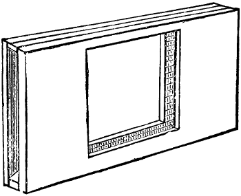
Fig. 2
These slides will be too small to use in the lantern by themselves, so you will have to make a wooden slider for them. This is made as in Fig. 2.
Fig. 3
Take two pieces of board one-eighth of an inch thick, four and a half inches wide, and eight inches long, with a square hole cut in each three and three-quarter inches square. These boards make the back and front of the slider, and are joined together at the top and bottom by two narrow strips of wood eight inches long, a quarter of an inch wide, and one-eighth of an inch thick. This slider is pushed into the slide-stage of the lantern, and the glass slides pushed into it as in Fig. 3.
The slider is rather smaller than the stage in the lantern, which allows of it being adjusted so that the centre of the picture is in a line with the centre of the lenses.
For making movable slides, such as slipping-slides, lever-slides, rack-slides, and chromatropes, you will require wooden frames.
To make these frames, get a carpenter to cut you some slips of pine or deal three or four feet long and half an inch square, with a groove running all along one side of each slip say one-eighth of an inch deep and one-sixteenth of an inch wide. Make your frames out of these slips of wood, seven inches long and four inches wide, outside measuring. Fit a glass in the groove like a slate is fitted in its frame.
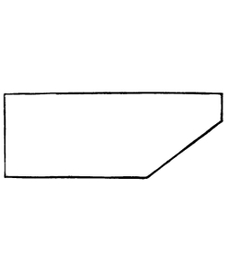
Fig. 4
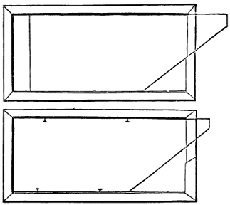
Fig. 5
Make about a dozen of these frames, and set them on one side to dry. Now cut some strips of glass three inches wide and seven inches long, and cut off one corner of each, as in Fig. 4, at any convenient angle, and then cut away the upper half of the front part of each frame flush with the glass, to allow the second glass to be pulled out about half an inch when put in position in the frame, as in Fig. 5.
Fig. 6
Your frames are now ready to receive the design. Trace the design on the inside of the fixed glass with the effects; if it is to be a figure raising and lowering its arm, the figure must be drawn with three arms—viz., the arm that is not raised and the other arm in each position, one up and the other down, as in Fig. 6. The other glass has nothing on it but two black patches, one or the other of which covers one or the other of the arms as the glass is pulled out or pushed in.
In painting these slides, all the glass in the frame around the figures is to be blackened with the opaque black, so that all light is excluded except that which comes through the figures. When this slide is painted, varnish it and paste a narrow strip of paper on the top and bottom of the glass for the movable glass to slide on without scratching the picture.
The black patches on the movable glass are painted and varnished on the inside of the glass. To get these in the right place, place the glass in position over the picture, and when pushed in as far as it will go, mark with your black on the outside of the glass the outline of the arm that is to be covered in that position; then pull out the glass as far as it will go and mark in the same way the outline of[244] the other arm; turn the glass over and fill in the outlines with opaque black, and on putting the glass in its place in the frame you will have a figure with its arms raised or lowered. Now put the glass in its place, and fix it there by pressing into the wood of the frame two small pins at the top and two at the bottom. In putting in these pins allow room for the glass to slide easily.
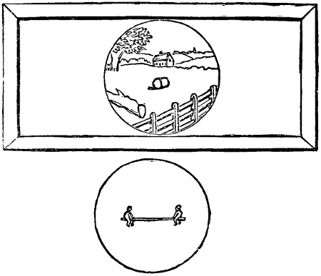
Fig. 7
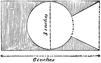
Fig. 8
The construction of lever slides is something like that of the slipping slides, except that the movable glass is circular, and the picture on the glass in the frame is painted circular and has a background. The movable glass has painted on it only the limb that is to be moved. You can get these circular glasses cut at a glazier’s; have them three inches in diameter. Fig. 7 will explain how the two glasses are to be painted. By placing the movable glass over the fixed glass, and moving it partly round and back again, the two boys will appear to move up and down. Of course the point that the board hinges on must be in the centre of the picture. Before painting the picture, cut out a piece of thin board a quarter of an inch thick, three inches wide, and six inches long. Cut this in the shape of Fig. 8 (the dark part represents the wood). Glue this wood on[245] to the glass inside the frame, and cut away the front edge of the frame down to the glass.
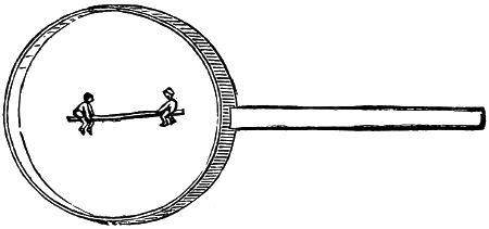
Fig. 9
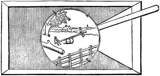
Fig. 10
Now you can paint your picture, and while that is drying take one of your circular glasses and fit a rim—made of thin brass plate, a sixteenth of an inch thick—to it. This rim is to fit the glass tightly, and is to be a quarter of an inch wide; the ends are to lap a little, and are to be soldered together. Now cut from the same brass plate a strip two and a half inches long and a quarter of an inch wide, and solder this on to the rim, as in Fig. 9. Fix the circular glass in this rim, and on the inside paint the board and children on it, put it in its place in the circular hollow in the frame, and fasten it in its place with small pins pressed into the wood and bent over the brass rim (Fig. 10). By raising or lowering the lever the board will rock up or down.
Rack slides are very like the last description of slide, but in these the movable glass is capable of being moved quite round by a rack-and-pinion work.
In my last section on magic-lantern slides, I mentioned that, although the frames for rack-work slides could be purchased, they were expensive. I have since then thought that the old-fashioned way of turning the revolving part—viz., by pulley and band—would be easy for boys to make, and answer very well if the cord is kept tight. In this section I give instructions in making these frames.
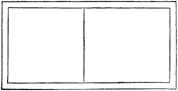
Fig 1
Make the outside frames five inches wide and ten inches long, out of wood half an inch by three-eighths, put edgeways. Cut a piece of thin deal or mahogany three-eighths of an inch thick and five inches square, and glue this on one side of half the frame (as Fig. 1). Cover the other half with a piece of glass four and a half inches square, and fasten it there with strips of deal, making them flush with the board on the other half. Glue corner-pieces (as in Fig. 4) on the other side of the glass, turning the frame over.
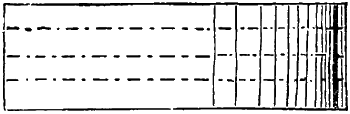
Fig 2
Make the circular frames out of a wooden circular box—such as a tooth-powder box—about four inches in diameter. Take off the lid and cut away the rim that it fits on, and saw the box into rings about a quarter of an inch wide, marking the box first with a pencil, and cutting through the marks with a fine[246] saw (as Fig. 2). Have your circular glasses cut the exact size of the inside of these rings. Fix the glass in each ring so that the wood projects a trifle beyond the glass on one side. With a three-cornered file cut a triangular groove all round each ring about one-sixteenth of an inch deep.
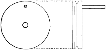
Fig 3
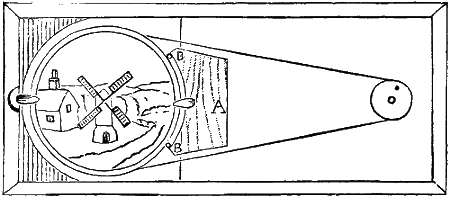
Fig 4
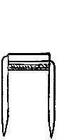
Fig 5
Make the small wheel out of a cotton-reel about an inch or an inch and a quarter in diameter. Cut off the ends and cut the other part into slices a quarter of an inch wide, and cut a groove about an eighth of an inch deep all round each (as Fig. 3). On one side of each of these pieces fix a short wire about three-quarters of an inch long near the edge; this wire will serve as a handle to turn the wheel by. Fasten this small wheel to the board by a screw that fits easily into the hole in the centre, without too much play (Fig. 4). Put the circular glass and frame in its place and glue a piece of wood (A, Fig. 4), about two inches wide and a quarter of an inch thick, to the wooden half of frame. Get two small glass beads about a quarter of an inch long and an eighth of an inch wide. Put a wire about an inch long through each, and bend the wires as in Fig. 5. Sharpen the ends and press them into the edge of the wood (A, Fig. 4, B B), so that the beads will turn easily without touching the wood. Cut away a semicircular portion of the end of the frame (Fig. 4) and fasten a small button made of brass plate in it, and fasten another button to the wood (A). These buttons will keep the circular frame in its place. Connect the two wheels with a piece of strong twine, not too thick, going round them both, and fasten the ends by lapping them and sewing them together. Now if you turn the small wheel the large circular frame will turn round in the same direction if your work is well done. The edge of the circular frame must not touch anything but the glass it rests on, the two beads, and the two buttons. The view is painted on the inside of the fixed glass, and the revolving portion is painted on the under side of the circular glass. In Fig. 4[247] the mill and background are painted on the fixed glass, and the sails on the movable one.
Chromatropes can be made in the same way, except that the small wheel has two grooves in its edge, and the other part is made up of two revolving frames, which are turned in opposite directions by one cord passing round both and the small wheel. The lower frame rests on the square glass, and the other frame rests on the lower one. The cord is passed from the right-hand side of the lower groove in the small wheel up the right side of the lower frame, round the top and down the left side to the left side of the upper groove in small wheel, round the upper groove to right side up to the left side of upper frame, round the top down the right side of frame to left side of lower groove of small wheel, brought round, and the two ends joined. It will be seen that by putting the cord this way the two frames are turned in opposite directions, although the small wheel turns them both. Have the cord tight, and well rub all the parts that work together with blacklead.
In painting chromatropes, each glass is painted with the same pattern, and then they are placed face to face, and in turning make very elaborate and constantly-changing figures.
Great inconvenience is often caused in fixing a screen in a room for the lantern, such as taking down pictures, etc.; and sometimes it is impossible to hang it without doing some damage to the walls and paint by driving nails and hooks. Even then the screen has to be put up in an inconvenient place.
By using the following contrivance all this will be avoided. The screen can be put in any part of a room most suitable for the show, and afterwards taken to pieces in a few minutes and packed away in a box thirty-six inches long and about eight inches deep and wide.
The frame, or stand, can be bought at the shops, but it is much cheaper to make your own.
The materials for this frame can be bought at a small outlay, and are—fifteen wooden rods three feet six inches long and about an inch and a quarter in diameter—the handles sold at the shops for fitting to hair broom-heads do very well indeed, and are not very dear; two pieces of wood six inches long, five inches wide, and one inch and a quarter thick; and, lastly, some stout tin plate.
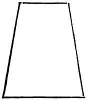
Fig. 1.
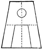
Fig. 2.
First of all, take the two wooden blocks and cut them the shape shown in Fig. 1; the width at top is three inches, and at the bottom five inches. Divide the top and bottom lines into two equal parts, and draw a line from top to bottom through the points of division. On this line mark a point an inch and a half from the top, and with this point as centre bore a hole right through the wood, which hole is to be just large enough for the wooden rods to fit tightly into. Draw a line across the[248] face of the block half way down (as in Fig. 2). Along this line, and from each end of it, mark inwards a distance equal to the diameter of the wooden rods, and do the same along the bottom line (as in Fig. 2). Join these points as in the figure; cut out the middle portion, leaving the projections three inches long and an inch and a quarter square. These projections must be rounded by taking off the corners with a sharp chisel or knife. Trim them down till they are the same size as the rods.
Now you will want your fifteen wooden rods. See that they are all the same thickness. Cut off the ends of each, to make them quite square, and making the rods exactly three feet six inches long. From your tin plate cut fourteen pieces, each piece to be six inches long, and wide enough to go round the rods and to lap about a quarter of an inch. The width can be found by rolling paper round the rod and letting it lap a quarter of an inch, and then cutting it off. Place this paper on the tin and mark the width. The tin can be cut with a large pair of scissors. Now roll each piece of tin round the rods so as to form fourteen tubes. These tubes will now require to be soldered. You can get your tinman to do this for you, or you can do it yourself. If so, the following is the way to do it.
First of all, get some muriatic acid and some clean zinc cuttings. Put the zinc into a bottle and pour over it the acid, and set it on one side for a time till it has quite done effervescing; then add a little more zinc, and if it begins again wait a little longer and add more. Do this till it does not effervesce on putting new zinc into it, when it is ready for use. You must get some solder from the plumber’s, and if you have not a soldering-bit he will perhaps lend you one; but you can buy the bits now in many shops where they are sold on a card with some solder. The cost is from one shilling upwards.
The first thing to do is to ‘tin the bit’ (or cover the face and point with solder). This is done as follows. Place the bit in the fire to get hot, but not red. Take a clean piece of tin-plate and put on it a few drops of the zinc solution, and put a small piece of solder into it. When the bit is hot enough take it out of the fire, and with a coarse file clean the face and edges of it, and place it on the solder in the zinc solution on the piece of tin. In a few seconds the solder will melt and flow all over the point of the bit. This must be done to the bit every time it gets red-hot, as in that case the solder is burnt off.
Now put the bit back into the fire and take one of the tin tubes and first clean the surfaces that lap together by scraping them with a penknife. Rub each surface with the zinc solution and lap them together, and tie the tube round with string, to keep the edges in their places. Take the bit out of the fire when it is hot enough, and place it on the end of the stick of solder, which will be melted and stick to the bit. Place the bit on the top of the lapping edges, and in a few seconds the solder will flow from the bit between the surfaces to be joined, and by drawing the bit from one end to the other it will draw after it the solder and make a strong joint. If the bit did not at first carry enough solder to make the whole joint, more can be added by applying the stick of solder to the bit while it is on the joint. Solder the fourteen tubes, and clean off the joints by scraping and filing the superfluous solder off and polishing up with a piece of glass-paper. Clean the joint inside well with a piece of oiled rag to destroy the zinc solution left inside.
Now fit a tube on one end of each of fourteen of the wooden rods. The tube[249] must be pushed on to the wood so that it is half way, or leaving an empty space of three inches. The tube can be fixed to the wood by two or three tacks driven through the tin. The fifteenth rod has no tube to it.
This is all there is to be made for the frame. In putting it together take the rod without a tube and two others, and join them together like a fishing rod, place each end of this compound rod into the hole in one of the blocks of wood, fit together the other rods into sets of three. There will be four of them. At one end of each set will be an empty tube, these are to be fitted on the pegs on the blocks at the ends of the other rod. The frame will now be composed of two uprights, each made up of two compound rods, and these support the cross rod or screen roller.
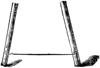
Fig. 3.
In the bottom rod of each set bore a hole with a gimlet, as in Fig. 3, and get two pieces of iron wire about one-quarter of an inch in diameter and bend the ends at right angles to the other part, leaving this middle part about two feet long. These are to be fitted to the rods, one to each pair, by pushing the bent ends into the holes in the ends of the rods as in Fig. 3; they are to be fitted on the outside of the rods.
Fasten these two wires together by passing a cord round both and tying the ends together. Sometimes the weight of the screen will cause the roller it is hung on to ‘sag’ or drop in the middle. But by tightening the cord underneath, the lower ends of the uprights will be brought towards each other, and will raise the middle of the screen roller.
To make the screen you must get some linen. This can be bought ten feet wide. Get three and a half yards of it, and have it hemmed at the top and bottom.
The top hem must be large enough for the roller to pass tightly through. The screen will get more or less creased in packing, but will come all right on being wetted and hung on the roller.
This frame is calculated for a ten-foot screen, which will be found large enough for most rooms. But it can be made for a larger one by adding one or more rods to each of the sets. The linen for a larger screen must be joined, as it is not made more than ten feet wide. In joining linen for this purpose do not let the seam come across the middle, but add an equal piece at the top and bottom, which will leave the middle of the picture clear, and the line of the join will come among the dark features of the foreground, and will not be seen so much. The tin tubes had better[250] be varnished over with Brunswick black, as they will look better and not be liable to rust. Varnish the iron wires also.
In packing up, the screen must not be rolled on the rods, but had better be folded up by itself in paper and placed in the bottom of the box, and then the rods put in afterwards. Otherwise the screen might have some patches of Brunswick black in the middle of it.
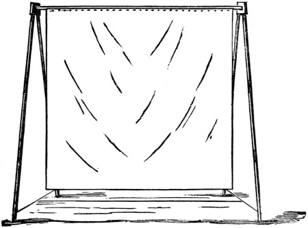
Fig. 4.
Fig. 4 is a view of the screen and frame when put together.
A lantern to exhibit opaque slides or ordinary pictures on paper or cardboard is, if anything, easier to make than one of the usual type. It is nothing but a photographer’s camera with the action reversed. In the camera the large well-lighted object is focussed down by the lens into the miniature copy in the darkened box; in the lantern the miniature in the well-lighted box is focussed up into the enlarged copy in the darkened room.
The essentials are, a good lens, a good light, and a well-focussed, well-illuminated picture. Any ordinary box will do. Its shape and size are of little moment, but the box must be blacked inside and have the top replaced by or covered with tin or sheet-iron. Let it be, as we have to make one, say eighteen inches long and two feet high. The depth of the lantern depends on the focal length of the lens you have chosen for it. This lens can be either a plain magnifying-glass, such as is used in cheap lanterns of the common build, or it may be compound, of the sort used in portrait cameras. The compound lens will give the best results. Suppose we are dealing with a three-inch lens having a focal length of ten inches, our box should then be ten inches deep. Very much smaller boxes with less powerful lenses can of course be made, and they will act just as satisfactorily.
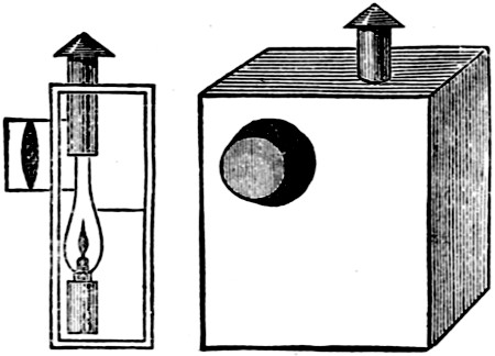
Fig. 1.
The top, as we have said, should be covered with tin, to prevent its catching fire, and it should be fitted with a chimney made by bending a sheet of tin and soldering its edges together. In order that a circle of light may not be thrown on to the ceiling, a cap must be fitted over the top so as to leave ample space for the passage of the heated air. In the front of the box a tube must be fitted, just large enough to hold another tube, in which the lens is held, and by this contrivance perfect adjustment of the focus is assured.
Arrange the interior as shown in the sketches, which are so numerous and self-explanatory that lengthened description is not required. The only peculiarity is in the back, which is so made to prevent a flood of light being thrown out behind each time a picture is changed. There are two doors to it, one being just a quarter the size of the other, and having a piece of wood of the same size fixed[251] on at right angles of it, on the same principle as is seen in many mahogany birdcages where the inside flap of the seed or water-carrier just fills the hole made for the real door when the real door is open. The slide-carrier is marked A, and when the door is shut the marked side of the shade (B) fits close up against the side of the box. The lamp is placed as shown, and should be just far enough from the lens to thoroughly light up the picture without permitting itself to be seen. A paraffin lamp is the best, and it should if possible have a round argand wick; but a flat one will do fairly well. The round shape of the wick is suggested as giving in the majority of instances the most equable light. The bottom of the door should be cut away slightly or perforated, as in the sketch, so as to allow air to enter freely, as no lamp will burn without a draught.
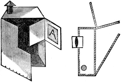
Fig. 2.
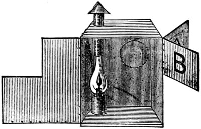
Fig. 3.
It is a good plan to try the chimney on the top before the top is fixed on, and then if the top is left a little larger all round than will be required it can be shifted about until the proper position of the lamp with regard to the lens and slides can be found by experiment, and all risk of failure avoided. When the correct distance is found the top should be screwed down and trimmed to shape. Inside the box, below the chimney, a ring or stop should be screwed to prevent the lamp slipping about in the event of the lantern receiving a sudden knock.
In another form of this lantern the back is in one piece, and the slides are introduced through a slit at the side, a plan, however, having a few disadvantages. The principle of the opaque-slide lantern is apparent at a glance, and once that is understood no difficulty should arise in devising many patterns of the instrument and utilising old materials for the purpose. Any pictures can be shown, coloured or uncoloured; even our own designs in this book can be thrown on the screen with good effect.
In the last chapter there is an illustrated description of a magic-lantern for opaque slides, and as I have for some time used a contrivance on the same principle for use with an ordinary lantern, the few words I have here to say may not prove uninteresting. Like the opaque lantern, this modification of it is very inexpensive.
The interest of a magic-lantern is greatly increased by its being made to show photographs of friends or public men, and also pictures or engravings, Christmas cards, etc. This can be done by the following simple contrivance, which will cost but a few pence. Indeed, the one I use cost me only threepence, and is made out of a cigar-box; but a better and stronger one can be made for less than a shilling. It consists of a five-sided box, with top and bottom, as seen in Figs. 2, 3, and 6. In two of the sides are circular holes, and one side is left open about two-thirds of its length, which opening is closed by a door or shutter revolving on a pivot at the top and bottom, to carry the photograph. This shutter is fitted with four small clips on each side for the purpose of securing the card in its place.
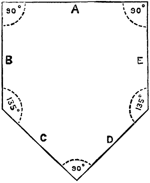
Fig. 1.
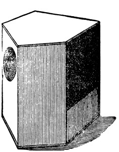
Fig. 2.
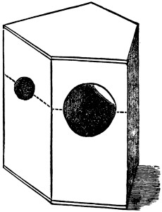
Fig. 3.
Now for the construction. Get some thin board—deal is very good for the purpose; it is to be a quarter of an inch thick—cut two pieces out of it for the top and bottom, the shape shown in Fig. 1.
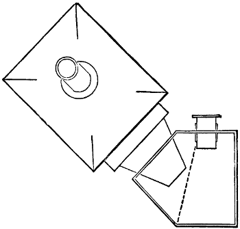
Fig. 4.
The dimensions of these pieces are as follows. The sides B and E four and a[253] half inches long; the side A five and a quarter inches long; the other two sides are each to be three and three-quarter inches long. The angles where A joins B and E are each to be a right angle; so is the angle where C joins D. The two other angles are to be a hundred and thirty-five degrees each, as marked in Fig. 1. The sides of the box are to be eight inches long each, and are a little less in width than the edges of the top and bottom that correspond, so that when put together the outside of the box is flush with the top and bottom. The joints are to be glued together, and can be strengthened with pins driven in like small nails. The side E is not to be covered in all the way up, but only about two inches and a half from the bottom; but this depends upon the height that the nozzle of the lantern comes up this side when placed against it. Fig. 2 shows the opening left. When the glue is quite dry unscrew the brass focussing-tube from the lantern and place the box with the side C resting against the nozzle of the lantern, and mark round the nozzle on the side. Find the centre of this circle, and through it draw a line right across the side C, parallel to the top and bottom, and continue this line across the side B in the same way, as seen in Fig. 3. Find the centre of these two lines, and with these two centres mark a circle on each of these two sides, the one in the side B to be of a size to fit the brass focussing-tube, and the one in the side C to be about three inches in diameter, or large enough to allow the nozzle of the lantern to fit into it as far as it will go without coming between the picture and the lens, as seen in Fig. 4.
Fig. 5.
The remaining part to be made is the shutter to carry the photographs. This must be exactly the same size as the opening left in the side E, and is to be made out of the same quarter inch board. Let it be quite square at the sides and corners. The opening in the side E is to be equal in length to twice the distance of the centres of the holes in the sides B and C from the top edge of the sides where they join the top board. On each side of the shutter, in each corner, fasten a clip, as in Fig. 5. These clips can be made out of card or thin metal, cut in the shape shown, and fastened to the shutter with small screws or short pins. Mark the middle of the top and bottom edges of the shutter and place it in its place in the side E, and mark on the side the points where these marks come to. Take the shutter out again and bore a hole in the bottom edge of it about half an inch deep, and large enough for a stout pin to go into. In the lower part of the side E, and in the edge that the shutter will rest on, drive a stout pin in middle so as to form a pivot for the shutter, leaving out about a[254] quarter of an inch, and cut off the head. Replace the shutter, fitting the pin into the hole bored for it, and drive a pin through the top board right into it, so as to form a second pivot. The shutter will revolve round these two pivots and expose the sides alternately to the lens. Fix two clips to the edge of the top board to keep the shutter in place while shut. Cover the whole of the box with unglazed black paper.
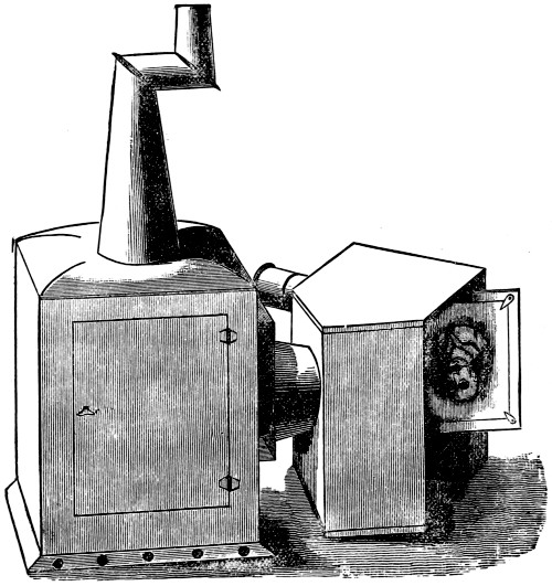
Fig. 6.
This simple little apparatus is all that is necessary to show any picture on the screen. To use it, first screw the tube carrying the focussing-tube into the hole cut for it in the side B, and push the nozzle of the lantern into the hole in the side C as far as it will go. Light the lantern and place the whole on the table so that the back of the lantern and the focussing-tube are directed to the screen, as seen in Fig. 6. Now place a photograph in the clips on one side of the shutter, and turn it round and put one in the clips on the other side. The photograph inside will be strongly illuminated by the light from the lantern, and an enlarged image of it will be projected by the lens on to the screen. The photographs placed on the shutter of the aphengescope must be, of course, upside down, as the lens will have the effect of inverting the pictures.
A strong light is required for this apparatus. The ordinary oil lamp will not show a bright picture at a distance of more than two or three feet. The ‘Trip[255]lexicon’ lamp, a lamp having three parallel wicks, burning paraffin oil, will give a good picture. But the best results are obtained from the oxycalcium and oxyhydrogen burners. These will distinctly show a large and brilliant picture, at a great distance from the lamp.
With this instrument, a watch placed on the shutter will show an enlarged image of itself, and the motion of the minute hand will be very distinctly seen. Anything that will go on the shutter will be shown on the screen. This adds greatly to the available articles to be used as slides.
Some of the most interesting slides are made by mounting entomological and botanical specimens on white cards, and putting the cards in the clips on the shutter, when enlarged images of the butterflies, moths, or beetles, etc., will be seen on the screen in all the glory of their natural colouring.
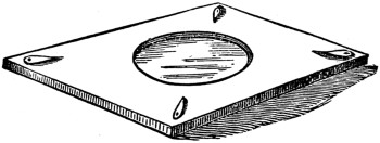
Fig. 7.
But the most interesting of all is the exhibition of living insects. This can be done in the following manner. Take out the shutter and lay it on the table: get a watch-glass, about two inches diameter, and deeply domed. Place this glass on the middle of the shutter, and with a lead pencil mark all round the glass. Remove the glass, and with a sharp knife cut into the wood of the shutter all round the pencil mark, cutting about one-eighth of an inch deep. Cut out all the wood inside this mark so as to form a hollow or well about two inches diameter and one-eighth of an inch deep, as Fig. 7. Cut the bottom of the well quite smooth, and line it with white paper.
Now get a piece of thin glass about the size of a photograph card, and thin enough to go under the clips on the shutter. Your shutter is now ready for the specimens. Replace the shutter and put a fly or other small insect into the well, and cover it with the flat glass, fastening it with the clips. Now turn on the light in the lantern, and focus the lens, and an enlarged image of the fly will be seen on the screen crawling about in a natural manner. For larger insects, such as a cockroach, wasp, etc., you must use the watch-glass to cover them instead of the flat glass. This can be fixed in its place by being pushed into the hollow or well, when the sides or walls will hold it. The two glasses are required for the reason that the insects ought not to have more room than will allow them to crawl about on the paper, as they would sometimes get on the glass, when they would be out of focus of the lens. But the glass must not be so close to them as to pinch them. You will have to keep your living specimens in boxes, with air-holes so as to have them ready for the exhibition, and will also require a small pair of forceps to handle them by, being very careful not to injure them.
On page 247 I have told you how you can make a light and portable frame for the screen, at a small cost. Lads who have experimented in chemistry ought to be able to make the oxygen gas for the oxycalcium light.
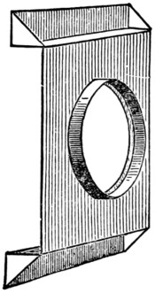
Fig. 8.
This instrument, as here described, was intended for use only with the tin lanterns as sold in the shops, which all have tapering nozzles. It can, however,[256] be used with the lantern described in my former article, but the stage of that lantern would require to be modified in the manner shown in Fig. 8.
Unsolder the large nozzle-tube from the front of the stage, and in its place solder on a band-ring of stout tin. This band is to be one and a quarter inch deep, and the diameter just enough to allow of the back end of the nozzle-tube fitting in it very tightly when the lantern is used in the ordinary way. The small turned-out rim of the nozzle-tube must be carefully cut off for this purpose. The aphengescope itself must have a small tin tube fastened in the small hole in the front of it, for the focussing-tube of the lantern to slide in; and the large hole must be cut large enough for the tin band on the front of the stage of the lantern to fit into it. This arrangement will allow of the light in the lantern being brought closer to the picture than can be done with the ordinary lanterns, and will, of course, illuminate it more strongly.
A very good lamp, with high illuminating power, to be used in any lantern, especially with this instrument, can be bought at the paraffin-lamp shops for a small sum. The tin duplex lamp, burning crystal oil, is the best. I should recommend any of my readers who have made, or are about to make, the lantern I have described, to get one of these, instead of making the lamp described with it, as it will give nearly twice the light. An arrangement will of course have to be made at the back for the reflector. If a lamp cannot be got that is low enough for the lantern, you can make the body of it yourself. You can generally get, at these shops, damaged lamps at a small cost. Get one that is damaged only in the body. Unscrew the brass-work, as though you were about to fill it, and put it on one side. Unsolder the brass screw-socket from the reservoir. Now make a square tin box for the new reservoir, covering in the top. The box is to be an inch and a quarter deep, and as large as the lantern will allow. In the top cut a hole to solder the brass screw-socket into. Then screw in the brass wick-carrier and make the clip for the reflector.
If a pair of lanterns are used the light will be proportionately stronger, and a strong light is an important thing with this instrument.
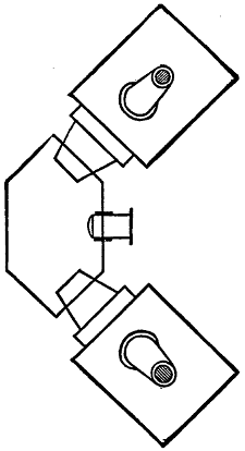
Fig. 9.
Fig. 9 gives the plan of the top and bottom boards of the instrument for use with a pair of lanterns, and requires no further description.
From Mr. Chasemore’s article on revolving slides for the magic-lantern we borrow the following diagram, as showing very clearly the principle which such slides are constructed (Fig. 1).
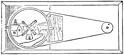
Fig. 1.
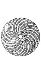
Fig. 2.
Round the slide runs a wooden border half an inch wide and three-eighths of an inch thick. The right-hand part of the slide is wood, the left glass, and the moving part showing towards us is also of glass, and fits into a circular wooden ring that is kept in position as it turns by the two tiny buttons on each side of it. One of these buttons works on the frame, the other is fastened to a piece of wood glued on to the wooden part of the slide. Farther to the right is a small silk reel, into which a handle is fixed, and an endless band from the reel round the circle in the buttons completes the machinery. All this is simple enough, and as it has already been described need not be gone into in detail.
The question with us now is how to apply this contrivance to the working of a chromatrope. A chromatrope is a lantern slide consisting of two or more pieces so painted as to give the effect on the screen of a set piece of fireworks. It is the easiest of all slides to paint, as it is purely geometrical, and the colours used require no mixing, but can be put on at once as they are got from the shop. And, best of all, the effects produced are far and away more brilliant than anything else in lantern practice.
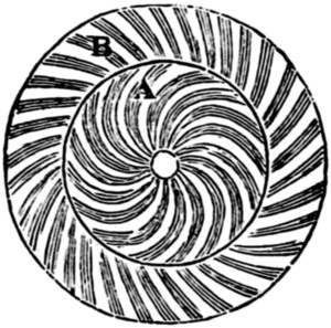
Fig. 3.
The essentials are a fixed slide of some bold design—star-shaped, circular, octagonal, or what not—and a moving shade that is of spiral pattern. The spiral pattern is the secret of the whole thing. Let the above be spun behind a star, so as to be only visible through its rays, and the star will seem to be alive. Turn it one way, the waves flow outwards; turn it the other, the waves flow inwards. The[258] standing pattern must have a centre, and the spiral must be worked on the same centre. That done, all is well. Sometimes a double spiral is desirable, and then the pattern in Fig. 3 is adopted. By it the outer part of the pattern (B) will seem to flow in a different direction from the inner (A). Paint the spirals any colours you please, providing that they are bright, and you get the results. Let reverse spirals appear in your fixed pattern, and you improve the effect. Have two revolving rings worked by the same wheel, one over the other, and the whole device will glow with life and brilliancy.
Fig. 4.
To begin modestly, take some simple design, such as that of the fountain in Fig. 4. Paint it on your slide, and stop it out all round with asphaltum or any dense black. Then fix to it a simple spiral disk, such as that given in Fig. 2, and the instant the spiral spins the water will begin to flow.
In all designs remember that the fixed slide must be broken up with black and colour, so as not to show the whole of the spiral at once. The wave should, as it were, sweep over the windows. For front designs nothing is superior to a good knighthood star.
The colours for slide-painting can either be bought ready prepared, or ground down on plate glass and mixed by Canada balsam or mastic varnish. Should the balsam be too thick, use a little turpentine. The clearest colours are lampblack, burnt umber, burnt sienna, raw sienna, gamboge, Prussian blue, verdigris, and scarlet lake, and these are put on in the ordinary way. Before you begin clean the[259] glass carefully with a little water and ammonia. Copy the design through the glass, and it would be as well not to forget that unless you can draw properly on paper you are not likely to do so on a lantern slide, where in the intense light and enlargement every mistake and shakiness of line is exaggerated for the benefit of the spectators. For those who cannot draw, figures of men and animals can be cut out with scissors and pasted on the slide, so as to give a shadow entertainment, as a change from the bought slides. Others can buy transparencies and stick them on for themselves, but the result will never equal hand-painting. One more caution before leaving hand-painting, and that is, do not be in a hurry, and give your slides at least a fortnight to dry.
If the spaces of the chromatrope are too narrow, or the design is worked too fast, you will only produce a fog, just as you do when you spin a toothed wheel. If, however, the teeth of the two wheels be fixed on the slant and the wheels turned in opposite directions, the teeth will be visible—upright if the teeth slant the way the wheel turns, slanting if they follow the course of the wheel. The principle holds good with the chromatrope; the spiral is but a toothed wheel.
The chromatrope was invented by Mr. W. Allen. He called it the pyreidotrope. It was improved, and soon became known as Chinese fireworks. From it the paper fireworks still popular in some circles were derived.
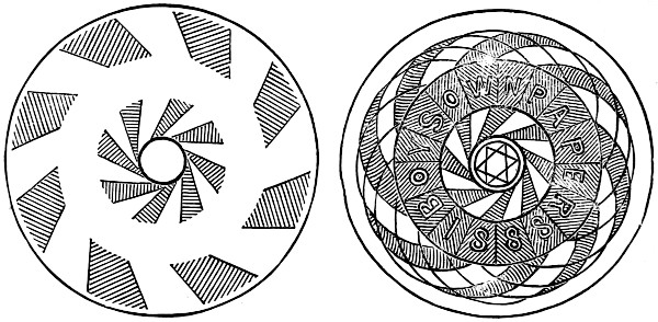
Fig. 5.
Paper fireworks are merely large chromatropes painted on oiled paper instead of on glass, and lighted by candles instead of a lantern. The wheels, and stars, and plumes, and pyramids are just the same as we have been describing, only much larger. The transparent portions are got by perforations. The machinery is the same, but of a rougher pattern, and the moving parts, instead of reels and bobbins, are barrel-hoops and butter-tubs. From what has been said above, their construction is sufficiently obvious, and we conclude with a design (Fig. 5) that may serve for either purpose.
Have our readers ever tried to work these together? If not, let them do so, and they will be rather surprised at the results. Begin in a small way, and treat the screen as the broad end of the kaleidoscope. Arrange it at an angle to the audience. Against it place two mirrors at the desired angle, just as in the well-known instrument, and then damp the screen and throw the image on from behind, so that it will take the place of the usual coloured fragments.
Chromatropes can be made in this way by devising a double slide, and filling up the space between the two sides with stained splinters of glass, beads, etc.; and this contrivance put into the lantern, and its image thrown on to the screen between the mirrors, will be multiplied into the most brilliant geometrical fireworks, whose pattern can be varied as often as desired by simply shaking the glass slide, so as to rearrange the coloured odds and ends. If the slide is a mechanical chromatrope, of course so much the better, as instead of one image of it there are many. Modifications of this experiment will easily suggest themselves to an ingenious lad.
Yet another praxinoscope, and a remarkable one. M. Reynaud is the inventor, and may well be proud of his ingenious combination. The sketch is so clear and complete that but little explanation is necessary. In the first place, there is a magic-lantern; in the drawing it is of the lampascope pattern, in which, by means of openings at top and bottom fitted with a sheath, an ordinary lamp can be used, if necessary, instead of the usual light, the chimney of the lamp being hidden by the top scabbard, and the beam that would illuminate the room being checked by the cap on the top of it. Any lantern can be altered so as to suit this arrangement, but the balance must be kept, and there must be no top-heaviness, so as to upset the lamp, and the under-sheath must be of the right length, so as to bring the centre of the flame opposite the centre of the lens. Any ordinary lantern with an ordinary lamp will, however, answer every purpose.
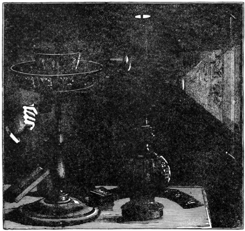
In the side of the lantern an aperture is cut, and around it is fixed a small triangular box containing a mirror set at an angle of forty-five degrees, and having a lens, in the base, of a very low power, or hardly any power at all. At the top of this side-box is fixed an adjustable lens of the same type as that in front of the lantern. In the lantern itself is placed a slide representing a landscape, an interior, etc., and the image of this is thrown on to the screen. At the back of the side-box is placed a praxinoscope of novel construction, and the images from it are thrown on to the sheet through the lens at its top, so that, as in a dissolving view, we have the picture seen by the assembly built up out of the slides.
The praxinoscope consists of a crown of mirrors sloping inwards, surrounded by a ring constructed to take a set of glass slides mounted in a strip by means of connecting links of silk or calico. The slides consist each of one of the figures alluded to in the last section, which form the series of instantaneous photographs that have revolutionised our ideas of the details of motion. They are, in fact, zoetropic pictures, each differing but slightly in attitude from the other, and each representing one of the changes assumed in a complete round of some definite movement.
The slides are slipped into the ring. The light from the lantern shining through the glass throws the images on to the praxinoscopic mirror, and thence it is reflected through the top lens on to the screen. The ring and crown are arranged at the angles given in the cut, and when the slides are revolved by means of the band and pulley shown below them, the different pictures as they pass the lens are reflected on to the background, and the figure appears in lifelike movement.
The lantern praxinoscope thus makes the zoetropic effects visible to a large assembly seated at their ease, and gives pictures of heroic size instead of the tiny proportions with which, when confined to the ordinary instrument, we are forced to be content. Many modifications of the arrangement will readily suggest themselves to our readers, and need not therefore be specially described.
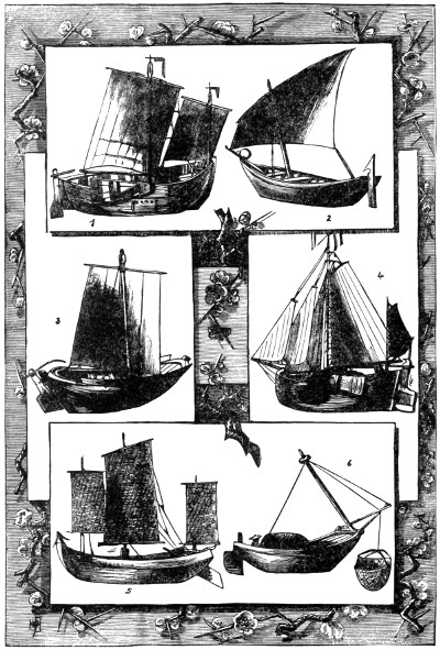
Some Typical Boats.
1. Heyst Fishing-Boat from Belgium. 2. Native Fishing-boat from Aden. 3. Swedish Seal-Hunting Boat. 4. Type of Dutch Boat. 5. Fishing-Boat of Swatow. 6. Boat and Method of Fishing at Ningpo, China.
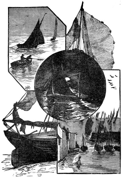
Until recently I was among the number of those who, though fond of boating, are not able to gratify their taste on account of not possessing a boat, or finding it convenient or possible to hire one.
Well, while walking one fine spring morning along the canal-side, the longing to be on its surface in a boat of my own became irresistible, and so, not having sufficient spare money to buy, I there and then determined to build, and I now purpose telling how I did so, and giving all particulars as to time and cost.

Fig. 1.—The Swallow.
The engraving (Fig. 1) is a reproduction from a photograph of the Swallow, as she appeared when on her first trial-trip. Since the taking of the photograph I have spent many a pleasant, quickly-flying hour in her, either sailing by myself or rowing with a couple of friends along the waters of a stream which runs clear and slowly among some of the finest scenery on the North Wales border.
In the first place, let me give a general description of the boat, with the totals of time and cost. She is 12 ft. long, 2 ft. 9 in. broad amidships inside, and 1 ft. 11⁄2 in. deep inside; of the same shape as an ordinary boat, but made after the style of a coracle, with a light wood framing, covered over on the outside with stout sailcloth, coated with three coats of paint to make it watertight. The total cost to me was £2 1s. 6d., in addition to which I paid 5s. for a year’s licence to keep my boat on the canal. The amount of time spent in building, painting, and rigging was 140 hours, which was extended over two months, owing to my not being able to keep constantly at work; and this, I should think, would be the average time for any one working by himself.
A certain amount of skill in carpentry is, of course, needed, as well as a few tools, but almost as essential as these is a large stock of patience and a firm resolution to succeed.

Fig. 2 Longitudinal Section
A B Keel, a b Keelson. C Stem Post. D Stern Post. E Transom. F Amidships Section, with seat and support. G Bow Seat, Rib, and Mast. 2 2 Inside of Top Lath and Gunwale. 3 Stern Seat. 4 Rudder. Laths and Ribs omitted.
Fig. 2 enlarged (41 kB)
The first thing to be done is to make the inner keel, or keelson (a b of Fig. 2). This can be made of deal, and should be planed perfectly straight. Its greatest length is 10 ft. 101⁄2 in. on the upper side; its breadth is 1 in., and thickness 11⁄2 in. The bow end is to be cut off square, and the stern to be cut to a level of 7 in. in a foot, or an angle of 120 degrees from the horizontal. Commencing at 11 in. from the bow end, on the upper side, bore a hole three-eighths of an inch in diameter straight through, and countersink it on the upper side; then make nine more holes of the same size at distances of one foot apart. These are the holes through which strong screws 3 in. long will be driven, in order to bind together, after the canvas is put on, the keelson (a b) and the keel (A B).
The stem piece (C, Fig. 2) should be made of oak, and of the shape shown in the figure, which is drawn to a scale of three-eighths of an inch to a foot. The curve is 9 in. radius, and the total depth 1 ft. 3 in. One strong screw, driven through the inner keel, or keelson (a b), at the point C1, will be sufficient to secure it, as, when the keel is screwed on, another screw at C2 will give it the necessary strength to resist shocks and blows.

Fig 3 Stern.
The stern piece is formed of two parts (D and E, Figs. 2 and 3), both of which should be made of oak three-quarters of an inch thick. The angle of the bevel of the stem is 120 degrees, or 7 in. in a foot, and when the stern pieces are fixed in their places on the keel, the slope should be in one line, and the piece E perfectly at right angles to the keel. D is fixed to the keelson by two strong screws at d and[267] d2. The width of the transom, or stem piece, E, is at the top 2 ft., and its depth 10 in. As, of course, the outline is the same on either side of the centre line, it will only be necessary for me to describe the shape of one side.
Beginning, then, at the top on the left-hand side of Fig. 3, the outline runs straight for 3 in., sloping inwards at a level of 1 in 3. After this it follows a curve of 6 in. radius, having its centre at e3, until at e5 the curve again bends outwards at the same radius, and with its centre at e6 following this curve to the bottom of the piece, where, at 10 in. from the top, the width between the two outlines will be three-quarters of an inch, or the same as the thickness of D.
Before screwing these two pieces together eight notches must be cut in the transom (E) for the reception of the ends of the laths, four on each side of the centre line. As, in the course of the construction of the boat, notches will several times have to be cut, with intervals of untouched wood, it will be advisable at the first to fix upon some method by which such notches and spaces may be described. Let, therefore, the spaces to be cut out for notches be enclosed in brackets thus: (11⁄4 in.,) 21⁄2 in., (11⁄4 in.,) the figures representing the breadth of the notch in inches, while the spaces between the notches are represented by the unenclosed figures.
The notches are throughout 1⁄4 in. deep; those in the transom (E) are, owing to the level of the stern, not straight across the wood, and must be marked out with the bevel, not the square.
Commencing then at the top left-hand corner of the transom (E) at the point e6 on Fig. 3, we have the notches to be cut as follows: (11⁄4 in.,) 21⁄2 in., (11⁄4 in.,) 21⁄2 in., (11⁄4 in.,) 21⁄2 in., (11⁄4 in.,) 3 in., or four notches and four spaces, the same having, of course, to be cut in the same order on the other side.
The transom (E) is sunk into the stem piece (D), as shown in Fig. 2, and secured at right angles to it by two screws at e1 and e2. The whole stem piece can now be fixed to the keelson (a b) by two strong screws at the points d and d2, Fig. 2.
The next part requiring attention is the amidships (section F of Figs. 2 and 4; see also Fig. 8); this can be made of deal 7⁄8 in. thick, 2 ft. 9 in. wide at the top, and 1 ft. 3 in. deep. The outline beginning at f1 is for 6 in. straight and at right angles to a line drawn across the boat, then it follows a curve of 7 in. radius whose centre is at f2 to the point f3, which is 1 ft. 11⁄2 in. below the top and 1 ft. from the centre line: from this point the outline runs straight until it joins the centre line at 1 ft. 3 in. from the top. A mortise 1 in. wide and 11⁄2 in. deep must be cut in the centre of this section at the bottom, in order that it may fit accurately over the keelson and at right angles to it, in which place it is fastened by a strong screw passing through the keelson from beneath. As its name implies, this section must be exactly amidships.
The notches and spaces are, beginning at f1, (11⁄4 in.,) 23⁄4 in., (11⁄4 in.,) 23⁄4 in., (11⁄4 in.,) 23⁄8 in., (11⁄4 in.,) 23⁄8 in., (11⁄4 in.,) 27⁄8 in., (11⁄4 in.,) 23⁄4 in., (11⁄4 in.,) 21⁄4 in. mortise for keelson in centre. The other side is the same.

Fig. 4
Amidships Section
The middle of this section is cut out for the sake of lightness, as shown in Fig. 4, and a seat 7 in. wide, and 4 in. from the top, is fixed across it.
Under the centre of the seat an upright support (f4) is fixed, of the same width as the seat, being also made to fit over the piece F and rest on the keel.
The seat must be screwed firmly into its place, so that the future rower may feel himself in no danger of being precipitated to the bottom of his boat among the débris of a broken seat.

Fig. 5.
Section on Line G.H.
2 2 Gunwales. Shaded portion a single rib. g1 g2 Screws for securing ribs together.
There will be two more sections required, somewhat similar to the amidships one, placed at distances of 3 ft. on either side of it. We will first take the one shown as section G H in Fig. 5, which is a section along the line G H of the plan Fig. 8; which appears on page 271.
This can be made in two ways—either the same as the amidships one, in a single piece cut from a soft wood, or in two pieces cut from a hard wood.
I made mine in the latter way, and that is the way I shall describe; but in either case the notches and outline are the same, and Fig. 5 shows both methods of cutting the inside, the shaded part showing the form of the hard wood rib.
The outline can be obtained by reference to Fig. 5, which is drawn to a scale of 1 in. to the foot.
The centres of the curves are at x x, and the batten of the straight part is 1 in. in 6 in.
The notches required in each rib are as follows, commencing at g3:—(11⁄4 in.,) 21⁄2 in., (11⁄4 in.,) 3 in., (11⁄4 in.,) 1⁄2 in., (11⁄4 in. A,) 3⁄4 in., (11⁄4 in.,) 2 in., (11⁄4 in.,) 21⁄4 in., (11⁄4 in.,) 11⁄8 in. the keelson, and the same on the other side. The notch marked A will be noticed farther on when the time comes for fixing the laths. This section must be firmly screwed to the keelson at 3 ft. from the bows. A seat is also required across it, and the remarks made about the amidship seat will apply to this,[269] except that, perhaps, this should be made the stronger one, as a hole of 11⁄2 in. diameter will be required in its exact centre if it is desired to use the boat for sailing.

Fig. 6.
Section on Line. I.J of Plan.
c c Centres of curves. s Screws for bolting ribs together. 2 2 Gunwales.
The other and last section, I J, of Figs. 6 and 8, is to be placed at a distance of 3 ft. aft of the amidships, and should be made of two oak ribs of the shape shown in Fig. 6, which should be 3⁄4 in. thick, and not less than 11⁄2 in. wide in the weakest place. The notches required are—(11⁄4 in.,) 23⁄4 in., (11⁄4 in.,) 21⁄2 in., (11⁄4 in.,) 7⁄16 in., (11⁄4 in. A,) 13⁄8 in., (11⁄4 in.,) 17⁄8 in., (11⁄4 in.,) 21⁄4 in., (11⁄4 in.,) 3 in. keelson, and on the other rib the same.
A small triangular piece of 3⁄4 in. oak should be fixed at the upper end of the stem post, to which the two upper laths and the gunwales may afterwards be fixed. The shape and size are shown at M in Fig. 8, on page 271.
About thirty-five hours will now have been spent in the building of the boat, and a casual observer would not be justified in asking what was being made, for the shape of the boat has now become apparent.
In order to prevent any mishap during the building, it is advisable to screw a strip of deal across from side to side of each section, and these strips can also be used for adjusting the position of each section, for if a small hole is bored in the exact centre of each strip, as well as in the bows and stern, and a small wooden peg be placed in each hole, it can be easily seen if the sections are in their proper positions, for, if they are so, the pegs will be in a straight line; and, if not, one or other of the sections will require adjusting until they are so.
The wood for the laths, keel, and gunwales will now be required; these, of course, will be obtained from a builder or sawyer.
Elm is the best wood of which to make the laths, as it is capable of being bent into almost any shape when steamed; in fact, it will be found as well also to make the keel and gunwales of elm, and if this be decided on the cost of the material and sawing of the laths, etc., will be 10s.
The lengths for the laths will be—six, 13 ft. long; six, 12 ft. 6 in. long; and ten, 9 ft. long; all 11⁄4 in. wide and 1⁄4 in. thick. These must all be planed on the one side and the edges.
The keel should be sawn 11 ft. 3 in. long, 3⁄4 in. wide, and 2 in. deep, and afterwards planed, the bow end being cut to suit the curve of the bows, and the stern end to the bend of the stern.
The gunwales are each 12 ft. 6 in. long, and 1 in. square, and are planed on three sides.
The next process in the building of the boat is characterised by its heat, and, in[270] fact, is somewhat similar to working in a vapour bath, for, as each of the ribs and laths requires to be boiled tender and flexible before it is possible to fix them, the nature of the work can better be imagined than described. Fig. 7, which is engraved from a photograph, will give a general idea of the position of the laths and ribs, as well as of the interior of the boat.
The first three long laths on either side can be screwed into their places without steaming; before fixing them it is, however, advisable to pencil their places on the bows. The divisions will be as follows, but it must be remembered that notches are not needed to be cut in the stern post, as the end of each lath is bevelled off before being screwed up. Beginning at the top of the stern post, C, Fig. 2, we have (11⁄4 in.,) 23⁄4 in., (11⁄4 in.,) 11⁄2 in., (11⁄4 in.,) 13⁄8 in., (11⁄4 in.,) 13⁄8 in., (11⁄4 in.,) 23⁄4 in. lower face of keelson, and on the other side the same.
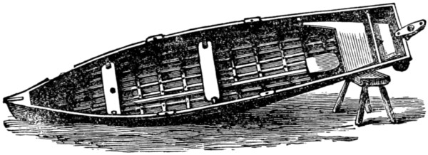
Fig. 7.—Showing the interior and framework of the boat. The footboards are removed in order to show keelson.
The fourth lath of each side need not be steamed, as it is a short one of 6 ft. 3 in., reaching only from the notches A of section I J across the midship section to the notch A of section G H.
The steaming process of which we now have need can be conducted in a laundry or washhouse boiler, and consists of boiling the wood until it is quite soft and flexible, when it can be bent to any desired shape, which it will always afterwards retain.
The laths (No. 5) will require boiling or steaming, and when perfectly flexible are to be tied firmly in their places, and screwed up when dry. Nos. 6 and 7 are to be treated the same, but No. 7 should not go quite to the bow end of the boat, being cut off and secured about half way between the section G H and the bows. The stern end also of this lath is to be screwed up to the stern post near the point marked d on Fig. 2.
The laths must be fixed one on each side alternately, or otherwise there is a danger of warping the boat. When the laths are all firmly screwed up in their notches the gunwales and ribs must be bent on. The gunwales should be well steamed, especially the bow ends, and then lashed on to the outside of the two top laths, but not screwed on yet.
The ribs, of which there are twelve, are of the same strength and material as the laths, and are placed three in each partition of the boat.
Beginning at the bow end, the first three are cut in half and screwed at equal distances on each side of the keelson. The three between the section G H and the amidships, as well as the three between the amidships and section I J, are in single lengths reaching from the inside of the top lath on the one side, inside the laths and outside the keelson, or rather sunk 3⁄4 in. into it, and then on top the other side, keeping inside the laths to the top lath.
A screw is driven through the rib into each lath, and the rib is firmly screwed to the keelson, the notch above it being afterwards filled up and planed level with the keelson.
The three ribs at the stern cannot be put in whole, and will require a certain amount of scheming to make them bend and fit in their proper places. The ends of the ribs must be cut off level with the top laths. The screws which hold the rib ends to the top lath are only temporary, for, after the canvas has been stretched on, and the gunwales screwed into their places they must be removed, and longer and stronger ones driven through rib, lath, and canvas into the gunwales.
The two rowlocks can be made by a blacksmith, and it would be well if a rowlock could be borrowed as a pattern from which he can work.
The gunwales must be strengthened to receive the rowlocks at the place k, k, k, k, on Fig. 8, and after the manner shown at k, Fig. 4, with oak strips screwed on to the gunwales, and an iron plate top and bottom, to prevent the holes being worn. The position of the rowlocks is 18 in. from the centre of the seat.
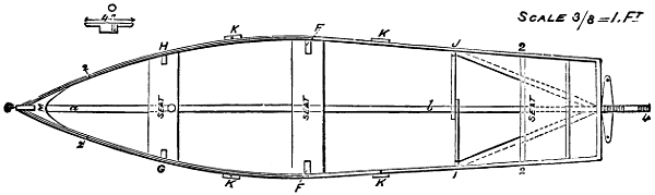
Fig. 8. Plan
The stem seat will now require attention. It should be placed at about 14 in. aft of the section I J, and its back should be no nearer the stem than 10 in.; it is supported on an A-shaped frame, as shown in Fig. 8, and should be something after the manner of the one shown in Figs. 7 and 8, though the builder will, of course, make it according to his own taste for comfort and appearance, but in any case let it be strong enough.
The rudder should be of the size shown in Fig. 2, and if sailing is contemplated two tillers or handles will be necessary, the one for sailing being a plain handle, as shown in Figs. 1 and 2, and the other with ropes and placed at right angles to the rudder, as shown in Figs. 7 and 8. Two cleats will be required in sailing, placed one on either side at about 8 in. aft of the section I J, and of the size and shape shown at O, Fig. 8.
The building of the boat will now have occupied about 100 hours, and the builder may congratulate himself that the greater part of his work is over.
The whole of the woodwork should receive a coat of paint, and be left to dry thoroughly. The framework of the boat is then ready to receive the canvas, which in this style of boat answers admirably in the place of boards. The best material for this purpose is a strong, closely-woven sailcloth; the stuff I used cost 1s. 1d. per yard square, and 61⁄2 yards were necessary to cover the boat.
The canvas is nailed outside the laths and keelson crossways, or from side to side; it should be made to fit like a glove, and the seams must be strongly sewn up. The edges are secured by being screwed up between the top laths and the gunwales, and all joints between it and woodwork must be smeared with a mixture of red and white lead before being nailed up. When it is properly fixed in its place, and before the keel is screwed on, it should be made waterproof. This can be done either by coating it first with boiled oil and then giving it several coats of paint, or by the following method, which is taken from the Field, and which I found to answer admirably. Take 6 oz. yellow soap and dissolve in 11⁄2 pints water, and while boiling add and stir in 5 lb. spruce ochre or other colouring matter, 1⁄2 lb. patent dryers, and 5 lb. of boiled linseed oil. This composition is applied with an ordinary paint brush, and one coat on the inside and three on the outside are sufficient to make the boat waterproof. Before putting on the last coat of paint, screw on the keel and caulk the joint with a mixture of red and white lead.
The ribs, etc., can be painted any desired colour, and, if it is wished to finish the boat off completely, a coat or two of oak varnish can be applied inside and out.
A strip of iron should be screwed all along the keel, to prevent the wood being damaged.
The mast may be 8 ft. 6 in. long, and 11⁄2 in. thick at the base, tapering upwards. The sail, which is made of coarse linen costing 5d. per yard, is of the shape shown in Fig. 1, and will require 7 yards if the linen is 31 in. wide, or what is in the trade, I believe, called seven-eighths breadth.
The gaff is 6 ft. long, and 1 in. thick, and should, as well as the mast, be made of ash.
The dimensions of the sail are as follows. Referring to Fig. 1, the length of the bottom is 7 ft.; the side close to the mast, 5 ft. 6 in.; top along the gaff, 5 ft. 9 in.; and the remaining side, 7 ft. 3 in. The edges are sewn around a piece of rope, and along the upper edge, close to the rope, is a row of eyelet-holes, through which strong string is passed to lash the sail to the gaff. Two more rows of eyelet-holes are required, the one 6 in. above the bottom edge, and the other 6 in. above that again. These are for the purpose of reefing the sail during a high wind.
A strip of linen should be sewn to the sail along the line of the eyelet-holes, in order to give the brass eyelets a better grasp. The brass eyelets can be obtained from any ironmonger at about fourpence per box, and pinchers for closing them can be borrowed from an ironmonger or a shoemaker.
Of course, ballast will be necessary when sailing, and for this a couple of bags of sand, equal to a weight of 1 cwt., will suffice.
And now I think that the building of the Swallow is finished, and the builder, somewhat weary, perchance, after his solitary labour, extending over some two months, is prepared to enter on the final and pleasanter task of launching his boat. This he may do with confidence, being certain that it will be quite watertight, very buoyant, and capable of carrying and seating three with ease.
Let me, before closing, express the hope that the builder will pass as many pleasant hours in the boat he has built as I have in mine, and then he will have no cause to regret the time and labour spent in its manufacture.
I propose to give directions for the construction of a canvas canoe requiring the expenditure of from 15s. to £1 in money, from a week to a fortnight of spare time, a very few tools, and a moderate amount of skill.
I have from time to time made canoes of various kinds, and have been led to adopt the pattern to be hereafter described as being most easily and cheaply constructed, and as possessing the important characters of speed, comfort, safety, and durability, and not being too heavy to carry on the shoulder for a quarter of a mile or so if necessary.
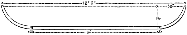
Fig. 1.
Fig. 1 enlarged (15 kB)
To proceed at once to my directions. It will be best to build under cover, though this is not a necessity. For the keel take a piece of straight deal or pine, free from imperfections, 10 ft. × 2 in. × 1 in. For stem and stern post, which should be alike, pieces of oak or elm should be cut to the pattern shown (Fig. 1) from a piece with a curved grain (to be had for about 6d.) 1 ft. 6 in. × 1 ft. × 3⁄4 in.; 3 in. at the ends should be bevelled off and fitted to the ends of the keel, taking care that the latter forms one plane with them. They are best fixed in their place by driving copper nails through, and tapping their ends over perforated caps known as ‘burs,’ which can be easily obtained; but wire nails clenched will do here, as in other parts of the work.
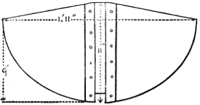
Fig. 2.
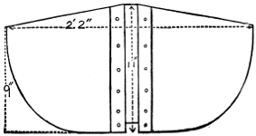
Fig. 3.
Next from 1⁄2 in. deal plank cut out two shapes to fit over keel (allowing it to project 1⁄4 in.), according to patterns (Figs. 2 and 3). Strips of 3⁄4 in. should be nailed on each side of the sockets cut for the keel, coming rather nearer at their other ends. The use of these is both to strengthen the shapes themselves and to make them fit firmly and tightly to the keel, also to make supports for the coamings round the well, to be described later.
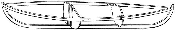
Fig. 4.
The shapes should be placed with strips turned towards the ends of the canoe and at right angles to the keel, the larger one 10 in. behind the middle point of the keel, and the smaller one 2 ft. 10 in. in front of the same point (Fig. 4). Take care that the middle points of the shapes are in a straight line with the stem and stern post. A good nail may now be driven right through the two ends of each pair of strips, clipping the keel tightly between them. Next take two clean strips of deal rather longer than the canoe. They should be perfectly free from knots or imperfections, or much trouble will be occasioned afterwards. Say 11⁄2 in. × 3⁄4 in. Fit them on as in Fig. 4, bevelling off the ends, and nailing into stem and stern post.
They should be allowed to take their natural curve, but pulled lengthways a little, so as to hold well to the shapes. Both sides should be alike, and the shapes should not be driven out of the central line. To prevent this, before nailing get a friend to hold the two ends against the stem while you nail the other ends to the stern post. Then nail the former ends to the stem, pulling them towards you a little, and keeping your eye on the central line. They may now be nailed to the shapes by means of corner pieces.
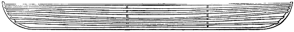
Fig. 5.
Next prepare, or get a carpenter to prepare for you, ten strips a little longer than the canoe, and 1⁄4 in. square. This is a very good thickness. These are to be arranged as in Fig. 5, the distances between the strips being equal, or, if anything, decreasing a little towards the keel, where the pressure of the water will be greatest. They should be put on in the same way as the upper stronger strips which already form the gunwale. I may repeat that this thin wood must be thoroughly good. If any strip is not so, it is useless and must be replaced by another. Cut rests for the strips in the shapes, allowing them to project a little. Let the strips lie flat to the edges of the shapes. Do not, however, twist them in fitting their ends to stem and[275] stern post. Those edges of the strips which would press into the canvas must be planed off. The ends, especially near the keel, will require care in fitting (Fig. 6).
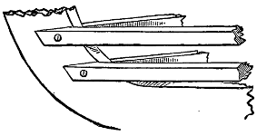
Fig. 6.
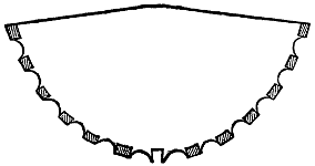
Fig. 7.
It is better to drive no nails through the strips except at the ends. Those parts of the shapes which are between the strips should now be hollowed out (Fig. 7), so that when the water presses in the canvas no projection shall be produced across the direction of motion of the canoe, as such projections seriously retard its progress. All the edges of the strips which would be liable to work through the canvas should be shaved off as before mentioned.
Next for the coamings round the well in which to sit. This should be made generally strong. Make a framework of deal 2 in. × 3⁄4 in., to fit in exactly between the shapes as shown in Fig. 10. The breadth at the stern end may be 18 in., and at the other 14 in. This will be quite broad enough. The two end pieces should be well nailed into those strips by which the shapes were strengthened. Also fit struts between the middle points of the sides of the well and the gunwale. Fit two strips about 11⁄2 in. × 3⁄4 in., or 2 in. × 1⁄2 in., from the middle point of the top of each shape, or end of the well, to the stem and stern post, nailing the gunwale at each end into it through some interposed wedges, so as to make a solid triangle at each end.
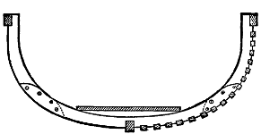
Fig. 8.
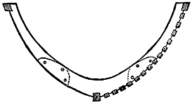
Fig. 9.
In each of the three compartments of the canoe fit a strengthening rib, as shown in Fig. 8 for middle, Fig. 9 for ends, which will sufficiently explain the construction. They should be fastened to the gunwale, but the thinner strips had better be arranged merely to rest against them, and not to be nailed into them. They need only be made of thin wood. Thin oak would be best.
Put one or two light cross strengtheners between the two sides of the gunwale, and one or two from the keel to the upper longitudinal pieces. The latter may be nailed into the cross pieces. Go carefully over the whole framework, removing any[276] eminences or loose nails likely to wear a hole in the canvas, remembering always that the water will press it well against the framework, and the canoe will be ready for covering. But the floor should be first put in, which may consist of a piece of 1⁄2 in. plank laid on the keel, strengthened at each end by a cross piece. By means of the latter it may be nailed into the shapes, and another piece across the middle may be added, which will not interfere with sitting.
The covering is best made of what is known by linendrapers as ‘crash,’ strong and close. It must be wide enough to go completely under the canoe, and can be had about 5 ft. wide, which will be quite wide enough. Seven yards of it will be sufficient.
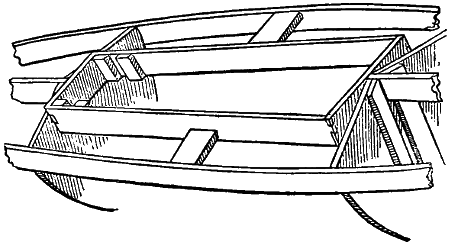
Fig. 10.
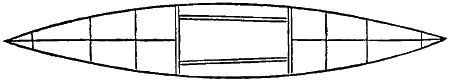
Fig. 11.
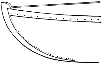
Fig. 12.
To put on the canvas, turn the canoe over. Lay the canvas with the centre line along the keel. Stretch it well by pulling at each end, and tack it through the middle at the extreme ends with a few tacks in a temporary manner. Put in temporary tacks along the gunwale at moderate intervals, stretching slightly, and endeavour to get rid of all folds. Begin in the middle and work towards the ends, and always pull straight away from the keel, and not along the gunwale. Then put in a second set of tacks half way between the first set of tacks on one side, pulling fairly tightly. Then on the other side put in tacks opposite to the latter, pulling as tightly as possible. The best way to do this is to seize the canvas with a pair of pincers, so that on pulling you can get the head of the pincers just over the gunwale, when they can be used as a lever to give an extra pull. A tack may then be put in on the outside of the gunwale. Half-inch galvanised tacks will do. Now remove the temporary set of tacks. To get rid of folds, which will not occur along the keel, but along the gunwale, keep bisecting the distance between two consecutive tacks by another tack, so that the canvas is equally loose on each side of it, always now pulling the canvas as tightly as possible. In this way the folds will disappear, and the canvas be stretched tight and well fastened to the gunwale. Leave that portion within a foot of each end untacked. Next cut away all that portion which projects beyond the stem and stern post, turn the edges in, and tack along the edges at moderate distances. Bisect these distances, and these again, till you have a very close row of tacks, as in Fig. 12. Pull fairly tight, but not too tight, and do not use pincers for this part. Quarter-inch tacks will be best. The ends may be cut out and put on, lapping the edges over the side, as shown in Fig. 12, and enough canvas will be left to fill the part[277] along the sides of the well, into which the canvas should be tacked with a fine row of tacks, afterwards being stretched over the gunwale. The canoe will now be completely covered in except the well. Before putting on the top, however, give the lower part outside a good coating of boiled linseed oil. This will be most of it absorbed into the canvas. The same may be done afterwards with the top. When this is dry—that is, after two or three days—give another good coating of the same. Then paint the canoe according to taste. Two coats for the bottom will be advisable, and paint which will stand water well should be used. It would be well to paint the framework with one coat before covering.
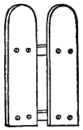
Fig. 13.
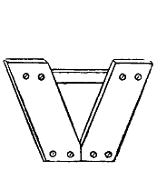
Fig. 14.
Make a stretcher (Fig. 13) for the feet of 1⁄2 in. board, and slips to fit it into (Fig. 10), with stops on the floor. Also a backboard of 1⁄2 in. board to correspond (Fig. 14). Each piece in the latter may be 18 in. × 4 in. They should be nailed into two cross-pieces behind, so as to form a hollow for back, and should be placed 2 in. apart, to allow a space for the spine. I prefer myself to fit in the backboard by means of stops on the floor and back of the well, making it keep one position, and that at a considerable slope, and have not found a swinging backboard so comfortable as some appear to have done.
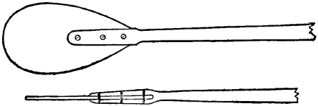
Fig. 15.
For the paddle, for which I think about 7 ft. 6 in. long over all is a good length, take a light, clean piece of yellow pine or fir 11⁄2 in. × 11⁄4 in., not more, and 6 ft. long. In the ends of this cut slots 6 in. long, each to receive two pear-shaped pieces of very light 1⁄2 in. plank 1 ft. 3 in. × 8 in. Nail them through with copper nails if possible. The blades should be at right angles to the thickest direction of the handle. Before nailing-in shave down the handle from an oval of 11⁄2 in. × 11⁄4 in. for 2 ft. of the middle to an oval of about 11⁄8 in. × 7⁄8 in. near the beginning of the blades. The handle should have its full thickness at the beginning of the blade but should be well tapered off along the blade, so as to be quite thin at its middle, where it ends. It should have its full breadth across the breadth of the blade. The blade itself may be shaved off thinner towards the edges. I do not think that for ordinary purposes any strip of copper or tin need be put round the blade, and the weight is increased by using it. The great thing about a paddle is that it should be as light as possible, and, if it appears able to stand it, it may be reduced still further. It may be painted or varnished, all but two feet in the middle. I find no rings on the paddles necessary.
A short strip nailed outside the gunwale in the middle of the canoe is a good thing; it prevents wear from the paddle, and forms something to catch hold of in lifting the canoe. A short outer keel is also a good thing at each end to prevent wear; but in making holes for the nails through the canvas into the keel care must be taken to turn in the edges round each hole, to tack with a close circle of tacks, and paint well, so as to render the place watertight.
An apron is seldom wanted, but may be made of canvas rendered waterproof with boiled oil if desired. It is well to fasten some inflated bladders in each end, so as to make the canoe a diminutive lifeboat, in case of an upset or of a hole being knocked in her.
The canoe will now be ready for launching. The owner should learn to put her carefully into the water and take her out by himself—to carry her on his shoulder. Superfluous wood may be cut from the central parts of the shapes, and also from along the keel towards the ends before covering. The floor forms a considerable item in the weight, consequently this should be made no wider or thicker than necessary. In paddling, learn to reach well forward and back, with a good swing of the body from side to side.
Such a canoe as described will be found to wear well, and one made by myself for a friend two years ago is now in use, and quite watertight.
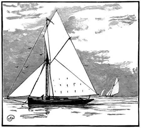
The most convenient size to make will probably be that of a canoe now in my possession, 17 ft. long, 27 in. wide, and 1 ft. deep. She is built as follows.
Two strong pieces of tough wood, forming together something the shape of a snowshoe, as Fig. 1, and lashed strongly together at the ends, form the gunwale. The ribs are of thin stuff about one-eighth of an inch thick, and two to three inches wide, running from gunwale to gunwale in one piece, the ends slightly pointed so as (Fig. 3) to fit into notches cut in the under side of the gunwale. Between these ribs and the outer skin is placed some kind of thin bark pitched over, and the outer skin is composed of birch bark.
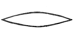
Fig. 1.
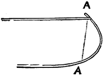
Fig. 2.
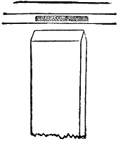
Fig. 3.
At each end, at the dotted line A A (Fig. 2), there is a strong apron-piece, but the bows are simply sewn together, as are the other joints in the boat, which is very light and handy. Now the thing is for you who have no birch bark to build a canoe on the same principle, easily and at little cost, and we will consider how this is to be done.
In an American paper there once appeared an article on ‘A Paper Boat,’ built on the lines of a birch-bark canoe, and it is not long since an adventurous young American went a tremendous distance on the American rivers in a paper canoe of his own construction. So you have paper proved to be possible as a skin for your boat as a substitute for birch bark. Another substitute and a far stronger one is canvas.
We will now proceed to get out the framework of the boat in question.
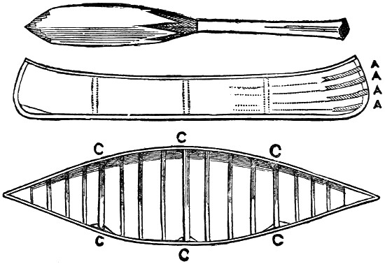
Fig. 4.
In the diagram (Fig. 4) you have sheer plan, body and deck plan, of a modified Canadian canoe; the ends are less curved than the original, but otherwise it is much the same. The first thing you will have to do is to draw a plan to scale on[280] this principle of the canoe you propose building, and the simplest scale you can use is that of one inch to a foot, and in this way, if you decide on a canoe fifteen feet by two feet by one foot, the plan on paper will be fifteen inches by two inches by one inch, which you can multiply by twelve to get your measurements for any part.
You must first get a piece of wood for the keel. These canoes are always built without any exterior keel, and are therefore easily turned and managed; at the same time they are as easily turned by the wind, if there should be any, and for rough water I should prefer giving a small exterior keel screwed on to the keel on which you build the canoe, and which forms part of the body of the boat itself; but this you must decide for yourself. If you only want to punt about in smooth water and in shallows, you can dispense with any exterior keel, and in any case you can easily screw on a false keel of whatever depth you consider necessary afterwards.
The keel proper had best be shaped broad in the middle—say, six inches—and tapering off to the ends where the stem and stern posts are joined on. Having got your keel ready, and the stem and stern posts kneed in, and ascertained by a plumb line that they are perpendicular to the keel, the next thing is to cut out shadows, or frames, from the body plan. Three of these shadows will do (see Fig. 4, C C C), one amidships, and one each between midships and the stem and stern. These shadows must be secured to the keel in such a way that they will not shift from the perpendicular, to which you must plumb them. The keel can be made of any good wood, elm or oak for preference; but common deal will do very well. It should be three-quarters of an inch by six inches in the middle, and taper to the ends. The stem and stern posts can be of three-quarter inch deal or hard wood, of sufficient length, and two to four inches deep, shaped out and secured with a galvanised iron or wooden knee to the keel. You can use an apron-piece or not, as you prefer. If you elect to dispense with the apron-piece the stem and stern posts must be deeper than if you use it, and a light groove of, say, one-eighth of an inch cut to receive the ends of the stringers. (See Fig. 5, A A A A.) Or this groove can be dispensed with, and the end of the stringer tapered off so as to come flush.
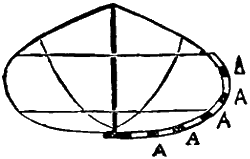
Fig. 5.
You will now want two to three stringers each side, of elm, ash or other tough wood, of sufficient length, and about half an inch thick by one inch wide. These will run from stem to stern over the shadows, and be firmly[281] secured to the parts. The gunwale must be of the same sort of wood, say one inch square, and let in half an inch into the shadows to bring it flush with the stringers. The gunwale must be secured to the stem and stern posts, leaving about an inch of the posts above it; and a triangular piece of hard wood an inch thick and about three to six inches deep must be shaped to fit between the gunwales and the stem and stern posts, and the gunwales firmly secured to it by countersunk screws. This will bind all firmly together. As you will have taken the measurements from your plans, in which you have decided the sheer of the boat, the gunwale will follow this sheer, starting from the midship shadow and curving up towards the posts.
You have now got the framework ready, with the exception of the ribs, which are put in afterwards. The next step will be to get the canvas to form the outside skin.
You must buy sufficient canvas to cover your canoe. See that it is close and strong (No. 6, Navy unbleached, or something as near that as possible). Turn the canoe upside down, and stretch your canvas over it, tacking it firmly along the keel with copper nails about an inch apart, and then strain it tightly to the gunwales and secure it there with copper tacks (iron or large tin tacks may be used here if you are short of copper), first turning down the raw edge of the canvas. Then tack down the ends to the stem and stern posts, lapping one side of the canvas first round the opposite side of the part and securing it, and then bringing the other side of the canvas over the part secured and tacking it on the opposite side, thus doubling the canvas over the stem and stern posts. It is as well to run a copper band from six inches down the stem and stern posts to about a foot along the keel, to take the wear off the canvas, and a slight wooden false keel may be screwed over all with brass screws, or fastened with copper nails. Any slackness that may exist in the canvas must now be taken up. Turn the canoe right side up and gather in the canvas where you can find it slack, which will probably be at the bow and stern; and, after gathering it tightly in a pleat, sew it strongly down on the inside. This, perhaps, had best be done before you completely secure the canvas down, and while it is only secured at the ends and along the gunwale, leaving it unfastened along the keel.
Next get your ribs ready; these had best be made of rock elm or other tough wood, to avoid the trouble of steaming. They must be about three-sixteenths of an inch by three-quarters wide, or one inch or even two inches wide will do if you can bend them. Space the ribs about six inches apart; you can put them closer if you want extra strength. See that they are cut the right length, that when put in—which must be done by main force—the ribs take all the stringers, and butt tightly under the gunwales. You may either cut a slight notch in the gunwale to receive the ends of the ribs, or, after all the ribs are in, run a strip of wood half an inch by half an inch under the gunwale and over all the ribs, screwing it firmly to the gunwale, to keep the ribs in their places. When the ribs are all in their places, you may remove the shadows and look over the canvas again to see if it is all tight, putting an extra rib in wherever you have taken it up, and securing such a plain to the rib by a few tacks.
You must now cut the crossbars the proper size and fit them in, securing them to the gunwale by knees on each side. You have now only to paint the canvas,[282] and when it has had two or three coats, firmly dried on, the canoe is ready to use. After using it turn it upside down, so that water cannot accumulate inside, as if it does it will soon rot the canvas, and whenever the paint wears off a little be careful to replace it. With these simple precautions such a canoe will last a long while, and will be of great use and amusement to you, as it can be easily carried from one piece of water to another by one person. Should you wish to make it a lifeboat, all you have to do is to get two zinc cases fitted to each end, which will float the canoe if capsized, or run a tapering belt of painted canvas filled with corks round the canoe outside on the water-line (see Fig. 5, A A A A A). If you take this precaution you will probably not regret it, as a capsize is a very simple matter to achieve in any round-bottomed light boat, and there is not much stuff in such a slightly-constructed craft to float the occupant if capsized.
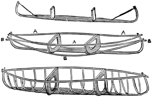
Fig. 6.
The American paper canoe was constructed something in the same way as to framework, but two of the shadows were left in after being cut away in the middle (see Fig. 6), leaving them three or four inches deep all round, and the keel was left about one foot wide between the two shadows, which were placed so as to divide the keel into three equal parts. They were firmly screwed to the keel, stringers (B B) were then run from stem to stern. The stem and stern posts were of green elm screwed to the bottom board or keel, and bent (see cut) into the required position; the ribs were made of osier willow switches put in while green; the gunwale (A A) was of ash. This framework was covered with very strong wrapping-paper, smooth and very tough, neither stiff nor very thick. This was secured first to the bottom board, the canoe being turned upside down; and then the paper was trimmed into shape and brought up to the gunwales, and secured there by being turned in over the gunwale and held down by long strips of ash or cane. The whole outside surface of the paper was then given three coats of varnish (Fig. 7).
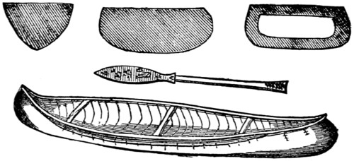
Fig. 7.
The constructor, however, found that the boat leaked, and he then covered it with unbleached muslin strained outside over the paper, tacked along the gunwales,[283] and sewn at the ends; it was then tightened by shrinking, and received three coats of a mixture of varnish and paint; this appears to have stopped the leaking entirely, and the owner then enjoyed a great deal of cruising and paddling in his paper boat.
After using it some time he discarded the ‘paddle proper,’ and fitted a pair of iron rowlocks sufficiently long to be secured to the bottom board and the gunwales, and used a pair of short sculls.
It must entirely depend on the surroundings of the maker as to what materials he had best use. If a lad has the ability to build a canoe at all, he must be the best judge of the easiest way for him to set about it, and it is impossible to lay down hard-and-fast rules as to what he shall use in its construction. All he requires is the general idea which is given here, and where a lad with every convenience and a long purse will use the best materials another, under different circumstances and perhaps far away from opportunities of getting the most suitable timber, etc., for his purpose, will have to exercise his ingenuity and bring into use those materials he is limited to. So, perhaps, in some instances where thick and good canvas cannot be got, a serviceable boat can be made of a thinner and cheaper material, such as unbleached calico put on over a skin of old newspapers pasted together to form a backing; and such a covering thoroughly varnished with several coats, or if that is too costly well painted inside and outside with a mixture of tar and pitch boiled together, half and half, would give a great deal of amusement to its owner, and cost a mere trifle. Of course, it would not look so well. The best backing to use under thin canvas or calico would be good paper, prepared in this way:—take a large sheet of good strong paper, brown preferably, and cover it with a coating of marine glue; place another piece of paper over it to cover the glue, and take a flat-iron, warm, but not too hot; thoroughly iron the top paper till the glue comes out through the pores of the paper; the two sheets will then be firmly held together by the waterproof glue, and any size can be prepared in this way, making a first-class stiffening inside skin, which can be covered outside with thin calico, painted and varnished.
The paddles used with these canoes are single-bladed. The stern paddle, which is used to steer as well as propel the canoe, is considerably larger than the bow paddle. The lengths of the paddles are—stern, five feet; bow, four feet; breadth of blade at broadest part—stern, six inches; bow, five inches; length of blade of paddle, two feet. The handle may be about three-quarters of an inch to one inch in diameter, but much thicker at the extreme end, where some of the paddles now used are shaped like Fig. 8.
Fig. 8.
The paddle is used as follows. You will readily understand that a stroke of a paddle used only on one side would cause the boat or canoe so propelled to turn its bow in the opposite direction; to meet this, before the paddle is withdrawn from the water, it must be slightly feathered and the handle brought inwards, the middle of the paddle resting on the gunwale of the canoe, the blade thus bringing the bow round and steering the canoe in a straight course. The pressure used must be merely adequate to bring the canoe straight,[284] and will depend on the amount of sheer she has taken. If this is properly done, which requires some practice, it will not at all interfere with the forward propulsion of the canoe. The handle of the paddle is left rather wide at the end to allow of an easy grasp, and the other hand holds the paddle not quite half way down.
In stalking game the Indians never withdraw the paddle from the water at all, but feather under water without making the slightest noise and scarcely causing a ripple.

Fig. 9.—Irish Curragh.
Another description of boat made of canvas is the Irish Curragh (Fig. 9), used principally in the south-west of Ireland. Some of these boats are of considerable size—I have seen one twenty-six feet by four feet beam—and are used in the heaviest weather and the roughest seas, and from their extreme lightness are wonderfully good sea boats, the peculiar construction of the bow, which rises very much, lifting the boat over the seas. They have a strong frame made of ribs with stringers spaced only about three inches apart. The stringers run the whole length of the boat, which is something of the shape of half a barrel greatly elongated. They are simply and easily constructed, and are covered with common canvas. Several coatings of a preparation of tar are given to the canvas, converting it into a species of tarpaulin, and as the interior framework is very close it is impossible to stand or press in any way on the canvas skin, which is thus kept from injury from that source. The curragh is propelled by[285] paddles used as sculls, and a large one has six men, each pulling two paddles. They have no rowlocks, but an iron pin stands up from the gunwale, and a chock is fixed to the paddle with a hole to fit the iron pin. In this way the paddles can be left without being unshipped if necessary, and fall alongside the boat with no chance of being lost.
The coracle used for fishing in Ireland and in Wales is merely a framework, sometimes of wicker and sometimes of wood, somewhat in the shape of the half of a walnut-shell. They are generally covered with leather, and are extremely light.
Since writing the above I have seen a paper which, to those who can afford the price, is the very thing to employ in building a canoe or small boat. I allude to the Willesden paper, invented by the late Dr. Scoffern. This paper is thoroughly water-proof, and is manufactured in all thicknesses. The best for the purpose is about one-eighth of an inch thick. It runs in sufficient length to build an ordinary canoe in one piece, and the width, being fifty-three inches, is amply sufficient. The price is five shillings per yard run, which, for a canoe say fifteen feet long, would be twenty-five shillings, and would be the principal part of the cost. This paper will not only make a[286] strong and safe boat, but also a very handsome and fast one, as, being in one piece, there is no joining or unevenness, but one perfectly smooth surface, offering little resistance to the water. For the purpose of building models it would be hard to find a better substitute for wood, and in most cases it would be found far cheaper.
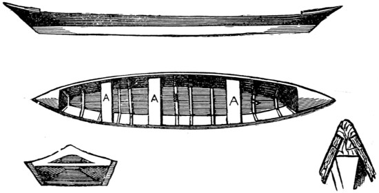
Fig. 10.—Canadian Batteau.
The Canadian batteau (Fig. 10) is a class of boat that is very easily constructed in paper, canvas, or wood, and you will see from the plan how it is made. It differs from the preceding canoe in that it is flat-bottomed, the American paper canoe approaching it most nearly in shape, though in the batteau the flat bottom is wider, and the sides are also flat, flaring out a good deal.
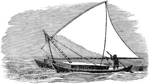
Fig. 11.—Double Canoe of the South Seas.
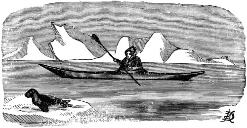
Fig. 12.—Esquimaux Kayak.
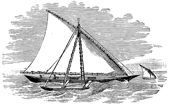
Fig. 13.—Flying Proa of the Ladrones, or Windward Islands.
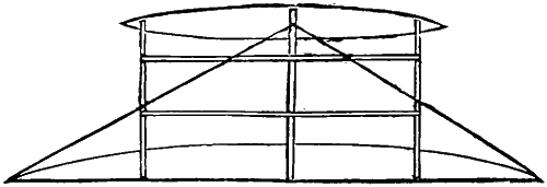
Fig. 14.—Plan of Proa, showing Outrigger.
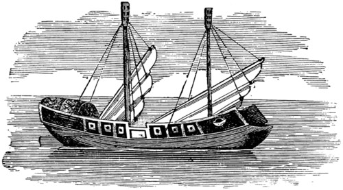
Fig. 15.—Chinese Junk.
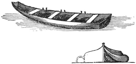
Fig. 16.—Norwegian Praäm.

Fig. 17.—Coracle.
I also give sketches of other types of crafts. And now for a parting word of advice: whatever type of canoe you select, I hope you will be able to produce one that will pass the examination when your parents and others hold a survey; and in view of this do your work well and carefully, or you had better leave it alone. In any case, do not canoe unless you can swim. A canoeist, particularly when racing, thinks nothing of an upset, which to an accomplished hand is merely the loss of a few minutes, when, the canoe righted and the owner once more in charge, the prize is still held in view. This, to a non-swimmer, might mean, however, loss of life. Speaking from my own experience, I can assure you that I should not now be writing this if I had been unable to swim, and in no case should canoeing or boating be indulged in by those who have not mastered that necessary and simple art. To the swimmer an upset is in most instances simply an annoyance, but to a non-swimmer it may mean a fatal accident.
Some years ago I wanted a cheap, strong punt for use in a large pond of some ten or twelve acres, and went to two or three regular boat-builders to ask the price of such an article. It varied from some sixteen shillings to a pound per foot. Now, as I needed something long enough to be rowed, or bear propulsion, with some steadiness, of course, and, moreover, to carry a good load, I perceived that nothing much less in length than about sixteen feet would answer my purpose.
The cost of this amounted to more than I was inclined to pay to a professed boat-builder, and so I put on my considering cap to see whether I could not escape the charges of an expert and yet realise my punt.
I determined to employ an intelligent country carpenter, who had never been in a shipyard in his life, and who, being wholly unacquainted with the structure of a boat, would be likely to follow out my directions without any bias of his own, yet take the whole credit of the result to himself.
We fixed on deal—good red, not white deal—for the wood of our boat, though my carpenter agreed with me that elm would have been better and teak best, for this latter does not split in the sun. Elm, however, is generally cut into lengths of only 12 ft. or 13 ft., which allows for the measure of two coffins, which are mostly made of this tree. Teak my friend had never seen. The worst of this is its original cost, and also, when a boat has to be built for inland waters, the expense of its carriage by rail from the neighbourhood of some coast ship-yard.
We settled on the red deal harmoniously. First we got four planks of 11-in. deal 12 ft. long and 11⁄2 in. thick. I had it of this thickness to ensure comparative immunity from splitting when the sides should be nailed on, for these were to form the floor or bottom of our punt. When planed on both sides, this thickness was of course reduced. The edges of the planks were ‘shot,’ and made to fit as for a glue joint. After being cramped together they were kept in position by nailing on transverse pieces 1 in. thick and 4 in. wide, these transverse pieces not reaching quite to the whole width of the floor. This, the floor, we narrowed, from the centre towards the ends, until the result was something like a gigantic ‘sole’ with its head and tail cut off square. This raft was our bottom or floor, four planks wide in the middle, and three planks wide at each end.
I wanted my boat to have not exactly a flat bottom, but one that should rise, or ‘spring,’ some two inches fore and aft. This gives a punt more buoyancy in rowing, and also enables it to be run aground easily, and to be pushed off without ‘sucking.’ A perfectly flat-bottomed punt sticks or clings to a shallow, muddy shore. If it is slightly curved, it is shoved off without any difficulty. The question was how to curve it.
We built our punt in a barn, with crossbeams overhead. First I got two[288] trestles, rather narrower than the ends of the bottom, and rested its ends upon them, there being some three or four inches to spare between the trestles and the ends of the bottom. It stood quite flat and stiff. You could not bend it with any pressure from the hand. I then measured the distance between its surface and a beam under which its centre stood at right angles, and found it to be exactly 11 ft. I next cut a length off a young fir-tree, which lay by our saw-pit, 11 ft. 2 in. in length, and requested our carpenter to set it upright on the middle of the punt floor, under the beam. Of course he could not. It was 2 in. too long. Then I got him and his assistant to stand on the bottom of the punt, whose ends just rested on the trestles, with three or four inches to spare, and to see if the tree would not then stand under the beam. It did easily. Then he and his assistant stepped off, and, lo! the punt floor, in trying to recover its flatness, was rigidly fixed, with a ‘spring’ or curve, fore and aft, of 2 in.
The fabric, so far, was steadied for further operations. Then I took two clean 9-in. planks, 1 in. thick, planed on both sides, and, keeping them duly apart with boards set edgewise the width of the punt bottom, nailed them to the sides. They bent quite easily, without any assistance from heat, and at once we had the two sides of our punt. I had these sides considerably longer than the bottom, in order that the punt might have projecting ends, and so be more easily stepped into from the shore when run up ‘end on.’ Then we got two pieces of wide elm plank for the two ends of our punt. These were the whole width of the end of the floor, and sloped out fore and aft. To these we nailed the ends of our sides, and the result was at once a very shipshape punt, but without any knees or thwarts. These we put in afterwards, as is usual in boat-building.
But the sides, though high enough to make a punt capable of carrying a considerable load, were too low to carry rowlocks unless the rower sat on the bottom of the boat. Thus we put on one other plank on each side 9 in. deep and 1 in. thick. It overlapped the other 2 in., and was long enough to continue the projection of the ends. It fitted very closely. We nailed these two side planks on with long copper nails, and put in other pieces of elm for the ends. Outside the top of these second planks we also nailed a strip 2 in. deep and 1 in. thick. This made the gunwale of the punt nearly 2 in. wide, and capable of receiving thowls, or pins.
The seats, or thwarts, we rested on the top of the lower side planks. This gave a seat of about 7 in. high for the rower, and sufficient height for the bed of the rowlock above the level of the rower’s seat, namely 7 in., which is about the usual rule. We strengthened the thwarts with oak knees against the upper side planks. This, moreover, gave great rigidity to the whole fabric of the punt. We also used oak knees or angles, called, in boat-building language, ‘hooks,’ at the four corners of the gunwale, nailing them in horizontally, and thus much tightening the punt at each corner.
The disposition of the thwarts in such a boat is matter of much importance. They should be at the proper distance from the rowlocks, and the rower should not take up too much of the available space in the punt. We arranged ours thus, and they answered admirably. The floor, be it remembered, was 12 ft. long. We ‘middled’ this, and set the centres of the two thwarts 18 in. from this line. This[289] gave 3 ft. as the distance between the centres of the two thwarts, and their position in the boat was such that one rower by himself sat just where his weight should be; so did two, and both sat well away from any ‘sitter’ in the end of the boat. The distance of 3 ft. between the centre of the thwarts enables the rowlocks to be correctly placed. They should come exactly halfway between the thwarts. By having three rowlocks on each side, equidistant, the rower or rowers had only to turn round and row in the opposite direction, the boat having stem and stern alike. This is convenient under some circumstances, as when there is not room to pull the boat itself round. The thwarts themselves should be 9 in. wide, and two boards of the same width at each end, resting on the top of the lower side planks, make sufficient accommodation for sitters, who, by the arrangement of thwarts and rowlocks which I have described, are well out of reach of the rower’s legs in a punt of the size we made. Altogether the result was excellent. The boat rowed with much lightness and ease, and would carry four or five adults. It was, moreover, very stiff in the water. There was no fear of it turning over when rowers shifted places. It ran far up on shore, so that ladies could step in and out dry-shod.
I should say that we made the ends project about 18 in. fore and aft, while the floor of the punt was 12 ft. long. Thus our length over all was 15 ft. If I built another I think I should make each of the ends project 2 ft., and curve the gunwale a little, giving it a drop of an inch or two in the middle. This gives an agreeable curve, and takes off the severe straightness of the upper line, which I must confess rather marred the ‘elegance’ of our punt as she lay on the water. A very little curve or wave-line produces the desired effect.
The cost of building our punt was not very much. I have before me the bill of the carpenter for wood, time, and some of the nails. It is £6 5s., and he was longer over it than he would have been had it not been his first attempt. Besides this, I had to buy the rest of the nails. Ours were mostly zinc, but on another occasion I should use only copper. The additional expenses were the oak knees for strengthening the boat, and the varnish with which we ‘dressed’ her. We used no paint, and only two or three places in the seams outside were ‘caulked’ with a little oakum.
I would advise the builder of such a punt, when not able to do the work himself, to employ an intelligent carpenter who makes his joints close. The whole cost, all expenses included, was between £7 and £8—the larger proportion being for labour, which sharp boys might themselves supply—and the fabric certainly seems as if it would last well. It has now passed its second year of service, and is as tight as a bottle, though it has been somewhat roughly used. For such a punt I should have had to pay at a boat-builders some £15, and I do not see why one built as I have advised should not be as strong and serviceable as any could be. The only point is that I would advise copper rivets, and not zinc, to be used throughout.
Of course, the expense might be lessened by using thinner wood, and therefore less heavy copper rivets. It is indeed a disputed question whether copper or iron nails and rivets should be used for fresh-water boats. Many Thames watermen prefer iron. This would, of course, make the cost of the punt less. I had our sides one inch thick, in order that the boat might stand very heavy work, and in case of cracking from extreme heat, might be cured without danger of battering the sides[290] in by caulking them, and without the necessity of patching them. I should add that we strengthened the ends with stout oak stem and stern posts nailed or riveted up the centre of the ends inside. They should be about 2 in. square. Into these we drove staples, to which a rope could be fastened.
I should, moreover, advise iron pins instead of, or as well as, ordinary thowls. We had them as well as thowls, there being halfway between each thowl-hole a hole for an iron pin half an inch thick. Then, if we wished to use thowls, we took the pins out, or vice versâ. The advantage of pins which run through the oar in places where the punt is used for fishing is, that the oars may be left on the pins without risk of slipping overboard.
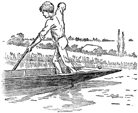
“The great thing in punting is not to lose your pole.”
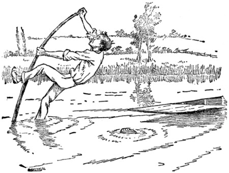
But it is also important not to lose your punt!
Over twenty years ago the Fairlie foundered in the Indian Ocean. Spars had been thrown overboard to form a raft, yet before anything but the skeleton of the framework could be lashed together the ship went down. The crew jumped into the square, scrambled on to the boundary spars, and remained astride them with their legs in the sea until they were rescued a day or two afterwards.
This is as simple a raft as any recorded in shipwreck annals. But what is a raft? It is indeed a difficult thing to define. Rafts are of all shapes and sizes, varying from the few booms of the Fairlie up to the elaborate raft of the Medusa, of which the model was shown in the London Fisheries Exhibition. A raft would seem to be any floating substance on which a man can sit or stand. Boys have paddled in a pond on rafts of a couple of planks, soldiers have crossed rivers on rafts of barn-doors, and we hear of armies using rafts of house-roofs, and wooden-shed walls, and casks and inflated skins, and pontoons of all shapes, of tin, zinc, copper, iron, leather, wood, and canvas.
Perhaps the simplest kind of river raft is that common in South Africa, where a stack of reeds some fifty feet in diameter is pushed into the water and allowed to float down stream, each day, as the under stems get waterlogged, more being cut from the banks and thrown on to the heap. A similar rough raft is not uncommon amongst us in winter, when the ice is very thin, for if a heap of reeds is then thrown on to a slab of ice, and well watered, a solid mass can be built up with alternate layers of reeds and ice which will float considerable weights. Besides the floating stack there is another reed raft in use amongst the Kaffirs, made of a mattress of reeds about four feet long, three feet broad, and eight inches thick, tied together with strips of the reeds themselves, with reed posts and railing round.
Skins stretched and inflated are in use all over the globe for raft purposes. In Peru a hide pinched up at the corners, secured there with a thorn, and dried in the sun, furnishes the only boat. In another American form we have holes bored all round the edge, a thong run through them and pulled tight over a framework of withies,—in fact, a coracle such as the Celts were so fond of, the washing basket with the waterproof covering which exists on the coast of Ireland to this day.
The contracting force exercised by skins as they dry has a great deal to do with the water-tight qualities of hide boats, as, in all cases, the framework is covered as soon as possible after the death of the animal.
It is astonishing what simple things have been made into boats. Admiral Fitzroy once sent a party of sailors ashore, and while they were encamped their boat was stolen. Out of the boughs of the trees around them they made a large basket, covered it with their canvas tent, puddled the inside with a little clay, and[292] put to sea, spending eighteen hours in this crazy contrivance before they got back to safety.
Alexander’s army passed the Indus, as Hannibal’s did the Rhine, on rafts made of inflated skins, or of skins stuffed with hay. On the Tigris and elsewhere at this very day such goat-skin rafts are still in use. The skins are lashed to a framework with one of the legs of each animal upwards; through this leg the air is driven in, and, as the traveller journeys down the stream, he visits the skins in succession and blows in fresh air to make up for what has escaped. A single ox-hide when inflated is said to make a float capable of sustaining three hundred pounds.
Casks are almost invaluable in raft-making, and many a shipwrecked crew has been saved on a platform lashed to floating barrels. One of the early lifeboats simply consisted of a boat with holes bored in her bottom and empty casks lashed inside her, the casks giving the floating power while the shape of the boat was retained. Four spars lashed together with a cask at each corner and a square of canvas fixed on them was all that one of the patent life-rafts consisted of.
Casks furnish great floating power in such a convenient form that it is hardly to be wondered at that they have been used over and over again in the construction of military bridges where boats have been unattainable. They are, however, but a makeshift, pontoons nowadays being always carried. When Darius crossed the Bosphorus and afterwards the Danube he did it on a bridge of boats oft very elaborate construction. When Xerxes crossed the Hellespont he had two bridges, one consisting of three hundred and sixty vessels anchored side by side and head to stern, and another, nearer the Archipelago, of three hundred and fourteen vessels similarly anchored. These were connected by cables, a platform of planks was laid stretching from each to each, and on the platform from shore to shore there was laid a thick bed of earth to form the road on which the Persian hosts passed into Europe. At Xenophon’s passage of the Tigris thirty-seven vessels were used.
The most famous boat-bridge in modern times was that thrown by the British over the Adour when Wellington invaded France. The bridge was 810 feet long, and was at first supported on hawsers, which were kept tight by capstans placed in the centre of each of the thirty to forty-ton chassemarées which formed the piers. These chassemarées were moored side by side at a distance of forty feet from each other’s centres, so that the intervals were equal. The platform was after a day or two shifted on to balks. To protect the bridge a boom was thrown across the river on each side of it. The best of the raft-bridges was Sokolniki’s over the Niemen at Grodno in 1792. The trunks, fifty to sixty feet long and about two feet in diameter, were lashed together in tens and joined end to end until they reached across the stream. The bridge was three hundred and sixty yards in length, and formed a great curve towards the current, with the centre of the curve supported by an anchored vessel. These trunks were lashed together. A better plan, however, is that adopted by the Canadian timber-men, who cross-lay their rafts, bore an auger-hole at the corners through both thicknesses, and fix a wedge in the cleft end of the stick which keeps them together. As the stick is driven home the wedge is forced upwards into the end and makes all fast.
On the coast of India it is a very common thing to see two or three natives afloat on a raft made of three logs of wood—of the pine varnish-tree—the centre log[293] being about five-and-twenty feet long and the breadth of the three together about a yard. These rafts are manœuvred with very great dexterity, and safely brave the roughest seas. Similar to them is the Brazilian catamaran, which carries a large triangular sail.
The Cingalese catamaran is a log of wood rounded beneath, and scooped out, with two planks lashed on the top, so as to increase the height above water. It has a boat-shaped outrigger, supported on two curved poles, to enable it to carry the large lug-sail, which in a fresh breeze so heels it over that the crew have to sit well out to windward on the connecting-bars to balance the swift but crazy craft. In the Mauritius the catamaran is an ordinary boat with a smaller boat at the end of the outrigger, in which is set a peculiar mizzen. In the Fijis the catamaran becomes a double canoe, with both hulls exactly the same, and bearing a platform giving just a little play, so as to allow of the individual peculiarities of the boats being sufficiently humoured.
These boats, although they may in a few rare cases upset end on—that is, turn a somersault—are the safest craft in the world, for, consisting as they do of double hulls sustaining a raft, should anything go wrong with the hulls, the raft will never sink, but will simply settle down until it floats on the waves. Owing to the great breadth there can be no question of ‘initial stability,’ and an ordinary capsize is impossible, while the very light draught of the hulls will take the craft over places where even a rowing-boat would meet her doom.
To build such a craft is not difficult, and Mr. W. L. Alden has recently shown us how it can be well and cheaply done. Adopting the principle of the flying proa of the Ladrones, which are credited with their twenty knots on a beam wind, he makes his hulls quite flat on one side, and thus avoids the ‘funnel difficulty,’ as it was called in the case of the Castilia and other steam catamarans, where the inner sides of the hulls being curved, the water between them was heaped up as it rushed through the narrowing strait. To make such a catamaran as that shown in our sketch—a craft speedy, safe, and handy, which is easily built, and will bear any amount of rough usage—four deal planks are required. These should be fifteen feet long, eighteen inches wide, and an inch thick. The width is unusually great, but should single boards not be obtainable, two or three boards can be keyed together so as to make it up. Take one of the planks, which should have been bought ready planed, divide it into five equal parts as shown in the diagram, and at each of the four divisions screw, with brass screws, a three-inch batten three-quarters of an inch thick. This will not only prevent the plank from warping, but will strengthen the joints if you are working with a board that has been made up.
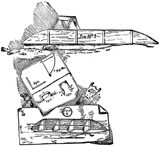
Fig. 1-6.—Construction of Catamaran.
Fig. 1-6 enlarged (146 kB)
Now shape the ends as shown in Fig. 1, first with a saw and then with a draw-knife and spokeshave. Take another of your eighteen-inch planks and treat it in exactly the same manner, and when you have finished the curves, which should exactly resemble the others, cut off along the longer side an inch and three-quarters off every cross-piece, so that when the planks are placed at right angles together they will fit close. Whitelead these edges thoroughly, and then nail the planks together with galvanised iron nails, as shown in Fig. 2, which gives you a section end-on. Now cut four quadrants eighteen and a quarter inches radius, and off one side cut a strip an inch wide and trim the other end so as to leave you a piece of the shape[294] shown in Fig. 3, one side of which (A B) is seventeen inches long, and the other (A C), eighteen inches, and which is so made to fit exactly into the angle made by the broad plank and close against the battens as sketched in Fig. 4. Finish all the edges off smooth and square and true, whitelead them well, and fix them in with galvanised iron nails.
Now make, or get made, six iron staples such as are shown in Fig. 5, where the distance from A to B horizontally and A to C vertically is just four inches. The iron is best an inch and a half wide, between an eighth and a quarter of an inch thick, and in it should be three holes, shown at P and in the ears marked H, large enough for quarter-inch bolts. You also require six other staples of the shape shown in Fig. 6, made of half-inch rod iron with counter-sunk sockets for the screws, and these, like the eared sockets, must be four inches wide.
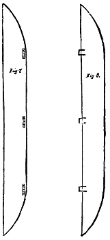
Figs. 7 and 8.
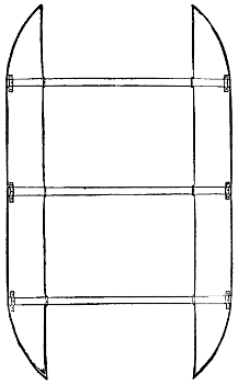
Fig. 9.
Screw down one of these eared sockets just where the curve goes off on the narrower side, as shown in Fig. 7, and in the centre fix a third. Use galvanised nuts and bolts for fastening, with a thin leather washer under the bolt and an oak washer under the nut, and make the holes watertight by hard screwing and plenty of whitelead. To the other edge at the angle, and so as to project beyond it and correspond with the eared sockets, fix your flat staples, as shown in Fig. 8, so that a bar can be passed through each, as shown in Fig. 9. Along the centre of the board above which the staples project bore five holes an inch in diameter, one in the centre of each of the five divisions with which you started, and then having first fitted a thin batten from A to B, as shown in Fig. 4, and let it down flush into the quadrants, give the construction a thorough coating of red-lead paint inside and out.
Next get some canvas forty inches wide. Coat it well with boiled oil, dry it thoroughly, and placing the lower edge of your framework along its centre, strain it up tight all round. Use copper nails to fasten it with, and running a streak of paint along its lower edge, finish it there with a thin oak batten, steamed to shape if necessary, and screwed on outside while the paint is wet, so as to serve for protection and form the keel. Now give your pontoon a good even coat of paint, and when that is thoroughly dry give it a trial coat of any colour you please.
Now make another pontoon in exactly the same way, and when it is finished fasten both hulls together with three pieces of scantling, as shown in Fig. 9. The cross-bars should be nine feet long and four inches square, and kept in their places by copper bolts slipped into them through the holes in the centre of each of the sockets.
Next make a platform of quarter-inch boards by nailing them together in two layers at right angles to each other. Use copper nails and clinch them. Round the outside of the platform run a low ridge of hard wood, so as to turn it into a tray, as shown in the sketch, and keep the water off the edges of the boards. Cut out a dozen grooves for the tops of the sockets to sink into; put the platform flat down on the cross-bars, and screw it into its place with galvanised nuts and bolts passing through the bars. The catamaran is now finished and ready for the mast, which can be stepped in an iron collar raised on three strong iron supports about twenty inches long, strongly riveted and bolted into the deck. Her sails and spars are made in the ordinary manner, the same as those of other boats as previously described. She requires a traverse or ring for the painter, and a rowlock to steer her by, and then, having carefully overhauled her to see that she is thoroughly watertight, whiteleaded every crack and crevice, and remembered throughout her construction never to have nailed a nail or screwed a screw without first covering it with whitelead, you can give her a farewell top coat of colour. Wait till she is thoroughly dry, and then, having placed a cork securely in each of the ten holes leading to her watertight compartments, which holes were made for you to get the water out in case any should leak in, you can launch her, seize your steering rudder,[296] and be off. She will go anywhere and do anything, providing always that the waves are not rough enough to wash you off her deck.
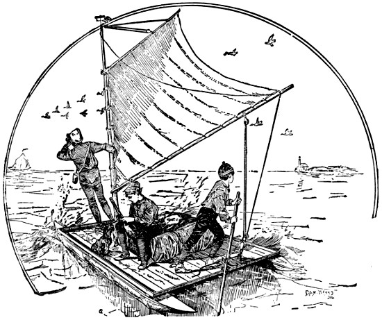
Fig. 10.—A Safe Craft.
Says Mr. Alden: ‘There is no better boat to cruise in than such a catamaran. At night you anchor her, unship your mast, pitch your tent, and sleep safely and comfortably. If you come to a dam you can take the craft apart and carry her round piecemeal. If you once try to build a catamaran and succeed—as you certainly will if you have patience—you will have the safest and most comfortable sail-boat in the world.’
A Case of Sea-birds.
It is surprising at how early an age the sporting instincts of the English race develop. The ordinary schoolboy let loose for the summer holidays, when not actively engaged at any game, is apt to look about him for something to destroy, and to destroy aimlessly and indiscriminately also. Now there are few surer protections against such a reprehensible habit than to make the Creator’s works in some branch or other a special study. The practical entomologist never kills for the mere sake of killing, and when he does deprive of life he endeavours to do so with as little cruelty as possible. Hence we need make no apology for this chapter. When we consider how many men hunt for exercise, or for food or clothing for the body, one can hardly consistently condemn a little margin to feed the mind.
Most boys have a taste for natural history, and the following practical hints may, it is hoped, tend to develop it, by teaching them not only how to destroy life, but how to preserve what they have destroyed. Thus they may learn wonderful lessons regarding the habits and the structure of the marvellous insects and birds and beasts with which the Almighty has peopled this beautiful world of ours.
I propose to begin with hints about butterflies, because the average British boy is apt first to turn his hunting instincts to these. Yet the catching and collecting of butterflies is a pursuit worthy of any age, and, to be done well, requires dexterity, delicacy of touch, and care. Under these conditions, and armed with a few simple implements, there is no reason why any boy should not, in time, become the happy possessor of one of the most beautiful of natural history collections, the which, should fate ever call upon him to leave his native shores, he will, in other climes, find a new pleasure in increasing. For butterflies may be collected in many a dull, out-of-the-way quarter, where larger game is conspicuous by its absence, or the means of pursuing it wanting.
The first consideration, however, is the momentous question, as to which is a butterfly and which is a moth? The answer to this is, that butterflies have blunt ends like pins-heads at the points of their antennæ, and that moths have none. In England there are seventy-two sorts of butterflies, not to be confounded with night or day moths, which number over nine hundred families in this country alone. A point which strikes the collector almost at the beginning, are the extremely local habits of butterflies. In almost every place new specimens are to be found, and the varied flight of each kind will soon lead the collector to learn to detect a new species. These are usually classed by their undermarkings, as many which present the same appearance on the top side are different underneath. My small boy, with[300] his rough cotton net and wild shout, left very little of the unfortunate insect he had captured, to put into his trouser pocket! The greatest care and manipulation are required to procure a specimen fit for a collection.
The net should be of silk gauze, fitted on to the circle of cane, nearly eighteen inches across. The two ends of the cane should run into a T-shaped brass socket. The foot of the T is a screw, which screws into the stick handle, the which may be used also either to hold a gaff or a landing net. The circle of cane should be covered with some soft thick flannel, firstly, that the silk gauze may be sewn on securely, and, secondly, that the butterflies, which are often struck by the rim of the net, are not injured by it. The flannel is, moreover, a saving to the wear and tear of the net.
Another kind of net is the collector’s scissor net, with which you can pick a butterfly off a flower. It is about five inches square, in the form of two bags mounted one on each point of a wire, which opens and shuts.
Having caught the butterfly, the next thing is to kill him. A pinch through the net, across the thorax (the part from which the wings spring) will accomplish this. For obstinate specimens, such as ‘skippers,’ a lethal chamber can be prepared, in the shape of a wide-mouthed two-pound jam bottle, with a well-fitting cork. At the bottom of this is fixed some blotting-paper, on which a few drops of chloroform have been poured. The butterfly should be left in the bottle a quarter of an hour.
The specimens can be carried home in safety in a collector’s box, about five inches long by three deep and broad, in the pocket. Triangular envelopes, varying in size, according to that of the butterfly, are often used. Into these the insects can be slipped with folded wings, and left for any length of time till it is convenient to relax and set him.
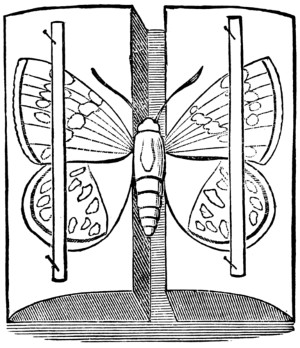
Fig. 1.
Now for the setting of the butterfly. Drying-boards can be bought of any length, made either of soft deal, or, better still, of cork, covered with white paper. They have a groove down the centre to receive the insect’s body. Different widths are required for different-sized insects. Place the row of butterflies to be set down the board, their bodies pinned in the groove. Cut strips of writing paper an eighth of an inch wide. Pin a strip of paper on each side of the groove, about the centre. Secure it additionally by a pin between each butterfly. With the point of a pin arrange the wings equally under the strips (Fig. 1). These drying-boards should be kept out of the dust, or ants or flies may damage the specimens. Some people have a box with a perforated zinc door, into which they slide the boards. I called such an one my meat safe!
In the case of dried specimens preserved in envelopes and which need relaxing before setting, there are two ways of going to work. The first is to float a piece of cork in hot water, and to pin the specimen on to the cork. The wings should not[301] touch the water. A saucepan is a good thing to use, as the lid can be put on. The cork should float high in the water.
But the best plan is to steam them in a tin box with cork in the lid. Pin the insects to the cork and half fill the box with boiling water, and close it. If the boiling water as it cools is renewed two or three times, in an hour or so the insects will be perfectly relaxed. They should then be set at once, after shaking off the drops from the wings, and placed near enough to the fire to feel the heat and to dry quickly, but not too near. The outer margins of the wings should be covered with the setting braces (the paper strips), or they will curl up with the heat. The wings should, if possible, not be allowed to touch the cork when being relaxed, as they suck up the moisture.
A butterfly cabinet with drawers is very expensive, and beyond the means of most boys. Cases to hold the butterflies should be uniform in size, made of mahogany, seasoned deal, or cedar, and lined with cork, to be procured at any shoemaker’s, and fitted with a glass lid on hinges. These can be hung as ornaments against the wall. In one corner should be fixed a little perforated tin match box containing a lump of camphor. The appearance of a collection is much improved by having a piece of black cotton stretched from two pins down the box, between the lines of butterflies. Cases for travelling should on no account be glazed, but be shaped like a book, with a hinge in the centre, that the butterflies may be put on either side.
The pins used had better be the headless taxidermist pins, sold for the purpose, which being so much slighter than the ordinary pins, do not spoil the specimens.
Should the larger butterflies show signs of decay in their bodies, paint them with a little solution of carbolic acid, equal parts of acid and water.
It is unnecessary to catch more than four or five good specimens of each class. First, the male (which is much smaller than the female), secondly, the female, can be set out. Then two butterflies, which have been set with their wings closed to show the undermarkings, can be placed body to body to economise space. The fifth specimen may be some abnormal one of the same class, if such has been caught.
All valuable collections are kept away from the light, which deteriorates them. In the British Museum but few specimens are shown to the general public, and even the cases containing these are covered with a square of American cloth, which the public are asked to replace after looking at them. The real collection is kept downstairs, and can only be seen by applying for an order.
Some of the best specimens in England have been bred for collection from the caterpillar. This accounts, to my mind, for the occasional appearance of some brilliant foreign specimen in this country. It has probably escaped from some one’s menagerie. I caught last year, on the southern coast, a beautiful specimen of the North American linea plexippus in such perfect condition that it could not possibly have been wafted across the Atlantic.
No creature in Nature goes through such marvellous evolutionary changes as the butterfly. It emerges from the chrysalis hanging on the bough, the male appearing fifteen days earlier than the female. This latter lays her eggs, as it were, on her death-bed, and they are hatched the following year into the minutest of larvæ. Each kind of butterfly lays its eggs in a spot where the caterpillar can procure the food[302] peculiar to it. Thus caterpillars kept in confinement require each kind a different sort of leaf. Some caterpillars hibernate and do not turn into a chrysalis till the second year.
In concluding this part of my subject, I must warn boys against handling hairy caterpillars with bare hands, as when the hand touches the face or neck it is apt to produce a rash like nettle-rash.
The wholesale destruction, for the sheer love of taking life, which goes on at all seasons round our seacoasts, is simply appalling. It is trusted that these hints on bird-stuffing may not stimulate it, but rather, by leading boys to take an interest in the marvellous structure of bird life, to venerate and spare it, shooting only here and there a solitary specimen for preservation.
On inspecting a bird which is intended for stuffing, it must be borne in mind that many species change their plumage in summer and in winter. This applies especially to sea-birds, and it is often difficult to recognise an individual in his sober winter garb as contrasted with his rich summer attire. Therefore it is quite allowable to preserve two specimens of the same sex and class, in order to show the difference in their plumage.
Mid-winter or midsummer is the best time to shoot birds for stuffing, as when they have been recently sitting, or moulting, their feathers are apt to be worn or only half formed. Be careful to use only small shot and small charges, at short distances, for small birds, or the skin will be irretrievably damaged. Increase the charge in proportion to the size of the bird, but it should never be a very heavy one. A friend once brought me to stuff a tame parrot of his which had flown away. Thinking to injure the skin the less, he had shot it with a charge of peas, but with the result of crushing it almost to a jelly, tearing the skin so that it was useless.
In the event of the bird being only wounded, press the breast bone in with the finger and thumb till life be extinct. This operation will not take more than two minutes. Push a piece of cotton wool down the throat, a piece of thread through the nose just above the beak, and make a loop to hold the bird by. Carefully examine the bird for any wounds, and stop such with a small plug of cotton wool. This will prevent the blood staining the feathers. Smooth down these with a handkerchief and pull out any that are bloodstained, as the sacrifice of a feather here and there is immaterial.
When the bird is brought safely home, it must be decided whether it should be slit down the back or down the breast, or whether, as in the case of large-headed birds like kingfishers, a small incision should be made in the throat, to skin the head through. But first, as regards the implements for the process, which need only be few and simple—a couple of dissecting knives with celt handles, a pair of pointed scissors, a large fish-hook, and a small gouge for the eyes being all that is required for the skinning process. For the setting-up we must add a file for giving the wires a sharp point, and a pair of compasses to measure the body.
Then place the bird on its back, and cut it open from the top of the breast bone to within a short distance of the vent. If, however, the specimen is one remarkable[303] for the beauty of its breast plumage, the process must be reversed. Break both the wing bones under the wings, and place a clean piece of wool in the mouth. Remove the skin with the celt handle of the knife. Here it must be explained that the term celt handle is derived from the prehistoric flint implements dug up in ancient barrows, and which, being necessarily blunt, have given their names to the blunt bone handles of dissecting knives. As you work along sprinkle the skin with a powder of wood ash, plaster-of-paris, or flour. It is a great help to have a fish-hook run through the top of the breast bone, and held firmly by another person, or tied to a hook on the wall. The neck must be cut through when it is met with, likewise the wings where they are broken, and the top joints of the legs. Use great care in drawing the skin down the back, as that is very frequently the most delicate place.
The Head.—If the head is very much larger than the neck, cut the throat lengthways to remove the head. It is immaterial whether the eyes are taken out before the head is skinned down or after. The gouge should go well to the back of the eye and separate the ligament which holds it to the socket. Should the gouge go into the eye, it will let out the moisture, which often damages the skin. Some people crush the skull slightly to make it come out of the skin easily, but this I do not advise. Remove the brains by taking out a piece of the skull at the back as you cut off the neck. Pull the eyes out of their cavity and fill up their place with wool soaked in arsenical soap. Anoint the skin of the head and the neck well with arsenical soap, and place in the neck a piece of stick covered with wool, the end of which put into the hole made in the skull for extracting the brains.
The Wings.—Remove the meat from the wings on the inside as far as you can skin. When you have taken out the body, to finish the wings, cut them open from the outside under the large wing feathers, which be careful not to detach from the large bone. Remove all the meat most carefully, and anoint with arsenical soap.
The Legs.—Skin down as far as you can, remove the meat, anoint the skin with arsenical soap, and cover the leg bones with paper, to prevent them damaging the skin.
The Feet can be left alone, unless large, when they can be cut into and anointed.
The Tail and the Back, if that of a large bird and very fat, like that of a peacock, should be well covered with wood ash, and scraped till as much fat as can be removed comes away. Then anoint freely with arsenical soap, fill the body with wool or paper, not too full, and close it with a couple of stitches across the breast. Smooth all the feathers into their place, and leave in a dry place before packing, for a day or two. Then pack the paper round the whole, to prevent the skin from being damaged.
So far the skin has only been cured, an operation which, in the case of a small bird and practised hands, takes about seven minutes. Next for the setting up. Though the skin thus preserved may be laid by and keep good for years, and may at any time be set up by a professional, yet it is a great amusement for a boy to stuff his birds himself, and this is how it is done:—
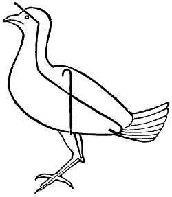
Fig. 2.
The body and the neck which have been taken out of the bird serve as models. The former is copied in tow, wound round with cotton. Through this is run a sharp-pointed piece of wire, bent over and fastened at the tail end. It protrudes beyond the body, is wrapped round with tow or wool to imitate the neck, and run up the latter, from which the stick has been removed. The point is run through the skull, bent back and made fast (Fig. 2).
Then run a sharpened wire up each leg, inside, starting from beneath the foot, and sticking into the body, where it is doubled back. Be careful that these wires are exactly in the centre of the body, or the legs will appear too far back.
The body and neck of the bird are now stuffed, but form a straight line. Sew up the breast with a few stitches, and with the following manipulation give the right curve to the neck: Bend it back at a little more than a right angle to the body, pressing with the thumb where the neck joins the body. Then press with the thumb at the back of the neck, and with the other hand pull the neck forward again. This will give it the desired graceful curve.
In a small piece of board, drill two holes in the position in which you wish the feet to be. Run the wires of the feet through these, turn them back, and fix them. Push the body slightly back, and, at the same time, bend the legs at the joints. If the bird is flying, the legs should not be bent, but straight out parallel with the body.
The position of the wings must also depend on that of the bird. If it is flying, they must be kept stretched out by a wire run through underneath them horizontally, catching each individual feather. If the wings are closed, needle points are enough to pin them through to the body. The thickness of the wire must depend on the size of the bird. The tail must be likewise fixed with wire. The eyes may now be put in by opening the eyelids and forcing them down far enough into the head, and then carefully manipulating the eyelid to get the eye to sit right. When a bird is first shot the colour of the eye should be noticed, and be matched as nearly as possible when buying the glass eyes.
When thus completed, the specimen will often present a battered and ugly appearance, but it is wonderful how much it will improve with careful touching up, and arranging the feathers with a needle point or probe. Varnishing the beak and legs is a further improvement. An artistic effect is obtained by considering the nature and habits of the specimen, and studying its natural poses. For instance, a pheasant struts with a straight neck, a swan sits on the water with its neck gracefully arched.
The arsenical soap above mentioned can be procured at any chemist’s, or made as follows: camphor, five drachms; arsenic, four ounces; white soap, four ounces; flaked lime, four ounces; mix with a little water into a soft paste.
Before using the arsenical soap, be careful to remove every scrap of meat from the skin. Be most careful, also, to wash the hands after using it.
A group of birds can be arranged in a case on imitation rocks, in the following manner: Lay a piece of paper over the wood stand on which the birds are fixed, and arrange it in the shape of rock and stones. Pour over it a hot solution consisting of one part glue, one part whiting, and one part sand, which in a short time becomes very hard. Dried stick, ferns, and grasses, or shells, can be added.
Although the manner of setting-up animals is somewhat similar to that of birds, the mode of preserving the skins and furs is very different. Whereas a bird has a most delicate skin, and is eventually put into a glass case out of the dust, an animal’s hide, in nine cases out of ten, is either used as a carriage or hearth rug, or a footstool, or, as in the case of a head, hung unprotected against the wall.
As in all probability tiger and buffalo skins will not come in the way of the readers of these lines, it is rather such ‘small deer’ as the denizens of our English woods they will be anxious to preserve, to wit, foxes’ heads, cats, otters, stoats, weazels, moles, or water-rats. But the following hints apply equally to a tiger-skin or a squirrel’s:—
Let us begin by imagining the keeper has brought in a fine large poaching cat. Take the beast to an out-house, and in the shade lay it on its back, and with a butcher’s, or indeed any sharp knife, make a long, straight, but not too deep cut, from the centre of the lower jaw to the end of the tail. Then cut down the legs on the underneath side till the cut down the centre of the body is reached. Now separate the skin from the body. If the animal has been badly shot, wash the skin thoroughly in cold soap and water. Place it in water for twenty-four hours. Then take it out and scrape it well from any fat; skin the ears on the inside and plunge it into a hot solution of one part salt and two parts alum, and let it soak well in. The solution should not be hotter than the hand can bear, and the skin should be left in it twenty-four hours. Then stretch the skin, hair downwards, on a board, nailing it with tacks round the edge. Be careful to get it the proper shape, and that one side is not more stretched than the other. Next apply a paste made of one part finely powdered alum, two parts chalk. When this is dry beat it off with a stick, and apply some more where the skin seems still to contain grease. After this remove the skin from the board when quite dry, and the more it is rubbed with the hand, the softer it will become.
Another process is to wash the skin well, and to peg it out on the ground or on a board, to rub it well with wood ashes, and to sprinkle it with carbolic acid and water in proportion of one part to thirty. Next with a knife cleanse the skin most thoroughly of every particle of flesh and fat, and rub in more wood ash till there is no grease left. Then keep the skin perfectly dry till you have an opportunity of sending it to a tanner’s. But no skin or fur, whether tanned or not, should ever be put in the sun. A good shaking and hanging out in the air is the best thing for it.
It is obvious that if a skin is to be used as a rug, the use of arsenic or other poisons is out of the question, though where an animal is to be set up and put in a glass case, like a weazel or a stoat, this rule does not apply. In this latter case an[306] incision is made between the forelegs and down the belly, large enough to allow of the animal’s body being extracted. The skin, when properly cleaned from fat and flesh, is plunged into cold carbolic acid and water, in the proportion of one part carbolic to forty of water. After lying in this for a week, it can be taken out and freely anointed with arsenical soap previous to setting up.
And now for the treatment of the head of a horned animal. Within six or eight hours of the death of the beast, cut off the head with a long neck. Cut the skin down the back of the neck as far as the two horns. Should the animal have no horns, this is unnecessary; should it have spiral horns, cut only up to one and round the other. Then remove the skin entirely from the skull, taking care that the skin round the eyes does not get injured, as it is a most delicate place, the skin there is so thin, and lies so close to the bone. Hang the head up in the outhouse and scrape and clean at leisure. Saw off a bit of the skull, and remove the brains. On no account lose the lower jawbones when they become detached.
Horns that will come off the bone, such as antelope’s, sheep’s, or goat’s, soak for a day or two in a tub of water a week or two after the animal has been killed.
Wash the skin well in soap and water, removing all the bits of meat. Split the lips and skin up the ears from the inside as far as you can, removing as much meat from them as can be filled in afterwards with cotton wool and not detected from the outside when the head is set up. Then place the skin in a jar of carbolic acid and water, enough to cover it, and let it remain there for six or eight weeks, until opportunity occurs to set up the head. It could even be packed up and sent away like this, as it were, in pickle. If the skin be much stained with extravasated blood, a few hours’ soaking in water will draw it out.
Next for the setting-up process. Take the skull, and fasten the upper and lower jaws in their places with wire. Set the skull on a wooden neck, the same length as the natural one, and set this neck on to a wooden shield to hang against the wall. Be careful to set the neck at a natural angle to the head. A deer holds his nose very high; a pig very low. If preferred, the shield can be dispensed with, and the staple by which to hang the head fixed in the wooden neck through the skin.
In many instances a solid wooden neck would be too heavy; but a small one filled out with tow, and fastened into the hole in the skull through which the brains were extracted, will answer the purpose just as well.
Fill the cavities in the skull for the eyes with putty, and put some wool under the jaws, some putty to form the nose, and enough to give a thickness to the nose. Then insert the glass eyes, which, in the case of a large animal, can be made from French wine bottles by breaking out the kick at the bottom. But manufactured eyes are much preferable. I have frequently bought cases of white glass eyes and painted them at the back the right colour. While on the subject of eyes, it may be mentioned that carnivorous animals have the light in the eye down the eye from top to bottom, while granivorous animals have it across.
Next take the skin out of the solution and smear the inside well with a paste of arsenical soap. Put some wool into the ears, and draw the skin over the skull like a glove. Sew up the cut at the back with a shoemaker’s awl. With a few tacks nail the skin on to the shield, and put a few stitches into the mouth to keep it properly closed.
A few pinches and touches will set the head, as it dries, into its natural form. When nearly dry, comb and brush the hair well.
A common mistake is to put wool or putty where there is no meat, which detracts from the wild look of the animal.
Only use white medicated carbolic acid crystal; it liquefies in a little warmth. Carbolic acid is a poison, and will burn the hands and clothes if not carefully handled. The antidote is oil. But when used in the proportion of one to forty parts of water it will do no harm.
The nose and lips of a head can be touched up with a little Brunswick black, and the horns oiled.
In conclusion, let me beg no boy to be discouraged with his first attempt, as often fine furred animals, like a fox, look very woebegone on first emerging from the solution, but improve vastly as they begin to dry and the hair to stand out naturally.
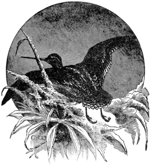
THE SNIPE.
He was a mean-looking man, to say the least of it. Even the coat he wore was a mile too big for him, albeit some time in the far-distant past it might have graced the shoulders of a country squire. Yes, he was decidedly mean-looking, nor did his character, as it came out, belie his appearance.
He shuffled when he walked and he snuffled when he talked, and was altogether unwholesome and undesirable. He and I were the only two—ahem!—gentlemen that stood on the little railway platform of B—— on a cold November morning, waiting for a late train that only stopped by signal.
Having been three or four times round the Cape and twice in the Polar regions, I dare say I look simple. Anyhow, it wasn’t long ere this mean-looking man addressed me.
‘Begging yer parding, sir,’ he said, ‘but could ye spare a trifle to a pore man wot’s got a starving wife and five babs dependin’ on ’im for a lively’ood. Maybe, sir, you’d buy these ’ere ’orns. I seed yer was a lookin’ at ’em, and I seed ye were a gent, sir, soon’s ever I clapped eyes on yer.’
He carried three nicely polished sets of ox-horns in his arms—a large, a medium, and a small.
‘They are very nice indeed,’ I said. ‘Are they attached to the skull?’
‘Oh dear, yes, sir,’ he said; ‘a piece of the skull were a-sawed out for the sake o’ the lovely ’orns, sir.’
‘And where might they come from?’ I asked; ‘and what might be their value?’
‘They belongs to the wild buffalo of the plains of Arfriker, sir. My nevey brought ’em ’ome. Been refused fifteen pound for ’em. You shall ’ave ’em for five, sir, ’cause I can see yer a gent. If I can’t sell ’em, sir, they’ll ’ave to be broke for combs, and that would be a peety, sir, them bootiful harticles, quite a hornament for any gentleman’s ’all like yourn.’
‘Sorry I can’t trade to-day,’ I replied, as I jumped into the train.
I saw no more of the man, for though he alighted at the same town as I did, he sidled his way through the crowd, making determined attempts, one would have thought, to gouge eyes out in all directions with his ‘bootiful ’orns.’ I saw no more of the man, but strange to say I did of the ‘’orns’ that same evening. They had been sold to a friend of mine for just five times their value. They had never come from Africa, of course; the larger pair had at one time probably adorned the head of some Highland bull. The others were probably English.
I do not believe this mean-looking man had polished those horns himself. He looked far too lazy for that; but in justice to the ’orns, if not to the man, I must[309] say they were very well done indeed, and would have made, as he said, ‘quite a hornament for any gentleman’s ’all.’
There is no end to the beautiful articles that can be manufactured from hoof or horn. Stuffed heads with the horns polished look very nice on the walls of rooms or in halls. I was in the drawing-room of a Highland cattle-breeder of fame the other day, and was both surprised and delighted to find on the walls, in recesses and places where there was room, not only the horns but heads, with necks and a portion of the brisket attached, of old favourites looking at me.
A ram’s head, with the crooked horns attached, makes a beautiful snuff-box. The box itself lies between the horns—or rather in the forehead—and is of silver, the lid usually adorned with a gigantic cairn-gorm. My Scotch readers know the sort of thing I mean.
But here we are again with another snuff-horn, more cheaply manufactured too. You simply get a shortish cow-horn and beautifully polish it; then another round flat piece of polished horn to form the lid. To this is attached, by means of silver nails, a piece of cork big enough to fit nicely into the mouth of the horn, and not more than an eighth of an inch thick. Then the lid is complete, and any watchmaker will hinge it on for you. Get also a little heart-shaped bit of silver, let into either the lid or the back of the horn, with the initials of the giver and the givee, thus: ‘From A. H. to W. H.’
Still another—a horse’s hoof. And there are many, many more which I do not at present remember, and need not enumerate if I did. But if you wish to see the many lovely articles that can be manufactured from polished horn, I prithee station thyself for a few brief moments anent a good jeweller’s window in any large city or town in the kingdom, and keep your weather-eye lifting.
Have you ever heard the Latin proverb, Aut Cæsar aut nullus? The English translate it, or paraphrase it, ‘Neck or nothing.’ I have heard a Scotchman speak of a boy in the following terms, which embody the same sentiment: ‘That boy will either make a spoon or spoil a horn.’
Now, then, if you are going to try your hand at horn-polishing, you must please bear that motto in mind, ‘Aut Cæsar aut nullus.’ You must either make a spoon or spoil a horn. But as horns are very cheap in the rough, it does not matter much if you do spoil one or two. Only this sort of work requires patience—and not only patience, but a deal of hard rubbing and much expenditure of elbow-grease.
Well, get your horns first. Where? you ask. You may go to your butcher and explain what you want, and he will tell you that the horns are sawn off with the hide and sent to the tanner’s thus. But if he be a civil man, as most butchers are, he will keep a pair for you, and he will probably knock them off, not saw them, so that you will be at once free from the awkward piece of bone that runs up the first portion of the centre; otherwise you would have to get this taken out.
Now the tools you want are not numerous. A very handy, and in some cases indispensable, one is what is called a spokeshave. It is for paring down the rough surfaces. It is a handy tool for woodwork as well, and as it costs only about eighteen pence, it is as well to have one among your tools. Just let me pause here for one instant to repeat a warning I have given more than once before. Never buy bad cheap tools. What are called boys’ boxes of tools are, as a rule, mere toys[310]—an insult to any growing lad who really means to do proper work. Make your own tool-box; buy your tools separately, and see that they are good. Indeed, it would be as well to get them second-hand at a broker’s shop. No matter if they be a little old so long as the steel is good, and the woodwork neither worn nor cracked.
Well, you must have a good knife with several blades—not a mere pot-metal cheese-cutter. This knife will come in handy for paring and for scraping. And what I myself have found very handy is a piece or two of plain window-glass. Glass makes a capital scraper, and when the edge goes off you have only to break it again and you find another. I shouldn’t wonder if you found a piece of sticking-plaster handy too. Do you know how to bind up a cut? Well, get any dirt there may be in it out first. Then, when the bleeding has stopped, bring the edges together with two or three narrow bits of plaster, leaving a tiny outlet for oozing, put a rag over all, and there you are.
The spokeshave is only to be used in paring down all the rough portions of your horn, and you must work with, and not against, the rough laminæ, that is, from and not towards the points of the horn. You will have a difficulty in holding your work, because the spokeshave is best used with both hands. You may fasten the horn in a vice or on the end of a stick, or any other way that occurs to you.
After the spokeshave the knife will come in handy, but you must have an even surface, and all stains must be removed. You will find the horn get harder and whiter beneath, and semi-transparent. It is down to this you want to go, but no farther.
Then after the knife comes your bit of glass, and while working with this, wherever you see any part out of symmetry, work carefully on that till you get all even and nice. When this is done half the work is finished.
When you have pared and scraped and cut down all unevenness, and have at last got a fairly plain surface by dint of hard labour with spokeshave, knife, and glass—perhaps a fine file may have aided you through some intricacies; this tool comes in handy enough when you want to polish bent horns—then you must have recourse to emery-paper. This is very cheap, and is sold in sheets of different fineness at colour shops or oil-merchants’.
Begin by using the roughest, then finer and finer.
Be tidy with your work. The dust that comes off horn is one of the best things in the world for soiling the waistcoat or nether garments. So place your horn over a piece of brown paper. You thus save your dress and save your dust as well. Put the latter in a saucer, and a drop or two of olive or colza oil over it. Mix and use it with a bit of chamois leather to polish with, after you have finished with the emery-paper or emery-paper and water.
If you feel discouraged and disappointed at want of gloss and beauty, depend upon it you have not worked hard enough. So you must go on again. Use next tripoli, or rouge, or both, first mixed with a little olive oil, and finally dry. Tripoli is the name given to a kind of infusorial earth, which was first found in Tripoli. It is now obtained in certain districts of the United States, and in many parts of Europe.
The name rouge may be somewhat misleading, there being so many different[311] kinds of it. Ladies use a rouge composed of chalk and carmine. This will not do so well for polishing horn. I believe, however, if you take equal parts of carbonate of iron and prepared chalk and rub them up together in a mortar, you will form a very nice rouge for the purpose of polishing either horn or plate. Polishers’ putty-powder is another article used for finishing off horns.
Well, you must put your final touches to the horn or hoof with simple chamois or prepared wash-leather, and after this it ought to shine as if waxed.
You will know by this time that in a horn there is a densely solid tip, and also at the other end a hollow part. The thinner end is used for making combs, etc. It is softened in boiling water, then exposed to a flame till partially fluid, then cut into the shapes desired. In this state the horn can be pulled flat if wished. After it has been pressed and prepared, the piece of horn, comb, or whatever it happens to be, is scraped and polished in the way we have described.
A great many useful articles are made from the solid or tip portion of horns, a great many useful and very beautiful articles, some of which are turned by the lathe, while others are cut. Whip-handles, stick and umbrella handles, and handles for knives and small tools, may be made from horn and afterwards scraped and polished. Goats’ and sheep’s horns are clearer and more transparent than those of the ox. They are not more easy to work on that account, however, but being clear they take staining better. They should be polished before being stained.
I am not sure whether those useful liquid dyes that are sold in the shops would do for staining horn, bone, or ivory, because I have never tried them, but I think if used boiling hot and the articles to be stained thereby were immersed in them for some time, the stain would be permanent. You see I have classed bone, horn, and ivory together, because in this case what is sauce for the goose is sauce for the gander. Here are receipts for a few stains:—
Black.—You may stain these substances black, and wood also, by frequent immersion in hot ink, or by leaving them for a few days in the ink, or in a solution of nitrate of silver, twenty grains to the ounce.
The latter preparation is poison, remember, and it will burn and stain the clothes or anything it may come in contact with.
Black may also be got by boiling in a strong decoction of logwood, and afterwards placing in a bath of acetate of iron.
Purple.—This colour is obtained by boiling in a strong decoction of logwood and alum until the proper tint is acquired. It must be done in an enamelled saucepan, else the colour will be a failure.
Red.—You may steep the article in hot red ink, letting it lie for a day or two. See that you get the best and brightest ink procurable. But you may also get a nice colour by first steeping for ten minutes in dilute nitric acid, then immersing in a decoction of cochineal or cochineal dissolved in liquid ammonia.
Scarlet.—This colour is acquired if you steep the articles or boil them in a decoction of brazil-wood or in madder, and then in a solution of muriate of tin.
Blue.—Steeping in a strong solution of sulphate of copper will impart a light blue. If dark blue is wanted, the article must be boiled in a solution of sulphate of indigo in which a little salt of tartar has been dissolved.
Green.—This is got either by boiling for a time in a solution of verdigris in vinegar, or an article already stained blue by the process above mentioned may be steeped in nitro-muriate of tin.
Yellow.—Immerse for a day or two in a solution of chromate of potash, then for a few minutes in boiling-hot solution of sugar-of-lead. Or you may reverse this order and steep first in the sugar-of-lead solution, then in that of chromate of potash.
Now to return for a moment to our horns. After you have nicely polished them you will naturally want to set them up. To do this you must get a piece of thick softish wood, and shape therefrom something in the semblance of a piece of the animal’s skull and forehead that the horns originally belonged to, leaving at each upper side a piece of wood, rounded, some inches long. To these elongated corners you fix the horns. The next thing will be to cover the wooden skull with something resembling the skin of the animal. Real skin, well preserved, will of course suit best, and it is to be brought round and tacked on the nether side. But black or brown astrakan cloth will generally do very well.
Your work is now finished, and you may hang the horns in your hall if you have one; if not, they will look well above the mantelpiece.
Very nice powder-horns may be made in the same way. Lads who wear the kilt, or Highland dress, sling these in a chain over the chest and shoulders, and handsome ornaments they make.
Bones of any kind are polished by paring, scraping, and rubbing in precisely the same way that horns are; and so is ivory, though it is much more difficult to work owing to its hardness. It is also very expensive.
Tortoiseshell requires great care in polishing, because it is thinner than horn, and you are apt to cut through it. Scrape it carefully first with a knife, then with glass, then with very fine glasspaper and water, or bath-brick and oil; next with rottenstone and oil. But the rottenstone must be specially prepared for the purpose. It should be pounded in a mortar—what a handy thing a mortar is for purposes innumerable! and it is not at all an expensive article—pounded well, and afterwards run through fine muslin. It is used mixed with oil.
The final polish for tortoiseshell is obtained by rubbing hard and well with jewellers’ rouge (a preparation of calcined oxide of iron). This is used upon a piece of prepared washleather.
Imitations of tortoiseshell are made from horn. The horn is a clear sort, and generally brought from the South of Europe. The pieces of horn are softened by steam, pressed flat, polished, and afterwards stained. They are then smeared here and there with a composition made for the purpose, and which may be got in the shops. Before this is put on, the horn is steeped in a weak solution of nitric acid. The paint is left on for a time and afterwards rubbed off, when it will take a polish, the stain remaining as if burned in. I think the paint is composed of litharge and quicklime, equal parts, mixed in whiting-and-water.
Seashells are pretty when polished. There is a deal of stuff to be worked off the outside of them, however, before you get down to the coloured or beautiful portion. Do this by scraping after you have steeped the work for some time in dilute aquafortis.
Practise on a mussel-shell first. Get a good large one. Polish with emery-paper and oil, finishing off with polishers’ putty and oil and rouge. When you have polished your mussel-shell, mount it by means of cement on a small polished slab of marble. It makes a most beautiful paper-weight, and you will find, too, that in this simple shell you have an excellent model of the hull of a yacht.
Stones.—These require, first and foremost, to be sawn into the shape you want them. Then the work must be held firm in a vice while you do the polishing. Soft stone and water are used to begin the smoothing-down. The stone used is called ‘grit-rock,’ and is of different kinds, the finest being used last. Next a stone is used, the popular name of which is ‘snake-stone,’ then polishers’ putty-powder, etc.
Beautiful ornaments can be made from various kinds of stone, and from marble itself.
The art of stone-polishing on a small scale is a very pretty one, and not at all difficult to get up to. I mentioned a vice to hold the work, but a wooden contrivance like what you may see on a carpenter’s bench will do even better. If you have an iron vice, and determine to use it, you must roll your work partially up in old canvas or leather, else the iron will scratch it.
In the art of polishing either stone, shell, or horn, any boy may soon become an adept. It is not half so difficult as it at first appears, only hard work, energy, and perseverance are most certainly required.
DR. GORDON STABLES, R.N.
An endless variety of delights can be enjoyed by the sea. Bathing, boating, fishing, paddling, building sand-castles and forts, engineering experiments in canals and ponds, prawning, shrimping, collecting shells, anemones, and seaweeds, sailing toy-boats, cricket and tennis on the sands. Well, now, you boys who love the pleasures of the seaside, my purpose here is to introduce a new attraction to your notice. The amusement we are going to bring before you possesses more solid and lasting attractions. What say you to PEBBLE-HUNTING as a seaside recreation?
Pebble-hunting is a resource calculated to excite high enthusiasm. It brings us into familiarity with some of the most beautiful objects in Nature. Pebbles can be obtained free of expense. Nature’s inexhaustible treasure-house is always open. She invites you to approach and help yourself at will. She offers with unstinting hand stones of imperishable beauty. It is ungracious to scorn her liberality.
We propose, then, to give particulars of British pebbles—how to recognise those worth collecting, where to look for them, and how to cut and polish them for yourselves. No writer for boys, so far as I know, has ever yet given practical instructions about cutting and polishing stones. The best pebble unpolished looks dull and dead. The polishing brings out its beauty and makes it a lasting treasure. The polishing is nothing else than rubbing the pebble smooth. A flint pebble is so hard that when rubbed perfectly smooth it reflects light just as glass and water do. Nothing is put on to make the surface shine, as in polishing wood. The pebble is merely rubbed smooth; and when this is done, the surface proves to be so hard that no instrument of the hardest steel, not even a file, will produce upon it the faintest scratch. I am speaking of flint-pebbles or agates, which are to be found upon many beaches.
The first difficulty is, how to recognise the good pebbles, as they lie amid the countless host of less interesting stones. I often hear the question, ‘Can you tell what a pebble will be like inside before you cut it?’ The answer is ‘Yes’ and ‘No.’ I can tell so far that I should not labour at cutting and polishing an obviously worthless stone; but, alas! often a stone which gives good promise on the outside proves uninteresting when cut, and so is laid aside on the shelf as an example of unrequited toil not worth any further trouble. This is inevitable. But, far from being a discouragement, such disappointments only serve to stimulate the zeal and sharpen the faculties in discriminating the real prizes.
We must not start with an idea of finding gems upon our beaches. These exquisite objects are exotics, natives principally of dark mines and sunny strands in the far East. The diamond, sapphire, ruby, topaz, peridot, emerald, beryl, tourmaline, turquois, chrysolite, garnet, and precious opal, are not for us. The[315] magnificent agates of India and Brazil are familiar to us when artificially stained and manufactured into bracelets, brooches, penholders, &c., and exhibited in the jewellers’ shops. Splendid specimens in their natural tints may be seen cut and polished in the Geological Museum, Jermyn Street, in the Natural History Museum, Cromwell Road, and elsewhere. But we shall never find such stones on our own beaches.
Oriental and Brazilian pebbles are not unfrequently palmed off upon innocent and unsuspecting visitors as the genuine products of some favoured beach within her Majesty’s British Dominions. A lady once told me that she picked up in a week a quantity of splendid onyxes at a watering-place—let us call it Rocksands—and had them ground and polished into a necklace of beads. Another showed me a beautiful brown onyx, set in gold, which she found (?) in the same neighbourhood. A third assured me that a friend of hers had picked up amethysts and topazes on the same beach. This was at the time when I first began to take an interest in pebbles. The summer holidays were approaching. My portmanteau was packed; I was off to Rocksands.
The long journey was at last accomplished, and the omnibus set me down at the Royal Hotel; when three steps and a jump landed me upon the famous beach. It was crowded with persons of both sexes and all ages. I never saw so many backs bending at one time for the same purpose. They carried baskets, which gradually groaned under the weight of minerals amassed. For three days I joined the glad throng, comparing notes with many treasure-seekers, and collected some hundred and fifty stones possessing better pretensions to celebrity than the obviously worthless specimens.
I took them to one of the lapidary establishments. They are so kind at Rocksands in looking over visitors’ findings and pronouncing upon their merits. The lapidary establishment was crowded. At last my turn came. With beating heart I displayed my beach upon the counter. ‘Oh yes; that’s a fine red carnelian; that’s an onyx, that’s a topaz; that’s a mocha stone; that’s a weed-agate. If you’ll come on Saturday they shall be ready.’
I came, and received some beautiful foreign agates, cut and polished ready for brooches, such as are imported wholesale from Germany, where they work the lapidary-wheels by water-power, and prepare the foreign stones at small cost. At any seaside place, in the attractive shops on the esplanade, you can buy for a shilling a magnificent onyx or agate brooch. It cost me from two shillings to half-a-crown each to have my Rocksands treasures cut and polished! And what were the stones which I actually took to the lapidary? Nothing else than absolute rubbish—pebbles of coarse quartz, slate, and porphyry!
Some years after this a gentleman living at Rocksands collected a number of stones, principally ‘amethysts and carnelians,’ as he was told. He forwarded me two of his finest specimens. They were pebbles of inferior quartz, but I cut and polished them to convince him, and his eyes were opened to the truth. Another forwarded me a stone which had been in his possession for years, prized and habitually shown to friends as most valuable. I wrote back, ‘You found that stone at Rocksands, and were told that it was an amethyst. It is not worth stooping to pick up!’ He replied that I was correct in the locality, but asked me to cut and polish it, notwithstanding the unflattering verdict. I did so, and his eyes were[316] likewise opened. Lapidaries are not, as a class, unprincipled, but some of them seem to find it hard to resist the temptation of imposing upon the simplicity of the public.
A few words about the topaz and amethyst. They belong to the magnificent sapphire group, very precious and exquisite crystals of alumina. Never by any possibility will such stones be found upon our beaches, unless some eccentric person sows them. They are Oriental gems, and I believe they have never been found in England. But there are crystals of quartz (pure flint) which closely resemble in colour and transparency the true topaz and amethyst. Such crystals are found on a large scale in cavities of rocks and mountains—e.g., in the ‘druses’ of the Alps. There are splendid crystals of smoky-brown and straw-coloured quartz found in the Grampian Mountains, known as ‘cairn-gorms.’ Now there is no reason why fragments of such crystals should not be found upon a beach rounded into pebbles, but I do not believe they have ever actually been found in England. A letter in a London daily paper some time ago stated that such amethysts were common in some parts of Ireland. It would be more correct to speak of them as pebbles of amethystine quartz. I have some good specimens of Irish amethysts from the Island of Achill. The so-called amethysts of Rocksands have no pretensions even to transparency.
If I were to tell you that in Cornwall they mend the roads with amethysts you might smile. But it is not so very far from the truth. I have a piece of granite picked up on a new-laid Cornish road full of beautiful crystals of amethystine quartz. The lady pebble-seekers and others might do well to travel west!
The pebbles we really do hope to find are moss-agates, ring-agates, chalcedonies, carnelians, choanites and other fossil-zoophytes, jaspers, conglomerates, shell-agates, variegated flints, and beetle-stones. There are besides large flint ‘geodes’ containing beautiful crystals of quartz, caskets of jewels from the chalk strata, but these are not suitable for cutting and polishing. It is fine exercise to go out with a stout hammer ‘flint-smashing’ under the cliffs of Beachy Head. Splendid treasures of crystal are to be found there, but they cannot be improved by artificial treatment.
Cairn-gorms are now very rare. I once made a pilgrimage into the heart of the Grampians, hoping to find some specimens, but without success. I also spent a day on the beaches of Loch Tay, having read in a mineralogical book that beautiful agates are to be obtained there, ‘in which the imaginative Highlander sees the lakes and mountains of his native land.’ There also I had no success; the nearest approach to agates that I found were fragments of old glass bottles; and I returned with the melancholy conviction that those bottles, when entire, must have contained a certain spirituous liquor dear to the heart of the ‘imaginative Highlander,’ under the influence of which his imagination was excited to set a false value upon the ‘chuckey stones’ at his feet.
A few simple definitions will assist progress. Chalcedony is a form of very pure translucent flint, often also transparent, sometimes tinted with delicate shades of blue, purple, pink, orange or brown. Choanite is the name given to a fossil-zoophyte of the sea-anemone class, with central funnel-shaped body (‘choanos’ is Greek for a funnel), and tentacles radiating from every part. Moss-agate is the pretty name given to chalcedonic pebbles, containing moss-like ramifications in various colours—pink, blue, black, orange, red, and yellow—due to the presence of metallic oxides, and often, no doubt, to the actual colouring matter of some[317] zoophyte round which the pebble originally formed. Conglomerate pebbles contain fragments of chalcedony, flint, etc., embedded in a matrix of different character, presenting an appearance somewhat resembling almond-rock. Translucent, transmitting light, but not the outlines or colours of objects behind it. Transparent, transmitting light, and also the outlines and colours of objects behind the light.
Some of the best hunting-grounds for pebbles are the beaches of our south coast. Taking the map, we may notice in order Dover, Folkestone, New Romney, Dungeness, Hastings, Eastbourne, Brighton, Worthing, Bognor, Littlehampton; in the Isle of Wight—Sandown, Shanklin, and Ventnor: the Chesil Beach, Seaton, and Sidmouth. Here are plenty of shingly beaches for you to choose from, and chalcedonic pebbles are common upon them all. So let us take a ramble, it does not much matter where.
Suppose we select the Chesil Beach, the most extensive accumulation of shingle in the British Isles. There is room to breathe under the frowning heights of Portland Bill, and the sea is so grand! If you wish to be impressed with the majesty of Nature, walk on the Chesil Beach after a fresh gale from the south-west, and the grandeur of the sea will be before you in all the magnificence of its strength.
Here we are! What a wonderful sight! The sea on both sides; nine miles of terraced shingle stretching in a great curve right away west to Bridport Harbour. Millions multiplied by millions of rounded pebbles! How can we possibly find the beauties among such an infinite host? The prospect is indeed vast, almost bewildering. But we will at once circumscribe the portion of beach to be searched. The sea fortunately happens to be calm, and the tide is ebbing. We will confine our attention to the narrow strip just out of reach of the waves, which is not yet dried by the sun. It is a great advantage to hunt upon a wet beach, because the colours and characters of the pebbles are more vividly shown when they are wet than when they are dry.
Now, then, keep your eyes open. You need not stoop. Walk upright, shoulders well back, head merely inclined forward, and eyes as sharp as a ferret’s. You must not get round-shouldered by pebble-hunting, or what will the drill-sergeant say? There is no necessity to stoop at all, except to pick up a stone.
See, there lies one almost transparent. You could not help noticing it. Pick it up and hold it to the light. See its pure, delicate, lustrous substance, a pale grey tint. That is chalcedony—pure flint. Look at it carefully. Now you know the kind of ‘stuff’ we are looking for. It is so clear and glassy, such a perfect oval shape, that it seems a shame to pitch it into the sea. Yet we cannot afford to keep it, for if we once began putting the clear chalcedonies into the bag, it would be filled in a hundred yards.
‘But why,’ you ask, ‘if this is a chalcedony, pure and perfect, must we throw it away?’ Because it is too perfect! It would merely resemble dull glass if cut and polished. There is no incidental beauty about it, no variety of colour and texture, no trace of any animal organism in it. It is too pure. We want the same article adulterated, so to speak, by Nature’s handicraft. We want to find the same substance containing some exquisite workmanship. We want to find such a pebble with some ‘fruit’ enclosed; just as a child wants the piece of jelly containing the imprisoned strawberry, and prefers that to any other portion in the dish.
Try now to find a pebble of the same character with traces of colouring and marking. How beautiful the wet pebbles are! All colours—brown, red, yellow, orange, pale blue, pink, purple, black, white; any colour except green; that is the rarest of all.
Now here is a pebble, part of chalcedony, part of baser flint; the chalcedony tinted red and orange. Look closely into it. Notice those ‘feelers’ delicately spread, like those of a sea-anemone in a pool. Notice the central body, like the eye of a daisy. You see at a glance that this is a choanite. When cut and polished this stone is certain to be a pleasing specimen. It is a good shape; the choanite is so well displayed; there are no serious cracks or flaws in the stone. Those are the points in deciding upon the merits of choanites.
We might make either a cross-section or longitudinal section of it, or polish it all over. However we treat it, it is sure to prove an attractive specimen. Notice that portion where the feelers have disappeared, decomposed, it would seem, during the process of ‘silicification,’ or conversion into flint. The débris of the feelers has become ‘moss,’ and the beautiful tints are probably due to the actual colouring of the creature itself. They are too delicate for iron oxides.
Now let us look again. No; that is merely a common flint variegated with stains of iron. No; that one is no use; nothing organic in it. No, nor that either. Oh! you must not be discouraged; Rome was not built in a day. The excitement of hope, the expectation of finding beautiful treasures, should prevent your getting weary of search, and it will when you have found a few really good stones.
Your eyes will soon be trained to detect the prizes. It merely wants a little practice and patience, and, when the knowledge is attained, what a new world is opened up! Amid the crowd of loungers bending over every pool and rock, poking with the aimless end of an umbrella or walking-stick, picking up occasionally a bit of seaweed or a shell, you pass along unnoticed, and under their very eyes you pounce upon a real treasure—aye, and actually valuable. I was offered ten shillings the other day by a professional lapidary for a stone I found, just as it was picked up. Even if some days may prove unprofitable, still the enthusiasm of hope will buoy you up. The trout-fisher never despairs, though sometimes he returns home with creel almost empty.
There, now! You have found a genuine moss-agate. Let us sit down and examine it closely. Notice that half of the stone is coarse muddy flint, but the other half is chalcedony of a red-purple tint. See these indications of ‘moss,’ black and orange, of beautiful and delicate texture, floating in the chalcedony. Wet the pebble again to make its beauty more vivid. Look hard at it. Look into its translucent depths. Get familiar with that ‘solidified jelly,’ for when you thoroughly understand its appearance you have the key to the whole beach. The chalcedonic pebbles, when decorated with coloured markings, are called ‘agates.’ If they contain moss-like markings, they are moss-agates.
Often in a moss-agate we find evident remains of tentacles, proving that when the pebble was born it contained some zoophyte or sea anemone kind of creature, which in the process of silicification was decomposed. The substance of these agates must once have been a semi-fluent jelly like thick syrup. Perhaps the silicon was plentifully dissolved in the sea water; we cannot tell. It is a mystery of science[319] not yet explained, therefore look with reverence upon this stone. You hold in your hand one of God’s secrets. Look at the choanite again which we found just now. That creature once lived, so frail as almost to melt in the sun when left, perhaps, on the rocks by the ebbing tide. And God has caused it to be caught in the embrace of adamantine flint, to rescue it from dissolution, and preserve it as an object of immortal beauty. The wonderful, unspeakable transformation was enacted in the waters of ocean far back in unknown ages, and the only clue to its mystery lies in that verse of the Psalm: ‘Whatsoever the Lord pleased, that did He in the earth, and in the sea, and in all deep places.’
Choanites always seem to me to speak eloquently of a Resurrection to a glorious state after death. I think of them living their humble life in ages before man appeared on this earth, clinging to rocks in unknown seas, waving their delicate arms with the movement of the waves, gathering the food brought within their reach by the beneficent hand of Him who takes thought for the meanest of His creatures. Nothing could seem less probable, than that these frail creatures should be preserved from destruction in death. God teaches us by them that He who has the power of life and death can stay the progress of corruption in the frailest bodies. They rise, as it were, from the dead after thousands of years, clothed in greater beauty and interest than they ever possessed in life. We should, perhaps, have shrunk from touching them when alive, but as found in their caskets of purest flint they are ‘laid with fair colours,’ and form objects of exquisite beauty. Thus we see them emerge from the grave in glorified form after a death of centuries. God, who ministered to their wants in life, also brought it about that their fragile bodies should not see corruption. He has given them immortal beauty, and by them He teaches us that He is able to deal in like manner with our own perishable bodies. Sown in corruption, they shall be raised in incorruption: sown in dishonour, they shall be raised in glory.
Choanites and Moss-Agates! If you only have patience and perseverance, you are sure to find specimens every time you take a good ramble along a shingly beach that has any likelihood of treasure. Some, of course, will be better than others. Experience will make you fastidious in taste. You will reject those that seem inferior in shape, or damaged and imperfect. Practice will soon teach you. Take your pebbles to a lapidary, if there is one in the town. Weymouth, unfortunately, does not boast one; but there are some at Brighton, I believe, and Hastings. At Worthing there is Mr. Dowsett, opposite the pier; at Eastbourne there is Mr. Hollobon, who has made one of the most magnificent collections of pebbles to be seen anywhere in England, all found, cut, and polished by himself during twenty-five years of labour and research. At Sidmouth there are three lapidaries. At Ventnor there is Mr. Billings, to whom, I think, the palm must be assigned as the most enterprising and skilful of the fraternity.
Take your stones, whenever you have the opportunity, to one of these; he will tell you whether they are worth polishing, and polish one for you at a small cost, if you wish, the charge being about sixpence a square inch. And more than that, he will show you really good stones, and tell you where they were found, and encourage you, if he sees you really interested in the subject.
There are other varieties of these fossil-agates, but the popular names are not worth much. You may call them all agates, and collect specimens of every variety with a view to their intrinsic beauty; and you may try and imagine what the creatures were like, and hunt them up in books as you proceed.
Let us leave the Chesil Beach and speed in a flash of thought some six hundred miles, right away to Montrose, N.B. We cross the estuary by the ferry, and walk down towards the lighthouse. Those low rocks are basaltic, or trap. In them we find a totally different class of agates—Ring-agates: see them sticking like plums in a cake. With hammer and chisel we can knock out as many as we please. Many prove hollow when cut, ceiled and paved with beautiful quartz-crystals. But others have the exquisite ringed formation, and the delicacy of the concentric bands is full of wonder. Among the rocks farther down the coast we can pick up numbers already separated from their rocky cavities by the disintegrating processes of sea and weather. I collected 300 in three days.
It is probable that the cavities in which they occur were formed by gases escaping when the soft rock was growing solid—just as cavities are formed in bread. Then water charged with silicious deposit filtered into the cavities. But no satisfactory explanation of the beautiful parallel banding has yet been set forth. Once more we are confronted by a Divine secret. In these cavities—deep places—the Lord did whatsoever He pleased.
The lapidary’s bench is a very simple arrangement, as can be seen from a glance at the sketch (fig. 1). There is no complicated machinery about it. All that is required is to turn a circular plate of lead or other material with mechanical advantage. For the rest, it is hard work with the coat off and the sleeves tucked up. Plenty of ‘elbow grease,’ energy, perseverance, and the determination to overcome difficulties. Therefore the art of polishing pebbles may exert a beneficial influence in strengthening the muscles and the character of a true Englishman.
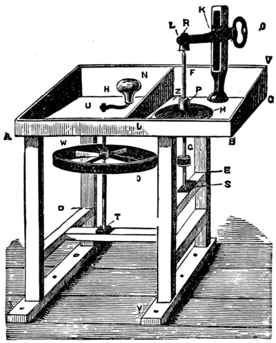
Fig. 1.
My bench, as drawn on the opposite page, was made and furnished with the requisite apparatus by Mr. Moore, 1, Clerkenwell Green, E.C., at the cost of £5. Any carpenter would probably make the bench from the description we shall now give at the cost of £1; and a practical blacksmith could easily manage the metallic fittings. But if you are expert in the simple processes of carpentry you had much better get the wood and make a bench for yourself.
We will describe the bench most carefully, giving all necessary dimensions.
Floor of bench (A B C) is made of seasoned deal 11⁄2 in. thick. From A to B the length is 3 ft. 8 in. From B to C the breadth is 2 ft. Back, sides, and partition are of 3⁄4 in. deal. Breadth of front board (A B) is 3 in.; of back board (V C) 6 in. The legs and cross-bars are of stout deal 3 in. by 2 in. Height from A to floor of room is 3 ft. If that is too high for you stand on a stool to work, but do not make the bench any lower, because in time you will grow taller, and the bench will not. From D to floor of room 1 ft. From E to floor of room 2 ft.
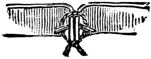
Fig. 2.
The large iron wheel (W) is 1 ft. 10 in. in diameter, fixed on an iron spindle, turned with the left hand by a curved crank (H) 7 in. long, and handle (N) of any wood nicely turned and fitted comfortably for the hollow of the hand to embrace it.[321] The strap (O) is of leather 1 in. wide, passing round the reel (G). Its ends are joined by a simple and effective method shown in Fig. 2. The strap is carefully measured to requisite length; a nail is passed through the two ends, and string wound tightly round the ends behind the nail and tied. If the strap slackens at all after much use, it can be readjusted by a piece of extra string wound tightly round.
Iron spindle (F) 1 ft. 6 in. long, with ‘lap’ (M), screw and nut (P), reel (G). Four circular laps will be required, each with its own spindle, screw, nut, and reel. The reels must be exactly the same size, so that the strap may suit them all alike. One lap is of lead, one of beech wood, one of pewter, one of deal with two layers of common felt strained over and neatly fastened with tacks on the under-side. Each lap is 10 in. in diameter, 1 in. thick at the edge, gradually sloping up to 11⁄2 in. towards centre. Spindles 1 in. square, rounded to sharp points at both ends. Reels 2 in. in diameter, of elm or box, fixed 3 in. from lower point of spindles. The laps are screwed on the spindles as shown in Fig. 1, where all measurements are given.
There is a circular hole in the floor of the bench to allow spindle and reel to pass in and out, 4 in. in diameter. The clamp (I) rises 13 in. above the floor of the bench, and is screwed into position by movable nut underneath. The movable arm (K L) is raised or lowered at will, and adjusted by screw and nut (Q). Length of arm from K to L is 71⁄2 in. A block of lignum vitæ (R) is inserted in arm. Blocks of the same wood are screwed on at S and T for the points of the spindles to work on. These points should be very sharp and only just ‘bite’ the wood, so that friction may be diminished as far as possible. When a hole is worn in the lignum vitæ the spindles can be shifted to a fresh part.
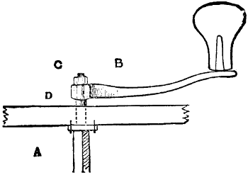
Fig. 3.
The spindle of the large iron wheel is made round at D, Fig. 3, where it works in the floor of the bench. That hole should be lined with soft leather, fitting the spindle like a glove, and kept well oiled. An iron plate (A) keeps the spindle in position. The spindle is, of course, square where the crank grips it at B, and a nut (C) screwed tight keeps the crank in position.
The legs of the bench are let into sleepers (X Y, Fig. 1), screwed firmly to the floor of the room, and clamps at C and elsewhere screwed to the wall of the room may give additional rigidity. The bench must stand true and fast, so that there may be no oscillation during work. It should be placed in front of a window, as plenty of light is desirable.
The following requisites must now be procured. Seven pounds of emery ‘46-hole’; some fine sifted silver sand; some rottenstone in lumps—the hardest is best; some putty powder. Then you will want a housemaid’s blacklead brush, a nail brush with handle, a brush used for cleaning silver plate. These should be old and nearly worn-out. A large earthenware vessel for water to stand on a stool or table at the right side of the bench within easy reach, and three jampots for water. You see that the furniture is of the humblest description.
All being now ready, we may hope to commence operations in polishing a pebble.
There are three distinct processes in polishing a pebble—grinding, smoothing, and facing. Let us take this pebble, a choanite, of a kind which I found at Sandown, Isle of Wight, and which I polished in the first of the only four lessons I ever had. It is a beautiful little rounded choanite, rather flattened on the upper and under surfaces. It is too small to be held comfortably between the thumb and two first fingers. We must therefore fix it upon a cement-stick. So we must manufacture some cement as follows. Here is the recipe:—
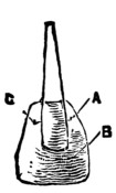
Fig. 4.
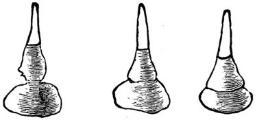
Fig. 5.
1 lb. of pitch, 1⁄2 lb. of resin, 1⁄4 lb. of shellac, 1 oz. of beeswax, must be broken up and put into a good-sized saucepan. Begin boiling the mixture upon a fire, and as it boils add gradually 11⁄2 lb. of Spanish brown, stirring all the while until all the ingredients are thoroughly mixed. Pour the contents of the saucepan upon the stone flags of the kitchen floor, or any pavement, in portions a foot in diameter. When cold remove the cement by a kitchen knife inserted underneath. Make some pieces of wood 4 in. long according to the shape in Fig. 4, and melt on them a portion of cement as shown at B. A nail driven into the wood at A and C will strengthen the cement. Fashion the cement into shape with the fingers well wetted. Warm the stone, and again melt the cement over a candle. Apply it to the stone, and work it on with the fingers. Be sure you have the stone firmly fixed. To test it, plunge the stone and stick into water, and when it is cool see if you can pull the stone off. The diagrams in Fig. 5 show the phases of cementing a stone. If[323] the stone is insecure, pull it off, and warm and melt up again. Practice makes perfect.
The first stage is that of GRINDING. Set up the lead lap as shown in the drawing of the bench (Fig. 1). Put a heap of emery in the left corner of the right compartment (J). Put a jam-pot of water at Z. Take the old blacklead brush, dip it in water, mix up some emery with it into a paste; wet the lap; brush it well over with emery. Take your cemented stone in the right hand, between the thumb and two first fingers; turn the handle N slowly from right to left, and as the lap revolves press the stone upon it. Grind away, understanding that you want to grind down all irregularities on the surface of the pebble. Try and throw the weight of the body through the right arm and wrist into the pebble. Emery is harder than flint. The pressure forces the emery into the lead lap, and so its surface is converted into a powerful rasp. Pause at intervals to brush fresh emery over the wheel. ‘Don’t spare your emery!’ was an exhortation I often heard when receiving my lesson. Do not attempt to do the whole surface of the pebble at once. Begin at a corner and finish it fairly, and so pass on to adjacent parts. Work towards the centre of the lap when grinding round surfaces, and keep the flat margin of the lap for flat stones.
Ah, your right hand begins to ache as it never ached before! You must not mind. Rest a while, and then at it again! You are bringing muscles into play which are unaccustomed to the work, and the strain will be felt until the muscles are strengthened by the exercise. Keep washing the pebble at intervals with the nail brush in the earthen vessel to see how the work progresses.
The surface of the pebble where you have been working now looks smooth, and the feelers of the choanite are vividly shown. Finish in the same manner the whole surface. Feel that you bring the weight of the arm—and even of the body—to play through the wrist of the right hand upon your stone. Do not forget the emery and washing, and see that you keep the surface of the stone true and free from ‘ridges’ and ‘shoulders.’
When you think the surface is sufficiently ground, then continue working on the lead without putting on any more emery. Continue patiently so grinding until the lap works perfectly free from grit, and the emery on it has been reduced to soft black paste. This will make the surface of your pebble much smoother. The nearer you reach perfection in this first stage the easier will be the afterwork. If you continue long enough the stone will look half polished when dry before you have finished. Dry the stone periodically to estimate progress, remembering that a pebble always looks polished when wet.
We may suppose now that you have completed the first process, so we pass on to the second.
Smoothing.—Lift off the strap by raising the part nearest to you off the wheel, and let the strap lie loose upon it. The strap consequently falls off the reel. Unscrew Q. Raise the arm K L, which remains raised by its own weight. Lift the lead lap carefully out and put it aside. Set up the beech wood lap instead. Use another jam-pot of water at Z, and see that no emery-grit gets upon the wood lap. Dip your right hand in water and thoroughly wet the surface of the lap while it slowly revolves. Then dip the wet fingers in sifted silver-sand[324] and rub them over the wood, and proceed as you did in the first process of grinding.
Our aim now is to smooth the surface of the stone, to carry to higher perfection the work of the emery. Do not go too fast, and keep the stone and lap well wetted, otherwise the heat caused by friction will crack the surface of the stone. Many a beautiful stone has been spoilt in this way. Do not use much sand. Wash and examine the pebble as you go on. See how beautiful it is getting to look! How wonderfully the texture and organism have been brought out by the smoothing! Make the work as perfect as you can upon the wood, and continue working your pebble without putting on any sand, until the wood seems free from grit. In the last stage of this smoothing process we work the stone almost entirely on moist wood, as the sand has been reduced to powder. Wipe the stone dry, and if you are satisfied that you cannot do anything more for it on the wood, we may pass on to the third process of facing the pebble.
Facing.—As before, remove the wood lap. And now we must proceed with extreme caution. We are going to set up the pewter lap. Bear in mind that ONE GRAIN OF SAND OR EMERY UPON THE PEWTER WILL RUIN YOUR WORK! The floor of the bench is covered with débris of sand and emery; there is a heap of emery in the corner. How can you possibly prevent catastrophe? Care and practice will bring success. Remember the caution, and you will do your best to keep clear of disaster. First of all sweep up the emery into a heap at J, keeping it well away from the vicinity of the lap. Thoroughly wipe the handle N, the clamp I, and the arm K L—everything that could bring a speck of grit upon the pewter. Shut the window, that no wandering breeze may work mischief. Wash your hands in a bowl of clean water, and put the bowl in place of the earthen vessel. Jam-pot of clean water at Z. Now set up the pewter lap. The first thing is to ‘notch’ the surface of the lap, that it may hold the rottenstone. This is done by holding a table-knife lightly by the handle in the right hand, and letting the edge of the knife play upon the surface of the lap as you slowly turn the handle N from right to left, and then from left to right. The result of this is to set up a ‘bibbering’ movement in the knife—such as you may notice in the bow when a nervous young lady is performing upon the violin. The surface of the pewter will soon be decorated, as in Fig. 6, with markings not unlike the pattern on the case of a watch. When this is done wash the surface of the lap by dipping the fingers of the right hand in clean water. Take a lump of rottenstone, thoroughly washed and free from grit, and press it on the pewter while slowly revolving. The rottenstone is conveyed as a brown paste to the surface of the pewter.
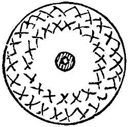
Fig. 6.
Now scrub the pebble, cement and stick with the plate-brush in the bowl of water, until you feel certain that no speck of grit lurks in any crevice, and begin working the pebble on the pewter lap as in the other stages, putting pressure through the wrist of the right hand, and letting the weight of the arm play, so that a sort of rhythmical movement is imparted to the pressure difficult to describe, but soon understood when you see a lapidary at work.
In polishing a round stone you must be careful to avoid producing ‘ridges’ by[325] dwelling too long on one spot. Keep on turning the stone slightly. Common sense will explain my meaning. And in this last stage BE SURE YOU NEVER WIPE YOUR HANDS OR YOUR STONE WITH THE CLOTH USED FOR THE SAND OR EMERY STAGE. Use a clean cloth. It took me two years to find out the force of this simple advice. I could not imagine how it was that just at the last moment, when I was putting the finishing touches to a pebble, some faint but hideous scratches would suddenly appear on its surface, ruining the beauty of the work. How many times have I despaired of success! How often have I written to lapidaries imploring advice, and feeling that there was some ‘wrinkle’ which had purposely been kept from my knowledge! But perseverance was at last rewarded.
There is no ‘dodge’ about it; the whole operation is one of patient labour and determination. After a little working on the pewter lap at one portion of your stone, wash and wipe it. That portion ought to be so perfectly polished that when held slantwise towards the window it reflects the landscape like a looking-glass; and if your work has been true this result will make your heart leap with delight. Continue working until the whole surface of the stone is finished. If at the end portions of it looked blurred, it may be that the texture of the stone is incapable of a high polish in such places; it may more likely be that you have not been particular enough in the first and second stages. Nevertheless the result ought to be encouraging. Your stone ought to be so far polished that you will be proud to show it to your friends, and say, ‘I found and I polished this stone!’
Probably, if you have carefully followed out my instructions, the result will be very creditable for a first attempt. And this is all you have a right to expect.
Some lapidaries, after smoothing their stones on the sand lap employ an elm lap with powdered pumice-stone, and dispense with the pewter lap altogether, facing the stone on the felt lap with putty powder. This process is advantageous in polishing stones all over. But on carefully comparing the systems I am convinced that there is nothing like the pewter and rottenstone for general purposes; though the felt is advisable for round stones when they are to be polished over the whole surface. As you proceed you will be able to try experiments at your discretion.
To polish flat surfaces of pebbles we work exactly as we have described, the only difference being that you work the stone flat on the margin of the laps. If you thoroughly understand the principle you will find the flat surfaces easier to manage than the round.
Mussel and other sea-shells, snail-shells, etc., may be polished in the same way—only that being soft they will not require the emery lap. Work them on the sand lap and cloth lap, and a little experience will soon make you proficient in the art.
We have reserved the process of CUTTING a pebble till the last, because it is advisable to understand the polishing process first. Many pebbles make most attractive specimens without being cut, but no pebble looks well after it is cut unless it be also polished. Therefore the polishing is the first essential, and I hope you thoroughly comprehend its principles and are enthusiastic about the whole subject.
To cut a pebble, with a view to polishing its inner surface, we want a spindle and reel as before, fitted with a disc of the thinnest soft iron. These discs are of particular make, and must be procured from a practised maker. You should get six of them, ten inches in diameter, from Mr. Oxley, 83, Caledonian Road, Islington, N. The shoulder for the disc to rest on should be about five inches from the upper point of the spindle, and the nut must be screwed home very tight to keep the disc in position. The disc is ‘panned,’ i.e., beaten into a saucer-shape so shallow as to be hardly perceptible to the eye. This precaution is necessary to ensure the edge of the disc being true, for otherwise it would be impossible to make such thin iron free from undulations in the edge.
The discs are by no means cut true when sent down, and as they must be brought to absolute perfection of truth before they can be used, the first thing will be to turn the edge true.
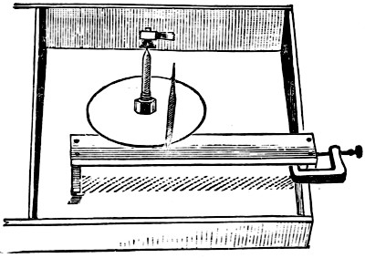
Fig. 7.
Procure three small triangular files, sold at fourpence each. Break an inch off the end of them, and grind them with emery on the lead lap into a pyramidal point (Fig. 7), with edges as keen as a razor and point sharp as a needle’s. Set up the ‘slitter’ (the disc and its spindle) in position, taking care that it stands truly perpendicular. Then arrange a wooden rest underneath the edge of the disc nearest to you, as shown in Fig. 7. The support must be securely fixed, and of the exact height to enable the disc to revolve upon it. Wet the edge of the disc, and turn the handle N with the left hand. Take a file and fix its point into the wooden rest, so that a keen edge may catch the edge of the revolving disc. This will take off a shaving of iron wherever it bites, and by degrees the edge of the disc will be turned true, and continuous shavings will curl off it. There is nothing difficult about this. It requires a neat hand, and you may want to use three files before finishing; but when you understand that you require the edge of the disc to be perfectly true you will soon attain the result; and by lightly applying the file to the upper and under surface of the edge of the disc you will remove any roughness caused by the turning, and the disc will be ready for use.
Remove the wooden support. Put a common plate under the slitter to catch the paraffin, which will shortly require notice.
The disc has now to be CHARGED WITH DIAMOND. This sounds somewhat alarming, but take courage. Diamond ‘bort’ consists of genuine diamonds not sufficiently good to be used for gems. It may be bought of any of the ordinary merchants at a cost of about six shillings the carat. That amount would be enough to cut about twelve or fourteen pebbles an inch and a half in diameter. This is the only serious expense when once the bench has been set up and furnished. And after all it is not very formidable. Take a fragment of[327] bort, and crush it upon a piece of hard steel by means of a steel rod one inch in diameter and six inches in length. Put the bort on the steel plate; smear a little butter over the bort to prevent the broken pieces flying away. Hold the steel rod upon it, and give it a smart blow with a hammer. This crushes the diamond. Then pound it into the smallest possible powder, using the steel rod as a pestle.
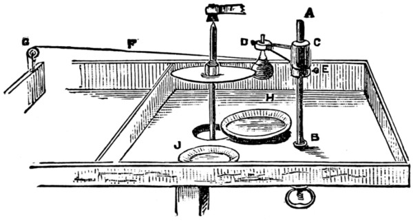
Fig. 8.
Now pour some paraffin into a saucer (J, Fig. 8), and with a feather smear paraffin over the edge of the disc revolving slowly. Take some of the powdered diamond on the forefinger of the right hand, and very carefully transfer it to the edge of the disc. The entire edge must in this way be anointed with crushed diamond-dust. Then a smooth pebble is taken in the right hand (the hand resting comfortably on a support G), and pressed against the edge of the disc revolving. Let us understand exactly the object and action of this. The diamond-powder is the hardest known substance in Nature; the disc is of soft iron; the flint pebble is very hard. By the process just described we press the diamond-powder into the substance of the disc, so that the edge becomes armed with grains of adamant; the edge becomes a mighty file, or an irresistible saw. The principle is so simple. When you have driven sufficient diamond-powder into the edge of the disc, you have invested the iron with an armature which can cut through every hard substance that exists in Nature except the diamond itself. The hardest flint, emery, iron, glass, metals, etc., must all bow beneath its mighty power. I should like to shake hands with the man who devised this simple and clever method. Before its invention agates kept their treasures locked in close caskets. The diamond-toothed ‘slitter’ has supplied the key for unlocking their secret beauty.
Well, now, the disc is CHARGED, and if you wish to proceed like most of the lapidaries do, you will take the pebble you wish to cut between the forefinger and the thumb of the right hand, letting it rest on the second and third fingers. You will place the support in position, that the hand may rest comfortably upon it when holding the pebble against the disc; and you will begin turning with the left hand. You will soon see that the disc has begun to cleave its path. A distinct cut is visible. You must keep feeding the edge with paraffin by means of the feather; and as, unfortunately, you have not got a third hand, you must hold the feather between your teeth, or else get a friend to do the turning. It ought to take about half an hour to cut an inch through a pebble two inches in diameter. The disc will have to be re-charged with diamond occasionally, which may be done by using the slit of the pebble you are cutting as a ‘charger.’
Such is the method of cutting in vogue among most lapidaries. It answers very well for professionals, but it certainly presents more than one objection to amateurs. I found the objections so weighty that it required no small determination to persevere. First of all, it is very difficult to hold the stone true, so that the cut shall proceed in the same straight line; then the paraffin and detritus of the cutting cause such a disagreeable ‘mess,’ in which the right hand has to take up permanent quarters, and the nuisance of feeding the paraffin by holding the feather in the mouth is very great. Finding these objections a grave impediment to success, I bethought me of a device I once saw used by a lapidary, and improved upon it in design, and got a tool made by Mr. Moore, of Clerkenwell, which has proved the greatest comfort and most complete success, entirely obviating all the[328] disagreeables alluded to above. The diagram (Fig. 8) ought to make it clear to you.
A B is a circular steel rod, with shoulder at B, and screwed underneath, rising ten inches above floor of bench. It has an arm (C D) moving easily round, which can be set at any height by screw and nut (E). At D is a hole large enough to admit the cement-stick with pebble attached. This is held securely by a screw at D. A string (F) is slipped over the cement-stick just above the pebble, with a weight attached to the other end. The string passes over a pulley (G) in the opposite side of the bench. It is obvious that the weighted string will always keep the pebble with even pressure against the disc. The result is that all difficulty in holding the pebble is removed. The pressure is constant, and the cut is made perfectly true. The right hand is now free to manipulate the feather for lubricating the disc, and you can work without getting a drop of oil upon your fingers. You turn the handle as briskly as you like. The large wheel multiplies the reel ten times—i.e., one revolution of the handle produces ten revolutions of the disc. I often attain a speed of fifteen hundred revolutions of the disc in a minute when cutting a pebble! Keep all points of friction well oiled, and everything will go merrily as a marriage bell. H shows the plate for catching the drops of paraffin and detritus from the stone; J shows the saucer of paraffin. The length of the arm (C D) is ten inches. When you want to recharge the disc with diamond, lift the weight at end of string, shift the arm and the stone to the right, feed the edge of the disc with diamond, and drive it in with a smooth stone as before described.
When your stone is cut through wash the halves, and remove the cement by heating over a candle. The same cement will do for many stones.
You must be careful not to bend the slitter or spoil its edge. Never put it away leaning on the disc. Keep it when not in use suspended by two strings, and wipe off the oil carefully when you put it away.
We have now gone through the various processes of GRINDING, SMOOTHING, FACING, and CUTTING pebbles. You have a clear knowledge of ‘how it is done.’ It remains for you to decide whether or not you are to become a practical lapidary. Remember that it is one thing to know how to work and another thing to put that knowledge into practice. If you resolve to take up the subject you should certainly make friends with some working lapidary, and get him to let you watch him at work, and if possible take a few lessons from him.
Since the foregoing chapter was prepared, W. B. has written to us from Ipswich: ‘I have been very interested in your article on stone polishing. I found, however, that with two hands free you could work the stone much better; so I bought a treadle and wheel (1 ft. 6 in. through) together, then for the grindery dovetailed two boards into one another, and having centred the upright ones, put a hardened coach-screw in, and turned an elm spindle 2 in. thick, and at one end turned a series of pulleys. Then at each end I drilled holes and screwed coach-screws in, after having centred their square heads and drilled a small dent for the other screws to work on. Next I got some wood “bobbins,” turned 5 in. through by 11⁄2 in. thick at hole on spindle, tapering to 3⁄4 in. The pulleys, of course, were for the driving speed, so that by putting the strap on the small one I could drive fast, and the large one slow.
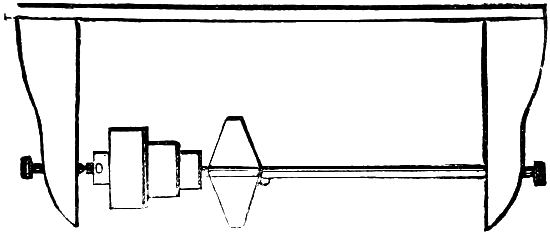
2 ft. 6 in.
‘Above is a rough drawing of the lathe part.
‘The best of this is you can screw the “lathe” to the table, and place the driving-wheel where you like, provided you lengthen or shorten the strap. I might add that the cost of the whole thing is under ten shillings.’
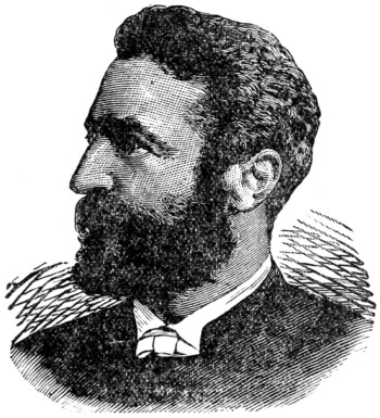
REV. A. N. MALAN, M.A., F.G.S.
Although for the last year or two its popularity has been somewhat on the wane, there can be no doubt that the copying machine, known by the various titles of chromograph, hektograph, multigraph, centograph, and others of similar nature, is a most useful invention, and one which saves an immense amount of labour to all those who wish to draw out a number of copies of diagrams, plans, circulars, letters, music, etc., without calling in the assistance of the printer. Drawings, too, may be traced by those who have no original artistic powers, programmes may be made out for entertainments, and in a hundred other ways the machine will prove a most profitable investment. Its chief disadvantage lies in its expense, but as the entire machine can easily be made at home for a very small cost, this drawback is more apparent than real.
The process of graph-making is a very simple one, and cannot fail if the directions which I am about now to give are implicitly followed.
The apparatus required is of a very limited character. First you will want an old tin biscuit-box, sound as to the corners, and of moderate depth. A saucepan would answer better still, but as you would probably never get it clean again, I do not recommend its use. Then you will require a short stick or rod with which to stir the composition, a spirit-lamp (or a gas-jet will do nearly as well), and a stout carpet-needle fastened into the end of a wooden handle. Finally, you must have a shallow tray to hold the composition, and also the ingredients themselves.
The tray must be of metal, and nothing will be better for this purpose than the lid of your biscuit-box, unless you wish to make a graph of phenomenal proportions. In that case, of course, you must get an ironmonger to make you a tray of the required dimensions, and be prepared to add an extra shilling or so to the necessary outlay. For all ordinary purposes, however, you cannot improve upon the box-lid.
Now as to the ingredients, which, for a graph of medium size, will be as follows:—Glycerine (common), eighteen ounces; water, twelve ounces; sulphate of barium, six ounces; powdered loaf-sugar, three ounces; Nelson’s gelatine, three ounces. The first and the third of these you had better get at a manufacturing chemist’s; ordinary druggists are apt to charge rather highly for the former, and do not keep the latter in stock. Each ought to cost you one penny per ounce. Nelson’s gelatine you can procure from almost any respectable grocer at fourpence-halfpenny per one-ounce packet. The total cost, therefore, of the compound should not exceed three shillings and twopence.
Everything being in readiness, place the ingredients in your biscuit-box, taking care that the proportions are measured correctly, and place them on one side for [331]four-and-twenty hours—this in order to allow them to macerate. Next day you will find that the gelatine has swollen to a wonderful degree, and has absorbed most of the water. Still, however, the mixture will be very far from perfect, and in order to complete it you must have recourse to heat. The best thing that you can do is to place the box upon the kitchen stove, and there leave it for two or three hours until the gelatine has melted. Take care, however, that the heat is not too great, or your composition will probably be spoiled.
Every half-hour or so stir the contents of the box with your stick, in order that they may thoroughly amalgamate. Lastly, when the whole is reduced to a thick, creamy-looking liquid, give a final stir, and pour the mixture into your tray, which you will have placed ready to receive it.
Most likely a number of air-bubbles will be floating on the surface of the liquid. These you must get rid of at once, or you will never be able to get off a clear and neat impression.
This part of the business is very easily managed. All that you need do is to heat your needle to a red heat, and touch each bubble in turn with the point. This treatment will cause them to burst, and by the time you have destroyed them all the composition will begin to set. For the next half-hour you must leave it perfectly undisturbed, upon a level surface, and at the end of that time it will be ready for use.
If all has gone well, your graph ought now to present the appearance of a pale yellow slab, yielding and rather clammy to the touch, and with a peculiarly glossy surface. This gloss will vanish after you have taken off your first impression, but that you need not trouble about.
When you wish to make use of your machine, write your letter or circular, or whatever it may be, with the special ink, and take care to make the up and down strokes as nearly as possible of the same thickness throughout. Let the writing dry, without blotting it, and then lay the sheet of paper face downwards upon your graph. Take care that in so doing you get no air-bubbles. If you do the result will be an uneven impression.
Now rub lightly with your finger over the whole of the paper as it lies upon the graph, in order to make sure that every part shall be in actual contact with the composition. Then, after about a minute or so, remove the paper very carefully, lifting it by one corner, and you will see that a reversed copy of the writing—a ‘negative,’ in fact—remains upon the graph.
Without loss of time take another sheet of paper, lay it upon the writing, rub as before, and remove after four or five seconds. An exact copy of the writing will by that time have been transferred to it, and by repeating the process you can take any number of impressions, up to fifty or sixty, that you may happen to want. As soon as you have printed off a sufficient quantity, wash your graph with cold water, rubbing lightly with a piece of clean rag until the writing has almost disappeared. Then dry, and put away until again required for use. If you leave it for any length of time before washing, the ink will sink deeply into the composition. This will not matter once or twice, but if you make a practice of allowing it to do so your graph will in course of time be simply saturated with the ink and will assume a deep violet hue.
The copies which you will have taken will probably have absorbed some of the moisture from the graph and curled up into a kind of spiral form. These you can easily straighten by means of warmth and a little judicious pressure.
After you have used it a few times the surface of your graph will most likely become rough and uneven and unfit for further service. When this is the case, cut the composition out of the tray with an old knife and melt it down afresh. When thoroughly liquid, stir it well, pour it back into the tray, and eradicate the bubbles as before. Do not melt it down in the tray itself. If you do the glycerine will rise to the surface for want of proper stirring, and utterly ruin every sheet of paper you place upon the machine, obliging you to melt down the composition over again before it can be of the least use.
After melting the mixture some fifteen or twenty times you will find it necessary to add a little water, and perhaps a small quantity of glycerine also, in order to replace that which has passed off by evaporation. Be careful not to overdo it, however, for a very slight error in the proportions of the different ingredients will render the mixture useless.
Ink you had better buy; it is cheap enough, costing only about ninepence a bottle, and can be obtained almost of any stationer. You can manufacture it yourself, of course, by making a saturated solution of one of the aniline dyes (mauveine is the most powerful), and adding a few drops of glycerine, but, so far as my own experience goes, the home-made article is never really satisfactory, and does not give nearly the number of copies yielded by that which is specially supplied. Always procure violet ink in preference to black or red. It is far more powerful, and gives better and more numerous impressions.
N.B.—If you should happen to spill some of this ink on your fingers, wash them at once, or you will not be able to remove the stain without considerable trouble.
One word in conclusion. Never put your graph away while wet. If you do, the composition will absorb the moisture, the proper proportions will be altered, and before very long you will find that the printing power of your machine will be a thing of the past.
I do not know what first made me take to deciphering cryptograms. I do not think I have more of the Paul Pry in my nature than most of my neighbours. If, for example, I saw two lovers whispering together, or heard two people talking aloud by my side in a language which they mistakingly imagined I was not familiar with, I would put my fingers in my ears or walk right away rather than listen to a word of their secret. But seeing a letter in cipher in the ‘agony column’ of one of the dailies always appeared to me to be a kind of challenge to my ingenuity; and, at sea, I have taken the newspaper directly away to my cabin, and never raised my head from over it until I had puzzled out the cryptogram.
This would, of course, often be a work of some hours, but it passed the time away, and that itself is something to an idle sailor. Besides, there was some satisfaction in knowing that I was the only officer in the mess who could read difficult ciphers; and there was, too often, a good deal of amusement to be obtained from a perusal of these secret missives.
Thief often writes to thief, and evil-doer to evil-doer; but the letters are more often those of lover to lover, and innocent enough too—aye, and I might add ‘green’ enough, as well as innocent. Each of the two correspondents has a copy of the alphabet they write in. In this alphabet some other letter or figure is used for the real one. For example, they might put the first three letters of their mysterious alphabet thus:—
| A | — | G |
| B | — | 5 |
| C | — | R |
and so on through it all. Then, if they wanted to write the word ‘Cab,’ it would read ‘Rg5’ in the agony column, and who, they wonder, that has not a copy of their key, can find this out, or know that they have chosen a ‘g’ to stand for an ‘a,’ a ‘5’ for a ‘b,’ an ‘r’ for a ‘c,’ and so forth.
But simple ciphers, when one letter or figure is substituted for another, are very easily read. If I saw the following, for instance: ‘2ssx 2s 5! 2??tnpo7x gn?ts 2! W?wwsx6,’ as soon as I glanced my eye over it I should be struck with the triple recurrence of double letters. Thus, in the first word, there are double S’s, in the fourth double marks of interrogation, and in the seventh double W’s.
Then I would ask the question of myself, ‘What are the letters most commonly doubled in the English language?’ They are the vowels e and o at the beginning of words; the consonants p, r, l, m, n, in the middle of words; and the letter s or[334] l at the end. The double letters in the word 2ssx I guess as ‘E’s.’ Well, a consonant would come before them, and what one more natural than ‘m.’ ‘Mee,’ and the ‘x’ must be ‘t.’ ‘Meet me;’ and after a little more thinking, puzzling, and conjecture, we would make out the cipher as ‘Meet me by moonlight alone, my poppets.’ Of course this would not be all the cipher; there would very likely be several words more, and this would make it all the less difficult to read.
Now take a further illustration, that presented by the ‘Language of the Restless Fays,’ as published some years ago:—
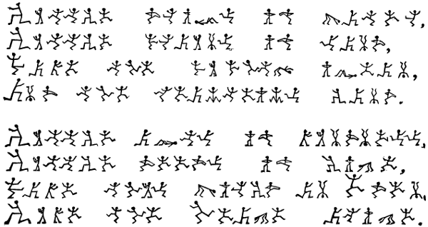
Here you have two very well-known verses written in the language of the Restless Fays. It is exactly the same as English, excepting in the forms of its letters. The Fays have twenty-six distinct positions, one for each letter of the alphabet. Now, who can read these verses? The first letter is an ‘L.’
Glancing over the verses, we find two of the same Fay that ends the first word standing together in the second word of the sixth line, and next to the first letter; they must, therefore, we think, be ‘O’s’ or ‘E’s,’ but ‘O’s’ do not often end words, so they must be ‘E’s.’ Down with them as ‘E’s.’ Our first word would now have got as far as this, ‘L . . . l e,’ the dots representing the letters still to be supplied; the second letter must be a vowel, and the double ones, therefore, consonants. Now run over the alphabet in your own mind, and see what two consonants are most likely to make sense before the finals l e. Why two ‘T’s’ would, and an ‘I’ before that completes the word ‘Little.’
Now we have four known letters to begin the battle, so we go over every line and top the Fays wherever we find them representing ‘L’s,’ ‘I’s,’ ‘T’s,’ or ‘E’s.[335]’ But the second words of the third, the fourth, and the eighth lines are precisely the same. They are words of three letters, and they end in the Fay we call ‘E.’ Now what is the commonest word of three letters in our language ending in ‘E’? Why ‘the,’ to be sure. These little words must be ‘the’s,’ so we mark them so, and this gives us another letter, namely, ‘H.’ Then we mark all our ‘H’s’—they are but few—and go on again rejoicing; and presently our eagle eye is riveted on the first word of the fourth line represented by three Fays, one kneeling like a volunteer, the other standing on his head, and the last touching his left toe, and we are not slow to notice that the last word in the same line ends with those three foolish Fays, preceded by an ‘L.’ So the second letter of that word must be a vowel, and it is neither ‘E’ nor ‘I.’ So it must be ‘O’ or ‘A.’ But the word ‘and’—a very common one—would with an ‘L’ prefixing it make the word ‘Land.’ Hurrah! we have it then. The first word of the line is ‘and’; the last is ‘land.’ And we hasten to put down all the ‘N’s’ and ‘A’s’ and ‘D’s’ in the verses over the heads of the representative Fays as before.
Glancing over the lines we find we have got nearly all the last word in the fifth line except the first and the two last letters, thus:—. I N D N E. . The two last are the same, two mad little Fays, running apparently for their dear little lives. Now ‘L’s’ and ‘S’s’ are both common as double terminal letters; but here the S’s make sense, and the L’s would not. The word of course is kindness.
Two more new letters? Why, we are getting on. Down they go.
It isn’t difficult now to guess the words love and above, and we have Eden and sand and this clear above us. We see, too, in the verses four words of the same two Fays each. The first Fay is O, so the second must be F, because it is not N nor H.
Now I’ll go no farther with you in the language of the Restless Fays. It would only be insulting my readers if I expressed a doubt of their being able to puzzle out the absent letters in the other words, ‘. o. l d’ you would readily guess would be ‘world,’ and that would supply you with an ‘R’ for the second word of the second line, namely, ‘r a i n s’—‘grains,’ of course. And so you quickly finish the cipher:—
Though, by the way, the printers have accidentally dropped the final letter in ‘Heaven.’
You will now understand that simple ciphers can with a little experience be easily read. Just try your ingenuity on the first one you find in any daily newspaper.
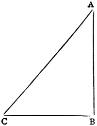
Here, by the way, is a kind of cryptogram which is difficult to decipher, and in which you might write to a friend through the public prints with comparative safety. The key to it is a rectangular triangle, and you write the word you want to[336] transpose from A to B (vide figure subjoined), the transposed word will be found at A—C. Thus, suppose we wanted to write the following sentence, which you will perceive contains nothing but the truth:—‘The Boy’s Own Paper is the best magazine of its kind, and we all dearly love it.’ Well, take your first word, ‘The,’ and arrange it in a triangle, filling it with the letters which follow naturally in the Alphabet, thus:—
| T | ||
| H | I | |
| E | F | G |
The word ‘The’ thus cryptogramised becomes ‘T I G.’ Now let us form a few of the other words in triangles, all in a row to save space:—
| B | O | P | I | T | B | M | |||||||||||||||||||||||||||||
| O | P | W | X | A | B | S | T | H | I | E | F | A | B | ||||||||||||||||||||||
| Y | Z | A | N | O | P | P | Q | R | E | F | G | S | T | U | G | H | I | ||||||||||||||||||
| S | T | U | V | E | F | G | H | T | U | V | W | A | B | C | D | ||||||||||||||||||||
| R | S | T | U | V | Z | A | B | C | D | ||||||||||||||||||||||||||
| I | K | L | M | N | O | ||||||||||||||||||||||||||||||
| N | O | P | Q | R | S | T | |||||||||||||||||||||||||||||
| E | F | G | H | I | K | L | M | ||||||||||||||||||||||||||||
and so on, and we would thus find that our little cipher would read thus:—‘Tig Bpav Oxp Pbrhv it tig bfuw mbiddotm,’ &c.
Now there are two things to which I wish to call your attention in this cipher: first, the primary letter of the transposed word is the same in every case as the original; and secondly, the letters are different in each word. Just observe that the ‘T’ in the word ‘The’ remains a ‘T,’ but in the word ‘Best’ it becomes a ‘W.’ The ‘I’ in the word ‘Is’ remains an ‘I,’ but in the word ‘Magazine’ it becomes an ‘O.’ In the latter word the first ‘A’ becomes ‘B,’ and the second ‘D,’ and ‘Z’ is also ‘D.’
In conclusion, let me just add that I consider cipher-reading one of the best mental exercises that any boy could indulge in.
A hammock, as most of our readers are doubtless aware, is a species of swinging bed in use at sea, and especially in the Royal Navy. Its chief utility lies in the readiness and ease with which it can be taken down, made up into a comparatively small bundle, and stowed away during the day, so as to leave the deck clear. A hammock is not at all difficult of construction, and any boy who is at all handy with his fingers should be able to make one for himself.
The hammock is made of canvas, which is suspended at each end by a number of small cords, termed clews, which are made fast to hooks in the beams.
A mattress, with the usual quantity of blankets, a pillow, etc., rests upon the canvas, which, owing to the manner in which it is hung—i.e., up to the beams—assumes an oval shape, and is really one of the most comfortable things in the world to sleep in. Its only drawback is the number of opportunities it gives to mischievous messmates to play off practical jokes upon a youngster who is making his first trip at sea.
Of course this is discountenanced in the Navy, but it is impossible altogether to prevent it; and no doubt many a victim to a slippery hitch could bear witness to the truth of this.
A slippery hitch, we may as well inform our readers, is a species of slipknot tied in the lanyard which connects the clews and the hook in the beam. It appears all right to a casual observer, but when the victim gets into his hammock his weight begins to tell, and the knot slips away and precipitates the sleeper on to the deck.
Then, again, there was the custom, which we hope and believe has gone out of fashion now, of ‘cutting down,’ which was effected by applying a sharp knife to the lanyard, and letting the sleeper down, generally head foremost.
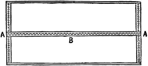
Fig. 1.
Now with respect to making a hammock, the first thing necessary is a piece of strong canvas, about 5 ft 8 in. in length and 3 ft. wide. In the Navy hammocks are made in two pieces (Fig. 1), which are stitched together down the centre (B). The sides and ends must be hemmed, and then the eyelet-holes for the clews to be fastened to must be made (A A). The eyelet-holes are twenty-four in number, at equal distances along the edge, at each end of the hammock. They are usually made in the following manner, although it is not absolutely necessary to be so particular.
A number of small rings made of white line (a kind of whipcord) are prepared, which are called grummets. These are placed in the eyelet-holes, and then sewn over all the way round with thin twine.
The next thing to make is a pair of clews. These are composed of what are termed at sea knittles, which are two or three yarns laid up together, by a jack or by hand, against the twist of the yarn. But good cod-line or anything else sufficiently stout, will answer the purpose equally well. The following is the proper way to make clews, although it is now sometimes dispensed with:—
Take twelve knittles about 5 ft. in length and double them. Then form an eye in the middle, which must be served with fine twine. This is done by winding the twine round and round as tightly as possible for a sufficient distance to form the eye; then seize or bind the knittles together for about an inch below the eye, as in Fig. 2.
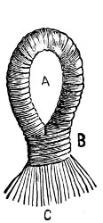
Fig. 2.
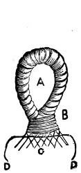
Fig. 3.
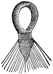
Fig. 4.
Now take a piece of twine, about half the size of the knittles, and place it between the knittles, so that twelve come up and twelve go down (Fig. 3); next bring both ends of the small twine, which is called filling, back again between the knittles, only altering them, making the upper ones point down and the lower ones point up; then leave out the two outside knittles and continue the circuit, leaving two knittles out each time until you come down to the last two, when knot the filling together and cut off the ends (Fig. 4). The ends of the knittles are then passed through the eyelet-holes in the canvas and fastened with two half-hitches. For the Navy now a great many clews are made without the platting arrangement we have described, and are left quite plain from the seizing below the eye down to the eyelet-hole. But the description we have given is of the old-fashioned style, and to our mind it looks much neater and more ornamental.
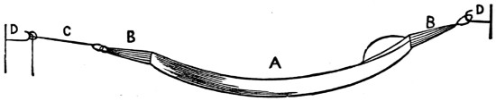
Fig. 5.
A piece of rope, called a lanyard, must now be spliced with an eye-splice into the eye of the clew that is to form the foot clew, and the hammock is completed.
In order to sling this it will be necessary to purchase a couple of stout hooks which will screw into the woodwork. These are easily obtained at any ironmonger’s, and may be fastened at the two opposite corners of a room, or in two trees in the garden at a convenient distance apart.
Then hook the head clew on, and pass the lanyard over the other hook, get the hammock level, and fasten it with a clove-hitch or two half-hitches.
And now one word of caution with regard to getting into a hammock. Be very careful the first time or two, and take notice how the hammock recedes, and then swings towards you. If you jump into it in the same manner as you would into a bed, the chances are that you will go right over it, and land on the ground the other side; but with a little care the proper method does not take long to learn.
To the reader who is desirous of learning the art of netting, we must give the same advice that the famous Mrs. Glasse did with reference to cooking a hare, viz.: ‘First obtain your hare.’ That is to say, the first thing is to obtain the netting instruments and materials.
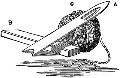
Fig. 1.
A, The needle. B, The mesh stick. C, The twine.
The instruments consist of a needle and a mesh (see Fig. 1). From eight to ten inches is a good length for the needle, while the mesh stick must vary according to the size of the net you are about to make. A mesh stick will make a mesh twice its own size. Thus a stick half an inch square will make a one-inch mesh.
Any youth at all handy with a knife can manufacture these articles for himself, and there only remains to obtain the material. This must depend upon what is going to be made, for once the stitch is learned there is no more difficulty in making a large seine than in making an onion net or a network hammock.
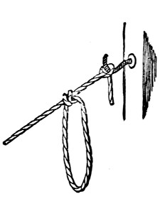
Fig. 2.
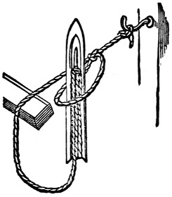
Fig. 3.
The better plan is to go to the nearest string shop, and pick out what is suitable in size and strength as well as in price. When the material is purchased—white line, seine twine, or common twine, whatever it may be—if it is not already in a ball, wind it into one. Then find a hook, or place one just a convenient distance above you as you sit, to which to fasten the end of the twine. Now fill your needle, pass the twine round the tine, or inside point, round the heel of the needle, then up round the tine again, until the needle[340] is full. Now fasten the end of the twine to the hook—a nail, if it be firm, will answer the same purpose—and tie a loop in it (Fig. 2). Then lay the mesh stick underneath the twine, and pass the needle up through the loop (Fig. 3). Then pull it tight, so that the end of the loop rests against the mesh stick (Fig. 4).
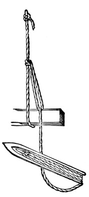
Fig. 4.
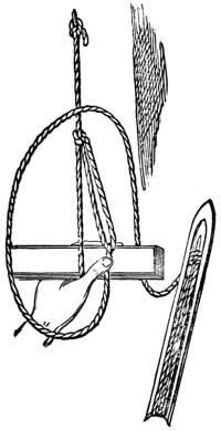
Fig. 5.
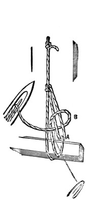
Fig. 6.
Now comes the important part, the formation of the knot. Hold the mesh stick in your left hand, with the thumb on the twine, and with the needle in the right hand. Now with a quick jerk throw the bight or loop of the twine over the stick and left wrist, as shown in Fig. 5.
Then push the point of the needle up between the first loop made, and the twine to the left of it, pull the needle through, and bring the knot into shape (Fig. 6), then tighten by pulling the needle in the direction of the dotted lines, and the knot is tied.
This simple knot is the foundation of all net-making, and once the reader[341] succeeds in making that, he will very quickly be able to manufacture anything he may require in that branch of work.

Fig. 7.
Now slip out the mesh stick and take the same stitch through the loop you have just made, and so continue on, passing the needle every time through the last loop made until you have made enough. You can generally guess the number of meshes you will require by the size of the mesh stick. By the time you have made as many as you think will be requisite, your work ought to look something like Fig. 7.
Next unfasten the end from the hook or nail, and untie the first loop made, because it is not the same size as the subsequent ones. Now pass a piece of cord through the upper row of meshes, tie the ends of the cord together, and hang it again over the hook.
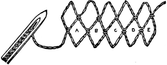
Fig. 8.
Next go on with the work as before, only do not slip the loop off the stick as at first. Knot through E, Fig. 8, then through D, then C, and so on, until you have travelled along the whole width.
Then turn the work over and travel back again in the same manner. It is better to make ten or a dozen meshes before slipping the stick out.
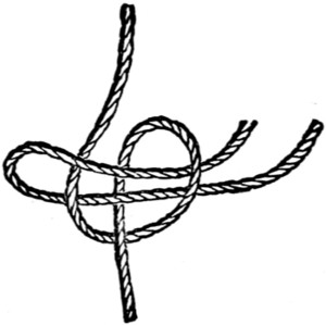
Fig. 9.
Presuming that the twine breaks, or you wish to join another ball, the way to do it is with a ‘becket-hitch,’ commonly called a ‘weaver’s knot.’ Form a bight with one part, pass the other part up through the loop, then over, under and back through its own loop (Fig. 9).
With regard to making a network hammock, proceed as we have described, and to make a full-sized hammock you would require between fifty and sixty two-inch meshes each way.
Then make the clews, as described in the article on canvas hammocks, and fasten them in the usual manner to each end of the hammock, tying the ends as regularly as you can.
Netting is a very pleasant as well as useful occupation, and is more suitable for boys than girls, owing to the strain of pulling the knots tight. The pleasure of being able to make nets for fishing, nets for the garden, to keep the birds off the trees, nets to hang vegetables or fruit in, and lastly, but not least, a net hammock, ought to amply repay any trouble or inconvenience caused by learning.
Various perpetual calendars have been published, but some of them are very elaborate, and others incorrect; therefore, by the editor’s invitation, I now present one in a most handy form. Table 1 shows the centuries, with the key numbers; Table 2, the last two figures of the year, and the seven key numbers below; Table 3, the months; and Table 4, the days. The key numbers are printed thick, the leap years in italics. January and February have two keys each, 3 and 6 for common years, 2 and 5 for leap years. The eleven days from September 3rd to 13th, 1752, were omitted. Every year which divides by 4 without a remainder is a leap year, except the centenaries, which are printed upright.
| Table 1. | Table 2. | Table 3. | Table 4. | |||||||||||||||||||
|---|---|---|---|---|---|---|---|---|---|---|---|---|---|---|---|---|---|---|---|---|---|---|
| First | 2 | 00 | 01 | 02 | 03 | 04 | 05 | Jan. | 3 | 2 | [3] | 1 | 2 | 3 | 4 | 5 | 6 | 7 | ||||
| 100 | 1 | 06 | 07 | 08 | 09 | 10 | 11 | Feb. | 6 | 5 | [3] | 8 | 9 | 10 | 11 | 12 | 13 | 14 | ||||
| 200 | 0 | 12 | 13 | 14 | 15 | 16 | Mar. | 6 | 15 | 16 | 17 | 18 | 19 | 20 | 21 | |||||||
| 300 | 6 | 17 | 18 | 19 | 20 | 21 | 22 | Apr. | 2 | 22 | 23 | 24 | 25 | 26 | 27 | 28 | ||||||
| 400 | 5 | 23 | 24 | 25 | 26 | 27 | May | 4 | 29 | 30 | 31 | |||||||||||
| 500 | 4 | 28 | 29 | 30 | 31 | 32 | 33 | June | 0 | 0 | S | M | T | W | Th | F | S | |||||
| 600 | 3 | 34 | 35 | 36 | 37 | 38 | 39 | July | 2 | 1 | M | T | W | Th | F | S | S | |||||
| 700 | 2 | 40 | 41 | 42 | 43 | 44 | Aug. | 5 | 2 | T | W | Th | F | S | S | M | ||||||
| 800 | 1 | 45 | 46 | 47 | 48 | 49 | 50 | Sept. | 1 | 3 | W | Th | F | S | S | M | T | |||||
| 900 | 0 | 51 | 52 | 53 | 54 | 55 | Oct. | 3 | 4 | Th | F | S | S | M | T | W | ||||||
| 1000 | 6 | 56 | 57 | 58 | 59 | 60 | 61 | Nov. | 6 | 5 | F | S | S | M | T | W | Th | |||||
| 1100 | 5 | 62 | 63 | 64 | 65 | 66 | 67 | Dec. | 1 | 6 | S | S | M | T | W | Th | F | |||||
| 1200 | 4 | 68 | 69 | 70 | 71 | 72 | ||||||||||||||||
| 1300 | 3 | 73 | 74 | 75 | 76 | 77 | 78 | |||||||||||||||
| 1400 | 2 | 79 | 80 | 81 | 82 | 83 | ||||||||||||||||
| 1500 | 1 | 84 | 85 | 86 | 87 | 88 | 89 | |||||||||||||||
| 1600 | 0 | 90 | 91 | 92 | 93 | 94 | 95 | |||||||||||||||
| 1700 | - | 6 | [1] | 96 | 97 | 98 | 99 | |||||||||||||||
| 2 | [2] | 0 | 1 | 2 | 3 | 4 | 5 | 6 | ||||||||||||||
| 1800 | 0 | |||||||||||||||||||||
| 1900 | 5 | |||||||||||||||||||||
| 2000 | 4 | |||||||||||||||||||||
| 2100 | 2 | |||||||||||||||||||||
| 2200 | 0 | |||||||||||||||||||||
| 2300 | 5 | |||||||||||||||||||||
| 2400 | 4 | |||||||||||||||||||||
[1]6 till Sept. 2, 1752.
[2]2 from Sept. 14, 1752.
[3]for leap years.
Example No. 1.—What day of the week was the 21st of June, 1581?
| 1500—key | 1 | in Table 1. |
| 81—key | 3 | in Table 2. |
| June—key | 0 | in Table 3. |
| Total | 4, | the three keys added. |
This 4 is the key for Table 4, where, on the right-hand side of this key, under the 21 st day, we find Wednesday.
If the three keys together make more than 6, seven is subtracted; and if more than 13, fourteen is deducted, and the remainder is the key to Table 4.
Thus we find June 6th, 1839, through 0 + 6 + 0 = 6, = Thursday.
August 9th, 1732, through 6 + 5 + 5 = 16, - 14 = 2 = Wednesday.
Columbus sailed from Palos on Friday, August 3rd, 1492, and discovered America on the 12th of October, 1492, which was also a Friday.
Example No. 2.—In what years will Christmas Day fall on a Sunday? Table 4 shows, below the 25th, the Sunday on the side of key 4; subtract the key of December, which is 1, there remains, for the present century, the key 3 of Table 2, showing the years 1887, 1892, 1898 and as this 4 for the next century will come from 5 + x + 1 minus 7, it follows that x means the key 5 in Table 2, which contains the years 1904, 1910, 1921, and the other years in that column.
We found the 6th of June, 1839, to be a Thursday, and see from the last column of Table 2 that it was again on a Thursday in 1844, 1850, 1861, etc.
Any one born on the 29th February, 1864, will have his birthday again on the same day of the week, a Monday, in 1892, that is, after an interval of 28 years, as is seen in the middle column of Table 2; and after that he will have it again on a Monday in 1904, 1932, etc.
Romulus, the founder of Rome, established a year consisting of ten months, named Martius, Aprilis, Maius, Junius, Quintilis, Sextilis, September, October, November, and December; but in the succeeding reign, that of Numa, two months were added, called Januarius and Februarius.
Julius Cæsar, aided by Sosigenes, an Alexandrian astronomer, instituted the Julian Calendar, which has come down to our own epoch. It was then decided to give an additional day to every fourth year. The date of the reform was 45 B.C., which was the Roman year 708, dating from the foundation of Rome. The Julian year began on the 1st of January, 708 A.U.C., and ended on the 31st of December, 709 A.U.C. In the first 48 years of the reform there prevailed some confusion about the bissextile or leap years, because during the first 36 years every third year was reckoned a leap year (12 intercalations had taken place instead of 9); but, in order to rectify the error, the next 12 years (i.e. 9 B.C. to 3 A.D. inclusive), elapsed without[344] an intercalary day, by decree of Cæsar Augustus, who also changed the names of Quintilis and Sextilis into Julius and Augustus, in honour of his uncle and himself. Thus the Roman years, 757, 761, 765, 769, etc., which were the years A.D. 4, 8, 12, 16, etc., were counted as leap years, and about all succeeding dates there is no doubt.
‘It was probably,’ writes Mr. Bond, of the Record Office, in his valuable work, ‘the original intention of Cæsar to commence the new year with the shortest day, the winter solstice at Rome, in the year 46 B.C. (common era), occurring on the 24th December of the Julian calendar. His motive for delaying the commencement for seven days longer, instead of taking the following day, was no doubt the desire to gratify the superstition of the Romans, by causing the commencement of the first year of the reformed calendar to fall on the day of the new moon, for it is found that the mean new moon occurred at Rome on the 1st of January, 45 B.C. (common era), at 6 h. 16 m. p.m.’
The Christian era was introduced in Italy, in the 6th century, by Dionysius the Little, a Roman abbot, and began to be used in Gaul in the 8th, though it was not generally followed in that country till a century later. From extant charters it is known to have been in use in England before the close of the 8th century. ‘At first, in A.D. 533,’ says Mr. Bond, ‘the era began with the 25th of March, but was subsequently reckoned from Christmas Day, the 25th of December, and in the 13th century, in some countries, was reckoned from the 1st of January according to the Julian era.’
The exact length of the mean solar or civil year is
365 d. 5 h. 48 m. 46 s.,
therefore the Julian year, being 365 days and 6 hours, departs from the course of the seasons at the rate of 11 m. 14 s., and consequently Aloysius Lilius, from Calabria, a physician and mathematician of Verona, projected a plan for amending the calendar, which induced Pope Gregory XIII. to introduce the plan on the 5th October, 1582, according to the former style, which day was decreed to be called the 15th October. These 10 days rectified the error of the past, in accordance with the day of the equinox, the 21st March. The error of the future, which was that an additional day every fourth year was too much, but that 129 years must elapse before the redundance would cause the equinox to be one day behind its time, was rectified thus: Adding 129 years to the year 1582 there results the year 1711, and it was decreed that the year 1700, which would, by the Julian Calendar, be a leap year, should be a common year, but, as stated below, it was still kept as a leap year in England, and appears as such in Table 1. In like manner 1800 was made a common year, and as in 1969 the 21st March would be a day behind the vernal equinox, it will be set right by making 1900 a common year. Another period of 129 years would extend to 2098, which will be remedied by making 2100 a common instead of a leap year.
Thus the equinox will be kept right by making three successive secular years common years; and the secular leap years will be those of which the first two figures are divisible by 4 without a remainder, as 2000, 2400, 2800, etc.
The keys or index figures in accordance with the Gregorian reform are these:—
| CENTURIES. | KEYS. | ||
|---|---|---|---|
| 1400 | 2 | ||
| 1500 | - | 1 till October 4, 1582. | |
| 5 from October 15, 1582. | |||
| 1600 | 4 | ||
| 1700 | 2 | ||
| 1800 | 0 | ||
The Papal decree of October, 1582, was adopted in France in December, 1582, in Poland in 1586, in the Catholic States of Germany in 1583, in the Protestant German States, through Weigel’s Calendar, in 1700, in Denmark and Switzerland soon after the adoption in Germany, in England in September, 1752, whereas Russia still adheres to the Julian Calendar. Thus the Russian legal equinoxes are now twelve days in advance of the real equinoxes.
In England the years used to begin upon the 25th March, but it was declared that 1752 should end on the 31st December, and 1753 begin on the day formerly called the 1st January, 1752. At that time the people in England used to write the new style under the old, thus:—
30th June, 11th July, 1753.
25th February, 1753. 8th March, 1754.
The death of Charles I. took place on Tuesday, January 30, 1648, as written at that time, but it is now written January 30, 1649, and often expressed by historians thus:—January 30, 1648-9.
In Scotland, the day after 31st December, 1599, was called 1st January, 1600.
The 4th August, 1581, was a Friday in all parts of Europe, but from 1582 to 1752 there was a variance in various parts, as there still is at present, between the east and the west of Europe. The variance was in the days of the month; the days of the week never changed. The 2nd September, 1752, was a Wednesday in England and in Russia, but a Saturday in the other States of Europe. Thus we find the 20th December, 1647, for England and Russia, through 0 + 2 + 1 = 3 = Monday, but for Italy, France, Spain, etc., through 4 + 2 + 1 = 7 - 7 = 0 = Friday. The 14th September, 1752, was a Monday in Russia, but a Thursday in England and the other European States. The 21st June, 1887, was a Tuesday in England, but in Russia it was twelve days later, that is, a Sunday, namely, the Sunday on which we had the 3rd of July. The Russians had the 9th June, 1887, on a Tuesday, that is the day on which we had the 21st June; and in writing to us they express that day thus:—June 9 21, 1887. They have the key 6 for 1700, and 5 for 1800.
The Turks use the Mohammedan Calendar, from the Hegira, July 16, A.D. 622, and it is lunar like the Jewish.
The following historical dates agree with our calendar:—
The battle of Hastings was fought on Saturday, Oct. 14th, 1066.
The Magna Charta was signed on Sunday, May 24, 1215.
Edward II. was crowned on Sunday, 25th February, 1308 (1307 in the old style).
The battle of Crecy took place on Saturday, August 26th, 1346.
The battle of Towton, Yorkshire, occurred on Palm Sunday, March 29, 1461.
The keys for the centuries and months can be arranged at pleasure, therefore the key 0 is chosen for the present century to calculate readily the dates of our time. To make the reckoning easy in the next century it will be well to have the key 0 for 1900, then the keys for the months must all be reduced by 2, and the tables will be:—
| Jan. | 1 | and 0 | May | 2 | Sept. | 6 | ||
| 1800 | 2 | Feb. | 4 | and 3 | June | 5 | Oct. | 1 |
| 1900 | 0 | Mar. | 4 | July | 0 | Nov. | 4 | |
| 2000 | 6 | Apr. | 0 | Aug. | 3 | Dec. | 6 | |
A very useful and instructive pastime for boys will be found in the construction of a sundial, full directions for making which I give in this chapter.

Fig. 1.
Fig. 1 enlarged (112 kB)
The first thing to be done is to make what is called the dialing scale (Fig. 1). It is constructed as follows: With a pair of compasses describe the circle A B C D with any radius, say four inches. Draw the two diameters A C and B D, cutting each other at right angles in the point 0. Join D C for the scale of chords and B C for the scale of latitudes. Through the point B draw the straight line 12—6 parallel and equal to the line A C, and let the point B bisect it. Join the points 0—12 and 0—6, cutting the circle in the points E and F. Now divide the arcs E B and B F each into three equal parts, and from the point 0 draw straight lines through these[348] points of division to the line 12—6, marking the points of intersection 12, 1, 2, 3, 4, 5, 6. This line is called the line of hours.
To make the scale of chords, divide the arc D C into nine equal parts, and then with the compasses, with one leg placed on the point C, protract each division on the line C D. Mark the points on this line from C 10, 20, 30, etc.; the point D will mark 90 degrees.
To make the scale of latitudes, draw lines from the points of division in the arc D C parallel to the line D 0, and cutting the line 0 C in points, counting from 0, 10, 20, 30, 40, etc. Now draw straight lines from D through these points, cutting the arc B C in the points 10, 20, 30, etc., and with your compasses, with one leg on B, protract these distances on to the line B C, which will be the scale of latitudes. Now our dialing scale is finished.
To make the dial, which will be a horizontal one, you must get a piece of zinc plate about one foot square. On this mark all round it, and one inch from the edges, lines making a smaller square of ten inches a side. Plate 1⁄8 inch thick.
Bisect one line of this square, and draw a line from this point to a point bisecting the opposite side. Now draw two other lines, one on each side of, and one-sixteenth of an inch from, this line, and parallel to it. These lines will then be one-eighth of an inch apart. They are made this distance apart as the style, or gnomon, will be that thickness, and has to stand between them. Now divide the other sides into five equal parts, and join the two second points of division, counting from the bottom. This line, which is called the six-o’clock line, will cut the two parallel lines in the points A C (Fig. 2). Mark the other or top ends of these lines B and D.
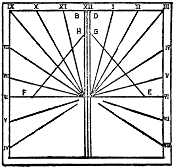
Fig. 2.
Now with your compasses take from the scale of latitudes the latitude of the place where you wish to erect your dial. Suppose you are in London, put one leg of the compasses on the point B, and the other leg on the point in the scale of latitudes marking 511⁄2 degrees, which is the latitude of London. Now mark this distance off on the six-o’clock line from C to E and from A to F (Fig. 2). Now take the length of the line of hours from 12—6 in the compasses, and, putting one leg on the point E, intersect the line C D in the point G. Do the same on the other side, putting one leg on point F, and intersecting the line A B in the point H. Draw the lines G E and H E (Fig. 2).
These lines are the same length as in the line of hours; mark them as that line is marked, using your compasses to get the distances, marking the line from G to E and from H to E; now from the point C draw lines through the divisions on G E to the lines of the inner square; do the same from point A through the line H F. The fourth and fifth lines on the right side must be continued back through the point C to opposite side of square, and the seventh and eighth on the left be continued back through A to right side. Now mark the hours. The double line is the twelve-o’clock line, and must be marked twelve. The line to the right is the one-o’clock[349] line, the next two, and so on to eight on the right side. On the left the line next the twelve-o’clock line is eleven, the next ten, and so on back to four. All the lines can be marked on the zinc with a pointed bradawl.
The dial plate is now finished.
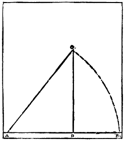
Fig. 3.
The next step is to make the gnomon. For this get a piece of the same zinc plate about six inches by eight. Along one of the shorter sides, about a quarter of an inch from the edge, draw a line A B, making it equal in length to C—60 on the scale of chords. With one leg of the compasses on the point A, and the other opened out to B, draw the arc B C as in Fig. 3. Now from the same scale of chords take the length of the latitude of the place, and mark it along the arc B C from B, join A C, from C draw a line at right angles to A B, cutting it in the point D (Fig. 3). The triangle A D C will be the gnomon, with the line A D for its base. Cut this triangle out carefully, making the edges quite square. Now you must get a tinman to solder this in its place on the dial-plate, the point A of the gnomon to be at the points A C on the plate, and the line A D along the two lines A H and C G. You must be very careful that the gnomon stands at right angles to the dial-plate.
The dial must be fixed in a sunny spot, if possible in the middle of a large lawn. The best way to do this is to fasten the dial-plate on a square board, which is fastened to a post driven into the ground. The post can be ornamented with rustic work. The dial must be quite level, and the gnomon pointing due north.
The line A C of the gnomon being made at the angle from the base equal to the latitude of the place will be parallel to the axis of the earth, and will show the hours correctly both on long and short days, as the sun’s course is at right angles to it. The dial can be made to show quarters or five minutes if you so divide the line of hours on the dial scale. The dial, if placed in an open, sunny spot, will show the hours from sunrise to sunset.
The horizontal sundial would be suitable for all places north and south of the equator. But in southern latitudes the style must point due south instead of north, and the numbering must be done from right to left instead of from left to right. The method, however, already described would not do for any place situated exactly on the equator. The reason for this is—the style, or gnomon, being parallel to the axis of the earth, it would be horizontal at the equator, and perpendicular at the poles, and the shadow would be parallel to the style at the equator and perpendicular to it at the poles. The style must be regulated in height by the size of the dial-plate, and the length of the line of hours, in the scale, must be regulated by the height of the upper edge of the style from the dial-plate.
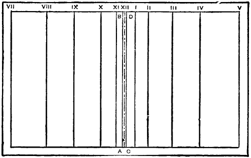
Fig. 1
I will now explain the construction of the equatorial dial. The dial-plate is to be cut about eighteen inches long by twelve inches wide. The inner lines are to be drawn all round, about one inch from the edges, as in the dial already described. Divide the dial-plate into two equal parts by a line drawn from points bisecting the long sides, as in Fig. 1 in the accompanying illustrations. This line is the twelve-o’clock line. The two lines A B and C D are to be drawn parallel to this line, one on each side of and a sixteenth of an inch from it. Before the hour lines can be drawn the style must be made. This must be rectangular in shape, with the long sides equal in length to the twelve-o’clock lines between the inner lines of the plate, and must not, for this size of dial-plate, be more than two inches wide or high. The dialing scale must now be made. It consists only of the line of hours. Draw the two lines O A and O B at right angles to each other, and make each equal in length to the height of the gnomon, or style—viz., two inches. Draw B C parallel to O A, and make it about ten or twelve inches long. Describe the arc A B, with O for the centre, and O A and O B for radii, as in Fig. 2. Divide this arc into six equal parts, and draw lines from the point O through the points of division to cut the line B C in the points 1, 2, 3, 4, 5. The six-o’clock point will not be required. This is the line of hours. With your compasses mark on the side lines of the dial-plate, from the points A B and C D, the divisions of the line of hours. Join the corresponding points on each side of the twelve-o’clock line by lines drawn parallel to it. These lines will represent the hours, and are numbered 1 to 5 to the right and 11 to 7 to the left. Fig. 3 shows this dial.
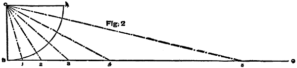
Fig. 2
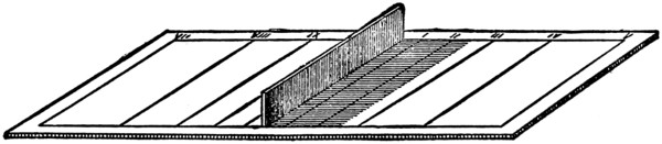
Fig. 3
This dial does not show the time before seven o’clock in the morning or after five o’clock in the evening. The reason of this is, the days and nights at the[351] equator being equal—viz., twelve hours each—the sun rises and sets at six o’clock. At six o’clock, the sun being exactly on the horizon, any object placed in the middle of a perfectly horizontal plane would cast an indefinite or unlimited shadow, as the shadow of the upper part would be parallel to the plane, and of course could not meet it. The dial can be made to show any time after six in the morning or before six in the evening by lengthening the dial-plate. Fig. 4 will show how inconvenient it would be to have a plate to show the time before seven or after five o’clock. In Fig. 4 the hour from five to six is divided into quarters, and shows that for 5.30 the plate must be about double, and for 5.45 about four times, the length required to show the time between seven and five o’clock. So that a plate about six feet long would be required for a dial having a style two inches high.
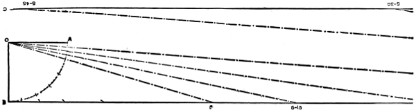
Fig. 4
The style is to be soldered to the dial-plate between the two lines A B and C D, and must be equal in thickness to the distance between them. The dial must be set up in a horizontal position with the gnomon directed due north and south.
Both these dials are horizontal. I will now explain the construction of vertical dials, or dials that are fixed in an upright position against a wall or house. The dialing scale, as already described, will be required for the construction of a vertical dial to be fixed on a wall facing the south.
Cut the zinc plate twelve inches square, and mark it with the inner square, the twelve-o’clock lines, and the six-o’clock line, as in the horizontal dial. From the line of latitudes, in the scale, take the length equal to the difference between 90 deg. and the latitude of the place (that is, not as in the horizontal dial, the latitude, but the complement of it).
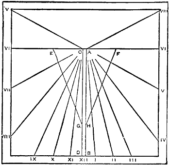
Fig. 5
Taking London as the place, take from the scale 381⁄2 deg., which is the difference between 90 and 511⁄2 deg. This distance must be marked off on the six-o’clock line from the points A and C. The rest of the construction is the same as for the horizontal dial, with the exception that the hours are limited to fourteen, viz. from five to seven[352] o’clock, and are numbered backwards, or from left to right as in Fig. 5. The style is made as for the horizontal dial, but the angle C A B is to equal 381⁄2 deg. in the case of London, or the complement of the latitude. The base A D is to equal the length of the twelve-o’clock lines, measuring from the six-o’clock line to the inside line at the lower edge, or the lines A B and C D. In fixing this dial care must be taken to let it face due south.
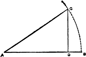
Fig. 6
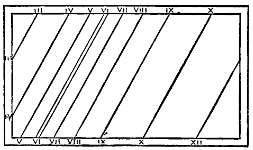
Fig. 7
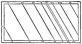
Fig. 8
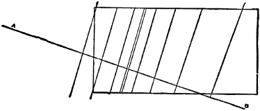
Fig. 9
The east and west vertical dials are made something like the equatorial horizontal dial, with a rectangular style. The same scale is required for making the line of hours, the lines of which are regulated in length by the height of the style. Make the plate about eighteen inches long and twelve inches wide, and draw the double lines which in these dials represent the six-o’clock line, as in Figs. 7 and 8. These double lines are drawn, making an angle with the lower edge of dial-plate equal to the latitude of the place. The style is cut rectangular, with the long sides equal to the double six o’clock lines, and the short sides two inches long. Draw the scale making O A and O B two inches long, and mark the hour line. Before the points on the hour line can be marked in on the dial-plate, a plan (Fig. 9) must be made. Draw on a large piece of paper a plan of either dial-plate, and mark in the double lines. Through these draw the line A B perpendicular to them as in Fig. 9. On this line, on each side of the double lines, mark the points on the hour line, and through these points draw lines parallel to the double lines, and letting them cut the sides of the plan of the dial-plate. The points where the lines cut it can be transferred to the dial-plate with a pair of compasses, and the hour lines drawn in parallel to the six-o’clock line. The style must be fixed in its place, and will be parallel to the axis of the earth when the dial is fixed up with the long sides quite horizontal. The east dial is marked as in Fig. 7, and the west as in Fig. 8, if for the northern hemisphere. For the southern, the west dial would take the place of the east, and the east, the place of the west with the numbering reversed.
There are several other kinds of sundials, which may be used for any degree of latitude, a few of which I will describe.
The first of these is the globular (Fig. 10). This is a white globe (any size), supported on an axis which is fixed in a position parallel to the axis of the earth (or[353] making an angle with the horizon equal to the latitude of the place, and pointing due north or south), in which position the globe is acted on by the sun exactly as the earth is. The globe is divided into twenty-four equal parts by lines running from pole to pole, and has an equator drawn around it, on which the hours are marked from 1 to 12 twice over. The axis is fixed in a stand so that one of the six-o’clock lines is in the zenith. The time is indicated by the edge of the shaded part (caused by the sun illuminating one-half of the globe, leaving the other in shade) passing over the hour lines. An ordinary globe answers very well for this dial, if it is rectified for the latitude, and placed so that the brass meridian is directed north and south.
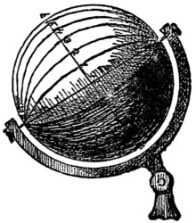
Fig. 10
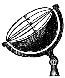
Fig. 11
Fig. 11 is another pattern; it is basin-shaped, and is made of a hollow hemisphere of metal, whitened inside, and has the inside divided into twelve equal parts by lines running from pole to pole, which are numbered on the equator from 6 to 6. A wire is stretched from pole to serve as the style, which casts a shadow on the line corresponding to the hour. The position of this dial is the same, as regards the axis of the earth, as Fig. 10.
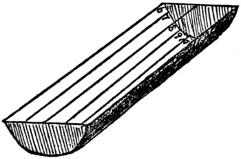
Fig. 12
Fig. 12 represents what I call the trough-shaped dial. It is made of metal-plate bent into the shape of a half-tube; the ends are closed with semicircular metal plates. The interior is divided into twelve equal parts by lines running parallel to the edges, and are numbered from 6 to 6. A wire is stretched from the centres of the semicircular end plates to serve for the style.
This dial must be fixed, with regard to the position and direction of the style, as the other dials are. This is the one constant condition of all dials, that[354] the edge of the style that is to cast the shadow must be parallel to the axis of the earth.
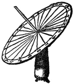
Fig. 13
Fig. 13 is a very simple dial, and is the last I shall describe. It consists of a circular dial-plate divided into twenty-four equal parts, numbered from 1 to 12 twice over. The style is a perpendicular wire fixed in the centre of the plate. The plate is hinged to a stand, so that one of the twelve-o’clock lines runs directly from the top to the bottom.
From the construction of the dials 10, 11, 12, 13, they can be used in any latitude, as well as on the equator, but of course the numbering would have to be reversed for the southern hemisphere. They all have an arrangement by which the style can be fixed at the required angle to suit the latitude of the place.
The sun does not always point out the true time, as on some days it is behind time and sometimes before it. The table below gives the minutes to be added to or subtracted from the time pointed out by the sun for each day in the year:—
| January. | ||
|---|---|---|
| Day. | Min. | |
| 1 | + | 4 |
| 4 | + | 5 |
| 6 | + | 6 |
| 8 | + | 7 |
| 11 | + | 8 |
| 13 | + | 9 |
| 16 | + | 10 |
| 19 | + | 11 |
| 23 | + | 12 |
| 27 | + | 13 |
| 31 | + | 14 |
| February. | ||
| 3 | + | 14 |
| 19 | + | 14 |
| 26 | + | 13 |
| March. | ||
| 3 | + | 12 |
| 4 | + | 11 |
| 12 | + | 10 |
| 15 | + | 9 |
| 19 | + | 8 |
| 22 | + | 7 |
| 25 | + | 6 |
| 28 | + | 5 |
| April. | ||
| 1 | + | 4 |
| 4 | + | 3 |
| 8 | + | 2 |
| 12 | + | 1 |
| 19 | - | 1 |
| 25 | - | 2 |
| 30 | - | 3 |
| May. | ||
| 1 | - | 3 |
| 17 | - | 4 |
| 28 | - | 3 |
| June. | ||
| 4 | - | 2 |
| 10 | - | 1 |
| 19 | + | 1 |
| 24 | + | 2 |
| 29 | + | 3 |
| July. | ||
| 4 | + | 4 |
| 10 | + | 5 |
| 19 | + | 6 |
| August. | ||
| 1 | + | 6 |
| 11 | + | 5 |
| 16 | + | 4 |
| 21 | + | 3 |
| 25 | + | 2 |
| 29 | + | 1 |
| September. | ||
| 4 | - | 1 |
| 7 | - | 2 |
| 10 | - | 3 |
| 13 | - | 4 |
| 16 | - | 5 |
| 18 | - | 6 |
| 21 | - | 7 |
| 24 | - | 8 |
| 27 | - | 9 |
| 30 | - | 10 |
| October. | ||
| 3 | - | 11 |
| 7 | - | 12 |
| 10 | - | 13 |
| 14 | - | 14 |
| 19 | - | 15 |
| 27 | - | 16 |
| November. | ||
| 10 | - | 16 |
| 17 | - | 15 |
| 21 | - | 14 |
| 25 | - | 13 |
| 28 | - | 12 |
| December. | ||
| 1 | - | 11 |
| 2 | - | 10 |
| 6 | - | 9 |
| 8 | - | 8 |
| 10 | - | 7 |
| 12 | - | 6 |
| 14 | - | 5 |
| 16 | - | 4 |
| 18 | - | 3 |
| 21 | - | 2 |
| 23 | - | 1 |
| 27 | + | 1 |
| 29 | + | 2 |
| 31 | + | 3 |
Did you never, reader, have a peep in beneath the black cloth where the artist hides his head while he is focusing a sitter for his photograph? I’m sure that many of you have. And what did you see? Why, a pretty little picture in colours of your friend sitting in the chair, laughing like a tramp at a twopenny roll, only upside down. And you have said to yourselves, What a pity it won’t come out in bright colours like that, and why in all the world should it be upside down?
Now I will answer this question before going any further, because it has a bearing on the subject before us—the making of a handy and cheap camera obscura, which cannot fail to be a source of amusement and pleasure, especially when the sun shines.
The reason why the object on the photographer’s ground-glass plate is seen upside down is easily explained. Light, as I need hardly remind older boys, proceeds in straight lines from any illuminated object. It is thus thrown upon the photographer’s plate. A glance at the accompanying diagram (Fig. 1) will suffice to show what I mean.
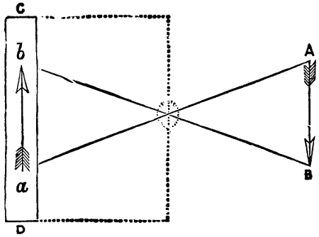
Fig. 1.
Let A B be the object—say, an arrow—under consideration, and C D a side view of the ground-glass plate on which the picture is seen. Passing, therefore, in straight lines, the light and colour from the point A will fall at a, will they not? and those from B at b, and so on from every portion of the arrow, so that the representation therefore on the object-glass will be upside down, or reversed. Q.E.D.
Now about the camera. No one can be said to have invented it, for it is constituted upon the firm and immutable laws of Nature. Roger Bacon is credited with having known this principle. Very likely he did, but he put it to no practical use, though over four hundred years after his time Giovanni Baptiste Porta did. But who knows that the ancients hundreds of years before the Flood were unacquainted with it? Here, for example, is a story a little bird told me one beautiful summer’s day while reclining on the greensward in my woodland study: I had been reading under the shade of my great oak-tree. The sun was very bright, and patches of its light penetrated even through the dark-green branches and fell on[356] my face. Probably it was that which set me a-thinking about the laws of optics and the camera obscura and camera lucida. Suddenly close up above me a bird alighted—it was early in the season—and began pouring out the most charming notes.
‘Many people,’ I said to myself, ‘would take that bird to be the nightingale, but I know it is only a black-cap.’
The words were hardly out of my mouth when a saucy little head with a bright bead of an eye peeped round the corner of a twig at me.
‘Only a black-cap!’ said the owner of the head and the eye. ‘I’d have you know, sir, that we black-caps, as you call us, are of a far older family than the nightingales, and that they first learned their wild notes from us, and not we from them!’
‘You know a deal, I dare say,’ I replied. ‘Can you explain this, then? There is a streak of light creeping in from a point among the boughs up there, and falling on my foolscap, and whenever a pigeon, or hawk, or rook flies past away overhead, his image appears on the paper and crosses it, only in a contrary direction.’
‘Foolscap, indeed!’ replied the bird, ‘it is yourself that should be wearing one. The image on your paper is caused by the reflection of the luminous rays from the flying bird. Now,’ continued the black-cap, ‘I’ll tell you about the camera.
‘You know the ancient Egyptians understood everything!’
‘So they supposed,’ I grunted, ‘but——’
‘Don’t interrupt, please. The dungeons of that mysterious land were once upon a time small and dark and dismal in the extreme, and for a very little fault indeed people were thrown therein, perhaps never to leave them alive.’
‘Well, it came to pass that a certain poor man had offended the king, and all his worldly goods were confiscated and he himself was thrown into a cell in a rock. It was not a large one, and its walls were smoothly cemented with a mixture of lime and sand, and some other ingredients known only to the ancient Egyptians. The cell was situated in the side of a hill, with a door at one side which was opened only once a week, to thrust in a pitcher of water and a bundle of cassava root, on which the poor man lived, and to have the cell cleaned out. The only aperture for light and air was a little round hole at the front of the room, too small for even a bird to get through, though bees and moths often entered and kept the prisoner company. But, lo! every day and all day, especially when the sun shone, the rays of light through that aperture brought with them a picture which they painted on the opposite wall. This picture was upside down, but that was but a small drawback, and everything that happened out of doors or in the city beneath was painted on the wall in a marvellous manner. But when the cell door was opened the picture faded away, so the gaoler never saw it.
‘One day the prisoner addressed the gaoler as follows: “Speak unto the king for me, O my son, and tell him, if all my trespasses are forgiven me, and I am taken up out of this loathsome den, I will build for him in his palace a dark room in which he can sit and see all that is going on in the city beneath spread out before him like a great moving picture.”
‘And the gaoler went and spoke to the king in the prisoner’s behalf, and the poor man was brought before the king and set to work in a room of the palace[357] tower. With the aid of workmen he turned the room into a camera obscura, by means of well-placed steel mirrors casting the picture down upon a white concave table.
‘When the king saw it he was greatly astounded and delighted, and ever after that there was no guest about the palace so greatly honoured as the poor man he had but lately thrown into a dungeon.’
I began to rub my eyes after this, and I am hardly sure yet whether the black-cap had really been speaking, or whether I had dropped asleep and been dreaming.
However, this prisoner did nothing more than you could do. I slept, when a boy, in a little turret chamber, which I easily converted into a camera, a description of which I had read in an old book on ‘The Arts and Sciences.’ I had a white screen placed at the proper focus, and a tiny round hole in the shutter, that was all. It was a very primitive arrangement, but pleased me then.
And I believe that most of my readers who are over twelve can make a handy portable camera from the hints I shall now give.
Before you read any further, then, get an empty matchbox, and put it on the table, bottom upwards. Now draw out the drawer of it about half-way. That matchbox is your rough model for the portable camera. Simple, is it not?
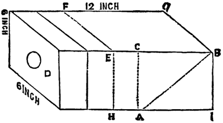
Fig. 2.
The sketch I here append, however (Fig. 2), is not that of a matchbox, but of your portable camera itself, minus its dark shade. The size of this portable camera will depend upon, and be in the ratio of, your own ambition; the perfection of its make will depend upon your own ingenuity.
1. Well, then, you are to make or get made a small box of either very thin wood or very strong pasteboard, covered with thin cloth and painted some dark colour. Size, say, six inches high, six inches wide, and one foot long. This box is open only in front, and therein fits or slips the focusing drawer with its lens.
2. This drawer is also of the same material, and is open at the end that fits into the box, that is the end opposite the lens, and should work easily in or out, and admit no light except through the lens, the magnifying power of which need not be very great.
3. The whole interior of box and drawer is to be stained of a dull black colour.
4. Into the top of the box is let a piece of ground glass, occupying the whole breadth nearly of the top, and two-thirds of its length.
5. Into the box is fitted or let a mirror, which faces the drawer and lies at an angle of forty-five degrees.
Now turn your eyes to Fig. 2, and I will try to explain it. The dimensions of the box are marked in plain figures, as the drapers say. The length of the drawer is about five inches or less. This drawer is represented in the figure as pulled about half-way out. When shut up it will reach the letters C A. The lens is about an inch in diameter, and may be bought cheap at any optician’s, or even fitted for you there.
The piece of ground glass on the top occupies the position marked out by the letters F, E, B, G.
The mirror inside occupies the position indicated by the dotted line A B.
But your camera is not complete yet. You have your dark shade to slip on and fasten. This shade (vide Fig. 3) is a lid, open at both ends, that goes right over two-thirds of the whole box when closed, covering that portion of it seen in Fig. 2 between the squares F, E, G, B and E, H, B, I. This lid is fixed by means of a close-gummed cloth hinge to the box at the dotted line F, E. It is free every way else, so that, when lifted up to an angle of forty-five degrees, it keeps the light away from the ground-glass top, and permits you to see the picture thereon. This shade is, of course, also stained of a dark colour internally.
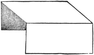
Fig. 3.
Now your portable camera is complete. To use it, all you have to do is to hold it in your hand, with the lens turned towards the picture you want represented, and the shade raised, then to pull the focusing-drawer in and out till you have a clear, well-defined picture on your ground-glass top. When the sun is shining brightly the effect is charming; but you yourself and camera ought to be well in the shade.
Now, the instrument I describe is very simple, but its principles may be extended. You might have it on a stand with racks and pulleys for adjustment; and you may have a dark cloth over the shade: the picture will then be ever so much more bright. The great charm of a camera like this is to have a real and lifelike picture in natural colours spread out before you, to see still life as it stands, the trees waving in the wind, and flowers nodding in the sunshine, and every human being or animal that passes walking and moving on your plate.

For some years it has been the custom for our boys to employ their leisure time during the winter months in the construction of cardboard models of locomotives, and some of the finished specimens exhibit a degree of skill and ingenuity which could hardly be expected. The work, to a great extent, is the result of the boys’ own observation and skill, added to from time to time by those more observant or more ingenious, and handed down traditionally from one generation of boys to another.
As it is a very interesting occupation, and a valuable means of educating both the eye and the hand, it occurred to me that, if it were possible to describe the processes on paper, it would prove acceptable to boys generally. I therefore gladly avail myself of the opportunity afforded me to lay before you, as clearly as I know how, all the steps necessary to produce a finished model.
To encourage those who may underrate their powers, and think it is useless for them to try, I would say that boys of nine, ten, and eleven often produce very creditable work, and that those who produce the very best are not always those most highly distinguished in class-work. A few more words only are necessary: take these three ‘P’s.’ as your helps, and I am sure you will succeed:
1. Be Precise; that is, endeavour carefully to carry out every detail.
2. Be Patient; that is, do not be too hasty in what you have to do.
3. Persevere; if you fail at first, ‘Try, try, try again.’
We will commence by making a list of the materials required, all of which may easily be obtained at a small cost. If two or three boys work together, the cost may be reduced, as the smallest quantity you can purchase of some of the things will suffice for more than one model.
1. Wood.—One-eighth of an inch thick, straight in the grain, and of width and length detailed afterwards. The backing of picture-frames, large cigar-boxes, boxes in which cocoa or blacking is kept at the grocers’ shops, all do capitally, and can generally be got for nothing.
2. Card.—(a) Thick, (b) medium, and (c) thin. The thick may be obtained from strong cardboard boxes; the thin can be bought at most stationers’ in penny sheets, about fourteen inches by ten; and for the medium obtain used postcards (white), which answer the purpose capitally.
3. Gum in solution.—Make your own, by purchasing two ounces of gum-arabic at one penny per ounce, and dissolving it with warm water till it is as thick as cream. Do not put too much water at first, you can easily add more if too thick. Have this always ready, for you require it constantly.
4. Water-Colours (Rowney’s or Reeve’s penny cakes).—Chrome green (2); vermilion (1); ivory-black (1); and a little Chinese white (the last not essential).
5. Camel-hair brushes.—Three or four of various sizes, halfpenny and penny each.
6. Elastic bands.—Six of various sizes.
7. Pins.—If you cannot beg from your mother or sister, one penny will buy what is necessary.
8. Sand-paper.—Coarse and fine (halfpenny per sheet).
9. Copper wire.—Such as is used for bell-hanging. Cost, one penny, sufficient for several.
10. Crystal varnish.—Cost, twopence.
11. Brass or steel chain.—A piece of a toy watch-chain does very well.
12. A few small pieces of coal from the coal-cellar, when required.
13. A knife, with sharp edge.—Boys need no advice on this point.
14. A cutting-board.—Any smooth piece of board about half an inch thick.
15. Cotton.—One reel of strong, any colour.
16. A few pieces of board for painting and drying gummed parts on. Such as described in No. 1 will do.
When all your materials are ready, select a piece of thin wood (marked 1 in the list of materials). Let it be free from knots and straight in the grain. The following dimensions are suitable for a medium-sized model; if larger or smaller models are desired, increase or decrease proportionately.
Length, fourteen inches; Width, two and three-quarter inches; Thickness, about one-eighth of an inch; this is called the Foundation.
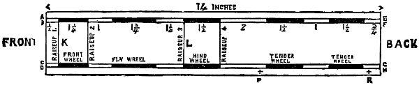
Fig. 1.—Plan of foundation, quarter of size.
Fig. 1 enlarged (22 kB)
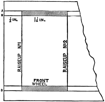
Part of Fig. 1.—Full size.
Having cut the exact size, next proceed to make on it, in pencil, the plan as[363] detailed in Fig. 1, as follows: Rule the two parallel lines A E, B F, at distances of a quarter of an inch and three-eighths of an inch respectively from one edge; rule C G, D H at the same distances respectively from the other edge. Next measure off from one end (which you had better mark ‘Front’) half an inch, then one inch and a quarter, one inch, one inch and three-quarters, etc., as on plan (this must be done on both edges); rule lines across where the words ‘RAISE UP,’ 1, 2, 3, 4, are marked. The shaded parts between the parallel lines should be shaded on your plan as in the diagram. These shaded parts are now to be cut out with a sharp knife. It requires both patience and care to prevent the wood splitting, but a little practice will enable you to do this easily and skilfully. These cut-out spaces (as will be seen afterwards) are for the wheels.
The foundation is now prepared, and the next process is to cut out four boiler ends, or ‘Raise-ups,’ as they are termed, 1 and 2 for the front, 3 and 4 for the back of boiler. They are all different, and are formed as follows: On four pieces of thick card (No. 2a in list of materials) describe circles with radius one and one-eighth of an inch (equal to half the distance from A D); in Nos. 2 and 3 describe a second circle, with radius not quite a quarter of an inch less.

Fig. 2.—‘Raise-ups,’ half the size.
Nos. 1, 2, 3, and 4 must each have a base-line two inches and a quarter long. The ends of Nos. 1 and 2 must curve up to meet the circle, and Nos. 3 and 4 are perpendicular lines from ends of base line to meet the circle (as shown above in Fig. 2). Now place these on your cutting-board (No. 14 in list of materials) and with a very sharp knife cut them neatly and carefully the required shapes. Nos. 1 and 4 must be left quite whole in the centre; Nos. 2 and 3 must have their centres cut out round the inner circle. (In cutting do not try to make a continuous cut, or your knife is almost certain to slip and spoil your work; do it by successive ‘digs’ with the point of the knife, in the manner adopted by a gardener when cutting round the edges of a flower-bed with his spade.)
We are now in a position to make the body of the boiler. For this, take a piece of thin card (2c in list); it should be seven inches long (the length from K to L in Fig. 1), and about eight inches and a half wide. This must be rolled into a cylinder, and is then ready for fitting into the ‘raise-ups’ 2 and 3. No. 1 is then placed at the front end and gummed on, and No. 4 at the other end and also gummed on. No. 2 should be one and three-eighths of an inch from No. 1, and No. 3 be one and seven-eighths of an inch from No. 4. These ‘raise-ups’ should[364] now all be fixed in their places on the foundation, and fastened at the bottom edge with the thick solution of gum (No. 3 in list), being held firmly to the foundation by elastic bands (No. 6 in list). These bands must not be too strong or they will flatten the boiler. In all gumming, pins should be freely stuck round to hold the parts in the desired position until they are dry. Our model will now present this appearance. The short perpendicular lines with knobs marked a represent pins; the lines marked b represent elastic bands.
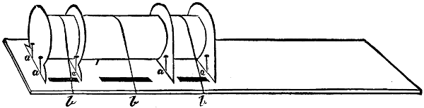
Fig. 3.
When this is firmly stuck, two other pieces of thin card should be prepared to connect the ‘raise-ups.’ One must be one and three-eighths of an inch wide, and the other one and seven-eighths of an inch, and long enough to reach from the ‘foundation’ on one side, over the top, to the ‘foundation’ again on the other side. They must exactly follow the shapes of the ‘raise-ups,’ and should be cut to exactly fit, but not before the previous work is quite dry and firm. When prepared, gum in position; they are called ‘over-raise-ups.’ Several folds of cotton must be wound round the part marked a b c d to hold it while drying.
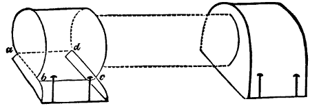
Fig. 4.
The next process is to well coat it with paint of the desired colour. If we are
copying one of the South-Eastern
Railway Company’s engines, the body
will have to be painted ‘chrome-green’;
if one of the Brighton Company’s,
it will have to be painted
‘yellow-ochre.’ As the latter is liable
to become soiled, we will select the
former, and commence by mixing our
colour. We shall require two penny cakes (No. 4 in list of materials). They
should be placed in a small tin or earthenware pot (one of Liebig’s extract-of-beef
pots answers the purpose admirably), a little water is then added,
and one of your cakes may easily be softened with a large paint-brush (No. 5
in list). Make your colour of the consistency of cream, so that it works freely.
It may be mixed while the previous work is drying. When all is ready, paint
the boiler and ‘over-raise-ups’ evenly with it, and let it dry; a second coat
is applied in the same way, and usually a third and fourth coat. The front and
back ‘raise-ups’ (Nos. 1 and 4) are not painted chrome-green. The body being
evenly painted, and dry, we proceed to ornament the boiler with some fine
lines; these are made by cutting with a sharp knife eight narrow strips of
paper, the exact width being, of course, very much a matter of taste. You
will[365]
require a ruler to guide your knife, and you must place your paper on something
smooth and very hard (not wood) while you cut, or the paper will curl up. These
strips must be about nine or ten inches long. Six are to be painted black and two
vermilion; immediately after painting them, just shift their position a little or the
edges will stick to the material on which they are laid, and they will break when
you attempt to lift them after they are dry. When dry, place them as follows:
First take a black strip, gum it, and stick it exactly midway between raise-ups
(Nos. 2 and 3) quite round the boiler; on each side of this, and about three-eighths
of an inch distant from it, gum a vermilion strip; next gum and place two black
strips similarly, one on each side, about an inch and a half distant from the centre
strip. The three remaining black strips are to be thus placed: one at the front
edge of the front ‘over-raise-up,’ a second at the back edge of the same, the third at
the front of the back ‘over-raise-up;’ the three last will then be exactly over the
raise-ups Nos. 1, 2, and 3. We now require two strips of card the exact length of
the space between Nos. 2 and 3 ‘raise-ups,’ and not quite half an
inch wide; paint them well over with ‘chrome-green’ like the
boiler, and when dry edge with a black line, using the smallest
paint-brush for this black line. These are to be gummed at the
lower side of the boiler touching the foundation, and meeting the
boiler obliquely, thus:—
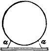 .
The position of the strips is shown at a. In all gumming use plenty of gum, but
let the greater part be on the side hid from view.
.
The position of the strips is shown at a. In all gumming use plenty of gum, but
let the greater part be on the side hid from view.
This end must be shaped to fit the boiler.
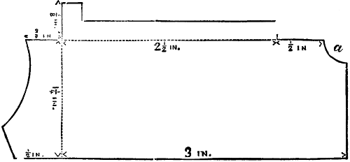
Fig. 5.—Full size.
Fig. 5 enlarged (14 kB)
We have now to construct ‘side-boxes.’ Take a piece of medium thickness
card (a used white postcard), and make it the shape of Fig. 5. Where the dotted
lines come, cut a little V-shaped groove,
not quite through the card, like this:—
 .
And by bringing the two edges of the groove together, thus,
.
And by bringing the two edges of the groove together, thus,
 ,
you will be
enabled to fold the card at right angles at those places without breaking it.
Having cut this as required, it must be folded and gummed into shape (put
plenty of gum into the joints and corners), and kept in this position on a piece
of wood by pins.
Fig. 6 shows its
appearance.
,
you will be
enabled to fold the card at right angles at those places without breaking it.
Having cut this as required, it must be folded and gummed into shape (put
plenty of gum into the joints and corners), and kept in this position on a piece
of wood by pins.
Fig. 6 shows its
appearance.
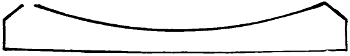
Fig. 5a.—To go round ‘middle-box.’
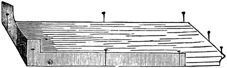
Fig. 6.

Fig. 7.
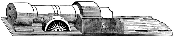
Fig. 8.
Make another similar to this for the other side; the same shaped card will do, all that you need alter is the V groove, which must be on the reverse side of the card to enable you to fold it so as to make a pair—right and left-handed. When[366] dry, paint ‘chrome-green,’ edge with black, and gum in position one on each side of the back ‘over-raise-up,’ to which they should exactly fit. Fig. 8 shows them in position marked b. The next thing to do is to make ‘MIDDLE-BOXES.’ They are two in number, and are placed, one on each side, exactly in the middle of the boiler, as marked a in Fig. 8. Medium thickness is required. Describe a circle, with radius one inch; within and concentric describe a second with radius seven-eighths of an inch, and a third concentric with radius three-eighths of an inch; divide this into two equal parts by the line A B, Fig. 7. Between the two inner circles draw radiating spokes, as in Fig. 7. Cut out the shaded parts neatly with a sharp knife. Cut through the line A B to divide into two parts. Now prepare two pieces of card shaped something like Fig. 5a; and the length must be sufficient to reach from A to B round the outer circle in Fig. 7, the curve being made to fit nicely to the boiler, as marked c in Fig. 8. Gum these to the middle-boxes, and, when dry, paint[367] ‘chrome-green,’ edged with black; gum middle-boxes in their places on the boiler. In the centre of the front ‘raise-up’ gum a circular piece of thin card (radius three-quarters of an inch)—this represents soot-door; a pin, with head and point cut off, gummed on the left side with two narrow strips of card from the pin to beyond the circle as annexed will form the hinges; two other pieces of pin, as shown on the side opposite to the hinges, form the handles.
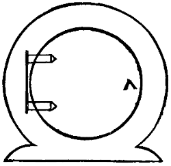
Half-size.
The soot-door should be painted black.
The model should now present the appearance of Fig. 8.
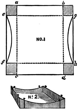
Fig. 9.
We have next to make a ‘DOME-BOX’ and a FUNNEL-BOX. As both of these are alike except in size, we will give details of the first, and dimensions only of the second. On a piece of ‘medium’ card construct a square with sides one and a half inch long, construct a second within it with sides one inch long, cut out the corners shaded, leave the sides A B and C D straight, but curve, as shown, the lines marked E F and G H, so that they fit the boiler; the annexed (Fig. 9, No. 1) is full size and exactly the shape. All round the inner square, where the dotted lines are shown, a V-shaped groove must be cut, as when making ‘side-boxes’: fold in, gum well in at the angles, and place pins round to keep it in position until dry, as at Fig. 9, No. 2.
The dimensions of the ‘funnel-box’ are: outer square, one and a quarter inches sides; inner square, three-quarters of an inch sides. The ‘dome-box’ is to be painted chrome-green and edged with black; the ‘funnel-box’ is to be painted black. When they are quite dry they must be gummed in position; the ‘dome-box’ is to be placed on the boiler, almost in the centre, but slightly nearer the front than the back; the ‘funnel-box’ exactly in the centre of the front over ‘raise-up.’

Wood shaped for Dome. Cut off at line A B.
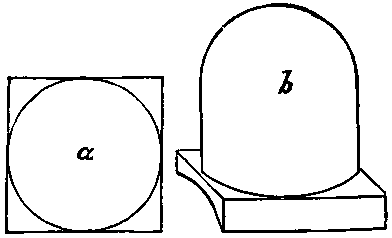
Fig. 10.
Now obtain a piece of deal about six inches long and rather more than an inch square; the corners are to be cut away at one end, so that the end is shaped something like a glass shade; then with sand-paper (coarse first and then fine) the rounded part is smoothed; cut it off square, about one inch and a quarter from the rounded end, as shown at A B.
This is the ‘DOME,’ and if it be gilded with a little of Judson’s or Bessemer’s gold paint, it adds much to the appearance; when gilded and dry, stick it on the[368] ‘dome-box;’ it should exactly reach the centre of each side of the square; looked at from above, it appears as at a; looked at from one side, it appears as at b.
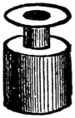
STEAM FUNNEL
Next take a piece of rather stout note-paper, about six inches long and half an inch wide, roll it round a piece of slate-pencil several times, gum the outer end, and when dry slip it off; cut a circular piece of medium card to fit the end, which should be about half an inch in diameter; now roll another piece of paper about a quarter of an inch wide so as to make a roll about a third of the diameter of the preceding, gum the outer end as before, and fix it in the centre of the circular card; cut a second disc of card with the centre cut out just to fit on the top of the small roll; it will then appear thus: It is called the ‘steam-funnel’; it is to be painted ‘chrome-green’ and edged with black; its position is the centre of the back ‘over-raise-up.’
We must now make our screen. For this we require a piece of thick card three and a half inches long and two and five-eighths inches wide. It is to be of the shape here given, but the width must be such that it will fit tightly in between the side-boxes (see b, Fig. 8) at the rear end of the boiler; the top must reach about half an inch higher than the steam-funnel and be rounded at the corners. In this two circular holes of about three-quarters of an inch in diameter must be cut; their position is half an inch below the top and a quarter of an inch from the sides; paint it chrome-green and edge with black. If pieces of circular glass, such as are used for covering objects when mounted for the microscope, were placed over the circular holes, and gilded round the edges, they would improve the appearance; they are not essential. On this screen we now provide a circular piece of thin card of the same diameter as the large end of boiler—viz., two and a[369] quarter inches; this must be painted black, and is then gummed on the screen so as to correspond with the boiler end when the screen is in position; a hole, horizontal at the top and circular below, of this shape and dimensions must now be cut through both cards for an ash-pan, the lower edge being about one-eighth of an inch from the edge of the circle; at the back, over the hole, gum a piece of paper painted vermilion, and dotted with black to represent fallen cinders.
On this boiler end must now be made furnace and furnace-door. For this take
a piece of ‘medium’ card, and on it describe a semi-circle, with diameter one and
three-quarter inches. In this make a door shaped as in the diagram, cut quite
through the part marked a, b, c, d, except where the dotted line comes. Where
this dotted line is shown it should be cut on the reverse side of the card, half
through the card. This is the door, and it will then stand partly open. Round
the circular part gum a piece of thin card, one-eighth of an inch wide. Fasten
down with pins as before to dry, as annexed. When dry, paint the part which
is to show outside black, and stick a piece of paper painted vermilion on the inner
side of door. The vermilion should show through the partly open door, in order
to give the ruddy appearance of fire. This furnace end may now be gummed on
the boiler end (see Fig. 11). When in position the bottom will be parallel with
the top of the ‘ash-pan’ opening, and about one eighth of an inch above
it. It will stand out from the boiler end. Now with a large pin make
holes all round the edge of the boiler end. They should be close
together, like this:  .
In these holes insert pins, with the heads showing outside, and
this will give the effect of bright rivets.
.
In these holes insert pins, with the heads showing outside, and
this will give the effect of bright rivets.
Next take a piece of medium card, and make it of this size and shape:
 As seen from front..
Where
the dotted lines marked ‘1’ are shown, bend it at right angles from you; where
the dotted lines marked ‘2’ are shown, bend at right angles outwards; it will,
when looked at edgeways, appear like
this:
As seen from front..
Where
the dotted lines marked ‘1’ are shown, bend it at right angles from you; where
the dotted lines marked ‘2’ are shown, bend at right angles outwards; it will,
when looked at edgeways, appear like
this:
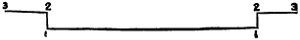 As seen from above..
Paint it black on both sides, and
gum the ends (2 to 3) on the screen
just above the boiler end. The lever
(4, 5) is to work in this on its centre (4). A narrow piece of thick card, about
one inch and a quarter long, will do
for the lever, while a pin inserted at
4 forms the centre on which it
moves.
As seen from above..
Paint it black on both sides, and
gum the ends (2 to 3) on the screen
just above the boiler end. The lever
(4, 5) is to work in this on its centre (4). A narrow piece of thick card, about
one inch and a quarter long, will do
for the lever, while a pin inserted at
4 forms the centre on which it
moves.
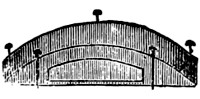
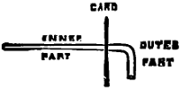
We then fix our ‘steam-gauge.’
It consists of a
circular piece of
white medium
card, on which is shown the numbers 10, 20, 30, 40, etc., to
indicate the pressure. A pin through the centre connects it with
the steam-funnel. The pin represents the steam-pipe. We now
require taps, which we make out of pins, by cutting off the heads
and bending them at right angles about one-eighth of an inch from
the headless end. The point is pushed through the card, leaving outside about
one-eighth of an inch in addition to the bent part, as shown in accompanying cut.
[370]
Above this we gum another piece of bent pin this size
 and shape, for handle
of tap. Two or three of these should be placed on the boiler end, at the
left side above the furnace.
and shape, for handle
of tap. Two or three of these should be placed on the boiler end, at the
left side above the furnace.
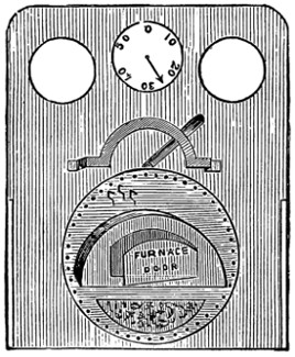
Fig. 11.—Appearance of screen,
but not
the correct size.
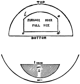
Ash-box, full size.
Our screen will now appear as shown at Fig. 11, and is ready for fixing. To enable us to do this, as its position is at the back end of the boiler, we first remove entirely No. 4 ‘raiseup’ and this must be done very carefully. A good plan is to cut out the bottom of the ‘raiseup,’ insert your finger and gently pull it, when, with a little coaxing, it will probably come out easily. The ‘raiseup’ being removed, we fix the screen firmly in its place, using plenty of gum on the inner side of the ‘over-raiseup,’ ‘side-boxes,’ and inner boiler end. To hold it in position while drying, stick two or three pins at the bottom into the ‘foundation,’ and tie a piece of cotton through the screen holes round the dome. This cotton must not be so tight as to pull off the dome or bend the screen. Let it dry.

Fig. 12.—Tender-side.—Exact size.
The next process is to provide ‘tender-sides.’ The name indicates what they are, viz. sides to the tender. They are made of wood; two pieces, each four and a half inches long, one inch and a quarter wide, and one-eighth of an inch thick, are required. The upper corner at the front end should be cut out to correspond with the projection from side-boxes (see Fig. 5, a). Paint chrome-green, edged with black, then divide into panels with black lines, as at Fig. 12, which is full size, and gives the exact appearance.[371] If found too difficult, omit all the inner lines. It is advisable to practise making these fine lines on a piece of paper before making them on your ‘sides.’
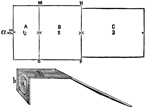
Fig. 13.—Half-size.
When they are quite ready they are placed in position (one on each side) at the rear of the ‘foundation,’ and firmly gummed. They must be in an exact line with the ‘side-boxes,’ and reach a little each way beyond the pair of tender-wheels (as shown in Fig. 1, P to R). To connect these, take a piece of ‘thick’ card of the shape shown (Fig. 13, a). The diagram is half size. At M O and N P, cut, as before explained, V-shaped grooves, and gum up the shape as at Fig. 13, b.
Paint the part marked A chrome-green; panel with black lines like sides of tender. Paint the parts marked B and C black. When quite dry, place in position; the part marked A is to be at the back end of the ‘tender-sides’ connecting them, the part marked B half-way along the top, in both cases extending to the outer edge of the wooden ‘tender-sides.’ The part marked C, which is narrower, comes between the ‘tender-sides,’ and should terminate just about the front end of them.
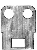
Fig. 14.—Back screen, half size.

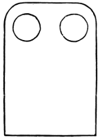
Screen.—This shape, but about twice the size.
The ‘screen’ to be placed at this end now requires making. It should be just wide enough below to fit in between the ‘tender-sides;’ the upper part should be wide enough to reach the outside edges of the ‘tender-sides.’ The height should be a quarter of an inch less than the ‘screen’ already constructed (Fig. 11), with top-corners rounded, and with two holes near the top similar to those in the ‘screen.’ Near the bottom a hole, one inch wide and three-quarters of an inch high, should be cut—this is for the stoker to get coals out. The diagram (Fig. 14) gives the shape. Paint chrome-green, and edge with black.
If you desire to make a screen with a top to it, as in the engines more recently constructed, obtain a piece of thick card long enough for both screens (which now must be of equal height) and the top; arrange it something like the annexed figure, placing all the details of both screens as before described, and finally making V-shaped grooves at A and B, where the bends are to be made. Gum up into shape and afterwards gum in position as before described. Very often this kind of engine has no ‘tender,’ and is called a ‘tank’ engine.
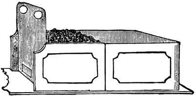
Fig. 15.
Now obtain some coal and break it into small pieces—about the size of gum[372] arabic when purchased. These are to be gummed on the card marked C, in Fig. 13 to fill the space level between it and the back screen, and thus give the appearance of a tender well filled with coal. The tender will now be as represented at Fig. 15.

Fig. 16.
Our attention must now be given to the wheels. We require five pairs. The diameter of these should be equal to the spaces cut out on the ‘foundation’ in Fig. 1, viz. one pair one inch and a quarter, one pair (fly-wheels) one inch and three-quarters, and three pairs one inch and a half. They are to be cut out of ‘thick’ card; the fly-wheels should have sixteen spokes, the others may have eight or twelve. In the centre of each wheel make a pin-hole. Fig. 16, full size, will show you how to mark and cut out your wheels. The shaded part is to be cut out neatly and carefully with a sharp knife. As each wheel is cut out, paint it chrome-green, and edge each spoke with black. Next obtain a piece or pieces of wood about three-eighths of an inch square at the end, and about one or two feet long. Cut off five pieces, each two inches and a quarter long—this is probably rather longer than required, but they can be cut shorter; they are for axles, and the ends should be painted black.
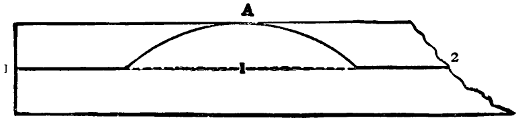
A piece of bearing shaft. Full size.

Bearing shaft complete, quarter of size.
Having all these prepared, fix each pair of wheels to an axle by sticking a pin through a pin-hole. They are not to be permanently fixed until the axles are stuck on the foundation, as possibly some of the pins may require to be placed higher or lower in the axles in order that all the wheels may be level at the bottom and the engine stand firmly when on a smooth surface. When this is done, fasten the wheels very firmly to the axles with pins cut in half. I should add, the wheels are not intended to revolve. Next provide ‘bearing-shafts’ by taking strips of thin card, the same length as the foundation, and about half an inch wide; draw a line down the the middle of each from end to end. Now fit them to the sides in order to mark[373] on them the positions of the engine-wheel centres, A, B, C. At these make curves, as shown. Cut through the line (1,2); it follows the centre line except at the curves; the bottom is quite straight. Paint this ‘vermilion,’ or better still, ‘crimson-lake,’ and edge with white. The bearing shafts are continued round the ends front and rear, but for these it is best to take separate pieces of card of medium thickness; they are only a quarter of an inch wide; paint and edge like the side pieces. Gum in position on the sides and ends of foundation; only the curved parts at A, B, C appear above, the straight part of the upper edge is ‘flush’ (that is, exactly even) with the foundation.
Our copper wire (No. 9 in list) is now needed. Cut two pieces just long enough to fit tightly between the second and third ‘raiseups,’ fix them in position parallel with boiler, rather more than half-way up, and near the edge of the ‘raiseups.’
Lamps are now to be made and fixed on the space in front; they are best made out of pieces of wood—the remainder of that used for axles will be useful for this if cut down; they should be about three-eighths of an inch wide and thick, and half an inch high. Paint the front side of one white, of the other green; when dry, make a circle on this front, and paint all black except within the circles; make two similar for the back, but these paint vermilion for the centres. In the top of each insert a bent pin with its head cut off for a handle.
Now make the buffers, the instructions for making steam-funnel will tell you how: the only difference is that there is to be no hole in the circular card at the end. The front part is painted vermilion, the rest black. Two are required at each end; they are placed on the bearing-shafts front and rear, about three-eighths of an inch from the sides.
The ‘FUNNEL’ now requires our attention. It is made of paper, long enough and wide enough, when tightly rolled, to form a cylinder about half an inch in diameter and two inches long. Gum the edge down. For the top, cut a circular ring, of medium card, three-quarters of an inch in diameter outside, half an inch in diameter inside. Fit this neatly on the top of the cylinder. Paint it black and gum in the centre of the funnel-box, previously described. A gold line or strip of gilt paper round the top of the funnel improves the appearance.
Fig. 17.
Funnel top.
A circular piece of medium card three-quarters of an inch in diameter, with a black cross or diamond painted on it, should be placed in front of the funnel-box. (Fig. 17).
Safety-valves, connected with the ‘dome,’ should now be put. Obtain two rather thick sewing-needles, about two inches long; make with the points two small holes, one-eighth of an inch apart, just behind the red strip at the back of the ‘dome;’ push the eye end of one of these needles carefully through these holes, so as to allow them to stand out about an inch and a half. They should incline to each other at the top, but otherwise be perpendicular. They are connected with the dome by pins with the heads cut off, but whose points are stuck into a little cube of cork gummed on the top of the dome.
The engine is now tolerably complete, and only requires to be varnished. For[374] this purpose, obtain some ‘crystal’ varnish, of good quality, and apply it with a large camel-hair brush. One good coat should suffice. Let it thoroughly dry before handling.
There are many little details which will probably occur to you. I have seen a metal cartridge-case used to represent a cylinder, a wire coming from the top representing the steam feed-pipe. Little pieces of chain, front and back, represent coupling-chains. In some, the apparatus for applying the vacuum brake is imitated. All you need do is to use your eyes and exercise your ingenuity. Should you fail at first, do not be discouraged; try once more. There are no obstacles but what may be conquered by patient and persevering attention.
The humming-top is a familiar toy that does not cost much to buy. At the same time there is always a satisfaction in making a thing for oneself—particularly when it costs nothing.
As it happens that a good loud humming-top can be made for nothing, we feel sure that some of our readers will not be above trying their hands at it.
The materials are an empty baking-powder canister, or any wooden box, and two pieces of firewood. The plan of operations is to cut a slit in the side of the box answering to the hole in the toy, making it half an inch square or round, as the case may be, and making a hole in the lid and bottom of the box for the spindle to come through. To make a good job of it the bottom hole should be square and the top hole round, and the spindle should be cut to fit, pushing it in, of course, from the bottom. When the holes and spindle are cut, put a little glue round the lid to make the box tight, and insert the spindle with a little glue at each hole. For the usual fork or handle with which the top is spun, a plain slip of wood with a hole at the end will be found to answer.
Very simple preparations all these, and yet everything is ready except the string.
When the top is dry, wind round the string, passing it through the hole in the handle as shown, and spin.
You will admit, I think, that if instead of fashioning wood by tools it were possible to make the wood grow into the shape desired, it would not only be curious, but under certain circumstances useful. Suppose, for instance, I wished to have a boat; it would not only be curious, but in some cases useful, if I could make the boat grow under my eyes by almost imperceptible additions, instead of fashioning it, as now, from planks. This is just what I am going to show you how to do, and very pretty work you will find it in long evenings.
You must begin by making a fluid called cupro-ammonium (you cannot buy it), which has the singular property of dissolving woody matter just as completely as water dissolves gum. You make this cupro-ammonium thus: Go to a wholesale druggist, or a drysalter, and purchase a Winchester quart bottle full of the very strongest solution of ammonia. This is known commercially as ‘eighty-eighty’ ammonia, by which name you are to inquire for it. Were you to purchase less than the measure of a Winchester quart it would cost you a much higher proportionate price, because, being very irritating to the nose and eyes, the vendor will take good care to charge you for all the sneezes and eye-blinkings he has to encounter in measuring out your required quantity.
Next you will require an empty Winchester quart stoppered bottle, or a bottle of equal capacity. Being thus provided, you will pour just one half of the contents of the full bottle into the empty bottle; the reason for doing which will presently be seen.
Get now some copper wire—it matters not what size—and having got it, cut into such lengths that being thrust into one of your half-full Winchester quart bottles it shall lie partly immersed in the ammonia, and partly exposed to air, like this:—
You will observe that the sketch represents not one length of copper wire, but many, the fact being that the object of using copper at all is that it may be dissolved by the ammonia; and it stands to reason that in proportion as the copper is more so will the necessary strength of solution be arrived at more quickly. Contact of air being necessary to effect the solution affords the reason for your dividing the original ammonia into halves.
So your bundle of copper wire being placed in the half-full bottle as described, there let it remain and steep, but you must take care to remove the stopper of your bottle from time to time—say once a day, at least—shaking the contained fluid well about, so as to promote air contact. An interesting change will be seen to[376] take place. The ammonia solution, originally colourless as water, grows blue and bluer still, until so very blue that you cannot see through it. To this blue solution the name of cupro-ammonia has been applied. It has the remarkable property of dissolving wood, as we shall presently discover in our workings.
Before going further I must point out to you that this cupro-ammonium has a very strong smell; not a disagreeable smell, far from it; the smell of hartshorn, in point of fact. Not an unhealthy smell, but one may easily have too much of it. To be working amidst sneezing and eyes full of water is not agreeable, so I will tell you betimes how, in your small workings, you may avoid this inconvenience. The smell depends on a colourless gas ammonia, which is a light gas and very tractable. If you sit in a draught and on the windward side whilst working, and in the open air, the ammonia is blown away from you and you smell nothing. If you work in a room and before a chimney, up which there is a draught, then again you smell nothing, because all the ammonia evolved goes up the chimney. These points being remembered, no trouble will be experienced in doing such small work as I shall teach you; but before working with cupro-ammonia could be conducted on a large manufacturing scale, as it now is conducted, special means had to be devised for disposing of the ammoniacal atmosphere.
Good, so far! And now about the tools. The hand, with its four fingers and a thumb, is so excellent a tool for an infinity of purposes, that certain thoughtless people would seem to be under the impression that whatever new thing they may have to do can be done without tools altogether. This is a mistake; tools you will want, but they are of the simplest description.
Inasmuch as cupro-ammonium not only stains the skin but irritates it, do not let it touch the skin. There is no danger in the matter, only inconvenience. You do not want the ladies of your family petulantly complaining about those boys having been ‘dabbling with their filthy chemicals.’ Should your fingers get stained, a little vinegar will get out the stain, but not without a certain smarting that may as well be avoided.
The chief tool you will have to employ will be a finger of the right hand.
Some operators may prefer the forefinger to others; the second will come most
natural. But whichever finger you determine to employ, case it in india-rubber.
This is easily done, and as follows: Having procured a sheet of raw or
unvulcanised india-rubber, cut a piece off, hold out your finger, and get some
friend, after warming the rubber, to stretch it over the
finger so:— squeezing the rubber where it comes round
the finger above into a flattened crest. The two surfaces
will stick together quite as much as is desirable.
Now let the operator, with a pair of sharp scissors, and at
one sweep, cut away the crest close up to the finger.
You will then have an india-rubber finger-stall.
squeezing the rubber where it comes round
the finger above into a flattened crest. The two surfaces
will stick together quite as much as is desirable.
Now let the operator, with a pair of sharp scissors, and at
one sweep, cut away the crest close up to the finger.
You will then have an india-rubber finger-stall.
If you choose to be a little more extravagant, you may provide yourself with an india-rubber glove. Gloves of this material are common enough now, being used for a variety of purposes, more especially by photographers for protecting their hands against the corrosive and poisonous agents employed in the practice of[377] photography. If, however, you do use gloves, see that they are thin, fitting well to the fingers. If thick they will interfere with the delicacy of touch necessary to your working. For my part, I do not recommend gloves, looking upon a finger-stall of india-rubber as superior.
The next tool that you must get is a pair of forceps, such as watchmakers use. It is a very inexpensive instrument, costing only a few pence, and in shape it is like this:—
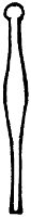
The next tool—and the last I shall have to indicate—is a pair of sharp and delicately made scissors. Do not calculate on family resources, taking the first pair of scissors that may come to hand: get a pair of your own. See that they are first-rate when you are about it, and you cannot buy scissors of this sort at random at any hardware shop. Go to a surgical instrument shop, where you will be able to get what you want.
And now I leave your cupro-ammonium to brew, and you to get together the few tools indicated. When you are quite ready, we will proceed to see what to do with it.
The first exercise I shall put to you is the manufacture of an artificial wooden bottle. There will be no particular use in the thing when made, but it will be a curiosity, and the making of it is the very best exercise that suggests itself to me after many years’ experience.
You will perhaps here call to mind what I have told you about the pungent smell of our working fluid, cupro-ammonium, if one chances to get a sniff at it, and how that inconvenience may be avoided by a little management. In addition to that memory, please now bear in mind that the intensity of the smell of odorous things is in proportion to the surface exposed. Presently, in order to use your cupro-ammonium fluid, some must be poured out into a vessel into which you can dip little pieces of paper. Now it is evident that the smell of a pint of cupro-ammonium, or of any other smelling fluid, will be less intense if the vessel be a comparatively narrow-mouthed jug than if it be a basin; but supposing a basin to be desirable for collateral reasons, then much smell may be avoided by providing yourself with a temporary cover, say a glass pane, which may be laid over the surface, resting on the basin rim at the intervals when the dipping of your pieces of paper must be interrupted.
Next as to the paper you are to use in making this bottle of artificial wood. The best for your purpose will be what is known as printing demy. Writing-paper, having a glazed surface, is not favourable. The glaze is produced by animal size, a material that does not go well with cupro-ammonium. It matters little, practically nothing at all, whether the printer’s demy be new or whether it be printed upon. I have made excellent artificial wood out of, I believe, all the London daily morning papers; so choose your paper, and let us fall to work. Theoretically and scientifically it matters not what shape you cut your paper into, but practically, and present purpose regarded, there can be no doubt but that discs of a circular shape, and scored with cuts all round the circumference, are most convenient. The discs may conveniently run about the accompanying size.
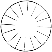
The basis or model of our bottle about to be, or rather flask, shall be a common oil-flask. Provide yourself, then, with one of these, and cleanse it thoroughly from all oil, the least touch of which would be fatal to the success of our workings. Having done this, provide some sort of stand, into which the neck of the flask being stuck, the whole may be turned round and round in the progress of working. It matters nothing what this movable stand is. A candlestick does very well, if you can find a candlestick with candle-socket big enough to admit the neck of the flask. A marmalade pot holding sand can always be got, and into the sand the mouth and neck of the flask being stuck, every necessary purpose will have been answered.
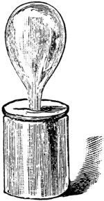
Preliminaries being thus seen to, you pour out some of the cupro-ammonium in, let us say, a basin. Do not be sparing as to the quantity you pour out, for a reason to be explained presently. Take now one of your paper circular discs, and, with your forceps nipping it quite at the edge, dip it into the cupro-ammonium bath. For how long? Ah! that is a question to be solved. Assuming your stock of cupro-ammonium to be in good working order—assuming it to have been brewing with the copper wire for not less than a month, air having been furnished to it day by day, as already enjoined—then about three seconds will be long enough for each immersion. Nothing but practice will settle the point, and after only a little practice the operator cannot be mistaken. Immerse, then, for trial a paper disc, and, withdrawing it after about three or four seconds, lay it upon the crown of your flask and spread it out regularly by means of your forceps and rubber-protected finger. If it feels slippery like an eel the fluid has come to condition; but otherwise, if the disc instead of feeling slippery give the impression of harshness, then the conditions are not all that one would desire them to be. The main question is this: will the next disc, when steeped in the bath, removed, and pressed down, stick satisfactorily to the preceding disc?
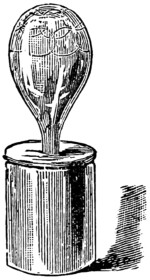
This we shall now see. I have shown you here how the discs must overlap each other like the scales of a fish. You need not be particular in aiming at the mathematical symmetry of the scale lying on a fish’s skin; it would be folly to attempt such a result except your discs had been mathematically cut to pattern, and extremely difficult of execution in any case. Supposing the adhesion to be satisfactory, you can go on covering the entire surface of the oil-flask, and I should think common sense would suggest that when you have come down a certain distance in your working it will be more convenient if you take the flask out of its support and reverse it on a tumbler thus:—
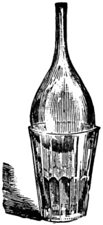
When one course of overlap disc-layering has been finished in the way described, I would advise you, this being your first experience, to lay your work aside and let it dry. It will be easy now to see whether the overlap adhesion by all that was[379] desired, and what the process is capable of. You are to remember, please, that we aim at no mere sticking together comparable to the result of gumming or pasting, but to an actual incorporation of material, so that junction being once effected, the layers can never more be separated by any known means. Were it otherwise, a thick material resulting from aggregated sheets of paper would have no claim to the designation ‘artificial wood.’ It would be simply papier-maché, reducible to paper pulp by mere steeping in water; whereas the material you and I are now engaged upon may be not only steeped in water, but actually boiled, and will never come to pieces. It will behave under those circumstances exactly like natural wood—that is to say, will soften a little to a certain depth, no more.
Cupro-ammonium is a very funny thing to work with, and has many curious ways. One curious point is this: Capable of effecting such complete adhesion—nay, more, incorporation, actual, bodily, as we have seen it to be—yet that quality ceases after only a few minutes’ removal from the bath. If you ask me the why and wherefore, frankly, I am unable to tell you, not myself knowing, though I have worked at this material for more than twenty years. So whatever work has to be done with cupro-ammonium has to be quickly done.
Another point of very highest importance is the following: Do you remember my telling you not to be sparing in the quantity of cupro-ammonium poured from the ‘brewing bottle,’ as we will call it, into the dipping basin? The fact is that every bit of paper you immerse and withdraw weakens the original solvent power of the bath, so in proportion as the bath liquor is smaller in quantity, by so much more speedily will its working power be lessened. For a long time that working power can be, and in practice is, restored by additional copper steepage, but it cannot be restored indefinitely.
Now pour back your bath-liquor; put away your tools, hereafter to renew your bottle building. Go on adding layer to layer until your bottle is as thick as you wish it to be, then giving the thing a sharp crack with the hammer, the glass flask will crumble almost to sand, which, when shook out, your own flask of cuproxylene, or artificial wood, will remain without support, but quite able to take care of itself.
The investigation of astronomical phenomena can only be made with the aid of a good telescope, the purchase of which is attended with considerable cost. It is my purpose in this chapter to give such directions as will enable any boy with average ingenuity to make for himself, at the cost of a few shillings, an instrument with which he can observe the more interesting of these phenomena.
This telescope will be of the simple non-achromatic class—that is, the colour effect of the unequal refraction of light is not corrected. Object-glasses of the achromatic construction are very expensive. All refracting telescopes were of the simple class up to 1758, when Mr. John Dollond, who had a few years before set up in business in London as optician, discovered a way to correct the colour effect on the image. This was by making the object-glass compound, or of two or more lenses fitted to each other, each being made of a different quality of glass from the other and having a different refracting power, one lens correcting or neutralising the dispersing caused by the other. The lenses for our telescope can be had from Messrs. Dollond and Co., descendants of the above John Dollond, No. 1, Ludgate Hill, who have given me some valuable hints with regard to the construction of this telescope.
A refracting telescope consists of an eye-piece, a tube, and an object-glass; these are mounted on a firm stand. The object-glass at one end of the tube collects the rays of light, reflected from an object, to a point, in the focus of the eyepiece, which magnifies the image that is there formed, enabling the eye, placed at the orifice of the eyepiece, to see an enlarged image of the object.
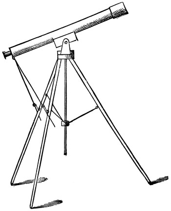
Fig. 1.
The stand must be firm, so as not to vibrate when any one passes along the floor of the room, and it must have a vertical and lateral motion connected with it. Fig. 1 shows what our instrument will be like when finished.
The first thing to be made is the tube; this must be thirty-nine inches long and two inches in diameter inside. Get a wooden roller four feet long and two inches wide. A piece of curtain rod will do. Now mix some strong glue. If you have not a glue-pot, mix it in a jar placed in a saucepan of water. Get some sheets of stout brown paper and well damp them. Take a strip of brown paper, that has not been damped, thirty-nine inches long and seven inches wide. Rub the roller all over well with powdered chalk and put this dry paper strip round it to form a case, lapping and gluing the edges together, but being very careful not to let any glue touch the roller. Now take your damped paper and rub it all over on both sides with hot glue, and roll it on the roller; roll it tightly and rub the glue well in, and rub each layer of paper well in to the under one, so that when dry it will form a mass of paper and glue. Put on enough paper to form a casing a quarter of an inch thick. When you have done papering set the whole on one side to get quite dry and hard. While this is drying we can be making the eyepiece and stand. For[382] the eyepiece we shall want a piece of brass tube four inches long and large enough for the larger of the two lenses that form the eyepiece to go inside; that will be a little more than an inch in diameter inside. Get your lenses before getting the tube. This tube can be bought at the ironmonger’s.
Now for the lenses. Go to Messrs. Dollond and ask for a two-inch simple object-glass, forty inches focus. This will be one shilling and sixpence. For the eyepiece ask for two plano-convex lenses—one of one-inch focus, the other of two-inch focus. These will be three shillings and sixpence the pair. The object glass is to be double convex. Now, having got your lenses, we will fix them in the tube.
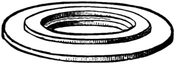
Fig. 2.
Cut a piece of cardboard three-quarters of an inch wide, and long enough to go all round inside the tube tightly, and not to lap. Push this in to form a lining at one end, and forming a shelf out of the thickness. This shelf is to be about two inches from the end. Now turn the other end of the tube up and drop the larger of the two lenses—which is called the field lens—on to the shelf with the rounded side downwards. Now push in on the top of it another cardboard lining three-quarters of an inch wide. Push this lining quite down on to the flat side of the lens to keep it firm. On to the shelf formed by this lining place a disc of cardboard the size of the inside of the tube, and with a hole cut in the centre half an inch in diameter. This hole must be cut quite clean. On to this disc push in a cardboard lining one inch wide to keep all firm. Now cut two discs of cardboard, one the exact size of the inside of the tube, with a hole in the centre a trifle smaller in diameter than the small lens, which is called the eye-lens; the other a quarter of an inch smaller, and having a hole in the centre the exact size of the eye-lens. Glue these two discs together (as in Fig. 2), being careful to get them concentric. When this is dry push the eye-lens into the ledge formed, the flat side downwards, and put the cardboard discs on to the lining in the tube, the rounded side of the glass inside the tube. Fasten the disc and lens in place with a narrow strip of cardboard, going all round just inside the tube.
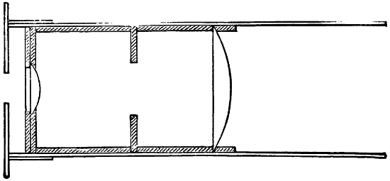
Fig. 3.
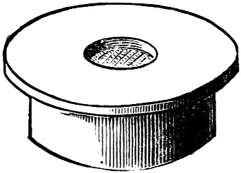
Fig. 4.
Fig. 3 will show the arrangement of lenses and disc in the tube. The lenses are to be an inch and three-quarters from edge to edge; the disc is to be an inch from the eye-lens. Now get a tinman to make you a cap of thin brass plate (like Fig. 4). This is to fit tightly on the end of the tube over the eye-lens, and is to have a hole in the centre of the top three-eighths of an inch in diameter.
Now the eyepiece is finished, and we will get on with the stand.
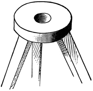
Fig. 5.
Let two circular pieces of beech five inches in diameter and one and a half inches thick, each to have a hole bored in the centre an inch in diameter, and going right through the wood. Take one of these pieces, and on the under side fasten, by three strong brass hinges that work stiffly, three legs, made of inch and a half square pine (Fig. 5). These legs are to be four feet six inches long.
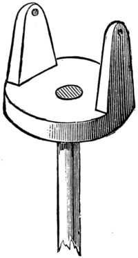
Fig. 6.
Take the other piece of beech and fasten a rod or roller of wood, two feet and a half long and one inch diameter, into the hole, so that one end is flush with the top side of the wood (Fig. 6). Now fasten two uprights to the top, letting them into the wood (Fig. 6). These are to be three-quarters of an inch thick, and four and a half inches high, and are to be three and a half inches apart.
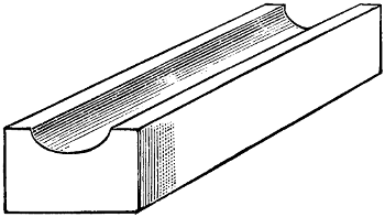
Fig. 7.
Bore a hole in each upright about half an inch from the top and about one[383] quarter of an inch in diameter. Now get nine screw stair-eyes at the ironmonger’s, and about seven feet of brass wire one eighth of an inch thick. Get this wire straightened. Into the inside of each leg, and one foot from the top, screw one of the brass stair-screws. Now get a piece of wood, circular, three inches diameter and one and a half inches thick (a ribbon roller will do very well), and bore a hole right through the centre, one and a quarter inches in diameter. Round this piece of wood at equal distances screw three more of the screw-eyes. Now cut from your brass wire three lengths of fourteen inches, and turn a ring at each end of each piece, and hook one end of each piece into a screw-eye in the circular block, and the other end into the eye in each leg, closing up the rings so that they will not come unhooked. This arrangement will keep the top from tilting. Now the stand is finished, and we will take the tube in hand if it is quite dry and hard. Before drawing out the roller, cut the ends off quite square with a sharp knife, leaving the tube thirty-seven and a half inches long. Now draw out the roller without breaking the tube. We must next fix the object-glass. Cut a strip of cardboard half an inch wide, and long enough to go all round inside the tube without lapping, and to fit tightly. Push this inside, so that it will form a shelf half an inch inside the end of the tube. Glue this in its place. Upon this place the object-glass, and fix it there by gluing a strip of cardboard all round inside the tube on the top of the lens. To fix the eyepiece, cut from the roller used to make the tube on, a piece one inch long, and bore a hole right through the centre of it the exact size of the eyepiece tube. Glue this block in the other end of tube. Push the brass tube in this hole with the field-lens inwards. The telescope can be focussed by pushing in or drawing[384] out the brass tube. Get a piece of deal eight inches long and three and a half inches wide and two inches deep. Cut a groove along the top as Fig. 7, one inch deep and a little more than two and a quarter inches wide, to fit the outside of the tube. Glue this block on the tube, so that one end is thirteen inches from the front end of the tube (the eyepiece end). Put the block in its place between the uprights on the stand, and fix it there by two screws passing through the holes in the uprights and screwing into the block. Pass the rod attached to the uprights through the hole in the top of stand and through the hole in the block underneath.
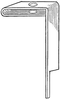
Fig. 8.
Now we have only to make the arrangement for elevating the telescope. For this you will want the rest of the brass wire and the remaining three stair-eyes as well as two pieces of thin brass plate, four and a half inches long, half an inch wide, and one-sixteenth of an inch thick. Bend these pieces of plate as in Fig. 8, making the bent parts one inch long, and get the ends cut as in the figure, and have holes drilled in the bent parts a little larger than the brass wire. Cut your wire into two lengths of eighteen and a half inches, and take them to the tinman and get him to cut a screw-thread nearly the whole length of each, leaving about two inches to each. At this end of each get him to turn a ring, and get him to close these two rings into one of the screw-eyes. Get him to make a screw-nut for each wire about the size of a farthing, but about twice the thickness. Screw the eye carrying these wires through the tube into the eyepiece block, screw the remaining two screw-eyes into two of the legs of the stand, on the outside of each leg and about one foot from the top of each. Bend the cut part of the brass plates into rings and close them in these screw-eyes. Now put the screw-nuts in their places in the brass plates, and put the screw wires through the holes in the top, and turn the nuts to the left, which will draw down the wires and with them the eyepiece of the telescope. To turn the telescope to the left turn the right-hand nut to[385] the right, and the other to the left, and to turn it to the right reverse the action of the nuts. In making this telescope you must be very careful in fixing the lenses. They are to be placed so that the centres are to be in one straight line, which line is to be at right angles to the lenses. You can cover your tube with coloured paper to give it a finish. It will be advantageous, in using the instrument, by keeping out all light not wanted, to make a cardboard tube about six inches long and large enough to slide easily on the end over the object-glass and to project about five inches. The telescope is now finished, and will with ordinary care last for years.

Fig. 9.
Appearance of the Moon as seen through one of these telescopes on June 9th
It may be well to add that astronomical telescopes show the image inverted; this is done to save the use of erecting glasses which absorb light, and consequently make the image faint. If you wish to make yours useful for terrestrial purposes, you must insert in front of the field lens, and about four inches from it, a lens of the same focal length; this will turn the image right way up. The blurring of the image is sometimes caused by the two lenses composing the eye-piece not being at the distance apart proper for their focal lengths.
The kaleidoscope is the most successful scientific toy of modern times. Immediately after its patenting by Sir David Brewster over three hundred thousand were sold in three months. Essentially it consists of a couple of mirrors arranged at an angle forming some even sub-multiple of three hundred and sixty. The angle usually chosen is the sixth, or sixty degrees.
Before proceeding to make a kaleidoscope for home use, it would be well to try a few experiments with two common pieces of looking-glass. Arrange them as in the diagram (Fig. 1), and placing an object at A, or standing them on a piece of colour work, notice the beautiful geometrical pattern formed by the various reflectors. Having experimented with various articles at the angle given, try the effect at another angle, and note how the slightest change affects the design.
Having grasped the general principle you can proceed to make one of the commoner varieties of the instrument as usually sold. These have three mirrors.
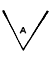
Fig. 1.
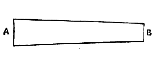
Fig. 2.
Fig. 3.
Cut three pieces of common glass into the shape here given. Let them be[386] seven and a half inches long, one inch and five-eighths wide at A, and one inch wide at B (Fig. 2). If they are silvered on the back so much the better; if they are not, paint them black on one side. A very good black paint for the purpose is made by mixing vegetable black with gold size until it is as thick as cream. Seven-pennyworth of gold size and a pennyworth of vegetable black, obtained from the nearest oil-shop, will give you enough paint for a dozen kaleidoscopes, and be useful for other purposes into the bargain. The three mirrors are to be arranged in a tube, with their blackened sides outwards (see Fig. 3); and the tube is to be made accordingly. An old copy-book cover can be rolled into the shape, or a well-pasted strip of newspaper rolled round and round on a stick, as described in the chapter on the telescope, will give the tube with very little trouble. To fit the mirrors we have cut the tube should be eight and a quarter inches long, two inches in diameter at the broad end, and one inch and an eighth in diameter at the narrow. Of course the tube is not absolutely necessary; a square box two inches wide and eight inches and a quarter long will answer every purpose, but then the mirrors, instead of being kept in position by the sides of the case, will have to be wedged up by pieces of cork or balls of paper.
Fig. 4.
Having made the case, fix an eyepiece of tin or cardboard at one end, so that a hole a quarter of an inch in diameter comes in the centre of the angle made by the mirrors. This hole is shown in position in Fig. 4, which represents the top of the tube or box.
At the other end of the tube a round piece of clear glass is to be fixed, and if the box is used a square piece will take its place. The round can be easily made from the square by chipping off the corners. An American glass-cutter, costing sixpence, can be obtained from most tool-shops, which will be found very useful in cutting glass for this and many other purposes. The secret in working wheel glass-cutters of all kinds is to keep the handle as nearly upright as possible and to bear firmly and equally on all parts of the work.
Having cut the plain glass end and fitted it close up against the broad end of the mirrors, the next thing is to cut a piece of ground-glass of the same size to fit over it. This ground-glass may be patterned, as in the kaleidoscopes of commerce. It is, however, more satisfactory to have it plain. Between the glasses you place the pieces of broken glass to form the designs.
‘The objects which give the finest outlines by inversion are those which have a curvilinear form, such as circles, ellipses, looped curves like the figure 8, curves like the figure 3 and the letter S; spirals and other forms, such as squares, rectangles, and triangles, may be applied with advantage. Glass, both spun and twisted, and of all colours and shades of colours, should be formed into the preceding shapes; and when these are mixed with pieces of flat coloured glass, blue vitriol, native sulphur, yellow ochre, and differently coloured fluids, enclosed and moving in small vessels of glass, they will make the finest transparent objects for the kaleidoscope. When the objects are to be laid upon a mirror plate, fragments of opaquely-coloured[387] glass should be added to the transparent fragments, along with pieces of brass wire, of coloured foils, and grains of spelter. In selecting transparent objects, the greatest care must be taken to reject fragments of opaque glass, and dark colours that do not transmit much light; and all the pieces of spun glass, or coloured plates, should be as thin as possible.’
As far as the harmony of colour is concerned, it may be as well to note that the deepest red harmonises with an equal mixture of blue and green; that red goes best with green and blue, the blue being predominant; that orange-red requires a blue with a good deal of indigo; that orange-yellow wants pure indigo; that light yellow is best with violet and indigo half and half; that greenish-yellow shows off best by the side of pale violet; that green goes with a full violet; that greenish-blue combines with violet and red; blue with orange and red; indigo with orange-yellow; and violet with green.
Satisfactory effects can, however, be produced with almost anything bright and shining. The first kaleidoscope we, in the thirst for knowledge, took apart was found to have for its objects about forty pieces of red, green, blue, and brown stained glass, smashed up into irregular fragments of about a quarter of an inch in width and length, and as the shapes were varied and the colours crude, the patterns at every shake were almost as startling as those produced by a sixpenny catharine-wheel on the 5th of November.
The ground glass should be fitted into a cap, so as to be removable at pleasure, and the fragments of coloured glass to form the patterns should be left free to move between the glasses.
Having made this kaleidoscope, and coaxed it into acting properly, experiments with other contrivances should be made. Mirrors should be arranged at ninety, forty-five, and forty-five; at ninety, sixty, and thirty, and other angular combinations. A lens should be fitted at the end of the tube for magnifying purposes, and the tube should be attached to a magic lantern, and the patterns, almost equalling the chromatrope, thrown on the screen.
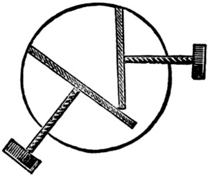
Fig. 5.
Having worked the fixed mirrors to the point of weariness, shifting mirrors should be tried, and then two mirrors, made to alter their angles by an arrangement of screws (see Fig. 5), as in the adjustable form of the instrument, should be experimented with.
You will soon find that when the inclination of the mirrors is not an aliquot part of 360 the reflections will not join, and then the following table from Sir David Brewster’s manual of the kaleidoscope may prove useful:—
| In- clina- tion. |
No. of Re- flec- tions. |
No. of Pic- tures. |
No. of Direct Pic- tures. |
|
|---|---|---|---|---|
| 120 | 3 | 2 | 1 | |
| 72 | 5 | 2 | 3 | |
| 51 | 3⁄7 | 7 | 4 | 3 |
| 40 | 9 | 4 | 5 | |
| 32 | 8⁄11 | 11 | 6 | 5 |
| 27 | 9⁄13 | 13 | 6 | 7 |
| 24 | 15 | 8 | 7 | |
| 21 | 3⁄17 | 17 | 8 | 9 |
| 18 | 18⁄19 | 19 | 10 | 9 |
| 17 | 1⁄7 | 21 | 10 | 11 |
These funny little people when well managed will afford great amusement at holiday and Christmas-tide gatherings. To see these little ladies and gentlemen dancing and singing and even lecturing on the miniature stage is very laughable, especially as they are only eighteen inches high. The following hints will enable any lad to make the figures, as well as a portable stage, for this entertainment.
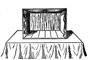
Fig. 1.
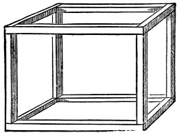
Fig. 2.
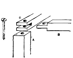
Fig. 3.
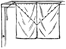
Fig. 4.
For the stage you must get some deal strips 11⁄4 inches square, and cut into four lengths 3 feet 6 inches long for the front and back cross-pieces; four 3 feet long for the uprights; and four 2 feet 6 inches long. These are to be fitted together with a mortise and tenon at each end of the cross-pieces, as in Fig. 2. The uprights are to have plain ends, with a screw-hole in each end. A screw-hole is to be made right through each corner of the top and bottom frames to screw them to the uprights by. Fig. 3 will show how the corners are fitted, in which A is the upright, B is the top front cross-piece, and C is one end cross-piece. The stage is formed of some half-inch board cut long enough to rest on the back and front bottom cross-pieces, as seen in Fig. 1, which is a view of the stage when finished and ready for use. You may, if you would like it more ornamental, put on a cardboard proscenium, but it would be in the way of portability, as when removed to take the stage to pieces it would get broken. The top, ends, and back are closed in with curtains, each curtain fastened by hooks to the cross-pieces, so that they can be taken off for packing purposes. The back curtain is to be long enough to hang down about one foot below the stage, and is to be put on very full, with numerous pleats. In the middle of this back curtain, cut a vertical slit about one foot long and about nine or ten inches above the stage, and round this slit stitch some elastic cord. This slit can be seen in Fig. 1. The front of the stage is closed with two curtains which meet in the middle, and can be drawn up to exhibit the figures. Fig. 4 is a back view of these curtains, with a part of the upper frame to show how they are drawn up by the cords.
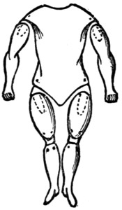
Fig. 5.
Fig. 6.
The curtains are fastened permanently to the inside of the front top cross-piece. The cords are sewn one on each, at the edges that meet in the middle when the curtains are down, at a distance down from the top equal to the width of the top of each (as in Fig. 4). Six small rings are sewn on the inside of each curtain in a diagonal direction to the top corner, and the cords are threaded through these rings. On the inside of the cross-piece and at each end and in the middle are screwed small picture-rings (as seen in the figure); and underneath the back cross-piece at the left-hand corner is screwed another picture-ring. The cord of the left-hand curtain is passed through the left-hand ring; the right cord is passed through the right-hand ring, and led through the middle ring, and then through the left-hand ring also, and then the two cords are knotted together and passed through the ring in the back cross-piece. A loop is made in the end of the cord to pull the curtains up by. At the bottom of the left-hand back upright a brass hook or screw is screwed in to hook the loop on to, to keep the curtains up. Now the stage is finished and ready for the figures. The curtains at back and sides must be of some dark material. The figures must be about twelve inches high without the head, and must be made headless. The body and limbs must be made of some light material, and yet solid. Virgin cork is a very good material to make them of, and is easily worked. Fig. 5 will show you how the body and limbs are made. The arms have no joint at the[390] elbow; the legs are jointed at the knees. The arms and thighs are hung to the body by tapes, and the knee-joints are also made of tape. All these joints must be very loose and free. The upper end of each arm and the upper ends of the thighs must have a hole bored into them about two inches deep (as shown by the dotted lines in Figs. 5 and 6). The fore-fingers of your hands are to be inserted in these holes through the curtain at the back, and through holes in the clothes of the figures left for that purpose, and by moving your fingers you can make the figures gesticulate or dance at pleasure. Fig. 7 will show you how this is managed. Fig. 6 is a back view of the body and a side view of the limbs. The body has a recess cut in the upper part of the back (as in Fig. 6). This is to allow of your neck fitting into it to let your head take the place of the head of the figure. The shoulders of the body are worked out to project a little over the arms, and the lower part of the body is cut away (as in Fig. 6) to allow of the legs fitting in their places. The hands can be made closed or open, but a good plan is to have the right hand closed and a hole bored through it (as in Fig. 6), when a stick can be placed in it. The body and limbs should be carved carefully, and to as good a shape as your anatomical knowledge will allow. The figures must be dressed in fancy costume—in coat, waistcoat, breeches, stockings, shoes, etc. The female figures must be dressed in light materials. In all the figures the clothes are fastened up the back, and the collar of the coat and the necktie are prolonged into a band to fasten round your neck with a button (as seen in Fig. 7). You must make this part of the dress very carefully, so as to disguise as much as possible the junction of the real with the artificial figure. This will be aided by the curtain at the back being very full, as the folds will hang closely round your neck. You must paint your face to suit the character of the figure, and put on fancy hats, also in character.
Fig. 7.
To use the stage and figures. First put your frame together and screw it securely. Then put on your curtains and put in the stage-boards, which need not be fastened. Thread the cords through the rings, and see if they work properly. When all is right, place the stage on a table with the back towards you, and flush with the back edge of the table, and hang a tablecloth over the table, hanging to the ground at the front and sides to hide your legs. Place your figures on the ground underneath the table, and have a chair to sit down on behind the stage. Now choose your first figure, make your face up, put on a suitable hat, and hang the figure round your neck, as in Fig. 7. Now push the figure and your head through the slit in the back curtain, and your fingers in the holes in the legs and arms; and, while some one is playing a lively air on the piano, pull the curtain up,[391] and commence your performance. If you can have help in pulling the curtain, do so, as it will leave your hands free. The legs can be worked with one hand, but the arms must have one hand each; but while the figure is gesticulating his legs will be still, so that you will have both hands at liberty. And if you use your left hand for the legs (using the two first fingers, one to each leg), you will be able to make the figures move one arm at the same time it is dancing. Of course you will have to learn one or two songs to suit the characters of the figures. You need not have more than two figures, as, if you have an assistant he can be changing the clothes of one while you are exhibiting another.
With this stage and figures, a lad with a good voice and plenty of comicality will be able to give from half to an hour’s entertainment. When the performance is over, take the stage to pieces and pack it up, rolling it up in the curtains. It will go into a very small compass.
Take four flat sticks—size or material does not matter, but for an example let them be of deal—eighteen inches long, half an inch wide, and a quarter of an inch thick, and plane them up true and smooth. At an inch from the end of each stick make a dot, and divide the sixteen inches between the dots into inches, half inches, etc., as if the sticks were measuring rules. Using the dots as centres, bore in each stick a round hole just large enough to hold a piece of brass or other tubing whose internal diameter is that of a pocket pencil. Into one end of each stick fit a section of the tube, opening the edge as in eyeleting to prevent the quarter-inch ring so made from slipping out. Take a pair of the sticks, and hinge them together at the ends which have not been so treated with a piece of the tube—it will be about half an inch deep—eyeleting as before. Hinge the other pair together in the same way.
Now take a half-inch block of wood of any shape you please, but not more than two inches across; bevel it round its upper edge, and through its centre from the back drive an inch screw whose threaded part will just fit into the holes in the sticks. Screw it in till the head is flush with the bottom of the block. You now want a tracer or stile, for which take a similar screw, and cut off its head by filing the smooth part down to a gently tapering point. Slip the screw into the hinge of one of the couples, and keep it in its place by a leather washer above and below, making the distance between the under side of the wood and the point exactly that of the thickness of the block.
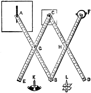
Now get half a dozen half-inch round-headed dresser-hooks, and put the[392] apparatus together in the way shown in the diagram, where B and C are the points at which your sticks are hinged. Slip one of the legs over the block F, and screw it down so that it will move freely but firmly with a leather washer. Place the leg (C D) under F B, and screw it into position from the upper surface with one of the dresser-hooks. Place the leg (C E) over A B, and screw that into place with another hook, also from above. The third hook is beneath the apparatus just close to B, the fourth beneath just close to A, and the fifth and sixth are used to screw the block on to the drawing-board, and are put in on the bevel, so that their heads will not project above the surface of the block. The tracer is screwed point downwards at C, the pencil is at A; and pencil-tracer, block, and hooks at A and B are all of equal length, so that the machine moves smoothly and evenly over the flat surface of your drawing-board.
Now place a map beneath the tracer, and a plain sheet of paper beneath the pencil. Hold the tracer with the right hand, the pencil with the left, and carefully guide the tracer over the outline of your map. Let the pencil move about as it pleases, and you will find that whatever the tracer does the pencil will mimic. The pencil will gradually draw a copy of the map, but it will move twice as fast as the tracer, and make its copy twice the size of the original. This is the result of the way we have at present arranged our pantagraph. The principle is that the copy compared with the original is always in the same proportion as the distance from the block to the pencil bears to that from the block to the tracer. Here the distance in a straight line from F to A is double that from F to C, hence the copy is double the size. The position of the tracer between the pencil and the block depends on the points in the sticks at which they are screwed together, and these you can vary to suit any scale you desire, remembering always that your figure (C G B H) must have its opposite sides equal—that is to say, C H must always equal G B, and C G must always equal B H.
To enlarge your map, the distance from F to C must be less than from F to A; to reduce your map the distance must somehow be greater. Hence you have only to transpose your pencil and tracer, putting the pencil at C and the tracer at A. To reverse the map, and keep it of the same size, put the block at C and the tracer at F. In short, by shifting about the pencil, block, and tracer in the different holes you will soon understand the curious properties of your new copying-machine. One thing do not forget, and that is that when you shift your pencil the hook which is put close by to steady its pressure on the paper should be moved with it.
The pantagraph, or pantograph, was invented by Christopher Scheiner two hundred and eighty years ago; and, carefully made of brass, is in many forms now used in architects’ and other offices where much drawing and copying are done. If not made quite truly its lines may be shaky, but it will be found invaluable for the accurate placing of points, to which lines can be afterwards filled in.
The pattern we have given is easy to make. The instrument may be of different dimensions and of different materials. It may be fitted together in a different manner, but it must have its central figure with the opposite sides equal.
Our mathematical friends will soon be able to demonstrate the reason of its action, and it may be no little satisfaction to the bulk of our readers to find that there is some practical use in old Euclid after all!
There are many forms of flagstaffs, and many ways of erecting and rigging them. They are sometimes made of iron, and are not unfrequently rigged with wire or with wire rope. Some are fitted with topmasts, yards, and gaffs, others simply consist of the one pole.
The flagstaff we are going to describe is not one that will run our readers into any unnecessary expense. It can be erected, fitted, and rigged by any ordinary boy of average ability, at a small expense, although of course the more money that is laid out upon it the better it should look when erected.
We shall give the description, however, of the very cheapest that can be made consistently with safety. To commence with, the staff itself can be obtained from any builder by purchasing a small scaffold pole, which will cost—according to your skill in bargaining—from one penny to three halfpence a foot. This can either be planed and varnished; or, if our reader is not much of a carpenter, it may be painted white with paint obtained already mixed from the nearest oilshop at about sixpence a pound.
The height we must leave to the taste of the reader, but the following scale will be found convenient, and will look very well. Let the pole be 46 feet in length. Then a hole will have to be dug in the ground 6 feet in depth to receive that amount of the staff. But before it is erected it must be rigged and have the ‘knees’ screwed or nailed upon it. A big flagstaff would have ‘crosstrees’ like the topmast of a ship, but it will be more easy and will look less clumsy simply to fix it with knees. These are pieces of wood which will be described afterwards, and which have to be fixed about 30 feet from the ground.
The next thing to arrange is the rigging. For that we shall require three shrouds on each side and one stay in front, besides signal halliards to hoist and lower the flag. Two-inch rope will do very well for the shrouds, but 21⁄2-inch would perhaps be a little safer. Rope is sold by weight, and 2-inch rope may be purchased at sixpence a pound, a pound of 2-inch rope equalling one fathom, which is 6 feet. The easiest way of measuring in order to ascertain what length of rope you will require is as follows. Having obtained your staff, lay it upon the ground. Then measure off the 6 feet that has to go in the ground and mark it with a piece of chalk. Now measure the 30 feet and mark the staff where the knees will be placed. Now measure a straight line at right angles to the lower chalk mark, where the staff, when erected, will be flush with the ground.
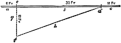
Fig. 1.
a, Six feet for insertion in ground. b, Thirty feet between ground and the knees. c, Ten feet above the knees. d, Chalk mark for knees. e, Chalk mark for insertion in ground. f, Chalk mark on ground ten feet from staff. g, Straight line. h, Length of one shroud or of the stay.
A good distance is about one-third the height of the staff from the ground to the knees, so we will say 10 feet, and mark the ground. Then stretch a piece of string from the upper mark to the mark on the ground, allowing also the circumference of the staff, that will give you the length of one shroud (Fig. 1).
Now you must measure for the ratlines.
Having obtained your rope, the next operation is to cut it into proper lengths. First of all make both ends fast, and stretch it as much as you can. Then measure with the line you used to obtain the length, and cut off two shrouds separately, and the stay. Then cut the remaining rope in half, so as to make two pairs of shrouds. The stay is generally of thicker and stronger rope than the shrouds, but with the staff 6 feet in the ground there is no necessity for this.

Fig 2
A, Pair of shrouds. a, The collar to go over the staff. b, The seizing. B, The single shrouds. a, The cut splice. C, The stay. a, The eye-splice.
Now comes the fitting of the rigging. With the two single shrouds you must make a cut-splice, making the splice sufficiently large to fit nicely over the staff. Then double the two pairs and seize them together separately, A, Fig. 2, leaving sufficient room to pass over the staff without chafing.
The stay you must fit with an eye-splice; and make the eye large enough, or it will look lubberly. (Fig. 2)
The eye and collars should be wormed, parcelled, and served, but this is not absolutely necessary, and might look clumsy if done by an amateur. Now screw on the knees; they are triangular pieces of wood to support the rigging and prevent it slipping down the staff. Two bolters, or rounded pieces of wood, will answer the purpose equally well, but they must be firmly attached to the staff. Now put on the rigging—first of all one pair of shrouds,[395] next the other pair, then the single shrouds with the cut splice, and lastly the stay.
The truck must now be placed on the top of the staff. If one is purchased a sheave will be found in it for the signal halliards to reeve through, and these had better be rove at once.

Fig 3
A, Iron spike. B, Cleats, a, wooden. b, iron.
If the reader’s taste runs in such a direction, a vane to show the direction of the wind can be placed on the truck—such as an arrow, a cock, or any of the numerous articles that are sold for the purpose. A cleat (Fig. 3) should be screwed to the side of the staff just within easy reach of the arm, say between 3 and 4 feet from the ground, in order to belay or make fast the halliards.
Now fix the staff in the ground, and see that the earth, etc., is well beaten in round it. The next proceeding is to set up the rigging. This may be done with deadeyes or with thimbles; the latter is certainly the neater way of doing it. Setting up with deadeyes need not be described here. The following is the method of doing it with thimbles.
Splice the end of each rope round a thimble, which is done as follows. Open out the rope to the length of twice and a half the round of the rope. Then measure the round of the thimble and the round of the rope, and put the marlin spike in there and commence splicing as though for an eyepiece. Now you will require for each rope an iron spike about 3 feet in length with an eye in it. These must be driven into the ground at regular intervals in a straight line, three on each side of the staff, 10 feet distant, and one for the stay in front. Then obtain some stout seizing stuff, such as cod-line, and splice it into the eye of the spike; then pass it through the thimble and then through the eye again, and so on, pulling it as tight as you can every time. At sea the necessary strength for getting the rigging as tight as possible is obtained with a tackle.
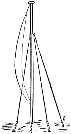
Fig 4
a a a, Shrouds. b, Stay.
Now your staff ought to look like Fig. 4, and you can commence ratling it down, for which half-inch rope ought to be used.
For this, get a wooden tooth-powder box, plain—that is, without projecting rims—take off the lid, and smooth it all over. Next make the compass-card. Cut this circular, about a quarter of an inch smaller than the inside of the box, which should be about two inches and three-quarters in diameter outside. Mark the centre of the card, and mark from this centre the thirty-two points of the compass (as Fig. 1). Now make the needle. This must be hard steel; you can get this at the tinman’s or ironmonger’s. Get him to cut it about two inches long and three-eighths of an inch wide in the middle, tapering to a point at each end. The steel should be about a sixteenth of an inch thick. Get him to drill a hole through the middle of this steel about an eighth of an inch in diameter. Get a small piece of brass wire a quarter of an inch in diameter and a quarter of an inch long. File a shoulder to this (as Fig. 2) about a sixteenth of an inch wide and an eighth of an inch from the end. Drill a hole triangular in section an eighth of an inch deep and about an eighth of an inch at the outside. Place this through the compass-card. Now magnetize your needle. This is done as follows.
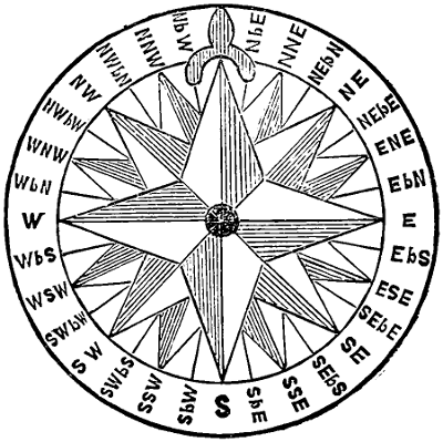
Fig. 1.
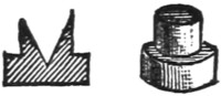
Fig. 2.
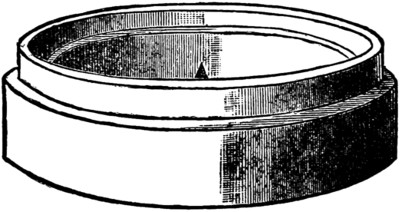
Fig. 3.
Get a magnet—most boys have one—and draw one end of it from end to end of the needle, always going the same way and never back again. Do this about twenty times and your steel needle will be a permanent magnet. Now place this underneath the compass-card and push the little brass button through the hole in it. Suspend this by placing a point in the hole in the brass stud, and one end of the needle will point towards the north. Mark this point, and turn the card on the stud till that end of the needle points to eighteen and a half degrees west of the north point on the card. Now fasten the brass in the needle by two or three taps with a hammer on the under side of the brass, being careful not to strike the[397] steel. Next fix it more securely with a dot of sealing-wax on each point and card. Now suspend it again on the point, and the north point will dip towards the earth. You must balance the card by putting dots of sealing-wax here and there till it swings quite level.
Next, in the centre of the bottom of your box fix a steel pin about half an inch high, brought to a point that will go loosely in the dent in the brass stud. Put your card on this point and it will swing easily in the box. Line the box with a strip of cardboard a little wider than the height of the top of the brass stud from the bottom of the box. Get a circular glass the size of the inside of the box (your glazier will cut this for you for a few pence). Put it on the shelf formed by the cardboard, which should be glued into the box, and fasten it in its place with a narrow strip of cardboard glued in all round the box.
By putting the glass in you can turn the box about any way in your pocket without the card coming off the peg.
Now to make the timepiece. Make a dial plate of paper the size of the top of the lid. You can first draw this on a sheet of paper, and then placing one leg of a pair of compasses on a point in the twelve-o’clock line—which must in this case be only one line, about half an inch from the six-o’clock line—mark a circle the exact size of the top of the lid. Inside this circle make another about a quarter of an inch from it, and mark the hours inside this circle. Paste this paper on the top of the lid, and put the lid on the box. Now draw a line from the twelve-o’clock line on the lid right down the side of the box; make this line quite perpendicular to the top and bottom. Now make the gnomon. Get a piece of very thin sheet brass or tin-plate about the thickness of a card and cut the gnomon out of it. The shape and size can be got from directions already given. Now with a thin, fine saw, cut the twelve-o’clock line into a slot about a sixteenth of an inch deep and going beyond the six-o’clock line a little, about an eighth of an inch. This slot must be the same depth in the six-o’clock end as at the edge of the lid. You can push the base of the gnomon into this slot, so that the axis edge exactly crosses the six-o’clock line.
To use the compass, take off the lid, place the box level, and note where the north points, and you can determine any point of the compass from that. To use the timepiece, set the box level, and bring the mark in the side of the box to correspond exactly with the north point of the card. Put the gnomon in the slot in the lid, and put the lid on the box without disturbing it, so that the mark in the side of the lid corresponds exactly with the mark in the side of the box, and the shadow of the axis of the gnomon will point out the hour. When you have seen the time, take off the lid, take the gnomon out of the slot, and put it inside the box, laying on the glass, and put the lid on. You can thus carry the whole in your pocket without a fear of it getting out of order; and when you are out for a walk, and the sun shines, you can always tell your way home and the time to go there.
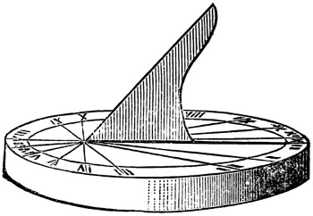
Fig. 4.
Walking-sticks of all varieties—apple, ash, blackthorn, brier, cherry, elm, hazel, holly, oak, vine, and whitethorn—are best when cut in the winter, between November and February; the sap is then sluggish, the leaves are off, and the character of the stick can be most easily descried.
To boys who desire to carry a stick of their own choice and dressing, the following practical notes will be of value.
Never attempt to trim a stick as soon as you have cut it. Leave the branches on it an inch or two long, and hang the stick up to dry for a week or so, knob end uppermost with a weight on the narrow end. Let it hang in a moderately cool place, and when it is dry and pliable, take it down and begin to trim it. Cut off the branches you do not want, and make the crook if you do not care to finish merely with a knob. To make the crook, plunge the end for a quarter of an hour in boiling water, bend it to shape, and keep it in place by a piece of string twisted by a stick in the middle, like the spring of a jumping frog, or the stretcher of a ribbon saw. When the stick has dried in shape, trim it to taste with a sharp knife, and give it a good rub down with sand-paper. When it is smooth and presentable, if you want it to remain its natural colour, give it a coat of boiled linseed-oil, and let this dry thoroughly into it. If you want the stick to be black, boil a pound of logwood chips for an hour in a quart of water, and brush the stick over with the boiling liquor. When the stick is dry, give it another boiling coat of the decoction. When that is dry, dissolve an ounce of green copperas in a quart of hot water and coat the stick with the solution. Keep the stick away from the fire, and let it dry each time slowly and well, and you will find that the mixture of the copperas and the logwood has dyed it an intense black. After you have stained it, give it a coat of boiled oil, and when that is thoroughly dry, begin to polish it.
For the polish, mix an ounce and a half of shellac with a quarter of an ounce of gum mastic, and dissolve them slowly in half a pint of methylated spirits, or, what is better, quicker, and cheaper, buy threepenny worth of French polish from the nearest oil-shop.
Having polished the stick, finish it with a coat of hard varnish or copal varnish such as the artists use, of which a little goes a long way. Hard varnish can be bought cheaply. If you must make it, mix together an ounce of gum mastic, two ounces of gum juniper, a quarter of an ounce of turpentine, and a pint of methylated spirits. Give the stick one or two even coats of varnish, and you will find it last for many months. Some sticks do very well varnished over the oil and stain, then the polish is saved. If you want to stain a stick brown, add dragon’s blood to the polish; if you like it golden coloured, drop in some yellow ochre or gamboge. The difficulty in stick-making, however, is not in the polishing; it is in the bending and trimming.
Apple makes excellent sticks if judiciously dried. Ash sticks are best cut from saplings; when cut from hedges or pollards, they are inclined to become brittle.[399] Like apple sticks, they require careful seasoning to be serviceable. Blackthorn sticks are heavy, and liable to splinter. They are best when cut from saplings. Brier sticks are also best when cut from saplings. Cherry sticks should be stripped of only a part of their bark, and require sand-papering, oiling, polishing, and varnishing. Elm sticks should have the rough bark left on; they also are best when taken from saplings, but it is very seldom indeed that an elm stick is fit for anything else than to be looked at. Hazel sticks are light and handsome, and do good service, no matter whence they are cut. They should be well rubbed down with sandpaper and carefully varnished. Holly sticks are as good as any. Cut them from the branch with the crook or knob attached, and let them have a long time to dry. Oak sticks are the strongest and toughest, but the most difficult to dry and trim. If you dry them too rapidly they split, if you dry them with the bark off they split, if you have the knots close together they split. If you get a good oak cudgel you can smash any stick of any other wood not exceeding it in size.[400] Vine sticks are also of value, but they have an unpleasant tendency to warp and twist. Whitethorn sticks are like unto blackthorn sticks—heavy, treacherous, and brittle.
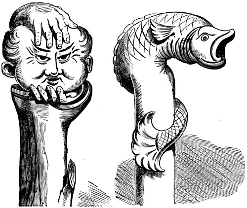
If you want to bark a stick, steep it in hot water, and rub off the coat with a piece of sacking. If you want to bend or straighten a stick, cover it with hot wet sand, and get it into shape while it is hot.
Of canes we need make no mention, nor need we deal with the birch. They are but luxuries, frequently doomed to be misunderstood. Their days are over. Alas, poor cane! Alas, poor birch!
Nothing has been said so far about carving its handle, and as a stick of our own cutting and carving has a certain charm about it, and in its making affords an agreeable exercise for a wet day, we herewith give a couple of designs which can easily be improved upon, and which are grotesque enough to look well even as failures; and this to a beginner is a quality not to be despised. We may as well, however, adopt the usual plan of descending from generals to particulars, and find space for a few notes on stick history.
When Œdipus solved the riddle of the Sphinx, he thought of a walking-stick—as many others of the puzzled have done. ‘There’s a being,’ said the riddler, ‘which has four feet, and three feet, with only one voice; but its feet vary, and when it has the most it is the weakest.’ ‘That,’ said Œdipus, ‘must be man, who, when he is a child, crawls on his hands and knees; when he is a man walks uprightly; and when he is old totters with a walking-stick!’
On the origin and development of the walking-stick a goodly volume might be written. Perhaps the most interesting form the stick took was that of the pilgrim’s staff. This staff was about four feet long, armed at the lower end with a spike, and fitted about a foot from its top with a knob for the hand to rest upon. The lower part was solid, the upper part was hollow, and was used for relics of saints, or a musical instrument, or something to eat, according to the taste of the owner. It was in a pilgrim’s staff that saffron was secretly brought from Greece to Saffron Walden, and it was in a similar way that silkworms found their way to Europe. This idea of using a stick as a carrier has been utilised in our own days, not only for telescopes, match-boxes, swords, and guns, but also for surgeons’ instruments.
Another striking form was that of the ferula, which derives its name from the giant fennel, of whose stalk it generally consisted. The tough lightness of the fennel wood rendered it particularly suited for the support of the aged, and hence it gradually became the prototype of those lighter wands which have continued amongst us as a sign of office or seniority; and at the same time it retained its popularity with the chastisers of erratic youth. In the East the ferula was replaced by the reed; but in Egypt the reed gave place to slender sticks of cherry wood, some of which had a carved handle. This carving of the head is, however, peculiar to no country and no age. It is a practice indulged in by all men, savage and civilised.
In our own Tudor period the walking-stick began to flourish much. Then for the first time do we get it elaborately carved and adorned with precious metals. In the inventory of the old palace at Greenwich, there is entered, “A cane garnished with sylver and gilte, with astronomie upon it. A cane garnished with golde, having a perfume on the toppe; under that a diall with a pair of twitchers and a pair of compasses of golde; and a foot rule of golde, a knife and a file of[401] golde, with a whetstone tipped with golde.” A somewhat elaborate battery to carry in a walking stick! In the seventeenth century sticks became even more ornamental, and in the eighteenth they began to be made entirely of agate, or clouded marble, or ivory. How these were used and abused can be learnt from No. 103 of the Tattler, where Isaac Bickerstaffe issues licences regarding them, and is appealed to by petitioners, one of whom asks for permission to retain his cane on account of its having become as indispensable to him as any of his other limbs. “The knocking of it upon his shoe, leaning one leg upon it, or whistling upon it with his mouth, are such great reliefs to him in conversation, that he does not know how he should be good company without it.” Later on this fashion of elaborate walking sticks was adopted by the old ladies, and it was quite common to see the dames out walking with wood, ivory, whalebone, or green glass sticks, five or six feet in length, having the ends bent over like a shepherd’s crook, and twisted back again towards the ground.
In these days, now that the means of communication have been so much improved and the world become one huge country, foreign sticks have lost much of their rarity. They come to us in tons, and a stick importer’s warehouse is a sight to see. The goods in the rough do not look inviting; in fact, anything more resembling a lot of firewood it would be difficult to imagine. Those who have not the chance of seeing the interior of one of these stores, can obtain a very good notion of what they are like by inspecting a shop window next door to the Autotype Gallery in what used to be New Oxford Street. There can be seen canes of all sorts, rough and rooty, from the eastern and western tropics—rajahs from Borneo; malaccas from Sumatra (nearly all the malaccas come from Siak, they are the stems of Calamus scipionum); whanghees (the stems of Phyllostachis) from Hongkong; lawyers (a species of Calamus) from Penang; ratans and dragons from Calcutta; white bamboos, black bamboos, fluted bamboos from other seaports in the great Bay of Bengal; partridge canes, jambees, and dog’s-head canes; Spanish reeds (Arundo donax); jacks (vine stems), cinnamons, pimentos (the stem of the allspice), cabbage-stalks, and coffee-branches from the West Indies, with the green-backed orange and knobby lemon sticks from the same colonies; triangular leaf stalks of the date palm from Tunis; myrtle, pomegranate, and olive sticks from Algeria and Italy; blue gums from Australia; mahoganies from Cuba; ebonies, tulips, and crocodiles; cabbage-stalks from Guernsey; and, perhaps, tooroos from Guiana.
But English sticks, and the foreign importations supposed to be such, are the favourites after all, and it is them that we would ask our readers to choose for their experiments. The chief, as already explained, are oak, ash, beech, blackthorn, cherry, maple, crab, and hazel, all of them within reach of those that walk or dwell in country places, and all easily dressed and made presentable.
The most useful of them are the ash and beech, which can be stained and cut to resemble any stick, and form the raw material of almost all the shams. A goodly proportion of the blackthorn sold in the streets are beech sticks carved and dyed. It is easy to dye a stick black. Brush it over it with a hot decoction of logwood and nutgalls, and when it is dry give it a brushing with vinegar in which rusty nails have lain for two or three days. If you wish to dye it red, add some dragon’s-blood gum to the polish; if you wish it to be yellow, use ochre instead of dragon’s blood.
All sticks should be cut in the winter and left to dry in the rough in a cool place. If the bark is to come away let the stick be half dry before you begin to work upon it. If the bark is to remain on, let the stick get thoroughly dry before you attempt to trim it.
Ash sticks can be got from the hedge or the thin branches of a pollard, but the best are young saplings taken up root and all, the root coming in handy for carving. Oak sticks are easy to carve, but difficult to dry without splitting; they are the toughest and strongest of all sticks, and are generally got from copse-wood stumps. Holly sticks are best with the bark off; they are best when cut from the secondary branches that shoot up parallel to the main trunk. Sometimes they are found as saplings, and then the roots are retained as groundwork for decoration. Elm sticks are easily got and easily worked, but seldom turn out satisfactorily. Hazel, on the contrary, gives first-rate stick wood, and is soft and easily cut, and if tolerably thick and well dried it will not bend. Blackthorn is the best stick in vogue at what has taken the place of the historic Donnybrook, but there are many tougher and more trustworthy weapons for the peculiar recreation in which it is usually employed. It is an easy stick to prepare and polish, but like case-hardened iron to carve. We are told that those who attempt its carving generally borrow the tools from some unsuspecting friend! Verb. sap., or rather verb. to those who have dried out its sap and not discovered brittleness. Cherry sticks and apple sticks come easily to hand, and are not unfrequently charred with a hot iron and stained with acids to enable them to be sold as foreigners. Birch and poplar are best left alone. British vines almost always warp; and brier and whitethorn, like all the Rosaceæ, have wood that snaps and splinters on the slightest provocation.
To shape a stick use hot sand or steam, and fix it in the desired position when hot. To straighten it lash it when hot to a board, or hang it up with a heavy weight at its end. To dress it or polish it employ one of the methods described in the former part of this section.
When carving a handle, choose some design that will be smooth to the hand. As examples try a man’s head. One of the most extraordinary collections of walking-sticks ever made was formed by Robertson of Kincraigie, who was popularly supposed to be ‘daft.’ It was his practice to carve on his stick the head of any friend or foe he met with, and in time he owned quite a portrait gallery of wooden heads, which proved the cause of much wonderment to his visitors, for every batch he entertained had their features promptly reproduced in oak or hazel! As suitable designs for stick-heads there may be instanced dogs’ heads, birds’ heads, particularly broad-beaked ones, such as goose and albatross, snakes’ heads, fishes, and squirrel and beaver tails. To get good results proper carving tools should be used, cutting up instead of down with the grain; but capital work can be done with an ordinary penknife, the secret of success consisting in never cutting away a chip unless its removal has been well thought over. Carving stick-heads is not like carving panels, and fine work is out of the question with regard to them. There is not much room for improvement in the art. We saw in the 1851 Exhibition a stick carved in China 4,000 years ago, and it was as well done as anything now obtainable from the London stick-seller.
Candidly, we must admit, that to attempt in this chapter to give anything like a complete and elaborate account of the making of the many different kinds of cages and hutches in which to keep pets of feather or pets of fur would be folly.
But I can give my readers many hints that will be of use to them on the subject in hand, and I may begin by telling them that it is not half so difficult to manufacture a good roomy, healthy, wholesome breeding-cage as may at first appear.
Nor need the cage you make be at all ugly or clumsy; only take pains with it, and do not be in a hurry, and I feel sure you will succeed. Do not let any person dishearten you by saying, ‘You can buy cheaper than you can make.’ I doubt if you could do so, but even allowing this were possible, you could not point proudly to your bought cage and say, ‘I made that.’
Now the first questions of practical moment I have to answer are these: 1, What tools are required in the manufacture of cages? And, 2, What materials?
An answer to the first question will enable you to decide at once whether or not you think it worth your time and trouble to go in for cage or hutch-making. I shall mention the tools that it is indispensable you should possess, and you may either buy them or borrow them, as you please. If you are merely going to make one cage or two, perhaps you had better borrow them. But I take this opportunity of reiterating this advice to all sensible boys who may have some spare time on their hands, to possess themselves of a box of useful tools. Cheap boxes of tools are worse than want. If you mean getting tools, get good ones. Do not be caught by the glitter and get-up of the box that contains them, nor by the sheen of the contents either. Be suspicious of articles that are advertised at an exceedingly low price, else you may find yourself possessed of hammers whose heads won’t stop on, saws as brittle as brass, gimlets and awls that burst their handles, planes with pot-metal tongues, and pliers as soft as cheese.
It is far better to fit your own box up, and fill it, buying the articles you require at a respectable ironmonger’s shop, and paying a fair price for them. Then all you have to remember is to keep everything in its place, and keep all steel work free from rust, and the box itself in its own corner and locked, so that Mary Ann, when she wants to break coals, will not have an opportunity of appropriating your axe.
Talking about rust, I find nothing better wherewith to smear tools that are to be laid past for a short time than a little blue ointment. You should keep a morsel of this in a chip box in a handy corner.
Well, now, as to birdcage and hutch-making, you must have, first and foremost, a bench whereon to work. Any old table will do if it be strong enough. But one thing it must have, and that is a contrivance to hold the wood on which you are working with the plane or other instrument. This may either be the wooden screw apparatus, or what is cheaper, the bench-lug.
The tools and things you really want, and must have, to make anything like a job, are (1) a nice sizeable saw, one that will either rip or cross-cut, so it must not have a back to it. (If you go in for fine and ornamental work about your cage it will be better to have a lathe—cost about £3 10s.—and a box of fretwork tools which will run you in to £1 10s. more. So take my advice—be content with what is useful for a time. If you breed some beautiful canaries you can sell them, and having extended the balance at your banker’s, go in for the ornamental afterwards.) (2) A plane or two, one plain plane, and one plough. I do not advise a jack. I know when I was a boy I could not manage the jack-plane nearly so well as the little short one. (3) Some chisels; say three; they are cheap and useful in a thousand ways. Mind, always keep them sharp, and do not use the mallet much on the end of them. (4) A wooden mallet. (5) A hammer or two, with claws at the end. (6) A spokeshave. (7) Pliers and pincers for ironwork. (8) A boring brace and bits to fit. (9) A bradawl or two. (10) A small hand-vice. (N.B.—This last is most essential for holding your wires, etc. Sometimes this vice itself will want holding to enable you to work with both hands. Very well, be handy, fasten it on to the end of your bench by means of the lug or screw apparatus.) (11) A two-foot rule. Do not buy a cheap one; it goes all out of shape in no time; besides, if you have a really serviceable article you can use it as a square. (12) A hone or sharpening stone. (13) Etceteras, in the shape of nails and screws of various sizes (I myself use nothing but the round French nails; they do not split the wood; they go home kindly, and with ordinary care they do not bend); a jam-pot to heat your glue, some glue to heat, a carpenter’s pencil, sand-paper, and a small oil-flask. Other little things may suggest themselves to you; I can’t think of anything else at present. And I would not mind beginning to make either an ordinary breeding cage or a hutch at this moment with the tools I have just named.
But, ‘What a lot!’ you will say, and ‘what a deal of money they will cost!’ Yes, but think of the many useful things you can make with those tools, quite independent of either cage or hutch.
And now as to the materials. What are these? I answer in two words, wood and wire. The wood may be almost any sort, but it must be very well seasoned, else as soon as it gets wet you will find the bottom of your cage coming off, or the back bulging out, and the whole concern gaping in the most unseemly way. The parts to be polished and stained may be hard wood.
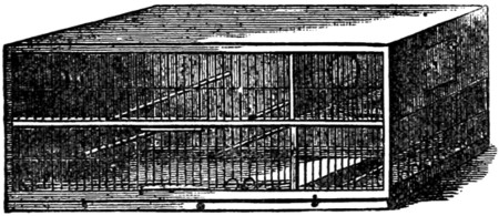
Fig. 1.—Simple Breeding Cage.
The cage I have had figured is an ordinary two-roomed breeding-cage. It might have been a trifle easier for you to have tried your ‘’prentice han’,’ as[405] Burns calls it, on perhaps a show-cage to begin with, but I cannot forget that the cock canary may have sometimes to be separated for a time from the hen; hence that partition with the hole in it, a hole that may be closed.
Some cagemen recommend this to be a fixture, but do you not think with me that if the partition can be withdrawn, so as to make both cages into one big one when required, it is better?
I have already said that the wood a cage is made of is a matter of secondary importance. The body may be pine, for instance, and the front parts any kind of ordinary hard wood—mahogany to wit. The cage (Fig. 2) which is now before us is one of the German kind, manufactured by Mr. Abrahams, naturalist, St. George Street East. The nest has, however, been put in the drawing in the wrong compartment.
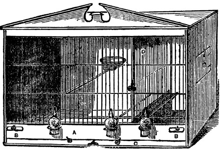
Fig. 2.
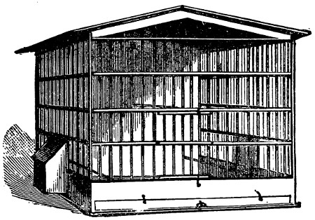
Fig. 3.
In order to make a breeding-cage like this, you repair to your working shop or garret, and having wood, wires, and tools all handy, you first determine the size you wish it to be. Well, I am of opinion that birds cannot have too much room; therefore, for sake of a little more wood and a little more wire, do not begrudge them space; say, 22 in. long, 11 in. wide, and 14 in. high. You can, I think, get wood wide enough to have the back all one piece, as well as each side and the bottom. If you cannot, just use your ingenuity, and make a neat job of joining.
Measure and cut the wood for the top and bottom first, both exactly the same, then the sides ditto. Now plane the wood very nicely, leaving it about three-eighths to half an inch thick. Do the same by the piece of wood that is to form the back.
No dovetailing is needed, and that is a good thing, is it not? Now cut out your square doorway in each gable. If you do this neatly the pieces that you have sawed out or cut out will themselves form the doors. Size of each door—say four inches square. This is big enough for any one’s hand, and big enough to put the nest in. But never mind fitting the doors at present; we will do that after.
Next proceed to fix the box-work of the cage; that is, fasten sides, back, and bottom in their positions, and we will then turn our attention to the front and the internal fittings. There is a hole in the back part, by-the-way, by which you hang the cage on a nail. You may as well make that before you fix up. Have your small nails, your hammer, and your glue-pot at hand, the latter hot, because before you send the nails quite home you must insert a goodly dose of glue. This is important, because it entirely fills up any crevice that might otherwise harbour vermin, and if these once get into your breeding-cage your prospects of doing any good are very likely to be ruined for one season.
Now nail and glue your sides to the back first and foremost, then turn the cage upside down, and fasten in the same way the bottom to the sides and back, reverse and do the same to the top. If you have previously taken correct measurements of the parts, the body of your cage will now look square and fair and neat. If you have not, you had better take it to pieces again and mend matters before you go any further.
Direct your attention next to the front, but you had better let the work you have already done get firm and dry before doing much more to it. Meanwhile measure and make the piece of hard wood that crosses the cage in front just above the bottom drawer (Fig. 2, A).This should be from two to two and a half inches wide, and an oblong space or opening (B B) is to be left at each end. These are for the little seed-tins to fit in. As soon as you have made this piece of wood (A) and dressed it most neatly, you may place it in position. This must be most carefully done, leaving a full inch of space beneath it for your bottom drawer or false bottom. Nail it from the sides.
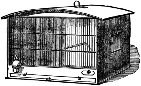
Fig. 4.
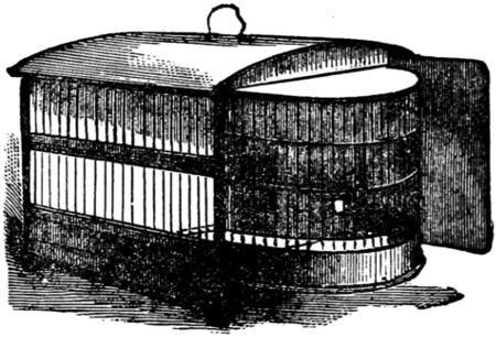
Fig. 5.
You can now proceed to make this false bottom, taking great care that the front part, which is of hard wood (Fig. 2, C), fits the space you left for it exactly, and without a flaw. The mechanism of this false bottom is so simple that instead of describing it or illustrating it, I beg to refer you to your friend Smith’s cage. A glance will suffice. But remember not to spare the glue on that either.
Well, a glance at the complete cage (Fig. 2) will show you that there is a wire partition at D dividing the cage into two compartments, a big and a small. This partition, however, does not go right to the bottom of the cage, because it is a sliding one and draws out. It runs at top and bottom in grooves made by three pieces of wood, one of the pieces of the lower groove being deeper than the others,[407] and quite filling up the vacancy between the false bottom and the wire partition, so as to prevent a bird from creeping through under.
This wire partition, then, had better be made next. It is simply a carefully measured and carefully adjusted square frame, neatly wired in the same way as the barred front of the cage is wired, of which I shall presently speak. You make the little frame first, then you bore your holes and wire it, and next you nail and glue a little front piece of hard wood on to it with a small wire-work handle in the centre, whereby to pull it out.
The grooves in which this is to run should now be made top and bottom, the lower one fastened to the cross board (A), and the upper to the back of the cage at one end and to the front when finished at the other.
Now for the front. This is to be made separately, and then slipped in. There is another plan, but I think I give the better of the two. Glance again at Fig. 2. Take a look at friend Smith’s cage as well. Now scratch your elbow thoughtfully, gather all your scattered senses together, and all your brains, and proceed to business. There is a top bar and a lower bar, and two strong cross wires; but mark this, please—these cross wires are not continuous all the way, there must be a space left for your wire partition to slip out and in.
Well, you have your wires all ready. Measure the length you want them, and cut them all of a size a little longer than they are actually required. They have to pass right through the upper bar (Fig. 2), and be fastened into the lower (Fig. 2), and as the same space—namely, half an inch—must exist between each wire, before you bore the holes for them you must carefully mark the places on both bars, and this is done either with a pair of compasses, or more surely and securely with the prongs of a two-toed fork. While making or wiring the front, be sure first that the top and bottom bars are exactly the same length, then lay them fair and square on your bench or table, and tack them down with small nails: so shall you do your work firmly and well. Bore the holes very even which you have marked off, then put each wire through separately and snip off with your pliers what is not wanted. The wires, by means of your hand-vice, should previously be made as straight as possible. When you have got all your upright wires in put on your cross pieces. These are simply laid on over the others and whipped in position with a long thread of very fine wire.
Now your front is all ready. Of course you have not forgotten the little ring-like spaces at the bottom, through which the canary pops its head to get a drop of water from the fountains. These last may be glass, and they are slung in wire loops from the cross-board.
The perches are easily put in. It is better to have one cross one as well as two or three from front to back.
When you have your little doors made, and neatly hinged with wire, the greater part of the work is finished.
The polishing and varnishing, and nest and nest material, I will speak about presently. The different types of cages shown in Figs. 3 to 5 need no verbal explanation, the pictures speaking for themselves.
It will be high time now to return your friend Smith’s cage, for the probability is that, as the breeding season will soon commence, he will want it himself. I gave full directions just now for the completion of your own cage, with one or two little items excepted. Take a glance before you carry it back, then, at the neat way small fastenings and hinges are made for the doors, and little handles to pull out the partition and the false bottom, and the solitary big one on the top for the purpose of lifting the cage. Very natty and neat, are they not? and all made out of wirework. Pliers and pincers, and a little handiness on your part, are all that is wanted, but it is better you should observe how things are done. The wire loops that hold the glass fountains are fastened in the same way—holes made, the wire put through and doubled down behind so that it shall not pull out, and the whole thing is ready.
Two tiny two-inch square or oval tin drawers to slip in at each corner of the lower front of the cage are infinitely better to hold seed and food generally, than those long wooden world-old drawers with holes in them, which make such beautiful receptacles for dust and vermin.
As to the nests, you have plenty of option. These can be bought. There are wooden ones to hang up on a nail at the back of the cage, tin ones, basket or rope ones, and also those which you can make yourself out of half a large cocoanut-shell. The basket and rope nests, it is said—I have not tried them and do not mean to—do very well if previously steeped in petroleum and dried. The tin and earthenware nests are neatly lined with soft felt; a bit of an old hat does very well properly shaped, steeped, and moulded in.
The cocoanut-shell will suit every useful purpose. You can make it yourself, lining it well with warm lambs’-wool. Fasten a loop of wire round the top edge to join in front, and finally extend to form two hooks to fasten the nest on to the cage.
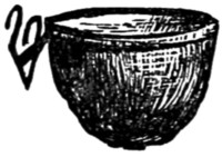
When breeding birds, it is as well to have a small nursery cage to put the fledgelings into. The parent birds then feed them through the bars. Also a bath-cage. Both these are attached when wanted to the main cage. They are very simple in construction, and you can easily make them yourself. Any ordinary small cage will do for the bath, one side being taken out and hooks put on wherewith to fit it to the side of the cage opposite the doorway. The bath is a tin or zinc dish inside the cage, but a large saucer or a soup plate will do very well. Remember, I am not talking now about breeding, but ordinary living cages.
Mr. Abrahams, the well-known naturalist, of 191, George Street East, London, a visit to whose menagerie would well repay any one fond of birds and beasts, writes to me in the following strain about canary breeding. I need hardly tell you that I value his opinions, as they are the result of long experience. He says: ‘I do not hold with the English way of breeding canaries; they will stick to their old style of a hundred years back. They use cages which may be divided, by means of a partition, into two compartments. In one of these compartments there are two[409] small boxes, in which the birds are to build their nests. Outside the cage a bag is fastened containing hair and other building material, which not seldom are far from cleanly, and often already provided with the eggs and germs of insects (vermin).
‘It is rarely that the male and female are of the same opinion in which box the nest should be built. If the hen has begun to build in one box the cock will pull the nest to pieces, and begin to work in the other box, and vice versâ. Thus not only is time lost, but the birds are excited and become weak. When at last they have young ones they are often wretched, timid little things, and often both young and parents die from being continually worried by insects.
‘Many tens of thousands of canaries are imported annually into England from the Continent, and of these the Belgian, Dutch, and French canaries especially are strong, bold-looking fellows, and nothing like our timid little creatures that flutter about or creep into a corner if anybody comes near the cage. How can this difference be accounted for? On my many travels in the countries of the Continent I have watched how canaries are bred there. Almost every working man breeds canaries in his workshop. On one side of the room he has his bench or worktable, and round the walls there are cages, parted off by partitions into smaller compartments of about three feet square. Each of these compartments can again be divided into two by a movable partition, which consists simply of a wooden frame covered over with wire. In one compartment the cock is put; in the other one or more hens; also a tin with seed and another with water. Now the moment is watched when the cock and hen become friendly, then the partition is withdrawn, so that both compartments become one. Then a nest—or more, if there are several hens—is hung up in position by hooks to the wire. For small birds, a small one; for longer birds, such as the Belgians, etc., a larger one. They are made of leather, lined with lambskin with wool on it, and ready for use, so that the birds do not receive or want any building material. It cannot be pulled to pieces. When once used it can be washed and be nice and clean for a second nesting, so that there is no fear of insects troubling the birds. Feeding and cleaning of cages takes only a few minutes daily. The eggs and the young ones can be looked at at any time without frightening the birds; they get used to their keeper and lose all fear. Is it to be wondered at, then, that the young also are strong, bold-looking birds?’
Referring to the German cage figured on page 405, he adds: ‘I forgot to mention that the cage is divided into two compartments by a wire partition. When the old birds go to nest a second time the young ones are shut up into the smaller compartment; the old ones will continue to feed them through the wire as long as it is necessary.’
Well now, if you have done all I told you, if you are the proud owner of a good box of tools, many, if not all of which, mind, you can buy for very little, second-hand, at any dealer’s or broker’s, and if you have managed to make a breeding cage, you are capable of making any other kind of cage or hutch either. I do not refer to those dandy all-wire and painted-tin businesses. You can try your hand at these if you like, but as I do not approve of them, on the principle that all birds should have a partially shut-in cage, as they dearly love a little privacy, I shall not[410] describe the process of manufacture. You will, however, naturally wish your cages to look nice. Well, varnish the front with the ordinary mahogany varnish of the shops, having first rubbed the woodwork very smooth.
I have spent so much time over directions for cage-making that my space is small in which to deal with hutches. I do not regret it, however, for the boy that can make a cage can make a hutch. He has only to see one and carefully examine it.
The same kind of hutch that is used for rabbits does excellently well for guinea-pigs.
Now you can make a very serviceable hutch out of that useful article a bacon box.
First it must be thoroughly washed and cleaned and exposed for a day or two to the weather. Then if meant to stand under cover, in, say, an outhouse, you simply make a doorway and cover it with galvanized iron network, price about twopence a yard, and cover all the front, with the exception of about a foot (this to be covered with wood), with the same kind of network. The bottom of the box should be covered with zinc for cleanliness’ sake. This is an ordinary hutch. The breeding hutch is different, as there must be a dark retiring room for the mother and young. The floors of hutches ought to slant a little forwards, and they ought to be always well raised off the ground.
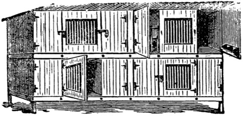
Fig. 6.—Hutches.
Squirrels’ and rats’ cages are easily made, and a good deal of amusement can be got out of these animals if they are well treated and have plenty of room. Both rats and squirrels like a dark retiring or sleeping compartment; this should have a door behind. Personally, I think the ordinary wheel arrangement is cruel. I do not like to see an animal that contributes to our amusement condemned to penal servitude and the treadmill.
Different kinds of birds require differently arranged cages, but whenever you make up your mind to keep any kind of bird as a pet, go boldly to work and make a cage for it, if needs be, borrowing one as a pattern for the purpose.
To make a cage with sleeping-boxes in the upper part, and a ladder for the mice to ascend and descend by, is by no means a difficult operation, nor does it cost an exorbitant price; and it is very pleasant to watch the inhabitants climbing up and down, and running in and out of the holes in their upstairs rooms, and also to see the small animals swinging about in their boat-swings; nor, after one or two days, do they seem at all to wish to get out, or to gnaw their bars, as many mice do if confined in a narrow space.
I will first give a list of the materials and their cost, and after that proceed to describe how the cage is to be made:—
| s. | d. | ||
|---|---|---|---|
| Thick wire | 0 | 5 | |
| Thin do. | 0 | 1 | |
| Zinc | 0 | 8 | |
| Perforated ditto | 0 | 1 | |
| Hinges | 0 | 2 | 1⁄2 |
| Screws for ditto | 0 | 2 | |
| Staples | 0 | 1 | |
| Brads | 0 | 3 | |
| Tacks | 0 | 2 | |
| Emery-paper | 0 | 1 | |
| Handle | 0 | 3 | |
| Screws for ditto | 0 | 0 | 1⁄2 |
| Iron bar | 0 | 6 | |
| Screws for ditto | 0 | 0 | 1⁄2 |
| 3 | 0 | 1⁄2 | |
| Without handle and bar | 2 | 3 | 1⁄2 |
These articles can be readily obtained at any ironmonger’s or smith’s, except the emery-paper, which an oilman would supply. The thick wire should be about as thick as a thin knitting-needle, the other wire, as it is for binding purposes, should be as thin as possible; so also should the zinc; the hinges ought to be about an inch long; the iron bar will be described as hereafter.
The following are the sizes and descriptions of pieces of wood for a cage 18 in. long by 13 in. high and 10 in. deep:—
| Framework. | ||||||||||
| A. | 11 | inches | by | 18 | inches. | Bottom. | ||||
| B. | 10 | „ | „ | 12 | 1⁄2 | „ | - | Ends. | ||
| B´. | 10 | „ | „ | 12 | 1⁄2 | „ | ||||
| C. | 5 | „ | „ | 18 | „ | Front half of cover. | ||||
| D. | 3 | 1⁄2 | „ | „ | 18 | „ | Upper half of back. | |||
| Sleeping-boxes. | ||||||||||
| E. | 6 | 1⁄2 | inches | by | 17 | inches. | Bottom. | |||
| F. | 3 | „ | „ | 17 | „ | Front. | ||||
| G. | 4 | 3⁄8 | „ | „ | 3 | „ | - | Divisions. | ||
| G´. | 4 | 3⁄8 | „ | „ | 3 | „ | ||||
| Doors. | ||||||||||
| H. | 9 | inches | by | 18 | inches. | Lower part of back. | ||||
| K. | 4 | 7⁄8 | „ | „ | 5 | 3⁄8 | „ | - | Cover of sleeping boxes. | |
| K´. | 4 | 7⁄8 | „ | „ | 5 | 3⁄8 | „ | |||
| K´´. | 4 | 7⁄8 | „ | „ | 5 | 3⁄8 | „ | |||
The wood should be 1⁄2 in. thick. The cage that I made, and which was a very neat one, was formed from a box and some loose pieces of wood obtained from a grocer for 4d.
First of all the pieces B B should be nailed at the ends of A, leaving 1 in. of A projecting at back, and then from the top of each of them a strip 5 in. by 1⁄2 in. should be cut, so that the piece C can now be nailed to join the ends and form front half of cover; across upper half of back we will next nail D: the framework is thus finished.
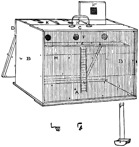
Now let us make the sleeping-boxes. First we must with a centrebit bore three holes an inch in diameter in piece F for entrances to nests; then let us nail G and[412] G´ on one side of F to divide sleeping-box into three equal compartments; to these we should next nail E, projecting 15⁄8 in. beyond F to form run in front of nests. Two holes should then be bored with a bradawl near the front edge of this run, opposite middle hole to F, to receive ends of ladder, which will be described hereafter. Next we must tack a strip of zinc along this run with eight or nine tacks, punching small holes just above those bored with bradawl; then nail the sleeping-boxes thus made to B B´ and D as shown in drawing, leaving a slit of 1⁄8 in. between F and back edge of C through which a piece of zinc 4 in. by 17 in. is to be slipped, to keep the mice in their boxes while cleaning out the cage. The ends, bottom, and large door should then be lined with zinc inside, leaving a space of 1⁄2 in. all[413] round front of cage, where the wires are to come; and just under the holes bored in the run outside sleeping-box punch two others the same distance apart in the zinc which lines the bottom—these are to hold the lower spikes of the ladder. The zinc should be tacked down as much as possible as well in the middle as at the edges, having holes punched in it for the tacks to go through.
Now bore holes 1⁄4 in. apart along C, and same in but not through A, about 1⁄4 in. from front edge of each, then cut off from your wire enough pieces 123⁄4 in. long to go through these holes, which will be about sixty-eight in number. Let the wood of A be quite 1⁄2 in. thick or a little more, so that the wires can have as much hold in it as possible. Straighten your wires, emery-paper them, and push them through the top holes, and bring them down to the corresponding ones in the bottom; then fix two longitudinal wires from B to B´ across the front of the others, and bind these upright wires to them with the pliant wire.
Hinge the doors to D, as shown in drawing, and splay front edge of each of small doors, K, K´ and K´´, and top edge of F, so that these doors may shut closely. Each small door should also have a hole made with the centrebit in the middle, and a piece of perforated zinc should be tacked over them inside to ventilate the nests. We now come to the ladder. Get two pieces of wood 83⁄4 in. long by 1⁄4 in. broad and 1⁄4 thick, and make holes every 1⁄2 in. along them, and in each end of them bore a hole, and drive a piece of thick wire 5⁄8 in. long in all these end holes, leaving 3⁄8 in. projecting from top ends, and 1⁄4 in. from bottom; then break off enough pieces 1 in. long to go into remaining holes of one of your sticks, and drive them in, but not so as to come through the other side; then drive the other ends into the remaining stick, and your ladder is finished. The boat-swings can be easily made in the same manner after looking at drawing, and fastened at the top of the wire that they are hung by with two staples to floor of sleeping-box. The fastenings can be made from staples, those marked a for large door, and b for small doors; the hooks of a should be put a little lower than middle of large door and the catches in ends of cage.
Thin strips of zinc should be tacked in any places where the mice could gnaw the wood.
Now, if you are going to have a handle, get as small an iron one as will comfortably lift your cage, and screw it on to C, as near sleeping-boxes as possible; then, as you will find the sleeping-box side will be the heavier, you might get a bar of old iron from an ironmonger or smith 18 in. long, between 1⁄4 in. and 3⁄8 in. thick, and broad enough to make your cage weigh equally; have three holes drilled in it, and screw it underneath the cage in front.
A few remarks more about the cage and its inhabitants, and I shall have finished.
The cage must have sawdust strewed on the floor and hay in the nests; the former must be changed once a day, and the latter every other day, or at least twice a week. If you cannot get sawdust anywhere else, an oilman will let you have enough to last you a month for twopence. In such a cage as I have described a ‘boar’ and six ‘sows’ may be kept. When a sow is about to have young it should be put in a small cage by itself, and as soon as the young are old enough to eat and run about they may be turned with their mother into this big cage. Perhaps[414] they will get chased about a little at first, but they will not be hurt, and will be all right by the next morning. As soon as they are a month or six weeks old they should be removed elsewhere. Only one full-grown boar should be kept in a cage.
When mice are first put in such a cage as I have described, the ladder appears steep for them, but they soon get used to it, and reach their nests in two or three bounds from the ground.

Heus! incaute puer—silvis latet ursus in altis

The harmonicon is not a very difficult instrument to make. It consists of a box and a series of plates—of metal, stone, or glass—to give the sounds.
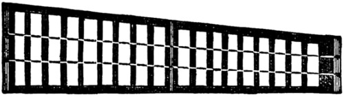
FIG 1
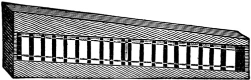
FIG 2
Take a piece of deal free from knots and shakes, and plane it smooth and true. Let it be of the shape of Fig. 1, three-sixteenths of an inch thick, six and a half inches wide at the top, four and an eighth inches wide at the bottom, and twenty-three and a half inches along the side which is at right angles to the ends. The slope will be just a trifle longer.
This piece of wood is for the bottom of the box. Now for the sides. Make them out of quarter-inch stuff, twenty-three and a half inches long and one inch and five-eighths wide. For the ends take two pieces of three-eighths stuff an inch and five-eighths wide; and let one be six and a half inches and the other four inches long. For the tops, as shown in Fig. 2, take two slips a quarter of an inch thick and two inches wide at one end, and an inch and a half wide at the other.
Let the wood be as perfect in quality and equal in thickness as possible, and glue up the box—without the tops—as evenly as you can. The box can be nailed or screwed if you think it will be easier for you, but the result will not be so satisfactory. The box is like a fiddle, and the more of a perfect shell it is the truer and fuller will be the sound.
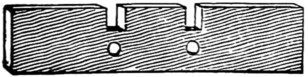
FIG 3
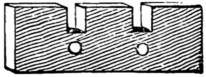
FIG 4
In the centre of the box glue in the bridge, which will be about five and a quarter inches long and half an inch wide, and should stand clear of the bottom and clear of the tops. Then in the broad end, at two and a quarter inches from its sides, cut the slots, as shown in Fig. 3; and at the other end, as shown in Fig. 4, cut the slots one inch and a quarter from each side. Below each slot is shown a small circle. This represents the head of the screw or tack round which the twine is strung on which the musical plates are to rest.
For the string use very fine twine, crochet cotton, or silk, and stretch it very tightly, and fasten it off at the end it started from; that is to say, fix it at the broad end under the tack, then pass it under the tack at the narrow end, then under the[418] other tack at the narrow end, and then bring it up to the broad end and there finish it off. It should be very tight, and just rest on the bridge in the middle.
The next thing is the glass, which should be cut in inch strips, and fixed on to the strings with a drop of sealing-wax. Let us have eighteen notes ranging from B to E in the key of C. The true dimensions and position will have to be found by experiment, but for glass a sixteenth of an inch in thickness the following will be found the suitable lengths. B should measure five and three-eighths; C, five and a quarter; D, five; E, four and seven-eighths; F, four and five-eighths; G, four and a half; A, four and three-eighths; B, four and a quarter; C, four and an eighth; D, three and three-quarters; E, three and five-eighths; F, three and a half; G, three and three-eighths; A, three and a quarter; B, three and an eighth; C, three and an eighth; D, three and an eighth; E, two and three-quarters. These are the lengths for glasses an inch in width.
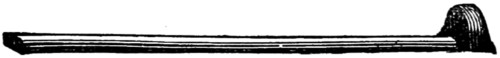
FIG 5
The glasses should be laid on the strings, which gradually approach each other, and they should be shifted about until the correct note for each is obtained. In Fig. 1 we have shown how they rest on the strings, and in Fig. 2 we have boxed them in and shown by the space at the end how they may have to be closed up to keep the proper intervals. As soon as the notes are right, fix the glasses on to the string with a tiny drop of sealing-wax. And also fasten the string on to the bridge with wax so as to make everything secure. Then glue on the tops to hide the ragged ends, and the harmonicon is complete. For the hammers glue a piece of cork or wood on to a length of whalebone or split cane, or any springy stick about eight inches long. A convenient shape is that shown in Fig. 5, where the black head represents the cork cut to a wedge.
Although many tunes can be very pleasingly played on this simple instrument, do not let it be supposed that it at all resembles the harmonica for which music was written by the great composers. That was a different affair altogether. Perhaps a few notes concerning it may not be uninteresting.
One of the first allusions to an instrument of the sort is by Harsdörfer in 1677, though among savage nations, Burmese and what not, rock, bone, and wood harmonicas have existed for ages. On St. George’s Day in 1746, Gluck played a concerto on twenty-six drinking-glasses, ‘tuned with spring water.’ The instrument was of his own invention, and he played it accompanied by the whole band. It was said to be capable of producing all the effects of the violin and harpsichord.
When Benjamin Franklin was in London in 1762, he saw Puckeridge and Delaval amusing themselves by playing tunes on ordinary drinking-tumblers. The tumblers were tuned by the water poured into them up to different levels—the higher the water the lower the note—and were sounded by wiping a wet finger round their brims. Franklin was so much struck with this that he straightway took the matter in hand and invented the harmonica, for which the music used to be written, and of which a specimen now rests in the South Kensington Museum.
The harmonica—Franklin called it the ‘armonica’—consisted of a series of glass bells fixed in regular order on an iron spindle made to revolve like a lathe with a treadle. The sound was produced by pressing the wet fingers on the bells as they rotated, and it could be increased or decreased in volume and tone by varying that pressure.
Franklin presented his invention to the Davies family, with whom he was connected, and one of them, Marianne, performed on it with great success in London, Paris, Florence, and Vienna. The constant thrilling of the fingers affected her nerves, however, and she had to abandon it, just in the same way as had Naumann, the composer, who ‘found it necessary to restrict himself in practising.’
Some of the music played by Miss Davies was specially written for the instrument by Hasse; and when, in 1791, the blind Kirchgässner went to Vienna, Mozart wrote an adagio and rondo in C for harmonica, flute, oboe, violin, and violoncello. Who in these days would imagine that the ‘musical glasses’ once stood so high in the world?
Three years afterwards Kirchgässner came to London, and there played on a new harmonica built by Fröschel. At Darmstadt the harmonica held its place in the Court orchestra, and C. F. Pohl ‘professed’ it. Beethoven even condescended to write for ‘the glasses,’ and Naumann’s half-dozen sonatas for them still exist.
The instrument, however, has been laid on the shelf—or rather consigned to its case as a curiosity—and the musical glasses of to-day are the harmonicon we have described, and the tumblers about which we may now say a word.
Musical glasses have been arranged in many ways. Sometimes they have been all of one size, and the different tones have been produced by varying quantities of water placed in them. This, however, was a troublesome and clumsy way of getting effects.
Another method was to place forty-one parallel glass cylinders of equal length and thickness on a perpendicular sounding-board. These tubes were wetted and stroked, the music varying by the greater or less pressure of the performer’s fingers. This, it is obvious, must have been a difficult instrument to play.
The musical glasses originally arranged by Dr. Arnott are undoubtedly the best, and with a little patience can be easily and cheaply made by anyone. The patience is required to hunt up glasses having the required notes on them.
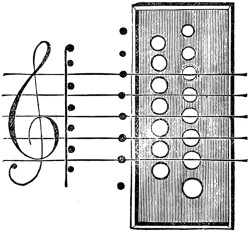
We give a drawing of this above. The open circles represent the mouths of the glasses standing in a wooden case. The relation of the glasses to the written musical notes is shown by the lines and spaces which connect them. The learner will see at once that one row produces the notes written upon the lines, the other row those in the spaces. There are two octaves, and the player stands by the side of the case, with the notes ascending towards the right hand, as in the pianoforte. The sounds are produced by passing the moistened fingers round the edges of the glasses. A little gum dissolved in the water makes the fingers ‘bite’ better, and produces a greater volume of sound.
In the section on ‘The Musical Glasses’ we gave at length the details of construction of a glass harmonicon. An instrument of the same character made of wood is now, it seems, taking a place in the French orchestras, and we herewith give an illustration of the latest form of the so-called ‘Xylophone’ as used in Paris, with the names of the notes marked in the French manner, wherein the ancient ‘Ut’ does duty for the modern ‘Do.’
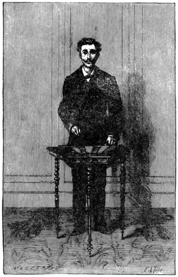
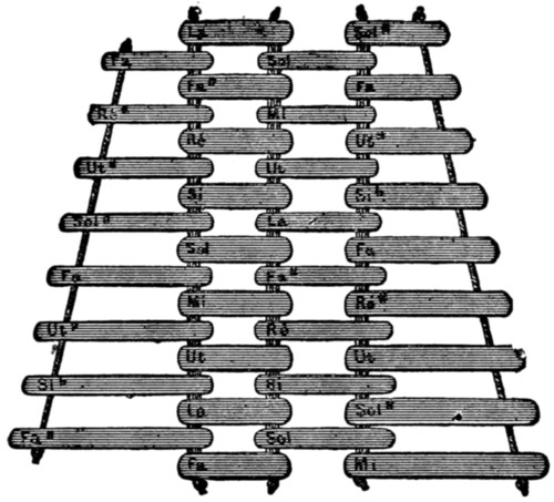
The curious in such matters must have noticed the wide distribution of the bamboo harmonicon. Some such instrument for the production of sharp, short sounds can be traced back to the old Greeks and Hebrews, and is found to-day amongst the Russians and Cossacks and Tartars of the Steppe, and the mountaineers of the Urals and Carpathians. Even in Sicily, in 1742, a wooden harmonicon was described under the name of the Xylonganum, and the wooden slips analogous to the nigger-bones laid on strings are mentioned as forming a German ‘music-maker’ more than three centuries ago. In 1830 Gussikow, a Russian, made a tour of Europe with a xylophone composed of wood and straws, the straws taking the place of the strings and tapes; and straws, it may be as well to observe, are excellent substitutes for the strings in a glass harmonicon. There is no difference in the treatment of these suspenders, and the arrangement given in our plan herewith does equally well for both.
Of the instrument very little explanation is required. A number of pieces of wood, metal, bones, or stones are selected which will give the required tone when struck by a small hammer, and these are arranged on strings which are tightened over a shallow wooden box, being fastened with a small lump of sealing-wax to keep them in position. The harder the wood chosen for the palettes the better will be[421] the sound; and if one good piece can be met with to give the set, the various sizes will give the tones almost without any variation. The straighter the grain the truer the sound; and though hard wood, such as oak and mahogany, is as a rule the best, yet pieces of ordinary deal will sometimes be found more musical. Some years ago we remember hearing a harmonicon made entirely out of a bundle of firewood scattered along a couple of waxed threads, and admirably was it played by the maker. There being no sustaining power in the materials, only very rapid tunes could be performed satisfactorily, but the sailor’s hornpipe on this bundle-wood harmonicon was quite a success. The notes being clear, sharp, and unmistakable, the very quick country dance and marching tunes could be delivered with great effect owing to there being no blurring of sounds. In combination with a piano or violin the xylophone is not to be despised, and in the orchestras wherein it has now been introduced it will probably prove more effective than is generally supposed. Being cheap, and easily made, it is worth having a try at.
The simplest pattern of Æolian harp is that which fits into any ordinary window frame. A box of thin straight-grained, well-planed deal is glued together, having a length equal to that of the width of the window for which it is destined, a depth of four or five inches, and a breadth of five or six inches. The wood of which it is made is carefully planed on both sides, and is not over an eighth of an inch in thickness, and the joints are as true and clean as it is possible to make them. The more carefully this box is made the better will be the tone of the instrument.
The bridges in all Æolian harps are of some hard wood, such as oak, box, or elm, and are glued on to the face of the sounding-case. They are about half an inch high and a quarter of an inch thick. The strings are of catgut tightened by pegs screwed into the edges of the case, which are occasionally strengthened for the purpose by a thin fillet of beech. The strings are tuned in unison. Three inches above them is placed a thin board, supported on four pegs, one at each corner of the case. The harp is rested on the bottom of the window frame, and the sash is brought down on the upper board. The air passes in and out between it and the sounding-box, and the strings being set in vibration give off that soft, melodious[423] murmur which, in a more subdued tone, is heard near telegraph posts when the wires are shaken by the wind.
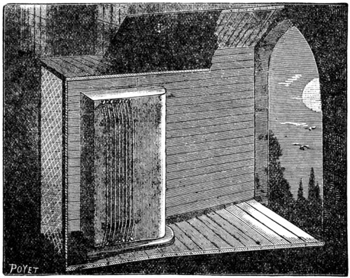
Fig. 1.
This is the ordinary Æolian harp, but in this country and on the Continent there are many more complicated forms of the instrument in existence. The Æolians of the four Strasburg Cathedral towers, for instance, are well known to tourists. At the castle of Baden Baden also the harps are a great attraction, and we here give a sketch of one of the loudest of these celebrated instruments.
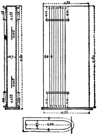
Fig. 2.
Fig. 2 enlarged (89 kB)
It is set well back in the gallery, and the window opening is gradually contracted by the curious shed, of which one side is removed to show the construction, the air passing out through the grating, which is only slightly wider than the harp. Of the harp itself we give the plan and section, and to avoid fractions we retain its original measurement in mètres and centimètres—sixty-one centimètres being as nearly as possible two feet, and a mètre being a hundred centimètres, or thirty-nine inches and three-eighths.
It will be noticed that this pattern of the instrument has strings on both sides, and that the inner edge of the box is fitted with narrow sound-holes. The front of the box is of thin wood steamed into shape, and fitted round the curved ends as carefully as the sides are built into the back and belly of a violin.
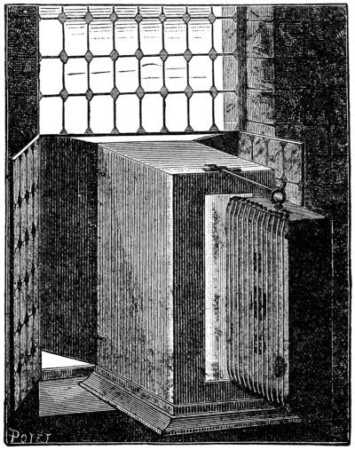
Fig. 3.
In Kircher’s harp, the older form, the screen fits into a window, the instrument is hung on an iron rod, and has a great many strings stretched over broad sound-holes. The case is freely perforated, and is hung so as to half overlap the aperture which gives admittance to the air.
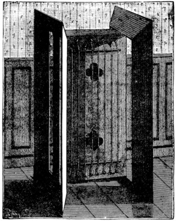
Fig. 4.
Kircher for a long time had the credit of being the inventor of the Æolian harp, but it is of much earlier date. It is, in truth, a very obvious contrivance, easily made, and not susceptible of much improvement. In our last figure we give its latest form, which differs from the others only in the arrangement of the screens. These are devised to throw a strong draught on to the strings, without having to be fitted into a window frame; but in this, as in all the other forms of the wind harp, it requires a pretty strong breeze to bring out its full tone.
The best penny whistles are tuned in D, and we shall assume that ours is so. Occasionally, however, they are in a different key, but this does not alter the fingering, as the intervals are the same, and the same air will be played with the same stopping. There are six holes, which, commencing from the mouthpiece end, we will number 1, 2, 3, 4, 5, and 6. Of these holes, 1, 2, and 3 should be worked by the fingers of the left hand; 4, 5, and 6 by those of the right.
The lowest note of the instrument is sounded when all the holes are stopped—the reason, of course, being that the vibration takes place along its whole length. To get this note is, however, not easy, as there is a great tendency to blow too strongly, and so get into overtones. ‘The very gentlest breath will give the dulcet note we seek.’ Having got the D, and it must be a good full note, unstop 6, so as to keep only 1, 2, 3, 4, and 5 shut, and you will with the same strength of wind sound E, the note that comes just above it in the scale.
F-sharp, the next note, is got by unstopping 5 and 6; G, the next, by unstopping 4, 5, and 6; A, the next, by unstopping 3, 4, 5, and 6; B, the next, by unstopping 2, 3, 4, 5, and 6; C-sharp by unstopping all the holes.
Nothing can be easier of remembrance than this. The fingers are lifted from the holes one after the other, beginning at the bottom of the instrument, and with every finger you lift you rise to a higher note. But we have not quite finished the octave. How do you get the D? By leaving 1 open and closing the rest. And one note we passed, C-natural, how is that obtained? By unstopping 1, 5, and 6.
We have thus gone from D to D and got our first octave. How do we get the next? By blowing a little stronger, a very little, and unstopping on the same principle as before. Beginning with D, we have 1 unstopped, and then closing 1 and opening 6 we get E; opening 5 and 6 we get F-sharp; opening 4, 5, and 6 we get G; opening 3, 4, 5, and 6 we get A; and opening 2, 3, 4, 5, and 6 we get B, just as we did before, the fingering being the same, but the notes, owing to the stronger blowing, being an octave higher. The next note, C-natural, is obtained by unstopping 1 and 6; the next, C-sharp, is given by clearing 1, 5, and 6; the next, D, by clearing 1, 4, 5, and 6. And so we have completed our second octave. But we have four more notes yet that can be safely sounded without giving our audience the ear-ache, and of these E is got by unstopping 3 and 6, F-sharp by unstopping 2 and 5, G by unstopping 2, 4, 5, and 6, and A by unstopping 1 and 6. We thus have a range of twenty-one notes, including the two C-sharps and three F-sharps, so that our instrument is by no means a defective one, and the only difficulty in playing it is the avoidance of overtones where the artistic merit comes in at the middle D. It is, however, easy to remember that if you blow softly you get the lower octave, if you blow firmly you get the higher octave, if[426] you blow wildly you get the peculiarly metallic screech which has made the penny whistle the abhorred of civilised men.
And now, having cleared the ground—for it is not our place here to teach the ‘rudiments of music,’ and in showing how to produce the notes we have gone as far as we need in a ‘monograph’ such as this—we will unfold the little scheme we had in view when we started on this description, and introduce to our readers the Boy’s Own Mechanical Penny Whistle!
The principle of the whistle, and, indeed, of all instruments of the flute and flageolet type, being that certain of the holes in different combinations should be left open in order to give the different notes, and that the expression should be given by the modulation of the wind strength, it follows that the fingering is merely mechanical. A substitute for the fingering can therefore be found, and the simplest substitute we have come across is a sheet of wrapping-paper!
Take a strip of brown paper or manilla paper, just wide enough to cover the holes on the whistle, or rather overlapping about half an inch on each side of the end holes. Mark off on the paper at each end of the strip where the centres of the holes come, and rule parallel lines[427] the whole length of the paper, so that as it pulls over the whistle each of the six lines will pass exactly over the centre of each of the six holes. On each side of these six lines draw a line so that the space between the two new lines on each side of the central one may be half as wide again as the diameter of the hole across which it is to move.
Now rule the paper crossways in lines three-sixteenths of an inch apart parallel to each other, and strictly at right angles to the lengthway lines. The strip is now ready for you to stop out your tune on the principle of the Jacquard loom or the American organettes now so common amongst us.
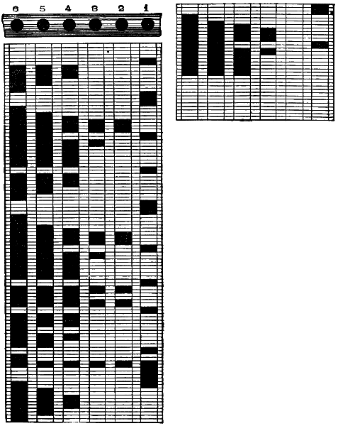
Fig. 1.
First find the shortest note the air contains—in our example, the ‘Blue Bells of Scotland,’ this is a quaver—and each of the ruled spaces cut by the lines through the whistle-holes must represent this interval of sound. Double the space will give double the interval of sound, and hence, if one space represents a quaver, two spaces will represent a crotchet. In the Blue Bells the first note is D, a crotchet; and as D is produced by unstopping 1, we fill up on the first line a double space. The next note is G, a minim; and, as G is produced by unstopping 4, 5, and 6, we fill up space on those lines, making them double the length of the first space, the note being double as long. The third note is a crotchet, F-sharp, and this is marked by blacking in 5 and 6. There is no need to continue this explanation in detail, as the method is sufficiently clear, and the notes are given in Fig. 1, and can be compared with the scale. One space equals a quaver, two spaces a crotchet, four a minim, in this instance; but should a quicker tune be selected the spaces may have to be given values of less interval. The simplest plan is to find the shortest note, and then, seeing how many of it would go to a bar, to mark off the bars along the edge of the scale, and then fill in at your ease. In our example eight spaces go to a bar, because the shortest note is a quaver, and eight quavers make the semibreve. Having filled in[428] the notes, take a sheet of glass, lay the paper on it, and with a sharp penknife cut away all the spaces you have blacked—in short, make a stencil of your brown paper.
We are now ready to commence. Hang the stencil over the whistle so that the holes you have made in it pass over the whistle holes, and blow gently as you drag it along. As the holes are cleared one after the other the notes are given forth, and the whistle can be played almost as easily as a barrel-organ—if you can only keep the paper straight and flat on to the tin. But this is not always easy to do, and so we require a further invention, which the accompanying sketches sufficiently describe.
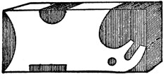
Fig. 2.
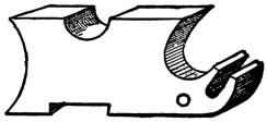
Fig. 3.
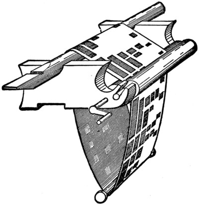
Fig. 4.
Fig. 2 is a piece of deal, the shaded part of which shows where it is to be cut away. Two of these blocks, each of them about three inches long and two inches wide, are required. Fig. 3 shows one of the blocks after it is in shape. The top groove in one must be larger and deeper than that in the other, owing to the tapering form of the whistle—for the whistle must fit firmly. Two rollers, made by sawing pieces off a broomstick, are taken of sufficient width to carry your stencil easily, and these are fixed as shown in Fig. 4. One has a handle made of bent wire, with the point that is driven into the roller flattened out and hammered in straight, so as to give a firm hold; the other has two spindles only.
The rollers are fitted with an elastic band, so as to keep them close together and make them act as a miniature mangle. A slip of wood is fastened beneath the blocks to keep them in position. If it is intended to play the air through only once, and to shift for each repetition, a weight is affixed to one end of the paper to keep it flat; if, however, the air is to be repeated without a pause, the ends of the stencil have simply to be pasted together, and a flanged roller hung in the loop, as shown in the cut.
This is all the contrivance consists of. It is effective, and easily made. The only difficulty in playing with it is the need of the stronger blow in the upper octave, a difficulty soon mastered after a little careful practice. The principle of the perforated keyboard is applicable to so many instruments that these rough notes on its construction may prove valuable, even if it be not applied to the humble whistle. The humble whistle! Alas! But let it not be imagined that squeals and screeches are the sounds the poor whistle was made to produce. Any other instrument, if improperly used, will give forth its appalling overtones. Treat it properly, gently, and firmly, and you will find it as sweet-toned as a flageolet.
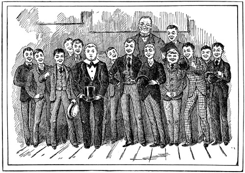
HOW VERY FUNNY!
In the whole history of science, from the Dark Ages down to the present time, there has been no record of any parallel to the extraordinary progress which electricity has made of late years.
It is comparatively but a short time since that people were marvelling at the telegraph, and the newspapers used to write gushingly about ‘compelling the lightning to bear our messages,’ and all that sort of thing. I dare say many boys who read this can remember what a sensation the electric light made when displayed on the top of one of the buildings in the Strand—they need not be very old boys to have seen it there. Nobody would be very much attracted by such a light anywhere now.
There is scarcely a single art, manufacture, or science into which electricity has not been pressed to do good service. Electric lighting has become a matter of course, both indoors and out; and, while it has been proposed to annihilate night in the city of Washington by setting up four huge electric ‘suns’ on the hill of the Capitol, so rendering any other illumination in the streets and houses as unnecessary as in the day-time; a modified lamp of a few ‘candle-power’ has recently been devised for small rooms, supplied by a little battery which might stand on the mantel-piece. Tennis is played and photographs are taken by the electric light; electric bells are as common as door-knockers; electricity is proposed as a means of killing sheep and bullocks in the slaughter-house and criminals on the scaffold, and is used by the physician as a remedy for the preservation of life.
On board some of our great men-of-war the captain can sit in his cabin and not only see the position of the helm, the speed of the ship, and the direction in which she is steering, but can fire every gun she carries—all by electricity. Electricity springs the deadly mine on the field of battle, and animates a sixpenny toy sold in the Lowther Arcade. Even the railway engines, tram-cars, and screw-boats propelled by electric force which have been lately invented cause but little surprise now, so habituated have we become to the gigantic strides of this nineteenth-century infant!
I am not going to preach a sermon upon it, however, as you may be expecting from this terrific introduction; nor am I going to bore you with a lecture on coils and currents and poles and induction, or any other technical details. But it occurs to me that a brief mention of one or two of what may be termed the minor applications of electricity—one or two only out of thousands—will perhaps interest you, as illustrating how widely spread the influence of the science has become, and how it penetrates into nearly all the affairs of life. To my mind, the fact of telegraph and telephone wires stretching for hundreds of miles across uncleared jungles and through virgin forests, as they do, is not half so strong an evidence of the pitch to which it has arrived as its being adapted to a conjuring trick.
At one of the places of amusement in Paris some ‘sprites’ carry wands which sparkle out and fade again as required, flashing in time to the music. But a much prettier and more elaborate arrangement has been brought out since, though I believe it has not yet been presented to the public. The performer—magician, fairy, or whatever he or she may be—wears a fancy dress, which is embroidered all over with what look like large glass beads or imitation pearls. These are in reality tiny electric lamps, all connected with each other by wires covered with silk in the texture of the dress, and communicating with two little iron plates in the heels of the fairy’s boots. Nothing remarkable, of course, is seen until these two iron discs come into contact with a certain spot—which is reached just at the appropriate moment—when every bead bursts into dazzling light, and the fairy becomes clothed with white living fire in an instant! Then she steps away from the communication with the batteries below, and the beads are as suddenly dead again.
Electric alarums for the detection of burglars have long been in vogue in the shape of bells and gongs, so arranged as to be sounded directly the fastening of a door or window is tampered with, and electric ‘booby-traps’ have even been tried, designed to give the thief a severe shock or take him prisoner—the result generally being that the master of the house or the servants get caught in the snare themselves half-a-dozen times, after which its use is discontinued.
The weak point in all these things has been that, from their costly and intricate nature, they could not conveniently be applied to every accessible situation, and that the mechanism was always liable to be thrown out of order. The burglars would carefully avoid meddling with the shutters and doors to which these appliances were known to be affixed, and would gain an entrance at some unprotected spot. Now, however, somebody has patented an electric mat, which can be put down anywhere at night, and which sounds an alarm directly an intruder steps upon it.
Galvanism is employed, as is well known, by medical men, to restore power to paralysed limbs, to revive people who are faint almost to death, and to cure diseases. Dentists owe a good deal to electricity, and their patients owe still more. When a surgeon wants to cauterise some very small spot deep down in the flesh, instead of cutting and burning all the way down, he now inserts a wire, which is shielded, except just at the part which will come in contact with the bad place; an electric current is sent through it, and the wire becomes red-hot.
Neater still is the way in which a needle is detected underneath the skin. I dare say you know that such a thing often gives a doctor a great deal of trouble, and it is an accident which you should be very careful to guard against. It frequently occurs to boys who run about the house with bare feet. The needle, having no head like a pin to stop it, slips right into the flesh. Sometimes the patient is not certain whether it is there or not, as it may have worked out again, for the danger in these cases arises from the tendency of the needle to travel through the flesh, doing great mischief as it goes along. What is the doctor to do? If he is quite sure that it is there and can feel it, he will of course cut it out; but he has to be very cautious. A needle is so fine and slender, that sometimes, even when he thinks he can feel it with the point of a probe, he finds himself mistaken. It has been suggested that a magnet hung over the part will turn if any steel lie concealed beneath—a very pretty theory, but one that does not answer when put into practice. But one may make[433] quite certain about it by probing the flesh with a little instrument which is connected with a battery in such a way that directly the point touches metal the circuit is completed and a bell rings.
Perhaps this was founded upon the very ingenious probe, by means of which the great French surgeon, Nélaton, discovered the bullet in Garibaldi’s foot. He could feel something there, at the bottom of the wound; but whether it was only the bone, or a bullet embedded in it, he could not say. So he made a slender probe of rough, unglazed porcelain, and rubbed it against the hard substance. On withdrawing it, he found it marked with lead!
Still more wonderful are the medical uses of the electric light. Not only is it made to illuminate the eye to the very back, but the throat as well. A little glass-bead lamp at the end of a rod is passed into the mouth, the current turned on, and there you can see the tonsils, gullet, windpipe and all, a great deal more distinctly than the interior of St. Paul’s Cathedral on a foggy day: while, to a bystander, the patient’s cheeks and throat look as if they were made of pink glass and filled with fire inside. Further, a similar rod and bead have been actually lowered into the stomach of a very thin person, and were found to be plainly visible through the semi-transparent skin; and it is thought that this may be valuable at times in the detection of disease.
From surgery to sleight-of-hand is a long step, but we find conjurers quite as eager to avail themselves of the assistance of electricity as doctors. Robert Houdin’s book on Magic gives an account of the marvellous adaptations of this science, wherewith his private house and park were furnished. He invented many of the tricks performed with electric apparatus by his successors at the present day—not such comparatively simple ones as ‘spirit-rapping’ hammers and drums which answer questions; but clever mysteries like the iron chest which a child can lift, yet which defies the strength of a man, and the crystal cash-box. These are things which might puzzle even scientific electricians who are not in the secret. By means of the first the great wizard acquired extraordinary influence over the Arabs in Algeria, because it seemed to them that he could at pleasure take away the strongest man’s power in a moment and cause him to become as weak as a baby, restoring it again as suddenly. It depends upon the fact that a current of electricity passed through a bar of soft iron makes it into a huge magnet for the time being. The little iron box, which is to be raised or remain immovable as the conjurer wills, is placed upon a pedestal, within which is the iron bar, connected with wires to a machine outside in charge of an assistant, who, at a given signal, turns on the current.
The crystal cash-box is a casket, the top, bottom, and sides of which are made of glass, bound with wire at the edges. No deception seems possible; it is transparent right through, and is suspended over the heads of the audience by four slender wires attached to little hooks at the corners; yet several half-crowns are seen and heard to fall down inside it at the word of command.
You will naturally guess that the entire affair is under the influence of a battery ‘behind the scenes.’ The coins are first concealed within a ground-glass ornamental design in the lid, the glass of which is double. The lower slip would be just loose enough to allow them to fall, but is kept up by a bit of black thread, which rests against the wire. Just at this point the wire is made of platinum, which becomes heated by electricity much more quickly than copper or iron, being a bad conductor.[434] Almost the instant the current passes this bit of platinum becomes red-hot, while the connecting wires are not affected; the thread is burnt through, down drops the slip of glass, and the half-crowns fall or slide out with a jingle.
We know that by the telegraph wire we can read what people write hundreds of miles away, and can hear what they say through the telephone. At the time when all these ‘phones’ and ‘graphs’ were being invented, one after another, almost daily, an American paper announced another novelty—the telegastrograph! You were to hold one end of a wire in your mouth and taste the orange, plum-pudding, or glass of wine into which the other end was stuck a thousand miles off! But although this was a hoax, it would hardly have been more wonderful, had it been true, than many real facts among the curiosities of electricity.
Nothing can be easier than to make the Leyden jar. Procure a smooth glass bottle, that is to say an unpatterned one; and let it have a wide mouth, though this is not essential. Thoroughly clean it and dry it, and paste on to it inside and out to the height shown in the illustration some sheets of tinfoil. Let the tinfoil cover the glass two-thirds or what not from the base, and leave no breaks below the line.
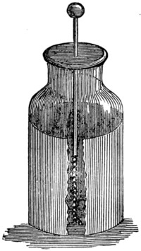
The best plan is to coat the inside first. Cut a circular piece of tinfoil a little larger than the bottom of the bottle, and paste it down with the edge pressed up against the side. Then drop into the bottle a well-pasted strip of foil the height you have selected, and just a trifle longer than the internal circumference of the glass on which it is to be stuck.
Having finished the inside, do the out. Cut a circular plate for the bottom, press it up round the edge and paste on the glass the strip for the exterior circumference, which should be of the same height as that inside. Then insert a piece of brass through a cork or mahogany stopper, fix a brass ball to one end and a brass chain to the other just long enough to rest on the bottom, wax or varnish the stopper, and the jar is complete.
Instead of lining the bottle with tinfoil, thin gold leaf or copper leaf can be used; and instead of the brass ball and bar a ball of baked wood and a copper tube. It was Harris who first used the baked wood; Hopkinson has experimented with Leyden jars in which sulphuric acid has taken the place of tinfoil! The form we have described is, however, the usual one, and as it is the cheapest it would be best to start with it.
To charge the jar the outside tinfoil is connected with the ground, and the inside is excited by means of the knob from the prime conductor of the machine. The electricity is, as the phrase goes, ‘bottled off,’ though ‘the fluid’ is no fluid, and is not ‘poured’ at all. Two conductors of large surface are separated by a rigid insulator, and hence the conditions are favourable for powerful attraction. That is all.
This simple apparatus, which takes such a prominent part in electrical experiments, obtained its name from having been invented at the old Dutch University, where Muschenbroek was at the time professor. In Germany it is called Kleist’s jar, from the name of another inventor, but it has been the custom amongst us to ascribe the honour of invention to either Muschenbroek, or Cuneus, his assistant.
It seems that Muschenbroek had noticed that excited electrics soon lost their electricity in the open air, and that this loss was quickened when the atmosphere was charged with moisture. Hence electricity was retained by surrounding its retainer with bodies that did not conduct it. To prove this he poured some water into a glass flask, put it into communication with the prime conductor of an electrical machine, and for fear of accidents judiciously handed it over to Cuneus to hold. When they thought it was charged enough, Cuneus tried to disconnect the chain from the conductor, and thereupon received such a lively shock in his arms and chest that he dropped the bottle and smashed it to pieces.
The professor was pleased; the assistant was not. He was ill for two days afterwards. ‘I would not take another shock for the kingdom of France,’ he wrote to Reaumur. And all the first experimenters with electrical apparatus were much alarmed at shocks which to us would seem hardly worth noticing. Poor Winkler, for instance, was so frightened at the unexpected experience that he ‘betook himself to cooling medicines to allay the fever.’
The shock received by Cuneus soon led up to the jar as we now know it. First water was tried, then mercury, and finally tinfoil. Muschenbroek’s experiments took place in 1746; in the next year Watson began to come to the front. He first fired gunpowder by electricity, then he mixed camphor with gunpowder and discharged muskets by electricity. Then hydrogen and spirits of wine were fired by the spark by means of a drop of water or a lump of ice.
Watson it was who put the inside and outside tinfoil coatings on the jar. Bevis suggested the outside; Smeaton, of Eddystone Lighthouse fame, suggested the inside. Watson’s experiments before the Royal Society attracted much attention to the science, though he had in some things been anticipated by the French, who had sent a discharge through 12,000 feet, and on one occasion had used the great basin of the Tuileries, giving an acre of water as part of the circuit.
Nollet sent a discharge from a jar through a regiment of 1500 men holding each other’s hands, and they were all shocked in the arms and shoulders. But perhaps the best known experiment is that of Franklin with his kite.
Two strips of cedar, fixed crosswise, with a large silk handkerchief tied at the corners, and a sharp-pointed wire projecting a foot above the upright, was all that Benjamin Franklin’s famous kite consisted of. It had an ordinary paper tail, a bellyband, and a long fine string, with a short piece of silk ribbon tied at the end. Just where the ribbon was knotted to the string he hung a key.
It was in June, 1752, when he let his kite up in the thunderstorm. He and his son, after some little difficulty, got it out to the full length of the string, and then stood up inside a doorway to keep the ribbon dry. A thundercloud passed over, and nothing seemed to happen. The experiment promised to be a failure. Gradually, however, the loose filaments of twine began to stand out at right angles, and were found to be attracted by the fingers; then a knuckle held to the key[436] extracted a spark from it, and as the string got thoroughly wet in the pouring rain the electricity became abundant. With it the experimenters charged the Leyden jar, whose discharges afterwards proved the identity of the electricity of the thundercloud with the electricity of the machine.
Another famous experiment is that known as Lichtenberg’s figures. It is generally performed as follows. Hold the jar, charged positively, in the hand, and with the knob draw on a glass plate, cake of resin, or sheet of vulcanite, a series of patterns. Then put the jar on an insulator, and, lifting it by the knob, trace another series of patterns with the outer coating, so as to cross and intertwine with those made by the knob. Having designed the patterns, make a mixture of red lead and flowers of sulphur and dust it on to the slab. A curious thing will happen. The red and yellow will sort themselves out. The sulphur will stick to the positive lines, the lead to the negative ones, and the pattern will be given in two well-marked colours. The sulphur will be in tufts, the lead in spots. In mixing the powder the sulphur became negatively electrified, the red lead positively so, and hence the disposition of the materials.
The terms negative and positive were first used by Symmer as alternatives for resinous and vitreous. Symmer was the man who discovered the electricity in his stockings and charged the jar by their aid. His experiments were the same in principle as those of Cigna with his silk ribbons, but were much more astonishing.
When Symmer pulled off his stockings he noticed that they often gave a crackling sound, and when he undressed in the dark he saw sparks issuing from them. When he wore silk stockings for show and worsted beneath them for warmth the effects were more powerful. When one stocking was drawn out of the other they appeared inflated, and attracted and repelled each other like electrified bodies!
He experimented with a pair of white silk stockings and a pair of black silk stockings. When he wore both white or both black on the same leg, nothing happened; but when he wore a white and black on the leg, and pulled them off after ten minutes or so, they remained inflated, and showed the shape of his leg! Brought within eighteen inches of each other, they rushed together; then they were separated, and again became inflated, and again rushed together.
Experimenting with the two pairs held against each other, he found that they sorted themselves out, rushing each to each, until they gradually wasted away, and from legs substantial enough for the foundation of a family ghost story—a ghostly legacy—dwindled down into mere flabby pieces of silk. The electricity he obtained from these classical stockings was considerable. He charged a Leyden jar from the four of them, and secured enough electricity to shock himself up to his elbows, and to light a teaspoonful of spirits of wine!
One caution before we conclude. In every experiment, whether it be merely in shocking, in rendering luminous half-a-dozen eggs placed end to end by sending the shock through them, in perforating a card by passing a spark through it as it rests on the foil, in splitting wood by driving the wires in until their points are close to each other, in breaking a glass by passing a spark from knob to knob in water, however simple it may be, remember always to discharge by touching the outside first. Otherwise you may receive an unpleasant surprise, and, like Cuneus, come to grief with your Leyden jar.
In our chapter on the Leyden Jar we assumed that those of our readers who were likely to experiment in frictional electricity would be in possession of an electrical machine to start with. Many, however, may be desirous of building an electrical machine of their own. As this can be easily done, and as the cost of the materials is comparatively slight, we purpose giving a few practical hints on the subject which may be of use to those wishing to build and those anxious to repair if they only knew how.
Before we deal with the cylindrical machine we must, however, devote a few words to the electrophorus by which the jar can be charged if desired. An electrophorus is easily made. Choose the lid of a tin canister about eight inches in diameter and half an inch deep for your ‘form,’ or have a lid specially made by a tinsmith with its sharp edge turned over a wire ring, so that it may keep its shape and not be so likely to cut your fingers. Let the tinsmith also make you a thin flat disc of zinc or brass, smooth and rounded at the edges, and measuring about six inches and a half across. To this disc solder three loops of brass wire, and to the loops tie three silk strings of equal length, by which you can lift the disc. The silk should be quite pure, and if you like something else you can use a handle made of sealing-wax and stick it on to the centre. The silk strings, however, are the simplest, strongest, and most easily replaced.
Turn the ‘form’ bottom upwards, and run round it a strip of thick white paper, so as to project about an inch above the bottom. This will be the mould into which the mixture is to be poured, for the lid is always to be used bottom upwards. In the old days the mixture was poured into the tin mould and left there, but it was found that the cake would crack very easily under such circumstances, whereas when it is left to itself it lasts for months with ordinary care. Make your mould, then, with the lid for its bottom and the paper for its rim, and proceed to melt your mixture. This should consist of yellow beeswax and Venice turpentine in equal quantities by weight. Use an earthenware pot, and gradually warm up the mass, stirring it with a piece of wood so as to ensure its melting equally. When it is melted, you have to add to it five times its weight of shellac—that is to say, if you used two ounces each of beeswax and turpentine, you will have to use twenty ounces of shellac. The shellac is to be added to the melting mixture a handful at a time, and all lumps must be dissolved before any more of the flakes are added. Do not let the liquid get too hot, or it will become like india-rubber and spoil. When all the shellac has been got in, take off the earthenware pot, give the mass a stir, and carefully pour it out into your paper-edged mould, until the liquid is half an inch deep. When the cake is cold, wet and tear off the paper, and then lift it off the tin. If you drop the cake it will almost certainly break, but if you keep it free from hard knocks it will last a long time. Do not have the cake too thick.
To use this electrophorus, turn your lid upside down, as you did during the casting, and place the cake on the top, turning it also bottom upwards, so that the smooth surface which came nearest the tin when it set is now the upper one. Let the whole apparatus be warm and dry. Strike or rub the surface rapidly with a piece of warm flannel or fur—fur is the best; and while you are beating the cake, keep your fingers on it to prevent it slipping off its stand. When you think the cake is sufficiently excited, which it will be in a minute or so, lay the cover in the centre, holding it by the silk strings or handle. Touch the cover with your finger, and then lift it from the cake, and you will get a powerful spark, and each time you touch the cover, before you lift, the result will be the same. In dry weather the cake will remain electrical for weeks, but it is better to recharge it each time it is used. Do not let your clothes get too near the electrophorus during your experiment, and keep all pointed things as far away from it as possible. An eight-inch electrophorus ought to give an inch spark if properly made and charged. To charge the Leyden jar, all you have to do is to hold the knob near the cover and take from fifty to a hundred sparks. You should have the electrophorus raised so as not to have to lift the cover too high each time, and you should hold the jar by its bottom, thus giving the necessary connection with the earth.
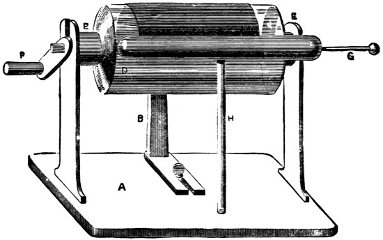
Fig. 1.
The cylinder machine (Fig. 1) is a much more complicated affair. It consists of a stand A; a cushion, of which the upright is shown at B, and from which the silk flap is shown at the top; a cylinder, shown at D with its caps E E, and its handle at F; and a prime conductor G, insulated on a glass rod H. It is best to buy the cylinder. Glass confectionery jars, Winchester quarts, ordinary bottles, and even commoner vessels have been used, but the results have rarely repaid the extra trouble necessitated by the want of a cylinder with proper ends. Such a cylinder[439] about six inches long will cost under two shillings, and one of a fair size, say ten inches long, can be obtained for five shillings from any chemical appliance seller, such as Griffin, of Long Acre, or Townson and Mercer, of Bishopsgate Street Within. Should a makeshift be adopted, the first step is to cement a disc of baked wood on to each end of the bottle so as to afford the needful fixing. The cement for the purpose should be made by melting rosin in an earthen pot, adding a little beeswax and raw linseed oil to toughen it. For half a gallipot full of rosin use a piece of wax about as big as a walnut, and a teaspoonful of oil. When the rosin is thoroughly melted, stir in some plaster-of-paris; and the more plaster you can manage to make it take up the harder will be your cement. The mixture must, however, be perfect. While it is liquid shake in some red lead to give it a good colour. The cement will have to be melted each time it is used, and the articles it is required to join should be warmed before it is applied, so that the change of temperature may be gradual.
The first thing to do is to provide our cylinder with an axis. The simplest way to mount it is to run a hard wood stick right through the centre, the stick being only just large enough to pass, but the most workmanlike way is to fit it with two hard wood ends. Unless, however, this be done with great accuracy, the cylinder will not be properly centred, and the result will be a failure. For beginners, therefore, it may be advisable to retain the central spindle. Before inserting it thoroughly clean the cylinder inside and out.
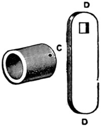
Fig. 2.
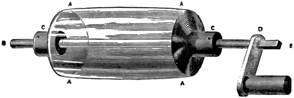
Fig. 3.
The spindle should project a few inches at each end; and to hide the glass collars and give a strong grip, a pair of ends (see Fig. 2) should be cut or turned which can be slipped down the stick. These can be fastened to the glass with cement, and further kept in place by a fine screw or French nail driven through to the centre so as to just avoid the glass. In the case of the spindle not being driven through, the ends are made longer, and on them the cylinder works. We have here (Fig. 3) the cylinder A duly fitted with the central spindle B, with the collar C shown by itself and in position, and the handle D slipped on to the squared end of[440] the spindle. This handle should be made to fit firmly, and it is best to cut the square hole in it first and then to cut the spindle end to suit it. Like the rest of the machine it should be of hard wood, and should have all its corners and edges sand-papered off.
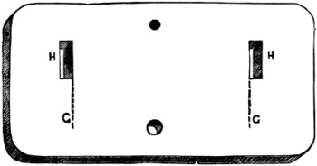
Fig. 4.
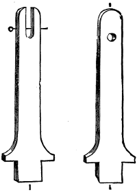
Fig. 5.
We must next make the stand for the cylinder to work on. Get a piece of board an inch or more thick, lay the cylinder on it, and mark where the two ends come at G G (Fig. 4). The cylinder is to revolve on the spindle, and the ends are to prevent its shifting from side to side, so that your marks will be at the junction. Now get out two uprights from the same thickness of board, and let them be twice the height of your cylinder’s diameter; let one have a hole large enough for the spindle to work in, and let the other have a slit from which the spindle can be kept from rising by a pin run through, as shown in Fig. 5. When your uprights are ready, cut the tongues at the end, and then cut the holes in the board for them to stand in. These holes will be to the outside of the lines given by the cylinder, and should be on one side of a line drawn through the centre parallel to the sides of the board. Fit in your uprights and try if the cylinder works freely in them. If all is true and level, take them out and glue them home.
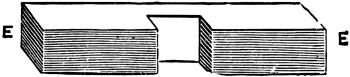
Fig. 6.
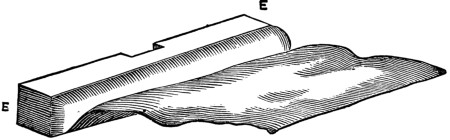
Fig. 7.
The next thing to make is the cushion, for which you require a block of wood, like E E (Fig. 6), an inch and a half wide, half an inch thick, and not quite as long as the cylinder. Cut a notch in the centre for the upright to be fixed in, and then procure a piece of coloured thin leather, or wash-leather, an inch longer than the wood, and wide enough to go barely round it. Glue it on to the top and bottom of the wood so that it is quite loose in front, and also glue up one end. When the glue is thoroughly dry, stuff the cushion with horsehair or tow, making it as uniform as possible. Glue up the open end. To the under edge of the cushion glue the silk flap, which should pass up in front of the rubber and over the top of the cylinder (see Fig. 7). It may be of oiled silk throughout,[441] or it may be made as follows. Glue a piece of leather the same as that used for the cushion along the under edge of the wood. Should you have used a coloured leather for the cushion, you will have to glue it coloured side down, so that the softer surface may come next the glass. This piece of leather should be the length of the cushion and just wide enough to reach to the top. Along its upper edge you have next to glue a piece of black sarcenet, and the leather and the sarcenet should together be as long as the flap would have been had you made it entirely of silk.
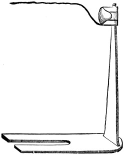
Fig. 8.
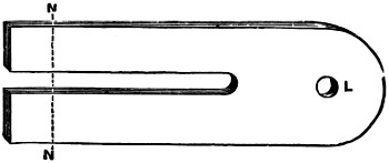
Fig. 9.
The cushion being thus completed, you have next to fix it to an upright, and this upright should be just high enough to admit of the cushion pressing along the centre of the cylinder. To increase the power of the machine you can, if you like, glue a strip of tinfoil along the bottom of the rubber, connecting it by a small chain to a hook at its back, from which hook a chain hung on to the nearest gaspipe affords the best connection with the earth. The upright (Fig. 8) is affixed to a foot in which a slide has been cut as shown at K in Fig. 9, where N is the position of the screw and L is the hole for the upright, so that it can be slipped backwards and forwards until the right pressure against the cylinder is obtained. A brass thumb-screw will keep it in position, as shown in our first illustration.
For the prime conductor use a wooden rolling-pin covered with tinfoil. If you have to prepare a piece of wood specially it is best to have it about two inches and a half in diameter, and instead of making it round to make it with an egg-shaped or pear-shaped section. This is, however, unusual at present, and a round stick is much easier to get. Its ends should be well rounded off. Tinfoil is cheap enough,—it costs about twopence-halfpenny a sheet, so that there is no need to be sparing of it; it should be carefully pasted on to the wood with ordinary paste, and have its edges notched so as to avoid wrinkles and folds. When it is dry, it should be burnished with a knife-handle to make it as smooth as possible. When it is finished off draw a line along it—in the case of a pear-shaped conductor let the line be along its thinnest edge—and at a quarter of an inch apart drive in stout pins, which should be filed off so that their points may be quite sharp and project about half an inch. The length of the row of pins should be rather less than that of the cushion; they should not run the whole length of the conductor, but stop about a couple of inches from the end. The conductor should be the same length as the cylinder, but it should be so fixed as to bring the row of pins immediately opposite the flap. It thus stands a little to the right of the centre, away from the handle end. At the longest end a thick wire is fixed, to which a brass ball is attached.
To support the conductor you require a glass rod, obtainable at the same time as the cylinder, and costing a shilling a pound. It should be half an inch in diameter and sufficiently long to fix well into the board and conductor, and bring the points level with the centre of the cylinder. To get it to remain fast you will have to roughen its ends on a grindstone and fasten them into holes with cement. It should be so fixed as to bring the points of the conductor about half an inch from the cylinder. Now cut the silk so that its edge is just above the row of pins; and then give all the edges and corners a final sand-papering, and set about getting the machine to work.
The first thing you have to do is to smear the cushion with amalgam costing sixpence an ounce, an ounce lasting for many weeks. It usually consists of five parts of zinc mixed with three parts of tin, and gradually mixed with nine parts of mercury, but an amalgam can be easily made by melting in a tobacco-pipe a piece of zinc about as large as a pea, and adding to it an ounce of mercury, stirring the mixture thoroughly and pouring it on the hearth to cool. If you have a silk flap over the cushion, smear the amalgam on to the cushion as evenly as you can manage; if you have a leather flap with silk top, spread the amalgam along the leather in a strip of about half an inch in width, which you have previously slightly greased with a tallow candle. To apply the amalgam you will have to unscrew the cushion from the stand.
When you have replaced the cushion and are ready to start, put the machine down to the fire to warm. Do not put it too near, or it may crack. The machine must be free from dust, so clean it well with a silk handkerchief; and it must be dry, more especially the cylinder where it is not covered with the flap and the glass support of the prime conductor. Unless these are free from damp the machine will not work. Do not turn the handle of the machine until you are assured that the cylinder is dry; by doing so you give the rubber the benefit of the whole circumference of moisture, and it may take you some time to get rid of the wet. If you ever[443] have a plate machine, remember this most particularly, for your brushes will be made quite useless for a time by such thoughtlessness. And one other word of caution with regard to plate machines, and that is, never place them sideways to the fire, always dry them end on. The thicker the glass the easier it splits with inequalities of temperature.
All being dry and warm, clamp the machine to a table and turn the handle. If you have carefully followed these instructions, your knuckle will receive a spark as soon as you apply it to the ball of the prime conductor; and the handle of the machine will turn more stiffly as you progress. If your cylinder becomes too greasy, wipe it clean and apply a little more amalgam. If it does not work quite right at first, see that some pointed thing on the table is not drawing the electricity away; even a hair will affect the working, so keep a good look-out for fragments of cotton and fluff. When you get the sparks bring your jar into play, charging by simply holding it out with its knob touching, or close to the knob of the prime conductor.
The essentials of the cylinder machine are that it should be made of hard dry wood and of glass without an excess of alkali, that its workmanship should be firm and true, that it should have no unnecessary points and edges, and that it should be only used when free from damp. Those who are interested in the subject, and wish to see what a well-made machine is like, should visit the Science Collection at the South Kensington Museum. There is there, among other noticeable things, a plate machine seven feet in diameter. The exhibition is one of the best in London, and it is most easily got at from the Queen’s Gate side, the entrance being the door nearest the private houses on the way up to the gardens from the railway station. It is open free on the usual South Kensington days—Monday, Tuesday, and Saturday.
Electrical machines are not always as persistently popular as they might be, owing to their possessors being at a loss for novel experiments. The apparatus is put through its facings like soldiers at drill, the bells are rung, the little men are danced up and down between the plates, the lady’s hair is stiffened like quills upon the maligned porcupine, the sparks are extracted on the glass stool, a few shocks are given, and the round ends in a certain weariness, to be repeated at ever-lengthening intervals. The apparatus is always the same, the experiments are the same, and to a good many boys the constant repetition becomes monotonous. Some, of course, take sufficient interest in the matter to master the theory of the experiments and gain a living pleasure in what they do; the majority, less sturdily endowed, require to be led more gently on and have their paths made smoother. All, however, are invariably interested in using their hands as well as their heads, and for their benefit we offer the following hints, and relate how we last raised our storm in a teacup.
We took two pieces of glass tube and laid them side by side on a cup. The tubes had been bought for threepence from the druggist’s across the street, and had been used as peashooters, for which they are most excellently adapted. They[444] are true, smooth, and to the ordinary tin peashooter very much what the modern rifle is to the old brown Bess. They carry a pea—but it suddenly occurs to us that we ought not to have said anything about such objectionable practices, which of course took place a good many years ago, as witness the ‘had been used’ with which the digression was introduced.

The pieces of glass tubing were then thoroughly dried and laid on the cup side by side. Over each of them a piece of tinfoil was pinched to represent the storm-clouds, and in one of the corners of each cloud, in order to make things easy for the electricity, we squeezed in a brass ball. To each cloud we attached a piece of silk twist out of the workbox, and then, by means of some copper wire—brass chain would have done just as well—we connected one cloud with the inside and one with the outside of a laden Leyden jar, or jar charged from the machine, whichever word-combination may appear preferable. We then proceeded to pull the silken strings, the tinfoil clouds slipped along their glassy ways, approached each other slowly, and then—a flash of lightning passed from each to each, and the thunder rolled in the form of the tiny snap which sounded as the discharge took place.
The theory of the thunderstorm suddenly awoke new interest in us, and having succeeded so well in the air, we resolved to advance further and do some damage. We took away one of the tubes, and resting the other on two cups—one at each end—placed a model house between for us to strike. The house was very loosely put together, the walls being only leant up against each other, and so arranged as to fall at the slightest jerk. In the chimney we placed a brass ball for the electricity to gather on instead of streaming off into the air, as it does on an ordinary lightning-conductor, and then, having joined up to the jar, we brought the cloud over and got our flash as we had hoped.
Then we soared to higher flights and put a pinch of gunpowder in the way of the flash, in the hope that we should have a little blow up, but, alas! the flash went through so quickly that the powder was scattered. Then we remembered the wet string with which our lecturer used to operate, and placing that in the path of the current, we slowed the rate, kept the flash in the powder long enough to ignite it, and blew down the walls of our house in grand style.
Then we worked up to our crowning success in the experiment line. We had a small model of a ship, and we resolved to strike it by lightning. We hung our cloud over a basin. Into the basin we put our ship, having first connected the[445] foremast with our jar, and placed the least pinch of powder in a hole, where it entered the deck. The jar was charged, the cloud hung in the sky, the ship came ‘sailing, sailing o’er the sea;’ it neared the storm; it passed into it; it came within striking distance; there was a flash, a crack, and ‘the saucy frigate floated on the bosom of the waves’—in the wash-hand basin—‘a helpless wreck.’
‘What was the use of all that?’ Well, the use was that we clearly understood what before we had half doubted because we had only taken it for granted. We left off talking about the ‘electric fluid’ and ‘thunderbolts;’ we no longer looked upon electricity as something liquid which dropped out of a cloud with a bang; we ceased to imagine that lightning-conductors should be insulated, ‘to lead the fluid.’ And we saw that the ‘stroke’ went up from the earth as well as down from the sky; that the flash took place at the meeting, and was simply due to the necessary transference in attaining equilibrium.
A good deal of the success of the experiment was due to the size of the jar, the quantity of electricity it accumulated being proportionate to the extent of the coated surface; while the intensity depended on the thickness of the glass. Ours was a fair-sized jar, but its strength was nothing like that of Cuthbertson’s famous battery, which he built for the Tylerian Society at Haarlem, which consisted of a hundred jars each of five and a half square feet, so that the total amount of coated surface was five hundred and fifty square feet, sufficient to magnetise large steel bars, rend four-inch blocks of boxwood in pieces, melt into red-hot globules iron wires twenty-five feet long, and dissipate eight-inch tin wires in a cloud of smoke. Of course with an ordinary battery we could have done as well, but even with frictional electricity distance is of little importance. Did not Bishop Watson, of Llandaff, send a discharge from a Leyden jar through 2,800 feet of wire and the same distance of earth? Did he not, at Shooter’s Hill, send a discharge through 10,600 feet of wire supported on insulators of baked wood? Did not Franklin, in 1748, send a Leyden jar discharge across the Schuylkill? and did not De Luc discharge a jar across the whole width of the Lake of Geneva? We may not be Watsons, Franklins, or De Lucs, and have their wealth of apparatus and dexterity of manipulation, but the poorest and clumsiest lad amongst us is quite capable of arranging the necessary device for securing ‘a storm in a teacup.’
| SOME VERY ELEMENTARY GEOMETRY! | ||
 |
||
| 1. The extremities of a line are points. | 2. A super fishes (superficies)—an acute angle. | 3. A Polly gone (polygon). |
 |
||
| 4. A problem proposes something to be done, such as the construction of a figure | 5. A postulate is a problem so simple that it is unnecessary to point out the method of performing it. | 6. An axiom is a theorem the truth of which is so apparent as to be instantly admitted. |
| SOME VERY ELEMENTARY GEOMETRY! | ||
|
||
| 1. The extremities of a line are points. | 2. A super fishes (superficies)—an acute angle. | 3. A Polly gone (polygon). |
|
||
| 4. A problem proposes something to be done, such as the construction of a figure | 5. A postulate is a problem so simple that it is unnecessary to point out the method of performing it. | 6. An axiom is a theorem the truth of which is so apparent as to be instantly admitted. |
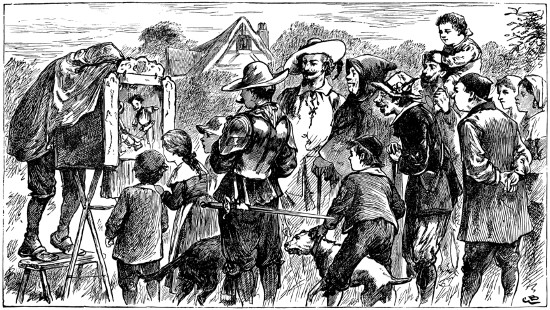
FUN IN OLDEN TIMES.
[Drawn by Gordon Browne.
The famous French conjurer, Robert Houdin, was engaged by the French Government in 1856 to proceed to Algiers, and there demonstrate to the natives that the Marabouts, whom the ignorant Arabs believed to possess supernatural powers, were only very clumsy tricksters. Never had conjurer a higher mission than this—to erase a debasing superstition from the minds of these children of the desert!
At the Algiers theatre were assembled all the leading chiefs and a large audience of minor natives. Houdin, skilled in all the sleight-of-hand, the scientific knowledge, and the finesse of the French school of magicians, was equal to any emergency. He was as cool and collected as on his own stage at Paris, and addressed his strange audience in a few well-chosen words, which were translated to the Arabs by interpreters provided by the French Government of the town.
In this little speech he told the natives that his art was simply the outcome of science and dexterity: that if his feats excelled those of the Marabouts, his audience could judge for themselves whether they had not been the victims of imposture for many years at the hands of very clumsy jugglers indeed; and that in the end he hoped to leave those poor wizards without a leg to stand on—professionally of course!
The conjurer commenced his performance with a few ordinary sleight-of-hand tricks sufficiently puzzling to create great wonder in the native mind, and then proceeded to bolder and more ambitious efforts. Carrying a small box down to the ‘practicable’ or ‘rake,’ running from the stage to the pit, he declared that though a little child might lift it, he could defy the strongest man in that assembly to do so if he willed otherwise. This being interpreted, an Arab of middle height, but well built and muscular, ventured to the test.
‘Are you very strong?’ asked Houdin.
‘Oh, yes,’ replied the son of the desert, carelessly, not heeding the Frankish magician’s assertion that he could deprive him of his strength.
Houdin allowed the man to pick up the box easily, as if it were a toy, and return it to the ‘rake,’ smiling to think that he could be made as a little child. But Houdin now made some mystic passes over the box, and requested the dusky Hercules to raise it once more. He tried; but tug and strain as he would, the box was immoveable. He stopped at length, panting, and was on the point of leaving his task, when pride overcame a desire to escape from this enchantment, and he made one final effort, cheered by his compatriots in front. All in vain: and just as he was on the point of giving in once more, he sank, with a terrible yell, upon his knees.
The reason of this was that the conjurer had given a signal, and the poor man[450] had received the shock of an electrical current, transmitted to the handles of the box. By similar means had the box been held to the stage when the conjurer willed it, for a bar of soft iron underneath the ‘rake’ was converted into a magnet by passing an electrical current in coils round it. When the current was suspended by Houdin’s assistant behind the scenes, the bar was demagnetised, and the box could be lifted up. Of course this was a mystery to the natives, and as the beaten Arab retired, murmurs of ‘Shaitan’ and ‘Djenoum’ running round the startled audience told that, notwithstanding the assurances of the interpreters, the natives gave Houdin credit for having dealings with one who shall here be nameless.
The skilful professor had been informed that the most startling of the supposed miracles of the Marabouts was their standing in front of a loaded gun, which, though pointed at them and the trigger pulled, producing sparks in plenty from the flint, would yet not go off. The cabalistic jargon of the Marabout was supposed to place his sacred person in safety; and this was one of the tricks the French Government was anxious to prove an imposture.
Houdin, though the guns would not go off, soon exploded the marvel. He saw at once that the mystery was of the simplest, the Marabout merely stopping up the vent of the firearm with grease while handing it to the experimentalist. Accordingly this was the next feat Houdin called the attention of his audience to, declaring himself invulnerable (by trickery alone), and defying even the ‘crack shot’ of the district to hit him.
An Arab, delighted to have a human target, bounded upon the stage with the words, ‘I will kill you!’ This was a Marabout jealous of a sorcerer greater than himself. Houdin gave him a cavalry pistol to examine. The man blew down the barrel and into the nipple, and then loaded it with powder and ball. To add to his other precautions, he had previously marked the bullet.
The French prestidigitateur placed an apple upon the point of a knife, and holding it up, said, ‘Aim straight at my heart!’ Though the Arab firmly believed the weapon to be really deadly, he took careful aim and fired point blank at Houdin. There was a pause. The conjurer fell not, but calmly advanced to the man, and presented him with the apple, in the heart of which the marked bullet was found, instead of in Houdin’s.
You see, the Frenchman had dexterously changed the marked bullet for a similar one in appearance, but composed of an amalgam of tinfoil and quicksilver, which is about the same weight as lead, and disperses on the firing. Into a hole previously made in the apple, on the side kept from the view of the audience, Houdin dropped the marked ball before placing the fruit upon his knife, and had closed the aperture with a round piece of apple afterwards, just as a cheesemonger makes his Stilton whole again after you have tasted from his scoop. When the apple was cut open, and the bullet fell out, attention was at once directed to the marks upon it, and, of course, so drawn from any scrutiny of the débris of the ball that had been fired from the pistol.
Houdin’s powers were put to another test subsequently to his public performance. A deputation of the élite of Algiers and its neighbourhood waited upon him, headed by Bash-aga Bou-Allem, the African Rothschild, to still further[451] test the gun-trick. Houdin was prepared. From beneath his snowy-white burnous an aged Arab produced two richly-chased pistols. These the Frankish conjurer loaded, previously handing round the bullets for inspection. Then he passed one pistol to the chief, who, at six paces, fired, and the ball was apparently caught between Houdin’s teeth. Dropping this from his mouth to prove its solidity, Houdin now took up the other pistol and fired at the stone wall of the apartment, when—great wonder to the chiefs, and dismay to the impostors—the bullet apparently drew blood from the stone. One of the defeated Marabouts actually put his finger on the blood and tasted it; then he collapsed.
This trick was ‘worked up’ very cleverly by Houdin. He ‘palmed’ both the real bullets, substituting one made of wax (hollow) and lampblack for the pistol he gave to the Arab, and crushing it as he rammed the charge home, so that it would not injure him at such short distance. The pistol he used himself had a hollow leaden ball dropped into it, and the cavity in the bullet was filled in with blood, so that when the lead was crushed against the wall the interior contents were splashed upon it.
Houdin was the finest political agent the French Government ever sent out, and the most civilising withal; for the clumsy tricks of the Marabouts, which he exposed, had very little effect upon any but the very lowest class afterwards.
Gun and pistol tricks are so much a part of the conjurer’s art that it may be well to describe some others, to show the ingenuity of these whilom ‘diverting vagabonds’—the wizards—who are now frequently to be found in very good company indeed.
One of the old gun-tricks was somewhat like Houdin’s device for nonplussing the Arab impostors. In this a fowling-piece was used, and loaded by any one in the company, the professor of mystery only taking the liberty of placing the ball—previously examined to prove its genuineness—into the barrel himself. Of course that real ball never went out of the magician’s possession, but a duplicate composed of blacklead was substituted for it, which could be readily reduced to powder by a vigorous ramming home of the charge, and so rendered harmless.
But modern magic goes far beyond so simple a trick, and has elaborated this kind of business until some apparently marvellous results are achieved.
To explain these it will be necessary, in the first place, to notice the peculiar construction of the wizard’s firearm. This consists of two parts, the outer of which is a conical tin funnel like the mouth of a trumpet, and tapering down to a tube, which fits the barrel of an ordinary pistol. This tube runs inside the cone, and affords a free passage for the loading and discharge of the pistol, and between the tube and the outer case any object supposed to be fired therefrom reposes in perfect security. Sometimes the performer borrows two or three watches and places them in a drawer, while he sends his assistant for a plate. To this the watches are transferred, and as the youth advances to the conjurer’s table, he purposely slips and falls, when the plate is smashed, and the watches roll all over the stage. The wizard makes much ado in rebuking this clumsiness, and picks up the fragments of delf and the watches, all of which he finds more or less injured. Never mind; he will soon find a way out of that difficulty, he says, so he proceeds [452]to load the pistol and ram all the débris of the (not silver) plate and the timekeepers into it, keeping them firm in their places with a wad of paper. Now the (supposed) clumsy assistant places a picture frame on the stage, at which the magician takes aim and fires, and at the same instant the plate and watches are seen in the frame (which up to this time apparently rejoiced in a plain black backboard only), all perfect save the plate. This appears with a piece out of it, and the conjurer seems chagrined that he has made a mistake, especially before his unskilful assistant. Looking about the stage he finds the missing piece, and is again equal to the occasion. Standing some distance from the frame, he appears to throw the piece he has found at the ‘willow pattern’ whose other component parts have been so unaccountably welded together. Lo! as the fragment seems to leave his opened palm the plate, whole as when it left the potter’s hands, is ready to be examined by the audience: and the watches, ticking as lively as ever, are restored to the pockets of their respective owners quite unscathed, notwithstanding the fearful trials they seemed to have passed through.
The explanation of this is simplicity itself. When the watches have been collected by the professor they are placed in what appears to be an ordinary drawer, but which is in reality a tricky arrangement that can be made to appear full or empty at pleasure. The conjurer has, of course, shown an empty drawer, but this has a false bottom wherein lie several ‘dummy’ watches, and it is these that are transferred to the plate and afterwards rammed into the pistol. The real watches are carried off the stage by the skilfully-clumsy assistant and attached to the frame (in a manner yet to be described), together with a duplicate of the broken plate before it is introduced to the view of the audience.
This picture-frame is a marvel of deception. Notwithstanding that it appears as if it possessed a plain black backboard only, it is in reality a shallow box, with a spring blind in front of it. Behind this screen the articles are suspended, on a background also black. When the professor fires, the assistant (out of sight) pulls a cord releasing a spring, and the curtain flies up with such rapidity as to be imperceptible from the point of view of the audience. The ‘click’ of the curtain is unheard in the noise made by the pistol, and the effect is as if the watches and plate had been fired from it.
But we have yet to explain how the broken plate is made whole. Our readers will have guessed, probably, that it never was broken at all, and such is the fact. A piece of black cloth lies over one edge of the plate, which makes it appear as if it is broken, and as the magician seems to throw (though he really retains) a piece of the plate actually smashed, the assistant again pulls a string smartly, which is attached to the bit of black cloth, and the plate instantly appears in a perfect state of preservation. That is more than can be said for the contents of all picture-frames after they have been ‘restored.’ Of course these tricks cannot be performed when an audience is very close to the wizard. ‘’Tis distance lends enchantment’ to many things in the conjurer’s art, as in others outside.
Sometimes this trick is ‘worked’ in other ways; say, after a borrowed watch has (apparently) been pounded to bits in a mortar, it is fired from a pistol at a magic target. In this there is no roller-blind illusion, but the ‘bull’s-eye,’ provided with a little hook (hook and eye should go together), revolves perpendicularly on its own axis. The back of the bull’s-eye is precisely similar to the front, but on the[453] hook there the real watch is secretly hung. When the pistol is fired, the pulling of a string releases a spring, and the centre of the target flies round. The mortar employed has a movable bottom, so that the performer can extract the real watch at pleasure. The débris which the conjurer pounds away at, and afterwards loads his trick pistol with, is obtained from the hollow pestle, the performer unscrewing the end of it against the bottom of the mortar as he appears to grind away at the borrowed watch.
The etymology of the word Ventriloquism gives an incorrect idea of the art, as it is based upon the old notion that the ventriloquial voice really proceeded from the stomach. As a matter of fact, the sources of all such sounds are in the throat or mouth.
By the aid of the laryngoscope, a scientific instrument mirroring the action and vibrating changes of the vocal organ, it has been shown that tone and voice come when the cords in the larynx are excited by the breath; but a muffled vibration in the cavity of the mouth, which is caused by the action of the tongue and lips, produces whispering, in which the words appear as from a distance, and, thus robbed of their distinct vocal sounds, can be produced with little or no movement of the muscles of the face.
But the ventriloquist knows full well that the judgment must be led astray quite as much as the ear; therefore, in disguising the true direction of his voice—or those assumed voices which he has added to his own—he requires finesse of a high order, which, while he shall be apparently unconscious of doing so, must lead his audience to certain conclusions respecting the situation of the sounds. In this he is greatly assisted by Nature, which lays the foundation of the art in the fact of the uncertainty of their direction as well as distance.
It was formerly common on the Continent for performers on the stage to go through the dumb show of singing while persons off the stage supplied the voices. The same uncertainty as to the direction of sound is manifested at a marionette show, where the actors—wooden dolls—‘strut and fret their hour upon the stage,’ their actions leading the spectators to ally the speeches with them, and to look upon the manikins almost as veritable human beings. The illusion, if properly carried out, is very perfect.
One of the most favourite modes of ventriloquists now and for a long time past has been to have two or more wooden figures with jaws moved by strings acted upon by the hands of the performer, or by pedals. The artist then holds converse between these, and so takes attention from his own movements. Another capital device is the ‘Talking Hand,’ which it may be here well to describe. Having first provided yourself with a mitten purposely made, with a hole in the centre, and a frill round it, thus:—
and painted the side of your hand to represent Biddy the apple-woman’s face, so:
you are ready to make a nice little speech, and introduce ‘Biddy’ to your expectant audience in the back parlour.
Indian ink will give her eyes as black as Susan’s, and a little red paint, judiciously applied to the top of the thumb and that part of the hand immediately above it, will materially assist the illusion by giving her a mouth.
The annexed is a picture of Biddy with her new cap on. Her nose must be indicated by black lines, and a slight redness at the uptilted end may not be considered out of character. The chin, you observe, is painted on the thumb.
Now stitch a skirt to the lower part of the mitten, and throw a shawl round her head, and you have the old apple-woman to the life.
You must arrange a little dialogue between Biddy and yourself, keeping the imaginations of the spectators in full play, so as to draw attention from your lips and muscles, which you must nevertheless keep in as much rest as possible. Let Biddy’s sentences be short and emphatic, and in a tone as unlike your natural voice as you can assume. As Biddy speaks you must move your thumb up and down, which motion can be so made as to give the idea of the lips moving.
How the imagination can be led astray even without motions at all may be instanced in the case of the imitations of Saville Carey, who often blew through a narrow chink in the corner of a coffee-room with an east-wind like whistle, whereupon the company began to shiver with cold, and some one was sure to rise and examine the windows to see if they were air-tight!
Starting, then, with these peculiarities of Nature on his side (that the direction and distance of sound are difficult to fix, and that the imagination is easily played upon), the ventriloquist, by tricks of manner, with subtle movements and actions, governs the imagination of his audience, and directs their attention to some given spot from which he desires they should think the voice proceeds, while simultaneously imitating it as closely as possible.
The ventriloquial power any one with a fair range of voice and patient practice may acquire. The rarer gift is that of mimicry, by which the illusions of change of tone, pitch, etc., are so greatly assisted. Unless endowed with this in some degree one would find the pursuit of the art a vain and profitless task, but a little will sometimes go a long way, and a careful noting of the modes of some good professors of ventriloquism will give many useful hints to the neophyte, after he has got ‘by heart’ all that has been written upon the subject.
He will notice that the jaws need never be moved, and that though the lips must be in action at times, the effect is neutralised by dexterously turning the side face to the spectators on those occasions. This standing in profile has another advantage also, as the lips can be drawn down on the hidden side, and a considerable alteration in the tone can thus be produced where required.
The vowel sounds, in various tones, may be obtained without movement by nearly closing the mouth, and resting the upper teeth on the inner part of the upper lips. Consonants are much more difficult, and are seldom or never used while facing the audience. When there is no excuse for turning the face sideways the expedient is adopted of dropping the consonants, which would make such a sentence as, ‘Mind what you are doing, you bad boy!’ sound like ‘Ind ‘ot you’re doing, you ‘ad whoy!’
The greater the compass of voice, of course the greater will be the pitch, while practice will produce elasticity in the organs. One word of advice is necessary as to practice—that is, you should never strain the voice. Let the power be developed naturally, or you will inevitably defeat your own object and lead to hoarseness, if no worse.
Study before a mirror. Any illusions you can there produce will be greater in effect when distance lends enchantment to the view, for the ventriloquist’s art cannot be practised with full effect in a very limited area.
An accurate ear will soon enable its possessor to imitate sounds, such as the barking of dogs, sawing wood, etc., but his difficulties will commence when he comes to attempt complete and rapid changes of voice, locality, and distance. From youth to age, from the infant in its nurse’s arms to the ‘lean and slippered pantaloon,’ the transition must be like a flash of lightning in rapidity. Dialects should also be acquired, and varieties of age and sex carefully studied.
It is after the human voice has been imitated without any apparent motion of the lips, and conversations with imaginary individuals have been carefully studied, that the higher power of the ventriloquist comes into play, and the performer has to lead the imagination of his audience from the real to the supposed source of the sounds. This is what, in acoustic illusions, is as necessary as glib speech (‘patter’) to the conjurer, who, by thus calling attention from his hands, is enabled to perform many tricks successfully which he might otherwise fail in. We have said that our judgments are very fallible in the matter of sound, and the performer’s efforts towards indicating their supposed direction is, to a great extent, the measure of his capacity as a ventriloquist.
Second sight, as it is called, is of a very puzzling character indeed. To such an extent is this the case that some clever people have been led to believe that a special gift—some abnormal power—must be brought into play to bring about its apparently marvellous results. The writer hopes, before the boys who read this have got to the end, that they may have a much clearer idea of the ingenious and, if rightly applied, innocent trickery than such persons seem to possess.
The word ‘abnormal’ has been mentioned, and it is almost applicable to the title of this chapter, as the memory must be developed beyond its ordinary tension by constant practice to give that ease and quickness without which second sight, or ‘clairvoyance,’ is but a sorry exhibition. It is wonderful, however (as all matters relating to our organisation are), what little spur memory needs to meet any strain put upon it. Generally, ‘Where there’s a will there’s a way.’
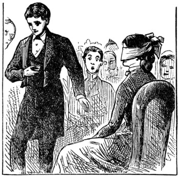
This exceedingly clever and subtle mode of conveying by words or letters what is in the mind of one person to the comprehension of another is not an invention of yesterday, though it has now attained to great perfection. It was introduced into England by the Italian conjurer Pinetti at the Haymarket Theatre in the year 1784. He announced that Signora Pinetti, seated in one of the front boxes with a handkerchief over her eyes, would ‘guess’ at everything imagined or proposed to her by the audience. The clever French magician, Robert Houdin, took up the trick, and ‘worked’ it with his son; and our own Scotch ‘professor,’ Anderson, followed in his wake, the ‘Wizard of the North’s’ daughter being the clairvoyante in this case. Robert Heller was also a capital exponent of second sight, with the assistance of his sister; and the Taylors, father and son, a few years ago astonished the lieges with their most befogging entertainment at the Polytechnic. Then M. Heriott and ‘Little Louie’ were perhaps the most noted in this peculiar line of business, the latter phenomenon startling even those who understood the system by her marvellous aptitude, and the precocity that could cram such a mass of intricate knowledge into so small a head.
We have stated that clairvoyance lies between two persons. These are, first, the interlocutor, who sees the articles hereafter to be described by the person in collusion with him; and, secondly, the latter gifted being, who, with eyes bandaged,[458] can yet grasp mentally, through the medium of the questions put, the nature of the answers to be given. Of course, all eyes are attracted to the clairvoyante, and all attention deliberately turned thereto, though the most difficult position is really occupied by the one asking the questions, he having to decide instantly as to his choice of words, and put them in such a natural, unstudied, and off-hand style—and so quickly withal—as to effectually nonplus those unlearned in the art and mystery.
Most public performers work with a code of their own, merely taking the idea, or ground-work, which past professors have laid down; and they elaborate and add to their word signals from day to day as the necessities of their position are thrust upon them. The best way, also, for any ‘going in’ for this fascinating bit of innocent deception is to adopt the same course, and when their code is, as nearly as they can imagine, perfect, to study and practise diligently, and make sure they are sufficiently ‘well-up’ and glib in their respective parts, so as to guard against being made a laughing-stock, and exposing the method at the same time. The interlocutor should be able to put the questions without hesitation or mistake (as, in the latter case, he runs the clairvoyante off the rails also), and with such nonchalance as to put the spectators off their guard.
Memory, of course, plays an important part in the matter, but not quite to the extent one might at first imagine. One hundred signals would exhaust the list of ordinary articles carried about the person; and a system of grouping—to be explained hereafter—will simplify the code, and yet more effectually mystify an audience, as presenting less variety in the questions put. After you have a large collection of miscellaneous articles coded (and you can never have too many, if well chosen), numbers—signalled by means of letters, not words—and an alphabet for the spelling of surnames, etc., will require great attention; but patience and perseverance will surmount all obstacles, and without these you had better not attempt second-sight at all.
As we have said, most persons who ‘go in’ for public clairvoyance compile a code of their own, and hence, after giving what we consider the best under the circumstances, we shall mention those of two public performers, who have given to the world their systems, one through the pages of a leading American magazine (Scribner’s), the other written by Mr. Washington Irving Bishop, who published a book on Second Sight, containing a résumé of his own professional signals; and as both of these differ from the following, and from each other in most important respects, they will be treated separately, so that the reader may elect which system to pursue before entering upon the (at first toilsome, but afterwards pleasant) path of laws.
We will now proceed to give examples of an easy code for miscellaneous articles: following which we will have a system of grouping, a code for numbers, and an alphabet; and we shall conclude with the application of all these.
In the miscellaneous articles let us understand that ‘Tell’ indicates articles of attire; ‘What,’ those taken from the pockets; ‘Do,’ those carried in the hands; ‘Can’ and ‘Will,’ jewellery, and other articles of adornment; and ‘Anything,’ various articles not enumerated in the foregoing.
‘TELL.’—ARTICLES OF ATTIRE.
‘WHAT.’—ARTICLES FROM THE POCKETS.
‘DO.’—ARTICLES CARRIED.
‘CAN’ AND ‘WILL.’—JEWELLERY, FLOWERS, ETC.
‘ANYTHING.’
Having treated of such miscellaneous articles as will generally be found in any assemblage of persons, we may now proceed to the system of grouping, which will greatly facilitate the working of the process. We give below examples, capable, of course, of great extension.
Money.
The same questions may be put as to
Metals.
Countries.
Etc., etc.
Precious Stones.
Dress Materials.
Etc., etc.
Flowers.
What made of.
Etc., etc.
Colours.
Rings.
Etc., etc.
Christian names, towns, animals, fishes, shape, etc., can also be arranged in the same manner.
The next process, after committing such grouped subjects to memory, is to study a code for numbers, which you will easily acquire in one lesson, the only difficulty you will find being in the rapid application of it. The numbers will be represented by letters thus:—
If one figure only is required the interlocutor will ask for the figure; if two figures he will ask for the number; if three he will precede his question with ‘good,[463]’ and the clairvoyant will know that he has entered into hundreds. If there are four figures he will say, ‘Very good,’ and that will indicate thousands; if five, ‘Very good, sir,’ or ‘madam,’ equivalent to tens of thousands. For six figures ‘good again,’ hundreds of thousands; and ‘If you please’ will act as a full stop. Example: ‘Tell me now, if you please, what figures there are here?’—t m n (132) precede the full stop of ‘If you please,’ and the interlocutor has dropped the ‘good,’ which would have warned the clairvoyant that three figures had to be deciphered. Again, ‘There are figures here. Very good. Find the numbers, can you?’ ‘Yes,’ says the clairvoyant, taking the first four initial letters after ‘Very good;’ ‘eight thousand one hundred and twenty-seven;’ and great is the marvel of the audience thereat.
The last and most difficult problem of all appertaining to our subject—though, luckily, the most easily dispensed with for private performance—is the abstruse Alphabet, by which the clairvoyant may learn the name of a person or gain other particulars in a way quite unsuspected by the spectators. This is managed by taking B to represent A, C to stand for B, and so on, always being one letter in advance of the ordinary alphabet, save in the variations noted below. Thus—
To illustrate this, say the interlocutor has an address card with ‘William Brown’ printed upon it; he would first ask the Christian name by the grouping process, and then, to get at the surname might say, ‘Come, speak plainly at once, if you please, the gentleman’s name?’ C S P A O is translated into BROWN by the above system, and the answer is correct. This transposition of letters, as we have said, is very difficult, but if once acquired, brings the reward of being eminently puzzling with it.
In addition to all here set forth, the ‘cue’ is frequently given to the clairvoyant in a very simple manner as, ‘Is it large or small?’ ‘It is small.’ ‘Plain, or with stones?’ ‘There are stones in it.’ ‘Is it gold?’ ‘No; only gilt.’ ‘Does this belong to a gentleman or a lady?’ ‘To a lady.’ Besides this, intonations, dwellings upon certain words, a hesitating cough, or an apparently chance remark let fall to one of the audience, conveys much to the initiated, and allows of that variation which is so necessary in public exhibitions to prevent persons getting at the secret. One very old and extremely useful form of question—generally used at the close of an entertainment—is the Sequence, the interlocutor touching various articles worn or held in[464] his immediate neighbourhood, and rapidly receiving replies from the clairvoyant, though his questions are of the simplest. This is done by numbering a set of such general articles as are sure to be met with. Thus, if it is wet weather, overcoats and umbrellas will be plentiful; if fine, sticks, parasols, and fans will be in the ascendant. Let three or four codes be arranged for these, so as to vary the sequence and avoid detection, thus:—
No. 1.—For a Fine Day.
No. 2.—For a Wet Day.
At a drawing-room entertainment such articles as we have here provided for would be quite out of place, as your visitors are not likely to carry their cloaks, hats, canes, or even opera-glasses with them. In such cases you can arrange with your clairvoyant five minutes before performance in what sequence you will take the more prominent articles on or about those ‘in front.’
A ‘head’ is chosen as the finale, so as to bring the curtain down with éclat, as the interlocutor can ask, ‘How many hairs are there on it?’ and the ready answer of, say, ‘Three thousand five hundred and sixty-five,’ will cause a hearty laugh. Besides this, all through the ‘business’ the person who interrogates will endeavour to amuse as well as to mystify his audience, to which end what is professionally known as his ‘patter’ (talk) is interlarded with ‘wheezes’ (jokes), and seemingly impromptu wit often of the most studied and built-up character. Some public performers also employ confederates, who lend an added wonder by producing very curious and out-of-the-way documents or other things, all of which, having been carefully studied beforehand, the clairvoyant can give full particulars of. The practice is, however, reprehensible; the art is sufficiently puzzling without such adventitious aids, and the secret is sure to leak out, when those who have been unable to fathom the business will jump to the conclusion that much more is due to confederacy than has really been the case.
Having gone through the drudgery, the hard study necessary to the full comprehension of the art, we now reach a stage when it may be put into practice, and can do nothing better than give an imaginary performance to show the application of the principles previously laid down.
A nice little speech will introduce yourself and confederate, the usual way being to modestly disclaim the supernatural for the wonders you are about to work. Suppose your assistant to be a young lady, she is blindfolded, and you proceed to[465] business by requesting assistance from the spectators by the loan of any article they would wish to be described by your clairvoyante.
Then you go to work at once:—
Will you name this?—It is a ring.
Name the kind of ring?—It is a mourning ring.
Anything on it, please?—Yes, initials.
Be sure, if you please, and say what they are?—A. R.
Quite right. Can you tell this?—It is a watch.
Silver or gold?—Gold.
Anything on it?—Yes, there is a crest.
Quite correct. Now, the time, if you please, by it?—Twenty-one minutes to one.
Very good. Can you name this?—Yes, it is a coin.
What coin?—A sixpence.
The date, if you please? (The clairvoyante knows it is of this century, as only two letters are given.)—Eighteen hundred and eleven.
Can you tell this, please?—It is a medal.
Please name the metal?—Bronze.
Does she know? If you please to ask the young lady I have no doubt she will tell you the campaign it is for, sir. (Here the interlocutor, in speaking to the owner of medal, has given the cue to the clairvoyante by d s k, which stand for CRI.) When the question is put, she says, ‘It is a Crimean medal.’
Now, there is an initial here; tell me that.—M.
Look now, if you please, at the number of the regiment.—The fifty-second.
Will you look here, please?—You now have a flower.
What flower?—Lily of the valley.
What name has this?—It is a cigarette.
What is here?—A pen-knife.
Now, how many blades are there?—Two.
Very easy. Pray view only here, if you please, and tell me the name engraved upon the handle?—The name is Young.
What material is the handle made of?—Pearl.
What is this?—A pocket-book.
Anything here, please?—There is a letter inside.
Quite correct. If you please, tell me the initials of the person to whom it is addressed?—P. B.
What is this, now?—A railway season ticket.
Can you tell the month it expires in?—Here the clairvoyante takes c for the seventh month and answers ‘July.’
Very good. Be so kind, now, if you please, as to give us the number of it?—Nine thousand and seventy-two.
Will you tell this, please?-It is a brooch.
Anything in it, please?—A child’s portrait.
Anything in it, now, at the back?—Yes, hair.
What colour is it?—Brown.
What is this for?—To smoke. It is a cigar; you can have it.
Is that right, sir? Thank you! What kind of cigar is it?—A Manilla.
Do you know what this is for?—That would also suit you; it is a cane!
Thank you, miss, you are very kind! Tell this.—That is a hat.

Can you tell the colour?—White.
And this?—A parasol.
Name the colour.—Blue.
Name the material of the handle, please.—Ivory.
And this?—That is a programme.
And this?—An opera-glass.
This?—A stick.
This?—A flower.
Do you know what flower?—Yes; a camellia.
This?—An eye-glass.
This?—A breast-pin.
This?—A fan.
This?—A chain.
Find the carat?—The clairvoyante knows that f stands for 8, and answers ‘Eighteen.’
This?—That is a glove.
Do you know the colour?—Black.
And this?—A head.
Anything in it?—No.
And so the curtain comes down with a hearty laugh at the unfortunate wight whose cranium is thus stigmatised as empty!
An ‘Ex-conjurer,’ who has treated of The Secret of Second Sight in Scribner’s, says he was inducted into its mysteries twenty years since by a Polish Jew who claimed to have invented the system; or, at least, he had ‘treamed it’ (dreamed it), and that it was he who gave the code to Robert Heller. As to the first of these statements, the inventing, or ‘treaming’ it, we know that the Polish Jew perverted the truth, ‘Clairvoyance’ having been practised with success before he was born: for the second, we shall find from a portion that has gone before and some to follow that Heller’s code differed widely from ‘Ex-conjurer’s,’ whose system may be described as the triplet and spelling code. For the triplets he gives a long list of numbered articles, arranged alphabetically, such as follow:—
For the first article in the triplet the performer merely gives the cue to the number; to the second he adds here, and to the third that.
To work in with these he has also a numbered alphabet, both letters and figures being represented by certain words as below:—
| Come | represents | A | and | 1 |
| Look | „ | B | „ | 2 |
| Hurry up, or Tell me | „ | C | „ | 3 |
| Make haste, or Tell us | „ | D | „ | 4 |
| Well | „ | E | „ | 5 |
| Please | „ | F | „ | 6 |
| Say | „ | G | „ | 7 |
| Answer, Call, or Called | „ | H | „ | 8 |
| Now | „ | I | „ | 9 |
| Let me know | „ | J | „ | 10 |
| Can you see | „ | K | „ | 11 |
| Try | „ | L | „ | 12 |
| Right away | „ | M | „ | 13 |
| Do you know | „ | N | „ | 14 |
| Go on | „ | O | „ | 15 |
| Let us hear | „ | P | „ | 16 |
| At once | „ | Q | „ | 17 |
| See | „ | R | „ | 18 |
| Look sharp | „ | S | „ | 19 |
| Let us know | „ | T | „ | 20 |
| Quick | „ | U | „ | 21 |
| Will you look | „ | V | „ | 22 |
| Do you see | „ | W | „ | 23 |
| Be smart | „ | X | „ | 24 |
| I’d like to know | „ | Y | „ | 25 |
| What is it | „ | Z | „ | 26 |
| There | „ | 0 | ||
| I want to know | „ | 100 | ||
This code ‘Ex-conjurer’ illustrates. ‘Do you see (W) what is this? Come (A), Let us know? (T), Hurry up (C), Answer (H).’ Surely this seems much too roundabout a way of getting at such an ordinary article as a watch! Nor does that of triplets offer great advantages, besides which the words or phrases chosen to represent letters and numbers come in awkwardly—and even offensively to an English ear—as will be apparent in the following extracts:—
‘Suppose a glove is offered. This is the first article of the fortieth triplet. The question would be “Tell us (4) what this is, there (0).”
‘Should the second article in the fifteenth triplet be offered, the question would be either, “Here, what’s this? Go on (15);” or, “Come (1), what’s this here? Well (5)?” and the answer in either case a button-hook.’
The best thing about ‘Ex-conjurer’s’ paper is the suggestive ‘tag,’ or speech[468] at the end of the performance. Our aspirants for ‘clairvoyant’ fame may be able to take a hint from it:—
‘Now, how is this done? Well, I don’t mind telling you, with the express understanding that it goes no farther. It is neither mesmerism, spiritism, ventriloquism, rheumatism nor any other ism. It is brought about by the action of arcane-dynamics, subjectively submitted to the action of the passive agent, and the result, as you have seen, is a stentonophonic reproduction of the original idea. I’m afraid it’s not yet quite clear to some of you. Well, then, in other words, it’s a system of mental telephony. When an article is offered to me, I seize it; and then my assistant, he sees it. Ah! you smile—you understand it; but, remember, not a word outside as to how it is done!’
The real second-sight, as practised by such eminent professors of the art as Houdin and Heller, is greatly superior to ‘Ex-conjurer’s’ code, and is contained partly in our instructions, and more exhaustively in a work recently published. In this the code for figures is arranged exactly in the same way as that given by us; with the addition that the word ‘Quick’ is used to give notice of fractions. Then if the interlocutor says, ‘Tell, now!’ the blindfolded wonder-worker knows the initials indicate 1 and 2; therefore, by aid of the preliminary warning, he (or she) ascertains that 1⁄2 is meant. Thus, if one-seventh had to be signalled, after ‘Quick!’ the cue might be given by saying, ‘Tell correctly, if you please, what other numbers are there.’
The work now under consideration, in addition to a code for spelling words the same as we have given, has also codes for money, coins, cards, colour, dates, etc., quite different from those in the preceding pages, and well worth perusal before any particular system is fixed upon.
The book concludes with an observation that an exhibitor of second sight will as likely as not tell you that this or that system is not the one by which his ‘clairvoyant’ reads mentally; and here the professor may speak quite truly. Nevertheless—and this point cannot be too frequently insisted upon, because abnormal, and even supernatural, power is frequently spoken of in connection with second sight—there is nothing in the mystery that cannot be solved with a little patience and perseverance; and you may feel satisfied that by a code and by that alone—word-signals carefully studied and rehearsed between the clairvoyant and the interlocutor—do all the seeming wonders come to pass.
We cannot more suitably conclude this chapter than by referring to an ingenious article some time ago on ‘unconscious counting’ in the Gartenlaube, in which the writer, Herr W. Preyer, points out that the ability possessed by any one of ordinary intelligence to distinguish three, four, or even five objects at a glance, and without being conscious of counting them, may by practice be perfected to such a degree that it becomes quite as easy to count ten objects as it is to count three, and that it is possible to give the exact number up to thirty objects at a single glance. As an example of the latter attainment, the writer points to the well-known arithmetician Dase, who died in 1861, and who declared that he could count thirty objects of the[469] same kind as quickly and easily as other people could count three or four. The truth of the assertion was often proved when Dase, with lightning rapidity, gave the correct number of a herd of sheep, of the books in a library, or the window-panes in a large house. The test of how far any one can count at a glance is easily made by putting several small objects, such as coins, pins, or matches, under a sheet of paper, then lifting the paper for a second and looking at the objects, and, after covering them again, give an estimate as to the number. At first it will be found difficult to fix the number if there are more than from three to five objects, but the eye becomes very soon accustomed to distinguish between larger numbers, so that after a short time eight or nine objects will be counted by the eye with the same facility. Care should, however, be taken that the counting is not done consciously, for that would take far too much time; the number of objects should only be valued.
The mistakes which are at first frequently made in this guessing game will become rarer and rarer, and almost anybody can become an expert in rapid counting up to ten objects; after that it becomes more difficult. The sensation, says Herr Preyer, of a person practised in unconscious counting, when looking attentively at larger numbers of objects, is that their number shoots rapidly through the head. To acquire this method of counting black spots should be made on white square pieces of cardboard, first symmetrically and in small numbers, as, for instance, the following:—
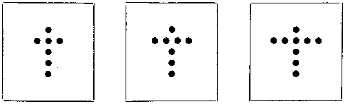
Afterwards their number may be increased and their position altered. It will also be good practice to open a book, cover part of the page, rapidly look at the lines left uncovered, and to guess at their number. It is astonishing how soon the eye gets accustomed to the numbers. The more advanced ‘unconscious counter’ should practise on spots not regularly arranged, which is much more difficult at first. Herr Preyer concludes his interesting article with the remark that unconscious counting, like all other oft-repeated processes, such as lifting the hat as a token of salutation, becomes at last an entirely mechanical process.
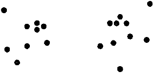
Spiritualism does not in reality mean conjuring; of course you all know that. But the term has now come to be familiarly applied to a certain class of performances, without any pretence of supernatural aid or deceit, and arose in this way. Some twenty-five years ago several people—the celebrated Davenport Brothers among them—appeared in this country and America, and gave entertainments at which they exhibited some very extraordinary and, at that time, novel effects of a magical character, the leading features being their release from cords which had been bound, knotted, and sealed upon them by members of the audience, leaving the knots and seals unbroken; causing inanimate objects to fly about and musical instruments to sound when it appeared impossible for any one to have touched them; and divining numbers and sentences which had been written down privately, unseen by them.
These things they professed to do, not by their own skill and dexterity, but by the aid of ‘spirits’ over whom they declared themselves to have control; and the whole was accompanied with a lot of nonsense in the shape of luminous ‘manifestations’ in the air when the gas was turned out (for darkness was indispensable), and ‘spirit-writings’ on slates and sheets of cardboard—messages, supposed to come from the unseen world, scrawled in a shocking bad hand that any boy would be ashamed of! Nevertheless, a great deal that was done was new and very clever, and had it only been honestly acknowledged to be the result of sleight-of-hand, the performers would certainly have earned and well deserved the reward of success.
But though people go to see conjuring perfectly prepared and willing to be deceived—if that can be called deception which is openly avowed to be misleading—they do not like to have their common sense insulted by irreverence, such as these spiritualists were guilty of in pretending to call up the dead; and a strong feeling of indignation soon set in against the imposture and all who practised it.
Clever as the exhibitions were, also, one or two slips were made which were fatal to them, though it does not ruin a straightforward conjurer to have a trick accidentally discovered now and then. For instance, on one occasion, a dreadful fiery hand, pale and deathly, though glowing with light, was seen sweeping through the air, high overhead, rushing from end to end of the room with a swiftness that no being could have possessed unless provided with wings, and at times descending to give somebody a cold, clammy touch on the cheek. One, bolder than the rest, had the courage to seize this hand, and, in spite of all opposition, insisted on retaining it until the gas was turned up, when the spirit-hand was found to consist of an old white kid glove, stuffed with damp tow and rubbed with phosphorus, suspended at the end of a cord, and waved overhead by means of a long fishing-rod, which folded up in short joints adapted for the ‘medium’s’ pocket!
Furthermore, professional conjurers were put on their mettle, and very quickly showed that they could do, not only the same things, but much more wonderful ones of a similar character in the full glare of the gaslight, without any aid from spirits. The mysterious cabinet, which took such a prominent part in the Davenports’ programme, was soon robbed of its mystery; and in 1865 Professor Pepper—whose name you will remember in connection with ‘Pepper’s Ghost’ at the Polytechnic—invented and patented a piece of apparatus, such as the spiritualists had never dreamed of, called the ‘Cabinet of Proteus.’
The ‘mediums’ have long since retired into comparative obscurity, and now limit their manifestations to displays in private; but they still have a number of followers who are ready to believe that what occurs at these gatherings is really the work of invisible spirits, because they do not see how else it can be done. I heard a famous conjurer say the other day, at the close of his entertainment, ‘If I have been able to deceive and perplex you; if I, telling you beforehand that the effects I was about to produce are the result of mere trickery and quickness of hand, challenging your detection in the full light of the room, have succeeded in making you, watchful and alert to find me out, imagine that black was white, and have convinced you that seeing is not always believing, how much more might a skilful impostor mystify a lot of superstitious people, already frightened out of their wits by fear, in a dark chamber with accomplices!’
When, therefore, we read now of a spiritualistic séance given in public, or of Messrs. Maskelyne and Cooke’s spirit manifestations, we understand the term to have reference to feats of that description, which originated in the above manner; and in telling you how you may exhibit a little ‘Spiritualism at Home’ to your friends, you will now see that I do not intend that you should even pretend to have anything to do with supernatural causes, but only to perform some very astonishing tricks on the same principle as you have been taught to make a halfpenny vanish and reappear.
Modern effects of this kind, as they are presented on the stage, demand, as a rule, not only great dexterity and years of practice, but the use of elaborate and costly apparatus and the help of skilled assistants. All sorts of ingenious mechanism, for which patents are often taken out—electricity, pneumatics, chemistry, optics, magnetism, and nearly every science and art—are pressed into the service, and the floor, the walls, the platform, and the ceiling may be riddled with wires and traps and springs, for anything you know to the contrary; or the lady and gentleman—or even the little boy or girl—sitting beside you may be confederates. Now, if you will carefully carry out the directions which I am about to give you, you will be able to do the following things—founded on the very essence of professed spiritualism—viz., the rope-tying, the ringing of bells and beating of tambourines without visible agency, mysterious writing, and secret reading—in your own or anybody’s room, in the presence of any number of spectators, in the full light, without preparation, without practice, without assistants or accomplices, without sleight-of-hand, and without any apparatus, except (for one trick) a very simple article, which any boy can make for himself in a few minutes.
Let me first describe the effect of the performance, without any explanation as to how it is done—that is to say, as it will appear to your audience. You give some[472] one a piece of ordinary tape or ribbon, which they can examine as closely as they please. One end of this ribbon, which is about two feet and a half long, is now tied firmly around your wrist. Placing your hands behind your back, you then allow the other end to be fastened around the other wrist in like manner. Thus your hands are tied behind your back, each being secured separately, to prevent the possibility of either slipping out, and the knots, or ends, are then sealed with sealing wax and stamped with a crest or private mark for identification afterwards. Sitting on a chair at the farther end of the room, with your back turned to the company, you pass your arms over the back of the chair, so that all may see the ribbon and seals; and while in this position you invite a spectator to step forward and tie his handkerchief around the cross-bar of the back of the chair, including the ligature which joins your two wrists, knotting the handkerchief tightly and sealing it as well.
So that you are now practically tied to the chair, with your hands fastened together behind you. Two of your audience then hold up a table-cloth or open newspaper in front of you as a temporary screen—of course giving their word not to look behind while so doing; a few bars of mysterious music are played on the piano; in a minute, at a signal from you, the newspaper is snatched away, and you are seen sitting in precisely the same attitude and bound as before, but with your coat removed and lying across your knees! Knots and seals are all discovered on examination to be firm and intact, nor does the cross-bar or any other portion of the chair ‘unship.’
No assistant could have approached you without being seen, and your coat can be passed round, to show that there is nothing peculiar in its construction. You can, if you please, be screened once more for a minute, and put it on again, and the second time you may be found standing beside the chair, entirely free from it, yet having your hands secured as tightly as ever behind your back, and leaving the sealed and knotted handkerchief undisturbed around the cross-bar. This, performed in a dark cabinet, was Ira Davenport’s great feat.
But you may elaborate this much further, and just as easily give some ‘manifestations’ which are truly astounding. The principle which lies at the bottom of it all is very little known, even among professional wizards, and not one person in ten thousand would as much as guess at it. Your hands are tied and secured to the chair in the same manner as last described; but now, in addition, you have your legs and ankles bound to the legs of the chair, and a rope or strap passed around your body. Perfect strangers may do all the tying, and everything is sealed.
This time you had better have a regular screen—a sheet or tablecloth thrown across a clothes-horse makes the best possible—and let it be so arranged that, while hiding your body, it leaves your feet visible. They can therefore see for themselves that you never move from the chair for a single instant, even if it were possible to do so. Handkerchiefs around the ankles will be better seen than cords or ropes. The screen must stand well out in the room, so that there may be no suspicion of a confederate ‘lending you a hand’ from any door. On a small table, concealed by the screen, but quite out of your reach, even if your hands were free, are placed a bell, a tambourine, an umbrella, and a slate or sheet of blank paper.
A few seconds after the clothes-horse has been pulled in front of you—or rather[473] behind you and in front of the audience, for you are sitting with your back towards them—the bell is heard to ring violently, and the umbrella, open, rises above the screen, dancing up and down in time to the music of the piano, presently hitching itself on the top rail. Then your coat comes flying over, and the tambourine is thumped and rattled, the bell never ceasing to ring energetically. Finally you give a shout, as agreed upon, the screen is quickly drawn aside, the bell and tambourine are seen to fall from somewhere—where, nobody can tell—and roll clashing and clattering over the floor before the eyes of all. The umbrella is open, your coat is off, the slate or paper is covered with writing. Yet not a single knot is untied nor a single seal broken: you are in exactly the same position as at first, and none of the articles show any trace of wax or thread. Bear in mind, too, that the spectators have had your feet, the legs of the chair, and those of the table, in full view the whole time, and will have seen that none of them moved in the slightest degree.
The mysterious reading or calculation may be done in conjunction with this, or as a trick by itself. When you have the method which forms its foundation, you can arrange its effect in a dozen different ways, according to your fancy. Perhaps the best and least complicated form is, before you are tied up, to pass round half a dozen slips of paper or cardboard, with a lead pencil, requesting each of the six people to whom they are distributed to write a number—any number they please—thereon in legible figures, secretly. The slips are collected in an envelope, fastened, and brought to you, and you entrust them to the ‘best arithmetician’ in the room, when the rest of the audience have decided who that lucky individual may be, to be opened and added together, without declaring their total or mentioning a word about them, whilst you are behind the screen. Then the number discovered on the sheet of paper or slate will prove to be the exact amount, or the tambourine may fly over and fall before them with the sum total mysteriously inscribed upon it—even before the arithmetician has added the numbers together. Or, as I say, this may constitute an experiment of itself, and the total may be found on a card hitherto blank, or written inside the lining of somebody’s hat, which is placed upon the owner’s head and retained there before the slips are even passed round. Or, before the total is declared, it may be written down privately by the one who has made the addition, the cards burnt, and the ashes rubbed on the performer’s bare arm; when, in the midst of the bluish smudge they produce, the amount will appear in figures of inky blackness.
So much for ‘Spiritualism at Home,’ as viewed from the ‘front.’ Now come behind the scenes and learn the modus operandi. It will not involve a very lengthy description.
The whole of the coat-stripping, bell-ringing, tambourine-beating, umbrella-opening, and other manœuvres executed under shelter of the screen depend upon the fact that it is actually possible to remove one hand from the tape or ribbon which is bound around the wrist and to replace it again without untying the knot! To understand this, just tie one end of a piece of cord around anything—say, the leg of a chair; that will, no doubt, be firm and secure enough. But now proceed to fasten the other end round the other leg, and you will perceive, on considering the matter, that you have only one end to tie with, instead of two as before. The[474] other end is fixed, and cannot be made use of, so that, tie as you will, you can only form a series of loops—in nautical phrase, ‘half-hitches’—around one straight piece. What is the consequence? Why, that these loops, being nothing more than so many rings strung on the line which comes from the other leg of the chair, can be slid backwards and forwards along it. When you have tied the second leg up tightly and neatly, and to all appearance as securely as the other, you have only to slip these rings, or knots, back towards the first leg, to allow of the second being drawn out, and on replacing it again you slide them back against it as firm as ever, having untied nothing.
This is precisely what you do with the last-tied wrist behind the screen, except that it is much more easily accomplished in this case than with the leg of a chair, because you can relax the long piece, and so give yourself more space by bringing the hands a little nearer to each other. It is difficult to comprehend this from a written description, and a diagram would be of little use to illustrate it, but you will see it readily on following out the successive steps just mentioned.
Let us go through the trick for the sake of noting one or two little points which require some care. Tape is better than string or rope, and ribbon is best of all, because, from the silk in its composition, it is slippery, and will glide smoothly, without requiring to be tugged, or being in danger of getting ‘jammed.’ The first wrist is tied before you; the manner in which it is done does not concern you, though you could, if need be, ‘capsize’ an ordinary knot—reef or granny—and convert it into the same condition as that applied to the second wrist. This, however, will be quite unnecessary. Nevertheless, you had better observe the mode in which this first knot is tied, for this reason: it would be possible for some skilful person—a sailor, for instance—to put a ‘clove hitch,’ or some other nautical complication, around the second wrist, which could not be manipulated in the way described. You are not likely to meet with anybody who will treat you so, and of course, in speaking of knots, one means the ordinary arrangements, such as nine hundred and ninety-nine people out of a thousand will tie.
But if you should find somebody who is clever and ill-natured enough to try to baffle you, let him tie away to his heart’s content on the first wrist, then, ‘to show there is no deception or confederacy,’ move on to some one else for the second. The best way is always to go to a lady; probably she will only tie a simple bow at first, which you will pull open at once, making a great merit of scorning to take advantage of such a thing, and requesting, for your own satisfaction, to be secured in a manner which will leave no doubt in the minds of the audience, etc., etc. The second wrist is tied behind your back, and when both are thus encircled a straight piece, about one foot in length, will connect the two hands.
But how about the seals? You will perceive that the knots in both cases lie close against the flesh, and it is only possible to put on the merest dot of wax—and this on the loops themselves—without burning the skin. Thus they will carry the seal unbroken with them as they slip backwards and forwards. But since there is, even so, a chance of your getting scorched, it is better in every way to request that an end of about two inches long be left in each case—you can adjust it yourself with the first wrist, as a pattern for the second—explaining your reason, and have this sealed down to the long piece which intervenes. You can have the end of it[475] sewn as well if you like. The more you are apparently hampered by precautions and impossibilities the more wonderful and impressive the feat becomes, and it must be evident to all that the knots cannot be untied when the ends are made fast without breaking the seals.
The handkerchief around the cross-bar of the chair, like the ankle-fetters and ropes around the body in the more elaborate version of the trick, are merely for the sake of effect, and are of no consequence to you at all; but be sure to draw just as much attention to these as the other, and lay as great stress on their being sealed.
Now I think you see how to proceed. Directly you are hidden by the newspaper catch hold of the knots last tied with the fingers of the opposite hand, and slide them gently outwards from the wrist towards the seal. This will enlarge the loop by a good inch or an inch and a half—more than enough to enable you to withdraw the hand. The arms are now free from one another, the ribbon with the enlarged loop at the end of it dangling from the first-tied wrist. This is pulled through the loop of the handkerchief, the coat quickly removed, and the whole process then simply reversed—the arms brought together behind the chair again, ribbon passed through loop of handkerchief, hand passed into the noose, and knots slipped back to the skin, tighter than ever. Putting on the coat is managed just in the same way. If you want to appear freed from the chair, do not pass the ribbon within the handkerchief in replacing your hand; or you may produce a most puzzling result, if you like, by twisting it around the cross-bar instead.
Do not be ‘flurried’ or over-eager. Remember, if you took half an hour about it the performance would be just as mysterious and incapable of explanation. You may, however, apparently shorten the time employed in its execution by asking some young lady to oblige you with a little appropriate music as soon as the screen is raised. ‘Something very solemn and soothing—a little slower, if you please; thank you, that will do nicely’—working away all the time. ‘Now then, who’s got a watch? You have, sir? Has it a second-hand? Now, kindly tell me when one minute has expired,’ and so on, according to the amount of delay you require. Always take care that there is no light behind you, or the screen will become transparent; and place your chair where you will not be reflected in any looking-glass.
But the bell-ringing and tambourine-beating, combined with this, will absolutely astonish your friends, for this is what fills the public with greater wonder than anything else, even when performed by professional conjurers amidst all the appliances of a regular stage. For this you will want some instrument which can lie folded up inside your waistcoat (not coat); it must therefore be not more than a foot long when not in use, but capable of being expanded to such a length as will enable you to reach the articles on the table with it while still sitting on your chair—the distance is not likely to be more than four feet at the outside. Indeed, it is not necessary to have it so much, for everybody will be able to see that you do not move from the chair. This may consist either of a sort of fishing-rod of four pieces, or a jointed rod made to fold up by hinges on the same principle as a pocket foot-rule, so that the joints bend in one direction, but are stiff in the other. If either of these is used, there must be a crook at the end to hook up the umbrella and tambourine, and the bell must have a loop of string attached to it, unless you choose to have a line running through an eye, as with a regular fishing-rod, and angle for the articles[476] with a noose. Much better, to my thinking, is that little bit of apparatus—commonly sold with boxes of toy-soldiers-known as ‘lazy-tongs.’ It is formed, as I dare say you know, by a number of X-shaped slips of wood, joined together at the extremities in a sort of lattice (XXXX). The rivets are loosely fixed, so that by pressing the arms of the end X together the whole shoots out to its full length, and, by separating them again, the ‘tongs’ fold up. You will see the same action exemplified in those ornamental lattice-fences which are made to surround flower-pots in a drawing-room. By means of this, the things on the table can not only be hooked, but pinched up if required, and can be rattled about there before they come near your hands. If writing-paper is used instead of a slate, a pellet of bees’-wax or a drawing-pin must be fixed at the end of the tongs.
Having freed your wrist as before, get hold of the bell first and seize the handle between your teeth, where you retain it the whole time, ringing it by shakes and nods of your head. Next bring over the umbrella and open it, causing it to appear above the screen and dance as described; you may even shoot it out beyond the side of the screen on the lazy-tongs, far beyond your arms’ reach, ‘even if they were not tied behind your back.’ Hang the umbrella on the top rail of the clothes-horse, and divest yourself of your coat, flinging it over. Then fetch the tambourine, ringing the bell as hard as you can all the while. Beat time to the piano for a few moments, making the umbrella dance again in unison. The tongs must hang on your arm when not wanted, for do not forget that the audience have a full view of the floor, and that if you drop anything you cannot pick it up again. To drop the lazy-tongs would reveal the secret entirely, but the other articles do not matter so much. Now if you are going to do any writing, get the paper or slate, the pencil will be in your waistcoat-pocket, and you can use the tambourine as a desk. Finally, tuck the latter under your chin, and roll the edge of the bell to and fro upon it while you tie yourself up again; give a shout, as the prearranged signal for somebody to remove the screen, releasing the bell and tambourine at the same instant. Down they fall, and go rolling and jingling over the floor before the spectators, and there you are, bound and strapped, as close a prisoner as ever!
I said you could do all this without practice, and so you can, since there is no sleight-of-hand or dexterity involved. But you had better rehearse once or twice privately before giving an exhibition, to see that you have everything in working order; by so doing you will acquire confidence, and produce your effects one after the other in a much shorter space of time, while you may hit on many others. For instance, if your table is one of those small, light, ornamental affairs resting on a single stem, you might cause it to rock violently by means of your tongs, and to ‘walk’ from one edge of the screen to the other, the audience being able to watch the motion of its feet. If you like you may even have your elbows secured to the back of the chair, and will still be sufficiently at liberty to do all but take your coat off. The great thing is to make all the effects fit in with one another compactly.
Some years ago a noted conjurer introduced a feature into his entertainment which, for a time, startled the public. He allowed himself to be handcuffed by any policeman present who would fetch a pair of Government handcuffs for the purpose; these were locked, and the key retained by the constable or some other member of the audience. The performer then stepped behind a curtain, and presently came[477] out, still manacled, but minus his coat. But after a bit it suddenly occurred to some one that all the Scotland Yard handcuffs issued to the police were made on the same pattern, and that the magician had only to unlock them with a duplicate key kept in a little pocket at the back of his waistcoat!
Now for the ‘Mysterious Addition,’ or ‘Spirit-writing.’ Six small pieces of cardboard or paper are distributed, and those to whom they are given are requested to pencil some number consisting of any figures they please. Let these people be separated as much as possible, ostensibly to show that there is no collusion, but really to prevent any comparing of notes; enjoin strict secrecy, too, as to the numbers written, for similar reasons. Let somebody collect the folded slips in one of those small envelopes such as are used for ‘Your change, with thanks,’ in shops, fasten it, and bring it to you. You go back to your table and lay it carelessly thereon, bringing forward your piece of ribbon instead, as though to save time; and while the first knot is being tied you ask, Who is the best arithmetician in the room? This being decided, you go back and get the envelope before the second wrist is tied, giving it to him with a pencil and plate, and bidding him, when he has added the six numbers together, to say nothing, but make a private memorandum of the amount, burn the slips on the plate, and keep the ashes for you.
In laying the little envelope ‘carelessly’ on the table, where you have your ribbon, candle, matches, plates, rope, sealing-wax, etc., in readiness, you are careless or careful enough to place it so that it shall be hidden by the rim of the plate, side by side with another little envelope of precisely similar appearance, also concealed by the margin of the plate. This second envelope contains six slips of paper or card, too, and on these you have written—in pencil, and in different ‘hands’—six numbers, the total of which is known to you. Let us suppose that you have put 209, 23, 1000, 7, 51, and 346; the sum of these is 1636, and is discovered to be such by the arithmetician—who, of course, is not chosen from among the six, ‘to prevent any deception,’ but is wholly independent of them—when you hand him this second envelope instead of the genuine one. Behind the screen, therefore, you have only to write 1636 on the slate or tambourine, which will be found to tally with his memorandum. Or, if you are doing this trick by itself, paint 1636 on your arm in glycerine with a fine brush, and let it dry in before commencing. This being transparent, will be quite invisible till the ashes are rubbed in, when the number will stand out jet black. You can vary this in a dozen ways, by writing the number and concealing it somewhere beforehand, since the amounts which the audience put down on their slips do not affect you at all. In every case it is well to have the slips burnt, and you can ask to have the numbers restricted within the hundreds—that is, in three figures—on the plea that it will otherwise be tedious to add up. Make your own amounts rather larger than those given above by way of example.
Of course no comparisons are made, or, even if any two or three did compare, no one can dispute the accuracy of the total, for no one knows what the numbers were beyond his or her own figures; and the addition is beyond suspicion when made by a representative whom the audience choose for themselves. But, you will ask, how is the first envelope concealed when you take up the plate to receive the ashes? Simply by having two plates, as though to provide against contingencies,[478] and giving the upper one, using the other to stand the candlestick upon if you like, and pushing it back a few inches casually to cover what was behind it.
If you prefer it, you may take out your handkerchief and draw it lightly over your arm after it is bared while the slips are being collected; then throw it casually on the table beside the plate to serve as a mask; or you may have a few spare handkerchiefs ready on the table and dispense with the plate as a means of concealment altogether. You will draw attention to the fact that you have handkerchiefs wherewith you may be secured if nobody will lend them, but that of course you prefer to use borrowed ones. Conjuring tables with traps and shelves are utterly unnecessary for small articles which cannot be seen by those seated a little way off if the smallest projection intervenes.
Always have everything ready and in its place before commencing. If you have to leave the room for anything in the middle of a trick your audience suspect something, and the effect is spoiled. Make a list: candle in candlestick, matches, sealing-wax, ribbon, scissors (for cutting the knots at the conclusion), rope, strap, chair, tablecloth or newspaper, screen, bell, umbrella, slate, tambourine, lazy-tongs, pencil, small envelope, slips, plates, duplicate envelope. The last need give you no anxiety, you can have it in your match-box, if you please, and coolly put it in the desired position while standing with your back to the people, ‘setting’ your table before commencing.
Talking of ‘spirit-writing’ reminds me of an anecdote—a problem put before me the other day by a post-office boy which might well have perplexed the cleverest of conjurers. I was sending a paper which I had just written to the Editor of the Boy’s Own Paper, but was uncertain about the amount of postage, so I stepped into the office to have it weighed and get stamps. Manuscript for the press goes at book-post rate if the ends are left open, and ‘Manuscript’ is marked on the wrapper.
‘Printed matter?’ asked the youthful and conscientious official (evidently a new hand) to whom I handed the document, as he prepared to put it in the scales.
‘No; manuscript,’ I replied. ‘But it’s all the same; book-post tariff covers it.’
The boy was obviously not quite satisfied on this point, for, having weighed the packet, he referred to a big book, doubtfully. ‘Twopence-halfpenny,’ he presently decided; ‘it will go for twopence-halfpenny, provided there’s no writing inside!’
YOUNG DOBBS’ HAT.
[A tragic story for Magic Lantern or Shadow Show.]
1. When Dobbs was a little boy, he was not so particular with his hats as he was when he grew up to young-manhood. For instance, on the very day he wore his first tall one he encountered a magnificent specimen of the cabbage butterfly.

2. Now he much wanted a cabbage butterfly to complete his collection, so he made straight at it. In the pursuit his hat suffered.
3. So did he when he got home! As for the butterfly, I have every reason to believe it died a natural death some time later.
Every boy at some time or other, I suppose, has felt himself irresistibly drawn towards the subject of toy-balloons; but first unaided experiments in that direction seldom prove altogether satisfactory, or maybe even pleasant. It is my intention, therefore, to go into the matter thoroughly and practically, explaining all about fire-balloons, and telling you at once how to make and use them.
If a thing—anything—be placed in the midst of any other thing lighter than itself, and if thing number two be not a solid, but either a liquid or a gas, both which permit of motion in any direction, then thing number one will ascend.
If you want to have this demonstrated, just plunge a cork down into water and see what happens. If instead of a cork you were to take a lump of iron—say a cannon ball—then the very idea of such a heavy material floating would seem to you ridiculous. It will float, nevertheless, not in water, truly, but in any fluid of greater weight than itself. Quicksilver, otherwise called mercury, is such a fluid, and the very experiment I have supposed you to perform for curiosity is actually turned to practical account by artillerists when they wish to ascertain whether a cannon ball is equally heavy on every part of corresponding size around the centre. If not equally heavy, then spots marked upon it will not float upwards equally well. If any particular spot insists on turning downwards, then the result proves that one side of the round cannon ball (please excuse the word side, a sphere really has no sides) is heavier than the rest.
But to return to our balloons. Well, please remember the globe on which we live is surrounded by an atmosphere—air we call it—and also please understand this atmosphere has weight; consequently it follows that anything lighter than the atmosphere will ascend in the atmosphere. In this we have the whole theory of balloons and ballooning.
The air has weight,—yes, more than you have been accustomed to think, perhaps. Just take the pen or pencil and mark out a piece of paper one square inch. Having marked out this, you are to understand that the air presses upon it with a force of about fifteen pounds. I say about, for the reason that atmospheric pressure is not always exactly the same. Sometimes it presses rather more, at other times rather less than fifteen pounds, but still the variation is not great.
Thus, air has weight, and you also know that air, being a fluid, permits objects to move about in it, so it follows that if we can find anything number two lighter than the air, it will ascend in the air. We shall look in vain amongst liquids and solids for thing number two, all being heavier than air; but of gases lighter than air there exist several. Why not use them? We can use some of them, and we presently[482] will; but it stands to reason that we can no more use a gas for lifting a weight up into air without first putting the gas into a bag, than we can use a horse for carriage-draught without first putting a collar round his neck, then attaching shaft and traces: no, indeed, not so well even, because in a case of emergency a carriage might be fixed to the horse’s tail!
The very simplest form of balloon is a soap-bubble. Most of us have probably at some time or other amused ourselves by blowing soap-bubbles, without perhaps troubling ourselves to understand the whys and wherefores of the case.
Why is it that a soap-bubble blown with air from the lungs ascends? You will tell me perhaps that it ascends because the air which comes from the lungs is of a lighter ‘nature’ than the atmosphere No, indeed, instead of having a lighter it has a heavier nature. Though air which comes out of the lungs is by ‘nature’ heavier than air which goes into the lungs, yet at the same time it is warmer, and for the reason of that warmth it remains during the existence of the warmth practically lighter.
This circumstance being remembered, you will at once understand why it is that a soap-bubble, even if it lives—so to put the case—long enough, does not continue to ascend as a balloon would have continued, but first slackens in its upward course, then descends, the reason of descent being the cooling of the air within it. If you had been clever enough to measure that soap-bubble twice, first at the very moment of rising, next at the last moment of setting, you would have found the warmer bubble to have been the larger.
If you were to blow a thin bag full of air, you would not expect it to ascend, on the supposition, that is to say, that the bagged air and the free air are of one and the same temperature; but if you could manage to make the bagged air hot, and keep it hot, then you would get lifting power. This is exactly what is done in the Montgolfier, or fire-balloon.
The reason of this seems very simple when one comes to think about it, yet the Brothers Montgolfier, inventors of the fire-balloon, did not exactly see the true science of the balloon that bears their name. They appeared to have reasoned somewhat in the following manner. A wreath of smoke ascends, therefore smoke must be lighter than air; therefore a bag filled with smoke, and kept full of smoke, should also ascend, supposing the bag to be made of sufficiently light materials.
If the Montgolfiers had said, instead of smoke, hot air, they would have truly represented the fact.
They made a bag of canvas, and they lined it with paper. Under the neck of this bag they hung a sort of fire-grate, and underneath this, but within reach of it, a car. Impressed as they were with the smoky notion, one of their first cares was to feed the fireplace with some variety of fuel that would yield abundant smoke. Chopped straw, slightly damped and mixed with wool, was one of the favoured combustibles.
Fire, or Montgolfier balloons, large enough to take up sky travellers, are no longer used; air-balloons, or, as it would be more proper to call them, gas-balloons, being more convenient and at the same time more safe. Toy fire-balloons are, however, still made and let off as a pretty firework, and I shall now describe the best and easiest ways of making them.
They may be constructed of any size; but an overgrown fire-balloon, according to my experience, is seldom satisfactory, and never returns value for the money expended in making it. As a boy I was a great fire-balloon maker. I have made them of various sizes; at length, however, coming to the conclusion that three sheets of tissue-paper, pasted end to end, then cut into shape and joined, make a balloon quite large enough to manage, and also large enough for every ornamental purpose.
‘Cut into shape,’ did I not say the paper was to be? Well, what sort of a shape? Perhaps I need not tell you that a perfectly globular bag will hold more than any other shaped bag you could make out of a given quantity of paper. A peeled orange or lemon will give the very best idea of the general shape of the gussets of a balloon. Speaking generally, the narrower you cut the gussets of your balloon the neater will be your turn out; but of course, if narrow gussets be employed, more of them will be needed than if you employed wide gussets. Neatness of manufacture is of no account when brought to bear on a toy firework that, after a few moments of ascent, reveals itself to lookers-on merely as a patch of moving light.
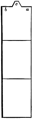
Fig. 1.
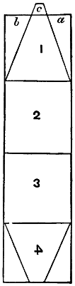
Fig. 2.
After many trials, I came to the conclusion that when using tissue-paper, three sheets pasted narrow edge to narrow edge, eight gussets were enough. Occasionally, however, I would slightly elongate each gusset by attaching one of the little corners a or b, and fixing it at c. Of course the pieces a and b have to be cut away in any case, else the necessary gussets could not be made.
With regard to the exact shape of a finished balloon, always remember that the more nearly globular it is the more gas or air will it hold, and the more stable will be its flight. Assuming you to have pasted end to end three sheets of tissue-paper, with the little bit (c) added to the top part over and above, I recommend you to divide, mentally at least, the three sheets and bit added, rectangle, into four parts. Of these the two middle parts need not be cut or trimmed at all. All the trimming needful can be done on the two end parts. Another thing—do not give any care to bringing the crown, or summit, of the balloon to a point. You will have to paste on what we call a round summit, or crown, at any rate, under which circumstance your bringing all the gussets to one terminal point is of no consequence. In cutting out the gussets, this is best done on the double, which will ensure symmetry.
You will tell me, perhaps, there is a sort of regularity about my preliminary work[484] that does not please the eye. You would like, perhaps, to make a graceful balloon like Fig. 3.
Better not. Do you not see what would happen when you came to set light to the fuel suspended under the mouth of the balloon? The flame would almost certainly strike against the paper of the narrow neck, and presently the whole balloon would be in a blaze.
Having cut out your gussets, the next thing is to join them. First as to cement. Use thin paste or gum water, which you please, and employ a camel-hair, or better, a sable-brush, to spread it. Half an inch lap is quite enough; and when the necessary paper junction has been made, I like to dry my work at once by means of a laundress’s smoothing iron. Taking this precaution, you will have no sticking at spots where sticking ought not to be.
A final word now about the best way of bringing the edges of your gussets together. The line diagram here given will make all comprehensible: a and b represent, we will say, two gussets.
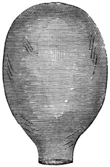 |
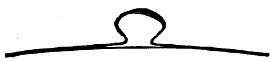 |
| Fig. 5. | |
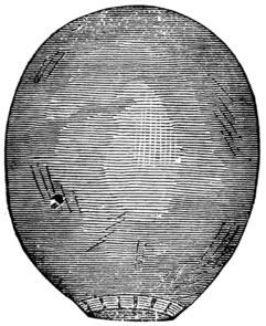 |
|
| Fig. 3. | |
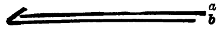 |
|
| Fig. 4. | Fig. 6. |
The edge of a is alone to be gummed or pasted to about half an inch wide; the corresponding edge of b is then to be bent down upon the cemented edge of a, and dried at once with the laundress’s hot iron; not laid naked upon the paper, but having a thickness of flannel interposed. Proceeding thus all round, you will at last finish your balloon all but the crown pieces and mouth stiffener. For a balloon of the dimensions recommended, I would advise you to paste on a crown piece of about a foot diameter. Don’t make it of tissue-paper, but of soft whitey brown paper, and in the middle of it paste a loop of calico, something similar to the loop of a saucepan lid. The utility of this will be found out when you come to let off your balloon.
As a mouth stiffener I prefer a circle of thick iron or brass wire to anything else. About three inches from the balloon-mouth had better be strengthened by a layer of calico, which being gashed or scalloped (Fig. 5), pasted and turned over the wire hoop, makes all firm. As to dimensions of mouth, I consider a circle of eighteen inches’ diameter quite big enough, and boys will please remember that three times and about one-seventh of a diameter makes the circumference of a circle.
Having made your balloon, the next thing to do, as it would seem, is to let it off.
Not exactly. You expect your balloon to lift a weight—fireworks probably—[485]which I will describe how to manage by-and-by. It will be necessary, then, to learn by experiment how much weight it will carry; otherwise, when the time of letting off arrives, you may fail altogether, and be much disappointed.
The weight-carrying experiment must be performed in a room, to avoid air-currents, and, as a preliminary, some sort of car must be attached to the balloon for the purpose of holding the weights. The car may be of various shapes, but as good a shape as any is this:—
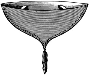
Fig. 7.—CAR.
It may be made out of cardboard, or, if you like, of wire. You need not be particular about any sort of elegance. Fire-balloons are designed to be sent on their travels at night, when any sort of ornament or elegance lavished on the car would not be seen.
The usual flame for heating the air in a paper balloon is spirits of wine. Methylated spirit does very well, and is much cheaper than pure spirits of wine. I do not recommend this source of flame when the balloon comes to be actually let off, as you will by-and-by see; but for our present experiment I do recommend it. You must make a note of the weight of spirits of wine presently to be used, and, if you do not happen to have scales and weights handy, you may take it for granted that a sherry wineglass full weighs about an ounce.
Ascertain, too, how much the car weighs. Probably, when the time comes for letting off the balloon, you will not require the car, so you should have ascertained its weight, that you may supply a weight equivalent, in the shape of fireworks, for example.
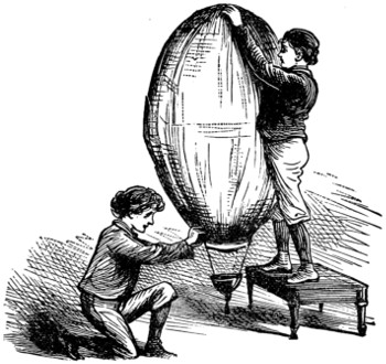
Fig. 8.—CHAMBER TRIAL OF THE BALLOON.
Two boys will be wanted for performance of the chamber experiment; one to stand upon a chair or stool, so as to be able to lift the crown of the balloon, the other to manage the flame department—to do what engineers would call the stoking (Fig. 8).
The spirit, you will remember, is not to be burned loosely, but absorbed by something or other. Sponge is the absorptive medium usually employed, though some operators use cotton wick. On the present occasion of chamber experiment I recommend you to employ sponge. The very coarsest sponge will do as well as the finest and most expensive. Such a piece as most oilmen sell under the name[486] of ‘slate sponge,’ and generally for a penny, will do quite well for the chamber experiment.
Let me now give you boys a piece of advice, and do not consider it of small value. It is of enormous value, being the value of the difference between success and failure. I do not only mean success or failure in the experiment you are about to perform, but any experiment. The advice is this:—Attend well to detail. Before you set about performing any experiment take care that you have provided, and arranged well to hand, everything necessary to the performance of the experiment. Do not say to yourself, this, that, or the other is a trifle, and as a trifle neglect it. In all experimental work, having once determined in your own mind the various things and arrangements necessary, nothing amongst them can be a trifle. Well, to the point. Provide yourself, by loan if your pocket-money does not run so far, with some handfuls of farthings. This little coin will be about the most convenient thing you can use for seeing how much weight your balloon will take up. You are ready. Well, No. 1, as I will call you, lay hold of the crown of the balloon, then jump on a stool or chair, lifting the entire balloon up in such way that the mouth of it may be conveniently disposed for what has to be done by No. 2.
Previous arrangements having been made, it will be well, to avoid accidents, for No. 2 to partially inflate the balloon by a fan. Were this precaution not taken, it might happen that flame driven against the tissue-paper might set it on fire. Those who have not tried the experiment little know what power there is in a fan to set up and keep going a current of air. Sometimes people revive a sluggish fire by hanging a sheet of paper in front of it, but a far better application of the paper is to squeeze it into a rough fan and begin fanning. My attention was first called to this fire-fanning process when, travelling in Andalusia, I wanted some chocolate in a hurry, at a lonely wayside posada. A damsel, fan in hand, lighted a bit of charcoal with a paper spill, laid it on the stove grating, put other charcoal round it, the chocolate-pot over all, and began fanning.
You are now ready to learn how much weight your balloon will carry. You will have attached the car, of course. You will have laid your bit of sponge on the tin pan already attached, and you will have remembered to steady the sponge and keep it from falling out by passing a little iron binding wire over the surface of it, and attaching the wire to the tin pan. All this having been done, you are to pour the spirits of wine upon the sponge and set fire to it. Presently the balloon, becoming charged with hot air, will fill out and rise. When risen, be prepared with your money—farthings. Throw in farthing upon farthing until your balloon not only can carry no more, but comes down. Let it come down, and let the spirit flame burn quite out. Any attempt at blowing it out would probably set the balloon in a blaze.
You have gained now the information required; you have learned what weight, when the serious time of letting off arrives, your balloon will carry. Count the farthings and make a memorandum of their weight. There is no particular mystery in the choice of farthings; they are cheap enough, and they are small enough. Sovereigns and half-sovereigns will do quite well, and if you are sufficiently ‘warm’ in pocket-money, you may employ them instead of farthings, over which they present the advantage of recording the actual weight. A sovereign newly minted[487] weighs one hundred and twenty-three grains and a small fraction; a half-sovereign half that weight. Taking one sovereign with another, you may assume one hundred and twenty-three grains to be the weight of each. Here, by the way, I may mention that, having weighed hundreds of sovereigns for the sake of a lazy experiment, I never yet met with two of exactly the same weight.
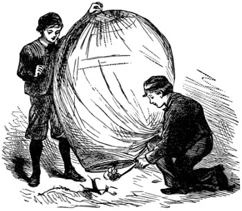
Fig. 9.—LETTING OFF THE BALLOON.
A fire-balloon is a pretty device of itself, but it becomes much better worth looking at when it is made to take up fireworks, so I will now give some instructions about these fireworks. I cannot recommend you to make the fireworks yourselves, but to buy them ready made and arrange them in suitable devices. You will want a few feet of Bickford’s fuse, and the same of quickmatch. Both may be obtained of Messrs. Brock, of Cheapside and the Crystal Palace.
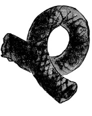
Fig. 10.—BICKFORD’S FUSE.
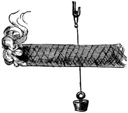
Fig. 11.
Bickford’s fuse is much used by miners for exploding their charges. For this purpose it is invaluable, a given length burning a given time, so that the miner knows exactly what his fuse must be in order to afford him the time necessary for escaping to a safe distance before his charge goes off. It is invaluable to you boy balloonists in another way. The prettiest balloon firework effects are those which are not lighted at the time when you let off your balloon, but which take fire apparently of themselves after the balloon has gained a considerable elevation. Bickford’s fuse enables you to accomplish this in a manner you will soon understand.
Looked at casually, Bickford’s fuse might be taken for a piece of black cord, something in size like this (Fig. 10). The outside is of woven material[488] made waterproof. The middle contains an inflammable wick, burning regularly to time.
If you were to pass through a length of Bickford’s fuse transversely a thread fixed at its upper end, and having a weight attached to the other end, and if then you were to light the fuse at one end, you see what would happen. The fire would creep along until, coming to the thread, it would burn the latter, and the weight would fall. It is many years since I had occasion to work with Bickford’s fuse, so I forget its rapidity of burning. It does not signify; when you have got your fuse you can try an experiment with any convenient length, timing the rapidity of burning by a watch.
Quickmatch consists of a paper tube with a rapidly inflammable wick running through it, the intention being that flame applied to one end of the match shall flash to the other, and instantaneously. The actual fireworks I recommend you to get are some blue-lights, some Roman candles, a few Catherine wheels, crackers, and maroons. The Roman candles you will only require to pick to pieces for the sake of the stars they contain, so if you could get the stars you would not want the candles. Mr. Brock, I think, would supply you with stars of various colours. He uses small pill-boxes for holding the star material.
I have now to explain to you a few fireworks for your balloon.
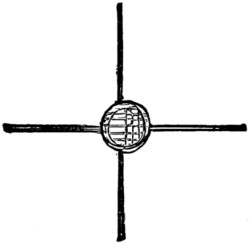
Fig. 12.
1. Fixed piece of blue-lights.—Having selected a cork of suitable size, bore its circumference with as many holes not going to the middle as you design to have blue-lights. Each excavation made will receive the blank end of a blue-light, just as a candlestick receives the end of a candle, so that when finished, supposing you to have used four blue-lights, you will have made something like this (Fig. 12).
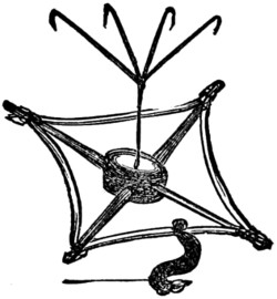
Fig. 13.
On observing the blue-lights which you have purchased, each will be found to have attached to it at the burning end a screw of soft paper, usually blue. This I hardly need tell any English boy is touch-paper, made by saturating soft paper with solution of nitre and drying. Firework cases are usually finished off with touch-paper, so that they may ignite immediately. When you send up such an arrangement of blue-lights as just described, the proposition will be to ignite them all at once with a flash, and after the lapse of a period of time which must be left to your own discretion. Quickmatch spread from end to end of each blue-light, and there secured, either by thread or else a slip of paper pasted loopwise over it, will accomplish the first, and a suitable length of Bickford’s fuse the second. All this is[489] obvious, but a diagram is given (Fig. 13). Hardly necessary is it to tell you that we want no car when using this device. A wire being passed through the middle of the cork hooked at one end, for attachment to hooked cross wires, and bent at the other end so that it shall not slip through the cork, are also obvious matters.
You will observe that I have represented the quickmatch as actually running through the Bickford transversely. This is the surest plan in this and all similar cases, because the walls of the Bickford are so thick that some time must elapse before they burn quite through. Transverse perforation and stretching out of the Bickford can easily be done, the walls of the fuse being very tough. Though my remarks have been directed to blue-lights only, yet obviously the arrangement applies to any other variety of tint.
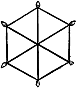
Fig. 14.
2. Dropping firework devices.—Some of the prettiest balloon firework effects are those which do not light until they have separated from the balloon and fallen through a varying distance, according to your arrangement. I shall not expect to find that you think it necessary to inquire how all this may be managed after what I have written about Bickford fuse and quickmatch. However, some few remarks about a certain convenience of arrangement may not come amiss. Suppose, then, that you have launched your balloon carrying several devices—we will assume it to carry six. You want the first of these devices to part company with the balloon, and shortly after ignite in falling, all to time. You want the successive five to part company with the balloon also to time. Obviously a length of Bickford fuse will accomplish all this, but there are inconvenient as well as convenient ways of arranging all. A convenient way is this (Fig. 14).
When I have told you this diagram represents a thing made of wire, and you are so to use it that a fall shall take place at every corner, you will see that all can be managed by Bickford fuse.
Amongst the fireworks that are effective when thus falling are small blue-lights, squibs, crackers, maroons, stars, but more especially catherine wheels. All explosive fireworks give a shock when exploded—maroons a great shock. Never, then, use a balloon-attached firework in such manner as that it shall explode whilst attached to the balloon, the steadiness of which it would certainly affect—perhaps cause a tongue of flame to come in contact with the paper and set it on fire. A wirework arrangement such as our diagram represents is only intended to carry six successive devices, and for the devices that have been noted you will most likely find that about half-a-dozen will make up the total weight your balloon can carry. But there are certain lighter fireworks, of which considerably more than six may be carried; for example, stars. If you take a star and enclose it in a tissue-paper bag, together with a very little—say half a saltspoonful of mealed, or powdered, gunpowder; then, if you tie the mouth of the bag round a short length of quickmatch, you see what must happen when the flame of a Bickford fuse sets the free end of the quickmatch alight. You will rig up the stars with their bags on wire cross-work as already described, but you will arrange that the successive ignitions follow a spiral course, like that of a loosely-coiled watch spring.
I think I have told you as much as can be profitable about the making of fire-balloons, so a few words now about parachutes. People who ascend in the cars of large balloons sometimes vary the display by cutting connection with the balloon[490] itself when at a certain height, and coming down by aid of a parachute. Parachutes used on these occasions are somewhat elaborate things, bearing a general resemblance to an umbrella deprived of its stick and ribs, having a cord attached to the spot where the terminal of each rib, if present, would have been, these cords all converging to join at their lower ends with a car.
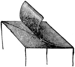
Fig. 15.
The parachute I shall describe for your fire-balloons is a more simple affair, and is made as follows:—Provide yourself with two sheets of soft whitey-brown paper, some twine, and some paste. Lay one sheet flat on a table, and then extend diagonally from corner to corner two lengths of twine which must project at least six inches beyond each corner. It may be wanted to project even more, but in that case each cord terminal may be easily lengthened to the desired extent by tying the necessary additional length of twine to it. Now spread a film of thin paste evenly by a brush over the sheet of paper and twine, and then close the second sheet of paper in exact correspondence with the first, as represented in the diagram.
Be particular, in sticking the two sheets of paper together, to avoid formation of air bubbles. This can only be done by making the pasting together successive and not instantaneous—that is to say, do not lay the second sheet of paper flat down upon the first sheet all at once, but having begun to effect the attachment at any one edge, follow on deliberately to the opposite edge, patting the two sheets well together with a soft pocket-handkerchief.
The way of using such a parachute hardly needs explanation. The projecting lengths of twine having been brought together, are attached to a car, and the whole suspended to your balloon, from which you intend that it shall separate and begin to fall, on your balloon attaining the desired elevation. This detachment can easily be effected by Bickford’s fuse. Here, whilst I think of it, never attempt to ignite a Bickford fuse with anything else than the flame of a port-fire or a blue-light. The chief beauty of any firework device consists in working to exact time. A Bickford fuse cannot readily be set on fire with a match-flame. You may crack many lucifers over the job without succeeding; your balloon, that ought to be off on its travels, all the time kept waiting.
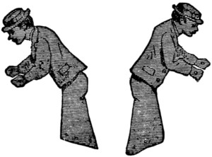
Fig. 16.
What will you put in the car? I shall leave this pretty much to your own taste. Some sort of weight there must be to pull the parachute down. I have heard of some boys who for ornament peopled the car with little figures of comical men, cut out of cardboard. I don’t see myself the sense of it. Fire-balloons are usually let off at night, when the little caricatures would almost need a spyglass to see them even before the balloon set out on its explorations. Balloons once off nobody could see the little men at all. However, do as you like, boys; here are two notions of such caricature men.
Attention! The point up to which you and I have been working is near. We are going to let off the balloon. When we were making our chamber trial, you will remember we used methylated spirit for fuel, absorbing it by a sponge. You may use the same sort of fuel now if you please, but as for myself I much prefer the good flare of cotton lamp-wick saturated with tallow, and sprinkled with either benzoline or turpentine, so that it may burst into flame without delay at the first touch of other flame. Not only does tallow burn with a far brighter light than spirits of wine, but the flame is more lasting. However, boys, I say again—do as you like. So now farewell to fire-balloons. I will now proceed to tell you how to make and fill so-called air-balloons, though gas-balloons would be a name more fitting. They are not of themselves illuminative, as fire-balloons are, but they will take up any fireworks you please, according to their weight-carrying capabilities.
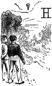
aving got fire-balloons out of hand, I will now have some words with you about air-balloons, usually so called, though ‘gas-balloons’ would be a more appropriate designation. Before describing how to make an air-balloon, suppose we gossip a little about the science of the thing.
Of gases there are many sorts, as you will become aware when a little advanced in your chemistry. Atmospheric air is a mixture of two gases, as probably you know—four measures of nitrogen to one of oxygen, roughly speaking; though were we describing the composition of atmospheric air in an exhaustive manner, we should have to chronicle the presence of numerous other gases besides oxygen and nitrogen, and some vapours; all, however, in quantities so extremely small that we need take no account of them here. Some gases are lighter than atmospheric air, some heavier, but it is evident that those only which are lighter can be employed for ballooning. The very lightest of all gases is hydrogen, which therefore is the very best gas for filling balloons. It is seldom now employed, however, coal-gas being usually substituted, on account of its being ready to hand, so to say, in every place where coal-gas illumination is practised.
Here, perhaps, some young gentleman will wish to inquire why it is I employ the ordinary name, coal-gas, instead of a chemical name. The reply is simple. Coal-gas always means gas from coal, but when I tell my readers that coal-gas has not necessarily always the same composition, although the same coal be used, they will see that no unchanging chemical name for it is applicable. According as the gas retort is heated more or less, so will the resulting gas differ in composition—not a difference as to nature of components, but as to quantity. Coal-gas must always be a combination of carbon with hydrogen, but the amount of carbon to a given amount of hydrogen may vary within wide limits. If coal-gas be required for illuminative purposes, the object of manufacture will be to make it as rich in carbon as possible. Now, the richest gaseous combination of carbon with hydrogen is[492] olefiant gas, but it would be the worst quality of coal-gas for balloon inflation. If olefiant gas be transmitted through a white-hot iron pipe it expands in volume, thus showing what would have happened had it originally been produced in a white-hot iron retort. A gas manager doing duty in one of our seaport towns once told me that he always managed to have expanded gas—we may call it adulterated gas—for night street service. It was good enough, he explained, for drunken sailors, and nobody else was about.
Probably you youngsters will generally use coal-gas for filling your balloons, it being so handy. I would prefer that you did not, but use hydrogen instead, because not only is the making of hydrogen chemically instructive, but a balloon of given size will lift at least half as much again as it would if filled with gas from coal taken as one finds it. Besides, general though the use of coal-gas illumination has become, it may happen that some boy is staying at a country house where coal-gas is not available, for all which reasons I shall begin by giving directions for the production of hydrogen on a sufficiently large scale, and easily.
There are many ways of preparing hydrogen. I shall offer you the choice between two. Both are equally good, and you will discover for yourselves which is the easier under your own special circumstances. No. 1 consists in acting upon zinc or iron—zinc is best—with a mixture of one part of oil of vitriol, measure, and six parts of water, also measure. No. 2 consists in passing steam through a red-hot iron pipe, loosely packed with fragments of iron—say iron nails. If oil of vitriol be available in the out-of-the-way country house where you are assumed to operate, I recommend you to follow plan No. 1. So now about the apparatus. Two large wide-mouthed pickle or preserve bottles, with bungs to match, and a few feet of small leaden gas-pipe, are all that you will require, and you must arrange your apparatus in the following fashion. (Figs. 1 and 2.)
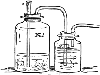
Figs. 1 and 2.
You will here observe that one bottle is represented as larger than the other. We may call it the generator. Into it a good handful of zinc fragments having been put, or in defect of these a handful of small iron nails, and the cork thrust in tight,[493] the mixture of oil of vitriol with water is to be poured down the upright tube at a, which you will observe has been reamed out into a sort of funnel shape by thrusting into it a conical piece of wood. It is worth while here to remark that though a large preserve bottle answers very well as a generator, yet a copper vessel answers much better, the gas development being much faster, on account of a galvanic condition, due to the contact of copper with zinc, and which on this occasion I do not consider necessary to write more about.
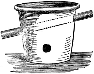
Fig. 3.
As for plan No. 2, the representation of which is annexed, it is much more simple than it looks, as you will gather when I tell you that the furnace part of the apparatus need be no more nor less than a flower-pot having the necessary holes knocked in (Fig. 3). Mind, however, to bind your flower-pot with wire, as it is sure to crack when fuel is first lighted within it. Let it crack as much as ever it pleases, your furnace will be none the worse for present purposes, and that is all you require.
I dare say you have heard of a dear departed lady, much respected in her time, a Mistress Glass. ‘First catch your hare,’ wrote Mistress Glass, when about to give directions for making hare-soup. First catch, or learn how to catch, your gas, say I. By this time you know and can judge for yourself which to use, whether hydrogen pure and simple, or else coal-gas.
Now about making your balloon. The first question is what you shall make it of. Large gas-balloons, such as ascend at public exhibitions with aëronaut travellers, are usually made of silk, covered with some sort of elastic varnish, though the material of very large balloons may be calico, linen, or even canvas. The general statement holds good that in proportion as the balloon is larger so does it admit of being made coarser and heavier. There is a sound mathematical reason for this which any sharp boy ought to perceive, and which, if he do not perceive, I would advise him for his own good to go to his mathematical master and accept castigation.
When the question was how to make a fire-balloon, solution was easy. Tissue-paper, plain and simple, leaves for this purpose nothing to be desired. If a few holes should happen to find themselves in your material, the consequence would not be very serious, inasmuch as the balloon carries its flame, its hot-air generator, along with it; but when you come to have one charge of gas, the gas not renewable, you are obliged to be particular, not merely as to holes, but even loosely packed fibres.
I am entitled to speak magisterially on this point, having recently had some professional talk over the matter with Mr. Brock, the pyrotechnist. ‘Gold-beater’s skin is the very best material for small balloons,’ was that gentleman’s remark to me,[494] ‘but it is very expensive. I want to be able to use paper, and every sort of varnish I have tried has been attended with very indifferent success.’ Mr. Brock went on to say that anybody who might succeed in rendering tissue-paper effectively gas-proof might make a fortune. Now I do not believe in the fortune-making part of the business at all, but I think I shall presently be able to tell you how to make tissue-paper effectively gas-proof. I say effectively, because I know that no varnished silk, cotton, or even canvas material—all used for making balloons—ever is gas-proof. If you fill the thickest ox-bladder you can get with hydrogen or coal-gas, tie the neck of it, and varnish the bladder into the bargain, still gas will come out and atmospheric air will go in. By simply looking at the closed bladder you would not fancy this had happened, because the bladder seems plump and well distended, but were you incautiously to allow a small jet of the contained gas to escape, and to ignite the jet, the whole bladder would explode with a loud report. Now neither hydrogen nor coal-gas will explode when unmixed with oxygen; it simply burns.
Having got the necessary sheets of tissue-paper, hold each of them successively between your eye and a bright light, which will disclose any absolute holes, should such exist. Having discovered them, your first care must be to stop them, and this you do by a plaster of tissue-paper smeared with solution of india-rubber in benzoline. I shall give you no proportions for this solution, but leave you to rule-o’-thumb guidance. Having charged a wide-mouthed bottle—a pickle-bottle does quite well-about half full with benzoline, put into it piece after piece of india-rubber—not vulcanised rubber, mind, which will not dissolve in benzoline, but raw rubber, and keep adding rubber, bit by bit, stirring occasionally with a table knife until you get a paste, not too thick for spreading with a knife-blade. The solution will not be complete for some days. With this, when complete, smear a breadth of tissue-paper, and consider it your plaster.
Remember well the following injunction. In any case when you desire to stick together two surfaces with this india-rubber cement, both surfaces must be smeared, as it does not suffice to smear only one. The next injunction is a very peculiar one, and would not be likely to come self-suggested. Do not bring the surfaces together whilst the solution is wet. Let your work stand until evaporation of the solvent benzoline has left the surfaces what may be called dry. Thus you see the working with this india-rubber paste is the very reverse of working with all ordinary sticking materials.
Repeat the plastering on of solution at least twice, and plaster thick; the result is thin enough when dry. Having in this manner stopped the holes, proceed to make the paper gas-proof. For this purpose you will need a special solution, made in this wise:—To a pint of benzoline add an ounce of solid paraffin—some of a paraffin candle, for example—and a drachm of raw, not vulcanised, rubber. When the two have dissolved, which will require some days’ waiting, lay your tissue-paper on a table, and by means of a flat varnish-brush spread the solution all over it. Wait till evaporation leaves the paper dry, then repeat the operation up to six times, when the paper will have been rendered sufficiently gas-proof for making a balloon. You are to cut this out into fillets, just as you did when making a fire-balloon, and you are to stick the fillets together with the cement already described, remembering well the two injunctions already given. You are[495] not restricted to shape as you are in fire-balloon making, but may adopt any shape, remembering, however, that to promote convenience of gas-collection, the balloon neck should be much narrower than that of a fire-balloon; tubular, so to speak, a tube of one inch diameter being quite sufficient. The reason for making a narrow tubular neck will be apparent from study of the accompanying diagram. It will be evident to you that on account of the narrow neck the mode of car, or weight attachment, cannot be similar to that adopted in the case of fire-balloons. The neatest and, at the same time, most obvious plan of procedure is that adopted in large balloons, by throwing a net, with strings dependent, over the whole balloon, and attaching the car or other weights to the pendent strings. Such elaborate work is, however, quite unnecessary in toy balloons. A length of cord tied round the neck and allowed to hang down affords every necessary facility for further attachment.
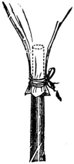
Now as regards what the balloon shall take up, that must be for your own taste to decide. All the resources of pyrotechny are open to you, and by discreet use of Bickford’s fuse and quickmatch you may get innumerable combinations. One of the most brilliant pyrotechnic devices is the ignition of a tuft of magnesium fillet; but it is somewhat expensive, and, if carried out, will make a hole in your pocket-money. All the magnesium balloons I have seen had the magnesium tuft ignited before the balloon was let off; but were it desired that the magnesium should only commence burning when the balloon had got some way upon it, nothing would be more easy. All that is necessary to do would be to wet the magnesium tuft with resin dissolved in benzoline, and then, whilst still wet, dust it over with mealed gunpowder. On drying, this prepared tuft will burst into flame on the slightest provocation. If you do not know how to effect this by judicious employment of Bickford fuse and quickmatch, I shall have written to small purpose.
The following hint is well worthy attention by such of you young gentlemen as are not overburdened with pocket-money. Fine zinc shavings will burn, and emit a bright light something after the style of magnesium, and may be procured at any zinc-worker’s for a mere trifle. A moderately brilliant effect may be got out of a tuft of zinc shavings well dusted with resin and mealed powder whilst made wet with benzoline. If you don’t expect too much out of this zinc-burning expedient, perhaps you will not be disappointed; but at any rate I have not commended the alternative to you very warmly. Of course, a portion of magnesium may be mixed up with the zinc shaving tuft, to the latter’s advantage, just as it has been experimentally proved that flint soup is all the better for a portion of onion and carrot, and better still for a portion of meat, peppered and salted.
Before concluding let me just hint at a very effective possibility in the way of pyrotechnic device, equally applicable to both fire and gas balloons, but which I have never known carried into practice. You will see that it is a main object in balloon pyrotechny to make a balloon carry the greatest amount of pyrotechnic effects using the minimum of weight. Thus, supposing it were desired to cause a succession of explosions, each equalling in noise the discharge of a forty-pounder cannon, large maroons would give such a noise, but no toy balloon would be[496] competent to lift the maroons. Now a mixture of two volumes hydrogen with one of oxygen yields an explosive mixture of tremendous violence. Even a small soap-bubble blown with this mixture and fired is deafening. I have no doubt that an ox bladder filled with this mixture and ignited would make a report equal to that of a forty-pounder gun. Several such bladders might be sent up with a very small toy balloon, and might be detached by means already described, so as to explode whilst falling. The exact modus operandi would be as follows:—Take a blue-light, and with a bradawl make a few transverse holes just above the sealing-wax closure; then smear the closed and transversely perforated end with a paste of mealed powder and water. After drying the neck of the bladder already charged with mixed oxygen and hydrogen, it is to be tightly bound down upon the blue-light, thus—
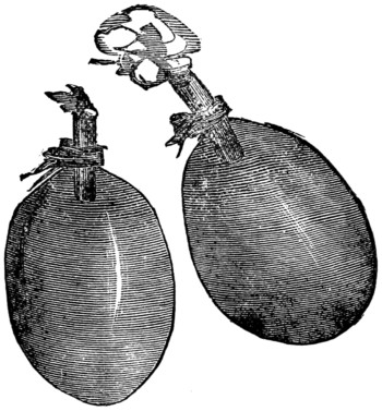
Bickford fuse and quickmatch would easily enable you to achieve the rest, supposing you to have given proper attention to preceding instructions.
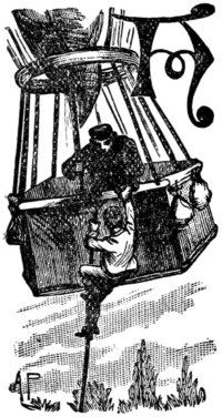
lthough balloon ascents are now matters of everyday occurrence, and scarcely a fête takes place at any of the public gardens without the announcement of an ascent to be conducted by some well-known aëronaut, yet there are very few people who really know anything practical about balloons or their construction, so we often read graphic descriptions of perils surmounted and deeds of heroism performed by aërial travellers, which aëronauts know to be utter impossibilities—such, for instance, as the climbing to the top of a balloon by the network in order to open the valve at the top and allow the gas to escape; not to mention other marvellous fictions invented by the imaginations of ‘sensational’ newspaper reporters.
It is my desire in the present chapter to give the reader a thorough practical knowledge of that truly wonderful machine by means of which man is enabled to rise above his mother earth, and gaze upon her beauties from a height unattainable otherwise. And, as it is first of all necessary to dispel the ignorance which prevails upon the subject, I shall commence by showing what a balloon is not, then I shall proceed to describe what it is, and finally I hope to give such information as shall enable my readers themselves to construct a perfect model of a balloon, such as, if made on a proportionately increased scale, would be capable of carrying into the air one, ten, or twenty people.
That the science of aërial navigation has a strong fascination for adventurous dispositions is a proposition which none will gainsay; and the very danger attending a balloon ascent adds to its pleasurable excitement. This danger, however, is not only, nor even chiefly in the air, but in the descent to the earth, when the greatest caution has to be observed to alight upon a favourable spot: and sometimes consists in the reception accorded to the traveller on his arrival upon terra firma, as the following little adventure will show.
I have been from my childhood a lover of ballooning, having been, I might almost say, born to the business, which was taught me by my godfather, the veteran aëronaut, Charles Green, whose memory is yet held in reverence by many who knew and loved him while he lived. I had frequently been taken by him in his various ascents, and as I grew into man’s estate I was able to be useful to him in his trips. On one occasion an ascent had been announced from what were then known as the Surrey Zoological Gardens. Everything was duly prepared, the balloon was filled with gas, and at the appointed time Mr. Green and I sailed gently into the sky[498] amid the crash of the band and the cheering of the people, which grew fainter and yet more faint, and at last quite inaudible, as we mounted higher and higher towards the azure vault above us.
It was a lovely afternoon in October, and a gentle breeze wafted us slowly away from the mighty city, over green fields wherein the grazing cattle looked rather smaller than ants, over villages whose toiling inhabitants seemed but tiny specks in the universe; until at length a light mist spread itself over the country.
My relative, experienced aëronaut though he was, manifested signs of anxiety as to the safety of our descent; for we had for some time past commenced descending by letting out the gas from the valve at the top of the balloon, but the nearer we approached the earth the denser became the fog, while the shades of evening warned us that the descent was an imperative necessity. Hoping to alight in the open country, we let fall the grapnel, which very speedily caught hold of something which checked our progress. Unluckily this something proved to be a tree, and not the earth, as we had, of course, hoped it would be.
‘Charlie,’ said Mr. Green, ‘there is only one thing to be done, and that is for you to get down and release the grapnel from the tree, and ascertain if you can how far we are from the open, for if the net gets entangled with the boughs we shall be lost, and the balloon spoiled.’
To me, well versed as I was in all kinds of gymnastics, it was a matter of little difficulty to descend the rope which connected us in some way with the earth; so putting another stout cord on my shoulder I went down ‘hand over hand’ until I found myself in a large elm-tree, and as the fog had risen considerably above the earth I was able to make out our whereabouts. We were in the middle of a thickly wooded park, though about two hundred yards to the east, in the direction in which we had drifted, I could see a large open space eminently fitted for the descent. I called out this information, cheerily adding that there was no fear of the net being broken this time. Then I quickly disengaged the grapnel, upon which the balloon sprang up gaily into the air, and next prepared to make my own descent from the tree by means of the cord with which I had provided myself. No sooner had my feet touched the ground than I felt myself roughly seized by two men, who bound my arms behind me in a jiffy, and at once commenced to rate me soundly.
‘Ah!’ said the elder man, savagely, ‘we’ve caught you at last, you rascal, have we? So you’re the chap as steals our governor’s pheasants, is it?’
‘Yes,’ grinned the other, ‘and it’s with a net as you takes ’em, just as I thought! We’ll see what the squire’ll say to you now!’
‘But, my good friends,’ I observed, ‘you have made a mistake. I’m not a poacher, but have just come down from a balloon, and shall be very much obliged to you if you will help me to secure it when it descends again, as it will, away from the trees.’
‘Ha! ha! ha! Ho! ho! ho!’ roared my captors, ‘that won’t do for us, young master. There ain’t no b’loon up that there tree; but what there is there is your pal with the net what you catches the pheasants with; and,’ raising his voice, ‘he may as well come down at once, ‘cos we means nabbing him now we knows where he is.’
Some passing labourers were hailed and stationed round the tree to await the descent of ‘the other poacher,’ while I, whose remonstrances were of no avail, was hurried up to ‘the house,’ wherein sat, on his chair of state, the redoubtable ‘squire,’ to whom the domain belonged, and whose pheasants I was accused of stealing. Again I told the story of the balloon. The old gentleman regarded me with stern dignity, and, wagging his finger at me, solemnly inquired of the keepers (my captors) whether they had seen any balloon. Upon receiving a reply in the negative, he assumed his most magisterial demeanour.
‘Young man,’ he said, ‘it is sad indeed to find a person of education in your unfortunate position. Your tale of having come down in a balloon is as audacious as it is ridiculous. No balloon was seen by my servants, and you were seen to descend a tree, your companion remaining no doubt until the hue and cry should be passed. I have lost many pheasants lately, and there can be no doubt now as to who the culprits have been. I have nothing more to do now than to commit you for to-night to the lock-up, and the case will be investigated in the morning.’
‘But, sir,’ I pleaded, ‘pray send to the field just outside your park, where my friend will doubtless be found by this time with his balloon, which could not be seen by your keepers on account of the fog, but which was then hovering above the tree in which the grapnel had caught, and from which I extricated it.’
Happily for me this request was acceded to, and in due course Mr. Green made his appearance and corroborated my statement, upon which every attention was lavished upon us both. We received an invitation to dinner, and, instead of passing the night in a village cell, I slept on the bed of down of our most jovial and courteous host, who would not hear of our leaving him until we had enjoyed a good night’s rest under his hospitable roof.
But I am in very great danger of forgetting that my present intention is to write a practical treatise, not to prattle about my adventures, so I will set myself seriously to work at once; and will begin by showing in a few words what a balloon is not.
In the first place, a balloon is most certainly not what it is sometimes erroneously called—a flying machine. One might as well compare the gracefulness of a good swimmer with the aimless floating of a dead dog, as to pretend that the helpless drifting of a balloon has anything in common with the as yet only partially accomplished science of aërial flight. What, then, is a balloon, and how is it constructed?
A balloon for carrying passengers consists of a certain number of gores cut in such a form that when they are sewn together they form a perfect sphere, the lower part or neck being elongated, which gives a pear-shaped appearance. This elongation at the neck is made in order to allow the gas to pass freely into the balloon during inflation. On the top is placed a valve, which is a circular double door composed of two semicircles. To each of these semicircular openings is attached a line, which, meeting a little lower down, form one line, which passes through the centre of the balloon, and comes out at the neck; so that when the aëronaut desires to descend he lets out the gas by pulling the line. The doors open inwards, and close themselves by means of springs with which they are fitted.
The balloon itself is composed of very fragile materials. It is merely a gas-holder, and is nowadays almost invariably made of fine cambric well varnished. Silk was the first-used material, but it is a needless expense. Thus it will be seen that the balloon itself has practically no strength in it whatever. All the space, however, and the pressure of the gas, are held in by a netting, which covers the whole of the balloon, to which it is fitted exactly, being shaped from the original pattern gore of the balloon itself—to be fully described hereafter.
Just below the neck of the balloon is a HOOP, to which all the netting lines are fastened. This hoop is made of ash, and is about three feet in diameter, all the strain of the balloon being concentrated at this point.
Below the hoop is attached the CAR, which is a large wicker basket suspended from the hoop by eight cords—technically termed car lines; and fastened to the hoop is a strong rope, generally made of flax, about 100 feet in length, which carries the anchor, or ‘grappling-iron,’ as it is called by aëronauts. This ‘grapnel’ differs in appearance from an ordinary anchor in that it has five prongs instead of only two. Inside the car are placed several canvas bags containing sifted sand, which is used as ballast, to regulate the ascending power of the balloon. The car also contains a few other requisites, notably a ‘liberating iron’ for letting the balloon go when all is reported ready, and an aneroid barometer, to show the altitude attained, &c.
Before entering upon the detailed description of how to make your model balloon, I think it will be well to give some idea of what an ordinary ascent really is, for it is of importance that we should realise what we are about before we proceed to construct the machine which is to carry us from the nether atmosphere into unknown regions miles above the earth, whether the ascent is to be made for scientific purposes or merely for amusement. I do not think there are many living men who can give better instruction on this point than myself, seeing that I have already made no less than eighty-four ascents, while I hope to make as many more before old age and infirmity put a stop to my ballooning career.
Balloons constructed to carry passengers vary very much in size, the smallest being of 18,000 cubic feet capacity, capable of raising two people only—the aëronaut and one passenger. This, or a little larger, is the size of the balloon now generally used, larger balloons being made principally for scientific purposes. Such a one was the celebrated ‘Mammoth,’ supplied by Mr. Coxwell for the memorable investigations by Mr. Glaisher about the year 1863, of which I suppose you may probably have heard, and concerning which it may interest you to learn that on two of their ascents I had the honour of accompanying those famous aëronauts, the ascents taking place on both occasions from the Crystal Palace, and the descents once at Singlewell, near Gravesend, and once near Woking.
The gas with which an ordinary balloon is filled is the gas supplied by the gas companies for street and house lighting, which is called carburetted hydrogen. Pure hydrogen is seldom employed for balloon inflation, though it may be interesting to state that the big captive balloon at the Paris Exhibition was initiated with pure hydrogen, manufactured with sulphuric acid, zinc, and water. This is called sulphuretted hydrogen, and possesses nearly double the lifting power of coal-gas. A balloon held down by a rope requires great ascending power, therefore all captive[501] balloons should be inflated with pure hydrogen. The very great expense of this gas, however, prevents its use in ordinary cases.
The balloon being filled with gas, the aëronaut and his passenger take their seats in the car, ready to ascend. The first thing to be done is to untie the neck of the balloon, which has been fastened up with a piece of string or a handkerchief since the hose-pipe was removed, when the balloon was quite inflated. The object of having the neck of the balloon wide open is this: Directly the balloon rises expansion takes place, owing to the rarefied state of the atmosphere, and the higher it ascends the more rarefied the air becomes, and consequently the less atmospheric pressure is there upon the balloon, the natural result being that the gas expands, and makes its way by degrees out of the neck. If there were no such escape, the balloon would burst. When the neck is wide open, those in the car can see into the middle of the balloon, which has a very curious appearance.
We are now supposed to be ready for starting, there having been placed at the bottom of the car several more bags of ballast than are known to be required. These are handed out, one by one, until the weight in the car is about equal to or a little lighter than the ascending power of the balloon. Then the aëronaut, feeling himself master of the situation, calls out in a loud voice, ‘All hands off!’ At the word of command the assistants, who have been keeping the car down, leave go their hold, and the balloon rises slowly and majestically into the air. (Please now to put yourself into the place of the passenger making his first ascent, with eyes and ears open to take in all the instruction that can be conveyed to him.)
When about fifteen feet in the air the passenger, who has by this time probably worked himself into a somewhat feverish state of excitement, is astonished and considerably alarmed by a sudden jerk or shock, and the equally sudden arrest of the balloon in its upward journey. The fact is that we had not finally left our mother earth, but have been pulled down again by a rope, held by the assistants, which was attached to the hoop by an instrument called the ‘liberating iron.’ The aëronaut himself lets the balloon take its final departure when he touches a lever attached to the liberating iron, and we are being pulled down again on the present occasion because it is found that we have too much ascending power, and can take in another half bag ballast; and the more ballast a balloon can carry the better, as sometimes ballast is found to be worth its weight in gold—or rather, worth as much more as life is worth more than the most precious of all earthly possessions. At the risk of fatiguing you by a digression, I will explain how this is.
The use of ballast is in getting rid of it. When the aëronaut desires to descend he pulls the line I have before described, letting the gas out of the valve at the top, when the balloon immediately comes down. Perhaps unfavourable weather, with a strong wind, may have arisen, and he suddenly sees beneath him a village, or a barn, or perhaps he has been borne out to sea. In any of these cases almost certain death would be the result of a sudden descent. So he throws some ballast out of the car, which immediately lightens it, and the balloon rises up again and carries him over the danger to some place where the descent may be made in safety. If all the ballast be injudiciously or prematurely expended, there is danger indeed in descending; and I know of one instance, at least, in which a daring but unskilful aëronaut was killed, who, in all human probability, would have been now living if he[502] had had with him but one more bag of ballast. So, you see, I do not exaggerate when I say that ballast is sometimes worth much more than its weight in gold.
To return to our ascent. Having taken on board the extra ballast, ‘All hands off!’ is again called out aloud; again we ascend into the air, the band strikes up, the guns are fired, the aëronaut, his hand upon the liberating iron, salutes the public, the rope is detached, and we are off!
And now I will leave my passenger gazing over the side of the car, lost in amazement at the grandeur of the scene beneath him, as the horizon, rising with our ascent, discloses to view an expanse of country of which he could have had no previous conception; for I have work to do. First, I look at the aneroid barometer and find that we have arrived at an altitude of about three thousand feet, which is the height usually attained in an ordinary ascent. The gas has been coming out of the neck very freely, and the balloon is consequently beginning to descend. As we do not intend to land just yet, however, it is necessary to check the descent by parting with a little ballast, which is thrown out over the edge of the car, and has the appearance of smoke as it passes into space.
Now we are about the same weight as the atmosphere with which we are travelling. Although there was only a slight breeze on the surface of the earth, the upper current is considerably stronger, and we are going along with the clouds at a speed of a little less than a mile a minute. Yet, though travelling at this rate, we appear to be in a dead calm, and if a feather be dropped from the car it will sink slowly in a perpendicular line underneath us. When a balloon has left the earth there is no perceptible motion in it whatever. We seem to be stationary, while the fields have the appearance of rushing quickly along beneath us. We are really, as it were, part and parcel of the air, and as the current moves so we drift with it, like a cork on a running stream; and if it were possible to put you blindfold into the car of a balloon, you might be taken up into the clouds and brought down again without your being any the wiser—indeed, without your knowing anything at all about the journey.
This I have been telling you while we have been sailing along through the beautiful summer sky, taking in deep gulps of the pure air, and looking down and around upon the glorious moving panorama. But now I must leave you again to your own resources, for it is time that we should prepare for the descent, and I require to have all my wits about me. The grapnel, which is hooked on to the edge of the car, is lowered down by the rope, which is 100 feet in length, and firmly fastened to the hoop. Now we must exercise judgment and caution in selecting a proper place on which to make our descent by looking along the earth in the direction in which we are travelling. We must not come down among the crops, or we shall have the farmer after us for damages. The trees are particularly dangerous, as we have seen. So are the telegraph wires, for even if they should not destroy us, it would go hard with us in the Law Courts if we were to damage them. An aëronaut must thus have his eyes wide open, and be able to see some miles in front of him; and he must try to make for some open park or pasture land, which he can distinguish from land on which crops are growing by the cattle grazing. So the valve is opened a little, with the immediate effect of causing the balloon to descend to from 1000 to 500 feet above the earth.
Now we pass rapidly over the country until we arrive over the selected spot, when, giving the valve another stout pull, the balloon obeys and drops. Perhaps, on a closer inspection, the place we have chosen is not so favourable as it appeared at a distance; then, of course, we have to part with a bag of ballast, and ascend again until we reach a more suitable alighting ground. The grapnel takes hold at last, and on a calm day the balloon may be brought down as lightly as a feather by the regulating of the ballast; but when there is a strong current of air the grapnel will sometimes trail, which causes the balloon to jerk unpleasantly, but with good management there is no danger.
Having thus taken you up, and brought you safely down again, I will redeem the promise I make in the title by showing you
which, simple as it may seem, is in reality a very intricate operation, and you will find, as you follow me, that there is a great deal to be learned. I do not fancy you will think it at all dull work, however; on the contrary, while it is instructive and scientific, it will afford you many hours’ agreeable and innocent amusement. You have been taught how to make yachts, and have been very delighted, I have no doubt, when your first attempt at shipbuilding has proved successful, and you have seen your ship float upon the water and carry sail; but I do not think there are many readers who have had the opportunity of learning how to make a balloon which will actually hold gas and ascend into the air. Perhaps you will find this latter part of my treatise rather technical, yet I hope you will give it your attention, for I am about to endeavour to let you know more about this subject than has ever been written upon it before; and though I do not expect, or wish, to make you all professional aëronauts, I do certainly desire to awaken in your minds an interest in ballooning—a science which is daily becoming of more recognised importance.
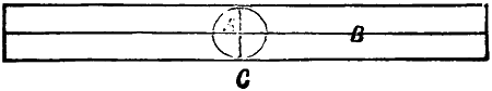
Fig. 1.
In making a balloon the first thing to be done is to take into consideration how many gores, or strips, will be required to form a balloon of any given diameter. For instance, if a balloon be required of the circumference of 3 feet, there will be twelve gores each 18 inches in length (that being half the circumference), and 3 inches in width at the equator, but tapering at each extremity, as will be hereafter described. Now divide the paper of the pattern gore into four equal parts, and then describe a circle in the centre (Fig. 1).
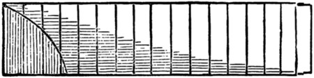
Fig. 2.
Divide one quadrant of the circle into any given number of parts—say seventeen. Then drop perpendiculars parallel with line C from each point of the divisions, intersecting line B in the quadrant. Now divide line B from centre of circle to end of pattern in seventeen equal parts, and raise perpendiculars from each point of division, as in Fig. 2.
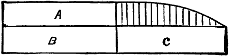
Fig. 3.
Next draw horizontal lines, or measure off with compasses from each point of division in the quadrant, cutting or intersecting the seventeen corresponding lines as shown, and with a free hand, or by the aid of a French curve, connect all these points together, as shown in Fig. 3.
Having now got a quarter of the pattern, it must be cut round, as shown, and transferred to the three other quarters, marked respectively in the figure A, B, C, which will be the pattern for a sphere. This is technically known as striking out a pattern gore by an intersection of lines, and this is quite near enough for the paper balloons, on which you must practise until you are sufficiently advanced in the science to enable you to begin on the proper material. There is another method which is still more accurate, in fact, will ensure absolute mathematical correctness, and that is by a calculation of a series of decimals corresponding with each of the seventeen perpendicular lines shown beneath (Fig. 4).
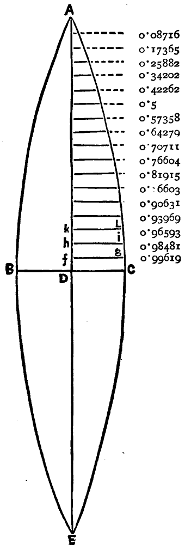
Fig. 4.
Suppose, for example, that the diameter of the balloon to be constructed is 20 ft., and that it is required to make it of 12 pieces; then, in order to draw the pattern for those pieces, find the circumference of the balloon, which is 62·83 ft., and, dividing it by 4, the quotient is 15·7 ft. Make, therefore, A D equal to 15·7 ft., and D E likewise of the same length. Divide the circumference, 62·83 ft., by 24, which is double the number of pieces that are to form the balloon, and the quotient, 2·618 ft., is the length of D C, and likewise of B D, so that B C is equal to 5·236 ft. Then, having divided the line A D into 18 equal parts, and having drawn the parallel lines from those points of division, find the length of each of those lines by multiplying 2·618 by the decimals annexed to that line. Thus 2·618, multiplied by 0·99619, gives 2·608 ft. for the length of f g, and, again multiplying 2·618 by 0·98481, the result gives 2·578 ft. for the length of h i, and so of the rest. In cutting the pieces after such a pattern, care should be taken to leave them about three-quarters of an inch all round wider than the pattern, which will be taken up by the seams; and the same rule must be borne in mind whether you are experimenting upon paper patterns, or upon the[505] materials required for a large balloon. Fig. 4 will illustrate the foregoing instruction, and those who like to take the trouble to prove the sum will take all the more interest in the manufacture of their balloon.
These decimals have been calculated by a mathematician, and are available for any sized balloon.
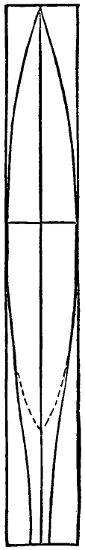
Fig. 5.
Now we come to the neck, the pattern of which may be drawn with a free hand, and maybe left to your own fancy, with this proviso—that the length ought not to exceed more than one-fifth of the whole length of the pattern. In Fig. 5 you will see what the neck should be, the dotted line showing the spherical portion of the pattern gore.
Small gas-balloons are generally made of tissue-paper, varnished over with boiled oil, which gives them a very transparent and skin-like effect. Sometimes gold-beater’s skin is used, but it is very expensive, and paper answers the same purpose. Supposing that you are about to begin upon a paper balloon, the first thing to be done, before making your pattern gore, is of course to select your paper. Ordinary tissue is manufactured from the size of 20 × 30 inches square. There are other sizes made of a stronger quality, suitable for larger balloons than that of three feet circumference, upon which I recommend you to practise, as this is a handy size, while the above-sized paper—obtainable everywhere—cuts in well for the width to make the pattern gore, though, for length, you will have, probably, to paste two sheets together.
When you have a sufficient number of lengths ready for cutting out, place them, one on the top of another, on a flat board; then place the pattern gore on the top, and, with a sharp knife or razor, cut the whole out at once, taking care not to cut the pattern gore. You will do well also to place a few weights on the top to keep the whole lot in place. After you have cut one edge, move your pattern about a quarter of an inch away from the edge that is cut. This is to allow for the ‘lap,’ as it is called, whether in pasting a small balloon or sewing a large one, for bringing the gores together in case you have not made such allowance on the pattern. In pasting together—in the case of paper balloons, or sewing in the case of larger balloons—you should take care, for the sake of effect, to do so in alternate colours. Red and white, yellow and white, green and black, all make effective contrasts, but these minor details may be safely left to your own taste. Paste them, first in pairs, then in fours, &c., in the following manner. Having provided yourself with a large, smooth pasteboard, begin by laying upon it a white gore, and then place carefully over it a coloured one, showing the ‘lap’ on the one underneath to allow for the folding. You can do this by carefully manipulating the gores with the fingers, or, still better, by the means of a palette or any other flat knife. Then, with a ‘dabber,’ as it is technically termed—a clean duster will answer the purpose—press down the overlapping seam the whole length, and immediately hang it up to dry, and proceed to do the same thing with the others, never attempting to paste others together until the first are perfectly secure by drying. A little alum should be put into the paste you are using for the purpose.
When you have pasted all the gores together, and they are quite dry, blow the balloon out with a pair of bellows through the neck. You will find at the top, where all the points of the gores meet, a small hole, which will let out the air with which you have filled your balloon, and à fortiori the gas with which it will have to[506] be filled presently, the gas being lighter than the air, and so more anxious to make its escape from its imprisonment. At all events this is very probable, even in the most carefully and scientifically constructed balloons. To obviate this fatal mistake, therefore, you must cut a round piece of paper, which is called the cap, answering to the valve in a real balloon, and carefully paste it over the meeting-places of the various gores. For you must bear in mind that a balloon is not a balloon at all unless it be perfectly air-tight.
Now let out the air by gentle pressure, and fold up the balloon, gore over gore, and commence the varnishing, which is laid on as thinly as possible with a small piece of flannel. The varnish used is simply boiled oil, which can be obtained from any oil and colour shop. After you have carefully varnished the whole of the gores, blow the balloon out again, and hang it up by the neck until it is dry, a process which will take about twelve hours.
The material used in the construction of balloons for carrying passengers is Scotch cambric—not silk, as is erroneously supposed. Silk has not been largely used in the manufacture of balloons for the last forty years, and I need hardly say that it is not pasted, as in a paper balloon, but sewn with double rows of stitches, and varnished exactly in the same manner as I have already described.
In big balloons, the most important part of all is
And I shall now describe the way in which, if you desire to make your model perfect, you must set about this portion of your manufacture, which, however, you can dispense with if you please in a paper gas-balloon. As I told you before, there is scarcely any strain whatever on the balloon; in fact you could make a large paper balloon to contain 20,000 cubic feet of gas, and if it were covered with a properly fitting net it would, for one ascent, answer the same purpose as a cambric balloon, the reason for making it of a material at once light and strong being to enable it to stand the wear and tear of laying out, folding, packing, &c. The first thing to be observed in making the net of a balloon is to take the same pattern gore as the balloon itself was cut from. Now draw a longitudinal line through the centre A (Fig. 6), the gore being reduced to two halves. Divide one half by the same rule as that on which you originally cut the pattern gore, the object of this division being to get the meshes of the intended netting reduced to such a small scale that four meshes may cover each gore. Measure on the centre line A, the distance B C, and half as long again. Draw a line parallel to B C from D to E.
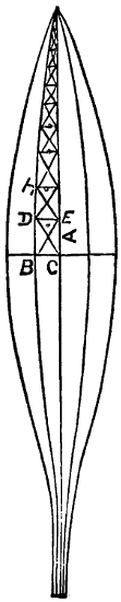
Fig. 6
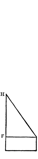
Fig. 7
Now draw a diagonal line from D to C, which will give you an angle of about sixty degrees. Now cut a templet or set square out of card or thin wood, corresponding with angle C B D, thus (Fig. 7).
Now with line F G on the templet corresponding with line D E in Fig. 6, draw E F, and continue this until you come to the crown—i.e. the part where[507] the valve is fixed. Now draw diagonal lines, similar to B E, all the way up (as shown in Fig. 6), which gives the different sizes of the meshes to be used in forming the net from the equator to the pole; and supposing you have decided to have twelve gores to form your balloon, you would then have forty-eight rows of meshes to go round the balloon, and so on, according to the number of gores of which the balloon is composed.
Now for making the netting from the equator to the hoop, concerning which the following instructions are to be observed. The first set, or row, of meshes below the equator are to be of the same length as those at the equator with one-fourth added—i.e. one-quarter longer; the second set, or row, of meshes from the equator are to be one-quarter longer than the last; the third set from the equator to be one-third longer than the second set; the fourth set one-third longer than the third set; the fifth set, or row, is called the drawing line, and is one-third longer than the last. Then come the cords, or leading lines, which are fastened to the hoop, to which the car is attached. This is the true way to make a proper balloon net, and on the same principles you may make the meshes much larger by setting them out three to the gore instead of four—indeed, they are often made in this manner for economy’s sake—and, instead of having a leading line to each row of meshes, two are frequently blended into one. The material to be used should be the best three-strand Italian hemp netting-line, and you must bear in mind that the meshes at the crown should be very fine, increasing in strength as you go downwards.
The last process in connection with this subject is
with which the balloon is to be inflated. It may be well for you to refer to the chapter by Dr. Scoffern, on the apparatus and method of inflating balloons with hydrogen gas, with his illustration of the apparatus; but as I am going more minutely into details, I give you here the quantities of ingredients for generating sufficient gas to fill a given-sized balloon. Thus, for instance—
| Diameter of Balloon. |
Sulphuric Acid. |
Zinc. | Water. | Size of Generator. |
|||||
|---|---|---|---|---|---|---|---|---|---|
| 24 | in. | 24 | oz. | 16 | oz. | 5 | pts. | 4 | qts. |
| 20 | „ | 14 | „ | 10 | „ | 3 | „ | 4 | „ |
| 18 | „ | 10 | „ | 6 | „ | 2 | „ | 5 | pts. |
The zinc and water are put into the generator first and corked down, and connections made with the iron or composite pipe to the purifier, which merely contains water (three parts full), and a small quantity of lime—say, a piece the size of a walnut to a pint of water. Should there be any leakage round the pipe, stop it with loam or clay. Pour the acid into the generator, through the feed-pipe, with a funnel, in small quantities at a time. As the gas passes into the balloon you can[508] tell how quickly it is forming by the bubbling sound which is taking place in the purifier. If you were to pour all the acid into the generator at once, you would burst it. When you hear the bubbling noise diminishing, add more acid.
Now there is another point you must understand—i.e. to be able to find the cubic capacity in feet of a balloon of a given diameter, which is done in the following simple manner:—
Diameter 2 ft. (or 24 in.). Multiply by diameter = 4. Multiply by diameter again, = 8. Now multiply by decimal numbers ·5236 = 4·1888.
The same decimal number will apply to any given diameter, and you see by this rule that a balloon of two feet diameter will contain four cubic feet of gas, and that the quantities of ingredients, &c., required are as given above. I hope you will excuse me for taking you to school again, but I am anxious to make this chapter as complete as possible.
With reference to the cost of the materials to be used in the construction of balloons, it is obviously impossible to enter into details without knowing the size of the balloon to be constructed. The following general instructions, however, may be found useful.
Strong tissue-paper, which measures twenty by thirty inches, costs about sixpence per quire, one quire being amply sufficient for a three-foot balloon.
Scotch cambric, which is forty-four inches wide, costs one shilling and twopence per yard, and you will be able to calculate how many yards are requisite for your purpose.
Boiled oil costs about fourpence per pint, half a pint being sufficient to varnish a three-foot paper balloon.
Tissue-paper can be had of all colours.
With regard to the netting, which is technically known and must be asked for as ‘netting line,’ it varies in size, and costs about two shillings per lb.
With these few remarks I leave you to the construction of your balloon, which I hope you will find an agreeable and not too difficult task.
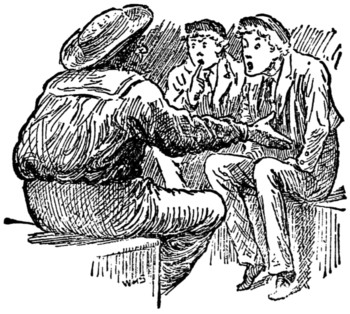
This is a portrait of Billy Baker (Fig. 1). It is not by the famous Flemish artist Van Daub, whose works are to be found in every gallery in Europe, but by his distant relative Von Smudge, whose efforts need only to be known to be equally appreciated. It is understood to be a successful attempt to tell Billy’s character ‘from his handwriting.’ It is not a flattering likeness. We are afraid Von Smudge found that the hand was not in due submission to the will. It, however, shows Billy as having a deal of breadth and very substantial understanding.
Fig. 1.
It is his own fault if he did not ‘come out’ better. All that he had to do was to write his ‘usual signature’ with a thickish pen dipped heavily into the ink, and while it was wet and easily blottable Von Smudge folded the paper so as to divide[510] it in the middle, gave a little pat with his finger where the head ought to be, a rub with his thumb where the arms should come, and an artistic flourish all along the line, and, lo! this was the ‘character’ he produced.
The parents of Billy were much flattered at the result, and, having ‘great faith in the system,’ proceeded to inquire whether their son would do best as a Rapparee or a Nigger corner-man. They were informed, however, that ‘as the handwriting changes the character develops,’ and agreed to wait before deciding, and in the meanwhile let Billy have six lessons from a professional writing master. This was done, and now Billy’s writing, like Billy himself, has no character at all!
Fig. 2.
Martin Jones was another of Von Smudge’s sitters. He also ‘wrote his usual signature,’ and in like manner did ‘the artist’ fold the paper on which it was written and produce the accompanying Napoleonic figure (Fig. 2). As Martin is a fat-faced stunted little fellow with no chance of reaching five feet two, he decided long ago to go in for ‘brain power and command,’ and the Bonapartish portrait is said by him to be ‘characteristic.’ So it is—of Von Smudge.
Fig. 3.
Von Smudge’s theory is, that no matter what name be written, ‘the character will always be that of the writer.’ In an unguarded moment he consented to sign himself as Walter Scott, and this is the ‘character’ that was revealed (Fig. 3). There must be some truth in Von Smudge’s theory, for this is not in the least like Sir Walter, whereas in general Janusfacedness and clumsiness it may be taken as a fit symbol of ‘the artist.’
Fig. 4.
Miss Jenks was persuaded to have her ‘character indicated.’ It was ‘indicated’ with a vengeance (Fig. 4).
She has not called again. Von Smudge says she used too fine a pen. ‘Freedom, perfect freedom, is necessary in the handwriting.’ To which we may add that the thicker the lines, the more the ink, and the harder the paper, the better the result.
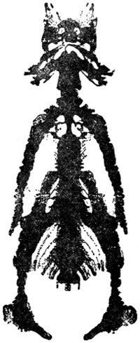
Fig. 5.
One success Von Smudge did have, that in the case of Ellis Ferris, whom he managed to hit off to a nicety—in a caricature, of course. We give the portrait of Ellis in Fig. 5. He is not pleased with it himself, but his friends and enemies assure him it is ‘very like.’ Ellis signed his name with a skewer dipped half an inch in the inkpot, and so gave himself a chance.
Von Smudge has not patented his invention, so that all can try it who care to do so. And it is not a bad amusement for a stray half-hour. The important point is not to be too scratchy in the writing or too careful of the ink.
It is also capable of development. If the paper, instead of being folded in the middle of the signature, be folded above or below it, a duplicate will be produced; if a portrait be drawn and folded down on to the paper while the ink is wet, a reverse copy will be printed off; and if an ornamental design be drawn on paper, it can also be reproduced in reverse by smudgeography, and, owing to the copy taking off the surplus ink and the original being thus reduced to about the same intensity, the pattern will be much more equal in tone than would be thought without trial. All sorts of outline decorative work can be done in this way, and with careful management of the ink the labour of drawing duplicates can be saved.
However, we began this chapter merely with a view of popularising Von Smudge’s new method of character-reading, which does not prosper in his hand quite so much as he expected. In fact, he has taken to saying, ‘There is the idea, let others try if they can make anything out of it.’ And others may as well. They will be just as near the ‘character’ by this means as by any other. It will take them some time to beat the sketch of Ferris the Fierce.
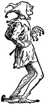
There is a toy more patronised by French boys than by English ones, though I have seen it here. The English name for this toy I do not know, but in France it is called the ‘Ludion.’ Being easily made, and instructive when made, you shall have a picture of the ludion and instructions for making.
Provide yourself with a toilet water-decanter and take care that it has a good wide mouth, the wider in fact the better. Next purchase one of those toy porcelain figures which girls sometimes dress up as miniature dolls, and see that the decanter’s mouth is big enough to admit the figure passing readily through; finally, select a walnut, also not too big for easy entrance into the bottle, and now you may set about making your ludion.
First split the walnut into halves with a knife, taking care you do not impart ragged edges to the two sides of the shell, then scoop out the nut and eat it, and having done so cement the two half-shells together—sealing-wax will do, but shellac is better, and marine glue (a compound of shellac with india-rubber) is best of all. Marine glue can be purchased of tool-makers and others, and it is to be used exactly like sealing-wax, not dissolved in water like ordinary glue. When the two sides of your walnut have cooled and set, you must bore a hole about the diameter of a pigeon’s quill at one end.
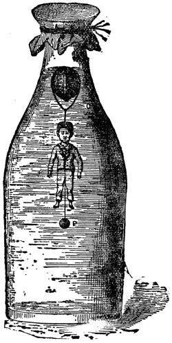
All this being done, pass a loop of fine wire lengthwise over the walnut-shell, taking care that the hole you have bored shall face downwards. From the loop you see that a straight length of wire passes downwards and is then attached to the head of the little figure. The easiest way to effect this attachment is by passing a small loop of the wire round the little man’s neck.
The smaller the wire is you use, by so much the more invisible will it be, and therefore the prettier. If you can get hold of a wire-covered fiddle or guitar string, and from it strip away a suitable length of wire, nothing can be better.
From the neck-loop a straight length of the same wire descends, as you see represented in the picture, and ends by attachment to what our artist has depicted[513] as a leaden bullet, but a weight of any other shape would have done as well, and I should advise you to use a piece of sheet-lead as affording easier means of attachment than does a bullet.
I have said nothing yet about one little matter you will have to see to—namely, some means of steadying and preventing from slipping the loop which passes round the shell lengthwise. This may be effected by sealing-wax, shellac, or marine glue; still, perhaps, better by passing a wire loop transversely round the walnut-shell, thus covering the wire of the first loop and obliging it to lie tight to the shell without shifting.
You had best now get a good large pail of water and regulate the weight of your little man and his belongings. The success of the manufacture altogether depends upon the care and accuracy with which this is done. Immerse the whole apparatus and see what happens. If it sink to the bottom of the pail, your leaden weight is too heavy, and you must cut away a portion—not too much, however, as that would destroy the balance you want to arrive at, and which is necessary to success. No rule other than what is called ‘rule of thumb’ can be set down for your guidance; but care, thought, and attention being given, you are sure to succeed at last.
When the proper weight has been attained, take your little man and his belongings out of the pail, and lower all in the water-bottle about two-thirds full of water, in which henceforth he is to dwell and perform his little gambols. Whether he can do so or not you will soon be in a position to see. Take a piece of thin sheet india-rubber and tie it over the decanter’s mouth, like a drumhead. If, on pressing the drumhead with a finger, your little man descends, bobbing up again when you remove the pressure, by this sign you shall know that the toy is complete. If otherwise, then it is proved that your weight is not heavy enough, so out your little man must come for emendation.
Now, how are you going to correct his balance? The most obvious way of doing so would be to attach a little more weight. That device would look ugly, however, and ugliness is to be avoided in a toy. Do you not see that putting a little water into the nutshell through the hole would effect the purpose? But how to get the water in is the problem; you cannot pour water in from a jug, or even a lipped glass. It might be done by using a syringe, but a far prettier, and at the same time more instructive device, is the one I will now show you. If you are an attentive young fellow, taking note of whatever has been once told you, the little instrument will come finished from your hands in ten minutes after your first setting about making it. If you are an inattentive fellow, I do not care about having anything to do with you. The little instrument about to be described must be made by a blow-pipe operation. This done, you will see how to make a good glass tool of this shape, and about this size:—
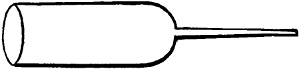
Over the mouth of it you are to stretch and lap with a piece of waxed string a thin film of sheet india-rubber. You want to get some liquid, water in our present case, into this apparatus. Well, dip the fine-drawn hollow spill into a vessel containing water, press the india-rubber drumhead with finger-tip, and air bubbles will come out. Remove the pressure, and water flows in. Removing now the immersed spill, water to any graduated amount can[514] be injected into the walnut by pressure on the drumhead—and, what is more, taken out again if necessary. All this could be done by a syringe, but not so neatly or conveniently.
By exercising the necessary amount of care in adjustment, it would be quite possible to dispense with the leaden-weight attachment to your little man altogether. This is sometimes done, and when done the toy is all the prettier.
Of course, no long explanations are needed to explain the mode of action of the toy. Pressure on the drumhead transfers itself to the air volume inside the bottle; the compressed air in its turn presses upon the water. Now water, unlike air, is inelastic—it cannot be made to occupy smaller space by any force you could apply; so up goes a portion of water temporarily into the walnut-shell, only to come out again on removal of the pressure.
(1) The Balance Puzzle.—Cut a piece of cardboard four inches square. In the middle punch two holes, and punch a hole also in each corner. Take four pieces of thread eight inches long and knot the ends together; then pass one thread through each corner hole of the card and fasten them there by tying a bead to each. Now take another piece of thread eighteen inches long and double it in the middle, then pass the loop down through one of the holes in the middle of the card and up through the other hole, and pass the loop through a small ring. Next pass the ends of the thread through the loop and draw it tight, and fasten the ends to the knot joining the four other threads (Fig. 1). The puzzle is to get the ring off the threads without cutting them.
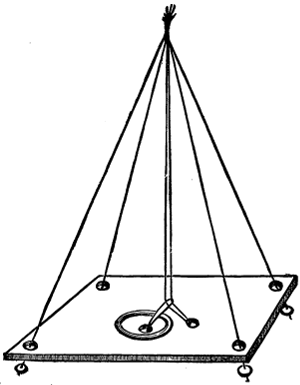
Fig. 1.
Take the loop and pass it down through one of the corner holes under the thread, and pull the bead down through the loop. Do this to each corner, and the loop will now be seen to surround the whole of the threads: pass the loop down over the cardboard, when the ring will come off. To replace the ring reverse the movement.
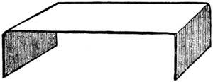
Fig. 2.
(2) The Card Bridge.—Take a visiting-card and bend it as in Fig. 2, so that the parts bent up are half an inch high. Now place this card on a table, resting on the two bent parts. The puzzle is to blow the card bridge right over on to its back. This will not be so easy a job as it appears. The secret is in blowing on the table about six inches in front of the bridge.
(3) The Triangle Puzzle.—Take six pieces of stick about three inches long, and with them form four equilateral triangles, each triangle to have one stick for the side. This is done by placing three sticks in a triangle on the table, and placing a stick at each corner and letting these three sticks come together at the other ends.
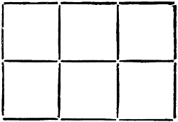
Fig. 3.
(4) The Six Squares Puzzle.—Take seventeen pieces of stick three inches long and arrange them as in Fig. 3. The puzzle is, by taking away five sticks, to leave three perfect squares, and three only, these three squares to be three of those originally formed, and all the same size. To do this take the two sticks from the two top corners and the middle stick at the bottom.
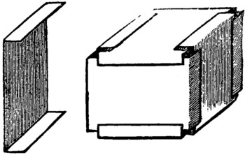
Fig. 4.
(5) The Puzzle Box.—Take six visiting-cards and bend them as in Fig. 4. The puzzle is to put them together in the form of a box, making them fasten each other. The box will bear rough usage. This is done by fitting the cards together as in Fig. 4, when they will be found to fasten each other.
If you make a small hole in one of the sides and get one of your smoking friends to fill the box with smoke, on tapping gently the side opposite to the hole a beautifully perfect ring of smoke will issue from the hole, and you can produce any number you like.
This game is not the same played by Irving Bishop a few years ago when he pretended to read the number of a bank-note held by a gentleman, but is quite as easy. This game was shown me by a friend home from Penang, where it is played a great deal, although not of foreign origin. It is played as follows:—One of the company goes out of the room while those remaining decide on something to be thought of; it may be something in the room or some idea suggested by something in the room. When this is decided upon, the absentee is admitted, and he has to guess what was thought of by asking questions, to which he only receives answer ‘Yes’ or ‘No.’ He may ask any question that will help him. The first question should be, ‘Is it a substance?’ ‘No.’ ‘Is it an abstract idea?’ ‘Yes.’ ‘Is the thing that suggested the idea in the room?’ ‘Yes.’ He should first localise the thing suggesting the idea by dividing the room by imaginary lines in all directions, and asking first if it is on one side, and then if it is on the other, always framing the question in such a manner that it can be answered by ‘Yes’ or ‘No’ as otherwise no answer will be given. The game allows of great ingenuity in selecting the idea[517] and also in working up to it in finding it out. One of the ideas I had to guess once was this—the quantity of silex or flint in the cane of a chair on which I was sitting. And another was this—the curve formed by the head of the hammer when giving the last stroke to a particular nail in the wall. These look difficult, but if properly managed will be found to be guessable. The game improves by practice, as after two or three times you will be able to find out ideas that would at first have appeared impossible.
Among the many wire puzzles which I have seen at different times, I was pleased with one which had two loops. I therefore added a third and subsequently a fourth, and was successful in making the puzzle more interesting. Any boy can easily construct the toy of iron-wire with a pair of pliers from the accompanying illustration.
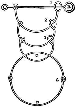
The large ring is 3 inches in diameter, and the bar is 4 inches long. The object is to remove the large ring by pushing it through the smaller ones. The movements are explained by means of the figures and letters written in the diagram. The ring of the bar is called B, the ring of the first loop is 1, that of the second loop is 2, and so on.
The large ring is folded by moving D upwards, so that it falls on C. Then A is pushed from the left to the right through 1, moved over B (that is, B is pushed through between the two wires), and drawn back through 1. Then the ring is folded the other way and pushed through 2 and 1, over B, back through 1, over 1 and B, and back through 2. Then all through 3. Then through 1, over B, back through 1; folded the other way; all through 2; then through 1, over B, and back; and the ring is off.
The ring is put on thus: Fold it, push it half length through 1, over B, back through 1; fold; all through 2; through 1, over B, back; fold all through 3; through 2, over B and 1, through 1, over B, back through 1 and 2, through 1, over B, back, and it is on.
When there is a fourth loop, then the ring is removed thus: Push it through 1, over B, back, fold, through 2 and 1, over B, back over 1 and B, back through 2, through 3 and 2, over B and 1, through 1, over B, back through 1 and 2, through 1, over B, back, over 2 and 1 and B, back through 3, all through 4, through 2, over B and 1, through 1, over B, back through 1 and 2, through 1, over B, back, fold, all through 3, through 1, over B, back, fold, all through 2, through 1, over B, back, off.
The ring is placed on the fourth loop thus: Fold it, push it half-way through 1, over B, back, fold, all through 2, through 1, over B, back, fold, all through 3, through 2, over B and 1, through 1, over B, back through 1 and 2, through 1, over B, back, fold, all through 4, through 3, over B and 1, through 1, over B, back, over 2, through[518] 2 and 1, over B, back, over 1 and B, back through 2 and 3, through 2, over B and 1, through 1, over B, back through 1 and 2, through 1, over B, back, open the ring.
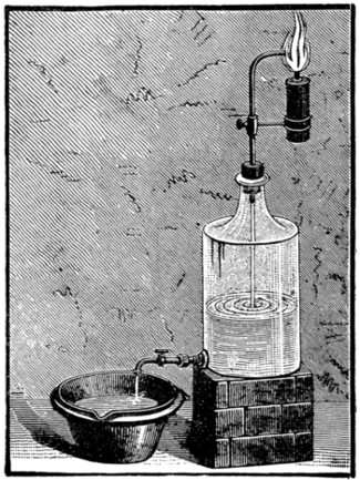 |
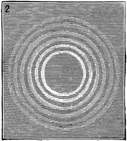 |
| Fig. 2. | |
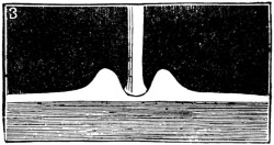 |
|
| Fig. 1. | Fig. 3. |
A few very pretty experiments can be made with smoke rings, and as the apparatus is cheap and easily procurable it may be worth while to say a few words about them. The best arrangement for producing satisfactory results is that shown in Fig. 1, where a glass jar with a tap at the base is resting on a stand. Into the jar and through the cork a small tube is fixed and the whole sealed down, so that all air passing into the jar must come through the tube. The finer the tube the better; the material is of no consequence—it may be of metal, glass, or clay—so long as the passage down it is kept clear. To it, as shown in the cut, a holder is fixed, to which the candle or what not is attached, so that the centre of the tube points fairly into the smoke. The jar is filled with water, the cork fixed down tightly, and the candle lighted. The tap is then turned, and as the water runs out it sucks down the smoke, and the rings will be seen rising through the water and forming on its surface, as shown in Fig. 2. These rings will soon disappear and gradually[519] merge into a sort of collar, shown in Fig. 3, where the central bar is the tube leading up to the source of smoke.
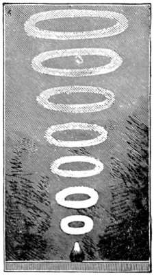
Fig. 4.
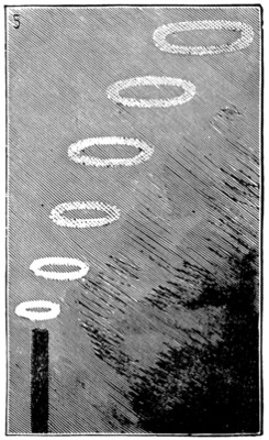
Fig. 5.
There are other ways of producing smoke rings. For instance, rings such as shown in Fig. 4 are produced during the combustion of phosphuretted hydrogen, the white vapours of the phosphoric acid rolling up into the air in apparently whirling crowns. From guns and field-pieces the smoke often emerges in rings, and steam out of a small vertical jet is often shot forth in small circles, such as shown in Fig. 5.
There is, however, a far simpler way of making smoke rings than any we have described, and that is by procuring a cubical cardboard box with a small round opening in two of its opposite faces, filling it with smoke from burning brown paper, and sending the ring into the air by hitting the palm of the hand against one hole so as to eject the smoke wreath at the other. In this way most excellent rings are formed, and if received on a piece of damp glass the rings can be caught and held for a few moments for examination. In a quiet room free from draughts the regularity and duration of the rings will provide a surprise for those who have not tried the experiment.
We are all of us familiar with the ordinary bubble, and we have probably all had a try with a long clay pipe and a basin of suds, and succeeded more or less, principally less, in setting 4-inch balloons afloat over some quiet neighbourhood. It is possible that a few of us have filled such soap balloons with hydrogen, and by applying a light to them have caused an explosion in mid air. But how many of us have tried to attach a car to our bubbles?
This can be done easily after a little practice, and the sketches herewith make clear how to set about it. Get an ounce of glass tube from the nearest druggist, and cut out of thin paper whatever your fancy leads you to fix to the balloon. As something out of the ordinary lines, we give the exact size of an aëronaut we recently despatched on a cruise (Fig. 1). D is a small disc of paper—proper size; F is a fine thread—proper length below it is the paper figure, cut out of the orange wrapper of one of the Boy’s Own Paper monthly parts, and it is traced from the figure we used.
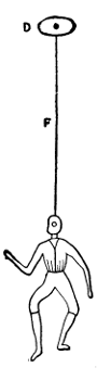
Fig. 1.
Fig. 2.
To make the experiment a success it is as well to remember the conditions. The bubble rises because the air it contains is lighter than that which surrounds it; it floats when the air is of the same temperature, it falls when the air within is colder than the air without. The air in the bubble comes hot from the lungs, and the greater the difference in heat between that air and the air you breathe the higher will the bubble go. In short, to have bubbles in perfection you should blow them in an ice room! As it is not every one that can obtain the use of a meat storage[521] safe for bubble blowing, let us make our first experiment in a cool room. Begin with working up a good stiff lather; and the better the soap the better the suds for our purposes. Use your tube as you would your pipe, and blow downwards into the basin steadily and strongly. Take a good breath of air to begin with, and hold it for a second or two. Keep the point of the tube downwards until you have fixed on the disc in the way shown in the sketch. No gum or stickiness is required: all you have to do is to let the dry disc drop lightly on the wall of the balloon; the moisture will keep it in its place provided the knot of the cotton is small enough. If you pass the cotton through with a needle and have the same sort of single knot as if sewing, the disc will answer all your requirements.
Fig. 3.
As soon as the disc is firmly fixed, turn the tube gently upwards, and away will go the bubble, aëronaut and all. It will not cross the Atlantic, but it will at least reach the ceiling; and if on a cold day you try it out of doors, you may get it to travel unchecked for several hundred yards.
or Fantoccini, are very entertaining when dexterously worked, as they may be by a little practice. Say you have a table with drapery arranged round it to form a little platform, and drapery also at the back. Let the latter be dark in colour, so that the string, thread, or silk, with which you work the dolls, may be less distinguishable if they are so at all.
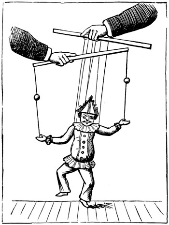
Fig. 1.
The human performer (out of sight) works the figures over the back drapery, moving every joint, and throwing balls about gaily, as in Fig. 1.
When Living Marionettes are introduced—as they sometimes are at public exhibitions—the effects are most comical. On a small stage an ordinary man’s head is apparently attached to a miniature body, and this latter walks, dances, and goes through many antics. The head, too, has eyes ‘in a fine frenzy rolling,’ and is gifted vocally, being able to talk and sing as well as many persons who fill a much larger space in the world.
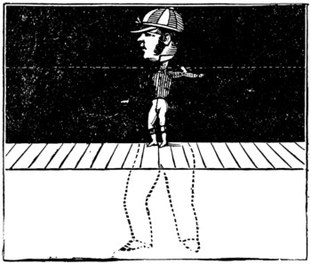
Fig. 2.
This is managed by having two backgrounds, one the height of the performer’s chin, the other—a little farther back—extending to the top of the scene. Both of these are black, and at a little distance the break in them is not distinguishable.[522] The performers walk on a platform at a lower level than the stage, the doll-bodies being fastened beneath their chins, hanging over the front drapery, and the doll’s feet resting on the platform in view of the audience. The performers also carry black curtains attached to them (not perceptible against the similar background), and through these wires, fixed to the arms and legs of the manikins, are pulled to give them motion. (See Fig. 2.) We have also described ‘Living Marionettes’ in another part of this volume.
A good deal of amusement can be had out of a pair of model wrestlers. The way in which the dolls are fitted and worked is sufficiently shown in the accompanying illustration. The legs are in one piece, and the arms are joined so that each doll has only four working parts. The feet are loaded to keep the figures upright on the string, but it is not necessary that this should be done, as they can be kept firmly on the table without. The device is a very old one. Curiously enough, in the Hortus Deliciarum of Herrade de Lansberg, Abbess of Hohenburg—a manuscript over seven hundred years old, now in the Paris Library—a man and woman are represented playing with a couple of figures arranged very much on the same principle, the only difference being that the dolls are separate, and worked with two strings instead of one. The figures are knights in complete armour, with swords[523] and shields. They are hung close together, so that the swords are crossed, and the heels are loaded to keep them upright. The strings are crossed, and held one in each hand by the man and woman. The cross comes between the figures, so that the string that is attached to the waist of one figure is fastened to the knee of the other, and any motion forward is balanced by one backward, and a most realistic encounter can be fought out almost automatically.
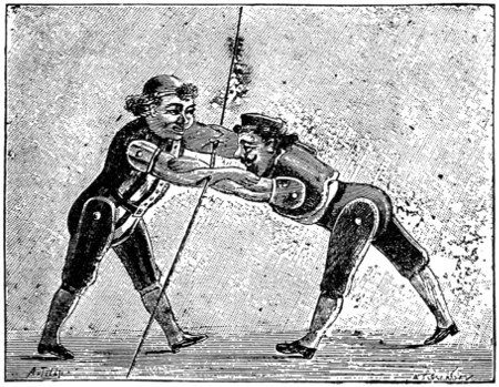
THE WRESTLING DOLLS
With the substitution of thin cap wire for the thread an excellent marionette or shadow show could be easily arranged, it being much easier to work horizontally than vertically in all cases where vigorous action is required to be simulated.
‘The unstable man here commemorated was a native of Cos. I have enlarged a little upon the description in order to introduce to you a figure which, in some respects, resembles him. Here it is. You may easily make one like it. Get a leaden bullet and cut it through the middle with an old knife and a hammer. Then cut out a light figure of cork or pith, and fasten its feet to the flat part of the bullet. Now if you try to make him lie down, you will not succeed. The moment you let go of him he springs up again and remains in an erect position. Why is this?’
‘His heels are heavier than his head.’
‘Yes. The man himself is so light, that nearly all the weight is in the lead; and this being round or half-spherical, when you lay the figure down you set the half-bullet on its edge. By so doing, you raise the centre of gravity; and it will not rest until it has fallen again and is supported.’
‘What is the centre of gravity?’
‘The centre of weight; that point in a body round where all the other parts[525] balance each other. It is not necessarily the centre of the figure, because one part of a figure may be denser and heavier than another; but it is the centre of its weight.’
‘Now take the other half of your bullet, and use it for the head of another figure. This man will be still more eccentric than the Greek, for he will persist in standing upon his head. His brains are evidently the heaviest part of him. The centre of gravity is in his skull, and therefore it will seek the lowest place, and keep it too. So you see what inconveniences a thick-brained, heavy-headed fellow is exposed to.’
‘He is not much worse off, though, than the light-headed Greek.’
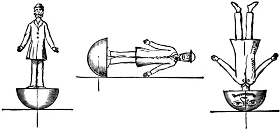
‘I suspect Ælian was quizzing some one who had no force of character, and was easily turned this way or that by anybody who would take the trouble to persuade him: like St. James’s double-minded man, unstable in all his ways, driven by the wind and tossed.’
‘Whereabouts is the centre of gravity in a man?’
‘That would be difficult to say. Somewhere in his body or trunk; for that is, of course, the heaviest part of him.’
‘How could you find it out?’
‘You might get near it by hanging him up in two different positions. Hang him first by his head, and by means of a plumb-line draw a perpendicular from the point of suspension. Then hang him by the shoulder or side, and draw another perpendicular, which, this time, will fall across him. Where these two lines cross each other will be the centre of gravity; and on that point you might balance him, if you were strong enough. I dare say you have seen it done in the streets or at a circus—a man balanced at the end of a long pole.’
‘Yes. And I once saw a donkey balanced at the top of a ladder. It was a very small donkey; but the ladder was rather a long one, and rested on the man’s chin.’
‘The longer the ladder the easier the feat would be; I’ll tell you why presently.’
‘If the centre of gravity is in our body or chest, how do we manage so easily to stand upright? My sister has a wooden doll which won’t stand up at all.’
‘That doll has no muscles in her feet. You have; and even when you are standing still those muscles are constantly at work, controlling the body so as to keep the centre of weight directly above the feet.’
‘I don’t feel them working.’
‘No; you are so used to it. But balance yourself on one foot. Do you feel the muscles now?’
‘Yes; they are constantly at work. Try it, all you boys.’
All the boys tried it; and very comical they looked standing in a row on one leg and swaying about in their efforts to keep the balance. The centre of gravity was in each case supported, though there was not much gravity in their faces. That is not the right place for ‘gravity’ at playtime.
‘Steady!’ cried their teacher, ‘you are swaying about like the unhappy Greek! Why do you throw out your arms, first to one side and then to the other?’
‘To keep the balance, sir.’
‘In other words, that you may bring the centre of gravity over the foot on which you are standing. The centre of gravity moves as your arms move. If you feeling yourself falling towards the left, you throw out your right arm, and that brings the centre of weight more towards the right side. The centre of gravity is but a point; and while you keep that point supported, you may stand upon a point, or upon a rope, or upon anything else. That is how the rope-dancers manage. They usually have a pole, weighted at each end with lead. The man and the pole form, practically, but one body, and have but one centre of gravity; therefore, by moving the pole a very little the performer can easily throw more weight to one side or the other as required, and so bring the centre of gravity directly over the rope.
‘It requires time and practice to become a good rope-dancer; more than it is worth, perhaps. But you can make a good balancer with very little trouble.
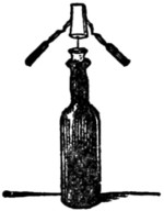
‘Take a common wine-bottle; fit a short cork to it, and stick a needle through the cork, so that the point may project upwards. That must be done before you put the cork into the bottle; otherwise you would have to get into the bottle to do it. The use of the bottle is merely as a stand. I wish the bottle were never put to any worse use than that.
‘Take another cork and stick a long pin through it, so that the point may project half an inch or so downwards, into the sides of this second cork stick two forks in a slanting direction, handles downwards. Now with a little patience you will be able to place the point of the pin upon the point of the needle; and once there, there it will remain balanced, swaying about and perhaps turning round a little, but without falling off. The weight is here in the forks, and the centre of gravity low down, between the two handles. The handles, therefore, being free to move, adjust themselves, so that the centre of gravity is supported, and that is all that is required.’
‘Our Jack was carrying a bucket of water the other day, and the handle came off. The bucket dropped down on one side, and he fell over on the other. What made him fall, sir, when the bucket fell?’
‘Jack was carrying the bucket in his left hand, I suppose, and leaning over to the right, stretching out the right arm to keep the balance. When the weight of the bucket was suddenly removed, the centre of gravity was raised, and thrown at the[527] same time to the opposite side. As long as the heavy bucket formed part of him (as I may say), the centre of gravity was nearer the ground; but when it fell, Jack’s centre was raised, and he overbalanced. The lower the centre of gravity is in any body, the more firmly that body will stand; and the higher it is up, the more likely it will be to topple over. I saw some of you walking on the top of a wall the other day, and you had some difficulty in balancing yourselves. Others crept on their hands and knees; they required no balancing, because their centre of gravity was lowered, and their base of support extended.’
‘Yes, I understand that. But you said just now that a man could be more easily balanced at the top of a long pole than on a short one; or a donkey (with four legs) upon a high ladder more easily than on a lower one. How can that be?’
‘It sounds like a contradiction, but it is true, nevertheless. Try it. Not with a donkey, but with this stick, which has a heavy knob at one end. With the knob downwards, resting on the palm of your hand, you can scarcely balance the stick for a moment; but with the knob upwards there is comparatively little difficulty.’
‘It is so, certainly; but I don’t understand why.’
‘Because in this case the centre of gravity is supported by keeping the hand in a proper position under it. When the weight is at the top of the stick, it has a larger arc to traverse in falling from the perpendicular than if it were lower down, and the person who balances it has a proportionately longer time to move his hand so as to give it the necessary support. In other words, the higher the centre of gravity is, the farther it has to fall, and the more time there is to check it while falling.
‘Do you ever walk on stilts? If so, you will know that it is much easier to keep the balance upon high stilts than on low ones. In some parts of France the people are in the constant habit of walking about on stilts. The elevation enables them to see farther across the level plains, and to observe where their flocks are feeding. If they were to fall they would describe a large arc, and come down with great force, but they do not fall. A very slight movement of the stilt is sufficient to keep it under their centre of gravity. If they were lower down, greater exertion and a swifter movement would be necessary to correct every unsteadiness. Men cannot stand still upon stilts, because there are no muscles at the foot of the stilt to play upon the ground and react upon the body. Observe, then, that when the base is movable, as in balancing a ladder with a donkey on it, or in walking upon stilts, the higher up the weight is the better. But when the base is not movable, the lower down the centre of gravity is, the less risk there will be of an upset. Boats have often been capsized by timid people standing up in a moment of alarm, and so raising the centre of gravity, and coaches by having too great a load of passengers and luggage on the roof, with no “insides.” The great thing is to keep the centre of gravity supported, and then, though it be but a pin’s point resting upon that of a needle, there can be no fall.’
‘Yes; but one can’t always be thinking about one’s centre of gravity.’
‘It is not necessary. Habit or instinct supplies all that is wanted. You balance yourselves from the time you get out of bed in the morning till you go to bed again[528] at night, without ever thinking about it. Only when you stand on one leg, or go into dangerous places, are you conscious of the effort you are making. Your Maker has ordered it thus, that you may guard against accidents, and yet be free from constant care and trouble in doing so. Even the birds are taught to place their heads under their wings when sleeping, so as to render their form more compact and their balance more perfect.
‘Walking has to be acquired in infancy, and until the foot has learnt to use its muscles unconsciously and rightly, the child has many a fall. There are also two ways of walking, a right and a wrong way. Some men sway from side to side as they walk, altering the centre of gravity at every step, and being obliged to straggle their feet accordingly to support it. A well-drilled soldier, on the contrary, keeps his body steady, and uses his legs for the forward movement only. Of course he gets over the ground much faster and with less exertion than the sloucher. Balancing, like everything else, has to be learnt, and, when learnt, is practised without any trouble. There was a man once who had been a cripple from his mother’s womb, and who never had walked. Suddenly the use of his limbs was given him—“his feet and ankle bones received strength.” If that had been all, it might have taken him days or weeks to learn the right use of his muscles; he would not have been able, without much practice, even to stand upright. But the miracle was carried beyond this. St. Peter’s words to the cripple were, “In the name of Jesus Christ of Nazareth, rise up and walk. And he leaping up stood, and entered with them into the temple, walking, and leaping, and praising God.” Not only was strength given him, but skill to use it; he was to “rise and walk,” and was enabled to do so at once.
‘That completeness of cure was intended to teach what the power of the Saviour can do for the soul in all ages, as then for the body. Our strength, and the instinct by which we apply it, come to us gradually, and not by a miracle: but let us think about it sometimes, and be thankful for it all the same.’

This transcription follows the original printed work; inconsistencies in spelling, lay-out, hyphenation, etc. have been retained, except as mentioned below.
Minor differences between the table of contents and the chapter/section headings have been retained; the numbering of sections in the text has been made consistent with the numbering in the table of contents.
Illustrations that are too small to show all detail have been linked to larger illustrations; this is not supported by all formats.
Phrases such as drawn to scale, full size and other similar references to scale are, of course, not applicable to this e-text.
Page 145, ... are about brazing ...: probably an error for are about to braze or are brazing.
Page 196, table, row 8 column 6: the move should be either 11-16 or 12-16. The second digit in the first number is illegible, and has been replaced by a question mark. Columns 3-7 appear to be off by one row, this has not been changed.
Page 418, paragraph The next thing is the glass, ...: A, three and a quarter; B, three and an eighth; C, three and an eighth; D, three and an eighth; E, two and three-quarters should possibly be A, three and a quarter; B, three and an eighth; C, three; D, two and seven-eighths; E, two and three-quarters.
Page 476, “sort of lattice”: the original work shows separate letters/symbols, not the lattice described.
Changes and corrections made to the text:
Illustrations have been moved to where they are explained or fit best
Minor obvious punctuation, formatting and typographical errors have been corrected silently
M.A./m.a. and other degrees and titles standardised to M.A. etc.
Page 47: ... fixed ... changed to ... fixed at ...
Page 79: I. added before heading How to make a Boat ...
Page 94: Stansfield-Hicks changed to Stansfeld-Hicks
Page 139: B B (Fig. 2) changed to B (Fig. 2)
Page 140: ... have to bent ... changed to ... have to be bent ...
Page 141: Fig. 11 rotated 90°
Page 151: Fig. 15 rotated 90°
Page 173: + changed to † as elsewhere (in chess game)
Page 194: (or 26 to 22) moved to previous line
Page 204-207: go-ban notation standardised to, for example, a1
Page 210-211: point references standardised from, for example, A 1 and A1 to A1
Page 211, game: ... the Black’s attack ... changed to ... Black’s attack ...
Page 213: 214,365 changed to 2, 1, 4, 3, 6, 5
Page 223: (see Fig. 5) changed to (see Fig. 4)
Page 261: ... zeotropic pictures ... changed to ... zoetropic pictures ...
Page 342, calendar: border added between columns 04 and 05
Page 347: caption added to Fig. 1
Page 358: captions added to Fig. 3
Page 369: in-line illustrations have been moved to what seemed the best location
Page 483: captions added to Fig. 1 and Fig. 2; ... the little bit (b) ... changed to ... the little bit (c) ...
Page 492: caption added to Fig. 1 and 2
Page 516: F changed to Fig. 3. (caption)
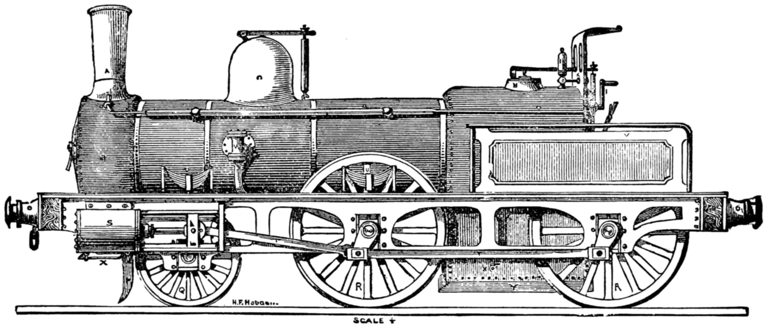
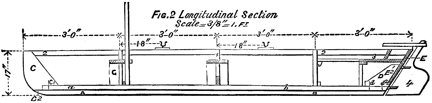
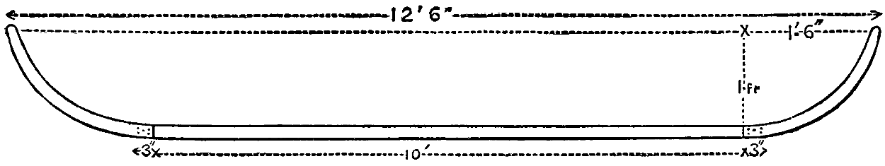
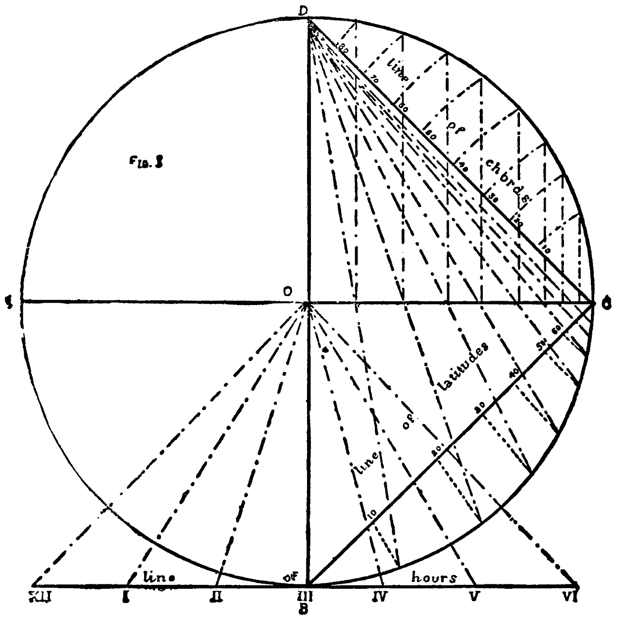
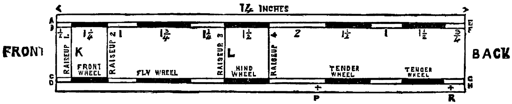