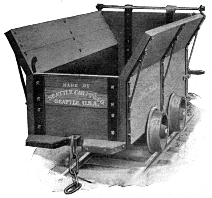
Standard Connected Trucks
(Skeleton Car)
The cover image was created by the transcriber and is placed in the public domain.
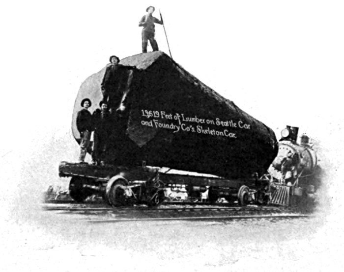
A Record Breaker
Standard Connected Trucks
(Skeleton Car)
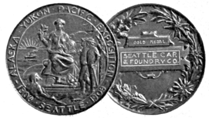
Six awards Alaska-Yukon-Pacific Exposition. Highest award Grand Prize. Logging Flat Cars, Logging Trucks, Patent Steel Bunks
OWNERS OF PATENTS COVERING HERCULES BUNK AND KNIGHT PATENT CHOCK BLOCKS, ETC., ETC.
HOME OFFICES
Seattle, Washington
U. S. A.
| Branches | Works |
|---|---|
| PORTLAND, ORE. | RENTON, WASH. |
| VANCOUVER, B. C. |
Seattle Car & Foundry Co.
FOUNDED 1905
The Seattle Car & Foundry Company was started in 1905 by a few Seattle business men who had faith in the ability of the Pacific Coast to support a home industry of this nature. A steady growth both in scope and quantity of business has confirmed their judgment. Today the Seattle Car & Foundry Company not only competes on an equal footing with the east for the trade of the Pacific, but has extended its field successfully into Alaska, British Columbia, China and all other sections of the Orient. In its commodious, modern and efficient plant it designs and builds Flat Cars, Box Cars, Logging Cars, Logging Trucks, Air-Equipped Connected Trucks, Logging Bunks and Chocks, Gondola Cars, Refrigerator Cars, Plantation Cars and Cane Cars, Caboose Cars, Camp Cars, Industrial Cars, Contractors Dump Cars, Push Cars, Quarry Cars, Track Construction Cars, Tram Cars.
MAIN OFFICES
Alaska Building
Seattle, Washington
| CABLE ADDRESS | WORKS |
|---|---|
| Carco, Seattle | Renton, Wash. |
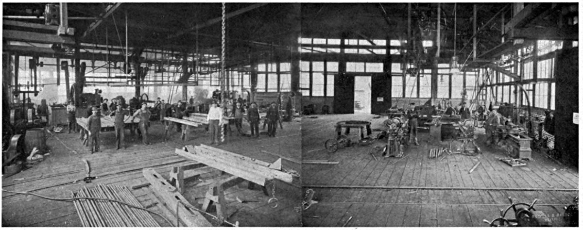
At the present time the works of the Seattle Car & Foundry Co. constitutes the largest and best equipped plant on the Pacific Coast for the manufacture of cars, trucks and contractor's equipment, with which is affiliated a rolling mill, providing us ample material under most favorable conditions.
While the shops are perhaps not so extensive as those of some of our Eastern and European competitors, they are capable of turning out work in sufficient quantities and of a quality to enable us to successfully bid on orders of any proportions.
We have been able to satisfy the most rigid requirements of such trans-continental railroads as the Northern Pacific, Southern Pacific, Chicago, Milwaukee & St. Paul, and the Harriman system, such electric companies as Stone & Webster, the British Columbia Electric Railway and the Portland Light & Power Company, not to mention successful competition in the Orient with the leading firms of Europe.
But in spite of this success we never lose sight of the fact that this plant was started primarily for the better service of the Pacific Coast—particularly of the Pacific Coast logging trade. In this field we claim a special fitness which has been proven, by the growth of our business, in a few years, from a very humble beginning into an organization of considerable industrial significance.
But whether you buy cars, trucks, forgings, castings, contractors, bridge building or mining equipment, we are in a position to give you better delivery than the East, greater capacity than any other coast shops of the same character, and prices that are most reasonable for the service rendered. Our sales and engineering department are at your disposal.
You will get satisfaction in dealing with us. Three quarters of our new business this year was from old customers. Why not get acquainted with them and us? Write them or us.
SEATTLE CAR & FOUNDRY COMPANY,
210-15 ALASKA BUILDING,
SEATTLE, WASH.
For information on further or Special Equipment, Address
Seattle Car & Foundry Company
210-215 Alaska Building
Seattle, Wash.
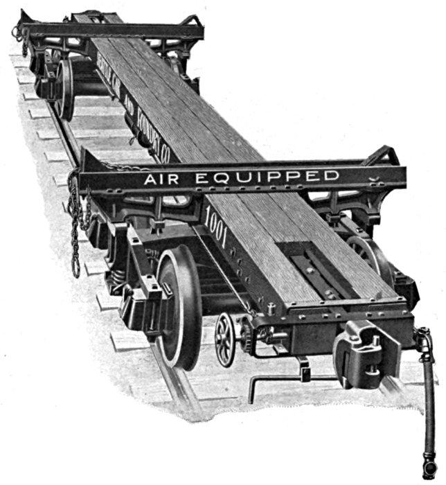
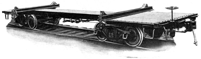
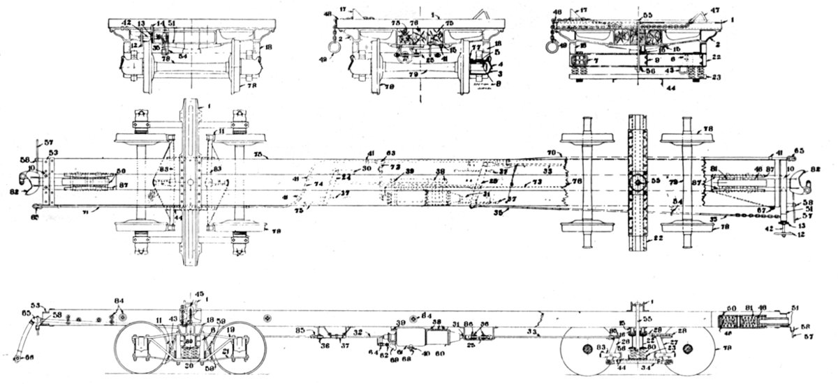
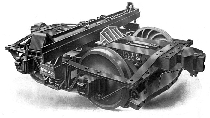
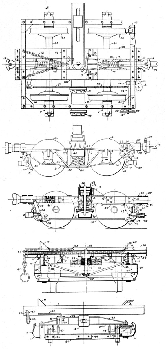
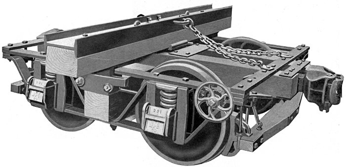
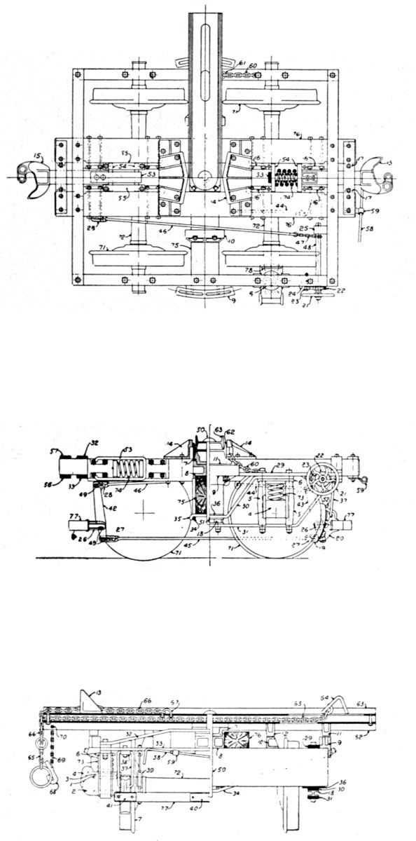
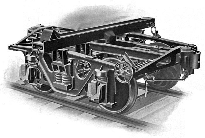
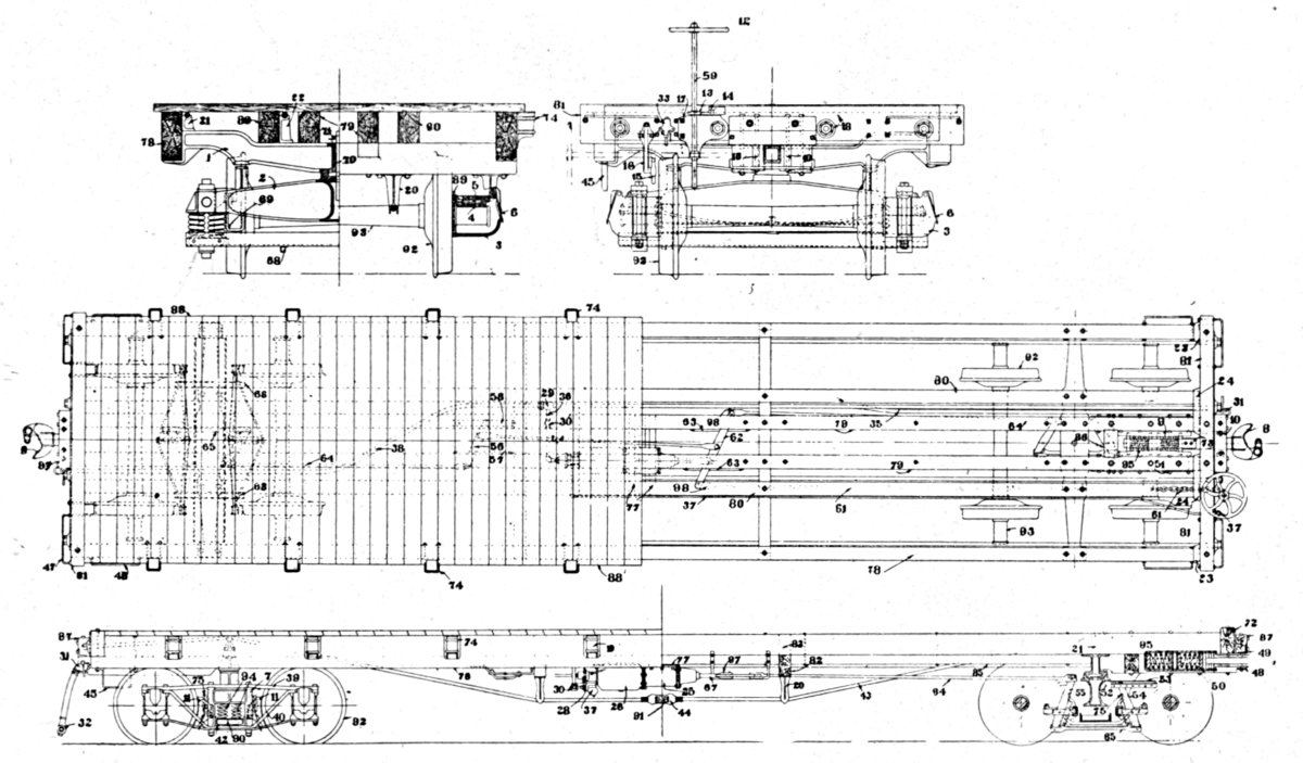
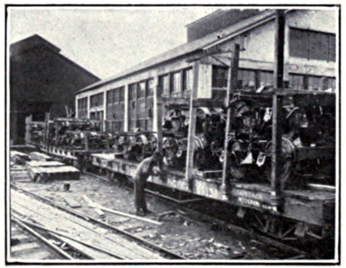
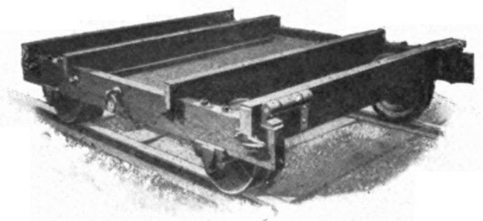
A detailed description of this truck will be found on the following page
This design is protected by U. S. patents
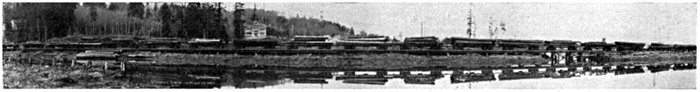
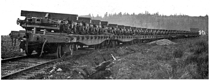
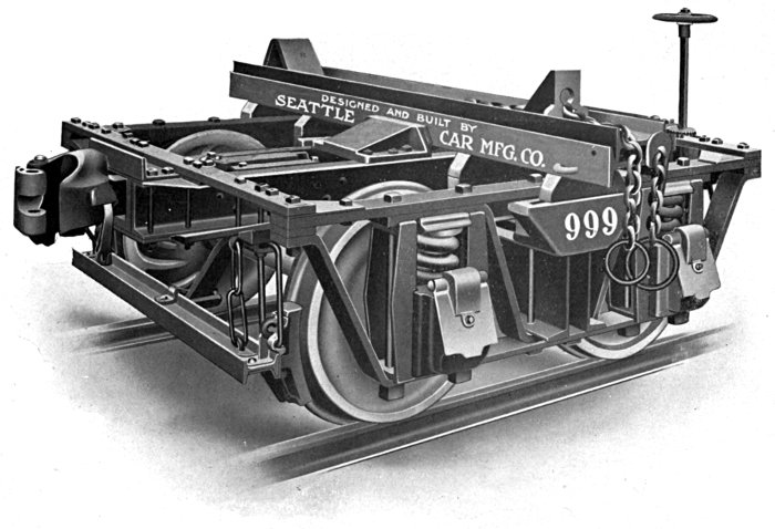
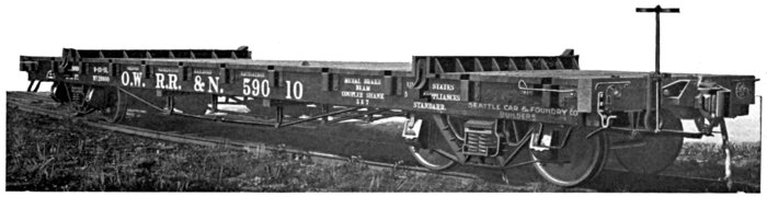
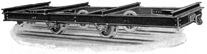
Part of a train of connected trucks operated by Smith-Powers Lumber Co. of Marshfield, Ore.[Pg 9]
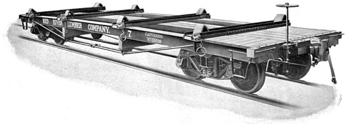
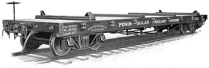
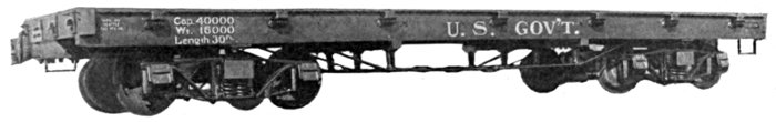
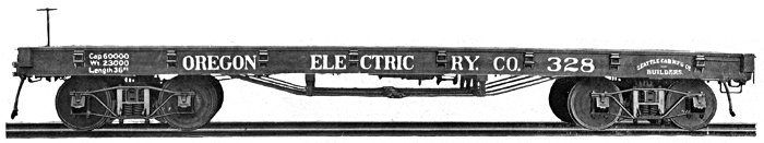
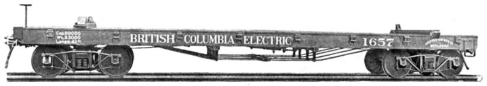
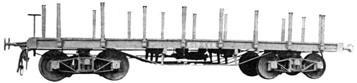
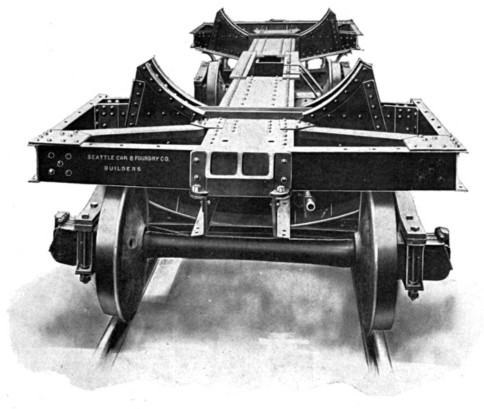
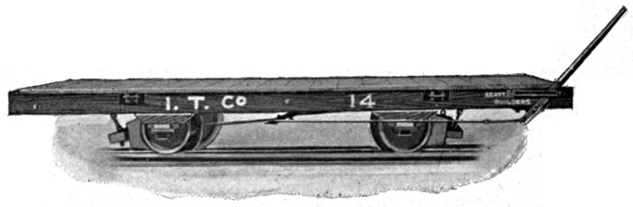
This car was designed with the object of providing heavy capacity Trucks with Air-Brakes, and at the same time reducing the dead weight and maintenance to a minimum. This has become a recognized Standard Logging Car, and as the design permits of considerable latitude in length of car and centers of bunks, we do not hesitate to recommend it to anyone who requires either Flat Cars or Trucks for strictly logging purposes. The convenience of operation as compared with other types of equipment is apparent. From an economic standpoint the comparison is even greater. Some of the advantages are given below in detail:
1st. SIMPLICITY. Few parts to get out of repair, consequently car is always in commission.
2nd. REDUCED COST. First cost is 18% less than Flat Car of same capacity and equipment.
3rd. SMALL COST OF MAINTENANCE. More than 50% less than Flat Car.
4th. SAFETY OF OPERATION. Greatly increased over detached Trucks on account of Air Equipment and rigidity of connection, and over Flat Car in loading and unloading on account of skeleton construction.
5th. REFUSE NOT CARRIED TO DUMP. No deck to accumulate rubbish, adding to dead weight of car, and carrying it to the dump where it is discharged, often necessitating dredging to secure necessary depth of water.
6th. REDUCED DEAD HAUL. Which is 30% less than Flat Car of same capacity and equipment. This is important where heavy grades are encountered.
7th. OPEN DESIGN. Facilitates operation of both loading and unloading, lessening the time required and reducing the danger. At the same time, ample protection is provided for Brake Rigging, eliminating danger of being fouled by falling logs.
8th. INCREASED BUFFING CAPACITY. Connecting timbers forming backbone of 300 sq. in. cross section, which offers great resistance to buffing shocks.
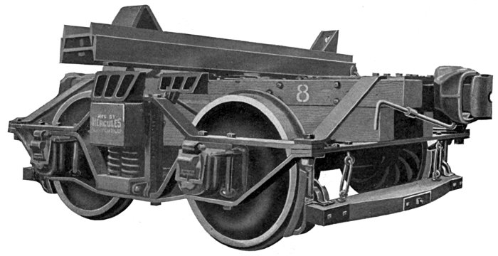
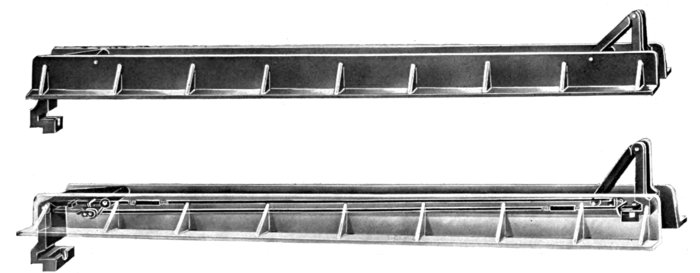
Length over timber, 40 feet, can be furnished up to 56 feet. Length over all, 42 feet. Width over connecting timbers, 30 inches. Height to center of Coupler, 2 feet, 10 inches. Height to top of Bunk, 48 inches. Width of Bunk, optional, 9 feet or 10 feet. Bunk centers in illustration, 24 feet, but is optional with purchaser. M. C. B. Automatic Couplers. Westinghouse Air Brakes. Inside Hung Metal Brake Beams. Standard Diamond Arch Bar Truck Frame. Metal Truck Bolster. Seattle Car Manufacturing Co.'s Patent Cast Steel Body Bolster in combination with Patent Cast Steel Bunks, riveted together, making solid section. Thirty-three inch Cast Iron Wheels, chilled tread, double plate. Steel Axles, 4½ × 8 inch Journals. Malleable Iron and Steel Castings used throughout. Draft Gear optional. (Twin Spring or tandem.) Bunks Cast Steel, Hercules Patent, equipped with Knight Patent Chock, the McLafferty Stake, or the Skookum Bunk. Weight, approximately 19,000 pounds. This Car is protected by U. S. Patents.
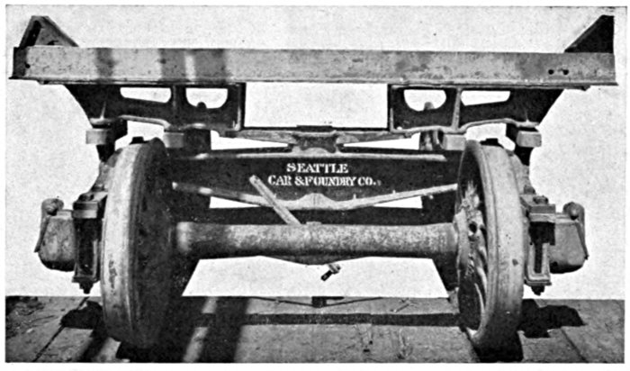
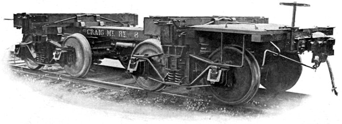
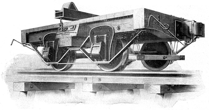
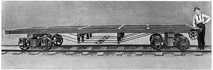
Owing to the original construction of Bunk and Bolster no part of the load is carried on the timber sills
Protected by U. S. Patents
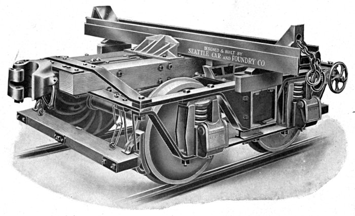
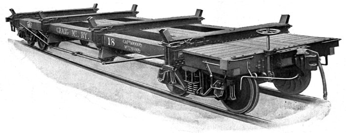
The Most Practical Skeleton Logging Car on the Market. Equipped With U. S. Safety Appliances to Meet Interstate Commerce Commission Requirements.
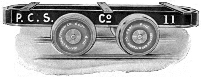
This car has done more to make the name of the Seattle Car & Foundry Co. well known among the logging fraternity than any other single one of our products. We instituted their use on the Pacific Coast. They were designed to avoid many of the obvious disadvantages of flat cars and to add the element of safety to trucks without materially increasing cost.
The letter which follows, pictures better than we could, the reception and experience of the trade, from the view point of the actual operator.
NORTHWEST LUMBER COMPANY
Kerriston Mill
Superintendent's Office
Kerriston, Wash., July 19, 1913
Mr. F. W. Chriswell, Chief Engineer,
Seattle Car & Foundry Co.,
Seattle, Washington
Dear Sir:
Mr. Horton our Secretary has requested me to write you of our experience with the connected logging trucks which we have been using for the last three or four years.
In a general way I might classify this under two heads, construction and operation. Regards to construction of these cars will say, while they are seemingly light, we have found them very strong, and more serviceable in our logging than flat cars which we had previously used and are still using. The air equipment as arranged in these cars is very well protected, and we have experienced practically no trouble whatsoever from breakage. Due to the construction of these cars with their three sills as the only woodwork, we have found the cost of maintenance very little, perhaps due to a certain extent to the accessibility of the parts, which permit of a thorough inspection by simply walking past the car. In operating, we have found these cars exceptionally adapted to the hauling of logs, and during our four years experience do not recall an instance where the load has been spilled due to any fault of the bunk or blocks. Our cars, of which we have twenty-four in operation, are built on twenty-four foot truck centers with nine and ten foot bunks, and during the last year and a half we have lost but one log except through derailment. We find that these cars seemingly ride easier than the seven flat cars which we have in service, permit of a larger load and carry their loads to better advantage. These cars are easily loaded, and it is not uncommon that we haul nine and ten thousand feet to the car. Our loads will average between seven and eight thousand feet per car. All of the trainmen who have worked on these cars, and the loaders in the woods like them very much. The fact that they are easy to load leads the loaders to put on a good load on them and in a careful manner, and in an all around way will consider them very much superior to the flat cars we are using, being seven in number of the standard logging type.
Any further information which I may be able to give you and which you may desire, will be furnished with pleasure upon request.
Very truly yours,
GEO. N. PECK,
General Superintendent
This Letter is Typical of Dozens We Have Received
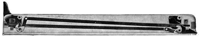
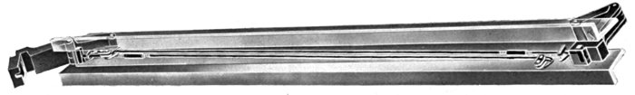
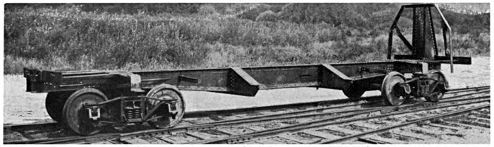
Old Style Standard Skeleton Car with Timber Bunk and Automatic Trip Pockets to Provide for the Use of High Stakes. Equipped With Air.
CASTINGS—
Give pattern number where possible in addition to list number.
FORGINGS—
AIR EQUIPMENT—
LUMBER—
SPECIALTIES—
Business of Making Trucks is one of the Specialties in which we Acknowledge no Superior.
We Build Regular Stock Lines and to Special Requirements.
Speedy Delivery Guaranteed.
Seattle Car and Foundry Co.'s Trucks Are Made for Pacific Coast Conditions.
Over 7000 in Actual Use.
Write to Those Who Have Tried Them.
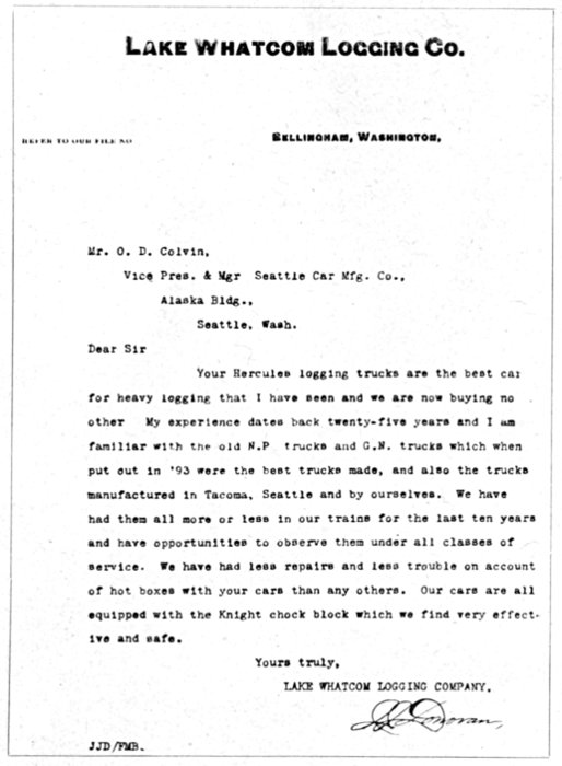
Bellingham, Washington.
REFER TO OUR FILE NO
Mr. O. D. Colvin,
Vice Pres. & Mgr. Seattle Car Mfg. Co.,
Alaska Bldg.,
Seattle, Wash.
Dear Sir
Your Hercules logging trucks are the best car for heavy logging that I have seen and we are now buying no other. My experience dates back twenty-five years and I am familiar with the old N.P. trucks and G.N. trucks which when put out in '93 were the best trucks made, and also the trucks manufactured in Tacoma, Seattle and by ourselves. We have had them all more or less in our trains for the last ten years and have opportunities to observe them under all classes of service. We have had less repairs and less trouble on account of hot boxes with your cars than any others. Our cars are all equipped with the Knight chock block which we find very effective and safe.
Yours truly,
LAKE WHATCOM LOGGING COMPANY.
J J Donovan
JJD/FMB.
This letter is a good example of what practical loggers think of Seattle Car & Foundry Co. trucks and bunks
Our 1914 Truck
Deep-Throat Punch
The Skookum Chief, One-Piece Cast Steel Truck Frame is a radical departure from the old and well known designs and is a distinct step forward. The cast steel frame in locomotive tender construction and passenger car trucks has been widely used and is in favor. The use of cast steel has many advantages. The most economic distribution of metal is made possible, and greatest strength with least weight is the result. In a built-up frame there is always some weak point which is usually where the parts are bolted together. Bolts become loose and nuts are lost. A comparison of the Skookum Chief with any other truck cannot fail to show clearly its advantages in this respect. The Side Frame, End Frame, Draft Beams and Bolster being in ONE PIECE eliminates possibility of weakness where these parts are usually joined by bolts, and the sections of the various parts are so well proportioned that nothing short of a serious wreck could cause failure. The repairman would be almost unnecessary and the Truck would always be in commission, making it possible to handle the business of a camp with one or two sets of trucks less.
Equipment of Skookum Chief
Bunks—Hercules Cast Steel, either 9 or 10 feet.
Chocks—"Knight," "McLafferty," or "Skookum"
Wheels—33 inch Chilled Cast Iron.
Axles—Steel with 5 × 9 Journals.
Couplers—Automatic with bottom unlocking lever.
Brakes—Either Inside or Outside Hung Beams with Hand Wheel at side.
Capacity—The capacity of this truck is limited only by the axles. The frame will carry a 50% overload.
Equipped with Knight Patent Chock Block and Cast Steel Bolster
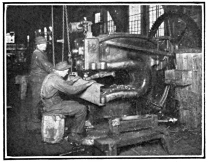
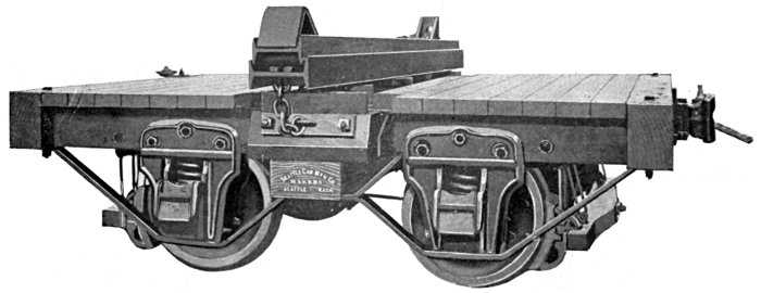
Heavy Bar Shear
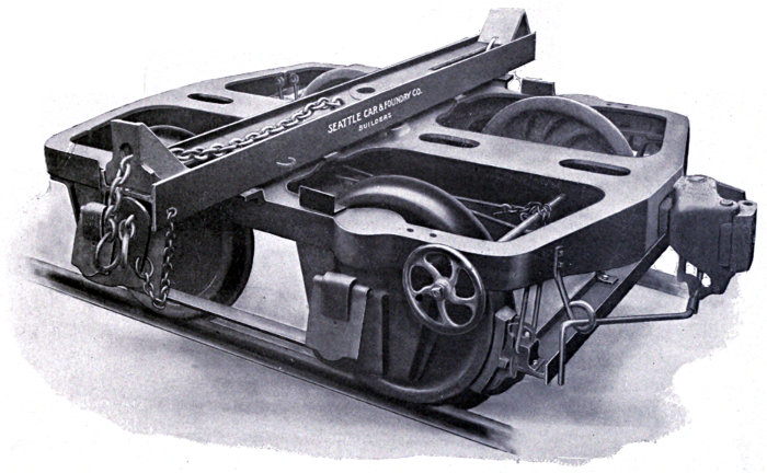
This is a steel frame truck, with cast steel bolster and bunk brace, and is here shown with structural bunk, but may be equipped with cast steel bunk of either the Hercules, McLafferty or Skookum patent, and also with steel draft beams, making an all steel truck.
33-inch Chilled Cast Iron Wheels and Steel Axles, with 4½ × 8 inch Journals. Height from rail to center of Drawbar, 25½ inches, and to top of Bunk, 40½ inches. Length over Draft Beams, 9 feet, 6 inches.
Automatic Couplers with Bottom Unlocking Attachments. Brake Shoes applied to all Wheels, with hand wheel at side or hand lever at end. Weight, approximately 18,000 pounds per set.
Equipped with Knight Patent Chock Block
Designed for heavy service and has proved its efficiency in handling the long, heavy timbers of the Northwest.
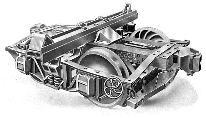
Our Standard Class A Truck Number 122, as shown in cut, is equipped with Hercules Patent Bunk, 9 feet long, and Knight Patent Chock Block. At purchaser's option can furnish our Patent Cast Steel Bunk, in either 9 or 10-foot lengths, of Hercules, McLafferty or Skookum Patent.
33-inch Chilled Cast Iron Wheels and Axles with 4½ × 8-inch Journals. 28 or 24-inch wheels are optional.
Height from Rail to center of Drawbar, 2 feet, 1½ inches. Height from top of Rail to top of Bunk, 3 feet, 4½ inches. Length over Couplers, 12 feet.
Automatic Couplers with Side-Unlocking Lever and M. C. B. Standard Draft Spring. Cast Iron Link and Pin Drawbar can be substituted.
Brake Shoes applied to all wheels with hand wheels at side or hand lever at end.
Truck Frame is the Rigid Diamond Arch Bar type with Steel Channel Spring Plank.
Bolsters of Red Fir heavily trussed.
Weight approximately 17,000 pounds per set.
The above Bunk and Chock Blocks are covered by U. S. and Canadian Patents and are manufactured exclusively by Seattle Car & Foundry Co., Seattle, U. S. A.
To Couple with Standard Railway Equipment
This cut shows our Class G-2 Truck, No. 125, which is equipped with Hercules Patent Bunk 9 feet long and Knight Patent Chock Block.
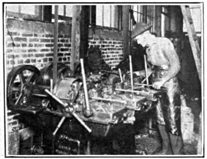
Multiple Boring Mill
33-inch Chilled Cast Iron Wheels and Axles with 4½ × 8 inch Journals.
Height from top of Rail to top of Bunk, 4 feet.
Automatic Couplers with Side Unlocking Lever and M. C. B. Standard Draft Springs.
Brake Shoes applied to all wheels with hand wheel at side or lever at end.
Truck Frame is the Rigid Diamond Arch Bar Type with Springs under Bolster and Steel Channel Spring Plank.
Extra heavy Bolster of Red Fir, heavily trussed.
Special Equipment may be same as our Class A-2 Hercules Truck.
Length over all, 12 feet, 0 inches. Weight approximately 18,000 pounds per set.
Castings—
FORGINGS—
SPECIALTIES—
LUMBER—
Brakebeams, Inside or Outside Hung, Optional with Purchaser
Awarded Grand Prize at A. Y. P. Exposition
To meet the demand for Trucks of heavier capacity, we are building All-Steel Trucks, which are fully illustrated in the cuts. This design is the result of a careful study of the prevailing practice in the large and up-to-date camps of the Northwest, with the aim of combining simplicity and strength with a minimum dead load. This Truck has been altered slightly to include all the latest improvements in logging truck construction, and was awarded the Grand Prize at the A. Y. P. Exposition.
Wheels, 33-inch Chilled Cast Iron, fitted on M. C. B. Standard Axles with 9 × 5-inch Journals. Automatic Couplers and Twin-Spring Draft Gear with M. C. B. Double-Coil Draft Spring. If desired, Link and Pin Drawbars can be substituted, as our pattern is interchangeable with Automatic Coupler. Journal Boxes are M. C. B. Standard. Bolster Steel Channels reinforced with Steel Cover Plates top and bottom. Draft Sills Steel Channels with Malleable Iron Draft Lugs riveted to same. Bolster and Draft Sills are securely tied together and braced with Steel Plates. Truck Frame of extra heavy Iron Bars, braced at corners with Gusset Plates, making it impossible for the frame to get out of square. Bunks, Hercules Patent with Knight Patent Chock. Bunks are equipped with metal brace as shown in illustration. Castings are of either Steel or Malleable Iron. Brake Shoes are applied to all Wheels and Brake Beams, either inside or outside hung, at purchaser's option. Brake Shaft can be furnished to operate with lever at end or wheel at side. Weight of 100,000-pound capacity Truck, 22,000 pounds. Weight of 80,000-pound capacity Truck, 20,000 pounds. Height to center of Coupler, 2 feet, 6 in., or 2 feet, 9 in. Length over Draft Sills, 9 ft. Length over all, 12 ft.
With Steel Bolster and Double I-Beam Hercules Bunk
Universal Milling Machine
This illustrates our 80,000-pound capacity Snohomish Truck, with all Metal Frame and Bolster, but with Fir Draft Timbers. This truck is designed to couple with standard equipment, with a height of 2 feet, 10 inches to center of coupler and 4 feet, 0 inches to top of bunk. The Bolster is built up of two heavy Steel Channels reinforced with steel cover plates top and bottom securely riveted to channels. The Truck is equipped with Hercules Bunk and Knight Chock and is also fitted with Metal Bunk Brace.
The same general remarks apply to this truck as to Snohomish Truck No. 123. The frame is of heavy iron bars and the fir draft timbers have a sectional area of 144 square inches, which offers great resistance to buffing shocks.
Weight per set trucks, of 20,400 pounds.
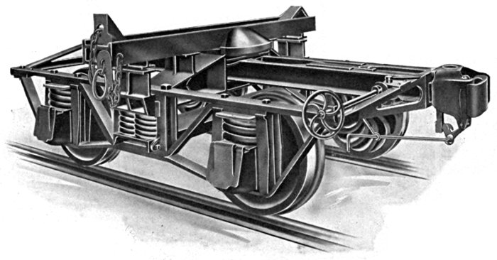
Without Chock Blocks
This truck is especially adapted to use on Logging Railroads, where an uneven track demands a flexible running gear and an extremely strong frame. These requirements are carried out in this design by placing the springs over the Journal Boxes and making the frame of extra heavy Iron Bars. The simplicity of the design also appeals to the operators, making it necessary to carry but few extra parts for repairs.
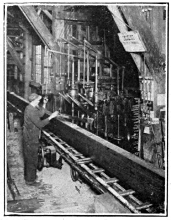
Arch Bar Gang
Bunk shown is made of straight grain Red Fir, reinforced with special heavy 12-inch I-Beam closely fitted on timber, but we recommend our Hercules Patent Bunk equipped with Knight Patent Chock, McLafferty Stake or Skookum Chock.
Either Automatic Couplers or Link and Pin Drawbars may be used, as our Link and Pin Drawbar is designed to be interchangeable with Automatic Coupler, the change being easily made at any time. Bolsters extra heavy Red Fir, strongly trussed. Draft Timbers, Red Fir. Draft Gear M. C. B. Standard with M. C. B. double coil Draft Springs. Truck springs, 70,000 lbs. capacity, heavy double coil.
Wheels 33-inch Chilled Cast Iron fitted on M. C. B. Axles with 4½ × 8 inch Journals. Cast Iron Journal Boxes with self-closing lids. Cast Iron Columns of heavy pattern. Brake Shoes applied to all wheels with hand wheel at side. Any style of Brake Shaft can be furnished.
When required the Truck is decked over between wheels and draft timbers and extending from end to end.
Length over all, 12 feet. Weight approximately, 18,000 pounds per set.
CASTINGS—
FORGINGS—
SPECIALTIES—
LUMBER—
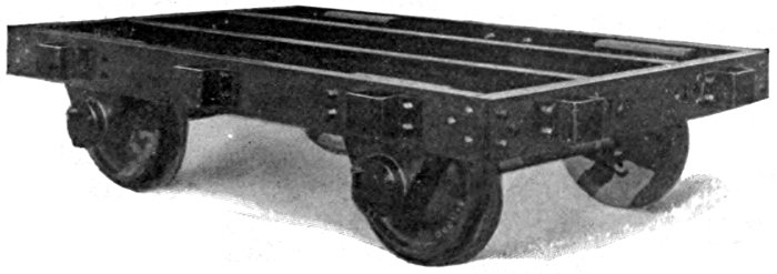
With Cast Steel Pedestals
This Wood Frame Truck has been improved by the substitution of Cast Steel Pedestals in place of Cast Iron, and has eliminated the possibility of failure in this part, which has heretofore been the weak spot in this type of Logging Truck.
Hydraulic Wheel Press
Automatic Couplers and Standard Draft Springs have also been applied, and this together with the Cast Steel Bunk places this truck easily in the lead of all wood frame trucks.
28-inch Chilled Cast Iron wheels are used to keep a low center of gravity which is quite essential.
Steel Axles with 4½ × 8 Journals.
Brake Shoes applied to all wheels with hand wheels at side or hand lever at end.
Any type of Bunk and Chock made by us may be used on this truck.
With Hercules Bunk and Knight Chock
This design is adapted to camps where repairs to wood frames are more readily made than forged parts, there being few forgings used. All timber used in the construction of these trucks is straight-grain Red Fir.
Molding Machine
Wheels, 24, 28 or 33-inch Cast Iron, Double Plate Chilled Tread.
Axles, Steel with M. C. B. Standard Journals.
Heavy Cast Iron Pedestals with Double Coil Pedestal Springs.
Oil Boxes fitted with either Hewitt Self-Closing or M. C. B. top hung lids.
Hand Brake with Wood Brake Beams.
Couplers, Cast Iron Link and Pin. Spring Drawbar one end and Solid Drawbar at other end.
Equipped with our Hercules Patent Steel Bunk and Knight Patent Chock, McLafferty Stake or Skookum Chock.
Weight in 70,000-pounds capacity, approximately 16,000 lbs. per set. Height, 2 feet, 6½ inches to center of Draw Bar, with 28-inch wheels. Height, 3 feet, 11 inches to Top of Bunk.
"Rainier" Logging Truck
Capacity 100,000 Pounds
We are the first builders of Logging Equipment to depart from the practice of the last twenty years and produce a Logging Truck designed along practical and economic lines. Modern railroading has developed the "Cast Steel" Engine Frame, Tender Frame and Passenger Truck Frame. Wherever safety is required together with lightness and durability, Cast Steel has been introduced.
Following this modern plan we have constructed the "Rainier" All Cast Steel Truck of eight pieces where ordinarily several hundred are used.
Each Side Frame is in one piece taking the place of Top Arch Bar, Inverted Arch Bar, Tie Bar, Heel Brace, Truck Columns, and the many Bolts used to hold these parts together.
Each End Frame is in one piece taking the place of Top End Bar, Bottom End Bar, Striking Plate, Carry Iron, Corner Gussets, Brake Staff Brackets, and the numerous Bolts necessary to tie these parts together.
The Draft Beams are each in one piece, taking the place of Draft Timber, Draft Lugs, and the Bolts required to anchor them.
The use of Cast Steel permits of the most economic distribution of the metal, and the "Rainier" Truck is an example of what can be accomplished.
The Bolster and Bunk are similar to those used in the Hercules Trucks.
Springs are located under the Bolster to absorb shocks which would otherwise be transferred directly to the Truck Frame. The Springs over the Journal Boxes provide additional protection from shocks and also permit the wheels to hold the rails on an uneven track or at low joints.
Brake Beams are hung between the wheels and kept high enough to protect them in case of derailment.
The equipment includes Automatic Couplers to Couple with Standard Equipment, 33 inches above rail, and 33 inch Chilled Cast Iron Wheels fitted on Steel Axles with 5 × 9 inch Journals.
Journal Boxes are Malleable Iron. No Cast Iron is used with the exception of Brake Shoes.
The Center Bearing of the Bunk and Bolster is so constructed that the Bunk cannot turn over under load when train is started or stopped suddenly, as the Bunk cannot be removed from the Truck until it is turned parallel to the Draft Beams. The "Rainier" Truck stands for safety first.
All-Steel Improved "Rainier" Truck
Capacity 100,000 lbs.
Designed and built exclusively by
The Seattle Car & Foundry Company
This truck is similar to the one shown on the preceding page. It differs only in having the side frames cast in one piece, thus reducing the number of parts and increasing the strength of the truck, a practice originated by us, on logging trucks and which is being widely adapted by leading railroads on standard equipment.
This truck is designed for extreme conditions where the timber is very large and is taken out in long lengths and where load at times will total from 40 to 60 tons.
From the fact that Cast Steel is substituted for structural design the expense of repair parts is practically eliminated while the factor of safety is sufficient to meet all demands unless cars meet with a wreck.
Attention is called to the method of holding the bunk in place by means of a bunk bracket which clamps in position on the half turn. The bunk is prevented from slipping out of position by Bunk Stops which can be seen on the side frames.
This truck is designed for extreme strength and rigidity. It is certain to become one of our most popular types. Both structurally and in appearance it is a high-grade product.
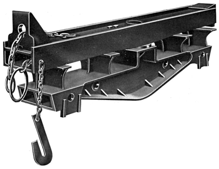
Quadruple Bunk Skeleton Logging Car
Capacity 80,000 lbs.
Designed and built exclusively by
The Seattle Car & Foundry Company
The efficiency of this car is a simple mathematical problem. Compare this 4-Bunk Car with a Flat Car with four bunks of the same capacity and note the saving. The percentage of dead weight to log capacity is 30% as compared to 36¼% for the flat car or a car cost per thousand feet logs of $78.50 as compared to $93.50 for flat car. This means a saving of 20% on the haul back of empty cars and nearly 20% in first cost.
Where a large percentage of logs from 12 to 20 feet are handled, this Quadruple Bunk car has a great advantage over any other type. The construction is such that the entire load can be carried safely on the two center Bunks. Logs in length from 12 to 41 feet can be carried with equal facility.
Details are as follows:
Westinghouse Air Brake, Automatic Couplers, Tandem Spring Draft Rig, Two Main Sills 10 × 10 in., forty feet.
The Bunks are arranged to dump the load on either side.
Two Side Sills 10 × 10 in. extending from Bolster to Bolster. Each Side Sill is trussed with two 1½ in. rods. Two intermediate bunks are located directly over cross ties. Bunks are 10 feet long equipped with Knight chocks.
Bolsters are built up of Structural and Cast Steel of ample capacity to carry load.
Trucks are Standard Arch Bar type with 4½ × 8 in. Journals. 33 inch chilled tread double-plate, Griffin wheels. Structural Steel Bolsters and spring plank. All metal Brake Beams inside hung.
This car is equipped with all necessary steps and handles and meets the requirements of the Inter-State Commerce Commission and the U. S. safety appliance laws.
Quadruple Bunk Skeleton Logging Car
Capacity 80,000 lbs.
Designed and built exclusively by
The Seattle Car & Foundry Company
This car is similar in construction to the Red River Car shown on preceding page and differs only in two important details, the first point of difference being the Bunks. These Bunks are built up of Structural Steel and are equipped with trip stakes. The stakes are released or tripped from the safety side of car. The other difference is that there is a 10 × 10 in. center sill between the two main sills which extends from draft rig to draft rig.
Where short length logs are handled four bunks must be provided in order to permit of thirty and forty ton loads. This car meets these conditions perfectly. Small cars of twenty and twenty-five ton capacity are not heavy enough for economical and careful handling in heavy trains.
The same efficiency applies in the handling of logs as compared with standard flat cars as the percentage shown on opposite page.
For details see the description of the "Red River" car on the opposite page.
Cast Steel "Rainier" Bunk
With Non-Buckling Compression Bars
(GENERAL VIEW)
(SECTIONAL VIEW)
This is a Cast Steel Bunk equipped with Cast Steel Chocks held in upright position by means of a lock together with a locking bar extending to the opposite end of Bunk. This bar, instead of being in direct compression as is the case of other Bunks of this type, has the compression stress reduced two thirds by means of the lock. The chock when once tripped can not rebound into position and lock which is a frequent occurrence in certain Bunks now on the market.
This bunk is absolutely Fool-Proof.
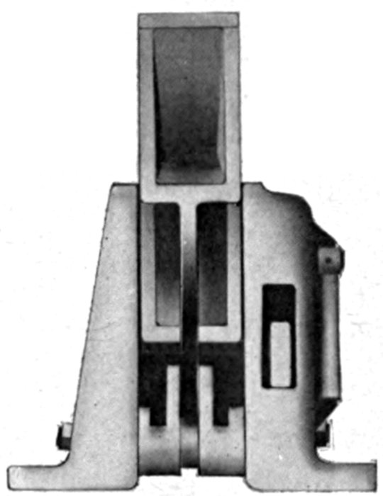
(END VIEW)
The reduction of the strain on the compression rods completely eliminates all possibility of buckling or binding, while the positive locking device does away completely with all danger of bad spills from falling logs.
The "Rainier" Bunk is made of high grade Cast Steel and is a picture of massive strength. It is as positive in its operation and as simply perfect in its mechanical construction as the automatic coupler. It facilitates and expedites the handling of logs, assuring a saving of at least ten cents a thousand and eliminates all possibility of danger to the operator.
(PATENTED)
Can be applied to any type of Logging Truck or Flat Car. Indestructible in service. No repairs. Weight approximately 1300 lbs.
The Chock Block attachment is simple in construction, easily adjusted and quick and positive in operation.
When Chock Blocks are in position against logs and grab hook applied, the load is secure.
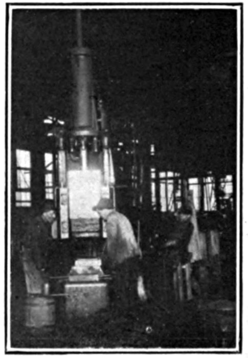
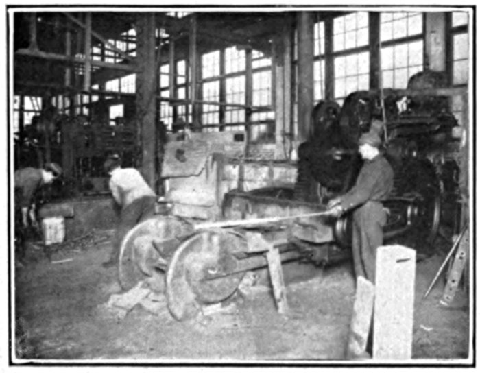
Steam Hammer
To unload, the grab hook is removed and the movement of the log slides chock block over end of bunk as illustrated in figure. The chock block on opposite end is readily adjusted to the position desired.
The men are never required to get on the unloading side of car. In flat car service the cost of all wooden stakes and blocks is eliminated, a saving alone in one year more than the cost of the Hercules Bunks.
Flat Cars can be unloaded in a fraction of the time, with absolutely no danger to employees, and the strain on car body reduced to a minimum, thereby increasing the life of the car.
When applied to flat cars a steel channel is substituted for the I-beam.
It is especially adapted for use on our Connected Trucks, and patents have been granted covering its application to this class of car.
This invention is thoroughly protected by patents in the United States and Canada and is manufactured exclusively by
Seattle Car & Foundry Company
SEATTLE, U. S. A.
Interchangeable with Hercules Double I-Beam Bunk
(PATENTED)
Bolt Threader
This illustrates one of the improvements in our Hercules Bunk, and some of the advantages are herein set forth.
Strength is more than doubled; there is no record of a failure of this Cast Steel Bunk.
Will not deflect under greatest load. Consequently there is always side bearing clearance, and danger of derailment from this cause is eliminated.
Ends are alike so that Chocks may be arranged to operate from either side.
Interchangeable with "Hercules" double I-Beam Bunk.
These Cast Steel Bunks are made for both Logging Trucks and Flat Cars. The weight of this Bunk for Logging Trucks in 9 foot length is 600 pounds each, and in 10 foot length is 675 pounds each. For Flat Cars the weight is 525 pounds each. This invention is protected by Patents in the United States and Canada, and is controlled by the
Seattle Car & Foundry Co.
SEATTLE, U. S. A.
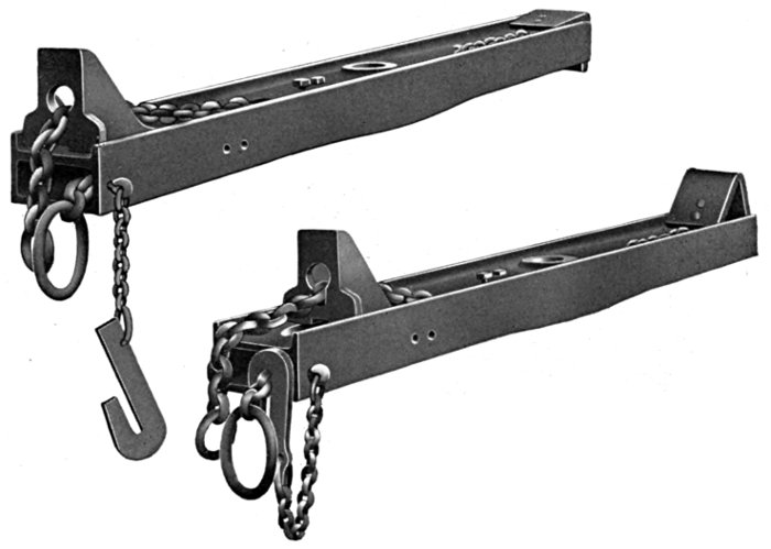
Hercules Bunk and Bolster
For 80,000 Pounds Capacity Trucks
(PATENTED)
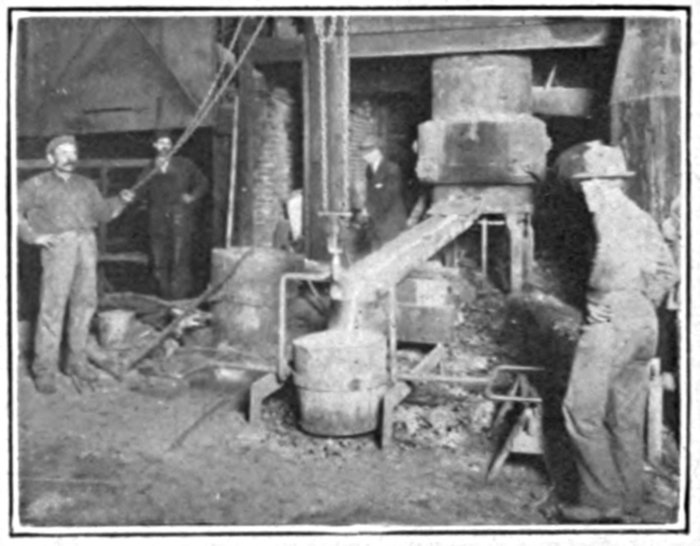
Taking off a Heat
The illustration shows the Cast Steel Bolster and Bunk, with which we equip our 80,000 pounds capacity Hercules Trucks, making practically an all steel truck, and when an all steel truck is required this is accomplished by the application of Steel Draft Sills. This Bolster and Bunk is designed with a great factor of safety and there is no record of a failure of this equipment in service. The Bunks or Bolster will not deflect, which means that there is always clearance between the side bearings which greatly reduces the danger of derailment on a curve.
This Bunk can be furnished in either 9 or 10 foot length. The weight of this Bolster with 9 foot Bunk is 1250 pounds, and with 10 foot Bunk is 1300 pounds.
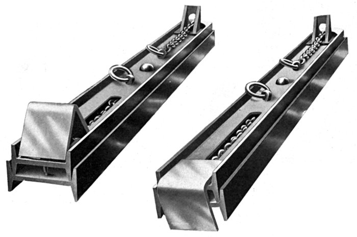
Our 1914 Bunk
For 80,000 Pounds Capacity Trucks
Phantom Illustration of the Skookum Bunk Showing the Lock
The Skookum Bunk Viewed from Underneath
This Bunk provides the desirable combination of a Cast Steel Body with a disappearing Chock secured by a Tension Locking Bar. Practical experiment and engineering skill have developed this Bunk to provide "Safety First" in handling the minimum load as prescribed by the railways. Where an adjustable Chock is not required the "Skookum" will prove its superiority on account of its Cast Steel Body, which is similar to our well known Hercules Cast Steel Bunk. It has also the upward projecting flanges to prevent the shifting of the load, and the hollow channel for the protection of the locking mechanism. This type has been copied by designers of all modern Bunks since our first model was introduced five years ago, and this fact is evidence of the merit of the design.
The offset foot of the upright leg of the Chock resting upon the sloping floor of the Bunk makes it easily held in position but impossible to prevent its disappearing when released. Unlocking the Chock is simple and easy and there are no sliding surfaces to wear away. The locking bar is held by a center crank and locks on the dead center. The recess in the heel of the Chock engages the T-head of the locking bar and makes a positive lock. The Chock locks automatically when brought to position. The locking bar is provided with a take-up to provide a means of overcoming trouble incident to wear or stretch of the parts, and always maintain a perfect adjustment.
Years of experience on the Pacific Coast have taught us to meet conditions peculiar to this locality. Our low logging flats have become standard among the trade. Being located in the heart of the best timber producing section of this continent our opportunities for selecting the finest sills and decking are unsurpassed. Wherever flats can be used to advantage for any purpose, our designing and construction departments are at your service to render valuable suggestions and adaptations to your needs. Our repair and rebuilding departments being close at hand are available to increase the length of life and service of your flats.
| Length over End Sills | 42 feet, | 0 inches |
| Width over Side Sills | 8 feet, | 8 inches |
| Height from Rail to Top of Deck | 3 feet, | 6½ inches |
This car is specially designed for heavy logging service with six Red Fir Sills and four 1½ inch Truss Rods. Body Bolsters, cast steel. Truck Bolsters, cast steel. Buffing Iron, cast steel. The truck frames are of cast steel instead of the usual arch bar type. Couplers are provided with a swinging carrier casting to allow side travel to the coupler and bring the coupler to the center by gravity. Uncoupling device is the Carmer patent. The car is equipped with Westinghouse air brake with hand brake staff arranged to stand vertically or drop to a horizontal position thus providing for projecting logs. The trucks are equipped with roller motion bolsters. Axles have M. C. B. 5 × 9 inch journals and 33 inch chilled cast iron wheels. Inside hung metal brake beams, malleable iron journal boxes. End Sills are of Oak.
This car is equipped with our new "Skookum Bunk."
Weight, 28,900 pounds.
"Tacoma Eastern Type"
80,000 Pounds Capacity
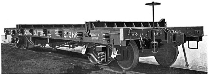
| Gauge | 4 feet, | 8½ inches |
| Length over End Sills | 42 feet, | 0 inches |
| Width over Side Sills | 8 feet, | 6 inches |
| Height from Rail to top of Deck, | 3 feet, | 10 inches |
| Standard Height Coupler | 2 feet, | 10½ inches |
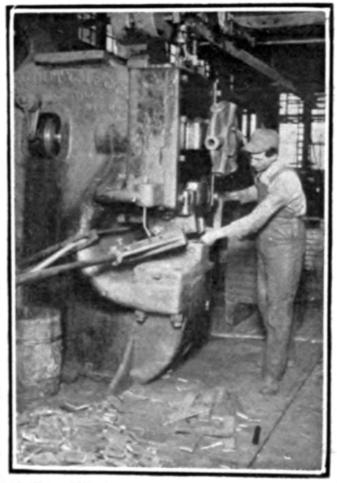
Bulldozer
This car was designed by the Milwaukee R. R. to meet conditions in the Northwest and has become a recognized standard on this Railroad. Fir Sills and Decking are specified. Body Bolsters are built up of heavy steel plates and cast iron fillers. Truck Bolsters are structural steel of the Bettendorf type. The Truck Side Frames are cast steel Bettendorf patent with journal boxes, arch bars and columns cast integral. The Steel Axles have 5 × 9 inch journals and the wheels are 33 inch chilled cast iron. The Couplers are automatic and the draft gear tandem type.
Automatic Quick-Action Air Brake with Hand Brake Staff arranged to work either vertically or horizontally.
CASTINGS—
Give pattern number where possible in addition to list number.
AIR EQUIPMENT—
FORGINGS—
LUMBER—
SPECIALTIES—
Gauge, 4 feet, 8½ inches. Length over End Sills, 41 or 42 feet. Width over Side Sills, 8 feet, 6 inches. Height from Rail to Top of Deck, 3 feet, 6 inches. Height from Rail to Top of Bunk, 4 feet. Height from Rail to Center of Coupler, 2 feet, 10½ inches.
This car is specially designed for heavy service, with extra heavy Red Fir Sills and Decking, and strongly trussed.
End Sills are protected by Steel Plate on face.
Steel Body Bolsters specially designed for Low Logging Car.
Automatic Couplers with Side Unlocking Lever and Standard Draft Gear, with either Tandem or Twin Springs.
Automatic Quick-Action Air Brake, with hand Brake arranged to work either vertically or horizontally.
As shown in illustration, this car is equipped with Hercules Patent Bunk and Knight Patent Chock, and consequently stake pockets are not necessary, but when required, malleable iron pockets with closed backs are furnished.
Rigid Diamond Arch Bar Trucks with Steel Spring Plank.
33-inch Chilled Cast Iron Wheels and Steel Axles with M. C. B. 5×9-inch Journals.
Malleable Iron Journal Boxes with Standard Lid and Wedge. Inside hung all-metal Brake Beams.
Weight, with Bunks, 28,500 pounds.
Gauge 3 feet, 0 inches. Couplers Automatic.
Center Sills, Steel Channel, reinforced with "Fishbelly" Web and Angle Truss, forming a girder with two web members, the continuous Channel Draft Sill acting as top flange of girder. Side Sills Steel Channels carried at Bolsters and on Cross bearers.
The Bolsters and Cross Bearers are similar in construction, being built in between the Sills and formed of plate webs and auger flanges and top and bottom cover plates. End Sill is a Steel Channel. The Draft Beam is a Steel Plate riveted to Center Sill and with Center Sill bottom flange angle extending through Bolster and continuing along bottom edge of Draft Beam.
The Draft Rig is the Singer Spring type with Malleable Iron Draft Castings riveted to Draft Beams.
Castings are of Steel and Malleable Iron. Stake Pockets are Pressed Steel.
The Deck is of Fir Plank. Brake Equipment is for Hand only with Brakes applied to all wheels.
The Trucks are a standard 60,000 pounds capacity truck, for 3 feet gauge with 24 inch wheels of Chilled Cast Iron, Steel Axles, Malleable Iron Journal Boxes, Standard Brass, Structural Steel Bolster, Metal Brake Beams, supported from Malleable Iron Columns. This car was furnished the U. S. Naval Station at Pearl Harbor, Hawaii.
Gauge 4 feet, 8½ inches. Length 30 feet, 0 inches. Width 8 feet, 6 inches.
Metal Bolsters, Standard Draft Gear, Diamond Arch Bar Trucks, 24 inch Chilled Cast Iron Wheels, Steel Axles, Channel Spring Plank and Standard Springs.
Wood Frame Flat Car
Capacity 40,000 Pounds
36-Foot Standard Flat Car
30 Tons Capacity
41-Foot Standard Flat Car
30 Tons Capacity Equipped with Hercules Bunks
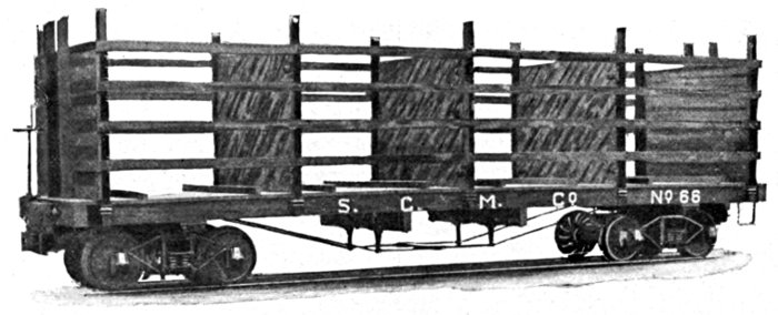
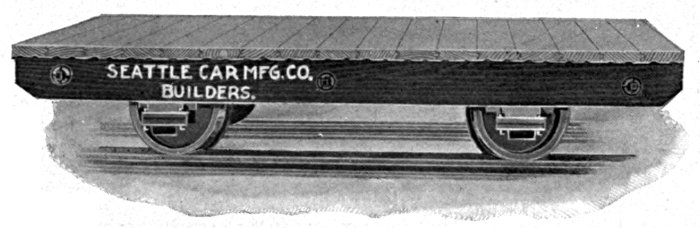
Hip High Skeleton Flat
5 Tons Capacity
For detailed description see page 35
Gauge, 4 feet, 8½ inches. Length over End Sills, 36 feet. Width over Side Sills, 8 feet, 6 inches. Height from Rail to center of Coupler, 2 feet, 10½ inches. Height from Rail to top of Deck, 4 feet, 1 inch.
Sills and Decking, Red Fir.
Draft Timbers, Red Fir reinforced with Steel Plate extending full depth of Center Sill and Draft Timber.
Automatic Couplers and Twin Spring Draft Rig fitted with M.C.B. Draft Springs.
Westinghouse Automatic Air Brake with Hand Brake arranged to operate either vertically or horizontally.
Malleable Iron Stake Pockets with Closed Backs.
Cast Steel Body Bolster.
Trucks, Rigid Diamond Arch Bar Type.
Metal Truck Bolster built of Steel I-Beams and Cover Plates.
Steel Channel Spring Plank.
Malleable Iron Columns with Bracket to support Brake Beams.
Inside Hung Metal Brake Beams.
Wheels, 33-inch Chilled Cast Iron.
Steel Axles with 4¼ × 8 inch Journals.
Malleable Iron Journal Boxes.
Gauge, 4 feet, 8½ inches. Length over End Sills, 41 feet. Width over Side Sills, 8 feet, 6 inches. Height from Rail to center of Coupler, 2 feet, 10½ inches. Height from Rail to top of Deck, 4 feet, 1 inch.
4 Truss Rods, 1⅜ inches round.
Sills and Decking, Red Fir.
Draft Timbers, Fir reinforced with Steel Plate full depth of Center Sill and Draft Timber.
Automatic Couplers and Twin Spring Draft Rig fitted with M.C.B. Standard Draft Springs.
Westinghouse Automatic Air Brake, with Hand Brake Shaft arranged to operate vertically or horizontally.
Malleable Iron Stake Pockets with Closed Back.
Metal Body Bolster.
Hercules Logging Bunks equipped with Knight Chock Blocks.
Truck, Rigid Diamond Arch Bar Type.
Metal Truck Bolsters with Special Long Slide Bearings for sharp curves.
Steel Channel Spring Plank.
Malleable Iron Columns with Bracket to support Brake Beams.
Inside Hung Metal Brake Beams.
Wheels, 33-inch Chilled Cast Iron.
Steel Axles with 4¼ × 8 inch Journals.
Malleable Iron Journal Boxes.
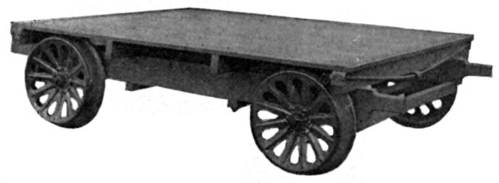
Length, 24 feet. Width, 8 feet. Six Sills. No Decking. Stake Pockets on End Sill. Trucks, Pedestal type with Springs over Journal Boxes. Hand Brakes applied to one Truck. Wheels, 20 inch Chilled Cast Iron, Spoke Wheels mounted on Iron Axles with 2 inch × 4 inch Journals. Wood Bolsters. This car is intended to carry four cord of Shingle Bolts.
Yosemite Flat Car
With Steel Frame and Reinforced Bulkheads
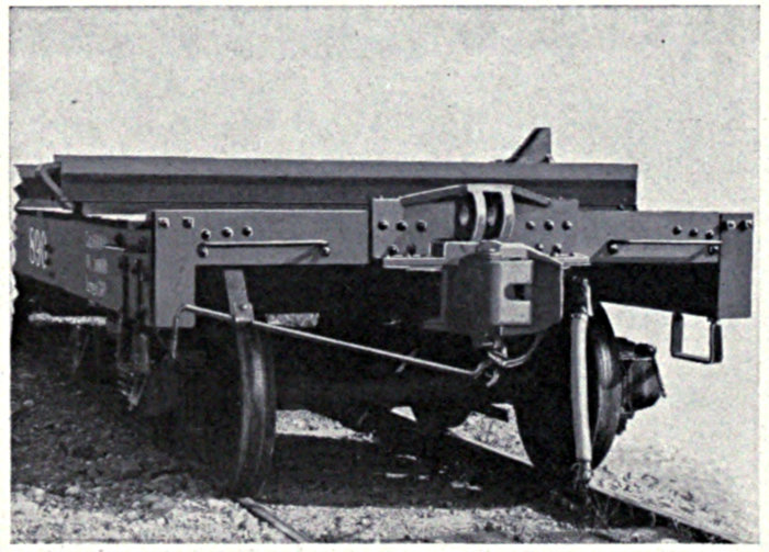
Detail Photo of Yosemite Flat, stripped, showing Steel Underframe
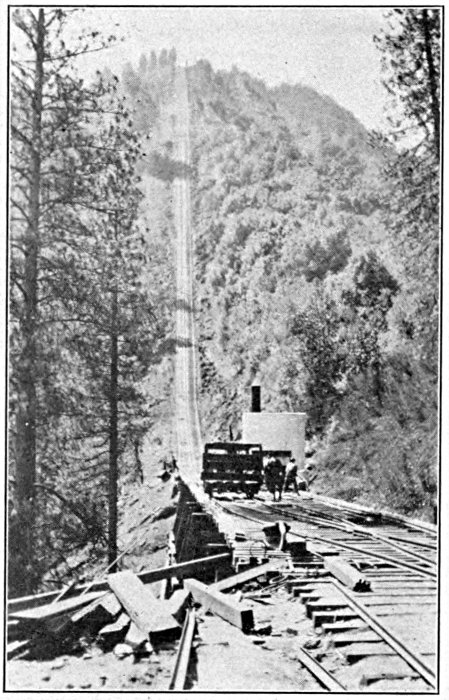
This car was specially designed for the Yosemite Valley Lumber Co. to operate on an incline 8,000 feet long, with a maximum grade of 78%, the rise in feet from the foot of the incline to the top being 3,100 feet, the incline being in a vertical plane, but following the general slope of the mountain side and changing from one slope to another. The cars are let down the incline by means of 1½ in. wire rope, attached to a donkey engine.
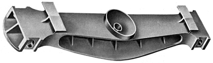
This car was designed to meet these conditions, and is provided with a steel backbone, reinforced at the ends forward of bolsters to provide for the extreme angle of cable pull from a horizontal line and at the down hill end to support the bulkhead, which is provided to keep the logs from shifting. The vertical bulkhead posts are riveted to the steel backbone. At the cable end a special combination buffer and cable casting of cast steel is secured to the backbone by means of gusset plates, and is also riveted to end sill.
The backbone is built up of steel plates and angles in the form of a box girder, of the fish belly type. Cross bearers are located intermediate of the bolsters, and are sufficiently strong to carry the loads from the side sills to the center construction. Experience has proved that for logging cars, steel is unsuited for use in side sills, as continual shocks, resulting from discharging the load, cause their failure. For this reason red fir side sills were introduced in this car, making the underframe a composite construction of steel and timber. The side sills being supported at four points, viz.: at bolsters and cross bearers, no trouble has been experienced from failure of these sills. In case of failure, they are readily replaced, and the work can readily be done at any camp.
The bulkhead is constructed with a steel frame, with planking for the bulkhead proper, so that in case blocking is necessary to fill out between the log and the Bulkhead, this blocking can be nailed to the bulkhead to secure it in place, the object being to provide against the possibility of the log starting to shift.
The cable casting is made with a machine-fit pin to engage the shackle on the cable and place the pin in positive shear.
The cars were equipped with four Hercules Bunks, to provide for short or long logs.
The trucks are of the Diamond Arch Bar type, with cast steel bolsters. The bolsters are of special design, with hemispherical center bearing, to take care of the rock of the trucks in passing over the sharp, vertical curves.
Axles with 4¼×8 in. journals, and 33 in. chilled cast iron wheels are used.
Cars are equipped with Westinghouse automatic air brakes and inside hung metal brake beams.
The draft rig is of the twin spring type, with automatic couplers.

General View of our Yosemite Grade Destroyer
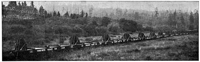
Train of Flat Cars in operation by the Yosemite Lumber Co. at Merced, Cal.
Cast Steel Bolster, showing Special Cup Shaped Center Plate Construction, giving full effective bearing
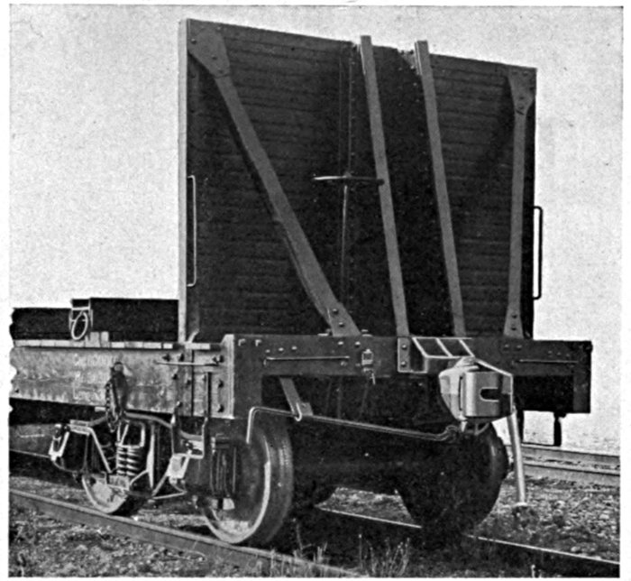
Bulkhead to Prevent Logs Shifting
End of Car, showing Special Cast Steel Plate for attaching Hoisting Cable
Lidgerwood Skidder Car
60,000 Pounds Capacity
This car is of special construction and is built for the Lidgerwood Manufacturing Co. It is illustrated here to show the class of work our shops produce. It has an all steel frame and specially constructed truck, as shown in small cut. Hydraulic jacks are located on the four corners of the body to raise the car, so that trucks may be swiveled and the car set to one side of track.
Skidder Car Truck
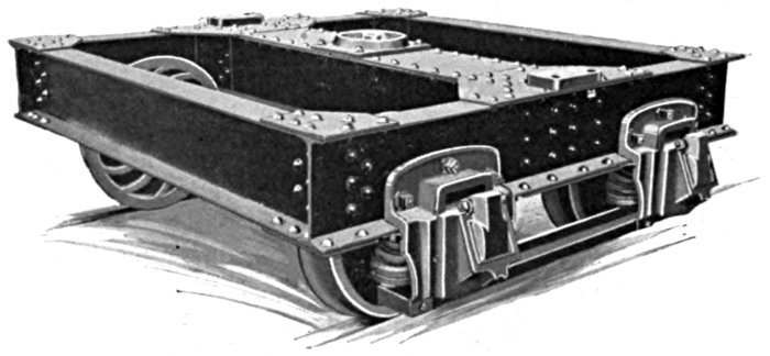
This truck is built to secure a very low center of gravity. It is accomplished by using specially designed pedestal and oil boxes, having a spring on each side of oil box.
The truck frame is of rigid construction, built of I beams, and flexibility is secured by using pedestals, equipped with springs.
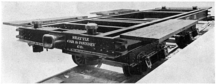
Reinforced Steel Framed Flat
60 Ton Capacity
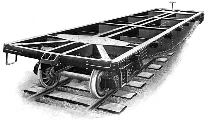
Capacity of Body, 120,000 pounds. Allowable load on one side Sill concentrated on 10 feet at Center, 60 tons. Center Sills are composed of Steel I-Beams and Side Sills are built up Steel Girders of Fishbelly type and sufficiently strong to carry a Donkey Engine mounted on a sled, and fully equipped with Wire Rope, Fuel and Water, and will carry this safely while the Donkey is being loaded or unloaded. The Trucks however are 80,000 capacity which is ample for special service where high speeds are not attained.
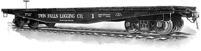
"Donkey" Flat Built for Twin Falls Logging Co.
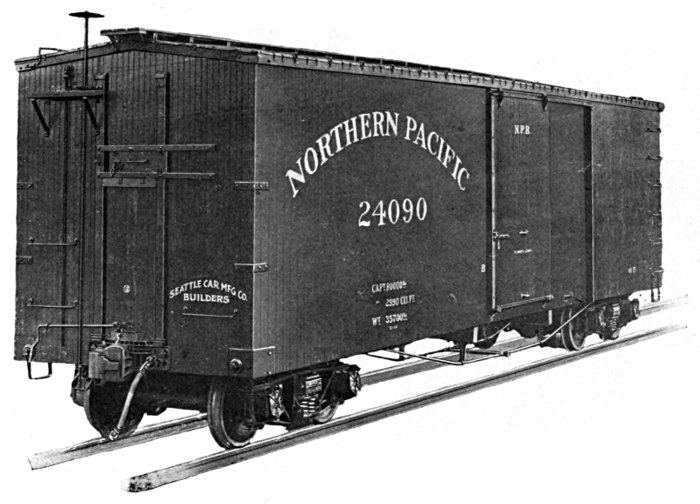
N.P. Standard Box Car
Capacity 40 Tons
"Our Machinery is Built to Last."
Gauge, 4 feet, 8½ inches. Length inside, 40 feet, 0 inches. Width inside, 8 feet, 6 inches. Height inside, 8 feet, 6 inches. Width of Door Opening, 5 feet, 6 inches. Height from Rail to center of Coupler, 2 feet, 10½ inches. Height from Rail to top of Floor, 3 feet, 6 inches. Red Fir used throughout for the woodwork of the car. Six Sills, 5 × 9 inches. Four Truss Rods, 1½ inches round. Automatic Couplers and Miner Tandem Spring Draft Gear. New York Automatic Air Brake. Murphy outside Metal Roof. Security Door Hangers. Metal End Door. Steel I-Beam End Posts. Cast Steel Body Bolster. Malleable Iron Post and Brace Pockets. Malleable Iron Sill Pockets. Trucks, Rigid Diamond Frame Arch Bar Type. Simplex Truck Bolster with Barber Roller Motion. Angle Iron Spring Plank. Wheels, 33-inch Chilled Cast Iron. Steel Axles with 5 × 9 inch Journals. Inside Hung Metal Brake Beams.
North Coast Standard Box Car
Capacity 40 Tons
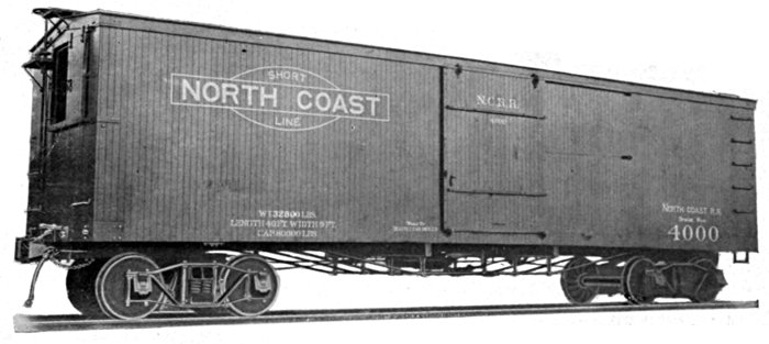
Gauge, 4 feet, 8½ inches. Length over End Sills, 40 feet, 10 inches. Width over Side Sills, 9 feet, 1½ inches. Width inside, 8 feet, 6 inches. Height inside, 8 feet, 0 inches. Width of Door Opening, 6 feet, 0 inches. Height from Rail to center of Coupler, 2 feet, 10½ inches. Height from Rail to Top of Floor, 4 feet, 1 inch.
Red Fir used throughout for woodwork of the car.
Six Sills 5 × 9 inches.
Four Truss Rods, 1½ inches round.
Automatic Couplers and Tandem Spring Draft Gear.
Westinghouse Automatic Air Brake.
Standard Two-Ply Roof with prepared Roofing Paper between the two courses.
Security Door Hangers.
One End Door.
Cast Steel Body Bolsters.
Malleable Iron Post and Brace Pockets.
Trucks, Rigid Diamond Frame Arch Bar Type.
Cast Steel Bolsters.
Steel Channel Spring Plank.
Wheels, 33-inch Chilled Cast Iron.
Steel Axles with 5 × 9 Journals.
Malleable Iron Journal Boxes.
Inside Hung Metal Brake Beams.
B. C. Box Car
Capacity 30 Tons
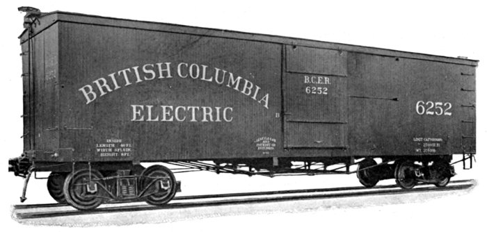
Gauge, 4 feet, 8½ inches. Length inside, 40 feet, 0 inches. Width inside, 8 feet, 6 inches. Width of Door Opening, 6 feet, 0 inches. Height from Rail to Center of Coupler, 2 feet, 10½ inches. Height from Rail to Top of Floor, 4 feet, 2 inches.
Draft Sills, Oak. Buffer Blocks, Oak. All other framing, Red Fir.
Six Sills, 5 × 9 inches.
Four Truss Rods, 1⅜ inches round.
Automatic Couplers and Standard Tandem Draft Rig.
Westinghouse Automatic Air Brake and Inside Hung Metal Brake Beams.
Seattle Car & Foundry Co's Plastic Roof.
Security Door Hangers on both Side and End Doors.
Cast Steel Body and Truck Bolsters with special side bearings to provide for sharp curves.
Diamond Arch Bar Frame Trucks.
Channel Spring Plank.
Malleable Iron Journal Boxes.
Malleable Iron Columns.
33-inch Chilled Cast Iron Wheels and Steel Axles with 4¼ × 8 inch Journals.
U. S. Standard Safety Appliances.
Standard Box Car
40 Tons Capacity
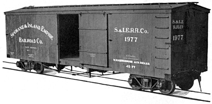
Gauge of Track, 4 feet, 8½ inches. Length over End Sills, 40 feet, 0 inches. Width over Side Sills, 9 feet, 1½ inches. Width inside, 8 feet, 6 inches. Height from Floor to Carline, 8 feet, 0 inches. Width of Door Opening, 6 feet, 0 inches. Height from Rail to center of Coupler, 2 feet, 10½ inches.
Sills, Red Fir. Framing, Red Fir. Red Fir Sheathing, Lining, Flooring and Roofing.
Automatic Couplers and Tandem Draft Gear.
Seattle Car Manufacturing Co's Standard Roof.
Westinghouse Automatic Quick-Action Air Brake.
Steel Bolster.
Malleable Iron Post and Brace Caps and Shoes.
Security Door Hangers.
Rigid Diamond Frame Arch Bar Trucks with Steel Bolster and Spring Plank.
Inside Hung Metal Brake Beams.
Steel Axles, 5 × 9 Journal.
33-inch Chilled Cast Iron Wheels.
Symington Malleable Journal Box with Pivot Lid.
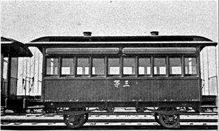
PASSENGER CAR ON THE LINE OF THE SWATOW CHAOCHOWFU RAILWAY IN CHINA.
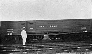
GOODS WAGON ON THE PEKING-KALGAU RY. SHOWING MR. KWONG, THE CHINESE ENGINEER IN CHIEF OF THE RAILWAY.
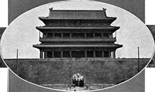
THE CHIEN MEN GATE, ENTRANCE TO THE TARTAR CITY OF PEKING FROM THE NATIVE CITY, BEING THE TERMINUS OF THE IMPERIAL RAILWAY OF NORTH CHINA AND THE PEKING-HANKOW RY.
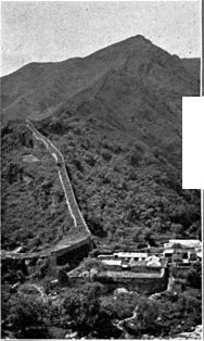
GREAT WALL OF CHINA AT NANKOU PASS ON THE LINE OF THE PEKING-KALGAU RY.
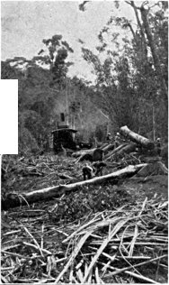
LOGGING IN THE PHILIPPINE ISLANDS WITH MODERN DONKEY ENGINES BUILT ON THE PACIFIC COAST AND HERCULES LOGGING TRUCK BUILT BY SEATTLE CAR & FDY. CO.
Transportation
... in the Orient
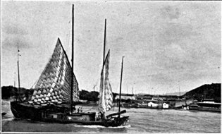
CHINESE JUNK ON THE YANGTZE RIVER. MODE OF TRANSIT IN VOGUE NOW AND WHICH HAS BEEN FOR OVER 2,000 YEARS.
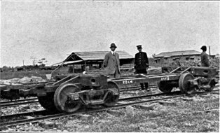
LOGGING CAR IN USE IN THE ISLAND OF FORMOSA AT KAGI, BY THE JAPANESE GOVERNMENT. MR. KANNO, CHIEF ENGINEER ARISAU RY. IN CENTER.
Chinese Box Car
30 Tons Capacity
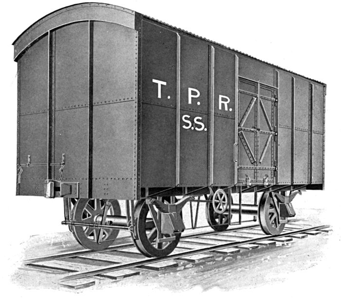
Length inside, 21 feet, 0 inches. Width inside, 9 feet, 6 inches. Wheel Base, 13 feet, 0 inches. Gauge, 4 feet, 8½ inches. Height from Rail to center of Coupler, 3 feet, 7 inches. Wheels, 42 inches, Steel Tired. Steel Axles with 4¾ × 9 inch Journals. Journal Centers, 6 feet, 6 inches. Cast Steel Journal Boxes and Semi Elliptic Springs. Automatic Couplers and Single Spring Draft Gear. Corrugated Metal Roof. Center Sills, Steel Channels. Inter Sills, Steel Channels. Side Sills, Steel Angles. End Sills, Steel Channels. Side and End Posts, Steel Angles. Carlines, Steel Angles. Floor, Steel Plates. Sides and Ends, Steel Plates. Metal Doors with Metal Frames. Metal Brake Beams. Screw Hand Brakes.
20 Ton Chinese Flat. Description on Application
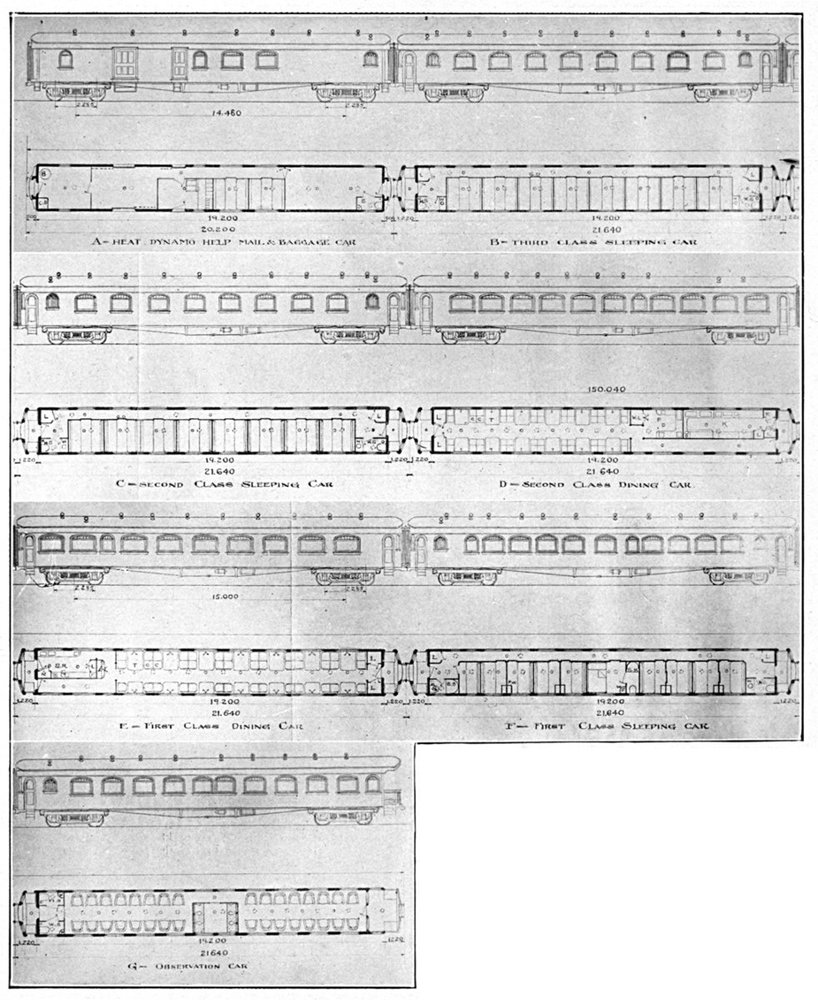
Similar to equipment used on Manchurian Railways. Specially designed for Oriental service. Length of train (7 cars) 492 feet. Accommodating 219 passengers. Weight of train, 280 tons. Structural Steel underframes. All Steel Trucks with Rolled Steel Wheels. Westinghouse Air Brakes. Steam Heated. Electric Lighted. Full Vestibules with Diaphragm. First Class Cars finished in Mahogany and upholstered in Leather and Rugs on floor. Second Class Cars finished in imitation Mahogany and imitation Leather or "Pontasote" with Linoleum Floor Covering. Kitchens, Diners and Sleepers fully equipped.
Steel Underframe
Beef Car
The interior of this car is arranged to accommodate halves of beef of the largest size suspended from trolleys on a track, and have ample clearance to keep the neck of the beef from the floor. There are three tracks extending the length of the car with switches at the door to direct the beef to any track desired. Between the tracks at each carline are cross hooks provided on which mutton may be hung. The tracks are arranged so that the beef may be handled by trolley directly from the cooling room into the car and left suspended in the car to be unloaded by trolley at destination. The economy of this specially designed car will appeal to the packer who ships from the Abattoir to various distributing centers. Provision is made to prevent the load from swinging which adds to the safety in transit. Ice boxes are arranged at ends with provision for ventilation and complete refrigeration. The thorough manner of insulation and ventilation makes it possible to reduce the capacity of ice boxes to a minimum, thereby reducing the cost of icing and at the same time increasing the space for loading.
The underframe is built of structural steel, and is designed to withstand the most severe handling with an ample factor of safety.
Gauge, 4 feet, 8½ inches. Length, 34 feet, 0 inches. Height inside, 10 feet, 2 inches. Height from Rail to center of Coupler, 2 feet, 10½ inches. Automatic Couplers. Westinghouse Friction Draft Rig fitted with Farlow Attachments. Westinghouse Automatic Air Brake. Trucks are Diamond Arch Bar Type. Bolsters all Metal. Wheels, 33-inch Chilled Cast Iron. Axles Steel with 4½ × 8 inch Journals. Journal Boxes, Malleable Iron. Truck Columns, Malleable Iron. Brake Beams all Metal Inside Hung. Spring Plank Steel Channel. Springs in Groups of Six Coils. Weight of Car, 49,000 pounds.
Steel Underframe
Beef Car
This car is constructed with an unusually heavy frame in the superstructure and the underframe is designed to carry the loads from the side to the center construction which is amply strong to carry the entire load. Body is double constructed throughout and is insulated in a modern and thorough manner. Ice Boxes are located at each end and Brine Pans are also provided to aid in securing a low temperature. Doors are located at diagonal corners and three meat tracks run from door to door with switches so that the beef may be directed to any track at will. The car is designed with the object of loading halves of beef suspended from trolleys and left hanging in the car while in transit so that it may be quickly removed at destination. This greatly facilitates the loading and unloading of the beef. Thrust Bars are located at intervals to prevent the meat from swinging.
Gauge, 4 feet, 8½ inches. Length, 34 feet. Width, 9 feet, 2 inches. Height inside, 9 feet, 11 inches. Height from Rail to center of Coupler, 2 feet, 10½ inches. Center Sills built up of Steel Plates and Angles. Cross Bearers built up of Steel Plates and Angles. Automatic Couplers and Farlow Twin Spring Draft Gear. Westinghouse Automatic Air Brake. Trucks are of the Diamond Arch Bar Type. Bolsters built up of I-Beams and Plates. Wheels, 33-inch Chilled Cast Iron. Axles, Steel with 4¼ × 8 inch Journals. Journal Boxes, Malleable Iron. Truck Columns, Malleable Iron, with Brackets to suspend, Brake Beams which are all Metal Trussed Inside Hung. Spring Plank, Steel Channel. Springs in groups of 6 Single Coils. Weight of Car, 48,000 pounds.
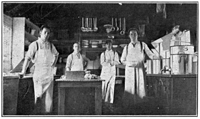
Interior of one of our Camp Cars. (The "Cookies" Domain)
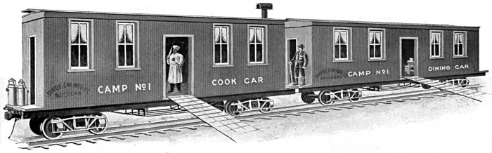
For several years the necessity of providing economical, sanitary and convenient commissary and living accommodations for the employes of Lumber Camps has induced us to investigate fully the best equipment now in use for that purpose and has enabled us to design equipment of Portable Camp Trains to meet the requirements of individual operators.
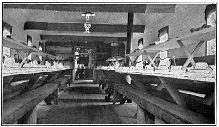
Detail Showing Seating Capacity of Camp Diner
These Portable Camps are being introduced and installed in nearly all large lumbering and railroad operations as they not only prevent many serious losses heretofore sustained by the destruction by fire of camp outfits but at the same time make it possible to keep the workmen's headquarters close to the work, thereby greatly increasing their physical efficiency.
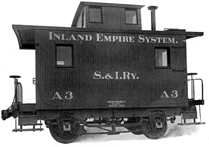
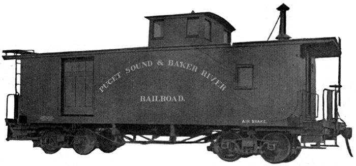
Eight Wheel Caboose
CODE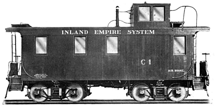
Gauge, 4 feet, 8½ inches. Length over Body, 24 feet, 0 inches. Length over Platform, 29 feet, 0 inches. Width over Side Sills, 9 feet, 1½ inches. Height from Rail to center of Coupler, 2 feet, 10½ inches.
Gauge, 4 feet, 8½ inches. Length over Body, 14 feet, 10 inches. Length over Platform, 18 feet, 10 inches. Width over Side Sills, 9 feet, 1½ inches. Height from Rail to Drawbar (center) 2 feet, 10½ inches.
Other details on application.
CODE
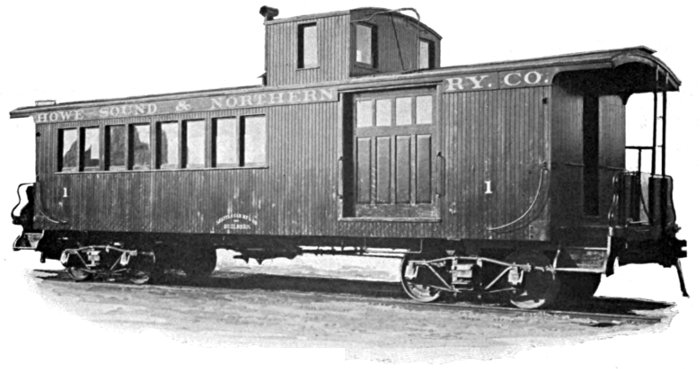
"Skagit"
Number 117
Gauge, 4 feet, 8½ inches. Length over Body, 30 feet. Length over Platform, 36 feet. Width over Side Sills, 9 feet, 1½ inches. Height from Rail to center of Drawbar, 2 feet, 10½ inches. Sills and Framing, Red Fir. Siding and Lining, Red Fir. Flooring, Red Fir. Roofing, Red Fir, covered with heavy Canvas Duck. Body Bolsters, all Metal built up. Automatic Couplers and Tandem Spring Draft Gear. Automatic Quick-Action Air Brakes. Standard Cupola arranged with Conductor's Desk and Revolving Chair on one side. Standard Cast Iron Caboose Stove. Baggage compartment occupies one-half of car. Baggage Room Doors hung on Rollers. Standard Platforms and Steps with Hand Brake Wheel at each end. Trunks, Rigid Diamond Arch Bar with Trussed Wood Bolster and Steel Channel Spring Plank. 33-inch Wheels and 4½ × 8-inch Journals. Outside hung Wood Trussed Brake Beams.
Length over Platform, 40 feet. Length inside, 33 feet. Length inside Passenger Compartment, 19 feet. Seating Capacity, 24 persons. Length inside Baggage Compartment, 9 feet. Length of Cupola, 5 feet. Equipment includes Stove, Toilet, Lockers, Conductors Valve and Air Gauge, Desk, Automatic Air Brakes and Couplers, Standard Arch Bar Trucks with full Elliptic Springs.
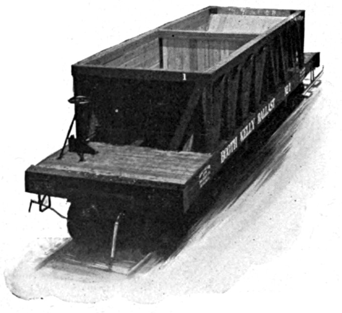
View of Standard Ballast Car, showing arrangement of Hoppers
The car illustrated herewith is an 80,000 pounds capacity Center Dump Ballast Car with Center Bulkhead. The Doors are operated by Worm Gear so as to control the discharge of the load. The Draft Gear is Standard Tandem Spring Rig with M. C. B. Automatic Couplers.
A steadily increasing demand throughout the Northwest for better roadbeds has led us to build a very strong, serviceable Ballast Car for the use of contractors and privately owned railways.
The other illustration is of a car of 60,000 pounds capacity Center Dump Ballast with the ordinary Winding Shaft and Ratchet to operate the Doors. The special feature of this car is the Radical Draft Gear fitted with a Standard Automatic Coupler, as the car is operated around a curve of 35 foot radius, and the Center Bearing is a Ball-bearing mounted on Hemispherical Center which greatly reduces Flange wear on curves. The Wheels are Griffin "F. C. S." Street Car type Flange and Tread. The arrangement of the Hoppers is such as to confine the Dump within the rails, which prevents waste of gravel, etc. A number of these cars are in actual service and giving good satisfaction.
The prices of these cars have been made so reasonable as to place it within reach of all. Send for quotations.
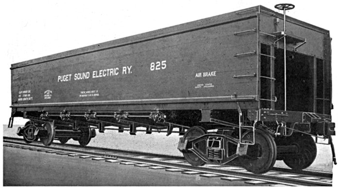
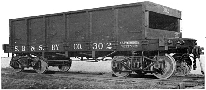
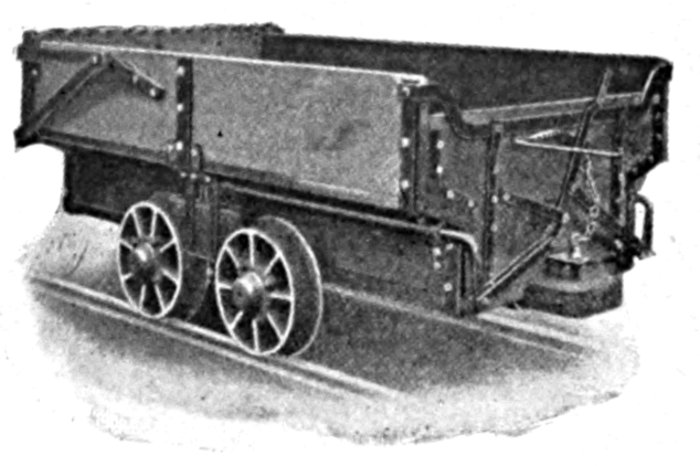
The above illustration shows a 40-ton, side dump coal car, typical of those delivered by us to the Puget Sound Electric Ry. for use on their principal and subsidiary lines.
These cars have proved very satisfactory in service, being strongly constructed and built in a careful, workmanlike manner.
Side bottom dump. Cubic capacity, 1,700 cubic feet. Length inside, 38 ft., 0 in. Length over end sills, 40 ft., 0 in.
Under frame, structural steel. Sides, Steel Truss frame with red fir plank. Floor, red fir plank, sloping from doors 30° up to ends.
Doors—Eight drop doors, discharging the load at each side outside of rail.
Draft Gear—Twin spring with automatic couplers.
Brakes—Westinghouse Automatic Air Brake. Two complete equipments. Hand brakes on both ends, operating on all wheels.
Angle of Trucks—To negotiate a curve of 40-foot radius.
Trucks—Bettendorf steel side frame cast steel bolsters. Wheels, 33 in., chilled cast iron. Steel axles with 5×9 Journals. Steel side bearings of extra length, to provide for sharp curves.
Safety Appliances—United States Standard.
Oil Tank Car
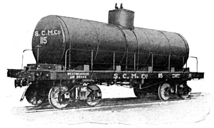
Sills and Framing, Straight-grain Red Fir. Automatic Couplers, or Link and Pin Drawbar. Standard Draft Gear. Air Brakes and Hand Brakes. Steel Trucks with Rigid Frame Diamond Arch Bar and Steel Channel Spring Plank. Bolsters built up of Steel I-Beams. Standard Cast Iron Chilled Wheels fitted to Axles with Journals standard for the required capacity. Tanks can be furnished in any diameter and length, and length of car made to suit. Tanks securely anchored to Underframe and thoroughly braced. When required, Safety Valves are attached to Dome.
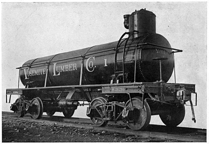
This cut illustrates the underframe used in the Tank Car shown on page 54, number 128. The two main Center Sills are Steel Channel Beams with top and bottom Cover Plates. The Recess in the center receives a Bracket which projects down from the Tank into the Recess and prevents any movement of the Tank and obviates the necessity of blocking at ends, which is the frequent cause of a leaky tank. This car is designed to operate on the incline of 78% grade for the Yosemite Lumber Company, and for this reason the Dome is located on the uphill end. The Tank is fitted with Safety Valve, and the equipment includes Automatic Air Brakes and Couplers, Twin Spring Draft Gear, special Cast Steel Buffer Block and Cable Casting at one end for the purpose of lowering the car down the incline. The Cast Steel Truck Bolster is shown on page 37. The Trucks are Standard Arch Bar Trucks with 33 inch Chilled Cast Iron Wheels.
Standard Cane Car
Capacity 12 Tons
Gauge, 3 feet, 0 inches. Length over End Sills, 30 feet. Width over Side Sills, 7 feet. Height of Partitions, 5 feet. Height from Rail to center of Drawbar, 21 inches.
Sills and Framing, Straight Grain Red Fir.
Body Bolsters, Fir Trussed.
Cast Iron Link and Pin Drawbar with Standard Single Spring Draft Gear.
Brakes applied to the Wheels of one Truck only, with Hand Brake at one end.
Steel Trucks with Rigid Frame Diamond Arch Bar and Steel Channel Spring Plank.
Truck Bolsters built up of Steel I-Beams.
Brake Beams all Metal inside hung.
Wheels, 24-inch Chilled Cast Iron fitted on Axles with 2¾ × 5 inch Journals.
The Superstructure has Slatted Sides with Solid Partitions.
This car can be furnished in any capacity.
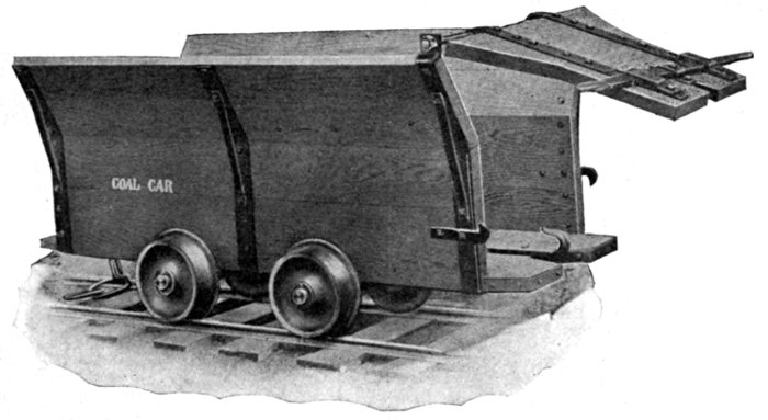
Four Wheel Coal Car
Built for Export to China
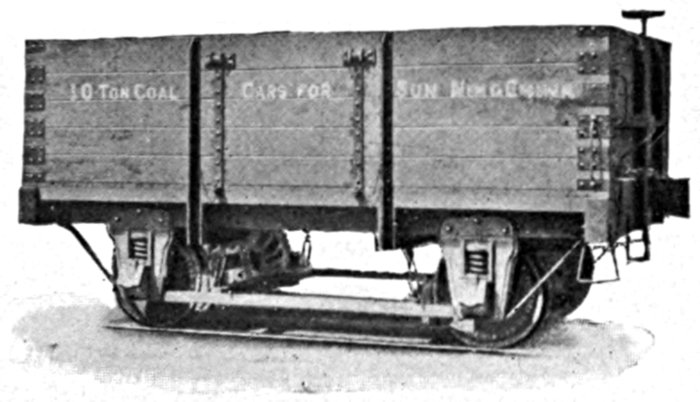
Capacity, 10 Tons. Gauge, 4 feet, 8½ inches. Weight of car, 11,600 pounds. Length inside, 15 feet. Width inside, 7 feet, 7 inches. Height inside Box, 3 feet, 8 inches. Height from Rail to center of Drawbar, 3 feet, 7 inches. Sills and Framing, Red Fir. Automatic Couplers and Standard Draft Gear. Brake Shoes applied to all Wheels with Hand Brake at one end. Doors on each side of car, hinged at top and arranged to swing out. Wheels, 33 inch Chilled Cast Iron, fitted on Axles with 4¼ × 8 inch Journals. Standard Pedestals with Springs over Journal Box. This car can be furnished in any capacity or gauge.
The rapid development of Alaska's mineral resources, assisted by the recent action of Congress providing for the construction of Government railroads in that territory, has led to the organization of a Department in our shop devoted exclusively to the construction of equipment to meet the demand for specially designed Mine Cars, and cars used in development work.
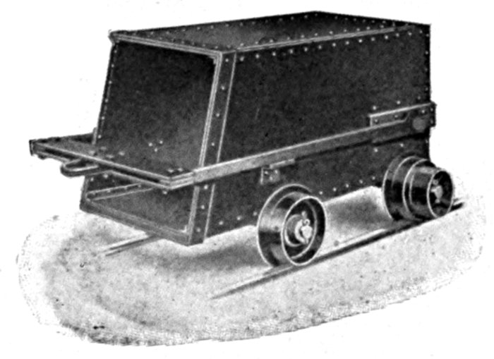
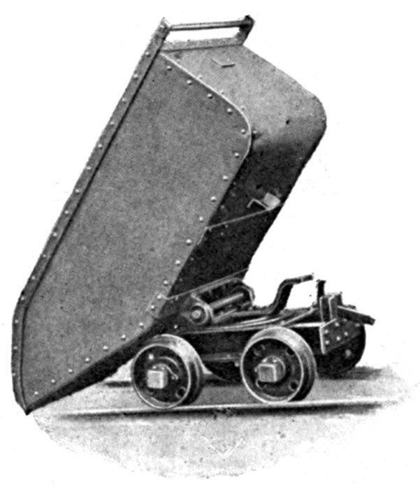
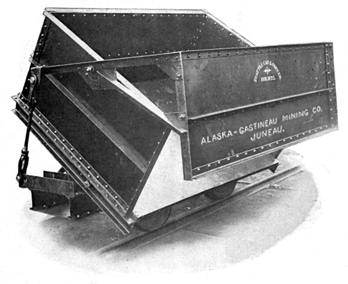
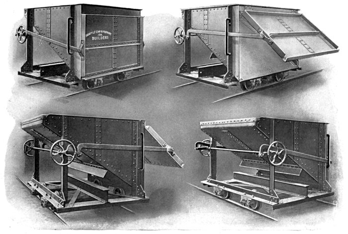
All Steel 1 1-2 Yard Two-Way Side Dump Car
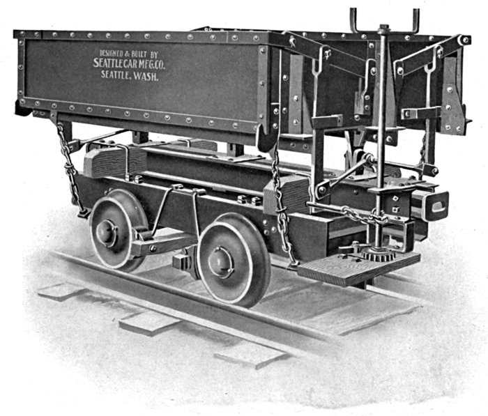
All Steel 1 1-2 Yard Two-Way Side Dump Car
All Steel 1 1-2 Yard Two-Way Side Dump Car
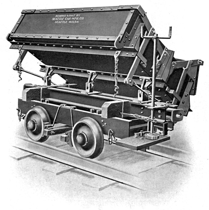
This dump car is particularly adapted for use in quarries in connection with lime or cement works, where a light easy running car is required. The body and truck frame is unusually rigid for a small capacity car, which adds much to its life. The body of the car is built of steel plate strongly braced with steel angles and the top rocker bearing is a steel casting. The bottom bearing is a forged jaw with a square shank which sets into a recess in the truck frame in such a manner that it cannot raise in dumping, but the body may be lifted from the trucks without removing any bolts or keys. The object of this construction is that the body will become separated from the truck in case the car is derailed and rolls down an embankment permitting the two parts to be handled with little difficulty. The angle of dump is ample to clear the load and the door is free to swing permitting a free discharge of the load without bringing any shock upon the door, which in the case of the door being held in a fixed position often causes an upset car and the consequent disabling of the car. The door closes and locks automatically as the body is righted. The truck frame is built of steel I-beams and channels and the drawhead is a heavy forging and fitted with draft springs. One man may easily dump the loaded car and bring the body back into position. The wheels are 16-inch chilled cast iron.
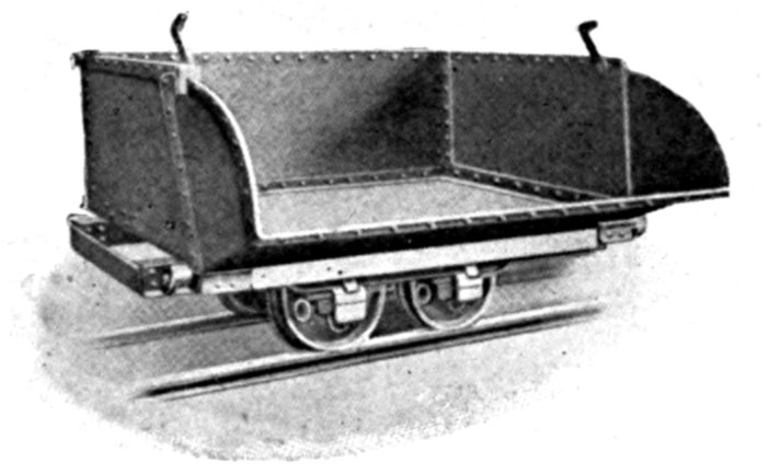
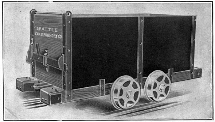
Four Yard Two-Way Side Dump Car
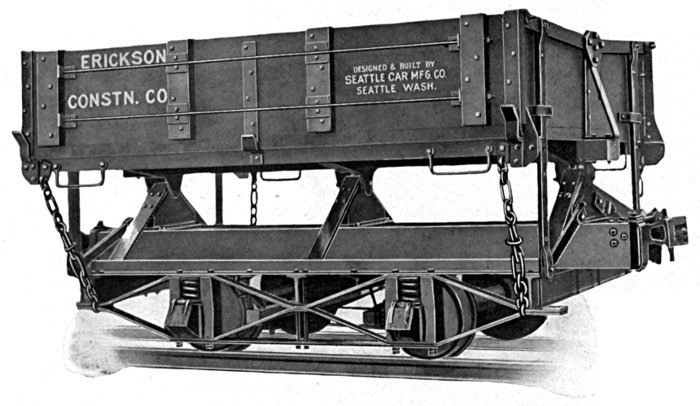
Gauge, 3 feet, 0 inches. Length of Bed inside, 9 feet 0 inches. Width of Bed inside, 7 feet, 10 inches. Depth of Bed inside, 1 foot, 9 inches. Top of Rail to Top of Floor, 3 feet, 9 inches. Top of Rail to Top of Side, 5 feet, 6 inches. Top of Rail to Center of Drawbar, 24 inches.
Wheel Base, 4 feet, 6 inches. Size of Wheel, 18 inches. Size of Journal, 2¾×6 inches.
Double Diamond Frame Truck.
Springs over Journal Boxes.
Steel I-Beam Cross Sills.
Fir Draft Timbers.
Link and Pin Drawbar fitted with Single Spring Draft Rig.
Bottom Rocker Bearing is formed of Press Steel and securely braced to Truck frame with Iron Bar. Top Rocker Bearing is a Heavy Forging.
The Bed is Strongly Braced with Steel Angle Irons and Cross Truss Bars.
The doors are arranged for a Wide Opening and so hinged that the door will offer no resistance to large obstructions, and so obviates any tendency to overturn the car when dumping. As the Car Body is brought to an upright position the doors close automatically. The angle of dump is sufficient to discharge the entire load without shoveling.
Approximate weight 5500 pounds.
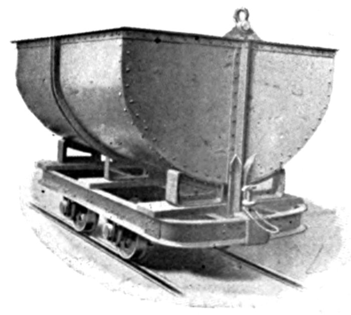
Automatic Dump
Ore Car
Bucket Dump Car
All Steel one way side dump Ore Car arranged to dump automatically when the car arrives at the chute. Can be built in any capacity up to 4 yards.
The floor is built double with a wood cushion between the steel plates.
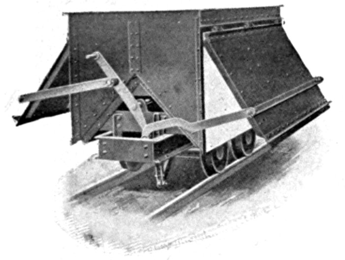
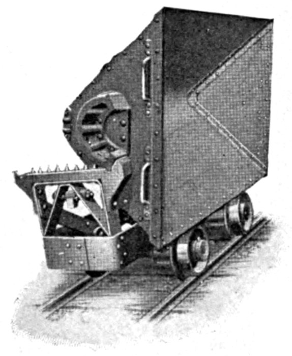
Automatic Dump Car
3 Yard Capacity
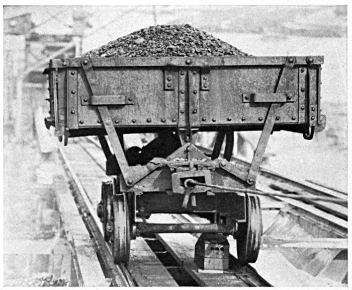
Fig. 1. Car Just Before Engaging Trip Block
The illustrations shown herewith are taken from actual operations on the Lake Washington canal. They show the car just prior to coming in contact with the release block, which is located between the rails. This block trips a lever and upsets the car by means of guide bars that automatically tilt it to the side and raise the corresponding side shutter allowing the load to discharge quickly and freely as shown in Figure 2.

Fig. 2. Car Just After Engaging Trip Block
The car is restored to the upright position by means of a similar block located outside the rail which comes in contact with the guide just at the desired point and throws the car back into place where it is securely locked until ready to be dumped again.
The simplicity and efficiency of this device are self evident. It is operated entirely by gravity. It unloads and recovers without any labor or supervision. It is positive in its operation and its simplicity obviates its getting out of order.
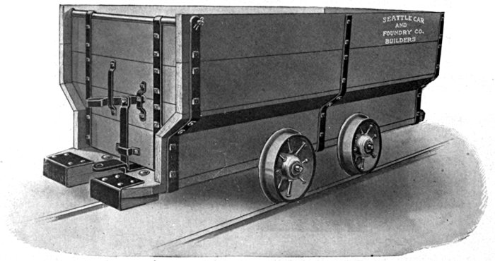
Incline Bottom Quarry Car
3 Yard Capacity
All Steel Incline Bottom one way side Dump Car for use in Quarry. Can be built in various gauges and up to 3 yard capacity. A convenient car around a cement plant or lime kiln where a one way dump can be used.
This car is a standard such as is used in medium low veins and is constructed of fir so that it may be easily repaired at the mine. It can be changed in any way to suit the individual operator.
This car is for use in comparatively deep veins and has steel sides and end. The door is of fir. Wheels are self oiling.
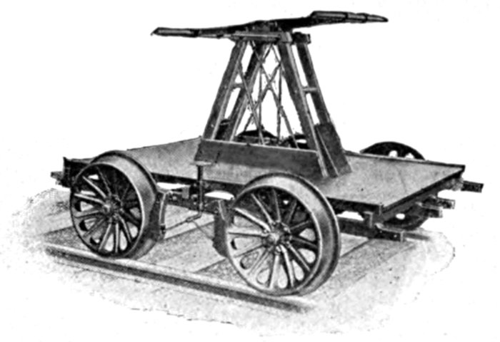
This cut shows Car built for Standard 4 feet 8½ inch Gauge. We make ten different styles of Hand Cars, Standard and Special, and can make them any Gauge desired.
Platform, 6 feet long, 4 feet, 4 inches wide. Axles, 15 inches. Wheels, 20 inches diameter.
Pressed Steel Wheels furnished unless otherwise specified. Weight, 510 lbs., packed for export, 750 lbs.
This car is made in capacities of from one to three tons. The frame is strongly trussed and braced. This Push Car is also built without decking and with the Cross Sills covered with Steel Plate.
Gauge, 4 feet, 8½ inches. Platform 7 feet long by 5 feet, 7½ inches wide.
Wheels, 20-inch Pressed Steel.
Framing and deck of Red Fir.
Two Sills project as Handles at ends. Weight approximately 700 pounds.
Frame 8 feet long, 6 feet 7½ inches wide, reinforced by Tie-rods; Cross Beams faced with flat Steel Bars; Axles 3 inches diameter. Wheels 16 inches diameter, 6 inch Tread.
Stout Hooks for pulling Car are provided, one at each corner, and Heavy Rings on each side for lifting with Derrick; Two Rollers at each end to facilitate handling iron.
Weight, 1620 pounds; packed for export, 1850 pounds, 112 cubic feet.
This car can be made any Gauge desired.
Gauge, 3 feet, 0 inches. Length over ends, 6 feet, 6 inches. Width over sides, 4 feet 6 inches. Height from rail to top of deck, 21 inches.
Sills Steel Channels, Decking Steel Plate.
Steel Axles, 2¾×5 inch Journals, Pedestal Journal Box with Cold Rolled Steel Roller Bearings.
16-inch Chilled Cast Iron Wheels.
Weight approximately 3,300 pounds.
We build these in any size for standard or special gauge track.
The car illustrated has 10 tons capacity and a platform 5×10 feet. These cars are designed for carrying stone or brick. The woodwork is of first grade Douglas Fir.
Platform, 14×4 feet; gauge 2 feet, 8 in.
The illustration shows a car which has met with the hearty approbation of Alaska miners. It is constructed very strongly of Douglas Fir reinforced with iron straps. It is equipped with positive acting hand brake, and will be found very useful for handling bulky loads.
Steel framed Tram Car constructed of very heavy iron reinforced for heavy duty. Platform 12×4 feet.
This car was designed primarily for running loads to the dry kiln, but it will be found adaptable for many other purposes around yards and mills.
We build these to handle up to 5,000 feet B. M. in short or long lengths. Any gauge.
These cars are employed in foundries and rolling mills to move billets, bars and other materials.
They are the product of our engineering department and are based upon the actual operations of similar concerns.
The car shown is 8 feet long with a 5 ton capacity.
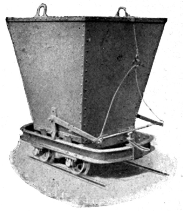
Coal Mine Car
Capacity 32 cubic feet
The simplest way of designating a railroad curve is by giving the length of the radius—i. e., the distance from the center to the outside of the circle, or one-half the diameter. The shorter the radius the sharper the curve. The length of the radius is usually stated in feet; but English engineers often state the radius in chains (one chain = 66 feet). The length of the radius of a railroad curve is measured to the center of the track.
Civil engineers designate railway curves by degrees (using the sign ° for degrees and " for minutes, there being 60 minutes in one degree). The sharpness of the curve is determined by the "degree of curve," or the number of degrees of the central angle subtended by a chord of 100 feet. Or, in other words, let two lines start from the center of a circle in the shape of a V, so that the angle at the point of the V is one degree (equivalent to 1/360 of a complete circle), then, if the two sides of the V are prolonged until they are 100 feet apart, any part of a circle made by using one of these lines for its radius is a "one-degree curve." The exact length of radius which with an angle of one degree has a chord of 100 feet is found to be 5,729.65 feet. For sake of convenience 5,730 feet is usually taken as the radius of a one-degree curve. If the angle at the point of the V is two degrees and the sides are prolonged until 100 feet apart, the length of each side is (almost exactly) one-half as long as when the angle is one degree, or one-half of 5,730==2,865 feet. For a three-degree curve the radius is one-third of 5,730; for a four-degree curve one-fourth of 5,730; and so on. For perfect exactness the length of 100 feet should be measured not along a straight line connecting the ends of the V, but along the line of the circle of which the sides of the V are radii—i. e., the arc should be used and not the chord. The difference, however, is so slight for any curves ordinarily used on main lines of standard gauge railroad as to be ignored in practice. But for extremely sharp curves, such as our locomotives both wide and narrow gauge are built for, a considerable mathematical error would be involved by the use of 100-foot chords and calculating the length of the radius by dividing 5,730 by the degree of curve. The ratio of this error increases with the degree of curve, since the error is caused by neglecting the difference between the length of the chord and of the arc (e. g., a 60-degree curve and 100-foot chord mathematically compels 100-feet radius instead of 95½ feet; a 90-degree curve and 100-foot chord, 71+feet radius instead of 63.6 feet).
In practice, however, the formula of dividing 5,730 by the degree of curve (R==5730/D) is almost universally used, and the mathematical error is avoided by using two 50-foot chords for curves ranging from 10 to 16 degrees, and four 25-foot chords for curves ranging from 17 to 30 degrees, and further sub-dividing for sharper curves, since this almost exactly balances the error, and it is also a practical necessity in laying out sharp curves to use short chords.
For extremely sharp curves, or say 100 feet radius or less, it is usual to express the curve by feet radius rather than by degrees. The table following is computed by the formula R==5730/D, and fractions of feet are not taken into account.
Note—The above engineers' method of designating the rate of curvature of a railway curve must not be confounded with the number of degrees of a circle occupied by the curved portion of the track; thus a curved track making a quarter turn, equivalent to a right angle, will always be 90 degrees of a circle (360 degrees—the whole circle) no matter whether the curve is an easy one with a long radius or a sharp one with a short radius.
| Degrees | Radius | |
|---|---|---|
| 1 | 5730 | feet |
| 2 | 2865 | " |
| 3 | 1910 | " |
| 4 | 1432 | " |
| 5 | 1146 | " |
| 6 | 955 | " |
| 7 | 819 | " |
| 8 | 717 | " |
| 9 | 637 | " |
| 10 | 573 | " |
| 11 | 521 | " |
| 12 | 478 | " |
| 13 | 441 | " |
| 14 | 410 | " |
| 15 | 382 | " |
| 16 | 358 | " |
| 17 | 337 | " |
| 18 | 318 | " |
| 19 | 302 | " |
| 20 | 287 | " |
| 21 | 273 | " |
| 22 | 260 | " |
| 23 | 249 | " |
| 24 | 239 | " |
| 25 | 229 | " |
| 26 | 220 | " |
| 27 | 212 | " |
| 28 | 205 | " |
| 29 | 198 | " |
| 30 | 191 | " |
| 31 | 185 | " |
| 32 | 179 | " |
| 33 | 174 | " |
| 34 | 169 | " |
| 35 | 163 | " |
| 36 | 159 | " |
| 37 | 155 | " |
| 38 | 151 | " |
| 39 | 147 | " |
| 40 | 143 | " |
| 41 | 140 | " |
| 42 | 136 | " |
| 43 | 133 | " |
| 44 | 130 | " |
| 45 | 127 | " |
| 46 | 125 | " |
| 47 | 122 | " |
| 48 | 119 | " |
| 49 | 117 | " |
| 50 | 115 | " |
| 51 | 112 | " |
| 52 | 110 | " |
| 53 | 108 | " |
| 54 | 106 | " |
| 55 | 104 | " |
| 56 | 102 | " |
| 57 | 100 | " |
| 58 | 99 | " |
| 59 | 97 | " |
| 60 | 95 | " |
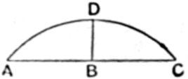
Stretch a string, say 20 feet long, or longer if the curve is not a sharp one, across the curve corresponding to the line from A to C in the diagram. Then measure from B, the center of the line A C, and at right angles with it, to the rail at D.
Multiply the distance A to B, or one-half the length of the string in inches, by itself; measure the distance D to B in inches, and multiply it by itself. Add these two products and divide the sum by twice the distance from B to D, measured exactly in inches and fractional parts of inches. This will give the radius of the curve in inches.
It may be more convenient to use a straight edge instead of a string. Care must be taken to have the ends of the string or straight edge touch the same part of the rail as is taken in measuring the distance from the center. If the string touches the bottom of the rail flange at each end, and the center measurement is made to the rail head, the result will not be correct.
In practice it will be found best to make trials on different parts of the curve to allow for irregularities. It is best not to measure across from one end of the curved track to the other even when the curve is so located that this is possible, since if any portion of the straight track at either end of the curve is included the result will be incorrect. This rule does not apply to curves of over one-half circle if the line is drawn connecting the two ends of the curve. It is a good plan to make the measurement on the inside of the outer rail of the curve, as this is often more convenient. In this case one-half of the width of gauge should be deducted from the radius when calculated, as the radius of the curve should be measured to the center of the track.
Example—Let A C be a 20-foot string; half the distance, or A B, is then 10 feet, or 120 inches. Suppose B D is found on measurement to be 3 inches. Then 120 multiplied by 120 is 14,400, and 3 multiplied by 3 is 9; 14,400 added to 9 is 14,409, which, divided by twice 3, or 6, equals 2,401½ inches, or 200 feet 1½ inches, which is the radius of the curve.
| A B2 plus B D2 | ||
| The formula is thus stated: | == R. | |
| 2 B D |
| 1202 plus 32 | ||
| Or applied to the above example, | == 2,401½ in. == 200 feet 1½ inches. | |
| 2 times 3 |
MATERIAL FOR ONE MILE OF TRACK
| Weight per Yard | Tons per Mile | ||
|---|---|---|---|
| 8 | lbs. | 12 | 4-7 |
| 10 | " | 15 | 5-7 |
| 12 | " | 18 | 6-7 |
| 16 | " | 25 | 1-7 |
| 20 | " | 31 | 3-7 |
| 25 | " | 39 | 2-7 |
| 30 | " | 47 | 1-7 |
| 35 | " | 55 | |
| 40 | " | 62 | 6-7 |
| 45 | " | 70 | 5-7 |
| 50 | " | 78 | 4-7 |
| 52 | " | 81 | 5-7 |
| 56 | " | 88 | |
| 60 | " | 94 | 2-7 |
| 63 | " | 99 | |
| 65 | " | 102 | 1-7 |
| 70 | " | 110 | |
| 75 | " | 117 | 6-7 |
| Number complete joints per mile 90 per cent, 30 ft. and 10 per cent, short length rails, 358. | |||
| Size Under Head | Average per Keg |
For Rail Weighing | Kegs per Mile |
|||||
|---|---|---|---|---|---|---|---|---|
| 6 | × | 9-16 | 320 | 75 | to | 100 | lbs. | 32 |
| 5½ | × | 9-16 | 375 | 52 | to | 75 | " | 30 |
| 5 | × | 9-16 | 400 | 45 | to | 60 | " | 26 |
| 5 | × | 1-2 | 450 | 35 | to | 45 | " | 23½ |
| 4½ | × | 1-2 | 530 | 25 | to | 40 | " | 20 |
| 4½ | × | 7-16 | 680 | 25 | to | 40 | " | 15½ |
| 4 | × | 1-2 | 600 | 20 | to | 35 | " | 17 2-3 |
| 4 | × | 7-16 | 720 | 20 | to | 35 | " | 14¾ |
| 4 | × | 3-8 | 1000 | 16 | to | 30 | " | 10½ |
| 3½ | × | 1-2 | 800 | 16 | to | 25 | " | 11 |
| 3½ | × | 7-16 | 900 | 16 | to | 25 | " | 12 |
| 3½ | × | 3-8 | 1190 | 12 | to | 20 | " | 9 |
| 3 | × | 3-8 | 1240 | 12 | to | 20 | " | 8½ |
| 2½ | × | 3-8 | 1342 | 8 | to | 16 | " | 7⅛ |
Quotations and Specifications furnished on Application. Special Attention given to Rush Orders.
The following well known corporations are among those who have purchased equipment of us and availed themselves of our Service Department:
and hundreds of the leading logging, milling, mining and contracting concerns of the Pacific Northwest and Alaska.
SEATTLE CAR & FOUNDRY CO.
UNION PRINTING Co. SEATTLE
Compiled by Foulser Advertising Service
The List of Subjects on p. 7 includes Bunks, McLafferty yet there is no corresponding section in the text.
The page title for p. 62 split the paragraph. Moved the page title to a position immediately prior to the first illustration.
There was no item number 66 on p. 17.
Most pages had a decorative rectangular border with "Seattle Car _and_ Foundry" at the top. Most of the other pages had a simple triple line rectangular border.
Silently corrected simple spelling, grammar, and typographical errors.
Retained anachronistic and non-standard spellings as printed.
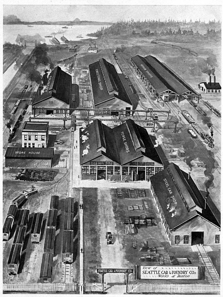