*** START OF THE PROJECT GUTENBERG EBOOK 49253 ***
The cover image was created by the transcriber and is placed in the public domain.
[Pg i]
THE THOUGHT IS IN THE QUESTION THE INFORMATION IS IN THE ANSWER
HAWKINS
ELECTRICAL GUIDE
NUMBER
SEVEN
QUESTIONS
ANSWERS
&
ILLUSTRATIONS
A PROGRESSIVE COURSE OF STUDY
FOR ENGINEERS, ELECTRICIANS, STUDENTS
AND THOSE DESIRING TO ACQUIRE A
WORKING KNOWLEDGE OF
ELECTRICITY AND ITS APPLICATIONS
A PRACTICAL TREATISE
 by
by
HAWKINS AND STAFF

THEO. AUDEL & CO. 72 FIFTH AVE. NEW YORK.
[Pg ii]
COPYRIGHTED, 1915,
BY
THEO. AUDEL & CO.,
New York.
Printed in the United States.
[Pg iii]
TABLE OF CONTENTS
GUIDE NO. 7.
| ALTERNATING CURRENT SYSTEMS |
1,531 to 1,586 |
| Advantages of the alternating
current—classification of
systems—vector summation;
examples—forms of circuit:
series, parallel, parallel series, series
parallel—transformer systems:
individual transformers; transformation at distribution
centers—single phase system; two wire
transmission and three wire distribution; objections to
single phase systems; advantages—monocyclic
system—two phase systems:
adaptation; ordinary voltages used; two phase three wire
system; two phase five wire system—three phase
systems: six wire; four wire; three wire; connections:
star, delta, star delta, delta star; evolution of three
wire system; pressure and current relations; connection of
transformers; open delta connection—change of
frequency—Schaghticoke-Schenectady transmission
line—transformation of phases:
three to one, three to two, two to six, and three to six
phase—Scott connection for transforming
from three to two phase—three to two phase with three
star connected transformers—economy of a.c.
systems—relative weights of copper
required for polyphase systems—aermotor
towers of Southern Power Co.—choice of
voltage—usual transmission
voltages—diagram of three phase
distribution—mixed current
systems; usual d.c. pressure on traction lines; use of
mixed systems. |
| AUXILIARY APPARATUS |
1,587 to 1,588 |
| Classification of auxiliary devices:
switching devices, types—current or pressure limiting
devices, types—lightning protection devices,
types—regulating devices, types—synchronous
condensers, types—indicating devices. [Pg
iv] |
| SWITCHING DEVICES |
1,589 to 1,612 |
| Definition of a switch—behaviour of the current when
the circuit is broken—points on design—installation
of single throw and double throw switches—plug
switches—forms of break: open, enclosed,
fuse, horn, oil—disconnecting switches—pole top
switches—horn break switches—motor
starting switch—oil switches;
nature of an oil break—remote control
oil switches—motor operated
switches—rupturing capacity of oil
switches—float switches. |
| CURRENT AND PRESSURE LIMITING DEVICES |
1,613 to 1,676 |
| Necessity for these devices; steam
analogy—fuses: advantages and
disadvantages; types: plug, cut out, expulsion, no arc,
magnetic blow out, quick break fuse, etc.—metal
used—current limiting inductances:
construction, location—circuit
breakers: progressive breaking of the circuit;
carbon contacts—automatic features:
overload trip, underload trip, low voltage trip, auxiliary
circuit trip—relays: adaptation;
classification: protective, regulative, communicative, a.c. and
d.c., circuit opening, circuit closing, primary, secondary,
overload, underload, over voltage, low voltage, reverse energy,
reverse phase, instantaneous, time limit, inverse time limit,
differential—how to select relays. |
| LIGHTNING PROTECTION DEVICES |
1,677 to 1,714 |
| Essential parts: air gaps,
resistances, inductances, arc suppressing
devices—requirements—air gap
arresters—multi-gap arresters;
difference between spark and arc; distribution of stress;
sparking at the gaps; how the arc is extinguished; effect of
frequency; graded shunt resistances; the cumulative or breaking
back effect—arresters for grounded Y
and non-grounded neutral systems—multiplex
connection—horn gap arresters:
operation; objection to the horn gap—electrolytic
arresters: critical voltage, temporary and permanent;
determination of number of cell; putting cell in commission;
nature of the film; horn gaps on electrolytic arresters;
charging of electrolytic arresters; charging arresters for
non-grounded circuits—grounded and non-grounded
neutral circuits—[Pg v]ground
connections—choke coils:
principal objects; principal electrical conditions to be
avoided; why choke coils are made in the form of an hour glass;
cooling—static interrupters; how to
connect condenser and choke coil; effect of condenser. |
| REGULATING DEVICES |
1,715 to 1,762 |
| Regulation of
alternators—a.c. feeder
regulation—application of induction
type regulators; types: induction, and variable ratio
transformer regulators; operation of induction regulators;
neutral position; regulator capacity—polyphase
induction regulators: construction, operation;
automatic control; why two relays are used;
difficulties encountered in operation of relays; vibration
or chattering of the contacts; poor contact of primary
relay—variable ratio transformer voltage
regulators: types: drum, and dial; dial type for high
voltage—small feeder voltage regulators:
construction and operation; adjustment—automatic
voltage regulators for alternators: method of
regulation—line drop compensators:
essential parts; connections; construction and operation;
diagram of automatic voltage regulator using a line drop
compensator—starting compensators:
necessity for; construction and operation—star
delta switches. |
| SYNCHRONOUS CONDENSERS |
1,763 to 1,776 |
| Characteristics—effect of fully loaded and lightly
loaded induction motors on the power factor—synchronous
motor used as condenser—effects of low
lagging power factors; example—cost
of synchronous condenser vs. cost of
copper—location of condenser—synchronous
condenser calculations and diagram for same. |
| INDICATING DEVICES |
1,777 to 1,838 |
| Virtual value of an alternating current or
pressure—the word effective
erroneously used for virtual: steam
engine analogy illustrating this error—classification
of instruments: electromagnetic or moving wire, hot wire,
induction, dynamometer—electromagnetic
or moving iron instruments: types: plunger,
inclined coil, magnetic vane; [Pg vi]character of
scale; objections and precautions—inclined
coil instruments—magnetic
vane instruments—hot wire
instruments—induction
instruments: types: shielded pole, rotary field;
operation of both types—dynamometers:
construction and operation; how arranged to measure
watts—watthour meters: types:
commutator, induction, Faraday disc; essential parts; object
of the motor; object of generator; objection to commutator
meter—principles of induction watthour
meters: essential parts; strength of rotating field;
moving element; retarding element; registering element;
frame and bearings; friction compensator; power factor
adjustment; frequency adjustment—Faraday disc,
or mercury motor ampere hour meter: construction
and operation—frequency indicators:
types: synchronous motor, resonance, induction; synchronous
motor as frequency indicator—resonance frequency
indicators: adaptation—induction
frequency meter: construction and
operation—synchronism indicators: types:
lamp or voltmeter, resonance or vibrating reed, rotating
field—power factor indicators: wattmeter
type; disc, or rotating field type—ground
detectors. |
[Pg 1531]
CHAPTER LV
ALTERNATING CURRENT SYSTEMS
The facility with which alternating current can be transformed
from one voltage to another, thus permitting high
pressure transmission of electric energy to long distances through
small wires, and low pressure distribution for the operation of
lighting systems and motors, gives a far greater variety of
systems of transmission and distribution than is possible with
direct current.
Furthermore, when the fact that two phase current can be
readily transformed into three phase current, and these converted
into direct current, and vice versa, by means of rotary
converters and rectifiers, is added to the advantages derived
by the use of high tension systems, it is apparent that the
opportunity for elaboration becomes almost unlimited. These
conditions have naturally tended toward the development of
a great variety of systems, employing more or less complicated
circuits and apparatus, and although alternating current practice
is still much less definite than direct current work, certain
polyphase systems are now being generally accepted as representing
the highest standards of power generation, transmission
and distribution.
A classification of the various alternating current systems,
to be comprehensive, should be made according to several points
of view, as follows:
[Pg 1532]
1. With respect to the arrangement of the circuit, as
- a. Series;
- b. Parallel;
- c. Series parallel;
- d. Parallel series.
2. With respect to transformation, as
3. With respect to the mode of transmitting the energy, as
- a. Constant pressure;
- b. Constant current.
4. With respect to the kind of current, as
- a. Single phase { two wire;
- { three wire;
- b. Monocyclic
- { four wire;
- c. Two phase { three wire;
- { five wire;
- { six wire;
- { three wire;
- { four wire;
- d. Three phase { star connection;
- { delta connection;
- { star delta connection;
- { delta star connection;
- e. Multi-phase { of more than
- { three phases;
5. With respect to transmission and distribution, as
- a. Frequency changing;
- b. Phase changing;
- c. Converter;
- d. Rectifier.
In order to comprehend the relative advantages of the various
alternating current systems, it is first necessary to understand
the principle of vector summation.
[Pg 1533]
Vector Summation.—This is a simple geometrical process
for ascertaining the pressure at the free terminals of alternating
current circuits. The following laws should be carefully noted:
1. If two alternating pressures which agree in phase are connected
together in series, the voltage at the free terminals of the
circuit will be equal to their arithmetical sum, as in the case of
direct currents.
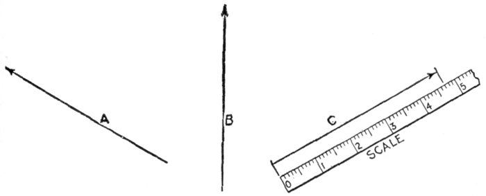
Fig. 2,123.—Vectors. A vector is defined as: a line, conceived to have both a fixed length and
a fixed direction in space, but no fixed position. Thus A and B are lines, each having a
fixed length, but no fixed direction. By adding an arrow head the direction is fixed and
the line becomes a vector, as for example vector C. The fixed length is usually taken
to represent a definite force, thus the fixed length of vector C is 4.7 which may be used
to represent 4.7 lbs., 4.7 tons, etc., as may be arbitrarily assumed.
When there is phase difference between the two alternating
pressures, connected in series, the following relation holds:
2. The value of the terminal voltage will differ from their
arithmetical sum, depending on the amount of their phase difference.
When there is phase difference, the value of the resultant is conveniently
obtained as explained below.
Ques. How are vector diagrams constructed for obtaining
resultant electric pressure?
Ans. On the principle of the parallelogram of forces.
[Pg 1534]
Ques. What is understood by the parallelogram of
forces?
Ans. It is a graphical method of finding the resultant of
two forces, according to the following law: If two forces acting
on a point be represented in direction and intensity by adjacent
sides of a parallelogram, their resultant will be represented by the
diagonal of the parallelogram which passes through the point.
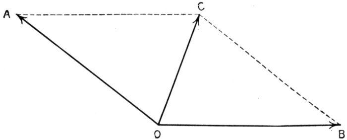
Fig. 2,124.—Parallelogram of forces. OC is the resultant of the two forces OA and OB. The
length and direction of the lines represent the intensity and direction of the respective
forces, the construction being explained in the accompanying text.
Thus in fig. 2,124, let OA and OB represent the intensity and direction
of two forces acting at the point O, Draw AC and BC, respectively
parallel to OB and OA, completing the parallelogram, then will OC,
the diagonal from the point at which the forces act, represent the
intensity and direction of the resultant, that is, of a force equivalent
to the combined action of the forces OA and OB, these forces being
called the components of the force OC.
Ques. Upon what does the magnitude of the resultant
of two forces depend?
Ans. Upon the difference in directions in which they act,
as shown in figs 2,125 to 2,128.
[Pg 1535]
Ques. Is the parallelogram of forces applied when the
difference in direction or "phase difference" of two forces
is 90 degrees?
Ans. It is sometimes more conveniently done by calculation
according to the law of the right angle triangle.
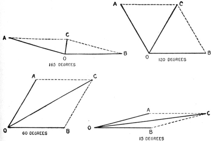
Figs. 2,125 to 2,128.—Parallelograms of forces showing increase in magnitude of the resultant
of two forces, as their difference of direction, or electrically speaking, their phase difference
is diminished. The diagrams show the growth of the resultant of the two equal
forces OA and OB as the phase difference is reduced from 165° successively to 120, 60,
and 15 degrees.
According to this principle, if two alternating pressures have a phase
difference of 90 degrees they may be represented in magnitude and
direction by the two sides of a right angle triangle as OA and OB in
fig. 2,129; then will the hypotenuse AB represent the magnitude and
direction of the resultant pressure. That is to say, the resultant pressure
AB = √((OA)2 + (OB)2) (1)
[Pg 1536]
EXAMPLE.—A two phase alternator is wound for 300 volts on one
phase and 200 volts on the other phase, the phase difference being 90°.
If one end of each winding were joined so as to form a single winding
around the armature, what would be the resultant pressure?
By calculation, substituting the given values in equation (1),
Resultant pressure = √(3002 + 2002) = √(130,000) = 360.6 volts.
This is easily done graphically as in fig. 2,129 by taking a scale, say,
1" = 100 volts and laying off OA = 3" = 300 volts, and at right angles
OB = 2" = 200 volts, then by measurement AB = 3.606" = 360.6 volts.
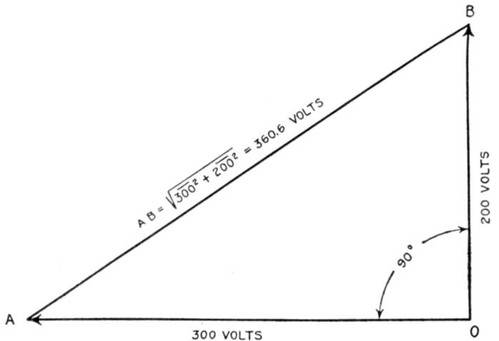
Fig. 2,129.—Method of obtaining the resultant of two component pressures acting at right
angles by solution of right angle triangle. The equation of the right angle triangle is
explained at length in Guide No. 5, page 1,070.
Ques. When the two pressures are equal and the
phase difference is 90°, is it necessary to use equation (1)
to obtain the resultant?
Ans. No. The resultant is obtained by simply multiplying
one of the pressures by 1.41.
This is evident from fig. 2,130. Here the two pressures OA and OB
are equal as indicated by the dotted arc. Since they act at right angles,
OB is drawn at 90° to OA. According to the equation of the right angle
triangle, the resultant AB = √(12 + 12) = √2 = 1.4142 which ordinarily
is taken as 1.41.
[Pg 1537]
This value will always represent the ratio between the magnitude of the
resultant and the two component forces, when the latter are equal, and have a
phase difference of 90 degrees.
Forms of Circuit.—Alternating current systems of distribution
may be classed, with respect to the kind of circuit
used, in a manner similar to direct current systems, that is, they
may be called series, parallel, series parallel, or parallel series
systems, as shown in figs. 2,131 to 2,134.
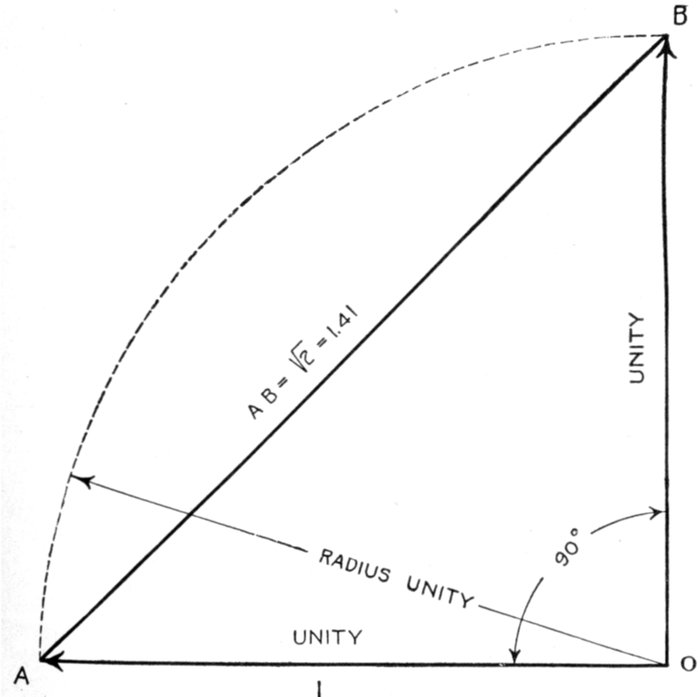
Fig. 2,130.—Diagram for obtaining the resultant of two equal component pressures acting
at right angles.
Series Circuits.—These are used in arc lighting, and series incandescent
lighting, a constant current being maintained; also for[Pg 1538]
constant current motors and generators supplying secondary
circuits.
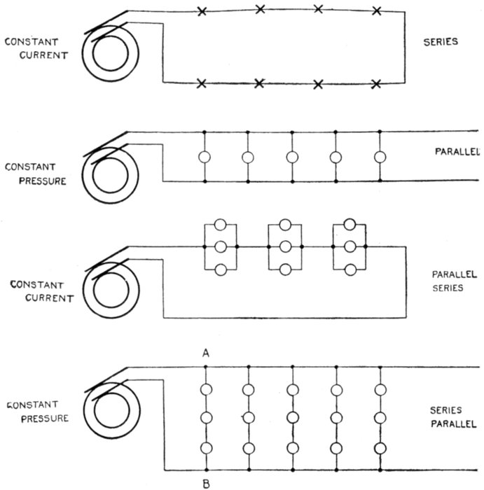
Figs. 2,131 to 2,134.—Various forms of circuit. These well known forms of circuit are used
in both alternating and direct current systems. The simple series circuit, fig. 2,131, is
suitable for constant current arc lighting. Fig. 2,132, shows the parallel constant pressure
circuit; this form of circuit is largely used but is seldom connected direct to the alternator
terminals, but to a step down transformer, on account of the low pressure generally
required. Fig. 2,133 illustrates a parallel series circuit, and 2,134, a series parallel
circuit.
Several forms of constant current alternator, analogous to
the Thompson-Houston and Brush series arc dynamos, have[Pg 1539]
been introduced. In the design of such alternators self-induction
and armature reaction are purposely exaggerated; so that the
current does not increase very much, even when the machine
is short circuited. With this provision, no regulating device
is required.
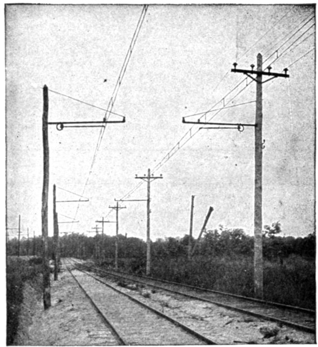
Fig. 2,135.—Typical American overhead 6,600 volt single phase interurban trolley line, Baltimore
and Annapolis short line, Annapolis, Md.
An objectionable feature is that the voltage of a constant
current alternator will rise very high if the circuit be opened,
because it is then relieved of inductance drop and armature
reaction.
To guard against a dangerous rise of voltage, a film cut out or
equivalent device is connected to the terminal of each machine so
that it will short circuit the latter if the voltage rise too high.
[Pg 1540]
Ques. What advantage have constant current alternators
over constant current dynamos?
Ans. The high pressure current is delivered to the external
circuit without a commutator, hence there is no sparking
difficulty.
The above relates to the revolving field type of alternator. There are,
however, alternators in which the armature revolves, the current being
delivered to the external circuit through collector rings and brushes.
This type of alternator, it should be noted, is for moderate pressures,
and moreover there is no interruption to the flow of the current such as
would be occasioned by a tangential brush on a dynamo in passing from
one commutator segment to the next.
In the revolving field machine, though the armature current be of very
high pressure, the field current which passes through the brushes and
slip rings is of low pressure and accordingly presents no transmission
difficulties.
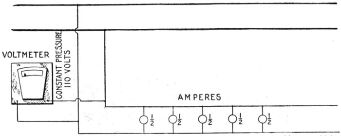
Fig. 2,136.—Diagram of parallel circuit. It is a constant pressure circuit and is very widely
used for lighting and power. If each lamp takes say ½ ampere, the current flowing in
the circuit will vary with the number of lamps in operation; in the above circuit with
all lamps on, the current is ½ × 5 = 2½ amperes.
Ques. State a disadvantage.
Ans. Some source of direct current for field excitation is
required.
Ques. In a constant current series system, upon what
does the voltage at the alternator depend?
Ans. The number of devices connected in the circuit, the
volts required for each, and the line drop.
[Pg 1541]
Parallel Circuits.—These are used for constant pressure
operation. Such arrangement provides a separate circuit for
each unit making them independent so that they may vary in
size and each one can be started or stopped without interfering
with the others. Parallel circuits are largely used for incandescent
lighting, and since low pressure current is commonly
used on such circuits they are usually connected to step down
transformers, instead of direct to the alternators.
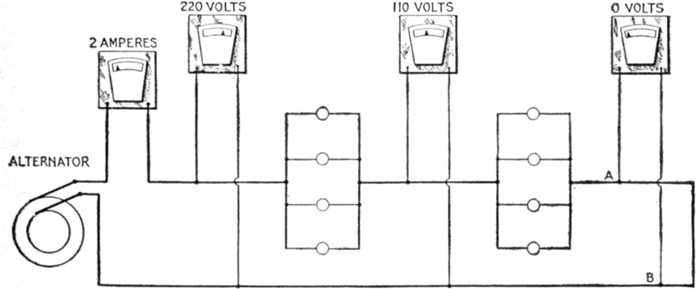
Fig. 2,137.—Diagram of parallel series circuit, showing fall of pressure between units. This
system is very rarely used; it has the disadvantage that if a lamp filament breaks, the
resistance of the circuit is altered and the strength of the current changed. The voltmeter
shows the fall of pressure along the line. It should be noted that, although the
meter across AB is shown as registering zero pressure, there is, strictly speaking, a slight
pressure across AB, in amount, being that required to overcome the resistance of the
conductor between A and B.
Parallel Series Circuits.—Fig. 2,137 shows the arrangement
of a parallel series circuit and the pressure conditions in
same. Such a circuit consists of groups of two or more lamps
or other devices connected in parallel and these groups connected
in series.
Such a circuit, when used for lighting, obviously has the
disadvantage that if a lamp filament breaks, the resistance of
the group is increased, thus reducing the current and decreasing
the brilliancy of the lamps. This arrangement accordingly
does not admit of turning off any of the lights.
[Pg 1542]
Series Parallel Circuits.—The arrangement of circuits of
this kind is shown in fig. 2,134; they are used to economize in
copper since by joining groups of low pressure lamps in series
they may be supplied by current at correspondingly higher
pressure.
Thus, if in fig. 2,134, 110 volt, ½ ampere lamps be used, the pressure
on the mains, that is, between any two points as A and B would be
110 × 3 = 330 volts. Each group would require ½ ampere and the
five groups ½ × 5 = 2½ amperes.
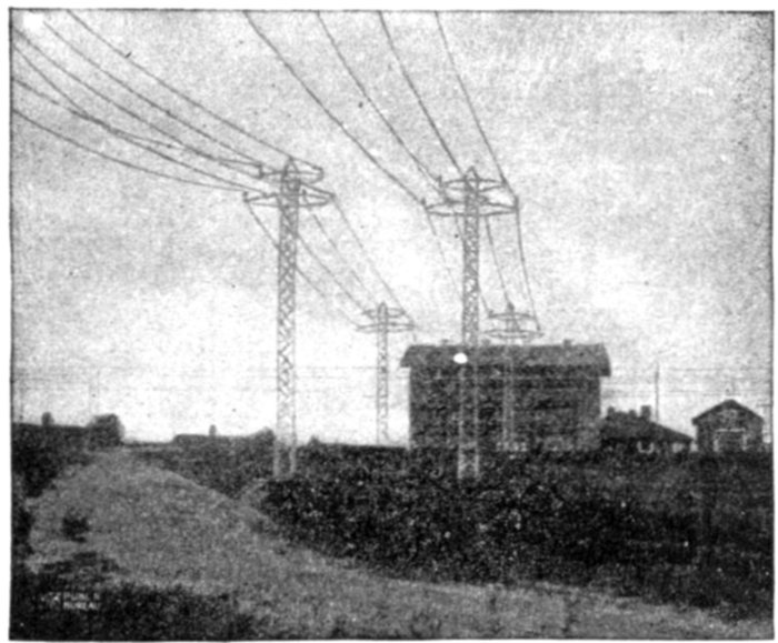
Fig. 2,138.—44,000 volt lines entering the Gastonia sub-station of the Southern Power Co.
The poles used are of the twin circuit two arm type, built of structural steel, their height
varying from 45 to 80 feet, the latter weighing 9,000 pounds each. These poles have
their bases weighted with concrete.
Transformer Systems.—Nearly all alternating current
systems are transformer systems, since the chief feature of
alternating current is the ease with which it may be transformed
from one pressure to another. Accordingly, considerable
economy in copper may be effected by transmitting the current
at high pressure, especially if the distance be great, and, by
means of step down transformers, reducing the voltage at points
where the current is used or distributed.
[Pg 1543]
Ordinarily and for lines of moderate length, current is sent
out direct from the alternator to the line and transformed by
step down transformers at the points of application.
With respect to the step down transformers, there are two
arrangements:
- 1. Individual transformers;
- 2. One transformer for several customers.
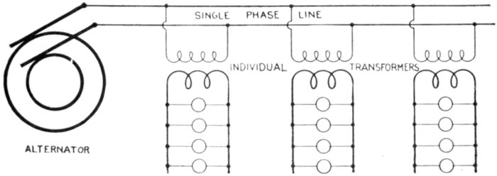
Fig. 2,139.—Diagram of transformer system with individual transformers. The efficiency is
low, but such method of distribution is necessary in sparsely settled or rural districts.
Individual transformers, that is, a separate transformer for
each customer is necessary in rural districts where the intervening
distances are great as shown in fig. 2,139.
Ques. What are the objections to this method of
distribution?
Ans. It requires the use of small transformers which are
necessarily less efficient and more expensive per kilowatt than
large transformers. The transformer must be built to carry,
within its overload capacity, all the lamps installed by the
customer since all may be used occasionally.
[Pg 1544]
Usually, however, only a small part of the lamps are in use, and
those only for a small part of the day, so that the average load on the
transformer is a very small part of its capacity. Since the core loss
continues whether the transformer be loaded or not, but is not paid
for by the customer, the economy of the arrangement is very low.
In the second case, where one large transformer may be placed at
a distribution center, to supply several customers, as in fig. 2,140, the
efficiency of the system is improved.
Ques. Why is this arrangement more efficient than
when individual transformers are used?
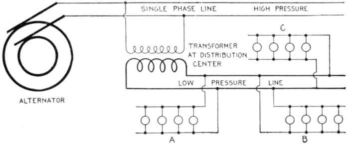
Fig. 2,140.—Diagram of transformer system with one transformer located at a distribution
center and supplying several customers as A, B, and C. Such arrangement is considerably
more efficient than that shown in fig. 2,139, as explained in the accompanying text.
Ans. Less transformer capacity is required than with individual
transformers.
Ques. Why is this?
Ans. With several customers supplied from one transformer
it is extremely improbable that all the customers will burn all
their lamps at the same time. It is therefore unnecessary to
install a transformer capable of operating the full load, as is
necessary with individual transformers.
Ques. Does the difference in transformer capacity
represent all the saving?
[Pg 1545]
Ans. No; one large transformer is more efficient than a
number of small transformers.
Ques. Why?
Ans. The core loss is less.
For instance, if four customers having 20 lamps each were supplied
from a single transformer, the average load would be about 8 lamps,
and at most not over 10 or 15 lamps, and a transformer carrying 30 to
35 lamps at over load would probably be sufficient. A 1,500 watt
transformer would therefore be larger than necessary. At 3 per cent.
core loss, this gives a constant loss of 45 watts, while the average load
of 8 lamps for 3 hours per day gives a useful output of 60 watts, or an
all year efficiency of nearly 60 per cent., while a 1,000 watt transformer
would give an all year efficiency of 67 per cent.
For long distance transmission lines, the voltage at the alternator
is increased by passing the current through a step up transformer,
thus transmitting it at very high pressure, and reducing the voltage
at the points of distribution by step down transformers as in fig. 2,141.
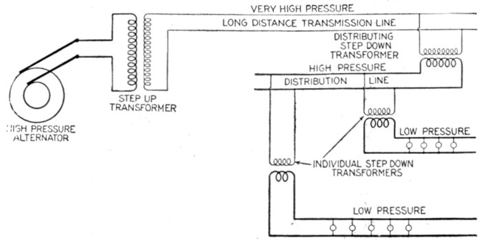
Fig. 2,141.—Diagram illustrating the use of step up and step down transformers on long distance
transmission lines. The saving in copper is considerable by employing extra high
voltages on lines of moderate or great length as indicated by the relative sizes of wire.
Ques. In practice, would such a system as shown in
fig. 2,141 be used?
Ans. If the greatest economy in copper were aimed at, a
three phase system would be used.
[Pg 1546]
The purpose of fig. 2,141 is to show the importance of the transformer
in giving a flexibility of voltage, by which the cost of the line is
reduced to a minimum.
Ques. Does the saving indicated in fig. 2,141 represent
a net gain?
Ans. No. The reduction in cost of the transmission is
partly offset by the cost of the transformers as well as by transformer
losses and the higher insulation requirements.
Fig. 2,142.—Single and twin circuit poles (Southern Power Co.). The twin circuit pole at the
right is used for 11,000 volt circuits, while the single circuit poles at the left carry 44,000
volt conductors, being used on another division for 100,000 volt line.
Every case of electric transmission presents its own problem, and
needs thorough engineering study to intelligently choose the system best
adapted for the particular case.
Single Phase Systems.—There are various arrangements
for transmission and distribution classed as single phase systems.
Thus, single phase current may be conveyed to the various[Pg 1547]
receiving units by the well known circuit arrangements known as
series, parallel, series parallel, parallel series, connections previously
described and illustrated in figs. 2,131 to 2,134.
Again single phase current may be transmitted by two wires
and distributed by three wires. This is done in several ways,
the simplest being shown in fig. 2,143.
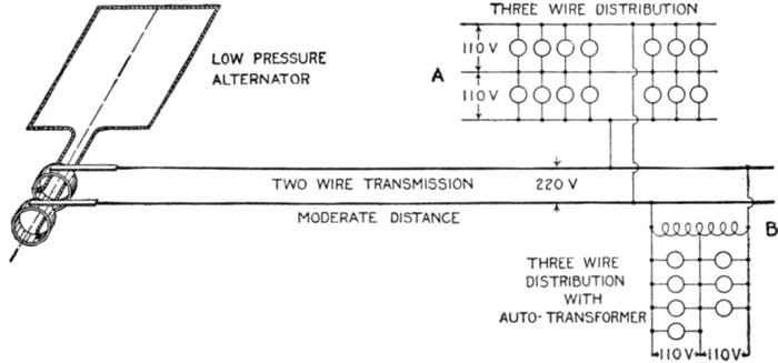
Fig. 2,143.—Diagram illustrating single phase two wire transmission and three wire distribution.
The simplified three wire arrangement at A, is not permissible except in cases of
very little unbalancing. Where the difference between loads on each side of the neutral
may be great some form of balancing as an auto-transformer or equivalent should be used,
as at B.
Ques. Under what conditions is the arrangement
shown in fig. 2,143 desirable?
Ans. This method of treating the neutral wire is only permissible
where there is very little unbalancing, that is, where
the load is kept practically the same on both sides of the neutral.
Ques. What advantage is obtained by three wire
distribution?
Ans. The pressure at the alternator can be doubled, which
means, for a given number of lamps, that the current is reduced[Pg 1548]
to half, the permissible
drop may be
doubled, the resistance
of the wires
quadrupled, and their
cost reduced nearly
75 per cent.
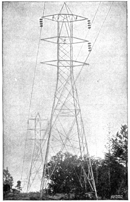
Fig. 2,144.—100,000 volt "Milliken" towers with one circuit
strung (Southern Power Co.). These towers are
mounted on metal stubs sunk 6 feet in the ground.
Where the angle of the line is over 15 degrees, however,
these stubs are weighted with rock and concrete, and
where an angle of over 30 degrees occurs, two and sometimes
three towers are used for making the turn. The
weight of the standard "Milliken" tower is 3,080 lbs.,
and its height from the ground to peak is 51 feet. The
towers are spaced to average eight to a mile and a strain
tower weighing 4,250 lbs. is used every mile. For particularly
long spans a special heavy tower weighing 6,000
lbs. is used. The circuits are transposed every 30 miles.
Multiple disc insulators are used, four discs being used
to suspend each conductor from standard towers and
ten discs to each conductor on strain towers. The
standard span is 600 feet, sag 11 ft at 50° Fahr.
Ques. What
modification of circuit
A (fig. 2,143),
should be made to
allow for unbalancing
in the three
wire circuit?
Ans. An auto-transformer
or "balance
coil" as it is
sometimes called
should be used as at B.
This is a very desirable
method of balancing
when the ratio of
transformation is not
too large.
Ques. For what
service would the
system shown in
fig. 2,143 be suitable?
Ans. For short
distance transmission,
as for instance, in[Pg 1549]
the case of an isolated plant because of the low pressure at
which the current is generated.
The standard voltages of low pressure alternators are 400, 480, and
600 volts.
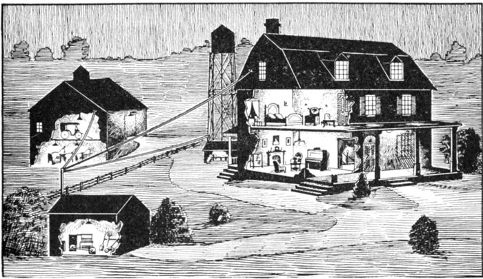
Fig. 2,145.—View of a typical isolated plant. The illustration represents an electric
lighting plant on a farm showing the lighting of the dwelling, barn, tool house
and pump house. The installation consists of a low voltage dynamo with gas engine
drive and storage battery together with the necessary auxiliary apparatus.
Ques. In practice are single phase alternators used
as indicated in fig. 2,143?
Ans. Alternators are wound for one, two or three phases.
Three phase machines are more commonly supplied and in
many cases it will pay to install them in preference to single
phase, even if they be operated single phase temporarily.
For a given output, three phase machines are smaller than single phase
and the single phase load can usually be approximately balanced between
the three phases. Moreover, if a three phase machine be installed,
polyphase current will be available in case it may be necessary to operate
polyphase motors at some future time.
Standard three phase alternators will carry about 70 per cent. of
their rated kilowatt output when operated single phase, with the same
temperature rise.
[Pg 1550]
Ques. How are three phase alternators used for single
phase circuits?
Ans. The single phase circuit is connected to any two of the
three phase terminal leads.
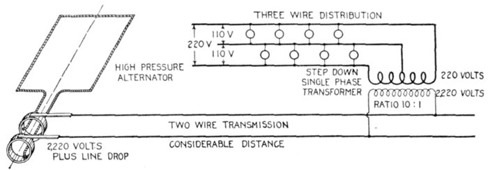
Fig. 2,146.—Diagram showing arrangement of single phase system for two wire transmission
and three wire distribution, where the transmission distance is considerable. In order
to reduce the cost of the transmission line, the current must be transmitted at high pressure;
this necessitates the use of a step down transformer at the distributing center
as shown in the illustration.
Ques. What form of single phase system should be
used where the transmission distance is considerable?
Ans. The current should be transmitted at high pressure,
a step down transformer being placed at each distribution
center to reduce the pressure to the proper voltage to suit the
service requirements as shown in fig. 2,146.
Thus, if 110 volt lamps be used on the three wire circuit, the pressure
between the two outer wires would be 220 volts. A transformation
ratio of say 10:1 would give 2,220 volts for the primary circuit. The
current required for the primary with this ratio being only .1 that
used in the secondary, a considerable saving is effected in the cost of the
transmission line as must be evident.
With the high pressure alternator only one transformation of the
current is needed, as shown at the distribution end.
In place of the high pressure alternator, a low pressure alternator
could be used in connection with a step up transformer as shown in
fig. 2,147, but there would be an extra loss due to the additional transformer,
rendering the system less efficient than the one shown in fig.
2,146. Such an arrangement as shown in the fig. 2,147 might be justified[Pg 1551]
in the case of a station having a low pressure alternator already in use
and it should be desired to transmit a portion of the energy a considerable
distance.
Ques. How could the system shown in fig. 2,147 be
made more efficient than that of fig. 2,146?
Ans. By using a high pressure alternator in order to considerably
increase the transmission voltage.
Thus, a 2,200 volt alternator and 1:10 step up transformer would
give a line pressure of 22,000 volts, which at the distribution end could
be reduced, to 220 volts for the three wire circuit, using a 100:1 step
down transformation.
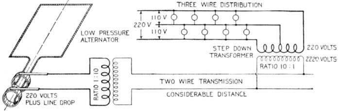
Fig. 2,147.—Diagram illustrating how electricity can be economically transmitted a considerable
distance with low pressure alternator already in use.
Ques. Would this be the best arrangement?
Ans. No.
Ques. What system would be used in practice for
maximum economy?
Ans. Three phase four wire.
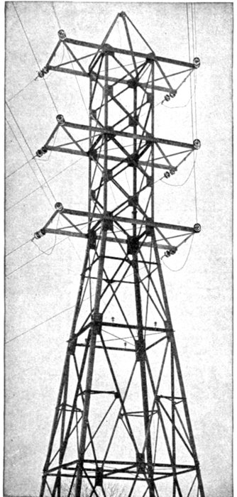
Fig. 2,148.—Angle tower showing General Electric
strain insulators. The tower being subject to
great torsional strains is erected on a massive concrete
foundation. The construction is similar to
the standard tower but of heavier material, and
having the same vertical dimensions but with
bases 20 ft. square.
Ques. What are the objections to single phase generation
and transmission?
Ans. It does not permit of the use of synchronous converters,
self-starting synchronous motors, or induction motor
starting under load. It is poorly adapted to general power[Pg 1552]
distribution, hence it is
open to grave objections
of a commercial nature
where there exists any
possibility of selling power
or in any way utilizing it
for general converter and
motor work.
Ques. For what service
is it desirable?
Ans. For alternating
current railway operation.
There are advantages of
simplicity in the entire
generating, primary, and
secondary distribution systems
for single phase roads.
These advantages are so
great that they justify considerable
expense, looked
at from the railway point
of view only, the single
phase system throughout
may be considered as offering
the most advantage.
Ques. What are the
objectionable features
of single phase alternators?
Ans. This type of alternator
has an unbalanced
armature reaction which
is the cause of considerable
flux variation in the[Pg 1553]
field pole tips and in fact throughout the field structure.
In order to minimize eddy currents, such alternators must
accordingly be built with thinner laminations and frequently
poorer mechanical construction, resulting in increased cost of
the machine. The large armature reaction results in a much
poorer regulation than that obtained with three phase alternators,
and an increased amount of field copper is required, also
larger exciting units. These items augment the cost so that
the single phase machine is considerably more expensive than
the three phase, of the same output and heating.
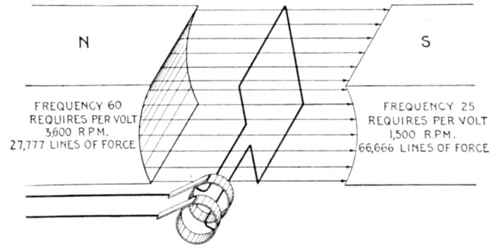
Fig. 2,149.—Elementary alternator developing one volt at frequencies of 60 and 25, showing
the effect of reducing the frequency. Since for the same number of pole, the R.P.M.
have to be decreased to decrease the frequency, increased flux is required to develop the
same voltage. Hence in construction, low frequency machines require larger magnets,
increased number of turns in series on the armature coils, larger exciting units as compared
with machines built for higher frequency.
Ques. What factor increases the difficulties of single
phase alternator construction?
Ans. The difficulties appear to increase with a decrease in
frequency.
The adoption of any lower frequency than 25 cycles may result in
serious difficulties in construction for a complete line of machine,
especially those of the two or four pole turbine driven type where the
field flux is very large per pole.
[Pg 1554]
Monocyclic System.—In this system, which is due to
Steinmetz, the alternator is of a special type. In construction,
there is a main single phase winding an auxiliary or teaser
winding connected to the central point of the main winding in
quadrature therewith.
The teaser coil generates a voltage equal to about 25 per cent. of
that of the main coil so that the pressure between the terminals
of the main coil and the free end of the teaser is the resultant
of the pressure of the two coils.
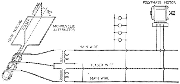
Fig. 2,150.—Diagram of monocyclic system, showing lighting and power circuits.
By various transformer connections it is possible to obtain
a practically correct three phase relationship so that polyphase
motors may be employed.
In this system, two wires leading from the ends of the single
phase winding in the alternator supply single phase current
to the lighting load, a third wire connected to the end of the
teaser being run to points where the polyphase motors are
installed as shown in fig. 2,150.
The monocyclic system is described at length in the chapter
on alternators, Guide No. 5, pages, 1,156 to 1,159.
[Pg 1555]
Two Phase Systems.—A two phase circuit is equivalent to
two single phase circuits. Either four or three wire may be
employed in transmitting two phase current, and even in the
latter instance the conditions are practically the same as for
single phase transmission, excepting the unequal current distribution
in the three wires. Fig. 2,151 shows a two phase
four wire system.
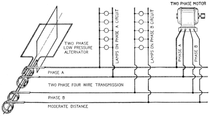
Fig. 2,151.—Diagram of two phase four wire system. It is desirable for supplying current
for lighting and power. The arrangement here shown should be used only for lines of
short or moderate length, because of the low voltage. Motors should be connected to a
circuit separate from the lighting circuit to avoid drop on the latter while starting a
motor.
Ques. For what service is the system shown in fig.
2,151 desirable?
Ans. It is adapted to supplying current for lighting and
power at moderate or short distances.
Either 110 or 220 volts are ordinarily used which is suitable for
incandescent lighting and for constant pressure arc lamps, the lamps
being connected singly or two in pairs.
[Pg 1556]
Ques. Where current for both power and light are
obtained from the same source how should the circuits
be arranged?
Ans. A separate circuit should be employed for each, in
order to avoid the objectionable drop and consequent dimming
of the lights due to the sudden rush of current during the starting
of a motor.
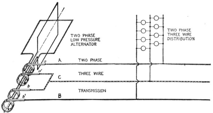
Fig. 2,152.—Diagram of two phase three wire system. A wire is connected to one end of
each phase winding as at A and B, and a third wire C, to the other end of both phases
as shown.
Disagreeable fluctuation of the lights are always met with when
motors are connected to a lighting circuit and the effect is more marked
with alternating current than with direct current, because most types of
alternating current motor require a heavy current usually lagging considerably
when starting. This not only causes a large drop on the
line, but also reacts injuriously upon the regulation of transformers
and alternators, their voltage falling much more than with an equal
non-inductive load.
Ques. What voltages are ordinarily used on two phase
lines of more than moderate length?
Ans. For transmission distances of more than two or three[Pg 1557]
miles, pressures of from 1,000 to 2,000 volts or more are employed
to economize in copper. For long distance transmission
of over fifty miles, from 30,000 to 100,000 volts and over are used.
Ques. For long distance transmission at 30,000 to
40,000 volts, what additional apparatus is necessary?
Ans. Step up and step down transformers.
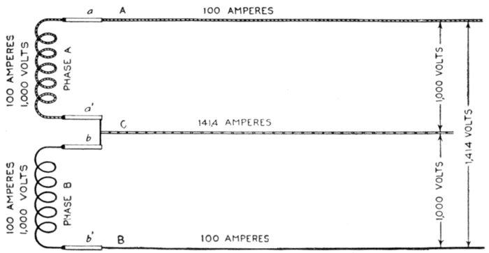
Fig. 2,153.—Diagram illustrating two phase three wire transmission. The third wire C is
attached to the connector between one end of phase A, and phase B windings.
Ques. Explain the method of transmitting two phase
current with three wires.
Ans. The connections at the alternator are very simple as
shown in fig. 2,152. One end of each phase winding is connected
by the brushes a and b', to one of the circuit wires, that is to
A and B respectively. The other end of each phase winding is
connected by a lead across brushes a' and b, to which the third
wire C is joined.
The current and pressure conditions of this system are represented
diagrammatically in fig. 2,153. The letters correspond to those in fig.
2,152, with which it should be compared.
[Pg 1558]
As shown in the figure each coil is carrying 100 amperes at 1,000
volts pressure. Since the phase difference between the two coils is
90°, the voltage between A and B is √2 = 1.414 times that between
either A or B and the common return wire C.
The current in C is √2 = 1.414 times that in either outside wire A or
B, as indicated.
Ques. How should the load on the two phase three
wire system be distributed?
Ans. The load on the two phases must be carefully balanced.
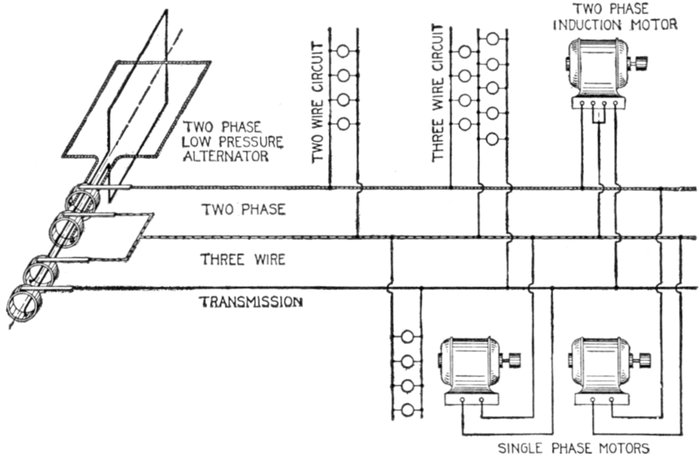
Fig. 2,154.—Diagram of two phase three wire system and connections for motors and lighting
circuits.
Ques. Why should the power factor be kept high?
Ans. A high power factor should be maintained in order to
keep the voltage on the phases nearly the same at the receiving
ends.
Ques. How should single phase motors be connected
and what precaution should be taken?
Ans. Single phase motors may be connected to either or[Pg 1559]
both phases, but in such cases, no load should be connected
between the outer wires otherwise the voltages on the different
phases will be badly unbalanced.
Fig. 2,154 shows a two phase three wire system, with two wire and
three wire distribution circuits, illustrating the connection for lighting
and for one and two phase motors.
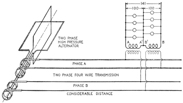
Fig. 2,155.—Diagram of two phase system with four wire transmission and three wire distribution.
In the three wire circuits the relative pressures between conductors are as
indicated; that is, the pressure between the two outer wires A and B is 141 volts, when
the pressure between each outer wire and the central is 100 volts.
Ques. Describe another method of transmission and
distribution with two phase current.
Ans. The current may be transmitted on a four wire circuit
and distributed on three wire circuit as in fig. 2,155.
The four wire transmission circuit is evidently equivalent to two
independent single phase circuits.
In changing from four to three wires, it is just as well to connect the
two outside wires A and B together (fig. 2,152), as it is to connect a´
and b. It makes no difference which two secondary wires are joined
together, so long as the other wires of each transformer are connected
to the outside wires of the secondary system.
[Pg 1560]
Ques. For what service is the two phase three wire
system adapted?
Ans. It is desirable for supplying current of minimum
pressure to apparatus in the vicinity of transformers. It is more
frequently used in connection with motors operating from the
secondaries of the transformers.
Ques. How should the third or common return wire
be proportioned?
Ans. Since the current in the common return wire is 41.4 per
cent. higher than that in either of the other wires it must be of
correspondingly larger cross section, to keep the loss equal.
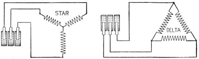
Figs. 2,156 and 2,157.—Conventional diagrams illustrating star and delta connected three phase
alternator armatures.
Ques. What is the effect of an inductive load on the
two phase three wire system and why?
Ans. It causes an unbalancing of both sides of the system
even though the energy load be equally divided. The self-induction
pressure in one side of the system is in phase with
the virtual pressure in the other side, thus distorting the current
distribution in both circuits.
Ques. Describe the two phase five wire system.
Ans. A two phase circuit may be changed from four to five
wires by arranging the transformer connections as in fig. 2,158.
[Pg 1561]
As shown, the secondaries of the transformers are joined in series and
leads brought out from the middle point of each secondary winding
and at the connection of the two windings, giving five wires.
With 1,000 volts in the primary windings and a step down ratio of
10:1, the pressure between A and C and C and E will be 100 volts
and between the points and the connections B or D at the middle of
the secondary coils, 50 volts.
The pressure across the two outer wires A and E is, as in the three
wire system, √2 or 1.41 times that from either outer wire to the middle
wire C, that is 141 volts.
The pressure across the two wires connected to the middle of the
coils, that is, across B and D, is 50 × √2 = 70.5 volts.
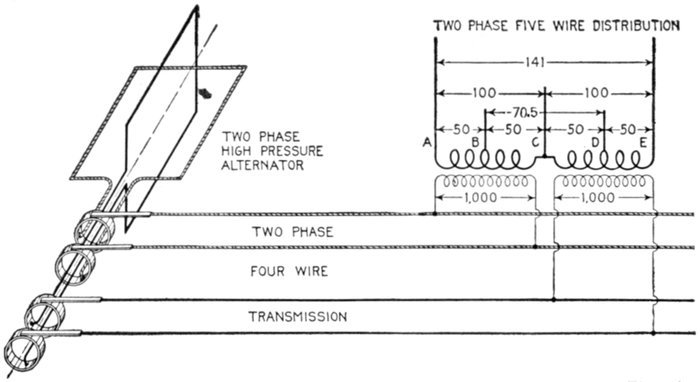
Fig. 2,158.—Two phase four wire transmission and five wire distribution system. The relative
pressures between the various conductors are indicated in the diagram.
Three Phase Systems.—There are various ways of arranging
the circuit for three phase current giving numerous
three phase systems.
1. With respect to the number of wires used they may be
classified as
- a. Six wire;
- b. Four wire;
- c. Three wire.
[Pg 1562]
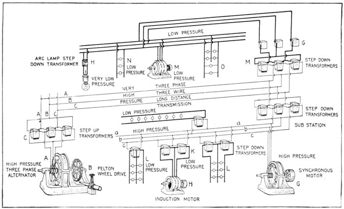
Fig. 2,159.—Line connections of three phase three wire long distance transmission, and distribution system. The three phase alternator
A, is driven by the water wheel B, and furnishes current at say 2,200 volts plus sufficient pressure to compensate for line
drop. With 1:10 step up transformers C, this would give a transmission pressure of 22,000 volts plus line drop. It is this transformation
that secures the copper economy of the system. At the distribution end are the step down transformers; one set
reducing the voltage down to 2,200 volts, and supplying current direct to the synchronous motor, and through another set of other
step down transformers, as L and K, to lighting and power circuits at 220 volts. Another set of step down transformers M reduce
the pressure directly to 120 volts for power and lighting, the pressure being regulated by the regulators G. Arc lamps with individual
transformers further reducing the pressure to 50 volts are connected to this circuit as shown.
[Pg 1563]
2. With respect to the connections, as
- a. Star;
- b. Delta;
- c. Star delta;
- d. Delta star.
The six wire system is shown in fig. 2,160. It is equivalent
to three independent single phase circuits. Such arrangement
would only be used in very rare instances.
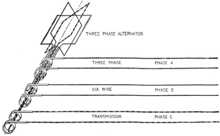
Fig. 2,160.—Three phase six wire system. It is equivalent to three independent single phase
circuits and would be used only in very rare cases.
Ques. How can three phase current be transmitted
by three conductors?
Ans. The arrangement shown in fig. 2,160 may be resolved
into three single circuits with a common or grounded return.
When the circuits are balanced the sum of the current being zero
no current will flow in the return conductor, and it may be dispensed
with, thus giving the ordinary star or Y connected three wire circuit,
as shown in fig. 2,163. The transformation from six to three wires
being shown in figs. 2,161 to 2,163.
[Pg 1564]
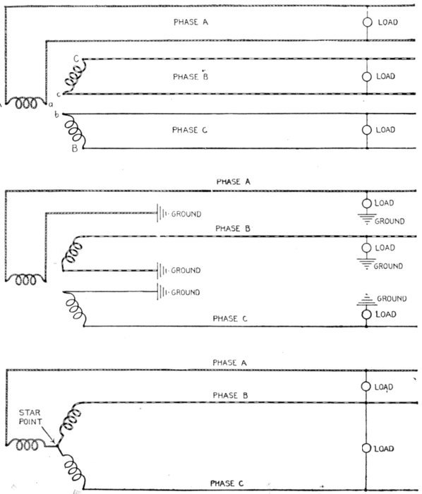
Figs. 2,161 to 2,163.—Evolution of the three phase three wire system. Fig. 2,161 is a conventional
diagram of the three phase six wire system shown in fig. 2,160. A wire is connected
to both ends of each phase winding, giving six conductors, or three independent
two wire circuits. In place of the wires running from A, B, and C, they may be removed
and each circuit provided with a ground return as shown in fig. 2,162. The sum of the
three currents being zero, or nearly zero, according to the degree of unbalancing, the
ground return may be eliminated and the ends A, B, and C of the three phase winding
connected, as in fig. 2,163, giving the so called star point.
[Pg 1565]
Fig. 2,166 is a view of an elementary three phase three wire star
connected alternator.
Ques. What are the pressure and current relations
of the star connected three wire system?
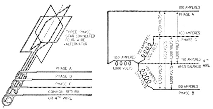
Figs. 2,164 and 2,165.—Three phase four wire star connected alternator and conventional
diagram showing pressure and current relations.
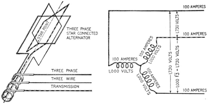
Figs. 2,166 and 2,167.—Three phase star connected alternator, and conventional diagram
showing pressure relations.
Ans. These are shown in the diagram, fig. 2,166 and 2,167.
[Pg 1566]
Assuming 100 amperes and 1,000 volts in each phase winding, the
pressure between any two conductors is equal to the pressure in one
winding multiplied by √3, that is 1,000 × 1.732 = 1,732 volts.
The current in each conductor is equal to the current in the winding,
or 100 amperes.
Ques. Describe the delta connection.
Ans. In the delta connection, the three phase coils are connected
together forming an endless winding, leads being brought
out from these points.
Fig. 2,168 shows a delta connected three phase alternator, the pressure
and current relation being given in fig. 2,169.
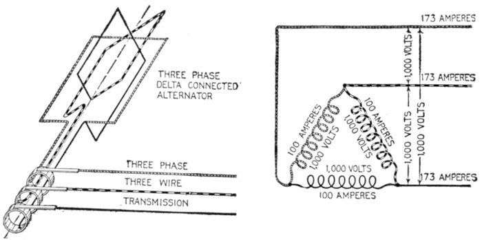
Figs. 2,168 and 2,169.—Three phase delta connected alternator and conventional diagram
showing pressure and current relations.
Ques. What are the pressure and current relations
of the delta connected three wire system?
Ans. They are as shown in fig. 2,169.
Assuming 100 amperes and 1,000 volts in each phase winding, the
pressure between any two conductors is the same as the pressure in
the winding, and the current in any conductor is equal to the current
in the winding multiplied by √3, that is 100 × 1.732 = 173.2 amperes,
that is, disregarding the fraction, 173 amperes.
[Pg 1567]
Ques. What are the relative merits of the star and
delta connections?
Ans. The power output of each is the same, but the star
connection gives a higher line voltage, hence smaller conductors
may be used.
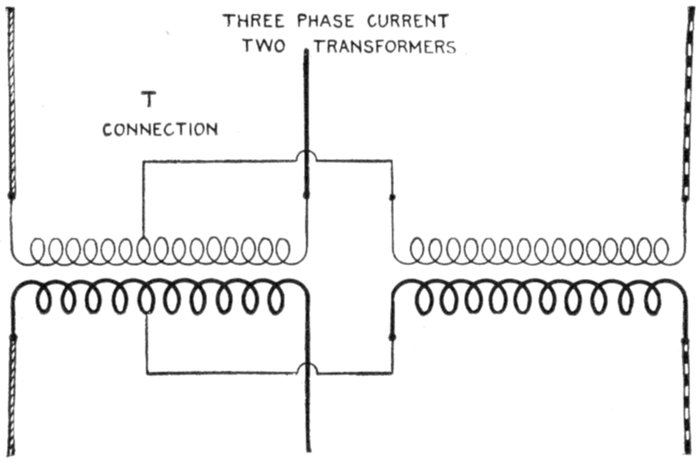
Fig. 2,170.—T connection of transformers in which three phase current is transformed with
two transformers. The connections are clearly shown in the illustration. The voltage
across one transformer is only 86.6% of that across the other, so that if each transformer
be designed especially for its work one will have a rating of .866 EI and the other EI.
The combined rates will then be 1.866 as compared with 1.732 EI for three single phase
transformers connected either star or delta.
When it is remembered that the cost of copper conductors is inversely
as the square of the voltage, the advantage of the Y connected system
can be seen at once.
Assuming that three transformers are used for a three phase system
of given voltage, each transformer, star connected, would be wound
for 1 ÷ √3 = 58% of the given voltage, and for full current.
For delta connection, the winding of each transformer is for 58% of
the current. Accordingly the turns required for star connection are
only 58% of those required for delta connection.
Ques. What is the objection to the star connection
for three phase work?
Ans. It requires the use of three transformers, and if anything
happen to one, the entire set is disabled.
[Pg 1568]
Ques. Does this defect exist with the delta connection?
Ans. No.
One transformer may be cut out and the other two operated at full
capacity, that is at ⅔ the capacity of the three.
Ques. Describe the T connection.
Ans. In this method two transformers are used for transforming
three phase current. It consists in connecting one
end of both windings of one transformer to the middle point of
like windings of the other transformer as in fig. 2,170.
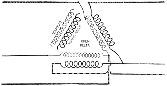
Fig. 2,171.—Open delta connection or method of connecting two transformers in delta for three
phase transformation. It is used when one of the three single phase delta connected transformers
becomes disabled.
Ques. What is the open delta connection?
Ans. It is a method of arranging the connections of a bank
of three delta connected transformers when one becomes disabled
as in fig. 2,171.
Change of Frequency.—There are numerous instances
where it is desirable to change from one frequency to another,
as for instance to join two systems of different frequency which[Pg 1569]
may supply the same or adjacent territory, or, in the case of a
low frequency installation, in order to operate incandescent
lights satisfactorily it would be desirable to increase the frequency
for such circuits. This is done by motor generator sets,
the motor taking its current from the low frequency circuit.
Synchronous motors are generally used for such service as
the frequency is not disturbed by load changes; it also makes it
possible to use the set in the reverse order, that is, taking power
from the high frequency mains and delivering energy at low
frequency.
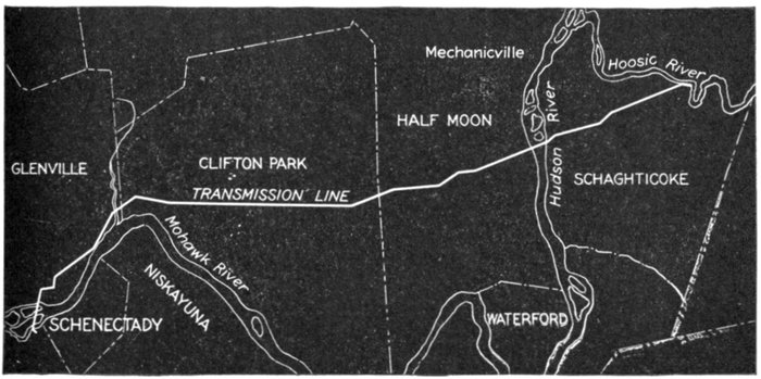
Fig. 2,172.—Course of the Schaghticoke-Schenectady transmission line of the Schenectady Power
Co. This transmission line carries practically the entire output of the Schaghticoke power
house to Schenectady, N. Y., a distance of approximately 21 miles. The line consists
of two separate three phase, 40 cycle, 32,000 volt circuits, each of 6,000 kw. normal capacity.
These circuits start from opposite ends of the power house, and, after crossing the Hoosic
River, are transferred by means of two terminal towers, fig. 2,173, to a single line of transmission
towers. The two circuits are carried on these on opposite ends of the cross arms,
the three phases being superimposed. The power house ends of the line are held by six
short quadrangular steel lattice work anchor poles with their bases firmly embedded in concrete,
the cables being dead ended by General Electric disc strain insulators. This equipment,
together with the lightning arrester horn gaps and the heavy line outlet insulators mounted
on the roof of the power house, is shown in fig. 2,174. While each circuit carries only
6,000 kw. under normal conditions, either is capable of carrying the entire output of the
station; in this case, however, the line losses are necessarily augmented. This feature
prevents any interruption of the service from the failure of one of the circuits. There are
altogether 197 transmission towers, comprising several distinct types.
[Pg 1570]
Ques. In the parallel operations of frequency changing
sets what is necessary to secure equal division of the load?
Ans. The relative angular position of the rotating elements
of motor and generator must be the same respectively in each set.
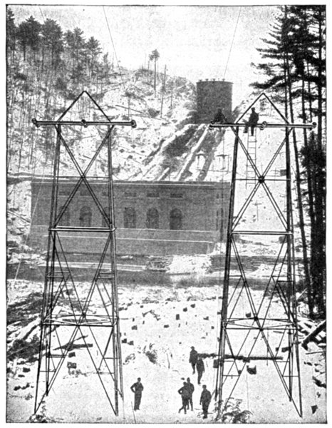
Fig. 2,173.—Beginning of Schaghticoke-Schenectady transmission line; view showing transfer
towers with power house in background.
Ques. How is this obtained?
Ans. Because of the mechanical difficulty of accurately[Pg 1571]
locating the parts, the
equivalent result is secured
by arranging the
stationary element in
one of the two machines
so that it can be given
a small angular shift.
Transformation of
Phases.—In alternating
current circuits it is
frequently desirable to
change from one number
of phases to another.
For instance, in the case
of a converter, it is less
expensive and more
efficient to use one built
for six phases than for
either two or three
phases.
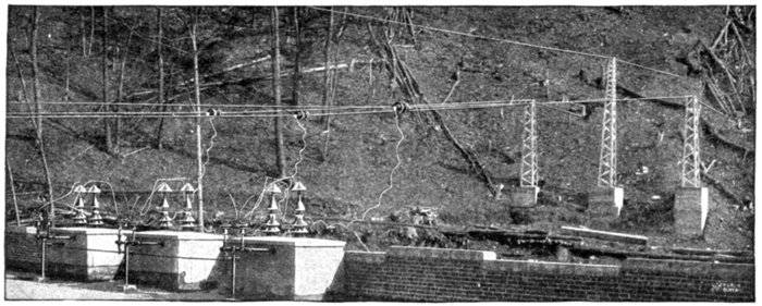
Fig. 2,174.—View from roof of power house of the Schaghticoke-Schenectady transmission line, showing anchor poles,
strain insulators, lightning arrester horn gap and line entrance bushings.
The numerous conditions
met with necessitate
various phase
transformations, as
- 1. Three phase to one phase;
[Pg 1572]
- 2. Three phase to two phase;
- 3. Two phase to six phase;
- 4. Three phase to six phase.
These transformations are accomplished by the numerous
arrangements and combinations of the transformers.
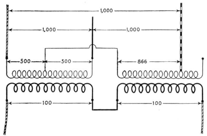
Fig. 2,175.—Three phase to one phase transformation with two transformers. The diagram
shows the necessary connections and the relative pressures obtained.
Three Phase to One Phase.—This transformation may be
accomplished by the use of two transformers connected as in
fig. 2,175 in which one end of one primary winding is connected
to the middle of the other primary winding and the second end
of the first primary winding at a point giving 86.6 per cent. of
that winding as shown. The two secondary windings are joined
in series.
Three Phase to Two Phase.—The three phase system is
universally used for long distance transmission, because it
requires less copper than either the single or two phase systems.[Pg 1573]
For distribution, however, the two phase system presents
certain advantages, thus, it becomes desirable at the distribution
centers to change from three phase to two phase. This may be
done in several ways.
Ques. Describe the Scott connection.
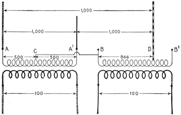
Fig. 2,176.—The Scott connection for transforming from three phase to two phase. In this
method one of the primary wires B of the .866 ratio transformer is connected to the middle
of the other primary as at C, the ends of which are connected to two of the three phase
wires. The other phase wire is connected at D, the point giving the .866 ratio. The
secondary wires are connected as shown.
Ans. Two transformers are used, one having a 10:1 ratio,
and the other, a ½√3:1, that is, an 8.66:1 ratio. The connections
are arranged as in fig. 2,176.
It is customary to employ standard transformers having the ratios
10:1, and 9:1.
Ques. What names are given to the two transformers?
Ans. The one having the 10:1 ratio is called the main
transformer, and the other with the 8.66:1 ratio, the teaser
transformer.
[Pg 1574]
In construction, the transformers may be made exactly alike so that
either may be used as main or teaser.
In order that the connections may be properly and conveniently
made, the primary windings should be provided with 50% and 86.6%
taps.
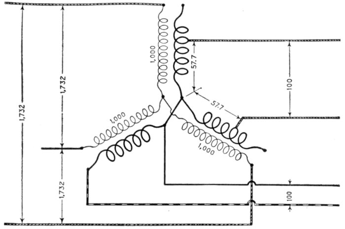
Fig. 2,177.—Three phase to two phase transformation with three star connected transformers.
Two of the secondary windings are tapped at points corresponding to 57.7% of full voltage;
these two windings are connected in series to form one secondary phase of voltage equal
to that obtained by the other full secondary winding.
Ques. Describe another way of transforming from
three to two phases.
Ans. The transformation may be made by three star connected
transformers, proportioning the windings as in fig. 2,177,
from which it will be seen that two of the secondary windings
are tapped at points corresponding to 57.7 per cent. of full
voltage.
[Pg 1575]
Three Phase to Six Phase.—This transformation is usually
made for use with rotary converters and may be accomplished
in several ways. As these methods have been illustrated in
the chapter on Converters (page 1,462), it is unnecessary to
again discuss them here. Fig. 2,178, below shows the diametrical
connection for transforming three phase to six phase.
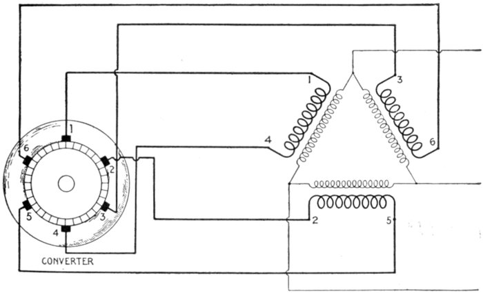
Fig. 2,178.—Diagram of diametrical connection, three phase to six phase. It is obtained
by bringing both ends of each secondary winding to opposite points on the rotary converter
winding, utilizing the converter winding to give the six phases. This transformation
of phases may also be obtained with transformers having two secondary windings.
Alternating Current Systems.—The saving in the cost
of transmission obtained by using alternating instead of direct
current is not due to any difference in the characteristics of the
currents themselves, but to the fact that in the case of alternating
current very high pressures may be employed, thus
permitting a given amount of energy to be transmitted with a
relatively small current.
[Pg 1576]
In the case of direct current systems, commutator troubles
limit the transmission pressure to about 1,000 volts, whereas
with alternating current it may be commercially generated at
pressures up to about 13,000 and by means of step up transformers,
transmitted at 110,000 volts or more.
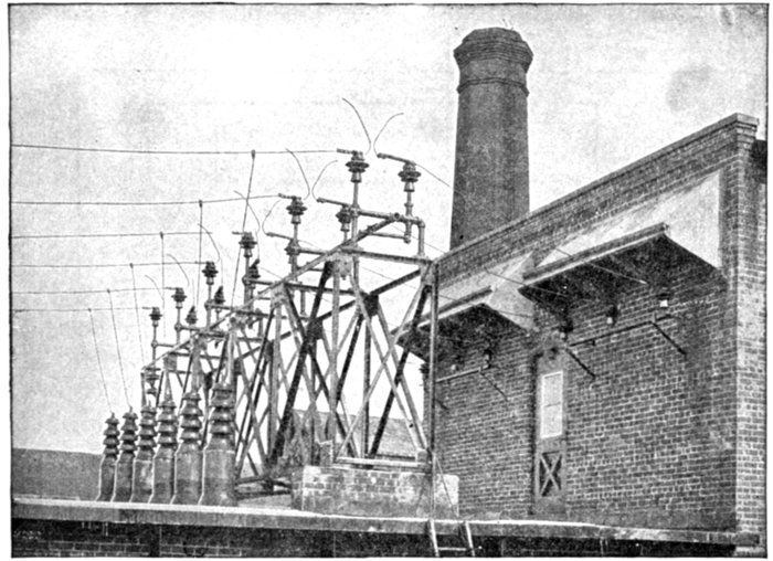
Fig. 2,179.—End of Schaghticoke-Schenectady transmission line at Schenectady; view showing
entrance bushings and lightning arrester horn gaps.
Relative Weights of Copper Required by Polyphase
Systems.—A comparison between the weights of copper required
by the different alternating current systems is rendered
quite difficult by the fact that the voltage ordinarily measured
is not the maximum voltage, and as the insulation has to withstand
the strain of the maximum voltage, the relative value of
copper obtained by calculation depends upon the basis of comparison
adopted.
[Pg 1577]
As a general rule, the highest voltage practicable is used for
long distance transmission, and a lower voltage for local distribution.
Furthermore, some polyphase systems give a multiplicity
of voltages, and the question arises as to which of these
voltages shall be considered the transmission voltage.
If the transmission voltage be taken to represent that of the
distribution circuit, and the polyphase system has as many
independent circuits as there are phases, the system would
represent a group of several single phase systems, and there
would be no saving of copper. Under these conditions, if the
voltage at the distant end be taken as the transmission voltage,
and the copper required by a single phase two wire system as
shown in fig. 2,180, be taken as the basis of comparison, the
relative weights of copper required by the various polyphase
systems is given in figs. 2,181 to 2,188.
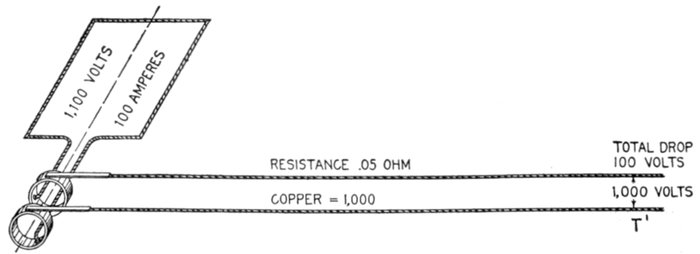
Fig. 2,180.—Single phase line, used as basis of comparison in obtaining the relative weights of
copper required by polyphase systems, as indicated in figs. 2,181 to 2,188.
In the case represented in fig. 2,180, if the total drop on the
line be 100 volts, the generated voltage must be 1,100 volts,
and the resistance of each line must be 50 ÷ 1,000 = .05 ohms.
Calculated on this basis, a two phase four wire system is equivalent
to two single phase systems and gives no economy of copper
in power transmission over the ordinary single phase two wire[Pg 1578]
system. This is the case also with any of the other two phase
systems, except the two phase three wire system.
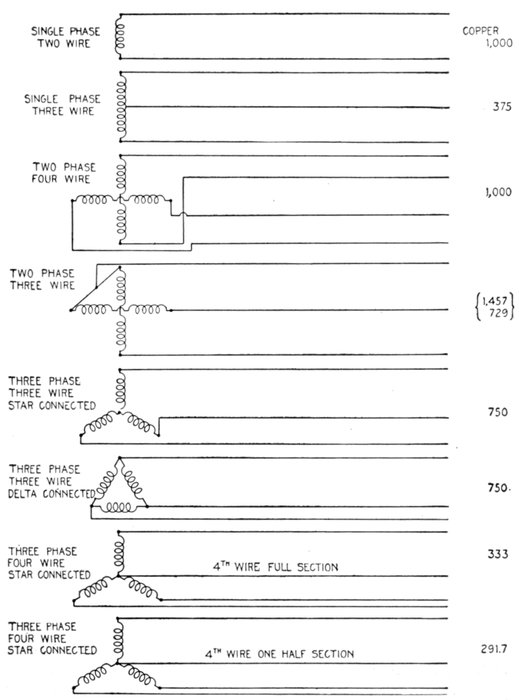
Figs. 2,181 to 2,188.—Circuit diagrams showing relative copper economy of various alternating
current systems.
[Pg 1579]
In this system two of the four wires of the four wire two phase system
are replaced by one of full cross section.
The amount of copper required, when compared with the single
phase system, will differ considerably according as the comparison is
based on the highest voltage permissible for any given distribution,
or on the minimum voltage for low pressure service.
If E be the greatest voltage that can be used on account of the insulation
strain, or for any other reason, the pressure between the other
conductors of the two phase three wire system must be reduced to
E ÷ √2.
The weight of copper required under this condition is 145.7% that
of the single phase copper.
On the basis of minimum voltage, the relative amount of copper
required is 72.9% that of the single phase system.
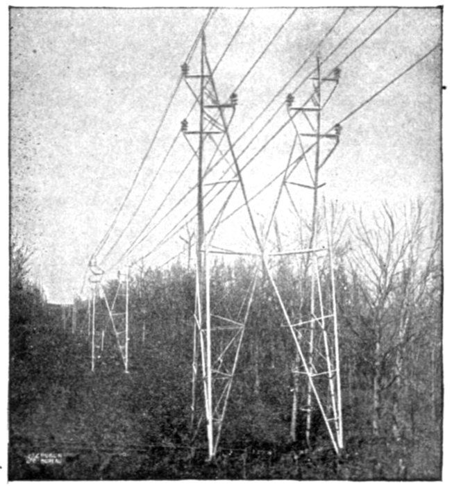
Fig. 2,189.—Twin circuit "aermotor" towers carrying 44,000 volt conductors (Southern
Power Co.). These towers vary in height from 35 to 50 feet, and the circuits are transposed
every 10 miles. The towers are assembled on the ground and erected by means of
gin poles. They are normally spaced 500 feet apart with a sag of 5 feet 8 inches. The
minimum distance between towers is 300 feet and the maximum 700 feet.
[Pg 1580]
Figs. 2,187 and 2,188 are two examples of three phase four wire systems.
The relative amount of copper required as compared with the
single phase system depends on the cross section of the fourth wire.
The arrangement shown in fig. 2,188, where the fourth wire is only
half size, is used only for secondary distribution systems.
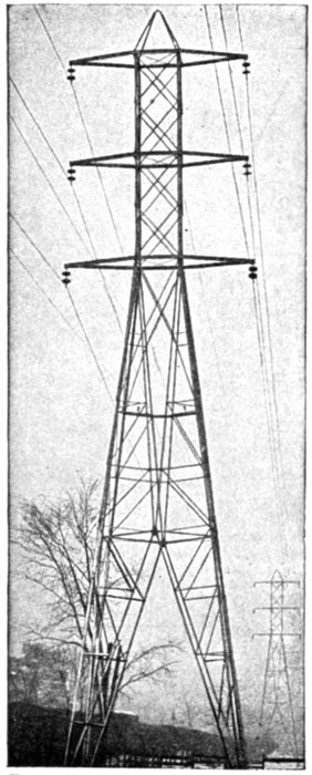
Fig. 2,190.—General Electric standard tower for high tension three phase transmission line.
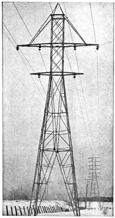
Fig. 2,191.—General Electric transposition tower for high tension three phase transmission line.
Choice of Voltage.—In order to properly determine the
voltage for a transmission system there are a number of[Pg 1581]
conditions which must be considered in order that the economy
of the entire installation shall be a maximum.
The nature of the diversely various factors which affect the
problem makes a mathematical expression difficult and unsatisfactory.
Ques. What is the relation between the cross sectional
area of the conductors and the voltage?
Ans. For a given circuit, the cross sectional area of the
conductors, or weight varies inversely as the voltage.
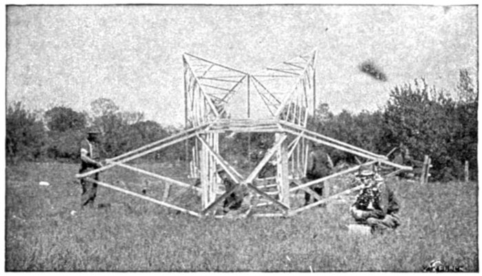
Fig. 2,192.—General Electric standard tower under construction.
Ques. Would the highest possible voltage then be used
for a transmission line?
Ans. The most economical voltage depends on the length
of the line and the cost of apparatus.
For instance, alternators, transformers, insulation and circuit control
and lightning protection devices become expensive when manufactured
for very high pressures. Hence if a very high pressure were used,
it would involve that the transmission distance be great enough so
that the extra cost of the high pressure apparatus would be offset by
the saving in copper effected by using the high pressure.
[Pg 1582]
In the case of the longest lines, from about 100 miles up, the saving
in copper with the highest practicable voltage is so great that the
increase in other expenses is rendered comparatively small.
In the shorter lines as those ranging in length from about one mile
to 50 or 75 miles, the most suitable voltage must be determined in
each individual case by a careful consideration of all the conditions
involved. No fixed rule can be established for proper voltage based
on the length, but the following table will serve as a guide:
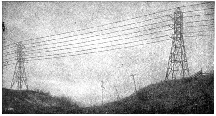
Fig. 2,193.—Line of the Schenectady Power Company crossing the tracks of the Boston and
Maine Railroad near Schaghticoke.
Usual Transmission Voltages
| Length of line in miles |
Voltage |
| 1 |
500 to 1,000 |
| 1 to 2 |
1,000 to 2,300 |
| 2 to 3 |
2,300 to 6,600 |
| 3 to 10 |
6,600 to 13,200 |
| 10 to 15 |
13,200 to 22,000 |
| 15 to 20 |
22,000 to 44,000 |
| 20 to 40 |
44,000 to 66,000 |
| 40 to 60 |
66,000 to 88,000 |
| 60 to 100 |
88,000 to 110,000 |
[Pg 1583]
Ques. What are the standard voltages for alternating
current transmission circuits?
Ans. 6,600, 11,000, 22,000, 33,000, 44,000, 66,000, 88,000.
The amount of power to be transmitted determines, in a measure, the
limit of line voltage. If the most economical voltage considered from
the point of view of the line alone, be somewhere in excess of 13,200,
step up transformers must be employed, since the highest voltage for
which standard alternators are manufactured is 13,200. In a given case,
the saving in conductor by using the higher voltage may be more than
offset by the increased cost of transformers, and the question must be
determined for each case.
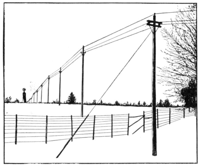
Fig. 2,194.—View of a three phase, 2,300 volt, 60 cycle line at Chazy, N. Y. The current is
transmitted at the alternator voltage 2¾ miles over the single circuit pole line. The
poles are of cedar with fir cross arms, and are fitted with pin insulators. They are from
35 to 40 feet high and are spaced at an average of about 120 feet. The conductors are
bare copper wire No. 00 B. & S. The alternators consist of one 50 kw., and one 100 kw.
General Electric machines.
Ques. What are the standard transformer ratios?
Ans. Multiples of 5 or 10.
[Pg 1584]
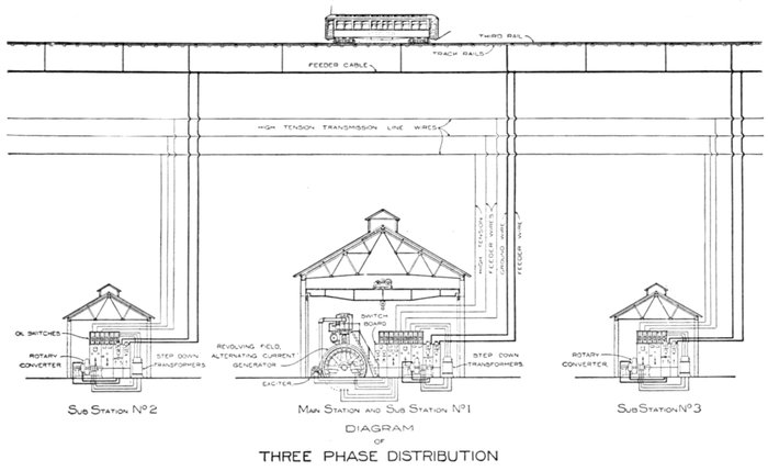
Figs. 2,195 to 2,197.—Diagram showing electric railway system. Three phase current is generated at the main station where it
passes to step up transformers to increase the pressure a suitable amount for economical transmission. At various points
along the railway line are sub-stations, where the three phase current is reduced in pressure to 500 or 600 volts by step down
transformers, and converted into direct current by rotary converters. The relatively low pressure direct current is then conveyed
by "feeders" to the rails, this resulting in a considerable saving in copper.
[Pg 1585]
Mixed Current Systems.—It is often desirable to transmit
electrical energy in the form of alternating current, and distribute
it as direct current or vice versa.
Such systems may be classed as mixed current systems. The
usual conversion is from alternating current to direct current
because of the saving in copper secured by the use of alternating
current in transmission, especially in the case of long
distance lines. Such conversion involves the use of a rotary
converter, motor generator set, or rectifier, according to the
conditions of service.
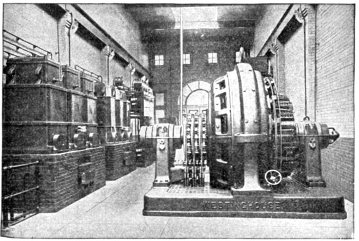
Fig. 2,198.—Example of converter sub-station, showing the Brooklyn Edison Co. Madison
sub-station. The transformers are seen on the left, the converter shown at the right is a
Westinghouse synchronous booster rotary converter, consisting of a standard rotary converter
in combination with a revolving armature alternator mounted on the same shaft
with the converter and having the same number of poles. The function of the machine
is to convert and regulate the pressure. By varying the field excitation of the alternator,
the A. C. voltage impressed on the rotary converter proper can be increased or decreased as
desired. Thus, the D. C. voltage delivered by the converter is varied accordingly. This
type of converter is well adapted for any application for which a relatively wide variation,
either automatic or non-automatic, in direct current voltage is necessary. Also especially
for serving incandescent lighting systems where considerable voltage variation is required
for the compensation of drop in long feeders, for operation in parallel with storage batteries
and for electrolytic work where extreme variations in voltage are required by changes in
the resistance of the electrolytic cells.
[Pg 1586]
The suburban trolley forms a good example of a mixed system,
in which alternating current is generated at the central station
and transmitted to sub-stations, where it is transformed to low
pressure, and converted into direct current for use on the line.
Fig. 2,195 shows the interior of a sub-station of this kind.
Ques. What direct current pressure is usually employed
on traction lines?
Ans. 500 volts.
Ques. Mention another important service performed
by a mixed system.
Ans. If the generator furnish alternating current it must be
converted into direct current in order to charge storage batteries.
[Pg 1587]
CHAPTER LVI
AUXILIARY APPARATUS
For the proper control of the alternating current in any of
the numerous systems described in the previous chapter, various
devices, which might be classed as "auxiliary apparatus," are
required. These may be grouped into several divisions,
according to the nature of the duty which they perform, as
1. Switching devices;
- a. Ordinary switches;
- b. Oil break switches;
- c. Remote control switches.
2. Current or pressure limiting devices;
- a. Fuses;
- b. Reactances;
- c. Circuit breakers;
- d. Relays.
3. Lightning protection devices;
- a. Air gap arresters;
- b. Multi-gap arresters;
- c. Horn gap arresters;
- d. Electrolytic arresters;
- e. Vacuum tube arresters;
- f. Choke coils;
- g. "Static" interrupters.
[Pg 1588]
4. Regulating devices;
- a. Induction voltage regulators;
- b. Variable ratio transformer regulators { drum type;
- { dial type;
- c. Compensation shunts;
- d. Pole type regulators;
- e. Small feeder voltage regulators;
- f. Automatic voltage regulators;
- g. Line drop compensators;
- h. Starting compensators;
- i. Star delta switches.
5. Power factor regulating devices;
- a. Condensers;
- b. Synchronous condensers.
6. Indicating devices;
- { plunger type;
- a. Moving iron instruments { inclined coil type;
- { magnetic vane type;
- b. Hot wire instruments;
- c. Induction instruments { shielded pole type;
- { repulsion type;
- d. Dynamometers;
- e. Instrument transformers;
- { commutator type;
- f. Watthour meters { induction type;
- { Faraday disc type;
- { synchronous motor type;
- g. Frequency indicators { resonance type;
- { induction type;
- { lamp type;
- h. Synchronism indicators { voltmeter type;
- { resonance type;
- { rotating field type;
- i. Power factor indicators { wattmeter type;
- { rotating field type;
- j. Ground detectors;
- k. Earth leakage cut outs;
- l. Oscillographs.
[Pg 1589]
CHAPTER LVII
SWITCHING DEVICES
A switch is a piece of apparatus for making, breaking, or changing
the connections in an electric circuit.
The particular form and construction of any switch is governed
by the electrical conditions under which it must operate.
Since the electric current cannot be stopped instantly when
the circuit in which it is flowing, is broken, an arc is formed as
the switch contacts separate; this tends to burn the contacts,
and to short circuit, the severity of such action depending on
the voltage and the proximity of the switch terminals. Accordingly
in switch design, provision must be made to counteract
these tendencies. Thus,
- 1. The contacts should separate along their entire length, rather than at a point;
- 2. The terminals should be far enough apart and properly protected to prevent short circuiting of the arcs;
- 3. The break should be quick;
- 4. The gap should be surrounded by the proper medium (air or oil) to meet the requirements of the electrical conditions.
A great variety of switches have been introduced to suit the
different requirements. Knife switches are used for low pressure
service, the multiple break form being used where it is desired
to reduce the arcing distance.
[Pg 1590]
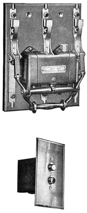
Figs. 2,199 and 2,200.—General
Electric triple pole solenoid
operated, single throw remote
control switch, and push button
switch for operating same.
Switch is a self-contained unit
with two sets of contacts,
main laminated copper brushes,
and carbon auxiliary contacts
to take the arc on breaking
the circuit. The main brushes
are so made that each lamination
makes an end on contact
with the switch blade without
any tendency to force the laminations
apart. A wiping effect,
given to the contacts every
time the switch is closed, keeps
the contact surfaces clean and
insures good contact at all
times. The carbon auxiliary
contacts are made of blocks of
carbon fastened without screws.
In operation, the switch is
actuated by a double coil
solenoid, one coil for closing
and one for opening, controlled
by the single pole double
throw push button switch
shown in fig. 2,200, which is
normally in the open position
and remains closed only when
held by the operator. One of
these switches is furnished with
each control switch and must
always be used, as the solenoid
coils are not intended for continuous
service. The power
required to operate the remote
control switch is small, being
approximately 1.6 amperes at
110 volts, 0.81 amperes at 220
volts direct current, and 10
amperes at 110 volts, and 6
amperes at 220 volts alternating
current 60 cycles. The
main switch can be closed and
opened by hand, and the push
button located at any point.
Ques. How should
single throw switches
be installed?
Ans. They should open
downward so gravity will
keep them open.
[Pg 1591]
Ques. How should double throw switches be installed?
Ans. Horizontally.
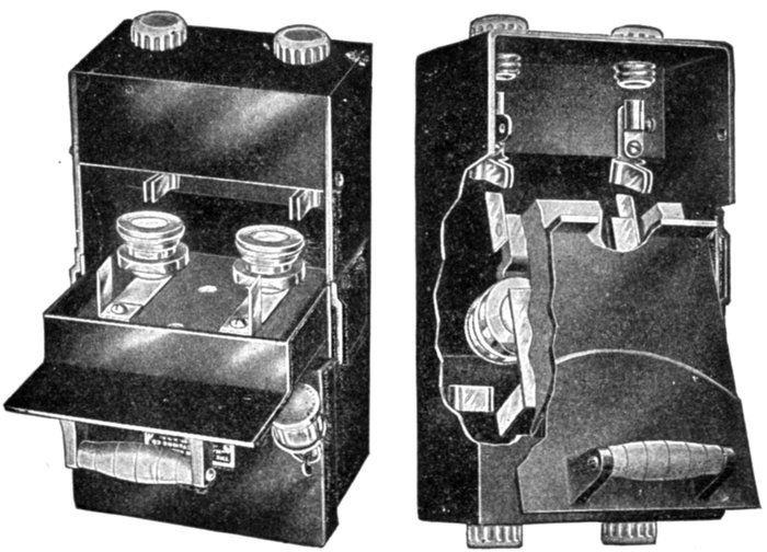
Figs. 2,201 and 2,202.—Palmer service switch and fuse box, for either plug, cartridge or
open link fuses. Fig. 2,201 illustrates the box in open position for the inspection of fuses,
etc. The cover is held open by a simple lock so that the switch cannot fall closed by
gravity, the box may be mounted so that the service wires lead directly into a sealed
terminal chamber from any direction, and all current carrying parts made accessible by
the opening of the switch are dead. Fig. 2,202 illustrates the device with side of box
and cover cut away to show interior and the normally sealed cover of terminal chamber
removed. The switch contacts do not enter their contact clips until the flanged cover
of the box has closed the switch opening, no current connections being made to line or
load until the box is completely closed, and in consequence there is no opportunity to
make improper connections to any live parts of switch, when conduit connections are
used to the service and meter wires.
Ques. What is a plug switch?
Ans. A switch in which the current is ruptured in a tube
enclosed at one end, thereby confining the arc and limiting the
supply of air.
They are used on high pressure circuits of from 10,000 to 20,000 volts,
for transferring live circuits and for voltmeter and synchronizing[Pg 1592]
circuits where there is very little energy. The usual current capacity is
from 4 to 7½ amperes.
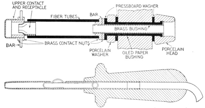
Fig. 2,203 and 2,204.—Bus transfer plug switch. The method of supporting the contact
farthest from the panel consists of a porcelain pillar of the same height as the receptacle,
clamped to a brass connecting or bus bar which in turn is fastened to the receptacle.
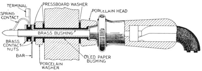
Fig. 2,205.—Ammeter jack. This plug switch is insulated for high pressure and consists of
two parts: the ammeter jack, and the ammeter jack plug, cable, and bushing. The receptacle,
which is simple in construction, consists of a brass bushing well insulated from the panel
and protected on the front of the panel by a porcelain bushing. On the end of this tube
and insulated from it, is a phosphor bronze spring which, when the plug is out, rests on the
brass tube and keeps the circuit closed. The plug consists of a brass rod well insulated and
set in a brass tube, both being fastened in a handle which is stained black and polished.
Inside the handle is run a twin conductor cable, one side being soldered in the brass tube
and the other to the brass rod. The other end of the cable is run through a bushing set in
the panel and thence to the ammeter or current transformer. Where it is desired to remove
the plug and cable from the board, or to plug both ends of the cable in different receptacles,
a plug instead of a bushing should be used. In this case a cable should be provided
with a plug on each end.
Forms of Break.—On high pressure circuits there are several
types of switch: they are classified with respect to the break,
that is to say, according as the break takes place,
[Pg 1593]
- 1. In open air;
- 2. In an enclosed air space;
- 3. Aided by a metal fuse;
- 4. Aided by a horn;
- 5. In oil.
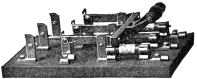
Fig. 2,206.—Westinghouse fused starting switch for squirrel cage motors. It is arranged for
National Electric Code fuses on one end only and has springs on the other end to open
the switch automatically if left closed at this end. The corresponding terminals at both
ends of the switch are connected in grooves in the back of the slate base so that the
wiring need be connected to one set of these terminals only, thus decreasing the number
of connections necessary, as shown in fig. 2,207. In starting an induction motor, the
switch is thrown to the end that is not fused and held there until the motor is up to
running speed; then it is quickly thrown to the fused position, thus protecting the circuit
under running conditions.
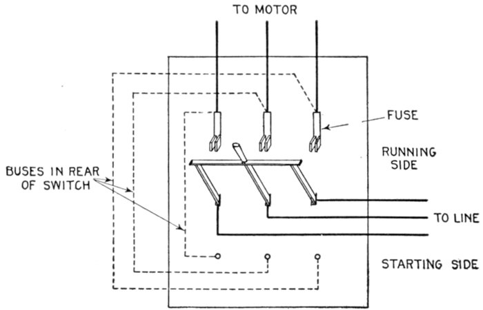
Fig. 2,207.—Diagram of connections of Westinghouse fused starting switch for squirrel cage
motors. The starting current of induction motors is several times the normal running
current and, when the controlling switch is fused to carry the running load only, the
fuses are apt to blow when the motor is started. The fuses must be of a capacity to
prevent overloads under running conditions. These switches are designed to meet this
difficulty and are used without auto-starters to control motors up to 5 horse power rating.
[Pg 1594]
Ques. What is the objection to open air break?
Ans. The relatively long gap required to extinguish the arc,
limiting this form of switch to low or moderate pressure circuits.
The open air arc may cause very high voltage oscillations when the
circuit contains inductance and capacity unless the break occur at
zero value.
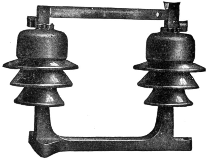
Fig. 2,208.—Westinghouse single pole disconnecting switch. Disconnecting switches are used
primarily for isolating apparatus from the circuit for purposes of inspection and repair;
also for sectionalizing feeders. They are not designed for opening under load, and therefore
no attempt should be made to open them with current in the circuit. In connection
with lightning arrester installations, disconnecting switches are particularly useful, providing
a simple and effective means for isolating the arresters while cleaning and inspecting.
The switch is opened and closed with a hook on the end of a wooden pole,
which hook engages in a hole provided in the switch blade. This type of disconnecting
switch is intended for wall mounting. The live parts are mounted on porcelain insulators
carried on a cast iron yoke or base, forming a simple and substantial construction.
Ques. What are disconnecting switches?
Ans. Knife switches in series with other switches so that the
apparatus controlled by the latter may be repaired in safety
by entirely disconnecting it from the bus bars or live circuit.
Such switches are not intended to rupture the load current.
[Pg 1595]
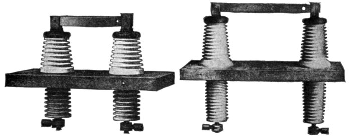
Figs. 2,209 and 2,210.—Westinghouse disconnecting switches for pressures over 3,300 volts.
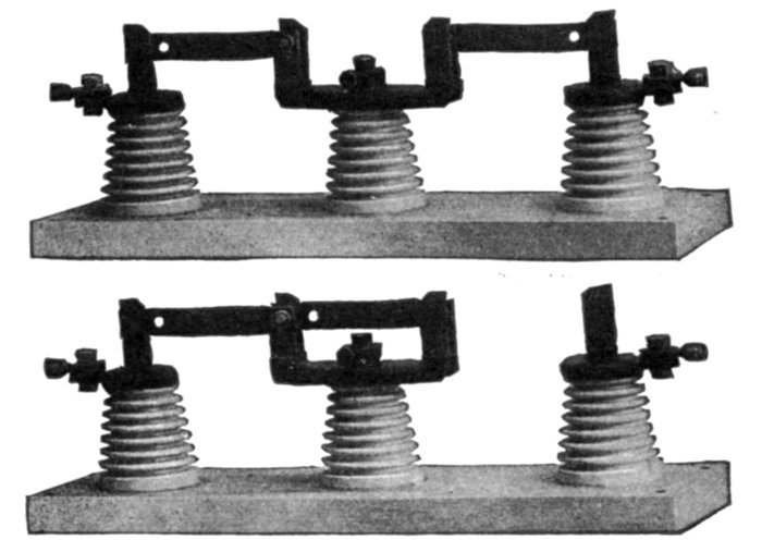
Figs. 2,211 and 2,212.—Westinghouse selector type disconnecting switch. Fig. 2,211, view
showing both sides closed; fig. 2,212, view with one side open. The selector type of
disconnecting switch is a transfer switch which does not require the circuit to be interrupted
while making the change. It can also be used to connect two independent circuits
in parallel. In construction, it is in effect two single throw, single pole disconnecting
switches with the hinge jaws connected together and mounted on the same insulator.
The hinge jaw is also provided with dummy jaws to hold either blade of the switch in
the open position. Except for these differences in the hinge jaws, the construction is
similar to the switch shown in fig. 2,209. It should not be used to open the circuit when
loaded.

Fig. 2,213.—Hook stick for operating a disconnecting switch.
[Pg 1596]
Ques. What are the features of the enclosed air break?
Ans. The switch is more compact than the open air break
type, but pressure oscillations are caused on opening the circuit
the same as with the open air break, and it is not desirable for
heavy current.
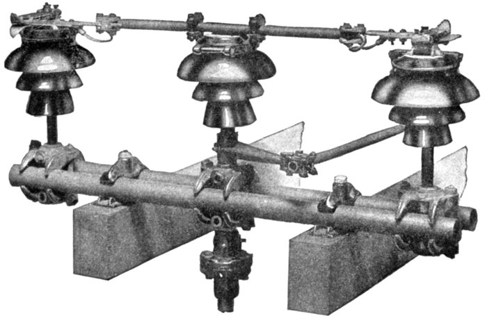
Fig. 2,214.—Baum 35,000 volt, 200 ampere, double break pole type switch. While designed for
disconnecting purposes only, it can break considerable amperage. The levers and couplings
are fastened with tape pins. The control shaft coupling is adjustable to any angle, and the
switch can be locked in the open or closed position. A removable wooden handle is supplied
and the switch can be handled in any weather. The arms can be extended to hold
fuse fittings, or dead end insulators in the event of a heavy strain, but it is preferable to
have fuses on another structure as a precaution against coming in contact with the
energized portion of the switch, and it is also preferable to take the strain of the line
on a pole a few feet from the switch, rather than on the switch structure, particularly
in the larger sizes. An insulating wood section in the control shaft separates the control
handle from the remainder of the switch. Discharging horns can be fitted to this
type of switch and when so equipped they have been found capable of breaking considerable
loads.
Ques. How is the fuse arranged in the metal fuse
break type of switch?
Ans. It is placed in a tube fitted with powdered carbonate
of lime or some other insulating powder.
[Pg 1597]
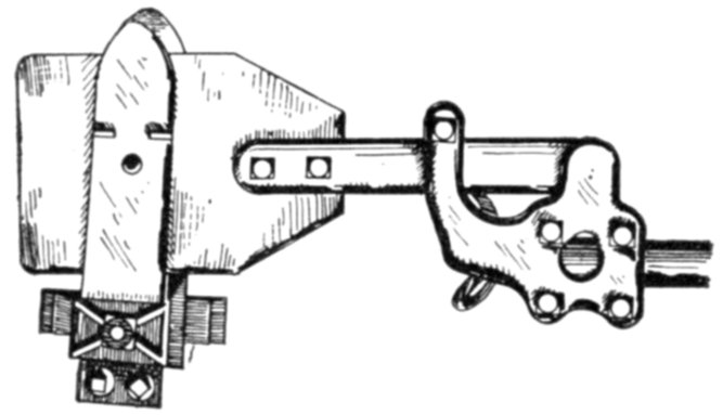
Fig. 2,215.—Pacific swivel type blade for Baum pole top switches. The twist type of blade,
here shown, is especially adapted to switches operating in freezing or sleety weather.
It will be seen that the first few degrees through which the rotating insulator is moved
have the effect of twisting the blade between the shoes of the contact, which breaks any seal
through freezing, or corrosion.
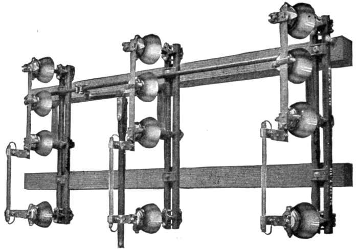
Fig. 2,216.—Pacific 22,000 volt, 100 ampere, pole top switch equipped with fuse tubes; designed
to meet the need for a small group controlled disconnecting switch, having several
features making it suitable for use with service transformer installations and line
branches. The switch is made with clamped pipe arms permitting adjustment. It is
equipped with fuse tubes and fittings, but should the fuses be not desired, the arm may
be shortened. Provision is made for fitting insulator pins to the top of the arms, when
the switch is mounted vertically, which will hold insulators at right angles to the switch,
making it possible to end a line on the top of these arms and then drop down through
the switch to the bank of transformers. The switch is so constructed that gravity tends to
hold it in either the open or the closed position. Provision can be made for locking.
[Pg 1598]
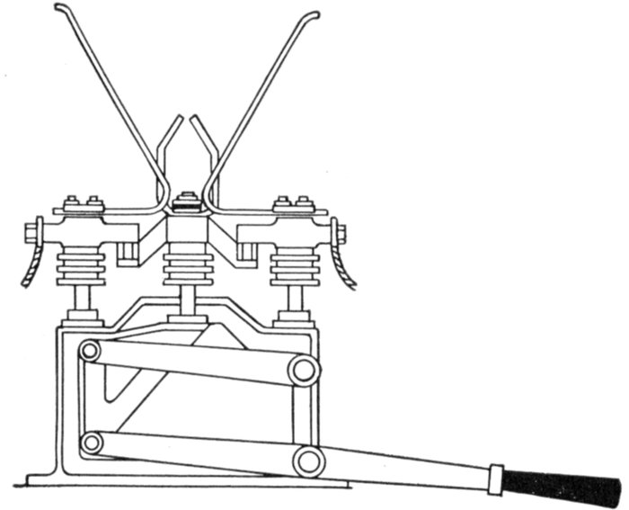
Fig. 2,217.—Horn break switch. In operation, the arc formed at break, will travel toward
the extremities of the horns because of the fact that a circuit will tend to move so as to
embrace the largest possible number of lines of force set up by it. Hence, the arc that
starts between the horns where they are near together rises between them until it becomes
so attenuated that it is extinguished.
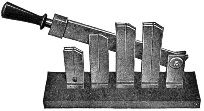
Fig. 2,218.—Westinghouse rear connected motor starting switch, for pressures up to 600
volts. It is used for starting rotary converters and direct current motors of large capacity
having starting torque small enough to permit cutting out the starting resistance in
few steps. The clips can be connected to any type of resistor, the steps of which are
successively short circuited as the switch closes; the amount of resistance in the armature
circuit is thus gradually reduced. A pause should be made after each step of resistance
is thrown in to allow the motor speed to accelerate. If the starting switch do not
have to carry the full load current and can be short circuited by another switch, a starting
switch of smaller capacity equivalent to 50 per cent of running current of the machine
can be used. The switch is of the single pole, single throw, rear connected, four point,
knife blade type.
[Pg 1599]
Ques. Describe its operation.
Ans. The moving arm of the switch draws the fuse through
the tube, thus opening the circuit without much disturbance.
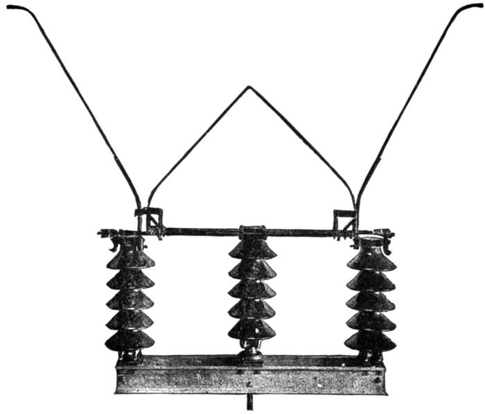
Fig. 2,219.—Baum disconnecting switch with horns and auxiliary
contacts (Pacific Mfg. Co.). This switch is for use on systems
operating at 100,000 volts or over. It has a spacing of five feet
between outer insulators, is equipped with auxiliary shoes that break
the circuit between the horns, diverting it from the current carrying
contacts so that they are not attacked by the arc.
Ques. What is the objection to the metal fuse switch?
Ans. The powder is set flying by the explosion of the arc,[Pg 1600]
which, as it settles, gets into the bearings of any machine that
may be in the vicinity.
Ques. What is a horn break switch?
Ans. One provided with horn shaped extensions to the
contacts, as shown in fig. 2,219.
The arc formed on breaking the circuit, as it travels toward the extremities
of the horns, becomes attenuated and is finally ruptured.
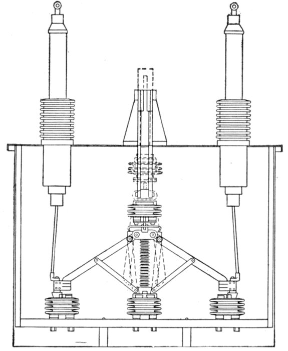
Fig. 2,220.—Kelman switching mechanism. The pantograph arrangement of the contact
blades gives a double horizontal break deep down in the oil. This gives over the break
a heavy head of oil which immediately closes in around the thin blades as they leave
the contacts in opening, thus effectually extinguishing the arc. The opening spring
acts within the pantograph itself without any intervening mechanism, and the light
weight of the few moving parts enables the spring to accelerate the blades rapidly, thus
obtaining a quick break. The contacts are of the return bend type, which makes a flexible
contact, to obtain alignment with the blades at all times. The pantograph and
contacts are supported on corrugated porcelain insulators on a hardwood base or insulator
board. The insulators are fitted with iron ends for securing the different parts. At
each end of the insulator board is an upright or lifting board which serves to lift the
switching mechanism out of the tank. The leads are heavily insulated.
[Pg 1601]
Ques. What are the objections to this type of switch?
Ans. The considerable space required for the horns and
arcs, and the line surges caused by the arc.
Horn switches were used extensively for high pressure alternating
current circuits before the introduction of oil switches.
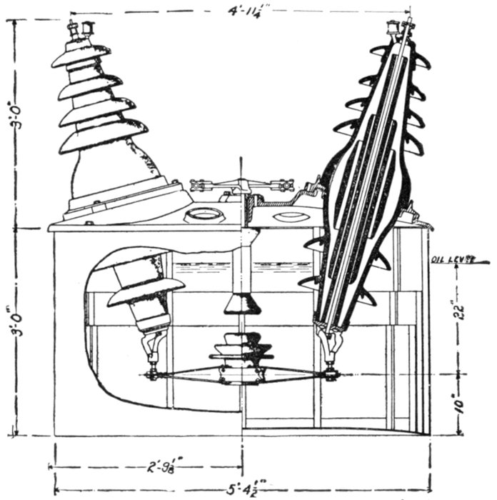
Fig. 2,221.—Sectional view of Pacific weatherproof oil switch for use in places exposed to
the weather. All moving and contact parts are supported from the cast iron top and
are readily removable for inspection or repair.
Oil Switches.—The extensive use of high pressure currents
and alternating current motors and other devices introducing
inductance make it necessary to use switches radically different
from the ordinary air break types.
[Pg 1602]
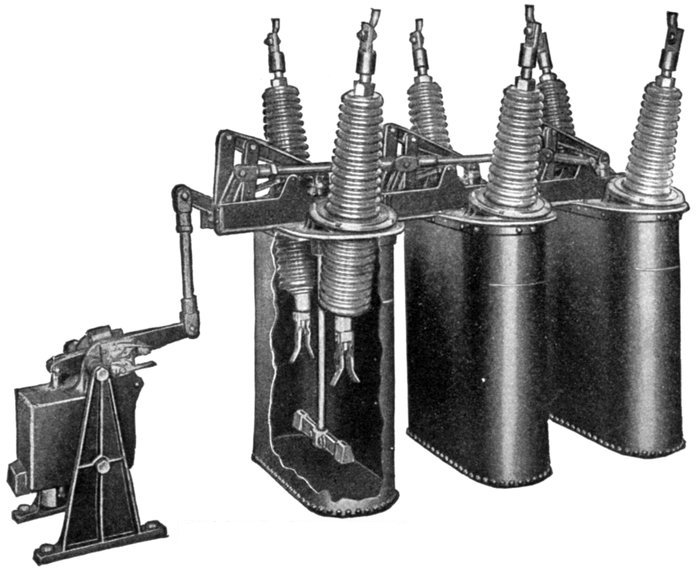
Fig. 2,222.—General Electric central station
triple pole single throw oil switch; view of
switch in tank. This type is for pressures up to 110,000 volts, being adapted for
stations employing open wiring, since the connections are made at the top of the
switch and its construction obviates the need for isolating it in a cell. One tank
with two breaks in series are used for each phase.
The opening of circuits of considerable current value with
inductive loads is not possible with old style switches which[Pg 1603]
were quite adequate for the service for which they were designed.
These circuits are controlled with ease and certainty
by the oil switch.
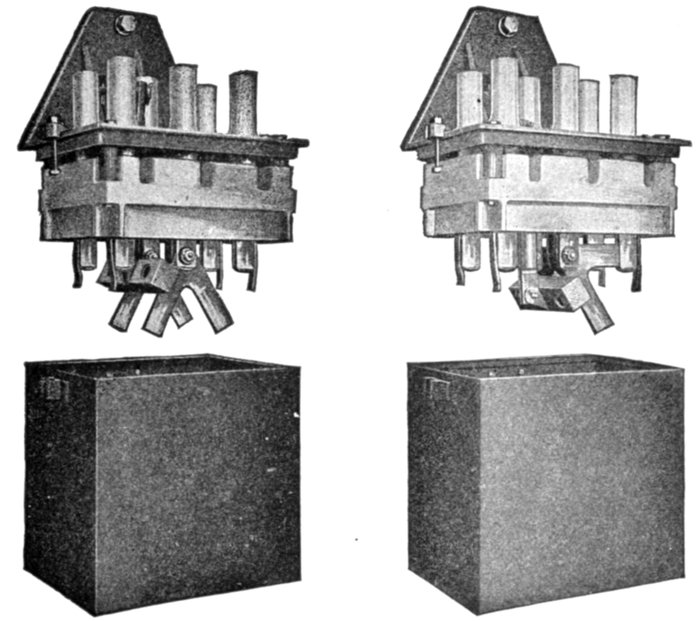
Figs. 2,223 to 2,226.—Westinghouse indoor, two pole double throw oil switch for pressures
not over 6,600 volts. Fig. 2,223, open position; fig. 2,225, closed position. This type
of switch is suited for a wide range of application, being made in both switchboard and
wall mounting styles; also for remote mechanical control by the use of bell cranks and
connecting rods. The wall mounting style is adaptable to motor installations on account
of the facility with which it may be mounted on any support, convenient to the motor
operator. The lever and handle extend outward over the oil tank, so that the switch
may readily be mounted against a wall, post or any vertical support. The characteristic
features of this type of switch are: knife blade contacts submerged in oil; live parts
carried on a porcelain base affording a permanent insulation between adjacent poles, and
between the frame and live parts; compactness and accessibility; enclosure of all live
metal parts; and low first cost. Each contact jaw has attached to it an arcing piece
which takes the final break, thus preventing any burning of the jaws. These arcing
pieces are inexpensive and readily replaced when worn or burnt away. The contact
making parts are enclosed in a sheet metal oil tank which has an insulating lining. The
leads are brought out at the top. Connections to the outside circuit are made inside
the switch and a porcelain insulator is slipped over the joint, thus providing a straight
continuous connection from the line with maximum insulation. On the 6,600 volt
switch, insulation is obtained by the use of porcelain bases for supporting the live parts.
In the 3,300 volt switch specially treated wooden bases are used, suitable barriers being
provided between the poles where necessary to prevent arcs communicating.
[Pg 1604]
Ques. What is an oil switch?
Ans. One in which the contact is broken under oil.
This type of switch is the one almost universally used on high pressure
alternating current circuits, because of the fact that the oil tends
to cause the current to break when at its zero value, thus preventing
the heavy arcing which would occur with an air break switch, and the
consequent surges in the line which are so often the cause of breakdown
of the insulation of the system.
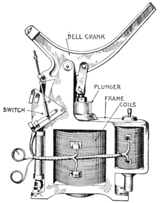
Fig. 2,227.—Kelman electric control unit for oil switch. It consists of an iron frame which
contains the opening and closing coils and the bearings for the operating bell crank.
A small switch on the frame automatically opens the coil circuit at the end of the stroke
in either direction and operates signal lamps to indicate the open or closed position.
The automatic overload release opens the switch by closing the opening coil circuit.
This electrical operating unit gives satisfactory service through a wide variation of voltage.
It requires a momentary expenditure of energy of from 1,500 to 4,000 watts, depending
on the size.
Ques. What is the nature of an oil break?
Ans. It is not a quick break.
Oscillograph records show that the effect of the oil is to allow the arc
to continue during several cycles and then to break the current, usually
at the zero point of the wave.
[Pg 1605]
Remote Control Oil Switches.—It is desirable in the case
of switches on high pressure circuits to locate the parts which
carry the high pressure current at some distance from the
switchboard in order that they may be operated with safety.
With respect to the manner in which the switches are operated
they may be classed, as
- 1. Hand operated;
- 2. Power operated.
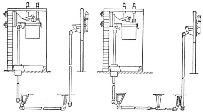
Figs. 2,228 and 2,229.—Views showing mechanism of hand operated remote control switches.
Fig. 2,228, straight mechanism; fig. 2,229, angular mechanism.
Ques. What kind of power is used?
Ans. Electricity is used in most cases; in some installations,
switches are operated by compressed air.
Ques. For what pressures should remote control
switches be used?
Ans. For pressures above 1,100 volts.
[Pg 1606]
Ques. Describe the operating mechanism of a remote
control, hand, and electrically operated switch.
Ans. For hand operation, the mechanism between the operating
lever and switch proper, consists simply of a system of
links and bell cranks. Various shapes of bell crank are used,
to permit change in direction or position of the force applied
to operate the switch.
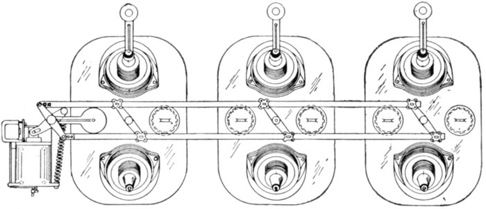
Fig. 2,230.—Pacific oil switch with solenoid control, designed for 60,000 and 70,000 volt
installations; it is capable of handling a 25,000 kw. generating station. The break
is horizontal, made by the rotation of a flat member edgewise through the oil. The
solenoid, at its extreme outer position, has a free start before commencing to move the
control parts of the switch. As it approaches the extreme inner position, where the
opening spring and the contacts begin to offer the greatest resistance, the magnetic action
is, of course, most powerful, and the leverage by which it is applied moves to an increasing
radius, by means of rollers working in the curved slots of the control shaft levers.
These curved slots and rollers have the additional advantage of making the opening
action very free and smooth. The tripping coil does not act on the latch directly, but
gives a hammer blow that is positive. The latch proper is a roller having a powerful
hold and easy release. Current can not be left on either the closing or opening coils,
as they are automatically cut out by the movement of the switch.
Ques. Name two classes of electrically operated remote
control switch.
Ans. Those operated by solenoids, and those operated by
motors.
The solenoid type are closed by the action of a plunger solenoid,
and opened either by another solenoid called a "tripping coil" or by
gravity. Some examples of remote control are shown in the accompanying
illustrations.
[Pg 1607]
Ques. What indicating devices are used with electrically
operated switches?
Ans. Red and green lamps; red for closed and green for
open as shown in fig. 2,231.
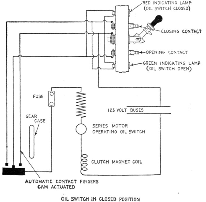
Fig. 2,231.—Diagram of connections of motor operated remote control switch. The motor
which operates the switch is controlled by a small lever generally mounted on the panel
with the instruments which are in the circuit controlled by the switch. The standard
pressure for operating the motors is 125 volts.
Ques. For what service are motor operated switches
used?
Ans. For exceptionally heavy work where the kilowatt
rupturing capacity is greater than that for which the other
types are suitable.
[Pg 1608]
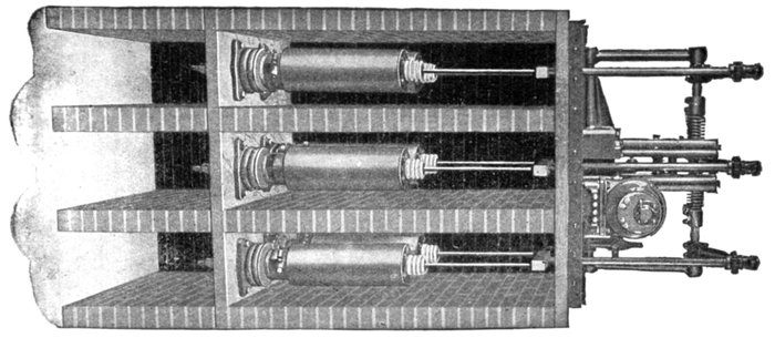
Fig. 2,232.—General Electric motor operated three phase oil switch. The operation of the oil switch is accomplished by a
small hand controlling switch, generally mounted on the panel, with the instruments which are in the circuit controlled
by the oil switch. The standard pressure for the operating motor is 125 volts. The switch has six breaks, each break
being a separate tank. In addition to this isolation of the breaks, each phase is enclosed in a fireproof brick compartment,
making it impossible for trouble in one phase to be communicated to another. The cells are constructed of brick
with top and bottom slabs of slate. The capacities of such switches, range from 2,500 to 60,000 volts, and from 100 to
1,000 amperes.
[Pg 1609]
Rupturing Capacity of Oil Switches.—While an oil switch
may be designed for a given pressure and to carry a definite
amount of current, it should not be understood that the switch
will necessarily rupture the amount of normal energy equivalent
to its volt ampere rating.
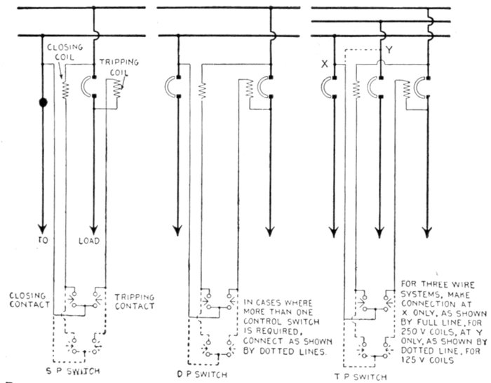
Figs. 2,233 to 2,235.—Diagrams showing connections for General Electric single, double, and
triple pole, solenoid operated remote control switches. The operating coils are shown
connected to main switch circuit, but may be connected to an entirely separate control
circuit. Connections are the same for either alternating or direct current.
Oil switches are often used on systems with generator capacity
of many thousand kilowatts. It is therefore essential that the
switches shall be able to break not only their normal current,
but also greatly increased current that would flow if a short
circuit or partial short circuit occur.
[Pg 1610]
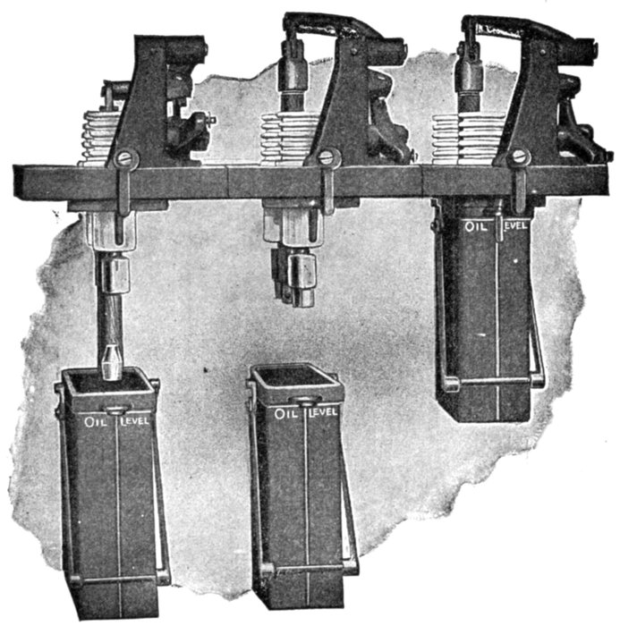
Fig. 2,236.—Westinghouse three pole hand operated remote control oil switch, adapted for
the control of alternating current circuits of small and moderate capacities, the pressures
of which do not exceed 25,000 volts. Each unit is installed in a separate masonry
compartment. The open position of contacts is maintained by gravity. Up to and
including the 600 ampere capacity, the contacts are cone shaped with an arcing tip, as
shown for capacities in excess of 600 amperes, brush contacts are furnished with auxiliary
arcing contacts of the butt type. Each pole has two sets of contacts, thus providing
a double break in each line. With both types of contact, the final break of the arc is
taken and the main contacts protected by auxiliary arcing contacts which are inexpensive
and readily renewable. The upper or stationary contacts are mounted on porcelain
insulators secured in the soapstone base. The lower or movable contacts are carried by
a wooden rod connected to and moved vertically by the operating mechanism. The
operating mechanism of the hand operated breaker consists of a simple system of levers,
bell cranks, and rods. The necessary energy for making a positive contact is small
owing to the use of a toggle mechanism. The leads are brought out of the top of the
breaker through heavy porcelain insulators. On breakers above 3,500 volts, the connections
to the line wires are made by means of a union which can be tightened with a
socket wrench fitting inside the insulator. As the leads coming into the switch are necessarily
insulated wire or cable, this arrangement eliminates all exposed live parts and is
well adapted to making connections readily to bus bars located above or in the rear of
the circuit breakers.
[Pg 1611]
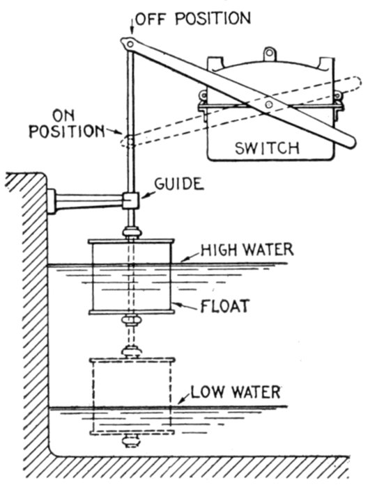
Fig. 2,237.—Cutler-Hammer enclosed float switch, designed for the automatic control of
alternating current motors operating pumps used to fill or empty tanks, sumps or other
reservoirs. The switch is operated by the rise and fall of a copper float which is connected
to the switch lever by a brass rod or copper chain. As the water level rises and
falls, the float moves up and down. This movement is transmitted to the switch lever
and the switch (if the movement be sufficient) is tripped to make or break the motor
circuit. To insure the best operation it is necessary that the float rod be provided with
a guide so that the float will move up or down in a vertical line, as shown. The minimum
difference in water level at which the switch will operate is approximately 10 to 12 inches.
When the float is placed in a closed tank, the minimum height inside from the bottom
of the tank to the top should be at least 6 inches greater than the difference in water level
to provide sufficient clearance for the float. When this type switch is used as a tank
switch, the contacts are closed when the water level is low, putting the motor, driving
the pump, in motion. When the water in the tank reaches a predetermined high level
the float arm opens the switch contacts, and the motor is disconnected from the line.
For sump pump purposes, the contacts open on low level and close on high level, the
lever being reversed for this purpose. Two pole, three pole and four pole switches of
this type are made, all arranged to completely disconnect single phase, two phase and
three phase motors from their circuits. When used with small motors which may be
thrown across the line to start, the switch may be used without a self starter if desired.
Under short circuit conditions alternators develop instantaneously
many times their normal load current, while the
sustained short circuit current is approximately two and a half
to three times normal, or even higher with turbine alternators.[Pg 1612]
Hence, circuit breakers of the so called instantaneous type must
be capable of rupturing the circuit when the current is at a
maximum, whereas, non-automatic switches, or circuit breakers
with time limit relays will be required to interrupt only the
sustained short current circuit. The reason is evident, since the
delay in opening the switch allows the current to approach the
sustained short circuit conditions.
[Pg 1613]
CHAPTER LVIII
CURRENT AND PRESSURE LIMITING
DEVICES
In any electric installation there must be provided a number
of automatic devices to secure proper control. The great multiplicity
of devices designed for this purpose may be divided into
two general classes, as
- 1. Current limiting;
- 2. Pressure limiting.
Because of the heating effect of the current which increases
in proportion to the square of the strength of the current, it
is necessary to protect circuits with devices which do not allow
the current to exceed a predetermined value.
Accordingly fuses, circuit breakers, reactances, etc., are used,
each possessing certain characteristics, which render it suitable
for particular conditions of service.
For instance, just as in analogy, steam boilers must be protected
against abnormal pressures by safety valves, electric circuits must
be guarded against excessive voltages by pressure limiting devices,
otherwise much damage would occur, such as the burning out of incandescent
lamps, grounding of cables, etc.
The control of steam is simple as compared to the electric current,
the latter being the more difficult to manage because of its peculiar
behaviour in certain respects, especially in the case of alternating
current which necessitates numerous devices of more or less delicate
construction for safety both to the apparatus and the operator.
[Pg 1614]
Fuses.—A fuse is "an electrical safety valve", or more specifically,
the actual wire or strip of metal in a cut out, which may be
fused by an excessive current, that is to say, by a current which
exceeds a predetermined value. A fuse, thus serves to protect
a circuit from any harm resulting from an undue overload.
Fuses have been treated at such length in Guide No. 2, Chapter XXV,
that very little can be said here, without repetition.
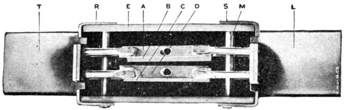
Fig. 2,238.—Sectional view of Noark 250 volt, 400 ampere enclosed fuse. The fusible element
is divided into strips A, B, C, and D. This parallel link construction results, upon
the operation of the fuse, in the formation of a number of small arcs, thus facilitating
the absorption of the metal vapor formed when the fuse blows. The fusible strips, of
which there are two or four in number, according to the ampere capacity of the fuse, are
entirely surrounded by a granular material which is chemically inactive with respect to
the fusible link and whose function is to absorb the metallic vapor formed upon the blowing
of the fuse. The contact blades T and L are made of round edge copper, the round
edges facilitating the insertion of the fuses in the circuit terminals. R and S are the
end ferrules, attached to cover E, by the pin M.
Ques. What effect have the terminals on a fuse?
Ans. The current at which a fuse melts may be greatly
changed by the size and shape of the terminals.
If near together and large, they may conduct considerable heat from
the fuse thus increasing the current required to blow the fuse.
Ques. What is the objection to large fuses?
Ans. The discharge of molten metal when the fuse blows is
a source of danger.
Ques. What should be used in place of large fuses?
Ans. Circuit breakers.
[Pg 1615]
Ques. What are the objections to fuses in general?
Ans. The uncertainty as to the current required to blow
them; the constant expansion and contraction is liable to loosen
the terminal screws when screws are used.
Ques. What is the advantage of fuses?
Ans. They form an inexpensive means of protecting small
circuits.
Fig. 2,239.—Cross section through plug fuse. With this type of fuse it is impossible to place
any except the correct size of plug in the socket.
Ques. Describe a plug fuse.
Ans. It is constructed as shown in fig. 2,239, the fuse wire
being visible and stretching between the two metal portions of
the plug.
Ques. What is a cut out fuse?
Ans. One similar to a simple fuse, but provided with clip
contacts as used for knife switch contacts.
The fuse wire is usually contained in a china or porcelain tube, which
also serves the purpose of a handle for withdrawing the fuse.
[Pg 1616]
Ques. What is an expulsion fuse?
Ans. One in which the fuse is placed in an enclosed chamber
with a vent hole.
In operation, when the fuse blows, the hot air and molten metal are
expelled through the vent.
Ques. What is a no arc fuse?
Ans. A cartridge type fuse, in which the space surrounding
the fuse wire is filled with powdered material.
Fig. 2,240.—Inside view of end ferrule of Noark enclosed fuse. Two prongs O and V, which
are a part of the knife blade K, pass through the square holes in the ends of the ferrule R,
and are riveted to the anchor plate T. The object of this plate is to stiffen the structure
and to increase the current carrying capacity of the metal between the holes, also to permit of
proper alignment of the plates. In each ferrule is placed a vent screen, composed of reticulate
material, such as cheese cloth. The fuzz between the threads of the cheese cloth prevents
the escape of the granular material through the vent holes A, but when the fuse
operates, allows free egress of the air, thereby permitting the vapor formed upon the operation
of the fusible element to quickly and freely pass through the interstices of the filling material
and become cooled, eliminating any possibility of flame issuing from the ends of the tube.
The object of the powdered material is to assist in extinguishing the
arc formed when the fuse blows.
Ques. What is a magnetic blow out fuse?
Ans. An enclosed fuse which is subject to the action of a
magnetic field produced by the current, the magnetic field
tending to blow out the arc when fusing occurs.
[Pg 1617]
Ques. What is a quick break fuse?
Ans. One having a weight suspended from its center, or
springs attached to its ends so that the arc formed at fusing is
quickly attenuated and extinguished.
Ques. What is the disadvantage of a fuse as compared
to an oil switch circuit breaker?
Ans. When a fuse blows, the arc causes oscillations in the
line, which cause excessive rise of pressure under certain capacity
conditions, whereas this disturbance is reduced to a minimum
with an oil switch.
Fig. 2,241.—Quick break fuse. The fuse wire is connected between the fixed terminal A
and the movable arm B, and is held under tension by the spring which exerts pressure
on the movable arm in a direction tending to separate A and B. In operation, when the
fuse blows, the movable arm quickly moves to the position B´, thus attenuating the arc
and accelerating its extinguishment.
Ques. What metal is used for fuse wires?
Ans. Various metals. Ordinary fuse wire is made of lead or
an alloy of lead and tin.
[Pg 1618]
Ques. What is the objection to aluminum?
Ans. It becomes coated with oxide or sulphide, which acts
as a tube tending to retain the metal inside and prevent rupture.
Ques. What is the objection to copper?
Ans. Its high fusing point.
Current Limiting Inductances.—The great increase in
capacity of power stations, for supplying the demands of densely
populated centers and large manufacturing districts, together
with the decrease in the reactance of modern alternators and
transformers due to improvement in design to obtain better
regulation, has presented a problem in apparatus protection not
contemplated in the earlier days of alternating current distribution.
This problem is entirely separate and distinct from
that of eliminating the tendency toward short circuit, incident
to the high voltages now common in transmission lines. It
accepts that all short circuits must occasionally occur and
considers only the protection of the connected apparatus against
the mechanical forces due to the magnetic stresses of such
enormous currents.
Fig. 2,242.—Notched end fuse. This is a simple form of fuse consisting of a strip of
metal (or wire) fixed between two end pieces to fit around the terminals. This type is often
proportioned so that it is only possible to place the correct size of fuse in the terminals.
Sometimes, in place of the end pieces as shown, the fuse metal is fixed between two
clamping screws.
[Pg 1619]
Ques. What means are employed to limit the value of
a short circuit current?
Ans. A current limiting inductance coil (called a reactance)
is placed in series with the alternators or transformers.
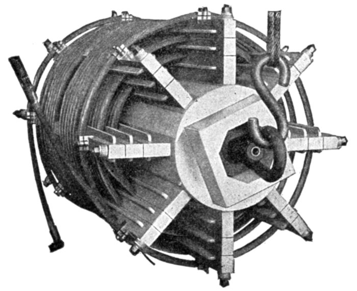
Fig. 2,243.—General Electric current limiting reactance; view showing details of construction.
The core consists of a hollow concrete cylinder, alloy anchor plates or sockets being
embedded in the core near the ends to receive the radial brass bolts. An extension at each
end of the core provides for clamping and bracing the reactance in installation. The
supports for the winding are made of resin treated maple and are located upon the core
by radial brass studs screwed into the alloy sockets, and insulated by mica tubes. The
nuts by which the structure is tightened, rest upon heavy fibre washers. Wooden barriers
fitted and shellacked into the supports add to the creepage surface between layers
of the winding and between the winding and the core. The supports of the layer next
to the core are separated from the core by strips of treated pressboard. The coil consists
of bare stranded cable in several layers, usually three in number. It is wound into
grooves in the treated wood supports, which are protected from contact with the cable
by heat shields of asbestos shellacked into the grooves. The winding is usually in the
form of two back turn sections, thereby allowing the terminals of the coil to be brought
out at the ends of the outside layer. This assures accessibility and ease of connection,
and the removal of the leads from proximity to the core. Two turns at each end of the
winding are given extra spacing for the purpose of additional insulation. The final turn
at each end of the coil is securely held in place by alloy clamps bolted to the supports.
The wood is protected from contact with the clamps by shields of asbestos. The ends
of the cable between the two sections are welded by the oxyacetylene process.
Ques. What are its essential features of construction?
Ans. It consists of bare stranded cable wound around a
concrete core and held in place by wooden supports as shown
in fig. 2,243.
[Pg 1620]
In order to avoid the prohibitive expense of high voltage insulation,
the reactance coil is designed for the low tension circuit. This requirement
prohibits the use of a magnetic core which, if economically designed
for normal operation, would become saturated at higher densities,
or, if designed large enough to avoid saturation at short circuit
conditions, would become prohibitive in cost and dimensions.
The elimination of all magnetic material from the construction of
the concrete core reactance permits of no saturation, and assures a
straight line voltage characteristic at all current loads.
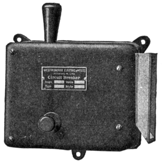
Fig. 2,244.—Westinghouse magnetic blow out circuit breaker, designed for the protection
of street railway and electric locomotive equipments; it serves the combined purpose
of fuse block and canopy switch. The contact tips are surrounded by a moulded arc
chute which confines and directs the arc until the magnetic blow out extinguishes it.
The current carrying contacts consist of copper strips separated by air spaces. An auxiliary
contact or "arcing tip" at the end of the switch lever takes the burning of the arc
when the breaker opens, and thus confines the burning to a very small piece which can
be easily removed and replaced at small cost. The hand tripping lever and the resetting
lever have insulated handles, so that they can be safely handled, even in the dark.
Ques. Where is the proper location for a current limiting
reactance?
Ans. As near the alternator as possible.
Ques. Why?
Ans. To lessen the possibility of a short circuit occurring
between the reactance and the alternator.
[Pg 1621]
Ques. Beside limiting the current, what other service
is performed by the reactance?
Ans. It protects the alternator from high frequency surges
coming in from the outside, and limits the current from other
machines on the same bus.

Fig. 2,245.—General Electric magnetic blow out circuit breaker. This type may be used in
air or water tight boxes and is peculiarly adapted for service where the arc must be confined.
Circuit Breakers.—The importance of circuit protective
devices, commonly called circuit breakers, is fully recognized.
The duty of a circuit breaker is to protect the apparatus in an
electrical circuit from undesirable effects arising from abnormal
conditions, by automatically breaking the circuit. Accordingly
a circuit breaker must comprise a switch in combination with[Pg 1622]
electrical control devices designed to act under abnormal conditions
in the circuit.
A circuit breaker is a device which automatically opens the
circuit in event of abnormal conditions, in the circuit.
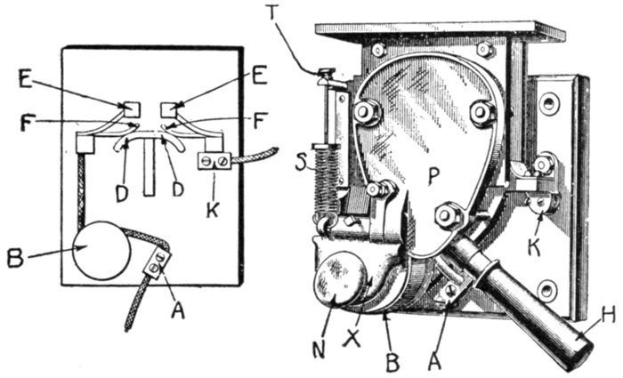
Fig. 2,246.—Magnetic blow out circuit breaker. This is a direct current breaker in which the
final break occurs in a magnetic field. It is a principle in electromagnetics that a conductor
carrying a current in a magnetic field will tend to move in a direction at right angles to
the field. The arc set up on breaking a circuit constitutes a conductor, and in magnetic
blow out circuit breakers, as generally manufactured, there is an electromagnet, energized
by the current to be broken, which produces a field in the neighborhood of the arc, with
the result that the arc moves outward, and so becomes attenuated and is finally extinguished.
The form shown in the figure is used on cars equipped with heavy motors. When
so used, it is in many cases mounted in a box with the handle H projecting at one end.
A and K are the terminals of the breaker and B is the tripping coil, which also serves to
set up the magnetic field necessary for blowing out the arc. X is the armature of coil B
and is pulled down against the action of the spring S whenever the current exceeds that
for which the breaker is set. The tripping current is adjusted by means of nut T. The
iron plate P and a similar one back of it are magnetized by the current in coil B, and as
the break takes place between these two poles, the arc is promptly extinguished by the
field that exists there. In operation, A and K are the terminals, D D is a contact that
is forced up against F, F when the breaker is set. The current then takes the path
A-B-F-D D-F-K. When the breaker trips, the contact piece D D flies down and the
tendency is for an arc to form between F, F; the magnetic field blows the arc upwards,
and whatever burning takes place is on the contacts E, E, which are so constructed that
they may be readily renewed. To trip the breaker by hand, the knob N is pressed.
In the design of circuit breakers, there are several methods
used to effect the rupturing of the arc between contacts when
opened on heavy overload, such as:
1. Magnetic blow out; 2. Thermal break; 3. Carbon break.
[Pg 1623]
In the magnetic blow out type, the arc is extinguished between
auxiliary contacts confined by a chute in which the arc is
rapidly blown out due to a powerful magnetic field from one or
more electromagnets. This type may be used in air or watertight
boxes and is peculiarly adapted for service where the arc
must be confined.
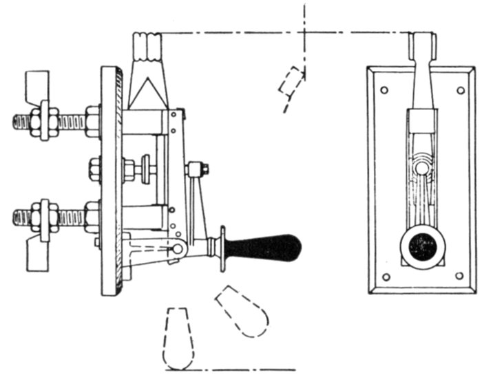
Fig. 2,247.—Thermal overload circuit breaker. In construction two contact blocks are
fixed rigidly to, but insulated from, the switch arm. They are connected electrically by two
parallel strips of suitable metal, each fitted with a steel catch piece. When the switch is
closed the strips are sprung apart over a fixed catch, and the full rated current does not
release the catch. Overload causes the strips to move apart, and the circuit breaker flies
off under the action of a spring.
In a carbon break type, the arc is finally ruptured between
carbon break contacts. The breaking of the circuit is accomplished
progressively, that is to say, it is done in three stages,
by several sets of contact, known respectively as
- 1. The main contacts;
- 2. The intermediate contacts;
[Pg 1624]
- 3. The carbon contacts.
In operation, as the circuit breaker acts to break the circuit,
first the main contacts, separate, then the intermediate contacts,
and finally the carbon contacts between which the arc is ruptured.
Ques. What is the object of the intermediate contacts?
Ans. To prevent the forming of an arc on the main contacts.
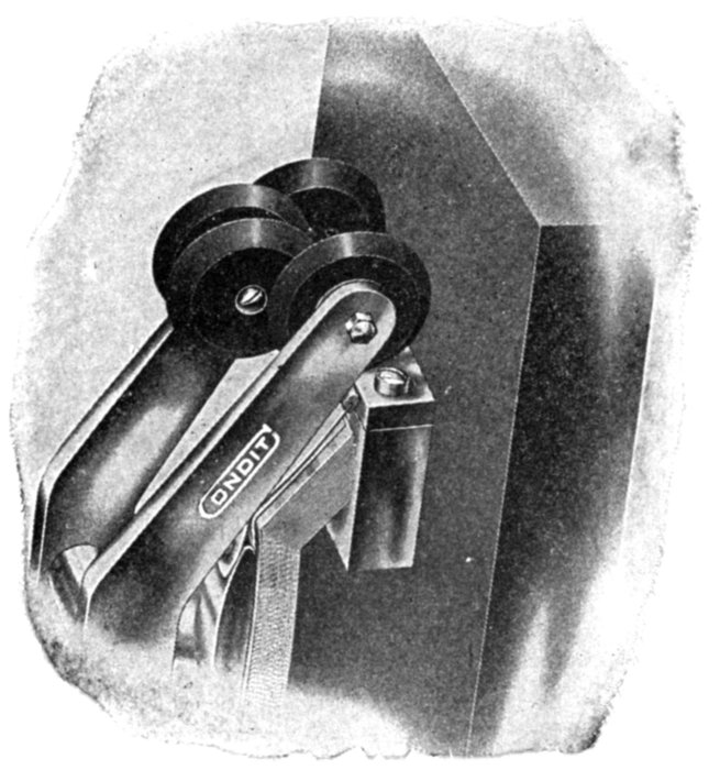
Fig. 2,248.—Carbon break discs of Condit circuit breaker. The two pairs of similar discs
which slide past each other are so arranged that these surfaces coincide at the instant the
intermediate contacts separate after which, as the contact arm opens further, they gradually
disengage.
Ques. What is the object of the carbon contacts?
Ans. First to protect the intermediate contacts by providing
a path for the current after the intermediate contacts separate,
and 2, to "slow down" the current by means of the considerable
resistance of the carbon, thus reducing to a minimum the arc
which is formed when the carbon contacts separate.
[Pg 1625]
Ques. How is the automatic operation of a circuit
breaker usually accomplished?
Ans. Usually through the medium of a solenoid, or electromagnet
energized by current from the circuit controlled by
the breaker.
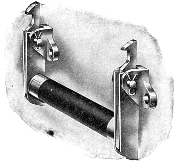
Fig. 2,249.—Mechanically connected insulated latches used on Condit circuit breakers to
produce inter-locking tripping.
The essential features of construction and operation of a circuit
breaker is shown in the elementary diagrams, figs. 2,250 to 2,253. In
construction as shown in fig. 2,250 it consists essentially of three sets
of contacts, a swinging contact arm which is set in the closed position
by the handle operating through the toggle joint, the movement of which
is limited in the closing direction by the stop. The latter is made adjustable
by an eccentric pin or equivalent. Connected to the toggle is
the plunger of the solenoid whose winding is energized by current from
the circuit which the circuit breaker is to control.
[Pg 1626]
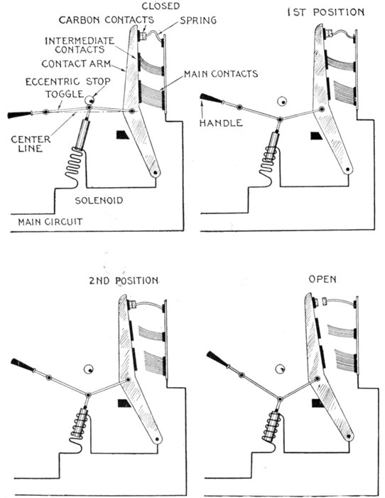
Figs. 2,250 to 2,253.—Elementary diagrams illustrating the operation of a carbon circuit
breaker of the overload type, showing the progressive opening of such device. Fig. 2,250,
closed position; fig. 2,251, main contacts open; fig. 2,252, intermediate contacts open; fig.
2,253, carbon contacts open, circuit broken.
[Pg 1627]
In operation, the circuit is closed by hand by turning the handle
downward to the position shown in fig. 2,250, that is as far as it will go.
Since the toggle has passed the center line the arm will be held normally
in this position because of the spring action of the contacts. Now,
if the current rise above a predetermined limit, the pull exerted by
the solenoid will overbalance the tendency of the toggle to remain in
the closed position, and pull the two toggle links downward below the
center line, drawing the contact arm back and breaking the circuit.
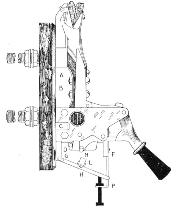
Fig. 2,254.—I-T-E overload circuit breaker. In operation: the current from one side of the
circuit enters the circuit breaker at A, passing through the laminated bridge B to contact
block C, thence through coil D and terminal E to the motor. The coil D surrounds
a magnetic core, having pole pieces F and G and armature H. The effect of
the current in the coil is to energize the magnet, thus tending to lift the armature against
the force of gravitation. The volume of current required to trip the circuit breaker
is determined by the position of the armature, which is subject to ready adjustment, and
is indicated on the calibration plate P. From the opposite side of the line, the current
enters at I, passing downward through the laminated bridge member J, into terminal K,
whence it passes out to the motor. When the current passing through the circuit breaker
attains sufficient volume, the force generated by the magnetic coil overcomes the weight of
the armature H; and the latter is drawn upward toward the pole pieces with constantly
increasing force, until the insulated projections L and M strike against the respective
restraining latches N and O, thereby releasing the two switch members, which at once open
in response to the force supplied by the spring of the contact members and auxiliary springs
provided for the purpose. Positiveness in opening is further assured by the blow of the
armature, which is added to the other opening forces; hence, the heavier the overload, the
more violent the blow and the quicker the circuit breaker opens; or the greater the current
the more promptly it is interrupted. This is the I-T-E or Inverse Time Element principle.
[Pg 1628]
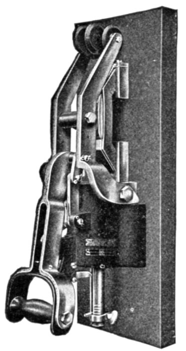
Fig. 2,255.—Condit 600 volt, 1,200 ampere,
single pole, type K, circuit breaker with
pull down handle.
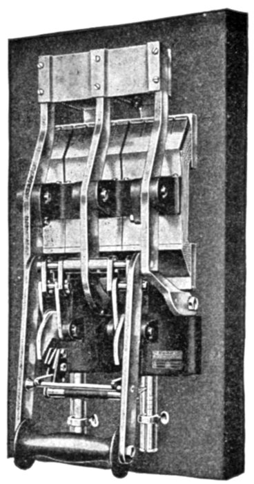
Fig. 2,256.—Condit 600 volt, 6,000 ampere,
single pole, switch board mounting, circuit
breaker, with pull down handle.

Fig. 2,257.—General
Electric
triple pole, overload,
circuit
breaker, with two
overload coils,
capacity 300 amperes,
480 volts.
[Pg 1629]
The progressive action which takes place during this operation is shown
in figs. 2,250 to 2,253 in which the main contacts separate first, then the
intermediate, and finally the carbon contacts as mentioned before.
Ques. What name is given to this type of circuit
breaker?
Ans. It is called an overload circuit breaker.
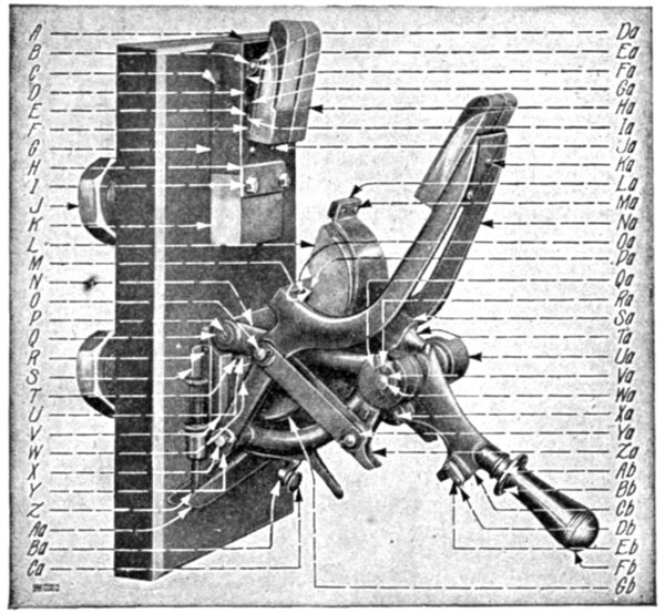
Fig. 2,258.—Parts of General Electric 2,000 ampere 650 volt circuit breaker. A, cover for
secondary contact bracket; B, spring washer for Ea.; C, pin for links and G; D, spring
for carbon support; E, plate for F; F, carbon support; G, secondary contact bracket; H,
contact plate; I, screw for H; J, nut for K and W; K, contact stud, upper; L, laminated
brush, complete with support; M, leather buffer for L; N, main link; O, pin for Na and La
left hand and Cb and Na right and left hand; P, screw for N and magnet frame shaft; Q,
washer for N and magnet frame shaft; R, screw for S and V; S, index plate; T, plate for Gb;
U, screw for T; V, magnet frame; W, contact stud, lower; X, pin for Cb, Na and V; Y,
washer for X and O; Z, calibrating screw with thumb nut; Aa, armature with contact plate;
Ba, catch lever complete with catch Ca, button handle for Ba; Da, spring cotter for Ea; Ea,
pin for F and Fa; Fa, operating link for G; Ga, pin for D; Ha, carbon holder with copper
and carbon contacts; Ia, flexible connections for G and F; Ja, screw for G and flexible
connection plate; Ka, screw for Na and Ha; La, copper secondary contact; Ma, screw for
La; Na, secondary contact lever; Oa, cross bar for Na; Pa, screw for L and M; Qa, secondary
toggle link (left hand); Ra, spring cotter for Wa and O; Sa, brush lever; Ta, buffer for
Cb and Sa; Ua, secondary toggle link (right hand); Va, washer for Wa; Wa, pin for Cb,
Qa, Ua and N; Xa, pin for Sa and Cv; Ya, spring cotter for all pins, except Wa, catch lever
pin and buffer; Za, secondary contact link; Ab, washer for Fb; Bb, guard for Fb; Cb,
handle lever; Db, catch for Cb; Eb, screw for Db; Fb, handle with stud; Gb, secondary
connection.
[Pg 1630]
Automatic Features.—There are three methods of connecting
the winding of the solenoid, or trip coil as it is called:
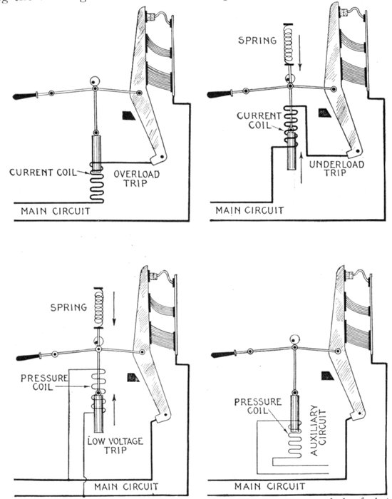
Figs. 2,259 to 2,262.—Elementary diagrams illustrating the various methods of electromagnetic
control for circuit breakers. Fig. 2,259, overload trip; fig. 2,260, underload trip,
fig. 2,261, low voltage trip; fig. 2,262, control from auxiliary circuit by means of a "relay."
[Pg 1631]
- 1. In series with the main circuit;
- 2. In shunt with the main circuit;
- 3. In shunt with an auxiliary circuit.
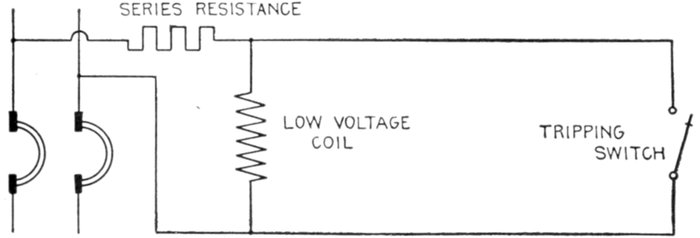
Fig. 2,263.—Diagram of General Electric low voltage trip with tripping switch normally open.
The automatic controls arising from these connections give
various kinds of protection to the circuit and are known as
- 1. Overload trip;
- 2. Underload trip;
- 3. Low voltage trip;
- 4. Auxiliary circuit trip.
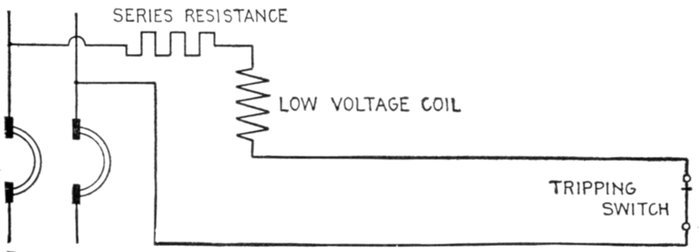
Fig. 2,264.—Diagram of General Electric low voltage trip, with tripping switch normally
closed.
Ques. What is the object of the overload trip?
Ans. It is intended to open the circuit when the current
exceeds a predetermined value.
[Pg 1632]
Ques. What modifications are made in the mechanism
shown in the elementary diagrams?
Ans. Sometimes a latch is used in place of the toggle and a
magnet in place of the solenoid as in figs. 2,265 and 2,266.
Ques. Why is a magnet used in combination with a
latch?
Ans. Because with this arrangement very little movement
is required to trip the breaker, and for such conditions, a magnet
is more efficient than a solenoid.
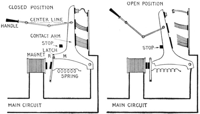
Figs. 2,265 and 2,266.—Circuit breaker with automatic control mechanism consisting of
magnet and latch; views showing breaker in open and closed positions, and essential
features. The toggle is used to obtain sufficient leverage to easily close switch against
the pressure of the brush contacts but not to lock switch, this being done by the latch
as shown, the latter closing by the action of a spring, there being a roller R at the end
which engages the arm to reduce friction. In operation, when the current exceeds a
predetermined limit the magnet attracts the latch and releases the contact arm. The
brush contacts which are exerting pressure against the contact arm, rapidly push it
away, and assisted by gravity, the arm flies open to the position shown in fig. 2,266.
Ques. How does the latch arrangement work?
Ans. When the proper current is reached, the magnet pulls
open the latch and the contact arm of the breaker moves by the
force of gravity or other means and opens the circuit.
[Pg 1633]
Ques. How does the underload trip operate?
Ans. The same as the overload type except that they operate
on a diminution of current instead of an excess.
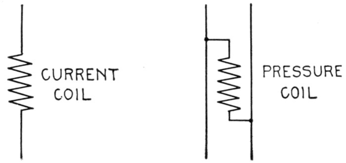
Figs. 2,267 and 2,268.—Positions in circuit of current and pressure coils of circuit breakers.
Ques. Describe the no voltage trip.
Ans. The energy for the trip of this breaker is derived from
a high resistance or fine wire coil which is arranged to be placed
directly across the line, in operation, when the current flowing
through the circuit falls below a predetermined value, the energy
of the coil is insufficient to counteract the force of a spring, which
then trips the breaker.
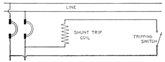
Fig. 2,269.—Diagram of General Electric shunt trip with coil connected beyond breaker and
thrown out of circuit after tripping.
[Pg 1634]
Ques. Describe the auxiliary circuit trip.
Ans. A pressure coil is used which is energized by current
from an auxiliary circuit. The coil is only momentarily energized,
by push button, relay or other control, as distinguished from the
preceding types, in which the coil is constantly energized.
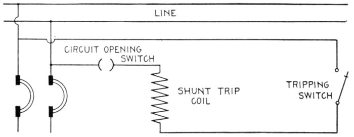
Fig. 2,270.—Diagram of General Electric shunt trip with auxiliary circuit opening switch to
throw coil out of circuit after tripping.
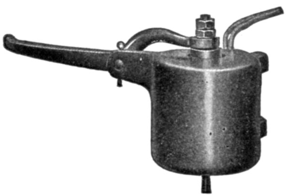
Fig. 2,271.—General Electric shunt trip attachment.
The shunt trip attachment has
been designed to provide for conditions
under which the low voltage attachment
cannot be successfully applied. It resembles
the low voltage attachment in construction,
but differs in that it trips the
circuit breaker when energized. The shunt
trip should be allowed to remain only momentarily
in circuit; hence it should be so
connected that the opening of the circuit
breaker immediately disconnects it from
the circuit. Whenever it is impossible to
connect the shunt trip in this manner, the
circuit opening auxiliary switch should be
used in connection with it.
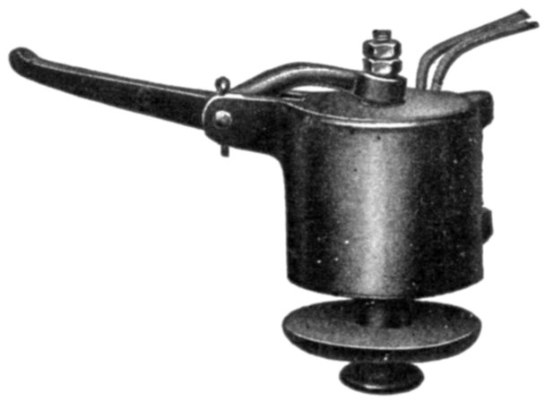
Fig. 2,272.—General Electric low voltage
attachment for circuit breakers. This low
voltage trip is designed to operate the
circuit breaker when the line voltage drops
to approximately 50 per cent or less of the
normal voltage. It should be noted that
the coil is always in circuit, as is the case
with the overload and underload coils, and
that it operates with the releasing of its
armature. It is always necessary to use
a fixed amount of resistance (depending
upon the voltage of the system) in series
with the low voltage release. The low
voltage release performs the functions of a
shunt trip coil when used in conjunction
with a push button, auxiliary switch or
speed limiting device, and is generally
preferred to the shunt trip attachment.
[Pg 1635]
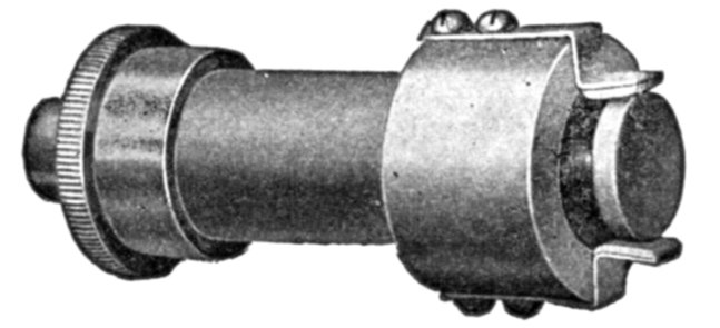
Fig. 2,273.—General Electric circuit opening auxiliary switch. This switch opens an auxiliary
circuit when the circuit breaker opens, and is intended to be used in connection with a
shunt trip attachment to insure the immediate disconnection of the shunt coil from the
circuit. It may also be employed to serve other purposes, such as tripping another circuit
breaker having a low voltage attachment, and permitting another circuit breaker to
remain closed only when the circuit breaker equipped with the auxiliary switch is open.
Ques. What other name is given to the auxiliary
circuit trip?
Ans. It is sometimes called the shunt trip, though ill advisedly
so.
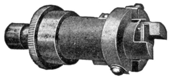
Fig. 2,274.—General Electric circuit closing auxiliary switch. This switch closes when the
circuit breaker opens, and may be used to announce the automatic opening of the circuit
breaker through the means of an indicating lamp or an alarm bell. It is often necessary
to arrange one circuit breaker so that, in opening, it will trip others. This may be accomplished
by using a circuit closing auxiliary switch in connection with a low voltage or shunt
trip attachment on the circuit breakers to be tripped. The construction of this type of
switch is such that it may be opened by hand after the circuit breaker opens, but it is automatically
reset when the circuit breaker is closed.
Relays.—Oil break switches and carbon break circuit breakers
are commonly used to open electrical circuits at some given
overload and on short circuit. To secure additional protection[Pg 1636]
under a variety of abnormal conditions or to provide for a certain
predetermined operation or sequence of operations, relays may
be employed.
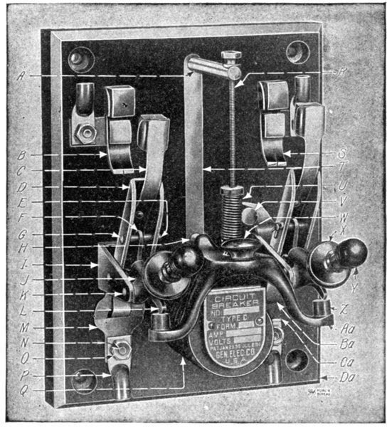
Fig. 2,275.—General Electric type C circuit breaker. Specially adapted to motor driven
machine tool applications. For use in mills, machine shops, factories, foundries
and office buildings. For general motor work, automobile charging outfits, storage
batteries, rectifier sets, cranes, etc. List of parts: A, calibrating post; B, laminated
contact; C, secondary contact spring; D, contact blade; E, cotter pin for G; F, toggle link;
G, pin for D and F; H, stop for Aa; I, hinge frame; J, operating lever; K, pin for I and J;
L, toggle link; M, connection; N, screw for M, O and P; O, nut for N and P; P, terminal;
Q, tripping coil; R, calibrating screw; S, laminated contact; T, calibrating scale; U, calibrating
spring; V, connection post; W, knob; X, washer for Y; Y, handle; Z, buffer; Aa,
armature; Ba, laminated connection; Ca, connection; Da, base.
A relay is defined as: A device which opens or closes an[Pg 1637]
auxiliary circuit under predetermined electrical conditions in
the main circuit.
The object of a relay is generally to act as a sort of electrical
multiplier, that is to say, it enables a comparatively weak current
to bring into operation a much stronger current.
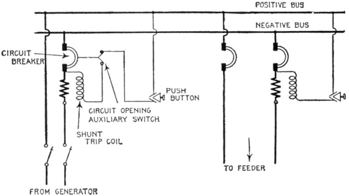
Fig. 2,276.—Diagram of connections of General Electric shunt trip coil with and without
circuit opening auxiliary switch.
Ques. For what service are relays largely used?
Ans. They are employed in connection with high voltage
switches where the small amount of energy derived from an
ordinary instrument transformer is insufficient for tripping.
The connections between relays and circuit opening devices are usually
electrical. Combinations of this nature are extremely flexible since
they permit the use of a number of devices, each having a different
function, with a single circuit breaker or oil switch as well as with two
or more switches, to secure the desired operation and protection.
Selection.—In all electrical installations protection of apparatus
is important, but in some large central stations this is
secondary to continuity of service.
[Pg 1638]
To combine maximum protection without interruptions of
service is not always possible, but these requirements can be
approximated very closely by the use of reliable and simple
controlling or protecting devices if proper care be taken to select
the relays suited to the special conditions of the installation.
To do this intelligently, a knowledge of the various types of
relay is necessary.
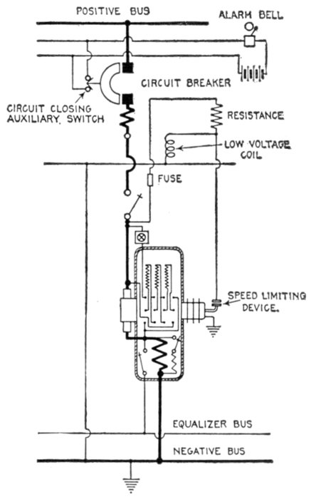
Fig. 3,073.—Diagram of connections of General Electric low voltage release coil when used
with speed limiting device on rotary converter.
[Pg 1639]
There is a multiplicity of types and a classification to be comprehensive,
should, as in numerous other cases, be made from
several points of view. Accordingly relays may be classified:
1. With respect to the nature of the service performed, as
- a. Protective;
- b. Regulative;
- c. Communicative.
2. With respect to the operating current, as
- a. Alternating current;
- b. Direct current.
3. With respect to the manner of performing their function, as
- a. Circuit opening;
- b. Circuit closing.
4. With respect to the operating current circuit, as
- a. Primary;
- b. Secondary.
5. With respect to the abnormal conditions which caused
them to operate, as
- a. Overload;
- b. Underload;
- c. Over voltage;
- d. Low voltage;
- e. Reverse energy;
- f. Reverse phase.
6. With respect to the time consumed in performing their
function, as
- a. Instantaneous (so called);
- b. Definite time limit;
- c. Inverse time limit.
[Pg 1640]
7. With respect to the character of its action, as
- a. Selective;
- b. Differential.
8. With respect to whether it acts directly or indirectly on
the circuit breaker, as
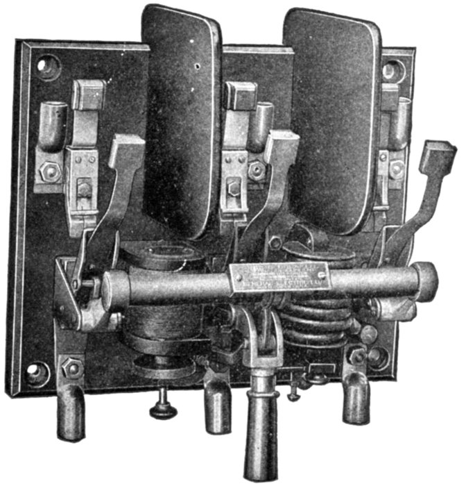
Fig. 2,278.—General Electric overload and low voltage type C circuit breaker for 600 volts
or less. It has one overload, and one low voltage coil as shown. Screens are provided
between contacts.
Protective Relays.—These are used to protect circuits from
abnormal conditions of voltage, or current, which would be
undesirable or dangerous to the circuit and apparatus contained
therein.
[Pg 1641]
Ques. How do protective relays operate?
Ans. They act in combination with automatic circuit
breakers, operating when their predetermined setting has been
reached, energizing the trip coil of the circuit breaker and opening
the circuit.
Fig. 2,279 shows the principles of relay operation. When the current
or pressure in the main circuit reaches the predetermined value at
which the protective system should operate, the relay magnet attracts
the pivoted contact arm and closes the auxiliary circuit; this permits
current to flow from the current source in that circuit and energize the
trip coil thus opening the main circuit.
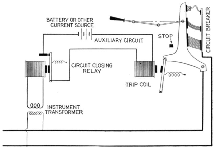
Fig. 2,279.—Diagram illustrating the operation of a circuit closing relay. When the predetermined
abnormal condition is reached in the main circuit, the relay closes the auxiliary
circuit, thus energizing the trip coil and opening the breaker.
Regulative Relays.—This class of relay is used to control
the condition of a main circuit through control devices operated
by a secondary circuit.
[Pg 1642]
Ques. For what service are relays of this class employed?
Ans. They are used as feeder circuit or generator regulators.
Ques. How do they differ from protective relays?
Ans. They have differentially arranged contacts, that is to say,
arranged for contact on either side of a central or normal position.
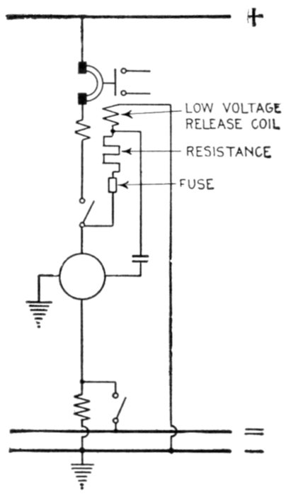
Fig. 2,280.—Diagram showing a railway synchronous converter protected by a single pole overload
circuit breaker with low voltage release attachment and bell alarm switch. The
low voltage attachment trips the breaker on failure of direct current voltage also when
speed limit device closes. Internal troubles are taken care of by the alternating current
automatic devices (not shown).
Communicative Relays.—These are used for signalling in
a great variety of ways for indicating the position of switching
apparatus or predetermining the condition of electric circuits.
[Pg 1643]
A. C. and D. C. Relays.—As here used, the classification
refers to the kind of current used on the auxiliary circuit. In
some cases direct current is used to energize the trip gear of the
circuit breaker or oil switch, and in others, alternating current.
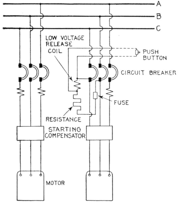
Fig. 2,281.—Diagram showing three phase motors protected by triple pole overload circuit
breakers, with two overload coils, also one overload coil and low voltage release coil. The
use of the low voltage release allows the breaker to be tripped from a distance by means
of a short circuiting switch or push button.
A. C. and D. C. relays are respectively known as circuit
opening and circuit closing relays, being later fully described.
Circuit Opening Relays.—The duty of a circuit opening
relay is to open the auxiliary circuit, usually alternating current,[Pg 1644]
nd thereby cause the oil switch or circuit breaker to be opened by
the use of a trip coil in the secondary of a current transformer, or
by low voltage release coil.
The trip coil of the breaker is generally shunted by the relay contacts
and when the moving contact of the relay disengages from the stationary
contact, the current from the transformer which supplies the
relay, flows through the trip coil thus opening the breaker. These
features of operation are shown in fig. 2,282.
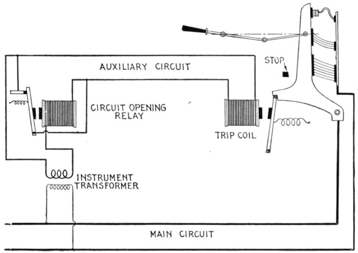
Fig. 2,282.—Diagram illustrating the operation of a circuit opening relay. When the relay
contacts are in the normal closed position, as shown, the coil is short circuited. When the
predetermined abnormal condition is reached in the main circuit, the relay contacts are
opened with a quick break, sending the current through the trip coil momentarily, and
opening the breaker.
Ques. Where are circuit opening relays chiefly employed?
Ans. In places where direct current is not available for
energizing the trip coil.
[Pg 1645]
Ques. What is the objection to alternating current
trip coils?
Ans. They have relatively high impedance and impose a
heavy volt ampere load on the transformers.
Circuit Closing Relays.—The duty of a circuit closing
relay is to close the auxiliary circuit at the time when the predetermined
abnormal condition is reached in the primary
circuit. The closing of the auxiliary circuit energizes the trip
coil and opens the breaker.
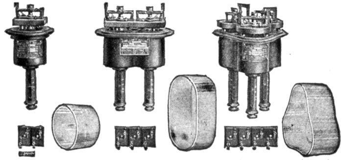
Figs. 2,283 to 2,291.—General Electric instantaneous overload circuit opening relays, covers
removed. Circuit opening relays are used chiefly in those cases where direct current for
the tripping circuit is not available. Alternating current trip coils have relatively high
impedance and impose a heavy volt ampere load on the current transformers. To reduce
this load during normal operation the circuit opening relay is frequently used and is
usually necessary where instruments and meters are to be operated on the same current
transformers as the trip coils if the greatest accuracy be required. The relay contacts
in the normal, closed position, short circuits the trip coil. When the relay operates on
overload or other abnormal condition the contacts are opened with a quick break, sending
the current through the trip coil circuit momentarily and tripping the switch. With
circuit opening relays, the trip coils of the oil switch must be set to trip somewhat lower
than the setting of the relay. In construction the relay consists of a solenoid with iron
frame forming the support for the relay; a central plunger or armature of special construction
which is picked up or released by the magnetic action of the solenoid; a plunger
rod which actuates the relay contacts, which are mounted on an insulated base usually
above the solenoid; a tube or plate for the calibration marking and adjustment; covers
of glass or metal to keep out dust; terminal boards with points corresponding to tagged
leads from relay coils and external wiring diagrams. The relay contacts are of two kinds,
circuit opening, as shown above, and circuit closing, as shown in figs. 2,292 to 2,300.
Ques. What kind of current is generally used for the
auxiliary circuit of a circuit closing relay?
Ans. Direct current.
[Pg 1646]
Ques. At what pressure?
Ans. From 125 to 250 volts.
Ques. Where is this current usually obtained?
Ans. From a storage battery, or from the exciter.
Ques. For what current are the contacts ordinarily
designed?
Ans. About 10 amperes.
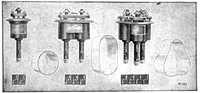
Figs. 2,292 to 2,300.—General Electric alternating current, instantaneous overload circuit
closing relays, covers removed. The function of a circuit closing relay is to close an
electrical circuit, usually direct current, through a trip coil on an oil switch or circuit
breaker, or it may short circuit a low voltage release coil, and thereby open the oil switch
or circuit breaker on occurrence of the condition upon which the relay is designed to
operate. Direct current at 125 or 250 volts taken from exciter bus bars or storage battery
system is generally used for the tripping circuit. Circuit closing contacts have a
cone shaped central element of carbon or metal which makes contact with flexible contact
fingers symmetrically arranged above the cone. These contacts will make and break a
circuit of 10 amperes at 125 volts without the use of auxiliary circuit opening switches.
Relays are made with two or three contacts for connecting one side of a direct current
circuit through one or two separate circuits, or trip coils respectively, to the side of opposite
polarity. Usually only two contacts are required. Where two or more trip coils
are used, which may not be connected permanently in parallel, the three contact relays
are selected and in some cases four contacts furnished.
Primary and Secondary Relays.—Primary relays are sometimes
called series relays as they have the current coils connected
directly in series with the line, both on high and low tension
circuits.
Secondary relays receive their current supply from the secondary
circuits of current transformers. Alternating current[Pg 1647]
relays connected to secondary of pressure transformers and
relays with both current and pressure windings are included
in this class.
Ques. What is the usual winding of the coils?
Ans. The current coils are usually wound for 5 amperes and
the pressure coils for 110 volts.
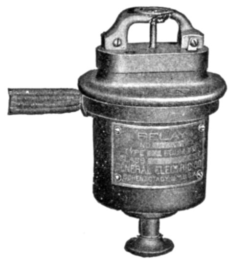
Fig. 2,301.—Alternating current low voltage circuit closing low voltage relay, for 600 volts
or less. The contacts are similar to those of the circuit closing overload type except that
they are inverted. As long as the pressure is normal the contact cone is held above the
contacts. When the pressure falls below one half normal, the cone and plunger rod drop
and close the contact. This relay does not pick up its own plunger. The plunger rod
is pushed up by hand after the pressure circuit is established. Low voltage relays are
generally used in connection with a low voltage release or shunt trip coil on an oil switch
or a circuit breaker. They are used in connection with motor booster sets to prevent
a disastrous speed of the booster which might result from the loss of alternating current
power. They are also sometimes used for indicating purposes.
Ques. What refinement is made in the design of relays
and why?
Ans. Care is exercised to reduce to a minimum the volt
ampere load imposed by the relay on the current transformer
to permit the use of un-stranded meters and relays upon the same
transformer.
The use of circuit opening relays to cut out the trip coil of an oil
switch during normal operation, has been described, and in the short
time that the trip coil is in circuit, it does not affect the accuracy of the
instrument readings. This practice, however, does not apply in the
[Pg 1648]case of curve drawing meters, voltage compensators or other devices
which have in themselves sufficient load for separate current transformers.
In this connection it should be noted that to obtain accurate
instrument and meter readings; the current transformers should not be
loaded beyond certain limits which depend upon the volt ampere load
and power factor of each of the connected devices.
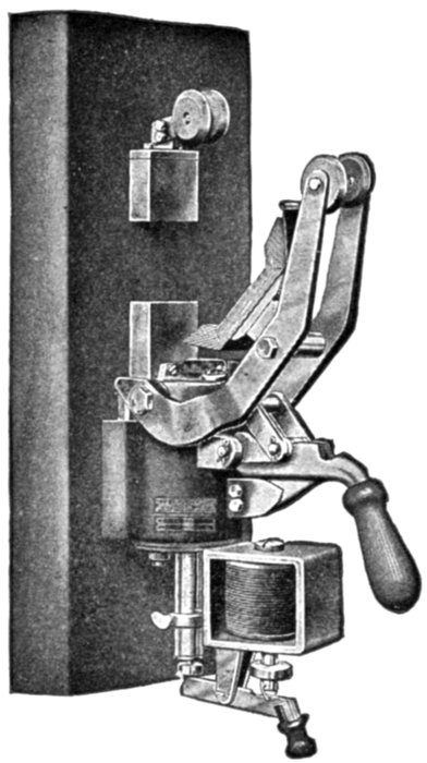
Fig. 2,302.—Condit type K circuit breaker with shunt trip and no voltage attachment. The
shunt trip is usually applied as an auxiliary to other types of trip. It consists of a fine wire
coil which is mounted as a self-contained part of the breaker and which when energized,
trips the circuit breaker. It is used to open the breaker from some distant point, and the
coil is arranged to be connected across the line. The coils are so arranged that the circuit
breakers will operate on a voltage 25% above or 25% below normal. The shunt trip coil
is not intended to remain across the line and should be only momentarily energized. The
no voltage trip, receives energy from a high resistance or fine wire coil which is arranged to
be placed directly across the line, but in contradistinction to the shunt trip type, in which the
coil is momentarily energized to trip the breaker, the no voltage coil is constantly energized
and a decrease or failure of pressure trips the breaker. It can be used as a remote control
device the same as the shunt trip. Its general use, however, is to cause the circuit breaker
to open when the voltage of the line fails from any cause. Its use is recommended on all
motor circuits, as it affords an additional protection against accidents, for if the voltage
should fail, the breaker immediately opens, and before the machine can start again the
attendant must close the breaker. It will not work for the protection of storage batteries
or of motor generator sets charging storage batteries, as, when the voltage of the generator
fails, the voltage of the battery still maintains its full value. The action of the coil is independent
of the direction of flow of current; it simply allows the breaker to stay closed as
long as the voltage is on the line and opens the breaker when the voltage on the line ceases.
No voltage circuit breakers are normally so adjusted that they will not release until the
voltage approaches 50% of normal.
[Pg 1649]
So great is the variety of combination used and the variations of
these factors in their several combinations at different loads and settings,
that special consideration of each arrangement is advisable.
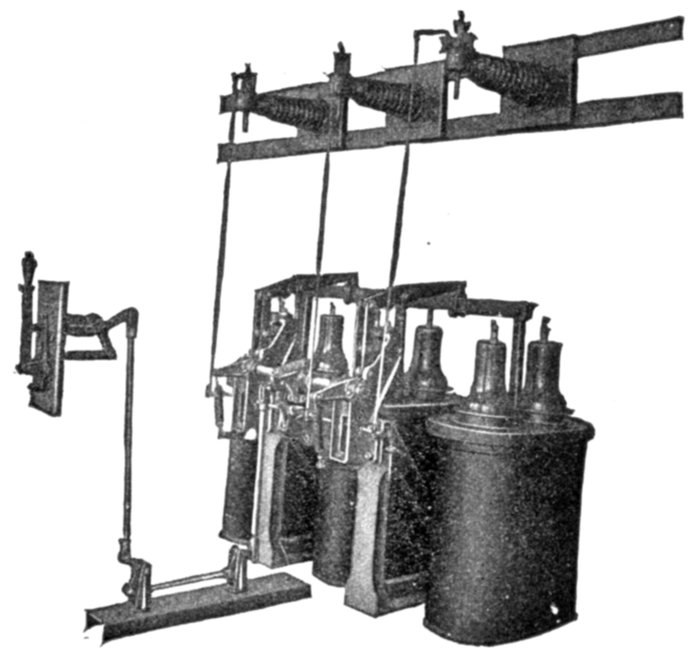
Fig. 2,303.—General Electric alternating current high pressure series overload relays controlling
45,000 volt oil switches. These relays are connected in series with the line. If
current transformers are to be used on the same circuit for other purposes, and have
sufficient capacity to supply energy for operating relay coils, then secondary relays would
be more economical, otherwise the series relays are much less expensive. By means of
a specially treated wooden rod, the relay operates a tripping switch, closing a separate
tripping circuit, usually 125 or 250 volts direct current. Relays and switches are for
mounting on flat surfaces. Series relays are essentially the same as secondary relays
except in the coil winding and insulation. The corrugated horizontal arms which carry
the relays, as shown, are insulated posts, insulating the relays from the ground. The
wood rod from each relay is connected directly to a tripping shaft on the oil switch which
buckles an auxiliary toggle, thereby opening the main toggle and tripping the oil switch.
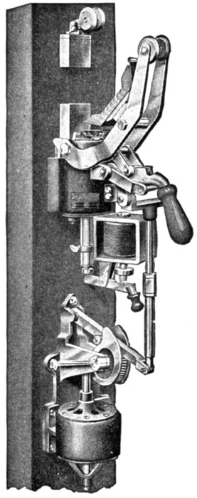
Fig. 2,304.—Condit 600 volt, 1,500 ampere single pole back connected type K circuit breaker,
motor operated. The mechanical and electrical features of the circuit breakers are no different
than when hand operated, the only difference being that the motor is used for the operating
means. This motor is so arranged that even should it over travel, due to an accident
to the controlling circuit, it cannot produce more than a predetermined strain on the circuit
breaker. In other words, after the motor has closed the circuit breaker, further
travel of the motor will not result in putting a strain on the operating parts. Suitable
motors are supplied for this service, the type of motor varying in accordance with the
character of the operating current supplied. The advantage of this type of electrical
operation is that it puts very little strain on the switch mechanism, takes very little operating
current, allows the use of standard parts, and makes an extremely substantial and
flexible structure. Its disadvantage is that it closes slowly, and it must not, therefore,
be used in places where quick closing is essential.
Overload Relays.—Series relays are connected directly in
series with the line and are chiefly used with high pressure oil
break switches for overload protection. If current transformers
are to be used on the same circuits for other purposes, and have
sufficient capacity to admit of adding a relay coil, secondary[Pg 1650]
relays would be more economical;
otherwise, the series relays are less
expensive.
By means of a specially treated
wooden rod, the relay operates a
tripping switch, closing a separate
tripping circuit, usually 125 or 250
volts direct current. Series relays
are essentially the same as secondary
relays except in the coil winding
and insulation.
Underload Relays.—These are
similar in construction to low voltage
relays but have current instead
of pressure windings.
Over Voltage Relays.—These
are usually of the circuit closing
type and are similar to secondary
overload relays, but have pressure
instead of current windings.
Low Voltage Relays.—Relays
of this class are in most cases used
[Pg 1651]
for the protection of motors in the event of a temporary weakening
or failure of the pressure. They are also used in connection with
a low voltage release or shunt trip coil on an oil switch or a
circuit breaker.
Reverse Energy Relays.—The chief object of this species of
relay is to protect the generator. When so used, the overload
adjustment is set at the maximum value to give overload protection
only at the maximum carrying capacity of the generator
and a sensitive reverse protection to prevent a return of energy
from the line.
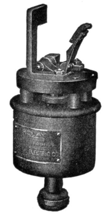
Fig. 2,305.—General Electric direct current solenoid control relay. Solenoids for operating
large switches, etc., frequently require comparatively large operating currents in the
"closing" coils. This necessitates the use of relatively heavy leads between the control
switch and the solenoid and is the cause of severe arcing at the control switch, especially
with solenoids of high inductance. These objectionable features can best be eliminated
by the use of a suitable control relay located near the solenoids. The control relay consists
of a solenoid plunger and switch, the latter insulated from the frame of the relay.
It operates satisfactorily on one-half the rated voltage and requires only a very small
operating current. The terminals of the switch and the relay coils are independent. The
relay can be wound for operation on 125, 250, or 600 volt circuits.
[Pg 1652]
Reverse Phase Relays.—This type of relay is used chiefly
to prevent damage in case of reversal of leads in reconnecting
wiring to two or three phase motors.
Time Element.—It is often inconvenient that a circuit
breaker should be opened immediately on the occurrence of
what may prove to be merely a momentary overload, so that
time lag attachments are frequently provided, particularly with
relays. These devices, which may form part of the relay or
may be quite distinct from it, retard its action until the overload
has lasted for a predetermined time—several seconds or more.
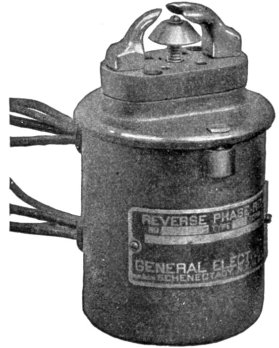
Fig. 2,306.—Alternating current series reverse phase single pole, circuit closing, two contact
relay for 600 volts or less. This type of relay is used chiefly to open motor circuits for
elevators to prevent damage in case of reversal of leads in reconnecting wiring to two
or three phase motors. The relay is provided with a dust proof metal cover.
Ques. What should preferably govern the time lag?
Ans. It should depend on the extent to which the overload is
reduced as the time elapses.
[Pg 1653]
Instantaneous Relays.—The so called instantaneous relays
operate almost instantly on the occurrence of the abnormal
condition that they are to control.
There is of course a slight time element comparable with that of an
overload circuit breaker, but for practical purposes, the operation may
be considered as instantaneous.
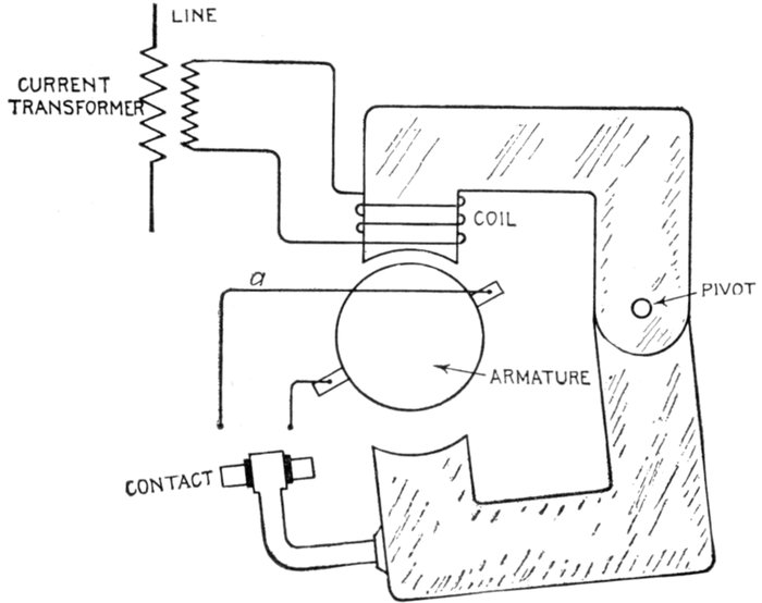
Fig. 2,307.—Electric circuits of Condit type "A" relay. The construction is described in
fig. 2,309. As here shown, the relay is not in operation, but should the current passing
through the coil be of sufficient value to cause the lower movable half of the magnetic
circuit to approach the upper stationary half of the circuit, the relay will be transformed
from an ordinary electromagnet into a repulsion motor. The contact will short circuit the
brushes of the armature and thus cause it to revolve, the speed of rotation being dependent
on the amount of current flowing to a predetermined point, and thereafter the speed
of rotation of the motor remains constant irrespective of the current value. Time adjustment:
This is obtained by varying the distance through which the contact travels,
provision being made whereby adjustment can be made as close as .1 of a second. Current
adjustment: This is obtained by means of a calibrated spring. Standard relays are
calibrated at 6, 8, 10, and 12 amperes, the coils being designed to carry five amperes
continuously, with a temperature rise not exceeding 86° Fahr. Power to operate relay:
The relay requires twenty volt amperes for its operation at full load; the influence of this
type of relay on the ratio and phase angle of current transformers is small.
[Pg 1654]
Time Limit Relays.—Under this classification there are two
sub-divisions.
- 1. Definite time limit;
- 2. Inverse time limit.
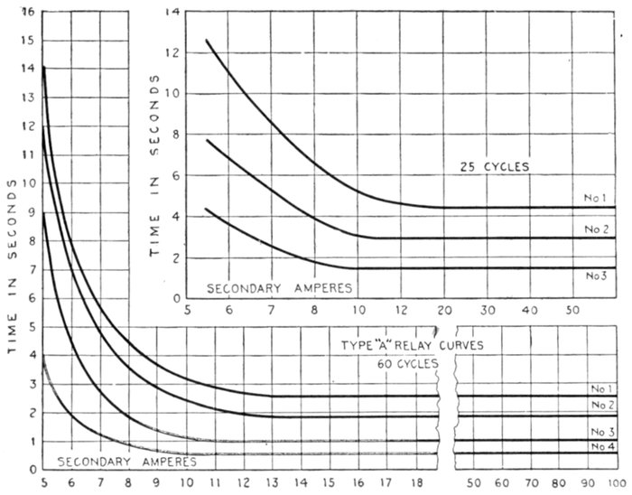
Fig. 2,308.—Characteristic curves of Condit type A selective relay. Curves 1, 2, 3, and 4
show the time variation of this relay with different settings at the various current values.
The relay may be adjusted to trip the switch at any point represented between curves 1
and 4. This relay is a combination of an inverse time limit relay and a definite time limit
relay. The combination of the characteristics of the two types are seen in the curve,
the first part of which is inverse, and the latter part definite from a point of three or four
times full load current. This combination of features being desirable as, for instance,
in transmission work, particularly where it is necessary to use circuit breakers set selectively,
as, due to the inverse feature of the curve, the relays can be set so that on a
moderate overload, they will require the proper length of time to operate, and at the
same time will operate quickly enough on heavy short circuits to prevent damage to
the distribution system or its apparatus. Due to the definite feature of the latter part
of the curve, the relays of the varying circuit breakers when once set to operate at different
time values will never operate simultaneously irrespective of the value of the short
circuit current, thus tending toward continuity of service.
[Pg 1655]
Ques. Describe the time mechanism of a definite time
limit relay.
Ans. It consists of an air dash pot, and an air diaphragm or
equivalent retarding device connected to the contact mechanism.
Ques. How does it operate?
Ans. In some designs, when the contacts are released, they
descend by gravity against the action of the retarding device
thereby making contact a definite interval after the occurrence
of the abnormal condition.
Fig. 2,309.—Condit type "A" selective relay, designed for use with circuit breakers where
selective or discriminating action is required. The circuits and connections of this relay
are illustrated in fig. 2,307, and its characteristics in fig. 2,308. In construction, the
relay consists of a special motor with a short circuited armature and a split field. Under
normal conditions, the fields are separated from each other and the motor armature
does not revolve. The force tending to pull the two faces of the field together is opposed
by a spring, the compression of which determines the number of amperes necessary to
cause the relay to begin operation. The motor structure performs the whole work and
the motor itself un-meshes and meshes the gears without the aid of any external device.
Ques. How does the inverse time limit type operate?
Ans. The actuating and contact mechanism is attached[Pg 1656]
directly to an air bellows and in operation tends to compress the
bellows against the action of a specially constructed escape
valve in the latter.
Fig. 2,310.—Condit type "B" time limit attachment, designed to give sufficient time to
allow an induction motor to start without opening the circuit breaker, and not have the
circuit breaker trip on the momentary rush of current. Its action is inverse; that is,
the greater the current the less time it takes to operate and is so arranged that four to five
times full load current or a short circuit will trip the circuit breaker instantly. The
time limit attachment is applied directly to the armature which trips the circuit breaker
and is adapted for the so called primary trip. It consists of an air vacuum dash pot
with a graphite piston, the dash pot being fastened to the stationary calibrating ring
of the trip coil and the moving outside cylinder is fastened to the armature of the circuit
breaker. When the current reaches a point where it overcomes the weight of the
armature and lifts the same, the magnetic force tending to raise the armature is opposed
by the vacuum created in the interior of the cylinder. As the magnetic force continues
the vacuum is overcome due to the leakage of air past the plunger and the armature
gradually moves up until it reaches the point where it trips the circuit breaker. If at
any point of the armature travel, the current drop back to normal, the armature immediately
resets itself by means of a ball valve in the top of the brass cylinder.
Ques. Why is the arrangement called inverse time limit?
Ans. Because the retardation varies inversely with the[Pg 1657]
pressure on the bellows, and therefore inversely with the magnitude
of the abnormal condition.
Ques. What other device may be used to retard the
operation?
Ans. A damping magnet is sometimes used which acts on a
disc or drum and which may be adjustable.
Figs. 2,311 and 2,312.—General Electric alternating current low pressure series overload
relays. Fig. 2,311, instantaneous time limit relay; fig. 2,312, inverse time limit relay.
These relays have carbon contacts and will make or break a direct current circuit of 10
amperes at 125 volts without auxiliary circuit opening switch. They are used where
several circuits are controlled by one automatic oil break switch or one shunt trip, overload
and shunt trip or low voltage release carbon break circuit breaker. These relays
may be used for signal purposes; they are back connected, the connections can be seen
in the illustrations.
Ques. How is the inverse time element introduced
by this arrangement?
Ans. The retardation is due to eddy currents induced by
moving the disc or drum through the magnetic field. The
reaction thus induced varies inversely with the magnitude of[Pg 1658]
the force with which the disc or drum is urged through the field
and hence inversely with the abnormal condition.
Ques. What are the ordinary limits of adjustment
for inverse time limit relays?
Ans. From one-half second to 30 seconds, depending upon
the time setting and magnitude of the overload current.
Figs. 2,313 to 2,321.—General Electric time limit overload circuit opening relays with covers
removed. The construction of this relay is similar to that of the inverse time limit relay,
except that it has a compression spring interposed between the plunger and diaphragm.
The plunger compresses the spring and further motion is prevented by a stop, making
the relay practically independent of the amount of the overload, only the stored energy
of the spring, if the overload continue, applies power, dependent on its own mechanical
strength, to the diaphragm. The time limit therefore becomes practically a constant
for any given setting under ordinary conditions of overload or short circuit. If, however,
the overload come on slowly so that the spring is not fully compressed at once, the
time limit will vary slightly. If the scheme of selective operation make it necessary to
take care of a creeping load of this character, two relays may be used and definite time
limit positively secured. In this case, an instantaneous circuit closing, overload relay
would be used and a definite time limit relay, provided with a direct current coil in circuit
with the closing contacts of the first relay. The time limit relay would be of the
circuit closing type and control a direct current trip coil on the oil switch.
A setting of from two to six seconds is ordinarily used, depending
upon the requirements. Where selective operation is desired a minimum
setting of two seconds is recommended.
Differential Relays.—In this type of relay there are two
electromagnets. In normal working these oppose and neutralize
each other. Should, however, either winding become stronger[Pg 1659]
or weaker than the other, the balance is upset, the magnet
energized, and the relay comes into operation.
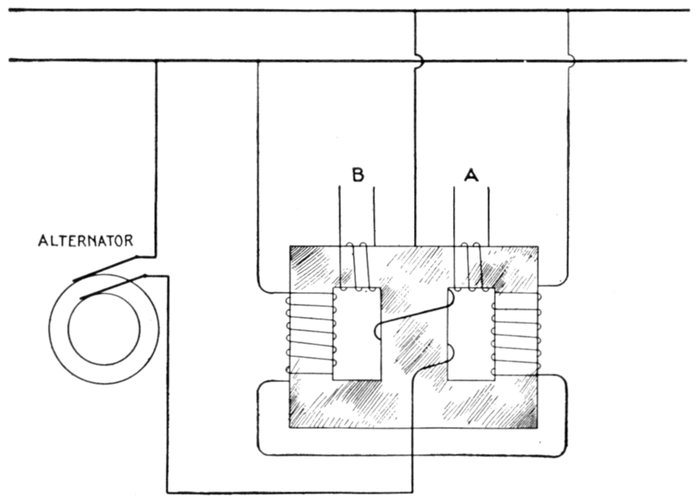
Fig. 2,322.—Differential relay transformer and reverse current circuit breaker discriminating
device. A differential relay is one whose electromagnet has two windings. In normal
working these oppose and neutralize one another. Should however, either winding become
stronger or weaker than the other, the balance is upset, the magnet is energized, and the
relay comes into operation. A modification of such a relay for alternating current is here
shown, from which it will be seen that when the currents are as indicated, the circuit A
has the larger pressure induced in it, whereas, should the main current reverse with reference
to the shunt current, the circuit B would have the larger induced pressure.
A modification of such a relay for alternating current is
shown in fig. 2,322, from which it will be seen that when the
currents are as indicated, the circuit A has the larger pressure
induced in it, whereas, should the main current reverse with
reference to the shunt current, the circuit B would have the
larger induced pressure.[Pg 1660]
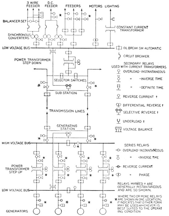
Fig. 2,323.—Diagram of modern power house wiring and busses showing location of relays.
[Pg 1661]
[1]How to Select Relays.—The following general information
on relays, together with reference to the one line diagram,
fig. 2,323, will be of interest and assistance in making a selection
from the various relays previously described to meet the requirements
of modern power house and sub-station layouts.
Single pole relays are used on single phase and on balanced three
phase circuits.
Double pole relays are used on ungrounded three phase and on
quarter phase.
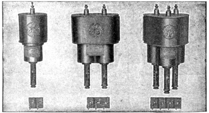
Fig. 2,324 to 2,329.—General Electric inverse time limit overload circuit closing relays. In
this type of relay its mechanism is so designed that a delay or lapse of time in opening
the circuit breaker after a predetermined condition of the circuit has been reached, depends
on the flow of current, that is, if the current be great, the time will be small, and
if the current be of a moderate value, the time will be correspondingly longer.
Triple pole relays are used on three phase grounded neutral and
interconnected quarter-phase.
Circuit closing relays are recommended in all cases where a constant
source of direct current is available for operating trip coils.
The conditions for which relays have been designed for power circuits
may perhaps be best described, by considering a one line diagram from
the generator end to the sub-station auxiliary machines and feeders.
Considering first alternating current circuits, the prevailing practice
is to make the circuit breakers by which the alternators are connected
to the low tension bus non-automatic, in order to insure minimum
interruption of alternator service. The chance of trouble in this part
[Pg 1662]of the circuit is remote, but should it occur, the station attendant could
generally open the circuit breaker before the machines would be injured.
Reverse current relays of instantaneous or time limit types are
often connected to the secondaries of current and of pressure transformers
to indicate by lamp or bell any trouble that may occur in the
generator circuit.
These relays operate with a low current reversal at full pressure and
conversely with a proportionally greater current at voltages less than
normal. At zero pressure, the relay would act as an overload one, set
for high overload. At zero current, a voltage considerably in excess of
normal would be required to operate it.
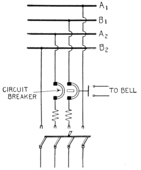
Fig. 2,330.—Diagram showing two phase motor or feeder circuit protected by double pole
double coil, overload circuit breaker (or two single pole breakers interlocked) with bell
alarm switch.
Specifications sometimes call for automatic generator circuit
breakers: in this case definite time limit overload relays are used.
They are connected in the secondaries of current transformers
and are designed to give the same time delay for all trouble
conditions; they allow the defective circuit to be opened, if
possible, at a point more remote from the generator than the
generator circuit breaker.
[Pg 1663]

Fig. 2,331.—Condit 600 volt,
1,500 ampere, single pole type
K circuit breaker pneumatically
operated. It is the same as
the electrically operated circuit
breaker, except that a pneumatic
cylinder mechanism is
supplied in place of either the
electromagnet or the motor.
This cylinder mechanism is so
arranged that the air pressure
is only on the cylinder at the instant of operation. At all other times the air pressure is shut
off by means of a control valve. The kind of remote control to be used depends on local
conditions. In general, the hand operated remote control device is preferable where conditions
are such that it can be used, and where it is necessary to use electrically operated,
the motor operated type is recommended if conditions be such that slow closing is not
objectionable.
When the total generator capacity
exceeds the rated rupturing
capacity of the circuit breakers, one
or more sectionalizing circuit breakers
are placed in each bus.
If operating conditions admit, these
devices are made non-automatic and are
left disconnected except in case of emergency;
but if it be necessary for them to
be continually in service, they may be
made automatic by means of instantaneous
overload relays connected to
current transformers in the low voltage
bus; the relays being adjusted to trip the
circuit breaker under short circuit conditions,
confining the trouble to one section
and preventing the circuit breakers
rupturing more than their rated capacity.
Installations with but one bank
of power transformers, and without
high voltage bus, are provided with
automatic circuit breakers operated
by an inverse time limit relay.
The relay is connected to the secondaries
of current transformers, which in
turn are connected in the low voltage side
of the power transformer.
Stations with more than one bank of
power transformers, a high voltage bus,
and high and low voltage circuit breakers,
may have both circuit breakers arranged
to trip at the same time or one after the
other. As in the former case, they are
operated from the inverse time limit relay
connected in the low voltage side.
[Pg 1664]
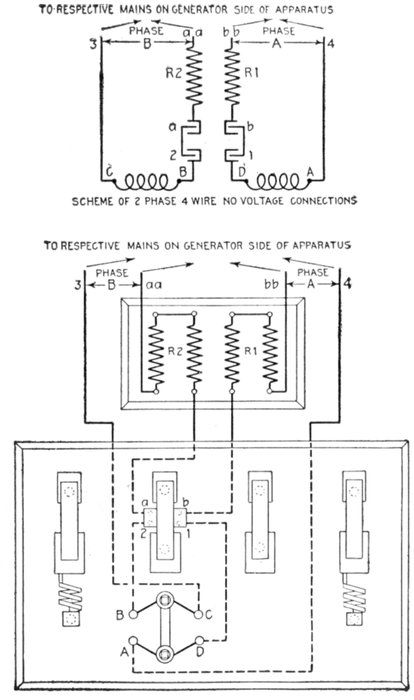
Figs. 2,332 and 2,333.—Diagram
showing two phase
four wire no voltage connections
for I-T-E circuit
breaker. The two no
voltage coils for two
phase four wire circuits
are connected respectively
to binding posts B, C
and A, D on the face of
the base. B and D are
connected to lower spring
contacts 2 and 1 respectively,
of the small disconnecting
switch. (In
instruments supplied on
individual bases, these
connections are made in
the factory, let into
channels in back of base
and covered with wax.)
Each of the upper contacts
a and b of the disconnecting
switch is connected
respectively
through resistance R2
and R1 to one main in
each phase at aa and bb.
C and A are respectively
connected to the other
main in each phase at 3
and 4. Thus each of the
no voltage coils operates
across one phase independent
of the other.
The terminals 3, aa, bb
and 4, must, in all cases,
be so connected that they
will be subject to the
full voltage of the circuit,
irrespective of the position
of the starting
switch.
[Pg 1665]
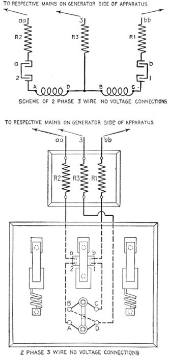
Figs. 2,334 and 2,335.—Diagram
showing two phase
three wire no voltage connections
for I-T-E circuit
breaker. The two no voltage
coils for two phase,
three wire circuits are connected
respectively to binding
posts B, C and A D on
the face of the base, and
from A and C connections
are made to lower contacts
2 and 1 respectively of the
disconnecting switch. Binding
posts B and D are connected
together on the
back of the board. (In
instruments supplied on
individual bases, these connections
are made in the
factory, let into channels
in back of base and covered
with wax.) Each of
the upper contacts a and b
is connected respectively
through resistance R2 and
R1 to one of the mains at
aa and bb as shown. D is
connected through resistance
R3 to the common
wire of both phases at 3 B
and D being connected as
aforesaid, thus forming a
common connection for
both no voltage coils. Terminals
aa and bb of the
resistances must be connected
to the outside main
across the two phases, terminal
3 to the main common
to both phases, the
connections being so made
that these terminals will be
subject to the full voltage of
the circuit irrespective of
the position of the starting
switch.
[Pg 1666]
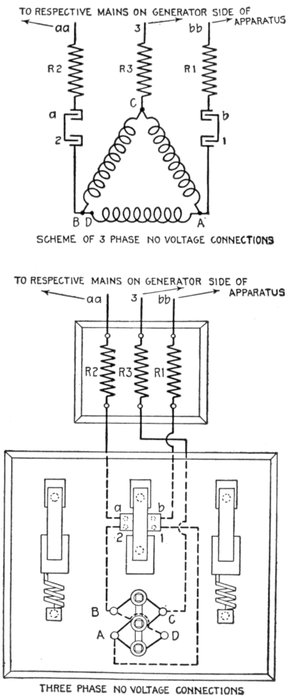
Fig. 2,336 and 2,337.—Diagram
showing three phase no voltage
connections for I-T-E circuit
breaker. The no voltage coils
for three phase circuits are connected
in Δ by means of binding
posts A, B, C and D on the
face of the base, and from the
A and B of the no voltage coils,
connections are made respectively
to spring contacts 1 and
2 of the small disconnecting
switch. Each of the contacts
a and b of the disconnecting
switch is connected respectively
through resistance R2 and
R1 to one of the mains at aa
and bb. The terminal C is
connected through resistance
R3 on the back of the board to
the middle main as shown at
point 3. The terminal D is
linked on the back of the board
to terminal B to complete the
[Greek: D
connection. The terminals
aa, bb and 3 of the circuit
breaker must, in all cases, be so
connected that they will be subject
to full voltage of the circuit
irrespective of the position of
the starting switch. Each no
voltage coil is supplied with
two terminal wires, one covered
with green and one with
black insulation. In replacing
these coils particular care
should be taken to see that the
terminal wires connected to any
one binding post are of unlike
color.]
[Pg 1667]
In plants in which two or more banks of transformers are
operated in parallel between high and low voltage busses, it is
desirable to have for each transformer bank, an automatic
circuit breaker equipment which will act selectively and disconnect
only the bank in which trouble may occur. With a
circuit breaker on each side of transformer bank, selective
action may be secured in two ways as follows:
1. By means of an instantaneous differential relay connected
in the secondaries of current transformers installed on both the
high and low voltage sides of each transformer bank.
The relay operates on a low current, reversal on either side of the bank.
2. By means of one inverse time limit, secondary or series
relay installed on that side of the transformer bank which is
opposite the source of power, the relay being arranged to trip
both the high and low voltage circuit breakers.
The first method has the disadvantage of high first cost due to the high
voltage current transformers required, but is more positive than the
second method and is independent of the number of transformer banks
in parallel.
The second method is the less expensive of the two and protects
against overloads as well as short circuits in the transformers, but it
is less positive and introduces delay in the disconnection of the transformer
when trouble occurs. Furthermore, it is not selective when less
than three banks are operating in parallel.
The automatic circuit breakers in the outgoing line may be
operated from inverse time limit relays connected in the secondaries
of current transformers; or in case transformers are
not necessary for use with instruments, series high voltage inverse
time limit relays connected directly in the line may be used.
Whether to select current transformers with relays insulated
for low voltage, or to choose series relays, is a question of first
cost and adaptability to service conditions. Below 33,000 volts,[Pg 1668]
the commercial advantages in favor of the series relay are slight,
and since it is somewhat difficult to design this device for the
large current capacities met with at the lower voltage, it is
generally the practice to use the relay with current transformer,
because of its operating advantage. This practice, however, is
not entirely followed, since some service conditions (described
later) make the use of series relays very desirable and practical.
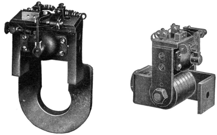
Figs. 2,338 and 2,339.—General Electric instantaneous direct current reverse current or "discriminating"
relays. Fig. 2,238, for 500 amperes; fig. 2,339 for 2,000 amperes. These
relays are designed for mounting directly on circuit breaker studs. These relays consist
of a horseshoe magnet with a shunt wound armature pivoted between its poles. The magnet
is mounted on the current carrying stud of the circuit breaker between the back of
the panel and the first contact or supporting nut, and is placed in a vertical position. The
contacts are insulated from the magnet permitting the use of an auxiliary circuit for the
tripping device, independent of the circuit controlled by the circuit breaker. The magnet
is excited by the current flowing through the stud, and the armature is connected across the
line in series with suitable resistance. Rotation of the armature in the normal direction is
prevented by a stop. Reversal of the current flowing through the stud changes the direction
in which the armature tends to rotate, causing it to move away from the stop and close
the circuit through an auxiliary trip coil and trip the circuit breaker. These relays are
used to protect dynamos, storage batteries, or main station busses from damage on reversal
of current due to short circuit, or from the grounding of machines or connection.
Relay contacts must not be used to open the shunt trip coil circuits. An auxiliary switch
should be provided for this purpose in all cases where the opening of the circuit breaker
does not disconnect the trip coil from the source of supply.
Inverse time limit relays are satisfactory for one, or more
than two outgoing lines in parallel as they act selectively to disconnect
the defective line only, but installations with only two[Pg 1669]
outgoing lines in parallel have the same load conditions in both
lines and selective tripping of the circuit breakers in the defective
line is obtained by means of a selective relay acting instantaneously
under short circuit conditions only.
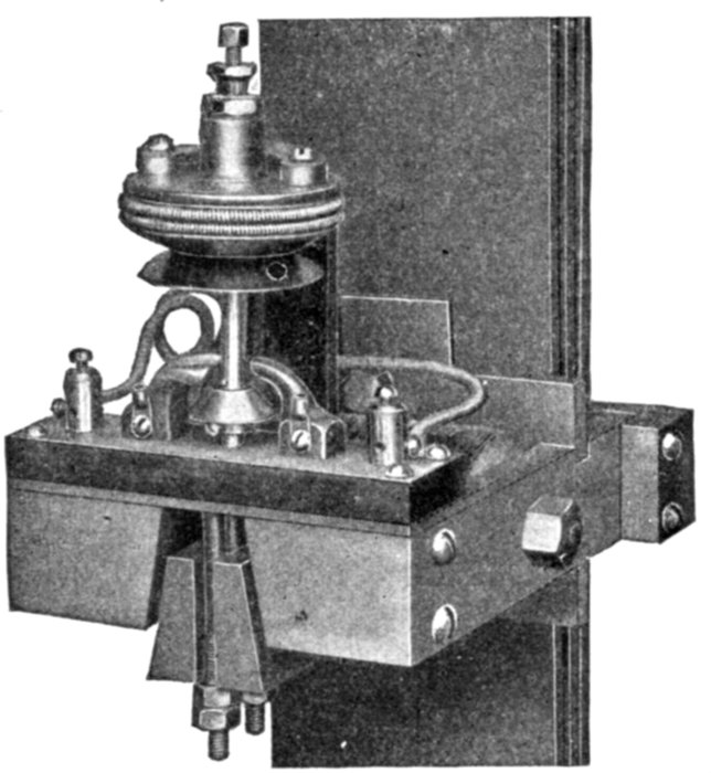
Fig. 2,340.—General Electric direct current, reverse current relay, used to protect dynamos,
storage batteries, or main station busses from damage on reversal of current due to short
circuits or from the grounding of machine or connections. It is mounted on vertical bus
bars as in the case of cables, on the side wall, or other flat surface, and the cables threaded
through the frame. When used to trip a circuit breaker, the breaker is provided with a
shunt trip connected across the circuit, the tripping circuit being closed through the relay
contacts on the occurrence of sufficient reverse current to lift the relay armature. The
relay is either instantaneous or time limit as desired. In the time limit relay, the time
interval is obtained by the leather bellows shown in the illustration. The time setting can be
varied within certain limits by means of a valve on the bellows outlet. The operation of
the relay depends on the relative value and direction of magnetic flux set up by a pressure
coil, shown in the illustration, and the current in the vertical bars. Under normal conditions
these fluxes are in the same direction and circulate around a closed magnetic circuit.
When the current in the bars reverses, the two fluxes oppose each other and force flux
through the normally open leg of the magnetic circuit. When the reversal of current is of
predetermined value, the relay armature is lifted and the purpose of the relay accomplished.
The relay design and action is similar to the reverse current relay
previously mentioned, and is connected to the secondaries of current
transformers in each high voltage line and pressure transformers in the
low voltage bus.
In the sub-station, the conditions are the reverse of those in the
main station, the incoming lines becoming the source of power.
If there be only one incoming line and no high voltage bus, the line[Pg 1670]
circuit breaker is generally non-automatic. With one incoming line
and high voltage bus, the circuits from the service side of the bus are
equipped with automatic circuit breakers and relays. These relays and
those used for other arrangements of two or more incoming lines in
parallel, as well as high and low voltage circuit breakers, are of the same
design and are applied in the same manner as for the generating station.
Regarding the relay equipments for auxiliary machines, the same
practice is recommended with the generator end of alternating current
motor generator sets as with the main generators, the outgoing feeder circuit
breakers being tripped from inverse time limit or instantaneous relays.
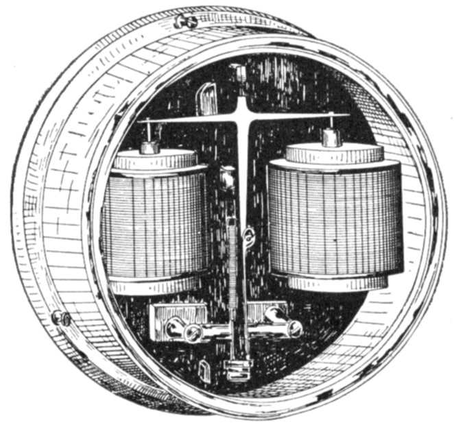
Fig. 2,341.—General Electric direct current differential relay for balancer set; instantaneous,
500 (or less) volt type for mounting on panel. In many power plants direct current,
three wire, power service is furnished by "high voltage" two wire dynamos operating
in connection with balancer sets consisting of two "low voltage" machines on a common
shaft. With this combination of machine, a short circuit or heavy overload on one side
of the system will shift the neutral considerably, and the lamps on the opposite side may
"burn out". To protect the lamps, a differential relay operating on 15 volts unbalancing,
is commonly used; it is connected to trip either the dynamo's circuit breakers (or a circuit
breaker connected in the bus between the balancer set and the other dynamos).
With several synchronous machines in parallel, the relays are arranged
to operate with the least time delay with which it is possible to get
selective action, in order to prevent the machines being thrown out of
step in event of trouble conditions causing a decrease of voltage.
The various types of induction motor and various conditions under which
they are employed, have brought about the development of several types
of relay to protect the motors and the apparatus with which they are used.
It is desirable to disconnect a large motor in case of voltage
failure, and with conditions requiring either a motor operated,[Pg 1671]
or a solenoid operated circuit breaker, a low voltage relay is
used to close the tripping circuit whenever the voltage decreases
to, approximately, 50 per cent. below normal.
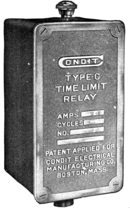
Fig. 2,342.—Condit time limit relay, designed primarily for use in connection with feeder
circuits, where close selection or discrimination of circuit breakers is not required. It may
be used satisfactorily on lighting and power circuits and also where there are sudden, momentary
fluctuations of current. This relay is used in connection with series transformers.
The contact arrangements are provided so that the relays may be used as circuit closing or
circuit opening relays. The delayed action is produced by an air vacuum dash pot with a
graphite piston. The piston of the dash pot is connected to an arm arranged to be moved
by the armature. When the current reaches a point where it overcomes the weight of the
armature and lifts the same, the magnetic force tending to lift the armature is opposed by
the pull of the vacuum created in the interior of the shell into which fits the graphite piston.
As the magnetic pull continues the vacuum is overcome due to the leakage of air past
the piston, and the armature gradually moves until it reaches a point where it causes the
circuit breaker to trip, either by closing the contacts in the circuit closing type, or by opening
the contacts in the circuit opening type. If, at any portion of its travel, the current
drop to normal, the armature immediately resets. The time adjustment consists of an
arrangement whereby the distance through which the armature moves before tripping the
breaker, may be changed, thus altering the time of tripping. The current adjustment is
made by changing the effective turns of the actuating coil, the travel of the armature and the
force exerted by it being the same for all current adjustment. The winding is designed
to carry 5 amperes continuously with a temperature rise not exceeding 68° Fahr. standard
calibration is provided so that the relay will start to operate at 5, 6, 8 and 12 amperes.
Up to 550 volts, these relays may be connected across the line, but
for higher voltages they are connected to secondaries of pressure[Pg 1672]
transformers. Smaller motors with which hand operated circuit breakers
are used, are generally provided with low voltage release attachments
that perform the same function as the relay.
Induction motors are sometimes subjected to high voltage
conditions and to protect them from injury, high or excess
voltage relays are employed to trip the automatic circuit breaker.
These relays are of similar design and wired in the same manner
as the low voltage relays.
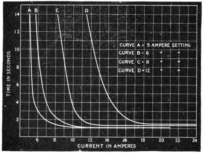
Fig. 2,343.—Characteristic curves of Condit time limit relay as illustrated in fig. 2,342. Settings:
curve A, 5 amperes; curve B, 6 amperes; curve C, 8 amperes; curve D, 12 amperes.
Reverse phase relays have been developed for operating conditions
under which a reversal of phase would cause trouble,
as for example, in the case of elevator motors.
These are so designed that any phase reversal that would reverse an
induction motor, would operate the relay and disconnect the automatic
circuit breaker.
The design is based on the principle of the induction motor, and in
the case of low voltage motors of limited capacity, the relay may be[Pg 1673]
connected in series in the motor leads. If the voltage or capacity of
the motor make this arrangement inexpedient, the relay may be placed
in the secondaries of current or pressure transformers connected in the
motor leads.
Underload relays are often used to trip the automatic circuit
breaker that is placed in the primaries of arc lighting circuits to
prevent an abnormal rise of secondary voltage in case of a break
in the secondary circuit.
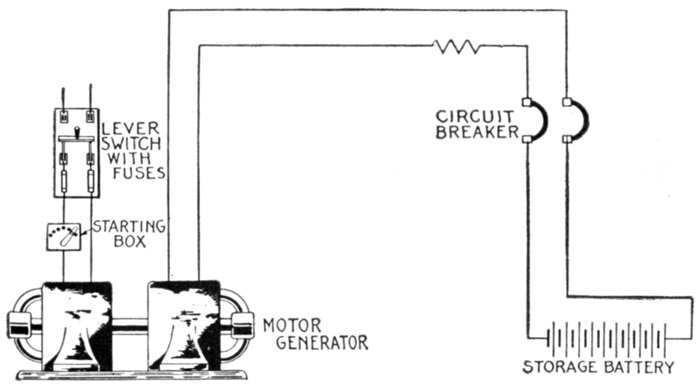
Fig. 2,344.—Diagram showing storage battery and charging dynamo protected by double
pole single coil underload circuit breaker. In operation, the circuit breaker disconnects
the battery when fully charged, and protects the dynamo from reverse current.
The underload relay is similar in design to the low voltage relay excepting
that it acts on a decrease of current.
The problem of protecting induction motors, from injury,
that may result from running on single phase, or from an overload,
and at the same time permit the motor to be started with
the necessarily high starting current that may be greatly in
excess of the overload current, has caused the development of
the series relay.
[Pg 1674]
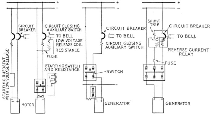
Fig. 2,345.—Diagram showing direct current motors protected by overload circuit breakers with bell alarm switches: a, double
pole single coil breaker no switch required. Low voltage device is on the starting rheostat; b, single pole breaker in series
with lever switch. Low voltage attachment on the breaker.
Fig. 2,346.—Diagram showing two wire dynamo, protected by a single pole overload circuit breaker with bell alarm switch.
Breakers must be on opposite side from the series field.
Fig. 2,347.—Diagram showing dynamo protected by a single pole overload circuit breaker with reverse current relay and
combined circuit opening and bell alarm switch.
[Pg 1675]
This device may be connected in series with the motor leads for
voltages up to 2,500; it is designed with an inverse time limit device
which may be adjusted to give the desired protection.
The field for relays is more extensive for alternating current
than for direct current power circuits, the latter being generally
confined to much smaller and simpler systems and areas
of distribution, and generally sufficient selective action can be
obtained by the use of fuses or circuit breakers arranged with
instantaneous trip.
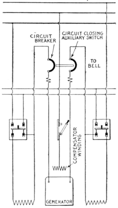
Fig. 2,348.—Diagram showing three wire dynamo protected by double pole double coil overload
circuit breaker (or two single pole breakers with interlock) with bell alarm switches.
Complete protection is secured as breaker is connected between armature and series field.
Operating conditions sometimes make it advisable for the
generator circuit breakers to open only after the auxiliary and
feeder circuit breakers have failed to isolate the trouble.
[Pg 1676]
This is accomplished by using direct current series inverse time limit
relays to trip the generator circuit breakers.
Instantaneous reverse current relays are used to trip the
machine circuit breaker of battery charging sets, rotaries and
motor generator sets to prevent their running as a motor on the
charging or direct current end. These relays can act only in
case of current reversal.
To prevent serious unbalancing of voltages in Edison three-wire
systems causing trouble, differential balance relays are
used to trip the circuit breakers on a small percentage of
unbalancing.
[Pg 1677]
CHAPTER LIX
LIGHTNING PROTECTION DEVICES
Lightning protection devices, or lightning arresters, are
devices for providing a path by which lightning disturbances
or other static discharges may pass to the earth.
Lightning arresters, designed for the protection of transmission
lines, must perform this function with a minimum
impairment of the insulation of the lines.
In general the construction of lightning arresters comprise
- 1. Air gaps;
- 2. Resistances;
- 3. Inductances;
- 4. Arc suppressing devices.
Ques. What are the causes of static charges?
Ans. They may be caused by sandstorms in dry climates,
or may be due to grounds on the high pressure side of a system.
Ques. What causes high frequency oscillations?
Ans. They are usually due to lightning discharges in the
vicinity of the line.
Ques. What are the requirements of lightning protection
devices?
Ans. They must prevent excessive pressure differences[Pg 1678]
between line and ground, line and line, and between conductor
turns in the electrical apparatus.
Air Gap Arresters.—method of relieving any abnormal
pressure condition is to connect a discharge air gap between
some point on an electric conductor and the ground. The
resistance thus interposed between the ground and the conductor
is such that any voltage very much in excess of the
maximum normal will cause a discharge to ground, whereas
at other times the conductor is ungrounded because of the air
gap. This forms the principle of air gap arresters.
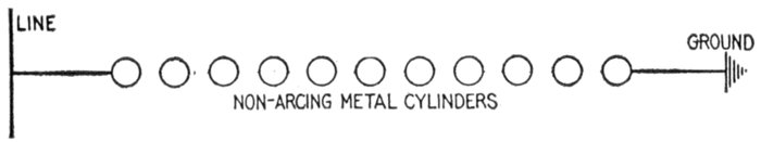
Fig. 2,349.—Non-arcing multi-gap arrester. Based on the principle of employing for the
terminals across which the arc is formed, such metals as are least capable of maintaining an
alternating arc between them. This so called non-arcing property of certain metals
was discovered by Alexander Wurtz. The action is such that the "line current" which
follows the lightning discharge follows as an arc, but is stopped at the end of one alternation
because of the property of the non-arcing metals to carry an arc in one direction,
but requiring an extremely high voltage to start a reverse arc. The non-arcing metals
ordinarily employed are alloys of zinc and copper. Plain multi-gap arresters as here
shown operate satisfactorily with the smaller machines and on circuits of limited power,
but for large machines of close regulation, and therefore of very large momentary overload
capacity, especially when a number of such are operated in parallel, such arresters
were found insufficient, the line current following the lightning discharge frequently was so
enormous that the circuit did not open at the end of the half wave, that is the arrester
held the arc and was destroyed. The introduction of synchronous motors made it necessary
that the arc should be extinguished immediately, otherwise the synchronous motors
and converters would drop out of step, and the system would in this way be shut down.
To insure the breaking of the arc, resistance was introduced in the arrester, the modified
device being known as the low equivalent arrester as shown in fig. 2,350.
The single gap while adequate for telegraph line protection,
was found insufficient for electric light and power circuits,
because since the current in such circuits is considerable and
usually at high pressure it would follow the lightning discharge
across the gap. Thus the problem arose to devise means for[Pg 1679]
short circuiting the line current resulting in various modifications
of gap arrester.
Multi-gap Arresters.—The essential elements of an arrester
of this type are a number of cylinders spaced with a small air
gap between them and placed between the line to be protected
and the ground, or between line and line.
In operation, the multi-gap arrester discharges at a much
lower voltage than would a single gap having a length equal
to the sum of the small gaps. In explaining the action of multi-gaps,
there are three things to consider:
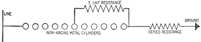
FIG. 2,350.—Low equivalent arrester. This is a modification of the multi-gap arrester shown
in fig. 2,349. About half of the total number of gaps are shunted by a resistance, and
another resistance inserted between the cylinders and the earth. With this arrangement
the middle point is at ground pressure, and there are between line and ground only one
half of the total number of gaps. This is sufficient to prevent a bridging of the gaps
under normal conditions.
1. The transmission of the static stress along the line of the
cylinders;
2. The sparking at the gaps;
3. The action and duration of the current which follows the
spark, and the extinguishment of the arc.
Ques. What is a spark?
Ans. The conduction of electricity by air.
Ques. What is an arc.
Ans. The conduction of electricity by vapor of the electrode.
[Pg 1680]
Distribution of Static Stress.—The cylinders of the multi-gap
arrester act like plates of condensers in series. This condenser function
is the essential feature of its operation.
When a static stress is applied to a series of cylinders between line
and ground, the stress is immediately carried from end to end.
If the top cylinder be positive it will attract a negative charge on
the face of the adjacent cylinder and repel an equal positive charge
to the opposite face and so on down the entire row.
The second cylinder has a definite capacity relative to the third
cylinder and also to the ground; consequently the charge induced on
the third cylinder will be less than on the second cylinder, due to the
fact that only part of the positive charge on the second cylinder induces
negative electricity on the third, while the rest of the charge induces
negative electricity to the ground. Each successive cylinder, counting
from the top of the arrester, will have a slightly smaller charge of electricity
than the preceding one.
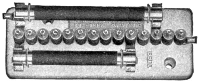
Fig. 2,351.—General Electric 2,200 volt multi-gap arrester for station installation. It consists
of fourteen ⅝" knurled cylinders and two shunt resistance rods mounted on a porcelain
base. One of these rods has a low resistance, and shunts nine gaps; the other
rod has a high resistance, and shunts eleven gaps. The effect of the shunt resistance in
extinguishing the line current arc is the same, therefore, as that of an equal series resistance
but is without the objectionable features of the latter. Series resistance limits
the discharge current to such an extent that an arrester with series resistance fails to
protect against destructive rises of voltage when the conditions are severest. Graded
shunt resistance responds to all frequencies and opens a discharge path for excessive
voltage when the frequencies are high as well as when they are low. Its further effect
in withholding the line current from the gaps after the relieving discharge has occurred,
is to aid the non-arcing quality of the metal cylinders in quickly suppressing the arc that
follows a discharge. The arc is extinguished at the end of the half cycle of line current
in which the discharge takes place.
Sparking at the Gaps.—The quantity of electricity induced on the
second cylinder is greater than on any lower cylinder and its gap has a
greater pressure strain across it as shown in fig. 2,357. When the voltage
across the first gap is sufficient to spark, the second cylinder is
charged to line voltage and the second gap receives the static strain
and breaks down. The successive action is similar to overturning a
row of ten-pins by pushing the first pin against the second. This phenomenon
explains why a given length of air gap concentrated in one
gap requires more voltage to spark across it than the same total length
made up of a row of multi-gaps.
[Pg 1681]
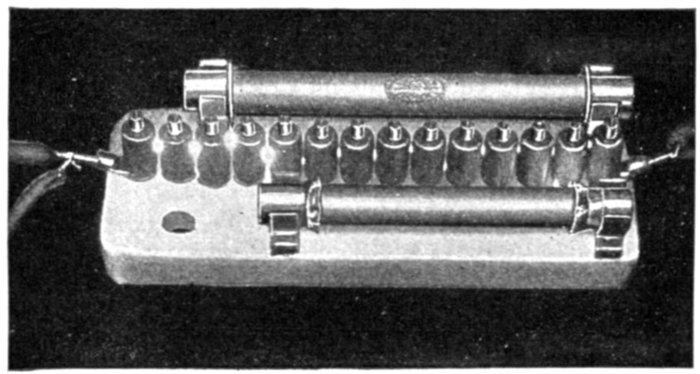
Fig. 2,352.—General Electric 2,200 volt arrester in the act of discharging, and shunting the
line current. The figure shows an actual discharge taking place. It will be seen that the
heavy line current passes across only four of the gaps, and then goes through the resistance
rods; while the static discharge passes straight across the entire series of thirteen
gaps. When the gaps of an arrester are shunted by even a low resistance, discharges of
very high frequency find it relatively difficult to pass through the resistance rods, owing
to the impedance of the rods, but comparatively easy to pass across all the gaps, owing
to the capacity effect in breaking down the gaps. The higher the frequency, the more
pronounced is this effect, hence the discharges select different paths through gaps and
resistances depending upon the frequency. By frequency is meant, not the frequency
of the line current but the lightning frequency, which may run into hundreds of thousands,
or into millions of cycles. The equivalent needle gap for this arrester is shown
by tests to be nearly the same for all frequencies and quantities of discharge; that is,
the arrester is equally responsive to all frequencies.
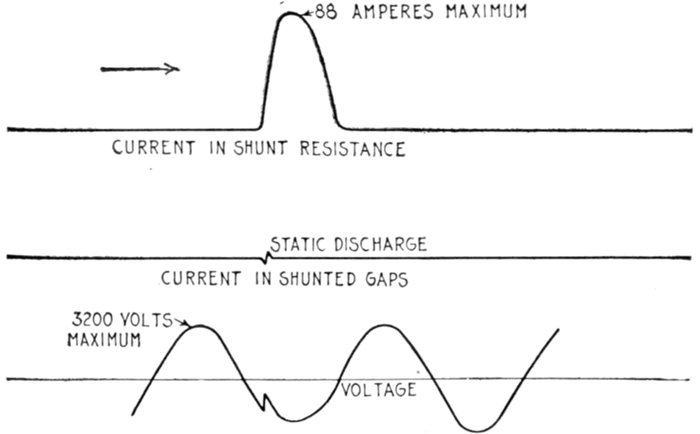
Figs. 2,353 to 2,355.—Oscillograph record of the phenomena that take place in the different
circuits or selective paths of a multi-gap arrester during a discharge such as shown in
fig. 2,352.
[Pg 1682]
As the spark crosses each successive gap, the voltage gradient along
the remainder readjusts itself.
How the Arc is Extinguished.—When the sparks extend across all
the gaps the line current will follow if, at that instant, the line pressure
be sufficient. On account of the relatively greater line current, the
distribution of pressure along the gaps becomes equal, and has the
value necessary to maintain the line current arc on a gap.
The line current continues to flow until the voltage of the generator
passes through zero to the next half cycle, when the arc extinguishing
quality of the metal cylinders comes into action.
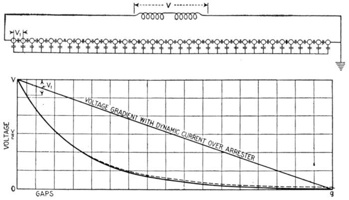
Figs. 2,356 and 2,357.—Diagram showing condenser action of cylinders and pressure gradient
for static stress.
The alloy contains a metal of low boiling point which prevents the
reversal of the line current. It is a rectifying effect, and before the
pressure again reverses, the arc vapor in the gaps has cooled to a non-conducting
state.
Effect of Frequency.—The higher the frequency of the lightning
oscillation, the more readily will the multi-gap respond to the pressure.
Briefly stated, the problem is to properly limit the line current so
that the arc may be extinguished; to arrange a shunt circuit so that
the series resistance will be automatically cut out if safety demand it
on account of a heavy lightning stroke and, while retaining these properties,
to make the arrester sensitive to a wide range of frequency.
[Pg 1683]
It should be noted that series resistance limits the rate of discharge
of the lightning as well as of the line current. The greater the value
of the line current, the greater the number of gaps required to extinguish
the arcs.
Graded Shunt Resistances.—Any arc is unstable and can be
extinguished by placing a properly proportioned resistance in parallel
with it. All the minor discharges then pass over the resistances and
the unshunted spark gaps, the resistance assisting in opening the line
current after the discharge.
Very heavy discharges pass over all the spark gaps, as a path without
resistance, but those spark gaps which are shunted by the resistance,
open after the discharge.
The line current, after the first discharge is accordingly deflected
over the resistances, and limited thereby, the circuit being finally opened
by the unshunted spark gaps. The arrangement of shunted resistances
is shown in fig. 2,358.
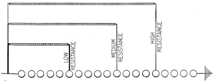
Fig. 2,358.—Arrangement of graded resistances on multi-gap arrester.
The Cumulative or "Breaking Back" Effect.—The graded shunt
resistance gives a valuable effect, where the arrester is considered as
four separate arresters. This is the "cumulative" or "breaking back"
action.
When a lightning strain between line and ground takes place, the
pressure is carried down the high resistance H (figs. 2,365 and 2,366),
to the series gaps GS, and the series gaps spark over.
Although it may require several thousand volts to spark across an
air gap, it requires relatively only a few volts to maintain the arc which
follows the spark. In consequence, when the gaps GS spark over, the
lower end of the high resistance is reduced practically to ground pressure.
If the high resistance can carry the discharge current without giving
an ohmic drop sufficient to break down the shunted gaps GH, nothing
further occurs—the arc goes out.
[Pg 1684]
If, on the contrary, the lightning stroke be too heavy for this, the
pressure strain is thrown across the shunted gaps, GH, equal in number
to the previous set. In other words, the same voltage breaks down
both of the groups of gaps, GS and GH, in succession. The lightning
discharge current is now limited only by the medium resistance M, and
the pressure is concentrated across the gaps, GM.
If the medium resistance cannot discharge the lightning, the gap
GM spark, and the discharge is limited only by the low resistance.
The low resistance should take care of most cases but with extraordinarily
heavy strokes and high frequencies, the discharge can break
back far enough to cut out all resistance.
In the last steps, the resistance is relatively low in proportion to the
number of shunt gaps, GL, and is designed to cut out the line current
immediately from the gap, GL. This "breaking back" effect is valuable
in discharging lightning of low frequency.
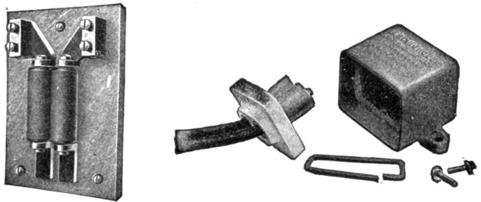
Figs. 2,359 to 2,364.—Westinghouse safety spark gaps. Fig. 2,359, indoor type; figs. 2,360
to 2,364, outdoor type. It is well known that with transformers, operating on high voltage
lines and having large ratios of transformation, there may occur, on the low tension
side, momentary voltages to ground greatly in excess of the normal. These momentary
increases in voltage between the low tension circuits and ground are commonly called
"static disturbances." In general they are the result of a change in the static balance
of the high tension side and its connecting circuits. Unless certain precautions are taken,
such a static disturbance on the low tension side may cause serious stresses in the secondary
insulation of a transformer with a high ratio of transformation. This induced
static voltage is independent of the ratio of transformation. The static stresses are more
serious in a high ratio transformer simply because the insulation of its secondary is less
able to withstand them. A method of relieving this disturbance is to connect a discharge
spark gap between some point of the low tension side of the transformer to be protected
(a middle or neutral point, if one be available) and the ground. The spark gap opening
is such that any voltage very much in excess of the maximum normal will cause a discharge
to ground, and thus the low tension side is practically tied to ground during such
disturbance, while at other times it is ungrounded. The Underwriters recommend the
grounding of the neutral point of low tension circuits when the conditions are such that
the maximum normal voltage between the point connected and ground will not exceed
250 volts. The rule allows one side of a 250 volt circuit or the middle point of a 550 volt
circuit to be grounded. The spark gaps shown above are designed for use on transformer
secondary circuits and for protecting individual series arc lamps. These spark gaps are
single pole, and consist of two cylinders of non-arcing metal with an air gap between.
One of the cylinders is connected to the ground, the other to the line.
[Pg 1685]
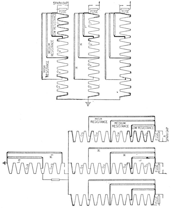
Figs. 2,365 and 2,366.—Graded shunt resistance arrester connections. Fig. 2,365, connections
for 33,000 volt Y system with grounded neutral; fig. 2,366, connections for 33,000
volt delta or ungrounded Y systems. The type of arrester shown above may be considered
as four arresters in one. First, for small discharges there are a few gaps in series
with a high shunt resistance. This part of the arrester will safely discharge accumulated
static and also all disruptive discharges of small ampere capacity. This path is shown
through H (resistance) and GS (gaps). Second, there are a number of gaps in series with
a medium shunt resistance which will discharge disruptive strokes of medium ampere
capacity. This path is shown through M (resistance) and GH plus GS (gaps). Third,
there are a greater number of gaps in series with a low shunt resistance which will discharge
heavy disruptive strokes. This path is shown through L (resistance) and GM
plus GH plus GS (gaps). Fourth, the total number of gaps has no series resistance, thus
enabling the arrester to freely discharge the heaviest induced strokes. This path is
shown through zero resistance and GH plus GM plus GH plus GS (gaps). In each of
the above circuits the number of gaps and the resistance are so proportioned as to extinguish
the line arc at the end of the half cycle in which the lightning discharge takes place.
[Pg 1686]
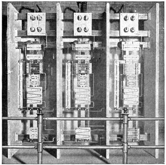
Fig. 2,367.—Installation of a General Electric 12,500 volt, three phase, multi-gap lightning
arrester in the Garfield Park sub-station of the West Chicago park common. The "V"
unit multi-gap arrester, which is plainly seen in the illustration, is made up of "V" units
consisting of gaps between knurled cylinders and connected together at their ends by
short metal strips. The base is of porcelain, which thoroughly insulates each cylinder,
and insures the proper functioning of the multi-gaps. The cylinders are made of an alloy
that contains metal of low boiling point which gives the rectifying effect, and metals of
high boiling point which cannot vaporize in the presence of the one of low boiling point.
The cylinders are heavily knurled. As the arc plays on the point of a knurl it gradually
burns back and when the metal of low boiling temperature is used up, the gap is
increased at that point. The knurling, thus, insures longer life to the cylinder by forcing
successive arcs to shift to a new point. When worn along the entire face, the cylinder
should be slightly turned. The low resistance section of the graded shunt is composed
of rods of a metallic alloy. These rods have large current carrying capacity, and practically
zero temperature coefficient up to red heat. The medium and high resistance rods
are of the same standard composition previously used. The contacts are metal caps
shrunk on the ends; the resistances are permanent in value and the inductance is reduced
to a minimum. The rods are glazed to prevent absorption of moisture and surface arcing.
[Pg 1687]
After the spark passes, the arcs are extinguished in the reversed
order. The low resistance, L, is proportioned so as to draw the arcs
immediately from the gaps, GL. The line current continues in the
next group of gaps, GM, until the end of the half cycle of the generator
wave.
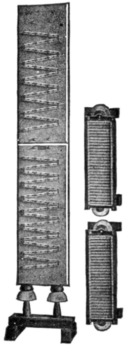
Figs. 2,368 to 2,370.—Multi-gap or low equivalent
lightning arrester. It consists of: 1, a number of
gap units in series; 2, a number of gap units in
shunt with a resistance; and 3, a series resistance.
All resistances are wire wound and the series
resistance is non-inductive. The shunt resistance
and gap units are mounted on marble. When a
discharge occurs, the series gaps are broken
down, and if the discharge be heavy enough, it will
meet opposition in the shunt resistance and pass
over the shunted gaps, through the series resistance
to the ground. The arc which tends to follow the
discharge is then withdrawn from the shunted
gaps by the shunt resistance, and aided by both
resistances is suppressed by the series gaps. The
pressure of discharge is determined by the number
of series gaps as sufficient number is used to
withstand the normal voltage and yet give a
proper factor of safety for the severest service.
At this instant the medium resistance, M, aids the rectifying quality
of the gaps, GM, by shunting out the low frequency current of the
alternator.
On account of this shunting effect the current dies out sooner in the
gaps, GM, than it otherwise would.
In the same manner, but to a less degree, the high resistance, H, draws
the line current from the gaps, GH.
This current now being limited by the high resistance, the arc is easily
extinguished at the end of the first one-half cycle of the alternator wave.
[Pg 1688]
Ques. What is the difference between arrester for
grounded Y and non-grounded neutral systems?
Ans. The connections are shown in figs. 2,365 and 2,366.
The difference in design lies in the use of a fourth arrester leg
between the multiplex connection and ground or ungrounded
system.
Ques. Why is the fourth leg introduced?
Ans. The arrester is designed to have two legs between
line and line. If one line become accidentally grounded, the
full line voltage would be thrown across one leg if the fourth
or ground leg were not present.
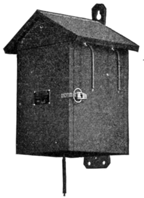
Fig. 2,371.—Westinghouse three pole or four pole arrester in weather proof wooden case which
protects the arrester units from rain and snow when they are installed in exposed locations,
as on poles or buildings.
On a Y system with a grounded neutral, the accidentally grounded
phase causes a short circuit of the phase and the arrester is relieved
of the strain by the tripping of the circuit breaker. Briefly stated,
the fourth or ground leg of the arrester is used when, for any reason,
the system could be operated, even for a short time with one phase
grounded.
[Pg 1689]
Ques. Describe the multiplex connection.
Ans. It consists of a common connection between the phase
legs of the arrester above the earth connection and provides
an arrester better adapted to relieve high pressure surges between
lines than would otherwise be possible.
Its use also economizes in space and material for delta and partially
grounded or non-grounded Y systems.
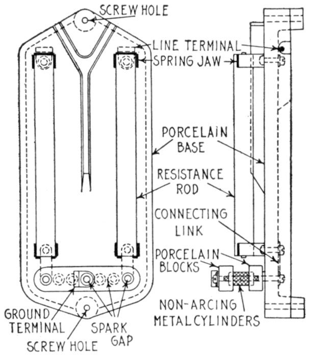
Figs. 2,372 and 2,373.—Westinghouse multi-gap lightning arrester and views showing parts.
In construction, a series of gaps, between non-arcing metal cylinders arranged in a row,
is connected between line and ground in series with a composition stick resistor having
a resistance of something between 80 and 120 ohms. In operation, if an excessive pressure
be developed on a line, electric discharge arcs form between the metal cylinders,
and the charge of electricity flows to ground, relieving the excessive stress. The resistance
of the stick resistor limits the flow so that an excessive power current cannot pass
through the arrester. The tendency for a destructive power arc to follow the discharge
arc is thus counteracted. The composition resistors and the gap cylinders are mounted
in pairs on a porcelain base, and complete units are arranged within weather proof
wooden boxes as indicated. For two pole arresters, one unit is mounted on the back of
the box. For three pole and four pole arresters, two units are used; one is secured on
each side of the box.
[Pg 1690]
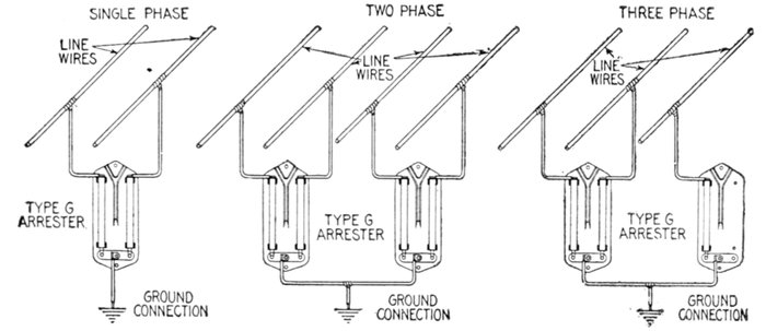
Figs. 2,374 to 2,376.—Connections for Westinghouse multi-gap (type G) arresters. These arresters may be installed outside
on poles or buildings, or indoors on station walls. The weather proof wooden case (as shown in fig. 2,371) protects the
arrester units from rain and snow when installed in exposed places. Fig. 2,374 shows single phase installation, fig. 2,375,
two phase installation, and fig. 2,376, three phase installation. On a two pole circuit one line wire is connected to the top
of each of the composition resistors of each arrester unit, as shown in fig. 2,374, and the ground wire is connected to the
middle point of the gap series. On four pole circuits, fig. 2,375, the same scheme of connections is used, but two arrester
units are necessary and the connections of both are the same. On three pole circuits, two arrester units are used, with
the same connections as for four pole circuits, except that there are but three line connections instead of four as in fig. 2,376.
Horn Gap Arresters.—A
horn
gap arrester consists
essentially of
two horn shaped
terminals forming
an air gap of variable
length, one
horn being connected
to the line
to be protected
and the other to
the ground usually
through series resistance
as shown
in fig. 2,378.
Ques. How
does the horn
gap arrester
operate?
Ans. The arc
due to the line
current which follows
a discharge,
rises between the
diverging horn and
becoming more
and more attenuated
is finally extinguished.
[Pg 1691]
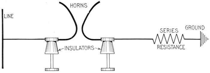
Fig. 2,377.—Horn gap arrester, diagram showing arrester and connections between line and ground. The horn type arrester
was invented by Oelschlaeger for the Allgemeine Electricitaets Gesellschaft, and like the Thomson arc circuit arrester, its
operation is based on the fact that a short circuit once started at the base, the heat generated by the arc will cause it to
travel upward until it becomes so attenuated that it is ruptured. On circuits of high voltage this rupture sometimes takes a
second or two, but seems to act with little disturbance of the line. Sometimes a water resistance is used, a choke coil being
inserted in the circuit in series. In one installation for a 40,000 volt line, the horns were made of No. 0,000 copper wire with
gap knees 2¼ to 3 or 3¼ inches. The capacity of the water resistance receptacle was 15 gallons. Users differ as to whether
the water should contain salt. The choke coil can be made of about 18 turns of iron wire wound on a 6 inch cylinder.
Ques. What is
the objection to
the horn gap on
alternating current
circuits?
Ans. The arc lasts
too long for synchronous
apparatus
to remain in step.
Ques. What
provision was
made to shorten
the duration of
the arc?
Ans. A series resistance
was inserted
in the arrester
circuit as shown in
fig. 2,377.
Ques. What
difficulty was
caused by the
series resistance?
Ans. With sufficient
series resistance
to prevent
loss of synchronism,
the arrester
failed to protect
the system under
severe conditions.
[Pg 1692]
Ques. With these objections what use was found for
the horn gap arrester?
Ans. It is used as an emergency arrester on some overhead
lines, to operate only when a shut down is unavoidable, also
for series lighting circuits.
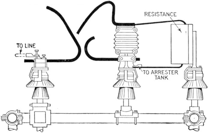
Fig. 2,378.—General Electric horn gap with charging resistance for cable system. Arresters
for cable systems differ from arresters for overhead circuits only in the construction of
the horn gaps. The necessity for this difference is due to the fact that a cable system
has a very much higher electrostatic capacity and much less inductance than an overhead
system. In consequence, the currents which flow into the arrester during charging
are somewhat higher. It is desirable to avoid these heavier currents, especially during
the time of breaking the arc at the horn gap. This is accomplished by using a special
horn gap and resistance. This consists of an auxiliary horn mounted above and insulated
from the regular horn in such a manner as to intercept the arc if it rise on the regular
horns. Enough resistance is connected in series with this auxiliary horn so that the
current flow and arc across this gap are always limited to a moderate value. Such a
device has several advantages. Since the mechanism is so arranged that the charging
is always done through the auxiliary horn the current rush is limited during the charging
and thus troubles from carelessness or ignorance are avoided. It also gives a nearer
uniform charging current. In the use of this auxiliary horn gap and resistance there
are three successive stages, as follows: 1, light discharges will pass across the smaller
gaps to the auxiliary horn and through the series resistance to the cells; 2, if the discharge
be heavy, the resistance offers sufficient impedance to cause the spark to pass to
the main horn. This is accomplished with only a slight increase in pressure because
the gap is already ionized. If the cells be in normal condition, the spark at the gap is
immediately extinguished, without any flow of line current; 3, if the cells be in poor
form, the line current may follow the discharge across the main gap and the arc will rise
to the safety horn and be extinguished through a resistance. For mixed overhead and
cable systems the choice of arrester will be a matter of judgment. If there be a comparatively
short length of cable, the usual practice for overhead systems may be adopted.
For direct connection to busbars, arresters with charging resistance should be used.
[Pg 1693]
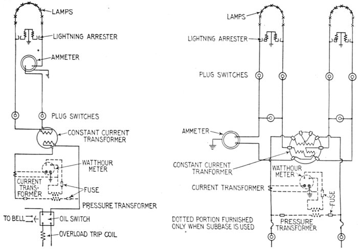
Figs. 2,379 and 2,380.—Diagram showing connections of horn type lightning arresters on series circuits.
[Pg 1694]
The necessity of service requires that series lightning systems be
fully equipped against damage by lightning and similar trouble. The
most common disturbances occurring on series circuits are the surges
set up by the sudden opening of the loaded circuit. These disturbances
are especially severe where circuits are accidentally grounded, due to
contact of the wires where they pass through other circuits.
Ques. How are the spark gaps adjusted?
Ans. They are set to give a low spark pressure relative to
the voltage of the line.
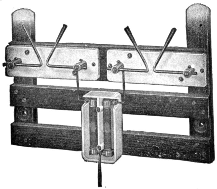
Fig. 2,381.—General Electric horn type arrester, mounted for 15 light series arc circuit. The
horn type arrester consists of a horn gap with series resistance between each line and
ground. The resistances and horn gaps are mounted on porcelain bases and the latter
on insulating wooden supports. The supports have asbestos barriers (except for lowest
voltages), and backs to eliminate liability of damage from the arc which forms in the
horn gap at the time of the discharge. The spark gaps are adjusted to give a low spark
pressure relative to the voltage of the circuit. The number and ohmic value of the
resistance rods used in the various arresters depend upon the voltage and current of the
circuit.
Ques. Why are horn arresters well suited to protect
series lighting circuits against surges?
Ans. Because the surges are damped out before the arc
which forms across the horn gaps is interrupted.
[Pg 1695]
These arcs last for several cycles, since the length of the time of action
of the arrester depends upon the lengthening of the arc between
the horn gaps, limited by the series resistance.
Since practically all disturbances on lighting circuits are of low frequency,
the series resistance can be used with good results; it aids the
horn in extinguishing the arc, limits the size of the arc and prevents
short circuits occurring during the period of discharge.
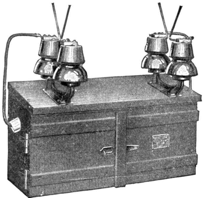
Fig. 2,382.—General Electric horn arrester for pole installation. Quite frequently series
circuits are run underground in cables for some distance from the generating station.
In order to protect the cables it is advisable to place horn arresters at the points where
the cable joins the overhead wires. The resistance units are mounted in the wooden
box. This design is used to economize space, since if the horn gaps be placed in the box
the latter would have to be made very large to accommodate the asbestos barriers and
backs. In installing this type of arrester it is advisable to place it as near as possible
to the top of the pole so that the arc may rise unobstructed and thus avoid the likelihood
of live wires coming in contact with the horns which, during the operation of the
series current, are alive.
Electrolytic Arresters.—Arresters of this class are sometimes
called aluminum arresters because of the property of aluminum
on which their action depends; that is, it depends on the
phenomenon that a non-conducting film is formed on the surface
of aluminum when immersed in certain electrolytes.
[Pg 1696]
If however, the film be exposed to a higher pressure, it may be
punctured by many minute holes, thus so reducing its resistance
that a large current may pass. When the pressure is
again reduced the holes become resealed and the film again
effective.
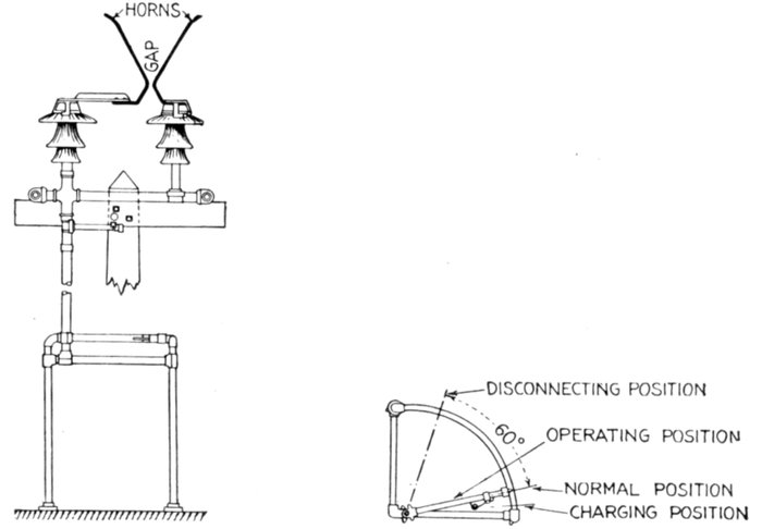
Figs. 2,383 and 2,384.—Elevation and plan of General Electric horn gaps and operating
stand for high voltage arresters.
In construction, the aluminum arrester consists essentially
of a system of nested aluminum cup shaped trays, supported
on porcelain and secured in frames of heated wood, arranged in
a steel tank.
The system of trays is connected between the line and ground,
and between line and line, a horn gap being inserted in the arrester
circuit which prevents the arrester being subjected to the
line voltage except when in action.
[Pg 1697]
The electrolyte is poured into the cones and partly fills the
space between the adjacent ones. The stack of cones with the
electrolyte between them is then immersed in a tank of oil.
The electrolyte between adjacent cones forms an insulation.
The oil improves this insulation and prevents the evaporation
of the solution.
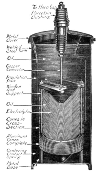
Fig. 2,385.—Cross section of General Electric aluminum (electrolytic) lightning arrester.
A cylinder of insulating material concentric with the cone
stack is placed between the latter and the steel tank, the object
being to improve the circulation of the oil and increase the
insulation between the tank and the cone stack. The arrester,
as just described consists of a number of cells connected in series.
Ques. Of what does a single cell consist and what are
its characteristics?
Ans. It consists of two of the cone shaped aluminium trays[Pg 1698]
or plates and an electrolyte, which forms a condenser that will
stand about 350 volts before breaking down. When this voltage
is exceeded the cell becomes a fairly good conductor of electricity,
but as soon as the voltage drops its resistance again resumes a
very high value.
Ques. What is the critical voltage?
Ans. The voltage at which the current begins to flow freely.
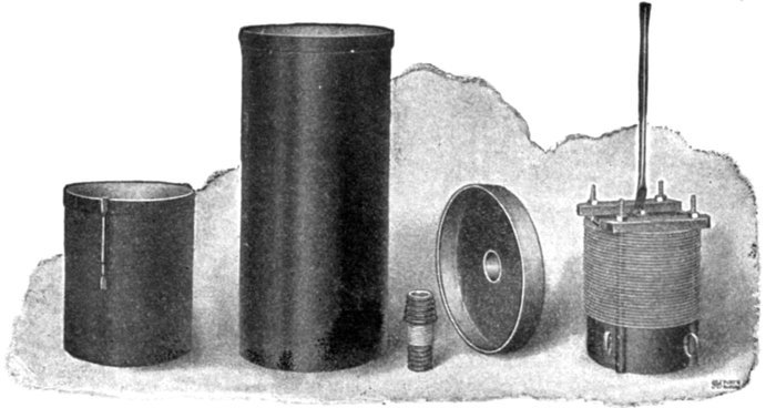
FIG. 2,386 to 2,390.—Parts of General Electric 15,000 volt aluminum lightning arrester, not
including horn gaps, etc.
Up to a certain voltage the cell allows an exceedingly low current to
flow, but at a higher voltage the current flow is limited only by the internal
resistance of the cell, which is very low. A close analogy to this
action is found in the well known safety valve of the steam boiler, by
which the steam is confined until the pressure rises above a given value,
when it is released. On the aluminum plates there are myriads of
minute safety valves, so that, if the electric pressure rise above the
critical voltage, the discharge takes place equally over the entire surface.
It is important to distinguish between the valve action of this
hydroxide film and the failure of any dielectric substance.
Ques. When a cell is connected permanently to the
circuit what two conditions are involved?
Ans. The temporary critical voltage and the permanent
critical voltage.
[Pg 1699]
For instance, if the cell have 300 volts applied to it constantly, and
the pressure be suddenly increased to, say 325 volts, there will be a
considerable rush of current until the film thickness has been increased
to withstand the extra 25 volts; this usually requires several seconds.
In this case 325 volts is the temporary critical voltage of the cell.
Similar action will occur at any pressure up to about the permanent
critical voltage, or the voltage at which the film cannot further thicken,
and therefore allows a free flow of current.
If the voltage be again reduced to 300 the excess thickness of film
will be gradually dissolved, and if it vary periodically between two
values, each of which is less than the permanent critical value, the
temporary critical voltage will be the higher value. This feature is of
great importance as it provides a means of discharging abnormal surges,
the instant the pressure rises above the impressed value.
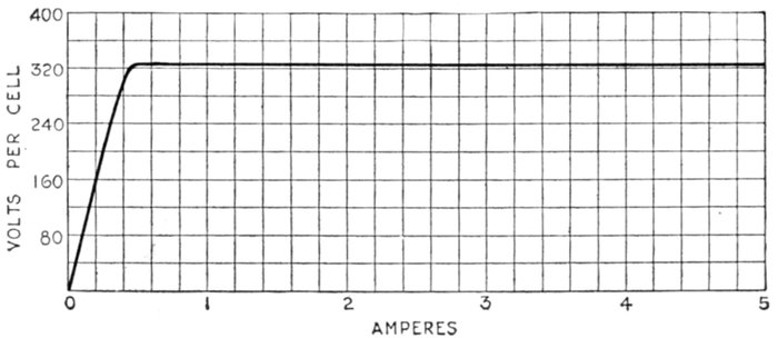
Fig. 2,391.—Volt ampere characteristic curve of a General Electric aluminum (electrolytic)
cell on alternating current. The permanent critical voltage is between 335 and 360 volts.
With alternating current, the cell acts as a fairly good condenser, and there is not only
the leakage through the film, but also a capacity current flowing into the cell. The
phase of this current, then, is nearly 90 degrees ahead of the pressure and represents a
very low energy factor.
Ques. How is the number of cells required for a given
circuit determined?
Ans. The number required for a given operating voltage
is determined by allowing about 250 to 300 volts per cell.
Ques. In putting cells in commission how is the
electrolyte introduced?
Ans. It is poured into the aluminum trays and the overflow
drawn off at the bottom of the tank.
[Pg 1700]
Ques. Describe the further operations in putting cells
in commission.
Ans. After putting in the electrolyte it is allowed to stand
for a few days until part has evaporated, then the oil is poured
over the surface to prevent further evaporation.
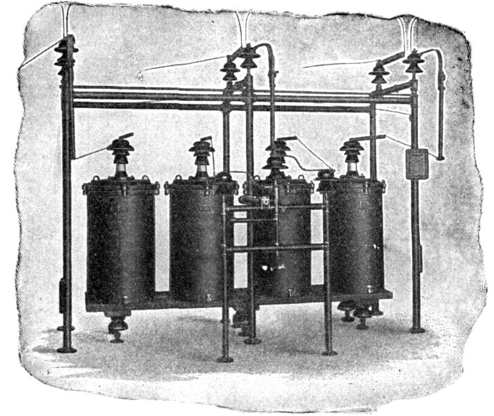
Fig. 2,392.—Westinghouse electrolytic lightning arrester, for three phase ungrounded neutral
service, 25,000 maximum voltage. These arresters are designed for the protection of
alternating current circuits from all kinds of static disturbances. They have been standardized
for installation on three phase circuits of voltages of 2,200 to 110,000. They
cannot be used for voltages of less than 13,500. For voltages below this the horn gaps
cannot, with safety, be set close enough together, out of doors, to take advantage of
the freedom of discharge of the electrolytic element. If the horn gaps be set too close
together they may be short circuited by rain. A shelter should be built for arresters of
13,500 volts and below for their protection when installed outside.
Ques. What action takes place when the trays stand in
the electrolyte and cell is disconnected from the circuit?
Ans. Part of the film deteriorates.
[Pg 1701]
Ques. What is the nature of the film?
Ans. The film is composed of two parts, one of which is
hard and insoluble, and apparently acts as a skeleton to hold
the more soluble part. The action of the cell seems to indicate
that the soluble part of the film is composed of gases in a liquid
form.
Ques. What action takes place when a cell which has
stood for some time disconnected, is reconnected to the
circuit?
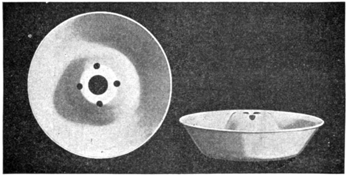
Figs. 2,393 and 2,394.—Aluminum trays for Westinghouse electrolytic lightning arresters.
Ans. There is a momentary rush of current which reforms
the part of the film which has dissolved.
This current rush will have increasing values as the intervals of rest
of the cell are made greater.
Many electrolytes have been studied, but none has been found which
does not show this dissolution effect to a greater or lesser extent.
If the cell has stood disconnected from the circuit for some time,
especially in a warm climate, there is a possibility that the initial current
rush will be sufficient to open the circuit breakers or oil switches.
This current rush also raises the temperature of the cell, and if the
temperature rise be great, it is objectionable.
When the cells do not stand for more than a day, however, the film
dissolution and initial current rush are negligible.
[Pg 1702]
Ques. What is the object of using horn gaps on electrolytic
arresters?
Ans. The use is threefold: 1, it prevents the arrester being
subjected continually to the line voltage; 2, acts as a disconnecting
switch to disconnect the arrester from the line for
repairs, etc., and 3, acts as a connecting switch for charging.
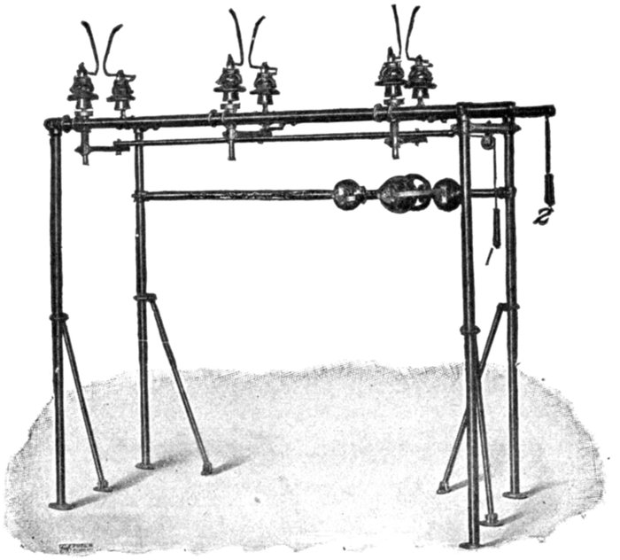
Fig. 2,395.—Horn gaps and transfer device of General Electric aluminium lightning arrester
for 12,500 volt non-grounded neutral circuit. The object of the transfer device is to
provide a means for interchanging the ground stacks with one of the line stacks of cones
during the charging operation so that the films of all the cells will be formed to the same
value. The transfer device consists of a rotating switch which may be turned 180 degrees,
thus interchanging the connections of the ground stack and one of the line stacks.
For arresters up to 27,000 volts the device is mounted with three insulators on the pipe
frame work, and is operated by a hand wheel; for arresters of higher voltage, the transfer
device is mounted directly over the tanks and is operated by bevel gears and hand wheel.
Charging of Electrolytic Arresters.—In electrolytic arresters
all electrolytes dissolve the film when the arrester is on[Pg 1703]
open circuit, the extent of the dissolution depending upon the
length of time the film is in the electrolyte, and upon its temperature.
It is therefore necessary to charge the cells from time
to time and thus prevent the dissolution and consequent rush
of current which would otherwise occur when the arrester
discharges.
Ques. Describe the charging operation for arresters
with grounded circuits.
Ans. It consists in simply closing simultaneously the three
horn gaps so that the full pressure across the cells causes a
small charging current to flow and form the films to their normal
condition.
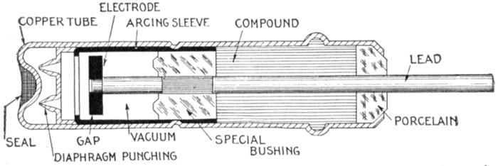
Fig. 2,396.—Sectional view of General Electric vacuum tube arrester for railway signal circuits.
The arrester is essentially a gap in a vacuum. In construction, the gap is formed
between the inner wall of a drawn metal shell and a disc electrode mounted concentric
with it. The electrode is supported on a brass rod which serves as the lead in connection,
and has ample current carrying capacity. The electrode system is insulated from
the tube and rigidly supported in position by a bushing made of vitreous material. The
bushing does not form the vacuum seal, that being made by a special compound. The
open end of the tube is finally closed by a porcelain bushing. The tube is exhausted in
a special machine which solders a small hole in the end after the vacuum has been established.
The possibility of solder entering the active part of the vacuum space is prevented
by a diaphragm punching, and both the electrode and the lining of the tube are
of non-arcing metal. The arrester has a spark pressure of from 350 to 600 volts
direct current, and an equivalent needle gap of about .005 inch. The arrester will not
stand a continuous flow of current due to excessive heating, hence if there be a possibility
of this due to high pressure crosses, fuses should be used. R.R.S.A. standard
terminals are used.
Ques. Describe the charging operation for arresters
for non-grounded circuits.
Ans. First, the horn gaps are closed for five seconds and
opened again to normal position, thus charging the cells of the[Pg 1704]
three line stacks. Second, with the horn gaps still in normal
position, the position of the transfer device is reversed and the
horn gaps are again closed for five seconds and returned to the
normal position.
The complete charging operation takes but a few moments and
should be performed daily. The operation is valuable, not only in
keeping the films in good condition, but also in giving the operator
some idea of the condition of the arrester by enabling him to observe
the size and color of the charging spark.
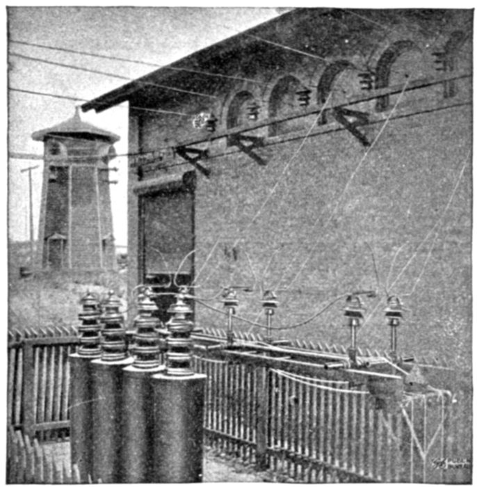
Fig. 2,397.—Highland Park sub-station, Charlotte, N.C., showing old lightning arrester tower
on the left and General Electric aluminum (electrolytic) cell lightning arrester and horn
gaps in foreground.
Grounded and Non-grounded Neutral Circuits.—It
is important to avoid the mistake of choosing an arrester for a
thoroughly grounded neutral when the neutral is only partially
grounded, that is, grounded through an appreciable resistance.
Careful consideration of this condition will make the above
statement clear.
[Pg 1705]
In an arrester for a grounded neutral circuit, each stack of
cones normally receives the neutral pressure when the arrester
discharges, but if a phase become accidentally grounded, the line
voltage is thrown across each of the other stacks of cones until
the circuit breaker opens the circuit. The line voltage is 173 per
cent. of the neutral or normal operating voltage of the cells and
therefore about 150 per cent. of the permanent critical voltage
of each cell. This means that when a grounded phase occurs,
this 50 per cent. excess pressure is short circuited through the
cells until the circuit breaker opens.
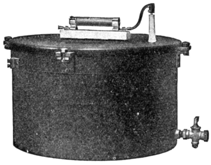
Fig. 2,398.—Westinghouse electrolytic station lightning arrester for direct current up to 1,500
volts consists of a tank of oil in which are placed, on properly insulated supports, a nest of
cup shaped aluminum trays. The spaces between the trays are filled with electrolyte, a sufficient
quantity for one charge being furnished with each arrester. The top tray is connected
with the line through a 60 ampere fuse, and the bottom tray is connected to the tank which
is thoroughly grounded by means of a lug. The fuse is of the enclosed type and mounted
on the cover of the arrester. A small charging current flows through the trays continuously
and keeps the films on the trays built up, so that no charging is required. This charging
current is not, however, of sufficient value to raise the temperature appreciably. The immersed
area of each tray is 100 square inches. The shape and the arrangement of the
trays is such that any gases generated by the discharge can pass out readily without
disturbing the electrolyte between the trays.
The amount of energy to be dissipated in the arrester depends
upon the kilowatt capacity of the generator, the internal[Pg 1706]
resistance of the cells, and the time required to operate the circuit
breakers. It is evident that the greater the amount of resistance
in the neutral, the longer will be the time required for the circuit
breakers to operate. Therefore, in cases where the earthing
resistance in the neutral is great enough to prevent the automatic
circuit breakers opening practically instantaneously, an
arrester for a non-grounded neutral system should be installed.
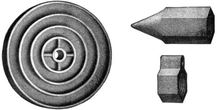
Figs. 2,399 to 2,401.—Westinghouse ground fittings. Fig. 2,399, ground plate; fig. 2,400, ground
point; fig. 2,401, cap. The ground plate consists of a circular piece of cast iron, 12
inches in diameter, 1⅜ inches thick with a ¾ inch pipe tap in center to connection to
arrester. The surface is increased by means of corrugations, as shown in the accompanying
illustrations, to 461 square inches, affording ample contact with the earth and
enabling it to take care of all discharges through the arrester. The plate should preferably
be buried at the foot of the pole so that the ground wire runs to it in a straight line
from the arrester. Care should, of course, be taken to see that the earth in which the
plate is buried is damp. If the ground wire be placed within the pipe leading to the
ground plate it should be soldered to a cap at the top of the pipe to eliminate the inductive
effect due to the wire being surrounded by iron. A simple and effective method
of securing a good ground is by means of an iron pipe with a malleable iron point having
a dipped galvanized finish, and a brass cap with a lug for soldering the ground wire.
The pipe may be driven into the earth, or if it be too hard to permit driving, a hole may
be dug and the pipe placed therein. It should extend from eight to ten feet above and
below the earth to secure, respectively, a good ground and prevent any tampering with
the ground wire. Should it be desired to make use of a longer pipe which would be
inconvenient to drive into the earth, two pieces can be used and connected together
by a coupling. The brass cap and malleable iron point are tapped for use with ¾ inch pipe.
Ground Connections.—In all lightning arrester installations
it is of the utmost importance to make proper ground
connections, as many lightning arrester troubles can be traced[Pg 1707]
to bad grounds. It has been customary to ground a lightning
arrester by means of a large metal plate buried in a bed of
charcoal at a depth of six or eight feet in the earth.
A more satisfactory method of making a ground is to drive
a number of one inch iron pipes six or eight feet into the earth
surrounding the station, connecting all these pipes together by
means of a copper wire or, preferably, by a thin copper strip.
A quantity of salt should be placed around each pipe at the surface
of the ground and the ground should be thoroughly moistened
with water. It is advisable to connect these pipes to the iron
framework of the station, and also to any water mains, metal
flumes, or trolley rails which are available.
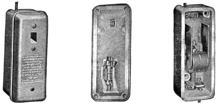
Figs. 2,402 to 2,404.—General Electric magnetic blow out arrester for use on railways. It
consists of an adjustable spark gap in series with a resistance. Part of the resistance
is in shunt with a blow out coil, between the poles of which is the spark gap.
The parts are mounted in a strong, porcelain box, which, for car and pole use, is in turn
mounted in a substantial asbestos lined, wooden box. In operation, when the lighting
pressure comes on the line, it causes the spark gap to break down and a discharge occurs
through the gap and the resistance rod to ground. Part of the current shunts through
the blow out coil producing a strong magnetic field across the spark gap. The magnetic
field blows out the discharge arc and restores normal conditions. The resistance is only 60
ohms (for 500 volt rating work), and the spark gap only one-fortieth of an inch (.025 in.).
The following suggestions are made for the usual size station.
1. Place three pipes equally spaced near each outside wall, making
twelve altogether, and place three extra pipes spaced about six feet
apart at a point nearest the arrester.
[Pg 1708]
2. Where plates are placed in streams of running water, they should
be buried in the mud along the bank in preference to being laid in the
stream. Streams with rocky bottoms are to be avoided.
3. Whenever plates are placed at any distance from the arrester,
it is necessary also to drive a pipe into the earth directly beneath the
arrester, thus making the ground connection as short as possible.
Earth plates at a distance cannot be depended upon. Long ground
wires in a station cannot be depended upon unless a lead is carried to
the parallel grounding pipes installed as described above.
4. As it is advisable occasionally to examine the underground connections
to see that they are in proper condition, it is well to keep on
file exact plans of the location of ground plates, ground wires and pipes,
with a brief description, so that the data can be readily referred to.
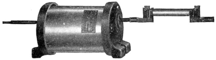
Fig. 2,405.—General Electric magnetic blow out arrester for line use. It consists essentially
of a small spark gap which is in series with a resistance, and between the poles of a magnet.
The operation is similar to that of the arrester shown in figs. 2,402 to 2,404, but the magnet
is a permanent magnet instead of an electromagnet. The spark gap and the magnet are
mounted within porcelain blocks in such a way that the discharge arc is blown by the magnet
through an arc chute and a cooling grid which is also held by the porcelain. The
cooling grid in the arc chute materially assists the magnet in extinguishing the discharge
arc, giving the arrester a high arc rupturing quality. The series rod is carborundum and is
connected externally to the other portion of the arrester. The arrester is self-contained.
5. From time to time the resistance of these ground connections
should be measured to determine their condition. The resistance of
a single pipe ground in good condition has an average value of about
15 ohms. A simple and satisfactory method of keeping account of the
condition of the earth connections is to divide the grounding pipes
into two groups and connect each group to the 110 volt lighting circuit
with an ammeter in series.
Choke Coils.—A lightning discharge is of an oscillatory
character and possesses the property of self-induction, accordingly
it passes with difficulty through coils of wire. Moreover,
the frequency of oscillation of a lightning discharge being much
greater than that of commercial alternating currents, a coil can[Pg 1709]
readily be constructed which will offer a relatively high resistance
to the passage of lightning and at the same time allow
free passage to all ordinary electric currents.
Opinions on the design of choke coils for use with lightning arresters
vary considerably. Some engineers recommend the use of very large
choke coils, but while large choke coils of high inductance do choke
back the high frequency currents better than smaller coils of less inductance,
they cost more, and under many conditions they are a menace
to the insulation unless the lightning arresters be installed on both
sides of them.
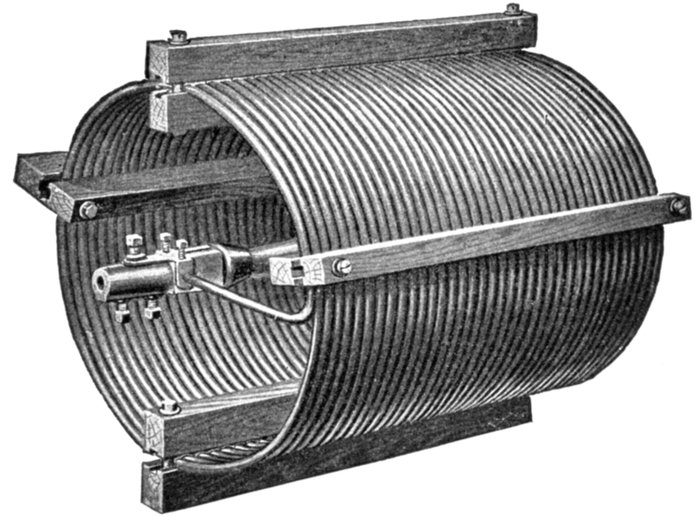
Fig. 2,406.—Westinghouse line suspension choke coil. It is so designed that it can be inserted
directly in the transmission line wire or in the station wiring and held in position
therein by the tension of the line or station wires. Because of the fact that no insulators
are required, solely to support this choke coil, and that it can be installed in either a
vertical or a horizontal position it can often be utilized effectively in power and sub-station
layouts. Terminals, each having a ½ inch round hole, to accommodate the
conductors are provided at each end of the coil. Three square headed binding screws
are supplied which clamp the conductors in position. The coil is provided with a strain insulator,
so arranged within the coil at its axis, that it assumes any mechanical tension
transmitted from the conductors. No mechanical tension reaches the turns of the choke
coil proper. In construction, the choke coil is made in but one size having a current
carrying capacity of 200 amperes and is suitable for a voltage of 2,000 to 22,000. For
higher voltages than 22,000, several choke coils are connected in series. One coil is used
for each 22,000 volts or fraction thereof, of the pressure between the wires of the circuit.
Application: This type of choke coil may be used for alternating current service
for the entire range from 22,000 to 110,000 volts. It may be used on transformers, but
is not recommended for the protection of generators.
[Pg 1710]
Part of the functions of the choke coil are performed by the end
turns of a transformer and extra insulation is invariably installed in all
power transformers built in recent years.
The choice of choke coils must be influenced by the condition of
insulation in the transformers as well as by the cost, pressure regulation,
and nature of the lightning protection required.
Ques. What are the primary objects of a choke coil?
Ans. To hold back the lighting disturbance from the circuit
apparatus during discharge, and to lower the frequency of
the oscillation so that whatever charge gets through the choke
coil will be of a frequency too low to cause serious pressure
drop around the first turns of the end coil in either alternator or
transformer.
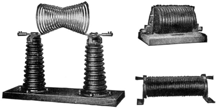
Figs. 2,407 to 2,409.—General Electric choke coils. Fig. 2,407, hour glass choke coil, 45,000
volts; fig. 2,408, low voltage choke coil, 6,600 volts; fig. 2,409, low voltage choke coil,
4,600 volts.
If there be no arrester, the choke coil cannot perform the first function,
accordingly a choke coil is best considered as an auxiliary to an arrester.
Ques. What is the principal electrical condition to
be avoided with a choke coil?
Ans. Resonance. The coil should be so arranged that if[Pg 1711]
continual surges be set up in the circuit, a resonant voltage due
to the presence of the choke coil cannot build up at the transformer
or generator terminals. This factor is a menace to the
insulation. Another way of stating the condition is as follows:
So arrange the choke coil as not to prevent surges, originating
in a transformer, passing to the arrester.
Ques. What is another electrical condition to be
avoided and why?
Ans. Internal static capacity between adjacent turns
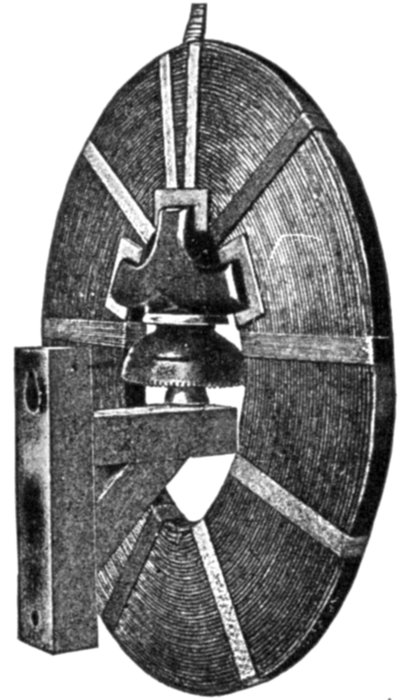
Fig. 2,410.—Westinghouse choke coil for high pressure transmission circuits, 2,200 to 25,000
volts. Choke coils of this type are wound without iron cores on circular or elliptical
center blocks. They have a large number of layers and few turns per layer (except
those made for small currents, they usually have one turn per layer), which give the best
condition for insulating and cooling. They are air cooled, heavily insulated and have a
line lead at the top, as shown. Choke coils are designed to prevent the short circuits
sometimes caused by the local concentration of pressure such as may be produced by
a lightning discharge. They limit, to some extent, an abnormal rise of pressure on the
apparatus by delaying the advance of a static wave from the line and thus give the arrester
more time to act. The disturbance caused by a lightning flash passes along the line
in the form of a surge or "tidal wave." If this wave pass a choke coil, it is flattened
out, and if the coil be of sufficient power, becomes practically harmless. It is evident,
however, that the choke coil receives the full force of the wave, and that, consequently,
it must be heavily insulated; moreover, the choke coil must not overheat under load,
nor introduce into the circuit excessive inductive resistance.
of the choke coil, because this lowers the effectiveness of the coil.
Ques. What is the object of making choke coils in
the form of an hour glass?
Ans. To prevent sagging between the supports.

Fig. 2,411.—Westinghouse air cooled choke coil particularly suitable for outdoor use. The
method of mounting is such that insulation for any desired voltage is readily obtained
with the same type of porcelain, and mounting in any position is possible. The coil is a
helix of aluminum rod, about 15 inches in diameter and containing about 30 turns. Bracing
clamps are provided to give mechanical strength to the helix, and the rod used is of
sufficient diameter to carry 200 amperes. The coil is supported on two insulating columns
made up of porcelain insulators, which, except for the end pieces, are interchangeable.
The number of insulators used in the columns depends on the voltage of the circuit
in which the coil is to be used. The apparatus can be mounted in any position convenient
for the wiring, on floor, wall, or ceiling. It is intended principally for the protection
of transformers. Where greater reactance than is afforded by a single coil is
desired on the higher voltage circuits, it is recommended that two or more coils be connected
in series, one coil being used for each 22,000 line voltage. This coil should not
be used for generators. The insulating columns are supported on substantial cast iron
blocks on wooden bases.
Ques. How are choke coils cooled?
Ans. By air, or by oil.
Ques. For what service are oil cooled choke coils used?
Ans. On circuits of pressures above 25,000 volts, choke
coils immersed in oil, as are transformer coils, have advantages
in that the coil is amply insulated not only from the ground[Pg 1713]
but against side flash, and that copper of comparatively small
section may be used without undue heating.
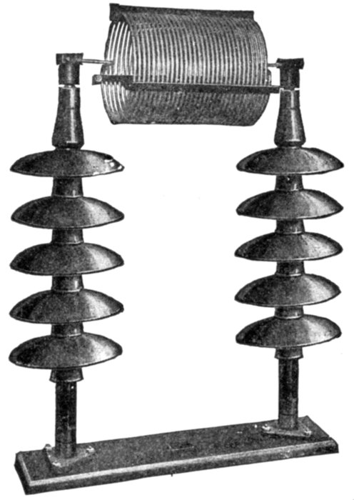
Fig. 2,412.—Westinghouse air cooled choke coil, for voltages of from 2,200 to 110,000. In
construction, the coils are made of aluminum rod wound into a helix of about 15 inches
in diameter and having 20 turns. The helix is supported on two insulators. For mechanical
reasons it is necessary to have the aluminum rod of sufficient size to secure
rigidity, consequently every coil has a capacity of 200 amperes and may be used on any
circuit up to that capacity. The coils are insulated according to the standard practice
for disconnecting switches, the insulators being mounted on wooden pins supported by
a wooden base. This apparatus can be mounted in any position. The wiring of a station
or sub-station is facilitated because the protection may be placed so as to simply
form part of the wiring. The coils are symmetrical so that it is immaterial which end
is connected to the line or to the apparatus.
"Static" Interrupters.—A static interrupter is a combination
of a choke coil and a condenser, the two being mounted together
and placed in a tank and oil insulated.
It is used on high pressure circuits and its function is to so delay the
erroneously called "static" wave in its entry into the transformer coil,
that a considerable portion of the latter will become charged before the
terminal will have reached full pressure.
[Pg 1714]
A choke coil alone sufficiently powerful to accomplish this
would be too large and costly on very high pressure and would
interfere with the operation of the system.
Ques. How is the condenser and choke coil connected?
Ans. The condenser is connected between the line and ground
behind the choke coil near the apparatus to be protected as
shown in fig. 2,413.
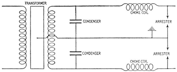
Fig. 2,413.—Diagram showing connections of static interrupter for protecting a transformer.
Ques. What is the effect of the condenser?
Ans. The condenser, which has a very small electrostatic
capacity, has no appreciable effect upon the normal operation,
but a very powerful effect upon the static wave on account of
its extremely high frequency.
[Pg 1715]
CHAPTER LX
REGULATING DEVICES
Regulation of Alternators.—Practically all the methods employed
for regulating the voltage of direct current dynamos
and circuits, are applicable to alternators and alternating current
circuits. For example: in order that they shall automatically
maintain a constant or rising voltage with increase of load,
alternators are provided with composite winding similar to the
compound winding of direct current dynamos, but since the
alternating current cannot be used directly for exciting the
field magnets, an accessory apparatus is required to rectify
it or change it into direct current before it is used for that purpose.
It is a fact, however, that composite wound alternators do
not regulate properly for inductive as well as non-inductive
loads.
In order to overcome this defect compensated field alternators
have been designed which automatically adjust the voltage for
all variations of load and lag. These machines have already
been described.
Alternating Current Feeder Regulation.—With slight
modification, the various methods of feeder regulation employed
with direct current, may be applied to alternating current distribution
circuits. For instance, if a non-inductive resistance be
introduced in any electric circuit, the consequent drop in voltage[Pg 1716]
will be equal to the current multiplied by the resistance. Therefore,
feeder regulation by means of rheostats is practically the
same in the case of alternating current as in that of direct
current. In the case of the former, however, the effect of self-induction
may also be utilized to produce a drop in voltage.
In practice, this is accomplished by the use of self-induction
coils which are commonly known as reactance coils.
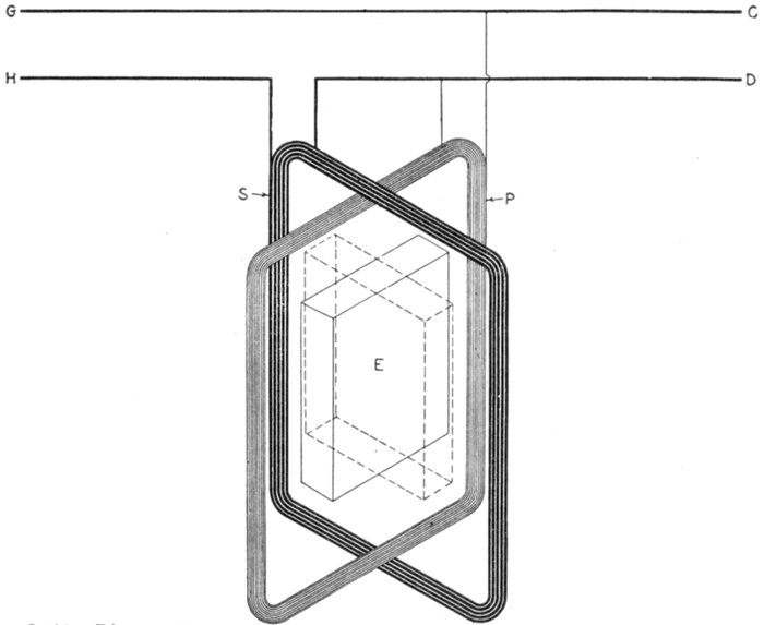
Fig. 2,414.—Diagram illustrating the principle of induction voltage regulators. The primary
coil P, consisting of many turns of fine wire, is connected across the main conductors C and
D, coming from the alternator. The secondary coil S, consisting of a few turns of heavy
wire, is connected in series with the conductor D. The laminated iron core E, mounted
within the coils, is capable of being turned into the position shown by the dotted lines.
When the core is vertical, the magnetic lines of force produced in it by the primary coil,
induces a pressure in the secondary coil which aids the voltage; when turned to the
position indicated by the dotted lines, the direction of the magnetic lines of force are
reversed with respect to the secondary coil and an opposing pressure will be produced
therein. Thus, by turning the core, the pressure difference between the line wires G
and H, can be varied so as to be higher or lower than that of the main conductors C
and D. Regulators operating on this principle may be used for theatre dimmers, as controllers
for series lighting, and also to adjust the voltage or the branches of unbalanced
three wire single phase and polyphase systems.
[Pg 1717]
Application of Induction Type Regulators.—In supplying
lighting systems, where the load and consequently the pressure
drop in the line increases or decreases, it becomes necessary to
raise or lower the voltage of an alternating current, in order
to regulate the voltage delivered at the distant ends of the
system. This is usually accomplished by means of alternating
current regulators or induction regulators. A device of this kind
is essentially a transformer, the primary of which is excited
by being connected directly across the circuit, while the secondary
is in series with the circuit as shown in fig. 2,414. By this
method the circuit receives the voltage generated in the secondary.
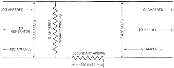
Fig. 2,415.—Diagram of induction regulator raising the voltage 10%. In the diagram an alternator
is supplying 100 amperes at 2,200 volts. The regulator raises the feeder pressure to
2,420 volts, the current being correspondingly reduced to 91 amperes, the other 9 amperes
flowing from the alternator through the primary of the regulator, back to the alternator.
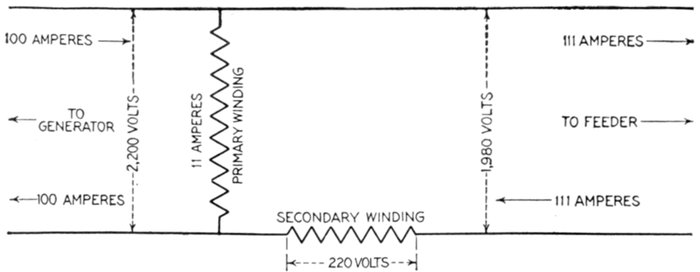
Fig. 2,416.—Diagram of induction regulator lowering the voltage 10%. The diagram shows
the regulator lowering the feeder pressure to 1,980 volts with an increase of the secondary
current to 111 amperes, the additional 11 amperes flowing from the feeder, through the
primary back to the feeder.
[Pg 1718]
Ques. Name two types of pressure regulator.
Ans. The induction regulator, and the variable ratio transformer
regulator.
Ques. Of what does an induction regulator consist?
Ans. It consists of a primary winding or exciting coil, a
secondary winding which carries the entire load current.
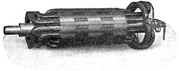
Fig. 2,417.—Moving element or primary of Westinghouse motor operated single phase induction
regulator. It consists of a core of punchings built up directly on the primary
shaft and carrying the primary winding, which is divided into four coils. The primary
coils are machine wound and the layers of the winding are separated from each other by
heavy insulating material in addition to the cotton covering of the inductors. The complete
coils are insulated and impregnated with insulating compound before being placed
in the slots. The coils are held in position by fibre wedges.
The primary is wound for the full transmission voltage, and is connected
across the line, while the secondary is connected in series with
the line.
Ques. What is its principle of operation?
Ans. When the primary coil is turned to various positions
the magnetic flux sent through the secondary coil varies in value,
thereby causing corresponding variation in the secondary voltage,
the character of which depends upon the value and direction
of the flux.
[Pg 1719]
Ques. What is the effect of turning the secondary
coil to a position at right angles with the primary coil?
Ans. The primary will not induce any voltage in the secondary,
and accordingly it has no effect on the feeder voltage.
Ques. What is this position called?
Ans. The neutral position.
Ques. What are the effects of revolving the primary
coil from the neutral position first in one direction then
in the other?
Ans. Turning the primary in one direction increases the
voltage induced in the secondary, thus increasing the feeder
voltage like the action of a booster on a direct current circuit
while turning the primary in the opposite direction from the
neutral position, correspondingly decreases the feeder voltage.
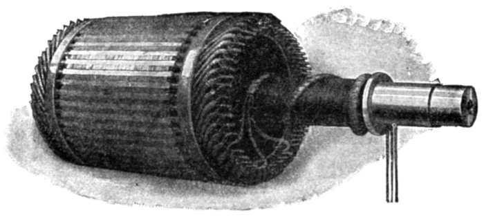
Fig. 2,418.—Moving element or primary of Westinghouse motor operated polyphase induction
regulator.
Ques. It was stated that for neutral position the
primary had no effect on the secondary; does the secondary
have any effect on the feeder voltage?
Ans. The secondary tends to create a magnetic field of its
own self-induction, and has the effect of a choke coil.
[Pg 1720]
Ques. How is this tendency overcome?
Ans. The primary is provided with a short circuited winding,
placed at right angles to the exciting winding. In the neutral
position of the regulator, this short circuited winding acts like
the short circuited secondary of a series transformer, thus
preventing a choking effect in the secondary of the regulator.
Ques. What would be the effect if the short circuited
winding were not employed?
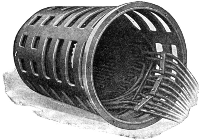
Fig. 2,419.—Top end of stationary element or secondary of Westinghouse polyphase induction
regulator; view showing leads. The secondary is built up in a short skeleton frame
with brackets for the rotor bearings bolted to the frame and the top cover bolted to the
top brackets. In assembling the secondary, the punchings are stacked loosely in the
skeleton frame and an expanding building mandrel placed inside the punchings and
expanded, thereby truing up the latter before they are finally compressed and the end
plates keyed in position. Then, prior to removing the mandrel a finishing cut is taken
on the surface of the frame to which the bearing brackets are attached, and as the top
cover and brackets are also accurately machined the alignment of the primary with the
secondary is almost perfect, thus reducing to a minimum the tendency to develop vibration
and noise.
Ans. The voltage required to face the full load current
through the secondary would increase as the primary is turned
away from either the position of maximum or minimum regulation,
reaching its highest value at the neutral position.
[Pg 1721]
The short circuited winding so cuts down this voltage of self-induction
that the voltage necessary to force the full load current through the
secondary when the regulator is in the neutral position is very little
more than that necessary to overcome the ohmic resistance of the
secondary.
Ques. What effect is noticeable in the operation of a
single phase induction regulator?
Ans. It has a tendency to vibrate similar to that of a single
phase magnet or transformer.
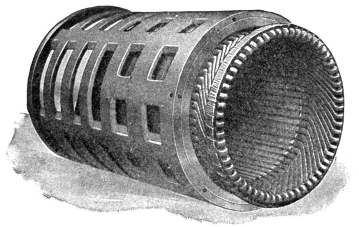
Fig. 2,420.—Bottom end of stationary element or secondary of Westinghouse polyphase induction
regulator.
Ques. Why?
Ans. It is due to the action of the magnetizing field varying
in strength from zero to maximum value with each alteration
of the exciting current, thus causing a pulsating force to act
across the air gap, which tends to cause vibration when the
moving part is not in perfect alignment.
Ques. Explain the effect produced by bad alignment?
Ans. If the bearings of the primary be not in perfect alignment
with the bore of the secondary, thereby making the air[Pg 1722]
gap on one side smaller than that on the other, the crowding
over of the flux to the smaller air gap will cause an intermittent
pull in that direction, which will develop vibration unless the
primary bearings are tight and the shaft sufficiently stiff to
withstand the pull.
Ques. Upon what does the regulator capacity for any
given service depend?
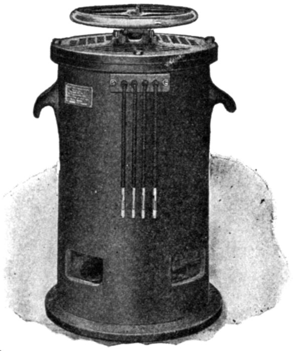
Fig. 2,421.—Westinghouse two kw., hand operated, air cooled induction regulator for testing
purposes.
Ans. It depends upon the range of regulation required and
the total load on the feeder.
Ques. How is the capacity stated?
Ans. In percentage of the full load of the feeder.
For instance, on a 100 kilowatt circuit, a 10 kw. regulator will give
10 per cent. regulation, and a 5 kw. regulator, 5 per cent. regulation.
Polyphase Induction Regulators.—The polyphase induction
regulator is similar to the single phase regulator except[Pg 1723]
that both the primary and secondary elements are wound with
as many sets of coil as there are phases in the circuit.
In construction these windings are distributed throughout
the complete circumference of the stationary and moving
elements and closely resemble the windings of an induction
motor.
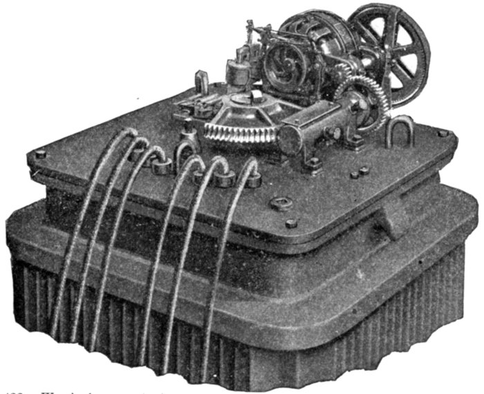
Fig. 2,422.—Westinghouse polyphase motor operated induction regulator showing operating
mechanism. The primary shaft is turned by means of a bronze worm wheel engaging
a forged steel worm, provided with a ball bearing end thrust. This worm gear is housed
in a separate casting bolted to the cover. The casting is made separate in order to permit
close adjustment between the worm wheel and the worm to aid in counteracting
the tendency to vibration. Finished surfaces on the worm gear casting are provided for
mounting the motor and the brake. On the automatic regulator, the worm shaft is connected
to the motor through a spur gear and pinion, which constitutes a compact driving
device having very little friction. Provision is made for either alternating current
or direct current motor drive. When a motor driven regulator is operated by hand, the
brake must be held in the release position, otherwise it will be impossible to operate the
regulator. In the hand operated regulator the spur gear is replaced by a hand wheel
and the regulator is driven directly from the worm shaft.
Polyphase regulators have but little tendency to vibrate
because the field across the air gap is the resultant of two or[Pg 1724]
more single phase fields and is of a constant value at all times.
This field rotates at a rate depending upon the number of poles
and the frequency of the circuit. This produces a mechanical
pull of constant value which rotates with the magnetic field
varying its position from instant to instant.
It is evident that this pull is of an entirely different character
from that produced by the single phase field and that there is
no tendency to set up the vibration that the mechanical pull
of the single phase regulator tends to establish.
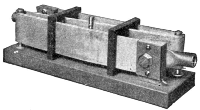
Fig. 2,423.—General Electric adjustable compensation shunt. It is used as the compensating
shunt for direct current voltage regulators. In operation, the shunt may be adjusted
so as to compensate for any desired line drop up to 15 per cent. It is preferably placed
in the principal lighting feeder but may be connected to the bus bars so that it will take
the total current. The latter method is sometimes undesirable, as large fluctuating power
loads on separate feeders might disturb the regulation of the lighting feeders. Adjustment
is made by sliding the movable contact shown at the center of the shunt. This contact
may be clamped at any desired point and it determines the pressure across the compensating
winding of the regulator's control magnet. Where pressure wires are run back
to the central station from the center of distribution, they may be connected directly to
the pressure winding of the main control magnet, and it is unnecessary to use the compensating
shunt.
There is, however, considerable torque developed, and the
device for revolving the moving element must be liberally
designed so as to withstand the excess torque caused by temporary
overloads or short circuits.
Ques. In what respects do polyphase induction regulators
differ in principle from single phase regulators?
Ans. The induced voltage in the secondary has a constant[Pg 1725]
value, and the regulation is effected by varying the phase relation
between the line voltage and the regulator voltage.
Ques. How is the primary wound?
Ans. It is wound with as many separate windings as there
are phases in the circuit, and these primary or shunt windings
are connected to the corresponding phases of the feeder.
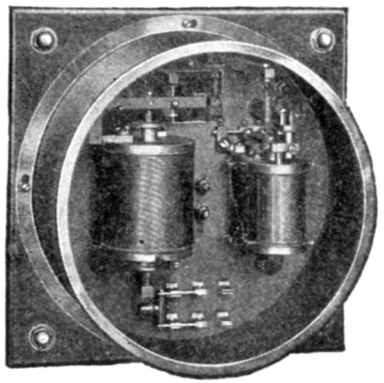
Fig. 2,424.—General Electric direct current (form S) voltage regulator. It consists of
a main control magnet, relay, condenser and reversing switch, as shown in the diagram
fig. 2,428. This regulator cannot be used for compensation of line drop as the current coil
is omitted; it is not a switchboard instrument, but is designed for inexpensive installations
such as for regulating the voltage of motor generator sets when the current is taken
from a trolley line or some other fluctuating source. The regulating outfit comprises,
besides the regulator, one or more condenser sections according to field discharge, set of
iron brackets when regulator cannot be mounted on front of switchboard, one compensating
shunt, when it is desired to compensate for line drop. Field rheostats having
sufficient resistance to reduce the voltage the proper amount must be used with voltage
regulator installations. To prevent undue decay at the relay contacts, allow one section
for each 15 kw. capacity of dynamo with laminated poles, and one for each 22 kw. capacity
with solid steel poles.
Ques. What kind of magnetizing flux is produced by
the primary windings?
Ans. A practically constant flux which varies in direction.
Ques. How is the secondary wound?
Ans. There is a separate winding for each phase.
Ques. Why is the voltage induced in the secondary
constant?
Ans. Because of the constant magnetizing flux.
[Pg 1726]
Ques. How is the line voltage varied by a polyphase
regulator?
Ans. When the regulator is in the position of maximum
boost, the line AB, fig. 2,425 represents the normal busbar
voltage, BC the regulator voltage, and AC the resultant
feeder voltage. When the regulator voltage is displaced 180
degrees from this position, the regulator is in the position to
deliver minimum voltage to the feeder, the regulator voltage
being then represented by BD, and the resultant feeder voltage
by AD. When the regulator voltage is displaced angularly in
the direction BF, so that the resultant feeder voltage AF becomes
equal to the normal busbar voltage AB, the regulator is
in the neutral position. Intermediate resultant voltages for
compensating the voltage variations in the feeders may be
obtained by rotating the moving element or primary in either
direction from the neutral position. For example, by rotating
the primary through the angle FBE, the resultant voltage may
be made equal to AE or AJ, thereby increasing the feeder voltage
by an amount BJ; or by rotating it in the opposite direction
through the angle FBG, the feeder voltage may be reduced by
an amount BH.
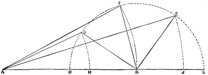
Fig. 2,425.—Diagram illustrating operation of polyphase induction regulator.
[Pg 1727]
Ques. How are induction regulators operated?
Ans. By hand or automatically.
Ques. How is automatic operation secured?
Ans. By means of a small motor, controlled by voltage
regulating relays.
Ques. How is the control apparatus arranged?
Ans. Two relays are employed with each regulator, a primary
relay connected to the feeder circuit and operating under changes
of voltage therein, and a secondary relay connected between
the primary relay and the motor, and operated by the contacts
of the former, for starting, stopping and reversing the motor in
accordance with changes in the feeder voltage, thereby causing
the regulator to maintain that voltage at its predetermined
normal value.
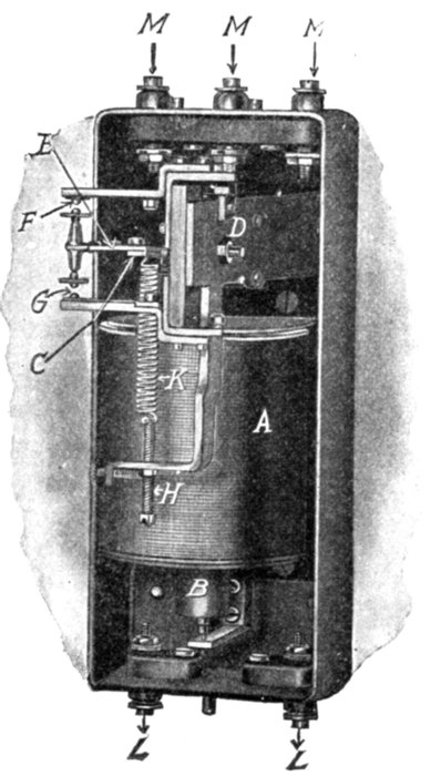
Fig. 2,426.—Westinghouse voltage regulating
primary relay; view of mechanism with case
removed. This relay is practically a voltmeter
arranged for making and breaking contacts
with fluctuations of voltage. As shown
in the figure, it consists essentially of a solenoid
and a balance beam carrying two movable
contact points on one end and attached
to the solenoid core at the other. The oscillation
of the core causes the contact carrying
end of the beam to move between two stationary
contact points connected to the auxiliary
or secondary relay circuit. The stationary
contact points are fitted with adjusting screws
for either increasing or decreasing the distance
between them, to the amount of change
in the voltage required for making or breaking
contact; in other words, for varying the
sensitiveness of the relay. Means for varying
the normal voltage which it is desired to
maintain are provided in the spring attached
to the balance beam and controlled by the
micrometer adjusting screw. Increasing the
tension of the spring results in lowering the
normal voltage position. The relay is wound
for a normal voltage of 110 volts, and has
a range of adjustment from 90 to 130 volts.
The total energy required for its operation is
about 50 watts at normal voltage. Voltage
transformers having at least 50 watts capacity
are, therefore, required. The parts are:
A, solenoid; B, solenoid core; C, end of balance
beam; D, pivots, bearings; E, movable
contact arm; F, upper stationary contact
point; G, lower stationary contact point; H,
adjusting screw; K, adjusting spring; L, feeder
binding posts; M, auxiliary circuit and secondary
relay binding posts.
[Pg 1728]
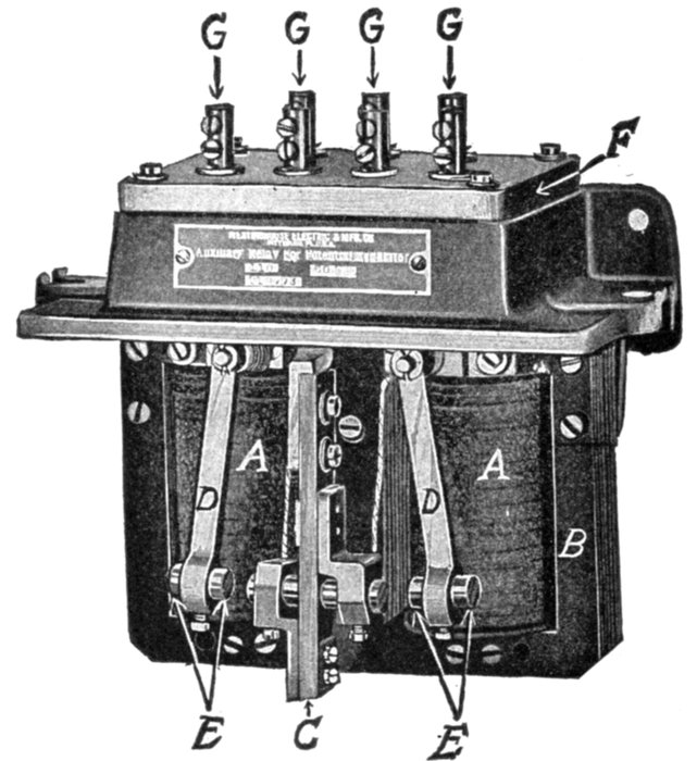
Fig. 2,427.—Westinghouse voltage regulating secondary relay; view showing relay removed
from oil tank. The secondary relay is practically a motor starting switch of the double
pole double throw type, electrically operated through the contacts of the primary relay.
It is provided with contact points of one-half inch rod. The relay is suitably connected
for starting, stopping and reversing the motor and for properly operating the motor
brake. The parts are: A, solenoid; B, laminated field; C, movable contact arm; D,
stationary contact arms; E, removable brass contact points; F, terminal block; G, terminals.
Ques. Why are two relays used?
Ans. For the reason that a primary relay, of sufficient
accuracy and freedom from errors due to temperature and[Pg 1729]
frequency variations, could not be made sufficiently powerful
to carry the relatively large current required for operating the
motor.
Ques. What names are given to the relays?
Ans. Primary and secondary.
Ques. What difficulties were encountered in the
operation of relays?
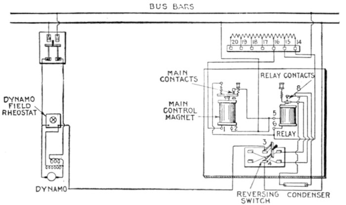
Fig. 2,428.—Diagram of connections of General Electric direct current (form S) voltage
regulator, for 125, 250, and 550 volts. The range of voltage is given in the following
table:
| Regulator |
Range of voltage |
| 16 |
17 |
18 |
19 |
20 |
| 125 |
105 |
110 |
115 |
120 |
125 |
| 250 |
210 |
220 |
230 |
240 |
250 |
| 550 |
550 |
|
|
|
|
Ans. Vibration or chattering at the contacts of both relays
and tendency of the movable contact arm of the primary relay
to hug closer to one of the stationary contact points than to the
other, thereby operating too often.
Ques. What causes vibration or chattering at the
contacts?
Ans. This is due to the voltage frequently approximating[Pg 1730]
the value required for closing a contact, thereby causing the
contact points to barely touch and make several poor contacts
in succession.
Ques. What objectionable action is produced by
vibration at the contacts?
Ans. Arcing, burning and pitting of the contacts, even when
alloys of the rarer metals are used, such as those of the platinum
group, having extreme hardness and high melting points.
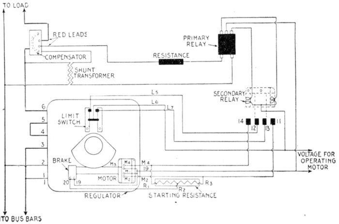
Fig. 2,429.—Diagram of connections of automatic induction regulator and auxiliary apparatus
on single phase circuit.
Ques. What effect is produced by poor contact of the
primary relay?
Ans. It causes chattering in the secondary relay; which
burns out and wears away its contact points, increasing the
heating of the motor, creating objectionable noise and entailing
wear and tear on the whole outfit.
[Pg 1731]
Ques. Why does the movable contact arm of the
primary relay tend to remain nearer one of the stationary
contact points than the other?
Ans. This is due to the tendency of the relay to open the contact
whenever the voltage equals that at which the contact closes.
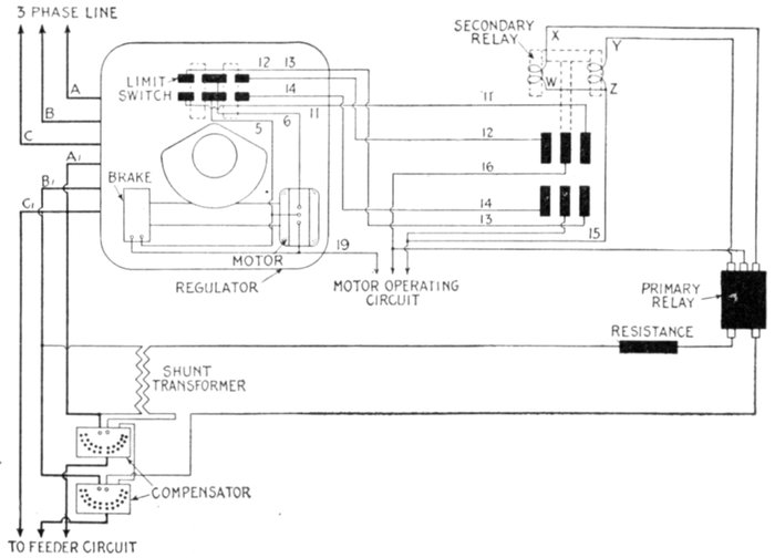
Fig. 2,430.—Diagram of connections of automatic induction regulator and accessory apparatus
on three phase feeder circuit.
Ques. What provision is made in the primary relay
to prevent vibration or chattering?
Ans. Two auxiliary windings are provided: one in series
with each of the stationary contact points and so arranged as
to assist in making the contact by increasing the pressure on
the contact points at the instant of closure.
The best effect of the compounding action of the auxiliary coils is
obtainable when arranged for ¾ per cent. of the torque of the main coil.
[Pg 1732]
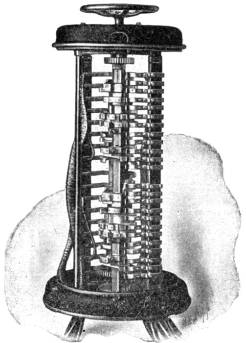
Fig. 2,431.—Westinghouse drum type variable transformer voltage regulator. It consists of
a drum and finger type switch. A preventive resistance is used between the different
contacts, making it unnecessary to open the circuit when moving from one tap of the
regulating transformer to the next tap. A spring actuated, quick moving, central stopping
mechanism is used to prevent burning the resistances. The regulator is arranged
to give 40 points of regulation. In many cases this large number of points is not absolutely
necessary, but it is desirable to use them because the voltage per step is thus reduced
to a small value, and a corresponding increase in the life of the contacts results
because of the reduced sparking at the lower voltage. Two drums are employed. The
first drum has ten contacts and a corresponding number of fingers, the latter being
mounted upon an insulated bar. These fingers are connected to the floating coils of
the regulating transformer, and as the drum is rotated, the finger connected to the line
is brought into contact successively with each of the ten taps. The second drum is of
similar construction and consists of a changing and reversing switch. It connects the
two floating coils to the various taps on the main secondary coil of the regulating transformer
at the proper time, and also reverses the transformer so that the total winding
can be used for either raising or lowering the voltage. All the points of regulation are
obtained by a continuous motion of the handle, the various connections produced in the
manner are shown in the diagram, fig. 2,433. The top and base of the regulator are made
of cast iron and the top is supported by steel bars, two of which are insulated, and used
to support the metallic bases finger to which the cable leads are attached. The drums
consist of metal castings mounted upon insulated shafts. The first drum, which is the
only one upon which arcing can take place, is provided with removable copper contact
tips. The main castings are made of aluminum to secure low inertia of the drum. A
sheet iron cover is used to enclose the regulator, and the leads are brought out through
the bottom of the controller.
[Pg 1733]
A non-inductive resistance placed in parallel with each coil of the
secondary relay, takes current approximately in phase with the current
in the main coil of the primary relay, and of proper strength to make the
number of ampere turns in the auxiliary coil three-fourths per cent. of
the number in the main coil. The resistances have the additional effect
of absorbing the "discharge" from the main coils of the secondary relay
when the contacts are broken, thereby obviating sparking at the primary
contact points.
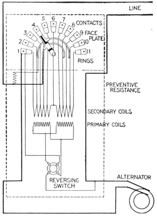
Fig. 2,432.—Diagram showing connections of the Stillwell regulator.
[Pg 1734]
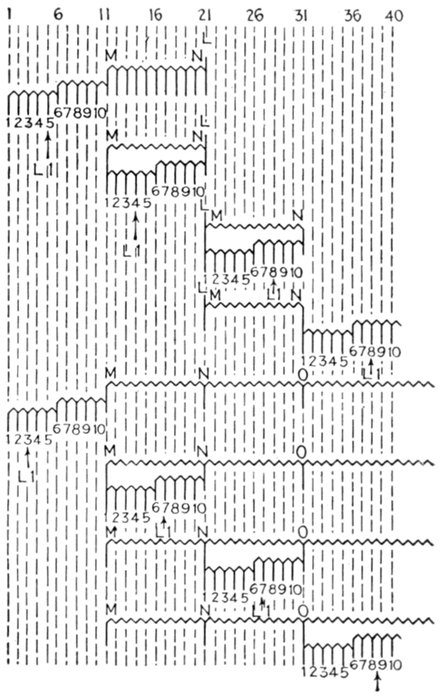
Fig. 2,433.—Diagram showing position of the floating coil
on different steps of Westinghouse drum type variable ratio
transformer regulator. The upper half of the diagram
shows the connections of the various coils for each position of
the regulator handle. This arrangement applies to a regulator
used in connection with an independent regulating
transformer. When regulators are used in connection with
large power transformers, the regulating transformer can be
omitted and auxiliary coils can be placed on the main transformer
to provide the necessary taps for regulating purposes.
The lower half of the diagram shows the connections used when
auxiliary coils are added to a large transformer. The diagram
shows connections for a single phase regulator.
Where polyphase regulators are required, the connections
consist essentially of two sets of single phase connection, and
the controller is extended in length so as to contain double
sets of drum and contact.
Variable Ratio Transformer Voltage Regulators.—The
principle of operation of this class of regulator is virtually the
same as that of the induction type regulator; that is to say,
both consist of regulating transformers, but in the variable
ratio method the primary or series coil is divided into a number
of sections which
may be successively
cut in or out of the
circuit to be regulated,
instead of
varying the flux
through the entire
coil, as in the induction
type.
There are two distinct
mechanical
forms of variable
ratio regulator:
- 1. Drum type;
- 2. Dial type.
Drum Type
Regulators.—This
form of variable
ratio transformer
consists essentially
of a drum and
finger type switch,
similar to a railway
controller.
There are many
contacts, giving a
large number of
points of regulation,
obtained by
the use of changing
switches and
floating coils.
[Pg 1735]
The floating coil is a part of the secondary winding of the regulating
transformer which is insulated from the main portion of the
winding, and is sub-divided by taps into a number of equal sections.
The sub-divisions of the main secondary winding are much
larger, each one being equivalent to the whole of the floating coil.
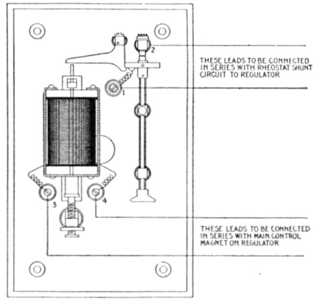
Fig. 2,434.—Diagram of connections of General Electric high voltage cut out relay (form
A) for voltage regulators. Its use in connection with the regulator protects the system
from any sudden rise in voltage due to some accident to the regulator which might cause
the relay contacts to stick, thus producing full field on the exciter. In construction, the
control magnet is connected in series with the alternating current control magnet on the
regulator and the contacts are connected in series with the rheostat shunt circuit. Then,
should the voltage rise beyond a certain value, predetermined by the setting of
the thumb screw supporting the plunger of the control magnet, the contacts of the relay
are tripped open which, by inserting all the resistance in the exciter field, reduces the exciter
voltage which in turn reduces the alternating current voltage. This relay has to be reset by hand.
Ques. Describe the operation of a drum regulator.
Ans. The floating coil and main windings are first connected
in series with each other and with the line to be regulated. The
floating coil is then cut out of the circuit step by step. When
entirely cut out it is transferred to the next lower tap on the
main winding, after which it is again cut out step by step and
then transferred again. By continuing this process a large
number of steps are provided with but comparatively few actual
taps on the transformer.
[Pg 1736]
Ques. How many floating coils are used and why?
Ans. Two floating coils are included in each regulator so
that one can be transferred while the other is supplying the
current to the line.
Dial Type Regulators.—This form of variable ratio transformer
regulator consists of a regulating transformer and a dial
type switch as shown in the accompanying illustrations. The
regulating transformer is similar to a standard transformer
except that the secondary winding is provided with a number
of taps leading to the contact of the dial switch as shown in
the diagram fig. 2,437.
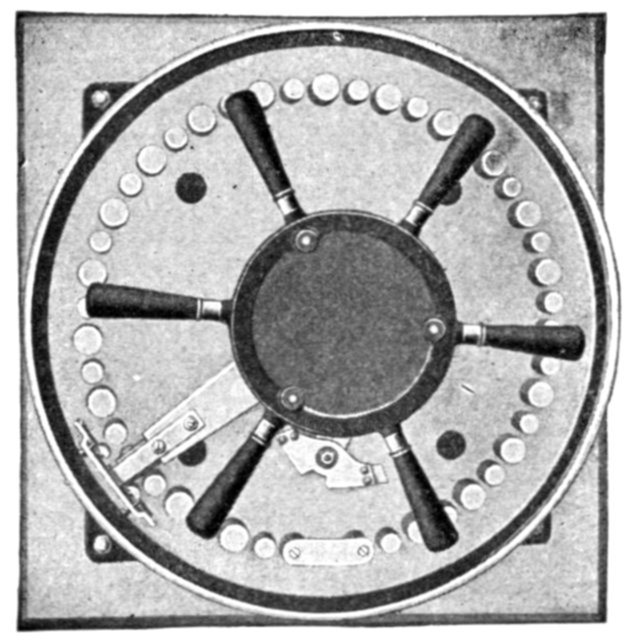
Fig. 2,435.—Dial of Westinghouse dial type variable ratio voltage regulator. The dial
consists of a marble slab, upon which the contacts are mounted in a circle as shown.
The contact arm is arranged to move from contact to contact. The alternate small contacts
are dummies, serving to prevent the contact arm springing down between contacts
when moving from one to another. The panel contains a changing switch which makes
it possible to double the range of a regulator, since the transformer connections can be
changed to both raise and lower to an extent equal to the full range of the transformer.
The total range in voltage from a certain per cent. below to a certain per cent. above the
line voltage can be obtained in a number of steps equal to twice the number of divisions
into which the secondary winding of the transformer is divided.
[Pg 1737]
Ques. What modification is made to adapt dial regulators
for heavy current?
Ans. A dial with a series transformer, and a shunt or auto-transformer
are employed as shown in fig. 2,436.
Ques. Why is such modification desirable?
Ans. Because, the additional cost of a series transformer is
small in comparison with the cost of building a dial with a large
current carrying capacity, and the cost of bringing out a number
of heavy leads from a small transformer.
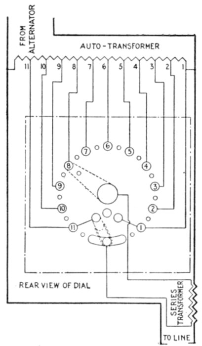
Fig. 2,436.—Diagram of connections for Westinghouse 11 point dial, series transformer and
auto-transformer. The auto-transformer has a number of taps connected across the
line, the series transformer is placed in series with one side of the line, and connected to
a dial, as shown.
Ques. How are dial regulators modified for high
voltage?
Ans. Standard dials may be used with series and shunt transformers
similar to the method used for heavy current circuits.
[Pg 1738]
Ques. Describe the connections.
Ans. The primary of the shunt transformer is connected
across the line and the secondary has a number of taps which
are connected to contacts on the dial. The primary of the series
transformer is connected in series with the line and two leads
from the secondary winding are connected to the dial.
The connections are similar to those shown in fig. 2,437, except that
shunt transformers are used instead of auto-transformers.
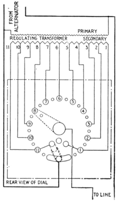
Fig. 2,437.—Diagram of connections for Westinghouse dial type variable ratio voltage transformer.
In construction the secondary winding of the transformer is divided into 10,
14, or 20 parts giving 11, 15, or 21 taps which are brought out from the secondary winding
and connected to the various points of the dial. The diagram shows connections
for an 11 point dial and regulating transformer. Since there is a difference of voltage
between adjacent contacts, the contact arm must not touch the contact toward which
it is moving until after it has left the contact upon which it was resting. Moreover, it
is undesirable to open the circuit each time in moving from one contact to the next.
These conflicting requirements are met by the use of arcing tips which are placed on
the contact arm so that a very close adjustment can be obtained, and so arranged that
the contacts are not short circuited but always have a gap of from one-sixteenth to one-eighth
inch in the circuit during the time of changing from one contact to the next. The
air gaps form a "preventive resistance." A quick moving mechanism is used to accelerate
the movement from one contact to the next, a very quick movement being necessary
to avoid undue arcing. The capacity of the regulator is 200 amperes at 2,200 volts,
being arranged to give a maximum increase in voltage of 400 volts. The maximum pressure
between contacts is 25 volts.
[Pg 1739]
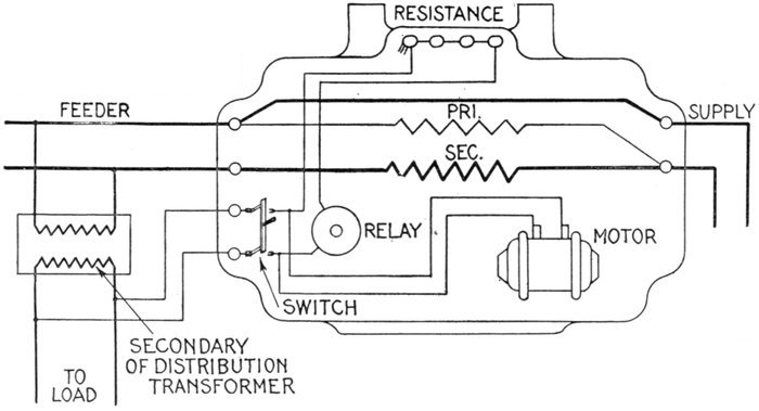
Fig. 2,438.—Diagram of connections of General Electric
pole type regulator. The operation of the regulator
is obtained by means of a small single phase
motor which is in continuous operation, and which by
mechanical means may be connected
to the regulator shaft. The control of
the mechanism is obtained by means
of a voltage relay. The operating
motor, which is of the drawn shell type, is provided with a starting clutch
and will consequently start up with full load. Under actual operating
conditions it will, of course, be comparatively seldom that the motor will
be called upon to start up. A non-inductive resistance, made up from
standard units, is connected in series with the relay winding and several
taps are provided, so that the relay can be adjusted for any voltage from
10 per cent. below normal. In order to readily dissipate the heat developed in the resistance, it has been mounted in a pocket
on the back of the tank, openings being provided for natural air ventilation. The relay plunger is hinged to one end of a
balance arm, which arm is provided with two trip pins to control the mechanism. An adjustable helical spring is attached to
the other end of the arm to assist the magnetic pull of the coil in balancing the plunger and also for adjustment. The relay is
not provided with series winding for line drop compensation, but it may be used with a standard line drop compensator, which
then has to be installed outside of the regulator. The voltage relay must be connected to the feeder side of the regulator, the
necessary low voltage to be obtained from a distributing transformer, or if this should not be available in the immediate vicinity,
a 200 watt step down transformer will be satisfactory. The motor is designed to operate in parallel with the relay, the normal
connections being as shown. The speed of the motor and the ratio of the gearing is such that it requires about 90 seconds to
operate the regulator from limit to limit, but, as this regulator is not intended to take care of sudden voltage fluctuations, the
comparatively long time of operation will not be objectionable.
[Pg 1740]
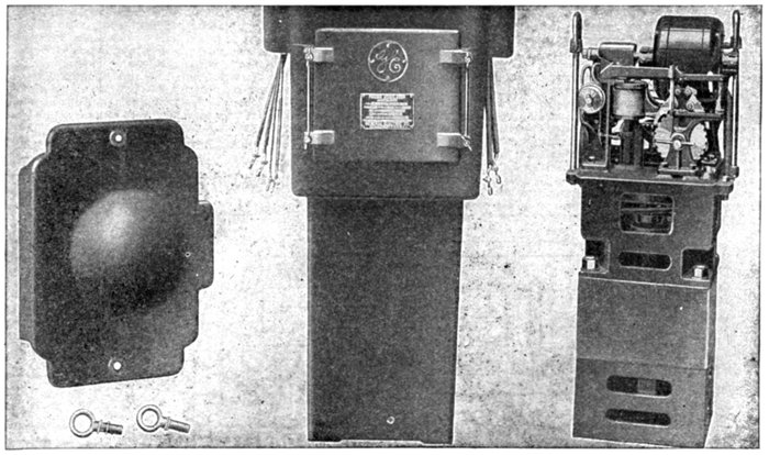
Figs. 2,439 to 2,443.—General Electric pole type regulator removed from tank. It consists essentially of a primary and secondary
coil, operating motor, and voltage relay mechanism. The regulator and mechanism is suspended in a cast iron tank, the
lower part, containing the regulator core and coils, being filled with oil. The leads for the regulator are brought out at the upper
part of the tank. The outgoing leads are compressed into bushings and connected to the leads of the regulator by
means of terminals, the arrangements being such that the regulator with mechanism can be removed from the tank
without difficulty. Besides the cover, the tank is also provided with a hinged door on the front side so as to give access
to the mechanism. The door is provided with a gasket and the construction is practically rain and dust proof. However
as there is always danger of the door not being clamped down perfectly, thus making it possible for water to enter the
tank, a pocket has been provided inside the tank and underneath the door to collect the water. Capacity up to 2.3 kw., to
control 2,300 volts, 60 cycle, 10 ampere feeders, and for a voltage range of 10 per cent. above or below normal, the operating
motor and relay being designed for 110 or 220 volts. No provision is made for line drop compensation, although this can
be obtained by installing a current transformer and a line drop compensator externally to the regulator.
[Pg 1741]
It will be seen that the circuit comprising the dial, the secondary
of the shunt, transformer and the secondary of the series transformer
form a circuit which is not electrically connected to the main circuit.
It can therefore be grounded without disturbing the main circuit as a
safeguard to render it impossible for the pressure of the dial to be higher
above the ground than the secondary voltage of the shunt transformer.
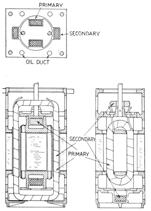
Figs. 2,444 to 2,446.—Sectional views of General Electric pole type regulator winding and
core. The secondary core has only two slots containing a single coil, while the rotor or
primary core has four slots. Two of these slots are occupied by a single primary coil,
and the two circular slots in quadrature thereto contain the compensating or short circuit
winding. This winding also serves to hold the primary punchings together, and it
consists of two copper rods riveted to the two cast brass flanges. The secondary coil is
form wound, while the primary coil is wound directly on the core. The rotor flanges,
both top and bottom, are provided with discs which are turned in alignment with the
punchings, and these discs bear against the top and bottom flanges between which the
secondary punchings are clamped. These secondary flanges are also turned in alignment
with the secondary punchings, so that an even air gap between the primary and the secondary
is assured. The secondary coil is wound with an opening in the upper horizontal
part which affords passage for the operating shaft of the rotor. A bearing for this shaft
is provided in the table which supports the mechanism and from which the regulator is
suspended. Flexible leads are brought out from the rotor and twisted around the shaft
as in standard regulator practice. The regulator being two pole, the rotor is turned
through an angle of 180 deg. to obtain the full range of the regulator.
[Pg 1742]
Small Feeder Voltage Regulators.—In some generating
stations the voltage is maintained constant at the busbars and
the line drop compensated by automatically operated regulators
connected in the main feeders. It is possible in this way
to obtain constant voltage at all loads at the various distribution
centers, that is, at those points on the feeders where the lines of
the majority of consumers are connected as shown in fig. 2,447.
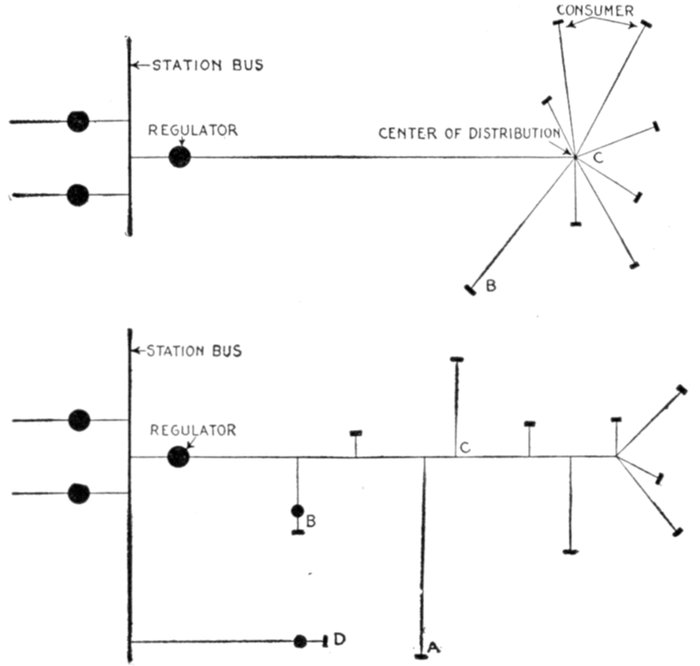
Figs. 2,447 and 2,448.—Systems of distribution illustrating use of small feeder or pole type
voltage regulators.
It is evident, however, that, while the voltage at the center
of distribution can be maintained constant, no account can
be taken of the drop in the lines between this center and the
consumers. This drop is generally negligible, except in some
particularly long lines, as, for example, consumer B in fig. 2,447.
[Pg 1743]
In order to obtain perfect regulation at B, it would be necessary
to install a separate regulator in that line, this regulator
to be installed either at the center C or preferably at B.
In a great many cases the power distribution is not as ideal as indicated
in fig. 2,447, but rather as shown in fig. 2,448, that is, the consumers
are connected all along the feeder. In this case there is no definite
center of distribution, and the automatic regulator installed in the
station can be adjusted to give only approximately constant voltage at
an imaginary center of distribution C; that is, the voltage cannot be
held constant at any definite point during changes of load distribution.
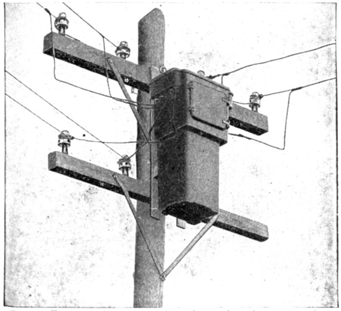
Fig. 2,449.—General Electric pole type regulator in service; its construction is shown in
fig. 2,450.
The majority of the consumers may, however, obtain sufficiently
good voltage while a few may have reason for criticism. To overcome
this difficulty it is necessary either to increase the copper in the feeder
or else to install small automatic regulators.
There are also cases where a small amount of power is transmitted
a long distance through a feeder direct from the station.
The amount of copper required to reduce the line drop is usually too
great to be considered and the cost of the ordinary automatic regulator
is also comparatively high. In such cases small pole type regulators as
shown in fig. 2,449 are desirable.
[Pg 1744]
Ques. Describe the operation of the regulator mechanism
shown in fig. 2,450.
Ans. Assuming the voltage to be normal, the balance arm
of the relay will be held horizontal, the trips F will not engage
with the triggers E, and no movement is therefore transmitted
to the ratchet wheel C. If the voltage drops below normal, the
left hand trip will descend until it finally gets in the way of the
left hand trigger just before it reaches the limit of its counterclockwise
travel. This trigger will therefore release the left
pawl D, which will engage with the ratchet wheel and will
consequently turn it clockwise until the rocker arm reaches its
right hand limit. Before the rocker arm reaches the left hand
limit, the released pawl must be locked by its trigger, so that
if the voltage has reached its normal value, further movement
of the ratchet wheel will not take place, whereas if the voltage
be still too low, the trigger will again release the pawl by striking
the trip of the relay.
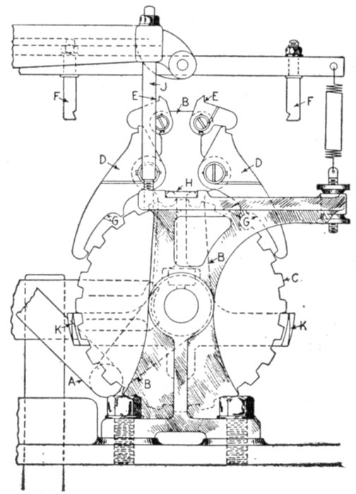
Fig. 2,450.—Mechanism of General Electric pole type regulator. The operating motor (described
in fig. 2,438) is direct connected to a worm and gear, the shaft of which is provided
with a bell crank. A rod A, connects the crank with the rocker arm B, which thus
may be caused to oscillate over a ratchet wheel C. The rocker arm is provided with
two pawls D, which can engage with the teeth of the ratchet wheel, so that this wheel
can be rotated one way or the other. The ratchet wheel is mounted on the same shaft
as a worm, which engages with the gear segment carried by the regulator shaft, so that
the movement of the ratchet wheel is directly transmitted to the regulator. Besides the
two large pawls D, the rocker arm also carries two smaller ones E, called the triggers.
These triggers usually hold the pawls locked in such positions as not to engage with the
ratchet wheel, but the pawls will be released when the triggers strike the trips F of the
relay arm. A limiting device for the movement of the ratchet wheel and the regulator
segment is provided, as shown. This device consists of two cams K, mounted on a common
arm, which can turn on the shaft of the ratchet wheel. Normally these cams are
not within reach of the pawls, but through a lever arrangement, controlled by the regulator
segment, the arm holding the cams may be rotated so that, if the trigger has been
raised, so as to release the pawl, the tip of the pawl will bear on the cam of the limiting
device, and before the pawl can engage with the ratchet wheel it has already been locked
by its trigger. A further movement of the ratchet wheel in that particular direction is
therefore impossible, while it is free to be moved the other way. A positive stop for the
gear segment is also provided. The motor is provided with oil ring bearings, and the
gear for the motor worm runs in oil, the supporting casting forming a well therefor.
[Pg 1745]
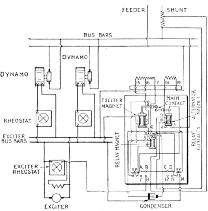
Fig. 2,451.—Diagram of connections of General Electric direct current voltage regulator
(form T) with two dynamos and one exciter. In cases where several shunt or compound
wound direct current machines are operating in parallel, either on two wire or three wire
systems, a good arrangement for voltage regulation and line drop compensation is
obtained by using this regulator and a separate exciter. The compensating shunt as well
as pressure wires can be used to maintain a constant pressure at the center of distribution.
[Pg 1746]
Ques. How is this automatic locking of the pawl
obtained?
Ans. By having a lip G on the under side of the pawl strike
a finger H fastened to the bearings in front of the ratchet wheel.
The pawl is thus raised just before it reaches the limit of its clockwise
travel sufficient to be locked by its trigger.
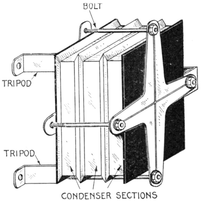
Fig. 2,452.—Condenser sections and method of assembling same with tripod. The tripod
bolts are made of extra length to accommodate the addition of extra condenser sections
if necessary. The illustration shows three sections in position.
Ques. How does the mechanism operate when the
voltage rises above normal?
Ans. As described above, with the exception that the right
hand trip causes a rotation of the regulator in the opposite
direction.
Ques. How is adjustment made for various voltages?
Ans. Taps are provided on the resistance in series with the[Pg 1747]
relay, and finer adjustment can be obtained by means of the
helical spring on the right hand end of the balance arm.
In order to adjust the sensitiveness of regulation, the bearing for the
balance arm can be raised or lowered by means of a stud J, fig. 2,450,
connecting this bearing with the bearing of the operating shaft, and the
regulator can be made to maintain the voltage within 1 per cent. above
or below normal.
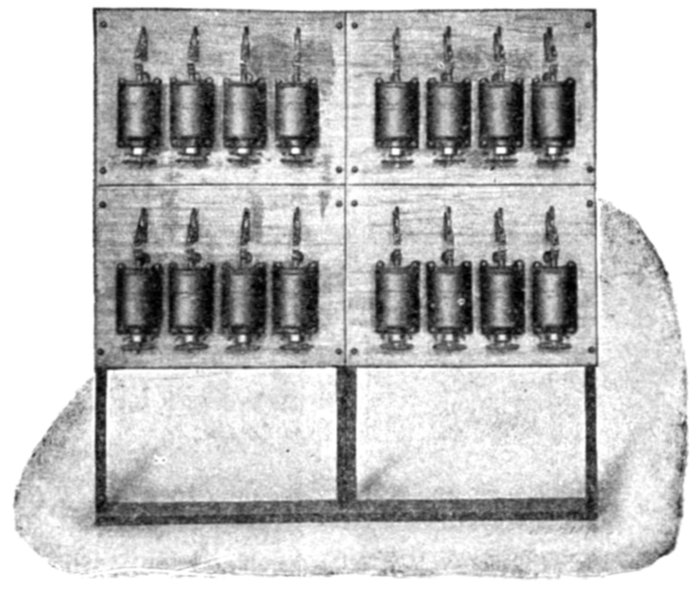
Fig. 2,453.—Westinghouse unit switch type pressure regulator, designed for handling heavy
currents where a variable ratio transformer type of regulator is desired. The regulator
consists of a number of electrically operated switches controlled from a master switch.
These switches are arranged to perform practically the same cycle of operation as previously
described for the drum type regulators. The transformer windings are divided
into sections, and two floating coils are provided which are connected to various taps
on the main auto-transformer. These floating coils have intermediate steps, and the
successive operation of the switches connects the floating coils in proper sequence to the
main auto-transformer, and transfers the line connection from one point of the floating
coil to the next. In this way a 23 point regulator with sixteen switches, and a 71 point
regulator with 21 switches may be supplied. The master switches are arranged with an
automatic lock to prevent their being operated too rapidly. The magnet switches themselves
are so interlocked that the proper sequence of operation is insured. The electrically
operated switches may be of the open type, mounted on a slate or marble switchboard,
when the whole control outfit is placed in a room which is comparatively free from dust
or dirt of any kind, and where there is no danger of employees coming in contact with
the switches. The other type of switch is entirely enclosed, the main contacts being
oil immersed. The frames of these switches are grounded and the whole design is arranged
to operate under ordinary dirty conditions. All of these switches, however, should
receive the necessary inspection and attention. The contacts have a long life and are
easily renewed. Regulators of this type are adapted for metallurgical purposes where
the regulation is effected in the primary circuit and the secondary circuit is of very low
voltage but large current capacity and is used for supplying power to the furnaces.
These regulators have been built in capacities up to 800 amperes at 3,300 volts.
[Pg 1748]
Ques. What provision is made for convenient inspection?
Ans. A snap switch is provided by means of which the power
to the motor and relay can be disconnected.
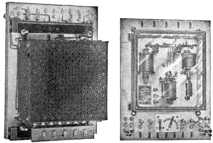
Figs. 2,454 and 2,455.—Front and rear views of General Electric automatic voltage regulator.
The regulator has a direct current control magnet, an alternating current control magnet,
and a relay. The direct current control magnet is connected to the exciter bus bars.
This magnet has a fixed stop core in the bottom and a movable core in the top which
is attached to a pivoted lever having at the opposite end a flexible contact pulled downward
by four spiral springs. For clearness, however, only one spring is shown in the
figure. Opposite the direct current control magnet is the alternating current control
magnet which has a pressure winding connected by means of a pressure transformer to
the alternator or bus bars. There is an adjustable compensating winding on the alternating
current magnet connected through a current transformer to the principal lighting
feeder. The object of this winding is to raise the voltage of the alternating current bus
bars as the load increases. The alternating current control magnet has a movable core
and a lever and contacts similar to those of the direct current control magnet, and the
two combined produce what is known as the "floating main contacts." The relay consists
of a U shaped magnet core having a differential winding and a pivoted armature
controlling the contacts which open and close the shunt circuit across the exciter field
rheostat. One of the differential windings of the relay is permanently connected across
the exciter bus bars and tends to keep the contacts open; the other winding is connected
to the exciter bus bars through the floating main contacts and when the latter are closed,
neutralizes the effect of the first winding and allows the relay contacts to short circuit
the exciter field rheostat. Condensers are connected across the relay contacts to prevent
severe arcing and possible injury.
Automatic Voltage Regulators for Alternators.—The
accurate regulation of voltage on any alternating current system[Pg 1749]
is of importance. The desired voltage may be maintained
constant at the alternator terminals by rapidly opening and
closing a shunt circuit across the exciter field rheostat.
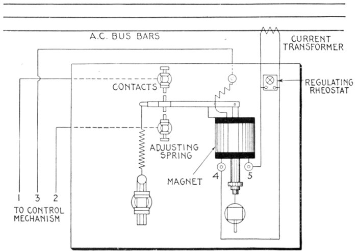
Fig. 2,456.—Diagram of connections of General Electric contact making ammeter for operating
on alternating current circuits. The instrument is designed to indicate with the aid
of a current transformer, certain values of current in an alternating current system. This
value depends upon the setting of the regulating rheostat in parallel with the pressure
coil of the ammeter. It is also possible with this instrument, together with the necessary
control apparatus, to hold certain values of current. By using a different magnet
coil this meter may be connected to a shunt instead of a current transformer and used
on a direct current system.
Ques. Describe in more detail this method of regulation.
Ans. The rheostat is first turned in until the exciter voltage
is greatly reduced and the regulator circuit is then closed. This
short circuits the rheostat through contacts in the regulator and
the voltage of the exciter and alternator immediately rise. At a
predetermined point, the regulator contacts are automatically[Pg 1750]
opened and the field current of the exciter must again pass
through the rheostat. The resulting reduction in voltage is
arrested at once by the closing of the regulator contacts which
continue to vibrate in this manner and keep the generator voltage
within the desired limits. The connections are shown in fig. 2,457.
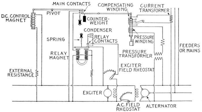
Fig. 2,457.—Diagram of General Electric automatic voltage regulator connections with alternator
and exciter. In operation, the circuit shunting the exciter field rheostat through
the relay contacts is opened by means of a single pole switch at the bottom of the regulator
panel and the rheostat turned in until the alternating current voltage is reduced
65 per cent. below normal. This weakens both of the control magnets and the floating
main contacts are closed. This closes the relay circuit and demagnetizes the relay magnet,
releasing the relay armature, and the spring closes the relay contacts. The single
pole switch is then closed and as the exciter field rheostat is short circuited, the exciter
voltage will at once rise and bring up the voltage of the alternator. This will strengthen
the alternating current and direct current control magnets, and at the voltage for which
the counterweight has been previously adjusted, the main contacts will open. The relay
magnet will then attract its armature and by opening the shunt circuit at the relay contacts
will throw the full resistance into the exciter field circuit tending to lower the exciter
and alternator voltage. The main contacts will then be again closed, the exciter
field rheostat short circuited through the relay contacts and the cycle repeated. This
operation is continued at a high rate of vibration due to the sensitiveness of the control
magnets and maintains a steady exciter voltage.
Line Drop Compensators.—In order that the actual voltage
at a distant point on a distribution system may be read at the
station some provision must be made to compensate for the line[Pg 1751]
drop, that is to say, for
the difference in voltage
between the alternator
and the center of
distribution.
In order to do this
a device which is known
as a "line drop compensator"
is placed in the
voltmeter circuit as
shown in the diagram,
fig. 2,458.
Ques. What are the
essential parts of a
line drop compensator?
Ans. The elements of
a line drop compensator
are a variable resistance,
and a variable inductance.
Ques. Describe the
connections.
Ans. The secondary
of a pressure transformer
is connected in series with
the compensator inductance
and resistance, and
the secondary of a current
transformer as shown
in the diagram, fig. 2,458.
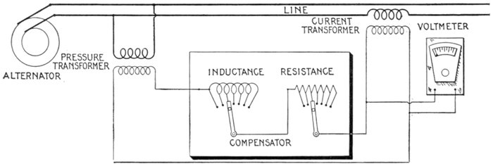
Fig. 2,458—Diagram showing essential parts and connections for a line drop compensator. The compensator corrects
the voltmeter indication at the supply end of a feeder for the ohmic and inductive drop in pressure between that point and the
point of consumption, so that the reading of the station voltmeter corresponds with the actual voltage at the point of consumption,
independent of the power factor and current. It is especially useful for adjusting pressure regulators.
[Pg 1752]
Ques. How are the inductance and resistance wound?
Ans. They are wound so that any proportion of the winding
of either can be put in or out of the voltmeter circuit.
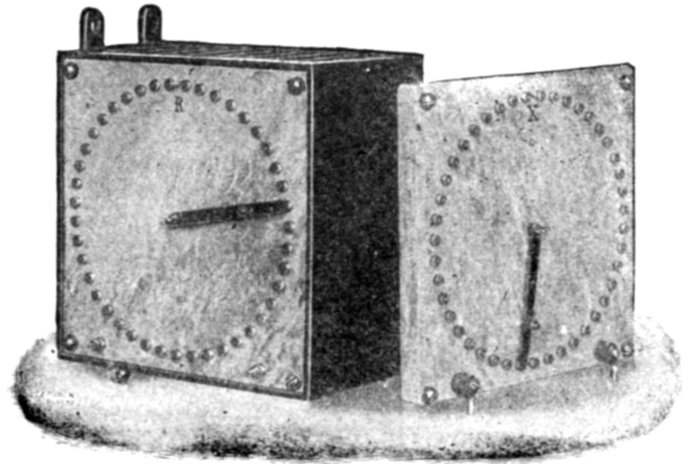
Fig. 2,459.—General Electric line drop compensator. It has two dial switches with many
taps to the resistance and reactance in the box so that it can be adjusted to compensate
accurately for line losses with loads of varying power factor. Dial R changes resistance,
and dial X, reactance.
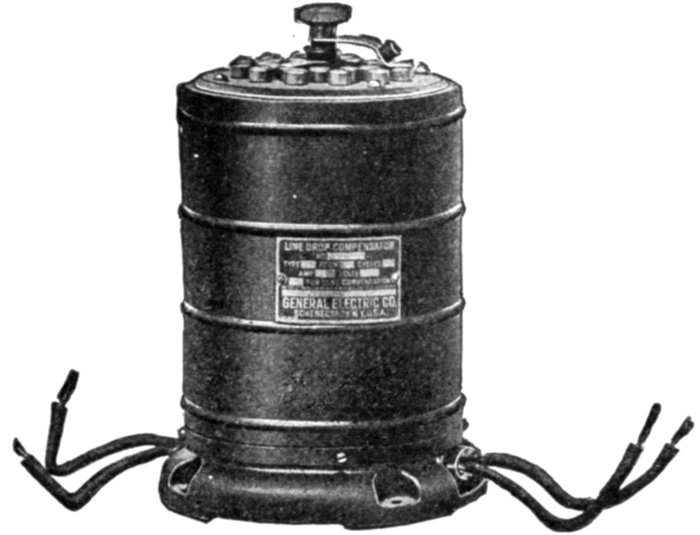
Fig. 2,460.—General Electric line drop compensator. This compensator contains besides
resistance and inductance, a current transformer, the secondary of the transformer being
connected in series with the resistance and inductance; the primary of the contained
current transformer is connected to an external current transformer. The reactance and
resistance are both so wound that any proportion of the winding can be cut in or out of
the voltmeter circuit. Both elements have 12 points of adjustment of one volt each,
giving a total combined drop at maximum setting of about 17 volts.
[Pg 1753]
Ques. How can the voltmeter indicate the pressure
at the center of distribution?
Ans. If the amount of inductance and resistance be properly
adjusted, there will be produced a local circuit corresponding
exactly in all its characteristics to the main circuit. Hence, any
change in the main circuit produces a corresponding change in
the local circuit, and causes the voltmeter to always indicate
the pressure at the end of the line or center of distribution or
at any point for which the adjustment is made.
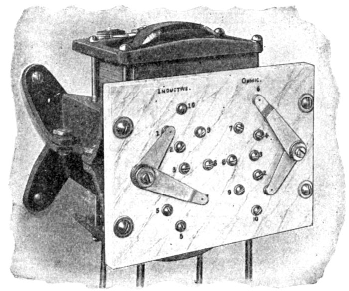
Fig. 2,461.—Westinghouse line drop compensator. For single phase circuits, one compensator
and one series transformer, that is the instrument as listed with transformers, will
give correct indications for a single phase circuit. The same voltage transformer serves
for both voltmeter and compensator. For balanced two phase circuits one compensator
and one transformer connected in one of the phases is sufficient. Two single phase compensators
should be used for unbalanced two phase circuits. For three phase circuits
the compensator should be connected by means of two series transformers.
Ques. How should the adjustment be made?
Ans. It is advisable to calculate the ohmic drop for full load
and set the resistance arm at the point which will give the[Pg 1754]
required compensation and then adjust the inductance arm
until the voltmeter reading corresponds to the voltage at the
point on the line selected for normal voltage.
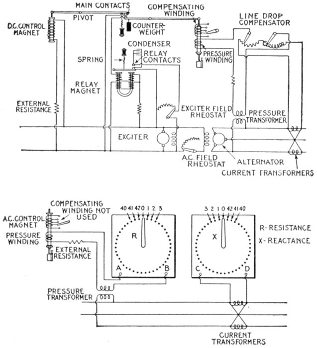
Fig. 2,462.—Diagram of automatic voltage regulator, using line drop compensator. For
ordinary installations the compensating winding on the alternating current control magnet
is connected to a current transformer in the main feeder. A dial switch is provided
by which the strength of the alternating current control magnet can be varied
and the regulator made to compensate for any desired line drop up to 15 per cent. according
to the line requirements. Where the power factor of the load has a wide range
of variation, a special line drop compensator, such as shown in fig. 2,459, adapted to
the regulator would be desirable. The connections are readily understood by the diagram.
The number of condenser sections which will prevent undue arcing at the relay
contacts depends on the characteristics of the exciter. They may be roughly estimated by
allowing one section for each 15 kw. capacity for exciters with laminated poles, and one
for each 22 kw. capacity for exciters with solid steel poles. It is necessary though to
have one condenser section for each pair of relay contacts, and at times it becomes necessary
to apply a double section for each pair of contacts. In the lower part of the figure
the line drop compensation and connections is reproduced in more detail on a larger scale.[2]
[Pg 1755]
Starting Compensators.—These are used for starting
induction motors and consist of inductive windings (one for
each phase) with a number of taps connecting with switch
contacts as shown in fig. 2,463. A starting compensator is
similar to a rheostat except that inductive windings are used in
place of the resistance grids.
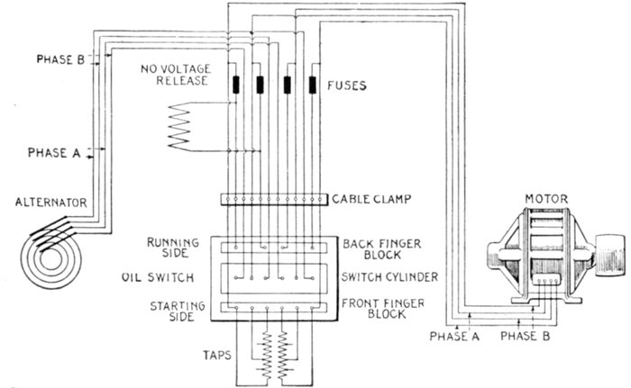
Fig. 2,463.—Diagram of connections of General Electric two phase starting compensator
with no voltage release and fuses.
Ques. Describe the inductive windings.
Ans. The compensator winding consists of an inductive
coil in each phase with each coil placed on a separate leg of a
laminated iron core. Each coil is provided with several taps
so located that a number of sub-voltages may be obtained.
[Pg 1756]
Ques. Are starting compensators necessary for small
motors? Why?
Ans. No, because the full voltage starting current taken,
although equal to several times the load current, is nevertheless
so small, compared with the capacity of the station
alternators or feeders, that it does not materially affect the
regulation of the circuit.
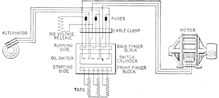
Fig. 2,464.—Diagram of connections of General Electric three phase starting compensator with
low voltage release and fuses.
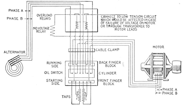
Fig. 2,465.—Diagram of connections of General Electric two phase starting compensator
with no voltage release and overload relays for 1,040 to 2,500 volt circuits.
[Pg 1757]
Motors larger than about 7 horse power cause an objectionably heavy
rush of current if thrown directly on the line. Starting compensators
obviate such sudden variations of line load and are accordingly recommended
for motors above 7 horse power except in cases where voltage
variations and excessive starting currents are not objectionable.
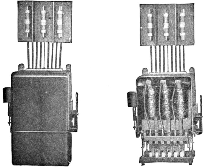
Figs. 2,466 and 2,467.—General Electric three phase hand operated starting compensator.
Fig. 2,466, compensator in case; fig. 2,467, compensator with case removed. The compensator
consists of a core and windings, a cable clamp, and a switch, assembled in a substantial
metal case with external operating handle and release lever. The windings
consist of coils wound on separate legs of a laminated core, and tapped at several points,
the connections terminating at the switch contacts. The shaft of the switch extends
through the sides of the compensator case, and is operated by a lever at the right, being
held in the running position by a lever at the left. It is provided with wiping contacts.
The switch is immersed in oil, and is intended to be used as a line switch as well as for
starting the motor. The lever has three positions: "off," "starting," and "running."
In the off position, both compensator and motor windings are disconnected from the
line. In the starting position, the switch connects the line to the ends and the motor to
the taps of the compensator winding without overload relays or fuses in circuit. In
the running position, the compensation winding is cut out and the motor is connected to
the line through suitable fuses or overload relays mounted directly above the compensator.
To prevent the attendant throwing the motor directly on the line, and thereby
causing a rush of current which it is the object of the compensator to avoid, an automatic
latch is provided and so arranged that the lever at off position can be thrown only
into the starting position (backward); and can be thrown thence into the running position
(forward) only by a quick throw of the lever, whereby any appreciable drop in speed and consequent
increase in current in passing from the starting into the running position is avoided.
[Pg 1758]
Ques. What should be noted with respect to the
compensator winding taps?
Ans. The choice of a tap giving so low a voltage as to require
over one minute for starting should be avoided so as to prevent
the overheating to which starting compensators, in common
with other motor starting devices, are liable if left in circuit
unnecessarily long, or if the motor be started several times in
rapid succession.
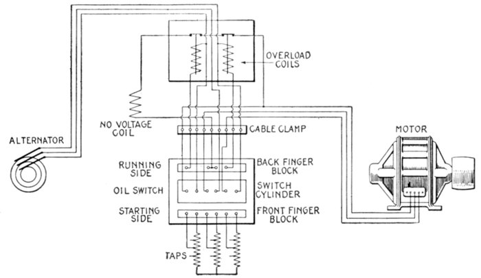
Fig. 2,468.—Diagram of connections of General Electric three phase starting compensator
with no voltage release and overload relays.
It should also be noted that the starting current diminishes rapidly
as full speed is approached. It is, therefore, important that the switch
be kept in the starting position until the motor has finished accelerating
to prevent any unnecessary rush of current when the switch is thrown
to the running position.
[Pg 1759]
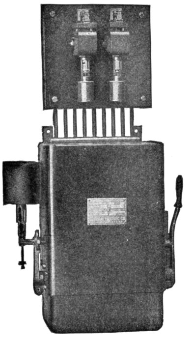
Fig. 2,469.—General Electric starting compensator
with low voltage release and overload
relays. On the switch shaft there are
mounted two levers, held together with a
strong spring which operates in either direction
and prevents the switch being left on the
starting position. On the running side it is
held by the external low voltage release lever
until released either by hand or by the action
of a low voltage relay. The low voltage release
consists of a cast iron frame open at
the bottom and totally enclosing the coil. A
laminated plunger is used to hold the tripping
lever, the latter engaging with the lever
mounted on the switch shaft. The compensator
cannot be thrown into the running
position without first going to the starting
position and it cannot be left on the starting
position.
Ques. What is the usual arrangement of starting
compensators for large motors?
Ans. Starting compensators may be wound for any voltage
or current for which it is practicable
to build motors. For
very large motors the switching
device is generally separate
from, the compensator
itself and consists of triple and
four pole switches for three
phase and two phase motors
respectively. One double
throw switch or two interlocked
single throw switches
are required for the motor
and a single throw switch for
energizing the compensator,
the running side of the motor
circuit being provided with
fuses or automatic circuit
breakers, or the switches provided
with low voltage and
overload release attachments.
Star Delta Switches.—These
are starting switches,
designed for use with small
three phase squirrel cage
motors having their windings
so arranged that they may
be connected in star for starting
and in delta for running.
Ques. Describe the operation
of a star delta switch.
Ans. In starting the motor,
the drum lever is thrown in the[Pg 1760]
starting direction which connects the field windings of the motor
in star. When the motor has accelerated and has come partially
up to speed the starting lever is quickly thrown to the running
position in which position the field windings are connected in
delta. The effect of connecting the field winding in star at
starting is to reduce the voltage applied to each phase winding,
while in the running position each phase of the field winding
has full line voltage impressed upon it.
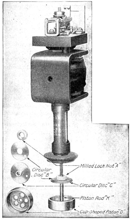
Figs. 2,470 to 2,474.—General Electric time
limit overload relay for starting compensator.
In case of overload, the relay
armature is raised and at the end of its
travel, opens the small switch at the top
which in turn opens the circuit of the
low voltage release coil causing the compensator
switch to return to the "off"
position. The oil dash pot provides a
certain time element and can be adjusted
to operate immediately upon overload
or at any interval up to five minutes.
Each relay has five calibrating
points, the lowest being the normal full
load current of the motor, the highest
300 per cent. full load current. The scale
on the calibration tube reads direct and
shows various values of current at which
the relay may be set to operate. To
change overload setting: 1, loosen set
screw; 2, turn relay plunger on piston rod
until white mark comes opposite required
value of current; 3, tighten set
screw. Time element adjustment:
Removing oil dash pot by turning to the
left will expose the cup shaped piston,
made of which are two concentric discs
(B and C) held together by a milled lock
nut, A. There is a hole in each disc
through which the oil
must pass when the
plunger of the relay is
raised. The time element
may be varied by changing
the size of the opening
between these discs, that
is, to have the relays operate
in a shorter period of
time, increase the size of
the opening and vice-versa.
To change the
time setting: 1, remove
the oil dash pot; 2, raise
the discs B and C on the
piston rod; 3, loosen the
lock nut A; 4, change
the opening between B
and C, giving a larger
opening for shorter time
of operation, and a
smaller opening for longer
time; 5, tighten lock
nut A; 6, replace discs
in piston D; 7, replace
oil dash pot.
[Pg 1761]
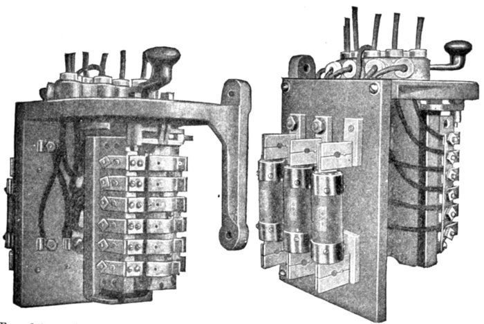
Figs. 2,475, and 2,476.—Front and side views (oil tank removed) of Cutler-Hammer star delta
switch for starting small three phase squirrel cage motors. In construction, the switch
consists of one set of stationary fingers and a rotating wooden cylinder, carrying two sets
of contacts. These parts are supported from the switch frame casting and are enclosed
in a steel tank which contains an insulating oil. Flexible oil proof cable leads are brought
out through insulated bushings in the top of the switch and tagged for convenience in
connecting to the lines and motor. To prevent seepage of oil, the leads are sealed into
the top of the cover with an oil proof sealing wax. The lever of the star delta switch is
arranged with an interlock which prevents its being thrown directly into the running
position from the off position. It is necessary to throw the lever first into the starting
position and then with an uninterrupted movement to the running position. The circuit
of the motor is broken only for an instant in changing from star to delta and no heavy
inrush current occurs. No voltage release protection is provided by a latching solenoid
which holds the spring centered drum cylinder in the running position. The no voltage
release coil is mounted in the lower part of the starting switch, immersed in the oil tank,
and is protected against mechanical injury and grounding. The coil is in circuit during
the running period only and requires not more than 8 to 15 watts to hold the switch in
the running position. The operation of this protective device is such that on failure of
voltage the star delta switch will immediately be returned to the off position. Overload
release protection consists of two relays on a small slate panel, which is mounted directly
on the side of the star delta switch. The switch contacts of the overload release are connected
in series with the connections to the no voltage release coil so that when an overload
occurs the overload relay operates to open the circuit to the no voltage release coil,
thus permitting the switch lever to return to the off position. The overload relays do not
afford overload protection during the starting period, and when such protection is desired
starting fuses should be installed. These fuses, if used, should have a capacity of 250 to
300 per cent. of the normal full load current of the motor.
[Pg 1762]
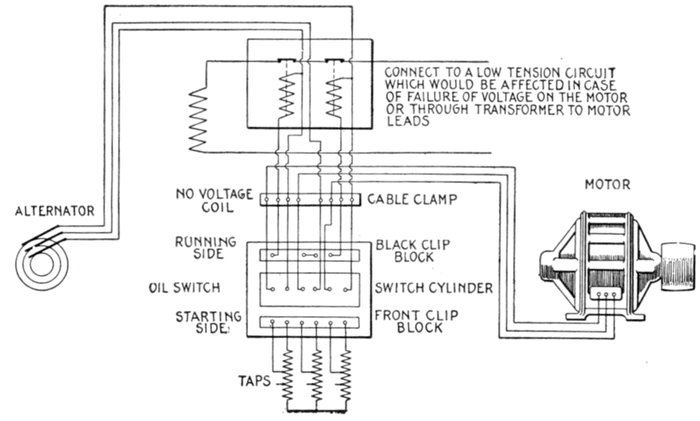
Fig. 2,477.—Diagram of connections of General Electric three phase starting compensator
with low voltage release and overload relays for 1,040-2,500 volt circuits.
[Pg 1763]
CHAPTER LXI
SYNCHRONOUS CONDENSERS
Synchronous Condensers.—A synchronous motor when
sufficiently excited will produce a leading current, that is, when
over excited it acts like a great condenser, and when thus operated
on circuits containing induction motors and similar apparatus
for the purpose of improving the power factor it is called a
synchronous condenser.
Although the motor performs the duty of a condenser it possesses
almost none of the properties of a stationary condenser
other than producing a leading current, and is free from many
of the inherent defects of a stationary condenser.
The relation of power factor to the size and efficiency of prime
movers, generators, conductors, etc., and the value of synchronous
condensers for improving the power factor is generally
recognized.
Induction motors and other inductive apparatus take a component
of current which lags behind the line pressure, and
thereby lowers the power factor of the system, while a non-inductive
load, such as incandescent lamps, takes only current
in phase with the voltage and operates at unity power factor.
Since transformers require the magnetizing current, they may
seriously affect the power factor when unloaded or partially
loaded, but when operating at full load their effect is practically
negligible.
[Pg 1764]
The relative effect of fully loaded and lightly loaded induction
motors on the power factor is indicated by the diagram, fig. 2,478.
The magnetizing current is nearly constant at all loads and is
wattless, lagging 90 degrees behind the impressed pressure, or
at right angles to the current which is utilized for power.
In the figure, AB is the magnetizing component, which is always
wattless, and CB the power component. The angle ACB gives the
phase relation between voltage and current; the cosine of this angle
CB ÷ AC is the power factor.
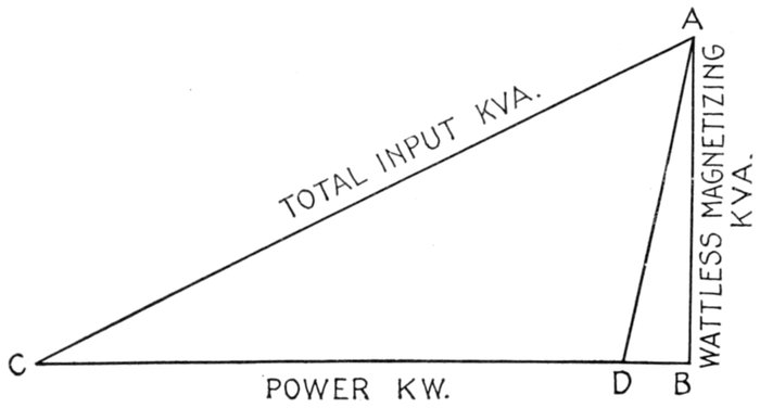
Fig. 2,478.—Diagram showing relative effect of fully loaded and lightly loaded induction motors
on power factor.
It is evident from the diagram that if the load be reduced, the side
CB is shortened, and as AB is practically constant, the angle of lag
ACB is increased. It therefore follows that the cosine of this angle, or
the power factor is reduced.
The figure clearly shows the reason for the low power factor of induction
motors on fractional loads and also shows that since the magnetizing
current is practically constant in value, the induction motor
can never operate at unity power factor.
With no load, the side CB (real power) is just sufficient to supply the
friction and windage. If this be represented by DB, since AB remains
constant, the power factor is reduced to 10 or 15 per cent. and the motor
takes from the line about 30 per cent. of full load current. It therefore
follows that a group of lightly loaded induction motors can take from
the system a large current at exceedingly low power factor.
[Pg 1765]
The synchronous motor when used as a condenser, as before
stated, has the property of altering the phase relation between
pressure and current, the direction and extent of the displacement
being dependent on the field excitation of the condenser.
It can be run at unity power factor and minimum current
input, or it can be over excited and thereby deliver leading current
which compensates for the inductive load on other parts of the
system. The synchronous condenser, therefore, can supply
magnetizing current to the load on a system while the power
component is supplied by the generators.
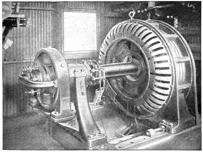
Fig. 2,479.—General Electric 400 kw., 550 volt, 600 R.P.M., synchronous condenser with
direct connected exciter installed in sub-station No. 1 of the Colorado Light & Power Co.,
Cripple Creek, Colo. The machine is designed for alternating current starting by means
of a compensator. The field is provided with a standard synchronous motor winding,
and, in addition, an amortisseur winding which assists in starting and serves as a damping
device to minimize hunting.
[Pg 1766]
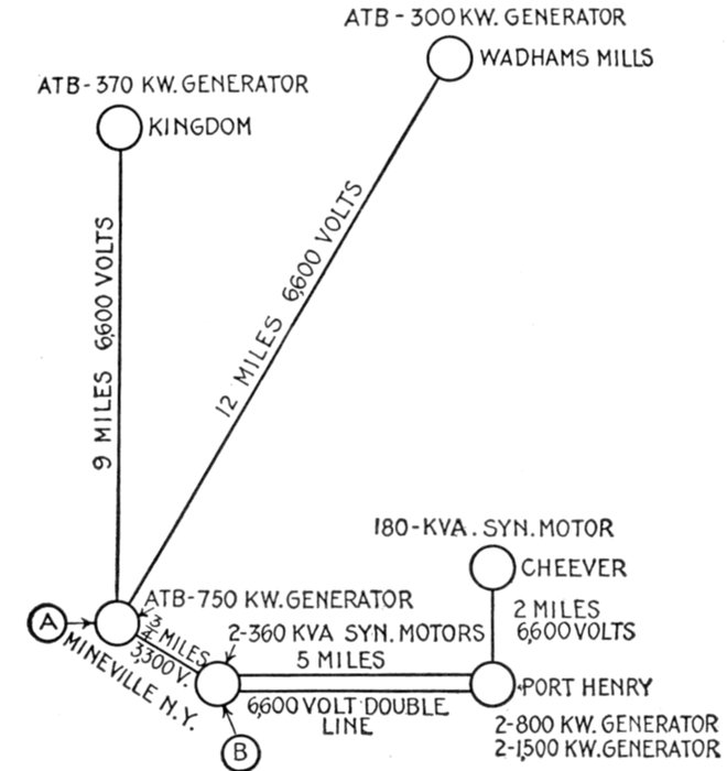
Fig. 2,480.—Diagram showing relative location of alternators and synchronous motors in
plant of Witherbee Sherman & Co., Mineville N. Y. The distribution system of the Company
is provided with three synchronous motors, as shown. The system includes two
hydro-electric, one turbine driven, and one engine driven generator plants; from three of
these, current is transmitted to the fourth, which is located in Mineville, at the point "A",
the current being distributed to the motor circuits from the points "A" and "B." The
transmission to the central station at Mineville is over three phase circuits at 6,600 volts.
For operating the mine at Cheever, current is transmitted direct from the generating
station at Port Henry. The distribution from "A" and "B" is all at 3,300 volts, being
stepped down to 440 volts for the operation of the motors, which have a total rated capacity
of 4,762 horse power. Excepting three synchronous motors, the load is practically all
inductive, there being less than 10 kw. required for lighting. The actual power demand
ranges from 60 to 65 per cent. of the rated motor capacity, and prior to the installation
of the synchronous motors, the power factor was approximately 68 per cent., the condenser
effect of these motors making it possible to maintain an average of about 90 per
cent. power factor in spite of the fact that a considerable portion of the induction motor
load is very widely distributed. The three synchronous motors are partially loaded, each
motor driving an air compressor through belting. The 180 kva. motor at Cheever takes
about 150 kw. for the operation of a 1,250 cubic foot compressor, while the two 360 kva.
machines take about 300 kw. each, for the operation of two 2,500 cu. ft. sets. The
operation of these compressors affords a method of utilizing a portion of the motor capacity
mechanically, inasmuch as the load on the motors is practically constant during the
time the mines are in operation, and thereby permit the motors to be run at approximately
80 per cent. power factor.
[Pg 1767]
Effects of Low Lagging Power Factors.—Transformers are
rated in kva. output; that is, a 100 kva. transformer is supposed
to deliver 100 kw. at unity power factor at normal voltage and at
normal temperatures; but, if the power factor should be, say .6
lagging, the rated energy output of the transformer would be
only 60 kw. and yet the current and, consequently, the heating
would be approximately the same as when delivering 100 kw.
at unity power factor.
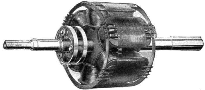
Fig. 2,481.—Field of a synchronous condenser. Note the amortisseur winding, erroneously
called squirrel cage winding, consisting of two end rings which serve to short circuit
spokes passing through the pole tips as shown. The amortisseur winding assists in
starting and serves also as a damping device to minimize hunting.
The regulation of transformers is inherently good, being for
small lighting transformers about 1½ to 2 per cent. for a load
of unity power factor, and about 4 to 5 per cent. at .7 power
factor. Larger transformers with a regulation of 1 per cent. or
better at a unity power factor load, would have about 3 per cent.
regulation at .7 power factor.
Alternators also are rated in kva. output, usually at any value
of power factor between unity and .8.
The deleterious effects of low power factor loads on alternators
are even more marked than on transformers. These are, decreased
kw. capacity, the necessity for increased exciter capacity,
decreased efficiency, and impaired regulation.
[Pg 1768]
Assume the case of a 100 kva. .6 power factor, 60 kw. output. It
is probable that normal voltage could be obtained only with difficulty,
unless the alternator was especially designed for low power factor service.
The lagging power factor current in the armature sets up a flux which
opposes the flux set up by the fields, and in consequence tends to demagnetize
them, resulting in low armature voltage.
It is often impracticable, without the installation of new exciters,
to raise the alternator voltage by a further increase of the exciting
voltage and current. The field losses, and therefore the field heating of
the alternator, when it is delivering rated voltage and current, are
greater at lagging power factor than at unity. Increased energy input
and decreased energy output both cause a reduction in efficiency.
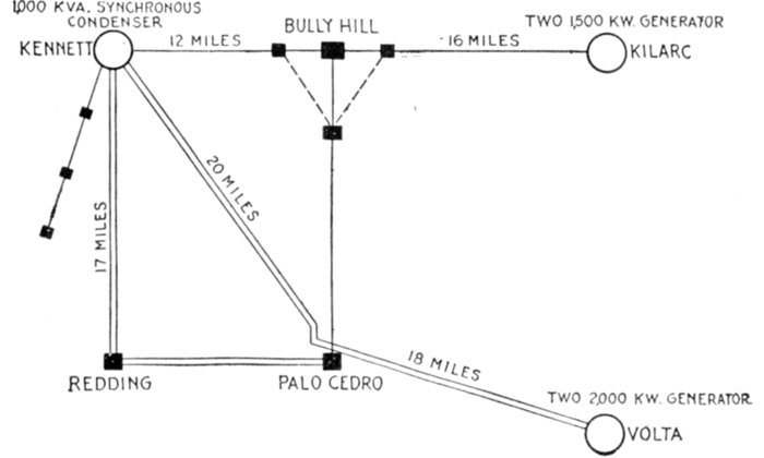
Fig. 2,482.—Diagram of a section of the Northern California Power Co.'s transmission system,
showing relative location of alternators and synchronous condenser. The synchronous
condenser is installed at Kennett, which is served by generating stations at Kilarc
and Volta, located respectively 28 and 38 miles from the point at which the condenser
is operated. The local demand amounts to about 6,500 kw., and before the installation
of the synchronous condenser, the power factor was about 79 per cent. and after installing,
about 96 per cent. while the voltage at the point where the synchronous condenser is installed
is raised approximately 10 per cent. during the change from no load to full load. In
order to obtain close voltage regulation, a regulator is used in connection with the synchronous
condenser and holds the voltage, at the center of distribution, within 2 per cent.
The regulator is mounted on the side of the control panel and connected in the field of
the synchronous condenser to automatically change the excitation and compensate for
voltage variations. A graphic demonstration of the improvement in voltage regulation,
which has been secured in this case, is given by the curve drawing voltmeter records reproduced
in fig. 2,483.
The regulation at unity power factor of modern alternators
capable of carrying 25 per cent. overload, is usually about 8 per[Pg 1769]
cent. Their regulation at .7 power factor lagging is about 25
per cent. The effect of low power factor on the lines can best be
shown by the following example:
EXAMPLE.—Assuming a distance of five miles and a load of 1,000
kw. and desiring to deliver this load at a pressure of about 6,000 volts,
three phase, with an energy loss of 10 per cent., each conductor at unity
power factor would have to be 79,200 c.m., at .9 power factor, 97,533 c.m.,
and at .6 power factor, 218,000 c.m. In other words, at the lower power
factor of .6, the investment in copper alone would be 2.8 times as much.
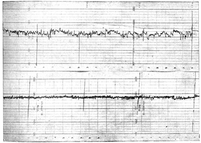
Fig. 2,483.—Curve drawing voltmeter records at Kennett, Cal. The upper curve shows
voltage regulation with synchronous condenser out of service, and the lower curve,
with synchronous condenser in operation.
If the same size of wire were used at both unity and .6 power factor
lagging, the energy loss would be about 2.8 times the loss at unity
power factor, or about 28 per cent. Low lagging power factor on a
system, therefore, will generally mean limited output of prime movers;
greatly reduced kilowatt capacity of generator, transformer and line;
and increased energy losses. The regulation of the entire system will
also be poor.
[Pg 1770]
Cost of Synchronous Condenser vs. Cost of Copper.—Referring
to the example given in the preceding paragraph,
and calculating the necessary extra investment in copper
with the .6 power factor load, and copper at 17 cents per
pound, the result is that 29,292 pounds more copper is required
than with the power factor of .9 which means a total extra investment
in copper alone of $5,000 (29,292 × $.17). A synchronous
condenser of sufficient capacity to accomplish the same
result would cost about the same amount. It would therefore
cost less to install the condenser because at the same time a
considerably increased capacity would be obtained from the
alternators, transformers, etc.
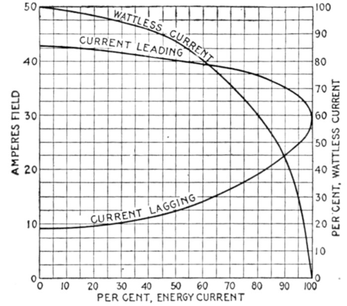
Fig. 2,484.—Diagram showing the field current taken by a synchronous motor of normal
design when operating at normal kva. input at various power factors. It will be noted
that a slight departure from unity power factor necessitates a considerable change
in field current. As the field curves increase with the square of the current, there is a
rapid increase in temperature with leading current. This action of leading or lagging current
serves automatically to keep the flux constant in the armature with changes in field excitation.
When the motor is running at unity power factor, an increase in field excitation
causes a leading current to flow, and at the same time this leading current demagnetizes
the field until the density of the armature is restored to its normal value. If the field
be decreased a lagging current flows which in turn magnetizes the field bringing the
density back to its original value. Therefore, with a constant line voltage, the iron losses
in a synchronous motor are approximately constant irrespective of the field excitations
with the exception that the internal voltage will vary slightly due to the armature I R
drop, the density being a trifle lower at full load than at no load.
[Pg 1771]
Synchronous Condenser Calculations.—In figuring on the
installation of a condenser for correcting power factor troubles, a
careful survey of the conditions should be made with a view of
determining just what these troubles are and to what extent they
can be remedied by the presence of a leading current in the system.
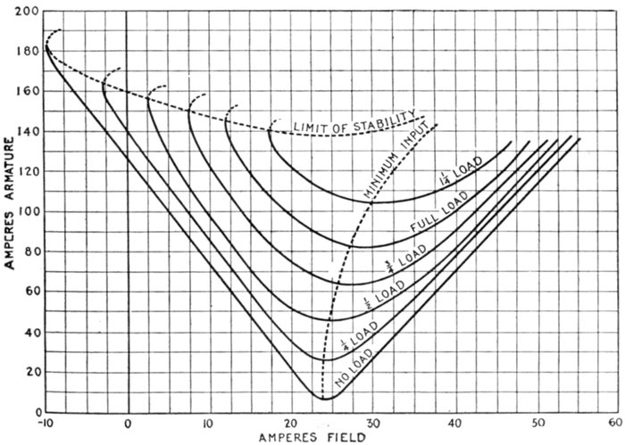
Fig. 2,485.—Diagram showing a set of phase characteristic curves taken from a General
Electric synchronous motor. These curves show the current input to the motor at
various loads with constant voltage and varying field excitation. There is a certain
field current at each load that causes a minimum current. Any increase or decrease
of field from the value increases the current and causes it to lead or lag with respect to
the line voltage. By referring to the minimum input curve, it will be noted that if the
machine be running at full load minimum input current and load is taken off, the current
will be leading or vice versa. In each case the phase characteristic curve was run
back on the lagging side to the break down point. At no load and one quarter load the
motor still ran in step when the field was reduced to zero and even taken off altogether,
and it was necessary to reverse the field current in order to back down the motor. The
motor runs without slip, as a synchronous motor, in this condition, obtaining its excitation
from the lagging current and running as a reaction machine. The amount of load
a machine will carry without field varies with the design, the average being about 40%
of full load. It will be noted from the limit of stability curve that the lighter the load
on the machine when it breaks down from lack of sufficient excitation, the greater the
current input at this point. The no load characteristic rises sharply on each side with
slight change in field current, while it flattens out with increase in load until at overload
the current input is practically the same throughout a large range of field current.
[Pg 1772]
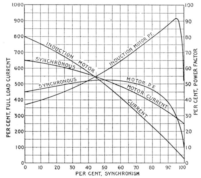
Fig. 2,486.—Comparison of the speed current curves and speed power factor curves of a
typical synchronous, and induction motor. It will be noted that the power factor of the synchronous
motor at start is higher than that of the induction motor owing to the higher resistance
of the squirrel cage winding. As the machine approaches synchronism, however,
the magnetizing current of the induction motor drops to a very much lower value
than in the synchronous motor and the power factor is consequently much higher. The
magnetizing current of the induction motor at full speed is usually 25 per cent. of full load
current while that of the synchronous motor is from 200 to 250 per cent. of full current,
or even higher when running full speed and normal voltage. This of course is due to the
large air gap on the synchronous machine. The current at start with full voltage
applied is usually higher in an induction motor owing to the fact that the total impedance
of the stator and rotor are less due to the greater distribution of the windings and the lower
resistance of the squirrel cage. The high magnetizing current of a synchronous motor
should not be lost sight of as it is a very important consideration in starting the machine.
Even though the motor can be brought practically to synchronous speed while still on the
compensator, if line voltage be thrown on, there will be a very heavy rush of current. The
obvious thing to do is to get the field on the motor while still on the compensator, whenever
possible, to avoid the high magnetizing current. This magnetizing current is obviously
equal to the circuit current of the machine at no load field. In some cases additional
torque near synchronism can be obtained by short circuiting the field winding through the
field rheostat. This has the effect of reducing the resistance of the rotor winding to some
extent and causing the motor to have less slip with a given load. The gain from this
source is small, however, in most cases, as the self-inductance of the field winding is so high
as to allow very little current to flow even if the field be short circuited so that the total
effective resistance of the rotor winding is not materially reduced. In some cases where the
torque is nearly sufficient, however, enough gain may be obtained to take care of the conditions.
If the field be short circuited before the motor is started there will be a reduction in
starting torque and an increase in current from the line, hence if this method be resorted to, arrangements
must be made to short circuit the field after the motor has come to constant speed.
[Pg 1773]
It is necessary to possess a thorough knowledge of the system,
covering the generating capacity in energy and kva., average and
maximum load, and power factor on the alternators, average and
maximum load, and power factor on the feeders, system of distribution,
etc.
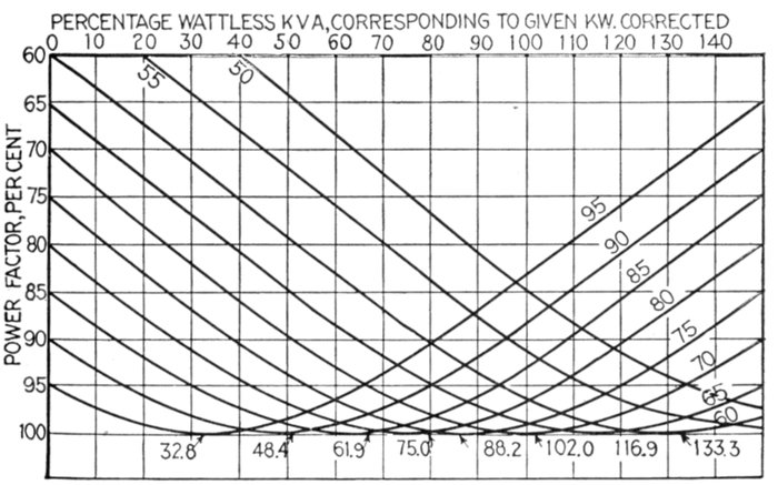
Fig. 2,487.—Curves showing amount of wattless component required to raise the power
factor of a given kw. load to required higher value. The wattless components are expressed
as percentages of the original kw. load. The numbers at the right which indicate
the points of tangency of the power factor curves to the 100 per cent. line, show the
amount of wattless component required to raise a given kw. load of given lagging power
factor to unity power factor. Obviously the addition of further wattless component in
a given case would result in a leading power factor less than unity.
The desirable location of a condenser is, of course, nearest the
inductive load in order to avoid the transmission of the wattless
current, but it often happens that a system is so interconnected
that one large condenser cannot economically meet the conditions,
in which case it may be better to install two or more smaller ones.
The question of suitable attendance should also be considered
and, for this reason, it may be necessary to compromise on the
location. When the location of the condenser has been decided[Pg 1774]
upon and the load and power factor within its zone determined,
the proper size of condenser to raise the power factor to a given
value can be found as follows:
The method of procedure can best be explained by reference to a
concrete case. Assume a load of 450 kw. at .65 power factor. It is
desired to raise the power factor to .9. What will be the rating of the
condenser?
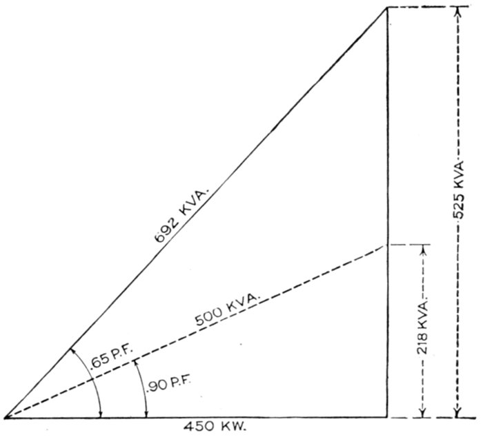
Fig. 2,488.—Diagram for synchronous condenser calculations.
Referring to the diagram, fig. 2,488, it is necessary to start with 450
kw. At .65 power factor, or 692 kva., this has a wattless lagging component
of √(6922 - 4502) = 525 kva. With the load unchanged and the
power factor raised to .9, there will be 500 apparent kva., which will have
a wattless component of √(5002 - 4502) = 218 kva.
It is obvious that the condenser must supply the difference between
525 kva. and 218 kva., or 307 kva. A 300 kva. condenser would,
therefore, meet the requirements.
If it be desired to drive some energy load with the condenser and
still bring the total power factor to .9, proceed as indicated in fig. 2,489.[Pg 1775]
Assume a total load of 150 kw. on the motor. As before, 450 kw.
at .65 power factor, or 692 kva., with a wattless component of 525 kva.
The energy load will be increased from 450 to 600 kw. as indicated,
and with the power factor raised to .9 there will be a kva. of 667 with a
wattless component of √(6672 - 6002) = 291.
There must be supplied 525 - 291 = 234 in leading kva.
The synchronous motor then must supply 150 kw. energy and 234
kva. wattless, which would give it a rating of √(1502 + 2342) = 278 kva.
at .68 power factor.
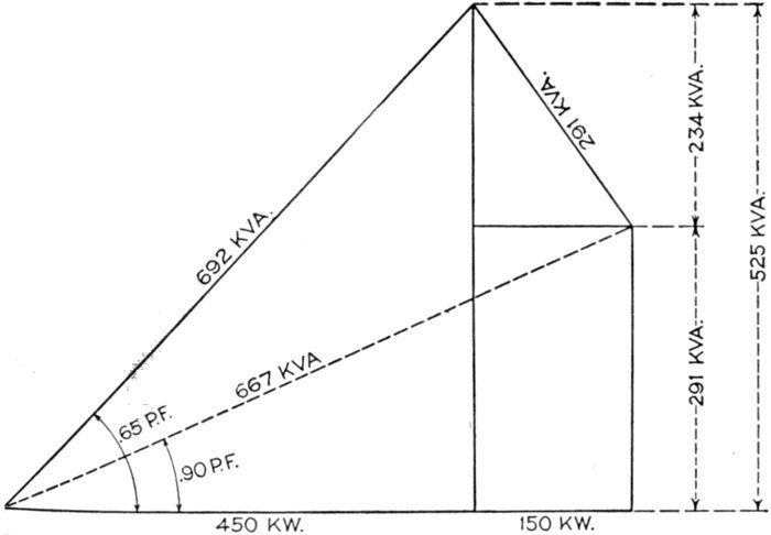
Fig. 2,489.—Diagram for synchronous condenser calculation for cases where it is desired to
drive some energy load with the condenser and still bring the total power factor to .9.
The standard 300 kva. condenser would evidently raise the power
factor slightly above .9 power factor leading.
By reference to the chart, fig. 2,490, the size of the required condenser
can be obtained direct without the use of the above calculation. The
method of using this curve is as follows: Assume a load of say 3,000 kw.
at .7 power factor and that it be desired to raise the power factor to .9.
Run up the vertical line at 3,000 kw. to the .7 power factor line, and from
there along the horizontal line to the margin and find a wattless component
at this power factor of 3,000 kva., approximately. Again run
up the 3,000 kw. vertical line to the .9 power factor line and from there
along the horizontal line to the margin and find a wattless component[Pg 1776]
of 1,500 kva. The rating of the condenser will then be 3,000 kva. - 1,500
kva. = 1,500 kva. This table of course can be used for hundreds of
kilowatts as well.
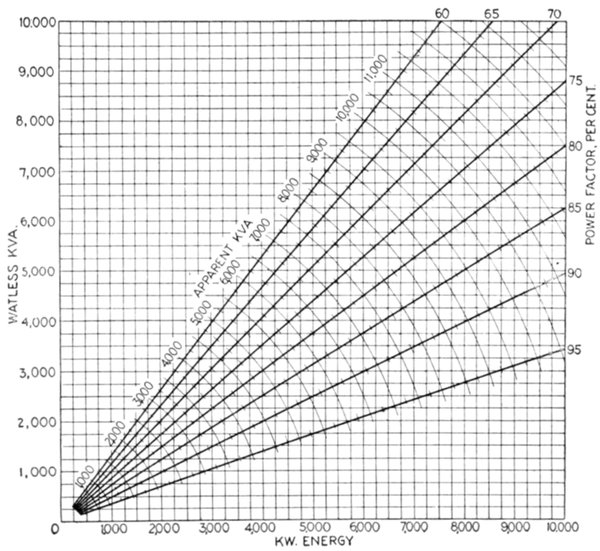
Fig. 2,490.—Curve showing the relation of energy load to apparent load and wattless components
at different power factors.
For determining the rating of a synchronous motor to drive an energy
load this curve is not so valuable, although it can be used in determining
the wattless component direct in all cases where the energy component
and power factor are known. Knowing this energy component and
power factor or wattless component, the energy load can obviously be
found by referring to the curved lines on the diagrams, the curve that
crosses the junction of the vertical energy line and the power factor or
wattless component line giving the total apparent kva.
[Pg 1777]
CHAPTER LXII
INDICATING DEVICES
Alternating current ammeters or voltmeters indicate the
virtual values of the current or pressure respectively, that is to
say, they indicate, the square root of the mean square of a variable
quantity.
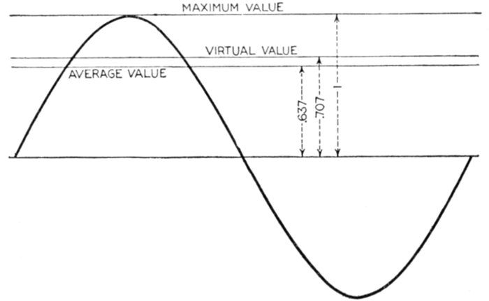
Fig. 2,491.—Line curve of alternating current, illustrating various current or pressure values.
The virtual value, or .707 × maximum value, is the value indicated by an ammeter or voltmeter.
Thus, if the maximum value of the current be 100 volts, the virtual value as indicated
by an ammeter is 100 × .707 = 70.7 amperes.
The virtual value of an alternating current or pressure is
equivalent to that of a direct current or pressure which would produce
the same effect.
For instance an alternating current of 10 virtual amperes will produce
the same heating effect as 10 amperes direct current.
[Pg 1778]
The relation of the virtual value of an alternating current to
the other values is shown in fig. 2,491. When the current follows
the sine law, the square root of the mean square, value of the
sine functions is obtained by multiplying their maximum value
by 1 ÷ √2 or .707.
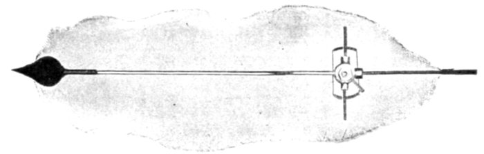
Fig. 2,492.—Wagner tubular aluminum pointer.
The word effective is commonly used erroneously for virtual,
even among the best writers and the practice cannot be too
strongly condemned[3].[4] The difference between the two is
illustrated in Guide No. 5, page 1,013, fig. 1,237, the mechanical
analogy here given may make the distinction more marked.
In the operation of a steam engine, there are two pressures acting on
the piston:
- 1. The forward pressure;
- 2. The back pressure.
The forward pressure on one side of the piston is that due to the live
steam from the boiler, and the back pressure, on the other side, that due
to the resistance or opposition encountered by the steam as it exhausts
from the cylinder.
[Pg 1779]
In order that the engine may run and do external work, it is evident
that the forward pressure must be greater than the back pressure, and
it follows that the pressure available to run the engine is the difference
between these two pressures, this pressure difference being known as
the effective pressure, that is to say
effective pressure = forward pressure - back pressure
Thus, electrically speaking, the effective voltage is that voltage which
is available for driving electricity around the circuit, that is,
In the case of the steam engine, the forward pressure absolute, that
is, measured from a perfect vacuum is the virtual pressure (not considering
the source). The back pressure may vary widely for different conditions
of operation as illustrated in figs. 2,493 and 2,494.
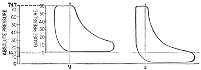
Figs. 2,493 and 2,494.—Steam engine indicator cards, illustrating in mechanical analogy, the
misuse of the term effective as applied to the pressure of an alternating current. The
card fig. 2,493, represents the performance of a steam engine taking steam at 60 lbs. (gauge)
pressure and exhausting into the atmosphere. The exhaust line being above the atmospheric
line shows that the friction encountered by the steam in flowing through the exhaust
pipe produces a back pressure of two lbs. Hence at the instant represented by the ordinate
y, the effective pressure is 60 - 2 = 58 lbs., or using absolute pressures, 74.7 - 16.7 = 58
lbs., the virtual pressure being 60 lbs. gauge, or 74.7 lbs. absolute. Now, the back pressure
may be considerably reduced by exhausting into a condenser as represented by the
card, fig. 2,494. Here, most of the pressure of the atmosphere is removed from the exhaust,
and at the instant y, the back pressure is only 6 lbs., and the effective pressure
74.7 - 6 = 68.7 lbs. Thus, in the two cases for the same virtual pressure of 60 lbs.
gauge or 74.7 lbs. absolute, the effective pressures are 58 lbs. and 68.7 lbs. respectively.
In the measurement of alternating current, it is not the average,
or maximum value of the current wave that defines the
current commercially, but the square root of the mean square value, because this gives the equivalent heating effect referred
to direct current. There are several types of instrument for
measuring alternating current, and they may be classified as
[Pg 1780]
- 1. Electromagnetic (moving iron);
- 2. Hot wire;
- 3. Induction;
- 4. Dynamometer.
Electromagnetic or Moving Iron Instruments.—This
type of instrument depends for its action upon the pull of flux
in endeavoring to reduce the reluctance of its path. This pull
is proportional to the product of the flux and the current, and
so long as no part of the magnetic circuit becomes saturated,
the flux is proportional to the current, hence the pull is proportional
to the square of the current to be measured.
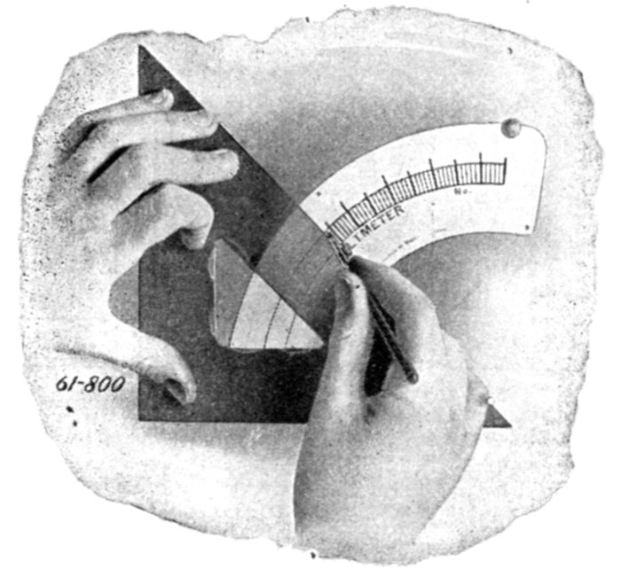
Fig. 2,495.—A calibrated scale. This means that printed scales are not employed, but each
instrument has its scale divisions plotted by actual comparison with standards, after which
the division lines are inked in by a draughtsman. There are makes of direct current
instruments employing printed scales in which the scale deflections are fairly accurate,
even though the scales are printed, but printed scales should not be used on alternating
current instruments.
[Pg 1781]
Ques. What are some objections to moving iron
instruments?
Ans. Instruments of this type are not independent of the frequency,
wave form, or temperature and external magnetic fields
may affect the readings temporarily.
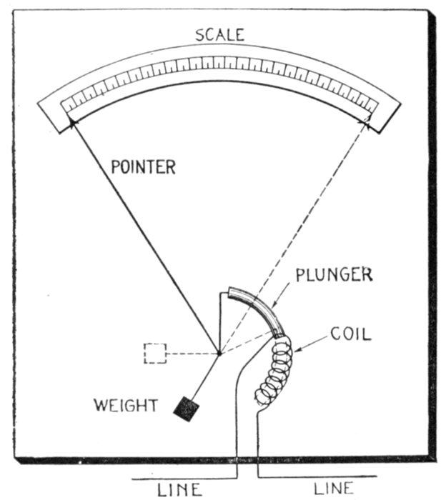
Fig. 2,497.—Plunger form of electromagnetic or moving iron type of ammeter.
There are several forms of moving iron ammeters, which may
be classified as
- 1. Plunger;
- 2. Inclined coil;
[Pg 1782]
- 3. Magnetic vane.
Ques. Describe the plunger type.
Ans. This type of ammeter consists of a series coil and a
soft iron plunger forming a solenoid, the plunger is so suspended
that the magnetic pull due to the current flowing through the
coil is balanced by gravity, as shown in fig. 2,497.
Ques. How should the plunger be constructed to
adapt it to alternating current, and why?
Ans. It should be laminated to avoid eddy currents.
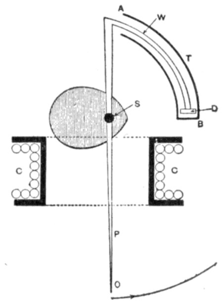
Fig. 2,497.—One form of plunger instrument as made by Siemens. It has gravity control,
is dead beat, and is shielded from external magnetic influence. The moving system consists
of a thin soft iron pear shaped plate I pivoted on a horizontal spindle S running in
jewelled centers. To this spindle S is also attached a light pointer P and a light wire
W, bent as shown, and carrying a light piston D, which works in a curved air tube T.
This tube T is closed at the end B but fully open at the other A, and constitutes the
air damping device for making the instrument dead beat.
Ques. What is the character of the scale and how
should it be constructed?
Ans. The scale is not uniform and should be hand made
and calibrated under the conditions which it is to be used.
Ques. What is the objection to moving iron ammeters?
Ans. Since the coil carries the entire current they are large
and expensive.
[Pg 1783]
Ques. What precaution should be taken in installing
moving iron ammeters?
Ans. Since gravity is the controlling force, the instrument
should be carefully levelled.
Ques. Describe an inclined coil instrument.
Ans. It consists of a coil mounted at an angle to a shaft
carrying the vane and pointer, as shown in fig. 2,498. A spring
forms the controlling force and holds the pointer at zero when
no current is flowing.
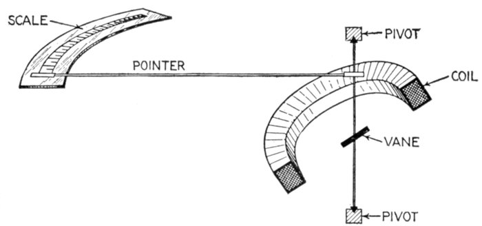
Fig. 2,498.—Inclined coil form of electromagnetic or moving iron instrument.
Ques. What is the principle of operation of the inclined
coil instrument?
Ans. When a current is passed through the coil, the iron
tends to take up a position with its longest sides parallel to the
lines of force, which results in the shaft being rotated and the
pointer moved on the dial, the amount of movement depending
upon the strength of the current in the coil.
Ques. Describe a magnetic vane instrument.
Ans. It consists of a small piece of soft iron or vane mounted
[Pg 1784]
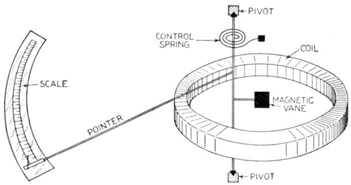
Fig. 2,499.—Magnetic vane form of electromagnetic or moving iron instrument.
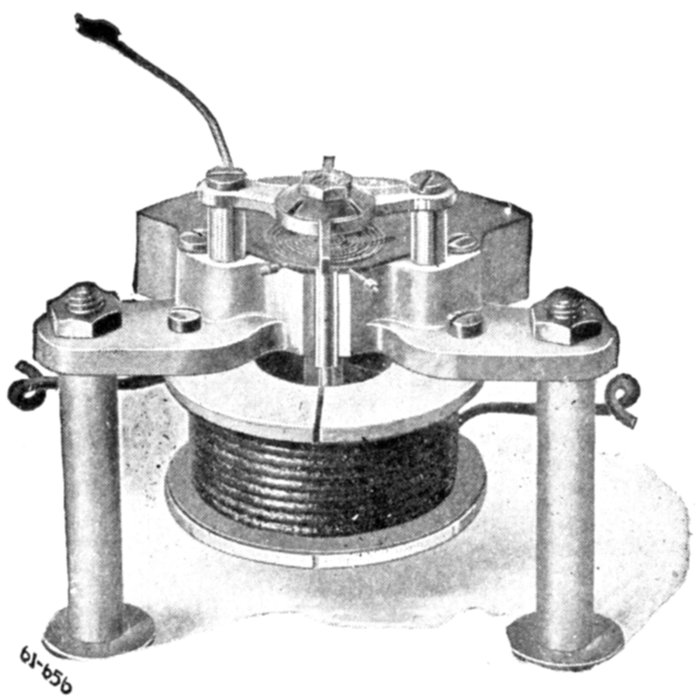
Fig. 2,500.—Magnetic vane movement of a Wagner instrument; it is used both for voltmeters
and ammeters. This type differs from the dynamometer movement in that a vane of very
soft iron replaces the moving coil. The magnetic vane movement makes use of its controlling
spring only for the purpose of resisting the pull on the vane and the returning of the
needle to zero. The spring does not carry any current.
[Pg 1785]
on a shaft that is pivoted a little off the center of a coil as shown
in fig. 2,499, and carrying a pointer which moves over a scale.
Ques. How does it work?
Ans. Its principle of operation is that a piece of soft iron
placed in a magnetic field and free to move, will move into such
position as to conduct the maximum number of lines of force.
The current to be measured is passed around the coil, producing
a magnetic field through the center of the coil. The magnetic
field inside the coil is strongest near the inner edge,
hence, the vane will move against the restraining force of a
spring so that the distance between it and the inner edge of
the coil will be as small as possible.
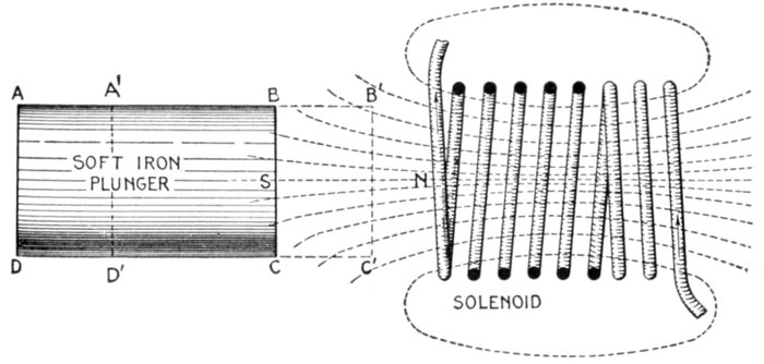
Fig. 2,501.—Solenoid and plunger illustrating the operation of moving iron instruments. When a current flows through the coil, a field is set up as indicated by the dotted lines
of force. The current flowing in the direction indicated by the arrow induces a north
pole at N, which in turn induces a south pole in the plunger at S, thus attracting the
plunger. The effect of the field upon the plunger may also be stated by saying that it
tends to cause the plunger to move in a direction so as to conduct the maximum number of
lines of force, that is, toward the solenoid. Thus if ABCD be the initial position of the
plunger only five lines of force pass through it: should it move to the position A´B´C´D´, the
number of lines passing through it will then be 9, assuming the field to remain unchanged.
The operation of moving iron instruments of the plunger type may be
explained by saying that the current flowing in the coil produces a pole
at its end and induces an unlike pole at the end of the plunger nearest
the coil, thus attracting the plunger, as illustrated in fig, 2,501 above.
[Pg 1786]
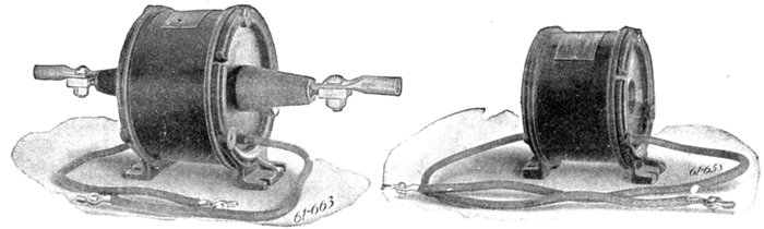
Figs, 2,502 and 2,503.—Wagner series transformers. Fig. 2,502, wound primary series transformer; fig. 2,503, open primary
transformer. Wagner series transformers are made in three general types: One for switchboard mounting with wound
primary; one for switchboard mounting with open primary, and one with open primary suitable for slipping over bus bars
or switch stud. These transformers have 5 ampere secondary winding, and are intended for use in connection with instrument
of scale capacity 0-5, although the scale should be calibrated to indicate the primary current. The capacities
are from 2 watts to 50 watts, being suitable for operation on circuits of 750 to 66,000 volts.
Hot Wire Instruments.—Instruments
of this class
depend for their operation
on the expansion and contraction
of a fine wire carrying
either the current to
be measured or a definite
proportion of that current.
The expansion or contraction
of the wire is caused
by temperature changes,
which in turn are due to the
heating effect of the current
flowing through the wire.
Since the variations in the
length of the wire are extremely
small, considerable
magnification is necessary.
Pulleys or levers are sometimes
used to multiply the
motion, and sometimes the
double sag arrangement
shown in fig. 2,504.
As shown here, A is the
active wire carrying the current
to be measured and
stretched between the terminals
T and T´. It is pulled
taut at its middle point by
another wire C, which carries
no current, and is,
in its turn, kept tight
by a thread passing round
the pulley D attached to[Pg 1787]
the pointer spindle, the whole system being kept in tension by the
spring E.
Hot wire instruments are equally accurate with alternating or direct
current, but have cramped scales (since the deflection is proportional to
the square of the current), and are liable to creep owing to unequal
expansion of the parts. There is also the danger that they may be
burnt out with even comparatively small overloads. They are not
affected by magnetic fields but consume more current than the other
types, these readings are inaccurate near either end of the scale.
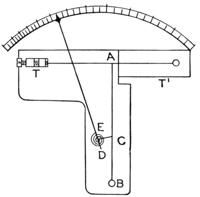
Fig. 2,504.—Diagram illustrating the principle of hot wire instruments. The essential parts
are the active wire A, stretched between terminals T and T´, tension wire C, thread E, and
pulley D to which is attached the pointer.
Induction Instruments.—These were invented by Ferraris,
and are sometimes called after him. They are for alternating
current only, and there are two forms:
- 1. Shielded pole type;
- 2. Rotary field type.
[Pg 1788]
Ques. Describe the shielded pole type of induction
instrument.
Ans. As shown in figs. 2,505, and 2,506 it consists, essentially
of a disc A, or sometimes a drum and a laminated magnet
B. Covering some two-thirds of the pole faces are two copper
plates or shields C, and a permanent magnet D.
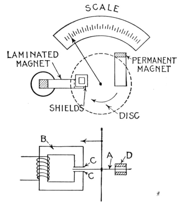
Figs. 2,505 and 2,506.—Plan and elevation of shielded pole type of induction instrument.
Ques. How does it work?
Ans. Eddy currents are induced in the two copper plates or
shields C, which attract those in the disc, producing in consequence
a torque in the direction shown by the arrow, against[Pg 1789]
the opposing action of a spring. Magnet D damps the oscillations.
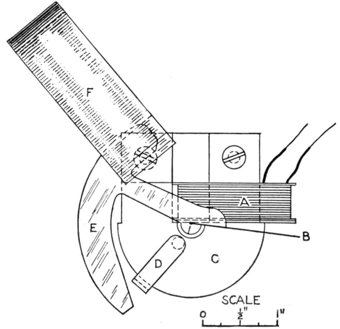
Fig. 2,507.—Diagram showing construction and operation of Hoskins instrument. It is of the
modified induction type in which the torque is produced from the direct repulsion between
a primary and a secondary, or induced current. As shown in the diagram, the instrument
embodies the principle of a short circuited transformer, consisting of a primary or exciting
coil A, a secondary or closed coil B, linked in inductive relation to the primary by a laminated
iron core C, constructed to give a completely closed magnetic circuit, that is, without
air gap. The secondary is so mounted with respect to the primary as to have a movement
under the influence of their mutual repulsion when the primary is traversed by an
alternating current. This movement of the secondary B is opposed by a spiral spring, so
that the extent of movement will be dependent upon and will indicate the strength of
the primary current. To increase the sensitiveness of the instrument and also to adjust
the contour of the scale, an adjustable secondary D, which has an attraction effect upon
the coil B, is provided upon the core. The effect of this coil is inversely proportional to
its distance from the end of the swing of the coil B. The vane, E, which is a part of the
stamping B, is adjusted to swing freely and with a large amount of clearance, between the
poles of a permanent magnet F, which acts as a damper on the oscillation of the moving
element, but does not cause any friction or affect the accuracy of the calibration. The
primary, like that of a transformer, is an independent electrical circuit and may be highly
insulated. This meter will withstand several hundred per cent. overload for some time
because of the very high value of the self-induction and the fact that the controlling spring
is not in the circuit and therefore cannot burn off.
[Pg 1790]
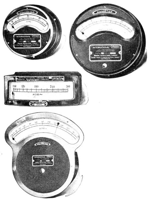
Figs. 2,508 to 2,511.—Hoskins
instruments.
Fig. 2,508, voltmeter,
small pattern; fig.
2,509, ammeter, large
pattern; fig. 2,510,
voltmeter, horizontal
edgewise pattern; fig.
2,511, illuminated
dial voltmeter.
[Pg 1791]
Ques. Describe the rotary field type of induction
instrument.
Ans. The parts are arranged similar to those of wattmeters,
the necessary split phase being produced by dividing the current
into two circuits, one inductive and the other non-inductive.
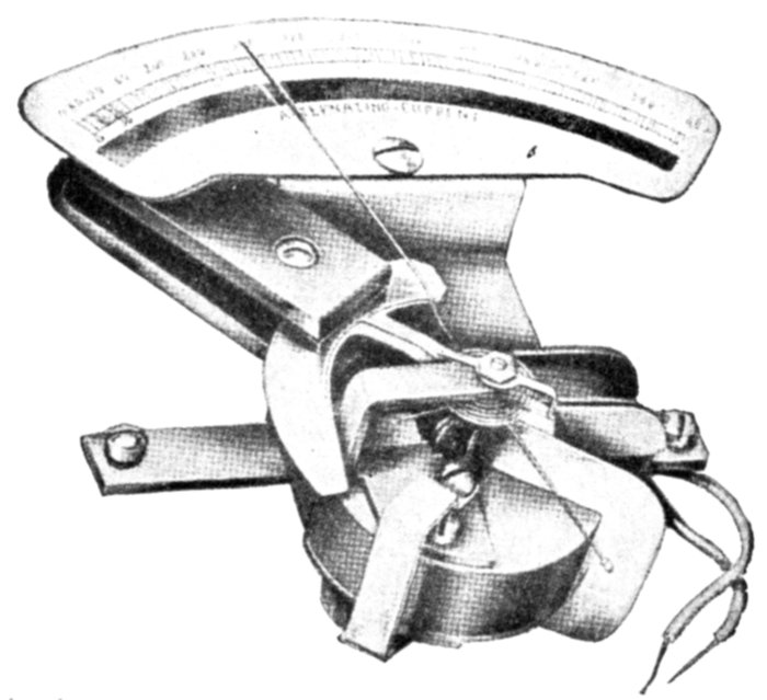
Fig. 2,512.—Hoskins instrument with case removed. It has a very short magnetic circuit
which is composed of silicon steel, permitting low magnetic densities to be used.
Dynamometers.—This type of instrument is used to measure
volts, amperes, or watts, and its operation depends on the
reaction between two coils when the current to be measured
is passed through them. One of the coils is fixed and the other
movable.
[Pg 1792]
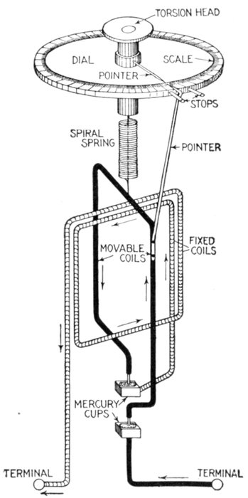
Fig. 2,513.—Diagram of Siemens' dynamometer. It consists of two coils on a common axis
but set in planes at right angles to each other in such a way that a torque is produced
between the two coils which measures the product of their currents. This torque is measured
by twisting a spiral spring through a measured angle of such degree that the coils shall
resume their original relative positions. When constructed as a voltmeter, both coils
are wound with a large number of turns of fine wire, making the instrument sensitive to
small currents. Then by connecting a high resistance in series with the instrument it can
be connected across the terminals of a circuit whose voltage is to be measured. When
constructed as a wattmeter, one coil is wound so as to carry the main current and the
other made with many turns of fine wire of high resistance suitable for connecting across
the circuit.
[Pg 1793]
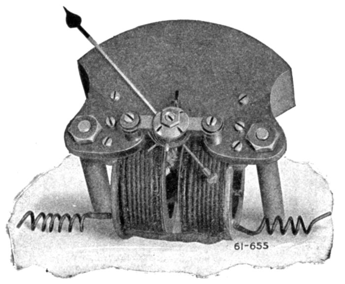
Fig. 2,514.—Wagner dynamometer movement. In this type of instrument the deflection is
proportional to the square of the current, producing a constantly decreasing sensitiveness
as the pressure applied is decreased. The dynamometer movement is, for any indication,
more accurate than the magnetic vane, but cannot readily be employed for the indication
of current, as required in ammeters.
Ques. Describe the construction of a dynamometer.
Ans. It consists, as shown in fig. 2,513, of a fixed coil, composed
of a number of turns of wire, and fastened to a vertical support.
The fixed coil is surrounded by a movable coil composed of a
few number of turns or often of only one turn of wire. The movable
coil is suspended by a thread and a spiral spring attached to a
tortive head which passes through the center of a dial. The
ends of the movable coil dip into mercury cups, which act as
pivots and electrical contacts, making connection with one end
of the fixed coil and one terminal of the instrument as shown.
The tortion head can be turned so as to place the planes of the
coils at right angles to each other and to apply tortion to the
spring to oppose the deflection of the movable coil for this
position when a current is passed through the coils. A pointer
attached to the movable coil indicates its position on the graduated
dial between the two stops. Another pointer attached to
the tortion head performs a similar function.
[Pg 1794]
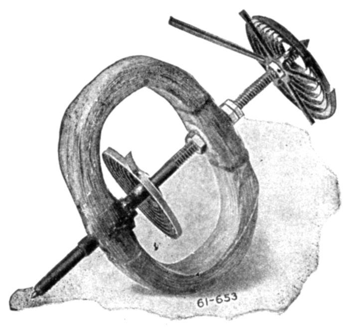
Fig. 2,515.—Armature of Wagner
dynanometer movement. Greater
accuracy is claimed for this movement
than the magnetic vane, but
it cannot readily be employed for
the indication of current flow, as
required in ammeters. The magnetic
vane movement is used
on the A. C. ammeter, and can be
used also in the A. C. voltmeters;
it makes use of its controlling
spring only for the purpose of resisting
the pull on the vane and
the returning of the pointer to
zero. The dynanometer movement
is recommended for voltmeters.
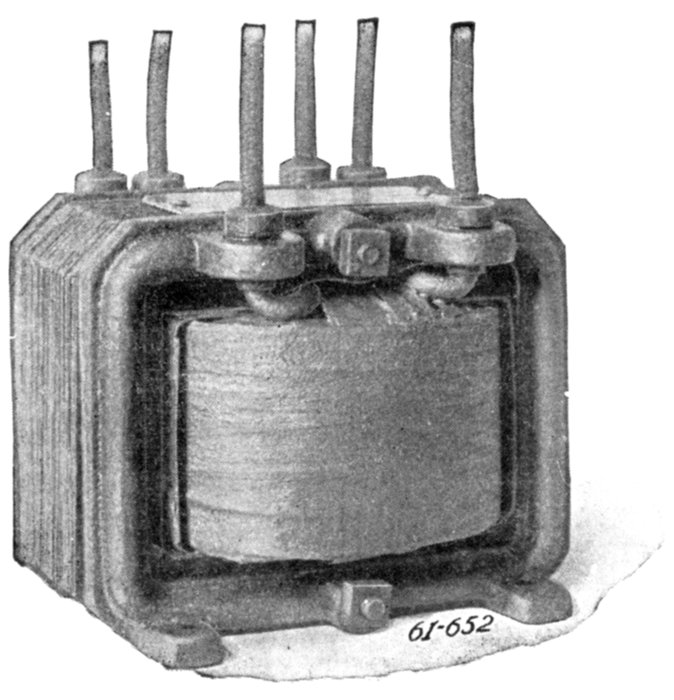
Fig. 2,516.—Wagner
25 watt pressure
transformer
for use with various
alternating
current instruments,
such as
voltmeters, wattmeters,
etc. They
are made in capacities
25, 50,
100, and 200
watts, and are
built for pressures
of 750 to
60,000 volts.
[Pg 1795]
Ques. How does the dynamometer operate?
Ans. When current is passed through both coils, the movable
coil is deflected against one of the stop pins, then the tortion
head is turned to oppose the movement until the deflection has
been overcome and the coil brought back to its original position.
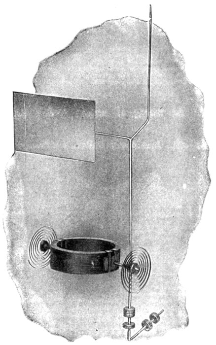
Fig. 2,517.—Moving element of Keystone dynamometer instrument. The illustration shows
the movable coil, pointer, aluminum air vane for damping the oscillations, controlling
springs, and counter weights.
[Pg 1796]
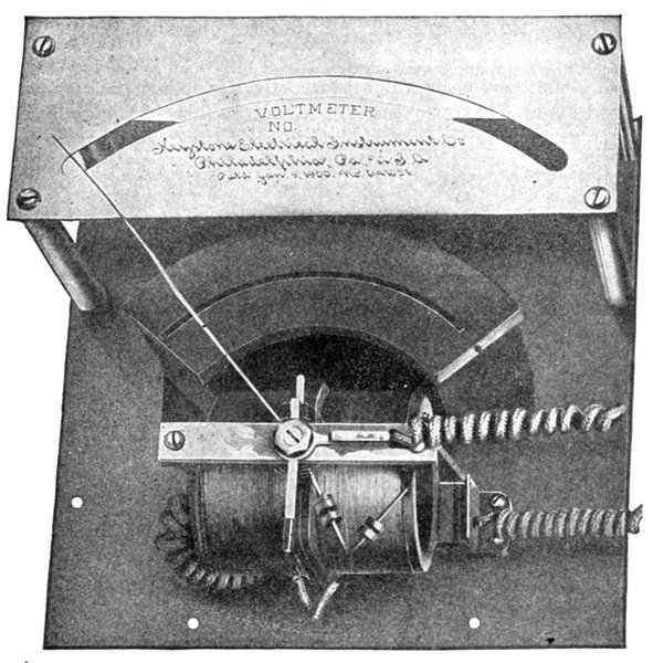
Fig. 2,518.—Keystone dynamometer movement. Since the law governing this type of instrument
is the law of current squares, it follows that in the case of voltmeters, equally divided
scales cannot be obtained. In the case of wattmeters, the scale is approximately equally
divided, due to the fact that the movement of the moving coil is proportional to the product
of the current in the fixed and moving coils. The moving parts have been made as
light in weight as is consistent with mechanical strength, and the entire moving system is
supported on jeweled bearings. The motion of the pointer is rendered aperiodic by the
use of an aluminum air vane moving in a partially enclosed air chamber. This method
of damping the oscillations of the moving parts renders unnecessary the use of mechanical
brakes or other frictional devices, which tend to impair the accuracy of the instrument.
The illustration shows a voltmeter, which, however, differs but little from a wattmeter.
In the case of a wattmeter the fixed coils are connected in series with the line, either directly
or through a current transformer, while the moving coil is connected in shunt to the line.
[Pg 1797]
The angle through which
the tortion head was
turned, being proportional
to the square root of the
angle of tortion, the current
strength in amperes is
equal to the square root of
the angle of tortion multiplied
by a calculated constant,
furnished by the
maker of the instrument.
Ques. How is the dynamometer
arranged to
measure watts?
Ans. When measuring
watts, the instrument
should be so arranged that
one coil carries the main
current, and the other a
small current which is proportional
to the pressure.
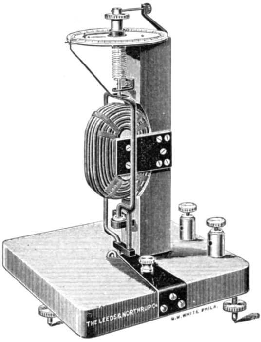
Fig. 2,519.—Leeds and Northrup electro-dynamometer.
It is a reliable instrument for the
measurement of alternating currents of commercial
frequencies. When wound with fine wire and
used in connection with properly wound resistances,
it is equally useful for measuring alternating
pressures, and may thus be employed to calibrate
alternating current voltmeters as well as ammeters.
To give accurate results the instruments must be
carefully constructed and designed with a view to
avoiding the eddy currents always set up by alternating
currents in masses of metal near, or in the
circuits. The constant of a dynamometer may
be obtained with a potentiometer, but this is usually
done with precision by the manufacturer and a
certificate giving the value of the constant is furnished
with the instrument. The size and cost of
dynamometers rapidly increase with the maximum
currents which they are designed to carry, and
when more than 500 amperes are to be measured,
the use of other instruments and methods is
recommended.
Ques. In the construction
of a dynamometer
what material
should not be used and
why?
Ans. No iron or other
magnetic material should
be employed because of the hysteresis losses occasioned thereby.
The frame should be of non-conducting material so as to avoid
eddy currents.
[Pg 1798]

Figs. 2,520 to 2,526.—Various types of Wagner instruments. Fig. 2,520, small round type;
fig. 2,521, horizontal edgewise type; fig. 2,522, smallest switchboard type; fig. 2,523, portable
type; fig. 2,524, combination voltmeter and ammeter in one case; fig. 2,525, vertical
type; fig. 2,526, polyphase type.
[Pg 1799]
Watt Hour Meters.—A watt hour meter is a watt meter
that will register the watt hours expended during an interval
of time. Watt hour meters are often erroneously called recording
or integrating watt meters.
There are several types of the electromotor form of watt hour
meter, which may be classified as
- 1. Commutator type;
- 2. Induction type;
- 3. Faraday disc type.
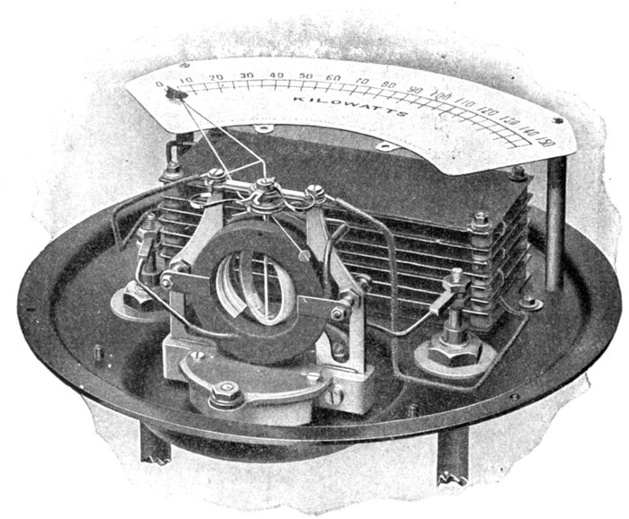
Fig. 2,527—Interior Weston single phase wattmeter. The general appearance of the dynamometer
movement and the relative positions of the various parts are clearly shown. The
parts are assembled on one base, the whole movement being removable by unfastening
two bolts. The fixed winding is made up of two coils, which together produce the field
of the wattmeter. The movable coil is wound to gauge with silk covered wire and
treated with cement. While winding, the coil is spread at diametrical points to allow the
insertion of the staff, which is centered by means of two curved plates cemented to the
inside surface of the coil and forming a part thereof. The coil is held in a definite position
by two tiny pins which pass through the staff and engage with ears on the curved plates.
[Pg 1800]
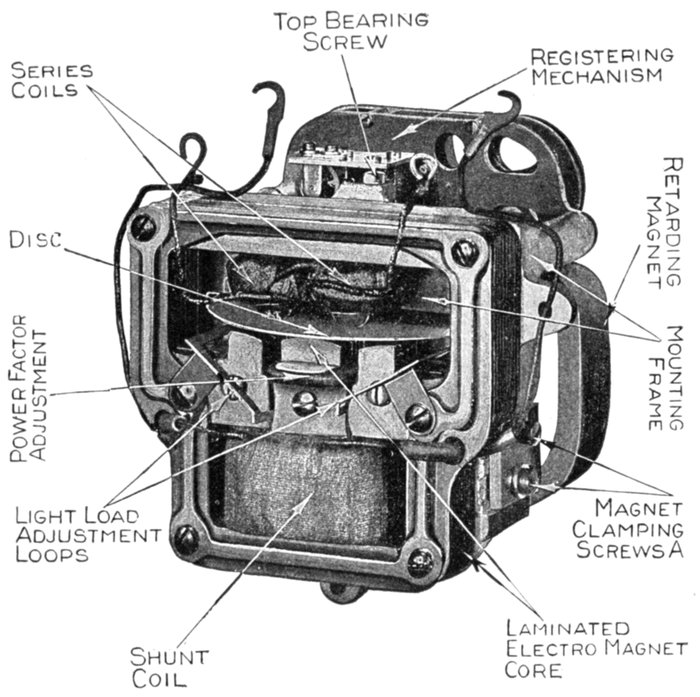
Fig. 2,528.—Westinghouse single phase induction type watt hour meter removed from case.
The friction compensation, or light load adjustment, is accomplished by slightly
unbalancing the two legs of the shunt magnetic circuit. To do this a short circuited loop
is placed in each air gap, and means are provided for adjusting the position of the loops
so that one loop will enclose and choke back more of the flux than the other loop, and
thus produce a slight torque. It will be noted, that this torque depends on voltage
alone, which is practically constant, and is entirely independent of the load. Adjustment
is accomplished by means of either of two screws which makes micrometer adjustment
possible. It is clamped when adjusted by means of a set screw, which prevents change.
This method makes possible an accuracy of adjustment which effectively prevents creeping.
The power factor adjustment consists of an adjustable compensating coil placed around
the shunt pole tip. This is adjusted at the factory by twisting together the leads of the
compensating coil, thus altering its resistance until the desired lagging effect is had. Frequency
adjustment. 133 cycle meters are first calibrated on 60 cycles and the leads
then untwisted to make them correct on 133 cycles. To change such a meter for use on
60 cycles it is necessary only to retwist these leads to the point shown by the condition
of the wire.
[Pg 1801]
Ques. What are the essential parts of a watt hour
meter?
Ans. A motor, generator, and counting mechanism.
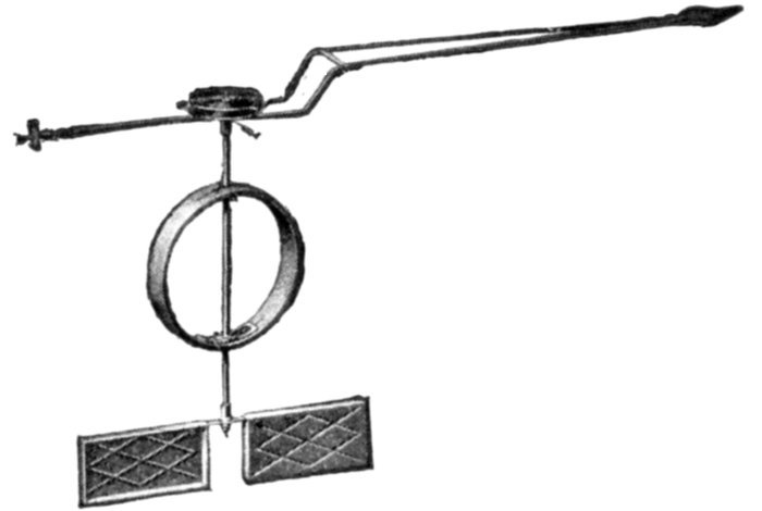
Fig. 2,529.—Pointer and movable system of Weston wattmeter. The coil is described
in fig. 2,527. The pointer consists of a triangular truss with tubular members, an index
tip of very thin metal being mounted at its extremity. The index tip is reinforced
by a rib stamped into the metal. The pointer is permanently joined to a balance cross,
consisting of a flat center web, provided with two short arms and one long arm, each
arm carrying a nut by means of which the balance of the system may be adjusted.
The longest arm, which is opposite the pointer, carries a balance nut, consisting of a thin
walled sleeve provided with a relatively large flange at its outer end. The sleeve is tapped
with 272 threads to the inch, the internal diameter of the sleeve being made slightly smaller
than the outside diameter of the screw, and the sleeve is split lengthwise; therefore when
sprung into place and properly adjusted it will remain permanently in position. A sleeve
which is forced over the end of the staff carries the pointer firmly clamped between a
flanged shoulder and a nut. By perforating the web plate of the balance cross with a
hole having two flat sides that fit snugly over a similarly shaped portion of the sleeve,
the pointer is given a definite and permanently fixed angular position. The air damperconsists of two very light symmetrically disposed vanes, which are enclosed in chambers
made as nearly air tight as possible. These vanes are formed of very thin metal stiffened
by ribs, stamped into them and by the edges, which are bent over to conform to the surface
of the side walls of the chambers. They are attached by metal eyelets to a cross bar carried
on a sleeve similar in construction to the one at the upper end of the staff. This cross
bar is held in place by a nut, and is provided at the center with a hole having two flat
sides, being similar in shape to the one in the balance cross. This hole likewise fits over a
sleeve and definitely locates the vanes with reference to the other parts of the system.
The damper box is cast in one piece to form the base that carries the field coils and the
movable system.
Ques. What is the function of the motor?
Ans. Since the motor runs at a speed proportional to the[Pg 1802]
energy passing through the circuit, it drives the counting mechanism
at the proper speed to indicate the amount of energy consumed.
Ques. What is the object of the generator?
Ans. It furnishes a suitable counter torque or load for the motor.
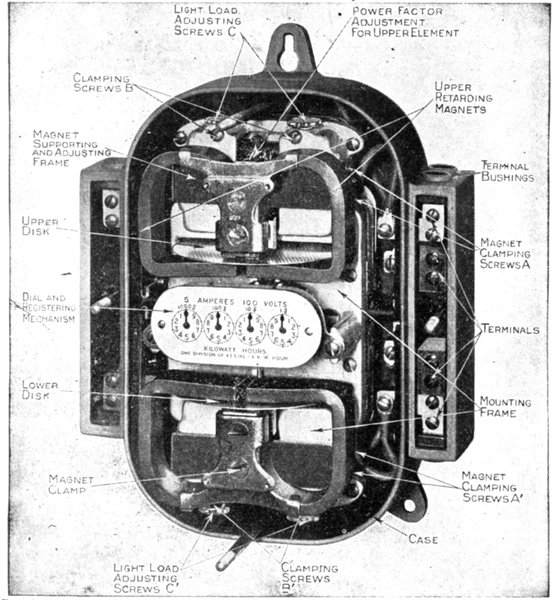
Fig. 2,530.—Westinghouse polyphase induction type watt hour meter, covers removed. This
type is made for two phase three wire and four wire, and three phase three wire and four
wire circuits. Meters for circuits of more than 300 amperes or 500 volts require transformers,
but, like the self-contained meters, are calibrated to read directly in kilowatt
hours on the dial, without a multiplying constant.
[Pg 1803]
Ques. Is there any other resistance to be overcome by
the motor?
Ans. It must overcome the friction of all the moving parts.
Ques. Is the friction constant?
Ans. No.
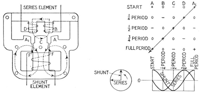
Figs. 2,531 to 2,533.—Diagram of electromagnetic circuit of Westinghouse induction type
watt hour meter, and diagram showing rotation of field. The dotted lines show the main
paths of the magnetic flux produced by the two windings, the directions, however, are
constantly reversing owing to the alternations of the current in the coils. Denoting the
shunt and series pole tips by the letters as shown, a clear statement of the relation of the
fields for each quarter period may be given. The signs + and - represent the instantaneous
values of the poles indicated. Thus, at one instant the shunt pole tips A, C, and
A1 are maximum +, -, and +, respectively because the instantaneous value of the current
is maximum, while the value of the series flux is zero. At ¼ period later the shunt current
is zero, giving zero magnetic pressure at the pole tips, while the series current has reached
a maximum value, giving maximum-and + at the pole tips B and D. At the next ¼
period the shunt current is again maximum, but in a direction opposite to what it was
at the beginning, making the pole tips A, C, and A1 +, -, and +, respectively, while the
series current again is zero, etc., the values for the complete cycle being given in fig. 2,533.
It will be observed from the table that both the + and - signs move constantly in the
direction from A1 to A, indicating a shifting of the field in this direction, the process being
repeated during each cycle.
Ques. What provision is made to correct the error
due to friction?
Ans. The meter is compensated by exciting an adjustable
auxiliary field from the shunt or pressure circuit.
Ques. What is the construction of the generator?
Ans. In nearly all meters it consists of a copper or aluminum[Pg 1804]
disc carried on the
same shaft with the
motor and rotated in
a magnetic field of
constant value.
Ques. How is the
counter torque
produced?
Ans. When the disc
is rotated in the magnetic
field, eddy currents
are induced in
the disc in a direction
to oppose the motion
which produces them.
Ques. For what
services is the commutator
type meter
used?
Ans. It is used on
both direct and alternating
current circuits.
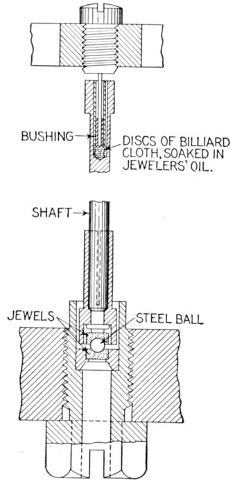
Figs. 2,534 and 2,535.—Cross section of bearings of Westinghouse induction type watt hour
meter. The lower bearing consists of a very highly polished and hardened steel ball
resting between two sapphire cup jewels, one fixed in the end of the bearing screw and the
other mounted in a removable sleeve on the end of the shaft. Owing to the minute gyrations
of the shaft the ball has a rolling action, which not only makes a lower friction coefficient
than the usual rubbing action, but presents constantly new bearing surfaces and
thus produces long life. The upper bearing is only a guide bearing to keep the shaft in
a vertical position, and is subject to virtually no pressure, and consequently little friction.
It consists of a steel pin fastened to a removable screw and projecting down into a bushing
in a recess drilled in the shaft. The bottom of this recess is filled with billiard cloth
saturated with watch oil. A film of oil is maintained around the pin by capillary action.
[Pg 1805]
Ques. What is the objection to the commutator meter?
Ans. The complication of commutator and brushes, and the
fact that the friction of the brushes is likely to affect the accuracy
of the meter.
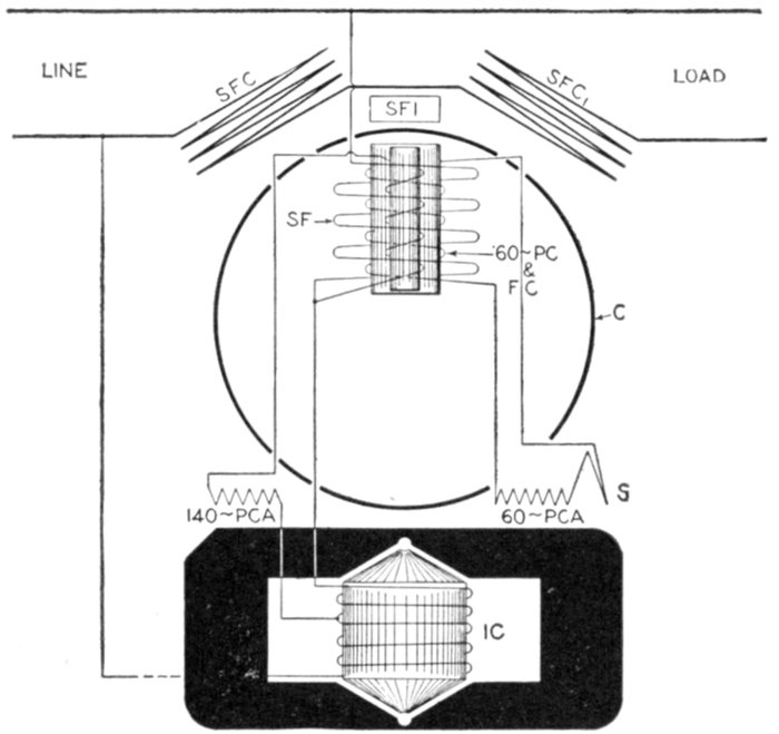
Fig. 2,536.—Diagram of Fort Wayne, induction watt hour meter. It is designed to register the
energy of alternating current circuits regardless of the power factor, and embodies the usual
induction motor, eddy current generator and registering mechanism. The electrical arrangement
of the meter consists of a current circuit composed of two coils connected in series
with each other and in series with the line to be measured, and a pressure circuit consisting
of a reactance coil and a pressure coil connected in series with each other and across the
line to be measured. In addition, the pressure circuit contains a light load coil wound over
a laminated sheet steel member, adjustably arranged in the core of the pressure coil and
connected across a small number of turns of the reactance coil so as to give a field substantially
in phase with the impressed pressure. The light load winding is further provided
with a series adjustable resistance furnished for the purpose of regulating the current
flowing in the light load winding, thereby providing a means of lagging the meter on high
frequencies, such as 125 or 140 cycle circuits. The pressure circuit also comprises a lag
coil wound over the upper limb of the core of the pressure circuit and provided with an
adjustable resistance for obtaining a held component in quadrature with the shunt field.
Ques. What are its characteristics?
Ans. It is independent of power factor, wave form, and
frequency when no iron is used in the motor.
[Pg 1806]
Ques. What meter is chiefly used on A. C. circuits?
Ans. The induction meter.
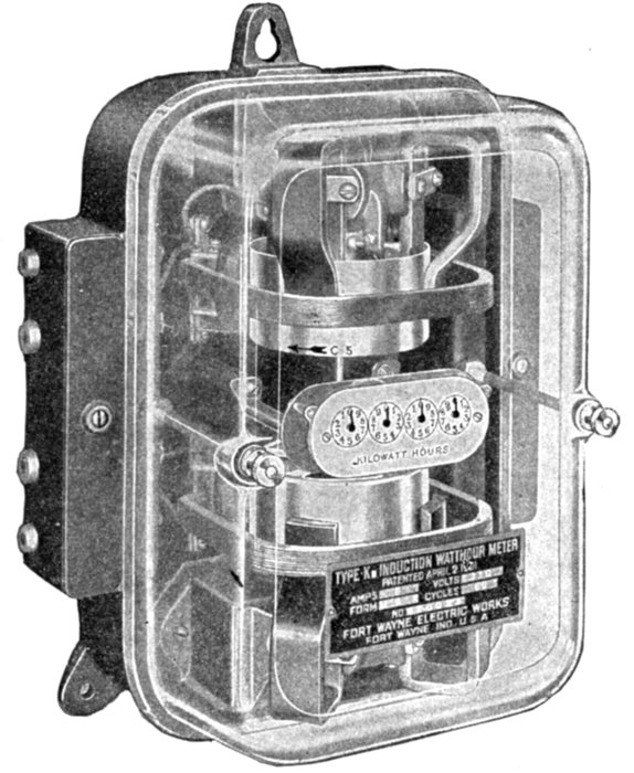
Fig. 2,537.—Fort Wayne multiphase induction watt hour meter. The construction of the
mechanism is essentially two single phase motor elements, one at the bottom of the meter
in a suitable position, the other inverted and placed at the top of the meter. Each element
acts on a separate cup, but both cups are mounted on a single shaft so that the registration
is due to the resultant torque of the two elements. The meter is provided with three supporting
lugs, the one at the top being keyholed and one of the bottom two, slotted to facilitate
leveling. The registering mechanism is mounted on a cast iron bracket at the middle
of the meter between the two motor elements. The supporting bracket is attached to the
meter base by two screws and aligned by two dowel pins. The register is of the four dial
type, reading in kilowatt hours. Each division of the right hand circle, or that passed
over by the most rapidly moving pointer, equals one kilowatt hour in meters without a
dial constant. In meters of larger capacities, dial constants of 10, 100 and 1,000 are used,
in which case it is only necessary to add one, two or three ciphers to the observed reading.
Principles of Induction Watt Hour Meters.—Every
commercial meter of this type is made up of a number of elements,[Pg 1807]
described below. Each of these elements and parts has certain
functions, and each is therefore necessary to the successful operation
of the meter; moreover, each element, unless correctly designed,
may introduce a source of inaccuracy. These elements are:
1. The field producing element;
2. The moving element;
3. The retarding element;
4. The registering element;
5. The mounting frame and bearings;
6. The friction compensator;
7. The power factor adjustment;
8. Frequency adjustment;
9. The case and cover.
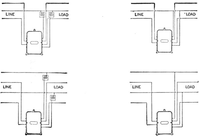
Figs. 2,533 to 2,541.—Connections of Fort Wayne multiphase watt hour meters (type k3—forms
MAB and MAK), for 100-625 volt circuits, 5-150 amperes. Fig. 2,538 two and
three phase, three wire circuit, 25-36 cycles; fig. 2,539 two and three phase, 3 wire circuit,
36 cycles and above; fig. 2,540, two phase 4 wire circuit, 25-36 cycles; fig. 2,541 two phase,
4 wire circuit 36 cycles and above.
[Pg 1808]
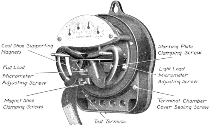
Fig. 2,542.—Fort Wayne single phase induction watthour meter with cover removed. The
rotating parts consist of an aluminum disc mounted on a short shaft of small diameter.
The lower end has inserted in it a hardened steel pivot which rests in a cup shaped jewel
bearing. The top of the meter shaft is drilled and provided with a small washer having
the central hole of very small diameter. Into this hole there extends a steel pin around
which the shaft turns. Two micrometer screws are provided for load adjustment—one
for the full load and the other for the light load adjustment. The adjustment for accuracy
on full load is secured by varying the position of the permanent magnets, sliding them
either in or out from the center of the rotating disc of the meter depending on whether it
is desired to increase or decrease the speed of the disc. The micrometer screw shown in
the figure serves to vary the position of the permanent magnets, causing the shoe in which
the two magnets are firmly clamped to slide on the milled magnet support which is cast
as an integral part of the meter frame. When the proper position of the magnets has been
accurately determined by adjustment and test, the shoe which holds the two magnets is
clamped firmly to the milled magnet support by two screws, one of which is shown in the
figure. The adjustment for accuracy on light load is secured by varying the position of a
metal punching, known as the starting plate, laterally under the pressure pole in the
path of the pressure flux. This lateral movement is accomplished by means of the
micrometer screw. When the proper position of this punching has been accurately determined
by adjustment and test, it is secured in place by tightening the two brass screws
which serve to clamp it to the meter frame.
1. The Field Producing Element.—This consists of the
electromagnetic circuit and the measuring coils. One of these
coils, connected in series with the circuit to be metered, is wound
of few turns and is therefore of low inductance. The current
through it is in phase with the current in the metered circuit.
The other coil, connected across the circuit, is highly inductive,
and therefore the current in it is nearly 90 degrees out of phase
with, and proportional to the voltage of the metered circuit[Pg 1809]
across its terminals. Therefore, when the current in the circuit
is in phase with the voltage (100 per cent. power factor) the
currents in the meter coils are displaced almost 90 degrees with
respect to each other.
Ques. How is this angle made exactly 90 degrees?
Ans. By means of the power factor adjustment.
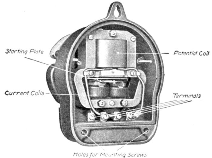
Fig. 2,543.—Rear view of Fort Wayne single phase induction watthour meter with back
cover plate removed. The pressure and current coils and their respective cores lie behind
the main frame of the meter. This complete electromagnetic unit can be removed as a
whole from its mounting in the case. The pressure coil is wound from enameled wire,
the number of turns being very high. The current coils have but few turns each and are
wound from cotton covered wire. All coils are treated with insulating compound before
assembling in the meters. The laminated iron cores placed within these coils are built
up from magnetic steel. The magnetic circuits formed by the cores of the pressure and
current coils are so arranged that they exert a high torque upon the disc of the rotating
element in order that minute variations in the friction of the moving parts, which are
likely to occur will not cause any appreciable error in the registration of the meter. The
iron case surrounding the electrical elements protect that part of the meter from the
effects of external stray fields, while the astatic arrangement of the permanent magnets
tends to prevent any influence on the damping system. The fact that the iron frame of
the meter lies between the permanent magnets and the current coils protects the magnets
from the effects of short circuits which create a strong magnetic field within the meter itself.
Ques. How are the coils mounted?
Ans. They are so mounted on the core that the currents in[Pg 1810]
them produce a rotating or shifting field in the air gap, in somewhat
the same manner that the currents in the primary windings
of an induction motor produce a rotating field.
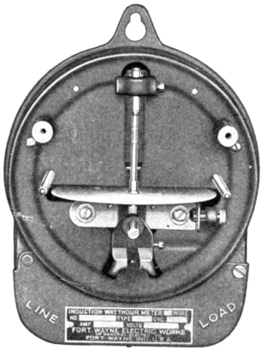
Fig. 2,544.—Fort Wayne single phase induction watthour meter with cover register and
permanent magnets removed to show solid meter frame. A heavy steel back plate held in
place by two screws inserted from the front of the central casting encloses the back part
of the completely assembled meter. A felt gasket lying on a suitable ledge seals the
joint against the entrance of dust or moisture when the back plate is drawn down firmly
by the screws. The cover which encloses the back part of the meter is a non-magnetic
metallic stamping. It is held in place by wing nuts on the two light brass studs extending
forward from the meter frame. This joint between the main frame and the cover is also
sealed against the entrance of dust and moisture by the use of a suitable felt gasket. Two
glass windows are provided in this cover, one to permit the reading of the register dials,
the other to permit observation of the disc's rotation. The cover is sealed in place in the
usual way by passing a sealing wire through a hole drilled in the cover sealing stud and
thence through a hole provided in the wing of the seal nut. The terminal chamber is an
extension of the casting which supports all the inner parts of the meter. The heavy brass
terminals used for connecting the meter in circuit are held permanently by a non-combustible
insulating compound which is moulded in place around them. This construction
gives excellent insulation and is a safeguard against accidental short circuits across terminals.
A punched terminal cover which fits over the terminal chamber is hinged at the
upper left hand corner so that it will of its own accord swing out of the way when the
terminal cover sealing screw is removed. This hinged style of cover will be found convenient
when installing and connecting the meter in circuit. When this cover is swung
back into closed position it is fastened in place by passing a seal right through the seal
screw and through a lug provided on the cover.
Ques. What is the strength of the rotating field with
90 degrees phase difference between the currents?
Ans. It is proportional to the product of the currents in the[Pg 1811]
two coils and therefore proportional to the product of current
and voltage in the metered circuit.
At any other power factor the field is proportional to this product
multiplied by the sine of the angle of phase difference between the two
meter currents. If the current in the voltage coil be in quadrature with
the voltage of the metered circuit, at any power factor the sine of the
angle of phase difference between the currents in the meter circuits
will be equal to the cosine of the angular displacement between the current
and voltage in the metered circuit. Under these conditions therefore
the strength of the shifting field is proportional also to the power
factor of the circuit. In other words, the strength of the rotating field
is proportional to the product of the volts, amperes and power factor
and is therefore a measure of the actual power.
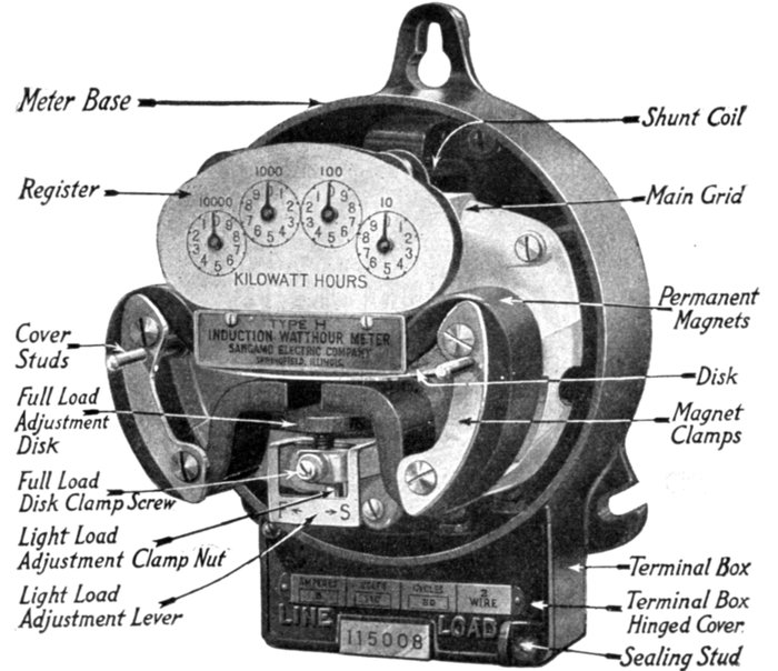
Fig. 2,545.—Sangamo single phase induction watt hour meter; view with cover removed showing
mechanism.
[Pg 1812]
Ques. In what part of the meter is energy consumed?
Ans. In the field producing element.
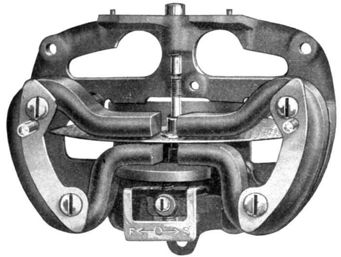
Fig. 2,546.—Main grid or supporting frame of Sangamo single phase induction watt hour meter.
The grid is of cast iron and its design is such that the weight of the permanent magnets,
series laminated element and return plate are carried on the main portion, the smaller
projecting brackets carrying no weight except that of the moving system. The supporting
grid is removed by taking out the three screws locating and holding it in position, to the
iron base, also removing at the same time the screws connecting the leads of the series coils
to the binding posts at the bottom. The meters are all built with four binding posts so
that they may be connected either with two series leads and a tap for the pressure connection
or with both sides of the circuit carried through the meter. The wire meters employ
a 220 volt shunt coil, connected across the binding posts within the meter, one series coil
being in each of the outer lines of the three wire system. This renders unnecessary the use
of a pressure tap.
It is upon the design of this element that the losses in the meter
depend. Current is flowing through the shunt coil continuously, even
when no energy is being taken, and the higher the inductance of this
coil, the smaller will be the energy component of the constant flow. The
series coil causes a loss of energy proportional to the square of the
current flowing. It also causes a drop in voltage, both inductive and
resistive, hence, the resistance and inductance of the series coil of the
meter should be as low as possible.
[Pg 1813]
Ques. How should the magnetic circuit be designed?
Ans. The design should be such that the increase of magnetic
flux with high voltage or high current will not have a retarding
action but will act only to increase the torque.
If the retarding effect be not prevented, the meter will, of course,
run slow at overloads. A comparative test of meters at varying load
and at varying voltage will reveal the characteristics of the magnetic
circuit.
2. The Moving Element.—This usually consists of a light
metal disc revolving through the air gap in which the rotating
field is produced.
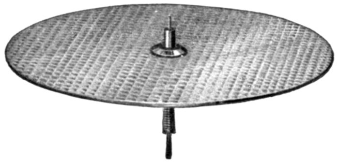
Fig. 2,547.—Moving element of Sangamo single phase induction watt hour meter. It consists
of a light aluminum disc mounted on a hard brass shaft, the entire system weighing 15.6
grams. The disc is swaged under heavy pressure, to render it stiff. The arrangement of
the disc, shaft, and bearings is shown in fig. 2,548. By unscrewing the upper and lower
bearings the disc and shaft can be removed without disturbing the magnets or adjustments.
Ques. What is the action of the disc?
Ans. It acts like the squirrel cage armature of an induction
motor, developing the motive torque for the meter.
Ques. How is this torque counter balanced?
Ans. By the retarding element so that the speed is proportional
to the torque.
Ques. How should the disc be made and why?
Ans. As light as possible to reduce wear on the bearings to
a minimum.
[Pg 1814]
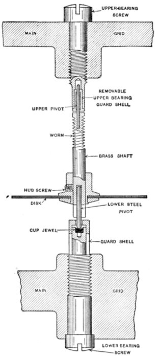
Fig. 2,548.—Bearing system of Sangamo single phase induction watthour meter. The
upper pivot, or bearing is made of tempered steel wire and of sufficiently small diameter to
be quite flexible in the length between the top of the brass shaft and the guide ring in which it
rotates. The guide ring, made of phosphor bronze, has the heavy hole lined and burnished.
The upper bearing screw, in which the bronze bushing is carried, is so constructed that a long
brass sleeve closely surrounds the upper pivot of the spindle. Any blow against the moving
system, caused by accident or short circuit, will slightly deflect the shaft until the steel
pivot touches against the side of the shell, thus preventing danger of breaking off or bending
the upper pivot. At the same time a cushioning or flexible action between the shaft and
the bearing shell is secured, thus eliminating the effect of vibration in the moving system,
which would tend to produce rattling. The lower bearing consists of a cup sapphire jewel,
supported in a threaded pillar, the upper end of which is provided with a sleeve so located
that it prevents the moving element dropping out during shipment. This protecting sleeve
is held friction tight on the shaft and can be removed if it be desired to inspect the jewel.
[Pg 1815]
3. The Retarding Element.—This part acts as a load on
the induction motor and enables the adjustment of its speed to
normal limits. In order that the speed shall be proportional to
the driving torque, which varies with the watts in the circuit,
it is necessary that the torque of the retarding device be proportional
to the speed. For this reason a short circuited constant
field generator, consisting of a metal disc rotating between permanent
magnet poles, has been generally adopted.
Ques. How is the retarding torque produced?
Ans. Eddy currents are induced in the disc in rotating through
the magnetic field which, according to Lenz's law, oppose the
force that produces them, thus developing a retarding torque.
Ques. How is the constant field for the retarding disc
produced?
Ans. By permanent magnets.
The retarding disc may be the same disc used for the moving element,
in which case the meter field acts on one edge while the permanent
magnet field acts on the edge diametrically opposite. This arrangement
simplifies the number of parts and saves space and weight of moving
element.
Ques. What error is likely to be introduced by the
retarding element?
Ans. If the strength of the permanent magnets change
from any cause, the retarding torque will be changed and the
calibration of the meter rendered inaccurate.
Ques. How may the strength of the permanent magnets
be changed?
Ans. They may become weak with age, or affected by the
proximity of other magnetic fields. The series coil of the meter
may, under short circuit so affect the strength of the permanent
magnets as to render the meter inaccurate.
[Pg 1816]
Ques. What precautions are taken to keep the strength
of the permanent magnets constant?
Ans. Weakening with age is prevented by the process of
"Aging." The effect of neighboring fields is overcome by iron
shields; this prevents the electromagnets affecting, through
overloads, the strength of the permanent magnets.
4. The Registering Element.—This mechanism comprises
the dials, pointers, and gear train necessary to secure the
required reduction in speed. This gear train is driven directly
by the rotor and therefore its friction should be low and constant.
The dials should be easily read and should register directly in
kilowatt hours. If a constant be used to reduce the reading to
kilowatt hours, it should be some multiple of 10, to avoid errors
in multiplication. By means of suitable gears in the meters this
is easily accomplished.
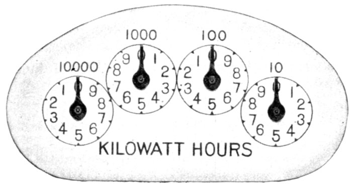
Fig. 2,549.—Register dial of Sangamo single phase induction watt hour meter (full size). The
dial circles read 10, 100, 1,000, and 10,000 kilowatt hours from right to left.
5. The Mounting Frame and Bearings.—These parts
have an important influence on the accuracy of the meter, as it[Pg 1817]
is in the bearings that most of the friction in the meter occurs.
The frame should be rigid and free from vibration, so that the
bearings will be at all times in perfect alignment.
Initial friction is unavoidable in any meter construction and can be
easily compensated for. A change in the initial friction, however, due
to wear of bearings, makes readjustment necessary.
In selecting a meter the special attention should therefore be given,
to the construction of the bearings, particularly the lower, or "step"
bearing which supports the weight of the moving element.
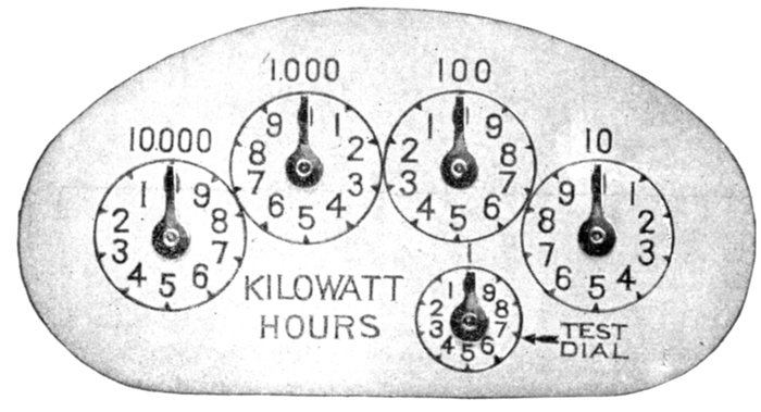
Fig. 2,550.—Canadian dial of Sangamo single phase induction watt hour meter. It has a small
test circle indicating one kilowatt hour per revolution in all sizes where the first regular
circle indicates 10. This is provided to conform with the requirements of the Canadian
government and it is intended that the hand on the test circle shall make not less than ½
revolution in one hour with full load on a meter. In the case of a 10 ampere meter, it will
make one complete revolution in one hour and for a 20 ampere, two revolutions, and so on.
The train or indicating mechanism is carried on a rigidly formed and swaged brass bracket
accurately located by two dowel pins set in the top face of the main grid, and is held to the
grid with two screws easily accessible when it is desired to remove the train for any
purpose. All indicating trains used on type "H" meters are marked with symbols on the
back of the train and on the compound attachment to indicate the gear ratio of each combination;
this ratio being different for meters of different capacities in order to obtain a
direct reading in kilowatt hours on the dial.
Ques. Describe a good construction for the step
bearing.
Ans. A desirable construction would consist of a very highly
polished and hardened ball with jewel seats.
[Pg 1818]
6. The Friction Compensator.—The object of this device
is to overcome the initial friction of the moving parts. It is
evident that if this initial friction were not compensated some
of the driving torque of the meter would be used in overcoming
it, and the meter would therefore not rotate at very light load,
and not fast enough at other loads, thus rendering the registration
inaccurate, especially at light loads.
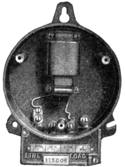
Fig. 2,551.—Base and shunt coil of Sangamo single phase induction watt hour meter. Since
the shunt or pressure coil sometimes breaks down or burns out, due to abnormal line conditions
or accident, provision is made for easy replacement. The shunt magnet with its
coil is held to the base by two dowel pins and four screws, enabling it to be removed as a
unit as shown. A new core and coil may then be substituted without the necessity of
removing and replacing laminations. The shunt coil in 25 cycle meters is wider and contains
more steel than the 60 and 133 cycle coils, the winding also being correspondingly increased.
The return plate and series coil laminations are also changed in proportion to
correspond to the increased width of the shunt magnet. The laminations forming the core
are laced into the shunt coil, and subjected to enormous hydraulic pressure, the rivets being
set at the same time, to form a compact unit and eliminate humming. The laminated core
of the shunt element has but a single air gap in which these discs rotate.
Since meters are usually run at light loads it is important that
an efficient light load adjustment or friction compensator should
be provided.
Ques. What important point should be considered in
the design of the friction compensator?
Ans. The compensating torque must not cause the moving
element to rotate or "creep" without current in the series coil.
[Pg 1819]
The rotation of a meter is caused by two distinct torques, the varying
meter torque, dependent on the power in the circuit, and the constant
torque adjusted to compensate the initial friction.
The friction at all speeds is not exactly the same as the initial friction,
and therefore the friction compensating torque may be in error a few
per cent. at high speeds.
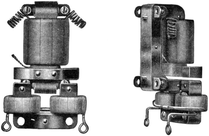
Figs. 2,552 and 2,553.—Arrangement of magnetic circuit of Sangamo single phase induction
meter. Fig. 2,552, front view; fig. 2,553, rear and side view. As shown, the gap of the
shunt held in which the disc rotates, projects in between the poles of the series magnet,
the return plate bending around so as to clear the upper leg of the shunt magnet. This
gives the desired proximity of shunt and series fields with a maximum radius of action for
both sets of field. In all capacities up to and including 60 amperes, 2 wire and 3 wire,
round wire and taped series coils are used, and in capacities of 80 and 100 amperes, strap
windings. Meters exceeding 100 ampere capacity have five ampere coils and are operated
from external current transformers having 5 ampere secondaries. The series windings
or coils are mounted on a laminated iron U shaped magnet having a laminated return path
above the disc of the meter, thus forming air gaps in which the disc rotates. The series
coils in all capacities not having strap windings are held firmly in position on the yoke so
that they cannot slip up from the lowest position. This is accomplished by means of a pair
of spring brass clips slipped through the coils on the rear face of the yoke, the clips being
held by the two screws which fasten the series magnet to the main grid. As an additional
precaution, spring steel lock washers are put beneath the heads of the holding screws, thus
eliminating any chance of the series magnet loosening and changing position.
If the compensating torque be small compared with the driving torque,
this small error percentage is negligible in its effect on accuracy. The
smaller it is, the greater will be the accuracy at all loads, and therefore,
as the compensating torque is adjusted to balance the initial friction,
the initial friction should be small compared with the driving torque.
[Pg 1820]
A high driving torque and low initial friction are therefore desirable,
but any increase in the driving torque which necessitates an increase in
friction, is obviously useless.
The desirable feature of a meter is high ratio of torque to friction.
As the friction is practically proportional, to the weight of the moving
element, in meters having the same form of bearing, the ratio of torque
to weight of rotor gives an approximation to the ratio of torque to
friction, but the design of bearing should not be overlooked.
A meter having a high torque obtained by using a thick and consequently
heavy disc, often has a lower ratio of torque to weight than
another with lower torque, and is consequently likely to be less accurate
over a given range. Furthermore, the heavy disc is a distinct disadvantage
because it produces more wear on the bearings and thus
reduces the life.
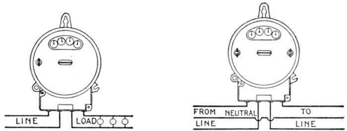
Figs. 2,554 and 2,555. Connections of Sangamo single phase induction meter. Fig. 2,554,
2 wire meter, 5-100 ampere capacity; fig. 2,555, 3 wire meter, 5-100 ampere capacity.
7. The Power Factor Adjustment. This adjustment is
necessary to make the phase angle between the shunt and series
field components 90° with unity power factor in the metered
circuit. Owing to the resistance and iron loss in the shunt field
circuit, that field is not shifted quite 90° with respect to the
voltage. Yet exact quadrature is necessary to make the strength
of the resultant field, and consequently the rotor speed, proportional
to the power factor, as explained in the discussion of
the field producing element.
Ques. What is the usual construction of the power
factor adjustment?
Ans. It usually consists of a short circuited loop enclosing
part or all of the shunt field flux.
[Pg 1821]
Ques. How does this loop act?
Ans. It acts like the secondary of a transformer.
The flux induces a current in it which, acting with the current in the
shunt coil, produces a slightly lagging field. By shifting the position of
the resistance of the short circuited loop, the lag may be so adjusted
that the shunt field flux is in exact quadrature with the voltage. It
should be noted, however, that this adjustment makes the meter correct
at or near one frequency only. This feature is not objectionable if
reasonable accuracy be maintained within the limits of normal variation
of frequency.
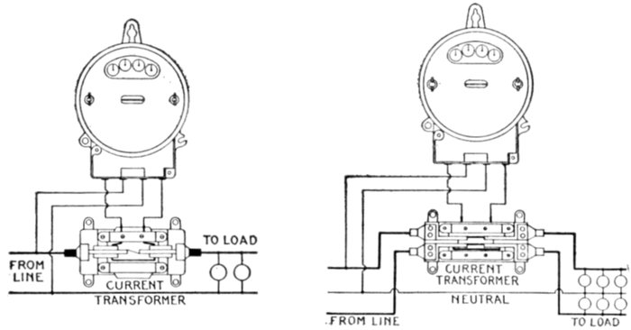
Figs. 2,556 and 2,557. Connections of Sangamo single phase induction meter. Fig. 2,556,
2 wire meter exceeding 100 amperes; fig. 2,557, 3 wire meter exceeding 100 amperes.
8. Frequency Adjustment.—This is often desirable, particularly
for systems operating at 133 cycles. Most makes of
meter are provided with means for changing the adjustment
from 133 to 60 cycles in case of change in the system.
9. The Case and Cover.—These parts should be dust and
bug proof, to avoid damage to the bearings, insulation and
moving parts, and should of course be provided with means for
sealing.
Terminal chambers so arranged that the cover of the meter
element need not be removed in connecting up, are an important[Pg 1822]
feature, particularly in meters that require no adjustment at
installation, as they prevent entrance of dust into the main
meter chamber.
A window through which the rotation of the disc can be observed
in checking, should be provided for the same reason.
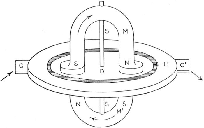
Fig. 2,558.—Faraday disc, or mercury motor ampere hour meter; view showing electric and
magnetic circuits.
The Faraday Disc, or Mercury Motor Ampere Hour
Meter.—On this type of meter the mercury motor consists
essentially of a copper disc floated in mercury between the
poles of a magnet and provided with leads to and from the
mercury at diametrically opposite points. The theoretical
relations of the various parts are shown in fig. 2,558.
[Pg 1823]
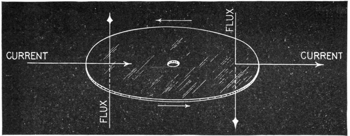
Fig. 2,559.—Diagram showing relative direction of current, magnetic flux, and motion of disc in Faraday disc, or mercury
motor ampere hour meter.
Ques. Explain its operation.
Ans. The electric current, as shown in fig. 2,558, enters the
contact C, passes through
the comparatively high
resistance mercury H to
the edge of the low resistance
copper disc D
across the disc to the
mercury H and out of
contact C'. The magnetic
flux cuts across the
disc on each side from
N to S, making a complete
circuit through M
and M'. The relative
directions of the magnetic
flux and the current of
electricity as well as the
resulting motion are shown
in fig. 2,559. According
to the laws of electromagnetic
induction, if
a current carrying conductor
cut a magnetic
field of flux at right angles,
a force is exerted upon
the conductor, tending to
push it at right angles to
both the current and the
flux. When connected to
an eddy current damper or
generator which requires
a driving force directly
proportional to the speed
of rotation, the mercury[Pg 1824]
motor generator becomes a meter. The speed of such a meter
is a measure of the current or rate of flow of the electricity
through the motor element, and each revolution of the motor
corresponds to a given quantity of electricity. Then, by
connecting a revolution counter to this motor generator, a
means is provided for indicating the total quantity of electricity
in ampere hours that is passed through the meter.
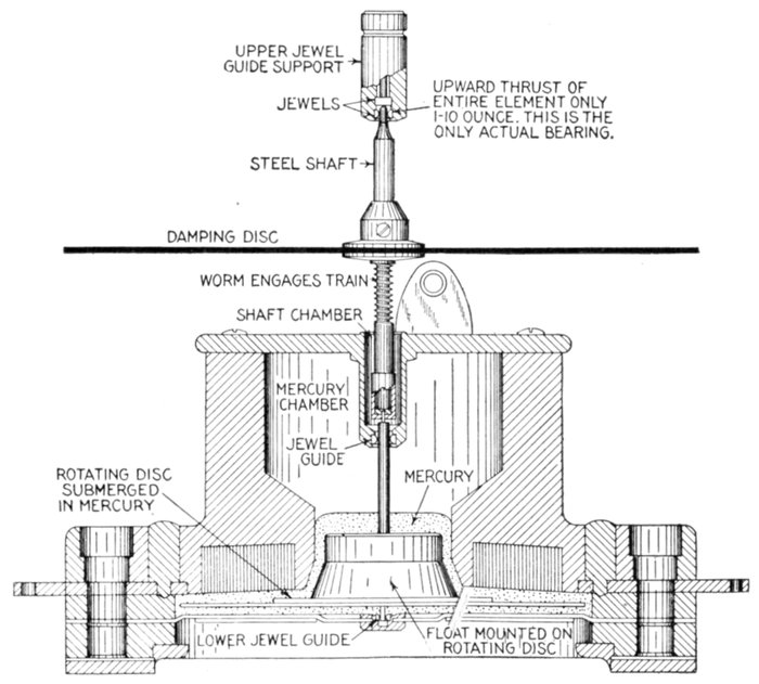
Fig. 2,560.—Sectional view of Faraday disc or mercury motor ampere hour meter as made
by Sangamo Electric Co. The illustration does not show the magnets and indicating
mechanism.
[Pg 1825]
Ques. How is the flux produced in the alternating
current form of Faraday disc meter?
Ans. By the secondary current of a series transformer.
Frequency Indicators.—A frequency indicator or meter is
an instrument used for determining the frequency, or number of
cycles per second of an alternating current. There are several
forms of frequency indicator, whose principle of operation differs,
and according to which, they may be classed as
- 1. Synchronous motor type;
- 2. Resonance type;
- 3. Induction type.
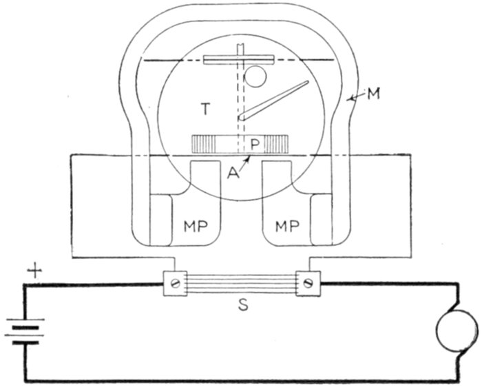
Fig. 2,561.—Circuit diagram of simple shunt Sangamo ampere hour meter. It is rated at
10 amperes, larger currents being measured by using shunts. In operation, the main or
line current to be measured passes through the shunt, while a part proportional to the
drop across the shunt, is shunted through the meter and measured. The only effect of
reversing the current will be to reverse the direction of rotation of the meter. In battery
installations it is never possible to take the same number of ampere hours from a battery
as are put into it, hence, if the simple shunt ampere hour meter be used for repeated and
successive charges and discharges, it will be necessary to reset the pointer to zero each
time the battery is fully charged. When the shunt meter is equipped with a charge stopping
device, the pointer is reset while charging, to allow for a predetermined overcharge.
[Pg 1826]
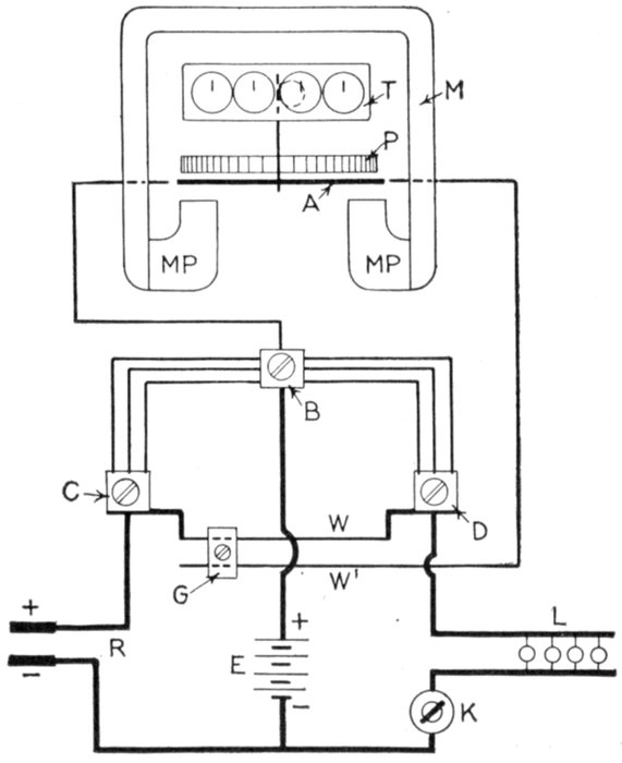
Fig. 2,562.—Circuit diagram of Sangamo differential shunt type ampere hour meter for
use in battery charging. Since a battery absorbs more energy on charge than it will give
out on discharge, at its working voltage, it is usually given a certain amount of overcharge.
This makes desirable a meter that automatically allows for the proper amount
of overcharge. Such a meter indicates at all times the amount of electricity available
for useful work without resetting the pointer every time the battery is charged. In other
words, the battery and the meter would keep in step for considerable periods of time
without readjustment. The Sangamo differential shunt meter is designed to meet these
requirements, and it consists essentially of a Sangamo meter with two shunts connected
as shown. The relative value of shunt resistance is adjustable by means of slider G, so
that the meter can be made to run slow on charge or fast on discharge, whichever may be
desired. The usual method is to allow the meter to register less than the true amount
on charge and the exact amount on discharge, the difference representing the loss in the
battery, or the overcharge. If the meter be provided with a charge stopping device, the
battery can be given an amount of overcharge predetermined by the setting of the slider
G. Therefore the amount of overcharge can be fixed in advance by a skilled man and the
actual charging done by any unskilled person, since all there is to do is to make the connection.
Ques. How is a synchronous motor employed as a
frequency indicator?
Ans. A small synchronous motor is connected in the circuit
of the current whose frequency is to be measured. After[Pg 1827]
determining the revolutions per minute by using a revolution
counter, the frequency is easily calculated as follows:
frequency = (revolutions per second × number of poles) ÷ 2.
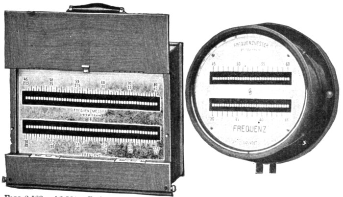
Figs. 2,563 and 2,564.—Frahm resonance type frequency meter. Fig, 2,563, portable meter;
fig. 2,564, switchboard meter. The readings are correct in either the vertical or horizontal
position. The energy consumption at 100 volts is about 1 to 2 volt amperes, and
is approximately proportional for other pressures. The regular portable meters are
arranged for pressures of from 50 to 300 volts, and for this purpose they are fitted with
terminals for 65, 100, 130, 180, and 250 volts. In order to obtain full amplitude at intermediate
pressures, a milled headed screw is provided for adjusting the base piece
mechanically, and thereby permitting of regulating the pressure range within ±20 per
cent; this insures indications of maximum clearness. Should it be desired to extend
the standard pressure range of 50 to 300 volts, up to 600 volts, two further terminals
for 350 and 500 volts are necessary, so that these instruments are provided with eight
fixed terminals in addition to the mechanical regulating device. Instruments which are
intended for connecting to one specific supply or to the secondary of a pressure transformer,
require only a single pressure range, say 100 volts, with the aforementioned regulating
device. The frequency range is from 7.5 to 600 cycles per second. In order to
obtain easily readable indications, one reed is provided for every quarter period for frequencies
below 30, for every half period for frequencies between 30 and 80, and for every
whole period for frequencies between 80 and 140. The use of a smaller number of reed,
that is to say, of larger intervals between the periods of vibration of adjoining reeds, is
only recommended for circuits having very variable frequencies, as otherwise no reed
might respond to the vibrations caused by intermediate frequencies. The arrangement
of the separate reeds on a common base piece, permits supplying any combination of
interval that may be required. It is often desirable to secure two ranges with one set
of reed. To do this a second electromagnet is supplied. It is polarized, and operates
on the same base plate. In the case of alternating current when the unpolarized magnet
is used the reeds receive two impulses during each cycle, while with the polarized magnet
they receive but one impulse per cycle. A commutator is provided to easily make
the change from one range to the other. If there be two sets of reed, the one commutator
may be connected to change both. This device is only applicable when alternating
current is measured. Instruments with unpolarized magnets are made with frequencies
of 15 to 300 cycles per second.
[Pg 1828]
Ques. Describe the resonance method of obtaining
the frequency.
Ans. In construction, the apparatus consists of a pendulum,
or reed, of given length, which responds to periodic forces having
the same natural period as itself. The instrument comprises a
number of reeds of different lengths, mounted in a row, and all
simultaneously subjected to the oscillatory attraction of an
electromagnet excited by the supply current that is being
measured. The reed, which has the same natural time period
as the current will vibrate, while the others will remain practically
at rest.
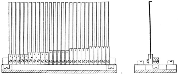
Figs. 2,565 and 2,566.—Side and end views of Frahm resonance type frequency meter reeds.
Owing to the principle employed in the meter it is evident that the indications are independent
of the voltage, change of wave form, and external magnetic fields.
The construction and operation of the instrument may be better
understood from figs. 2,565 and 2,566, which illustrates the indicating
part of the Frahm meter. This consists of one or more rows of tuned
reeds rigidly mounted side by side on a common and slightly flexible base.
The reeds are made of spring steel, 3 or 7 mm. wide, with a small
portion of their free ends bent over at right angles as shown in fig. 2,566
and enameled white so that when viewed end on they will be easily
visible. The reeds are of adjustable length, and are weighted at the end.
A piece of soft iron, rigidly fastened on the base plate which supports
the reeds, forms the armature of a magnet.
[Pg 1829]
When the magnet is excited by alternating current, or interrupted
direct current, the armature is set in vibration, and that gives a slight
movement to the base plate at right angles to its axis, thereby affecting
all the reeds, especially those which are almost in tune with its vibrations.
The reed which is in tune will vibrate through an arc of considerable
amplitude, and so indicate the frequency of the exciting current.
Ques. For what use is the resonance type of frequency
meter most desirable?
Ans. For laboratory use.
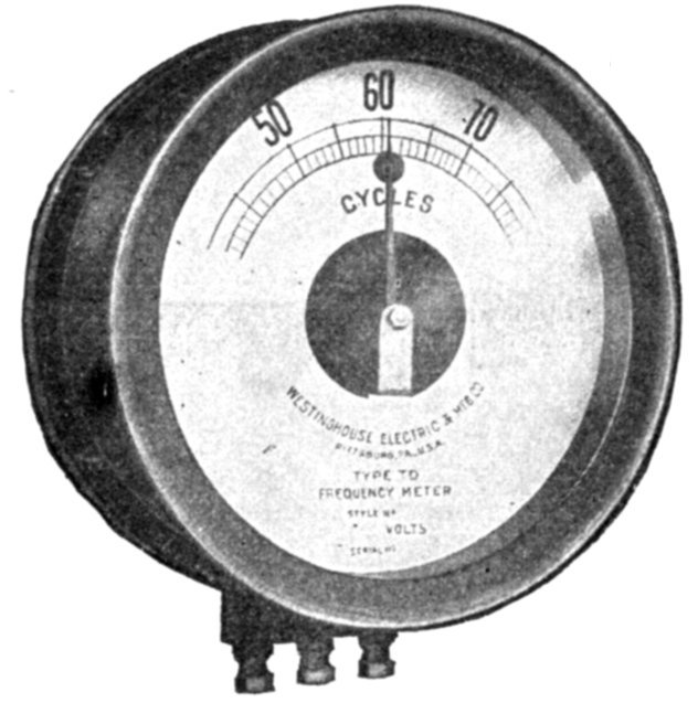
Fig. 2,567.—Westinghouse induction type frequency meter. The normal frequency is usually
at the top of the scale to facilitate reading. The damping disc moves in a magnetic field,
thus damping by the method of eddy currents. The standard meters are designed for
circuits of 100 volts nominal and can be used for voltages up to 125 volts. For higher
voltages, transformers with nominal 100 volt secondary should be used.
Ques. Describe the induction type of frequency meter.
Ans. It consists of two voltmeter electromagnets acting in
opposition on a disc attached to the pointer shaft. One of the
magnets is in series with an inductance, and the other with a
resistance, so that any change in the frequency will unbalance
the forces acting on the shaft and cause the pointer to assume a
new position, when the forces are again balanced. The aluminum
disc is so arranged that when the shaft turns in one direction[Pg 1830]
the torque of the magnet tending to rotate it decreases, while
the torque of the other magnet increases. The pointer therefore
comes to rest where the torques of the two magnets are
equal, the pointer indicating the frequency on the scale.
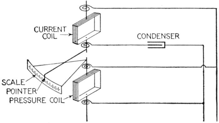
Fig. 2,568.—Langsdorf and Begole frequency meter. The operation of this meter is based
on the fact that if an alternating pressure of E Volts be impressed on a condenser of
capacity C, in farads, the current in amperes will be equal to 2π ~ EC, provided the pressure
be constant. In construction, the scale is mounted on the same axis as the pressure
coil, across the mains so as to render the instrument independent of variation of voltage.
For a discussion of this meter, see Electrical Review, vol. LVIII, page 114.
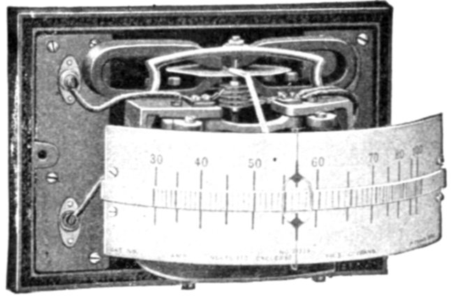
Fig. 2,569.—General Electric horizontal edgewise, induction type frequency indicator. It
is provided with an external inductance and resistance placed in a ventilated cage for
mounting on the back of the switchboard. Means are provided for adjusting the instrument
for the characteristics of the circuit on which it is installed. Standard instruments
are wound for 100 to 125 volt circuits only, but can be wound for circuits up to and including
650 volts. Instruments for use on circuits in excess of 650 volts are always
provided with pressure transformers. The normal operating point is marked at approximately
the center of the scale, thus giving the advantage of very open divisions.
The standard frequencies are 25, 40, 60,125 and 133.
[Pg 1831]
Ques. What is the object of the aluminum disc?
Ans. Its function is to damp the oscillations of the pointer.
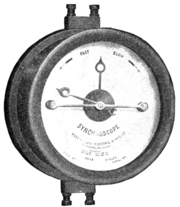
Fig. 2,570.—Westinghouse rotary type of synchroscope or synchronism indicator. The indication
is by means of a pointer which assumes at every instant a position corresponding
to the phase angle between the pressures of the busbars and the incoming machine, and
therefore rotates when the incoming machine is not in synchronism. The direction of
rotation indicates whether the machine be fast or slow, and the speed of rotation depends
on the difference in frequency. The pointer is continuously visible, during both the
dark and light periods of the synchronizing lamps.
Synchronism Indicators.—These devices, sometimes called
synchroscopes, or synchronizers indicate the exact difference in
phase angle at every instant, and the difference in frequency,
between an incoming machine and the system to which it is
to be connected, so that the coupling switch can be closed at
the proper instant. There are several types of synchronizer,
such as
- 1. Lamp or voltmeter;
- 2. Resonance or vibrating reed;
- 3. Rotating field.
[Pg 1832]
The simplest arrangement consists of a lamp or preferably
a voltmeter connected across one pole of a two pole switch
connecting the incoming machine to the busbars, the other pole
of the switch being already closed.
If the machines be out of step, the lamps will fluctuate in
brightness, or the voltmeter pointer will oscillate, the pulsation
becoming less and less as the incoming machine approaches synchronous
speed. Synchronism is shown by the lamp remaining
out, or the voltmeter at zero.
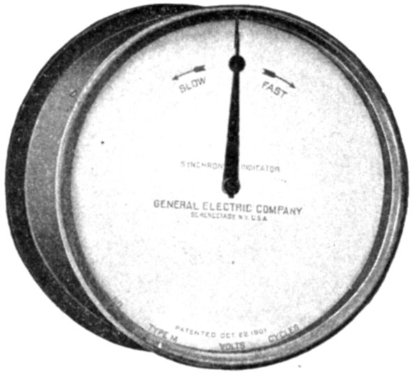
Fig. 2,571.—General Electric synchronism indicator. The synchronism indicator is
a motor whose field is supplied with single phase current from one of the machines to be synchronized,
and its armature from the other. The armature carries two inductance coils placed
at a large angle, one supplied through a resistance, the other through an inductance.
This arrangement generates a rotating field in the armature, while the stationary field
is alternating. The armature tends to assume a position where the two fields coincide
when the alternating field passes through its maximum; hence, the armature and pointer
move forward or backward at a rate corresponding to the difference of frequency, and
the position when stationary depends on the phase relation. When the machines are
running at the same frequency and in phase the pointer is stationary at the marked point.
In construction, it is like a small, two phase, bipolar synchronous motor, the field being
supplied with alternating instead of direct current. The armature is mounted in ball
bearings in order to make it sufficiently sensitive and smooth in operating. The armature
coils are not exactly 90 degrees apart, since it is not possible to get the current in
the two coils exactly in quadrature without introducing condensers on other complicated
construction. Standard ratings are for 110 and 220 volt circuits. Synchronism indicators
should be ordered for the frequency of the circuit on which they are to be operated, although
the instruments may be used on circuits varying 10 per cent to 15 per cent from the
normal. The words "Fast" and "Slow" on the dial indicate that the frequency on
binding posts E and F is respectively higher or lower than that on A and B; or, in other
words, clockwise rotation of the pointer means that the incoming machine is running at
too high speed, counter clockwise rotation indicating too low speed.
[Pg 1833]
Ques. How does the resonance type of synchronism
indicator operate?
Ans. On the same principle as the resonance type of frequency
indicator, already described.
Ques. What is the principle of the rotating field type
of synchronism indicator?
Ans. Its operation depends on the production of a rotating
field by the currents of the
metered circuits in angularly
placed coils, one for each
phase in the case of a polyphase
indicator. In this field
is provided a movable iron
vane or armature, magnetized
by a stationary coil
whose current is in phase
with the voltage of one
phase of the circuit. As the
iron vane is attracted or repelled
by the rotating field,
it takes up a position where
the zero of the rotating field
occurs at the same instant
as the zero of its own field.
In the single phase meter
the positions of voltage
and current coils are interchanged
and the rotating
field is produced by means
of a split phase winding
connected to the voltage
circuit.
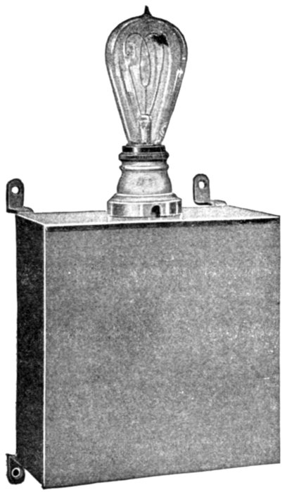
Fig. 2,572.—General Electric external resistance
and inductance for 110 volt synchronism
indicator. Both the resistance and inductance
are intended to be placed behind
the switchboard.
[Pg 1834]
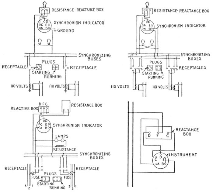
Figs. 2,573 to 2,576.—Connections of General Electric synchronism indicator. Fig. 2,573,
connections with grounded secondaries on pressure transformers; fig. 2,574, connections
with ungrounded secondaries on pressure transformers; fig. 2,575, connections for 200 to
240 volt circuits, with six point receptacles; fig. 2,576, connections for checking location of
needle. The various letters referred to in the diagrams will be found marked on the
ends of the instrument studs and back of reactance coil box. It is important that the
instrument be connected in circuit in the proper manner so that the needle will come
to the mark on the upper part of the scale when synchronism is obtained. In case the
pointer become moved or a change in its position be necessary, it is advisable to make a
check on the indication before relocating the needle. This test can be made as follows:
Connect together (fig. 2,573) studs marked B and E and connect stud A to terminal F
on the external reactance box. When these connections are made, the instrument can
be connected to a single phase circuit of normal voltage and if the instrument be correct,
the pointer will stand vertically at the point of synchronism. If it do not, the needle
can be moved and should be fastened in the correct position. The synchronizing lamps
when connected as illustrated in the diagrams, show dark when synchronism is reached.
This is the only connection possible when grounded secondaries are used, as in fig. 2,573,
and for the high voltage indicators when used as in fig. 2,575, but with ungrounded secondaries
(fig. 2,574) the lamps may be connected as indicated, when they will show bright
at the moment of synchronism. The connections to the synchronism indicator remain the
same as before.
[Pg 1835]
Power Factor Indicators.—Meters of this class indicate the
phase relationship between pressure and current, and are therefore
sometimes called phase indicators. There are two types:
- 1. Wattmeter type;
- 2. Disc, or rotating field type.
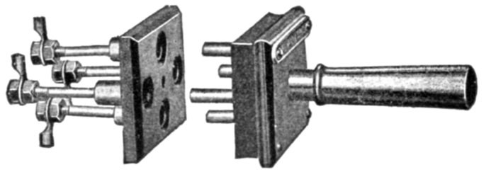
Fig. 2577.—General Electric synchronizing receptacle and plug for use with synchronism
indicator.
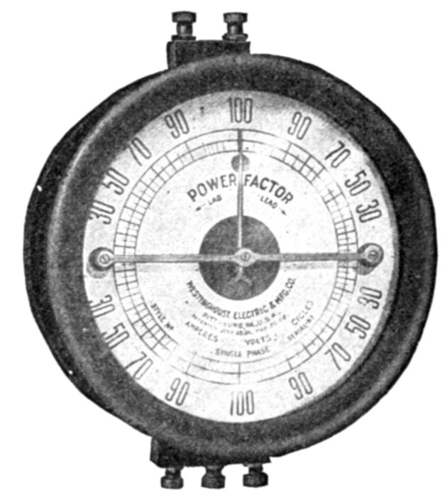
Fig. 2,578.—Westinghouse rotating field type power factor meter. The rotating field is produced
by the currents of the metered circuits in angularly placed coils, one for each phase
of the system, in the case of polyphase meters. In the three phase meter the rotating
field is produced by three coils spaced 60° apart; in the two phase meter by two coils
spaced 90°; in the single phase meter the positions of voltage and current coils are interchanged
and the rotating field is produced by means of a split phase winding, connected
to the voltage circuit. There are no movable coils or flexible connections. Single
phase meters indicate the power factor of a single phase circuit, or of one branch of
any polyphase circuit. Special calibration is necessary in order to use a single phase
instrument on a three phase circuit unless the voltage coil be connected from one line
to the neutral. Polyphase meters indicate the average angle between the currents and
voltages and are superior for polyphase service to meters having only one current coil.
[Pg 1836]
In the wattmeter type, the phase relation between the pressure and
the current fluxes is such that on a non-inductive load the torque is zero.
For instance, in a dynamometer wattmeter, the pressure circuit is
made highly inductive and the instrument then indicates
volts × amperes × sin φ instead of volts × amperes × cos φ,
that is to say, it will
indicate the wattless component of the power. A dynamometer of this
type is sometimes called an idle current wattmeter.
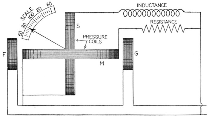
Fig. 2,579.—Single phase power factor meter of the rotating field or disc type.
Ques. Describe a single phase power factor meter of
the disc or rotating field type.
Ans. It consists of two pressure coils, as shown in fig. 2,579,
placed at right angles to each other, one being connected through
a resistance, and the other through an inductance so as to "split"
the phase and get the equivalent of a rotating magnetic field.
The coils are placed about a common axis, along which is pivoted an
iron disc or vane. The magnetizing coils FG are in series with the load.
If the load be very inductive, the coil M experiences very little torque and
the system will set itself as shown in the figure. As the load becomes less
inductive, the torque on S decreases and on M increases so that the
system takes up a particular position for every angle of lag or lead.
Ground Detectors.—Instruments of this name are used for
detecting (and sometimes measuring) the leakage to earth or[Pg 1837]
the insulation of a
line or network and
are sometimes
called ground or
earth indicators, or
leakage detectors.
For systems not permanently
earthed anywhere,
these instruments are nearly
all based on a measurement
of the pressure difference
between each pole and earth,
two measurements being required
for two wire systems,
and three for three wire,
whether direct current single
phase, or polyphase alternating
current. In the case of direct current
systems, the insulation, both
of the network and of the individual
lines, can be calculated from the readings,
but with alternating current,
the disturbance due to capacity effects is
usually too great. In any case, however,
the main showing the smallest pressure
difference to earth must be taken as
being the worst insulated.
For low tension systems moving
coil (for alternating current)
or moving iron instruments
(for direct current) are the
most used, while for high tension
systems electrostatic
voltmeters are to be
preferred. On systems
having some point permanently
earthed at the
station, as for instance the
neutral wire of direct current
system, or the neutral point
of a three phase system, an
ammeter connected in the
earth wire will serve as a
rough guide. It should indicate
no current so long as
the insulation is in a satisfactory
state, but on the occurrence
of an earth it will
at once show a deflection.
The indications are, however,
often misleading, and
serve more as a warning than
anything else.
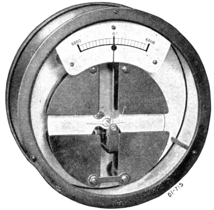
Fig. 2,580.—Westinghouse single phase electrostatic ground detector.
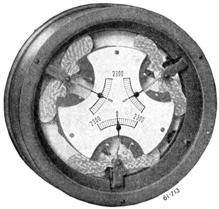
Fig. 2,581.—Westinghouse three phase electrostatic ground detector.
[Pg 1838]
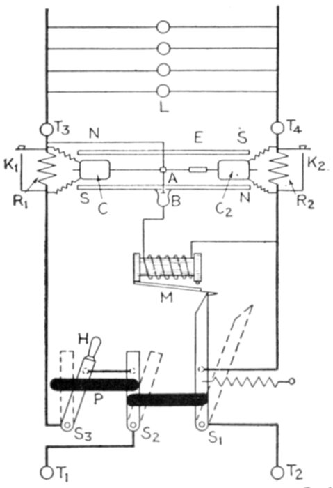
Fig. 2,582.—Wallis-Jones automatic earth leakage cut out. It is an instrument which so
protects a direct current circuit that the circuit is broken whenever a leak occurs from
either main to earth, and so that the circuit cannot be permanently re-established until the
leak has been removed. The instrument and its connections may be explained by the
aid of the accompanying diagram, in which T1 and T2 represent the points of connection
from the mains, and T3 and T4, the points of connection to the circuit to be protected. So
S2, and S3 will preferably be ordinary tumbler switches, but they are diagrammatically
represented as plain bar switches, their fixed contacts being diagrammatically represented
by dotted circles. When the three switches S1, S2, and S3 are closed, the current passes from
T1 to T3 through the small resistance R1, through circuit L to T4, and back through the
resistance R2 to T2. In shunt with R1 and R2, are the two moving coils C and C2, working
in the magnetic field of the magnets NS, NS, and rigidly fixed on one spindle, which is
broken electrically by an ebonite block E. The points of connection to the shunts are
adjusted so that when the same current passes out through one and back through the other,
the effect on the two coils is equal and opposite, and there is thus no movement. Should,
however, any minute portion of the current through R1 leak to earth instead of returning
via R2, the balance is disturbed, C becomes stronger than C2, the system is deflected, and
a contact is made by the arm A at B, no matter in which direction the coils deflect. The
system is similarly deflected for a leak on the other lead. In the diagram these contacts
are shown at right angles to their normal plane. As soon as the contact is made, the electromagnet
M is energized, the arm of S1 is released and the spring at once pulls it off its contact,
at the same time breaking S2. The positions of the blades when the switches are
open are shown dotted. The only means the user has of closing the circuit is by putting
on S3 by the handle H, which is outside the locked box. The first effect of putting on S3
is to break its circuit; it then by means of the slotted bar P begins to pull on S2 and S1, which
can thus be closed again, and held closed by the trigger as before. The circuit, is, however,
still broken till S2 is pushed back. Then if the leak be still on, the slot in P allows S1
and S2 to open at once as before. It is therefore impossible to keep the circuit closed
while the leak exists. The working condition of the instrument can be tested at any time
by switching a lamp on in the circuit and depressing one of the keys K1, K2. This short
circuits R1 or R2, throws the coils out of balance, and the switch opens. The contact arm
is closed in an inner dust tight case, and it will be noted that it makes contact only; the
break occurs at the switches, thus avoiding any sparking. Since the two coils work in the
two gaps of one and the same field, changes in the strength of the magnets have no effect,
the apparatus is enclosed in a locked metallic box, and the only part to which the user
has access is the handle H, and, if desired, the testing keys K1 K2.]
[Pg 1839]
HAWKINS PRACTICAL LIBRARY OF
ELECTRICITY
IN HANDY POCKET FORMPRICE $1 EACH
They are not only the best, but the cheapest work published on Electricity.
Each number being complete in itself. Separate numbers sent postpaid to
any address on receipt of price. They are guaranteed in every way or
your money will be returned. Complete catalog of series will be mailed
free on request.
ELECTRICAL GUIDE, NO. 1
Containing the principles of Elementary Electricity, Magnetism,
Induction, Experiments, Dynamos, Electric Machinery.
ELECTRICAL GUIDE, NO. 2
The construction of Dynamos, Motors, Armatures, Armature
Windings, Installing of Dynamos.
ELECTRICAL GUIDE, NO. 3
Electrical Instruments, Testing, Practical Management of Dynamos
and Motors.
ELECTRICAL GUIDE, NO. 4
Distribution Systems, Wiring, Wiring Diagrams, Sign Flashers,
Storage Batteries.
ELECTRICAL GUIDE, NO. 5
Principles of Alternating Currents and Alternators.
ELECTRICAL GUIDE, NO. 6
Alternating Current Motors, Transformers, Converters, Rectifiers.
ELECTRICAL GUIDE, NO. 7
Alternating Current Systems, Circuit Breakers, Measuring Instruments.
ELECTRICAL GUIDE, NO. 8
Alternating Current Switch Boards, Wiring, Power Stations,
Installation and Operation.
ELECTRICAL GUIDE, NO. 9
Telephone, Telegraph, Wireless, Bells, Lighting, Railways.
ELECTRICAL GUIDE, NO. 10
Modern Practical Applications of Electricity and Ready Reference
Index of the 10 Numbers.
Theo. Audel & Co., Publishers.
72 FIFTH AVENUE,
NEW YORK
TRANSCRIBER'S NOTES
Silently corrected simple spelling, grammar, and typographical errors.
Retained anachronistic and non-standard spellings as printed.
*** END OF THE PROJECT GUTENBERG EBOOK 49253 ***