THE THOUGHT IS IN THE QUESTION THE INFORMATION IS IN THE ANSWER
2
THEO. AUDEL & CO. 72 FIFTH AVE. NEW YORK.
COPYRIGHTED, 1914,
BY
THEO. AUDEL & CO.,
NEW YORK.
Printed in the United States.
3
| THE ARMATURE | 221 to 228 |
|---|---|
|
|
| ARMATURE WINDINGS | 229 to 256 |
|
|
| THEORY OF THE ARMATURE | 257 to 282 |
|
|
| COMMUTATION AND THE COMMUTATOR | 283 to 302 |
|
|
| BRUSHES AND THE BRUSH GEAR | 303 to 320 |
|
|
| ARMATURE CONSTRUCTION | 321 to 348 |
|
|
| MOTORS | 349 to 388 |
|
|
| SELECTION AND INSTALLATION | 389 to 406 |
|
|
| AUXILIARY APPARATUS | 407 to 430 |
|
|
The armature of a dynamo consists of coils of insulated wire wound around an iron core, and so arranged that electric currents are induced in the wire when the armature is rotated in a magnetic field or the field magnets rotated and armature held stationary.
The commutator is in fact a part of the armature, but is of sufficient importance to be considered in a separate chapter.
Ques. What are the practical objections to the elementary armature, described in fig. 165?
Ans. It induces a very feeble current, which is not of constant pressure, but pulsating; that is, it consists of two pronounced impulses in each revolution as shown in fig. 168.
Ques. Why does the elementary armature produce a pulsating current?
Ans. The pulsations are due to the coil moving alternately into, and out of, the positions of best and least action in the magnetic field.
Ques. How is a continuous current, or one of uniform pressure obtained?
Ans. If an additional coil be added to the elementary armature, at right angles to the existing coil, and its ends suitably connected to a four part commutator, as in fig. 185, so that 222 one coil is in the position of best action, while the other is in the position of least action, the pulsations of the resulting current will be of less magnitude. By increasing the coils and suitably altering the construction of the commutator to accommodate the ends of these coils, the resultant current may be represented by practically a straight line, indicating the so called continuous current, instead of the wavy resultant curve No. 6, as illustrated in fig. 187.
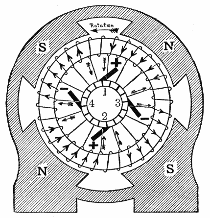
Fig. 247.—Ring armature of four pole dynamo: diagram of winding and connections, showing direction of the induced currents. The currents in the windings under the upper N and S poles are opposed to each other and flow to the external circuit by the positive brush 1, and back to this half of the armature by the negative brushes 3 and 4. At the same instant the opposed currents in the lower windings flow to the external circuit by positive brush 2 and return to the armature through negative brushes 3 and 4. The armature is thus divided into four circuits and four brushes are required which must be placed between the poles so as to short circuit the coils as they pass through the neutral space. In this form of winding there is no difference of potential between the + brushes, so that they are connected in parallel, as are also the negative brushes, and then to the external circuit. In multipolar machines there are as many brushes as pole pieces. Since opposite commutator bars are of the same potential on this four pole dynamo they may be joined by a cross connecting wire and two brushes, as 2 and 4, dispensed with. This can only be done when there is an even number of coils. The armature is said to be "cross connected."
An armature for practical use has a large number of coils, suitably arranged upon an iron core, so that a large proportion of them are always actively cutting the lines of force, or moving into the positions of best action in the magnetic field.
223
Types of Armature.—Although there are many forms of armature, all may be divided into three classes, according to the arrangement of the coils or winding on the core, as:
1. Ring armatures;
2. Drum armatures;
3. Disc armatures.
Each of these forms of armature has its own special advantages for particular purposes, the disc type being least in favor and not having had any extensive application in this country.
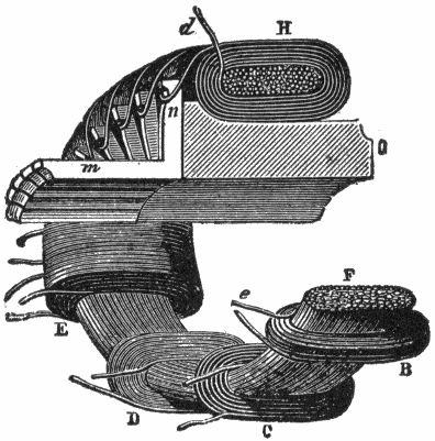
Fig. 248.—Early form of Gramme ring armature, the core being shown cut through, and some of the coils displaced to make it clearer. The core, F, consists of a quantity of iron wire wound continuously to form a ring of the shape shown by the section. Over this is wound about thirty coils of insulated copper wire, B C D, etc., the direction of the winding of each being the same, and their adjacent ends connected together. The commutator segments consist of a corresponding number of brass angle pieces, m, n, which are fixed against the wooden boss, o, carried on the driving shaft. The junction of every two adjacent coils is connected to one of the commutator segments, as shown at n.
Ques. What is the comparison between ring and drum armatures?
Ans. The drum armature is electrically and mechanically the more efficient, possessing, as it does, possibilities in the way of better mechanical construction of the core, and in the 224 arrangement and fixing of the inductors thereon not to be found in the ring form. Less wire and magnetizing current are required for the field magnets for a given output than with the ring armature. Drum winding is not so simple as ring winding, and it is more difficult to ventilate a drum than a ring armature, it being necessary to provide special ventilating ducts.
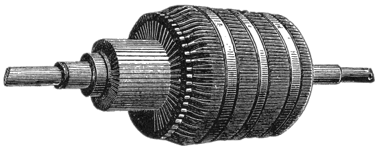
Fig. 249.—Modern form of Gramme ring armature. The core consists of a number of thin flat rings of well annealed charcoal iron, the outer diameter of each ring or disc being 11½ inches, and its inner diameter 9¼ inches. Sheets of thin paper insulate each disc from its neighbors to prevent the flow of eddy currents. The armature is mounted on a steel shaft to which is keyed a four armed metal "spider," the extremities of whose arms fit into notches cut in the inner edges of the soft iron core rings, so that a good mechanical connection is obtained between the core and the shaft. The spider is made of a non-magnetic metal, to reduce the tendency to leakage of lines of force across the interior of the armature. The armature inductors consist of cotton covered copper wire of No. 9 standard wire gauge, wound around the core in one layer, and offering a resistance, from brush to brush, of 0.048 ohm. There are two convolutions in each section, the adjacent ends of neighboring sections being soldered to radial lugs projecting from the commutator bars.
Ques. Describe a ring armature.
Ans. It consists essentially of an iron ring, around which is wound a number of coils. These various coils are wound on separately, the wire being carried over the outside of the ring, then through the center opening and again around the outside, this operation being repeated until the winding for that individual section is completed. The adjacent coil is then wound in the same way, the ends of each being brought out to the commutator side of the armature, the arrangement of 225 the coils on the ring and connections with the commutator being shown in fig. 247, examples of actual construction being shown in figs. 248 and 249.
Ques. For what conditions of operation is the ring armature specially adapted, and why?
Ans. It is well suited to the generation of small currents at high voltage, as for series arc lighting, because the numerous coils can be very well insulated.
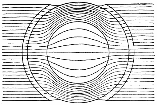
Fig. 250.—Distribution of magnetic lines of force through a Gramme ring. Since the metal of the ring furnishes a path of least reluctance, most of the magnetic lines will follow the metal of the ring and very few will penetrate into the aperture of the interior. This condition causes a serious defect in the action of ring armatures rendering the winding around the interior useless for the production of electromotive force. Hence, in ring armatures only about half of the winding is effective, the rest or "dead wire," adding its resistance to the circuit, thus decreasing the efficiency of the machine.
Ques. Why does a ring armature require more copper in the winding than a drum armature?
Ans. For the reason that those inductors which lie on the inner side of the iron ring, being screened from practically all the lines of force, as shown in fig. 250, do not generate any current.
226
Numerous attempts have been made to utilize this part of the winding by making the pole pieces extend around the ring in such a manner that lines of force will pass to the inside of the ring, also by arranging an additional pole piece on the inside of the armature, but mechanical considerations have shown these methods to be impractical.
Ques. Is any portion of the winding of a drum armature inactive?
Ans. Yes; the end connectors do not generate any current.
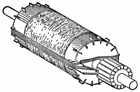
Fig. 251.—Illustrating the principle of Siemens' drum winding. In order to make the winding and connections clear, one coil and the commutator is shown assembled, although the latter is not put in place until after all the sections have been wound, the ends of the wires being temporarily twisted together until all can be soldered to the risers. The cores of these early machines were of wood overspun circumferentially with iron wire before receiving the longitudinal copper windings.
Ques. What is the chief advantage of the drum armature?
Ans. It reduces considerably the large amount of dead wire necessary with the ring type.
227
Ques. How is this accomplished?
Ans. By winding the wire entirely on the outer surface of a cylinder or drum, as it is called, as shown in fig. 251, thus none of the wire is screened by the metal of the core.
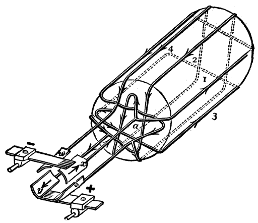
Fig. 252.—Elementary four coil drum winding, showing the connections with the commutator segments, and directions of currents in the several coils. The action of this type of armature is fully explained in the text.
Fig. 252 shows an elementary four coil drum armature. Starting from the point a and following the winding around without reference at first to the commutator, it will be found that the rectangular turns of the wire form a closed circuit, and are electrically in series with one another in the order of the numbers marked on them.
With respect to the connections to the four segments w, x, y, z, of the commutator it will be found that at two of these, x and y, the pressures in the windings are both directed from, or both directed toward the junction with the connecting wire. At the other two segments, z and w, one pressure is toward the junction and the other directed from it. If, therefore, the brushes be placed on x and y they will supply current to an external circuit, z and w, for the moment being idle segments.
228
Disc Armatures.—The inductors of a disc armature move in a plane, perpendicular to the direction of the lines of force, about an axis parallel to them as shown in fig. 253. The main difficulty with this type has been in constructing it so that it will be strong and capable of resisting wear and tear. It was introduced in an effort to avoid the losses due to eddy currents and hysteresis present in the other types of armature.
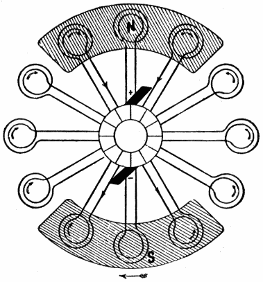
Fig. 253.—Disc armature of Niaudet. It is equivalent to a ring armature, having the coils turned through an angle of 90°, so that all the coils lie in a plane perpendicular to the axis of rotation. The connections of the coils with each other and with the commutator remain the same, the beginning and the end of adjacent coils leading to a common commutator bar as shown. The magnetic field is arranged by the use of two magnets, so arranged as to present the north pole of one to the south pole of the other, and vice versa. In the figure one of these magnets is considered as above the paper, and the other below. If this armature be rotated through the magnetic field as shown, a reversal of current takes place in each coil, when it is in such a position that one of its diameters coincides with the pole line, NS. If the brushes be set so as to short circuit the coils that are in this position, the armature will be divided into two branchings, the current flowing in an opposite direction in each, and a direct current will flow in the exterior circuit.
On account of the nature of the construction of a disc armature, it is necessary that the coils subject to induction occupy as small a space as possible in the direction of their axes. This requirement, as well as the connection of the inductors with each other and with the commutator, prevented the general adoption of this form of armature, and subsequent experience failed to justify the existence of the type.
229
To connect up rightly the inductors on an armature so as to produce a desired result is a simple matter in the case of ring winding, for bipolar or multipolar machines. It is a less easy matter in the case of drum winding, especially for multipolar machines. Often there are several different ways of arriving at the same result, and the fact that methods which are electrically equivalent may be geometrically and mechanically different makes it desirable to have a systematic method of treating the subject.
The elementary arrangement of drum and disc armatures has already been considered, which is sufficient explanation for small armature coils of only a few turns of wire, but in the case of larger machines which require many coils, further treatment of the subject is necessary.
For example, in order to direct the winder how to make the connections for, say a four pole machine having 100 bars spaced around its armature, some plain method of representing all the connections so that they may be easily understood is necessary. From this the workman finds out whether he is to connect the front end of bar No. 1 across to 50 or across a quarter of the circumference to 24, or across three quarters of it to bar 75. Again, he ascertains to which bar he is to connect the back1 end of the bar, and how the bars are to be connected to the commutator.
230
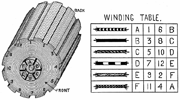
Winding Diagrams and Winding Tables.—In the construction of armatures, instructions to winders are given in the form of diagrams and tables. In the tables the letters F and B stand for front and back, meaning toward the front end, and from the front end respectively. The letters U and D stand for up and down.
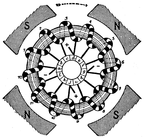
Fig. 254.—End of ring winding for a four pole machine. An end view is simply a view showing the arrangement of the armature inductors and connections looking from the front or commutator end. A developed view of the above winding is shown in fig. 257.
There are three kinds of winding diagram:
1. End view diagram;
2. Radial diagram;
3. Developed diagram.
The end view is simply a view showing the arrangement of the armature inductors and connections looking from the front or commutator end, such as shown in fig. 254.
231
In the radial diagram the inductors of the armature are represented by short radial lines, while the end connectors are represented by curves or zigzags, those at one end of the armature being drawn within, those at the other end, without the circumference of the armature. With the radial diagram it is easier to follow the circuits and to distinguish the back and front pitch of the winding.
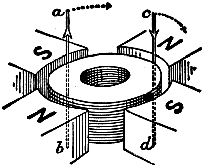
Fig. 255.—Partial sketch of a four pole machine laid on its side. If the observer imagine himself placed at the center, and the panorama of the four poles to be then laid out flat, the developed view thus obtained would appear as in fig. 256.
The developed diagram is a mode of representation, originally suggested by Fritsche of Berlin, in which the armature winding is considered as though the entire structure had been developed out of a flat surface. This is best explained by aid of figs. 255 and 256.
If in fig. 255, which represents an armature core and a four pole field, wires a and c be placed parallel to the axis of the armature to represent two of the armature inductors, and moved along the air gap space clockwise past the S poles, they will cut magnetic lines inducing electromotive forces in the directions indicated. To attempt to show a large number of inductors in a drawing of this kind would be unintelligible. Accordingly, the observer is considered as being placed at the center of the armature, and the panorama of the four poles surrounding him to be then laid out flat or "developed" as in fig. 256.
232
The faces of the N and S poles are shaded obliquely for distinction. By choosing the proper directions for these oblique lines, a piece of paper having a narrow slit to represent the wire may be laid over the drawing of the pole and when moved, as indicated by the dotted arrows to the right, the slit in passing over the oblique lines will cause an apparent motion in the direction in which the current in reality tends to flow. It is easily remembered which way the oblique lines must slope, for those on the N pole slope parallel to the oblique part of the letter N.
Lap Winding and Wave Winding.—In winding armatures there are two distinct methods employed, known respectively as lap and wave winding. The distinction arises in the following manner: Since the inductors, in passing a north pole generate electromotive forces in one direction, and in passing a south pole generate electromotive forces in the opposite direction, it is evident that an inductor in one of these groups ought to be connected to one in nearly a corresponding position in the other group, so that the current may flow down one and up the other in agreement with the directions of the electromotive forces. The order followed in making these connections gives rise to lap and wave windings.
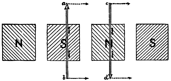
Fig. 256.—Developed view of the four pole field shown in perspective in fig. 255.
233
Ques. What is lap winding?
Ans. One in which the ends of the coils come back to adjacent segments of the commutator; the coils of such a winding lap over each other.
Ques. What is a wave winding?
Ans. One in which the coil ends diverge and go to segments widely separated, the winding to a certain extent resembling a wave.
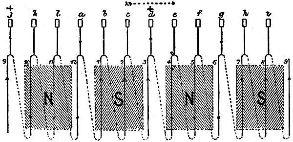
Fig. 257.—Development of ring winding of four pole machine shown in fig. 254. The dead wire or inactive inductors on the inside of the ring are shown in dotted lines, the full lines representing the active portion of the winding.
Angular Pitch or Spread of Drum Coils.—Before taking up the winding as a whole, the form of the individual coil should be considered. Fig. 260 shows an end view of one coil in position on a drum armature of a multipolar machine. The two slots X and Y contain the sides of the coil and the distance between them on the surface of the drum is called the angular pitch or spread of the coil. Theoretically this is equal to the 234 235 pitch of the poles, represented by the angle M, which is the angle between the pole centres.
Figs. 258 and 259.—Wooden armature core and winding table for practice in armature winding. By using strings of different colors to represent the various coils, the path of each coil is easily traced when the winding is completed, as in fig. 263.
For instance, on a four pole machine the pitch would be 90°, on a six pole machine, 60°, etc. Usually the angular pitch of the coil is made just a little less than the pole pitch of the machine, in order to shorten the end connections of the coils from slot to slot. However, if the angular pitch be made too small trouble will be encountered in commutation.
In addition to the angular pitch there is the commutator pitch which relates to the distance around the commutator bridged by the ends of the coil. Thus, if the commutator segments were numbered consecutively 1, 2, 3, etc., and the commutator pitch say is 10, it would signify that one end of the coil was connected to segment 1 and the other end to segment 11; the ends of the next coil in order then would be connected to segments 2 and 12, in each case there would be ten segments between the two segments connecting with the coil ends.
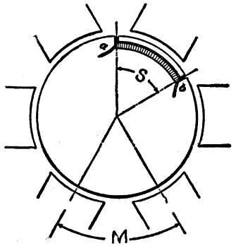
Fig. 260.—End view of drum armature of a multipolar machine showing one coil in position to illustrate the angular pitch or spread of drum coils.
Parallel or Lap Drum Winding.—In order to avoid much of the difficulty usually experienced by students of drum winding, the beginner should construct for himself a wooden armature core upon which he can wind strings of various colors, or wires with distinctive insulation, to represent the numerous coils that are used on real armatures. A few windings attempted in this way will make clear many points that cannot be so easily grasped from a written description.
236
The type of drum core best adapted for this work is the slotted variety as shown in fig. 258, as it will facilitate the winding. The core as shown in the illustration has twelve slots and six commutator segments, the number of each required for the example of lap winding indicated in the winding table fig. 259.
In making the wooden core, the slots may be formed by nailing a series of thin strips around a cylindrical piece of wood, thus avoiding the trouble of cutting grooves. In the illustrations the commutator segments are shortened (leaving no room for brushes) in order to show the connections as clearly as possible.
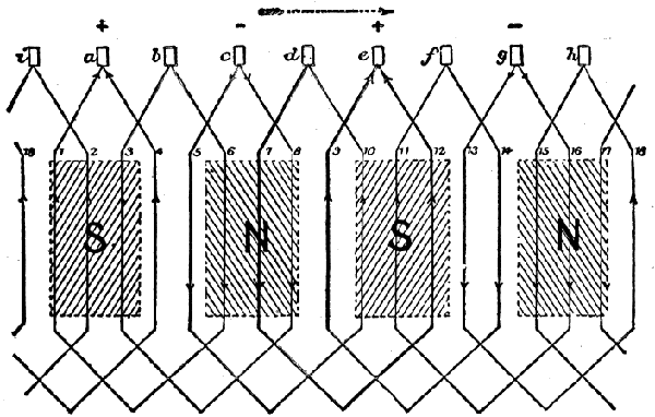
Fig. 261.—Developed view of a typical lap winding. From the figure it is seen that at the back of the armature each inductor is united to one five places further on, that is, 1 to 6, 3 to 8, etc., and at the front end of the winding, after having made one "element," as for example d-7-12-e, then forms a second element e-9-14-f which "laps" over the first, and so on all around until the winding returns on itself.
Ques. Describe the simple lap winding fig. 259.
Ans. As given in the table, it consists of six loops of wire presenting twelve inductors on the cylindrical surface of the core or drum. In the table, six wires are shown, having 237 distinctive and varied insulation so as to readily distinguish the different coils. Opposite these are letters and figures designating the path and connections of each coil.
Ques. What is the path of the first coil?
Ans. According to the table it is:
A — 1 — 6 — B
that is, one end of the wire is connected to commutator segment
A (fig. 262) and then wound to the back of the drum through
slot 1, across the back of the drum to slot 6, returning through
this slot, and then connected with commutator segment B.
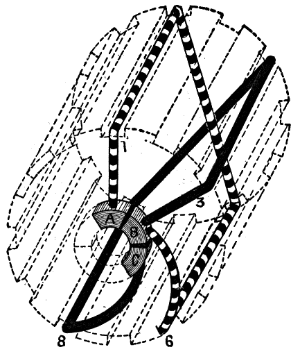
Fig. 262.—Skeleton view of wooden armature core showing in position the first two coils of the winding indicated in the table fig. 259.
Ques. Describe the path of the second coil.
Ans. The second coil, having the block insulation, is wound
according to the table, in the order:
238
B — 3 — 8 — C
that is, beginning at segment B, thence to back of drum through
slot 3, across the back to slot 8, returning through this slot and
ending at segment C.
The completed winding of the first two coils are shown in fig. 262, the drum being shown in dotted lines so that all of each coil may be visible.
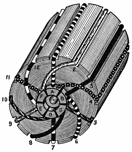
Fig. 263.—View of completed winding as indicated in the table fig. 259. Thus the path of the first coil, according to the table is A-1-6-B which means that the coil begins at segment A of the commutator, rises to slot 1, and proceeds through the slot to the back of the drum; thence across the back to slot 6, through the slot and ending at segment B. The other coils are wound in similar order as indicated in the table.
Ques. How are the remaining coils wound on the drum?
Ans. Each of the succeeding coils are wound as indicated in the table, the last connection being made to segment A, the one from which the winding started.
239
Ques. What is the general form of the completed winding?
Ans. It may be considered simply as a wire wound spirally around the drum, with loops brought down to the commutator segments, and ending at the segment from which the start was made.
The completed winding as indicated by the table is shown in fig. 263. Here the path of each coil is easily distinguished by means of the varied insulations although in part hidden by the drum. Fig. 264 shows a developed view of the winding.
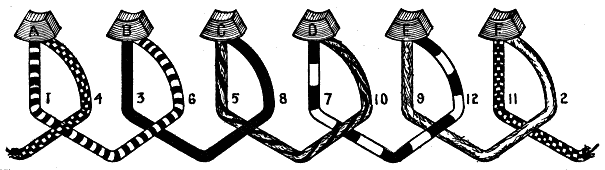
Fig. 264.—Developed view of the winding shown in perspective in fig. 263.
Ques. What condition must obtain in winding an even number of coils?
Ans. The wire must not be wound around the drum to diametrically opposite positions, as for instance 1 to 7 in fig. 265.
Ques. Why is this?
Ans. The reason will be clearly seen by attempting the winding on the wooden core. A winding of this kind on the drum fig. 258, would proceed as follows:
| A | — | 1 | — | 7 | — | B |
| B | — | 3 | — | 9 | — | C |
| C | — | 5 | — | 11 | — | D |
240
In order now to continue winding in a regular way, the wire from segment d should pass to the rear of the armature along space 7, but this space is already occupied by the return of the first coil. Continuing the winding from this point, it would be necessary to carry the wire from segment d to 6 or 8, resulting in an unbalanced winding.
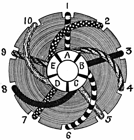
Fig. 265.—Lap winding for bipolar machine, with uneven number of coils; in this case the rear connectors may be made directly across a diameter as shown.
Ques. How is a symmetrical winding obtained having an even number of coils?
Ans. The inductors, in passing from the front to the rear of the armature, fig. 263, must occupy positions 1, 3, 5, 7, 9, 11, and the even numbered positions will then serve as the returns for these wires.
In the example here shown there are six coils, comprising twelve inductors and six commutator segments; it should be noted, however, that if there were an uneven number of coils, the rear connections 241 could be made directly across a diameter as shown in fig. 265, which would give a symmetrical winding.
With ten slots as shown in the figure, the drum would be wound, for a bipolar machine, according to the following table:
| A | — | 1 | — | 6 | — | B |
| B | — | 3 | — | 8 | — | C |
| C | — | 5 | — | 10 | — | D |
| D | — | 7 | — | 2 | — | E |
| E | — | 9 | — | 4 | — | F |
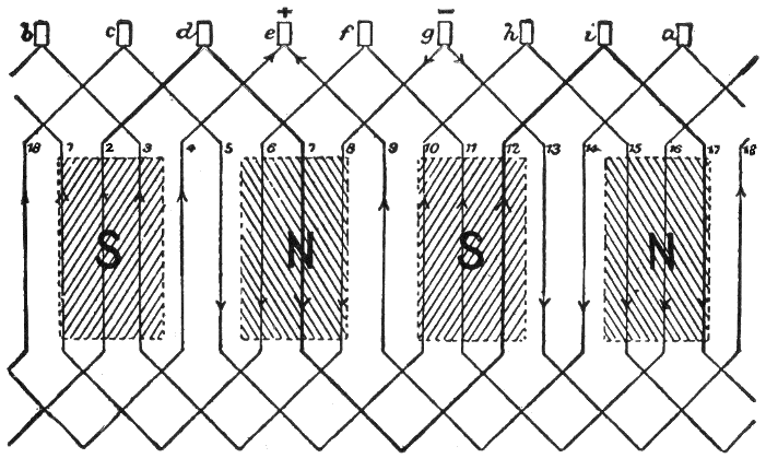
Fig. 266.—Developed view of a typical wave winding. This winding, instead of lapping back toward the commutator segment from whence it came, as in lap winding, turns the other way. For instance, d-7-12 does not return directly to e, but goes on to i, whence another element i-17-4-e continues in a sort of zigzag wave.
Ques. Are coils such as shown in figs. 263 and 265 used in practice?
Ans. No, for practical use each coil would consist of several turns, the diagram then merely indicates the end connections and slots for the several turns of each coil.
Series or Wave Drum Winding.—In this mode of winding, the inductors are arranged around the armature so that they do not turn back, thus describing a zigzag or wave-like path; that 242 is, the coil ends instead of connecting with adjacent segments of the commutator, are attached to segments more or less remote.
Ques. Describe the circuits of a simple or simplex wave winding.
Ans. Only two sets of brushes are required for such a winding, but as many brushes as there are poles can be used.
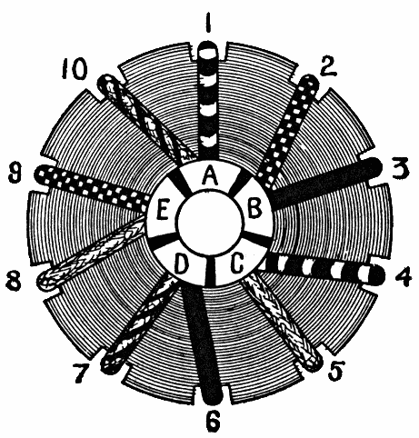
Fig. 267.—Five coil wave winding for a four pole machine. In this winding only two brushes are used, there being only two paths through the armature.
Ques. For what service are wave windings adapted?
Ans. They are generally used on armatures designed to furnish a current of high voltage and low amperage.
An example of wave drum winding for a four pole machine is shown in fig. 267. For simplicity, very few coils are taken, there being only five as shown in the illustration. To make the winding, one strip should be removed from the wooden core and the others spaced equally around the cylindrical surface. This will give ten slots, the number required for the five coils. The winding is indicated in the following table:
243
| A | — | 1 | — | 4 | — | C |
| B | — | 3 | — | 6 | — | D |
| C | — | 5 | — | 8 | — | E |
| D | — | 7 | — | 10 | — | A |
| E | — | 9 | — | 2 | — | B |
Accordingly the first coil starting at segment A, is carried to the back of the drum through slot 1, thence across the back and returning through slot 4, ending at segment C the starting point of the second coil. Each coil is wound on in similar manner, the last coil ending at segment A, the starting point of the first coil. A developed view of the winding is shown in fig. 268.
Double Windings.—In the various drum windings thus far considered, each coil had its individual slots, that is, no two occupied the same two slots. This arrangement gave twice the number of slots as commutator segments.
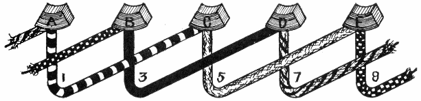
Fig. 268.—Developed view of the five coil wave winding shown in fig. 267.
In a double winding there are as many segments as slots, each of the latter containing two inductors, comprising part of two coils.
The Siemens Winding.—In winding drum armatures for bipolar dynamos of two horse power or less, and especially for very small machines as used in fan or sewing machine motors, a form of winding, known as the Siemens winding, which is shown in fig. 271, is largely used. It consists in dividing the surface of the armature core in one equal number of slots, say 16, and using a 16 part commutator.
244
In the Siemens winding, the end of the wire used at the start is to be connected to the first commutator bar, but must be fastened to the armature core out of the way so as not to interfere with the winding of the coils.
If eight turns of wire be required to fill a slot with one layer, then the wire is carried from front to back and bent aside so as to clear the shaft; after passing across the back or pulley end of the armature, it is wound in the diametrically opposite section and brought to the front, then across the commutator end and up close to the beginning of the coil.
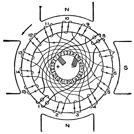
Fig. 269.—Series connected wave wound ring armature for a four pole machine. The coils are so connected that only two brushes are necessary.
Since eight turns are to be used, the process of winding is continued until the section is full and the end of the coil will lie in a position ready to begin the next section. Sometimes the wire is cut at this part of the coil leaving 3 or 4 inches projecting for connecting to the commutator bar 2, or next to the first bar where the winding was started.
The usual practice is, however, to make a loop of the wire of sufficient length to make the connection to the commutator and it has the advantage that since all of the coils on the armature are joined in series, the ending of one coil is joined to the beginning of the next which avoids making mistakes in making the commutator connections.
If the ends be cut they should be marked "beginning" and "end" to avoid trouble, because if they get mixed, it will be necessary to test each coil with a battery and compass needle in order to determine the polarity produced and find which is the beginning of the coil and which the end.245 With 32 ends of the wire projecting from the end of the armature, it is confusing and mistakes are often made in the connections, so that one or more coils may oppose each other which would reduce the voltage.
After the surface of the armature is covered with one layer it will be noticed that the number of leads from the coils to the commutator bars is only one-half the number of bars and that they lie on one-half of the armature.
In order to complete the winding the first layer should be insulated and the second layer wound on. The beginning of the new coil will be directly over the first coil put on, but the beginning of the new coil will be diametrically opposite the beginning of the first coil wound.
The winding is now continued section by section and as each coil is finished a loop or pair of leads is left to connect to each bar. When the last coil is wound, its end will be found lying next to the wire used in starting and should be joined to it and finally connected to bar number one where the start was made.
Fig. 270.—Developed view of the series connected wave wound ring armature shown in fig. 269.
With the winding and commutator connected, all of the coils are in series and the beginning of the first coil joins the end of the last coil.
If a pair of brushes be now placed on the commutator at opposite points the current will flow into the bar and then divide between the two leads connected to it, half of the current flowing around one side and the other half flowing around the other half of the armature or in other words, the two halves of the armature are joined in parallel.
Ques. What is the objection to the Siemens winding just described?
Ans. It produces an unsightly head where the wires pass 246 around the shaft and requires considerable skill to make it appear workmanlike.
Ques. How may this be avoided?
Ans. By using the chord windings of Froehlich or Breguet, which are improvements over the Siemens in appearance and are more easily carried out.
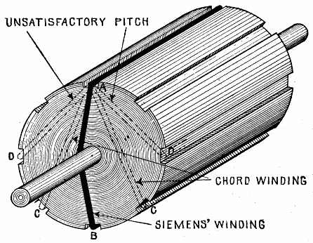
Fig. 271.—End view of an armature, showing the distinction between Siemens' winding and chord winding.
Chord Winding.—In cases where the front and back pitches2 are so taken that the average pitch differs considerably from the value obtained by dividing the number of inductors by the number of poles, the arrangement is called a chord winding.
In this method each coil is laid on the drum so as to cover an arc of the armature surface nearly equal to the angular pitch of the poles; it is sometimes called short pitch winding.
247
Ques. What is the difference between the Siemens winding and the chord winding?
Ans. This is illustrated in fig. 271, which shows one end of an armature. In the Siemens winding, a wire starting, say at A, crosses the head and enters the slot marked B. If it enters slot C it is a chord winding.
Ques. Describe a chord winding.
Ans. The winding is started in the same manner as described in the Siemens method, only instead of crossing the head and returning in the section diametrically opposite, the section A C, fig. 271, next to it is used for the return of the wire to the front end. Leads for connecting to the commutator are left at the beginning and end of each section as before stated and the only difference between the two methods will be noticed when the first layer is nearly complete in that two sections lying next to each other have no wire in them. This will cause the winder to think he has made a mistake, but by continuing the winding and filling in these blank spaces in regular order when the two layers are completed, all the sections will be filled with an equal number of turns and there will be the required number of leads from the coils to connect up to the commutator bars.
Ques. How many paths in the chord winding just described?
Ans. Two.
Multiplex Windings.—An armature may be wound with two or more independent sets of coils. Instead of independent commutators for the several windings, they are combined into one having two or more sets of segments interplaced around the circumference. Thus, in the case of two windings, the brush comes in contact alternately with segments of each set.248 The brush then must be large enough to overlap at least two segments, so as to collect current from both windings simultaneously. Both windings then are always in the circuit in parallel.
Ques. What is the effect of a multiplex winding?
Ans. It reduces the tendency to sparking, because only half of the current is commutated at a time, and also because adjacent commutator bars belong to different windings.
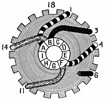
Fig. 272.—A progressive wave winding. If the front and back pitches of a wave winding be such that in tracing the course of the winding through as many coils as there are pairs of poles, a segment is reached in advance of the one from which the start was made, the winding is said to be progressive. The figure shows three coils of a winding having 18 inductors. From the definition, the number of coils to consider to determine if the winding be progressive is equal to the number of poles divided by 2, which in this case is equal to 2. These coils are shown in the figure as follows: A—1—4—F and F—11—14—B. The second coil ends at segment B which is in advance of segment A from which the winding began, indicating that the winding is progressive. Fig. 272 is given simply to illustrate the definition of a progressive winding, and not to represent a practical winding.
Ques. Does an accident to one winding disable the machine?
Ans. No, it simply reduces its current capacity.
249
Ques. Can multiplex windings have more than two windings?
Ans. Yes, there may be three or four windings.
Ques. What is the objection to increasing the number of windings?
Ans. It involves an increased number of inductors and commutator segments, which is undesirable in small machines, but for large ones might be allowable.
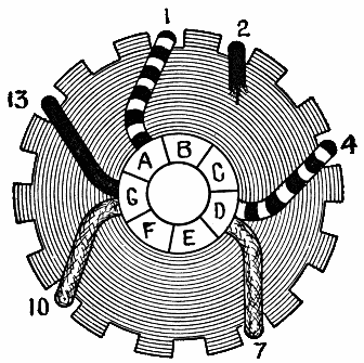
Fig. 273.—A retrogressive wave winding. If the pitches be such that in tracing the winding through as many coils as there are pairs of poles, the first segment of the commutator is not encountered or passed over, the winding is said to be retrogressive. The number of coils to consider is two, as follows: A-1-4-D and D-7-10-G. The second coil ends at G, hence, since the segment A where the start was made has not been reached or passed over the winding is retrogressive. Fig. 273 is given simply to illustrate the definition of retrogressive winding, and not to represent a practical winding.
When there are two independent windings the arrangement is called duplex, with three windings, triplex, and with four, quadruplex.
Ques. What loss is reduced with multiplex windings?
Ans. In these windings, the division of what otherwise would be very stout inductors into several smaller ones, has the effect of reducing eddy current loss.
250
Ques. For what service are machines with multiplex windings specially adapted?
Ans. Multiplex windings are used in machines intended to supply large currents at low voltages, such as is required in electrolytic work.
Number of Brushes Required.—The number of places on the commutator at which it is necessary or advisable to place a set of collecting brushes can be ascertained from the winding diagrams. All that is necessary is to draw arrows marking the directions of the induced electromotive forces. Wherever two arrow heads meet at any segment of the commutator, a positive brush is to be placed, and at every point from which two arrows start in opposed directions along the winding, a negative brush should be placed.
Ques. How many brushes are required for lap windings and ordinary parallel ring windings?
Ans. There will be as many brushes as poles, and they will be situated symmetrically around the commutator in regular order and at angular distances apart equal to the pole pitch.
It should be noted that the number of brush sets does not necessarily show the number of circuits through the armature.
Ques. How many brushes are required for wave windings?
Ans. If arrows be drawn marking the direction of the induced electromotive forces to determine the number of brushes, it will be found that only two brushes are required for any number of poles.
251
Ques. What is the angle between these two brushes?
Ans. It is the same as the angle between any north and south pole.
For instance, in a ten pole machine with wave winding the pitch between the brushes may be any of the following angles:
| 360 / 10 | = | 36° |
| 3 * 36° | = | 108° |
| 5 * 36° | = | 180° |
Figs. 274 and 275.—Right and left hand windings. These consist respectively of turns which pass around the core in a right or left handed fashion. Thus in fig. 274, in passing around the circle clockwise from a to b, the path of the winding is a right handed spiral. In fig. 275, which shows one coil of a drum armature, if a be taken as the starting point, in going to b, a must be connected by a spiral connector across the front end of the drum to one of the descending inductors such as M, from which at the back end another connector must join it to one of the ascending inductors, such as S, where it is led to b, thus making one right handed turn.
Sometimes with lap winding it is desirable to reduce the number of brushes. In fig. 276, is shown the distribution of currents in a four pole lap wound machine having four brushes and generating 120 amperes. In each of the four circuits the flow is 30 amperes, and the current delivered to each brush is 60 amperes. If now two of the brushes be removed, the current through each of the remaining two will be 120 amperes, while 252 internally there will be only two circuits as shown in fig. 277. It should be noted, however, that these two circuits do not take equal shares of the current since, though the sum of the electromotive forces in each circuit is the same, the resistance of one is three times that of the other, giving 90 amperes in one and 30 amperes in the other, as indicated in the figure. If no spark difficulties occur in collecting all the current with only two brushes, the arrangement will work satisfactorily, but the heat losses will be greater than with four brushes.
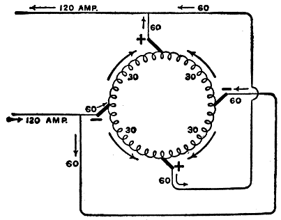
Fig. 276.—Distribution of armature currents in a four pole lap wound dynamo having four brushes and generating 120 amperes.
Ques. Are more than two brushes ever used with wave winding?
Ans. It is sometimes advisable to use more than two brushes with wave windings, especially when the current is very large.
For instance, in the case of a singly re-entrant3 simplex wave winding for an eight pole machine, whenever any brush bridges adjacent bars 253 of the commutator, it short circuits one round of the wave winding and this round is connected at three intermediate points to other bars of the commutator. Hence, if the short circuiting brush be a positive brush, no harm will be done by three other positive brushes touching at the other points. If these other brushes be broad enough to bridge across two commutator bars, they may effect commutation, that is, three rounds instead of one undergoing commutation together.
Number of Armature Circuits.—It is possible to have windings that give any desired even number of circuits in machines having any number of poles.
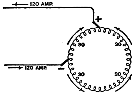
Fig. 277.—Showing effect of removing two of the brushes in fig. 275. If no spark difficulties occur in collecting the current with only two brushes, the arrangement will work satisfactorily, but the heat losses will be greater than with four brushes.
Ques. How many paths are possible in parallel?
Ans. For a simplex spirally wound ring, the number of paths in parallel is equal to the number of poles, and for a simplex series wound ring, there will be two paths. In the case of multiplex windings the number of paths is equal to that of the simplex winding multiplied by the number of independent windings.
In large multipolar dynamos it is, as a rule, inadvisable to have more than 100 or 150 amperes in any one circuit, except in the case of special machines for electro-chemical work. Such considerations are factors which govern the choice of number of circuits.
254
Equalizer Rings.—These are rings resembling a series of hoops provided in a parallel wound armature to eliminate the effects of "unbalancing," by which the current divides unequally among the several paths through the armature. By means of leads, equalizer rings connect points of equal potential in the winding and so preserve an equalization of current.
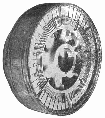
Fig. 278.—Rear view of armature of a large dynamo built by the General Electric Co., showing equalizer rings.
Ques. In multipolar machines what points are connected by equalizer rings?
Ans. Any two or more points in the winding, that during the rotation, are at nearly equal potentials.
255
If there were perfect symmetry in the field system, no currents would flow along such connectors; however, owing to imperfect symmetry, the induction in the various sections of the winding may be unequal and the currents not equally distributed.
Drum Winding Requirements.—There are several conditions that must be satisfied by a closed coil drum winding:
1. There cannot be an odd number of inductors;
An odd number of inductors would be equivalent to not having a whole number of coils. The even numbered inductors may be regarded as the returns for the odd numbered inductors.
2. Both the front and back pitches must be odd in simplex windings.
3. The average pitch should be approximately equal to the number of inductors divided by the number of poles.
This condition must obtain in order that the electric pressures induced in inductors moving simultaneously under poles of opposite sign, will be added. The smallest pitch meeting this condition would stretch completely across a pole face, while the largest would stretch from the given pole tip to the next pole tip of like polarity.
The choice of front and back pitch for a given number of inductors should, with lap and wave windings in general, comply with the following conditions:
1. All the coils composing the winding must be similar, both mechanically and electrically, and must be arranged symmetrically upon the armature.
2. Each inductor of a simplex winding must be encountered once only, and the winding must be re-entrant.
3. Each simplex winding composing a multiplex winding must fulfill the requirement for a simplex winding.
4. A singly re-entrant multiplex winding must as a whole satisfy the requirement for a simplex winding. 256
In addition to the above requirements for lap and wave windings in general, lap windings must comply with the following conditions:
1. The front and back pitches must be opposite in sign;
2. The front and back pitches must be unequal;
If they be equal, the coil would be short circuited upon itself.
3. The front and back pitches must differ by two;
4. In multiplex windings, the front and back pitches must differ by two multiplied by the number of independent simplex windings composing the multiplex winding;
5. The number of slots on a slotted armature may be even or odd;
6. The number of inductors must be an even number; it may be a multiple of the number of slots;
In the case of wave windings the several conditions to be fulfilled may be stated as follows:
1. The front and back pitches must be alike in sign;
2. The front and back pitches may be equal or they may differ by any multiple of two.
They are usually made nearly equal to the number of inductors divided by the number of poles.
257
Current Distribution in Ring and Drum Armatures.—In studying the actions and reactions which take place in the armature, the student should be able to determine the directions of the induced currents. The basic principles of electromagnetic induction were given in chapter X, from which, for instance, the distribution of current in the gramme ring armature, shown in fig. 279, is easily determined by the application of Fleming's rule.
Tracing the current from the negative to the positive brush, it will be seen that it divides, half going through coils 1, 2, 3, and half through coils I, II, III, these two currents ascend to the top of the ring, uniting at the positive brush.
Ques. In the Gramme ring armature (fig. 279) what is the distribution of armature currents?
Ans. There are two paths in parallel as indicated in fig. 279.
Ques. How does the voltage vary in the coils?
Ans. It varies according to the position of the coils, being least when vertical and greatest when horizontal in a two pole machine arranged as in fig. 279.
The upper and lower coils in the right hand half of the ring armature, fig. 279, will have about the same electromotive force induced in them, say 2 volts each, while the two coils between them will have a higher electromotive force, at the same instant, say 4 volts each, since they occupy 258 nearly the positions of the maximum rate of change of the magnetic lines threading through them. These eight coils may be represented by two batteries connected in parallel, each battery consisting of two 2 volt cells and two 4 volt cells as shown in fig. 280. The voltage of each battery then will be
2 + 4 + 4 + 2 = 12 volts
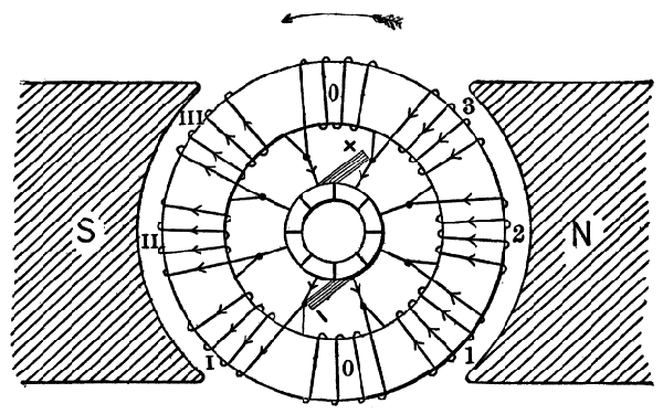
Fig. 279.—Current distribution in a gramme ring armature. There are two paths for the current between the brushes, half going up each side of the ring as indicated by the arrows, thus giving two paths in parallel as indicated in fig. 281.
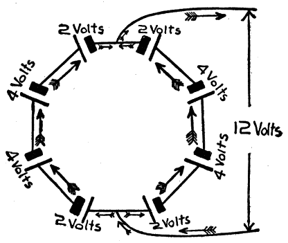
Fig. 280.—Battery analogy illustrating current distribution in a ring armature. The eight coils of the armature, fig. 279, are represented by two batteries of four cells each. The action of the two units thus connected is indicated by the arrows. In the external circuit the voltage is equal to that of one battery and the current is equal to the sum of the currents in each battery.
259
The two batteries being connected in parallel, the voltage at the terminals will be the same, but the current will be the sum of the currents in each battery.
Ques. How may the number of paths in parallel be increased?
Ans. By increasing the number of poles.
For instance, in a four pole machine, as in fig. 283, there are four paths in parallel. In this case the armature may be used to furnish two separate currents, though this is not desirable.
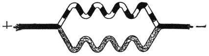
Fig. 281.—Diagram showing distribution of current in the gramme ring armature of fig. 279. The current flows in two parallel paths as indicated.
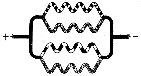
Fig. 282.—Diagram showing current distribution through armature of a four pole machine with like brushes connected. There are four paths in parallel, hence the induced voltage will equal that of one set of coils, and the current will be four times that flowing in one set of coils.
260
Ques. How are the brushes connected?
Ans. Usually all the positive brushes are connected together, and all the negative brushes as in fig. 283, giving four paths in parallel through the armature as indicated in fig. 282.
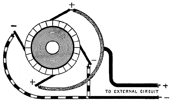
Fig. 283.—Brush connections for four pole dynamo. It is usual to connect all the positive brushes to one terminal and all the negative brushes to the other which gives four parallel paths as shown in the diagram, fig. 282. In a four pole machine, two separate currents can be obtained by omitting the parallel brush connections.
Ques. How does this method of brush connection affect the voltage?
Ans. The voltage at the terminals is equal to that of any of the sets of coils between one positive brush and the adjacent negative brush.
Thus in the four pole machine, fig. 283, the coils of the four quadrants are in four parallels, which gives an internal resistance equal to one-sixteenth that of the total resistance of the entire ring.
When the coils are connected in two circuits or series parallel, it requires only two brushes at two neutral points on the commutator, for any number of poles; this arrangement is shown in fig. 269.
261
Ques. In general what may be said about the current paths through an armature?
Ans. The paths may be in parallel or series parallel according as the winding is of the lap or wave type.
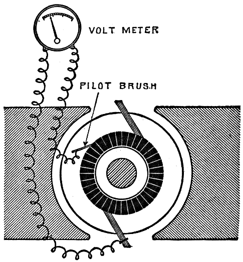
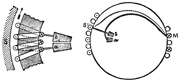
Fig. 284.—Morday's method of measuring the variation of voltage around the commutator by use of a single exploring brush and volt meter. It consists in connecting one terminal of the volt meter (preferably an electrostatic one) to one brush of the machine, and the other terminal to the exploring brush, which can be moved from point to point, readings being taken at each point.
Variation of Voltage Around the Commutator.—There are numerous ways of determining the value of the induced voltage in an armature at various points around the 262 commutator. In the method suggested by Morday, it can be measured by the use of a single exploring brush and a volt meter as shown in fig. 284.
In this method, one terminal of the volt meter is connected to one of the brushes of the dynamo, and the other terminal is joined by a wire to a small pilot brush which can be pressed against the commutator at any desired part of its circumference. With the machine running at its rated speed, the exploring brush is placed in successive positions between the two brushes of the machine. In each position a reading of the volt meter is taken and the angular position of the exploring brush noted.
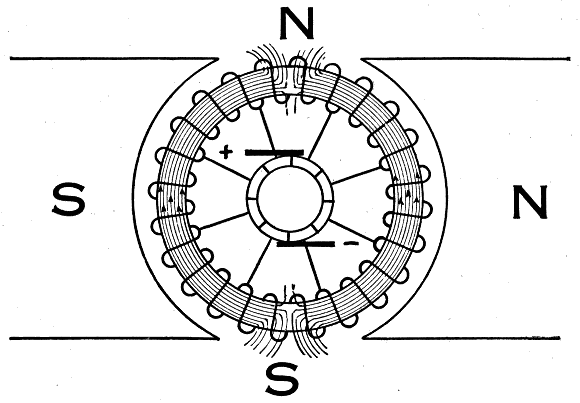
Fig. 285.—Cross magnetization. This is defined as lines of magnetic force set up in the windings of a dynamo armature which oppose at right angles the lines of force created between the poles of the field magnet. The figure shows this cross flux which is due to the armature current alone.
Ques. How does the voltage vary between successive pairs of commutator segments?
Ans. The variation is not constant.
263
Cross Magnetization; Field Distortion.—In the operation of a dynamo with load, the induced current flowing in the armature winding, converts the armature into an electromagnet setting up a field across or at right angles to the field of the machine. This cross magnetization of the armature tends to distort the field produced by the field magnets, the effect being known as armature reaction. To understand the nature of this reaction it is best to first consider the effect of the field current and the armature current separately.
Fig. 285 represents the magnetic flux through an armature at rest, where the field magnets are separately excited. If the armature be rotated clockwise, induced currents will flow upward through the two halves of the winding between the brushes, making the lower brush negative and the upper brush positive.
Ques. If, in fig. 285, the current in the field magnet be shut off, and a current be passed through the armature entering at the lower brush, what is the effect?
Ans. The current will divide at the lower brush, flowing up each side to the top brush. These currents tend to produce north and south poles on each half of the core at the points where the current enters and leaves the armature. Hence, there will be two north poles at the top of the ring and two south poles at the bottom.
Ques. What effect is produced by the like poles at the top and bottom of the ring?
Ans. The external effect will be the same as though there were a single north and south pole situated respectively at the top and bottom of the ring.
264
Ques. In the operation of a dynamo, how do the poles induced in the armature affect the magnetic field of the machine?
Ans. They distort the lines of force into an oblique direction as shown exaggerated in the diagram fig. 286.
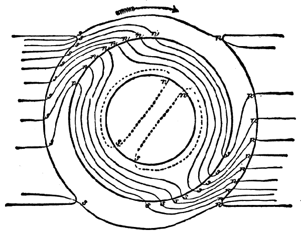
Fig. 286.—Distortion of magnetic field due to cross magnetization. For clearness, the effect is shown somewhat exaggerated. A drag or resistance to the movement of the armature is caused by the attraction of the north and south poles on the armature and pole pieces respectively.
Ques. What effect has the presence of poles in the armature on the operation of the machine?
Ans. In fig. 286, the resultant north pole n, n, n, where the lines emerge from the ring, attracts the south pole, s, s, s, where the lines enter the field magnet, hence a load is brought upon the engine, which drives the dynamo, in dragging the armature around against these attractions. The stronger the current induced in the armature, the greater will be the power necessary to turn it.
265
Ques. Why does this reaction in the armature require more power to drive the machine?
Ans. The effect produced by the armature reaction is in accordance with Lenz's law which states that: In electromagnetic induction, the direction of the induced current is such as to oppose the motion producing it.
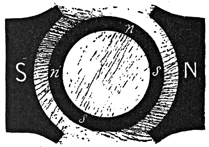
Fig. 287.—Actual distortion of field resulting from cross magnetization, as shown by iron filings.
Remedies for Field Distortion.—Since the distortion of the magnetic field of a dynamo causes unsatisfactory operation, numerous attempts have been made to overcome this defect, as for instance, by:
1. Experimenting with different forms of pole piece;
The reluctance of the pole piece should be increased in the region where the magnetic flux tends to become most dense. The trailing horn of the pole piece may be made longer than the advancing horn and cut farther from the surface of the armature, so as to equalize the distribution of the magnetic flux.
266
2. Lengthening the air gap;
This increases the reluctance, and also necessitates more ampere turns in the field winding. The field distortion, however, will not be so great, as it would be if the magnetic field of the machine were weaker.
3. Slotting the pole pieces;
Both longitudinal gaps and oblique slots have been tried. The reduction of cross section of the pole piece causes it to become highly saturated and to offer large reluctance to the cross field.
4. The use of auxiliary poles.
These are small poles placed between the main poles and so wound and connected that their action opposes that of the cross field.
Normal Neutral Plane.—This may be defined as a plane passing through the axis of the armature perpendicular to the magnetic field of the machine when there is no flow of current in the armature, as shown in fig. 288. It is the plane in which the brushes would be placed to prevent sparking when the machine is in operation were the field not distorted by armature reaction, and there were no self-induction in the coils.
Commutating Plane; Lead of the Brushes.—It has been found that in order to reduce sparking to a minimum, the brushes must be placed in certain positions found by trial and designated as being located in the neutral plane.
When the brushes are in the neutral plane, they are in contact with commutator segments connecting with coils that are cutting the lines of force at the minimum rate.
Ques. Define the term "commutating plane."
Ans. This is a plane passing through the axis of the armature and through the center of contact of the brushes as shown in figs. 289 and 300.
267
Ques. What is the angle of lead?
Ans. The angle between the normal neutral plane and the commutating plane.
In the operation of a dynamo since the field, on account of armature reaction, is twisted around in the direction of rotation, the proper position for the brushes is no longer in the normal neutral plane, but lies obliquely across, a few degrees in advance. Hence, for sparkless commutation, the commutating plane is a little in advance of the normal neutral plane, the lead being measured by the angle between these planes, as stated in the definition.
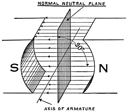
Fig. 288.—Normal neutral plane. This is a reference plane from which the lead is measured. As shown, the normal neutral plane lies at right angles to the lines of force of an undistorted field.
268
Ques. What may be said with respect to the angle of lead?
Ans. For sparkless commutation, the angle of lead varies with the load.
If the field be much altered at full load, it is evident that at half or quarter-load it will not be nearly so much twisted, hence the necessity for mounting the brushes on some kind of rocking device which will allow them to be shifted in different positions for different loads. A desirable point, then, in dynamo design is to make the angle of lead at full load so small that it will not be necessary to shift the brushes much for variation of load. This can be accomplished by making the field magnet field considerably more powerful than the armature field.
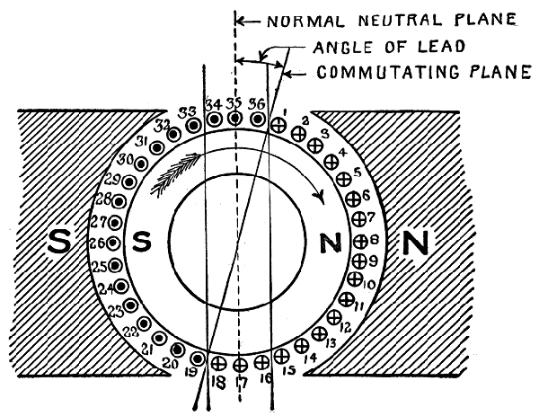
Fig. 289.—Diagram illustrating the demagnetizing effect of armature reaction. This results from the forward lead given the brushes in order to secure sparkless commutation.
269
Demagnetizing Effect of Armature Reaction.—In the operation of a dynamo, as previously explained, the position of the brushes for sparkless commutation must be varied with the load; that is, for light load they should occupy a position practically midway between the poles and for a heavy load they must be moved a few degrees in the direction of rotation. In other words, the commutating plane must be more or less in advance of the normal neutral plane as shown in fig. 289.
Ques. What is the effect of lead?
Ans. It produces a demagnetizing effect which tends to weaken the field magnets.
Ques. Describe this demagnetizing effect in detail.
Ans. Tracing the armature currents, in fig. 289 according to Fleming's rule, it will be seen that current in inductors 1 to 18 flow from the observer indicated by crosses representing the tails of retreating arrows and in inductors 19 to 36, toward the observer from the back of armature, indicated by dots representing the points of approaching arrows. In determining these current directions the inductors to the right of the neutral line are considered as moving downward, and those to the left as moving upward. The current in inductors 1 to 15 and 19 to 33, tends to cross magnetize the magnetic field of the machine, but the current in inductors 34 to 36 and 16 to 18 tends to produce north and south poles as indicated. These poles are in opposition to the field poles and tend to demagnetize them. Hence, the inductors lying outside the two upright lines are known as cross magnetizing turns, and those lying inside, as demagnetizing turns.
270
The breadth of the belt of demagnetizing turns included between the two upright lines is clearly proportional to the angle of lead; therefore, the demagnetizing effect increases with the lead.
Eddy Currents; Lamination.—Induced electric currents, known as eddy currents, occur when a solid metallic mass is rotated in a magnetic field. They consume considerable energy and often occasion harmful rise in temperature. Armature cores, pole pieces, and field magnet cores are specially subject to these currents.
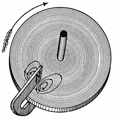
Fig. 290.—Arago's experiment illustrating eddy currents. Arago found that if a copper disc be rotated in its own plane underneath a compass needle, the needle was dragged around as by some invisible friction. The explanation of this phenomenon, known as Arago's rotations, is due to Faraday, who discovered that it was caused by induction. That is, a magnet moved near a solid mass of metal, induces in it currents, which, in flowing from one point to another, have their energy converted into heat, and which, while they last, produce (in accordance with Lenz's law) electromotive forces tending to stop the motion. Thus, in the figure, there are a pair of eddies in the part passing between the poles, and these currents oppose the motion of the disc. Foucault showed by experiment the heating effect of eddy currents, but such currents were known years before Foucault's experiments, hence they are incorrectly called Foucault currents.
271
Ques. Describe the formation of eddy currents.
Ans. In fig. 291, a bar inductor is seen just passing from under the tip of the pole piece N of the field magnet. Noting the distribution of the lines of force, it will be seen that the edge c d is in a weaker field than the edge a b, hence, since the two edges move with the same velocity, the electromotive force induced along c d will be less than that induced along a b. This gives rise to whirls or current eddies in the copper bar as shown.
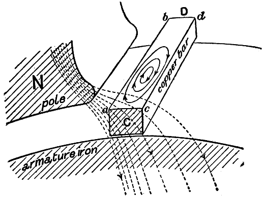
Fig. 291.—Formation of eddy currents in a solid bar inductor. On account of its appreciable size, the field is sometimes weaker at one point than another, hence the unequal electromotive forces thus produced will induce eddy currents.
Ques. What should be noted in seeking a remedy for eddy currents?
Ans. It should be noted that eddy currents are due to very small differences of pressure and that the currents are large only because of the very low resistance of their circuits.
272
Ques. What is the best means of reducing eddy currents?
Ans. Lamination.
Ques. Explain this mode of construction with respect to the bar inductor fig. 291.
Ans. In the case of a large bar inductor such as shown in fig. 291, it could be replaced by a number of small wires soldered together only at the ends. The layer of dirt or oxide on the outside of the wires will furnish sufficient resistance to practically prevent the eddy currents passing from wire to wire.
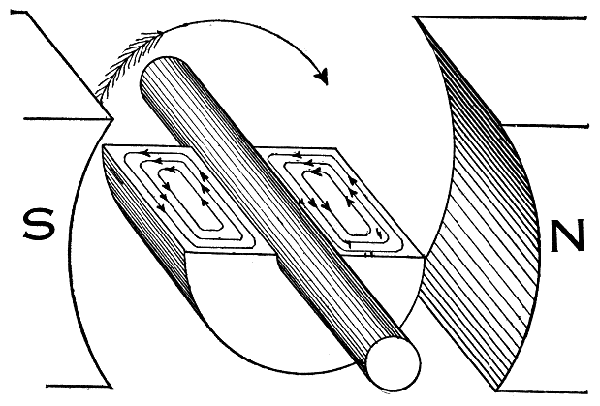
Fig. 292.—Eddy currents induced in a solid armature core. Eddy currents always occur when a solid metallic mass is rotated in a magnetic field, because the outer portion of the metal cuts more lines of force than the inner portion, hence the induced electromotive force not being uniform, tends to set up currents between the points of greatest and least potential. Eddy currents consume a considerable amount of energy and often occasion harmful rise in temperature.
273
Ques. How should an armature core be laminated to avoid eddy currents?
Ans. It should be laminated at right angles to its axis.
Fig. 292 shows the induced eddy currents in a solid armature core, and fig. 293 shows the manner in which the paths of these currents are interrupted and the losses due to their effect diminished by the use of laminated cores.
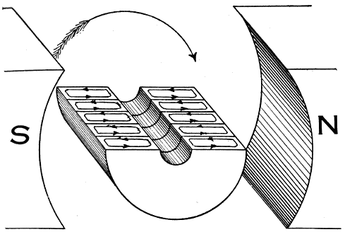
Fig. 293.—Armature core with a few laminations showing effect on eddy currents. In practice the core is made up of a great number of thin sheet metal discs, about 18 gauge, which introduces so much resistance between the discs that the formation of eddy currents is almost entirely prevented.
In fig. 293, only five laminations or plates are indicated, so as to show the sub-division of the eddy currents, but in practical armatures, the number of laminations or punchings ranges from 40 to 66 to an inch, and brings the eddy current loss down to about one per cent. A greater increase in the number of laminations per inch is not economical, however, owing to the difficulties encountered in the punching and handling of extremely thin sheets of iron, and the loss of space between the plates.
274
Armature cores constructed of the number of plates stated, and forced together by means of screws and heavy hydraulic pressure, contain from 80 to 90 per cent. of iron, and have a magnetic flux carrying capacity only from 5 to 15 per cent. less than when they are made of an equal volume of solid iron.
Magnetic Drag on the Armature.—Whenever a current is induced in an armature coil by moving it in the magnetic field so as to cut lines of force, the direction of the induced current is such as to oppose the motion producing it. Hence, in the operation of a dynamo, considerable driving power is required to overcome this magnetic drag on the armature.
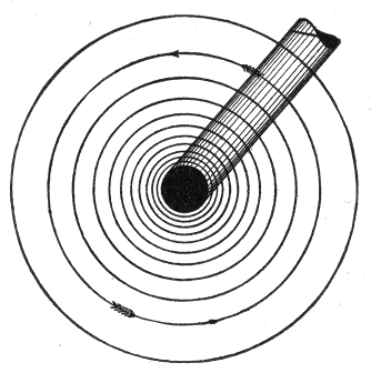
Fig. 294.—Circular concentric magnetic field surrounding a conductor carrying a current. If this conductor be moved across a magnetic field, as between the poles of a magnet, the lines of force will be distorted as in fig. 295, which will oppose the motion of the conductor.
A conductor carrying a current is surrounded by a circular concentric magnetic field. If now such a conductor, with current flowing toward the observer as in fig. 294, be placed in a uniform magnetic field, a distortion of the magnetic lines will occur as shown in fig. 295. The resulting mechanical 275 actions are easily determined by remembering that the magnetic lines act like elastic cords tending to shorten themselves. There is in fact a tension along the magnetic lines and a pressure at right angles to both, proportional at every point to the square of their density.
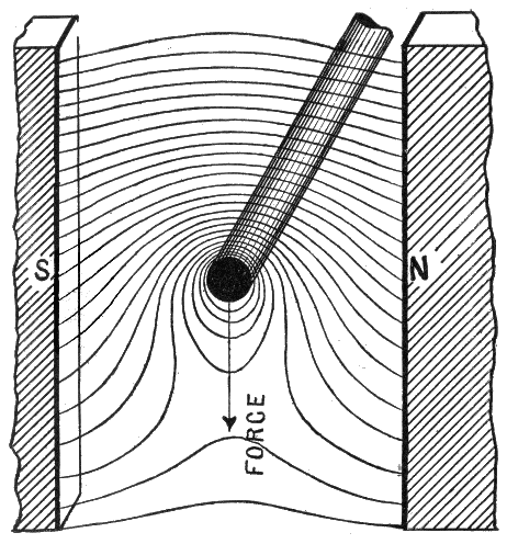
Fig. 295.—Illustrating drag on armature inductors. In moving a wire carrying a current through a magnetic field, the lines of force are distorted, and the effect on the wire is the same as though the magnetic lines were elastic cords tending to shorten themselves. They, therefore, oppose the motion of the wire; hence, in dynamo operation, more or less power is absorbed in overcoming this drag on the numerous inductors. In the figure the inductor is being moved upward against the "drag" due to the magnetic field.
It is evident by inspection of the lines in fig. 295, that there is a drag upon the conductor in the direction shown by the arrow. 276
Smooth and Slotted Armatures.—The inductors of an armature may be placed on a smooth drum or in slots cut in the surface parallel to the axis.
In the first instance, the magnetic drag comes on the inductors and in the case of slots, upon the teeth.
The effect of embedding the armature inductors in slots is to distort the magnetic field as shown in fig. 296. Most of the lines of force pass through the teeth, thus, not only are the inductors better placed for driving purposes, but, being screened magnetically by the teeth, the forces acting on them are reduced, the greater part of the magnetic drag being taken up by the core.
It should be noted that, although screened from the field, the inductors in a slotted armature cut magnetic lines precisely as if they were not protected. The effect is as though the magnetic lines flashed across the slots from tooth to tooth, instead of passing across the intermediate slot at the ordinary angular velocity.
Comparison of Smooth and Slotted Armatures.—The slotted armature has the following advantages over the smooth type:
1. Reduced reluctance of the air gap;
2. Better protection for the winding;
3. Inductors held firmly in place preventing slippage;
4. No magnetic drag on inductors;
5. No eddy currents in inductors;
6. Better ventilation;
7. Opposition to armature reaction.
Due to increased density of flux through the teeth.
The disadvantages of slotted armatures may be stated as follows:
1. Tendency of the teeth to induce eddy currents in the pole pieces;
2. Increased self-induction of the armature coils; 277
3. Greater hysteresis loss on account of denser flux in the teeth;
4. Leakage of lines of force through the core, especially in the case of partially enclosed slots.
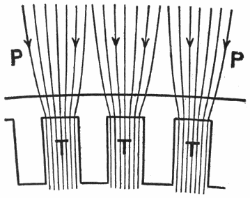
Fig. 296.—Effect of slotted armature. The teeth, as they sweep past the pole face, cause oscillations of the magnetic flux in the iron near the surface because the lines in the pole piece PP tend to crowd toward the nearest teeth, and will be less dense opposite the slots. This fluctuation of the magnetic lines produce eddy currents in the pole faces unless laminated. The armature inductors, being screened from the field, are relieved of the drag which is taken by the teeth.
Magnetic Hysteresis in Armature Cores.—When the direction or density of magnetic flux in a mass of iron is rapidly changed a considerable expenditure of energy is required which does not appear as useful work. For instance, when an armature rotates in a bipolar field, the armature core is subjected to two opposite magnetic inductions in each revolution; that is, at any one instant a north pole is induced in the core opposite the south pole of the magnet and a south pole in the core opposite 278 the north pole of the magnet as indicated in fig. 297 by n and s. Accordingly, if the armature rotate at a speed of 1,000 revolutions per minute, the polarity of the armature will be changed 2,000 times per minute, and result in the generation of heat at the expense of a portion of the energy required to drive the armature. This loss of energy is due to the work required to change the position of the molecules of the iron, and takes place both in the process of magnetizing and demagnetizing; the magnetism in each case lagging behind the force.
Core Loss or Iron Loss.—These terms are often employed to designate the total internal loss of a dynamo due to the combined effect of eddy currents and hysteresis, but as the losses due to the former are governed by laws totally different from those applicable to the latter, special analysis is required to separate them.
The eddy current loss per pound of iron in the armature core diminishes with the thinness of the laminated sheets, and may be made indefinitely small by the use of indefinitely thin iron plates, were it not for certain mechanical and economical reasons.
The loss due to hysteresis per pound of iron in the core, does not vary with the thinness of the core plates; it can be reduced only by the use of a material having a low hysteretic coefficient.
Dead Turns.—The voltage generated in a dynamo with a given degree of field excitation is not strictly proportional to the speed, but somewhat below on account of the various reactions. That is, the machine acts as though some of its revolutions were not effective in inducting electromotive force.
279
The name dead turns is given to the number of revolutions by which the actual speed exceeds the theoretical speed for any output.
Again, this term is sometimes used to denote that portion of the wire on an armature which comes outside the magnetic field and is therefore rendered ineffective in inducing electromotive force. The number of dead turns is about 20% of the total number of turns.
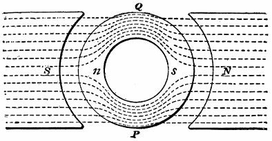
Fig. 297.—Magnetic hysteresis in armature core. Unlike poles are induced in the core opposite the poles of the field magnet. Since on account of the rotation of the core the induced poles are reversed a thousand or more times a minute, considerable energy is required to change the positions of the molecules of the iron for each reversal, resulting in the generation of heat at the expense of a portion of the energy required to drive the armature.
Self-induction in the Coils; Spurious Resistance.—Self-induction opposes a rapid rise or fall of an electric current in just the same way that the inertia of matter prevents any instantaneous change in its motion. This effect is produced by the action of the current upon itself during variations in its strength.
In the case of a simple straight wire, the phenomenon is almost imperceptible, but if the wire be in the form of a coil, the adjacent turns act inductively upon each other upon the principle of the mutual induction arising between two separate adjacent circuits.
280
Ques. What effect has self-induction on the operation of a dynamo?
Ans. It prevents the instantaneous reversal of the current in the armature coils. That is, the current tends to go on and in fact does actually continue for a brief time after the brush has been reached.
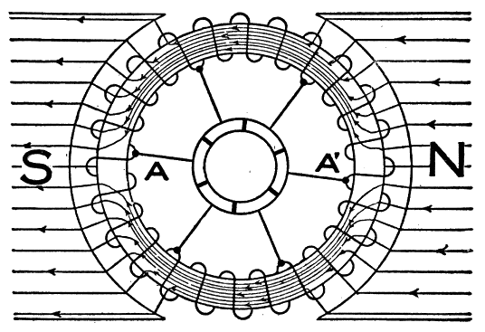
Fig. 298.—Distribution of magnetic lines through a ring armature. Since the lines follow the metal of the ring instead of penetrating the interior, no electromotive force is induced in that portion of the winding lying on the interior surface of the ring. There is, therefore, a large amount of dead wire or wire that is ineffective in inducing electromotive force; this is the chief objection to the ring type of armature.
Ques. What becomes of the energy of the current at reversal?
Ans. The energy of the current in the section of the winding undergoing commutation is wasted in heating the wire during the interval when it is short circuited, and as it passes on, energy must again be spent in starting a current in it in the reverse direction. There is, then, a lagging of the current in the armature coils due to self-induction.
281
Ques. What is spurious resistance?
Ans. This is an apparent increase of resistance in the armature winding, which is proportional to the speed of the armature, and due to the lagging of the current.
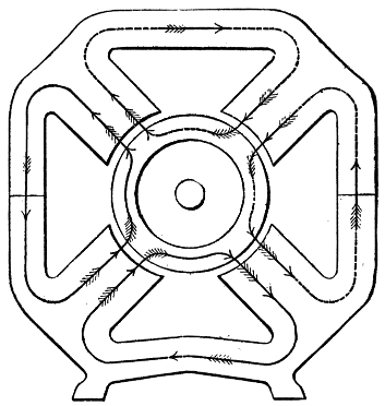
Fig. 299.—Distribution of magnetic lines through solid drum armature of a four pole machine.
Armature Losses.—The mechanical power delivered to the pulley of a dynamo is always in excess of its electrical output on account of numerous mechanical and electrical losses. Mechanical losses result from:
1. Friction of bearings;
2. Friction of commutator brushes;
3. Air friction.
The electrical losses may be classified as those due to:
1. Armature resistance;
2. Hysteresis;
3. Eddy currents.
282
Ques. How do the mechanical and electrical losses compare?
Ans. The mechanical losses are small in comparison with the electrical losses.
Ques. What may be said with respect to friction?
Ans. The bearing friction varies with the load. In calculating this loss not only must the weight of the armature be considered but also the belt tension and magnetic attraction in order to get the resultant thrust on the bearing. Friction of the brushes is very small and may be neglected. A small loss of power is caused by the friction of the air on the armature. The latter, since it revolves rapidly, acts to some extent as a fan, and in some machines this fan action is made use of for ventilation and cooling.
Ques. How are the other losses determined?
Ans. The loss of power due to armature resistance is easily found by Ohm's law, but the hysteresis and eddy current losses, known collectively as iron losses, are not so easily determined. If the magnetization curve of the particular quality of iron used for armature plates be known, the hysteresis loss may be calculated approximately. Eddy current losses are the most important, especially in large machines. As previously explained, in all the moving metal masses unless laminated, there will be eddy currents set up if they cut magnetic lines. Power may be lost from this cause even in the metal of the shaft if there be leakage of magnetic lines into it.
283
The act of commutation needs special study. If it be incorrectly performed, the imperfection at once manifests itself by sparks which appear at the brushes. In the study of this chapter on commutation it would be advisable for the student to first review the basic principles of commutation as given in chapter XIV, which contains a brief and simple explanation of how the alternating current in the armature is converted into direct current by the action of the commutator.
Ques. What is the period of commutation?
Ans. The time required for commutation, or the angle through which the armature must turn to commute the current in one coil.
Ques. Upon what does the period of commutation depend?
Ans. Upon the width of the brushes as shown in fig. 300.
This fixes the angle through which the armature must revolve to commute the current in one coil. This angle is formed, as shown in the figure, by two intersecting planes, M and S, which pass through the axis of the armature and the two edges of the brush. Commutation then, begins at M and ends at S.
284
Ques. What is the position of the commutating plane with respect to M and S, in fig. 300?
Ans. It bisects the angle formed by the planes M and S.
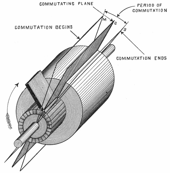
Fig. 300.—Armature with one brush in position to illustrate the period of commutation and commutating plane. The latter is called "commutating line" by some writers. The period of commutation depends on the thickness of the brush end in contact with the commutator. Careful distinction should be made between commutating plane, neutral plane, and normal neutral plane as defined elsewhere.
Ques. What is the commutating plane?
Ans. An imaginary plane passing through the axis of the armature and the center of contact of the brush.
285
Ques. What two planes are referred to in stating the position of the brushes?
Ans. The normal neutral plane and the commutating plane.
The angle intercepted by these two planes represents the lead, thus in stating that the brushes have a lead of 6°, means that the angle intercepted by the normal neutral plane and the commutating plane is 6°.

Fig. 301.—The proper position of the brushes, if there were no field distortion and self-induction in the armature coils, would be in the normal neutral plane. In the actual dynamo these two disturbing effects are present which makes it necessary to advance the brushes as shown in figs. 302 and 303 to secure sparkless commutation.
Ques. What is the difference between the normal neutral plane and the neutral plane?
Ans. This is illustrated in figs. 301 and 302. The normal neutral plane is the position of zero induction assuming no 286 distortion of the field as in fig. 301. The neutral plane is the position of zero induction with distorted field as in fig. 302 and as is found in the actual machine; the distortion is exaggerated in the figure for clearness.
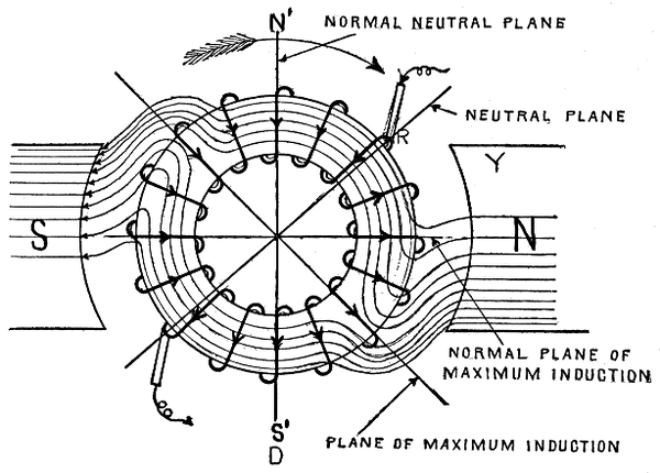
Fig. 302.—Brush adjustment for field distortion. The effect of the latter is to twist the lines of force around in the direction of rotation, thus maximum induction takes place in an inclined plane. The brushes then must be advanced to the neutral plane which is at right angles to the plane of maximum induction. This gives the proper position of the brushes neglecting self-induction.
Ques. What is the normal plane of maximum induction?
Ans. A plane, 90° in advance of the normal neutral plane, being the position of maximum induction with no distortion of field, as in fig. 301. 287
Ques. What is the plane of maximum induction?
Ans. A plane 90° in advance of the neutral plane, being the position of maximum induction in a distorted field as in fig. 302.
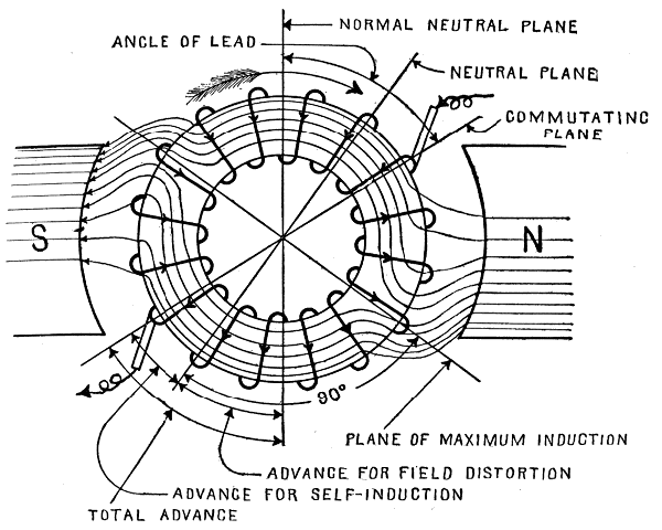
Fig. 303.—Brush adjustment for self-induction. For convenience an electric current is regarded as having weight and hence possessing the property of inertia. The current then during commutation cannot be instantly brought to rest and started in the reverse direction but these changes must be brought about gradually by an opposing force. Hence by advancing the brushes beyond the neutral plane as illustrated, commutation takes place with the short circuited coil cutting the lines of force so as to induce a current in the opposite direction; this opposes the motion of the current in the short circuited coil, brings it to rest and starts it in the opposite direction, thus preventing sparks. Figs. 301 to 303 should be carefully compared and thoroughly understood.
Ques. What should be noted with respect to the different planes?
Ans. The commutating plane should be carefully distinguished from the normal neutral plane and from the neutral plane, as shown in fig. 303. 288
Commutation.—In order to understand just what happens during commutation, a section of a ring armature may be used for illustration, such as shown in fig. 304. Here the coils A, B, C, D, E, are connected to commutator segments 1, 2, 3, 4, and the positive brush is shown in contact with two segments 2 and 3, the brush being in the neutral position. Currents in the coils on each side of the neutral line flow to the brush through segments 2 and 3; the brush then is positive.
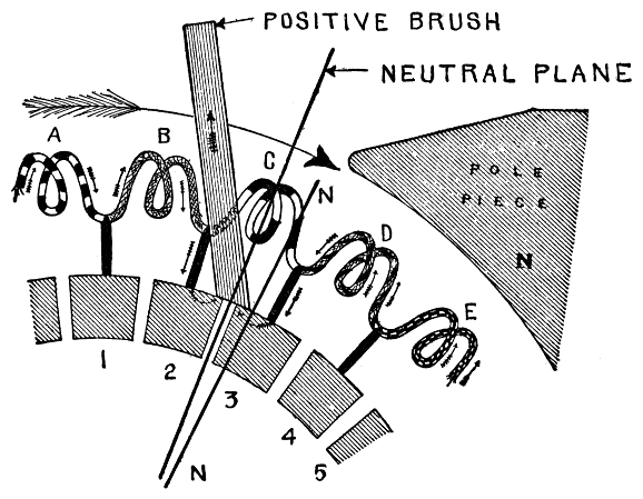
Fig. 304.—Commutation. This takes place during the brief interval in which any two segments of the commutator are bridged by the brush. The coil connecting with the two segments under the brush is thus short circuited. During commutation the current in the short circuited coil is brought to rest and started again in the reverse direction against the opposition offered by its so called inertia, or effect produced by self-induction.
Now, as the armature turns, the commutator segments come successively into contact with the brush. In the figure, segment 3 is just leaving the brush and 2 is beginning to pass under it, hence, for an instant the coil C is short circuited.
289
Ques. In fig. 304, what are the current conditions?
Ans. Previous to contact with segment 2, current flowed in coil C in the same direction as in coil B.
Ques. What occurs while the brush is in contact with segments 2 and 3?
Ans. During this brief interval, the current in C is stopped and started again in the opposite direction.
Similarly each coil of the armature as it passes the brush will be short circuited and have its current reversed. This is known as commutation.
Ques. What is the effect of field distortion with respect to commutation?
Ans. The neutral plane no longer coincides with the normal neutral plane but is advanced in the direction of rotation of the armature as shown in fig. 302.
The reaction of the poles N' and S' of the armature field on the poles S and N of the main magnetic field tends to crowd the lines of force into the upper pole face of the south pole of the magnet, and into the lower pole face of the north pole. This effect is due to the strong magnetic attraction between the opposite poles S and N' and N and S', and the equally strong repulsion between like poles N and N' and S and S'. Hence, the plane of maximum induction no longer coincides with the normal plane of maximum induction, but is advanced in the direction of rotation, depending upon the strength of the armature current, being shifted forward for an increase of current, and backward for a decrease of current. This distortion of the field and the consequent shifting of the plane of maximum induction naturally results in the shifting of the neutral plane from the vertical position to the inclined position as shown.
Position of the Brushes; Sparking.—In accordance with the laws of electromagnetic induction, if the bipolar ring armature shown in fig. 301 be rotated in the direction indicated by the arrow the armature current entering at the brush E will 290 divide, one part passing through the coils on the right half of the ring, and the other part through the coils on the left half of the ring, to the brush F, from which the total current will pass out, urged by the full value of the electromotive force induced in all the coils on both halves of the ring.
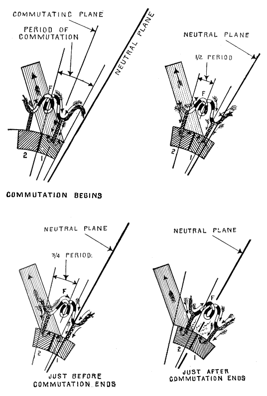
Figs. 305 to 308—Improper brush adjustment resulting in excessive sparking. When the brushes are not advanced far enough, commutation takes place before the short circuited coil reaches the neutral plane, hence, its motion is not changed with respect to the magnetic field so as to induce a reverse current till after commutation. There is then no opposing force, during commutation, to stop and reverse the current in the short circuited coil, and when the brush breaks contact with segment 1, as in fig. 308, the "momentum" of the current in coil F causes it to jump the air gap from segment 1 to segment 2 and the brush, against the enormous resistance of the air, thus producing a spark whose intensity depends on the momentum of the current in coil F. Sparking, if allowed to continue, will injure the brushes and commutator segments.
Again, if the brushes be placed at the points G and H, each half of a current entering at G, will pass through one-half of the coils on the left side and one-half of the coils on the right side of the ring, so that each half of the current will be urged forward by an electromotive force equal to the electromotive force tending to force it back, and therefore, no current will pass in or out through the brushes. From these considerations it is obvious that the proper position for the brushes would be 291 in the normal neutral plane, were it not for the disturbing effects of armature reaction and self-induction of the current.
Ques. Should the brushes of a dynamo be placed in the neutral plane?
Ans. No.
Ques. Why not?
Ans. The brushes must be advanced beyond the neutral plane to prevent sparking.
Ques. What is the cause of sparking at the brushes?
Ans. It is due to self-induction in the coil undergoing commutation.
292
Ques. Explain the effect of self-induction in detail.
Ans. When commutation takes place with the brushes in the neutral plane as in fig. 304, there will be no voltage induced in the short circuited coil C. The current, therefore, which flowed in coil C before it was short circuited will cease, and as segment 3 breaks contact with the brush, it will be thrown as a perfectly idle coil upon the right hand half of the ring in which a current is flowing toward the brush. Moreover, the current which was flowing through D and 3 directly to the brush, must suddenly traverse the longer path through the idle coil C. Now, 293 on account of self-induction, the current acts in precisely the same manner as though it had weight; that is:
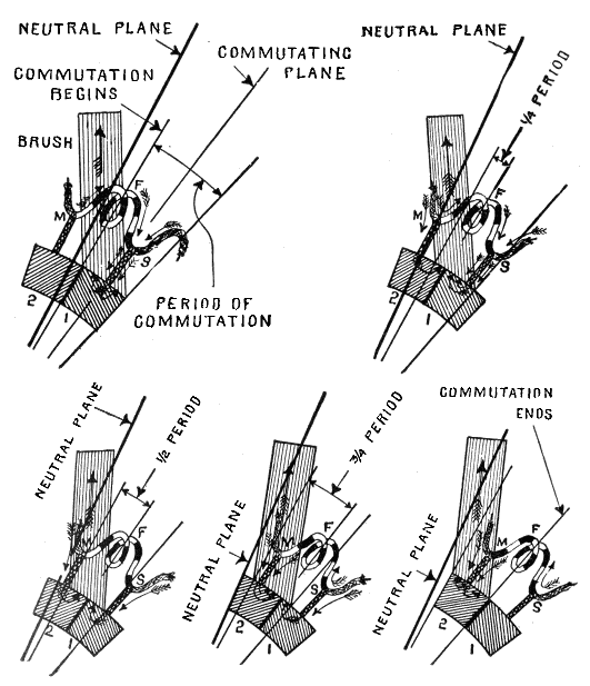
Figs. 309 to 313.—How sparkless commutation is obtained by advancing the brushes beyond the neutral plane; commutation progressively shown.
Fig. 310.—Segment 2 has come into contact with the brush and coil F, in which commutation is taking place, is now short circuited. The current now divides at M, part passing to the brush through segment 2, and part through coil F and segment 1. Although coil F is short circuited and having passed the neutral plane, is cutting the lines of force so as to induce a current in the opposite direction, it still continues to flow with unchanged direction against these opposing conditions. This is due to self-induction in the coil which resists any change just as the momentum of a heavy moving body, such as a train of cars, offers resistance to the action of the brakes in retarding and stopping its motion.
Fig. 311.—Segment 2 has moved further under the brush, and the opposition offered to the forward flow of the current in the short circuited coil F by the reverse induction in the magnetic field to the right of the neutral plane has finally brought the current in F to rest. The currents from each side of the armature now flow direct to the brush through their respective end segments 1 and 2.
Fig. 312.—Segment 1 is now almost out of contact with the brush. A current has now been started in the coil F in the reverse direction due to induction in the magnetic field to the right of the neutral plane; it flows to the brush through segment 2. The current has not yet reached its full strength in F, accordingly, part of the current coming up from the right divides at S and flows to the brush through segment 1.
Fig. 313.—Completion of commutation in segments 1 and 2; the brush is now in full contact with segment 2, the current in coil F has now reached its full value, hence the current flowing up from the right no longer divides at S but flows through F and segment 2 to the brush. If the current in F had not reached its full value, at the instant segment 1 left contact with the brush, it could not immediately be made to flow at full speed any more than could a locomotive have its speed instantly changed. This, as previously explained, is due to self-induction in the coil or the so called "inertia" of the current which opposes any sudden change in its rate of flow or direction. Accordingly that portion of the current which was flowing up from the right and passing off at S to the brush through segment 1 as in fig. 312, would, when this path is suddenly cut off as in fig. 313, encounter enormous opposition in coil F. Hence, it would momentarily continue to flow through segment 1 and jump the air gap between this segment and the brush, resulting in a more or less intense spark depending on the current conditions in coil F.
Therefore, when segment 3 leaves the brush, the current will not instantly change its path and flow through C, but will be urged by its "momentum," and jump the air gap between the brush and segment 3, thus producing a spark.
294
Ques. How may this sparking be prevented?
Ans. If the brushes be given additional lead, that is shifted further to the right to some position as N N, fig. 304, coil C will not remain idle during the interval it is short circuited, but will cut the magnetic lines in such a way as to induce a current in the reverse direction through it. Under these conditions, when segment 3 breaks contact with the brush, the current flowing through D does not encounter an idle coil, but one in which a current is flowing in the same direction, hence, the tendency to jump the air gap and produce a spark is reduced; with proper adjustment of the brushes, there will be no sparking.
Ques. What is the objection to very thin brushes?
Ans. Time must be allowed for reversal of the current, hence the brushes must not be so thin as merely to bridge the insulation between segments.
Ques. What is the effect of lead?
Ans. There is usually much sparking when the lead is too small; a little sparking when too great, and no sparking when just right. If the lead be excessive, there is a waste of energy due to the generation of a larger reverse current in the short circuited coil than is necessary.
Fixed Position of Brushes.—The condition for sparkless commutation is that the current in the short circuited coil be reduced to zero, and increased in the opposite direction up to the same value as that in the next coil leading. If the brushes are to remain in a fixed position, this condition will only be realized at the particular load for which the brushes are set. Thus, if the brushes be set for the average load, the reversing field will not be correct for either a weaker or stronger load. Hence, sparkless commutation with fixed brushes must be due to some other factor. 295
Ques. What may be said with respect to carbon brushes?
Ans. Since carbon possesses a high resistance, the drop will vary greatly with the contact area, thus affecting a difference of potential in the two segments passing under the brush and it is largely to this that sparkless commutation is due.
Ques. What is the effect of resistance on commutation?
Ans. In fig. 304 during commutation, that is, while the brush contacts with any two segments, as 2 and 3, the currents coming up through the winding on either side of the neutral plane are offered two paths to the brush: 1, direct to brush through the connecting segment, or 2, across the short circuited coil and adjacent segment. Thus, on the right side: to brush through segment 3, or across coil C and adjacent segment 2.
At the beginning of commutation, almost the entire brush area being in contact with segment 3, the contact resistance of this segment will be much less than for segment 2; hence, not only will the current at the right flow through 3, but also the current at the left after first traversing the short circuited coil. As commutation progresses, the area of contact of 3 decreases while that of 2 increases, and the respective resistances vary in inverse proportion. Likewise the tendency of the current in the left half of the winding to take the longer path through coil C and segment 3 to the brush gradually decreases, becoming zero when the two contact areas become equal. During the second half of the period of commutation, the contact area of segment 2 becomes greater and of 3, less; thus the resistance of 2 is lowered, and that of 3 increased. Accordingly, all of the current at the left will flow through segment 2, and the current at the right will flow through C and 2 rather than through 296 3. In this way the current is reversed in C, and, if the brush be broad enough to allow a sufficient time interval, the current in C is built up to its full value before segment 3 leaves the brush, thus securing sparkless commutation.
This contact resistance factor in sparkless commutation is illustrated in figs. 314 to 318, it being assumed that during commutation, the brush contact resistance is inversely proportional to the area of contact, and that the winding is free of resistance and inductance. The current is taken as 40 amperes, in which case 20 amperes will flow from each side of the winding to the brush.
In fig. 314 the instant before commutation begins all the current will flow through segment A. At the end of the first quarter of the period of commutation, fig. 315, 30 amperes will flow from the right to brush through A, and from the left, 10 amperes through the short circuited coil via A and 10 amperes through B.
At the end of the second quarter or half period, fig, 316, the current through each half of the winding will flow to the brush through these respective segments.
At the end of the third quarter, fig. 317, the current from the right will divide, 10 amperes going through A, and 30 amperes traversing the short circuited coil and out through B. The entire current from the left will flow through segment B.
At the end of the fourth quarter, fig. 318, or completion of the period the current from each half of the winding will flow to the brush through B.
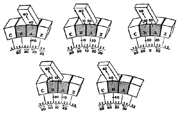
Figs. 314 to 318.—Brush contact resistance theory of commutation, neglecting self-induction and resistance in the coils. The total current is assumed to be 40 amperes made up of 20 amperes flowing toward the brush from the coils on the right and 20 amperes from the coils on the left. During commutation, that is, the interval during which the brush contacts with any two adjacent segments of the commutator, the current is assumed to vary directly as the contact area.
Fig. 314.—Beginning of commutation; segment A is entirely under the brush, and B is at the initial point of contact. For this position the currents from both sides flow to the brush through segment A.
Fig. 315.—One-quarter period of commutation. One quarter of the brush area is in contact with B and three quarters in contact with A; hence, 10 amperes will flow through B and 30 amperes through A.
Fig. 316.—Second quarter of commutation period. The brush now contacts equally with both segments, hence 20 amperes will flow through each segment.
Fig. 317.—Third quarter of commutation period. Three quarters of the brush area is in contact with segment B and one quarter with segment A; accordingly, 30 amperes will flow through B and 10 amperes through A.
Fig. 318.—Completion of commutation. The brush is in full contact with segment B and at the point of breaking contact with A, hence the entire current from both sides or 40 amperes will flow through B.
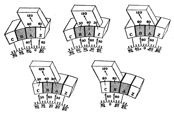
Figs. 319 to 323.--Brush contact theory of commutation for case in which the brush covers two segments of the commutator. Fig. 319 beginning of commutation; fig. 320 one-quarter period; fig. 321, one-half period; fig. 322, three-quarter period; fig. 323 completion of commutation. 297
Ques. What is the effect of increasing the degree of contact of the brushes?
Ans. It lengthens the period of commutation, and permits it to start in one coil before the preceding coil has entirely passed through this stage.
The effect of changing the degree of contact is shown in figs. 319 to 323, in which the width of the brush is made equal to that of two segments.
Construction of Commutators.—The commutator for a closed coil armature consists of a number of segments or L-shaped bars C of drop forged hard-drawn copper assembled around a tubular iron hub as shown in figs. 324 and 325. The bars are 298 held in position by the nuts E, and washers F, screwed on the ends of the tube D. The bars are insulated from each other and from the washers by mica as shown by the heavy lines G, and they are also insulated from the tube either by a tube of mica H, or by a sufficient air space. The ends of the sections of winding are connected to the vertical portions of the bars K, by insertion in the slots L, where they are securely held in place by means of the binding screws, which for greater security are soldered together, and may be released from the slots, whenever necessary, by the application of a hot soldering iron.
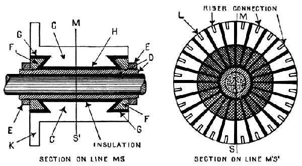
Figs. 324 and 325.—Side and end sectional views of commutator showing construction. The parts are: C, segments; D, tubular iron hub; E, end nuts; F, clamps; G, insulation; L, riser connection.
It is very important that all the parts of the commutator should be fitted together perfectly and screwed up tightly, in order to prevent looseness. Commutator segments are often made with the washers E, projecting beyond the ends, but such construction reduces the effective length of the commutator, therefore the under cut form of bar is preferable.
299
In the construction of commutators, the conditions of operation require that there be:
1. Adequate insulation;
It is necessary to have good insulation between each segment, and a specially good insulation between the segments and the hub or sleeve on which they are mounted; also between the segments and end clamps. The insulating material must not absorb moisture, hence asbestos, plaster, or vulcanized fibre are not used. The end insulating rings are usually built up of mica and shellac, moulded while hot under pressure to the correct shape.
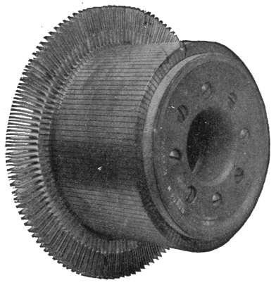
Fig. 326.—Front view of Western Electric Commutator for bar wound armature. This commutator is made of hard-drawn copper and insulated throughout, ventilating spaces being provided near the shaft.
2. Rigidity against centrifugal force;
Since the segments are subject to centrifugal force, they must be securely clamped in place. Screws cannot be used, for that would destroy the insulation. They are therefore held in place by insulated clamps as shown in fig. 324. These clamps should be strong and capable of holding the segments firmly in position, for if a segment should rise out of its place through centrifugal force, it would disturb the action of the brush and cause sparking.
300
3. Provision for wear.
The segments should be of considerable radial depth, so that the commutator may be turned down from time to time to preserve its circular form.
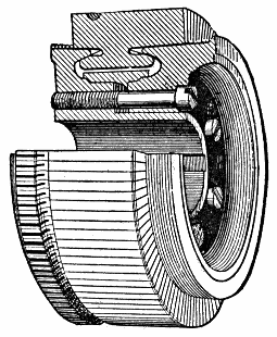
Fig. 327.—Sectional view of a General Electric commutator. The segments are of rolled or forged copper and are separated by soft mica insulating sheets. This mica must wear down evenly with the copper, hence its consistency is important. The segments are wedge shaped so that when drawn radially inward they support each other like the stones of an arch. They are drawn together by hollow cone collars which bear upon lugs projecting from the ends of the segments. These lugs are turned to form a smooth cone after the segments are assembled. The collars are insulated with mica from the segments and they are held in place by nuts upon the commutator shell or by bolts passing from end to end under the segments. The segments are also provided with lugs for connection to the windings.
Points Relating to Commutators.—1. The number of commutator segments depends on the scheme of winding and on the number of sections in the armature winding.
2. Increasing the number of bars diminishes the tendency to spark, and lessens the fluctuations of the current.
There are two practical reasons for not using a very great number of segments: it increases the cost, and in small machines the segments would be so thin that a brush of the proper thickness to collect the current would lap over, or bridge several segments.
301
Types of Commutator.—Commutators are made in various forms, but they may be grouped into two general types:
1. Commutators for closed coil armatures;
These consist of a large number of segments or bars, insulated from each other and varying in number according to the scheme of armature winding, and on the number of sections into which that winding is grouped.
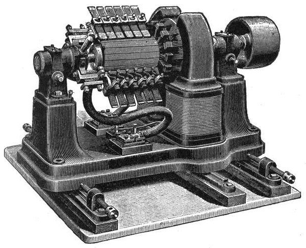
Fig. 328.—A large current low voltage bipolar dynamo built for electrolytic work and here shown to illustrate the large size commutator and brushes necessary to collect the large current. Carbon brushes would not be suitable for this class of machine because even with copper brushes, whose conductivity is much higher than carbon, the commutator must be of considerable size to give the required brush contact area. The contrast between the axial lengths of the armature and the commutator is very marked. The rocker construction is of the ordinary type, and heavy flexible cables conduct the current from the brush holders to the fixed terminals. The machine here illustrated gives 310 amperes at 7 volts when running at a speed of 1400 R. P. M., corresponding to an output of 2.17 kilowatts.
302
2. Commutators for open coil armatures;
This form of commutator is used on some machines designed especially for arc lighting, such as the Brush and Thomson-Houston machines. They consist of a comparatively small number of segments each of which covers a wide angle, and are separated from each other by air gaps.
3. The segments should be of considerable depth to permit returning occasionally so that their circular form may be preserved;
4. The insulating material must be such that it will not absorb oil or moisture;
Mica is best adapted for insulation, but as there are a great many varieties, differing greatly in hardness and other equalities, it is important to select the kind that wears at the same rate as the segments. If the mica be too hard, the wearing of the segments will leave it projecting and prevent proper contact with the brushes; again, if the mica be too soft, it will result in furrows or depressions between the segments into which copper dust will collect, causing short circuits.
303
With respect to construction, brushes may be broadly classified as: 1, those made of metal, and; 2, those made of carbon. There are several varieties of metal brush, such as:
1. Gauze brushes;
2. Wire brushes;
3. Laminated or strip brushes.
Gauze Brushes.—These are very flexible and yielding, their use being attended with little wear of the commutator.
Ques. What is the construction of a gauze brush?
Ans. A gauze brush is made up of a sheet of copper gauze, folded several times, with the wires running in an oblique direction, so as to form a solid flat strip of from ¼ to ½ inch in thickness, increasing with the volume of the current to be collected.
Ques. What is the object of folding the gauze with the wires running in oblique directions?
Ans. It is to prevent the ends of the brush fraying or threading out, which would be the case if the gauze were folded up in any other manner.
304
Ques. What are the features of gauze brushes?
Ans. They make good contact, but are quite expensive. They may be set either tangentially or radially, the latter preferably, since the point of contact remains the same as the brushes wear away.
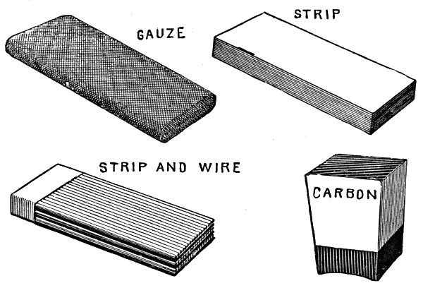
Figs. 329 to 332.—Various forms of brush. Fig. 329 gauze brush; fig. 330 laminated or strip brush; fig. 331 strip and wire brush as used on the early Edison machines; fig. 332 carbon brush. Carbon is preferred to copper for brushes on account of the reduction of sparking secured by its use.
Wire Brushes.—This class of brush, which was extensively used before the invention of the gauze brush, is made up of a bundle of brass or copper wires, laid side by side and soldered together at one end. Since wire brushes are harder than the gauze brush, they are more liable to cut or score the commutator, and are also more troublesome to trim. 305
Laminated or Strip Brushes.—These probably represent the simplest form of brush, but are not extensively used owing to the lack of flexibility. They consist of a number of strips of copper or brass, laid one upon the other and soldered at one end, as in fig. 330.
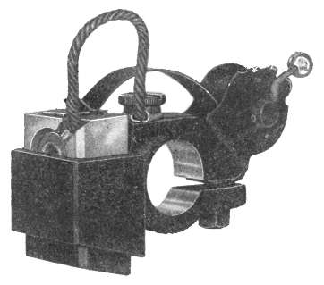
Fig. 333.—General Electric brush holder. The brush holder yoke consists of a cast iron ring of elliptical section, supported from the bracket of the end shield in such a manner as to facilitate the shifting of the brushes. It is provided with a suitable handle, and may be fastened in any position by means of a thumb nut on the outside of the bracket. It is so constructed that the tension on the individual brush can be adjusted without lifting the brush from the commutator and without the use of tools. The brush can be removed while the machine is running, without moving the holder on the stud and without disturbing any other brush. Removal of the brushes for inspection can be accomplished without permanent change in the adjustment of the tension of the brush holder spring. The connection between the brush and stud is made through a flexible copper connection.
Ques. What name is generally given to strip brushes?
Ans. They are commonly and erroneously called tangential brushes, but they are really beveled at the end and set inclined to the line of tangency so that the ends of all the sheets will make contact.
306
In the Brush and Thomson-Houston arc dynamos, in which the current is limited to ten amperes, the brushes consist of a simple strip of flexible sheet copper, the ends of which are slit in a number of places so as to insure contact at several points.
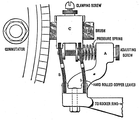
Fig. 334.—Crocker-Wheeler brush holder. The carbon brush B is firmly clamped in the "box" C by two screws which bear on a sheet of brass to protect the carbon from being broken by the ends of the screws. The box C is carried by four flexible springs S S, one at each corner and formed of hard copper leaves. These are fixed at one end to the box and at the other to the solid base which is in one piece with the spoke attached to the rocker ring. An adjusting screw passes through appropriate lugs on the box C and loosely through the head A of a fixed arm a. Between the lower surface of a and the upper lug on the box C is placed the pressure spring.
Carbon Brushes.—When metallic brushes are used upon the commutators of high tension machines, they frequently give rise to excessive sparking and also heating of the armature, the metallic dust given off appearing to lodge between the segments of the commutator, thus partially short circuiting the 307 armature. To obviate this, carbon brushes are extensively used in such dynamos, this material being found very effectual in the prevention of sparking.
Ques. What is the usual form of carbon brushes?
Ans. They are usually in the form of oblong blocks.
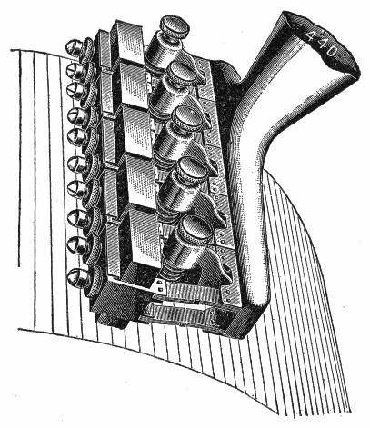
Fig. 335.—Perspective views of Crocker-Wheeler brush holder. This holder is of the parallel type in which the brushes may be adjusted without affecting the lead. Each brush is held rigidly in its box and there are no sliding contacts in the path of the current. The holder is further described under fig. 334.
Ques. How are they adjusted on the commutator?
Ans. They are set "butt" end on the commutator, and fed forward as they wear away by means of a spring holder.
308
Ques. Why are carbon brushes so extensively used?
Ans. Because they are the only form of brush that will give good commutation with fixed lead.
Ques. What may be said of the different grades of carbon in use for brushes?
Ans. The very soft carbon leaves a layer of graphitic matter on the commutator, and at high voltages, this may cause sparking; such grade of carbon should only be used on low voltage machines.
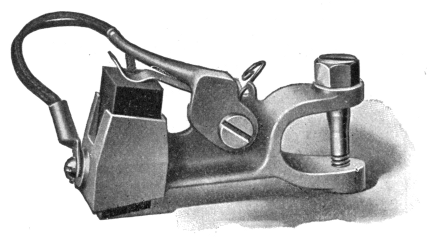
Fig. 336.—Western Electric box type brush holder. The box which holds the brush is broached to allow the brush to slide freely, but not loosely, to and from the commutator against which it is normally held by a lever acting directly upon the brush head. This avoids the possibility of uneven bearing on the commutator, as the brushes are allowed very slight lateral or angular motion. The adjustment of a brush is also simplified after it has been removed and then replaced. Tension on the brush head is obtained by a special spring which maintains any given tension for which it may be set. An auxiliary flat steel spring on the lower side of the lever acts as a shock absorber between the lever and the brush head, absorbing all minor vibrations caused by a worn commutator. Side contact between brush and brush holder is not relied upon to carry the current, flexible copper pigtails performing this function to the exclusion of sliding contacts or tension springs, in order to reduce the brush loss. It is not necessary to take the brush rigging apart or loosen cable connections when it is desired either to remove or reverse the brushes to change the direction of armature rotation.
Ques. How are the ends of carbon brushes treated and why?
Ans. They are usually covered at their upper part with a coating of electro-deposited copper to insure good contact with the holder.
309
Comparison of Copper and Carbon Brushes.—Copper brushes tend to tear and roughen the surface of the commutator, while carbon brushes tend to keep the surface smooth. Copper causes more wear of the commutator than carbon. With carbon brushes, the armature may be run in either direction. The resistance of carbon being greater than copper, there is less short circuiting caused by carbon particles than by those of copper.
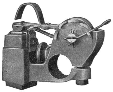
Fig. 337.—Westinghouse brush holder. It is made of brass, cast in one piece, and of standard sliding type with a shunt of braided copper wire directly connected to a clamp on each brush and to the solid portion of the holder, where it is held by a screw. This shunt relieves the spring of heavy currents. The holder is so arranged as to be easily accessible for adjustment, cleaning and renewal of carbons. Proper tension is provided by spiral strap springs so mounted as to eliminate friction and give uniform pressure over a wide working range. The spring tension is readily adjusted by a simple ratchet arrangement.
Ques. What is the chief merit of carbon brushes?
Ans. They give less sparking than other types.
Ques. How has the construction of carbon brushes been varied?
Ans. Since, for minimum sparking, it is only necessary that the brush have high resistance in the region near its edge,310 attempts have been made to increase the conductivity of the other portions by combining with the carbon, copper sheets or wires.
Ques. What are the objections to carbon brushes?
Ans. They are easily broken and not being flexible, vibration, or any roughness of the commutator will cause bad contact.
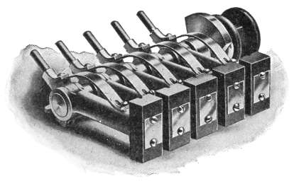
Fig. 338.—Holzer Cabot multiple brush holder. Each brush is fastened securely to a machined surface by one or two machine screws, making a positive contact. Several strips of flexible copper of ample section to carry the current are interposed between the part of the holder carrying the brush and the portion clamping the stud, no sliding contact or spring being therefore required to carry any current. The brushes are proportioned for a carrying capacity of not more than 25 amperes per square inch of brush surface. The brush can be adjusted to any degree of tension during the operation of the machine if necessary. Each holder is insulated in such a manner that no short circuit can occur if the holder be accidentally tipped backward while the operator is changing a brush or cleaning the commutator during a run.
Ques. For what class of machine are carbon brushes specially adapted?
Ans. For machines furnishing a small current at high pressure.
When carbon brushes are used, it is desirable that the current be small, because, on account of the low conductivity of the carbon, more contact area is necessary than with copper for equal current transmission. For fixed lead and fluctuating currents, carbon brushes should be used.
311
Ques. For what class of machine are copper brushes especially adapted?
Ans. For machines furnishing large current at low pressure, as in fig. 328.
Size of Brushes.—The number of brush sets depends upon the number of poles of the machine, but there may be several brushes in each set. It is usual, except in the smallest machines, to place at least two brushes exactly similar side by side instead of one broad brush, thus allowing one brush to be removed for trimming or renewal while the machine is running. Moreover, better contact is secured by this sub-division, because a slight elevation in the commutator surface at one point may slightly raise one brush of a set at each revolution without much harm, while with one broad brush, the entire brush would be lifted, causing bad sparking.
Ques. What determines the number of brushes in each set?
Ans. It depends upon the current capacity, size of machine, and judgment of the designer.
Ques. What may be said with respect to the dimensions of the brushes?
Ans. No general rule can be given for breadth and thickness of brush. The contact face must clearly be wider than the thickness of the insulation between commutator segments, since the period of commutation must last an appreciable interval of time on account of self-induction.
Ques. What should be the minimum width of the brush contact face?
Ans. It may be taken as one and one-half times the thickness of the commutator segments.
312
Ques. How wide should a carbon brush contact be?
Ans. The brush should be thick enough to cover two and one-half commutator segments. The thickness should in no case be excessive on account of the loss due to heating, which results from the difference of potential at the forward and rear edge of the brush.
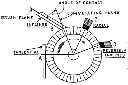
Fig. 339.—Contact angle for the different types of brush. At A is shown a brush with tangential contact, and at B, a so called tangent brush; the latter is properly called an inclined brush. Sheet copper brushes are set tangentially as at A, and gauze brushes inclined as at B. Carbon brushes are placed radially as at C when mounted in box holders, and inclined opposite to the direction of rotation when used with reaction holders.
Contact Angle of Brush.—This may be defined as the angle which the brushes make with the commutating plane as shown in fig. 339. The several kinds of brush, together with the varied conditions of operation require different contact angles ranging from zero to 90°.
Thus in the figure, a copper strip brush may lie at 90° or tangentially as at A.
313
Wire or gauze brushes should make a more or less acute angle as at B, in order to present the end and not the side of the brush to the commutator.
Carbon brushes may be placed end on or radially as at C, which is the position almost universally used in the case of traction or other reversing motors.
Sometimes the carbon brush is inclined as at D, in order that the revolving commutator may tend to push the brush against its supports and thus ensure better contact.
Brush Contact.—The relation between contact pressure, contact resistance, and friction of brushes varies greatly for different kinds of brush. Copper brushes will carry from 150 to 200 amperes per square inch of contact surface; and carbon brushes from 40 to 70 amperes per square inch. The usual contact pressure is 1.25 to 1.5 pounds per square inch for copper brushes, and 1.5 to 2 pounds per square inch for carbon brushes. The rim velocities of commutators vary from 1,500 to 2,500 feet per minute, the velocity usually increasing with the size of the machine.
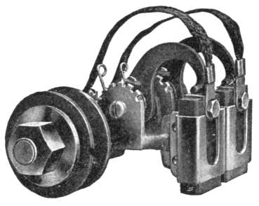
Fig. 340.—Bissell double brush holder. Flexible cables carry the current between the brushes and holders. This holder works equally well for forward or reverse rotation. Two or more holders are used on each stud except for the two smallest frames. The construction permits of adjustment or renewal of brush while the machine is in operation. Sufficient contact area of brush is provided to permit running on one carbon at ordinary loads in case the other become worn or inoperative.
Ques. What is the drop in voltage at the brushes?
Ans. For carbon brushes it is about 0.8 to 1.0 volt at each contact, or 1.6 to 2.0 volts for the two, positive and negative, contacts of a machine.
314
This value is not materially affected by placing a number of brushes in parallel or by using several sets, as in the case of multipolar machines, as such arrangement merely reduces the current density, and since the contact resistance varies in the inverse ratio, their product remains nearly constant.
Ques. What may be said of the friction of the brushes?
Ans. The coefficient of friction of brushes is about .2 to .25 for copper and .3 for carbon.
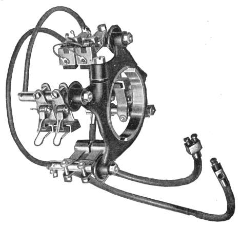
Fig. 341.—Western Electric brush gear. The brush holders carry carbon brushes and are so designed that the brushes may be firmly clamped in position and also be capable of independent adjustment. Any brush can be removed while the machine is in operation without disturbing the others and without moving the holder on the stud.
Ques. How many watts are lost at the brushes?
Ans. The watt loss is equal to 1.6 to 2. volts for carbon multiplied by the total current carried.
The watt lost on account of friction may be calculated by the formula: ((.3 x 746)/33000) × (P x S) = watts lost by carbon friction, in which P 315 is the total pressure in pounds on the commutator, and S, the rim velocity of the commutator in feet per minute.
The losses due to contact resistance and brush friction are very liable to be greatly increased above the values that may be obtained by the preceding methods, if the commutator and brushes are dirty and rough, or not in good condition.
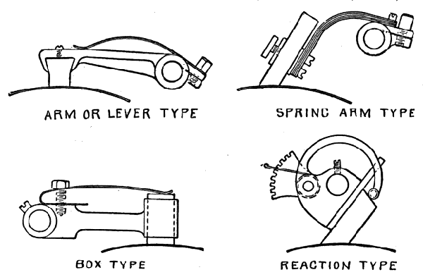
Figs. 342 to 345.—Various types of brush holder. Fig. 342, arm or lever type; fig. 343, spring arm type; fig. 344, box type; fig. 345, reaction type.
Brush Holders.—These are devices employed to hold the brushes against the commutator with the proper pressure. They differ considerably in various types of machine, hence, no general rules can be given with respect to their construction or use, but any brush holder must fulfill the following requirements:
1. It must hold the brush securely and at the same time feed it forward as it wears away so as to maintain a proper contact;
2. It must hold the brush at the proper contact angle;
316
3. It must be capable of being raised from the commutator, and held out of contact by some form of catch;
4. It must be so constructed that the brush can be easily removed for cleaning or renewal;
5. The spring pressure must be adjustable;
6. The brush holders themselves must be carried on a rocker arm, or rocker ring.
It is desirable that brush holders be capable of individual adjustment, so that each may be set at its own point of minimum sparking. A few forms of brush holder are illustrated in figs. 342 to 345.
The various kinds of brush holder may be divided into four types:
1. Arm or lever type;
2. Spring arm type;
3. Box type;
4. Reaction type.
In the arm or lever type the brush is firmly attached to the extremity of a rigid arm capable of movement about the brush spindle, except in so far as it is restrained by a spring as in fig. 342.
Fig. 343 shows a brush holder of the spring arm type. The brush is firmly attached to the extremity of a spring arm, the other end of which is secured to the brush spindle, and when once adjusted is not capable of movement about the brush spindle.
In the box type of brush holder as illustrated in fig. 344, the brush is free to move up and down in the brush box, so far as it is not restrained by a spring rigidly secured to the arm which carries the brush box at its extremity.
317
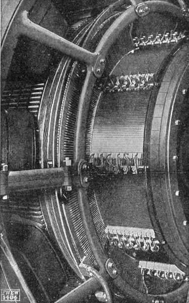
Fig. 346.—Fort Wayne type MPL dynamo; view showing details of armature, commutator and brush rigging of large machine. The laminations of the armature core are punched from thin sheet steel, annealed and japanned. Spacing ribs are built into the core at proper intervals forming air passages for ventilation. In addition, there are recesses in the inside of the flanges which permit the passage of air from the interior around the ends of the core to the openings in the end flanges. The armature coils are constructed of round or bar copper on standard forms. The coils are laid in slots in the surface of the core. The commutator is constructed of bars of hard-drawn copper of uniform size and shape, supported and clamped at either end between beveled rings and securely seated on the commutator drum. The drum is connected by radial arms to the commutator sleeve which is mounted and keyed on the armature hub extension.
318
Fig. 345 shows the reaction type of brush holder, in which the movement of the brush is constrained in one direction by the surface of a part rigidly secured to the brush spindle, and is further constrained by a spring controlled arm, the pressure of which is capable of ready adjustment.
Among the special forms of brush holder may be mentioned
1. Scissor type of brush holder, used for slip rings, and consisting of two arms pivoted together like a pair of scissors. The lower ends of the arms carry the brushes, suitably mounted, and the upper ends are drawn together by a spring, which thus exerts pressure on the brushes.
2. Clock spring type of brush holder in which the necessary contact pressure is applied to the brush by means of a clock spring, which, with the aid of a ratchet may be wound up and adjusted to any desired pressure.
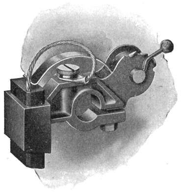
Fig. 347.—Western Electric brush holder. This holder consists of a rugged iron casting, elliptical in section, and supported from the commutator end bearing bracket in such a manner as to provide for the shifting of the brushes. A handle attached to the yoke aids in this shifting and a thumb nut on the outside holds the whole brush gear in the desired position. The brush is fed through an accurately broached slot by a spring which maintains uniform pressure against the commutator throughout the wearing length of the brush. The long lever arm of the spring is sufficiently flexible to take up any minor vibrations of the brush. The tension of the brush may be adjusted without lifting it from the commutator or disturbing any of the other holders. The brush, may be removed for inspection by throwing the spring out of notch. The brush is connected to the holder by flexible copper pig tails of ample current carrying capacity.
319
Ques. How are brush holders carried?
Ans. They are carried by a rocker arm for bipolar, and by a rocker ring for multipolar machines, which is mounted upon one of the main bearings, or upon a support specially provided for it, being pivoted to revolve from the same center as the shaft, to permit shifting the brushes.
Ques. Mention one trouble sometimes encountered with brush holders.
Ans. There is sometimes trouble resulting from the current passing through the spring which heats it and destroys its elasticity.
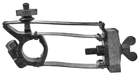
Fig. 348.—Western Electric parallel spring brush holder as used on the larger machines.
Ques. How may this be avoided?
Ans. By insulating one end of the spring, and carrying the entire current directly from the brush itself to the main conductors by a flexible copper strip or cable firmly connected to both.
Ques. What may be said with respect to brush construction on machines for electrolytic work?
Ans. The collection of large currents at low voltage, generated by comparatively small machines, requires careful design of brushes and brush holders. The commutator is longer than the 320 commutators on machines of equal capacity at higher voltages, and as a rule the commutator segments are thicker and fewer in number. Each brush set is made up of numerous narrow brushes rather than two abnormally wide ones.
An example of brush and brush gear designed to meet such conditions is shown in fig. 328.
In large machines for electrolytic work, it is not unusual to find the current divided between two wide commutators, one at each end of the armature, thus giving a longer axial bearing surface for the brushes without inconveniently lengthening the pins upon which the separate brushes are threaded.
Multipolar Brush Gear.—The brush gear which includes the holders and carrier arm or ring, becomes more complicated as the number of poles and magnitude of the current is increased.
In the early days of multipolar machines, schemes of armature winding were devised such that all the necessary cross connections were made inside the machine, and the number of brush holders reduced to two and placed at an angular distance apart depending upon the number of poles. Such windings, though possible, are not used much, chiefly on account of their complexity, which not only increases the danger of error in construction, but also makes repairs costly. In modern multipolar machines, such complicated windings are avoided, and the several sets of brushes are connected together in two groups, positive and negative. These connections are carefully designed as part of the brush gear.
Ques. How are the brushes held in large multipolar dynamos?
Ans. They are held at the proper points of commutation by arms offset from a cast iron rocker ring, which is itself supported by brackets projecting from the magnet yoke as shown in fig. 346.
Ques. What provision is made for shifting the ring to adjust the lead?
Ans. The ring is rotated by means of a worm gear and hand wheel.
321
The armature of a dynamo has been defined as: a collection of coils of wire wound around an iron core, and so arranged that electric currents are induced in the wire when the armature is rotated in a magnetic field.
From the mechanical point of view the armature may be said to be made up of the following parts:
1. Shaft;
2. Core;
3. Spider
(in large machines);
4. Winding;
5. Commutator
(broadly speaking).
Of the two types of armature, ring and drum, the latter is almost universally used, hence the examples of construction which follow will be confined chiefly to this type.
Shaft.—A typical armature shaft is shown in fig. 349. It is made of steel and, except in the smaller machines, is thicker in the middle than at the ends for stiffness to withstand the 322 strong magnetic side pull on the core when the latter is slightly, nearer one pole piece than the other.
Ques. What is the object of providing shoulders on the shaft as in fig. 349?
Ans. They serve to keep the armature in the proper position with respect to the bearings.
Ques. How is the shaft proportioned?
Ans. If it be proportioned to secure the proper stiffness, it will be found of ample size to resist the twisting strain.
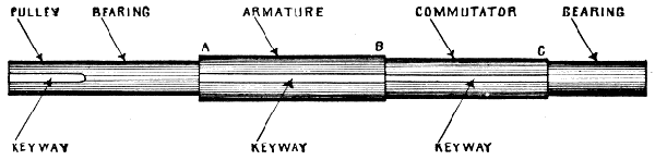
Fig. 349.—Typical shaft for an armature. The illustration shows the keyways for pulley armature and commutator. In the smaller sizes, there is usually a flange at A, and threads at B and C for retaining nuts.
The shaft is subject also to bending by the weight of the armature, by the magnetic drag on its core, and in belt driven machines, by the lateral drag of the pulley. When running, it is also subjected to bending stresses if the armature be not properly balanced. If the bearings do not give, it is evident that all such actions tend to bend the shaft at definite points.
Core.—In the small and medium size dynamos, the core is attached direct to the shaft. There are two kinds of core:
1. Smooth;
2. Slotted.
323
Ques. What may be said of the smooth type of core?
Ans. It has become obsolete, except in special cases, as for machines used for electrolytic work where a large current at low voltage is required.
Ques. What is necessary with a smooth core?
Ans. Driving horns as later described.
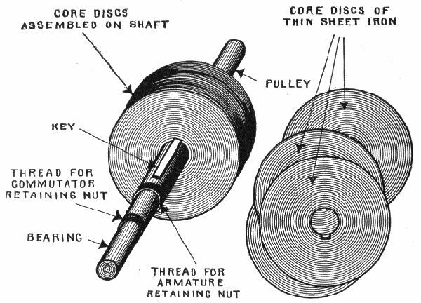
Fig. 350.—Laminated smooth core armature partly assembled. It consists of numerous discs of thin sheet iron threaded on the shaft and pressed together by end plates. The object of this construction is to prevent eddy currents.
Ques. What is a slotted core?
Ans. One having a series of parallel slots, similar to the spaces between the teeth of a gear wheel, and in which the inductors are laid.
324
Ques. What provision is made to avoid eddy current in cores?
Ans. They are laminated.
Ques. Describe this method of construction.
Ans. The core is made of stampings of thin wrought iron or mild steel. The numerous discs stamped from the sheet metal are threaded on the shaft as in fig. 350, forming a practically solid metal mass.
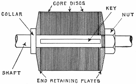
Fig. 351.—Sectional view of laminated smooth core armature showing end plates, flange and retaining nut. A key is provided to prevent rotation of the core with respect to the shaft.
Ques. How thick are the discs?
Ans. The thickness ranges from .014 inch to .025 inch, corresponding to 27 and 22 B and S gauge respectively, 27 gauge being mostly used.
Ques. How are the discs held in place?
Ans. By two end plates pressed together either by large nuts screwed directly on the shaft as in fig. 351, or by bolts 325 passing through the core from end to end, as in fig. 352, holes being punched in the discs for the purpose.
Ques. What precaution is taken with respect to the core bolts?
Ans. They are insulated from the core by tubes and washers of mica or other insulating material.
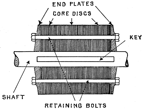
Fig. 352.—Laminated armature core with through retaining bolts. In the larger sizes, these bolts are used instead of a nut threaded on the shaft on account of the large size of the latter.
Ques. What is the construction of the core end plates, and why?
Ans. The rims are beveled quite thin to avoid eddy currents.
Ques. How is the core connected to the shaft?
Ans. Since the core has the full torque exerted upon it by the drag of the inductors, it must be firmly connected to the shaft by means of a key, as shown, so that it may be positively driven.
326
Core discs are stamped in one piece up to about 30 inches in diameter, and for larger sizes they are built up from sections as later described.
Figs. 353 and 354 show two forms of disc stamped in one piece. The first illustrates a solid disc, and the second a ventilated disc in which more or less of the metal is cut away near the center, thus providing passages for the circulation of air which carries away some of the heat generated in the armature.
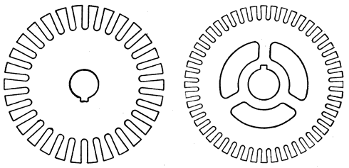
Figs. 353 and 354.—Solid and ventilated core discs. In fig. 353, the metal cut away near the center reduces the weight and provides passages for air circulation. In some instances a forced circulation is secured by means of a fan attached to the armature, as shown in fig. 366.
Insulation of Core Discs.—When the discs are stamped from very thin metal, the mere existence of a film of oxide is sufficient insulation. It is usual, however, to apply a quick drying varnish that will give a hard tough coat and not soften with heat or become brittle and crumble under vibration. The varnish may be applied either by dipping or with a japanning machine; it must be very thin, and the solvent employed should be a very volatile spirit.
Forms of Armature Teeth.—The teeth stamped in the core discs are made in various shapes, depending largely on the 327 method of securing the inductors in the slots against electromagnetic drag and centrifugal force. The teeth may be cut with their sides:
1. Inclined;
2. Projecting;
3. Notched.
Ques. What may be said of teeth with inclined sides?
Ans. A tooth of this type is shown in fig. 356, being slightly narrower at the root than at the top, the resulting slot having parallel sides.
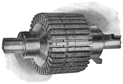
Fig. 355.—Western Electric slotted armature core. The laminations are of sheet steel, annealed and japanned. They are mounted directly on the shaft, (except in the large sizes) and held in place by substantial end plates.
Ques. What are the features of the projecting type of tooth?
Ans. The projecting type is shown in figs. 357 and 358 in which the tops project; this gives a larger core area around the circumference of the armature which reduces the reluctance of the air gap, and provides projecting surfaces for retaining the inductors in the slots by the insertion of wedges.
328
Ques. What is the object of cutting notches in teeth?
Ans. They are provided for the insertion of retaining wedges, as in fig. 361; this results in less area at the top of the teeth.
Ques. How should teeth be proportioned to secure most efficient operation?
Ans. The width of the tooth should be about equal to the width of the slot minus twice the thickness of the slot insulation; that is, the cross sectional area of the teeth should be equal to that of the slots.
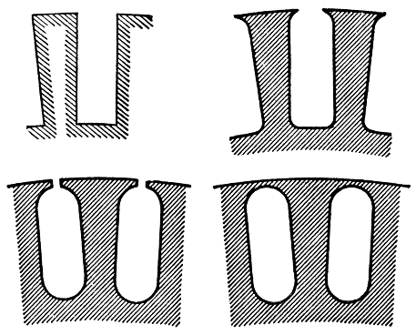
Figs. 356 to 359.—Various forms of armature teeth; fig. 356 inclined type forming a slot with parallel sides; figs. 357 and 358 projecting type which provides a support for the retaining wedges; fig. 359 enclosed type which forms "tunnels" for the inductors.
Advantages and Defects of Slotted Armatures.—The slotted armature, sometimes called the Pacinotti armature, after its inventor, has the following advantages over the smooth type: 329
1. The inductors are held more firmly in place to resist stresses due to electromagnetic drag and centrifugal force;
2. The inductors are protected by the teeth against mechanical injury;
3. Less reluctance of the air gap;
4. The intermittent induction due to the presence of the teeth prevents the formation of eddy currents.
5. When the teeth are saturated they oppose the shifting of the lines due to armature reaction.
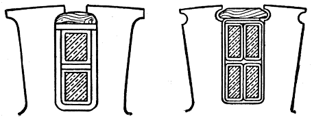
Figs. 360 and 361.—Projecting and notched teeth; cross sections showing inductors and retaining wedges in place.
The disadvantages of slotted armatures compared with the smooth type are:
1. Greater hysteresis loss, caused by denser flux in the teeth;
2. Generation of eddy currents in the polar faces when the latter are not of laminated construction;
3. Greater self-induction in the armature coils;
4. Construction more expensive;
5. Leakage of magnetic lines through core, exterior to winding.
The generation of eddy currents in the polar faces may be overcome by making the air gap at least 50 per cent. of the distance between the teeth, so that the magnetic lines can spread from the corners of the teeth, and become nearly uniformly distributed over the polar faces. Magnetic leakage through the core may be reduced by making the amount of metal above the inductors very small.
330
Slotted Cores; Built Up Construction.—In the case of large dynamos, the core discs are built up in order to reduce the cost of construction; the following parts are used:
1. Spider;
2. Core rings split into sections.
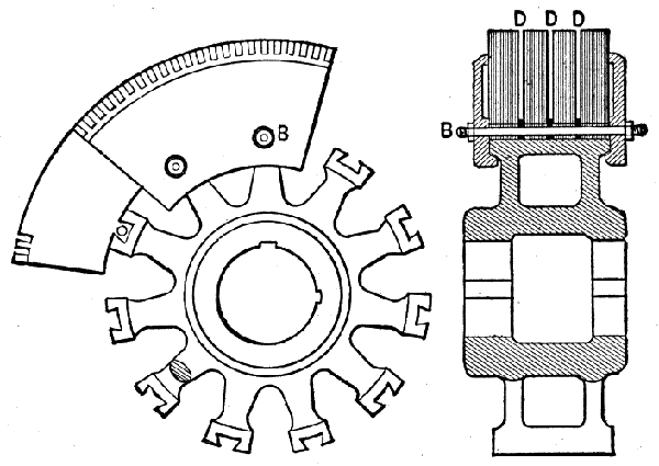
Figs. 362 and 363.—Side and end view of built up armature core. The sheet metal ring sections containing the teeth are fastened into dovetail notches in the spider as shown. The layers of ring sections are placed so as to break joints and are held by end clamps and through bolts B. Distance pieces are inserted at intervals to provide ventilating spaces D, D, D.
Ques. What is the approved method of core construction in large armatures?
Ans. The core should be of the built up construction to avoid waste of material in the stampings.
Ques. Describe the construction of a built up core.
Ans. Ring sections stamped, from sheet metal are fastened to a central support or spider, which consists of an iron hub 331 with radiating spokes and a rim with provision for fastening the rings. The rim of the spider is provided with dovetail notches into which fit similarly shaped internal projections on the core segments. These features are shown in figs. 362 to 364. Each layer of core sections is placed on the spider so as to break joints and the core thus formed is firmly held in place by end clamps as shown. The manner of fastening the rings to the spider is an important point, for it must be done without reducing the effective cross section of the core in order not to choke the magnetic flux.
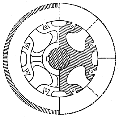
Fig. 364.—Built up core with four spoke spider, each spoke carrying two dovetail notches In this construction a little more air space is obtained for ventilation than where a separate spoke is provided for each notch.
In order to secure a better fit and reduce the machine work, the spider hub in large machines is sometimes cored with enlarged section between the outer bearing surfaces, and it is not unusual to find these surfaces turned to two different sizes as in fig. 365, to admit of easier erecting.
332
To avoid any trouble that may arise by unequal expansion, the rim of the spider is not made continuous, but in several sections as shown in fig. 364. The rim here consists of four sections each of which has two dovetail notches. By thus dividing the rim into sections, its weight is somewhat reduced and the ventilating spaces between the sections increased.
Ventilation.—In the operation of a dynamo more or less heat is generated, depending on the load; hence it is desirable that provision be made to carry off some of this heat to prevent excessive rise of temperature.
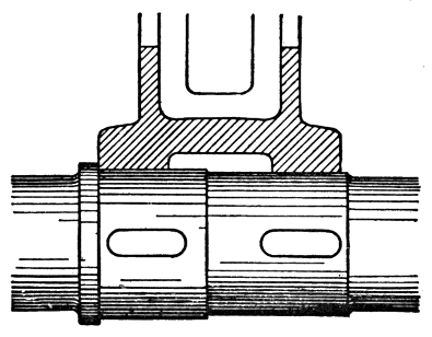
Fig. 365.—Hub and shaft design on large machines to reduce the machine work and facilitate erecting.
Ques. Why do armature cores heat?
Ans. They heat from these causes: eddy currents, hysteresis, and heat generated in the inductors.
Ques. How is adequate ventilation secured?
Ans. The spider is constructed with as much open space as possible through which air currents may circulate. The core 333 is divided into several sections with intervening air spaces D as shown in fig. 363, the discs being kept apart at these points by distance pieces. These openings between the discs are called ventilating ducts; they are usually spaced from 2 to 4 inches apart.
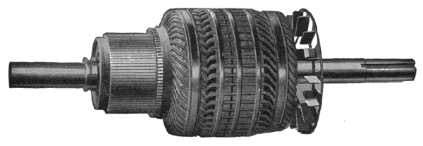
Fig. 366.—Western Electric barrel wound armature, having a fan attached at one end to induce a circulation of air for ventilation.
Ques. What other provision is sometimes made to secure ventilation?
Ans. In some machines a forced circulation of air is secured by means of a fan attached to one end of the armature as shown in fig. 366.
Insulation of Core.—Before the winding is assembled on the core, the latter should be thoroughly insulated. Japan or enamel insulation is not sufficient because it is liable to have bubbles or minute holes in it, or be pierced by particles of metal or by the rough edges of the core discs. Two or more layers of strong paper, fibre, canvas or mica, should be applied to the334 core before placing the inductors in position. The ends of the core should be insulated with thicker material, since the strain upon it is greater, especially at the edges.
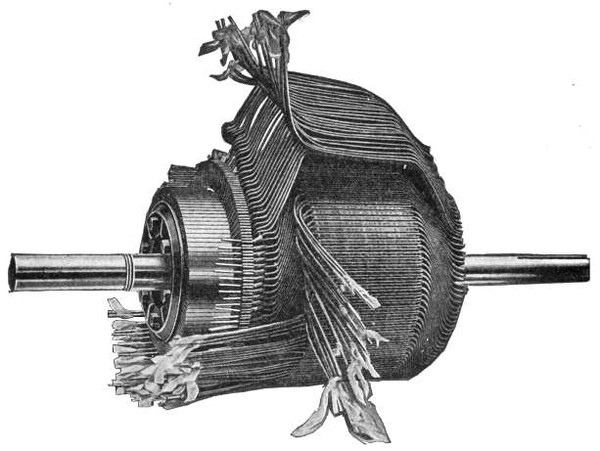
Fig. 367.—Holzer Cabot partially wound barrel wound armature showing arrangement of coils. The core is built up of thin discs of soft annealed steel, which are slotted to allow the wire to sink below the surface, this being sometimes called iron clad construction. The discs are held by end plates, clamped without through bolts. The coils are machine formed of round ribbon or bar copper depending on the size and purpose of the machine, being without joint except at the commutator. They lie in insulated troughs, the upper layers being insulated from the lower layers by fibre.
Armature Windings.—The subject of windings has been fully treated from the theoretical point of view in chapter XVIII. It remains then to explain the different methods employed in the shop and the mechanical devices used to construct the scheme of winding adopted.
335
Ques. What is the construction of the inductors?
Ans. They are made of copper; the ordinary form consists of simple copper wire, insulated with a double or triple covering of cotton, and in some cases copper bars are used for large current machines.
Ques. What is the objection to copper bars?
Ans. They are liable to have eddy currents set up in them as illustrated in fig. 291.
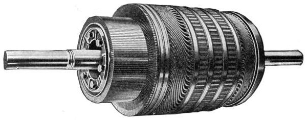
Fig. 368.—Holzer Cabot iron clad band wound armature complete; view showing openings for ventilation. The advantage of the form of winding adopted, is the ease with which a coil may be replaced in case of injury and the additional cooling surface. The coils are held in place by maple wedges secured by binding wires which are soldered throughout their length.
Ques. What may be said with respect to the sizes of wire used for inductors?
Ans. Wire larger than about number 8 B and S gauge (.1285 inch diameter) is not easily handled, hence for large inductors, two or more wires may be wound together in parallel.
According to the mechanical features and manner of assembling on the core, drum windings may be divided into several classes, as follows:
1. Hand winding;
3362. Evolute or butterfly winding;
3. Barrel winding;
4. Bastard winding;
5. Former winding.
Hand Winding.—The first windings were put on by hand and proved objectionable on account of the clumsy overlapping of the wires at the ends of the armature, which stops ventilation and hinders repairs, while the outer layers overlying those first wound, bring into close proximity inductors of widely varying voltage. The method is still used in special cases and for small machines. Such a winding has rarely, if ever, been made with one continuous wire.
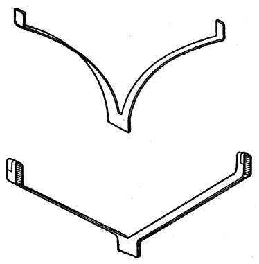
Figs. 369 and 370.—Evolute and "straight out" connectors. In small machines the connectors must be curved as in fig. 369, but in large machines, especially where the teeth are wide, they may be straight as in fig. 370. These connectors may take either of the following forms: 1. involute or evolute connectors—An involute is the curve drawn by the extremity of a piece of string which is unwound from a cylinder; 2. spiral connectors—These consist of double spirals, the commutator being usually connected to the junction of the two spirals. These connectors are also known as "butterfly" connectors.
337
Evolute or Butterfly Winding.—This mode of winding, was introduced by Siemens for electroplating dynamos to overcome the objections to hand winding. It takes its name from the method of uniting the inductors by means of spiral end connectors as shown in fig. 374, also in figs. 369 and 370, which show more modern forms.
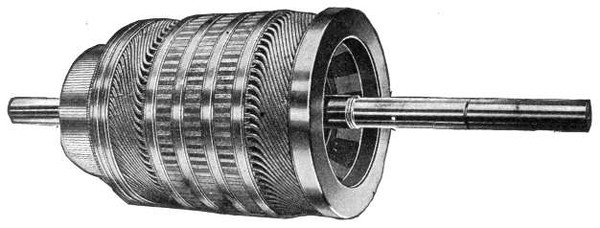
Fig. 371.—Holzer Cabot armature; rear view showing back head and coil guard. The construction of core and winding is described in fig. 367. The shaft is of crucible steel ground to gauge. The commutator segments are of drop forged copper in the smaller and hard-drawn copper in the larger sizes. The insulating material between the segments is mica. On the larger sizes, the commutator shell is fitted with a thread and mounted on a spider. This construction provides openings between the commutator and shaft for ventilation.
Ques. What are evolute connectors?
Ans. The fork shaped strips used to connect bars at different positions on the armature, as shown in fig. 369.
In large machines, especially where the teeth are wide, these connections may be straight, but in small cc machines they must be curved in the manner shown in the upper part of the figure, as the room available may diminish by as much as half, as the lowest point is reached, and the room occupied by the strip is the width of a horizontal section at various points. This width, in the case of the straight connections, is constant.
In place of the wooden block, used in early machines, for fastening the middle part of the connectors, they may be anchored to an insulated clamping device built up like a commutator and for that reason called a false commutator.
338
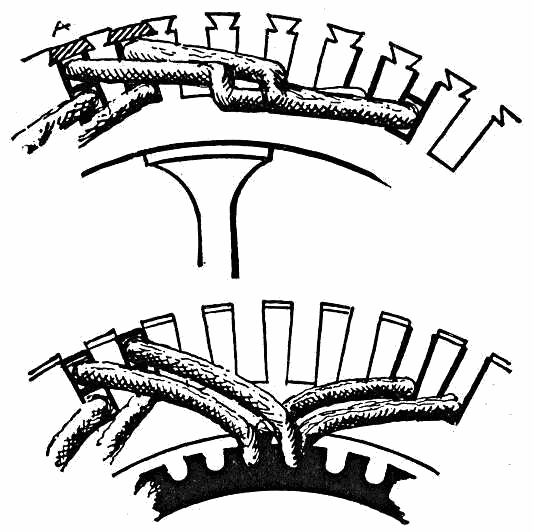
Figs. 372 and 373.—Barrel and evolute windings; end views showing placement of coils. When all the coils are wound on the former, the placing of them on the armature is a simple matter. After insulating the slots, the winder begins at any convenient slot, and inserts the coils as shown. Before he can fill all the slots, some of the first coils must be raised and the last ones inserted underneath. There is not much difference between barrel and evolute winding and one style may be used at one end of the armature and the other at the opposite end.
Ques. How are the inductors arranged in evolute winding?
Ans. In fig. 373, it will be seen that the ends of the evolute connectors lie in two planes, hence the inductors must project to different distances beyond the core. Accordingly, one long and one short bar may be conveniently placed in each slot, side by side. In large machines, especially where the teeth are wide,339 the connectors may be straight as in fig, 370. Evolute connectors may be used for either lap or wave windings.
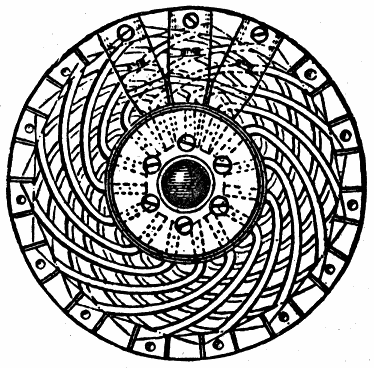
Fig. 374.—Siemens' bar armature; end view. Each inductor in the form of a bar is connected to the next by means of two evolute spiral copper strips, one bending inwardly, the other outwardly, their junction being in some cases secured to a block of wood upon the shaft. Their outer ends are attached to the bars by rivets or silver solder.
Barrel Winding.—This is a form of drum winding in which the inductors are arranged in two layers and carried out obliquely on an extension of the cylindrical surface of the drum to meet and connect with radial risers.
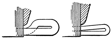
Figs. 375 and 376.—Single layer and double layer barrel winding. Barrel winding is a method of arranging the ends of armature coils as they pass from one pole to the next, in which, instead of using involute or butterfly connections, V-shaped end connections are used which lie on a cylindrical surface, which is a continuation of the armature surface. The coil ends must of necessity be arranged in two layers, but the method may be used for either one or two coils per slot, the difference in arrangement for these is here illustrated.
340
Barrel winding has been very widely adopted. Although it involves an increased length of armature, this gives additional cooling surface and provides for good ventilation.
In barrel winding, the coil ends must of necessity be arranged in two layers but the method may be used for either one or two coils per slot, the difference in arrangement for these two cases being shown in figs. 375 and 376. In the single layer barrel winding, fig. 375, each slot is occupied by but one side of one coil. In the double layer barrel winding, fig. 376, the opposite sides of two separate coils occupy space in the same slot. The coils, on emerging from the slots bend in opposite directions, and if one side of a coil occupy the bottom portion of a slot, its other side usually occupies the top portion of a slot distant from the first slot by the polar pitch.
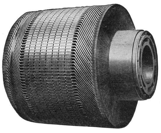
Fig. 377.—Westinghouse barrel wound armature. The coils are former wound from copper strap and are interchangeable. In the larger size machine they are of the single type. The illustration shows plainly the characteristic feature of barrel winding, namely the oblique end connectors carried out on the extended drum.
Bastard Winding.—In this type of winding, the end connectors project from the inductors in straight lines parallel to the shaft and then are bent inward. It has the 341 effect of being somewhat shorter than the barrel winding. In order to secure better ventilation, it is usual to combine a bastard winding at the rear end of the armature with a barrel winding at the commutator end. This class of winding is used only with bar armatures.
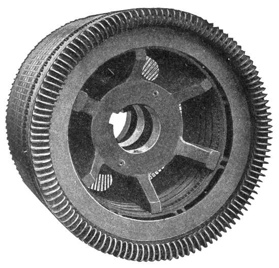
Fig. 378.—Rear end of Westinghouse wave-barrel wound armature; view showing ventilation.
Former Winding.—This relates to a method of winding coils, and not to any particular type; that is, mechanical winding as distinguished from hand winding. While hand winding is necessary for ring armatures, a drum armature is wound better and more easily by the aid of machinery.
342
Ques. What is a "former" coil?
Ans. A former coil, as its name suggests, is one that is wound complete upon a former before being placed upon the armature.
Ques. What is the advantage of this method of winding coils?
Ans. By the use of formers much time is saved, thus reducing the cost, and also by their use all the coils are symmetrical which improves the appearance of the finished winding.
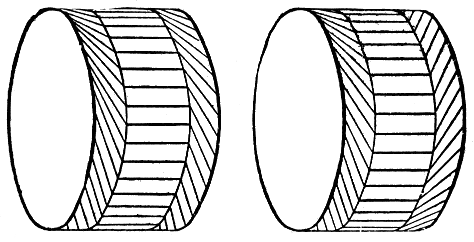
Figs. 379 and 380.—Diagrams illustrating lap and wave barrel windings.
Ques. How is the required shape of the template or former for winding the coils determined?
Ans. By winding one coil on the armature in order to ascertain its dimensions and shape; it is then removed from the armature and used as a pattern in constructing the former.
Types of Former Coil.—Of the numerous shapes of former coil, mention should be made of:
1. Evolute coils;
2. Straight out coils.
Ques. Describe the evolute type of former coil.
343
Ans. The evolute coil is wound around eight pins inserted in a board as shown in fig. 381. The required number of turns are taken around these pins and their ends G and H left projecting. The coil thus formed is now covered with tape and after removal from the board, is put into a clamp at C and F, and opened up as shown in fig. 382, which is the form required for insertion in the proper slots of the armature.
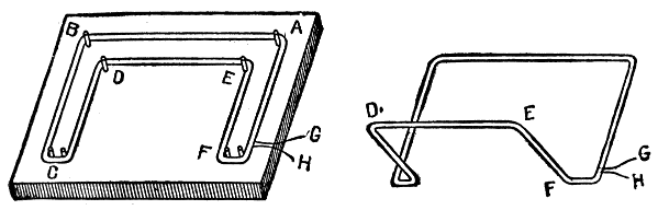
Fig. 381.—Method of winding evolute coils. In preparing the former, it is necessary to know the dimensions of the coil, hence, a pattern coil must first be made, from which the spacing of the pins can be taken so that the completed coil will fit into the slots for which it is intended. After the pins have been properly spaced on the board, the wire is wound around them as indicated, as many turns being taken as decided on for each coil. When the coil is thus completely wound, it is taken from the pins, and the lower ends, C and F, placed in a suitable clamp. The two halves of the coil are then spread apart, the coil assuming the shape illustrated in fig. 382.
Fig. 382.—Appearance of an evolute former wound coil opened out. The points A, B, C, etc., correspond to similar points in fig. 381.
Ques. What is the peculiarity of the evolute coil?
Ans. The two sides of the evolute coil have unequal dimensions. The part marked AB, in fig. 381 which is an upper layer inductor is longer than the part DE, which constitutes a lower layer inductor. The portions DC and EF act as parts of an inner layer of evolutes, and the portions AF and BC as parts of an outer layer of evolutes. These features are shown in fig. 382.
Ques. How are evolute coils placed on the core?
344
Ans. They are placed in position as shown in figs. 372 and 373, continuing around the core until all the slots are filled. To complete the operation it is necessary to raise some of the first laid coils and insert the last ones below them. The winding is thus completed and is symmetrical.
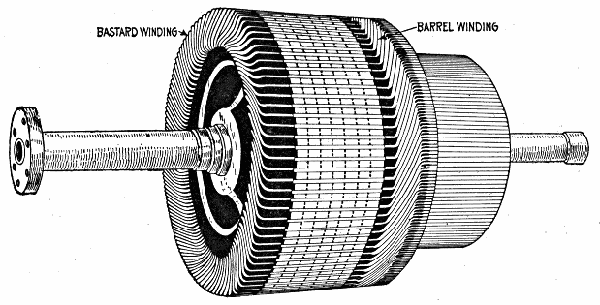
Fig. 383.—Westinghouse combination bastard and barrel winding. A bastard winding at the rear end is combined with a barrel winding at the commutator end, as shown in the illustration, to secure better ventilation.
Ques. Describe the method of winding the "straight out" type of former coil.
Ans. The straight out coil may be wound on a former such as shown in fig. 384. This consists of a board having four upright pins, A, B, D, E, properly spaced and two horizontal pins C, F, attached to extensions at each end of the board. A coil of the required number of turns is wound around these pins and then opened out as in fig. 385. After varnishing and baking it is ready to be placed on the armature.
345
Ques. For what class of winding are straight out former coils suitable?
Ans. For barrel winding.
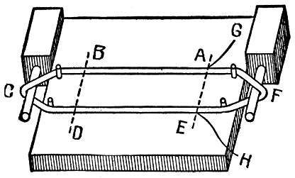
Fig. 384.—Method of winding "straight out" coils. There are several ways of making these coils. A former may be prepared, as shown in the figure, with a board having inserted four pins, and having attached two blocks at the ends carrying horizontal pins as shown. Around the several pins, the coil is wound to the required number of turns and taped. This coil differs from the evolute coil in that the two halves are of equal size, the parts which act respectively as upper and under inductor being of equal length. The coil as shown is suitable for wave winding.
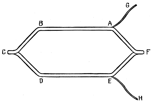
Fig. 385.—Appearance of straight out coil after being opened out. In opening out the coil, the ends C and F are put into a clamp and twisted at right angles to the plane of the coil. The letters correspond to the points indicated in fig. 384.
346
Ques. How are straight out coils placed on the core?
Ans. In the same manner as described for evolute coils; when in position straight out coils appear as in fig. 372.
Ques. What is the approved method of putting tape on a coil?
Ans. Considerable time is saved by the use of a machine designed for the purpose, such as shown in fig. 387.
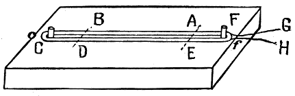
Fig. 386.—Another and simpler method of winding a "straight out" coil. A board with only two pins is employed as shown; this plan, however, gives more trouble in the subsequent opening out of the coil.
The construction of these machines is such that a roll of tape placed on a split metal ring is revolved around the coil to be taped, the coil being gradually moved until it is entirely covered.
Coil Retaining Devices.—In the operation of a dynamo there are two forces which tend to throw the inductors out of position:
1. Armature drag;
2. Centrifugal force.
Both of these forces are present with smooth core armatures, but only centrifugal force with slotted armatures. The devices used to hold the inductors in position against these forces are:
347
1. Driving horns;
2. Binding ribbons;
3. Retaining wedges.
Ques. What are driving horns?
Ans. They are simply pins or strips projecting from the surface of a smooth core as shown in fig. 251.
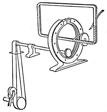
Fig. 387.—Armature coil taping machine. Numerous machines have been invented for taping armature coils. They consist essentially of a device which revolves a roll of tape around the coil, in such a direction that the tape is unwound from the roll and rewound on the coil. The speed at which the coil is fed through the machine will determine the overlapping of the tape.
Ques. What other kinds of retainer are used on smooth core armatures?
Ans. They require several binding ribbons or brass bands placed around the winding to prevent the inductors being thrown off the core by centrifugal force.
348
Ques. With slotted armatures what provision must be made for retaining the inductors in position?
Ans. Retaining wedges must be inserted into the notches or between the projecting tops of the teeth.
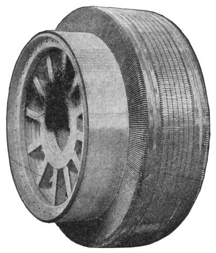
Fig. 388.—Front view of large armature for direct connected dynamo, built by the General Electric Co.
Ques. How are the wedges made?
Ans. They are usually made of well baked hard wood, such as hornbeam, or hard white vulcanized fibre. Sometimes a springy strip of German silver is used.
349
An electric motor is just the reverse of a dynamo; it is a machine for converting electrical energy into mechanical energy.
The electrical energy delivered by the dynamo must be obtained from a steam engine, gas engine, or other power; the mechanical energy obtained from the motor comes from the energy of the current flowing through its armature.
Ques. What is the construction of a motor?
Ans. It is constructed in the same manner as a dynamo.
Any machine that can be used as a dynamo will, when supplied with electrical power, run as a motor, and conversely, a motor when driven by mechanical power, will supply electrical energy to the circuit connected to it. Dynamos and motors, therefore, are convertible machines, and the differences that are found in practice are largely mechanical; they arise chiefly from the conditions under which the motor must work. Hence, the study of the motor begins with a knowledge of the dynamo, and accordingly the student should understand thoroughly all the fundamental principles of the dynamo, as already given, before proceeding further with the study of the motor.
Principles of the Motor.—All the early attempts to introduce motors failed, chiefly because the law of the conservation of energy was not fully recognized. This law states that energy can neither be created nor destroyed.
350
Early experimenters discovered, by placing a galvanometer in a circuit with a motor and battery, that, when the motor was running, the battery was unable to force through the wires so strong a current as that which flowed when the motor was standing still. Moreover, the faster the motor ran, the weaker did the current become.
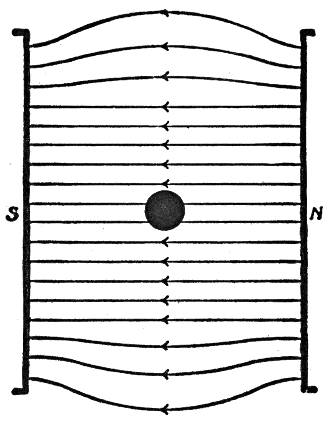
Fig. 389.—Conductor, lying in a magnetic field and carrying no current; the field is not distorted whether the conductor be at rest or in motion.
Ques. Why does less current flow when the motor is running than when standing still?
Ans. Because the motor, on account of its rotation acts as a dynamo and thus tends to set up in the circuit a reverse electromotive force, that is, an electromotive force in opposite direction to the current which is driving the motor.
351
Ques. What is the real driving force which causes the armature of a motor to rotate?
Ans. The propelling drag, that is, the drag which the magnetic field exerts upon the armature wires through which the current is flowing, or in the case of deeply toothed cores, upon the protruding teeth.
The Propelling Drag.—In fig. 389 is shown the condition which prevails when a conductor carrying no current is placed in a uniform magnetic field. The magnetic lines pass straight from one pole to the other. The field is not distorted whether the conductor be at rest or in motion, so long as there is no flow of current. This represents the condition in the air gap of a motor or dynamo, when no current is flowing in the armature.
Ques. What happens when a current flows in the conductor of fig. 389.
Ans. It sets up a magnetic field of its own as shown in fig. 390.
Ques. What is the effect of this magnetic field?
Ans. It distorts the original field (fig. 389) in which the conductor lies, making the magnetic lines denser on one side and less dense on the other as in fig. 390.
Ques. What is the nature of these distorted magnetic lines?
Ans. They tend to shorten themselves to their original form of straight lines.
352
Ques. What effect has this on the conductor?
Ans. It produces a force on the conductor tending to push it in the direction indicated by the arrow, fig. 390.
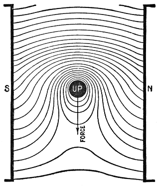
Fig. 390.—Conductor carrying a current in a magnetic field. The current flowing in the conductor sets up a magnetic field which distorts the original field as shown, making the magnetic lines denser on one side and less dense on the other. This results in a force upon the wire, which, in the case of a dynamo (fig. 391) opposes its movement, and which forms the propelling drag in the case of a motor (fig. 392).
The distorted magnetic lines may be regarded as so many rubber bands tending to straighten themselves; The result then is clearly to force the conductor in the direction indicated.
According to Lenz' law, the direction of the current in the armature of a dynamo is such as to oppose the motion producing it. When the armature of a dynamo is rotated, the bending of the lines of force of the main magnetic field due to armature reaction acts as a drag against the motion of the armature. Armature reaction increases with the increase of the armature current. Therefore, the effect of the drag increases with the increase of load and requires an additional expenditure of power to drive the armature.
In a motor, the direction of the actuating current is the reverse of that of the armature current of a dynamo, consequently, the armature 353 reaction which constitutes a drag, acting against rotation of the armature of a dynamo, becomes a pull in the direction of rotation of the armature of a motor and constitutes its real turning effect or torque which is used at the pulley to do mechanical work. The greater the load applied to the motor, the greater will be the amount of current taken from the supply mains, and consequently, the greater the torque.
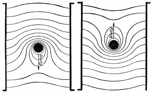
Figs. 391 and 392.—Action of the magnetic force in a dynamo and motor. In the first instance, according to Lenz' law, the direction of the current induced in the wire is such as to oppose the motion producing it. In the operation of a motor, the current supplied in flowing through the armature winding distorts the field and thus produces rotation. In the figures, the direction of the force is clearly indicated by remembering that the distorted lines of force act like rubber bands tending to straighten and shorten themselves.
Ques. What are the essential requirements of construction in a motor?
Ans. They are: 1, a magnetic field, 2, conductors placed perpendicular to the field, and 3, provision for motion, of the conductors across the field in a direction perpendicular to both themselves and the field.
354
The Reverse Electromotive Force.—When an electric current flows through some portion of a circuit in which there is an electromotive force, the current will there either receive or give up energy, according to whether the electromotive force acts with or against the current.
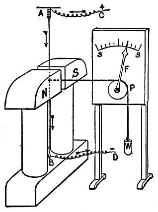
Fig. 393.—Force exerted on a current carrying conductor placed across a magnetic field. Let N, S, be the pole pieces of an ordinary electromagnet, having their faces flat and with only a narrow air gap between. In this gap is stretched the vertical copper wire A B, kept taut by a strong spring at A; current can be passed into the wire from the leads C and D. Attached to the wire in the middle of the gap is a horizontal cord passing over a pulley P and kept taut by a weight W; the pulley carries a pointer F which moves in front of a scale s s. If the electromagnet be now excited and have the polarity indicated, it will be found that on passing a strong current down the wire, the index F moves toward the right, showing a similar movement in the wire. The index returns to zero when the current in the wire ceases, and moves in the opposite direction if the current in the wire be reversed and sent up instead of down. The experiment can be further varied by reversing the magnetizing current of the electromagnet.
This is illustrated in fig. 395, which represents a circuit in which there is a dynamo and a motor. Each is rotating clockwise, and accordingly, each generates an electromotive force tending upward from the lower to the upper brush. In both cases the upper brush is positive. In the dynamo, however, where energy is being supplied to the circuit, the electromotive force is in the same direction as the current, and in the motor, where work is being done, the electromotive force is in the reverse direction to that of the dynamo.
355
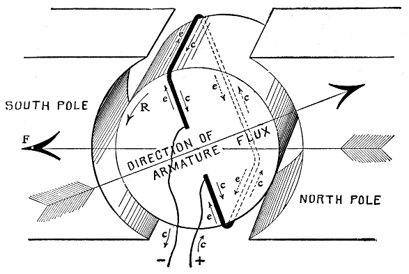
Fig. 394.—Showing relative directions of armature current and reverse electromotive force of a motor. When a motor is in operation, the wires around the periphery of its armature "cut" the magnetic lines of force produced by the field magnet exactly as in the case of the dynamo. Consequently, an electromotive force is induced in each wire, as in the dynamo armature. This induced electromotive force is in opposition to the flow of current due to the electromotive force of the supply circuit, and tends, therefore, to keep down the flow of current. The figure shows a single loop of wire, on the armature core connected directly to the source of electricity. With current flowing in the loop in the direction indicated by the arrows marked c, a magnetic field is set up in the direction indicated by the large arrow marked "direction of armature flux." With the field magnet energized so as to produce a field in the direction indicated by the large arrow F, the reaction between the two fields will turn the armature core in the direction indicated by the arrow R. As the core turns, the upper wire of the loop will cut the flux under the south pole of the field magnet, and the other side of the loop will cut the flux under the north pole. The result will be the induction of a reverse electromotive force in the loop, the direction being indicated by the small arrows marked e. The actual flow of current in the armature is that due to the difference between the impressed and reverse voltage; the latter is proportional to the speed of the armature, the number of armature wires and the strength of the magnetic field in the air gaps between the armature and the pole faces. The speed of a motor supplied with current at constant voltage varies directly with the reverse electromotive force, also with other conditions fixed, the stronger the field, the slower the speed. Weakening the field will increase the speed up to the point where the increase in reverse electromotive force due to the increased speed cuts down the armature current below the value necessary to give the requisite pull at the armature periphery. When this point is reached, any weakening of the field will reduce the speed of the armature. The pull or torque of a motor armature is directly proportional to the strength of the magnetic field, and to the strength of the armature current, the number of armature inductors being fixed. In a field of constant strength, therefore, the pull of the armature depends on the amount of current passing through the winding. The torque must be just sufficient to overcome the load; if in excess, the speed will increase until the increase of the reverse electromotive force reduces the current and the increase of speed increases the load to the point of equilibrium between load and torque. If the torque be insufficient for the load, the speed will diminish until equilibrium is established, assuming the motor is running on constant voltage circuit.
356
Ques. Describe similar conditions which prevail in the operation of a dynamo.
Ans. When no current is being generated by the dynamo, little power is required to drive it, but when the external circuit is closed and current is forced through it against more or less resistance, work is being done, hence more power is required. In other words, there is an opposition to the mechanical force applied at the pulley which is proportional to the electric power delivered by the dynamo. An opposing reaction or reverse force then is set up in a dynamo when it does work.
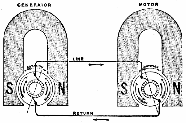
Fig. 395.—Circuit with generator and motor. Whenever current flows through some portion of a circuit in which there is an electromotive force, the current will there either receive or give up energy according to whether the electromotive force acts with the current or against it. In the figure, the generator and motor are rotating clockwise, and hence each generates an electromotive force tending upwards from the lower brush to the higher. In each case the upper brush is the positive one. In the dynamo, where energy is being supplied to the circuit, the electromotive force is in the same direction as the current, while in the motor where work is being done and energy is leaving the circuit, the electromotive force is in a direction which opposes the current.
357
Ques. In the operation of a motor what is the nature of the reverse electromotive force?
Ans. It is proportional to the velocity of rotation, the strength of the magnets, and to the number and arrangement of the wires on the armature, that is, the reverse voltage depends on the rate at which the lines of force are cut.
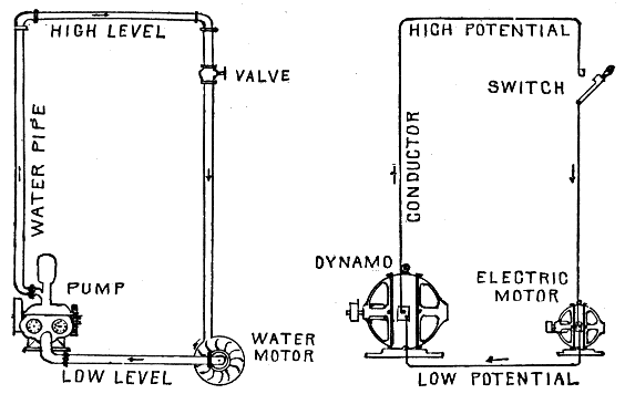
Figs. 396 and 397.—Water and electric circuits. Diagrams showing comparison between water motor and electric motor.
| In the diagrams: | ||||
|---|---|---|---|---|
| The pump | corresponds | to | the | dynamo. |
| The high level pipe | " | " | " | positive conductor. |
| The low level pipe | " | " | " | negative conductor. |
| The valve | " | " | " | switch. |
| The water motor | " | " | " | electric motor. |
| The water pressure (called head) | " | " | " | electric pressure (called voltage). |
| The flow in gallons per minute | " | " | " | amperes. |
| The size of pipe | " | " | " | size of conductor. |
| The foot pounds | " | " | " | watts. |
The greater the difference between the height of the two pipes the higher the pressure, and the greater the difference between the pressures of the two conductors the higher the voltage. The larger the diameter of the pipes the less resistance is offered to the flow of water, and the larger the diameter of the conductors the less resistance is offered to the flow of electricity. The more water required by the water wheel, the more power is required to drive the pump. The more electricity required by the motor the more power is required to drive the generator. 358
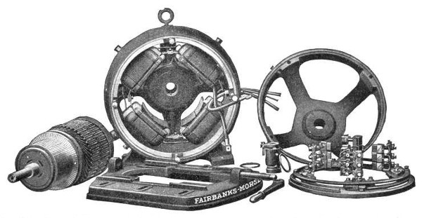
Fig. 398.—Fairbanks-Morse standard TR type motor. This type is built in the smaller sizes and the design is such that the motor can be installed upon the floor, wall or ceiling, the bearing yokes being attached to the frame by four equally spaced bolts so that they can be turned to provide for proper operation of the oiling devices in either position. A substantial base is provided with a thrust screw for adjusting the belt tension. This base has clamping bolts which permit adjusting the position of the motor while suspended. There is a cast ring type frame having steel side pieces which press firmly together, the steel laminations making up the pole pieces. The field coils armature, and armature coils are illustrated in detail in figs. 399 to 401. The commutator bars are of drawn copper, insulated with mica. The lugs which extend outward from the bars to receive the lead wires from the armature windings are formed in one piece with the bars, and are of the full width of the bars with the insulator extending outward between them, so that when assembled a solid flange is formed to receive the armature connections. Self-oiling bearings are provided and the location of the bearing sleeves in the housing is adjustable so that the armature may be centered in the magnetic field. The brush rigging is carried on a skeleton rocker supported in a groove, turned in the edge of the frame. The brush holders are of the box type with independently adjustable tension spring for each. Standard shunt windings are for 115, 230 and 550 volts. The compound wound motors operate at approximately the same full load speeds as the shunt wound, but the no load speeds will be about 20 per cent. higher than the full load speeds. They have, however, the ability to exert a more powerful starting effort than shunt motors without drawing such a heavy current from the line, and are, therefore, especially adapted for driving apparatus that has to be frequently started and stopped under load and where close speed regulation is not required.
359
Ques. Describe an experiment which shows the existence of a reverse electromotive force in a motor.
Ans. The apparatus required consists of a small motor, battery, and ammeter. They should be connected in one circuit and the deflection of the ammeter observed when the armature is held stationary, and when it rotates with various loads.
In an experiment of this kind made on a motor with separately excited magnets, the following figures were obtained:
Revolutions per minute 0 50 100 160 180 195 Amperes 20 16.2 12.2 7.8 6.1 5.1 Apparently, if the motor had been helped on to run at 261½ revolutions per minute, the current would have been reduced to zero. In the last result obtained, the current of 5.1 amperes was absorbed in driving the armature against its own friction at the speed of 195 revolutions per minute.
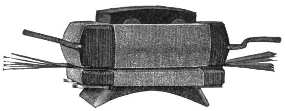
Fig. 399.—Fairbanks-Morse field coil and pole piece. The field coils are wound upon iron forms, each layer treated with insulating compound. Afterward they are removed from the forms and baked hard and dry and finally wrapped with insulating materials; all but the three smaller sizes are wrapped with a protecting cord. The series and shunt coils of the compound winding here shown are wound separately, the smaller one being the series coil and the larger the shunt coil.
Ques. Explain the action of the current supplied to a motor for its operation.
Ans. The motor current passing through the field magnets polarizes them and establishes a magnetic field, and entering the armature, polarizes its core in such a way that the positive 360 pole of the core is away from the negative pole of the magnetic field, and the negative pole is away from the positive pole of the magnetic field. The magnetic repulsions and attractions thus created cause the armature to rotate in a position of magnetic equilibrium or so as to bring its positive and negative poles opposite the negative and positive poles respectively of the magnetic field. It is evident that unless suitable means were provided to reverse the polarity of the armature core at the instant it reached the position of the magnetic equilibrium, the armature would not rotate any further. The construction is such that the polarity of the armature core, or the direction of the current in the armature coils is reversed at the proper instant automatically by the commutator, thus giving continuous rotation.
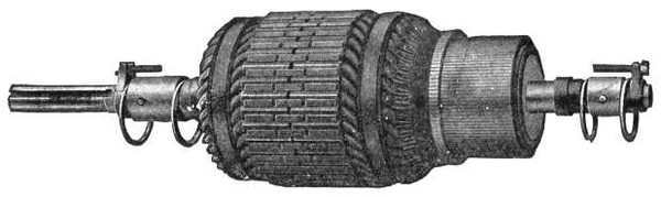
Fig. 400.—Fairbanks-Morse armature for 7½ H. P., 1300 R. P. M., TR type motor. The armature core is built up of thin sheet steel laminations with notches in the circumference, which, when the discs are placed together, form grooves or slots to receive the armature coils. The armature cores for the larger machines are mounted on a cast iron spider, which also carries the commutator, making the two parts entirely self-contained, and with this construction, it is possible to remove the armature shaft, without disturbing the core, commutator or windings. Cores of all sizes are provided with ventilating spaces, running from the surface to the central opening of the core, so that air is drawn through the core and blown out over the windings by the revolution of the armature.
Direction of Rotation of Motors.—In the case of either a motor, or a dynamo used as a motor, the direction in which the armature will rotate is easily found by the left hand rule, as 361 illustrated in fig. 411, when the polarity of the field magnets and the direction of currents through the armature are known.
Ques. How may the rotation of a motor be reversed?
Ans. By reversing either the current through the fields, or the current through the armature.
Ques. What will happen if both currents be reversed?
Ans. The motor will run in the same direction as before.
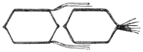
Fig. 401.—Fairbanks-Morse wire wound armature coils. These coils are form wound and are thoroughly insulated and baked before assembling in the slots. Material of great mechanical strength as well as high insulating value is used, and the coils are subjected to dippings in insulating compound and to bakings, thus driving out all moisture and making a coil which is practically waterproof and which will withstand rough handling. These coils, when completed, are placed in the slots, where they are retained by bands on the three smaller sizes and by hardwood wedges on the larger sizes.
Ques. What is the effect of supplying current to a series dynamo?
Ans. It will run in a direction opposite to its motion as a dynamo.
Ques. What is the result of reversing the direction of current at the terminals of a series motor?
Ans. It will not change its direction of rotation, since the current still flows through the armature in the same direction as through the field.
362
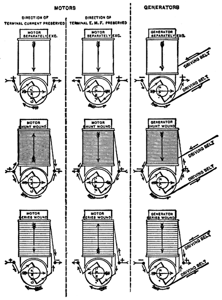
Figs. 402 to 410.—Diagrams showing relative direction of rotation of motors and dynamos. From figs. 391 and 392, it is seen that the direction of the current in a motor armature must be such as will increase, by the flux it produces, the intensity at the leading polar edge and decrease the intensity at the trailing polar edge. In a dynamo, the armature has to be moved by mechanical force, against a magnetic force, hence the leading polar edge is weakened, while the trailing edge is strengthened. The magnetomotive force in a motor armature is, therefore, opposed to the direction of that in a generator armature, when the direction of rotation and the direction of the field magnetomotive force are the same. Upon this depends all the relations existing between the direction of rotation of a machine when acting as a motor or as a dynamo.
363
Ques. What is the behavior of a shunt dynamo when used as a motor?
Ans. Its direction of rotation remains unchanged.
Ques. Why is this?
Ans. Because if the connections be such that the current supplied will flow through the armature in the same direction as when the machine is used as a dynamo, the current through the field will be reversed, since the field windings are in parallel with the brushes.
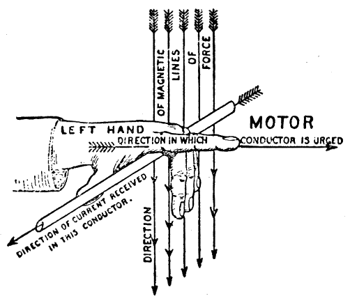
Fig. 411.—The "left hand rule" for direction of motion in motors. Place the left hand, as shown, so that the thumb points in the direction of the current, the 3rd, 4th and 5th fingers in the direction of the lines of force, then will the 2nd or forefinger, at right angles to the others, point in the direction in which the conductor is urged.
Armature Reaction in Motors.—In the operation of a motor the reaction between the armature and field magnets distorts the field in a similar manner as in the operation of a dynamo. A current supplied from an outside source magnetizes the armature of a motor and transforms it into an 364 electromagnet, whose poles would lie nearly at right angles to the line joining the pole pieces, were it not for the fact that negative lead must be given to the brushes.
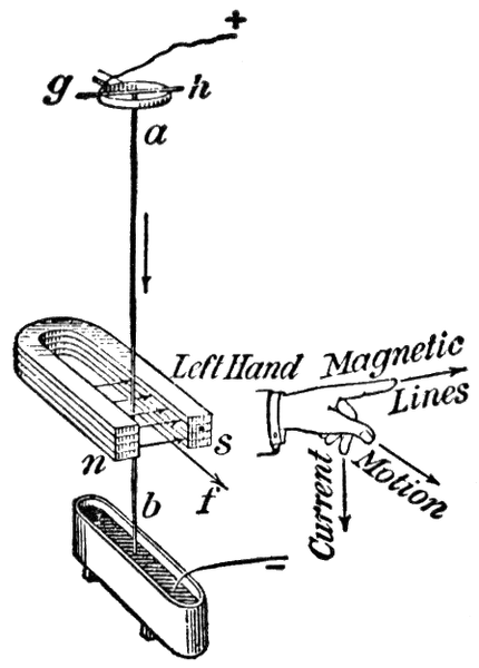
Fig. 412.—Principle of the electric motor as illustrated by experiment showing effect of a magnetic field on a wire carrying an electric current. Let a vertical wire ab be rigidly attached to a horizontal wire gh, and let the latter be supported by a ring or other metallic support as shown, so that ab is free to oscillate about gh as an axis. Let the lower end of ab dip into a trough of mercury. When a magnet is held in the position shown and a current from a cell is sent through the wire as indicated, the wire will move in the direction shown by the arrow f, that is, at right angles to the direction of the lines of magnetic force. Let the direction of the current in the wire be reversed, then the direction of the force acting on the wire will be found to be reversed also. The conclusion is that a wire carrying a current in a magnetic field tends to move in a direction at right angles both to the direction of the field and to the direction of the current. The relation between the direction of the magnetic lines, the direction of the current, and the direction of the force, is often remembered by means of the following rule, known as the motor rule, and which differs from the dynamo rule only in that it is applied to the fingers of the left hand instead of to those of the right. Let the forefinger of the left hand point in the direction of the magnetic lines of force and the middle finger in the direction of the current sent through the wire, then will the thumb, at right angles to the other two fingers, point in the direction in which the wire is urged.
Negative lead is the amount of backward advance of the brushes against the direction of the rotation of the armature, measured in degrees from the neutral plane.
If the brushes be given positive lead, that is, placed in advance of the neutral plane in the direction of rotation, the cross magnetizing force is converted into one that tends to increase that of the field magnet, while if they be given negative lead, it tends to demagnetize the field magnet.
Since with positive lead the armature polarity strengthens that of the field magnet, it is possible, disregarding sparking, to operate a motor without any other means being taken to magnetize the field magnets, because the armature will induce a pole in the field magnet and then attract itself towards this induced pole.
365
Ques. What effect has the cross magnetizing force on the field?
Ans. It tends to shift the field around in a direction opposite to that of the rotation.
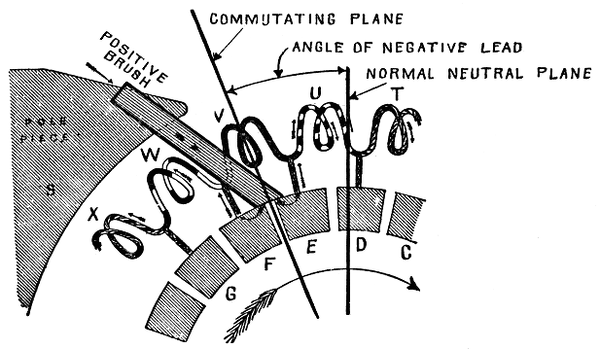
Fig. 413.—Current commutation in a motor. Considering the coil W which is ascending, current is flowing through it from the top brush, while it is itself the seat of an electromotive force that tends to stop or reverse its current. The condition for sparkless commutation requires that during the interval the coil is short circuited by the brush, the coil should be passing through a field that is not only sufficiently strong but one that tends to reverse the direction of its current. The coil is already in such a field, hence, commutation must take place before it passes put of this field. To accomplish this the brushes must be shifted backward, that is, given negative lead, to overcome sparking. In other words, the commutating plane must be shifted back of the neutral plane in a motor instead of being placed in advance as in a dynamo.
Ques. What are the conditions of minimum sparking?
Ans. The same conditions must obtain as in a dynamo, that is, the current in the coil undergoing commutation must be brought to rest and started again in the opposite direction. This involves that while the coil is short circuited by the brush, it should be passing through a field that tends to reverse the direction of the current. Since the coil is already in such a 366 field, the act of commutation must take place before it passes out of this field. Accordingly, a negative lead must be given the brushes.
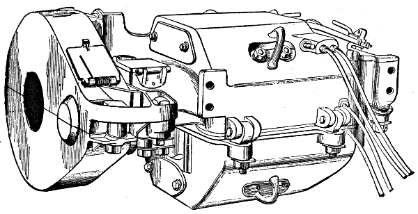
Fig. 414.—Railway motor. This type of motor, since it must operate under cars, has taken on the peculiar form under which it is most familiar. As illustrated, the case is of such shape that compactness and water proofing are secured, and the means of attachment to the car axle and support from the axle and truck frame are provided.
Method of Starting a Motor.—Although motors and dynamos are practically similar in general construction and either one of them will act as the other when suitably traversed by an electric current, there are certain differences between the connections and accessories of a machine operated as generator and one employed as a motor. For instance, when a machine is operated as a dynamo, it is first driven up to speed until it has excited itself to the right pressure, and then it is connected to the circuit; but when a machine is used as a motor it will not start until it has been connected to the circuit, and this must not be done until the proper precautions have been taken to ensure that the current, which will pass through it when so connected, will not be excessive and thereby result in serious injury to the motor. For this reason a rheostat or variable 367 resistance, commonly called a starting box is usually inserted in the armature circuit of a motor to prevent an undue rush of current before the motor attains its speed, and subsequently the speed is regulated by the cutting in or out of the circuit of certain extra resistances which constitute the controller used on a series motor requiring variable torque at variable speed, as in the case of elevator or electric traction service.
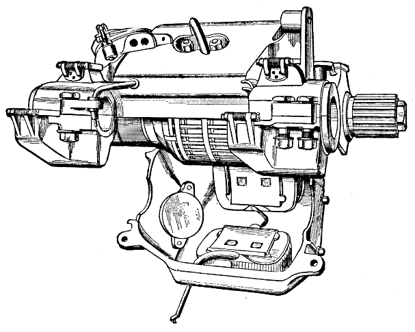
Fig. 415.—View of railway motor, open. The frame is of cast steel for lightness, and which serves as magnetic circuit and protecting case. It is circular or octagonal in form except in very large motors. Four short magnets project from the case. The armature is large in order to secure the required torque. It is always series wound, requiring two brushes. The brush holders are mounted upon a frame of insulating material which is attached to the upper half of the case. The brushes are adjustable radially, but usually it is not necessary to provide for shifting as they remain in the neutral plane. In motors which receive so little attention as these, special attention must be given to the design of devices for keeping oil and grease out of the case. These would injure the insulation of the coils and produce sparking at the commutator. Oil rings are, therefore, placed on the shaft, and these discharge into chambers connected to the oil wells or allow the oil to overflow on the track. The bearings are made self-oiling or self-greasing by means of rings or wicks and will run for weeks without attention.
368
Classes of Motor.—Motors are classified in the same manner as dynamos. The fields may be either bipolar or multipolar, and with respect to the type of armature winding employed, motors are classed as:
1. Series wound;
2. Shunt wound;
3. Compound wound.
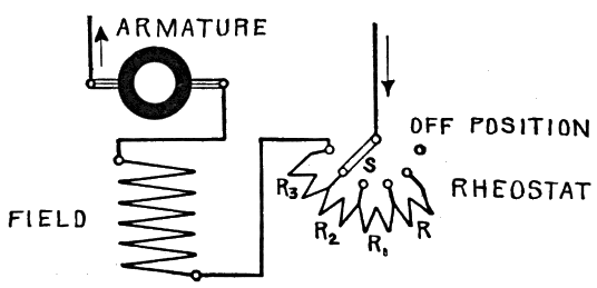
Fig. 416.—Series motor connections. A series motor on a constant voltage circuit does not have a constant field strength, and does not run at uniform speed. If the load be taken off it will run at excessive speed. To start the motor, the circuit is completed through a variable resistance or rheostat by moving the switch S so that the resistances R, R1, R2, R3, are gradually cut out of the circuit. To stop, the switch S is moved back to its "off" position.
Series Motors.—A series motor is one in which the field magnet coils, consisting of a few turns of thick wire, are connected in series with the armature so that the whole current supplied to the motor passes through the field coils as well as the armature. Fig. 416 is a diagram of a series motor showing the connections and rheostat.
Ques. What are the characteristics of a series motor?
Ans. The field strength increases with the current, since the latter flows through the magnet coils. If the motor be run on a 369 constant voltage circuit, with light load, it will run at a very high speed; again, if the motor be loaded heavily, the speed will be much less than before.
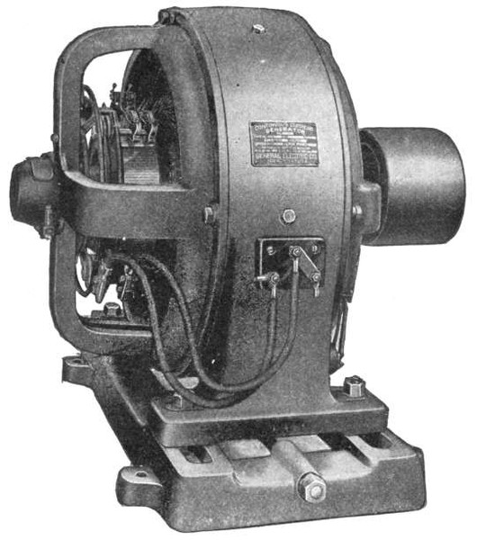
Fig. 417.—General Electric type CL-B motor for slow and moderate speeds. It is of multipolar construction, having six pole pieces. The advantages of slow speed machinery are generally understood, and in motors the additional outlay to secure slow speeds is warranted, inasmuch as it results in diminished wear and friction losses in gearing, belting, bearings, and commutators, and decreased brush renewals. The comparatively slow speeds of these motors are of importance in that they permit belting or gearing the motors directly to ordinary slow speed line shafting without employing intermediate counter shafting. When motors are geared to heavy duty machines, it is considered better practice to supply an outboard bearing to take up the additional strain that would otherwise be put on the gearing and bearing.
Ques. For what kinds of service are series motors unsuited?
Ans. Series motors should not be employed where the load may be entirely removed because they would attain a dangerous speed. They should not be used for driving by means of belts,370 because a sudden release of the load due to a mishap to the belt would cause the motor to "run away."
Very small series motors may be used with belts since their comparatively large frictional resistance represents an appreciable load, restraining the motor from reaching a dangerous speed.
Ques. For what service are series motors adapted?
Ans. For gear drive.
In the case of a sudden release of the load the gears provide some load on account of the frictional resistance of the gear teeth.
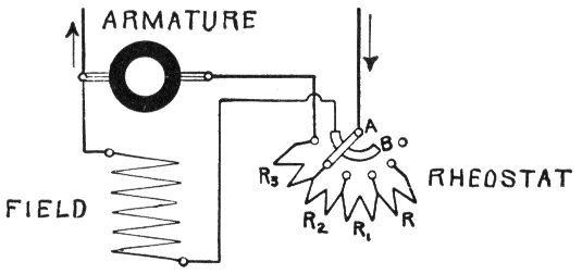
Fig. 418.—Shunt motor connections. A shunt motor runs at constant speed on a constant voltage circuit. In connecting the motor in circuit, the field coils must be placed in circuit first, so that there is a certain amount of field strength to produce rotation of the armature and thus prevent excessive current through the armature. If the field magnets were not put in the circuit first, the armature, at rest on receiving current, would probably burn out, because it is of low resistance, and would take practically all the current supplied, especially since no reverse voltage is generated in the armature at rest. The method of starting is shown in the illustration. To start, the switch is closed, and the rheostat lever pushed over so as to make contact with A and B, thus first exciting the magnets. On further movement of the lever, the rheostat resistances R, R1, R2, R3, etc., are gradually cut out as the speed increases, until finally all the resistance coils are cut out. To stop, the lever is brought back to its original position.
Ques. What advantage is obtained with series motors with respect to the connections?
Ans. A single wire only proceeds from the rheostat to the motor, so that, with the return wire, only two wires are required.
371
Ques. For what service are series motors specially adapted?
Ans. Series motors are used principally for electric railways, trolleys, and electric vehicles, and similar purposes where an attendant is always at hand to regulate or control the speed. They are also used on series arc light circuits in which the current is of constant strength. Very small motors are generally provided with series windings.
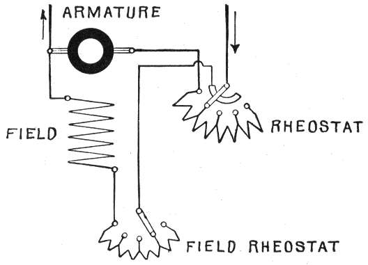
Fig. 419.—Speed regulation of a shunt motor. The speed of a motor depends on the voltage of the current supplied and the field strength. The motor tends to rotate so fast as to produce a reverse voltage nearly equal to that supplied to the brushes; hence, the speed varies with the voltage supplied. By decreasing this voltage then, the speed is decreased. Accordingly, the speed may be reduced by inserting, by means of a rheostat, a resistance in series with the motor. By inserting this resistance in the field circuit, the voltage at the terminals of the motor is lowered, thus giving the condition necessary to reduce the speed. The arrangement for speed regulation shown in the figure includes a starting regulator and a shunt regulator.
Shunt Motors.—A shunt motor may be defined as one in which the field coils are wound with many turns of comparatively fine wire, connected in parallel with the brushes. The 372 373 current then is offered two paths: one through the armature, and one through the field coils.
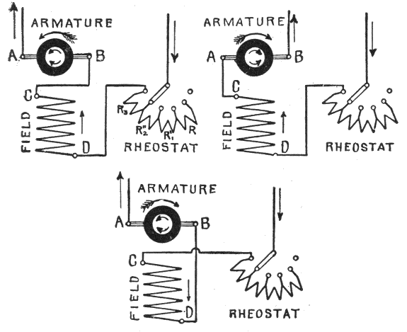
Figs. 420 to 422.—Reversing the direction of rotation of a series motor. Fig. 420 shows the connections for counter clockwise rotation. The motor may be reversed: 1, by allowing the current to flow in its original direction (from D to C) in the field magnet coils, and altering the direction of the armature current by changing the two connections on the brushes A and B, thus connecting C to A and B to the return wire as in fig. 421, or 2, by leaving the direction of the current in the armature in its original direction, and reversing that of the field current, as in fig. 422. If the wires leading to the rheostat and motor directly, were reversed there would be no reversal of the motor, because by so doing, both the armature and field magnet currents would be reversed.
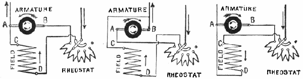
Figs. 423 to 425.—Reversing the direction of rotation of a shunt motor. Fig. 423 shows the connections for counter clockwise rotation. The motor may be reversed: 1, by allowing the current to flow in its original direction through the field magnet coils (from D to C), and reversing its direction through the armature (from A to B) as in fig. 424, or 2, by allowing the armature current to flow in its original direction (from B to A) and reversing the current through the field coils (from C to D) as in fig. 425.
Ques. What may be said with respect to the speed of a shunt motor?
Ans. It is practically constant with varying loads.
The variation of speed ranges from 1/10 to 5 per cent., except in the case of small motors, in which the variation may be much greater.
Ques. How should a shunt motor be started?
Ans. To properly start the machine, the field coils must be fully excited.
It is, therefore, necessary to switch the magnet coils immediately on to the voltage of supply, while a variable resistance must be provided for the armature circuit. To get both connections at the same time, rheostats for shunt motors are arranged as shown in fig. 418.
Influence of Brush Position on Speed.—In the case of a shunt motor supplied with current at constant pressure, the speed is a minimum when the brushes are in the neutral plane, and the effect of giving the brushes either positive or negative lead is to increase the speed, especially with little or no load.
Ques. Why does the speed increase?
Ans. When the brushes are shifted from the neutral plane, the reverse voltage between the brushes is decreased, speed remaining unchanged. Accordingly, the pressure in the supply mains forces an increased current through the armature thus producing an increased armature pull which causes the speed to increase until the reverse voltage reaches a value sufficiently large to reduce the current to the value required to supply the necessary driving torque.
374
Compound Motors.—This type of motor has to a certain extent, the merits of the series motor without its disadvantages, and is adapted to a variety of service. If the current flow in the same direction through both of the field windings, then the effect of the series coil strengthens that of the shunt coil; this strengthening is greater, the larger the armature current.
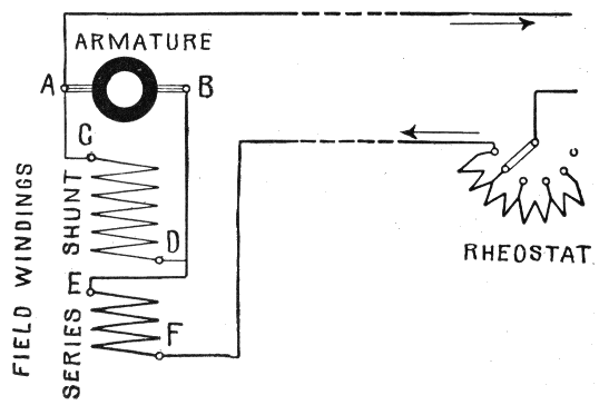
Fig. 426.—Compound motor connections for starting from a distant point. A compound winding may be used on motors for many different purposes. If the current flow in the same direction through both windings, then the effect of the series coil strengthens that of the shunt coil. This strengthening increases with the load. Thus the motor gets, at increasing load, a stronger magnetic field, and will therefore, if the voltage remain constant run slower than before. Accordingly, for a given current, the starting power will be greater than that of a shunt motor. With a decreasing load the motor will run faster. The compound motor has, to a certain extent, the merits of the series motor without its disadvantages. By means of compound motors the starting at a distance with only two mains may be effected, just as in the case of the series motor. The connections are shown in the diagram. If the motor be regarded as being without the shunt coil, then it is connected up exactly as the series motor in fig. 416. The current coming from the starter enters the series coil at F, flows through the series coil and leaves it at E, flowing from there to the armature brush B, through the armature to brush A, and from there through the second main back to the generator. The shunt winding is connected directly with the armature brushes A and B, and gets at starting, therefore, only a very small voltage, hence its field is nearly ineffective. But on account of the series winding, the motor starts as a series motor. Obviously such a motor will not develop a very large starting power like a real series motor, for, on account of the large space occupied by the shunt coils, there is less space available for the series coils than with a series motor. A compound motor may, however, even with this arrangement, be easily started, provided the load on starting be not too heavy. When once running the armature will produce a reverse voltage and the shunt coil will be supplied with nearly the full terminal voltage.
375
Ques. Mention some characteristics of the compound motor.
Ans. Since it is a combination of the shunt and series types, it partakes of the properties of both. The series winding gives it strong torque at starting (though not as strong as in the series motor), while the presence of the shunt winding prevents excessive speed. The speed is practically constant under all loads within the capacity of the machine.
Ques. Describe the connections for starting a compound motor at a distance.
Ans. Control at a distance can be effected with only two wires, just as in the case of a series motor. In the diagram fig. 426, the current coming from the rheostat enters the series coil at F, and leaves it at E, thence it flows to the armature brush B, through armature to brush A, and from here back to the dynamo. The shunt winding, which is connected across the brushes, gets a very small voltage at starting and is accordingly very ineffective. The motor then starts as a series motor. The starting effect is smaller than in a series motor because of the fewer turns in the series winding, most of the available space being occupied by the shunt coils.
Power of a Motor.—The word "power" is defined as the rate at which work is done, and is expressed as the quotient of the work divided by the time in which it is done, thus:
| power = | work |
| time |
The difference between power and work should be clearly understood. 376
Work is the overcoming of resistance through a certain distance. It is measured by the product of the resistance into the space through which it is overcome, thus:
| work = distance × space |
For instance, in lifting a body from the earth against the attraction of gravity, the resistance is the weight of the body, and the space, the height to which the body is raised, the product of the two being the work done.
The unit of work is the foot pound, which is the amount of work done in overcoming a pressure or weight equal to one pound through one foot of space.
The unit of power is the horse power which is equal to 33,000 foot pounds of work per minute, that is:
| horse power = | foot pounds per minute |
| 33,000 |
The unit of power was established by James Watt as the power of a strong London draught horse to do work during a short interval, and used by him to measure the power of his steam engines.
In order to measure the mechanical power of a motor, it is necessary to first determine the following three factors upon which the power developed depends:
1. Pull of the armature, in pounds;
2. Distance in feet at which the pull acts from the center of the shaft;
3. Revolutions per minute.
Example.—If the armature pull of a motor having a two foot pulley, be such that a weight of 500 lbs. attached to the rim, is just balanced, and the speed be 1,000 revolutions per minute, what is the horse power?
377
Here, the distance that the pull acts from the center of the shaft is one foot, hence for each revolution the resistance of 500 pounds is overcome through a distance equal to the circumference of the pulley or
π × diameter = 3.1416 x 2 = 6.2832 feet.
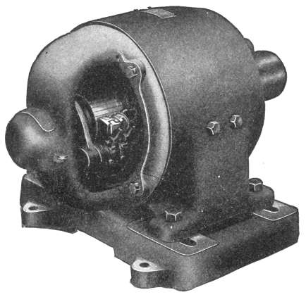
Fig. 427.—General Electric type CQ Motor. These motors range in capacity from 1/6 to 20 horse power. The small sizes are bipolar, and the larger sizes have four poles. For installations where the motor is exposed to dust, mechanical injury or moisture, it may be partially or entirely enclosed by means of hand hole covers. The standard voltages are 115, 230 and 550.
The work done in one minute is expressed by the following equation:
| { | work per minute |
} | = | { | weight in lbs |
} | × | { | circumference of pulley in feet |
} | × | { | revolutions per minute |
} | = foot pounds |
| = | 500 | × | 6.2832 | × | 1,000 | =3,141,600 |
Hence, the power developed is
3,141,600 ÷ 33,000 = 95.2 horse power.
378
Ques. What is "brake" horse power?
Ans. The net horse power developed by a machine at its shaft or pulley; so called because a form of brake is applied to the pulley to determine the power.
Ques. Describe the apparatus used in making a brake test.
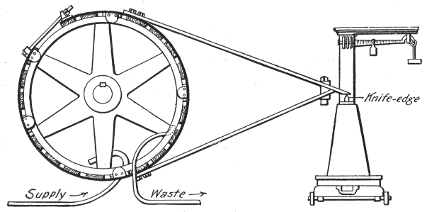
Fig. 428.—Prony brake for determining brake horse power. It consists of a friction band ring which may be placed around a pulley or fly wheel, and attached to a lever bearing upon the platform of a weighing scale in such a manner that the friction between the surfaces in contact will tend to rotate the arm in the direction in which the shaft revolves. This thrust is resisted and measured in pounds by the scale. In setting up the brake the distance between the center of the shaft and point of contact (knife edge) with the scales must be accurately measured, the knife edge being placed at the same elevation as the center of the shaft. An internal channel permits the circulation of water around the interior of the rim as shown, to prevent overheating.
Ans. Tests of this kind are usually made with a Prony brake as shown in fig. 428. It consists of a band of rope or strip iron—the latter is the arrangement shown—to which are fastened a number of wooden blocks, several carrying shoulders to prevent the contrivance from slipping off the wheel rim. The brake band is drawn tight, as shown, so that the blocks press against the surface all around. The brake thus formed is restrained from revolving with the pulley by two arms attached near the 379 top and bottom centers of the wheels, and joined at the opposite ends to form a lever which bears upon an ordinary platform scale, a suitable leg or block being arranged to keep its end level with the center of the shaft. By this arrangement the amount of friction between the brake band and the revolving wheel is weighed upon the scales. Since the brake fits tightly enough to be carried around by the wheel, but for the arms bearing upon the scale, the amount of frictional power exerted by the wheel in turning free within the blocks may be transmitted and measured, just as would be the case were a machinery load attached, instead of a friction brake.
Ques. Why must the point of contact of the brake with the scales be level with the center of the shaft?
Ans. In order to determine the force acting at right angles to the line joining the point of contact and center of the shaft.
Ques. What is the distance between the center of the shaft and point of contact with the scales called?
Ans. The lever arm.
Ques. What three quantities must be determined in a test in order to calculate the brake horse power?
Ans. The lever arm, the force exerted on the scales, and the revolutions per minute.
Ques. How is brake horse power calculated?
Ans. From the following formula:
| B. H. P. = | 2 π L N W |
| 33,000 |
380
in which
| B. H. P. | = brake horse power; |
| L | = lever arm, in feet; |
| N | = number of revolutions per minute; |
| W | = force in pounds at end of lever arm as measured by scales. |
Example—In making a brake test on a motor, the lever arm of the brake is 3 ft., and the reading of the scales is 30 lbs. When the motor is running 1,000 revolutions per minute, what is the brake horse power?
Substituting the given values in the formula,
| B. H. P. = | 2 π x 3 x 1,000 x 30 | = 17.1 |
| 33,000 |
Now, if the voltmeter and ammeter readings be 220 and 65 respectively, what is the efficiency of the motor at this load?
The amount of power absorbed by the motor, or in other words, the input is
| E. H. P. = | 220 x 65 | = 19.16 |
| 746 |
and since the output is 17.1 horse power,
| efficiency = | output | = | brake horse power | = | 17.1 | = 89% |
| input | electrical horse power | 19.16 |
Speed of a Motor.—The normal speed at which any motor will run is such that the sum of the reverse electromotive force and the drop in the armature will be exactly equal to the electromotive force applied at the brushes. The drop in the armature is the difference between the applied voltage and the reverse voltage.
381
Mutual Relations of Motor Torque and Speed.—The character of the work to be done not only determines the condition of the motor torque and speed required, but also the suitability of a particular type of motor for a given service. There are three general classes of work performed by motors, and these require the following conditions of torque and speed:
1. Constant torque at variable speed;
Suitable for driving cranes, hoists, and elevators, etc., where the load is constant and has to be moved at varying rates of speed.
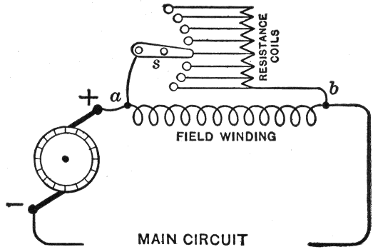
Fig. 429.—Two path method of speed regulation of series motor. A rheostat is connected in shunt to the field coils as shown. The current passing from a to b divides between the magnet coils and the rheostat coils; the higher the resistance of the rheostat the less current passes through it, and the more through the magnet coils, hence the stronger the field magnet.
2. Variable torque at constant speed;
Suitable for driving line shafting in machine shops, which must run at constant speed regardless of variations of torque due to variations in the number of machines in operation at a time, or the character of work being performed.
3. Variable torque at variable speed.
382
Suitable for electric railway work. For example: when a car is started, the torque is at its maximum value and the speed zero, but as the car gains headway, the torque decreases and the speed increases.
Speed Regulation of Motors.—The speed of motors connected to constant voltage circuits is usually regulated by the two following methods:
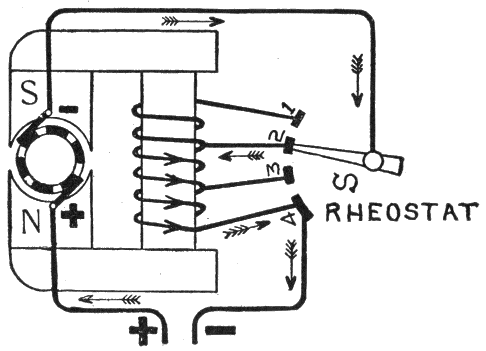
Fig. 430.—Variable field method of speed regulation of series motor. The field winding is divided into a number of sections with leads connecting with switch contact points as illustrated. The speed then is regulated by cutting in or out of the circuit sections of the field winding thus varying the strength of the field.
1. By inserting resistances in the armature circuit of a shunt wound motor;
2. By varying the strength of the field of a series motor.
The first method is sufficiently explained under fig. 418 and the second method is illustrated in fig. 430. The controller switch S is so arranged that a greater or lesser number of field coils can be inserted in the field circuit. When the switch arm is 383 on point 1, the motor current will flow through all the field windings, and the strength of the field will be at its maximum. When the switch arm is moved so as to successively occupy positions 2, 3, and 4, thus cutting out of circuit a greater and greater number of field coils the strength of the field will be gradually decreased until practically all of the motor current is led or wired through the armature. Under these conditions, when the field of a motor is at its maximum strength, the motor torque will be at a maximum for any given strength of current, and the reverse electromotive force will also be at a maximum for any given speed, therefore, when the field strength is increased the speed will decrease and vice versa.
Ques. What results are obtained by this method of regulation?
Ans. The speed of a series motor may be nearly doubled, that is, if the lowest permissible speed of the motor be 250 revolutions per minute it can be readily increased to 500 revolutions per minute by changing the field coil connections from series to parallel. It is on this account, as much as on their powerful starting torque, that series motors have been until recently almost exclusively employed for electric traction purposes.
Series Parallel Controller.—When two motors are used in electric railway work, their armatures are connected in series with each other and an extra resistance which prevents the passage of an excessive current through the armature before the motor starts. As the speed of the car increases, the extra resistance is gradually cut out of circuit and the field winding connections changed from series to parallel by means of a series 384 parallel controller, which finally connects each motor directly across the supply mains, or between the trolley line and the track or ground return.
Efficiency of a Motor.—The commercial efficiency of a motor is the ratio of the output to the input. As a rule, the power developed by a motor increases as the reverse voltage generated by it decreases, until this voltage equals one-half of the voltage applied at the brushes. After this point is reached, the power developed by the motor decreases with the decrease of the reverse voltage. Therefore, a motor performs the largest amount of work when its reverse voltage is equal to one-half the impressed voltage.
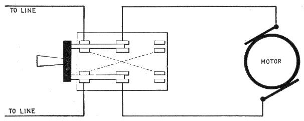
Fig. 431.—Double-throw, double-pole switch for reversing direction of rotation of a motor. The direction of rotation can be reversed by changing the direction of current in either the armature or the field coils. It is preferable, however, to reverse the direction of rotation by changing the direction of current through the armature. The switch is wired as shown, means of reversal being provided by running the wires as indicated by the dotted lines.
The efficiency of a motor as just stated is the ratio of the output to the input; this is equivalent to saying that the efficiency 385 of a motor is equal to the brake horse power divided by the electrical horse power.
The electrical horse power is easily obtained by multiplying the readings taken from volt meter and ammeter, which gives the watts, and dividing the product by 746, the number of watts per horse power. That is:
| Electrical horse power = | volts × amperes | = | watts |
| 746 | 746 |
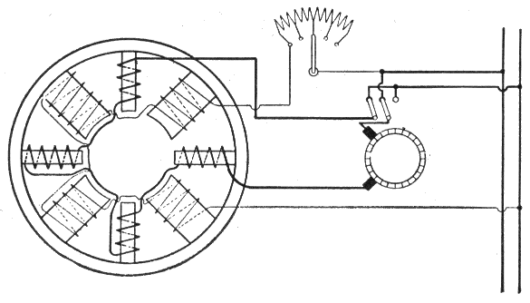
Fig. 432.—Wiring diagram, showing electrical connections between the armature, field, and interpoles of an interpole motor. As the name implies, an interpole motor has in addition to the main poles, a series of interpoles which are placed between the main poles, and whose function is to assist in the reversal of the current under the brushes. They provide a separate commutating field of a correct value at all loads and speeds, and their windings are for this purpose connected in series with the armature. The proper functioning of the interpoles is independent of the direction of rotation of the armature, also of the load carried over the whole speed range. In an ordinary motor without interpoles, commutation is assisted by a magnetic fringe emanating from the main poles, but as the value of this fringe is altered by the load of the motor and by rheostatic field weakening, if higher speeds be desired from such a machine, commutation becomes imperfect and sparking results, making a readjustment of the brushes necessary.
Interpole Motors.—An interpole motor has in addition to the main poles, a series of interpoles, placed between the main poles. The object of these poles is to provide an auxiliary flux or "commutating" field at the point where the armature coils are short circuited by the brush.
386
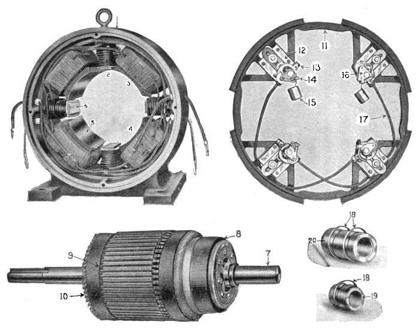
Figs. 433 to 437.—Parts of the type S interpole motor built by Electro Dynamic Co. They are as follows: 1. yoke—commutator view; 2. interpole coil; 3. top R. H. main coil; 4. bottom R. H. main coil; 5. main pole; 6. interpole; 7. armature shaft, R. H. bearing; 8. commutator; 9. armature wedge; 10. armature coil; 11. brush ring; 12. brush carrier insulation; 13. brush carrier; 14. brush guard; 15. carbon brush; 16. brush holder; 17. cross connecting cable; 18. oil ring; 19. commutator end bearing bushing; 20. pulley end bearing bushing.
387
Ques. What is the object of the commutating field produced by the interpoles?
Ans. Its object is to assist commutation, that is, to help reverse the current in each coil while short circuited by the brush, and thus reduce sparking.
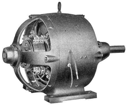
Fig. 438.—Interpole motor as built by the Electro Dynamic Co. This type of motor is devised to prevent sparking at all loads by the use of interpole magnets, that is, small magnets placed between the field magnets. The interpoles set up a field in a direction to stop and reverse the current in the armature coils while they are short circuited by the brushes.
Ques. What is the nature of the commutating field?
Ans. The excitation of the interpoles being produced by series turns, the field will vary with the load, and will, if once adjusted to give good commutation at any one load, keep the same proportion for any other load, provided the iron parts of the circuit be not too highly saturated.
388
Ques. State briefly how sparking is reduced or prevented by the action of the interpoles.
Ans. Sparking is due to self-induction in the coil undergoing commutation, which impedes the proper reversal of the current. The action of the interpoles corrects this in that they set up a field in a direction that causes a reversal of the current in the coil while it is short circuited. Thus, the coil at the instant it leaves the brush, is not an idle coil, but has a current flowing in it in the right direction to prevent sparking.
Ques. Mention some of the claims made for interpole motors.
Ans. Constant or adjustable speed, and momentary overloads without sparking; constant brush position; operation at adjustable speeds on standard supply circuits of 110, 220, and 500 volts; constant speed with variable load; reversal without changing the position of the brushes.
389
General Conditions Governing Selection.—In any particular case, the voltage, current capacity, and type of dynamo selected will depend upon the system of transmission or distribution to which it is to be connected, and the character of the work which it is required to perform. The suitability of the different types of dynamo for various kinds of work has already been considered to some extent, but there are certain general conditions which are applicable to almost all cases, such as:
1. Construction;
2. Operation;
3. Cost;
4. Number and size of units.
Construction.—This should be as simple as possible and of the most solid character. All parts should be interchangeable, and have a good finish. All machines should be provided with eye bolts or other means by which they can be lifted or moved, as a whole or in parts, easily and without injury. These features are so carefully attended to and guaranteed by the manufacturers as to leave little choice in this direction.
390
Operation.—The considerations relating to the operation of a machine involve an examination of the details of its construction, in order to determine the amount of attention it will require, the character of its regulating device, its capacity, form, and weight.
Ques. What may be said regarding capacity?
Ans. Dynamos and motors should not be overloaded, because the efficiency is greater when the working load does not exceed the rated capacity of the machine.
Form.—As a rule, there is not much choice in the matter of form between standard machines, as they are uniformly symmetrical, well proportioned and compact. It is a mistake, however, to select a light machine for stationary use, as the weight of a machine increases its strength, stability and durability.
Cost.—In some cases, the matter of first cost is important and deserves careful consideration. It should be remembered, however, that high grade electric machinery cannot be built out of low grade materials and with poor workmen; therefore, when necessity compels the selection of a cheap machine, it should not be expected that its service will be as satisfactory as that of a first class machine.
Number and Size of Units.—The best number and size of units for an electrical plant is usually governed by the requirements of the driving engines. As a rule, dynamos and motors are not much less efficient at quarter-load than at full load, and the smaller dynamos are fully equal to the larger machines in this respect, therefore, a generating plant can be subdivided, and if so desired, without any detrimental results except those to a multiplicity of units.
391
Ques. What is the important consideration with respect to efficiency?
Ans. Efficiency at maximum load is not so important as efficiency at average load.
For instance, in the diagram, fig. 439, the rated efficiency of one dynamo as shown by the curve A, is 95 per cent., and that of another, as shown by curve B, is 91 per cent., but it will be observed that the average efficiency of B is much higher, being 75 per cent. at quarter-load, 89 per cent. at half-load, and 91 per cent. at three-quarter-load, to 55, 77 and 89 per cent. of A, at the corresponding loads. In this case, A is higher than B only at full load, and as full load is a limit which should not be reached except in special cases, and then only for short intervals of time, the service rendered by B would be much more satisfactory in the long run. In order to avoid the difficulties possible under these conditions, a guarantee to carry 25 per cent. overload for two hours without injury should be required, and either this or the rated load be taken, as the full load, so as to give a factor of safety of 25 per cent.
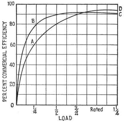
Fig. 439.—Efficiency curves for 100 K. W. dynamos. The efficiency of a dynamo at maximum load is not so important as at average load. For instance, if in the figure the curve O B C represent the efficiency of a 100 K. W. dynamo and O A D, that of another machine, it would be in accordance with common practice to compare them at rated load, at which the efficiency of the first is only 91%, while the other is 93%. The first machine, however, is far better than the second, since its average efficiency is much higher, being nearly 91% between half-load and 25% overload. It should be noted that full load is a limit which should be but occasionally reached, and then only for short periods of time.
392
Ques. Upon what does the choice of field winding of a dynamo depend?
Ans. The different classes of field winding have already been discussed, but in general the conditions governing selection are as follows: The series dynamo is used where a constant current at variable voltage is desired, as in series arc lamp circuits. A shunt dynamo is used on constant voltage circuits, where the distance from the machine to the load is not great, that is, where there is small line loss. With a compound dynamo there is compensation for line loss, that is, it can be constructed so that the voltage at its terminals, or at the load can be maintained constant or allowed to increase or decrease with a change in load. It can thus operate lamps at constant voltage though they be located at some distance, or the voltage at the end of the line can be made to increase with an increase of load, as is frequently the case in railway work.
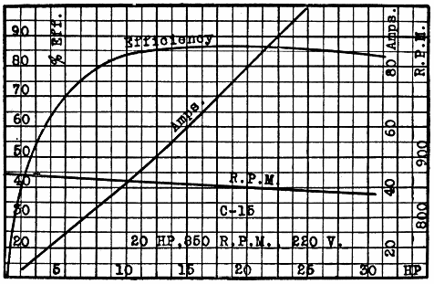
Fig. 440.—Holzer Cabot performance curves of standard 20 H. P. motor, showing efficiency, speed regulation, and amperes input.
393
Ques. For what conditions of service are series motors adapted?
Ans. They are used on constant current circuits, and also on constant voltage circuits as in railway work and similar purposes where an attendant is always at hand to regulate the speed.
Ques. Name some advantages and disadvantages of series motors.
Ans. They are easily started even under heavy loads, the winding is cheaper than the other types and the speed is nearer constant than shunt motors when operated on constant current circuits. When used on constant pressure circuits, such as is employed for incandescent lighting, the speed will depend on the load.
Ques. What kind of circuit is suitable for shunt motors?
Ans. They are used on constant voltage circuits.
Ques. What are the advantages of shunt motors?
Ans. The speed remains nearly constant for variable load.
Ques. State the disadvantages.
Ans. They start less easily under a heavy load than do series motors, and the speed cannot be varied through any wide range without considerable loss. The shunt motor requires more attention than the series type and is more liable to be burnt out.
Location.—The place chosen for the dynamo or motor should be dry, free from dust, and preferably where a cool current of air can be had. It should allow sufficient room for a belt of proper length when a belt drive is used.
394
Foundations.—It is most important to secure a good foundation for every dynamo, and great care should be taken to have them entirely separate from those of the walls of the building in which the machine is installed, and if the dynamo be directly driven, but not on the same bed plate as the engine, a foundation large enough for both together should be laid down. Stone or concrete may be used, or brick built with cement, having a large thick stone bedded at the top.
For small machines the holding down bolts may be set with lead or sulphur in holes in the stone top, but for large machines the bolts should be long enough to pass down to the bottom, where they should be anchored with iron plates.
Setting up of Dynamos and Motors.—In unpacking the machines care should be taken to avoid injury to any part, and in putting the parts together, each part should be carefully cleaned, and all the parts put together in exactly the right way. The shafts, bearings, magnetic joints, and electrical connection should receive especial attention and be thoroughly cleaned of every particle of dirt, grit, dust, metal clippings, etc.
Ques. Who should preferably assemble the machines?
Ans. Whenever possible, they should be assembled by someone thoroughly familiar with the construction; but if the services of such a person cannot be had, no one should attempt to put a machine together unless he has a drawing or photograph of the same for a general guide.
Ques. What precaution should be taken with the armature?
Ans. It should be handled carefully to avoid any injury to the wires of the winding and their insulation.
395
If it become necessary to lay the armature on the ground it should be laid on clean paper or cloth, but it is better to support it by the shaft on two wooden horses or other supports, and thus avoid any strain on the armature body or commutator.
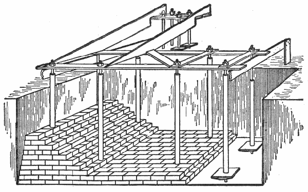
Fig. 441.—Foundation. It may be made either of concrete, stone or brick. The machinery is held firmly in place on the foundation by anchor bolts built into it; the proper position for the bolts are determined by a wooden template suspended above the foundation as shown. The bolts are surrounded by iron pipe that fixes them vertically but permits a little side play to allow for any slight errors in locating the centers on the template.
Connecting Up Dynamos.—The manner in which the connections of the field magnet coils, brushes, and terminals, are connected to one another depends entirely upon the type of machine. The field magnet shunt coils of shunt and compound wound dynamos, are invariably arranged in series with one another, and then connected as a shunt to the brushes or terminals of the machine. The series coils of series and compound wound machines are arranged either in series or in parallel with one another, according to conditions of operation, and then connected in series to the armature and external circuit.
396
Coupling Up Field Magnet Coils.—In coupling up the coils of either salient or consequent pole field magnets, assume each of the pole pieces to have a certain polarity (in bipolar dynamos two poles only, a north and south pole respectively, are required; in multipolar dynamos the poles must be arranged in alternate order around the armature, the number of N and S poles being equal), then apply Flemming's rule as given under fig. 132, to each of the coils, and ascertain the direction in which the magnetizing current must flow in each in order to produce the assumed polarity in each of the pole pieces. Having marked these directions on the coils, they can be coupled up in either series or parallel connection according to requirements, so that the current flows in the proper direction in each.
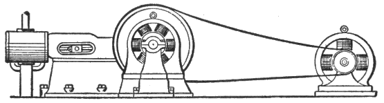
Fig. 442.—Comparison of space occupied by direct and belt connected dynamos. In office buildings space is of value and the room required by belt connected dynamos can always be put to profitable use. For this reason the direct connected unit has become generally adopted in the best type of office buildings. In large factories the direct connected unit is generally adopted also to save space. Where these conditions do not obtain, belted type of dynamo can be used to advantage as a given output can be obtained with a smaller size machine than where it is direct connected to the engine. This is due to the limited rotative speeds at which engines can be run. The illustration shows the relative space required by the two types.
The Drive.—Various means are employed to connect the engine or other prime mover with the dynamo, or the motor with the machinery to driver. Among these may be mentioned the following:
397
1. Direct drive;
2. Belt drive;
3. Rope drive;
4. Gear drive;
5. Friction drive.
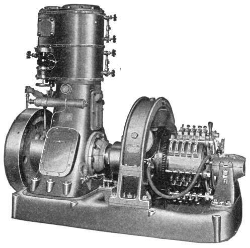
Fig. 443.—General Electric type M P, marine generating set with tandem compound engine. The requirements of such units are compactness, light weight, simplicity, freedom from vibration and noise at high speed, perfect regulation and durability. By adopting a short stroke for the engines and a special armature winding for the dynamos, the height and length of the sets have been reduced. The bed is carried out to the full width of the dynamo frame, making an ample base surface for foundation without increasing the floor space required. While the construction gives a massive appearance, the bed has been cored out and the various parts so designed that the complete sets have an approximate capacity of 3½ watts per pound. All of the moving parts are enclosed by the engine column, excluding dust and reducing wear and attention to a minimum. The bearing are oiled automatically under pressure. These sets are made in sizes from 25 K. W. to 75 K. W., the cylinder dimensions for the smallest size being 6½ and 10½ by 5, and for the largest size 10½ and 18 by 8. Single cylinder sets are made in sizes ranging from 2½ K. W. to 50 K. W., the cylinder dimensions ranging from 3½ x 3 to 12 x 11. See fig. 730.
398
Ques. What is a direct drive?
Ans. One in which the driving member is connected direct to the driven member, without any interposed gearing.
Fig. 443 shows a direct connected unit, which is an example of direct drive.
Ques. What may be said with respect to direct drive?
Ans. It is the simplest method and the space required is less than with belt drive. With direct drive the engine and dynamo must run at the same speed; this is a disadvantage because the desirable speeds of the two machines may not agree.
Since the usual engine speeds are slower than dynamo speeds, direct drive involves the use of a larger dynamo for a given output than would be necessary with belt connection, and involves a corresponding increase in cost and greater friction loss due to the rotation of larger and heavier parts.
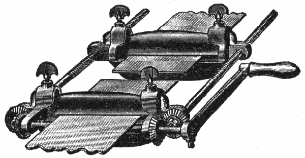
Fig. 444.—Belt clamp for stretching belt and holding the ends while making joint. It consists of a stretching frame, the two ends of which are coupled by screwed bars; used for pulling the ends of a belt together with the proper tension, when lacing or joining the ends.
Ques. Mention some of the features of belt drive.
Ans. Greater flexibility in the original design of a plant is possible and new arrangements of old apparatus can be made at any time. It gives conveniently any desired speed ratio and permits the use of high speed dynamos and motors.
399
Ques. State some of the disadvantages of belt drive.
Ans. Considerable space is required and the action is not positive. Belts exert a side pull on the bearings which results in wear, also loss of power by friction.
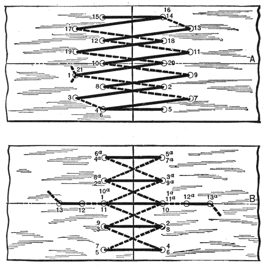
Figs. 445 and 446.—Two methods of lacing a belt. In fig. 445 two rows of oval holes should be made with a punch, as indicated. The nearest hole should be ¾ inch from the side, and the first row 7/8 inch from the end, and the second row 1¾ inches from the end of the belt. In large belts these distances should be a little greater. A regular belt lacing (a strong, pliable strip of leather) should be used, beginning at hole No. 1, and passing consecutively through all the holes as numbered. In fig. 446 the holes are all made in a row. This method has the advantage of making the lacers lie parallel with the motion on the pulley side. The lacing is doubled to find its middle, and the two ends are passed through the two holes marked "1" and "1a" precisely as in lacing a shoe. The two ends are then passed successively through the two series of holes in the order in which they are numbered, 2, 3, 4, etc., and 2a, 3a, 4a, etc., finishing at 13 and 13a, which are additional holes for fastening the ends of the lacer.
400
Ques. Give a rule for determining the proper size of belt.
Ans. A single belt travelling 1,000 feet per minute will transmit one horse power per inch of width; a double belt will transmit twice this amount.
EXAMPLE.—What size of double belt is required to transmit 50 horse power at 4,000 ft. speed, and what diameter pulley must be used for 954 revolutions per minute at 4,000 ft. speed of belt?
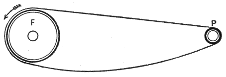
Fig. 447.—Wrong way to run a belt. The pull should not come on the top side, because, with slack at bottom there is a tendency to slip.
The horse power transmitted per inch is
4,000 × 2 = 8 1,000 accordingly, the width of belt required to transmit 50 horse power is
50 ÷ 8 = 6.25, say 6".
For 4,000 ft. per minute belt speed, the distance in inches travelled by the belt per revolution of the pulley.
4,000 x 12 = 50.31 inches 954 This is equal to the circumference of the pulley, and the corresponding diameter is
50.31 = 16.1, say 16 inches. π
401
Ques. What is the proper speed for a belt?
Ans. From 3,000 to 5,000 feet per minute, depending on conditions.
1. The amount of power that a belt of given size can transmit is not a very definite quantity. The rule just given is conservative and will give an amply large belt for ordinary conditions.
2. A belt should make a straight run through the air and over the pulleys without wabbling; it should maintain an even and perfect contact with that part of the pulley with which it comes in contact. In order to do this it should be kept soft, pliable, and have no abrasions or rough places.
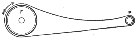
Fig. 448.—Right way to run a belt. The pull should come on the lower side bringing the slack on top.
3. When belt fasteners give way there is too much strain upon belt. The greatest amount of slack in a belt is found where it leaves the driving pulley, hence the tightener should be near the driving pulley, as it takes up the slack, prevents vibration and diminishes strain on belts and bearings. More than 100 degrees of heat is injurious to belts.
4. Double belts should always run with the splices, and not against them. Quarter turn belts should be made of two ply leather, so as to diminish the side strain.
5. Friction is greatest when the pulleys are covered with leather. Friction depends upon pressure, but adhesion depends upon surface contact; the more a belt adheres to pulley surface without straining, through too much tightening, the better the driving power. Slipping occurs on wet days because the leather absorbs dampness.
6. A leather covered pulley will produce more resistance than polished or rough iron ones. A good belt dressing makes a smooth, resisting surface, and as it contains no oils which create a slippery surface to belts, it increases belt adhesion. The friction of leather upon leather is five times greater than leather upon iron. 402
7. Moisture and water distend the fibres, change the properties of the tanner's grease and softening compounds. Repeated saturation and drying will soon destroy leather. Leather well filled with tanner's grease or animal oil, if allowed to hang in a warm room for several months without handling, will dry out, become harsh, and will readily crack.
8. A running belt is stretched and relaxed at different times and unless there be perfect elasticity in all its parts there will not be uniform distension.
9. There should be 25 per cent. margin allowed for adhesion before a belt begins to slip.
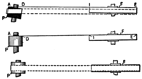
Figs. 449 to 451.—Method of aligning engine and dynamo. In fig. 449, a line is stretched from A to E and the dynamo shifted until the line contacts with points A, D, I, and E. In a small dynamo, the pulley may be loosened and set back on the shaft as in fig. 450, while lining up the faces, and then moved back to its original position as in fig. 451. When the pulley is not easily shifted the distances at A and D (fig. 449) may be measured.
Rules for Calculating Speed and Sizes of Pulley.—When two pulleys are working together connected by a belt, the one which communicates the motion is called the driver and the other which receives it, the driven pulley.
To Find the Size of the Driving Pulley: Multiply the diameter of the driven pulley by its required number of revolutions, and divide the product by the revolutions of the driver. The quotient will be the diameter of the driver.
To Find the Number of Revolutions of the Driven Pulley: Multiply the diameter of the driver by its number of revolutions, and divide by diameter of driven. The quotient will be the number of revolutions of the driven.
403
To Find the Diameter of the Driven that shall Make a Given Number of Revolutions, the Diameter and Revolutions of the Driver Being Given: Multiply the diameter of the driver by its number of revolutions, and divide the product by the number of revolutions of the driven pulley. The quotient will be the diameter of the driven pulley.
Rope Drive.—In this method of power transmission, rope is run in V-shaped grooves in the rims of the pulleys; this form of drive, in some cases, is more desirable than others.
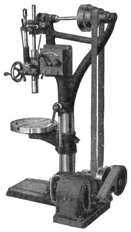
Fig. 452.—General Electric C Q back geared motor driving Hamilton sensitive drill. When slowly moving machines are to be driven, or where, for any reason, very moderate belt speeds are required, the back geared motor is desirable. Two ratios of gear reduction have been adopted as standard; they are:—4 to 1 and 8 to 1.
Ques. What are some of the advantages of rope drive?
Ans. More power can be transmitted with a given diameter and width of pulley, on account of the increased grip in the grooves. Rope drive can be employed for long or short distances by reason of its lightness and the action of the grooves.
404
Gear Drive.—This method is used where a positive drive is desired, as for elevator or railway motors. It admits of any degree of speed reduction without attending difficulties as would be encountered with belt drive.
Thus, with the worm type of gear as used on elevator motors a great reduction in velocity can be made without incurring the expense of countershaft as with a belt.
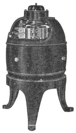
Fig. 453.—Watson vertical motor designed to operate a vertical shaft, either through belt connection, or by direct drive. Hess-Bright ball bearings are used, taking the downward thrust due to the weight of the armature. For mounting on the floor or ceiling, a tripod base (as shown) is furnished, the standard sliding base being used on a side wall. The armature shaft may be extended for pulley or coupling either above or below the motor.
Friction Drive.—This is a very simple mode of transmitting power and has the advantages of simplicity and compactness. In operation, the driving wheel is pressed against the wheel to be driven, transmitting motion to the latter by the frictional 405 grip. The drive is thrown out of gear by slightly moving the machine on its sliding base. In construction, the friction may be increased by making one wheel of the pair of wood, compressed paper, or leather.
Electrical Connections.—Circuits for dynamos and motors should be carefully planned so as to secure the simplest arrangement, and to avoid unnecessary expense and delay, the wiring should be installed in accordance with the requirements of the National Electrical Code.
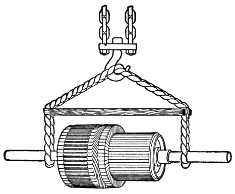
Fig. 454.—Sling for handling armatures. In raising an armature it should be supported by the shaft to avoid any strain on the armature body or commutator.
Ques. What may be said with respect to exposed and concealed wiring?
Ans. Exposed wiring is cheap and accessible; a short circuit or ground is easily located and repaired. Concealed wiring, especially when placed under the floor, has the advantage of being out of the way, and thus protected from injury.
406
Ques. In wiring a dynamo what are the considerations with respect to size of wire?
Ans. All conductors, including those connecting the machine with the switchboard, as well as the bus bars on the latter, should be of ample size to be free from overheating and excessive loss of voltage. The drop between the generator and switchboard should not exceed one-half per cent. at full load, because it interferes with proper regulation and adds to the less easily avoided drop on the distribution system.
407
There are numerous devices that must be used in connection with dynamos and motors for proper control and safe operation. Among these may be mentioned:
1. Switches;
2. Fuses;
3. Circuit breakers;
4. Rheostats;
5. Switchboards.
Switches.—A switch is a device by means of which an electric circuit may be opened or closed. There are numerous types of switch; they may be either single or multi-pole, single or double-throw and either of the "snap" or knife form.
Ques. What is the difference between a single and double-pole switch?
Ans. A single-pole switch controls only one of the wires of the circuit, while a double-pole switch controls both.
Ques. What is the difference between a single-break and a double-break switch?
Ans. The distinction is that the one breaks the circuit at one point only, while the other breaks it at two points.
408
Ques. What is the advantage of a double-break?
Ans. If the circuit be opened at two points in series at the same instant, the electromotive force is divided between the two breaks and the length to which the current will maintain an arc at either break is reduced to one-half; thus there is less chance of burning the metal of the switch. Another reason for providing two breaks is to avoid using the blade pivot as a conductor, the contact at this point being too poor for good conductivity.
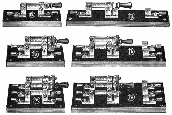
Figs. 455 to 457.—Adam's single-throw knife switches without fuse connections. Fig. 455, single-pole switch; fig. 456, double-pole switch; fig. 457, three-pole switch.
Figs. 458 to 460.—Adam's single-throw knife switches with fuse connections at the handle end. Fig. 458, single-pole switch; fig. 459, double-pole switch; fig. 460, three-pole switch.
Ques. When should a knife switch be used?
Ans. When the capacity of the circuit in which it is to be placed exceeds 10 amperes.
409
Ques. Describe a knife switch.
Ans. Fig. 461 illustrates a knife switch of the double-pole, single-throw type. It consists of the following parts: base, hinges, blades, contact jaws, insulating cross bar, and handle, as shown.
Ques. How should knife switches be installed?
Ans. They should be placed so that gravity tends to open them.
Otherwise if the hinges become loose, the weight of the blades and handle would tend to close the switch, thus closing the circuit and possibly resulting in considerable damage.
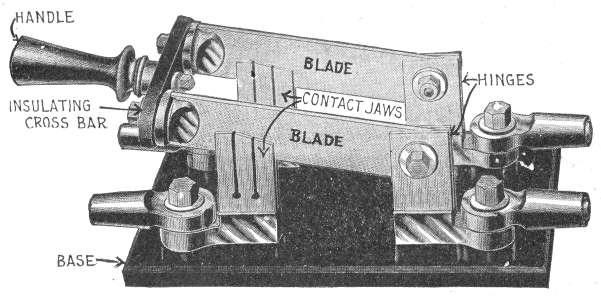
Fig. 461.—A single-throw, two pole knife switch. As usually constructed it is made of hard-drawn copper with cast terminal lugs and fibre cross bar.
Ques. How should switches be proportioned?
Ans. The minimum area of the contact surfaces should not be less than .01 square inch per ampere, and in those used on arc lighting or other high voltage circuits where the current is usually small, the area of the contact surfaces are usually from .02 to 410 .05 inch per ampere. Since dirt or oxidation would prevent good contact under a simple pressure between the contact surfaces, the mechanism of a switch provides a sliding contact.
In the general design of switches, all parts which carry current are given a cross sectional area of at least one square inch per 1,000 amperes if they be made of copper, and about three times as much if made of brass, as the conductivity of the latter is only one-third that of the former. Furthermore, the current should never be permitted to pass through springs, as the heat generated will destroy their elasticity.
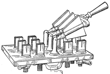
Fig. 462.—Triple-pole, double-break double-throw knife switch for very heavy current. The blades are made up of numerous strips to give adequate contact area. A double-throw switch is used when it is desirable to open one circuit and immediately close another, or to transfer one or more connections from one circuit to another in the least practical interval of time, also, when one connection is to be broken and another closed and it is undesirable to allow both to be closed at the same time.
Ques. What difficulty is experienced in opening a circuit in which a heavy current is flowing?
Ans. It is impossible to instantly stop the current by opening the switch, consequently the current continues to flow and momentarily jumps the air gap, resulting in a more or less intense arc which tends to burn the metal of the switch.
411
Ques. How is this remedied to some extent?
Ans. The contact pieces are so shaped that they open along their whole length at the same time, so as to prevent the concentration of the arc at the last point of contact. This feature is clearly shown in fig. 461.
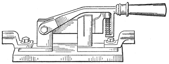
Fig. 463.—A "quick break" knife switch of the single-throw, single-break, one pole, type. The contact blade is held between the jaws by their clamping friction until the handle compresses the spring sufficiently to force the blade out. As soon as it breaks contact with the jaws, the spring expands and drives the blade away from the jaws with greater rapidity than could be done by hand. The object of this action is to break the arc as quickly as possible to prevent burning the metal of the switch.
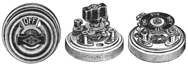
Figs. 464 and 465.—Snap switch; views showing switch with cover on, and exposed to show mechanism. The switch is provided with indicating dial which registers "on" and "off" positions.
Fig. 466.—Gas Engine snap switch. The first snap makes connection so that igniter is run from storage battery; second snap connections are changed so that igniter is supplied from dynamo; third snap makes connections so that dynamo supplies igniter and charges storage battery; fourth snap, all off.
Ques. For what service are "snap" switches suitable?
Ans. They are used on circuits containing lamps in comparatively small groups, and other light duty service.
412
Ques. What is a quick break switch?
Ans. A form of switch in which the contact pieces are snapped apart by the action of the springs, as shown in fig. 463, so as to make the duration of the arc as short as possible.
The current allowed in each branch circuit of an electric lighting system is limited by the insurance rules to a maximum of 660 watts equivalent to 12 lamps of 16 c.p. each at 110 volts. They are also employed to control lamps in groups in theatres and other places where many lamps are turned on or off at about the same time.
Fig. 467.—Spool of fuse wire. The wire is usually made of an alloy of tin and lead, such as half and half solder. Bismuth is frequently added to the alloy to lower the melting point For half and half solder the melting point is 370° Fahr. The quickness with which a fuse will melt after the current has reached the limit depends upon the specific heat and latent heat of the metal. The current required to "blow" a fuse increases somewhat with the age of the fuse owing to oxidation and molecular changes. Fuses are sometimes rated according to the number of amperes to be taken normally by the circuit they are to protect. Thus, a 10 ampere fuse is supposed to protect a circuit whose regular current should not exceed 10 amperes, and to blow if the current rise to say 12 amperes. The Underwriters' rule requires that the rating be about 80% of the maximum current it can carry indefinitely, thus allowing about 25% overload before the fuse melts. The fusing current varies considerably according to circumstances. The temperature of the surrounding air or other substances affects the melting current greatly, because the rate at which heat from the fuse will be transferred to the surroundings depends upon the difference of temperance between them and the fuse. Hence a fuse in a warm place will be melted by a smaller current than a similar fuse in a cold place. For a similar reason, a fuse in an enclosed place where there is little chance for the heat to be dissipated, will melt with a smaller current than the same in an open place. If the current increase gradually to that which would ordinarily melt the fuse, the high temperature makes the fuse wire oxidize rapidly; this sometimes makes a sort of tube of oxide which will not break even after the fuse wire inside has melted, and so the fuse carries more than its rated current. Open fuses are so unreliable that circuit breakers are preferable for large currents; when fuses are used, the enclosed type as shown in figs. 468 to 470, is usually the more desirable.
413
Fuses.—All circuits subject to abnormal increase of current which might overheat the system, should be protected by fuses which will melt and thus open the circuit. A fuse is simply a strip of fusible metal, often consisting of lead with a small percentage of tin, connected in series in the circuit.
Experiments have shown that for large fuses, a multiple fuse is more sensitive than a single one. A one hundred ampere fuse may be made by taking four wires of twenty-five amperes capacity. A fuse block may be overloaded, not because the metal of the terminals is not of sufficient cross section to carry the current, but because of insufficient area of, contact, or loose contact of fuse and wires; the overload thus caused results in heating and frequently melts the fuse.
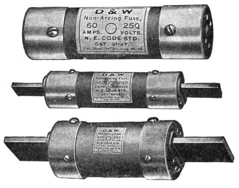
Figs. 468 to 470.—D & W, enclosed "cartridge" fuses. Fig. 468, type for 3 to 60 amperes; fig. 469, type for 61 to 100 amperes; fig. 470, type for 101 to 1,000 amperes.
Ques. Where should fuses be placed?
Ans. They should be inserted wherever the size of wire changes or wherever there is a branch of smaller size wire connected, unless the next fuse on the main or larger wire is small enough to protect the branch or small wire.
414
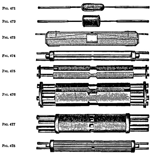
Figs. 471 to 478.—Interior construction of D. & W. fuses. In the manufacture of these fuses, four types of fuse link are used according to capacity of fuse, and classified as: 1, air drum link; 2, flat link; 3, multiple link; 4, cylinder link. In the air drum link, figs. 471 and 472, a capsule provides an air space about the center of the link, the rate of heat conduction through the confined air being very slow, the temperature of that portion of the link rises rapidly with increasing current, rendering the blowing point practically constant; fig. 473 shows a section through the complete fuse. In the flat link, fig. 474, the section is reduced in the center, cutting down as far as possible the volume of metal to be fused. Figs. 475 to 478 show various form of multiple link construction. By subdividing the metal, increased radiating surface is obtained which permits a reduction in the volume of fusible metal necessary, and the metal vapor formed when the fuse blows on heavy overload is more readily dissipated. Figs. 477 and 478 show two forms of the cylinder link, the plain cylinder fig. 477, being used for low voltage and large current, and fig. 478, for certain high tension service. The corrugated cylinder presents more surface to the fuse filling than the plain type and secures a maximum radiating surface with resulting minimum volume of metal for a given current.
415
Ques. How should fuses be mounted?
Ans. They should be placed on a base of slate, porcelain, marble, or other incombustible material.
Ques. What is the objection to copper fuses?
Ans. They heat perceptibly soon after their rated capacity is passed. The melting temperature is higher than lead alloy.
Ques. Upon what consideration does the choice between switches and circuit breakers depend?
Ans. Simple knife switches are suitable for use when the circuit is not liable to be opened while carrying large current. A circuit breaker, operated automatically or by hand should be used for interrupting heavy currents.
Figs. 479 and 480.—D & W fuse indicator. The operation is illustrated in the figures which show appearance of the label before the blowing of the fuse, fig. 479, and the same fuse blown, as indicated by the appearance of the black spot within the circle fig. 480.
Circuit Breakers.—A circuit breaker is a switch which is opened automatically when the current or the pressure exceeds or falls below a certain limit, or which can be tripped by hand.
Ques. What is the construction of a circuit breaker?
Ans. It is composed of a switch and a solenoid in the main circuit. When the current, flowing through the circuit, exceeds a certain value, the core of the solenoid is drawn in and trips a trigger which allows the switch to fly open under the action of a spring.
416
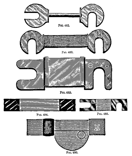
Figs. 481 to 486.—Various open fuses. Fig. 481, fuse for main and branch blocks; fig. 482, standard railway fuse; fig. 483, Edison main style; fig. 484, W. U. pattern; fig. 485, Bell telephone style; fig. 486, sneak current fuse. When an open fuse "blows" as a result of overloading, the rupture is accompanied by a flash, and by spattering of the fused material. With large currents this phenomenon is a source of danger, and the use of enclosed fuses is accordingly recommended whenever the rating of the fuse exceeds 25 amperes. Various types of enclosed fuse are shown in figs. 468 to 470.
417
There are numerous kinds of circuit breaker to meet the varied conditions of service of which may be mentioned the following:
1. Maximum circuit breaker;
2. Minimum circuit breaker;
3. Reverse current circuit breaker;
4. Maximum and reverse circuit breaker;
5. No voltage circuit breaker.
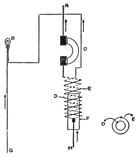
Figs. 487 and 488.—Reverse current circuit breaker; fig. 488, view looking at end of coils of cut out, showing direction of current. A to + bus bar; B, resistance lamp; C, brush of cut out; D, shunt coil; E, series coil; F, core that trips cut out; G, to—bus bar; H, to + pole of dynamo.
Of these the maximum, reverse, and maximum and reverse types are the more important.
A maximum circuit breaker is equivalent to a fuse, but has the advantage that it can be at once reset, whereas a fuse must be replaced.
A reverse breaker is used in connection with dynamos in parallel, to automatically cut out a machine if it takes more than say, 10 per cent. motor current.
Maximum and reverse circuit breakers are frequently used on dynamo panels.
418
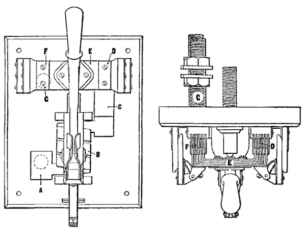
Figs. 489 and 490.—Front and top views of I-T-E automatic overload circuit breaker. In fig. 489 the current in the circuit enters at A, passes through the solenoid coil B (which in its iron jacket becomes a powerful magnet), through the copper terminal C, to the contact blades D, across the bridge at E to the contact blades F, and out into the line at G. The path of the current as indicated above is more clearly indicated in the top view fig. 490. When the current in the solenoid coil produces sufficient magnetism to overcome the weight of the plunger, the latter is drawn up with constantly increasing velocity until it strikes a restraining latch or trigger which forces the arm out of the switch, thus automatically opening the circuit. The device is so constructed that in opening the circuit the arc is broken on the carbon contacts instead of the copper contacts.
Ques. Describe a reverse current circuit breaker or discriminating cut out.
Ans. This type of circuit breaker is arranged to open a circuit in the event of current flowing in the circuit in a direction reverse to the normal. This is sometimes effected by winding the electromagnet of the circuit breaker with two coils, one connected as a shunt across the main circuit and the other in series with the main circuit, the two coils being so arranged that when the main current flows in the normal direction their effects assist one another, whereas, when the main current reverses, the effects of the coils are neutralized and the breaker opens.
419
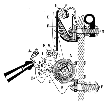
Fig. 491.—Roller-Smith "S.E." plain overload circuit breaker. In operation, current entering through the lower studs flows through the laminated strap windings C, from this into the arm D, through the contact plate E, into the stationary brush F, and finally out through the upper stud Q. In its passage through the laminated windings C, the square core A is of course magnetized to a degree dependent on the current strength. When this magnetization reaches a predetermined value, the attraction exerted on the ends K of the pivoted armature causes the same to rise with great and increasing velocity, finally bringing the finger D which forms part of the armature into violent contact with the face R of the corresponding projection on the housing which carries the handle and the roller H. This heavy blow causes H, in its rotation about the shaft J, to go over the center and consequently allows the strong outward pressure of the brush F and the resilient coil C to throw the arm outward with a high velocity and so break the circuit, first between the brush fingers and the contact plate and finally between the carbons S and F, the one of which is rigidly secured to the arm and the other of which is resiliently mounted on its supporting spring. To reset the breaker, the handle, which the act of opening has raised, is pulled down, thus bringing roller H into engagement with roller G once more and in that way forcing the arm back into its initial position.
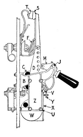
Fig. 492.—Roller-Smith "S.E." combination overload and underload circuit breaker. Attached to the supporting frame B is the extension Z, which like B, is of non-magnetic material and carries a rectangular magnetic core around which there are wrapped laminated copper conductors. Hinged at U is a heavy cup-shaped mass of magnetic material, and hinged at V is a flat lever X which bears against the extension Y secured to the housing which carries the operating handle. The circuit through the breaker conveys the current around the windings of this underload coil carried by frame Z and passes from it to the regular overload winding C from which it pursues the same course and exercises the same function as in a plain overload breaker. The core of Z being thus magnetized, the cup-shaped member W is held in firm contact therewith and the lever X hangs free. Should, however, the current fall below the minimum value, W is no longer sustained by the magnetic attraction but drops away, swinging on its hinge U until the projection on the heel thereof strikes the lever X, which blow is transmitted through Y to the handle and thus trips the breaker. When closing to reset the breaker, the handle is manipulated just as in the case of a plain overload breaker, that is, it is pulled down, thus not only closing and locking the breaker as before but through the pressure exerted by Y on X and by X on W, putting the latter into contact with its rectangular core to which it will adhere if the necessary current be present.
420
Ques. State some disadvantages of a discriminating cut out.
Ans. If one current reverse very rapidly, and soon reach a large value in the opposite direction, it is possible the cut out may not open at the desired instant, and thereafter the effect of the heavy reverse current will be so great that the breaker will be held in more and more strongly; a second disadvantage is that should the supply fail, the breaker will open in any case, and have to be reset before the supply can be resumed, though in certain cases, as, for instance where there is a motor load, this feature is an advantage and not a disadvantage, since the breaker acts as a no-voltage cut out as well as a reverse current cut out.
Reverse breakers, however, can be made positive in their action; that is, they can be so arranged that a reverse current exerts a positive pull on the tripping gear, so that the greater the reverse current, the greater the tripping effect.
Ques. What are time limit attachments?
Ans. Devices which are fitted to circuit breakers and which act as dampers and prevent the too sudden operation of the breakers on what may be only a temporary overload or reverse current.
By having different time limits on feeder and dynamo breakers it can be ensured that the former operate before the latter, and suitably in other cases where it is desired that one breaker shall operate before another.
Ques. Describe a time limit attachment.
Ans. There are numerous types. It may consist of a clockwork device, a weight acting on a small drum or pulley,421 a modified dash pot arrangement, or a device operating by the expansion of a conductor due to the heat generated by a current passing through it.
Ques. How should a time limit device be arranged?
Ans. It should be so arranged that the heavier the overload the quicker the device acts, until with a short circuit the device is almost instantaneous in its action.
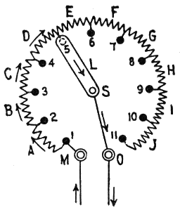
Fig. 493.—Diagram showing connections of a rheostat. The various resistance coils are connected to brass buttons or "contacts." The rheostat is connected in series in the circuit that it is to control. In operation when the lever is on contact 1, the current is opposed by all the resistance of the rheostat so that the flow is very small. As the lever is moved over contacts 1, 2, 3, etc., the coils are successively cut out, thus diminishing the resistance, and when contact 11 is reached all the resistance is short circuited allowing the full current to flow. In some types of rheostat the wire is wound around an iron framework which has been previously dipped into a fireproof insulating enamel. The advantage of this construction is that the heat from the wire is dissipated much more rapidly, so that a much smaller wire can be used to carry a given current. The size of such an enameled rheostat required for absorbing a given amount of energy is much smaller than one made of coils of wire stretched between an iron supporting framework.
Rheostats.—These devices consist of conductors inserted into a circuit for the purpose of diminishing, either constantly or in a variable degree, the amount of current flowing, or to develop heat by the passage of a current through them. Rheostats designed to be used in starting electric motors are frequently called "starting boxes."
422
Ques. Describe the construction of a rheostat.
Ans. In fig. 493, resistance coils, A, B, C, etc., are mounted in a frame or box, and are connected at intervals to the contacts 1, 2, 3, etc. The rheostat arm or lever L is pivoted at S, and when moved over the contacts, inserts more or less of the resistance in the circuit thus regulating the flow of the current. One terminal M of the rheostat is connected to the first contact and the other terminal O, to the lever at S.
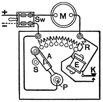
Fig. 494.—Starter with no voltage release for a series motor. A helical spring coiled around the lever pivot P, and acting on the lever A, tends to keep it in the off position against the stop S. This lever carries a soft iron armature I, which is held by the poles of the electromagnet E, when, in starting the motor, the arm has been gradually forced over as far as it will go. Should anything happen to interrupt the current while the motor M is running, E will lose its magnetism and A will be released, and will fly over to the off position. E is usually shunted by a small resistance R, so that only a portion of the main current flows through it. This device constitutes the no voltage release, and ensures that all the resistance is in circuit every time the motor is started.
Ques. How is a starting box connected to a motor?
Ans. In series.
Ques. Why should a starting box be used with a motor?
Ans. If the line voltage should be applied directly to the terminals of the armature when not running, an excessive flow of current will result, on account of the low resistance. 423 424 Accordingly, to prevent injury to the winding, a variable resistance or starting box is inserted between one supply terminal and the armature so that the pressure may be applied gradually while the motor is coming up to speed.
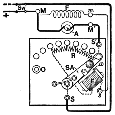
Fig. 495.—Starter with no voltage release for a shunt motor. The terminals of the motor are at M, M', m, and those of the starter at S, S', s. The lever SA is shown in the "on" position. The current enters the motor at the terminal M, and there divides, part going through the field coil F, and the main current through the motor armature A. The armature current enters the starter at the terminal S', and traversing the lever SA, leaves by the terminal S. The field current enters the starter at the terminal s, traverses the coil of the magnet E (which holds up the armature a linked to the lever) and thence completes its journey through the whole of the resistance R, and through the lever SA, to the terminal S. When the supply is cut off by opening Sw, or should the field circuit be accidentally broken, the magnet E will release a and the lever, which will thereupon fly to the "off" stop O. It should be noticed that when SA is off, A and F form a closed circuit with the resistance R and magnet E. The inductance of F has consequently no chance of causing destructive sparking when the current is shut off. In starting the motor, Sw is first closed, and then, as the lever is slowly moved, the resistance R, which at first is all in circuit with A, is gradually transferred from A to F. The resistance of R is too small to affect appreciably the current in F, which necessarily consists of a comparatively large number of turns of fine wire. The arrangement is adopted to render the breaking of the shunt circuit unnecessary and is rendered clearer by the diagram fig. 496. It should be noted that E may be provided with a short circuiting key or push if required.
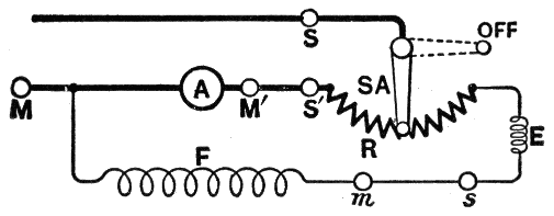
Fig. 496.—Simplified diagram of the connections of fig. 495.
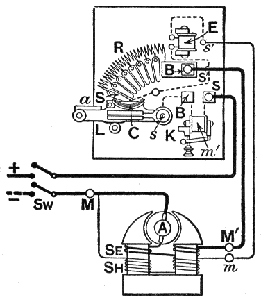
Fig. 497.—Starter with no voltage release and overload release connected to a compound motor. With a shunt motor, the only difference in the diagram would be that the series winding Se would be absent, and the armature A would then be connected straight across between the main terminals M and M'. When switch Sw is closed, the current will enter the starter at its terminal S, and pass through the magnet coil m' of the overload release to the switch lever L, which is shown in the off position. As soon as L is moved up to make contact with the first contact S the current divides; part going through the resistance R and the terminals S' and M' to the series coil Se (if a compound motor) and armature A; and part through the no voltage magnet E to the shunt winding Sh. As the lever L is moved up toward E, the effect is to take R out of the armature circuit and put it into the shunt circuit. When the iron armature a, fixed on the switch lever, comes against the poles of E, the laminated copper brush C bears against the blocks B, B, and so affords a better path for the current than through the spindle s. Should the supply voltage fail, either temporarily or permanently, E will release a, and L will fly off under the tension of a helical spring coiled round s. If there should be an overload on the motor, tending to pull it up and cause an excess of current to flow through the armature; this excess current, passing through m', will make it attract its armature, so bringing two contacts together at K which will short circuit E, and allow the switch to fly off. The connections between E and m' are not shown in the figure, but they are indicated at C in fig. 498, which is a simplification of fig. 497, and which should be carefully compared therewith. When only the normal current is flowing, the attraction between m' and its armature is not sufficient to pull the latter up. The actual forms and arrangement of parts on the starters are well shown in some of the figures.
425
Ques. What attachments should be provided on a starting box?
Ans. An overload release, and a no voltage release.
Ques. Describe these devices.
Ans. The overload release is an electromagnetic circuit breaker that opens the circuit if the motor become greatly overloaded. A no voltage release may consist of an electromagnet in series with the shunt field circuit; it holds the rheostat arm in the operating position as long as current flows through the shunt field from the line. If the line switch be opened or the shunt field circuit accidentally broken, the device becomes demagnetized and releases the arm, which returns to its starting position by the action of a spring.
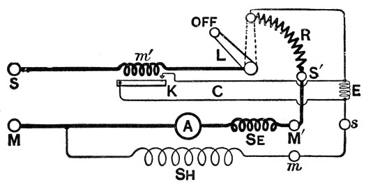
Fig. 498.—Simplified diagram of the connections of starter connected to compound motor as shown in fig. 497.
The general arrangement of switches, cut outs and starting boxes should be in accordance with the requirements of the National Electrical Code as follows:
"Each motor and starting box must be protected by a cut out and controlled by a switch, said switch plainly indicating whether 'on' or 'off.' The switch and rheostat must be located within sight of the 426 motor, except in cases where special permission to locate them elsewhere is given, in writing by the inspection department having jurisdiction.
"Where the circuit breaking device on the motor starting rheostat discs disconnects all wires of the circuit, this switch may be omitted.
"Overload release devices on motor starting rheostats will not be considered to take the place of the cut out required if they be inoperative during the starting of the motor.
"The switch is necessary for entirely disconnecting the motor when not in use, and the cut out to protect the motor from excessive currents, or careless handling when starting. An automatic circuit breaker disconnecting all wires of the circuit, may, however, serve as both switch and cut out."
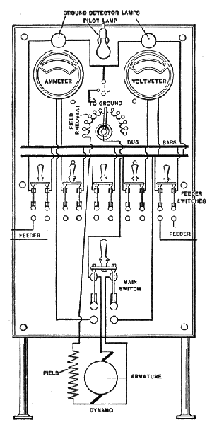
Fig. 499.—View showing general arrangement of a switchboard. The wires are shown to illustrate the various connections, but in actual construction these wires are connected on the back of the switchboard.
Switchboards.—A switchboard consists of a panel or series of panels of slate, marble, soapstone or brick tile erected in an electric plant for the purpose of mounting in a convenient group the instruments for controlling and distributing the current and safeguarding the system. Switchboards may be divided according to operation into two classes:
427
1. Direct control;
2. Remote control.
A direct control switchboard has all its apparatus mounted directly on the board and controlled by hand, while in the remote control type, the main current carrying parts are at some distance from the operating board, the control being effected by mechanical devices or by electric motors or solenoids. When the control system of a plant is very extensive, it sometimes occupies a separate building known as the switch house.
Ques. What may be said with respect to the material for switchboards?
Ans. In order to avoid danger of fire from short circuits, the panel should be made of some non-combustible material, such as marble, slate, glass plates or earthenware tiles. If slate be used, care should be taken to have it free from conducting veins, or it should be marbleized, that is, subjected to a treatment that will fill up the pores of the veins and thus prevent the absorption of moisture.
Wood is seldom used, except in cases where the switches, fuse blocks, wire supports, etc., are all mounted on porcelain or other incombustible material.
Ques. How should the instruments and connections be arranged on a switchboard?
Ans. They should be arranged so as to provide the shortest possible path for the current, and preferably always in the same direction, that is, from right to left or from top to bottom, the connecting wires being brought in on one side and out on the other, and the crossing of wires avoided as far as possible.
All wires and current carrying parts should be kept far enough apart at all points to prevent accidental contact or the jumping across of the 428 current where there is a great difference of voltage. Such wires should be also kept at a sufficient distance from screw heads, metal brackets, gas pipes, water pipes, and other conducting bodies, in order to prevent accidental grounds or short circuits.
All instruments and switches should be placed so as to be conveniently accessible for observation and operation, and sufficiently out of reach of accidental contact by persons; otherwise they should be protected by some form of insulating shield.
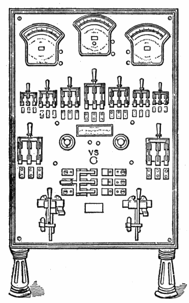
Fig. 500.—Small switchboard suitable for two dynamos; view showing ammeters and voltmeters, switches, circuit breakers, etc.
Ques. What type of switch is used on switchboards?
Ans. The "knife" switch.
Ques. Describe a small switchboard.
Ans. Fig. 500 shows one suitable for two dynamos. At the top is a voltmeter and two ammeters. Immediately below is a row of feeder switches serving to connect and disconnect the 429 various feeders with and from the bus bars which are mounted behind the board. Below are two rheostat handwheels, and two large switches connecting the dynamos with the bus bars. V S is a voltmeter switch connecting the voltmeter with various parts of the system. Below the voltmeter switch is a double-throw switch to transfer the bus bars from connection with the dynamo switches to one with some other source of current such as a street circuit, in the event of a breakdown. At the bottom are two circuit breakers.
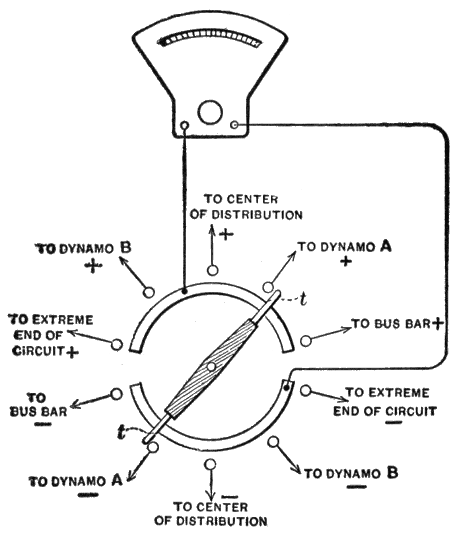
Fig. 501.—Diagram showing various connections of voltmeter switch of the small switchboard shown in fig. 500.
Ques. Describe the voltmeter switch.
Ans. Fig. 501 shows the connections, from which it can be seen that the voltmeter can be connected with the terminals of either dynamo or with the bus bars, or with either a central or remote part in the lamp circuits.
430
Under ordinary conditions it remains connected to the circuit at the central point of distribution. When one dynamo is already in circuit, however, and it becomes necessary to connect up the other one, the voltage of the latter must be the same as that at the bus bars. Accordingly, connections are provided to the voltmeter switch such that the attendant can compare the voltages at the dynamo terminals and bus bars before closing the dynamo switch. All the positive connections are on one side of the circle swept by the switch and all the negative connections on the other side.
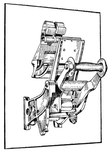
Fig. 502.—Roller-Smith, single-pole, plain overload circuit breaker. As its name indicates, the function of the plain overload circuit breaker is to automatically interrupt the circuit in which it is placed when the flow of current through it exceeds the predetermined limit for which the apparatus is set. It is the most common of all of the types and is utilized for the protection of dynamos and motors and all other electrical apparatus which, by reason of the conditions of operation, may become subject to loads in excess of the normal. The single-pole type may be used separately for the protection of a single wire of a given circuit or grouped to protect the two or more wires of one circuit, becoming in the latter case the so called independent arm multi-pole apparatus. The action of this type of circuit breaker is fully explained in fig. 491.
431
They are not only the best, but the cheapest work published on Electricity. Each number being complete in itself. Separate numbers sent postpaid to any address on receipt of price. They are guaranteed in every way or your money will be returned. Complete catalog of series will be mailed free on request.
Theo. Audel & Co., Publishers.
72 FIFTH AVENUE,
NEW YORK
1 NOTE:—The "front" end means the end at which the commutator is located. Armatures are most conveniently regarded from this end, the opposite end being known as the "back" end.
2 NOTE—The term back pitch means the number of spaces between the two inductors of a coil. For instance, in fig. 267, the pitch is 3; that is, there are three spaces between say inductors 1 and 4 which form part of the coil A—1—4—C. It is called the back pitch in distinction from the front or commutator pitch, which in this instance is 2.
3 NOTE—A re-entrant winding is one in which both ends re-enter or lead back to the starting point; a closed winding.
Inconsistent spelling and hyphenation are as in the original.