*** START OF THE PROJECT GUTENBERG EBOOK 48134 ***
The cover image has been created for this e-text, and has been placed in the public domain.
Please also see the Transcriber’s Notes at the end of this text.
Published by the
McGraw-Hill Book Company
New York
| Successors to the Book Departments of the |
| McGraw Publishing Company |
Hill Publishing Company |
| Publishers of Books for |
| Electrical World |
The Engineering and Mining Journal |
| The Engineering Record |
Power and The Engineer |
| Electric Railway Journal |
American Machinist |
ELECTRIC TRANSMISSION
OF
WATER POWER
By
ALTON D. ADAMS, A.M.
MEMBER AMERICAN INSTITUTE OF ELECTRICAL ENGINEERS
NEW YORK
McGraw-Hill Book Co.
1906
Copyrighted, 1906, by the
McGRAW PUBLISHING COMPANY
New York
TABLE OF CONTENTS
| CHAPTER |
PAGE |
| I. |
Water-Power in Electrical Supply |
1 |
| II. |
Utility of Water-Power in Electrical Supply |
10 |
| III. |
Cost of Conductors for Electric-power Transmission |
19 |
| IV. |
Advantages of the Continuous and Alternating Current |
31 |
| V. |
The Physical Limits of Electric-Power Transmission |
44 |
| VI. |
Development of Water-Power for Electric Stations |
51 |
| VII. |
The Location of Electric Water-Power Stations |
64 |
| VIII. |
Design of Electric Water-Power Stations |
83 |
| IX. |
Alternators for Electrical Transmission |
103 |
| X. |
Transformers in Transmission Systems |
122 |
| XI. |
Switches, Fuses, and Circuit-breakers |
135 |
| XII. |
Regulation of Transmitted Power |
155 |
| XIII. |
Guard Wires and Lightning Arresters |
168 |
| XIV. |
Electrical Transmission under Land and Water |
187 |
| XV. |
Materials for Line Conductors |
200 |
| XVI. |
Voltage and Losses on Transmission Lines |
215 |
| XVII. |
Selection of Transmission Circuits |
233 |
| XVIII. |
Pole Lines for Power Transmission |
246 |
| XIX. |
Entries for Electric Transmission Lines |
261 |
| XX. |
Insulator Pins |
270 |
| XXI. |
Insulators for Transmission Lines |
287 |
| XXII. |
Design of Insulator Pins for Transmission Lines |
298 |
| XXIII. |
Steel Towers |
306 |
| |
Index |
327 |
[1]
ELECTRIC TRANSMISSION OF WATER-POWER.
CHAPTER I.
WATER-POWER IN ELECTRICAL SUPPLY.
Electrical supply from transmitted water-power is now distributed
in more than fifty cities of North America. These include Mexico City,
with a population of 402,000; Buffalo and San Francisco, with 352,387
and 342,782 respectively; Montreal, with 266,826, and Los Angeles, St. Paul,
and Minneapolis, with populations that range between 100,000 and
200,000 each. North and south these cities extend from Quebec to Anderson,
and from Seattle to Mexico City. East and west the chain of
cities includes Portland, Springfield, Albany, Buffalo, Hamilton, Toronto,
St. Paul, Butte, Salt Lake City, and San Francisco. To reach
these cities the water-power is electrically transmitted, in many cases
dozens, in a number of cases scores, and in one case more than two
hundred miles. In the East, Canada is the site of the longest transmission,
that from Shawinigan Falls to Montreal, a distance of eighty-five
miles.
From Spier Falls to Albany the electric line is forty miles in length.
Hamilton is thirty-seven miles from that point on the Niagara escarpment,
where its electric power is developed. Between St. Paul and its
electric water-power station, on Apple River, the transmission line is
twenty-five miles long. The falls of the Missouri River at Cañon Ferry
are the source of the electrical energy distributed in Butte, sixty-five miles
away. Los Angeles draws electrical energy from a plant eighty-three
miles distant on the Santa Ana River. From Colgate power-house, on
the Yuba, to San Francisco, by way of Mission San José, the transmission
line has a length of 220 miles. Between Electra generating station in the
Sierra Nevada Mountains and San Francisco is 154 miles by the electric
line.
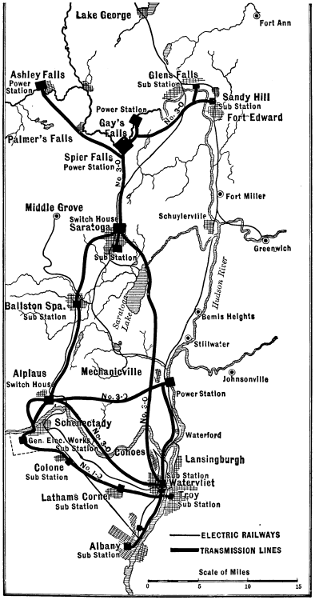
Fig. 1.—Spier Falls Transmission Lines.
Larger map (204 kB)
These transmissions involve large powers as well as long distances.
The new plant on the Androscoggin is designed to deliver 10,000 horse-power[2]
[3]
for electrical supply in Lewiston, Me. At Spier Falls, on the
Hudson, whence energy goes to Albany and other cities, the electric generators
will have a capacity of 32,000 horse-power. From the two water-power
stations at Niagara Falls, with their twenty-one electric generators
of 5,000 horse-power each, a total of 105,000, more than 30,000 horse-power
is regularly transmitted to Buffalo alone; the greater part of the
capacity being devoted to local industries. Electrical supply in St. Paul
is drawn from a water-power plant of 4,000 and in Minneapolis
from a like plant of 7,400 horse-power capacity. The Cañon Ferry station,
on the Missouri, that supplies electrical energy in both Helena and
Butte, has a capacity of 10,000 horse-power. Both Seattle and Tacoma
draw electrical supply from the 8,000 horse-power plant at Snoqualmie
Falls. The Colgate power-house, which develops energy for San
Francisco and a number of smaller places, has electric generators of
15,000 horse-power aggregate capacity. At the Electra generating station,
where energy is also transmitted to San Francisco and other cities
on the way, the capacity is 13,330 horse-power. Electrical supply in
Los Angeles is drawn from the generating station of 4,000 horse-power,
on the Santa Ana River, and from two stations, on Mill Creek, with an
aggregate of 4,600, making a total capacity of not less than 8,600 horse-power.
Five water-power stations, scattered within a radius of ten miles
and with 4,200 horse-power total capacity, are the source of electrical
supply in Mexico City.
The foregoing are simply a part of the more striking illustrations of
that development by which falling water is generating hundreds of thousands
of horse-power for electrical supply to millions of population. This
application of great water powers to the industrial wants of distant cities
is hardly more than a decade old. Ten years ago Shawinigan Falls was
an almost unheard-of point in the wilds of Canada. Spier Falls was
merely a place of scenic interest; the Missouri at Cañon Ferry was not
lighting a lamp or displacing a pound of coal; that falling water in the
Sierra Nevada Mountains should light the streets and operate electric cars
in San Francisco seemed impossible, and that diversion of Niagara, which
seems destined to develop more than a million horse-power and leave
dry the precipices over which the waters now plunge, had not yet begun.
In some few instances where water-power was located in towns or cities,
it has been applied to electrical supply since the early days of the industry.
In the main, however, the supply of electrical energy from water-power
has been made possible only by long-distance transmission. The
extending radius of electrical transmission for water-powers has formed[4]
[5]
the greatest incentive to their development. This development in turn
has reacted on the conditions that limit electrical supply and has materially
extended the field of its application. Transmitted water-power has
reduced the rates for electric service. It may not be easy to prove this
reduction by quoting figures for net rates, because these are not generally
published, but there are other means of reaching the conclusion.
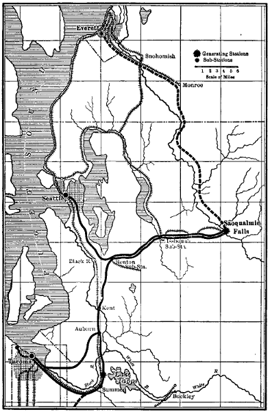
Fig. 2.—Snoqualmie Falls Transmission Lines.
Larger map (185 kB)
In the field of illumination electricity competes directly with gas, and
in the field of motive power with coal. During the past decade it is well
known that the price of gas has materially declined and the price of coal,
barring the recent strike period, has certainly not increased. In spite of
these reductions electrical supply from water-power has displaced both
gas and coal in many instances.
Moreover, the expansion of electric water-power systems has been
decidedly greater, as a rule, than that of electrical supply from steam-driven
stations. An example of the fact last stated may be seen in Portland,
Me. In the spring of 1899, a company was formed to transmit and
distribute electrical energy in that city from a water-power about thirteen
miles distant. For some years, prior to and since the date just named,
an extensive electric system with steam-power equipment has existed in
Portland. In spite of this, the system using water-power, on January 1st,
1903, had a connected load of 352 enclosed arcs and 20,000 incandescent
lamps, besides 835 horse-power in motors.
Comparing the expansion of electric water-power systems with those
operated by steam, when located in different cities, Hartford and Springfield
may be taken on the one hand and Fall River and New Bedford on
the other. The use of water-power in electrical supply at Hartford began
in November, 1891, and has since continued to an increasing extent.
Throughout the same period electrical supply in Fall River has been
derived exclusively from steam. In 1890 the population of Hartford was
53,230, and in 1900 it stood at 79,850, an increase of 50 per cent. At
the beginning of the decade Fall River had a population of 74,398, and
at its close the figures were 104,863, a rise of 40.9 per cent. In 1892 the
connected load of the electric supply system at Fall River included 451
arc and 7,800 incandescent lamps, and motors aggregating 140 horse-power.
By 1901 this load had increased to 1,111 arcs, 24,254 incandescent
lamps, and 600 horse-power in motors. The electric supply system
at Hartford in 1892 was serving 800 arcs, 2,000 incandescent lamps, and
no motors. After the use of transmitted water-power during nine years
the connected load of the Hartford system had come to include 1,679
arcs, 68,725 incandescent lamps, and 3,476 horse-power of motor capacity[6]
in 1901. At the beginning of the decade Hartford was far behind
Fall River in both incandescent lamps and motors, but at the end Hartford
had nearly three times as many incandescent lamps and nearly six
times as great a capacity in connected motors. As Fall River had a population
in 1900 that was greater by thirty-one per cent. than the population
of Hartford, and the percentage of increase during the decade was
only 9.1 lower in the former city, water-power seems to have been the
most potent factor in the rise of electric loads in the latter. Electric
gains at Hartford could not have been due to the absence of competition
by gas, for the price of gas there in 1901 was $1 per 1,000 cubic feet,
while the price in Fall River was $1.10 for an equal amount.
Water-power began to be used in electrical supply at Springfield during
the latter half of 1897. In that year the connected load of the Springfield
electric system included 1,006 arcs, 24,778 incandescent lamps, and
motors with a capacity of 647 horse-power. Five years later, in 1902,
this connected load had risen to 1,399 arc lamps, 45,735 incandescent
lamps, and a capacity of 1,025 horse-power in electric motors. At New
Bedford, in 1897, the electric system was supplying 406 arc and 22,122
incandescent lamps besides motors rated at 298 horse-power. This load,
in 1902, had changed to 488 arcs, 18,055 incandescent lamps, and 432
horse-power in capacity of electric motors. From the foregoing figures
it appears that while 82 arc lamps were added in New Bedford,
393 such lamps were added in Springfield. While the electric load at
New Bedford was increased by 134 horse-power of motors, the like increase
at Springfield was 378 horse-power, and while the former city lost
4,067 from its load of incandescent lamps, the latter gained 20,957 of
these lamps. During all these changes electrical supply in Springfield
has come mostly from water-power, and that in New Bedford has been
the product of steam. Population at Springfield numbered 44,179 in
1890 and 62,059 in 1900, an increase of 40.5 per cent. In the earlier of
these years New Bedford had a population of 40,733, and in the later
62,442, an increase of 53.3 per cent. In 1902 the average price obtained
for gas at Springfield was $1.04 and at New Bedford $1.18 per 1,000
cubic feet.
Springfield contains a prosperous gas system, and the gross income
there from the sale of gas was thirty-one per cent greater in 1902 than
in 1897. During this same period of five years the gross income from
sales of electrical energy, developed in large part by water-power, increased
forty-seven per cent. For the five years of general depression,
ending in 1897 gross annual income of gas sales in Springfield rose[7]
only five per cent, and the like electric income nine per cent. In the five
years last named the electrical supply system was operated with coal.
The application of transmitted water-power in electrical supply has
displaced steam as a motive power in many large industrial plants that
never would have been operated from steam-driven electric stations. An
example of this sort exists at Portland, where one of the motors operated
by the electric water-power system, in an industrial plant, has a capacity
of 300 horse-power. Every pound of coal burned in Concord, N. H., is
hauled by the single steam railway system entering that city, which railway
operates large car and repair shops there. Some years ago the railway
installed a complete plant of engines, dynamos, and motors for electric-driving
throughout these shops. These engines and dynamos now
stand idle and the motor equipment, with an aggregate capacity of 590
horse-power, is operated with energy purchased from the local electrical
supply system and drawn from water-power.
Another striking example of the ability of electric water-power systems
to make power rates that are attractive to large manufacturers may be
seen at Manchester, N. H. One of the largest manufacturing plants in
that city purchases energy for the operation of the equivalent of more than
7,000 incandescent lamps, and of motors rated at 976 horse-power, from
the electrical supply system there, whose generating stations are driven
mainly by water-power. The Manchester electrical supply system also
furnishes energy, through a sub-station of 800-horse-power capacity, to
operate an electric railway connecting Manchester and Concord. This
electric line is owned and operated in common with the only steam railway
system of New Hampshire, so that the only inducement to purchase
energy from the water-power system seems to be one of price.
In Buffalo the electric transmission system from Niagara Falls
supplies large motors of about 20,000 horse-power capacity in manufacturing
and industrial works, and 7,000 horse-power to the street railway
system, besides another 4,000 horse-power for general service in
lighting and small motors. Few large cities in the United States have
cheaper coal than Buffalo, and in Portland, Concord, and Manchester
coal prices are moderate. In the Rocky Mountain region, where coal is
more expensive, the greater part of the loads of some electric water-power
systems is made up of large industrial works. In Salt Lake City the electrical
supply system, which draws its energy almost exclusively from
water-powers, had a connected load of motors aggregating 2,600 horse-power
as far back as 1901, and also furnished energy to operate the local
electric railway, and several smelters six miles south of the city, besides[8]
all the local lighting service. As good lump coal sells in Salt Lake for
$4.50 per ton, slack at less than one-half this figure, and the population
there by the late census was only 53,531, the figures for the load of motors
are especially notable. At Helena energy from the 10,000 horse-power
station at Cañon Ferry operates the local lighting and power systems, two
smelting and a mining plant.
Cities with Electrical Supply from Water-Power.
| City. |
Miles from
Water-Power
to City. |
Horse-Power of
Water-Driven
Stations. |
Population. |
| Mexico City |
10 to 15 |
4,200 |
402,000 |
| Buffalo |
23 |
|
[A]30,000 |
352,387 |
| Montreal |
85 |
|
— |
266,826 |
| San Francisco |
147 |
|
13,330 |
342,782 |
| Minneapolis |
10 |
|
7,400 |
202,718 |
| St. Paul |
25 |
|
4,000 |
163,065 |
| Los Angeles |
83 |
|
8,600 |
102,479 |
| Albany |
40 |
|
32,000 |
94,151 |
| Portland, Ore. |
— |
|
— |
90,426 |
| Hartford |
11 |
|
3,600 |
79,850 |
| Springfield, Mass. |
6 |
|
3,780 |
62,059 |
| Manchester, N. H. |
13 |
.5 |
5,370 |
59,987 |
| Salt Lake City |
36 |
.5 |
10,000 |
53,531 |
| Portland, Me. |
13 |
|
2,660 |
50,145 |
| Seattle |
— |
|
8,000 |
80,671 |
| Butte |
65 |
|
10,000 |
30,470 |
| Oakland |
142 |
|
15,000 |
66,900 |
| Lewiston, Me. |
3 |
|
3,000 |
23,761 |
| Concord, N. H. |
4 |
|
1,000 |
19,632 |
| Helena, Mont. |
20 |
|
— |
10,770 |
| Hamilton, Ont. |
35 |
|
8,000 |
|
| Quebec |
7 |
|
3,000 |
|
| Dales, Ore. |
27 |
|
1,330 |
|
| [A] Power received. |
In Butte, energy from the station just named operates the works of
five smelting and mining companies, driving motors that range from 1 to
800 horse-power in individual capacity. The capacity of the Butte sub-station
is 7,600 horse-power.
The great electric water power system marked by the Santa Ana station
at one end and the city of Los Angeles at the other, eighty-three miles
distant, includes more than 160 miles of transmission lines, several hundred
miles of distribution circuits, and supplies light and power in twelve
cities and towns. Among the customers of this system are an electric
railway, a number of irrigation plants, and a cement works. These[9]
works contain motors that range from 10 to 200 horse-power each in
capacity. Motors of fifty horse-power or less are used at pumping stations
in the irrigation systems.
Applications of water-power in electrical supply during the past decade
have prepared the way for a much greater movement in this direction.
Work is now under way for the electric transmission of water-power,
either for the first time or in larger amounts, to Albany, Toronto,
Chicago, Duluth, Portland, Oregon, San Francisco, Los Angeles, and
dozens of other cities that might be named.
Another ten years will see the greater part of electrical supply on the
American continent drawn from water-power.
Only the largest city supplied from each water-power is named above.
Thus the same transmission system enters Albany, Troy, Schenectady,
Saratoga, and a number of smaller places.
[10]
CHAPTER II.
UTILITY OF WATER-POWER IN ELECTRICAL SUPPLY.
In comparatively few systems is the available water-power sufficient
to carry the entire load at all hours of the day, and during all months of
the year, so that the question of how much fuel can be saved is an uncertain
one for many plants. Again, the development of water-power
often involves a large investment, and may bring a burden of fixed
charges greater than the value of the fuel saved.
In spite of these conflicting opinions and factors, the application of
water-power in electrical systems is now going on faster than ever before.
If a saving of fuel, measured by the available flow of water during those
hours when it can be devoted directly to electrical supply, were its only
advantage, the number of cases in which this power could be utilized at a
profit would be relatively small. If, on the other hand, all of the water
that passes down a stream could be made to do electrical work, and if the
utilization of this water had other advantages nearly or quite as great as
the reduction of expense for coal, then many water-powers would await
only development to bring profit to their owners.
No part of the problem is more uncertain than the first cost and subsequent
fixed charges connected with the development of water-power.
To bring out the real conditions, the detailed facts as to one or more
plants may be of greater value than mere general statements covering
a wide range of cases.
On a certain small river the entire water privilege at a point where a
fall of fourteen feet could be made available was obtained several years
ago. At this point a substantial stone and concrete dam was built, and
also a stone and brick power-house with concrete floor and steel truss
roof. In this power-house were installed electric generators of 800 kilowatts
total capacity, direct-connected to horizontal turbine wheels. The
entire cost of the real estate necessary to secure the water-power privilege
plus the cost of all the improvements was about $130,000. More than
enough water-power to drive the 800-kilowatt generators at full load was
estimated to be available, except at times of exceptionally low water. At
this plant the investment for the water-power site, development, and[11]
complete equipment was thus $162 per kilowatt capacity of generators
installed.
Allowing 65 days of low water, these generators of 800 kilowatts capacity
may be operated 300 days per year. If the running time averages
ten hours daily at full load, the energy delivered per year is 2,400,000
kilowatt hours. Ten per cent of the total investment should be ample
to cover interest and depreciation charges, and this amounts to $13,000
yearly. It follows that the items of interest and depreciation on the
original investment represent a charge of 0.54 cent per kilowatt hour on
the assumed energy output at this plant. This energy is transmitted a
few miles and used in the electrical supply system of a large city.
On another river the entire water privilege was secured about four
years ago at a point where a fall of more than 20 feet between ledges of
rock could be obtained and more than 2,000 horse-power could be developed.
At this point a masonry dam and brick power-house were built,
and horizontal turbine wheels were installed, direct-connected to electric
generators of 1,500 kilowatts total capacity. The entire cost of real estate,
water rights, dam, building, and equipment in this case was about
$250,000.
Assuming, as before, that generators may be operated at full capacity
for 10 hours per day during 300 days per year, the energy delivered by
this plant amounts to 4,500,000 kilowatt hours yearly. The allowance
of 10 per cent on the entire investment for interest and depreciation is
represented by $25,000 yearly in this case, or 0.56 cent per kilowatt hour
of probable output. Energy from this plant is transmitted and used in
a large system of electrical supply.
If, through lack of water or inability to store water or energy at times
when it is not wanted, generators cannot be operated at full capacity
during the average number of hours assumed above, the item of interest
and depreciation per unit of delivered energy must be higher than that
computed. With the possible figure for this item at less than six-tenths
of a cent per kilowatt hour, there is opportunity for some increase
before it becomes prohibitive. At the plant last named the entire
investment amounted to $166 per kilowatt capacity of connected generators,
compared with $162 in the former case, and these figures may be
taken as fairly representative for the development of water-power in a
first-class manner on small rivers, under favorable conditions. In both
of these instances the power-houses are quite close to the dams. If long
canals or pipe lines must be built to convey the water, the expense of
development may be greatly increased.
[12]
One advantage of water- over steam-power is the smaller cost of the
building with the former for a given capacity of plant. The building for
direct-connected electric generators, driven by water-wheels, is relatively
small and simple. Space for fuel, boilers, economizers, feed-water heaters,
condensers, steam piping, and pumps is not required where water-power
is used. No chimney or apparatus for mechanical draught is
needed.
The model electric station operated by water-power usually consists
of a single room with no basement under it. One such station has floor
dimensions 27 by 52 feet, giving an area of 1,404 square feet, and contains
generators of 800 kilowatts capacity. This gives 1.75 square feet of floor
space per kilowatt of generators. In this station there is ample room for
all purposes, including erection or removal of machinery.
Next to the saving of fuel, the greatest advantage of water-power is
due to the relatively small requirements for labor at generating stations
where it is used. This is well illustrated by an example from actual
practice. In a modern water-power station that contributes to electrical
supply in a large city the generator capacity is 1,200 kilowatts. All of
the labor connected with the operation of this station during nearly
twenty-four hours per day is done by two attendants working alternate
shifts.
These attendants live close to the station in a house owned by the
electric company, and receive $60 each per month in addition to house
rent. Considering the location, $12 per month is probably ample allowance
for the rent. This brings the total expense of operation at this
station for labor up to $132 per month, or $1,584 per year, a sum corresponding
to $1.32 yearly per kilowatt of generator capacity.
At steam-power stations of about the above capacity, operating
twenty-four hours daily, $6 is an approximate yearly cost of labor per
kilowatt of generators in use. It thus appears that water-power plants
may be operated at less than one-fourth of the labor expense necessary
at steam stations per unit of capacity. On an average, the combined
cost of fuel and labor at electric stations driven by steam-power is a little
more than 76 per cent of their total cost of operation. Of this total, labor
represents about 28, and fuel about 48 per cent. Water-power, by dispensing
with fuel and with three-fourths of the labor charge, reduces the
expense of operation at electric stations by fully 69 per cent.
But this great saving in the operating expenses of electric stations can
be made only where water entirely displaces coal. If part water-power
and part coal are used, the result depends on the proportion of each, and[13]
is obviously much affected by the variations of water-power capacity.
In such a mixed system the saving effected by water-power must also
depend on the extent to which its energy can be absorbed at all hours
the day. By far the greater number of electric stations using water-power
are obliged also to employ steam during either some months in
the year or some hours in the day, or both.
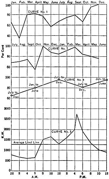
ENERGY CURVES FROM WATER POWER ELECTRIC STATIONS.
Fig. 3.
It is highly important, therefore, to determine, as nearly as may be,
the answers to three questions:
[14]
First, what variations are to be expected in the capacity of a water-power
during the several months of a year?
Second, if the daily flow of water is equal in capacity to the daily output
of electrical energy, how far can the water-power be devoted to the
development of that energy?
Third, with a water-power sufficient to carry all electrical loads at
times of moderately high water, what percentage of the yearly output of
energy in a general supply system can be derived from the water?
To the first of these questions experience alone can furnish an answer.
Variations in the discharge of rivers during the different months of a year
are very great. In a plant laid out with good engineering skill some provision
will be made for the storage of water, and the capacity of generating
equipment will correspond to some point between the highest and
lowest rates of discharge.
Curve No. 1 in the diagram on the opposite page represents the energy
output at an electric station driven entirely by water-power from a small
stream during the twelve months of 1901, the entire flow of the stream
being utilized. During December, 1901, the output of this station was
527,700 kilowatts, and was greater than that in any other month of the
year. Taking this output at 100 per cent, the curve is platted to show
the percentage attained by the delivered energy in each of the other months.
At the lowest point on the curve, corresponding to the month of February,
the output of energy was only slightly over 33 per cent of that in December.
During nine other months of the year the proportion of energy
output to that in December was over 60 and in three months over 80 per
cent. For the twelve months the average delivery of energy per month
was 73.7 per cent of that during December.
Percentages of Energy Delivered
in Different Months, 1901.
| January |
68.0 |
| February |
33.1 |
| March |
80.5 |
| April |
81.7 |
| May |
77.9 |
| June |
58.6 |
| July |
67.7 |
| August |
75.8 |
| September |
79.3 |
| October |
65.9 |
| November |
95.8 |
| December |
100.0 |
At a somewhat small water-power station on another river with a
watershed less precipitous than that of the stream just considered, the
following results were obtained during the twelve months ending June
30th, 1900. For this plant the largest monthly output of energy was in
November, and this output is taken at 100 per cent. The smallest delivery
of energy was in October, when the percentage was 53.1 of the
amount for November. In each of seven other months of the year the
output of energy was above 80 per cent of that in November. During[15]
March, April, May, and June the water-power yielded all of the energy
required in the electrical supply system with which it was connected, and
could, no doubt, have done more work if necessary. For the twelve
months the average delivery of energy per month was 80.6 per cent of
that in November, the month of greatest output.
Percentages of Energy Delivered
in Different Months, 1899 and 1900.
| July |
68.6 |
| August |
69.1 |
| September |
73.3 |
| October |
53.1 |
| November |
100.0 |
| December |
87.0 |
| January |
84.9 |
| February |
91.3 |
| March |
98.5 |
| April |
85.7 |
| May |
80.8 |
| June |
74.9 |
The gentler slopes and better storage facilities of this second river
show their effect in an average monthly delivery of energy 6.9 per cent
higher as to the output in a month when it was greatest than the like percentage
for the water-power first considered. These two water-power
illustrate what can be done with only very moderate storage capacities
on the rivers involved. At both stations much water escapes over the
dams during several months of each year. With enough storage space
to retain all waters of these rivers until wanted the energy outputs could
be largely increased.
As may be seen by inspection of curve No. 2, the second water-power
has smaller fluctuations of capacity, as well as a higher average percentage
of the maximum output than the water-power illustrated by curve
No. 1.
If the discharge of a stream during each twenty-four hours is just
sufficient to develop the electrical energy required in a supply system during
that time, the water may be made to do all of the electrical work in
one of two ways. If the water-power has enough storage capacity behind
it to hold the excess of water during some hours of the day, then it
is only necessary to install enough water-wheels and electric generators
to carry the maximum load. Should the storage capacity for water be
lacking, or the equipment of generating apparatus be insufficient to work
at the maximum rate demanded by the electrical system, then an electric
storage battery must be employed if all of the water is to be utilized and
made to do the electrical work.
The greatest fluctuations between maximum and minimum daily
loads at electric lighting stations usually occur in December and January.
The extent of these fluctuations is illustrated by curve No. 3, which represents
the total load on a large electrical supply system during a typical
week-day of January, 1901. On this day the maximum load was 2,720
and the minimum load 612 kilowatts, or 22.5 per cent of the highest rate[16]
of output. During the day in question the total delivery of energy for
the twenty-four hours was 30,249 kilowatt hours, so that the average load
per hour was 1,260 kilowatts. This average is 46 per cent of the maximum
load.
Computation of the area included by curve No. 3 above the average
load line of 1,260 kilowatts shows that about 17.8 per cent of the total
output of energy for the day was delivered above the average load, that
is, in addition to an output at average load. It further appears by inspection
of this load curve that this delivery of energy above the average
load line took place during 12.3 hours of the day, so that its average rate
of delivery per hour was 438 kilowatts.
If a water-power competent to carry a load of 1,260 kilowatts twenty-four
hours per day be applied to the system illustrated by curve No. 3,
then about 17.8 per cent of the energy of the water for the entire day
must be stored during 11.7 hours and liberated in the remaining 12.3
hours. This percentage of the total daily energy of the water amounts
to 36 per cent of its energy during the hours that storage takes place.
If all of the storage is done with water, the electric generators must
be able to work at the rate of 2,720 kilowatts, the maximum load. If all
of the storage is done in electric batteries, the use of water may be uniform
throughout the day, and the generator capacity must be enough
above 1,260 kilowatts to make up for losses in the batteries. Where
batteries are employed the amount of water will be somewhat greater
than that necessary to operate the load directly with generators, because
of the battery losses.
In spite of the large fluctuations of electrical loads throughout each
twenty-four hours, it is thus comparatively easy to operate them with
water-powers that are little, if any, above the requirements of the average
loads.
Perhaps the most important question relating to the use of water-power
in electrical supply is what percentage of the yearly output of
energy can be derived from water where this power is sufficient to carry
the entire load during a part of the year. With storage area for all surplus
water in any season, the amount of work that could be done by a
stream might be calculated directly from the records of its annual discharge
of water. As such storage areas for surplus water have seldom,
or never, been made available in connection with electrical systems, the
best assurance as to the percentage of yearly output that may be derived
from water-power is found in the experience of existing plants.
The question now to be considered differs materially from that involving[17]
merely the variations of water-power in the several months, or
even the possible yearly output from water-power. The ratio of output
from water-power to the total yearly output of an electrical system includes
the result of load fluctuations in every twenty-four hours and the
variable demands for electrical energy in different months, as well as
changes in the amount of water-power available through the seasons.
In order to show the combined result of these three important factors
curve No. 4 has been constructed. This indicates the percentages of
total semi-yearly outputs of electrical energy derived from water-power
in two supply systems. Each half-year extends either from January to
June, inclusive, or from July to December, inclusive, and thus covers a
wet and dry season. Each half-year also includes a period of maximum
and one of minimum demand for electrical energy in lighting. The period
of largest water supply usually nearly coincides with that of heaviest
lighting load, but this is not always true.
Electrical systems have purposely been selected in which the water-power
in at least one month of each half-year was nearly or quite sufficient
to carry the entire electrical load. The percentage of energy
from water-power to the total energy delivered by the system is presented
for each of five half-years. Three of the half-years each run from July
to December, and two extend from January to June, respectively. The
half years that show percentages of 66.8, 80.2, and 95.6, respectively, for
the relation of energy from water-power to the total electrical output
relate to one system, and the half years that show percentages of 81.97
and 94.3 for the energy from water-power relate to another system.
For the half-year when 66.8 per cent. of the output of the electrical
system was derived from water-power, the total output of the system was
3,966,026 kilowatt hours. During the month of December in this half-year
more than 98 per cent of the electrical energy delivered by the
system was from water-power, though the average for the six months was
only 66.8 per cent from water.
In the following six months, from January to June, the electrical supply
system delivered 4,161,754 kilowatt hours, and of this amount the
water-power furnished 80.2 per cent. For the six months just named,
one month, May, saw 99 per cent of all the delivered energy derived from
water-power.
The same system during the next half-year, from July to December,
without any addition to its water-power development or equipment, got
95.6 per cent of its entire energy output from water-power, and this output
amounted to 4,415,945 kilowatt hours. In one month of the half-year[18]
just named only 0.2 per cent of the output was generated with
steam-power.
These three successive half years illustrate the fluctuations of the
ratio between water-power outputs and the demands for energy on a
single system of electrical supply. The percentage of 81.9 for energy
derived from water-power during the half-year from July to December
represents the ratio of output from water to the total for an electrical supply
system where water generated 94 per cent of all the energy delivered
in one month.
In the same system during the following six months, with exactly the
same water-power equipment, the percentage of output from water-power
was 94.3 of the total kilowatt-hours delivered by the system. This result
was reached in spite of the fact that the total outputs of the system in the
two half-years were equal to within less than one per cent.
The lesson from the record of these five half-years is that comparatively
large variations are to be expected in the percentage of energy developed
by water-power to the total output of electrical supply systems
in different half-years. But, in spite of these variations, the portion of
electrical loads that may be carried by water-power is sufficient to warrant
its rapidly extending application to lighting and power in cities and
towns.
[19]
CHAPTER III.
COST OF CONDUCTORS FOR ELECTRIC-POWER TRANSMISSION.
Electrical transmission of energy involves problems quite distinct
from its development. A great water-power, or a location where fuel
is cheap, may offer opportunity to generate electrical energy at an exceptionally
low cost. This energy may be used so close to the point of its
development that the cost of transmission is too small for separate consideration.
An example of conditions where the important problems of transmission
are absent exists in the numerous factories grouped about the great
water-power plants at Niagara and drawing electrical energy from it. In
such a case energy flows directly from the dynamos, driven by water-power,
to the lamps, motors, chemical vats, and electric heaters of consumers
through the medium, perhaps, of local transformers. Here the
costs and losses of transmitting or distributing equipments are minor
matters, compared with the development of the energy.
If, now, energy from the water-power is to be transmitted over a distance
of many miles, a new set of costs is to be met. In the first place,
it will be necessary to raise the voltage of the transmitted energy much
above the pressure at the dynamos in order to save in the weight and cost
of conductors for the transmission line. This increase of voltage requires
transformers with capacity equal to the maximum rate at which energy
is to be delivered to the line. These transformers will add to the cost of
the energy that they deliver in two ways: by the absorption of some energy
to form heat, and by the sum of annual interest, maintenance, and depreciation
charges on the price paid for them. Other additions to the cost
of energy delivered by the transmission line must be made to cover the
annual interest, maintenance, and depreciation charges on the amount of
the line investment, and to pay for the energy changed to heat in the
line.
Near the points where the energy is to be used, the transmission line
must end in transformers to reduce the voltage to a safe figure for local
distribution. This second set of transformers will further add to the
cost of the delivered energy in the same ways as the former set.
[20]
From these facts it is evident that, to warrant an electrical transmission,
the value of energy at the point of distribution should at least equal
the value at the generating plant plus the cost of the transmission.
Knowing the cost of energy at one end of the transmission line and its
value at the other, the difference between these two represents the maximum
cost at which the transmission will pay.
Three main factors are concerned in the cost of electric power transmission,
namely, the transformers, the pole line, and the wire or conductors.
These factors enter into the cost of transmitted energy in very
different degrees, according to the circumstances of each case. The
maximum and average rates of energy transmission, the total voltage,
the percentage of line loss, and the length of the line mainly determine
the relative importance of the transformers, pole line, and conductors in
the total cost of delivered energy.
First cost of transformers varies directly with the maximum rate of
transmission, and is nearly independent of the voltage, the length of the
transmission, and the percentage of line loss. A pole line changes in first
cost with the length of the transmission, but is nearly independent of the
other factors. Line conductors, for a fixed maximum percentage of loss,
vary in first cost directly with the square of the length of the transmission
and with the rate of the transmission; but their first cost decreases as the
percentage of line loss increases and as the square of the voltage of transmission
increases.
If a given amount of power is to be transmitted, at a certain percentage
of loss in the line and at a fixed voltage, over distances of 50, 100, and
200 miles, respectively, the foregoing principles lead to the following conclusions:
The capacity of transformers, being fixed by the rate of transmission,
will be the same for either distance, and their cost is therefore
constant. Transformer losses, interest, depreciation, and repairs are also
constant. The cost of pole line, depending on its length, will be twice as
great at 100 and four times as great at 200 as at 50 miles. Interest, depreciation,
and repairs will also go up directly with the length of the pole lines.
Line conductors will cost four times as much for the 100- as for the
50-mile transmission, because their weight will be four times as great, and
the annual interest and depreciation will go up at the same rate. For the
transmission of 200 miles the cost of line conductors and their weight will
be sixteen times as great as the cost at 50 miles. It follows that interest,
depreciation, and maintenance will be increased sixteen times with the
200-mile transmission over what they were at 50 miles, if voltage and line
loss are constant.
[21]
A concrete example of the cost of electric power transmission over a
given distance will illustrate the practical application of these principles.
Let the problem be to deliver electrical energy in a city distant 100 miles
from the generating plant. Transformers with approximately twice the
capacity corresponding to the maximum rate of transmission must be
provided, because one set is required at the generating and another at the
delivery station. The cost of these transformers will be approximately
$7.50 per horse-power for any large capacity.
Reliability is of the utmost importance in a great power transmission,
and this requires a pole line of the most substantial construction. Such
a line in a locality where wooden poles can be had at a moderate price
will cost, with conductors in position, about $700 per mile, exclusive of
the cost of the conductors themselves or of the right of way but including
the cost of erecting the conductors. The 100 miles of pole
line in the present case should, therefore, be set down at a cost of
$70,000.
A large delivery of power must be made to warrant the construction
of so long and expensive a line, and 10,000 horse-power may be taken as
the maximum rate of delivery. On the basis of two horse-power of
transformer capacity for each horse-power of the maximum delivery rate,
transformers with a capacity of 20,000 horse-power are necessary for the
present transmission. At $7.50 per horse-power capacity, the first cost
of these transformers is $150,000.
Before the weight and cost of line conductors can be determined, the
voltage at which the transmission shall be carried out and the percentage
of the energy to be lost in the conductors at periods of maximum load
must be decided on. The voltage to be used is a matter of engineering
judgment, based in large part on experience, and cannot be determined
by calculation. In a transmission of 100 miles the cost of conductors is
certain to be a very heavy item, and, as this cost decreases as the square
of the voltage goes up, it is desirable to push the voltage as high as the
requirements for reliable service permit.
A transmission line 142 miles long, from the mountains to Oakland,
Cal., has been in constant and successful use for several years with
40,000 volts pressure. This line passes through wet as well as dry climate.
It seems safer to conclude, therefore, that 40,000 volts may be
used in most places with good results.
Having decided on the amount of power and the voltage and length of
the transmission, the required weight of conductors will vary inversely
as the percentage of energy lost as heat in the line. The best percentage[22]
of loss depends on the number of factors, some of which, such as the cost
of energy at the generating plant, are peculiar to each case.
As a provisional figure, based in part on the practice elsewhere, the
loss on the line here considered may be taken at 10 per cent. when transmitting
the full load of 10,000 horse-power. If the line is constructed
on this basis the percentage of loss will be proportionately less for any
smaller load. Thus, when the line is transmitting only 5,000 horse-power,
the loss will amount to 5 per cent. During the greater portion
of each day the demand for power is certain to be less than the maximum
figure, so that a maximum loss of 10 per cent will correspond to an average
loss on all the power delivered to the line of probably less than 7
per cent.
In order to deliver 10,000 horse-power by the transformers at a receiving
station from a generating plant 100 miles distant where the pressure
is 40,000 volts, the copper conductors must have a weight of about
1,500,000 pounds, if the loss of energy in them is 10 per cent of the energy
delivered to the line. Taking these conductors at a medium price of 15
cents per pound, their cost amounts to $225,000.
The combined cost of the transformers, pole line, and line conductors,
as now estimated, amounts to $445,000. No account is taken of the
right-of-way for the pole line, because in many cases this would cost
nothing, the public roads being used for the purpose; in other cases the
cost might vary greatly with local conditions.
The efficiency of the transmission is measured by the ratio of the
energy delivered by the transformers at the receiving station for local distribution
to the energy delivered by the generating plant to the transformers
that supply energy to the line for transmission. If worked at full
capacity the large transformers here considered would have an efficiency
of nearly 98 per cent; but as they must work, to some extent, on partial
loads, the actual efficiency will hardly exceed 96 per cent.
The efficiency of the line conductors rises on partial loads, and may
be safely taken at 93 per cent for all of the energy transmitted, though
it is only 90 per cent on the maximum load. The combined efficiencies
of the two sets of transformers and the line give the efficiency of the transmission,
which equals the product of 0.96 × 0.93 × 0.96, or almost
exactly 85.7 per cent. In other words, the transformers at the water-power
station absorb 1.17 times as much energy as the transformers at
the receiving station deliver to distribution lines in the place of use.
Interest, maintenance, and depreciation of this complete transmission
system are sufficiently provided for by an allowance of 15 per cent[23]
yearly on its entire first cost. As the total first cost of the transmission
system was found to be $445,000, the annual expense of interest, depreciation,
and repairs at 15 per cent of this sum amounts to $66,750.
In order to find the bearings of this annual charge on the cost of
power transmission the total amount of energy transmitted annually must
be determined. The 10,000 horse-power delivered by the system at the
sub-station is simply the maximum rate at which energy may be supplied,
and the element of time must be introduced in order to compute the
amount of transmitted energy. If the system could be kept at work during
twenty-four hours a day at full capacity, the delivered energy would
be represented by the product of the numbers which stand for the capacity
and for the total number of hours yearly.
Unfortunately, however, the demands for electric light and power
vary through a wide range in the course of each twenty-four hours, and
the period of maximum demand extends over only a small part of each
day. The problem is, therefore, to find what relation the average load
that may be had during the twenty-four hours bears to the capacity required
to carry this maximum load. As the answer to this question depends
on the power requirements of various classes of consumers, it can
be obtained only by experience. It has been found that some electric
stations, working twenty-four hours daily on mixed loads of lamps and
stationary motors, can deliver energy to an amount represented by the
necessary maximum capacity during about 3,000 hours per year. Applying
this rule to the present case, the transformers at the sub-station,
if loaded to their maximum capacity of 10,000 horse-power by the heaviest
demands of consumers, may be expected to deliver energy to the
amount of 3,000 × 10,000 = 30,000,000 horse-power hours yearly.
The total cost of operation for this transmission system was found
above to be $66,750 per annum, exclusive of the cost of energy at the generating
plant. This sum, divided by 30,000,000, shows the cost of energy
transmission to be 0.222 cent per horse-power hour, exclusive of the first
cost of the energy. To obtain the total cost of transmission, the figures
just given must be increased by the value of the energy lost in transformers
and in the line conductors. In order to find this value, the cost
of energy at the generating plant must be known.
The cost of electrical energy at the switchboard in a water-power station
is subject to wide variations, owing to the different investments
necessary in the hydraulic work per unit of power developed. With
large powers, such as are here considered, a horse-power hour of electrical
energy may be developed for materially less than 0.5 cent in some[24]
plants. As the average efficiency of the present transmission has been
found to be 85.7 per cent of the energy delivered by the generators, it is
evident that 1.17 horse-power hours must be drawn from the generators
for every horse-power hour supplied by the transformers at the sub-station
for distribution. In other words, 0.17 horse-power hour is wasted
for each horse-power hour delivered.
The cost of 0.17 of a horse-power hour, or say not more than 0.5 ×
0.17 = 0.085 cent, must thus be added to the figures for transmission
cost already found, that is, 0.222 cent per horse-power hour, to obtain
the total cost of transmission. The sum of these two items of cost
amounts to 0.307 cent per horse-power hour, as the entire transmission
expense.
It may now be asked how the cost of transmission just found will increase
if the distance be extended. As an illustration, assume the length
of the transmission to be 150 instead of 100 miles. Let the amount of
energy delivered by the sub-station, the loss in line conductors, and the
energy drawn from the generating plant remain the same as before.
Evidently the cost of the pole line will be increased 50 per cent, that is,
from $70,000 to $105,000. Transformers, having the same capacity, will
not be changed from the previous estimate of $150,000. If the voltage
of the transmission remain constant, as well as the line loss at maximum
load, the weight and cost of copper conductors must increase with the
square of the distances of transmission. For 150 miles the weight of
copper will thus be 2.25 times the weight required for the 100-mile
transmission.
Instead of an increase in the weight of conductors a higher voltage
may be adopted. The transformers for the two great transmission
systems that extend over a distance of about 150 miles, from the Sierra
Nevada Mountains to San Francisco Bay, in California, are designed
to deliver energy to the line at either 40,000 or 60,000 volts, as desired.
Though the regular operation at first was at the lower pressure, the
voltage has been raised to 60,000.
The lower valleys of the Sacramento and the San Joaquin rivers,
which are crossed by these California systems, as well as the shores of
San Francisco Bay, have as much annual precipitation and as moist an
atmosphere as most parts of the United States and Canada. Therefore
there seems to be no good reason to prevent the use of 60,000 volts
elsewhere.
The distance over which energy may be transmitted at a given rate,
with a fixed percentage of loss and a constant weight of copper, goes up[25]
directly with the voltage employed. This rule follows because, while the
weight of conductors to transmit energy at a given rate, with a certain
percentage of loss and constant voltage, increases as the square of the
distance, the weight of conductors decreases as the square of the voltage
when all the other factors are constant.
Applying these principles to the 150-mile transmission, it is evident
that an increase of the voltage to 60,000 will allow the weight
of conductors to remain exactly where it was for the transmission of
100 miles, the rate of working and the line loss being equal for the two
cases.
The only additional item of expense in the 150-mile transmission, on
the basis of 60,000 volts, is the $35,000 for pole line. Allowing 15 per
cent on the $35,000 to cover interest, depreciation, and maintenance, as
before, makes a total yearly increase in the costs of transmission of $5,250
over that found for the transmission of 100 miles. This last sum amounts
to 0.0175 cent per horse-power hour of the delivered energy.
The cost of transmission is thus raised to 0.307 + 0.0175 = 0.324
cent per horse-power hour of delivered energy on the 150-mile system
with 60,000 volts.
Existing transmission lines not only illustrate the relations of the
factors named above to the cost and weight of conductors, but also show
marked variations of practice, corresponding to the opinions of different
engineers. In order to bring out the facts on these points, the data of a
number of transmission lines are here presented. On these lines the distance
of transmission varies between 5 and 142 miles, the voltage from
5,000 to 50,000, and the maximum rate of work from a few hundred to
some thousands of horse-power. For each transmission the single length
and total weight of conductors, the voltage, and the capacity of the generating
equipment that supplies the line is recorded. From these data
the volts per mile of line, weight and cost of conductors per kilowatt capacity
of generating equipment, and the weight of conductors per mile
for each kilowatt of capacity in the generating equipment are calculated.
In each case the length of line given is the distance from the generating
to the receiving station. The capacity given for generating equipment
in each case is that of the main dynamos, where their entire output
goes to the transmission line in question, but where the dynamos supply
energy for other purposes also, the rating of the transformers that feed
only the particular transmission line is given as the capacity of generating
equipment.
[26]
Distance and Voltage of
Electrical Transmission.
| |
Distance
in
Miles. |
Volts. |
Volts
per
Mile. |
| Colgate to Oakland, Cal. |
|
142 |
|
60,000 |
422 |
| Cañon Ferry to Butte, Mont. |
65 |
|
50,000 |
769 |
| Santa Ana River to Los Angeles |
83 |
|
33,000 |
397 |
| Ogden to Salt Lake City, Utah |
36 |
.5 |
16,000 |
438 |
| Madrid to Bland, N. M. |
32 |
|
20,000 |
625 |
| Welland Canal to Hamilton, Can. |
- |
|
35 |
|
22,500 |
643 |
| 37 |
|
| San Gabriel Cañon to Los Angeles |
|
23 |
|
16,000 |
695 |
| Cañon City to Cripple Creek, Colo. |
23 |
.5 |
20,000 |
851 |
| Apple River to St. Paul, Minn. |
25 |
|
25,000 |
1,000 |
| Yadkin River to Salem, N. C. |
14 |
.5 |
12,000 |
827 |
| Into Victor, Colo. |
8 |
|
12,600 |
1,575 |
| Montmorency Falls to Quebec |
7 |
|
5,500 |
785 |
| Farmington River to Hartford |
11 |
|
10,000 |
909 |
| Sewall’s Falls to R.R. shops Concord |
5 |
.5 |
10,000 |
1,818 |
| Wilbraham to Ludlow Mills |
4 |
.5 |
11,500 |
2,555 |
| To Dales, Ore. |
27 |
|
22,000 |
814 |
The transmission systems here considered have been selected because
it was possible to obtain the desired data as to each, and it may be presumed
that they fairly illustrate present practice. It may be noted at
once that in general the line voltage is increased with the length of the
transmission. Thus, the transmission for the Ludlow Mills over a distance
of 4.5 miles is carried out at 11,500 volts. On the other hand, the
transmission between Cañon Ferry and Butte, a distance of 65 miles, employs
50,000 volts and represents recent practice. The system from
Colgate to Oakland, a distance of 142 miles, the longest here considered,
now has 60,000 volts on its lines. In spite of the general resort to high
pressures with greater distances of transmission, the rise in voltage has
not kept pace with the increasing length of line. For the Wilbraham-Ludlow
transmission the total pressure amounts to 2,555 volts per mile,
while the line from Colgate to Oakland with 31.5 times the length of the
former operates at an average of only 422 volts per mile. Of the fifteen
transmissions considered, six are over distances of less than 15 miles,
and for four of the six the voltage is more than 900 per mile. Eight
transmissions range from 23 to 83 miles in length, with voltages that
average between 1,000 volts per mile at 25 miles and only 397 per mile
on the 83-mile line. The volts per mile are 6 times as great in the
Ludlow as in the Oakland transmission.
[27]
Capacity of Generating Stations
and Weight of Conductors.
| Location of Transmission. |
Kilowatt
Capacity
at
Generators. |
Total
Weight of
Conductors. |
Pounds of
Conductors
per
Kilowatt
Capacity. |
| Wilbraham to Ludlow |
4,600 |
|
17,820 |
3.7 |
[A] |
| Sewall’s Falls to railroad shops |
50 |
6,914 |
15 |
|
| Into Victor, Colo. |
1,600 |
15,960 |
10 |
| To Dales, Ore. |
1,000 |
33,939 |
34 |
| Apple River to St. Paul |
3,000 |
159,600 |
53 |
| Farmington River to Hartford |
1,500 |
54,054 |
36 |
| Cañon City to Cripple Creek |
1,500 |
59,079 |
39 |
| Yadkin River to Salem |
1,500 |
58,073 |
39 |
| Montmorency Falls to Quebec |
2,400 |
189,056 |
79 |
| Cañon Ferry to Butte |
5,700 |
658,320 |
115 |
| San Gabriel Cañon to Los Angeles |
1,200 |
73,002 |
61 |
| Welland Canal to Hamilton |
6,000 |
376,494 |
63 |
| Madrid to Bland, N. M. |
600 |
127,680 |
212 |
| Ogden to Salt Lake City |
2,250 |
292,365 |
129 |
| Santa Ana River to Los Angeles |
2,250 |
664,830 |
295 |
| Colgate to Oakland |
11,250 |
- |
|
906,954 |
81 |
| 446,627 |
40 |
[A] |
| |
|
|
|
| [A] Aluminum. |
These wide variations in the volts per mile on transmission lines and
in length of lines lead to different weights of conductors per kilowatt
of generator capacity. All other factors remaining constant, the weight
of conductors per kilowatt of generator capacity would be the same whatever
the length of the transmission, provided that the volts per mile were
uniform for all cases. One important factor, the percentage of loss for
which the line conductors are designed at full load, is sure to vary in different
cases, and lead to corresponding variations in the weights of conductors
per kilowatt of generator capacity. In conductors of equal
length one pound of aluminum has nearly the same electrical resistance
as two pounds of copper, and this ratio must be allowed for when copper
and aluminum lines are compared.
From the table it may be seen that the weight of conductors per kilowatt
of generator capacity for the transmission from Santa Ana River is
29.5 times as great as the like weight for the line into Victor. But the
volts per mile are four times as great on the Victor as they are on the
Santa Ana River line. The extreme range of the cases presented is that
between the Ludlow plant, with the equivalent of 7.4 pounds, and the
Santa Ana River system with 295 pounds of copper conductors per kilowatt
of generator capacity. Three transmissions with 1,575 to 2,555[28]
volts per mile have the equivalent of 7.4 to 15 pounds of copper each, per
kilowatt of generator capacity.
Weight and Cost of Conductors.
| |
Pounds
per
Kilowatt
Mile. |
Dollars
per
Generator
Kilowatt. |
| Wilbraham to Ludlow |
|
0 |
.86[A] |
1.11 |
| Sewall’s Falls to railroad shops |
2 |
.7 |
2.25 |
| Into Victor, Colo. |
0 |
.9 |
1.50 |
| To Dales, Ore. |
1 |
.2 |
5.10 |
| Apple River to St. Paul |
2 |
.1 |
7.95 |
| Farmington River to Hartford |
3 |
.2 |
10.80 |
| Cañon City to Cripple Creek |
1 |
.6 |
5.85 |
| Yadkin River to Salem |
2 |
.6 |
5.85 |
| Montmorency Falls to Quebec |
11 |
.2 |
11.85 |
| Cañon Ferry to Butte |
1 |
.7 |
17.25 |
| San Gabriel Cañon to Los Angeles |
2 |
.6 |
9.85 |
| Welland Canal to Hamilton |
1 |
.7 |
9.45 |
| Madrid to Bland, N. M. |
6 |
.6 |
31.80 |
| Ogden to Salt Lake City |
3 |
.5 |
19.35 |
| Santa Ana River to Los Angeles |
3 |
.5 |
44.25 |
| Colgate to Oakland |
- |
|
|
.56 |
24.15 |
| |
.27[A] |
| |
|
|
| [A] Aluminum. |
Of the seven transmissions using between 36 and 79 pounds of copper
for each kilowatt of generator capacity, four have voltages ranging
from 827 to 1,000 per mile, and on only one is the pressure as low as
643 volts per mile. Five transmission lines vary between 115 and 295
pounds of copper, or its equivalent, per kilowatt of generator capacity,
and their voltages per mile are as high as 769 in one case and down to
281 in another. Allowing for some variations in the percentages of loss
in transmission lines at full load, the fifteen plants plainly illustrate the advantage
of a high voltage per mile, as to the weight of conductors. This
advantage is especially clear if the differences due to the lengths of the
transmissions are eliminated by dividing the weight of conductors per
kilowatt of generator capacity in each case by the length of the transmission
in miles. This division gives the weight of conductors per kilowatt
of generators for each mile of the line, which may be called the weight
per kilowatt mile. For the Ludlow transmission this weight is only 0.86
pound of aluminum, the equivalent of 1.72 pounds of copper, while the
like weight for the line into Quebec is 11.2 pounds of copper, or 6.5 times[29]
that for the former line. But the voltage per mile on the Ludlow is 3.2
times as great as the like voltage on the Quebec line.
The weight of conductor per kilowatt mile in the Victor line is only
0.9 pound, and the like weight for the line between Madrid and Bland is
6.6 pounds, or 7.3 times as great. On the Victor line the voltage per
mile is 2.5 times as great as the voltage for each mile of the Bland line.
Comparing systems with nearly equal voltages per mile, it appears
in most cases that only such difference exists in their pounds of conductors
per kilowatt mile as may readily be accounted for by designs for various
percentages of loss at full load. Though the transmission line into
Butte is nearly twice as long as the one entering Hamilton, the weight of
conductors for each is 1.7 pounds per kilowatt mile. The line from Santa
Ana River is more than twice as long as the one entering Salt Lake City,
but its voltage per mile is only nine per cent less, and there are 3.5
pounds of copper in each line per kilowatt mile.
The final, practical questions as to conductors in electrical transmission
relate to their cost per kilowatt of maximum working capacity, and
per kilowatt hour of delivered energy. If the cost of conductors per kilowatt
of generator capacity is greater than that of all the remaining equipment,
it is doubtful whether the transmission will pay. If fixed charges
on the conductors more than offset the difference in the cost of energy per
kilowatt hour at the points of development and delivery, it is certain that
the generating plant should be located where the power is wanted. The
great cost of conductors is often put forward as a most serious impediment
to long-distance transmission, and the examples here cited will indicate the
weight of this argument. In order to find the approximate cost of conductors
per kilowatt of generator capacity for each of the transmission
lines here considered, the price of bare copper wire is taken at 15 cents,
and the price of bare aluminum wire at 30 cents per pound. In each case
the weight of copper or aluminum conductor per kilowatt of generator
capacity is used to determine their costs per kilowatt of this capacity at the
prices just named. This process when carried out for the 15 transmission
lines shows that their cost of conductors per kilowatt of generator
capacity varies between $1.11 for the 4.5 mile line into Ludlow and $44.25
for the line of 83 miles from the Santa Ana River. It should be noted that
the former of these lines operates at 2,555 and the latter at 397 volts per
mile. The line into Madrid shows an investment in conductors of $31.80
per kilowatt of generator capacity with 625 volts per mile. That a long
transmission does not necessarily require a large investment in conductors
per kilowatt of generator capacity is shown by the line 65 miles long[30]
into Butte, for which the cost is $17.25 per kilowatt, with 769 volts per
mile. For the transmission to St. Paul, a distance of 25 miles, at 1,000
volts per mile, the cost of conductors is $7.95 per kilowatt of generator
capacity. The seven-mile line into Quebec shows an investment of
$11.85 per kilowatt of generator capacity.
[31]
CHAPTER IV.
ADVANTAGES OF THE CONTINUOUS AND ALTERNATING CURRENT.
Electrical transmissions over long distances in America have been
mainly carried out with alternating current. In Europe, on the other
hand, continuous current is widely used on long transmissions at high
voltages. So radical a difference in practice seems to indicate that
neither system is lacking in points of superiority.
A fundamental feature of long transmissions is the high voltage necessary
for economy in conductors, and this voltage is attained by entirely
different methods with continuous and alternating currents. In dynamos
of several hundred or more kilowatts capacity the pressure of continuous
current has not thus far been pushed above 4,000 volts, because
of the danger of sparking and flashing at the commutator. Where 10,000
or more volts are required on a transmission line with continuous current
a number of dynamos are connected in series so that the voltage of each
is added to that of the others. In this way the voltage of each dynamo
may be as low as is thought desirable without limiting the total line voltage.
There is no apparent limit to the number of continuous-current
dynamos that may be operated in series or to the voltage that may be
thus obtained. In the recently completed transmission from St. Maurice
to Lausanne, Switzerland, with continuous current, ten dynamos are connected
in series to secure the line voltage of 23,000. When occasion requires
twenty or thirty or more dynamos to be operated in series, giving
50,000 or 75,000 volts on the line, machines exactly like those in the transmission
just named, may be used. No matter how many of these dynamos
are operated in series the electric strain on the insulation of the
windings of each dynamo remains practically constant, because the iron
frame of each dynamo is insulated in a most substantial manner from the
ground. The electric strain on the insulation of the windings of each
dynamo in the series is thus limited to the voltage generated by that
dynamo. There is no practical limit to the thickness or strength of the
insulation that may be interposed between the frame of each dynamo
and the ground, and hence no limit to line voltage as far as dynamo insulation
is concerned.
[32]
It is impracticable to operate alternating dynamos in series so as to
add their voltages, and the pressure available in transmission with alternating
current must be that of a single dynamo or must be obtained by
the use of transformers. The voltage of an alternating may be carried
much higher than that of a continuous-current dynamo of very large
capacity, and in many cases pressures of 13,200 volts are now supplied
to transmission lines by alternating dynamos. Just how high the
voltage of single alternating dynamos will be carried no one can say,
but it seems probable that the practical limit will prove to be much less
than the voltages now employed in some transmissions. As the voltage
of alternating dynamos is carried higher the thickness of insulation on
their armature coils and consequently the size or number of slots in
their armature cores and the size of these cores increase rapidly. The
dimensions and weight of an alternating dynamo per unit of its capacity
thus go up with the voltage, and at some undetermined point the cost
of the high-voltage dynamo is greater than that of a low-voltage dynamo
of equal capacity with raising transformers. To the voltage that may
be supplied by transformers there is no practical limit now in sight.
Lines have been in regular operation from one to several years on which
transformers supply 40,000 to 50,000 volts; some large transformers have
been built for commercial use at 60,000 volts, and other transformers for
experimental and testing purposes have been employed in a number of
cases for pressures of 100,000 volts and more.
Available voltages for continuous- and alternating-current transmissions
are thus on a practically equal footing as to their upper limit. The
amount of power that may be generated and delivered with either the
alternating- or continuous-current system of transmission is practically
unlimited. Single alternating dynamos may be had of 5,000 or even
8,000 kilowatts capacity if desired, but it is seldom that these very large
units are employed, because the capacity of a generating station should
be divided up among a number of machines. It is perhaps impracticable
to build single continuous-current dynamos with capacities equal to
those of the largest alternators, but as any number of the continuous-current
machines may be operated either in series or multiple, the power
that may be applied to a transmission circuit is unlimited.
At the plant or plants where the power transmitted by continuous
current is received, a number of motors must be connected in series to
operate at the high-line voltage. These motors may all be located in a
single room, may be connected to machinery in different parts of a building,
or may be in use at points miles apart. The vital requirement is that[33]
the motors must be in series with each other so that the line voltage
divides between them. If simply mechanical power is wanted at the
places where the motors are located, they complete the transmission
system and no further electrical apparatus is required. Where, however,
as at Lausanne, the transmitted power is to be used in a system of general
electrical supply, the motors that receive the current at the line voltage
must drive dynamos that will deliver energy of the required sorts.
In the station at Lausanne four of the motors to which the transmission
line is connected each drives a 3,000-volt three-phase alternator for the
distribution of light and power. The fifth motor at this station drives a
600-volt dynamo which delivers continuous current to a street railway.
A sixth motor in the same series drives a cement factory some distance
from the station. Neglecting minor changes in capacity due to losses
in the line and motors, this continuous-current system must thus include
three kilowatts in motors and dynamos for each kilowatt delivered for
general electrical distribution at the receiving station. In a case in which
only mechanical power is wanted at the receiving station, the dynamos
and motors concerned in the transmission must have a combined capacity
of two horse-power for each horse-power delivered at the motor
shaft. In contrast with these figures, the electrical equipment in a transmission
with alternating current for mechanical power alone includes two
kilowatts capacity in generators and motors, besides two kilowatts capacity
in transformers for each corresponding unit of power delivered
at the motor shaft unless generators and motors operate at the full
line voltage. If a general electrical supply is to be operated by the alternating
system of transmission, either motors and dynamos or rotary
converters must be added to transformers where continuous current is
required. An alternating transmission may thus include as little as
one kilowatt in dynamos and one in transformers, or as much as two
kilowatts capacity in dynamos, two in transformers, and one in motors
for each kilowatt delivered to distribution lines at the receiving
station.
Line construction from the continuous-current transmission is of the
most simple character apart from the necessity of high insulation. Only
two wires are necessary and they may be of any desired cross-section,
strung on a single pole line and need not be transposed. On these wires
the maximum voltage for which insulation must be provided is the nominal
voltage of the system. It is possible under these conditions to build
a single transmission line with two conductors of such size and strength
and at such a distance apart that a high degree of reliability is attained[34]
against breaks in the wires or arcing between them. In a transmission
of power by two- or three-phase alternating current at least three
wires are necessary and six or more are often employed. If six or
more wires carrying current at the high voltages required by long transmissions
are mounted on a single line of poles, it is not practicable to
obtain such distances between the wires as are desirable. The repair of
one set of wires while the other set is in operation is a dangerous task,
and an arc originating between one set of the wires is apt to be communicated
to another set. For these reasons two pole lines are frequently
provided for a transmission with alternating current, and three or more
wires are then erected on each line. Compared with a continuous-current
transmission, one with alternating current often requires more poles
and is quite certain to require more cross-arms, pins, insulators, and labor
of erection. For a given effective voltage of transmission it is harder
to insulate an alternating- than a continuous-current line. In the first
place the maximum voltage of the alternating line with even a true sine
curve of pressure is 1.4 times the nominal effective voltage, but the
insulation must withstand the maximum pressure. Then comes the
matter of resonance, which may carry the maximum voltage of an alternating
circuit up to several times its normal amount, if the period of
electrical vibration for that particular circuit should correspond to the
frequency of the dynamos that operate it. Even where the vibration
period of a transmission circuit and the frequency of its dynamos do not
correspond, and good construction should always be planned for this
lack of agreement, resonance may and often does increase the normal
voltage of an alternating transmission by a large percentage. The alternating
system of transmission must work at practically constant voltage
whatever the state of its load, so that the normal stress on the insulation
is always at its maximum. In a transmission with continuous current
on the other hand, if the prevailing practice of a constant current and
varying pressure on the line is followed, the insulation is subject to the
highest voltage only at times of maximum load on the system. Lightning
is a very real and pressing danger to machinery connected to long transmission
lines, and this danger is much harder to guard against in an
alternating system than in a system with continuous constant current.
The large degree of exemption from damage by lightning enjoyed by
series arc dynamos is well known, the magnet windings of such machines
acting as an inductance that tends to keep lightning out of them. Moreover,
with any continuous-current machines lightning arresters having
large self-induction may be connected in circuit and form a most effective[35]
safeguard against lightning, but this plan is not practicable on alternating
lines.
In the matter of switches, controlling apparatus, and switchboards,
an alternating transmission requires much more equipment than a system
using continuous, constant current. The ten dynamos in the generating
station at St. Maurice, with a capacity of 3,450 kilowatts at 23,000
volts, are each connected and disconnected with the transmission by a
switch in a small circular column of cast-iron that stands hardly breast
high. An amperemetre and voltmetre are mounted on each dynamo.
The alternating generators in a station of equal capacity and voltage
would require a large switchboard fitted with bus-bars, oil switches, and
automatic circuit-breakers. Relative efficiencies for the continuous-current
and the alternating-transmission systems vary with the kind of
service required at receiving stations and with the extent to which transformers
are used in the alternating system, other factors being constant.
For purposes of comparison the efficiency at full load of both alternating-
and continuous-current dynamos and motors, also of rotary converters,
may be fairly taken at 92 per cent, and the efficiency of transformers at
96 per cent.
For the line an efficiency of 94 per cent may be assumed at full load,
this being the actual figure in one of the Swiss transmissions of 2,160
kilowatts at 14,400 volts to a distance of 32 miles. Where the continuous
current system must simply deliver mechanical power at the receiving
stations, its efficiency under full load amounts to 92 × .94 × .92 =
79.65 per cent from dynamo shaft to motor shaft. An alternating system
delivering mechanical power will have an efficiency of 92 × .94 ×
.96 × .92 = 76.46 per cent between dynamo shaft and motor shaft, if
the line voltage is generated in the armature coils of the dynamo and
the line loss is 6 per cent. If step-up transformers are employed to
secure the line voltage the efficiency of the alternating transmission delivering
mechanical power drops to the figure of 92 × .96 × .94 × .96
× .92 = 73.40 per cent. It thus appears that for the simple delivery
of mechanical power the continuous current transmission has an advantage
over the alternating of three to six per cent in efficiency, depending
on whether step-up transformers are employed.
When the receiving station must deliver a supply of either continuous
or alternating current for general distribution, the efficiency of the continuous-current
transmission amounts to 92 × .94 × .92 × .92 = 73.27
per cent. The alternating-transmission system in a case in which no step-up
transformers are employed will deliver alternating current of the same[36]
frequency as that on the transmission line at any desired pressure for
general distribution at an efficiency of 92 × .94 × .96 = 83.02 per cent,
if step-down transformers are used, but the efficiency drops to 83.02 ×
.96 = 79.70 per cent. when step-up transformers are introduced. If
the alternating transmission uses no step-up transformers and delivers
either alternating or continuous current by means of motor generators,
its efficiency at full load is 83.02 × .92 × .92 = 70.26 per cent, but with
step-up transformers added the efficiency drops to 70.26 × .96 = 67.43
per cent. In a transmission where electrical energy must be delivered
for general distribution, the full-load efficiency of an alternating system
ranges either higher or lower than that of a continuous-current system
depending on whether the current from the transmission line must be
converted or not.
Line loss is the same whatever the load in a constant-current transmission,
so that line efficiency falls rather rapidly with the load. On the
other hand, at constant pressure the percentage of energy loss on the line
varies directly with the load, but the actual rate of energy loss with the
square of the load. On partial loads the line efficiency is thus much
higher with alternating than with continuous constant current.
Efficiency of electrical machinery is generally low at partial loads, so
that in cases in which the number or capacity of alternating dynamos,
transformers, motors, or rotary converters for a transmission would be
greater per unit of delivered power than the corresponding number or
capacity of machines for a transmission by continuous current, the latter
would probably have the advantage in the combined efficiency of machinery
at partial loads. In this way the lower-line efficiency of one system
might offset the lower efficiency of machinery in the other. Energy
is usually very cheap at the generating station of a transmission system.
For this reason small differences in the efficiencies of different systems
should be given only moderate weight in comparison with the items of
first cost, reliability, and expense of operation.
In the matter of first cost at least the continuous-current system seems
to have a distinct advantage over the alternating. Without going into a
detailed estimate, it is instructive to consider the figures given by a body
of five engineers selected to report on the cost of continuous- and alternating-current
equipments for the St. Maurice and Lausanne transmission.
According to the report of these engineers, a three-phase transmission system
would have cost $140,000 more than the continuous-current system
actually installed, all other factors remaining constant. It should be noted
that the conditions of this transmission are favorable to three-phase working[37]
and unfavorable to continuous-current equipment, because all of the
energy except that going to the 400 horse-power motor at the cement mill
must be delivered at the receiving station for general distribution. Moreover,
four out of the five motors at Lausanne drive three-phase generators,
and only one drives a continuous-current dynamo for the electric railway,
so that a three-phase transmission would have required only one rotary
converter. Had the transmission been concerned merely with the delivery
of mechanical power, as at the cement mill, the advantage of the
continuous- over the alternating-current system in the matter of first cost
would have been much greater than it was.
Long-distance transmission with three-phase current began at Frankfort,
in 1891, when 58 kilowatts were received over a 25,000-volt line
from Lauffen, 109 miles away. Shortly after this historic experiment,
three-phase transmission in the United States began on a commercial
scale, and plants of this sort have multiplied rapidly here. Meantime
very little has been done in America with continuous currents in long
transmissions. In Europe, the birthplace of the three-phase system, it
has failed to displace continuous current for transmission work. About
a score of these continuous-current transmissions are already at work
there. If the opinion of European engineers as to the lower cost of the
continuous-current system, all other factors being equal, is confirmed by
experience, this current will yet find important applications to long transmissions
in the United States.
Systems of transmission with continuous-current may operate at constant
voltage and variable current, at constant current and variable voltage,
or with variations of both volts and amperes to correspond with
changes of load. Dynamos of several thousand kilowatts capacity each
can readily be had at voltages of 500 to 600, but the attempt to construct
dynamos to deliver more than two or three hundred kilowatts
each at several thousand volts has encountered serious sparking at the
commutator. Thus far, dynamos that yield between 300 and 400 kilowatts
each have been made to give satisfactory results at pressures as high
as 2,500 volts.
Another one of the Swiss transmissions takes place over a distance of
thirty-two miles at 14,400 volts, the capacity being 2,160 kilowatts. To
give this voltage and capacity, eight dynamos are connected in series at
the generating station, each dynamo having an output of 150 amperes at
1,800 volts, or 216 kilowatts.
Continuous-current motors are, of course, subject to the same limitations
as dynamos in the matter of capacity at high voltage, so that a series[38]
of motors must be employed to receive the high-pressure energy from the
line. The number of these motors may just equal, or may be less or
greater than the number of dynamos, but the total working voltage of all
the motors in operation at one time must equal the total voltage of the
dynamos in operation at that time minus the volts of drop in the line.
Each constant-current motor may have any desired capacity up to
the practicable maximum, but it must be designed for the current of the
system. The voltage at the terminals of each motor varies with its load,
being greatest when the motor is doing the most work. Constant speed
is usually attained at each motor by means of a variable resistance connected
across the terminals of the magnet coils. The amount of this resistance
is regulated by a centrifugal governor, driven by the motor shaft.
This governor also shifts the position of the brushes on the commutator
to prevent sparking as the current flowing through the magnet coils is
changed.
For a constant-current transmission the magnet and armature windings
of both dynamos and motors are usually connected in series with
each other and the line so that the same current passes through every
element of the circuit, except that each motor may have some current
shunted out of its magnet coil for the purpose of speed regulation.
In some cases, however, the magnet coils of the dynamos are connected
in multiple with each other and receive their current from a separate
dynamo designed for the purpose. With this separate excitation
of the magnet coils, the dynamo armatures are still connected in series
with each other and the line.
The total voltage at the generating station and on the line of a constant-current
system varies with the rate at which energy is delivered, and
has its maximum value only at times of full load. To obtain this variation
of voltage, it is the general practice to change the speed of the dynamos
by means of an automatic regulator which is actuated by the line
current. Any increase of the line current actuates the regulator and reduces
the speed of the dynamos, while a decrease of the line current
raises the dynamo speed. With a good regulator the variations of the
line current are only slight. Under this method of regulation the dynamos
in operation have a substantially constant current in both armature
and magnet coils at all times, so that there is no reason to shift the position
of the brushes on the commutator.
Generating stations of constant current transmission systems are
generally driven by water-power and the speed regulator operates to
change the amount of water admitted to each wheel. Each turbine[39]
wheel usually drives a pair of dynamos, but one or any number of dynamos
might be driven by a single wheel. The two dynamos driven by
a single wheel are generally connected in series at all times, and are cut
in or out of the main circuit together. When the load on a constant-current
generating station is such that the voltage can be developed by
less than all the dynamos, one or more dynamos may be stopped and
taken out of the circuit.
To do this the dynamo or pair of dynamos to be put out of service
may be stopped, their magnet coils having first been short-circuited, and
then a switch across the connections of their armatures to the lines
closed, after which the connections of the armatures to the line are
opened. By a reverse process, any dynamo or pair of dynamos may be
cut into the operating circuit.
At the terminals of each dynamo in the series, while in operation, the
voltage is simply that developed in its armature, so that the insulation
between the several windings is subject to only a corresponding stress.
The entire voltage of the line, however, tends to force a current from the
coils of the dynamo at one end of the series into its frame, thence to any
substance on which that frame rests, and so on to the frame and coils of
the dynamo at the other end of the series. To protect the insulation of
the dynamo coils from the line voltage, thick blocks of porcelain are
placed beneath the dynamo frames, and the armature shafts are connected
to those of the turbines by insulating couplings.
Besides the switches, already mentioned, a voltmeter and ammeter
should be provided for each dynamo and also for the entire series of
machines. This completes the switchboard equipment, which is, therefore,
very simple. As the line loss of a constant-current system is the
same whatever the load that is being operated, this loss may be a large
percentage of the total output when the load is light. If, for illustration,
five per cent of the maximum voltage of the station is required to force
the constant current through the line, the percentage of line loss will
rise to ten when the station voltage is one-half the maximum, and
to twenty when the station is delivering only one-quarter of its full
capacity.
In view of this property of constant-current working, the line loss
should be made quite small in its ratio to the maximum load, as most
stations must work on partial loads much of the time. Five per cent of
maximum station voltage is a fair general figure for the line loss in a constant-current
transmission, but the circumstances of a particular case
may dictate a higher or a lower percentage.
[40]
On the 32-mile transmission, above named, the loss in the line is six
per cent of the station output at full load.
If a transmission with continuous current is to be carried out at constant
pressure the limitation as to the capacity and voltage of each dynamo
is about the same as with constant current. Probably more energy
is now transmitted by continuous current at constant pressure than by
any other method, the greater part being devoted to electric railway work
at 500 to 600 volts. Dynamos for about these voltages can readily be
had in capacities up to several thousand kilowatts each, but the length
of transmission that can be economically carried out at this pressure is
comparatively small. For each kilowatt delivered to a line at 500 volts
and to be transmitted to a distance of five miles at a ten per cent loss in
the line, the weight of copper conductors must be 372 pounds, costing
$56.80 at 15 cents per pound. This sum is twice to four times the cost
of good continuous-current dynamos per kilowatt of capacity. If the
distance of transmission is ten miles and the voltage and line loss remain
as before, the weight of copper conductor must be increased to
1,488 pounds per kilowatt delivered to the line, costing $227.20.
Experience has shown that in sizes of not more than 400 kilowatts,
continuous-current dynamos may safely have a voltage of 2,000 each,
and any number of such dynamos may be operated in multiple, giving
whatever capacity is desired. At 2,000 volts and a loss of 10 per cent
in the line the weight of copper conductors per kilowatt would be 93
pounds, costing $13.95, for each kilowatt delivered to the line on a 10-mile
transmission. With 2,000 volts on a 20-mile transmission the
weight of conductors per kilowatt would be the same as their weight on
a 5-mile transmission at 500 volts, the percentage of loss being equal in
the two cases. Large continuous-current motors of, say, 50 kilowatts or
more can be had for a pressure of 2,000 volts, so that any number of
such motors might be operated from a 2,000-volt, constant-pressure line
entirely independent of each other. From these figures it is evident that
a transmission of 10 miles may be carried out with continuous-current at
constant pressure from a single dynamo with good efficiency and a moderate
investment in conductors.
When the distance is such that much more than 2,000 volts are required
for the constant-pressure transmission, with continuous current,
resort must be had to the connection of dynamos and motors in series.
Any number of dynamos may be so connected as in the case of constant-current
work. The combined voltages of the series of motors connected
to the constant-pressure transmission line must equal the voltage of that[41]
line, so that the number of motors in any one series must be constant. If
the voltage of transmission is so high that more than two or three motors
must be connected in each series, there comes the objection that motors
must be operated at light loads during much of the time. Moreover,
each series of motors must be mechanically connected to the same work,
as that of driving a single dynamo or other machine, because if the loads
on the motors of a series vary differently, these motors will not operate
at constant speed. Continuous-current transmission at constant pressure
with motors in series thus lacks the flexibility of transmission at
constant current where any motor may be started and stopped without
regard to the others in the series, the line voltage being automatically
regulated at the generating station according to the number of motors in
use at any time and to the work they are doing.
In the efficiency of its dynamos, motors and line, a constant-pressure
system of transmission is substantially equal to one with constant current
at full load. At partial loads the constant-pressure line has the advantage
because the loss of energy in it varies with the square of the load.
Thus at constant pressure the line loss in energy per hour at half-load is
only one-fourth as great as the loss at full load. On the other hand, the
energy loss in the constant-current line is the same at all stages of load.
Because of these facts it is good practice to allow, say, a ten-per-cent loss
in a constant-pressure line and only five per cent in a constant-current line
at full load.
In a generating station at 2,000 volts or more constant pressure, it is
desirable to have the magnet coils of the main dynamos connected in
multiple and separately excited by a small dynamo at constant pressure.
This plan is especially desirable when the armatures of several dynamos
are connected in series to obtain the line voltage. Separately excited
magnet coils make it easier to control the operation of the several dynamos,
coils of low-voltage are cheaper to make than coils of high voltage,
and the low voltage windings are less liable to burn out. If a series of
constant-pressure motors is in use at one point, it may be cheaper and
safer to excite its magnet coils from a special dynamo than from the line.
In a transmission carried out with series-wound dynamos and motors,
the speed of the motors may be constant at all loads without any special
regulating mechanism. To attain this result it is necessary that all the
motors be coupled so as to form a single unit mechanically and that the
dynamos be driven at constant speed. A transmission system of this
sort may include a single dynamo and a single motor, or two or more dynamos,
and two or more motors may be used in series.
[42]
When the dynamos of such a system are driven at constant speed and
a variable load is applied to the single motor, or to the mechanically connected
motors, both the voltage of the system and the amperes flowing
in all its parts change together so that practically constant speed is maintained
at the motors, provided that the design of both the dynamos and
motors is suitable for the purpose. With the maximum load on the
motors the volts and amperes of the system have their greatest values, and
these values both decline with smaller loads. The chief disadvantage of
this system lies in the fact that where more than one motor is employed
all the motors must be mechanically joined together so as to work on
the same load.
Compared with the constant-current system, this combination of
series dynamos with mechanically connected series motors has the distinct
advantage that neither the dynamos nor motors require any sort of
regulators in order to maintain constant motor speed. It is only necessary
that the dynamos be driven at constant speed and that both the dynamos
and motors be designed for the transmission. In comparison with
a constant-pressure system, the one under consideration has the advantage
that neither its dynamos nor motors require magnet coils with a high
voltage at their terminals and composed of fine wire or separate excitation
by a special dynamo. These features of the system with series dynamos
and motors, the latter being joined as a mechanical unit, make it
cheaper to install and easier to operate than either of the other two.
This system is especially adapted for the delivery of mechanical power
in rather large units. The voltage available may be anything desired,
but is subject to the practical limitations that all the motors must deliver
their power as a mechanical unit, so that unless the power is quite large
the number of motors in the series and, therefore, the voltage is limited.
An interesting illustration of the system of transmission just described
exists between a point on the River Suze, near Bienne, Switzerland, and
the Biberest paper mills. At the river a 400 horse-power turbine water-wheel
drives a pair of series-wound dynamos, each rated at 130 kilowatts
and 3,300 volts. These dynamos are connected in series, giving a total
capacity of 260 kilowatts and a pressure of 6,600 volts. At the Biberest
mills are located two series-wound motors, mechanically coupled and
connected in series with each other and with the two-wire transmission
line, which extends from the two dynamos at the River Suze. Each of
these motors has a capacity and voltage equal to that of either of the dynamos
previously mentioned. The coupled motors operate at the constant
speed of 200 revolutions per minute at all loads and deliver over[43]
300 horse-power when doing maximum work. Between the generating
plant at the river and the Biberest mills the distance is about 19 miles,
and the two line wires are each of copper, 275 mils, or a little more
than one-fourth inch in diameter. The dynamos and motors of this
system are mounted on thick porcelain blocks in order to protect the
insulation of their windings from the strain of the full-line voltage.
Either of the three systems of transmission by continuous-current that
have been considered requires a smaller total capacity of electrical apparatus
for a given rate of mechanical power delivery than any system using
alternating current except that where both the dynamos and motors
operate at line voltage.
[44]
CHAPTER V.
THE PHYSICAL LIMITS OF ELECTRIC-POWER TRANSMISSION.
Electrical energy may be transmitted around the world if the line
voltage is unlimited. This follows from the law that a given power may
be transmitted to any distance with constant efficiency and a fixed weight
of conductors, provided the voltage is increased directly with the distance.
The physical limits of electric-power transmission are thus fixed by
the practicable voltage that may be employed. The effects of the voltage
of transmission must be met in the apparatus at generating and receiving
stations on the one hand, and along the line on the other. In both situations
experience is the main guide, and theory has little that is reliable
to offer as to the limit beyond which the voltage will prove unworkable.
Electric generators are the points in a transmission system where the
limit of practical voltage is first reached. In almost all high-voltage
transmissions of the present day in the United States alternating generators
are employed. Very few if any continuous-current dynamos with
capacities in the hundreds of kilowatts and voltages above 4,000 have
been built in Europe, and probably none in the United States. Where
a transmission at high voltage is to be accomplished with continuous current,
two or more dynamos are usually joined in series at the generating
station, and a similar arrangement with motors is made at the receiving
station, so that the desired voltage is available at the line though not
present at any one machine.
Alternating dynamos that deliver current at about 6,000 volts have
been in regular use for some years, in capacities of hundreds of kilowatts
each, and may readily be had of several thousand kilowatts
capacity. But even 6,000 volts is not an economical pressure for transmissions
over fifteen to fifty miles, such as are now quite common; consequently
in such transmissions it has been the rule to employ alternators
that operate at less than 3,000 volts, and to raise this voltage to the desired
line pressure by step-up transformers at the generating station.
More recently, however, the voltage of alternating generators has been
pushed as high as 13,000 in the revolving-magnet type where all the armature[45]
windings are stationary. This voltage makes it practicable to dispense
with the use of step-up transformers for transmissions up to or
even beyond 30 miles in some cases. This voltage of 13,000 in the armature
coils is attained only by constructions involving some difficulty because
of the relatively large amount of room necessary for the insulating
materials on coils that develop this pressure. The tendency of this construction
is to give alternators unusually large dimensions per given capacity.
It seems probable, moreover, that the pressures developed in the
armature coils of alternating generators must reach their higher limits at
a point much below the 50,000 and 60,000 volts in actual use on present
transmission lines. In the longest transmissions with alternating current
there is, therefore, little prospect that step-up transformers at the generating
stations and step-down transformers at receiving stations can be
dispensed with. The highest voltage that may be received or delivered
at these stations is simply the highest that it is practicable to develop by
transformers and to transmit by the line.
A very high degree of insulation is much more easy to attain in transformers
than in generator armatures, because the space that can be
readily made available for insulating materials is far greater in the transformers,
and further because their construction permits the complete
immersion of their coils in petroleum. This oil offers a much greater
resistance than air to the passage of electric sparks, which tend to set up
arcs between coils at very high voltages and thus destroy the insulation.
Danger to insulation from the effect known as creeping between coils at
widely different pressures is largely avoided by immersion of the coils in
oil. For several years groups of transformers have been worked regularly
at 40,000 to 60,000 volts, and in no instance is there any indication
that the upper limit of practicable voltage has been reached. On the
contrary, transformers have repeatedly been worked experimentally up
to and above 100,000 volts.
From all these facts, and others of similar import, it is fair to conclude
that the physical limit to the voltages that it is practicable to obtain
with transformers is much above the 50,000 or 60,000 volts now in practical
use on transmission systems. So far as present practice is concerned,
the limit to the use of high voltages must be sought beyond the
transformers and outside of generating and receiving stations. As now
constructed, the line is that part of the transmission system where a
physical limit to the use of higher voltages will first be reached. The
factors that tend most directly to this limit are two: temporary arcing
between the several wires on a pole, and the less imposing but constant[46]
passage of energy from one wire to another. On lines of very high voltage
arcing is occasionally set up by one of several causes. At a point
where one or more of the insulators on which the wires are mounted
become broken or defective, the current is apt to flow from one wire
to another along a wet cross-arm, until the wood grows carbonized and
an arc is formed that ends by burning up the cross-arm or even the pole.
Where lines are exposed to heavy sea fog, the salt is in some cases deposited
on the insulators and cross-arms to an extent that starts an arc
between the wires, and ends often in the destruction of the cross-arm.
In some instances the glass and porcelain insulators supporting wires
used with high voltages are punctured by sparks that pass right through
the material of the insulator to the pin on which it is mounted, thus burning
the pin and ultimately the cross-arm. This trouble is easily met,
however, by the adoption of a better grade of porcelain or of an insulator
with a greater thickness of glass or porcelain between the wires and the
supporting pin. Arcs between lines at high voltages usually start by
sparks that jump from the lower edges of insulators, when they are wet
or covered with salt deposit, to the cross-arm. As the lower edges of
insulators are only a few inches from their cross-arms, the sparks find a
path of comparatively low resistance by passing from insulator to cross-arm
and thence to the other insulator and wire. The wood of a wet
cross-arm is a far better conductor than the air. Where wires are several
feet or more apart, sparks probably never jump directly through the air
from one to the other. Large birds flying close to such wires, however,
have in some instances started momentary arcs between them. The
treatment of cross-arms with oil or paraffine reduces the number of arcs
that occur on a line of high voltage, but does not do away with them.
As the voltages of long transmissions have gone up, the distance
through the air between wires and the distances between the lower wet
edges of insulators and the cross-arms have been much increased. Most
of the earlier transmission lines for high voltages were erected on insulators
spaced from one to two feet apart. In contrast with this practice,
the three wires of the transmission line in operation at 50,000 volts between
Cañon Ferry and Butte are arranged at the corners of a triangle
seventy-eight inches apart, one wire at the top of each pole and the other
two at opposite ends of the cross-arm. A voltage that would just start
an arc along a wet cross-arm between wires eighteen inches apart would
be quite powerless to do so over seventy-eight inches of cross-arm, the
lower wet edges of insulators being equidistant from cross-arms in the
two cases. To reach the cross-arm, the electric current passes down over[47]
the wet or dirty outside surface of the insulator to its lower edge. In the
older types of insulators the lower wet edge often came within two inches
of the cross-arm. For the 50,000-volt line just mentioned the insulators
(see illus.) are mounted with their lower wet edges about eight inches
above the cross-arms. At its lower edge each insulator has a diameter
of nine inches, and a small glass sleeve extends several inches below this
edge and close to the wooden pin, to prevent sparking from the lower wet
edge of the insulator to the pin. These increased distances between
wires in a direct line through the air, and also the greater distances between
the lower wet edges of insulators and their pins and cross-arms, are
proving fairly effective to prevent serious arcing under good climatic conditions,
for the maximum pressures of 50,000 to 60,000 volts now in use.
If these voltages are to be greatly exceeded it is practically certain that
the distance between wires, and from the lower wet edges of insulators to
the wood of poles or cross-arms, must be still further increased to avoid
destructive arcing.
The nearest approach to an absolute physical limit of voltage with
present line construction is met in the constant current of energy through
the air from wire to wire of a circuit. A paper in vol. XV., Transactions
American Institute Electrical Engineers, gives the tests made at
Telluride, Col., to determine the rates at which energy is lost by passing
through the air from one wire to another of the same circuit. The tests
at Telluride were made with two-wire circuits strung on a pole line
11,720 feet in length, at first with iron wires of 0.165 inch diameter and
then with copper wires of 0.162 inch diameter. Measurements were
made of the energy escaping from wire to wire at different voltages on
the line, and also with the two wires at various distances apart. It was
found that the loss of energy over the surfaces of insulators was very
slight, and that the loss incident to the passage of energy directly through
the air is the main one to be considered. This leakage through the air
varies with the length of the line, as might be expected. Tests were
made with pairs of wires running the entire length of the pole line and
at distances of 15, 22, 35, and 52 inches apart respectively. Losses
with wires 22 or 35 inches apart were intermediate to the losses when
wires were 15 and 52 inches apart respectively. Results given in the
original paper for the pair of wires that were 15 inches apart and for the
pair that were 52 inches apart are here reduced to approximate watts per
mile of two-wire line. At 40,000 volts the loss between the two wires that
were 15 inches apart was about 150 watts per mile, and between the two
wires that were 52 inches apart the loss was 84 watts per mile. The two[48]
wires 15 inches apart showed a leakage of approximately 413 watts per
mile when the voltage was up to 44,000, but the wires 52 inches apart
were subject to a leakage of only 94 watts per mile at the same voltage.
At 47,300 volts, the highest pressure recorded for the two wires 15
inches apart, the leakage between them was about 1,215 watts per mile,
while an equal voltage on the two wires 52 inches apart caused a leakage
of only 122 watts per mile, or one-tenth of that between the wires that were
15 inches apart. When about 50,000 volts were reached on the two wires
52 inches apart, the leakage between them amounted to 140 watts per
mile; but beyond this voltage the loss went up rapidly, and was 225 watts
per mile at about 54,600 volts. For higher pressures the loss between
these two wires still more rapidly increased, and amounted to 1,368
watts per mile with about 59,300 volts, the highest pressure recorded.
With a loss of about 1,215 watts per mile between the two
wires 52 inches apart, the voltage on them was 58,800, in contrast
with the 47,300 volts producing the same leakage on the two wires 15
inches apart.
Evidently, however, at even 52 inches between line wires the limit of
high voltage is not far away. When the voltage on the 52-inch line was
raised from 54,600 to 59,300, the leakage loss between the two wires increased
about 1,143 watts per mile. If the leakage increases at least in
like proportion, as seems probable, for still higher pressures, the loss
between the two wires would amount to 6,321 watts per mile with 80,000
volts on the line. On a line 200 miles long this loss by leakage between
the two wires would amount to 1,264,200 watts. Any such leakage as this
obviously sets an absolute, physical limit to the voltage, and consequently
the length of transmission.
Fortunately for the future delivery of energy at great distances from
its source, the means to avoid the limit just discussed are not difficult.
Other experiments have shown that with a given voltage and distance
between conductors the loss of energy from wire to wire decreases rapidly
as their diameters increase. The electrical resistance of air, like that of
any other substance, increases with the length of the circuit through it.
The leakage described is a flow of electrical energy through the air from
one wire to another of the same circuit. To reduce this leakage it is simply
necessary to give the path from wire to wire through the air greater
electrical resistance by increasing its length, that is, by placing the wires
at greater distances apart. The fact demonstrated at Telluride, that with
47,300 volts on each line the leakage per mile between the two wires 15
inches apart was ten times as great as the leakage between the two wires[49]
52 inches apart, is full of meaning. Evidently, leakage through the air
may be reduced to any desired extent by suitable increase of distance between
the wires of the same circuit. But to carry this increase of distance
between wires very far involves radical changes in line construction.
Thus far it has been the uniform practice to carry the two or three wires
of a transmission circuit on a single line of poles, and in many cases several
such circuits are mounted on the same pole line. For the 65 mile
transmission into Butte, Mont., only the three wires of a single circuit are
mounted on one pole line, and this represents the best present practice.
The cross-arms on this line are each 8 feet long, and one is attached to
each pole. The poles are not less than 35 feet long and have 8-inch tops.
One wire is mounted at the top of each pole, and the other two wires near
the ends of the cross-arm, so that the three wires are equidistant and 78
inches apart. By the use of still heavier poles the length of cross-arms
may be increased to 12 or 14 feet, for which their section should be not
less than 4 by 6 inches. Placing one wire at the pole top, the 12-foot
cross-arm would permit the three wires of a circuit to be spaced about
10.5 feet apart. The cost of extra large poles goes up rapidly and there
are alternative constructions that seem better suited to the case. Moreover,
a few tens of thousands of volts above present practice would bring
us again to a point where even 10.5 feet between wires would not prevent
a prohibitive leakage. Two poles might be set 20 feet apart, with a
cross-piece between them, extending out 5 feet beyond each pole and
having a total length of 30 feet. This would permit three wires to be
mounted along the cross-piece at points about 14 feet apart.
If the present transmission pressures of 50,000 to 60,000 volts are to
be greatly exceeded, the line structure may involve the use of a separate
pole for each wire of a circuit, each wire to be mounted at the
top of its pole. This construction calls for three lines of poles to carry
the three wires of a three-phase transmission. Each of these poles may
be of only moderate dimensions, say 30 feet long with 6- or 7-inch top.
The cost of three of these poles will exceed by only a moderate percentage
that of a 35- or 40-foot pole with an 8- to 10-inch top, such as would be
necessary with 12-foot cross-arms. The distance between these poles at
right angles to the line may be anything desired, so that leakage from wire
to wire through the air will be reduced to a trifling matter at any voltage.
Extra long pins and insulators at the pole tops will easily give a distance
of two feet or more between the lower wet edge of each insulator and
the wood of pin or pole. Such line construction would probably safely
carry two or three times the maximum voltage of present practice, and[50]
might force the physical limit of electrical transmission back to the
highest pressure at which transformers could be operated. With not
more than 60,000 volts on the line the size of conductors is great enough
in many cases to keep the loss of energy between them within moderate
limits when they are six feet apart, but with a large increase of voltage
the size of conductors must go up or the distances between them must
increase.
[51]
CHAPTER VI.
DEVELOPMENT OF WATER-POWER FOR ELECTRIC STATIONS.
Electrical transmission has reduced the cost of water-power development.
Without transmission the power must be developed at a
number of different points in order that there may be room enough for
the buildings in which it is to be utilized. This condition necessitates
relatively long canals to conduct the water to the several points where
power is to be developed, and also a relatively large area of land with
canal and river frontage.
With electrical transmission the power, however great, may well be
developed at a single spot and on a very limited area of land. The canal
in this case may be merely a short passageway from one end of a dam to
a near-by power-house, or may disappear entirely when the power-house
itself forms the dam, as is sometimes the case.
These differences between the distribution of water for power purposes
and the development by water of electrical energy for transmission
may be illustrated by many examples.
A typical case of the distribution of water to the points where power
is wanted may be seen in the hydraulic development of the Amoskeag
Manufacturing Company at Manchester, N. H. This development
includes a dam across the Merrimac River, and two parallel canals
that follow one of its banks for about 3,400 feet down stream. By means
of a stone dam and a natural fall a little beyond its toe a water head of
about forty-eight feet is obtained at the upper end of the high-level canal.
Below this point there is little drop in the bed of the river through
that part of its course that is paralleled by the two canals. All of the
power might be thus developed within a few rods of one end of the dam,
if means were provided for its distribution to the points where it must be
used.
Years ago, when this water-power was developed, the electrical transmission
or distribution of energy was unheard of, and distribution of the
water itself had therefore to be adopted. For this purpose the two canals
already mentioned were constructed along the high bank of the river at
two different levels.
[52]
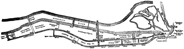
Fig. 4.—Hydraulic Development on the Merrimac River.
Larger plan (124 kB)
The high-level canal, so called,
was designed to take water directly
from the basin or forebay a
little below one end of the dam, so
that between this canal and the
river there is a full water head of
about forty-eight feet. Over nearly
its entire course the nearer side of
this high-level canal runs between
450 and 750 feet from the edge of
the river wall, and thus includes
between it and the river a large
area on which factories to be
driven by water-wheels may be located.
It was thought, however,
that this strip of land between the
high-level canal and the river was
too wide for a single row of mill
sites, and the lower level canal
was therefore constructed parallel
with that on the higher level, but
with about twenty-one feet less
elevation.
Between these two canals a strip
of land about 250 feet wide was left
for the location of mills. By this
arrangement of canals it is possible
to supply wheels located between
the high and the low levels with
water under a head of about twenty-one
feet, and to supply wheels
between the lower canal and the
river with water under a head of
about twenty-nine feet. The entire
area of land between the high
canal and the river is thus made
readily available for factory buildings.
Water for the lower canal is
drawn mainly from the high canal[53]
through the wheels in buildings that are located between the two canals.
It is desirable in a case of this sort to have as much water flow through
the wheels between the high and low canal as flows through the wheels
between the low canal and the river, but this is not always possible. A
gate is therefore provided at the forebay where the two canals start, by
which water may pass from the forebay directly into the low canal when
necessary, but the head of twenty-one feet between the forebay and the
low canal is lost as to this water. Between the high and low canal, and
between the low canal and the river twenty-three turbine wheels or pairs
of wheels have been connected, and these wheels have a combined rating
of 9,500 horse-power.
To carry out this hydraulic development it thus appears that about
1.3 miles of canal have been constructed; one-half this length of river-front
has been required, and about one-sixth square mile of territory has
been occupied. Contrast with this result what might have been done if
electrical transmission of power had been available at the time when this
water-power was developed. All but a few rods in length of the existing
1.3 miles of canal might have been omitted, and an electric generating
station with wheels to take the entire flow of the river might have been
located not far from one end of the dam. Factories utilizing the electric
power thus developed might have been located at any convenient points
along the river-front or elsewhere, and no space would have been made
unavailable because of the necessity of head- and tail-water connections
to scattered sets of wheels.
Compare with the foregoing hydraulic development that at Cañon
Ferry on the Missouri River, in Montana, where 10,000 horse-power is
developed under a water-head of 32 feet. At Cañon Ferry the power-house
is 225 feet by 50 feet at the floor level inside, contains turbine
wheels direct-connected to ten main generators of 7,500 kilowatts, or
10,000 horse-power combined capacity, and is built on the river bank
close to one end of the 500-foot dam. The canal which runs along the
land side of the power-house, and takes water at the up-stream side of
the abutment, is about twice the length of the power-house itself. The
saving in the cost of canal construction alone, to say nothing of the saving
as to the required area of land, is evidently a large item in favor of the
electrical development and transmission. In its small area and short
canal the Cañon Ferry plant is not an exception, but is rather typical of
a large class of electric water-power plants that operate under moderate
heads.
A like case may be seen in the plant at Red Bridge, on the Chicopee[54]
River, in Massachusetts, where a canal 340 feet long, together with penstocks
100 feet long, convey water from one end of the dam and deliver
it to wheels in the electric station with a head of 49 feet. This station
contains electric generators with a combined capacity of 4,800 kilowatts
or 6,400 horse-power, and its floor area is 141 by 57 feet.
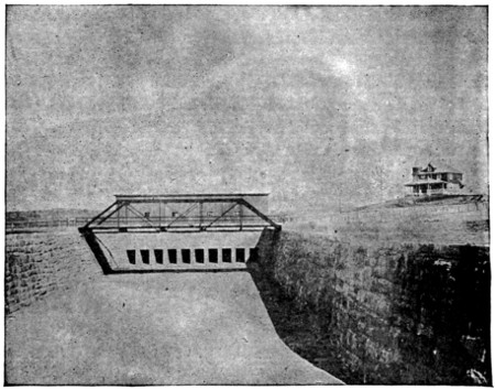
Fig. 5.—Canal at Red Bridge on Chicopee River.
So, again, at Great Falls, on the Presumpscot River, in North Gorham,
Me. (see cut), the electric station sets about 40 feet in front of
the forebay wall, which adjoins one abutment of the dam, and there is
no canal whatever, as short penstocks bring water to the wheels with a
head of 35 feet. In ground area this station is 67.5 by 55 feet, and its
capacity in main generators is 2,000 kilowatts or 2,700 horse-power.
A striking illustration of the extent to which electrical transmission
reduces the cost of water-power development may be seen at Gregg’s
Falls on the Piscataquog River, in New Hampshire, where an electric
station of 1,200 kilowatts capacity has been built close to one end of the
dam, and receives water for its wheels under a head of 51 feet through
a short penstock, 10 feet in diameter, that pierces one of the abutments.
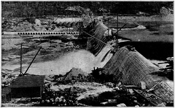
Fig. 6.
Perhaps the greatest electric water-power station anywhere that rests
close to the dam that provides the head for its wheels is that at Spier[55]
[56]
Falls (see cut), on the upper Hudson. One end of this station is formed
by the high wall section of the dam, and from this wall the length of the
station down-stream is 392 feet, while its width is 70 feet 10 inches, both
dimensions being taken inside. The canal or forebay in this case, like
that at Cañon Ferry, lies on the bank side of the power-station, and is
about equal to it in length. From this canal ten short penstocks, each
12 feet in diameter, will convey water under a head of 80 feet to as many
sets of turbine wheels in the station. These wheels will drive ten generators
with an aggregate capacity of 24,000 kilowatts or 32,000 horse-power.
Sometimes the slope in the bed of a river is so gradual or so divided
up between the number of small falls, or the volume of water is so small,
that no very large power can be developed at any one point without the
construction of a long canal. In a case of this sort electrical transmission
is again available to reduce the expense of construction that will make it
possible to concentrate all the power from a long stretch of the river at a
single point. This is done by locating electric generating stations at as
many points as may be thought desirable along the river whose energy is
to be utilized, and then transmitting power from all of these stations to
the single point where it is wanted.
A case in point is that of Garvins Falls and Hooksett Falls on the
Merrimac River and four miles apart. At the former of these two falls
the head of water is twenty-eight feet, and at the latter it is sixteen feet.
To unite the power of both these falls in a single water-driven station
would obviously require a canal four miles long whose expense might well
be prohibitive. Energy from both these falls is made available at a
single sub-station in Manchester, N. H., by a generating plant at both
points and transmission lines thence to that city.
At Hooksett the present capacity of the electric station is 1,000 horse-power,
and at Garvins Falls the capacity is 1,700 horse-power. The
river is capable of developing larger powers at both of these falls, however,
and construction is now under way at Garvins that will raise its
station capacity to 5,000 horse-power.
A similar result in the combination of water-powers without the aid
of a long canal is reached in the case of Gregg’s Falls and Kelley’s Falls,
which are three miles apart on the Piscataquog River. At the former of
these two falls the electric generating capacity is 1,600 horse-power, as
previously noted, and at the latter fall the capacity is 1,000 horse-power.
In each case the station is close to its dam, and no canal is required.
Electrical transmission unites these two powers in the same sub-station[57]
at Manchester that receives the energy from the two stations above
named on the Merrimac River.
Instead of transmitting power from two or more waterfalls to some
point distant from each of them, the power developed at one or more
falls may be transmitted to the site of another and there used. This is,
in fact, done at the extensive Ludlow twine mills on the Chicopee River,
in Massachusetts. These mills are located at a point on the river where
its fall makes about 2,500 horse-power available, and this fall has been
developed to its full capacity. After a capacity of 2,400 horse-power in
steam-engines had been added, more water-power was sought, and a new
dam was located on the same river at a point about 4.5 miles up-stream
from the mills. The entire flow of the river was available at this new
dam, and a canal 4.5 miles long might have been employed to carry the
water down to wheels at the mills in Ludlow.
Such a canal would have meant a large investment, not only for land
and construction, but also, possibly, for damages to estates bordering on
the river, if all of its water was diverted. Instead of such a canal, an
electric generating station was located close to the new dam with a capacity
of 6,400 horse-power, and this power is transmitted to motors in the
mills at Ludlow.
Even where the power is to be utilized at some point distant from each
of several waterfalls, it may be convenient to combine the power of all
at one of them before transmitting it to the place of use. This is actually
done in the case of two electric stations located respectively at Indian
Orchard and Birchem Bend on the Chicopee River, whose energy is delivered
to the sub-station of the electrical supply system in Springfield,
Mass. At the Indian Orchard station the head of water is 36 feet,
and at Birchem Bend it is 14 feet, while the two stations are about 2
miles apart. A canal of this length might have been built to give a head
of 50 feet at the site of the Birchem Bend dam, but instead of this an electric
station was located near each fall, and a transmission line was built
between the two stations. Each generating station was also connected
with the sub-station in Springfield by an independent line, and power is
now transmitted from one generating plant to the other, as desired, and
the power of both may go to the sub-station over either line. In the Indian
Orchard station the dynamo capacity is about 2,000 kilowatts, and
at Birchem Bend it is 800 kilowatts.
Another case showing the union of two water-powers by electrical
transmission, where the construction of an expensive canal was avoided,
is that of the electrical supply system of Hartford, Conn. This system[58]
draws a large part of its energy from two electric plants on the
Farmington River, at points that are about 3 miles apart in the towns of
Windsor and East Granby, respectively. At one of these plants the head
of water is 32 feet, and at the other it is 23 feet, so that head of 55 feet
might have been obtained by building a canal 3 miles long. Each of
these stations is located near its dam, and the generator capacity at one
station is 1,200 and at the other 1,500 kilowatts. Transmission lines
deliver power from both of these plants to the same sub-station in Hartford.
Sometimes two or more water-powers on the same river that are to be
united are so far apart that any attempt to construct a canal between
them would be impracticable. This is illustrated by the Spier and Mechanicsville
Falls on the Hudson River, which are 25 miles apart in a
direct line and at a greater distance by the course of the stream. At Spier
Falls the head is 80 feet, and at Mechanicsville it is 18 feet. Union of the
power of these two falls is thus out of the question for physical reasons
alone. Electrical transmission, however, brings energy from both of
these water-powers to the same sub-stations in Schenectady, Albany, and
Troy.
In another class of cases electrical transmission does what could not
be done by any system of canals, however expensive; that is, unites the
water-powers of distinct and distant rivers at any desired point. Thus
power from both the Merrimac and the Piscataquog rivers is distributed
over the same wires in Manchester; the Yuba and the Mokelumne contribute
to electrical supply along the streets of San Francisco; and the
Monte Alto and Tlalnepantla yield energy in the City of Mexico.
It does not follow from the foregoing that it is always more economical
to develop two or more smaller water-powers at different points along a
river for transmission to some common centre than it is to concentrate
the water at a single larger station by more elaborate hydraulic construction,
and then deliver all of the energy over a single transmission line.
The single larger hydraulic and electric plant will usually have a first
cost larger than that of the several smaller ones, because of the required
canals or pipe lines. A partial offset to this larger hydraulic investment
is the difference in cost between one and several transmission
lines, or at least the cost of the lines that would be necessary between the
several smaller stations in order to combine their energy output before
its transmission over a single line to the point of use.
Against the total excess of cost for the single larger hydraulic and
electrical plant there should be set the greater expense of operation at[59]
several smaller and separate plants. Even a small water-driven electric
station that can be operated by a single attendant at any one time must
have two attendants if it is to deliver energy during the greater part or all
of every twenty-four hours. But a single attendant can care for a water-power
plant of 2,000 horse-power or more capacity, so that two plants of
750 horse-power each will require double the operating force of one plant
of 1,500 horse-power. If two such plants are constructed instead of one
that has their combined capacity, the monthly wages of the two additional
operators will amount to at least one hundred dollars. If money
is worth six per cent yearly, it follows that an additional investment of
$1,200 ÷ 0.06 = $20,000 might be made in hydraulic work to concentrate
the power at one point before the annual interest charge would equal
the increase of wages made necessary by two plants.
Reliability of operation is one of the most important requirements in
an electric water-power plant, and its construction should be carried out
with this in view. Anchor ice is a serious menace to the regular operation
of water-wheels in cold climates, because it clogs up the openings in
the racks and in the wheel passages. Anchor ice is formed in small
particles in the water of shallow and fast-flowing streams, and tends to
form into masses on solid substances with which the water comes in contact.
At the entrance to penstocks or wheel chambers, steel racks with long,
narrow openings, say one and one-quarter inches wide, are regularly
placed to keep all floating objects away from the wheels. When water
bearing fine anchor or frazil ice comes in contact with these racks, it rapidly
clogs up the narrow openings between the bars, unless men are kept
at work raking off the ice as it forms. At the Niagara Falls electric
station, in some instances, when the racks become clogged, they have
been lifted, and the anchor ice allowed to pass down through the wheels.
This is said to have proved an effective remedy, but it would obviously
be of no avail in a case where the ice clogged the passages of the wheels
themselves.
The best safeguard against anchor ice is a large, deep forebay next
to the racks, where the water, being comparatively quiet, will soon freeze
over after cold weather commences. The anchor ice coming down to
this forebay and losing most of its forward motion, soon rises to the surface
or to the under side of the top coating of solid ice, and the warmer
water sinks to the bottom. Good construction puts the entrance ends
of penstocks well below the surface of water in the forebay, so that they
may receive the warmer water that contains little or no anchor ice.
[60]
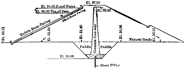
Fig. 7.—Cross Section of Dike on Chicopee River at Red Bridge.
Illustrations of practice along these lines, as to size, depth of forebay,
and location of penstocks may be seen in many well-designed plants.
One instance is that at Garvins Falls, on the Merrimac River, where the
new hydraulic development for 5,000 horse-power is now under way.
Water from the river in this case comes down to the power-station through
a canal 500 feet long, and of 68 feet average width midway between the
bottom and the normal flow line. In depth up to his flow line the canal
is 12 feet at its upper and 13 feet at its lower end, just before it widens
into the forebay. In this forebay the depth increases to 17 feet, and the
width at the rack is double that of the canal. The steel penstocks, each
12 feet in diameter, terminate in the forebay wall at an average distance
of 7 feet behind the rack, and each penstock has its centre 10.6 feet below
the water level in the forebay. As there is a large pond created by the
dam in this case, and as the flow of water in the canal is deep rather than
swift, enough opportunity is probably afforded for any anchor ice to rise
to the surface before it reaches the forebay in this case.
Penstocks for the electric station at Great Falls, on the Presumpscot
River, whence energy is drawn for lighting and power in Portland, Me.,
are each 8 feet in diameter, and pierce the forebay wall behind the rack
with their centres 15 feet below the normal water level in the forebay.
In front of the forebay wall the water stands 27 feet deep, and the pond
formed by the dam, of which the forebay wall forms one section, is 1,000
feet wide and very quiet. Though the Maine climate is very cold in
winter and the Presumpscot is a turbulent stream above the dam and
pond, there has never been any trouble with anchor ice at the Great Falls
plant. An excellent illustration is thus presented of the fact that deep,
still water in the forebay is a remedy for troubles with ice of this sort.
Maximum loads on electrical supply systems are usually from twice
to four times as great as the average loads during each twenty-four hours.[61]
A pure lighting service tends toward the larger ratio between the average
and maximum load, while a larger motor capacity along with the lamps,
tends to reduce the ratio. Furthermore, by far the greater part of the
energy output of an electrical supply system during each twenty-four
hours must be delivered between noon and midnight. For these reasons
there must be enough water stored, that can flow to the station as wanted,
to carry a large share of the load during each day, unless storage batteries
are employed to absorb energy at times of light load, if the entire
normal flow of the river is to be utilized.
It is usually much cheaper to store water than electrical energy for
the daily fluctuations of load, and the only practicable place for this storage
is most commonly behind the dam that maintains the head for the
power-station. This storage space should be so large that the drain upon
it during the hours of heavy load will lower the head of water on the
wheels but little, else it may be hard to maintain the standard speed
of revolution for the wheels and generators, and consequently the transmission
voltage.
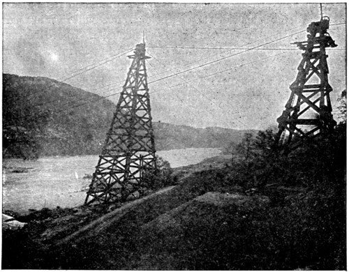
Fig. 8.—Valley Flooded above Spier Falls on the Hudson River.
At the Great Falls plant, water storage to provide for the fluctuations
of load in different parts of the day takes place back of the dam, and for[62]
about one mile up-stream. This dam is 450 feet long in its main part,
and a retaining wall increases the total length to about 1,000 feet. For
half a mile up-stream from this dike and dam the average width of the
pond is 1,000 feet, and its greatest depth is not less than 27 feet. As the
station capacity is 2,700 horse-power in main generators, with a head of
35 feet at the wheels the storage capacity is more than ample for all
changes of load at different times of day.
The dam at Spier Falls, on the Hudson River, is 1,820 feet long between
banks, 155 feet high above bedrock in its deepest section, and raises
the river 50 feet above its former level. Behind the dam a lake is formed
one-third of a mile wide and 5 miles long. Water from this storage reservoir
passes down through the turbines with a head of 80 feet, and is to
develop 32,000 horse-power. As a little calculation will show, this lake
is ample to maintain the head under any fluctuation in the daily load.
At Cañon Ferry, where electrical energy for Butte and Helena, Mont.,
is developed, the dam, which is 480 feet long, crosses the river in a narrow
canyon that extends up-stream for about half a mile. Above this canyon
the river valley widens out, and the dam, which maintains a head of 30
feet at the power-station, sets back the water in this valley, and thus forms
a lake between two and three miles wide and about seven miles long.
At the station the generator equipment has a total rating of 10,000 horse-power.
From these figures it may be seen that the storage lake would
be able to maintain nearly the normal head of water for some hours, when
the station was operating under full load, however small the flow of the
river above.
[63]
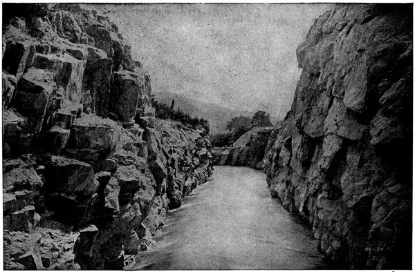
Fig. 9.—Canal at Bulls Bridge on Housatonic River.
[64]
CHAPTER VII.
THE LOCATION OF ELECTRIC WATER-POWER STATIONS.
Cost of water-power development depends, in large measure, on the
location of the electric station that is to be operated. The form of such
a station, its cost, and the type of generating apparatus to be employed
are also much influenced by the site selected for it. This site may be
exactly at, or far removed from, the point where water that is to pass
through the wheels is diverted from its natural course.
A unique example of a location of the former kind is to be found near
Burlington, Vt., where the electric station is itself a dam, being built
entirely across the natural bed of one arm of the Winooski River at a
point where an island near its centre divides the stream into two parts.
The river at this point has cut its way down through solid rock, leaving
perpendicular walls on either side. Up from the ledge that forms the bed
of the stream, and into the rocky walls, the power-station, about 110 feet
long, is built. The up-stream wall of this station is built after the fashion
of a dam, and is reënforced by the down-stream wall, and the water flows
directly through the power-station by way of the wheels. A construction
of this sort is all that could well be attained in the way of economy, there
being neither canal nor long penstocks, and only one wall of a power-house
apart from the dam. On the other hand, the location of a station directly
across the bed of a river in this way makes it impossible to protect the
machinery if the up-stream wall, which acts as the dam, should ever
give way. The peculiar natural conditions favorable to the construction
just considered are seldom found.
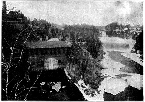
Fig. 10.—Power-house on the Winooski River, near Burlington, Vt.
One of the most common locations for an electric water-power station
is at one side of a river, directly in front of one end of the dam and close
to the foot of the falls. A location of this kind was adopted for the station
at Gregg’s Falls, one of the water-powers included in the electric system
of Manchester, N. H., where the spray of the fall rises over the roof of the
station. Two short steel penstocks, each ten feet in diameter, convey the
water from the forebay section of the dam to wheels in the station with a
head of fifty-one feet.
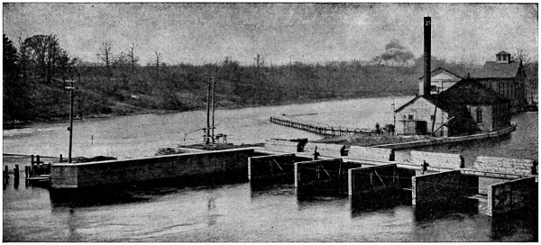
Fig. 11.—Canal and Power-house on St. Joseph River, Buchanan, Mich.
A similar location was selected for the station at Great Falls, on the[65]
[66]
[67]
Presumpscot River (see cuts), whence electrical energy is delivered in
Portland, Me. Four steel penstocks, a few feet long and each eight feet
in diameter, bring the water in this case from the forebay section of the
dam to the wheel cases in the power-house.
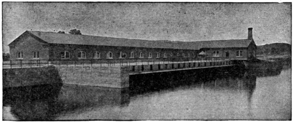
Fig. 12.—Power-house on Hudson River at Mechanicsville.
Where the power-station is located at the foot of the dam, as just
described, that part which serves as a forebay wall usually carries a head
gate for each penstock. The overfall section of a dam may give way in
cases like the two just noted without necessarily destroying the power-station,
but in times of freshet or very high water the station may be
flooded and its operation stopped. The risk of any such flooding will
vary greatly on different rivers, and in particular cases may be very
slight. Location of the generating station close to the foot of the dam
at one end obviously avoids all expense for a canal and cuts the cost of
penstocks down to a very low figure.
Such locations for stations are not limited to falls of any particular
height, and the short penstocks usually enter the dam nearer its base than
its top and pass to the station at only a slight inclination from the horizontal.
At Great Falls, above mentioned, the head of water is thirty-seven
feet.
A short canal is constructed in some cases from one end of a dam to
a little distance down-stream, terminating at a favorable site for the electric
station. Construction of this sort was adopted at the Birchem Bend
Falls of the Chicopee River, whence energy is supplied to Springfield,
Mass. These falls furnish a head of fourteen feet, and the water-wheels
are located on the floor of the open canal at its end. The power-station
is on the shore side of this canal, and the shafts of the water-wheels extend
through bushings in the canal wall, which forms the lower part of one
side of the station, to connect with the electric generators inside.
[68]
This rather unusual location of water-wheels has at least the obvious
advantage that they require no room inside of the station. Furthermore,
as the canal is between the station and the river, any break in the canal
is not apt to flood the station.
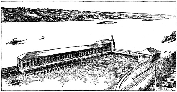
Fig. 13.—York Haven Power-house, on Susquehanna River, Pennsylvania.
An illustration of the use of a very short canal to convey water from
one end of a dam to a power-station exists in the 10,000 horse-power
plant at Cañon Ferry, Mont., where the head of water is thirty feet. In
this case the masonry canal is but little longer than the power-house, and
this latter sits squarely between the canal and the river, virtually at the
foot of the falls. Other examples of the location of generating stations
between short canals and the river may be seen at Concord, N. H., where
the head of water is sixteen feet; at Lewiston, Me., where the head is
thirty-two feet; and at Spier Falls, on the Hudson River, New York,
where there is a head of eighty feet.
There is some gain in security in many cases by locating the power-station
several hundred feet from the dam and a little to one side of the
main river channel. For such cases a canal may be cheaper than steel
penstocks when the items of depreciation and repairs are taken into account.
Aside from the question of greater security for the station in the
event of a break in the dam, it is necessary in many cases to convey the
water a large fraction of a mile, or even a number of miles, from the point
where it leaves its natural course to that where the power-station should
be located. An example in point exists at Springfield, Mass., where
one of the electric water-power stations is located about 1,400 feet down-stream
from a fall of thirty-six feet in the Chicopee River, because land
close to the falls was all occupied at the time the electric station was built.
[69]
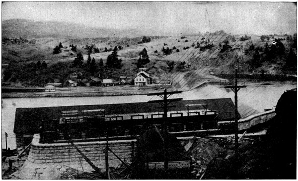
Fig. 14.—Power-house at Cañon Ferry on the Missouri River.
[70]
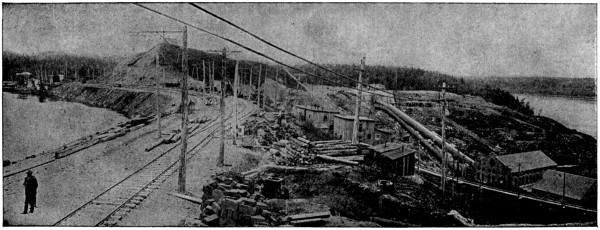
Fig. 15.—Shawinigan Falls Power-plant.
[71]
The Shawinigan Falls of the St. Maurice River in Canada occur at
two points a short distance apart, the fall at one point being about 50 and
at the other 100 feet high. A canal 1,000 feet long takes water from the
river above the upper of these falls and delivers it near to the electric
power-house on the river bank below the lower falls. In this way a head
of 125 feet is obtained at the power-house. The canal in this case ends
on high ground 130 feet from the power-house, and the water passes down
to the wheels through steel penstocks 9 feet in diameter.
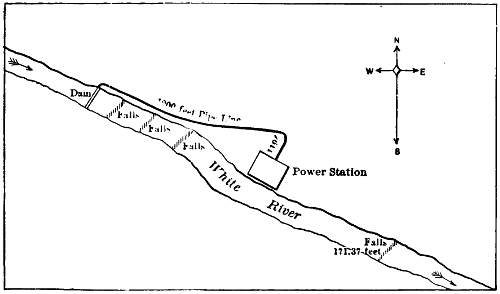
Fig. 16.—Power-house on White River, Oregon.
Another interesting example of conditions that require a power-house
to be located some distance from the point where water is diverted from
its natural course may be seen at the falls on the Apple River, whence
energy is transmitted to St. Paul, Minn. By means of a natural fall of
30 feet, a dam 47 feet high some distance up-stream, and some rapids in
the river, it was there possible to obtain a total fall of 82 feet. To utilize
this entire fall a timber flume, 1,550 feet in length, was built from the dam
to a point near the power-house on the river bank and below the falls and
rapids. The flume was connected with the wheels, 82 feet below, by a
steel penstock 313 feet long and 12 feet in diameter.
As the St. Mary’s River leaves Lake Superior it passes over a series
of rapids about half a mile in length, falling twenty feet in that distance.
To make the power of this great volume of water available, a canal 13,000
feet long was excavated from the lake to a point on the river bank below
the rapids. Between the end of the canal and the river sits the power-station,
acting as a dam, and the water passes down through it and the
wheels under a head of twenty feet.
[72]
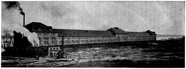
Fig. 17.—Power-house Across Canal at Sault Ste. Marie, Mich.
[73]
By means of a canal 16,200 feet long from the St. Lawrence River
a head of water amounting to fifty feet has been made available at a
point on the bank of Grass River near Massena, N. Y. There again the
power-station acts as a dam, and the canal water passes down through it
to reach the river.
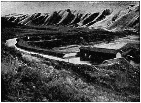
Fig. 18.—Canal and Station on Payette River, Idaho.
From these illustrations it may be seen that in many cases, in comparatively
level country, a water-power can be fully developed only by
means of canals or pipe lines, and the generating stations cannot be located
at the points where the water is diverted.
Thus far the cases considered have been only those with moderate
heads and rather large volumes of water. In mountainous country,
where rivers are comparatively small and their courses are marked by
numerous falls and rapids, it is generally necessary to utilize the fall of
a stream through some miles of its length in order to effect a satisfactory
development of power. To reach this result, rather long canals, flumes,
or pipe lines must be utilized to convey the water to power-stations and
deliver it at high pressures.
In cases of this kind the cost of the canal or pipe line may be the largest
item in the power development, and it may be an important question
whether this cost should be reduced or avoided by the erection of several[74]
small generating plants instead of one large one. California offers numerous
examples of electric-power development with water that has been
carried several miles through artificial channels. An illustration of this
class of work exists at the Electra power-house on the bank of the Mokelumne
River, in the Sierra Nevada Mountains. Water is supplied to
the wheels in this station under a head of 1,450 feet through pipes 3,600
feet long leading to the top of a near-by hill. To reach this hill the water,
after its diversion from the Mokelumne River at the dam, flows twenty
miles through a canal or ditch and then through 3,000 feet of wooden stave
pipe.
Another example of the same sort may be seen in the power-house at
Colgate, on the North Yuba River, in the chain of mountains above
named. Water taken from this river passes through a wooden flume
nearly eight miles long to the side of a hill 700 feet above the power-house,
and thence down to the wheels through steel and cast-iron pipes,
five in number and thirty inches each in diameter.
Even with long flumes, canals, and pipe lines, it may be necessary
to locate a number of generating stations along a single river of the
class now under consideration in order to utilize its entire power.
Thus on the Kern River, which rises in the Sierra Nevada Mountains
and empties into Tulare Lake, two electric power-stations are under
construction, and surveys are being made for three more. Of these
stations, the one at the lowest level will operate under an 872-foot head
of water, and this water, after its diversion from the river, will pass
through twenty-one tunnels, with an aggregate length of about ten
miles, and through six flumes mounted on trestles and having a total
length of 1,703 feet.
Next up-stream is a station near the point where water is diverted for
the plant just named. This second station will work under a head of
317 feet, and water for it will come from a point farther up-stream by
canals, tunnels, and flumes, with an aggregate length of eleven and one-half
miles. At three points still higher up on this river it is the intention
to locate three other power-stations by conducting the water in artificial
channels, about twelve and one-half, fifteen, and twenty miles in length
respectively.
Farther south in California, on the Santa Ana River and Mill Creek,
extensive power developments on the lines just indicated have been carried
out. On Mill Creek, about six miles from the city of Redlands, is
an electric station operating under a head of 530 feet, with water in part
diverted from the stream a little less than two miles above and brought[75]
[76]
down through a steel pipe 10,250 feet long and thirty inches in diameter.
This pipe line also takes water from the tail race of another generating
plant at its upper end. With some additions and modifications,
the station just described is the famous Redlands plant, built in 1893,
and believed to be the first for three-phase transmission in the United
States.
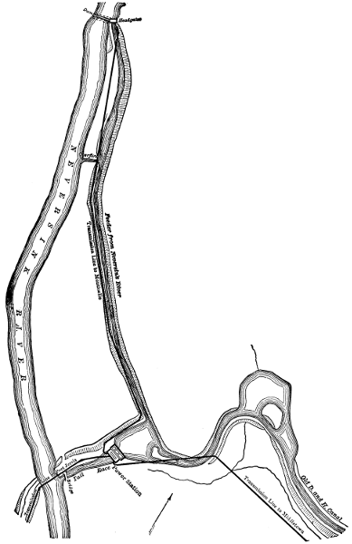
Fig. 19.—Canal and Power-station on Neversink River, New York.
Larger map (176 kB)
At the upper end of the pipe line just named the second station operates,
in part, with water drawn from Mill Creek through a combination
of tunnels, flumes, and cement and steel pipes, with a combined length
of about three miles, and delivered to some of the wheels with a head of
627 feet. The other wheels at this plant receive water drawn from the
same creek by a pipe line about six miles long. A large part of this line
is composed of 31-inch cement pipe, laid in trenches and tunnels. The
water in the 8,000 feet of pipe next to the power-house has a fall of 1,960
feet, and this pipe is of steel and 24 and 26 inches in diameter. The
head of 1,960 feet, minus friction losses in the steel pipes, is delivered at
the wheels.
From the foregoing it appears that in a space of eight miles along
Mill Creek there is a fall of more than 2,490 feet. To utilize this fall,
water is diverted from the creek at three points within a distance of six
miles and delivered in two power-stations under three different heads.
As the stream gathers in volume between the upper and the lower intakes,
an equal amount of power could have been developed in a single
station only by taking the three separate conduits or pipe lines to it and
delivering their water there at three heads.
Whether the expense of extending conduits and pipe lines to a single
generating station will more than offset the advantages to be gained
thereby is a question that should be decided on a number of factors varying
with each case. In general, it may be said that the smaller the
volume of water to be handled and the greater its head, the more advantageous
is it to concentrate the generating machinery in the smallest
practicable number of stations.
On the Santa Ana River, into which Mill Creek flows, the Santa
Ana plant, whence energy is transmitted to Los Angeles, is located.
Water reaches this plant through a conduit of tunnels, flumes, and pipes,
with a total length of about three miles from the point where the flow of
the river is diverted. The 2,210 feet of this conduit nearest the power-plant
are composed of 30-inch steel pipe, with a fall of 728 feet.
Within fifteen miles of Mexico City are five water-power stations that
supply energy for its electrical system. Two of these stations are on the[77]
Monte Alto and three are on the Tlalnepantla River, the two former
stations being about three miles, and the more distant of the three latter
stations five miles, apart. At a distance of several miles above the highest
station on each river the water is diverted by a canal, and the water of
each of these canals, after passing through the wheels of the highest
station, goes on to the remaining station, or stations, on the same river
by a continuation of the canal.
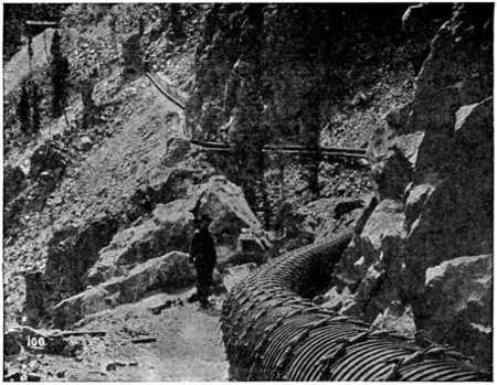
Fig. 20.—Wood Pipe Line to Pike’s Peak Power-house.
By placing the stations so short a distance apart the head of water
at each station is reduced. On one stream these heads are 492 and 594
feet respectively, and at two of the stations on the other stream they are
547 and 295 feet respectively. This division of the total head of water
afforded by each river results in a rather small capacity for each station,
the total at the five plants being only 4,225 kilowatts.
In contrast with this figure the already mentioned Electra plant has
generators of 10,000, the Santa Ana plant generators of 3,000, and the
larger of the two Mill Creek plants generators of 3,500 kilowatts capacity.
It should be noted that the cost of operation, as well as that of
original construction, will vary materially between one large and several
smaller stations of equal total capacity, the advantage as to operative cost
being obviously with the one large plant.
[78]
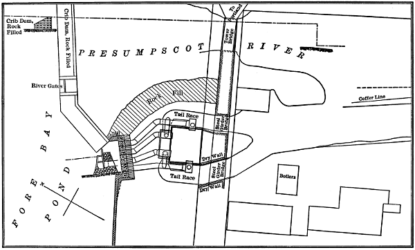
Fig. 21.—Power-house at Great Falls, Presumpscot River.
Larger plan (153 kB)
[79]
All of the power-stations here considered have been equipped with
water-wheels and generators operating on horizontal shafts, and this is
the general practice. This arrangement brings the generators and the
floor of the power-station within a few feet of the level of the tail-water.
By the general use of draught tubes with turbine wheels the floors of stations
are often kept twenty feet or more above the tail-water level.
Where the total available head of water is quite small, as is often the
case with rivers where the volume of water is great, it is generally necessary
to bring the level of the station floor down to within a few feet of
the tail-water. The Birchem Bend station of the Springfield, Mass.,
electric system affords a good example of this sort, the floor of this station
being only 2.6 feet above the ordinary level of the tail-water. At this
station the difference of level between the head- and tail-water is only
fourteen feet, and even with the low floor level named the top sides of the
horizontal turbine wheels are covered only by 4.5 feet of water.
At the Garvin’s Falls station of the Manchester, N. H., electric system
the level of the floor of the generator room is thirteen feet above
the ordinary level of the Merrimac River, on the bank of which this station
is located; but in this case the total head of water is about twenty-eight
feet. The high water of the Merrimac in 1896, before the Garvin’s
Falls station was built, reached a point 5.24 feet above its present floor
level, and 18.24 feet above the ordinary level of the river at the point
where the station is located.
Under the Red Bridge electric station of the Ludlow Manufacturing
Company, on the Chicopee River, in Massachusetts, the tail-water is
twenty feet below the level of the floor and twenty-four feet below the centres
of the water-wheel and generator shafts. The difference between
wheel-shaft and tail-water levels at this station is near the maximum that
can be attained with horizontal pressure turbines, because a draught
tube much longer than twenty-five feet does not give good results.
In a pressure turbine the guides and wheel must be completely filled
with water, as must also the draught tube, for efficient operation. If
draught tubes are much more than twenty-five feet long, it is hard to keep
a solid column of water from turbine to tail-water in each, and if this is not
done a part of the head of water becomes ineffective. As pressure turbines
are employed almost exclusively at electric stations with low heads
of water, it is frequently impossible to locate such stations above the possible
level of tail-water in times of flood if horizontal wheels direct-connected
to generators are employed.
[80]
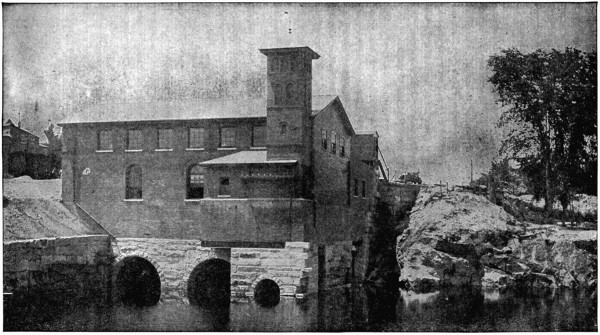
Fig. 22.—Power-house at Garvin’s Falls on the Merrimac River.
If turbines with vertical shafts are to be used, a power-station may be[81]
so located or constructed that all the electrical equipment will be above
the highest known water-mark. With vertical shafts, connecting wheels,
and generators, the main floor of an electric station may be located above
the crest of the falls where the power is developed instead of at or near
their base.
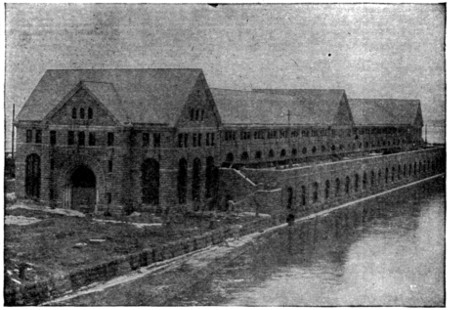
Fig. 23.—Power-house No. 2 at Niagara Falls.
By far the most important examples of electric stations laid out on this
plan are those at Niagara Falls, where there are four such plants. Two
of these generating plants, with an aggregate capacity of 105,000 horse-power,
stand a mile above the falls, and are supplied with water through
a short canal from Niagara River. Beneath each of these two stations a
long, narrow wheel pit has been excavated through rock to a depth of 172
feet below the level of water in the canal. Both wheel pits terminate in
a tunnel 7,000 feet long that opens into the river below the falls.
In this wheel pit the tail-water level is 161 feet below that of the water
in the canal, and 166 feet below the floor of the power-station. Water
passes from the canal down the wheel pits to the wheels near the bottom
through steel penstocks, each seven feet in diameter, and a vertical shaft
extends from each wheel case to a generator in the station above.
Locations like that at Niagara give great security against high water
and washouts, but are seldom adopted because of the large first cost of
plant construction. With heads of water from several hundred to 2,000
feet the loss of a few feet of head reduces the available power to only a[82]
very slight extent, and impulse wheels are usually employed. Draught
tubes are not available to increase the heads at such wheels, and any
fall of the water after it leaves the wheels does no useful work.
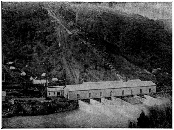
Fig. 24.—Colgate Power-house.
Electric stations driven by impulse wheels under great heads, like
those at Colgate, Electra, Kern River, Santa Ana River, and Mill Creek,
may be located far enough above the beds of their water-courses to avoid
dangers from freshets, without serious loss of available power.
[83]
CHAPTER VIII.
DESIGN OF ELECTRIC WATER-POWER STATIONS.
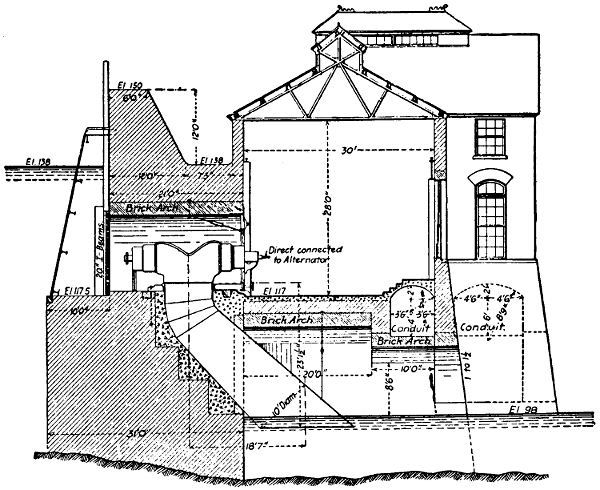
Fig. 25.—Cross Section of Columbus, Ga., Power-station.
Larger cross section (251 kB)
Water-wheels must be located at some elevation between that of
head- and tail-water. With horizontal shafts and direct-connected wheels
and generators the main floor of the station is brought below the level of
the wheel centres. This is much the most general type of construction,
and was followed in the Massena, Sault Ste. Marie, Cañon Ferry, Colgate,
Electra, Santa Ana, and many other well-known water-power stations.
If horizontal shafts are employed for wheels and generators with
belt or rope connections between them the floor of the generator room
may be elevated a number of feet above the wheels. This difference of
elevation is usually provided for either by upper and lower parts of the
same room, or by separate rooms one above the other and a floor between
them. A two-story construction of this latter sort was frequently adopted[84]
in the older water-power stations, and good examples of it may be seen in
connection with the electrical supply system at Burlington, Vt., and the
Indian Orchard station in the Springfield, Mass., system. Vertical
wheel shafts make the elevation of the main or generator floor of a station
independent of that of the wheels, and thus give the highest degree of
security against high water. After the vertical wheel shaft reaches the
generator room, it may be geared to a horizontal shaft that has one or
more dynamos directly mounted on it, or drives dynamos through belts
or ropes. Belt-driving in this way, from horizontal shafts connected by
bevel gears with vertical wheel shafts, is not uncommon in the older class
of water-power stations. Generators mounted singly or in pairs on horizontal
shafts that are driven by gearing on vertical wheel shafts have
been adopted at the Lachine Rapids and South Bend plants, and it
seems to offer a desirable method of connection in cases where vertical
wheels are necessary and the cost of generators must be kept at a low
figure. With this method of driving the generators can be designed for
any economical speed and step bearings avoided.

Fig. 26.—Cross Section of Combined Steam- and
Water-power Station at Richmond, Va.

Fig. 27.—Cross Section of Wheel House at Buchanan, Mich.
Larger cross section (140 kB)
The most desirable method of driving generators with vertical wheels,
where the expense is not too great, is the direct mounting of each generator[85]
on the upper end of a wheel shaft (see cut). This method of connection
not only requires a special type of generator, but may put serious
limits on its speed. In general, the peripheral speed of a pressure turbine
should be about 75 per cent of the theoretical velocity of water issuing
under a head equal to that at which the wheel operates, in order to give
the best efficiency. The rotative speeds of turbines, operating under any
given head, should thus increase as their capacities and diameters decrease.
Because of these principles it is the common practice, with horizontal
wheels, to mount two or more on each shaft to which a generator
is direct-connected in order to obtain a greater speed of rotation than
could be obtained with a single wheel of their combined power. Thus,
at Sault Ste. Marie the horizontal shaft on which each 400-kilowatt generator
is mounted is driven at 180 revolutions per minute by four turbines
under a head of about 20 feet. At Massena the head of water is 50 feet,
and each 5,000 horse-power generator is driven at 150 revolutions per minute
by six turbines on a horizontal shaft. Vertical turbines are sometimes
mounted singly on their shafts, as was done in the hydroelectric plant at
Oregon City on the Willamette River, and this practice gives speeds that[86]
are too low for direct-connected dynamos of moderate cost, unless the
head of water is unusually great. At the Oregon City plant the head of
water is only 40 feet, and yet a single 42-inch turbine was mounted on the
vertical shaft that drives each generator.
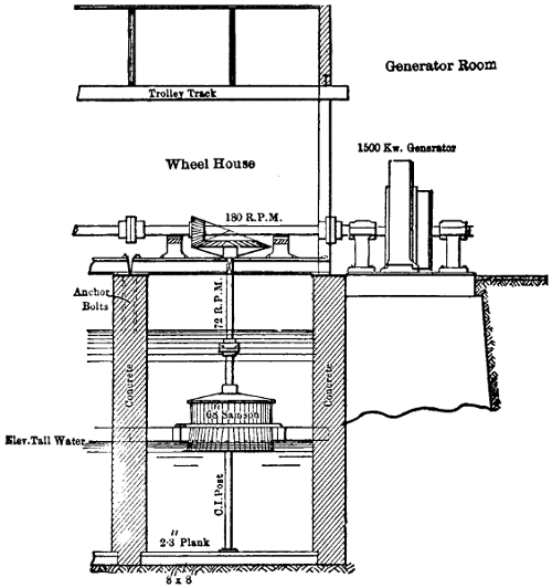
Fig. 28.—Longitudinal Section of Buchanan, Mich., Power-house.
Larger longitudinal section (146 kB)
The most notable examples of direct-connected generators and vertical
turbines is that at Niagara Falls, where twenty-one generators of
5,000 horse-power each are mounted at the tops of as many vertical
wheel shafts in two of the four stations. Each vertical shaft in the
Niagara stations is driven at 250 revolutions per minute by a pair of
turbines, one above the other. The maximum head between the water
in the Niagara canal and that in the tunnel which forms the tail-race
is 161 feet. On ten shafts the centres of the wheel cases are 136 feet
below the level of water in the canal, and no draft tubes are used.

Fig. 29.—Section of Power-house No. 2 at Niagara Falls.
Larger section (242 kB)
The eleven pairs of wheels at the second Niagara power-house have
their centre line 128.25 feet below the canal level and a draft tube for each
pair of wheels extends to a point below the tail-water level. It is
entirely practicable to use more than a single pair of turbines on the
same vertical shaft, as is shown at the Hagneck station on the Jura, in[87]
[88]
[89]
Switzerland, where the head of water is about twenty-one feet and four
turbines are mounted on each vertical shaft. The combined capacity
of these four wheels on each shaft is 1,500 horse-power and its speed
is 100 revolutions per minute. At the top of each shaft an 8,000-volt
generator, with external, revolving magnet frame, is mounted. The
use of four wheels per vertical shaft presents no great difficulty and
should be resorted to more frequently in the future.
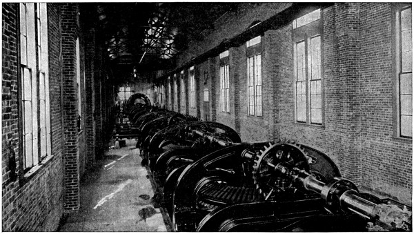
Fig. 30.—Interior of Power-house, Buchanan, Mich.
For horizontal, direct-connected turbine wheels and generators the
nearly uniform practice is to locate the generators in a single row from
one end of a station to the other, and this brings the turbines into a parallel
row. On this plan the shaft of each connected generator and its
group of turbines sets at right angles to the longer sides of a station and
approximately parallel with the direction in which water flows to the
wheels. The typical water-power station with direct-connected units is
thus a rather long, narrow building into which water enters on one side
through penstocks and leaves on the other through tail-races. Such stations
usually set with one of the longer sides parallel to the river into
which the tail-water passes and between this river and the canal or pipe
line. At Massena the electric station occupies the position of a dam between
the end of the power canal and the Grass River, being about 150
feet wide and 550 feet long. Canal water entering this station passes
through its wheels to the river under a head of about 50 feet. A similar
construction was followed at Sault Ste. Marie, where the power-station
separates the end of the canal from the St. Mary’s River. This station is
100 feet wide, 1,368 feet long, and is to contain 80 sets of horizontal
wheels, each set being connected to its own generator, and through these
wheels the canal water passes under a head of approximately 20 feet. Ten
generators are placed in line at the Cañon Ferry station which is 225 by 50
feet inside, and each generator is driven by a pair of horizontal wheels
under a head of 30 feet. This station sets between a short canal and the
Missouri River, near one end of the dam. Passing from water-heads of
less than 50 to those of several hundred or even more than 1,000 feet, the
general type of station building remains about the same, but there is an
important change in the arrangement of direct-connected wheels and
generators. With these high heads of water, wheels of the impulse type,
to which the water is supplied in the form of jets from nozzles, are employed.
These jets pass to the wheels in planes at right angles to their
shafts, instead of flowing in lines parallel to these shafts like water to pressure
turbines. The shafts of impulse wheels and their direct-connected
generators are consequently arranged parallel with the longer instead of[90]
the shorter sides of their stations. This plan results in long, narrow stations
with water entering at one and leaving at the other of the longer
sides, just as in the case of direct-connected turbines under moderate
heads. Stations with direct-connected impulse wheels are even longer
for a given number and capacity of units than are stations with pressure
turbines. Colgate power-house, on the North Yuba River, contains
seven generators, each direct-connected to an impulse wheel and shafts
all parallel to its longer sides. This station is 275 feet long by 40 feet
wide, and the water which enters one side by five iron pipes, 30 inches[91]
[92]
each in diameter, under a head of about 700 feet, is discharged from the
other side into the river.
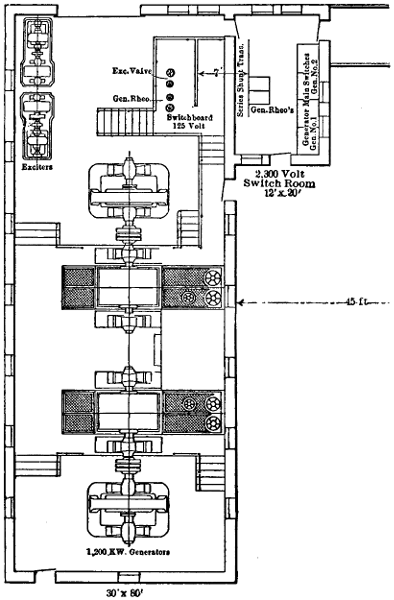
Fig. 31.—Plan of Generating Station near Cedar Lake for City of Seattle, Wash.
Larger plan (89 kB)
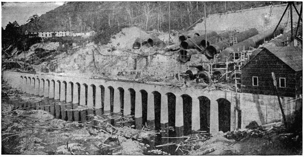
Fig. 32.—Foundation of Power-station at Spier Falls.

Fig. 33.—Plan of Power-station at Great Falls.
Larger plan (207 kB)
At Electra station on the Mokelumne River five pairs of impulse
wheels are direct-connected to five generators, each unit having its shaft
diagonal with the walls of the building, and pipes deliver water to the
wheels under a head of 1,450 feet. The ground plan of the generator
room at this plant is 40 by 208 feet. The power-station on Santa Ana
River, whence energy is transmitted 83 miles to Los Angeles, measures
127 feet long and 36 feet wide inside, and contains four generating units[93]
in line, each of which consists of a direct-connected dynamo and impulse
wheel, with shafts parallel to the longer sides of the station. Jets driving
the wheels in this station are delivered under a head of 728 feet minus
the loss by friction in a penstock 2,210 feet long.
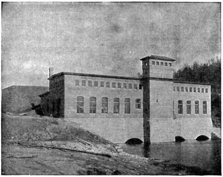
Fig. 34.—Power-house at Red Bridge on Chicopee River.
Both of the first Niagara plants, with vertical wheels far below the stations
in the pits, are long and narrow and have their generators in a single
row. The later of these two stations has a ground area of approximately
72 by 496 feet outside, and contains eleven generators all in line. From
these examples it may be seen that the prevailing type of electric water-power
station, whether designed for horizontal or vertical wheels of either
the pressure or impulse type, is wide enough for only a single row of generators
and wheels, and has sufficient length to accommodate the required
number of units.
A few modern stations that depart from this general plan will be
found, as that at Great Falls, on the Presumpscot River, whence electrical
supply for Portland, Me., is drawn. This station sets about forty
feet in front of the forebay end of the dam, and two penstocks enter the
rear wall, while the other two enter one each through two of the remaining
opposite sides. Of the four generators, with their direct-connected[94]
wheels, two are arranged with parallel shafts, while the other two have
their shafts in line and at right angles to the lines of the former two.
The station containing these generating sets has a floor area of 55 by
67.5 feet.

Fig. 35.—Plan and Elevation of Red Bridge Station on the Chicopee River.
Larger plan and elevation (222 kB)
Modern electric stations driven by water-power are usually but one
story in height and are clear inside from floor to roof, save for cranes and
roof trusses. This construction may be seen in the Niagara, Spier Falls,
Cañon Ferry, Colgate, Electra, Santa Ana River and many other notable
plants. In spite of this one-story style of construction, the electric stations
reach fair elevations because of the necessity for head room to operate
cranes in placing and removing generators. At Garvin’s Falls, on
the Merrimac River, the electric station contains generators of 650 kilowatts
each and the distance from floor to the lower cords of roof trusses
is 27 feet. In the station at Red Bridge, on the Chicopee River, where
generators are of 1,000 kilowatts capacity each, the distance between floor[95]
and the under side of roof beams is 30.66 feet. Between the floor and
roof trusses at the Birchem Bend station, on the river last named, the distance
is 26.25 feet, but each generator is rated at only 400 kilowatts. In
the Cañon Ferry plant, with its generators of 750 kilowatts each, the distance
from floor to roof trusses is 28 feet. At the plant on Santa Ana
River, the 750-kilowatt generators, being connected to impulse-wheels,
operate at 300 revolutions per minute, have relatively small diameters and
are mounted over pits in the floor so that their shaft centres are only
about two feet above it. By these means the distance from floor to roof
trusses was reduced to 18.25 feet. All these examples of elevations between
floors and roof supports are for stations with direct-connected generators
and horizontal wheels. In the new Niagara station, where generators
of 3,750 kilowatts each are mounted on vertical wheel shafts that
rise from the floor, the distance between the floor and roof trusses is
39.5 feet.
Electric stations driven by water-power are now constructed almost
entirely of materials that will not burn—that is, stone, brick, tile, concrete,
cement, iron, and steel. Stone masonry laid with cement mortar or concrete
masonry is very generally employed for all those parts of the foundations
that come in contact with the tail-water. For sub-foundations
bedrock is very desirable, but where this cannot be reached piles are driven
closely and their tops covered with several feet of cement concrete as a
bedding for the stone foundation. Where stone is plenty or bricks hard
to obtain, the entire walls of a water-power station are frequently laid entirely
with stone in concrete mortar. If bricks can readily be had they are
more commonly used than stone for station walls above the foundations.
Concrete formed into a monolithic mass is a favorite type of construction
for the foundations, walls and floors of water-power plants in Southern
California. Cement and concrete are much used for station floors in all
parts of the country, and these floors are supported by masonry arches
in cases where the tail-water flows underneath the station after leaving
the wheels. Station roofs are usually supported by steel trusses or I-beams,
and slate and iron are favorite roof materials. With iron roof-plates
an interior lining of wood, asbestos, or some other poor conductor
of heat is much used to prevent the condensation of water on the under
side of the roof in cold weather. Walls of water-power stations are
usually given sufficient thickness of masonry to support all loads that
come upon them without the aid of steel columns. In some cases
where cranes do not extend entirely across their stations, one end of
each crane is supported by one of the station walls and the other end[96]
by a row of iron or steel columns rising from the floor. Where the
generator-room of a station has its floor level below high-water mark
especial care should be taken to make the walls water-proof to an elevation
above this mark. As the travelling-crane and the loads which
it carries in erecting wheels and generators form a large part of the
weight on the station walls, these walls are often reduced as much as
one-half in thickness at the level of the crane, thus forming benches
on which the ends of the cranes rest.
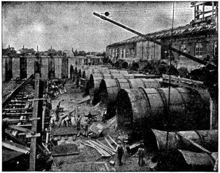
Fig. 36.—Steel Penstocks at Chamblay Power-house.
The Garvin’s Falls station, on the Merrimac River, rests on arches
of stone masonry through which the tail-water passes, and the brick walls
are water-proofed to an elevation eight feet above the floor. At twenty
feet above the floor the twenty-four-inch brick walls on the two longer
sides are reduced to eight inches in thickness, thus forming benches each
sixteen inches wide on which the crane travels. Arches of stone masonry
support the twenty-four-inch brick walls of the station at Red Bridge, on
the Chicopee River, and these walls on the two longer sides decrease in
thickness to twelve inches at an elevation of twenty-one feet above the
floor, thus forming benches twelve inches wide for the ends of the crane.
One concrete wall of the Santa Ana station is 2.5 feet thick to a distance[97]
of 13.5 feet above the floor, and then shrinks to a thickness of 1.5
feet, corresponding to that of the opposite wall, thus forming a bench
twelve inches wide for one end of the crane. The other end of the crane
in this case is supported by an I-beam on a row of iron columns.
It is not uncommon to locate horizontal turbines in a room separate
from that occupied by the generators to which they are direct-connected,
in order to protect the latter from water in the event of a break in penstocks
or wheel cases. In cases of this sort the shafts connecting wheels
and generators pass through the wall between them. The horizontal
turbines may be located at the bottom of a canal whose water presses
against the wall through which the wheel shafts pass, or they may be
contained in iron cases at the ends of penstocks. In this latter case an
extension of the station is often provided for a wheel room to contain
these cases. Such wheel rooms are long, narrow, low-roofed and parallel
to the generator rooms of their stations. The floors of these wheel rooms
are at nearly the same levels as the floors of generator rooms, but elevations
of their roofs above the floors are much less than like elevations in
the main parts of the stations. The Garvin’s Falls, Red Bridge, and
Apple River stations have wheel rooms of the type just described. With
impulse-wheels to which water passes in planes at right angles to their
shafts it is desirable, in order to avoid changes in the direction of water
pipes, that direct-connected wheels and generators occupy the same room,
and this is the arrangement at the Colgate, Electra, Santa Ana, Mill
Creek, and many other power-houses using such equipments. The area
of a wheel room may frequently be reduced at stations operating direct-connected
horizontal-pressure turbines under low heads by placing the
wheels at the bottom of the canal which has one side of the station or generator
room for a retaining wall. This plan was adopted at the Birchem
Bend plant with a head of fourteen feet, and at the Sault Ste. Marie
station where the head of water is about twenty feet. Vertical wheels
direct-connected to generators must be directly underneath the main
room of their station, and may be in a canal over which the station is
built, in a wheel room that forms its lower part, or in a wheel pit and
supplied with water through penstocks, as at the Niagara Falls plants.
Step-up transformers developing very high voltages are not an element
of safety in a generator room, and the better practice is to locate
them in a separate apartment by themselves, if not in a separate building.
For the Niagara Falls plant, the transformers that deliver three-phase
current at 22,000 volts are located in a building across the canal from the
generating plant. At Cañon Ferry the transformers operating at 50,000[98]
volts, three-phase, are located in a steel and iron addition to the power-house.
Transformers at Electra station, which are intended to work
ultimately at 60,000 volts, are located in an extension of the main building
and are separated from the generator-room by a wall. At the Santa
Ana plant the 33,000-volt transformers are grouped in one corner of the
generator room, but no partition separates their space from the remainder
of the room. In the Colgate plant the transformers, working at 40,000
volts, are spaced along one of the longer sides of the station opposite to
and only a few feet from the row of generators. One end of the main
room in the Apple River plant is devoted exclusively to the 25,000-volt
transformers, and there is a distance of about twenty-seven feet between
them and the nearest generator. The highest degree of safety for transformers
at these great voltages seems to require that they be located in a
separate room where the floor, walls, and roof are made entirely of incombustible
material.
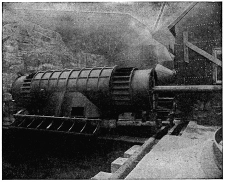
Fig. 37.—One of the Turbine Wheels at Spier Falls on the Hudson River.
Water supplied to horizontal turbine wheels under moderate heads
usually enters the station by penstocks on one side and leaves it by the
tail-race on the other, but this is not true in every case. At the Birchem
Bend plant, the canal in which the wheels are located being between the[99]
station and the river, water never enters or passes under the station,
which has a continuous foundation. So again at the Apple River plant
the single supply pipe, twelve feet in diameter and delivering water under
a head of eighty-two feet, lies parallel with the greater length of the station
and between it and the river. Short penstocks pass from this supply
pipe into the wheel section of the power-house, and the water after passing
through the wheels flows out to the river between the masonry piers
that support the twelve-foot pipe. The generator section of this station
has thus no water flowing under it. An interesting distinction may be
noted between the conditions as to the tail-water about the foundations of
stations working under low and those under great water heads. In cases
of the former sort the volumes of water are relatively great and the foundations
of stations are usually submerged, and much reduced in area to
make room for the tail-races. Thus, the foundations of the station at
Red Bridge, where there is 49 feet head, have nearly all of their footings
under water, and of a total length of 145 feet at the top of these foundations
the six tail-races underneath cut out 92 feet. These tail-races extend
underneath both the wheel and generator rooms.
Where power is derived from water delivered under great head from
pipe nozzles to impulse-wheels, stations are usually well above the water
levels of streams into which they discharge, and passages for tail-water
underneath the station shrink to small tunnels through their foundations.
Seven of these tunnels have a total width of less than 25 feet at the Santa
Ana River station, which is 127 feet long, and where the head of water
is 728 feet. At the Colgate plant, with its head of 700 feet, the water,
at times of light load, instead of flowing out of its passages underneath
the station, shoots from the pipe nozzles clear across the North Yuba
River on the bank of which the station stands.

Fig. 38.—Power Plant of Ludlow Manufacturing Company.
Larger section (173 kB)
In a comparison of floor areas per kilowatt of main generator capacities
in electric stations using water- and those using steam-power, the
matter of space for transformers may be entirely omitted, because the
extent of this space is independent of the type or location of water-wheels,
or the difference of water and steam as motive powers. Where water-wheels
and their connected generators occupy separate rooms, as is often
the case with turbines under low pressures, the wheel room has a little
less length, and is generally narrower than the generator room. Thus,
at the Red Bridge station the generator room is 141 feet long and the
wheel room about 127 feet, while the former is 33.33 feet and the latter
24 feet wide. So again at Apple River Falls the generator room is 140
by 30 feet and the wheel room 106 by 22 feet, the generator room in this[100]
[101]
case containing also transformers. It follows that if wheels can be located
outside of the station, as in a canal, quite a reduction in its total floor
area can be made, which may easily range from 20 to 40 per cent. The
kilowatt capacity per square foot of floor area in both wheel and generator
rooms combined tends to increase with the individual capacity of the
generating units. Generators on vertical shafts seem to require about
as much floor space per unit of capacity as do generators on horizontal
shafts. In the Red Bridge station the total capacity is 4,800 kilowatts
of main generators in six horizontal units, and the area of the generator
room alone is 0.96 square foot per kilowatt of this capacity. The second
station with vertical units at Niagara Falls has a capacity of 41,250 kilowatts
in eleven generators on vertical shafts, and its floor area amounts
to 0.86 square foot per kilowatt; narrow impulse-wheels of large diameter
tend to economy of floor space, as in Electra station, where the room
containing wheels and generators has an area of only 0.83 square foot
per unit of its 10,000 kilowatts capacity. At the Colgate plant, where
the total rating of generators is 11,250 kilowatts, the floor area under
wheels and generators is almost exactly one square foot per kilowatt.
The Santa Ana station, with a total capacity of 3,000 kilowatts, has
1.52 square feet of floor area for each unit of capacity. This last figure
may be compared with the 1.72 square feet per kilowatt of generator[102]
rating for the 4,800-kilowatt station at Red Bridge and the 1.75 square
feet per unit of capacity in the 800-kilowatt plant at Birchem Bend.
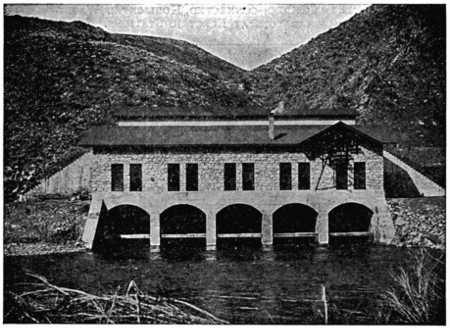
Fig. 39.—Power-house on Payette River, Idaho.
All types of water-power stations with direct-connected wheels and
generators have much smaller floor areas per unit capacity than do
steam-power stations with direct-connected horizontal units. Thus,
the modern steam-driven station at Portsmouth, N. H., has a plan area
in engine- and boiler-rooms of 16,871 square feet, and its total capacity
in four direct-connected units is 4,400 kilowatts, so that the area
amounts to 3.82 square feet per kilowatt rating of its generators. Of
this area about 46 per cent is in the boiler-room.
Floor Dimensions for Direct-connected, Horizontal
Water-wheels and
Generators at Electric Stations.
| Station. |
Feet
Long. |
Feet
Wide. |
Number of
Generators. |
Total
Kilowatt
Capacity. |
| [A]Niagara, No. 2 |
|
496 |
|
72 |
|
11 |
41,250 |
| Sault Ste. Marie |
1,368 |
100 |
80 |
32,000 |
| Colgate |
275 |
40 |
7 |
11,250 |
| Electra |
208 |
40 |
5 |
10,000 |
| Cañon Ferry |
225 |
50 |
10 |
7,500 |
| Red Bridge |
141 |
57 |
6 |
4,800 |
| Apple River |
|
- |
|
140 |
|
30 |
|
|
- |
4 |
3,000 |
| 106 |
22 |
| Santa Ana River |
|
127 |
36 |
|
4 |
3,000 |
| Great Falls |
67 |
.5 |
55 |
|
4 |
2,000 |
| Garvin’s Falls |
|
- |
|
62 |
|
30 |
|
|
- |
2 |
1,300 |
| 50 |
23 |
| Birchem Bend |
|
56 |
.6 |
26 |
.7 |
2 |
800 |
| Portsmouth (steam-driven) |
- |
|
|
14 |
.4 |
119 |
.66 |
|
- |
|
5 |
4,400 |
inside, but minus 360
square feet. |
| |
|
|
|
|
[A] Vertical wheel shafts.
Some of these dimensions apply to the inside and some to the outside of stations.
Some small projections are not included. |
[103]
CHAPTER IX.
ALTERNATORS FOR ELECTRICAL TRANSMISSION.
Dynamos in the generating station of an electric transmission system
should be so numerous that if one of them is disabled the others can carry
the maximum load. If only two generators are installed, it is thus desirable
that each be large enough to supply the entire output, so that the
dynamo capacity exceeds the greatest demand on the station by 100 per
cent. To avoid so great excess of dynamo capacity it is common practice
to install more than two generators.
Other considerations also tend to increase the number of dynamos
in the generating station of a transmission system. Thus one transmission
line may be devoted exclusively to lighting, another to stationary
motors, and a third to electric railway service; and it may be desirable
that each line be supplied by an independent dynamo to avoid any effect
of fluctuations of railway or motor load on the lighting system.
At the generating station of the transmission system that supplies
electric light and power in Portland, Me., the idea of independent units
has been carried out with four 500-kilowatt dynamos, each driven by a
pair of wheels fed with water through a separate penstock from the dam.
Each of these dynamos operates one of the four independent transmission
circuits. Where a number of water-power stations feed into a single
sub-station the requirement that each generating station have its capacity
divided up among quite a number of dynamos may not exist, since one
station may be entirely shut down for repairs and the load carried meantime
by the other stations. A good illustration of this point may be seen
at Manchester, where a single sub-station receives energy transmitted
from four water-power plants. At one of these plants the entire capacity
of 1,200 kilowatts is in a single generator.
The foregoing considerations as to the number of dynamos apply
with equal force to both steam- and water-driven stations, but other
factors tend to increase the number of dynamos in water-power plants
where the head of water is comparatively small. This tendency is due
to the fact that the peripheral speeds of pressure turbine water-wheels
should be about twenty-five per cent less than the velocity at which water[104]
[105]
would issue from an opening under the head of water at which these
wheels operate in order to secure high efficiency. This velocity of
water and therefore the peripheral speed of pressure turbine wheels varies
with the square root of the head of water.
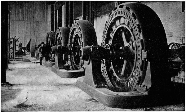
Fig. 40.—Generators at Sault Ste. Marie Power Plant.
Since the peripheral speed of turbines is thus determined by the heads
of water under which they operate, and since the diameters of turbines
must increase with their capacities, the rate of revolution for pressure
turbines under any given head decreases as the power goes up. For this
reason it is often desirable to use a larger number of dynamos in a water-power
plant than would otherwise be required in order to avoid very low
speeds of revolution on the direct-connection to the turbines. A notable
illustration of this practice exists in the great water-power plant of the
Michigan-Lake Superior Power Company, at Sault Ste. Marie, Mich.,
where a generating capacity of 32,000 kilowatts is divided up between
80 dynamos of 400 kilowatts each. The head of water available at the
pressure turbines in this plant is about 16 feet, and their speed is 180
revolutions per minute. In order to obtain even this moderate speed
under the head of 16 feet it was necessary to select turbines of only 140
horse-power each. Four of these turbines are mounted on each shaft
that drives a 400-kilowatt dynamo, direct-connected, so that there are
320 wheels in all. Had a smaller number of wheels been employed to
yield the total power their speed and that of direct-connected dynamos
must have been less than 180 revolutions per minute. As the cost of
dynamos increases with very low speeds it is often cheaper to install a
larger number of dynamos at a higher speed than a smaller number
at a lower speed for a given total capacity.
The use of a larger number of units than would otherwise be necessary
in order to avoid a very low speed is further illustrated by the 7,500-kilowatt
plant of the Missouri River Power Company, at Cañon Ferry,
Mont. This capacity is made up of ten generators, each rated at 750
kilowatts and direct-connected to a pair of pressure turbine wheels operating
at 157 revolutions per minute, under a head of about 32 feet.
Under comparatively high heads of water pressure turbines operate
at speeds that are ample for direct-connection to even the largest dynamos.
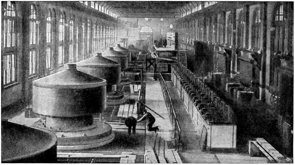
Fig. 41.—Interior of Power-house No. 2, Niagara Falls.
Thus in the Niagara Falls plant, where the head of water is 136 feet,
each pair of turbines drives a direct-connected dynamo of 3,750 kilowatts
at 250 revolutions per minute. In the rare case where the power to be
developed is so great that the number of generators necessary to give
security and reliability to the service leaves each generator with a capacity[106]
[107]
larger than is desirable for structural reasons, the number must be
increased simply to reduce the size of each generator. Such a state of
facts existed at Niagara Falls, where the first station contains ten
dynamos of 3,750 kilowatts each, and the second station contains eleven
units of like capacity.
In the greater number of transmission systems the generators are
direct-connected to either steam-engines or water-wheels, and their
speeds of rotation are largely determined by the requirements of these
prime movers. Steam-engines can be designed with some regard to the
desirable speeds for direct-connection to dynamos, but water-wheels are
less flexible in this particular. Each type of wheel has its peripheral
speed mainly determined by the head of water under which it may be
required to operate, and variation from this speed means serious loss of
efficiency.
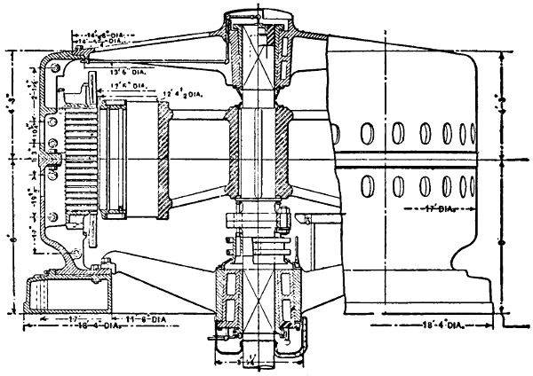
Fig. 42.—10,000 H. P. 12,000
Volt Generator in Canadian Power-house at Niagara Falls.
Larger illustration (176 kB)
Under heads of much more than 100 feet pressure turbines operate
at rather high speeds in all except very large sizes. It is much
the more common to see water-wheels at a lower speed belted to dynamos
at a higher speed; but in some instances, as at the lighting plant
of Spokane, Wash., wheels of a higher speed are belted to dynamos
of a lower speed. Another plan by which moderate dynamo speeds are
obtained with water-wheels under rather high heads mounts a dynamo at
each end of the shaft of a large turbine or pair of turbines. This plan is
followed at the plant of the Royal Aluminum Company, Shawinigan[108]
Falls, Quebec, where there are two pairs of horizontal turbine wheels,
each pair developing 3,200 horse-power under a head of 125 feet, and
driving a dynamo direct-coupled on each end of its shaft. Where vertical
wheels are employed it is sometimes more desirable to drive some
standard type of dynamo with horizontal shaft by means of bevel gears
than to design a special dynamo to mount directly on the vertical shaft.
This latter plan is warranted in very large work like that at two of the
Niagara Falls generating stations, where the twenty-one 3,750-kilowatt
dynamos are direct-connected, each on the vertical shaft of a turbine.
This type of connection is not one that will be frequently followed, but
at one other point—Portland, Ore.—each dynamo is mounted directly
on the shaft of its vertical turbine wheel.
Where water-wheels must operate under heads of several hundred
feet, it is usually necessary to abandon pressure turbines and to adopt
one of the types of impulse-wheels. In this class of wheels the peripheral
speed of highest efficiency is only one-half the spouting velocity of
the water under any particular head. This gives the impulse-wheels
about two-thirds the peripheral speed of pressure turbines of equal
diameter and consequently about two-thirds as many revolutions per
minute. But as the water may be applied at one or more points on the
circumference of an impulse-wheel, as desired, such wheels may have
much greater diameters than pressure turbines for equal power under a
given head.
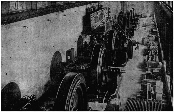
Fig. 43.—Generators in Power-station at Mechanicsville on the Hudson River.
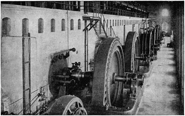
Fig. 44.—Generators at Chamblay, Quebec, Power-house.
These properties of low peripheral speed, as to head and great diameter,
as to power developed, fit impulse-wheels for direct-connection to
dynamos where great heads of water must be employed, and they are
generally used in such cases. This is particularly true for the Pacific
coast, where water-powers depend more on great heads than on large
volumes. In the generating plant of the Bay Counties’ Power Company,
at Colgate, Cal., the dynamos are direct-connected to impulse-wheels
that operate under a head of 700 feet. The three 2,250-kilowatt dynamos
in this plant are each mounted on a wheel shaft operating at 285
revolutions per minute, and each of the four 1,125-kilowatt dynamos is
direct-driven by an impulse-wheel at 400 revolutions per minute.
At the Electra, Cal., plant of the Standard Electric Company the
impulse-wheels operate at 240 revolutions per minute under a head
of 1,450 feet. Each of the five pairs of these wheels drives a 2,000-kilowatt
generator, direct-connected. As the head of water at these
wheels is 1,450 feet, its spouting velocity is about 300 feet per second,
or 18,000 feet per minute. Each wheel is eleven feet in diameter, so[109]
[110]
[111]
that a speed of 240 revolutions per minute gives the periphery a little
less than 9,000 feet per minute, or about one-half of the spouting velocity
of the water. These two great plants are excellent illustrations of the
way in which impulse-wheels, under great heads, may be given speeds
that are suitable for direct-connected dynamos.

Fig. 51a.
Plan and Elevation of Water Wheels and Generators at Power Station on
Burrard Inlet, near Vancouver, B. C.
Larger plan and elevation (155 kB)
Three types of alternators, the revolving armature, the revolving[112]
magnet, and the inductor, are used in the generating plants of electric
transmission systems.
Revolving armatures are used in the dynamos of comparatively few
transmission systems and hardly at all in those of recent date. The prevailing
type of alternator for transmission work is that with internal
revolving magnets and external stationary armature. This type is employed
in the great water-power plants at Cañon Ferry, Mont.; Sault Ste.
Marie, Mich., and for all of the generators installed in the later Niagara
Falls plants. For the sixteen earlier vertical generators at Niagara Falls
the revolving magnets are external to the stationary armatures, but this
construction has the disadvantage of high first cost and inaccessibility of
the internal armature, and is not likely to be often adopted elsewhere.
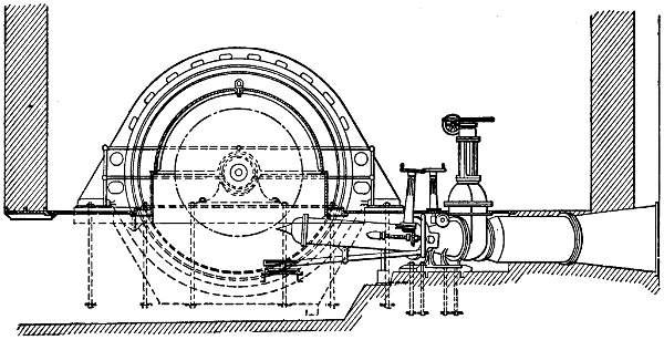
Fig. 46.—Elevations of Water-wheels
and Generators at Power-station on Burrard Inlet,
near Vancouver, B. C.
Inductor alternators are those in which both the armature and magnet
coils are stationary and only a suitable structure of iron revolves; they
are employed in a comparatively small number of transmission systems,
but this number includes some of the largest plants. The seven alternators
in the Colgate, Cal., plant aggregating 11,250 kilowatts capacity, and
the five alternators in the plant at Electra in the same State, with a capacity
of 10,000 kilowatts, are all of the inductor type. As more commonly
constructed the magnet winding of the inductor alternator consists of
only one or two very large coils, which are in some cases as much as ten
feet in diameter. The repair of these large magnet coils seems to present
a more serious problem, in case of accident, than the repair of the
small coils used on interval, revolving magnets. As far as satisfactory[113]
operating qualities are concerned, inductor alternators and those with
revolving magnets seem to be on an equality, but for structural reasons
inductor alternators will probably be built less freely in the future than
in the past.
Nearly all long transmissions are now carried out with either two- or
three-phase current. The most notable two-phase installation is that at
Niagara Falls, where the original ten generators, as well as the eleven
dynamos later added in two of the large plants, are all of the two-phase
type. At Cañon Ferry, Mont., the first four of the 750-kilowatt generators
were two-phase, but the six machines of like capacity installed later
are three-phase. In the latest plants of large capacity or involving very
long transmissions three-phase machines have been generally employed.
This is true of the Colgate and Electra plants in California, and of that
at Sault Ste. Marie, Mich.
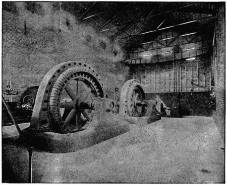
Fig. 47.—Interior of Power-house at Garvin’s Falls on the Merrimac River.
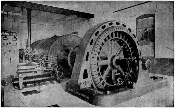
Fig. 48.—500-Kilowatt Generator
in Station at Great Falls on the Presumpscot River.
As to frequency, existing practice extends all the way from 133 cycles
per second on the lines at Marysville, Cal., down to only 15 cycles on the
transmission for the Washington & Baltimore Electric Railway.
More common practice ranges between 25 and 60 cycles. Niagara
Falls saw the first great plant installed for 25 cycles, but others of that[114]
[115]
frequency are now engaged in the supply of light and power for general
distribution. For transmission to electric railway lines a frequency of
25 cycles has been and is being widely used, prominent examples of
which may be seen in the New Hampshire traction, the Berkshire, and
the Albany & Hudson systems.
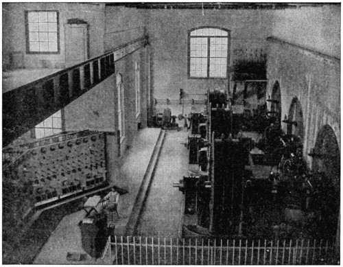
Fig. 49.—Columbus, Ga., Water-power Station.
The strong feature of a system at 25 cycles is that it is well suited to
the supply of continuous currents through rotary converters with reasonable
numbers of poles, armature slots, and commutator bars.
[116]
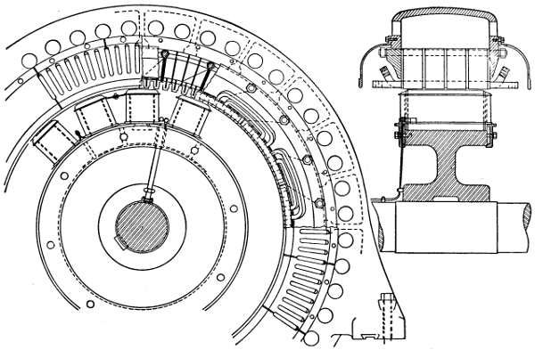
Fig. 50.—1065-Kilowatt,
2300 volt Generator Connected to Motor in Shawinigan Sub-station at Montreal.
On the other hand, the cost of transformers is greater with current at
25 cycles per second than with a higher frequency, and this current is
only just bearable for incandescent lighting and quite unsuited for arc
lamps, because of the fluctuating character of the light produced. At 15
cycles per second a current can be employed for incandescent lighting
with satisfactory results only by means of some special devices, as lamps
with very thick filaments, to avoid the flicker. Very low fluctuations cut[117]
down undesirable effects in the way of inductance and resonance, but
these effects can be avoided to a large degree in other ways.
Where power is the most important element in the service of an electric
water-power and transmission system there is a decided tendency to
adopt a rather small number of periods for the system, even at some disadvantage
as to lighting facilities. This is illustrated by the transmission
from St. Anthony’s Falls, Minn., at 35 cycles, from Cañon City to
Cripple Creek, Col., at 30 cycles, by the Sault Ste. Marie plant of 32,000
kilowatts at 30 cycles, as well as by the two Niagara Falls plants of
78,750 kilowatts at 25 cycles.
Where the main purpose of a transmission system is the supply of
light and power for general distribution, sixty periods per second are
adopted as the standard in many cases. This number of periods in
comparison with a smaller one tends to increase the cost of rotary converters
but decreases the cost of transformers, and is suitable for both
incandescent and arc lighting.
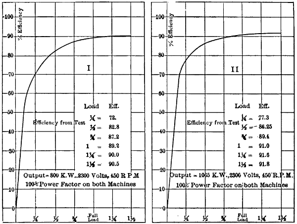
Fig. 51.—Efficiency Curves for Motor Generators at Montreal Sub-station of the
Shawinigan Transmission Line.
Few, if any, transmission systems have recently been installed for
frequencies above sixty cycles, and the older plants that worked at higher
figures have in most cases been remodelled.
During the past decade the voltages of alternators have been greatly[118]
increased, but have not caught up with the demand for high pressures
on long-transmission lines. Ten years ago when the first long transmissions
were going into operation 2,000 volts was considered high for an
alternator. As this voltage is too low for economy of conductors longer
than three or four miles, the important early transmissions were all carried
out with the aid of step-up transformers at generating stations. The
practice then was, and to a large extent still is, to design the alternators
for a transmission with a voltage well suited to their economical construction,
and then give the step-up transformers any ratio necessary to attain
the required line voltage.
Alternators in Transmission Systems.
| Location of System. |
Num-
ber
at
Plant. |
Kilo-
watts
Each. |
Alter-
nator
Volt-
age. |
Phase. |
Cycles. |
R.
P.
M. |
Type
of
Magnet. |
Method
of
Connec-
tions. |
| Niagara Falls[A] |
16 |
3,750 |
2,300 |
2 |
25 |
|
250 |
|
External
re-
volving |
Direct |
| Niagara Falls[A] |
5 |
3,750 |
2,300 |
2 |
25 |
|
250 |
|
Internal |
„ |
| Colgate to Oakland |
3 |
2,250 |
2,400 |
3 |
60 |
|
285 |
|
Inductor |
„ |
| Colgate to Oakland |
4 |
1,125 |
2,400 |
3 |
60 |
|
400 |
|
„ |
„ |
| Electra to S.Francisco |
5 |
2,000 |
.... |
3 |
60 |
|
240 |
|
„ |
„ |
| Portsmouth to Pelh’m |
1 |
2,000 |
13,200 |
3 |
25 |
|
83 |
.3 |
Internal |
„ |
| Portsmouth to Pelh’m |
2 |
1,000 |
13,200 |
3 |
25 |
|
94 |
|
„ |
„ |
| Virginia City |
2 |
750 |
500 |
3 |
60 |
|
400 |
|
External |
„ |
| Ogden & Salt Lake |
5 |
750 |
2,300 |
3 |
60 |
|
300 |
|
Internal |
„ |
| Chaudière Falls |
2 |
750 |
10,500 |
3 |
66 |
.6 |
400 |
|
„ |
„ |
| Yadkin River Falls |
2 |
750 |
12,000 |
3 |
66 |
|
166 |
|
„ |
„ |
| Lewiston, Me. |
3 |
750 |
10,000 |
3 |
60 |
|
180 |
|
„ |
„ |
| Farmington River |
|
- |
2 |
750 |
500 |
3 |
60 |
|
... |
„ |
„ |
| to |
| Hartford, Conn. |
2 |
600 |
500 |
2 |
60 |
|
... |
„ |
„ |
| Cañon Ferry to Butte |
10 |
750 |
500 |
3 |
60 |
|
157 |
|
„ |
„ |
| Apple Riv. to St. Paul |
4 |
750 |
800 |
3 |
60 |
|
300 |
|
„ |
„ |
| Edison Co., L. Angeles |
4 |
700 |
750 |
3 |
50 |
|
... |
„ |
„ |
| Madrid to Bland |
2 |
600 |
605 |
3 |
60 |
|
90 |
|
„ |
„ |
| Cañon City to Cripple Creek |
3 |
450 |
500 |
3 |
30 |
|
... |
..... |
„ |
| Sault Ste. Marie |
80 |
400 |
2,400 |
3 |
30 |
|
180 |
|
„ |
„ |
| St. Hyacinthe, Que. |
3 |
180 |
2,500 |
3 |
60 |
|
600 |
|
„ |
„ |
| Great Falls to Portland, Me. |
4 |
500 |
10,000 |
3 |
60 |
|
225 |
|
„ |
„ |
| [A] Niagara Falls Power Company. |
Thus in the two water-power plants connected with the electrical
supply system of Hartford, Conn., the alternators operate at 500 volts
with transformers that put the line voltage up to 10,000. In the station[119]
on Apple River that supplies the lighting system of St. Paul, Minn., the alternators
operate at 800 volts, and this is raised to 25,000 volts for the
line. At Cañon Ferry the alternator voltage of 500 is multiplied by 100
in the transformers giving 50,000 on the line.
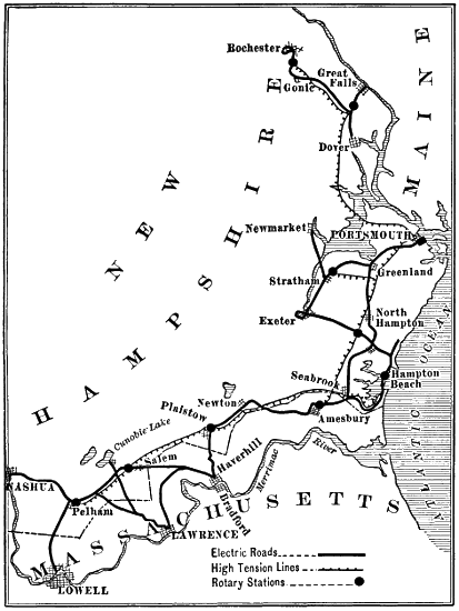
Fig. 52.—Transmission Line of New Hampshire Traction Company.
Where the generating station of a transmission system is located
close to a part of its load the alternators are given a voltage suitable for
distribution, say about 2,400, and any desired pressure on the line is
then obtained by means of step-up transformers. Two of the Niagara[120]
Falls plants are an illustration of this practice, the voltage of all the
alternators there being 2,200, which is raised to 22,000 for the transmission
of a part of the energy to Buffalo. A similar practice is followed in
the water-power plant at Ogden, where the generators furnish current
at 2,300 volts for local distribution, and transformers raise the pressure
to 26,000 volts for the transmission to Salt Lake City. In the 32,000-kilowatt
plant at Sault Ste. Marie, Mich., the alternators operate at
2,400 volts and a large part of their load is local, but this voltage will no
doubt be raised by transformers when transmission lines are operated.
For generating stations that carry little or no local loads the cost of
transformers can be saved if the generators develop the voltage required
on the transmission lines. This possible saving has led to the development
of alternators that generate voltages as high as 15,000 in their
armature coils. Such alternators have stationary armatures in all cases
and are of either the revolving magnet or inductor type.
At the present time many transmission systems in the United States
operating at 10,000 or more volts develop these pressures in the armature
coils of their alternators, and the number of such systems is rapidly
increasing. It is now the rule rather than the exception to dispense
with step-up transformers on new work where the line voltage is anything
under 15,000. Perhaps the longest transmission line now in
regular operation with current from the armature coils of an alternator
is that at 13,200 volts between the generating station at Portsmouth and
one of the sub-stations of the New Hampshire Traction system at Pelham,
a distance of forty-two miles.
In at least one transmission system now under construction, that of
the Washington, Baltimore & Annapolis Electric Railway, the voltage of
generators to supply the line without the intervention of step-up transformers
will be 15,000.
The company making these alternators is said to be ready to supply
others that generate 20,000 volts in the armature coils whenever the
demand for them is made. In quite a number of cases alternators of
about 13,000 volts have been installed for transmissions along electric
railway lines.
| Systems Using High-voltage Alternators. |
Alternator
Voltages. |
| Electrical Development Co. of Ontario, Niagara Falls |
12,000 |
| Lighting and Street Railway, Manchester, N. H. |
10,000 |
| Lighting and Street Railway, Manchester, N. H. |
12,500 |
| Lighting and Power, Portland, Me. |
10,000 |
| Lighting and Power, North Gorham, Me. |
10,000 |
| Mallison Power Co., Westbrook, Me. |
10,000 |
| Lighting and Power, Lewiston, Me. |
10,000 |
| Electric Railway, Portsmouth, N. H.[121] |
13,200 |
| Electric Railway, Pittsfield, Mass. |
12,500 |
| Ludlow Mills, Ludlow, Mass. |
13,200 |
| Electric Railway, Boston to Worcester, Mass. |
13,200 |
| Electric Railway, Albany & Hudson, N. Y. |
12,000 |
| Empire State Power Co., Amsterdam, N. Y. |
12,000 |
| Lehigh Power Co., Easton, Pa. |
12,000 |
| Hudson River Power Co., Mechanicsville, N. Y. |
12,000 |
| Light and Power, Anderson, S. C. |
11,000 |
| Fries Mfg. Co., Salem, N. C. |
12,000 |
| Light and Power, Ouray, Col. |
12,000 |
| Washington & Baltimore Electric Railway |
15,000 |
| Canadian Niagara Power Co., Niagara Falls |
12,000 |
| Ontario Power Co., Niagara Falls |
12,000 |
This list of high-voltage alternators is not intended to be exhaustive,
but serves to indicate their wide application. If such alternators can be
purchased at a lower price per unit of capacity than alternators of low
voltage plus step-up transformers, there is an apparent advantage for
transmission systems in the high-voltage machines. This advantage may
rest in part on a higher efficiency in the alternators that yield the line
voltage than in the combination of low-voltage alternators plus step-up
transformers. It is not certain, however, that depreciation and repairs
on the generators of high voltage will not be materially greater than the
like charges on generators of low voltage, and some advantage in price
should be required to cover this contingency.
Just how far up the voltage of alternators can be pushed for practical
purposes is uncertain, but it seems that the limit must be much
below that for transformers where there is ample room for solid insulation
and the coils can be immersed in oil. The use of generators at
10,000 volts and above tends to lower the volts per mile on transmission
lines, because it seems better in some cases to increase the weight of line
conductors rather than to add step-up transformers, as in the 42-mile
transmission from Portsmouth to Pelham.
[122]
CHAPTER X.
TRANSFORMERS IN TRANSMISSION SYSTEMS.
Transformers are almost always necessary in long electric systems
of transmission, because the line voltage is greater than that of generators,
or at least that of distribution. As transformers at either generating
or receiving stations represent an increase of investment without corresponding
increase of working capacity, and also an additional loss in
operation, it is desirable to avoid their use as far as is practicable. In
short transmissions over distances of less than fifteen miles it is generally
better to avoid the use of transformers at generating stations, and in
some of these cases, where the transmission is only two or three miles,
it is even more economical to omit transformers at the sub-stations.
Thus, where energy is to be transmitted two miles and then applied
to large motors in a factory, or distributed at 2,500 volts, the cost of bare
copper conductors for the three-phase transmission line will be only about
$6 per kilowatt of line capacity at 2,500 volts, with copper at 15 cents
per pound, and a loss of 5 per cent at full load. The average loss in such
a line will probably be as small as that in one set of transformers and a
line of higher voltage. Furthermore, the first cost of the 2,500-volt
generators and line without transformers will be less than that of generators
and line of higher voltage with step-down transformers at the sub-station.
As generators up to 13,500 volts are now regularly manufactured, it
is quite common to omit step-up transformers at the main stations of
rather short transmission systems. This practice was followed in the
13,500-volt transmission to Manchester, N. H., the 10,000-volt transmission
to Lewiston, Me., and the 12,000-volt transmission to Salem, N. C.
In most transmission over distances of twenty-five miles or more,
step-up transformers at generating stations as well as step-down transformers
at sub-stations are employed. As yet the highest voltages that
have been put into practical use on transmission lines (that is, 50,000 to
60,000) are much below the pressures that have been yielded by transformers
in experimental work. These latter voltages have in a number
of instances gone above 100,000. The numbers and capacities of transformers[123]
[124]
used at main stations vary much in their relation to the numbers
and individual capacities of generators there. In some cases there are
three times as many transformers as three-phase generators, and the
capacity of each transformer is either equal to or somewhat greater than
one-third of the capacity of each generator.
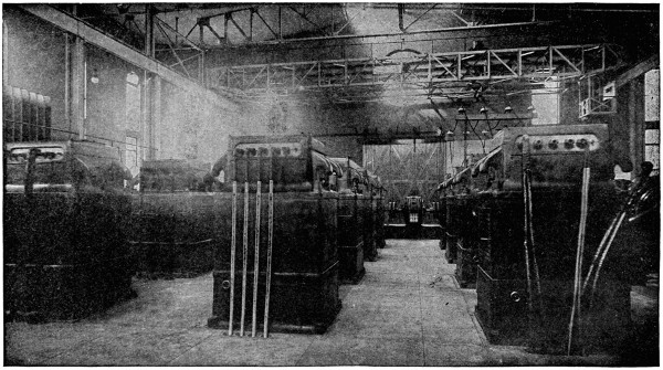
Fig. 53.—Transformers at Central Sub-station, Montreal.
Thus in the station at Spier Falls on the Hudson, whence power is
transmitted to Albany and other cities, the number of step-up transformers
will be thirty and their aggregate capacity will be 24,014 kilowatts,
while the total number of three-phase generators will be ten, with
a combined capacity of 24,000 kilowatts. Another practice is to give
each transformer a capacity greater than one-third of that of the three-phase
generator with which it is to be connected, and make the total number
of transformers less than three times as great as the number of generators.
An example of this sort exists in the station on Apple River,
whence power is transmitted to St. Paul. This station contains four
three-phase generators of 750 kilowatts each, and six transformers of
500 kilowatts each, these latter being connected in two sets of three each.
The use of three transformers for each three-phase generator instead of
three transformers for each two or three generators, tends to keep transformers
fully loaded when in use, and therefore to increase their efficiency.
On the other hand, efficiency increases a little with the size of
transformers, and the first cost per unit capacity is apt to be less the
greater the size of each.
Another solution of the problem is to provide one transformer for
each three-phase generator, each transformer being wound with three
sets of coils, so that the entire output of a generator can be sent into it.
This practice is followed at the Hochfelden water-power station, whence
power is transmitted to Oerlikon, Switzerland, also in the water-power
station at Grenoble, France, whence energy at 26,000 volts is transmitted
to a number of factories. With three-phase transformers each generator
and its transformer may form an independent unit that can be connected
with the line at pleasure, thus tending to keep transformers at full load.
Though three-phase transformers are much used in Europe, they
have thus far had little application in the United States. Single-phase
transformers may, of course, be limited in number to that of the three-phase
generators with which they are used, but such transformers must
regularly be connected to the generators and line in groups of two or three.
Such an equipment was provided in part at the 7,500-kilowatt station on
the Missouri River at Cañon Ferry, which contains ten three-phase generators
of 750 kilowatts each. The transformers at this station include[125]
twelve of 325 kilowatts each, connected in four groups of three each, also
six transformers of 950 kilowatts each which are also connected in groups
of three. Three of these larger transformers have a capacity of 2,850
kilowatts, or nearly equal to that of four generators.
With two-phase generators single-phase transformers must be connected
in pairs, and it is common to provide two transformers for each
generator. Thus, in the Rainbow station on the Farmington River,
whence energy is transmitted to Hartford, there are two generators of the
two-phase type and rated at 600 kilowatts each, also four transformers
rated at 300 kilowatts each.
As the regulation of transformers on overloads is not as good as that
of generators, it seems good practice to give each group of transformers
a somewhat greater capacity than that of the generator or generators
whose energy is to pass through it. This plan was apparently followed
at the Cañon Ferry station, where the total generator capacity is 7,500
kilowatts and the total capacity of step-up transformers is 9,600 kilowatts.
Each group of the 325-kilowatt transformers there has a capacity of 975
kilowatts, while each generator is only of 750 kilowatts. Usually the
number of groups of transformers at a two-phase or three-phase generating
station is made greater than the number of transmission circuits supplied
by the station, for some of the reasons just considered. When this
is not the case it is commonly desirable in any event to have as many
groups of step-up transformers as there are transmission circuits, so that
each circuit may be operated with transformers that are independent of
the other circuits.
At sub-stations it is desirable to have a group of transformers for each
transmission circuit, and it may be necessary to subdivide the transformer
capacity still further in order to keep transformers in operation
at nearly full load, or to provide a group of transformers for each sort of
service or for each distribution circuit. All of the transformers at a sub-station
should have a total capacity at least equal to that of the generators
whose energy they are to receive, minus the losses in step-up transformers
and the line. Transformers at sub-stations do not necessarily correspond
in number or individual capacity with those at generating stations,
and the number of sub-station transformers bears no necessary relation
to the number of generators by which they are fed.
Two transmission circuits extend from Cañon Ferry to a sub-station
at Butte, and in that sub-station there are six transformers divided into
two groups for three-phase operation, each transformer being rated at
950 kilowatts. This sub-station equipment thus corresponds to only the[126]
six 950-kilowatt transformers in the generating station, because the four
groups of smaller transformers there are used to supply the transmission
line to Helena.
In the sub-station at St. Paul that receives the entire output of the
plant on Apple River, where the six transformers of 500 kilowatts each
are located, ten transformers receive energy from two three-phase transmission
circuits. Six of these transformers are rated at 300 kilowatts
each. The 300-kilowatt transformers are connected in two groups of
three each, and the 200-kilowatt in two groups of two each, transforming
current from three-phase to two-phase. The aggregate capacity of the
sub-station transformers is thus 2,600 kilowatts, while that of transformers
at the generating station is 3,000 kilowatts. With four generators at
the water-power plant there are ten transformers at the sub-station,
where all the energy, minus losses, is delivered.
At Watervliet, where one of the several sub-stations of the system with
its larger generating plant at Spier Falls is located, the capacity of each
transformer is 1,000 kilowatts, though each transformer at Spier Falls
has a rating below this figure.
In the sub-station at Manchester, N. H., that receives nearly all of
the energy from four water-power plants, containing eight generators
with an aggregate capacity of 4,030 kilowatts, there are located twenty-one
step-down transformers that have a total rating of 4,200 kilowatts.
These twenty-one transformers are fed by six circuits, of which five are
three-phase and one is two-phase. A part of the transformers supply
current to motor-generators, developing 500-volt current for a street railway,
and the remaining transformers feed circuits that distribute alternating
current.
From these examples it may be seen that in practice either one or
more groups of transformers are employed in sub-stations for each transmission
circuit, that the total number of these transformers may be just
equal to or several times that of the generators from which they receive
energy, and that the individual capacities of the transformers range from
less than one-third to more than that of a single generator. Groups of
transformers at a main station must correspond in voltage with that of
the generators in the primary and that of the transmission line in the
secondary windings. Sub-station transformers receive current at the line
voltage and deliver it at any of the pressures desired for local distribution.
Where step-up transformers are employed the generator pressure
in nearly all cases is at some point between 500 and 2,500 volts.
At the Cañon Ferry station the voltage of transformers is 550 in[127]
in the primary and 50,000 in the secondary windings. In the Colgate
power-house, whence energy is transmitted to Oakland, the generator
pressure of 2,400 volts is raised to 40,000 volts by transformers. Generator
voltage in the power-house on Apple River is 800 and transformers
put the pressure up to 25,000 for the line to St. Paul. Transformers
at the Niagara Falls station raise the voltage from 2,200 to 22,000 for the
transmission to Buffalo.
As transformers can be wound for any desired ratio of voltages in
their primary and secondary coils, a generator pressure that will allow
the most economical construction can be selected where step-up transformers
are employed. In general it may be said that the greater the
capacity of each generator, the higher should be its voltage and that of
the primary coils of step-up transformers, for economical construction.
At sub-stations the requirements of distribution must obviously fix the
secondary voltages of transformers.
Weight and cost of transformers depend in part on the frequency of
the alternating current employed, transformers being lighter and cheaper
the higher the number of cycles completed per second by their current,
other factors remaining constant. In spite of this fact the tendency during
some years has been toward lower frequencies, because the lower
frequencies present marked advantages as to inductive effects in transmission
systems, the distribution of power through induction motors, the
construction and operation of rotary converters, and the construction of
generators. Instead of the 133 cycles per second that were common in
alternating systems when long transmissions first became important,
sixty cycles per second is now the most general rate of current changes
in such transmission systems. But practice is constantly extending to
still lower frequencies. The first Niagara Falls plant with its twenty-five
cycles per second reached the lower limit for general distribution, because
incandescent lighting is barely satisfactory and arc lighting decidedly
undesirable at this figure.
In contrast with the great transmissions from Cañon Ferry to Butte,
Colgate to Oakland, and Electra to San Francisco, which operate at sixty
cycles, the system between Cañon City and Cripple Creek, in Colorado,
as well as the great plant at Sault Ste. Marie, employs thirty-cycle
current, and the lines from Spier Falls to Schenectady, Albany, and
Troy are intended for current at forty cycles per second. From these
examples it may be seen that the bulk and cost of transformers is not
the controlling factor in the selection of current frequency in a transmission
system.
[128]
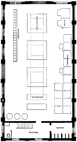
Fig. 54.—First Floor of Saratoga Sub-station.
Larger plan (73 kB)
[129]
Transformers used at either generating or sub-stations are cooled
by special means in many cases.
The advantages of so-called artificial cooling are smaller weight and
first cost in transformers, and perhaps longer life for the insulation of
windings. For these advantages a small increase in the cost of operation
must be paid. Station transformers are usually cooled either by
forcing air through their cases under pressure, or else by passing water
through pipes in the oil with which the transformer cases are filled. If
cooling with air-blast is adopted, a blower, with electric motor or some
other source of power to operate it, must be provided. Where transformers
are oil-insulated and cooled with water there must be some pressure
to maintain the circulation. If free water under a suitable head
can be had for the cooling of transformers, as in most water-power plants,
the cost is very slight. Where water must be purchased and pumped
through the transformers its cost will usually be greater than that of cooling
with air-blast. One manufacturer gives the following as approximate
figures for the rate at which water at the temperature of 15° centigrade
must be forced through his transformers to prevent a rise of more than
35° centigrade in their temperature, probably when operating under full
loads.
Trans-
formers—
Kilowatts. |
Gallons
per
minute. |
| 150 |
0 |
.5 |
| 400 |
|
.75 |
| 400 |
1 |
.00 |
| 1,000 |
1 |
.5 |
| 75 |
|
.37 |
An air-blast to cool transformers at main or sub-stations may be provided
in either of two ways. One plan is to construct an air-tight compartment,
locate the transformers over openings in its top, and maintain
a pressure in the compartment by means of blower-fans that draw cool
air from outside. Such an arrangement has been carried out at the sub-station
in Manchester, N. H. The basement underneath this sub-station
is air-tight, and in the concrete floor over it there are twenty-seven
rectangular openings, each twenty-five by thirty inches, and intended for
the location of a 200-kilowatt transformer. Aggregate transformer capacity
over these openings will thus be 5,400 kilowatts. Pressure in this
basement is maintained by drawing outside air through a metal duct that
terminates in a hood on the outside of the sub-station about nine feet
above the ground. In the roof of this sub-station there are ample skylight
openings to permit the exit of hot air that has been forced through
the transformers. In the air-tight basement are two electric motors of[130]
ten horse-power each, connected to the blower that maintains the
pressure. It may be noted that in this case there is less than one-horse
power of motor capacity for each 200 kilowatts capacity in transformers.
Where there are not more than six or nine transformers to be cooled,
it is common practice to provide a separate motor and blower for each
group of three transformers, and lead the air directly from each blower
to its group of transformers by a metal duct, thus avoiding the necessity
for an air-chamber. In such cases a blower giving a three-eighth-ounce
air pressure per square inch and a motor of one horse-power capacity are
generally provided for each group of three transformers rated at 100 to
150 kilowatts each. Where cooling with air-blast is adopted, oil-insulation
cannot be carried out because the air must come into intimate contact
with the transformer coils and core. Both oil-insulation with water
cooling and dry insulation with cooling by air-blast have been widely
used in transmission systems of large capacity and high voltage.
In the Colgate plant, where the line pressure is 40,000 volts, the 700-kilowatt
transformers are oil-insulated and water-cooled, and this is also
true of the 950-kilowatt transformers in the 50,000-volt transmission between
Cañon Ferry and Butte. On the other hand, the transmission
system between Spier Falls, Schenectady, and Albany, carried out at
26,500 volts, includes transformers that range from several hundred to
1,000 kilowatts each in capacity and are all air-cooled. Either a water-cooled
transformer or one cooled by air-blast may be safely overloaded
to some extent, if the circulation of air or water is so increased that the
overload does not cause heating beyond the allowable temperature.
The circulation of air or water through a transformer should never
be forced to an extent that cools the transformer below the temperature
of the air in the room where it is located, as this will cause the condensation
of water on its parts.
In some cases it is desirable that means for the regulation of transformer
voltages through a range of ten per cent or more each way from
the normal be provided. This result is reached by the connection of a
number of sections at one end of the transformer winding to a terminal
board, where they may be cut in or out of action at will. Regulation is
usually desired, if at all, in a secondary winding of comparatively low
voltage, and the regulating sections generally form a part of such winding,
but these sections may be located in the primary winding.
In order to keep the number of transformers smaller and the capacity
of each larger than it would otherwise be, it is practicable to divide the
low-voltage secondary winding of each transformer into two or more[131]
parts that have no electrical connection with each other. These different
parts of the winding may then be connected to distinct distribution lines
or other services. An example of this sort exists in the Hooksett sub-station
of the Manchester, N. H., transmission system. Three-phase
current at about 11,000 volts enters the primary windings of three transformers
at this sub-station. Each of these transformers has a single
primary, but two distinct secondary windings. Three of these secondaries,
one on each transformer, are connected together and feed a rotary
converter at about 380 volts, three-phase. The other three secondary
windings are connected in like manner to a second rotary converter.
Each of these transformers is rated at 250 kilowatts, and each rotary is
rated at 300 kilowatts, so that the transformer capacity amounts to 750
kilowatts and that of the converters to 600 kilowatts, giving a desirable
margin of transformer capacity for railway service. With the ordinary
method of connection and windings, six transformers of 125 kilowatts
each would have been required in this sub-station.
High voltage for transmission lines may be obtained by the combination
of two or more transformers with their secondary coils in series.
This method was followed in some of the early transmissions, as in that
at 10,000 volts to San Bernardino and Pomona, begun in 1891, where
twenty transformers, giving 500 volts each, were used with their high-voltage
coils in series. Some disadvantages of such an arrangement are
its high cost per unit of transformer capacity and its low efficiency.
In a single-phase system the maximum line pressure must be developed
or received in the coils of each transformer, unless two or more
are connected in series. This is also true as to either phase of a two-phase
system with independent circuits. In three-phase circuits the coils
of a transformer connected between either two wires obviously operate
at the full line pressure. The same result is reached when the three
transformers of a group are joined to the line in mesh or Δ-fashion. If
the three transformers of a group are joined in star or Y-fashion, the coils
of each transformer are subject to fifty-eight per cent of the voltage between
any two wires of the three-phase line on which the group is connected.
It is no longer the practice to connect two or more transformers in series
either between two wires of a two-phase or between two wires of a three-phase
circuit, because it is cheaper and more efficient to use a single transformer
in each of these positions. Where very high voltage must be developed
or received with a three-phase system, the star or Y-connection
of each group of three transformers has the advantage of a lower strain
on the insulation of each transformer than that with the mesh or Δ-grouping.[132]
Thus if the Δ-grouping is used, the line pressure equals
that of each transformer coil, but if the Y-grouping is used the line
voltage is 1.73 times that of each transformer coil.
At the Colgate power-house, the 700-kilowatt transformers are designed
for a maximum pressure of 60,000 volts on the three-phase line
when Y-connected, so that the corresponding voltage is 34,675 in their
secondary coils. The primary coils of these same transformers are connected
in mesh or Δ-form and each coil operates at 2,300 volts, the
generator pressure.
Transformers are in some cases provided with several sets of connections
to their coils so that they may be operated at widely different pressures.
Thus, in the Colgate plant, each transformer has taps brought
out from its secondary coils so that it can be operated at either 23,175,
28,925, or 34,675, with 2,300 volts at its primary coil. Corresponding to
the three voltages named in each secondary coil are voltages of 40,000,
50,000, and 60,000 on a three-phase line connected with three of these
transformers in Y-fashion.
The mesh or Δ-connection is used between the coils of transformers
on some transmission lines of very high voltage. The 950 kilowatt
transformers in the system between Cañon Ferry and Butte illustrate this
practice, being connected Δ-fashion to the 50,000-volt line.
When transformers that will operate at the desired line voltage on
Δ-connection can be obtained at slight advance over the cost of transformers
requiring Y-connections, it is often better practice to select the
former, because this will enable an increase of seventy-three per cent in
the voltage of transmission to be made at any future time by simply
changing to Y-connections. Such an increase of voltage may become
desirable because of growing loads or extension of transmission lines.
An example of this sort came up some time ago in connection with
the transmission between Ogden and Salt Lake City, which was operating
at 16,000 volts, three-phase, with the high-pressure coils of transformers
connected in Δ-form. By changing to Y-connections the line voltage
was raised seventy-three per cent without increasing the strain on transformer
insulation.
In some cases it is desirable to change alternating current from two-phase
to three-phase, or vice versa, for purposes of transmission or distribution,
and this can readily be done by means of static transformers.
One method often employed to effect this result includes the use of two
transformers connected to opposite phases of the two-phase circuit. The
three-phase coil of one of these transformers should be designed for the[133]
desired three-phase voltage, and should have a tap brought out from its
central point. The three-phase coil of the other transformer should be
designed for 87 per cent of the desired three-phase voltage. One end of
the coil designed for 87 per cent of the three-phase voltage should be connected
to the centre tap of the three-phase coil in the other transformer.
The other end of the 87 per cent coil goes to one wire of the three-phase
circuit. The other two wires of this circuit should be connected, respectively,
to the outside end of the coil that has the central tap. As a matter
of illustration it may be required to transform 500-volt, two-phase current
from generators, to 20,000-volt, three-phase current for transmission.
Two transformers designed for 500 volts in their primary coils are necessary
for this work. One of these transformers should have a secondary
coil designed for 20,000 volts, so that the ratio of transformation is 20,000
÷ 500 or 40 to 1, and a tap should be brought out from the centre of this
coil. The other transformer should have a secondary voltage of 0.87 ×
20,000 = 17,400, so that its ratio of transformation is 34.8 to 1.
These two transformers, with the connections above indicated, will
change the 500-volt, two-phase current to 20,000 volts, three-phase.
At one of the water-power stations supplying energy for use in Hartford,
four transformers of 300 kilowatts each change 500-volt, two-phase
current from the generators to 10,000-volt, three-phase, for the
transmission line.
In the Niagara water-power station the generators deliver two-phase
current at 2,200 volts, and 975-kilowatt transformers are connected in
pairs to change the pressure to 22,000 volts, three-phase, for transmission
to Buffalo.
A transformer is used in some cases to raise the voltage and compensate
for the loss in a transmission line. For this purpose the secondary
of a transformer giving the number of volts by which the line pressure is
to be increased is connected in series with the line. The primary winding
of this transformer may be supplied from the line boosted or from
another source.
Transformers ranging in capacity from 100 to 1,000 kilowatts each,
such as are commonly used for transmission work, have efficiencies of
96 to 98 per cent at full loads, when of first-class construction. Efficiency
increases slowly with transformer capacity within the limits named, and
98 per cent can be fairly expected in only the larger sizes. In any given
transformer the efficiency may be expected to fall a little, say one or two
per cent, between full load and half load, and another one per cent between
half load and quarter load. These figures for efficiencies at partial[134]
loads vary somewhat with the design and make of transformers. In
general, it may be said that step-up or step-down transformers will cost
approximately $7.50 per kilowatt capacity, or about one-half of the like
cost of low-voltage dynamos. If dynamos of voltage sufficiently high
for the transmission line can be had at a figure below the combined cost
of low-volt dynamos and raising transformers, it will usually pay to avoid
the latter and develop the line voltage in the armature coils. This plan
avoids the loss in one set of transformers.
Transformers in Transmission Systems.
| Transmission System. |
Transformers
at
Power-stations. |
Transformers
at
Sub-stations. |
Generators
at
Power-stations. |
| No. |
Kw.
Each. |
No. |
Kw.
Each. |
No. |
Kw.
Each. |
| Cañon Ferry to Butte |
12 |
325 |
[A] |
[A] |
... |
... |
| |
6 |
950 |
6 |
950 |
10 |
750 |
| Apple River to St. Paul |
... |
... |
6 |
300 |
... |
... |
| |
6 |
500 |
4 |
200 |
4 |
750 |
| White River to Dales |
3 |
400 |
3 |
375 |
2 |
500 |
| Farmington River to Hartford |
4 |
300 |
... |
... |
2 |
600 |
| Ogden to Salt Lake |
[B]9 |
250 |
... |
... |
5 |
750 |
| Colgate to Oakland |
... |
700 |
... |
... |
- |
|
3 |
1125 |
| 4 |
2250 |
| Presumpscot River to Portland |
... |
... |
- |
|
6 |
200 |
... |
... |
| 3 |
150 |
4 |
500 |
| Four water-powers to Manchester |
... |
... |
21 |
200 |
- |
|
1 |
180 |
| 3 |
300 |
| 1 |
450 |
| 4 |
650 |
| 1 |
1200 |
| |
|
|
|
|
|
|
[A] Other transformers at Helena sub-stations.
[B] Part of energy distributed directly from generators. |
[135]
CHAPTER XI.
SWITCHES, FUSES, AND CIRCUIT-BREAKERS.
Electrical transmission has worked a revolution in the art of switching.
As long as the distances to be covered by distribution lines required
pressures of only a few hundred volts, the switch contacts for generators
and feeders could well be exposed in a row on the surface of vertical
marble slabs and separated from each other by distances of only a few
inches. These switches were capable of manual operation even at times
of heavy overload without danger of personal injury to the operator or
of destructive arcing between the parts of a single switch or from one
switch to another near-by. On the back of these marble slabs one or
more sets of bare bus-bars could be located without much probability
that an accidental contact between them would start an arc capable of
destroying the entire switchboard structure and shutting down the station.
The rise of electric pressures to thousands and tens of thousands of
volts in distribution and transmission systems has vastly increased the
difficulty of safe and effective control with open-air switches. The higher
the voltage of the circuit to be operated under load the greater must be
the distance between the contact parts of each switch and also between
adjacent switches. Such switches must also be farther removed from
the operators as the voltages of their circuits go up, as a person cannot
safely stand very close to an electric arc of several feet or even yards in
length. In the West, where long transmissions are most common, long
break-stick switches have been much used with high voltages. These
switches depend on the length of the break to open the circuit and on the
length of the stick that moves the switch-jaw or plug to insure the safety
of the operator. Where switches of this sort are used it is highly important
to have ample distances between the contact points of each switch
and also between the several switches. On circuits of not more than
10,000 volts an arc as much as a yard long will in some cases follow the
opening switch blade and hold on for several seconds. On the 33,000-volt
transmission line at Los Angeles a peculiar form of switch is used[136]
which makes a break between a pair of curved wire horns that are ten
inches apart at their nearest points. When the contact between these
horns is broken the arc travels up between portions of the horns that
curve apart and is thus finally ruptured. Besides the very large space
required for open switches on circuits of 5,000 to 10,000 volts or more,
there is a further objection that the arcs developed by opening such
switches under heavy loads rapidly destroy the contact parts and produce
large quantities of metallic vapor that is objectionable in a central station.
In some experiments performed at Kalamazoo (A. I. E. E., vol.
xviii., p. 407) with open-air switches the voltages ranged from 25,000 to
40,000. The loads on circuits broken by the switches were highly inductive
and mounted from 1,200 to 1,300 kilovolt-amperes. At 25,000
volts the arc produced by the open-air switch held on for several seconds.
At 40,000 volts the arc following the opening of this switch was over
thirty feet long, and being out of doors near the pole line the arc struck
the line wires and short-circuited the system. It has been shown that
the oscillations of voltage occurring when a circuit under heavy load is
opened by an open-air switch may be very dangerous to insulation (A. I.
E. E., vol. xviii., p. 383). In the Kalamazoo test the oscillations of this
sort were reported to have reached two or three times the normal voltage
of the system when the open-air switch was used.
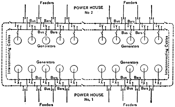
Fig. 55.—Connections between Power-houses 1 and 2 at Niagara Falls.
Facts of the nature just outlined have led to the development of oil
switches. The general characteristic of oil switches is that the contact
parts are immersed in, and the break between these contacts takes place
under, oil. Two types of the oil switch are made, one having all of its
contact parts in the same bath of oil and the other having a separate
oil-bath for each contact. Compared with those of the open-air type,
oil switches effect a great saving of space, develop no exposed arcs or
metallic vapors, cause little if any oscillation or rise of voltage in an alternating
circuit, and can be depended on to open circuits of any voltage and
capacity now in use. In the tests above mentioned at Kalamazoo, a
three-phase oil switch making two breaks in each phase and with all the
six contacts in a single oil-bath was used to open circuits of 25,000 volts
and 1,200 to 1,300 kilovolt-arcs with satisfactory results. At 40,000
volts, however, this type of switch spat fire and emitted smoke, indicating
that it was working near its ultimate capacity. A three-phase switch
with each of its six contacts in a separate cylindrical oil-chamber was
used to open the 40,000-volt 1,300 kilovolt-arc circuit at Kalamazoo with
perfect success even under conditions of short-circuit and without the
appearance of fire or smoke at the switch. The three-phase switch used[137]
in the tests at Kalamazoo and having each of its contacts in a separate
oil-chamber was similar in construction to the switches used in the Metropolitan
and Manhattan railway stations in New York City. In each of
these switches the two leads of each phase terminate in two upright brass
cylinders. These cylinders have fibre linings to prevent side-jumping of
the arcs when the switch is opened, and each cylinder is filled with oil.
Into the two brass cylinders of each phase dips a ∩-shaped contact piece
through insulating bushings, and the ends of this contact piece fit into
terminals at the bottom of the oil pots. A wooden rod joins the centre
or upper part of the ∩-contact piece, and the three rods of a three-phase
switch pass up through the switch compartment to the operating mechanism
outside. The six brass cylinders and their three ∩-contact pieces
are usually mounted on a switch cell built entirely of brickwork and
stone slabs. For a three-phase switch the brick and stone cell has three
entirely separate compartments, and each compartment contains the two
brass cylinders that form the terminals of a single phase. On top of and
outside the cell the mechanism for moving the wooden switch rods is
mounted. In the Metropolitan station, where the voltage is 6,000, the
vertical movement of the ∩-shaped contact piece with its rod is twelve
inches. At the Manhattan station, where the operating voltage is 12,000,
the vertical movement of the ∩-contacts in opening a switch is seventeen
inches. The total break in each phase in a switch at the Metropolitan
station is thus twenty-four inches, or four inches per 1,000 volts, and the[138]
total break per phase in switches at the Manhattan station is thirty-four
inches, or 2.66 inches per 1,000 volts total pressure.
Oil switches are now very generally employed on alternating circuits
that operate at 2,000 volts or more for purposes of general distribution.
On circuits of moderate voltage like that just named, and even
higher, it is common practice to use oil switches that have only a single
reservoir of oil each, the entire six contacts in the case of a three-phase
switch being immersed in this single reservoir. Such switches are usually
operated directly by hand and are located on the backs of or close
to the slate or marble boards on which the handles that actuate the switch
mechanism are located. A good example of this sort of work may be
seen at the sub-station in Manchester, N. H., where energy from four
water-power stations is delivered over seven transmission lines and then
distributed by an even larger number of local circuits at 2,000 volts three-phase.
At the Garvin’s Falls station, one of the water-power plants that
delivers energy to the sub-station in Manchester, the generators operate
at 12,000 volts three-phase, and these generators connect directly with
the bus-bars through hand-operated oil switches on the back of the
marble switchboard. These last-named switches, like those at the
Manchester sub-station, have all the contacts of each in a single reservoir
of oil.
With very high voltages, where only a few hundred kilowatts are concerned,
and also with powers running into thousands of kilowatts at
as low a pressure as 2,000 volts, it is very desirable to remove even oil
switches from the switchboard and the vicinity of the bus-bars. Great
powers as well as very high voltages not only increase the element of
personal danger to an attendant who must stand close to a switch
while operating it, but also render the damage to other apparatus that
may result from any failure of or short-circuit in a switch much more
serious.
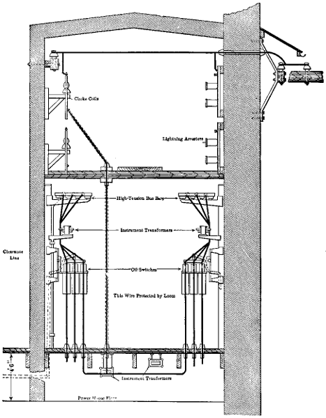
Fig. 56.—Wire-room Back
of Switchboard in Power-station on French Broad River, North Carolina.
Larger illustration (200 kB)
As soon as the switches are removed to a distance from the operating
board the necessity for some method of power control becomes evident,
since the operator at the switchboard should be able to make or break
connections of any part of the apparatus quickly. The necessity for the
removal of switches for very large powers to a distance from the operating
boards and for the application of mechanical power to make and break
connections was met before the development of oil switches. Thus at
the first Niagara (A. I. E. E., vol. xviii., p. 489) power-house, in 1893,
the switches for the 3,750-kilowatt, 2,200-volt generators, though of the
open-air type, were located in a special switch compartment erected in[139]
[140]
the generator room and over a cable subway at some distance from the
operating board. These switches were actuated through compressed-air
cylinders into which air was admitted by the movement of levers near
the switchboard. Evidently a switch of this capacity—1,000 amperes per
pole and 2,200 volts, two-phase—could not well be operated by hand-power
wherever located, because of the large effort required. In the
second generating station at Niagara Falls oil switches similar to those
used at the Manhattan Elevated Railway plant in New York, but two-phase,
were employed. Each of these oil switches at Niagara Falls has
a capacity of 5,000 horse-power, like the previous open-air switches,
and is electrically actuated.
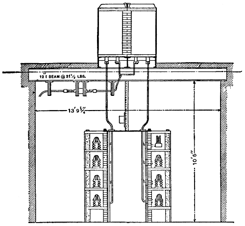
Fig. 57.—Section through Cable Subway under Oil Switches in Niagara
Power-house No. 2.
In these electrically operated oil switches a small motor is located on
top of the brick cell that contains the contact parts, and this motor releases
and compresses springs that open and close the switch. While it
is not desirable to employ open-air switches to open circuits of several
thousand or even hundreds of kilowatts at voltages of 2,000 or more, it[141]
is nevertheless possible to do so. This is shown by the experience of the
first Niagara Falls station, where the 2,200-volt two-phase switches are
reported to have opened repeatedly currents of more than 600 amperes
per phase without injurious sparking. The great rise of voltage that was
shown by the experiments at Kalamazoo to follow the opening of a simple
open-air switch was avoided at the first Niagara switches by a simple
expedient. In these 5,000 horse-power open-air switches a shunt of high
resistance was so connected between each pair of contacts that the blades
and jaws that carried the main body of the current never completely
opened the circuit. When the main jaws of one of these switches were
opened the shunt resistance continued in circuit until subsequently
broken at auxiliary terminals. That no excessive rise of voltage took
place when one of these switches was open was shown by connecting two
sharp terminals in parallel with the switch and by adjusting these terminals
to a certain distance apart. Had the voltage risen on opening
the switch above the predetermined amount there would have been
an arc formed by a spark jumping the distance between the pointed
terminals.
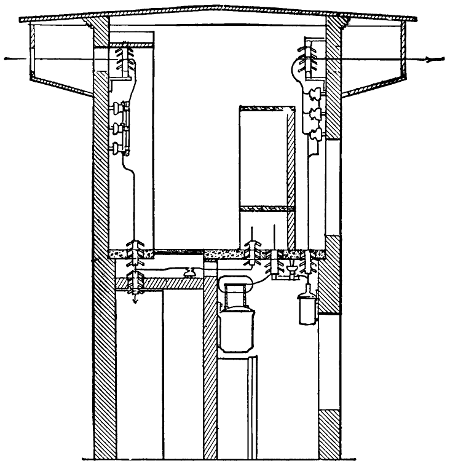
Fig. 58.—Schenectady Switch-house on Spier Falls Line.
[142]
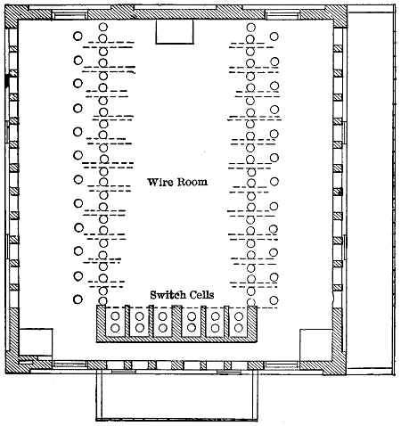
Fig. 59.—Second-floor Plan of Saratoga Switch-house on Spier Falls Line.
Safety and reliability of operation at high voltages, say of 5,000 or
more, require that each element of the equipment be so isolated as well
as insulated from every other element that the failure or even destruction
of one element will not seriously endanger the others. With this end in
view the cables from each generator to its switch should be laid in a conduit
of brick or concrete that contains no other cables. The brick or
stone compartment for each phase of each switch should be so substantial
that the contacts of that phase may arc to destruction without injury to
the contacts of another phase. Bus-bars, like switches, should be removed
from the operating switchboard, because an arc between them
might destroy other apparatus thereon, and even the board itself. It is
not enough to remove bus-bars from the switchboard where very high
voltages are to be controlled, but each bar should be located in a separate
brick compartment so that an arc cannot be started by accidental contact[143]
between two or more of the bars. It is convenient to have the brick and
stone compartments for bus-bars built horizontally one above the other.
The top and bottom of each compartment may conveniently be formed
of stone slabs with brick piers on one side and a continuous brick wall
on the other to hold the stone slabs in position. Connections to the
bus-bars should pass through the continuous brick wall that forms
what may be termed the back of the compartments. To close the openings
between the brick piers at the front of the compartments movable
slabs of stone may be used. Feeders passing away from the bus-bars,
like dynamo cables running to these bars, should not be grouped close
together in a single compartment, but each cable or circuit should be
laid in a separate fireproof conduit to the point where it passes out of
the station.
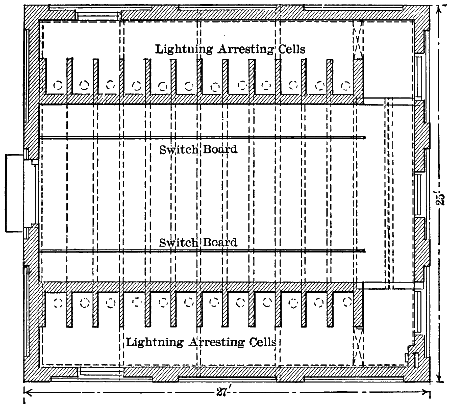
Fig. 60.—Ground Floor of Saratoga Switch-house.
The folly of grouping a large number of feeders that transmit great
powers together in a single combustible compartment was well illustrated
by the accident that destroyed the cables that connected the first
Niagara power-station with the transformer-house on January 29th,[144]
1903. On the evening of that day lightning short-circuited one of the
cables in the short bridge that connects No. 1 station with the transformer-house,
and all the cables in this bridge, supplying local consumers
as well as railways and lighting in Buffalo, were destroyed. This bridge
contained probably more than thirty-six cables, as that number of new
cables was put in position within twenty-four hours after the accident,
and these cables, covered with inflammable insulation, were close
together. The result was not only the loss of the cables, but also the
damage to power users. If these cables had been located in separate
fire-proof conduits, it is highly probable that only the one directly
affected by lightning would have been destroyed.
The brick and stone compartments for bus-bars may be located in
the basement underneath the switchboard, as at the Portsmouth station
of the New Hampshire Traction Company, or at any other place in a
station where they are sufficiently removed from the other apparatus.
In power-house No. 2 at Niagara Falls a cable subway beneath the floor
level runs the entire length, parallel with the row of generators (A. I. E.
E., vol. xix., p. 537). In this subway, which is thirteen feet nine and
three-quarter inches wide and ten feet six inches high, the two structures
for bus-bar compartments are located. Each of these structures measures
about 6.6 feet high and 1.8 feet wide, and contains four bus-bar
compartments. In each compartment is a single bar, and the four bars
form two sets for two-phase working. Above the bus-bar compartments
and rising from the floor level are the oil switches. A space over the
cable subway midway of its length and between the two groups of oil
switches is occupied by the switchboard gallery which is raised to some
elevation above the floor and carries eleven generator, twenty-two feeder,
two interconnecting, and one exciter panels. In power-house No. 1 the
bus-bars are located in a common space above the 5,000 horse-power
open-air switches already mentioned, and each bar has an insulation of
vulcanized rubber covered with braid and outside of this a wrapping of
twine. Of course; an insulation of this sort would amount to nothing if
by any accident an arc were started between the bars. Where each bus-bar
is located in a separate fireproof compartment, as at Niagara power-house
No. 2, the application of insulation directly to each bar is neither
necessary nor desirable. Consequently the general practice where each
bar has its own fireproof compartment is to construct the bars of bare
copper rods.
With main switches for generators and feeders removed from the
operating board and actuated by electric motors or magnets, the small[145]
switches at the board with which the operator is directly concerned must
of course control these magnets or motors. The small switches at the
operating board are called relay switches, and the current in the circuits
opened and closed by these switches and used to operate the magnets
or motors of the oil switches may be conveniently obtained from a
storage battery or from one of the exciting dynamos.
Probably the best arrangement of the relay switches is in connection
with dummy bus-bars on the face of the switchboard, so that the connections
on the face of the board constitute at all times a diagram of the
actual connections of the generator and feeder circuits. It is also desirable
for quick and correct changes in the connections of the main apparatus
that all the relay switches and instruments necessary for the control
of any one generator or any one feeder be brought together on a single
panel of the switchboard. If this plan is followed, the operator at any
time will have before him on a single panel all of the switches and instruments
involved in the connections then to be made, and the chance for
mistakes is thus reduced to a minimum. The plan just outlined was
that adopted at the Niagara power plant No. 2, where a separate panel
is provided for each of eleven generators and each of twenty-two feeders.
On each of the eleven generator panels there are two selector relay
switches, one generator relay switch, and one relay generator field switch.
On each of the twenty-two feeder panels there are two relay selector
switches. The relay switches on the two interconnecting panels serve
to make connections between the two groups of five and six generators
respectively in power-house No. 2 and the ten generators of power-house
No. 1. On each panel there are relay indicators to show whether the oil
switches that carry the main current respond to the movements of their
relay switches.
Where the electric generators operate at the maximum voltage of the
system, as at Garvin’s Falls and in the power-house of the Manhattan
Elevated Railway, there may be said to be only one general plan of connections
possible. That is, the generators must connect directly with
the main bus-bars at the voltage of the system, and the feeders or transmission
lines must also connect to these same bars. Of course there
may be several sets of bus-bars for different circuits or classes of work,
but this does not change the general plan of through connections from
generators to lines. So, too, the arrangement of switches is subject
to variations, as by placing two switches in series with each other in
each dynamo or feeder cable, or by connecting a group of feeders
through their several switches to a particular set of bus-bars and then[146]
supplying this set of bars from the generator bus-bars through a single
switch.
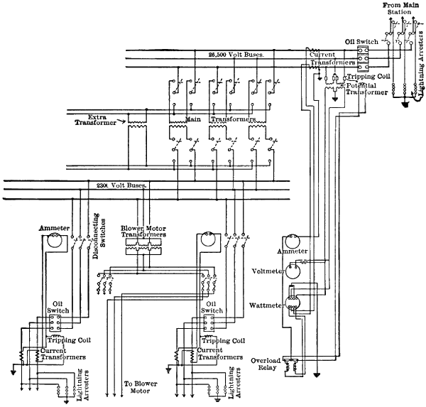
Fig. 61.—Switchboard Wiring, Glens Falls Sub-station on Spier Falls Line.
Where the voltage of transmission is obtained by the use of step-up
transformers, the connections of these transformers may be such as to
require nearly all switching to be done on either the high- or low-tension
circuits. The more general practice was formerly to do all switching in the
generator circuits and on the low-tension side of transformers, except in
the connection and disconnection of transformers and transmission lines[147]
with the high-tension bus-bars, when not in operation. Where generators
operate at the maximum voltage of the system only two main groups of
switches are necessary, one group connecting generators to bus-bars, and
the other group connecting bus-bars to the transmission lines. As soon
as step-up transformers are introduced the number of switch groups
must be increased to four if the usual method of connection is followed,
and there must be both a high voltage and a low voltage set of bus-bars.
That is, one set of switches must connect generators with low-tension
bus-bars, another group must connect low-tension bars with the primary
coils of transformers, a third group joins the secondary coils of transformers
with the high-tension bars, and the fourth group of switches joins the
transmission lines to the high-tension bus-bars. Switches connecting
the secondary coils of step-up transformers to the high-tension bus-bars,
and also the transmission lines to these same bars, have often
been of the simple open-air type with short knife-blade construction.
These switches have been used to disconnect the secondary coils of
transformers and also the transmission lines from the high-tension bus-bars
when no current was flowing, and switches of the simple knife-blade
construction with short breaks could of course be used for no
other purpose. With switches of this sort on the high-tension side of
apparatus the practice is to do all switching of line circuits on the low-tension
side.
It is possible to avoid some of this multiplication of switches if
each generator with its transformers is treated for switching purposes
as a unit and the switching for this unit is done on the secondary or
high-voltage side of the step-up transformers. The adoption of this
plan, of course, implies the use of switches that are competent to break
the secondary circuit of any group of transformers under overload
conditions and at the maximum voltage of the system, but oil switches
as now made are competent to meet this requirement. When all
switching of live circuits is confined to those of high voltage there is
also the incidental advantage that heavy contact parts carrying very
large currents are avoided in the operating switches. Where each generator
is connected directly to its own group of transformers the secondary
coils of these transformers will pass through oil switches to high-tension
bus-bars, and the use of low-tension bus-bars may be avoided.
From these high-tension bus-bars the transmission lines will pass through
oil switches, so that on this plan there are only two sets of oil switches,
namely, those connecting the secondary coils of transformers to the high-tension
bus-bars, and those connecting the transmission lines to the same[148]
bars. Each group of two or three transformers, according as two or
three are used with each generator, should be connected to its generator
through short-break, open-air knife switches for convenience in disconnecting
and changing transformers that are not in operation, but these
switches are not intended or required to open the circuit of the generators
and primary coils when in operation.
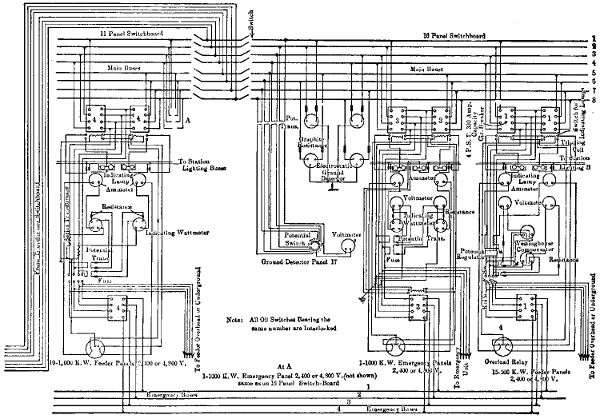
Fig. 62.—Distributing Switchboard, Central Sub-station, Montreal.
Larger illustration (184 kB)
A plan similar to that just outlined was followed at the station of the
Independent Electric Light and Power Company, San Francisco, where[149]
each of the 550-volt generators is ordinarily connected directly to the
primary coils of two transformers that change the current from two-phase
to three-phase and then deliver it through oil switches to the high-tension
bus-bars at 11,000 volts. To these bus-bars the 11,000-volt feeders for
five sub-stations are connected through switches. At this station there
is a set of 550-volt bus-bars to which any of the generators may be connected,
but to which no generator is connected in ordinary operation.
The generators alone have switches connecting with these bars. When
it is desirable to operate any particular generator on some pair of transformers
other than its own, that generator is disconnected from its own
transformers and connected to the 550-volt bus-bars. The generator
whose transformers are to be operated by the generator before mentioned
next has its switch connected to the 550-volt bus-bars, while the brushes
of the contact rings of the former generator are raised. As the leads
from each generator to its two switches are permanently joined, the
switching operations just named connect the transformers of one
generator with the other generator that has its switch closed on the
550-volt bars.
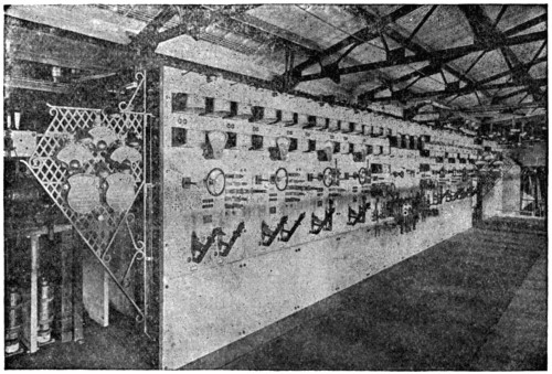
Fig. 63.—Switchboard at Chambly Power-station.
Where it is desired that a single reserve transformer may be readily
substituted for any one of a number of transformers in regular use, the
connections to each of these latter transformers may be provided with[150]
double-pole double-throw knife switches on both the primary and secondary
sides, so that when these switches are thrown one way at any
transformer in regular use the reserve transformer will be connected in
its place.
Fuses and automatic circuit-breakers alike are intended to break connections
without the intervention of human agency under certain predetermined
conditions. In the fuse the heat generated by a certain current
is sufficient to melt or vaporize a short length of special conductor.
In the circuit-breaker a certain current gives a magnet or motor sufficient
strength to overcome the pressure of a spring, and contact pieces through
which the current is passing are pulled apart. The primary object of
both the fuse and the circuit-breaker is thus to open connections and
stop the flow of energy when more than a certain current passes. When
any current passes through a circuit in the reverse of its regular direction
the circuit-breaker can be arranged to break the connections, though the
fuse cannot. A fuse must carry the current at which it is designed to
melt during some seconds before enough heat is developed to destroy it,
and the exact number of seconds for any particular case is made a little
uncertain by the possibility of loose connections at the fuse tips which
develop additional heat and also by the heat-conducting power of its connecting
terminals. A circuit-breaker may be set so as to open its connections
in one or more seconds after a certain current begins to flow.
When connections are broken by a fuse the molten or vaporized metal
forms a path that an arc may easily follow. A circuit-breaker with its
contacts under oil offers a much smaller opportunity than a fuse for the
maintenance of an arc. These qualities of fuses and circuit-breakers
form the basis of their general availability and comparative advantages
in transmission circuits.
Much variation exists in practice as to the use of fuses and circuit-breakers
on transmission circuits. One view often followed is that fuses
and circuit-breakers should be entirely omitted from the generator and
transmission lines. The argument in favor of this practice is that temporary
short circuits due to birds that fly against the lines or to sticks and
loose wires that are thrown onto them will interrupt all or a large part of
the transmission service if fuses or circuit-breakers that operate instantly
are employed. On the other hand, it may be said that if fuses and circuit-breakers
are omitted from the generator and transmission circuits
a lasting short circuit will make it necessary to shut down an entire plant
in some cases until it can be removed. Electric transmission at high
voltages became important before magnetic circuit-breakers competent[151]
to open overloaded circuits at such voltages were developed. Consequently
the early question was whether a transmission line and the generators
that fed it should be provided with fuses or be solidly connected
from generators to the distribution circuits of sub-stations. The original
tendency was strong to use fuses in accord with the practice at low voltages.
The great importance of continuous service from transmission
systems and the many interruptions caused by temporary short circuits
where fuses were used led to their abandonment in some cases. An
example of this sort may be seen at the first Niagara station. In 1893,
when this station was equipped, no magnetic circuit-breaker was available
for circuits of either 11,000 or 2,200 volts, carrying currents of several
thousand horse-power, and fuses were employed in lines at both these
pressures (A. I. E. E., vol. xviii., pp. 495, 497). The fuses adopted in this
case were the same for both the 2,200 and the 11,000-volt lines and were
of the explosive type. Each complete fuse consisted of two lignum-vitæ
blocks that were hinged together at one end and were secured when
closed at the other. In these blocks three parallel grooves for fuses were
cut and in each groove a strip of aluminum was laid and connected to
suitable terminals at each end. Vents were provided for the grooves in
which the aluminum strips were placed so that the expanding gas when
a fuse was blown would escape. When these fuse blocks were new and
the blocks of lignum vitæ made tight joints the metallic vapor produced
when a fuse was blown was forced out at the vents and the connections of
the line were thus broken. After a time, however, when the joints between
the blocks were no longer tight because of shrinkage, the expanding gas
of the fuse would reach the terminals and an arc would continue after
the fuse had blown. These aluminum fuses, which were adopted about
1893, were abandoned at the Niagara plant in 1898. Since this later date
the 2,200-volt feeders from the No. 1 power-house to the local consumers
have had no fuses at the power-house, nor have circuit-breakers been
installed there in the place of the fuses that were removed. At the large
manufacturing plants supplied through these local Niagara feeders, the
feeders formerly terminated in fuses, but these have since been displaced
by circuit-breakers. In the second Niagara power-station, completed in
1902, the local 2,200-volt feeders are provided with circuit-breakers, but
no fuses. Between the generators and bus-bars of the first Niagara plant
the circuits were provided with neither fuses nor automatic circuit-breakers,
and this practice continues there to the present time.
Besides the aluminum fuses in the 11,000-volt transmission line at
the first Niagara station, there were lead fuses in the 2,200-volt primary[152]
circuits of the step-up transformers that supplied these lines. At the
other end of these lines, in the Buffalo sub-station, another set of aluminum
fuses was inserted before connection was made with the step-down
transformers. Between the secondary coils of these transformers and
the 550-volt converters there were no fuses, but these converters were connected
to the railway bus-bars through direct current circuit-breakers.
These lead fuses, which contained much more metal than those of aluminum,
when blown set up arcs that lasted until power was cut off by
opening a switch, and usually destroyed their terminals. An effort was
made to so adjust the sizes of the fuses in this transmission system that
in case of a short circuit in distribution lines at Buffalo only the fuses in
the sub-station would be blown, leaving those at Niagara entire. This
plan did not prove effective, however, and a severe overload on the distribution
lines in Buffalo would blow out fuses clear back to the generator
bus-bars at the Niagara station.
In order to accomplish the opening of overloaded circuits with greater
certainty, to delay such opening where the overload might be of only a
momentary nature, and to confine the open circuit to the lines where the
overload existed, automatic circuit-breakers were substituted for the fuses
named in the Niagara and Buffalo transmission system. This system
was also changed from 11,000 to 22,000 volts on the transmission lines,
thus rendering the requirements as to circuit-opening devices more severe.
These circuit-breakers were fitted with time-limit attachments so
that any breaker could be set to open at the end of any number of seconds
after the current flowing through it reached a certain amount. A circuit-breaker
with such a time-limit attachment will not open until the time
for which it is set, after the amperes flowing through it reach a certain
figure, has elapsed, no matter how great the current may be. Moreover,
if the overload is removed from a line before the number of seconds for
which its time-limit circuit-breaker is set have elapsed, the circuit-breaker
resets itself automatically and does not open the connections. If a circuit-breaker
is set to open a line after an interval of say three seconds
from the time when its current reaches the limit, the line will not be
opened by a mere momentary overload such as would blow out a fuse.
By setting the time-limit relays of circuit-breakers in transmission lines
to actuate the opening mechanism after three seconds from the time that
an overload comes on, and then leaving the breakers on distribution lines
to operate without a time-limit, it seems that the opening of breakers on
the distribution lines should free the system from an overload there before
the breakers on the transmission lines have time to act. Such a result[153]
is very desirable in order that the entire service of a transmission system
may not be interrupted every time there is a fault or short circuit on one
of its distribution lines. This plan was followed in the Niagara and
Buffalo system. In the 22,000-volt lines at the Niagara station the time
relays were set to actuate the breakers after three seconds, at the terminal
house in Buffalo, where the transformers step down from 22,000 to
11,000 volts, the circuit-breakers in the 11,000 volt lines to sub-stations
had their relays set to open in one second. Finally the circuit-breakers
in the distribution lines from the several sub-stations were left to operate
without any time limit. By these means it was expected that a short
circuit in one of the distribution circuits from a sub-station would not
cause the connections of the underground cable between that sub-station
and the terminal house to be broken, because of the instant action of the
circuit-breaker at the sub-station. Furthermore, it was expected that a
short circuit in one of the underground cables between the terminal house
and a sub-station would be disconnected from the transmission line at
that house and would not cause the circuit-breakers at the Niagara station
to operate. It is reported that the foregoing arrangement of circuit-breakers
with time relays failed of its object because the breakers did not
clear their circuits quick enough and that the time-limit attachments on
the 22,000 and 11,000 volt lines are no longer in use (A. I. E. E., vol.
xviii., p. 500). As the circuits under consideration convey thousands of
horse-power at 11,000 and 22,000 volts it may be that time-limit devices
with circuit-breakers would give good results under less exacting
conditions. Time-limit relays are perhaps an important aid toward reliable
operation of transmission systems, but they are subject to the objection
that no matter how great the overload they will not open the circuit
until the time for which they are set has run. In the case of a short circuit
the time-limit relay may lead to a prolonged drop in voltage throughout
the system, which is very undesirable for the lighting service and also
allows all synchronous apparatus to fall out of step. With a mere momentary
drop in voltage the inertia of the rotating parts of synchronous apparatus
will keep them in step. For these reasons it is desirable to have
circuit-breakers that will act immediately to open a line on which there is
a short circuit or very great overload, but will open the line only after an
interval of one or more seconds when the overload is not of a very extreme
nature. This action on the part of circuit-breakers at the second Niagara
power-station was obtained by the attachment of a dash-pot to the tripping
plunger of each circuit-breaker (A. I. E. E., vol. xviii., p. 543). With
moderate overloads of a very temporary nature this dash-pot so retards[154]
the action of a tripping plunger that the circuit-breaker does not open.
When a short circuit or great overload comes onto a line the pull on the
tripping plunger or the circuit-breaker on that line is so great that the
resistance of the dash-pot to the movement is overcome at once and the
line is disconnected from the remainder of the system.
The fact that a circuit-breaker may be designed to open the line which
it connects, whenever the direction from which the flow of energy takes
place is reversed, is taken advantage of at some sub-stations to guard
against a flow of energy from a sub-station back toward the generating
station. By this means a flow of energy from a sub-station to a short
circuit in one of the lines or cables connecting it with the generating plant
is prevented.
[155]
CHAPTER XII.
REGULATION OF TRANSMITTED POWER.
Regulation of voltage at incandescent lamps is a serious problem
in the distribution of electrically transmitted energy. Good regulation
should not allow the pressure at incandescent lamps rated at 110 to
120 volts to vary more than one volt above or below the normal.
Electric motor service is much less exacting as to constancy of voltage,
and the pressure at motor terminals may sometimes be varied as much
as ten per cent without material objection on the part of users. A mixed
service to these three classes of apparatus must often be provided
where transmitted energy is used, and the limitations as to variations at
incandescent lamps are thus the ones that must control the regulation
of pressure.
Transmission systems may be broadly divided into those that have
no sub-stations and must therefore do all regulation at the generating
plant, and those that do have one or more sub-stations so that regulation
of voltage may be carried out at both ends of the transmission line.
Fig. 64.—Arc-lighting Switchboard at Central Sub-station, Montreal.
As a rule, a sub-station with an operator in attendance is highly
desirable between transmission and distribution lines, and this is the
plan generally followed at important centres of electrical supply, even
though the transmission is a short one. One example of this sort may
be noted at Springfield, Mass., where energy for electrical supply is
transmitted from two water-power plants on the Chicopee River only
about four and a half and six miles, respectively, from the sub-station
in the business centre of the city. The voltage of transmission for two-phase
current in this case is 6,000, and is reduced to about 2,400 volts at
the sub-station for the general distribution of light and power. A similar
instance may be seen at Concord, N. H., where electrical energy at both
2,500 and 10,000 volts is delivered to a sub-station in the business section
from a water-power plant at Sewall’s Falls, on the Merrimac River, four
and one-half miles distant. From this sub-station the current is distributed
at about 2,500 volts for the supply of lamps and motors. A sub-station[156]
[157]
was found desirable at Concord for purposes of regulation before
the voltage of transmission was raised above that of distribution. Subsequently,
when the load increased, the voltage of 10,000 was adopted on
a part of the transmission circuit in order to avoid an increase in the size
of their conductors.

Fig. 65.—Area of Electrical Distribution at Montreal.
Larger map (167 kB)
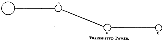
Fig. 66.
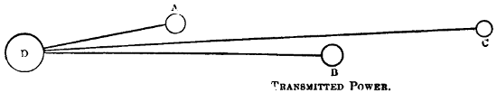
Fig. 67.
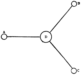
Fig. 68.
In some instances, however, transmission and distribution lines are
joined without the intervention of a sub-station, where regulation of
voltage can be accomplished, though this practice has little to recommend
it aside from the savings in first cost of installation and subsequent
cost of operation. These savings are more apparent than real if fairly
constant pressure is to be maintained at the lamps, because what is
gained by the omission of sub-stations will be offset, in part at least, by
additional outlays on the lines if good regulation is to be maintained.
This fact may be illustrated by reference to Figs. 66, 67, and 68,
in each[158]
of which D represents a generating station and A, B, and C towns or
cities where energy from the station is to be distributed. In the case
of each figure it is assumed that the distance between the generating
station and each of the cities or towns is such that distributing lines
with a loss of, say, not more than two per cent in voltage at full load
cannot be provided between the generating station and each city or
town because of the cost of conductors. This being so, one or more
centres of distribution must be located in each town, and the transmission
lines must join the distribution lines at these centres either on
poles or in sub-stations. If several of these towns are in the same general
direction from the generating plant so as to be reached by the same
transmission line, as A, B, and C in Fig. 66, this one line will be all that
is necessary with a sub-station in each town. Where sub-stations are
not employed a separate transmission circuit must be provided between
the generating plant and each town for reasons that will appear presently.
The percentage of voltage variation in a transmission line under changing
loads will be frequently from five to ten, and is thus far beyond the
allowable variations at incandescent lamps. To give good lighting service[159]
the centre of distribution, where the transmission line joins the distribution
circuits, must be maintained at very nearly constant voltage if
no sub-station is located there. Regulation at a generating station will
compensate for the changing loss of pressure in a line under varying loads
so as to maintain a nearly constant voltage at any one point thereon. No
plan of station regulation, however, can maintain constant voltages at
several points on the same transmission line when there is a varying load
at each. The result is that even though the several towns served are in
the same general direction from the generating station, as in Fig. 67, yet
each town should have its separate transmission line where no sub-stations
in the towns are provided. In the case illustrated by Fig. 68, where
the towns served are in very different directions from the generating
station, there should be a separate transmission line to each, regardless
of whether there is a sub-station or only a centre of distribution
there.
Even in the case illustrated by Fig. 68, as in each of the others, there
is a large saving effected in the cost of distribution lines by the employment
of a sub-station at the point where these lines join the transmission
circuit, provided that the variation of pressure at lamp terminals
is to be kept within one volt either way from the standard. With the
variations of loads the loss of pressure in the distribution lines will range
from zero to its maximum amount and the connected lamps will be subjected
to the change of voltage represented by this total loss, unless the
distribution start from a sub-station where the loss in distribution lines
can be compensated for by regulation. To give good service the distribution
lines should be limited to a loss of one per cent at full load if
there is no sub-station where they join transmission lines. With opportunity
for regulation at a sub-station the maximum loss in distribution
lines may easily be doubled, thus reducing their weight by one-half in
comparison with that required where there is no sub-station.
Another advantage of connecting transmission and distribution lines
in a sub-station, where regulation of voltage can be had, lies in the fact
that it is practically impossible to maintain an absolutely constant pressure
miles from a generating plant at the end of a transmission line that
is carrying a mixed and varying load. A result is that without the intervention
of regulation at a sub-station it is almost impossible to give
good lighting service over a long transmission line. Furthermore, the
labor of regulation at a generating station is much increased where there
are no sub-stations, because it must be much more frequent and accurate.
The absence of sub-stations from a transmission system thus implies[160]
more transmission circuits, heavier distribution circuits, more labor
at the generating plant, and a poor quality of lighting service.
Where stationary motors form the great bulk of the load on a transmission
system, and good lighting service is of small importance, it may
be well to omit sub-stations at some centres of distribution. This is a
condition that sometimes exists in the Rocky Mountain region where the
main consumers of power along a transmission line may be mines or
works for the reduction of ores. An example of this sort exists in the
system of the Telluride Power Transmission Company, in Utah, which
extends from Provo Cañon, on the river of the same name, entirely
around Utah Lake by way of Mercur, Eureka, and Provo, and back to
the power-house in Provo Cañon, a continuous circuit of 105 miles.
The transmission voltage on this line is 40,000, and at intervals where
there are distributing points the voltage is reduced to about 5,000 by
transformers on poles, and without the aid of regulation at sub-stations
in some cases. The power thus transmitted is largely used in mines and
smelters for the operation of motors, but also for some commercial lighting.
Regulation at generating stations of the voltage on transmission lines
may be accomplished by the same methods whether there are sub-stations
at centres of distribution or not. In any such regulation the aim
is to maintain a certain voltage at some particular point on the transmission
line, usually its end, where the distribution circuits are connected.
If more than one point of distribution exists on the same transmission
line, the regulation at the generating plant must be designed to maintain
the desired pressure at only one of these points, leaving regulation at the
others to be accomplished by local means. One method of regulation
consists in the overcompounding of each generator so that the voltage
at its terminals will rise at a certain rate as its load increases. If a generator
and transmission line are so designed that the rise of voltage at
the generator terminals just corresponds with the loss of voltage on the
line when the output of that generator alone passes over it to some particular
point, then the pressure at that point may be held nearly constant
for all loads if no energy is drawn from the line elsewhere. These
several conditions necessary to make regulation by the compounding of
generators effective can seldom be met in practice. If a varying number
of generators must work on the same transmission line, or if varying
loads must be supplied at different points along the line, no compound
winding of generators will suffice to maintain a constant voltage at any
point on the line that is distant from the power-station. For these reasons[161]
the compound winding of generators is of minor importance so far as the
regulation of voltage on transmission lines is concerned, and on large
alternators is not generally attempted. An example may be noted on the
3,750-kilowatt generators at Niagara Falls, where the single magnet
winding receives current from the exciters only.
A much more effective and generally adopted method of regulation
of voltage at the generating plants of transmission systems is based on
the action of an attendant who varies the current in the magnet coils of
each generator so as to raise or lower its voltage as desired. The regulation
must be for some one point on the transmission line, and the attendant
at the generating plant may know the voltage at that point either by
means of a pair of pressure wires run back from that point to a voltmeter
at the generating plant, by a meter that indicates the voltage at the point
in question according to the current on the line, or by telephone connection
with a sub-station at the point where the constant voltage is to be
maintained. Pressure wires are a reliable means of indicating in the
generating station the voltage at a point of distribution on the line, but
the erection of these wires is quite an expense in a long transmission, and
in such cases they are only occasionally used. Owing to inductive effects
and to variable power-factors the amperes indicated on a line carrying
alternating current are far from a certain guide as to the drop in voltage
between the generating station and the distant point. In long transmissions,
telephone communication between the generating plant and the
sub-stations is the most general way in which necessary changes to
maintain constant voltage at sub-stations are brought to the attention
of the attendant in the generating plant. Few, if any, extensive transmission
systems now operate without telephone connection between a
generating plant and all of its sub-stations, or between a single sub-station
and the several generating plants that may feed into it. Thus, the
generating plant at Spier Falls, on the Hudson River, will be connected
by telephone with sub-stations at Schenectady, Albany, Troy, and some
half-dozen smaller places. On the other hand, the single sub-station in
Manchester, N. H., that receives the energy from four water-power plants
has a direct telephone line to each.
Where two or more transmission lines from the same power-station
are operated from the same set of bus-bars the voltage at a distant point
on each line cannot be held constant by changes of pressure on these
bus-bars. One generator only may be connected to each transmission
line and be regulated for the loss on that line, but this loses the advantages
of multiple operation. Another plan is to connect a regulator[162]
in each transmission line before it goes from the generating plant.
One type of regulator for this purpose consists of a transformer with
its secondary coil divided into a number of sections and the ends of
these sections brought out to a series of contact segments. The primary
coil of this transformer may be supplied with current from the
bus-bars and the secondary coil is then connected in series with the
line to be regulated, so that the secondary voltage is added to or subtracted
from that of the main circuit. A movable contact arm on the
segments to which the sections of the secondary coil are connected makes
it possible to vary the secondary voltage by changing the number of these
sections in circuit. In another transformer used for regulating purposes
the primary coil is connected to the bus-bars as before and the movable
secondary coil is put in series with the line to be regulated. The regulation
is accomplished in this case by changing the position of the secondary
relative to that of the primary coil and thus raising or lowering the secondary
voltage. Both of these regulators require hand adjustment, and
the attendant may employ the telephone, pressure wires, or the compensating
voltmeter above mentioned, to determine the voltage at the centre
of distribution. The voltage indicated by this so-called “compensator”
is that at the generating station minus a certain amount which varies with
the current flowing in the line to be regulated. The voltmeter coil of
the compensator is connected in series with the secondary coils of two
transformers, which coils work against each other. One transformer has
its secondary coil arranged to indicate the full station voltage, and the
other secondary coil is actuated by a primary coil that carries the full
current of the regulated line. By a series of contacts the effect of this
last-named coil can be varied to correspond with the number of volts that
are to be lost at full load between the generating station and the point
on the transmission line at which the voltage is to be held constant. If
there is no inductive drop on the transmission line, or if this drop is of
known and constant amount, the compensator may give the actual voltage
at the point for which the regulation is designed.
Automatic regulators are used in some generating stations to maintain
a constant voltage either at the generating terminals or at some distant
distributing point on a line operated by a single generator. These regulators
may operate rheostats that are in series with the magnet windings
of the generators to be regulated, and raise or lower the generator voltage
by varying the exciting current in these windings. These regulators are
much more effective to maintain constant voltage at generating stations
than at the distributing end of long transmission lines with variable[163]
power-factors. In spite of the compound winding of generators, of automatic
regulators for the exciting currents in their magnet coils, and of
regulating transformers in the transmission circuits, hand-adjustment of
rheostats in series with the magnet coils of generators remains the most
generally used at the generating stations of long transmission systems.
Automatic regulators at the ends of transmission lines in sub-stations are
now being introduced, and may prove very desirable.
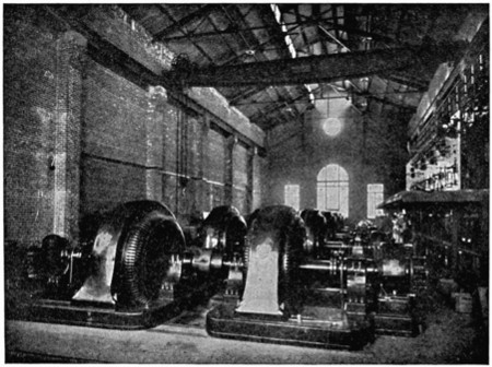
Fig. 69.—Motor-generators in Shawinigan Sub-station at Montreal.
The more exacting and final work of regulation in transmission systems
is usually done at the sub-stations. After a nearly constant voltage
is delivered at the high-pressure coils of step-down transformers in a
sub-station, there remains the varying losses in these transformers, in
motor-generators or converters, in distribution lines and in service transformers,
to be compensated for. In general, three or four sorts of loads
must be provided for, namely, arc or incandescent lamps for street lighting
on series circuits, usually of 4,000 to 10,000 volts. Arc and incandescent
lamps on constant-pressure circuits of 2,000 to 2,500 volts for commercial
lighting, direct-current stationary motors on constant-pressure
circuits of about 500 volts, and alternating motors which may be served
at either 2,500 or 500 volts according to their sizes and locations. To
these loads may be added that of street-car motors of 500 volts, direct
current. Both the stationary and the street-car motors, but more especially[164]
the latter, by their changes
of load give rise to large and rapid
fluctuations of voltage on the distribution
lines to which they are connected.
The problem of regulation
with combined lamp and motor loads
is not, therefore, so much to maintain a
nearly constant voltage at the motors
as to protect the lamps from the fluctuations
of voltage which the motors set up.
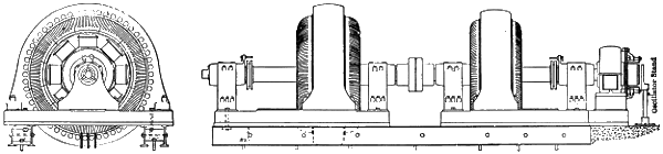
Fig. 70.—One of the 1,065-kilowatt
Motor-generators in the Shawinigan Sub-station at Montreal.
Larger illustration (71 kB)
For street-car motors using direct
current at about 500 volts, the sub-station
equipment includes either step-down
transformers and converters
or motor-generators with or without
transformers. It is the practice in
some cases where both lighting and
street-railway service are drawn from
the same transmission system to keep
these two kinds of service entirely
separate, devoting independent generators
and transmission lines, as well
as independent transformers and converters
or motor-generators, to the
street-car work. This is done in
the transmission system centring at
Manchester, N. H., in which each
one of the four water-power plants,
as well as the sub-station, has a
double set of bus-bars on the switchboard;
and from each water-power
plant to the sub-station there are two
transmission circuits. In operation,
one set of generators, bus-bars, transmission
circuits, and transformers
supply converters or motor-generators
for the street-car motors; and another
set of generators, bus-bars, transmission
circuits, and transformers are
devoted to lighting and stationary[165]
motors in this system. Where street-car motors draw their energy from
the same generators and transmission lines that supply commercial incandescent
lamps, some means must be adopted to protect the lighting
circuits from the fluctuations of voltage set up by the varying street-car
loads. One way to accomplish this purpose is to operate the lighting
circuits with generators driven by synchronous motors in the sub-stations.
These generators may, of course, be of either direct or alternating type
and of any desired voltage. The synchronous motors driving these
generators take their current from the transmission line either with or
without the intervention of step-down transformers. By this use of synchronous
motors the lighting circuits escape fluctuations of voltage corresponding
to those on the transmission line, because synchronous motors
maintain constant speeds independently of the voltage of the circuits to
which they are connected. This plan was followed at Buffalo, where the
street-car system and the lighting service are operated with energy from
the Niagara Falls stations over the same transmission line. In one of
the sub-stations at Buffalo, both 2,200-volt, two-phase alternators, and
150-volt continuous-current generators for lighting service, are driven by
synchronous motors connected to the Niagara transmission line through
transformers. At other sub-stations in Buffalo, the 500-volt continuous
current for street-car motors is obtained from the same transmission system
through transformers and converters. Another solution of the problem
of voltage regulation where street-railway and commercial lighting
service are to be drawn from the same transmission line is found in the
operation of 500-volt continuous-current generators in the sub-stations
by synchronous motors fed from the line either directly or through transformers.
This plan has been adopted in the transmission system of the
Boston Edison Company, which extends to a number of cities and towns
within a radius of twenty-five miles. The sub-stations at Natick and
Woburn in this system, where there are street-railway as well as lighting
loads, contain 500-volt continuous-current generators driven by synchronous
motors connected directly to the three-phase transmission lines.
In a case like this the synchronous motors maintain their speed irrespective
of the voltage on the line and thus tend to hold that voltage steady
in spite of the variable losses due to fluctuating loads.
Stationary motors should not as a rule be operated from the same
distribution lines that supply incandescent lamps, especially in sizes
above one horse-power, and this is the better practice. Motor circuits
of about 2,400 volts and two- or three-phase, alternating, or 500 volts,
alternating or direct current, may be supplied at a sub-station either[166]
by transformers alone in the first case or by transformers and converters
in the second. In either case no especial provision is usually necessary
for the regulation of constant pressure on the motor circuits.
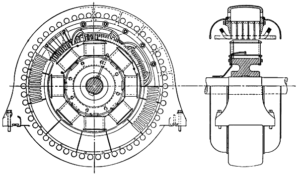
Fig. 71.—1,100-kilowatt,
2,300-volt, Three-phase, 30-cycle, Synchronous Motor at Sub-station of Shawinigan
Line in Montreal.
In some transmission systems the distribution circuits for stationary
motors are not fed by the same transmission lines that carry the lighting
load, but draw their energy from lines that do no other work. This
practice is certainly desirable, as it frees the lighting circuits from all
fluctuations of voltage due to line losses with changing motor loads.
Examples of this sort may be seen at Springfield, Mass., and Portland[167]
and Lewiston, Me., in each of which the load of stationary motors is
operated over independent transmission as well as distribution lines.
In transmission systems series arc and incandescent lamps for street
lighting are commonly operated either by direct-current arc dynamos or
by constant-current transformers or constant-pressure transformers with
automatic regulators at the sub-stations. The arc dynamos are driven
by either induction or synchronous motors supplied directly from the
transmission line or through transformers. As the arc dynamos regulate
automatically for constant current no further regulation is required. If
the series arc and incandescent lamps are to be supplied with alternating
current, the constant-current transformer or the constant-current regulator
come into use. This type of transformer and regulator alike depend
for their regulating effect on the movement of a secondary coil on
a transformer core in such a way that the current in this coil, which is in
series with the lamps, is held nearly constant. Such constant-current
transformers and regulators are usually supplied from the transmission
line through regular constant-pressure transformers, and they hold their
currents sufficiently constant for the purposes of their use.
The main problem of regulating thus comes back to the 250- or
2,200-volt, constant-pressure circuits for incandescent lighting, supplied
from transmission lines through transformers or motor generators or both
at the sub-station. For this regulation one of the most reliable instruments
is the hand of a skilful attendant, guided by voltmeters connected
with pressure wires from minor centres of distribution, and adjusting the
regulating transformers above mentioned, or other regulating devices.
[168]
CHAPTER XIII.
GUARD WIRES AND LIGHTNING ARRESTERS.
Lightning in its various forms is the greatest danger to which transmission
systems are exposed, and it attacks their most vulnerable point,
that is, insulation. The lesser danger as to lightning is that it will puncture
the line insulators and shatter or set fire to the poles. The greater
danger is that the lightning discharge will pass along the transmission
wires to stations and sub-stations and will there break down the insulation
of generators, motors, or transformers. Damage by lightning may
be prevented in either of two ways, that is, by shielding the transmission
line so completely that no form of lightning charge or discharge can reach
it, or by providing so easy a path from line conductors to earth that
lightning reaching these conductors will follow the intended path instead
of any other. In practice the shielding effect is sought by grounded
guard wires, and the easy path for discharge takes the form of lightning
arresters, but neither of these devices is entirely effective.
Aerial transmission lines are exposed to direct discharges of lightning,
to electromagnetic charges due to lightning discharges near by, and to
electrostatic charges that are brought about by contact with or induction
from electrically charged bodies of air. It is evidently impracticable to
provide a shield that will free overhead lines from all these influences.
To cut off both electrostatic and electromagnetic induction from a wire
and also to free it from a possible direct discharge of lightning, it seems
that it would at least be necessary completely to incase the wire with a
thick body of conducting material. This condition is approximated when
an electric circuit is entirely beneath the surface of the ground, but would
be hard to maintain with bare overhead wires. It seems, however, that
grounded guard wires near to and parallel with long aerial circuits should
tend to discharge any high electrostatic pressures existing in the surrounding
air, and materially to reduce the probability that a direct discharge
of lightning will choose the highly insulated circuits for its path to
earth. Lightning arresters may conduct induced and direct lightning
discharges to earth, without damage to transmission lines, so that both
arresters and guard wires may logically be used in the same system.
[169]
Wide differences of opinion exist as to the general desirability of
grounded guard wires on transmission lines, both because of their undoubted
disadvantages and because the degree of protection that they
afford is uncertain. It seems, however, that the defects of guard wires
depend in large degree on the kind of wire used for the purpose, and
the method of its erection. Galvanized iron wire with barbs every
few inches has been more generally used for guard wires along transmission
lines than any other sort. Sometimes a single guard wire of
this sort has been run on a pole line carrying transmission circuits,
and the more common location of this single wire is on the tops of the
poles. In other cases two guard wires have been used on the same pole
line, one of these wires being located at each end of the highest cross-arm
and outside of the power wires. Besides these guard wires at the
ends of the top cross-arms of a pole line, a third wire has in some systems
been added to the tops of the poles. These guard wires have sometimes
been secured to the poles and cross-arms by iron staples driven over the
wire and into the wood, and in other cases the guard wires are mounted
on small glass insulators. Much variation in practice also exists as to
the ground connections of guard wires, such connections being made at
every pole in some systems, and much less frequently in some others.
With all these differences in the practical application of guard wires
it is not strange that opinions as to their utility do not agree. Further
reason for differences of opinion as to the practical value of guard wires
exists in the fact that in some parts of the country the dangers from lightning
are largely those of the static and inductive sort, that are most effectively
provided for by lightning arresters, while in other parts of the
country direct lightning strokes are the greatest menace to transmission
systems. At the present time, knowledge of the laws governing
the various manifestations of energy that are known under the general
head of lightning is imperfect, and the most reliable rules for the use
of guard wires along transmission lines are those derived from practical
experience.
A case where a guard wire did not prove effective as a protection
against lightning is that of the San Miguel Consolidated Gold Mining
Company, of Telluride, Col., whose three transmission lines ran from the
water-power plant to points from three to ten miles distant, as described
in A. I. E. E., vol. xi., p. 337, and following pages. This transmission
operated at 3,000 volts, single-phase, alternating, and the pole lines ran
over the mountains at elevations of 8,800 to 12,000 feet above sea-level,
passing across bare ridges and tracts of magnetic material. It was stated[170]
that the country over which the circuits ran is so dry and rocky that it
was practically impossible to secure good ground connections along the
line, and no mention was made of the way in which the ground wire was
grounded, or of the number of its ground connections. Furthermore, it
does not appear that there was more than one guard wire on each pole
line. Under these circumstances, and with a certain make of lightning
arresters in use at the station, lightning was a frequent cause of damage
to the connected apparatus. The insulation of some of the machinery
is described as honeycombed with perforations which led to continual
leakage, grounds, and short-circuits, which seems to indicate that the
damage was being done by static and inductive discharges rather than
by direct lightning strokes, one of which would have disabled a machine
at once. The type of lightning arrester in use on this system was
changed, and thorough ground connections were provided for the new
arresters, after which the damage by lightning came to an end. It is not
stated, however, that the guard wires were removed. This case has been
referred to as one in which guard wires failed to give protection, but, as
may be seen from the above facts, such a statement is hardly fair. In
the first place, it does not appear that the single guard wire on each pole
line was effectively grounded anywhere. Again, a large part of the
damage to apparatus appears to have been the result of static or inductive
discharges that could not in the nature of things have been prevented
by a guard wire. Finally, as the guard wire was not removed
after the new lightning arresters were erected, it is possible that this wire
prevented some direct discharges over the transmission wires that would
have been destructive.
On page 381 of the volume of A. I. E. E. above cited, it is stated that
the frequency and violence of lightning discharges that entered a certain
electric station on Staten Island were much less after guard wires had
been erected along the connected circuits than they were before the guard
wires were put up.
It is also stated on page 385 of the same volume that examination of
statistics of a number of stations in this country and Europe had shown
that in every case where an overhead guard wire had been erected over
power circuits, or where these circuits ran for their entire distance beneath
telegraph wires, lightning had given no trouble on the circuits so protected.
Unfortunately, the speaker who made this statement did not tell
us where the interesting statistics mentioned could be consulted.
On the first pole line erected for power transmission from Niagara
Falls to Buffalo, two guard wires were strung at opposite ends of the top[171]
cross-arm on guard irons there located. This cross-arm also carried parts
of two power circuits, and the nearest wires of these circuits were distant
about thirteen inches from the guard irons. These guard wires were
barbed, and grounded at every fifth pole, according to an account given in
A. I. E. E., vol. xviii., at 514 and following pages. The character of the
ground connections is not stated. Much trouble in the way of grounds
and short circuits on the transmission lines was caused by these guard
wires at times when they were broken by the weight of ice coatings and
wind pressure. As a result of these troubles the guard wires were removed
in 1898. Since that date it appears that the transmission lines
between Niagara Falls and Buffalo have been without guard wires. Up
to 1901, according to page 537 in the volume just cited, twenty per cent
of the interruptions in operation at the Niagara plant were caused by
lightning, and it seems probable that this record applies to the period
after 1898, when the guard wires were removed. It is also stated that
during a single storm the line was struck five times, and that five poles
with their cross-arms were destroyed. If these direct lightning strokes
occurred while there were no guard wires along the line, as seems to
have been the fact, it is a fair question whether such wires well
grounded would not have carried off the discharges without damage.
In California, the country of long transmissions, the use of guard
wires along the pole lines is quite general. Many of these lines run
east and west across the State, and a single line may thus have elevations
in its different parts all the way from that of tide-water up to
several thousand feet above sea-level. Unless guard wires are strung
with these lines there is much manifestation of induced or static electricity,
according to an account at page 538, in vol. xviii., A. I. E. E.,
where it is said that in the absence of guard wires a person will be
knocked off his feet every time he touches a transmission wire that is
entirely disconnected from the source of power. It is also said that this
static charge on idle power lines is sufficient, in time, to puncture the
insulation of the connected apparatus. On the other hand, where the
grounded and barbed guard wires are strung over the entire lengths of
these long power lines, these lines may be handled with impunity when
they are idle. Ground connections to the guard wire are said to be
made at about every fourth pole, and to consist of a wire stapled down
the face of the pole and joined to an iron plate beneath its butt. The
barbed guard wire itself, of which each pole line appears to have but
one, is regularly stapled to the tops of the poles.
At the reference just named it is related that on a certain transmission[172]
line running east and west across the State for a distance of forty-six
miles, and protected by a guard wire, no trouble was experienced during
a severe storm that swept north and south over the line. Meantime the
damage on other lines in the same neighborhood, and presumably not
protected by guard wires, was large.
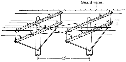
Fig. 72.—Transposition of Wires on Chambly Montreal Line.
Between the electric plant at Chambly, on the Richelieu River, and
Montreal, Quebec, a distance of 16.6 miles, a transmission line of three
circuits on two pole lines, with guard wires, was operated from some time
in 1898 to December 1st, 1902, or somewhat more than four years. On
the date last named the dam that maintained the head of water at the
Chambly station gave way, and the plant was shut down during nearly
a year for repairs. For as much as three years this line was operated at
12,000 volts, sixty-six cycles per second, two-phase. During the remainder
of the period up to the failure of the dam the line was operated
at 25,000 volts, sixty-three cycles, three-phase. In each transmission
two pole lines were employed with two cross-arms per pole. One two-phase,
four-wire circuit was carried on each of three of these cross-arms.
At each end of the upper cross-arm on each pole, and at a distance of
fifteen inches from the nearest power wire, a guard wire was mounted
on a glass insulator. A third guard wire was mounted on a glass insulator
at the top of each pole, and this third guard wire was about twenty
inches from the nearest power wire. Each of these guard wires was made
up of two No. 12 B. W. G. galvanized iron wires twisted together, with
a four-point barb every five inches of length. Poles carrying these lines
were ninety feet apart, and at each pole all three of the guard wires were
connected by soldered joints to a ground wire that was stapled down the
side of the pole, passed through an iron pipe eight feet long, and was then
twisted several times about the butt of the pole before it was set in the[173]
ground. At three points along the line the conductors consisted of single-conductor
underground or submarine cables that had an aggregate
length of about twenty-five miles. No lightning arresters were employed
at the points where the overhead transmission wires joined the underground
cables.
These two-phase, 12,000-volt circuits were operated from some time
in 1898 to some time in 1902, and during that time there was no damage
done by lightning either at the Chambly plant, on the overhead line or
the underground cable, or at the Montreal sub-station. This record is
not due to lack of thunder-storms, for in the territory where the line
is located these storms are frequent and severe. One very severe storm
during the period in question resulted in serious damage on distribution
lines at Chambly and Montreal, where the guard wires were not in use,
but the transmission line and its connected apparatus escaped unharmed.
The path of this storm was in the direction of the transmission line from
Montreal to Chambly, and several trees were struck on the way. At
the time of this storm and during an entire summer there were no lightning
arresters in the power-house at Chambly.
In 1902, when the transmission line just considered was changed from
two-phase to three-phase, and its voltage raised from 12,000 to 25,000,
the method of protection by grounded, barbed guard wires, as above
described, was retained. Two three-phase circuits were arranged on
each of the two pole lines, with one wire of each circuit on an upper
cross-arm and two wires of each circuit on a lower cross-arm, so that the
nearest power wire on the upper cross-arm is thirty-two inches from the
guard wire, and the nearest power wire on the lower cross-arm is about
thirty inches from the guard wire at each end of the upper cross-arm.
The guard wire at the tops of the poles is about thirty-three inches from
each of the power wires on the upper cross-arm. In this three-phase line
there is about 1,440 feet of three-conductor underground cable, and this
cable lies between the end of the overhead line and the sub-station in
Montreal. At the juncture of the overhead line and the cables there is
a terminal house containing lightning arresters, and there are also arresters
at the Chambly plant and the Montreal sub-station. No lightning
arresters are connected to this line save those at the generating plant, the
terminal house and the sub-station.
During that part of the year 1902 in which the new 25,000-volt line
was in operation—that is, after the change and up to the time of the failure
of the dam—this line and its connected apparatus were not damaged
in any way by lightning, and the same is true for the period in which the[174]
line was idle pending repairs on the dam. The experience on this Montreal
and Chambly transmission is probably among the best evidence to
be found anywhere as to the degree of protection from lightning that
may be had by the use of guard wires. In spite of cases like that just
considered, where guard wires appear to have given a large degree of
protection to transmission systems, many important transmissions are
operated without them.
An example of this sort may be seen in the transmission line between
the 10,000-horse-power plant at Electra, in the Sierra Nevada Mountains
of California, and San Francisco, a distance of 154 miles, where it seems
that no guard wires are in use. Another important transmission line
that appears to get along without guard wires is that between the 10,000-horse-power
plant at Cañon Ferry, on the Missouri River, and Butte,
Mont., sixty-five miles away. On the transmission line between the
power-station on Apple River, in Wisconsin, and the sub-station at St.
Paul, Minn., about twenty-seven miles long, there are no guard wires
for lightning protection. Further east, on the large, new transmission
system that stretches from Spier Falls and Glens Falls on the north to
Albany on the south, a distance in a direct line of forty miles, no guard
wires are employed. On its way the transmission system just named
touches Saratoga, Schenectady, Mechanicsville, Troy, and a number of
smaller places, thus forming a network with several hundred miles of
overhead wire. Examples of this sort might be multiplied, but those
already named are sufficient to show that it is entirely practicable to
operate long transmission systems without guard wires as a protection
against lightning.
With these examples of transmission systems both with and without
guard wires, the expediency of their use on any particular line should be
determined by weighing their supposed advantages against their known
disadvantages, under the existing conditions. It seems fairly certain
from all the evidence at hand that if guard wires are to offer any large
degree of protection to transmission systems such wires must be frequently
and effectively grounded. There is certainly some reason to
think that the failures of guard wires to protect transmission systems in
some instances may have been due to the lack of numerous and effective
ground connections. Such, for example, may have been the case above
mentioned, at Telluride, Col. On the other hand, it seems reasonable
to believe that the apparently high degree of protection afforded by the
guard wires on the Chambly and Montreal line is due to the fact that
these wires are connected through soldered joints at every pole with a[175]
ground wire that is wound about its base. The nearer the guard wires
are located to the power wires on a line the greater is the danger that
a guard wire will come into contact with a power wire by breaking or
otherwise. It is probable that the protection given by a guard wire
does not increase nearly as fast as the distance between it and a power
wire is diminished. Even if one guard wire on a line is thought to be
desirable, it does not follow that two or more such wires should be used,
for the additional protection given by two or three guard wires beyond
that given by one wire may be trifling, while the cost of erection and the
danger of crosses with the power circuits increase directly with the number
of guard wires. At one time it was thought very desirable to have
barbs on guard wires, but now the better opinion seems to be that, as
barbs tend to weaken the wire, they lead to breaks and cause more
trouble than they are worth. The point where the barbs are located
seems to rust more quickly than do other parts of the wire. In some
cases barbed guard wires that have given trouble by breaking have been
taken down and smooth wires put up instead. If a guard wire is well
grounded at least as often as every other pole, its size may be determined
largely on considerations of mechanical strength and lasting qualities.
For ordinary spans a No. 4 B. & S. G. galvanized soft iron wire seems
to be about right for guarding purposes. Iron seems to be the most
desirable material for guard wires because it gives the required mechanical
strength and sufficient conductivity at a less cost than copper, aluminum,
or bronze, and is easier to handle and less liable to break than steel.
It was formerly the practice to staple guard wires to the tops of poles or
to the ends of cross-arms, but it was found that the wire was more apt
to rust and break at the staple than elsewhere, and in the better class of
work such wires are now mounted on small insulators. This practice,
as stated above, was followed on the Montreal and Chambly line. In
all cases the connection between the guard wire and each of its ground
wires should be soldered, and the ground wire should have a large surface
in contact with damp earth, either through a soldered joint with a
ground plate, by winding a number of turns about the butt of the pole,
or by other means.
It is thought by some telegraph engineers that the use of a separate
ground wire running to the top of each pole is quite as effective as a protection
against lightning as is a guard wire that runs to all of the poles
and is frequently connected to the ground.
This practice is mentioned at page 26 of “Culley’s Handbook of
Practical Telegraphy.” Such ground wires are free from most of the[176]
objections to the ordinary guard wires. It seems quite certain that a
guard wire along an alternating-current line, and grounded at frequent
intervals, must act as a secondary circuit of a transformer by reason of
its ground connections, and thus absorb some energy from the power
circuits. No experimental data are yet available, however, to show how
large this loss may be in an ordinary case. It is fairly evident that there
must be some electrostatic effects between the working conductors and
a guard wire, but here again data are lacking as to the amount of any
such effect. On most, if not all, transmission lines the guard wire or
wires, if used at all, are placed either above or on a level with the highest
power conductors. With one conductor of a three-phase circuit mounted
on a pin set in the top of a pole, and the two remaining conductors on a
two-pin cross-arm beneath, in the method most frequently adopted for
transmission lines of very high voltage, it is obviously impracticable to
put guard wires either above or on a level with the power circuits. In
the latest transmissions there is a strong tendency to omit guard wires entirely
and rely on lightning arresters for protection.
Lightning arresters are wrongfully named, for their true purpose is
not to arrest or stop lightning, but to offer it so easy a path to the ground
that it will not force its way through the insulation of the line or of machinery
connected to the system. The requirements of a lightning arrester
are in a degree conflicting, because the resistance of the path it
offers must be so low as to allow discharges of atmospheric electricity
to earth and so high as to prevent any flow of current between the transmission
lines. In other words, the insulation of the line conductors must
be maintained at a high standard in spite of the connection of lightning
arresters between each conductor and the earth; but the resistance to the
arrester must not be so high that lightning will pierce the insulation of
the line or machinery at some other point. When a lightning discharge
takes place through an arrester the resistance which the arrester offers
to a flow of current is for the moment greatly reduced by the arcs which
the lightning sets up in jumping the air-gaps of the arrester. Each wire
of a transmission circuit must be connected alike to arresters, and the
paths of low resistance through arcs in these arresters to the earth would
obviously short-circuit the connected generators unless some construction
were adopted to prevent this result. In some early types of lightning
arresters magnetic or mechanical devices were resorted to in order to
break arcs formed by the discharge of lightning.
The type of lightning arrester now in common use on transmission
lines with alternating current includes a row of short, parallel, brass[177]
cylinders mounted on a porcelain block and with air-gaps of one-thirty-second
to one-sixteenth of an inch between their parallel sides.
The cylinder at one end of the row is connected to a line wire and the
cylinder at the other end to the earth, when a 2,000 or 2,500-volt circuit
is to be protected. For higher voltages a number of these single
arresters are connected in series with each other and with the free ends
of the series to a line wire and to the earth, respectively. Thus, for
a 10,000-volt line, four or, better, five single arresters are connected in
series to form a composite arrester for each line conductor. For any
given line voltage the number of single arresters going to make up the
composite arrester should be so chosen that the regular working voltage
will not jump the series of air-gaps between the little brass cylinders,
but yet so that any large rise of voltage will be sufficient to force sparks
across these gaps. A variation of this practice by one large manufacturing
company is to mount the group of single arresters on a marble board
in series with each other and with an adjustable air-gap. This gap is
intended to be so adjusted that any large increase of voltage on the lines
will be relieved by a spark discharge. An arrester made up entirely
of the brass cylinders and air-gaps has the disadvantage that an arc
once started between all the cylinders by a lightning discharge so lowers
the resistance between each line wire and the earth that the generating
equipment is short-circuited and the arcs may not cease with the escape
of atmospheric electricity. To avoid this difficulty it is the practice to
connect a conductor of rather large ohmic resistance such as a rod of
carborundum in series with the brass cylinders and air-gaps of lightning
arresters. This resistance should be non-inductive so as not to
offer a serious obstacle to lightning discharge, and its resistance should
be great enough to prevent a flow of current from the generators that
will be large enough to maintain the arcs started in the arrester by the
lightning discharge. Accurate data are lacking as to the amount of
this resistance that should be employed with arresters for any given
voltage. As a rough, approximate rule it may be said that in some
cases good results will be obtained with a resistance in ohms in series
with a group of lightning arresters that represents one per cent of the
numerical value of the line voltage. That is, for a 10,000-volt line the
group of arresters for each wire may be connected to earth through
a resistance of, say, 100 ohms, so that if the generator current follows
the arc of a lightning discharge through the arresters it must pass
through a fixed resistance of 200 ohms in going from one line wire to
another. This rule is given merely as an illustration of the resistance[178]
that will work well in some cases, and should not be taken to have a
general application. If the resistance connected in series with lightning
arresters is high, the tendency is a little greater for lightning to go to
earth at some point in the apparatus where the insulation is low. If
only a small resistance is employed to connect lightning arresters with
the earth, the danger is that arcs formed by lightning discharges will
be followed and maintained by the dynamo currents. In one make of
lightning arrester the row of little brass cylinders is connected at the
ends to carbon rods which form a resistance for the purpose just mentioned.
Two of these carbon rods are contained in each arrester for
2,000 or 2,500 volts, and the resistance of each rod may be anywhere
from several score to several hundred ohms as desired. This form of
arrester may be connected directly from line to earth without the intervention
of any outside resistance, since the carbon rods may easily be
given all the resistance that is desirable.
One of the most important features in the erection of a lightning
arrester is its connection to earth. If this connection is poor it may
render the arrester useless so far as protection from lightning is concerned.
It need hardly be said that ground connections formed by driving long
iron spikes into the walls of buildings or into dry earth are of slight value
as far as protection from lightning is concerned. A good ground connection
for lightning arresters may be formed with a copper or galvanized
iron plate, which need not be over one-sixteenth of an inch thick, but
should have an area of, say, ten to twenty square feet. This plate may
be conveniently made up into the form of a cylinder and should have a
number of half-inch holes punched in a row down one side into which
one or more copper wires with an aggregate area equal to that of a No.
4 or No. 2 wire, B. & S. gauge, should be threaded and then soldered.
This plate or cylinder should be placed deep enough in the ground to
insure that the earth about it will be constantly moist, and the connected
copper wire should extend to the lightning arresters. It is a good plan
to surround this cylinder with a layer of coke or charcoal.
A good earth connection for lightning arresters may be made through
large water-pipes, but to do this it is not enough simply to wrap the wire
from the lightning arresters about the pipe. A suitable contact with
such a pipe may be made by tapping one or two large bolts into it and
then soldering the wires from lightning arresters into holes drilled in the
heads of these bolts. A metal plate laid in the bed of a stream makes a
good ground.
With some of the older types of lightning arresters it was the custom[179]
to insert a fuse between the line wire and the ground, but this practice
defeats the purpose for which the arrester is erected because the fuse
melts and leaves the arrester disconnected and the circuit unprotected
with the first lightning discharge. The modern arresters for alternating-current
circuits are made up of a series of metal cylinders and short air-gaps
and are connected solidly without fuse between line and earth.
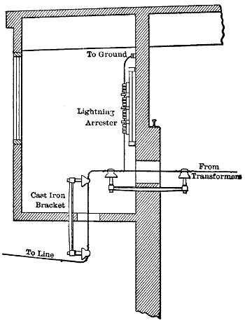
Fig. 73.—Entry of Lines at the Power-house on Neversink River.
It was once the practice to locate lightning arresters almost entirely
in the stations, but this has been modified by experience and consideration
of the fact that as the line acts as a collector of atmospheric electricity,
paths for its escape should be provided along the line. Consideration
fails to reveal any good reason why lightning that reaches a transmission
line some miles from a station should be forced to travel to the station,
where it may do great damage before it finds an easy path to earth. It
is, therefore, present practice to connect lightning arresters to each wire at
intervals along some lines as well as at stations and sub-stations. The
main purpose of arresters is to offer so easy a path to earth that lightning
discharges along the lines will not flow to points of low insulation[180]
in generators, transformers, or even the line itself. Practice is far from
uniform as to the distance between lightning arresters on transmission
lines, the distances varying from less than one to a large number of
miles apart. In general the lines should be provided with lightning arresters
at least where they run over hilltops and at any points where
lightning strokes are unusually frequent. Where a long overhead
line joins an underground cable arresters should always be connected,
and the same is true as to transformers located on the transmission line.
The multiplication of arresters along pole lines should be avoided as far
as is consistent with suitable protection, because every bank of arresters
may develop a permanent ground or short-circuit, unless frequently inspected
and kept clean and in good condition.
Arresters, besides those connected along the lines, should be located
either in or just outside of stations and sub-stations. If the buildings
are of wood, the arresters had better be outside in weather-proof cases,
but in brick or stone buildings the arresters may be properly located
near an interior wall and well removed from all other station equipment.
Transmission lines, on entering a station or sub-station, should pass
to the arresters at once and before connecting with any of the operating
machinery.
To increase the degree of protection afforded by lightning arresters
choke-coils are frequently used with them. A choke-coil for this purpose
usually consists of a flat coil of copper wire or strip containing twenty
to thirty or more turns and mounted with terminals in a wooden frame.
This coil is connected in series with the line wire between the point where
the tap for the lightning arrester is made and the station apparatus.
Lightning discharges are known to be of a highly oscillatory character,
their frequency being much greater than that of the alternating currents
developed in transmission systems. The self-induction of a lightning
discharge in passing through one of these choke-coils is great, and the
consequent tendency is to keep the discharge from passing through the
choke-coil and into the station apparatus and thus to force the discharge
to pass to earth through the lightning arrester. The alternating current
employed in transmission has such a comparatively low frequency that
its self-induction in a choke-coil is small. Increased protection against
lightning is given by the connection of several groups of lightning arresters
one after another on the same line wire at an electric station. This
gives any lightning discharge that may come along the wire several paths
to earth through the different groups of arresters, and a discharge that
passes the first group will probably go to earth over the second or third[181]
group. In some cases a choke-coil is connected into a line wire between
each two groups of lightning arresters as well as between the station apparatus
and the group of arresters nearest thereto.
An electric transmission plant at Telluride, Col., where thunder-storms
are very frequent and severe, was equipped with arresters and
choke-coils of the type described, and the results were carefully noted
(vol. xi., A. I. E. E., p. 346). A small house for arresters and choke-coils
was built close to the generating station of this system and they were
mounted therein on wooden frames. Four choke-coils were connected
in series with each line wire, and between these choke-coils three lightning
arresters were connected, while a fourth arrester was connected to the
line before it reached any of the choke-coils. These arresters were
watched during an entire lightning season to see which bank of arresters
on each wire discharged the most lightning to earth. It was found
that, beginning on the side that the line came to the series of arresters,
the first bank of arresters was traversed by only a few discharges of
lightning, the second bank by more discharges than any other, the
third bank by quite a large number of discharges, and the fourth bank
seldom showed any sign of lightning discharge. Over the second
bank of arresters the lightning discharges would often follow each
other with great rapidity and loud noise. The obvious conclusion from
these observations seems to be that three or four banks of lightning arresters
connected in succession on a line at a station together with choke-coils
form a much better protection from lightning than a single bank. At
the plant in question, that of the San Miguel Consolidated Gold Mining
Company, the entire lightning season after the erection of the arresters
in question was passed without damage by lightning to any of the equipment.
During the two lightning seasons previous to that just named
the damage by lightning to the generating machinery at the plant had
been frequent and extensive.
A good illustration of the high degree of security against lightning
discharges that may be attained with lightning arresters and choke-coils
exists at the Niagara Falls plants and the terminal house in Buffalo,
where the step-up and step-down transformers have never been damaged
by lightning though the transmission line has been struck repeatedly and
poles and cross-arms shattered (vol. xviii., A. I. E. E., p. 527). This example
bears out the general experience that lightning arresters, though
not an absolute protection, afford a high degree of security to the apparatus
at electric stations.
Lightning arresters are in some cases connected across high-voltage[182]
circuits from wire to wire so that the full line pressure tends to force a
current across the air-gaps. The object of this practice is to guard
against excessive voltages on the circuit such as might be due to resonance.
In such a case, as in that where arresters are connected from
line wire to earth as a protection against lightning, the number of air-gaps
should be such that the normal line voltage will not force sparks
across the air-gaps and thus start arcs between the cylinders.
The number and total length of air-gaps in a bank of arresters
necessary to prevent the formation of arcs by the regular line
voltage depends on a number of factors besides the amount of that
voltage.
According to the report of the Committee on Standardization of the
American Institute of Electrical Engineers, the sparking distances in air
between opposed sharp needle points for various effective sinusoidal voltages
are as follows (vol. xix., A. I. E. E., p. 1091):
Kilovolt
Square Root
of
Mean Square. |
Inches
Sparking
Distance. |
| 5 |
0 |
.225 |
| 10 |
|
.47 |
| 15 |
|
.725 |
| 20 |
1 |
.0 |
| 25 |
1 |
.3 |
| 30 |
1 |
.625 |
| 35 |
2 |
.0 |
| 40 |
2 |
.45 |
| 45 |
2 |
.95 |
| 50 |
3 |
.55 |
| 60 |
4 |
.65 |
| 70 |
5 |
.85 |
| 80 |
7 |
.1 |
| 90 |
8 |
.35 |
| 100 |
9 |
.6 |
| 110 |
10 |
.75 |
| 120 |
11 |
.85 |
| 130 |
12 |
.95 |
| 140 |
13 |
.95 |
| 150 |
15 |
.0 |
It may be noted at once from this table that the sparking distance
between the needle points increases much faster than the voltage between
them. Thus, 20,000 volts will jump an air-gap of only an inch between
the points, but seven times this pressure, or 140,000 volts, will force a
spark across an air-gap of 13.95 inches. Two cylinders or other blunt
bodies show smaller sparking distances between them at a given voltage
than do two needle points, but when a number of cylinders are placed
in a row with short air-gaps between them the aggregate length of these
gaps that will just prevent the passage of sparks at a given voltage
may be materially greater or less than the sparking distance of that
voltage between needle points. It has been found by experiment that
the numbers one-thirty-second-inch spark-gaps between cylinders of[183]
non-arcing alloy necessary to prevent the passage of sparks with the
voltages named and a sine wave of electromotive force are as follows
(vol. xix., A. I. E. E., p. 1026):
Number of
1⁄32-Inch
Air-Gaps
in Series. |
Normal
Voltage
Withheld. |
| 5 |
6,800 |
| 10 |
10,000 |
| 15 |
12,500 |
| 20 |
14,500 |
| 25 |
16,400 |
| 30 |
18,200 |
| 35 |
19,300 |
| 40 |
20,500 |
| 45 |
21,700 |
| 50 |
22,600 |
| 55 |
23,900 |
| 60 |
25,000 |
| 65 |
26,000 |
| 70 |
27,000 |
| 75 |
28,000 |
| 80 |
29,000 |
According to these data, only ten air-gaps of one-thirty-second of an
inch each and 0.3125 inch combined length are required between cylinders
to prevent a discharge at 10,000 volts, though opposed needle points
may be 0.47 inch apart when a spark is obtained with this voltage. On
the other hand, eighty air-gaps of one-thirty-second of an inch each between
cylinders of non-arcing metal, or a total gap of 2.5 inches, are
necessary to prevent a discharge at 29,000 volts, though 30,000 volts can
force a spark across a single gap of only 1.625 inches between opposed
needle points.
Under the conditions that existed in the test just recorded the pressure
at which the aggregate length of one-thirty-second of an inch air-gaps
that just prevents a discharge equals the single sparking distance between
needle points seems to be about 18,000 volts.
The object of dividing the total air-gap in a lightning arrester for
lines that carry alternating current up into a number of short gaps is to
prevent the continuance of an arc by the regular generator or line current
after the arc has been started by a lightning discharge. As soon as an
electric spark leaps through air from metal to metal, a path of low electrical
resistance is formed by the intensely heated air and metallic vapor.
If the arc thus formed is, say, two inches long it will cool a certain amount
as the passing current grows small and drops to zero. If, however, this
total arc of two inches is divided into sixty-four parts by pieces of metal,
the process of cooling as the current decreases will go on much more
rapidly than with the single arc of two inches because of the great conducting
power of the pieces of metal. As an alternating current comes
to zero twice in each period, the many short arcs formed in an arrester[184]
by a lightning discharge are so far cooled during the small values of the
following line current that the resistance quickly rises to a point where
the regular line voltage cannot continue to maintain them, if the arrester
is properly designed for the system to which it is connected. In this
way the many-gap arrester destroys the many small arcs started by lightning
discharges that would continue and short-circuit the line if they were
combined into a single long arc.
When an electric arc passes between certain metals like iron and
copper a small bead is raised on their surfaces. If these metals were
used for the cylinders of arresters the beads on their surface would quickly
bridge the short air-gaps. Certain other metals, like zinc, bismuth, and
antimony, are pitted by the passage of arcs between their surfaces. By
suitable mixture of metals from these two classes, an alloy is obtained for
the cylinders of lightning arresters that pits only slightly and is thus but
little injured by lightning discharges. After long use and many discharges
an arrester of the class here considered gradually loses its power
to destroy electric arcs. This may be due to the burning out of the zinc
and leaving a surface of copper on the cylinders.
Aside from the structure of an arrester and the normal voltage of
the circuit to which it is connected, its power to destroy arcs set up by
lightning discharges depends on the capacity of the connected generators
to deliver current on a short-circuit through the gaps, and upon the
inductance of the circuit. The greater the capacity of the generators
connected to a system the more trying are the conditions under which
arresters must break an arc because the current to be broken is greater.
So, too, an increase of inductance in a circuit adds to the work of an
arrester in breaking an arc.
An arc started by lightning discharge at that period of a voltage phase
when it is at or near zero is easily destroyed by the arrester, but an arc
started at the instant when the regular line voltage has its maximum
value is much harder to break because of the greater amount of heat generated
by the greater current sent through the arrester. For this reason
the arcs at arresters will hold on longer in some cases than in others, according
to the portion of the voltage phase in which they are started by
the lightning discharge. Lightning discharges, of course, may occur at
any phase of the line voltage, and for this reason a number of discharges
must take place before it can be certain from observation that a particular
arrester will always break the resulting arc. Between twenty-five and
sixty cycles per second there is a small difference in favor of the latter
in the power of a given arrester to break an arc, due probably to the fact[185]
that more heat in the arcs is developed per phase with the lower than with
the higher frequency.
It will now be seen that while increase of the regular line voltage requires
a lengthening of the aggregate air-gap in lightning arresters to
prevent the formation of arcs by this voltage alone, the increase of generating
capacity requires more subdivisions of the total air-gap in order
that the arcs maintained by the larger currents may be cooled with sufficient
rapidity. These two requirements are to some extent conflicting,
because the subdivision of the total air-gaps renders it less effective to
prevent discharges due to the normal line voltage, as has already been
shown. The result is that the more an air-gap is subdivided in order to
cool and destroy arcs that have been started by lightning, the longer must
be the aggregate air-gap in order to prevent the development of arcs
directly by the normal line voltage.
Furthermore, the practical limit of subdivision of the air-gap is soon
reached because of the difficulty of keeping very short gaps clean and of
nearly constant length. As a resistance in series with an arrester cuts
down the generator current that can follow a lightning discharge, such
a resistance also decreases the number of air-gaps necessary to give an
arrester power to destroy arcs on a particular circuit.
The increase of resistance in series with a lightning arrester as well as
the increase in the aggregate length of its air-gaps subjects the insulation
of connected apparatus to greater strains at times of lightning discharge.
On systems of large capacity the number and aggregate length of air-gaps
in arresters necessary to destroy arcs must be greater than the number
or length of these air-gaps necessary to prevent the development of
arcs by the normal line voltage, unless a relatively large resistance is connected
in series with each arrester. To reduce the strains produced on
the insulation of line and connected apparatus under these conditions by
lightning discharges, a resistance is connected in shunt with a part of the
air-gaps in one make of lightning arrester. The net advantage claimed
for this type of arrester is that a lower resistance may be used in series
with all the air-gaps than would otherwise be necessary. One-half of
the total number of air-gaps in this arrester are shunted by the shunt
resistance and the series and shunt resistance are in series with each other.
Only the series air-gaps or those that are not shunted must be jumped
in the first instance by the lightning discharge, which thus passes to earth
through these air-gaps and the shunt and series resistance in series. An
arc is next started in the shunted air-gaps, and this arc is in turn destroyed
because the shunt weakens the current in these gaps. This throws the[186]
entire current of the arc through the series air-gaps and the shunt and
series resistance all in series with each other. As the shunt resistance is
comparatively large, the current maintaining the arc in the series air-gaps
is next so reduced that this arc is broken. Taking the claims of its
makers just as they stand, the advantages of the shunted air-gaps are
not very clear. The series air-gaps alone must evidently be such that
the normal line voltage will not start an arc over them, and these same
series gaps must be able to break the arcs of line current flowing through
them and the shunt and series resistance all in series. Evidently the
greatest strain on the insulation of the line and apparatus occurs at the
instant when the lightning discharge takes place through the series gaps
and the shunt and series resistances all in series with each other.
Why develop subsequent arcs in the shunted air-gaps? Why not
throw the shunted air-gaps away and combine the shunt and series resistances?
[187]
CHAPTER XIV.
ELECTRICAL TRANSMISSION UNDER LAND AND WATER.
Energy transmitted over long distances must sometimes pass through
conductors that are underground or beneath water. In some other cases
it is a question of relative advantages merely, whether portions of a transmission
line go under water or overhead. Where the transmitted energy
must enter a sub-station in the heart of a large city, it not infrequently
must go by way of underground conductors without regard to the voltage
employed. In some cities the transmission lines may be carried overhead,
provided that their voltage is within some moderate figure, but not
otherwise. Here it becomes a question whether transmission lines at
high voltage shall be carried underground, or whether transforming stations
shall be established outside of the restricted area and then low-pressure
lines brought into the business section overhead or underground,
as desired. Where a transmission line must cross a steam railway track
it may be required to be underground, whether the voltage is reduced
or not. The distance across a body of water in the path of a transmission
line may be so great that a span is impossible and a cable under the water
therefore necessary. Such a cable may work at the regular line voltage,
or a transformer station may be established on one side or on each side
of the body of water. Even where it is possible to span a body of water
with a transmission line, the cost of the span and of its supports may be
so great that a submarine cable is more desirable. A moderate increase
in the length of a transmission line in order to avoid the use of a submarine
cable is almost always advisable, but where rivers are in the path
of the line it is generally impossible to avoid crossing them either overhead
or underneath. Thus, St. Paul could only be reached with the
25,000-volt line from the falls on Apple River by crossing the St. Croix
River, one-half mile wide, on the way. In order to carry out the 40,000-volt
transmission between Colgate and Oakland, the Carquinez Straits,
which intervened with nearly a mile of clear water, were crossed. Sometimes,
as in the former of the two cases just named, an existing bridge
may be utilized to support a transmission line, but more frequently the
choice lies between an overhead span from bank to bank of a river and a
submarine cable between the same points.
[188]
The prime advantage of an overhead line at high voltage is its comparatively
small first cost, which is only a fraction of that of an underground
or submarine cable in the great majority of instances. At very
high voltages, like 40,000 to 50,000 or more, the overhead line must also
be given first place on the score of reliability, since the lasting qualities
of underground and submarine cables at such pressures is as yet an unknown
quantity. On the other hand, at voltages in which cable insulation
has been shown by experience to be thoroughly effective, underground
or submarine cables may be more reliable than overhead lines
because of the greater freedom from mechanical disturbances which these
cables enjoy.
In the business portion of many cities a transmission line must go
underground, whether its voltage is high or low. Under these conditions,
it may be desired either to transmit energy to a sub-station for distribution
within the area where conductors must be underground, or to transmit
energy from a generating station there located to outside points. If the
transmitted energy is reduced in pressure before reaching such a sub-station,
a transforming station must be provided, and this will allow the
underground cables to operate at a moderate voltage. For such a case
the advantages as to insulation at the lower voltage should be compared
with the additional weight of conductors in the cable and the cost of the
transforming apparatus and station. If the voltage at which current is
delivered from the transforming station does not correspond with the required
voltage of distribution at the sub-station, the necessary equipment
of step-down transformers is doubled in capacity by lowering the
voltage of the transmitted energy where it passes from the overhead line
to the underground cables. Conditions of just this sort exist at Buffalo
in connection with the delivery of energy from the power-stations at
Niagara Falls. This transmission was first carried out at 11,000 volts,
and a terminal station was located at the Buffalo city limits where the
overhead lines joined underground cables that continued the transmission
at the same voltage to several sub-stations in different parts of the
city. Later the voltage of the overhead transmission line was raised to
22,000, and it not being thought advisable to subject the insulation of
the underground cables to this higher pressure, transformers were installed
at the terminal station to lower the line voltage to 11,000 for the
underground cables. As the sub-stations in this case also have transformers,
there are two kilowatts of capacity in step-down transformers
for each kilowatt of delivery capacity at the sub-stations.
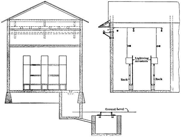
Fig. 74.—Cable Terminal House for the 25,000-volt Chambly Line at Montreal.
The saving effected in capacity of transformers and in the weight of[189]
cables by continuing the full transmission voltage right up to the sub-stations
whence distribution takes place furnishes a strong motive to
work underground cables at the pressure of the overhead transmission
line of which they form a continuation. Thus, at Hartford, the 10,000-volt
overhead lines that bring energy from water-power stations to the
outskirts of the city connect directly in terminal houses there with underground
cables that complete the transmission to the sub-station at the
full line voltage. In Springfield, Mass., the overhead transmission lines
from water-power stations connect directly with underground cables at[190]
a distance of nearly two miles from the sub-station, and these cables are
thus subject to the full line pressure of 6,000 volts. The overhead line
that brings energy at 25,000 volts from Apple River falls to St. Paul terminates
about three miles from the sub-station there, and the transmission
is completed by underground cables that carry current at the 25,000-volt
pressure.
In these and similar cases the relative advantages of underground
cables at the full voltage of transmission and of overhead lines at a much
lower pressure, in the central portions of cities, must be compared.
The overhead lines at moderate voltage will no doubt cost less in
almost every case than underground cables of equal length and at the
full transmission voltage.
As an offset to the lower cost of overhead city lines at moderate voltage,
where they are permitted by local regulations, comes the increase in
weight of conductors due to the low pressure on the overhead lines, and
also the cost of additional transformer capacity, unless the lines that
complete the transmission operate at the voltage of distribution. The
10,000-volt lines that transmit energy from Great Falls to Portland, Me.,
terminate in two transformer houses that are distant about 0.5 mile and
2.5 miles, respectively, from the sub-station there. In these transformer
houses the voltage is reduced to 2,500, and the transmission is then continued
at this pressure to the sub-station whence distribution takes place
without further transformation.
Where a river or other body of water must be crossed by a transmission
line, either of three plans may be followed. The overhead line may
be continued as such across the water, either by a single span or by two
or more spans supported by one or more piers built for that purpose in
the water. The overhead line may connect directly with a submarine
cable, this cable being thus exposed to the full voltage of the transmission.
As a third expedient, a submarine cable may be laid and connected
with step-down transformers on one bank and with step-up transformers
on the other bank of the river or other body of water to be crossed. The
overhead lines connecting with these transformers can obviously be operated
at any desired voltage, and this is also true of the cable.
Even though the distance across a body of water is not so great that
a transmission line can not be carried over it in a single span, the cost
of such a span may be large. A case in point is that of the Colgate
and Oakland line, where it crosses the Carquinez Straits by a span of
4,427 feet. These straits are about 3,200 feet wide where the transmission
line crosses, and overhead lines were required to be not less than[191]
200 feet above high water so as not to impede navigation. In order to
gain in ground elevation and thus reduce the necessary height of towers,
two points 4,427 feet apart on opposite sides of the straits were selected
for their location. Under these circumstances two steel towers, one sixty-five
feet and the other 225 feet high, were required to support the four
steel cables that act as conductors across the straits. To take the strain
of these four cables, each with a clear span nearly three times as great as
that of the Brooklyn Bridge, eight anchors with housed strain insulators
were constructed, four on the land side of each tower. On each of these
anchors the strain is said to be 24,000 pounds. At each end of the cables
making this span is a switch-house where either of the two three-phase
transmission lines may be connected to any three of the four steel cables,
thus leaving one cable free for repairs. It is not possible to state here
the relative cost of these steel towers and cables in comparison with that
of submarine cables for the same work, but at first glance the question
appears to be an open one. The voltage of 40,000, at which this transmission
is carried out, is probably higher than that on any submarine
cable in use, but it is possible that a suitable cable can be operated at
this voltage. Whatever the limitations of voltage as applied to submarine
cables, it would, of course, have been practicable to use step-up and
step-down transformers at the switch-houses and thus operate a submarine
cable at any voltage desired.
In another case, on a transmission between Portsmouth and Dover,
N. H., it was necessary to cross an arm of the sea on a line 4,811 feet
long with a three-phase circuit operating at 13,500 volts. It was decided
to avoid the use of either a great span or of raising and lowering transformers
at this crossing, and to complete the line through a submarine
cable operating at the full voltage of transmission. To this end a brick
terminal house six by eight feet inside, and with an elevation of thirteen
feet from the concrete floor to the tile roof, was erected on each bank of
the bay at the point where the submarine cable came out of the water.
The lead-covered cable pierced the foundation of each of these terminal
houses at a point four feet below the floor level and rose thence on one
wall to an elevation eleven feet above the floor to a point where connection
was made with the ends of the overhead lines. From this connection
on each of the three conductors a tap was carried to a switch and series
of lightning arresters. A single lead-covered cable containing three conductors
makes connection between these two terminal houses. At each
end of this cable the lead sheath joins a terminal bell one foot long and
2.5 inches in outside diameter, increasing to four inches at the end where[192]
the three conductors pass out. This terminal bell is filled nearly to the
flaring upper end with an insulating compound.
In the instance just named it is possible that the cost of the submarine
cable was less than would have been the outlay for shore supports
and a span nearly a mile long across this body of water.
Underground and submarine cables have been operated at voltages
suitable for transmission during periods sufficiently long to demonstrate
their general reliability. The Ferranti underground cables between
Deptford and London have regularly carried current at 11,000 volts since
a date prior to 1890. During about five years cables with an aggregate
length of sixteen miles have transmitted power from St. Anthony’s Falls
to Minneapolis. At Buffalo, some thirty miles of rubber-insulated cables
have been in use for underground work at 11,000 volts since 1897, and
eighteen miles of paper-insulated cable since the first part of 1901.
These examples are enough to show that transmission through underground
cables at 11,000 to 12,000 volts is entirely practicable. At Reading,
Pa., an underground cable one mile long has carried three-phase
current at 16,000 volts for the Oley Valley Railway since some time in
1902. The cables in the transmission from Apple River to St. Paul,
which carry three-phase current at 25,000 volts, have a total length of
three miles, and have been in use since 1900. This voltage of 25,000 is
probably the highest in regular use on any underground or submarine
cable conveying energy for light or power. From the experience thus
far gained there is much reason to think that the voltages applied to
underground cables may be very materially increased before a prohibitive
cost of insulation is reached.
On submarine cables the voltage of 13,000 in the Portsmouth and
Dover transmission, above mentioned, is perhaps as great as any in use.
It does not appear, however, that any material difference exists, as to the
strain on its insulation at a given voltage, between a cable when laid in
an underground conduit and when laid under water. In either case the
entire stress of the voltage employed operates on the insulation between
the several conductors in the cable and between each conductor and the
metallic sheath. Underground conduits have little or no value as insulators
of high voltages, because it is practically impossible to keep them
water-tight and prevent absorption or condensation of moisture therein.
For these reasons a cable that gives good results at 25,000 volts in an
underground conduit should be available for use at an equal voltage under
water. The standard structure of high-voltage cables for either underground
or submarine work includes a continuous metallic sheath outside[193]
[194]
of each conductor or of each group of conductors that goes to make up
a circuit. As most transmissions are now carried out with three-phase
current, the three conductors corresponding to a three-phase circuit are
usually contained in a single cable and covered by a single sheath. The
cables used in transmission systems at Portsmouth, Buffalo, and St. Paul
are of this type. If single-phase or two-phase current is transmitted, each
cable should contain the two conductors that go to make up a circuit.
In work with alternating currents the use of only one conductor per cable
should be avoided because of the loss of energy that results from the currents
induced in the metallic sheath of such a cable.
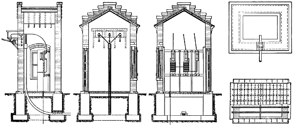
Fig. 75.—Cable Terminal House at Piscataqua River Crossing.
Where the two, three, or more conductors that form a complete circuit
for alternating current are included in a single metallic sheath, the
inductive effects of currents in the several conductors tend to neutralize
each other and the waste of energy in the sheath is in large part
avoided. To neutralize more completely the tendency to local currents
in their metal sheath, the several insulated conductors of an alternating
circuit are sometimes twisted together, after being separately insulated,
before the sheath is put on. Distribution of power at Niagara Falls
was at first carried out through single-conductor, lead-covered cables
with two-phase current at 2,200 volts. One objection to this plan
was the loss of energy by induced currents in the lead coverings of the
cables. It was later decided to adopt three-phase distribution at
10,000 volts for points distant more than two miles from the power-station.
Each three-phase circuit for this purpose was made up of three
conductors separately insulated and then covered with a single lead
sheath, so as to avoid losses through induced currents in the latter.
Underground and submarine cables for operation at high voltages are
generally covered with a continuous lead sheath and sometimes with a
spiral layer of galvanized iron wire. For high-voltage work underground
the lead covering is generally preferred without iron wire, but
in submarine work coverings of both sorts are employed. The lead
sheath of a cable being continuous completely protects the insulation
from contact with gases or liquids. As ducts of either tile, wood, or iron
form a good mechanical protection for a cable, the rather small strength
of a lead sheath is not a serious objection in conduit work. Submarine
cables, on the other hand, depend on their own outer coverings for mechanical
protection, and may be exposed to forces that would rapidly cut
through a lead sheath. Cables for operation under water should usually
be covered, therefore, with a layer of galvanized iron wires outside of
the lead sheath. These wires are laid closely about the cable in spiral[195]
form and are usually between 0.12 and 0.25 inch in diameter each, depending
on the size of the cable and its location.
Underground conduits cannot be relied on to exclude moisture and
acids of the soil from the cables which they contain, and either of these
agents may lead to destructive results. If cables insulated with rubber,
but without a protecting covering outside of it, are laid in underground
conduits, the rubber is apt to be rapidly destroyed by fluids and gases
that find their way into the conduit. If a plain lead-covered cable is
employed the acids of the soil attack it, and if stray electric currents from
an electric railway find the lead a convenient conductor it is rapidly eaten
away where they flow out of it. To avoid both of these results the underground
cable should have a lead sheath, and this sheath may be protected
by an outside layer of hemp or jute treated with asphaltum.
Rubber, paper, and cotton are extensively used as insulation for
underground and submarine cables, but the three are not usually
employed together. As a rule, the insulation is applied separately to
each conductor, and then an additional layer of insulation may be
located about the group of conductors that go to make up the cable.
Where rubber insulation is employed, a lead sheath may or may not be
added, but where insulation depends on cotton or paper the outer covering
of lead is absolutely necessary to keep out moisture. The radial
thickness of insulation on each conductor and of that about the group of
conductors in a cable should vary according to the voltage of operation.
Cables employed between the generating and sub-stations of the Manhattan
Elevated Railway, to distribute three-phase current at 11,000
volts, are of the three-conductor type, rubber insulated, lead covered,
and laid in tile conduits. Each cable contains three No. 000 stranded
conductors, and each conductor has its own insulation of rubber. Jute
is laid on to give the group of conductors an outer circular form, and outside
of the group a layer of insulation and then a lead sheath is placed.
Outside diameter of this cable is nearly three inches, and the weight nine
pounds per linear foot.
The 11,000-volt, three-phase current from Niagara Falls is distributed
from the terminal house to seven sub-stations in Buffalo through about
30 miles of rubber-insulated and 18 miles of paper-insulated, three-conductor,
lead-covered cables, all in tile conduits. In each cable the three
No. 000 stranded conductors are separately insulated and then twisted
into a rope with jute yarn laid in to give an even round surface for the
lead sheath to rest on. A part of the rubber-insulated cables have each
conductor covered with 9⁄32-inch of 30 per cent pure rubber compound,[196]
and the remaining rubber cables have 8⁄32-inch covering on each conductor
of 40 per cent pure rubber compound. The paper-insulated cable
has 13⁄64-inch of paper around each conductor, and also another 13⁄64-inch
of paper covering about the group of three conductors and next to the
lead sheath. In outside diameter the rubber-insulated cable is 23⁄8 inches,
and of the paper-insulated cable 25⁄8 inches, the radial thickness of the
lead sheath being 1⁄8-inch in each case. It is reported that the cables
insulated with 9⁄32-inch of the mixture, said to be 30 per cent pure rubber,
have proved to be more reliable than the cables insulated with 8⁄32-inch
of a mixture said to be 40 per cent pure rubber. Vol. xviii., A. I. E. E.,
136, 836.
The six miles of underground cables that carry three-phase, 25,000-volt
current in St. Paul are of the three-conductor type, lead covered, and
laid in a tile conduit. One of the two three-mile cables is insulated with
rubber and the other with paper. In the former cable each conductor
is separately insulated with a compound containing about 35 per cent of
pure rubber and having a radial thickness of 7⁄32-inch. The three conductors
after being insulated are laid up with jute to give a round surface,
tape being used to hold them together, and then a rubber cover 5⁄32-inch
thick is placed about the group, after which comes the lead sheath over
all. In the three miles of paper-insulated cable each conductor is separately
covered with paper to a thickness of 9⁄32-inch, then the three conductors
are laid together with jute and taped, and next a layer of paper
4⁄32-inch thick is put on over the group. Outside of all comes the lead
sheath, which has an outer coating of tin. The paper insulation in these
cables was saturated with a secret insulating compound. The lead
sheath on both the rubber and paper insulated cables is 1⁄8-inch thick and
the sheath of the former contains 3 per cent of tin. Each of the three
conductors in each cable consists of 7 copper strands and has an area of
66,000 circular mils. Outside of the lead sheath each of these cables
has a diameter of about 21⁄4 inches. By the manufacturer’s contract these
cables were tested up to 40,000 volts before shipment, and might be tested
up to 30,000 volts in their conduits during any time within five years from
their purchase. In first cost the cable with rubber insulation was said
to be about 50 per cent more expensive than the cable in which paper was
used. Vol. xvii., A. I. E. E., 650.
Underground cables in which the separate conductors are covered
with cotton braid treated with an insulating compound, and then the
group of conductors going to make up the cable enclosed in a lead sheath,
are extensively used in Austria and Germany. For cables that operate[197]
at 10,000 to 12,000 volts the radial thickness of cotton insulation on each
conductor is said to be within 3⁄16-inch, and these cables are tested up to
25,000 volts by placing all of the cable except its ends in water, and then
connecting one end of the 25,000-volt circuit to the water and the other
end to the conductors of the cable.
A test on the paper-insulated cable at St. Paul showed its charging
current to be 1.1 amperes at 25,000 volts for each mile of its length. For
the cable with rubber insulation the charging current per mile of length
was found to be about twice as great as the like current for the paper-insulated
cable. Each of the two overhead transmission lines connected
with these cables consisted of three solid copper wires with an area of
66,000 circular mils each, and all three so mounted on the poles as to form
the corners of an equilateral triangle twenty-four inches apart. The
charging current of one of these three-wire, overhead circuits was found
to be about 0.103 ampere per mile, at 25,000 volts, or a little less than
one-tenth of the like current for the paper cable. These tests were made
with three-phase current of sixty cycles per second.
Where overhead transmission lines join underground or submarine
cables, either with or without the intervention of transformers, lightning
arresters should be provided to intercept discharges of this sort that come
over the overhead wires. Lightning arresters were provided in the terminal
house at Buffalo, where the 22,000-volt overhead lines feed the
11,000-volt cables through transformers, also at the terminal house in
St. Paul, where the 25,000-volt overhead lines are electrically connected
to the underground cables. If an underground or submarine cable connects
two portions of an overhead line, as in the Portsmouth and Dover
transmission above mentioned, lightning arresters should be provided at
each end of the cable, as was done in that case. One advantage of a
high rather than a low voltage on underground cables, where power is
to be transmitted at any given rate, lies in the fact that the amperes flowing
at a fault in the cable determine the destructive effect there, rather
than the voltage of the transmission. It is reported that a fault or short-circuit
in one of the 11,000-volt cables at Buffalo usually melts off but
little lead at the sheath and does not have enough explosive force to
injure the cable or its duct.
Ozone seems to destroy the insulating properties of rubber very rapidly,
and as it is well known that the silent electric discharge from conductors
at high voltages develops ozone, care should be taken to protect
rubber insulation from its action. This is especially true at the ends of
cables where connections are made with switches or other apparatus, and[198]
the rubber insulation is exposed. To protect the rubber at such points
it is the practice to solder a brass cable head or terminal bell to the lead
sheath near its end, this head having a diameter perhaps twice as great
as that of the sheath, and then to fill the space about the cable conductors
in this head with an insulating compound. Heads of this sort were used
on the 11,000-volt cables at Buffalo as well as on the 13,500-volt cable in
the Portsmouth and Dover transmission.
As insulating materials, whether rubber, cotton, or paper, may be
impaired or destroyed by heat, it is necessary that the temperature of
underground cables under full load be kept within safe limits. Rubber
insulation can probably be raised to 125° or 150° Fahrenheit without
injury, and paper and cotton may go a little higher. For a given size
and make of leaded cable the rise of temperature in its conductors above
that of the surrounding air, for a given loss in watts per foot of the cable,
may be determined by computation or experiment. The next step is to
find out how much the temperature of the air in the conduits where the
cable is to be used will rise above the temperature of the earth in which
the conduits are laid, with the given watt loss per foot of cable. On this
point there are but little experimental data. Obviously, the material of
which ducts are made, the number of ducts grouped together with cables
operating at the same time, and the extent to which ducts are ventilated
must have an important bearing on this question. At Niagara Falls
some tests were made to show the rise of air temperature in a section of
thirty-six-duct conduit lying between two manholes about 140 feet apart.
For the purpose of this test twenty-four of the thirty-six ducts in the conduit
had one No. 6 drawing-in wire passed through each of them. These
twenty-four wires were connected into three groups of eight wires each,
so that one group was all in ducts next to the surrounding earth, another
group was one-half in ducts next to the earth and the other half in ducts
separated from the earth by at least one duct, while the third group of
wires was entirely in ducts separated from the earth by at least one duct.
It was found that when enough current was sent through these wires to
represent a loss of 5.5 watts per foot of ducts in which they were located,
the rise of temperature in the air of the ducts next to the earth was about
108° Fahrenheit above that of the earth. For the ducts separated from
the earth by at least one other duct the rise in temperature of contained
air was 144° Fahrenheit above the earth. If the earth about the ducts
reached 70° in hot weather, the temperature of air in the inner
ducts, with a loss of 5.5 watts per duct foot, would thus be 214°.
This temperature is too high for either rubber, cotton, or paper insulation,[199]
to say nothing of the amount by which the temperature of the conductors
and insulation of a cable in operation must exceed that of the
surrounding air in its duct. The cables actually installed in the ducts
just considered were designed for a loss of 2.34 watts per foot. As the
No. 6 wire used in the test did not nearly fill each duct as a cable would
do, it would be very interesting to know how much ventilation took place
while the test was going on. Unfortunately, this point was not reported.
Vol. xviii., A. I. E. E., 508.
[200]
CHAPTER XV.
MATERIALS FOR LINE CONDUCTORS.
Copper, aluminum, iron, and bronze are all used for conductors in
long-distance electric transmissions, but copper is the standard metal for
the purpose. An ideal conductor for transmission lines should combine
the best electrical conductivity, great tensile strength, a high melting
point, low coefficient of expansion, hardness, and great resistance to oxidation.
No one of the metals named possesses all of these properties in
the highest degree, and the problem is to select the material best suited
to each case. Aluminum suffers very slightly by exposure to the weather,
copper and bronze suffer a little more, while iron and steel wire are attacked
seriously by rust.
Iron, copper, and bronze are all so hard that little or no trouble has
occurred from wires of these metals cutting or wearing away at the points
of attachment to insulators. Aluminum, on the other hand, is so soft
that swaying of the wire may, in time, cause material wear at the supports,
or it may be cut by tie wires. But lines of aluminum wire have not been
in use long enough to determine how much trouble is to be expected from
its lack of hardness.
A small coefficient of expansion is desirable in transmission wires,
because the strain on the wire itself and on its supports varies rapidly
with the amount of vertical deflection of each span, becoming greater as
the deflection decreases. Taking the expansion of copper as unity,
that of aluminum is 1.4; of bronze, 1.1; and of iron and steel, 0.7.
From these figures it follows that iron and steel wires show the least
variation in the amount of sag between supports, and aluminum wire
shows the most.
Wrought iron melts at about 2,800°, steel at 2,700°, copper at 1,929°,
bronze at about the same point as copper, and aluminum at 1,157° Fahrenheit.
This low melting point of aluminum may prove a source of
trouble by opening a line of that material where some foreign wire falls
on it. This, according to a report, was illustrated at a sub-station on a
30,000-volt transmission line where a destructive arc was started at the
switchboard. Not being able to extinguish the arc in any other way, a[201]
lineman threw an iron wire across the aluminum lines just outside of the
sub-station, and these lines were immediately melted through by the iron
wire, thus opening the circuit. The trouble may have warranted so desperate
a remedy in this case; but, as a rule, it does not pay to cut a transmission
line in order to get rid of a short circuit.
In the ordinary construction of transmission lines on land the tensile
strength of wire is secondary in importance to its electrical conductivity,
because supports can be spaced according to the strength of the conductor
used. When large bodies of water must be crossed, tensile strength is a
prime requirement. Thus a 142-mile line from Colgate to Oakland, in
California, crosses the Straits of Carquinez in the form of steel cables,
each seven-eighths of an inch in diameter and 4,427 feet long. Steel wire
was selected for this long span, probably because it can be given a greater
tensile strength than that of any other metal. Annealed iron wire has a
tensile strength between 50,000 and 60,000 pounds per square inch.
Steel wires vary all the way from 50,000 to more than 350,000 pounds per
square inch in strength, but mild steel wire with a strength ranging from
80,000 to 100,000 pounds per square inch is readily obtained.
Soft copper shows a tensile strength between 32,000 and 36,000
pounds per square inch, and hard-drawn copper between 45,000 and
70,000 pounds, depending on the degree of hardness. Silicon-bronze
wires vary in strength from less than 60,000 to more than 100,000 pounds
per square inch, and phosphor-bronze has a tensile strength of about
100,000 pounds. Bronze wires, like those of most alloys, show a much
wider range of strength than those of iron or copper.
In silicon-bronze wire the electrical conductivity decreases as the
tensile strength increases. The tensile strength of aluminum wire is
lower than that of any other used in transmission lines, being only about
30,000 pounds per square inch. Solid aluminum wires of large size have
given trouble by breaking under strains well within their nominal
strength, due probably to imperfections or twists. This trouble is now
generally avoided by the use of aluminum cables.
In that most necessary property of a transmission line—conductivity—copper
excels all other metals except silver. Taking the conductivity
of soft copper wire at 100, the conductivity of hard-drawn copper is 98;
that of silicon-bronze ranges from 46 to 98; that of aluminum is 60; of
phosphor-bronze, 26; of annealed iron wire, 14; and of steel wire of
100,000 pounds tensile strength per square inch, 11. Copper wire, both
soft and hard, as regularly made, does not vary more than one per cent
from the standard, and aluminum and annealed iron wires also show[202]
high uniformity as to resistance. Silicon-bronze and steel wires, on the
other hand, fluctuate much in electrical conductivity. For any particular
transmission line the resistance is usually determined by considerations
apart from the metal to be used as a conductor, so that a line of given
resistance or conductivity must be constructed of that material which best
conforms to the requirements as to size of wire, weight, strength, and
cost.
Allowing the weight of any definite mass of copper to represent unity,
the weight of an equal mass of wrought iron is 0.87; of steel, 0.89; of
aluminum, 0.30; while that of bronze is very nearly equal to that of the
copper. The smallest line wire that can be used for a given length and
resistance is one of pure, soft copper. Next in cross-sectional area come
hard-drawn copper and some silicon-bronze, either of which need be
only two per cent larger than the soft copper for an equal resistance.
Some other silicon-bronze wire of greater tensile strength per square inch
would require a sectional area of 2.17 times that of the soft copper.
Aluminum wire with 60 per cent of the conductivity of copper requires
1.66 of its section for wires of equal resistance. As phosphor-bronze
has only 26 per cent of the conductivity of copper, the section of
the bronze must be 3.84 times that of the copper wire if their lengths and
resistance are to be equal. An annealed iron wire is equal in resistance
to a copper wire of the same length when the iron has 7.14 times the section
of the copper. Steel, with 11 per cent of the conductivity of copper,
must have 9.09 times the copper section in order that wires of the same
length may have equal resistances.
It is not desirable to use a copper wire smaller than No. 4 B. & S.
gauge for transmission lines, because of the lack of tensile strength in
smaller sizes. When the conductivity of a copper wire smaller than No.
4 is ample, an iron wire will give the required conductivity, with a strength
far greater than that of the copper. For a line of given length and conductivity
of any other metal the weight compared with that of a copper
line is represented by the product of the figures for relative section of
the two lines and of the weight of unit mass of the metal in question compared
with that of copper.
Thus, for the same conductivity the weight of a certain length of iron
wire is 0.87 × 7.14 = 6.21 times the weight of a copper wire. For the
steel wire above named the weight is 0.89 × 9.09 = 8.09 times that of
a copper line of equal conductivity. Phosphor-bronze in a line of given
length and resistance has 3.84 times the weight of soft copper. Silicon-bronze
for a transmission line must weigh from 1.02 to 2.17 times as[203]
much as soft copper for a given length and conductivity. Aluminum
for a line of fixed length and conductivity will weigh 1.66 × 0.3 = 0.5
times as much as copper. For a line of fixed length and resistance,
hard-drawn copper will weigh about two per cent more than soft
copper.
Taking the tensile strength of soft copper at 34,000 pounds per square
inch, hard-drawn copper at 45,000 to 70,000, silicon-bronze at 60,000 to
100,000, phosphor-bronze at 100,000, iron at 55,000, steel at 100,000, and
aluminum at 30,000 pounds, the relative strengths of wires with equal
sectional areas compared with the soft copper are, for hard-drawn copper,
1.32 to 2.06; silicon-bronze, 1.76 to 2.94; phosphor-bronze, 2.94;
iron, 1.62; steel, 2.94; and for aluminum, 0.88.
Comparing wires on the basis of equal resistances for equal lengths,
with soft copper again the standard, the tensile strength of each as to it
is as follows: A hard-drawn copper line has 1.02 × 1.32 = 1.34 to
1.02 × 2.06 = 2.10 times the strength of a line of soft copper. With
silicon-bronze the strength of line wire would range between 1.02 ×
1.76 = 1.79 and 2.17 × 2.94 = 6.38 times that of copper. Iron would
give the line a strength as to soft copper represented by 7.14 × 1.62 =
11.56. Steel of 100,000 pounds tensile strength per square inch will
give a line 9.09 × 2.94 = 26.70 times as strong as it would be if composed
of soft copper. With aluminum the strength of the line would be
1.66 × 0.88 = 1.46 times that of copper. For phosphor-bronze the figures
are 3.84 × 2.94 = 11.29.
From the foregoing it may be shown how many times the price of
soft copper per pound may be paid for each of the other metals to form
a line of given length and resistance at a cost equal to that of a soft copper
line. These prices per pound for the several metals relative to that
of soft copper are as follows: Taking the price of soft copper as one, the
price for hard-drawn copper must be 1 ÷ 1.02 = 0.98. For silicon-bronze
the price may be as high as 1 ÷ 1.02 = 0.98, or as low as 1 ÷
2.17 = 0.46 of the price of soft copper wire. Phosphor-bronze may
have a price represented by only 1 ÷ 3.84 = 0.26 that of copper. The
price of iron wire should be 1 ÷ 6.21 = 0.16 of that of copper, and for
steel wire of the quality stated the price can only be 1 ÷ 8.01 = 0.12.
Aluminum wire alone may have a higher price per pound than soft copper
for the same resistance and cost of line, the figure for the relative
cost of this metal being 1 ÷ 0.5 = 2.
From the foregoing it appears that for a line of given cost, length,
and resistance, soft copper has the least cross-section and tensile strength;[204]
steel, the greatest cross-section, weight, tensile strength, and lowest permissible
price per pound; and aluminum, the least weight and highest
price per pound.
Relative Properties of Wires
Having Equal Lengths and Resistances.
| Metal in Wire. |
Relative
Cross
Sections. |
Relative
Weights. |
Relative
Tensile
Strengths. |
Relative
Prices
per Pound
for Same
Total
Cost. |
| Soft Copper |
1.00 |
1 |
.00 |
1 |
. |
1 |
.00 |
| Hard Copper |
1.02 |
1 |
.04 |
1 |
.34 |
|
.98 |
| Very Hard Copper |
1.02 |
1 |
.02 |
2 |
.10 |
|
.98 |
| No. 1 Silicon-Bronze |
1.02 |
1 |
.02 |
1 |
.79 |
|
.98 |
| No. 2 Silicon-Bronze |
2.17 |
2 |
.17 |
6 |
.38 |
|
.46 |
| Aluminum |
1.66 |
|
.50 |
1 |
.46 |
2 |
.00 |
| Phosphor-Bronze |
3.84 |
3 |
.84 |
11 |
.29 |
|
.26 |
| Annealed Iron |
7.14 |
6 |
.21 |
11 |
.56 |
|
.16 |
| Mild Steel |
9.09 |
8 |
.09 |
26 |
.70 |
|
.12 |
The relative cross sections and weights of both iron and steel wires
are so great as to prevent their general use because of the labor and cost
of their erection.
So far as the first cost of the wire alone is concerned, iron may be
approximately equal to copper in some metal markets. The only practical
place for an iron wire, however, is one where copper would be too
small or not strong enough. Steel wire finds a place, in spite of its high
resistance, in those exceptional cases where a single span of several thousand
feet must be made, requiring high tensile strength. In such cases
it is usually better to give the steel span a greater resistance than an equal
length of the main portion of the line, so as to avoid excessive size and
weight of the span. Even when this is done the resistance of the steel
span would be very small compared with that of a long transmission
line.
Phosphor-bronze finds little use as conductors in transmission systems
because of its relatively high electrical resistance. If great tensile
strength is wanted, iron or steel will supply it at a fraction of the cost of
phosphor-bronze. As a conductor simply, phosphor-bronze is worth only
0.26 as much per pound as soft copper, while its actual market price is
greater than that of copper.
Silicon-bronze of relatively high resistance, requiring 2.17 times the
section and weight of copper for equal conductivity, is entitled to little[205]
or no consideration as a transmission line material. This alloy, in order
to give equal conductivity at equal cost with copper, must sell at only
0.46 of the price of copper per pound. But the price of silicon-bronze
is equal to, or greater than, the price of copper, so that the cost of the
high-resistance silicon-bronze for a line of given resistance will be more
than twice that of copper. For this more than double cost the bronze
gives 6.38 times the tensile strength of a soft copper line of equal conductivity.
Taking the market price of steel at one-fifth that of copper, which
is amply high for the steel, as a rule, a steel wire of equal conductivity
with the copper will cost only 1.6 times as much and will have 26.7
times the tensile strength of the copper, or four times the tensile strength
of a wire of equal conductivity made from the high-resistance silicon-bronze.
From this it is clear that steel offers a cheaper combination of
conductivity and strength than does silicon-bronze of high resistance.
That grade of silicon-bronze having the lowest resistance may cost 0.98
as much per pound as soft copper, and will have 1.79 times the strength
of the copper for equal conductivity. This bronze actually costs more
per pound than copper, so that it cannot give equal conductivity at equal
cost.
Very hard-drawn copper has a conductivity equal to that of the best
silicon-bronze, and the tensile strength of this copper is seventeen per
cent greater than that of the bronze. Silicon-bronze costs more per
pound than hard copper, but even with equal prices the hard copper
gives equal conductivity and higher strength at the same cost. Furthermore,
the conductivity of silicon-bronze is much more liable to serious
variations than that of hard copper. Between hard-drawn copper and
steel there is very little apparent place for any grade of bronze in electric
transmission lines.
The hardest copper wire is very stiff, and is more liable to crack
when twisted or bent than is wire of only medium hardness. Such medium-hard
copper has a tensile strength of thirty-four per cent greater
than soft copper of equal conductivity, and is much used on long transmission
lines. Aluminum is the only metal which, for given conductivity
in a transmission line, combines a smaller weight, a greater tensile
strength, and a higher permissible price than soft copper for the same
total cost. For equal conductivity an aluminum wire has a greater tensile
strength than one of medium-hard copper, and costs less than copper
of any grade when the price per pound of the aluminum is less than
twice that of copper, which is usually the case.
[206]
These properties make aluminum by far the most important competitor
of copper in electric transmission and have led to its use in a number
of cases, notably for the two longest lines in the world, namely,
between Colgate and Oakland and between Electra and San Francisco,
in California.
It has not been found practicable to solder joints in aluminum wires
because of the resulting electrolytic action when aluminum is in contact
with other metals. Joints of aluminum wires are usually made by slipping
the ends past each other in an oval aluminum sleeve and then giving
the sleeve and wires two or three complete twists, or by a process of cold
welding with a sleeve joint.
Long transmission lines are in nearly all cases run with bare wire
supported by poles. Where very high voltages are employed no insulation
that can be put on the wire will make it safe to handle, and the cost
of such insulation would add materially to that of the entire line. It is,
therefore, the practice to run transmission lines above all other wires
and to rely entirely on the supports for insulation.
The considerations thus far noted apply alike to wires carrying continuous
and alternating currents, but there are some other factors that
apply solely to alternating lines. Owing to the inductive effects of alternating
currents in long, parallel wires, such wires should be transposed
between their supports at frequent intervals. The induction between
wires increases with the frequency of the current carried, and decreases
with the distance between the wires. According to these conditions,
wires should be transposed as often as every eighth of a mile in some
cases, and at intervals of one mile or more in others.
An alternating current when passing along a line tends to concentrate
itself in the outer layers of the wire, leaving the centre idle. This unequal
current distribution increases with the frequency of the current and with
the area of the cross section of the wire. The practical effect of this unequal
distribution is to make the resistance of a wire a little higher for
alternating than for continuous currents. In existing transmission lines
the increase of resistance due to this cause seldom amounts to one per
cent.
When an alternating current passes through a circuit, the action
termed self-induction sets up an electromotive force in the circuit that
opposes the flow of current, as does the resistance of the wire, and this
is called the inductance of the circuit. The ratio of this inductance to
the resistance of a circuit increases with the number of periods per second
of the alternating current used and with the sectional area of the wires[207]
composing the circuit. For a circuit of No. 6 B. & S. gauge wire the
inductance amounts to only five per cent of the line resistance, but for
a circuit of No. 000 wire the inductance consumes as much of the applied
voltage as does the resistance, with 60-cycle current.
Both the unequal distribution of alternating current over the cross-section
of a conductor and the inductance of circuits make it desirable to
keep the diameters of transmission wires as small as other considerations
permit. As soft copper has greater conductivity per unit of area than
any of the other available metals, it clearly has an advantage over all of
them as to inductance and increase of resistance with alternating current.
At very high voltages there is an important leakage of energy between
the conductors of a circuit, and this loss varies inversely with the distance
between these conductors. Thus it happens that inductance
makes it desirable to bring the parallel wires of a circuit close together,
while the leakage of energy from wire to wire makes it desirable to carry
them far apart.
To provide greater security from interruption, the conductors for
important transmissions are in some cases carried on two independent
pole lines. Even where all the conductors are on a single line of poles
it is frequent practice to divide them up into a number of comparatively
small wires, and this decreases inductance.
Data of a number of transmission lines presented in the appended
table illustrate the practice in some of the more recent and important
cases as to the materials, size, number, and arrangement of the
wires. The plants of which particulars are given include the greatest
power capacities, the longest distances, and the highest voltages now
involved in electrical transmissions. Each of the lines named is worked
with alternating current of two- or three-phase. Each three-phase line
must have at least three wires, and each two-phase line usually has four
wires.
On ten of the lines the number of wires is greater than three or four,
thus reducing the necessary size of each wire for a given conductivity of
the line. The Butte, Oakland, and Hamilton lines are run on two sets
of poles for greater security, and a second pole line has been added to
the Niagara and Buffalo system to carry additional wires.
The largest wire used in any of these lines is the aluminum cable of
500,000 circular mils between Niagara Falls and Buffalo. This cable
has 1.66 times the area in cross section of a copper cable of equal conductivity.
[208]
Sizes and Materials of Wires on Some American Transmission Lines.
| Location of Transmission. |
Line
Voltage. |
Num-
ber
Wires. |
Size of
Each Wire
B. & S.
Gauge. |
Metal
in
Wire. |
Length
of
Trans-
mission.
Miles. |
| Cañon Ferry to Butte |
50,000 |
6 |
0 |
Copper |
65 |
|
| Colgate to Oakland |
40,000 |
3 |
00 |
Copper |
142 |
|
| |
3 |
000 |
Aluminum |
142 |
|
| Electra to San Francisco |
40,000 |
3 |
471,034 C. M. |
„ |
147 |
|
| Santa Ana R. to Los Angeles |
33,000 |
6 |
1 |
Copper |
83 |
|
| Apple River to St. Paul |
25,000 |
6 |
2 |
„ |
25 |
|
| Welland Canal to Hamilton |
22,500 |
3 |
1 |
„ |
35 |
|
| |
3 |
00 |
„ |
37 |
|
| Cañon City to Cripple Creek |
20,000 |
3 |
3 |
„ |
23 |
1⁄2 |
| Madrid to Bland |
20,000 |
6 |
4 |
„ |
32 |
|
| White River to Dales |
22,000 |
3 |
6 |
„ |
27 |
|
| Ogden to Salt Lake City |
16,000 |
6 |
1 |
„ |
36 |
1⁄2 |
| San Gabriel Cañon to Los Angeles |
16,000 |
6 |
5 |
„ |
23 |
|
| To Victor, Col |
12,600 |
3 |
4 |
„ |
8 |
|
| Niagara Falls to Buffalo |
22,000 |
6 |
350,000 C. M. |
„ |
23 |
|
| Nia„ara Fa„s to Bu„ |
22,000 |
3 |
500,000 C. M. |
Aluminum |
20 |
|
| Yadkin River to Salem |
12,000 |
3 |
1 |
Copper |
14 |
.5 |
| Farmington Riv’r to Hartford |
10,000 |
3 |
336,420 C. M. |
Aluminum |
11 |
|
| Wilbraham to Ludlow Mills |
11,500 |
6 |
135,247 C. M. |
„ |
4 |
.5 |
| Niagara Falls to Toronto |
60,000 |
6 |
190,000 C. M. |
Copper |
75 |
|
Aluminum lines are now employed for the three longest electrical
transmissions in North America. In the longest single line, that from
Electra power-house to San Francisco, a distance of 147 miles, aluminum
is the conductor used. The 142-mile transmission between Colgate
and Oakland is carried out with three aluminum and three copper line
wires. For the third transmission in point of length, that from Shawinigan
Falls to Montreal, a distance of 85 miles, three aluminum conductors
are employed.
The three transmissions just named have unusually large capacities
as well as superlative lengths, the generators in the Electra plant being
rated at 10,000, in the Colgate plant at 11,250, and in the Shawinigan
plant at 7,500 kilowatts. Weight and cost of such lines are very large.
For the three No. 0000 aluminum conductors, 142 miles each in length,
between Colgate and Oakland, the total weight must be about 440,067
pounds, costing $132,020 at 30 cents per pound. Between Electra and
Mission San José, where the line branches, is 100 miles of the 147-mile
transmission from Electra to San Francisco. On the Electra and Mission[209]
San José section the aluminum conductors comprise three stranded
cables of 471,034 circular mils each in sectional area and with a total
weight of about 721,200 pounds. This section alone of the line in question
would have cost $216,360 at 30 cents per pound. The 85-mile
aluminum line from Shawinigan Falls to Montreal is made up of three-stranded
conductors each with a sectional area of 183,708 circular mils.
All three conductors have a combined weight of about 225,300 pounds,
and at 30 cents per pound would have cost $67,590.
Aluminum lines are not confined to new transmissions, but are also
found in additions to those where copper conductors were at first used.
Thus, the third transmission circuit between the power-house at Niagara
Falls and the terminal house in Buffalo, a distance of 20 miles by the
new pole line, was formed of three aluminum cables each with an area
of 500,000 circular mils, though the six conductors of the two previous
circuits were each 350,000 circular mils copper.
From these examples it may be seen that copper has lost its former
place as the only conductor to be seriously considered for transmission
circuits. Aluminum has not only disputed this claim for copper, but has
actually gained the most conspicuous place in long transmission lines.
This victory of aluminum has been won in hard competition. The
decisive factor has been that of cost for a circuit of given length and
resistance.
From the standpoint of cross-sectional area aluminum is inferior to
copper as an electrical conductor. Comparing wires of equal sizes and
lengths, the aluminum have only sixty per cent of the conductivity of the
copper, so that an aluminum wire must have 1.66 times the sectional area
of a copper wire of the same length in order to offer an equal electrical
resistance. As round wires vary in sectional areas with the squares
of their diameters, an aluminum wire must have a diameter 1.28 times
that of a copper wire of equal length in order to offer the same conductivity.
The inferiority of aluminum as an electrical conductor in terms of
sectional area is more than offset by its superiority over copper in terms
of weight. One pound of aluminum drawn into a wire of any length
will have a sectional area 3.33 times as great as one pound of copper in
a wire of equal length. This follows from the fact that the weight of
copper is 555 pounds while that of aluminum is only 167 pounds per
cubic foot, so that for equal weights the bulk of the latter is 3.33 times
that of the former metal. As the aluminum wire has equal length with
and 3.33 times the sectional area of the copper wire of the same weight,[210]
the electrical conductivity of the former is 3.33 ÷ 1.66 = 2 times that
of the latter. Hence, for equal resistances, the weight of an aluminum
is only one-half as great as that of a copper wire of the same length.
From this fact it is evident that when the price per pound of aluminum
is anything less than twice the price of copper, the former is the cheaper
metal for a transmission line of any required length and electrical resistance.
The tensile strength of both soft copper and of aluminum wire is
about 33,000 pounds per square inch of section. For wires of equal
length and resistance the aluminum is therefore sixty-six per cent
stronger because its area is sixty-six per cent greater than that of a soft
copper wire. Medium hard-drawn copper wire such as is most commonly
used for transmission lines has a tensile strength of about 45,000
pounds per square inch, but even compared with this grade of copper
the aluminum wire of equal length and resistance has the advantage in
tensile strength. While the aluminum line is thus stronger than an
equivalent one of copper, the weight of the former is only one-half that
of the latter, so that the distance between poles may be increased, or the
sizes of poles, cross-arms, and pins decreased with aluminum wires. In
one respect the strain on poles that carry aluminum may be greater than
that on poles with equivalent copper lines, namely, in that of wind pressure.
A wind that blows in a direction other than parallel with a
transmission line tends to break the poles at the ground and prostrate
the line in a direction at right angles to its course. The total wind
pressure in any case is obviously proportional to the extent of the surface
on which it acts, and this surface is measured by one-half of the external
area of all the poles and wires in a given length of line. As the aluminum
wire must have a diameter twenty-eight per cent greater than that of
copper wire of equal length, one-half of the total wire surface will also
be twenty-eight per cent greater for the former metal. This carries with
it an increase of twenty-eight per cent in that portion of the wind pressure
due to wire surface. In good practice the number of transmission wires
per pole line is often only three, and seldom more than six, so that the surface
areas of these wires may be no greater than that of the poles. It follows
that the increase of twenty-eight per cent in the surface of wires may
correspond to a much smaller percentage of increase for the entire area
exposed to wind pressure. Such small difference as exists between the
total wind pressures on aluminum and copper lines of equal conductivity
is of slight importance in view of the general practice by which some
straight as well as the curved portions of transmission lines are[211]
now secured by guys or struts at right angles to the direction of the
wires.
Vibration of transmission lines and the consequent tendency of cross-arms,
pins, insulators, and of the wires to work loose is less with aluminum
than with copper conductors as ordinarily strung, because of
the greater sag between poles given the former and also probably because
of their smaller weight. An illustration of this sort may be seen
on the old and new transmission lines between Niagara Falls and Buffalo.
The two old copper circuits consist of six cables of 350,000 circular
mils section each on one line of poles, and are strung with only a moderate
sag. In a strong wind these copper conductors swing and vibrate in
such a way that their poles, pins, and cross-arms are thrown into a vibration
that tend to work all attachments loose. The new circuit consists
of three 500,000 circular mil aluminum conductors on a separate pole
line strung with a large sag between poles, and these conductors take
positions in planes at large angles with the vertical in a strong wind,
but cause little or no vibration of their supports. One reason for the
greater sag of the aluminum over that of the copper conductors in this
case is the fact that the poles carrying the former are 140 feet apart while
the distance between the poles for the latter is only seventy feet, on
straight sections of the line.
The necessity for greater sag in aluminum than in copper conductors,
even where the span lengths are equal, arises from the greater coefficient
of expansion possessed by the former metal. Between 32° and 212°
Fahrenheit aluminum expands about 0.0022, and copper 0.0016 of its
length, so that the change in length is 40 per cent greater in the former
than in the latter metal. The conductors in any case must have enough
sag between poles to provide for contraction in the coldest weather, and
it follows that the necessary sag of aluminum wires will be greater than
that of copper at ordinary temperature.
In pure air aluminum is even more free from oxidation than copper,
but where exposed to the fumes of chemical works, to chlorine compounds,
or to fatty acids the metal is rapidly attacked. For this reason
aluminum conductors should have a water-proof covering where exposed
to any of these chemicals. The aluminum line between Niagara Falls
and Buffalo is bare for most of its length, but in the vicinity of the large
chemical works at the former place the wires are covered with a braid
treated with asphaltum. Aluminum alloyed with sodium, its most common
impurity, is quickly corroded in moist air, and should be carefully
avoided. All of the properties of aluminum here mentioned relate to the[212]
pure metal unless otherwise stated, and its alloys should not, as a rule, be
considered for transmission lines. As aluminum is electropositive to
most other metals the soldering of its joints is quite sure to result in electrolytic
corrosion, unless the joints are thoroughly protected from moisture,
a result that is hard to attain with bare wires. The regular practice
is to avoid the use of solder and rely on mechanical joints. A good joint
may be made by slipping the roughened ends of wires to be connected
through an aluminum tube of oval section, so that one wire sticks out at
each end, then twisting the tube and wires and giving each of the latter
a turn about the other. Aluminum may be welded electrically and also
by hammering at a certain temperature, but these processes are not convenient
for line construction. Especial care is necessary to avoid scarring
or cutting into aluminum wires, as may be done when they are tied
to their insulators. Aluminum tie wires should be used exclusively. To
avoid the greater danger of damage to solid wires and also to obtain
greater strength and flexibility, aluminum conductors are most frequently
used in the form of cables. The sizes of wires that go to make
up these cables commonly range from No. 6 to 9 B. & S. gauge for widely
different cable sections. Thus the 183,708 circular mil aluminum cable
between Shawinigan Falls and Montreal is made up of seven No. 6
wires, and the 471,034 circular mil cable between Electra and Mission
San José contains thirty-seven No. 9 wires. From the Farmington River
to Hartford each 336,420 circular mils cable has exceptionally large
strands of approximately No. 3 wire. It appears from the description
of a 43-mile line in California (vol. xvii., A. I. E. E., p. 345) that a solid
aluminum wire of 294 mils diameter, or No. 1 B. & S. gauge, can be used
without trouble from breaks. This wire was tested and its properties
reported as follows:
- Diameter, 293.9 mils.
- Pounds per mile, 419.4.
- Resistance per mil foot, 17.6 ohms at 25° C.
- Resistance per mile at 25° C., 1.00773 ohms.
- Conductivity as to copper of same size, 59.9 per cent.
- Number of twists in six inches for fracture, 17.9.
- Tensile strength per square inch, 32,898 pounds.
This wire also stood the test of wrapping six times about its own
diameter and then unwrapping and wrapping again. It was found in
tests for tensile strength that the wire in question took a permanent set
at very small loads, but that at points between 14,000 and 17,000 pounds
per square inch the permanent set began to increase very rapidly. From
this it appears that aluminum wires and cables should be given enough[213]
sag between poles so that in the coldest weather the strains on them shall
not exceed about 15,000 pounds per square inch. This rather low safe
working load is a disadvantage that aluminum shares with copper.
From the figures just given it is evident that the strains on aluminum
conductors during their erection should not exceed one-half of the ultimate
strength in any case, lest their sectional areas be reduced.
Aluminum Cables in Transmission Systems.
| Locations. |
Number
of
Cables. |
Miles
of
Each. |
Circular
Mils
of Each. |
Strands
per
Cable. |
Size of
Strands.
B. & S. G.
Approx-
imate. |
| Niagara Falls to Buffalo |
3 |
20 |
|
500,000 |
.. |
.. |
| Shawinigan Falls to Montreal |
3 |
85 |
|
183,708 |
7 |
6 |
| Electra to Mission San José |
3 |
100 |
|
471,034 |
37 |
9 |
| Colgate to Oakland |
3 |
144 |
|
211,000 |
7 |
5-6 |
| Farmington River to Hartford |
3 |
11 |
|
336,420 |
7 |
3 |
| Lewiston, Me. |
3 |
3 |
.5 |
144,688 |
7 |
8 |
| Ludlow, Mass. |
6 |
4 |
.5 |
135,247 |
7 |
7 |
This table of transmission systems using aluminum conductors is far
from exhaustive. Aluminum is also being used to distribute energy to
the sub-stations of long electric railways, as on the Aurora and Chicago
which connects cities about forty miles apart. The lower cost of aluminum
conductors is also leading to their adoption instead of copper in
city distribution of light and power. Thus at Manchester, N. H., the
local electric lines include about four miles each of 500,000 and 750,000
circular mil aluminum cable with weather-proof insulation. The larger
of these cables contains thirty-seven strands of about No. 7 wire.
As may be seen from the foregoing facts, the choice of copper or
aluminum for a transmission line should turn mainly on the cost of conductors
of the required length and resistance in each metal. So nearly
balanced are the mechanical and electrical properties of the two metals
that not more than a very small premium should be paid for the privilege
of using copper. As already pointed out, the costs of aluminum and
copper conductors of given length and resistance are equal when the price
per pound of aluminum wire is twice that of copper. During most of the
time for several years the price of aluminum has been well below double
the copper figures, and the advantage has been with aluminum conductors.
With the two metals at the same price per pound aluminum would[214]
cost only one-half as much as equivalent copper conductors. When the
price of aluminum is fifty per cent greater per pound than that of copper,
the use of the former metal effects a saving of twenty-five per cent. For
the new Niagara and Buffalo line, completed early in 1901, aluminum
was selected because it effected a saving of about twelve per cent over
the cost of copper. All of the aluminum lines here mentioned, except
the short one near Hartford, were completed during or since 1900. Most
of the facts here stated as to the line between Niagara Falls and Buffalo
are drawn from vol. xviii., A. I. E. E., at pages 520 and 521.
The greater diameter of aluminum over equivalent copper conductors
has advantages in transmission with alternating current at very high
voltages. At high voltages, say of 40,000 or more, the constant silent
loss of energy from one conductor to another of the same circuit through
the air tends to become large and even prohibitive in amount. This loss
is greater, other factors being constant, the smaller the diameter of the
conductors in the line. It follows that this loss is more serious the
smaller the power to be transmitted, because the smaller the diameter of
the line wires. The silent passage of energy from wire to wire increases
directly with the length of line and thus operates as a limit to long
transmissions.
[215]
CHAPTER XVI.
VOLTAGE AND LOSSES ON TRANSMISSION LINES.
The voltage on a transmission line may be anything up to at least
60,000, and the weight of conductors varies inversely with the square of
the figures selected, the power, length and loss being constant. Whatever
the total line pressure, the weight of conductors varies inversely
with the percentage of loss therein.
The case of maximum loss and minimum weight of conductors is that
in which all of the transmitted energy is expended in heating the line
wires. Such a case would never occur in practice, because the object of
power transmission is to perform some useful work.
Minimum loss is theoretically zero, and the corresponding weight
of conductors is infinite, but these conditions obviously cannot be
attained in practice. Between these extremes of minimum and of infinite
weights of conductors comes every practical transmission with a
line loss greater than zero and less than 100 per cent.
To determine the weight and allowable cost of conductors, the cost
of the energy that will be annually lost in them enters as one of the factors.
At this point the distinction between the percentage of power
lost at maximum load and the percentage of total energy lost should
come into view.
Line loss ordinarily refers to the percentage of total power consumed
in the conductors at maximum load. This percentage would correspond
with that of total energy lost if the line current and voltage were constant
during all periods of operation, but this is far from the case.
A system of transmission may operate with either constant volts or
constant amperes on the line conductors, but in a practical case constancy
of both these factors is seldom or never to be had. This is because
the product of the line volts and amperes represents accurately in a continuous-current
system, and approximately in an alternating-current system,
the amount of power transmitted. In an actual transmission system,
the load—that is, the demand for power—is subject to more or less
variation at different times of the day, and the line volts or amperes, or
both, must vary with it.
[216]
If the transmission system is devoted to the operation of one or more
factories the required power may not vary more than twenty-five per cent
during the hours of daily use; but if a system of general electrical supply
is to be operated, the maximum load will usually be somewhere between
twice and four times as great as the average load for each twenty-four
hours. Such fluctuating loads imply corresponding changes in the volts
or amperes of the transmission line.
A number of rather long transmissions is carried out in Europe
with continuous, constant current, and in such systems the line voltage
varies directly with the load. As the loss of power in an electrical
conductor depends entirely on its ohms of resistance, which are constant
at any given temperature, and on the amperes of current passing through
it, the line loss in a constant-current system does not change during the
period of operation, no matter how great may be its changes of
load. For this reason the percentage of power loss in the line at maximum
load is usually smaller than the percentage of energy loss for an
entire day.
If, for example, the constant-current transmission line is designed to
convert into heat 5 per cent of the maximum amount of energy that will
be delivered to it per second—that is, to lose 5 per cent of its power at
maximum load—then, when the power which the line receives drops to
one-half of its maximum, the percentage of loss will rise to 10, because
0.05 ÷ 0.5 = 0.1. So again, when the power sent through the line falls
to one-quarter of the full amount, the line loss will rise to 0.05 ÷ 0.25
= 0.2, or 20 per cent.
From these facts it is clear that a fair all-day efficiency for a constant-current
transmission line can be obtained only in conjunction with a
high efficiency at maximum load, if widely varying loads are to be operated.
It does not necessarily follow from these facts as to losses in constant-current
lines that such losses should always be small at maximum
loads, for if a large loss may be permitted at full load a still greater
percentage of loss at partial loads may not imply bad engineering.
In a large percentage of electric water-power plants some water goes
over the dam during those hours of the day when loads are light, the storage
capacity above the dam not being sufficient to hold all of the surplus
water during most seasons of the year. If, therefore, the line loss in a
constant-current transmission, where all of the daily flow of water cannot
be used, is not great enough to reduce the maximum load that would
otherwise be carried, then the fact that the percentage of line loss at
small loads is still larger is not very important.
[217]
Obviously, it makes little difference whether water goes over a dam
or through wheels to make up for a loss in the line. In a case where all
the water can be stored during small loads and used during heavy loads,
it is clearly desirable to keep the loss in a constant-current line down to a
rather low figure, say not more than five per cent, at maximum load.
Much the greater number of electrical transmissions are carried out
with nearly constant line voltage, mostly alternating, and the line current
in such cases varies directly with the power transmitted, except as
to certain results of inductance on alternating lines. As line resistance
is constant, save for slight variations due to temperature, the rate of
energy loss on a constant-pressure line varies with the square of the
number of amperes flowing, and the percentage of loss with any load
varies directly as the number of amperes.
These relations between line losses and the amperes carried follow
from the law that the power, or rate of work, is represented by the product
of the number of volts by the number of amperes, and the law that
the power actually lost in the line is represented by the product of the
number of ohms of line resistance and the square of the number of amperes
flowing in it. In each of these cases the power delivered to the
line is, of course, measured in watts, each of which is 1⁄746 of a horse-power.
Applying these laws, it appears that if the loss of a certain constant-pressure
transmission line is 10 per cent of the power delivered to it at
full load, then, when the power, and consequently the amperes, on the
line is reduced one-half, the watts lost in the line as heat will be (1⁄2)2 =
1⁄4
of the watts lost at full load, because the number of amperes flowing has
been divided by 2.
But the amount of power delivered to the line at full load having been
reduced by 50 per cent, while the power lost on the line dropped to one-fourth
of 10 per cent, or to 2.5 per cent of the full line load, it follows
that the power lost on the line at half-load is represented by 0.025 ÷ 0.5
= 0.05, or 5 per cent of the power then delivered to it.
This rise in the efficiency of a constant-pressure transmission line as
the power delivered to it decreases, together with the fact that maximum
loads on such lines continue during hardly more than one to two hours
daily, tends to raise the allowable percentage of line loss at maximum
loads.
This is so because a loss of fifteen per cent at maximum load may
easily drop to an average loss of somewhere between five and ten per cent
for the entire amount of energy delivered to a line during each day under[218]
ordinary conditions in electrical supply. In the practical design of transmission
lines, therefore, the sizes of conductors are influenced by the
relation of the largest load to be operated to the greatest amount of
power available for its operation, and by questions of regulation, as
well as by considerations of all-day efficiency.
If the maximum load that must be carried by a transmission system
during a single hour per day requires nearly as much power as can be
delivered to the line conductors, either because of lack of water storage or
of water itself, even if it is stored, it may be desirable to design these
conductors for a small loss at maximum load, rather than to install a
steam plant.
So again, as the fluctuation in voltage at the delivery end of a transmission
line between no load and full load will amount to the entire drop
of volts in the line at full load, if the pressure at the generating end is
constant, the requirements of pressure regulation on distribution circuits
limit the drop of pressure in the transmission conductors. For good
lighting service with incandescent lamps at about 110 volts, the usual
pressure, it is necessary that variations be held within one volt either
way of the pressure of the lamps—that is, between 109 and 111 volts.
Every long-transmission system for general electrical supply necessarily
includes one or more sub-stations where the distribution lines join
the transmission circuits, and where the voltage for lighting service is
regulated. As the limits of voltage variations on lighting circuits are so
narrow, it is necessary to keep the changes of pressure on the transmission
lines themselves within moderate limits, or such as can be compensated
for at sub-stations.
This is particularly true in cases where energy transmitted over a
single circuit is distributed for both incandescent lamps and large electric
motors, because the starting and operation of such motors causes large
fluctuations of amperes and terminal voltage on the transmission circuits.
To hold such fluctuations within limits which a sub-station can
readily compensate for, it is necessary that the loss in the transmission
line be moderate, say often within ten per cent of the total voltage delivered
to it at maximum load.
Capacity and cost of equipment at generating stations go up with the
percentage of line loss, and thus serve to limit its economical amount.
For every horse-power delivered to a transmission line at a water-power
station there must be somewhat more than one horse-power of capacity
in water-wheels, at least one horse-power in generators, and frequently
a further capacity of one horse-power in step-up transformers. Every[219]
additional horse-power lost in the line at maximum load, if the generating
plant is to be worked up to its full capacity, implies an addition of somewhat
more than one horse-power capacity in water-wheels, one horse-power
in generators, and one horse-power in transformers.
Since the cost of a generating station is thus increased as the maximum
line loss is raised, a point may be reached where any further saving
in the cost of the line is more than offset by the corresponding addition
to the cost of the station and of its operation. Just where this point, as
indicated by a percentage of line loss, is to be found depends on the
factors of each case, important among which is the length of the transmission
line.
Much effort has been made to fix some exact relation for maximum
economy between the first cost of conductors for a transmission line and
the amount of energy annually lost as heat therein. The best-known
statement applying to this case is that of Lord Kelvin, made in a paper
read before the British Association in 1881. According to the rule there
laid down, the most economical size for the conductors of a transmission
line is that for which the annual interest on first cost equals the cost of
the energy annually wasted in them.
If transmission systems were designed for the sole purpose of wasting
energy in their line conductors this rule would exactly apply, for it
simply shows how the cost of energy wasted, plus the interest on the cost
of the conductor in which it is wasted, may be brought to a minimum.
As a matter of fact, transmission systems are primarily intended to deliver
energy rather than to waste it; but of the proportions of the entire
energy to be delivered and wasted (which is exactly what we want to
know), the rule of Kelvin takes no account.
According to his rule, the cheaper the cost of power where it is developed,
the less should be paid for conductors to bring it to market.
The obvious truth is that the less the cost of power development at a
particular point, the more may be invested in a line to bring it to market.
If power cost nothing whatever at its source it would not be worth while
to build any transmission line at all if this rule is correct.
A modification of Lord Kelvin’s rule has been proposed by which it
is said that the interest on the cost of the conductors and the annual
value of the energy lost in them should be equal, value here meaning
what the energy can be sold for. This rule would make an investment
in line conductors too large.
The entire cost of production and transmission for the delivered
energy should not be greater than the cost of a like amount of energy developed[220]
at the point where the delivery is made. In this entire cost of
production and transmission, interest on the investment in line conductors
is only one item.
It is perhaps impossible to state any exact rule for the most economical
relation between the cost of conductors and the loss of energy
therein that will apply to every transmission. A maximum limit to the
weight of conductors may, however, be set for most cases. This limit
should not allow the annual interest and depreciation charges on the
investment in line conductors, plus all other costs of development and
transmission, to raise the total cost of the transmitted energy above the
cost of development for an equal amount of energy at the point where
the transmitted energy is delivered.
While the maximum investment in transmission conductors may be
properly limited in the way just stated, it by no means follows that this
maximum limit should be reached in every case. In the varying requirements
of actual cases, the problem may be to deliver a fixed amount of
power at the least possible cost, or to deliver the largest possible amount
of power at a cost per unit under that of development at the point
of use. Frequently a transmission system has a possible capacity in
excess of present requirements, and a line that would not be too heavy
for future business might put an unreasonable burden of interest charges
on present earnings.
The foregoing considerations apply to the design of conductors for
a transmission line after the voltage at which it is to operate has been
decided on. Quite a different set of facts should influence the selection
of this voltage. A transmission that would be entirely impracticable with
any percentage of line loss that might be selected, if carried out at some
one voltage, might represent a paying business at some higher voltage
and any one of several sizes of line conductors. The power that could be
delivered by a line of practicable cost, operated at one voltage, might be
too small for the purpose in hand, while the available power at a higher
voltage might be ample.
If any given power is to be transmitted with a given percentage of
maximum loss in line conductors, the weight of these conductors will
increase as the square of their length, and decrease as the square of the
full voltage of operation in every case.
Thus, if the length of this transmission is doubled, the weight of the
conductors must be multiplied by four, the voltage remaining the same;
but if the voltage is doubled and the line length remains unchanged, the
weight of conductors must be divided by four. With the length of line[221]
and the voltage of transmission either lowered or raised together, the
weight of the conductors remains fixed, for constant power and loss.
An illustration of this last rule may be drawn from the case of lines
designed to transmit any given power a distance of ten miles at 10,000
volts, and a distance of fifty miles at 50,000 volts, in which the total
weight of conductors would be the same for each line if the percentage
of loss was constant.
This statement of the rule as to proportionate increase of voltage and
distance presents the advantages of high voltages in their most favorable
light. Though a uniform ratio between the voltage of operation and
the length of line allows a constant weight of conductors to be employed
for the transmission of a given power with unchanging efficiency of
conductors, yet other considerations soon limit the advantage thus obtained.
Important among these considerations may be mentioned the mechanical
strength of line conductors, difficulties of line insulation, losses
between conductors through the air, limits of generator voltages, and the
cost of transformers.
If the ten-mile transmission at 10,000 volts, above mentioned, requires
a circuit of two No. 1/0 copper wires, the total weight of these wires will
be represented by (5,500 × 10 × 2 × 320) ÷ 1,000 = 35,200 pounds,
allowing 5,500 feet of wire per mile of single conductor to provide something
for sag between poles, and 320 pounds being the weight of bare
No. 1/0 copper wire per 1,000 feet.
When the length of line is raised to 50 miles, the two-wire circuit
will contain 5,500 × 50 × 2 = 550,000 feet of single conductor,
and since the voltage is raised to 50,000 at the same time, the total
weight of conductors will be 35,200 pounds as before. The weight of
single conductor per 1,000 feet is therefore only 64 pounds in the
50-mile line.
A No. 7 copper wire, B. & S. gauge, has a weight of 63 pounds per
1,000 feet, and is the nearest regular size to that required for the 50-mile
line as just found. It would be poor policy to string a wire of this size
for a transmission line, because it is so weak mechanically that breaks
would probably be frequent in stormy weather. The element of unreliability
introduced by the use of this small wire on a 50-mile line would
cost far more in the end than a larger conductor.
As a rule, No. 4 B. & S. gauge wire is the smallest that should be
used on a long transmission line in order to give fair mechanical strength,
and this size has just twice the weight of a No. 7 wire of equal length.[222]
Here, then, is one of the practical limits to the advantages that may be
gained by increasing the voltage with the length of line.
As line voltage goes up, the strain on line insulation increases rapidly,
and the insulators for a circuit operated at 50,000 volts must be larger
and of a much more expensive character than those for a 10,000-volt circuit.
In this way a part of the saving in conductors effected by the
use of very high voltages on long lines is offset by the increased cost of
insulation.
Another disadvantage that attends the operation of transmission lines
at very high voltages is the continuous loss of energy by the silent passage
of current through the air between wires of a circuit. This loss increases
at a rapid rate after a pressure between 40,000 and 50,000 volts
is reached with ordinary distances between the wires of each circuit.
To keep losses of this sort within moderate limits, and also to lessen the
probability of arcs on a circuit at very high voltage, the distance of eighteen
inches or two feet between conductors that carry current at 10,000
volts should be increased to six feet or more on circuits that operate at
50,000 volts.
Such an increase in the distance between conductors makes the cost
of poles and cross-arms greater, either by requiring them to be larger
than would otherwise be necessary or by limiting the number of wires
to two or three per pole and thus increasing the number of pole lines.
These added expenses form another part of the penalty that must be paid
for the use of very high voltages and the attendant saving in the cost of
conductors.
Apparatus grows more expensive as the voltage at which it is to operate
increases, because of the cost of insulating materials and the room
which they take up, thereby adding to the size and weight of the iron
parts.
Generators for alternating current can be had that develop as much
as 13,500 volts, but such generators cost more than others of equal power
that operate at between 2,000 and 2,500 volts. These latter voltages are
as high as it is usually thought desirable to operate distribution circuits
and service transformers in cities and towns, so that if more than 2,500
volts are employed on the transmission line, step-down transformers are
required at a sub-station. For a transmission of more than ten miles
the saving in line conductors by operation at 10,000 to 12,000 volts will
usually more than offset the additional cost of generators designed
for this pressure and of step-down transformers. If the voltage
of transmission is to exceed that of distribution, it will generally be[223]
found desirable to carry the former voltage up to 10,000 or 12,000,
at least.
As the cost of generators designed for the voltage last named is less
than that of lower voltage generators plus transformers, step-up transformers
should usually be omitted in systems where these pressures are
not exceeded. For alternating pressures above 13,000 to 15,000 volts,
step-up transformers must generally be employed. In order that the
saving in the weight of line conductors may more than offset the additional
cost of transformers when the voltage of transmission is carried
above 15,000, this voltage should be pushed on up to as much as 25,000
in most cases.
Power transmission with continuous current has the advantage that
the cost of generators remains nearly the same whatever the line voltage,
and that no transformers are required. Such transmissions are common
in Europe, but have hardly a footing as yet in the United States. The
reason for the uniform cost of continuous-current generators is found in
the fact that they are connected in series to give the desired line voltage,
and the voltage of each machine is kept under 3,000 or 4,000. As a partial
offset to the low cost of the continuous-current generators and to the
absence of transformers, there is the necessity for motor-generators in a
sub-station when current for lighting as well as power is to be distributed.
In spite of the various additions to the cost of transmission systems
made necessary by the adoption of very high voltages, these additions are
much more than offset by the saving in the cost of conductors on lines
30, 50, or 100 miles in length. In fact, it is only by means of voltages
ranging from 25,000 to 50,000 that the greatest of these distances, and
others up to more than 140 miles, have been successfully covered by
transmission lines. Above 60,000 volts there has been but slight practical
experience in the operation of transmission lines.
Calculations to determine the sizes of conductors for electric transmission
lines are all based on the fundamental law discovered by Ohm,
which is that the electric current flowing in a circuit at any instant equals
the electric pressure that causes the current divided by the electric resistance
of the circuit itself, or current = pressure ÷ resistance.
Substituting in this formula the units that have been selected because
of their convenient sizes for practical use, it becomes, amperes = volts
÷ ohms, in which the ohm is simply the electrical resistance, taken as
unity, of a certain standard copper bar with fixed dimensions.
The ampere is the unit flow of current that is maintained with the
unit pressure of one volt between the terminals of a one-ohm conductor.[224]
When this formula is applied to the computation of transmission lines
the volts represent the electrical pressure that is required to force the
desired amperes of current through the ohms of resistance in any particular
line, and these volts have no necessary or fixed relation to the
total voltage at which the line may operate. Thus, if the total voltage
of a transmission system is 10,000, it may be desirable to use 500, 1,000,
or even 2,000 volts to force current through the line, so that one of these
numbers will represent the actual drop or loss of volts in the line conductors
when the number of amperes that represent full load is flowing.
As it is a law of every electric circuit that the rate of transformation
of electric energy to heat or work in each of its several parts is directly
proportional to the drop of voltage therein, it follows that a drop
of 500 or 1,000 or 2,000 volts in the conductors of a 10,000-volt transmission
line at full load would correspond to a power loss of five to ten
or twenty per cent respectively. Any other part of 10,000 volts might
be selected in this case as the pressure to be lost in the line. Evidently
no formula can give the number of volts that should be lost in line conductors
at full load for a given power transmission, but this number
must be decided on by consideration of the items of line efficiency, regulation,
and the ratio of the available power to the required load.
Having decided on the maximum loss of volts in the line conductors,
and knowing the full voltage of operation, the power and consequently
the number of amperes delivered to the line at maximum load, the resistance
of the conductors may then be calculated by the formula, amperes
= volts ÷ ohms. Thus, if the proposition is to deliver 2,000,000 watts
or 2,000 kilowatts to a two-wire transmission line with a voltage of
20,000, the amperes in each wire must be represented by 2,000,000 ÷
20,000 = 100. With a drop of ten per cent or 2,000 volts in the two
line conductors, their combined resistance must be found from 100 =
2,000 ÷ ohms, and the ohms are therefore twenty. If the combined
length of the two conductors is 200,000 feet, corresponding to a transmission
line of a little under twenty miles, the resistance of these conductors
must be 20 ÷ 200 = 0.1 ohm per 1,000 feet. From a wire table it
may be seen that a No. 1/0 wire of copper, B. & S. gauge, with a diameter
of 0.3249 inch, has a resistance of 0.1001 ohm per 1,000 feet at the temperature
of 90° Fahrenheit, a little less at lower temperatures, and is thus
the required size. Obviously, the resistance of twenty ohms is entirely
independent of the length of the line, all the other factors being constant,
and wires of various sizes will be required for other distances of transmission.
[225]
It is often convenient to find the area of cross section for the desired
transmission conductor instead of finding its resistance. This can be
done by substituting in the formula, amperes = volts ÷ ohms, the expression
for the number of ohms in any conductor, and then solving as
before.
Electrical resistance in every conductor varies directly with its length,
inversely with its area of cross section, and also has a constant factor that
depends on the material of which the conductor is composed. This constant
factor is always the same for any given material, as pure iron,
copper, or aluminum, and is usually taken as the resistance in ohms of a
round wire one foot long and 0.001 inch in diameter, of the material to
be used for conductors. Such a wire is said to have an area in cross
section of one circular mil, because the square of its diameter taken as
unity is still unity, that is, 1 × 1 = 1. In like manner, for the convenient
designation of wires by their areas of cross-section, each round wire
of any size is said to have an area in circular mils equal to the square of
its diameter measured in units of 0.001 inch each. Thus, a round wire
of 0.1 inch diameter has an area of 100 × 100 = 10,000 circular mils,
and a round wire one inch in diameter has an area of 1,000 × 1000 =
1,000,000 circular mils. The circular mils of a wire do not express its
area of cross section in terms of square inches, but this is not necessary
since the resistance of a wire of one circular mil is taken as unity. Obviously,
the areas of all round wires are to each other as are their circular
mils.
From the foregoing it may be seen that the resistance of any round
conductor is represented by the formula, ohms = l × s ÷ circular mils,
in which l represents the length of the conductor in feet, s is the resistance
in ohms of a wire of the same material as the conductor but with
an area of one circular mil and a length of one foot, and the circular
mils are those of the required conductor. Substituting the quantity, l ×
s ÷ circular mils, for ohms in the formula, amperes = volts ÷ ohms,
the equation, amperes = volts ÷ (l × s ÷ circular mils), is obtained, and
this reduces to circular mils = amperes × l × s ÷ volts. For any proposed
transmission all of the quantities in this formula are known, except
the desired circular mils of the line conductors. The constant quantity
s is about 10.8 for copper, but is conveniently used as eleven in calculation,
and this allows a trifle for the effects of impurities that may exist in
the line wire.
The case above mentioned, where 2,000 kilowatts were to be delivered
to a transmission line at 20,000 volts, and a loss of 2,000 volts at full load[226]
was allowed in the line conductors, may now be solved by the formula
for circular mils. Taking the resistance of a round copper wire 0.001
inch in diameter and one foot long as eleven ohms, and substituting the
100 amperes, 2,000 volts, and 200,000 feet of the present case in the
formula, gives circular mils = (100 × 200,000 × 11) ÷ 2,000 = 110,000.
The square root of this 110,000 will give the diameter of a copper
wire that will exactly meet the conditions of the case, or the more practical
course of consulting a table of standard sizes of wire will show that
a No. 1-0 B. & S. gauge, with a diameter of 0.3249 inch, has a cross
section of 105,500 circular mils, or about five per cent less than the calculated
number, and is the size nearest to that wanted. As this No. 1-0
wire will give a line loss at full load of about 10.5 per cent, or only one-half
of one per cent more than the loss at first selected, it should be
adopted for the line in this case.
The formula just made use of is perfectly general in its application,
and may be applied to the calculation of lines of aluminum or iron or any
other metal just as well as to lines of copper. In order to use the formula
for any desired metal, it is necessary that the resistance in ohms of a
round wire of that metal one foot long and 0.001 inch in diameter be
known and substituted for s in the formula. This resistance of a wire
one foot long and 0.001 inch in diameter is called the specific resistance
of the substance of which the wire is composed. For pure aluminum
this specific resistance is about 17.7, for soft iron about sixty, and for
hard steel about eighty ohms. The use of these values for s in the formula
will therefore give the areas in circular mils for wires of these three
substances, respectively, for any proposed transmission line. In the
same way the specific resistance of any other metal or alloy, when known,
may be applied in the formula.
The foregoing calculations apply accurately to all two-wire circuits
that carry continuous currents, whether these circuits operate with constant
current, constant pressure, or with pressure and current both variable.
Where circuits are to carry alternating currents, certain other
factors may require consideration. Almost all transmissions with alternating
currents are carried out with three-phase three-wire, or two-phase
four-wire, or single-phase two-wire circuits. Of the entire number of
such transmissions, those with the three-phase three-wire circuits are in
the majority, next in point of number come the two-phase transmissions,
and lastly a few transmissions are carried out with single-phase currents.
The voltage of a continuous-current circuit, by which the power of the
transmission is computed and on which the percentage of line loss is[227]
based, is the maximum voltage operating there; but this is not true for
circuits carrying alternating currents. Both the volts and amperes in an
alternating circuit are constantly varying between maximum values in
opposite directions along the wires. It follows from this fact that both
the volts and amperes drop to zero as often as they rise to a maximum.
It is fully demonstrated in books on the theory of alternating currents,
that with certain ideal constructions in alternating generators, and certain
conditions in the circuits to which they are connected, the equivalent
or, as they are called, the virtual values of the constantly changing volts
and amperes in these circuits are 0.707 of their respective maximum
values. Or, to state the reverse of this proposition, the maximum volts
and amperes respectively in these circuits rise to 1.414 times their equivalent
or virtual values. These relations between maximum and virtual
volts and amperes are subject to some variations with actual circuits and
generators, but the virtual values of these factors, as measured by suitable
volt- and amperemeters, are important in the design of transmission circuits,
rather than their maximum values. When the volts or amperes of
an alternating circuit are mentioned, the virtual values of these factors
are usually meant unless some other value is specified. Thus, as commonly
stated, the voltage of a single-phase circuit is the number of virtual
volts between its two conductors, the voltage of a two-phase circuit is the
number of virtual volts between each pair of its four conductors, and the
voltage of a three-phase circuit is the number of virtual volts between
either two of its three conductors.
Several factors not present with continuous currents tend to affect the
losses in conductors where alternating currents are flowing, and the importance
of such effects will be noted later. In spite of such effects, the
formula above discussed should be applied to the calculation of transmission
lines for alternating currents, and then the proper corrections of
the results, if any are necessary, should be made. With this proviso as
to corrections, the virtual volts and amperes of circuits carrying alternating
currents may be used in the formula in the same way as the actual
volts and amperes of continuous current circuits. Thus, reverting to the
above example, where 2,000 kilowatts was to be delivered at 20,000 volts
to a transmission line in which the loss was to be 2,000 volts, the kilowatts
should be taken as the actual rate of work represented by the alternating
current, and the volts named as the virtual volts on the line. The virtual
amperes will now be 100, as were the actual amperes of continuous current,
and the size of line conductor for a single-phase alternating transmission
will therefore be 1-0, the same as for the continuous-current line.[228]
If the transmission is to be carried out on the two-phase four-wire system,
the virtual amperes in each of these wires will be fifty instead of 100, as
the power will be divided equally between the two pairs of conductors,
and each of these four wires should have a cross-section in circular mils
just one-half as great as that of the No. 1-0 wire. The required wire will
thus be a No. 3 B. & S. gauge, of 52,630 circular mils, this being the
nearest standard size. In weight the two No. 1-0 wires and the four
No. 3 wires are almost equal, and they should be exactly equal to give
the same loss in the single-phase and the two-phase lines. For a three-phase
circuit to make the transmission above considered, each of the
three conductors should have an area just one-half as great as that of
each of the two conductors for a single phase circuit, the loss remaining
as before, and the nearest standard size of wire is again No. 3, as it was for
the two-phase line. This is not a self-evident proposition, but the proof
can be found in books devoted to the theory of the subject. From the foregoing
it is evident that while the single-phase and two-phase lines require
equal weights of conductors, all other factors being the same, the weight
of conductors in the three-phase line is only seventy-five per cent of that
in either of the other two. Neglecting the special factors that tend to
raise the size and weight of alternating-current circuits, the single-phase
and two-phase lines require the same weight of conductors as does a
continuous-current transmission of equal power, voltage, and line loss.
It should be noted that in each of these cases the factor l in the formula
for circular mils denotes the entire length of the pair of conductors for
a continuous-current line, or double the distance of the transmission
with either of the alternating-current lines.
Having found the circular mils of any desired conductor, its weight
per 1,000 feet can be found readily in a wire table. In some cases it is
desirable to calculate the weight of the conductors for a transmission line
without finding the circular mils of each, and this can be done by a modification
of the above formula. A copper wire of 1,000,000 circular mils
weighs nearly 3.03 pounds per foot of its length, and the weight of any
copper wire may therefore be found from the formula, pounds = (circular
mils × 3.03 × l) ÷ 1,000,000, in which pounds indicates the total weight
of the conductor, l, its total length, and the circular mils are those of its
cross-section. This formula reduces to the form, circular mils = (1,000,000
× pounds) ÷ (3.03 × l) and if this value for circular mils is substituted
in the formula above given for the cross-section of any wire, the
result is (1,000,000 × pounds) ÷ (3.03 × l) = (l × amperes × 11) ÷
volts. Transposition of the factors in this last equation brings it to the[229]
form, pounds = (3.03 × l2 × amperes × 11) ÷ (1,000,000 × volts),
which is the general formula for the total weight of copper conductors
when l, the length of one pair, the total amperes flowing, and the volts
lost in the conductors are known for either a continuous-current, a single-phase,
or a two-phase four-wire line.
If the value of l, 200,000, of amperes, 100, and of volts, 2,000, for the
transmission above considered are substituted in the formula for total
weight, just found, the result is pounds = (3.03 (200,000)2 × 100 × 11)
÷ (1,000,000 × 2,000), which reduced to pounds = 66,660, the weight
of copper wire necessary for the transmission with either continuous,
single-phase or two-phase current. With three-phase current the weight
of copper in the line for this transmission will be 75 per cent of the 66,660
pounds just found. One or more two-wire circuits may be employed
for the continuous current or for the single-phase transmission, and if
one such circuit is used the weight for each of the two wires is obviously
33,660 pounds. For a two-phase transmission two or more circuits of
two wires each will be used, and in the case of two circuits, if all four of
the wires are of equal cross section, as would usually be the case, the
total weight of each is 16,830 pounds. If the transmission is made with
one three-phase circuit, the weight of each of the three wires is 16,830
pounds, and their combined weight, 50,490 pounds of copper. In each
of these transmission lines the length of a single conductor in one direction
is 100,000 feet, or one-half of the length of the wires in a single two-wire
circuit. For the two-wire line the calculated weight of each conductor
amounts to 66,660 ÷ 200 = 333.3 pounds per 1,000 feet. For a
two-phase four-wire line and also for a three-phase three-wire line, the
weight of each conductor is 16,830 ÷ 100 = 168.3 pounds per 1,000 feet.
On inspection of a table of weights for bare copper wires it may be seen
that a No. 1-0 B. & S. gauge wire has a weight of 320 pounds per 1,000
feet, and being much the nearest size to the calculated weight of 333
pounds should be selected for the two-wire circuit. It may also be seen
that a No. 3 wire, with a weight of 159 pounds per 1,000 feet, is the size
that comes nearest to the calculated weight of 168 pounds, and should
therefore be employed in the three-wire and the four-wire circuits, for
two- and three-phase transmissions. Either a continuous-current, single-phase,
two-phase, or three-phase transmission line may of course be split
up into as many circuits as desired, and these circuits may or may not be
designed to carry equal portions of the entire power. In either case the
combined weights of the several circuits should equal those above found,
the conditions as to power, loss, and length of line remaining constant.[230]
It will be noted that the formulæ for the calculation of the circular mils
and for the weight of the conductors in the transmission line lead to the
selection of the same sizes of wires, as they obviously should do.
Several laws governing the relations of volts lost, length and weight
of line conductors, may be readily deduced from the above formulæ.
Evidently the circular mils and weight of line conductors vary inversely
with the number of volts lost in them when carrying a given current, so
that doubling this number of volts reduces the circular mils and weight
of conductors by one-half. If the length of the line changes, the circular
mils of the required conductors change directly with it, but the weight of
these conductors varies as the square of their length. Thus, if the
length of the line conductors is doubled, the cross-section in circular
mils of each conductor is also doubled, and each conductor is therefore
four times as heavy as before for the same current and loss in volts.
Should the length of the conductors and also the number of volts lost in
them be varied at the same rate, the circular mils of each conductor remain
constant, and its weight increases directly with the distance of
transmission. Thus, with the same size of line wire, both the number
of volts lost and the total weight are twice as great for a 100- as for a fifty-mile
transmission. If the total weight of conductors is to be held constant,
then the number of volts lost therein must vary as the square of
their length, and their circular mils must vary inversely as the length.
So that if the length of a transmission line is doubled, the circular mils
for conductors of constant weight are divided by two, and the volts lost
are four times as great as before. Each of these rules assumes that the
watts and percentage of loss in the line are constant.
The above principles and formulæ apply to the design of transmission
lines for either continuous or alternating currents, but where the alternating
current is employed certain additional factors should be considered.
One of these factors is inductance, by which is meant the counter-electromotive
force that is always present and opposed to the regular voltage in
an alternating current circuit. One effect of inductance is to cut down
the voltage at that end of the line where the power is delivered to a sub-station,
just as is also done by the ohmic resistance of the line conductors.
Between the loss of voltage due to line resistance and the loss due to inductance
there is the very important difference that the former represents
an actual conversion of electrical energy into heat, while the latter is
simply the loss of pressure without any material decrease in the amount
of energy. While the loss of energy in a transmission line depends
directly on its resistance, the loss of pressure due to inductance depends[231]
on the diameter of conductors without regard to their resistance, on the
length of the circuit, the distance between the conductors, and on the
frequency or number of cycles per second through which the current
passes. As a result of these facts, it is not desirable or even practicable
to use inductance as a factor in the calculation of the resistance or weight
of a transmission line. On transmission lines, as ordinarily constructed,
the loss of voltage due to inductance generally ranges between 25 and
100 per cent of the number of volts lost at full load because of the resistance
of the conductors. This loss through inductance may be lowered
by reducing the diameter of individual wires, though the resistance of all
the circuits concerned in the transmission remains the same, by bringing
the wires nearer together and by adopting smaller frequencies. In practice
the volts lost through inductance are compensated for by operating
generators or transformers in the power-plant at a voltage that insures
the delivery of energy in the receiving-station at the required pressure.
Thus, in a certain case, it may be desirable to transmit energy with a
maximum loss of ten per cent in the line at full load, due to the resistance
of the conductors, when the effective voltage at the generator end of the
line is 10,000, so that the pressure at the receiving-station will be 9,000
volts. If it appears that the loss of pressure due to inductance on this
line will be 1,000 volts, then the generators should be operated at 11,000
volts, which will provide for the loss of 1,000 volts by inductance, leave
an effective voltage of 10,000 on the line, and allow the delivery of energy
at the sub-station with a pressure of 9,000 volts, when there is a ten-percent
loss of power due to the line resistance.
Inductance not only sets up a counter-electromotive force in the line,
which reduces the voltage delivered to it by generators or transformers,
but also causes a larger current to flow in the line than is indicated by the
division of the number of watts delivered to it by the virtual voltage of
delivery. The amount of current increase depends on both the inductance
of the line itself and also on the character of its connected apparatus.
In a system with a mixed load of lamps and motors there is quite certain
to be some inductance, but it is very hard to predetermine its exact
amount. Experience with such systems shows, however, that the increase
of line current due to inductance is often not above five and usually
less than ten per cent of the current that would flow if there were no
inductance. To provide for the flow of this additional current, due to
inductance, without an increase of the loss in volts because of ohmic resistance,
the cross section of the line conductors must be enlarged by a
percentage equal to that of the additional current. This means that in[232]
an ordinary case of a transmission with either single, two, or three-phase
alternating current, the circular mils of each line wire, as computed with
the formulæ above given, should be increased by five to ten per cent.
Such increase in the cross section of wires of course carries with it a like
rise in the total weight of the conductors for the transmission. If wire of
the cross section computed with the formulæ is employed for the alternating
current transmission, inductance in an ordinary case will raise the
assumed line loss of power by five to ten per cent of what it would be if
no inductance existed. Thus, with conductors calculated by the formulæ
for a power loss of ten per cent at full load, inductance in an ordinary
case would raise this loss to somewhere between 10.5 and eleven per
cent. As a rule it may therefore be said that inductance will seldom increase
the weight of line conductors, or the loss of power therein, by more
than ten per cent.
When an alternating current flows along a conductor its density is
not uniform in all parts of each cross section, but the current density is
least at the centre of the conductor and increases toward the outside
surface. This unequal distribution of the alternating current over each
cross section of a conductor through which it is passing increases with
the diameter or thickness of the conductor and with the frequency of
the alternating current. By reason of this action the ohmic resistance
of any conductor is somewhat greater for an alternating than for a continuous
current, because the full cross section of the conductor cannot be
utilized with the former current. Fortunately, the practical importance
of this unequal distribution of alternating current over each cross section
of its conductor is usually slight, so far as the sizes of wires for transmission
lines are concerned, because the usual frequencies of current and
diameters of conductors concerned are not great enough to give the effect
mentioned a large numerical value. Thus, sixty cycles per second is the
highest frequency commonly employed for the current on transmission
lines. With a 4-0 wire, and the current frequency named, the increase
in the ohmic resistance for alternating over that for continuous current
does not reach one-half of one per cent.
Having calculated the circular mils of weight of a transmission line
by the foregoing formulæ, it appears that the only material increase of
this weight required by the use of alternating current is that due to
inductance. This increase cannot be calculated exactly beforehand because
of the uncertain elements in future loads, but experience shows
that it is seldom more than ten per cent of the calculated size or weight
of conductors.
[233]
CHAPTER XVII.
SELECTION OF TRANSMISSION CIRCUITS.
Maximum power, voltage, loss, and weight of conductors having been
fixed for a transmission line, the number of circuits that shall make up
the line, and the relations of these circuits to each other, remain to be
determined.
In practice wide differences exist as to the number and relations of
circuits on a single transmission line between two points. Cases illustrating
this fact are the 147-mile transmission from Electra power-house
to San Francisco and the 65-mile transmission between Cañon Ferry,
on the Missouri River and Butte, Mont. At the Electra plant the generator
capacity is 10,000 kilowatts, and the transmission to San Francisco
is carried out over a single pole line that carries one circuit composed of
three aluminum conductors, each with an area in cross section of 471,000
circular mils. From the generators at Cañon Ferry, which have an
aggregate capacity of 7,500 kilowatts, a part of the energy goes to Helena
over a separate line, and the transmission to Butte goes over two pole
lines that are 40 feet apart. Each of these two pole lines carries a single
circuit composed of three copper conductors, and each conductor has a
cross section of 105,600 circular mils. The difference in practice illustrated
by these two plants is further brought out by the fact that their
voltages are not far apart, as the Cañon Ferry and Butte line operates at
50,000, and the Electra and San Francisco line at 60,000 volts.
Economy in the construction of a transmission line points strongly to
the use of a single circuit, because this means only one line of poles,
usually but one cross-arm for the power wires per pole, the least possible
number of pins and insulators, and the smallest amount of labor for the
erection of the conductors. In favor of a single circuit there is also the
argument of greatest mechanical strength in each conductor, since the
single circuit is to have the same weight as that of all the circuits that
may be adopted in its place. Where each conductor of the single circuit
would have a cross section of less than 83,690 circular mils, if of copper,
corresponding to a No. 1 B. & S. gauge wire, the argument as to mechanical
strength is of especial force, since two equal circuits instead of[234]
one, in the case where one circuit of No. 1 wires would have the required
weight, reduce the size of each conductor to No. 4 wire, of 41,740 circular
mils cross section, and this is the smallest wire that it is practicable to
use on long lines for mechanical reasons. Opposed to these arguments
for a single circuit are those based on the supposed greater reliability of
two or more circuits, their greater ease of repair, their more effective
means of regulation, and the influence on inductance of a reduction in
the size of conductors.
In spite of the consequent reduction in the size of each conductor,
the use of two or more separate circuits for the same transmission is
sometimes thought to increase its reliability, because in case of a break
or short-circuit on one of the circuits the other will still be available.
Breaks in transmission conductors are due either to mechanical strains
alone, as wind pressure, the falling of trees, or the accumulation of ice,
or else to an arc between the conductors that tends to melt them at some
point. As a smaller conductor breaks or melts more readily than a large
one, the use of two or more circuits instead of a single circuit tends to
increase troubles of this sort. It thus seems that while two or more circuits
give a greater chance of continued operation after a break in a conductor
actually occurs, the use of a single circuit with larger conductors
makes any break less probable.
When repairs must be made on a transmission line, as in replacing
a broken insulator or setting a pole in the place of one that has burned,
it is certainly convenient to have two or more circuits so that one may
be out of use while the repairs on it are made. It is practicable, however,
to make such repairs on any high-voltage circuit, even when it is in use,
provided the conductors are spaced so far apart that there is no chance
of making a contact or starting an arc between them. To get such distance
between conductors there should be only one circuit per pole, and
even then more room should be provided for that circuit than is common
in this type of construction. On each of the two pole lines between
Cañon Ferry and Butte there is a single circuit of three conductors
arranged in triangular form, two at the opposite ends of a cross-arm and
one at the top of the pole, and the distance from each conductor of a
circuit to either of the other two is 6.5 feet. This distance between conductors
is perhaps as great as that on any transmission circuit now in
use, but it seems too small to make repairs on the circuit reasonably safe
when it is in operation at a pressure of 50,000 volts. There seems to be
no good reason why the distance between the conductors of a single
circuit to which a pole line is devoted might not be increased to as much[235]
as ten feet, at the slightly greater expense of longer cross-arms. With
as much as ten feet between conductors, and special tools with long
wooden handles to grasp these conductors, there should be no serious
danger about the repair of even 60,000-volt lines when in operation. As
the 60,000-volt line between Electra and San Francisco consists of only
one circuit, it seems that repairs on it must be contemplated during
operation.
Another example of a high-voltage transmission carried out with a
single circuit is that between Shawinigan Falls and Montreal, a distance
of eighty-five miles. In this case the circuit is made up of three aluminum
conductors, each of which has an area in cross section of 183,750
circular mils, and these conductors are located five feet apart, one at the
top of each pole, and two at the ends of a cross-arm below. This single
circuit is in regular operation at 50,000 volts for the supply of light and
power in Montreal, and it is hard to see how repairs while there is
current on the line are to be avoided.
Inductance varies with the ratio between the diameter of the wires
in any circuit and the distance between these wires, but as inductance
simply raises the voltage that must be delivered by generators or transformers,
and does not represent a loss of energy, it may generally be
given but little weight in selecting the number of circuits, the distance between
conductors, and the size of each conductor. If two or more circuits
with smaller conductors have a combined resistance in multiple equal to
that of a single circuit with larger conductors, the loss of voltage due to inductance
may be greater on the single circuit than the corresponding loss
on the multiple circuits, but the advantages due to the single circuit may
more than compensate for the higher pressure at generators or transformers.
That such advantages have been thought to exist in actual
construction may be seen from the fact that the 147-mile line from
Electra power-house to San Francisco, and the 83-mile line from Shawinigan
Falls to Montreal, are composed of one circuit each. As inductance
increases directly with the length of circuits, these very long lines
are especially subject to its influence, yet it was thought that the advantages
of a single circuit more than offset its disadvantages in each case.
Where several sub-stations, widely separated, are to be supplied with
energy by the same transmission line, another argument exists for the
division of the line conductors into more than one circuit, so that there
may be an independent circuit to each sub-station. As the pressure for
local distribution lines must be regulated at each sub-station, it is quite
an advantage to have a separate transmission circuit between each sub-station[236]
and the power plant, so that the voltage on each circuit at the
power-house may be adjusted as nearly as possible to the requirements
of its sub-station. An interesting illustration of this practice may be
noted in the design of transmission circuits for the line between Spier
Falls on the Hudson River and the cities of Schenectady, Troy, and
Albany, located between thirty and forty miles to the south, which passes
through Saratoga and Ballston on the way. When this transmission line
is completed, four three-phase circuits, one of No. 0 and three of No. 000
copper wire, will run to the Saratoga switch-house from the generating
plant at the Falls, a distance of some eight miles.
From this switch-house two circuits of No. 0 conductors go to the
Saratoga sub-station, a little more than one mile away, two circuits of
No. 000 wires run to the Watervliet sub-station, across the river from
Troy and thirty-five miles from the generating station, and one circuit
of No. 0 and one circuit of No. 000 wires are carried to Schenectady,
thirty miles from Spier Falls, passing through and supplying the Ballston
sub-station on the way. Other circuits connect the sub-station at Watervliet
with that at Schenectady and with the water-power station at
Mechanicsville. From the Watervliet sub-station secondary lines run to
sub-stations that control the local distribution of light and power in
Albany and Troy. This network of transmission circuits was made
desirable by the conditions of this case, which include the general supply
of light and power in three large and several smaller cities, the operation
of three large electric railway systems, and the delivery of thousands of
horse-power for the motors in a great manufacturing plant.
In not every transmission system with different and widely scattered
loads it is thought desirable to provide more than one main circuit.
Thus, the single circuit eighty-three miles long that transmits energy
from Shawinigan Falls to Montreal is designed to supply power also in
some smaller places on the way.
So again, the 147-mile circuit from Electra power-house to San Francisco
passes through a dozen or more smaller places, including Stockton,
and is tapped with side lines that run to Oakland and San José. In cases
like this, where very long lines run through large numbers of cities and
towns that sooner or later require service, it is obviously impracticable
to provide a separate circuit for each centre of local distribution. It may
well be in such a case that a single main transmission circuit connected
to a long line of sub-stations will represent the best possible solution of
the problem. At the power-house end of such a circuit the voltage will
naturally be regulated to suit that sub-station where the load is the most[237]
important or exacting, and each of the other sub-stations will be left to
do all of the regulating for its own load.
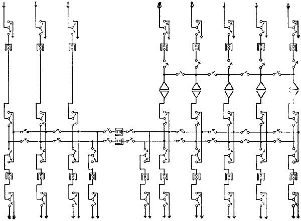
Fig. 76.—Connections at Watervliet Sub-station on Spier Falls Line.
The greater the total loss of voltage on a transmission line supplying
sub-stations that are scattered along much of its length, the larger will
be the fluctuations of voltage that must be compensated for at all of the
sub-stations save one, under changing loads, if only one circuit is employed
between the power-plant and these sub-stations. Suppose, for
example, that a transmission line 100 miles long is composed of a single
circuit, and supplies two sub-stations, one located 50 miles and the other
100 miles from the power-plant. Assume at first that there is no load
whatever at the intermediate sub-station. If the single transmission circuit
operates with 50,000 volts at the power-plant, and 45,000 volts at
the sub-station 100 miles away when there is a full load there, corresponding
to a loss of ten per cent, then the pressure at the intermediate sub-station
will be 47,500 volts. If, now, the load at the sub-station 100
miles from the power-house drops to a point where the entire line loss
is only 1,000 volts, and the pressure at the generating plant is lowered
to 46,000 volts so as to maintain 45,000 volts at the more distant sub-station,
then the pressure at the intermediate sub-station will be 45,500
volts, or 2,000 volts less than it was before. If the loss on the entire line
at full load were only five per cent, making the voltage at the sub-station
100 miles away 47,500 when that at the generating station is 50,000,[238]
then the pressure at the intermediate sub-station will be 48,750 volts.
Upon a reduction of the loss on the entire length of line to one-fifth of
its maximum amount, or to 500 volts, the pressure at the generating station
must be reduced to 48,000 volts, if that at the more distant sub-station
is to be held constant at 47,500. At the intermediate sub-station
the pressure will then be 47,750 volts, or 1,000 volts less than it was at
full load. From these two examples it may be seen that the extent of
pressure variation at the intermediate sub-station will depend directly
on the maximum line loss, if the regulation at the generating station is
such as to maintain a constant voltage at the sub-station 100 miles away.
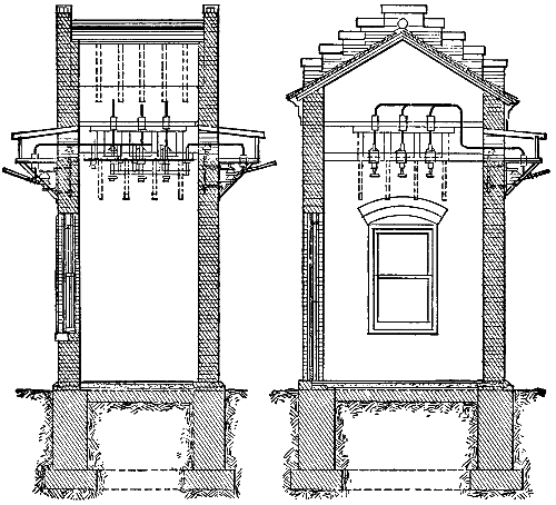
Fig. 77.—Sections of Switch-house on New Hampshire Traction System.
All the foregoing has assumed no load to be connected at the intermediate
sub-station, and with a load there the fluctuations of pressure
will of course depend on its amount as well as on the load at the more
distant sub-station.
One of the strongest reasons for the use of two or more circuits in
the same transmission line arises from the rapid fluctuations of load
where large stationary motors or an electric railway system is operated.
When a transmission line must carry a load of stationary or railway
motors, it is a common practice to divide the line into at least two circuits,[239]
and to devote one circuit exclusively to railway or motor work
and another to lighting, at any one time. In some cases this division
of the transmission system into two parts, one devoted to the lighting
and the other to the motor load, is carried out not only as to the sub-station
apparatus and the line, but also as to the transformers, generators,
water-wheels, and even the penstocks at the power-plant. It is
possible even to carry this division of the transmission system still further,
and to separate either the motor or the lighting load, or both, into
sections, and then to devote a distinct transmission circuit, group of
transformers, generator, and water-wheel to the operation of each section.
An example of the complete division of generating and transmitting
apparatus into independent units may be noted in the case of the
system that supplies light and power in Portland, Me., from a generating
plant on the Presumpscot River, thirteen miles away. At this station
four steel penstocks, each provided with a separate gate at the forebay
wall, bring water to as many pairs of wheels, and each pair of wheels
drives a direct-connected generator. Four three-phase circuits connect
the generating plant with the sub-station at Portland, and each circuit
between the generating plant and a transformer-house outside the business
section of the city is made up of No. 2 solid soft-drawn copper
wires.
Each of these four sets of apparatus, from head-gate to sub-station,
is usually operated independently of the others, and supplies either the
motor load or a part of the electric lighting. In this way changes in the
amount of one section of the load cause no fluctuation of the voltage
on the other sections. At Manchester, N. H., the sub-station receives
energy from four water-power plants, and is provided with two sets of
low-tension, 2,300-volt, three-phase bus-bars, one set of these bus-bars
being devoted to the operation of the local electric railway system, and
the other set to the supply of lamps and stationary motors. Each set
of these bus-bars is divided into a number of sections, and by means of
these sections different transmission circuits are devoted to different
portions of the lighting and motor loads. As three of the four water-power
plants are connected to the sub-station by two circuits each, the
division of loads in this case is often carried clear back to the generators,
one generator in a power-house being operated, for instance, on railway
work and another on a lighting load at the same time. This plan has
the obvious advantage that much of the regulation for the several parts
of the entire load may be done at the generators, thus reducing the
amount of regulation necessary at the sub-station, and that fluctuating[240]
motor loads do not affect the lamps. In this case the conductors
of the several transmission circuits are all of moderate size, and the
division of the lines was evidently adopted for purposes of regulation,
rather than to reduce the amount of inductance. Thus the line between
Gregg’s Falls and the sub-station, a distance of six miles, is made up of
one three-phase circuit of No. 4 and one circuit of No. 6 bare copper
wires. The fourteen-mile line between the plant at Garvin’s Falls and
the sub-station, the longest of the four transmissions, is made up of two
three-phase circuits, each composed of No. 0 bare copper wires. In the
case of the Gregg’s Falls plant the subdivision of the line has gone further
than that of the generating equipment, for the station there contains only
a single generator, the rating being 1,200 kilowatts, while two circuits
run thence to the sub-station. Another instance showing extensive subdivision
of a line into separate circuits may be noted in the seven-mile
transmission from Montmorency Falls to Quebec, Canada, where sixteen
conductors, each No. 0 copper wire, make up four two-phase circuits
that connect a plant of 2,400 kilowatts capacity with its sub-station.
Such multiplication of transmission circuits has some advantages from
the standpoint of regulation, but there are good reasons for limiting it
to rather short lines, where it is, in fact, almost exclusively found. On
very long lines the use of numerous circuits composed of rather small
conductors would obviously increase the constant expense of inspection
and repairs and add materially to uncertainty of the service. Very few,
if any, transmission lines of as much as twenty-five miles in length are
divided into more than two circuits, and in several instances lines of
superlative length have only a single circuit each. The greatest single
power transmission in the world, that between Niagara Falls and Buffalo,
is carried out with two pole lines, one of which is about twenty and the
other about twenty-three miles long. The longer pole line, which is also
the older, carries two three-phase circuits, each of which is made up of
three 350,000 circular mil copper conductors. The shorter pole line
carries a single three-phase circuit composed of aluminum conductors,
each of which has an area in cross section of 500,000 circular mils. In
electrical conductivity the aluminum circuit is intended to be equal to
each of the two that are composed of copper. According to the description
of the Niagara Falls and Buffalo transmission system in vol. xviii.,
A. I. E. E., pages 518 to 527, each of these three circuits is designed to
transmit about 7,500 kilowatts, and the maximum power transmitted up
to August, 1901, was 15,600 kilowatts, or about the calculated capacity
of two of the circuits. According to the description just mentioned, the[241]
transmission circuits used to supply energy for use at Buffalo are regularly
operated in parallel, and this is also true of the generators and the
step-down transformers, though the uses to which this energy is applied
include lighting, large stationary motors, and the electric railway system.
Apparatus in the generating station at Niagara Falls and in the terminal-house
near the city limits of Buffalo is so arranged, however, that two
of the 3,750 kilowatt generators and eight step-up transformers at the
power-house, together with one transmission circuit and three step-down
transformers in the terminal-house at Buffalo, may be operated independently
of all the other apparatus.
As already pointed out, the use of separate circuits for each sub-station,
and for lighting and power loads at each sub-station in very long
transmission systems, is often impracticable. Even in comparatively short
transmissions the multiplication of circuits and the use of rather small
and mechanically weak conductors increased the first cost of installation
and the subsequent expense of inspection and repairs. An objection to
operation with a single circuit in a transmission line that supplies widely
separated sub-stations with lighting, power, and railway loads is the
consequent difficulty of pressure regulation on the distribution lines at
each sub-station. Such a transmission line necessarily delivers energy
at different and fluctuating voltages at the several sub-stations, and
these fluctuations are of course reproduced on the secondary side of
the step-down transformers. Fortunately, however, the use of synchronous
motor generators, either in place of or in connection with static
transformers, goes far to solve the problem of pressure regulation for distribution
circuits supplied with energy from transmission lines. This is
due to the well-known fact that with constant frequency the speed of rotation
for a synchronous motor is constant without regard to fluctuations in
the applied voltage or changes in its load. With a constant speed at the
motor and its connected generator it is of course easy to deliver current
at constant voltage to the distribution lines. This constancy of speed
makes the synchronous motor generator a favorite in large transmission
systems with both power and lighting loads. The satisfactory lighting
service in Buffalo, operated with energy transmitted from Niagara Falls,
seems to be due in some measure to the use of synchronous motor generators
at the sub-station in Buffalo, whence lighting circuits are supplied.
As above stated, the three circuits that make up the transmission
line between Niagara Falls and Buffalo are operated in multiple, and in
the latter place there is a large load of both railway and stationary motors.
As the three circuits are operated in multiple, they of course amount to[242]
only a single circuit so far as fluctuations of voltage due to changes in
these several sorts of loads are concerned. According to vol. xviii., A. I.
E. E., pages 125 and following, the load on the transmission system at
Buffalo in 1901 was made up of about 7,000 horse-power in railway
motors, 4,000 horse-power in induction motors, and 4,000 horse-power
divided up between series arc lamps, constant pressure incandescent
lamps, and continuous current motors. The railway load is operated
through step-down transformers and rotary converters. The induction
motors are connected either to the 2,000-volt secondary circuits of the
step-down transformers or to service transformers supplied by these
circuits. On these railway and stationary motor loads there is of course
no necessity for close pressure regulation. Series arc lamps are operated
through step-down transformers and synchronous motors direct-connected
to constant continuous current dynamos. Continuous current
stationary motors draw power from the transmission lines through step-down
transformers and rotary converters, like the railway load. For the
2,200 volt circuits that supply service transformers for commercial arc and
incandescent lighting the transmitted energy passes through step-down
transformers and synchronous motor-generators. These motor-generators
raise the frequency from twenty-five to sixty cycles per second.
Finally the continuous current three-wire system for incandescent lighting
at about 250 volts between outside wires is operated through step-down
transformers and synchronous motors direct-connected to continuous
current generators. For this last-named service rotary converters
were at first tried, but were found to be impracticable because voltage
fluctuations on the transmission line (due largely to the railway and
motor loads) were reproduced on the continuous-current circuits by the
rotary converters. Since the adoption of motor-generators this fluctuation
of the service voltage is no longer present.
Another case in which synchronous motor-generators deliver power
from a transmission line that carries both a lighting and a motor load
is that of the Shawinigan sub-station in Montreal. At this sub-station
the 85-mile transmission line from the generating plant at Shawinigan
Falls terminates. As already pointed out, this line is composed of a
single three-phase circuit of aluminum conductors, each of which has a
cross section of 183,750 circular mils. In the Montreal sub-station the
thirty-cycle, three-phase current from Shawinigan Falls is delivered to
transformers that lower the voltage to 2,300. The current then goes to
five synchronous motor-generators of 1,200 horse-power capacity each,
and is there converted to sixty-three cycles per second, two-phase, at the[243]
same voltage. This converted current passes onto the distribution lines
of the local electrical supply system in Montreal, which also draws energy
from two other water-power plants, and is devoted to lighting, stationary
motors, or to the street railway work, as may be required. Though separate
local distribution circuits are devoted to these several loads, the
fluctuations in the stationary and railway motor work necessarily react
on the voltage of the transmission line and transformers at the sub-station.
By the use of the synchronous motor-generators the lighting circuits are
protected from these pressure variations.
As the numbers of sub-stations at different points on long transmission
lines increase, and stationary motor and railway loads at each become
more common, it is to be expected that the use of synchronous
motor-generators for lighting service will be much more frequent than
at present. With such use there will disappear one of the reasons for
the multiplication of transmission circuits.
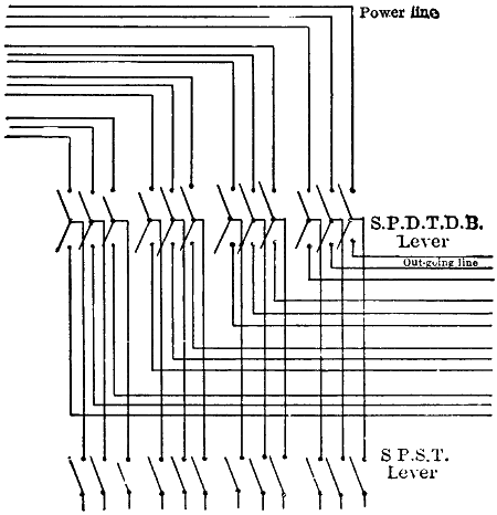
Fig. 78.—Transfer Switches at Saratoga Switch-house on Spier Falls Line.
Where several transmission circuits connect a generating plant with
a single sub-station, or with several sub-stations in the same general
direction, it is desirable to have switches so arranged that two or more
circuits may be combined as one, or so that any circuit that ordinarily
operates a certain load or sub-station may be devoted to another when
occasion requires. For this purpose transfer switches on each circuit[244]
are necessary at generating plants, sub-stations, and often at switch-houses.
These transfer switches will ordinarily be of the knife type,
and intended for manual operation when the circuits to which they
are connected are not in use. As such switches are exposed to the full
voltage of transmission, the insulation of their conducting parts should
be very high. In the extensive transmission system between the power-plants
at Spier Falls and Mechanicsville and the sub-stations at Troy,
Albany, and Schenectady, N. Y., a transfer switch of highly insulated
construction has been much used. The two blades of this switch move
independently of each other, but both are mounted between the same
metal clips. Each blade is of two by one-quarter inch drawn copper
rod, and the clips supporting the two blades are mounted on top of a
circular metal cap four and three-quarter inches in outside diameter and
two inches high, that is cemented over the top of a large, double petticoat,
porcelain line insulator.
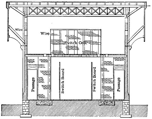
Fig. 79.—Cross Section of Schenectady Switch-house on Spier Falls Line.
Clips into which these copper blades are swung in closing the switch
are also mounted in caps carried by insulators in the way just described.
Each of these insulators is mounted on a large wooden pin, and these pins
are secured in timbers at the points where the switches are wanted.
This construction of switches gives ample insulation for the line voltage[245]
of 30,000 in this system. By means of the transfer switches just described,
either of the transmission circuits leaving the Spier Falls power-plant
may be connected to any one of the ten generators and ten groups
of transformers there. At the Saratoga switch-house, any one of the
twelve conductors, making up the four three-phase circuits from Spier
Falls may be connected to any one of the eighteen conductors making
up the six three-phase circuits that go south to Saratoga, Watervliet, and
Schenectady sub-stations, in the way indicated by the drawing. So
again at the Watervliet sub-station, where energy at 26,500 volts is received
from Spier Falls and energy at 10,800 volts from Mechanicsville,
any single conductor from either of these water-power plants may be
connected, either directly or through a transformer, with either conductor
running to the railway and lighting sub-stations about Albany and Troy.
Where several transmission circuits are employed, this complete flexibility
of connection evidently adds materially to the convenience and reliability
of operation.
Circuits in Transmission Lines.
| Location of Lines. |
Length
in
Miles. |
Number
of
Circuits. |
Number
of Pole
Lines. |
Circular
Mils
per
Wire. |
Cycles
per
Second
of
Current. |
| Electra to San Francisco |
147 |
1 |
1 |
|
[A]471,034 |
60 |
| Colgate to Oakland, Cal. |
142 |
2 |
2 |
|
133,100 |
60 |
| |
|
|
|
[A]211,000 |
|
| Santa Ana River to Los Angeles |
83 |
2 |
1 |
|
83,690 |
60 |
| Shawinigan Falls to Montreal |
85 |
1 |
1 |
|
[A]183,750 |
30 |
| Cañon Ferry to Butte |
65 |
2 |
2 |
|
106,500 |
60 |
| Welland Canal to Hamilton |
35 |
1 |
1 |
|
83,690 |
60 |
| Welland Canal to Hamilton |
37 |
1 |
1 |
|
133,100 |
60 |
| Spier Falls to Schenectady |
30 |
2 |
1 |
|
105,600 |
40 |
| |
|
|
|
167,800 |
|
| Spier Falls to Watervliet, N. Y. |
35 |
2 |
1 |
|
167,800 |
40 |
| Ogden to Salt Lake City |
36 |
2 |
1 |
|
83,690 |
60 |
| Apple River Falls to St. Paul |
27 |
2 |
1 |
|
66,370 |
60 |
| Niagara Falls to Buffalo |
23 |
2 |
1 |
|
350,000 |
25 |
| Niagara Falls to Buffalo |
20 |
1 |
1 |
|
[A]500,000 |
25 |
| Farmington River to Hartford |
11 |
1 |
1 |
|
[A]364,420 |
60 |
| Niagara Falls to Toronto |
75 |
2 |
1 |
[B] |
190,000 |
25 |
| [A] Aluminum conductor. |
| [B] Steel towers. |
[246]
CHAPTER XVIII.
POLE LINES FOR POWER TRANSMISSION.
Long transmission lines should follow the most direct routes between
generating and sub-stations as far as practicable. The number of poles,
cross-arms, and insulators increases directly with the length of line, and
the weight of conductors with the square of that length, other factors
remaining equal. Every material deviation from a straight line must
therefore be paid for at a rather high rate.
Distribution lines necessarily follow the public streets in order to
reach consumers, but the saving of the cost of a private right of way and
ease of access are the main considerations which tend to keep transmission
lines on streets and highways. Except in very rough or swampy
country, the difficulty of access to a pole line on a private right of way is
not a serious matter and should be given but little weight. The cost of
a private right of way may be more important, and should be compared
with the additional cost of the pole line and conductors if erected on the
public highway. In this additional cost should be included any items for
paving about the poles, extra pins, insulators, and guys made necessary
by frequent turns in the highway, and the sums that may be required to
secure the necessary franchises. There is also the possible contingency
of future legislation as to the voltage that may be maintained on wires
located over public streets. These considerations taken together give a
strong tendency to the location of long transmission lines on private rights
of way, especially where the amount of power involved is great and the
voltage very high.
A transmission line 80.3 miles in length recently erected between
Rochester and Pelham, N. H., by way of Portsmouth, where the generating
station is located, to feed an electric railway system, operates
at 13,200 volts and is mainly located on private rights of way. Deeds
conveying the easements for this right of way provide that all trees or
branches within one rod on either side of the line may be cut away.
The transmission line between Niagara Falls and Buffalo, about twenty-three
miles long and operating at 22,000 volts, is largely on a private
way thirty feet wide.
[247]
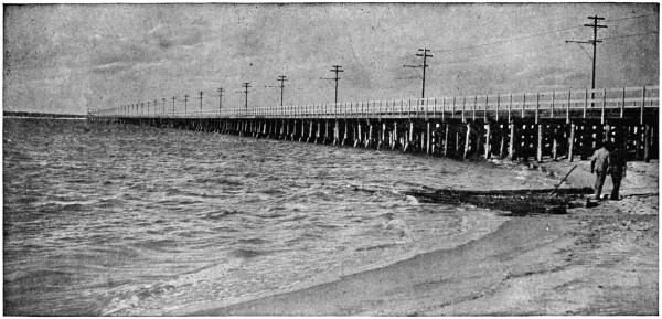
Fig. 80.—Transmission
Line of New Hampshire Traction Company over Hampton River Bridge, 4,623 Feet Long.
[248]
For the transmission between Cañon Ferry and Butte the line is
mainly located on a private way. Between Colgate and Oakland the
transmission line is mostly on private way, and this is also true of the
greater part of some other high-pressure lines in California. These private
rights of way range from fifty to several hundred feet wide, it being
necessary in forests to cut down all trees that are tall enough to fall onto
the wires.
In some cases of transmission at very high voltage two independent
pole lines are erected and one or more circuits are then run on each
set of poles. This construction has been followed on the transmission
line between Niagara Falls and Buffalo, Cañon Ferry and Butte, Welland
Canal and Hamilton, and between Colgate and Oakland. Such double
pole lines are more usually located on the same right of way, this being
true of the Cañon Ferry and Colgate systems, but this is not always the
case. In the Hamilton system the two lines of poles, one thirty-five
miles and the other thirty-seven miles in length, are located several
miles apart. The two sets of poles on a part of the Buffalo line are
less than thirty feet, on the Colgate line are twenty-five feet, and on the
Cañon Ferry line are forty feet apart.
The main reasons for the use of two pole lines instead of one are the
probability that an arc started on one circuit will be communicated to
another on the same poles, and the greater ease and safety of repairs when
each circuit is on a separate line of poles. On each pole line of the Cañon
Ferry transmission, and also on each pole line of the Colgate transmission,
there is only one three-wire circuit. On the Cañon Ferry line each wire of
the two circuits has a cross-section of only 106,500 circular mils, and on
the Colgate line one circuit is of 133,225 circular mils wire and the other
circuit is of 211,600 circular mils cable. In contrast with these figures the
line of the Standard Electric Company between Electra and Mission San
José, a distance of ninety-nine miles, is made up of only three conductors,
each being an aluminum cable of 471,034 circular mils section. Inductance
increases with the frequency of the current in a conductor, and in
each of the three systems just considered the frequency is sixty cycles
per second.
The use of one circuit of larger wire instead of two circuits of smaller
wire has the obvious advantage of greater mechanical strength in each
conductor, saves the cost of one pole line and of the erection of the second
circuit. With voltages above 40,000 to 50,000 on long transmission lines
there is a large loss of energy by leakage directly through the air from wire
to wire. To keep this loss within desirable limits it may be necessary to[249]
give each wire of a circuit a greater distance from the others of the same
circuit than can readily be had if all the wires of each circuit are mounted
on one line of poles. If there is only one three-wire circuit to be provided
for, three lines of poles or two lines with a long crosspiece between them
may be set with any desired distance between the lines so that the leakage
through the air with one wire on each pole will be reduced to a small
quantity. On a line built in this way it would be practically impossible
for an arc to start between the wires by any of the usual means.
Distances from pole to pole in the same line vary somewhat with the
number, size, and material of the conductors to be carried. On ordinary
construction in a straight line poles are often spaced from 100 to 110 feet
apart—that is, about fifty poles per mile. On curves and near corners
the spacing of poles should be shorter. Poles for the 80.3 miles, mentioned
in New Hampshire, are regularly located 100 feet apart. Of the
two pole lines between Niagara Falls and Buffalo, the older was designed
to carry twelve copper cables of 350,000 circular mils each, and
its poles were spaced only 70 feet apart. The newer line is designed to
carry six aluminum cables of 500,000 circular mils each and its poles are
140 feet apart. Poles in each of the lines between Cañon Ferry and
Butte are regularly spaced 110 feet apart and each pole carries three
copper cables of 106,500 circular mils.
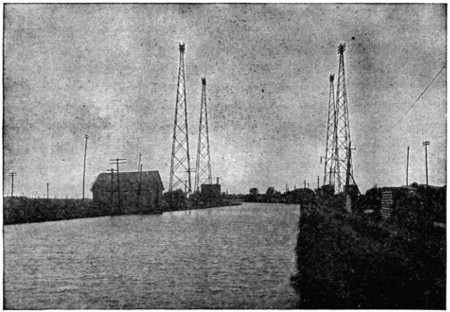
Fig. 81.—Chambly-Montreal Line Crossing the Chambly Canal.
[250]
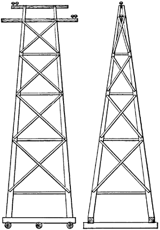
Fig. 82.—Special Wooden Structures on Line Between Spier Falls and Schenectady.
The two 142-mile lines between Colgate and Oakland are each made
up of poles 132 feet apart, and one line of poles carries the three copper
conductors and the other line of poles the aluminum conductors already
named. As aluminum wire has only one-half the weight of copper
wire of equal conductivity, the length of span between poles carrying
aluminum wire may be greater than that where copper is used. Only
a part of the strain on poles is due to the weight of wires carried, however.
Where a body of water must be crossed, a very long span, with
special supports for the wires at each side, may be necessary. A case
of this sort was met where the Colgate and Oakland line crosses the
Carquinez Straits at a point where the waterway is 3,200 feet wide. It
was necessary to have the lowest part of the cables across these straits at
least 200 feet above the surface of the water so that vessels with the tallest
masts could pass underneath. To secure the necessary elevation for the
cables a steel tower was built on each bank of the straits at such a point
that the distance between the points for cable support on the two towers
is 4,427 feet apart. As the banks rise rapidly from the water level, one
steel tower was given a height of only 65 feet, while the height of the other
was made 225 feet. Between these two towers four steel cables were
suspended, each cable being made up of nineteen strands of galvanized[251]
steel wire, having an outside diameter of seven-eighths inch and weighing
7,080 pounds for the span. The breaking strain of each cable is 98,000
pounds, and it has the electrical conductivity of a No. 2 copper wire.
The cables are simply supported on the towers by steel rollers, and the
pull of each cable, amounting to twelve tons, is taken by an anchorage
some distance behind each tower, where the cable terminates. Each
anchorage consists of a large block of cement deeply embedded in the
ground, and with anchor bolts running through it. Each cable is secured
to its anchorage through a series of strain insulators, and the regular line
cables of copper and aluminum are connected with the steel cables just
outside of the shelter built over the strain insulators of each anchor.
Steel cables were used for the long span across the straits because of the
great tensile strength that could be had in that metal. This span is, no
doubt, the longest and highest that has ever been erected for electrical
transmission at high voltage.
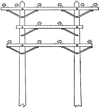
Fig. 83.—Special Structure on Line Between Spier Falls and Schenectady.
It has been suggested in one instance that steel towers ninety feet
high and 1,000 feet apart be substituted for pole lines and the wires
strung from tower to tower. Such construction would increase the
difficulty of insulation and would cost more at the start than a line of
wooden poles. The question is whether a lower maintenance and
depreciation rate for the steel towers would offset their disadvantages[252]
compared with poles. Pole lines should be staked out with a transit, and
the same instrument can be used to give a perpendicular position to each
pole and bring it into line. Wooden poles are used in most cases of
high-voltage transmission lines. Iron poles would make it unsafe to
work on any circuit carried by them when it was transmitting current
at high voltage. With iron poles a defective insulator might lead to
the destruction of the conductors at that point through continuous
arcing on to the iron.
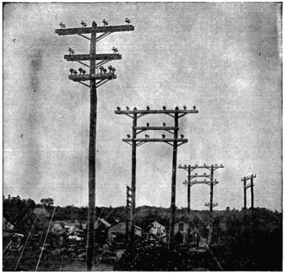
Fig. 84.—Crossing of Delaware and Hudson Railway Tracks
by 30,000-volt Line at
Saratoga, N. Y.
The kinds of wood used for poles vary in different sections of the
country. In New England, chestnut poles are a favorite and were used
on the 80.3 miles of transmission line mentioned in New Hampshire.
Cedar poles are used to some extent in nearly all parts of the country,
including Canada. Spruce and pine poles are employed to some extent,
especially in lengths of more than fifty feet. In the Rocky Mountain
region and in California round cedar poles from the forests of Oregon,[253]
Washington, and Idaho are much used. Sawed redwood poles from the
trunks of large trees were erected on the 147-mile line between Electra
power-house and San Francisco. For the Colgate and Oakland line
Oregon cedar poles were selected, and the transmission between Cañon
Ferry and Butte was carried out with cedar poles from Idaho. For
transmission circuits it is far more important at most points to have poles
very strong rather than very long. Where wires or obstructions must
be crossed by the high-voltage circuits the poles should be long enough
to carry these circuits well above everything else. In the open country,
where no obstructions are to be avoided, it does not pay to use poles with
a length greater than thirty-five feet.
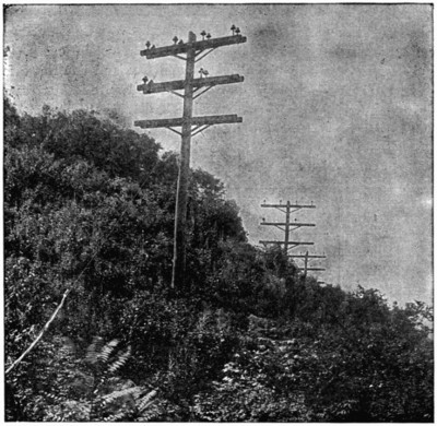
Fig. 85.—Pole Line from Spier Falls over Mount McGregor.
Short poles offer less surface to the wind, the length of the lever
through which wind pressure acts to break the pole at the ground decreases
with the length of pole, and the shorter the poles the smaller is
the strain on struts and guy wires. If poles are only thirty or thirty-five[254]
feet long, they may be large in diameter without excessive cost. As a
rule, no pole should be used with a top less than seven inches in diameter,
and a pole with this top should not be required to carry more than
three wires. A pole with seven- or eight-inch top and thirty feet long
should measure not less than twelve inches in diameter at the butt. For
longer poles the diameters at the butt should increase up to at least eighteen
inches for a round pole sixty feet long.
In the New Hampshire transmission above named the standard
length of poles is thirty-five feet. On the line between Cañon Ferry and
Butte the poles range from thirty-five to ninety feet in length. The
round cedar poles used in the Colgate and Oakland line range from
twenty-five to sixty feet in length, from eight to twelve inches diameter
at the top, and from twelve to eighteen inches diameter at the butt. On
the line between Electra and San Francisco the square-sawed redwood
poles are reported to have the following dimensions, in a paper read at
the annual convention of Edison Illuminating Companies in 1902.
Height,
Feet. |
Top,
Inches. |
Butt,
Inches. |
Depth
in
Ground. |
| 35 |
7 |
× |
7 |
12 |
|
× |
12 |
|
5 |
.5 |
| 40 |
8 |
× |
8 |
13 |
1⁄2 |
× |
13 |
1⁄2 |
6 |
|
| 45 |
9 |
× |
9 |
15 |
|
× |
15 |
|
6 |
.5 |
| 50 |
10 |
× |
10 |
16 |
|
× |
16 |
|
7 |
|
| 60 |
11 |
× |
11 |
17 |
|
× |
17 |
|
8 |
|
The relative dimensions of these poles are of interest because, being
sawed from the trunks of large trees, they could have any desired measurements
at the tops and butts. These poles, over the greater part
of the line, carried the three aluminum cables of 471,034 circular mils
each, previously mentioned. Depth to which poles are set in the ground
ranges from about five feet for twenty-five- or thirty-foot poles to eight
feet for poles sixty feet long. In locations where the soil is very soft or
where poles must resist heavy strains the stability of each pole may be
much increased by digging the hole two feet or more larger in diameter
than the butt of the pole, and then filling in cement concrete—one
part, by measure, of Portland cement, three of sand and five of broken
stone—all around the butt of the pole after it is in the hole. The butts
of poles up to a point one foot or more above the ground line are frequently
treated with hot tar, pitch, asphalt, or carbolineum before the
poles are erected, and in Salt Lake City salt is said to be used around pole
butts after they are in the hole.
[255]
In some cases the poles of transmission lines are painted over their
entire length. Pole tops should always be pointed or wedge-shaped, to
shed water, and paint or tar should be applied to these tops. In some
cases poles are filled with crude petroleum or other preservative compound
in iron retorts, where moisture is withdrawn from the pole by
exhausting the air, and then, after treatment with dry steam, the poles
have the compound forced into them by hydraulic pressure.
In favorable soils cedar poles may remain fairly sound for twenty
years, chestnut poles more than one-half of that time, and spruce and
pine about five years. Poles up to forty feet in length may be readily
set with pike poles, but when they are much longer than this a derrick
will save time and labor. A derrick should have a little more than one-half
the length of the poles to be set.
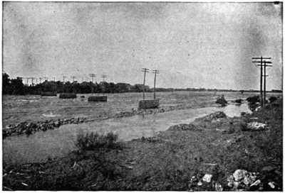
Fig. 86.—Chambly-Montreal Line Crossing the Richelieu River.
Poles should be guyed or braced at all points where there are material
changes in the direction of the line, and on long straight stretches about
every fifth pole should be guyed or braced in both directions to prevent
the poles setting back when the line wire is cut or broken at any point.
Where there is room for wooden struts, as on a private right of way, they
should be used instead of guys because of their more substantial character
and the higher security of insulation thus obtained. Ordinary strain
insulators cannot be relied on with lines that operate at very high
voltages, and where guys must be used a timber four by six inches and[256]
ten to twenty feet long may have the guy twisted about each end of
it and be used as a strain insulator. A guy or strut should come well up
under the lower cross-arm on a pole to avoid breaking of the pole at the
point of attachment.
Where poles have heavy circuits and several cross-arms each it is
sometimes desirable to attach a guy or strut beneath the lowest arm and
also a guy close to the pole top. Galvanized iron or steel wire is the
material best suited for guys, and the cable form has greater strength
and is more flexible than solid wire.
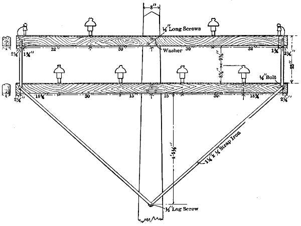
Fig. 87.—Cross-arms and
Insulators on the Line Between the Chambly Plant and Montreal.
On the transmission line between Electra and San Francisco, which
is intended to operate at 60,000 volts, the use of guys has been mostly
avoided and struts employed instead. Where a guy had to be used, a[257]
strain insulator of wood six by six inches and twenty feet long was inserted
in it.
The number and spacing of cross-arms on the poles of transmission
lines are regulated by the number of circuits that each pole must carry
and by the desired distance apart of the wires. Formerly it was common
to carry two or more circuits on a single line of poles, but now
a frequent practice is to give each pole line only one circuit and each
pole only one cross-arm, except that a small cross-arm for a telephone
circuit is placed some feet below the power wires. With only one
transmission circuit per pole line, one wire is usually placed at the
top of the pole and the other two wires at opposite ends of the single
cross-arm. The older pole line for the transmission between Niagara
Falls and Buffalo carried two cross-arms per pole for the power wires,
these cross-arms being two feet apart. Each cross-arm was of yellow
pine, twelve feet long, four by six inches in section, and intended to
carry four three-wire circuits, but only two circuits have been erected
on these two cross-arms. On the later pole line for this same transmission
each pole carries two cross-arms, the upper intended for four and
the lower cross-arm for two wires, so that one three-wire circuit may be
strung on each side of the poles, two wires on the upper and one on the
lower arm in the form of an equilateral triangle. The pole lines between
Cañon Ferry and Butte, Colgate and Oakland, and Electra and San
Francisco all have only one cross-arm for power wires per pole, and the
third wire of the circuit in each case is mounted at the top of the pole
so that the three conductors are at the corners of an equilateral triangle.
This relative position of the conductors makes it easy to transpose
them as often as desired. On the line from Cañon Ferry to Butte the
cross-arms are each eight feet long with two holes for pins seventy-eight
inches apart, and are attached to the pole five feet ten and one-half
inches from the top. Gains for cross-arms should be cut from one to
two inches deep in poles before they are raised, and one hole for three-quarters
or seven-eighths-inch bolt should be bored through the centre of
the cross-arm and of the pole at the gain. Each cross-arm should be
attached to the pole by a single bolt passing entirely through the pole
and cross-arm with a washer about three inches in diameter next to the
cross-arm. One large through bolt weakens the pole and arm less than
two smaller bolts or lag-screws, and the arm can be more easily replaced
if there is only one bolt to remove. Alternate poles in a line should
have their cross-arms bolted on opposite sides, and at corners double
arms should be used.
[258]
Yellow pine is a favorite wood for cross-arms, though other varieties
are also used. The large, long pins necessary on high voltage lines tend
to increase the sectional area of cross-arms, and a section less than five
and one-half by four and one-half inches is seldom desirable. On the
line between Electra and San Francisco, which carries the three aluminum
cables of 471,034 circular mils each, the cross-arms of Oregon
pine have a section of six by six inches each. Standard dimensions of
some smaller cross-arms are four and three-quarters by three and
three-quarters inches, but it may be doubted whether these arms are
strong enough for long transmission work. Cross-arms should be
surfaced all over and crowned one-quarter to one-half inch on top so
as to shed water. After being kiln dried, cross-arms should be boiled
in asphaltum or linseed oil to preserve the wood and give it higher
insulating properties. Cross-arms longer than five feet should be
secured by braces starting at the pole some distance below each arm
and extending to points on the arm about half-way between the pole
and each end of the arm.
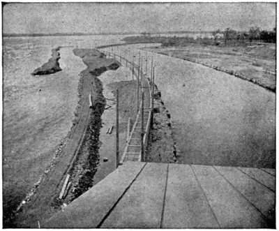
Fig. 88.—Tail Race and Pole Line at Chambly, Quebec Power-station.
Each brace may be of flat bar iron about one and one-half by one-quarter
inch in section, or the brace for both ends of an arm may be made[259]
of a single piece of angle-iron bent into the proper shape. For high-voltage
lines it is undesirable to employ iron braces of any sort, since these
braces form a path of low resistance that comes much too close to the
pins on which the insulators and wires are mounted. Braces formed of
hard wood are much better as to insulation, and such braces of maple
are in use on the line between Butte and Cañon Ferry where the voltage
is 50,000. Each brace on that line is thirty-six inches long and three
inches wide, with one end bolted to the centre of its pole and the other
end to the cross-arm twenty-three inches from the pole centre.
The line from Electra has hard-wood braces secured with wood pins.
Wood is the most common material for pins on which to mount the
insulators of high-voltage transmission circuits. Iron has been used for
pins to some extent, and its use is on the increase. Oak and locust pins
are generally used, the latter being stronger and more lasting. In California,
pins of eucalyptus wood are much used and are said to be stronger
than locust. All wooden pins should be boiled several hours in linseed
oil after being well dried. This increases the insulating and lasting
properties of the pins.
High-voltage lines require long pins to hold the lower edges of insulators
well above the cross-arms, and these pins must be much stronger
than those used on ordinary lines, because of the increased leverage of
each wire.
A pin twelve inches long over all and having a diameter of one and
one-half inches in the part that enters the cross-arm has been much
used for transmission circuits, but is much too short and weak for
high voltages. On the 50,000-volt line between Cañon Ferry and Butte
the pins are seasoned oak boiled in paraffin. Each of these pins is
seventeen and one-half inches long, two and one-half inches in diameter
for a length of four and one-half inches in the middle part, two inches in
diameter for a length of five and one-half inches that fits into the cross-arm
or pole top, and one and one-half inches in diameter at the top of the
thread inside of the insulator. These pins hold the outside edges of the
insulators nine inches above the tops of cross-arms. Each of these pins
is held in its socket by a three-eighths-inch bolt that passes entirely through
the pin and the cross-arm or pole top.
On the line between Electra and San Francisco the pins are each
sixteen and seven-eighths inches long, two and three-quarters inches in
diameter at the largest central part, and two and one-quarter inches in
diameter in the lower part, five inches long, that fits into the cross-arm
or pole top. One of these pins broke at the shoulder with a pull of 2,200[260]
pounds at the threaded part. Carriage bolts one-half inch in diameter
pass through the cross-arm and pin two inches from the top of the arm,
and one bolt three inches from the pin on each side. Without these
bolts the arms split on test with a pull of 1,200 pounds on the pin, but
with the bolts the pin broke as above.
[261]
CHAPTER XIX.
ENTRIES FOR ELECTRIC TRANSMISSION LINES.
The entrance of transmission lines into generating plants and sub-stations
presents special problems in construction and insulation. One
of these problems has to do with the mechanical security of each conductor
at the point where it passes through the side or roof of the station. Conductors
are sometimes attached to the station so that the strain of the
line is borne by the side wall where they enter and tends to pull it out
of line.
This practice has but little to commend it, aside from convenience,
for unless the conductors are rather small, or the wall of the station is
unusually heavy, the pull of the former is apt to bulge the latter in the
course of time. For any heavy line the end strain is ultimately most
suitably taken by an anchor securely fixed. As special insulators must
be used where a conductor is secured directly to such an anchor, it is
usually more convenient to set one or more heavy poles with double cross-arms
at the end of a line, and then to make these poles secure by large
struts, or by guys attached to anchors. Extra heavy cross-arms on these
end poles should be provided with iron pins for the line insulators; two
or more of the insulators mounted in this way within a few feet of each
other, for each wire, will stand up against the end strain on almost any
line.
Insulators that are to take the end strain of a line in this way should
allow attachment of the wire at the side, so that the force exerted by each
conductor tends to press the insulator against the side of its pin, rather
than to pull off the top of the insulator. The end strain of the line having
been taken on poles close to the station, the conductors may be attached
to insulators on the wall, the latter thus being subjected to very
little mechanical strain.
Overhead lines usually enter a station through one of its side walls,
but an entry may be made in the roof. It is desirable to have a side entry
on the gable end of a building rather than on a side below the eaves
where there will be much dripping of water. If an entry must be made
below the eaves, a shelter should be provided above the entry, and the[262]
roof of this shelter should have a gutter that will carry water away from
the wires.
Entrance of each conductor into a station must be effected in such a
way that ample insulation of the circuit will be maintained, and in some
cases so that rain, snow, and wind will be excluded. The line voltage
and the climate where the station is located thus have an important
bearing on the form of entry that is suitable in any particular case.
The simplest form of entry for a high-voltage line is a clear opening,
usually circular in form, through the wall of the station for each wire.
Insulators for each wire should be provided both inside and outside of
the wall to hold the wire at the centre of this opening. Such insulators
are usually most conveniently supported by fixtures attached to both sides
of the wall, and insulators on the outside should of course be kept in an
upright position, unless completely protected from rain and snow.
The diameter of the openings through the wall should be great
enough to prevent any visible discharge of current between the wire and
wall under the worst conditions of snow, rain, fog, or dust. Such an
opening must, therefore, increase in diameter with the voltage of the line.
The larger these openings for the line wires, the greater is the opportunity
for rain, snow, dust, and cold air to enter the station through them.
Openings may be so protected as to keep out snow and rain by means
of shelters on the outside of the wall on which they are placed, but such
shelters cannot keep out the cold air. If the openings for the entrance
of wires are located in the wall of a room that contains air-blast transformers,
the area of openings for circuits of very high voltage may be
no greater than is necessary to allow the escape of heated air from the
transformers.
The milder the climate, other factors being the same, the higher the
voltage of circuits which may enter a station through openings that are
free for the movement of air. With circuits of only moderate voltage,
say less than 15,000, it is quite practicable to admit wires to a station
through perfectly free openings, in the coldest parts of the United States.
With voltages of 20,000 to 60,000 it is often necessary, in the colder parts
of the country, to close the opening in the wall through which each wire
enters with a disc of insulating material.
In order to keep the current leakage over these discs within proper
limits, the diameters of the discs must increase with the voltage of the
circuit. This increase of disc diameter obviously lengthens the path of
leakage current over the disc surface. Where the openings in a wall for
the entrance of high-voltage circuits are closed by insulating discs about[263]
the wires, these discs may make actual contact with bare wires, or the
wire at each entry may have some special insulation.
In the side wall of the sub-station at Manchester, N. H., the entrance
of transmission lines from four water-power plants is provided for by
circular openings in slate slabs that are built into the brickwork. The
transmission circuits from three of the water-power plants operate at
10,000 to 12,000 volts, and the circuit from the fourth plant at about
6,000 volts. Circular openings in the slate slabs are each five inches in
diameter, and they are spaced twelve to fifteen inches between centres.
A single wire enters through each of these openings and is held at the
centre by insulators both inside and outside of the wall. Each wire is
bare where it passes through the slate slab, and the circular openings are
not closed in any way. The largest wires passing through these five-inch
circular openings in the slate slabs are of solid copper, No. 0, of
0.325-inch diameter each.
Before passing through the opening in the slate slabs the wires of
these transmission circuits are tied to regular line insulators supported
by cross-arms secured to the outside of the brick wall by iron brackets.
The point of attachment of each wire to its insulator is about nine inches
below the centre of the circular hole by which it enters the sub-station.
This Manchester sub-station is equipped with air-blast transformers
from which the hot air is discharged into the same room that the transmission
lines enter. Along one side of the sub-station there are twenty-seven
of these five-inch circular openings in the slate slabs for entrance
of the high-voltage lines, and on another side of the sub-station there are
a greater number of smaller openings for the distribution circuits. Were
it not for the air-blast transformers, all of these openings would probably
admit more air than would be desirable in a climate as cold as that at
Manchester.
Another example of openings in the walls of a station for the entrance
of transmission circuits, where there is free movement of the air between
the inside and outside of the building, is that of the 33,000-volt line between
Santa Ana River and Los Angeles, Cal. In this case a sewer pipe
twelve inches in diameter is built into the wall of the station for each
wire of the line, so that there is a free opening of this size from inside to
outside.
Each wire of the 33,000-volt circuit enters the station through the
centre of one of these twelve-inch pipes, and is thus surrounded by six
inches of air on every side. As the temperature near Los Angeles seldom
or never goes down to zero, these large openings do not admit[264]
enough air to be objectionable. Besides this mild climate, air-blast
transformers add to the favorable features in the stations having the
twelve-inch openings.
In another case, however, where the openings for the entrance of
wires of very high voltage allow free movement of air between the inside
and outside of the station, the climate is cold and the winter temperatures
go down to 30° or more below zero. This condition exists on the 25,000-volt
line between Apple River Falls and St. Paul, where six No. 2 wires
enter the generating station through plain circular openings in the brick
side wall of a small extension where the lightning arresters are located.
Air-blast transformers are located in the end of the station next to this
lightning-arrester house, but it is not certain that the hot air from them
escapes through the openings for the wires.
In another case where the climate is about as cold as that just named,
a gallery is built along one side of the exterior of the station at some distance
above the ground, and two openings are provided for each wire of
the high-tension line. One of these two openings is in the horizontal
floor of the gallery and allows the entrance of the wire from the outside,
and the other opening is in the side wall of the station against which the
gallery is built. The two openings for each wire being thus at right
angles to each other, and the opening to the outside air being protected
from the wind by its horizontal position, no more than a permissible
amount of cold air, it is said, finds its way into the station.
In some cases with lines of moderate voltage, say 10,000 to 15,000,
and in probably the majority of cases with lines of 25,000 volts or more,
the entry for the high-tension wires is entirely closed. An example of
this practice may be seen at the various sub-stations of the New Hampshire
Traction Company, which are located along their 12,000-volt line
between Portsmouth and Pelham, in that State.
For the entry of each wire on these lines a sixteen-inch square opening
is made in the brick wall of the sub-station. On the outside of this
wall a box is built about a group of three or more of these openings
located side by side. The top or roof of this box is formed by a slab of
bluestone three inches thick, which is set into the wall and extends
twenty-six inches from the face of the wall, with a slight slope from the
horizontal.
The ends, the bottom, and the outer side of this box are formed by
slabs of slate one inch thick, so that the enclosed space has an area in
vertical cross section at right angles to this building 15.5 inches high and
twenty-two inches wide.
[265]
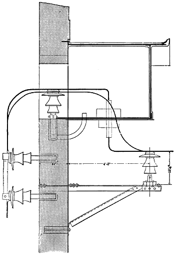
Fig. 89.—Cable Entering Building.
[266]
In the bottom of this box there is a circular opening for each wire,
and into this opening fits a heavy glass or porcelain bushing through
which the wire passes. After reaching the inside of the box the wire
turns at right angles and passes through the sixteen-inch square opening
into the sub-station. Beneath the box a special insulator is secured by
an iron bracket to the outside of the brick wall for each line wire, and this
insulator takes the strain of the wire before it is carried up through the
bushing in the bottom of the box. This form of entry is permissible
where the desire is to exclude cold air from the station, and where the
voltage is not high enough to cause serious leakage over the surface of
the bushing and the slate forming the bottom of the box. In all of the
cases above mentioned the wires used to enter the stations were the regular
line conductors and were bare.
Another type of entry in sub-stations is that employed on the extensive
transmission system between Spier Falls, Schenectady, and Albany,
N. Y. The maximum voltage on this system is 30,000, and the lines
usually enter each sub-station through the brick wall at one of its gable
ends. Outside of and about the entry of each circuit or group of circuits a
wooden shelter is built on the brick wall of the sub-station. Each shelter
has a slanting roof that starts from the brick wall at some distance above
the openings for the entrance of the line, and terminates in a gutter. The
front of each shelter is carried down three feet below the centre of the
openings in the brick wall, and the ends go still lower. The front of
each shelter is four feet in height, is four feet from the face of the brick
wall, and has a circular opening of 10-inch diameter for each wire of
the transmission line.
In line with each circular opening in the wooden shield there is an
opening of 15-inch diameter in the brick wall of the sub-station, and into
this opening in the brickwork fits a ring of wood with 15-inch outside and
11-inch inside diameter. To this wooden ring a 15-inch disc of hard fibre
1⁄8-inch thick is secured, and a porcelain tube 24 inches long and of 2-inch
inside diameter passes through a hole in the centre of this disc. Within
the wooden shield and in line with each circular opening in it and with
the corresponding porcelain tube through the fibre disc a line insulator
is secured. Within the sub-station and in line with each tube there is
also an insulator, and the two insulators near opposite ends of each tube
hold the line wire that passes through it in position.
Each wire of the transmission lines, of which the largest is No. 000
solid of 0.410-inch diameter, terminates at one of the insulators within
the wooden shield, and is there connected to a special insulated wire that[267]
passes through one of the porcelain tubes into the sub-station. A copper
trolley sleeve 12 inches long is used to make the soldered connection between
the bare line wire and the insulated conductor that passes through
the porcelain tube. Each of these entry cables, whatever its size, is
insulated first with a layer of rubber 9⁄32-inch thick, then with varnished
cambric wound on to a thickness of 9⁄32-inch, and lastly with two layers
of weather-proof braid outside of the cambric. This form of closed
entry for the transmission lines obviously excludes snow, rain, cold air,
and dust from the station. Whether the fibre discs and wooden rings,
together with the insulation on the entry cables, are as desirable as a
glass disc at the entry is another question.
Another instance where the entry for a high-tension line is closed
with the aid of combustible material is that of the 25,000-volt transmission
between the water-power plant at Chambly, on the Richelieu River, and
the sub-station in Montreal. The four three-phase circuits of this line
are made up of No. 00 wires of 0.365-inch diameter each, which enter
the power-station at Chambly and the terminal-house in Montreal bare,
as they are outside.
At each end of the line the wires are secured to insulators on a horizontal
arm with their centres twenty-two inches outside of an end wall of the
station or terminal building. The insulators are mounted with their
centres thirty inches apart, and a few inches above the tops of these
insulators a corresponding row of wooden bushings pass through the
wall with an outward slant.
At the Chambly end of the line each of these bushings is of oak,
boiled in stearin, four inches in diameter and twelve inches long. At the
Montreal end the wall bushings are of boxwood, and each is four inches
square and twelve inches long. Each of the wooden bushings carries a
glass tube, and is itself held in position by the concrete of the wall in
which it is located. Entrance to the station by each of the bare No. 00
wires is gained through one of these glass tubes, and cold air is excluded.
Quite a different type of closed entry for the wires of a transmission
line is in use on that between Shawinigan Falls and Montreal, which
operates at 50,000 volts. For the entry of each of the three aluminum
cables that make up this line, each cable being composed of seven No. 6
B. & S. gauge wires, a tile pipe of twenty-four-inches diameter was set
into the station wall. The end of each tile pipe is closed by a glass plate,
with a small hole at its centre, through which the cable passes.
As the cable is thus held twelve inches from the terra cotta pipe all[268]
the way around, any leakage of current must pass over this length of glass
surface at each cable or through the air.
A heavy coating of frost sometimes collects on these plates, and this
increases the amount of current leakage over them. Surface leakage in
a case of this sort, of course, varies with the size of the glass plate, and
if a tile pipe is used the limit of size is soon reached.
There seems to be no good reason, however, why a glass plate of any
desired dimensions should not be set directly into the brick wall of a
station for each line wire and the tile pipes entirely omitted. This plan
is followed on the system of the Utah Light & Power Company, which
extends to Salt Lake City, Ogden, Provo, and a number of other points
in that State.
On the 40,000-volt line of that system an entry for each wire is provided
by setting two plates of glass into the brick wall, one plate being
flush with the inner surface and the other with the outer surface of the
wall.
In the centre of each plate there is a hole of about 2.5-inch diameter,
into which a glass or porcelain tube fits. The line wire enters the station
through this tube, and it does not appear that any shelter for the glass
plates is located outside of the building. An entry of this type for the
40,000-volt line with glass plates in a brick wall at a gable end of the
Murphy mill is said to have given satisfactory results during four years,
though that wall faces the southwest, from which direction most of the
storms come. At this entry each glass plate is not more than eighteen
inches in diameter, and the wires are about four feet apart. On a
16,000-volt line of the same company, a glass plate twelve inches square
with a three-quarter-inch hole at its centre, and the bare wire passing
through without a tube, has given results that were entirely satisfactory.
Two quite different types of entry to stations are used on the 50,000-volt
line between Cañon Ferry and Butte, Mont. One type, employed
at the side wall of a corrugated iron building, consists of a thick bushing
of paraffined wood carrying a glass tube two inches in diameter, four feet
long, with a side wall of five-eighths to three-quarter-inch, through which
the line conductor passes.
On the roof of the power-station at Cañon Ferry a vertical entry is
made with the 50,000-volt circuit. For this purpose each line wire is
brought to a dead end on three insulators carried by a timber fixture on
the roof. A vertical tap drops from each line wire and passes through
the roof and into the station. This roof is of wood, covered with tin
outside and lined with asbestos inside. Each tap is an insulated wire,[269]
and elaborate methods are adopted in the way of further insulation, and
to prevent water from following the wire down through the roof.
Over the point of entrance sits a large block of paraffined wood with
a central hole, and down through this hole passes a long cylinder of paper
that extends some distance above the block. Into the top end of this
cylinder fits a wood bushing, and a length of the tap wire that has been
served with a thick layer of rubber is tightly enclosed by this bushing.
The rubber-covered portion of the tap wire also extends above the bushing,
and has taped to it a paper cone that comes down over the top of the
paper cylinder to keep out the water. On the outside of this paper
cylinder, at a lower point, a still larger paper cone is attached to prevent
water from following the cylinder down through the wooden block. At
the lower end of the paper cylinder, within the station, there is another
bushing of wood, and between this and the wooden bushing at the top
of the cylinder and inside of the paper cylinder there is a long glass tube.
Down through this tube and into the station the insulated tap wire
passes.
From the experience thus far gained with high-voltage lines, it seems
that their entrance into stations should always be at a side wall, unless
there is some imperative reason for coming down through the roof. If
climatic conditions permit, no form of entry can be more reliable than a
plain, ample opening through the wall with a large air-space about each
wire. If the opening must be closed, it had better be done with one or
more large plates of thick glass set directly into the brickwork of the wall.
Some additional insulation is obtained by placing a long glass or porcelain
tube over each wire where it passes through the central hole in the glass
plates. Each conductor should be bare at the entry, as it is on the line.
Some of the above examples of existing practice in entries for transmission
lines are taken from Vol. xxii., A. I. E. E.
[270]
CHAPTER XX.
INSULATOR PINS.
Wooden insulator pins are among the weakest elements in electric
transmission systems. As line voltages have gone up it has been necessary
to increase the distances between the outside petticoats of insulators
and their cross-arms and to lengthen the insulators themselves in
order to keep the leakage of current between the conductors within permissible
limits. To reduce the leakage, the wires on most lines are
located at the tops instead of in the old position at the sides of their
insulators.
All this has tended to a large increase of the mechanical strains that
operate to break insulator pins at the point where they enter the cross-arm,
because the strain on each line wire acts with a longer leverage.
Again, it is sometimes necessary that transmission lines make long spans
across rivers or elsewhere, and a very unusual strain may be put on the
insulator pins at these places.
As long as each electric system was confined to a single city or town
a broken insulator pin could be quickly replaced, and any material interruption
of service from such a cause was improbable. Where the light
and power supply of a city, however, depends on a long transmission line,
as is now the case in many instances, and where the line voltage is so great
that contact between a wire and a cross-arm will result in the speedy
destruction of the latter by burning, a broken pin may easily lead to a
serious interruption of the service.
Besides the increase of mechanical strains on insulator pins, there is
the danger of destruction of wooden pins by charring, burning, and other
forms of disintegration due to leakage of current over the insulators.
This danger was entirely absent in the great majority of cases so long as
lines were local and operated at only moderate voltages. These several
factors combined are bringing about marked changes in design.
On straight portions of a transmission line the insulator pins are subject
to strains of two principal kinds. One of these is due directly to the
weight of the insulators and line wire, and acts vertically to crush the pins
by forcing them down onto the cross-arm. The other is due to the horizontal[271]
pull of the line wire, which is often much increased by coatings of
ice and by wind pressure, tending to break the pins by bending—most
frequently at the point where they enter the cross-arm. A strain of
minor importance on pins is that encountered where a short pole has been
set between two higher ones, and the line at the short pole tends to lift
each insulator from its pin, and each pin from the cross-arm.
Where the line changes its direction, as on curves and at corners, the
side strain on pins is greatly increased, and such places give by far the
largest amount of trouble through the breaking of pins. The latter seldom
fail by crushing through the weight of the lines they support, because
the size of pin necessary to withstand the bending strain has a
large factor of safety as to crushing strength. Insulators are sometimes
lifted from wooden pins, and the threads of these pins stripped where
a short pole is used, as already noted; but failure of this kind is not
common.
Iron pins are either screwed or cemented into their insulators, but
the cemented joint is much more desirable, because where a screw joint
is made the unequal expansion of the iron and the glass or porcelain is
apt to result in breakage of the insulator. Where cement is used, both
the pins and insulators should be threaded or provided with shoulders
of some sort, so that, although the shoulders of threads do not come into
contact with each other, they will, nevertheless, help to secure a better
hold. Pure Portland cement, mixed with water to a thick liquid, has
been used with success, the insulator being placed upside down and the
pin held in a central position in the hole of the insulator while the cement
is poured in. Another cement that has been used for the same purpose
is a mixture of litharge and glycerin. Melted sulphur is also available.
The same forces that tend to lift an insulator from its pin tend also
to pull the pin from its socket in the cross-arm or pole top. With wooden
pins the time-honored custom has been to drive a nail into the side of the
cross-arm so that it enters the shank of the pin in its socket. This plan
is good enough so far as immediate mechanical strength is concerned, but
is not desirable, because it is hard to remove a nail when a pin is to be
removed, and also because the rust of the nail rots the wood. A better
plan is to have a small hole entirely through each cross-arm and insulator
pin at right angles to the shank of that pin in its socket, and
then to drive a small wooden pin entirely through from side to side.
Some of the important factors affecting the strains on insulator
pins vary much on different transmission lines, as may be seen from
the following table of lines on which wooden pins are used. On the[272]
older line between Niagara Falls and Buffalo, the regular length of
span is 70 feet, and each copper conductor of 350,000 circular mils is
attached to its insulator 7.5 inches above the cross-arm. On the new
line the length of span is 140 feet, and each aluminum conductor of
500,000 circular mils is attached to its insulator 10 inches above the
cross-arm.
Table I.—Data of Lines on Wooden Pins.
| Location of the Lines. |
Circular
Mils
of Each
Conductor. |
Feet
Length
of Span
Between
Poles. |
Inches
from Wire
to Shank
of Pin. |
| Colgate to Oakland |
[B]133,100 |
... |
13 |
|
| Electra to San Francisco |
[A]471,034 |
130 |
15 |
|
| Cañon Ferry to Butte |
[B]105,600 |
110 |
13 |
1⁄2 |
| Shawinigan Falls to Montreal |
[A]183,750 |
100 |
16 |
1⁄4 |
| Niagara Falls to Buffalo |
[B]350,000 |
70 |
7 |
1⁄2 |
| Niagara Falls to Buffalo |
[A]500,000 |
140 |
10 |
|
| Chambly to Montreal |
[B]133,100 |
90 |
8 |
1⁄2 |
| Colgate to Oakland |
[A]211,600 |
... |
13 |
|
| [A] Aluminum conductors. |
| [B] Copper conductors. |
Table II.—Dimensions of Wooden Pins in Inches.
| Location of Lines. |
Length
of
Stem. |
Length
of
Shank. |
Diameter
of
Shank. |
Diameter
of
Shoulder. |
Diameter
of
Threaded
End. |
Length
of
Threaded
Part. |
| Colgate to Oakland |
10 |
3⁄8 |
5 |
3⁄8 |
2 |
1⁄8 |
2 |
1⁄2 |
1 |
3⁄8 |
2 |
|
| Electra to San Francisco |
12 |
|
4 |
7⁄8 |
2 |
1⁄4 |
2 |
3⁄4 |
1 |
3⁄8 |
2 |
|
| Cañon Ferry to Butte |
12 |
1⁄2 |
5 |
1⁄8 |
2 |
|
2 |
1⁄2 |
1 |
1⁄8 |
3 |
|
| Shawinigan Falls to Montreal |
13 |
1⁄2 |
5 |
|
2 |
3⁄4 |
3 |
|
1 |
|
.. |
| Niagara Falls to Buffalo[A] |
5 |
1⁄4 |
6 |
|
2 |
|
2 |
3⁄4 |
|
7⁄8 |
1 |
1⁄2 |
| Niagara Falls to Buffalo[B] |
7 |
3⁄4 |
6 |
|
2 |
1⁄4 |
2 |
3⁄4 |
1 |
1⁄2 |
2 |
1⁄2 |
| Chambly to Montreal[C] |
7 |
|
5 |
|
1 |
1⁄2 |
1 |
7⁄8 |
.. |
.. |
| Cañon Ferry to Butte[D] |
12 |
3⁄8 |
7 |
7⁄8 |
2 |
1⁄8 |
2 |
1⁄2 |
1 |
1⁄8 |
3 |
|
| [A] Pins on old line. |
| [B] Pins on new line. |
| [C] Approximate dimensions. |
| [D] Pole top pins. |
To compensate for the greater strains introduced by doubling the
length of span and using pins of longer stem, the diameter of the shank
of the new pins was increased to two inches. One line between Colgate[273]
and Oakland is of copper, and the other is of aluminum conductors, but
the same pins appear to be used for each. On the line between Cañon
Ferry and Butte, Mont., the pin used in pole tops has a shank 23⁄4 inches
longer and 1⁄8-inch greater in diameter than the pin used in cross-arms.
The weakest pin included in the table seems to be that in use on the line
between Chambly and Montreal, which is of hickory wood, about 11⁄2
inches in diameter at the shank, and carries its No. 00 copper wire 81⁄2
inches above the cross-arm.
The following dimensions for standard wooden insulator pins to be
used on all transmission lines are proposed in vol. xxi., page 235, of the
Transactions of the American Institute of Electrical Engineers. These
pins are designed to resist a uniform pull at the smaller end and at right
angles to the axis in each case. The length of each pin, in inches between
the shoulder and the threaded end, is represented by L, and the
diameter of each pin at its shank by D.
| L. |
D. |
| 1 |
0.87 |
| 2 |
1.10 |
| 3 |
1.26 |
| 4 |
1.39 |
| 5 |
1.50 |
| 6 |
1.59 |
| 7 |
1.67 |
| 8 |
1.75 |
| 9 |
1.82 |
| 10 |
1.88 |
| 11 |
1.95 |
| 13 |
2.06 |
| 15 |
2.17 |
| 17 |
2.25 |
| 19 |
2.34 |
| 21 |
2.42 |
The two strongest pins in Table II. appear to be those in use on the
line between Shawinigan Falls and Montreal and on the line from Niagara
Falls to Buffalo. The former have a diameter of 23⁄4 inches at the
shank, and the wire is carried 161⁄4 inches above the shoulder of the pin.
On the new Niagara line the shank diameter of each pin is only 21⁄4 inches,
but the line wire is only 10 inches above the shoulder. It was found by
tests that a strain of 2,100 pounds at the top of the insulator and at right
angles to the axis of this Niagara pin was necessary to break it at the
shank. This strain is about six times as great as the calculated maximum
strain that will occur in service on the line.
Some of the pins here noted are much stronger than those proposed
in the above specifications for standard pins. The pins on the old Niagara
line have a shank diameter of 2 inches, with a stem only 51⁄4 inches
long, while the proposed pin of 2 inches diameter at the shank has a
stem 11 inches long. On the Colgate and Oakland line a shank diameter
of 21⁄8 inches goes with a length of 103⁄8 inches in the stem, but the proposed
pin with this size of shank has a stem 13 inches long. For a shank[274]
of 21⁄4 inches diameter the proposed pin has a stem 15 inches long, but the
pins with this diameter of shank on the Electra line are only 12 inches
long in the stem.
The 21⁄4-inch diameter of shank in the pins on the new Niagara line
goes with a length of only 73⁄4 inches in the stem. The new Niagara pin
is thus almost exactly twice as strong as the proposed pin, since the
strength of a pin where the shank joins the stem varies inversely as the
length of the stem, all other factors being the same.
Pins on the Shawinigan Falls line have a shank 23⁄4 inches in diameter,
with a length of 131⁄2 inches in the stem; but the largest of the proposed
pins, that with a stem 19 inches long, has a diameter of only 21⁄2 inches
in the shank.
It is hardly too much to say in the interest of good engineering that
the wooden pin of about 5 inches length of stem and 11⁄2 inches diameter
of shank, as well as all longer pins of no greater strength, should be discarded
for long transmission lines of high voltage. These pins have done
good service on telegraph and telephone lines, and on local lighting circuits
of No. 6 B. & S. gauge wire or smaller, and they may well be left
for such work.
To meet the conditions of transmission work a change in both the
shape and size of pins is necessary. In the first place, the shoulder on
pins where the shank and stem meet, that relic of telegraph practice,
should be entirely discarded. This change will save considerable lumber
on pins of a given diameter at the shank, and will increase the strength
of the pin by avoiding the sharp corner at the junction of the shank and
stem.
Another change of design should leave an excess of strength in the
stem of the pin, to provide for deterioration of the wood, and particularly
for charring by current breakage. This increase of diameter and
strength near the top of the pin will cost nothing in lumber, for the wood
is necessarily there unless it is turned off. The shank of each pin should
be proportionately shorter than in the older type, and the pin hole should
be bored only part way through the cross-arm. A saving in lumber for
pins and for cross-arms will thus be made, since the size of the cross-arm
may be less for a given resistance to splitting.
With these changes in general design the pin is a simple cylinder in
the shank, with a gentle taper from the shank to form the stem. An
example of this design, which might well serve as a basis for a line of
standard pins, would be a pin 2 inches in diameter and 31⁄2 inches long in
the shank, and tapering for a length of 5 inches from the shank to form[275]
the stem, with a diameter of 11⁄2 inches at the top. The hole in a cross-arm
for this pin should be 31⁄2 inches deep, and this, in an arm 43⁄4 inches
deep, would leave 11⁄4 inches of wood below the pin. From the lower end
of the pin hole, a hole 1⁄4-inch in diameter should run to the bottom of the
cross-arm to drain off water. A line of longer pins designed to resist
the same line pull as this short one would be strong enough for small
conductors, say up to No. 1 B. & S. gauge wire.
For larger wires, long spans and sharp angles in a line, a pin 21⁄4
inches in diameter and 41⁄2 inches long in the shank, tapering for 5 inches
to a diameter of 13⁄4 inches at the top, or longer pins of equal strength,
should be used.
Where the pin holes do not extend through the cross-arm there is no
need of a shoulder on the pin to sustain the weight of the line wire. In
the cross-arm on the new Niagara Falls line each pin hole is bored to a
depth of 5 inches, leaving 1 inch of wood below the hole. On the line
from Electra to San Francisco the depth of each pin hole is again 5 inches,
and the depth of the cross-arm 6 inches.
The pins for use on the Electra line were kept for several hours in a
vat of linseed oil at a temperature of 210° F. The pins for the Shawinigan
line were boiled in stearic acid. All wooden pins should be treated
chemically, but the object of this treatment should be to prevent decay
rather than to give them any particular insulating value.
The lack of strength in wooden pins and their destruction in some
cases by current leakage are leading to the use of iron and steel pins. Such
a pin, in use on the lines of the Washington Power Company, of Spokane,
Wash., is made up of a mild steel bar 171⁄2 inches long and 11⁄8 inches in
diameter, cast into a shank at one end, so that the total length is 18 inches.
The cast-iron shank has a diameter of 21⁄16 inches, with a shoulder of 21⁄2
inches diameter at its upper end. To prevent the pin from lifting out of
its hole a small screw enters the top of the cross-arm and bears on the
top end of the shank. Above the cast-iron shank the length of the steel
rod is 12 inches, and starting 3⁄4 inch down from its top a portion of the
rod 3⁄4 inch long is turned to a diameter of one inch.
It is said that this pin begins to bend with a pull of 1,000 pounds at
its top, but that it will support the insulator safely even when badly
bent.
Insulators may resist puncture and prevent surface arcing from wire
to pin, but still allow a large though silent flow of energy over the pins
and cross-arms between the conductors of a transmission circuit. The
rate at which current flows from one wire of a transmission circuit to[276]
another in this way depends on the total resistance of each path over
insulator surfaces and through air to the pins and cross-arm, and then
over these parts.
If the pins and cross-arm are entirely of iron, the total resistance of
the path through them from wire to wire is practically that of the insulator
surfaces. If the pins and cross-arm are of wood which is dry, they may
offer an appreciable part of the total resistance of the path through them
between the wires of a circuit; but if the wood be wet, its resistance is
very much reduced.
The resistance of wooden pins and cross-arm may be so small compared
with that of the air and insulator surfaces that complete the path
through them from wire to wire of a circuit, that the effect of these wooden
parts in checking the flow of current between conductors is relatively
unimportant, and yet the resistances of these pins and the cross-arm
may affect their lasting qualities.
The current that flows over the pins and cross-arms from one wire
to another of a high-tension circuit may be so small as not to injure these
wooden parts when evenly distributed over them, and yet this same current
may char or burn the wood if confined to a narrow path. Such a
leakage current will naturally cease to be evenly distributed over pins
and their cross-arms when certain portions of their surfaces are of much
lower resistance than others, because an electric current divides and follows
several possible paths in the inverse ratio of their resistances.
These narrow paths of relatively low resistance along wooden pins
and cross-arms are heated and charred by the very current that they
attract, so that the conductivity of the path and the heat developed
therein react mutually to increase each other, and tend toward the destruction
of the wood.
Among causes that tend to make some parts of pins and cross-arms
better conductors than others, there may be mentioned cracks in the
wood, where dirt and moisture collect, dust, with a mixture of salt deposited
on the wood by the winds at certain places, and sea fogs that are
often blown only against one side of the pins and arms and deposit salt.
To make matters worse, the same cause that creates a path of relatively
good conductivity along wooden pins and cross-arms often materially
lowers the resistance offered to the leakage of current by the insulator
surfaces. Thus an increase of the rate at which energy passes from
wire to wire of a circuit, and the concentration of this energy in certain
parts of the wooden path, are sometimes brought about at the same
time. Where the line insulators employed are so designed that the resistance[277]
of the dry wooden pins and cross-arms forms a material part of
the total resistance between the wires of a circuit, a rain or heavy fog may
cause a very large increase in the rate at which energy passes over these
wooden parts between the conductors.
As long as only moderate voltages were carried on line conductors,
the charring and burning of their pins and cross-arms was a very unusual
matter; but with the application of very high pressures on long circuits
the destruction of these wooden parts by the heat of leakage currents has
become a serious menace to transmission systems. Even with low voltages
there may be charring and burning of pins and cross-arms if the line
insulators are very poor or if the conditions as to weather and flying dust
are sufficiently severe.
In vol. xx. of the Transactions of the American Institute of Electrical
Engineers, pages 435 to 442 and 471 to 479, an account of the charring
and burning of pins on several transmission lines is given, from which
some of the following examples are taken.
In one case a line that ran near a certain chemical factory was said
to be much troubled by the burning of its pins, though the voltage employed
was only 440, and the insulators were designed for circuits of
10,000 volts. In rainy weather, when insulators, pins, and cross-arms
were washed clear of the chemical deposits, there was no pin burning.
Similar trouble has been met with on sections of the 40,000-volt Provo
line, in Utah, where dust, mixed with salt, is deposited on the insulators,
pins, and cross-arms. On page 708 a 2,000-volt line is mentioned on
which fog, dust, and rain caused much burning of pins.
When circuits are operated at voltages of 40,000 to 60,000, no very
severe climatic conditions are necessary to develop serious trouble in the
wooden pins by leakage currents, even where the transmission lines are
supported in insulators of the largest and best types yet developed.
Striking examples along this line may be seen in the transmission systems
between Colgate and Oakland, Cal., and between Electra and San Francisco.
Both of these systems were designed to transmit energy at 60,000
volts, but the actual pressure of operation seems to have been limited to
about 40,000 volts during much of their period of service.
Insulators of a single type and size are used on both of these transmission
lines, and are among the largest ever put into service on long circuits.
Each of these insulators is 11 inches in diameter, and 111⁄4 inches
high from the lower edge to the top, the line wire being carried in a
central top groove. The wooden pins used on the two lines vary a little
in size, so that on the Electra line each pin stands 111⁄2
inches above its[278]
cross-arm, while on the Colgate line the corresponding distance is 12
inches. As the insulators are of the same size in each case, the length of
the pin between the lower edge of each insulator and the top of the
cross-arm is 4 inches on the Colgate line and 31⁄2 inches on the Electra line.
On the latter line a porcelain sleeve, entirely separate from and making
no contact with the insulator, covers each pin from the top of its
cross-arm to a point above the lower edge of the insulator. On the Colgate
line each insulator makes contact with its pin for a length of 21⁄2
inches down from the top of its thread, and on the Electra line the contact
of each insulator with its pin runs down 31⁄2 inches below the top of the
thread. This leaves 9 inches in the length of the pin between the insulator
contact and the top of each cross-arm on the Colgate line, and a corresponding
length of pin amounting to 81⁄2 inches on the Electra line. Of
this 81⁄2 inches of pin surface, about 6 inches is covered by the porcelain
insulating sleeve used on each pin of the Electra line, so that only about
21⁄2 inches of the length of each pin on that line is exposed to the leakage
of current from the insulator directly through the air. Both the sizes of
pins just mentioned were made of eucalyptus wood, boiled in linseed oil.
Each one of three pins taken from a pole, between North Tomer
and Cordelia, on the Colgate line, was badly charred and burned
on its side that faced the damp ocean winds. This charring extended
all the way down each pin from the point where the insulator made contact
with it, a little under the threads, to the top of the cross-arm nine
inches below. Two of these pins were located at the opposite ends of a
cross-arm, and the third was fixed in the top of the pole. This cross-arm
was charred or burnt, as well as the pin, but no defects could be detected
in the insulators that the pins supported.
As to these three pins, the most reasonable explanation seems to be
that enough current leaked over both the outside and inside surfaces of
each insulator and through the air to char the pin and cross-arm. In
flowing down each pin, the current was naturally concentrated on the
side exposed to the damp winds of the ocean, because the deposit of
moisture by these winds lowered the resistance on that side. When these
winds were not blowing, and before a pin became charred on one side,
its resistance was probably about the same all the way around, and the
leakage current, being distributed over the pin, was not sufficient to char
it. The damp wind would, of course, lower the surface resistance of
each insulator, and this, with the deposit of moisture on the pins and
cross-arm, many have made a very material reduction in the total resistance
from wire to wire.
[279]
The insulators used on these pins each had two petticoats, an upper
one, 11 inches in diameter, and a lower one, 61⁄2 inches in diameter, the
lower edge of the smaller petticoat being 71⁄2 inches beneath the lower
outside edge of the larger petticoat. As the inner surface of the larger
petticoat was much nearer to a horizontal plane than the inner surface
of the smaller petticoat, moisture would have been more readily retained
on it, and the greater part of the surface resistance of the insulator during
wet weather must therefore have been on the inside of the smaller petticoat.
At its lower edge the smaller petticoat was distant radially about
13⁄4 inches from the pin, and the distance between the pin and the inside
surface of the smaller petticoat gradually decreased to actual contact at
a point 51⁄2 inches above this lower edge.
The path of the current from the line wire to the pin in this case seems
to have been first over the entire insulator surface to the lower edge of
the smaller petticoat and then partly up over the inner surface of this
petticoat and partly from that surface through the air. On each of these
three pins the charring was quite as bad just below the thread as it was
further down, so that a large part of the leakage current seems to have
gone up over the interior surface of the smaller petticoat. The charred
portion of these pins extended but little, if at all, into the threads near
the tops or into the part of the pin fitting into the cross-arm. The preservation
of the part of each pin that entered the cross-arm seems to have
been due to the increase of surface and decrease of resistance of the
cross-arm in comparison with the pin. Preservation of the threaded part
of each pin seems to have been due to its protection from moisture and
its high resistance, so that little or no current passed over it.
Another pin taken from the same line as the three just considered was
badly burned at a point about 1.75 inches below the threads, but on sawing
it completely across at two points below the charred spot the entire section
was found to be perfectly sound and free from any sign of burning.
The explanation of the condition of this pin is, perhaps, that the resistance
of the burned part, owing to its additional protection and dryness,
was high compared with that of the lower part of the pin, and thus developed
most of the heat on the passage of current. It is not clear, however,
why this pin should burn only just below the thread, while other
pins of the same kind on the same line were charred all the way down
from the thread to the cross-arm.
Another curious result noticed in some pins on this same line is the
softening of the threads so that they can be rubbed off with the
fingers.
[280]
Relation of Pins and Insulators.
| Location of Line. |
Voltage
of
Line. |
Diameter
of
Insulator. |
Height
of
Insulator. |
Length
of Pin
Covered by
Insulator. |
| |
|
Inches. |
Inches. |
Inches. |
| Electra to San Francisco |
60,000 |
11 |
|
11 |
1⁄4 |
12 |
|
| Colgate to Oakland |
60,000 |
11 |
|
11 |
1⁄4 |
8 |
|
| Cañon Ferry to Butte |
50,000 |
9 |
|
12 |
|
10 |
1⁄2 |
| Shawinigan Falls to Montreal |
50,000 |
10 |
|
13 |
|
10 |
1⁄4 |
| Santa Ana River to Los Angeles |
33,000 |
6 |
3⁄4 |
4 |
7⁄8 |
2 |
1⁄2 |
| Provo around Utah Lake |
40,000 |
7 |
|
5 |
3⁄4 |
4 |
3⁄4 |
| Spier Falls to Schenectady |
30,000 |
8 |
1⁄2 |
6 |
3⁄4 |
5 |
1⁄4 |
| Niagara Falls to Buffalo |
22,000 |
7 |
1⁄2 |
7 |
|
5 |
|
The softened wood of the threads is not charred, but is said to have
a sour taste and to resemble digested wood pulp. While the threads of
a wooden pin are destroyed in this way the remainder of the pin may still
remain perfect and show no charring.
Relations of Pins and Insulators.
| Location of Line. |
Length of Pin
Between
Insulator
and Cross-arm. |
Distance from
Outer Petticoat
to Pin
Through Air. |
Distance from
Lowest Petticoat
to Pin
Through Air. |
| |
Inches. |
Inches. |
Inches. |
| Electra to San Francisco |
0 |
|
10 |
1⁄2 |
3 |
1⁄2 |
| Colgate to Oakland |
3 |
1⁄2 |
10 |
|
2 |
1⁄2 |
| Cañon Ferry to Butte |
1 |
1⁄2 |
0 |
|
1 |
1⁄2 |
| Shawinigan Falls to Montreal |
3 |
1⁄4 |
9 |
1⁄2 |
1 |
|
| Santa Ana River to Los Angeles |
3 |
1⁄2 |
2 |
3⁄4 |
.. |
| Provo around Utah Lake |
3 |
1⁄2 |
2 |
1⁄2 |
.. |
| Spier Falls to Schenectady |
4 |
|
4 |
|
|
5⁄8 |
| Niagara Falls to Buffalo |
3 |
|
4 |
1⁄2 |
2 |
|
In explanation of this disintegration of the threads of wooden pins it
was stated that a number of these pins, the tops of which were reduced
to a white powder, had been taken from the line between Niagara Falls
and Buffalo, on which the voltage is 22,000, and that this powder proved
on analysis to be a nitrate salt. This salt was thought to be the result
of the action of nitric acid on the wood, it being supposed that the acid
was formed by a static discharge acting on the oxygen and nitrogen of[281]
the air between the threads of the insulator and pin. In support of this
view it was stated that an experimental line of galvanized-iron wire at
Niagara Falls, which was operated at 75,000 volts continuously during
nearly four months, turned black over its entire length of about two miles.
This surface disintegration was not due to the normal action of the air,
for similar wire at the same place remained bright when not used as an
electrical conductor.
These facts seemed to indicate that the brush discharge from the
wires carrying the 75,000-volt current developed nitric acid from the
oxygen and nitrogen of the air, and that this acid attacked the wire.
One of the above-mentioned pins used on the Electra line was much
charred and burned away at a point a little below the threads. The
charred path of the current could also be traced down the side of the pin
to the cross-arm, but this path was not as badly burned as the spot near
the top of the pin.
A composite pin from a 33,000-volt line, probably a part of the transmission
system between the Santa Ana River and Los Angeles, was
burned through its wooden threads to the central iron bolt, along a narrow
strip at one side. Every pin burned on this line was said to show
the effects of the current in the way just described, but no cross-arms
were burned and very few insulators punctured.
The composite pin was made up of a central iron bolt 105⁄8 inches
long, 1⁄2-inch in diameter, and with a thin head above the wooden threads,
a sleeve of wood 25⁄8 inches long and 1 inch in diameter in its threaded
portion, and a sleeve of porcelain 31⁄8 inches long and 11⁄4 inches in diameter
at its upper and 211⁄16 inches at its lower end. The sleeves of wood
and porcelain were slipped over the central iron bolt so that the portions
of the pin above the cross-arm measured 57⁄8 inches. In this case the
path of the leakage current seems to have been over both the exterior and
interior surface of the insulator and then through the wooden sleeve to
the central bolt and the cross-arm.
The facts just outlined certainly indicate a serious menace to the permanence
and reliability of long, high-voltage transmission lines supported
by insulators on wooden pins. If such results have been encountered
on the lines above named, where some of the largest and best
designs of insulators are employed, it is only fair to assume that similar
destructive effects of leakage currents are taking place on many other
lines that operate at high voltages.
It seems at least doubtful whether any enlargement or improvement
of the insulators themselves will entirely avoid the destruction of their[282]
wooden pins in one of the ways mentioned. It is probable, but not certain,
that further extension of distances through air and over insulator
surfaces, both exterior and interior, between line wires and wooden pins,
will prevent charring and burning of the latter by leakage currents.
Much has already been done in the way of covering most of the
pin above its cross-arm with the insulator parts, but even those portions
of the pin that are best protected in this way are not free from
burning.
Thus, on the Colgate line, eight inches of each pin is protected by
the interior surface of its insulator, but these pins were charred quite as
badly where best protected, up close to the thread, as they were down
near the cross-arm. The same is true of the Electra line, where a porcelain
sleeve runs up about the pin from the cross-arm to a point above
the inner petticoat of each insulator, so that the entire length of the pin
above the cross-arm is protected. On the Cañon Ferry line, a glass
sleeve that virtually forms a part of each insulator, though mechanically
separate from it, protects the pin from its threaded portion to within 1.5
inches of the cross-arm.
Insulators on the line from Shawinigan Falls to Montreal are each 13
inches long and extend down over the pin to within 1.5 inches of the
cross-arm. The burned portion of each pin from the Santa Ana line
was that carrying the threads, and thus in actual contact with that part
of the insulator which was separated by the greatest surface distance
from the line wire.
Aside from the burning of pins is the destruction of their threaded
parts by some chemical agency that is developed inside of the tops of
the insulators, as shown in the cases of the Colgate and Niagara lines.
It does not appear that any improvement of insulators will necessarily
prevent chemical action.
Though it may not be practicable to so increase the surface resistance
of each insulator that the burning of wooden pins by leakage current will
be prevented, the substitution of a conducting for an insulating pin may
remedy the trouble. As the insulators, pins, and cross-arm form a path
for the leakage current from wire to wire, the wooden pins by their resistance,
especially when dry, must develop heat. In pins of steel or
iron this heat would be trifling and would do no damage. With pins
of good conducting material, like iron, the amount of leakage from wire
to wire, with a given design of insulator, would, no doubt, be somewhat
greater than the leakage with wooden pins.
It will be cheaper, however, to increase the resistance of new insulators[283]
up to the combined resistance of present insulators and their wooden
pins than it will be to replace these pins when they are burned.
From all the evidence at hand, it seems that insulators which reduce
the leakage of current over their surfaces to permissible limits as far as
mere loss of energy is concerned, even with iron pins, will not prevent
the charring and destruction of wooden pins.
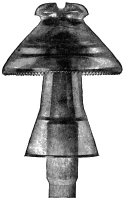
Fig. 90.—Glass Insulator and Sleeve on 50,000-volt Line
Between Cañon Ferry
and Butte, Mont.
When any suitable insulator is dry and clean it offers all necessary
resistance to the leakage of current over its surface, and any resistance
in the pin that carries the insulator is of small importance. If the resistance
of an insulator needs to be reinforced by that of its pin in any case,
it is when the surface of the insulator is wet or dirty. Unfortunately,
however, the same weather conditions that deposit dirt or moisture on
an insulator make similar deposits on its pin, and the resistance of the
pin is lowered much more than that of the insulator by such deposits.
The increase of current leakage over the surface of an insulator during
rains and fogs usually does no damage to the insulator itself, but such
leakage over the wet pin soon develops a surface layer of carbon that
continues to act as a good conductor after the moisture that temporarily[284]
lowered the resistance has gone. Reasons like these have led some engineers
to prefer iron pins with insulators that offer all of the resistance
necessary for the voltage employed on the line.
It may be suggested that the use of iron pins will transfer the charring
and burning to the wooden cross-arms, but this does not seem to be a
necessary result. The comparative freedom of cross-arms from charring
and burning where wooden pins are used seems to be due to the larger
surface and lower resistance of the cross-arms. With iron pins having
a shank of small diameter, so that the area of contact surface between the
pin and the wooden cross-arm is relatively small, there may be some
charring of the wood at this contact surface. Should it be thought desirable
to guard against any trouble of this sort, the surface of the iron
pin in contact with the cross-arm may be made ample by the use of
large washers, or by giving each pin a greater diameter at the shank than
elsewhere.
It may be noted that the pins with a central iron bolt only half an
inch in diameter, that were used on the 33,000-volt Santa Ana line, were
said to have caused no burning of their cross-arms in those cases in which
the wooden threads about the top of the central bolt were burned through.
Another possible trouble with iron pins is that they, by their greater
rate of expansion than glass or porcelain, will break their insulators.
Such results can readily be avoided by cementing each iron pin into its
insulator, instead of screwing the insulator onto the pin. Iron pins will,
no doubt, cost somewhat more than those of wood, but this cost will
in any event be only a small percentage of the total investment in a
transmission line. Considering the cost of the renewals of wooden
pins, there seems little doubt that on a line where the voltage and other
conditions are such as to result in frequent burning, iron pins would be
cheaper in the end.
Iron pins have already been adopted on a number of high-voltage
lines. Not only iron pins, but even iron cross-arms and iron poles are
in use on a number of transmission lines. On a long line now under
construction in Mexico, iron towers, placed as much as 400 feet apart,
are used instead of wooden poles, and both the pins and cross-arms are
also of iron. The 75-mile line from Niagara Falls to Toronto is carried
entirely on steel towers.
The Vancouver Power Company, Vancouver, British Columbia, use
a pin that consists of a steel bolt about 12 inches long fitted with a sleeve
of cast iron 41⁄2 inches long to enter the cross-arm, and a lead thread to
screw into the insulator. On the 111-mile line of the Washington Power[285]
Company, of Spokane, which was designed to operate at 60,000 volts and
runs to the Standard and Hecla mines, a pin consisting of a steel bar 11⁄8
inches in diameter, with a cast-iron shank 21⁄16 inches in diameter to
enter the cross-arm, and with the lead threads for the insulator, is used.
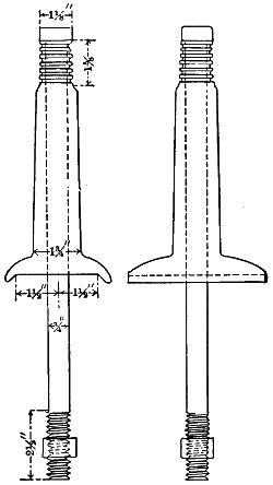
Fig. 92.—Iron Pins on Spier Falls Line.
On the network of transmission lines between Spier Falls, Schenectady,
Albany, and Troy, in the State of New York, the insulators are
supported on iron pins of two types. One of these pins, used at corners
and where the strain on the wire line is exceptionally heavy, is made up
of a wrought-iron bolt 3⁄4-inch in diameter and 161⁄2 inches long over the
head, and of a malleable iron casting 83⁄4 inches long. This casting has a
flange of 5 by 33⁄4 inches at its lower end that rests on the top of the cross-arm,
and the bolt passes from the top of the casting down through it and
the cross-arm. Threads are cut on the lower end of the bolt, and a nut
and washer secure it in the cross-arm. The total height of this pin above
the cross-arm is 91⁄4 inches.
For straight work on this line a pin with stem entirely of malleable
iron, and a bolt that comes up through the cross-arm and enters the base
of the casting, is used. The cast top of this pin has four vertical webs,[286]
and its rectangular base, which rests on the top of the cross-arm, is 31⁄2
by 4 inches. The bolt that comes up through the cross-arm and taps
into the base of the casting is 3⁄4-inch in diameter. The cast part of this
pin has such a length that the top of its insulator is carried 103⁄4 inches
above the cross-arm. For the casting the length is 91⁄4 inches.
Both of the types of iron pins in use on the Spier Falls lines are secured
to their insulators with Portland cement poured into the pin hole
while liquid when the insulator is upside down and the pin is held centrally
in its hole. The top of each casting is smaller in diameter than the
hole in the insulator, and is grooved so as to hold the cement.
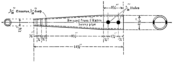
Fig. 93.—Standard Pin, Toronto and Niagara Line.
On a long line designed for 60,000 volts, and recently completed in
California, wooden pins are used with porcelain insulators, each 14 inches
in diameter and 121⁄2 inches high. Each of these pins is entirely covered
with sheet zinc from the cross-arm to the threaded end, and it is expected
that this metal covering will protect the wood of the pin from injury by
the leakage current.
[287]
CHAPTER XXI.
INSULATORS FOR TRANSMISSION LINES.
Line insulators, pins, and cross-arms all go to make up paths of
more or less conductivity between the wires of a transmission circuit.
The amount of current flowing along these paths from one conductor
to another in any case will depend on the combined resistance of the
insulators, pins, and cross-arm at each pole.
As a general rule, the wires of high-voltage transmission circuits are
used bare because continuous coverings would add materially to the cost
with only a trifling increase in effective insulation against high voltages.
In some instances the wires of high-pressure transmission lines
have individual coverings for short distances where they enter cities,
but often this is not the case. At Manchester, N. H., bare conductors
from water-power plants enter the sub-station, well within the city limits,
at 12,000 volts. From the water-power at Chambly the bare 25,000-volt
circuits, after crossing the St. Lawrence River over the great Victoria
bridge, pass overhead to a terminal-house near the water-front in Montreal.
In order to reach the General Electric Works, the 30,000-volt
circuits from Spier Falls enter the city limits of Schenectady, N. Y.,
with bare overhead conductors.
Where transmission lines pass over a territory exposed to corrosive
gases, it is sometimes desirable to give each wire a weather-proof covering.
An instance of this sort occurs near Niagara Falls where the
aluminum conductors forming one of the circuits to Buffalo are covered
with a braid that is saturated with asphaltum for some distance.
Each path, formed by the surface of the insulators of a line and the
pins and cross-arm by which they are supported, not only wastes the
energy represented by the leakage current passing over it, but may lead
to the charring and burning of the pins and cross-arm by this current.
To prevent such burning, the main reliance is to be placed in the
surface resistance of the insulators rather than that of pins and cross-arms.
These insulators should be made of glass or porcelain, and
should be used dry—that is, without oil. In some of the early transmission
lines, insulators were used on which the lower edges were[288]
turned inward and upward so that a circular trough was formed
beneath the body of the insulator, and this trough was filled with
heavy petroleum. It was found, however, that this trough of oil
served to collect dirt and thus tended to lower the insulation between
wire and cross-arm, so that the practice was soon abandoned. Glass
and porcelain insulators are rivals for use on high-tension lines, and each
has advantages of its own. Porcelain insulators are much stronger
mechanically than are those of glass, and are not liable to crack because
of unequal internal expansion, a result sometimes met with where glass
insulators are exposed to a hot morning sun. In favor of glass insulators
it may be said that their insulating properties are quite uniform, and
that, unlike porcelain, their internal defects are often apparent on
inspection. In order to avoid internal defects in large porcelain insulators,
it has been found necessary to manufacture some designs in several
parts and then cement the parts of each insulator together.
Defective insulators may be divided into two classes—those that the
line voltage will puncture and break and those that permit an excessive
amount of current to pass over their surfaces to the pins and cross-arms.
Where an insulator is punctured and broken, the pin, cross-arm, and
pole to which it is attached are liable to be burned up. If the leakage
of current over the surface of an insulator is large, not only may the loss
of energy on the line where the insulator is used be serious, but this
energy follows the pins and cross-arm in its path from wire to wire, and
gradually chars the former, or both, so that they are ultimately set on
fire or break through lack of mechanical strength. The discharge over
the surface of an insulator may be so large in amount as to have a disruptive
character, and thus to be readily visible. More frequently this
surface leakage of current over insulators is of the invisible and silent
sort that nevertheless may be sufficient in amount to char, weaken, and
even ultimately set fire to pins and cross-arms.
All insulators, whether made of glass or porcelain, should be tested
electrically to determine their ability to resist puncture, and to hold back
the surface leakage of current, before they are put into practical use on
high-tension lines. Experience has shown that inspection alone cannot be
depended on to detect defective glass insulators. Electrical testing of insulators
serves well to determine the voltage to which they may be subjected
in practical service with little danger of puncture by the disruptive passage
of current through their substance. It is also possible to determine the
voltage that will cause a disruptive discharge of current over the surface
of an insulator, when the outer part of this surface is either wet or dry.[289]
This is as far as electrical tests are usually carried, but it seems desirable
that such tests should also determine the amount of silent, invisible leakage
over the surface of insulators both when they are wet and when they
are dry, at the voltage which their circuits are intended to carry. Such
a test of silent leakage is important because this sort of leakage chars
and weakens insulator pins, and sets fire to them and cross-arms, besides
representing a waste of energy.
The voltage employed to test insulators should vary in amount
according to the purpose for which any particular test is made. Glass
and porcelain, like many other solid insulators, will withstand a voltage
during a few minutes that will cause a puncture if continued indefinitely.
In this respect these insulators are unlike air, which allows a disruptive
discharge at once when the voltage to which it is exposed reaches an
amount that the air cannot permanently withstand. Because of this
property of glass and porcelain insulators, it is necessary in making a
puncture test to employ a voltage much higher than that to which they
are to be permanently exposed. In good practice it is thought desirable
to test insulators for puncture with at least twice the voltage of the circuits
which they will be required to permanently support on transmission
lines.
For the first transmission line from Niagara Falls to Buffalo, which
was designed to operate at 11,000 volts, the porcelain insulators were
tested for puncture with a voltage of 40,000, or nearly four times that
of the circuits they were to support.
Porcelain insulators for the second line between Niagara Falls and
Buffalo, after the voltage of transmission had been raised to 22,000,
were given a puncture test at 60,000 volts. Of these insulators tested
at 60,000 volts only about three per cent proved to be defective. These
puncture tests were carried out by placing each insulator upside down
in an open pan containing salt water to a depth of two inches, partly
filling the pin hole of the insulator with salt water, and then connecting
one terminal of the testing circuit with a rod of metal in the pin hole,
and the other terminal with the pan. Alternating current was employed
in these tests, as is usually the case (Volume xviii., Transactions A. I.
E. E., pp. 514 to 520). For the transmission lines between Spier Falls,
Schenectady, Albany, and Troy, where the voltage is 30,000, the insulators
were required to withstand a puncturing test with 75,000 volts
for a period of five minutes after they had been soaked in water for
twenty-four hours.
There is some difference of opinion as to the proper duration of a[290]
puncturing test, the practice in some cases being to continue the test
for only one minute on each insulator, while in other cases the time runs
up to five minutes or more. As a rule, the higher the testing voltage
compared with that under which the insulators will be regularly used,
the shorter should be the period of test. Instead of being tested in salt
water as above described, an insulator may be screwed onto an iron pin
of a size that fits its threads, and then one side of the testing circuit put
in contact with the pin and the other side connected with the wire groove
of the insulator. Care should be taken where an iron pin is used either
in testing or for regular line work, that the pin is not screwed hard up
against the top of the insulator, as this tends to crack off the top, especially
when the pin and insulator are raised in temperature. Iron expands
at a much higher rate than glass or porcelain, and it is desirable
to cement iron pins into insulators rather than to screw them in. There
seems to be some reason to think that an insulator will puncture more
readily when it is exposed to severe mechanical stress by the expansion
of the iron pin on which it is mounted.
Tests of insulators are usually made with alternating current, and
the form of the voltage curve is important, especially where the test is
made to determine what voltage will arc over the surface of the insulator
from the line wire to the pin. The square root of the mean square for
two curves of alternating voltage or mean effective voltage, as read by
a voltmeter, may be the same though the maximum voltages of the two
curves differ widely. In tests for the puncture of insulators, the average
alternating voltage applied is more important than the maximum voltage
shown by the highest points of the pressure curve, because of the
influence of the time element with glass and porcelain. On the other
hand, when the test is to determine the voltage at which current will arc
over the insulator surface from the line wire to the pin, the maximum
value of the pressure curve should be taken into consideration because
air has no time element, but permits a disruptive discharge under a
merely instantaneous voltage.
Alternators used in transmission systems usually conform approximately
to a sine curve in the instantaneous values of the pressures they
develop, and it is therefore desirable that tests on line insulators be made
with voltages whose values follow the sine curve. Either a single transformer
or several transformers in series may be employed to step up to
the required voltage, but a single transformer will usually give better
regulation and greater accuracy. An air-gap between needle points is
not a very satisfactory means by which to determine the average voltage[291]
on a testing circuit, because, as already pointed out, the sparking distance
between the needle points depends mainly on the maximum instantaneous
values of the voltage, which may vary with the load on the
generator, and the saturation of its magnets. For accurate results a
step-down voltmeter transformer should be used on the testing circuit.
An insulator that resists a puncture test may fail badly when subjected
to a test as to the voltage that will arc over its surface from line
wire to pin. This arc-over test should be made with the outer surface
of the insulator both wet and dry. For the purpose of this test the
insulator should be screwed onto an iron pin, or onto a wooden pin
that has been covered with tinfoil. One wire of the testing circuit
should then be secured in the groove of the insulator, and the
other wire should be connected to the iron or tin foil of the pin.
The voltage that will arc over the surface of an insulator from the
line wire to the pin depends on the conditions of that surface and of
the air. In light air, such as is found at great elevations, an arc will
jump a greater distance than in dry air near the sea-level. A fog increases
the distance that a given voltage will jump between a line wire
and its insulator pin, and a heavy rain lengthens the distance still further.
The heavier the downpour of rain the greater is the distance over the
outside surface of an insulator that a given voltage will arc over. The
angle at which the falling water strikes the insulator surface also has an
influence on the voltage required to arc over that surface, a deviation
from a downpour perpendicular to the plane of the lower edge of the
petticoat of the insulator seeming to increase the arcing distance for a
given voltage.
An insulator should be given an arc-over test under conditions that
are approximately the most severe to be met in practice. These conditions
can perhaps be fairly represented by a downpour of water that
amounts to a depth of one inch in five minutes for each square inch of
the plane included by the edge of the largest petticoat of the insulator,
when the direction of the falling water makes an angle of forty-five degrees
with that plane. A precipitation of one inch in depth on a horizontal
plane during five minutes seems to be a little greater than any recorded
by the United States Weather Bureau. Under the severe conditions
just named, the voltage required to arc over the insulator surface from
line wire to pin should be somewhat greater at least than the normal
voltage of the circuit where the insulator is to be used. For the transmission
line between Spier Falls and Schenectady, on which the maximum
voltage is 30,000, the insulators were required to stand a test of[292]
42,000 volts when wet, without arcing over from line wire to pin. In
these wet tests the water should be sprayed evenly onto the insulator
surface like rain, and the quantity of water that strikes the insulator
in a given time should be measured.
When the outside of an insulator is wet with rain, it is evident that
most of the resistance between the line wire and the insulator pin must
be offered by the inside surface of the petticoat of the insulator. For this
reason an insulator that is to withstand a very high voltage so that no arc
will be formed over its wet outside surface must have a wide, dry surface
under its petticoat. In some tests of line insulators reported in Volume
xxi., Transactions A. I. E. E., p. 314, the results show that the voltage
required to arc over from line wire to pin depends on the shortest distance
between them, rather than on the distance over the insulator surface.
Three insulators, numbered 4, 5, and 7 in the trial, were in each
case tested by a gradual increase of voltage until a discharge took place
between the wire and pin. The pins were coated with tinfoil, and the
testing voltage was applied to the tie wire on each insulator and to the
tinfoil of its pin. Insulators 4, 5, and 7 permitted arcs from wire to pin
when exposed to 73,800, 74,700, and 74,700 volts respectively, the surfaces
of all being dry and clean. The shortest distances between wires
and pins over insulator surface and through air were 65⁄8,
61⁄4, and 77⁄8
inches respectively for the three insulators, so that the arcing voltages
amounted to 11,140, 11,952, and 9,479 per inch of these distances.
Measured along their surfaces, the distances between wires and pins on
these three insulators were 8, 111⁄4, and 151⁄2 inches respectively, so that
the three arcing voltages, which were nearly equal, amounted to 9,225,
6,640, and 4,819 per inch of these distances. These figures make it
plain that the arcing voltage for each insulator depends on the shortest
distance over its surface and through the air, from wire to pin. It
might be expected that the voltage in any case would arc equal distances
over clean, dry insulator surface or through the air, and the experiments
just named indicate that this view is approximately correct. The sparking
distance through air between needle points, which is greater than
that between smooth surfaces, is 5.85 inches with 70,000 volts, and 7.1
inches with 80,000 volts according to the report in Volume xix., A. I.
E. E., p. 721. Comparing these distances with the shortest distances
between wires and pins in the tests of insulators numbered 4, 5, and 7,
which broke down at 73,800 to 74,700 volts when dry, it seems that a
given voltage will arc somewhat further over clean, dry insulator surface
than it will through air. This view finds support from the fact that only[293]
a part of each of the shortest distances between wire and pin was over
insulator surface, the remainder being through air alone.
The fact that the dry part of the surface of an insulator and the air
between its lower wet edge and the pin or cross-arm offer most of the
resistance between the line wire and the pin and cross-arm is plainly
brought out by the results of the tests above mentioned, in the cases of
insulators numbered 4 and 7. While 73,800 volts were required to arc
from line-wire to pin when the entire insulator was dry and clean, the
arc was formed at only 53,400 volts during a moderate rain-storm, in
the case of No. 4 insulator. With insulator No. 7 the arcing voltage
was 74,700 when the entire surface was clean and dry, but the arc from
wire to pin was started at 52,800 volts during a moderate rain. No. 5
insulator seems to present an erratic result, for when dry and clean the
arc jumped from wire to pin at 74,700 volts, and yet during a moderate
rain no arc was formed until a voltage of 70,400 was reached. For each
of the seven insulators on which tests are reported as above, the voltage
required to arc from line wire to pin was nearly or quite as great during
a dry snow-storm as when the insulator surface was clean and dry.
When the insulators were covered with wet snow their surface insulation
broke down at voltages that were within ten per cent above or below the
arcing voltages during a moderate rain in five cases. With two insulators
the arcing voltages, when they were covered with wet snow, were only
about sixty per cent of the voltages necessary to break down the surface
insulation between wire and pin during a moderate rain.
When the outside surface of an insulator is wet, as during a moderate
rain, it seems that the under surface of the insulator, and the distance
through air from the lower wet edge of the insulator to the pin or cross-arm,
make up most of the insulation that prevents arcing over from the
wire to the pin or cross-arm. It further appears that it is useless to
extend the distance across the dry under surface of the insulator indefinitely
without a corresponding increase of the direct distance through air
from the lower wet edge of the insulator to the wood of cross-arm or pin.
Insulator No. 7 in the tests under consideration had a diameter at the
lower edge of its outer petticoat of seven inches, and was mounted on a
standard wooden pin. The diameter of this pin in the plane of the lower
edge of the insulator was probably about 11⁄4 inches, so that the radial
distance through air from this edge to the pin must have been 27⁄8 inches
approximately. During a moderate rain the surface insulation of this
insulator broke down and an arc was formed from wire to pin with 52,800
volts. The sparking distance between needle points at 50,000 volts is[294]
3.55 inches, according to Volume xix., A. I. E. E., p. 721, and must
be shorter between smooth surfaces, such as the wire and pin in question,
so that nearly all of the 52,800 volts in this case must have been required
to jump the 27⁄8 inches of air, leaving very little to overcome the slight
resistance of the wet outside surface of the insulator. On this insulator
the surface distance from wire to pin was 15-1⁄2 inches, while the shortest
breaking distance was only 77⁄8 inches, so that the distance across the dry
under surface of the insulator must have been 151⁄2 -
(77⁄8 - 27⁄8) = 101⁄2
inches approximately. It is evidently futile to put a path 101⁄2 inches
long across dry insulator surface in parallel with a path only 27⁄8 inches
long in air, as an arc will certainly jump this shorter path long before
one will be formed over the longer. The same line of reasoning applies
to No. 3 insulator in this test, which had a diameter of 63⁄4 inches, a surface
distance from wire to pin of 13 inches, and a minimum distance of 71⁄4
inches, and whose surface insulation broke down at 48,600 volts during
a moderate rain. The necessity of increasing the distance between the
lower wet edges of insulators and the pins and cross-arm, as well as the
distance across the dry under surfaces of insulators, led to the adoption
of the so-called umbrella type for some high-voltage lines. In this type
of insulator the main or outer petticoat is given a relatively great diameter,
and instead of being bell-shaped is only moderately concave on its
under side. With an insulator of this type mounted on a large, long pin,
the lower edge of the umbrella-like petticoat may be far removed from
the pin and cross-arm. Beneath the large petticoat of such insulators
for high voltages there are usually one or more smaller petticoats or[295]
sleeves that run down the pin, and increase the distance between it and
the lower edge of the largest petticoat.
Insulators on Transmission Lines.
| Location of Line. |
Voltage
of
Line. |
Material
of
Insulator. |
Inches
Diameter
of
Insulator. |
Inches
Height
of
Insulator. |
| Electra to San Francisco |
60,000 |
Porcelain |
11 |
|
11 |
1⁄4 |
| Colgate to Oakland |
60,000 |
Porcelain |
11 |
|
11 |
1⁄4 |
| Cañon Ferry to Butte |
50,000 |
Glass |
9 |
|
12 |
|
| Shawinigan Falls to Montreal |
50,000 |
Porcelain |
10 |
|
13 |
1⁄2 |
| Provo around Utah Lake |
40,000 |
Glass |
7 |
|
5 |
3⁄4 |
| Santa Ana River to Los Angeles |
33,000 |
Porcelain |
6 |
3⁄4 |
4 |
7⁄8 |
| Spier Falls to Schenectady |
30,000 |
Porcelain |
8 |
1⁄2 |
6 |
3⁄4 |
| Apple River Falls to St Paul |
25,000 |
Glass |
7 |
|
5 |
3⁄4 |
| Chambly to Montreal |
25,000 |
Porcelain |
5 |
1⁄2 |
6 |
1⁄2 |
| Niagara Falls to Buffalo |
22,000 |
Porcelain |
7 |
1⁄2 |
7 |
|
| Portsmouth to Pelham, N. H. |
13,000 |
Porcelain |
5 |
1⁄4 |
3 |
3⁄4 |
| Garvins Falls to Manchester, N. H. |
12,000 |
Glass |
5 |
|
4 |
3⁄4 |
The inner petticoat or sleeve that runs down over the pin and sometimes
reaches nearly to the cross-arm, of course becomes wet on its
outside surface and at its lower edge during a rain; but between this
lower wet part of the inner petticoat, or sleeve, and the lower wet edge
of the larger outside petticoat, there is a wide, dry strip of insulator surface.
A result is that an arc over the surface of the outside petticoat
can reach the wet edge of the sleeve only by crossing the strip of dry
under surface or jumping through the air.
The same type of insulator is used on the 60,000-volt lines between
Electra and San Francisco and between Colgate and Oakland, each
insulator having an outer petticoat 11 inches in diameter and one inner
petticoat or sleeve 61⁄2 inches in diameter. This inner petticoat runs down
the pin for a distance of 71⁄2 inches below the outer petticoat. Slightly
different pins are used for mounting the insulators on the two transmission
lines just named, so that on the former the distance through air
from the lower edge of the outer petticoat to the cross-arm is 11 inches,
and on the latter the corresponding distance is 111⁄2 inches. On the Electra
line the lower edge of the inner petticoat of each insulator is about
31⁄2 inches, and on the Colgate line about 4 inches above the cross-arm.
Insulators on Transmission Lines.
| Location of Line. |
Inches from
Top of
Insulator
to Cross-arm. |
Inches from
Outside
Petticoat
to Cross-arm. |
Inches from
Lowest
Petticoat
to Cross-arm. |
Inches from
Edge of
Outside
to Edge of
Lowest
Petticoat. |
| Electra to San Francisco |
14 |
1⁄2 |
11 |
|
3 |
1⁄2 |
7 |
1⁄2 |
| Colgate to Oakland |
15 |
|
11 |
1⁄2 |
4 |
|
7 |
1⁄2 |
| Cañon Ferry to Butte |
13 |
1⁄2 |
7 |
3⁄4 |
1 |
1⁄2 |
6 |
1⁄4 |
| Shawinigan Falls to Montreal |
16 |
1⁄4 |
11 |
3⁄4 |
3 |
1⁄4 |
8 |
1⁄2 |
| Santa Ana River to Los Angeles |
8 |
5⁄8 |
3 |
3⁄4 |
3 |
3⁄4 |
0 |
|
| Spier Falls to Schenectady |
10 |
3⁄4 |
7 |
3⁄8 |
4 |
1⁄4 |
3 |
3⁄8 |
| Niagara Falls to Buffalo |
10 |
|
5 |
1⁄2 |
3 |
|
2 |
1⁄2 |
| Chambly to Montreal |
8 |
1⁄2 |
4 |
1⁄2 |
2 |
|
2 |
1⁄2 |
| On each of the lines named in this table the wires are strung on the tops of their insulators. |
The Cañon Ferry line is carried on insulators each of which has three
short petticoats and a long separate sleeve that runs down over the pin
to within 11⁄2 inches of the cross-arm. This sleeve makes contact with
its insulator near the pin hole. The outside petticoat of each insulator[296]
on this line is 73⁄4 inches above the cross-arm and 61⁄4 inches above the
lower end of the sleeve. Both the main insulator and the sleeve, in
this case, are of glass.
White porcelain insulators are used to support the 50,000-volt Shawinigan
line, and are of a recent design. Each of these insulators has
three petticoats ranged about a central stem so that their lower edges
are 41⁄2 inches, 9 inches, and 13 inches respectively, below the top. The
highest petticoat is 10 inches, the intermediate 93⁄4 inches, and the lowest
41⁄4 inches in diameter. The height of this insulator is 13 inches, compared
with 111⁄4 inches for those used on the Electra and Colgate lines
and 12 inches for the combined insulator and sleeve used on the Cañon
Ferry line. When mounted on its pin, this insulator on the Shawinigan
line holds its wire 161⁄4 inches above the cross-arm, compared with a corresponding
distance of 141⁄2 inches on the Electra, 15 inches on the Colgate,
and 131⁄2 inches on the Cañon Ferry line. The two upper petticoats
on each of these insulators are much less concave than the lowest one,
and the edges of all three stand respectively 113⁄4,
71⁄4, and 31⁄4 inches above
the cross-arm. From the edge of the top to the edge of the bottom
petticoat the direct distance is 81⁄2 inches.
Of the three transmission lines above named that operate at 50,000
to 60,000 volts, that between Shawinigan Falls and Montreal leads
as to distances between the line wire and insulator petticoats and the
cross-arm. On the Santa Ana line, where the voltage is 33,000, the
insulator is of a more ordinary type, being of porcelain, 63⁄4 inches in
diameter, 47⁄8 inches high, and having the lower edges of its three petticoats
in the same plane. Each of these insulators holds its wire 85⁄8
inches above the cross-arm, and has all of its petticoats 31⁄2 inches above
the cross-arm. Unlike the three insulators just described, which are
mounted on wooden pins, this Santa Ana insulator has a pin with an
iron core, wooden threads, and porcelain base. This base extends up
from the cross-arm a distance of 31⁄8 inches, and the wooden sleeve, in
which the threads for the insulator are cut, runs down over the central
bolt of the pin to the top of the porcelain base, which is 5⁄8-inch below
the petticoats.
The 30,000-volt lines from Spier Falls are carried 103⁄4 inches above
their cross-arms by triple petticoat porcelain insulators. Each of these
insulators is 81⁄2 inches in diameter, 63⁄4 inches high, and is built up of
three parts cemented together. A malleable-iron pin cemented into each
insulator with pure Portland cement carries the outside petticoat 71⁄2
inches and its lowest petticoat 41⁄4 inches above the cross-arm. When[297]
the voltage on the Spier Falls lines was raised from about 13,000 to
30,000, the circuits being carried in part by one-piece porcelain insulators,
a number of these insulators were punctured at the higher
pressures, and some cross-arms and poles were burned as a result. No
failures resulted on those parts of these lines where the three-part insulators
were in use. The second pole line between Niagara Falls and
Buffalo was designed to carry circuits at 22,000 volts, or twice that for
which the first line was built. Porcelain insulators were employed on
both of these lines, but while the 11,000-volt line was carried on three-petticoat
insulators, each with a diameter of 7 inches and a height of 51⁄2
inches, the 22,000-volt line was mounted on insulators each 71⁄2 inches in
diameter and 7 inches high, with only two petticoats. The older insulator
has its petticoats 2 inches above the cross-arm, and the lower petticoat
of the new insulator is 3 inches above the arm. These two insulators
illustrate the tendency to lengthen out along the insulator axis as the
voltage of the circuits to be carried increases.
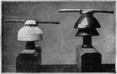
Fig. 93A.—The Old and New Insulators on the Niagara Falls-Buffalo Line.
For future work at still higher voltages, the advantage as to both first
cost and insulating qualities seems to lie with insulators that are very
long in an axial direction, and which have their petticoats arranged one
below the other and all of about the same diameter, rather than with
insulators of the umbrella type, like those on the Electra and Colgate
lines.
[298]
CHAPTER XXII.
DESIGN OF INSULATOR PINS FOR TRANSMISSION LINES.
Bending strains due to the weights, degree of tension, and the directions
of line wires, plus those resulting from wind-pressure, are the chief
causes that lead to the mechanical failure of insulator pins.
Considering the unbalanced component of these forces at right
angles to the axis of the pin, which alone produce bending, each pin may
be considered as a beam of circular cross section secured at one end and
loaded at the other.
For this purpose the secured end of the beam is to be taken as the
point where the pin enters its cross-arm, and the loaded end of the beam
is the point where the line wire is attached to the insulator. The distance
between these two points is the length of the beam. The maximum
strain in the outside fibres of a pin measured in pounds per square
inch of its cross section, represented by S, may be found from the formula,
S = P X
.0982 D3
where P is the pull of the wire in pounds, D is the diameter of the pin
at any point, and X is the distance in inches of that point from the wire.
Inspection of this formula shows that S, the maximum strain at any point
in the fibres of a pin, when the pull of the line-wire, P, is constant, increases
directly with the distance, X, from the wire to the point where
the strain, S, takes place. This strain, S, with a constant pull of the
line wire, decreases as the cube of the diameter, D, at the point on the
pin where S occurs increases. That cross section of a pin just at the
top of its hole in the cross-arm is thus subject to the greatest strain, if
the pin is of uniform diameter, because this cross section is more distant
from the line wire than any other that is exposed to the bending strain.
For this reason it is not necessary to give a pin a uniform diameter
above its cross-arm, and in practice it is always tapered toward its top.
Notwithstanding this taper, the weakest point in pins as usually made
is just at the top of the cross-arm, and it is at this cross section where
pins usually break. This break comes just below the shoulder that is[299]
turned on each pin to prevent its slipping down through the hole in its
cross-arm. If the shoulder on a pin made a tight fit all around down
onto the cross-arm, the strength of the pin to resist bending would be
thereby increased, but it is hard to be sure of making such fits, and they
should not be relied on to increase the strength of pins. By giving a
pin a suitable taper from its shoulder at the cross-arm to its top, the
strain per square inch, S, in the outside fibres of the pin may be made
constant for every cross section throughout its length above the cross-arm,
whatever that length may be. The formula above given may be
used to determine the diameters of a pin at various cross sections that
will make the maximum stress, S, at each of these cross sections constant.
By transposition the formula becomes
D3 = P
.0982 S X.
Where the pin is tapered so that S is constant for all cross sections, then
for any pull, P, of the line wire on the pin the quantity (P.0982 S) must
be constant at every diameter, D, distant any number of inches, X,
from the point where the wire is attached. If the constant, (P.0982 S)
is found for any one cross section of a pin, therefore, the diameter at
each other cross section with the same maximum stress, S, may be
readily found by substituting the value of this constant in the formula.
The so-called “standard” wooden pin that has been very generally used
for ordinary distribution lines, and to some extent even on high-voltage
transmission lines, has a diameter of nearly 1.5 inches just below the
shoulder. The distance of the line wire above this shoulder varies between
about 4.5 and 6 inches, according to the type of insulator used,
and to whether the wire is tied at the side or top of the insulator. If the
line wire is tied to the insulator 5 inches above the shoulder of one of the
standard pins, then X becomes 5, and D becomes 1.5 in the formula
last given. From that formula by transposition and substitution
P.0982 S =
D3X =
(1.5)35 =
0.675.
Substituting 0.675 for the quantity P0.0982 S
in the formula D3 =
P0.0982 S
X gives the formula D3 = 0.675 X, from which the diameters
at all cross sections of a tapered pin above its shoulder, that will[300]
give it a strength just equal to that of a section of 1.5 inches diameter
and 5 inches from the line wire, may be found. To use the formula
for this purpose it is only necessary to substitute any desired values of
X therein and then solve in each case for the corresponding values of D.
Let it be required, for instance, to determine what diameter a pin should
have at a cross section one inch below the line wire in order that the
maximum strain at that cross section may equal the corresponding strain
at a cross section five inches below the line wire and of 1.5 inch diameter.
Substituting one as the value of X, the last-named formula becomes
D3 = 0.675, and from this, D = 0.877, which shows that the diameter
of the pin one inch below the line wire should be 0.877-inch. A similar
calculation will show that if a pin is long enough so that a cross section
above the cross-arm is 12 inches below the line wire, the diameter of this
cross section should be equal to the cube root of 0.675 × 12 = 8.1, which
is 2.008, or practically two inches. It should be observed that the calculations
just made have nothing to do with the ability of a pin to resist
any particular pull of its line wire. These calculations simply show
what diameters a pin should have at different distances below its line
wire in order that the maximum stress at each of its cross sections may
equal that at a cross section 5 inches below the wire where the diameter
is 1.5 inches. In Vol. xx., A. I. E. E., pp. 415 to 419, specifications
are proposed for standard insulator pins based on calculations like
those just made. As a result of such calculations, the following table
for the corresponding values of X and D, as used in the above formula,
are there presented, each expressed in inches.
| X |
D |
| 1 |
0 |
.877 |
| 2 |
1 |
.106 |
| 3 |
1 |
.263 |
| 4 |
1 |
.395 |
| 5 |
1 |
.500 |
| 6 |
1 |
.592 |
| 7 |
1 |
.678 |
| 8 |
1 |
.754 |
| 9 |
1 |
.825 |
| 10 |
1 |
.888 |
| 11 |
1 |
.95 |
| 13 |
2 |
.06 |
| 15 |
2 |
.17 |
| 17 |
2 |
.25 |
| 19 |
2 |
.34 |
| 21 |
2 |
.42 |
A pin twenty-one inches long between the line wire and the cross-arm
will have a uniform strength to resist the pull of the wire if it has
the diameter given in this table at the corresponding distances below
the line wire. From this it follows that a pin of any length between
wire and cross-arm corresponding to X in the table will be equally
strong to resist a pull of the line wire as a standard 1.5-inch diameter pin
with its wire five inches above the cross-arm. In other words, if a pin
that is twenty-one inches long between the line wire and the cross-arm[301]
has the diameters given in the table at the corresponding distances below
the wire, then a pin of equal strength to resist bending, and of any
shorter length, would correspond in the part above the cross-arm to an
equal length cut from the top end of the longer pin. Designating that
part of a pin that is above the cross-arm as the “stem,” and that part
in the cross-arm as the “shank,” each pin in the specifications under
consideration is named by the length of its stem, as a 5-, 7- or 11-inch
pin. It is proposed that each pin of whatever length be threaded for a
distance of 2.5 inches at the top of its stem with four threads per inch,
the sides of each thread being at an angle of ninety degrees with each
other. Each thread is to cut into the pin about 3⁄32 inch, come to a
sharp angle at the bottom, and be about 1⁄16 inch wide on top. At the
end of the pin the proposed diameter over the thread is one inch in all
cases, and at the lower end of the threaded portion the outside diameter
is 1.25 inches. Near the end of the pin the diameter at the bottom
of the thread is thus only 13⁄16 inch, and the corresponding diameter
at the lower end of the threaded portion is about 11⁄16 inches on all pins.
Each pin is to have a square shoulder to rest on the cross-arm, and the
diameter of this shoulder is to be 3⁄8 inch greater than the nominal diameter
of the shank of the pin. The proposed length of this shoulder on all pins
is 1⁄4 inch before the taper begins. The actual diameter of the shank of
each pin just below its shoulder is to be 1⁄32 inch less than the nominal
diameter, and the actual diameter of the lower end of each shank is to
be 1⁄16 inch less than the nominal diameter. With these explanations
the proposed sizes of pins have dimensions as follows in inches:
Length
of
Stem. |
Length
of
Shank. |
Nominal
Diameter
of Shank. |
| 5 |
4 |
1⁄4 |
1 |
1⁄2 |
| 7 |
4 |
1⁄4 |
1 |
3⁄4 |
| 9 |
4 |
1⁄4 |
1 |
7⁄8 |
| 11 |
4 |
3⁄4 |
2 |
|
| 13 |
4 |
3⁄4 |
2 |
1⁄8 |
| 15 |
4 |
3⁄4 |
2 |
1⁄4 |
| 17 |
5 |
3⁄4 |
2 |
3⁄8 |
| 19 |
5 |
3⁄4 |
2 |
1⁄2 |
In order rightly to appreciate the utility of this table of proposed
standard pins, it is necessary to have in mind the fact that all the dimensions
are based on the assumption that a wooden pin with a shank of
one and one-half inches diameter, and with its line wire attached five
inches above the cross-arm, is strong enough for general use on transmission
lines. Such an assumption covers a wide range of practice, but
its truth may well be doubted for many cases. That this assumption[302]
does form the basis of the entire table is clearly shown by the fact that
the calculated diameter at the shank of each pin is made to depend on
a uniform pull, P, of the line wire, giving a uniform maximum stress, S, in
the outer fibres of the wood just where the shank joins the stem. In other
words, every pin in the table is designed to break with a uniform pull of
the line wire, provided that the point on the insulator where the wire is
attached is just on a level with the top of its pin in each case. It will
at once occur to practical men that while a five-inch pin with one and
one-half inch shank, or a larger pin of equal ability to resist the pull of
a line wire, may be strong enough for the conductors of some transmission
lines, this same pin may be entirely too weak for the longer spans,
sharper angles, and heavier conductors of other lines.
Thus, on the sixty-five-mile line between Cañon Ferry and Butte,
Mont., each conductor is of copper and has a cross section of 106,500
cm., while on the older line between Niagara Falls and Buffalo each
copper conductor has a cross section of 350,000 cm. Evidently with
equal conditions as to length of span, amount of sag, and sharpness of
angles on these two lines, pins ample in strength for the smaller wire
might be much too weak for the larger wire.
A little consideration will show that it is neither rational nor desirable
to adopt pins of uniform strength for all transmission lines, but that
several degrees of strength are necessary to correspond with the range
in sizes of conductors in regular use. The size of pins for use on any
transmission line, when the maximum bending strain exerted by the
conductors has been determined, should be found by calculation and
experiment, or by experiment alone. According to Trautwine, the
average compressive strength of yellow locust is 9,800 pounds, of hickory
8,000 pounds, and of white oak 7,000 pounds per square inch in the direction
of the grain. These compressive strengths are less than the tensile
strengths of the same woods, and should therefore be employed in calculation,
since the fibres on one side of a bending pin are compressed while
the fibres on the other side are elongated. Substituting 1,000 for the
value of S in the formula, S = P X.0982 D3, and also 5 for the value of
X, and 11⁄2 for the value of D, the resulting value of P is found to be
736.5 pounds. This result shows that with a locust pin of 11⁄2 inches
diameter at the shank, and with its line wire attached five inches above
the shoulder, the unbalanced side pull of the wire that will break the
pin by bending is 736 pounds, provided that the wood of the pin has a
strength of 1,000 pounds per square inch in compression. As all of the[303]
proposed standard pins in the above table are designed for uniform
strength to resist the same pull of a line wire attached on a level with
the top of the pin in each case, it follows that the pull of 736 pounds by
the wire will break any one of these pins under the conditions stated.
The calculation just made takes no account of the fact that the actual
diameter of the shank of each pin just below the shoulder is 1⁄32 inch less
than the nominal diameter, but this of course reduces the strength somewhat.
Trautwine states that the figures above given for the compressive
strengths of wood are only averages and are subject to much variation.
Of course no pin should be knowingly loaded in regular practice to the
breaking point, and to provide against variations in the strength of wood,
and for unexpected strains, a liberal factor of safety, say four, should be
adopted in fixing the maximum strains on insulator pins. Applying this
factor to the calculations just made, it appears that the maximum pull
of the line wire at the top of any one of the above proposed standard
pins should not exceed 736 ÷ 4 = 184 pounds in regular work. A
little calculation will readily show that the side pull of some of the larger
conductors now in use on transmission lines will greatly exceed 184
pounds under conditions, as to sag, angles and wind pressure, that are
frequently met in practice.
On page 448, Vol. xx., A. I. E. E., some tests are reported on six
locust wood pins with shank diameters of 17⁄16 to 11⁄2 inches. Each of
these pins was tested by inserting its shank in a hole of 11⁄2 inches diameter
in a block of hard wood, and then applying a strain at about right
angles to the pin and about 41⁄2 inches from the block by means of a
Seller’s machine. The pull on each pin was applied gradually, and in
most of the pins the fibres of the wood began to part when the side pull
reached 700 to 750 pounds, though the maximum loads sustained were
about ten per cent above these figures. The average calculated value
of S, the compressive strength of the wood in these pins, was 11,130
pounds per square inch on the basis of the loads at which the fibres of
the wood began to break, and 13,623 pounds per square inch for the
loads at which the pins gave way. On pages 650 to 653 of the volume
last cited, results are reported of tests on twenty-two pins of eucalyptus
wood, which is generally used for this purpose in California. Twelve
of these pins were of a size much used in California on lines where the
voltage is not above 30,000. Each of the twelve pins was 67⁄8 inches
long in the stem, 45⁄8 inches long in the shank, 11⁄2 inches in diameter at
the shank, 2 inches in diameter at the square shoulder where the shank
joins the stem, and 13⁄8 inches in diameter at
the top of the thread. The[304]
pins were tested by mounting each of them in a cross-arm, securing the
cross-arm in a testing machine so that the pin was horizontal, placing
an insulator on the pin, and exerting the strain on a cable wrapped
around the side groove of the insulator. This cable varied a little from
right angles to the axis of each pin, but the component of the strain at
right angles to this axis was calculated and the breaking load here mentioned
is that component. Nearly all of these twelve pins broke square
off at the cross-arm.
For a single pin, the lowest breaking strain was 705 pounds, the
largest 1,360 pounds, and the average for the twelve pins was 1,085
pounds. Unfortunately, the exact distance of the cable from the cross-arm
is not stated, but as the cable was wound about the side groove of
the insulator it was probably either in line with or a little below the top
of the pin. It seems probable also that the diameter of these pins at the
shoulder—that is, two inches—may have increased the breaking strain
somewhat by giving the shoulder a good bearing on the cross-arm. The
ten other pins were of the size in use on the 60,000-volt line between
Colgate power-house and Oakland, Cal. Each of these pins had a
length of 53⁄8 inches and a maximum diameter of 21⁄8 inches in the shank,
and a length of 103⁄8 inches in the stem, with a diameter of 21⁄2 inches at
the shoulder. This shoulder was not square, but its surface formed an
angle of forty-five degrees with the axis of the pin, and this bevel shoulder
took up 1⁄4 inch of the length just given for the stem of the pin. At 21⁄2
inches from its threaded end the stem of the pin had a diameter of 115⁄16
inches, and the diameter slopes to 13⁄8 inches at two inches from the end.
The two inches of length at the top of the stem has the uniform diameter
of 13⁄8 inches, and is threaded with four threads per inch for the insulator.
Each of these ten pins was tested, as already described, until it broke,
but the break in this case started as a split at the lower end of the threaded
portion and ran down the stem to the shoulder in a line nearly parallel
with the axis of the pin. The pull on the cable at right angles to the
axis of each pin had a maximum value of 1,475 pounds in one case, and
a corresponding value of 3,190 pounds in another, while the average
breaking strain for the ten pins was 2,310 pounds. Unfortunately, the
report of this test above named does not distinctly state just how far the
testing cable was attached above the shank of each of these large pins;
but it seems probable that the same insulator was used with the larger
as with the smaller pins, and if this was so the testing cable was attached
near the end of each pin, as this cable was wound about the side groove
of the insulator used on the smaller pins. With the types of insulator[305]
in actual use on the Colgate and Oakland line the wire is carried at the
top groove and its centre is about two and a half inches above the top
of the pin. It is therefore probable that these pins would not withstand
as great strains on the lines as they did in these tests. The bevel shoulder
on each of these larger pins no doubt increases its ability to resist a bending
strain, because the bevel surface fits tightly down into a counterbore
in the cross-arm. Where the pin has a shoulder at right angles with the
axis, as is more usually the case, and the top of the cross-arm is a little
rounding, the square shoulder does not have a firm seat and is of slight
importance as far as the strength of the pin to resist a bending strain is
concerned. Evidently the weakest point in the ten larger pins of this
test was at the lower end of the threaded portion, since in each case the
break was in the form of a long split starting where the thread ended.
There seems to be no sufficient reason for the reduction of the diameter
of a pin intended for a heavy line wire to a diameter as small as one
inch at the threaded end, or for limiting the length of the threaded portion
to 2.5 inches, as proposed in the specifications for standard pins.
It is certain that the cost of the pin would be no more if its diameter at
the threaded end were 11⁄4 or 13⁄8 inches with a uniform taper from the end
of the pin down to the shoulder and with the thread cut down the stem
for three or four inches. Furthermore, any increase in the cost of insulators
for these larger threaded ends of pins would no doubt be a small
matter. Some excess of strength in the stem of a pin over that of its
shank is to be desired, for the stem is more exposed to the weather and
to charring by leakage currents over the surface of the insulator. On
high-voltage lines, this charring is usually worse at that part of each pin
just below its thread, and the commonest breaks of pins on these lines
leave the insulators with the threaded portions of their pins hanging on
the wire, while the remainder of each pin remains on the cross-arm.
From the tests just noted it is evidently poor design to give the threaded
portion of a pin a short length of uniform diameter, and then to increase
the diameter at once by a shoulder, as was done with the pins on
the Colgate and Oakland line. This design evidently leads to failure
of pins by splitting from the lower end of the threads. The better
design is the more common one which gives the stem of the pin a uniform
taper from the shoulder to the top. Where the line wire is secured to
the top of its insulator, anywhere from one to three inches above the top
of the pin, there is a strong tendency for the insulator to tip on its pin,
and this tendency is more effectively met the longer the joint between
the pin and insulator.
[306]
CHAPTER XXIII.
STEEL TOWERS.
Steel towers are rapidly coming into use for the support of electric
transmission lines that deliver large units of energy at high voltages to
long distances from water-powers.
One case of this sort is the seventy-five-mile transmission of 24,000
horse-power at 60,000 volts from Niagara Falls to Toronto. Another
example may be seen in the seventy-five-mile line of steel towers which
carries transmission circuits of 60,000 volts to Winnipeg. Guanajuato,
Mexico, which is said to have produced more silver than any other city
in the world, receives some 3,300 electric horse-power over a 60,000-volt
transmission line one hundred miles long on steel towers. Between
Niagara Falls and Lockport the electric circuits now being erected are
supported on steel towers. On a transmission line eighty miles long
in northern New York, for which plans are now being made, steel
towers are to support electric conductors that carry current at 60,000
volts.
For the elevations above ground at which it is common to support the
conductors of transmission lines—that is, from twenty-five to fifty feet—a
steel tower will cost from five to twenty times as much as a wooden pole
in various parts of the United States and Canada. It follows at once
from this fact that there must be cogent reasons, apart from the matter
of first cost, if the general substitution of steel towers for wooden poles
on transmission lines is to be justified on economic grounds. During
fifteen years the electric transmission of energy from distant water-powers
to important centres of population has grown from the most
humble beginnings to the delivery of hundreds of thousands of horse-power
in the service of millions of people, and the lines for this work are
supported, with very few exceptions, on wooden poles. Among the
transmissions of large powers over long distances at very high voltages
that have been in successful operation during at least several years with
wooden pole lines are the following: the 60,000-volt circuit that transmits
some 13,000 horse-power from Electra station across the State of
California to San Francisco, a distance of 147 miles, is supported by[307]
wooden poles. In the same State, the transmission line 142 miles long
between Colgate power-house and Oakland, at 60,000 volts, and with a
capacity of about 15,000 horse-power, hangs on wooden poles, save at
the span nearly a mile long over the Straits of Carquinez. Wood is used
to carry the two 55,000-volt circuits that run sixty-five miles from the
10,000-horse-power station at Cañon Ferry on the Missouri River to
Butte. Between Shawinigan Falls and Montreal, a distance of eighty-three
miles, the conductors that operate at about 50,000 volts are carried
on wooden poles. Electrical supply in Buffalo to the amount of
30,000 horse-power depends entirely on circuits from Niagara Falls that
operate at 22,000 volts and are supported on lines of wooden poles.
In the operation of these and many other high-voltage transmissions
during various parts of the past decade some difficulties have been met
with, but they have not been so serious as to prevent satisfactory service.
Nevertheless, it is now being urged that certain impediments that are
met in the operation of transmission systems would be much reduced
by the substitution of steel towers for wooden poles, and it is even suggested
that perhaps the first cost, and probably the last cost, of a transmission
line would be less with steel than with wood for supports. The
argument for steel in the matter of costs is that while a tower requires a
larger investment than a pole, yet the smaller number of towers as compared
with that of poles may reduce the entire outlay for the former to
about that for the latter. More than this, it is said that the lower depreciation
and maintenance charges on steel supports will make their
final cost no greater than that of wooden poles.
In the present state of the market, steel towers can be had at from
three to three and one-half cents per pound, and the cost of a steel tower
or pole will vary nearly as its weight. During the first half of 1904 the
quotations on tubular steel poles to the Southside Suburban Railway
Company, of Chicago, were between the limits just stated. That company
ordered some poles built up of steel sections about that time at a
trifle less than three cents per pound. Each of these poles was thirty
feet long and weighed 616 pounds, so that its cost was about eighteen
dollars (xxi, A. I. E. E., 754). For a forty-five-foot steel pole to carry
a pair of 11,000-volt, three-phase circuits along the New York Central
electric road the estimated cost was eighty dollars in the year last named
(xxi, A. I. E. E., 753). On the 100-mile line to Guanajuato, Mexico,
above mentioned, the steel towers were built up of 3″ × 3″ × 3⁄16″ angles
for legs, and were stayed with smaller angle sections and rods. Each of
these towers has four legs that come together near the top, is forty feet[308]
high, weighs about 1,500 pounds, and carries a single circuit composed
of three No. 1 B. & S. gauge hard-drawn copper cables. The weight of
each of these cables is 1,340 pounds per mile, and the forty-foot towers are
spaced 440 feet apart, or twelve per mile, over nearly the entire length of
line. At three cents per pound, the lowest figure at which these towers
could probably be secured for use in the United States, the approximate
cost of each would be forty-five dollars. Between Niagara Falls and
Lockport each of the steel towers that is to carry a single three-phase
transmission circuit has three legs built up of tubing that tapers from two
and one-half inches to smaller sizes and is braced at frequent intervals.
The height of these towers is forty-nine feet, and the weight of each is
2,800 pounds. At three cents per pound the cost of each tower amounts
to eighty-four dollars. For a long transmission line in northern New
York bids were recently had on towers forty-five feet high to carry six
wires, and the resulting prices were $100 to $125 each for a tower weighing
about 3,000 pounds. On the line between Niagara Falls and Toronto
the standard tower holds the lowest cables 40 feet above ground
at the insulators, has a weight of 2,360 pounds, and would cost $70.80
at 3 cents per pound.
In January, 1902, four steel towers were purchased to support transmission
circuits for two spans of 132 feet each over the Chambly Canal,
near Chambly Canton, Quebec. Each pair of these towers was required
to support eleven No. 2-0 B. & S. gauge bare copper wires with the
span of 132 feet between them. The vertical height of each of these four
towers is 144 feet above the foundation, and they were designed for a
maximum stress in any member of not more than one-fourth of its ultimate
strength, with wires coated to a diameter of one inch with ice and
under wind pressure. For these four steel towers erected on foundations
supplied by the purchasers the price was $4,670, and the contract called
for a weight in the four towers of not less than 121,000 pounds. On the
basis of this weight the cost of the towers erected on foundations was
3.86 cents per pound.
With these examples of the cost of steel towers a fair idea may be gotten
of the relative cost of wooden poles. For poles of cedar or other desirable
wood thirty-five feet long and with eight-inch tops fitted with either
one or two cross-arms an estimated cost of five dollars each is ample to
cover delivery at railway points over a great part of the United States
and Canada. This size of pole has been much used on the long, high-voltage
transmission systems that involve large power units and use
heavy conductors. Examples of lines where such poles are used may[309]
be seen between Niagara Falls and Buffalo, between Colgate power-house
and Oakland, and between Cañon Ferry and Butte. Of course
some longer poles were used in special locations, like the crossing of steam
railways, but it is also true that on the lines supported by steel towers
such locations make exceptionally high towers necessary. The thirty-five-foot
poles will hold the electric lines about as high above the ground
level as the forty-nine-foot towers on the Niagara Falls and Toronto
transmission, because the former will be set so much closer together.
On the line just named the regular minimum distance of the electric
cables above the ground level at the centres of spans is twenty-five feet.
The standard towers on this line carry the lower electric cables forty feet
above the ground at the insulators, and it was thought desirable to allow
a sag of fifteen feet at the centres of the regular spans of four hundred
feet each. On these towers the conductors that form each three-phase
circuit are six feet apart, and lines drawn between the three cables
form the sides of an equilateral triangle. With a pin fourteen and three-fourths
inches long like that used on these steel towers, and one conductor
at the top of a thirty-five-foot pole, where the other two are
supported by a cross-arm five feet three inches below, giving six feet
between cables, the lower cables are held by their insulators twenty-six
feet above the ground, when the poles are set five feet deep. Between
thirty-five-foot poles one hundred feet is a very moderate span, and one
that is exceeded in a number of instances. Thus on the 142-mile line
from Colgate power-house to Oakland the thirty-five-foot poles are 132
feet apart, and one line of these poles carries three conductors of 133,000-circular-mil
copper, while the other pole line has three aluminum
cables of 168,000 circular mils. On the later transmission line from
Niagara Falls to Buffalo, which was designed for three-phase circuits
of 500,000-circular-mil cable, the regular distance between the thirty-five-foot
poles is 140 feet.
A maximum sag of twenty-four inches between poles 100 feet apart
under the conditions named above brings the lowest points of the wire
twenty-four feet above the ground. The steel towers on the line to
Guanajuato being only forty feet in length, and spaced 440 feet apart,
it seems that the distance of conductors from the ground at the centres of
spans is probably no greater than that just named. Particular attention
is called to this point because it has been suggested that the use of steel
towers would carry cables so high that wires and sticks could not be
thrown onto them. It thus appears that thirty-five-foot wooden poles
set one hundred feet apart will allow as much distance between conductors,[310]
and still keep their lowest points as far above the ground, as
will forty- to forty-nine-foot towers placed four hundred feet or more
apart. The two lines that have their conductors further apart perhaps
than any others in the world are the one from Cañon Ferry to Butte, on
thirty-five-foot wooden poles, and the one to Guanajuato, on steel
towers. In each of these cases the cables are seventy-eight inches apart
at the corners of an equilateral triangle. With steel towers four hundred
feet or wooden poles one hundred feet apart, four of the latter must
be used to one of the former. At $5 per pole this requires an investment
of $20 in poles as compared with at least $45 for a tower like
those on the Guanajuato line, $84 for a tower like those on the line from
Niagara Falls to Lockport, or $70 for one of the towers on the Niagara
and Toronto line. Each of the towers on the line to Toronto carries two
three-phase circuits, and the least distance between cables is six feet.
To reach the same result as to the distance between conductors with the
two circuits on poles, it would be desirable to have two pole lines, so
that $40 would represent the investment in the poles to displace one
tower for two circuits. The older pole line between Niagara Falls and
Buffalo carries two three-phase circuits on two cross-arms, and the
350,000-circular-mil copper cables of each circuit are at the angles of
an equilateral triangle whose sides are each three feet long. In this
case, however, the electric pressure is only 22,000 volts.
The costs above named for poles and towers include nothing for
erection. Each tower has at least three legs and more commonly four,
and owing to the heights of towers and to the long spans they support
it is the usual practice to give each leg a footing of cement concrete. It
thus seems that the number of holes to be dug for a line of towers is
nearly or quite as great as that for a line of poles, and considering the
concrete footings the cost of erecting the towers is probably greater than
that for the poles. With wooden poles about four times as many pins
and insulators are required as with steel towers, or say twelve pins and
insulators on poles instead of three on a tower. For circuits of 50,000
to 60,000 volts the approximate cost of each insulator with a steel pin
may be taken at $1.50, so that the saving per tower reaches not more
than $13.50 in this respect. In the labor of erecting circuits there may
be a small advantage in favor of the towers, but the weight of the long
spans probably offsets to a large extent any grain of time due to fewer
points of support.
An approximate conclusion from the above facts seems to be that a
line of steel towers will probably cost from 1.5 to twice as much as a line[311]
or lines of wooden poles to support the same number of conductors the
same distance apart, even when the saving of pins and insulators is
credited to the towers. This conclusion applies to construction over a
large part of the United States and Canada. It is known that wooden
poles of good quality retain enough strength to make them reliable as
supports during ten or fifteen years, and it is doubtful whether steel
towers will show enough longer life to more than offset their greater first
cost. It may be noted here that any saving in the cost of insulators or
other advantage that there may be in spans four hundred feet or more
long can be as readily secured with wooden as with steel supports.
With these long spans the requirements are greater height and strength
in the line supports, and these can readily be obtained in structures
each of which is formed of three or four poles with cross-braces. Such
wooden structures have long been in use at certain points on transmission
lines where special long spans were necessary or where there were large
angular changes of direction. In those special cases where structures 75
to 150 or more feet in height are necessary to carry a span across a
waterway, as at the Chambly Canal above mentioned, steel is generally
more desirable than wood because poles of such lengths are not readily
obtainable. Neither present proposals nor practice, however, contemplates
the use of steel towers having a length of more than forty to
fifty feet on regular spans.
Much the strongest argument in favor of steel towers for transmission
lines is that these towers give a greater reliability of operation than
do wooden poles. It is said that towers will act as lightning-rods and
thus protect line conductors and station apparatus. As to static and inductive
influences from lightning, it is evident that steel towers can give
no protection. If each tower has an especial ground connection it will
probably protect the line to some extent against direct lightning strokes,
but there is no reason to think that this protection will be any greater
than that given by well-grounded guard wires, or even by a wire run
from a ground plate to the top of each pole or wooden tower. If a direct
lightning stroke passes from the line conductors to a wooden support it
frequently breaks the insulator on that support, and the pole is often
shattered or burned. Such a result does not necessarily interrupt the
transmission service, however, as the near-by poles can usually carry the
additional strain of the line until a new pole can be set. Quite a different
result might be reached if lightning or some other cause broke an
insulator on a steel tower, and thus allowed one of the electric cables to
come into contact with the metal structure, as the conductor would then[312]
probably be burned in two. To repair a heavy cable thus severed where
the spans were as much as 400 feet long would certainly require some
little time. Where a conductor in circuits operating at 20,000 to 35,000
volts has in many cases dropped onto a wooden cross-arm, it has often
remained there without damage until discovered by the line inspector,
but no such result could be expected with steel towers and cross-arms
(xxi, A. I. E. E., 760). Where steel towers are employed it would seem
to be safer to use wooden cross-arms, for the reasons just stated. This
is, in fact, the practice on the steel towers before named that support
25,000-volt circuits over the Chambly Canal, and also on the steel towers
that carry the 60,000-volt circuits from Colgate power-house over the
mile-wide Straits of Carquinez.
On the 40,000-volt transmission line between Gromo and Nembro,
Italy, where timber is scarce and steel is cheap, both the poles and cross-arms
are of wood. It is thought that the comparatively small number
of insulators used where a line is supported at points about four hundred
feet apart should contribute to reliability in operation, but insulators
now give no more trouble than other parts of the line, and the leakage
of energy over their surfaces is very small in amount, as was shown in
the Telluride tests. Whatever benefits are to be had from long spans
are as available with wooden as with steel supports, and at less cost.
One advantage of steel towers over wooden poles or structures is
that the former will not burn and are probably not subject to destruction
by lightning. Where a long line passes over a territory where there
is much brush, timber or long grass, the fact that steel towers will not
burn may make their choice desirable. In tropical countries where insects
rapidly destroy wooden poles the use of steel towers may be highly
desirable even at much greater cost, and such a case was perhaps presented
on the line to Guanajuato, Mexico.
Mechanical failures of wooden insulator pins have been far more common
than those of poles, both as a direct result of the line strains and
because such pins are often charred and weakened by the leakage of
energy from the conductors. For these reasons the general use of iron
or steel pins for the insulators of long lines operating at high voltages
seems desirable. Such pins are now used to support the insulators on
a number of lines with wooden poles and cross-arms, among which may
be mentioned the forty-mile, 30,000-volt transmission between Spier
Falls and Albany and the forty-five-mile 28,000-volt line from Bear
River to Ogden, Utah. Iron or steel pins add very little to the cost of a
line, and materially increase its reliability. One of the cheapest and[313]
best forms of steel pins is that swaged from a steel pipe and having a
straight shank and tapering stem with no shoulder. A pin of this sort
for the 400-foot spans of 190,000-circular-mil copper cable on the line
from Niagara Falls to Toronto measures three and one-quarter inches
long in the shank, eleven and one-half inches in the taper, and has diameters
of two and three-eighths inches at the larger and one and one-eighth
inches at the smaller end. On spans under 150 feet between
wooden poles pins of this type but with a much smaller diameter
could be used to advantage.
On long transmission lines where the amount of power involved is
very large the additional reliability to be had with steel towers is probably
great enough to justify their use. For the great majority of power
transmissions, however, it seems probable that wooden poles or structures
will long continue to be much the cheaper and more practicable
form of support.
The line of steel towers on a private right of way seventy-five miles
long, carrying two circuits for the transmission of 24,000 horse-power at
60,000 volts from Niagara Falls to Toronto, is one of the most prominent
examples of this type of construction.
Eventually there will be two rows of steel towers along the entire
length of the line.
On the straight portions of the line the steel towers are regularly
erected 400 feet apart, but on curves the distances are less between towers,
so that their total number is about 1,400 for each line. Standard curving
along the line requires towers placed 50 feet apart, and a change in the
direction of not more than ten degrees at each tower, except at the beginning
and end of the curve, where the change in direction is three
degrees. When the change in the direction of the line is not more than
six degrees, the corresponding spans allowed with each change are as
follows:
Degrees
change. |
Feet
of
span. |
| |
1⁄2 |
300 |
| 1 |
|
286 |
| 1 |
1⁄2 |
273 |
| 2 |
|
259 |
| 2 |
1⁄2 |
246 |
| 3 |
|
232 |
| 3 |
1⁄2 |
219 |
| 4 |
|
205 |
| 4 |
1⁄2 |
192 |
| 5 |
|
178 |
| 5 |
1⁄2 |
165 |
| 6 |
|
151 |
At some points along the line conditions require a span between
towers of more than 400 feet, the regular distance for straight work.
One example of this sort occurs at Twelve-Mile Creek, where the stream[314]
has cut a wide, deep gorge in the Erie plateau. At this point the lines
make a span of 625 feet between towers.
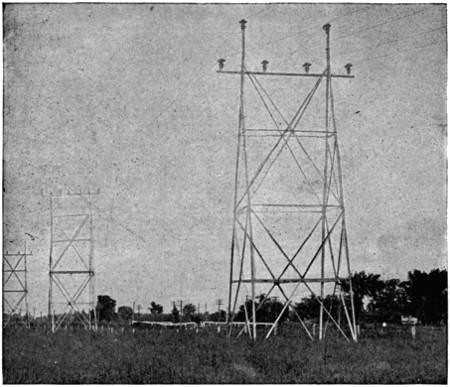
Fig. 94.—Transposition Tower (Second Tower).

Fig. 95.—Elevations and Plan of Tower.
Larger elevations and plan (70 kB)
The regular steel tower used in this transmission measures 46 feet
in vertical height from its foot to the tops of the lower insulators, and 51
feet 3 inches to the tops of the higher insulators. The lower six feet of
this tower are embedded in the ground, so that the tops of the insulators
measure about 40 feet and 45 feet 3 inches respectively above the earth.
At the ground the tower measures 14 feet at right angles to the transmission
line and 12 feet parallel with it. The width of each tower at
the top is 12 feet at right angles to the line, and the two sides having
this width come together at points about 40 feet above the ground.
Between the two L bars thus brought nearly together, at each side of a
tower a piece of extra heavy 3-inch steel pipe is bolted so as to stand in
a vertical position. Each piece of this pipe is about 31⁄2 feet long and
carries a steel insulator pin at its upper end. The two pieces of pipe
thus fixed on opposite sides of the top of a tower carry the two highest
insulators. For the other four insulators of each tower, pins are fixed
on a piece of standard 4-inch pipe that serves as a cross-arm, and is[315]
bolted in a horizontal position between the two nearly rectangular
sides of each tower, at a point two feet below the bolts that hold the
vertical 3-inch pipes, already named, in position. Save for the two short
vertical and one horizontal pipe, and the pins they support, each tower
is made up of L-shaped angle-bars bolted together. Each of the two
nearly rectangular sides of a tower consists of two L bars at its two
edges, three L bars for cross-braces at right angles to the edges, and
four diagonal braces also formed of L bars. The lower halves of the L
bars at the edges of each side of a tower have sections of 3″ × 3″ × 1⁄4″, and
the upper halves have sections of 3″ × 3″ × 3⁄16″. This last-named cross-brace
and the other two cross-braces have a common section of 2″ × 11⁄2″
× 1⁄8″. For the lower set of diagonal braces the common section is
21⁄2″ ×
2″ × 1⁄8″, and the upper set has a section of 2″
× 11⁄2″ × 1⁄8″ in each
member.[316]
At the level of the lowest
cross-braces the two rectangular
sides of a tower
are tied together by one
member of 2″ × 11⁄2″ × 1⁄8″
of L section and at right
angles to the sides, and by
two diagonal braces of 5⁄8″
round rod between the
corners of the tower. On
each of its two triangular
sides a tower has four
horizontal braces and
three sets of diagonal
braces. The two upper
horizontal braces are of
2″ × 11⁄2″ × 1⁄8″ L section,
and the lowest is the
same, but the remaining
horizontal brace has a
section of 21⁄2″ × 2″ × 1⁄8″.
Bars of 2″ × 11⁄2″ × 1⁄8″ L
section are used for the
two upper sets of diagonal
braces, and bars of
21⁄2″ × 2″ × 1⁄8″ for the lower
set. In addition to the
cross-braces named, each
triangular side of a tower
near the top of the corner
bars has two short cross-pieces
with the common
L section of 31⁄2″ × 31⁄2″ ×
5⁄8″, one just above and the
other just below the cross-arm
of 4-inch pipe to
hold it in place. At the
bottom of each of the
four corner bars of a
tower a foot is formed[317]
by riveting a piece of 3″ × 1⁄4″ L section and 15 inches long at right
angles to the corner bar. On one corner bar of each tower there are
two rows of steel studs for steps, one row being located in each flange
of the L section. On the same flange these steps are two feet apart,
but taking both flanges they are only one foot apart. Every part of
each steel tower is heavily galvanized.
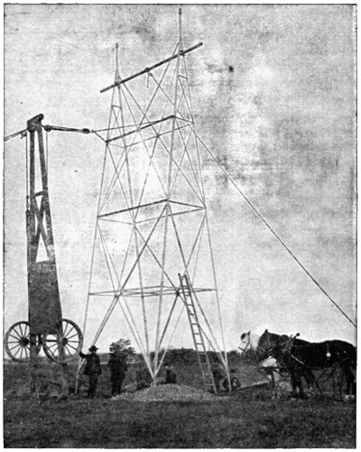
Fig. 99.—One of the Towers in Position.
The labor of erecting these steel towers was reduced to a low figure
by the method employed, as shown in the accompanying illustration.
Each tower was brought to the place where it was to stand with its[318]
parts unassembled. For erecting the towers a four-wheel wagon with
a timber body about thirty feet long was used. When it was desired
to raise a tower, two of the wheels, with their axle, were detached from
the timber body of the wagon, and this body was then stood on end to
serve as a sort of derrick. This derrick was guyed at its top on the side
away from the tower, and a set of blocks and tackle was then connected
to the top of the derrick and to the tower at a point about one-fourth
of the distance from its top. A rope from this set of blocks ran through
a single block fixed to the base of the derrick and then to a team of
horses. On driving these horses away from the derrick the steel tower
was gradually raised on the two legs of one of its rectangular sides
until it came to a vertical position. The next operation was to bring
the legs of the tower into contact with the extension pieces that were
fixed in the earth and then bolt them together.
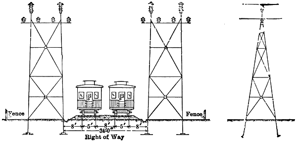
Fig. 100.—Steel Tower for Transmission Line.
The tops of the three pins that carry the insulators for each three-phase
circuit are at the corners of an equilateral triangle (Fig. 100), each
of whose sides measures six feet. The six steel insulator pins used on
each tower are exactly alike, and each is swaged from extra heavy pipe.
Each finished pin is 23⁄8 inches in diameter for a length of 31⁄4 inches, and
then tapers uniformly to a diameter of 11⁄8 inch at the top through a
length of 111⁄2 inches. This gives the pin a total length of 143⁄4 inches.
In the larger part there are two 9⁄16-inch holes from side to side, and
within two inches of the top there are three circular grooves each 3⁄16
inch wide and 1⁄16 inch deep. Forged steel sockets of two types are
employed to attach the steel pins with the pipes. Each socket is made
in halves, and these halves are secured to both the pipe and the pin
by through bolts. Like all other parts of the towers, these steel pins and[319]
sockets are heavily galvanized. On each of the four corner bars of a
tower the lower six feet of its length is secured to the upper part by
bolts or rivets. This lower six feet of each corner bar is embedded in
the earth, and the construction just named makes it easy to replace the
bars in the earth when corrosion makes it necessary.
Footings for each tower are provided by digging four nearly square
holes with their sides at approximately 45 degrees with the direction of
the transmission line, and the shortest side of each hole at least two feet
long. Centres of these holes are 14 feet 3 inches apart in a direction
at right angles to the line, and 13 feet 9 inches apart parallel with the
line. In hard-pan each one of the holes was filled to within 2 feet 6
inches of the top with stones, after the leg of the tower was in position,
and then the remainder of the hole was filled with cement grouting
mixed four to one.
At the bottom of each hole in marsh land a wooden footing 3 feet ×
6 inches × 24 inches was laid flat beneath the leg of the tower, and then
the hole was filled to within 21⁄2 feet of the surface with the excavated
material. Next above this filling comes a galvanized iron gutter-pipe,
four inches in diameter, and filled with cement about the leg of the
tower for a length of two feet. Outside of this pipe the hole is made
rounding full of cement grouting.
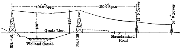
Fig. 101.—Transmission Line at Welland Canal.
At some points along the transmission line exceptionally high towers
are necessary, a notable instance being found at the crossing over the
Welland Canal, where the lowest part of each span must not be less than
150 feet above the water. For this crossing two towers 135 feet high
above ground are used, as seen in Fig. 101. Each of these towers is designed
to carry all four of the three-phase power circuits that are eventually
to be erected between Niagara Falls and Toronto. For this purpose
there was used a special design of tower with a width of about 48 feet
at right angles to the direction of the line below the top truss, and a
width of about 68.5 feet at that truss where the two lower conductors
of each circuit are attached.
[320]
With all spans longer than 400 feet, a tower of heavier construction
than the standard type is used, and this tower provides three insulators
for the support of each conductor. A tower of this type that supports
the lowest conductors about 40 feet above the ground level has its corner
bars made up of 4″ × 4″ × 3⁄8″
and 4″ × 4″ × 5⁄16″ L sections, has three
cross-arms of extra heavy 4-inch pipe, and a 6-inch vertical standard pipe
to support each group of three insulators for the highest conductor of
each circuit. Each of the lower conductors of a circuit on this tower
is supported by an insulator on each of the three parallel cross-arms.
On some of these towers, for long spans, the two outside insulators for
the support of each conductor are set a little lower than the insulator
between them.
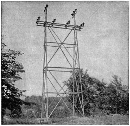
Fig. 102.—Heavy Tower at Credit River.
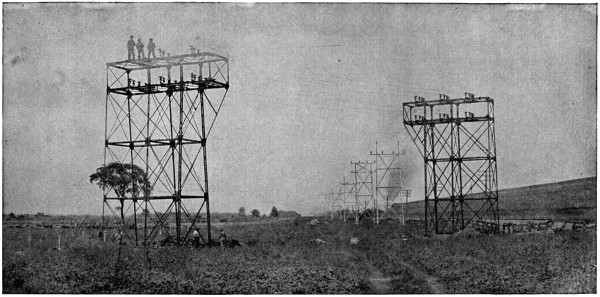
Fig. 103.—Angle Tower Near Bronte.
Angle towers, used where the line makes a large change in direction
at a single point, have three legs on each rectangular side, a width of
20 feet on each of these sides for some distance above the ground, and a
width of 27 feet 2 inches at the top. In these towers the two legs on[321]
[322]
the triangular side that is in compression are each made up of four
3″ × 3″ × 1⁄4″ L
sections joined by 11⁄2″ × 1⁄4″ lattices and rivets. Towers
of this sort are used near the Toronto terminal-station, where the line
changes 35 degrees at a single point, and near the crossing of Twelve-Mile
Creek, where the angular change of the line on a tower is 45 degrees.
Close to each terminal-station and division-house the transmission
line is supported by terminal towers. These towers differ
from the others in that each carries insulators for only three conductors,
and these insulators are all at the same level. Each terminal tower has
nine insulators, arranged in three parallel rows of three each for the conductors
of a single circuit, and each conductor thus has its strain distributed
between three pins. All three wires of a circuit are held 40 feet
above the ground by a terminal tower, and pass to their entries in the
wall of a station at the same level. As these terminal towers must resist
the end strain of the line, they are made extra heavy, the four legs each
being made up of 4″ × 4″ × 5⁄16″
and 4″ × 4″ × 3⁄8″ L sections. For the
three cross-arms on one of these towers three pieces of 4-inch pipe, each
15 feet 9 inches long, are secured at its top with their parallel centre
lines 30 inches apart in the same plane. Each of these pipes carries
three insulator pins with their centres 7 feet 41⁄2 inches apart. On the
bottom of each leg of a terminal tower there is a foot, formed by riveting
on bent plates, that measure 15 and 18 inches, respectively, on the two
longer sides. Each foot of this tower is set in a block of concrete 5 feet
square that extends from 3.5 feet to 7.5 feet below the ground level.
Insulators for the transmission line, which are illustrated in Fig. 104,
are of brown, glazed porcelain, made in three parts, and cemented together.
The three parts consist of three petticoats or thimbles, each of
which slips over or into one of the others, so that there are three outside
surfaces and three interior or protected surfaces between the top of an
insulator and its pin.
From top to bottom the height of each insulator is 14 inches, and
this is also the diameter of the highest and largest petticoat. The next
or middle petticoat has a maximum diameter of 10 inches and the
lowest petticoat one of 8 inches. Cement holds the lowest petticoat of
the insulator on one of the steel pins previously described, and in this
position the edge of the lowest petticoat is about 21⁄2 inches from the
steel support. At the top of each insulator the transmission conductor
is secured, and the shortest distance from this conductor to any of the
steel parts through the air is about 17 inches.
From the step-up transformer house at Niagara Falls to the terminal-station[323]
at Toronto, a distance of seventy-five miles, each three-phase,
60,000-volt, 25-cycle circuit on the steel towers is made up of three hard-drawn
copper cables with a cross section of 190,000 circular mils each,
and is designed to deliver 12,000 electric horse-power with a loss of ten
per cent, on a basis of 100 per cent power factor. Six equal strands
of copper make up each cable, and this wire has been specially drawn
with an elastic limit of more than 35,000 pounds and a tensile strength
of over 55,000 pounds per square inch. This cable is made in uniform
lengths of 3,000 feet, and these lengths are joined by twisting their ends
together in copper sleeves, and no solder is used. No insulation is used
on these cables.
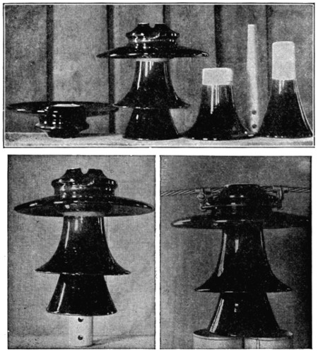
Fig. 104.—Insulators.
Instead of a tie-wire, a novel clamp is employed to secure the[324]
copper cable on each insulator. This complete clamp is made up of
two separate clamps that grasp the cable at opposite sides of each insulator
and of two half-circles of hard-drawn copper wire of 0.187 inch
diameter. Each half-circle of this wire joins one-half of each of the
opposite clamps, and fits about the neck of the insulator just below its
head. Two bronze castings, one of which has a bolt extension that
passes through the other, and a nut, make up each separate clamp.
When the combined clamp is to be applied, the sides are separated by
removing the nut that holds them together, the half-circles are brought
around the neck of the insulator, and each of the side clamps is then
tightened on to the cable by turning the nut that draws its halves together.
This complete clamp can be applied as quickly as a tie-wire,
is very strong, and does not cut into the cable.
Each of the regular steel towers is designed to withstand safely a
side strain of 10,000 pounds at the insulators, or an average of 1,666
pounds per cable. With the 190,000-mil cable coated to a depth of
1⁄2 inch with ice and exposed to a wind blowing 100 miles per hour, the
estimated strains on each steel pin for different spans and angular
changes in the direction of the line are given in the accompanying table:
Pounds Strain on Pins, 1⁄2-inch Sleet, 100 Miles Wind.
Span,
feet. |
Degrees and Minutes. |
| 0 |
0.30 |
1 |
1.30 |
2 |
2.30 |
3 |
3.30 |
4 |
4.30 |
5 |
5.30 |
6 |
| 0 |
0 |
35 |
69 |
104 |
138 |
173 |
207 |
242 |
276 |
311 |
345 |
380 |
414 |
| 100 |
256 |
291 |
325 |
360 |
394 |
429 |
463 |
498 |
532 |
567 |
601 |
636 |
670 |
| 200 |
512 |
547 |
581 |
616 |
650 |
685 |
719 |
754 |
788 |
823 |
857 |
892 |
926 |
| 300 |
768 |
803 |
837 |
872 |
906 |
941 |
975 |
1,010 |
1,044 |
1,079 |
1,113 |
1,148 |
1,182 |
| 400 |
1,024 |
1,059 |
1,093 |
1,128 |
1,162 |
1,197 |
1,231 |
1,266 |
1,300 |
1,335 |
1,369 |
1,404 |
1,438 |
| 500 |
1,280 |
1,315 |
1,349 |
1,384 |
1,418 |
1,453 |
1,487 |
1,522 |
1,556 |
1,591 |
1,625 |
1,660 |
1,694 |
| 600 |
1,536 |
1,571 |
1,605 |
1,640 |
1,674 |
1,709 |
1,743 |
1,778 |
1,812 |
1,847 |
1,881 |
1,916 |
1,950 |
| 700 |
1,792 |
1,827 |
1,861 |
1,896 |
1,930 |
1,965 |
1,999 |
2,034 |
2,068 |
2,103 |
2,137 |
2,172 |
2,206 |
| 800 |
2,048 |
2,083 |
2,117 |
2,152 |
2,186 |
2,221 |
2,255 |
2,290 |
2,324 |
2,359 |
2,393 |
2,428 |
2,462 |
| 900 |
2,304 |
2,339 |
2,373 |
2,408 |
2,442 |
2,477 |
2,511 |
2,546 |
2,580 |
2,615 |
2,649 |
2,684 |
2,718 |
| 1,000 |
2,560 |
2,595 |
2,629 |
2,664 |
2,698 |
2,733 |
2,767 |
2,802 |
2,836 |
2,871 |
2,905 |
2,940 |
2,974 |
The copper cables were so strung as to have a minimum distance
from the ground of 25 feet at the lowest points of the spans. In
order to do this the standard steel towers that hold the lower cables
40 feet above the ground level at the insulators are spaced at varying
distances apart, according to the nature of the ground between them.
At each tower the upper cable of each circuit is 5 feet 3 inches
higher than the two lower cables, and this distance between the elevations
of the upper and the lower cables is maintained whatever the[325]
amount of sag at the centre of each span. If there is a depression between
two standard towers on a straight portion of the line, the sag in
the centre of a span 400 feet long may be as much as 18 feet. Where
a rise and fall in the ground between towers make it necessary to
limit the sag to 14 feet in order to keep the lowest cables 25 feet above
the highest point of earth, the length of span is limited to 350 feet.
If the rise and fall of ground level between towers allow a sag of only
11 feet with the lowest cable 25 feet above the earth, the length of span
with 40-foot towers is reduced to 300 feet; and if for a like reason the
sag is limited to 8 feet, the span may only be 250 feet.

Fig. 105.—Take-up Arrangement on Terminal Tower.
At each terminal tower, where the cables are secured before they
pass into a terminal-station, the three insulators for each cable are in a
straight line with their centres, 30 inches apart. When a line cable
reaches the first insulator of the three to which it is to be attached on
one of these towers, it is passed around the neck of this insulator and
then secured on itself by means of two clamps that are tightened with
bolts and nuts. See Fig. 105. The cable thus secured turns up and
back over the tops of the three insulators and goes to the terminal-station.
Around the neck of the insulator to which the line cable has been
secured in the way just outlined a short detached length of the regular
copper cable with the parts of a turnbuckle at each end is passed, and
this same piece of cable also passes around the neck of the next insulator
in the series of three. By joining the ends of the turnbuckle and tightening
it, a part of the strain of the line cable in question is transferred
from the first to the second insulator of the series. In the same way a
part of the strain of this same line cable is transferred from the second
insulator of the series to the third, or one nearest to the terminal-station.
[326]
[327]
INDEX.
- Air-blast cooled transformers, 129
- Air-gap data, 183
- Air gaps, number in series to stand given voltage, 183
- Albany-Hudson Ry. Plant, 121
- Alternating currents, 227
- Alternator voltage, 118
- Alternators, 103
- data, 118
- for high voltage, 120
- inductor, 112
- types of, 111
- Aluminum as a conductor, 200, 209
- cables in use, 213
- conductor joints, 206
- conductors, 27, 28
- corrosion of, 211
- properties of, 212
- soldered joints, 206
- vs. copper, 209
- wire, cost of, 29
- Amoskeag Mfg. Co. plant, 51, 52
- Amsterdam (N. Y.) plant, 121
- Anchor ice, 59
- Anderson (S. C.) plant, 121
- Apple River (Minn.) plant, 1, 26, 27,
28, 71, 97, 98, 99,
102, 118, 119, 124,
126, 127, 134, 174,
187, 190, 192, 208,
245, 264, 294
- Arc lighting, 167
- Arcing, 46
- Automatic regulators, 162
- Barbed wire, 169, 175
- Belt drive, 83, 107
- Bienne plant (Switzerland), 42
- Birchem Bend, 57, 67, 79,
95, 97, 98, 102
- Blower capacity necessary to cool transformers, 130
- Boosters, 133
- Boston-Worcester Ry. plants, 121
- Braces for cross-arms, 259
- Bronze conductors, 200
- Brush discharge, 281
- Buchanan (Mich.) plant, 88
- Building materials, 95
- Bulls Bridge plant, 63
- Burrard Inlet (B. C.) plant, 111, 112
- Bus-bars, 142, 147
- dummy, 145
- Cable insulation, 195
- sheaths, 194
- ways, 140
- Cables, aluminum, 212
- aluminum, in use, 213
- charging current, 197
- cost of, 188, 196
- for alternating current, 194
- high-voltage, 191
- paper insulated, 196
- protection against electrolysis, 195
- rubber-covered, 195
- submarine, 192
- temperature of, 198
- voltage in, 190, 196
- Canadian-Niagara Falls Power Co., 121
- Canals, 51, 53
- long, 68
- Cañon City plant, 26, 27, 28,
117, 118, 127, 208
- Cañon Ferry plant, 1, 3, 26,
27, 28, 46, 49, 53,
62, 68, 69, 83, 89,
94, 95, 97, 102, 105,
112, 113, 118, 119,
124, 125, 126, 127,
130, 132, 134, 174,
208, 233, 234, 245,
246, 249, 254, 257,
259, 268, 272, 280,
282, 294, 295, 302
- Cedar Lake plant, 90
- Chambly plant, 96, 110, 149,
156, 172, 189, 249,
255, 256, 257, 267,
272, 287, 294, 295,
311, 312
- Charging current for cable[328],
197
- Charring of pins, 276, 278
- Chaudière Falls plant, 118
- Choke-coil used with lightning arresters, 180
- Circuit breakers, 135, 150
- breakers, time limit, 152
- Circuits, selection of, 233
- Coal, price of, in Salt Lake City, 8
- Colgate plant, 1, 3, 26,
27, 28, 74, 82, 83,
90, 94, 97, 98, 99,
101, 102, 108, 112,
113, 118, 127, 130,
132, 134, 187, 190,
201, 206, 208, 213,
245, 246, 250, 254,
257, 272, 277, 280,
282, 294, 295, 304,
309
- Columbus (Ga.) plant, 83, 115
- Compounding, 160
- Compressive strength of woods, 302
- Conductivity of the conductor metals, 201
- Conductors, 200
- aluminum, 27, 28, 206
- aluminum, properties of, 212
- coefficients of expansion, 200
- corrosion of, 211
- cost of, 22, 29, 203, 204,
205
- cost of aluminum, 29
- cost of per k. w., 28
- cost of copper, 29
- data, 204
- data from representative transmission plants, 208
- expansion of aluminum and copper, 211
- melting points, 200
- minimum size for transmission line, 202
- properties of ideal, 200
- relative conductivity, 201
- relative cost of, 20
- relative properties for equal lengths and resistances, 204
- relative strengths for given area, 203
- relative weight for given conductivity, 202
- relative weight of, 202
- relative weights of three-phase, two-phase, and single-phase lines, 220
- resistance of, 225
- skin effect, 206, 233
- weight per k. w., 27
- Conduits, 195
- radiation loss in, 198
- temperature rise in, 198
- Constant current regulator, 167
- transformer, 167
- Control equipment for d. c. and a. c. plants, 35
- Copper conductors, 200
- cost of, 22
- vs. aluminum, 209
- wire, cost of, 29
- Corrosion of conductors, 211
- Cross-arm braces, 258
- iron, 284
- location of, 257
- material, 258
- Cross-arms, 49, 256
- Crossings, 187
- Dales plant (White River), 26, 27, 28,
71, 134, 208
- Dams, 62
- Delta connection, 131
- Depreciation, 11
- Design of power-plant, 83
- Dike, 60
- Direct connection, 84
- Discharge, static, 170
- Distribution system, 158
- Draught tubes, 79
- Dummy bus-bars, 145
- Easton (Pa.) plant, 121
- Edison Co. (Los Angeles) plant, 118
- Efficiency constant-current transmission, 216
- curves, motor-generator set, 117
- of constant-voltage transmission, 217
- of transformers, 133
- relative, of a. c. and d. c. transmission, 35
- Electra plant[329], 1,
3, 74, 82, 83, 92,
94, 97, 98, 101, 102,
108, 112, 113, 118,
127, 174, 206, 208,
212, 213, 233, 235,
236, 245, 248, 253,
254, 256, 259, 272,
275, 277, 280, 281,
282, 294, 295
- Electric power, market for, 7
- Electrical Development Co., Niagara plant, 120
- Electricity vs. gas, 6
- Electrolysis, 195
- Energy curves of hydro-electric stations, 13
- electrical, cost of at switchboard, 23
- Entrance end strain, 261, 325
- insulating discs, 262
- into buildings, 179
- of lines, 179, 261, 265
- through roof, 269
- wall openings, 262
- Entries for transmission lines, 261
- Expansion, coefficient of, for copper and aluminum, 211
- coefficients of, for various conductor metals, 200
- Farmington River (Conn.) plant, 26, 27, 28,
58, 118, 125, 134,
208, 212, 213, 245
- Feeders, 143
- Ferranti cables, 192
- Fire-proofing, 95
- Floor, distance from roof to, 95
- location of, 79
- space, 12, 101, 102
- space per k. w. of generators, 12
- Floors, 95
- Fog, 46, 277
- Fore-bay, 59, 60
- Foundations, 95
- Frequency, 113, 127
- effect on transformer cost, 116
- Fuel, price of, in Salt Lake City, 8
- Fuses, 135, 150
- Garvins Falls plant, 56, 60, 79,
80, 94, 96, 97, 102,
113, 145, 240, 294
- Gas vs. electricity, 6
- Gears, 84, 108
- Generators (a. c.), 103
- d. c. vs. a. c., 31
- Generators, belt-driven, 107
- capacity of, 32
- compounding of, 160
- cost of, 40
- (a. c.) cost, 32
- (a. c.) data, 118
- direct-connected to horizontal turbines, 89
- to impulse wheels, 90
- connection to vertical shafts, 84
- (d. c.) field excitation of, 41
- floor space, 101
- per k. w., 12
- gear-driven, 108
- (a. c.) high-voltage, 120
- (d. c.) in series, 31
- (d. c.) installation of, 41
- insulation of, 39, 45
- lightning protection, 34
- limiting voltage of, 44
- (a. c.) limiting voltage of, 32
- (d. c.) limiting voltage of, 31
- overload capacity, 103
- relation between voltage and capacity, 127
- revolving armatures, 112
- fields, 112
- series-wound, 41
- speed regulation, 38
- Glass vs. porcelain insulators, 288
- Great Falls plant, 54, 60, 61,
64, 67, 78, 92, 93,
102, 114, 118
- Greggs Falls plant, 54, 56, 64,
240
- Ground connections, 178
- for guard wires, 171, 172
- Grounded guard wires, 168
- Guard wires, 168
- installation of, 175
- Guying of poles, 255
- Hagneck (Switzerland) plant, 86
- Hooksett Falls plant, 56, 131
- Hydro-electric plants, 1
- built at the dam, 64-67
- canals, long, 68-73
- long and short, 58
- short[330], 53-56
- capacity and weight of conductors per k. w. for various plants, 27
- (800 k. w.) cost of, 10
- (1500 k. w.) cost of, 11
- cost of labor, 12
- cost of operation, 12, 77
- design of, 83
- floor, 79
- space per k. w., 101
- interest and depreciation, 11
- linked together, 56-58
- load factors, 14, 15
- location of, 64
- model design, 12
- operation, 59
- vs. steam plant, 5, 12
- with pipe-lines, 73-77
- with steam auxiliary, 84
- Ice, 59
- Impulse wheel speed, 108
- wheels, 82, 90
- location of, 99
- Indian Orchard plant, 57, 84
- Inductance, 206, 230
- Induction, electro-magnetic, electrostatic, 168
- on lines, 206
- regulator, 162
- Inductor alternators, 112
- Insulation, as affected by ozone, 197
- cost of paper vs. rubber, 196
- of a. c. and d. c. lines, 34
- of apparatus, 142
- of cables, 195
- of electrical machines, 45
- of generators, 39
- protection against ozone, 198
- Insulator arc-over test, 291
- -pins, 270 (see Pins)
- Insulators, 277, 282, 287,
322
- and pins, data from various plants, 280
- defective, 288
- glass vs. porcelain, 288
- in snow, 293
- method of fastening to iron pins, 271
- novel clamp, 323
- on various transmission lines, 294
- petticoats, 294
- testing of, 288
- tests, 290
- test voltage, 289
- with oil, 287
- Iron conductors, 200
- Kelley’s Falls plant, 56
- Kelvin’s law, 219
- Labor, cost of, 12
- in hydro-electric stations, 12
- Leakage, 275, 287
- line, 207, 214
- Lewiston (Me.) plant, 118, 120, 122,
167, 213
- Lighting, incandescent, minimum frequency, 116
- series distribution, 167
- Lightning arrester, effect of series resistance, 185
- arresters, 168, 176
- ground connection, 178
- multiple air-gap, 176, 183
- non-arcing metals in, 184
- series connection of, 180
- shunted air-gaps, 185
- with choke coil, 180
- protection, 34
- Line calculations, 221-232
- charging current, 197
- conductors, 200
- conductors, cost of, 22
- weight of, 21
- construction, 222
- cost, 310
- cross-arms, 49
- spacing of wires, 46
- (a. c.) transmission, 34
- (d. c.) transmission, 33
- end strain, 325
- leakage, 47
- loss, 39
- losses due to grounded guard wires, 176
- Lines, sag[331], 309
- transposition of, 314
- Line voltages, 45
- Load factors, 14, 15
- lighting, 61
- maximum, 60
- motor, 160
- railway, 164
- Loss in conduits, 198
- relation to weight of conductors, 215
- Losses due to grounded guard wire, 176
- on transmission lines, 215
- Ludlow Mills plant, 26, 27, 28,
57, 79, 100, 121,
208, 213
- Madrid (N. M.) plant, 26, 27, 28,
118, 208
- Manchester (N. H.) plants, 120
- Market for electric power, 7
- Materials, building, 95
- for line-conductors, 200
- Mechanicsville plant, 58, 67, 109,
121, 174
- Melting points of conductor metals, 200
- Montmorency Falls plant, 26, 27, 28,
240
- Motor load, 160
- Motor-generator set efficiency curve, 117
- Motors, series-wound, 41
- (d. c.) speed regulation, 38
- synchronous, 241
- Multiple air-gap arrester, 176
- Needle-point spark-gap for measuring pressure, 290
- Neversink River plant, 75, 179
- Niagara Falls Power Co., 3, 59, 81,
86, 87, 93, 94, 95,
97, 101, 102, 105,
106, 107, 108, 112,
113, 117, 118, 119,
127, 133, 137, 140,
143, 145, 151, 153,
161, 165, 170, 181,
188, 194, 195, 208,
211, 240, 245, 246,
257, 272, 273, 275,
280, 287, 289, 294,
295, 297
- Nitric acid from air, 281
- Non-arcing metals, 184
- North Gorham (Me.) plant, 120
- Ogden (Utah) plant, 26, 27, 28,
118, 120, 132, 134,
208, 245
- Ohm’s law, 223
- Oil switches, 136
- Ontario Power Co., 121
- Operating expenses, 59
- Operation, cost of, 12, 77
- Operations, reliability of, 311
- Ouray (Col.) plant, 121
- Overhead line connection to underground, 197
- Overload capacity of generators, 103
- Ozone, 197
- Painting of poles, 255
- Paper insulated cables, 196
- vs. rubber insulation, 196
- Payette River (Idaho) plant, 73, 101
- Penstocks, 59, 98
- Phase, 113
- Pike’s Peak plant, 77
- Pilot wires, 161
- Pins, 259, 270
- and insulators, data from various plants, 280
- burning of, 270, 276, 278
- charring of, 276, 278
- composite, 281
- compressive strength of woods, 302
- design of, 298
- dimensions of, 301
- formula for diameter of, 299
- iron, 275, 285, 286
- expansion of, 290
- method of fastening insulators, 271
- method of fastening to cross-arms, 271
- metal, 271, 275, 282,
285, 286
- of uniform strength, 300, 302
- proportions, 301
- relative cost of metal and wooden, 284
- shank, 274
- shoulder, 275, 299, 305
- softening of threads, 280
- steel, 275, 312
- strain with 1⁄2-inch sleet and 100-mile wind for different spans,
324
- strains on[332], 270,
298
- strength of, 303
- table of standard, 301
- treatment of, 259, 275
- weakest point, 298
- wooden, data from various plants, 272
- dimensions of, 272
- dimensions of standard, 273
- Pipe-lines, 73
- Pittsfield (Mass.) plant, 121
- Pole line, cost of, 21
- lightning arresters, 179
- relative cost of, 20
- lines, 246
- Poles, cost, 310
- depth in ground, 254
- diameter of, 254
- dimensions of, 254
- guying of, 255
- iron, 284
- length of, 253, 309
- life of, 255
- setting of, 252
- spacing of, 249
- steel, cost of, 307
- treatment of, 255
- woods for, 252
- Porcelain vs. glass insulators, 288
- Portland (Me.) plant, 120, 166, 239
- Portsmouth, N. H. plant (steam), 102, 118, 119,
120, 121, 144, 194,
264, 294
- Power plant, relative cost of a. c. and d. c., 36
- transmitted, total cost of, 24
- Radiation loss in conduits, 198
- Railway crossing, 187, 252
- service, 164
- Red Bridge plant, 53, 60, 79,
93, 94, 96, 97, 99,
101, 102
- Regulation, 155, 239
- as effected by synchronous motors, 165
- at receiving end, 162
- hand, 161
- Regulator, automatic, 162
- constant-current, 167
- induction, 162
- Relay-switches, 145
- Resistance, 225
- in series with lightning arrester, 185
- Revolving armature alternators, 112
- field alternator, 112
- River crossings, 187, 190, 249
- Roof, distance from floor, 95
- Roofs, 95
- Rope-drive, 83
- Rotaries, cost of, 117
- suitable frequency for, 115
- Rubber-covered cables, 195
- maximum temperature, 198
- protection against ozone, 198
- Sag in lines, 309
- St. Hyacinthe (Que.) plant, 118
- St. Joseph plant, 66
- St. Maurice plant (Switzerland), 31
- Salem (N. C.) plant, 121, 122
- San Gabriel Cañon plant, 26, 27, 28,
208
- Santa Ana plant, 1, 26, 27,
28, 74, 76, 82, 83,
92, 94, 95, 96, 97,
98, 99, 101, 102,
208, 245, 263, 280,
281, 294, 295, 296
- Sault Ste. Marie plant, 72, 83, 85,
89, 97, 102, 104,
105, 112, 113, 117,
118, 120, 127
- Scott system, 132
- Series distribution, 167
- machines, 41
- Sewall’s Falls plant, 26, 27, 28,
155
- Shawinigan Falls plant, 1, 70, 71,
107, 116, 117, 163,
164, 166, 209, 212,
213, 235, 236, 242,
245, 267, 272, 273,
280, 282, 294, 295,
296
- Sheaths for cables, 194
- Shunted air-gaps, 185
- Skin effect, 206, 232
- Snoqualmie Falls plant, 3, 4
- map of transmission lines, 4
- Snow, 293
- Soldered joints, 206
- Spacing of poles, 249
- of wire, 234
- Spans, long, 190, 250
- strains for different lengths, 324
- Sparking distances, 182
- voltages[333], 182
- Speed, peripheral, of impulse wheels, 108
- peripheral of turbines, 85, 103
- regulation, 38, 42
- d. c. motors, 38
- Spier Falls plant, 1, 2, 3,
54, 58, 61, 62, 68,
91, 94, 98, 124, 126,
127, 130, 141, 142,
146, 161, 174, 236,
237, 243, 244, 245,
250, 253, 266, 280,
285, 287, 289, 291,
294, 295, 296, 312
- Star connection, 131
- Static discharges, 170
- Steam and water-power station combined, 84
- electric plant, cost of labor, 12
- cost of operation, 12
- floor area per k. w., 102
- vs. water-power, 5
- Steel towers, 306
- Storage capacity, 15
- Strains on insulation as affected by resistance in series with arrester, 185
- Stray currents, protection against, 195
- Submarine cables, 187, 192, 194
- Sub-station, arrangement of apparatus, 128
- Sub-stations, 157, 237
- Surges, 136
- Switchboard, 156
- wiring, 146, 148, 149
- Switches, 135, 244
- arcing of, 135
- electrically operated, 140
- long break, 135
- oil, 136
- open-air, 136
- pneumatically operated, 140
- power operated, 138
- relay, 145
- Switch-houses, 141, 142, 238,
244
- Switching, 146
- high-tension, 147
- Synchronous converters, 115
- cost, 117
- motors, 165, 241
- Tail-race, 96
- Telephone, 161
- Telluride plant, 47, 160, 169,
181
- Temperature of cables, 198
- rise in conduits, 198
- Tensile strength of conductor metals, 201
- Time-limit circuit-breaker, 152
- Time relays, 152, 153
- Towers, 250, 306
- angle, 320
- cost, 310
- dimensions, 314
- erection of, 316-319
- heavy, 320
- reliability of operation, 311
- spans, 313
- steel, cost, 307, 308
- steel pins, 312
- strain on, 324
- Transformers, 122
- air-blast vs. water-cooled, 129
- artificially cooled, 129
- at sub-stations, 125
- blower capacity necessary to cool, 130
- constant-current, 167
- cooling, quantity of water necessary, 129
- cost, 21, 116, 124,
134
- cost of operation, 129
- cost of, relative, 20
- delta and star connections, 131
- efficiency, 133
- frequency, effect of, 116
- insulation, 45
- in transmission systems, 134
- limiting voltage for, 32
- location of, 97
- polyphase, 124
- regulation, 125
- reserve, 149
- secondary, in series, 131
- single-phase, 124
- two- to three-phase, 132
- used to compensate drop, 133
- used to regulate voltage, 162
- voltages, 45
- when to use, 122
- Transmission, constant-current, 38, 216
- constant-voltage[334], 40,
217
- continuous-current, 31, 32
- control equipment, 35
- cost of, 19, 40, 222
- (d. c.) cost of, 40
- efficiency, 35, 41
- first long line, 37
- frequency, 113
- generator end, 103
- lightning protection, 34
- limiting voltage, 44
- lines, arcing, 46
- calculation of, 221-232
- charging current, 197
- construction, 222
- cost, 310
- cross-arms, 49, 256
- crossings, 187, 190
- data from various plants, 245
- effect of length on cost, 20
- effect of length on cost of power, 24
- efficiency, 22, 24
- end strain at entries, 325
- entrance to buildings, 179, 261
- inductance, 206
- induction, 168
- insulation, 34
- insulators (see Insulators), 287
- insulator-pins (see Pins), 270
- interest, maintenance and depreciation, 22
- leakage, 47, 207, 214
- length of, capacity of, population supplied, 8
- lightning arresters (see Lightning Arresters), 179
- lightning protection, 118
- long spans, 190
- loss, 22, 39
- losses, 215
- maximum investment in, 220
- method of fastening conductors to insulators, 323
- operation, 311
- pole spacing, 249
- regulation with synchronous motors, 241
- relative weights of three-phase, two-phase, and single-phase, 228
- right-of-way, 246
- sag in, 309
- spacing of wire, 234
- steel towers (see Towers), 306
- switch-houses, 238
- switches, fuses, and circuit-breakers, 135
- take up, arrangement for, 325
- total cost of, 22
- total cost of operation, 23
- transposition of wires, 206, 314
- voltage, 21, 215
- in cables, 190
- regulation, 130
- wind pressure, 210
- long line, 221
- minimum-sized wire, 202
- physical limits of, 44
- a. c. pole line construction, 34
- d. c. pole line construction, 33
- pole lines, 246
- problems, 19
- regulation, 155, 239
- selection of circuits, 233
- single vs. parallel circuits, 241
- spacing of conductors, 46
- submarine, 187
- three-phase, 113
- three-phase and two-phase, 228
- two-phase, 113
- underground, 187
- without step-up transformers, 120
- Transposition of wires, 206
- Turbines, high-speed, 107
- horizontal, 79, 83, 89,
97
- impulse, 82, 90, 99
- speed of, 108
- low-head good speed, 105
- peripheral, speed of, 85, 103
- pressure, 79
- several on same shaft, 85, 105
- vertical[335], 79,
84, 85, 86, 97
- Underground cable connected to overhead line, 197
- cables, 187
- Victor (Colo.) plant, 26, 27, 28,
208
- Virginia City plant, 118
- Voltage drop compensation, 133
- fluctuations, 218
- high, alternators, 120
- measurements, 290
- in cables, 190, 196
- limiting, 44
- for a. c. machines, 32
- for d. c. machines, 31
- of transmission lines, 21, 215
- regulation, 130, 155
- sparking, 182
- test for insulators, 289
- Volts per mile, 26
- Wages paid attendants, 12
- Walls, 95
- Washington & Baltimore Ry., 121
- Washouts, 81
- Water-cooled transformers, 129
- Water-power, development of, 51
- high head, 74-77
- low head, 51-74
- per cent. of energy available, 16
- pure hydraulic development, 51
- stations (see Hydro-electric Stations)
- storage capacity, 15, 61
- utilization of, 10
- vs. steam, 5
- Water, storage of, 15, 61
- Weight of the conductor metals, 202
- Welland Canal plant, 1, 26, 27,
28, 208, 245, 248
- Westbrook (Me.) plant, 120
- White River to Dales plant, 26, 27, 28,
71, 134
- Wind, 324
- pressure on lines, 210
- Winooski River plant, 64
- Wire room, 139
- Wood, compressive strength of, 302
- Woods for poles, 252
- Yadkin River (N. C.) plant, 26, 27, 28,
118, 208
Transcriber’s Notes
This transcription uses the text of the original work. Inconsistencies (e.g., per cent. and per cent; Chambly and Chamblay;
Garvin’s and Garvins Falls; 1-0 and 1/0 B. & S. gauge; hyphenation; capitalisation; use of italics, etc.) have been retained,
except as mentioned below. Some of the calculations in the book give different results to the ones provided; these have not been
corrected.
The symbol ∩ has been used to represent an upside-down U.
In this book, “cm.” stands for circular mils, not for centimeters.
Where the illustrations do not provide sufficient detail, links to larger images have been provided (not available in all formats).
Page 76, Fig. 16: the text in the centre of the illustration probably reads 1200 feet Pipe Line.
Page 111: between figures 44 and 46 the original book has figure 51a; the numbering has not been changed.
Changes made:
Obvious minor typographical and punctuation errors have been corrected silently.
Fractions have been standardised to x⁄y; all occurrences of vs. have been italicised.
Table of Contents: the Index has been added.
page 15: table header changed to small caps as others
page 31: Electrical transmission changed to Electrical transmissions
page 56: Canon changed to Cañon
page 77: Tlaluepantla changed to Tlalnepantla
page 312: Teluride changed to Telluride
page 332: Canon changed to Cañon.
*** END OF THE PROJECT GUTENBERG EBOOK 48134 ***
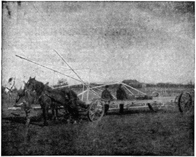
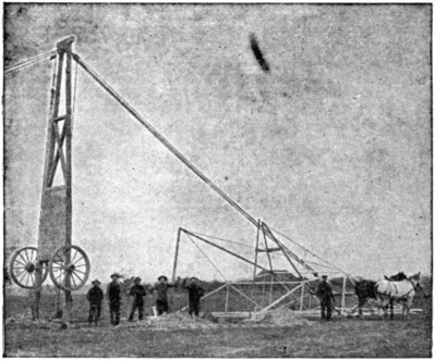
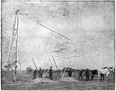
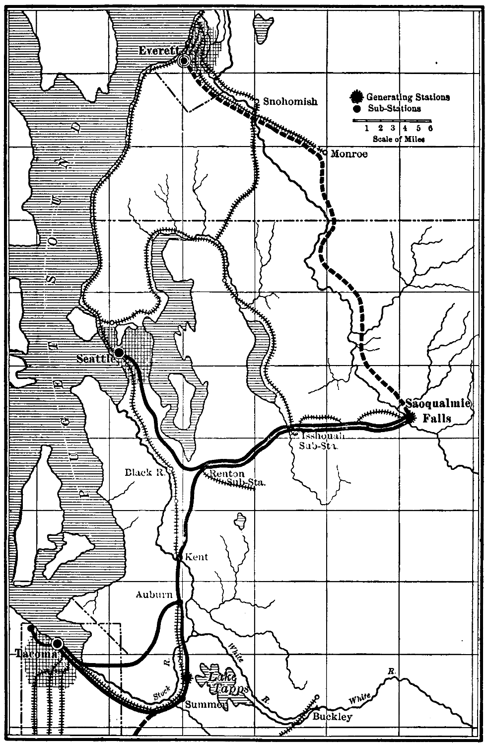
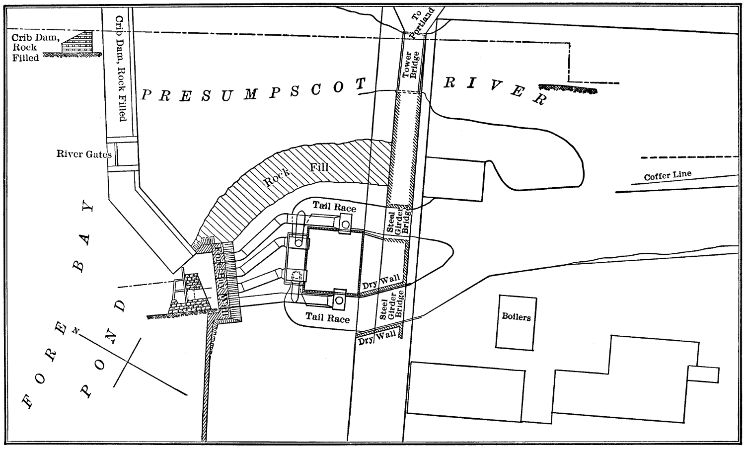
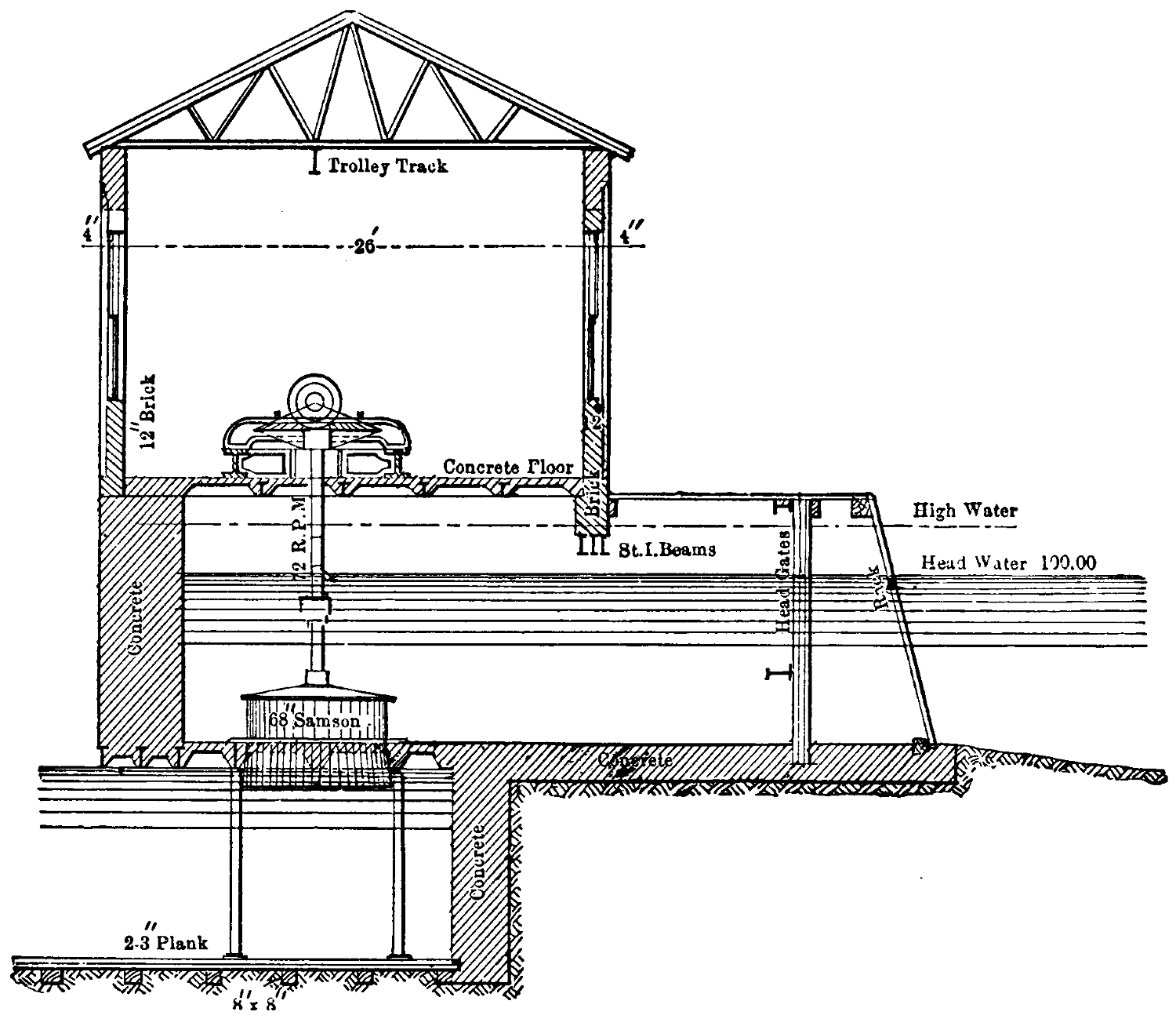
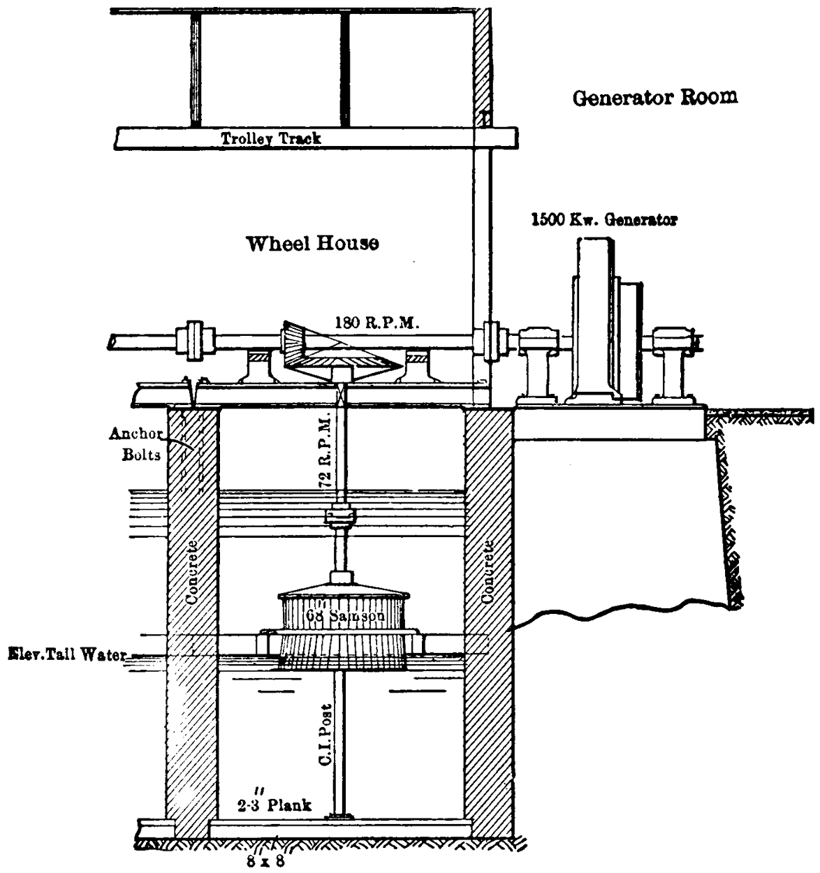
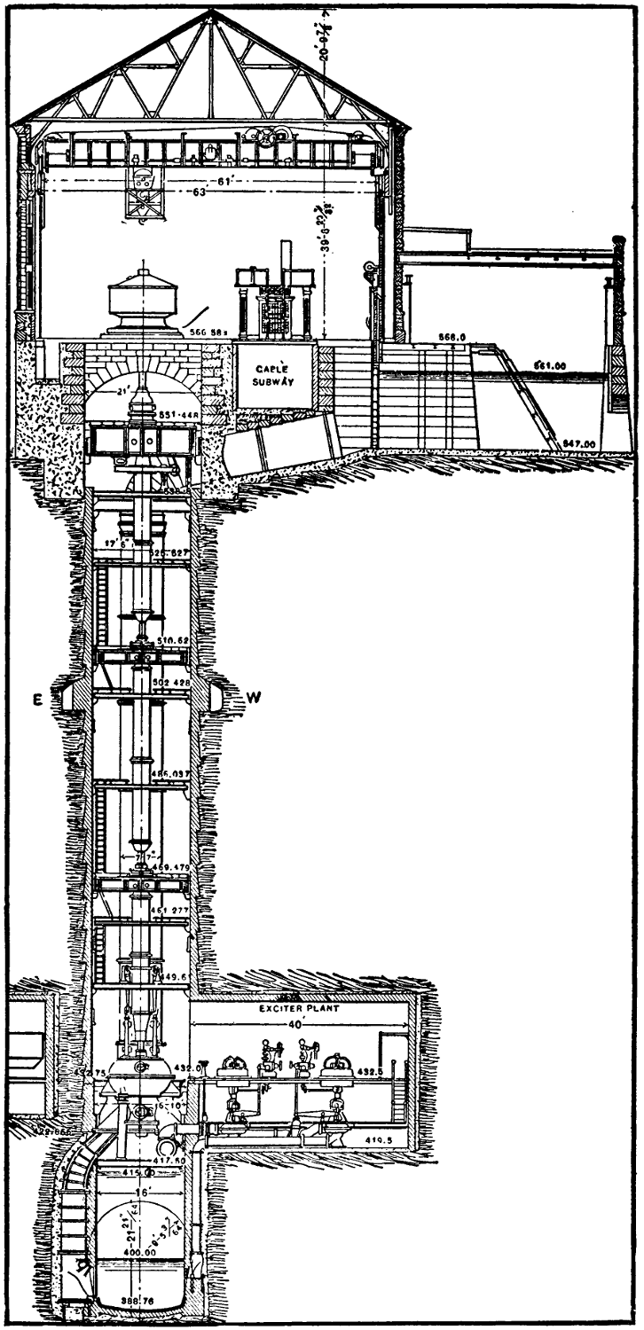
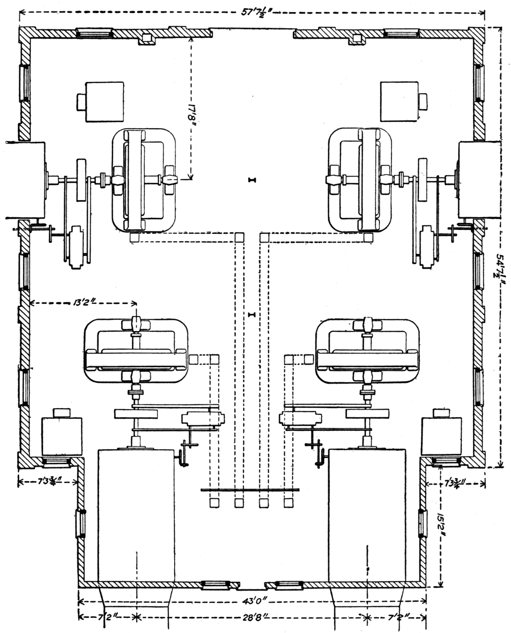
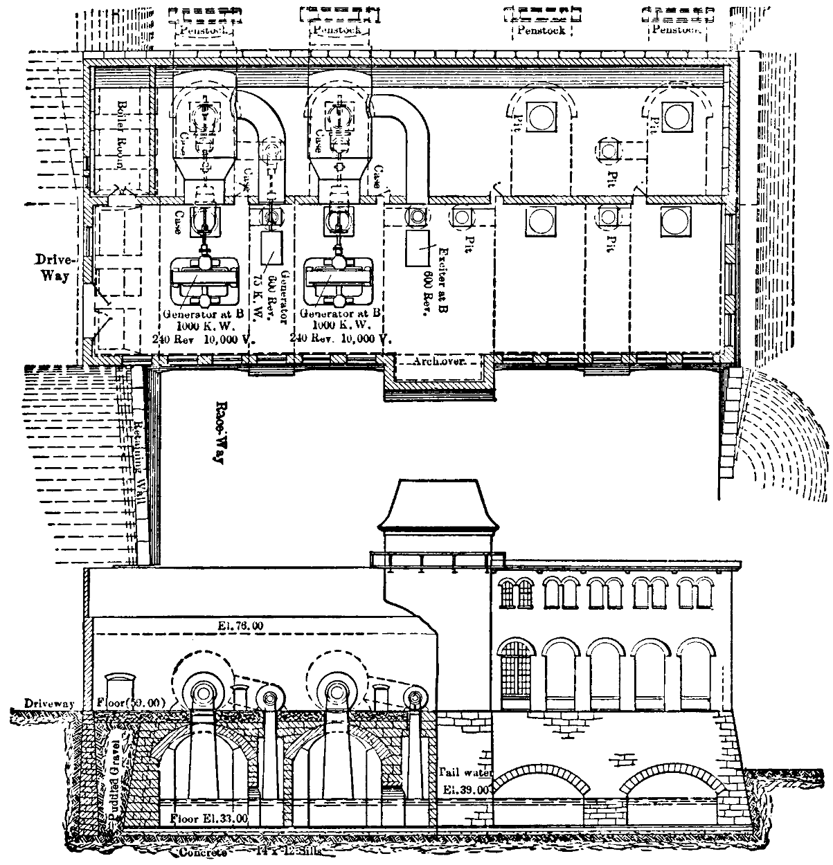
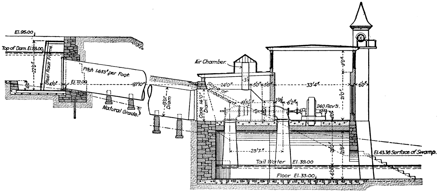
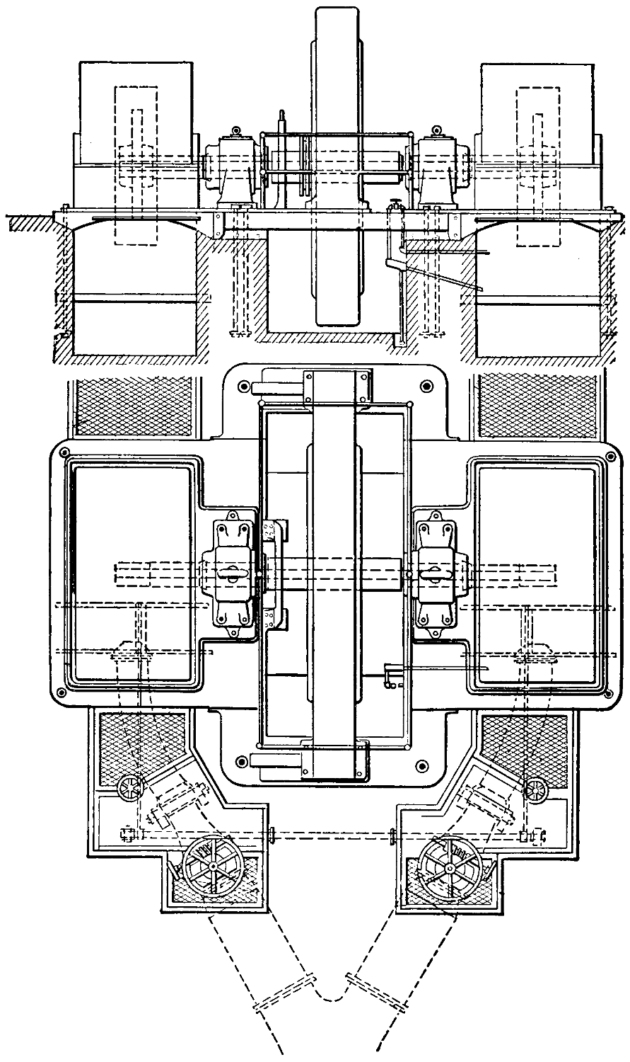
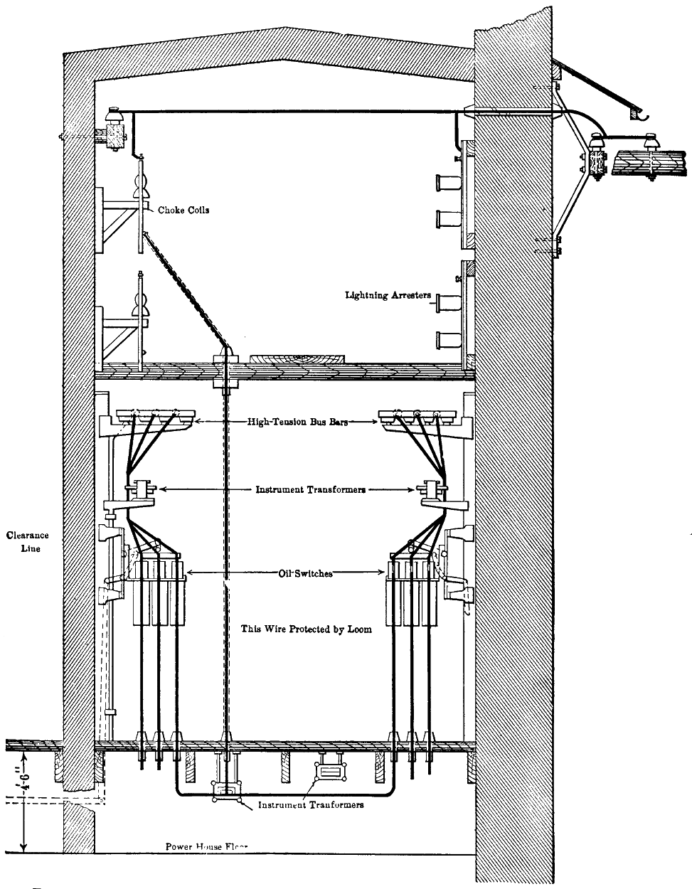
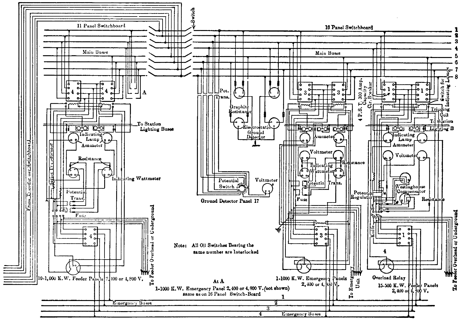
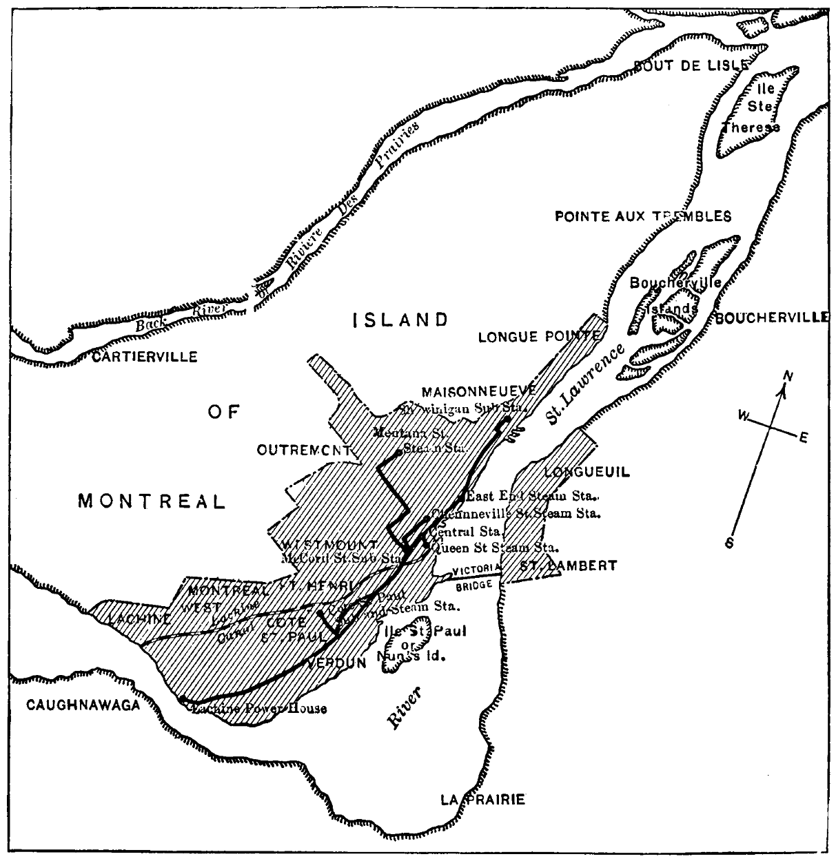
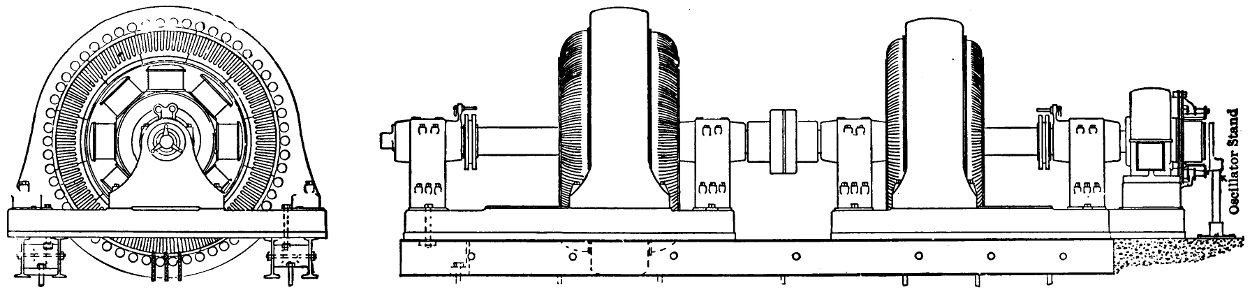
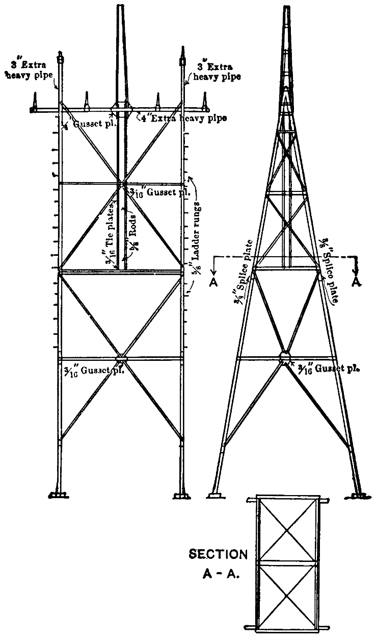