*** START OF THE PROJECT GUTENBERG EBOOK 48041 ***
The Study of Elementary Electricity and Magnetism by Experiment
BY THE SAME AUTHOR.
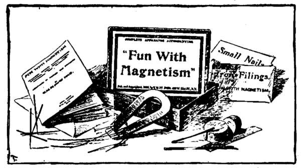
FUN WITH MAGNETISM. A book and complete outfit for
Sixty-One Experiments.
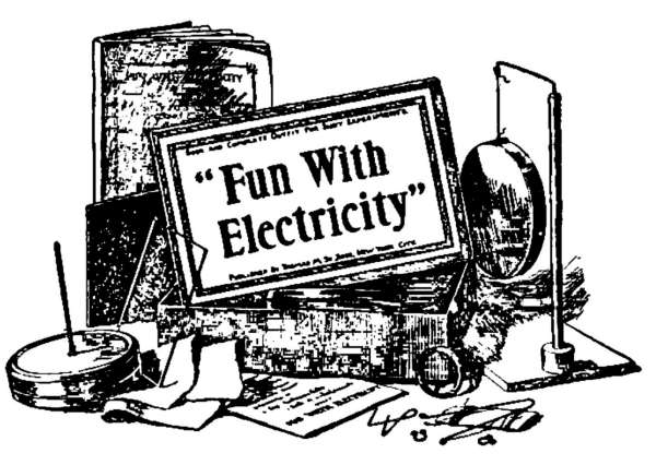
FUN WITH ELECTRICITY. A book and complete outfit for
Sixty Experiments.
FUN WITH PUZZLES. A book and complete outfit for Four
Hundred Puzzles.
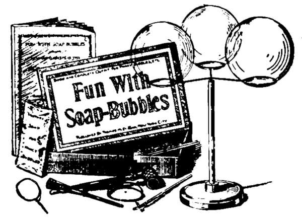
FUN WITH SOAP-BUBBLES. A book and complete outfit
for Fancy Bubbles and Films.
HUSTLE-BALL. An American game. Played by means of
magic wands and polished balls of steel.
JINGO. The great war game, including JINGO JUNIOR.
HOW TWO BOYS MADE THEIR OWN ELECTRICAL
APPARATUS. A book containing complete directions for
making all kinds of simple apparatus for the study of elementary
electricity.
THE STUDY OF ELEMENTARY ELECTRICITY AND
MAGNETISM BY EXPERIMENT. This book is designed
as a text-book for amateurs, students, and others who wish to
take up a systematic course of simple experiments at home or in
school.
IN PREPARATION.
THINGS A BOY SHOULD KNOW ABOUT ELECTRICITY.
This book explains, in simple, straightforward
language, many things about electricity; things in which the
American boy is intensely interested; things he wants to know;
things he should know.
Ask Your Toy Dealer, Stationer, or Bookseller for
our Books, Games, Puzzles, Educational
Amusements, Etc.
Thomas M. St. John, 407 West 51st St., New York.
The Study of Elementary Electricity
and Magnetism by Experiment
Containing
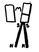
TWO HUNDRED EXPERIMENTS
PERFORMED WITH
SIMPLE, HOME-MADE APPARATUS
BY
THOMAS M. ST. JOHN, Met. E.
Author of "Fun With Magnetism," "Fun With Electricity," "How
Two Boys Made Their Own Electrical Apparatus," Etc.
NEW YORK
STHOMAS M. ST. JOHN
407 West 51st Street
1900
Copyright, 1900,
By Thomas M. St. John.
To the Student.
This book is designed as a text-book for amateurs,
students, and others who wish to take up a systematic
course of elementary electrical experiments at home or in
school.
The student is advised to begin at the beginning, to
perform the experiments in the order given, and to understand
each step before proceeding. Certain principles
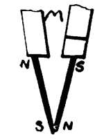
and explanations necessarily precede the practical and
perhaps more interesting applications of those principles.
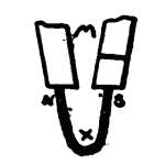
In selecting the apparatus for the experiments in this
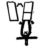
book, the author has kept constantly in mind the fact
that the average student will not buy the expensive
pieces usually described in text-books.
The two hundred experiments given can be performed
with simple, inexpensive apparatus; in fact, the student
should make at least a part of his own apparatus.
For the benefit of those who wish to make their own
apparatus, the author has given, throughout the work,
explanations that will aid in the construction of certain
pieces especially adapted to these experiments. For
those who have the author's "How Two Boys Made
Their Own Electrical Apparatus," constant references
have been made to it as the "Apparatus Book," as this
contains full details for making almost all kinds of simple
apparatus needed in "The Study of Elementary Electricity
and Magnetism by Experiment."
THOMAS M. ST. JOHN.
New York, April, 1900.
The Study of Elementary Electricity and
Magnetism by Experiment
Part I—Magnetism
Part II—Static Electricity
Part III—Current Electricity
[vii]
The Study of Elementary Electricity
and Magnetism by Experiment.
TABLE OF CONTENTS.
|
PART I.—Magnetism. |
| | Page. |
| CHAPTER I. Iron and Steel |
3 |
|
Introduction.—Kinds of iron and steel.—Exp. 1, To
study steel.—Discussion.—Exp. 2, To find whether a
piece of hard steel can be made softer.—Annealing.—Exp.
3, To find whether a piece of annealed steel can be
hardened.—Hardening; Tempering.—Exp. 4, To test the
hardening properties of soft iron.—Discussion.
| |
| CHAPTER II. Magnets |
7 |
| Kinds of magnets.—Exp. 5, To study the horseshoe
magnet.—Poles; Equator.—Exp. 6, To ascertain the
nature of substances attracted by a magnet.—Magnetic
Bodies; Diamagnetic Bodies.—Practical Uses of Magnets.—Exp.
7, To study the action of magnetism through
various substances.—Magnetic Transparency; Magnetic
Screens.—Exp. 8, To find whether a magnet can give
magnetism to a piece of steel.—Discussion; Bar Magnets.—Exp.
9, To make small magnets.—Exp. 10, To find
whether a freely-swinging bar magnet tends to point in
any particular direction.—North-seeking Poles; South-seeking
Poles; Pointing Power.—The Magnetic Needle;
The Compass.—Exp. 11, To study the action of magnets
upon each other.—Exp. 12, To study the action of a magnet
upon soft iron.—Laws of Attraction and Repulsion.—Exp.
13, To learn how to produce a desired pole at a
given end of a piece of steel.—Rule for Poles.—Our
Compass.—Review; Magnetic Problems.—Exp. 14, To
find whether the poles of a magnet can be reversed.—Discussion;
Reversal of Poles.—Exp. 15, To find whether
we can make a magnet with two N poles.—Exp. 16, To
study the bar magnet with two N poles.—Discussion;
Consequent Poles.—Exp. 17, To study consequent poles.
Exp. 18, To study the theory of magnetism.—Theory of
[viii]
Magnetism; Magnetic Saturation.—Exp. 19, To find
whether soft iron will permanently retain magnetism.—Retentivity
or Coercive Force; Residual Magnetism.—Exp.
20, To test the retentivity of soft steel.—Discussion.—Exp.
21, To test the retentivity of hard steel.—Exp. 22,
To test the effect of heat upon a magnet.—Discussion.—Exp.
23, To test the effect of breaking a magnet.—Discussion. |
|
| CHAPTER III. Induced Magnetism |
20 |
|
Exp. 24, To find whether we can magnetize a piece of
iron without touching it with a magnet.—Temporary
Magnetism; Induced Magnetism.—Exp. 25, To find
whether a piece of steel can be permanently magnetized
by induction.—Exp. 26, To study the inductive action of
a magnet upon a piece of soft iron.—Polarization; Pole
Pieces.—Exps. 27–30, To study pole pieces. |
|
| CHAPTER IV. The Magnetic Field |
23 |
| Exp. 31, To study the space around the magnet, in
which pieces of iron become temporary magnets by induction.—Discussion;
The Magnetic Field.—Exp. 32, To
study the magnetic field of a bar magnet.—Magnetic Figures;
Lines of Magnetic Force.—Exps. 33–37, To study
the magnetic fields of various combinations of bar magnets.—Exps.
38–39, To study the lifting power of combinations
of bar magnets.—Discussion; Compound Magnets.—Exps.
40–42, To study the magnetic field of the
horseshoe magnet.—Discussion; Resistance to Lines of
Force.—Exp. 43, To show that lines of force are on all
sides of a magnet.—Discussion.—Exp. 44, To study a
horseshoe magnet with movable poles.—Discussion; Advantages
of Horseshoe Magnets. |
|
| CHAPTER V. Terrestrial Magnetism |
31 |
| The Magnetism of the Earth.—Declination.—Exp. 45,
To study the lines of force above and below a bar magnet
placed horizontally.—The Dip or Inclination of the
Magnetic Needle.—Exp. 46, To study the dip or inclination
of the magnetic needle due to the action of the earth.—Discussion;
Balancing Magnetic Needles.—Exps. 47–48,
To study the inductive influence of the earth.—Discussion.—Natural
Magnets.—Exp. 49, To test the effect
of twisting a wire held north and south in the earth's
magnetic field.—Exp. 50, To test for magnetism in bars
[ix]of iron, tools, etc. |
|
PART II.—Static Electricity. |
| CHAPTER VI. Electrification |
39 |
| Some Varieties of Electricity.—Exp. 51–52, To study
electrification by friction.—Discussion.—Electrified and
Neutral bodies.—Force; Resistance; Work; Potential
Energy; Electrification.—Heat and Electrification.—Exps.
53–54, To study electrical attraction.—Discussion.—Exp.
55, To study mutual attractions.—Mutual Attractions.—Exps.
56–58, To study electrical repulsions.—The
Carbon Electroscope.—Discussion of Experiments 56, 57,
58.—Exp. 59, To study the electrification of glass.—Questions.—Exp.
60, To compare the electrification produced
by ebonite and flannel with that produced by glass and
silk.—Discussion.—Laws. |
|
| CHAPTER VII. Insulators and Conductors |
47 |
| Exps. 61–63, To study insulators.—Conductors.—Exp.
64, To study conduction.—Discussion.—Exp. 65, To
study conduction.—Telegraph line using static electricity.—Discussion.—Relation
between conductors and
insulators.—Electrics and Non-electrics.—Exp. 66, To
study the effect of moisture upon an insulator.—Discussion.—Exp.
67, To test the effects of moisture upon
bodies to be electrified. |
|
| CHAPTER VIII. Charging and Discharging Conductors |
52 |
| The Electrophorus.—Exp. 68, To learn how to use the
electrophorus.—Exp. 69, To study "charging by conduction."—Exp.
70, To study potential; Electromotive force.—Pressure;
Potential; Electromotive force; Current,
Spark.—Theories about Electrifications.—Exp. 71, To
study some methods of discharging an electrified body.—Disruptive,
Conductive and Convective Discharges.—Exp.
72, To study intermittent or step-by-step discharges.—Discussion.—Exp.
73, To ascertain the location
of the charge upon an electrified conductor.—Discussion.—Hollow
and Solid Conductors.—Exp. 74, To study the
effect of points upon a charged conductor.—Electric
Density.—Electric Wind. |
|
| CHAPTER IX. Induced Electrification |
60 |
| Electric Fields; Lines of Force.—Exp. 75, To study
electric induction.—Electric Polarization; Theory of Induction.—Exp.
76, To learn how to charge a body by
induction.—Free and Bound Electrifications.—Exp. 77,
To show that a neutral body is polarized before it is
[x]attracted by a charged one.—Polarization Precedes
Attraction.—Exp. 78, To find whether electric induction
will act through an insulator.—Dielectrics.—Exp. 79, To
find whether a polarized conductor can act inductively
upon another conductor.—Successive Induction.—Inductive
Capacity.—Exp. 80, To study the action of the electrophorus.—Discussion.—Details
of action.—Exp. 81, To
see, hear, and feel the results of inductive influence and
polarization.—Discussion.
|
|
| CHAPTER X. Condensation of Electrification |
68 |
| Exp. 82, To find whether a large surface will hold more
electrification than a small one.—Electrical Capacity.—Exp.
83, To find whether the capacity of a given conductor
can be increased without increasing its size.—Condensation;
Condensers.—The Leyden Jar.—Fulminating
Panes.—Induction Coil Condensers.—Submarine Cables.—Exp.
84, To study the condensation of electrification.—Discussion.—Exp.
85, To study the action of the condenser.—Discussion.—Exp.
86, To study the effect of
electrical discharges upon the human body.—Shocks;
Dischargers.—Exps. 87–88, To show the strong attraction
between opposite electrifications in the condenser.—Discussion.—Exp.
89, To show how the condenser may be
slowly discharged.—The Electric Chime.—Exp. 90, To
ascertain the location of a charge in a condenser.—Discussion.—Exp.
91, To find whether any electrification
remains in the condenser after it has once been discharged.—Residual
Charge.—Exp. 92, To study successive
condensation; the chime cascade.—Discussion.
|
|
| CHAPTER XI. Electroscopes |
77 |
| Electroscopes.—Our leaf electroscope.—Exp. 93, To
study the leaf electroscope; charging by conduction.—Discussion.—Exp.
95, To learn some uses of the electroscope.—Discussion.—The
Proof-plane.
|
|
| CHAPTER XII. Miscellaneous Experiments |
81 |
| Exp. 96, To show that friction always produces two
kinds of electrification.—Discussion.—Exp. 97, To show
"successive sparks."—Exp. 98, To show to the eye the
strong attraction between a charged and a neutral body.—Exp.
99, To feel the strong attraction between a charged
and a neutral body.—Exp. 100, The human body a frictional
electric machine.—Static Electric Machines.
|
|
| CHAPTER XIII. Atmospheric Electricity |
84 |
| Atmospheric Electricity.—Lightning.—Thunder.—Lightning
Rods.—Causes of Atmospheric Electricity.—St. Elmo's Fire.—Aurora Borealis.
|
|
[xi]
|
PART III.—Current Electricity. |
| CHAPTER XIV. Construction and Use of Apparatus |
89 |
| Exp. 101, To study the effect of the electric current upon
the magnetic needle.—Electrical Connections.—Current
Detectors.—Exp. 102, To study the construction and use
of a simple "key."—Exp. 103, To study the construction
and use of a simple "current reverser."—Exp. 104, To
study the simple current detector.—Exp. 105, To study
the construction and use of the simple galvanoscope.—Discussion;
True Readings.—Exp. 106, To study the construction
and use of a simple astatic needle.—Astatic
Needles.—Exp. 107, To study the construction and use
of a simple astatic galvanoscope.—Astatic Galvanoscopes.
|
|
| CHAPTER XV. Galvanic Cells and Batteries |
102 |
| Exp. 108, To study the effect of dilute sulphuric acid
upon carbon and various metals.—To amalgamate.—Dilute
sulphuric acid.—Discussion.—Exp. 109, To study
the effect of dilute sulphuric acid upon various combinations
of metals.—Discussion.—Exp. 110, To study the
construction of a simple Voltaic or Galvanic cell.—The
Electric Current.—Source of the Electrification.—The
Electric Circuit; Open and Closed Circuits.—Plates or
Elements.—Direction of Current.—Poles or Electrodes.—Chemical
Action in the Simple Galvanic Cell.—Action in
Cell Using Impure Zinc; Action Using Pure Zinc.—Exp.
111, To see what is meant by "local currents" in the
cell.—Local Action; Local Currents.—Reasons for Amalgamating
Zinc Plates.—Exp. 112, To study the "single-fluid"
Galvanic Cell.—The Simple Cell.—Polarization of
Cells.—Effects of Polarization.—Remedies for Polarization;
Depolarizers.—Exp. 113, To study the "two-fluid"
Galvanic Cell.—Setting Up the Two-Fluid Cell.—Care of
Two-Fluid Cell.—Copper Sulphate Solution.—Chemical
Action in the Two-Fluid Cell.—Various Galvanic Cells;
Open and Closed Circuit Cells.—The Leclanché Cell—Dry
Cells.—The Bichromate of Potash Cell.—The Daniell
Cell.—The Gravity Cell.
|
|
| CHAPTER XVI. The Electric Circuit |
115 |
| Exp. 114, To see what is meant by "divided circuits" and
"shunts."—Divided Circuits; Shunts.—Exp. 115, To see
[xii]what is meant by "short circuits."
|
|
| CHAPTER XVII. Electromotive Force |
117 |
| Electromotive Force.—Unit of E. M. F.; The Volt.—Exp.
116, To see whether the E. M. F. of a cell depends
upon the materials used in its construction.—Discussion.—Electromotive
Series.—Exp. 117, To see whether the E.
M. F. of a cell depends upon its size.—Discussion.
|
|
| CHAPTER XVIII. Electrical Resistance |
120 |
| Resistance.—Exp. 118, To study the general effect of
"resistance" upon a current.—External Resistance;
Internal Resistance; Unit of Resistance; The Ohm.—Resistance
Coils; Resistance Boxes.—Simple Resistance
Coil.—Exp. 119, To test the power of various
substances to conduct galvanic electricity.—Conductors
and Nonconductors.—Exp. 120, To find the effect of sulphuric
acid upon the conductivity of water.—Internal
Resistance.—Exp. 121, To find what effect the length of
a wire has upon its electrical resistance.—Discussion.—Exp.
122, To find what effect the size (area of cross-section)
of a wire has upon its electrical resistance.—Discussion.—Exp.
123, To compare the resistance of a
divided circuit with the resistance of one of its branches.
Discussion.—Exp. 124, To study the effect of decreasing
the resistance in one branch of a divided circuit.—Current
in Divided Circuits.
|
|
| CHAPTER XIX. Measurement of Resistance |
130 |
| Exp. 125, To study the construction and use of a simple
Wheatstone's Bridge.—The Simple Bridge.—Equipotential
Points.—Example.—Exp. 126, To measure the resistance
of a wire by means of Wheatstone's Bridge; the
"bridge method."—Allowances for Connections.—Exps.
127–137, To measure the resistances of various wires,
coils, etc., by the "bridge method."—Table.—Exp. 138,
To study the effect of heat upon the resistance of metals.—Effect
of Heat upon Resistance.—Exp. 139, To measure
the resistance of a wire by the "method of substitution."—Simple
Rheostat.—Exp. 140, To measure the E.
M. F. of a cell by comparison with the two-fluid cell.—Exp.
141, To measure the internal resistance of a cell
by the "method of opposition."
|
|
| CHAPTER XX. Current Strength |
142 |
| Strength of Current.—Unit of Current Strength; The
Ampere.—Measurement of Current Strength.—The Tangent
Galvanometer.—The Ammeter.—The Voltameter.—Unit
of Quantity; The Coulomb.—Electrical Horse-power;
[xiii]The Watt.—Ohm's Law.—Internal Resistance
and Current Strength.—Exp. 142, Having a cell with
large plates, to find how the strength of the current is
affected by changes in the position of the plates, the external
resistance being small.—Exp. 143, Same as Exp.
142, but with small plates.—Exp. 144, To find whether
the changes in current strength, due to changes in internal
resistance, are as great when the external resistance is
large, as they are when the external resistance is small.—Discussion,
with examples.—Arrangement of Cells and
Current Strength.—Cells in Series.—Cells Abreast.—Exp.
145, To find the best way to join two similar cells
when the external resistance is small.—Exp. 146, To
find the best way to join two similar cells when the external
resistance is large.—Best Arrangement of Cells.
|
|
| CHAPTER XXI. Chemical Effects of the Electric
Current |
151 |
| Chemical Action and Electricity.—Electrolysis.—Exp.
147, To study the electrolysis of water.—Composition
of Water.—Electromotive Force of Polarization.—Exp.
148, To coat iron with copper.—Exp. 149, To study the
electrolysis of a solution of copper sulphate.—Electroplating.—Exp.
150,
To study the chemistry of electroplating.—Discussion.—Electrotyping.—Voltameters.—Exp.
151, To study the construction and action of a
simple "storage" cell.—Secondary or Storage Cells.
|
|
| CHAPTER XXII. Electromagnetism |
158 |
| Electromagnetism.—Exp. 152, To study the lines of
force about a straight wire carrying a current.—Ampere's
Rule.—Lines of Force About Parallel Wires.—Exp. 153,
To study the lines of force about a coil of wire like that
upon the galvanoscope.—Exp. 154, To study the magnetic
field about a small coil of wire.—Coils.—Polarity of
Coils.—Exp. 155, To test the attracting and "sucking"
power of a magnetized coil or helix.—Exp. 156, To find
whether a piece of steel can be permanently magnetized
by an electric current.—Exp. 157, To study the effect of
a piece of iron placed inside of a magnetized coil of wire.
|
|
| CHAPTER XXIII. Electromagnets |
165 |
| Electromagnets.—Cores of Electromagnets.—Exps. 158–163,
To study straight electromagnets; Lifting power;
Residual magnetism of core; Magnetic tick; Magnetic
figures; Magnetic field.—Horseshoe Electromagnets.—Use
[xiv]of Yoke.—Experimental Magnets.—Method of
Joining Coils.—Exps. 164–173, To study horseshoe
electromagnets; To test the poles; To study the inductive
action of one core upon the other; Magnetic figures;
Permanent Magnetic Figures; Lifting power; Residual
magnetism when magnetic circuit is closed.—Closed Magnetic
Circuits.
|
|
| CHAPTER XXIV. Thermoelectricity |
175 |
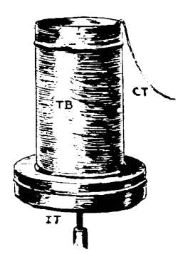
| Exp. 174, To find whether electricity can be produced by
heat.—Home-made Thermopile.—Thermoelectricity.—Peltier
Effect.—Thermopiles.
|
|
| CHAPTER XXV. Induced Currents |
178 |
| Electromagnetic Induction.—Exp. 175, To find whether
a current can be generated with a bar magnet and a
hollow coil of wire.—Discussion.—Induced Currents and
Work.—Exp. 176, To find whether a current can be
generated with a bar magnet and a coil of wire having
an iron core.—Exp. 177, To find whether a current can be
generated with a horseshoe magnet and a coil of wire
having an iron core.—Induced Currents and Lines of
Force.—Exp. 178, To find whether a current can be generated
with an electromagnet and a hollow coil of wire.—Exp.
179, To find whether a current can be generated
with an electromagnet and a coil of wire having an iron
core.—Discussion of Exps. 178–179.—Exp. 180, To study
the effect of starting or stopping a current near a coil of
wire or other closed circuit.—Exp. 181, To study the
effect of starting or stopping a current in a coil placed
inside of another coil.—Discussion of Exps. 180–181.—Direction
of Induced Current.—Laws of Induction.—Primary
and Secondary Currents.—Exp. 182, To see what
is meant by alternating currents.—Direct and Alternating
Currents.—Self-induction; Extra Currents.
|
|
| CHAPTER XXVI. The Production of Motion by Currents |
187 |
| Currents and Motion.—Exp. 183, Motion produced
with a hollow coil and a piece of iron.—Exp. 184, Motion
with hollow coil and bar magnet.—Exp. 185, Motion with
electromagnet and piece of iron.—Exp. 186, Motion with
electromagnet and bar magnet.—Exp. 187, Motion with
electromagnet and horseshoe magnet.—Exp. 188, Motion
with two electromagnets.—Discussion of Exps. 183–188.—Exp.
189, Rotary motion with a hollow coil of wire and
a permanent magnet.—Exp. 190, Rotary motion with an
electromagnet and a permanent magnet.—Discussion of
[xv]Exps. 189–190. |
|
| CHAPTER XXVII. Applications of Electricity |
192 |
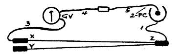
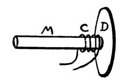
| Things Electricity Can Do.—Exp. 191, To study the
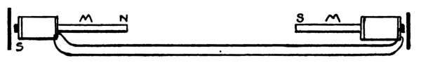
action of a simple telegraph sounder.—Discussion.—Telegraph
Line; Connections.—Operation of Line.—Exp.
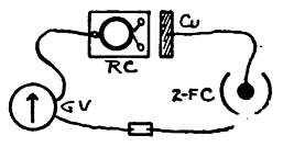
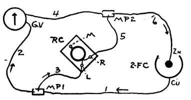
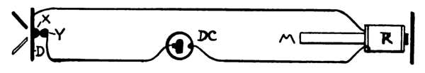
192, To study the action of the "relay" on telegraph
lines.—The Relay.—Exp. 193, To study the action of a
two-pole telegraph instrument.—Exp. 194, To study the
action of a simple "single needle telegraph instrument."—Exp.
195, To study the action of a simple automatic
contact breaker, or current interrupter.—Automatic
Current Interrupters.—Exp. 196, To study the
action of a simple electric bell, or a "buzzer."—Electric
Bells and Buzzers.—Exp. 197, To study the action of a
simple telegraph "recorder."—Exp. 198, To study the
action of a simple "annunciator."—Discussion.—Exp.
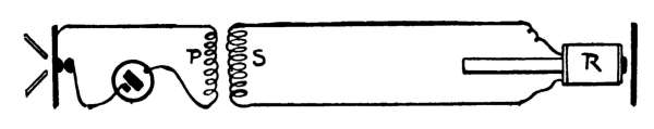
199, To study the shocking effects of the "extra current."
Induction Coils.—Action of Induction Coils.—Transformers.—The
Dynamo.—The Electric Motor.—Exp. 200,
To study the action of the telephone.—The Telephone.—The
Bell, or Magneto-transmitter.—The Receiver.—The
Carbon Transmitter.—Induction Coils in Telephone
Work.—Electric Lighting and Heating.—Arc Lamps.—The
Incandescent Lamp.
|
|
| CHAPTER XXVIII. Wire Tables |
208 |
| APPARATUS LIST |
210 |
| INDEX |
215 |
MAGNETISM
A Few Dont's for Young Students.
Don't fail to make at least a part of your own apparatus;
there is a great deal of satisfaction and pleasure in
home-made apparatus.
Don't experiment in all parts of the house, if working at
home. Fit up a small room for your den, and carry
the key.
Don't begin an experiment before you really know what
you are trying to do. Read the directions carefully,
then begin.
Don't rush through an experiment to see what happens
at the end of it. See what happens at each step,
and notice every little thing that seems unusual.
Don't try to do all parts of an experiment at the same
time. Understand one part, then proceed.
Don't fail to ask yourself questions, and form an opinion
about the results of an experiment before you read
what the author has to say about it.
Don't fail to keep a note-book. Keep all the data and
arithmetical work for future reference.
Don't leave the apparatus around after you have finished
the day's work.
[3]
PART I.—MAGNETISM.
CHAPTER I.
IRON AND STEEL.
1. Introduction. We should know something about
iron and steel at the start, because we are to use them in
nearly every experiment. The success with some of the
experiments will depend largely upon the quality of the
iron and steel used.
When we buy a piece of iron from the blacksmith, we
get more than iron for our money. Hidden in this iron
are other substances (carbon, phosphorus, silicon, etc.),
which are called "impurities" by the chemist. If all
the impurities were taken out of the iron, however, we
should have nothing but a powder left; this the chemist
would call "chemically pure iron," but it would be of no
value whatever to the blacksmith or mechanic. The
impurities in iron and steel are just what are needed to
hold the particles of iron together, and to make them
valuable. By regulating the amount of carbon, phosphorus,
etc., manufacturers can make different grades and
qualities of iron or steel.
When carbon is united with the pure iron, we get what
is commonly called iron.
2. Kinds of Iron and Steel. Cast iron is the
most impure form of iron. Stoves, large kettles, flatirons,
etc., are made of cast iron. Wrought iron is the[4]
purest form of commercial iron. It usually comes in
bars or rods. Blacksmiths hammer these into shapes to
use on wagons, machinery, etc. Steel contains more
carbon than wrought iron, and less than cast iron.
Soft steel is very much like wrought iron in appearance,
and it is used like wrought iron.
Hard steel has more carbon in it than soft steel. Tools,
needles, etc., are made of this.
EXPERIMENT 1. To study steel.
Apparatus.
A steel sewing-needle (No. 1).
[A]
[A] NOTE. Each piece of apparatus used in the
following experiments has a number. See
"Apparatus list" at the back of this book for
details. The numbers given under "Apparatus,"
in each experiment, refer to this list.
3. Directions. (A) Bend a sewing-needle until it breaks. Is
the steel brittle?
(B) If you have a file, test the hardness of the needle.
4. Discussion. "Needle steel" is usually of good
quality. It will be very useful in many experiments.
Do you know how to make the needle softer?
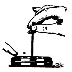
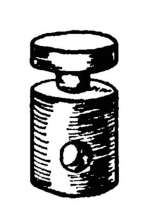
EXPERIMENT 2. To find whether a piece of hard steel
can be made softer.
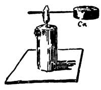
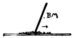
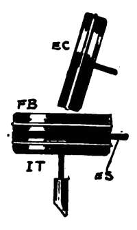
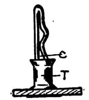
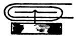
Fig. 1.
Apparatus. Fig. 1. A needle; a
cork, Ck (No. 2); lighted candle
(No. 3). The bottom of the candle
should be warmed and stuck to a
pasteboard base.
5. Directions. (A) Stick the point of the
needle into Ck, Fig. 1, then hold the needle
in the flame until it is red-hot. (The upper
part of the flame is the hottest.)
(B) Allow the needle to cool in the air.
(C) Test the brittleness of the steel by bending it. Test its
hardness with a file (Exp. 1).
6. Annealing. This process of softening steel by
first heating it and then allowing it to cool slowly, is called
annealing. All pieces of iron and steel are, of course,
hard; but you have learned that some pieces are much
harder than others.
EXPERIMENT 3. To find whether a piece of annealed
steel can be hardened.
Apparatus. The needle just annealed and bent; cork,
etc., of Exp. 2; a glass of cold water.
7. Directions. (A) Heat the bent portion of the needle in the
candle flame (Exp. 2) until it is red-hot, then immediately plunge
the needle into the water.
(B) Test its brittleness and hardness, as in Exp. 2.
8. Hardening; Tempering. Good steel is a
very valuable material; the same piece may be made hard
or soft at will. By sudden cooling, the steel becomes very
hard. This process is called hardening, but it makes the
steel too brittle for many purposes. By tempering is
meant the "letting down" of the steel from the very
hard state to any desired degree of hardness. This may
be done by suddenly cooling the steel when at the right
temperature, it not being hot enough to produce extreme
hardness. (The approximate temperature of hot steel
can be told by the colors which form on a clean surface.
These are due to oxides which form as the steel gradually
rises in temperature.)
EXPERIMENT 4. To test the hardening properties of
soft iron.
Apparatus. A piece of soft iron wire about 3 in. (7.5
cm.) long (No. 4); the candle, water, etc., of Exp. 3.
9. Directions. (A) Test the wire by bending and filing.
(B) Heat the wire in the candle flame as you did the needle
(Fig. 1), then cool it suddenly with the water. Study the results.
[6]
10. Discussion. Soft iron contains much less carbon
than steel. The hardening quality which steel has is
due to the proper amount of carbon in it. If you have performed
the experiments so far, you will be much more
able to understand later ones, and you will see why we
are obliged to use soft iron for some parts of electrical
apparatus, and hard steel for other parts.
[7]
CHAPTER II.
MAGNETS.
11. Kinds of Magnets. Among the varieties of
magnets which we shall discuss, are the natural, artificial,
temporary, permanent, bar, horseshoe, compound, and
electro-magnet.
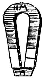
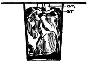
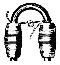
The Horseshoe Magnet, H M (Fig. 2), is the most
popular form of small magnets. The red paint
has nothing to do with the magnetism. The
piece, A, is called its armature, and is made of
soft iron, while the magnet itself should be
made of the best steel, properly hardened. The
armature should always be in place when the
magnet is not in use, and care should be taken
to thoroughly clean the ends of the magnet
before replacing the armature. The horseshoe magnet is
artificial, and it is called a permanent magnet, because it
retains its strength for a long time, if properly cared for.
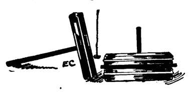
EXPERIMENT 5. To study the horseshoe magnet.
Apparatus. Fig. 2. The horseshoe magnet, H M (No. 16).
12. Directions. (A) Remove the armature, A, from the
magnet, then move A about upon H M to see (1) if the curved
part of H M has any attraction for A, and (2) to see if there is
any attraction for A at points between the curve and the extreme
ends of H M.
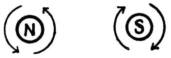
13. Poles; Equator. The ends of a magnet are
called its poles. The end marked with a line, or an N,
should be the north pole. The unmarked end is the south
pole. N and S are abbreviations for north and south.
The central part, at which there seems to be no magnetism,
is called the neutral point or equator.
[8]
EXPERIMENT 6. To ascertain the nature of substances
attracted by a magnet.
Apparatus. The horseshoe magnet, H M (Fig. 2); silver,
copper, and nickel coins; iron filings (No. 17), nails, tacks,
pins, needles; pieces of brass, lead, copper, tin, etc.
(Ordinary tin is really sheet iron covered with tin.) Use
the various battery plates for the different metals.
14. Directions. (A) Try the effect of H M upon the above
substances, and upon any other substances thought of.
15. Magnetic Bodies; Diamagnetic Bodies.
Substances which are attracted by a magnet are said to be
magnetic. A piece of soft iron wire is magnetic, although
not a magnet. Very strong magnets show that nickel,
oxygen, and a few other substances not containing iron,
are also magnetic. Some elements are actually repelled
by a powerful magnet; these are called diamagnetic
bodies. It is thought that all bodies are more or less
affected by a magnet.
16. Practical Uses of Magnets. Many practical
uses are made of magnets, such as the automatic picking
out of small pieces of iron from grain before it is ground
into flour, and the separation of iron from other metals,
etc. The most important uses of magnets are in the
compass and in connection with the electric current, as in
machines like dynamos and motors. (See experiments
with electro-magnets.)
EXPERIMENT 7. To study the action of magnetism
through various substances.
Apparatus. Horseshoe magnet, H M; a sheet of stiff
paper; pieces of sheet glass, iron, zinc, copper, lead,
thin wood, etc.; sewing-needle. (A tin box may be used
for the iron, and battery plates for the other metals.)
17. Directions. (A) Place the needle upon the paper and move
H M about immediately under it.
(B) In place of the paper, try wood, glass, etc.
[9]
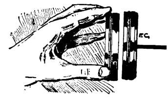
(C) Invent an experiment to show that magnetism will act
through your hand.
(D) Invent an experiment to show that magnetism will act
through water.
18. Magnetic Transparency; Magnetic
Screens. Substances, like paper, are said to be transparent
to magnetism. Iron does not allow magnetism to
pass through it as readily as paper and glass; in fact,
thick iron may act as a magnetic screen.
EXPERIMENT 8. To find whether a magnet can give
magnetism to a piece of steel.
19. Note. You have seen that the horseshoe magnet can lift
nails, iron filings, etc.; you have used this lifting power to show
that the magnet was really a magnet, and not merely an ordinary
piece of iron painted red. Can we give some of its magnetism
to another piece of steel? Can we pass the magnetism along
from one piece of steel to another?
Apparatus. The horseshoe magnet, H M; two sewing-needles
that have never been near a magnet; iron filings.
20. Directions. (A) Test the needles for magnetism with the
iron filings, and be sure that they are not magnetized.
(B) Remove the armature, A, from H M, then touch the point
of one of the needles to one pole of H M.
(C) Lay H M aside, and test the point of the needle for magnetism.
(D) If you find that the needle is magnetized, rub its point upon
the point of the other needle; then test the point of the second
needle for magnetism.
21. Discussion; Bar Magnets. A piece of good
steel will attract iron after merely touching a magnet.
To thoroughly magnetize it, however, a mere touch is
not sufficient. There are several ways of making magnets,
depending upon the size, shape, and strength desired.
For these experiments, the student needs only a
good horseshoe magnet, or, better still, the electro-magnets
described later; with these any number of small[10]
magnets may be made. Straight magnets are called bar
magnets.
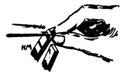
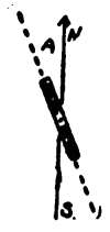
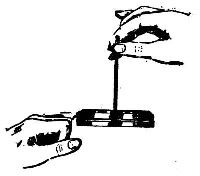
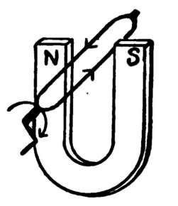
EXPERIMENT 9. To make small magnets.
Apparatus. Fig. 3. The horseshoe magnet, H M;
sewing-needles; iron filings. (See Apparatus Book, Pg.
140, for various kinds of steel suitable for small magnets.)
22. Directions. (A) Hold H M (Fig. 3) in the left hand, its
poles being uppermost. Grasp the point of the needle with the
right hand, and place its point upon the N or marked pole of H M.
(B) Pull the needle along in the direction of its length (see the
arrow), continuing the motion until its head is at least an inch
from the pole.
(C) Raise the needle at least an inch above H M, lower it to its
former position (Fig. 3), and repeat the operation 3 or 4 times.
Do not slide the needle back and forth upon the pole, and be
careful not to let it accidentally touch the S pole of H M.
(D) Test the needle for magnetism with iron filings, and save
it for the next experiment.
EXPERIMENT 10. To find whether a freely-swinging bar
magnet tends to point in any particular direction.
Apparatus. Fig. 4. A magnetized sewing-needle (Exp.
9); the flat cork, Ck (No. 2); a dish of water. (You can
use a tumbler, but a larger dish is better.)
23. Note. An oily sewing-needle may be floated without the
cork by carefully lowering it to the surface of the water. All
magnets, pieces of iron and steel, knives, etc., should be
removed from the table when trying such experiments. Why?
24. Directions. (A) Place the little bar magnet (the needle)
upon the floating cork, turn it in various positions, and note the
result.
[11]
25. North-seeking Poles; South-seeking
Poles; Pointing Power. It should be noted that
the point swings to the north, provided the needle is
magnetized as directed in Exp. 9. This is called the
north, or north-seeking pole. The N-seeking pole is
sometimes called the marked pole. For convenience, we
shall hereafter speak of the N-seeking pole as the N pole,
and of the S-seeking pole as the S pole. We shall hereafter
speak of the tendency which a bar magnet has to
point N and S, as its pointing power. An unmagnetized
needle has no pointing power.
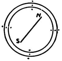
26. The Magnetic Needle; The Compass.
A small bar magnet, supported upon a pivot, or suspended
so that it may freely turn, is called a magnetic needle.
When balanced upon a pivot having under it a graduated
circle marked N, E, S, W, etc., it is called a compass.
These have been used for centuries. (See Apparatus
Book for Home-made Magnetic Needles.)
EXPERIMENT 11. To study the action of magnets upon
each other.
Apparatus. Two magnetized sewing-needles (magnetized
as in Exp. 9); the cork, etc., of Exp. 10.
27. Directions. (A) Float each little bar magnet (needles)
separately to locate the N poles.
(B) Leave one magnet upon the cork, and with the hand bring
the N pole of the other magnet immediately over the N pole of
the floating one. Note the result.
(C) Try the effect of two S poles upon each other.
(D) What is the result when a N pole of one is brought near a
S pole of the other?
EXPERIMENT 12. To study the action of a magnet upon
soft iron.
Apparatus. A magnetized sewing-needle; cork, etc.,
of Exp. 10; a piece of soft iron wire, 3 in. long; iron filings.
28. Directions. (A) Test the wire for magnetism with filings.[12]
Be sure that it is not magnetized. If it shows any magnetism,
twist it thoroughly before using. (Exp. 19.)
(B) Float the magnetized needle (Exp. 10), then bring the end
of the wire near one pole of the needle and then near the other
pole.
(C) Place the wire upon the cork, hold the needle in the hand
and experiment.
29. Laws of Attraction and Repulsion. From
experiments 11 and 12 are derived these laws:
(1) Like poles repel each other; (2) Unlike
poles attract each other; (3) Either pole attracts
and is attracted by unmagnetized iron
or steel.
The attraction between a magnet and a piece of iron or
steel is mutual. Attraction, alone, simply indicates that
at least one of the bodies is magnetized; repulsion proves
that both are magnetized.
EXPERIMENT 13. To learn how to produce a desired pole
at a given end of a piece of steel.
30. Directions. (A) Magnetize a sewing-needle (Exp. 9) by
rubbing it upon the N pole of H M from point to head. Float it
and locate its N pole.
(B) Take another needle that has not been magnetized, and
rub it on the same pole (N) from head to point. Locate its N pole.
(C) Magnetize another needle by rubbing it from point to head
upon the S pole of H M; locate its N pole. Can you now determine,
beforehand, how the poles of the needle magnet will be
arranged?
31. Rule for Poles. The end of a piece of steel
which last touches a N pole of a magnet, for example,
becomes a S pole.
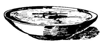
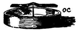
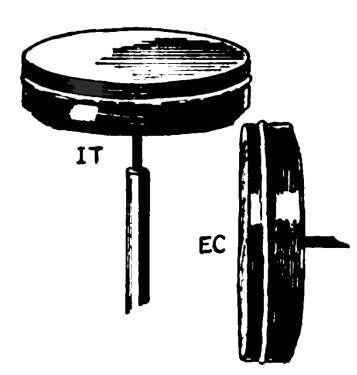
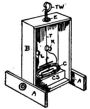
32. Our Compass (No. 18). While the floating
magnetic needle described in Exp. 10, and shown in Fig.
4, does very well, it will be found more convenient to[13]
use a compass whenever poles of pieces of steel are to be
tested. Fig. 5 shows merely the cover of the box which
serves as a base for the magnetic needle furnished. We
shall hereafter speak of this apparatus as our compass,
O C. (See Apparatus Book, Chap. VII, for various
forms of home-made magnetic needles and compasses.)
33. Review; Magnetic Problems. To be sure that you understand
and remember what was learned in Exp. 11, do these problems:
1. Using the S pole of the horseshoe magnet, magnetize a
needle so that its head will become a N pole. Test with floating
cork, as in Exp. 11.
2. Using the N pole of the horseshoe magnet, magnetize a
needle so that its head shall be a S pole. Test.
3. Magnetize two needles, one on the N and one on the S pole
of the horseshoe magnet, in such a way that the two points will
repel each other. Test.
If the student cannot do these little problems at once, and test
the results satisfactorily to himself, he should study the previous
experiments again before proceeding.
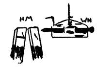
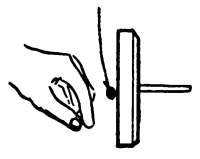
EXPERIMENT 14. To find whether the poles of a magnet
can be reversed.
Apparatus. Fig. 6. The horseshoe magnet, H M; a
thin wire nail, W N, 2 in. (5 cm.) long; a piece of stiff
paper, cut as shown, to hold W N; thread with which to
suspend the paper; compass, O C (No. 18).
34. Directions. (A) Magnetize W N so that its point shall be
a S pole. Test with O C to make sure that you are right.
(B) Swing W N in the paper (Fig. 6), then slowly bring the S
pole of H M near its point. Note result.
(C) Quickly bring the S pole of H M near the point. Is W N
still repelled? Has its S pole been reversed?
[14]
35. Discussion; Reversal of Poles. The poles
of weak magnets may be easily reversed. This often
occurs when the apparatus is mixed together. It is
always best, before beginning an experiment, to remagnetize
the pieces of steel which have already served as
magnets. The same may be shown by magnetizing a
needle, rubbing it first in one direction, and then in
another upon the magnet, testing, in each case, the poles
produced.
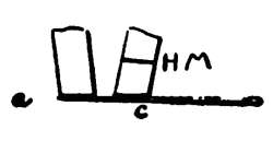
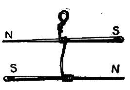
EXPERIMENT 15. To find whether we can make a magnet
with two N poles.
Apparatus. The horseshoe magnet, H M; an unmagnetized
sewing-needle; compass, O C (No. 18).
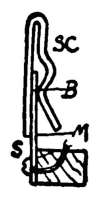
36. Note. You have already learned that the polarity of a
weak magnet can be changed (Exp. 14). Can you think of any
method by which two N poles can be made in one piece of steel?
37. Directions. (A) Place the needle upon H M, as in Fig. 7.
(B) Keeping the part, C, in contact with the N pole of H M, and
using the N pole of H M as a pivot, turn the needle end for end
so that its head will be in contact with the S pole of H M.
(C) Pull the needle straight from H M, being careful not to
slide it in either direction.
(D) Test the polarity of the ends with O C (Fig. 5), and save it
for the next experiment.
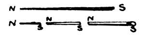
EXPERIMENT 16. To study the bar magnet with two N
poles.
Apparatus. The strange magnet just made (Exp. 15);
iron filings; compass, O C (No. 18).
38. Directions. (A) Sprinkle filings over the whole length of
the needle and then raise it (Fig. 8).
(B) Break the needle at its center, and test, with O C, the two[15]
new ends produced at that point. Remember that repulsion is
the test for polarity.
39. Discussion; Consequent Poles. Iron filings
cling to a magnet where poles are located. In this
case, two small magnets were made in one piece of steel;
they had a common S pole at the center. The pointing
power (§ 25) of such a magnet is very slight; would it
have any pointing power if we could make the end poles
of equal strength? Intermediate poles, like those in the
needle just discussed, are called consequent poles. Practical
uses are made of consequent poles in the construction
of motors and dynamos.
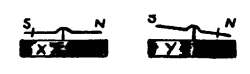
EXPERIMENT 17. To study consequent poles.
Apparatus. An unmagnetized sewing-needle; horseshoe
magnet, H M (No. 16); iron filings (No. 17); compass
(No. 18).
40. Directions. (A) Let w, x, y, and z stand for four places
along the body of the needle, w being at its point and z at its
head.
(B) Touch w with the N pole of H M, x with the S pole, y with
the N pole, and z with the S pole. Do not slide H M along on
the needle, just touch the needle as directed.
(C) Cover the needle with filings, then lift it.
EXPERIMENT 18. To study the theory of magnetism.
Apparatus. A thin bar magnet,
B M (No. 21); iron filings; a sheet
of paper. Fig. 9 shows simply the
edge of B M and the paper. B M
should be magnetized as directed
in Exp. 9.
41. Directions. (A) Sprinkle some iron filings upon a sheet of
paper.
(B) Bring one pole of B M in contact with the filings (Fig. 9),
and lightly sweep it through them several times, always in the
same direction. Are the filings simply pushed about?
(C) Do the same with a stick, and compare the result with that
produced with B M.
[16]
42. Theory of Magnetism; Magnetic Saturation.
This bringing into line the particles of iron
indicates that each particle became a magnet. This
experiment should aid in understanding what is thought
to take place when steel is magnetized. The pile of
filings represents the body to be magnetized, and each
little filing stands for a particle of that body. A bar of
steel is composed of extremely small particles, called molecules.
They are very close together and do not move
from place to place as easily as the pieces of filings. A
magnet, however, when properly rubbed upon the steel,
seems to have power to make the molecules point in the
same direction. This produces an effect upon the whole
bar.
Each molecule of the steel is supposed to be a magnet.
When these little magnets pull together, the whole bar
becomes a strong magnet. When a magnet is jarred,
and the little magnetized molecules are mixed again, they
pull in all sorts of directions upon each other. This lessens
the attraction for outside bodies.
Steel is said to be saturated, when it contains as much
magnetism as possible. A piece of steel becomes slightly
longer when magnetized.
It is thought, by many, that there is a current of electricity
around each molecule, making a little magnet of
it. (See electro-magnets.)
EXPERIMENT 19. To find whether soft iron will permanently
retain magnetism.
Apparatus. A piece of soft iron wire, 3 or 4 in. (7.5 to
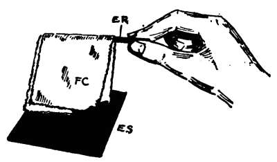
10 cm.) long (No. 4); the horseshoe magnet, H M; iron
filings; flat cork, F C (No. 2), and the dish of water used
in Exp. 10 (Fig. 4).
43. Directions. (A) Magnetize the wire (Exp. 9). Notice that
the wire clings strongly to H M.
[17]
(B) Test the lifting power of the little wire magnet by seeing
about how many iron filings its poles will raise.
(C) Test the pointing power (§ 25) of the wire by floating it on
F C (Fig. 4).
(D) Holding one end of the wire in the hand, thoroughly jar it
by striking the other end several times against a hard surface.
(E) Test the lifting and pointing powers, as in B and C.
44. Retentivity or Coercive Force; Residual
Magnetism. Soft iron loses most of its magnetism
when simply removed beyond the action of a magnet.
We say that it does not retain magnetism; that is, it has
very little retentivity or coercive force. This is an important
fact, the action of many electric machines and instruments
depending upon it. A slight amount of magnetism
remains, however, in the softest iron, after removing
it from a magnet. This is called residual magnetism. A
piece of iron may show poles, when tested with the compass,
although it may have almost no pointing power.
EXPERIMENT 20. To test the retentivity of soft steel.
Apparatus. A wire nail, W N (No. 19); horseshoe magnet,
H M; iron filings; flat cork, F C; the dish of water
(Exp. 10, Fig. 4).
45. Directions. (A) With H M magnetize the nail; this is
made of soft steel.
(B) Test the lifting and pointing powers of W N (Exp. 19).
(C) Strike W N several times with a hammer to jar it.
(D) Again test its lifting and pointing powers.
46. Discussion. Soft steel has a greater retentivity
than soft iron. It contains less carbon than cast or tool
steel, and is called mild steel or machinery steel. You
do not want soft steel for permanent magnets.
EXPERIMENT 21. To test the retentivity of hard steel.
Apparatus. A hard steel sewing-needle (No. 1); other
articles used in Exp. 20.
47. Directions. (A) Magnetize the needle with H M.
[18]
(B) Test its lifting and pointing powers (Exp. 19).
(C) Hammer the needle and test again as in (B).
EXPERIMENT 22. To test the effect of heat upon a
magnet.
Apparatus. A magnetized sewing-needle; the candle,
cork, etc., of Exp. 2. (See Fig. 1.)
48. Directions. (A) Test the needle for magnetism.
(B) Stick the needle into the cork (Fig. 1), and heat it until it is
red-hot.
(C) Test the needle again for magnetism.
(D) See if you can again magnetize the needle.
49. Discussion. Heating a body is supposed to
thoroughly stir up its molecules. Jarring or twisting a
magnet tends to weaken it. (See Exp. 19.)
The molecules of steel do not move about or change
their relative positions as readily as those of soft iron.
When the molecules of hard steel are once arranged, by
magnetizing them, for example, they strongly resist any
outside influences which tend to mix them up again.
A magnet does not attract a piece of red-hot iron.
The particles of the hot iron are supposed to vibrate too
rapidly to be brought into line; that is, the iron cannot
become polarized by induction. (See Exp. 24.)
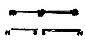
EXPERIMENT 23. To test the effect of breaking a
magnet.
Apparatus. A magnetized sewing-needle; iron filings;
compass, O C (No. 18).
50. Directions. (A) Break the little bar
magnet (needle), and test the two new ends
produced for magnetism, with the iron filings.
(Fig. 10).
(B) Touch the two new poles together to
see whether they are like or unlike.
(C) Test the nature of the poles with O C (Fig. 5)
(D) Break one of the halves and test its parts.
[19]
51. Discussion. The above results agree with the
theory that each molecule is a magnet (Exp. 18). No
matter into how many pieces a magnet is broken, each
part becomes a magnet. (Fig. 10). This shows that
those molecules near the equator of the magnet really
have magnetism. Their energy, however, is all used
upon the adjoining molecules; hence no external bodies
are attracted at that point.
[20]
CHAPTER III.
INDUCED MAGNETISM.
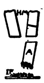
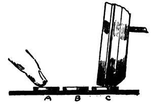
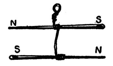
EXPERIMENT 24. To find whether we can magnetize a
piece of iron without touching it with a magnet.
Apparatus. Horseshoe magnet, H M; iron filings, I F
(Fig. 11).
52. Directions. (A) Hold the armature of the magnet in a
vertical position (Fig. 11), its lower end being directly
in a little pile of iron filings.
(B) Bring the N pole of H M near the upper end
of A, but do not let them touch each other.
(C) Keeping A and the pole of H M the same distance
apart, lift them. Do any filings cling to A?
(D) Without moving or jarring A, take H M away
from it and note result upon the filings.
53. Temporary Magnetism; Induced Magnetism.
The armature, A, was induced to become a
magnet without even touching H M. Its magnetism
was temporary, however, as the filings dropped as soon as
the inductive action of H M was removed. A small amount
of residual magnetism (44) remained in A. Soft iron
is exceedingly valuable, because it has very little retentivity
(44), and because it can be easily magnetized by
induction. The armature was made of soft iron. It had
induced magnetism. It was a temporary magnet.
EXPERIMENT 25. To find whether a piece of steel can be
permanently magnetized by induction.
Apparatus. An unmagnetized sewing-needle; horseshoe
magnet, H M; iron filings; sheet of stiff paper.
54. Directions. (A) Test the needle for magnetism.
(B) Place the unmagnetized needle upon the paper, then move
H M about immediately under it, so that the needle will be
attracted.
(C) Test the needle again for permanent magnetism.
[21]
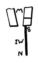
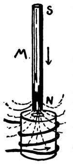
EXPERIMENT 26. To study the inductive action of a
magnet upon a piece of soft iron.
Apparatus. Horseshoe magnet, H M; iron filings,
I F; a piece of soft iron wire about an inch long, I W
(Fig. 12), placed upon the N pole of H M; compass, O C
(No. 18), (§ 32).
55 Directions. (A) Test the lower end of I W for magnetism
with I F.
(B) Leaving I W upon the N pole of H M, test the
pole at the lower end of I W with O C, to determine
whether it is N or S.
(C) Jar I W (Exp. 19), then place it upon the S pole
of H M, and again test the polarity of the lower end.
56. Polarization; Pole Pieces. The
wire, I W (Fig. 12), was acted upon by induction
(Exp. 24) and behaved like a magnet. Poles
were produced in it, so we say that the wire was polarized.
Pieces of iron, placed upon the poles of a magnet, are
called pole pieces. It should be noted that the lower end
of the wire has a pole like the pole of H M, to which it is
attached.
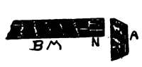
EXPERIMENTS 27–30. To study pole pieces.
Apparatus for Experiments 27–30. Horseshoe magnet,
H M; soft iron wires; iron filings, I F.
57. Directions. (A) Suspend two wires, each about an inch
long (Fig. 13) from one pole of H M. Do their lower ends
attract or repel each other?
EXPERIMENT 28.
58. Directions. (A) Place the two wires just used so that one
shall cling to the N pole of H M, and the other to the S pole of
H M (Fig. 14).
[22]
(B) Bring the lower ends of the wires near each other. Do
they attract or repel each other?
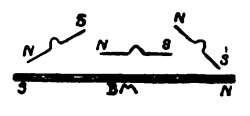
EXPERIMENT 29.
59. Directions. (A) Bend a 2-inch iron wire, as in Fig. 15,
and place it upon the poles of H M.
(B) See if its central part, marked X, will strongly attract
filings.
EXPERIMENT 30.
60. Directions. (A) Bend the wire just used a little more,
and place its ends upon one pole of H M (Fig. 16).
(B) See if the iron filings and small wires will cling to its
central part.
[23]
CHAPTER IV.
THE MAGNETIC FIELD.
EXPERIMENT 31. To study the space around a magnet,
in which pieces of iron become temporary magnets by induction.
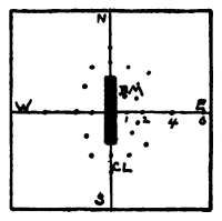
Apparatus. A bar magnet, B M (No. 21); a compass
(No. 18); a sheet of stiff paper about 1 ft. (30 cm.)
square, with a center line, C L, drawn parallel to one of
its sides (Fig. 16½), and with another line, E W, drawn
perpendicular to C L. (See Apparatus Book, Chap. VI.,
for various ways of making home-made permanent
magnets.)
61. Directions. (A) Lay the paper upon the table, and place
the compass over the center of the line, C L, previously drawn.
(B) Place the eye directly over the compass-needle, then turn
the paper until the line is N and S; that is, until the line is
parallel to the length of the needle. Pin the paper to the table to
hold its center line N and S.
(C) Place B M upon the paper, as shown (Fig. 16½), its N pole
to the north, and its center at the cross
line, E W.
(D) Slowly move the compass entirely
around and near B M, and note the various
positions taken by the needle. Note especially
the way in which its N pole points.
This is to get a general idea of the action
of the needle.
(E) Place the compass in the position
marked 1, which is on E W, about 1 in.
from the line, C L. Press the wooden support down firmly upon
the paper to show, by the dent made in the paper by the pin-head,
the exact place on the paper that is under the center of the compass-needle.
Before removing the compass from this position,
look down upon it again, and make a dot on the paper with a
pencil directly under each end of the needle. Remove the compass,
and draw a line through the dent and the two dots just
made. This will show a plan of the exact position of the needle.
[24]
(F) Repeat this for the various points marked 2, 4, 6 in. from
C L, always marking on the plan the position of the N pole of the
needle. Do the same with the other points marked on Fig. 16½
by dots, and study the resulting diagram.
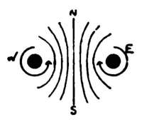
62. Discussion; The Magnetic Field. The
compass-needle was decidedly affected all around B M
(Fig. 17), showing that induction can take place in a considerable
space around a magnet; this space is called the
magnetic field of the magnet. Let us consider one position
taken by the compass-needle in the field of B M (Fig.
17), as, for example, the one in which the needle has
been made black. The S
pole of the black needle is
attracted by the N pole of
B M, and is repelled by the
S pole of B M. The N pole
of the compass-needle is attracted by the S pole of B M,
and is repelled by B M's N pole. The position which it
takes, therefore, is due to the action of these 4 forces,
together with its tendency to point N and S.
Every magnet has a certain magnetic field, with its
lines of force passing through the surrounding air in
certain definite positions. As soon, however, as a piece
of iron or another magnet is brought within the field, the
original position of the lines of force is changed. This
has to be considered in the construction of electrical
machinery.
EXPERIMENT 32. To study the magnetic field of a bar
magnet.
Apparatus. A sheet of stiff paper; iron filings, I F;
bar magnet, B M (No. 21); a sifter for the filings (No. 24);
(See Apparatus Book, §48, 49, 50, for home-made sifters.)
63. Directions. (A) Place B M upon the table, and lay the
paper over it.
(B) With the sifter sprinkle some filings upon the paper directly[25]
over B M, then tap the paper gently, to assist the particles to
take final positions. Study the results.
64. Magnetic Figures; Lines of Magnetic
Force. The filings clearly indicated the extent and
nature of the magnetic field of B M. You should notice
how the filings radiate from the poles, and how they form
curves from one pole to the other. They make upon the
paper a magnetic figure. Each particle of the filings
becomes a little magnet, by induction (Exp. 24), and
takes a position which depends upon attractions and repulsions,
as discussed in Exp. 31.
Magnetism seems to reach out in lines from the poles
of a magnet. The position and direction of some of the
lines are shown by the lines of filings. They are very
distinct near the poles, and are considered, for convenience,
to start from the N pole of a magnet, where they
separate. They then pass through the air on all sides of
the magnet, and finally enter it again at the S pole.
These lines are called lines of force or lines of magnetic
induction.
The poles must not be considered mere points at the
ends of a magnet. As shown by magnetic figures, the
lines of magnetic induction flow from a considerable portion
of the magnet's ends.
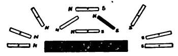
EXPERIMENTS 33–37. To study the magnetic fields of
various combinations of bar magnets.
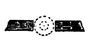
Apparatus for Exps. 33–37. Two bar magnets, B M
(Nos. 21, 22); an iron ring, I R (No. 23); iron filings, I F;
a sheet of stiff paper; the sifter (No. 24).
65. Note. The student will find it very helpful to make the
magnetic figures of the combinations given. Thoroughly magnetize
the bar magnets upon an electro-magnet, or upon a strong
horseshoe magnet, and mark their N poles in some way. The N
poles may be marked by sticking a small piece of paper to them.
66. Directions. (A) Arrange the two magnets, B M, as in[26]
Fig. 18, with their unlike poles about an inch apart. (The dotted
circle indicates the iron ring to be used in the next experiment.
About a quarter, only, of the magnets are shown.)
(B) Place the paper over the magnets, and sift filings upon it
immediately over the unlike poles. Note particularly the lines of
filings between N and S.
(C) Make a sketch of the result. (See experiments with electromagnets,
and the illustrations of magnetic figures with them.)
EXPERIMENT 34.
67. Directions. (A) Leaving the opposite poles an inch apart,
as in Exp. 33, place the iron ring, I R (No. 23), between them
(Fig. 18, dotted circles).
(B) Place the paper over it all, and sprinkle filings upon it to
get the magnetic figure.
(C) Make a sketch of the resulting figure, and compare it with
the figure made in Exp. 33. Why do the lines of force appear
indistinct in the center of the ring and around it? (See §74.)
EXPERIMENT 35.
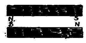
68. Directions. (A) Arrange the two bar magnets, as in Exp.
33, but with their two N poles an inch apart.
(B) Make the magnetic figure of the combination. Do the lines
of force flow from one N pole directly to the N pole of the other?
Do the particles of filings reaching out from one B M attract or
repel those from the other B M?
EXPERIMENT 36.
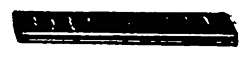
69. Directions. (A) Place the two bar magnets side by side,
so that their unlike poles shall be arranged as in Fig. 19.
(B) Make the magnetic figure.
EXPERIMENT 37.
70. Directions. (A) Turn one B M end for end, so that their
like poles shall be near each other, but otherwise arranged as
in Fig. 19.
(B) Make and study the magnetic figure.
[27]
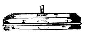
EXPERIMENTS 38–39. To study the lifting power of
combinations of bar magnets.
Apparatus for Exps. 38–39. Two bar magnets, B M
(No. 21, 22), of about equal strength; iron filings, I F.
71. Directions. (A) Find out about how
many filings you can lift with the N pole of
one magnet.
(B) Place the two magnets together (Fig.
20), their like poles being in contact; then
see whether the two N poles will lift more or less filings than
one pole.
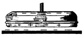
EXPERIMENT 39.
72. Directions. (A) Remove all filings from the two magnets
just used, and hold them tightly together (Fig. 20), with their
unlike poles in contact.
(B) Compare the amount of filings you can lift at one end of
this combination with that lifted in Exp. 38 (A) and (B).
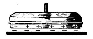
73. Discussion; Compound Magnets. Many
lines of force pass into the air from two like poles. Such
a combination is called a compound magnet. A piece of
thin steel can be magnetized more strongly in proportion
to its weight than a thick piece, because the magnetism
does not seem to penetrate beyond a certain distance into
the steel. Thin steel may be magnetized practically
through and through. A thick magnet has but a crust
of magnetized molecules; in fact, a thick magnet may be
greatly weakened by eating the outside crust away with
acid. By riveting several thin bar or horseshoe magnets
together, thick permanent magnets of considerable
strength are made.
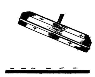
74. Lines of force, in passing from the N to the S pole
of a magnet, meet a resistance in the air, which does not
carry or conduct them as easily as iron or steel. In the
arrangement of Exp. 39 the lines of force are not obliged
to push their way through the air, as each magnet serves
as a return conductor for the lines of force of the other.[28]
Either magnet may be considered an armature for the
other.
To show in another way that few lines of force pass
into the air, the student may lay the above combination
upon the table and make a magnetic figure. (See Apparatus
Book, p. 38, for method of making home-made compound
magnets.)
In the case where a ring was placed between the poles
of two bar magnets (Exp. 34), the lines of force from the
N pole jumped across the first air-space. They then disappeared
in the body of the ring, until they were obliged
to jump across the second air-space, to get to the S pole.
The weakness of the field in the central space was clearly
shown by the filings. There were no stray lines of force
passing through the air, because it was easier for them to
go through the iron ring. This will be discussed again
under "Dynamos and Motors." (See also § 78.)
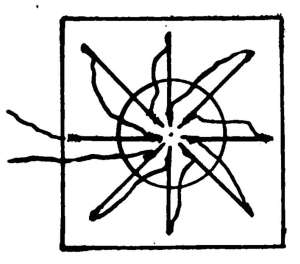
EXPERIMENTS 40–42. To study the magnetic field of the
horseshoe magnet.
Apparatus for Exps. 40–42. Horseshoe magnet, H M;
iron filings, I F; sheet of stiff paper.
75. Directions. (A) Place H M, with its armature removed,
flat upon the table, and cover it with the paper; then make the
magnetic figure. (Exp. 32.)
(B) Compare the number of well-defined curves at the poles
with the number at the equator.
EXPERIMENT 41.
76. Directions. (A) Make the magnetic figure of H M with
its armature in place.
(B) Is the attraction for outside bodies increased or decreased
by placing the armature on H M?
EXPERIMENT 42.
77. Directions. (A) Lay H M flat upon the table, and place
one or two matches between its poles and the armature; cover
with paper as before, and make the magnetic figure. Do lines of
force still pass through the armature?
[29]
78. Discussion; Resistance to lines of Force.
It is evident, from the last 3 experiments, that lines of
force will pass through iron whenever possible, on their
way from the N to the S pole of a magnet. When the
armature of a horseshoe magnet is in place, most of the
lines of magnetic induction crowd together and pass
through it rather than push their way through the air.
Air is not a good conductor of lines of force; and the
magnet has to do work to overcome the resistance of the
air, when the armature is removed, in order to complete
the magnetic circuit. This work causes a magnet to
become gradually weaker. The soft iron armature is an
excellent conductor of lines of force; it completes the
magnetic circuit so perfectly that very little work is left
for the magnet to do.
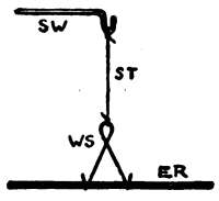
EXPERIMENT 43. To show that lines of force are on all
sides of a magnet.
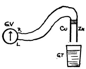
Apparatus. Our compass, O C (No. 18); horseshoe
magnet, H M; glass tumbler,
G T; sheet of stiff paper; iron
filings, I F. Arrange as in
Fig. 21. H M may be supported
in a vertical position
by placing paper, or a handkerchief,
under it. The poles
should just touch the stiff
paper placed over the tumbler.
79. Directions. (A) Sprinkle
iron filings upon the paper, and study the resulting magnetic
figure.
(B) Place O C upon the paper in different positions. Does the
magnetic needle always come to rest about parallel to the lines
of filings?
80. Discussion. The student should keep in mind
the fact that the filings in the magnetic figure show the
approximate extent and form of the magnetic field simply[30]
in one plane. If the paper were held in some other
position near the magnet (in a tilted position, for example,)
the lines of filings would not be the same as those
produced in Exp. 40–42. The lines of force come out of
every side of the N pole. When a magnetic needle is
placed in any magnetic field, its N pole points in the
direction in which the lines of force are passing; that is,
it points towards the S pole of the magnet producing the
field.
EXPERIMENT 44. To study a horseshoe magnet with
movable poles.
Apparatus. A narrow strip of spring steel, S S (No.
25); iron filings, I F.
81. Directions. (A) Magnetize the spring steel, S S.
(B) Bend S S until its poles are about ¼ in. apart, then using
it as a horseshoe magnet, and keeping its poles the same distance
apart, see about how many filings you can lift.
(C) Clean the poles of S S, press them tightly together, then
again test its lifting power with filings.
82. Discussion; Advantages of Horseshoe
Magnets. When the opposite poles of the flexible
magnet are pressed together, the lines
of force do not have to pass through
the air; there is very little attraction
for outside bodies. The same effect
is produced with the armature (Exp.
41). A horseshoe magnet has a strong attraction for its
armature, because it has a double power to induce and to
attract. Suppose the N pole of a bar magnet, B M (Fig.
22), be placed near one end of a piece of iron, as, for
example, the armature, A. A will become a temporary
magnet by induction (Exp. 24). The S pole of A, polarized
by induction, will be attracted by B M, while its N
pole will be repelled by B M; so, you see, that a bar
magnet does not pull to advantage.
[31]
CHAPTER V.
TERRESTRIAL MAGNETISM.
83. The Magnetism of the Earth. The student
must have guessed, before this, that the earth acts
like a magnet. It causes the magnetic needle to take a
certain position at every place upon its surface, and this
position depends upon the earth's attractions and repulsions
for it. The earth has lines of force which flow
from its N magnetic pole, and these lines, before they can
get to the earth's S magnetic pole, must spread out
through the air on all sides of the earth.
As the magnetic needle points to the earth's N magnetic
pole (which is more than 1,000 miles from its real
N pole), it is evident that the compass-needle does not
show the true north for all places upon the earth's surface.
In fact, the N pole of the needle may point E, W,
or even S. This effect would be seen by carrying a compass
around the earth's N magnetic pole.
84. Declination. For convenience, we shall represent
the true N and S, at the place where you
are experimenting, by the full line, N S, in
Fig. 23. The dotted line shows the direction
taken by the compass-needle. The angle, A,
between them, is called the angle of variation
or the declination. This angle is not the same
for all places; and, in fact, it changes slowly
at any given place; so it becomes necessary to
construct magnetic maps for the use of mariners and
others.
[32]
EXPERIMENT 45. To study the lines of force above and
below a bar magnet placed horizontally.
Apparatus. A bar magnet, B M (No. 21); compass, O
C (No. 18).
85. Directions. (A) Lay B M upon the table and place O C
upon its center. Note the position of the compass-needle.
(B) Slide O C along from one end of B M to the other, and
study the effect upon its needle. Do lines of force curve over B
M as well as around its sides, as shown in Exp. 31?
(C) Place O C upon the table. Hold B M horizontally above
O C, and move O C back and forth under B M. Does the needle
remain horizontal, or does it show that lines of force pass under
B M on their way from its N to its S pole?
86. The Dip or Inclination of the Magnetic
Needle. The needle is said to
dip when it takes positions like
those in Fig. 24. Compass-needles
should be horizontal, when properly
balanced, and entirely free from all
effects other than those of the earth. The excessive dip
shown (Fig. 24) is due, of course, to the efforts of the
magnetic needle to place itself in the direction in which
the lines of force of B M pass.
EXPERIMENT 46. To study the dip or inclination of the
magnetic needle, due to the action of the earth.
Apparatus. Fig. 25. Our compass, O C (No. 18);
horseshoe magnet, H M (No. 16); piece of paper.
87. Directions. (A) Place O C
upon the table, and mark upon a
piece of paper the height of the
N pole of its needle above the
table. (Fig. 25.) The paper should
be held in a vertical position, and
near the pole.
(B) With H M reverse the poles
of the compass-needle (Exp. 13),
so that its former N pole shall become a S pole.
[33]
(C) Place the needle upon its pivot again, and mark upon the
paper, as before, the height of its new N pole above the table.
Does the needle remain horizontal?
(D) Remagnetize the needle, and reverse its poles so that it will
again balance.
88. Discussion; Balancing Magnetic Needles.
If a piece of unmagnetized steel be balanced and
then magnetized, it will no longer remain horizontal; it
will dip. Try this. Compass-needles are balanced after
they are magnetized. Can you now see why the needle
did not remain horizontal after its poles were changed?
A piece of steel first balanced and then magnetized, has
to have its S pole slightly weighted, as suggested by the
line at S (Fig. 26 x), to make it
horizontal. The magnetic needle
does not tend to dip at the earth's
equator, because the lines of force
of the earth are nearly horizontal at the equator. As
we pass toward the north or south on the earth, the
lines of force slant more and more as they come from
or enter the earth's magnetic poles. What position
would the needle take if we should hold it directly over
the earth's N magnetic pole? Fig. 24 shows what the
needle does when held near the poles of a bar magnet.
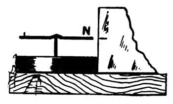
EXPERIMENTS 47–48. To study the inductive influence
of the earth.
Apparatus for Exps. 47–48. Compass, O C, (No. 18); an
iron stove poker, or other rod of iron; a hammer. (The
iron and hammer are not furnished.)
89. Note. You have seen (Exp. 24), that iron becomes magnetized
by induction when placed near a magnet. As the earth
acts like a huge magnet, having poles, lines of force, etc., will it
magnetize pieces of iron which are in the air or upon its surface?
90. Directions. (A) Test the poker for poles with O C, remembering
that repulsion is necessary to prove that it is polarized.[34]
If the poker has very weak poles, proceed; but if it shows
some strength, hold it in an east and west direction, and hit it
several sharp blows on the end with the hammer. Test for polarity
again.
(B) With one hand hold the poker in the N and S line, give it a
dip toward the north, and strike it several times with the hammer
to thoroughly stir up its molecules.
(C) Test again for poles with O C, and note especially whether
the lower end (of the poker) became a N or a S pole.
EXPERIMENT 48.
91. Directions. (A) Turn the poker end for end (See Exp. 47);
repeat the striking, and test again the pole produced at the lower
and north end of it.
(B) Now hold the poker horizontally in the east and west line,
and pound it.
(C) Test for poles. Has this strengthened or weakened the
poker magnet?
92. Discussion. Dipping the poker places it nearly
in the same direction as that taken by the earth's lines of
force. The magnetic influence of the earth acts to advantage
upon the poker, by induction, only when the poker is
properly held.
It no doubt occurs to the student that the end of a
magnetic needle which points to the north is really opposite
in nature to the north magnetic pole of the earth.
The N pole of a needle, then, must be in reality a S pole
to be attracted by the earth's N pole. It has been agreed,
for convenience, to call the N-seeking pole of a magnet
its N pole.
93. Natural Magnets. Nearly all pieces of iron
become more or less magnetized by the inductive action
of the earth's magnetism. Your poker was slightly magnetized
at the start, perhaps, from standing in a dipping
position.
Induction takes place along lines of force. In northern
latitudes the earth's lines of force have a dip to the north.[35]
You should now see why the greatest effect was produced
upon the poker when it, also, was made to dip.
Parts of machinery, steel frames of bridges and buildings,
tools in the shop, and even certain iron ores, become
polarized by this inductive action. These might all be
called natural magnets. Magnetic iron ore, called lodestone,
is referred to, however, when speaking of natural
magnets. Lodestone was used thousands of years ago to
indicate N and S, and it was discovered, later, that it could
impart its power to pieces of steel when the two were
rubbed together.
EXPERIMENT 49. To test the effect of twisting a wire
held north and south in the earth's magnetic field.
Apparatus. Compass, O C (No. 18); a piece of soft iron
wire, 6 in. (15 cm.) long (No. 15). Bend up about an inch
of the wire at each end so that it may be firmly held when
twisting it.
Note. You have seen that we can pound magnetism into or
out of a piece of iron at will. Can we twist it into a wire and
out again without the use of magnets?
94. Directions. (A) Test the wire for poles with O C.
(B) Hold the wire in a N and S direction, dipping it at the same
time, as directed in Exp. 47 for the poker, and twist it back and
forth.
(C) Test again for poles with O C. As the poles of the wire
may be very weak, bring them slowly toward the compass-needle
(see Exp. 14), and note the first motions produced upon the needle.
(D) Hold the wire horizontally east and west, twist and test
again. Has its magnetism become weaker or stronger than
before?
EXPERIMENT 50. To test for magnetism in bars of iron,
tools, etc.
Apparatus. Steel drills; files; chisels; bars or rods of
iron that have been standing in an upright position;
stove-lid lifters; stove pokers, etc., etc.; a compass.
95. Directions. (A) With the compass test the ends of the
above for magnetism, and note which ends are S.
Notes.
[39]
STATIC ELECTRICITY
PART II.—STATIC ELECTRICITY
CHAPTER VI.
ELECTRIFICATION.
100. Some Varieties of Electricity. Static electricity
does not seem to "flow in currents" as readily as
some other varieties; its tendency is to stand still, hence
the name, static. The simplest way to produce it is by
friction. Thermo electricity is produced by changes in
temperature. When certain combinations of metals become
hotter or colder, a current is produced. Voltaic or
Galvanic electricity is produced by chemical action. Batteries
give this variety. Induced electricity is produced
by other currents, and by combinations of magnets and
moving coils of wire, as in the dynamo. This is, by far,
the most important variety of electricity, and the dynamo
is the most important producer of it.
Each of the above varieties of electricity will be studied
experimentally with simple apparatus.
EXPERIMENTS 51–52. To study electrification by friction.
Apparatus. Ebonite sheet, E S (No. 26); flannel cloth,
F C (No. 30). See what is said in preface about static
electricity.
101. Directions. (A) Examine E S. Note that its surface is
not smooth, like that of ordinary hard-rubber combs. Can you
think of any reason for this?
(B) Hold its flat surface near your face, then near the back of
your hand. Do you feel anything unusual?
(C) Lay E S upon a flat board, or uncovered wooden table, and
slide it about. Can you easily pick it up?
[40]
(D) Place E S flat upon the table again; keep it from sliding
about with your left hand, and rub it vigorously for a minute with
F C. Does E S act exactly as it did before in (B) and (C)?
(E) Repeat the experiment in a dark room.
(F) Thoroughly electrify E S, and see if it will cling to the wall
strongly enough to support its own weight.
102. Discussion; Electrified and Neutral
Bodies. The ebonite sheet became electrified or charged;
and as the electrification was produced by friction, we may
say that the action of the ebonite indicated the presence
of frictional electricity. No one can tell just why the
ebonite acted so queerly, but we can learn a great deal by
experimenting. Bodies which are not charged are said
to be neutral. The table, chairs, earth, etc., are neutral.
We may consider that a neutral body has been discharged.
103. Force; Resistance; Work; Potential Energy;
Electrification. It takes force to raise water
into a tank placed on the roof. In raising the water, work
has to be done, and we have to do the work; but when we
once have the water in the tank we have accomplished
something. The water has potential energy; that is, on
account of its high position, we can make it do some work
by simply turning a stop-cock so that the water can run
out and turn a water-wheel, for example.
It takes force to vigorously rub a piece of ebonite with
a flannel cloth, for resistance has to be overcome; that is,
work has to be done. Several things are accomplished
by this work; heat is produced, for we can feel that the
ebonite gets warm; we can hear sounds and see sparks.
The simple muscular exertion on our part has been
changed to heat, light, and sound. The most wonderful
part of it all, however, is that we have electrified or
charged the ebonite. We did the work at first, and now
the ebonite has the power to do something, as you will[41]
soon see. Electrification is, then, a sort of potential
energy.
104. Heat and Electrification. We say that
heat passes to or from a body to make it hot or cold.
Heat produces the sensation of warmth, but heat isn't
warmth. We can force a cold body to become hot; in
other words, we can get it into a hot condition in various
ways, such as rubbing it, hammering it, or by placing it
near or in contact with another hot body.
Electrification is, also, a condition or state into which
we can force a body; but electrification isn't electricity.
We know whether a body is hot or cold by its effects
upon us, upon thermometers,
and upon
other bodies. We can
tell, also, whether a body
is electrified or not by
the way it acts, and, in
certain cases, by the
sound, heat, and light
which accompany the
electrification.
Do not get the idea
that an electrified body
is covered with a layer of
electricity just as a board is covered with a layer of paint.
EXPERIMENT 52.
105. Directions. Repeat Exp. 51, but in place of the ebonite,
use hot tissue-paper, hot brown paper, hot newspaper, or a hot
silk handkerchief. Rub your hand vigorously over them. Do
these become charged?
EXPERIMENTS 53–54. To study electrical attractions.
Apparatus. The ebonite sheet, E S (No. 26); flannel
cloth, F C (No. 30); small pieces of dry tissue-paper, T P
(No. 31); thread (No. 32).
[42]
106. Directions. (A) Thoroughly electrify E S as before,
then lift and hold it in the air. (Fig. 28.)
(B) See what the paper and thread will do when held loosely
near E S.
107. Discussion. Exp. 53 shows that an electrified
body attracts neutral ones. This much was known about
electricity over 2,000 years ago. They didn't have ebonite
then, but some of the educated men of Greece knew
that amber would attract light bodies after being rubbed.
The Greek word for amber is elektron, and from this has
been made the word electricity.
EXPERIMENT 54.
108. Directions. Charge a sheet of hot paper by friction; lift
it, by its opposite ends, and lower it over small pieces of tissue-paper
placed on the table. What happens to the little pieces?
EXPERIMENT 55. To study mutual attractions.
Apparatus. The support and its attachments (See § 109);
support wire, S W (No. 36); silk thread, S T (No. 33), or
a rubber band, R B (No. 45); ebonite rod, E R (No. 28);
flannel cloth, F C (No. 30); wire swing, W S (No. 37).
Tie one end of S T to W S, Fig. 29; tie the other end of S T to
S W; adjust W S by bending, if necessary,
so that it will securely hold E R. It will be
found convenient to use a rubber band instead
of S T; if you do, let W S straddle
one end of R B (Fig. 33), and hang the other
end of R B upon S W.
109. The support consists of a support
base (S B, Fig. 56), a support rod (S R, Fig.
56), and a support wire (S W, Fig. 29).
There is a small hole in one end of S R to receive the wire, S W,
and a large hole in the other end to take the short ebonite which
holds the insulating table (Fig. 32). A little paper should be
wound around the lower end of S R, so that it will stand solidly
in the spool which forms a part of the base.
110. Directions. (A) Electrify E R with F C, and place E R
in the swing, W S (Fig. 29).
[43]
(B) Bring your finger near one side of the rubbed end of E R,
then near the unrubbed end, and compare the results.
111. Mutual Attractions. A neutral body, like
the hand, for example, attracts electrified ones. From
Exp. 53, 54, 55, it is seen that the attraction between a
neutral and an electrified body is mutual; each attracts
the other.
EXPERIMENT 56. To study electrical repulsions.
Apparatus. Same as for Exp. 55; ebonite sheet, E S
(No. 26).
112. Directions. (A) Charge E R, and place it in W S, Fig. 29.
(B) Charge E S, and bring it slowly near one side of the charged
end of E R.
EXPERIMENT 57. To study electrical repulsions.
Apparatus. A sheet of tissue-paper, T P (No. 31);
shears or a knife. Cut T P, as in Fig. 30. Each leg
should be about ¼ in. wide and 3 or 4 in. long.
113. Directions. (A) Heat the paper, then place it flat upon
the table and electrify it by rubbing it with your hand. You
must rub away from the uncut part, or you will break the legs.
(B) Raise T P, holding it by the uncut part. Note the action
of legs, and make a sketch of them.
EXPERIMENT 58. To study electrical repulsions.
Apparatus. Ebonite rod, E R (No. 28); a carbon electroscope,
C E, Fig. 31 (see § 114); the support complete (see
§ 109); small piece of damp tissue-paper.
[44]
114. The Carbon Electroscope. Light an ordinary
match, and let it burn until it is charred through
and through. The black substance remaining is carbon.
This is very light; it has, also, another important property
which you will soon understand. Tie a small piece
of the carbon to one end of a dry silk thread, and fasten
the other end of the thread to the support wire, S W,
which is fastened to the support (Fig. 31). We shall
call this piece of apparatus the carbon e-lec-tro-scope. (See
Electroscopes, Chapter XVIII., Apparatus Book.)
115. Directions. (A) Electrify E R, then hold it near the carbon
of the electroscope.
(B) Bring the charged rod near little pieces of damp tissue-paper.
116. Discussion of Experiments 56, 57, 58.
In 56 the two pieces of ebonite were made of the same
material, and both were rubbed with flannel. They must
have been similarly electrified. In 57, different parts of
the same piece of paper were similarly electrified. In 58,
the little piece of carbon took some of the electrification
from the charged rod, just as it would take molasses from
your finger should your sticky finger touch it. The
electrification on the carbon must have been of the same
kind as that on the rod. The carbon was charged by
contact. We learn, then, that two bodies repel each other
when they have the same kind of electrification. Do two
charged bodies always repel each other? Is it possible
that there are different kinds of electrifications?
EXPERIMENT 59. To study the electrification of glass.
Apparatus. The sheet of glass, G (No. 38), heated (a
hot bottle or lamp chimney will do); a piece of silk large
enough to rub G. (A silk handkerchief is just the thing,
but in case you have no silk, use the flannel cloth, F C,
No. 30.)
[45]
117. Directions. (A) Vigorously rub the hot glass with the
silk (or flannel), also heated.
(B) Test G for electrification by means of little pieces of tissue-paper
and the carbon electroscope, Exp. 58.
118. Questions. Will two pieces of electrified glass
repel each other? Arrange an experiment to show
whether you are right or not. Is the charge on the glass
exactly like that on the ebonite? Do you know how to
find out?
EXPERIMENT 60. To compare the electrification produced
by ebonite and flannel with that produced by glass and
silk.
Apparatus. The support (see § 109); wire swing, W S
(No. 37); ebonite rod, etc., of Exp. 55 (Fig. 29); the glass,
G, and silk of Exp. 59.
119. Directions. (A) Electrify E R, and place it in W S,
Fig. 29.
(B) Bring the uncharged glass near E R, noting the action of
E R.
(C) Heat and electrify G; bring it near E R, and carefully note
whether the attraction between them is stronger or weaker than
before, or whether they repel each other.
120. Discussion. We know that the glass was
electrified, because it lifted tissue-paper; hence, its charge
was not of the same kind as that on the ebonite. Had
the electrifications been exactly alike, we should have
had a repulsion (Exps. 56, 57, 58).
The exact difference between these two kinds of electrifications
is not known. It has been agreed, for convenience,
to call that produced by glass and silk a positive
electrification. With ebonite and flannel a negative electrification
is produced. The sign + is generally written
for the word positive, and - for negative. These signs
indicate kind, and not more or less, as in arithmetic.
[46]
121. Laws. We have learned from the experiments
these facts, which are called laws:
(1) Charges of the same kind repel each other; (2)
charges of unlike kinds attract each other; (3) either
kind of a charge attracts, and is attracted by a neutral
body.
[47]
CHAPTER VII.
INSULATORS AND CONDUCTORS.
EXPERIMENT 61. To study insulators.
Apparatus. Ebonite rod, E R (No. 28); flannel cloth, F
C (No. 30); tissue-paper, T P (No. 31).
122. Directions. (A) Holding one end of E R in the hand,
charge the other end by rubbing it with F C.
(B) With bits of the T P test each end of E R for a charge, and
compare the results.
EXPERIMENT 62. To study insulators.
Apparatus. The ebonite sheet, E S (No. 26); flannel
cloth, F C (No. 30).
123. Directions. (A) Thoroughly electrify E S (Exp. 51, D),
then lift and hold it in the air, as in Fig. 28.
(B) By moving your rounded knuckle about near the surface of
E S, see if you can get more than one spark from it.
EXPERIMENT 63. To study insulators.
Apparatus. A hard-rubber comb (not furnished); flannel
cloth, F C (No. 30); dull pointed nail (No. 19).
124. Directions. (A) Electrify the comb with F C.
(B) Move the nail along near the teeth of the comb, and listen
carefully.
125. Discussion of Experiments 61, 62, 63;
Insulators. In 61 the electrification remained at one
end of the rod. In 62 and 63 the sparks showed that all
parts of the ebonite were not discharged at the same time.
A substance, like ebonite, which will not allow electrification
to pass from one part of it to another, is called
an insulator. Silk and glass are also insulators. Do you
now see why a silk thread was used to make the carbon
electroscope?
[48]
Why do they fasten telegraph wires to glass insulators?
126. Conductors. It has already been stated that
water in an elevated tank has potential energy. We can
allow the water to flow through a conducting pipe to
another tank a little lower than the first, and it will still
retain much of the potential energy, but not all.
Can we conduct from one place to another this peculiar
state of things, this queer form of potential energy
which we call electrification?
It is clear, from
the last experiments, that
in order to do it we need
something besides ebonite,
which really acts like a
closed stop-cock to the
flow of electrification.
To keep electrification
in one place we need an
insulator; to get it from
one place to another we
need a conductor. Insulators
are as important as
conductors.
You saw that sparks went to the finger from the ebonite,
so we call the finger a conductor. You have learned
that attractions and repulsions show the presence of electrification.
Can we have our charged body in one place
and get attractions or repulsions at some other place?
EXPERIMENT 64. To study conduction.
Apparatus. Fig. 32; the support (see § 109); a bent hairpin,
H P (No. 39); ebonite sheet, E S; flannel cloth, F C;
tin disk, B F B (No. 40), which is the bottom of the flat-box,
F B; the insulating table, I T (see § 127).
[49]
127. The Insulating Table consists of a tin box (exactly like
that used for the electrophorus cover), and an ebonite rod about
1¾ in. long. See § 139 for full details about fitting the rod into
the box, etc. The lower end of the short rod fits into the large
hole in one end of the support rod, S R. Arrange as in Fig. 32.
B F B should swing about very easily.
128. Directions. (A) Charge E S, then rub it upon I T, as
shown, noting the action of B F B.
129. Discussion. Ebonite being an insulator
(§ 125), we say that I T, H P and B F B were insulated.
You can see that the electrification must have passed
through I T and H P to get to the disk, B F B. H P was
the conductor, allowing the disk, also,
to become charged. The wood, S R,
is a conductor, and, as it was not
insulated from the earth, S R was
neutral. Account for the attraction.
(See § 121.)
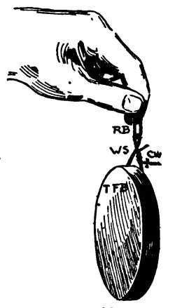
EXPERIMENT 65. To study conduction.
Apparatus. A copper wire, C W
(No. 44); insulating rubber band, R
B (No. 45, Fig. 33); wire swing, W
S (No. 37); the other half of the flat
box, T F B (No. 41); apparatus of
Exp. 69.
130. Telegraph Line. To have our
telegraph line using frictional electricity complete, we must have:
(1) Some way of generating or making the electricity; (2) Some
means of getting it or its effects to the other end of the line;
(3) Some way of showing that it has been taken there.
The charged E S will be the source of the electrification. New
York will represent the end at which we send the message, so at
N. Y. we must have a sending instrument. See Fig. 33, which explains
itself. R B or a silk thread must be used to insulate the
sender. Around one leg of W S is twisted one bare end of the
conductor, C W.
[50]
Boston will represent the end of the line at which the message
is received, and there we need a receiving instrument. This is
similar to the apparatus described in Exp. 69, Fig. 37. In addition
to this, tie the middle of a moist cotton thread that is 6 in.
long, to B C (Fig. 37), and let its two free ends lie over the top
and reach down against the bottom of the tin; that is, on the left-hand
side. Fig. 42 will give you an idea in regard to the looks
of the thread; at first, however, it should be close to the bottom
of the tin. Twist the other bare end of the copper wire around
B C.
When the line is properly constructed and ready for use, both
instruments and C W are entirely insulated. Do not let any part
of C W touch the table or your clothing.
131. Directions. (A) Touch the insulated sending instrument
with the charged ebonite sheet, and watch for any motion in the
receiving instrument.
Note. Better results will be obtained by using the charged
electrophorus cover as the source of electrification, instead of E
S. (Exp. 68.)
132. Discussion. The action here was like that in
the previous experiment, the difference being that a
longer conductor was used. Electrification is always
looking for some place to get to the earth, just as water
will run from a roof to the ground. You will understand
more about it a little later. In our apparatus just described,
the only way that the earth could be reached
was through the wooden rod S R. Do not get the idea
that real messages are sent in any such way, or that electricity
flows through a wire as water flows through a pipe.
133. Relation between Conductors and Insulators.
The above terms are merely relative. Static
electricity is easily conducted by dry wood, while Galvanic
electricity is practically insulated by it. A substance
may be an insulator for currents of low potential,
while at the same time it will conduct high potential currents.
(See Potential § 144.)
[51]
134. Electrics and Non-electrics. Bodies like
glass, sealing-wax, amber, etc., were called electrics by
the first students of electricity, because it was upon these
substances that they could easily produce electrification.
They called iron and other metals non-electrics, because
they could detect no electrification after rubbing them.
Can you explain why they did not detect any electrification
on metals? Can you devise an experiment to prove
that metals may be charged? Do you see any relation
between a non-electric and a conductor?
EXPERIMENT 66. To study the effect of moisture upon
an insulator.
Apparatus. Same as for Exp. 65, with the exception
of the copper wire; this is to be replaced by a dry silk
thread about 2 feet (60 cm.) long (No. 33).
135. Directions. (A) See if a charge can be sent through the
thread, in the same manner as it was through the copper. Is
dry silk a conductor?
(B) Thoroughly wet the thread, being careful not to wet the
rubber band insulator (Fig. 33); see if wet silk is a conductor.
136. Discussion. Dry silk is an insulator, while
wet silk is a good conductor of static electricity. It is
the water, however, which really does the conducting.
Even small amounts of moisture on glass, or other insulators,
will allow the charge to escape. Glass collects
much moisture from the air. Do you now see why it is
necessary, to get good results, to have the paper, glass,
etc., hot before electrifying them?
EXPERIMENT 67. To test the effects of moisture upon
bodies to be electrified.
Apparatus. Two pieces of newspaper, each about 4 in.
(10 cm.) square.
137. Directions. (A) Heat one piece to make it thoroughly
dry, and leave the other cold.
(B) Stroke each, say 10 times, with your hand, pressing them
upon the table; then place them upon the wall at the same time,
being careful not to let them touch your clothing. See which
will cling to the wall the longer.
[52]
CHAPTER VIII.
CHARGING AND DISCHARGING CONDUCTORS.
138. The Electrophorus. While the ebonite sheet
alone, or a good hard-rubber comb, may be used for
many experiments in frictional electricity, the sparks
produced are small, and the ebonite has to be electrified
as often as it is discharged. To obtain real good sparks,
and to avoid this continual rubbing, the student should
be provided with an e-lec-troph'-o-rus. This is, really, a
simple, cheap, and efficient frictional electric machine. An
electrophorus consists of 2 insulators and 1 conductor—that
is, of 3 parts: (1) insulating handle, (2) cover, and
(3) a plate or base of insulating material.
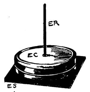
139. Our Electrophorus is shown in Fig. 34. For the insulating
handle use the ebonite rod, E R (No.
28); for the plate, use the ebonite sheet,
E S (No. 26). The electrophorus cover,
E C (No. 42), furnished, is a tin box
with a fancy top. A hole has been
punched in the center of its top, and into
the hole has been riveted a short tube, so
that the handle, E R, can be firmly held.
The hole has been made a little larger
than E R for convenience. To make E R
fit tightly in the hole, so that you can lift
E C, wrap a small piece of paper around
the end of E R before pushing it into the hole. You can easily
find out how much paper to use to make a good fit. With a knife
cut away all loose points of paper that stick out of the hole around
E R; this is important. The top and bottom of E C should be
pressed firmly together.
First learn how to use the electrophorus. With the large amount
of electrification produced we can then find out how it works.
[53]
EXPERIMENT 68. To learn how to use the electrophorus.
Apparatus. Shown in Figs. 34, 35. Do not fail to read
§ 139.
140. Directions. (A) Place E S upon a flat, uncovered, wooden
table, and rub it vigorously for a minute with the warm flannel, F
C, to thoroughly charge it. Do not let E S slide about, and do
not lift it from the table.
(B) With the right hand grasp E R at its extreme end, and
place E C upon E S.
(C) Touch E C for an instant with a finger of your left hand
(Fig. 35).
(D) Remove your finger entirely from E C, then lift E C by its
insulating handle, E R, at the same time holding E S down to the
table, if it tries to follow E C.
(E) Bring your left hand near E C (Fig. 36). You should get a
good spark from E C.
(F) It is not necessary to immediately rub E S again. You have
discharged E C by taking a spark from it. To recharge it, simply
place it upon E S again; let it remain there while you count 5;
touch it as before, and then lift by E R.
141. Extra Notes. You may repeat the above operation many
times. As soon as the sparks begin to get small, electrify E S
again. The charge on E C is +, although that on E S is -. You
will understand, later, why this is so.
If you do not get a good spark from the electrophorus, read the
directions again. The ebonite must be well electrified; the cover[54]
must be lifted by the end of its handle; you must touch the cover
and withdraw your finger from it before lifting. You must allow
the cover to remain upon the ebonite 3 or 4 seconds each time.
The board, or table, upon which E S rests, must be flat, and not
warped, so that E C will fit down perfectly upon E S.
EXPERIMENT 69. To study "charging by conduction."
Apparatus. Fig. 37. To one end of a silk thread, S T, is
tied a little bent clamp, B C (No. 46); the other end of S T
is tied to the support wire, S W (No. 36); the bottom of the
flat box, B F B (No. 40), is supported by B C, and thus
insulated from the table and earth; the electrophorus (Exp.
68) is also necessary.
142. Directions. (A) Charge E C (Exp. 68), and bring it near
B F B (Fig. 37). Note the spark.
(B) Repeat (A) twice, noting the relative sizes of the sparks.
Does B F B continue to be attracted by E C?
(C) Bring your knuckle slowly towards the charged disk,
B F B.
EXPERIMENT 70. To study potential; electro-motive
force.
143. Directions. (A) Pass a spark from the thoroughly
charged E C (Exp. 68) to I T.
[55]
(B) Recharge E C, and see how many times I T will take good
sparks from it, and note the relative sizes of the sparks.
(C) As soon as I T refuses to take more sparks from E C,
touch E C to see if it is completely discharged.
(D) Touch I T.
144. Pressure; Potential; Electro-motive
Force. Water runs down hill. It always tries to run
from a high place to a lower one. Electrification acts
very much like water in this respect. We say that
water has a pressure, or a head of so many feet. In
speaking of a charge, we say that it has a potential, or
an electro-motive force. Water may have a high or low
pressure, and a charge may have a high or low potential.
The greater the pressure of water, the harder it tries to
break away and get somewhere; the greater the potential
of a charge, the farther it will jump to your hand.
144a. Current; Spark. Electrification will easily
pass from a place of high potential to one of low potential
through a conductor, and when it passes we say we
have an electric current, or a current of electricity. Water
has no desire to flow on a dead level, and the electric
current does not care to flow between two places of equal
potential. The potential of the earth and of all neutral
bodies is zero; that is, they have no charge, no potential;
so it is very easy for a charge to escape into the earth.
Dry air is a pretty good insulator, but when the attraction
between a charged and a neutral body gets great
enough, the spark rips right through the air. Benjamin
Franklin proved by experiment that lightning is caused
by the electrification in the clouds and air. (See Atmospheric
Electricity.)
145. Theories about Electrifications. The "One-Fluid"
Theory suggests that neutral bodies have a certain amount of
electrification, and that they have a certain potential called zero[56]
potential. If the potential of a body becomes greater than that
of the earth, the body is said to be positively electrified; if the
potential of the body is less than that of the earth, it is said
to be negatively electrified. If we fill a bottle with sea water,
we have a great deal of water when we compare it with the bottle,
but a very little water when we compare it with the sea. The
earth is so large that small amounts of electrification taken from
it or added to it do not affect its potential to any extent.
146. The "Two-Fluid" Theory suggests that there are two
absolutely different kinds of electrification, one called positive (+),
and the other negative (-). When these two are equal in
quantity, the body is said to be neutral. If the body contains
more + than -, the body is said to be charged positively.
It is evident then, if the two-fluid theory be accepted, that no
matter how strongly a
body is charged positively
there must be in it some
negative electrification;
that is, we may charge a
neutral body + by adding
+ electrification to it, or
by taking - electrification
from it. There must always
be, then, some +
and - electrifications in a
body.
These theories do not
require much consideration by the student of elementary electricity.
The best thing he can do is to learn what electricity can
do, and how it can be used.
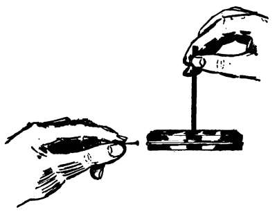
EXPERIMENT 71. To study some methods of discharging
an electrified body.
147. Note. You have seen sparks pass from E C to your
rounded knuckle, and to other conductors. In all of these cases
the discharge was sudden, one spark doing the work. Can we
slowly discharge E C, or discharge it without sounds?
[57]
148. Directions. (A) Thoroughly charge E C, and test it with
your knuckle to be sure that it is working properly.
(B) Charge E C again; hold the pin in your left hand (Fig. 39),
and slowly bring its head toward E C; listen for sparks.
(C) Recharge E C, and bring the point of the pin slowly toward
it. Touch E C to see whether it has been discharged or not.
149. Disruptive, Conductive, and Convective
Discharges. Sudden discharges, accompanied by
bright sparks, are said to be disruptive. When the electrification
is continuously carried away by a conductor,
there is a conductive discharge. There is a convective discharge
when the electrification escapes from points into
the air. (See § 155.) The nature of
the discharge depends upon the
potential of the charge, upon the
nature of the charged conductor,
and upon the nature of the surrounding
air and objects. Convective
discharges are often silent,
as in Exp. 71 (C). In this case,
electrification passed from the earth
through the pin-point to the cover to neutralize it. (See
Induced Electricity.)
EXPERIMENT 72. To study intermittent or step-by-step
discharges.
150. Directions. (A) Charge E C, then hold your hand on
one side of the carbon (Fig. 40), and hold E C upon the opposite
side. What should the carbon do?
151. Discussion. The carbon and E C were insulated,
while the hand was "grounded"—that is, it was
connected with the earth. Carbon is a good conductor;
it may be quickly charged and discharged.
[58]
EXPERIMENT 73. To ascertain the location of the charge
upon an electrified conductor.
Apparatus. The electrophorus (Exp. 68); the insulating
table, I T (Exp. 64); the tin box, T B (No. 47), Fig. 41;
a piece of moist cotton thread, C T, 5 or 6 in. long, bent
double, and hung over the edge of the open box, T B.
One-half of C T should be inside of T B, which, in turn,
should stand on I T.
152. Directions. (A) Charge E C; pass a spark to T B, and
note the action of both parts of C T.
153. Hollow and Solid Conductors. The moist
thread, being a conductor, became
charged as well as the box. The
electrification seemed to be entirely on
the outside of T B. A hollow conductor
will hold as large a charge as a
solid one having the same amount of
surface. This refers to charges of
static electricity, not to currents. An
electric current passes through the
whole substance of a conductor.
EXPERIMENT 74. To study the
effect of points upon a charged conductor.
Apparatus. The electrophorus (Fig. 34); a pin, bent
slightly to keep it from rolling.
154. Directions. (A) Charge E C; test its charge with your
knuckle. Be sure that you get a good spark.
(B) Charge E C again, and hold it by its insulating handle,
E R, long enough to count 10 before discharging it with your
knuckle. Be sure that it holds its charge during this time.
(C) While E C is upon E S (Fig. 34), lay the bent pin upon E C,
so that its point will project into the air. The point should stick
out about ¼ in. from the edge of E C.
(D) Touch E C; raise it by E R; count 10 as before; then test
with your knuckle to see if E C is still charged.
[59]
155. Electric Density; Electric Wind. A
charge resides upon the outside of a conductor (Exp.
73), and it continually tries to escape. It seems to pile
up at points and corners, and we say that it is denser
at such places than at well-rounded parts of a charged
conductor. All points and sharp places should be removed
from a conductor, if it is desired to keep a charge
for any length of time.
Electrification may escape from a point so rapidly that
currents are produced in the surrounding air. As the
particles of air become charged, they repel each other.
The movement of the air particles may be so great that
a lighted candle will be affected when placed near the
point. This current of air is called electric wind.
Electrification easily passes from points, and the electrophorus
may be easily and silently discharged by holding
a pointed pin near it (Exp. 71, C). Thorns, leaves
with sharp edges, etc., have a great effect upon atmospheric
electricity. They allow a silent escape of electrification
from the earth to neutralize that in the clouds
which is opposite in nature. (See Atmospheric Electricity.)
[60]
CHAPTER IX.
INDUCED ELECTRIFICATION.
156. Electric Field; Lines of Force. In our
study of magnetism you learned that a magnet can act
through the air, and induce a piece of iron to become a
magnet. You saw how the iron filings arranged themselves
around the magnet, showing that the lines of force
reached out from the poles in a very peculiar manner.
There is an electric field all around a charged conductor,
just as there is a magnetic field about a magnet. The
lines of force in the
electric field pass from
the positively charged
body to the negatively
charged one, or to some
neutral one, which, you
will soon see, is practically
the same thing.
When the positively
charged electrophorus
cover is held above the negatively charged ebonite sheet,
a very strong electric field exists between them.
157. Note. You have seen that we can charge an insulated
conductor by touching it with the charged cover, or by allowing a
spark to pass to the conductor. What effect, if any, has a
charged body upon an insulated conductor before they touch each
other, and before any spark passes to the conductor?
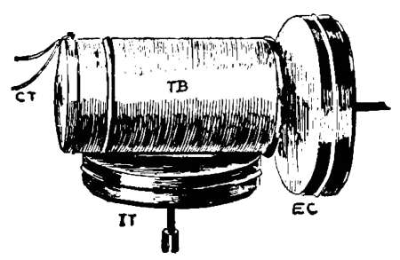
EXPERIMENT 75. To study electric induction.
Apparatus. Fig. 42. The insulating table, I T (for details
see Exp. 64); tin box, T B (No. 47, Fig. 42); moist
cotton thread, C T; the electrophorus (Exp. 68); tie C[61]
T around one end of the closed T B, and leave the ends
of C T long enough to hang down over the end. Place a
match on each side of T B to keep it from rolling.
158. Directions. Part 1.—(A) Pass a spark from the charged
E C to T B, and note the action of the thread, which will be our
electroscope. Remove E C.
(B) Touch the charged T B with the finger, watching C T.
Part 2. (C) Bring the re-charged E C near the neutral T B,
and parallel to its end surface; but keep them at least an inch
apart, so that a spark cannot pass. Watch C T.
(D) Withdraw E C, and try to explain the action of C T.
159. Electric Polarization; Theory of Induction.
This experiment should remind the student
of Exp. 24, in magnetism, in which a piece of soft iron
was magnetized by the inductive action of a magnet.
The soft iron was in a magnetic field; it became polarized.
Is it possible that the box, T B, was polarized, being in
the electric field of E C?
We know, by the action of C T (Fig. 42), that the top
end of T B was charged while E C was in place. The
charge was not conducted.
You know, from previous experiments, that + and -
electrifications rush together whenever possible. Why
can we not suppose that a neutral body, like the box at
the start, contains an equal amount of both kinds, and
that these different electrifications have already rushed
together?
If you imagine a small army of positive soldiers struggling,
"man to man," with the same number of equally
strong negative soldiers, you can readily see that one-half
of them can hold the other half from running away. A
body remains neutral, then, according to this idea, as long
as it has an equal quantity of the two opposite kinds of
electrification. (See Theories, § 145, 146.)
As soon as the positively charged E C was brought[62]
near T B, it destroyed the neutrality of T B, by pulling
at its - electrification, and by pushing back its + electrification
to the top end and into C T. We say that the
charged E C produced a separation of the combined electrifications
of T B by induction, and not by contact. As
soon as the inductive action of E C was removed, T B
became neutral again.
160. Note. Figs. 43 and 44 may aid the student. In Fig. 43,
T B is supposed to be neutral. The "double sign" means that
the + and - electrifications are united; and, as there are an
equal number of both kinds,
none are left free to tell the
tale. Fig. 44 shows what happens
when the + E C is near.
What would happen if we
could cut into T B at the middle
with an insulated knife while it is polarized by E C?
EXPERIMENT 76. To learn how to charge a body by induction.
161. Directions. (A) Bring the charged E C within an inch of
the bottom of T B, and as soon as C T is repelled, showing that T
B is polarized (Exp. 75), touch T B with your finger; then remove
your finger while you still hold E C in place.
(B) Withdraw E C and its inductive action. Explain the
motions of C T during the experiment. Is it still repelled by T
B after E C is removed?
162. Free and Bound Electrifications. As
explained in Exp. 75, and as shown in Fig. 44, T B became
polarized. The - electrification was drawn towards
E C; it was held or bound there as long as E C was near.
The + was actually repelled by E C, and it was free to
escape through your arm as soon as T B was touched,
leaving the top end of T B neutral. As soon as E C was
removed, the - electrification, no longer held by E C,[63]
spread all over T B and on to C T. T B was charged by
induction. It was charged negatively by driving out +
electrification.
EXPERIMENT 77. To show that a neutral body is polarized
before it is attracted by a charged one.
Apparatus. The electrophorus (Exp. 68); dry tissue-paper,
T P. Cut out 2 pieces of T P, each about ¼
inch square.
163. Directions. (A) Place the bits of dry T P upon a board
or table, and convince yourself that they are attracted equally by
the charged E C.
(B) Slightly moisten one piece of T P only. See if one is attracted
by E C more readily than the other.
164. Polarization Precedes Attraction. Dry
tissue-paper is not a good conductor; you have seen
(Exp. 52) that it can be electrified, which indicates that
it is at least a partial insulator. Insulators are not easily
polarized. (Why?) Even if the pieces of T P were
polarized, the opposite electrifications were so near each
other that the attraction of E C for the - was nearly
overcome by the repulsion for the +; the result being that
T P was not strongly attracted by E C until the + had a
chance to escape. The moist tissue-paper allowed its +
to escape more quickly than the dry piece. A conductor
is attracted by a charged body more strongly than an insulator,
because the latter is not easily polarized. A
neutral body, then, is really no longer neutral when it is
in the electric field. Polarization precedes attraction.
EXPERIMENT 78. To find whether electric induction will
act through an insulator.
Apparatus. Small bits of carbon (Exp. 58); bits of moist
tissue-paper, T P; one-half of the flat box, T F B (No.
41); sheet of glass, G (No. 38); electrophorus (Exp. 68).
Place the carbon and T P into T F B (Fig. 45), and cover
with the glass.
[64]
165. Directions. (A) Charge the electrophorus cover, E C
(Exp. 68), move it about a little above the glass, and see if the
carbon, etc., are attracted.
166. Dielectrics. The carbon must have been
polarized and attracted through the glass. You saw,
Exp. 7, that the lines of magnetic force could penetrate
and act through paper, glass, etc.; it is now evident that
the electric field is not easily fenced in, even by an insulator.
Substances, like the glass, which allow this
inductive influence to act through them, are called dielectrics.
EXPERIMENT 79. To find whether a polarized conductor
can act inductively upon another conductor.
Apparatus. Fig. 46. Insulating table, I T (for details
see Exp. 64); ebonite sheet, E S (No. 27); flat box complete
F B (Nos. 40, 41); sheet of glass, G (No. 38); small
piece of slightly moist tissue-paper, T P; charged electrophorus
cover, E C. Arrange as shown.
167. Directions. (A) Hold E C, charged, near and under I T,
then bring your finger, F, near T P. Explain the action of T P.
168. Successive Induction. The inductive influence
of E C first polarized I T; this acted through the
dielectric, E S, and polarized F B, which, in turn, polarized[65]
T P through the second dielectric, G. This induction
after induction is called successive induction.
169. Inductive Capacity. Dielectrics are insulators.
Two substances may be equally good insulators,
that is, they may equally well resist the spread of electrification
over their surfaces, or the flow of the electric current
through them, while one may be, nevertheless, a
better dielectric than the other. The better the dielectric,
the easier it is for the electric field to polarize a conductor
placed beyond the dielectric. A good dielectric is said to
have a high inductive power or capacity. Glass is about 3
times as good a dielectric as dry air; and as the latter
(under certain conditions) is taken as the standard, or as
unity, we may say that the specific inductive capacity of
glass is about 3.
EXPERIMENT 80. To study the action of the electrophorus.
Apparatus. The electrophorus (Exp. 68); small bits of
moist tissue-paper, T P.
170. Directions. (A) Thoroughly electrify E S, Fig. 34, and
place E C upon it by its handle, E R.
(B) Touch E C, as directed in Exp. 68, and listen for a small
spark which should pass from E C to your finger.
(C) Again, place a little piece of T P upon E C before lowering
it upon E S. Do not touch E C, but bring your finger near T P.
What does T P do? Now, touch E C and see, when you bring
your finger near it, if T P acts as it did before.
(D) Again, place several pieces of T P upon E C (E S being
thoroughly charged); touch E C, then lift it by its handle. Note
action of T P, which should be slightly moist.
171. Discussion. The electrification upon the
ebonite is negative (Exp. 60). Although E S and E C
(Fig. 34) seem quite smooth, there are many little hills,
valleys, and air-spaces between them, which keep them
from touching each other perfectly. The ebonite has[66]
the electric field at the start, and it really acts across these
minute air-spaces by induction (Exp. 75), and polarizes E
C. The air-spaces form the dielectric (Exp. 78). The -
electrification of E C being repelled by the - of E S, it
is driven to the top of E C, while the + is drawn to the
bottom. This + is kept from rushing to the - of E S
by the air dielectric, and because E S is a non-conductor.
By touching E C the free - escapes to the earth, leaving
E C positively charged when it is lifted.
172. Details of Action. The different steps in the action of
the electrophorus are shown graphically in Figs. 47 to 51. Fig.
47 shows E S negatively charged. E C is neutral at first, Fig. 48;
that is, it is supposed to contain both + and -, as shown by the
"double sign" (§ 160). Fig. 49 shows that E C has been polarized
by the inductive action of E S. The repelled - escapes to
the finger (this escaping is what gave the small spark to the finger
and charged the T P in the last experiment), leaving the top
uncharged, while the + is bound (Fig. 50). As soon as E C is[67]
lifted (Fig. 51) the + spreads all over E C, which is then charged.
The +, upon going to the top, charged the pieces of T P (Exp.
80, D), causing them to be repelled. The charge of - upon E S
has not been removed, so the operation may be repeated many
times before E S must be again electrified.
The - electrification on the ebonite acts inductively through
E S, drawing up + electrification from the earth. To make this
action easier a "sole," or metal conductor, is often placed under
the ebonite.
EXPERIMENT 81. To see, hear, and feel the results of
inductive influence and polarization.
Apparatus. Ebonite sheet, E S (No. 26); insulating
table, I T; flannel cloth, F C.
173. Directions. (A) Thoroughly charge E S with F C. With
the right hand bring E S near and parallel to the top surface of
I T, but do not let them touch each other.
(B) Remove E S, then touch I T to see if it is charged.
(C) Repeat (A), and while you hold E S about ½ inch from I T,
their flat surfaces being parallel, touch I T. Watch for any
sparks, and note any peculiar actions of E S.
(D) Remove your finger from I T, then withdraw E S; finally
touch I T with your knuckle.
174. Discussion. This apparatus is really the electrophorus
upside down. It shows very clearly (1) the
escape of the - electrification from I T, by the spark;
(2) that the attraction between I T and E S is much
greater than before, when this - is removed; and (3) it
shows the different steps of the inducing and charging
process, as described in Exp. 75, and as shown in Figs.
43 and 44.
[68]
CHAPTER X.
CONDENSATION OF ELECTRIFICATION.
EXPERIMENT 82. To find whether a large surface will
hold more electrification than a small one.
Apparatus. The insulating table (for details, see Exp.
64); a large tin basin or pan (not furnished); the electrophorus
(Exp. 68).
175. Directions. (A) Test the electrophorus and be sure that
it is working properly.
(B) As in Exp. 70, see how many good sparks I T will take
from E C (which should be recharged at each trial) before the
potential of I T is raised so that it equals the potential of E C.
(C) Carefully set the basin or pan upon I T, then count the
number of good sparks you can pass to it from E C (recharged at
each trial). Compare the number of sparks necessary to raise
the potential of the large surface until it equals that of E C, with
the number found in part (B).
176. Electrical Capacity. It takes more heat to
raise the temperature of a gallon of ice-water to the boiling
point, than it takes for a quart of ice-water. You
have just seen that a large insulated surface will take
more sparks from a charged body than a small one, before
its potential is raised to that of the small one, and to
that of the charging body. We say that a large surface
has a greater capacity than a small one, the shape and
other conditions being the same.
EXPERIMENT 83. To find whether the capacity of a given
conductor can be increased without increasing its size.
Apparatus. Fig. 52. Insulating table. I T (Exp. 64);
the extra ebonite sheet, E S (No. 27); the complete flat
box, F B (No. 40, 41); the charged electrophorus cover,[69]
E C (Exp. 68). Arrange, as shown, I T being insulated
from the earth by E S. F B should rest upon a wooden
table or other large conductor.
177. Directions. (A) See how many good sparks I T will take
from E C. Re-charge E C at each
count, and note the relative sizes of
the sparks.
(B) Discharge I T by touching it
with your knuckle.
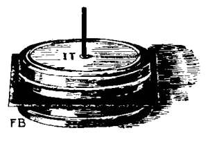
178. Condensation; Condensers.
As I T easily held
more sparks than it would take
before (Exp. 70), we say that its capacity has been increased.
Its potential didn't increase, because that could
not get greater than the potential of E C, the charging
body. To describe this state of affairs, we say that the
electrification was denser than before, and that it was
condensed. The capacity of I T was greatly increased by
the presence of another conductor, F B, insulated from I T,
but "grounded." Such a combination, 2 conductors,
with a dielectric between them, is called a condenser.
A condenser can hold much more electrification at a
certain potential than an equal amount of surface can
hold when not properly arranged. We might call a condenser
a storage battery for static electricity. The capacity
of a condenser depends, among other things, upon
the area of the conducting surfaces, and upon the thickness
and nature of the dielectric. Among the various forms
of condensers may be mentioned the Leyden jar, and the
fulminating pane.
179. The Leyden Jar consists of a wide-mouthed glass jar,
with tin-foil pasted upon the inside and outside to within 2 or 3
inches of the top. The inner coat or conductor is connected to a
knob or ball at the top by means of a chain. To charge the jar,
the outer coat is connected with the earth by holding it in the[70]
hand, or by resting it upon a table while the electrification is passed
to the knob. A Leyden Battery consists of 2 or more connected
jars, the object being to increase the area of the surface. The
jar is discharged by touching one end of a discharger (§ 188) to
the outer coat, and swinging its other end over to the knob, when
a bright spark will pass between the knob and discharger. (See
Exp. 86.)
180. Fulminating Panes, or Franklin's Plates, are practically
the same as a Leyden Jar. The tin-foil, however, is pasted upon
the opposite sides of a pane of glass, a margin of about an inch
being left all around. One side of the pane is charged, and takes
the place of the inside coat of the jar. The other side is grounded.
The pane is discharged by connecting the two sheets of foil.
181. Induction Coil Condensers consist of sheets of tin-foil
separated by sheets of paraffined paper, which act as the dielectric.
(See Induction Coils.)
182. Submarine Cables, with the surrounding water, act like
condensers, the result being that the condensing effect slows up
the electric current and retards the signals. These make a condenser
of enormous capacity. The wires inside form one conductor,
and the water the other, while the insulation around the
wires forms the dielectric.
EXPERIMENT 84. To study the condensation of electrification.
Apparatus. Same as in last experiment, but arrange
so that F B and I T shall be near each other at one side;
that is, so that the edge of E S shall be even with the
edges of the two tins.
183. Directions. (A) Pass good sparks to I T from the
charged E C until something happens. Watch the side where
I T and F B are near each other.
184. Discussion. We may say that the electrification
was condensed, in this experiment, until the charge
became so great that the condenser suddenly discharged
itself. Condensers may be made in many ways, but they
all consist of 2 conductors, with a dielectric between
them. One conductor is insulated, and receives the
charge; the other conductor is grounded.
[71]
EXPERIMENT 85. To study the action of the condenser.
Apparatus. Fig. 53. The insulating table, I T; ebonite
sheet, E S (No. 27); flat box, F B, complete (Nos. 40,
41); the electrophorus (Exp. 68). Note that this is really
the same apparatus as that just used; both conductors of
this condenser, however, are insulated and reversed in
position.
185. Directions. (A) See that your electrophorus works
properly, then find out how many good sparks
you can pass from E C to F B, recharging E C
each time. Note the relative sizes of the
sparks, and compare the result with the number
taken by the condenser in the last experiment.
(B) When F B seems to be fully charged,
touch I T with your knuckle. (From your
study of induction what should be the result?)
(C) Now see if F B will again take good
sparks from the charged E C. Pass sparks to
F B until it seems fully charged.
(D) Again touch I T, then repeat (A) and (B) several times,
until a bright spark passes from F B over the edge of E S to I T.
186. Discussion. The action of the condenser, as
clearly shown, depends upon induction. You should now
be able to explain and show by diagram the different
steps.
E C was positively charged (Exp. 80). This also charged F B
positively by contact. F B acted inductively through the dielectric,
E S, drawing up some of the - in I T, and repelling some of
the +. As I T was insulated, this free + electrification could
not escape. Before we touched I T, its + and - electrifications,
although partially separated, were struggling against this inductive
action; and, on account of their strong attraction for each
other, our efforts to charge the condenser were retarded. Upon
touching I T the free + escaped to the earth. (This was the cause
of the spark.) This left some - electrification bound on the
underside of E S, and some + bound on the upperside of E S.
The capacity of F B was increased by this process, as the +[72]
already put into it was very much occupied by the attractions
of the induced - just under E S. As more + was given to F B,
more - was drawn up under E S and more + was pushed out of
I T. This action went on until the two conductors were strongly
and oppositely charged. This action goes on continuously when
the lower conductor is grounded. The spark between the tins
was due to the rushing together of the + and - electrifications;
it showed that there was a momentary current of electricity.
EXPERIMENT 86. To study the effect of electrical discharges
upon the human body.
Apparatus. The condenser (Fig. 52), with E S centrally
placed so that the apparatus cannot discharge
itself; the hairpin discharger, H P D (No. 48); the electrophorus.
187. Directions. (A) Charge the condenser (Exp. 83) with 10
good sparks from E C, then touch I T (Fig. 52).
(B) Recharge the condenser with 10 sparks, then touch F B.
Discharge it by again touching I T as in (A).
(C) Recharge with 10 sparks; then place your thumb against
F B, and quickly swing the first finger of the same hand over to
I T, and get a slight shock.
(D) Recharge with as many sparks as you think you can stand.
(E) Instead of using your hand to discharge the condenser, try
the bent hairpin. Keeping one end against F B, swing the other
end over near I T.
188. Shocks; Dischargers. The two conductors
being oppositely charged in the condenser (Exp. 85), it
is only necessary to place some conductor between them
to allow the charges to rush together. Any conductor so
used is called a discharger. The hand carried the
whole current which caused the shock. When I T was
touched first, the current was obliged to pass through
your body, through the floor, and up the table-legs into
F B. Always touch the "grounded" conductor first
with the discharger, so that you will get a good spark
and not a shock.
[73]
EXPERIMENTS 87–88. To show the strong attraction between
the opposite electrifications in the condenser.
Apparatus. Flat box, F B (Nos. 40, 41); sheet of glass,
G (No. 38); electrophorus (Exp. 68). The two parts of
F B are used for the conductors of the condenser (Fig. 54)
for the sake of lightness. The bottoms should be next
to the glass, which is used for the dielectric on account
of its stiffness. The lower tin should rest upon the table.
The glass should be perfectly clean and dry (hot).
189. Directions. (A) Charge the condenser with 15 or 20
good sparks from E C.
(B) Lift the condenser by one corner of G (Fig. 54), being careful
not to discharge it. Explain why the lower conductor follows
the glass.
EXPERIMENT 88.
190. Directions. (A) Charge
and lift the condenser as just
explained (Exp. 87). Fig. 54.
(B) With your right hand
touch the upper tin alone, then
the lower tin alone.
(C) Touch both tins at the same time, and note the action of
the lower one.
191. Discussion. This clearly shows how strongly
the two electrifications are bound in the condenser. Each
refuses to escape to the earth, but they instantly rush
together at the first opportunity. The dielectric may be
shattered in a very heavily-charged condenser by this
strong attraction.
EXPERIMENT 89. To show how the condenser maybe
slowly discharged.
192. Directions. (A) Charge
the condenser by means of the[74]
electrophorus; then hang the carbon so that it can swing between
the upper conductor and E C placed as shown.
193. The Electric Chime. The charging and
discharging of the carbon being rapid, it acts like a
chime as it taps against the tins.
EXPERIMENT 90. To ascertain the location of the charge
in the condenser.
Apparatus. The condenser, consisting of flat box,
F B (Nos. 40, 41); ebonite sheet, E S (No. 27); insulating
table, I T (Exp. 64); (when charging, arrange as in Fig.
52.); the electrophorus; hairpin discharger, H P D (No.
48).
194. Directions. (A) Charge the condenser with 15 or 20 good
sparks from E C.
(B) Lift I T away from E S by its insulating handle, and set it
upon the table. (It may be necessary to hold E S down.)
(C) Lift E S directly up and away from F B. (Lift by 2 corners;
do not scrape E S along on F B; do not allow E S to touch your
clothing.)
(D) Replace E S and then I T by its handle quickly, making
the condenser complete again.
(E) With H P D see if the condenser still holds a charge.
Touch F B first (Exp. 86).
195. Discussion. As the conductors were completely
discharged, being left for a few moments upon the
table, it is evident that the opposite electrifications must
reside in and upon the dielectric. The conductors allow
an even and rapid discharge from all parts of the dielectric
at the same time. The dielectric is considerably
strained when a condenser is heavily charged. This
strain, caused by the attraction of the opposite electrifications,
may be great enough to break or puncture the
dielectric.
EXPERIMENT 91. To find whether any electrification
remains in the condenser after it has once been discharged.
Apparatus. The condenser (Fig. 52); the electrophorus
(Exp. 68); hairpin discharger, H P D.
[75]
196. Directions. (A) Thoroughly charge the condenser.
(B) Discharge it with H P D, being sure to touch F B first, and
to touch I T for an instant while H P D is against F B.
(C) After a few moments use H P D again, and see if you get a
slight spark.
197. Residual Charge. The two electrifications
on the opposite sides of the dielectric have such an attraction
for each other, when the condenser is charged, that
they seem to penetrate, or soak into, the dielectric. These
do not completely soak out again at the discharge. The
small amount left is called a residual charge.
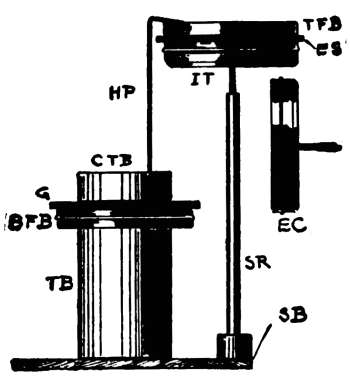
EXPERIMENT 92. To study successive condensation; the
chime cascade.
Apparatus. Fig. 56. This really consists of two condensers,
joined by a wire. The upper condenser consists
of T F B (No. 41), E S (No. 27), and the insulating
table, I T. (See Exp. 64.) The lower condenser consists
of the cover of the tin box, C T B (No. 47), the sheet of
glass G (No. 38), and B F B (No. 40). The tin box, T B
(No. 47), is placed under this to raise it, simply. A wire
or hairpin, H P, is hung upon the edge of T F B, its
lower end being inside of C T B and not quite touching
it. This acts like a pendulum, which is to swing to C T B
at the proper time. The source of electrification is E C.
[76]
Note. You have learned that in charging the condenser with
the positively charged E C, + electrification is driven from F B
into the earth. Can we use this to charge a second condenser?
198. Directions. (A) Pass 15 or 20 good sparks from E C to
the under side of I T (Fig. 56), noting the action of H P.
(B) Hold E C in the hand, and, with its insulating handle, poke
H P away from the condensers. Do not discharge them.
(C) With H P D test the lower condenser for a charge, touching
T B first.
(D) With H P D touch T F B first (why?), and discharge the
upper condenser.
199. Discussion. A long row of condensers may
be charged in this way. There is no advantage in it, as
the electrification is merely divided between them. How
can two condensers be joined to get the advantages of a
large surface?
[77]
CHAPTER XI.
ELECTROSCOPES.
200. Electroscopes are instruments to show the
presence, relative amount, or kind of electrification on a
body. (See Apparatus Book, Chap. XVIII, for Home-Made
Electroscopes.) The carbon electroscope has been
described (Exp. 58). The pith-ball electroscope is made
by using pith from elder, corn-stalk, or milk-weed, in
place of the carbon. The
gold-leaf electroscope is a very
delicate instrument. The
gold-leaf is supported, as suggested
in Fig. 57, at the lower
end of a wire conductor which
sticks through and hangs from
the cork of a glass jar or flask.
To the top end of the wire is
soldered a ball or disk. The
glass jar insulates the gold-leaf,
and keeps it dry and free
from dust.
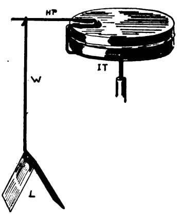
201. Our Leaf Electroscope (Fig. 57) is made with aluminum-leaf.
Gold-leaf is too delicate for unskilful handling, and aluminum
will do for all ordinary experiments. To cut it into any
desired shape, place it between two sheets of paper, then cut
through paper and all.
202. Construction. Bend one leg of a hairpin, H P, as in
Fig. 57, and slide it onto I T. Hang a wire, W, or another hair
pin straightened, then bent, from the horizontal leg of H P. This
is to support the "leaves," L, which are made from a strip of[78]
aluminum-leaf about 4 in. long and ¾ in. wide. Moisten the
under side of the horizontal part of W with paste or mucilage;
press it upon the middle of the strip laid flat upon the table, and
then lift W. The leaves should cling to W. Each leaf should be,
then, 2 in. long. They should hang close together when not in
use. A large chimney, or fruit-jar, may be used to surround the
leaves, and to keep currents of air from them. The leaves should
not touch the side of the jar when spread.
EXPERIMENT 93. To study the leaf electroscope; charging
by conduction.
Apparatus. The leaf electroscope (Fig. 57, § 201, 202);
ebonite rod, E R (No. 28); flannel cloth, F C (No. 30).
203. Directions. (A) Thoroughly charge E R, then scrape it
along upon I T, noting the action of the leaves, L.
(B) See if the leaves will remain spread for some time.
(C) Touch I T to discharge it, and note the action of L.
204. Discussion. No explanation should be necessary
for this. Are the leaves charged alike? As they
were charged by contact, is the electrification on them +
or -?
EXPERIMENT 94. To charge the leaf electroscope by induction.
Apparatus. Our electroscope (Fig. 57, § 202); ebonite
sheet, E S (No. 27); flannel cloth, F C (No. 30).
205. Directions. (A) Charge E S with F C, then hold E S
above I T (Fig. 57), their surfaces being kept parallel and about
2 or 3 inches apart. Watch the leaves.
(B) Withdraw E S. Do the leaves remain spread?
(C) Repeat (A), and before removing E S, touch I T.
(D) Remove your finger from I T, then withdraw E S. Do the
leaves now remain spread?
206. Discussion. The permanent divergence of L
was due to a charge given by induction. (Exp. 76.)
As E S was -, what was the kind of a charge in L?
Did any electrification go to the electroscope from E S?
In (C) what became of the charge in L? Explain why[79]
the leaves again diverged in (D). The electroscope was
charged with + electrification by taking - out of it.
EXPERIMENT 95. To learn some uses of the electroscope.
Apparatus. Our electroscope (Fig. 57, § 202); ebonite
rod, E R (No. 28); ebonite sheet, E S (No. 27); glass, G
(No. 38); flannel cloth, F C (No. 30).
207. Directions. (A) With the charged E R charge the electroscope
negatively by conduction (Exp. 93). Note the amount
of permanent divergence of the leaves.
(B) Electrify the glass, which will be +, (or use the + E C),
and slowly lower it over I T, noting the effect upon L. Raise and
lower G or E C several times. Does G, which has an opposite
charge to the electroscope, make L diverge more or less?
(C) Discharge the electroscope and recharge as in (A).
(D) Slowly lower the charged E S over I T.
(E) Slowly lower the palm of your hand over I T.
Note. If the + G is brought too near the -ly charged electroscope,
L will first collapse and then instantly diverge again
with a + charge by contact. The first motions should be observed.
208. Discussion. As a neutral body causes a slight
collapse of the leaves, as well as a body charged positively
(when the charge in the leaves is -), an increase of divergence
is really the only sure test to tell how a body is
charged. The - leaves collapse when a + body is
brought near I T, because the - in them is drawn up
towards the body. The leaves diverge more when a -
body is brought near, because the - in I T is repelled
into them.
209. The Proof-plane. Since charges of static
electricity reside upon the outside of conductors, it is an
easy matter to take samples of the electrification. This
may be done with a little instrument called a carrier, or
proof-plane. It consists of a small conductor with an insulating
handle. A ring or coin may be used for the[80]
conductor, and a silk thread for the handle. By touching
the carrier to any charged body, it, also, becomes
charged; and the nature of the charge may be determined
by the use of a previously charged leaf electroscope (Exp.
95). A delicate gold-leaf electroscope would be ruined
by coming in contact with a heavily charged body. The
carrier allows a small sample to be tested.
[81]
CHAPTER XII.
MISCELLANEOUS EXPERIMENTS.
EXPERIMENT 96. To show that friction always produces
two kinds of electrifications.
Apparatus. Fig. 58. The carbon electroscope (Exp.
58); flannel cloth, F C, doubled twice to make 4 thicknesses
(see Fig. 58); ebonite sheet, E S (No. 26); ebonite
rod, E R (No. 28); charged electrophorus cover, E C.
210. Directions. (A) Vigorously rub E S with F C (folded as
in Fig. 58). See if you can discover any attraction between them.
(B) Rub E S again, but do
not lift F C from it with the
hand alone. Slip E R under
the top fold in F C (Fig. 58),
and lift F C straight up
from E S. Do not let F C
touch the table or your
hand.
(C) See if F C is charged,
using 2 or 3 different tests.
(D) Charge the electroscope with F C until the carbon is
strongly repelled.
(E) Bring the positively charged E C slowly near the carbon,
and note the result.
(F) Slowly bring the negatively charged E S near the carbon
that has been charged by contact with F C.
211. Discussion. This experiment showed that
while the ebonite was negatively charged, the flannel was
positively charged. One kind of electrification is never
produced without the other. It can also be shown that
the two kinds are equal in amount.
[82]
EXPERIMENT 97. To show "successive sparks."
Apparatus. Fig. 59. The electrophorus (Exp. 68); the
extra ebonite sheet, E S (No. 27); three coins (marked A,
B, C, in Fig. 59). The coins should nearly touch each
other, and rest upon E S. A part, only, of the electrophorus
cover is shown.
212. Directions. (A) Thoroughly charge the electrophorus
cover.
(B) Place your finger upon the coin marked A, to "ground" it,
then quickly touch the coin C with the charged cover, at the same
time watching for sparks between the coins. If you cannot see
the sparks, darken the room a little, and look at the center coin,
B, while doing the experiment.
EXPERIMENT 98. To show to the eye the strong attraction
between a charged and a neutral body.
Apparatus. The flat box, F B (Nos. 40, 41); the electrophorus
(see Exp. 68).
213. Directions. (A) Stand F B upon its edge upon a level
table, then bring the charged electrophorus cover near it.
(B) Instead of the above, use light hoops made of paper, eggshells,
feathers, sawdust, etc.
EXPERIMENT 99. To feel the strong attraction between
a charged and a neutral body.
Apparatus. Fig. 60. The flat box F B(Nos. 40, 41); the
electrophorus (Exp. 68).
214. Directions. (A) Hold F B in the left hand, as shown,
then slowly bring near it the charged cover, at the same time looking
between them so that you can keep them the same distance
apart all the way round.
[83]
(B) Bring them near enough to allow a spark to pass from E C
to F B.
EXPERIMENT 100. The human body a frictional electric
machine.
Apparatus. Yourself; a carpet; a room with dry air,
easily had on a cold winter's day.
215. Directions. (A) Scrape your feet along upon the carpet,
then quickly touch your finger to some conductor, as, for
example, a friend's nose.
(B) It is possible to light the gas by the above process. Have a
friend turn on the gas just before you bring your finger to the
jet, and be sure that the spark from your finger passes through
the gas on its way to the conductor, the jet.
(C) Bring your finger quickly near a small piece of tissue paper
after you have scraped your feet along to charge your body.
216. Static Electric Machines are used to produce
large quantities of static electricity. In the early
forms, the electrification was produced by friction.
Modern machines depend upon the principle of induction.
The electrophorus (Exp. 68) is really a very simple form
of induction machine. The potential of these machines
is very great, as the spark may jump many inches.
Thousands of Galvanic cells would be needed to make a
spark an inch long. When the spark passes through the
air it meets with an extremely high resistance, as air
practically insulates ordinary electricity. This high
resistance in the circuit reduces the strength of the
current. While the potential is very high, the strength
of the current is very low. (See Ohm's Law.)
[84]
CHAPTER XIII.
ATMOSPHERIC ELECTRICITY.
217. Atmospheric Electricity. The air is generally
electrified, even in clear weather. Its charge is
usually +. Clouds are sometimes +, and sometimes -.
The cause of atmospheric electricity is not thoroughly
understood. It is thought, by some, to be due to the
friction of the particles of vapor upon each other. It is
also thought that the evaporation of sea water, and the
friction of winds, produce it.
218. Lightning. Benjamin Franklin, in 1752,
proved by his famous kite experiment that atmospheric
and frictional electricities were of the same nature. By
means of a kite, the string being wet by the rain, he
succeeded, during a thunder-storm, in drawing sparks,
charging condensers, etc.
Lightning may be produced by the passage of electricity
between clouds, or between the cloud and the
earth, which, with the intervening air, have the effect of
a condenser. If one cloud is charged, it acts inductively
upon another, producing in it the opposite kind of
electrification. When the attraction between the two
electrifications becomes great enough, it overcomes the
resistance of the air, and lightning is produced.
The flash is practically instantaneous. The direction
taken seems to depend upon the conditions of the surrounding
air. It has generally a zigzag motion, and is
then called chain lightning. The air in the path of the
electricity becomes intensely heated; it is this effect, and[85]
not the electricity which we see. In hot weather flashes
are often seen which light up whole clouds, no thunder
being heard. This is called heat lightning, and is generally
considered to be due to distant discharges, the light
of which is reflected by the clouds.
The potential of the lightning spark is beyond all calculation.
The spark jumps through miles of air, which
is, really, an insulator. This spark represents billions and
billions of volts.
219. Thunder is caused by the violent disturbances
produced in the atmosphere by lightning. The nature of
the sound depends, among other things, upon the distance
of the observer from the discharge, and upon the
length and shape of the path taken. Clouds, hills, and
other objects produce echoes, which also modify the
original sound. It takes nearly five seconds for the
sound to travel one mile.
220. Lightning-Rods, when well constructed,
often prevent violent discharges of atmospheric electricity.
They have pointed prongs at the top, which
allow the negative of the earth (which is being attracted
by the cloud when it is positively charged) to pass
quietly into the air above; this neutralizes the cloud. In
case of a discharge, the rods aid in conducting the electricity
to the earth.
221. Causes of Atmospheric Electricity.
There are several theories about this. Some think that
it is due to the rotation of the earth, different parts being
acted upon differently by the heat of the sun.
Some claim that the evaporation of the water in the
ocean produces it, while others say that the electrification
is produced in the clouds by the friction[86]
of their particles upon each other. The matter has
not been settled.
222. St. Elmo's Fire Electrification from the
earth is often drawn up through the masts of ships to
neutralize that in the clouds (see § 220), and, as it escapes
from the points of the masts, light is produced. This
may be clearly shown by repeating Exp. 71 in the dark;
the head of the pin (Fig. 39) will represent the end of a
mast, and the charged electrophorus cover will be the
charged cloud.
223. Aurora Borealis, also called Northern Lights,
are luminous effects often seen in the north. They often
occur at the same time with magnetic storms, at which
times telegraph and telephone work may be disturbed.
The exact cause of this light is not known, but it is
thought by many to be due to disturbances in the earth's
magnetism, caused by the action of the sun.
[89]
CURRENT ELECTRICITY.
PART III.—CURRENT ELECTRICITY.
CHAPTER XIV.
CONSTRUCTION AND USE OF APPARATUS.
Note.—Before taking up the study of cells and the electric current,
let us perform a few experiments in order to understand the
construction and use of some of the apparatus needed for such
study. A dry cell will be used as the source of the electricity for
these first experiments, because it is convenient. You will understand
its action later. Use this cell only as directed; improper
use of it might spoil it.
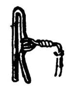
EXPERIMENT 101. To study the effect of the electric
current upon the magnetic needle.
Apparatus. A compass (No. 18); a dry cell, D C (No.
51); wires with spring connectors attached (§ 226) for
making connections. Fig. 66 shows a plan or top view
of the arrangement. Any other form of cell will do in
place of D C.
226. Electrical Connections. One must constantly join
wires, connect wires with apparatus, or connect one piece of apparatus
to another, to make the proper electrical connections. A very
simple method of connections has been used in all the apparatus
described in these experiments.
A little arrangement which we shall call a spring
connector, S C, (Fig. 61), gives us a means of quickly
making connections; that is, it does away with expensive
binding-posts. It is made of brass, nickel plated,
and may be used anywhere without affecting the magnetic
needle.
Six or eight wires, about No. 24 gauge, each about 1½ ft.
long, should be prepared with a connector at each end. You may
use wire furnished (No. 53). Scrape the insulation from the ends
of the wires for about 1½ inches, then twist the bare ends around[90]
the connectors as shown in Fig. 61. The wire should pass around
tightly at least 4 or 5 times and then be twisted a little, as shown,
to help tighten it. Do not put it on so poorly or in such quantity
that the part, B, will spread.
227. Fig. 62 shows how the connector should be slipped upon
a thin piece of metal, M, like that on the galvanoscope, for example.
The wire, W, from the apparatus itself is permanently
fastened under the head of the screw, S, while the wire from any
other apparatus is one of those kept on hand as above mentioned
and connected with S C.
228. Fig. 63 shows how several wires may be quickly joined,
electrically, by slipping the connectors at their ends upon a thin
metal plate, M P, which may be a piece of tin, zinc, copper, etc.
M P should not be too thick. In case the connectors become too
much spread to pinch the plate, squeeze the part, A, a little more
together.
229. Fig. 64 shows the method of connecting with the special
form of binding-post used, for example, upon the resistance coil,
R C. The end, C, of S C, is pressed down into the tube, T, until
you feel, by moving it, that it springs firmly against the sides of
the tube. In case you wish S C to fit very tightly in T, one of the
legs may be slightly bent outwards.
230. The connector may be used in still another
way; that is, by pushing the part, A, into the hole of an
ordinary binding-post, (Fig. 65), and using it just the
same as a thick wire.
231. Directions. (A) Stand the compass and D C
near each other (Fig. 66). Attach one end of an insulated
copper wire, C W, to the binding-post, C, which
is on the carbon plate of the cell. Do not join the other
end to the other binding-post, Zn, of the zinc plate.
[91]
(B) With the left hand hold C W above and near the compass-needle,
and in the N and S line, so that it will extend over the
entire length of the needle.
(C) Take the free end of C W in the right hand and touch
binding-post, Zn, for an instant only, watching the needle.
Repeat.
232. Current Detectors. We know that a magnet
can act, by induction, through the air upon a piece
of iron or upon another magnet. The deflection of the
needle in this experiment shows that there must be a
magnetic field around a wire carrying a current. This
fact is of the greatest possible importance. The simple
magnetic needle, when used as above, becomes a detector
of electricity.
EXPERIMENT 102. To study the construction and use
of a simple "key."
Apparatus. A key, K (No. 55) (§ 233); a dry cell, D C,
(No. 51); a compass, O C (No. 18). Arrange as shown in
Fig. 67, which is a top view or plan. Connect the pieces
of apparatus with wires and spring connectors (§ 226).
Binding-post, C, is joined to I (in) of the key; O (out) of
key is joined to binding-post, Zn, the wire, C W, passing
directly over and near O C, which is to be used as a
detector. The current cannot pass until the lever, L, is
pressed. A metal plate, M P, is used to connect two
short wires (§ 228) in case C W is not long enough.
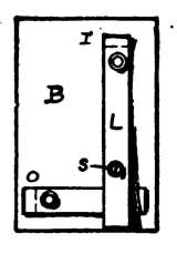
233. A key is merely a piece of apparatus by which the
circuit can be conveniently and rapidly opened and closed at the
will of the operator; that is, by it the electricity can be quickly
turned on or off. Fig. 68 shows a simple form of key. To the
base, B, are fastened two metal pieces or straps, the upper one,
L, being the lever or key proper. The front end of L is raised[92]
above O, so that the two do not touch each other unless L is
firmly pressed down. A screw, S, keeps L from springing too
far above O. For convenience we shall suppose that the wire
leading to the key joins it at I (in); the wire from
the key is joined to O (out), by means of connectors
(§ 226).
The key may be put into any circuit by first cutting
a wire and then joining the ends to I and O.
Spring connectors make the best connections with
this form of key. (For Home-Made Keys see
Apparatus Book.)
234. Directions. (A) The magnetic needle
being directly under the wire, press L down for
an instant only and note the action of the needle.
(B) Press L again, hold it down for 3 seconds, not over that,
and watch the needle.
Discussion. The key allows us to easily regulate
the length of time during which the current passes. This
experiment shows, also, that the magnetic field about the
wire disappears as soon as the current ceases to pass.
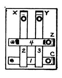
EXPERIMENT 103. To study the construction and use of
a simple "current reverser."
Apparatus. A dry cell, D C (No. 51); a compass, O C
(No. 18); a current reverser, C R (No. 57) (See § 235); an
insulated copper wire, C W, 2 or 3 feet long, with spring
connectors joined to its ends (§ 226).
Arrange as in Fig. 70. The wire, C W, leading from X
should be held by the left hand so that it will be just
above (or below) and parallel to the magnetic needle.
The current cannot pass through C W until one of the
straps or levers on C R is pressed. (See
Apparatus Book for Home-Made Reversers.)
235. The Current Reverser. (No. 57.) To
the wooden base (Fig. 69) are fastened four
metal straps, each turned up at the end so
that spring connectors (§ 227) can be slipped
on to make electric connections with other
pieces of apparatus.
Suppose that at C and Z connections are
made with the carbon and zinc of the cell, by[93]
means of wires and spring connectors (§ 226). The current
comes from the cell to C. As the two straps, 2 and 3, press firmly
up against strap 4, and do not touch 1, it is evident that no
current can pass from 1 to 2 or to 3 until they are pressed down
upon 1. Two wires are joined by spring connectors to 2 and 3
at their turned up ends, X and Y, and these wires lead to any
desired instrument.
236. Directions. (A) Press down lever 2 (Fig. 70), for an
instant only, at the same time
noting carefully in which
direction the N pole of the
needle is deflected.
(B) After allowing lever 2
to spring up again, and after
the needle comes to rest, press
down lever 3 for an instant, watching the needle. Is the N pole
of the needle deflected in the same direction as it was in (A)?
237. Discussion. The reverser gives us a quick
and easy means of reversing the current which is to pass
through any desired instrument, first in one direction and
then in the opposite direction. Suppose (Fig. 69) that
the current enters C R at C, as it does when C is joined
to the carbon of the cell; the current can go no farther
until one lever is lowered. If lever 2 (Fig. 69) be now
pressed down, as in part (A), the current will pass along
2, which does not now touch 4, out through X to a coil of
wire or any instrument, and back to the reverser by the
wire joined to Y. It will then pass from 3 onto 4, to Z,
and back to the Cell; that is, the current enters C W at
X. When lever 3 is pressed, the current still entering C R
at C, the electricity will pass onto 3 and out at Y, and
back through X, 4 and Z to the cell. The current, then,
can be made to pass out of X or Y at will by pressing the
proper lever. This experiment also teaches something
about currents, but these will be discussed later.
[94]
EXPERIMENT 104. To study the simple current detector.
Apparatus. The compass (No. 18); dry cell, D C (No.
51); current reverser, C R (No. 57); copper wire, C W,
a few feet long, with spring connectors on its ends.
(See Apparatus Book, Chapter XIII, for Home-Made
Detectors.)
238. Directions. (A) Join the ends of the wire to X and Y of
the reverser, C R, as in the last experiment. Coil up C W so
that you can hold the coil with your left hand, as
shown in Fig. 71, the magnetic needle being inside
of it and parallel to it.
(B) Press lever 2 of the reverser for an instant
only. Is the needle deflected more or less than it
was when the wire simply passed over or under it once?
(C) Reverse the current through C W by pressing lever 3, and
note the result.
(D) Get clearly in mind which way the N pole of the needle is
deflected when the current enters C W at X, also when it enters
at Y.
239. Discussion. The current passed over the
needle in one direction, and under it in the opposite
direction; that is, the part of the wire above helps that
below. Each turn of the wire increases the strength of
the magnetic field about the coil, and helps to deflect the
needle. In this way, by increasing the number of turns,
detectors may be made that will show the presence of
very weak currents. The magnetic fields about wires
and coils will be studied in a later chapter.
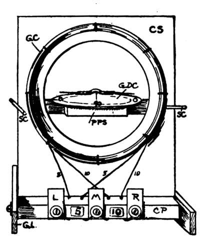
EXPERIMENT 105. To study the construction and use of
the simple galvanoscope.
Apparatus. The galvanoscope, G V, complete (No. 58),
described in § 240–246; dry cell, D C (No. 51); current
reverser, C R (No. 57) (§ 235); wires, with spring connectors,
to join the different pieces of apparatus (§226).
(See Apparatus Book, Chapter XIII, for Home-Made
Galvanoscopes.)
240. The Galvanoscope (Fig. 72) is more than a mere detector
of electricity. With it we shall be able to study, more fully, cells,
currents, etc., etc. We must first understand its construction.
[95]
241. The Coil-support,
C S, is fastened to the
cross-piece, C P, on which
are the 3 binding-posts or
coil-ends, L, M and R (left,
middle, right). The legs,
G L, are screwed to C P in
such a way that C P is held
a little above the table: this
allows C S to be tipped to
the front or rear to adjust
it vertically. On account
of the peculiar arrangement
of the legs, the galvanoscope
can be made to
stand firmly, even upon
uneven surfaces. The
screws holding G L should
not be put in far enough
to tear the threads in the wood, C P.
242. The Galvanoscope Coils, G C, are two in number, both
being fastened to the coil-support, C S. The first coil has five
turns of wire, its ends being fastened to L and M; the other coil
has ten turns, with ends at M and R. The current can, at will,
be made to pass through 5, 10 or 15 turns of wire by making the
proper connections.
Suppose that we have two wires direct from a cell, or from the
current reverser, with spring connectors on them so that we can
slip them onto L, M or R, which stand for left, middle or right.
When the wires are joined to L and M the current can pass
through but 5 turns; when joined to M and R it will go through
10 turns; and when to L and R it will pass through the entire 15
turns. When the current enters the galvanoscope at L and
passes out at M or R, it will pass through the turns of wire from
left to right, at the top; that is, it will pass in a "clockwise"
direction.
243. The Compass-needle, furnished with O C (No. 18), will
do also for this galvanoscope. It should be placed upon the pin-point
after fixing on the pointers (§ 246). The length of the
needle should be parallel to the plane of the coil when no current[96]
passes; that is, the coil and coil-support should be in the N and
S line.
The needle can be centered in regard to right and left, and in
regard to up and down, by properly adjusting the position of the
pin-point support, P P S; this is held firmly to C S by two spring-connectors.
By removing S C, the support, P P S, may be raised
or lowered.
244. To place the coil in the N and S line, simply swing the
galvanoscope bodily around, at the same time looking down upon
the needle, until the length of the needle becomes parallel to the
coil-support. When once carefully adjusted N and S, a line may
be drawn upon the table as a guide for its position in future
experiments. The coil should stand in a vertical plane, and this
straight up and down position can be easily adjusted.
To place the coil in the E and W line, turn it until the pointers
are at the 90° (90 degree) marks,—the 0° (zero degree) marks
remaining, of course, as described above.
245. The Degree-Card, G D C (Fig. 72) has a dot at its center,
to show where to make a pin-hole for the pin that supports the
compass-needle. With this you can tell how many degrees the
needle is deflected when the current passes. This card, G D C,
should be pressed down over the pin-point. The zero points of
G D C should be N and S, also, when the coil is in that position;
that is, they should be in the plane of the coil. The pointers on
the needle (§ 246) will then be at O, when the needle is at rest,
no current passing through the coils. (See Apparatus Book
§ 272 for Home-Made Degree-Card.) G D C may be held permanently
in position after it is adjusted, by sticking a short pin
through it into P P S. Do not let this pin interfere, however,
with the swinging of the needle.
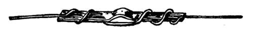
246. Pointers (Fig. 73) should be fastened to the needle, in
order to make the readings of degrees accurate. Fasten to the
compass-needle a piece of No. 30 insulated copper wire, as shown.
It may be cut to the proper length after it is wound around the
needle. See that the wire does not touch the pin when needle is[97]
in place; balance needle by cutting a little from the heavier end
of wire with shears; bend the ends of wire so that they are at
opposite sides of the degree-card, both pointing at O, for example.
The needle must swing freely, be nicely balanced, and the wire
must not touch pin or degree-card.
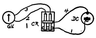
247. Directions. (A) Arrange as in Fig. 74, the coil being N
and S (§ 244). Join the ends of the wires, 2 and 3, with the 5-turn
coil of G V as shown. Wire, 2, is connected to L (Fig. 72). Press
lever 2 of C R (Fig. 69) for an instant, watching the compass-needle
and noting how many degrees it swings the first time. Get
thoroughly in mind the direction in which the N pole of the needle
is deflected when the current passes around G C in a "clockwise"
direction. There must be no magnets, iron, or pieces of steel
within 3 feet of A G.
(B) Press lever, 3, for an instant, watching the needle. The
current will now pass in an "anti-clockwise" direction. Is the
needle deflected about the same number of degrees as in (A)?
(C) Change the ends of the wires, 2 and 3, to the 10-turn coil
(§ 242) and repeat (A) and (B).
(D) Change 2 and 3 to L and R (Fig. 72), thus allowing the current
to pass around 15 turns; then repeat (A) and (B).
248. Discussion; True Readings. Is not possible
to get the magnetic needle, M, exactly in the center
of G C; the pointers will not exactly be in the axis of
M; the coils will not be exactly N and S: hence, if you
pass a certain current through the coil and the pointer
reads 20 degrees, you will find, if you reverse the current,
that the pointer may read 24 degrees on the other side of
the zero mark. To get the true reading, average the two,
in this case the average being 22 degrees.
[98]
The galvanoscope gives us an instrument with which
we can study, more fully, cells, currents, etc.
249. Note of Caution. It has already been stated that the
compass-needle should be in the center of the coil (§ 243), and
that the coil should be in the N and S line (§ 244). In addition to
the above, see that there are no magnets near G V, when using it;
tap G V occasionally to be sure that the needle swings freely,
hold the eye directly over the pointers when reading degrees;
the pointers should be at zero when no current
passes through G V; be sure that the
electrical connections are good.
There are several sources of error in
taking readings, and in all the quantitative
experiments given. The author takes it for
granted that such errors will be looked out
for by the teacher.
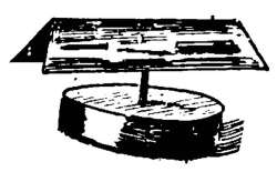
EXPERIMENT 106. To study the construction and use of
a simple astatic needle.
Apparatus. Two unmagnetized sewing-needles (No. 1);
horseshoe magnet, H M (No. 16); piece of stiff paper
doubled and cut as in Fig. 75; a pin-point on which to
support the paper. The pin may be stuck through a
cork, or that of O C (No. 18) may be used.
250. Directions. (A) Draw each needle across the N pole of
H M five times from point to head (Exp. 9). This should make
them of nearly equal strength, both points being N poles.
(B) Stick the needles through the paper as shown, the N poles
being at the same end of the paper. Balance the paper upon the
pin-point. Has this combination a strong or weak pointing-power?
(C) Turn one of the needles end for end. Again test the pointing-power.
251. Discussion; Astatic Needles. By arranging
the needles so that their poles oppose each other, the
pointing-power becomes almost nothing. This sort of a
needle is needed in some experiments in electricity. Their
magnetic fields are still retained. The combination is
called an astatic needle; it is used to detect very feeble[99]
currents. The more nearly equal the magnets are in
strength, the better. They are usually arranged with one
above the other (Fig. 76).
EXPERIMENT 107. To study the construction and use of
a simple astatic galvanoscope.
Apparatus. An astatic galvanoscope, A G (No. 59)
(§ 252–254); dry cell, D C (No. 51); current reverser,
C R (No. 57) (§ 235); wires for connections (§ 226).
Arrange as shown in Fig. 80, which is a top view. The
wires from C R are connected to the binding-posts of
A G at the back, the spring connectors being slipped
into them (§ 229).
252. Construction of the Astatic Galvanoscope. When not
to be used for a long time, or for shipping, the legs, A (Fig. 77)
may be removed, and the whole packed inside of the box, B.
The Coil, C, has a resistance of about 5 ohms, and is fastened
to the coil-support, C S. The ends of the coil are permanently
fastened to the binding-posts, L and R (left and right). The ends
are so arranged that when the current enters at L it will pass
around the coil in a clockwise direction.
253. The Astatic Needle (Exp. 106) is supported by a small
thread, T, which is tied to the thread-wire, T W. This T W
springs into an eyelet, E, which, in turn, rests in a hole made in
the end of B. E should turn easily in the hole, but it should not
wabble.
[100]
Fig. 78 shows a sectional view of the coil and needle. The
wire, W, should be bent, as shown, so that the magnets can be as
near the center-line of C as possible. Fig. 79 shows a front view
of the needle. As a matter of convenience it will be best to
arrange the poles of the needles, as shown, to agree with the
descriptions of the experiments.
To keep the needle from being affected by air currents, the
glass plate (No. 38) may be placed in front of the box, B. Stand
it upon the legs, A, and tie a string around it, and B, to hold it in
place.
254. Adjusting the Needle. As T is tied to T W, the needle
may be swung completely around by turning T W. This should
be done until the length of the needle is parallel to the turns of
C. The up and down position of the needle should be fixed as
nearly as possible when fastening T to T W, the exact place
being finally fixed by raising or lowering T W through E. The
spring in T W should hold it firmly in E after adjustment. The
wire, W, joining the needle-magnets should not touch the coil.
It may be made to just swing free from C by tilting the box forward
or backward a little. The construction of the legs, etc.,
makes it possible to tilt the box, and to make it stand firmly upon
an irregular surface.
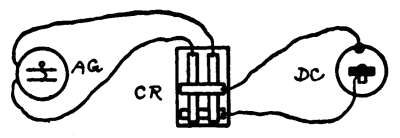
255. Directions. (A) See that there are no magnets within 3
feet of A G. Test the astatic needle, after you have it properly
suspended, to convince yourself that it does not try to swing
around in a N and S line. In case the needle-magnets have been
in contact with other magnets, or are not equally magnetized,
remagnetize them as directed in Exp. 106. They must remain in
any position given them by turning T W. Finally, bring them
parallel to the turns of the coil. (See § 254.) Arrange as in
Fig. 80.
[101]
(B) Press lever 2 of C R (§ 235) for an instant only. This allows
the current to enter A G at L. Repeat several times until you
thoroughly fix in your mind the direction in which the right-hand
end of the needle is deflected. Does the needle jump suddenly
when the current passes?
(C) Press lever 3 for an instant only. Study the result.
256. Astatic Galvanoscopes. It is evident that
in the ordinary current detector (Exp. 104), the pointing
power of the needle has to be overcome by the magnetic
field about the coil, before the needle can be forced from
its N and S line. Very weak currents will not visibly
move the needle in ordinary detectors. To make a sensitive
instrument we must have strong fields about both the
needle and coil, and we must, at the same time, decrease
the pointing power of the needle. Both of these things
are accomplished by using an astatic needle in connection
with a coil containing considerable wire. The uses of the
astatic galvanoscope will be studied more fully in later
experiments.
[102]
CHAPTER XV.
GALVANIC CELLS AND BATTERIES.
EXPERIMENT 108. To study the effect of dilute sulphuric
acid upon carbon and various metals.
Apparatus. A piece each of copper and iron wire 4 in.,
(10 cm.) long; two narrow strips of sheet zinc (No. 60),
one being amalgamated (§ 257); a carbon rod (No. 64); a
tumbler (No. 65), partly filled with dilute sulphuric acid,
(§ 258); mercury (No. 52).
257. To amalgamate one of the above zinc strips is to coat it
with mercury. Remove all jewelry from the hands before proceeding.
Wash the zinc with water, and with a cloth remove all
dirt from its surface. Amalgamated zinc is very brittle, so lay it
flat upon a piece of board or upon a plate, after dipping it for an
instant in the dilute acid. Place a small drop or two of mercury
upon the strip, and rub the mercury about upon both sides of the
zinc with a cloth made wet with the dilute acid.
Mercury clings strongly to zinc or tin, so you may use a narrow
piece of either as a spoon to carry a small drop from the supply
to the zinc. Tap it upon the zinc to dislodge the drops. Do not
get on too much mercury, just enough to coat it, or, at least, that
part of it that will be under the acid. Be careful not to break the
thin zinc when amalgamating it, as it gets very brittle. It should
look bright. (See Apparatus Book § 32, 33.)
Note. Should any mercury get upon copper plates it may be
removed by heating them in a flame.
258. Dilute sulphuric acid, for these experiments, should be
made by mixing 1 part, by volume, of concentrated acid, with 20
parts of water. Do not let the acid get upon clothes or carpets.
Do not add water to acid. Mix by slowly adding the acid to the
water in a glass or earthen dish, stirring at the same time. Mix
over a sink or out of doors. (For fuller details see App. Book;
§ 21, 22, 23, 24, 25.) To save time, make at least a quart of the
mixture, bottle, and label it for use.
259. Directions. (A) Bend over one end of each of the wires
and metal strips, and hang them upon the edge of the tumbler[103]
(Fig. 81), so that their lower ends shall be in the acid. Do not let
them touch each other. Stand the carbon rod in the acid.
If there is no visible action upon any of the above substances,
add a few drops of concentrated acid to the tumbler.
Note carefully what takes place in the tumbler, and state which
of the substances are dissolved, which simply made brighter, and
which not acted upon at all.
260. Discussion. The bubbles of gas that arise
from the zinc when it dissolves are hydrogen, and they
indicate that a vigorous chemical action is going on in the
tumbler, and that the zinc is being eaten away.
EXPERIMENT 109. To study the effect of dilute sulphuric
acid upon various combinations of metals.
Apparatus. The same as in the last experiment. A
small piece of amalgamated zinc, however, will be better
than the whole strip.
261. Directions. (A) Twist one end of the clean copper wire
around the small piece of amalgamated zinc (Fig. 82). Hold one
end of the wire in the hand and dip the combination into the acid.
What takes place? Watch the surface of the copper, remembering
that each, alone, was not acted upon by the acid (Exp. 108).
(B) Use the clean iron wire in place of the copper wire, and
repeat (A). Watch the surface of the iron.
(C) With a string or thread tie a small piece of well amalgamated
zinc to the carbon rod (Fig. 82), then dip the combination into the
acid. Watch the surface of the carbon.
262. Discussion. While amalgamated zinc is not
rapidly dissolved by dilute sulphuric acid, a vigorous[104]
action of some kind takes place when it is in contact with
another metal or with carbon in the acid. The bubbles
of hydrogen that are liberated do not seem to come from
the zinc; they appear to grow, in the fluid, directly at
the surface of the copper, iron, or other metal used with
the zinc. This shows that something besides the mere
dissolving of a metal takes place.
Can we arrange our apparatus so that we can get some
useful results from this action?
EXPERIMENT 110. To study the construction of a simple
Voltaic or Galvanic cell.
Apparatus. A narrow strip of zinc (No. 60), amalgamated
as directed in § 257. (An amalgamated zinc rod (No. 74)
may be used in place of the strip); a narrow strip of
sheet copper (No. 67); the tumbler of dilute acid of Exp.
108; a flexible copper wire about 2 feet long, with spring
connectors (No. 54) attached to its ends. (See Electrical
Connections, § 226.)
263. Directions. (A) Holding the amalgamated zinc strip in
one hand and the copper strip in the other (Fig. 83), dip them into
the acid, but do not let them touch each other.
Note any chemical action.
(B) Touch the copper and zinc together,
below the surface of the acid. Watch the
copper.
(C) Separate the lower ends of the strips,
then touch them together above the acid.
Anything still happen to the copper?
(D) Slip one spring connector with the attached
wire upon the zinc strip, then stand the
strips in the tumbler, so that they can not touch each other. Now
touch the copper strip with the free end of the wire, at the same
time watching the copper.
(E) Raise the wire from Cu, touch it to Cu again, and repeat
several times until you are sure that something takes place every
time the wire touches Cu.
264. The Electric Current. Something must
happen in or through the wire, and it can only happen[105]
when the two metals are joined in some way. This
peculiar, invisible action in the wire is called the electric
current, and such an arrangement is called a Galvanic cell.
265. Source of the Electrification. When
two different metals are placed in acid they are electrified
unequally by chemical action. Each has a higher potential
than the acid, but their potentials are not the same.
This electrification tends to pass from the place of higher
to the place of lower potential, and the conducting wire
allows this transfer to take place. As the difference of
potential is kept up by the continued chemical action, the
current is continuous, and not simply instantaneous, as
in discharges of frictional electricity. As heat is produced
by the burning of coal, so electrification is produced
by the chemical burning of zinc. Chemical energy is
the source of electrification in the Galvanic cell, just as
muscular energy was the source of the electrification in
the experiments with frictional electricity.
266. The Electric Circuit; Open and Closed
Circuits. The simple Galvanic cell just used, together
with the wire which joined the metal strips, is called an
electric circuit. If the current should pass through a telegraph
instrument, for example, on its way from one strip
to the other, the telegraph instrument would also be in the
circuit. When the wire is cut or removed from one metal
strip, the circuit is said to be open—that is, we have an
open circuit. When the current passes, the circuit is
closed. We also say make and break the circuit, and that
the circuit has been broken.
267. Plates or Elements. The copper and zinc
strips are called the plates or elements of the cell. The
zinc, Zn, Fig. 84, is dissolved by the acid, and is called
the positive plate (+ plate). The copper, Cu, is the neg[106]ative
plate (- plate). The copper is also called the
cathode, and the zinc the anode.
268. Direction of Current. It has been agreed,
for convenience, that in the cell the current passes from
the zinc through the liquid to the copper,
where the hydrogen bubbles are deposited.
It then passes through the wire, or other
conductor furnished, back to the zinc,
through the liquid to Cu again, and so on
around and around thousands of times per
second. The current really starts at the
surface of the zinc, where the chemical action is.
When carbon and zinc are used, the action and direction
of the current are the same, carbon being the - plate.
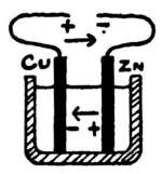
269. Poles or Electrodes. If the wire were cut,
the electricity coming from the + plate would be stopped
at the end of the wire marked +, Fig. 84, after passing
through the acid and up Cu. This end of the wire is
called the + pole or electrode (positive). The end of the
wire joined to Zn is called the - pole or electrode; that
is, the + electrode is the end of the wire attached to
the - plate. The tops of Cu and Zn may be considered electrodes.
The top of Cu is the + pole of the cell, while Cu
is the - plate.
270. Chemical Action in the Simple Galvanic Cell. The
chemical formula of sulphuric acid is H2SO4 (read H, 2, S, O, 4).
This means that it is a compound of hydrogen (H), sulphur (S),
and oxygen (O). The H2SO4 stands for molecule of acid, and the
small figures show that the molecule is made up of 2 atoms of
hydrogen (H2), one of sulphur (S), and 4 of oxygen (O4). The
atoms are held together by chemical attraction or affinity.
There is a stronger chemical affinity between zinc (Zn) and
SO4 than between H2 and SO4; so, as soon as the Zn gets a
[107]chance, as it does in the cell, it drives out the H2, and it takes its
place in the molecule. This chemical reaction may be shown by
the following chemical equation:
Zn + H2SO4 = ZnSO4 + H2.
Zinc and sulphuric acid produce zinc sulphate and hydrogen.
The zinc sulphate produced weakens the effect of the acid; in
fact, the acid has to be renewed occasionally, as it is changed to
the sulphate which remains in solution.
271. Action in Cell Using Impure Zinc. The above action
takes place in the cell when impure zinc is used, even when no
current passes, heat being produced by the reaction instead of
useful electricity. (See Local Currents.)
Action in Cell Using Pure Zinc. When pure zinc (or impure
zinc that has been properly amalgamated) is used in the cell, it
dissolves, or is eaten away, only when the current passes. It
should be noted that the bubbles of hydrogen do not even then
appear at the zinc; they are not seen throughout the body of the
liquid. There seems to be an unseen transfer of hydrogen from
the zinc, through the liquid, to the copper (or other - plate used),
and it appears there in the shape of bubbles. The larger the
quantity of pure zinc dissolved, the stronger the current, and the
larger the amount of hydrogen produced.
As the zinc dissolves it parts with its latent energy, and this
energy forces the electric current through the circuit. While the
hydrogen of the decomposed acid makes its way towards the
- plate, the SO4 part of it travels towards the Zn plate, where
the ZnSO4 is formed. (See § 270.)
EXPERIMENT 111. To see what is meant by "local currents"
in the cell.
Apparatus. Tumbler of dilute sulphuric acid. (§ 258);
strip of unamalgamated zinc; crystal of copper sulphate
(blue vitriol) (No. 86); a galvanized iron nail (No. 69),
this being iron covered with zinc.
272. Directions. (A) Hold the nail in the acid for a few
seconds, and note result.
(B) Rub the copper sulphate upon the zinc simply in one spot,
then place the zinc in the acid, noting the result at the spot.
273. Local action; Local Currents. Ordinary
commercial zinc contains such impurities as carbon, iron,
lead, etc., in small quantities. It was seen, Exp. 109,[108]
that when different metals were in contact with the
zinc, the zinc was rapidly dissolved by the acid. The
impurities in the zinc act like the copper plate in the
simple cell, thus producing local currents in the zinc,
which rapidly destroy it without doing any good. These
currents pass from zinc to impurities, and back to the
zinc, without going out into the main wire. This local
action takes place even when the main circuit is open.
274. Reasons for Amalgamating Zinc Plates.
Pure zinc is not affected by dilute sulphuric acid, but it
is too expensive to use in cells; so amalgamated zinc is
used instead, because it is cheaper, and acts the same as
pure zinc. The impurities are removed from the surface
of the zinc, as the zinc alone is dissolved by the mercury.
There is, then, a liquid layer of pure zinc with mercury
upon the surface of the amalgamated plate. This is not
acted upon by the acid when the circuit is open. A
stronger and more regular current is produced with amalgamated
zinc than with the impure unamalgamated zinc.
EXPERIMENT 112. To study the "single-fluid" Galvanic
cell.
Apparatus. The galvanoscope G V (No. 58), (See § 240,
etc.); the simple cell arranged as described in § 275, the
zinc being amalgamated.
275. The Simple Cell should be arranged so that the plates
will be held firmly in position. The zinc, Zn (No. 60), and copper,
Cu (No. 67), should be fastened to the wooden cross-piece, W C P
(No. 70), as shown in Fig. 85. Care should be taken not to use
longer screws than those provided for (No. 72). If the screws
touch each other they will short circuit the cell. Partly fill the
tumbler (No. 65) with dilute sulphuric acid (§ 258), join wires with
connectors to the plates. The free ends of the wires are then
ready to join to apparatus. The ends of wires may be fastened
under the screw-heads instead of using connectors on the plates.
Do not put the plates into the acid until you read the "directions."
[109]
276. Directions. (A) Arrange as in Fig. 86. Place the coil of
G V, N and S (§ 244). Before putting the plates in the acid join
them to the 15-turn coil of G V (§ 242). The compass-needle should
point to zero. See that the needle swings freely.
(B) Place the plates in the acid, and quickly bring the needle to
rest with the aid of the hand, so that you can take the reading at
once before the hydrogen bubbles entirely cover the copper plate.
Watch the action of the needle for a few minutes. Make a note
of the reading, in degrees, at the beginning of the experiment
and at the end of five minutes. (See Note.)
Note. If no change takes place in the position of the needle,
the change beginning inside of 10 seconds after the plates are
let down into the acid, withdraw the plates, then clean and
thoroughly dry the copper to remove all traces of hydrogen.
This may be done by heating the copper over a gas flame. Let
the copper remain in the air 15 minutes, then try again. In taking
the first reading you must work quickly. Catch the needle
during its first swing. If you allow it to swing back and forth
until it comes to rest, your first reading will not be what it
should be.
(C) After the needle has remained in one position, without
change, for 2 or 3 minutes, take hold of the wooden cross-piece,
move the plates back and forth in the acid to dislodge the
hydrogen bubbles, and note carefully the action of the needle.
Does the current seem stronger when the plates are moved? Can
you get the needle back to the first reading?
(D) Remove the plates from the acid, dry and clean the copper,
let them stand in the air for 15 minutes, then take another quick
reading and compare it with the first.
[110]
278. Polarization of Cells. The acid gets a
little weaker, of course, as it is decomposed by the zinc
(§ 270), but the chief cause of the weakening of the current
is hydrogen, which forms a filmy coating upon the
copper plate. This coating even seems to soak into the
copper, and it takes some time for it to be thoroughly
removed. The zinc plate is kept comparatively free from
hydrogen by amalgamation.
279. Effects of Polarization. The hydrogen
bubbles weaken the current in at least two ways. In the
first place, hydrogen is not a conductor of electricity; so
it holds the current back, as any other resistance would.
Secondly, acid acts upon hydrogen as it would upon
another metal. When the copper plate becomes well
covered with hydrogen, the acid cannot touch it; so we
really have a hydrogen plate in the cell. Hydrogen acts
very much like zinc in the acid; we say that it is more
electro-positive than copper. The result is, then, that a
new current starts up, and as this is towards the zinc, in
the acid, it partially destroys or neutralizes the main zinc-to-copper
current. Practical use is made of the principles
of polarization (see Secondary Batteries).
280. Remedies for Polarization; Depolarizers.
Any scheme by which the hydrogen may be destroyed
and kept from the inactive, or negative plate, will
prevent polarization. Mechanical means have been employed
to brush away the hydrogen by keeping up a constant
circulation of the liquid. Chemical action is another
means by which the hydrogen may be side-tracked before
it gets to the - plate in single-fluid cells. Substances like
nitric acid and bichromate of potash, called depolarizers,
contain large quantities of oxygen, and, during the chemical
changes that take place, this oxygen unites with the[111]
hydrogen. These substances are used in zinc-carbon cells.
(See § 286, etc. for various forms of cells.)
There is another form of cell, the two-fluid type, in
which electro-chemical means are employed, and in which
a metal is deposited upon the - plate instead of hydrogen.
The - plate is usually copper, copper being deposited upon
it.
EXPERIMENT 113. To study the "two-fluid" Galvanic
cell.
Apparatus. The glass tumbler, G T, (No. 65); porous
cup, P C, (No. 73); the strip of zinc (No. 60), well amalgamated
(§ 257), or the amalgamated zinc rod (No. 74);
piece of sheet copper (No. 75), bent so that it will surround
P C; copper wires, C W, with connectors; a saturated
solution of copper sulphate, commonly called blue vitriol
or blue stone (See § 283); dilute sulphuric acid (See
§ 258). With the above, set up the two-fluid cell (See
§ 281). The galvanoscope, G V, complete, is also needed,
and if quantitative work is to be done, a pair of scales
weighing to 0.1 gram is necessary. (See App. Book,
Chapter I, for Home-Made Two-Fluid Cells.)
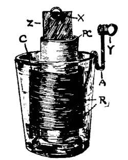
281. Setting Up the Two-Fluid Cell. Fig. 87. Stand the
amalgamated zinc rod, Zn, in P C, then place P C in the tumbler,
G T; put in the copper plate as shown. Pour diluted acid (§ 258)
into P C until it stands about 2½ in. deep; then at once pour the
copper solution (§ 283) into G T, on the outside of P C, until it
stands at the same height as the acid in P C. As soon as the[112]
liquids have soaked into P C the cell will be ready for use; but it
is better to connect it with the galvanoscope at once and note the
increase of current during the first few minutes while the liquids
soak through P C. A crystal of copper sulphate should be put
outside of P C to keep the solution full strength. This is a form
of the well-known Daniell cell. Fig. 87 shows a form of home-made
two-fluid cell as described in Apparatus Book. If you
have the one furnished, use the rod instead of sheet zinc, and
use connectors on the plates.
282. Care of Two-Fluid Cell. This experimental cell should
be taken apart when not in use. It should not be left in open
circuit, even for half an hour. Even after the plates are removed,
copper may be deposited upon P C in case there are any metallic
impurities on it. Remove the plates and P C, and thoroughly
wash them. The copper solution should be put into a bottle to
prevent evaporation; the dilute acid may be thrown away to be
replaced by fresh acid for the next experiment.
283. Copper Sulphate Solution is made by adding the blue
crystals to water until no more will dissolve—that is, the solution
should be "saturated," extra crystals always being left in the
stock bottle. An ounce of the crystals to half a tumbler of water
will be about right, but a pint or so should be made at a time and
be kept bottled to save time.
284. Directions. (A) In case you have access to a pair of
scales that weigh to within 0.1 gram, carefully weigh both copper
and zinc before proceeding. They should be washed and dried
with a cloth. See that there are no drops of mercury upon the
zinc that may fall off during the experiment.
(B) Replace the plates in the cell, and connect them with the
15-turn coil of G V, placed N and S. Allow the circuit to remain
closed for half an hour, and record the position of the needle
every 5 minutes.
(C) Again wash, dry with a cloth without rubbing, and weigh
both the zinc and copper. Compare the new weights with those
found in (A).
285. Chemical Action in the Two-Fluid Cell.
In this form of cell the hydrogen is not allowed to collect
upon the copper plate. The action inside of P C is like[113]
that explained in § 270, hydrogen being set free. As
soon as this hydrogen (H2) comes in contact with the
copper sulphate (CuSO4), and it begins to do this in
the walls of P C, a new chemical reaction takes place.
Hydrogen has a stronger attraction for SO4 than Cu has,
so it unites with the SO4, forming H2SO4 (sulphuric
acid), and this at the same time throws out the Cu bodily.
This Cu is then free, instead of hydrogen, to be deposited
upon the copper plate. The current is constant, as there
is no polarization.
286. Various Galvanic Cells; Open and
Closed Circuit Cells. There is no one form of cell
that is best for all kinds of work. If momentary currents
only are wanted, such as for bells, telephones, etc., in
which the cell has plenty of time to rest, open circuit cells
are used. These cells polarize, however, when the circuit
has to be closed for any length of time. This form of
cell is always ready for use, and may not need attention
for months at a time. The most common forms of the
open circuit cells are the Leclanché (§ 287) and dry cell
(§ 288). Open circuit cells polarize quickly, because the
depolarizer (§ 280) is slow in destroying the hydrogen.
When a strong current is needed for a considerable
time, such as for telegraph lines, motors, etc., a closed
circuit cell is necessary. The depolarization must be rapid
and constant. The bichromate (§ 289) and the Daniell
cell (§ 290) are very common forms of closed circuit cells.
(See, also, Storage Cells.)
287. The Leclanché Cell is an open circuit cell in which
carbon and zinc are the plates. The carbon is surrounded with
dioxide of manganese, a depolarizer; the two are either packed
together in a porous cup, or the latter is compressed into blocks,
which are fastened to the carbon. The porous cup stands in a
jar containing a solution of sal ammoniac (ammonium chloride),[114]
which acts as the exciting fluid, and in which stands a zinc rod.
The zinc is not acted upon when the circuit is open. The
hydrogen given off by the decomposition of the ammonium chloride
is destroyed by the oxygen contained in the manganese dioxide.
The E. M. F. is nearly 1.5 volts.
288. Dry Cells are for open circuit work. Sheet zinc forms
at the same time the active plate and the outside cylinder or case.
A carbon plate acts as the inactive or - plate. The exciting fluid
is kept from spilling by its being absorbed by one of the various
substances used for that purpose.
289. The Bichromate of Potash Cell is a very common one
for laboratory use. It gives a strong current, and although a
single fluid cell, it does not readily polarize. Zinc and carbon
plates are used. In the sulphuric acid, which is the exciting
fluid, is dissolved bichromate of potash. This cell is used for
running small motors, induction coils, etc. It has, with fresh
solutions, an E. M. F. of about 2 volts. (See Apparatus Book,
Chapter I., for Home-Made Batteries.)
290. The Daniell Cell, of which the two-fluid cell used in Exp.
112 is a form, is noted for its constant current. The E. M. F. is a
little over 1 volt, and it should be kept working through a resistance
when not in regular use; it should not be left in open circuit.
The porous cup keeps the two fluids from mixing, but it does not
stop the current.
291. The Gravity Cell is a form of the above. As one of the
fluids is heavier than the other, no porous cup is needed. Gravity,
together with the action of the current, tends to keep the fluids
separated. A copper plate is placed in the bottom of the jar, and
upon this is put the copper sulphate solution. The zinc plate is
supported by the top of the jar and rests in a solution of zinc
sulphate, which is lighter than the blue solution below. An
insulated wire extends from the copper through the liquids. This
cell is used for telegraph and similar work. (See Apparatus Book
for Home-Made Gravity Cell, its Regulation, etc.)
[115]
CHAPTER XVI.
THE ELECTRIC CIRCUIT.
EXPERIMENT 114. To see what is meant by "divided circuits"
or "shunts."
Apparatus. The galvanoscope, G V (No. 58); astatic
galvanoscope, A G (No. 59); two-fluid cell, 2-F C (see §
281); 6 wires with connectors; small thin pieces of tin or
other metal, M P, for rapidly making connections (§ 226).
Arrange as in Fig. 88. The wires, 1 and 4, from 2-F C,
lead to the metal plates M P-A and M P-B, for convenience.
The wires, 2 and 3, from G V, are also connected
with these plates. The wires, 5 and 6 (dotted lines),
lead from A G, to be used as directed in part (B) of the
experiment. See that G V is properly placed. See that
A G is adjusted.
292. Directions. (A) Without A G in place, take the reading
of G V. The current now
passes from Cu through 1, M
P-B, 2, G V, 3, M P-A, 4 to Zn.
(B) Connect wires 5 and 6 to
the plates, as shown by the
dotted lines. Again take reading
of G V, and compare it
with the first reading. Does some of the current pass through
A G?
293. Divided Circuits; Shunts. The current
divides at M P-B into two parts; one part may be called
a shunt of the other. The circuit is said to be divided;
it has two branches. If the two ends of a wire be
fastened to another as in Fig. 101, the circuit is also
divided. When two or more conductors lead side by
side from one point to another, they are called parallel
circuits; that is, the conductors are joined in parallel.
As strong currents would injure delicate galvanometers,[116]
a small part only of the current may be allowed to pass
through the galvanometer by using a shunt. Fig. 89
shows such an arrangement, in which most of the current
passes through the shunt, S. There are many practical
uses of shunts.
EXPERIMENT 115. To see what is meant by "short circuits."
Apparatus. About the same as in Exp. 114, Fig. 88.
The astatic galvanoscope is not needed; in place of it
provide a short piece of metal, such as a battery-plate, or
even a jack-knife. Arrange as in Fig. 88, but without
A G.
294. Directions. (A) With the current passing as described
in Exp. 114 (A), take the reading of G V.
(B) Lay the ends of the metal, or other thick conductor, upon
M P-A and M P-B. Compare the new reading of G V with that
in part (A).
(C) Remove the conductor used to short circuit G V, take the
reading in degrees, then touch M P-A to M P-B; watch G V.
295. Short Circuits are very apt to occur unless
care is taken. Do not allow uninsulated wires to touch
each other. As shown by the above experiment, practically
the whole of the current may be side-tracked by a
shunt of low resistance. A galvanic cell is short-circuited
by connecting the plates directly by a wire or other conductor.
[117]
CHAPTER XVII.
ELECTROMOTIVE FORCE.
296. Electromotive Force. It has been stated
that a galvanic cell has the power to charge one of its
plates positively and the other negatively; this power is
called electromotive force, and, for short, E. M. F. is
written. The E. M. F. of a cell depends upon the kinds
of plates used and their condition, the chemicals used in
the exciting fluids, etc. The greater the E. M. F. of a
cell the greater its power to force the current through
wires, etc. The E. M. F. of a cell does not depend upon
the size of its plates, as will be seen by later experiments.
297. Unit of E. M. F.; The Volt. A certain
amount of E. M. F. has been taken as the standard, and,
in honor of Volta, it has been called the volt. The E.
M. F. of the two-fluid cell used in Exp. 113 is not far
from 1 volt. If a certain cell has the power to keep up
twice the difference of potential between its terminals that
the Daniell cell has, we say that it has an E. M. F. of
about 2 volts.
Voltmeters are instruments to measure E. M. F.
EXPERIMENT 116. To see if the E. M. F. of a cell depends
upon the materials used in its construction.
Apparatus. Tumbler two-thirds full of dilute sulphuric
acid (258); strips of zinc, Zn (No. 60); copper strips, Cu
(No. 67); iron strip, I (No. 76); lead strip, L (No. 77);
carbon rod (No. 64); the galvanoscope, G V (No. 58); 2
wires with connectors (§ 226), so that the plates can be
changed quickly; the wooden cross-piece, W C P (No. 70).
Arrange as in Fig. 90. The metal strips are all of the
same size; they may be held with the hand firmly against
W C P, in order to have them the same distance apart in
each trial. They should be lowered to the bottom of the
tumbler in each case, in order to have them acted upon
by the same amount of acid. Place G V properly.
[118]
298. Directions. (A) With Zn and Cu connected to G V as
shown (Fig. 90), take the reading in
degrees, and note in which direction
(east or west) the N end of the needle is
deflected. Tabulate results, as shown
in Fig. 91, filling in each column of your
table made out on paper.
(B) In like manner try the following
combinations in the order given, in each
case connecting the first-mentioned plate with the left-hand
binding-post, L, of G V. For (B) use zinc-iron.
(C) Use zinc-lead; (D) iron-copper; (E) iron-lead; (F) lead-copper;
(G) copper-carbon.
| PART | PLATES. |
LIQUID. |
DEFLECTION. |
CURRENT IN
CELL FROM |
| (A) |
ZINC. |
COPPER. |
DIL. SULP. ACID. |
65° WEST. |
CU TO ZN |
| (B) |
|
|
|
|
|
| (C) |
|
|
|
|
|
Fig. 91.
299. Note. Some of the combinations produce but slight currents.
In case G V is not delicate enough to show clearly which
way the current passes, use the astatic galvanoscope in its place
for such combinations.
300. Discussion. Exp. 116 clearly showed that
different combinations of metals in the acid have different
powers of pushing electricity through the galvanoscope.
Although some of the pairs of metals furnished so weak
a current that it was necessary to use the astatic galvanoscope
to study the current, all produced some current,
and from the results can be formed an electromotive series
(§ 301). The strength of acid, condition of plates, etc.,
affect the E. M. F. of a cell.
301. Electromotive Series. All metals are not acted upon to
the same degree by dilute acid. From the results of Exp. 116 it
is seen, part (B), that iron is electronegative to zinc; that is, the[119]
current in the cell flows from zinc to iron. Part (D) showed that
iron is electropositive to copper, as the current flowed from iron
to copper in the cell. It is possible to arrange the metals in a
series, one below the other, in such a way that any one will be
electronegative to those above it and electropositive to those
below it; that is, the list should have the most electropositive
metal at the top, and the one least acted upon by the acid at the
bottom. Make such a list from your results. The farther the
metals used are apart in the list, the greater will be the E. M. F. of
the cell. Good carbon is acted upon the least of all, so zinc and
carbon are better than zinc and copper.
EXPERIMENT 117. To see whether the electromotive
force of a cell depends upon its size.
Apparatus. Galvanoscope; two glass tumblers; dilute
acid; two wooden cross-pieces; two copper and two zinc
strips, the same size as those used for Exp. 112. (See §
275). These materials will form two simple cells like
Fig. 85. Have about 3 in. of acid in one tumbler, and
but 1 in. in the other. The plates of one cell will then be
about 2½ in. in acid, and those of the other cell only
½ in. in acid. This gives us the same effect as a large
and a small cell.
302. Directions. (A) Join the large and small cells with G V
so that their currents will oppose each other. To do this, join
the two zinc plates by means of a wire and connectors. With
two other wires connect the two copper plates with the galvanoscope
binding-posts, and watch for any indication of current.
Does one cell oppose the other?
303. Discussion. The E. M. F. of a cell, then, does
not depend upon the size of its plates. The small piece
of zinc—that is, the one in but little acid—had the same
potential as the large piece; they must have had, as they
were joined. The large cell will give a stronger current,
under certain conditions, than the small one; but this
depends upon other things than E. M. F. (See experiments
under Current Strength.) A zinc-copper cell,
like the one just used (Exp. 117), has the same voltage as
one of the same kind would have, even though it were
made as large as a barrel.
[120]
CHAPTER XVIII.
ELECTRICAL RESISTANCE.
305. Resistance. It is harder for a horse to draw
a wagon through deep sand than over a smooth pavement.
We may say that the sand holds the horse back—that
is, it offers a resistance. The electric current does
not pass through all sorts of substances with the same
ease, and when it succeeds in pushing its way through a
circuit of considerable resistance, we cannot expect it to
arrive at the end of its journey without being weaker
than when it started. Do we expect this of a man or
horse? We shall soon see that there is a definite relation
between resistance and the strength of the current at the
end of its journey.
EXPERIMENT 118. To study the general effect of "resistance"
upon a current.
Apparatus. Galvanoscope, G V (No. 58); resistance
coil, R C (No. 79) (§ 310); two-fluid cell, 2-F C (§ 281); 4
wires with connectors (§ 226). Arrange as in Fig. 92.
The current passes as shown by the arrow, and the circuit
may be opened and closed at the metal plate, M P,
or by using a key in its place. Properly place G V.
306. Directions. (A) Take the reading of G V in degrees, the
current passing through the entire length of R C. (See § 310.)
(B) Change the end of wire 4 from binding-post R to M, on R
C, so that the current will pass through one-half only of R C.
Note the reading of G V.
(C) Remove R C entirely and connect wires 3 and 4 by means
of a metal plate. Compare the readings of (A), (B) and (C).
What do they show?
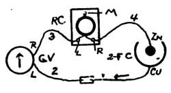
307. External Resistance; Internal Resistance.
When we consider a circuit like that shown in[121]
Fig. 92 we see that it is composed of two parts, and that
we have two kinds of resistances. The wires, instruments,
etc., make up what is called the external resistance
of the circuit; that is, the part that is external to the
cell. The liquids in the cell
offer a resistance to the current;
this is called internal resistance.
(See § 314.) The strength of the
current depends upon the relation
between these two resistances, as
will be seen by future experiments,
as well as upon the E. M. F. of the cell. As liquids
are not as good conductors as metals, the internal resistance
of cells may be quite high.
308. Unit of Resistance; The Ohm. Whenever
anything is to be measured, a standard, or unit, is
necessary. The unit of resistance is called the ohm, in
honor of Ohm, who made careful investigations upon this
subject. A column of mercury having a length of a little
over 3 feet has been taken as a unit. (The column
taken is 106.3 cm. with a weight of 14.4521 grams;
it has a cross-section of about 1 sq. mm., at a temperature
of 0°C.) Mercury is a liquid, and has no "grain"
to affect the resistance. For the use of students, 9 ft. 9
in. of No. 30 copper wire, or 39 ft. 1 in. of No. 24 copper
wire will make a fairly good ohm. We might, of
course, take any other length as our standard; the above,
however, will give results that are approximately correct.
(See wire tables at the end of this book.)
309. Resistance Coils; Resistance Boxes.
Coils of wire, having carefully-measured resistances, are
called resistance coils. The wire for any coil is doubled
at the center before it is wound into coils or upon spools[122]
(Fig. 93) to avoid the magnetic effect. The ends of the
coils are attached to binding-posts, or to brass blocks, in
regular instruments, so that one or more coils can be used
at a time; that is, so that they may be handled in a manner
similar to that in which the different coils on the
galvanoscope are used.
If we have 4 coils of 1, 2, 2, and 5 ohms resistance,
we shall be able to use any number of ohms from 1 to 10
by making the proper connections. (See Apparatus
Book, chapter XVII, for Home-made Resistance Coils.)
For protection and convenience, coils are usually placed
in a box, the whole being called a resistance box. The
ends of the coils are joined to brass blocks, placed near
each other on the top of the box, and between which
may be pressed plugs when it is desired to short circuit
the coils. By removing a plug, the coil, whose ends are
joined to the blocks touching it, is brought into the
circuit.
310. Simple Resistance Coil. Fig. 94 shows a simple form of
coil, R C (No. 79). The total resistance is 2 ohms, L (left) and R
(right) being binding-posts to which the ends of the coil, C, are
joined. M (middle) connects with the middle of the wire, at
which point the wire is doubled. The coil is fastened to a stiff
pasteboard base, B.
[123]
Connections. When 2 ohms resistance are wanted, let the current
enter at L and leave at R (or the reverse). When 1 ohm is
wanted, let the current leave or enter at M, the other wire being
joined to L or to R. Connections should be made with spring
connectors. See § 229.
EXPERIMENT 119. To test the power of various substances
to conduct galvanic electricity.
Apparatus. Galvanoscope, G V (No. 58); dry cell, D C,
or two-fluid cell, 2-F C; pieces of different metals; wood,
dry and damp; tumbler of pure water; rubber; ebonite;
silk; glass, etc., etc. Arrange as in Fig. 92, leaving out
R C, and instead of having M P between wires 1 and 2,
use their free ends to press firmly upon the ends of the
substance to be tested; that is, the body under test should
take the place of M P in the Fig. G V will show a deflection,
of course, when the particular thing under test is a
conductor.
311. Directions. (A) Make tests with the above substances,
and with any others at hand, and note which are conductors and
which are not.
312. Conductors and Nonconductors. It is
evident, from the experiments, that bodies which conduct
static electricity do not necessarily conduct galvanic electricity.
The greater the E. M. F. of a current, the greater
its power to overcome resistance. Some bodies, like dry
wood, that readily conduct the high potential static electricity,
make fairly good insulators for the low potential
galvanic currents. For convenience, substances may be
divided into good conductors, partial conductors, and insulators,
or nonconductors.
Good Conductors. Metals, charcoal, graphite,
acids, etc.
Partial Conductors. Dry wood, paper, cotton, etc.
Insulators. Oils, porcelain, silk, resin, shellac,
ebonite, paraffine, glass, dry air.
EXPERIMENT 120. To find the effect of sulphuric acid
upon the conductivity of water.
[124]
Apparatus. Galvanoscope, G V; cell; 2-F C; connecting
wires; saucer or tumbler, S; a little sulphuric acid.
Arrange as in Fig. 95.
313. Directions. (A) Put a little pure water in S, and see if
enough current can pass through it
to deflect the needle of G V. The
ends of the wires, 1 and 2, should
be gradually moved toward each
other, the needle being watched.
(B) Put 4 or 5 drops of concentrated
acid into the water; stir it, then repeat
the test. What effect has the acid?
314. Internal Resistance. As found in Exp. 120,
pure water is not a good conductor of galvanic electricity.
The acid in the simple cell, and in other single-fluid cells,
acts upon the zinc and at the same time makes it possible
for the current to pass, as it reduces the internal resistance.
As seen later, this resistance in cells is greatly diminished
by bringing the plates near each other, and by increasing
the surface of the plates that are in contact with
the acid. The larger the plates the less the internal resistance,
other things remaining the same. The internal
resistance of a battery can be changed by connecting the
cells differently. (See Chap. on Arrangement of Cells.)
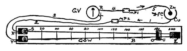
EXPERIMENT 121. To find what effect the length of a
wire has upon its electrical resistance.
Apparatus. A No. 30 German-silver wire, G-S W, a
little over two meters long, un-insulated (No. 81); the
two-fluid cell, 2-F C (Exp. 113); galvanoscope, G V (No.
58); plate binding-posts, X, Y and Z (No. 83–84–85);
copper washers (No. 87).
Arrange as in Fig. 96, so that the current will flow, at
first, as shown by the arrow. The metal plates, M P 1
and M P 2, are used so that the connections may be
changed without disturbing G V. The binding-posts may
be fastened directly to the top of the table; but it will be
more convenient to permanently fix them to a board, B,
as shown, so that the same arrangement can be used for[125]
future experiments. The binding-posts, X and Y, should
be about ⅛ in. apart, just far enough so that their edges
do not touch each other.
The binding-post, Z, should be fastened to B with its
inside end 1 meter(100 centimeters, cm.) from the ends of
X and Y. Marks should be made upon B, 10 centimeters
apart, as indicated by the cross lines. This distance may
be taken from the scale on the rule (No. 88).
Fasten one end of the No. 30 wire, G-S W, to X. To
do this twist its end around the screw, S, between X and
the copper washer, then turn the screw in with a screw-driver
until it firmly holds X to the board. Pass the
wire around the screw in Z, and bring its free end to the
other binding-post, Y, to be fastened (Fig. 96). Two
meters of wire then form a path for the current from X
to Y. Have the board wide enough so that another set
of binding-posts can be put by the side of Y. It will be
best to permanently leave the No. 30 wire upon the board,
and to fasten the No. 28 wire (next experiment) to another
set of binding-posts, placed in the same manner as
those in Fig. 96. Make holes in the wood with an awl
before forcing in the screws.
315. Note. This experiment is usually done with a reverser
in the circuit, first taking readings with the current passing in
one direction, and then in the opposite direction. Considerable
time will be saved by taking all the readings for one direction of
the current at a time, simply using different lengths of German-silver
wire, and allowing the current to flow constantly during
each part. This obviates all danger of poor contacts in the
reverser, etc.; it saves the trouble of handling the reverser, and
much of the time needed for the needle to come to rest.
| Length of Circ., Cm. |
200 |
180 |
160 |
140 |
120 |
100 |
80 |
60 |
200 |
O |
| Deflection; West |
26° |
28° |
30° |
|
|
|
|
|
26° |
67° |
| Deflection; East |
25° |
27° |
30° |
|
|
|
|
|
25° |
67° |
| Average |
25.5 |
27.5 |
30 |
|
|
|
|
|
25.5 |
67 |
Fig. 97.
316. Directions. (A) With the circuit arranged as in Fig. 96,
and with G V properly placed, take the reading of G V, the
current passing through 200 cm. of No. 30 G-S W. Record your[126]
results in a diagram made like Fig. 97. The row of figures
across the top shows the length of the circuit. The table is
started with results from one experiment. Your results will
probably be different from these.
(B) Get the deflection with the current passing through 180 cm.
of wire. To do this press a piece of copper (O, Fig. 96) upon the
wire at the mark 10 cm. from Z, another thin piece of metal, U,
having been slipped under the wire. This will allow the current
to pass across from one wire to the other. Record the deflection
in the col. marked 180.
(C) Record the deflections for the lengths, 160 cm., 140, 120, 100,
80, and 60; then repeat (A) to be sure that the cell has been working
uniformly. This deflection should agree with that in (A).
(D) Change the direction of the current through G V; to do
this, change wire, 1, from M P 2 to M P 1, and wire 5 to M P 2.
This must be done without disturbing G V.
(E) Repeat (A), (B), and (C), and record the deflections for the
different lengths.
(F) Get the average deflections.
(G) Take, for future use, the deflection produced without G-S
W being in the circuit. Swing the end of wire, 3, that is joined
to Y, around to M P 2. The current will then pass simply
through G V. Record deflection in col. marked O.
Note. It is best to do the next experiment at once with the
same cell, so that the results of the two experiments can be compared.
In case this is impossible, get your cell to produce the
same deflection when you use it again, as shown in col. O, Fig.
97. You can regulate the deflection of the needle of G V by
varying the strength and quantity of the acid in P C.
[127]
317. Discussion. The resistance of a wire evidently depends
(Exp. 121) upon its length. The exact relation between resistance
and length cannot be seen from these results, however, which are
used in the next experiment. It will be shown later that in a
wire, other things remaining the same, the resistance varies
directly as its length.
EXPERIMENT 122. To find what effect the size (area of
cross-section) of a wire has upon its electrical resistance.
Apparatus. Same as in last experiment, with one
change, however. Replace the No. 30 G-silver wire with
a No. 28 G-silver wire (No. 82), or, what is better still,
fasten it to another set of binding-posts on the board and
leave the No. 30 for future use. The two should be
stretched side by side for constant use.
318. Directions. (A) See that your cell is in the same condition
as for Exp. 121; that is, it should produce the same deflection
of the needle of G V as before, when the two, only, are in
the circuit. (See Exp. 121, G.) The deflection may be changed
by changing the strength and quantity of the dilute acid and copper
solution.
(B) Find the average deflection of the needle with the 2 meters
of No. 28 G-s wire in the circuit, arranged as in Fig. 96.
(C) Compare this average deflection with the results obtained
in Exp. 121, in order to find what length of the No. 30 wire has
the same resistance as 2 meters of No. 28 wire. To find how
many times greater one length is than another, we divide the
larger length by the smaller; hence, to find the relation between
the two lengths of wire that gave the same deflection,—lengths
of equal resistance,—we divide the 200 centimeters (the length of
the No. 28) by the length of No. 30 found as directed.
(D) From the wire tables it will be found that the area of cross-section
of No. 28 wire is about 1.59 times that of No. 30 wire.
How does this quotient, or ratio, compare with that found in part
(C)? What is the relation between the area of cross-section of a
wire and its resistance? (See § 319, also Exp. 136.)
319. Discussion. If we find that a certain wire,
X, which is 576 feet long, has the same resistance as a
shorter one, Y, 360 feet long, we see (576 divided by 360)
that the ratio of their lengths is 1.6. This means that[128]
the longer one, X, is 1.6 times as good a conductor as Y;
or, in other words, that the resistance of Y is 1.6 times
that of X.
It is easier for water to flow through a large pipe than
it is through a small one. The same general principle is
true of electricity. A large wire offers less resistance to
the current than a small one of the same material. If
one wire is twice the size of another of equal length, it
will be twice as good a conductor as the other; that is,
it will have one-half the resistance of the smaller, provided
they are of the same material. (See Laws.)
EXPERIMENT 123. To compare the resistance of a divided
circuit with the resistance of one of its branches.
Apparatus. Same as in last experiment. Arrange as
in Fig. 98.
320. Directions. (A) Note the deflection of the needle when
the current passes through 1 meter of G-s wire, as shown. This
will be considered as one branch of the divided circuit.
(B) Still allowing the current to pass as in part (A), press a piece
of copper firmly across the binding-posts X and Y, to electrically
connect them, and note the reading of the needle. In this case
the current divides at Z through the two branches. What is
learned from the results of (A) and (B)?
(C) See if you can show the same results with apparatus
arranged as in Fig. 99.
321. Discussion. Two wires placed side by side as
in (B), Exp. 123, really form a conductor having twice
the size (area of cross section) of one of the branches.
The more paths a current has in going from one place to[129]
another, the less the resistance. (See Exp. 135.) The
wires are said to be in "parallel" or in "multiple arc."
EXPERIMENT 124. To study the effect of decreasing the
resistance in one branch of a divided circuit.
Apparatus. Galvanoscope, G V (No. 58); resistance coil,
R C (No. 79); two-fluid cell, 2-F C (§ 281), or a dry cell; 6
connecting wires; metal plates, M P.
Arrange as in Fig. 100, so that the current divides into
two branches at M P 1. The branches unite at M P 2.
322. Directions. (A) Take the reading of G V with 2 ohms
resistance in the lower branch; that is, with the whole of R C in
circuit.
(B) Take the reading of G V with one ohm in circuit; that is,
with the end of wire, 5, connected to M instead of to R.
(C) Cut out R C from the lower branch by replacing it with a
metal plate, thus joining wires 3 and 5. Compare the results from
(A), (B), and (C), and explain.
323. Current in Divided Circuits. Let us consider
a circuit like that shown in Fig. 101. If the points,
C and Z, were at the same potential, no current would
pass from C to Z. As the current does pass, Z must be
at a lower potential than C; there is a fall of potential from
C to Z. If the branch, A B, has the same resistance as
R X, the same amount of current will pass through each.
Exp. 124 has shown that when the branches have unequal
resistances, most of the current passes through the
one of small resistance. If R X has a greater resistance
than A B, most of the current will pass through A B.
[130]
CHAPTER XIX.
MEASUREMENT OF RESISTANCE.
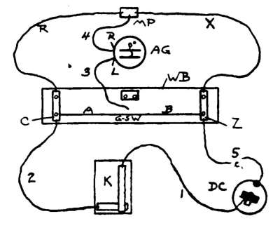
EXPERIMENT 125. To study the construction and use of
a simple "Wheatstone's Bridge."
Apparatus. Fig. 102. A Wheatstone's bridge, W B
(No. 80), (§ 324); astatic galvanoscope, A G (No. 59); dry
cell, D C (No. 51); key, K (No. 55); 7 wires with spring
connectors, two of which, R and X, are equal in length;
metal plate, M P, for connecting wires.
Arrange as in Fig. 102.
The carbon of D C is
joined to K, and this to
the point, C, of the bridge.
The zinc of D C connects
with the point Z on W B.
The A G is placed between
the branches for clearness.
Wire 3 is joined to the left-hand
binding-post of A G,
and wire 4 joins M P with
the right-hand one. When
the end of wire 3 does not
touch G-s W, it is evident
that as soon as K is pressed,
the current divides at C on
its way to Z, where the
branches unite again. K is used so that D C will not be
polarized by steady use.
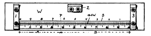
324. The Simple Wheatstone's Bridge (Fig. 103) consists of a
wooden base, W, at the ends of which are fastened two aluminum
conductors, 1 and 3. At one side of W is fastened another
conductor, 2. In Fig. 104 are side views of the conductors. These[131]
are used merely for convenience in making connections, and take
the place of the metal plates used in previous experiments. A
German-silver wire, G-s W, is stretched between 1 and 3, and
under this is a scale, S, divided into 100 small parts, these being
tenths of the larger divisions. The ends of
G-s W are held between eyelets, as shown at
E, Fig. 104.
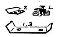
Reading the Scale. The value of part A
can be read directly from the scale, using the
lower row of figures. The point marked P,
for example, would be read 3.7 (three and seven-tenths large
divisions); B would be 6.3, found by subtracting 3.7 from 10. The
sum of A and B must always equal 10. The 6.3 may also be read
directly by using the upper row of figures for the whole numbers,
counting the tenths to the left. Try to divide the smallest divisions
into halves, at least; that is, if A = 3.75, B = 6.25. Take
the readings carefully.
325. Directions. (A) Touch the free end of wire, 3, to the
point, C, which has a higher potential than M P. Press down K
for an instant only. Some current should pass through A G, as
a shunt. Should it pass from C to M P or the reverse? Note in
which direction the right-hand end of the astatic needle is deflected.
(B) Swing the end of 3 around and touch it to the point, Z,
which has a lower potential than M P. Press K for an instant,
watch the needle, and compare with the results in (A).
(C) Move the free end of 3 along on G-s W, touching K at intervals,
until a point is found at which the needle of A G is not
deflected. How does the potential of this point compare with
that of M P?
326. Discussion; Equipotential Points.
Since one end of the G-s W has a higher, and its other
end has a lower potential than M P, there must be, somewhere
on it, a point at which the potential is the same as
at M P. This place is quickly found by sliding the free
end of wire, 3, along, pressing K occasionally, until A G
shows that no current tends to pass through it in either
direction, when the current passes from C to Z through[132]
the two branches of the divided circuit. This point and
M P are called equipotential points.
If the resistance of the part, X, be increased, it should
be evident that the part of the bridge-wire, B, should be
also increased to find a point having the same potential
as M P; that is, the end of 3 should be moved towards C.
We have, in the bridge-wire, a simple means of varying
the resistance of its parts, A and B.
327. Use of Wheatstone's Bridge. It will be found, upon
trial, if we put a resistance of 2 ohms in place of R, Fig. 102, and
2 ohms in place of X, that the free end of wire 3 will have to be
at the center of the bridge-wire in order to get a "balance"; that
is, to find the place where A G is not affected. No matter what
the resistance of R and X are, provided they are equal, this will
be true. The value of both A and B, on the scale, will be 5
whole spaces, no tenths. From this we see that A: B:: R: X,
which reads A is to B as R is to X; this means that A × X = B × R.
Supplying the values of the letters, we have 5 × 2 = 5 × 2. If we
did not know the value of X, that is, if we were measuring the
resistance of a coil of wire, using a 2-ohm coil as the standard, or
R, we could find the value of X, knowing the other 3 parts of the
proportion. 5 × X = 5 × 2, which means that 5 times the value
of X is 10; hence the value of X is 10 ÷ 5 = 2 ohms.
Suppose that we have R = 2 ohms, which is the standard
resistance coil (No. 79), and are trying to find the resistance of a
coil, X. We slide the end of wire, 3, along on the bridge-wire
until the correct place is found. (See Exp. 125, 126, for details.)
Take the values of A and B (§ 324), supply them in the equation
given, and work out the value of X.
328. EXAMPLE. R = 2 ohms; A = 3.7; B = 6.3; to find
the value of X in ohms.
A: B:: R: X, which means that A × X = B × R, or 3.7 × X
= 6.3 × 2. X must equal, then (6.3 × 2) ÷ 3.7 = 3.405 ohms.
Note. In practice it is most convenient to make connections as
shown in Fig. 105 when measuring resistances (Exp. 126). The
arrangement given in Fig. 102 is simply for explanation. It will
be seen that the smaller A is, compared with B, the larger the
unknown resistance compared with your standard.
[133]
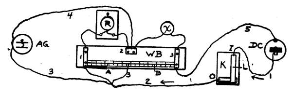
EXPERIMENT 126. To measure the resistance of a wire
by means of Wheatstone's Bridge; the "bridge method."
Apparatus. Same as in Exp. 125; the two-ohm resistance
coil, R C (No. 79); a coil of wire, X, as, for example,
the 15-turn coil on the galvanoscope, G V (No. 58).
Arrange as in Fig. 105. You will observe that the central
conductor of the bridge (2, Fig. 104) takes the place
of M P in previous explanations. We still have the same
kind of a divided circuit as explained in Exp. 125, A G
being connected with points of equal potential. It will
be found convenient to have D C at the right, and A G
facing you at the left, the key being in front. (See Exp.
107 in regard to adjusting A G.)
Notice that you have a standard resistance (2 ohms)
in place of R, Fig. 102, and an unknown resistance (galvanoscope
coil) in place of X. (See § 330.)
329. Directions. (A) Touch the free end of wire, 3, to the
left-hand side of the bridge-wire, press the key for an instant,
only, and note the direction taken by the right-hand end of the
needle. Move the end of wire, 3, to the right-hand side of the
bridge-wire, touch key, watching needle. Does the needle move
more or less than before? In the same or opposite direction? If
the deflections are opposite, the point that has the same potential
as binding-post, 2, must be between the two points touched.
(B) Be sure that all connections are good. Find the point on
G-s W, at which there is no deflection, as directed in Exp. 125
(C). Note the readings on the scale, as explained in § 324.
(C) Make the proper calculation, § 327, 328, and find the resistance
of the coil of G V, the resistances of the wires joining R C
and G V to the bridge being neglected.
(D) Make proper allowances for the resistances of the wires[134]
just mentioned (see § 330), and compare them with the results
found in part (C).
330. Allowances for connections. It should be remembered
that the wires joining R C and G V to the bridge also have some
resistance. Such connections, in regular instruments, are made
by heavy copper straps or by thick, short wires, so that their resistances
can be neglected. In case you use the ordinary No. 24
copper wire, as directed, the resistances of the pieces can be measured
by means of the bridge, or you can calculate their resistances
from the wire tables. The resistances should be allowed for. It
is evident that your standard resistance is 2 ohms plus the resistance
of the connecting wires, and that the resistance of the coil, X,
is found by deducting the resistance of its connecting wires from
that found from the proportion previously used.
Example. We see from the table that the resistance of about 39 ft.
1 in. of No. 24, B and S copper wire is 1 ohm. This equals 469
in. If 469 in. have a R (resistance) of 1 ohm, 1 in. will have a
R of one-469th of an ohm; that is 1 divided by 469, which equals
a little over .002 ohm. For every inch of No. 24 wire used, then,
for connections, we may allow .002 ohm. This will be near
enough for our purposes.
Suppose that each connection is 18 in. long, the regular wires
with connectors being used. The R of the 36 in. joined to R C
will then be 36 times .002 = .072 ohm. Our standard R must
then be considered as 2.072 ohm. If we substitute this in the
example, as stated in § 328, we have 3.7 × X = 6.3 × 2.072. X
must equal (6.3 × 2.072)/3.7 = 3.528 ohm, which includes the
unknown resistance and 36 in. of connections, the R of which is
.002 ohm; 3.528 - .072 = 3.456, the resistance of X alone. Compare
this with the answer to example, § 328. Make allowances
according to length of connectors used.
Note.—Carefully keep all the results of these experiments
in a note book for future reference. Be sure that
connections are good.
EXPERIMENTS 127–137. To measure the resistances of
various wires, coils, etc., by the "bridge method."
Apparatus. The coils of wire, etc., as stated in the
"Directions" of each experiment. The details of each
piece of apparatus may be found by referring, from the
numbers given, to the "Apparatus List," and to descriptions
in the paragraphs mentioned. Also all the apparatus
of Exp. 126.
Note. Make proper allowances for connections (§ 330) in all
experiments in measuring resistances.
[135]
EXPERIMENT 127.
331. Directions. (A) As explained in Exp. 126, measure the
resistance of the 10-turn coil of G V, allowing for connections
(§ 330). Read the bridge-scale carefully.
(B) Use one-half of the 2-ohm coil as standard and repeat.
EXPERIMENT 128.
332. Directions. (A) Measure the resistance of the 5-turn coil
of G V (see Exp. 126, etc.), using 2 ohms as standard.
(B) Use 1 ohm as standard, repeat, and compare results.
(C) Add the resistances of the 5 and 10-turn coils, and compare
the sum with the resistance of the 15-turn coil, as found in Exp.
126, D. The difference should be but a few hundredths of an
ohm.
EXPERIMENT 129.
333. Directions. (A) Measure the resistance of the coil of
No. 24 copper wire (No. 89). This coil is used for later experiments.
Spring connectors are fastened to the ends of this coil,
allowing it to be directly connected to the conductor on the bridge,
so no allowance should be made for its connecting wires. (See
Exp. 126 for details.) Mark the resistance upon the coil for future
use. (See Note.)
Note. The student will be surprised, perhaps, to find that
different results are obtained for the resistance of a given wire in
case he uses different standard resistances in the various tests;
that is, he will probably get a different result in Exp. 127 (A)
from the result of Exp. 127 (B). The difference here, however,
may not be large. The best results are obtained by making the
standard resistance as nearly equal as possible to the resistance
to be measured, so that a balance can be found when the end of
wire 3 (Fig. 105) is near the center of the bridge-wire. If R, Fig.
105, is much larger or smaller than X, the point desired on G-s W
will be near one of its ends, and large errors thereby produced.
The approximate resistance of X can be found by trial, then more
or less resistance can be used for R to suit. The student should
make several coils as explained in Apparatus Book, Chapter
XVII. The resistance of the different coils furnished should be
measured and marked. These can be used to vary the value
of R.
[136]
EXPERIMENT 130.
334. Directions. (A) Measure the resistance of the coil of No.
25 copper wire (No. 90). (See Exp. 126 for details and the Note,
Exp. 129.)
EXPERIMENT 131.
335. Directions. (A) Measure the combined resistance of the
two coils used in Exps. 129 and 130, when they are joined in
"series"; that is, when one end of one coil is joined to one end
of the other by means of a metal plate, the free ends being connected
to the bridge (Exp. 126). The current has to travel
through the entire length of both coils.
(B) Compare this result with the sum of their separate resistances
found in Exps. 129 and 130. (See Exp. 129, Note.)
EXPERIMENT 132.
336. Directions. (A) Measure the resistance of the two coils
(Exp. 131) when they are joined "in parallel." (See § 293.) They
may be joined in parallel by connecting them both to the bridge
at the same time, one end of each being slipped onto 2 (Fig. 103),
the other end of each being joined to 3. In this way the current
has two paths, side-by-side, to get from 2 to 3. (See Exp. 129,
Note.)
(B) Compare this resistance with that of Exp. 131.
EXPERIMENT 133.
337. Directions. (A) Measure the resistance of 1 meter of No.
28 German-silver wire. Use the wire as arranged on a board,
Exp. 122 (Figs. 96 and 98), making the connections with the
bridge from binding-posts, X and Z. (See Exp. 129, Note.) The
wires connecting the bridge with the ends of the G-s wire will
each have to be about 2 ft. long. In making deductions (§ 330)
figure according to the length used.
(B) Divide the total resistance by 100 to get the resistance of
1 cm. of the wire, and carefully mark off the board into cm. This
will give 100 parts between X and Z.
EXPERIMENT 134.
338. Directions. (A) Using the No. 28 G-s wire on the board,
as arranged for Exp. 122, measure the resistance of the 2 meters
in series, the connections being made with the bridge from X and
Y, Fig. 98.
[137]
(B) Compare the result with that of Exp. 133. What is the relation
between the length of a wire and its resistance? See Summary
of Laws. (See Exp. 129, Note.)
EXPERIMENT 135.
339. Directions. (A) Measure the resistance of the above two
meters of No. 28 G-s wire when joined in parallel. (§ 293.) The
binding-posts, X and Y, can be joined by a short wire with connectors
on its ends, or by clamping a thin strip across by means
of spring connectors. Use the 2-ohm coil as the standard, and
make proper allowances. (§ 330.)
(B) From the results of Exps. 132 and 135 what can be said
about the resistances of parallel circuits as compared with the
resistances of the separate branches?
EXPERIMENT 136.
340. Directions. (A) Arrange the 2 meters of No. 30 G-s
wire on the table or board, again (Exp. 121, Fig. 96).
(B) Measure the resistance of one meter. Find the value of X
approximately, and use a resistance for R that will suit. (See
Exp. 129, Note.)
(C) Divide the result by 100 to get the resistance of 1 cm. of
the wire.
(D) Compare the resistance of one meter of No. 28 G-s wire,
found in Exp. 133, with the resistance of 1 meter of No. 30 G-s
wire. What is the relation, then, between the size (area of cross-section)
of a wire and its resistance? (See the results of Exp.
122, and § 319, also Summary of Laws.)
EXPERIMENT 137.
341. Directions. (A) Measure the resistance of 2 meters of
No. 30 copper wire, arranged on a board as in Fig. 96. (See
Exp. 129, Note.) Get the resistance of 1 meter.
(B) Compare the conductivities of copper and German silver by
studying the results of Exps. 136 and 137. Which has the greater
resistance? To find out how many times greater one resistance
is than the other, divide the larger by the smaller.
EXPERIMENT 138. To study the effect of heat upon the
resistance of metals.
Apparatus. Same as for Exp. 126; the coil of No. 24
wire (No. 89); a lamp or other source of heat. Arrange
as in Fig. 105.
[138]
342. Directions. (A) Measure the resistance of the coil as
before, Exp. 129. The result should nearly agree with that of
Exp. 129, provided connections, etc., are the same.
(B) Remove the coil from the bridge, hold it about a foot above
a lamp or stove, to warm it thoroughly, but do not heat it enough
to injure the covering. It will take a minute or so to warm it so
that the heat will get to the inside also.
(C) Replace the coil, measure its resistance, and compare the
result with its resistance when cold. Does heat increase or
decrease the resistance of a copper wire?
343. Effect of Heat upon Resistance.
Although there was but the fraction of an ohm difference
in the resistances of the hot and cold coil, it was evident
that changes of temperature affect the conducting power
of copper. This is true of all metals; but German silver
and other alloys are much less affected than pure metals,
so they are used in making standard resistance coils.
The resistance of liquids that can be decomposed by the
electric current decreases as the temperature rises.
Carbon acts like the liquids, while the resistance of
metals increases as their temperature rises.
EXPERIMENT 139. To measure the resistance of a wire
by the method of "substitution."
Apparatus. The coil of No. 24 wire (No. 89), the resistance
of which has been measured, but which will be considered
an unknown resistance, X; G V, 2-F C, M P, connecting
wires, etc., previously used; rheostat (§ 344).
Arrange as in Fig. 106 first, then as in Fig. 107.
344. Simple Rheostat. The No. 28 and No. 30 G-s
wires stretched upon the board (Fig. 96), make a convenient
form of rheostat. The resistance per cm. being
known from the results of Exp. 133 and 136, the resistance
for any number of cm. is easily found. The 10-cm.
divisions should be divided into centimeters. These
spaces may be marked off from the rule (No. 88).
[139]
345. Directions. (A) Be sure that 2-F C gives a constant
current, shown by the uniform deflection at G V, when arranged
as in Fig. 106. Do not use a cell that quickly polarizes. The
coil, X, forms a part of the circuit; it is joined to wires, 1 and 2,
by means of metal plates, so that it may be quickly removed
without disturbing either G V or 2-F C. Carefully read the
deflection at G V.
(B) Remove X from the circuit, and join the free end of wire,
2, to binding-post, X, and the free end of wire, 1, to a small piece
of sheet copper, which can be firmly pressed upon the G-s wire
to make a contact. Move this along on the G-s wire until the
deflection produced equals that of part (A), remembering that
the longer the G-s wire in the circuit the less the deflection.
Make two or three trials, as one or two cm. difference in length
make but a little difference in the deflection. Note the number
of cm. of G-s wire used, the resistance of which must equal that
of the coil, X.
(C) Find the resistance of X by multiplying the length just
found by the resistance of each cm., and compare the result with
the value found by using the bridge method directly.
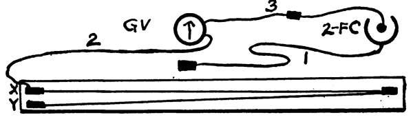
EXPERIMENT 140. To measure the E. M. F. of a cell by
comparison with the two-fluid cell.
Apparatus. Rheostat (§ 344); the two-fluid cell, 2-F C
(Exp. 113), the E. M. F. of which may be taken as 1 volt;
dry cell, D C; galvanoscope, G V. Arrange first as in
Fig. 107.
[140]
346. Directions. (A) Be sure that 2-F C gives a constant
current. Take the reading of G V without the rheostat in the
circuit; that is, with wires, 2 and 1, joined directly. The deflection
should be 50 or 60 degrees at least, and be constant.
(B) Attach a small piece of copper to the end of 1, and firmly
rub it along upon the G-s wire, thus introducing resistance into
the circuit, until the deflection is, say, 60° (50 or 55 degrees will
do). Note the length of G-s wire used and call it (B).
(C) Gradually add more resistance by moving the end of 1
along until the deflection is 50°, 10 degrees less than before. (If
the original was 50° make the new 40°). Call the number of cm.
of wire used (C).
(D) Replace 2-F C with the dry cell D C. Add resistance, as
before, until G V indicates a deflection of 60°, being careful not
to keep the circuit closed long enough to partially polarize D C.
Make 2 or 3 trials, allowing D C to rest a few minutes between
each. Call the number of cm. of G-s wire used (D).
(E) Again add more resistance, as in (C), until the deflection is
reduced to 50°. Call the length used (E).
347. Calculation. It is known that resistances that are able
to reduce the strength of the currents equally are proportional to
the electromotive forces; that is, the electromotive forces of the
two cells are to each other as the two resistances necessary to
produce equal changes in the deflections, which, of course, indicate
equal changes in the strength of the currents. Since the
resistances used in the two cases are directly proportional to the
lengths used, we have:
Length (C-B): Length (E-D):: E. M. F. of 2-F C: E. M. F. of
D C.
Substitute the values found and find the E. M. F. of D C.
EXPERIMENT 141. To measure the internal resistance of
a cell by the "method of opposition."
Apparatus. All the apparatus of Exp. 126. Two simple
cells (§ 275), the plates of which should be of the same
size, the same distance apart, and immersed in acid to the
same extent in both. The acid in both should be of the
same strength.
348. Directions. (A) Connect the two cells in opposition, so
that no current will be generated by them, and so that the two[141]
can be treated as a dead resistance. Do this by joining the two
zinc plates by a wire with connectors, and use wires to connect
the copper plates to the bridge like any other unknown resistance.
(B) Measure the resistance of the two by the regular bridge
method, allowing for wires used for connections. One-half of
the resistance found will give the internal resistance of one cell.
(See Note.)
Note.—The standard resistance will have to be arranged to
suit each particular case to make the calculations even approximately
correct. (See Exp. 129, Note.) The standard resistance
may be increased by adding the various coils and rheostat wires,
their values being known.
349. Summary of Laws of Resistance. 1. The
resistance of a wire is directly proportional to its length,
provided its cross-section, material, etc., are uniform.
EXAMPLE. If 39.1 ft. of No. 24 copper wire has a resistance
of 1 ohm, 78.2 ft. will have a resistance of 2 ohms, because 78.2
is twice 39.1; 70.38 ft. will have a resistance of 1.8 ohms, as
(70.38 ÷ 39.1 = 1.8) it is 1.8 times 39.1.
2. The resistance of a wire is inversely proportional to its
area of cross-section. The areas of cross-section of round
wires vary as the squares of their diameters; so the
resistance of a wire is also inversely proportional to the
square of its diameter, other things being equal.
EXAMPLE. A No. 30 wire has a diameter of about .01 inch,
while the diameter of a No. 24 wire is about .02 in.; that is, the
No. 24 has twice the diam. that the No. 30 has. The area of
cross-section of the No. 24, however, is four times that of the
No. 30, so its resistance is but ¼ that of the No. 30, the lengths,
etc., being the same. (See Wire Tables.)
3. The resistance of a wire depends upon its material, as
well as upon its length, size, etc.
4. The resistance of a wire depends upon its temperature.
(See Elementary Electrical Examples.)
[142]
CHAPTER XX.
CURRENT STRENGTH.
350. Strength of Current. The water in a certain
tank may be under great pressure, but if it is obliged
to pass through long tubes before it can turn a water-wheel,
for example, it is evident that the work done will
depend not only upon the pressure in the tank, but upon
the resistance to be overcome before the water gets to
the wheel. The work that the water can do depends
upon its rate of flow, and may be used to measure the
strength of the current.
The strength of a current of electricity is measured
also by the work that it can do, and it depends upon its
rate of flow at the point measured. The strength may be
determined from its magnetic, heating, or chemical
effects.
351. Unit of Current Strength; The Ampere.
A current having the strength of 1 ampere, when passed
through a solution of silver nitrate under proper conditions,
will deposit 0.001118 gramme of silver in one
second; if passed through a solution of copper sulphate,
copper plates being used for the electrodes, in the solution,
0.0003277 gramme of copper will be deposited in one
second. (See Chemical Effects of the Current.) The
thousandth of an ampere is called the milliampere. The
strength of a current is proportional to the amount of
chemical work that it can do per second. (See § 357.)
352. Measurement of Current Strength. The
galvanoscope previously described simply shows the presence[143]
of a current, or whether one current is larger or
smaller than another. When the degree-card is used to
get the relative deflections, the instrument may be called
a galvanometer.
The Tangent Galvanometer is made on the same
general idea as our galvanoscope, the diameter of the coil
being twenty times, or more, the length of the needle. In
these the strengths of the two currents compared are proportional
to the tangents of the angles of deflection produced.
(See Elementary Electrical Examples.) There
are several varieties of galvanometers, each designed for
its special work. They are often calibrated or standardized
so that the amperes of current passing through them
can be read off directly from the scale.
353. The Ammeter is really a galvanometer from
which may be read directly the strength of a current.
The coil has a low resistance so that it will not greatly
reduce the strength of the current to be tested.
The Voltameter measures the strength of a current
by chemical means.
354. Unit of Quantity; The Coulomb. A current
having a strength of 1 ampere will do more chemical
work by flowing one hour than it can do in 1 second.
In speaking of the quantity of electricity we introduce
the element of time. The unit of quantity is called the
coulomb, just as a cubic foot of water may be taken as a
unit of quantity for water. A coulomb is the quantity
of electricity given, in one second, by a current having a
strength of 1 ampere. Coulombs are found by multiplying
amperes by seconds; thus, a current of 5 amperes
will give 20 coulombs in 4 seconds.
355. Electrical Horse-power; The Watt. The[144]
electric current has power to do work, and we speak of
the horse-power of an electric motor in the same way as
for a steam-engine. A current with the strength of 1
ampere and an E. M. F. of 1 volt has a unit of power
called the watt. 746 watts make an electrical horse-power.
Watts = amperes × volts.
Watts ÷ 746 = the number of horse-power.
(See Transformers, also Elementary Electrical Examples.)
356. Ohm's Law. It was first shown by Ohm that
the strength of a current is equal to its E. M. F. divided
by the resistance in the circuit; that is,
Strength of current (amperes) = E. M. F. (volts). / resistance (ohms).
If we let C stand for the strength in amperes, E for the
E. M. F. in volts, and R for the resistance in ohms, we
have the short formula, easily remembered,
C = E/R
357. An Ampere would be produced by a current of
1 volt pushing its way through a resistance of 1 ohm.
Knowing any two of the three, C, E, or, R, the other
may be found. The resistance, R, it must be remembered,
is the total resistance in the circuit, and is composed
of the total internal and external resistances.
(See Elementary Electrical Examples.)
358. Internal Resistance and Current
Strength. It is evident that the internal resistance of
a cell varies with the position and size of the plates. We
shall now study the effects of these changes upon the
strength of the current.
[145]
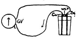
EXPERIMENT 142. Having a cell with LARGE PLATES,
to find how the strength of the current is affected by changes in
the position of the plates, the external resistance being small.
Apparatus. Galvanoscope, G V; materials for simple
cell (Exp. 110); connecting wires. Arrange as in figure
108, omitting the wooden cross-piece.
359. Directions. (A) Connect the wires with the 5-turn coil
of G V, which has but little resistance.
Have the tumbler nearly full of dilute
acid to get the effect of large plates;
that is, the current has a large liquid
conductor to pass through in the cell,
and the internal resistance will be small.
G V should be properly placed N and S.
(B) Place the copper and zinc plates as far apart as possible in
the acid, and press them against the bottom of the tumbler.
Note the reading of G V. It is not necessary to take readings
with reversed current.
(C) Still pressing them against the bottom of the glass, to keep
the same amount of surface under acid, slowly bring them near
each other and watch the needle.
(D) Hold the plates about an inch apart, and against the bottom,
and note the reading of G V. Slowly raise the plates, keeping
them the same distance apart until they are out of the acid.
Watch the action of the needle.
Make a note of your readings in degrees and write your conclusions.
Does a change in internal resistance affect the strength
of the current?
EXPERIMENT 143. Having a cell with SMALL PLATES
to find how the strength of the current is affected by changes
in the position of the plates, the external resistance being
small.
Apparatus. Same as in Exp. 142, the acid, however,
being but 1 in. deep in the tumbler; that is, we have the
effect of a cell with small plates, each being about 1 in.
by ½ in.
360. Directions. (A) Repeat (B) and (C) of Exp. 142, recording
the reading of G V in each case.
(B) Compare the results with those of Exp. 142, remembering
that the internal resistance is larger than before. Is the current[146]
as strong with small plates as with large plates when the external
resistance is small? When the external resistance is small (the
5-turn coil, for example), should the cell have a high or low
internal resistance to produce the greatest effect upon the
needle?
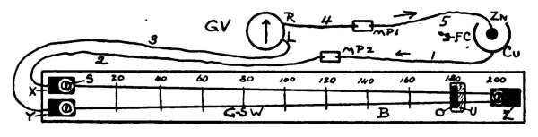
EXPERIMENT 144. To find whether the changes in
current strength, due to changes in internal resistance, are as
great when the external resistance is large, as they are when
the external resistance is small.
Apparatus. Same as for Exp. 142, 143, also the rheostat
containing the two meters of G-s wire (Exp. 121).
361. Directions. (A) Arrange as in Fig. 109, the external
resistance being 2 meters of No. 30 G-s wire in series with G V.
The 2-F C in the Fig. is replaced, however, by the simple cell as
in Exp. 143.
(B) Find the effect upon the strength of the current of moving
the plates about when but 1 in. of acid is in the tumbler.
(C) Nearly fill the tumbler with acid and repeat (B), taking
readings with plates near each other and as far apart as possible.
Lift them nearly out of the acid and take the reading.
(D) Still increase the external resistance of the circuit by
adding coils of wire or the meter of No. 28 G-s wire and repeat.
Is the strength of the current greatly affected by slight changes
in the internal resistance when the external resistance is large?
362. Discussion. We shall study, by means of
figures, how changes in internal resistance affect the
strength of the current.
Let R stand for the total external resistance of a circuit,[147]
and r for the total internal resistance of the cell or
cells; ohm's law, then, will be expressed by
C = E / (R + r)
EXAMPLE. Let us take a circuit (A) when the external resistance,
R, is small, and (B) when R is large compared with r,
E being taken as 1 volt in both cases.
(A) Let R = 1, and r = 2; substituting these values in the
formula above, we have:
C = 1 / (1 + 2) = 1 / 3 = .33+ ampere.
Now let the internal resistance, r, be slightly increased from 2
to 3 ohms; the value of C then becomes ¼ ampere, as R + r = 4.
The change in C, then, is the difference between ⅓ and ¼; and
this expressed in decimals becomes .33 - .25 = .08 ampere.
(B) Let R = 200 ohms, and r = 2 ohms as in (A). Substituting
these values we have,
C = 1 / (200 + 2) = 1 / 202 = .00495 ampere.
Increasing r from 2 to 3, as before, etc., we find that C = 1
divided by 203 = .00492 ampere.
The above shows clearly (A) that the value of C is changed
considerably by changes in r when R is small, and (B) that
changes in r produce very slight changes in C when R is large.
Review your results of Exps. 142–144. (See Elementary Electrical
Examples.)
363. Arrangement of Cells and Current
Strength. We have seen that internal resistance affects
current strength. In joining cells, then, attention must
be given to the internal resistance as well as to the E. M.
F. of the combination.
364. Cells in Series. It has been shown by careful
experiments that the E. M. F. of two cells joined in[148]
series (Fig. 110) is equal to the sum of the E. M. F. of
each. Ten cells, joined in series, have ten times the E.
M. F. of one cell, provided they have the same E. M. F.
As the Zn of one is joined to the Cu of the other, the
current is obliged to pass through one solution after the
other; that is, the internal resistance of the two in series
is equal to the sum of their internal resistances. Ten
cells, joined in series, have ten times the internal resistance
of one cell, provided they have equal internal resistances.
365. Cells Abreast. When the positive plates are
joined together and the negative plates are also joined
together (Fig. 111), the cells are said to be abreast, in
parallel, or in multiple arc. It has been shown that two
cells of equal strength, joined abreast, have the same E.
M. F. as one cell. The two Cu plates, being joined,
must have the same potential; all the Zn plates have the
same potential, so the difference of potential at the terminals
of the combination is the same as that at the terminals
of a single cell.
In two cells abreast (Fig. 111) the current has two
liquid paths, side by side, to get from Cu to Zn; this
makes the internal resistance one-half that of one cell,
provided their internal resistances are equal. Ten cells,
of equal internal resistance, when joined abreast, have
one-tenth the internal resistance of one cell.
[149]
EXPERIMENT 145. To find the best way to join two similar
cells when the external resistance is small.
Apparatus. Two simple cells using dilute sulphuric
acid, with copper and zinc elements, as in Exp. 112;
galvanoscope, G V; connecting wires, etc. Have the
zincs well amalgamated. Remove them from the acid as
soon as readings are taken.
366. Directions. (A) Partly fill the tumblers with the acid.
Join the cells in series (Fig. 110), then connect wire 1 (Fig. 110)
with the left-hand binding-post of G V, and wire 2 with the middle
one, thus putting the 5-turn coil into the circuit. Take the
reading of G V.
(B) Join the cells in multiple arc (Fig. 111), connecting them as
in (A) with G V. Write down the reading, and compare it with
that found in (A).
(C) Take the reading with but 1 cell joined to G V.
EXPERIMENT 146. To find the best way to join two
similar cells when the external resistance is large.
Apparatus. Same as for Exp. 145, also the rheostat
containing 2 metres of No. 28 or 30 G-s wire. Arrange
the G-s wire in series with the 15-turn coil of G V, as
shown in Fig. 109, two simple cells being used, however,
instead of 2-F C as shown.
367. Directions. (A) Take the reading of G V when the two
cells are in series (Exp. 145), the external resistance being the
15-turn coil and G-s wire.
(B) Join the cells in parallel and take the reading, using the
same external resistance as in (A).
(C) Increase the external resistance by adding coils of wire or
2 metres of No. 28 G-s wire and repeat (A) and (B). What does
the experiment show?
(D) Take the reading with 1 cell and large external resistance.
368. Best Arrangement of Cells. It will be
seen by experiments that with a given number of cells
the strongest current is produced when they are arranged
so that the internal resistance of the battery nearly
equals the external resistance of the circuit.
When the external resistance is small, the internal[150]
resistance may be kept down by joining the cells in
parallel; and, although the E. M. F. is also kept small,
the value of C will be larger than it would be with a
larger internal resistance and a larger E. M. F.
When the external resistance is large, the internal
resistance can be made large by joining the cells in series.
The advantage comes, however, from having a large
value of E. A large resistance can not hold back a
current of large E. M. F. By joining the cells in series
the value of E is made large, and the value of C becomes
large even though there is an increased internal resistance.
(See Elementary Electrical Examples.)
[151]
CHAPTER XXI.
CHEMICAL EFFECTS OF THE ELECTRIC CURRENT.
369. Chemical Action and Electricity. We
have learned that the electric current is produced, in the
cell, by chemical action. There is a definite relation between
the chemical action and the current produced. We
are now to study the changing of electrical energy back,
again, to chemical energy.
370. Electrolysis is the name given to the process
of decomposing chemical compounds by passing the electric
current through them. The compound
decomposed is the electrolyte. Fig.
112 shows a tumbler of liquid (electrolyte)
through which the current is to pass in the
direction of the arrow. Two carbon plates,
A and C, are in the liquid, and are joined
to the source of electricity. The current
enters at A (anode) and leaves at C
(cathode).
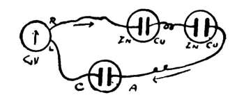
EXPERIMENT 147. To study the electrolysis of water.
Apparatus. The two simple cells (§ 275) joined in series
(§ 364), although two Daniell or
two dry cells will be better. A
tumbler of water containing a
few drops of sulphuric acid to
make the water a conductor.
Two pieces of sheet copper will
serve as the electrodes. The
galvanoscope may also be put
into the circuit as in Fig. 113.
371. Directions. (A) Allow the current to pass, and note (1)
whether gas is set free at both electrodes, A and C, and (2) at[152]
which the quantity of gas is the greater. If very little gas is
produced use more cells.
(B) Remove A and C from the liquid, to remove the gas, then
watch the action of the needle of G V as the water is again decomposed.
372. Composition of Water. The two gases
liberated in Exp. 147 were hydrogen (H) and oxygen
(O). The chemical formula for water is H2O, which
means that it is composed of two parts, by volume, of H
and one part of O. With proper apparatus these gases
may be collected, tested, and the amounts measured.
373. Electromotive Force of Polarization.
We know that H and O have a strong chemical attraction,
or affinity, for each other. In order, then, for the
current to decompose water, this attraction between the
gases must be overcome; and as soon as the current
ceases, these gases try to rush together again to form
water. This sets up an electromotive force of almost 1.5
volts; in fact, a current is produced if the H and O be allowed
to form water again (See Storage Cells). To decompose
water the current must have an E. M. F. of
over 1.5 volts to overcome this E. M. F. of polarization.
It was seen in the study of simple cells that the current
became rapidly weaker as hydrogen was deposited upon
the copper plate, on account of this opposing electromotive
force.
In decomposing other compounds, the anode is made
of the metal which is to be deposited at the cathode. If
copper is to be deposited from a solution of copper sulphate
the anode should be a copper plate; this keeps the
solution at same strength, and avoids the opposing E.
M. F. of polarization; that is, a very weak current will
do the work (See Exp. 149), because the electrodes are
of the same metal.
[153]
EXPERIMENT 148. To coat iron with copper.
Apparatus. Iron nail, solution of copper sulphate
(§ 283).
374. Directions. (A) Clean the nail with sandpaper, then
hold it in the copper solution for a few seconds. Machinists
often cover iron or steel tools with a thin coating of copper in
this way.
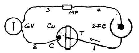
EXPERIMENT 149. To study the electrolysis of a solution
of copper sulphate.
Apparatus. Galvanoscope, G V; two-fluid cell, 2-F C;
a tumbler, T, containing about an inch of copper sulphate
solution (§ 283); a wooden cross-piece to which is
fastened a copper strip; carbon rod, C; wire 2 is held to
C by a rubber band.
Arrange as in Fig. 114,
so that Cu will be the
anode (§ 370), the current
passing as shown by
arrow. A dry cell may
be used for short experiments
instead of the
2-F C.
375. Directions. (A) The carbon being clean, allow the
current to pass, C and Cu being kept about ½ in. apart. Watch
the surface of C, and note the beautiful color of the deposited
copper. Save the coated rod for the next experiment. Has the
Cu plate been acted upon?
376. Electroplating is the name given to the process
of coating substances with metal with the aid of the
electric current. The copper sulphate, CuSO4, is
broken up into Cu and SO4 by the current. The Cu
goes to the cathode, and the SO4 attacks the anode,
gradually dissolving it if it be copper; that is, the metal
part of CuSO4 is carried in the direction of the current.
Most metals are coated with copper before they are
silver or gold plated. A solution of silver is used for
silver plating, silver being used as the anode.
EXPERIMENT 150. To study the chemistry of electroplating.
Apparatus. Same as in last experiment, but use two[154]
carbon rods for the electrodes. Arrange as in Fig. 114,
with the Cu replaced by another carbon. Two simple
cells (§ 275) are also needed.
377. Directions. (A) Allow the current to pass as before. Is
copper still deposited? Does anything occur now at the surface
of the anode? Is the copper deposited as rapidly as before?
(B) Try the effect of the two simple cells joined in series,
Instead of the two-fluid cell.
(C) After a fair coating of copper has been deposited upon the
carbon cathode, reverse the direction of the current through the
copper solution; that is, use the coated rod for the anode. Allow
the current to pass until a change takes place in the anode.
378. Discussion. Ions are the names given to the
parts into which an electrolyte is decomposed by the
electric current. In the case of CuSO4, the ions are
Cu and SO4, which is called an acid radical. This
SO4 can not dissolve carbon or platinum, so these are
used when water is to be electrolyzed. Where copper is
used as the anode for copper plating, the SO4 attacks it,
forming CuSO4 again, and this keeps the solution
strong. If carbon were used instead, the SO4 would
take H2 from the water around the anode and H2SO4
(sulphuric acid) would be formed, the oxygen of the
water being set free at the anode. The amount of Cu
dissolved from the copper anode equals nearly the amount
deposited upon the cathode. Exp. 150 shows that the
metal is carried in the direction of the current. As
hydrogen is produced at the cathode it is chemically considered
a metal.
379. Electrotyping consists in making a copy in
metal, of a woodcut, page of type, etc. A mould or
impression of the type is first made in wax, or other
suitable material (the pages of this book, for example, as
set up by the printer). These moulds are, of course, the
reverse of the type. They are coated with graphite to[155]
make them conduct electricity, and hung as the cathode,
in a bath of copper sulphate. After a thin coat of
copper has been deposited by an electric current, the
wax is removed and the thin copper backed with soft
metal. The metal surface next to the wax will be just
like the type, only made of copper. These plates or
electrotypes can be printed from, the original type being
used to set up another page. (See "Things a Boy
Should Know About Electricity.")
380. Voltameters are cells used to measure the
strength of an electric current. In the Water Voltameter
the hydrogen and oxygen produced are measured. The
H acts like a metal and goes to the cathode, two parts of
H being formed to one of O.
Copper Voltameter. This cell measures the amount of
copper deposited in a given time by a current. The copper
cathode is weighed before and after the current flows.
The weight of Cu deposited is then divided by the number
of seconds during which the current passed, and this
result, in turn, by .000328, which will give the average
strength of the current in amperes. (See § 351.) Other
forms of voltameters are also used.
In all voltameters the quantity of metal deposited is
proportional to the time that the current flows, and to its
strength.
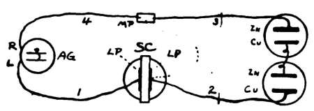
EXPERIMENT 151. To study the construction and action
of a simple "storage" cell.
Apparatus. Two lead plates, L P, (Nos. 77, 78) fastened
to a wooden cross-piece (§ 275). The spring-connectors
should not be forced upon the thick lead. Fasten
one end of the wire under the screw-head. A tumbler
two-thirds full of dilute sulphuric acid (§ 258); the astatic
galvanoscope, A G; wires to form connections; the two
simple cells joined in series. Arrange as in Fig. 115.[156]
One L P is joined to binding-post, L, of A G by the wire
marked 1; wire 2 connects the other L P to the copper
Cu. Wire 3 joins the zinc to any thin metal plate, M P,
which is used for convenience, so that the spring connectors
can be quickly slipped on or off. Wire 4 joins M
P with binding-post R of A G.
381. Directions. (A) Get clearly in mind the direction in
which the right-hand end of the astatic needle is deflected when
the current passes, remembering that it passes into A G at L and
leaves at R. Allow the current to flow for 10 or 15 minutes
through the circuit, at the same time watching the needle to see
whether the strength of the current remains constant.
(B) Remove the connector from Cu, swing it over into the
position of the dotted line (Fig. 115), slip the connector upon M
P and watch the needle. This cuts the cells out of the circuit;
but, if you desire, also remove wire 3 from M P. Does the
storage cell, S C, produce any current? Does it pass through
A G in the same direction as that which came directly from the
two cells?
(C) Try the dry cell in place of the two simple cells. Try 2
other cells in series if you have them.
382. Secondary or Storage Cells must be charged
by a current before they can give out a current. Electricity
is not really stored. Chemical changes are produced
in the storage cell by the charging current, as in
the voltameter or electroplating bath; and it is, then,
potential chemical energy that is stored. When the new
compounds are allowed to go back to their original condition
by joining the electrodes of the charged cell a
current is produced. In other words, an electric current[157]
produces chemical changes in the cell by electrolysis, and
these new compounds have an E. M. F. of polarization
because they are constantly willing and anxious to get
back to their old state. The plates are lead and are
usually coated with compounds of lead. Hydrogen and
oxygen are given out at the electrodes. The current
from a dynamo is used to charge secondary batteries.
(See "Things a Boy Should Know About Electricity.")
[158]
CHAPTER XXII.
ELECTROMAGNETISM.
383. Electromagnetism is the name given to
magnetism that is developed by electricity. You have
already seen that if a magnetic needle be placed in the
magnetic field of a magnet, its N pole will point in the
direction in which the lines of force pass on their way
from the N to the S pole of the magnet. You have also
seen that in the galvanoscope, etc., a coil of wire acts like
a magnet when a current passes through it. Can we
not, then, use the needle to study the lines of force about
wires and coils?
EXPERIMENT 152. To study the lines of magnetic force
about a straight wire carrying a current.
Apparatus. The compass, O C; key, K; dry cell, D C.
Arrange as in Fig. 116.
384. Directions. (A) Arrange the wire so that the current
will flow through it from N to S over the compass-needle as soon
as the circuit is closed (Fig. 117, A). Press K for an instant only,
and note the direction in which the N pole is deflected. Repeat
two or three times until you get clearly in mind the direction taken[159]
by the needle. Sketch the result in your note-book, and compare
with Fig. 118, A. The arrow shows the direction of the current.
(B) Let the current pass for an instant from N to S and under
the needle, as shown in Fig. 117, B. Sketch result.
(C) Let the current pass for an instant from S to N above the
needle (Fig. 117, C). Sketch result.
(D) Let it pass from S to N under the needle (Fig. 117, D).
Sketch result.
(E) Let it pass through the wire from east to west (Fig. 117, F)
above the needle, then under it, and note result. Compare the
results with those indicated in Fig. 118.
385. Lines of Force About a Wire. When a
current passes through a wire, the needle, over or under
it, tends to take a position at right angles to the wire.
This shows that the lines of force pass around the wire
and not in the direction of its length. The needle does
not swing entirely perpendicular to the wire; that is, to
the E and W line, because the earth is at the same time
pulling its N pole towards the N. If the needle had no
pointing power, and at the same time retained its magnetic
field, it would point exactly at right angles to the
wire as soon as the current passed.
If you look along the wire, Fig. 119, from
the point, C, towards the positions, A and
B, you will see (A) that under the wire the
lines of force pass to the
left, and that above the
wire (B) they pass towards
the right. This is
because the N pole points
in the directions mentioned.
(See Fig. 118.)
Looking along the wire from Z towards position, D and
C, you will see just the opposite to the above, as the
current comes towards you.
[160]
Rule.—When the current goes from you, the lines of
force pass around the wire in a clockwise direction, and
when the current comes toward you they pass around it
in an anti-clockwise direction.
386. Ampere's Rule may be used to remember what
has been learned in Exp. 152.
If you imagine yourself swimming in the wire with the
current, always facing the needle, the N-seeking pole of the
needle will always be deflected towards your left hand.
When the needle is above the wire you must imagine
that you swim upon your back, in order to face the needle.
Another Rule.—Hold the right hand with the thumb
extended and with the fingers pointing in the direction
of the current, the palm being towards the needle and on
the opposite side of the wire from the needle. The N-seeking
pole will then be deflected in the direction in
which the thumb points.
387. If a wire carrying a strong current be dipped in
iron filings, the magnetic field about the wire acts by
induction upon the particles of filings, making magnets
of them. These cling to each other simply because they
are little magnets.
388. Lines of Force about Parallel Wires.
When a current passes in the same direction in two
parallel wires the lines of force pass around the wires in
the same direction in both, and the magnetic fields attract
each other. When the currents flow in opposite directions
the magnetic fields repel each other.
EXPERIMENT 153. To study the lines of force about a
coil of wire like that upon the galvanoscope.
Apparatus. Galvanoscope, G V; dry cell; key; compass.
Arrange as in Fig. 116, using G V instead of the compass
shown. The coil of G V should be placed in the E and W[161]
line. The current can pass only when the key is pressed.
Connect the wires with G V, so that the current will pass
through the 15-turn coil from W to E on top of the coil;
that is, so that the current will have a "clockwise"
motion. Fig. 120 represents a front view of the coil.
389. Directions. (A) Hold the compass in the various places
marked with a dot (Fig. 120) and note the directions taken by its
N pole. Make a circle similar to the one shown to represent the
coil, and sketch upon it the way in which the lines of force pass
around it according to your observations.
(B) Make a diagram like Fig. 121, which represents a cross-section
of the coil through the center. Imagine that you have
removed the top half of the coil and that you are looking down
upon the ends of the wire of the lower half. Draw curved arrows
about the coil at W and E to show which way the lines of force
are passing. Compare your results with those in Fig. 119,
remembering that at E, Fig. 121, the current is going away from
you.
(C) Move O C back and forth on the center-line that runs N and
S through the coil, and note the positions of the compass-needle.
Does the coil seem to have poles?
(D) Reverse the current through the coil and repeat your
observations.
EXPERIMENT 154. To study the magnetic field about a
small coil of wire.
Apparatus. A coil of wire (No. 89), described in § 390;
current reverser, C R (No. 57); dry cell; connecting wires,
etc.
390. Coils of wire for some of the following experiments
should be wound upon wooden spools that have been turned
down thin, so that the wire will be as near the central hole as[162]
possible. They should be wound with a winder. (See Apparatus
Book, Chapter X.)
For convenience we shall call the starting end of the coil, that
is, the end that comes from the wire that is near the center, the
inside end, I E. The end of the last layer of the coil we shall call
the outside end, O E. These letters should be noted in the diagrams.
See Apparatus List for details of the special coils used
in these experiments.
391. Directions. (A) Arrange as in Fig. 122, so that the axis
of the coil will lie in the E and
W line. Place O C about 2 in.
from the E end of the coil. Press
one lever of C R so that the
current will pass around the coil
for an instant in a clockwise
direction; that is, so that it will
enter the coil at O E. Note the
action of the needle. If the needle
is not affected move it nearer the
coil and press the lever again.
Get clearly in mind the connections, the direction in which the N
end of the needle is deflected, etc. Is the E end of the coil a
N or a S pole?
(B) Reverse the current through the coil. What effect has it
upon the polarity of the E end of the coil?
(C) Place O C at the west end of the coil and repeat (A) and (B).
(D) Place O C in various positions about the coil and note the
action of the needle when the current passes. Does this coil act
like a magnet, having poles, magnetic field, etc.?
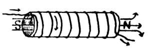
392. Polarity of Coils. It is evident from Exps.
153 and 154 that a coiled conductor has poles, magnetic
field, etc., when a current passes, and that it strongly
resembles a magnet, even though no iron enters into its
construction. We may say that the coil becomes magnetized
by the electric current.
Fig. 123 shows a right handed coil
or helix of wire, the current passing
as shown by the small arrows. The[163]
left-hand end is a S pole because the current passes
around it in a clockwise direction. When you face the
right-hand end of the coil the current is seen to pass
around it in an anti-clockwise direction; this produces a
N pole. As the N pole of the magnetic needle is attracted
toward the S pole of the coil, it is clear that the lines of
force pass through the inside of the coil as shown by the
large arrows. They then curve through the air and
return to the S pole as with magnets.
EXPERIMENT 155. To test the attracting and "sucking"
power of a magnetized coil or helix.
Apparatus. The coil, battery, etc., used in Exp. 154,
Fig. 122; a sewing-needle.
393. Directions. (A) Arrange the coil, etc., as described in
Exp. 154. The coil need not lie in the E and W line, however,
and a key may be used instead of the current reverser.
(B) Magnetize the needle so that its point will be a N pole.
(C) Tie a thread about the center of the magnetized needle,
hold the thread in the hand so that the S pole of the needle will
swing freely at the hole at the right-hand
end of the coil (Fig. 124). If
the current passes as directed, the
right-hand end of the coil will be a N
pole. What happens to the needle
when the key is pressed for an instant.
(D) Change the needle to the left end of the coil and repeat.
(E) Try a nail, pen, iron, etc., instead of the needle.
EXPERIMENT 156. To find whether a piece of steel can
be permanently magnetized by an electric current.
Apparatus. Same as for last experiment; an unmagnetized
sewing-needle; the compass.
394. Directions. (A) Be sure that the needle is not magnetized.
It should attract both ends of the compass-needle. How
can any magnetism in the needle be removed?
(B) Place the needle inside of the coil with its point to the east;
that is, with its point at the N pole of the coil, and its head at[164]
the S pole. Close the circuit for an instant. Test the needle
again for poles. Is the point a N or a S pole?
(C) Turn the needle end for end in the coil, and see whether
its polarity can be reversed.
(D) Experiment with iron wire, nails, steel pens, spring steel,
etc.
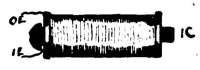
EXPERIMENT 157. To study the effect of a piece of iron
placed inside of a magnetized coil of wire.
Apparatus. Same as in Exp. 154; a short rod or iron
core, I C, of soft iron (No. 92) that will fit inside of the
coil. This combination is called an electromagnet.
395. Directions. (A) Arrange first as for Exp. 154, Fig. 122,
with the coil in the E and W line, no core being used, and place
O C about 6 in. from the right-hand end of the coil.
(B) Press the lever for an instant to see whether the field of
the coil is strong enough to move the compass-needle at that distance.
Move O C a little nearer or farther from the coil until the
needle just moves, when the circuit is closed.
(C) Place I C inside of the coil (Fig. 125), and repeat (B) to see
whether the magnetic field of the coil is stronger or weaker than
before.
(D) Study the location of the poles. Can they be reversed?
[165]
CHAPTER XXIII.
ELECTROMAGNETS.
396. Electromagnets are important to the student
of electricity. They form the principal part of nearly
every electrical instrument. You have seen that a wire
has a magnetic field about it the instant a current passes
through it. A coil, or helix of wire, has a stronger field
than a straight wire carrying the same current, because
each turn, or convolution, adds its field to the fields of
the other turns. By having a core of soft iron instead of
air, wood, or other non-magnetic material, the strength
of the magnet is greatly increased. The central core
may be permanently fixed in the coil, or it may be removable.
(See Apparatus Book, Chapter IX, for Home-made
Electromagnets.)
397. Cores of Electromagnets. A strong magnet
has more lines of force passing from its N pole through
the air to its S pole than a weak magnet. By increasing
the number of lines of force we increase the strength of
a magnet. It has been seen, in experiments with permanent
magnets, that lines of force do not pass as readily
through air as through soft iron, and that lines of force
will go out of their way to pass through iron. It was
learned in Exp. 154 that inside of a helix (Fig. 123) the
lines of force pass from the S to the N pole; they then
spread out through the air and pass back on all sides of
the coil to its S pole, as in the case of permanent magnets.
The air around and inside of a helix offers a great resistance
to the lines of force, and tends to weaken the[166]
magnetic field. When part of the circuit consists of an
iron core, which is a splendid conductor of lines of force,
the magnetic field is greatly increased in strength.
EXPERIMENTS 158–163. To study straight electromagnets.
Apparatus. A good dry cell or other source of a fairly
strong current; coil with soft iron core; key; wires with
connectors, etc.; small nails; iron-filings; compass; large
wire nail; tin box (No. 94) to act as a base for the electromagnets.
EXPERIMENT 158. Lifting power.
398. Directions. (A) Join the cell, key, and coil, as explained
in Exp. 154, so that the current will pass only when the key is
pressed. Place the core inside of the coil(Fig. 125). Two good
cells in series can be used to advantage.
(B) Hold the coil in a vertical position near small nails, iron
filings, tin boxes, etc.; then press the key and raise coil; carry
the clinging iron to another place, break the circuit at the key,
and explain the result. Why do nails cling more strongly to the
core than filings after the circuit is broken?
EXPERIMENT 159. Residual magnetism of core.
399. Directions. (A) After the current has passed through
the coil with the core in place, remove the core and test it for
magnetism with the compass. Will the small end of the core attract
both poles of the compass-needle, or is it slightly magnetized?
(B) If there is any residual magnetism, strike the core with a
hammer and test again.
(C) Use a soft steel wire nail for the core, and repeat (A) and
(B). Why does soft iron make a better core than steel for electromagnets?
Which should be the more easily magnetized?
EXPERIMENT 160. Magnetic tick.
400. Directions. (A) Join the electromagnet with the cell and
key as before (Exp. 154). Hold one end of the core firmly against
the top of a tin box which should stand upon the table and which
should act as a sounding-board. The flat boxes used in the
experiments on static electricity are good for this, or use the tin[167]
box, No. 94, for a base. Rapidly open and close the circuit by
means of the key and listen for any clicks made by the core.
(B) Listen for this sound in telegraph sounders, electric bells,
etc., if you have them. The armature should be held, of course,
so that slight sounds can be heard.
401. Discussion. A bar of iron becomes slightly longer when
it is magnetized, the particles of iron being made to point in the
same direction. As soon as the current ceases to flow through the
coil the particles of the soft core nearly all resume their mixed
positions. The click heard is supposed to be due to the changes
in the molecules of iron. The core becomes gradually warmer
when it is rapidly magnetized and demagnetized by a strong
current.
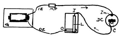
EXPERIMENT 161. Magnetic figures.
402. Directions. (A) Arrange as in Fig. 126. The key should
be used in case a dry
cell acts as the source
of the current. Two
good cells joined in
series can be used to
advantage. Lay the
coil flat upon the table
and place on it a piece of stiff, smooth paper, or a sheet of glass.
(B) Sprinkle a few iron filings upon the glass, which may be
held in place by books. Gently tap the glass with a pencil while
you close the circuit at the key. Do the filings arrange themselves
as in the case of permanent magnets? Make a sketch of
the field, remembering that you have both N and S poles, and
compare it with previous results.
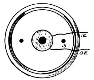
EXPERIMENT 162. Magnetic
figures.
403. Directions. (A) Arrange as
in Fig. 126, but stand the coil on end,
using the base as directed in § 407, to
hold it firmly in position. Join the
ends, O E and I E, to the key as
before. Fig. 127 shows a top view of
the coil and base.
(B) With books, etc., fix a piece of[168]
stiff, smooth paper, or glass just over the top of the core, and
proceed as in Exp. 161 to study the field. See § 417 for making
permanent pictures of magnetic fields.
EXPERIMENT 163. Magnetic field.
404. Directions. (A) Use same arrangement as for Exp. 162,
except filings and glass, which are replaced by the compass.
(B) Hold the compass about 2 in. from the top pole of the
electromagnet, close the circuit for a second or two and note
action of needle. Is the top N or S, when the current enters the
coil at O E? Compare result with § 392.
(C) Move the compass quickly about the pole, the circuit being
closed, and note action of needle. Compare result with directions
taken by particles of iron filings in Exp. 163.
(D) Reverse the direction of the current through the coil and
test the nature of the pole at the top.
405. Horseshoe Electromagnets. Fig. 128
shows a simple form of electromagnet with two coils
which have a bent piece of iron as a core for both. The
coils have to be wound on by hand in this form. As this
is troublesome, the coils are generally wound on two
separate cores which are joined by a yoke (§ 406), which
takes the place of the curved part in Fig. 128. The
separate coils can be quickly made with a "winder" and
joined to suit. (See Apparatus Book, Chapter IX, for
Home-made Electromagnets.) Fig. 129 shows a top view[169]
of a home-made experimental horseshoe electromagnet.
The coils are joined by an iron strap, called the yoke,
which is screwed to a wooden base. A strip of iron
placed above the magnets to be attracted by them, when
the current passes, is called the armature. (See Telegraph
Sounders.)
406. Use of Yoke. It has been explained (§ 82)
why horseshoe magnets are, in general, better than
straight ones. The same is true of electromagnets; there
are two poles to attract, and two to induce. The lines
of force pass through the yoke on their way from one
core to the other, and this reduces the resistance to them.
The strength of the horseshoe magnet would be greatly
reduced if the lines of force were obliged to pass through
two air spaces instead of one; in fact, if there were no
yoke we should have simply two straight magnets. The
yoke should be made of soft iron.
407. Experimental Magnets are quickly joined to a tin base
(No. 94), which has 3 holes punched in, through which screws can
be put to hold the cores in place. Fig. 127 shows plan of tin.
Fig. 130 shows how removable cores are fastened to the base, the
coils being on the spools, and Fig. 131 shows how home-made
coils on bolts can be used. The coils on bolts should be wound
as directed in Apparatus Book, Chapter X. The tin base also
serves as the yoke.
Removable Cores. Fig. 130. These are of soft iron (No. 92, 93).
In one end of each is a hole for the screws, S. Part of the tin
has been cut away in the Fig. The copper washer, C W,[170] should
be used. (See § 408.) Connectors are fastened to the ends of the
coils (§ 226–230).
Bolt Cores. Fig. 131. After winding on the coils, as directed
in Apparatus Book, remove the nut and put on an extra washer,
E W, so that the ends of the coils will not be pressed against the
tin, but come out between the two washers. Push the screw-end
of the bolt through holes (about 2 in. apart) punched in the tin,
then put on the nut, as shown. Do not force the nut on too far,—just
far enough to hold the cores in place. The ends of the
wires are not shown in Figs. 130, 131. Connectors are fastened
to them (§ 408).
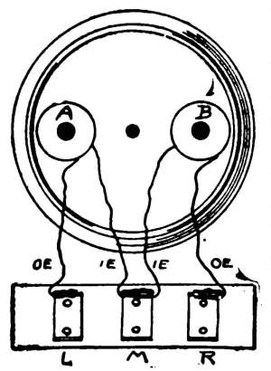
408. Method of Joining Coils. To produce the best results
the poles of the horseshoe electromagnet should be unlike. As
the coils are wound alike, their ends
must be joined in such a manner that
the current will pass around them in
opposite directions; that is, if the current
enters one coil at the outside end, O E,
it must enter the other coil at the
inside end, I E. Fig. 132 shows a plan
of the connections, spring connectors
being fastened to the coil-ends, to allow
rapid and easy changes in the arrangement.
L, M, and R are pieces of metal
fastened to a strip of wood (No. 95), used
to make connections from cells or other
apparatus. They are turned up at each
end as in Fig. 104, 3. Care should be
taken not to get short circuits by allowing two wires to touch the
tin base.
By changing the ends of the coils upon L, M, and R (left, middle,
and right), and by changing the direction in which the current
enters the "combination connecting plates" (No. 95), it is
evident that the nature of the poles can be regulated to suit.
EXPERIMENTS 164–173. To study horseshoe electromagnets.
Apparatus. Coils of wire with cores and yoke like those
explained in this chapter. Coils fastened to tin base or
yoke with wires leading from them to the combination[171]
connecting plates (No. 95, Fig. 132), are very handy.
Cells; iron filings; compass; iron strip (No. 76).
EXPERIMENT 164. To test the poles.
409. Directions. (A) Arrange as in Fig. 126, but use the experimental
magnets and combination connections (Fig. 132) in
place of the single coil shown in Fig. 126. Join O of the key
with L, and Zn of the cell with R of Fig. 132. When the key is
pressed the current will enter the magnets from L and leave at R.
(B) With the compass test the polarity of the cores as in Exp.
163, B, C. Make a sketch of the arrangement, and note which
pole is N and which S.
(C) See which way the current must pass around each coil, by
the way it is wound, and compare the results of (B) with Exp.
154, Fig. 123.
EXPERIMENT 165. To test the poles.
410. Directions. (A) Arrange as in Exp. 164, but reverse the
direction of the current through the coils. Do this by joining O
of the key (Fig. 126) with R of Fig. 132, and Zn of the cell with L.
(B) Repeat (B) and (C) of Exp. 164 and study results.
EXPERIMENT 166. To test the poles.
411. Directions. (A) Arrange all connections as in Exp. 164,
then reverse the positions of O E and I E of coil A; that is, join
O E to M, and I E to L, Fig. 132. This will make unlike ends
come together at M; in other words, when the current enters at
L and leaves at R it will pass
around both coils in the same
direction.
(B) Study the nature of the
poles, as in Exps. 164, 165, and
note results.
Note.—Fig. 133 shows simply
the two cores of a horseshoe electromagnet with arrows to
indicate in which direction the current is passing in each coil to
produce N and S poles.
EXPERIMENT 167. To study the inductive action of one
core upon the other.
412. Directions. (A) Arrange as for Exp. 164, but join the[172]
wire from Zn of the cell to M (Fig. 132). In this way coil B will
be cut out of the circuit. Place the coils in the E and W line.
(B) Find about how far the residual magnetism of the core of
B can act upon the compass-needle, holding the compass on the
side away from coil A, no current passing.
(C) Press the key for an instant, and note whether the magnetism
of coil B has been made stronger or weaker. Explain the
action of core A on core B.
EXPERIMENT 168. Magnetic figures.
413. Directions. (A) Arrange as in Exp. 164. With books, etc.,
fix a piece of smooth, stiff paper, or a sheet of glass, just above
the poles of the electromagnets.
(B) Sprinkle iron filings upon the glass, and gently tap it while
the circuit is closed at the key for a few seconds. Make a sketch
of the magnetic figure produced. Do the lines of force from the
opposite poles attract or repel each other? See § 417 for making
permanent figures. (See "Things a Boy Should Know About
Electricity" for drawings of magnetic figures.)
Note.—If possible, use two or three good cells in series for
making magnetic figures, as a fairly strong field is best.
EXPERIMENT 169. Magnetic figures.
414. Directions. (A) Arrange apparatus as for Exp. 165, and
make the magnetic figure for this combination, as directed in Exp.
168. Sketch and study the results.
EXPERIMENT 170. Magnetic figures.
415. Directions. (A) Arrange the apparatus and connections
as in Exp. 166, and make the magnetic figure of this combination
as directed in Exp. 168. In this case the poles are alike. Sketch
and study the results.
EXPERIMENT 171. Magnetic figures.
416. Directions. (A) Arrange apparatus and connections as
in Exp. 167, and make the magnetic figure of the combination as
directed in Exp. 168. Compare the figure produced with that of
Exp. 168. In this case the current passes through but one coil.
417. Permanent Magnetic Figures can be made in several
ways for future study and comparison.
(A) Paraffine paper figures. Make paraffine paper as directed in
Apparatus Book, page 135. For this purpose smooth, stiff, white[173]
paper is best, so that the filings will show plainly, and but a thin
coating of paraffine should be given. Place the magnets upon
the table, lay over them a piece of unparaffined paper, and fix
the paraffine paper directly over this. This is necessary, as the
coated paper sticks when heated. For electromagnets it will be
necessary to support the edges of the paper with books, etc.
Sprinkle on the filings and tap the paper to make them arrange
themselves while the circuit is closed. After the lines of force
show plainly, the current need not be used again, provided the
paper be kept perfectly still. Pass the flame of a Bunsen burner
over the paper to melt the coating. This will, no doubt, make
the two pieces of paper stick together, and permanently fix the
particles of filings in place. Do not heat the paper too much—just
enough to melt the paraffine. If you have no gas, hold a
fire-shovel, containing hot coals, over the paper. As soon as the
paraffine cools, the figures will stand considerable handling.
Blue print figures are very pretty, and last indefinitely. Get
some blue-print paper at a photographer's, who will give you
directions about "developing" it with water. Keep this in the
dark, and take out but one sheet at a time for experiments. To
make the figures, take your apparatus near a window where
bright sunlight comes in. Pull down the curtain so that you have
but a dim light when you make the magnetic figure, as directed
before. After the lines of force show plainly, raise the curtain,
and let the bright sunlight shine on it for 5 or 6 minutes, or until
the surface of the paper has a rich, bronze color. The paper
cannot be acted upon by the light under the particles of filings.
Quickly shake the filings from the paper, and wash it in 3 changes
of water to "develop" it, then pin the paper up to dry.
EXPERIMENT 172. Lifting power.
418. Directions. (A) Arrange the apparatus as in Exp. 164.
Hold an iron strip (No. 76), a screw-driver, or other iron bar
directly over and near the poles of the experimental electromagnet.
Close the circuit at the key, then lift the magnets by
the "armature," as the iron strip may be called, the circuit being
kept closed for a few seconds. If your cell is good there should
be no trouble in lifting the magnets by the armature. Open the
circuit, and see whether the magnets drop.
(B) Hold the magnets upside down directly over nails, tin[174]
boxes, iron filings, or other pieces of iron. Close the circuit,
move the attracted iron to another place on the table, and open
the circuit. Can this principle be used for practical purposes?
Note.—Some experiments illustrating practical uses of electromagnets
will be given in a future chapter.
EXPERIMENT 173. Residual magnetism when magnetic
circuit is closed.
419. Directions. (A) Arrange as in Exp. 164. You have
already seen that each core retains some magnetism after the
circuit is closed. Place the iron strip firmly across the poles,
close the circuit for an instant, open the circuit, then see whether
the armature still clings to the cores with some strength. The
armature should fit well upon the cores for this experiment.
(B) Again press the armature upon the cores, no current being
used; then lift it as in (A). Compare the attraction with that
found in (A).
420. Closed Magnetic Circuits. It was seen
in the study of the permanent horseshoe magnet, that the
armature clung strongly to the magnet. The armature
closed the magnetic circuit, the lines of force having
almost no resistance. In the case of electromagnets the
magnetic circuit becomes closed when the armature
touches both poles at the same time. The armature
clings strongly to the poles even after the current ceases
to flow. As soon as the magnetic circuit is broken,
however, but little residual magnetism remains. The
armatures of electromagnets are usually arranged so that
they can not quite touch the cores, to avoid this sticking.
[175]
CHAPTER XXIV.
THERMOELECTRICITY.
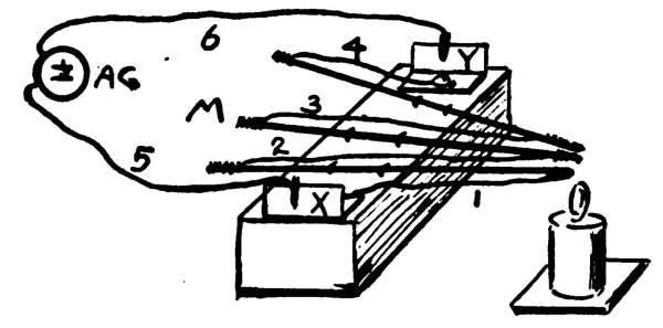
EXPERIMENT 174. To find whether electricity can be
produced by heat.
Apparatus. The home-made thermopile described in
§421; astatic galvanoscope; connecting wires; candle or
alcohol lamp.
421. Home-made Thermopile. (Fig. 134.) For this you need
3 hairpins, copper wire, a piece of wood about 3 in. long and 1 in.
square on the ends, 2 pieces of tin, and some small nails.
Straighten the hairpins and scrape the coating off with sandpaper
or a file. Scrape the insulation from 4 pieces of copper
wire, each about 8 in. long. Twist the ends of the copper wire
about the ends of the hairpins (Fig. 134), and then fasten the
hairpins to the block. They may be held firmly by small nails
which should be driven partly into the block and bent over. The
hairpins at the right-hand side of the Fig. are shown to be near
but not touching each other. This allows all to be heated at the
same time.
The tin binding-posts may be nailed or screwed to the block,
and if the bare copper wires 1 and 4 be placed under X and Y
before they are screwed down they will be electrically connected.
The ends of 1 and 4 may be held under the screw-heads. The[176]
block may be supported upon other blocks to raise it to the proper
height, which will depend upon the length of the candle.
A thermopile in the form of a circle with several pairs of metals,
can easily be made by fastening the hairpins to a piece of
cardboard (Fig. 135) with a hole at the
center. This may be supported by
blocks, the heat being applied under the
center.
422. Directions. (A) Arrange the
apparatus as in Fig. 134. See that the
astatic needle is properly adjusted, no
magnets being near it.
(B) Heat the joints as shown, and
watch the needle. Can a current be
produced by heat?
(C) Remove the connector on wire 6 from Y to M, thus cutting
one pair out of the circuit. Heat the joints again and compare
the strength of the current with that produced in (B).
(D) See whether much current is produced by one pair. From
results obtained do you see any relation between the strength of
the current and the number of pairs?
423. Thermoelectricity is produced by heating
the junction between two metals. Different pairs of metals
produce different results. Antimony and bismuth are
often used. If the end of a strip of bismuth be soldered
to the end of a similar strip of antimony, and the free
ends be connected to a galvanometer of low resistance, the
presence of a current will be shown when the point of
contact becomes hotter than the rest of the circuit. The
current will flow from the bismuth to antimony across the
joint. By cooling the junction below the temperature of
the rest of the circuit a current will be produced in the
opposite direction.
Thermoelectric currents have a low potential. The
energy of the current is kept up by the heat absorbed.
424. Peltier Effect. The action noted in § 423[177]
can be reversed; that is, if a current from a battery be
sent through the metals, the parts at the junction become
slightly warmer or cooler than before, depending upon
the direction of the current. This is known as the Peltier
Effect, the heat not being due to the resistance to the
current.
425. Thermopiles. As the E. M. F. of the current
produced by a single pair of metals is small, several
pairs are usually joined in series in such a way that the
different currents help each other and flow in the same
direction. Such combinations, usually made of antimony
and bismuth, are called thermoelectric piles, or simply
thermopiles. They are useful in detecting very small differences
in temperature. The heat of a match, or the cold
of a piece of ice, will produce a current even at some distance,
the thermopile being connected with a sensitive
short-coil astatic galvanometer. (See "Things a Boy
Should Know About Electricity.")
[178]
CHAPTER XXV.
INDUCED CURRENTS.
426. Electromagnetic Induction. You have
seen, by experiments, that a magnet has the power to induce
another piece of iron or steel to become a magnet.
You have also seen, in the study of static electricity, that
an electrified body has the power to act through space
upon another conductor. A body may be polarized and
charged with static electricity by induction.
Several questions now come up. Can a current of electricity
in a conductor induce a current in another conductor
not in any way connected with the first? Can
current electricity produce effects through space? Is
there an electromagnetic induction?
It has been seen that a current-carrying wire has a
magnetic field, and that magnetic fields can act through
space. It is evident, then, that a conductor will be surrounded
and cut by lines of force when it is placed in a
magnetic field, or near a wire or coil through which a current
passes. Let us study this by experiments.
EXPERIMENTS 175–182. To study induced currents.
Apparatus. The two coils of wire (Nos. 89, 90); two
short, soft iron cores (Nos. 92, 93); long iron core (No.
96); bar magnet (No. 97); astatic galvanoscope (No. 59);
dry cell (No. 51); key (No. 55); horseshoe magnet; connecting
wires with spring connectors (No. 54) on the ends
(§ 226–230); coil of wire (No. 98) wound on an iron core;
compass.
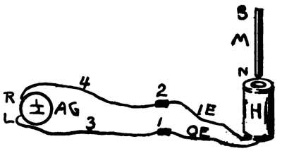
EXPERIMENT 175. To find whether a current can be
generated with a bar magnet and a hollowed coil of wire.
427. Directions. (A) Arrange as in Fig. 136. The coil (No.
90) of fine wire is joined to A G (No. 59) as shown. Small pieces[179]
of tin or copper, 1 and
2, are used to make
connections between
the coil ends and wires,
3 and 4, which are
attached to the galvanoscope.
It is best to
use the wires, 3 and 4,
so that the coil will be
2 feet at least, from
A G; otherwise the needle of A G might be affected by the
magnet, M (No. 97).
(B) Get clearly in mind in which direction the right-hand end of
the needle is deflected when a current enters A G at L, the left-hand
binding-post. If you have forgotten the results of previous
experiments, use the cell for an instant, touching the wire from
the carbon to L and that from the zinc to R. If any currents
come from the coil, later, you should be able to tell in which
direction they flow, the coil and A G forming a closed circuit.
(C) Hold the magnet, M, as shown, and quickly push it into the
coil until it has the place of a core, at the same time watching the
needle. If a current is produced, in which direction does it flow
from the coil? Does the needle remain deflected? Is the current
constant or temporary?
(D) After the magnet, M, has been placed in the coil, as in (C),
and the needle has come to rest, quickly pull M from the coil,
watching the needle. If a current is produced, does it pass from
the coil in the same direction as before, in (C)?
(E) Turn M end for end, repeat (C) and (D), and study the
results. Are lines of force made to cut the turns of the coil?
(F) Repeat (C) and (D), moving M slowly.
428. Discussion. An induced current, produced
as in the above experiment, is a momentary one. No
current passes when the magnet and coil are still; at least
one of them has to be in motion. When the magnet is
inserted, the induced current is said to be an inverse one,
as it passes in a direction opposite to that which would be
necessary to give the magnet its poles, it being considered[180]
a core magnetized by the current. A direct current is
produced when the magnet is withdrawn from the coil.
Rapid movements produce stronger currents than slow
ones. (See § 439.)
429. Induced Currents and Work. It takes
force to move a magnet through the center of a coil, and
it is this work that is the source of the induced current.
When the coil is pushed on to the magnet, or when it is
moved through a magnetic field, force is also required.
We have, in this simple experiment, the key to the action
of the dynamo and other important electrical machines.
These will be discussed later.
EXPERIMENT 176. To find whether a current can be generated
with a bar magnet and a coil of wire having an iron core.
430. Directions. (A) Arrange as in Exp. 175, Fig. 136, and,
in addition, place an iron core (No. 92) inside of the coil (No. 90).
(B) Hold the bar magnet (No. 97) as in Fig. 136, and quickly
lower it until it touches the core, at the same time watching the
needle. Study results, direction of current, etc., as before.
(C) Suddenly withdraw M from the core. Is the current produced
in the same direction as that from (B)?
(D) Turn M end for end and repeat (B) and (C).
(E) Repeat (C) and (D), moving magnet slowly.
How does the strength of the current compare with that of
Exp. 175? Are lines of force made to cut the turns of the coil?
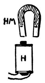
EXPERIMENT 177. To find whether a current can be generated
with a horseshoe magnet and a coil of wire
having an iron core.
431. Directions. (A) Arrange the apparatus as
in Exp. 176, but use the horseshoe magnet, H M,
instead of the bar magnet. Fig. 137 shows the coil
(No. 90) with one pole of H M held over the core.
(B) Study the effect of quickly lowering and raising
first one pole and then the other over the core, as
with the bar magnet. Get clearly in mind the direction
in which the induced current flows in each case.
[181]
432. Induced Currents and Lines of Force.
In the experiments just given, it should be remembered
that the permanent magnets are sending out thousands
of lines of force from their N poles, and receiving them
again at their S poles. As the magnet is pushed into
the coil (Exp. 175), the lines of force not only cut
through the turns of the coil, but the number of lines of
force that cut the coil at any instant varies rapidly as the
magnet is moved.
Motion is necessary, with this arrangement, to make a
change in the number of cutting lines of force. The current
passes only while the magnet moves; and the direction
of the current at any moment depends upon whether
the number of lines of force is increasing or decreasing
at that moment. (See § 438, 439.)
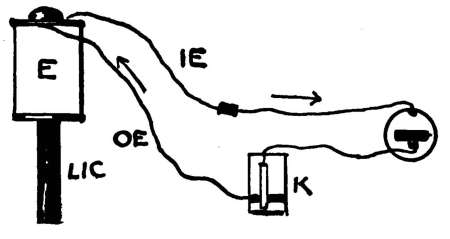
EXPERIMENT 178. To find whether a current can be
generated with an electromagnet and a hollow coil of wire.
433. Directions. (A) The hollow coil (No. 90) should be joined
to the astatic galvanoscope,
as shown in Fig.
136. Instead of the bar
magnet in Fig. 136, an
electromagnet is to be
used, and this should be
joined in series with a
cell and key, as shown
in Fig. 138. The current
from the cell will pass
only when K is pressed.
(B) Note from the winding which way the current must pass
around the coil when the circuit is closed at K, and determine
whether the lower end of the long iron core, L I C (No. 96)
should be N or S. With the compass test the poles of the core to
be sure you are right.
(C) Quickly lower the end of L I C into the hollow coil (H, Fig.
136), the circuit being kept closed long enough to allow the needle[182]
to partially come to rest again. Withdraw L I C before you open
the circuit. Explain action of needle.
(D) Reverse the direction of the current through the electromagnet,
by changing the connections, and repeat (C). Does any
induced current pass through A G when the core is held still in
the coil H, even though a current passes through coil E?
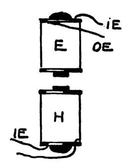
EXPERIMENT 179. To find whether a current can be
generated with an electromagnet and a coil of wire having an
iron core.
434. Directions. (A) Fig. 139 shows simply the arrangement
of coils. Coil H (No. 90) with core, is
joined to the galvanoscope as in Fig. 136.
Coil E, with short core, should be joined
to key and cell as shown in Fig. 138.
(B) Keeping in mind the polarity of the
lower end of core E, quickly lower it to the
core of H, the circuit being kept closed for
a few seconds. Does the needle remain
deflected after the motion ceases?
(C) Quickly raise E, the circuit being still
closed, then open the circuit. Compare the
directions taken by the induced currents in
(B) and (C).
435. Discussion of Exps. 178, 179. This
motion in straight lines is not suitable for producing currents
strong enough for commercial purposes. In order
to produce currents of considerable strength, the coils of
wire have to be pushed past magnets with great speed.
Special machines (see Dynamos) are constructed in which
the coils are wound so that they can be given a rapid
rotary motion as they fly past strong electromagnets. In
this way the coil can keep on passing the same magnets,
in the same direction, as long as force is applied to the
shaft that carries them.
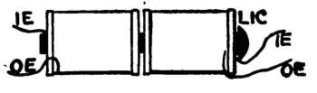
EXPERIMENT 180. To study the effect of starting or stopping
a current near a coil of wire or other closed circuit.
436. Directions. (A) Arrange as in Fig. 140. Place the two[183]
coils, H and E, on the same core,
L I C. Connect E with the key
and cell as before (Fig. 138).
Connect H with the astatic
galvanoscope, A G, as in Fig.
136. Keep the coils 2 or 3 feet
from A G, so that the needle will not be affected by them.
(B) Close the circuit at the key, watching the needle, then as
soon as the needle regains its former position, open the circuit
again. Compare the direction of the induced current in H with
that of the current in E, (1) when the main circuit is closed, and
(2) when it is opened. Is any current induced in H by a steady
current in E? (See Transformers.)
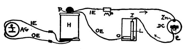
EXPERIMENT 181. To study the effect of starting or stopping
a current in a coil placed inside of another coil.
437. Directions. (A) Arrange as in Fig. 141. Join coil H
with the astatic galvanoscope, A G. Place the small coil P (No.
98) with core, inside of H, and connect the ends of P with the
key and cell, as shown.
(B) Close the circuit at K; watch the needle, and as soon as it
regains its position, open the circuit again.
Compare the direction of the induced current in H with that of
the inducing current in P, (1) when the inducing circuit is closed,
and (2) when it is broken. (See Induction Coils.)
438. Discussion of Exps. 180, 181. When a
current suddenly begins to flow through a coil, the effect
upon a neighboring coil is the same as that produced by
suddenly bringing a magnet near it; and when the current
stops, the opposite effect is produced.
We may consider that when the inducing circuit is[184]
closed, the lines of force shoot out through the turns of
the outside coil. Upon opening the circuit the lines of
force cease to exist; that is, we may imagine them drawn
in again.
439. Direction of Induced Current. Fig. 142
shows the magnet on its way into the coil;
the number of lines of force is increasing in
the coil, and the induced current passes in an
anti-clockwise direction when looking down
into the coil along the lines of force. This
produces an indirect current. If a current
from a cell were passed through the coil in
the direction of this indirect current, the lower
end of a bar of iron would become a S pole.
(See § 428.)
440. Laws of Induction. (1) An increase
in the number of lines of force that pass through a
closed circuit produces an indirect induced current; while
a decrease produces a direct one. (See § 428.)
(2) The E. M. F. of the induced current is equal to the
rate of increase or decrease in the number of lines of force
that pass through the circuit.
(3) A constant current produces no induced current,
provided there is no motion.
(4) Closing a circuit produces an indirect current.
(5) Opening a circuit produces a direct current.
(6) Lenz's Law. Induced currents have a direction
that tends to stop the motion that produces them.
441. Primary and Secondary Currents. In
the preceding experiments in induction, it must be kept
in mind that the current from the cell did not pass through
the galvanoscope. There were two entirely separate circuits,[185]
in no way connected. The primary current comes
from the cell, while the secondary current is an induced
one.
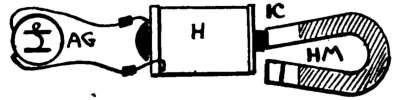
EXPERIMENT 182. To see what is meant by alternating
currents.
442. Directions. (A) Arrange as in Fig. 143. Connect coil H
with A G, as before. Place one pole of H M against the end of
the core I C, hold H with one hand, and with the other quickly
push the other pole of H M onto the core. This should produce
a momentary current through A G, first in one direction, and then
in the other. Let the needle come to rest.
(B) Move H M back and forth upon the end of I C, changing
its polarity rapidly. A minute's practice will enable you to slide the
core from one pole of H M to the other and back again rapidly—3
complete vibrations per second being about right. The needle
should be parallel to the coil of A G, and if properly done, the
needle will be made to vibrate back and forth slightly at each
change in the polarity of I C.
443. Direct and Alternating Currents. A
current that flows steadily in one direction is said to be a
direct current. A cell gives a direct current when the circuit
is closed. When the current passes in one direction for
an instant, and then reverses immediately and flows in
the opposite direction, it is said to alternate. The induced
current which flowed through the galvanoscope in Exp.
182 was an alternating one. Currents of this class have
great practical uses.
444. Self-Induction; Extra Currents. It has
been shown that a magnetized coil can act through space[186]
and induce a current in a neighboring coil. The lines of
force which reach out from an electromagnet will generate
a current in any conductor which happens to be in the
field, or which is moved across the lines. It is evident,
then, since the lines of force from each turn of a coil cut
all the other turns of the same coil, that each turn acts as
a conductor placed in the field of every other turn. The
instant a current begins to flow through a coil, there is an
inverse current of self-induction started in the coil, which
opposes the current in the cell. When the circuit is
broken, this extra current, as it is also called, is a direct
one and adds its strength to that of the current from the
cell; as this takes place at the instant the circuit is broken,
a bright spark is seen at the key, and this shows that the
E. M. F. of this extra current is high. Practical uses
are made of it.
[187]
CHAPTER XXVI.
THE PRODUCTION OF MOTION BY CURRENTS.
445. Currents and Motion. We have seen, in
the experiments on induced currents, that a current of
electricity can be generated by properly moving magnets
near coils of wire. (See Dynamo-electric Machines.)
Can we reverse this process? Can motion be produced
by the electric current?
EXPERIMENTS 183–190. To study the production of motion
by means of the electric current.
Apparatus. The support, including base, rod, and
support wire, S W (Fig. 144.) Coils of wire (No. 89, 90);
iron cores for coils; cell; key; connecting wires; compass;
current reverser; bar magnet; horseshoe magnet.
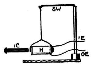
EXPERIMENT 183. Motion produced with a hollow coil
and a piece of iron.
446. Directions. (A) Arrange as in Fig. 144. Coil H (No. 90)
is to be used as a pendulum, and
can be supported by fastening a
string to it, the upper end of
which should be tied to S W.
Connect the ends of H with K
and D C. There will be a slight
magnetic field about H as soon as
the circuit is closed.
(B) Hold I C near the end of
the coil. Close the circuit for an
instant. Is there any motion produced in H? While the motion
will be slight, there should be enough to be noticed if the cell is
strong.
(C) Swing the suspended coil back and forth like a pendulum
for a minute, until you get in mind the rapidity of its vibrations.
Stop it, then repeat (B), closing and opening the circuit at regular
intervals, so that the little impulses given by the attraction for[188]
I C will gradually cause H to vibrate. The wires leading from
H should not drag upon the table.
EXPERIMENT 184. Motion with hollow coil and bar
magnet.
447. Directions. (A) Substitute the bar magnet M (No. 97)
for the iron of Exp. 183 (Fig. 144). Get clearly in mind the
polarity of the coil from the way the current flows through it,
then test it with the compass to find whether you are right.
(B) Hold the N pole of M near the left-hand end of the coil,
close the circuit for an instant and study results.
(C) Reverse the magnet and repeat (B). Compare the results
with those of Exp. 183. Try to make the coil vibrate.
EXPERIMENT 185. Motion with electromagnet and piece
of iron.
448. Directions. (A) Arrange as described in Exp. 183, Fig.
144. Place a short core inside of the coil and repeat. (See § 446
for directions.) Why is the motion produced much larger than
that given by a hollow coil?
(B) The coil can gradually be made to swing through quite a
little space by closing and opening the circuit regularly (§ 446, C).
Could any use be made of such a motion, if it were on a large
scale? Could it be made to run a machine?
EXPERIMENT 186. Motion with electromagnet and bar
magnet.
449. Directions. (A) Arrange as in Fig. 145, the coil being
suspended and connected as in
Exp. 183 (Fig. 144).
(B) Study the effect of closing
the circuit when the N pole of M
is held near the core of H. Reverse
M, and repeat.
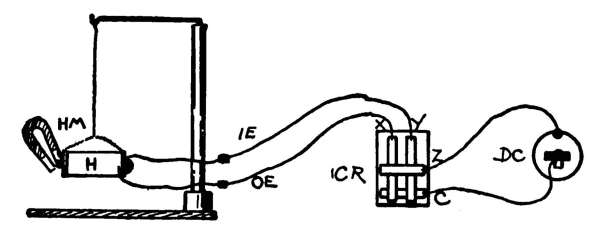
EXPERIMENT 187. Motion
with electromagnet and horseshoe magnet.
450. Directions. (A) Arrange as in Fig. 146. The ends of
H (No. 89) are joined to X and Y of the current reverser C R
(No. 57). It is evident, then, that the direction of the current
through H can be easily and rapidly reversed by C R. (See
Exp. 103.) Either pole of the horseshoe magnet H M will attract
I C when it is not magnetized.
[189]
(B) Place the end of I C near the N pole of H M so that it will
be attracted to it. You have learned that like poles repel each
other, so press the lever of C R that will produce a N pole at the
left-hand end of I C. The core I C should be repelled by the N
pole of H M and be instantly attracted by its S pole.
(C) Rapidly reverse the current and make I C jump back and
forth from one pole to the other. The results of this experiment
should be remembered, as they will aid in understanding motors.
A core ¼ in. in diameter can be placed in between the poles and
be made to vibrate rapidly as the current is reversed.
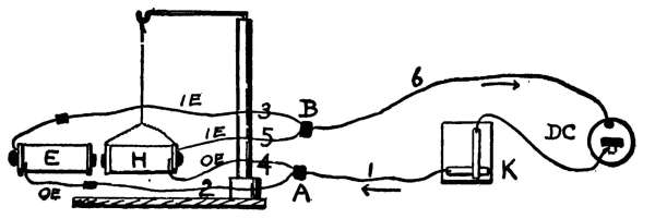
EXPERIMENT 188. Motion with two electromagnets.
451. Directions. (A) Arrange as in Fig. 147. Join the two coils,
H and E, in parallel. Connect their two outside ends O E to a
metal plate A, and their inside ends I E to B. Join wires 1 and 6
to K, D C, A and B, as shown. When the circuit is closed at K,
the current will pass along wire 1 and divide at A, entering E
and H at the same time by wires 2 and 4 and returning through 3
and 5 to B, and thence to D C.
(B) Close the circuit for an instant with wires arranged as in
Fig. 147. Do the electromagnets attract or repel each other?[190]
Study out the direction in which the current passes around the
coils, and see whether they should attract or repel.
(C) Change wire 4 to B, and wire 5 to A. The polarity of H,
only, will be changed when this circuit is closed. Press the key
for an instant and study the results.
452. Discussion of Exps. 183–188. From the
results it is evident that motion can be produced with
the aid of the electric current in many different ways. It
can be produced at the ends of wires which simply reach
across the room, or which reach miles from the source of
the current. To get practical results for commercial
purposes we require a proper source of current, proper
conductors, and proper apparatus to convert the motions
into useful work. The motions given to the parts of the
apparatus in the previous experiments are not suitable
for commercial purposes, as they are in straight lines. A
rotary motion is needed to do good work; and when this
is applied to a shaft, belts can be used to run all sorts of
machinery. (See Electric Motors.)
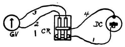
EXPERIMENT 189. Rotary motion with a hollow coil of
wire and a permanent magnet.
453. Directions. (A) Arrange as in Fig. 148. A key can be
used instead of the reverser.
The coil of the galvanoscope,
G V, has a magnetic field
about it when the circuit is
closed. The needle has a
permanent field.
(B) Close the circuit for an
instant, let the needle swing back past the zero mark, close the
circuit again, etc., until the added impulses give the needle a
complete turn.
(C) Keep the needle turning on its axis by opening and closing
the circuit at the proper time. With a little practice you can
make it turn rapidly.
(D) Reverse the motion of the needle. (See § 455.)
[191]
EXPERIMENT 190. Rotary motion with an electromagnet
and a permanent magnet.
454. Directions. (A) Arrange as in Fig. 149. Place the compass
a short distance from the end of the core of the coil H (No.
89). Close the circuit, and as soon as the needle gets part way
around open it again, closing it at the proper time to give the
needle a new impulse. The speed can be regulated, somewhat,
by changing its distance from the core. A key may be used in
place of a reverser.
(B) Reverse the direction of rotation.
455. Discussion of Exps. 189–190. We have,
in these experiments, the key to the action of electric
motors. By properly opening and closing the circuit,
the rotary motion can be kept up as long as current is
supplied. If a small pulley were attached to the top of
the compass-needle in Exp. 190, a tiny belt could be
attached, and we should have a machine that could do,
perhaps, a fly-power of work. (See Electric Motors.)
[192]
CHAPTER XXVII.
APPLICATIONS OF ELECTRICITY.
456. Things Electricity Can Do. Among the
almost countless things that electricity can do are the
following: It signals without wires. It drills rock, coal,
and teeth. It cures diseases and kills criminals. It
protects, heats, and ventilates houses. It photographs
the bones of the human body. It rings church bells and
plays church organs. It lights streets, cars, boats, mines,
houses, etc. It pumps water, cooks food, and fans you
while eating. It runs all sorts of machinery, elevators,
cars, boats, and wagons. It sends messages with the
telegraph, telephone, and search-light. It cuts cloth,
irons clothes, washes dishes, blackens boots, welds metals,
prints books, etc., etc.
As this book deals almost exclusively with experiments,
to be performed with simple, home-made apparatus, space
cannot be given for a discussion of the many instruments
and machines which make electricity a practical every-day
thing. (See "Things A Boy Should Know About
Electricity.") The principles upon which a few important
instruments depend, however, will be given.
EXPERIMENT 191. To study the action of a simple
"telegraph sounder."
457. Directions. (A) Arrange as in Fig. 150. The electromagnet
is supported upon its base, as directed in § 407. Coil H,
K, and D C are joined in series. The iron strip, I, can be held
by the left hand, while K is worked with the right.
(B) Press the key, closing the circuit for different lengths of
time, and note that the armature, I, responds exactly to the
motions at K.
[193]
458. Discussion. The downward click makes a
distinct sound, and in regular instruments the armature
is allowed to make an upward click, also. The time
between the two clicks can be short or long to represent
dots or dashes, which, together with spaces, represent
letters. (For telegraph alphabet, and complete
directions for making and connecting a home-made telegraph
line, see Apparatus Book.)
459. Telegraph Line; Connections. Fig. 151
shows complete connections for a home-made telegraph
line. The capital letters are used for the right side, R,
and small letters for the left side, L.
Gravity cells, B and b, are used. The sounders S and
s, and the keys, K and k, are shown by a top view, or
plan. The broad black lines of S and s represent the
armatures, which are directly over the electromagnets.
The keys have switches, E and e.
The two stations, R and L, may be near each other or
in different houses. The return wire, R W, passes from
the copper of b to the
zinc of B. This is important,
as the cells
must help each other;
that is, they are in
series. The line wire,
L W, passes from one
station to the other, and[194]
the return may be through a wire, R W, or through the
earth; but for short lines a return wire is best.
460. Operation of Line. Suppose R (right) and
L (left) have a line. Fig. 151 shows that R's switch, E,
is open, while e is closed. The entire circuit, then, is
broken at but one point. As soon as R presses his key,
the circuit is closed, and the current from both cells
rushes around from B through K, S, L W, s, k, b, R W
and back to B. This makes the armatures of S and s
come down with a click at the same time. (See Exp.
191.) As soon as the key is raised, the armatures raise,
making the up-click. (See § 458.) As soon as R has
finished, he closes his switch, E. L then opens e and
answers R. Both E and e are closed when the line is
not in use, so that either can open his switch at any
time and call up the other. Closed circuit cells are used
for such lines. On large lines the current from a dynamo
is used.
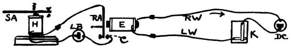
EXPERIMENT 192. To study the action and use of the
"relay" on telegraph lines.
461. Directions. (A) Arrange as in Fig. 152. Place K and
D C at one end of the table to represent the sending station. At
the other end of the table place E, which is the electromagnet of
the relay, and H, the electromagnet of the sounder. Connect the
ends of E with K and D C, L W being the line wire, and R W the
return. In practice, the return is through the earth. The relay
armature, R A, should vibrate towards E every time K is pressed.
C is a piece of copper against which R A presses each time it is
attracted by E, and this closes what is called the local circuit.
Connect the poles of another battery, L B, with C and H, and the[195]
other end of coil H with R A. The sounder armature, S A, should
be arranged as in Exp. 191. Small springs are shown on the two
armatures, and these keep them away from the cores when the
circuits are open.
(B) Fasten the parts to a board, and study the connections and
action of this home-made outfit.
462. The Relay replaces the sounder in the line wire circuit,
and its coils are usually wound with many turns of fine wire, so
that a feeble current will move its nicely adjusted armature.
Owing to the large resistance of long telegraph lines, the current
is weak when it reaches a distant station, and not strong enough
to work an ordinary sounder. The current passes back from the
relay to the sending station through
the earth. The relay armature acts
as an automatic key to open and close
the local circuit, which includes also
a battery and sounder. The line
current does not enter the sounder.
(See "Things A Boy Should Know
About Electricity.")
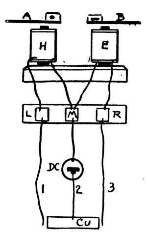
EXPERIMENT 193. To study
the action of a two-pole telegraph
instrument.
463. Directions. (A) Arrange as
in Fig. 153. Connect the two coils
to the connecting plates, as described
in § 408. Join a strip of copper Cu
with wire 2 leading from D C, and
join the zinc of D C to M. The ends
of wires 1 and 3 should be near Cu
but they must not touch it. If Cu be slightly curved so that
its ends are raised above the table, the ends of wires 1 and 3 may
be put directly under the ends of Cu; each half of Cu can then
be used as a key. Two armatures, A and B, should be held as
shown. D C can be placed at one side, of course, its terminals
being joined to M and Cu.
(B) Press first one end and then the other of Cu, so that the
current will pass through H or E at will.
(C) Paste pieces of paper to the armatures, the left one being
marked with a dot, and the other with a dash. The one who[196]
sends the message can make dots or dashes at the instrument by
pressing the proper key. This form of instrument can be easily
made by boys, and the messages are more easily read by the eye
than by the ear, as in regular
sounders.
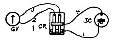
EXPERIMENT 194. To
study the action of a simple
"single needle telegraph instrument."
464. Directions. (A) Arrange
as in Fig. 154. Stick a pin on each side of the N pole of
the galvanoscope-needle through the degree-card, so that the
needle can make but part of a turn when the circuit is closed.
(B) Touch one lever of the reverser C R, then the other, to see
whether connections are right. The needle should be forced
against one pin and then against the other. If motions to the
left represent dots, and those to the right dashes, combinations of
dots and dashes can be used for letters as in the "sounder"
(Exp. 191).
(C) Arrange the apparatus shown in Fig. 122 so that messages
can be sent.
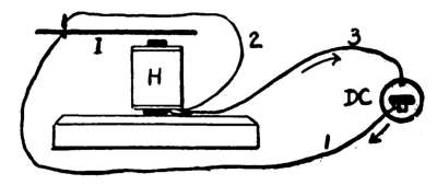
EXPERIMENT 195. To study the action of a simple automatic
"contact breaker," or "current interrupter."
465. Directions. (A) Arrange as in Fig. 155. Slip a spring
connector attached to wire 1 upon the iron strip I, a short distance
from its end. Hold the left-hand end of I firmly in one
hand, and with the other hold the connector on wire 2 just above
that on 1. The right-hand end of I should be just above the
core of H.
(B) Allow the current to pass through the circuit by touching
the two connectors together gently. Does the armature make
one click, as in the telegraph sounder, or does it vibrate rapidly?
(C) Try the connectors
in various positions on I.
466. Automatic
Current Interrupters
are used on bells,
buzzers, induction
coils, etc. The principle[197]
upon which they work is shown in the above experiment
(Fig. 155). The current, as it comes from the
carbon of D C, is obliged to stop when it reaches I, unless
the two connectors touch. As soon as the current passes,
I is pulled down and away from the upper connector,
and this breaks the circuit. I, being held firmly in the
hand, immediately springs back to its former position,
closing the circuit. The rapidity of the vibrations
depends somewhat upon the position of the connectors
upon I. In regular instruments, a platinum point is used
where the circuit is broken; this stands the constant
sparking at that point.
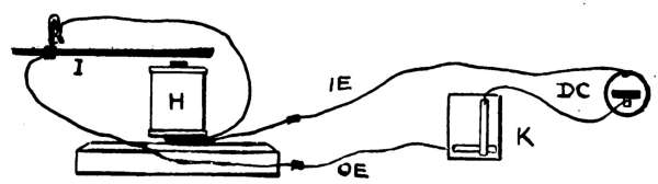
EXPERIMENT 196. To study the action of a simple "electric
bell," or a "buzzer."
467. Directions. (A) Fig. 156 shows the circuit explained in
Exp. 195, with a key or push-button put in, so that the circuit
can be closed at a distance from the vibrating armature.
(B) Have a friend work the key while you hold I and wires 1
and 2 as directed in Exp. 195. The circuit must not be broken at
two places, of course, so begin by holding the two connectors
together. The armature should vibrate rapidly each time K is
pressed.
468. Electric Bells and Buzzers are very nearly
alike in construction; in fact, you will have a buzzer by
removing the bell from an ordinary electric bell. Buzzers
are used in places where the loud sound of a bell would
be objectionable.
[198]
By placing a bell near the end of the vibrating armature
(Fig. 156), so that the bell would be struck by it at each
vibration, we should have an electric bell. By making
the wires 1 and 3 long, the bell or buzzer can be worked
at a distance. (See Apparatus Book, Chapter XV, for
Home-made Bells and Buzzers.)
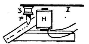
EXPERIMENT 197. To study the action of a simple
telegraph "recorder."
469. Directions. (A) Cut from a tin box, or can, a piece of
tin about 4 in. long and 1½ in. wide.
Bend this double to make two thicknesses.
This will serve as an armature
I (Fig. 157). Nail to one end
of I a small spool, S, and into this
put a short length of lead-pencil, P,
which may be held firmly in S by
wrapping a little paper around it. Connect the ends of coil H
to a key and cell as in Fig. 156.
(B) Hold or fasten I in place, and have a friend make dots and
dashes at the key, while you draw a piece of paper past the end of
P. A little adjusting will be necessary to get the pencil to
write only while the circuit is closed. In regular machines all
the parts are automatic.
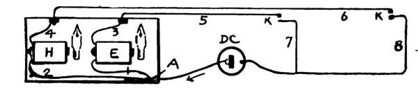
EXPERIMENT 198. To study the action of a simple "annunciator."
470. Directions. (A) Arrange as in Fig. 158. Fasten the two
electromagnets, H and E, to a board or a piece of stiff cardboard.
They may be held in place by passing strings over them and
through the board, tying on the other side. The ends of coils H
and E should be joined to pieces of tin, A, B, C, by means of
connectors. K and K are keys or push-buttons, which in real
instruments are in different rooms. Two steel pens may be[199]
swung on pins a short distance from the ends of the cores, so
that their lower ends will be attracted to the cores the instant the
current passes through them. The residual magnetism should
hold them against the cores until removed. Hairpins, nails, or
needles can be used instead of pens.
(B) Press first one K and then the other to see whether your
connections are correct.
471. Annunciators. There are many forms of
annunciators in use to indicate, in a hotel for example, a
certain room when a bell rings at the office. If a bell be
included in the circuit between D C and A in Fig. 158,
it will ring each time a key is pushed. This will call
attention to the fact that some one has rung, and the
annunciator will show the location of the special call.
Large instruments are made with hundreds of electromagnets,
each one answering to a special room. The
instrument should be set, of course, after each call. A
nail or screw wound with insulated wire can be used for
the electromagnets of a home-made annunciator.
EXPERIMENT 199. To study the shocking effects of the
"extra current."
472. Directions. (A) Use the two electromagnets joined to
the connecting plates (Fig. 132), to generate a self-induced or
extra current. Connect R of Fig. 132 with the zinc of a dry cell,
and between L and the carbon of the cell place a key; in other
words, join the electromagnets, cell, and key in series. Two
good cells in series can be used to advantage.
(B) Wet the ends of two fingers of the left hand, press one upon
L and the other on R, thus making a shunt with your hand.
With the right hand work the key rapidly. If the current is strong
enough you should feel a slight shock in the fingers each time
the circuit is broken. The extra current (§ 444) causes the shock
as it shoots through the fingers.
(C) If you have electric bells or telegraph sounders use them
for this experiment.
473. Induction Coils are instruments for producing
induced currents of high E. M. F. The apparatus shown[200]
in Fig. 141 forms a simple induction coil. The primary
coil is made of coarser wire and has less turns of wire
than the secondary coil. The current in the primary
circuit is usually interrupted by an automatic interrupter
(Exp. 195), thus producing an alternating current in the
secondary coil, the voltage of which depends upon the
relative number of turns in the two coils. Induction
coils are used in telephone work, for medical purposes,
for X-ray work, etc., etc.
(For Home-made Induction Coils see Apparatus Book,
Chapter XI.)
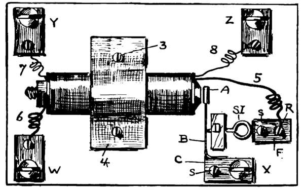
474. Action of Induction Coils. Fig. 159 shows a top view of
one of the home-made induction coils described, in full, in the
Apparatus Book. Wires 5 and 6 are the ends of the primary
coil, while wires 7 and 8 are the terminals of the secondary coil.
The battery wires should be joined to binding-posts W and X,
and the handles to Y and Z. Fig. 160 shows the details of the
automatic interrupter which is placed in the primary circuit.
If the current enters at W, it will pass through the primary
coil and out at X, after going through 5, R, F, S I, B, E and C.
The instant the current passes, the bolt becomes magnetized;
this attracts A, which pulls B away from the end of S I, thus
automatically opening the circuit. B at once springs back to its[201]
former position against S I, as A is no
longer attracted; the circuit being
closed, the operation is rapidly repeated.
(For commercial forms and uses of
induction coils see "Things A Boy
Should Know About Electricity.")
475. Transformers, like induction
coils, are instruments for
changing the E. M. F. and strength of currents.
There is very little loss of energy in well-made transformers.
They consist of two coils of wire on the same
core; in fact, an induction coil may be considered a
transformer. If the secondary coil has 100 times as
many turns of wire as the primary, a current with an
E. M. F. of 100 volts can be taken from the secondary
coil, when the E. M. F. of the current passing through
the primary is 1 volt; but the strength (amperes) of the
secondary current will be but one-hundredth that of the
primary current. By using the coil of fine wire as the
primary, the E. M. F. of the current that comes from the
other coil will be but one-hundredth that in the fine coil.
It will have 100 times its strength, however. Continuous
currents from cells or dynamos must be interrupted, as in
induction coils, to be transformed from one E. M. F. to
another. Transformers are now largely used in lighting
and power circuits, etc. (See "Things A Boy Should
Know About Electricity.")
476. The Dynamo. We saw in the Exps. of
Chapter XXV. that currents of electricity can be generated
in a coil of wire (closed circuit) by rapidly moving
it through the field of a magnet. As shown by the
experiments, this can be accomplished in many ways.
The dynamo is a machine for doing this on a large scale,
the coils being given a rotary motion in a very strong[202]
magnetic field; and as the number of lines of force that
cut the coil is constantly changing, there is a current in
the coil as long as power is applied, and this current is
led from the machine by proper devices.
The dynamo is a machine for converting mechanical
energy into an electric current, through electromagnetic
induction.
If a loop of wire (Fig. 161) be so arranged on bearings
at its ends that it can be made to revolve, a current will
flow through it in one direction during one-half of the
revolution, and in the opposite direction during the other
half, it being insulated from all external conductors.
Such a current inside of the machine would be of no
value; it must be led out to external conductors. Some
sort of sliding contact is necessary to connect a revolving
conductor with a stationary one.
Fig. 162 shows the ends of a coil joined to two rings,
X, Y, which are insulated from each other, and which
rotate with the coil. Two stationary pieces of carbon, A,
B, called brushes, press against the rings, and to these are
joined wires which complete the circuit, and which lead
out where the current can do work. The arrows show
the direction of the current during one-half of a revolution.
The rings form a collector, and this arrangement
gives an alternating current.
[203]
In Fig. 163 the ends of the coil are joined to the two
halves of a cylinder. These halves, X and Y, are
insulated from each other and from the axis. The current
flows from X onto the brush A, through some external
circuit where it does work, and thence
back through brush B onto Y. By the
time that Y gets around to A the
direction of the current in the loop
has reversed, so that it passes towards
Y; but it still enters the outside circuit
through A because Y is then in
contact with A. This device is called
a commutator, and it allows a constant or direct current
to leave the machine.
In regular machines there are many loops of wire and
several segments to the commutator. The rotating coils
are wound upon an iron core, so that the lines of force, in
passing from one pole to the other, will meet with as
little resistance as possible. The coils, core, and commutator,
taken together, are called the armature. The
magnets which furnish the field are called the field-magnets.
These are electromagnets, the current from
the dynamo, or a part of it, being used to excite them.
There are many forms of dynamos, and many ways of
winding the armature and field-magnets, but space will
not permit a discussion of them here. (See "Things a
Boy Should Know About Electricity.")
477. The Electric Motor. Experiments have
shown that motion can be produced by the electric current
in many ways. The galvanoscope may be considered a
tiny motor.
An electric motor is a machine for transforming electric
energy into mechanical power.
[204]
While the electric motor is similar in construction to
the dynamo, it is opposite to it in action. Motors receive
current and produce motion. The motion is a rotary
one, the power being applied to other machines by means
of belts or gears.
EXPERIMENT 200. To study the action of the telephone.
478. Directions. (A) Join the ends of coil H (Fig. 164) to the
astatic galvanoscope. Move
magnet M back and forth in
front of the soft iron core, while
H is held in position. Watch
the needle. Imagine that vibrations
in the air caused by the
voice are strong enough to give
M a slight motion to and fro, and you can see how a current
would be sent through the galvanoscope by speaking against M.
479. The Telephone is an instrument for reproducing
sounds at a distance, and electricity is the agent
by which this is generally accomplished. The part
spoken to is called the transmitter, and the part which
gives the sound out again is called the receiver. Sound
itself does not pass over the line. Although the same
apparatus may be used for both transmitter and receiver,
they are generally different in construction.
480. The Bell or Magneto-transmitter generates
its own current, and is, strictly speaking, a dynamo
that is run by the voice. You have seen, by experiments,
that a current can be generated in a coil of wire by
moving a magnet back and forth in front of its soft iron
core. In the telephone this process is
reversed, soft iron in the shape of a
thin disc (D, Fig. 165) being made to
vibrate by the voice immediately in
front of a coil having a permanent
magnet, M, for a core.
[205]
The soft iron diaphragm is fixed near, but it does not
touch the magnet. The coil consists of many turns of
fine insulated wire. The current generated is an alternating
one and exceedingly feeble; in fact, it can not be
detected by a galvanoscope.
481. The Receiver has the same construction as the
bell transmitter, and receives the currents from the line.
As the diaphragm is always attracted by the magnet, it
is under a constant strain. This strain is increased when
a current passes through the coil in a direction that adds
strength to the magnet, and decreased when the current
weakens the magnet.
When the current through the coil is always in the
same direction, but varies in strength, the diaphragm
will vibrate on account of the varying pull upon it.
When the current through the coil is an alternating
one, the same result is obtained, as the magnet gets
weaker and stronger many times per minute. Fig. 166
shows two bell instruments joined, either being used as
the transmitter and the other as the receiver.
482. The Carbon Transmitter does not in itself
generate a current like the magneto-transmitter; it
merely produces changes in the strength of a current that
flows through it, and that comes from some outside
source.
In Fig. 167, X and Y are two carbon buttons, X being
attached to the diaphragm, D. Button Y presses gently
against X. When D is caused to vibrate by the voice,[206]
X is made to press more or less against Y, and this allows
more or less current to pass through the circuit, in which
also is the receiver, R. This direct undulating current
changes the pull upon the diaphragm of R, causing it to
vibrate and reproduce the original sounds spoken into the
transmitter.
483. Induction Coils in Telephone Work.
As the resistance of telephone lines is large, a current
with a fairly high E. M. F. is desired. While the current
from one or two cells is sufficient to work the transmitter,
it is not strong enough to force its way over a long
line. To get around this difficulty an induction coil is
used to transform the battery current, that flows through
the transmitter and primary coil, into a current with a
high E. M. F. that can go into the main line and force
its way to a distant receiver.
The battery current in the primary coil is undulating,
but always in the same direction, the magnetic field
around the core getting weaker and stronger. This
causes an alternating current in the secondary coil and
main line.
Fig. 168 shows the two coils, P, S, of the induction
coil. The primary, P, is joined in series with a cell[207]
and transmitter. The secondary coil, S, is joined to the
receiver. One end of S can be grounded, the current
completing the circuit through the earth and into the
receiver through another wire entering the earth. There
are many forms of transmitters. (See "Things a Boy
Should Know About Electricity.")
484. Electric Lighting and Heating. Whenever
resistance is offered to the electric current, heat is
produced. By proper appliances, the heat of resistance
can be applied just where it is needed, and many commercial
processes depend upon electricity for their success.
Dynamos are used to generate currents for lighting
and heating purposes. There are two great systems
of lighting, the one by arc lamps and the other by
incandescent lamps. (See "Things a Boy Should Know
About Electricity.")
485. Arc Lamps produce a light when a current
passes from one carbon rod to the other across an air-space.
As the current starts through the lamp, the ends
of the carbons touch, and the imperfect contact causes
resistance enough to heat the ends red-hot. They are
then automatically separated, and the current passes from
one to the other, causing the "arc." The resistance of
the air-space is reduced by the intensely heated vapor
and flying particles of carbon.
486. The Incandescent Lamp consists of a glass
bulb, in which is a vacuum, and the light is caused by
the passage of a current through a thin fibre of vegetable
carbon, enclosed in the vacuum. The fibre would burn
instantly if allowed to come in contact with the air. The
fibres have a high resistance, and are easily heated to
incandescence.
[208]
CHAPTER XXVIII.
WIRE TABLES.
Copper Wire Tables are very convenient, and a necessity
when working electrical examples. The tables here given
are taken from a dealer's catalogue, and will be found
sufficiently accurate for ordinary work.
Explanation of Tables. In the first column are given
the sizes of wires by numbers. The B & S or American
gauge is used. In the table below is given a comparison
between the B & S and the Birmingham gauges.
The second column gives the diameters of wires. The
diameter of No. 36 wire is 5 thousandths of an inch; the
diameter of No. 24 wire is a little over 20 thousandths or
2 hundredths of an inch.
The third column contains what is called circular mils,
a mil being a thousandth of an inch. The figures in this
column are obtained by squaring those in the second;
thus, for No. 36 wire, 5 × 5 = 25. This column is useful
when working examples where the squares of the
diameters are wanted. The rest of the table explains
itself.
The table at the bottom gives a comparison between
the fractional and decimal parts of an inch. Space can
not be given here for a series of examples showing the
many uses of this table. (See "Elementary Electrical
Examples.")
[209]
COPPER WIRE TABLES. (Based on the B. A. Unit.)
| Gauge |
DIAMETER. |
Sectional
AREA |
Capacity. |
OHMS |
| B.&S. No. |
In
1000ths |
In
Circular
Mils. |
In Amperes. |
Per
1,000
feet. |
Per Mile. |
Per Pound. |
| 0000 | .460 | 211600. | 312. | .04906 | .25903 | .000077 |
| 000 | .40964 | 167805. | 262. | .06186 | .32664 | .00012 |
| 00 | .3648 | 133079. | 220. | .07801 | .41187 | .00019 |
| 0 | .32486 | 105534. | 185. | .09831 | .51909 | .00031 |
| 1 | .2893 | 83694. | 156. | .12404 | .65490 | .00049 |
| 2 | .25763 | 66373. | 131. | .15640 | .8258 | .00078 |
| 3 | .22942 | 52634. | 110. | .19723 | 1.0414 | .00125 |
| 4 | .20431 | 41743. | 92.3 | .24869 | 1.313 | .00198 |
| 5 | .18194 | 33102. | 77.6 | .31361 | 1.655 | .00314 |
| 6 | .16202 | 26251. | 65.2 | .39546 | 2.088 | .00499 |
| 7 | .14428 | 20817. | 54.8 | .49871 | 2.633 | .00792 |
| 8 | .12849 | 16510. | 46.1 | .6529 | 3.3 | .0125 |
| 9 | .11443 | 13094. | 38.7 | .7892 | 4.1 | .0197 |
| 10 | .10189 | 10382. | 32.5 | .8441 | 4.4 | .0270 |
| 11 | .090742 | 8234. | 27.3 | 1.254 | 6.4 | .0501 |
| 12 | .080808 | 6530. | 23. | 1.580 | 8.3 | .079 |
| 13 | .071961 | 5178. | 19.3 | 1.995 | 10.4 | .127 |
| 14 | .064084 | 4107. | 16.2 | 2.504 | 13.2 | .200 |
| 15 | .057068 | 3257. | 13.6 | 3.172 | 16.7 | .320 |
| 16 | .05082 | 2583. | 11.5 | 4.001 | 23. | .512 |
| 17 | .045257 | 2048. | 9.6 | 5.04 | 26. | .811 |
| 18 | .040303 | 1624. | 8.1 | 6.36 | 33. | 1.29 |
| 19 | .03589 | 1288. | .... | 8.25 | 43. | 2.11 |
| 20 | .031961 | 1021. | .... | 10.12 | 53. | 3.27 |
| 21 | .028462 | 810. | .... | 12.76 | 68. | 5.20 |
| 22 | .025347 | 642. | .... | 16.25 | 85. | 8.35 |
| 23 | .022571 | 509. | .... | 20.30 | 108. | 13.3 |
| 24 | .0201 | 404. | .... | 25.60 | 135. | 20.9 |
| 25 | .0179 | 320. | .... | 32.2 | 170. | 33.2 |
| 26 | .01594 | 254. | .... | 40.7 | 214. | 52.9 |
| 27 | .014195 | 201. | .... | 51.3 | 270. | 84.2 |
| 28 | .012641 | 159.8 | .... | 64.8 | 343. | 134. |
| 29 | .011257 | 126.7 | .... | 81.6 | 482. | 213. |
| 30 | .010025 | 100.5 | .... | 103. | 538. | 338. |
| 31 | .008928 | 79.7 | .... | 130. | 685. | 539. |
| 32 | .00795 | 63. | .... | 164. | 865. | 856. |
| 33 | .00708 | 50.1 | .... | 206. | 1033. | 1357. |
| 34 | .006304 | 39.74 | .... | 260. | 1389. | 2166. |
| 35 | .005614 | 31.5 | .... | 328. | 1820. | 3521. |
| 36 | .005 | 25. | .... | 414. | 2200. | 5469. |
| 37 | .004453 | 19.8 | .... | 523. | 2765. | 8742. |
| 38 | .003965 | 15.72 | .... | 660. | 3486. | 13772. |
| 39 | .003531 | 12.47 | .... | 832. | 4395. | 21896. |
| 40 | .003144 | 9.88 | .... | 1049 | 5542. | 34823. |
| Gauge |
FEET. |
POUNDS. |
| B.&S. No. |
Per Pound. |
Per Ohm. |
Per
1,000 feet. |
Per Ohm. |
| 0000 | 1.56122 | 20497.7 | 640.51 | 12987. |
| 000 | 1.9687 | 16255.27 | 507.95 | 8333. |
| 00 | 2.4824 | 12891.37 | 402.83 | 5263. |
| 0 | 3.1303 | 10223.08 | 319.45 | 3225. |
| 1 | 3.94714 | 8107.49 | 253.34 | 2041. |
| 2 | 4.97722 | 6429.58 | 200.91 | 1282. |
| 3 | 6.2765 | 5098.61 | 159.32 | 800. |
| 4 | 7.9141 | 4043.6 | 126.35 | 505. |
| 5 | 9.97983 | 3206.61 | 100.20 | 318. |
| 6 | 12.5847 | 2542.89 | 79.462 | 200. |
| 7 | 15.8696 | 2015.51 | 63.013 | 126. |
| 8 | 20.0097 | 1599.3 | 49.976 | 80. |
| 9 | 25.229 | 1268.44 | 39.636 | 50. |
| 10 | 31.8212 | 1055.66 | 31.426 | 37. |
| 11 | 40.1202 | 797.649 | 24.924 | 20. |
| 12 | 50.5906 | 632.555 | 19.766 | 12.65 |
| 13 | 63.7948 | 501.63 | 15.674 | 7.87 |
| 14 | 80.4415 | 397.822 | 12.435 | 5.00 |
| 15 | 101.4365 | 315.482 | 9.859 | 3.12 |
| 16 | 127.12 | 250.184 | 7.819 | 1.95 |
| 17 | 161.29 | 198.409 | 6.199 | 1.23 |
| 18 | 203.374 | 157.35 | 4.916 | .775 |
| 19 | 256.468 | 124.777 | 3.899 | .473 |
| 20 | 323.399 | 98.9533 | 3.094 | .305 |
| 21 | 407.815 | 78.473 | 2.452 | .192 |
| 22 | 514.193 | 62.236 | 1.945 | .119 |
| 23 | 648.452 | 49.3504 | 1.542 | .075 |
| 24 | 817.688 | 39.1365 | 1.223 | .047 |
| 25 | 1031.038 | 31.0381 | .9699 | .030 |
| 26 | 1300.180 | 24.6131 | .7692 | .0187 |
| 27 | 1639.49 | 19.5191 | .6099 | .0118 |
| 28 | 2067.364 | 15.4793 | .4837 | .0074 |
| 29 | 2606.959 | 12.2854 | .3835 | .0047 |
| 30 | 3287.084 | 9.7355 | .3002 | .0029 |
| 31 | 4414.49 | 7.72143 | .2413 | .0018 |
| 32 | 5226.915 | 6.12243 | .1913 | .0011 |
| 33 | 6590.41 | 4.85575 | .1517 | .00076 |
| 34 | 8312.8 | 3.84966 | .1204 | .00046 |
| 35 | 10481.77 | 3.05305 | .0956 | .00028 |
| 36 | 13214.16 | 2.4217 | .0757 | .00018 |
| 37 | 16659.97 | 1.92086 | .06003 | .00011 |
| 38 | 21013.25 | 1.52292 | .04758 | .00007 |
| 39 | 26496.237 | 1.20777 | .03755 | .00004 |
| 40 | 33420.63 | 0.97984 | .02992 | .000029 |
Comparative Table
of the Fractional and Decimal
Parts of an Inch. |
|---|
| 1/64 | = .015625 |
| 1/32 | = .031250 |
| 3/64 | = .046875 |
| 1/16 | = .062500 |
| 5/64 | = .078125 |
| 3/32 | = .093750 |
| 7/64 | = .109375 |
| 1/8 | = .125000 |
| 9/64 | = .140625 |
| 5/32 | = .156250 |
| 11/64 | = .171875 |
| 3/16 | = .187500 |
| 13/64 | = .203125 |
| 7/32 | = .218750 |
| 15/64 | = .234375 |
| 1/4 | = .250000 |
| 17/64 | = .265625 |
| 9/32 | = .281250 |
| 19/64 | = .296875 |
| 5/16 | = .312500 |
| 21/64 | = .328125 |
| 11/32 | = .343750 |
| 23/64 | = .359375 |
| 3/8 | = .375000 |
| 25/64 | = .390625 |
| 13/32 | = .406250 |
| 27/64 | = .421875 |
| 7/16 | = .437500 |
| 29/64 | = .453125 |
| 15/32 | = .468750 |
| 31/64 | = .484375 |
| 1/2 | = .500000 |
Comparative Table of B. and S. and B. W. Gauges in Decimal Parts of an Inch.
No. of
Wire Gauge. |
American
(B. and S.)
Wire Gauge. |
Birmingham
Wire Gauge. |
| 0000 | .46 | .454 |
| 000 | .40964 | .425 |
| 00 | .3648 | .38 |
| 0 | .32486 | .34 |
| 1 | .2893 | .3 |
| 2 | .25763 | .284 |
| 3 | .22942 | .259 |
| 4 | .20431 | .238 |
| 5 | .18194 | .22 |
| 6 | .16202 | .203 |
| 7 | .14428 | .18 |
| 8 | .12849 | .165 |
| 9 | .11443 | .148 |
| 10 | .10189 | .134 |
| 11 | .090742 | .12 |
| 12 | .080808 | .109 |
| 13 | .071961 | .095 |
| 14 | .064084 | .083 |
| 15 | .057068 | .072 |
| 16 | .05082 | .065 |
| 17 | .045257 | .058 |
| 18 | .040303 | .049 |
| 19 | .03589 | .042 |
| 20 | .031961 | .035 |
| 21 | .028468 | .032 |
| 22 | .025347 | .028 |
| 23 | .022571 | .025 |
| 24 | .0201 | .022 |
| 25 | .0179 | .02 |
| 26 | .01594 | .018 |
| 27 | .014195 | .016 |
| 28 | .012641 | .014 |
| 29 | .011257 | .013 |
| 30 | .010025 | .012 |
| 31 | .008928 | .01 |
| 32 | .00795 | .009 |
| 33 | .00708 | .008 |
| 34 | .006304 | .007 |
| 35 | .005614 | .005 |
| 36 | .005 | .004 |
| 37 | .004453 | |
| 38 | .003965 | |
| 39 | .003531 | |
| 40 | .003114 | |
[210]
LIST OF APPARATUS
FOR
The Study of Elementary Electricity and Magnetism
by Experiment.
The 100 pieces of apparatus in the following list are referred
to, by number, in the experiments contained in "The Study of
Elementary Electricity and Magnetism by Experiment." This
list is furnished to give those who wish to make their own
apparatus an idea of the approximate size, etc., of the various
articles used. The author is preparing a price catalogue of the
articles included in this list, and of odds and ends needed in the
construction of simple, home-made apparatus.
No. 1. A package of 25 steel sewing-needles. To be suitable
for experiments in magnetism, these should be of good, hard
steel, and not too thick.
No. 2. A flat cork, about 1 in. in diameter and ⅜ in. thick.
No. 3. A candle for annealing steel.
No. 4–15. One dozen assorted annealed iron wires, from 1 in.
to 6 in. in length. The iron should be very soft.
No. 16. One English horseshoe magnet, 2½ in. long, best
quality.
No. 17. A small box of iron filings from soft iron.
No. 18. A compass (Fig. 5). The needle swings very freely;
it is enclosed in a wooden pill box, the cover of which forms the
support.
No. 19, 20. Two soft steel wire nails, 2 in. long.
No. 21, 22. Two pieces of spring steel, about 3 in. long and ⅜
in. wide, to be magnetized by the student and used as bar
magnets.
No. 23. An iron ring, or washer, about ⅞ in. in diameter.
No. 24. A sifter for iron filings. This consists of a pasteboard
pill box: Prick holes through the bottom with a pin.
No. 25. A thin, flexible piece of spring steel, about 3 in. long
and ⅛ in. wide.
[211]
No. 26, 27. Two ebonite sheets (E S, Fig. 34), each 4 in.
square. These are made with a special surface. They are very
much better than the ordinary smooth ebonite.
No. 28. One ebonite rod (E R, Fig. 34), 3½ in. long, with
special surface.
No. 29. One ebonite rod, 1¾ in. long, with special surface,
used to support the insulating table, No. 43 (I T, Fig. 32).
No. 30. One piece of flannel cloth, 7 in. square.
No. 31. Six sheets of tissue-paper, each 4 in. square.
No. 32. A few feet of white cotton thread.
No. 33. A few feet of black silk thread.
No. 34. One support base (S B, Fig. 56). This is of thin wood,
about 3¾ in. by 6½ in., to one end of which is fastened a spool
for holding the support rod (No. 35).
No. 35. One support rod (S R, Fig. 56), 7 in. long and 5/16 in.
in diameter. This rod has a hole in each end. The small hole
is for holding the support wire (No. 36); the large hole is for the
ebonite rod (No. 29).
No. 36. One support wire (S W, Fig. 144).
No. 37. One wire swing (W S, Fig. 29).
No. 38. One sheet of glass, 4 in. square.
No. 39. One bent hairpin (H P, Fig. 32).
No. 40. Bottom of flat box (B F B, Fig. 32), 3⅝ in. in diameter.
No. 41. Top of flat box (T F B, Fig. 33).
No. 42. One electrophorus cover (E C, Fig. 34), 3⅝ in. in
diameter. This has rounded edges, and a small tube is riveted
into the top of it to hold the insulating handle, E R.
No. 43. One insulating table (I T, Fig. 32). This is made the
same as No. 42, and is supported by No. 29.
No. 44. One insulated copper wire, 2½ feet long.
No. 45. One rubber band (R B, Fig. 33).
No. 46. Six bent wire clamps (B C, Fig. 37).
No. 47. One tin box conductor (T B, Fig. 42). This cylindrical
conductor is about the size of an ordinary baking powder
box.
No. 48. One hairpin discharger for the condenser.
No. 49. Two sheets of aluminum-leaf for the leaf electroscope
(Fig. 57) and other experiments.
No. 50. One bent wire (H P, Fig. 57) used in connection with
the leaf electroscope.
[212]
No. 51. A dry cell, ordinary size about 7 in. high and 2½ in.
in diameter.
No. 52. Enough mercury to amalgamate battery zincs. A
wooden pill box containing about half a thimbleful will do.
No. 53. A coil containing 25 feet of No. 24 insulated copper
wire for connections.
No. 54. One dozen spring connectors (Fig. 61) for making
connections. These are made of brass, nickel plated, and do not
affect the compass-needle.
No. 55. A telegraph key (Fig. 68) without switch. The metal
straps are made of aluminum; they are ½ in. wide, and are
fastened to a neat wooden base.
No. 56. Three metal plates, each about 2 in. by ¾ in., on which
spring connectors (No. 54) are to be pushed in order to join two
wires.
No. 57. A current reverser (Fig. 69). The straps are made of
aluminum and are fastened to a neat wooden base.
No. 58. A galvanoscope (Fig. 72) including a degree-card
(No. 99). The cardboard coil-support, C S, is 5 × 6¼ in., and the
hole in it is 3⅜ in. in diameter. The coil is 4¼ in. in diameter,
made of No. 24 insulated copper wire.
No. 59. An astatic galvanoscope (Fig. 77). The whole may
be taken apart and mailed in the containing box, B, which is
4⅜ × 3⅛ × 1 in. The coil is made of No. 31 wire, and has a
resistance of about 5 ohms. Spring connectors are used to join
a wire to the apparatus by pushing the connectors into the
tubular binding-posts, L and R.
No. 60–63. Four strips of sheet zinc, 4 in. by ½ in., not amalgamated.
No. 64. A carbon rod, 4 in. long (Fig. 81).
No. 65, 66. Two glass tumblers (Fig. 81).
No. 67, 68. Two strips of sheet copper, 4 in. by ½ in. (Fig.
85).
No. 69. One galvanized iron nail.
No. 70, 71. Two wooden cross-pieces (Fig. 85).
No. 72. One dozen brass screws, ⅝ in. long, size No. 5, with
round heads.
No. 73. A porous cup (P C, Fig. 87) that will stand inside of
the tumblers (No. 65).
[213]
No. 74. A zinc rod, about ⅜ in. in diameter, like those used in
Leclanché cells.
No. 75. A sheet copper plate for the two-fluid cell (C, Fig. 87).
This is 2 in. wide; it nearly surrounds the porous cup, and is
supported upon the edge of the tumbler by a narrow strip, A,
with which connections are made by spring connectors (No. 54).
No. 76. One strip of sheet iron, 4 in. by ½ in.
No. 77, 78. Two strips of sheet lead, 4 in. by ½ in.
No. 79. A resistance coil (Fig. 94). The coil is made of No.
24 insulated copper wire; it has a resistance of 2 ohms (nearly)
and is fastened to a cardboard base. It is so arranged that either
one or two ohms can be used at will.
No. 80. A Wheatstone's bridge (Fig. 103), including a scale
(No. 100). The aluminum straps, 1, 2, 3, are fastened to a neat
wooden base, 10 in. long by 2 in. wide. A No. 28 German-silver
wire is used for the bridge.
No. 81. A piece of No. 30 uncovered German-silver wire, 2.1
meters long, used for resistance (Fig. 96).
No. 82. A piece of No. 28 uncovered German-silver wire, 2.1
meters long.
No. 83–85. Three plate binding-posts, consisting of bent
straps of sheet aluminum (X, Y, Z, Fig. 96).
No. 86. Two ounces of copper sulphate, commonly called bluestone.
The crystals may be kept in a large wooden pill box.
No. 87. One dozen copper washers.
No. 88. One combination rule, 1 ft. long, marked with English
and metric systems.
No. 89. A hollow coil of No. 24 insulated copper wire (Fig.
130). The spool, on which the wire is wound, has a hole for a
five-sixteenths inch core. It is turned down thin, so that the wire
is near the core. The coil is about 1⅛ in. long and 1 in. in diameter.
Spring connectors are joined to the ends of the coil.
No. 90. A hollow coil of No. 25 insulated copper wire, similar
to No. 89, with spring connectors attached to its ends.
No. 91. Carbon rod for electroplating.
No. 92, 93. Two soft iron cores, with screws (I C, Fig. 130).
These cores are 5/16 in. in diameter, and have a threaded hole in
one end for fastening them to No. 94.
No. 94. A tin box with three holes punched in its top[214] (Fig.
132). This serves as a base, as well as a yoke, for the two electromagnets,
A, B, shown in plan.
No. 95. Combination connecting plates (Fig. 132). Three
aluminum straps are fastened to a wooden base. They are
turned up at their ends so that spring connectors can be easily
pushed upon them.
No. 96. One long iron core (L I C, Fig. 140). This is of soft
iron, 5/16 in. in diameter, and long enough to pass through both
coils (No. 89, 90).
No. 97. Bar magnet, about 4 in. long and 5/16 in. in diameter.
No. 98. Coil of insulated wire wound on a soft iron core, to
act as a primary coil for induction experiments. This coil fits
inside of the hollow coils (Nos. 89, 90).
No. 99. A printed degree-card for the galvanoscope (No. 58).
This is printed on stiff cardboard, about 3 in. in diameter.
No. 100. A printed scale for the Wheatstone's bridge (No. 80).
This is printed on stiff paper. The scale is 8 in. long, and is
divided into 10 large divisions, each of which is subdivided into
10 parts, thus making 100 parts in all.
[215]
INDEX.
Numbers refer to paragraphs. See Table of Contents for the
various experiments.
- Abreast, arrangement of cells, 365.
- Accumulators. (See storage cells.)
- Action, local, 273.
- Air, as insulator, 144, a.
- Alternating currents, 443.
- Amalgamating, 257, 274.
- Amber, 107.
- Ammeter, 353.
- Ampere, the, 351, 357.
- Ampere's rule, 386.
- Annealing, 6.
- Annunciators, 471.
- Anode, 373, 378.
- Applications of electricity, Chap. XXVII.
- Arc lamp, 485.
- Arrangement, of cells, 363 to 368.
- Armature, the, 11, 78, 476.
- Astatic needles, 251, 253, 254;
- galvanoscope, 252, 256.
- Atmospheric electricity, Chap. XIII., 217;
- causes of, 221.
- Attraction, mutual, 111;
- and repulsion, laws of magnetic, 29;
- electric, laws of, 121.
- Aurora borealis, 223.
- Batteries, Chap. XV.;
- storage, 382.
- Bell, electric, 468.
- Bell telephone, 480.
- Bichromate cell, 289.
- Bound electrification, 162, 191.
- Breaking a magnet, 51.
- Bridge, Wheatstone's, 324 to 330.
- Brushes, 476.
- Buzzers, electric, 468.
- Cable, submarine, as condenser, 182.
- Capacity, inductive, 169;
- electrical, 176, 178.
- Carbon, transmitter, 482;
- electroscope, 114.
- Cathode, 373.
- Cell, galvanic, Chap. XV.;
- arrangement of, 363, 364, 365, 368;
- chemical action in, 270, 271;
- direction of current in, 268;
- local action in, 273;
- open and closed circuit, 286;
- polarization of, 278;
- poles of, 269;
- simple, 275;
- secondary, 382;
- single-fluid, 275;
- two-fluid, 281, 285;
- various galvanic, 286 to 291.
- Charge, in condenser, 195;[216]
- residual of condensers, 197.
- Charging conductors, Chap. VIII.
- Chemical action, 369.
- Chemical effects of current, Chap. XXI.
- Circuit, electric, 266;
- divided, 293;
- short, 295.
- Coercive force, 44, 46.
- Coils, 390;
- induction, 473, 474;
- method of joining, 408;
- polarity of, 392;
- resistance, 309;
- simple resistance, 310.
- Commutator, 476.
- Compass, 26;
- our, 32;
- needle, 243, 249.
- Compound magnets, 73.
- Condensation of electrification, Chap. X., 178.
- Condensers, 178;
- action of, 186, 191;
- induction coil, 181;
- submarine cables, 182.
- Conductive discharge, 149, 184.
- Conductors, 126, 129, 133;
- hollow and solid, 153;
- and insulators, relation between, 133;
- and non-conductors, 312.
- Connections, electrical, 226 to 230.
- Contact breaker, Exp. 195;
- § 466.
- Convective discharge, 149.
- Copper sulphate solution, 283.
- Cores, of electromagnets, 397.
- Coulomb, the, 354.
- Current electricity, Part III.
- Current, 144, a, 264;
- detectors, 232, 239;
- direction of in cell, 268;
- direct and alternating, 443;
- extra, 444;
- interrupters, 466;
- primary and secondary, 441;
- measurement of, 352;
- reverser, 235, 237;
- strength of, Chap. XX., 350, 358, 362 to 365;
- unit of, 351.
- Daniell cell, 290.
- Declination, 84.
- Depolarizers, 280, 282.
- Detectors, current, 232, 239.
- Diamagnetic bodies, 15.
- Dielectric, 184, 191, 195.
- Dielectrics, 166.
- Dip, 86.
- Direct currents, 428, 443.
- Dischargers, 188.
- Discharges, kinds of, 149.
- Divided circuits, 293, 323.
- Dry cells, 288.
- Dynamo, 435, 476.
- Earth's magnetism, 83, 92, 93.
- Electric, bells, 468;
- chime, 193;
- circuit, 266, Chap. XVI.;
- current, 144, a, 264;
- density, 155;
- field, 156;
- horse-power, 355;
- lighting, 484;
- machines, static, 216;
- motor, 477;
- polarization, 159;
- resistance, Chap. XVIII.;
- wind, 155.
- Electricity, static, Part II.;
- Current, Part III.;
- Applications of, Chap. XXVII., 456;
- kinds of, 100;
- derivation of name, 107;
- Atmospheric, Chap. XIII., 217.
- Electrification, Chap. VI., 103, 116, 132, 134;
- and heat, 104;
- condensation of, Chap. X.;
- escape of, 155;
- free and bound, 162;
[217]
- induced, Chap. IX.;
- kinds of, 120;
- of earth, 222;
- source of in cells, 265;
- theories about, 145;
- two kinds of, 120, 211.
- Electrics and non-electrics, 134.
- Electrified bodies, 102, 107.
- Electrodes, 269.
- Electromagnetism, Chap. XXII., 383.
- Electromagnets, Chap. XXIII., 396;
- cores of, 397;
- horseshoe, 405.
- Electromotive force, 144, Chap. XVII., 296, 300, 303;
- measurement of, Exp. 140;
- of polarization, 373, 382;
- series, 301;
- unit of, 297.
- Electrophorus, 138;
- action of, 171, 172;
- our, 139.
- Electrolysis, 370.
- Electrolyte, 370.
- Electroplating, 376, 378.
- Electroscope, action of, 206, 208;
- carbon, 114;
- pith-ball, 200;
- our leaf, 201, 202.
- Electroscopes, Chap. XI.
- Electrotyping, 379.
- Equator of magnet, 13.
- Equipotential points, 326.
- External resistance, 307, 368.
- Extra current, 444;
- Exp. 199.
- Field, electric, 156;
- magnetic, Chap. IV., 62, 80;
- magnets, 476.
- Figures, magnetic, 64;
- permanent, 417.
- Force, 103;
- lines of magnetic, 64, 73, 80, 156;
- lines of electric, 156;
- lines of about a wire, 385.
- Franklin, Benjamin, 218.
- Free electrification, 162.
- Frictional electricity, Part II.
- Fulminating panes, 180.
- Galvanic cells, Chap. XV., 265;
- chemical action in, 270;
- various kinds of, 286 to 291.
- Galvanoscope, 240 to 249.
- Glass, as insulator, 136.
- Gold-leaf electroscope, 200, 209.
- Gravity cell, 291.
- Hardening steel, 8, 10.
- Heat, effect on resistance, 343;
- effect on magnet, 49.
- Horse-power, electric, 355.
- Horseshoe magnet, 11;
- advantages of, 82;
- electromagnets, 405.
- Hydrogen, 260, 262, 271, 278, 279, 373.
- Inclination of needle, 86.
- Induced currents, Chap. XXV.;
- and work, 429;
- and lines of force, 432, 435, 438;
- direction of, 439.
- Induced magnetism, Chap. III.
- Induction coils, 473;
- action of, 474;
- condensers of, 181;
- with telephone, 483.
- Induction, electromagnetic, 426;
- laws of, 440;
- static, theory of, 159;
- successive, 168.
- Inductive capacity, 169.
- Insulators, Chap. VII., 125.
- Internal resistance, 307, 314, 358, 362, 368.
- Iron and steel, Chap. I.
- [218]
Iron, hardening properties of,
- Exp. 4;
- impurities of, 1;
- kinds of, 2;
- soft, 10.
- Jar, Leyden, 179.
- Key, 233, 234.
- Lamp, arc, 485;
- incandescent, 486.
- Laws, of electrification, 121;
- of induction, 440;
- of magnetism, 29;
- of resistance, 349.
- Leclanché cell, 287.
- Leyden jar, 179.
- Lighting, 484, 485, 486.
- Lightning, 144, a; 218;
- rods, 220.
- Lines of force, about a wire, 385, 388;
- electric, 156;
- and induced currents, 432, 438;
- magnetic, 64, 73, 74, 80, 156;
- resistance to, 78, 397.
- Local action, 273.
- Local currents, 273.
- Lodestone, 93.
- Magnetic, bodies, 15;
- circuits, closed, 420;
- field, 62, 80;
- figures, permanent, 417;
- figures, 64, Exp. 161, 162, Exps. 168 to 171;
- force, lines of, 64, 80, 156;
- induction of the earth, 92;
- needle, 26;
- needles, balancing of, 88;
- needle, dip of, 86;
- problems, 33;
- saturation, 42;
- screens, 18;
- tick, Exp. 160;
- transparency, 18.
- Magnetism, Part I.;
- induced, Chap. III., 53;
- residual, 44, 53;
- temporary, 53;
- terrestrial, Chap. V.;
- theory of, 42;
- of earth, 83;
- laws of, 29.
- Magnets, bar, 21;
- compound, 73;
- effect of breaking, 51;
- equator of, 13, 51;
- experimental, 407;
- kinds of, 11;
- natural, 93;
- poles of, 13, 25;
- practical uses of, 16.
- Mercury, 274.
- Motion, production of, Chap. XXVI., 445, 452, 455.
- Motors, electric, 477.
- Mutual attractions, 111.
- Natural magnets, 93.
- Needle, astatic, 251, 253, 254;
- magnetic, 26, 32.
- Negative electrification, 120.
- Neutral bodies, 102.
- Non-conductors, 312.
- Non-electrics, 134.
- North-seeking poles, 25.
- Ohm, the, 308.
- Ohm's law, 356.
- One-fluid theory, 145.
- Open and closed circuits, 266;
- cells, 286.
- Oxygen, 372, 373, 382.
- Peltier effect, 424.
- Pith-ball electroscope, 200.
- Plates or elements, 267.
- Polarization of cells, 278;
- effects of, 279;
- electric, 159, 164;
- electromotive force of, 373;
- magnetic, 56;
- remedies for, 280.
- Poles, 13, 25, 64, 92;
- consequent, 39;
- of coils, 392;
- of electrodes, 269;
- reversal of, 35;
- [219] rule for, 31.
- Pole pieces, 56.
- Positive electrification, 120.
- Potential, 133,144;
- energy, 103.
- Primary current, 441.
- Proof-plane, 209.
- Quantity, unit of, 354.
- Recorder, Exp. 197.
- Relay, telegraph, 462.
- Repulsion, laws of electrostatic, 121;
- laws of magnetic, 29.
- Residual, charge in condenser, 197;
- magnetism, 44;
- magnetism of core, Exp. 159.
- Resistance, coils, 309;
- effect of heat on, 343;
- electrical, Chap. XVIII., 305, 319, 321;
- external and internal, 307, 362, 368;
- internal, 314, 358;
- laws of, 349;
- to lines of force, 78;
- measurement of, Chap. XIX.;
- unit of, 308.
- Retentivity, 44, 46.
- Reverser, current, 235, 237.
- Rheostat, simple, 344.
- Saturation, magnetic, 42.
- Secondary cells, 382;
- current, 441.
- Self-induction, 444.
- Series arrangement of cells, 364.
- Shocks, 188.
- Short circuits, 295.
- Shunts, 293.
- Silk, as insulator, 136.
- Single-fluid cell, 275.
- Single needle telegraph, Exp. 194.
- Sounder, telegraph, 458.
- Spark, 144, a.
- Static electricity, Part II.
- Static electric machines, 216.
- Steel, Chap. I.;
- kinds of, 2;
- magnetism of, 42, 46, 49.
- St. Elmo's fire, 222.
- Storage cells, 382.
- Successive, induction, 168;
- condensation, 199.
- Sulphuric acid, 258, 262, 314.
- Tangent galvanometer, 352.
- Telegraph, line, 459, 460;
- relay, 462;
- single needle instrument, Exp. 194;
- sounder, 458;
- static, 130.
- Telephone, the, 479;
- Bell, 480;
- carbon transmitter, 482;
- with induction coils, 483;
- receiver, 481.
- Tempering steel, 8.
- Temporary magnetism, 53.
- Terrestrial magnetism, Chap. V.
- Thermoelectricity, Chap. XXIV., 423.
- Thermopile, 425;
- home-made, 421.
- Thunder, 219.
- Transformers, 475.
- Transmitters, 480, 482.
- Two-fluid cell, 280, 281;
- care of, 282;
- chemical action in, 285.
- Two-fluid theory of electrification, 146.
- Unit of, current strength, 351;
- E. M. F., 297;
- of power, 355;
- quantity, 354;
- [220] resistance, 308.
- Variation, angle of, 84.
- Varieties of electricity, 100.
- Volt, the, 297.
- Voltameters, 297, 353, 380.
- Water, composition of, 372.
- Watt, the, 355.
- Wheatstone's bridge, 324 to 330.
- Wind, electric, 155.
- Wire tables, Chap. XXVIII.
- Yoke, use of, 406.
- Zero, potential, 144, a.
- Zinc, chemical action with, 271;
- with commercial, 273.
- Zinc plates, reasons for amalgamating, 274.
Notes.
Notes.
ELECTRICAL BOOKS
ELECTRICAL APPARATUS
 GAMES
PUZZLES
GAMES
PUZZLES
EDUCATIONAL
AMUSEMENTS
THOMAS M. ST. JOHN, Met. E.
A Word to Parents About Games and
Educational Amusements.
Systematic play is as important as systematic
work. The best games and home amusements
are as valuable to a child as school-studies; in
fact, they bring out and stimulate qualities in
a child, which no school-study can. Fascinating
home amusements are as necessary as school-books.
Boys and girls like to be busy. Their amusements
should be entered into as heartily, chosen
as carefully, and purchased as willingly as
school-books.
Games.—Jingo and Hustle-Ball are good
games.
- They are interesting and full of action.
- They arouse a child's common-sense.
- They cultivate an ability to think rapidly,
judge correctly, and decide quickly.
- They educate the eye and hand at the same time.
- They are very simple, and may be played at
once.
Educational Amusements.—There is a peculiar
fascination about Electricity and Magnetism,
which makes these subjects appeal to every
boy and girl.
There is nothing better than science studies,
to teach children to observe and to see what they
look at; besides, it is fun to experiment. "Fun
With Electricity" and "Fun With Magnetism"
are educational amusements. They contain
fascinating experiments and are systematically
arranged.
Juvenile Work in Electricity.
From The Electrical Engineer, May 19, 1898.
The position that Young America is now taking in
the electric and magnetic field is very clearly shown
at the Electrical Show now being held at Madison Square
Garden, by an exhibit of simple experimental apparatus
made by young boys from the Browning School, of this
city.
The models shown cover every variety of apparatus
that is dear to the heart of a boy, and yet, along the
whole line from push-buttons to motors, one is struck by
the extreme simplicity of design and the ingenious uses
made of old tin tomato cans, cracker boxes, bolts, screws,
wire, and the wood that a boy can get from a soap box.
The apparatus in this exhibit was made by boys 13,
14 and 15 years of age, from designs made by Mr.
Thomas M. St. John, of the Browning School. It clearly
shows that good, practical apparatus can be made from
cheap materials by an average boy. The whole exhibit
is wired and in working order, and it attracts the attention
of a large number of parents and boys who hover
around to see, in operation, the telegraph instruments,
buzzers, shocking coils, current detectors, motors, etc.
Mr. St. John deserves the thanks of every boy who
wants to build his own electrical apparatus for amusement
or for experimental purposes, as he has made the designs
extremely simple, and has kept constantly in mind the
fact that the average boy has but a limited supply of
pocket money, and an equally limited supply of tools.
How Two Boys Made Their Own
Electrical Apparatus.
CONTENTS: Chapter I. Cells and Batteries.—II. Battery Fluids and Solutions.—III.
Miscellaneous Apparatus and Methods of Construction.—IV.
Switches and Cut-Outs.—V. Binding-Posts and Connectors.—VI. Permanent
Magnets.—VII. Magnetic Needles and Compasses.—VIII. Yokes and Armatures.—IX.
Electro-Magnets.—X. Wire-Winding Apparatus.—XI. Induction
Coils and Their Attachments.—XII. Contact Breakers and Current Interrupters.—XIII.
Current Detectors and Galvanometers.—XIV. Telegraph Keys
and Sounders.—XV. Electric Bells and Buzzers.—XVI. Commutators and Current
Reversers.—XVII. Resistance Coils.—XVIII. Apparatus for Static Electricity.—XIX.
Electric Motors.—XX. Odds and Ends.—XXI. Tools and Materials.
"The author of this book is a teacher and writer of great ingenuity,
and we imagine that the effect of such a book as this falling into Juvenile
hands must be highly stimulating and beneficial. It is full of explicit
details and instructions in regard to a great variety of apparatus, and the
materials required are all within the compass of very modest pocket-money.
Moreover, it is systematic and entirely without rhetorical frills,
so that the student can go right along without being diverted from good
helpful work that will lead him to build useful apparatus and make him
understand what he is about. The drawings are plain and excellent. We
heartily commend the book."—Electrical Engineer.
"Those who visited the electrical exhibition last May cannot have
failed to notice on the south gallery a very interesting exhibit, consisting,
as it did, of electrical apparatus made by boys. The various devices there
shown, comprising electro-magnets, telegraph keys and sounders, resistance
coils, etc., were turned out by boys following the instructions given
in the book with the above title, which is unquestionably one of the most
practical little works yet written that treat of similar subjects, for with
but a limited amount of mechanical knowledge, and by closely following
the instructions given, almost any electrical device may be made at very
small expense. That such a book fills a long-felt want may be inferred
from the number of inquiries we are constantly receiving from persons
desiring to make their own induction coils and other apparatus."—Electricity.
"At the electrical show in New York last May one of the most interesting
exhibits was that of simple electrical apparatus made by the boys
in one of the private schools in the city. This apparatus, made by boys of
thirteen to fifteen years of age, was from designs by the author of this
clever little book, and it was remarkable to see what an ingenious use had
been made of old tin tomato-cans, cracker-boxes, bolts, screws, wire, and
wood. With these simple materials telegraph instruments, coils, buzzers,
current detectors, motors, switches, armatures, and an almost endless
variety of apparatus were made. In his book Mr. St. John has given
directions in simple language for making and using these devices, and has
illustrated these directions with admirable diagrams and cuts. The little
volume is unique, and will prove exceedingly helpful to those of our
young readers who are fortunate enough to possess themselves of a copy.
For schools where a course of elementary science is taught, no better text-book
in the first-steps in electricity is obtainable."—The Great Round
World.
Exhibit of Experimental Electrical Apparatus
AT THE ELECTRICAL SHOW, MADISON SQUARE GARDEN, NEW YORK.
While only 40 pieces of simple apparatus were shown in this exhibit, it gave visitors something of an idea
of what young boys can do if given proper designs.
"HOW TWO BOYS MADE THEIR OWN ELECTRICAL APPARATUS"
Gives Proper Designs—Designs for over 150 Things.
How Two Boys Made Their Own
Electrical Apparatus.
Containing complete directions for making all kinds of simple
electrical apparatus for the study of elementary electricity. By
Professor Thomas M. St. John, New York City.
The book measures 5 × 7½ in., and is beautifully bound in
cloth. It contains 141 pages and 125 illustrations. Complete
directions are given for making 152 different pieces of Apparatus
for the practical use of students, teachers, and others who wish
to experiment.
PRICE, POST-PAID, $1.00.
The shocking coils, telegraph instruments, batteries, electromagnets,
motors, etc., etc., are so simple in construction that any
boy of average ability can make them; in fact, the illustrations
have been made directly from apparatus constructed by young boys.
The author has been working along this line for several years, and
he has been able, with the help of boys, to devise a complete line of
simple electrical apparatus.
THE APPARATUS IS SIMPLE because the designs and
methods of construction have been worked out practically
in the school-room, absolutely no machine-work
being required.
THE APPARATUS IS PRACTICAL because it has been
designed for real use in the experimental study of
elementary electricity.
THE APPARATUS IS CHEAP because most of the parts
can be made of old tin cans and cracker boxes, bolts,
screws, wires and wood.
Address, THOMAS M. ST. JOHN,
407 West 51st Street,
New York.
Fun With Magnetism.
BOOK AND COMPLETE OUTFIT FOR SIXTY-ONE
EXPERIMENTS IN MAGNETISM....
Children like to do experiments; and in this way, better than in
any other, a practical knowledge of the elements of magnetism may be
obtained.
These experiments, although arranged to amuse boys and girls,
have been found to be very useful in the class-room to supplement
the ordinary exercises given in text-books of science.
To secure the best possible quality of apparatus, the horseshoe
magnets were made at Sheffield, England, especially for these sets.
They are new and strong. Other parts of the apparatus have also
been selected and made with great care, to adapt them particularly
to these experiments.—From the author's preface.
CONTENTS.—Experiments With Horseshoe Magnet.—Experiments
With Magnetized Needles.—Experiments With Needles, Corks, Wires, Nails,
etc.—Experiments With Bar Magnets.—Experiments With Floating Magnets.—Miscellaneous
Experiments.—Miscellaneous Illustrations showing what very
small children can do with the Apparatus.—Diagrams showing how Magnetized
Needles may be used by little children to make hundreds of pretty designs
upon paper.
AMUSING EXPERIMENTS.—Something for Nervous People to
Try.—The Jersey Mosquito.—The Stampede.—The Runaway.—The Dog-fight.—The
Whirligig.—The Naval Battle.—A String of Fish.—A Magnetic Gun.—A
Top Upsidedown.—A Magnetic Windmill.—A Compass Upsidedown.—The
Magnetic Acrobat.—The Busy Ant-hill.—The Magnetic Bridge.—The Merry-go-Round.—The
Tight-rope Walker.—A Magnetic Motor Using Attractions and
Repulsions.
The Book and Complete Outfit will be sent, Post-paid,
upon receipt of 35 Cents, by
THOMAS M. ST. JOHN, 407 W. 51st St., New York.
A Few Off-Hand Statements
that have been made about "Fun With Magnetism" and "Fun With
Electricity" in letters of inquiry to the author. (These statements
were absolutely unsolicited.)
"My little boy has your 'Fun With Magnetism' and enjoys it so
much that if the 'Fun With Electricity' is ready I would like to
have it for him. Please let me know," etc.
"I have had much fun with 'Fun With Magnetism.'"
"My boy has 'Fun With Magnetism' and has enjoyed it very
much and would like the other. Will you," etc.
"Please let me know when 'Fun With Electricity' is upon the
market, for if it is as good as this, I shall certainly want it."
"I have just received 'Fun With Magnetism' and am delighted
with it. Please send me 12 sets," etc.
"I have 'Fun With Magnetism' and 'Fun With Electricity' and
have enjoyed them very much. Please send," etc.
"I am much pleased with 'Fun With Electricity' and would like
to have," etc.
"'Fun With Electricity' is fine and I have had lots of fun with it.
Please send," etc.
"Having experimented with both of your apparatus 'Fun With
Magnetism' and 'Fun With Electricity,' and having found them
both amusing and instructive, I wish to ask," etc.
"I have purchased your outfits 'Fun With Electricity' and 'Fun
With Magnetism,' and though they are designed for amusement, I
find them a great help in my studies. Will you please," etc.
"I have one of your outfits of 'Fun With Electricity,' and I enjoy
it very much, some of the experiments being very astonishing.
Will you please," etc.
"I have enjoyed 'Fun With Magnetism' and 'Fun With Electricity'
very much."
"My little boy has your book 'Fun With Electricity,' which has
given him much amusement. He would like to have," etc.
"I am very much pleased with both outfits. I am very much in
favor of such things for boys; it keeps them occupied with something
that is both amusing and instructive. Send me," etc.
Fun With Electricity.
BOOK AND COMPLETE OUTFIT FOR SIXTY
EXPERIMENTS IN ELECTRICITY....
Enough of the principles of electricity are brought out to make
the book instructive as well as amusing. The experiments are
systematically arranged, and make a fascinating science course. No
chemicals, no danger.
The book is conversational and not at all "schooly," Harry and
Ned being two boys who perform the experiments and talk over the
results as they go along.
"The book reads like a story."—"An appropriate present for a
boy or girl."—"Intelligent parents will appreciate 'Fun With Electricity.'"—"Very
complete, because it contains both book and
apparatus."—"There is no end to the fun which a boy or girl can
have with this fascinating amusement."
THERE IS FUN IN THESE EXPERIMENTS.—Chain Lightning.—An
Electric Whirligig.—The Baby Thunderstorm.—A Race with Electricity.—An
Electric Frog Pond.—An Electric Ding-Dong.—The Magic Finger.—Daddy
Long-Legs.—Jumping Sally.—An Electric Kite.—Very Shocking.—Condensed
Lightning.—An Electric Fly-Trap.—The Merry Pendulum.—An
Electric Ferry-Boat.—A Funny Piece of Paper.—A Joke on the Family Cat.—Electricity
Plays Leap-Frog.—Lightning Goes Over a Bridge.—Electricity
Carries a Lantern.—And 40 Others.
The OUTFIT contains 20 different articles. The BOOK OF INSTRUCTION
measures 5 × 7½ inches, and has 38 illustrations, 55 pages, good paper
and clear type.
The Book and Complete Outfit will be sent, by mail or
express, Charges Prepaid, upon receipt of 65 Cents, by
THOMAS M. ST. JOHN, 407 W. 51st St., New York.
Fun With Puzzles.
BOOK, KEY, AND COMPLETE OUTFIT FOR
FOUR HUNDRED PUZZLES....
The BOOK measures 5 × 7½ inches. It is well printed, nicely
bound, and contains 15 chapters, 80 pages, and 128 illustrations.
The KEY is illustrated. It is bound with the book, and contains
the solution of every puzzle. The COMPLETE OUTFIT
is placed in a neat box with the book. It consists of numbers,
counters, figures, pictures, etc., for doing the puzzles.
CONTENTS: Chapter (1) Secret Writing. (2) Magic Triangles, Squares,
Rectangles, Hexagons, Crosses, Circles, etc. (3) Dropped Letter and Dropped
Word Puzzles. (4) Mixed Proverbs, Prose and Rhyme. (5) Word Diamonds,
Squares, Triangles, and Rhomboids. (6) Numerical Enigmas. (7) Jumbled
Writing and Magic Proverbs. (8) Dissected Puzzles. (9) Hidden and Concealed
Words. (10) Divided Cakes, Pies, Gardens, Farms, etc. (11) Bicycle and Boat
Puzzles. (12) Various Word and Letter Puzzles. (13) Puzzles with Counters.
(14) Combination Puzzles. (15) Mazes and Labyrinths.
"Fun With Puzzles" is a book that every boy and girl should
have. It is amusing, instructive,—educational. It is just the thing
to wake up boys and girls and make them think. They like it,
because it is real fun. This sort of educational play should be given
in every school-room and in every home.
"Fun With Puzzles" will puzzle your friends, as well as yourself;
it contains some real brain-splitters. Over 300 new and original
puzzles are given, besides many that are hundreds of years old.
Secret Writing. Among the many things that "F. W. P." contains,
is the key to secret writing. It shows you a very simple way
to write letters to your friends, and it is simply impossible for others
to read what you have written, unless they know the secret. This,
alone is a valuable thing for any boy or girl who wants to have
some fun.
The Book, Key, and Complete Outfit will be sent, postpaid,
upon receipt of 35 cents, by
THOMAS M. ST. JOHN, 407 West 51st St., New York City.
Fun With Soap-Bubbles.
BOOK AND COMPLETE OUTFIT FOR FANCY
BUBBLES AND FILMS....
THE OUTFIT contains everything necessary for thousands of beautiful
bubbles and films. All highly colored articles have been carefully avoided, as
cheap paints and dyes are positively dangerous in children's mouths. The
outfit contains the following articles:
One Book of Instructions, called "Fun With Soap-Bubbles," 1 Metal Base for
Bubble Stand, 1 Wooden Rod for Bubble Stand, 8 Large Wire Rings for
Bubble Stand, 1 Small Wire Ring, 3 Straws, 1 Package of Prepared Soap, 1
Bubble Pipe, 1 Water-proof Bubble Horn. The complete outfit is placed in
a neat box with the book. (Extra Horns, Soap, etc., furnished at slight cost.)
CONTENTS OF BOOK.—Twenty-one Illustrations.—Introduction.—The
Colors of Soap-bubbles.—The Outfit.—Soap Mixture.—Useful Hints.—Bubbles
Blown With Pipes.—Bubbles Blown With Straws.—Bubbles Blown With
the Horn.—Floating Bubbles.—Baby Bubbles.—Smoke Bubbles.—Bombshell
Bubbles.—Dancing Bubbles.—Bubble Games.—Supported Bubbles.—Bubble
Cluster.—Suspended Bubbles.—Bubble Lamp Chimney.—Bubble Lenses.—Bubble
Basket.—Bubble Bellows.—To Draw a Bubble Through a Ring.—Bubble
Acorn.—Bubble Bottle.—A Bubble Within a Bubble.—Another
Way.—Bubble Shade.—Bubble Hammock.—Wrestling Bubbles.—A Smoking
Bubble.—Soap Films.—The Tennis Racket Film.—Fish-net Film.—Pan-shaped
Film.—Bow and Arrow Film.—Bubble Dome.—Double Bubble Dome.—Pyramid
Bubbles.—Turtle-back Bubbles.—Soap-bubbles and Frictional Electricity.
"There is nothing more beautiful than the airy-fairy soap-bubble with its
everchanging colors."
THE BEST POSSIBLE AMUSEMENT FOR OLD
AND YOUNG.
The Book and Complete Outfit will be sent, POST-PAID,
upon receipt of 35 cents, by
THOMAS M. ST. JOHN, 407 West 51st St., New York City.
Things A Boy Should Know
About Electricity.
(In Preparation.)
This book explains, in simple, straightforward language, many
things about electricity; things in which the American boy is intensely
interested; things he wants to know; things he should
know.
It is free from technical language and rhetorical frills, but it
tells how things work, and why they work.
It is brimful of illustrations—the best that can be had—illustrations
that are taken directly from apparatus and machinery,
and that show what they are intended to show.
This book does not contain experiments, or tell how to make
apparatus; our other books do that. After explaining the simple
principles of electricity, it shows how these principles are used
and combined to make electricity do every-day work. The following
are
Some of the Things Electricity Can Do:
- It signals without wires.
- It drills rock, coal, and teeth.
- It cures diseases and kills criminals.
- It protects, heats, and ventilates houses.
- It photographs the bones of the human body.
- It rings church bells and plays church organs.
- It lights streets, cars, boats, mines, houses, etc.
- It pumps water, cooks food, and fans you while eating.
- It runs all sorts of machinery, elevators, cars, boats,
and wagons.
- It sends messages with the telegraph, telephone, telautograph,
and search-light.
- It cuts cloth, irons clothes, washes dishes, blackens
boots, welds metals, prints books, etc., etc.
Everyone Should Know About Electricity.
Things A Boy Should Know About Electricity will interest
you. We shall be glad to send you complete information as soon
as it is ready. Send us your address now.
Dewey Flag Poles
ARE LITTLE MODELS OF REAL
FLAG POLES....
They are appropriate for any occasion, and
suitable for any kind of decoration. They
should stand on tables, mantels, pianos, etc.;
in fact, there is no better ornament for general
use.
"They should be in every home and in
every school-room in the United States."
"No toy fort complete
without a Dewey Flag
Pole."
"The children can fasten
them on the windowsill
and watch them flutter
by the hour."
"They hoist like big flags, at half-mast, etc."
"Invaluable for store-window decoration."
PRICES
- Small Size: height 18 inches, fitted with
United States or Cuban Silk Flag (4×6 in.)
post-paid, 30c.
- Large Size: height 24 inches, fitted with
United States Silk Flag (7 × 10 in.), post-paid, 40c.
- Large Size: fitted with Cuban or British Silk
Flag (8×12 in.), post-paid, 50c.
DEWEY FLAG POLES are beautifully made
of hard wood, and fitted with best Silk Flags.
GAMES.
Hustle=Ball.
A quick, sharp, decisive game that is
thoroughly American.
Played by means of Magic Wands,
and Polished Balls of Steel.
Needed: "A quick eye and a nimble hand."—Shakespeare.
The Rule: Just keep cool—and hustle.
Four Games with One Outfit:
- "Hustle Ball,"
- "Leap-Frog,"
- "Cross-Country Race,"
- "Magnetic Potato-Race."
The game-board is new and original, as well as the methods of
playing. The game is put up in a strong box having a beautifully
lithographed cover, and measures 8 × 15½ inches. With
the game-board are furnished, magic wands, polished steel balls,
an "extra strength" horseshoe magnet, and a complete set of
illustrated rules and directions for playing.
- "Unlike all other games."
- "Any one can play Hustle-Ball."
- "Just the thing for progressive parties."
- "Hustle-Ball games are intensely exciting."
- "No waiting for some one to play."
- "You win or lose a point in a few seconds."
- "By handicapping the best players, all games are made equally
interesting and exciting."
- "A game for Grandparents, as well as for Grandchildren."
A Brand-New Idea in Games.
'A HUSTLE FROM THE WORD GO.'
This Exciting Game will be sent, Charges
Prepaid, by mail or express, upon receipt of
65 Cents.
Address THOMAS M. ST. JOHN,
407 West 51st Street,
New York City.
JINGO
THE GREAT
WAR GAME
Social
Exciting
Interesting Simple.
A Thorough War Game:—Infantry Against
Infantry, Cavalry Against Cavalry, Etc.
Jingo is really a great war contest between England and
America. Upon the game-board are 14 beautiful war scenes,
each lithographed in 8 colors. American and English flags, coats
of arms, cannon, torpedoes, etc., aid in making this game
artistic, handsome and attractive. The following companies,
ships, etc., are shown:—American, 12th U. S. Infantry,—6th
U. S. Cavalry,—2d U. S. Light Artillery,—U. S. Mortar Battery,—U.
S. Monitor "Miantonomoh,"—U. S. Ram "Katahdin,"—U.
S. Battleship "Indiana,"—U. S. Torpedo Boat "Cushing,"—U.
S Dynamite Cruiser "Vesuvius." English, 30th East Lancashire,—1st
Royal Dragoons,—Royal Horse Artillery,—Royal
Artillery,—H. M. S. "Thunderer,"—H. M. S. "Seagull,"—H.
M. S. "Nile,"—H. M. S. "Australia,"—H. M. S. "Dart."
The game board is over 16 inches square when opened. Jingo
is made and finished in a manner which makes it the most beautiful,
artistic, and practical game ever published.
- "Just what every boy likes."
- "A good idea well carried out."
- "The Game-board is a work of art."
- "Any child can play Jingo at once."
- "It is the handsomest game on the market."
JINGO JUNIOR is the Greatest Game ever
Invented for Little Folks.
It is played upon the Jingo board with the extra
ammunition furnished.
These Two Great Games make a most complete and beautiful
outfit for home amusement.
JINGO AND JINGO JUNIOR.
Two Fascinating and Entirely Different
Games, Played with One Outfit, and
Complete in One Box.
THIS HANDSOME OUTFIT for playing the
TWO GREAT WAR GAMES will be
sent CHARGES PREPAID upon receipt of
$1.00.
Address THOMAS M. ST. JOHN,
407 West 51st Street,
New York City.
Transcriber's Notes
In the text version, Italic text is denoted by _underscores_ and bold
text by =equal signs=.
Obvious punctuation errors have been repaired.
The book contains some inconsistent hyphenation which has been left as
printed.
- p. xi. (TOC) "constructiou" changed to "construction"
- p. xiv. (TOC) "The Prodution of Motion" changed to "The Production of Motion"
- p. 27. para. 73. "thick permament magnets" changed to "thick permanent magnets"
- p. 99. para 253. "wabble" may be a typo for wobble but has been left on
the off chance that this could be what was intended.
- p. 118. Fig 91. The final column has been scored through but appears to
read "CU to ZN"
- p. 131. para. 324, 325. German-silver Wire, G-s W used here but previously G S W used.
- p. 164. para 395. "circuit in closed" changed to "circuit is closed"
- p. 166. para 398. "core inside of the c l" changed to "core inside of
the coil" after checking original scans.
- p. 169–170. It appears that a word has been omitted across the page
break. "The copper washer, C W, be used." has been changed to "The
copper washer, C W, should be used.". (Alternative words are possible!)
- p. 211. No. 35. 5-16 in. changed to 5/16 in.
- p. 213. No. 92, 93. 5-16 in. changed to 5/16 in.
- p. 214. No. 96. and No. 97. 5-16 in. changed to 5/16 in.
- p. 216. Entry for Coulomb moved from end of "C" to above Current.
*** END OF THE PROJECT GUTENBERG EBOOK 48041 ***