*** START OF THE PROJECT GUTENBERG EBOOK 47187 ***
Steam Shovels
—AND—
STEAM SHOVEL WORK.
By E. A. HERMANN, M. Am. Soc. C. E.
1894.
ENGINEERING NEWS PUBLISHING CO.,
New York.
Copyright. 1894, by Engineering News Publishing Co.
CONTENTS.
| Pages. |
| Part 1.—Steam Shovels | 1-19 |
| "2.—Steam Shovel Work | 19-41 |
| "3.—Disposition of Material | 41-55 |
| "4.—Cost of Steam Shovel Work | 55-57 |
- Ballast, plowing, 48
- Blasting, 39, 52
- Brine, sprinkling earth, 52
- Cars, dump, 19, 41, 47
- Flat, 42
- Loading, 19
- Unloading, 42, 47
- Cost of work, 55
- Cuts, 28, 36, 39
- Time for, 17
- Widening, 19
- Explosives, 39, 52
- Fills, trestles for, 47
- Grades, construction track, 34
- Cutting down, 28
- Grading, 25
- Gravel train, 42, 45, 50
- Engines for, 50
- Unloading, 48
- Leveling, 53
- Loading cars, 19
- Gangs for, 21, 22, 23
- Operating, men for, 18
- Plow, Barnhart, 43
- Gravel, 42
- Plowing, cable for, 50
- Gravel train, 48
- Hauling engine for, 51
- Winter, brine for, 52
- Railways, construction, 33
- Reducing grades, 28
- Widening cuts, 19
- Railway work, 18, 28, 33
- Rapid unloader, 51
- Spreaders, 53
- Steam shovels, Barnhart, 6
- Boilers, 9
- Bucyrus, 4
- Clement, 10
- Daily capacity, 41
- Description, 5
- Giant, 12
- Invention of, 1
- Little Giant, 12
- Industrial Works, 10
- Machinery of, 5
- Marion S. S. & Dredge Co., 6
- Number of men, 18
- Operation, 16
- Osgood, 2
- Otis-Chapman, 14
- Repairs, 19
- Souther's, 14
- Thompson, 4
- Toledo F. & M. Co., 8
- Types, 3
- Victor, 8
- Vulcan Iron Works, 12
- Tools, 16, 18
- Track, arrangement of, 19
- Narrow gage, 47
- Trains, dirt, handling, 19, 42, 45, 48, 50
- Trestles for fills, 47
- Widening cuts, 19
[1]
STEAM SHOVELS AND STEAM SHOVEL WORK.[1]
By E. A. Hermann, M. Am. Soc. C. E.
Part I.—Steam Shovels.
The following article originated in a short paper which was
read before a local society of civil engineers, and there were
so many requests made for this paper and the illustrations presented
with it that the author was led to believe that there was
a demand for such information. Believing that a better understanding
of the capabilities of these machines will serve a useful
purpose in economizing money, time and labor in the execution
of work to which they are adapted, the author presents in this
article the information learned by a long practical experience
in this special class of work. Descriptions of the various steam
shovels can readily be found in the trade catalogues of the different
manufacturers, but very little has been published on the
manner of using them in the execution of different classes of
work, and the disposition of the excavated material after it has
been loaded on cars or wagons. This part of the subject will
receive most attention, and although much of it may seem very
elementary to those who have had an extended experience in
operating steam shovels, it may be entirely new to the much
larger number who have had few or no opportunities for doing
work of this kind. It has been the aim of the author to condense
the reading matter as much as possible, making it a point
to use many illustrations in place of lengthy explanations, thus
presenting the subject more clearly than by extended descriptions.
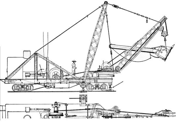
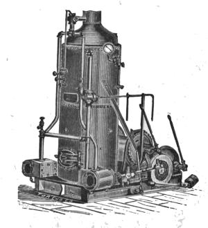
FIG. 1. ELEVATION AND HALF PLAN OF OSGOOD
STEAM SHOVEL; Osgood Dredge Co., Albany,
N. Y.
The steam shovel, or steam excavator, is a modified form
of dredge adapted for excavating material on dry land. It was
designed and patented by a Mr. Otis, about 1840, and like most
new inventions the first machine built was a very clumsy affair,[3]
but even in this crude state it possessed many advantages for
removing large masses of material. Its merits were recognized
in its earliest stages, and with increased experience in its operation
improvements were soon made which rendered it almost
indispensable on all works requiring large quantities of excavation.
It was not until 1865, however, that the machine came into
general use. About this time the largely increased railway construction
created an active demand for the steam shovel, which
demand was quickly supplied by several manufacturers, whose
machines vary in distinctive designs of various parts, but the
principles of operation are essentially the same in them all.
Types of Steam Shovels.—There are three types of steam
shovels: First; machines mounted on trucks of standard gage,
transported from place to place in freight trains (or propelled
by their own power), and intended for railway work only. Second;
machines mounted on wheels of other than standard gage,
transported in sections by boat or wagon, or loaded complete on
flat cars, and intended for both railway and other work. Third;
machines mounted on wheels fitted for transportation over
common roads, propelled by their own power, and intended for
railway and other work.
The first machines built were of the second type. As now
constructed they are mounted on a wide wooden frame or car
body, supported by four small wheels of 7 ft. to 8 ft. gage, thus
placing the machinery close to the ground, with a wide base of
support. In transporting this machine from one place to another,
not on the line of a railway, it is necessary to take it apart,
forward the sections and put them together again at the site of
the new work. The machine is built with a view to rapid dismantling
and re-erection, and for work requiring a large machine
for economical excavation, located in hilly country not
yet made accessible by rail, or requiring transportation by boat,
it is the machine most generally used. Its ready adaptability
to all kinds of work in any location has made it the favorite
machine with many general contractors whose work includes
large contracts for railway and other excavation. For transportation
by rail this machine is run onto an ordinary flat car,
only the crane being detached and loaded on a separate car.
With this manner of shipment the machine can be made ready
for railway work very quickly, but for exclusive railway work[5]
a machine of a later design has come into use and is now generally
preferred for this class of work.
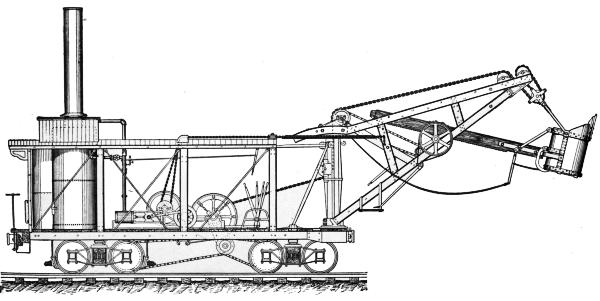
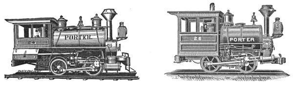
FIG. 2.—THOMPSON STEAM SHOVEL; Bucyrus
Steam Shovel & Dredge Co., South Milwaukee,
Wis.
This is the machine of the first type, resting on a wooden or
iron car body, supported on trucks of standard gage, with an
iron or steel crane from 18 to 26 ft. high over the track when
in working order, and which can be lowered to 14 ft. to permit
shipment through tunnels and under low overhead bridges.
Machines of the third type are generally of smaller capacity
than the others; they have come into general use only within
the past few years, but are now multiplying rapidly in numbers
as their utility for nearly all kinds of work is better appreciated.
They are especially adapted to smaller jobs and work not readily
accessible by rail, but where common roads are available.
These three types are shown in Figs. 1 to 9, representing the
machines of seven of the principal manufacturers.
Steam shovels will excavate any kind of material except solid
rock, and they will load rock if it has been broken up by explosives
into pieces of not more than 3-4 cu. yd. in size. The
materials excavated by them are mostly sand, loose gravel, all
kinds of clay, cemented gravel, hardpan, clays mixed with
bowlders and other small stones, ore, phosphate rock, loose
rock and thin seams of slate, shale or sandstone.
These machines are used for excavating material, loading it
on cars or wagons for ballasting tracks; for filling trestles,
streets, roads, dams, lots and new city additions; for widening
embankments for double track, side tracks, yards,
shops and station grounds; for cutting down street, road
and railway grades; grading lots and new city additions, railway
yards, shop and station grounds; widening cuts, removing
land slides, stripping coal fields, ore beds and stone quarries;
digging canals and drainage ditches, loading clays for brick
yards, etc.
Construction of Steam Shovels.—The general plan of construction
of the machines, shown in Figs. 1 to 9, is essentially
the same in all, and consists of a strong frame, mounted on
wheels, forming the base to which all working parts are attached.
The boiler and machinery are placed near the rear end of the
frame, and the mast, or post, and crane at the front end. The
crane is made in two pieces connected only at the top or point,
and at the foot of the mast. Between these pieces, serving as
guides, is the dipper handle, carrying at its farther end the dipper[7]
or scoop. To the top of the post (or to the foot in some machines)
the swinging circle is secured.
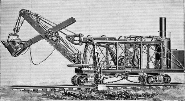
FIG. 3.—BARNHART STEAM SHOVEL; Marion Steam Shovel Co., Marion, O.
The most used, and hence the most important part of the
machinery of the steam shovel is the gearing imparting motion
to the hoisting drum, actuating the chains by which the dipper
is raised and lowered. It is in almost constant use, and is often
subjected to severe shocks in hard digging. Of all parts of the
machinery it is the most likely to break or rapidly wear out.
Naturally it has received the most attention of any part of the
steam shovel in all efforts to improve the design, strength and
durability of the machine. There are a number of different
gears in use, and essentially they are either friction clutches or
positive gearing. The use of the former subjects the machinery
and crane to less severe shocks, and can be thrown in and out
of gear more rapidly, but it wears out quicker, often causes delay
by heating, and requires frequent repairs. Positive gearing
exposes the machinery and crane to more severe shocks in hard
digging, and must be started slower, especially in hard material,
but while these machines are a little slower than those operated
with friction clutches, they are less subject to the expense of repairs
and delay due to the disarrangement of the hoisting gear,
so that their total output of material about equals, and sometimes
exceeds, the quicker moving friction gear machine.
The mechanism for thrusting the dipper into the bank is attached
to the crane, and the forms most generally used are as
follows:
1. A chain, one end of which is attached to the rear end of
the dipper handle, and the other end wound around a drum
receiving its motion by an endless chain passing over a sprocket
wheel connected to the axle of the sprocket wheel at the top of
the mast, over which the hoisting chain passes, thereby revolving
both wheels. This drum is thrown into gear by a friction
clutch, and its motion regulated by the cranesman's lever and
footbrake.
2. A rack on the dipper handle operated by a pinion attached
to a shaft revolved and regulated as above described.
3. A small double cylinder engine operating either a pinion
and rack as above described, or revolving a drum with a chain
attached to it, and the rear end of the dipper handle as described
in the first case.
4. A long steam cylinder attached to the dipper handle, whose[9]
piston rod is connected to the dipper, extending or withdrawing
it as desired.
FIG. 5.—VICTOR STEAM SHOVEL; Toledo Foundry & Machine Co., Toledo, O.
The thrusting mechanism used in the last two cases imparts
a rapid, steady and powerful motion, but the extra engines or
steam cylinder and their connecting steam pipes involve a complication
which often more than balances their advantages.
Swinging the crane in a horizontal direction is generally accomplished
in one of the following three ways:
1. A chain passing around the swinging circle attached to
the post, and wound around drums connected to the engine by
positive gearing or friction clutches.
2. A wire rope passing round the swinging circle and connected
to the piston rods operated by two long steam cylinders.
3. A chain passing round the swinging circle and wound
around a drum connected to a small reversible engine.
The mechanisms used in the last two cases have the same advantages,
but also suffer from the same objections urged against
employing small engines or a steam cylinder for thrusting the
dipper into the bank.
The engines are either of the upright type with a single steam
cylinder, or of the horizontal type, with double horizontal steam
cylinders. The size of the cylinders varies for machines of different
capacities, ranging from 8 by 10 ins. to 10 by 12 ins. for
the upright engines, and 6 by 8 ins. to 13 by 16 ins. for the
horizontal engines.
The upright type of boiler with submerged flues is usually
preferred, as it occupies only a small space. Horizontal boilers
of the locomotive type are used in a few machines, and are
more economical in the use of fuel, but occupy too large a floor
space. Forced draft is used in both types of boilers, and they
are generally worked to the limit of their capacity. The usual
working pressure is 90 lbs. per sq. in. The safety valve is generally
set to blow off at 120 lbs. per sq. in. The boiler is supplied
with water either from an upright circular sheet iron tank
located in a corner of the machine, behind the boiler, or from a
sheet iron box tank hung under the floor. These tanks usually
hold about 1,000 gallons of water, enough to run the machine
half a day. The water is obtained by a pump or siphon from the
tender of a locomotive on railway work, or is hauled to the
machine by wagon on other work.
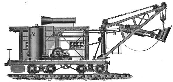
FIG. 6.—CLEMENT STEAM SHOVEL; Industrial Works, Bay City, Mich.
In some machines the frame or car body is made of wood,[11]
generally oak, often incased with heavy plate iron. In others
it is constructed of iron or steel I-beams and channels. In all
machines it is strongly built and braced with a view to sustain
the weight of the working parts and to resist the shocks to which
it is subjected. The floor is usually of 3-in. oak plank.
The mast or post is made of cast or wrought iron, strongly
braced and guyed to the frame. It is the pivot about which the
crane swings, and easy working in its bearings is of great importance
for the rapid and economical operation of the machine.
In order to prevent breakage or delay it should never be permitted
to wabble by neglecting to promptly tighten its braces
and guys in case they should work loose. The post should
always stand vertical, or practically so, to insure the horizontal
motion of the crane and avoid unnecessary straining of the
swinging gear. For this reason the machine should be set
practically level before beginning operations; and using a small
mason's level is better than trusting to the eye, when blocking
under the track and adjusting the jack screws for this purpose.
The crane is secured to the post, and is made of wood, iron
or steel, strongly and compactly built to resist the shocks to
which it is often subjected. It is from 14 to 20 ft. high above
the track or ground, varying with machines of different sizes
and manufacture, and swings horizontally through an angle of
180 to 240 degrees, with a radius of 15 to 20 ft. In some machines
it must be detached from the post for shipment, in others
(mostly those made for railway use exclusively) it can be lowered
to a height of 14 ft. above the track, thereby permitting shipment
without detaching from the post.
The dipper, scoop, or bucket is made of iron or steel, shaped
somewhat like a coal scuttle. Its cutting edge is protected by
four teeth made of steel or steel pointed. These teeth are easily
removed for sharpening or replacement. Dippers vary in size
from ½ cu. yd. to 2½ cu. yds. capacity. They also vary
somewhat in shape, according to the material to be excavated,
though no special provision is made for this unless there are
very large quantities of the same kind of material to be removed;
or for machines working in a certain class of material only, like
ore loaders. For general work in all kinds of materials the dipper
is seldom changed.
For soft, tenacious material, likely to adhere to the inner sides
of the dipper, and not drop out promptly when the bottom door[12]
is opened for unloading, the dipper is shaped as shown in Fig.
10, with a larger bottom than mouth. In hard, or dry soft material
the section shows parallel sides, as in Fig. 11. For general
use the bottom of the dipper should be slightly larger than
the mouth, as most materials contain more or less moisture
which is likely to produce a partial clogging of the dipper by
material sticking to the inner sides, especially between the teeth,
necessitating frequent cleaning out whenever the machine is
stopped while preparing to move forward, and sometimes
oftener. For ordinary clay, cemented gravel, and hard dry
materials, a dipper with a wide and shallow mouth, as shown in
plan in Fig. 12, is preferred to the one shown in Fig. 13, which
latter is better adapted for loose gravel, sand and other soft dry
materials where a deep cut can easily be made. For hardpan,
shale, loose rock and similar materials, ample strength of teeth
and dipper is of greater importance than its shape.
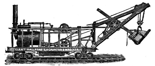
FIG. 7.—GIANT STEAM SHOVEL; Vulcan Iron Works Co., Toledo, O.
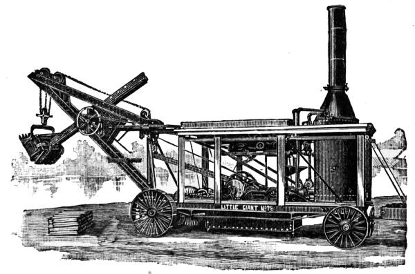
FIG. 8.—LITTLE GIANT STEAM SHOVEL; Vulcan Iron Works Co., Toledo, O.
[13]
To prevent tenacious material from sticking to the inner sides
of the dipper, and to allow it to drop out freely when the bottom
door is opened, it is often good economy to place a barrel
of water near the head of the machine from which a bucketful
can be taken and thrown into the dipper just before each cut.
The water acts as a lubricant and causes the material to drop out
more readily. For cleaning the dipper, the tool shown in Fig.
14 is used.
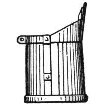
Fig. 10.
Fig. 11.
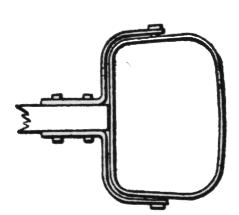
Fig. 12.
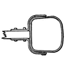
Fig. 13.
The chains have links of three-quarters-inch to one-inch
diameter, and are made of iron, sometimes of steel. Their constant
use necessarily subjects them to great wear, and as they are
also often exposed to severe shocks (especially the hoisting chain)
they must be made of the very best material and in the most
careful manner. At present iron chains are preferred to those
made of steel: they are more durable, and less likely to break
under severe shocks. Steel chains have suffered in reputation
through rapid wear and frequent breakages occurring within the
last few years, but with increased experience in their manufacture
and use they will undoubtedly be improved, and eventually
take the lead over iron chains.
The propelling mechanism consists of an endless chain connecting
one or more axles of the truck or supporting wheels
with the shaft of the hoisting drum by means of friction clutches
or positive gearing. The usual speed is five to six miles per
hour.
FIG. 9.—OTIS-CHAPMAN STEAM SHOVEL; John Souther & Co., Boston, Mass.
Steam shovels of seven of the most prominent manufacturers[15]
are shown in Figs. 1 to 9, and the general particulars of each
are given in condensed form in Table I. In each case the boiler
is upright.
TABLE I.—General Description of the Important Parts of the Most
Prominent Makes of Steam Shovels.
| | | <—Frame—> | |
| Fig. |
Shovel. |
Material. |
Size, ft. |
Running gear. |
Gage, ft. ins. |
B'l'r |
Eng-
ine |
Cylinder, ins. |
H'st'g gear. |
| 1. |
Osgood |
Wood |
10 × 34 |
2 trucks |
4 8½ |
V |
H |
2 |
10 × 12 |
F |
| |
" |
" |
10 × 30 |
" |
" |
" |
" |
" |
8¼ × 10 |
F |
| |
" |
" |
10 × 25 |
" |
" |
" |
" |
" |
7 × 10 |
F |
| 2. |
Thompson |
{I-be'm} |
10 × 32 |
" |
" |
" |
" |
" |
10 × 14 |
F |
| |
" |
{and} |
10 × 30 |
" |
" |
" |
" |
" |
8 × 12 |
F |
| |
" |
{chan- } |
10 × 28 |
" |
" |
" |
" |
" |
8 × 10 |
F |
| |
" |
{nels} |
10 × 24 |
" |
" |
" |
" |
" |
6 × 8 |
F |
| 3. |
Barnhart |
" |
10 × 28 |
" |
" |
" |
V |
" |
8 × 10 |
F |
| |
" |
" |
10 × 26 |
" |
" |
" |
H |
1 |
8 × 10 |
F |
| |
" |
" |
10 × 24 |
" |
" |
" |
V |
" |
8 × 10 |
F |
| |
" |
" |
10 × 22 |
" |
" |
" |
" |
" |
6 × 8 |
F |
| 5. |
Victor |
" |
10 × 30 |
" |
" |
" |
H |
2 |
8 × 10 |
F |
| 6. |
Clement |
" |
10 × 30 |
" |
" |
" |
" |
" |
8 × 10 |
P |
| 7. |
Giant |
" |
10 × 35A |
" |
" |
" |
" |
" |
13 × 16 |
F |
| |
" |
" |
10 × 35 |
" |
" |
" |
" |
" |
8 × 12 |
F |
| |
" |
" |
10 × 30 |
" |
" |
" |
" |
" |
7 × 11 |
F |
| 8. |
Little Giant |
" |
7 × 23 |
{4 r'd wh |
8 0 |
" |
" |
" |
7 × 11 |
F |
| |
" " |
" |
6 × 23 |
{4 r'd wh |
8 0 |
" |
" |
" |
6 × 8 |
F |
| 9. |
Otis-Ch'pm'n |
Wood |
10 × 22 |
{4 fl'ge wh |
7 10 |
" |
V |
1 |
10 × 12 |
P |
| |
" |
" |
10 × 18 | {4 fl'ge wh |
7 10 |
" |
" |
" |
8 × 10 |
P |
Transcriber's Note:
Boiler and Engine—V=Vert., H=Hor.
Hoisting Gear—F=Friction Clutch, P=Positive
| Fig. |
Thrusting Mechanism. | |
Swinging Mechanism. |
| | { | Reversible engines, 2 steam cylinders |
} | |
| 1. | { | each 6 × 8 ins. |
} | |
| | { | Do., do 5 × 6 ins. |
} | Chains attached to circle |
| | } | geared |
| 2. | { | Rack on dipper handle |
} | to hoisting drum. |
| | { | actuated by friction clutch |
} | |
| 3. | { | geared to hoisting drum. |
} | |
| |
| 5. | | Reversible engine, |
} | Wire ropes |
| | | 2 steam cyls. 6 × 8 ins. |
} | attached to circle |
| 6. | | Long st'm cyl., |
} | and pist'n rods |
| | | piston rod at'ch'd to dipper |
} | in long st'm cyl. |
| |
| 7. | { | Reversible engine, |
} | Reversible engine, 2 steam |
| | { | 2 steam cyls. 5 × 6 ins.; |
} | cylinders |
| 8. | { | 5 × 6 ins. |
} | except A, cylinders 7 × 9 ins. |
| |
| | { | Chains on dipper handle actuated by |
} | Chains attached to circle |
| 9. | { | friction clutch geared to |
} | geared to |
| | { | hoisting drum. |
} | hoisting drum |
| |
<————————Crane————————> |
|
| |
<—H'ght ab've—>
gr'nd or track. |
|
| Fig. |
Post
material. |
Material. |
Working order,
ft. |
Shipping order,
ft. |
Radius,
ft. |
Swinging
angle,
deg. |
Capacity
of dipper,
cu. yds. |
W'ht,
tons. |
| 1. |
{ | Wt. iron | } |
Wt. iron |
26 |
14 |
24 |
240 |
2 |
40 |
| | { |
A | } |
" |
24 |
14 |
24 |
240 |
1½ |
30 |
| | { |
frame | } |
" |
20 |
14 |
20 |
240 |
1 |
20 |
| |
| 2. | { |
Cast iron | |
" |
23 |
14 |
20 |
200 |
2½ |
45 |
| | { |
" | |
" |
18 |
14 |
18 |
200 |
1¾ |
40 |
| | { |
" | |
" |
18 |
14 |
16 |
200 |
1¼ |
30 |
| | { |
" | |
" |
16 |
14 |
12 |
200 |
¾ |
20 |
| |
| 3. | { |
Wt. iron | |
Wood |
26 |
14 |
20 |
200 |
1½ |
37 |
| | { |
" | |
" |
24 |
14 |
20 |
200 |
1 |
26 |
| | { |
" | |
" |
20 |
14 |
18 |
200 |
¾ |
16 |
| | { |
" | |
" |
18 |
14 |
18 |
200 |
½ |
12 |
| |
| 5. | { |
Hollow wt. ir. | |
Wt. iron |
19 |
14 |
20 |
200 |
2 |
40 |
| 6. | { |
Cast iron | |
" |
20 |
14 |
20 |
200 |
2 |
40 |
| |
| 7. | { |
Cast steel | |
Steel |
20 |
14 |
19 |
200 |
2½ |
70 |
| | { |
Cast iron | |
" |
20 |
14 |
19 |
200 |
1¾ |
45 |
| | { |
" | |
" |
18 |
14 |
17 |
200 |
1¼ |
30 |
| 8. | { |
" | |
" |
16 |
Detach'd |
15 |
185 |
1¼ |
20 |
| | { |
" | |
" |
15 |
" |
15 |
185 |
¾ |
18 |
| |
| 9. | { |
" | |
Wood |
20 |
" |
20 |
200 |
2½ |
26 |
| | { |
" | |
" |
16 |
" |
18 |
200 |
1¼ |
15 |
Makers: 1 (Osgood): Osgood Dredge Co., Albany, N. Y. 2 (Thompson): Bucyrus
Steam Shovel & Dredge Co., Bucyrus, O. 3, 4 (Barnhart): Marion Steam
Shovel Ca., Marion, O. 5 (Victor): Toledo Foundry & Machine Co., Toledo, O.
6 (Clement): Industrial Works, Bay City, Mich. 7 (Giant) and 8 (Little Giant):
Vulcan Iron Works Co., Toledo, O. 9 (Otis-Chapman): John Souther & Co.,
Boston, Mass.
[16]
Operation of Steam Shovels.—All movements of the steam
shovel are controlled by two men, the engineman and the cranesman.
The former is stationed near the engine, the latter
on a small platform attached to the crane. The engineman directs
the movements for raising and lowering the dipper, swinging
it into position for unloading, and moving the machine forward
or backward. The cranesman regulates the depth of the
cut made by the dipper, releases it from the bank when full or
near the top of the crane, and pulls the spring latch of the bottom
door of the dipper when in position for unloading, thereby
dumping its contents.
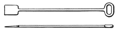
Fig. 14.—Spade for Cleaning Buckets.
These motions are shown in Figs. 15 and 16. Beginning
with the dipper in the position shown at A, Fig. 15, the engineman
throws the hoisting drum into gear, and starting the engine
pulls the dipper upward, the cranesman at the same time thrusting
it forward, regulating the depth of the cut so that it will not
stop the engine or tip up the rear end of the machine. When
the dipper has reached the position B, near the top of the crane,
the engineman throws the hoisting drum out of gear, and holds
it in position with a foot brake; at the same time the cranesman
by easing his foot brake, allows the dipper to fall back to the
position C. The engineman then swings the dipper over the
car or wagon, as shown in Fig. 16, when the cranesman pulls
the latch rope, thereby opening the bottom door of the dipper
and dropping the contents. The engineman then swings the
crane back again to the next cut, at the same time releasing his
foot brake on the hoisting drum until the dipper has fallen to
a point near the ground, as at D, Fig. 15, where he holds it for
an instant with the foot brake, then drops it by releasing the
brake, while the cranesman (during this slight drop) regulates
the length of the radius of the dipper handle by releasing his
foot brake so as to bring the dipper into the position A again,
and adjoining the last cut. While the dipper is being lowered,
the bottom door closes and latches itself by its own weight, when
all is ready again for another cut.
[17]
These motions are very simple when taken separately, but
when performed together by two different men, experience and
quickness in both are required to carry on the work rapidly
and harmoniously, without breakages or delays. In loose
gravel one cut can be made in a half to three-quarters of a minute;
in hard materials one and a half to two minutes, seldom
more.
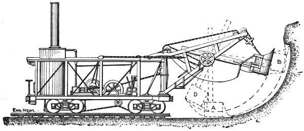
Fig. 15.—Showing Series of Operations for Excavating.
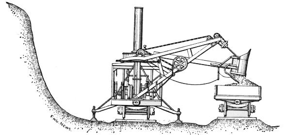
Fig. 16.—Loading Earth from Steam Shovel Onto Cars.
After all material within reach of the dipper has been removed,
an unoccupied section of track (generally about 4 ft. long) at the[18]
rear of the steam shovel is attached to the dipper by a chain
and dragged around the machine to the front (by swinging the
dipper horizontally) and there placed in position in line with the
sections of track under the machine. The screws at the ends of
the jack arm (a horizontal bar at the front end of the machine
used for steadying it when cuts are taken at right angles to the
steam shovel) are then released, and the machine moved forward
three or four feet by throwing the propelling gear into
motion. After placing the jack screws into their new position,
and tightening them, and blocking the supporting wheels of the
steam shovel, the machine is ready for another series of cuts.
The regular employees for operating a steam shovel are the
engineman, cranesman, fireman and four laborers. The latter
are under the supervision of the cranesman, and their duties are
to shovel forward any lumps or loose material which may roll
down and lodge too close to the front of the steam shovel to
be reached by the dipper, to level the surface of the ground in
front of the machine, preparing it for the next section of track,
to lay these sections of track, to attend to the jack screws and
blocking and to act as general utility men.
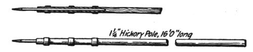
Fig. 17.—Pole for Breaking Down Edge of Excavation.
With this crew dry sand and loose gravel can readily be
loaded. In harder or more tenacious materials from two to
six extra men are required, depending upon the kind of material
to be excavated, and also upon good management of the
contractor or foreman in charge. Wet sand and fairly loose
gravel requires only two extra men, whose duty is to break
down the overhanging ledges of these materials which cannot
be reached by the dipper, and are liable to fall when the machine
has advanced, burying it or blocking the pit behind it. The
implement used by these men is a pole, Fig. 17, headed by an
iron point, resembling a surveyor's pole. With these poles
fairly loose gravel and sand can be readily broken down, sloped
at its natural angle, and fed into the pit in front of the steam
shovel. In harder materials three to four extra men are usually
sufficient, but in very hard or tenacious materials as many as[19]
six must be employed. These men break down overhanging
material in the face of the bank which cannot be reached by the
dipper, bore or drill holes for powder or dynamite when blasting
becomes necessary, cut and remove trees, etc.
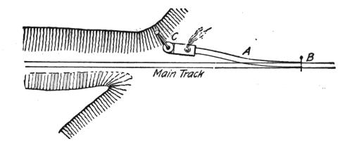
Fig. 18.
On all but very small pieces of railway work there are also
employed a blacksmith and helper, and two to five car repairers.
The blacksmith's work consists mostly of repairs about the cars,
mainly bent or broken aprons, sideboards, chains, etc. The
steam shovel occupies much the smaller part of his time. His
accommodation requires a small rough frame shop about 10 by
16 ft. (an old box car body is frequently used), with forge and
tools. Another rough frame shed of about the same size is
needed for the storage of tools, oils and supplies. The section-men
of the respective sections are occasionally called on for the
building and maintaining (or taking up) of the various side
tracks required during the progress of the work.
Part II.—Steam Shovel Work.
Widening a Cut; Loading on the Main Track.—The simplest
and one of the most frequent cases for the application of a steam
shovel is the widening of a single track railway cut. The manner
of doing this is shown in Fig. 18. A switch, A B, is put
in the main track just beyond the end of the cut and far enough
away to permit the steam shovel (when standing on the side
track) to clear cars on the main track. Cars are then placed
opposite it on the main track and the machine is ready for excavation.
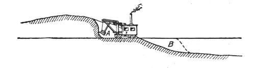
Fig. 19.
It very frequently happens that the end of the cut joins directly
on an embankment, as shown in profile, Fig. 19. In[20]
cases of this kind it would be necessary to widen the embankment
for the reception of the side track, near the end of
the cut, if the machine were to begin work at that point, C, Fig.
18. This is very seldom done; the usual method is to remove
the section, A, Figs. 19 and 20, to B by hand labor with wheelbarrows
or with teams and scrapers. The excavated material
is used to widen part of the embankment near the end of the
cut for the reception of the side track. Section A is made
barely long enough to provide a standing place for the steam
shovel and clear cars on the main track; it is seldom over 50 ft.
long, and averages about 30 ft. After placing the machine in
this space it is ready for work. Strings of 10 to 20 cars are
then drawn along the main track, and stopped opposite the machine
for loading.
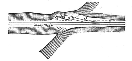
Fig. 20.
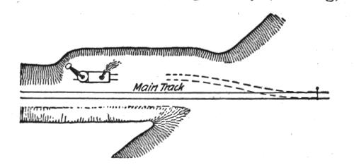
Fig. 21.
When the machine has reached the end of the switch, it advances
on short sections of track, generally 4 ft. long, which are
placed in front of it, and again taken from its rear when it has
moved forward one section of track more than its own length.
When no more cuts are to be made for still further widening,
the switch is taken up again and the machine advances on its
own track sections, Fig. 21. When other cuts are to follow,
however, a loading track is needed for the next cut; the side
track is then extended for this purpose at convenient intervals,
generally about 300 ft. at a time though often after each space[21]
of a rail length (usually 30 ft.) is clear. The latter is by far the
best practice, as it permits the immediate withdrawal of the machine
in case of a threatened cave-in, sidehill slip, or other unforeseen
danger.
After all the cars have been loaded they are taken away for
unloading. Sometimes the steam shovel is left idle until the
train returns, which is a very wasteful method of working, even
where the haul to the dump is short, half a mile to two miles.
Two engines and crews should be furnished for hauls up to ten
miles; three engines and crews, or more, for longer hauls, or
where the traffic on the main line is very heavy, and delays to
the work trains are frequent. The material is generally utilized
in filling trestles, widening embankments for side tracks, double
tracks, yards, etc., thereby making two improvements at the
same time.
Fig. 22.
In widening a cut it is good policy to keep the grade of the
pit from 1 to 2 ft. below the surface of the subgrade of the main
track, as shown in Fig. 22, thereby providing for drainage of
the ballast and also providing a receptacle for the spreading of
loose material dropping off the cars and washing in from the
surface of the cut; there is nearly always considerable of this
loose material to roll or wash into the pit after the cut has
been completed; and unless room is provided for it, the accumulation
will soon reach the height of the track, washing mud on
it, and choking the drainage, thus injuriously affecting the main
track.
Widening a Cut; Loading on a Side Track Graded by Hand
or Steam.—The delays in loading on the main track of a railway
in operation, due to the clearing of the track for all trains, vary
from one to four hours per day of ten hours, and sometimes
amount to as much as seven hours, depending upon the density
of the traffic on the line. The first cut in a case such as the latter
is therefore necessarily an expensive one, and where the[22]
traffic is so heavy it is often cheaper to make a narrow cut for
the side track, on which the steam shovel is to load, either by
wagons and wheel scrapers, Fig. 23, or by hand with wheelbarrows
loading back on cars, Fig. 24.
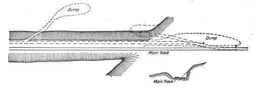
Fig. 23. Fig. 23, a.
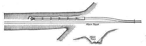
Fig. 24. Fig. 24, a.
The latter plan has the great disadvantage that only one car
at a time can be loaded and only a few men (six to ten) can be
employed. Therefore this plan is never adopted where quick
work is required, but is used only where ample time is available,
and mostly as an early spring preliminary job, preparing the
way for the operation of the steam shovel later in the season.
From three to six flat or coal cars are used, enough to require
a whole day for the gang of men employed to load; the material
from the face of the excavation is loaded on wheelbarrows, and
wheeled over the empty cars to the one farthest from the cut.
This car is loaded first, then the one next to it, etc. At night the
loaded cars are taken out of the switch by the first available
freight train and hauled to the nearest yard or side track where
widening of the embankment is wanted, or where the material
can be otherwise used to advantage, and there unloaded by a[23]
small gang of men on the following day; the cars to be returned
again the next night. Other empty cars are placed in the pit
track for loading next day, by a train bound toward the pit the
same night the loaded cars were taken out. The work can be
carried on from either one or both ends of the cut. Coal cars
should never be used if flats can possibly be obtained, as the
latter can be unloaded by a gang of men one-third as large as
would be necessary for unloading coal cars.
Fig. 25. Fig. 25, a.
Sometimes small dump cars are used, drawn by horses or
mules, and the material unloaded at the end of the cut, thereby
widening the embankment for a long side track, Fig. 25. The
narrow gage track, A, is laid over the ditch adjoining the main
track; the material for any slight excavation that may be necessary
for this track is shoveled on the slope of the cut, as at C,
on the cross section. The material is then loaded on small
dump cars standing on track A, and unloaded at D. The cars
are returned on track B. The cross-overs, E and F, are taken
up occasionally and relaid near the advancing ends of the cut
and dump.
In short cuts the narrow excavation necessary for placing
a side track in the cut for the steam shovel to load on is generally
taken out by carts and dumped at the ends of the cut,
widening the embankment for a long side track.
The plan of excavation with wagons or wheel scrapers for this
side track, shown in Fig. 23, is adopted where the traffic is too
heavy to permit loading on the main track; when the side track
is wanted at the earliest possible time; and in cuts not over 40
ft. deep. The material is dumped at the ends of the cut until
the haul becomes too long, then it is taken to the top of the
cut over sidehill driveways excavated for the purpose, and unloaded[24]
at a sufficient distance from the edge of the new cut to
prevent its washing back by rains.
These expedients are necessary only on railways where traffic
is very heavy. On most railways (on all where the total delay
does not exceed five hours per day) it is cheaper to load on the
main track until the first cut has been made. This necessarily
involves the delay due to running to and returning from the
nearest side track to get out of the way of every main line train,
until the pit track is long enough to contain the construction
train. This, however, seldom requires more than two weeks,
generally only one; the excavation of all of the first cut does
not often occupy more than a month, and is only a very short
time compared with the whole length of time that the steam
shovel is usually in operation on all but very small jobs.
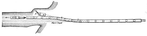
Fig. 26.
After a side track has been laid in the first cut made by one
of the methods described above, the steam shovel begins work
at A, Fig. 26, loading cars standing on the side track, and some
of them extending out on the main track. At first not more
than ten cars should be coupled to the engine, so that the train
can quickly run into the side track on the approach of a main
line train, and not delay its passage. After the steam shovel
has advanced a train-length, the full number of empty cars can
be coupled to the engine, as they will all be on the side track
while being loaded.
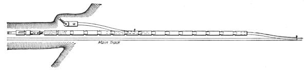
Fig. 27.
Where the embankment has been previously widened by the[25]
excavated material from the cut, Fig. 27, a sufficient length to
permit laying a side track long enough to hold the construction
train, the full number of cars can be used at once, a great advantage
in keeping the steam shovel at work without interruption
by passing trains, which is unavoidable when some of
the cars extend out on the main track.
After the machine has reached the other end of the cut it is
either withdrawn for other work, or placed on the other side
of the main track for widening the cut on that side. The steam
shovel begins at A, Fig. 28, loading cars standing on the main
track; the main line traffic being carried over a temporary main
track built in the excavation previously made by the steam
shovel on the other side of the main track. Only a few cars
at a time can be used for loading at first, unless the temporary
main track has been extended toward B a sufficient length to
clear the usual string of about 20 cars when the first car is being
loaded.
Grading Wide Areas.—In loading gravel for ballasting, or in
widening a cut for the purpose of grading yard, shop or station
grounds, the usual manner of doing the work is shown in Figs.
29 to 34. After the first cut has been made by one of the methods
already described the steam shovel is started in at A, Fig.
29, for the second cut. After its completion the first side track
becomes available for the storage of empty and loaded cars as
in Fig. 30, greatly increasing the convenience of handling the
cars and preventing delays by interferences between the strings
of empty and loaded cars, then the latter cannot be taken away
promptly on account of passing or shortly expected trains on
the main line. After the completion of the third cut, another
side track is available for cars, Fig. 31, the loaded cars are then
placed on the first inside track and the empty ones on the second.
The former are taken away by the road crew, and on their
return placed on track No. 2. The pit crew set their loaded
cars on track No. 1 for the road crew, and get their empties from
track No. 2. The pit track in the rear of the steam shovel is
used as a repair track for cars.
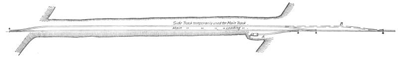
Fig. 28.
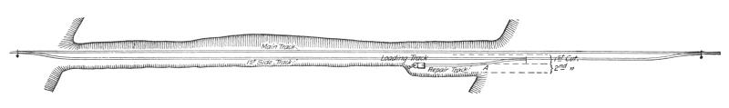
Fig. 29.
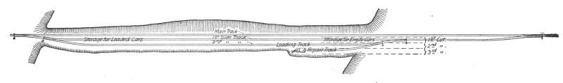
Fig. 30.
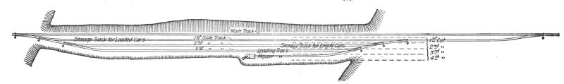
Fig. 31.
After the completion of the fourth cut, Fig. 32, track No. 3
is used for a car repair and extra storage track for loads or
empties, for which there may not be room in tracks 1 or 2.
Enough tracks have then been built for the most efficient and
economical handling of the loaded material, and if the empty[28]
cars are promptly returned the steam shovel can be kept almost
constantly at work. Each pit track, on which the steam shovel
advances, becomes a side track on the completion of that cut,
to be used as a loading track for the next cut up to the fourth
cut, after which the loading tracks are taken up on completion
of the cut for which they are used, Fig. 33, and relaid in the
pit of the next cut, to be used, taken up, and relaid as before
for the following cuts. In pits less than one-quarter mile in
length, it is sometimes necessary to retain more of these tracks
to provide ample storage space for all loaded and empty cars.
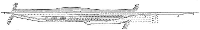
Fig. 32.
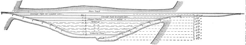
Fig. 33.

Fig. 35.
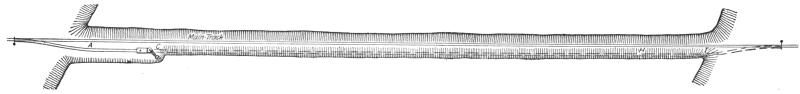
Fig. 36.
On all large pieces of work where the main line traffic is
heavy it is important that the first side track from A to B, Fig.
32, shall be of sufficient length (usually about 700 ft.) to hold
the engine and a full string of cars to avoid going on the main
track when switching loads to C, and obtaining empties from
D. If there is an embankment from A to B it can be widened
with material taken from the cut, either by wagon or cars.
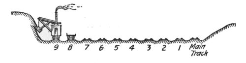
Fig. 34.
Grading by this method for yard, shop and station grounds
occurs mostly near large cities where better terminal facilities
must be provided for. The width of the area excavated in this
manner seldom exceeds 200 ft. (eight cuts) except in old gravel
pits used for furnishing material for ballasting track, which are
sometimes 300 ft. (twelve cuts) or more in width.
Gravel pits and other wide areas excavated are seldom less
than one-quarter mile or more than one mile in length. One-half
to three-fourths of a mile is the most usual length; in exceptional
cases two miles have been reached. Long and narrow
pits can be worked more advantageously than short and wide
ones.
Cutting Down Grades.—For cutting down grades on railways
where the traffic is not too heavy to prohibit loading on
the main track, the usual plan of operations is shown in Figs.
35 to 42. The machine begins work at A, Figs. 35 and 36,
the beginning point of the new grade, loading cars on the main
track, cutting to the line of the new grade, and moving forward[29]
on the track on the surface of the pit as long as the height of
the crane permits raising the dipper high enough over the cars
to open the bottom door of the dipper and discharge its contents,
B, Fig. 35. This point is usually about 2 ft. below the
main track. The machine must then be gradually run upward
on a cribwork of wooden blocking, generally pieces of pine
6 by 12 ins. by 4 ft. long, with some longer track stringers for
supporting the sections of track on top of the blocking, and
some thinner pieces for attaining exact heights of blocking
when needed. As the machine moves forward the dipper still
continues cutting to the line of the new grade, while the machine
is gradually run upward on the blocking on a grade parallel
to the grade of the main track, and slightly below it, maintaining
a constant height between the top of the track on the
blocking and the highest point to which the dipper can be
raised on the crane to insure discharging its load on the cars.
When the dipper has cut as low as the length of the dipper
handle will permit, C, Fig. 35, the greatest depth to which the
machine will cut below the level of the main track has been
reached, and as the steam shovel advances the surface of the
pit will be on a grade parallel to the grade of the main track,
running upward to the summit, S, then downward, and continue
so until it cuts the new grade line at H, when the dipper
is made to cut on this grade, while the blocking under the machine
is gradually lowered as it was previously raised, until
the steam shovel reaches the end of the new grade at I, when
it is again on the surface of the pit.
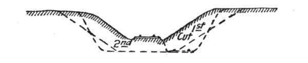
Fig. 37.
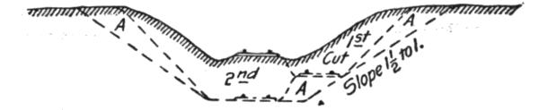
Fig. 38.
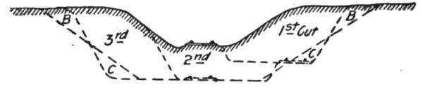
Fig. 39.
Although the machine is gradually run upward and downward,
it is always blocked level after each forward move before[30]
beginning work, to insure quick and easy swinging of the
crane, as previously explained. Most machines will cut 5 ft.
below the main track and load on a flat car with 18 ins. side
boards. Some machines will cut as low as 8 ft., and they are
preferred to others on railways where much work of this kind
is done, as their use often avoids making an extra cut.
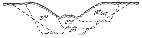
Fig. 40.
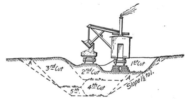
Fig. 41.
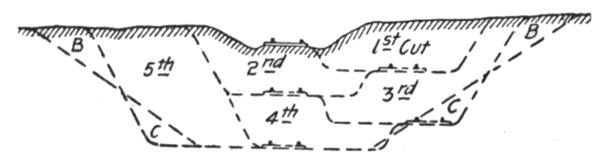
Fig. 42.
After the first cut has been completed, the pit track, A 1, Fig.
36, becomes the temporary main and loading track; the main
track is taken up from C to H, and the steam shovel run back
to C to begin the second cut, Fig. 42, excavating it in the same
way as the first, and loading on the temporary main track. This
track again is taken up after the second cut, the machine begins
at D and ends at G for the third cut and loads on the pit track
in the second cut; the fourth cut is made in a similar way, the
machine beginning at E and ending at F, Fig. 36. The fifth
and last cut is merely a widening cut, made by loading on the
track in the pit of the fourth cut. The material of each cut
after the first is loaded on the track laid in the preceding cut.
After the completion of the last cut, the permanent subgrade
having been reached, the main track is laid on the permanent
line, and the small quantity of material obtained from cutting
the ditches loaded on cars by hand and taken away for unloading.[31]
The most frequent depth of cut made at the summit of
grades is about 10 ft. (two cuts), Figs. 38 and 39.
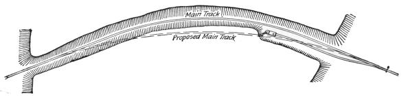
Fig. 42½.
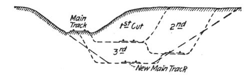
Fig. 43.
Fig. 44.
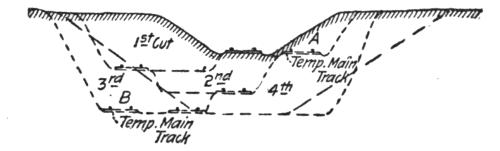
Fig. 45.
When the main track is on a curve, as frequently happens,
an extra cut can often be avoided by slightly changing the alinement
of the new main track, and at the same time reducing the
degree of curvature, as shown by Figs. 42½ and 43. This
is particularly applicable where an odd number of cuts must
be taken to reach the bottom of the new grades. The dipper
will cut to a slope of about 1 to 1. When greater slopes are required,
it must be done by hand or undercutting resorted to.
Sloping by hand is slow and expensive work, impracticably so
in all tenacious materials; it has therefore become the exception,
and undercutting the rule. Cuts made in the latter manner
sometimes present a rather ragged appearance when just completed,
but the irregularities soon merge into a smooth surface
as the action of the elements produces the natural slope of the
material; the smaller cost amply compensates for the temporary
lack of finished appearances. The amount of hand labor necessary[32]
where undercutting is not practiced is shown by the sections
A in Figs. 38 and 41. This can be entirely avoided by
undercutting the slopes, as shown in Figs. 39 and 42; the sections
B will slough off within a year or two and most of the
material lodge in the spaces C; a small part of this material
may roll to the bottom of the cut, and can be removed by loading
on cars by hand, or space may be provided for it by making
the cut a few feet wider at the bottom. In most cuts for reducing
grades this extra width must be cut out anyhow to
provide room for both steam shovel and loading track.
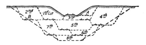
Fig. 46.
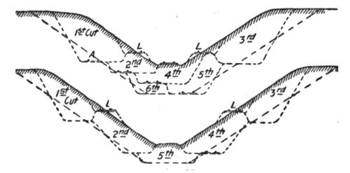
Fig. 47.
Fig. 48.
In reducing grades on railways with a traffic too heavy to
permit loading on the main track, a temporary main track
must first be built by one of the methods shown in Figs. 23, 24
and 25. The temporary main track, A, Figs. 44, 45 and 46, is
then laid, as shown in Fig. 28, to carry the traffic of the road
unobstructed. The main track then becomes the loading track
for the first cut, and the following cuts are made as shown in
Figs. 44, 45 and 46. The temporary main track, A, is moved
to a second position, B, when the material under it must be
cut away. Great care should be taken to arrange the cuts so
that the temporary main track will have to be moved as few
times as possible, and to attain the lowest level when it is
moved. In loose gravel or sandy materials wider bermes and
longer slopes must be allowed for the shelf on which the temporary
main track rests than are shown in the above figures,
but the method of doing the work is essentially the same.
[33]
If the depth of the original cut in tenacious materials exceed
the height which the dipper can reach, and break down the material
above it, the cuts are arranged as shown in Figs. 47, 48
and 49. Temporary loading tracks, L, are built on the side of
the slope, and the first cut on each side made by loading on
them; the following cuts are then made, as shown on the
figures. If the main line traffic is very heavy, it is turned over
the temporary main track, A, Fig. 47, until the cut is completed.
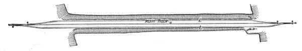
Fig. 49.
The original cuts are not often more than 10 ft. deep, and the
section shown in Fig. 45 covers the majority of cases.
On double-track railways the traffic in both directions is generally
turned over one track for the length of the new cut,
thereby avoiding considerable expense in providing two temporary
main tracks.
Each different piece of work presents different conditions;
and while the same general principles apply to all, every case
requires disposition according to its own special circumstances.
Great care and study should be exercised in arranging the cuts,
to reduce them to the fewest possible number, and avoid shifting,
taking up and relaying tracks oftener than absolutely necessary.
Fig. 50.
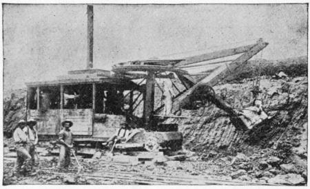
Fig. 51.
Construction Work.—On railways the steam shovel is used
mostly in connection with maintenance of way work: loading
gravel for ballasting the track, widening cuts, filling trestles, etc.,[34]
but it is also largely used for various construction work, particularly
re-alinements of the main track for reducing grades
and curvature. In excavation of this class, thorough cutting
should be avoided if possible, for reasons which will be subsequently
explained. The work is begun by laying a temporary
track, A, Figs. 50, 51 and 52, over the surface of the ground if
its natural grade is not too steep to permit operating construction
trains over it. Grades up to 6 per cent. (316.8 ft. per mile)
can be used. A mogul engine will draw six empty flats over
such a grade, a sufficient number of cars to start the work for
the short cuts near the summit. The cuts are then made as
indicated in Fig. 52.
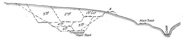
Fig. 52.
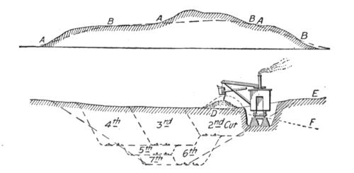
Fig. 53.
Fig. 54.
If the grade of the ground is too steep to operate a track laid
on it, one of the three methods may be adopted to obtain a
grade for this track:
1. The steam shovel is made to cut a trench between the
points A and B, Fig. 53, where the slope of the ground is too
steep to permit operating a track laid on its surface, and varying
in depth from 5 to 10 ft. as may be necessary to attain the
desired grade. The excavated material is dumped at D, Fig.
54, to be removed with the next cut. The length of the crane
will not permit dumping at E a sufficient distance (20 ft. or
more) to obtain a berme and prevent the material washing back[35]
into the new cut in the course of time; it must, therefore, be
dumped at D and removed as described, unless the slope of
the ground is away from the cut, as indicated by the line D F,
Fig. 54; in such a case the excavated material can be dumped
at F.
2. By excavating the trench with teams and scrapers.
3. By through-cutting a trench with the steam shovel, loading
the material on small dump cars or wagons, and wasting
it at the nearest available place.
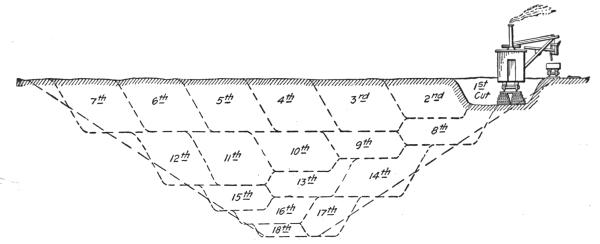
Fig. 55.
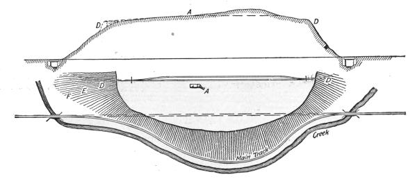
Fig. 56.
Fig. 57.
After the first loading track has been laid in this trench, the
cuts are made as indicated in Fig. 54.
[36]
When the slope of the ground is too steep to permit a track
to be laid on it which can be operated, or to cut a trench for
it, as frequently occurs when the excavation passes through a
high spur or knoll, Figs. 55, 56 and 57, the steam shovel
mounted on standard gage railway tracks cannot be used, and
a machine independent of a railway track for transportation
must be employed. It is started at A, Figs. 56 and 57, loading
small dump cars drawn by horses, and dumping at the nearest
available place outside of the lines of the new cut, as at D, Figs.
56 and 57. Sometimes wagons are used if the cuts near the top
are short and not very deep, so that a temporary standard gage
track can soon be run through the cut, and the material loaded
on cars. The dumping track at D is changed to E F, etc., Fig.
57, as the machine cuts lower, maintaining a descending grade
from the steam shovel.
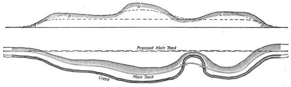
Fig. 58.
Fig. 59.
Fig. 60.
In cases of this kind it is often necessary to run the steam
shovel up a very steep grade to reach the point where it is to
begin work. This can readily be done by attaching one end
of a one and a half inch rope to a strong tree and winding the
other end around the driving axle. Then starting the running
gear the machine can be drawn up grades where it could not
otherwise propel itself. As a precautionary measure, it is advisable
to use at least two ropes.
[37]
A combination of all these methods sometimes becomes
necessary, as shown in Figs. 58 and 59. The material in the
knoll, K, Fig. 58, is loaded on small dump cars and unloaded
at the nearest available place. When this knoll has been cut
down sufficiently, and trenches cut between A B and C D,
the track A B C D is built, and the excavation proceeded with,
as heretofore described. The high points B, K and C are cut
down first until the grade of the loading track between B and
C is parallel to the grade of the proposed new main track. Cuts
nearly 100 ft. in depth and a mile in length have been excavated
in this manner. Two and often three steam shovels are employed
at the same time, working near the ends of the cut
until the through track has been laid, and then following each
other, as shown in Fig. 60. As soon as possible, a through
track should always be laid, as it greatly increases the capacity
for the prompt and efficient handling of the cars.
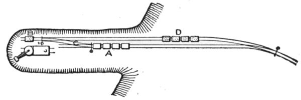
Fig. 61.
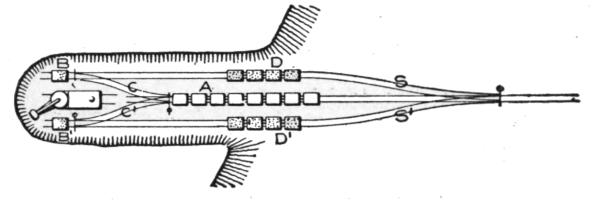
Fig. 62.
Enough side tracks for storing both empty and loaded cars
should be built close to the work, where they can be reached
without going out on the main track. Sometimes the pit tracks
behind the steam shovels are utilized for this purpose, but these
tracks are taken up too often, and should not be depended upon
for side tracks, though they may be used as such occasionally.
In through-cutting the material is loaded on small dump
cars running on tracks of about 3 ft. gage, drawn by horses,
and wasted on some side hill or other nearest available place;
this haul seldom exceeds a quarter of a mile in length. In Fig.
61, the empty dump cars standing at A are drawn over the
cross-over C by a horse, to be loaded at B; then run to D, and
when from four to six cars have been loaded they are taken to
the dumping place and unloaded; then returned to A.
[38]
In loose materials considerable time is lost in waiting from
the time the loaded car is run to D and the next empty brought
from A to B. In tenacious materials not nearly so much time
is lost, as the dipper cannot be filled so rapidly. This loss of
time is largely avoided by arranging double loading tracks,
Fig. 62, one on each side of the steam shovel, and connected
to a central track for empties by the cross-over C and C´ and
switches S and S´. Two horses are used, one on each side of
the central track, to bring forward the empty cars from A to
B, and A to B´, and return them to D and D´; these operations
are alternately performed, each empty car on one loading track
being brought forward while the other is being loaded. The
cross-overs C and C´ should be kept close to the rear of the
steam shovel, and as it advances they must be taken up and
relaid; this becomes necessary about once in three days in soft
materials and about once a week in hard stuff.
Portable sections of tracks, switches and cross-overs are generally
used between the points A and B, and can be relaid very
quickly.
Standard gage railway cars cannot be used in thorough cutting,
as the track cannot be laid in front of a point at right
angles to the post of the steam shovel, and when the track ends
there the crane cannot swing back far enough to load the car.
Thorough cutting should be avoided if possible, the cost due
to the loss of time in switching cars, relaying tracks, extra
horses and men, etc., makes it more expensive than excavating
from a side cut.
In excavating canals, harbor and dockwork, stripping coalfields,
stone quarries, grading for new city additions, and other
work not connected with a railway, as well as railway construction
and re-alinement work which is inaccessible to a railway
track in its early stages, the general manner of using the steam
shovel is the same as for railway work; varying only in details,
depending upon the means of disposing of the loaded material,
by wagons, carts or dump cars, and the use or waste of this material.
Although the steam shovel is employed mostly on railway
work, it is not exclusively a railway machine. It is already
largely used on other work, and its use in this direction is
rapidly extending, especially on the increasing number of extensive
public works in the vicinity of large cities.
[39]
The most economical height of cut varies greatly with the
nature of the material. In dry clay, loam and other dry materials
which can be broken down readily with a bar or iron
pointed pole (Fig. 17), cuts of 25 to 30 ft. in height are usually
taken. In harder and more tenacious materials it should not
exceed the height to which the dipper can be raised, 14 to 20 ft.,
varying with the size of the machine. In sand and loose gravel
which easily falls down to the machine heights up to 60 ft. are
common, and sidehill cuts in loose gravel up to 300 ft. in height
have been taken. In such cases, and also in the removal of
landslides, great care must be taken to avoid an avalanche of
the material burying the machine when the toe of the slope is
cut away. The pit track should always be kept close up to the
sections of track under the steam shovel, so that it can be
quickly withdrawn when necessary. As a general rule, the
higher the cut the better, as the machine can then load the greatest
amount of material between each advance, and lose the least
possible amount of time. Each forward move of the machine
requires from three to ten minutes, depending upon the height
of blocking, if any, it is working on; this is a dead loss, as no
cars or wagons can be loaded during that interval.
Powder and dynamite are frequently used to good advantage
to shatter the harder materials before excavating. When thus
broken up about twice the amount of these materials can be
loaded in a day. Great care must be exercised in the quantity
of the explosive used, and in the location of the drill holes to
prevent injury to the steam shovel. The explosives should be
stored in a safe place, preferably in a vault at some distance from
the place where they are to be used.
The use of dynamite is confined mostly to bowlders, ledges
of rock and stumps of trees, while powder is generally used for
hardpan, shale, slate, cemented gravel and hard clays. For the
latter materials dynamite is usually too powerful, as instead of
merely lifting and loosening them, as desired, it shatters shale
and slate into fragments, and compresses the other materials
about it, forming a "cistern" from 3 to 5 ft. in diameter, as shown
in Fig. 63. Sometimes small quantities of it are used specially
for this purpose to make room for a large charge of powder at
the bottom of the drill hole, where its explosion will have the
most effect in loosening the superincumbent material. A
charge of one-quarter to one-half of an ordinary dynamite cartridge[40]
will usually blow out a "cistern" large enough to contain
from one-half to one keg of powder, Fig. 64.
The depths of the drill holes in these materials vary from 4 to
20 ft.; they are made with a drill, or, in the softer materials, with
an auger similar to a plank auger, generally about 2 ins. diameter,
with extension pieces for deep holes, as shown in Fig.
65. Crowbars and wooden and iron wedges are also often used
in breaking down overhanging material when it cannot quite
be reached by the dipper.
The excavation of materials for which powder or dynamite
are used to loosen them requires a powerful machine, with a
strongly built, medium size dipper. A small or lightly built
machine giving good satisfaction in soft materials would prove
an utter failure here.
Fig. 63.
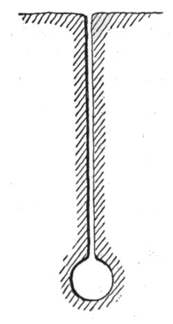
Fig. 64.
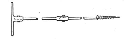
Fig. 65.
Assuming good management and a competent crew, the
daily output of a steam shovel depends mostly upon the nature
of the material excavated; it is also somewhat dependent upon
the height and width of the face of the cutting, and largely upon
the facilities for disposing of the loaded material, and keeping
the machine almost constantly at work by an ample supply of
empty cars and wagons. Although these varying conditions
differ on each piece of work, the probable output of a machine
for a given excavation can be closely estimated by good judgment[41]
based on previous experience with similar work. The
average daily output in different kinds of materials, and under
average, favorable and unfavorable conditions, as described
above, is shown in Table II.:
TABLE II.
| Capacity |
Delay. |
Sand. |
Loose gravel. |
Dry loam. |
Dry clay. |
Damp clay. |
| of dipper. |
hours.[2] |
Cu. yds. |
Cu. yds. |
Cu. yds. |
Cu. yds. |
Cu. yds. |
| 2½ cu. yds. |
1 |
Good |
2,400 |
2,400 |
2,000 |
1,800 |
1,200 |
| " |
5 |
Poor |
1,200 |
1,200 |
1,000 |
900 |
600 |
| " |
2½ |
Avg. |
1,800 |
1,800 |
1,500 |
1,350 |
900 |
| 1¾ cu. yds. |
1 |
Good |
1,600 |
1,600 |
1,200 |
1,000 |
800 |
| " |
5 |
Poor |
800 |
800 |
600 |
500 |
400 |
| " |
2½ |
Avg. |
1,200 |
1,200 |
900 |
750 |
600 |
| 1 cu. yd. |
1 |
Good |
1,000 |
1,000 |
800 |
700 |
500 |
| " |
5 |
Poor |
500 |
500 |
400 |
350 |
250 |
| " |
2½ |
Avg. |
750 |
750 |
600 |
525 |
375 |
TABLE II.—Continued.
| |
<————— Loosened by explosives.———> |
| |
|
Stiff blue |
Hard |
Mixed clay |
Loose |
Cemented |
| Capacity |
Delay. |
clay. |
pan. |
and boulders. |
rock. |
gravel. |
| of dipper. |
hours.[3] |
Cu. yds. |
Cu. yds. |
Cu. yds. |
Cu. yds. |
Cu. yds. |
| 2½ cu. yds. |
1 |
Good |
800 |
600 |
600 |
600 |
600 |
| " |
5 |
Poor |
400 |
300 |
300 |
300 |
300 |
| " |
2½ |
Avg. |
600 |
450 |
450 |
450 |
450 |
| 1¾ cu. yds. |
1 |
Good |
600 |
400 |
400 |
400 |
400 |
| " |
5 |
Poor |
300 |
200 |
200 |
200 |
200 |
| " |
2½ |
Avg. |
450 |
300 |
300 |
300 |
300 |
| 1 cu. yd. |
1 |
Good |
400 |
300 |
300 |
300 |
300 |
| " |
5 |
Poor |
200 |
150 |
150 |
150 |
150 |
| " |
2½ |
Avg. |
300 |
225 |
225 |
225 |
225 |
Part III.—Disposition of Material.
Loading the Material for Transportation.—The material excavated
by a steam shovel is loaded on cars, wagons or carts.
On railway work it is usually loaded on dump or flat cars. On
other construction work small dump cars are most generally
used, and sometimes wagons or carts.
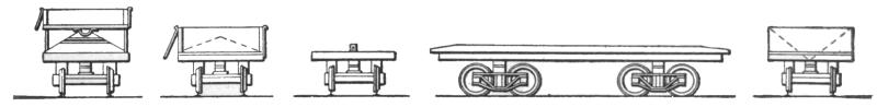
Fig. 66.Fig. 67.Fig. 68.
Fig. 69.Fig. 73.
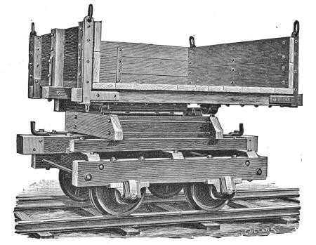
Standard gage railway dump cars, Figs. 66 and 67, have
nearly gone out of use. They were replaced by the center ridge
flat car, Figs. 68 and 69, and it in turn has been replaced by the
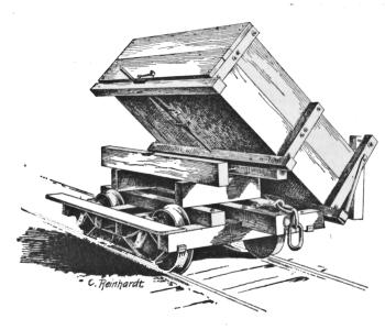
ordinary flat car. Dump cars are of two styles, dumping either
by tipping, Fig. 66, or by means of a hinged sideboard opening
on an inclined floor, Fig. 67. Both are heavy, clumsy, costly[42]
and can be used for scarcely any other purpose, often standing
idle from six to eight months of the year. They dump dry materials
very rapidly, but are often slow in discharging damp,
tenacious materials, especially in the hinged sideboard car,
whose floor slope is often not sufficient to permit the material
to slip out quickly, and the material must then be pushed out,
thus causing much delay. The greatest objection to these cars
is that they can be used for scarcely any other purpose, on most
railways for no other purpose; and there is not sufficient work
for them to justify keeping the necessary number on hand for
the ordinary work in this line. They were replaced by the
center ridge car, Figs. 68 and 69, as above noted, which is
merely an ordinary flat car with a timber 4 by 6 ins. bolted on
its floor along the center line, serving as a guide for a plow,
Fig. 70, drawn over it by the locomotive, thereby unloading the
material. The ridge timber is slightly pointed at both ends to
assist in guiding the plow onto the car as it passes from one
car to another. The top edges of the ridge are sometimes protected
by angle irons, as in Fig. 71, and the points by cast iron
caps, Fig. 72. By taking off the center ridge this car can
readily be restored to general service after completing the steam
shovel work. The center dump car, shown in Fig. 73, is used
only for gravel ballasting where the material is wanted delivered
between the rails.
Fig. 70.

Fig. 71.
Fig. 72.
The brakes are placed on one side of the car, as shown in
Figs. 74 and 75. When boulders, loose rock, etc., are to be
unloaded, the brake staff is set in a socket, Fig. 76, and taken
out before the plow is started. This avoids bending or breaking
the staff in case any stone should be wedged between it and
the moving plow. Sometimes the socket is used with the brake
at its ordinary place at the end of the car; in such a case it
must always be taken out before the plow reaches it.
The plow, Fig. 70, is built of heavy plate and angle iron,
strongly braced, and headed by a cast steel point, to which the[43]
cable is attached. The sides are curved outward at the bottom,
working under the material and pushing it aside as the plow is
drawn along, and held down on the car by the weight of the
material and the partly downward pull of the cable at its point.
Short pieces of old rails and other scrap iron are also often
placed on the plow to help hold it down on the car when very
tenacious materials are to be unloaded. The groove extending
along the center line on the bottom fits over the ridge timber
on the car, and forms the guide by which its movement is directed.
Small stones, protruding bolts, slivered ridge timbers
and other obstructions in the groove of the plow sometimes
wedge the point fast, and before the engine can be stopped, the
plow is turned up on its point, and falling to either side, tumbles
off the car. The weight and elasticity of the cable is often sufficient
to draw the plow half a car-length after the engine has
been stopped, and it is often difficult to stop the plow quick
enough to prevent upsetting when obstructions occur, although
the speed is usually only two to three miles per hour. The unloading
nearly always occurs on trestles or embankments, and
when the plow is thrown off the car, its replacement often requires
much time and labor, sometimes even making the services
of the wrecking car necessary. This difficulty is very likely to
occur when unloading on curves, where one side of the point
of the groove presses against the ridge timber. This plow unloads
the material equally on both sides of the car, as it is
wanted in filling trestles, raising embankments, tracks, etc.; but
it cannot be used to advantage where the material is wanted on
one side only, as in widening embankments for double track,
side tracks, yards, station grounds, etc.
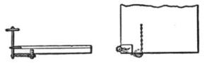
Fig. 74.
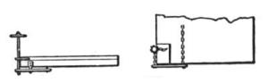
Fig. 75.
Fig. 76.
The many objections to the center ridge car are almost entirely
avoided by the use of the Barnhart plow, Fig. 77, employing
the ordinary flat car without any preparations except changing[44]
the brake staffs to one side or placing them in sockets at
their ordinary places and inserting short stakes in the stake
pockets, permitting the immediate use of the car for general
service if necessity should so require. This plow is also built of
heavy plate and angle irons, strongly braced, and headed by a
cast steel point to which the cable is attached; it is preceded
and followed by guiding sleds attached to it by adjustable hinges
and guided over the car by the stakes in the stake pockets,
which are indicated by the dotted lines. The usual speed at
which it is drawn over the car is about four miles per hour, but
in loose gravel it can safely be drawn at a speed of six miles
per hour. On straight track it is scarcely ever thrown off the
car unless carelessly handled, and it works equally well on
curves when the usual means are adopted to maintain a tangential
pull of the cable, as will be subsequently described. Two
styles of the Barnhart plow are in use: One unloading on both
sides of the car, and called the center plow, Fig. 77; and the
other unloading on one side only and called the side plow,
Fig. 78.
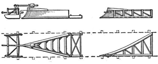
Fig. 77. Fig 78.
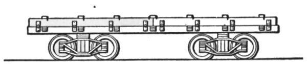
Fig. 79.
On all but very small pieces of work the cars should be provided
with hinged drop sideboards, Fig. 79, using either of the
arrangements shown in Figs. 80 and 81, which will enable them
to carry 12 to 14 cu. yds. instead of 6 or 7. The side boards
are made in two pieces on each side of the car, Fig. 79. Those
shown in Fig. 80 are used for both center and side plows; they
can be quickly dropped by a man walking along the train, after
arriving at the unloading place and striking the hook A an
upward blow with a light hammer. The boards are hooked up[45]
again after the cars have been returned to the steam shovel pit.
The side boards shown in Fig. 81 are used where the side plow
only is used. Here the board on one side only (the unloading
side) is hinged (or chained), and dropped by pulling out the pin
B, thus leaving that side of the car entirely unobstructed for
unloading the material; the board on the other side of the car is
bolted to the stake pocket and is not moved.
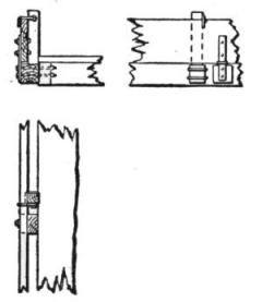
Fig. 80.
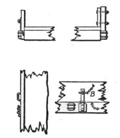
Fig. 81.
The cars should also be provided with sheet iron aprons,
Figs. 82 and 83, extending from the end of one car onto the
floor of the next, to prevent the material from falling on the
track between the cars as the plow is drawn over them, and delaying
the departure of the train until it can be shoveled out.
These aprons are made either in two pieces, Fig. 82, or in one
piece only, Fig. 83. The former are more easily handled, and
permit access to the coupling of the cars without lifting the
apron. Very little material drops on the track when the aprons
and the center plow are used. The single apron is used mostly
in connection with the side plow.
The number of cars and engines required for each steam
shovel to keep it in nearly constant operation depends upon the
nature of the material excavated, the length of haul, and the
density of other traffic upon the main line. This number must
be determined by accompanying circumstances in each case;
ordinarily, however, it averages about as given in Table III.:
TABLE III.
| |
In the steam shovel pit. |
<————On the road up to—————> |
| |
10 miles. |
25 miles. |
50 miles. |
75 miles. |
| |
Loco. |
Cars. |
Loco. |
Cars. |
Loco. |
Cars. |
Loco. |
Cars. |
Loco. |
Cars. |
| Loose gravel |
1 |
30 |
1 |
30 |
2 |
60 |
3 |
90 |
4 |
120 |
| Dry clay |
1 |
22 |
1 |
22 |
2 |
40 |
- |
- |
- |
- |
| Damp stiff |
| clay |
1 |
18 |
1 |
18 |
2 |
36 |
- |
- |
- |
- |
| Hardpan, cemented gravel, etc., loosened by explosives |
1 |
16 |
1 |
16 |
2 |
32 |
- |
- |
- |
- |
[46]
The length of haul usually ranges from 2 to 15 miles; it seldom
exceeds 25 miles for any material except gravel ballast,
where hauls of 75 miles are frequent, and sometimes reach 200
miles.
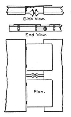
Fig. 82.
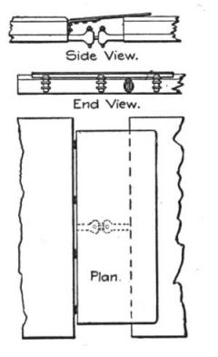
Fig. 83.
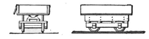
Fig. 84.
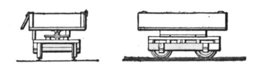
Fig 85.
On hauls exceeding 25 miles the full number of cars and engines
required can seldom be obtained, and the output of the
steam shovel is correspondingly decreased. The delay in returning
empty cars due to detentions from other trains is the
great trouble most keenly felt in steam shovel work on railways
in operation. The so-called "mud train" is generally considered
an outcast, and is usually the last train to receive the dispatcher's
attention for an order to the road. These delays are
daily occurrences, and it is quite an exceptional case when the
machine is amply supplied with empty cars. The record of
most steam shovels on such work is therefore a rather poor one,
when the machine really made a good showing for the crippled
condition of its car service. Some of these delays can be[47]
avoided or shortened by stationing a telegraph operator at the
outgoing end of the pit, and on all but very small pieces of work
his wages will be many times balanced by the time gained in
keeping the whole plant moving, by obtaining train orders
quicker, and remaining constantly informed of the whereabouts
of the construction and other trains, and regulating the work in
the pit accordingly.
For general construction work where the excavated material
is not loaded on standard gage railway cars, small dump cars,
Figs. 84 and 85, are generally used. They are more economical
than wagons or carts, which are employed only in special
cases, mostly in cities, where the material must be hauled some
distance over several intersecting streets, and where a track will
not be allowed; or for very small jobs with a long haul which
would not justify building a track.
The gage of these tracks is usually 2½ or 3 ft., sometimes
2 ft. or even 1½ ft. only; the latter gages are not often used,
and the 3-ft. gage is usually preferred.
The rails most generally used weigh 20 lbs. per yd. Although
these tracks are only temporary their construction should
be fairly substantial; but they are often built in an exceedingly
careless and insecure manner, causing a great waste of power
in pulling the cars over them, and resulting in frequent delays,
due to derailments. The grade is usually arranged so that the
loaded cars will run downhill by gravity, and only the empty
cars need be drawn back to the pit. On small work, horses or
mules are used to pull the cars, but on large jobs small locomotives
are employed. Small dump cars vary in capacity from
1 to 3 cu. yds., the latter size being most generally used. The
side dump car, Fig. 84, dumps on either side. The rotary dump
car, Fig. 85, unloads on either side or end; the box can be
turned around horizontally, revolving about a vertical pin in a
turntable on the frame; they are used mostly in dumping off the
end of a fill.
In making fills it is nearly always the best plan to build a
temporary trestle of round pieces of beech, cottonwood or other
cheap trees, old bridge or building timber, or other second-class
lumber, and then filling in with the side dump cars. By adopting
this plan the unloading will progress much more rapidly
than by dumping from the end of a fill, where only one car at a
time can be unloaded. These trestles are inexpensive, and the[48]
saving in labor and time in making the fill will amply repay
their cost.

Fig. 86.

Fig. 87.

Fig. 88.

Fig. 89.
Unloading the Material.—On railways the unloading is seldom
done by slow and expensive hand labor with the shovel;
sometimes dump cars are employed, but in most cases flat cars
and the plow are used. The trains consist of 10 to 30 cars. The
car carrying the plow is attached to the rear of the train at the
nearest side track to the unloading place, if it is not over 10
miles from the steam shovel pit this car is generally carried
back and forth to avoid an extra stop to couple it on the train
at the side track. One end of a steel wire cable is then hooked
to the plow and the other end (which is attached to an ordinary
car coupling link) coupled to a car or the engine. Usually this
cable is about 400 ft. long and extends over 12 cars. The
brakes on these cars are then set up tight and the engine started
with the forward cars, Fig. 86. In very tenacious or partially
frozen material the rear cars are sometimes pulled along by the
plow; the wheels are then blocked with pieces of wood or with
stones; sometimes it is even necessary to chain a few of these
cars to the track to prevent the rear lot of cars from moving.
After the plow has been started, it is drawn along slowly until
it arrives on the last car, Fig. 87. The engine is then stopped
and backed up a few feet to permit the cable to be thrown on
one side of the track, Fig. 88. The train is then backed up
again and coupled to the unloaded cars, when four to six men
throw the cable on the next loaded cars, Fig. 89, coupling its
forward end to a car or to the engine if the cable is long
enough. The operation is then repeated until all but the car
next to the engine is unloaded; this car carries the plow and is[49]
the first car to be unloaded by the next train. The ends of the
cable are then detached from engine and plow, thrown to one
side of the track, and left there for the next train to pick up
and use in the same manner.
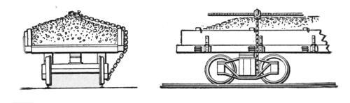
Fig. 90.
Fig. 91.
When filling a trestle the cable cannot be thrown on one
side, as described, but must be unhooked from the plow (the rear
lot of cars being left standing on the trestle), dragged across
the trestle, and there thrown to one side. The forward lot of
cars is then backed up until its rear car is opposite the rear end
of the cable, when it is loaded, the train backed up, coupled and
unloaded, as before described. After unloading the train the
cable must again be dragged beyond the trestle, and there
thrown to one side of the track and left for the next train. The
time required for unloading varies from 10 to 30 minutes, depending
upon the nature of the material and the number of
cars, and averages about 20 minutes, doing as much work
in that time as 20 men can do in a day.
When unloading on curves the operations are delayed by
the necessity of using snatch blocks on the cars to insure a nearly
tangential pull of the cable and avoid pulling the plow off the
car. These blocks are applied as shown in Fig. 90, and at A,
Fig. 91. They are hooked to long chains extending over the
car and fastened to the bolster or arch bar of the truck. The
number of snatch blocks required depends upon the degree of
the curve and the length of the cable; generally four to six
blocks, one to every third car, are enough. As the plow approaches
one of these blocks it must be stopped, block and
chain removed and transferred forward for use at that end of[50]
the train. The other operations of unloading are the same as
when on straight track. The time required in unloading on
curves varies from 20 minutes to an hour, and averages about
40 minutes, doing as much work in that time as 20 men can do
in a day.
The steel wire cables used vary from 1 in. to 1½ ins. diameter.
The former are used for unloading loose gravel and
sandy material; they are light and easily handled, but cannot
bear much jerking. The most usual size is 1¼ ins. diameter.
Heavier cables require too many men (six to eight) to load them
on the car preparatory to starting the plow.
One of the heaviest locomotives on the road (preferably one
of the consolidation type) should be used for drawing the plow
over the cars. These engines are generally able to keep the
plow moving with a strong steady pull, avoiding the necessity
of taking a run to start the plow, and all injurious jerking of
the cable, which frequently breaks it. For tenacious materials
and where the haul is not more than 25 miles, it is often good
policy to keep one heavy engine at this work, the other engines
merely hauling the trains; this can generally be arranged so that
no more engines are used than if each engine were to unload
its own train. Sometimes two light engines are used for this
purpose, but they can seldom move in perfect unison and more
or less jerking is the result. Unfortunately the engines for the
"mud trains" are not always in the best working order; they
are mostly those which are about to go into the shops for turning
down the tires or for general repairs, and are not in fit
condition for general traffic, but still considered good enough
for this service. Expensive delays due to badly working engines
are frequently the result.
The locomotive in the steam shovel pit should always be
equipped with a steam or air driver brake to assist in quickly
stopping the cars at exactly the right place when setting them
for loading by the steam shovel. For the same reason the
brakeman should be allowed to use short sticks in the brake-wheels
to obtain a greater leverage in turning them.
Both engine and train crews should be changed as little as
possible and they should retain their respective trains in the pit
on the road or at the dump. Most of the men dislike the "mud
train" service, but some (especially the older ones) are glad to
get a steady job with a full night's rest, and these are the men[51]
to be chosen. They take an interest in the success of the work,
and soon acquire an expertness in handling cars, plows, etc.,
that makes them worth twice as much as the inexperienced or
unwilling ones. The wages of these men should be equalized
to average the same as the men on the road in other service,
otherwise dissatisfaction and indifference are sure to result.
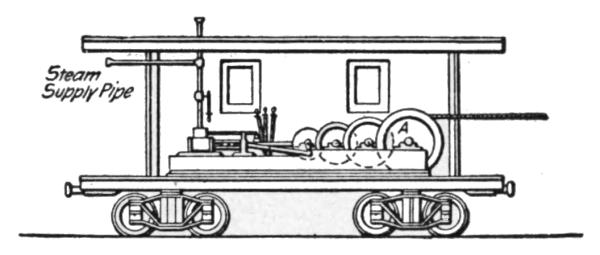
Fig. 92.
The machine shown in Fig. 92 has lately come into use for
pulling the plow over the cars to unload them. This is merely
a double cylinder (10 by 12 ins.) reversible hoisting engine,
resting on a heavy cast iron bedplate attached to the floor of a
box car. Steam is supplied to the engine from the locomotive
of the train, which is coupled to this car when the unloading is
to begin. With this machine there is no injurious jerking of
the cable, and consequently very little breakages or delays, and
heavy loads of 15 cu. yds. of tenacious material are readily
plowed off the cars in a more satisfactory manner than can be
done by any one or two locomotives. Blocking the wheels or
chaining cars to the track need not be resorted to; the cars cannot
move, for the machine pulls the plow toward itself and the
strain is resisted by the cars between them. If it is desired to
scatter small quantities of material along the track, as it is often
wanted in surfacing or raising track, both plow and train are
moved in the same direction at the same or varying speeds, as
may be necessary to unload the required amount of material.
If a large quantity of material is wanted within a short distance,
as usually happens on washouts, train and plow are moved in
opposite directions. By moving them in this manner at the
same speed, a whole train can be unloaded at any desired spot.
Where two locomotives must be used to pull the plow over the
cars, the use of this machine will dispense with one of them,
and do the work in half the time. On large jobs it should not
be missing. The cable is wound around the drum, A, Fig. 92,
and must be long enough to extend over the whole length of[52]
the train. A steel wire cable 1-1/8 ins. diameter is generally
used; but for loose gravel a 1 in. cable is amply strong enough.
The steam shovel can be operated continuously throughout
the year in all kinds of weather, though operations are often suspended
in extremely cold weather. When working in cold
weather the face of the bank sometimes freezes during the night
to the depth of 3 to 6 ins., but this crust is easily broken in the
morning by a few small charges of powder, and then the material
can be excavated as easily as at any other season.
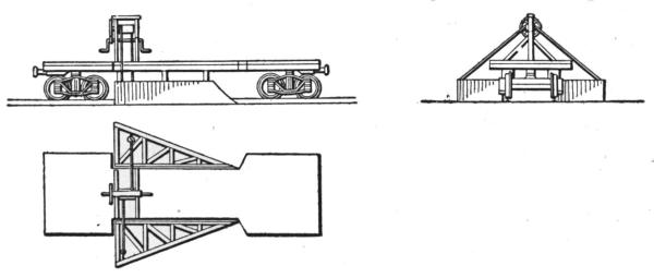
Fig. 93.
Harris & Carter
Spreader.
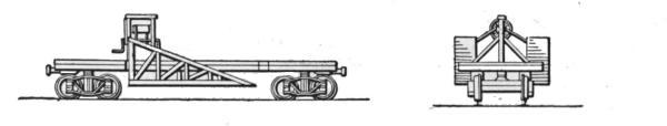
Fig. 94.
In freezing weather the floors of the cars should be sprinkled
with brine just before loading; the brine is kept in barrels at the
head of the machine, and one man using an ordinary garden
sprinkling can is detailed for the work. This prevents the material
from freezing to the floor of the car for three to four
hours, and allows it to slip off readily when the plow is put in
operation. No train should be left standing over night without
unloading. The brine will not prevent freezing for this length
of time, and to unload one car of the frozen stuff requires a day's
labor of four to six men.
Distributing the Material After Unloading.—In widening
embankments for side tracks, double track, yard and station
grounds, etc., the material is unloaded, as described above, forming
a ridge on both sides of the track if unloaded with the
center plow, or on one side of the track only if unloaded with the[53]
side plow. This material is sometimes leveled off by hand, a
very slow and expensive job, but generally it is done with a leveler
or spreader, Figs. 93 to 96.
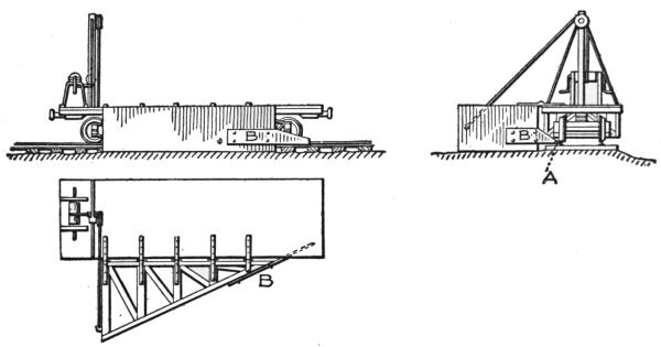
Fig. 95.
Edson
Spreader.
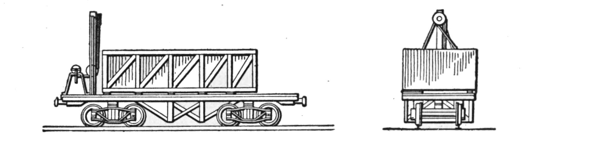
Fig. 96.
In the Harris & Carter spreader, Figs. 93 and 94, the car
body is cut away between the trucks to receive the two wings
which level or spread the material. One or both wings can be
used, and they can be raised and lowered to adjust them to any
height of new embankment wanted. They will spread the material
for a distance of 3 ft. from the rail. When shipping the
spreader over the road the wings are drawn up by a hand windlass,
revolving about hinges fixed to the braces under the floor
of the car, as shown in Fig. 94. In this position the clearance
is the same as that of an ordinary passenger car.
The Edson spreader, Figs. 95 and 96, has only one wing,
attached to an ordinary flat car, and arranged to raise and
lower to adjust it to any height of new embankment wanted.
The wheel, A, bears against the head of the rail, forming a brace
where one is most needed, and greatly assists in preventing a
derailment when hard or tenacious materials are suddenly encountered.[54]
The wing, braces, windlass, etc., are so constructed
that they can be readily removed from the car, thereby restoring
it to general service on completion of the work in hand. This
spreader is used mostly in connection with the side plow; it will
level the material for a distance of 15 ft. from the rail, wide
enough to permit laying a side track from which the embankment
can be further widened. Only one side at a time can be
widened with this spreader. If it is desired to widen the embankment
on both sides of the track, one side is completed first;
the cars and spreader are then turned around on the nearest
turntable or Y-track, and the other side widened by drawing
the spreader in the opposite direction. If the cars are not provided
with aprons they need not be turned around. This
spreader is generally arranged to cut about 6 ins. below the
bottom of the ties of the main track, thereby forming the subgrade
for the side track, and maintaining proper drainage of
the main track. The apron, B, is bolted on the spreader, and
serves to remove any loose material which may fall on the
track between the rail and the ends of the ties. When shipping
the spreader over the road, Fig. 96, it is drawn up by a hand
windlass revolving about hinges on the side sill of the car and
folded down on it; in this position it will clear anything that
other cars can pass.
The cars of both styles of spreaders are loaded with old rails,
frogs, scrap iron, etc., to hold them down and prevent derailments
when hard or tenacious materials are suddenly encountered.
Loads of five to ten tons are generally sufficient, though
loads up to 15 tons are sometimes required.
Spreaders are usually drawn at a speed of six to eight miles
per hour; in loose gravel the speed often reaches 10 miles per
hour. They will level off a ridge a mile in length in six to
ten minutes, doing as much work in that time as 100 men can do
in a day.
The spreader is usually stationed in the nearest side track to
the unloading place. Frequently it can be hauled between this
track and the dump without raising it, or raising it only partially
to clear depot platforms, switch stands and other obstructions
and thereby avoid the necessity of folding it down on the
car while passing between these points.
Ordinarily the spreading is done by the last train before the
close of the day. In cold weather or on short dumps it must[55]
be done oftener; either to prevent freezing, or to make room for
the unloading material which would otherwise pile up too high
for easy spreading, or be liable to roll back on the track and
obstruct it for the next train. In using the spreader it is coupled
to the rear of the car carrying the plow, and after the train has
been unloaded it is pulled over the length of the ridge of material
unloaded from its own and preceding trains, as shown
in Figs. 97 and 98.
Part IV.—Cost of Steam Shovel Work.
The cost of steam shovel work varies greatly with the different
conditions affecting each piece of work. It depends mainly
upon the nature of the material, its location, the capacity and
efficiency of the steam shovel, and the supply of empty cars or
wagons. The efficiency of a steam shovel is not necessarily
proportional to its capacity, but to the amount of work done
compared to its cost; and while the amount of work done is
generally larger in the machines of larger capacities, this advantage
may be more than balanced by the greater cost of operation,
including the cost of labor, fuel, supplies and repairs, etc.
Machines of the largest capacity, with dipper of 2½ cu. yds.
capacity, are employed mostly in excavating soft materials, especially
in loading gravel for ballasting. Machines of medium
capacity are usually the most efficient for general construction
work.
The average daily operating expenses of a steam shovel of
medium capacity are about as follows:
| One engineman | $4.00 | |
| One cranesman | 3.50 | |
| One fireman | 2.00 | |
| Four pitmen at $1.50 | 6.00 | |
| | —— | |
| Wages of crew | $15.50 | —— |
| | | $15.50 |
| One ton coal | $3.00 | |
| Oil and waste | .75 | |
| Water | .50 | |
| | —— | |
| Fuel and supplies | $4.25 | —— |
| | | $19.75 |
| Interest on capital, $6,000, at 6% | $1.00 | |
| Depreciation at 10% | 2.00 | |
| Repairs | 1.00 | |
| | —— | |
| | $4.00 | —— |
| Total daily expense with regular crew | | $23.75 |
This will suffice for loading loose gravel; in the harder materials
ordinarily occurring on construction work the following
daily expenses must be met:
[56]
| Expenses of regular crew | | $23.75 |
| Foreman | $5.00 | |
| Two pole (or bank) men at $1.50 | 3.00 | |
| Two extra men at $1.50 | 3.00 | |
| One night watchman | 1.50 | |
| Powder and dynamite | 1.00 | |
| | —— | |
| | $13.50 | —— |
| Daily expenses on average construction work | | $37.25 |
To the above must be added the expense of transporting the
machine to the work, and returning.
The cost of hauling is also a variable item; it depends mostly
upon the length of the haul, and on railways very largely upon
the delays met with in going to and from the dumping place.
On construction work it is seldom less than 3 cts. per cu. yd.,
and sometimes reaches 10 cts. On railways it is not often below
4 cts. for hauls up to 10 miles in length, and may reach 50
cts. or more for hauls of 75 miles or farther.

Fig. 97.

Fig. 98.
Dumping is a very small item where small dump cars are used
on construction work, and does not exceed ½ ct. per cu. yd.
When wagons are used it will average about 1½ cts. On
railways the cost of unloading with the plow varies somewhat,
depending upon the kind of material; it averages about ½ ct.
per cu. yd. Unloading by hand averages 6 cts.
On railway work, where the spreader is used, the average
cost of leveling the material for widening embankments is only
0.1 ct. per cu. yd.; spreading it by hand will range from 5 to 20
cts. per cu. yd. for widths of 5 to 15 ft. from the unloading track.
The total cost per cu. yd. of excavating and loading, hauling
and dumping different kinds of materials with the most usual
length of haul averages about as follows:
| |
Loading. |
Hauling. |
Dumping. |
Total. |
| |
Cents. |
Cents. |
Cent. |
Cents. |
| Sand and loose gravel |
3 | 4 to 10 |
½ |
7½ to 13½ |
| Loam |
3½ |
" |
" |
8 to 14 |
| Dry clay |
4 |
" |
" |
8½ to 14½ |
| Damp clay |
6 |
" |
" |
10½ to 16½ |
| Stiff blue clay |
8 |
" |
" |
12½ to 18½ |
Cemented gravel, hardpan, etc.,
materials loosened by explosives |
10 to 16 |
" |
" |
14½ to 26½ |
[57]
The steam shovel will do the work of 60 to 120 men, saving
from 5 to 25 cts. per cu. yd. of material excavated and loaded.
The gain is proportionally much greater in the harder, and particularly
in the more tenacious materials. The machine is not
adapted to small jobs, and is seldom worked in cuts of less than
8 ft. in depth; nor is it cheaper than hand and team labor on
such small jobs, but on nearly all large work it is much cheaper
and faster; and last, though not least, its use largely reduces the
number of laborers required, and hence the probability of strikes
and other labor troubles.
APPENDIX.
ACTUAL COST OF STEAM SHOVEL WORK.
(From an article in Engineering News, June 9, 1888, we take the following
particulars of reports on the actual cost of steam shovel work,
and these reports show how variable is the cost of excavating, depending,
as it does, upon delay, unavoidable on every line of railway, upon
the weather, character of the material, length of haul, and many other
conditions. When conditions are favorable as to material, prompt and
short hauling, with no delays, the results show a very large increase
in the output, and often a decrease in cost.—Ed. Eng. News.)
From a report of the General Roadmaster of the New York
Central & Hudson River R. R. of work done by two shovels
on the Eastern and Western divisions, we find the largest day's
work for one shovel at Yost's pit was 174 cars, the average
for the month of August being 121 cars per day and for July 116
cars per day. It could have made a larger average than this with
twenty more cars, as the trains making long runs could not keep cars
in the pit. The largest day's work at Bergen pit with one machine
was 156 carloads, the June average being 117 cars and the July 116
cars per day, and for two weeks in August 134 cars per day. At this
pit they came in contact with cement, hard pan, and very coarse material.
At Yost's pit they have loaded 10,511 cars in four months up
to Aug. 1. Figuring these at 9 yds. per car, which is low, makes
94,599 yds. The cost of delivering on roadbed was $5,261.25, or about
5½ cts. per yd. The average cost for handling by men loading and
unloading is 14 cts. per yd.
The report on a machine working in New Mexico on the Atchison,
Topeka & Santa Fe R. R. says: "In cemented gravel, we find no
difficulty, under favorable circumstances, in loading 75 to 100 cars per
day, at a cost not to exceed 10 cts. per cu. yd."
The engineer of the Cleveland, Mt. Vernon & Delaware R. R. gives[58]
some statements as to the cost and amount of some excavating work
done under his direction. This shovel worked about 5½ months in
stiff clay, as follows:
- March loaded 1154 cars, worked 24 days.
- July loaded 955 cars, worked 24 days.
- Aug. loaded 1157 cars, worked 22 days.
- Sept. loaded 1556 cars, worked 23 days.
- Oct. loaded 1552 cars, worked 23 days.
- Nov. loaded 539 cars, worked 12 days.
Total, 6,915 cars, 41,490 cu. yds. Greatest number of cars loaded in a
single day, 97. Shovel supposed to work ten hours a day, but did not
average more than 6½ hours on account of waiting for cars. Carloads
average 6 cu. yds. per car. Average cost of loading, 3 cts. per cu.
yd., including expense of all men, shovel, oil, waste, etc. Loaded,
hauled material, and unloaded at a distance of ten miles from pit, at
10 cts. per yd., including all costs, shovel, use of cars, engines and
crews. A 20-mile haul on this road cost 15 cts. per yd., and a 30-mile
haul about 20 cts. per yd., while on some roads a 30-mile haul costs
over 75 cts. per yd., depending on the frequency of trains.
The following report from the superintendent of the Sioux City &
Pacific Ry. gives the operations of a shovel for nine months working
in a yellow clay bank from 30 to 40 ft. in length, and with a one-mile
haul: "The total number of cars loaded was 31,420 in 209 days, giving
an average of 150¾ cars per day. The greatest number of cars
loaded in one day was 275, with an average of 6 cu. yds. per car. The
average cost of loading per cu. yd. is 6½ cts., including expense of all
men about shovel, and shifting of shovel track. Average cost of unloading
with one-mile haul, 7.8 cts., including wages of all men with
trains and engines, use of cars and locomotives, with all supplies and
repairs of same, making a total cost of 14.3 cts. per cu. yd. or 85.8 cts.
per car delivered on track."
A report showing the largest amount of work, with the most complete
detail as to the expense of operation was furnished by the resident
engineer of the Missouri Valley & Blair Railway & Bridge Co.,
contractors for the Chicago & Northwestern Ry. bridge across the
Missouri River at Missouri Valley, Ia., the material excavated being
used in the approaches to the bridge. The work, a tabulated statement
of which is given in Table IV., was done under the most favorable
circumstances, with but few delays, and with but one locomotive,
as the cars ran down the hill themselves while being loaded, the locomotive
being employed to haul the empty cars back; the haul was
short and a round trip was made in 30 minutes. The report shows
that during the work of six months the average number of cars loaded
per day was 205, including delays and movings, and that the average
cost per cu. yd. was 7 cts., which, as shown, included labor of loading,
moving shovel about once a month, moving track to suit, dynamite
for caving bank, repairs of shovel, fuel, oil, waste, wages of watchman,
rent of cars and locomotives, labor of engineers, firemen and
wipers, labor, conductors and brakemen, and, in fact, absolutely
everything connected in any way with filling the embankment.
[59]
TABLE IV.
Work Done by Steam Excavator in Six Months at Missouri Valley, Ia.
| Repairs to locomotive, shovel and cars; material | $457.14 |
| Repairs to locomotive, shovel and cars; labor | 211.80 |
| Supplies for shovel | 1,760.00 |
| Rent of locomotive and cars | 1,404.75 |
| Supplies for locomotive | 1,781.52 |
| Wages of locomotive attendants | 1,508.37 |
| Wages of all other employees | 10,680.01 |
| | ————— |
| Total cost | $17,803.59 |
| Cars loaded | 32,141 |
| Cost per car | 55.38 cts. |
| Cost per cubic yard | 7 cts. |
| Hours worked by gang | 2,325 |
| Hours worked by shovel | 1,926 |
The report of the Roadmasters' Association for 1885 gives the cost
of steam shovel work as follows:
| Railway. | Work. | Cost per yd. |
| Baltimore & Ohio |
Including everything, haul 5 to 25 miles |
|
8.1 cts. |
| Michigan Central |
Loading |
|
4.5 cts. |
| Michigan Central |
Hauling, 30 miles, labor only |
|
4.0 cts. |
| N. Y., P., & O. |
Loading |
|
7.0 cts. |
| Central Iowa |
Loading |
4.75 | cts. |
| "" |
Unloading |
1.9 | cts. |
| "" |
Engine service |
3.1 | cts. |
| |
|
—— | |
| "" |
Total |
9.75 |
cts. |
The detailed statement given in Table V. was prepared by Mr. E. A.
Hill, Acting Chief Engineer of the Indianapolis, Decatur & Springfield
R. R., and is a record of work done under the supervision of Mr.
A. J. Diddle, Roadmaster. It shows marked economy and gives an
excellent idea of how the expenses are apportioned. The Otis type
of excavator was used, which cuts 24 ft. wide and to a depth of 4 ft.
below the track. The banks were about 15 ft. high, the average haul
4,000 ft. Twelve flat cars constituted a train. By a special cable arrangement
the time of plowing off, ordinarily requiring about 15 minutes,
was reduced to 5 or 6 minutes.
TABLE V.
Steam Shovel Work; Indianapolis, Decatur & Springfield R. R.
| |
Sangamon
River
Trestle. |
Montezuma
Gravel
Pit. |
Sangamon
River
Trestle. |
Guion
Trestle. |
Nichol's
Hollow
Trestle. |
| |
1885. |
1886. |
1886. |
1887. |
1887. |
| Total number of days |
54 |
186 |
48 |
108 |
51 |
| Number of working days |
46 |
115 |
38 |
85 |
40 |
| Days idle besides Sundays |
0 |
45 |
3 |
7 |
4 |
| Material handled |
light clay. |
gravel. |
light clay. |
light clay. |
light clay. |
| Average height of bank |
10 ft. |
12 ft. |
10 ft. |
10 ft. |
12 ft. |
| Total No. cars loaded |
2,899 |
8,631 |
2,771 |
5,254 |
2,528 |
| Greatest No. load. per day |
94 |
124 |
90 |
80 |
75 |
| Least No. cars load. per day |
22 |
16 |
50 |
30 |
15 |
| Average No. loaded per day |
63 |
75 |
73 |
61.8 |
63.2 |
| Average length of haul |
1 mile. |
9 miles. |
1 mile. |
2 miles. |
¾ mile. |
| Grade, shovel to dump, p. c. |
-1.00 |
varying. |
-1.00 |
-1.00 |
-1.00 |
| Tons coal used, shov. & eng. |
141 |
853 |
99 |
170 |
65 |
| No. car loads per ton coal. |
20.5 |
10 |
28 |
30.9 |
38.9 |
[60]
Cost of Work Per Car Load.
| |
Sangamon
River
Trestle. |
Montezuma
Gravel
Pit. |
Sangamon
River
Trestle. |
Guion
Trestle. |
Nichol's
Hollow
Trestle. |
| |
1885. |
1886. |
1886. |
1887. |
1887. |
| |
Cts. | Cts. | Cts. |
Cts. | Cts. |
| Foreman at $125 per month |
8.86 | 9.67 | 8.00 |
9.01 | 9.88 |
| Cranesman, $2 to $2.50 day |
5.35 | 5.62 | 4.80 |
3.54 | 5.57 |
| Fireman (shovel) $1.50 day |
2.88 | 3.37 | 2.87 |
2.90 | 3.27 |
| Laborers (4) $1.25 per day |
7.86 | 9.92 | 8.77 |
9.80 | 9.80 |
| Watchman at $1 per day |
2.07 | 1.96 | 1.88 |
2.50 | 2.25 |
| Total shovel crew |
27.02 | 30.54 | 26.32 |
27.75 | 30.77 |
| Engr. and fireman (engine) |
12.00 | 14.50 | 7.44 |
11.00 | 13.10 |
| Trainmen (conductor, $2.50; brakemen, $1.50) |
5.97 | 14.60 | 5.74 |
5.25 | 5.77 |
| Total train crew |
17.97 | 29.10 | 13.18 |
16.25 | 18.87 |
| Helpers distrb. earth, $1.10 |
.... | 1.74 | .... | .... |
2.72 |
| Sec. men (track work), $1.10 |
0.81 | 1.88 | 1.38 |
1.45 | .... |
| Bridge carpenters (repairs to plant), $2.50 |
0.15 | 1.58 | 0.16 | 1.04 |
2.08 |
| Sec. men (reprs plant), $1.10 |
.... | 0.62 | .... | .... |
.... |
| Shop bills (repairs to plant) |
1.69 | 10.90 | 1.27 |
10.60 | 1.67 |
| Total repairs to plant |
1.84 | 13.10 | 1.43 |
11.64 | 1.67 |
| Coal from $1.25 to $1.41 ton |
6.31 | 13.30 | 4.47 |
4.31 | 3.28 |
| Oil, waste, etc. |
0.52 | 1.55 | 0.75 |
0.86 | 0.36 |
| Total supplies |
6.83 | 14.85 | 5.22 |
5.17 | 3.64 |
| |
—— | —— |
—— | —— | —— |
| Grand total per car load |
54.47 | 91.19 | 47.53 |
62.26 | 59.75 |
| |
—— | —— |
—— | —— | —— |
| Cost, cu. yd., 8 yds. per car |
6.43 | 11.40 | 5.94 |
7.79 | 7.47 |
| Add " " for interest on cost of plant |
1.00 | 1.00 | 1.00 |
1.00 | 1.00 |
| |
—— | —— |
—— | —— | —— |
| Cost per cu. yd., includ. int. |
7.43 | 12.40 | 6.94 | 8.79 |
8.47 |
[i]
—BACON'S—
HOISTING
ENGINES
For Every Possible Duty.
FARREL'S—Ore and Rock
CRUSHERS.
Screens, Elevators, Etc.
THE STANDARD FOR 25 YEARS.
EARLE C. BACON,
ENGINEER,
Havemeyer Building, New York.
WORKS:
PACIFIC IRON WORKS.
FARREL FOUNDRY & MACHINE CO.
Steam Shovel
REPAIRS.
Dippers, Dipper Teeth, Dipper Bails, Dipper
Mouths, Kept in Stock.
CHAINS OF ULSTER AND NORWAY IRON.
We have built a new shop, and are preparing designs for
STEAM SHOVELS
of very substantial construction.
We call attention to the fact that we have made for years a specialty of
Pile Drivers
and Steam Dredges.
VULCAN IRON WORKS,
CHICAGO.
NEW YORK DREDGING CO.,
ENGINEERS AND CONTRACTORS.
Hydraulic Dredge discharging through 5,700 ft. Pipe.
Will dig and put ashore any Material, Rock excepted.
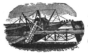
Patent Canal Excavator.
Machines at Work, Washington, D. C.,
Jacksonville, Fla., and Oakland, Cal.
INCORPORATED UNDER LAWS OF NEW YORK.
CEO. W. CATT, M. Am. Soc. C. E., President and Engineer.
O. L. WILLIAMS, Secretary and Treasurer.
SPECIALTIES:
Machinery for Economical Excavation of Canals for
Dredging; for Reclamation of Low Lands.
CORRESPONDENCE SOLICITED.
WORLD BUILDING, New York, N. Y.
[ii]
G. L. STEUBNER & CO.,
—MANUFACTURERS OF—
HOISTING BUCKETS
OF ALL KINDS AND FOR ALL PURPOSES.
Side Dumping Cars,
End Dumping Cars,
Bottom Dumping Cars,
Charging Cars,
Special Cars,
Iron Wheelbarrows,
Iron Hoisting Blocks,
Tar Heating Furnaces,
Sheet-Iron Work,
Iron Forgings, Etc.
...
Send for Catalogue and Price List.
168-176 EAST THIRD ST., LONG ISLAND CITY, N. Y.
THE BEST STEAM SHOVEL CAR.
WRITE FOR PRICES AND CATALOGUE TO ——
Ryan-McDonald Mfg. Co.,
44 SOUTH STREET,
BALTIMORE, MD.,
MANUFACTURERS OF ——
Light Locomotives, Contractors' Cars, Derrick
Irons and Crabs, Hoisting Engines and All
Classes of Narrow Gauge Cars.
[iii]
CONTRACTORS'
AND
RAILROAD SUPPLIES.
Construction,
Dump and Mine Cars.
CATALOGUE AND PRICES ON APPLICATION.
HAROLD C. DAYTON & CO.,
44 DEY STREET, NEW YORK.
[iv]
M. BEATTY & SONS,
WELLAND, ONT.
Dredges, Ditchers, Derricks and Steam Shovels
OF VARIOUS STYLES AND SIZES TO SUIT ANY WORK.
SUBMARINE ROCK DRILLING MACHINERY,
HOISTING ENGINES, SUSPENSION CABLEWAYS,
HORSE-POWER HOISTERS, GANG STONE-SAWS,
CENTRIFUGAL PUMPS for Water, Sand and
Gold Mining.
AND OTHER CONTRACTORS' PLANT.
[v]
Contractor's Locomotives on Hand.
WE Keep on hand a number of sizes both narrow and wide
gauge locomotives, of best construction, for contractors'
service. Catalogue mailed and prices quoted on application.
H. K. PORTER & CO.,
BUILDERS OF LIGHT LOCOMOTIVES,
WOOD STREET, Near 7th Ave., PITTSBURGH, PA.
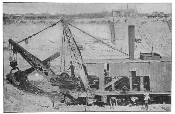
NO. 1 SHOVEL ON CHICAGO DRAINAGE CANAL.
OSGOOD DREDGE CO., Albany, N. Y.
MFRS. OF DREDGES AND STEAM SHOVELS.
[vi]
OTIS & CHAPMAN,
STANDARD GRAVEL and
HARDPAN
EXCAVATOR
MANUFACTURED EXCLUSIVELY BY
JOHN SOUTHER & CO., Boston.
Earth Displaced at ONE-QUARTER LESS EXPENSE
Than by Any Other Machine
To Whom It May Concern:
I hereby certify that I have used
the Otis patent improved Steam
Excavator the past twenty years,
in all kinds of earth excavation,
and believe it to be the best dry
land excavator in use, and the only
one that will work successfully in
hardpan material. I have excavated
and put into cars five million
yards under one contract for making
land in Boston; with two of
these machines I loaded from seventy
to eighty thousand yards per
month.
N. C. MUNSON.
C. P. Treat,
CONTRACTOR BANGOR & AROOSTOOK R. R.
J. A. LANE, Manager.
ROB'T SMITH, Ass't Manager.
S. H. DOTY, Engineer.
H. C. DECKER, Cashier.
Houlton, Maine, December 31, 1894.
This is to certify that in the month of October, 1894, the
bearer, Mr. John B. Shaw, with 1¾ yds. Souther Steam
Shovel, loaded on cars 38,168 cubic yds. of ballast. Pit measurement
by R. R. Co.'s Engineers.
(Signed)
C. P. TREAT,
per S. H. Doty.
Transcriber's Notes
Illustrations in this booklet are not always labelled in order of
appearance, so full page diagrams may appear out of order. Fig. 4. seems
to have been ommitted and is not found (or referenced) in any of the
online sources. Minor corrections made to punctuation. inconsistent
hyphenation and spelling.
In particular:
- p7. "rceiving" changed to "receiving".
- p11. "wabble" has been left - it appears to be a variant spelling of wobble.
- p18. "overhanging ledges or these materials" changed to "overhanging ledges of these materials".
- p22. "only few men" changed to "only a few men"
- TABLE II.
"Loose gravel 1 30 1 30 2 60 3 90 4 12"
changed to
"Loose gravel 1 30 1 30 2 60 3 90 4 120"
- p50. "steam or air driver" change to "steam or air driven"
*** END OF THE PROJECT GUTENBERG EBOOK 47187 ***