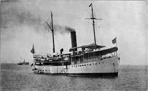
SURVEYING STEAMER FATHOMER IN MANILA BAY. (Frontispiece)
SURVEYING STEAMER FATHOMER IN MANILA BAY. (Frontispiece)
BY
G. R. PUTNAM, M.S.
MEMBER OF THE AMERICAN SOCIETY OF CIVIL ENGINEERS
DIRECTOR OF COAST SURVEYS, PHILIPPINE
ISLANDS, 1900 TO 1906
FIRST EDITION
FIRST THOUSAND
NEW YORK
JOHN WILEY & SONS
London: CHAPMAN & HALL, Limited
1908
Copyright, 1908,
by
G. R. PUTNAM
Stanhope Press
F. H. GILSON COMPANY
BOSTON, U.S.A.
In preparing the material for a lecture on Charts for Columbia University, the writer was impressed with the fact that although nautical charts are mentioned or discussed in many publications, there was not found any one which covered the general subject of their origin, construction, and use. In the countries of the world more than a million copies of such charts are now issued annually. A considerable portion of the human race is interested directly or indirectly, whether as mariners or passengers or shippers, in navigation upon the sea. Aside from supplying a handbook for those who might have a general interest in the subject, it was thought that a discussion of charts might lead to further consideration of the principles governing their construction.
This paper has intentionally been made as non-technical as seemed feasible in treating a somewhat technical subject. The writer is indebted to the Coast and Geodetic Survey for various illustrative material from its archives, and to a number of authors for facts or suggestions. A list is appended of books and papers which have been freely consulted, bearing on this and related subjects.
G. R. P.
Washington, D.C., May 24, 1908.
| PAGE | |
| List of Books or Papers bearing on Nautical Charts and related Subjects | vii |
| Charts and Maps | 1 |
| Collection of Information for Charts | 31 |
| Preparation of Information for Charts | 67 |
| Publication of Charts | 84 |
| Correction of Charts | 97 |
| Reading and Using Charts | 112 |
| Use of Charts in Navigation | 124 |
| Publications Supplementing Nautical Charts | 154 |
| Index | 161 |
Periplus, an Essay on the Early History of Charts, and Sailing Directions. A. E. Nordenskiöld, Stockholm, 1897.
Maps, their Uses and Construction. G. James Morrison, London, 1902.
Charts and Chart Making. Lieut. John E. Pillsbury, U.S.N., in Proceedings U. S. Naval Institute, 1884.
Principal Facts relating to the Earth's Magnetism. L. A. Bauer, in U. S. Magnetic Declination Tables, Coast and Geodetic Survey, 1903.
Marine Hydrographic Surveys of the Coasts of the World. G. W. Littlehales, in Report of the Eighth International Geographic Congress, 1904.
Smithsonian Geographical Tables. R. S. Woodward, Washington, 1906.
Admiralty Charts, Abridged list of. Published by J. D. Potter, London, 1907.
Military Topography. Capt. C. B. Hagadorn, U.S.A., West Point, 1907.
Service Hydrographique de la Marine, Paris, 1900.
A Manual of Conventional Symbols in Use on Official Charts. United States Hydrographic Office, Gustave Herrle, 1903.
Hydrographical Surveying. Admiral W. J. L. Wharton, London, 1898.
On the Correction of Charts, Light Lists, and Sailing Directions. Published by J. D. Potter, London, 1904.
Notes Relative to the Use of Charts. D. B. Wainwright, Coast and Geodetic Survey, 1900.
The Law relating to Charts and Sailing Directions. H. Stuart Moore, London, 1904.
Notes bearing on the Navigation of H. M. Ships. Hydrographic Office, London, 1900.
The Relations of Harbors to Modern Shipping. W. H. Wheeler, in Engineering News, September 6, 1906, New York.
Wrinkles in Practical Navigation. Capt. S. T. S. Lecky, London, 1899.
Navigation and Compass Deviations. Commander W. C. P. Muir, U.S.N., Annapolis, 1906.
The Practice of Navigation. Henry Raper, London, 1898.
Lehrbuch der Navigation. Reichs-Marine-Amt, Berlin, 1906.
The Nautical Magazine, London.
Dangers and Ice in the North Atlantic Ocean. Bureau of Navigation, U. S. Navy Department, 1868.
Reported Dangers in the North Pacific Ocean. U. S. Hydrographic Office, 1871.
Pacific Islands, Vol. III, chapter on "Vigias." British Hydrographic Office, London, 1900.
Harriman Alaska Expedition, Vol. II, Bogoslof, our Newest Volcano, by C. Hart Merriam, New York, 1901.
Expedition to the Aleutian Islands, 1907. T. A. Jaggar, Jr., in The Technology Review, 1907, Boston.
Recent Changes in Level in the Yakutat Bay Region, Alaska, by R. S. Tarr and Lawrence Martin, in Bulletin of the American Geological Society, 1906.
An Index to the Islands of the Pacific Ocean. W. T. Brigham, Honolulu, 1900.
Geography, articles by C. R. Markham, A. R. Clarke, and H. R. Mill in Encyclopædia Britannica.
Development in Dimensions of vessels, Elmer L. Corthell, Tenth International Navigation Congress, 1905.
Need of maps. Maps are useful and necessary for many purposes. Only by means of a correct map or globe can a clear idea of the geography of a region be given. An attempt to convey the same information by a written description would in comparison be both cumbersome and obscure. Even by passing over an extensive region a man unaided by instruments will obtain only a rather crude notion of the relations, which he could clearly see on a good map. The importance among the human arts of the making of maps is indicated by the references to them in very early historical records, and by the skill in map drawing shown by some of the primitive peoples of to-day. This skill exists particularly among races whose mode of life gives them a wide horizon, as for instance the Eskimos. An interesting instance of this was the case of Joe, an Eskimo guide, who, in 1898, before the surveys of the Yukon delta were made, drew a map of the Yukon mouths with much more complete information than any previously available.
Without attempting to enumerate in detail the special uses for maps, in the broader sense they may be said to be essential for commercial, engineering, military, scientific, educational, and political purposes.
Early geography and map making. The oldest map known is a plan of gold mines in Nubia, drawn on a papyrus. This is of the thirteenth century B.C., and was found in Egypt.
In the earliest historic times men believed the earth to be a flat surface of nearly circular outline, a natural inference for those with limited outlook and communication. Later the idea was introduced of the ocean as a river bounding the earth disk. The spherical theory of the earth was, however, early accepted by learned men, and was demonstrated by Aristotle (384 to 322 B.C.), who used as proofs the earth's shadow on the moon, and the change in the visibility of the stars in traveling north or south. Crates constructed a terrestrial globe in the second century B.C.
There is no Greek or Latin map extant of earlier date than the time of Ptolemy, but there are references showing that maps were in use. One of the first of such passages in Greek literature is the interesting comment of Herodotus written in the fifth century B.C., "but I laugh when I see many who already have drawn the circuits of the earth, without any right understanding thereof. Thus they draw Oceanus flowing round the earth, which is circular, as though turned by a lathe, and they make Asia equal to Europe."
A map of the world was drawn by Anaximander, 560 B.C. A hundred years later Democritus drew a map having an oblong shape, and taught that the width of the world from east to west was one and a half times its extent from north to south, a conclusion based on his travels eastward as far as India. This theory, which was for a time accepted, has left an enduring[Pg 3] mark in the words longitude and latitude, originally signifying the length and the breadth of the earth.
The first application of astronomy to geography was made by Pytheas, who about 326 B.C. obtained the latitude of Marseilles by an observation of the altitude of the sun. Dicearchus in 310 B.C. determined the first parallel of latitude by noting places where on the same day the sun cast shadows of equal length from pillars of equal height. Eratosthenes (276 to 196 B.C.) was the first to compute the circumference of the earth from observations of the altitude of the sun at Alexandria and at Syene in Upper Egypt and an estimation of the distance between these two places. Ptolemy, a Greek of Alexandria, in the years from 127 to 151 A.D. wrote extensively on geographic subjects, and collected into systematic form all geographic knowledge then existing; he was the greatest geographer of early history.
In the ten centuries which followed, part of the early advance in this science was obscured, and the theory that the earth was a flat disk surrounded by the sea again became prevalent. The voyages of discovery of the middle ages, however, led to a rapid development of geographic knowledge.
The flattening of the spherical earth was not suspected until in 1672 a clock regulated to beat seconds at Paris, when taken to Cayenne near the equator was found to lose two and one-half minutes a day. Newton proved that this was due to the fact that the earth is an oblate spheroid. In 1735 accurate measurements were undertaken to determine the size and shape of the earth. The equatorial diameter has been found to be 7926.6 miles and the polar diameter 7899.6 miles,[Pg 4] the difference, or 27 statute miles, being the amount of the flattening at the poles.
The first sailing directions. The early Greek and Roman writers do not allude to charts or maps intended especially for the use of seafarers. There are, however, extant several peripli or descriptions of the coast. Some of these appear certainly to have been intended for use as nautical guides, corresponding to the modern sailing directions. It is probable that they were explanatory of or accompanied by coast charts, now lost. They are of interest therefore as being probably the first compilations for the guidance of seamen. One of the earliest, written apparently in the fifth and fourth centuries B.C., is entitled "Scylax of Caryanda, his circumnavigation of the sea of the inhabited part of Europe and Asia and Libya." It contains a systematic description of the coasts of the Mediterranean, Black Sea, and part of the west coast of Africa. The following are some extracts which indicate the character of the work. It is to be noted that no bearings are given, and that distances are usually stated by day's sail: Africa is referred to as Libya.
"Europe. I shall begin from the Pillars of Hercules in Europe and continue to the Pillars of Hercules in Libya, and as far as the land of the great Ethiopians. The Pillars of Hercules are opposite each other, and are distant from each other by one day's sail.... From Thonis the voyage to Pharos, a desert island (good harborage but no drinking water), is 150 stadia. In Pharos are many harbors. But ships water at the Marian mere, for it is drinkable.... From Chersonesus is one day's sail; but from Naustathmus to[Pg 5] the harbor of Cyrene, 100 stadia. But from the harbor to Cyrene, 80 stadia; for Cyrene is inland. These harbors are always fit for putting into. And there are other refuges at little islands, and anchorages and many beaches, in the district between.... After the isthmus is Carthage, a city of the Phœnicians, and a harbor. Sailing along from Hermæa it is half a day to Carthage. There are islands off the Hermæan cape, Pontia island and Cosyrus. From Hermæa to Cosyrus is a day's sail. Beyond the Hermæan cape, towards the rising sun, are three islands belonging to this shore, inhabited by Carthaginians; the city and harbor of Melite, the city of Gaulus, and Lampas; this has two or three towers.... The sailing along Libya from the Canopic mouth in Egypt to the Pillars of Hercules ... takes 74 days if one coast round the bays.... From the cape of Hermæa extend great reefs, that is, from Libya towards Europe, not rising above the sea; it washes over them at times.... From Thymiateria one sails to cape Soloes, which juts far into the sea. But all this district of Libya is very famous and very sacred.... This whole coasting from the Pillars of Hercules to Cerne Island takes twelve days. The parts beyond the isle of Cerne are no longer navigable because of shoals, mud, and sea-weed. This sea-weed has the width of a palm, and is sharp towards the points, so as to prick."
That there were many other similar writings in the following centuries is shown by the following quotation from Marcianus, in a preface to sailing directions written in the fifth century A.D.: "This I write after having gone through many sailing directions, and spent much time on their examination. For it behooves all[Pg 6] who are men of education, to scrutinise such attempts at learning in this subject, so as neither rashly to believe the things that are said, nor incredulously to set their private opinions against the careful decisions of others."
The oldest extant sailing directions of the middle ages bear date 1306 to 1320.
Development of chart making. The application of the compass to nautical use in the twelfth century A.D. had a marked effect in encouraging voyages of exploration, and therefore indirectly on chart making. The following, written toward the close of the twelfth century, is the first known mention of the use of the compass in Europe: "The sailors, moreover, as they sail over the sea, when in cloudy weather they cannot longer profit by the light of the sun, or when the world is wrapped in the darkness of the shades of night, and they are ignorant to what part of the horizon the prow is directed, place the needle over the magnet, which is whirled round in a circle, until, when the motion ceases, the point of it (the needle) looks to the north." The nautical compass of that time appears to have consisted of a magnetized needle, floated in a vessel of water by a cork or reed, and having no index nor compass card. Peregrinus in 1269 made notable improvements in the compass, including a pivot suspension for the needle, a graduation, a lubber line, and an azimuth bar for sighting on the sun or other object.
Nautical charts are known to have been in use since the thirteenth century A.D., but the earliest extant of which the date can be fixed is Vesconte's loxodromic chart of 1311.
The loxodromic charts first appeared in Italy, and were so called from the fact that they were crossed by loxodromes (or rhumb lines) radiating from a number of crossing points distributed regularly over the map. Compass roses carefully drawn were later added at these crossing points, the first appearing on a chart of 1375. The earliest known mention of the variation of the compass from true north was on the first voyage of Columbus, who discovered this important fact in 1492, and as a consequence his "seamen were terrified and dismayed." Before that time it was assumed in Europe that the compass pointed "true to the north pole." The apparent failure to detect the variation earlier was doubtless to some extent due to its small amount at that time along the Mediterranean. The earlier charts showed both lines and compass roses apparently oriented with the true meridian, though there is some evidence to indicate that they were actually oriented with the magnetic meridian, the designer not recognizing any difference. The variation of the compass was first marked on a map in 1532 and on a printed chart in 1595, but the placing of magnetic compasses on charts did not become customary until about fifty years ago. These early charts were drawn on parchment, using bright colors. They were copied by hand, one from another, with gradual variations. They had no projections, and the draftsmen evidently had no idea of the sphericity of the earth. Islands and points were usually exaggerated; shallows were indicated, but no soundings; no information was given as to the interior of the countries; a scale of distances was nearly always provided.
Charts were first printed about 1477, and are known to have been engraved on copper by 1560.
The maps of Ptolemy were ruled with degree lines, but no chart was so provided until 1427; by 1500, however, most charts were graduated. Before this date it is not known on what projection the charts were constructed. On the first graduated charts the degree lines were equidistant parallel straight lines cutting each other at right angles and thus dividing the chart into equal squares or rectangles. These were known as "plain charts." This square projection had little to commend it save simplicity of construction, as in higher latitudes it gave neither directions nor distances correctly. The difficulties of its use in navigation were early recognized, and nautical works contained chapters on "sailing by the plain chart, and the uncertainties thereof."
The example of early chart making shown in Fig. 2 is of great interest as being the earliest extant chart which includes America. This chart was drawn on ox-hide in 1500 by Juan de la Cosa, who accompanied Columbus on his first voyage as master of his flagship, and on his second voyage as cartographer. The chart, of which only a portion is shown here, purports to cover the entire world; it joins Asia and America as one continent, the Pacific Ocean being then still unknown.
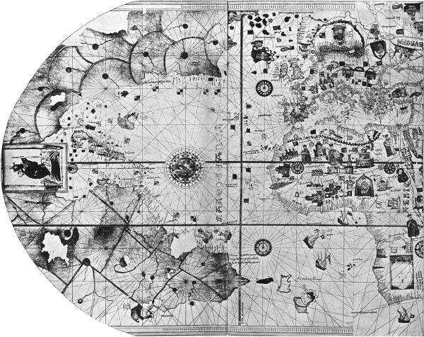
FIG. 2. CHART OF NORTH ATLANTIC OCEAN, BY JUAN DE LA COSA, 1500. EARLIEST EXTANT CHART SHOWING AMERICA.
Fig. 2 enlarged (652 kB)
Gerhard Krämer, a Flemish map-maker, better known by his Latin name of Mercator, in 1569 published his famous Universal Map. In this map the meridians and parallels were still straight lines intersecting at right angles, but the distances between the parallels were increased with increasing latitude in such proportion that a rhumb line, or line cutting the meridians at a constant angle, would appear on the map as a straight line. Mercator never explained the construction of his chart, and as the above condition was not accurately carried out, it is thought that the chart was drawn by comparing a terrestrial globe with a "plain chart." After examination of a mercator chart in 1590, Edward Wright developed the correct principles on which such a chart should be constructed, and published in 1599 his treatise "The Correction of Certain Errors in Navigation." It took nearly a century to bring this chart into use, and even in the middle of the eighteenth century nautical writers complain that "some prefer the plain chart."
The Arcano del Mare, 1646, was the first marine atlas in which all the maps were drawn on the mercator projection.
In the sixteenth, seventeenth and eighteenth centuries charts and sailing directions were often bound together in large volumes. These usually had quaint titles, not overburdened with modesty, of which the following is an example: "The Lightning Columne, or Sea-Mirrour, containing the Sea-Coasts of the Northern, Eastern, and Western Navigation. Setting forth in divers necessaire Sea-Cards, all the Ports, Rivers, Bayes, Roads, Depths, and Sands. Very curiously placed on its due Polus height furnished. With the Discoveries of the chief Countries and on what Cours and Distance they lay one from another. Never there to fore so Clearly laid open, and here and there very diligently bettered and augmented for the use of all Seamen. As also the situation of the Northerly Countries, as[Pg 9-10] Islands, the Strate Davids, the Isle of Jan Mayen, Bears Island, Old Greenland, Spitsbergen and Nova Zembla. Adorneth with many Sea-Cards and Discoveries. Gathered out of the Experiences and practice of divers Pilots and Lovers of the famous Art of Navigation. Where unto is added a brief Instruction of the Art of Navigation, together with New Tables of the Sun's Declination, with a new Almanach. At Amsterdam. Printed by Casparus Loots-Man, Bookseller in the Loots-Man, upon the Water. Anno 1697. With Previlege for fiftheen years."
In 1633 a cartographer was appointed to the States-General of Holland, and it was his duty to correct the charts from the ships' logs. The Dutch at an early date made important progress in publishing charts. In 1720 there was established in Paris by order of the king, a central chart office ("dépôt des cartes et plans, journaux et mémoires concernant la navigation"), and in 1737 the first charts were published by this office. Detailed surveys of the coast of France were commenced in 1816.
In 1740 "the commissioners for the discovery of longitude at sea" were authorized by Parliament to expend money on the survey of the coasts of Great Britain, this commission having been created in 1713. Various rewards were offered by this commission, including one of £10,000, for the discovery of a method of determining the longitude within 60 miles, an interesting side light on the uncertainties of navigation at that time. Compensated timepieces, which have been so important a factor in improving navigation, were invented by Harrison about 1761.
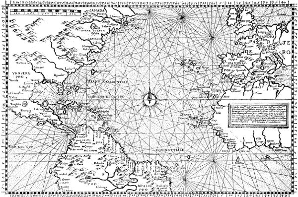
FIG. 3. LOXODROMIC CHART OF NORTH ATLANTIC OCEAN, 1565. A PLAIN CHART WITH LATITUDE DEGREES OF EQUAL LENGTH.
In 1795, by an Order in Council, a Hydrographical Office was established in London, "to take charge and custody of such plans and charts as then were, or should thereafter be, deposited in the Admiralty, and to select and compile such information as might appear to be requisite for the purpose of improving navigation." This office had at first one assistant and one draftsman. Before that time many charts of a private or semiofficial character had been published; the catalogue of the East India Company in 1786 included 347 charts.
In 1807 the Congress of the United States authorized the President "to cause a survey to be taken of the coasts of the United States, in which shall be designated the islands and shoals, with the roads or places of anchorage, within twenty leagues of any part of the shores of the United States; and also the respective courses and distances between the principal capes, or headlands, together with such other matters as he may deem proper for completing an accurate chart of every part of the coasts within the extent aforesaid." This law was the origin of the present United States Coast and Geodetic Survey, now under the Department of Commerce and Labor.
In 1841 a systematic survey of the Great Lakes was commenced; this is the Survey of the Northern and Northwestern Lakes, briefly known as the Lake Survey, conducted under the Corps of Engineers.
In 1866 the United States Hydrographic Office was established under the Navy Department "for the improvement of the means for navigating safely the vessels of the Navy, and of the mercantile marine, by providing under the authority of the Secretary of[Pg 14] the Navy, accurate and cheap nautical charts, sailing directions, navigators, and manuals of instructions for the use of all vessels of the United States, and for the benefit and use of navigation generally."
Systematic surveying and chart making date back little more than a century, and most of the information shown on modern charts has been gathered in that time. At present all the principal maritime nations of the world have made, or are extending, careful surveys of their own coasts.
Several of the countries have added valuable contributions in the examination of other regions and oceanic areas beyond their borders. The maritime and colonial interests of Great Britain impelled that nation to carry on extensive surveys along coasts whose inhabitants were not prepared to do this work in the earlier days; the British have made surveys along the coasts of Asia and Africa and a part of South America, and the resulting charts have been a very important and not sufficiently known contribution to commercial intercourse among the nations, as well as to geography.
The Dutch, French, Spanish, and other European governments have made nautical surveys in various parts of the world, largely in connection with their own colonies, and in recent years much useful work has been done by vessels of the German government. The United States has also beyond its own territory made valuable additions to hydrographic knowledge in the work of officers of the Navy in a number of oceanic exploring expeditions, and surveys on the coasts of Mexico and in the West Indies, and in the explorations of Fish Commission vessels.
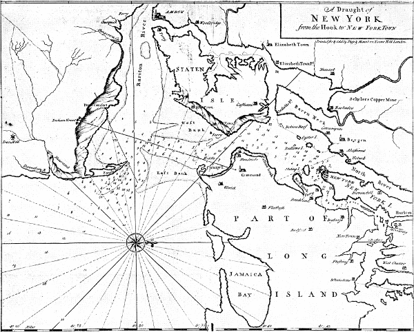
FIG. 4. EARLY CHART OF NEW YORK HARBOR, 1737.
Extension of maritime surveys. Of the total area of the earth's surface, 51,886,000 square miles is land and 145,054,000 square miles is sea. The oceans thus occupy nearly three-fourths of the whole surface, affording highways open to the nations. To conduct international commerce by water the ships of one country must enter the ports of another. Thus both on the open sea and in the harbors there is an interest, common to seamen of all nationalities, in the advance of marine surveys and in the publication of charts.
To keep the coasts properly charted, as well as lighted and buoyed, is an obligation devolving on modern nations, not only for the benefit of their own commerce but for that of other countries.
As shown below, only a small part of the coast line of the world is thoroughly surveyed. In the extensive ocean areas which are dotted with islands or reefs, a large amount of work is required for their sufficient charting, although many doubtful areas have been cleared up in recent years. Even the parts that are known to be of depths so great as to be free from navigational dangers should be sounded over sufficiently to develop the general configuration of the ocean bottom.
Through international understanding a thorough exploration of all the water area of the globe and the coasts may in time be effected, and the many doubtful spots which still disfigure the charts may be either eliminated or definitely located.
Present state of progress of hydrographic surveys. A comparatively small proportion of the coasts of the world can be considered as completely surveyed at the present time, and even such regions require much[Pg 18] additional revision. In the class of more thoroughly surveyed coasts should be included the Atlantic and most of the Pacific coast of the United States, Porto Rico, nearly all the coasts of Europe, Algeria, and portions of the coasts of Japan, the Philippine Islands, and India.
A large part of the world's coasts has been surveyed incompletely, but sufficiently well to permit the publication of navigational charts. This is the condition as respects most of southeastern Alaska and some other portions of the Alaskan coast, British Columbia, most of Mexico, Central America, the West Indies, Brazil and parts of Chile, the Hawaiian Islands, China, Malay Peninsula, Siam, the Dutch East Indies, Australia, New Zealand, Persia, Arabia, most of Africa, Iceland, northern Scandinavia, and Finland.
Another considerable portion of the coasts has not been surveyed, but has been covered by explorations which have been embodied in nautical charts of varied degrees of incompleteness. In this class are the north coast and considerable portions of the south and west coasts of Alaska, the Aleutian Islands, Siberia, most of the oceanic groups in the Pacific, the northern coasts of Europe and North America, Greenland, the west coast of South America, Venezuela, and Argentina.
Only a very small proportion of the total length of coasts is now entirely unexplored, and such portions are confined to the polar regions.
Chart publications of various nations. There are about eighteen nations publishing navigational charts, and adding to the information on which charts are based. Many of these nations republish to some extent[Pg 19] the charts prepared by the others. Great Britain has kept up a series of charts covering all parts of the world and practically including in some form all information published elsewhere. This series now (1908) includes 3725 different charts, of which the annual issue is about 600,000 copies. France (1906) publishes 2948 different charts.
In the United States, charts are published by the Coast and Geodetic Survey for the coasts and tidal waters of the main country and the insular possessions, by the Hydrographic Office for oceanic areas and foreign coasts, and by the Lake Survey for the Great Lakes. The total number of different charts issued by these bureaus is about 2300, and the total annual issue is about 225,000 copies.
Systems in use on various charts.
Longitude. The first chart of New York, published by the Coast Survey in 1844, was referred to the City Hall of New York as the initial longitude, and some years ago it was the prevailing custom for each nation to use a local initial longitude. While this satisfied local pride it led to much geographical and navigational confusion. Happily the charts of all countries are now referred to Greenwich, with the following exceptions:
France refers to Paris, which is 2° 20´ 15´´ E. of Greenwich.
Spain refers to San Fernando, which is 6° 12´ 20´´ W. of Greenwich.
Portugal refers to Lisbon, which is 9° 08´ 24´´ W. of Greenwich.
Units for depths. The English fathom or foot is used for depths on the charts of Great Britain, the United States, and Japan. Russia uses the sajene of seven[Pg 20] English feet. On the modern charts of practically all the other countries the meter is used, though on older charts various units are found.
In the first group feet are ordinarily found only on large scale or local charts of areas with moderate depths, and the other charts are in fathoms, except that on the earlier charts of the Coast and Geodetic Survey feet were used on a sanded surface inside of the three-fathom curve and fathoms on the white surface outside of that curve. Heights are stated in feet on the charts of the first group.
Plane of reference. As the depth of water varies with the tide, it is necessary for charting purposes to adopt some standard plane to which the soundings are referred. Practically all countries have adopted for this purpose a low stage of the tide, as this is obviously on the side of safety; in most cases an extreme low water is used, so that the actual depths will seldom, owing to the tide, be less than those shown on the chart. The definite reference planes used on the American charts will be mentioned later.
On nearly all charts heights are referred to mean high water, doubtless owing to this being the visible limit of the land at high tide. On topographic maps of the interior, the heights are referred to mean sea level, which plane is of course lower than the preceding by one-half the range of tide.
Symbols on charts. Fair uniformity as to general principles, with differences as to details in carrying them out, exists on the various series of charts regarding their general arrangement and the more important symbols, such as in the shading of land to distinguish[Pg 21] from water, the use of depth curves, the representation of hills by shade or contour, the indication of shoals and dangers, and of lighthouses and buoys.
Desirability of uniformity in charts. Ships engaged in international commerce must enter foreign ports. As the information is constantly changing and charts are being corrected or improved, it is sometimes desirable for the navigator to consult the local foreign charts, and it may often be necessary for him to carry in his chart room the charts of several different countries. There are therefore important advantages in international uniformity in chart publication.
There should be a common initial longitude, and as the longitude of Greenwich has been so extensively adopted, it appears quite probable that its use may some day become universal.
A common unit for soundings and heights would be very desirable, but the fact that a large group of nations has united on the metric system, while a small group with great commercial interests retains another system, makes the attainment of uniformity difficult.
Substantial agreement as to the use of symbols on charts, particularly such as represent aids or dangers to navigation, would be desirable and doubtless feasible.
Privately published charts. Many of the earlier charts were prepared and published by private enterprise, and such charts are still published, as, for instance, the so-called "blue-back" charts printed in London. These charts have usually differed from those published by the various governments either in representing the main features in a very bold manner with little detail or in including a considerable area with many plans on a[Pg 22] single large sheet backed for permanency. An objection to the latter is that the durability together with the high price tends to keep an old chart in use long after it is out of date. It would be financially difficult for a private firm to give the service that a government does in the matter of correcting the charts and issuing new editions, and this is an important consideration in the selection of charts.
Purpose of charts. The main purpose of charts is to furnish graphical guides to aid in taking a vessel safely from one port to another; they are maps for the use of navigators. An experienced mariner may be able to steer his vessel over a familiar course without charts, but this does not make their publication less necessary. Even such an expert pilot doubtless studied the charts in the first place; the uncertainties of the sea and the changes of information are such that his vessel's equipment should include the latest charts, and safety requires their examination. The passengers and the merchants who intrust their lives or their goods to the sea are largely dependent upon the correctness of the charts.
Besides their main purpose charts fill many other needs, among which are; for preliminary planning of harbor improvements and various engineering works, for defensive works and other military uses, for the fishing interests, and for general information as to the coastal regions. Charts will furnish much of interest and instruction to the traveler by sea and the dweller near the coast, who will learn to read them. Passenger steamers should more often for the interest of their patrons display charts of the waters traversed. No[Pg 23] written or verbal description can give as clear an idea of geographical features and relations as a good map or chart.
As the charts are revised from time to time, a comparison of editions at different dates furnishes a record of the changes wrought by nature or man, and this is especially useful in studying the action in many harbor and river entrances, as well as for historical purposes.
Requirements for charts. As charts are maps of the water areas, including the adjoining land, and intended primarily for the use of mariners, they differ in important respects from topographic maps or general maps, even such as include the water areas. The main requirements for charts are these; correct and complete information, early publication of new data, clear and intelligible representation of the information, convenient arrangement as navigational instruments, and high standard of publication.
The special and sometimes difficult conditions under which charts must be used on shipboard call for good judgment throughout their preparation. Even the paper on which they are printed is of importance, in order that they may be sufficiently durable and suitable for plotting.
Information given on charts. It is evident that it is impossible to represent on a chart of any practicable scale all the features that exist on the corresponding area of the earth's surface. It is essential, therefore, that a selection be made of the classes of facts that are to be shown, as well as of the detail that is to be used for each class. The practical utility of the chart depends largely on the good judgment used in this selection. In[Pg 24] the information shown, charts differ from maps principally in representing by soundings and curves the configuration of the bottom of the water area, and in showing ordinarily the topographic features only in the vicinity of the coast line.
The convenience of mariners should govern in the selection and arrangement of the information to be shown on charts, though they may be made useful for other purposes so long as this convenience is not lessened. The needs and preferences of navigators alone, however, differ so much that a reasonable chart must be somewhat of a compromise between conflicting views. For certain classes of navigation a boldly drawn chart showing only the dangers and a few other soundings and some landmarks might be useful. For other maritime purposes a more detailed chart would be valuable. The first, however, would fail to give facts often demanded in the navigational use of the chart, and the second if carried to an extreme would make a chart difficult to use.
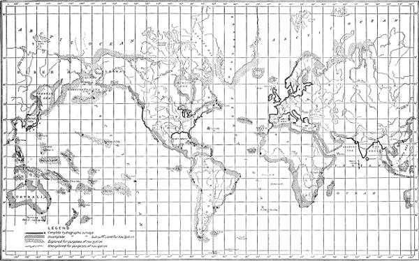
FIG. 5. STATE OF ADVANCEMENT OF HYDROGRAPHIC SURVEYS OF THE COASTS OF THE WORLD, 1904. By G. W. Littlehales.
Shoals and dangers are shown either by the least depth or by rock or reef symbols. The characteristic soundings are shown on the chart, with abbreviations indicating the nature of the bottom. Depth curves are drawn, joining together points of like depth, and inclosing areas of less depth, on the same principle that contours are used on land maps; usually also the shoaler spots are made more prominent by sanding or tinting the area within them. Lighthouses, buoys, and other artificial aids to navigation are represented, with descriptive abbreviations. The coast is shown by a bold solid line for high water and a dotted line[Pg 25-29] for low water. The main topographic features are represented for a moderate distance from the coast, with such detail as is useful, depending on the scale of the chart. Elevations are given in figures for prominent summits, islands, and rocks; the general configuration of hills and mountains is represented by contours on large scale charts or by hachures or shading on small scale charts. Rivers, streams, lakes, marshes, towns, roads, prominent buildings, and other important topographic features are shown by appropriate symbols. It is important that objects which may be useful in navigation as landmarks, whether natural or artificial, be plainly shown and described, if necessary to their identification, and that they should not be obscured by details of lesser importance. On the larger scale charts only, vegetation features, particularly areas covered by trees, are represented by symbols. The land area is usually clearly distinguished from the water area by a tint or stipple. Latitude and longitude are given by the projection lines and the subdivided border, or sometimes on harbor plans by a note giving the position of some one point. Brief information as to the time and range of the tides is stated in a note. Data regarding currents, whether due to tidal or other causes, are given by current arrows placed on the chart, or by explanatory notes. Compasses are for convenience printed on the charts, and data given as to the magnetic variation and its rate of change. On large scale charts scales are provided for use in measuring distances. Ranges and channel lines are given when required. The ports are indicated where storm warning signals are displayed. The areas of forbidden anchor[Pg 30]ages are shown, and when important, the positions of submarine cables. The lines dividing the high seas from inland waters are sometimes stated on United States charts. Life saving stations are given, and time balls are usually noted. Views of important features are shown on some charts.
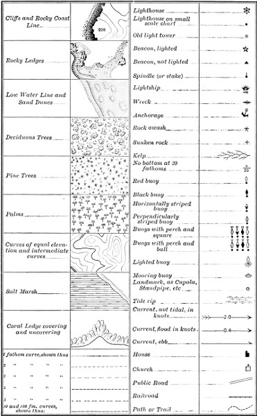
FIG. 6. SYMBOLS USED ON CHARTS OF THE UNITED STATES COAST AND GEODETIC SURVEY.
The layman who looks at the printed chart probably does not appreciate the amount or the variety of information that must be gathered and sifted and put in proper shape for a single chart.
Need of thorough surveys. As has been stated, a good chart requires that a thorough and correct survey be first made of the region to be charted. It is said that men are very apt to accept as true anything they see on a map. As to the nautical chart the mariner is likely to be somewhat more critical, however, and it is well that he is. The difficulty of charting an invisible surface such as the bottom of the sea is great, and the proportion of the navigable waters surveyed in sufficient detail to be at all certain of the absence of uncharted dangers is small.
The planning of surveys in a new region, such, for instance, as the Philippine Islands, presents many interesting problems, on the solution of which the effectiveness in chart results and the cost of the work materially depend. Many local conditions must be taken into account. The surveys are made on opposite coasts according to the seasonal winds and rainfall. In some parts fair-sized steamers are necessary; in others launches and small boats can do the work more economically. Shore parties with land transportation are used for portions of the work where the country permits. Natives are employed as far as practicable for the classes of work they can do; the Filipinos, for instance, make good sailors on the vessels and excellent penmen in the office.
The following is a brief outline of the steps of a com[Pg 32]plete survey for charting purposes, according to the present practice of the United States Coast and Geodetic Survey. These are given in their logical order, though in actual work this order must often be departed from. In this Survey the methods of control have been of a high standard; that is, the main stations have been accurately determined and permanently marked and described, and this has proven an advantage in the joining together of the original surveys and resurveys.
Astronomical observations. To locate on the surface of the earth the area to be charted, astronomical observations are required for the latitude and longitude of one or more points. In the best practice the longitude of a point is obtained by observing the transits of stars to get the local time, and sending time signals by telegraph to obtain the difference from the local time of some other place whose longitude is known. The latitude is observed by measuring the difference of zenith distance of pairs of stars crossing the meridian north and south of the zenith. The azimuth or true direction of some line is also obtained from star observations, usually by observations with a theodolite on a circumpolar star. Much existing chart work depends on positions determined by less accurate methods, as, for instance, longitudes obtained by transporting chronometers between the known station and that to be determined, or by observations of moon culminations, and latitudes obtained by direct observations of the altitudes of stars with theodolite or sextant.
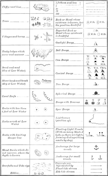
FIG. 7. SYMBOLS USED ON CHARTS OF THE BRITISH HYDROGRAPHIC OFFICE.
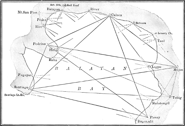
FIG. 8. TRIANGULATION OF A BAY, SHOWING LOCATION OF SURVEY SIGNALS AND LANDMARKS.
Triangulation. The main framework of the survey consists of a series of triangles connecting prominently located points which are permanently marked in the[Pg 33-39] ground and the location described so that they can be found at a future time. At long intervals in the survey base lines are laid out and carefully measured with steel tape. Signals are erected over the points, including those at the ends of the base line, and angles are then measured at the various stations. From the measured length of the base and the angles the lengths of the sides of the triangles are computed, and from these lengths and the latitude and longitude of one point the latitudes and longitudes of all the other points are obtained. When several astronomically determined points are connected by such a triangulation a complication arises from what is known as "deflection of the plumb line," which is the angular amount by which the actual sea-level surface of the earth departs from the symmetrical figure of revolution, owing to the variations in the density of the earth's outer layers. The distance between two points as measured by triangulation thus differs from the distance computed from the astronomically determined positions. If this irregularity were not taken care of by adopting mean positions, the discrepancy in joining up different surveys would in extreme cases amount to about half a mile.
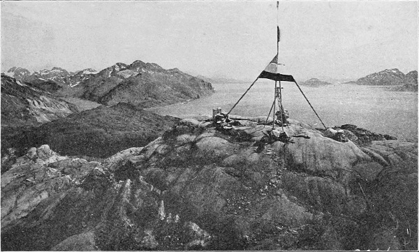
FIG. 9. TRIANGULATION STATION AND SIGNAL, ON ALASKA COAST.
Survey sheets are next prepared, of suitable size and scale. On each sheet a projection is laid down, that is, the meridians and parallels are drawn, and all the points determined in the triangulation are plotted in their true relation. Usually separate sheets are prepared for the topography or shore survey and for the hydrography or survey of the water area.
Topography. The topographic survey of the shore and as much of the adjacent area as is required is[Pg 40] usually made with a plane table, on which the map is actually drawn in the field as the work progresses. Points are located on the plane table sheet either by direct reading of the distance on a stadia rod or by intersections from two or more stations. On the plane table sheet it is customary to locate the shore or high-water line, the low-water line, off-lying rocks, streams, rivers, roads, towns, lighthouses, and all prominent features near the coast. Elevations are measured with the plane table or obtained from the triangulation, and are represented on the sheet both by figures and by contours, which are lines joining together points of the same elevation. For instance, a 100-foot contour represents the line where a plane 100 feet above sea level would cut the surface of the ground. It is particularly important in this topographic work to locate accurately objects which are good landmarks and likely to be of use to the mariner. In some regions auxiliary methods are used in filling in the topography, as, for instance, along a difficult coast each feature of importance may be located by sextant angles, or a traverse line may be run along the shore by the transit and stadia method.
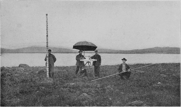
FIG. 11. TOPOGRAPHIC SURVEY PARTY AT WORK WITH PLANE TABLE ON THE PRIBILOF ISLANDS.
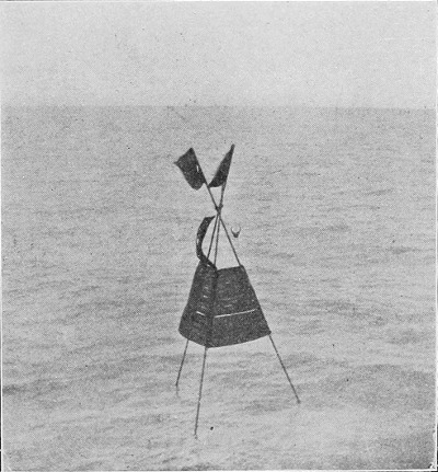
FIG. 12. SURVEY SIGNAL OF IRON PIPE ON THE BAR OFF THE MOUTH OF THE YUKON RIVER.
The hydrography, or the survey of the water area, is of prime importance for the chart, but in the order of prosecution of the work it is convenient but not essential that it come after sufficient points have been located by the triangulation and topography. A hydrographic sheet is prepared on which all the points are plotted which will be useful. A system of sounding lines is then run over the entire area to be surveyed, locating the position of the sounding boat at intervals by sextant[Pg 41-49] angles on survey signals or by angles from the shore. The ordinary method of sounding is to cast a lead from a boat and read the depth when the lead touches bottom and the line is vertical, and make note of the nature of the bottom. There is a systematic spacing between the casts of the lead and between the lines passed over by the boat, depending on the depth of water and character of the bottom. For soundings in deeper water various forms of sounding machines are used, with weight attached to a wire. For very great depths a small steel wire is employed and the weight is detached and left on the bottom. The deepest sounding thus far made, 5269 fathoms, or nearly six miles, was obtained by this method in the Pacific Ocean near Guam.
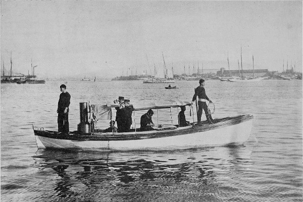
FIG. 13. HYDROGRAPHIC PARTY SOUNDING WITH LAUNCH IN BALTIMORE HARBOR.
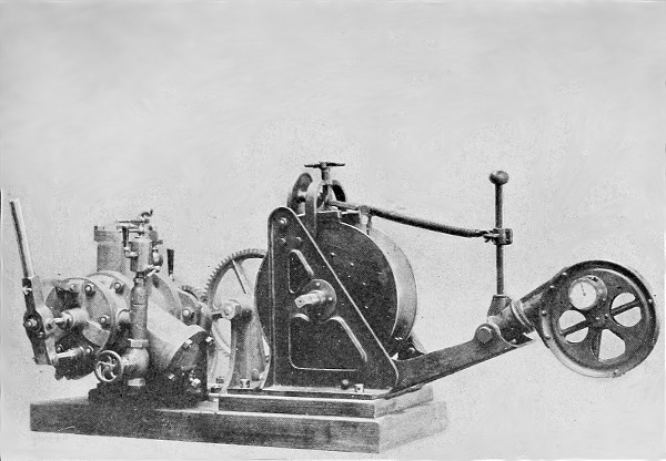
FIG. 14. THE LUCAS AUTOMATIC SOUNDING MACHINE FOR DEPTHS TO 5000 FATHOMS, WITH ENGINE.
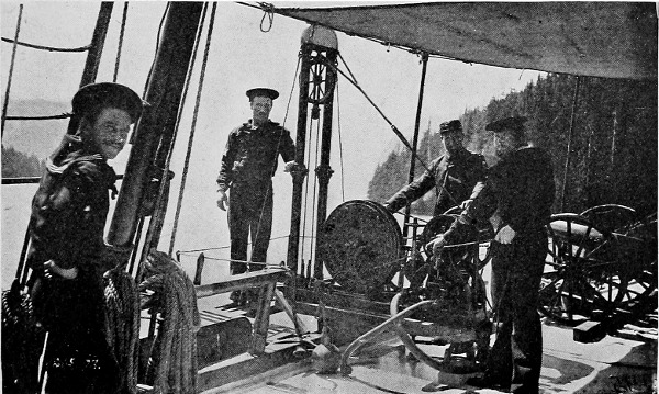
FIG. 15. THE SIGSBEE SOUNDING MACHINE ON A SURVEYING VESSEL.
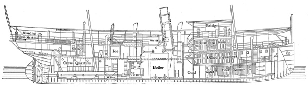
FIG. 16. LONGITUDINAL SECTION OF SURVEYING STEAMER FATHOMER, SHOWING GENERAL ARRANGEMENTS.
Fig. 16 enlarged (58 kB)
The offshore soundings are made from a surveying steamer; the inshore work is usually done by a launch or small boat.
So far as the navigational use of charts is concerned it is important that the hydrography shall show the limiting depths and the freedom from dangers, of channels, entrances, harbors, and anchorages. It is also desirable that the soundings shall be carried off shore at least as far as the one-hundred-fathom curve, as with the modern forms of navigational sounding machines it is possible for vessels under way to obtain soundings to this depth, and such soundings may be of value in identifying the location of the vessel. For depths greater than one hundred fathoms the soundings have less direct value to navigation except as proving the absence of shoaler areas, but soundings throughout the oceanic regions are of great geographical interest as well as of direct practical value in the laying of cables.
It is obvious that the plan of mapping the sea bottom by dropping a lead at intervals over its hidden surface is far from an ideal one. The lead gives the depth only at the point at which it touches the bottom, and no information as to the space between the casts except such as may be inferred from the relation of successive soundings. In numerous cases, after what was considered a very thorough survey of a region had been made, at some later day a pinnacle rock or other danger has been discovered. For instance, a very detailed hydrographic survey of Buzzards Bay was made in 1895; the sounding lines were run at intervals of 50 to 100 yards, and 91,000 soundings were made for a single sheet. Within this area the cruiser Brooklyn in 1902 touched a rock which was found to have 18 feet over it. (Fig. 17.) The least depth in the vicinity developed in the original survey was 31 feet.
For the satisfactory development of hydrographic work some invention is much needed which as it passes along the bottom will give a continuous depth curve. Several devices have successfully accomplished this in shoal water, but great credit awaits the inventor who designs something of more general application.
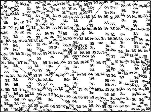
FIG. 17. PORTION OF ORIGINAL HYDROGRAPHIC SHEET, BUZZARDS BAY, ON SCALE 1-10000, SHOWING AREA CLOSELY SOUNDED IN 1895, WHERE THE BROOKLYN STRUCK IN 1902.
Tides and currents. Information must be obtained as to the movement of the water, both vertical and horizontal. The rise and fall of the tide are obtained by tide gauges, either automatic, which draw a continuous tidal curve on a roll of paper, or simple tide staffs, which must be read at intervals. The currents, whether due to the tides or other movements, are measured by noting the movement of partially sub[Pg 51-55]merged floats. Less accurate but useful information as to currents is obtained from the logs of vessels.
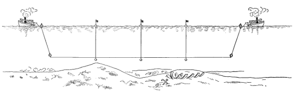
FIG. 18. DRAGGING FOR DANGERS WITH A LONG WIRE.
Dragging for dangers has long been resorted to for the investigation of isolated spots. A valuable and successful means has been employed recently of making sure that an area is free from shoals or rocks having less than a certain depth. This is done by dragging through the water a wire from 500 to 1400 feet long, and suspended at the required depth, with suitable buoys and weights, and kept taut by the angle of pull. If, for instance, the wire is set at a depth of 30 feet it will indicate the presence of any obstruction of less depth by catching on it and upsetting the buoys, and such spots are at once marked and investigated. Considerable work has been done with such drags in the last few years on the Atlantic and Gulf coasts and on the Great Lakes. This is of course a somewhat tedious process and gives no information as to depths greater than that for which the wire is set, but the experience already had indicates its great value. It will probably be found desirable in time to thus drag all water areas important to navigation where the depth is near the draft of vessels and the irregular nature of the bottom gives indication of dangers. In extensive dragging operations near Key West and in Jericho Bay, Maine, a number of shoals have been picked up which were not found in the original surveys.
A remarkable instance of the value of the drag was the recent discovery of a rock in Blue Hill Bay on the coast of Maine. This rock has but 7 feet of water over it, and is only 6 feet in diameter at the top. It is surrounded by depths of 78 feet, from which it rises[Pg 56] nearly perpendicularly. The original survey gave no indication of a danger here, and its existence was not suspected until it was discovered with the wire drag.
Another method of dragging that has been employed is by means of a pipe suspended beneath a ship's bottom.
Magnetic variation. As the compass is a universal navigational instrument, information as to the magnetic variation is needed for the charts. The angle between the direction of the magnetic needle and the true north is measured at various points on both land and sea, and at some stations these observations are repeated after a number of years. From these results magnetic maps are made, from which both the variation and its annual change may be taken.
Reports of dangers. Aside from the more systematic surveys as outlined above, much information has been placed on the charts from other sources. On the earlier charts and on those of more remote regions at the present day much of the work has been sketched rather than surveyed. Even in the better surveyed portions reports come in as to dangers or other matters not shown, and if of importance and the report appears to be reliable these are sometimes at once put on the chart pending further investigation, or in other cases an examination is first made.
Shoals, rocks, and even islands have in numerous instances been shown on the charts which no one has been able to find again, and many of them after repeated searches have been removed. The same island or danger has sometimes been charted in two or more different positions as reported at various[Pg 57] times. The treatment of such cases is one of the serious and interesting problems of the chart maker. It is generally less harmful to show a danger which does not exist than to omit one which does exist. On the other hand a non-existing danger shown on a chart may be the cause of actual expense and loss of time in compelling a vessel needlessly to go out of its course.
It is surprising to note with what lack of care and of sufficient evidence reports of dangers at sea have sometimes been made, and how incomplete are many of the reports even when the existence of the danger is beyond question. It is unfortunately true that some of these reports are the result of effort to escape blame for accident by throwing the fault on the chart. Many such reports also result from various illusory appearances. A large tree covered with weeds, an overturned iceberg strewn with earth and stones, a floating ice-pan covered with earth, the swollen carcass of a dead whale, a whale with clinging barnacles and seaweed, reflections from the clouds, marine animalculæ, vegetable growth, scum, floating volcanic matter, and partially submerged wrecks covered with barnacles, have been mistaken for islands, shoals, or reefs. A school of jumping fish has given the appearance of breakers or caused a sound like surf, and tide rips have been mistaken for breakers. Raper very properly calls attention to the obligation upon every seaman of carefully investigating doubtful cases and making reliable reports. "Of the dangers to which navigation is exposed none is more formidable than a reef or a shoal in the open sea; not only from the almost certain fate of the ship and her crew that have the[Pg 58] misfortune to strike upon it, but also from the anxiety with which the navigation of all vessels, within even a long distance, must be conducted, on account of the uncertainty to which their own reckonings are ever open. No commander of a vessel, therefore, who might meet unexpectedly with any such danger, could be excused, except by urgent circumstances, from taking the necessary steps both for ascertaining its true position, and for giving a description as complete as a prudent regard to his own safety allowed."
As to the older doubtful dangers now shown on the oceanic charts, it is estimated that the positions may be considered as uncertain by 10 miles in latitude and 30 miles in longitude, and areas of this extent must be searched to determine definitely the question of their existence.
The following are interesting or typical cases of reported dangers:
The master of an Italian bark in September, 1874, reported sighting a large rock in latitude 40° N. and longitude 62° 18´ W. Fortunately for the charts there were two independent reports from other vessels in the same month of sighting a partially submerged wreck in this vicinity.
The Spanish steamer Carmen was wrecked in 1891 by running on a rock off the southwest coast of Leyte; the rock was reported to lie one mile off shore, a dangerous position for vessels using Canigao Channel. A survey made in 1903 showed 58 feet of water in this location, and that Carmen Rock on which the vessel struck was really within one-fourth mile of the beach. The rock had, however, for twelve years been shown on[Pg 59] the charts in a position which made it an obstruction to navigation.
The ship Minerva in 1834 was reported to have struck a rock near the middle of the broad entrance to Balayan Bay; the fact that this occurred at 2 A.M. indicated a very doubtful position, but it was stated that an American ship had previously been wrecked on the same rock. It consequently appeared as a danger on the charts for seventy-one years, when a survey showed no depth of less than 190 fathoms in this vicinity, and it was removed from the charts.
A British steamer was wrecked in San Bernardino Strait in 1905; the master reported that he was in a position where the chart showed 51 fathoms, and that he was 112 miles distant from Calantas Rock, and on these grounds the finding of the official inquiry was that "no blame can be attached to the master, officers, or any of the crew for the casualty." Very shortly after the disaster, the surveying steamer Pathfinder definitely located the wreck and made a survey of the vicinity. The previous chart of Calantas Reef was found to be fairly correct, and the stranding was determined to have occurred well within this reef in a position where the chart showed soundings of 334 to 434 fathoms, and 12 mile from Calantas Rock, which rises 5 feet above high water.
A transport entering San Bernardino Strait a few years ago ran on a rock and was damaged; the position was reported as about two miles southeast of San Bernardino Island and near the middle of the passage. The rock was not put on the charts, as prompt investigation showed 50 fathoms of water in this vicinity, and[Pg 60] that in all probability the transport actually touched a small reef making out from the island.
The master of the brig Helen reported that his vessel was wrecked on a reef lying six miles from Rockall. When surveyed Helen Reef was found to be about one-third this distance from Rockall.
An island has been reported in eight different positions, ranging in latitude from 30° 29´ to 30° 42´ N. and in longitude from 139° 37´ to 140° 38´ E.
There have been a number of reports of islands in the area from latitude 40° 00´ to 40° 30´ N. and longitude 150° 30´ to 151° 00´ W. The master of the bark Washington reported in 1867: "On my passage from the Sandwich Islands to the northwest coast of the United States, when in latitude 40° 00´ N., in a dense fog, I perceived the sea to be discolored. Soundings at first gave great depths, but diminished gradually to 9 fathoms, when through the mist an island was seen, along which I sailed 40 miles. It was covered with birds, and the sea swarmed with seal and sea elephants." A United States vessel searched in this vicinity without seeing any indication of land, and obtained soundings of 2600 fathoms. A British ship in 1858 searched for fourteen days over this area without finding anything. Searches were also made in 1860 and 1867 without success, and the present charts show no islands in this part of the Pacific.
In a number of cases erroneous positions have been due simply to blunders. Thus Lots Wife, first seen by Captain Meares in 1788, was shown on his chart in latitude 29° 50´ N., longitude 156° 00´ E., and stated in his book to be in latitude 29° 50´ N. and longitude[Pg 61] 142° 23´ E. Massachusetts Island by one report was in longitude 177° 05´ E. and by another in 167° 05´ E. The apparent blunder of 10° is now immaterial, as the island has disappeared from the charts altogether. The Knox Islands were placed by the Wilkes Exploring Expedition in latitude 5° 59´ 15´´ N., longitude 172° 02´ 33´´ E. The old British charts showed islands of this name also in latitude 5° 59´ N., longitude 172° 03´ W., the longitude being doubtless transposed. In the case of Starbuck Island, discovered south of the equator, the latitude was apparently transposed, as on old charts it was also shown in the position, latitude 5° 40´ N., longitude 156° 55´ W.
A pinnacle rock can sometimes be located only with great difficulty even when known to exist. Rodger Rock, on which the bark Ellen struck and was damaged, lies in latitude 0° 41´ 15´´ N. and longitude 107° 31´ E. It has but three feet over it at low tide. The British surveying ship Rifleman searched four days before finding it, although the plotted tracks showed that she and her boats had passed very close to it. This indicates that great caution must be used in removing a reported danger from the charts.
The old charts of the Atlantic indicated a danger 30 to 45 miles to the southwest of Cape St. Vincent. This danger was omitted from the charts about 1786 owing to lack of confirmation. Later, in 1813 and 1821, it was reported that vessels were lost or damaged by striking this rock. Soundings of over a thousand fathoms are now shown on the chart in this vicinity and the rock no longer appears.
A comparison of a Pacific Ocean chart of about[Pg 62] forty years ago with one of the present time (Fig. 19) illustrates in a striking manner how many doubtful dangers, or vigias, have gotten on the charts and how after laborious search many of them have now been removed. This condition was especially true of the Pacific, owing to the numerous reports of an indefinite nature from whaling ships, among whose captains there was a saying "that they do not care where their ship is, so long as there are plenty of whales in sight."
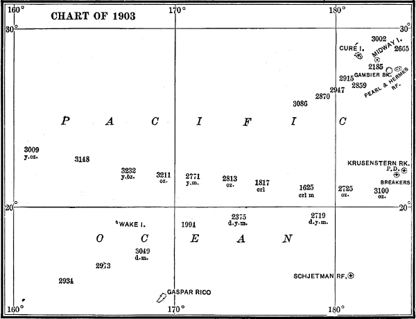
FIG. 19. PORTION OF CHARTS OF 1869 AND 1903, OF THE PACIFIC OCEAN WEST OF THE HAWAIIAN ISLANDS, TO ILLUSTRATE THE REMOVAL OF DOUBTFUL DANGERS.
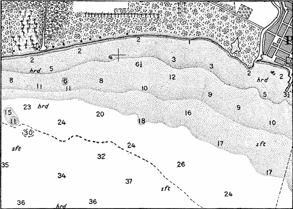
FIG. 20. PORTION OF CHART OF PONCE HARBOR, SCALE 1-20000, TO SHOW SELECTION OF SOUNDINGS FROM ORIGINAL SURVEY GIVEN BELOW.
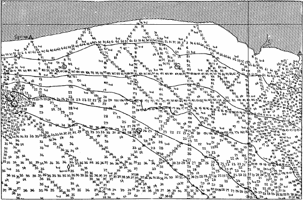
FIG. 21. HYDROGRAPHIC SURVEY OF SAME PORTION OF PONCE HARBOR, REDUCED TO ONE-HALF SCALE OF ORIGINAL SHEET.
Chart schemes. Before commencing the preparation of a chart it is necessary to arrange a definite scheme for it, and the usefulness of the chart will depend materially on this preliminary plan, in which must be outlined its scale, size, limits, and features to be represented. New charts have sometimes been prepared simply to fit the surveys as they progressed or to fill immediate or local requirements. It is, however, desirable that general plans for series or groups of charts be made, and with changing needs, information, and conditions it is sometimes necessary that existing schemes be modified.
Compilation of information. Considerable work must usually be done to get the field records in shape for the published chart. The soundings must be plotted and the characteristic depths selected. Only a part of the soundings that are made can be shown on the original sheet and only a small part of these are used on the final chart. A selection is made showing the least soundings on shoals and bars, the channel depths, and the characteristic soundings in anchorages and other areas. The original surveys are generally made on a considerably larger scale than that on which the chart is published, in order that the soundings may be more thoroughly plotted. The sheets must then be reduced to the scale of publication, and this can conveniently be done by means of photography or with a pantograph.
The best judgment is required in selecting the important features to be shown on the chart and omitting the less important and not essential features which might tend to obscure the others. In charts of new regions where complete surveys are lacking, care must be exercised in weighing, combining, and adjusting information from various sources and which is, perhaps, more or less conflicting.
Projections. The surface of the earth being curved, there is no possible system of projection by which it can be represented on a flat sheet of paper in an ideally satisfactory way. Numerous methods of projecting the earth's surface upon a plane have been proposed and many of them are actually used for various purposes. In general each projection has qualities which are valuable for certain uses, and deficiencies which make it less valuable in other ways. Only four of the different projections need be mentioned here as of special interest in chart construction.
Mercator projection. This is a rectangular projection in which the meridians are straight lines spaced at equal intervals and the parallels are straight lines so spaced as to satisfy the condition that a rhumb line, or line on the earth cutting successive meridians at the same angle, shall appear on the developed projection as a straight line preserving the same angle with respect to the meridians.
This projection may be considered as the unrolling upon a plane of the surface of a cylinder tangent to the earth along the equator, and upon which the various features of the earth's surface have been projected in such manner as to satisfy the above requirement.
On this projection there is a constant distance between the meridians, whereas on the earth they actually converge toward the poles. The distance between the parallels increases in passing toward the poles, approximately in the proportion of the secant of the latitude. For each small portion of the map the relative proportions are maintained as on the earth.
Some characteristics of the mercator projection are these: The meridians and parallels are all straight lines and perpendicular to each other; there is no convergence of the meridians; the minute of longitude is a constant distance on the map; the minute of latitude increases in length from the equator toward the poles but locally retains its true proportion to the minute of longitude; areas and distances increase in scale with the latitude so that a given scale is strictly correct only for one latitude; great circles and consequently lines of sight are curved lines excepting the meridians and the equator; rhumb lines or lines having a constant angle with the meridians are straight, and for the same angle are parallel in all parts of the chart. These qualities are all rigid and the projection can therefore be used for all areas, small or large, up to the extent of the earth's surface, except that it cannot be extended to the poles, as there the length of the minute of latitude would become infinite.
An interesting fact regarding a rhumb line oblique to the meridians is that it is a spiral continually approaching but never reaching the pole; this spiral makes an infinite number of revolutions around the pole, and yet it has a finite length for the reason that[Pg 70] the length of each revolution diminishes as the number of revolutions increases.
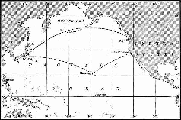
FIG. 22. MERCATOR PROJECTION OF NORTH PACIFIC OCEAN, SHOWING GREAT CIRCLE ROUTES YOKOHAMA TO PUGET SOUND, AND YOKOHAMA TO HONOLULU AND THENCE TO SAN FRANCISCO.
The mercator projection has been extensively used for nautical charts, for which it presents important mechanical advantages, in that adjacent charts can be joined on all their edges while still oriented with the meridian; all charts are similar; the border may be conveniently subdivided, giving a longitude scale applicable to any part of the chart, but a latitude scale that may be used in the same latitude only; courses are laid down as straight lines and can be transferred with parallel rulers from one part of the chart to another without error. On a mercator chart an island in latitude 60° would appear four times as large as an island of the same actual area at the equator, but this distortion of areas, while it gives erroneous impressions on charts of great extent in latitude, does not seriously affect the use of the chart for nautical purposes. Areas may also be correctly measured on a mercator map by taking each projection quadrilateral separately, subdividing it if necessary, and using the published tables of areas of quadrilaterals in different latitudes. Although distance scales vary with the latitude, distances can be taken from this chart with fair correctness by the use of the latitude border scale for the middle latitude, subdividing the total distance if there is much range of latitude. The inability to take off the great circle or shortest course directly from the mercator chart is from a navigational point of view a defect, but the most convenient solution for this appears to be the supplementary use of a gnomonic chart as will be described. The fact that lines of sight are not[Pg 71-73] straight lines on this projection is another defect, as by the plotting of bearings and angles on approaching the land the positions of vessels are located on the chart; fortunately, however, the error due to this cause usually falls within the other uncertainties involved in locating a ship; if need be it would be practicable to allow for this curvature. In the polar regions, however, the faults of the mercator projection become so much exaggerated that it is not used for navigational purposes, but because of the absence of commercial navigation there this is a minor matter in the general question of chart projection. For the plotting of original surveys the mercator projection is not suited and is not used, for the reasons above mentioned.
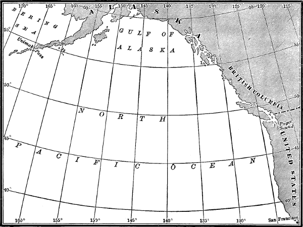
FIG. 23. POLYCONIC PROJECTION OF PORTION OF NORTH PACIFIC OCEAN.
Tables of "meridional parts" are published which give the distance in terms of minutes of longitude from the equator to the various parallels; with these tables a mercator projection may readily be constructed.
Airy proposed a graphical method of sweeping the arc of a great circle on to a mercator chart, and tables are published for this purpose. The method is only approximate and is limited in application, and the supplementary use of a gnomonic chart would appear to be preferable.
Polyconic projection. In plotting the original surveys it is essential that a projection be used which will for the area included on a survey sheet show the points in their correct relation both as to direction and distance. These conditions are substantially fulfilled by several projections, of which the polyconic is used in the United States. If a hollow cone were placed so that it would either be tangent to the earth's surface along[Pg 74] one of the parallels of latitude or cut it along two parallels, and the points projected on to this cone, and the cone then unrolled and laid out flat, the result would be a conical projection, of which there are several variations. If successive tangent cones be used and each parallel of latitude be developed as the circumference of the base of a right cone tangent to the spheroid along that parallel, the result is the polyconic projection, which has been used for field sheets and for the large scale charts, as well as for the topographic maps of the United States. This projection has valuable qualities for moderate areas of the earth's surface, within which the scale is approximately uniform, areas retain nearly their true proportions, and great circles and consequently all bearings and directions are approximately straight lines. The parallels of latitude are arcs of circles with radiuses increasing as we recede from the pole; therefore they are not truly parallel and the length of the degree of latitude increases either side from the central meridian. The meridians converge toward the poles and become slightly curved as we recede from the central one; the longitude scale is everywhere correct, but the latitude scale is strictly correct only on the central meridian. The angles of intersection of parallels and meridians are right angles or nearly so. The polyconic projection is not used for very extensive areas of the earth's surface, as for instance a hemisphere.
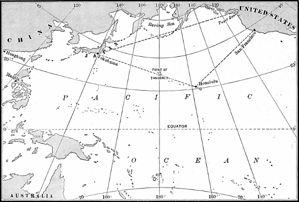
FIG. 24. GNOMONIC CHART OF NORTH PACIFIC OCEAN, SHOWING GREAT CIRCLE ROUTES YOKOHAMA TO PUGET SOUND, AND YOKOHAMA TO HONOLULU AND THENCE TO SAN FRANCISCO.
Gnomonic projection. In this projection the eye is assumed to be at the center of the earth and the features are projected upon a plane tangent to some point on the earth's surface. It is practicable to use this projection for oceanic areas, and it has the very important[Pg 75-79] quality that every straight line on it represents a great circle of the earth. To obtain the great circle or shortest course between two points it is therefore only necessary to draw a straight line between the points on a gnomonic chart. Because of the great distortion near the edges this projection is not otherwise adapted to navigational use, and it is employed only to mark out the general course, and sufficient points are then transferred to a mercator chart. The gnomonic chart is therefore useful in supplementing the mercator chart, supplying its deficiencies as to convenience in marking out great circle courses. The great circle course can be derived not only more easily and quickly from the gnomonic chart than by computation, but the chart is also to be preferred because the course marked out on it will show at once if any obstruction, as an island or danger, is met or too high a latitude is reached. A modified or composite course can readily be laid out on a gnomonic chart.
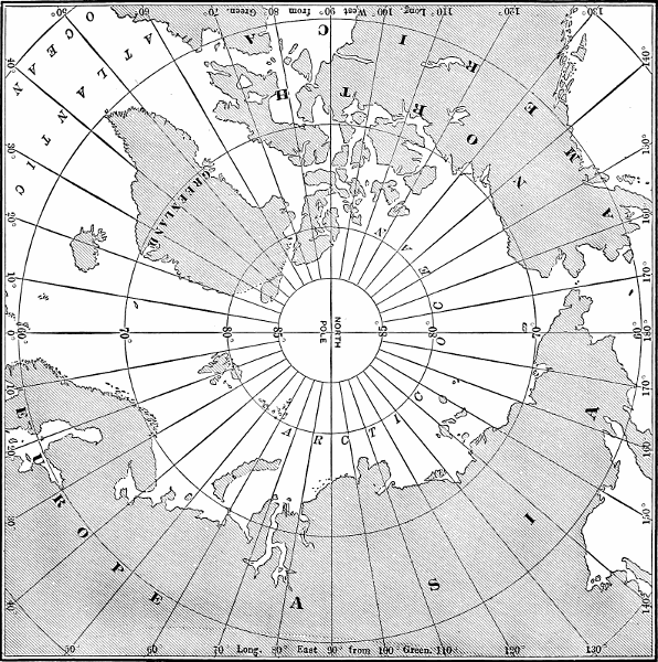
FIG. 25. NORTH POLAR CHART ON ARBITRARY PROJECTION.
Arbitrary projection. The few charts published of the polar regions are sometimes on an arbitrary projection, in which the meridians are straight lines radiating from the pole and the parallels are equidistant circles with the pole as center. The latitude scale is uniform. At some distance from the pole the longitude scale becomes very much distorted, but the projection is a practicable and convenient one for the immediate polar regions. Gnomonic and conical projections are also used for the polar charts, differing little from the foregoing for moderate areas.
Scales. Charts are published on a variety of scales to suit different needs of navigation, and the usual[Pg 80] classification depends on scale. In addition to the ocean charts covering a single ocean in either one or several sheets and intended for navigation on the high seas, there are for our Atlantic coast the following series:
Sailing charts, scale about 11200000, for general coastwise navigation.
General coast charts, scale 1400000, for local coastwise navigation.
Coast charts, scale 180000, for approaching the coast at any point and for inside passages.
Harbor and channel charts, of various large scales from 15000 to 160000, for entering harbors and rivers and passing through channels.
The expression of scales by miles to the inch or inches to the mile is the more familiar. The expression of scale in the manner used by the Coast Survey and by most of the European countries, by standard fractions as 180000, meaning that any distance on the chart is 180000 of the actual distance on the earth, has some advantages. For instance, the relation of these fractions gives at a glance the relation of the scales of the charts. Thus a 180000 chart is on a scale five times as large as a 1400000 chart.
For the more important harbors charts have been published on several different scales to meet various needs. Thus New York Harbor is shown on charts of scales of 110000, 140000, 180000, 1200000, 1400000 and 11200000, each of course including a different area.
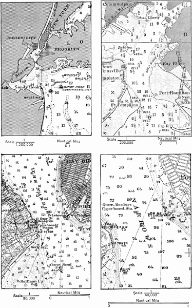
FIG. 26. NEW YORK HARBOR, PORTIONS OF CHARTS ON FOUR DIFFERENT SCALES.
The selection of suitable publication scales is of prime importance; a large scale permits of greater clearness and of showing more detail, but on the other hand restricts the area and the points that can be shown[Pg 81-83] on a single sheet, or else makes a chart of excessive dimensions. In general in chart preparation the scale should be restricted to the minimum that can be used to fulfill the particular object and clearly represent what is desired. A chart of very large scale is not convenient for plotting, and a moving vessel may pass quickly beyond it or into range of objects beyond the limits of the chart.
Methods of publication. An ideal process of publication for nautical charts would include the following features; rapidity in getting out new charts, facility in reprinting and correcting existing charts, clearness and sharpness of print, durability of paper and print, and correctness of scale. It is difficult to fulfill all these requirements by any method as yet developed. In the Coast and Geodetic Survey several different processes are in use at present; charts are engraved on copper and printed directly from the copper plate, or they are transferred from the copper plate to stone and printed from the stone, or a finished drawing is made and transferred to stone by photolithography and printed from the stone, or an etching is made on copper from a finished drawing and printed from a transfer to stone. Charts in other countries are in large part printed from engraved plates, excepting some preliminary charts by lithography.
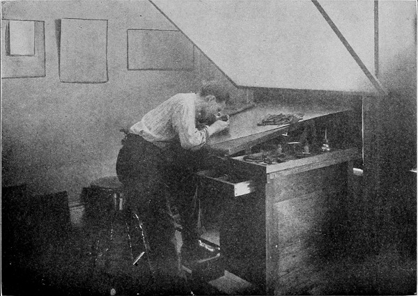
FIG. 27. ENGRAVING A CHART ON A COPPER PLATE.

FIG. 28. ENGRAVING SOUNDINGS ON A COPPER PLATE WITH A MACHINE.
Copper plate engraving and printing have long been used in chart preparation. A drawing is prepared as a guide for the engraver; this must be correct as to all information to be shown but need not be a finished drawing. A true projection is ruled upon a copper plate. By photography a matrix is made from the drawing and a wax impression taken from this matrix. This is then laid down on the copper to fit the projection, and the impression is chemically fixed on to the copper.[Pg 85-89] The work thus marked out is engraved by hand or by machine. A high degree of skill is required in the accuracy and finish necessary for chart engraving. Machines have been invented in recent years which can be used for portions of the work on copper plates, as for instance for cutting the sounding figures, the bottom characteristics, the border and projection lines, border divisions, compasses, line ruling, and stipple ruling. Stamps and dies have been successfully used for some symbols and notes, and roulettes for shading. By means of these various machines, many of which are American inventions, the process of chart publication from plates has been materially facilitated.
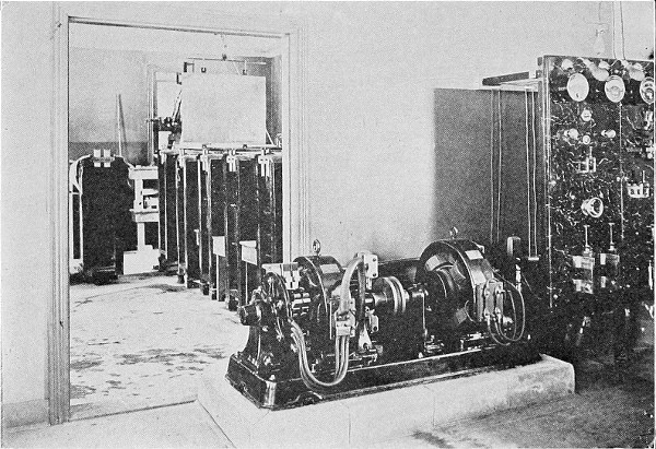
FIG. 29. ELECTROTYPING PLANT FOR ELECTROTYPING CHART PLATES.
When the plate is completed an alto, or raised copy, is made by depositing copper on to it in an electrotype vat, and from this alto another basso or sunken copy is made by the same process. This latter basso is used in printing. A copper plate may be used for about 3000 impressions, after which it may become too much worn for satisfactory chart printing. By printing from a duplicate basso the original plate is preserved and additional copies can be made when needed. The use of the alto also greatly facilitates matters when a considerable correction to the chart is required. All the portions of the chart to be changed can be scraped off the alto, and when a new basso is electrotyped from this scraped alto all such areas will of course appear as smooth copper, on which the new work can be engraved. Numerous small corrections are called for on charts, and on copper plates where these are to replace old work the latter is removed either by hammering up the back of the plate or by scraping its face.
Printing directly from plates is a laborious process. After the press bed has been carefully padded to take up inequalities in the plate, the surface of the latter is covered with ink and then carefully wiped off by hand, leaving the ink only in the engraved lines. The paper, first dampened, is laid on the plate, and passes with it beneath the cylinder of the press under considerable pressure. The prints are calendered by being placed in a hydraulic press under 600 tons pressure. The charts are beautifully clear and sharp, not equalled by other methods of printing. Owing to the wetting and drying of the paper, the finished print is, however, quite appreciably smaller in scale than the plate, and the shrinkage is greater in one direction than in the other. The average day's work for one press and two men is 75 prints. This is small compared with the output practicable with lithographic presses. On the other hand a plate can be prepared for printing more readily than a lithographic stone. For small editions the plate printing compares well in economy with lithographic printing, and the plate can also be printed on short notice. Because of changes in aids to navigation and other corrections, it is usually desirable to print at one time only a sufficient number of copies of a chart to meet current demands, and not to carry a large stock on hand.
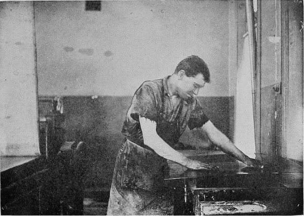
FIG. 30. PRINTING CHARTS FROM COPPER PLATES; FINAL CLEANING OF THE PLATE BY HAND; PLATE PRESS ON THE LEFT.
The copper plates, bassos, and altos make a very convenient and enduring means of preserving the chart ready for printing or for further correction. A large number of plates can be placed in a small space, and if properly cared for they may be stored indefinitely without deterioration.
With plate printing it is not practicable to print more than one impression on the chart or to use more than one color, and plate-printed charts are therefore in black only.
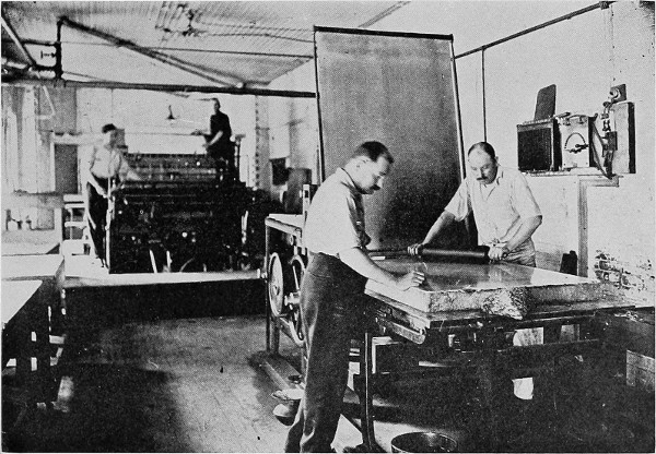
FIG. 31. LITHOGRAPHING PRESSES FOR PRINTING CHARTS; LITHOGRAPH STONE ON TRANSFER PRESS.
Engraving on stone. On the United States Lake Survey the charts are first engraved on stone, and by a special process the work is then transferred to small copper plates, which are preserved. The final publication is by lithography, transferring again from the plates to stone.
Photolithography is a quick method of publishing a chart. It would be practicable by this means to reproduce the original survey sheets, but ordinarily these are not suitable as to scale and legibility, and it is necessary to make a new drawing, usually on tracing vellum. This is photographed on to glass plates, on the scale of the proposed chart. From these glass negatives positive prints are made on sensitized lithographic paper. These prints are fitted together and then inked, taking the ink only where the lines appear. This transfer print is then laid face down on the lithographic stone and run through a press under pressure, the stone absorbing the ink from the paper. The stone is then treated so that the inked portion remains slightly raised, and from this stone an indefinite number of charts can be printed in a lithographic press at the rate of 1000 an hour. The paper is not moistened, and consequently there is little distortion or change of scale in prints from stone. If desired to shade the land or use another color for any other purpose, additional impressions can be made on the same charts from other stones. Because of the bulk[Pg 94] of the stones, work cannot ordinarily be retained on them, but the chart is cleaned off and the stones repeatedly used until worn thin. The original drawing as well as the negatives is preserved, from which the chart can again be published. For republication, the process is, however, not entirely satisfactory; the negatives are not always permanent, the work must again be assembled and transferred to the stone, changes or corrections are not very conveniently made on either drawing or negative, and after repeated changes the drawing becomes difficult to use in photolithography. Whether the charts are actually printed from copper or stone, there are decided advantages therefore in the matter of correction work and future editions in having the charts engraved on copper. On the other hand, the advantages of the photolithographic process are the ability to publish new drawings promptly, to use more than one shade on a chart, to obtain prints with little change of scale or distortion, and to print large editions rapidly.
Lithographic printing by transfer from engraved plates. An impression on transfer paper may be taken from an engraved plate and this laid down on the stone in a manner similar to that used in laying down the prints from the glass negatives in photolithography. Prints are then made from the stone the same as in photolithography, but with superior results as to clearness. This general process is extensively used in both map and chart publishing in this country, as it combines the advantages of the plate in preservation of the chart record and facility of correction, and the advantages of the lithographic printing in less distortion[Pg 95] of the printed chart, ability to print more than one shade, and facility for large editions. As the transfer from the plate can be readily made it is also better applicable to small editions than is photolithography. It is, however, not as convenient in the latter respect as plate printing, and it does not give a resulting impression equal in clearness or durability to the impression directly from the plate.
Etching on copper for chart publication has been recently developed in the Coast and Geodetic Survey. A finished tracing is made, the surface of a smooth copper plate is sensitized, and by exposure to the sun a print is made on the sensitized surface. It is essential to use an air-exhausted printing frame so as to get good contact between the vellum and the plate. The work is then etched into the copper and the plate cleaned and touched up, after which it may be used the same as a hand-engraved plate, either for transfer to stone or direct plate printing. The expense and time required in the etching process are much less than for hand engraving. The process has been successfully used for a number of harbor charts. The etching of course will be of the same scale as the vellum at the time of the print, and vellum varies somewhat in scale with weather conditions and age. Unless overcome by the substitution of some more invariable material in place of vellum, this might be an obstacle to the use of the process for general charts where a true scale on the copper plate is desirable because of future work to be done on the plate. It must also be taken into account that the etching requires a finished tracing in ink, which is not essential for the hand engraver; if, however,[Pg 96] the chart is first published by photolithography, as is the usual practice in the Coast and Geodetic Survey, the same tracing is used for both processes.
Distribution of charts. Charts published by the government are sold to the public at a small price, estimated to cover the cost of paper and printing. The charts may be obtained direct from the publishing office or from the chart agents who are to be found in all the principal seaports. Catalogues are published from time to time giving complete lists of the current charts and the main facts regarding them. Index maps show graphically the area covered by each chart. The notices to mariners contain announcement of new charts or new editions published and of charts or editions cancelled, as well as of all corrections.
Need for revision. The making of the survey and the printing of the chart do not complete the problem of the chart maker. Both nature and man are constantly changing the facts the representation of which has been attempted on the charts, and also the needs of man are always varying. The original surveys are made to meet the reasonable requirements of the time, but breakwaters and jetties are built, and channels and harbors dredged and otherwise improved, and cities built, and new paths of commerce are opened which bring vessels into waters previously thought of minor importance.
With the increase of commerce and speed of vessels more direct routes are demanded for reasons of economy. Inside routes not originally used are sometimes developed for defensive reasons. The average draft of the larger vessels has also increased remarkably since the modern hydrographic surveys were commenced, and surveys once made to insure safety for the deepest vessels of that time are now not adequate. The average loaded draft of the 20 largest steamships of the world has increased as follows: 1848, 19 feet; 1873, 24 feet; 1898, 29 feet; 1903, 32 feet. The average length of these vessels was 230 feet in 1848, 390 feet in 1873, 541 feet in 1898, and 640 feet in 1903. The number of vessels drawing as much as 2614 feet rose from 36 in 1902 to 185 in 1904. In 1906 there were 17 vessels[Pg 98] afloat, drawing 32 feet and upwards. There are now two steamers on the Atlantic 790 feet long, 88 feet beam, and 3712 feet draft when fully loaded, and larger vessels are already planned.
Great natural agencies are also constantly at work effecting changes in features shown on the charts. The action of currents and waves is continually cutting away or building the shore, particularly on sandy coasts exposed to storms. When surveyed in 1849 Fishing Point on the east coast of Maryland was but a bend in the shore line. By 1887 it had built out about two miles in a southerly direction, and in 1902 about two-thirds of a mile further, curving to the westward. Altogether in about half a century this tongue of land has grown out nearly three miles.
Rivers are bearing vast quantities of sediment and depositing these near their mouths, pushing out the coast line and filling in the bottom. The main mouths of the Mississippi are advancing into the Gulf, but at a comparatively slow rate. A break from the main river at Cubit's Gap just above the head of the passes, however, has done an enormous amount of land making, filling in an area of about 50 square miles between 1852 and 1905.
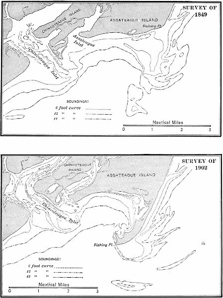
FIG. 32. FISHING POINT, MARYLAND, FROM SURVEYS OF 1849 AND 1902, ILLUSTRATING BUILDING OUT OF A POINT ON THE COAST.
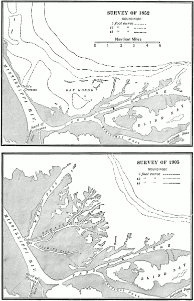
FIG. 33. GROWTH OF LAND AT CUBITS GAP, MISSISSIPPI DELTA, FROM 1852 to 1905.
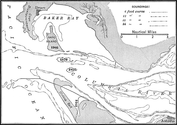
FIG. 34. COLUMBIA RIVER ENTRANCE, SHOWING MOVEMENT OF SAND ISLAND, SURVEYS OF 1851, 1870 AND 1905.
The mouth of the Columbia River in Oregon shows an interesting example of the movement of an island. The chart of 1851 shows the center of Sand Island 314 miles southeast of Cape Disappointment, the chart of 1870 shows it 234 miles southeast, and the chart of 1905 shows it 114 miles easterly. This island has thus moved 2 miles northwesterly directly across the middle of the river entrance, closing up the former[Pg 99-109] north channel. The southern point of the entrance, Clatsop Spit, has built out about the same distance.
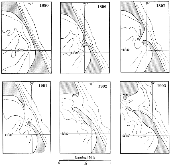
FIG. 35. CHANGES IN HAULOVER BREAK, NANTUCKET ISLAND, 1890 TO 1903.
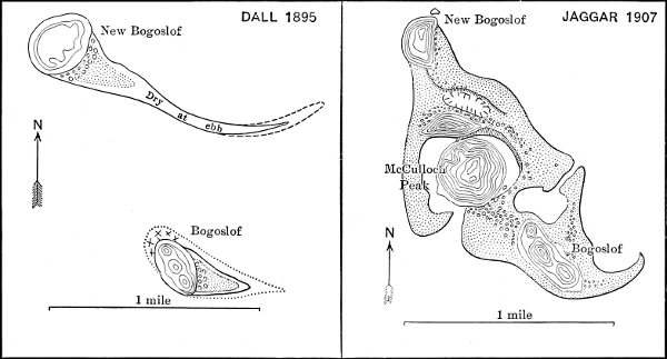
FIG. 36. MAPS OF BOGOSLOF ISLAND, 1895 AND 1907, SHOWING CHANGES DUE TO VOLCANIC ACTION.
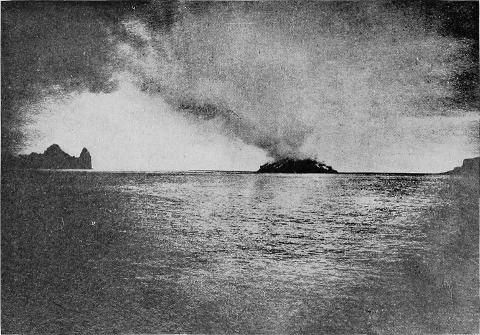
FIG. 37. BOGOSLOF VOLCANO, BERING SEA.
Volcanic action in well authenticated cases has caused islands to rise or disappear. In the present location of Bogoslof Island in Bering Sea the early voyagers described a "sail rock." In this position in 1796 there arose a high island. In 1883 another island appeared near it. In 1906 a high cone arose between the two, and a continuous island was formed over 112 miles long and 500 feet high. The latest report (September, 1907) was that this central peak had suddenly collapsed and disappeared. Bogoslof is an active volcano, and the main changes have been the result of violent volcanic action. The history of this island for over a century past forms a remarkable record of violent transformations in the sea.
Earthquakes sometimes cause sudden displacements, horizontal or vertical, of sufficient amount to affect the information shown on the charts. A careful investigation of the effects of the earthquake in Yakutat Bay, Alaska, in September, 1899, showed that the shore was raised in some parts with a maximum uplift of 47 feet and depressed in other parts, and that at least two reefs and four islets were raised in the water area where none appeared before. Undoubtedly there were changes in the water depths, but definite information is lacking because there had been no previous hydrographic survey. The San Francisco earthquake of 1906 caused little vertical displacement, but there were horizontal changes of relative position as much as 16 feet; so far as known this earthquake did not affect the practical accuracy of the charts. Related[Pg 110] to earthquake phenomena are the gradual coast movements of elevation or subsidence which are taking place but at so slow a rate as not to sensibly affect the charts in ordinary intervals of time.
Another agency at work is the coral polyp on the coral reefs; although the rate of growth appears to be very slow, the resulting reefs and keys are an important feature in tropical seas.
Practically all of the land features shown on charts are likewise subject to changes, the more rapid of which are mainly due to the works of man.
The changes of channels and of commercial needs cause many alterations to be made from time to time in the lights and buoys which are shown on the charts.
Methods of correction. The problem of keeping a chart sufficiently up to date is one of much practical importance and one which must be taken into account in planning what should be shown on the chart in the first place so as to bring it within the range of practicable revision.
Certain features are corrected at once on the charts as soon as the information is received, such as dangers reported, and changes in lights and buoys. Where harbor works are in progress the periodic surveys made in this country by the Corps of Engineers furnish data which are applied promptly to the charts. Reported dangers in channels and bars are investigated by special surveys and the information is put on the charts. Examinations are made from time to time for the revision of the features along the coast line. Complete resurveys have been made, at long intervals, of some important portions of the coast where there has been[Pg 111] evidence of change, and these, when they become available, are applied to the charts. All parts of the coast where the exposed portions are not of very permanent material will require resurveys at intervals, depending on their importance and the rate of change.
Notwithstanding the great progress made in hydrographic surveys, a considerable number of rocks and shoals dangerous to navigation and not previously shown on the charts are reported, averaging nearly 400 each year for the last six years, according to the British reports. Of the 367 reported in 1906, 11 were discovered by vessels striking them.
Immediate information in the form of Notices to Mariners is published, of the more important corrections to charts which can be made by hand. These corrections show what charts are affected, and give sufficient data for plotting.
In the case of extensive corrections or new surveys a new edition of the chart is printed and all existing copies of the previous edition are canceled.
It is important that the user of the chart shall make certain that he has the latest edition and that all corrections from its date of issue have been applied from the Notices to Mariners.
It is unfortunately true that owing to failure to take proper account of the notices, or to economy, old editions or unconnected charts are sometimes used, and in a number of cases the loss of vessels has been directly due to this cause. Those responsible for the safe navigation of vessels should insist that the latest editions of charts are provided and that all charts to be used are inspected and corrected to date.
Reading charts. A chart is a representation on paper of hydrographic and topographic information by means of various conventional methods and symbols. It is evidently important for those making use of charts to understand the system and conventions used, and to be able to interpret readily the various parts of the chart. The ability to read a chart must include an understanding of all its features, such as scale, projection, geographic position, directions, depths, plane of reference, aids to navigation, tides, currents, elevations, topography, and date of survey and publication.
Scale. For American and British charts the scale is usually expressed by the inches or fractions of an inch to the minute or degree of latitude, or by the fractional proportion of a distance on the map to the corresponding distance on the earth. These fractions are sometimes stated on the British charts, and nearly always on those of the United States Coast Survey. The chart catalogues give the scale in one or the other form. A familiarity with the meaning of scales is of value in selecting the most suitable chart, in judging of the relative uses of charts, and in estimating distances. Where the fractional scales are stated they furnish a simple means of comparing charts, as, for instance, a chart on 150000 scale will show all distances just twice as long as a chart on 1100000 scale.
The following are scale equivalents:
| Scale | 110000 | is equivalent to 7.30 inches | to one nautical mile. |
| Scale | 120000 | is equivalent to 3.65 inches | to one nautical mile. |
| Scale | 140000 | is equivalent to 1.82 inches | to one nautical mile. |
| Scale | 150000 | is equivalent to 1.46 inches | to one nautical mile. |
| Scale | 180000 | is equivalent to 0.91 inch | to one nautical mile. |
| Scale | 1100000 | is equivalent to 0.73 inch | to one nautical mile. |
| Scale | 1200000 | is equivalent to 0.36 inch | to one nautical mile. |
| Scale | 1400000 | is equivalent to 0.18 inch | to one nautical mile. |
| Scale | 11000000 | is equivalent to 0.07 inch | to one nautical mile. |
| Scale | 11200000 | is equivalent to 0.06 inch | to one nautical mile. |
For use in measuring distances on large scale charts the length of one or more nautical miles is usually drawn on the chart, and sometimes scales are also given in other units. On British charts the nautical mile scale is divided into tenths (that is, cables of 100 fathoms or 600 feet length); on the American charts into quarters and eighths. Where the scale covers more than one mile the fractional divisions are shown only for the left-hand mile and the zero of the scale is placed between this and the full mile scale, so that with dividers the full miles and fraction may readily be taken off. The nautical mile in the United States is taken to be the length of a minute of arc of a great circle on a sphere whose surface equals that of the earth; this definition makes the nautical mile equal 6080.27 feet. Lecky adopts 6080 feet as the nautical mile. The length of the actual minute of latitude on the earth's surface increases from 6046 feet at the equator to 6108 feet at the poles, an increase of about one per cent. It is, however, this somewhat variable unit of length which[Pg 114] is ordinarily used in scaling distances on the sailing charts.
On small scale charts there is usually a border scale entirely around the chart, conveniently subdivided; this serves the double purpose of facilitating the plotting or reading of positions by latitude and longitude and of furnishing a scale of minutes of latitude for use in measuring distances. On a mercator chart this scale of course varies with the latitude and it must be referred to in the mean latitude of the distance to be measured. In general practice the minute of latitude is taken as equal to the nautical mile.
Projection. On only a few charts is there a statement of the projection used. Practically all general sailing charts are on the mercator projection, which can be readily recognized by the rectangular network of meridians and parallels and the increase with latitude of the distance between the parallels. On large scale local and harbor charts the kind of projection used is not of importance to navigation, as for such limited areas the difference between projections would not affect the use of the chart. On certain small scale charts of the United States Coast Survey which are on the polyconic projection this fact is stated on the chart, and can also be readily recognized by the convergence of the meridians and curvature of the parallels. Gnomonic charts intended for taking off great circle courses are always described in their titles and are also easily recognized by the increased scale and distortion toward all the borders. Charts of the polar regions are published on several different projections, which are distinguished from the mercator by their circular or curved parallels.
Geographic position. For large scale and harbor charts the latitude and longitude of some point marked on the chart are sometimes stated on the face of the chart. For others of these, however, and for smaller scale and general charts, positions are obtained by reference to the border scale. There is a latitude scale down either side of the chart, and a longitude scale across the top and bottom. These scales are conveniently subdivided into degrees, minutes, or fractions of a minute. The minute is divided into tenths (6´´), sixths (10´´), quarters (15´´), or halves (30´´) on various charts.
Directions are indicated on charts both by the projection lines and by compass roses. Nearly all charts are now oriented with the meridian, that is, north is the top of the chart, and on a mercator chart the east and west border lines are parallel with the meridians and the north and south border lines with the parallels. Formerly many charts were not so oriented. Some of these are still in use and can readily be recognized by the diagonal or inclined direction of the projection lines with respect to the border of the chart. Of course directions must not be referred to the border lines of these diagonal charts, and scales along such border lines must not be used. Directions with respect to true north may always be referred to the projection lines of the chart, but on a polyconic or polar chart a direction must not be carried so far from any projection line as to introduce error on account of convergence of the meridians. Compass roses are placed on charts to facilitate the taking off or laying down of directions, though in some respects their use is less accurate and[Pg 116] convenient than the use of protractors, referring to the projection lines. The British charts and many of those of the United States Coast Survey have only magnetic compasses, with degrees outside and points inside, the former graduated to 90°. These are engraved on the chart with the magnetic variation for the date of publication, or for a few years in advance, and give the annual change in the variation. Because of expense of engraving they can be changed on the charts only at intervals of some years, and until this is done allowance for the change in variation is to be made if important. The German charts and those of the United States Hydrographic Office now have a threefold compass, the outer one degrees true, the middle degrees magnetic and the inner points magnetic; the degrees in both cases are graduated to 360°, reading from north through east, south, and west; thus northwest would be stated as 315° instead of N. 45° W. Small scale charts covering extensive areas have no magnetic compasses. They sometimes have true compasses, and usually have the isogonic lines, or lines of equal magnetic variation, marked on them, from which the variation at any intermediate point can be estimated.
Depths. The unit used for depths is always stated plainly on the chart, and it is important to note this carefully, as the British, American, and Japanese charts use fathoms for some charts and feet for others, and most other countries use meters. Some of the earlier charts of the United States coast have the depths inside of the 18-foot curve in feet and outside of that curve in fathoms.
Depth curves are shown on charts in order to bring[Pg 117] clearly to the eye the different depth areas and the limits for navigation of vessels of various drafts. The shoaler areas are usually indicated by sanding the outer limit or the entire area within the depth curve. For the curves of greater depths various standard symbols are used which vary slightly in the different series but which may readily be recognized by the soundings on either side of them. On the British charts the 1 and 3 fathom curves are usually indicated by sanding the outer edge of the areas of these depths respectively; beyond these the standard curves shown on these charts are the 5, 10, 20, and 100 fathom curves. Similar curves are used on the United States charts. The German charts show the 2, 4, 6, 10, and 20 meter and various deeper curves, and the French the 2, 5, 10, and 20 meter and deeper curves. On the United States Lake Survey charts the areas included within the 6, 12, and 18 foot curves are shaded with a blue tint, heavy along the outer edge, which brings out strongly the shoal areas.
Depth curves if clearly shown are a great aid in interpreting the hydrography and making plain the shoals and passages. The system of curves should always be understood when using a chart, and it may sometimes aid the navigator to trace out with a pencil an additional curve, if needed, beyond the draft of his vessel. The abbreviations used for the bottom characteristics are explained either on the chart or on the sheet of chart symbols, and give information which is useful in anchoring, and may be helpful in identifying a position by soundings. When a sounding is made without the lead reaching bottom, the depth obtained is sometimes[Pg 118] shown on the chart by a short line and zero above the figure, indicating that at the depth stated, bottom was not obtained (no bottom). There are a few important symbols shown in the water area of charts. The sunken rock symbol indicates a dangerous area, or a danger having a moderate depth of water over it, or a rock the least water over which is not known; ordinarily on the United States charts the least depth will be stated when known, and the symbol omitted. The rock awash symbol indicates a rock awash at some stage of the tide, unless more definitely stated. The position of a wreck is indicated by a special symbol. P. D. (position doubtful) and E. D. (existence doubtful) are placed after soundings or rocks or other features which depend on some doubtful report not yet verified.
The following are the relations between depth units found on various charts:
| 1 meter | = 3.281 | English feet = | 0.547 English fathoms. |
| 1 sajene (Russian) | = 7 | English feet = | 1.167 English fathoms. |
| 1 braza (old Spanish) | = 5.484 | English feet = | 0.914 English fathom. |
| 1.829 meters | = 6 | English feet = | 1.000 English fathom. |
Aids to navigation. Each series of charts has a definite system of representing the aids to navigation; these are similar in principle but differ as to detail. The characteristics of the lights, light-vessels, buoys, and beacons are usually explained by abbreviations placed by the side of each, and the entire system of representation is given on the explanatory sheet for the charts. Various methods of coloring lights and sectors and buoys are in use on different charts. It is evidently of importance that the user of the chart should readily[Pg 119] understand the significance of the navigational aids as shown. For details regarding lights it is of course desirable to refer to the light lists; for the coasts of the United States detailed buoy lists are also published. Range and channel lines when shown are represented by distinctive symbols with bearings indicated. Danger ranges for the avoidance of shoals are sometimes shown. On the British charts bearings as stated on range and channel lines are magnetic; the custom varies on other charts and must be carefully noted in each case.
Plane of reference. The soundings given on the chart express the depth of water when the tide is at the height adopted for the plane of reference; this same plane is used in the tide tables, which thus will indicate the amount to be added to the soundings when the tide is above the plane, or to be subtracted when it is below. In order to be on the safe side the plane of reference adopted is always some low stage of the tide, so that there is usually more water than shown on the chart.
On the British and German charts the soundings are reduced to the mean low water of ordinary spring tides, unless otherwise stated. On the charts of the Coast and Geodetic Survey the following are the planes of reference: for the Atlantic and Gulf coasts, the mean of the low waters; for the Pacific coast, Alaska, and the Philippines, the mean of the lower low waters, except for Puget Sound and Wrangell Narrows, where planes two and three feet lower respectively have been adopted. According to the Tide Tables for 1908, at New York (Sandy Hook) the tide will fall below the plane of reference on 135 days during the year, but the extreme low tide will be only one foot below the plane. At[Pg 120] Portland, Maine, in 1908, the extreme low water is 2.1 feet below the plane, and at San Francisco 1.5 feet. Of course when the tide is below the plane of reference the amount must be subtracted from the depths shown on the chart.
Strong winds and unusual barometric pressure may have a marked effect on the height of tide, so that it may differ appreciably from the predicted height, which is of course based on normal conditions. At Baltimore and at Willets Point observation shows that a heavy wind may reduce the tide four feet below the predicted heights.
Tides. Information regarding tides is given on all large scale charts, and additional information and predictions may be found in the Tide Tables. On the charts of the United States coast there is a small tide table giving for the high and low waters the time relations to the moon's transit and the height relations to the plane of reference. On the British charts there is a brief statement as to the tides either at the port on the chart or in the general notes; this ordinarily gives the interval in hours and minutes between the moon's meridian passage and the time of high water for the periods of full and new moon, and also the amount in feet that the spring and neap tides rise above the plane of reference, and the range of the neap tide. The following is an example of such a tide note: "H. W. F. and C. Campbellton IVh 0m. Springs rise 10 feet, Neaps 7 feet."
At some important ports information as to the state of the tide is given to vessels, either by means of signal balls, or by automatic tidal indicators, as at the Narrows in New York Harbor, where a large dial shows to[Pg 121] passing vessels the height of the tide, and an arrow indicates whether it is rising or falling.
The tidal information becomes important and must be considered in navigation or in anchoring in waters where the available depth at low water approximates the draft of the vessel. In the general use of coast charts it is also important to observe the effect of the stage of tide on the appearance of many features. Rocks rising some feet above low water may be entirely submerged at high water. In some areas the aspect may be radically changed between high and low water by the baring of extensive shoals or reefs.
Currents. Information, when available, as to currents is given either by a note or by current arrows placed on the chart at the position of observation. Additional information as to certain regions is given in the United States Tide Tables. Tidal currents, flood and ebb, and currents not due to tidal action are distinguished by symbols, and the velocity is given in knots, and on some charts is indicated by the lengths of the arrows.
Complete and systematic current observations have been made in comparatively few localities because of the time and expense necessary to get the full information as to the variations of the currents with the tides and seasons. Ordinarily therefore the current arrows shown on charts indicate only the average direction and velocity, or possibly only the conditions existing at the season when the survey was made. Oceanic and coast currents are probably much less uniform than might be inferred from the current streams drawn on maps and charts. A more systematic[Pg 122] investigation of ocean currents is required to fulfill the needs of navigation.
The tidal currents seldom turn with the tides, and there may be an interval of as much as three hours between the time of high tide or low tide and slack water. This leads to the apparent anomaly that in cases the current may be running with its greatest velocity at the time of high or low water, and may be running into a channel for several hours after the tide commences to fall. It is therefore, evidently, not safe to draw inferences as to currents solely from the tidal heights.
There are passages where the tidal currents become of the greatest importance to navigation, as, for instance, in Seymour Narrows on the inside route to Alaska, where the current velocity reaches 12 knots and the interval of apparent slack water lasts but a few minutes.
Elevations. The unit used for elevations is also stated on the face of the chart, as also the plane to which elevations are referred. On the United States charts this is generally mean high water and on British charts the high water of ordinary spring tides. Rocks and islets usually have figures shown beside them, either in brackets or underscored, which indicate the height above high water. Rocks which are bare at low water sometimes have a note "dries" or "bares" so many feet, indicating their height above low tide, although they are covered at high tide. The British charts in some regions where there is a large range of tide have underlined figures in the area between high water and low water indicating the heights above low[Pg 123] water, or the depths of water over the bank at high water, as explained in each case.
Topography. The land area on most charts is distinguished from the water area by a stipple or tint; on some charts the topographic features have, however, been depended upon to bring out the land from the water. The solid shore line is the high-water line, and should be clear on the chart; the area between high and low water is sanded or otherwise shaded on all charts. The relief of the land is represented by hill shading or by contour lines which are the successive curves of elevation on the land. Topographic symbols are used for some of the more important features, such as cliffs, rocky ledges, buildings, bridges, trees, roads, etc. It is important for the navigator to understand the significance of the hill representation and the symbols, as they will aid him in recognizing a coast or island, and in identifying landmarks.
Date of survey and publication. There is usually an authority note on each chart showing the source of information or date of survey; if on a coast subject to change, the latter is important. On the United States Coast Survey charts the date of publication of the edition is given, and on British and other charts the date of both large and small corrections. The chart catalogues give the dates of the last editions, or the dates of extensive corrections, and this affords a means of seeing whether the copy of the chart in use is the latest edition available.
Chart working. In crossing the open and deep portions of the ocean, where the only data given may be the projection lines and soundings far deeper than can be reached with navigational sounding machines, the chart is used to lay out in advance the general course to be followed and to plot the positions of the vessel at intervals either as determined by observations or, lacking these, by dead reckoning. When necessary the courses of the vessel are modified as the plotted positions are found to fall one side or the other of the proposed general track.
The principal operations on a chart are plotting or taking off positions by latitude and longitude, laying down or taking off bearings, directions, and courses, plotting or measuring distances, and laying down or taking off angles.
To plot a position by its latitude and longitude on a mercator chart, set a parallel ruler on the adjacent parallel and then move it to the required latitude as shown by the border scale at either side; then with a pair of dividers at the upper or lower longitude border scale take the distance from the nearest meridian and lay this distance off along the edge of the parallel ruler. The latitude and longitude of a point are taken from the chart by reversing this process, or with the dividers only. A direction is laid down on the chart or read from the chart preferably by using some form of pro[Pg 125]tractor and measuring the angle from the projection lines. In this country it is more commonly done by carrying the direction with a parallel ruler either from or to a compass rose printed on the chart. Distances are measured or laid down on a mercator chart by using the latitude border scale for the middle latitude. On polyconic and other larger scale charts distances are measured from the scales printed on the chart. It should be remarked that in general where special accuracy is required distances should be computed and not scaled from any chart, because of the error due to the distortion of paper in printing.
The use of protractors on charts in plotting by angles in the three-point problem will be referred to later.
The course to be steered to allow for a set due to current or wind may be obtained by a graphical solution on the chart, though it will be preferable to do this on other paper, using a larger scale. (Fig. 38.) The direction and velocity of the set and the course and speed of the ship may be considered as two sides of a parallelogram of forces, of which the diagonal is the distance and course made good. To obtain the course to steer to reach a given point with a given current and speed of vessel, lay down the direction of the destination; from the starting point lay off the direction of set and the amount in one hour; from the extremity of this describe an arc with radius equal to the speed of the vessel in one hour. A line drawn from the extremity of the direction of set to the point of intersection of the arc and the course to be made good will give the direction of the course to be steered, and the point of intersection will also be the[Pg 126] estimated position of the vessel at the end of the hour's run.
Methods of locating a vessel. The principal methods used for locating the position of a vessel are by astronomical observations, by dead reckoning, by compass bearings, by ranges, by horizontal angles, by soundings, by vertical angles, and by sound. The full discussion of these methods pertains to navigation and pilotage, and they will be only briefly referred to here as to their graphical application to charts.
Astronomical methods. There are a number of methods of obtaining the position of a vessel by astronomical observations. When the position is computed the chart enters into these only in the plotting of the final result, so that with one exception these methods will not be referred to further here.
The elegant method discovered by an American seaman, Captain Sumner, in 1843, is in part graphical, to be worked out upon the chart. This method is based on the obvious fact that at any instant there is a point on the earth having the sun in its zenith and which is the center of circles on the earth's surface along the circumference of any one of which the sun's altitude is the same at all points. A short portion of such a circle may be considered as a straight line and can be determined by locating one point and its direction, or two points in it. This is known as a Sumner line. (Fig. 39.)
From an observation of the sun's altitude and azimuth and an assumed latitude a position is computed and plotted and a line drawn on the chart through this position at right angles to the azimuth of the sun as taken from the azimuth tables and laid off from a[Pg 127-129] meridian. Another method is to compute positions with two assumed latitudes and plot the two resulting positions and draw a line through them. The vessel must be somewhere on the resulting Sumner line. A good determination may be obtained by the intersection of two Sumner lines obtained from two observations of the sun with sufficient interval so that there will be a change of azimuth of as much as 30 degrees to give a fair intersection. Allowance must be made for the movement of the vessel between the two observations by drawing a line parallel to the first and at a distance equal to the distance made good. An excellent intersection may be obtained by observation of the sun, and before or after it of a star in the twilight at a different azimuth.
Even a single Sumner line, however, furnishes valuable information, as it may be combined with other sources of information to obtain an approximation to the position. The vessel must be somewhere on this line, and this gives a good check on the position by dead reckoning, or an intersection may be obtained with a line or bearing of a distant land object, or a line of soundings may be compared on the chart with the Sumner line.
If an observation is taken when the observed heavenly body is bearing abeam, it is evident that the resulting Sumner line will be the direction of the course of the vessel, and this fact may be useful in shaping the course when nearing the land or a danger.
Dead reckoning. When impossible to obtain the position by any other means, it is computed or plotted from the last determined position, using the courses[Pg 130] and distances run as shown by compass and log and allowing for effect of current and wind. Because of uncertainties in all these elements, positions so obtained may be from five to twenty miles in error in a two-hundred-mile run, depending of course to some extent on the speed of the vessel.
Compass bearings. A compass bearing of a single object, as a lighthouse or a tangent to a point of land, laid down on the chart, shows that the vessel is somewhere on that line, and when combined with other information, as with a Sumner line or the course by dead reckoning or the distance by a vertical angle, will give a position whose correctness of course depends on the accuracy of the data used. Bearings of two objects not in the same direction give two lines on the chart whose intersection is the position. This will be very weak if the angle of intersection is acute, and will become stronger as it approaches a right angle. A bearing of a third object should be taken when practicable, as it affords a valuable check in that the three lines should intersect in the same point; if they do not do so when plotted the error is either in the observations, or the compass, or the plotting, or the chart. (Fig. 40). All compass bearings are of course dependent upon the accuracy of the compass and the knowledge of its errors due to the local magnetic effect of the ship, and also upon the correctness with which the magnetic variation from true north is known. Bearings of near objects should therefore always be preferred, and those of distant objects considered as giving only approximate positions. An error of one degree in the bearing of an object 30 miles away will deflect the plotted line about one-half[Pg 131] mile. Because of the facility with which they may be taken compass bearings are much used for inshore navigation, but in point of reliability they are inferior to some of the other methods.
A single or "danger" bearing of an object is often a valuable guide in avoiding a danger. For example, a reef may lie to the westward of a line drawn South 10° East from a lighthouse; in approaching a vessel will pass safely to the eastward of the reef if the lighthouse is not allowed to bear any to the northward of North 10° West. (Fig. 41.)
Two successive bearings of a single object, as, for instance, a lighthouse, noting the distance run in the interval, afford a convenient and much used means of locating the position with respect to that object. Such bearings are drawn on the chart in reversed direction from the object. The distance run between the bearings, as read by the log and corrected for current if practicable, is scaled off with dividers and the course of the vessel is set off with parallel ruler; the latter is then moved across the two plotted directions until the distance intercepted between them equals that scaled with the dividers, and the edge of the ruler then represents the track of the vessel. (Fig. 42.) If the angle from the bow, or from the course of the vessel, for the second bearing is double that for the first bearing, the distance from the object at the second bearing is equal to that run by the vessel in the interval, and the use of this simple relation is designated as "doubling the angle on the bow." If the angles between the course and the object are respectively 45° and 90° when the two bearings are taken on an object on the shore, the dis[Pg 132]tance that the ship passes offshore when the object is abeam is equal to the distance run between the two bearings; this is a much used navigational device, known as the "bow and beam bearing" or the "four-point bearing." There is an advantage, however, in using bearings at two and four points (or 22.5° and 45°), as these give the probable distance that the object will be passed before it is abeam.
Ranges. A valuable line of position is obtained by noting when two well-situated objects are in range, that is, one back of the other in the line of sight from the vessel, as, for instance, a church spire appearing behind a lighthouse or a rock in line with a prominent point. Such ranges are of course entirely free from compass errors, and should be noted whenever there is favorable opportunity. The value of the range in plotting will increase with the distance between the objects, and if the two are close in proportion to the distance to the vessel the direction will be weak owing to the uncertainty in drawing a direction through close points. Artificial ranges are often erected as aids to navigation, usually to indicate the course to be followed in passing through a channel. Ranges afford a valuable guide in avoiding dangers, as for example an inspection of the chart may show that if a certain lighthouse is kept in line with or open from an islet a dangerous shoal will be given a good berth; on coasts not well buoyed such danger ranges are sometimes marked on the charts. (Fig. 43.)
Horizontal sextant angles. The location of a position by the three-point problem, using sextant angles, is much more exact than by bearings, but is less used because not so well known and also because additional[Pg 133-135] instruments are required and the conditions are not always favorable. It is so valuable a method, however, that it should be used, when necessary, on every well-equipped vessel. A single horizontal angle taken with a sextant between objects, as two lighthouses, defines the position of the vessel as somewhere on the circumference of a circle passing through the two objects and the vessel. A protractor laid on the chart with two of its arms set at the observed angle and passing through the two objects, will permit of locating two or more points of this circle on the chart. This furnishes a line of position which may be combined with other information to locate the vessel. With a compass bearing of one of the objects the position may be plotted directly from the single angle. Two sextant angles measured at the same instant between three objects furnish one of the most accurate means of locating the position of a vessel, this being the same method that is ordinarily used in hydrographic surveying, known as the three-point problem. (Fig. 44.) The two angles are conveniently set off on a three-arm protractor, which is shifted on the chart until the three arms touch the three points, when the position of the center is plotted. A third angle to a fourth point furnishes a valuable check in case of doubt. Two angles may also be taken to four objects without any common point, and in this case portions of the two circles of position are plotted and their intersection will be the ship's position.
The value of this method depends largely on the selection of favorably located objects, and it is quite important that the principles of the three-point problem[Pg 136] be understood. If the ship is on or near the circumference of a circle which passes through the three objects the position will be very weak, and the same is true if the distance between any two of the objects is small as compared with the distance from them to the vessel. A useful general rule is that the position will be strong if the middle one of the three objects is the nearest to the vessel, provided that no two of the objects are close together in comparison with the distance to the vessel.
A single sextant angle furnishes a means of avoiding a known danger by using what is known as the horizontal "danger angle." (Fig. 45.) Note two well-defined objects on the coast either side of the danger to be avoided and describe a circle through them and passing sufficiently outside of the reef to give it a safe berth. With a protractor on the chart note the angle between the objects at any point on the outer part of this circle. If in passing, the angle at the ship between the two objects is not allowed to become greater than this "danger angle" the danger will be given a sufficient berth. This method as well as any use of sextant angles or bearings depends of course on the accuracy of the chart, and caution must be used where it is not certain that the chart depends upon an accurate survey.
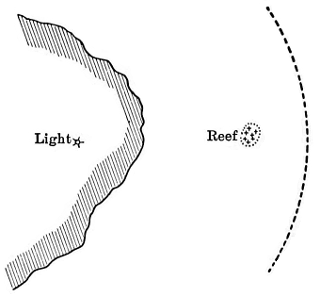
VERTICAL DANGER ANGLE
FIG. 46.
Soundings. Even if objects cannot be seen, due to distance or thick weather, the chart furnishes a valuable aid when a vessel has approached within the limits where it is practicable to obtain soundings. Modern navigational sounding machines permit of obtaining soundings to depths of nearly one hundred fathoms without stopping the vessel. A rough check is at once[Pg 137-139] obtained by comparing such soundings with those given on the chart for the position carried forward by dead reckoning. If a number of soundings are taken and plotted on a piece of tracing paper, spaced by the log readings to the scale of the chart, and this tracing paper is laid over the chart and shifted in the vicinity of the probable position until the soundings best agree with those on the chart, a valuable verification of position may be obtained. This is particularly the case if the area has been well surveyed, and the soundings taken on the vessel are accurate, and the configuration of the bottom has marked characteristics. For instance, in approaching New York the crossing of the 30, 20, and 10 fathom curves will give a fair warning of the distance off the Long Island and New Jersey coasts, and soundings across such a feature as the submerged Hudson gorge extending to the southeastward of Sandy Hook will give a valuable indication of position. The taking of soundings should be resorted to even in favorable conditions, in approaching shoal water, as a check on other means of locating the vessel. Many marine disasters are attributed to failure to make sufficient use of the lead, the simplest of navigational aids.
Vertical angles. The vertical angle of elevation of an object whose height is known will give the distance, and combined with a bearing or other information this permits of locating a vessel where better means cannot be used. Distance tables are published for this method. (Fig. 46.) The vertical angle is measured with a sextant and must be the angle at the ship between the top of the object and the sea level vertically beneath it; for a hill or mountain, therefore, the eye of the observer should[Pg 140] be near the water. The object should not be so distant that curvature becomes appreciable. The "vertical danger angle" is a means of avoiding a known danger, on a principle similar to that of the horizontal danger angle; that is, the angle of elevation of a known object is not permitted to become greater than a fixed amount depending on the distance from the object to the danger to be avoided.
Positions by sound. In thick weather sound affords a valuable aid to the navigator. In narrow passages noting the echo of the whistle from a cliff is a method resorted to, as for instance in Puget Sound and along the Alaska coast. Fog whistles and bell buoys are maintained at many places. Submarine bells have recently been introduced at a number of points along the Atlantic coast, and vessels may be equipped to receive these submarine signals transmitted through the water, which indicate also the general direction from which the sound comes.
Need of vigilance. Too great importance cannot be attached to frequent verification of positions by the best available means, particularly when approaching the land. Neglect of this or overconfidence has caused many disasters. A notable instance was the loss of one of the largest Pacific steamers on the coast of Japan in March, 1907. In the afternoon of a clear day this vessel ran on to a well-known reef about a mile from a lighthouse, resulting in the total loss of vessel and cargo valued at three and a half million dollars. The captain was so confident of his position and that he was giving the reef a sufficient berth that he laid down no bearings on the chart and took no soundings.
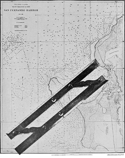
FIG. 47. FIELD'S PROTRACTOR AND PARALLEL RULER IN USE ON A CHART, PLOTTING BEARING OF A LIGHTHOUSE.
[Pg 143]Instruments. The principal instruments needed for use with charts are; dividers for taking off distances and latitudes and longitudes, parallel ruler for transferring directions to or from a compass rose and for taking off or plotting the latitude on a mercator chart, protractor of 180 degrees for reading the angle with the meridian of any direction or for laying off on the chart any given angle with the meridian, and three-arm or other full-circle protractor for plotting a position by the three-point problem.
Parallel rulers on the principle of Field's are strongly recommended for chart work, as they combine in a single instrument the advantages of a parallel ruler and a 180-degree protractor. Any direction can be read or laid off by simply moving the parallel ruler to the nearest projection line, which is a process not only more convenient than referring to the compass rose printed on the chart but also more accurate because of the longer radius. These instruments can also be used the same as a plain parallel ruler. Field's parallel rulers are made in two forms, one rolling and the other sliding. The former is a single ruler with edge graduated 90 degrees either way, and mounted on rollers; it is the most rapid instrument for reading or laying off a direction, but it requires a smooth surface. The latter is an ordinary two-bar parallel ruler with edge when closed graduated 90 degrees either way; it is a very serviceable instrument and probably more to be depended upon for ordinary use than the rolling form. Some form of combined protractor and parallel ruler should be in every navigational equipment, and it is unfortunate that these instruments are not better known in this country.[Pg 144] There are other forms of half-circle protractors which are used on the same principle, that is, of bringing the center on to a projection line and reading where the line cuts the border graduation of the protractor. Thus a semicircular protractor is used with a separate straight edge, along which it is slid to the nearest meridian; another form is the simple circular protractor with a thread fastened at the center. All these forms of protractors, it will be noted, are intended to work from the true meridian, and they are usually graduated in degrees only; the use of degrees instead of points is becoming much more general in navigational work, and reference to the true meridian is also more common than formerly.
The standard three-arm protractor, or station pointer, as it is known to the English, should be a part of every navigational outfit because of its value in locating a position by the three-point problem. A recent American invention, Court's three-arm protractor, is an instrument made of celluloid for the same purpose. It should not be considered as a substitute for the standard metal instrument, but it is a simple, cheap, and handy supplement to it, as it may be readily used for small angles and short distances where there are mechanical difficulties in working with the metal three-arm protractor. Other protractors can be used for the three-point problem, as, for instance, Cust's protractor on celluloid, on which the angles are drawn in pencil and erased, and the tracing-paper protractor.
Degree of reliance on charts. The value of a chart must not be judged alone from its general appearance,[Pg 145-147] as skill in preparation and publication may give a handsome appearance to an incomplete survey. On the other hand a thorough survey might through poor preparation result in a chart defective either in information or in utility.
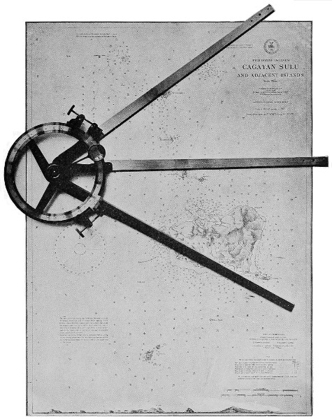
FIG. 48. THREE-ARM PROTRACTOR IN USE ON A CHART, PLOTTING POSITION FROM TWO ANGLES.
The degree of completeness of the soundings, the character of the region, and the date of the survey should be taken into account in deciding as to the amount of reliance to be placed on the chart. Areas where the soundings are not distributed with fair uniformity may be assumed not to have been completely surveyed. Caution should be used in navigating on charts where the survey is not complete, and even where careful surveys exist care must be taken if the bottom is of very irregular nature with lumps near the navigable depth, as for instance on some of the coral reef coasts. Isolated soundings shoaler than the surrounding depths should be avoided, as there may be less water than shown. In such a region, unless the whole area is dragged, it is impossible to make it entirely certain that all obstructions are charted.
While an immense amount of faithful work has been put into the preparation of many charts, the user must constantly exercise his own judgment as to the reliance to be placed on them. A coast is not to be considered as clear unless it is shown to be; buoys may get adrift and be in a different position or be gone altogether; fog signals vary in distinctness owing to atmospheric conditions; extreme or unusual tides may fall below the plane of reference; owing to strong winds the actual tide may differ from the predicted tide. Errors sometimes creep in from various sources,[Pg 148] such as those due to different reference longitudes or the use of a corrected longitude for a portion of the chart without changing other positions to which the same correction is applicable; clerical and printing errors may occur; there are sometimes omissions in surveys; a feature may get plotted in two different positions; tide rips are reported as breakers and floating objects as rocks or islands, and thus many dangers have gotten on the charts which cannot be found again, and false reports are sometimes made to shield some one from blame. Most of these classes of errors and uncertainties, however, disappear in the use of charts of a thoroughly surveyed coast.
Use the latest editions of charts. The latest edition of a chart should always be used and should be corrected for all notices since its issue. Carelessness or false economy in not providing the largest scale or the latest chart has been the cause of more than one marine disaster.
The British Board of Trade issue the following official notice to shipowners and agents: "The attention of the Board of Trade has frequently been called to cases in which British vessels have been endangered or wrecked through the masters' attempting to navigate them by means of antiquated or otherwise defective charts. The Board of Trade desires, therefore, to direct the especial attention of shipowners and their agents to the necessity of seeing that the charts taken or sent on board their ships are corrected to the time of sailing. Neglect to supply a ship with proper charts will be brought prominently before the Court of Inquiry in the event of a wreck occurring from that cause."
The following is a translation of a notice in the preface to the catalogue of charts published by the German government: "Owners and masters of vessels are apprised that cases of marine accidents in which the casualty was due to antiquated or erroneous charts, have frequently been before the admiralty courts. In consequence of this, the 'Instructions for the prevention of accidents to steamers and sailing vessels,' issued by the Seeberufsgenossenschaft have been amended by the following additional paragraph: 'It is obligatory upon every master, except when engaged in local coastwise navigation, to keep the Notices to Mariners regularly, and with the aid of them to carefully keep his charts up to date.'"
The British shipping laws provide that a ship may not be sent to sea in such an unseaworthy state that the life of any person is thereby endangered, and the House of Lords has defined the term "seaworthy" to mean "in a fit state as to repairs, equipment, and crew, and in all other respects, to encounter the ordinary perils of the voyage." Proper charts and sailing directions are a necessary part of the equipment of a vessel, and the courts have frequently inquired into this.
The records of the British courts, however, show that even in recent years many ships have been damaged or lost owing directly or indirectly to failure to have the latest information on board. The following are instances from these records.
In 1890 the steamer Dunluce was lost owing to the use of an old edition of the Admiralty chart which showed a depth of 412 fathoms on the Wikesgrund, whereas the later chart showed much less water. In[Pg 150] this case the master had requested his ship chandler to send him the latest chart.
In 1891 the steamer St. Donats got ashore on a patch which was not shown on the chart in use, which was privately published in 1881; the danger was, however, shown on the Admiralty chart corrected to 1889.
Also in 1891 the steamer Trent was lost on the Missipezza Rock in the Adriatic. The ship was navigated by a private chart published in 1890 which did not show this rock, and by sailing directions published in 1866.
The steamer Aboraca, stranded in the Gulf of Bothnia in 1894, was being navigated by a chart corrected to 1881 which did not show that the Storkallagrund light-vessel had been moved eight miles.
The steamer Ravenspur was lost on Bilbao Breakwater owing to the use of a chart not up to date which did not show the breakwater. In 1898 the steamer Cromarty was lost in attempting to enter Ponta Delgada harbor, and in 1901 the steamer "Dinnington" was lost by steaming on to the new breakwater in Portland harbor; both of these disasters were likewise due to the use of old charts which did not show the breakwaters. In these three cases the masters of the vessels had authority to obtain the necessary charts at the owners' expense.
Not so, however, in the following case from the finding of a British marine court in 1877: "The primary cause of the ship's getting on shore was due to the master's being guided in his navigation by an obsolete Admiralty chart dated September 1, 1852, and corrected to April, 1862, and on which no lights are shown[Pg 151] to exist either in ... or ... and to his not being supplied with the latest sailing directions. The Court, considering that the master was obliged to furnish himself with chronometer, barometer, sextant, charts, sailing directions, and everything necessary for the navigation of his vessel out of his private resources, which, under very favorable circumstances, might perhaps reach £150 a year, find themselves unable in this instance to pass a heavier censure upon him than that he be severely reprimanded."
The loss of the German steamer Baker on the coast of Cuba on January 31, 1908, was declared by the marine court at Hamburg to be due in part to the use of an unofficial chart which did not show the latest surveys on that coast.
Use the largest scale charts. The largest scale chart available should be employed when entering channels, bays, or harbors, as it gives information with more clearness and detail, positions may be more accurately plotted, and sometimes it is the first corrected for new information.
The records of the courts of inquiry also show cases where vessels have been wrecked owing to the use of charts of too small scale.
In 1890 the steamer Lady Ailsa was lost on the Plateau du Four. The only chart on board for this locality was a general chart of the Bay of Biscay, and the stranding was due to the master's mistaking one buoy for another. The court found that the chart, although a proper one for general use, was not sufficient for the navigation of a vessel in such narrow waters and on such a dangerous coast.
The Zenobia was stranded on the San Thomé Bank in 1891. On this vessel the owners were to furnish the chronometers and the master the charts and sailing directions. The master was, however, apparently satisfied with only a general chart of the South Atlantic for navigation on the coast of Brazil, and had no sailing directions at all.
The depth curves on charts furnish a valuable guide, and if the curves are lacking or broken in some parts it is usually a sign that the information is incomplete. The 100-fathom curve is a general warning of approach to the coast. The 10-fathom curve on rocky coasts should be considered as a danger curve, and caution used after crossing it. The 5-fathom curve is the most important for modern vessels of medium draft, as it indicates for them the practical limit of navigation. The 3, 2, and 1-fathom curves are a guide to smaller vessels, but have less significance than formerly because of the increase of draft of vessels.
The shrinkage of paper, especially in plate printing, has been referred to. This introduces two possible sources of error: first, the shrinkage being different in the two directions, any scale printed on the chart will be accurate only when used in a direction parallel to itself; second, for the same reason, angles and directions will be somewhat distorted. Fortunately these errors are not serious in the ordinary navigational use of a chart, but they should not be overlooked when accurate plotting or measuring of distances is attempted on a plate-printed chart.
The actual shrinkage measured on charts printed from plates varies from 13 inch to 1 inch in a length[Pg 153] of chart of 36 inches. On British and American plate printed charts the shrinkage is usually from two to nearly three times as much in one direction as it is in the other.
Care of charts. In order that they may be properly used charts should be filed flat and not rolled. They should be systematically arranged so that the desired chart can be instantly found. They should be cared for and when in bad condition replaced by new copies. They can be most conveniently filed in shallow drawers, thus avoiding the placing of many charts in a single drawer. The latter is a common fault; it not only increases the labor of handling the charts but adds to the liability of their injury.
There are several publications in book and in chart form which are either necessary or convenient for use in connection with nautical charts. These comprise the coast pilots, notices to mariners, tide tables, light and buoy lists, and various special charts.
Coast pilots, or sailing directions, are books giving descriptions of the main features, as far as of interest to seamen, of the coast and adjacent waters, with directions for navigation. They contain much miscellaneous information of value to the mariner, especially the stranger. Although they contain additional facts which cannot be shown on the charts, they are not at all intended to supersede the latter; the mariner should in general rely on the charts. The sailing directions can be less readily corrected than the charts, and in all cases where they differ the charts are to be taken as the guide.
The most extensive series of sailing directions is that published by the British Admiralty, comprising fifty-six volumes and including all the navigable regions of the world. In the United States the Coast and Geodetic Survey publishes ten volumes of coast pilots for the Atlantic, Gulf, and Pacific coasts, Porto Rico, and southeastern Alaska, and eight volumes of sailing directions for Alaska and the Philippine Islands. The United States Hydrographic Office publishes six[Pg 155]teen volumes of sailing directions for various parts of the world.
Notices to Mariners are published at frequent intervals, giving all important corrections, which should be at once applied by hand to the charts, such as rocks or shoals discovered and lights and buoys established or moved. New charts, new editions, and canceled charts are also announced.
These notices should be carefully examined and the necessary corrections made on all charts of the sets in use on the vessel. A chart should be considered as a growing rather than a finished instrument, and constant watchfulness is required to see that it is kept up to date. Neglect of this may cause shipwreck, as the following instance shows. Report came to Manila in 1904 that there was a low sand islet lying off the very poorly charted northeast coast of Samar; this information was promptly published in the local Notice to Mariners. About a month later a small steamer was sent to land some native constabulary on that coast. The captain failed to obtain or observe this notice, and approached the coast before daylight on a course which led directly across the sand islet. The vessel was driven far up on the sand, where it still lies.
In the United States, weekly Notices to Mariners are published by the Department of Commerce and Labor for the coasts under the jurisdiction of the United States, and by the Navy Department for all regions. These notices are distributed free and can be obtained from chart agents and consular officers. In Great Britain the notices are published at frequent intervals by the Hydrographic Office, and practically[Pg 156] all countries issuing charts also issue such notices. Information as to important changes in lights and other announcements of navigational interest are also sometimes printed in the marine columns of newspapers and in nautical periodicals.
Tide Tables. Brief information as to the time and height of the tide is usually for convenience given on the face of the chart. More complete information is published in the Tide Tables, with which every navigator should be provided. "The Tide Tables for United States and foreign ports," published annually in advance by the United States Coast and Geodetic Survey, give complete predictions of the time and height of high and low water for each day of the year for 70 of the principal ports of the world, and the tidal differences from some principal port for 3000 subordinate ports. The other leading nations also publish annual tide tables; those of the British government are entitled "Tide Tables for British and Irish ports, and also the times of high water for the principal places on the globe."
Light and buoy lists. Brief information as to all artificial aids to navigation is shown on the charts. Every vessel should also have on board the latest official light and buoy lists, which give a more detailed description than can be placed on the charts.
Light and buoy lists for the coasts of the United States are published annually by the Light-House Board. The United States Hydrographic Office publishes a "List of Lights of the World" (excepting the United States), in three volumes.
The British Hydrographic Office publishes eight[Pg 157] volumes of Lists of Lights, and these are corrected annually.
Chart catalogues are published in connection with all series of charts. They give the particulars and price of each chart published, and are usually arranged in geographical order, with both alphabetical and numerical indexes, for convenience in finding charts either by position, name, or number.
Charts for special purposes. There are various special charts published for the benefit of mariners, although not intended for direct use in plotting the course of a vessel or in locating its position. Some of the more important of these are mentioned below.
Gnomonic charts are intended solely for laying down the great circle or shortest practicable courses between points, for which purpose they are very convenient. Their use has already been described. The United States Hydrographic Office publishes six such charts, for the North Atlantic, South Atlantic, Pacific, North Pacific, South Pacific, and Indian Oceans.
Current charts are published by the British Hydrographic Office for the various oceans; these usually show the average ocean currents, but for the Atlantic there are monthly and for the Pacific quarterly current charts.
Magnetic variation charts are published by both the United States and British governments. They show on a mercator chart of the world the isogonic lines, or lines along which the variation of the needle from true north is the same. The lines are drawn for each degree of variation. The annual change in the variation is also indicated.
Other magnetic charts are published showing the lines of equal magnetic dip, horizontal magnetic force, and vertical magnetic force.
Meteorological ocean charts are published by several governments, including the United States, Great Britain, and Germany, and give the average weather conditions, winds, fogs, currents, ice, tracks of storms, and other information. "Pilot charts" of the North Atlantic and North Pacific Oceans are issued by the United States Hydrographic Office about the first of each month, and give "a forecast of the weather for the ensuing and a review of that for the preceding month, together with all obtainable information as to the most available sailing and steam routes, dangers to navigation, ice, fog, derelicts, etc., and any additional information that may be received of value to navigation." Mariners in all parts of the world have joined in contributing the information which has been used in compiling these pilot charts.
Track charts are published by the British and United States governments. That of the latter is entitled "Track and distance chart of the world, showing the routes traversed by full-powered steamers between the principal ports of the world, and the corresponding distances."
Telegraph charts are published showing the "telegraphic connections afforded by the submarine cables and the principal overland telegraph lines."
Index charts are outline plans showing the area covered by each chart of a series, and furnish a convenient means of finding a chart of any desired region or of selecting the most suitable chart for any purpose.[Pg 159] These index charts are published either in sets, showing all the charts of a series, or are bound into the chart catalogues.
Star charts are included in navigational series, and are conveniently arranged for use on shipboard in identifying the brighter stars. The United States Hydrographic Office publishes two, constellations of the northern and of the southern hemispheres.
Explanatory sheets are published in connection with various series of charts, giving explanations of the symbols and abbreviations used and of other important features. In the United States the Coast and Geodetic Survey has issued a small pamphlet, "Notes on the use of charts," which contains explanations of its chart symbols, and the Hydrographic Office has published "A manual of conventional symbols and abbreviations in use on the official charts of the principal maritime nations."
| PAGE | |
| Aids to navigation, | 118 |
| Arbitrary projection, | 79 |
| Astronomical observations, | 32 |
| Astronomical positions, | 126 |
| Bearings, position by, | 130 |
| Board of Trade notice, | 148 |
| Care of charts, | 153 |
| Catalogues of charts, | 157 |
| Changes in the coast, | 98 |
| Chart making, development of, | 6 |
| Chart publications of various nations, | 18 |
| Charts, earliest nautical, | 6 |
| Charts, loxodromic, | 7 |
| Charts, plain, | 8 |
| Chart schemes, | 67 |
| Chart working, | 124 |
| Coast and Geodetic Survey, United States, | 13 |
| Coast pilots, | 154 |
| Compass bearings, | 130 |
| Compass, nautical use of, | 6 |
| Compass, variation of, | 7 |
| Compilation of information, | 67 |
| Correction of charts, method of, | 110 |
| Cosa, Juan de la, | 8 |
| Current charts, | 157 |
| Currents, | 50, 121 |
| Danger angle, horizontal, | 136 |
| Danger bearing, | 131 |
| Danger range, | 132 |
| Dangers, reports of, | 56 |
| Dates on charts, | 123 |
| Dead reckoning, | 129 |
| Depth curves, | 116, 152 |
| Depths, unit for, | 19, 116 |
| Depth units, relation of, | 118 |
| Directions on charts, | 115 |
| Distances, measured on chart, | 125 |
| Distribution of charts, | 96 |
| Doubling angle on bow, | 131 |
| Draft of vessels, | 97 |
| Dragging for dangers, | 55 |
| Earthquakes, | 109 |
| Electrotyping plates, | 89 |
| Elevations, | 122 |
| Engraving machines, | 89 |
| Engraving on copper, | 84 |
| Engraving on stone, | 93 |
| Eskimo map, | 1 |
| Etching on copper, | 95 |
| Explanatory sheets, | 159 |
| Flattening of the earth, | 3 |
| France, establishment of chart office, | 10 |
| Geographic position on charts, | 115 |
| Geography, early, | 2 |
| Germany, contributions to hydrography, | 14 |
| Gnomonic charts, | 79, 157 |
| Gnomonic projection, | 74 |
| Great Britain, contributions to geography, | 14 |
| Holland, development of chart making, | 10 |
| Hydrographic Office, British, | 13 |
| Hydrographic Office, United States, | 13 |
| [Pg 162]Hydrography, | 40 |
| Index charts, | 158 |
| Information on charts, | 23 |
| Instruments used on charts, | 141 |
| Lake Survey, United States, | 13 |
| Largest scale chart, | 151 |
| Latest editions of charts, | 148 |
| Light and buoy lists, | 156 |
| Lithographic printing, | 94 |
| Locating a vessel, | 126 |
| Longitude, initial, | 19 |
| Longitude, uncertainties in, | 10 |
| Magnetic charts, | 157 |
| Magnetic variation, | 56 |
| Map, earliest, | 2 |
| Map making, development of, | 2 |
| Maps, need of, | 1 |
| Maritime surveys, extension of, | 17 |
| Mercator chart, history, | 8 |
| Mercator projection, | 68 |
| Meteorological charts (pilot charts), | 158 |
| Navigation, use of charts in, | 124 |
| Notices to mariners, | 111, 155 |
| Paper, shrinkage of, | 152 |
| Parallel rulers, Field's, | 141 |
| Photolithography, | 93 |
| Plane of reference, | 20, 119 |
| Plotting positions, | 124 |
| Polyconic projection, | 73 |
| Printing, plate, | 84, 90 |
| Privately published charts, | 21 |
| Progress of hydrographic surveys, | 17 |
| Projection, explanation of, | 114 |
| Projections, | 68, 114 |
| Protractor, three-arm, | 144 |
| Ptolemy, | 3 |
| Publication of charts, methods, | 84 |
| Purpose of charts, | 22 |
| Ranges, | 132 |
| Reading charts, | 112 |
| Reliance on charts, | 144 |
| Reports of dangers, erroneous, | 57 |
| Requirements for charts, | 23 |
| Revision of charts, need of, | 97 |
| Rock, Brooklyn, | 50 |
| Sailing directions, early, | 4 |
| Sailing directions, | 154 |
| Scale equivalents, | 113 |
| Scales of charts, | 79, 112 |
| Set, graphical allowance for, | 125 |
| Sextant angles, | 132 |
| Sheets for surveys, | 39 |
| Shrinkage of paper, | 152 |
| Sound, position by, | 140 |
| Sounding machines, | 49 |
| Soundings, position by, | 136 |
| Star charts, | 159 |
| Station pointer, | 144 |
| Steamer for surveying, | 49 |
| Sumner's method, | 126 |
| Supplementary publications, | 154 |
| Surveys on foreign coasts, | 14 |
| Surveys, need of thorough, | 31 |
| Symbols on charts, | 20 |
| Telegraph charts, | 158 |
| Three-point problem, | 132, 135 |
| Tides, | 50, 120 |
| Tide tables, | 156 |
| Topography, | 39 |
| Topography on charts, | 123 |
| Track charts, | 158 |
| Triangulation, | 32 |
| Uniformity in charts, | 21 |
| Use of charts in navigation, | 124 |
| Vertical angles, | 139 |
| Vigias, removal of, | 62 |
| Vigilance, need of, | 140 |
| Volcanic action, | 109 |
| Wrecks due to deficient charts, | 149 |
SHORT-TITLE CATALOGUE
OF THE
PUBLICATIONS
OF
JOHN WILEY & SONS,
New York.
London: CHAPMAN & HALL, Limited.
ARRANGED UNDER SUBJECTS.
Descriptive circulars sent on application. Books marked with an asterisk (*) are sold at net prices only. All books are bound in cloth unless otherwise stated.
AGRICULTURE.
| Armsby's Manual of Cattle-feeding. | 12mo, | $1 75 |
| Principles of Animal Nutrition. | 8vo, | 4 00 |
| Budd and Hansen's American Horticultural Manual: | ||
| Part I. Propagation, Culture, and Improvement. | 12mo, | 1 50 |
| Part II. Systematic Pomology. | 12mo, | 1 50 |
| Elliott's Engineering for Land Drainage. | 12mo, | 1 50 |
| Practical Farm Drainage. | 12mo, | 1 00 |
| Graves's Forest Mensuration. | 8vo, | 4 00 |
| Green's Principles of American Forestry. | 12mo, | 1 50 |
| Grotenfelt's Principles of Modern Dairy Practice. (Woll.) | 12mo, | 2 00 |
| Hanausek's Microscopy of Technical Products. (Winton.) | 8vo, | 5 00 |
| Herrick's Denatured or Industrial Alcohol. | 8vo, | 4 00 |
| Maynard's Landscape Gardening as Applied to Home Decoration. | 12mo, | 1 50 |
| * McKay and Larsen's Principles and Practice of Butter-making. | 8vo, | 1 50 |
| Sanderson's Insects Injurious to Staple Crops. | 12mo, | 1 50 |
| * Schwarz's Longleaf Pine in Virgin Forest. | 12mo, | 1 25 |
| Stockbridge's Rocks and Soils. | 8vo, | 2 50 |
| Winton's Microscopy of Vegetable Foods. | 8vo, | 7 50 |
| Woll's Handbook for Farmers and Dairymen. | 16mo, | 1 50 |
ARCHITECTURE.
| Baldwin's Steam Heating for Buildings. | 12mo, | 2 50 |
| Bashore's Sanitation of a Country House. | 12mo, | 1 00 |
| Berg's Buildings and Structures of American Railroads. | 4to, | 5 00 |
| Birkmire's Planning and Construction of American Theatres. | 8vo, | 3 00 |
| Architectural Iron and Steel. | 8vo, | 3 50 |
| Compound Rivetée Girders as Applied in Buildings. | 8vo, | 2 00 |
| Planning and Construction of High Office Buildings. | 8vo, | 3 50 |
| Skeleton Construction in Buildings. | 8vo, | 3 00 |
| Brigg's Modern American School Buildings. | 8vo, | 4 00 |
| [2]Carpenter's Heating and Ventilating of Buildings. | 8vo, | 4 00 |
| Freitag's Architectural Engineering. | 8vo, | 3 50 |
| Fireproofing of Steel Buildings. | 8vo, | 2 50 |
| French and Ives's Stereotomy. | 8vo, | 2 50 |
| Gerhard's Guide to Sanitary House-inspection. | 16mo, | 1 00 |
| Sanitation of Public Buildings. | 12mo, | 1 50 |
| Theatre Fires and Panics. | 12mo, | 1 50 |
| * Greene's Structural Mechanics. | 8vo, | 2 50 |
| Holly's Carpenters' and Joiners' Handbook. | 18mo, | 75 |
| Johnson's Statics by Algebraic and Graphic Methods. | 8vo, | 2 00 |
| Kellaway's How to Lay Out Suburban Home Grounds. | 8vo, | 2 00 |
| Kidder's Architects' and Builders' Pocket-book. Rewritten Edition. | 16mo, mor., | 5 00 |
| Merrill's Stones for Building and Decoration. | 8vo, | 5 00 |
| Non-metallic Minerals: Their Occurrence and Uses. | 8vo, | 4 00 |
| Monckton's Stair-building. | 4to, | 4 00 |
| Patton's Practical Treatise on Foundations. | 8vo, | 5 00 |
| Peabody's Naval Architecture. | 8vo, | 7 50 |
| Rice's Concrete-block Manufacture. | 8vo, | 2 00 |
| Richey's Handbook for Superintendents of Construction. | 16mo, mor., | 4 00 |
| * Building Mechanics' Ready Reference Book: | ||
| * Carpenters' and Woodworkers' Edition. | 16mo, morocco, | 1 50 |
| * Cementworkers and Plasterer's Edition. (In Press.) | ||
| * Stone- and Brick-mason's Edition. | 12mo, mor., | 1 50 |
| Sabin's Industrial and Artistic Technology of Paints and Varnish. | 8vo, | 3 00 |
| Siebert and Biggin's Modern Stone-cutting and Masonry. | 8vo, | 1 50 |
| Snow's Principal Species of Wood. | 8vo, | 3 50 |
| Sondericker's Graphic Statics with Applications to Trusses, Beams, and Arches. | 8vo, | 2 00 |
| Towne's Locks and Builders' Hardware. | 18mo, morocco, | 3 00 |
| Turneaure and Maurer's Principles of Reinforced Concrete Construction. | 8vo, | 3 00 |
| Wait's Engineering and Architectural Jurisprudence. | 8vo, | 6 00 |
| Sheep, | 6 50 | |
| Law of Operations Preliminary to Construction in Engineering and Architecture. | 8vo, | 5 00 |
| Sheep, | 5 50 | |
| Law of Contracts. | 8vo, | 3 00 |
| Wilson's Air Conditioning, (In Press.) | ||
| Wood's Rustless Coatings: Corrosion and Electrolysis of Iron and Steel. | 8vo, | 4 00 |
| Worcester and Atkinson's Small Hospitals, Establishment and Maintenance, Suggestions for Hospital Architecture with Plans for a Small Hospital. | 12mo, | 1 25 |
| The World's Columbian Exposition of 1893. | Large 4to, | 1 00 |
ARMY AND NAVY.
| Bernadou's Smokeless Powder, Nitro-cellulose, and the Theory of the Cellulose Molecule. | 12mo, | 2 50 |
| Chase's Screw Propellers and Marine Propulsion. | 8vo, | 3 00 |
| Cloke's Gunner's Examiner. | 8vo, | 1 50 |
| Craig's Azimuth. | 4to, | 3 50 |
| Crehore and Squier's Polarizing Photo-chronograph. | 8vo, | 3 00 |
| * Davis's Elements of Law. | 8vo, | 2 50 |
| * Treatise on the Military Law of United States. | 8vo, | 7 00 |
| Sheep, | 7 50 | |
| De Brack's Cavalry Outposts Duties. (Carr.) | 24mo, morocco, | 2 00 |
| Dietz's Soldier's First Aid Handbook. | 16mo, morocco, | 1 25 |
| * Dudley's Military Law and the Procedure of Courts-martial. | Large 12mo, | 2 50 |
| [3]Durand's Resistance and Propulsion of Ships. | 8vo, | 5 00 |
| * Dyer's Handbook of Light Artillery. | 12mo, | 3 00 |
| Eissler's Modern High Explosives. | 8vo, | 4 00 |
| * Fiebeger's Text-book on Field Fortification. | Small 8vo, | 2 00 |
| Hamilton's The Gunner's Catechism. | 18mo, | 1 00 |
| * Hoff's Elementary Naval Tactics. | 8vo, | 1 50 |
| Ingalls's Handbook of Problems in Direct Fire. | 8vo, | 4 00 |
| * Lissak's Ordnance and Gunnery. | 8vo, | 6 00 |
| * Lyons's Treatise on Electromagnetic Phenomena. Vols. I. and II. | 8vo, each, | 6 00 |
| * Mahan's Permanent Fortifications. (Mercur.) | 8vo, half morocco, | 7 50 |
| Manual for Courts-martial. | 16mo, morocco, | 1 50 |
| * Mercur's Attack of Fortified Places. | 12mo, | 2 00 |
| * Elements of the Art of War. | 8vo, | 4 00 |
| Metcalfe's Cost of Manufactures—And the Administration of Workshops. | 8vo, | 5 00 |
| * Ordnance and Gunnery. 2 vols. | 12mo, | 5 00 |
| Murray's Infantry Drill Regulations. | 18mo, paper, | 10 |
| Nixon's Adjutants' Manual. | 24mo, | 1 00 |
| Peabody's Naval Architecture. | 8vo, | 7 50 |
| * Phelps's Practical Marine Surveying. | 8vo, | 2 50 |
| Powell's Army Officer's Examiner. | 12mo, | 4 00 |
| Sharpe's Art of Subsisting Armies in War. | 18mo, morocco, | 1 50 |
| * Tupes and Poole's Manual of Bayonet Exercises and Musketry Fencing. | 24mo, leather, | 50 |
| Weaver's Military Explosives. | 8vo, | 3 00 |
| Wheeler's Siege Operations and Military Mining. | 8vo, | 2 00 |
| Winthrop's Abridgment of Military Law. | 12mo, | 2 50 |
| Woodhull's Notes on Military Hygiene. | 16mo, | 1 50 |
| Young's Simple Elements of Navigation. | 16mo, morocco, | 2 00 |
ASSAYING.
| Fletcher's Practical Instructions in Quantitative Assaying with the Blowpipe. | 12mo, morocco, | 1 50 |
| Furman's Manual of Practical Assaying. | 8vo, | 3 00 |
| Lodge's Notes on Assaying and Metallurgical Laboratory Experiments. | 8vo, | 3 00 |
| Low's Technical Methods of Ore Analysis. | 8vo, | 3 00 |
| Miller's Manual of Assaying. | 12mo, | 1 00 |
| Cyanide Process. | 12mo, | 1 00 |
| Minet's Production of Aluminum and its Industrial Use. (Waldo.) | 12mo, | 2 50 |
| O'Driscoll's Notes on the Treatment of Gold Ores. | 8vo, | 2 00 |
| Ricketts and Miller's Notes on Assaying. | 8vo, | 3 00 |
| Robine and Lenglen's Cyanide Industry. (Le Clerc.) | 8vo, | 4 00 |
| Ulke's Modern Electrolytic Copper Refining. | 8vo, | 3 00 |
| Wilson's Cyanide Processes. | 12mo, | 1 50 |
| Chlorination Process. | 12mo, | 1 50 |
ASTRONOMY.
| Comstock's Field Astronomy for Engineers. | 8vo, | 2 50 |
| Craig's Azimuth. | 4to, | 3 50 |
| Crandall's Text-book on Geodesy and Least Squares. | 8vo, | 3 00 |
| Doolittle's Treatise on Practical Astronomy. | 8vo, | 4 00 |
| Gore's Elements of Geodesy. | 8vo, | 2 50 |
| Hayford's Text-book of Geodetic Astronomy. | 8vo, | 3 00 |
| Merriman's Elements of Precise Surveying and Geodesy. | 8vo, | 2 50 |
| * Michie and Harlow's Practical Astronomy. | 8vo, | 3 00 |
| * White's Elements of Theoretical and Descriptive Astronomy. | 12mo, | 2 00 |
BOTANY.
| Davenport's Statistical Methods, with Special Reference to Biological Variation. | 16mo, morocco, | 1 25 |
| Thomé and Bennett's Structural and Physiological Botany. | 16mo, | 2 25 |
| Westermaier's Compendium of General Botany. (Schneider.) | 8vo, | 2 00 |
CHEMISTRY.
| * Abegg's Theory of Electrolytic Dissociation. (Von Ende.) | 12mo, | 1 25 |
| Adriance's Laboratory Calculations and Specific Gravity Tables. | 12mo, | 1 25 |
| Alexeyeff's General Principles of Organic Synthesis. (Matthews.) | 8vo, | 3 00 |
| Allen's Tables for Iron Analysis. | 8vo, | 3 00 |
| Arnold's Compendium of Chemistry. (Mandel.) | Small 8vo, | 3 50 |
| Austen's Notes for Chemical Students. | 12mo, | 1 50 |
| Beard's Mine Gases and Explosions. (In Press.) | ||
| Bernadou's Smokeless Powder.—Nitro-cellulose, and Theory of the Cellulose Molecule. | 12mo, | 2 50 |
| Bolduan's Immune Sera. | 12mo, | 1 50 |
| * Browning's Introduction to the Rarer Elements. | 8vo, | 1 50 |
| Brush and Penfield's Manual of Determinative Mineralogy. | 8vo, | 4 00 |
| * Claassen's Beet-sugar Manufacture. (Hall and Rolfe.) | 8vo, | 3 00 |
| Classen's Quantitative Chemical Analysis by Electrolysis. (Boltwood.) | 8vo, | 3 00 |
| Cohn's Indicators and Test-papers. | 12mo, | 2 00 |
| Tests and Reagents. | 8vo, | 3 00 |
| Crafts's Short Course in Qualitative Chemical Analysis. (Schaeffer.) | 12mo, | 1 50 |
| * Danneel's Electrochemistry. (Merriam.) | 12mo, | 1 25 |
| Dolezalek's Theory of the Lead Accumulator (Storage Battery). (Von Ende.) | 12mo, | 2 50 |
| Drechsel's Chemical Reactions. (Merrill.) | 12mo, | 1 25 |
| Duhem's Thermodynamics and Chemistry. (Burgess.) | 8vo, | 4 00 |
| Eissler's Modern High Explosives. | 8vo, | 4 00 |
| Effront's Enzymes and their Applications. (Prescott.) | 8vo, | 3 00 |
| Erdmann's Introduction to Chemical Preparations. (Dunlap.) | 12mo, | 1 25 |
| * Fischer's Physiology of Alimentation. | Large 12mo, | 2 00 |
| Fletcher's Practical Instructions in Quantitative Assaying with the Blowpipe. | 12mo, morocco, | 1 50 |
| Fowler's Sewage Works Analyses. | 12mo, | 2 00 |
| Fresenius's Manual of Qualitative Chemical Analysis. (Wells.) | 8vo, | 5 00 |
| Manual of Qualitative Chemical Analysis. Part I. Descriptive. (Wells.) | 8vo, | 3 00 |
| Quantitative Chemical Analysis. (Cohn.) 2 vols. | 8vo, | 12 50 |
| Fuertes's Water and Public Health. | 12mo, | 1 50 |
| Furman's Manual of Practical Assaying. | 8vo, | 3 00 |
| * Getman's Exercises in Physical Chemistry. | 12mo, | 2 00 |
| Gill's Gas and Fuel Analysis for Engineers. | 12mo, | 1 25 |
| * Gooch and Browning's Outlines of Qualitative Chemical Analysis. | Small 8vo, | 1 25 |
| Grotenfelt's Principles of Modern Dairy Practice. (Woll.) | 12mo, | 2 00 |
| Groth's Introduction to Chemical Crystallography. (Marshall.) | 12mo, | 1 25 |
| Hammarsten's Text-book of Physiological Chemistry. (Mandel.) | 8vo, | 4 00 |
| Hanausek's Microscopy of Technical Products. (Winton.) | 8vo, | 5 00 |
| * Haskin's and MacLeod's Organic Chemistry. | 12mo, | 2 00 |
| Helm's Principles of Mathematical Chemistry. (Morgan.) | 12mo, | 1 50 |
| Hering's Ready Reference Tables (Conversion Factors.) | 16mo, morocco, | 2 50 |
| Herrick's Denatured or Industrial Alcohol. | 8vo, | 4 00 |
| Hind's Inorganic Chemistry. | 8vo, | 3 00 |
| * Laboratory Manual for Students. | 12mo, | 1 00 |
| Holleman's Text-book of Inorganic Chemistry. (Cooper.) | 8vo, | 2 50 |
| Text-book of Organic Chemistry. (Walker and Mott.) | 8vo, | 2 50 |
| * Laboratory Manual of Organic Chemistry. (Walker.) | 12mo, | 1 00 |
| [5]Holley and Ladd's Analysis of Mixed Paints, Color Pigments, and Varnishes. (In Press.) | ||
| Hopkins's Oil-chemists' Handbook. | 8vo, | 3 00 |
| Iddings's Rock Minerals. | 8vo, | 5 00 |
| Jackson's Directions for Laboratory Work in Physiological Chemistry. | 8vo, | 1 25 |
| Johannsen's Key for the Determination of Rock-forming Minerals in Thin Sections. (In Press.) | ||
| Keep's Cast Iron. | 8vo, | 2 50 |
| Ladd's Manual of Quantitative Chemical Analysis. | 12mo, | 1 00 |
| Landauer's Spectrum Analysis. (Tingle.) | 8vo, | 3 00 |
| * Langworthy and Austen. The Occurrence of Aluminium in Vegetable Products, Animal Products, and Natural Waters. | 8vo, | 2 00 |
| Lassar-Cohn's Application of Some General Reactions to Investigations in Organic Chemistry. (Tingle.) | 12mo, | 1 00 |
| Leach's The Inspection and Analysis of Food with Special Reference to State Control. | 8vo, | 7 50 |
| Löb's Electrochemistry of Organic Compounds. (Lorenz.) | 8vo, | 3 00 |
| Lodge's Notes on Assaying and Metallurgical Laboratory Experiments. | 8vo, | 3 00 |
| Low's Technical Method of Ore Analysis. | 8vo, | 3 00 |
| Lunge's Techno-chemical Analysis. (Cohn.) | 12mo | 1 00 |
| * McKay and Larsen's Principles and Practice of Butter-making. | 8vo, | 1 50 |
| Maire's Modern Pigments and their Vehicles. (In Press.) | ||
| Mandel's Handbook for Bio-chemical Laboratory. | 12mo, | 1 50 |
| * Martin's Laboratory Guide to Qualitative Analysis with the Blowpipe. | 12mo, | 60 |
| Mason's Water-supply. (Considered Principally from a Sanitary Standpoint.) 3d Edition, Rewritten. | 8vo, | 4 00 |
| Examination of Water. (Chemical and Bacteriological.) | 12mo, | 1 25 |
| Matthews's The Textile Fibres. 2d Edition, Rewritten. | 8vo, | 4 00 |
| Meyer's Determination of Radicles in Carbon Compounds. (Tingle.) | 12mo, | 1 00 |
| Miller's Manual of Assaying. | 12mo, | 1 00 |
| Cyanide Process. | 12mo, | 1 00 |
| Minet's Production of Aluminum and its Industrial Use. (Waldo.) | 12mo, | 2 50 |
| Mixter's Elementary Text-book of Chemistry. | 12mo, | 1 50 |
| Morgan's An Outline of the Theory of Solutions and its Results. | 12mo, | 1 00 |
| Elements of Physical Chemistry. | 12mo, | 3 00 |
| * Physical Chemistry for Electrical Engineers. | 12mo, | 5 00 |
| Morse's Calculations used in Cane-sugar Factories. | 16mo, morocco, | 1 50 |
| * Muir's History of Chemical Theories and Laws. | 8vo, | 4 00 |
| Mulliken's General Method for the Identification of Pure Organic Compounds. Vol. I. | Large 8vo, | 5 00 |
| O'Driscoll's Notes on the Treatment of Gold Ores. | 8vo, | 2 00 |
| Ostwald's Conversations on Chemistry. Part One. (Ramsey.) | 12mo, | 1 50 |
| """" Part Two. (Turnbull.) | 12mo, | 2 00 |
| * Palmer's Practical Test Book of Chemistry. | 12mo, | 1 00 |
| * Pauli's Physical Chemistry in the Service of Medicine. (Fischer.) | 12mo, | 1 25 |
| * Penfield's Notes on Determinative Mineralogy and Record of Mineral Tests. | 8vo, paper, | 50 |
| Pictet's The Alkaloids and their Chemical Constitution. (Biddle.) | 8vo, | 5 00 |
| Pinner's Introduction to Organic Chemistry. (Austen.) | 12mo, | 1 50 |
| Poole's Calorific Power of Fuels. | 8vo, | 3 00 |
| Prescott and Winslow's Elements of Water Bacteriology, with Special Reference to Sanitary Water Analysis. | 12mo, | 1 25 |
| * Reisig's Guide to Piece-dyeing. | 8vo, | 25 00 |
| Richards and Woodman's Air, Water, and Food from a Sanitary Standpoint. | 8vo, | 2 00 |
| Ricketts and Miller's Notes on Assaying. | 8vo, | 3 00 |
| Rideal's Sewage and the Bacterial Purification of Sewage. | 8vo, | 4 00 |
| Disinfection and the Preservation of Food. | 8vo, | 4 00 |
| Riggs's Elementary Manual for the Chemical Laboratory. | 8vo, | 1 25 |
| Robine and Lenglen's Cyanide Industry. (Le Clerc.) | 8vo, | 4 00 |
| [6]Ruddiman's Incompatibilities in Prescriptions. | 8vo, | 2 00 |
| * Whys in Pharmacy. | 12mo, | 1 00 |
| Sabin's Industrial and Artistic Technology of Paints and Varnish. | 8vo, | 3 00 |
| Salkowski's Physiological and Pathological Chemistry. (Orndorff.) | 8vo, | 2 50 |
| Schimpf's Text-book of Volumetric Analysis. | 12mo, | 2 50 |
| Essentials of Volumetric Analysis. | 12mo, | 1 25 |
| * Qualitative Chemical Analysis. | 8vo, | 1 25 |
| Smith's Lecture Notes on Chemistry for Dental Students. | 8vo, | 2 50 |
| Spencer's Handbook for Chemists of Beet-sugar Houses. | 16mo, morocco, | 3 00 |
| Handbook for Cane Sugar Manufacturers. | 16mo, morocco, | 3 00 |
| Stockbridge's Rocks and Soils. | 8vo, | 2 50 |
| * Tillman's Elementary Lessons in Heat. | 8vo, | 1 50 |
| * Descriptive General Chemistry. | 8vo, | 3 00 |
| Treadwell's Qualitative Analysis. (Hall.) | 8vo, | 3 00 |
| Quantitative Analysis. (Hall.) | 8vo, | 4 00 |
| Turneaure and Russell's Public Water-supplies. | 8vo, | 5 00 |
| Van Deventer's Physical Chemistry for Beginners. (Boltwood.) | 12mo, | 1 50 |
| * Walke's Lectures on Explosives. | 8vo, | 4 00 |
| Ware's Beet-sugar Manufacture and Refining. Vol. I. | Small 8vo, | 4 00 |
| """""Vol. II. | Small 8vo, | 5 00 |
| Washington's Manual of the Chemical Analysis of Rocks. | 8vo, | 2 00 |
| Weaver's Military Explosives. | 8vo, | 3 00 |
| Wehrenfennig's Analysis and Softening of Boiler Feed-Water. | 8vo, | 4 00 |
| Wells's Laboratory Guide in Qualitative Chemical Analysis. | 8vo, | 1 50 |
| Short Course in Inorganic Qualitative Chemical Analysis for Engineering Students. | 12mo, | 1 50 |
| Text-book of Chemical Arithmetic. | 12mo, | 1 25 |
| Whipple's Microscopy of Drinking-water. | 8vo, | 3 50 |
| Wilson's Cyanide Processes. | 12mo, | 1 50 |
| Chlorination Process. | 12mo, | 1 50 |
| Winton's Microscopy of Vegetable Foods. | 8vo, | 7 50 |
| Wulling's Elementary Course in Inorganic, Pharmaceutical, and Medical Chemistry. | 12mo, | 2 00 |
CIVIL ENGINEERING.
BRIDGES AND ROOFS. HYDRAULICS. MATERIALS OF ENGINEERING. RAILWAY ENGINEERING.
| Baker's Engineers' Surveying Instruments. | 12mo, | 3 00 |
| Bixby's Graphical Computing Table. | Paper 1912 × 2414 inches, | 25 |
| Breed and Hosmer's Principles and Practice of Surveying. | 8vo, | 3 00 |
| * Burr's Ancient and Modern Engineering and the Isthmian Canal. | 8vo, | 3 50 |
| Comstock's Field Astronomy for Engineers. | 8vo, | 2 50 |
| * Corthell's Allowable Pressures on Deep Foundations. | 12mo, | 1 25 |
| Crandall's Text-book on Geodesy and Least Squares. | 8vo, | 3 00 |
| Davis's Elevation and Stadia Tables. | 8vo, | 1 00 |
| Elliott's Engineering for Land Drainage. | 12mo, | 1 50 |
| Practical Farm Drainage. | 12mo, | 1 00 |
| * Fiebeger's Treatise on Civil Engineering. | 8vo, | 5 00 |
| Flemer's Phototopographic Methods and Instruments. | 8vo, | 5 00 |
| Folwell's Sewerage. (Designing and Maintenance.) | 8vo, | 3 00 |
| Freitag's Architectural Engineering. 2d Edition, Rewritten. | 8vo, | 3 50 |
| French and Ives's Stereotomy. | 8vo, | 2 50 |
| Goodhue's Municipal Improvements. | 12mo, | 1 50 |
| Gore's Elements of Geodesy. | 8vo, | 2 50 |
| * Hauch and Rice's Tables of Quantities for Preliminary Estimates. | 12mo, | 1 25 |
| Hayford's Text-book of Geodetic Astronomy. | 8vo, | 3 00 |
| [7]Hering's Ready Reference Tables (Conversion Factors). | 16mo, morocco, | 2 50 |
| Howe's Retaining Walls for Earth. | 12mo, | 1 25 |
| Hoyt and Grover's River Discharge. | 8vo, | 2 00 |
| * Ives's Adjustments of the Engineer's Transit and Level. | 16mo, Bds. | 25 |
| Ives and Hilts's Problems in Surveying. | 16mo, morocco, | 1 50 |
| Johnson's (J. B.) Theory and Practice of Surveying. | Small 8vo, | 4 00 |
| Johnson's (L. J.) Statics by Algebraic and Graphic Methods. | 8vo, | 2 00 |
| Laplace's Philosophical Essay on Probabilities. (Truscott and Emory.) | 12mo, | 2 00 |
| Mahan's Treatise on Civil Engineering. (1873.) (Wood.) | 8vo, | 5 00 |
| * Descriptive Geometry. | 8vo, | 1 50 |
| Merriman's Elements of Precise Surveying and Geodesy. | 8vo, | 2 50 |
| Merriman and Brooks's Handbook for Surveyors. | 16mo, morocco, | 2 00 |
| Nugent's Plane Surveying. | 8vo, | 3 50 |
| Ogden's Sewer Design. | 12mo, | 2 00 |
| Parsons's Disposal of Municipal Refuse. | 8vo, | 2 00 |
| Patton's Treatise on Civil Engineering. | 8vo half leather, | 7 50 |
| Reed's Topographical Drawing and Sketching. | 4to, | 5 00 |
| Rideal's Sewage and the Bacterial Purification of Sewage. | 8vo, | 4 00 |
| Riemer's Shaft-sinking under Difficult Conditions. (Corning and Peele.) | 8vo, | 3 00 |
| Siebert and Biggin's Modern Stone-cutting and Masonry. | 8vo, | 1 50 |
| Smith's Manual of Topographical Drawing. (McMillan.) | 8vo, | 2 50 |
| Sondericker's Graphic Statics, with Applications to Trusses, Beams, and Arches. | 8vo, | 2 00 |
| Taylor and Thompson's Treatise on Concrete, Plain and Reinforced. | 8vo, | 5 00 |
| Tracy's Plane Surveying. | 16mo, morocco, | 3 00 |
| * Trautwine's Civil Engineer's Pocket-book. | 16mo, morocco, | 5 00 |
| Venable's Garbage Crematories in America. | 8vo, | 2 00 |
| Wait's Engineering and Architectural Jurisprudence. | 8vo, | 6 00 |
| Sheep, | 6 50 | |
| Law of Operations Preliminary to Construction in Engineering and Architecture. | 8vo, | 5 00 |
| Sheep, | 5 50 | |
| Law of Contracts. | 8vo, | 3 00 |
| Warren's Stereotomy—Problems in Stone-cutting. | 8vo, | 2 50 |
| Webb's Problems in the Use and Adjustment of Engineering Instruments. | 16mo, morocco, | 1 25 |
| Wilson's Topographic Surveying. | 8vo, | 3 50 |
BRIDGES AND ROOFS.
| Boller's Practical Treatise on the Construction of Iron Highway Bridges. | 8vo, | 2 00 |
| Burr and Falk's Influence Lines for Bridge and Roof Computations. | 8vo, | 3 00 |
| Design and Construction of Metallic Bridges. | 8vo, | 5 00 |
| Du Bois's Mechanics of Engineering. Vol. II. | Small 4to, | 10 00 |
| Foster's Treatise on Wooden Trestle Bridges. | 4to, | 5 00 |
| Fowler's Ordinary Foundations. | 8vo, | 3 50 |
| Greene's Roof Trusses. | 8vo, | 1 25 |
| Bridge Trusses. | 8vo, | 2 50 |
| Arches in Wood, Iron, and Stone. | 8vo, | 2 50 |
| Grimm's Secondary Stresses in Bridge Trusses. (In Press.) | ||
| Howe's Treatise on Arches. | 8vo, | 4 00 |
| Design of Simple Roof-trusses in Wood and Steel. | 8vo, | 2 00 |
| Symmetrical Masonry Arches. | 8vo, | 2 50 |
| Johnson, Bryan, and Turneaure's Theory and Practice in the Designing of Modern Framed Structures. | Small 4to, | 10 00 |
| Merriman and Jacoby's Text-book on Roofs and Bridges: | ||
| Part I. Stresses in Simple Trusses. | 8vo, | 2 50 |
| Part II. Graphic Statics. | 8vo, | 2 50 |
| Part III. Bridge Design. | 8vo, | 2 50 |
| Part IV. Higher Structures. | 8vo, | 2 50 |
| [8]Morison's Memphis Bridge. | 4to, | 10 00 |
| Waddell's De Pontibus, a Pocket-book for Bridge Engineers. | 16mo, morocco, | 2 00 |
| * Specifications for Steel Bridges. | 12mo, | 50 |
| Wright's Designing of Draw-spans. Two parts in one volume. | 8vo, | 3 50 |
HYDRAULICS.
| Barnes's Ice Formation. | 8vo, | 3 00 |
| Bazin's Experiments upon the Contraction of the Liquid Vein Issuing from an Orifice. (Trautwine.) | 8vo, | 2 00 |
| Bovey's Treatise on Hydraulics. | 8vo, | 5 00 |
| Church's Mechanics of Engineering. | 8vo, | 6 00 |
| Diagrams of Mean Velocity of Water in Open Channels. | paper, | 1 50 |
| Hydraulic Motors. | 8vo, | 2 00 |
| Coffin's Graphical Solution of Hydraulic Problems. | 16mo, morocco, | 2 50 |
| Flather's Dynamometers, and the Measurement of Power. | 12mo, | 3 00 |
| Folwell's Water-supply Engineering. | 8vo, | 4 00 |
| Frizell's Water-power. | 8vo, | 5 00 |
| Fuertes's Water and Public Health. | 12mo, | 1 50 |
| Water-filtration Works. | 12mo, | 2 50 |
| Ganguillet and Kutter's General Formula for the Uniform Flow of Water in Rivers and Other Channels. (Hering and Trautwine.) | 8vo, | 4 00 |
| Hazen's Clean Water and How to Get It. | Large 12mo, | 1 50 |
| Filtration of Public Water-supply. | 8vo, | 3 00 |
| Hazlehurst's Towers and Tanks for Water-works. | 8vo, | 2 50 |
| Herschel's 115 Experiments on the Carrying Capacity of Large, Riveted, Metal Conduits. | 8vo, | 2 00 |
| * Hubbard and Kiersted's Water-works Management and Maintenance. | 8vo, | 4 00 |
| Mason's Water-supply. (Considered Principally from a Sanitary Standpoint.) | 8vo, | 4 00 |
| Merriman's Treatise on Hydraulics. | 8vo, | 5 00 |
| * Michie's Elements of Analytical Mechanics. | 8vo, | 4 00 |
| Schuyler's Reservoirs for Irrigation, Water-power, and Domestic Water-supply | Large 8vo, | 5 00 |
| * Thomas and Watt's Improvement of Rivers. | 4to, | 6 00 |
| Turneaure and Russell's Public Water-supplies. | 8vo, | 5 00 |
| Wegmann's Design and Construction of Dams. 5th Edition, enlarged. | 4to, | 6 00 |
| Water-supply of the City of New York from 1658 to 1895. | 4to, | 10 00 |
| Whipple's Value of Pure Water. | Large 12mo, | 1 00 |
| Williams and Hazen's Hydraulic Tables. | 8vo, | 1 50 |
| Wilson's Irrigation Engineering. | Small 8vo, | 4 00 |
| Wolff's Windmill as a Prime Mover. | 8vo, | 3 00 |
| Wood's Turbines. | 8vo, | 2 50 |
| Elements of Analytical Mechanics. | 8vo, | 3 00 |
MATERIALS OF ENGINEERING.
| Baker's Treatise on Masonry Construction. | 8vo, | 5 00 |
| Roads and Pavements. | 8vo, | 5 00 |
| Black's United States Public Works. | Oblong 4to, | 5 00 |
| * Bovey's Strength of Materials and Theory of Structures. | 8vo, | 7 50 |
| Burr's Elasticity and Resistance of the Materials of Engineering. | 8vo, | 7 50 |
| Byrne's Highway Construction. | 8vo, | 5 00 |
| Inspection of the Materials and Workmanship Employed in Construction. | 16mo, | 3 00 |
| Church's Mechanics of Engineering. | 8vo, | 6 00 |
| Du Bois's Mechanics of Engineering. Vol. I. | Small 4to, | 7 50 |
| * Eckel's Cements, Limes, and Plasters. | 8vo, | 6 00 |
| [9]Johnson's Materials of Construction. | Large 8vo, | 6 00 |
| Fowler's Ordinary Foundations. | 8vo, | 3 50 |
| Graves's Forest Mensuration. | 8vo, | 4 00 |
| * Greene's Structural Mechanics. | 8vo, | 2 50 |
| Keep's Cast Iron. | 8vo, | 2 50 |
| Lanza's Applied Mechanics. | 8vo, | 7 50 |
| Martens's Handbook on Testing Materials. (Henning.) 2 vols. | 8vo, | 7 50 |
| Maurer's Technical Mechanics. | 8vo, | 4 00 |
| Merrill's Stones for Building and Decoration. | 8vo, | 5 00 |
| Merriman's Mechanics of Materials. | 8vo, | 5 00 |
| * Strength of Materials. | 12mo, | 1 00 |
| Metcalf's Steel. A Manual for Steel-users. | 12mo, | 2 00 |
| Patron's Practical Treatise on Foundations. | 8vo, | 5 00 |
| Richardson's Modern Asphalt Pavements. | 8vo, | 3 00 |
| Richey's Handbook for Superintendents of Construction. | 16mo, mor., | 4 00 |
| * Ries's Clays; Their Occurrence, Properties, and Uses. | 8vo, | 5 00 |
| Rockwell's Roads and Pavements in France. | 12mo, | 1 25 |
| Sabin's Industrial and Artistic Technology of Paints and Varnish. | 8vo, | 3 00 |
| * Schwarz's Longleaf Pine in Virgin Forest. | 12mo, | 1 25 |
| Smith's Materials of Machines. | 12mo, | 1 00 |
| Snow's Principal Species of Wood. | 8vo, | 3 50 |
| Spalding's Hydraulic Cement. | 12mo, | 2 00 |
| Text-book on Roads and Pavements. | 12mo, | 2 00 |
| Taylor and Thompson's Treatise on Concrete, Plain and Reinforced. | 8vo, | 5 00 |
| Thurston's Materials of Engineering. 3 Parts. | 8vo, | 8 00 |
| Part I. Non-metallic Materials of Engineering and Metallurgy. | 8vo, | 2 00 |
| Part II. Iron and Steel. | 8vo, | 3 50 |
| Part III. A Treatise on Brasses, Bronzes, and Other Alloys and their Constituents. | 8vo, | 2 50 |
| Tillson's Street Pavements and Paving Materials. | 8vo, | 4 00 |
| Turneaure and Maurer's Principles of Reinforced Concrete | ||
| Construction. | 8vo, | 3 00 |
| Waddell's De Pontibus. (A Pocket-book for Bridge Engineers.) | 16mo, mor., | 2 00 |
| * Specifications for Steel Bridges. | 12mo, | 50 |
| Wood's (De V.) Treatise on the Resistance of Materials, and an Appendix on the Preservation of Timber. | 8vo, | 2 00 |
| Wood's (De V.) Elements of Analytical Mechanics. | 8vo, | 3 00 |
| Wood's (M. P.) Rustless Coatings: Corrosion and Electrolysis of Iron and Steel. | 8vo, | 4 00 |
RAILWAY ENGINEERING.
| Andrew's Handbook for Street Railway Engineers. | 3x5 inches, morocco, | 1 25 |
| Berg's Buildings and Structures of American Railroads. | 4to, | 5 00 |
| Brook's Handbook of Street Railroad Location. | 16mo, morocco, | 1 50 |
| Butt's Civil Engineer's Field-book. | 16mo, morocco, | 2 50 |
| Crandall's Transition Curve. | 16mo, morocco, | 1 50 |
| Railway and Other Earthwork Tables. | 8vo, | 1 50 |
| Crookett's Methods for Earthwork Computations. (In Press) | ||
| Dawson's "Engineering" and Electric Traction Pocket-book. | 16mo, morocco, | 5 00 |
| Dredge's History of the Pennsylvania Railroad: (1879). | Paper, | 5 00 |
| Fisher's Table of Cubic Yards. | Cardboard, | 25 |
| Godwin's Railroad Engineers' Field-book and Explorers' Guide. | 16mo, mor., | 2 50 |
| Hudson's Tables for Calculating the Cubic Contents of Excavations and Embankments. | 8vo, | 1 00 |
| Molitor and Beard's Manual for Resident Engineers. | 16mo, | 1 00 |
| Nagle's Field Manual for Railroad Engineers. | 16mo, morocco, | 3 00 |
| Philbrick's Field Manual for Engineers. | 16mo, morocco, | 3 00 |
| Raymond's Elements of Railroad Engineering. (In Press.) | ||
| [10]Searles's Field Engineering. | 16mo, morocco, | 3 00 |
| Railroad Spiral. | 16mo, morocco, | 1 50 |
| Taylor's Prismoidal Formulæ and Earthwork. | 8vo, | 1 50 |
| * Trautwine's Method of Calculating the Cube Contents of Excavations and Embankments by the Aid of Diagrams. | 8vo, | 2 00 |
| The Field Practice of Laying Out Circular Curves for Railroads. | 12mo, morocco, | 2 50 |
| Cross-section Sheet. | Paper, | 25 |
| Webb's Railroad Construction. | 16mo, morocco, | 5 00 |
| Economics of Railroad Construction. | Large 12mo, | 2 50 |
| Wellington's Economic Theory of the Location of Railways. | Small 8vo, | 5 00 |
DRAWING.
| Barr's Kinematics of Machinery. | 8vo, | 2 50 |
| * Bartlett's Mechanical Drawing. | 8vo, | 3 00 |
| *"""Abridged Ed. | 8vo, | 1 50 |
| Coolidge's Manual of Drawing. | 8vo, paper, | 1 00 |
| Coolidge and Freeman's Elements of General Drafting for Mechanical Engineers. | Oblong 4to, | 2 50 |
| Durley's Kinematics of Machines. | 8vo, | 4 00 |
| Emch's Introduction to Projective Geometry and its Applications. | 8vo, | 2 50 |
| Hill's Text-book on Shades and Shadows, and Perspective. | 8vo, | 2 00 |
| Jamison's Elements of Mechanical Drawing. | 8vo, | 2 50 |
| Advanced Mechanical Drawing. | 8vo, | 2 00 |
| Jones's Machine Design: | ||
| Part I. Kinematics of Machinery. | 8vo, | 1 50 |
| Part II. Form, Strength, and Proportions of Parts. | 8vo, | 3 00 |
| MacCord's Elements of Descriptive Geometry. | 8vo, | 3 00 |
| Kinematics; or, Practical Mechanism. | 8vo, | 5 00 |
| Mechanical Drawing. | 4to, | 4 00 |
| Velocity Diagrams. | 8vo, | 1 50 |
| MacLeod's Descriptive Geometry. | Small 8vo, | 1 50 |
| * Mahan's Descriptive Geometry and Stone-cutting. | 8vo, | 1 50 |
| Industrial Drawing. (Thompson.) | 8vo, | 3 50 |
| Moyer's Descriptive Geometry. | 8vo, | 2 00 |
| Reed's Topographical Drawing and Sketching. | 4to, | 5 00 |
| Reid's Course in Mechanical Drawing. | 8vo, | 2 00 |
| Text-book of Mechanical Drawing and Elementary Machine Design. | 8vo, | 3 00 |
| Robinson's Principles of Mechanism. | 8vo, | 3 00 |
| Schwamb and Merrill's Elements of Mechanism. | 8vo, | 3 00 |
| Smith's (R. S.) Manual of Topographical Drawing. (McMillan.) | 8vo, | 2 50 |
| Smith (A. W.) and Marx's Machine Design. | 8vo, | 3 00 |
| * Titsworth's Elements of Mechanical Drawing. | Oblong 8vo, | 1 25 |
| Warren's Elements of Plane and Solid Free-hand Geometrical Drawing. | 12mo, | 1 00 |
| Drafting Instruments and Operations. | 12mo, | 1 25 |
| Manual of Elementary Projection Drawing. | 12mo, | 1 50 |
| Manual of Elementary Problems in the Linear Perspective of Form and Shadow. | 12mo, | 1 00 |
| Plane Problems in Elementary Geometry. | 12mo, | 1 25 |
| Elements of Descriptive Geometry, Shadows, and Perspective. | 8vo, | 3 50 |
| General Problems of Shades and Shadows. | 8vo, | 3 00 |
| Elements of Machine Construction and Drawing. | 8vo, | 7 50 |
| Problems, Theorems, and Examples in Descriptive Geometry. | 8vo, | 2 50 |
| Weisbach's Kinematics and Power of Transmission. (Herrmann and Klein.) | 8vo, | 5 00 |
| Whelpley's Practical Instruction in the Art of Letter Engraving. | 12mo, | 2 00 |
| Wilson's (H. M.) Topographic Surveying. | 8vo, | 3 50 |
| [11]Wilson's (V. T.) Free-hand Perspective. | 8vo, | 2 50 |
| Wilson's (V. T.) Free-hand Lettering. | 8vo, | 1 00 |
| Woolf's Elementary Course in Descriptive Geometry. | Large 8vo, | 3 00 |
ELECTRICITY AND PHYSICS.
| * Abegg's Theory of Electrolytic Dissociation. (Von Ende.) | 12mo, | 1 25 |
| Anthony and Brackett's Text-book of Physics. (Magie.) | Small 8vo, | 3 00 |
| Anthony's Lecture-notes on the Theory of Electrical Measurements. | 12mo, | 1 00 |
| Benjamin's History of Electricity. | 8vo, | 3 00 |
| Voltaic Cell. | 8vo, | 3 00 |
| Betts's Lead Refining and Electrolysis. (In Press.) | ||
| Classen's Quantitative Chemical Analysis by Electrolysis. (Boltwood.) | 8vo, | 3 00 |
| * Collins's Manual of Wireless Telegraphy. | 12mo, | 1 50 |
| Morocco, | 2 00 | |
| Crehore and Squier's Polarizing Photo-chronograph. | 8vo, | 3 00 |
| * Danneel's Electrochemistry. (Merriam.) | 12mo, | 1 25 |
| Dawson's "Engineering" and Electric Traction Pocket-book. | 16mo, morocco, | 5 00 |
| Dolezalek's Theory of the Lead Accumulator (Storage Battery). (Von Ende.) | 12mo, | 2 50 |
| Duhem's Thermodynamics and Chemistry. (Burgess.) | 8vo, | 4 00 |
| Flather's Dynamometers, and the Measurement of Power. | 12mo, | 3 00 |
| Gilbert's De Magnete. (Mottelay.) | 8vo, | 2 50 |
| Hanchett's Alternating Currents Explained. | 12mo, | 1 00 |
| Hering's Ready Reference Tables (Conversion Factors). | 16mo, morocco, | 2 50 |
| Hobart and Ellis's High-speed Dynamo Electric Machinery. (In Press.) | ||
| Holman's Precision of Measurements. | 8vo, | 2 00 |
| Telescopic Mirror-scale Method, Adjustments, and Tests. | Large 8vo, | 75 |
| Karapetoff's Experimental Electrical Engineering. (In Press.) | ||
| Kinzbrunner's Testing of Continuous-current Machines. | 8vo, | 2 00 |
| Landauer's Spectrum Analysis. (Tingle.) | 8vo, | 3 00 |
| Le Chatelier's High-temperature Measurements. (Boudouard—Burgess.) | 12mo, | 3 00 |
| Löb's Electrochemistry of Organic Compounds. (Lorenz.) | 8vo, | 3 00 |
| * Lyons's Treatise on Electromagnetic Phenomena. Vols. I. and II. | 8vo, each, | 6 00 |
| * Michie's Elements of Wave Motion Relating to Sound and Light. | 8vo, | 4 00 |
| Niaudet's Elementary Treatise on Electric Batteries. (Fishback.) | 12mo, | 2 50 |
| Norris's Introduction to the Study of Electrical Engineering. (In Press.) | ||
| * Parshall and Hobart's Electric Machine Design. | 4to, half morocco, | 12 50 |
| Reagan's Locomotives: Simple, Compound, and Electric. New Edition. | Large 12mo, | 3 50 |
| * Rosenberg's Electrical Engineering. (Haldane Gee—Kinzbrunner.) | 8vo, | 2 00 |
| Ryan, Norris, and Hoxie's Electrical Machinery. Vol. I. | 8vo, | 2 50 |
| Thurston's Stationary Steam-engines. | 8vo, | 2 50 |
| * Tillman's Elementary Lessons in Heat. | 8vo, | 1 50 |
| Tory and Pitcher's Manual of Laboratory Physics. | Small 8vo, | 2 00 |
| Ulke's Modern Electrolytic Copper Refining. | 8vo, | 3 00 |
LAW.
| * Davis's Elements of Law. | 8vo, | 2 50 |
| * Treatise on the Military Law of United States. | 8vo, | 7 00 |
| * | Sheep, | 7 50 |
| * Dudley's Military Law and the Procedure of Courts-martial. | Large 12mo, | 2 50 |
| Manual for Courts-martial. | 16mo, morocco, | 1 50 |
| Wait's Engineering and Architectural Jurisprudence. | 8vo, | 6 00 |
| Sheep, | 6 50 | |
| Law of Operations Preliminary to Construction in Engineering and Architecture. | 8vo, | 5 00 |
| Sheep, | 5 50 | |
| Law of Contracts. | 8vo, | 3 00 |
| Winthrop's Abridgment of Military Law. | 12mo, | 2 50 |
MANUFACTURES.
| Bernadou's Smokeless Powder—Nitro-cellulose and Theory of the Cellulose Molecule. | 12mo, | 2 50 |
| Bolland's Iron Founder. | 12mo, | 2 50 |
| "The Iron Founder," Supplement. | 12mo, | 2 50 |
| Encyclopedia of Founding and Dictionary of Foundry Terms Used in the Practice of Moulding. | 12mo, | 3 00 |
| * Claassen's Beet-sugar Manufacture. (Hall and Rolfe.) | 8vo, | 3 00 |
| * Eckel's Cements, Limes, and Plasters. | 8vo, | 6 00 |
| Eissler's Modern High Explosives. | 8vo, | 4 00 |
| Effront's Enzymes and their Applications. (Prescott.) | 8vo, | 3 00 |
| Fitzgerald's Boston Machinist. | 12mo, | 1 00 |
| Ford's Boiler Making for Boiler Makers. | 18mo, | 1 00 |
| Herrick's Denatured or Industrial Alcohol. | 8vo, | 4 00 |
| Holley and Ladd's Analysis of Mixed Paints, Color Pigments, and Varnishes. (In Press.) | ||
| Hopkins's Oil-chemists' Handbook. | 8vo, | 3 00 |
| Keep's Cast Iron. | 8vo, | 2 50 |
| Leach's The Inspection and Analysis of Food with Special Reference to State Control. | Large 8vo, | 7 50 |
| * McKay and Larsen's Principles and Practice of Butter-making. | 8vo, | 1 50 |
| Maire's Modern Pigments and their Vehicles. (In Press.) | ||
| Matthews's The Textile Fibres. 2d Edition, Rewritten. | 8vo, | 4 00 |
| Metcalf's Steel. A Manual for Steel-users. | 12mo, | 2 00 |
| Metcalfe's Cost of Manufactures—And the Administration of Workshops. | 8vo, | 5 00 |
| Meyer's Modern Locomotive Construction. | 4to, | 10 00 |
| Morse's Calculations used in Cane-sugar Factories. | 16mo, morocco, | 1 50 |
| * Reisig's Guide to Piece-dyeing. | 8vo, | 25 00 |
| Rice's Concrete-block Manufacture. | 8vo, | 2 00 |
| Sabin's Industrial and Artistic Technology of Paints and Varnish. | 8vo, | 3 00 |
| Smith's Press-working of Metals. | 8vo, | 3 00 |
| Spalding's Hydraulic Cement. | 12mo, | 2 00 |
| Spencer's Handbook for Chemists of Beet-sugar Houses. | 16mo, morocco, | 3 00 |
| Handbook for Cane Sugar Manufacturers. | 16mo, morocco, | 3 00 |
| Taylor and Thompson's Treatise on Concrete, Plain and Reinforced. | 8vo, | 5 00 |
| Thurston's Manual of Steam-boilers, their Designs, Construction and Operation. | 8vo, | 5 00 |
| Ware's Beet-sugar Manufacture and Refining. Vol. I. | Small 8vo, | 4 00 |
| """""Vol. II. | 8vo, | 5 00 |
| Weaver's Military Explosives. | 8vo, | 3 00 |
| West's American Foundry Practice. | 12mo, | 2 50 |
| Moulder's Text-book. | 12mo, | 2 50 |
| Wolff's Windmill as a Prime Mover. | 8vo, | 3 00 |
| Wood's Rustless Coatings: Corrosion and Electrolysis of Iron and Steel. | 8vo, | 4 00 |
MATHEMATICS.
| Baker's Elliptic Functions. | 8vo, | 1 50 |
| Briggs's Elements of Plane Analytic Geometry. | 12mo, | 1 00 |
| Buchanan's Plane and Spherical Trigonometry. (In Press.) | ||
| Compton's Manual of Logarithmic Computations. | 12mo, | 1 50 |
| Davis's Introduction to the Logic of Algebra. | 8vo, | 1 50 |
| * Dickson's College Algebra. | Large 12mo, | 1 50 |
| * Introduction to the Theory of Algebraic Equations. | Large 12mo, | 1 25 |
| Emch's Introduction to Projective Geometry and its Applications. | 8vo, | 2 50 |
| Halsted's Elements of Geometry. | 8vo, | 1 75 |
| Elementary Synthetic Geometry. | 8vo, | 1 50 |
| * Rational Geometry. | 12mo, | 1 50 |
| [13]* Johnson's (J. B.) Three-place Logarithmic Tables: Vest-pocket size paper, | 15 | |
| 100 copies for | 5 00 | |
| * Mounted on heavy cardboard, 8 × 10 inches, | 25 | |
| 10 copies for | 2 00 | |
| Johnson's (W. W.) Elementary Treatise on Differential Calculus. | Small 8vo, | 3 00 |
| Elementary Treatise on the Integral Calculus. | Small 8vo, | 1 50 |
| Johnson's (W. W.) Curve Tracing in Cartesian Co-ordinates. | 12mo, | 1 00 |
| Johnson's (W. W.) Treatise on Ordinary and Partial Differential Equations. | Small 8vo, | 3 50 |
| Johnson's Treatise on the Integral Calculus. | Small 8vo, | 3 00 |
| Johnson's (W. W.) Theory of Errors and the Method of Least Squares. | 12mo, | 1 50 |
| * Johnson's (W. W.) Theoretical Mechanics. | 12mo, | 3 00 |
| Laplace's Philosophical Essay on Probabilities. (Truscott and Emory.) | 12mo, | 2 00 |
| * Ludlow and Bass. Elements of Trigonometry and Logarithmic and Other Tables. | 8vo, | 3 00 |
| Trigonometry and Tables published separately. | Each, | 2 00 |
| * Ludlow's Logarithmic and Trigonometric Tables. | 8vo, | 1 00 |
| Manning's Irrational Numbers and their Representation by Sequences and Series | 12mo, | 1 25 |
| Mathematical Monographs. Edited by Mansfield Merriman and Robert S. Woodward. | Octavo, each | 1 00 |
No. 1. History of Modern Mathematics, by David Eugene Smith. No. 2. Synthetic Projective Geometry, by George Bruce Halsted. No. 3. Determinants, by Laenas Gifford Weld. No. 4. Hyperbolic Functions, by James McMahon. No. 5. Harmonic Functions, by William E. Byerly. No. 6. Grassmann's Space Analysis, by Edward W. Hyde. No. 7. Probability and Theory of Errors, by Robert S. Woodward. No. 8. Vector Analysis and Quaternions, by Alexander Macfarlane. No. 9. Differential Equations, by William Woolsey Johnson. No. 10. The Solution of Equations, by Mansfield Merriman. No. 11. Functions of a Complex Variable, by Thomas S. Fiske.
| Maurer's Technical Mechanics. | 8vo, | 4 00 |
| Merriman's Method of Least Squares. | 8vo, | 2 00 |
| Rice and Johnson's Elementary Treatise on the Differential Calculus. | Sm. 8vo, | 3 00 |
| Differential and Integral Calculus. 2 vols. in one. | Small 8vo, | 3 50 |
| * Veblen and Lennes's Introduction to the Real Infinitesimal Analysis of One Variable. | 8vo, | 2 00 |
| Wood's Elements of Co-ordinate Geometry. | 8vo, | 2 00 |
| Trigonometry: Analytical, Plane, and Spherical. | 12mo, | 1 00 |
MECHANICAL ENGINEERING.
MATERIALS OF ENGINEERING, STEAM-ENGINES AND BOILERS.
| Bacon's Forge Practice. | 12mo, | 1 50 |
| Baldwin's Steam Heating for Buildings. | 12mo, | 2 50 |
| Barr's Kinematics of Machinery. | 8vo, | 2 50 |
| * Bartlett's Mechanical Drawing. | 8vo, | 3 00 |
| *"""Abridged Ed. | 8vo, | 1 50 |
| Benjamin's Wrinkles and Recipes. | 12mo, | 2 00 |
| Carpenter's Experimental Engineering. | 8vo, | 6 00 |
| Heating and Ventilating Buildings. | 8vo, | 4 00 |
| Clerk's Gas and Oil Engine. | Small 8vo, | 4 00 |
| Coolidge's Manual of Drawing. | 8vo, paper, | 1 00 |
| Coolidge and Freeman's Elements of General Drafting for Mechanical Engineers. | Oblong 4to, | 2 50 |
| Cromwell's Treatise on Toothed Gearing. | 12mo, | 1 50 |
| Treatise on Belts and Pulleys. | 12mo, | 1 50 |
| [14]Durley's Kinematics of Machines. | 8vo, | 4 00 |
| Flather's Dynamometers and the Measurement of Power. | 12mo, | 3 00 |
| Rope Driving. | 12mo, | 2 00 |
| Gill's Gas and Fuel Analysis for Engineers. | 12mo, | 1 25 |
| Hall's Car Lubrication. | 12mo, | 1 00 |
| Hering's Ready Reference Tables (Conversion Factors). | 16mo, morocco, | 2 50 |
| Hutton's The Gas Engine. | 8vo, | 5 00 |
| Jamison's Mechanical Drawing. | 8vo, | 2 50 |
| Jones's Machine Design: | ||
| Part I. Kinematics of Machinery. | 8vo, | 1 50 |
| Part II. Form, Strength, and Proportions of Parts. | 8vo, | 3 00 |
| Kent's Mechanical Engineers' Pocket-book. | 16mo, morocco, | 5 00 |
| Kerr's Power and Power Transmission. | 8vo, | 2 00 |
| Leonard's Machine Shop, Tools, and Methods. | 8vo, | 4 00 |
| * Lorenz's Modern Refrigerating Machinery. (Pope, Haven, and Dean.) | 8vo, | 4 00 |
| MacCord's Kinematics; or, Practical Mechanism. | 8vo, | 5 00 |
| Mechanical Drawing. | 4to, | 4 00 |
| Velocity Diagrams. | 8vo, | 1 50 |
| MacFarland's Standard Reduction Factors for Gases. | 8vo, | 1 50 |
| Mahan's Industrial Drawing. (Thompson.) | 8vo, | 3 50 |
| Poole's Calorific Power of Fuels. | 8vo, | 3 00 |
| Reid's Course in Mechanical Drawing. | 8vo, | 2 00 |
| Text-book of Mechanical Drawing and Elementary Machine Design. | 8vo, | 3 00 |
| Richards's Compressed Air. | 12mo, | 1 50 |
| Robinson's Principles of Mechanism. | 8vo, | 3 00 |
| Schwamb and Merrill's Elements of Mechanism. | 8vo, | 3 00 |
| Smith's (O.) Press-working of Metals. | 8vo, | 3 00 |
| Smith (A. W.) and Marx's Machine Design. | 8vo, | 3 00 |
| Thurston's Treatise on Friction and Lost Work in Machinery and Mill Work. | 8vo, | 3 00 |
| Animal as a Machine and Prime Motor, and the Laws of Energetics. | 12mo, | 1 00 |
| Tillson's Complete Automobile Instructor. | 16mo, | 1 50 |
| Morocco, | 2 00 | |
| Warren's Elements of Machine Construction and Drawing. | 8vo, | 7 50 |
| Weisbach's Kinematics and the Power of Transmission. (Herrmann—Klein.) | 8vo, | 5 00 |
| Machinery of Transmission and Governors. (Herrmann—Klein.) | 8vo, | 5 00 |
| Wolff's Windmill as a Prime Mover. | 8vo, | 3 00 |
| Wood's Turbines. | 8vo, | 2 50 |
MATERIALS OF ENGINEERING.
| * Bovey's Strength of Materials and Theory of Structures. | 8vo, | 7 50 |
| Burr's Elasticity and Resistance of the Materials of Engineering. 6th Edition. Reset. | 8vo, | 7 50 |
| Church's Mechanics of Engineering. | 8vo, | 6 00 |
| * Greene's Structural Mechanics. | 8vo, | 2 50 |
| Johnson's Materials of Construction. | 8vo, | 6 00 |
| Keep's Cast Iron. | 8vo, | 2 50 |
| Lanza's Applied Mechanics. | 8vo, | 7 50 |
| Martens's Handbook on Testing Materials. (Henning.) | 8vo, | 7 50 |
| Maurer's Technical Mechanics. | 8vo, | 4 00 |
| Merriman's Mechanics of Materials. | 8vo, | 5 00 |
| * Strength of Materials | 12mo, | 1 00 |
| Metcalf's Steel. A Manual for Steel-users. | 12mo, | 2 00 |
| Sabin's Industrial and Artistic Technology of Paints and Varnish. | 8vo, | 3 00 |
| Smith's Materials of Machines. | 12mo, | 1 00 |
| Thurston's Materials of Engineering. | 3 vols., 8vo, | 8 00 |
| Part II. Iron and Steel. | 8vo, | 3 50 |
| Part III. A Treatise on Brasses, Bronzes, and Other Alloys and their Constituents. | 8vo, | 2 50 |
| [15]Wood's (De V.) Treatise on the Resistance of Materials and an Appendix on the Preservation of Timber. | 8vo, | 2 00 |
| Elements of Analytical Mechanics. | 8vo, | 3 00 |
| Wood's (M. P.) Rustless Coatings: Corrosion and Electrolysis of Iron and Steel. | 8vo, | 4 00 |
STEAM-ENGINES AND BOILERS.
| Berry's Temperature-entropy Diagram. | 12mo, | 1 25 |
| Carnot's Reflections on the Motive Power of Heat. (Thurston.) | 12mo, | 1 50 |
| Creighton's Steam-engine and other Heat-motors. | 8vo, | 5 00 |
| Dawson's "Engineering" and Electric Traction Pocket-book. | 16mo, mor., | 5 00 |
| Ford's Boiler Making for Boiler Makers. | 18mo, | 1 00 |
| Goss's Locomotive Sparks. | 8vo, | 2 00 |
| Locomotive Performance. | 8vo, | 5 00 |
| Hemenway's Indicator Practice and Steam-engine Economy. | 12mo, | 2 00 |
| Hutton's Mechanical Engineering of Power Plants. | 8vo, | 5 00 |
| Heat and Heat-engines. | 8vo, | 5 00 |
| Kent's Steam boiler Economy. | 8vo, | 4 00 |
| Kneass's Practice and Theory of the Injector. | 8vo, | 1 50 |
| MacCord's Slide-valves. | 8vo, | 2 00 |
| Meyer's Modern Locomotive Construction. | 4to, | 10 00 |
| Peabody's Manual of the Steam-engine Indicator. | 12mo, | 1 50 |
| Tables of the Properties of Saturated Steam and Other Vapors. | 8vo, | 1 00 |
| Thermodynamics of the Steam-engine and Other Heat-engines. | 8vo, | 5 00 |
| Valve-gears for Steam-engines. | 8vo, | 2 50 |
| Peabody and Miller's Steam-boilers. | 8vo, | 4 00 |
| Pray's Twenty Years with the Indicator. | Large 8vo, | 2 50 |
| Pupin's Thermodynamics of Reversible Cycles in Gases and Saturated Vapors. (Osterberg.) | 12mo, | 1 25 |
| Reagan's Locomotives: Simple, Compound, and Electric. New Edition. | Large 12mo, | 3 50 |
| Sinclair's Locomotive Engine Running and Management. | 12mo, | 2 00 |
| Smart's Handbook of Engineering Laboratory Practice. | 12mo, | 2 50 |
| Snow's Steam-boiler Practice. | 8vo, | 3 00 |
| Spangler's Valve-gears. | 8vo, | 2 50 |
| Notes on Thermodynamics. | 12mo, | 1 00 |
| Spangler, Greene, and Marshall's Elements of Steam-engineering. | 8vo, | 3 00 |
| Thomas's Steam-turbines. | 8vo, | 3 50 |
| Thurston's Handy Tables. | 8vo, | 1 50 |
| Manual of the Steam-engine. | 2 vols., 8vo, | 10 00 |
| Part I. History, Structure, and Theory. | 8vo, | 6 00 |
| Part II. Design, Construction, and Operation. | 8vo, | 6 00 |
| Handbook of Engine and Boiler Trials, and the Use of the Indicator and the Prony Brake. | 8vo, | 5 00 |
| Stationary Steam-engines. | 8vo, | 2 50 |
| Steam-boiler Explosions in Theory and in Practice. | 12mo, | 1 50 |
| Manual of Steam-boilers, their Designs, Construction, and Operation. | 8vo, | 5 00 |
| Wehrenfennig's Analysis and Softening of Boiler Feed-water. (Patterson.) | 8vo, | 4 00 |
| Weisbach's Heat, Steam, and Steam-engines. (Du Bois.) | 8vo, | 5 00 |
| Whitham's Steam-engine Design. | 8vo, | 5 00 |
| Wood's Thermodynamics, Heat Motors, and Refrigerating Machines. | 8vo, | 4 00 |
MECHANICS AND MACHINERY.
| Barr's Kinematics of Machinery. | 8vo, | 2 50 |
| * Bovey's Strength of Materials and Theory of Structures. | 8vo, | 7 50 |
| Chase's The Art of Pattern-making. | 12mo, | 2 50 |
| [16]Church's Mechanics of Engineering. | 8vo, | 6 00 |
| Notes and Examples in Mechanics. | 8vo, | 2 00 |
| Compton's First Lessons in Metal-working. | 12mo, | 1 50 |
| Compton and De Groodt's The Speed Lathe. | 12mo, | 1 50 |
| Cromwell's Treatise on Toothed Gearing. | 12mo, | 1 50 |
| Treatise on Belts and Pulleys. | 12mo, | 1 50 |
| Dana's Text-book of Elementary Mechanics for Colleges and Schools. | 12mo, | 1 50 |
| Dingey's Machinery Pattern Making. | 12mo, | 2 00 |
| Dredge's Record of the Transportation Exhibits Building of the World's Columbian Exposition of 1893. | 4to, half morocco, | 5 00 |
| Du Bois's Elementary Principles of Mechanics: | ||
| Vol. I. Kinematics. | 8vo, | 3 50 |
| Vol. II. Statics. | 8vo, | 4 00 |
| Mechanics of Engineering. Vol. I. | Small 4to, | 7 50 |
| Vol. II. | Small 4to, | 10 00 |
| Durley's Kinematics of Machines. | 8vo, | 4 00 |
| Fitzgerald's Boston Machinist. | 16mo, | 1 00 |
| Flather's Dynamometers, and the Measurement of Power. | 12mo, | 3 00 |
| Rope Driving. | 12mo, | 2 00 |
| Goss's Locomotive Sparks. | 8vo, | 2 00 |
| Locomotive Performance. | 8vo, | 5 00 |
| * Greene's Structural Mechanics. | 8vo, | 2 50 |
| Hall's Car Lubrication. | 12mo, | 1 00 |
| Hobart and Ellis's High-speed Dynamo Electric Machinery. (In Press.) | ||
| Holly's Art of Saw Filing. | 18mo, | 75 |
| James's Kinematics of a Point and the Rational Mechanics of a Particle. | Small 8vo, | 2 00 |
| * Johnson's (W. W.) Theoretical Mechanics. | 12mo, | 3 00 |
| Johnson's (L. J.) Statics by Graphic and Algebraic Methods. | 8vo, | 2 00 |
| Jones's Machine Design: | ||
| Part I. Kinematics of Machinery. | 8vo, | 1 50 |
| Part II. Form, Strength, and Proportions of Parts. | 8vo, | 3 00 |
| Kerr's Power and Power Transmission. | 8vo, | 2 00 |
| Lanza's Applied Mechanics. | 8vo, | 7 50 |
| Leonard's Machine Shop, Tools, and Methods. | 8vo, | 4 00 |
| * Lorenz's Modern Refrigerating Machinery. (Pope, Haven, and Dean.) | 8vo, | 4 00 |
| MacCord's Kinematics; or, Practical Mechanism. | 8vo, | 5 00 |
| Velocity Diagrams. | 8vo, | 1 50 |
| * Martin's Text Book on Mechanics, Vol. 1, Statics. | 12mo, | 1 25 |
| * Vol. 2, Kinematics and Kinetics. | 12mo, | 1 50 |
| Maurer's Technical Mechanics. | 8vo, | 4 00 |
| Merriman's Mechanics of Materials. | 8vo, | 5 00 |
| * Elements of Mechanics. | 12mo, | 1 00 |
| * Michie's Elements of Analytical Mechanics. | 8vo, | 4 00 |
| * Parshall and Hobart's Electric Machine Design. | 4to, half morocco, | 12 50 |
| Reagan's Locomotives: Simple, Compound, and Electric. New Edition. | Large 12mo, | 3 50 |
| Reid's Course in Mechanical Drawing. | 8vo, | 2 00 |
| Text-book of Mechanical Drawing and Elementary Machine Design. | 8vo, | 3 00 |
| Richards's Compressed Air. | 12mo, | 1 50 |
| Robinson's Principles of Mechanism. | 8vo, | 3 00 |
| Ryan, Norris, and Hoxie's Electrical Machinery. Vol. I. | 8vo, | 2 50 |
| Sanborn's Mechanics: Problems. | Large 12mo, | 1 50 |
| Schwamb and Merrill's Elements of Mechanism. | 8vo, | 3 00 |
| Sinclair's Locomotive-engine Running and Management. | 12mo, | 2 00 |
| Smith's (O.) Press-working of Metals. | 8vo, | 3 00 |
| Smith's (A. W.) Materials of Machines. | 12mo, | 1 00 |
| Smith (A. W.) and Marx's Machine Design. | 8vo, | 3 00 |
| Sorel's Carbureting and Combustion of Alcohol Engines. (Woodward and Preston.) | Large 8vo, | 3 00 |
| [17]Spangler, Greene, and Marshall's Elements of Steam-engineering. | 8vo, | 3 00 |
| Thurston's Treatise on Friction and Lost Work in Machinery and Mill Work. | 8vo, | 3 00 |
| Animal as a Machine and Prime Motor, and the Laws of Energetics. | 12mo, | 1 00 |
| Tillson's Complete Automobile Instructor. | 16mo, | 1 50 |
| Morocco, | 2 00 | |
| Warren's Elements of Machine Construction and Drawing. | 8vo, | 7 50 |
| Weisbach's Kinematics and Power of Transmission. (Herrmann—Klein.) | 8vo, | 5 00 |
| Machinery of Transmission and Governors. (Herrmann—Klein.) | 8vo, | 5 00 |
| Wood's Elements of Analytical Mechanics. | 8vo, | 3 00 |
| Principles of Elementary Mechanics. | 12mo, | 1 25 |
| Turbines. | 8vo, | 2 50 |
| The World's Columbian Exposition of 1893. | 4to, | 1 00 |
MEDICAL.
| * Bolduan's Immune Sera. | 12mo, | 1 50 |
| De Fursac's Manual of Psychiatry. (Rosanoff and Collins.) | Large 12mo, | 2 50 |
| Ehrlich's Collected Studies on Immunity. (Bolduan.) | 8vo, | 6 00 |
| * Fischer's Physiology of Alimentation. | Large 12mo, cloth, | 2 00 |
| Hammarsten's Text-book on Physiological Chemistry. (Mandel.) | 8vo, | 4 00 |
| Lassar-Cohn's Practical Urinary Analysis. (Lorenz.) | 12mo, | 1 00 |
| * Pauli's Physical Chemistry in the Service of Medicine. (Fischer.) | 12mo, | 1 25 |
| * Pozzi-Escot's The Toxins and Venoms and their Antibodies. (Cohn.) | 12mo, | 1 00 |
| Rostoski's Serum Diagnosis. (Bolduan.) | 12mo, | 1 00 |
| Salkowski's Physiological and Pathological Chemistry. (Orndorff.) | 8vo, | 2 50 |
| * Satterlee's Outlines of Human Embryology. | 12mo, | 1 25 |
| Steel's Treatise on the Diseases of the Dog. | 8vo, | 3 50 |
| Von Behring's Suppression of Tuberculosis. (Bolduan.) | 12mo, | 1 00 |
| Woodhull's Notes on Military Hygiene. | 16mo, | 1 50 |
| * Personal Hygiene. | 12mo, | 1 00 |
| Wulling's An Elementary Course in Inorganic Pharmaceutical and Medical Chemistry. | 12mo, | 2 00 |
METALLURGY.
| Betts's Lead Refining by Electrolysis. (In Press.) | ||
| Egleston's Metallurgy of Silver, Gold, and Mercury. | ||
| Vol. I. Silver. | 8vo, | 7 50 |
| Vol. II. Gold and Mercury. | 8vo, | 7 50 |
| Goesel's Minerals and Metals: A Reference Book. | 16mo, mor. | 3 00 |
| * Iles's Lead-smelting. | 12mo, | 2 50 |
| Keep's Cast Iron. | 8vo, | 2 50 |
| Kunhardt's Practice of Ore Dressing in Europe. | 8vo, | 1 50 |
| Le Chatelier's High-temperature Measurements. (Boudouard—Burgess.) | 12mo, | 3 00 |
| Metcalf's Steel. A Manual for Steel-users. | 12mo, | 2 00 |
| Miller's Cyanide Process. | 12mo, | 1 00 |
| Minet's Production of Aluminum and its Industrial Use. (Waldo.) | 12mo, | 2 50 |
| Robine and Lenglen's Cyanide Industry. (Le Clerc.) | 8vo, | 4 00 |
| Smith's Materials of Machines. | 12mo, | 1 00 |
| Thurston's Materials of Engineering. In Three Parts. | 8vo, | 8 00 |
| Part II. Iron and Steel. | 8vo, | 3 50 |
| Part III. A Treatise on Brasses, Bronzes, and Other Alloys and their Constituents. | 8vo, | 2 50 |
| Ulke's Modern Electrolytic Copper Refining. | 8vo, | 3 00 |
MINERALOGY.
| Barringer's Description of Minerals of Commercial Value. | Oblong, morocco, | 2 50 |
| Boyd's Resources of Southwest Virginia. | 8vo, | 3 00 |
| [18]Boyd's Map of Southwest Virginia. | Pocket-book form. | 2 00 |
| * Browning's Introduction to the Rarer Elements. | 8vo, | 1 50 |
| Brush's Manual of Determinative Mineralogy. (Penfield.) | 8vo, | 4 00 |
| Chester's Catalogue of Minerals. | 8vo, paper, | 1 00 |
| Cloth, | 1 25 | |
| Dictionary of the Names of Minerals. | 8vo, | 3 50 |
| Dana's System of Mineralogy. | Large 8vo, half leather, | 12 50 |
| First Appendix to Dana's New "System of Mineralogy." | Large 8vo, | 1 00 |
| Text-book of Mineralogy. | 8vo, | 4 00 |
| Minerals and How to Study Them. | 12mo, | 1 50 |
| Catalogue of American Localities of Minerals. | Large 8vo, | 1 00 |
| Manual of Mineralogy and Petrography. | 12mo, | 2 00 |
| Douglas's Untechnical Addresses on Technical Subjects. | 12mo, | 1 00 |
| Eakle's Mineral Tables. | 8vo, | 1 25 |
| Egleston's Catalogue of Minerals and Synonyms. | 8vo, | 2 50 |
| Goesel's Minerals and Metals: A Reference Book. | 16mo, mor., | 3 00 |
| Groth's Introduction to Chemical Crystallography (Marshall.) | 12mo, | 1 25 |
| Iddings's Rock Minerals. | 8vo, | 5 00 |
| Johannsen's Key for the Determination of Rock-forming Minerals in Thin Sections. (In Press.) | ||
| * Martin's Laboratory Guide to Qualitative Analysis with the Blowpipe. | 12mo, | 60 |
| Merrill's Non-metallic Minerals. Their Occurrence and Uses. | 8vo, | 4 00 |
| Stones for Building and Decoration. | 8vo, | 5 00 |
| * Penfield's Notes on Determinative Mineralogy and Record of Mineral Tests. | 8vo, paper, | 50 |
| Tables of Minerals. | 8vo, | 1 00 |
| * Richards's Synopsis of Mineral Characters | 12mo, morocco, | 1 25 |
| * Ries's Clays. Their Occurrence, Properties, and Uses. | 8vo, | 5 00 |
| Rosenbusch's Microscopical Physiography of the Rock-making Minerals. (Iddings.) | 8vo, | 5 00 |
| * Tillman's Text-book of Important Minerals and Rocks. | 8vo, | 2 00 |
MINING.
| Beard's Mine Gases and Explosions. (In Press.) | ||
| Boyd's Resources of Southwest Virginia. | 8vo, | 3 00 |
| Map of Southwest Virginia. | Pocket-book form, | 2 00 |
| Douglas's Untechnical Addresses on Technical Subjects. | 12mo, | 1 00 |
| Eissler's Modern High Explosives. | 8vo, | 4 00 |
| Goesel's Minerals and Metals; A Reference Book. | 16mo, mor., | 3 00 |
| Goodyear's Coal-mines of the Western Coast of the United States. | 12mo, | 2 50 |
| Ihlseng's Manual of Mining. | 8vo, | 5 00 |
| * Iles's Lead-smelting. | 12mo, | 2 50 |
| Kunhardt's Practice of Ore Dressing in Europe. | 8vo, | 1 50 |
| Miller's Cyanide Process. | 12mo, | 1 00 |
| O'Driscoll's Notes on the Treatment of Gold Ores. | 8vo, | 2 00 |
| Robine and Lenglen's Cyanide Industry. (Le Clerc.) | 8vo, | 4 00 |
| Weaver's Military Explosives. | 8vo, | 3 00 |
| Wilson's Cyanide Processes. | 12mo, | 1 50 |
| Chlorination Process. | 12mo, | 1 50 |
| Hydraulic and Placer Mining. 2d edition, rewritten. | 12mo, | 2 50 |
| Treatise on Practical and Theoretical Mine Ventilation. | 12mo, | 1 25 |
SANITARY SCIENCE.
| Bashore's Sanitation of a Country House. | 12mo, | 1 00 |
| * Outlines of Practical Sanitation. | 12mo, | 1 25 |
| Folwell's Sewerage. (Designing, Construction, and Maintenance.) | 8vo, | 3 00 |
| Water-supply Engineering. | 8vo, | 4 00 |
| [19]Fowler's Sewage Works Analyses. | 12mo, | 2 00 |
| Fuertes's Water and Public Health. | 12mo, | 1 50 |
| Water-filtration Works. | 12mo, | 2 50 |
| Gerhard's Guide to Sanitary House-inspection. | 16mo, | 1 00 |
| Sanitation of Public Buildings. | 12mo, | 1 50 |
| Hazen's Filtration of Public Water-supplies. | 8vo, | 3 00 |
| Leach's The Inspection and Analysis of Food with Special Reference to State Control. | 8vo, | 7 50 |
| Mason's Water-supply. (Considered principally from a Sanitary Standpoint) | 8vo, | 4 00 |
| Examination of Water. (Chemical and Bacteriological.) | 12mo, | 1 25 |
| * Merriman's Elements of Sanitary Engineering. | 8vo, | 2 00 |
| Ogden's Sewer Design. | 12mo, | 2 00 |
| Prescott and Winslow's Elements of Water Bacteriology, with Special Reference to Sanitary Water Analysis. | 12mo, | 1 25 |
| * Price's Handbook on Sanitation. | 12mo, | 1 50 |
| Richards's Cost of Food. A Study in Dietaries. | 12mo, | 1 00 |
| Cost of Living as Modified by Sanitary Science. | 12mo, | 1 00 |
| Cost of Shelter. | 12mo, | 1 00 |
| Richards and Woodman's Air. Water, and Food from a Sanitary Standpoint. | 8vo, | 2 00 |
| * Richards and Williams's The Dietary Computer. | 8vo, | 1 50 |
| Rideal's Sewage and Bacterial Purification of Sewage. | 8vo, | 4 00 |
| Disinfection and the Preservation of Food. | 8vo, | 4 00 |
| Turneaure and Russell's Public Water-supplies. | 8vo, | 5 00 |
| Von Behring's Suppression of Tuberculosis. (Bolduan.) | 12mo, | 1 00 |
| Whipple's Microscopy of Drinking-water. | 8vo, | 3 50 |
| Wilson's Air Conditioning. (In Press.) | ||
| Winton's Microscopy of Vegetable Foods. | 8vo, | 7 50 |
| Woodhull's Notes on Military Hygiene. | 16mo, | 1 50 |
| * Personal Hygiene. | 12mo, | 1 00 |
MISCELLANEOUS.
| Association of State and National Food and Dairy Departments (Interstate Pure Food Commission): | ||
| Tenth Annual Convention Held at Hartford, July 17-20, 1906. | 8vo, | 3 00 |
| Eleventh Annual Convention, Held at Jamestown Tri-Centennial Exposition, July 16-19, 1907. (In Press.) | ||
| Emmons's Geological Guide-book of the Rocky Mountain Excursion of the International Congress of Geologists. | Large 8vo, | 1 50 |
| Ferrel's Popular Treatise on the Winds. | 8vo, | 4 00 |
| Gannett's Statistical Abstract of the World. | 24mo, | 75 |
| Gerhard's The Modern Bath and Bath-houses. (In Press.) | ||
| Haines's American Railway Management. | 12mo, | 2 50 |
| Ricketts's History of Rensselaer Polytechnic Institute, 1824-1894. | Small 8vo, | 3 00 |
| Rotherham's Emphasized New Testament. | Large 8vo, | 2 00 |
| Standage's Decorative Treatment of Wood, Glass, Metal, etc. (In Press.) | ||
| The World's Columbian Exposition of 1893. | 4to, | 1 00 |
| Winslow's Elements of Applied Microscopy. | 12mo, | 1 50 |
HEBREW AND CHALDEE TEXT-BOOKS.
| Green's Elementary Hebrew Grammar. | 12mo, | 1 25 |
| Hebrew Chrestomathy. | 8vo, | 2 00 |
| Gesenius's Hebrew and Chaldee Lexicon to the Old Testament Scriptures. (Tregelles.) | Small 4to, half morocco, | 5 00 |
| Letteris's Hebrew Bible. | 8vo, | 2 25 |
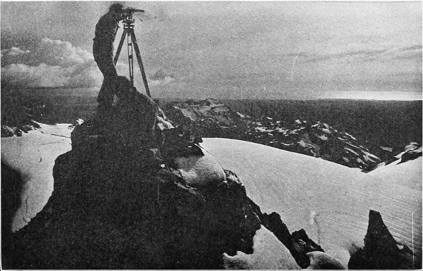
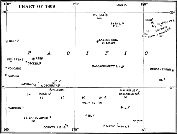
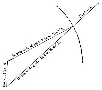
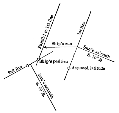
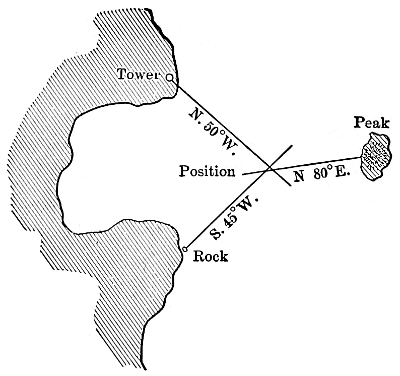
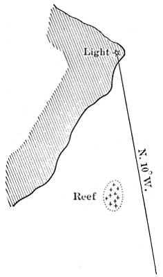
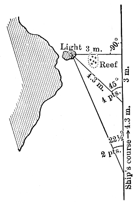
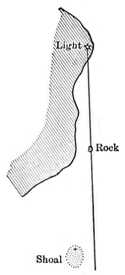
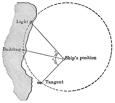
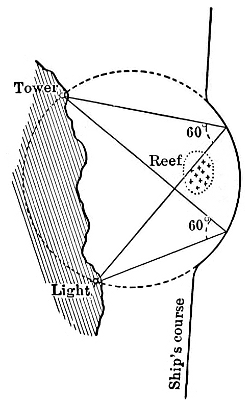
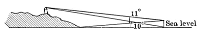
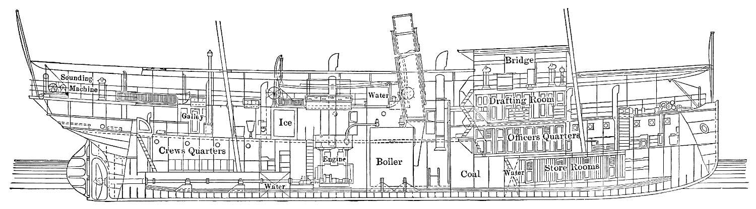