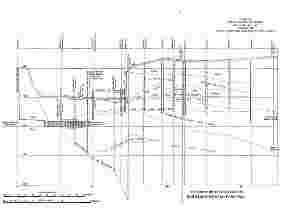
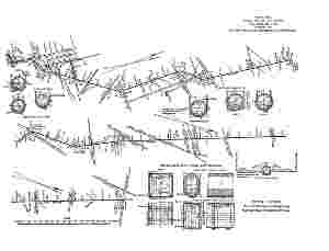
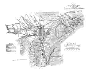
 Plate II.—General Plan Of The Water Supply And Drainage Works For
Monterrey, N. L., Mexico.
Plate II.—General Plan Of The Water Supply And Drainage Works For
Monterrey, N. L., Mexico.Larger.
The Project Gutenberg EBook of ASCE 1193: The Water-Works and Sewerage of
Monterrey, N. L., Mexico, by George Robert Graham Conway

This eBook is for the use of anyone anywhere at no cost and with
almost no restrictions whatsoever.  You may copy it, give it away or
re-use it under the terms of the Project Gutenberg License included
with this eBook or online at www.gutenberg.org


Title: ASCE 1193: The Water-Works and Sewerage of Monterrey, N. L., Mexico
       The 4th article from the June, 1911, Volume LXXII,
              Transactions of the American Society of Civil Engineers.
              Paper No. 1193, Feb. 1, 1911.

Author: George Robert Graham Conway

Release Date: December 31, 2011 [EBook #38455]

Language: English

Character set encoding: ISO-8859-1

*** START OF THIS PROJECT GUTENBERG EBOOK ASCE 1193: THE WATER-WORKS ***


Produced by Juliet Sutherland, Henry Gardiner and the
Online Distributed Proofreading Team at http://www.pgdp.net
Monterrey, the Capital of the State of Nuevo León, Mexico, is built on the site of the old village of Santa Lucía de León, which was established in 1583 by the Governor of the Kingdom of León, Don Luis Carabajal. Four years later Carabajal was imprisoned by the Inquisition, and the village of Santa Lucía was abandoned by its few inhabitants.
In 1596, Captain Diego Montemayor, a resident of Saltillo, in the adjoining State, wishing to render a service to his king, Philip II of Spain, assembled his friends, and on September 20th of that year, proceeded to establish a town on the site of the old village on the northern side of the principal spring at the place. The town was named "Nuestra Señora de Monterrey" (Our Lady of Monterrey), after the Count of Monterrey (Ojos de Santa Lucía y Valle de Extremadura), the ruling Governor of New Spain, as Mexico was then called.
Monterrey is approximately in the center of the State of Nuevo León, 1° 12´ west of Mexico City, and in latitude 26° 40´ N. It is a distributing railway center on the main line of the National Railroad, 270 km. from the Rio Grande at Laredo, 1,022 km. from Mexico, and 520 km. from Tampico by the Mexican Central Railway. It is the center of many large industries, and is the second largest manufacturing city in the Republic.
The works described in this paper were carried out under a guaranteed concession granted by His Excellency, General Bernardo Reyes, Governor of the State of Nuevo León, to Messrs. James D. Stocker and William Walker, of Scranton, Pa. The concession is dated October 19th, 1904, and is for 99 years from that date; the works for a complete water and drainage system were to be finished in 3 years from the time of their commencement. Before the works were designed and begun, the concession was acquired by Mr. William Mackenzie, of the firm of Mackenzie, Mann and Company, Limited, of Toronto, Ont., Canada, who, on May 4th, 1906, organized the Monterrey Water-Works and Sewerage Company, Limited (Compañía de Servicio de Agua y Drenaje de Monterrey, S. A.), under the laws of the Dominion of Canada, of which company he is President. Mr. Mackenzie is also President of the Monterrey Railway, Light, and Power Company, Limited, which was constructing the street railways of Monterrey concurrently with the water-works. Under the provisions of the concession, the Government appointed a Financial Interventor, who had authority to examine and check the company's expenditures, and also a Technical Inspector to examine and report on the construction. The duties of these officials also apply to the operation of the system when the construction is finished. The Government has the right, after the system has been operated 40 years, to purchase the entire property, subject to 6 months' notice, for a sum equal to 162⁄3 times the average annual net proceeds during the 3 preceding years. This right may be exercised at the end of 40 years, or at the end of any 10-year period thereafter, up to 99 years from the commencement of operations.
Monterrey lies in a plain at the foot of the Eastern Sierra Madre Mountains which constitute the eastern margin of the Mexican Cordilleran 477Plateau, and is surrounded by the magnificent mountains of that group, among the most notable of which are the beautiful Mitra and Silla Mountains. In the neighborhood of Monterrey these mountains attain heights of from 2,000 to 2,400 m., and are noted for their broken and jagged sky-lines. The leading geological characteristics of the district are the uplifted limestones of the older cretaceous age which form the main mass of the mountains.
Primarily, the mountains are compressional folds which, in the Sierra Madre, near Monterrey, are close and vertically compressed.[2] The drainage areas of the Santa Catarina River, which flows through Monterrey, and of the Estanzuela and Silla Rivers, its tributaries, are of limestone and shale; originally the shales were above the limestone, but the convulsion which formed the Sierra Madre as an anticlinal fold, left the originally horizontal strata standing nearly upright, and subsequent erosion in the upper part of the anticline has exposed nearly vertical strata in many places. The limestone being hard and resisting erosion, there is generally, along the line of contact, an abrupt drop vertically on the face of the limestone to the shale below. In many places this abrupt drop is broken by a limestone talus, but the line of contact can generally be traced. Mining operations in these mountains have revealed the presence of large caves at a considerable elevation, many of which contain large reservoirs of water, delivered to them through numerous faults. The river valleys are formed of masses of limestone conglomerate and coarse gravels, re-cemented in many cases by the lime deposits of the flowing waters. One of the chief characteristics of the subsoil of Monterrey itself is a local rock called "sillar," which is a superficial deposit of carbonate of lime from the evaporated waters. In some places the "sillar" is largely mixed with a conglomerate called "tepetate," or "impure sillar."
Topographically, the region around Monterrey is distinguished by the drainage area of the River Santa Catarina, which rises in the Sierra Madre near the Laguna de Sanchez, at an elevation of 1,850 m., as shown on Plate II. From this Laguna it follows a tortuous course between precipitous mountains through the Boca of Santa Catarina to Monterrey, for a distance of 90 km., eventually finding 478its way to the San Juan River, a tributary of the Rio Grande. Throughout its course it disappears, flows underground, and again appears; and, except in flood time, it has a subsurface flow for a distance of 16 km. above the city. In the Cañon of Santa Catarina it appears at the surface, having a normal flow of about 1,415 liters (50 cu. ft.) per sec., and its waters at that point are divided into two parts and carried into irrigation canals. The drainage area of the river above Monterrey is 1,410 sq. km., and its bed at Monterrey is between 518 and 545 m. above sea level.
Southward from Monterrey the country rises along the valley of the Silla for a distance of 19 km., where the Silla is separated from the San Juan by a low divide, the former flowing northward to Monterrey and the latter southeastward toward Allende. The Silla Valley is bounded on the east and west by the steep ranges of the Silla and Sierra Madre Mountains. The floor of this valley is gently rolling, but is cut by many arroyos which carry little or no water during the greater part of the year. The chief feeder of the Silla River is the Estanzuela, a stream which derives its waters from several springs coming to the surface near the line of contact between the limestone and the shale, at elevations of about 800 and 900 m.[3] above datum. The water-shed of this stream is rich with abundant vegetation due to the precipitation being greater than on the Santa Catarina water-shed. To the south of the divide the country is well wooded, and El Porvenir, 35 km. from Monterrey, is the garden spot of the State of Nuevo León. Here the rainfall is much greater than at any other point near Monterrey, and there are many streams which are used for irrigation purposes. Monterrey is built on a plain, chiefly on the north side of the Santa Catarina River. This plain has a general fall toward the northeast, and beyond the city it slopes gently northward for several miles toward the Topo Grande River, and then southeastward to join the great coastal plain of the Gulf of Mexico. The general elevation of the city lies between the 519- and 550-m. contours. The Plaza Zaragoza, in the center of the city, is 533.90 m. above sea level; the elevation of the highest part of the city, at the western boundary, is 550.05 m., and of the lowest part, at the northeastern boundary, 518.0 m. above sea level.
 Plate III, Fig. 1.—General View of Line, Estanzuela
Aqueduct.
Plate III, Fig. 1.—General View of Line, Estanzuela
Aqueduct.
The population of Monterrey has increased as follows:
| Census | of | 1851 | 14,621 | |
| " | " | 1861 | 26,000 | |
| " | " | 1871 | 33,811 | |
| " | " | 1881 | 39,456 | |
| " | " | 1891 | 41,154 | |
| " | " | 1901 | 73,508 | |
| (Estimated) | 1909 | 86,000 to 90,000 |
The greatest progress, it will be noted, was between 1891-1901, with an increase of more than 22,000 in 10 years. In designing the new works, provision has been made for the future requirements of a city of 200,000 persons.
The actual area within the city limits proper is 960.5 hectares (2,374 acres), forming the area to be provided with water and drainage, but the municipal district extends to many surrounding suburbs, and covers an area of 33,758 hectares (83,426 acres).
| Year. | Population. (Census Est.) | Deaths from all causes. | Rate per 1,000. | Deaths From Typhoid Fever. | Deaths from Typhoid fever per year per 100,000 population. | ||||||||||||
| Jan. | Feb. | Mar. | Apr. | May. | Jne. | Jly. | Aug. | Sep. | Oct. | Nov. | Dec. | Total for year. | |||||
| 1901 | 73,508 | 2,965 | 40.3 | 0 | 2 | 1 | 3 | 4 | 3 | 6 | 6 | 3 | 6 | 4 | 2 | 40 | 54 |
| 1902 | 74,500 | 3,338 | 44.8 | 1 | 4 | 2 | 3 | 6 | 5 | 3 | 1 | 1 | 2 | 3 | 5 | 36 | 48 |
| 1903 | 76,000 | 3,825 | 50.3 | 3 | 2 | 4 | 1 | 0 | 5 | 3 | 5 | 6 | 16 | 3 | 1 | 49 | 64 |
| 1904 | 77,500 | 2,905 | 37.4 | 0 | 1 | 1 | 5 | 3 | 3 | 3 | 4 | 1 | 5 | 1 | 0 | 27 | 35 |
| 1905 | 79,000 | 2,951 | 37.4 | 2 | 0 | 0 | 3 | 3 | 7 | 6 | 3 | 2 | 7 | 2 | 2 | 37 | 47 |
| 1906 | 80,000 | 2,935 | 36.7 | 1 | 2 | 1 | 3 | 3 | 6 | 5 | 3 | 2 | 1 | 2 | 3 | 32 | 40 |
| 1907 | 82,500 | 3,269 | 39.6 | 4 | 6 | 3 | 3 | 5 | 6 | 4 | 4 | 9 | 3 | 0 | 3 | 50 | 61 |
| 1908 | 84,000 | 3,188 | 37.9 | 5 | 2 | 5 | 3 | 8 | 5 | 9 | 7 | 2 | 7 | 4 | 0 | 57 | 68 |
| 1909 | 86,000 | [4]3,477 | 40.4 | 5 | 1 | 4 | 5 | 13 | 11 | 15 | 12 | 6 | 8 | 3 | 4 | 87 | 101 |
Table 1 gives particulars of the death rate for 1901 to 1909, inclusive, and data relative to the mortality due to typhoid fever. The high death rate is caused by the excessive infantile mortality, which is so prevalent throughout the whole of Mexico. The climatic condition of Monterrey, with its exceptionally healthy subsoil, ought to make it one of the healthiest of cities, if proper care were taken to enforce sanitary laws. The data regarding typhoid mortality are probably 480 understated, as they were compiled by the writer, in the absence of any official publications, from the actual death certificates, but no special care is taken by the authorities to insure accuracy in such certificates. Attention is called to the typhoid rate in May, June, July, and August, 1909; this high rate coincides with a scarcity of rainfall and the greatest period of drought experienced in 30 years, and immediately precedes the great flood of August 27th. It was probably due to the lowering of the ground-water throughout the city and the consequent contamination of the private wells, which were largely in use during that time. Throughout the city the wells are sunk to a depth of about 12 or 15 m., in order to reach the subterranean waters, and the cesspools are often in dangerous proximity to them and at a much higher level. The nature of the subsoil, which is often much fissured and open in the conglomerate and sillar strata, would make the passage of contamination an easy matter, and this alone would account for a high mortality due to water-borne diseases.
The precipitation records of Monterrey and its neighborhood are very meager, and cannot be relied on for a longer period than from 1894 to 1909, inclusive. The records are available from 1886, but in the early years there are many apparent discrepancies, and they are probably inaccurate. The average rainfall for the 15 years (1894-1908) is 21.94 in.; the driest years for this period are as follows: 1894, 14.14 in.; 1902, 15.29 in.; 1907, 15.23 in.; 1908, 15.11 in. Assuming the early records to be correct, the average rainfall for the period, 1886-1908, would be 19.86 in.
At Saltillo, which is 50 miles due southwest, at an elevation of about 1,520 m. above sea level, the average rainfall for the 23 years, 1884-1908, inclusive, is given as 21 in. The maximum year was 1889, with 331⁄2 in., and the minimum 1903, with 71⁄2 in.
At Carmen, in the State of Tamaulipas, 144 km. southwest of Monterrey, at an elevation of about 310 m. above sea level, the average fall for 12 years is 24.70 in., the maximum year being 1897, with a fall of 34.09 in., and the minimum year, 1905, with 13.41 in.
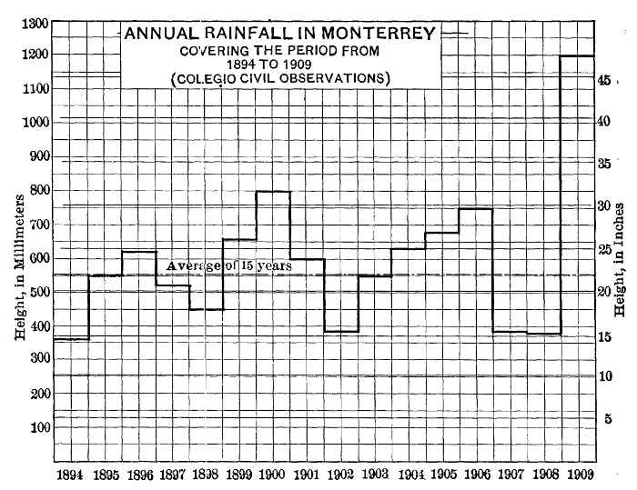 Fig. 1.—Annual Rainfall In Monterrey
Fig. 1 shows the annual variation of rainfall at Monterrey for 1894-1909. Fig. 2 shows the monthly variation during the same period, and gives the minimum, average, and maximum for each month. 481 From these diagrams it will be seen that the months of least rainfall are December, January, February, and March, with averages of 0.66, 0.59, 0.79, and 0.93 in., respectively. The months of greatest rainfall are August, with an average of 4.39 in., and September with 4.87 in. The maximum in any month prior to 1909 was 16.75 in., during September, 1904.
Rainfall in 1909.—The rainfall in 1909 was unprecedented, causing the disastrous flood in the Santa Catarina River, which will be referred to when describing the works. Fig. 3 shows the monthly rainfall for 1906 to 1909, inclusive, and has been plotted to show the variation of rainfall prior to the great precipitation of August, 1909. In that month there were two heavy falls, one beginning at midnight on August 9th, and during the following 42 hours a fall of 13.28 in. was recorded by the gauge at the Water-Works Company's general offices, 10.20 in. of which fell, during the first 24 hours. From 6 P. M. to 11 P. M., on August 10th, 5.019 in. were recorded, or an average of 1 in. per hour.
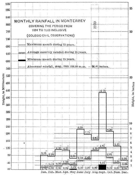 Fig. 2.—Monthly Rainfall in Monterrey Covering
The Period From 1894 To 1909 Inclusive.
Fig. 2.—Monthly Rainfall in Monterrey Covering
The Period From 1894 To 1909 Inclusive.
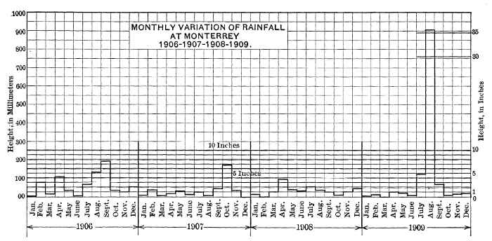 Fig. 3.—Monthly Variation Of Rainfall At Monterrey 1906-1907-1908-1909.
After 13 dry days, another rainstorm began, at 4 P. M., on August 48225th, and continued more or less intermittently until August 29th. During this 98-hour period there was an additional fall of 21.61 in., 11.27 in. falling in 24 hours.
The total precipitation during the month amounted to 36.00 in. The highest previous record for the month of August was in 1895, with a fall of 6.61 in. Fig. 4 gives the details of the two heavy precipitations in August. As no automatic recording gauge was available, 484 the maximum intensity could only be computed approximately, owing to the intermittent character of the readings taken from the ordinary rain gauge on the roof of the Water-Works Company's office in the city. From the readings thus obtained, it was shown that the maximum intensity occurred early on the morning of the 28th, and was nearly 2 in. per hour. Above Monterrey, in the Santa Catarina water-shed, it is believed that the precipitation was considerably greater, but no gauges were accessible during the month.
 Fig. 4.—Curve Of Rainfall At Monterrey During
August 10th & 11th And From August 25th To 29th - 1909.
Fig. 4.—Curve Of Rainfall At Monterrey During
August 10th & 11th And From August 25th To 29th - 1909.The total rainfall for 1909 amounted to 47.46 in., of which 75% fell in August. This is 50% greater than the previous highest annual record (31.65 in. in 1900) for Monterrey.
Temperature.—Fig. 6 gives a record of the temperature at Monterrey from 1901 to 1909, inclusive. These records were taken at an altitude of 520 m. It will be noted that the lowest recorded temperatures are in January and February. The lowest during these years was 24° Fahr., in January, 1905. The monthly maxima vary between 80 and 110° Fahr. The mean annual temperature is 72.65° Fahr. (The mean annual barometer is 28.2 in.)
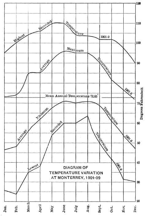 Fig. 6.—Diagram Of Temperature Variation At Monterrey,
1901-09.
Fig. 6.—Diagram Of Temperature Variation At Monterrey,
1901-09.
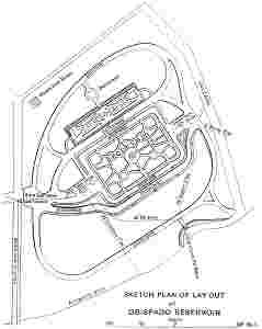
The question of the best sources from which Monterrey should be supplied with potable water was one that had been long under discussion, and was the subject of many investigations prior to the granting of the present concession. Several of the original schemes called for an impounding reservoir in the Cañon of Santa Catarina and it was on the assumption that a dam would be built that a clause was inserted in the concession for the purpose of making its construction obligatory. The general character of the physical and geological conditions surrounding Monterrey has already been referred to. A thorough study of these conditions proved that no suitable site for impounding the Santa Catarina River could be found, apart from the fact that periodically this river is subject to enormous floods which tear through the steep cañon with tremendous velocity.
At the site originally proposed for the dam, a considerable underflow was found, and later investigations, carried out under the present concession, proved that, although borings were carried to a depth of 54 m., bed-rock could not be found, the strata being composed of gravels, conglomerate and sand. Assuming that such a dam could 486 have been built, the quality of the water draining from a comparatively barren water-shed, on which many thousands of goats are pastured, would have made its filtration an absolute necessity before it could be delivered to the consumers.
The various available sources from which water could be delivered to the city by gravity were investigated by Mr. F. S. Hyde, in the autumn of 1905, and also by J. D. Schuyler, M. Am. Soc. C. E., who was afterward retained as Consulting Engineer for the Company. The various investigations made from time to time showed that the question of a satisfactory supply was one of extreme difficulty, requiring prolonged observation and study, more particularly into the character of the underground sources of supply.
One of the chief characteristics of many of the streams in the State of Nuevo León, is their disappearance and reappearance at different points along their routes, and the Santa Catarina River, under normal conditions, as already remarked, is a very notable example of a river which is very dry at the surface for many kilometers of its length. In the writer's opinion, the waters of this and similar rivers in the State pass through many open caverns underground, so that experience gained in the investigation of underflow waters in other places would be insufficient to determine the quantity passing at any point along the river if ascertained by merely computing it from the velocity of the underflow and the area of the water-bearing gravels. The rainfall on the water-shed of the Santa Catarina River is probably 25% greater than at Monterrey, and all ordinary rains sink rapidly into the limestone soils and quickly disappear. In another water-shed of a very similar character, namely, that of the Rio Blanco, in the southern part of the State, the underflow waters appear at the surface at a place called Mezquital, where a metamorphosed sandstone barrier prevents them from disappearing underground. At this point the normal quantity of water is about 5,660 liters (200 cu. ft.) per sec., but it gradually disappears, and a few kilometers below it has sunk to an insignificant stream, finally disappearing altogether for about 20 km. In the neighborhood of Monterrey similar conditions exist with regard to the surface-water supplies, and investigations, therefore, were directed toward obtaining unpolluted supplies from springs and underground sources.
Santa Catarina Sources.—The chief points from which it was 488 thought desirable to obtain underflow supplies were (1) at the barrier of San Geronimo, and (2) at the Cañon of Santa Catarina, both shown on Plate II.
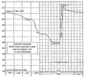
Conditions at San Geronimo, which is only 61⁄2 km. west of Monterrey, were investigated by the State Government in 1892, to determine the depth of bed-rock, the rock on either side of the valley being shale, with its original bedding planes standing almost vertical. To determine this depth, borings were made by driving 2-in. tubes until it was assumed that bed-rock had been reached, a method which, in strata containing so many boulders, was obviously unreliable. These borings indicated that bed-rock was from 12 to 15 m. below the surface. If these had proved to be correct, there is no doubt that a development of the underground water at this point, by constructing a submerged dam combined with an infiltration gallery, would have yielded a large supply.
In March, 1906, the Company commenced operations at San Geronimo by sinking a well a few meters north of the then dry bed of the river. Water was found in considerable quantities a few meters below the surface, practically at the level of the river, that is, 570 m. above datum. This supply was used for provisional purposes, and will be referred to later in describing the San Geronimo gravity supply works.
Between August, 1906, and January, 1907, 4-in. bore-holes were sunk in the river bed and on the high ground to the north with a "Keystone" driller outfit. These borings showed bed-rock immediately under the river bed, at a depth of from 15 to 45 m., but dipping gradually as the borings were carried northward.
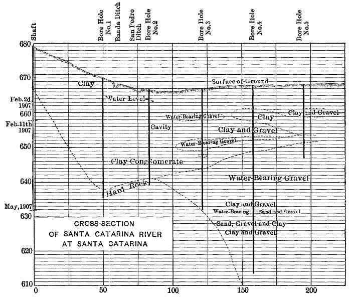
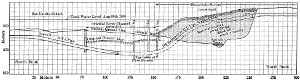
Boring operations were also carried on at Santa Catarina, during November and December, 1906, and in January, 1907, to determine the geological conditions, and the results are shown on Fig. 7. From the area of water-bearing gravels found, it was proposed to tap the underflow water at the 630-m. level by an infiltration gallery. This would have necessitated a gravitation tunnel 3,000 m. long, and an aqueduct of 14 km., which it was proposed to carry to one of two distributing reservoirs at Guadalupe, on the south side of the river, opposite Monterrey. In May, 1907, the writer, after making a study of all the available data which had been accumulated, had additional borings sunk farther across the valley to the north, and these revealed a considerable area of water-bearing gravels, and proved that, in former 489 geological times, the Santa Catarina flowed about 500 m. north of its present position, and to the back of Obispado Mountain, instead of through the city. This aspect of the subject was discussed with Mr. Schuyler, who agreed with the writer that, in the interest of economy, it was better to tap this supply by an infiltration gallery at the 560-m. level, and bring the water thus obtained to a reservoir to be placed at the western limits of the city, dividing the city, for distribution purposes, into two interchangeable systems, a high- and a low-pressure, the high-pressure system being supplied from Estanzuela, 18 km. south of the city. One advantage to be gained from this change was that the scheme was capable of considerable extension, and any future developments at Santa Catarina Cañon would form part of the works to be constructed for both high- and low-pressure districts.
The future extension of the Santa Catarina sources, the writer believes, can be developed best by driving an infiltration gallery 10 m. below the surface of the Santa Catarina River, a little west of the village of the same name, and then conveying the water through a comparatively 490short gravitation tunnel and pressure conduit to a main reservoir near San Geronimo having a top water level at an elevation of about 590 m. above datum.
Southern Sources of Supply.—The available sources of supply southward from Monterrey include a number of springs at various points in a distance of 40 km. Many of these springs are of uncertain quantity, and some are quite dry during periods of drought. The chief perennial springs near Monterrey are those which contribute to form the Estanzuela and Diente Rivers, both tributaries of the Silla, while farther south, at the Potrero Cerna, near El Porvenir, there are excellent springs, at a considerable elevation, with a minimum flow of from 170 to 200 liters (from 6 to 7 cu. ft.) per sec. The total quantity of water available from all these springs during the driest season would probably not be less than about 560 or 700 liters (from 20 to 25 cu. ft.) per sec.
The Estanzuela springs issue at the foot of the Sierra Madre Mountains, and have a normal flow of from 56 to 85 liters (2 to 3 cu. ft.) per sec. in an ordinary dry year; they probably derive their water, through the limestone formation, from the neighboring water-shed of Santa Catarina, as the catchment area of the stream is only 910 hectares, and the stream has never been known to fail, even in the driest periods of prolonged drought. The rainfall on the area is about 30 in. per annum, and the catchment area is well wooded and covered with abundant vegetation. The El Diente springs have an ordinary dry-weather flow of about 281⁄2 liters (1 cu. ft.) per sec.; but part of the water is carried underground, and the real quantity is much greater and could be developed by a small submerged dam carried down to bed-rock.
The elevation and the extreme purity of the water of the Estanzuela River made its acquisition very desirable, and the Company, therefore, purchased the Federal water rights owned by various members of the Estanzuela community, amounting to 91 liters per sec., and has since acquired a Federal concession to all the flood-waters of that river. It was decided, therefore, to adopt the Estanzuela River as the first step toward developing the water to the south of Monterrey for a high-pressure supply, the advantage of the scheme being that from time to time extensions could be made to tap other sources by gravity, as the demands of the city required. The Estanzuela scheme, therefore, 491 is a preliminary step toward future extensions which will be necessary in this direction as the city grows. The springs near El Porvenir, and others which contribute to the San Juan River, can be tapped at a sufficiently high level to convey them by a gravity pressure line to the Estanzuela Aqueduct near Mederos.
The two sources definitely decided on in July, 1907, were those from Estanzuela and San Geronimo. The works were designed to supply 40,000,000 liters daily, which it was assumed would be sufficient for all future developments for a population of 200,000 at a per capita consumption of 200 liters per day. The present requirements of the city's population, assuming that all the water was supplied by the Company, would be, at that rate, which is a very liberal one, only 18,000,000 liters daily. This, it was thought, would be easily met by the San Geronimo source alone, as it was estimated that it would provide not less than 20,000,000 liters, if the infiltration gallery was driven far enough into the water-bearing gravels.
The question of a high-pressure water supply for domestic use in a city like Monterrey is not a serious one, as practically nine-tenths of the houses are of one story. The increase in the number of large commercial buildings, however, will make the demand greater in the future, and this point has been kept in mind in arranging the division of the distribution systems.
Cement.—In the early stages of construction the cement for the work was obtained from the Associated Portland Cement Manufacturers, Limited, of London, which supplied the "Pyramid" brand, from the Knight, Bevan, and Sturges Works, but later the supply was obtained from a new factory at Hidalgo, near Monterrey. The total quantity of Portland cement used was 42,500 bbl. of "Pyramid" and 32,500 bbl. of "Hidalgo." The English cement was tested for the Water-Works Company in London before shipment and again at Monterrey, to conform to the British Standard Specifications; the "Hidalgo" cement was required to pass the Standard Specifications advocated by the Special Committee of the American Society of Civil Engineers. The quality in each case was of the very highest, no difficulties being experienced at any time.
492
Sand and Rock.—One of the chief difficulties in connection with the construction work in its initial stages was in procuring satisfactory sand for the concrete. An investigation of the quality of all the available sands in the neighborhood of Monterrey resulted in the decision to use a manufactured sand obtained from the calcareous shales in the foot-hills opposite the city, on the south side, and near the site of one of the proposed reservoirs. A quarry was opened, and the raw material was delivered by a gravity plane to a crushing plant, 230 m. from the quarry and at a level about 50 m. lower.
The plant consisted of a No. 5 Austin gyratory rock-crusher, fitted with elevators and revolving screens of various dimensions, driven by a 150-h.p. Erie steam engine; two sets of Traylor's heavy-duty crushing rolls, one having 30 by 16-in. and the other 18 by 12-in. rolls; and a Niagara sand disintegrator. This plant, except during a short period when the requirements were beyond its capacity, was able to produce all the sand and rock required for construction purposes. More than 40,000 tons of rock were quarried, the greater part of which was converted into crushed stone and sand.
Table 2 gives the chemical analysis of the chief constituents of the various sands examined.
| No. | Location. | Percentage of silica (absolute), SiO2 | Percentage of alumina, Al2O3 | Percentage of sesquioxide, Fe2O3 | Percentage of lime carbonate, CaCO3 |
| 1. | Arroyo Seco, near brickyard at Monterrey |
60.10 | 17.95 | 2.89 | 8.01 |
| 2. | Arroyo Seco, near brickyard at Monterrey, No. 2 |
42.92 | 14.26 | 4.66 | 34.58 |
| 3. | Near Garcia Station, Mexican National R. R., Chiquito River, No. 1 | 50.22 | 9.72 | 1.44 | 34.62 |
| 4. | Near Garcia Station. Mexican National R. R., Chiquito River, No. 2 | 48.7 | 4.92 | 8.28 | 35.43 |
| 5. | San Luis Potosí | 85.02 | 5.00 | 7.38 | 2.21 |
| 6. | Topo Grande, Pesquería River |
40.20 | 5.15 | 4.25 | 46.50 |
| 7. | Hornos, near Torreón | 77.9 | 13.1 | 2.4 | 4.9 |
| 8. | Salinas River, at Salinas | 41.5 | 5.7 | 1.4 | 48.2 |
| 9. | Pits near Caballeros, on Tampico Branch of Mexican Central R. R. |
73.4 | 5.6 | 4.4 | 10.1 |
| 10. | Santa Catarina River,
near San Geronimo (washed sand) |
12.40 | 2.06 | 1.14 | 81.70 |
| 11. | Santa Catarina River, at Monterrey | 17.4 | 2.50 | 2.00 | 77.00 |
| 12. | Composition of rock, quarry in foot-hills opposite Monterrey, Monterrey Water-Works and Sewer Company's property |
40.44 | 15.70 | 2.20 | 34.30 |
| 13. | Manufactured sand from above quarry (run of crusher) |
51.80 | 12.14 | 8.7 | 32.6 |
493
The chief sands used for ordinary building purposes in Monterrey are Nos. 10 and 11, which are procured from the bed of the Santa Catarina River. As these sands contain large proportions of lime carbonates, which make them very undesirable for important structures, their use was limited to relatively unimportant work. The best sands procurable were Nos. 5 and 9, but the long distance of the pits from Monterrey, and consequently the heavy freight rate, made their use prohibitive on economical grounds. The best of the available sands, although it was very fine, was No. 7, from Hornos, near Torreon, as it could be depended on for uniformity and could be obtained f. o. b. cars at Monterrey for 3.18[5] pesos per ton.
The bulk of the sand and crushed rock used was similar to Nos. 12 and 13, and reference to the cement sand tests in Table 3, will show that the manufactured sands gave very satisfactory results.
Table 3 gives the average tests made with the "Hidalgo" cement and various sands, alone and in combination, for the purpose of obtaining comparative results; the mixtures tested were composed of 3 parts of sand to 1 of cement.
| Sand. | At 7 days. | At 28 days. | ||
| Ottawa (Standard) | 305 | lb. | 414 | lb. |
| Monterrey, 11⁄2 parts, Hornos, 11⁄2 parts | 188 | " | 313 | " |
| Monterrey | 253 | " | 365 | " |
| Hornos | 202 | " | 301 | " |
| Manufactured sand, Company's crusher | 372 | " | 566 | " |
| Hornos, 2 parts, Crusher sand, 1 part | 231 | " | 352 | " |
| Hornos, 11⁄2 parts, Crusher sand, 11⁄2 parts | 265 | " | 346 | " |
| Hornos, 1 part, Crusher sand, 2 parts | 248 | " | 328 | " |
The Hornos sand was used during a few weeks in the latter part of 1908, when the crusher was unable to produce all that was required. Its use was restricted to thick walls which were required to be water-tight, and it was always used in equal proportions with the crusher dust.
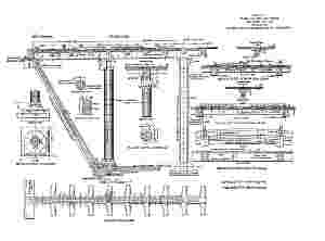
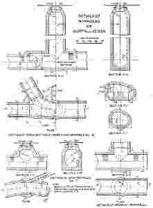
Intake Works.—The intake (Fig. 8) is about 1 km. below the lowest spring and at a point where the maximum flow of the stream was observed. The works consist of a small monolithic concrete dam, placed obliquely across the stream at an angle selected for the purpose of obtaining a foundation running parallel to the direction of the strata, which at this point were lying almost vertically across the bed of the stream. Above these strata the stream bed was formed chiefly of large cemented limestone blocks and smaller conglomerate. No storage being possible in this valley, which has a very precipitous fall, the height of the dam was fixed merely to obtain a small settling basin for sand and débris brought down in time of flood. The dam foundation was excavated to bed-rock, from which the upper disintegrated portions were carefully removed; the rock was then stepped, and dovetailed recesses were left for properly bonding the concrete.
The dam is carried well into the banks. Its extreme length is 52 m., its maximum height 4.50 m., and its greatest thickness 2 m. The up-stream face has a batter of 1 in 12, and the down-stream face, 1 in 8. The top of the wall is 1 m. thick. For the discharge of flood-water there is a weir 10 m. long, and it was calculated that with a depth of 1 m. it would discharge about 400 times the ordinary flow, or about 23,000 liters per sec., but, in addition, the whole length of the dam (excluding that occupied by the gate-house) was arranged for the discharge of abnormal floods, one of which, on August 27th, reached the enormous quantity of 82,070 liters (2,900 cu. ft.) per sec., or 825 cu. ft. per sec. per sq. mile of drainage area, a remarkable run-off from so small an area as 910 hectares. The concrete forming the dam is a 1:3:5 mixture. The overflow sill is 692 m. above sea level. When the dam was completed it was filled to the overflow level, in order to test the water-tightness of the basin, which, when cleared, was found to be slightly fissured on the north side. The leakage was sufficient to cause a serious loss during periods of drought, and it was then decided to line the basin with concrete, so that the stream would enter it without being under a head greater than its own depth. The length of the basin, measured along the center line of the original stream surface, is 85 m., and its area is 1,100 sq. m. At its upper end it is merely a lined channel, 5 m. wide at the entrance. The floor of the basin has a fall of 4 m. The lining was formed in 496two thicknesses totaling 30.5 cm. (12 in.) of 1:21⁄2:31⁄2 concrete, laid in panels approximately 3 m. square, the upper panels breaking joint with those immediately below; in this way a very satisfactory and water-tight lining was obtained. A parapet wall, 45.7 cm. high, surrounds the basin. For scouring out the basin a 30.5-cm. (12-in.) cast-iron pipe was taken through the dam at the lowest point, this pipe being provided with a gate-valve encased in concrete on the down-stream face.
The gate-house was built in connection with the dam at the north end of the overflow weir, its inner dimensions being 4.34 by 2.80 m. The substructure, to the level of the dam, is of concrete founded on the solid rock, and the superstructure is of brick rendered with cement plaster. The roof is of framed timber with red French tiles.
The intake pipe is of cast iron. 40.6 cm. (16 in.) in internal diameter, fitted outside with a movable copper screen which is further protected by a wrought-iron hinged screen to prevent damage from stones, floating timber, etc., during times of flood. Inside the gate-house the outlet pipe is provided with a 40.6-cm. (16-in.) sluice-valve, operated from the floor level by a vertical head-stock with worm-gearing. The gate-house has a scour-out pipe (also operated by a head-stock) and duplicate copper screens fitted to iron frames. From this house the water is conveyed to the upper portion of the conduit, which is a 45.7-cm. (18-in.) cast-iron pipe.
Of the total area of land, 885 hectares (2,187 acres), owned by the company, 392 hectares (970 acres) have been fenced in, to prevent any contamination of the springs. This fence is formed of five lines of barbed wire protected with stout hog netting at the bottom, in order to prevent more particularly the entrance of goats, many thousands of which pasture in the adjoining mountains.
On the high ground immediately below the intake, a 3-roomed stone house has been constructed for the inspector in charge of the intake works, who also keeps in daily touch with the general office and records the condition of the stream, particulars of rainfall, etc.
Aqueduct.—The total length of the aqueduct, from the intake dam to the South Reservoir, is 18,700 m., made up as shown in Table 4.
| Description. | Length, in meters | ||
| Cast-iron pipes, 45.7 cm. (18 in.) in diameter, along the stream bed of the Estanzuela River | 110 | ||
| Concrete tubes, 55.9 cm. (22 in.) in diameter, to Mederos (including 281 m. of tunnel) | 4,473.81 | ||
| Cast-iron siphons, 45.7 cm. (18 in.) in diameter: | Calabozos | 239 m | |
| South Virgen | 124 " | ||
| North Virgen | 177 " | ||
| Mederos | 426 " | ||
| —— | 966 | ||
| Concrete tubes, 63.5 cm. (25 in.) in diameter, Mederos to South Reservoir. | 12,039.19 | ||
| Cast-iron siphons, 50.8 cm. (20 in.) in diameter: | |||
| Necaxa | 315 m. | ||
| San Augustin | 796 " | ||
| —— | 1,111 | ||
| ——— | |||
| Total | 18,700 | ||
The gradient of the concrete pipes is 0.43% from Estanzuela to Mederos, and 0.53% from Mederos to the South Reservoir. The calculated discharging capacity of the conduit when running full is 364 497liters (13 cu. ft.) per sec. for the upper, and 465 liters (16.4 cu. ft.) per sec. for the lower section. For these pipes, the coefficient, n, in Kutter's formula, was taken at 0.013. At present the line has been limited by overflows to discharge three-quarters full.
The increase in the size of the pipes from Mederos is for the purpose of receiving the waters of the Mederos River and other springs in the San Pablo and Aqua Verde catchment areas, as shown on Plate II.
The invert of the concrete conduit where it leaves the Estanzuela River is 684.25 m. above datum, and at the valve-house of the South Reservoir it is 589.00 m.
The concrete pipes were manufactured and laid under contract with Mr. Arthur S. Bent, of Los Angeles, Cal., the Company providing all materials, labor, etc. The contractor was paid 10 cents per lin. ft. of pipe manufactured and 10 cents per lin. ft. laid. He was also responsible for the satisfactory completion of the work.
Fig. 9 shows the details of the joint recommended by Mr. Schuyler and adopted for these pipes. The 63.5-cm. (25-in.) pipes were 61 cm. long and 76 mm. (3 in.) thick. The 55.9-cm. (22-in.) pipes were of the same length, but 70 mm. (23⁄4 in.) thick. For the purpose of strengthening these pipes while hauling them over very rough roads they were reinforced with four rings of No. 6 galvanized-iron wire.
Manufacture of Pipes.—The pipes were manufactured under the Supervision of Mr. H. Stanley Bent, at a pipe yard established below 498the crushing plant, from which the crushed rock and sand were delivered by gravity in bogies run on narrow-gauge rails. The area of the pipe yard was approximately 11⁄4 hectares, and it was laid out with parallel lines of 76-mm. (3-in.) galvanized-iron piping with hose couplings for sprinkling purposes. After trials with aggregates of various sizes, the concrete for the pipes was proportioned by volume as follows:
| Crushed rock broken to pass through a 19-mm. screen | 0.136 | cu. | m. |
| Manufactured sand (run of rolls) | 0.119 | " | " |
| Portland cement | 0.090 | " | " |
| ————— | |||
| Total | 0.345 cu. m. | ||
| = (12.2 cu. ft.) |
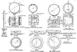
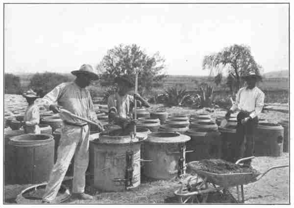 Plate III, Fig. 2.—Steel Forms for Moulding Concrete Tubes,
Estanzuela Aqueduct.
Plate III, Fig. 2.—Steel Forms for Moulding Concrete Tubes,
Estanzuela Aqueduct.
The above quantity manufactured two 63.5-cm. pipes; a 55.9-cm. pipe required 0.1415 cu. m. (5 cu. ft.) of the material, in the same proportions. Fig. 9 shows the forms for these pipes, and Fig. 2, Plate III, illustrates the process of moulding. The forms consist of cast-iron bottom rings, to the proper section of the joint, and inner and outer steel forms of 3-mm. plate, provided with inner and outer locking arrangements. The concrete was poured through a cast-iron hopper which fitted to the top of the outer form.
The concrete, which was mixed very dry, in a 1⁄2-cu. yd. batch, "Smith" mixer, was thoroughly tamped with a 22-lb. tamper, and worked until it was of a stiff jelly-like consistency, the wire rings being added as the concrete was placed. The best results were obtained with the minimum quantity of water. The upper joint was moulded with a heavy cast-iron ring. The jacket and core forms were loosened immediately, and placed over other rings, a sufficient number of bottom rings being used for a day's work. For the pipes required for curves, special forms were used to give the necessary bevel to the joint. After 24 hours the finished pipes were lifted from the bottom ring with a special lifter, and ranged in position for coating internally with a Portland cement grout to which a little freshly slaked lime was added. The pipes were all numbered, and were kept moist for 10 days by constant sprinkling. They were not hauled to the work until 28 days after they were moulded, although this rule was sometimes broken, to the detriment of the pipes. More than 32,000 pipes were 500manufactured, but some were used for purposes other than the Estanzuela Aqueduct.
Cost of Pipes.—The contractor brought with him experienced concrete pipe makers from California, and these were afterward assisted by Mexican labor. In a day two tampers could manufacture from 45 to 50 pipes of the larger (63.5-cm,), and from 55 to 60 of the smaller (55.9-cm.) size.
The cost varied from 2.75 to 3.25 pesos per pipe for the smaller, and from 3.50 to 4.00 pesos for the larger size.
The approximate cost of manufacturing is as follows: Taking, as a fair example, one week's work during March, 1908, the wages paid to the 74 men comprising the total pay-roll (though part of this labor was intermittent) amounted to 981 pesos. This includes a general foreman at 10 pesos per day, four American tampers at 7.50 pesos, and Mexican labor varying from 4 to 1 peso, and all labor necessary to handle and finish the pipes, including coating the interiors. During this week there were made 1,126 of the 63.5-cm. and 1,095 of the 55.9-cm. size. The pay-roll includes 520 pesos for the larger pipes (46 cents each) and 461 pesos for the smaller pipe (42 cents each). Table 5 shows the quantities and cost of the materials used in the manufacture of these pipes.
| For 1,126 pipes 63.5 cm. in diameter. | For 1,095 pipes 55.9 cm. in diameter. | |||||||||
| Materials. | ||||||||||
| Quantities. | Cost. | Quantities. | Cost. | |||||||
| Portland cement, at 8.00 pesos per bbl., delivered at pipe-making yard. | 401 | bbl. | 3,208.00 | pesos. | 303 | bbl. | 2,424.00 | pesos. | ||
| Sand, at 2.65 pesos per cu. m. | 85 | cu. m. | 225.25 | " | 68 | cu. m. | 180.20 | " | ||
| Crushed rock, 19-mm. (3⁄4-in.), at 2.65 pesos per cu. m. | 62 | cu. m. | 164.30 | " | 50 | cu. m. | 132.15 | " | ||
| No. 6 galvanized-wire hoops. 4 rings to each pipe. | 4,504 | 203.00 | " | 4,380 | 183.00 | " | ||||
| Totals. | ... | 3,800.55 | pesos. | ... | 2,919.45 | pesos. | ||||
| Cost per pipe. | ... | 3.37 | pesos. | ... | 2.66 | pesos. | ||||
From Table 5 it is seen that the cost of the 63.5-cm. pipes was 3.37 pesos for material plus 0.46 peso for labor = 3.83 pesos per pipe, or 6.26 pesos per lin. m. (1.91 pesos per lin. ft.).
501
The cost of the 55.9-cm. pipes amounted to 2.66 pesos for material plus 0.42 peso for labor = 3.08 pesos per pipe, or 5.05 pesos per lin. m. (1.54 pesos per lin. ft.).
The cost of cement included hauling from the bodega to the yard, a distance of about 5 km. At a later date, after the Company had commenced using the "Hidalgo" cement, some additional 55.9-cm. pipes were manufactured, so as to have them on hand as a reserve in case of emergency. In this work only Mexican labor was used, as the previous gang had been dispersed, but the tampers had previous experience. Taking the cost of 418 pipes made during one period of 9 days, the detailed cost was as given in Table 6.
| Labor For 9 Days. | ||
| Tampers, 2 at 4 pesos. | 72.00 | Pesos. |
| Cement mixers (hand-mixing) and helpers, 6 at 1 peso. | 54.00 | " |
| Water boy. | 4.50 | " |
| Proportion of time of crusher foreman, one-third of 6 pesos, 2 pesos. | 18.00 | " |
| Making 1,672 wire hoops, at 5 pesos per thousand. | 8.36 | " |
| Man coating pipe, at 1 peso per day. | 5.00 | " |
| ——— | ||
| Cost of labor making 418 pipes. | 161.86 | Pesos. |
| Cost of labor per pipe. | 0.38 | Peso. |
| Material. | ||
| Cement, 1181⁄2 bbl., at 6.40 pesos per bbl., at pipe-making yard. | 758.40 | Pesos. |
| Sand, 24.6 cu. m., at 2.50 pesos per cu. m. | 61.50 | " |
| Rock, 21.6 cu. m., at 2.00 pesos per cu. m. | 43.20 | " |
| No. 6 wire, 3,362 lin. m. | 55.56 | " |
| Lime. | 1.50 | " |
| ——— | ||
| Cost of material for 418 pipes. | 920.16 | Pesos. |
| Cost of material per pipe. | 2.20 | " |
| Add cost of labor. | 0.38 | " |
| Total cost per pipe for labor and material. | 2.58 | Pesos. |
| Equivalent to 4.23 pesos per lin. m., or 1.29 pesos per lin. ft. |
Excavation for Pipe Line and Siphons.—The excavation for the pipe line and for bridge works, etc., was let by contract to Messrs. Scott and Lee, of Monterrey, under three classifications:
(1) "All material which in the judgment of the Engineer can be economically loosened with picks and handled with shovels."
(2) "Indurated earth or gravel, shale or rock which can be loosened without blasting, and 'sillar', locally so-called, whether pure or mixed with other substances, and whether it requires blasting or not."
(3) "All rock not included in the above which requires drilling or blasting."
Locally, this classification is well understood, particularly No. 2, as it covers the sillar soils which are common in the neighborhood of 502Monterrey. The contract prices were: No. 1, 50 cents; No. 2, 1.50 pesos; and No. 3, 2.50 pesos per cu. m. These prices were over and above the clearing and grubbing of the line, which was paid for at the rate of 100 pesos per hectare.
The route of the pipe line being along broken country, at some points difficult of access, service roadways, about 3 m. wide, for hauling material were constructed, and, for about 7 km., a roadway was made along the line of the trench.
The prices for the roadway, under the above classification, were: For No. 1, 35 cents; No. 2, 1.50 pesos; and No. 3, 2.50 pesos per cu. m.
The trenches were excavated 5 cm. below the required finishing depth, to allow for grading the pipes in selected material, and were taken out to an average width of 40 cm. greater than the outside diameter of the pipe, to allow for their proper jointing, and also to give sufficient room to roll the pipes in the trenches.
The final quantities of excavation were:
| Trench: | No. 1 | 11,115 | cu. m. |
| No. 2 | 18,096 | " | |
| No. 3 | 6,650 | " | |
| ——— | |||
| Total | 35,861 | cu. m. | |
| Roadways: | No. 1 | 4,165 | cu. m. |
| No. 2 | 1,999 | " | |
| No. 3 | 30 | " | |
| ——— | |||
| Total | 6,194 | cu. m. |
The route of the pipe line was laid out so as to obtain an average fill of not more than 1 m. over the tops of the pipes, but in some cases the cuts, for short lengths, were 3 m. deep. The excavation for this work began in June, 1907.
Hauling Pipes.—The pipes were hauled to the site of the work with ox-carts and mule teams. The cost of hauling varied from 25 cents per pipe at the lower end, to 1 peso per pipe at the upper and, comparatively speaking, inaccessible portion of the line. The weight of each 55.9-cm. pipe was about 182 kg.; that of each 63.5-cm. pipe was about 216 kg.
The breakages in all the pipes cast at the pipe yard amounted to about 1%, due chiefly to unloading them carelessly near the pipe line.
503
Pipe Laying.—The pipe-laying gang was composed of 7 Mexicans under the direction of an American foreman, who was in charge of several gangs. One gang could lay daily from 60 to 73 m. (from 100 to 120 pipes). The following was the ordinary pay-roll for one gang:
| 1 Foreman at 8 pesos (proportion). | 2.00 | pesos. |
| 1 Pipe layer at 3 pesos. | 3.00 | " |
| 1 Pipe layer's assistant at 2 pesos. | 2.00 | " |
| 1 Cement mixer at 2 pesos. | 2.00 | " |
| 2 Outside plasterers at 2.50 pesos. | 5.00 | " |
| 2 Inside plasterers at 2.25 pesos. | 4.50 | " |
| 1 Water boy at 0.50 peso. | 0.50 | " |
| ——— | ||
| Total. | 20.00 | pesos. |
This brings the average cost of laying the pipes to 32.8 cents per lin. m.
The pipes were jointed with 1:2 cement mortar, the outer joint being rounded over both pipes for a width of 121⁄2 cm. (5 in.) and a height of about 19 mm. (3⁄4 in.). In making these joints the pipe layers wore rubber gloves. The joints were kept moist, and the trench was back-filled with fine, screened material to a depth of 10 cm. above the top of the pipe. Inside, the joints were carefully caulked with cement and rendered smooth, the plasterers working continuously along with the pipe layers, doing from 20 to 35 m. at a time. Water had to be conveyed to the trenches by barrels on burros, and during the dry season it was sometimes carried 5 or 6 km.
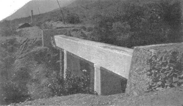 Plate IV, Fig. 1.—Typical Reinforced Concrete Girder Bridge,
Estanzuela Aqueduct.
Plate IV, Fig. 1.—Typical Reinforced Concrete Girder Bridge,
Estanzuela Aqueduct.
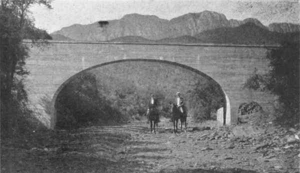 Plate IV, Fig. 2.—Elliptical Arch Bridge Carrying Estanzuela
Aqueduct.
Plate IV, Fig. 2.—Elliptical Arch Bridge Carrying Estanzuela
Aqueduct.
Bridges.—The line as laid out passed over many gulches and dry arroyos, and these were crossed with reinforced concrete bridges of varying spans and heights, two being shown on Plate IV.
These bridges were formed of continuous horizontal girders, 1.10 m. deep and 1 m. wide, with a cantilever overhang at the abutments, varying in length from 1 to 2 m., so as to avoid settlement between the pipes and the bridges. The bottom reinforcement consisted of from 2 to 6 twisted bars of mild steel, varying in different spans from 12.7 to 19 mm. (1⁄2 to 3⁄4 in.) in diameter. The turned up bars were 281⁄2 mm. (11⁄8 in.) in diameter; they were placed on either side, carried over the upper part of the beams, and continued along the end for the 504overhanging part of the girder. These bars, when not obtainable of the full length, were spliced with a lap of 1.2 m. with No. 6 galvanized-steel wire. The vertical stirrups were 4.7 by 25.4 mm. (3⁄16 by 1 in.), of mild steel; they were equally spaced 30.5 cm. (12 in.) apart, and carried all around the girders, lapping at the center about 15 cm. (6 in.), all the steel being carefully wired together before placing the concrete.
The general type of the piers and abutments is shown by Fig. 1, Plate IV, and varies in height with practically every bridge, the foundations in every case resting on hard rock. The concrete for the girders was a 1:21⁄2:31⁄2 mixture, the crushed stone used having all passed a mesh of 19 mm. (3⁄4 in.). The piers were of 1:31⁄2:51⁄2 concrete, and heavy "displacers" were embedded within them.
The concrete was placed after the pipes had been laid through the form by the pipe contractor, the joints being kept clear of the bottom to the required distance by small moulded concrete blocks. The tops of the girders were moulded to a slightly segmental form. The bridges were all kept watered for about 15 days, and the forms were not struck for 28 days after placing. At Station 13.4 the pipes were carried over a picturesque arroyo on an elliptical arched bridge (Fig. 2, Plate IV) of 11 m. clear span.
The abutments of all bridges were protected by rubble walls in cement mortar carried up 60 cm. above the tops of the girders.
The contract price for the concrete work of these bridges, the Company furnishing the steel and cement, was 14 pesos per cu. m., and for placing reinforcing steel 35 pesos per metric ton (2,204 lb.).
There are 49 single-span bridges, the larger spans being 9.10 m.; 8 two-span, and 11 three-span bridges, their total length, including the overhang, amounting to 870.50 m., or 41⁄2% of the whole length of aqueduct.
Concrete Aprons.—At 76 points there were small depressions which did not necessitate the construction of bridges, and at these places the pipes were encased in blocks of concrete carried up the hillside in the form of an apron having small abutment walls from 1 to 2 m. apart. This also served to protect the pipes from scouring action during rainstorms. At the upper end of the line, near the intake, the pipe had to be protected by concrete continuously for a distance of about 300 m., in order to prevent damage from falling rocks.
505
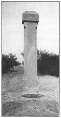
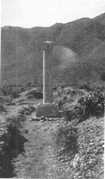 Plate V, Fig. 1.—Ventilating Column and Entrance Manhole,
Estanzuela Aqueduct.
Plate V, Fig. 1.—Ventilating Column and Entrance Manhole,
Estanzuela Aqueduct.
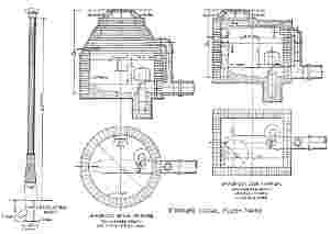
Ventilators and Manholes.—Along the route of the concrete pipe there are 27 ventilators, one of which, together with an entrance manhole, is shown by Fig. 1, Plate V. They consisted of simple concrete columns, 3.35 m. high, above the ground line, the interior of the shafts being formed of fire-clay pipes, 15 cm. (6 in.) in diameter. At each ventilator the pipe was cut and a block of concrete, the width of the trench, filled in as a foundation. Entrance manholes were also placed at 49 points, at 27 of which they immediately adjoined the ventilating columns.
Estanzuela Tunnel.—At 1,560 m. from the intake at Estanzuela, the conduit is laid through a tunnel 281 m. long. The tunnel was driven through hard calcareous strata from the open cuttings at each end. The inner dimensions were trimmed to approximately 2 m. high and 11⁄2 m. wide. At the ends of the tunnel the rock was moderately easy to take out, but the inner section was very hard and difficult to blast. Ordinary hand drilling was adopted, and the actual cost of driving varied from 28 pesos per lin. m. at the ends to 50 pesos in the center.
The pipes were laid through the tunnel in the ordinary way, and back-filled from the center, so as to give a cover of about 45 cm. above to protect them from falling pieces of shale.
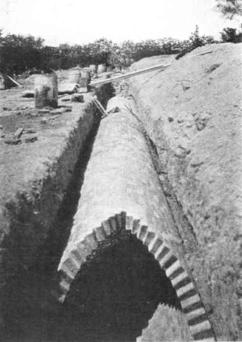
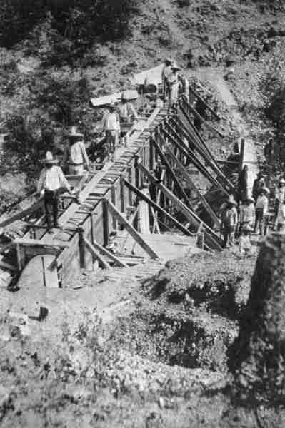 Plate V, Fig. 2.—Placing Concrete Pipes in Forms for Bridge
Crossing at North End of Tunnel, Estanzuela Aqueduct.
Plate V, Fig. 2.—Placing Concrete Pipes in Forms for Bridge
Crossing at North End of Tunnel, Estanzuela Aqueduct.
Siphons.—It has already been mentioned that there are 6 cast-iron pipe siphons. The head on these varies between 10 and 38 m. All are provided with special inlets and outlets, forming combined overflow and ventilating chambers, and have wooden hand-sluices to divert the water when necessary. The bottoms of all siphons are provided with 20-cm. cast-iron scour-out pipes, fitted with valves, and carried down to a lower point to obtain a free outlet. The valve-boxes are protected by being placed in heavy concrete chambers carried up above the level of ordinary floods.
The siphons are formed of cast-iron socket pipes, 3.65 m. (12 ft.) long, caulked in the ordinary way with lead joints. The thickness of the 45.7-cm. (18-in.) pipes is 19 mm.; that of the 50.8-cm. pipes is 21 mm. On the steep hillsides the pipes are anchored securely to the rock in concrete blocks reinforced with heavy iron chains. In some cases these siphons were difficult of access, but ox-teams hauled the pipes in a very efficient and satisfactory manner.
Overflow Chambers.—The ordinary overflows, of which there are 14, are similar in design to the siphon inlets.
Testing, etc.—When the line was completed it was tested for water-tightness, and the loss was found to be about 5%, part of which was probably due to absorption. At a later date it was found that the waters of the Estanzuela River, which contain 150 parts of calcium carbonate (CaCO3) per million, deposited a very fine film of lime on the interior of the pipes, completely filling any pores there might have been. At the present time there is no measurable leakage, thus proving that the character of the work is very satisfactory.
The water was turned into the conduit on June 11th, 1908, and delivered to the city on the following day through a by-pass, before the reservoir was completed.
The pipe line is patrolled daily by an inspector with the authority of a gendarme, so as to prevent the unlawful abstraction of water, a very necessary precaution in so dry a country.
The distributing reservoir for the Estanzuela supply is at Guadalupe, on the foot-hills to the south of the Santa Catarina River, about 2 km. from the center of the city. The reservoir is a covered one, of reinforced concrete, and its capacity is 38,000,000 liters (10,000,000 U. S. gal.).
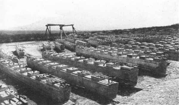
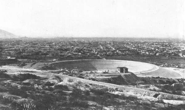 Plate VIII, Fig. 1.—General View of Excavation and Embankment for
South Reservoir Before Lining.
Plate VIII, Fig. 1.—General View of Excavation and Embankment for
South Reservoir Before Lining.
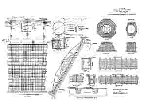
Excavation and Embankment.—The heavy slope of the ground at the selected site made the circular form the most desirable. On the low side the ground was excavated about 2 m. below the original ground line, while the excavation at the upper part of the slope was about 12 m. deep. The excavated material consisted chiefly of sillar and limestone conglomerate, which when broken up forms a calcareous clay of an excellent character for the formation of embankments, when proper care is taken. The dimensions fixed for the internal diameter of the finished concrete work of the reservoir were: 81 m. (265.68 ft.) at the top, and a depth of water of 9 m., with sides sloping 55 in 100.
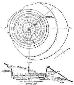
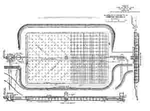
Fig. 10 is a plan of the reservoir, with a cross-section of the excavation and embankment. On the lower side the original ground line was cut down in steps, and all loose earth, roots, etc., were carefully removed. The floor of the reservoir was chiefly sillar conglomerate, a hard material that required a considerable amount of blasting for its removal. The embankments were formed in 10-cm. layers 507of sillar and conglomerate broken into small fragments and then rolled with 3-ton sectional rollers drawn by teams of 4 and 6 mules, which assisted in disintegrating the mass thoroughly, and produced by constant wetting a homogeneous and compact clay. The excavation and embankment were left so that 15 cm. of trimming could be done at a later date, immediately prior to the lining of the reservoir. The excavated material amounted to about 34,000 cu. m., and, of this quantity, 31,500 cu. m. were used to form the embankment; the 508remainder was taken to a spoil bank immediately adjoining, the black earth stripping being separated and reserved for covering the reservoir, etc. The contract prices for the excavated material placed in the embankment were:
| Pesos per cubic meter | |
| Class 1.—Material which could be removed by plows and scrapers | 0.60 |
| Class 2.—This consisted chiefly of "sillar" | 1.09 |
| Class 3.—Limestone conglomerate (requiring blasting) | 1.65 |
The prices (for the same classification) for material taken to the spoil bank, were 0.40, 0.80, and 1.40 pesos, respectively. Of the material taken out, 15% came under No. 1 classification, 80% under No. 2, and 5% under No. 3.
The excavation was begun at the end of May, 1907, and completed in January, 1908, by Scott and Lee, the contractors. The embankments were then allowed to stand until the beginning of July, 1908, to permit the whole to become thoroughly settled and consolidated prior to beginning the lining. In July the work of trimming the embankments and excavating for the foundations of the reservoir columns was commenced, under the Company's own administration, which completed the entire work.
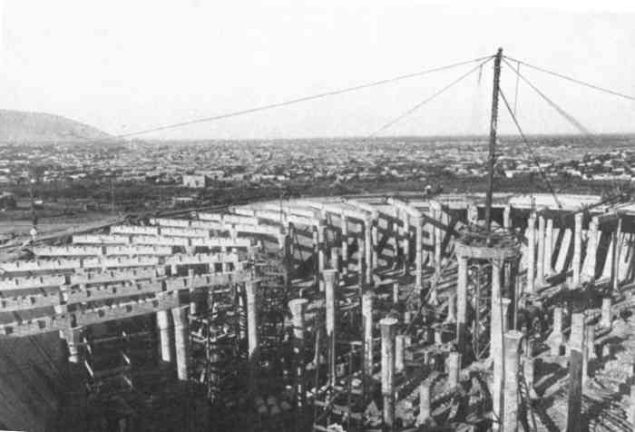 Plate VIII, Fig. 2.—View of Western Half of South Reservoir, Showing
Final Setting Up of Derrick on Central Columns.
Plate VIII, Fig. 2.—View of Western Half of South Reservoir, Showing
Final Setting Up of Derrick on Central Columns.
Concrete Lining and Roof.—The general arrangement and details of the side-walls, columns, and roof are shown on Plates VI, VII, VIII and IX. The principal feature consists in dividing the reservoir into radial sections and supporting the roof on 135 primary and 670 secondary beams, from 135 columns, spaced as follows:
| Outer | ring, | at | 34.25 | m. | from center | 40 | columns. |
| 2d | " | " | 27.88 | " | " | 40 | " |
| 3d | " | " | 21.51 | " | " | 20 | " |
| 4th | " | " | 15.41 | " | " | 20 | " |
| 5th | " | " | 8.77 | " | " | 10 | " |
| 6th | " | " | 2.40 | " | " | 5 | " |
| —— | |||||||
| Total | 135 | columns. |
The inner bottom diameter of the reservoir is 70.32 m. (230.64 ft.); the upper inside diameter is 81 m. (265.68 ft.); the water depth at the overflow level is 9 m. (291⁄2 ft).
509
The roof was designed to carry a dead load (the earth cover) of 150 lb. per sq. ft., and a live load of 100 lb. The maximum compressive fiber stress in the concrete was assumed at 550 lb. per sq. in. for the beams, and at 350 lb. for the columns, a low figure, because of their eccentric loading. The tensile strength of the steel was taken at 14,500 and 16,000 lb. per sq. in. The twisted steel used for the column reinforcement was made at the local steel plant, but for the beams, etc., a twisted lug bar, of higher quality and greater permissible tensile stress, was used. The total quantity of steel used was 178 tons. It was calculated that the load on the column foundations would not exceed 11⁄4 tons per sq. ft. With the exception of the side-wall and floor, all the concrete was reinforced with steel, of the sizes and spacing shown on Plate VI.
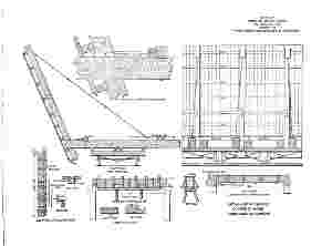
General Construction and Erection Scheme.—The question of ordinary forms, requiring very heavy timber work, was a serious one, as suitable lumber is very expensive in Mexico; and the necessity of finishing this reservoir before the end of the first term allowed under the concession, which expired on December 31st, 1908, led to the adoption of what the writer believes is an original scheme for so large a structure. This scheme was to cast the columns in short sections, mould the radial and secondary beams as separate members, and then place them in position with derricks. At the same time, in the case of the beams, it was important not to sacrifice either the benefit of that part of the slab which is ordinarily assumed to act as a part of the beam, or the additional strength due to continuity; and, in case of the columns, the strength due to the reinforcement extending from the foundation to the beams.
The T-beam section was secured by notching the tops of the moulded members, with notches 10 cm. deep, throughout the lengths of the beams, as shown on Plate VI. A computation of the maximum flange increment shows that these notches are sufficient to transfer the flange stresses to the stem, but, for additional security, flat steel bars were bent to a Z-shape and embedded in the top of the beam, about 60 cm. apart. Continuity in the beams was secured by carrying the steel to the tops of the beams over all supports, and, after erection, concreting them into the roof slab. The secondary beams, after casting, were dropped into recesses left in the radial beams for the purpose.
510
Concreting, Mixing, etc.—The radial beams and column sections were cast as nearly as possible under their ultimate positions; the secondary beams were cast outside and immediately adjoining the reservoir.
The rock and sand was brought from the Company's crushing plant, in 3-cu. yd., side-dump cars, running on a 30-in. track by gravity a distance of 1 km., the last 150 m. requiring hauling with 6 mules. The cars returned all the way to the crusher by gravity. These cars dumped the material into bins on the high ground above the reservoir; from there it was hoppered into cars which carried to the mixer all the material for one batch of concrete. Two No. 1 Smith mixers were used, and from 25 to 30 batches per hour could be handled in each machine.
The concrete was transported from the mixers to place in 1⁄2-cu. yd., 18-in. gauge, swivel, steel dump-cars pushed by two men. All the concrete used in the bottom of the reservoir, for the main beams, columns, and floor, amounting to about 2,460 cu. m., was dumped through a chute into smaller cars. The chute had so many baffle-plates and bolts that it resembled a gravity mixer, but, although it was 12 m. long, it effectively prevented the separation of the materials.
Concrete Placing and Moulding.—The square foundations for the columns were deposited in situ, a recess being left for the reception of the pedestals, which were moulded in place afterward. The capitals and pedestals were cast in one piece, and the columns in 1.21-m. (48-in.) sections, eight 5-cm. holes being left in them by using wrought-iron pipes, held in place by templates and removed when the castings were about 3 hours old. The columns were erected by threading them on the 15.8-mm. (5⁄8-in.) reinforcing rods, which extended from the pedestals up through the capitals. The rods were in two lengths, arranged to lap alternately at one-fourth, the center, and three-fourths of the height of the columns. In erection, a light timber frame was used in conjunction with the derrick, and, as the columns were placed, the reinforcing steel was grouted solid with 1:2 cement mortar.
All the erection was done with a combined stiff-leg or guy derrick, having an 80-ft. boom and a 50-ft. mast, and fitted with a 30-h.p. Lambert hoisting engine. The derrick was erected seven times at the circumference, and its final position was on top of the center columns. The moving of the derrick a distance of about 45 m. and its subsequent 511erection occupied usually about 48 hours. The erection work was carried on continuously, day and night, the placing of the whole of the radial and secondary beams and columns occupying 21⁄2 months.
Forms.—As the erection scheme was designed to reduce the cost of forms, economical construction was of considerable importance. The wall was formed in 40 panels, about 6 m. wide and 11.27 m. high. The chief object in arranging them in this manner was to permit an expansion joint, 30 cm. wide, at each panel; this joint was not filled until after the completion of the roof, when the temperature inside the reservoir was uniform and not subjected to such great fluctuations as if exposed alternately to the hot sun and comparatively cool nights. The range of temperature during the construction period sometimes amounted to 80° Fahr. in 24 hours.
The expansion joints were left to the last, when a uniform temperature of about 70° inside permitted the filling of the joints, thus avoiding all trouble from expansion cracks.
The forms are shown in detail on Plate VII. They consisted of shutters stiffened with four trapezoidal trusses. The bottom posts of the trusses were fixed in holes formed in the foundation block; they were propped back from the embankment at the top, and secured to anchorages by iron rods.
Six sets of these forms were used to construct the whole wall. The concrete was placed in position through stove-pipe chutes, 20 cm. in diameter, in continuous layers, the workmen treading and spading it well as it was deposited. The forms were allowed to remain 4 or 5 days, and were then struck and removed to another section. The pedestals and capital forms were of lumber, and five of each were used to cast the total number required. In the column sections the outer steel forms used in the manufacture of the Estanzuela pipes were adapted for this purpose. The radial beam forms, shown on Plate VII, were arranged with internal wedge-shaped blocks to mould accurately the recess for the secondary beams. The bottom forms were left attached to the beams for 28 days, but the sides and ends were removed after 24 hours. Eight forms were sufficient for the whole 135 beams.
For the secondary beams, 29 forms were used for the 670 beams, the bottom lumber also being left until they were mature for handling.
By referring to the cross-section of the secondary beam, it will 512be noticed that it is jug-shaped, shelves being left on either side for the support of the roof forms, which were placed after the secondary beams had been properly grouted to the radial ones. The lagging was laid diagonally, so that the short diameter was slightly greater than the distance between the beams. This greatly facilitated the removal of the lagging, as it was merely necessary to strike the wedge-shaped fillets beneath, and turn them clockwise, after tearing out the end lagging.
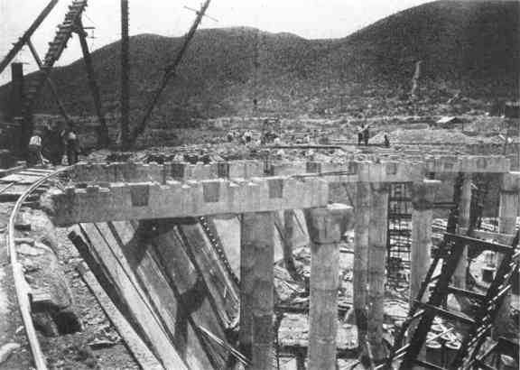 Plate IX, Fig. 2.—Setting Primary Beams, South
Reservoir.
Plate IX, Fig. 2.—Setting Primary Beams, South
Reservoir.
The writer believes that the adoption of forms of this type, rather than the ordinary kind, led to a saving of lumber of about 400,000 ft. b. m. During the erection and placing of the concrete, all the joining surfaces were carefully picked and cleaned, particular care being taken at the junction of the secondary with the radial beams, and the upper surfaces of all beams before laying the roof slab.
After the greater part of the roof was completed, the floor was laid in those sections where it was protected from the sun's rays. The concrete was placed in two 15-cm. thicknesses, and the work was carried on night and day, without any joints. The laying of the floor occupied 8 days, or an average of nearly 100 cu. m. daily.
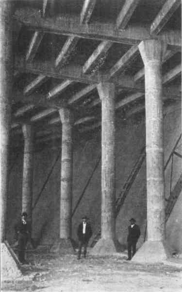 Plate X, Fig. 1.—View of Completed Section of South Reservoir.
Expansion Joints in Side-Wall Not Yet Filled.
Plate X, Fig. 1.—View of Completed Section of South Reservoir.
Expansion Joints in Side-Wall Not Yet Filled.
Proportions of Concrete.—All the concrete work was brought to a smooth face by careful spading, no plastering being used throughout the reservoir, except in the superstructures. The work was kept well watered in every case for about 15 days. The whole of the concrete work in connection with the reservoir was completed in 51⁄2 months. The concrete for the columns and foundations was a 1:3:5 mixture, the aggregate consisting of equal parts of 19-mm. (3⁄4-in.) and 38-mm. (11⁄2-in.) crushed stone. The remainder of the concrete, except that for the roof, was a 1:2:4 mixture, the aggregate also consisting of equal parts of 19-and 38-mm. stone. With the exception of a short length of the side-walls, the sand used was that manufactured by the Company. When the crushing plant was unable to produce all the sand required, the Hornos sand (see Table 3) was used in the side-walls in equal proportions with the crusher sand.
Reservoir Outlet and Entrance Tower.—The outlet, 61 cm. (24 in.) in diameter, leads from a well in the center of the reservoir and passes under the floor and embankment to an outside valve-pit, 89 m. from the center. This pipe was laid in a trench in a solid cutting before the construction of the embankment, and was encased in 1:4:8 concrete. 513Where it passes under the embankment a 1:2:4 concrete cut-off wall, 3.6 m. wide, 2.5 m. high, and 1 m. thick, was placed across it at right angles. The cast-iron pipe is curved upward in the central well, and has a bellmouth on which rests a movable circular copper screen.
Above the outlet well, and on the roof of the reservoir, there is a central tower, giving access to the interior by a steel stairway. This tower also serves as a main ventilating shaft, and in it are arranged the guide-screens and gearing for raising them for cleaning purposes. In addition to the ventilation provided in the tower, 20 circular openings, 30 cm. in diameter, are carried through the roof of the reservoir at the circumference and into the parapet walls.
Inlet Gate-House, etc.—The inlet gate-house is above the reservoir and about 541⁄2 m. from its center. The conduit enters at 589.00 m. above datum, and the gate-house contains the valves for controlling the inlet pipe to the reservoir, the by-pass, overflow, scour-out pipe, and the copper screens. The inlet, which is 45.7 cm. (18 in.) in diameter, is of cast-iron flanged pipes, carried on iron hangers on the side-wall of the reservoir, and, at a point 90 cm. above the floor level, it is turned at right angles to the side-wall and carried on concrete piers to the center of the first row of columns. The end of the pipe is closed by a blank flange, and the water is deflected at right angles through two 30-cm. (12-in.) branches, for the purpose of setting up a slight circular motion as it enters the reservoir.
The valve-pit is clear of the embankment, and in it are brought together the main supply and by-pass pipes on which are placed two 61-cm. (24-in.) sluice-valves; and between them there is a 20-cm. (8-in.) scour-out pipe, for emptying the reservoir into an adjoining arroyo. The arrangement of the valves gives complete control over the contents of the reservoir.
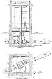
Venturi Meter-House.—Fig. 11 shows the arrangement of the Venturi meter and its automatic register in a house over the main supply pipe. This house is designed to form a feature of the entrance gateway of the reservoir grounds, which cover an area of 12 hectares.
General.—The roof of the reservoir has been laid out as a garden, and the embankments are turfed. The intention is to develop the Company's land as a public park, as it commands fine views of the city and the surrounding mountains. An inspector's house has been built, and a private telephone line provides for communication with the Estanzuela intake and also with the general offices in the city.
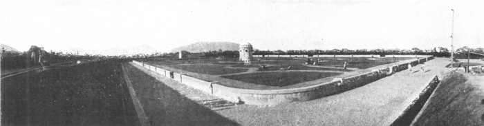
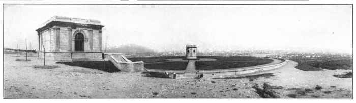 Plate XVIII, Fig. 1.—View of South Reservoir, Looking Toward the
City.
Plate XVIII, Fig. 1.—View of South Reservoir, Looking Toward the
City.
Provisional Supply.—It has already been stated that the Company began operations at San Geronimo in March, 1906, by sinking a well on the north bank of the Santa Catarina River at San Geronimo. At this point, a little later, a small steam pumping plant, sufficient to handle about 8,000 liters per min., was installed. The lowest depth to which this well was ultimately sunk in water-bearing strata, was 7 m., the normal level of the water during 1906 and 1907 never falling lower than 569 m. above datum. Tests made from time to time during 1907-08, showed that this well was capable of supplying nearly 10,000,000 liters (264,000 gal.) of water daily.
The excellent supply yielded by this well made it desirable to adopt it immediately as a provisional measure, pending the completion of the larger works forming the western source of supply. To utilize the well to its fullest extent, a reinforced concrete reservoir, of 3,000,000 liters capacity, was constructed on the south bank of the river, the top water level being 585 m. above datum, that is, at the same elevation as the proposed reservoir for the Estanzuela supply. The reservoir is 53.80 m. long, 21 m. wide, and has a water depth of 3.25 m. at the overflow level. It is excavated on a steep hill slope, and has an earth embankment on the lower side. The lining is of concrete, 20 cm. thick, and the roof is of reinforced concrete composed of flat arches springing from beams carried on 46 by 35-cm. reinforced columns. There are 68 of these columns, and they are 3 m. apart longitudinally and 5 m. apart transversely. The roof was not constructed until October and November, 1907, and prior to that time the necessity of covering the reservoir was amply demonstrated by the growth, during hot weather, of considerable quantities of green algæ, which had to be skimmed from the surface of the reservoir every few days.
The delivery pipe from the pumping plant was originally of riveted steel and was asphalted. It was 30 cm. in diameter, 2 mm. in thickness, with slip joints, and where it crossed the river it was encased in concrete. This pipe was afterward replaced by a cast-iron pipe of the same diameter. The supply pipe to the city was also of sheet steel, 30 cm. in diameter. For a part of its length it was laid in the high ground of the south bank of the river, which it crossed near the western limits of the city, and was then connected to a 30-cm, cast-iron pipe in the 516distribution system. The total length of the pipe from the reservoir to the city distribution system was 2,850 m.
This provisional pipe continued in service from October, 1906, until August 27th, 1909, when the river portion was completely swept away, together with the provisional pump-house at San Geronimo, during the great flood in the Santa Catarina River. Fortunately, the permanent supply works were completed at the time, so that the destruction of this pipe line, which had already served its original purpose, had no effect on the supply of water to the city.
Infiltration Gallery.—The chief feature of the San Geronimo gravity supply is the infiltration gallery. By referring to the profile on Plate XI it will be seen that at this place there is a considerable area of what is undoubtedly water-bearing gravel. The main conditions were revealed by the borings previously carried across the valley, but the profile has been corrected to show the actual conditions as established at a subsequent date by shafts. Practically, the water-bearing strata are not limited merely to the sand and coarse gravels, as the clay formation lying above and below them is full of small gravel deposits containing considerable volumes of water. The main direction of the underflow is toward the east, and the hydraulic gradient, which was established from wells sunk farther west, was found to be approximately 1%, or practically the same as the average surface of the bed of the river above the line of the infiltration gallery.
The general scheme for tapping this underflow was to drive a main gallery at the 560-m. level on a grade of 0.05%, which was sufficiently high to take the supply by gravity to the western reservoir, having a top water level at 558.75 m. above datum. This elevation is sufficient to give an excellent pressure over about 60% of the city, and a fair pressure to reach the upper stories of the highest houses, if required, over the whole supply district. From this gallery it was proposed to sink shafts at frequent intervals, for a total distance of 300 m., carrying them below the gallery level, to tap any water-bearing gravels there might be in the clay formation underlying the gravels and sands. From the main gallery it was proposed to construct branch galleries up stream on a flat gradient, so as to obtain the advantage of an increased head due to the steep hydraulic gradient of the underflow water.
In investigations of this kind, it is of first importance to have a continuous record of the level of the water plane, and Fig. 12 has been 517plotted to show its variation at San Geronimo from the beginning of 1905 to March, 1910. From January, 1909, to March 31st, 1910, these levels are averages of daily readings taken in 9 shafts sunk along the proposed line of the infiltration gallery. In 1902 the water plane was standing at 570.18 m. above datum, but from that date until 1905 the writer has been unable to find any records. This diagram should be examined together with the rainfall diagram, Fig. 3, and it will be noticed that the fall in the water plane drops with the general scarcity of the rainfall during 1907-08, and until July, 1909. The year previous to July, 1909, is regarded, by many competent local observers to have been the longest period of extreme drought in 30 years in Nuevo León, and the evidence which the writer has been able to gather regarding stream flow in the neighborhood of Monterrey supports this view. The total rainfall at Monterrey for the year prior to July 1st, 1909, amounted to 9.98 in., or 4.16 in. less than the lowest record for any 518calender year since 1894, or, in other words, about 45% of the average annual rainfall.
The lowest point to which the water plane dropped was during June and July, 1909, when the levels stood slightly above 565.00 m., or 5 m. above the level of the floor of the infiltration gallery. During this period pumping tests were made in the various wells, and from these it was quite clear that the infiltration gallery, if carried far enough to meet them all, would yield a supply of from 25,000,000 to 40,000,000 liters daily. During the great rainfall of August, 1909, the water levels rose very rapidly; the heavy precipitation between August 9th and 10th caused the level to rise to 568.00 m. in about 4 days, and 6 days after the great flood of August 27th, the water level, which had continued rising gradually, reached 571.40 m., and then fell gradually until at the end of March, 1910, it was practically the same as it had been from 1902 to 1905.
It should be noticed that the readings were taken in the shafts on the high ground to the west of the present river bed, and were independent of any flow there might be in the river. During times of ordinary floods in the river, it was very noticeable that, notwithstanding the fact that the river water might be turbid to an extreme degree, the well even in immediate proximity to the river bed did not show the least sign of discoloration.
Design of Works.—Plate XII shows the general design of the gravity scheme, which consists of a main tunnel 550 m. long and a concrete aqueduct, 1.06 m. (42 in.) in internal diameter and 2,311 m. in length, discharging into a low-service distributing reservoir at the extreme western limits of the city. The tunnel and aqueduct were laid on a gradient of 0.05%, and the latter was designed to discharge 55,000,000 liters per day (22.8 cu. ft. per sec.) if flowing to its full capacity.
Gravitation Tunnel.—This tunnel, shown on Plate XII and Fig. 13, was completed prior to driving the infiltration gallery into the water-bearing gravel, so that the water encountered in the gallery could be easily drained off by gravity, thus avoiding a heavy outlay for pumping. The tunnel passes through various strata, the principal ones being calcareous shale, conglomerate, and gravels. The tunneling operations were carried on from 5 shafts, No. 1 being 23 m. deep, and the others varying from 20 to 10 m. The shafts in loose ground were 520timbered in the usual way, having clear inside dimensions of 2 m. Shaft No. 1, which was entirely in shale, was taken out approximately to 3.35 m. in diameter, so as to permit it to be lined with concrete having a finished internal diameter of 2.43 m.
Fig. 13 shows the details of the tunnel, which was lined with concrete, the bottom and sides being approximately 23 cm. (9 in.) thick. The interior dimension is 0.91 m. at the invert level and 1.016 m. at a height of 1.22 m., the corners between the side-walls and the floor being slightly curved. The arch is formed of two rings of brickwork in cement mortar, this thickness being increased in some lengths to three rings. Where the rock was in good condition, and not likely to disintegrate easily, the arch, for a distance of 90 m., was left unlined. Of the total distance of 550 m., careful timbering was required for 300 m. In lining the timbered portion of the tunnel with concrete, all the timber was removed, except in loose ground, where the laggings were left in position.
While the tunnel was being driven, a start was made to drive the north end of the infiltration gallery, which was in rock for a distance of 44 m. Water appeared at about 35 m., and then the work was temporarily suspended until the gravitation tunnel was completed and a length of the aqueduct had been constructed far enough down stream on the north bank of the river to permit of draining direct to the river. This point was reached at 1,170 m. from Shaft No. 1, and there a temporary overflow chamber was constructed.
When the tunnel was completed, the two intermediate shafts were filled up, the remaining three being retained permanently. Shafts Nos. 2 and 3 were lined with concrete, 76 cm. (30 in.) in internal diameter, and 23 cm. thick. They were domed at the top to form circular openings to receive cast-iron covers. Progress on this tunnel was slow, taking from December, 1907, to November, 1908, to complete, owing chiefly to difficulties with an incompetent contractor. The contract was subsequently transferred to Mr. John Phillips, of Mexico City (who was also the contractor for the aqueduct), who completed it satisfactorily.
Continuation of the Infiltration Gallery.—When the aqueduct (to be referred to again) was completed as far as 1,170 m. from Shaft No. 1, the driving of the infiltration gallery, which was 2 m. high and 11⁄2 m. wide, was continued until gravel was encountered in the roof, at 44 m. 521from the shaft. At this point the rock dipped at an angle of 45°, and the gravels contained quantities of large boulders mixed with fine sand; immediately after encountering the gravel, a flow of about 90 liters per sec. was met, evidently coming through from a pot-hole in the shale. This quantity diminished in about 10 days to about one-fourth, but gradually increased again as the driving proceeded. The operations of driving the tunnel from 44 m. forward were begun in the dry season, in February, 1909, and the gravel was encountered for a distance of 24 m., or up to 68 m. from the shaft. The center of this gravel bed was about 30 m. south of the old river channel, which had been continuously dry at the surface for several years. Up to 68 m. the work was very difficult, owing to the upper part being of loose gravel and the lower in very contorted shale. The timbering of the tunnel in the full gravel section consisted of heavy square settings, 1 m. apart. At 68 m. the clay and gravel formation was met, and the rate of progress then was about 4 or 5 m. a week. A short branch gallery was also driven about 7 m. up stream near Shaft No. 2. The total distance the infiltration gallery was carried from Shaft No. 1, was 100 m., when the floods of August, 1909, caused its suspension.
During the progress of the gallery, attempts were made to sink a 31⁄2 by 2-m. shaft at a point along the line of the infiltration gallery, about 130 m. from Shaft No. 1, but water in such abundance was encountered that it was practically impossible to sink it in the ordinary way more than about 6 m. deep, the quantity of water to be dealt with amounting to about 20,000,000 liters daily. Seven shafts were then sunk in the high ground to the north of the river, five of these being on the line of the gallery and two 30 m. westward. They were sunk during the dry season prior to July, 1909. These were ordinary timbered shafts, 2 m. square between the walings, and were carried to the depths shown on Plate XI. In Shafts Nos. 5, 6, and 7 the water was flowing with considerable velocity, while Shaft No. 9 seemed to have penetrated a different water plane and one which was probably independent of that showing in any of the other shafts, in which the water was practically at a uniform level. The evidence obtained showed that if the gallery could be carried to Shafts Nos. 6 or 7 a great abundance of water would be intercepted. Owing to the difficulties of sinking ordinary shafts in the wide river channel, circular shafts were put down. These were 1.37 m. in internal diameter and 23 cm. 522thick, and were of concrete reinforced with No. 10 vertical rods, 19 mm. in diameter, tied together with No. 6 wire. These shafts were provided with steel cutting edges.
Shaft No. 2 was sunk to a depth of 1 m. below the infiltration gallery level, No. 3 within 2 m., and No. 4 within 4 m., before August, 1909. The shafts were sunk by digging them out and loading them at the top, the top of the shafts being kept generally 3 m. out of the ground. Shaft No. 3 encountered great volumes of water, and, in order to enable sinking operations to proceed, a pumping shaft, 21⁄4 m. square, was sunk a little west of it to draw off the water. Notwithstanding the fact that the prolonged period of drought had lowered the general water plane in all the shafts to 565.00 m. above datum, the difficulties of handling the water even at that level were considerable. At the beginning of August the work was progressing very satisfactorily, but the extraordinary rainfall of that month caused the work to be shut down temporarily.
Effect of the Floods in the Santa Catarina River.—The area of the water-shed of the Santa Catarina River above Monterrey is about 1,410 sq. km. (544 sq. miles), and its area at San Geronimo, owing to its configuration, is practically the same. Its general character has already been referred to. On the night of August 10th and early on the morning of August 11th, a big flood came down the river, flowing at its maximum about 1,130 cu. m. (40,000 cu. ft.) per sec., due to the heavy rainfall (Fig. 4). This flood carried away all the temporary staging around the shafts, seriously wrecking the temporary pumping station, as well as destroying the 30-cm. cast-iron pipe, notwithstanding the fact that it had been encased in a block of concrete 3 m. wide and 11⁄2 m. thick right across the river; but no damage was done to the infiltration gallery or to the shafts in the river channel. The effect of the flood on this pipe is shown by Fig. 2, Plate XXXI.
Following this flood, which had caused the loss of 14 lives in the city, 3 miles below San Geronimo, there was practically no rain for 13 days. Then, on August 25th the second heavy precipitation began and continued until August 29th, the details being shown on Fig. 4.
This precipitation, therefore, fell on a water-shed which was completely saturated, as it had already absorbed a large proportion of the 13.38 in. of rain which fell during August 10th and 11th; and at every point along the river, prior to August 25th, springs were issuing forth, 523and there had been very little evaporation during the intervening dry spell.
The writer has calculated that at Monterrey this flood reached the enormous quantity of 6,650 cu. m. (235,000 cu. ft.) per sec., a rate equal to 432 cu. ft. per sec. per sq. mile of water-shed.[6] The effect of this flood was to demolish completely about 1,200 "sillar" houses (without taking into consideration the numerous wooden houses) at Monterrey, and to cause a fearful loss of life, variously estimated between 3,000 and 5,000 persons; the lower figure the writer believes is approximately correct. At San Geronimo the original pumping station was carried away entirely, leaving practically no trace whatever.
Shaft No. 2 was apparently destroyed, while No. 3 was turned at an angle of about 50° down stream and filled up completely with sand. The infiltration gallery, near Shaft No. 2, was completely blocked with fine sand and gravel, and access could only be obtained as far as 54 m. The profile, Plate XI, shows the change which had taken place in the river bed. The original course of the stream was changed to the north bank, 50 m. distant, the effect of the scouring action of the flood being to lower the general level at this point about 3.65 m., while the southern portion of the channel was slightly raised. At present (April, 1910), the end of the driven portion of the infiltration gallery is about 35 m. from the center of the stream, which is still carrying about 2,270 liters (80 cu. ft.) per sec.
Immediately after the flood the flow in the gallery was 450 liters (16 cu. ft.) per sec., and this quantity has remained constant since that time. The probable effect of the flood was to disturb the whole subsurface above the infiltration gallery and put it in motion, completely cleaning the gravels of their surrounding clay, which would account for the large infiltration of water in so limited a distance. The water has always been limpid and pure, but its hardness remains the same as it was prior to the flood.
With the copious supply of water from this source, due of course to abnormal conditions and not likely to be permanent, the operations of tunneling have been suspended temporarily; but it is proposed to 524continue the driving of the gallery, from a new shaft west of No. 3. The water encountered will be drained off by pumping until the main water-bearing gravels, in the neighborhood of Shaft No. 5, are reached. It is also proposed to reconstruct the 30-cm. high-level pipe line, from San Geronimo along the high road on the north bank of the river, so that by pumping water can be delivered to the city system from Shafts Nos. 5, 6, and 7, in the event of a shortness of supply from the Estanzuela River.
Shaft No. 1.—Shaft No. 1 is designed to connect the infiltration gallery with the gravitation tunnel. This shaft has an inner diameter of 2.43 m. (8 ft.) and is fitted with a special gate-valve. In the bottom of the door of this valve there is a smaller valve, 30 cm. in diameter, so that, when the infiltration gallery is closed for cleaning out the sump, the smaller door, which is operated through the same spindle by a bevel-geared head-stock at the top of the shaft, can be opened first. Space is also left for screens if these should be found necessary. Access to this shaft is gained by a reinforced concrete stairway in nine stages. The superstructure is to be supported on reinforced concrete column foundations carried to the firm rock, owing to the loose condition of the strata at the top of the shaft.
Aqueduct.—The construction of the concrete conduit was begun in April, 1908. Fig. 13 shows the general types. Type A was adopted in gravel and conglomerate formation, and Type B where the excavation was in "sillar," the soft nature of this rock permitting it to be excavated exactly to the required external diameter of the concrete lining.
The concrete which was without steel reinforcement was a 1:21⁄2:31⁄2 mixture, the sand being from the crusher and the aggregate from the river bed, screened to pass a 25-mm. mesh. Where the conduit crossed the river obliquely, immediately below the gravitation tunnel, it was strengthened with mass boulder concrete of Type C. During the great flood this heavy section withstood its effects without damage of any kind, but beyond this point, where the conduit had been laid in compact cemented gravels, the scouring action of the flood on the north bank lowered the level of the gravels from 2 to 3 m.; the only damage, however, was the scouring away of the gravels at the south side of the conduit. To prevent such an occurrence in the future, the conduit at that point was strengthened with additional concrete for a distance of 525195 m., as shown on Fig. 13. The extra concrete, amounting to 733 cu. m., was a 1:3:5 mixture, in which was embedded 20% of heavy boulders. The top of this special length now forms a weir for the present river flow. Where the conduit enters the bluff on the north side of the river, at 1,200 m., there is an overflow chamber which has a sluice-gate 76 cm. wide, arranged so that the conduit can overflow at the present time when running 76 cm. deep. To deflect the flow in the conduit, a wrought-iron plate, provided with a balance weight, is dropped into a groove on the lower side. The outlet is a 61 cm. concrete tube, having its invert above ordinary flood level, and arranged to be closed by a gate.
At 1,963 m. the conduit is carried over an arroyo on a segmental arch of 8 m. clear span, as shown on Fig. 13. There are 5 ventilating columns and 5 manholes on the aqueduct.
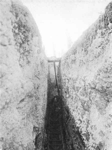 Plate X, Fig. 2.—Setting Forms for San Geronimo
Culvert.
Plate X, Fig. 2.—Setting Forms for San Geronimo
Culvert.The aqueduct terminates in the Obispado distributing reservoir valve-house, at a level of 558.50 m. The work in connection with this aqueduct was completed by December, 1908.
The main distributing reservoir for the San Geronimo gravity supply is immediately below the historic Obispado (Bishop's Palace), at the western limits of the city. The general arrangement and lay-out is shown on Plate XIII.
Valve-House.—The invert of the conduit from San Geronimo, where it enters the valve-house, is 558.50 m. above datum. The valve-house, which is built in the center of the reservoir, is shown on Fig. 2, Plate XVIII. One of its special features is the provision of the main overflow at this point instead of within the reservoir proper. The inlet, main supply tunnel, independent by-pass overflow, scour-out pipes, gate-valves, and screens, are all controlled within the valve-house.
Reservoir.—The reservoir is rectangular, 126 by 81 m. (413.28 by 265.68 ft.) at the top, and has a water depth of 4 m. (13.1 ft.). In the design it was necessary to limit it to the lowest economical depth, so as to increase the static pressure over the low-pressure district as much as possible.
Excavation and Embankment.—The excavation, except for a depth of about 1 m. which was in black soil, was chiefly in a disintegrated 526"sillar" stratum of a heavy clayey nature, the greater part of which could be handled conveniently with plows and scrapers; the actual foundation on the eastern half required blasting for the final depths.
The total excavation amounted to 56,479 cu. m., of which 7,255 cu. m. were placed in the embankment, the remainder being deposited in the immediate neighborhood of the reservoir. The final trimming of the banks, which were left 30 cm. full, was not undertaken until the lining was begun. The work was done under contract with Mr. J. S. Nickerson, of Monterrey. The excavation had only one classification, and the contract prices were 0.50 peso per cu. m. for material carried to spoil banks, and 1.00 peso for material placed in the embankment. The excavation was begun in December, 1907, and completed in April, 1908. The work was then left standing until the end of 1908 to allow the banks to consolidate thoroughly prior to lining, which was begun on January 4th, 1909.
Concrete Lining and Roof.—Plate XIII shows the general plan and sections, the main feature being the simple division of the reservoir into 24 rows of columns longitudinally and 15 rows transversely, making a total of 360 columns, less the four left out at the central tower. All the columns are 5 m. apart both ways. The roof was designed for a live load of 100 lb. and a dead load of 150 lb., the same as at the South Reservoir. With the exception of the floor, all the concrete work was reinforced with twisted steel lug bars. The foundation load on the columns for the eastern half of the reservoir is 0.9 ton per sq. ft.; that on the columns for the western half, where the foundation is of very hard sillar and conglomerate, is 1.95 tons per sq. ft.
Under-drainage of the Floor.—To provide for proper drainage in case of seepage, the floor was underdrained with rubble drains, 30 cm. wide and 23 cm. deep, filled with large round gravel carted from the bed of the Santa Catarina River. The total length of these underdrains is 1,160 m. In order to facilitate the detection of any seepage, they were conducted to a permanent inspection pit outside of the reservoir.
Main Distributing Conduit.—The main distributing conduit is laid along the inside of the reservoir, at the inlet end, and carried on elliptical arches of 2 m. span to a height of 71 cm. above the finished floor level. This conduit is 76 cm. high and 45.7 cm. wide, and it branches in two directions from the inlet tunnel to each side of the 527reservoir, its total length being 69 m. In order to prevent any stagnation and to give a continuous circulation, the water is delivered at eight points, in the length of the distributing pipe, through square openings with semicircular tops, the areas of the openings increasing toward the ends. These inlets are placed so that the current will not strike the roof columns.
Outlet Tunnel and Valve-House.—The outlet tunnel is at the north end of the reservoir, and was excavated in hard sillar rock. The tunnel is lined with concrete 30 cm. thick, the finished internal dimensions being 1.52 by 0.91 m. The length of the tunnel is 22.5 m. to the point where it enters the outlet-house. This house is divided by a wall 45 cm. thick, which supports a 76-cm. (30-in.) penstock-valve. The supply pipe to the city leaves this chamber in the west wall, and is also fitted with a 76-cm. penstock-valve. The supply pipe has a copper screen of the same design and dimensions as those in the inlet-house. A 30-cm. (12-in.) scour-out pipe in this chamber provides for draining the contents of the reservoir to a neighboring irrigation ditch, when necessary.
The superstructure of the valve-house is of concrete, and at the floor level there are bevel-geared head-stocks to raise the valves, etc.
By-Pass and Supply Pipes.—The by-pass and supply pipes are carried below the reservoir embankment to join the main 76-cm. (30-in.) cast-iron distributing pipe to the city. For this short distance they were constructed of concrete, 76 cm. in internal diameter, 10 cm. (4 in.) thick, reinforced with 61⁄2-mm. square steel longitudinal rods, 30 cm. from center to center in the circumference, and hooped with 61⁄2-mm. square steel rods spaced 30 cm. apart. The concrete forming these pipes was a 1:11⁄2:21⁄2 mixture.
Parapet Walls.—The parapet walls have 12 piers at each side and 8 at each end. In these piers there are ventilating openings branching at the top to each side of the parapet, with outlets provided with cast-iron screens. This arrangement gives 4 sq. m. of ventilating space (exclusive of that provided in the central tower), equally distributed at 40 points around the walls of the reservoir.
General Construction Scheme.—The concrete mixing plant, which consisted of two No. 1 Smith mixers, was arranged in connection with the bins and hoppers for the rock and sand on the high ground to the west, and from there the material was conveyed on a framed timber 528gangway carried right across the center of the reservoir, as shown by Fig. 1, Plate XVII. From this central platform the concrete for the columns was filled from stages placed on the top of traveling towers, 5 m. high, which were run between two rows of columns on standard-gauge rails laid on the floor of the reservoir. By this arrangement 24 columns could be filled from each length of track. A main narrow track was also laid right around the reservoir, with the necessary turn-outs.
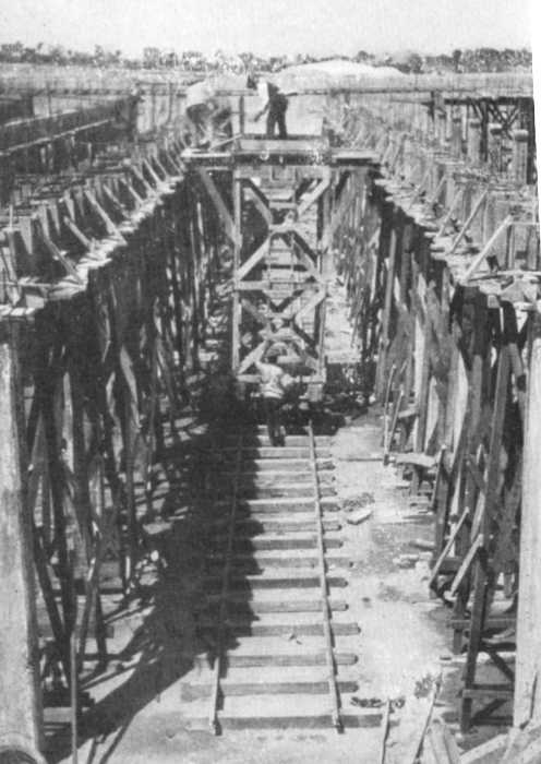 Plate XVII, Fig. 1.—Filling Primary Beams from Traveling Tower,
Obispado Reservoir.
Plate XVII, Fig. 1.—Filling Primary Beams from Traveling Tower,
Obispado Reservoir.
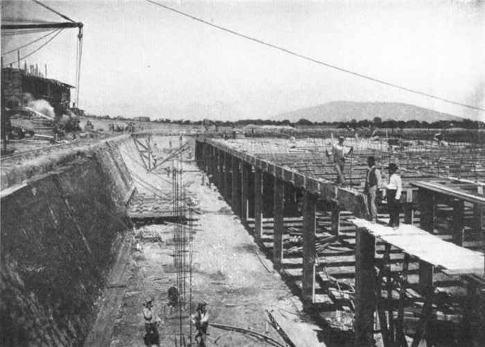 Plate XV, Fig. 1.—Construction of West Side-Wall of Obispado
Reservoir.
Plate XV, Fig. 1.—Construction of West Side-Wall of Obispado
Reservoir.
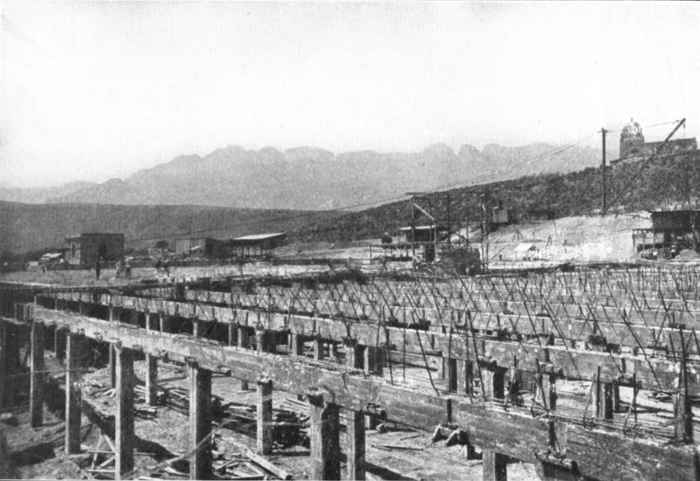 Plate XV, Fig. 2.—Primary Beams and Columns, Obispado
Reservoir.
Plate XV, Fig. 2.—Primary Beams and Columns, Obispado
Reservoir.
The forms for the columns, primary and secondary beams, are shown on Plate XIV. The side forms for the primary beams were struck in 24 hours, so as to economize lumber; but the bottom lumber was left in position for 28 days. To avoid much unnecessary timber, the secondary beam forms were supported at the ends on reinforced concrete corbels cast on the primary beams.
For placing the side-walls, a special traveling form was used, the details of which are shown clearly on Plate XIV. At the end of each form an expansion joint of 25 cm. was left to be filled after the roof was placed in position. The concrete was delivered to the wall through stove-pipe chutes, and carefully spaded by workmen in the limited space between the forms and the embankment. The wall form was removed after 36 hours, by loosening the jacks and pulling forward the hooked tie-rods. This form is also shown on Fig. 2, Plate XVI.
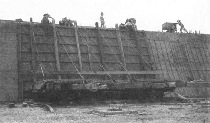 Plate XVI, Fig. 2.—Traveling Side-Wall Form, Obispado
Reservoir.
Plate XVI, Fig. 2.—Traveling Side-Wall Form, Obispado
Reservoir.
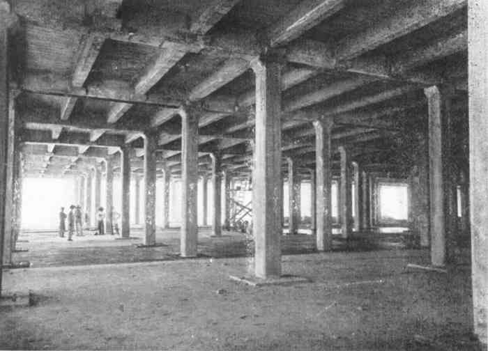 Plate XVI, Fig. 1.—Preparing Floor for Concreting, Obispado
Reservoir.
Plate XVI, Fig. 1.—Preparing Floor for Concreting, Obispado
Reservoir.
The concreting of the roof slab was carried on continuously, and, when partly completed, the floor was laid in the shade. The bottom layer of the floor, 13 cm. thick, was laid in continuous panels between the columns, and brought to a fairly smooth surface. On this surface, after keeping it wet for 10 days and then allowing it to dry thoroughly, a layer of asphaltum, supplied by the American Asphaltum and Rubber Company, of Chicago, was placed. The work was done by ordinary Mexican laborers after they had received a few days' instruction from one of the Asphaltum Company's superintendents. The surface of the lower layer was kept perfectly clean, and then received one coat of "Pioneer" paint. The asphaltum, heated in a boiler inside the reservoir to a temperature of approximately 425° Fahr., was then poured over the floor from buckets, in a layer approximately 4 mm. thick. Where the floor joined the column pedestals, and at each new panel section, a double thickness was used. The labor cost of water-proofing, including superintendence, etc., amounted to 5293.3 cents (Mexican) per sq. m. for painting with "Pioneer" paint, and 5.4 cents for the asphaltum coating, or a total labor cost of 8.7 cents per sq. m. for the complete water-proofing. This cost is based on a rate of 8.00 pesos per day for a foreman, and 1.00 peso for each laborer. It required 50 U. S. gal. of the paint to cover 265.2 sq. m., and an average of about 6 lb. of asphaltum for 1 sq. m.
The upper concrete layer of the floor, 10 cm. thick, was placed so as to break joint with the lower, and was brought to a smooth surface with wooden floats sheathed with steel and reaching across the panels. In this way a perfectly smooth surface was obtained without any plastering.
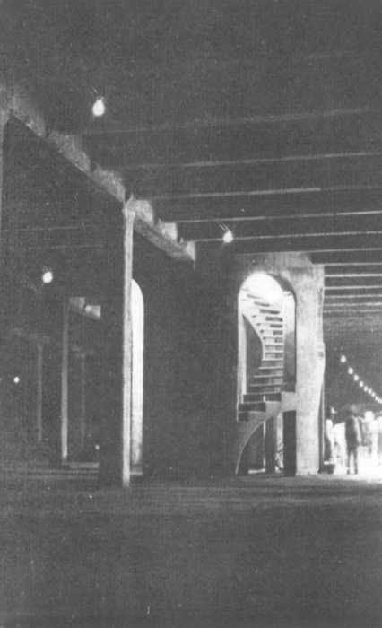 Plate XVII, Fig. 2.—Central Tower and Stairway, Obispado
Reservoir.
Plate XVII, Fig. 2.—Central Tower and Stairway, Obispado
Reservoir.
The concrete for the beams, columns, side-walls, and floor, was a 1:21⁄2:4 mixture, crushed sand and stone being used throughout. In the roof slab the mixture was 1:2:3.
The whole of the concrete work of the reservoir was completed in 6 months, by the Company's own administration, and the reservoir was first put into service a few days after the great flood of August 27th, when the Estanzuela supply main, crossing the Santa Catarina River, was partly destroyed. Since that time frequent examinations of the inspection pit, which is connected by a pipe to the rubble drains under the floor, have never revealed the slightest leakage.
Lay-Out of the Reservoir Roof and Grounds.—The Company owns about 111⁄2 hectares of land, which includes that occupied by the reservoir and its surroundings, and as this property is in an attractive situation, commanding fine views of the Sierra Madre Mountains, the whole of the works have been given a pleasing architectural character, and the grounds laid out to form a public park for the citizens of Monterrey.
The general plan of the scheme is shown by Fig. 14 and Fig. 2, Plate XVIII. The roof, which has an area of 1 hectare, has been laid out with walks and grass plots, and the surrounding embankments have been converted into driveways. Above the reservoir a small plazuela of 1⁄2 hectare has been laid out with a space above it for a band-stand. The whole of the ground has been encircled with carriage drives, on which it is the intention to plant shade trees. The lay-out of this land also embraced the scheme for protecting the reservoir by draining the surface-water away to the irrigation ditches.
The two reservoirs are practically of the same capacity, the only difference being the level of the overflows in their relationship to the roof, which gives the Obispado Reservoir a slightly greater capacity. Some comparative figures may be of interest, owing to the differences in type and construction. Table 7 gives the comparative quantities of material in each reservoir proper, that is to say, exclusive of the valve-houses, lay-out of grounds, etc.
531
| South Reservoir. | Obispado Reservoir. | ||||
| No. | Quantities, in cubic meters: | No. | Quantities, in cubic meters: | ||
| Earthwork: | |||||
| Total excavation | ... | 34,000 | ... | 56,479 | |
| Placed in embankment | ... | 31,500 | ... | 7,255 | |
| Placed in spoil banks | ... | 2,500 | ... | 49,224 | |
| Concrete: | |||||
| Columns (including foundations) | 135 | 1,240 | 356 | 543 | |
| Primary beams | 135 | 440 | 374 | 462 | |
| Secondary beams | 670 | 515 | 1,252 | 576 | |
| Side-walls | ... | 1,255 | ... | 710 | |
| Roof slab | Square meters: 5,140 | 520 | Square meters: 10,206 | 1,020 | |
| Floor | 4,070 | 780 | 9,200 | 2,120 | |
| Parapet walls | ... | 90 | ... | 165 | |
| Total concrete | ... | 4,840 | ... | 5,596 | |
| Reinforcing steel bars | ... | Pounds: 387,000 | ... | Pounds: 380,000 | |
| Expanded metal in roofs, slabs, etc. | ... | Square meters: 5,691 | ... | Square meters: 10,490 | |
The total cost of these reservoirs, including valve-houses, by-passes, and the length of supply pipe where the by-pass joins, and including all engineering expenses, etc., but exclusive of the cost of lands, planting, fencing, and special work in connection with the formation of parks, was as follows:
South Reservoir: 394,000 pesos, or 10,368 pesos per million liters.
Obispado Reservoir: 375,000 pesos, or 9,375 pesos[7] per million liters.
These rates may be regarded as reasonable when taking into consideration the special difficulties of construction in Mexico, and the high cost of all imported material, on which heavy duties are levied.
The value of the materials alone in these reservoirs amounted to more than 70% of their total cost.
Table 8 shows analyses of the Estanzuela and San Geronimo waters, made in February, 1910, by Messrs. Ledoux, of New York City. The Estanzuela sample was taken at the valve-house of the South Reservoir, while that of San Geronimo was taken in Shaft No. 1 of the infiltration gallery when flowing at the rate of about 450 liters per sec. Both waters are absolutely free from turbidity.
| Estanzuela. | San Geronimo Infiltration Gallery. | |
| Total solid matter in solution | 209.00 | 305.00 |
| Organic and volatile matter | Not weighable. | Not weighable. |
| Analysis of Solids: | ||
| Silica | 10.5 | 12.0 |
| Iron and Alumina | Traces. | Traces. |
| Lime | 85.4 | 112.6 |
| Magnesia | 3.8 | 22.6 |
| Soda (Na2O) | 13.3 | 20.2 |
| Potash (K2O) | 2.0 | 1.9 |
| Sulphuric Acid | 24.4 | 11.5 |
| Chlorine | 2.0 | 2.8 |
| Probable Combination of Bases & Acid Radicals in the Solids: | ||
| Silica | 10.5 | 12.0 |
| Iron and Alumina | Traces. | Traces. |
| Sodium Chloride | 3.3 | 4.6 |
| Potassium Sulphate | 3.7 | 3.5 |
| Sodium Sulphate | 26.3 | 40.8 |
| Calcium Sulphate | 13.3 | 22.1 |
| Calcium Carbonate | 142.7 | 184.8 |
| Magnesium Carbonate | 8.4 | 49.8 |
| —— | —— | |
| 208.2 | 317.6 | |
| Nitrogen as Free Ammonia | 0.004 | 0.032 |
| Nitrogen as Albuminoid Ammonia | 0.006 | 0.022 |
| Nitrogen as Nitrites (N2O3) | 0.002 | 0.002 |
| Nitrogen as Nitrates (N2O3) | 0.100 | 1.85 |
| Total Hardness (as CaCO3) | 155.0 | 220.0 |
| Alkalinity (as CaCO3) | 121.0 | 180.0 |
The distribution system was begun in September, 1906, but the general lay-out of the mains was modified in July, 1907, in view of the division of the system into two services, for high and low pressure. Plate XIX shows in skeleton form the lines of the cast-iron mains. These are laid at the present time along routes containing houses 533 (excluding wooden shacks) which can be served immediately. The distribution system is arranged to serve as follows:
| Estanzuela supply | 4,150 | houses. |
| San Geronimo supply | 8,600 | " |
| ——— | ||
| Total | 12,750 | houses. |
This represents, at the present time, a division of the city of 321⁄2% for the Estanzuela, and 671⁄2% for the San Geronimo supply. Of the area of the supply district north of Santa Catarina River, 57% will be supplied from San Geronimo and 43% from Estanzuela. The real development of the city, however, is northward in the area of the low-pressure supply.
The static pressure over the city in the two sections varies as follows:
| Estanzuela supply | 85 to 50 lb. |
| San Geronimo supply | 55 to 29 lb. |
The main supply pipe from the South Reservoir is 61 cm. (24 in.) in internal diameter, and this size allows ample provision for future extensions. The supply pipe from the Obispado Reservoir is 76 cm. (30 in.) in internal diameter. On this main, in Calle de Cinco de Mayo, at a distance of 320 m. from the reservoir, has been placed a 76-cm. (30-in.) Venturi meter, the recording apparatus being in the house on the side of the road. Both these supply pipes are carried well into the city, and from them the distribution mains are laid; these are 45.7 and 30 cm. (18 and 12 in.) in internal diameter, with intermediate sections of 15 and 10 cm. (6 in. and 4 in.). Along Calle de Cinco de Mayo, where the division between the two services takes place, two lines are laid, a 30-cm. for high pressure and a 38-cm. (15-in.) for the low pressure. A duplicate pipe, 30 cm. (12 in.) in diameter, is also laid in Calle de Dr. Coss. On Calle de Alvarez the low-pressure pipe is 61 cm. (24 in.), and the high-pressure, 45.7 cm. (18 in.) in diameter. Provision is also made for extending the range of the two services to other districts. Practically every block is provided with gate-valves to cut off the supply in any direction. On the 76-cm. main, 61-cm. (24-in.) valves are used, and are connected by tapers to the pipe. On the 61-cm. mains, 45.7-cm. (18-in.) valves are used. The actual frictional loss by reducing the valve 534being small, this method permitted the use of valves of a more convenient size. On all the larger valves there are 15-cm. by-passes fitted with independent gate-valves.
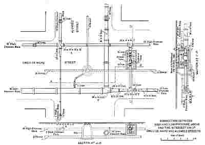 Fig. 15.—Connection Between High-and Low-pressure Areas
And The Intersection Of Cinco De Mayo And Alvarez
Streets.
Fig. 15.—Connection Between High-and Low-pressure Areas
And The Intersection Of Cinco De Mayo And Alvarez
Streets.Scour-out pipes, 10 cm. (4 in.) and 15 cm. (6 in.) in diameter, are placed in various parts of the system, draining to the sewers. Air-valves, both double and single, are also placed at high points in different parts of the system.
Reducing Valves.—At four points in the system the mains are arranged so that the supply can be interchangeable. Fig. 15 shows the arrangement of the mains at the junction of Cinco de Mayo and Alvarez Streets, and is typical of the arrangement at the other points.
Each reducing valve is placed on a 30-cm. (12-in.) branch main between the two services. These valves adjust themselves automatically to the pressure required, after they have been properly regulated to the different pressures on either side. To allow repairs to be easily made, there are ordinary gate-valves at each end enclosed in the same pit. If necessary, as in case of fire, any part of the system can be changed into high pressure temporarily by closing the valves against the San Geronimo supply.
Table 9 gives the length of the mains as laid, and the number of valves.
| Diameter: | Length, in meters. | Number of gate-valves. | |
| Centimeters. | Inches. | ||
| 10.2 | 4 | 49,831.68 | 677 |
| 15.2 | 6 | 31,918.31 | 306 |
| 30.5 | 12 | 14,461.31 | 117 |
| 38.1 | 15 | 1,661.98 | 11 |
| 45.7 | 18 | 4,522.61 | 5 |
| 61.0 | 24 | 2,826.54 | 10 |
| 76.2 | 30 | 1,454.40 | |
| ———— | ——— | ||
| Totals | 106,676.83 | 1,126 | |
The pipes were all cast according to the British Standard Specification, in 3.65-m. (12-ft.) lengths, and were supplied by Messrs. D. Y. Stewart and Company, and Messrs. Dick, Kerr and Company, of Kilmarnock and London. The valves were all of standard design, faced with gun-metal, and were supplied by Messrs. Glenfield and Kennedy, Limited, of Kilmarnock, Scotland.
536
In the distribution system it is proposed to provide 200 fire-hydrants, by arrangement with the municipality, but only a few of these have been placed. The general type is a double hydrant for two 63.5-mm. (21⁄2-in.) streams. These are to be placed at the corner of every block in the business portion of the city; single-way hydrants will be used in the residential districts.
Laying Cast-iron Pipes.—Table 10 has been prepared to show what can be accomplished with Mexican labor in laying pipes. In this kind of work the labor was particularly efficient; after the gangs were once drilled into shape, the work proceeded systematically, and at very good speed. All the pipes, after being laid, were tested to 150 lb. per sq. in. in the presence of the Technical Inspector.
Table 11 gives the details of the excavation, the material, and the average cost, of laying about 106.6 km. of pipes.
House Connections.—The ordinary house connections, which are of 19-mm. (3⁄4-in.) galvanized-steel pipe, are connected to the mains by lead goosenecks and brass corporation cocks. The Company's obligation under the concession extended to the edge of the sidewalk, and at this point curb-boxes, chiefly of the Hays pattern, were placed; but, subsequently, owing to the metering of every house service in the city, the control of the Company extended to the meter, which, as a rule, is placed immediately inside of the house. Owing to the rapid deterioration of the house service pipes in some districts of the northern part of the city, where the soil is formed of decaying organic matter, it has been decided to use lead pipe entirely from the main to the meter.
Damage Due to Floods.—During the night of August 27th, the main 61-cm. pipe, under the river bed of Santa Catarina, at the point where the main entered the city, was destroyed for a distance of 130 m., due to the scouring away of a whole block of city property. The Venturi meter register chart at the South Reservoir showed that the break occurred a few minutes before midnight. The location of this pipe is shown by Fig. 5; its broken end was in proximity to an old bridge pier. Fortunately, at the time of the flood, the Obispado Reservoir works were completed, and the whole city was supplied with water from San Geronimo within 48 hours. As only about 1,500 services had then been connected, this delay was not serious; in fact, in the lower part of the city, the water in the mains was sufficient until the San Geronimo supply could be connected. To make a temporary connection 537to conduct the high-pressure water to the city, a 15-cm. steel pipe was placed above ground, on the line of the main, for a distance of 100 m. This pipe was supported by a cable, 30 mm. in diameter, and by timber trestles. By limiting the supply district, this pipe was of sufficient capacity to serve until the large main could be safely restored.
| Employees. | Rate for 10 hour day. Pesos. | Total No. men. | Total cost of labor. Pesos. | No. of pipes laid.. | Cost per linear meter. Pesos. |
| Foreman | 4.50 | 1 | 4.50 | ... | ... |
| Caulkers | 3.00 | 4 | 12.00 | ... | ... |
| Lead pourers | 2.00 | 2 | 4.00 | ... | ... |
| Lead melter | 1.50 | 1 | 1.50 | 20 | 0.498 |
| Pipe cutter | 2.00 | 1 | 2.00 | ... | ... |
| Peons | 1.00 | 12 | 12.00 | ... | ... |
| Water boy | 0.50 | 1 | 0.50 | ... | ... |
| —— | ——— | ||||
| ... | 22 | 36.50 | ... | ... |
| Employees. | Rate for 10 hour day. Pesos. | Total No. men. | Total cost of labor. Pesos. | No. of pipes laid.. | Cost per linear meter. Pesos. |
| Foreman | 4.50 | 1 | 4.50 | ... | ... |
| Caulkers | 3.00 | 5 | 15.00 | ... | ... |
| Lead pourers | 2.00 | 2 | 4.00 | ... | ... |
| Lead melter | 1.50 | 1 | 1.50 | 25 | 0.410 |
| Pipe cutter | 2.00 | 1 | 2.00 | ... | ... |
| Peons | 1.00 | 10 | 10.00 | ... | ... |
| Water boy | 0.50 | 1 | 0.50 | ... | ... |
| —— | ——— | ||||
| ... | 21 | 37.50 | ... | ... |
| Employees. | Rate for 10 hour day. Pesos. | Total No. men. | Total cost of labor. Pesos. | No. of pipes laid.. | Cost per linear meter. Pesos. |
| Foreman | 4.50 | 1 | 4.50 | ... | ... |
| Caulkers | 3.00 | 4 | 12.00 | ... | ... |
| Lead pourers | 2.00 | 2 | 4.00 | ... | ... |
| Lead melter | 1.50 | 1 | 1.50 | 35 | 0.287 |
| Pipe cutter | 2.00 | 1 | 2.00 | ... | ... |
| Peons | 1.00 | 12 | 12.00 | ... | ... |
| Water boy | 0.50 | 1 | 0.50 | ... | ... |
| —— | ——— | ||||
| ... | 22 | 36.50 | ... | ... |
| Employees. | Rate for 10 hour day. Pesos. | Total No. men. | Total cost of labor. Pesos. | No. of pipes laid.. | Cost per linear meter. Pesos. |
| Foreman | 4.50 | 1 | 4.50 | ... | ... |
| Caulkers | 3.00 | 4 | 12.00 | ... | ... |
| Lead pourers | 2.00 | 2 | 4.00 | ... | ... |
| Lead melter | 1.50 | 1 | 1.50 | 40 | 0.221 |
| Pipe cutter | 2.00 | 1 | 2.00 | ... | ... |
| Peons | 1.00 | 8 | 8.00 | ... | ... |
| Water boy | 0.50 | 1 | 0.50 | ... | ... |
| —— | ——— | ||||
| ... | 18 | 32.50 | ... | ... |
| Employees. | Rate for 10 hour day. Pesos. | Total No. men. | Total cost of labor. Pesos. | No. of pipes laid.. | Cost per linear meter. Pesos. |
| Foreman | 4.50 | 1 | 4.50 | ... | ... |
| Caulkers | 3.00 | 4 | 12.00 | ... | ... |
| Lead pourers | 2.00 | 2 | 4.00 | ... | ... |
| Lead melter | 1.50 | 1 | 1.50 | 45 | 0.196 |
| Pipe cutter | 2.00 | 1 | 2.00 | ... | ... |
| Peons | 1.00 | 8 | 8.00 | ... | ... |
| Water boy | 0.50 | 1 | 0.50 | ... | ... |
| —— | ——— | ||||
| ... | 18 | 32.50 | ... | ... |
| Employees. | Rate for 10 hour day. Pesos. | Total No. men. | Total cost of labor. Pesos. | No. of pipes laid.. | Cost per linear meter. Pesos. |
| Foreman | 4.50 | 1 | 4.50 | ... | ... |
| Caulkers | 3.00 | 4 | 12.00 | ... | ... |
| Lead pourers | 2.00 | 2 | 4.00 | ... | ... |
| Lead melter | 1.50 | 1 | 1.50 | 60 | 0.147 |
| Pipe cutter | 2.00 | 1 | 2.00 | ... | ... |
| Peons | 1.00 | 8 | 8.00 | ... | ... |
| Water boy | 0.50 | 1 | 0.50 | ... | ... |
| —— | ——— | ||||
| ... | 18 | 32.50 | ... | ... |
| Employees. | Rate for 10 hour day. Pesos. | Total No. men. | Total cost of labor. Pesos. | No. of pipes laid.. | Cost per linear meter. Pesos. |
| Foreman | 4.50 | 1 | 4.50 | ... | ... |
| Caulkers | 3.00 | 4 | 12.00 | ... | ... |
| Lead pourers | 2.00 | 2 | 4.00 | ... | ... |
| Lead melter | 1.50 | 1 | 1.50 | 100 | 0.082 |
| Pipe cutter | 2.00 | 1 | 2.00 | ... | ... |
| Peons | 1.00 | 6 | 6.00 | ... | ... |
| Water boy | 0.50 | 1 | 0.50 | ... | ... |
| —— | ——— | ||||
| ... | 16 | 30.50 | ... | ... |
| Employees. | Rate for 10 hour day. Pesos. | Total No. men. | Total cost of labor. Pesos. | No. of pipes laid.. | Cost per linear meter. Pesos. |
| Foreman | 4.50 | 1 | 4.50 | ... | ... |
| Caulkers | 3.00 | 4 | 12.00 | ... | ... |
| Lead pourers | 2.00 | 2 | 4.00 | ... | ... |
| Lead melter | 1.50 | 1 | 1.50 | 150 | 0.0574 |
| Pipe cutter | 2.00 | 1 | 2.00 | ... | ... |
| Peons | 1.00 | 6 | 6.00 | ... | ... |
| Water boy | 0.50 | 1 | 0.50 | ... | ... |
| —— | ——— | ||||
| 16 | 30.50 | ... | ... |
538
| Pipe Diameter | Thickness | Weight of Pipe | Cost/piece fob Monterrey | Lead | Oakum | Charcoal | Total Material Cost per m | ||
| cm | in | mm | kg | pesos | Weight kg | Cost pesos | Cost pesos | Cost pesos | pesos |
| 10 | 4 | 10.3 | 109 | 11.65 | 2.0 | 0.37 | 0.025 | 0.0525 | 3.30 |
| 15 | 6 | 11.1 | 163 | 15.74 | 3.7 | 0.67 | 0.0675 | 0.065 | 4.51 |
| 30.5 | 12 | 15.8 | 463 | 76.50 | 7.9 | 1.44 | 0.1225 | 0.1 | 21.35 |
| 38 | 15 | 17.4 | 680 | 79.36 | 10.6 | 1.94 | 0.175 | 0.12 | 22.30 |
| 45.7 | 18 | 19.0 | 871 | 90.28 | 13.4 | 2.42 | 0.2375 | 0.1375 | 25.42 |
| 61 | 24 | 22.2 | 1,261 | 117.60 | 18.8 | 3.42 | 0.335 | 0.175 | 33.20 |
| 76 | 30 | 25.4 | 1,946 | 199.05 | 24.5 | 4.42 | 0.44 | 0.2125 | 55.77 |
| Diameter of pipe: | Width of trench | Depth | Cubic meters per linear meter | Cost of excavation per lin. m | Back-filling and removing surplus | Total cost, excavation back filling etc. | Hauling per linear meter | Cost of laying per linear meter | Total hauling and laying per linear meter | Total excavation and laying, labor, complete | ||
| cm | in | m | m | Pesos | Pesos | Pesos | Hauling | Misc. | Pesos | Pesos | Pesos | |
| 10 | 4 | 0.55 | 0.90 | 0.50 | 0.60 | 0.18 | 0.78 | 0.0275 | 0.005 | 0.06 | 0.0925 | 0.8725 |
| 15 | 6 | 0.60 | 1.00 | 0.60 | 0.72 | 0.22 | 0.94 | 0.45 | 0.005 | 0.825 | 0.1325 | 1.0725 |
| 30.5 | 12 | 0.65 | 1.20 | 0.78 | 0.94 | 0.29 | 1.23 | 0.18 | 0.0075 | 0.1475 | 0.335 | 1.565 |
| 38 | 15 | 0.70 | 1.30 | 0.91 | 1.10 | 0.34 | 1.44 | 0.2725 | 0.01 | 0.19 | 0.4775 | 1.9125 |
| 45.7 | 18 | 0.80 | 1.40 | 1.12 | 1.34 | 0.41 | 1.75 | 0.2725 | 0.01 | 0.245 | 0.5275 | 2.2775 |
| 61 | 24 | 1.00 | 1.50 | 1.50 | 1.80 | 0.55 | 2.35 | 0.825 | 0.08 | 0.41 | 1.315 | 3.665 |
| 76 | 30 | 1.10 | 1.60 | 1.76 | 2.11 | 0.65 | 2.76 | 0.83 | 0.10 | 0.53 | 1.46 | 4.22 |
Note.—The above costs of earthwork are based on the following rates and percentages over the whole city:
| Earth, per cubic meter | 0.35 | pesos | 50% |
| Soft sillar | 0.75 | " | 20% |
| Hard sillar | 1.50 | " | 20% |
| Rock (chiefly conglomerate) | 4.00 | " | 10% |
| Diameter of pipe: | Total labor cost. | Materials. | Total cost per linear meter. | |
| Centimeters. | Inches. | Pesos. | Pesos. | Pesos. |
| 10 | 4 | 0.8725 | 3.30 | 4.1725 |
| 15 | 6 | 1.0725 | 4.51 | 5.5825 |
| 30.5 | 12 | 1.565 | 21.35 | 22.915 |
| 38 | 15 | 1.9125 | 22.30 | 24.2125 |
| 45.7 | 18 | 2.2775 | 25.42 | 27.6975 |
| 61 | 24 | 3.665 | 33.20 | 36.865 |
| 76 | 30 | 4.22 | 55.77 | 59.99 |
The flood destroyed about 1,200 houses in the neighborhood of the river. In a number of blocks the smaller mains were scoured away, but considerable salvage was done afterward, and, as it is the intention of the authorities not to permit rebuilding along the flood-path of the river, these mains do not require reconstruction.
The Company's obligations, as far as drainage is concerned, were limited to the removal and disposal of sewage, no provision being required for storm-water, which is allowed to find its way to the natural watercourses. Apart from that fact, however, the best system for a city like Monterrey, where rainfall for many months at a time is very scarce, is the strictly "separate system." In the design advantage was taken of the natural topography of the drainage district, which is almost an ideal one for a gravitation system of sewers, the general fall in all directions being northeast; it was also in this direction that the best available land could be obtained for disposal purposes.
Plate XX shows in skeleton form the general lay-out of the sewers. Two drainage districts are arranged, divided by Calle de Washington, which may be regarded as practically the center of the city, and each of these districts has an independent main collector connecting to the outfall sewer at the northeast extremity of the city.
The system has been designed so that extensions may be made and may cover any part within the city limits; the main collectors are large enough for the whole area when fully built up.
The sewers are designed on a very liberal basis, namely, on the assumption that when flowing half full the quantity to be dealt with will be 380 liters per capita per day, with a maximum rate of flow of 200 per cent. It was assumed that each house would be occupied by 7 persons and have a frontage of 121⁄2 m. The minimum velocities in the sewers, when running full, vary between 0.91 and 1.5 m. per sec., with the exception of a few blocks.
540
The minimum size adopted was 24.3 cm. (8 in.) in internal diameter. The sewers of diameters between 24.3 and 50 cm., are 0.91 m. (36 in.) long, and are of salt-glazed vitrified clay, imported from San Antonio, Tex.
Table 12 gives the details of the length of the various sewers laid.
| Diameter: | Kind. | Length, in meters. | |
| cm | in. | ||
| 24.3 | 8 | Fire clay | 38,332.85 |
| 25.4 | 10 | " | 16,400.69 |
| 30.5 | 12 | " | 7,953.15 |
| 38.1 | 15 | " | 4,850.56 |
| 45.7 | 18 | " | 2,023.40 |
| 50.8 | 20 | " | 1,450.53 |
| 55.9 | 22 | Reinforced concrete tubes, 6.9 cm. thick | 3,134.20 |
| 61.0 | 25 | Reinforced concrete tubes, 7.6 cm. thick | 357.40 |
| 68.6 | 27 | Brick and concrete | 484.05 |
| 76.2 | 30 | Brick and concrete | 662.69 |
| ——— | |||
| Total | 75,649.15 | ||
The greater number of the manholes are of brickwork, 23 cm. thick, and have concrete inverts. They have a diameter of 1.2 m., which is reduced to 0.61 m. at the top, and each is provided with a heavy cast-iron frame and closed cover weighing about 190 kg. There are 521 manholes, and they are placed at every block and on long lines about 80 m. apart.
The sewers are flushed with 15-cm. (6-in.) automatic flushing siphons of the Miller pattern with 20-cm. (8-in.) discharge pipes. There are 278 of these siphons, and they are placed in flush-tanks (Fig. 16) built of brickwork and plastered with 1:1 cement mortar. Their capacity varies from 800 to 1,200 liters, and they discharge from 221⁄2 to 281⁄2 liters per sec. They are timed to flush once in 24 hours.
The system is at present ventilated by 23-cm. (9-in.) steel ventilating columns (Fig. 16), with ornamental cast-iron bases. There are 220 of these columns. Most of them are 7.85 m. above the level of the edge of the sidewalk, and are connected to special 15-cm. branch pipes leading from the sewer on the outside of the flush-tanks. In the center of the city they are provided with extension lengths, giving a total height of 12 m.
Table 13 gives the particulars of the average distributed cost of laying the 75.6 km. of sewers.
| Kind of Sewer. | Internal Diameter of Sewers. | Cost of materials including 10 cm. (4 in.) branches every 41⁄2 m. Pesos. | Earthwork and Labor: | Total cost of sewer complete per linear meter. | |||
| cm. | in. | Average depth of sewer m. | Cost of excavation, including back filling, removing surplus, etc. Pesos. | Cost of labor in laying (including hauling, etc.). Pesos. | |||
| Fire clay | 24.3 | 8 | 2.00 | 2.10 | 3.46 | 0.21 | 5.67 |
| " | 25.4 | 10 | 2.78 | 2.25 | 3.97 | 0.2625 | 7.0125 |
| " | 30.5 | 12 | 3.64 | 2.50 | 4.705 | 0.305 | 8.65 |
| " | 38.1 | 15 | 6.14 | 2.75 | 5.50 | 0.4375 | 12.0775 |
| " | 45.7 | 18 | 8.80 | 3.00 | 6.745 | 0.645 | 16.19 |
| " | 50.8 | 20 | 11.30 | 3.50 | 8.275 | 0.815 | 20.39 |
| Concrete | 55.9 | 22 | 5.93 | 3.50 | 9.19 | 1.325 | 16.445 |
| " | 61.0 | 25 | 7.30 | 3.75 | 11.245 | 1.685 | 20.23 |
| One brick thick on concrete foundations | 68.6 | 27 | 7.17 | 3.75 | 11.735 | 3.93 | 22.835 |
| 76.2 | 30 | 7.925 | 4.00 | 14.53 | 4.515 | 26.97 | |
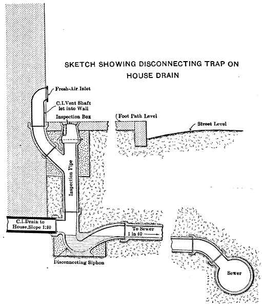 Fig. 17.—Sketch Showing Disconnecting Trap On House
Drain.
Fig. 17.—Sketch Showing Disconnecting Trap On House
Drain.
The house connections are chiefly of 10-cm. (4-in.) pipes, laid on a minimum gradient of 21⁄2%, from oblique branches on the sewer to siphon intercepting traps near the house, as shown by Fig. 17. From this trap a 10-cm. fire-clay inspection pipe is carried up and capped at the sidewalk level with a cast-iron box having a locked cover. From this inspection pipe a branch is connected to a cast-iron fresh-air inlet, in most cases set in the wall of the house, the inlet being 30 cm. above the level of the pavement.
Effect of the Flood on Sewers.—The flood of August 27th and 28th, 1909, partly destroyed one of the main collectors, which was laid along the banks of the river and encased in concrete. This has now been relaid farther north, and out of the way of any future floods. The total length of the new sewers replacing those damaged amounts to 1200 m., and they vary in internal diameter from 20 to 55.9 cm. (8 to 22 in.).
The direction of the main outfall sewer was determined after a thorough study of all the available land lying to the north and northeast of the city, as it was the intention of the Company to utilize 543for irrigation purposes the sewage and any surplus waters that might be developed. The best available site was found to be about 12 km. north of the city, a little northwest of the village of San Nicolas de los Garzas, as shown on Plate II. The long length of outfall required was justified by the cheap cost of the land and its excellent character for sewage irrigation. The sewer was designed for a capacity of 90,000,000 liters a day (36.76 cu. ft. per sec.) in order to allow for conveying surplus waters as well as sewage.
The outfall intercepts the two main branches of the city sewers at Calle de Allende and Calle de Tapia, and its total length is approximately 54411,900 m. The chief type adopted is shown on Plate XXII. It is formed with an invert of radial bricks laid in 1:2 cement mortar, on a foundation of 1:3:5 concrete approximately 7 cm. thick. As the ground was chiefly in hard sillar, only a little concrete was required to mould the bottom to the correct shape. The arch was formed of special radial bricks, 15 cm. (6 in.) deep, laid in cement mortar. These bricks were adopted in preference to concrete, owing to the heavy cost of sand and rock, due to the long haul, and for the purpose of obtaining rapid work. Plate XXI shows the sewer arch, and one of the ventilating columns and manholes. The bricks were obtained from the local brick plant, and form a very satisfactory material for sewers, being well burnt, thoroughly hard, and absorbing not more than 71⁄2% of their weight of water. The contract prices for the labor on the brickwork were 1.25 pesos per sq. m., and 1.38 pesos for the arch.
The general route of the sewer is very direct, long straight lines of several kilometers being possible, and these were joined by curves of approximately 30 m. radius. The gradient of the sewer invert is 0.2% (1 in 500) which is approximately the general fall of the ground northward from Monterrey.
The total quantity of excavation was as follows:
| No. 1, soft earth | 8,960 | cu. m. |
| No. 2, sillar | 18,492 | " |
| No. 3, conglomerate rock | 9,822 | " |
| ——— | ||
| Total | 37,274 | cu. m. |
The contract prices for this excavation were: for No. 1, 32 cents; No. 2, 85 cents; and No. 3, 2.17 pesos per cu. m.
All the excavation was in perfectly dry ground. Where the sewer was partly out of the ground it had a foundation of concrete, 1.75 m. wide, from 15 to 23 cm. thick, below the bottom of the brickwork, and carried up to the springing of the arch, and a well-tamped embankment, with slopes of 11⁄2 to 1, to protect the sewer to a height of 30 cm. (12 in.) above the arch. For 342 m. at the Monterrey end of the line, the sewer was constructed in tunnel, from, the open end and from two intermediate shafts. The tunnel throughout was in sillar, and the contract price for excavation was 24.50 pesos per lin. m. This work was done without timbering of any kind, except at the shaft lengths. Plate XXII shows 545the lining of the tunnel, which was of concrete with a brick invert. At four places the sewer passes under main railway tracks, which at these points were carried on steel girders supported on concrete abutments, the sewer being carried under the tracks in the ordinary way.
Bridges.—At three points the sewer was carried over arroyos on reinforced concrete girders. No. 1, at Station 5,600, consisted of four 10-m. spans; No. 2, at Station 8,365, over the Estanscia Arroyo, consisted of nine 10-m. spans; and No. 3, at Station 8,960, over the Topo Chico Arroyo, consisted of three 10-m. spans. One of these bridges is shown on Plate XXIII. They were designed as two parallel continuous girders with connecting top and bottom slabs. The concrete for the girders was a 1:21⁄2:31⁄2 mixture, the sand being from the crusher and the rock gauged to pass a 19-mm. (3⁄4-in.) screen. The inside was rendered with a coat of 1:1 cement mortar, 7 mm. thick, for water-tightness.
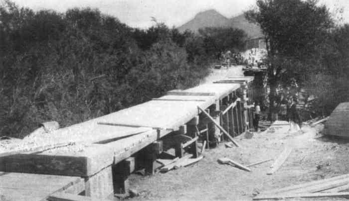 Plate XXIII, Fig. 1.—Forms for Main Girders, Estanscia Bridge,
Outfall Sewer.
Plate XXIII, Fig. 1.—Forms for Main Girders, Estanscia Bridge,
Outfall Sewer.
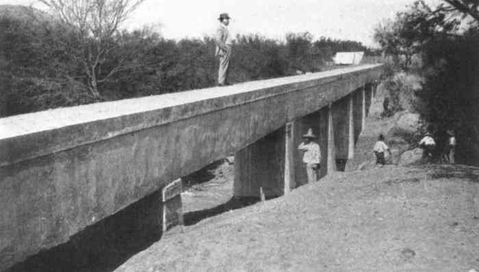 Plate XXIII, Fig. 2.—View of Estanscia Bridge,
Completed.
Plate XXIII, Fig. 2.—View of Estanscia Bridge,
Completed.
The piers of the Estanscia Bridge (Plate XXIII) were carried down through soft earth to a stiff clay from 41⁄2 to 6 m. below the surface, and the foundations were spread so that the pressure would not exceed 1 ton per sq. ft. The ends of the bridges were protected by rubble wing-walls supporting the embankment over the sewer. A 1:3:5 concrete was used for the upper part of the piers, and the lower part was of the same mixture with 30% of large boulders. There are 70 manholes (Fig. 19) along the line of the sewer, and they vary from 150 to 230 m. apart. The sewer is ventilated with 30 concrete towers (Fig. 18, and Fig. 2, Plate XXI), 2.9 m. high, having 20-cm. (8-in.) shafts.
The works for the outfall sewer were carried out satisfactorily under a contract with Mr. John Phillips, of Mexico City, the Company supplying the greater part of the materials. The work was begun on March 16th, and finished on November 12th, 1908.
For the purpose of disposing of the sewage and using it profitably, the Company purchased 909 hectares (2,246 acres) of land from the Community of San Nicolas de los Garzas, the outfall sewer being carried to the southwestern boundary of the land acquired. This area has a general fall in all directions to the northeastern boundary, with a gradual fall of about 25 m. across the diagonal of the land. The area purchased was practically virgin land, only small portions having 546been cultivated. The greater part was covered with a growth of mezquite trees and small shrubs. The quality of the land is excellent, if properly irrigated, and capable of yielding abundant crops of every description. The limits of this land are shown on Plate II.
Sewage Purification Tanks.—For the purpose of obtaining a satisfactory effluent to discharge on the land without causing nuisance, the Company built a system of detritus chambers and liquefying tanks at the end of the outfall sewer. One difficulty to be faced, in designing these works, was the fact that there were no data regarding the probable quantity of dry-weather sewage, nor any particulars as to its general 548character; there was also the probability that the outfall sewer would have to carry large quantities of surplus water. Therefore, the system was designed so as to be capable of extension if necessary, and the sizes of the various tanks were limited at present, because of the septic processes which would be set up in the long length of outfall sewer. The tanks were designed to deal with 10,000,000 liters of sewage proper per day, and the channels, etc., were proportioned to take the full flow of the sewer if necessary. Provision was also made for discharging large volumes of surplus water directly on the land, independent of the tanks. To do this a by-pass was taken from the sewer a short distance before reaching the site of the tanks. By properly timing the flow, arrangements could be made to discharge these waters in the early hours of the morning, by allowing the scour-pipes in the distribution system to be opened at night when the domestic sewage flow was at its minimum. As the area of land available is very great, the degree of purification in the tanks was relatively unimportant; the object to be obtained consisted chiefly in distributing on the land an effluent which would be innocuous and clear.
The general design of the works is shown on Plate XXIV, and they consist essentially of a screen chamber, duplicate detritus tanks, and three liquefying tanks. There is also a sludge-pit 629 m. from the tanks.
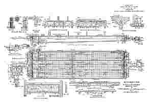 Plate XXIV.—Sewage Disposal Works At San
Nicolas De Los Garzas
Plate XXIV.—Sewage Disposal Works At San
Nicolas De Los GarzasScreen Chamber and Detritus Tanks.—Enlarged details of the screen chamber are shown on Plate XXV. The invert, where the sewer enters the screen chamber, is 489.45 m. above datum. This chamber has duplicate screens which are fully detailed on Plate XXX. For cleaning purposes the screens are raised by a steel-framed head-gear, which is arranged so that they may be lowered to a small traveling bogie, out of the way of the screen chamber.
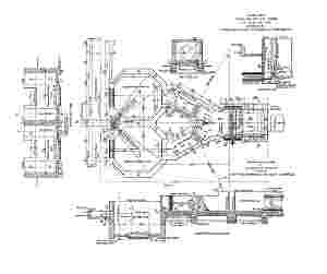 Plate XXV.—Sewage Disposal Works At San
Nicolas De Los Garzas.
Plate XXV.—Sewage Disposal Works At San
Nicolas De Los Garzas.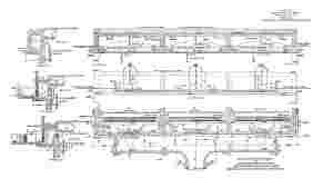 Plate XXVI.—Sewage Disposal Works At San Nicolas De Los
Garzas
Plate XXVI.—Sewage Disposal Works At San Nicolas De Los
Garzas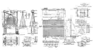 Plate XXX.—Sewage Disposal Works At San Nicolas De Los
Garzas.
Plate XXX.—Sewage Disposal Works At San Nicolas De Los
Garzas.From the screen chamber there are two main channels, 1.22 m. wide, branching to the two concrete detritus chambers. Each channel has a square penstock, so that the sewage can be diverted into either chamber when necessary.
The detritus chambers are octagonal in plan, 4 m. in diameter, and each is provided with an outlet weir 1.50 m. wide. At the weir level the chambers have a depth of 1.75 m., with drainage channels below that level. The coping is 1 m. above the outlet weir of the detritus tanks. To drain off these chambers, each has a scour-out pipe, 30 cm. in 549diameter, controlled from valves with spindles carried above the coping level. Each of these pipes is connected to a central chamber, and leads to a 56-cm. (22-in.) sludge-pipe. The chambers as designed are of smaller capacity than those usually provided, but, as all surface water is strictly excluded from the sewerage system, the quantity of detritus reaching the chambers may be small. The velocity through them when both are in use will be approximately 0.082 m. (0.27 ft.) per sec.
From these chambers the sewage is carried to the three liquefying tanks by a main channel, 11.5 m. long and 1.50 m. wide.
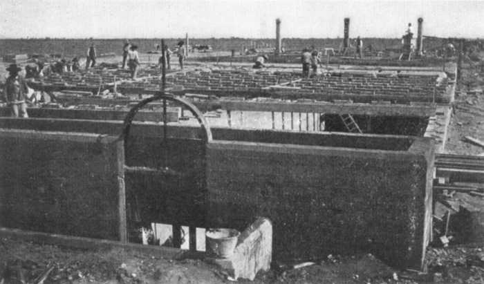 Plate XXVII, Fig. 1.—Cast Concrete Beams Being Placed in Position,
Liquefying Tanks.
Plate XXVII, Fig. 1.—Cast Concrete Beams Being Placed in Position,
Liquefying Tanks.
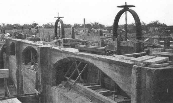 Plate XXVII, Fig. 2.—Inlet Weirs to Liquefying Tanks, During
Construction.
Plate XXVII, Fig. 2.—Inlet Weirs to Liquefying Tanks, During
Construction.
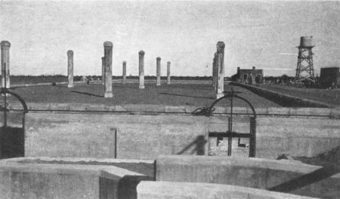 Plate XXVIII, Fig. 1.—View of Liquefying Tanks, from Inlet
End.
Plate XXVIII, Fig. 1.—View of Liquefying Tanks, from Inlet
End.
The tanks are of concrete and have reinforced concrete roofs. Each is 66 m. long and 6 m. wide; the minimum depth for the sewage is 1.50 m. at the outlet end, and 2.25 m. at the inlet, increasing to a maximum depth of 2.75 m. at the lowest depth at the scour-out channel. Their combined capacity is 2,500,000 liters, which is equivalent to 6 hours' flow of the quantity of sewage for which they were designed. The sewage passes from the main channel, through penstock-valves which control the flow, into one or the other of the tanks. From these valve openings it flows over concrete weirs, 5 m. long, and is deflected to the bottom of the tank by a reinforced concrete scum-plate, extending across each tank, with a clearance of 15 cm. at each end. This scum-plate is 1.5 m. deep and 10 cm. thick, and is placed 40 cm. from the end walls.
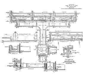 Plate XXIX.—Sewage Disposal Works At San Nicolas De Los
Garzas;
Plate XXIX.—Sewage Disposal Works At San Nicolas De Los
Garzas;The details of the concrete division and outside walls are shown on Plate XXIX. The floor was constructed in two layers, and its surface is divided into 6 channels formed by small walls, 20 cm. wide and 15 cm. deep, the object of these channels being to facilitate the cleaning of the floor by scouring it out to a specially arranged channel at the deepest point of the tank, near the inlet end. Each scour-out channel has a 30-cm. (12-in.) gate-valve, controlled from the roof of the tank, the three scour-pipes meeting in a concrete chamber outside of the tanks, from which a 56-cm. (22-in.) concrete pipe discharges the contents of the tanks to the sludge-pit during cleaning operations. The velocity through the tanks, when they are used in combination, is 0.0253 m. (0.083 ft.) per sec., the tanks being made as long as economically possible, in order to obtain this low velocity and thus permit the proper sedimentation of the suspended matters. The roof of each tank is 1 m. above the weir level. Each tank has four ventilating columns, 3.7 m. high and 30 cm. in diameter, vitrified clay pipes, with an exterior 550casing of contrete, being used for the shafts. The roof is enclosed within parapet walls, and is covered with a layer of earth 25 cm. thick.
The outlet channel from the tanks leads to a measuring chamber, 3 m. square, as shown on Plate XXIX. This chamber is fitted with penstocks, 1.83 m. wide, and measuring weirs. From this chamber the sewage is delivered to two main irrigation ditches, which distribute the sewage in two directions, one northward and the other to the western extremity of the lands.
Construction of Tanks.—The excavation for the tanks was in soft earth for a depth of 11⁄2 m.; the lower depths were in a firm foundation of sillar and calcareous clay. The total excavation in the tanks, channels, etc., was 8,335 cu. m., and the actual cost was 453⁄4 cents per cu. m. To facilitate the construction, about six-tenths of the concrete beams were cast as single monoliths and placed in position by sliding them across the tanks on temporary timbers. The remainder of the beams, the roof, and the slab were placed in position in the ordinary way with timber forms. The total quantity of concrete placed was 1,360 cu. m. A 1:21⁄2:41⁄2 concrete was used for the walls, channels, etc., and a 1:2:3 mixture for the roof slab and beams.
Table 14 gives the average cost per cubic meter for all the concrete work.
| Pesos per cubic meter. | Pesos per cubic meter. | |
| Labor: | ||
| Mixing and placing | 5.20 | |
| Carpenter work in forms, framing, etc. | 4.20 | |
| ——— | ||
| Total labor cost | 9.40 | |
| Materials: | ||
| Screened gravel | 4.04 | |
| Sand (from neighboring arroyo) | 4.98 | |
| Cement (including hauling) | 15.19 | |
| Lumber, nails, and other supplies | 1.90 | |
| ——— | ||
| Total materials cost | 26.11 | |
| Total cost of concrete per cubic meter | 35.51 |
Sludge-pit.—The sludge-pit, used when cleaning out the tanks, is carried 639 m. northward, far enough to get the available fall to drain the bottom of the detritus chambers and liquefying tanks. The drainage 551pipe was formed of 56-cm. (22-in.) concrete tubes. The sludge-pit is merely an excavation in the earth 20 m. square and 2 m. deep, the sides having a slope of 11⁄2 to 1. An overflow drains the pit to an irrigation ditch, the solid matter being allowed to settle and the liquid to drain off. From time to time it is proposed to dig out the solids and plow them into the land.
General.—To the east of the tanks a 3-roomed house has been built for the inspector.
In order to provide a good supply of water for cleaning operations, a well 22 m. deep has been sunk and is fitted with pumps operated by an Eclipse windmill, 4 m. in diameter, on a tower 22 m. high, which delivers the pump water to a circular wooden tank of 20,000 liters capacity.
The work in connection with the purification tanks was carried out by the Company's own staff; it was begun on September 10th, 1908, and practically completed by the first week in January, 1909.
At the time of writing, the tanks have to deal with the sewage from a population of only 10,000 persons, as only from 15 to 20% of the connections have been made. The sewage, therefore, has been diluted with several times its volume of surplus water, and the necessary scum on the top of the sewage in the tanks has not yet assumed the usual thick matty condition observed in most systems. As there are no available means in Monterrey of having proper determinations made of the degree of purification which takes place in the passage of the sewage through the liquefying tanks, a few simple tests have been made. These tests were limited to the determination of the amount of oxygen absorbed in 4 hours, and show a purification of 50% in passing from the detritus chambers to the outlet. The sewage, although very black and full of suspended matter as it enters the tanks, leaves them in a very clarified condition.
Of the total area of land acquired by the Company, 904 hectares (2,234 acres) have been leased to the Monterrey Railway, Light, and Power Company, for 99 years, the Water-Works Company reserving 5 hectares (12 acres) absolutely for future extensions of the sewage works. By giving 12 months' notice, the Company also reserves the right to utilize any part of 145 hectares (358 acres) near the tanks, should it be required at any time in the future for sewage purification purposes.
All the work was practically under the direction of English-speaking superintendents and general foremen. For the ordinary skilled and low-skilled labor, Mexicans were employed exclusively, and, on the work, which was quite new to them, they proved entirely efficient and satisfactory; throughout the work, on which at some periods between 2,000 and 3,000 men were employed, chiefly under the Company's direct administration, they were very tractable and willing to do their best, and no trouble was experienced at any time. The Mexican "peon," and also the ordinary skilled workman in the north of Mexico, is intelligent, and is excellent for purely routine work, but he is not adaptable or resourceful in cases of emergency. Under intelligent and careful supervision, however, it is quite possible to get as good results as could be obtained anywhere.
The daily rates of wages for a 10-hour day were approximately as given in Table 15, these rates being varied in special cases.
| Pesos per day. | |
| General foreman | 8.00 to 10.00 |
| Foreman | 6.00 to 8.00 |
| Cabos | 2.00 to 4.00 |
| Masons | 3.00 to 4.00 |
| Bricklayers | 3.00 to 4.00 |
| Masons and bricklayers helpers | 1.50 |
| Cast-iron pipe jointers (foreman) | 4.50 |
| Cast-iron pipe caulkers | 3.00 |
| Cast-iron pipe helpers | 1.50 to 2.00 |
| Fire-clay pipe layers | 1.75 |
| Fire-clay pipe helpers | 1.25 to 1.50 |
| Drillers | 1.25 to 1.50 |
| Carpenters | 2.00 to 2.50 |
| Blacksmiths | 2.50 |
| Crane men | 6.00 |
| Peons (laborers) | 1.00 to 1.25 |
| Boys (watering concrete) | 0.371⁄2 to 0.50 |
| Watchman | 1.00 |
| Timekeepers | 22.00 per week. |
Table 16 gives the main items of the approximate expenditure. These include all expenses for preliminary location, engineering, superintendence, purchase of lands, water rights, etc., but do not include other heavy expenditures chargeable to the concession, such, for example, as general expenses, interest at the rate of 6% during the construction period, 553preliminary expenses for investigations, etc., items which would increase the total by nearly 25 per cent.
| Pesos, Mexican currency. | ||
| Estanzuela Supply: | ||
| Aqueduct and dam | 502,000 | |
| South Reservoir | 429,000 | |
| ——— | 931,000 | |
| San Geronimo Gravity Supply: | ||
| Aqueduct, tunnel, and infiltration gallery | 223,000 | |
| Obispado Reservoir | 436,000 | |
| ——— | 659,000 | |
| San Geronimo Provisional Supply, | ||
| including boring operations, etc. | 130,000 | |
| City Water Distribution System | 1,195,700 | |
| City Sewer System | 1,036,000 | |
| Outfall: | ||
| Main outfall sewer | 425,000 | |
| Sewage purification works | 75,000 | |
| ——— | 500,000 | |
| ————— | ||
| Total | 4,451,700 |
As a general statement, the actual cost of labor is about 331⁄3% of the total cost of the construction work, including materials. Fig. 20 shows in graphic form the amount of the labor pay-rolls and the progress of the work during the whole construction period from 1906 to 1909, inclusive, comprising also that done under contract.
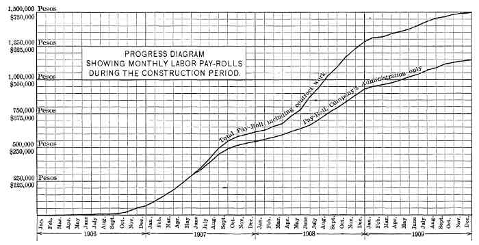 Fig. 20.—Progress diagram showing monthly
labor pay-rolls during the construction period.
Fig. 20.—Progress diagram showing monthly
labor pay-rolls during the construction period.
Tariffs.—The tariffs charged for the water and drainage service (Table 17) were approved by the State Government (which accepts the responsibility for their collection), under a compulsory State law which came into force on March 1st, 1910, for the southern portion of the city, and on July 1st, for the northern half, the penalty for non-compliance being a tax of 10% on the monthly rental value of the property, as assessed by the State officials.
The basis of the tariffs (which were published on February 22d, 1909) is a charge for water varying between 12 and 16 cents (Mexican) per 1,000 liters, with a minimum monthly rate for each different class of property connected to the system. The rate for house drainage is fixed at 80% of the minimum water rate levied on the consumer. The minimum rates have been fixed so that the poorer classes of the community 554will not be overtaxed, while at the same time the rate is actually levied on the quantity of water used, as indicated by the meter. All the services at the present time are metered, and the meter system will be used throughout.
| Class | Monthly property rental. Pesos. | Liters of water allowed. | Price for 1,000 liters. Cents. | Minimum monthly rate. Pesos. | Rate for drainage service. Pesos. | Total rate payable. Pesos. | |
| I | Up to 20 | 7,800 | 16 | 1.25 | 1.09 | 2.25 | |
| II | 21 to 40 | 12,500 | 16 | 2.00 | 1.60 | 3.60 | |
| III | 41 to 60 | 18,750 | 16 | 3.00 | 2.40 | 5.40 | |
| IV | 61 to 120 | 23,350 | 15 | 3.50 | 2.80 | 6.30 | |
| V | 121 to 300 | 30,000 | 15 | 4.50 | 3.60 | 8.10 | |
| VI | 301 upward | 33,350 | 15 | 5.00 | 4.00 | 9.00 |
"Notes: (1st) The rental for the water meters 5⁄8-in. size (151⁄2 mm.), which shall always be considered the property of the Company, will be 20 cents per month. Houses of the first and second classes shall be exempt from paying such rental for one year's time, counting from this date.
"(2d) All excess consumption of water over that allowed by the tariff will be charged for at 2 cents less than the price shown in the tariff per thousand liters.
"(3d) Extra large houses, large establishments, such as colleges, hotels, etc., etc., having a consumption of 50,000 to 60,000 liters of water per month, will pay at the rate of 14 cents per thousand liters. The drainage rate for such buildings will be arranged in proportion to the water tariff, or 80% of the value of the water.
"(4th) The laundry establishments, bath-houses, etc., when using 50,000 liters or upward, can arrive at some agreement so as to pay 12 cents per 1,000 liters.
"(5th) Groups can be formed of two or more small houses so as to obtain a joint service under the proportion shown in the tariff.
"(6th) Any other combination that cannot be entered into under the basis of this tariff, will be arranged by specially agreed upon prices, such agreement being as much as possible subject to the basis mentioned."
Sanitary Regulations.—The State Government, on March 1st, 1909, published regulations for the proper installation of the water and drainage services within the houses.
At the Government's request, a draft of the proposed regulations was submitted by the writer, who prepared it, after a study of American 556and British sanitary by-laws, to suit the special conditions of Monterrey. These regulations were afterward modified by him in collaboration with the Government Technical Inspector and Financial Interventor, and, in their final form, though not as stringent as those adopted in many northern cities, are probably more complete than those in any other Mexican city. Under these regulations only registered plumbers can undertake plumbing installations, and they have to execute a bond to the satisfaction of the Alcalde Primero (City Mayor) for the sum of 2,000 pesos as a guaranty of responsibility. For defective workmanship or any infraction of the plumbing regulations, they are liable to heavy fines, and can be called on to make good all defects in workmanship, without extra charge to the owner of the property. The provisions of the regulations are carried out under the supervision of the Government Technical Inspector, the Company's obligations extending only to the sidewalk and to the meters placed within the houses.
G. S. Binckley, M. Am. Soc. C. E., was Chief Engineer of the Company from February to December, 1906. The writer was Chief Engineer from May 1st, 1907, until April, 1910, and is responsible for the design and construction of the works carried out during that period. Mr. J. D. Schuyler advised the Company throughout all preliminary studies and investigations, and acted as Consulting Engineer until February, 1908. The Technical Inspector, on behalf of the Government, throughout the whole progress of the works, has been Rudolf Meyer, M. Am. Soc. C. E., and the writer wishes to record the valuable assistance the Company has received from him.
In conclusion the writer may be permitted to pay a tribute to the devoted public spirit shown by his Excellency, General Bernardo Reyes, the Governor of the State of Nuevo León from 1885 to February, 1910, and who, untiring in his devotion to the interests of the city, was primarily responsible for the inception of the works and their successful completion.
James D. Schuyler, M. Am. Soc. C. E. (by letter).—For completeness of detail and wide range of subjects of general interest to engineers, this paper is certainly one of the notable contributions to recent engineering literature. It is a minute and painstaking record of the successful accomplishment of construction work under unusual climatic conditions and difficult circumstances, and reflects credit on the author, not only in his capacity as an engineer, but as a faithful recorder of facts. It was particularly fortunate that he was an eyewitness of the disastrous and extraordinary flood which swept through Monterrey, destroying many lives and much property, and has thus been able to give an intelligent estimate of the maximum discharge of the river during the height of the flood wave of August 27th-28th, 1909, when the rate of run-off per unit of area of water-shed drained reached an amount which has seldom been equalled or exceeded, as far as reliable records extend. It is worthy of note that works deriving their water supply from the source of such torrential floods should have survived with so little actual damage, and with scarcely any interruption of service. The repair of all damages to the system was estimated to have cost not more than $20,000.
As Mr. Conway did not assume charge of construction until May, 1907, he was spared the responsibility of deciding on the general plan of securing an abundant supply of pure water from sources permitting of delivery by gravity under adequate pressure for fire protection—a responsibility which devolved on the writer, assisted by G. S. Binckley, M. Am. Soc. C. E., Mr. Conway's predecessor, as Chief Engineer. Not only the water-works, but the system of sewerage and sewage disposal by broad irrigation were subsequently carried out on the plans submitted to the State Government by the writer in 1906, and given provisional acquiescence at that time.
There was no lack of water at hand for the supply of a city of that size, as there are large perennial springs which flow out of the travertine of the plain, and are used for irrigation in the valley below the city. One of the largest of these, near the civic center, has a normal flow of nearly 30 cu. ft. per sec.; another nearby, also within the city limits, flows some 10 or 12 sec-ft., while both the Estanscia and Robalar springs, but a few miles below (shown on Plate II), discharge more than 20 sec-ft., as nearly as memory serves. Besides this supply, the water to be developed by sinking shafts in certain parts of the plain, as demonstrated at the brewery and elsewhere, was apparently a reliable source of large volume.
To utilize these sources, however, would have involved condemnation of the water-rights in the case of the springs, depriving present owners of the use of the water, and this Governor Reyes wished to 558avoid. Besides, it would have necessitated pumping the water for the city in perpetuity, an expense which the Governor was equally anxious to save; hence a gravity supply was made the prime requisite of the plans.
Until the concession was granted, and for a year or more afterward, it was assumed that an adequate supply could only be obtained by the storage of the flood-water of the Santa Catarina River in a large reservoir; and the earlier plans of the concessionaires were based on the construction of a high masonry storage dam at the upper end of the "narrows," where the river turns from a western direction to a course almost due east, between high vertical cliffs of limestone. The concession distinctly provided for such a dam, and among the plans on file in the State Capitol is one prepared by the late E. Sherman Gould, M. Am. Soc. C. E., for a masonry weir across the gorge. Samuel M. Gray, M. Am. Soc. C. E., also filed a plan and report proposing a capacious, shallow, storage reservoir near the city, to be filled by a large flood-water canal from the Santa Catarina Cañon.
Although the writer could not have anticipated the occurrence of floods of the magnitude of the one of August, 1909, which would surely have destroyed any reservoir built in the Cañon, he was unable to endorse the storage plan of water development, chiefly because of the uncertainty of the water-tightness of the reservoir in a cavernous limestone formation, and also because of the probable impurity of water draining from such extensive goat pastures. He, therefore, urged the development of the underflow of the river, which was manifesting itself in the springs referred to. Mr. Binckley secured two Keystone drilling machines and proceeded to profile the bed-rock at Santa Catarina Cañon and at San Geronimo, the two places on the stream where the river flows between walls of rock in situ. At both sites the strata were standing nearly vertical across the channel, and, by careful sampling and testing, it was found that in both locations there were thick strata of limestone so highly silicious as to be insoluble, and hence free from caverns. From this determination it was concluded that all the water which appeared in the valley below must pass through the sections where the borings were made. The results of this drilling, however, proved conclusively that the depth to bed-rock at either place was too great to permit of a masonry dam being considered as practical, and demonstrated the inadequacy of methods which had been used in the earlier investigations when dams were regarded as feasible.
The results have also shown that the subterranean supply at the lower cross-section of the river, at San Geronimo, is abundant, and can probably be increased to an indefinite degree by continuing the filtration gallery; while at Santa Catarina the same type of development can be made for a high-source supply, although requiring a long and expensive tunnel and conduit.
David T. Pitkethly, Assoc. M. Am. Soc. C. E. (by letter).—Having been engaged on the design of sewerage systems for some years, the writer finds this paper of peculiar interest, particularly the sewerage portion. There are some points in the design, however, which do not appear to be clear.
The system is described as "strictly separate," and yet the sewers are designed to run half-full, providing a capacity of 200%, the 100% basis, or 380 liters per capita, being 90%, or 180 liters, in excess of the calculated water supply of 200 liters per capita.
It has been the writer's practice to design sanitary sewer systems on the basis of the water consumption, and to assume the whole daily amount to reach the sewer in 16 hours, thus providing capacity sufficient to care for the maximum or wash-day flow without causing the sewers to run above the calculated hydraulic gradient, which should be placed within the pipe so as to provide air space for ventilation under all circumstances.
The practice of calculating sanitary sewers to run half-full is a good one when ground-water is expected in sufficient amount to fill the remaining portion of the sewer, but when no ground-water, or roof-, or surface-water is allowed to enter the system, or all precautions are taken to exclude such, then the system may be designed so that the expected maximum, or wash-day flow, will fill the sewer to the desired hydraulic gradient.
The method of ventilating the sewers does not seem practicable. The houses are principally of one story, and yet the stand-pipes on the sewers have openings 25 ft. 9 in. above the sidewalk. Are the ventilating or vent pipes of the house plumbing carried to a height to balance this, or will these chimneys draw the air from the house drains and fresh-air pipes, breaking the seal in the so-called disconnecting traps, thus causing the circulation of air in the house piping to be downward through the sewers instead of upward through the fresh-air inlets and vents, as designed?
It is interesting to note that crude sewage, as well as the liquefying (septic) tank effluent, is to be applied to land for irrigation purposes, but the application of crude sewage without any attempt at removing the suspended matter, or the effluent from the septic tanks where only a partial removal occurs, seems to be bad practice.
The author states that:
"The degree of purification in the tanks was relatively unimportant; the object to be obtained consisted chiefly in distributing on the land an effluent which would be innocuous and clear."
How he expects to obtain such an effluent by passage through screens, detritus tanks, and septic tanks only, is more than the writer can understand.
The removal of suspended matter in a septic tank depends on the 560strength of the sewage, the time of retention, the time elapsing between cleaning, the presence of trade wastes, etc., and seldom exceeds 38 per cent.
The subject of septic tanks and their effect on sewage is discussed in the "Fifth Report of the Royal Commission on Sewage Disposal" (England, 1908), and the following extracts, relative to the application of crude sewage to land and the effect of septic tanks on sewage, seem apropos:
"23. * * * There are also many cases in which crude sewage has been passed over land, but the evidence shows that land treatment of crude sewage is liable to give rise to nuisance by the accumulation of solids on the surface of the land. Moreover, in some cases these solids are apt to form an impervious layer, which interferes with the aeration of the soil, and so impairs the efficiency of the treatment."
"31. * * * At that time it was claimed that the septic tank possessed the following, among other, advantages:
"That it solved the sludge difficulty, inasmuch as practically all the organic solid matter was digested in the tank.
"That it destroyed any pathogenic organisms which there might be in the sewage."
"32. As regards the first of these claims, it is now clearly established that, in practice, all the organic solids are not digested by septic tanks, and that the actual amount of digestion varies to some extent with the character of the sewage, the size of the tanks relative to the volume treated, and the frequency of cleansing."
"At Huddersfield, Mr. Campbell estimated that about 38 per cent. of the solids were converted into gas or digested; * * * while at Birmingham, Messrs. Watson and O'Shaughnessy say that the figures available indicated a digestion of not more than 10 per cent. of the suspended matter entering the tanks."
"33. As regards the second claim, we find as a result of a very large number of observations that the sewage issuing from the septic tanks is, bacteriologically, almost as impure as the sewage entering the tanks."
Messrs. Winslow and Phelps, in their interesting paper, "Investigations on the Purification of Boston Sewage," [8] quote a suggestion made by Stoddart (1905):
"He finds, in a septic tank of several compartments, a considerable deposit of sludge in the first compartment, giving a fairly clear supernatant liquid, which in the last chamber of all undergoes a secondary decomposition, leading to the throwing down of an additional precipitate of offensive sludge."
What took place in the case referred to by Stoddart corresponds to the author's observations of the liquid leaving the tanks in a clarified condition, but the secondary decomposition must take place in some manner, and, when it does, a nuisance seems to be unavoidable where no provision is made to care for it.
561
In view of the experience of others, some further treatment seems to be necessary. Such treatment should include disinfection, as no method of disposal yet devised has succeeded in reducing materially the pathogenic germs usually to be found in sewage and tank effluents.
If the crops to be irrigated are to be eaten, uncooked, by mankind, then disinfection at least is imperative.
George S. Binckley, M. Am. Soc. C. E. (by letter).—Mr. Conway's admirable paper is of special interest to the writer, as the entire general design of the system, as well as the extensive hydrological studies and final selection of the sources of water supply, was completed during 1906 through the joint labors of the writer, as Chief Engineer, and James D. Schuyler, M. Am. Soc. C. E., as Consulting Engineer.
In this work, Mr. Schuyler and the writer had the rare privilege of dealing from its inception with the problem of designing a complete and somewhat extensive system of municipal water supply and drainage, unhampered by any existing works to which the new systems would have to be adapted. It would probably be difficult to find in the United States a city of 85,000 inhabitants, previously totally lacking either a water supply or sewerage system, which, under a consistent and harmonious design, has been provided with both in the degree of completeness and structural excellence exemplified in the works at Monterrey.
The few important changes or amplifications made in the original design, and the manner in which its detail has been executed is naturally most interesting to the writer, and this excellent paper should be of very substantial value, particularly to engineers engaged on similar work in Mexico or Spanish America.
The very novel construction method adopted by Mr. Conway in the roofing of the South or Guadalupe Reservoir, seems to the writer rather to invite criticism, and the fact that in the subsequent construction of the roof over the rectangular Obispado Reservoir the customary monolithic concrete construction was apparently reverted to after experience with the separate-unit plan previously used, would indicate that Mr. Conway reached the same conclusion.
The original design of the circular Guadalupe Reservoir contemplated just about the same arrangement of columns and roof support as that actually used, but the writer had expected that the columns would be cast in place, and that the system of primary and secondary beams would be filled at the same time as, and integral with, the roof slab, the reinforcement being placed in accordance with what may be described as conventional practice. The writer believes that the efficiency of the concrete and steel placed in this manner would be notably higher than under the system actually adopted, which, in effect, is pretty much the same as constructing the supporting system of units of cut stone. If, with all the elements of structural weakness involved in the multiplicity of mortised joints, discontinuous reinforcement, 562etc., this construction is strong enough, it would seem that an important reduction in the dimensions of the members could have been effected by monolithic construction and continuous reinforcement, without sacrifice of strength.
The comparison, in Table 7, of the costs of these two reservoirs, is interesting, but very moderately illuminating, as the comparative unit cost of the most important element in their construction—the concrete—is not given. The total excavation cost for each reservoir is practically the same, and the general expense, engineering, and cost of fittings and accessories presumably so, but the total cost of the Guadalupe Reservoir as given is $19,000 (pesos) in excess of that of the Obispado Reservoir, while, in the latter, there were 756 cu. m. more concrete. This certainly indicates a much higher cost of concrete per unit as laid in the South (Guadalupe) Reservoir. An actual comparison of the cost per unit of concrete laid under the two systems would be instructive.
The writer is interested to observe that the same system of sub-drainage used by him in the construction of the reservoir for the provisional supply of water from San Geronimo, has been used by the author in the Obispado Reservoir. This arrangement of drains under the floor of the reservoir at San Geronimo was devised as a safeguard against damage to the lining through the accumulation of water inside the impervious bank against its back.
It was realized that, in such a climate as that of Monterrey, perfect water-tightness of the lining might be difficult to secure or maintain, and, if leaks existed, a sudden draft on the contents of the reservoir might result in serious damage through the static pressure exerted against the lining of the sides or upward thrust against the floor. In the writer's opinion, such a system of drains is an important element, as not alone the fact but the quantity of leakage may be determined, and danger of saturation of the supporting bank avoided—a matter of importance where, as is sometimes the case, the material of such a bank is unfit to resist the effects of saturation. The author does not state whether or not this safeguard was omitted in the Guadalupe Reservoir. Incidentally, however, the matter of saturation of the bank is not important in either reservoir, as the material of which these banks are constructed is such that settlement or failure through saturation is out of the question. It may be remarked, however, that in fixing the angle of the sides of the Guadalupe Reservoir at 60° the writer contemplated the same system of constructing the bank as he used in that of the San Geronimo Reservoir. In this case, the bank was built up by spreading the material in thin layers, wetting down, and rolling and puddling by the passage of the ox-carts used for the transportation of the material, the wheels of the carts, and especially the cloven hoofs of the animals, producing a most excellent effect. The inside slope 563was built up in this fashion to a much lower angle, and with a top width considerably in excess of the finished dimensions. The excess material was then picked off to the line, and exactly to the slope. Thus the finished slope presented a surface which was compacted to a degree impossible to attain at or near the surface of the bank as built, and presenting a support of the best possible character for the concrete lining and coping.
V. Saucedo, Assoc. M. AM. Soc. C. E. (by letter).—The author's description of the water-works and sewerage of Monterrey, one of the most extensive schemes in Mexico, will be of general interest to engineers, especially those engaged in hydraulic and sanitary problems. The writer, having been connected with the works for four years, knows the local conditions well, and presents herewith some complementary data on what he considers an important feature, the subject of floods, mentioned by the author on different occasions, especially as certain developments in the works show the importance of such occurrences as a factor in designing.
Abnormal rainfalls of long duration and high intensity are common in the semi-arid region of Mexico. They come at irregular intervals, though tending to coincide with the early fall. The floods of August, 1909, were a repetition of similar occurrences in the past; and, though there are no numerical records of previous cases, local traditions and historical state documents describe them as having occurred since the foundation of the city, at intervals of from 15 to 40 years. The graphic descriptions of the places flooded are in accord with the character of the floods of August, 1909, and September, 1910.
The diagram, Fig. 21, is a record of the rainfall during the latter flood, and was plotted from intermittent readings of standard gauges. It demonstrates that the intensity increased toward the mountains on the south, which form the tributary water-shed of the Santa Catarina River, showing a difference of 10.54 in. between the city and the Estanzuela Dam, which is not quite 12 miles to the southeast.
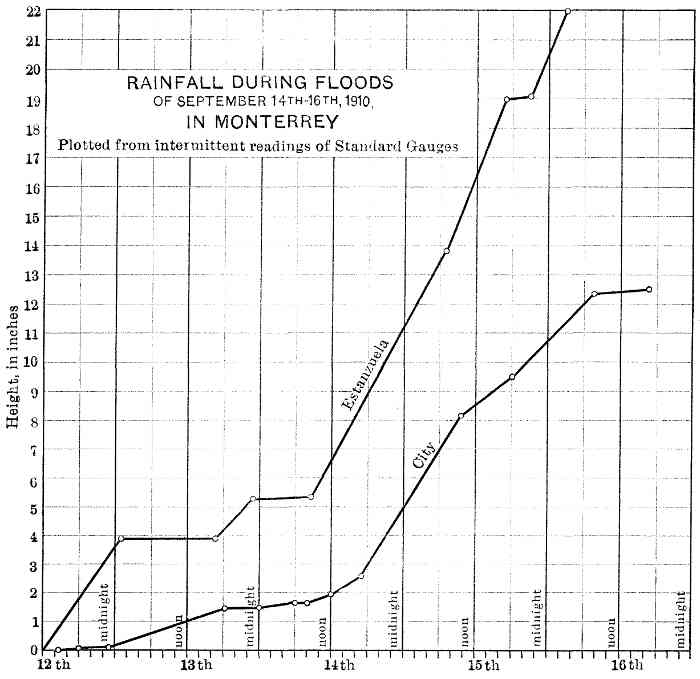 Fig. 21.—Rainfall during floods of
September 14th-16th, 1910, in Monterrey.
Fig. 21.—Rainfall during floods of
September 14th-16th, 1910, in Monterrey.
An estimate of the volume of discharge of the river at the time of maximum flood is only a reasonable conjecture which (without special reference to accuracy) aims to impress those who have not witnessed such occurrences with the tremendous volume coming from barren steep surfaces previously saturated.
The original computation, referred to by the author, was obtained from the average of two different methods which gave results close to each other. In one method the extent and nature of the water-shed were considered, together with the maximum period of precipitation that occurred, sufficient to gather a maximum volume of water in the river. In the other method the volume was derived from a cross-section of the wetted perimeter of the river at the time of maximum flow, in combination with velocity approximations obtained by using 564rough floats. This gave 271,500 cu. ft. per sec. The figure submitted by the author, 235,000 cu, ft. per sec., is in accord with the proposed formula[9] for impervious surfaces by C. E. Gregory, M. Am. Soc. C. E. In the first and last methods, the intensity, a governing factor, is more or less of an assumption, and the cross-sectional method is also unreliable, as the river-bed was greatly disturbed, due to the high velocity of the water, which deepens the channel to a considerable extent at times of maximum flood, the gravels being redeposited during the period of subsidence. Such was the case during the flood of September, 1910, when the depth of gravel above the roof of the San Geronimo Infiltration Gallery was diminished to such an extent that it was so inefficient as a filter for the flood as to permit the percolation of turbid water into the underground supply.
During the floods of August, 1909, Shafts Nos. 2 and 3 were damaged beyond repair, and sand and gravel, entering through them, 565blocked up the gallery to within about 150 ft. of Shaft No. 1. The interior timbering probably collapsed, due to cavings and disturbance in the river-bed during the period of maximum flood, but no explorations have been possible on account of the great quantity of water still coming through (at present more than 650 liters per sec.). For this reason the work of driving the gallery, as well as lining Shaft No. 1, has been suspended.
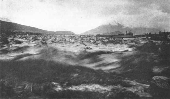 Plate XXVIII, Fig. 2.—View of Santa Catarina River in Flood, on August
28th, 1909.
Plate XXVIII, Fig. 2.—View of Santa Catarina River in Flood, on August
28th, 1909.
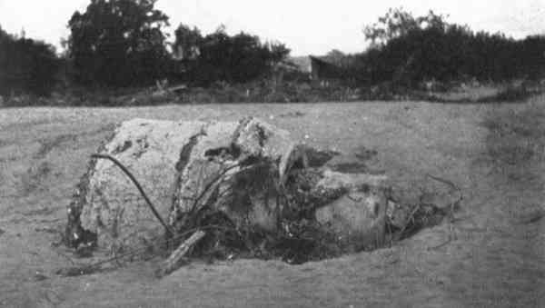 Plate XXXI, Fig. 1.—Flush-Tank Carried Down by Flood of August
27th-28th, 1909.
Plate XXXI, Fig. 1.—Flush-Tank Carried Down by Flood of August
27th-28th, 1909.
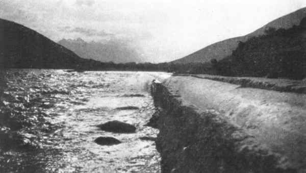 Plate XXXI, Fig. 2.—View Showing Scouring Effect Of Flood
On San Geronimo Aqueduct.
Plate XXXI, Fig. 2.—View Showing Scouring Effect Of Flood
On San Geronimo Aqueduct.
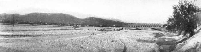 Plate XXXII, Fig. 1.—View of Santa Catarina River After the
Flood.
Plate XXXII, Fig. 1.—View of Santa Catarina River After the
Flood.
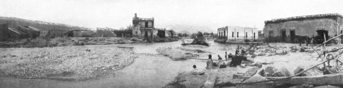 Plate XXXII, Fig. 2.—View of Santa Catarina River Flowing Through
Low-Lying Streets, 8 Days After the Flood.
Plate XXXII, Fig. 2.—View of Santa Catarina River Flowing Through
Low-Lying Streets, 8 Days After the Flood.
On reaching the city, the flood of August, 1909, swept away two streets adjoining the river. These streets had been built on made ground, in what was originally the river-bed. The sewers and water mains laid in them were destroyed entirely, and some 460 ft. of the 24-in. cast-iron pipe, buried under the river-bed at a depth of 8 ft., were carried away. In relaying this portion of the main, and for protecting the remainder of it across the river, it is now proposed to encase it in a solid rubble concrete block, 8 ft. square, which will impart weight and stability against the scouring effect of floods.
The South Reservoir is circular in shape, with an interior diameter of 165.68 ft. at the top, and is partly excavated in the ground and partly completed by an embankment of vast proportions (Fig. 10). Right after the flood of August, 1909, a wet spot appeared on the northeastern toe of the embankment, and it was supposed for some time that it was the effect of the saturation produced by the preceding rains, but, as it persisted for several months, it was obvious that its origin was in the interior of the reservoir, which was emptied when the writer took charge of the work. The first inspection revealed a horizontal crack in the concrete lining, about 310 ft. long and extending about 153° around the circumference on the north side. Throughout its length it coincided with the line of cut and fill. Vertical cracks, coinciding with the panel points in the lining, had also developed, and extended from the main horizontal crack to the roof. The circumstances originating this development can be conjectured by considering the position of the main crack, its characteristic features, and the conditions that preceded its formation. The coincidence of the crack with the joint of cut and fill, points to this line as a source of danger. An examination showed, besides, that the fracture was clean and sharp, ranging in thickness from a hair line at the ends to 3⁄16 in. at the center, and that its upper border projected over the lower one perceptibly, a proof that horizontal motion had taken place. The vertical cracks were a secondary effect, the consequence of the displacement immediately after it was scoured. A fracture was discovered in the floor of the reservoir. It started at the center and branched out into two diverging lines in a radial direction.
The circumstance of two abnormal rainfalls, giving 35 in. in 9 days, the precipitation being concentrated in two periods, not far 566apart, of 42 hours and 98 hours, respectively (Fig. 4), together with lack of provision for shedding the water from the roof of the reservoir and from the surrounding embankment, lead to the inference that the latter became saturated, increasing thereby in weight and decreasing in stability, especially in its steep inner face. A settlement and the consequent horizontal displacement, under these conditions, was natural. The concrete lining, only 16 in. thick at that height, was not sufficient to sustain the resulting strain, and the main fracture developed, permitting the stored-up water to leak into the bank. In time this seepage found its way under the bottom of the reservoir, softening the ground and producing a slight settlement which caused the crack in the floor. Had under-drainage been provided, as at the Obispado Reservoir, the actual conditions would have been noticed earlier. However, as the embankment is of vast proportions, stable in itself to sustain with a large margin of safety the weight of the stored-up water, there was no actual danger of failure, except for the fact that the material forming the structure, on account of its calcareous nature, is dissolved by water. Long exposure to this condition would, in time, open passages in the embankment, and it is certain that there would be cavings in its interior.
The necessary grouting has been done, and provision is being made for water-proofing the interior of the reservoir and shedding the water from the roof and from the embankment, thus relieving the structure of the consequent strain.
Another place in the works where floods have had a damaging effect is the Estanzuela intake basin, which, when the dam was completed, was filled to the overflow level in order to test its water-tightness. As this basin, when cleaned, was found to be slightly fissured on the north side, it was decided to line it with concrete. As shown in Fig. 8, the lining does not cover its entire area, but only the central portion, leaving a strip on either side without protection. The flood of September, 1910, coming in greater volume than the previous ones of August, 1909, in passing through the narrow gorge at the entrance, undermined the lining in those places where it was not founded on solid rock. Figs. 1, 2, and 3, Plate XXXIII, show some of the damage caused by this flood. The buoyant effect of the water and the impact of large rolling boulders caused fractures all over the surface, and lifted the concrete lining bodily; but the dam proper, being founded on rock bottom, did not suffer any injury. In the future, in order to avoid the seepage of the ordinary supply, alluded to by the author, the water will be carried to the valve-house in an open rubble concrete channel, lined with cement mortar and built high up against the western hillside. The remainder of the basin will be paved with large boulders.
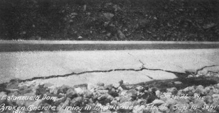 Plate XXXIII, Fig. 1.—Estanzuela Dam: Broken Concrete Basin
Lining.
Plate XXXIII, Fig. 1.—Estanzuela Dam: Broken Concrete Basin
Lining.
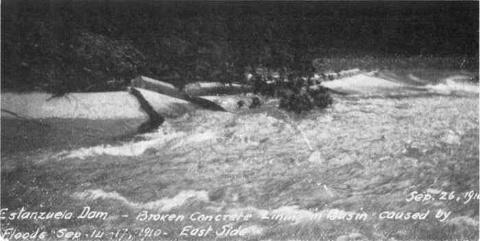 Plate XXXIII, Fig. 2.—Estanzuela Dam: Broken Concrete
Basin Lining, East Side.
Plate XXXIII, Fig. 2.—Estanzuela Dam: Broken Concrete
Basin Lining, East Side.
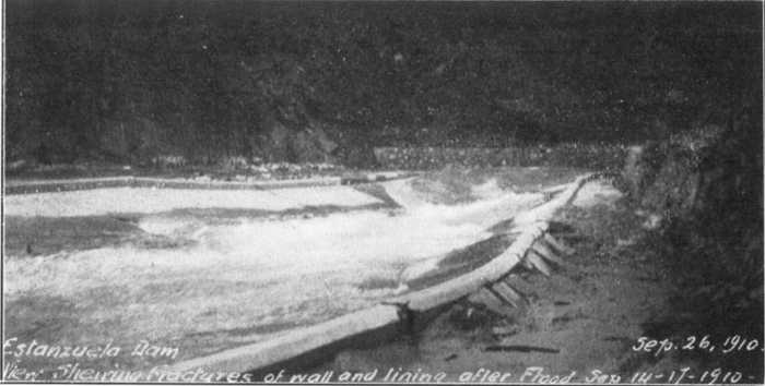 Plate XXXIII, Fig. 3.—Estanzuela Dam Sept. 26, 1910:
View of Shearing Fractures of Wall and Lining After Flood Sept. 14-17, 1910.
Plate XXXIII, Fig. 3.—Estanzuela Dam Sept. 26, 1910:
View of Shearing Fractures of Wall and Lining After Flood Sept. 14-17, 1910.
In conclusion, the writer wishes to emphasize the point that, notwithstanding 567the severity of the test, relatively small damage was inflicted on the extensive works carried out under the author's design and direction. A test so severe that it caused serious damage and immense losses in the entire region, washing away kilometers of railroad track and destroying practically all the bridges within reach of the flood, is an occurrence of paramount importance, and should be remembered as a leading factor in the design of engineering works.
George T. Hammond, M. AM. Soc. C. E. (by letter).—In a country, such as that described in this paper, where water is valuable, and a shortage is at times possible, where the majority of the population is very poor, and water and sewage discharge are both to be paid for on a basis of volume, the question of the expected quantity of daily water supply and sewage flow per capita is of primary importance. This question, notwithstanding its difficulty, should be given a first place in the studies for water-works and sewerage projects, and should never be lost sight of in the design, which should be such that, while proper for the expected future flow for a reasonable time, should also be proper and economical for conditions which at present obtain and may change but slowly.
It is desirable, of course, to get as much capacity in works as one can for the outlay, but there are instances where one can get too much for the money, as where a larger pipe than is necessary is used for a sewer, merely because it costs about the same as a smaller one, and as a result the cost of maintenance is permanently increased.
The water-works were designed to supply 40,000,000 liters (10,582,000 gal.) daily, which it was assumed would be sufficient for all future developments in Monterrey for a population of 200,000 at a per capita consumption of 200 liters (about 53 gal.) per day. The present population of the city is given as less than 90,000, there having been an increase of 22,000 in ten years (1891-1901), but it is evident that in the last ten years (1901-1911) this rate of increase has not continued. Taking into account all the data known to the writer, it does not seem that the city will attain a population of 200,000 in a great many years, if it ever does; but this is a matter of personal opinion, and is only stated as such.
The present requirements of the city's population, assuming that each person uses 200 liters (53 gal.) per day, would be, at that rate, which is a very liberal one, only 18,000,000 liters (4,762,000 gal.) per day, or less than half the amount which may be provided.
If the water were not to be metered and the sewage discharge paid for by measure, it is possible that the free use of water might lead to the usual waste with which all are fairly familiar; but the use of meters, and the rates charged, will reduce the water consumption 568to a minimum. This end will especially result from Section 5 of the Tariffs which provides that:
"Groups can be formed of two or more small houses so as to obtain a joint service under the proportion shown in the tariff."
This provision will keep down the per capita supply, among the majority of the people, to about 371⁄2 liters (10 gal.) per day. A similar provision led to abuse in Santiago de Cuba, as well as in other Cuban cities, where one householder, taking water, frequently delivers it to adjoining houses and tenements through rubber hose. As many as ten or twelve families are sometimes found to be supplied from one tap in this manner. Indeed, it may be stated as a rule, having but few exceptions, that where water is paid for by meter its use is always restricted.
The water mains and distribution system, however, are so well laid out, and the whole design is so good, that the writer would not anticipate much difficulty because it is on rather too liberal lines for the present or probable future. It may, perhaps, be argued that it may cost more to keep the mains in such a system clean; but this extra cost will scarcely be of much moment, and will be offset by the greater lasting quality of the larger pipes. There is another feature of the problem, however, which is not affected favorably by a too liberal forecast of the per capita water supply, namely, the sewerage system.
If it is assumed that, using 200 liters per capita per day, the total water supply of the city for the present population will be 18,000,000 liters, and that this may double in fifty years, or even amount to 40,000,000 liters in that time, it would seem that a rather liberal provision has been made for the water supply, and that this will scarcely be exceeded by the sewage, for the latter must come from the water supply, there being little or no ground-water and no storm-water taken into the sewers. Designing the sewers to flow half full for all diameters less than 18 in., and seven-tenths full for all larger sizes, it would seem that this would give ample capacity for all time to come in such a city, and that good practice would not exceed these figures, it being more desirable that the sewers should not be too large to work well, than that they should be large enough in all places to meet every possible contingency. If all the sewers of a system are too large, the condition is incurably bad; while, if a few miles prove to be too small, on account of growth and prosperity not anticipated by the designer, it will be easy enough to relay such parts when this becomes necessary.
Mr. Conway states that:
"The sewers are designed on a very liberal basis, namely, on the assumption that when flowing half full the quantity to be dealt with will be 380 liters [100 gal.] per capita per day, with a maximum rate of flow of 200 per cent."
569
If the writer understands this statement correctly, it means that the sewers, flowing half full, will carry 380 liters per capita in 12 hours, or are designed with 200% of the capacity required to take the assumed flow in 24 hours.
It was assumed that each house would be occupied by 7 persons and have a frontage of 121⁄2 m. (about 41 ft.), that is, about 700 gal. per day per house, the maximum flow rate being 200%, or at the rate of 700 gal. per house in 12 hours.
It is to be remembered that nearly all the houses are of one story, and that, as a rule in tropical and sub-tropical countries, the per capita use of water diminishes with some function of the increasing number of inhabitants in one house. Most of the water is used in the kitchen, and where there are 7 persons instead of 5, the quantity used by the smaller number will generally serve the larger.
The writer is unable to understand how this quantity of sewage will be produced, especially as the author states that, as far as the company is concerned, it is limited to the removal and disposal of the sewage, and is not required to provide for storm-water. He also states that:
"Apart from that fact, however, the best system for a city like Monterrey, where rainfall for many months at a time is very scarce, is the strictly 'separate system'."
The minimum velocities in the sewers, when running full, vary between 0.91 and 1.5 m. (from 3 to 5 ft.) per sec., and will be the same flowing half full.
From the foregoing data it will be observed that:
(1) The water supply is the only source from which sewage flow is anticipated;
(2) The water supply is very liberally estimated at 200 liters (53 gal.) per capita daily;
(3) For purposes of sewer design, the daily flow of sewage expected (all of which is derived from the water supply of 200 liters per capita) is estimated at 380 liters per capita, with a maximum rate of flow of 200% (or at the rate of 760 liters per capita), and with this quantity the sewers are designed to flow only half full;
(4) The gradients are such that a velocity of from 3 to 5 ft. (0.91 to 1.5 m.) per sec. will be secured in the sewers flowing half full with the above quantity of flow per capita.
The writer does not agree with this method of computation, as he feels sure that it will give sewers which are too large, with grades too steep for the best obtainable results. His experience, extending over more than twenty years in sewer design and hydraulic work, convinces him that the method pursued is wrong in principle.
The principles involved in sewer design are first of all hydraulic. The quantity of flow, in the nature of things, cannot be forecasted 570accurately; success depends on getting the nearest possible approximation to average conditions. If 200 liters per capita per day is a liberal allowance, and 40,000,000 liters per day is a liberal expectation at this rate for double the present population, and the sewers are designed to flow half full only, why should this again be doubled?
The design of a sewer system for a city such as Monterrey is, in fact, a very difficult problem, especially as the quantity of sewage will be very limited, flush-water will have to be used in considerable quantities, and water in that part of the world is precious at all times and often scarce. Under these circumstances, the size or shape of the pipes selected for the lateral sewers, should have been such as would more nearly agree with the requirements than does the 8-in. circular.
A. P. Folwell, M. Am. Soc. C. E., writing of the 8-in. circular size, states:[10]
"To secure a flow in this pipe having an average depth of 4 inches would require the sewage from a population of 6,500. In general it may be said that the ordinary depth of flow in any sewer should not be less than 2 inches, nor should it be less than 1⁄2 the radius of the invert, since if it is so there is much more danger of deposits forming along the edges and even in the center of the stream. It will sometimes be impossible to meet this requirement fully, but it should be kept in mind as extremely desirable."
Sewers of small size should be proportioned throughout the system so that the depth of the minimum daily flow in the invert, and the velocity of flow, will be the best possible to prevent deposits. The transporting power of water is dependent mainly on the depth of flow, a minimum velocity being selected rather than a minimum depth of flow. To those who have had charge of the maintenance of sewers, as well as of their design and construction, this principle seems so obvious that it is always a surprise to see it disregarded by designers, who in these days seem inclined to consider sewerage as a system of grades and sizes of pipes installed for ideal, rather than for actual, conditions. Messrs. Staley and Pierson have well stated the principle involved as follows:
"A stream having a depth of flow sufficient to immerse solid matter held in suspension, to a certain extent lifts it and carries it forward. The entire surface is also exposed to the action of the current. A stream having an equal velocity but a less depth in proportion to the diameter of the solid matters to be transported, evidently has less transporting power. * * * An amount of sewage which can be properly transported by a circular sewer of a given size, cannot be as efficiently transported by one of larger diameter."
From some strange idea, which is apparently without foundation in logic or based on any actual justification from experience, it has of late years become the practice of designing engineers to make the 5718-in. circular pipe the smallest size for sewers; and it is not improbable that the designer of the Monterrey system has merely followed this example. It has also become the frequent practice of designers to give every length of sewer all the grade possible, regardless of the fact, taught both by hydraulics and experience, that the best grade is that which will give as much depth of flow as is consistent with a scouring velocity.
Some years ago it was the standard practice, in the "strictly separate system" of sewers, to use the 6-in. pipe as the minimum size, and, as far as the writer has been able to discover, after giving the matter a rather extensive investigation, the 6-in. size has given excellent results wherever its use was proper. In places where it has not succeeded there were excellent reasons why it should not have been selected, and these could easily have been observed at the time the designs were made. The best sizes for the sewers in a given system is always a matter to be determined by local conditions; but there seems to be no reason why the 6-in. size should not be used where the flow is so slight that the 8-in. will not work well; or where the velocity must of necessity be so great that a flotation depth of flow cannot be maintained in the larger size. As to likelihood of clogging and stoppage, the writer's opinion, based on the maintenance of three rather extensive systems in different parts of the United States, in each of which the 6-in. size comprises more than 75% of the whole length of pipe, and of three other systems, one having 12-in. and two having 8-in. as the minimum sizes, is that the 6-in. size, where properly used, is less likely to become clogged than either of the others used improperly. The cost of maintaining the 6-in. pipe lateral, under these circumstances, is much less than that of maintaining the 8-in. lateral.
The 6-in. pipe is not being used now as much as the 8-in., and in most cases this is probably because the capacity of the latter is nearly double that of the 6-in., and costs only a few cents more per foot. If there is a sufficient population per acre, or if, within 30 or 40 years, such a population is anticipated as will fill the 8-in. pipe half full, its use, of course, is justified and necessary; but where it is quite evident that this will never occur, its use is counter-indicated.
In Monterrey, where the building lots have a frontage of 41 ft., where the houses, as a rule, are only one story high, where the water service is metered and paid for, and the sewage flow is also paid for, there seems to be no reason to justify the use of 8-in. pipe for the upper reaches of the smallest sewers. The sewage flow to be anticipated will probably never be sufficient to keep an 8-in. pipe sewer in a good clean condition at the upper ends of the lines of sewers without excessive flushing; and the sharper or steeper the grade on which it is placed, the worse will be the result, because the sharper the 572grade, the thinner the flowing thread of sewage will be drawn out in the invert; on the other hand, if the grades are flat, the slight quantity of sewage flow will be spread out in a sluggish stream, without sufficient depth, on the bottom of the 8-in. pipe.
Where a wide surface is given to a small quantity of flowing sewage, it stagnates slowly along the bottom of the sewer, leaving frequent deposits to undergo decomposition and create foul air, if not to choke the sewer, a result often produced; and where a circular sewer which is too large for the ordinary flow is given a strong velocity by using steep grades, the stream, though flowing rapidly, is drawn out to such a thin thread that it will not effect the flotation of the solid masses in the sewage brought in at house connections, and the shallow and thin stream simply flows around such masses until a dam or obstruction forms and the sewage is backed up sufficiently to force the obstruction farther down, to form another obstruction in a larger pipe below. Flushing may possibly keep such a sewer fairly clean; but, as usually practiced, it is effective only for a few hundred feet from the flush-tank; and the quantity of flush-water required by an 8-in. pipe is more than twice as much as that required to keep the 6-in. pipe clean. Ventilation is better in the smaller sewer than in the larger, as there is less air to move; but the elaborate ventilating stacks provided at Monterrey may take care of this; and it is evidently a place where ventilation will be needed.
The ideal size and shape of cross-section for a sewer is such as will give the best flotation to moving solids which are being carried along by the flow; and this means the sewer that, with the expected ordinary or average flow, will give the best depth in the invert, when the velocity of flow is sufficient to keep suspended solids, grit, etc., moving at a rate of from 2 to 3 ft. per sec. The size, however, is limited by practical considerations. The circular pipes cannot well be less than 6 in. in diameter, because the house connections cannot well be less than 4-in. pipe, and the sewer should be larger than the house connections, for various practical reasons; but, in order to secure flotation and a scouring flow, the smallest pipe, or the pipe having the smallest invert radius, that practical considerations permit, should be selected. The grade should be such, and the collecting system so laid out, that the flow may be conserved as far as possible, and the sewage flow should be kept of as great a depth in the invert, or bottom of the sewer, as safety in self-cleansing velocity will permit. This will save flush-water and prevent stoppages, and thus reduce the cost of maintenance to a minimum. For good sanitary practice, the sewers should be designed, first of all, to comply with the requirements of the present, or immediately expected, ordinary flow, with some reasonable allowance for the future. They should be 573neither too large nor too small, and the grade should neither be too great nor too little, to secure the best flotation and scouring effects and the best flush-wave action under all circumstances.
The use of cement concrete pipe for sewers seems to be growing in favor; nor is this surprising, in view of the many improvements made in their design and manufacture. The excellence of the concrete pipe used in Monterrey and its success, suggest the query: Why was it not used still more extensively?
Table 13 shows that the cement pipe cost much less than the vitrified tile, or "fire-clay" pipe. Thus, the 38.1 cm. (15-in.) fire-clay cost 6.14 pesos per lin. m., the 45.7 cm. (18-in.) cost 8.80 pesos, and the 50.8 cm. (20-in.) cost 11.30 pesos. Compared with this, the concrete pipe was much the cheaper; the 55.9 cm. (22-in.) cost 5.93 pesos, which is less than the cost of the 38.1 cm. (15-in.) fire-clay; and the 61.0 cm. (25-in.) concrete pipe cost 7.30 pesos, which is less than the 45.7 cm. (18-in.) fire-clay.
The writer's experience with concrete pipe, derived mainly from a long service in sewer design and construction in Brooklyn, N. Y., leads him to believe that at Monterrey the whole sewer system might, with advantage, have been built of concrete pipe, using an egg-shaped pipe with an area slightly larger than an 8-in. circle, designed for a discharge equal to an 8-in. pipe for all the smaller sewers. The invert of such an egg-shaped pipe would fulfill the present requirements in carrying a very small flow with good flotation depth, better than would a 6-in. circular pipe, and the reserve capacity of the 8-in. pipe would be secured without interfering with good present service. Egg-shaped pipes, similar to those used in Brooklyn, the writer believes, would have given far better satisfaction throughout the Monterrey sewerage system than circular fire-clay pipe, and would have cost no more, but probably less. The egg-shaped pipe referred to is made with a flat base and a self-centering joint, thus insuring perfect alignment, and a smoother interior surface than can be obtained with fire-clay pipes.
Brooklyn has about 450 miles of concrete pipe sewers, of all sizes less than 24 in., the greater part of which is egg-shaped. There are also about 250 miles of vitrified stoneware circular pipe sewers of similar sizes, and the cost of repairs and replacing pipe, over a period of years is about the same per mile for each kind. Incidentally, it may be stated that the annual cost of repairs per mile on both kinds of pipe is very small, and is only about one-fifth of the cost of repairs per mile on the brick sewers, of which there are about 200 miles.
The principal advantages and disadvantages of cement concrete pipe sewers may be summed up as follows:
574
(a) Cement concrete pipe is usually less costly than vitrified pipe.
(b) It can be formed in any shape desired.
(c) It is not cracked by vibration, and resists impact better than vitrified pipe, for which reason it is a better material to lay near the surface of a street in which there is heavy traffic.
(d) It is not affected by ordinary sewage.
(e) The cost of repairing and maintaining is about the same as for a vitrified pipe sewer.
(f) It can be made in the city or town where it is to be installed, thus giving the locality the advantage of having some of the money paid for labor in its manufacture spent in the place where the sewers are being put in, where it is raised as a tax, etc.; also saving freight charges, etc.
(g) It can be made under the most careful local supervision and inspection, of selected material, by the engineer who is responsible for the success of the work. Vitrified pipe can seldom be made in this way.
(a) If not carefully made and of the best of materials, it is subject to failure by disintegration, etc.
(b) It will not stand strong chemical action, and therefore the smaller sizes should not be used where they are likely to be exposed to trade wastes containing strong acids. In the larger sizes the quantity of flow mixes so quickly with the trade wastes that this danger is minimized, and it is very seldom that even the smaller sizes become affected; but vitrified pipe may be used in places where chemical action is anticipated.
(c) If not properly made, it will be attacked by steam and hot vapor, and by animal fats in the sewage; but, if properly made, it is not affected by these.
(d) Unless reinforced or made very thick, it will not stand as great a crushing load as the best vitrified stoneware pipe; but, as sewers are not intended to be used under very heavy pressure, this is not so very important. It is amply strong to withstand any internal pressure or any external crushing load to which it probably will be submitted.
(e) Under a considerable head of ground-water, it may permit water to infiltrate through its walls for a considerable time after it is laid, thereby temporarily increasing the flow, which, if the sewage is to be pumped, will increase the cost of pumping. This difficulty can be met by using a carefully selected mix of materials in making the pipe, and by making 575the joints carefully. Infiltration through concrete diminishes rapidly after the sewer is in use; it occurs in vitrified pipe, also, to some extent.
The house connection drain adopted in Monterrey, with the disconnecting trap, is very much like one which the writer has seen introduced with very bad result. These are being removed as rapidly as possible by one of his clients, a sewerage company, in the Southern States. It has been a fruitful cause of stoppages and bad smells; the ordinary method now in general use is much better. In the design shown, it would seem that there may even be some danger that the ventilation of the sewer by the stand-pipes in the streets may force the traps.
One is rather surprised to learn that the main outfall sewer is designed with a capacity of 90,000,000 liters per day, the present sewage being estimated as not more than 18,000,000 liters, and the far future being thought to require only 40,000,000 liters. Why this excessive size? Possibly the surplus water which it is to carry is to be discharged into the sewers from the water supply system direct, and is intended for irrigating the land at the disposal area, when the sewage is insufficient for this purpose. The author states that all surface water is strictly excluded.
The method of sewage disposal gives rise to several questions. It is proposed to use an extensive area for growing crops, which are to be irrigated with sewage. The paper states that the underlying strata at Monterrey contain numerous caverns, and the first question is: What will be the effect on the water supply of other towns lower down the valley? The writer recollects a serious outbreak of typhoid fever in Bluefield, W. Va., caused by the pollution of the water in similar strata finding its way through unknown underground caverns and channels to the city's water supply.
The next question is: What crops will be grown? It is a well-known fact that vegetables grown by the use of sewage as a fertilizer, are unsafe in a raw state for human consumption. This is well-known to European travelers in China and Japan, where the use of fecal matter as fertilizer renders the various water supplies (where not filtered and disinfected) and all green vegetables, unsafe, on account of typhoid germs. Moreover, crops not intended for human consumption, which are grown on lands irrigated by sewage bearing typhoid germs, etc., are unsafe for men to handle; even to store them may cause a dissemination of disease. It is evident, therefore, that the whole sewage flow should be in some manner disinfected at least, if not filtered, before it is used.
The method of sewage disposal and the use of merely settled septic sewage for irrigation seem to be open to objection. The disposal plant is not sufficiently effective to meet the present requirements of sanitary 576science; and the sludge-pit will be certain to breed a pest of flies, if it is not also an intolerable nuisance on account of foul smells. Monterrey would seem to be a proper place for the introduction of the Imhoff tank, with percolating filters, and a final settling tank, the effluent being disinfected, before entering the latter tank. The flow might then be used safely for irrigation purposes for crops not to be eaten uncooked by man. The writer does not see how the method provided can possibly fulfill the object stated, to distribute on the land an effluent which will be "innocuous and clear," or how any consequential degree of purification can be obtained in the tanks provided.
While there are described in this paper many things to find fault with, there are also many things to commend. The water supply system, with its reservoirs, etc., seems to be admirable; and the methods of construction by which the expense for forms was reduced is very interesting. The parking and ornamentation of the grounds over the reservoir roofs cannot fail to benefit the people and popularize the work.
Rudolf Meyer, M. AM. Soc. C. E. (by letter).—The writer, as Engineer for the Government (guaranteeing the concessionaires a gross return of 10% per annum on the capital invested), and as inspector of the various works has had exceptional opportunities to become acquainted, not only with their construction, but also with events leading up to the granting of the final concession under which they were built and will be extended. In order to judge of the extent to which the different engineers, in their turn contributed toward the design of these works, the writer has thought it desirable to submit a complete statement of all matters relating to the inception, investigations, surveys, tests, etc., previous to the adoption of the present plans.
Data regarding former investigations, plans, and concessions which have since lapsed, have been obtained from the Government archives. These refer to periods prior to Mr. Conway's engagement, and anterior to the retaining of Mr. Schuyler by the concessionaires, and Mr. Binckley's connection with the scheme, and they are presented here as complementary to the information in the paper.
Samuel M. Gray, M. Am. Soc. C. E., acting in the interest of some American capitalists (who had been induced by Col. J. A. Robertson, of Monterrey, to look into the merits of a concession acquired by him, for building these works), being guided by the Government's proposition to supply the city with water by damming the flood-waters of the Santa Catarina River in the narrow gorge through which the stream emerges from the Sierras, some eight miles from the city, had several soundings made and reservoir sites surveyed in the first two box cañons up the river, and prepared and presented to the Government several alternative projects, besides the one mentioned by Mr. Schuyler. Several different dam sites were designated by Mr. 577Gray, whose investigations extended over some two years, and were finally abandoned after he had designed the general outlay for a complete network of water mains and sewers for the city, on account of the unwillingness of the Government at that time, about 1897, to grant any guaranties as to bonds or income to the concessionaire or his assigns. Mr. Gray did not favor the general scheme of storing flood-waters as a water supply, but strongly recommended to the attention of the Government the greater advantages of deriving the supply from subterranean flow in the river, by an infiltration gallery driven into the water-bearing gravels in the Santa Catarina Cañon (only a short distance above the place where Mr. Binckley afterward established his bore-holes across the river). He proposed to take advantage of the steep slope of the river at a turn in the cañon, and from the lower end drive a tunnel through a projecting rock spur, which tunnel, though starting well above the ordinary reach of floods, would terminate in water-bearing gravel, at a sufficient depth below the surface of the river-bed to intercept part of the underflow. Mr. Gray, through investigations made under his direction, by Nathaniel Turner, M. Am. Soc. C. E., had ascertained that there was an abundant subterranean flow, and work had actually been started on the proposed tunnel.
The results of Mr. Gray's investigations were put at the disposal of Messrs. Mackenzie, Mann & Co. by Mr. Robertson, at whose offices Mr. Binckley prepared the first plans submitted by him for the approval of the Government.
After Mr. Gray's investigations, Messrs. Mackin and Dillon (F. H. Dillon, Assoc. M. Am. Soc. C. E.), under contract with the Government, prepared the following plans: For a dam in the Santa Catarina Cañon; for a pipe line, similar to the one proposed by Mr. Gray, to a reservoir and settling basin on the left bank of the river (a short distance above where the provisional pumping station was established afterward by Mr. Binckley), but on the flat above the bluff skirting the river, practically at the same elevation as the present high-pressure reservoirs; for a complete network of water mains and sewers in the city, indicating the approximate direction in which the sewage would be disposed of, either by turning it into the river or by spreading it over suitable lands, the location of which was to be determined later; and also a complete set of specifications.
On these data bids were invited by publication, and inquiries were received from several parties. Finally, Messrs. Stocker and Walker, of Scranton, Pa., entered into negotiations with the Government, and the present concession was agreed upon and granted.
Messrs. Stocker and Walker engaged the late E. Sherman Gould, M. Am. Soc. C. E., to prepare a plan for a storage dam in the Santa Catarina Cañon, and submitted plans for water distribution and sewers 578in the city, slightly modifying the original plans of Messrs. Mackin and Dillon.
In the fall of 1905, the concession was acquired by Messrs. Mackenzie, Mann & Co., of Toronto, Canada, together with all plans, etc., presented by the original concessionaires. The new concessionaires stated that they would examine the whole situation again, for the purpose of presenting modified plans for works.
Mr. Schuyler, in the interest of the new owners, had paid one flying visit to Monterrey when Mr. Gray's projects were brought to his notice, and the writer had an opportunity to show him the tunnel which had been started. Mr. Schuyler left for Brazil and did not return until February, 1906, when he was accompanied by the Chief Engineer appointed by the concessionaires. Messrs. Schuyler and Binckley then prepared plans for the water distribution and sewer systems in the city and for a provisional water supply to be pumped at San Geronimo, some two miles up the river. The new plans for the city work followed closely the general disposition by Mr. Gray, the principal difference being that the main reservoirs for the permanent water supply were located to the south instead of to the west. This change was due to the results of an investigation, made during Mr. Schuyler's absence in Brazil, by Mr. F. S. Hyde, late Hydraulic Engineer of the Necaxa Water Power plant, who, accompanied by the writer, visited the whole water-shed of the Santa Catarina River in October, 1905, in search of suitable dam sites and prospects of power development. Mr. Hyde extended his studies to the Santiago Cañon, southeast of the city, recommending finally that the water be brought from that cañon, and that wells be dug in different points of the Santa Catarina River between San Geronimo and the entrance of the cañon, and tested by pumping, for the purpose of establishing levels and ascertaining the available amount of underflow, with a view of determining the location for an infiltration gallery high enough up the river to permit of a gravity delivery and under good pressure in the city.
In view of Mr. Hyde's report, and as the result of a visit to the Santiago Cañon, Mr. Schuyler decided to locate the reservoirs south of the town, intending to bring in water from the southeast, from springs in the Santiago Cañon, and also by infiltration from Santa Catarina, his and Mr. Binckley's scheme of water supply being for the same pressure throughout the city.
To supply water during construction, and partly meet the demands of the city, Mr. Binckley, on his arrival, decided to establish a provisional pumping station at the well in the river nearest to town, started by direction of Mr. Hyde at San Geronimo. This well was situated within the bed of inundation of high floods, on a low bank, at the foot of a conglomerate bluff some 20 ft. high, limiting a flat which was above the reach of any flood. It was on the same side of the river 579as the city, and there was plenty of good ground on the flat above for the establishment of a reservoir.
A slightly shorter pipe line was secured by crossing the river, building the reservoir (a substantial concrete-lined and vaulted-over structure) on the opposite bank, laying out the pipe line to follow that bank nearly to the city, and finally crossing back again; but the result has been that since the flood of August, 1909, in which the river crossings were destroyed, the reservoir remains isolated on the other side of the river from town, though intended to form part of the permanent works and act as a compensating reservoir for equalizing the pressure of the high-pressure system. Fortunately, the pumping station, the larger pumps, and the boilers, had been moved up the bank (after a rapid rise in the river on August 10th, 1909) to the new wells established by Mr. Conway on the line of the proposed prolongation of the infiltration gallery. The reservoir, however, is left to stand alone on the other side of the river, and its usefulness will not be restored until a new line is laid across the river, re-establishing its connection with the new pump line and the new and permanent pipe line to be laid along the north bank from the pumping station to the city. This will free Monterrey from the constant menace of a water famine. At present its two main water supplies may be cut off by unexpected floods like those of 1909 and 1910, as both supplies are carried across the river, and though only the cast-iron pipe connecting with the water supply from Estanzuela was carried away by the flood, the concrete conduit of the San Geronimo low-pressure supply was seriously threatened. Such risks are too great to be carried for any length of time; besides, a succession of dry years would cause such a reduction in the Estanzuela supply as to require an additional reserve in the way of pumping stations drawing on the under-flow of the river, such as already exists in San Geronimo.
Afterward, Messrs. Schuyler and Binckley submitted preliminary plans and profiles for the projected concrete gravity conduit from Estanzuela to the reservoir south of the city, and Mr. Binckley submitted excavation plans for two reservoirs, only one of which was built, and from designs by Mr. Conway.
Stephen E. Kieffer, M. Am. Soc. C. E., was intrusted by Mr. Binckley with the revision of the plans of the water distribution and sewers. The southern half was approved by the Government and executed according to his plans; the northern part was afterward revised by Mr. Conway and has been partly built.
The final maturing of the project of an infiltration gallery in San Geronimo as a low-pressure gravity supply, the division of the city into high- and low-pressure districts corresponding to the two supplies, with one reservoir, instead of two to the south of the city, and the other to the west at the Obispado, the entire details of both these gravity 580schemes, and of the whole sewage disposal scheme, as well as the modification introduced into the city work for the northern half, are unquestionably due to Mr. Conway, independently of the general views which may have been held on those points by other engineers.
In March, 1910, Mr. Conway left Monterrey, all the principal works being finished. Since that time Vicente Saucedo, Assoc. M. Am. Soc. C. E., has put in many additional water mains and sewers in the northern part of the city, and is finishing the force majeure work caused by the destruction wrought in the districts along the river banks by the extraordinary floods.
The writer, having had an opportunity to watch the earnest efforts of the several engineers connected with these works, in the course of their design and construction, resulting without doubt in being the first of their kind built in Mexico, has been induced to contribute this discussion in order to bring out clearly the share of each.
Mr. Pitkethly's apprehensions as to the adequacy of the system of ventilation adopted have not been realized, in part perhaps because the houses, though generally of only one story, have such high ceilings that the tops of their vent pipes are generally higher than the ventilating columns at the heads of the branch sewers.
George Robert Graham Conway, M. AM. Soc. C. E. (by letter).—The writer regrets that some features of the works described in this paper have failed to call forth the many useful criticisms which he expected, and his remarks, therefore, are limited to the few points which have been raised. He is particularly indebted to Messrs. Schuyler, Meyer, and Saucedo for adding supplementary information of value to the paper, but regrets that he cannot support Mr. Binckley in his claim that "the entire general design of the system, as well as the extensive hydrological studies and final selection of the sources of water supply, was completed in 1906," etc. On May 1st, 1907, when the writer assumed responsibility as Chief Engineer, he was unfortunately confronted with the fact that very little data and only a few preliminary and incomplete plans were available. His first duty was to report upon the final sources of supply, and the recommendations made in his report (dated July 12th), received Mr. (now Sir William) Mackenzie's approval during the same month. The final plans, upon which the approval of the State Government was definitely obtained, were prepared by the writer during the summer of 1907, were submitted to the Governor of the State, Gen. Bernard Reyes, on October 19th, and received his approval on December 12th, 1907. No works, with a long preliminary history, such as those at Monterrey, can rightly be said to be due to any one individual; many engineers contributed to the final result, and the writer willingly acknowledges his indebtedness to the able men, who, for ten years prior to the construction of the 581works, investigated the particular problems which were met—problems which were not only of an engineering and physical nature, but racial and financial. The responsibility of constructing the works in their present form, and leaving them practically complete, did, however, fall on the writer's shoulders.
Messrs. Pitkethly and Hammond have criticized the basis of the calculations upon which the sewer system was laid down. In considering this problem, it is necessary to remember that, in designing this system, there was practically no information upon which to base the calculations; and the writer believed that the wisest course was to anticipate a liberal growth, and provide a large margin of safety. In designing a sewer system in older and well-established communities, the engineer is generally able to compile considerable information regarding the probable sewage flow for which it is necessary to provide. In Monterrey this quantity was absolutely unknown. The writer's practice in other places has been to assume that about 8% of the total daily discharge of sewage will flow off in one hour; and, from many curves which he has plotted regarding sewage flow in British towns, this rate appears to him to be approximately correct. In Monterrey, however, the old Mexican traditions are rapidly changing, and the city is now becoming one of the most Americanized in Mexico; the old one-story houses will give way in time to buildings of several stories—a change, already noticeable, which has occurred during the past few years, particularly in the business portion of the city. Taking these facts into consideration, it is believed that it would be, not only bad engineering, but bad business, for a company whose concession lasts 99 years, to provide sewers as small as 6 in., as Mr. Hammond would recommend, and then be called upon, under the terms of the concession, to relay larger sewers at a future date, thus incurring further capital expenditure upon which no Government guaranty would apply, and no further revenue be obtained. In matters of this kind, not only the engineering, but the commercial, aspect of the question must be kept in view, and this point, the writer must frankly admit, he has always seriously considered.
The writer's experience with reference to the method of ventilating sewers by tall columns extends over many years, and he still maintains that no other system gives such satisfactory results. In this view he finds considerable support in a recent paper on "Salisbury Drainage," by Mr. W. J. E. Binnie,[11] written since the system at Monterrey was installed, in which the result of a series of experiments carried on during 1906-07 are given. At Salisbury, England, 68 ventilators, 6 in. in internal diameter, 30 ft. high, were connected to the main sewer by 6-in. stoneware pipes. They were placed about 540 ft. apart, 582and, from careful anemometer readings, the following conclusions were reached:
"(1) That four ventilators all lying in the lower portion of the town acted sometimes as air-inlets and sometimes as air-outlets, and that the other sixty-four acted as air-outlets.
"(2) That the average velocity of the air escaping up these columns was 3.2 feet per second, representing the circulation of 3,600,000 cubic feet of air per diem, or sufficient to change the air in the sewers every 10 minutes.
"(3) That the average velocity of the current of air in the ventilating-column increases with the size of the sewer to which it is connected, averaging 2.4 feet per second with the 7-inch sewer, 3.6 feet per second with the 9-inch sewer, 3.7 feet per second with the 12-inch sewer, and 4.1 feet per second with the 15-inch sewer in these experiments.
"(4) That the draught in the column is very largely dependent on the wind, being at its minimum on a still day, and could therefore be readily increased by the use of a suitable cowl.
"(5) That the draught is very little affected by the sewer-gradients. It was expected that, in ventilating-columns placed in connection with the upper end of a sewer laid at a steep gradient, a strong draught would have been obtained. No direct connection, however, was traceable."
As the result of these experiments, Mr. Binnie rightly came to the conclusion that this system of ventilation was efficient.
Mr. Hammond anticipates that the house connection trap system at Monterrey will lead to bad results, but the writer has seen the system at work in many widely different cities with excellent results. He believes that it is in accord with the best practice of the most eminent sanitarians during the last 20 years, and has no apology to make for introducing that system in Monterrey.
Regarding Mr. Hammond's summary of the advantages of concrete pipes for sewer construction, the writer is in entire agreement, and would willingly have introduced them throughout the whole of the Monterrey system, but for the fact that it was an exceedingly difficult matter to obtain suitable sand for their manufacture during the early days of construction, and considerable delays would have arisen if a complete network of such pipes had been used. His later experience at Monterrey, when the sand difficulty had been solved, clearly showed that concrete pipe could be laid down at much less expense than fire clay.
Both Mr. Pitkethly and Mr. Hammond refer to the system of liquefying tanks used at Monterrey preparatory to turning the sewage on the irrigation lands, and both express doubts as to their efficiency. The writer is now separated from his library and notes by many thousands of miles, and cannot quote "chapter and verse" as accurately as he would like, in order to support his views that the system adopted 583was adequate for dealing with a system such as that at Monterrey. It must be pointed out that not only was it intended to prevent the sewage from becoming a nuisance, but that the sewage flow plus a large quantity of surplus water was intended to be used profitably for irrigation purposes. With that object, the Company—or rather its allied Company, the Monterrey Railway, Light, and Power Company—obtained the control of 2,246 acres of the very finest arable land, with almost perfect natural drainage conditions, so that this land could be utilized to create a profitable revenue from the use of the sewage. The outfall sewer was accordingly designed to carry sufficient water and sewage to irrigate about 2,500 acres of land, which area could be considerably extended if necessary at any future time.
Most authorities now agree that before turning sewage upon land, a preliminary treatment is required to remove as much as possible of the suspended matter, and then reduce the latter by subsidence in liquefying or septic tanks, so that the quantity remaining in the effluent is so small and finely divided that it may be readily decomposed and oxidized by bacterial action without risk of clogging the surface or interstices of the land upon which it may discharge. [12]
Mr. Pitkethly quotes Messrs. Watson and O'Shaughnessy as saying, in their evidence before the Royal Commission on Sewage Disposal, that not more than 10% of the solids are digested in septic tanks, but it must be remembered that in many other places evidence was given before the same Commission showing that from 25 to 30% was actually obtained.
Mr. J. D. Watson, in his paper, "Birmingham Sewage-Disposal Works," [13] read in March, 1910, points out that:
"The much-maligned sewage-farm still may be allowed (where the conditions are favourable) to rank as one of the best methods of sewage-disposal. Diverse opinions may be held as to what are favourable conditions, particularly as conditions are sure to vary widely with locality; but it may be assumed that where there is 1 acre of suitable land per 100 persons, as in Berlin and several other important cities, the efficiently-worked sewage-farm, when judged solely by the standard of the effluent produced, is still in the front rank. Effluents from such a farm are remarkable for their paucity of micro-organisms, their low albuminoid ammonia, and their unvarying character."
Assuming that not more than 2,000 acres of the irrigated land at Monterrey were available for sewage purposes, this area would represent the sewage treatment of the present population of not more than 45 persons per acre, and on the basis of the design, that is, for a population of 200,000 persons, this represents not more than 100 persons per acre. In many sewage farms on the continent of Europe, the number 584treated per acre varies between 80 and 200 persons; for example, at Breslau it is 187, at Berlin 105, at Brunswick 88, and at Steglitz 185.
Regarding the crops to be grown on the land, very satisfactory results were obtained from growing Indian corn, and two excellent crops per annum were taken from an area of 500 acres during the period in which the writer was responsible for the works. It was also his intention to grow alfalfa, and turn a part of the land into a pecan grove, and, although he does not share the apprehensions of danger of either Mr. Pitkethly or Mr. Hammond as to growing root crops, he believes the growth of alfalfa, Indian corn, oats, barley, and pecan and fruit trees is eminently suitable for the land, which is a deep rich loam, from 4 to 8 ft. deep, overlying the "sillar" formation referred to in the paper. The writer has seen many sewage farms during the last 18 years, upon which root crops of excellent quality have been grown, and not the least suspicion has ever been raised regarding their use.
In reference to the adoption of the monolithic form for constructing the South Reservoir, the writer is so convinced as to its economy that had he to build this reservoir again, he would adopt the same method. Mr. Binckley, in drawing attention to the method of construction, has overlooked the fact that the cost of forms for a reservoir 30 ft. deep was a very serious item, and warranted the adoption of this new method, not only on account of economy but because of rapidity of construction; while, in the case of the Obispado Reservoir, which is very much shallower, simpler forms could be and were adopted.
Mr. Saucedo's remarks regarding the repetition of the extraordinary floods of August, 1909, in September, 1910, are particularly interesting, and show how abnormal conditions are in so dry a section of Mexico as the State of Nuevo León. These two floods, the writer believes, are among the most instructive in North America, particularly when one remembers that prior to 1909 the average rainfall during a period of 15 years, was less than 22 in. per annum.
| River. | Drainage area, in square miles. | Maximum recorded flow, in cu. ft. per sec. | Cu. ft. /sec. per square mile. | Annual amount of rainfall. |
| Santa Catarina, Monterrey, August 27th, 1907 | 544 | 235,000 | 432 | 22 |
| Estanzuela, near Monterrey, August 28th, 1909 | 3.5 | 2,900 | 825 | 25 |
| Tansa, India | 52.5 | 35,000 | 666.7 | 101 |
| Krishna, India | 345 | 118,000 | 342.6 | 258 |
| Coquitlam River, Vancouver | 100 | 12,000 | 120 | 147-189 |
| Sweetwater, Cal. | 186 | 18,150 | 99 | ... |
| Delaware, Lambertville, N. J. | 6,820 | 250,000 | 36.5 | 45 |
| Colorado, Austin, Tex. | 37,000 | 123,000 | 3.3 | 24.5 |
| Ohio, Cairo, Ill. | 214,000 | 700,000 | 3.3 | 54.9 |
585
Table 18, compiled by the writer, shows how very extreme the floods of 1909 were compared with those on other rivers, while those of 1910, referred to by Mr. Saucedo, although not so great, would appear to have reached a rate of flow of about 300 cu. ft. per sec. per sq. mile of the drainage area.
The writer agrees with Mr. Saucedo that in the semi-arid regions of Mexico and the Southern States, and also in India, the possibility of these abnormal floods is an important consideration in the design of hydraulic works.
Transcriber's Note: The table of contents has been added. Blank pages
have been deleted. Illustrations may have been moved. Discovered
publisher's punctuation errors have been corrected. Some wide tables
have been re-formatted to narrower equivalents with some words replaced
with commonly known abbreviations and possibly a key. Some ditto marks
have been replaced with the words represented. In addition, the
following changes or corrections were made:

p. 501: but the tampers had had[del 2nd had] previous experience
p. 508: shown on Plates VI to IX[VI, VII, VIII, IX[to accomodate links]]
p. 516: at this place there is a considererable[considerable] area
p. 538: based on the following rates and and[del 2nd and] percentages
p. 579: by crossing the river, build-the[building the] reservoir
p. 550: [For Table 14: added "Total materials cost"]
p. 566: respectively (Fig. 5)[(Fig. 4)], together with lack of
p. 584: [Table 17 renamed to Table 18 to avoid duplication.]
p. 584: Table 17[18], compiled by the writer, shows how very extreme
End of the Project Gutenberg EBook of ASCE 1193: The Water-Works and
Sewerage of Monterrey, N. L., Mexico, by George Robert Graham Conway

*** END OF THIS PROJECT GUTENBERG EBOOK ASCE 1193: THE WATER-WORKS ***

***** This file should be named 38455-h.htm or 38455-h.zip *****
This and all associated files of various formats will be found in:
        http://www.gutenberg.org/3/8/4/5/38455/

Produced by Juliet Sutherland, Henry Gardiner and the
Online Distributed Proofreading Team at http://www.pgdp.net


Updated editions will replace the previous one--the old editions
will be renamed.

Creating the works from public domain print editions means that no
one owns a United States copyright in these works, so the Foundation
(and you!) can copy and distribute it in the United States without
permission and without paying copyright royalties.  Special rules,
set forth in the General Terms of Use part of this license, apply to
copying and distributing Project Gutenberg-tm electronic works to
protect the PROJECT GUTENBERG-tm concept and trademark.  Project
Gutenberg is a registered trademark, and may not be used if you
charge for the eBooks, unless you receive specific permission.  If you
do not charge anything for copies of this eBook, complying with the
rules is very easy.  You may use this eBook for nearly any purpose
such as creation of derivative works, reports, performances and
research.  They may be modified and printed and given away--you may do
practically ANYTHING with public domain eBooks.  Redistribution is
subject to the trademark license, especially commercial
redistribution.


*** START: FULL LICENSE ***

THE FULL PROJECT GUTENBERG LICENSE
PLEASE READ THIS BEFORE YOU DISTRIBUTE OR USE THIS WORK

To protect the Project Gutenberg-tm mission of promoting the free
distribution of electronic works, by using or distributing this work
(or any other work associated in any way with the phrase "Project
Gutenberg"), you agree to comply with all the terms of the Full Project
Gutenberg-tm License (available with this file or online at
http://gutenberg.org/license).


Section 1.  General Terms of Use and Redistributing Project Gutenberg-tm
electronic works

1.A.  By reading or using any part of this Project Gutenberg-tm
electronic work, you indicate that you have read, understand, agree to
and accept all the terms of this license and intellectual property
(trademark/copyright) agreement.  If you do not agree to abide by all
the terms of this agreement, you must cease using and return or destroy
all copies of Project Gutenberg-tm electronic works in your possession.
If you paid a fee for obtaining a copy of or access to a Project
Gutenberg-tm electronic work and you do not agree to be bound by the
terms of this agreement, you may obtain a refund from the person or
entity to whom you paid the fee as set forth in paragraph 1.E.8.

1.B.  "Project Gutenberg" is a registered trademark.  It may only be
used on or associated in any way with an electronic work by people who
agree to be bound by the terms of this agreement.  There are a few
things that you can do with most Project Gutenberg-tm electronic works
even without complying with the full terms of this agreement.  See
paragraph 1.C below.  There are a lot of things you can do with Project
Gutenberg-tm electronic works if you follow the terms of this agreement
and help preserve free future access to Project Gutenberg-tm electronic
works.  See paragraph 1.E below.

1.C.  The Project Gutenberg Literary Archive Foundation ("the Foundation"
or PGLAF), owns a compilation copyright in the collection of Project
Gutenberg-tm electronic works.  Nearly all the individual works in the
collection are in the public domain in the United States.  If an
individual work is in the public domain in the United States and you are
located in the United States, we do not claim a right to prevent you from
copying, distributing, performing, displaying or creating derivative
works based on the work as long as all references to Project Gutenberg
are removed.  Of course, we hope that you will support the Project
Gutenberg-tm mission of promoting free access to electronic works by
freely sharing Project Gutenberg-tm works in compliance with the terms of
this agreement for keeping the Project Gutenberg-tm name associated with
the work.  You can easily comply with the terms of this agreement by
keeping this work in the same format with its attached full Project
Gutenberg-tm License when you share it without charge with others.

1.D.  The copyright laws of the place where you are located also govern
what you can do with this work.  Copyright laws in most countries are in
a constant state of change.  If you are outside the United States, check
the laws of your country in addition to the terms of this agreement
before downloading, copying, displaying, performing, distributing or
creating derivative works based on this work or any other Project
Gutenberg-tm work.  The Foundation makes no representations concerning
the copyright status of any work in any country outside the United
States.

1.E.  Unless you have removed all references to Project Gutenberg:

1.E.1.  The following sentence, with active links to, or other immediate
access to, the full Project Gutenberg-tm License must appear prominently
whenever any copy of a Project Gutenberg-tm work (any work on which the
phrase "Project Gutenberg" appears, or with which the phrase "Project
Gutenberg" is associated) is accessed, displayed, performed, viewed,
copied or distributed:

This eBook is for the use of anyone anywhere at no cost and with
almost no restrictions whatsoever.  You may copy it, give it away or
re-use it under the terms of the Project Gutenberg License included
with this eBook or online at www.gutenberg.org

1.E.2.  If an individual Project Gutenberg-tm electronic work is derived
from the public domain (does not contain a notice indicating that it is
posted with permission of the copyright holder), the work can be copied
and distributed to anyone in the United States without paying any fees
or charges.  If you are redistributing or providing access to a work
with the phrase "Project Gutenberg" associated with or appearing on the
work, you must comply either with the requirements of paragraphs 1.E.1
through 1.E.7 or obtain permission for the use of the work and the
Project Gutenberg-tm trademark as set forth in paragraphs 1.E.8 or
1.E.9.

1.E.3.  If an individual Project Gutenberg-tm electronic work is posted
with the permission of the copyright holder, your use and distribution
must comply with both paragraphs 1.E.1 through 1.E.7 and any additional
terms imposed by the copyright holder.  Additional terms will be linked
to the Project Gutenberg-tm License for all works posted with the
permission of the copyright holder found at the beginning of this work.

1.E.4.  Do not unlink or detach or remove the full Project Gutenberg-tm
License terms from this work, or any files containing a part of this
work or any other work associated with Project Gutenberg-tm.

1.E.5.  Do not copy, display, perform, distribute or redistribute this
electronic work, or any part of this electronic work, without
prominently displaying the sentence set forth in paragraph 1.E.1 with
active links or immediate access to the full terms of the Project
Gutenberg-tm License.

1.E.6.  You may convert to and distribute this work in any binary,
compressed, marked up, nonproprietary or proprietary form, including any
word processing or hypertext form.  However, if you provide access to or
distribute copies of a Project Gutenberg-tm work in a format other than
"Plain Vanilla ASCII" or other format used in the official version
posted on the official Project Gutenberg-tm web site (www.gutenberg.org),
you must, at no additional cost, fee or expense to the user, provide a
copy, a means of exporting a copy, or a means of obtaining a copy upon
request, of the work in its original "Plain Vanilla ASCII" or other
form.  Any alternate format must include the full Project Gutenberg-tm
License as specified in paragraph 1.E.1.

1.E.7.  Do not charge a fee for access to, viewing, displaying,
performing, copying or distributing any Project Gutenberg-tm works
unless you comply with paragraph 1.E.8 or 1.E.9.

1.E.8.  You may charge a reasonable fee for copies of or providing
access to or distributing Project Gutenberg-tm electronic works provided
that

- You pay a royalty fee of 20% of the gross profits you derive from
     the use of Project Gutenberg-tm works calculated using the method
     you already use to calculate your applicable taxes.  The fee is
     owed to the owner of the Project Gutenberg-tm trademark, but he
     has agreed to donate royalties under this paragraph to the
     Project Gutenberg Literary Archive Foundation.  Royalty payments
     must be paid within 60 days following each date on which you
     prepare (or are legally required to prepare) your periodic tax
     returns.  Royalty payments should be clearly marked as such and
     sent to the Project Gutenberg Literary Archive Foundation at the
     address specified in Section 4, "Information about donations to
     the Project Gutenberg Literary Archive Foundation."

- You provide a full refund of any money paid by a user who notifies
     you in writing (or by e-mail) within 30 days of receipt that s/he
     does not agree to the terms of the full Project Gutenberg-tm
     License.  You must require such a user to return or
     destroy all copies of the works possessed in a physical medium
     and discontinue all use of and all access to other copies of
     Project Gutenberg-tm works.

- You provide, in accordance with paragraph 1.F.3, a full refund of any
     money paid for a work or a replacement copy, if a defect in the
     electronic work is discovered and reported to you within 90 days
     of receipt of the work.

- You comply with all other terms of this agreement for free
     distribution of Project Gutenberg-tm works.

1.E.9.  If you wish to charge a fee or distribute a Project Gutenberg-tm
electronic work or group of works on different terms than are set
forth in this agreement, you must obtain permission in writing from
both the Project Gutenberg Literary Archive Foundation and Michael
Hart, the owner of the Project Gutenberg-tm trademark.  Contact the
Foundation as set forth in Section 3 below.

1.F.

1.F.1.  Project Gutenberg volunteers and employees expend considerable
effort to identify, do copyright research on, transcribe and proofread
public domain works in creating the Project Gutenberg-tm
collection.  Despite these efforts, Project Gutenberg-tm electronic
works, and the medium on which they may be stored, may contain
"Defects," such as, but not limited to, incomplete, inaccurate or
corrupt data, transcription errors, a copyright or other intellectual
property infringement, a defective or damaged disk or other medium, a
computer virus, or computer codes that damage or cannot be read by
your equipment.

1.F.2.  LIMITED WARRANTY, DISCLAIMER OF DAMAGES - Except for the "Right
of Replacement or Refund" described in paragraph 1.F.3, the Project
Gutenberg Literary Archive Foundation, the owner of the Project
Gutenberg-tm trademark, and any other party distributing a Project
Gutenberg-tm electronic work under this agreement, disclaim all
liability to you for damages, costs and expenses, including legal
fees.  YOU AGREE THAT YOU HAVE NO REMEDIES FOR NEGLIGENCE, STRICT
LIABILITY, BREACH OF WARRANTY OR BREACH OF CONTRACT EXCEPT THOSE
PROVIDED IN PARAGRAPH 1.F.3.  YOU AGREE THAT THE FOUNDATION, THE
TRADEMARK OWNER, AND ANY DISTRIBUTOR UNDER THIS AGREEMENT WILL NOT BE
LIABLE TO YOU FOR ACTUAL, DIRECT, INDIRECT, CONSEQUENTIAL, PUNITIVE OR
INCIDENTAL DAMAGES EVEN IF YOU GIVE NOTICE OF THE POSSIBILITY OF SUCH
DAMAGE.

1.F.3.  LIMITED RIGHT OF REPLACEMENT OR REFUND - If you discover a
defect in this electronic work within 90 days of receiving it, you can
receive a refund of the money (if any) you paid for it by sending a
written explanation to the person you received the work from.  If you
received the work on a physical medium, you must return the medium with
your written explanation.  The person or entity that provided you with
the defective work may elect to provide a replacement copy in lieu of a
refund.  If you received the work electronically, the person or entity
providing it to you may choose to give you a second opportunity to
receive the work electronically in lieu of a refund.  If the second copy
is also defective, you may demand a refund in writing without further
opportunities to fix the problem.

1.F.4.  Except for the limited right of replacement or refund set forth
in paragraph 1.F.3, this work is provided to you 'AS-IS' WITH NO OTHER
WARRANTIES OF ANY KIND, EXPRESS OR IMPLIED, INCLUDING BUT NOT LIMITED TO
WARRANTIES OF MERCHANTIBILITY OR FITNESS FOR ANY PURPOSE.

1.F.5.  Some states do not allow disclaimers of certain implied
warranties or the exclusion or limitation of certain types of damages.
If any disclaimer or limitation set forth in this agreement violates the
law of the state applicable to this agreement, the agreement shall be
interpreted to make the maximum disclaimer or limitation permitted by
the applicable state law.  The invalidity or unenforceability of any
provision of this agreement shall not void the remaining provisions.

1.F.6.  INDEMNITY - You agree to indemnify and hold the Foundation, the
trademark owner, any agent or employee of the Foundation, anyone
providing copies of Project Gutenberg-tm electronic works in accordance
with this agreement, and any volunteers associated with the production,
promotion and distribution of Project Gutenberg-tm electronic works,
harmless from all liability, costs and expenses, including legal fees,
that arise directly or indirectly from any of the following which you do
or cause to occur: (a) distribution of this or any Project Gutenberg-tm
work, (b) alteration, modification, or additions or deletions to any
Project Gutenberg-tm work, and (c) any Defect you cause.


Section  2.  Information about the Mission of Project Gutenberg-tm

Project Gutenberg-tm is synonymous with the free distribution of
electronic works in formats readable by the widest variety of computers
including obsolete, old, middle-aged and new computers.  It exists
because of the efforts of hundreds of volunteers and donations from
people in all walks of life.

Volunteers and financial support to provide volunteers with the
assistance they need, are critical to reaching Project Gutenberg-tm's
goals and ensuring that the Project Gutenberg-tm collection will
remain freely available for generations to come.  In 2001, the Project
Gutenberg Literary Archive Foundation was created to provide a secure
and permanent future for Project Gutenberg-tm and future generations.
To learn more about the Project Gutenberg Literary Archive Foundation
and how your efforts and donations can help, see Sections 3 and 4
and the Foundation web page at http://www.pglaf.org.


Section 3.  Information about the Project Gutenberg Literary Archive
Foundation

The Project Gutenberg Literary Archive Foundation is a non profit
501(c)(3) educational corporation organized under the laws of the
state of Mississippi and granted tax exempt status by the Internal
Revenue Service.  The Foundation's EIN or federal tax identification
number is 64-6221541.  Its 501(c)(3) letter is posted at
http://pglaf.org/fundraising.  Contributions to the Project Gutenberg
Literary Archive Foundation are tax deductible to the full extent
permitted by U.S. federal laws and your state's laws.

The Foundation's principal office is located at 4557 Melan Dr. S.
Fairbanks, AK, 99712., but its volunteers and employees are scattered
throughout numerous locations.  Its business office is located at
809 North 1500 West, Salt Lake City, UT 84116, (801) 596-1887, email
business@pglaf.org.  Email contact links and up to date contact
information can be found at the Foundation's web site and official
page at http://pglaf.org

For additional contact information:
     Dr. Gregory B. Newby
     Chief Executive and Director
     gbnewby@pglaf.org


Section 4.  Information about Donations to the Project Gutenberg
Literary Archive Foundation

Project Gutenberg-tm depends upon and cannot survive without wide
spread public support and donations to carry out its mission of
increasing the number of public domain and licensed works that can be
freely distributed in machine readable form accessible by the widest
array of equipment including outdated equipment.  Many small donations
($1 to $5,000) are particularly important to maintaining tax exempt
status with the IRS.

The Foundation is committed to complying with the laws regulating
charities and charitable donations in all 50 states of the United
States.  Compliance requirements are not uniform and it takes a
considerable effort, much paperwork and many fees to meet and keep up
with these requirements.  We do not solicit donations in locations
where we have not received written confirmation of compliance.  To
SEND DONATIONS or determine the status of compliance for any
particular state visit http://pglaf.org

While we cannot and do not solicit contributions from states where we
have not met the solicitation requirements, we know of no prohibition
against accepting unsolicited donations from donors in such states who
approach us with offers to donate.

International donations are gratefully accepted, but we cannot make
any statements concerning tax treatment of donations received from
outside the United States.  U.S. laws alone swamp our small staff.

Please check the Project Gutenberg Web pages for current donation
methods and addresses.  Donations are accepted in a number of other
ways including checks, online payments and credit card donations.
To donate, please visit: http://pglaf.org/donate


Section 5.  General Information About Project Gutenberg-tm electronic
works.

Professor Michael S. Hart is the originator of the Project Gutenberg-tm
concept of a library of electronic works that could be freely shared
with anyone.  For thirty years, he produced and distributed Project
Gutenberg-tm eBooks with only a loose network of volunteer support.


Project Gutenberg-tm eBooks are often created from several printed
editions, all of which are confirmed as Public Domain in the U.S.
unless a copyright notice is included.  Thus, we do not necessarily
keep eBooks in compliance with any particular paper edition.


Most people start at our Web site which has the main PG search facility:

     http://www.gutenberg.org

This Web site includes information about Project Gutenberg-tm,
including how to make donations to the Project Gutenberg Literary
Archive Foundation, how to help produce our new eBooks, and how to
subscribe to our email newsletter to hear about new eBooks.