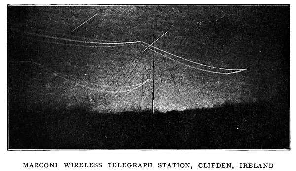
Photographed at night while sending a message across the Atlantic.
The terrific snapping of the electric discharge is heard by one standing near the station, but no light is seen. The strange light given out from the network of wires is invisible to the eye, but is caught by the photographic plate.
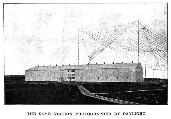 THE SAME STATION PHOTOGRAPHED BY DAYLIGHT
THE STORY OF GREAT INVENTIONS
BY
ELMER ELLSWORTH BURNS
Instructor in Physics in the Joseph Medill High School, Chicago
WITH MANY ILLUSTRATIONS
HARPER & BROTHERS PUBLISHERS
NEW YORK AND LONDON
MCMX
Copyright, 1910, by Harper & Brothers
Published November, 1910.
Printed in the United States of America
CONTENTS
THE AGE OF ARCHIMEDES
Archimedes the first great inventor.—The battle of Syracuse.—Archimedes' principle.—Inventions of the ancient Greeks Page 1
CHAPTER II
THE AGE OF GALILEO
Galileo and the battle for truth.—The pendulum clock.—Galileo's experiment with falling shot.—The telescope.—Galileo's struggle.—Torricelli and the barometer.—Otto von Guericke and the air-pump.—Robert Boyle and the pressure of air and steam.—Pascal and the hydraulic press.—Newton.—Gravitation.—Colors in sunlight Page 9
CHAPTER III
THE EIGHTEENTH CENTURY
James Watt and the steam-engine.—The first steam-engine with a piston.—Newcomen's engine.—Watt's engine.—Horse-power of an engine.—The Leyden jar.—Conductors and insulators.—Two kinds of electric charge.—Franklin's kite experiment.—The lightning-rod.—Galvani and the electric current.—Volta and the electric battery Page 34
CHAPTER IV
FARADAY AND THE FIRST DYNAMO
Count Rumford.—Count Rumford's experiment with the cannon.—Davy.—Faraday's electrical discoveries.—Oersted and electromagnetism.—Ampère.—Arago.—Faraday's first electric motor.—An electric current produced by a magnet.—Detecting and measuring an electric current.—An electric current produced by the magnetic field of another current.—Faraday's dynamo.—A wonderful law of nature Page 55
CHAPTER V
GREAT INVENTIONS OF THE NINETEENTH CENTURY
Electric batteries.—The dry battery.—The storage battery.—The dynamo.—Siemens' dynamo.—The drum armature.—Edison's compound-wound dynamo.—Electric power.—The first electric railway.—Electric lighting.—The telegraph.—Duplex telegraphy.—The telephone.—The phonograph.—Gas-engines.—The steam locomotive.—How a locomotive works.—The turbine Page 88
CHAPTER VI
THE TWENTIETH-CENTURY OUTLOOK
Air-ships.—The aeroplane.—How the Wright aeroplane is kept afloat.—Submarines.—Some spinning tops that are useful.—The monorail-car.—Liquid air and the greatest cold.—The electric furnace and the greatest heat.—The wireless telegraph.—The wireless telephone.—Wonders of the alternating current.—X-rays and radium Page 173
APPENDIX
Brief notes on important inventions Page 237
Index Page 247
ILLUSTRATIONS
| FIG. | PAGE |
| MARCONI WIRELESS-TELEGRAPH STATION, CLIFDEN, IRELAND | Frontispiece |
| THE SAME STATION PHOTOGRAPHED BY DAYLIGHT | |
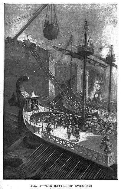
| 1–THE BATTLE OF SYRACUSE | 3 |
| 2–GALILEO'S PENDULUM CLOCK | 11 |
| 3–AN AIR THERMOMETER | 14 |
| 4–TORRICELLI'S EXPERIMENT | 19 |
| 5–GUERICKE'S AIR-PUMP | 22 |
| 6–GUERICKE'S WATER BAROMETER | 24 |
| 7–A LIFT-PUMP | 25 |
| 8–A SIMPLE HYDRAULIC PRESS | 26 |
| 9–HOW AN HYDRAULIC PRESS WORKS | 28 |
| 10–AN HYDRAULIC PRESS WITH BELT-DRIVEN PUMP | 29 |
| 11–NEWTON'S EXPERIMENT WITH THE PRISM | 32 |
| 12–PAPIN'S ENGINE | 36 |
| 13–THE NEWCOMEN ENGINE, IN REPAIRING WHICH WATT WAS LED TO HIS GREAT DISCOVERIES | 39 |
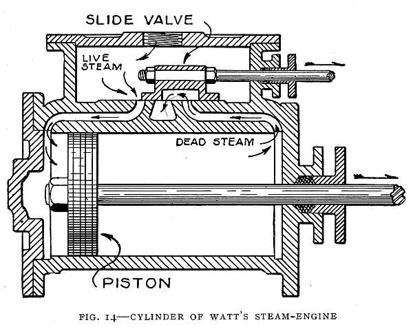
| 14–CYLINDER OF WATT'S STEAM-ENGINE | 41 |
| 15–A FLY-BALL GOVERNOR | 42 |
| 16–A LEYDEN JAR | 43 |
| 17–FRANKLIN'S KITE EXPERIMENT | 47 |
| 18–VOLTA EXPLAINING HIS ELECTRIC BATTERY TO NAPOLEON BONAPARTE | 52 |
| 19–THE FIRST ELECTRIC BATTERY | 54 |
| 20–COUNT RUMFORD'S EXPERIMENT WITH THE CANNON, MAKING WATER BOIL WITHOUT FIRE | 60 |
| 21–OERSTED'S EXPERIMENT | 66 |
| 22–A COIL WITH A CURRENT FLOWING THROUGH IT ACTS LIKE A MAGNET | 67 |
| 23–A BAR OF SOFT IRON WITH A CURRENT FLOWING AROUND IT BECOMES A MAGNET | 67 |
| 24–TWO COILS WITH CURRENTS FLOWING IN THE SAME DIRECTION ATTRACT EACH OTHER | 68 |
| 25–TWO COILS WITH CURRENTS FLOWING IN OPPOSITE DIRECTIONS REPEL EACH OTHER | 68 |
| 26–ARAGO'S EXPERIMENT | 70 |
| 27–ONE POLE OF A MAGNET SPINS ROUND A WIRE THROUGH WHICH AN ELECTRIC CURRENT FLOWS | 71 |
| 28–WHEN A MAGNET IS THRUST INTO A COIL OF WIRE IT CAUSES A CURRENT TO FLOW IN THE COIL, BUT THE CURRENT FLOWS ONLY WHILE THE MAGNET IS MOVING | 73 |
| 29–A COIL OF WIRE AROUND A COMPASS-NEEDLE | 74 |
| 30–FARADAY'S INDUCTION-COIL | 76 |
| 31–HISTORICAL APPARATUS OF FARADAY IN THE ROYAL INSTITUTION 77 | |
| 32–FARADAY'S FIRST DYNAMO | 78 |
| 33–FARADAY'S LABORATORY, WHERE THE FIRST DYNAMO WAS MADE | 79 |
| 34–THE FIRST TRANSFORMER | 80 |
| 35–THE "MAGNETIC FIELD" IS THE SPACE AROUND A MAGNET IN WHICH IT WILL ATTRACT IRON | 81 |
| 36–MAGNETIC FIELD OF A HORSESHOE MAGNET | 81 |
| 37–A DANIELL CELL | 90 |
| 38–A GRAVITY CELL | 91 |
| 39–SHOWING WHAT IS IN A DRY BATTERY | 92 |
| 40–A STORAGE BATTERY, SHOWING THE "GRIDS" | 94 |
| 41–A STORAGE-BATTERY PLATE MADE FROM A SHEET OF LEAD | 95 |
| 42–STURGEON'S ELECTROMAGNET | 97 |
| 43–AN ELECTROMAGNET WITH MANY TURNS OF INSULATED WIRE | 98 |
| 44–AN ELECTROMAGNET LIFTING TWELVE TONS OF IRON | 99 |
| 45–A DYNAMO WITH SIEMENS' ARMATURE | 101 |
| 46–RING ARMATURE | 102 |
| 47–FIRST DYNAMO PATENTED IN THE UNITED STATES | 103 |
| 48–A DRUM ARMATURE, SHOWING HOW AN ARMATURE OF FOUR COILS IS WOUND | 104 |
| 49–A SERIES-WOUND DYNAMO | 106 |
| 50–A SHUNT-WOUND DYNAMO | 107 |
| 51–A COMPOUND-WOUND DYNAMO | 108 |
| 52–ONE OF EDISON'S FIRST DYNAMOS | 109 |
| 53–A DYNAMO MOUNTED ON THE TRUCK OF A RAILWAY CAR | 110 |
| 54–FIRST ELECTRIC LOCOMOTIVE | 113 |
| 55–FIRST EDISON ELECTRIC LOCOMOTIVE | 115 |
| 56–EDISON'S FIRST PASSENGER LOCOMOTIVE | 117 |
| 57–FIRST COMMERCIAL ELECTRIC RAILWAY | 119 |
| 58–EDISON, AMERICA'S GREATEST INVENTOR, AT WORK IN HIS LABORATORY | 122 |
| 59–EDISON'S FAMOUS HORSESHOE PAPER-FILAMENT LAMP OF 1870 | 123 |
| 60–FIRST COMMERCIAL EDISON ELECTRIC-LIGHTING PLANT; INSTALLED ON THE STEAMSHIP "COLUMBIA" IN MAY, 1880 | 125 |
| 61–A TELEGRAPH SOUNDER | 129 |
| 62–MORSE'S FIRST TELEGRAPH INSTRUMENT | 131 |
| 63–A TELEGRAPHIC CIRCUIT WITH RELAY AND SOUNDER | 132 |
| 64–A SIMPLE TELEGRAPHIC CIRCUIT | 133 |
| 65–FIRST TELEGRAPH INSTRUMENT USED FOR COMMERCIAL WORK | 135 |
| 66–HOW TWO MESSAGES ARE SENT OVER ONE WIRE AT THE SAME TIME | 137 |
| 67–HOW TWO MESSAGES ARE SENT OVER ONE WIRE AT THE SAME TIME. BRIDGE METHOD | 139 |
| 68–FIRST BELL TELEPHONE RECEIVER AND TRANSMITTER | 142 |
| 69–A TELEPHONE RECEIVER | 143 |
| 70–TWO RECEIVERS USED AS A COMPLETE TELEPHONE | 145 |
| 71–CARBON-DUST TRANSMITTER | 146 |
| 72–THE PHONAUTOGRAPH, A FORERUNNER OF THE PHONOGRAPH | 149 |
| 73–EDISON'S FIRST PHONOGRAPH AND A MODERN INSTRUMENT | 150 |
| 74 to 77–THE FOUR-CYCLE GAS-ENGINE | 152 |
| 78–TWO-CYCLE GAS-ENGINE. CRANK AND CONNECTING-ROD ARE ENCLOSED WITH THE PISTON | 154 |
| 79–SELDEN "EXPLOSION BUGGY," FORERUNNER OF THE MODERN AUTOMOBILE | 155 |
| 80–SOME EARLY LOCOMOTIVES | 158 |
| 81–HOW A LOCOMOTIVE WORKS | 161 |
| 82–HERO'S ENGINE | 164 |
| 83–AN UNDERSHOT WATER-WHEEL WITH CURVED BLADES | 165 |
| 84–AN OVERSHOT WATER-WHEEL | 166 |
| 85–DE LAVAL STEAM-TURBINE | 167 |
| 86–A MODERN STEAM-TURBINE WITH TOP CASING RAISED SHOWING BLADES | 168 |
| 87–DIAGRAM OF TURBINE SHOWN IN FIG. 86 | 169 |
| 88–A STEAM-TURBINE THAT RUNS A DYNAMO GENERATING 14,000 ELECTRICAL HORSE-POWER | 170 |
| 89–BRITISH ARMY AIR-SHIP "NULLI SECUNDUS" READY FOR FLIGHT | 176 |
| 90–BASKET, MOTOR, AND PROPELLER OF THE BRITISH ARMY AIR-SHIP "NULLI SECUNDUS" | 178 |
| 91–A ZEPPELIN AIR-SHIP | 181 |
| 92–COUNT ZEPPELIN'S "DEUTSCHLAND," THE FIRST AIR-SHIP IN REGULAR PASSENGER SERVICE | 182 |
| 93–THE BALDWIN AIR-SHIP USED IN THE UNITED STATES ARMY | 183 |
| 94–IN FULL FLIGHT | 185 |
| 95–WRIGHT AIR-SHIP IN FLIGHT | 187 |
| 96–HOW THE WRIGHT AIR-SHIP IS KEPT AFLOAT | 189 |
| 97–THE SEAT AND MOTOR OF THE WRIGHT AEROPLANE | 191 |
| 98–THE BLÉRIOT MONOPLANE | 192 |
| 99–THE "PLUNGER" | 195 |
| 100–U. S. SUBMARINE "SHARK" READY FOR A DIVE | 197 |
| 101–FIRST SUBMARINE CONSTRUCTED IN THE UNITED STATES. IT WENT TO THE BOTTOM WITH SEVEN MEN, WHO WERE DROWNED | 198 |
| 102–HOW MEN IN A SUBMARINE SEE WHEN UNDER THE WATER | 199 |
| 103–A TOP THAT SPINS ON A STRING | 200 |
| 104–A CAR THAT RUNS ON ONE RAIL | 202 |
| 105–MANUFACTURING DIAMONDS—FIRST OPERATION | 207 |
| 106–MANUFACTURING DIAMONDS—SECOND OPERATION | 209 |
| 107–MANUFACTURING DIAMONDS—THIRD OPERATION | 211 |
| 108–MARCONI AND HIS WIRELESS-TELEGRAPH SENDING AND RECEIVING INSTRUMENTS | 215 |
| 109–DIAGRAM OF WIRELESS-TELEGRAPH SENDING APPARATUS | 217 |
| 110–DIAGRAM OF MARCONI WIRELESS-TELEGRAPH RECEIVING APPARATUS | 218 |
| 111–RECEIVER OF BELL'S PHOTOPHONE | 223 |
| 112–A GAS FLAME IS SENSITIVE TO ELECTRIC WAVES | 224 |
| 113–CAPTAIN INGERSOLL ON BOARD THE U. S. BATTLE-SHIP "CONNECTICUT" USING THE WIRELESS TELEPHONE | 226 |
| 114–INCANDESCENT ELECTRIC LAMP LIGHTED THOUGH NOT CONNECTED TO ANY BATTERY OR DYNAMO | 229 |
| 115–AN ELECTRIC DISCHARGE AT A PRESSURE OF 12,000,000 VOLTS, A CURRENT OF 800 AMPERES IN THE SECONDARY COIL | 230 |
| 116–AN ELECTRIC DISCHARGE SIXTY-FIVE FEET IN LENGTH | 231 |
| 117–A PHYSICIAN EXAMINING THE BONES OF THE ARM BY MEANS OF X-RAYS | 233 |
| 118–X-RAY PHOTOGRAPH OF THE EYE | 234 |
| 119–PHOTOGRAPH MADE WITH RADIUM | 235 |
INTRODUCTORY NOTE
Great inventions are a never-failing source of interest to all of us, and particularly to the boy in his teens. The dynamo, the electric motor, the telegraph, with and without wires, the telephone, air-ships, and many other inventions excite in him an interest which is deeper than mere curiosity. He wants to know how these things work, and how they were invented. The man is so absorbed in the present that he cares little for the past. Not so with the boy. He cares for the history of inventions, and in this he is wiser than the man, for it is only by a study of its origin and growth that we can understand the larger significance of a great invention.
Great inventions have their origin in great discoveries. The story of great inventions, therefore, includes the story of the discoveries out of which they have arisen. The stories of the discoveries and the inventions are inseparable from the lives of the men who made them, and so we must deal with biography, which in itself is of interest to the boy. Such a story is the story of physical science in the service of humanity.
The interest of the youth in great inventions is unquestioned. Shall we stifle this interest by overemphasis of technical detail, or shall we minister to it as a thing vital in the life of the youth of to-day?
A few sentences quoted from G. Stanley Hall will indicate the author's point of view. "The youth is in the humanist stage. Nature is sentiment before it becomes idea or formula or utility." "The heroes and history epochs of each branch [of science] add another needed quality to the still so largely humanistic stage." "A new discovery, besides its technical record, involves the added duty of concise and lucid popular statement as a tribute to youth." The need of a "concise and lucid popular statement" of the rise of the great inventions which form the material basis of our modern civilization and all of which are new to the young mind, has no doubt been keenly felt by others as it has been by the author. The story of our great inventions has been told in sundry volumes for adult readers, but nowhere has this story, alive with human interest, been told in a form suited to the young. It was the realization of this need growing out of years of experience in teaching these branches that led the author to attempt the task of writing the story.
The purpose of this book is to tell in simple language how our great inventions came into being, to depict the life-struggles of the men who made them, and, in the telling of the story, to explain the working of the inventions in a way the boy can understand. The stories which are here woven together present the great epochs in the history of physics, and are intended to give to the young reader a connected view of the way in which our great inventions have arisen out of scientific discovery on the one hand, and conditions which we may call social and economic on the other hand. If the book shall appeal to young readers, and lead them to an appreciation of the meaning of a great invention, the author will feel that his purpose has been achieved.
The author is deeply indebted to Dr. Charles A. McMurry and Prof. Newell D. Gilbert, of the Northern Illinois State Normal School; Profs. C. R. Mann and R. A. Millikan, of the University of Chicago; and Prof. John F. Woodhull, of Columbia University, for reading the manuscript and offering valuable suggestions. Acknowledgment is further made here of valuable aid in collecting material for illustrations and letter-press. Such acknowledgment is due to Prof. A. Gray, University of Glasgow; Prof. Antonio Favaro, Royal University of Padua; Prof. A. Zammarchi, Brescia, Italy; Mr. Nikola Tesla; the Royal Institution, London; McClure's Magazine; The Technical World Magazine; The Scientific American; the Ellsworth Company; Commonwealth-Edison Company; Association of Edison Illuminating Companies; Electric Controller and Supply Company; Kelley-Koett Manufacturing Company; Watson-Stillman Company; Gould Storage Battery Company; Thordarson Electric Company; the Westinghouse Machine Company; Marconi Wireless Telegraph Company of America, and the Siemens-Schuckert Werke, Berlin.
The drawings illustrating Faraday's experiments are from exact reproductions of Faraday's apparatus, made by Mr. Joseph G. Branch, author of Conversations on Electricity, and are reproduced by his kind permission.
Chicago, June, 1910.
THE STORY OF GREAT INVENTIONS
Chapter I
THE AGE OF ARCHIMEDES
Archimedes, the First Great Inventor
Archimedes, the first great inventor, lived in Syracuse more than two thousand years ago. Syracuse was a Greek city on the island of Sicily. The King of Syracuse, Hiero, took great interest in the discoveries of Archimedes.
One day Archimedes said to King Hiero that with his own strength he could move any weight whatever. He even said that, if there were another earth to which he could go, he could move this earth wherever he pleased. The King, full of wonder, begged of him to prove the truth of his statement by moving some very heavy weight. Whereupon Archimedes caused one of the King's galleys to be drawn ashore. This required many hands and much labor. Having manned the ship and put on board her usual loading, he placed himself at a distance and easily moved with his hand the end of a machine which consisted of a variety of ropes[2] and pulleys, drawing the ship over the sand in as smooth and gentle a manner as if she had been under sail. The King, quite astonished, prevailed with Archimedes to make for him all manner of machines which could be used either for attack or defence in a siege.
The Battle of Syracuse
During the life of King Hiero Syracuse had no occasion to use the war machines of Archimedes. The grandson of King Hiero, who succeeded to the throne, was a tyrant. He attempted to throw off the sovereignty of Rome and entered into an alliance with Carthage. His cruelty toward his own people was so great that, after a short reign, he was assassinated. There was anarchy in Syracuse for a time, the Roman and anti-Roman parties striving for supremacy. The anti-Roman party gaining possession of the city, the Romans, in order to bring Syracuse again into subjection, prepared for an attack by sea and land. Then it was that Syracuse had need of the war machines made by Archimedes (Fig. 1).
The Romans came with a large land force and a fleet. They were sure that within five days they could conquer the city. But there are times when one man with brains is worth more than an army. In the battle which followed, Archimedes with his inventions was more than a match for the Romans.
The city was strong from the fact that the wall on one side lay along a chain of hills with overhanging brows; on the other side the wall had its foundation close down by the sea.[3]
[4]
A fleet of sixty ships commanded by Marcellus bore down upon the city. The ships were full of men armed with bows and slings and javelins with which to dislodge the men who fought on the battlements. Eight ships had been fastened together in pairs. These double vessels were rowed by the outer oars of each of the pair. On each pair of ships was a ladder four feet wide and of a height to reach to the top of the wall. Each side of the ladder was protected by a railing, and a small roof-like covering, called a penthouse, was fastened to the upper end of the ladder. This covering served to protect the soldiers until they could reach the top of the wall. They thought to bring these double ships close to shore, raise the ladders by ropes and pulleys until they rested against the wall, then scale the wall and capture the city.
But Archimedes had crossbows ready, and, when the ships were still at some distance, he shot stones and darts at the enemy, wounding and greatly annoying them. When these began to carry over their heads, he used smaller crossbows of shorter range, so that stones and darts fell constantly in their midst. By this means he checked their advance, and finally Marcellus, in despair, was obliged to bring up his ships under cover of night. But when they had come close to land, and so too near to be hit by the crossbows, they found that Archimedes had another contrivance ready. He had pierced the wall as high as a man's head with many loopholes which on the outside were about as big as the palm of the hand. Inside the wall he had stationed archers and men with crossbows to shoot down the marines. By these means he not only baffled the enemy, but killed the greater number of them. When they tried to use their ladders, they discovered[5] that he had cranes ready all along the walls, not visible at other times but which suddenly reared themselves above the wall from the inside and stretched their beams far over the battlements, some of them carrying stones weighing about five hundred pounds, and others great masses of lead. So, whenever the ships came near, these beams swung round on their pivots and by means of a rope running through a pulley dropped the stones upon the ships. The result was that they not only smashed the ships to pieces, but killed many of the soldiers on board.
Another machine made by Archimedes was an "iron hand" or grappling-hook swung on a chain and carried by a crane. The hook was dropped on the prow of a ship, and when it had taken hold the ship was lifted until it stood on its stern, then quickly dropped, causing it either to sink or ship a great quantity of water.
With such machines, unknown before, Archimedes drove back the enemy. On the landward side similar machines were used. The Romans were reduced to such a state of terror that "if they saw but a rope or a stick put over the walls they cried out that Archimedes was levelling some machine at them and turned their backs and fled."
After a long siege, however, hunger forced the Syracusans to surrender. Marcellus so admired the genius of Archimedes that he gave orders that he should not be injured. Yet, in the sack of the city which followed, Archimedes was slain by a Roman soldier.
The Roman historian Livy records that "Archimedes, while intent on some figures which he had made in the dust, although the confusion was as great as could possibly be,[6] was put to death by a soldier who did not know who he was; that Marcellus was greatly grieved at this, and that pains were taken about his funeral, while his relations also were carefully sought and received honor and protection on account of his name and memory."
Archimedes' Principle
Hiero, when he became King of Syracuse, decreed that a crown of gold, of great value, should be placed in a certain temple as an offering to the gods, and sent to a manufacturer the correct weight of gold. In due time the crown was brought to the King, and a beautiful piece of work it was. The weight of the crown was the same as that of the gold, but a report was circulated that some of the gold had been taken out and silver supplied in its place. Hiero was angry, but knew no method by which the theft might be detected. He therefore requested Archimedes to give the matter his attention.
While trying to solve this problem Archimedes went one day to a bath. As he got into the bath-tub he saw that as his body became immersed the water ran out of the tub. He quickly saw how he could solve the problem, leaped out of the bath in joy, and, running home naked, cried out with a loud voice "Eureka! eureka!" (I have found it! I have found it!)
Using a piece of gold and a piece of silver, each equal in weight to the crown, and a large vase full of water, he proved that the crown was not pure gold, and found how much silver had been mixed with the gold.
The incident of the golden crown may have been the[7] starting-point of Archimedes' study of solid bodies when immersed in fluids. Every one knows that a boy can lift a heavy stone under water that he could not lift out of water. The stone seems lighter when in the water. A diver with his lead-soled shoes could scarcely walk on land, but walks easily under water. When the diver comes up, the place where he was immediately becomes filled with water. Now, whatever that water weighs which fills the diver's place, just that much weight will the diver lose when he goes down. What is true of the diver is true of the stone or of any object under water. The stone when in the water loses just as much weight as the weight of the water that would fill its place. This is the fact which was discovered by Archimedes and which is called "Archimedes' Principle."
It is said by an ancient author that Archimedes invented more than forty machines. Of these the best known are the block and tackle, the endless screw (worm gear), and the water snail, or Archimedean screw. Yet his delight was not in his machines, but in his mathematics. Though he had invented machines to please his king, he regarded such work as trifling, and took little interest in the common needs of life.
Inventions of the Ancient Greeks
The common needs of life are to-day the chief concern of the greatest men, and so we find it hard to sympathize with this view of Archimedes. His view, however, was that of other learned men of his time, that the common needs of life are beneath the dignity of the scholar, and so we can see why the Greeks made so few great inventions.[8]
Hero, who lived a century later than Archimedes, invented a steam-engine, which, however, was only a toy. A water-clock, in which the first cog-wheels were used, was invented by another Greek named Ktesibus, who also invented the force-pump. The suction-pump was known in the time of Aristotle, who lived about a century before the time of Archimedes, but the inventor is unknown.
Concerning electricity, the Greeks knew very little. They knew that amber when rubbed will attract light objects, such as dust or chaff. Amber was called by the Greeks "electron," because it reflected the brightness of the sunlight, and their name for the sun was "Elector." From the Greek name for amber we get our word "electricity."
The Greeks possessed scarcely more knowledge of magnets than of electricity. In fact, their ideas of magnets cannot be called knowledge, for they consisted chiefly of legends.
They told of the shepherd Magnes, who, while watching his flock on Mount Ida, suddenly found the iron ferrule of his staff and the nails of his shoes adhering to a stone; that, later, this stone was called, after him, the "Magnes stone," or "Magnet."
They told impossible stories of iron statues being suspended in the air by means of magnets, and of ships sailing near the magnetic mountains when every nail and piece of iron in the ship would fly to the mountain, leaving the ship a wreck upon the waves.
[9]
Chapter II
THE AGE OF GALILEO
Galileo and the Battle for Truth
For eighteen centuries after the time of Archimedes no inventions of importance were made. Men sought for truth where truth could not be found. They looked within their mouldy manuscripts and asked, "What do the great philosophers say ought to happen?" instead of looking at nature and asking, "What does happen?" And when a man arose who dared to doubt the authority of the old masters and turn to nature to find out the truth, all the weapons at the command of the old school were hurled against him.
Let us, at this distance, blame neither the one side nor the other. The conflict was inevitable. It was an accident of history that the brunt of the attack fell upon a man born in Italy in 1564, and that the battle was fought chiefly in the "Eternal City," from which centuries before had marched the legions that conquered the world.
The boy, Galileo, who was to become the central figure of the great conflict, was talented in many ways. In lute-playing his skill excelled that of his father, who was one of the noted musicians of his day. His skill in drawing was[10] such that noted artists submitted their work to him for criticism. He wrote essays on the works of Dante and other classical writers. He amused his boy companions by constructing toy machines which, though ingenious, did not always work.
His preference was for mechanics, but, as this subject offered little prospect of profitable work, he took up the study of medicine in accordance with his father's wishes.
In his eighteenth year he entered the University of Pisa. Here he found men who refused to think for themselves, but decided every question by referring to what the ancient philosophers said. Galileo could not endure such slavish submission to authority. So strongly did he assert himself that he was nicknamed "The Wrangler," and, by his wrangling, he lost a scholarship in the university.
He neglected his medical studies and secretly studied mathematics. His father, learning of this, consented to his becoming a mathematician. Thus he followed his bent, though it seemed to lead directly to poverty.
The Pendulum Clock
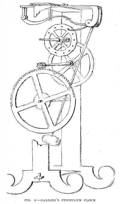
It was while a student at the University of Pisa that he discovered a law of pendulums which makes possible our pendulum clocks. While at his devotions in the cathedral, he observed the swinging of the bronze lamp which had been drawn back for lighting. Timing its swinging by means of his pulse, the only timepiece in his possession, he found that the time of one swing remained the same, though the length of the swing grew smaller and smaller. This [12]discovery led to his invention of an instrument for physicians' use in timing the pulse. About fifty years later he invented the pendulum clock (Fig. 2).
Lack of funds compelled him to leave the university without completing his course. He returned to the parental roof and continued his scientific studies. The writings of Archimedes were his favorite study. With Archimedes' famous experiment on King Hiero's crown as a starting-point, he discovered the laws of floating bodies, which explain why a ship or other object floats on water, and invented a balance for weighing objects in water.
But such employment won nothing more substantial than honor and fame. Food and clothing were needed. For two years he strove without success to secure employment. At the end of that time he was appointed professor of mathematics in the University of Pisa at the magnificent salary of sixty scudi (about sixty-three dollars) per year. "But any port in a storm; and in Galileo's needy circumstances even this wretched salary was not to be rejected." Moreover, he could add somewhat to his income by private tutoring.
Galileo's Experiment with Falling Shot
While teaching at the University of Pisa, he performed his famous experiment of dropping from the top of the leaning tower two shot, one weighing ten pounds, the other one pound. Now, according to Aristotle, the ten-pound shot should fall in one-tenth the time required by the one-pound shot. But the assembled company of professors and students saw the two shot start together, fall together, and[13] strike the ground at the same instant, and still refused to believe their own eyes. They continued to affirm that a weight of ten pounds would reach the ground in a tenth of the time taken by a one-pound weight, because they were able to quote chapter and verse in which Aristotle assured them that such is the fact. Thus Galileo made enemies of the other professors, but for a time they could do nothing more than annoy him.
About this time Galileo incurred the wrath of the Grand Duke of Tuscany, from whom he had received his appointment. He was commissioned to examine a machine invented by a nephew of the Grand Duke for the purpose of cleaning harbors. Galileo plainly said that the machine was worthless. It was tried, and his opinion proved true. But like the kings of olden time who killed the bearer of evil tidings even though the tidings were true, his enemies made his position so unpleasant that he resigned.
He had neither employment nor money. His father's death occurring about this time, threw upon him the care of a mother, a worthless brother, and two sisters. In his distress he sought help from a friend, and secured an appointment as professor of mathematics in the University of Padua. His salary was one hundred and eighty florins (about ninety-five dollars), while other professors received more than ten times as much.
While at Padua, Galileo was busy inventing. He invented the sector, which is to be found in most cases of mathematical instruments and is used in certain kinds of drawing. He also invented an air thermometer (Fig. 3), the first instrument for measuring temperature.[14]
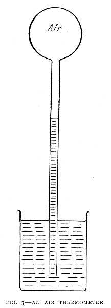 FIG. 3–AN AIR THERMOMETER
When the air in the bulb grows cooler it contracts, and the air outside forces the Water up the tube. When the air in the bulb grows warmer it expands and forces the water down in the tube.
In 1604 there appeared a new star of great brilliancy. It continued to shine with varying brightness for eighteen months, and then vanished. This was a strange event, and Galileo made use of it. He proved that the new star must lie among the most distant of the heavenly bodies, and this fact did not agree with Aristotle's view that the heavens are perfect, and therefore never change. A heated controversy followed, and Galileo came out boldly in favor of the theory that the earth revolves about the sun, the prevailing notion then being that the earth does not move, but that the sun and other heavenly bodies revolve around it.
The Telescope
In 1609 Galileo learned of a discovery that was to be of great value to the world, but a source of untold trouble to himself. An apprentice of a Dutch optician, while playing with spectacle lenses, chanced to observe that if two of the lenses were placed in a certain position objects seen through them appeared much nearer. Galileo, learning of this, set to work to construct a spy-glass, applying his knowledge of light. In one day he had constructed such an instrument, in which he used two lenses like the lenses of the modern opera-glass. Thus, while the Dutchman's discovery was by accident, Galileo's was by reasoning, and was the more fruitful, as we shall see.
Galileo continued improving his telescope until he had made one which would magnify thirty times. He was the first to apply the telescope to the study of the heavenly bodies. The most startling of his discoveries was that of[16] the moons of the planet Jupiter, which he called new planets.
This aroused the fury of his enemies, who ridiculed the idea of there being new planets; "for," they said, "to see these planets they must first be put inside the telescope." The excitement was intense. Poets chanted the praise of Galileo. A public fête was held in his honor. One of his pupils was imprisoned in the tower of San Marco, where he had gone to make observations with his telescope, and could not escape until the crowd had satisfied their curiosity. Some of the philosophers refused to look lest they should see and be convinced.
Galileo's Struggle
His enemies sought to steal from him the honor of his discoveries. Some claimed to have made the discoveries before Galileo did. Others claimed that his discoveries were false, that their only use was to gratify Galileo's vanity and thirst for gold. In these trying times the friendship of the great astronomer Kepler warded off some of the most exasperating attacks.
Galileo's fame spread throughout Europe. Students came in great numbers, so that he had little leisure left for his own studies. He therefore decided to leave Padua, and secured an appointment as mathematician and philosopher to the Grand Duke of Tuscany. This appointment took him to Florence. It was here that an incident occurred that marked the beginning of a persecution which continued to the end of his life.
As we read the story of this conflict let us remember that[17] it was not primarily a conflict between the Roman Catholic Church and Galileo. It was a conflict of principles. On the one side were arrayed those who said that men should always believe as the ancient writers did; on the other, those who said men should think for themselves. In the first party were most of the university professors and others who dreaded the introduction of new beliefs, whether in religion or science. In the second party were Galileo and a small band of devoted followers.
At a dinner at the table of the Grand Duke in Pisa the conversation turned on the moons of Jupiter. Some praised Galileo. Others condemned him, saying that the Holy Scriptures were opposed to his theory of the motion of the earth. A friend reported the incident to Galileo, and he replied to the arguments of his opponents in a letter which was made public. No doubt the sting of his sarcasm made his enemies more bitter. He admitted that the Scriptures cannot lie or err, but this, he said, does not hold good of those who attempt to explain the Scriptures. In another letter, he quoted with approval a saying of Cardinal Baronius, "The Holy Spirit intended to teach us in the Bible how to go to Heaven, not how the heavens go."
The first shot had been fired. The battle was on, and the Church, because it possessed the most powerful weapons of attack, was used by the combined forces to break the power of Galileo's reasoning. He went to Rome to make his defence, but was commanded by the Holy Office not to hold or teach that the sun is immovable, and that the earth moves about the sun.
During another visit to Rome there was shown to Galileo[18] an instrument which, it was said, would show a flea as large as a cricket. Galileo recalled that some years before he had so arranged a telescope that he had seen flies which he said looked as big as a lamb, and were covered all over with hair. This was the first microscope. Galileo quickly improved the instrument, and soon his microscopes were in great demand.
In violation of the decree of the Church, to which he had submitted, he published his most famous work in which he defended the theory that the earth moves about the sun. The book was the outcome of his life-work, but the Church believed it dangerous. He was summoned to Rome. Confined to a sick-bed, he pleaded for delay, which was granted. Before he recovered, however, the summons was made imperative. He must go to Rome, or be carried in irons. He went in a litter, carried by servants of the Grand Duke. In Rome he was to appear before the Inquisition. There he was treated with a consideration never before accorded to a prisoner of the Inquisition. Nor was he subjected to torture, as has been stated by some. He was found guilty of teaching the doctrine that the sun does not move, and that the earth moves about the sun. He was compelled to recant, and sentenced to the prison of the Holy Office and, by way of penance, to repeat once a week for three years the seven penitential Psalms.
He yielded without reserve to the decree of the Inquisition, renounced his "errors and heresies," and, with his hand on the Bible, took oath never again to teach the forbidden doctrine.
And now, though a shattered old man of seventy-four,[19] enjoined to silence on the chief results of his life-work, nothing could quench his devotion to science. In these last years, he published a new book which, with his earlier work, entitles him to be regarded as the founder of the science of mechanics.
In his study of machines Galileo found that no machine will do work of itself. Whenever a machine is at work, a man or a horse, or some other power, is at work upon the machine. In no case will a machine do work without receiving an equal amount of work.
Torricelli and the Barometer
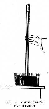
Galileo had a pump which he found would not work when the water was thirty-five feet below the valve. He thought the pump was injured, and sent for the maker. The maker assured him that no pump would do better. This led Torricelli, one of Galileo's pupils, to the discovery of the barometer. Men had said that water rises in a pump because nature abhors a vacuum. Torricelli believed that air-pressure and not nature's "horror of a vacuum" is the cause of water rising in a pump. He invented the barometer to measure air-pressure.
The first barometer was a glass tube filled with quick-silver or mercury (Fig. 4). The tube was closed at the[20] upper end, and the lower end, which was open, dipped in a dish of mercury. He allowed the tube to stand, and saw that the height of the mercury changed. This he believed was because the air-pressure changed. Wind, Torricelli said, is caused by a difference of air-pressure, which is due to unequal heating of the air. For this reason a cool breeze blows from the mountain top to the heated valley, or from sea to land on a summer day.
Otto Von Guericke and the Air-Pump
About this time a German burgomaster, Otto von Guericke, of Magdeburg, was performing experiments on air-pressure. The Thirty Years' War had been raging for thirteen years. The Swedish King, Gustavus Adolphus, had landed in Germany, and was winning victory after victory over the imperial troops. Magdeburg had entered into an alliance with the Swedish King, by which he was granted free passage through the city, while, on the other hand, he promised protection to the city.
The imperial army under Tilly and Pappenheim laid siege to the city. On the one side there was hope that Gustavus would arrive in time to effect a rescue; on the other, a determination to conquer before such aid could arrive. While Gustavus was on his way to the rescue, Magdeburg was taken by storm, and the most horrible scene of the Thirty Years' War was enacted. Tilly gave up the city to plunder, and his soldiers without mercy killed men, women, and children. In the midst of the scene of carnage the city was set on fire, and soon the horrors of fire were added to the[21] horrors of the sword. In less than twelve hours twenty thousand people perished.
Guericke's house and family were saved, but the sufferings of the city were not yet ended. In five years the enemy was again before the walls, and Magdeburg, then in the possession of the Swedes, was compelled to yield to the combined Saxon and imperial troops. Guericke entered the service of Saxony, and was again made mayor of the city.
In the midst of these scenes of war, he found time to continue his studies. He made the first air-pump, and with it performed experiments which led to some very important results.
The experiments which Guericke made with his air-pump aroused the attention of the princes, and especially Emperor Ferdinand. Guericke was called to perform his experiments before the Emperor. The most striking of these experiments he performed with two hollow copper hemispheres about a foot in diameter, fitted closely together. When the air was pumped out, sixteen horses were barely able to pull the hemispheres apart, though, when air was admitted, they fell apart of their own weight.
Another experiment which astonished his audience was performed with the cylinder of a large pump (Fig. 5). A rope was tied to the piston. This rope was passed over a pulley, and a large number of men applied their strength to the rope to hold the piston in place. When the air was taken out of the cylinder, the piston was forced down by air-pressure, and the men were lifted violently from the ground. This experiment, as we shall see, was of great importance in the invention of the steam-engine.[22]
[23]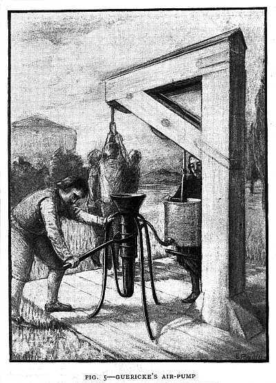
Guericke's study of air-pressure led him to make a water barometer (Fig. 6). This consisted of a glass tube about thirty feet long dipping into a dish of water. The tube was filled with water, and the top projected above the roof of the house. On the water in the tube he placed a wooden image of a man. In fair weather the image would be seen above the housetop. On the approach of a storm the image would drop out of sight. This led his superstitious neighbors to accuse him of being in league with Satan.
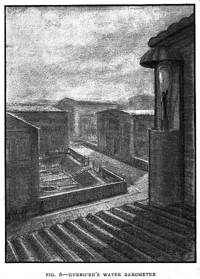 FIG. 6–GUERICKE'S WATER BAROMETER
In fair weather the image appeared above the housetop. When a storm was approaching the image dropped below the roof into the house.
The first electrical machine was made by Guericke. This was simply a globe of sulphur turning on a wooden axle. He observed that when the dry hand was held against the revolving globe, the globe would attract bits of paper and other light objects.
Robert Boyle and the Pressure of Air and Steam
Robert Boyle, in England, improved the air-pump and performed many new and interesting experiments with it. One of his experiments was to make water boil by means of an air-pump without applying heat. It is now well known that water when boiling on a high mountain is not so hot as when boiling down in the valley. This is because the air-pressure is less on the mountain top than in the valley. By using an air-pump to remove the air-pressure, water may be made to boil when it is still quite cold to the hand.
Boyle compared the action of air under pressure to a steel spring. The "spring" of the air is evident to us in the pneumatic tire of the bicycle or automobile. Boyle found that the more air is compressed the greater is its pressure or "spring," and that steam as it expands exerts [25]less and less pressure. This is important in the steam-engine.
Pascal and the Hydraulic Press
It was Blaise Pascal, a Frenchman, who proved beyond the possibility of a doubt that air-pressure supports the mercury in a barometer, and lifts the water in a pump (Fig. 7). He had two mercury barometers exactly alike set up at the foot of a mountain. The mercury stood at the same height in each. Then one barometer was left at the foot of the mountain, and the other was carried to the summit, about three thousand feet high. The mercury in the second barometer then stood more than three inches lower than at first. As the barometer was carried down the mountain the mercury slowly rose until, at the foot, it stood at the same height as at first. The party stopped about half-way down the mountain, allowing the barometer to rest there for some time, and[26] observing it carefully. They found that the mercury stood about an inch and a half higher than at the foot of the mountain. During all this time the height of the mercury in the barometer which had been left at the foot of the mountain did not change.
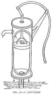 FIG. 7–A LIFT-PUMP
Air pressing down on the water in the well causes the water to rise in the pump. The air can do this only when the plunger is at work removing air or water and reducing the pressure inside the pump.
It is now known that when a barometer is carried up to a height of nine hundred feet, the mercury stands an inch lower than at the earth's surface. For every nine hundred feet of elevation the mercury is lowered about one inch. In this way the height of a mountain can be measured, and a man in a balloon or an air-ship can tell at what height he is sailing. For this purpose, however, a barometer is used that is more easily carried than a mercury barometer.
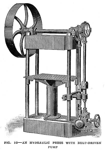
Pascal invented the hydraulic press, a machine with which he said he could multiply pressure to any extent, which reminds us of Archimedes' saying that, with his own hand, he could move the earth if only he had a place to stand. Pascal could so arrange his machine that a man pressing with a force of a hundred pounds on the handle could produce a pressure of many tons. In fact, a man can so arrange this machine that he can lift any weight whatever (Fig. 8).
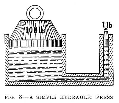
The hydraulic press has two cylinders. One cylinder[27] must be larger than the other. The two cylinders are filled with a liquid, as water or oil, and are connected by a tube so that the liquid can flow from one cylinder into the other. There is a tightly fitting piston in each cylinder. If one piston has an area of one square inch, and the other has an area of one hundred square inches, then every pound of pressure on the small piston causes a hundred pounds of pressure on the large piston. A hundred pounds on the small piston would lift a weight of ten thousand pounds on the large piston. But we can see that the large piston cannot move as fast as the small one does. Though we can lift a very heavy weight with this machine, we must expect this heavy weight to move slowly. There must be a loss in speed to make up for the gain in the weight lifted (Fig. 9). An hydraulic press with belt-driven pump is illustrated in Fig. 10.
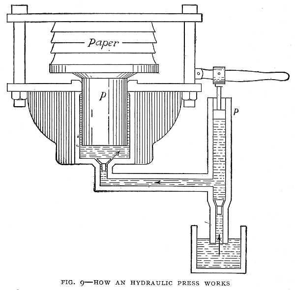 FIG. 9–HOW AN HYDRAULIC PRESS WORKS
One man with the machine can exert as much pressure as a hundred men could without the machine. The arrows show the direction in which the liquid is forced by the action of the plunger p. The large piston P is forced up, thus compressing the paper.
Newton
Sir Isaac Newton as a boy did not show any unusual talent. In school he was backward and inattentive for a number of years, until one day the boy above him in class gave him a kick in the stomach. This roused him and, to avenge the insult, he applied himself to study and quickly passed above his offending classmate. His strong spirit was aroused, and he soon took up his position at the head of his class.
It was his delight to invent amusements for his classmates. He made paper kites, and carefully thought out the best shape for a kite and the number of points to which to attach the string. He would attach paper lanterns to[28] these kites and fly them on dark nights, to the delight of his companions and the dismay of the superstitious country people, who mistook them for comets portending some great calamity. He made a toy mill to be run by a mouse, which he called the miller; a mechanical carriage, run by a handle[29] worked by the person inside, a water-clock, the hand of which was turned by a piece of wood which fell or rose by the action of dropping water.
At the age of fifteen, his mother, then a widow, removed him from school to take charge of the family estate. But the farm was not to his liking. The sheep went astray,[30] and the cattle trod down the corn while he was perusing a book or working with some machine of his own construction. His mother wisely permitted him to return to school. After completing the course in the village school he entered Trinity College, Cambridge.
Gravitation
It was in the year following his graduation from Cambridge that he made his greatest discovery—that of the law of gravitation. A plague had broken out in Cambridge, to escape which Newton had retired to his estate at Woolsthorpe. Here he was sitting one day alone in the garden thinking of the wonderful power which causes all bodies to fall toward the earth. The same power, he thought, which causes an apple to fall to the ground causes bodies to fall on the tops of the highest mountains and in the deepest mines. May it not extend farther than the tops of the mountains? May it not extend even as far as the moon? And, if it does, is not this power alone able to hold the moon in its orbit, as it bends into a curve a stone thrown from the hand?
There followed a long calculation requiring years to complete. Seeing that the results were likely to prove his theory of gravitation, he was so overcome that he could not finish the work. When this was done by one of his friends, it was found that Newton's thought was correct—that the force of gravitation which causes bodies to fall at the earth's surface is the same as the force which holds the moon in its orbit. As the earth and moon attract each[31] other, so every star and planet attracts every other star and planet, and this attraction is gravitation.
Colors in Sunlight
About the same time that he made his first discoveries regarding gravitation, he took up the study of light with a view to improving the construction of telescopes. His first experiment was to admit sunlight into a darkened room through a circular hole in the shutter, and allow this beam of light to pass through a glass prism to a white screen beyond. He expected to see a round spot of light, but to his surprise the light was drawn out into a band of brilliant colors.
He found that the light which comes from the sun is not a simple thing, but is composed of colors, and these colors were separated by the glass prism. In the same way the colors of sunlight are separated by raindrops to form a rainbow. The colors may be again mingled together by passing them through a second prism. They will then form a white light.
Suppose that the light of the sun were not composed of different colors, that all parts of white light were alike, then there would be no colors in nature. All the trees and flowers would have a dull, leaden hue, and the human countenance would have the appearance of a pencil-sketch or a photographic picture. The rainbow itself would dwindle into a narrow arch of white light; the sun would shine through a gray sky, and the beauty of the setting sun would be replaced by the gray of twilight (Fig. 11).[32]
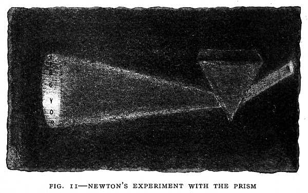 FIG. 11–NEWTON'S EXPERIMENT WITH THE PRISM
Sunlight separated into the colors of the rainbow. The seven colors are: violet, indigo, blue, green, yellow, orange, red.
One of Newton's inventions was a reflecting telescope—that is, a telescope in which a curved mirror was used in place of a lens. He made such a telescope only six inches long, which would magnify forty times.
Newton was a member of the Convention Parliament, which declared James II. to be no longer King of England and tendered the crown to William and Mary. He was made a knight by Queen Anne in 1705.
His knowledge of chemistry was used in the service of his country when he was Master of the Mint. It was his duty to superintend the recoining of the money of England, which had been debased by dishonest officials at the mint. He did his work without fear or favor.
Once a bribe of £6000 ($30,000) was offered him. He[33] refused it, whereupon the agent who made the offer said to him that it came from a great duchess. Newton replied: "Tell the lady that if she were here herself, and had made me this offer, I would have desired her to go out of my house; and so I desire you, or you shall be turned out."
Although Newton's discoveries in the world of thought were among the greatest ever made by man, he regarded them as insignificant compared with the truth yet undiscovered. He said of himself: "I do not know what I may appear to the world, but to myself I seem to have been only like a boy playing on the sea-shore and diverting myself in now and then finding a smoother pebble or a prettier shell than the ordinary, whilst the great ocean of truth lay all undiscovered before me."[34]
Chapter III
THE EIGHTEENTH CENTURY
James Watt and the Steam-Engine
If you had visited the coal-mines of England and Scotland three hundred years ago, you might have seen women bending under baskets of coal toiling up spiral stairways leading from the depths of the mines. At some of the mines horses were used. A combination of windlass and pulleys made it possible for a horse to lift a heavy bucket of coal. There came a time, however, when slow and crude methods such as these could not supply the coal as fast as it was needed. The shallower mines were being exhausted. The mines must be dug deeper. The demand for coal was increasing. The supply of coal, it was thought, would not last until the end of the century. The wood supply was already exhausted. It seemed that England was facing a fuel famine.
There was only one way out of the difficulty. A machine must be invented that would do the work of the women and horses, a machine strong enough to raise coal with speed from the deepest mines. Then it happened that two great inventors, Newcomen and Watt, arose to produce the machine that was needed. When the world needs an invention[35] it seldom fails to appear. It is true of the world, as of an individual, that "Necessity is the mother of invention."
In the mean time Torricelli had performed his famous barometer experiment, and Otto von Guericke had astonished princes with proofs of the pressure of the air. There was no apparent connection between these experiments and the art of coal-mining, yet these discoveries made possible the steam-engine which was to revolutionize first the coal-mining industry and, later, the entire industrial world.
The First Steam-Engine with a Piston
The first steam-engine with a piston was made by Denys Papin, a Frenchman. Papin had observed that, in Guericke's experiment, air-pressure lifted several men off their feet. So he thought the air could be made to lift heavy weights and do useful work. But how should he produce the vacuum? His first thought was to explode gunpowder beneath the piston. The gunpowder engine had been tried by others and found wanting. He next turned his attention to steam, and discovered that if the piston were forced up by steam and then the steam condensed, a vacuum was formed beneath the piston, and air-pressure forced the piston to descend. If the piston were attached to a weight by a rope passing over a pulley, then, as the piston descended, it would lift the weight. Papin's engine consisted simply of a cylinder and piston (Fig. 12). There was no boiler, but the water was placed in the cylinder beneath the piston. A fire was placed under the cylinder and, as[36] the water boiled, the steam raised the piston. Then the fire was removed and, as the cylinder cooled, the steam condensed, and the piston was forced down by air-pressure. This was a slow and awkward method. The engine required several minutes to make one stroke.
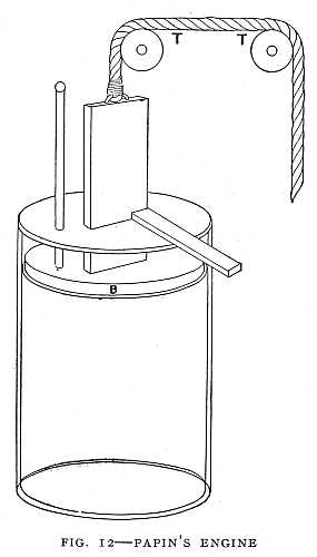 FIG. 12–PAPIN'S ENGINE
The first steam-engine with a piston. When the piston B was forced down by air-pressure, a weight was lifted by means of a rope TT passing over pulleys.
The principle of Papin's engine was first successfully applied by Thomas Newcomen. Newcomen was a blacksmith by trade, and his great successor, Watt, was a mechanic. Thus we see that great discoveries soon become common property. The blacksmith and the mechanic soon learn to use the discoveries of the scientist.
Newcomen's Engine
In the Newcomen engine the piston moved a walking-beam to which was attached a pump-rod. Steam was used merely to balance the air-pressure on the piston and allow the pump-rod to descend by its own weight. The steam was condensed[37] in the cylinder, and the pressure of the air forced the piston down. Thus the work of raising water in the pump was done by the air. Newcomen's first engine made twelve strokes a minute, and at each stroke lifted fifty gallons of water fifty yards. He used this engine in pumping water from the mines, and also made engines for lifting coal.
At first the steam was condensed by throwing cold water on the outside of the cylinder. But one day the engine suddenly increased its speed and continued to work with unusual rapidity. The upper side of the piston was covered with water to make the piston air-tight, and it was found that this water was entering the cylinder through a hole that had worn in the piston, and this jet of cold water was rapidly condensing the steam. This was the origin of "jet condensation."
After this steam and water were alternately admitted to the cylinder through cocks turned by hand. A boy, Humphrey Potter, to whom this work was intrusted, won fame by tying strings to the cocks in such a way that the engine would turn the cocks itself and the boy, Humphrey, was free to play. This device was the origin of valve-gear.[1]
[1] Any device by which a steam-engine operates the valves which admit steam to the cylinder is called "valve-gear." One form of valve-gear is the link motion invented by Stephenson. This form will be described in connection with the locomotive. A simple valve-rod, worked by an eccentric such as is used on most stationary engines, is also a form of valve-gear.
Newcomen's engine was extensively used. The tin and copper mines of Cornwall were deepened. Coal-mines were sunk to twice the depth that had been possible. But as [38]the mines were deepened the cost of running the engines increased. The largest engines consumed about $15,000 worth of coal per year. The Newcomen engine required about twenty-eight pounds of coal per hour per horse-power, while a modern engine consumes less than two pounds. Again, because of increased cost, mines were being abandoned. Such was the situation when James Watt came into the field of action.
Watt had learned the mechanic's trade in one year in a London shop, and, because he had not passed through an apprenticeship of seven years, the Guild of Hammermen, a labor-union of his time, refused him admission, and this refusal meant no employment. He found shelter, however, in the University of Glasgow, and was there provided with a small workshop where he could make instruments for sale.
Watt's Engine
A small Newcomen engine belonging to the University of Glasgow was out of repair. London mechanics had failed to make it work. The job was given to Watt. That he might do a perfect piece of work on this engine, he made a study of all that was then known relating to steam (Fig. 13).
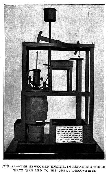 FIG. 13–THE NEWCOMEN ENGINE, IN REPAIRING WHICH WATT WAS LED TO HIS GREAT DISCOVERIES
Preserved in the University of Glasgow.
He saw that there was a great loss of heat in admitting cold water into the cylinder to condense the steam, and that, to prevent this loss, the cylinder must be kept always as hot as the steam that enters it. While thinking upon this problem the idea came to him that, if connection were made between the cylinder and a tank from which the air [40]had been pumped out, the steam would rush into the tank, and might there be condensed without cooling the cylinder. This was the origin of the condenser.
We have seen that, in the Newcomen engine, the steam acted only on the under side of the piston, air acting on the upper side. It occurred to Watt that the steam should act on both sides of the piston. So he proposed to put an air-tight cover on the cylinder with a hole and stuffing-box for the piston to slide through and to admit steam to act upon it instead of air. Thus he was led to invent the double-acting engine. The action in the cylinder of Watt's engine was the same as that of the modern engine.
To save the power of steam, Watt arranged the valve in his engine in such a way that the steam was cut off from the cylinder when the piston had made about one-fourth of a stroke. The steam in the cylinder continues to expand and drive the piston. This device more than doubles the amount of work that the steam will do (Fig. 14).
Horse-Power of an Engine
When horses were about to be replaced by the steam-engine at the mines, the question was asked: "How many horses will the engine replace?" Tests were made by Watt and others before him of the rate at which a horse could work in pumping water or in lifting a weight by means of a pulley. Watt's experiments showed that "a good London horse could go on lifting 150 pounds over a pulley at the rate of 2-1/2 miles an hour or 220 feet per minute, and continue the work eight hours a day." This would be[41] equal to lifting 33,000 pounds one foot high every minute. This rate of doing work he called a horse-power. It is more than the average horse can do, but this number was used by Watt that he might give good measure in his engines. The horse-power of an engine at that time meant the rate of work in lifting water or coal. Now it means the rate of work done by the steam upon the piston, so that to find the useful horse-power of an engine we must deduct the work wasted in friction.
The indicator for measuring the pressure of steam in the cylinder and the fly-ball governor are also inventions made[42] by Watt (Fig. 15). The fly-ball governor replaced the throttle-valve which was at first used by Watt to regulate the speed of his engines. The throttle-valve is still used on locomotives.
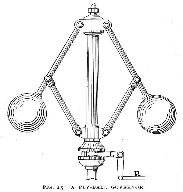 FIG. 15–A FLY-BALL GOVERNOR
The balls as they rotate regulate the admission of steam to the cylinder by means of the lever L and the rod R.
At the end of the eighteenth century the steam-engine was full grown. It remained for the nineteenth century to apply the engine to locomotion on sea and land, to develop the steam-turbine, and so to increase the power of the steam-engine that, early in the twentieth century, a 68,000-horse-power engine should speed an ocean liner across the Atlantic in five days.[43]
The Leyden Jar
The first electrical invention of practical use was made by Benjamin Franklin. In Franklin's time great interest in electricity had been aroused by the strange discovery of a German professor, Pieter van Musschenbroek, of the University of Leyden. This professor had tried what he called a new but terrible experiment. He had suspended by two silk threads a gun-barrel which received electricity from an electrical machine. From one end of the gun-barrel hung a brass wire. The lower end of this wire dipped in a jar of water. He held the jar in one hand, while with the other he tried to draw sparks from the gun-barrel. Suddenly he received a shock which seemed to him like a lightning stroke. So violent was the shock that he thought for a moment it would end his life.
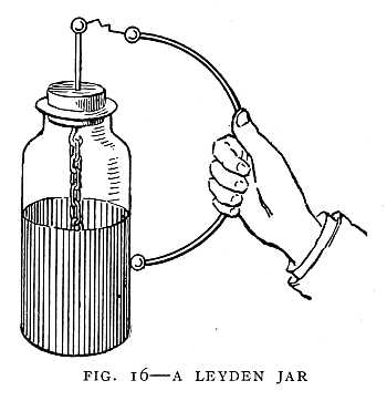
Out of this experiment came the Leyden jar, which for a century and a half was of no practical use, but which now forms an important part of every wireless telegraph equipment. The Leyden jar is simply a glass bottle or jar coated with tin-foil both inside and outside (Fig. 16). When charged with electricity the jar will hold its charge until the two coatings are connected by a metal wire or other[44] good conductor of electricity. A person may receive a strong shock by holding the jar in one hand and touching a knob connected to the inner coating with the other hand.
Popular interest in electricity was aroused by this discovery. The friction electrical machine and the Leyden jar were simple and easy to make. People of fashion found them interesting and amusing, the more so because of the shock felt on taking through the body the discharge from the "wonderful bottle," and the fact that several persons could receive the shock at the same instant. On one occasion the Abbé Nollet discharged a Leyden jar through a line composed of all the monks of the Carthusian Monastery in Paris. As the line of serious-faced monks a mile in length jumped into the air, the effect was ridiculous in the extreme.
Conductors and Insulators
About this time other great electrical discoveries were made. Early in the century, Stephen Gray discovered that some objects conduct electricity and others do not. He discovered that, when a glass tube is electrified by rubbing, it will attract and repel light objects. In the same way a comb or penholder of rubber may be electrified by rubbing it on the sleeve. A bit of paper which touches the comb becomes electrified. Electricity can be transferred from one object to another. Gray discovered further that contact is not necessary, that a hempen thread or a wire will carry an electric charge from one object to another. A silk thread will not carry the electric charge. "Some things convey electricity," he said, "and some do[45] not, and those which do not can be used to prevent the electricity escaping from those which do." Could this obscure inventor have seen a modern telegraph line with the glass insulators on the poles, which prevent the electric current escaping from the telegraph wire, he might have realized the importance of his discovery. He set up a line of hempen thread six hundred and fifty feet long, and with an electrical machine at one end of the line electrified a boy suspended from the other end.
Two Kinds of Electric Charge
A Frenchman, DuFay, while carrying further the experiments of Gray, was watching a bit of gold-leaf floating in the air. The gold-leaf had been repelled after contact with his electrified glass tube. Thinking to try the action of two electrified objects on the gold leaf, he rubbed a piece of gum-copal and brought it near the leaf. To his astonishment the leaf, which was repelled by the glass tube, was attracted by the gum-copal. He repeated the experiment again and again, and each time the leaf was repelled by the glass and attracted by the gum. He concluded from this that there are two kinds of electricity, which he named "vitreous" and "resinous." The two kinds of electric charge were called by Franklin "positive" and "negative."
Franklin made a battery of Leyden jars, connecting the inner coating of one to the outer coating of the next throughout the series. In this way he could get a much stronger spark than with a single jar. On one occasion he nearly lost his life by taking a shock from his battery of Leyden jars.[46] He magnetized and demagnetized steel needles by passing the discharge from his Leyden jars through the needles.
Franklin's Kite Experiment
The conjecture that lightning is of the same nature as the spark from the Leyden jar or the electrical machine had gained a hold on the minds of others before Franklin. In France sparks had been drawn from a rod ninety-nine feet high, but this did not reach into the clouds. Franklin determined to send a kite into a thunder-cloud, thinking electricity from the cloud would follow the string of the kite and could be stored in a Leyden jar, and used like the charge from an electrical machine. He had felt the power of a Leyden-jar discharge, and through it had nearly lost his life. He knew that lightning is far more powerful than any battery of Leyden jars, and yet to test the truth of his theory, that lightning is an electrical discharge, he was about to draw the lightning to his hand. He knew little of conductors of electricity. Whether the cord would draw little or much of the "electric fire" he knew not. So far as he knew he was toying with death.
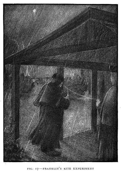
The kite was made of two light strips of cedar placed crosswise, and a large silk handkerchief fastened to the strips. A sharp wire about a foot long was fastened to one of the strips. To the lower end of the cord he attached a key and a silk ribbon. By means of the ribbon he held the cord to insulate it from his hand. The kite soared into the clouds, and Franklin and his son stood under a shed awaiting the coming of the "electric fire" (Fig. 17). Soon [48]the fibres of the cord began to bristle up. He approached his knuckles to the key. A spark passed. He brought up a Leyden jar and charged it with electricity from the cloud, and found that with this charge he could do everything that could be done with electricity from his machine. He had proved the identity of lightning and electricity.
The Lightning-Rod
Some time before, he had discovered the action of a point in discharging electricity. He said: "If you fix a needle to the end of a gun-barrel like a little bayonet, while it remains there the gun-barrel cannot be electrified so as to give a spark, for the electric fire continually runs out silently at the point." In the dark you may see a light gather upon the point like that of a firefly or glow-worm. If the needle is held in the hand and brought near to an object charged with electricity, the object is quietly discharged, and a light may be seen at the point of the needle. This action of points explains the light sometimes seen on the tops of ships' masts, called by sailors "Saint Elmo's fire," and perhaps, also, the observation of Cæsar that, in a certain African War, the spears of the Fifth Roman Legion appeared tipped with fire.
The lightning-rod was the outcome of Franklin's observations, and this was the first practical invention relating to electricity. A building may be electrified by an electrified cloud passing over it. If the building is protected by pointed rods, the electric charge will quietly escape from the points. The lower ends of the rods must be in the[49] moist earth below the surface. The lightning-rod has not proved so great a protection as Franklin supposed it would. He supposed that a lightning-stroke is a discharge in one direction only; but we now know that it is a rapid surging back and forth, and this fact accounts for the failure of the lightning-rods to furnish perfect protection. In surging back and forth, the lightning may skip from the lightning-rod to some metal object within the building, as a stove or radiator. The lightning-rod robbed the thunder-storm of its terrors to the timid, and in time dispelled the superstition of people who believed that thunder and lightning are evidence of the wrath of the Deity.
Franklin was the first to propose an answer to the question: What is electricity? He believed electricity to be a subtle fluid existing in all objects. If an object has more than a certain amount of this fluid, it is positively electrified; if less than this amount, it is negatively electrified.
The "one-fluid" theory of Franklin was soon met by the "two-fluid" theory proposed by Robert Symmer, for Franklin's theory had failed to explain why two bodies negatively electrified should repel each other. According to Symmer, an uncharged body contains an equal quantity of two different electrical fluids. An excess of one of these produces a positive charge, an excess of the other a negative charge.
Symmer's experiments are almost ludicrous. He wore two pairs of silk stockings, and found that white and black silk worn together became strongly electrified. When the two stockings worn on one foot were pulled off together, and then separated, they were found to be electrified, and[50] attracted each other so strongly that a force of about one pound was required to separate them. The two charges, negative and positive, could, however, be separated. He thought, therefore, that there are "two electrical powers," not one, as Franklin believed. His belief was strengthened by examining a quire of paper through which an electric spark had passed, and finding that "the edges of the holes were bent two different ways, as if the hole had been made in the quire by drawing two threads in contrary directions through it."
There was a long controversy regarding the two theories, and neither quite gained possession of the field. Each contained some truth, and each had its weak points. The two had more in common than men at that time thought.
Galvani and the Electric Current
Franklin had proven that there is electricity in the atmosphere, and that lightning is an electric discharge. A widespread interest in the electricity of the atmosphere followed this discovery. Aloisio Galvani, a physician in Bologna, Italy, in attempting to learn the effect of atmospheric electricity on the nerves and muscles of the human body, made a discovery which led to the electric battery and a knowledge of electric currents.
Having dissected a frog, he laid it on a table on which stood an electrical machine. When one of his assistants touched lightly the nerve of the thigh with the point of a knife while a spark was drawn from the electrical machine, the muscles contracted violently, as if they were attacked[51] by a cramp. When he held the knife by the bone handle, there was no convulsion as there was when he held it by the steel blade.
He next thought it important to find out if lightning would excite contraction of the muscles. He stretched and insulated a long iron wire in the open air on the housetop and, as a storm drew near, hung on it a dissected frog. To the feet he fastened another long iron wire, which was allowed to dip in the water in the well. "The result," he said, "came about as we wished. As often as the lightning broke forth, the muscles were thrown into repeated violent convulsions, so that always, as the lightning lightened the sky, the muscle contractions and movements preceded the thunder and, as it were, announced its coming. It was best, however, when the lightning was strong, or the clouds from which it broke forth were near the place of the experiment."
He describes his greatest experiment as follows: "After we had investigated the power of atmospheric electricity in storms, our hearts burned with the desire to investigate the daily quiet electricity of the atmosphere. Therefore, as the prepared frogs, hung on an iron railing which surrounded a hanging garden on our house, with brass hooks inserted in the spinal cord, fell into convulsions not only when it lightened, but when the sky was calm and clear, I thought that the cause of these contractions was the changes in the electricity of the atmosphere. Then for hours, yes, even days, I observed the animals, but almost never a movement of the muscles could be seen. At last, tired with such fruitless waiting, I began to press the brass hooks, which were [53]fastened in the spinal cord, against the iron railing to see if such a trick would cause the muscles to contract, and if instead of changes in the atmospheric electricity any other changes would have any influence. I observed, indeed, vigorous contractions, but none which could be caused by the condition of the atmosphere."
It was pressing the brass hook against the iron railing, thus forming an electric battery, that caused electricity to pass through the muscles of the frog. Galvani did not know that he had discovered a new source of electricity. He never arrived at a correct explanation of his results, and never knew the value of his discovery.
Volta and the Electric Battery
It was left for Alexander Volta to show that, in Galvani's experiment, the muscles of the frog, together with the brass hook and the iron railing, formed an electric battery. Volta showed that an electric charge can be produced merely by bringing two different metals into contact. He found that, if he placed copper and zinc in sulphuric acid, or a solution of common salt, he could, produce a continuous flow of electricity (Fig. 18).
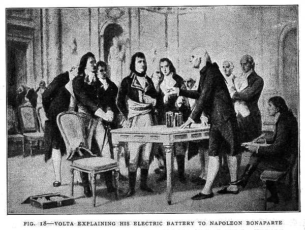 FIG. 18–VOLTA EXPLAINING HIS ELECTRIC BATTERY TO NAPOLEON BONAPARTE
From a painting. Photo by Dubray.
In the beginning of the year 1800 Volta made the first electric battery (Fig. 19). It was made of copper and zinc disks placed alternately, with a piece of wet cloth above each pair of disks. With his column of disks he could obtain a strong shock; indeed, many shocks, one after the other. This first battery of Volta's was a form of "dry battery." Later Volta devised his "crown of[54] cups," a form of wet battery similar to some batteries in use to-day. Each cup contained a strip of copper and a strip of zinc in dilute sulphuric acid.
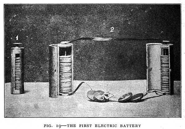 FIG. 19–THE FIRST ELECTRIC BATTERY
No. 1—A battery of one hundred pairs of copper and zinc disks.
No. 2—Two such batteries connected.
By permission of the Italian Institute of Graphic Arts, Bergamo.
Volta did not know the real use of the liquid in his battery, nor that the strength of the current depends on the rate at which the metal is dissolved by the acid; but he had discovered the electric current, and with this discovery began a new era in electrical invention.[55]
Chapter IV
FARADAY AND THE FIRST DYNAMO
Michael Faraday, a London newsboy, the son of a blacksmith, became the inventor of the dynamo, and prepared the way for the wonderful electrical inventions of the nineteenth century. He began his career as a book-binder's apprentice, employing his spare moments in reading the books he was binding. One of these books led him to make some simple experiments in chemistry. He also made an electrical machine, first with a glass bottle, and afterward with a glass cylinder.
While an apprentice he wrote to his young friend, Benjamin Abbott: "I have lately made a few simple galvanic experiments, merely to illustrate to myself the first principles of the science. I was going to Knight's to obtain some nickel, and bethought me that they had malleable zinc. I inquired, and bought some—have you seen any yet? The first portion I obtained was in the thinnest pieces possible. It was, they informed me, thin enough for the electric stick. I obtained it for the purpose of forming disks with which and copper to make a little battery. The first I completed contained the immense number of seven pairs of plates!!! and of the immense size of halfpence[56] each!!!!!! I, sir, I my own self, cut out seven disks of the size of half pennies each! I, sir, covered them with seven halfpence, and I interposed between them seven, or rather six, pieces of paper soaked in a solution of muriate of soda (common salt). But laugh no longer, dear A., rather wonder at the effects this trivial power produced."
This tiny battery made of half pennies with zinc disks and salt solution would decompose a certain solution which Faraday tested. A larger battery made of copper and zinc disks with salt solution would decompose water from the cistern. When the wires from the larger battery were put in the cistern-water he saw a dense white cloud descending from the positive wire, and bubbles rising from the negative wire. This action continued until all the white substance was taken out of the water.
Because of his interest in science, young Faraday attracted the attention of a Mr. Dance, a member of the Royal Institution and a customer of his master, Mr. Riebau. Through the kindness of Mr. Dance he heard four lectures by Sir Humphry Davy. He took notes on the lectures, wrote them out carefully, and added drawings of the apparatus. These notes he sent to Davy with a letter expressing the wish that he might secure employment at the Royal Institution. In a short time, after a warning from Sir Humphry that he had better stick to his business of book-binding, that "Science is a harsh mistress," his wish was granted, and we find him cleaning and caring for apparatus in the Royal Institution and assisting Davy in preparing for his lectures.[57]
Count Rumford
Our story now takes us back to the time of the American Revolution. In America, we find a young man of nineteen, Benjamin Thompson by name, serving as major in the Second Regiment of New Hampshire. The appointment of so young a man as major, and his evident hold on the governor's favor, aroused the jealousy of the older officers. He was accused of being unfriendly to the cause of liberty. He denied the charge, and was acquitted by the committee of the people of Concord. A mob gathered round his house, but he escaped. Driven from his refuge in his mother's home, he fled to England, leaving his wife and child. Appointed lieutenant-colonel in the British Army, he returned to America and fought against his former friends.
The war having ended, he returned to England, thence to the Continent, intending to take part in an expected war between Austria and Turkey. A chance meeting with a Bavarian prince, Maximilian, changed the course of his life. This prince, while commanding on parade, saw Thompson among the spectators mounted on a fine English horse, and addressed him. Thompson informed him that he came from serving in the American war. The prince, pointing to a number of his officers, said: "These gentlemen were in the same war, but against you. They belonged to the Royal Regiment of Deux Ponts, that acted in America under the orders of Count Rochambeau." Thompson dined with the prince and French officers. They conversed of war and the battles in which they met. The prince, attracted to the[58] colonel, induced him to pass through Munich, and gave him a letter to his uncle, the Elector of Bavaria.
It was in Bavaria, the country to which such unexpected turns of fortune led him, that his greatest work was done. He entered the service of the Duke of Bavaria as aide-de-camp. It was his aim while in the service of the Bavarian Government to better the condition of the people. He introduced reforms in the army, used the soldiers to rid the country of beggars and robbers, and took steps to provide for the infirm and find employment for the strong, his motto being that people can best be made virtuous when first made happy.
A Military Workhouse was opened for the beggars, and a House of Industry for the poor. A Military Academy was formed with a view to the free education of young people of talent for the public service. He became absorbed in the one aim of helping the poor. So thorough was his devotion to the people, and so deeply did he win their affection, that when he was dangerously ill a multitude of hundreds went in procession to the church to make public prayers for his recovery.
He saw that the poor may be helped by teaching them to save, and in nothing is there greater need of saving than in fuel and heat. In the kitchens of the Military Academy and the House of Industry he carried out a series of experiments on the economy of fuel, and succeeded in greatly reducing the amount of fuel needed for cooking the food. He did this by using a "closed fireplace," the forerunner of the stove. The closed fireplace was in reality a brick stove, and was a great improvement over the open chimney[59] fireplaces then in common use. He made the covers of the cooking utensils double, to save the heat, for he had found that heat cannot escape through confined air.
Benjamin Thompson was knighted by George III., and in 1791 he was made a Count of the Holy Roman Empire, and is known to the world of science as Count Rumford.
Count Rumford's Experiment with the Cannon
While in the service of the Duke of Bavaria, it became his duty to organize the field artillery. To provide cannon for this purpose, he erected a foundry and machine-shops. Being alert for any unusual fact relating to heat, he observed the very high temperature produced by the boring of the cannon. He was eager to learn how so much heat could be produced. For this purpose he took a cannon in the rough, as it came from the foundry, fixed it in the machine used for boring, and caused the cannon to be turned by horses while a blunt borer was forced against the end of the cannon. He first tested the temperature of the metal itself as it turned. Then he surrounded the end of the cannon with water in an oblong box fitted water-tight (Fig. 20).
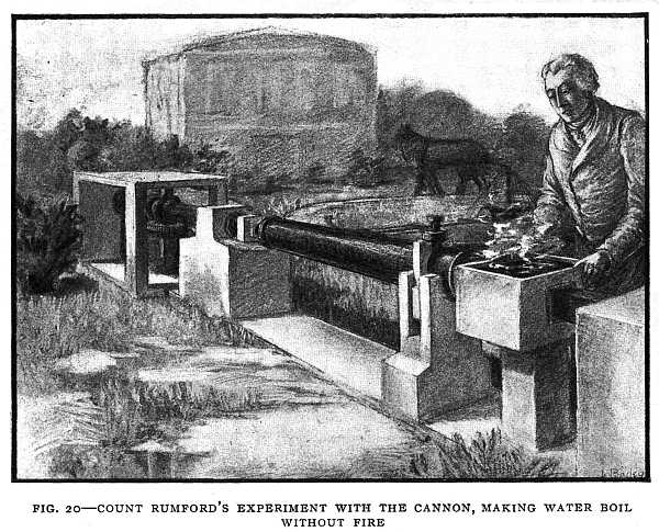 FIG. 20–COUNT RUMFORD'S EXPERIMENT WITH THE CANNON, MAKING WATER BOIL WITHOUT FIRE
The horses make the water boil by walking around the track; the work the horses do is changed into heat by the friction of the drill.
The cannon had been turning but a short time when he found by putting his hand in the water that heat had been produced. In two hours and thirty minutes the water actually boiled. Astonishment was expressed in the faces of the bystanders on seeing so large a quantity of water heated and actually made to boil without any fire.
"Heat," Count Rumford said; "may thus be produced merely by the strength of a horse, and, in case of necessity, [61]this heat might be used in cooking victuals. But no circumstance can be imagined in which there is any advantage in this method of procuring heat, for more heat might be obtained by burning the fodder which the horse would eat." The meaning of this last remark was not understood until the time of Robert Mayer, about fifty years later. Rumford had found that the work of a horse can produce heat, and heat, in a steam-engine, can do the work of a horse. Thus surely, though slowly, men were learning of the forces that move the world and do man's bidding.
Count Rumford, true to his adopted land, returned to London and became the founder of the Royal Institution in which Faraday and his successors have achieved such marvellous results. He believed that the poor can be helped in no better way than by giving them knowledge, so that they can better their own condition. For this purpose he founded the Royal Institution. Here he intended that men skilled in discovery should gain new knowledge that would add to the comfort and happiness of the people.
Davy
In the English coal-fields many accidents due to the burning of fire-damp had occurred. Fire-damp is caused by gas issuing from the coal. On the approach of a flame this gas catches fire, and as it burns it produces a violent wind, driving the flame before it through the mine. Miners were scorched to death, suffocated, or buried under ruins from the roof. Hundreds of miners had been killed. No means of lighting the mines in safety had been devised.[62] Sir Humphry Davy, Professor of Chemistry in the Royal Institution, was appealed to. After many experiments he devised a "safe lamp," which was a common miner's lamp enclosed in a wire gauze. This proved a perfect protection from fire-damp, and the Davy safety lamp has been used by miners the world over for more than a century.
But Davy's best work was with the electric battery. Some of the facts most familiar to us were discovered by him. Volta had contended that the contact of the metals in a battery produces a current, that the liquid merely carries the electricity from one metal plate to the other. But Davy proved that there can be no current without chemical action. Whenever we put two metals in an acid or other solution that will dissolve one metal faster than the other, and connect the metals with a wire, an electric current is produced. If we use water with silver and gold, there is no current, because water will not dissolve either the silver or the gold.
Davy discovered the metal, potassium, by means of his electric battery. Potassium is found in common potash and saltpetre, and, when separated, is a very soft metal. The newly discovered metal aroused great interest in other countries. When Napoleon heard of it, he inquired impetuously how it happened the discovery had not been made in France. On being told that in France there had not been made an electric battery of sufficient power, he exclaimed: "Then let one be instantly made without regard to cost or labor." His command was obeyed, and he was called to witness the action of the new battery. Before any one could interfere he placed the ends of the wires[63] under his tongue and received a shock that nearly deprived him of sensation. On recovering he left the laboratory without a word, and was never afterward heard to refer to the subject.
Davy made many great discoveries, but the greatest was his discovery of Faraday.
A journey on the Continent with Davy was an event in the life of Faraday, who up to that time had never to his own recollection travelled twelve miles from London. On this journey he met Volta, whom he describes as "an hale elderly man, very free in conversation." He visited the Academy del Cimento, in Florence, and wrote: "Here was much to excite interest; in one place was Galileo's first telescope, that with which he discovered Jupiter's satellites. It was a simple tube of wood and paper, about three and a half feet long, with a lens at each end. There was also the first lens which Galileo made. It was set in a very pretty frame of brass, with an inscription in Latin on it."
Faraday crossed the Alps and the Apennines, climbed Vesuvius, visited Rome, and saw a glow-worm. The last he thought as wonderful as the first.
Shortly after his return to London he fell in love. Now, Faraday had determined that he would not be conquered by the master passion. In fact, he had written various aspersions on love, of which the following is a sample:
And what the curse that often brings a wife?
'Tis Love.
[64]
For which a dunce is fully competent?
What's that the wise man always strives to shun,
Though still it ever o'er the world has run.
'Tis Love."
But he reckoned not with his own heart. It is not long until we find him writing to Miss Sarah Barnard, a bright girl of twenty-one: "You have converted me from one erroneous way, let me hope you will attempt to correct what others are wrong.... Again and again I attempt to say what I feel, but I cannot. Let me, however, claim not to be the selfish being that wishes to bend your affections for his own sake only. In whatever way I can minister to your happiness, either by close attention or by absence, it shall be done. Do not injure me by withdrawing your friendship or punish me for aiming to be more than a friend by making me less."
They were married and lived in rooms at the Royal Institution. No poet ever loved more tenderly than Faraday. Truly, science does not dry up the heart's blood. At the age of seventy-one he wrote to his wife while absent from home for a few days: "Remember me; I think as much of you as is good for either you or me. We cannot well do without each other. But we love with a strong hope of love continuing ever."
Faraday's Electrical Discoveries
Now we shall turn to Faraday's electrical discoveries and inventions. Men had long known that, in houses that[65] have been struck by lightning, steel objects such as knives and needles are sometimes found to be magnetized. Ships struck by lightning had found their compass-needles pointing south instead of north, or wandering in direction and worthless. Men had wondered how an electrical discharge could magnetize steel. They had tried the spark of the electrical machine with no definite result. Franklin, in his experiment of magnetizing a steel needle by passing an electric spark through it, could not tell before the spark was passed through the needle which end would be the north pole. There was no seeming connection between the direction of the electric discharge and the polarity of the needle. After the discovery of the electric battery, men tried to discover a relation between the electric current and magnetism.
Oersted and Electromagnetism
The first success in this direction was achieved by Hans Christian Oersted, a native of Denmark. Poverty impelled his father to take him from school at the age of twelve and place him in an apothecary's shop. The boy, Hans, found delight in the chemical work of the apothecary. His eagerness to learn and the pressure of poverty led him to neglect the usual sports of boyhood and devote his leisure time to reading and study. Again he entered school, and, though paying his way by his own work, he graduated with honor from the University of Copenhagen. He was appointed Professor of Physics in this university, and here he made his first great discovery in electromagnetism.
After working for seven years to discover a relation be[66]tween current electricity and magnetism, he made a discovery which proved to be the first step in the invention of the dynamo. He was using a magnetic compass, which is a small magnetic needle balanced on a steel point. The needle points nearly north and south unless disturbed by a magnet brought near it. He had tried to find if a wire through which a current is flowing would disturb the compass as a magnet does. He had tried placing the wire east and west, thinking the compass-needle would follow the wire as it does a magnet. One day, while lecturing to his students, it occurred to him for the first time to place the wire north and south over the compass-needle. He was surprised and perplexed as he did so to see the needle swing round and point nearly east and west (Fig. 21). On reversing the current the needle swung in the opposite direction. He had discovered the magnetic action of an electric current. It was learned soon afterward that a coil of wire with an electric current flowing through it acts like[67] a magnet, and that a current flowing around a bar of soft iron makes the iron a magnet (Figs. 22 and 23).
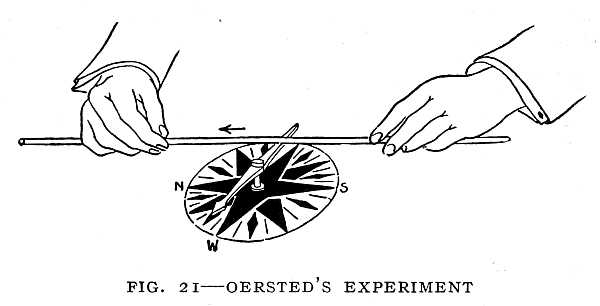 FIG. 21–OERSTED'S EXPERIMENT
An electric current flowing over the compass-needle toward the north causes the needle to turn until it points nearly west.
By permission of Joseph G. Branch.
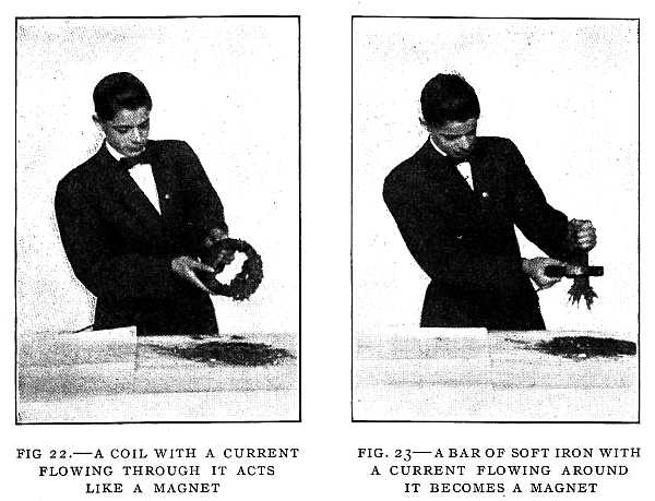 FIG. 22.—A COIL WITH A CURRENT FLOWING THROUGH IT ACTS LIKE A MAGNET
The coil is picking up iron filings.
FIG. 23–A BAR OF SOFT IRON WITH A CURRENT FLOWING AROUND IT BECOMES A MAGNETAmpère
The news of Oersted's discovery aroused great interest throughout Europe. Soon after its announcement in France, André Marie Ampère made a discovery of equal importance. Oersted had discovered electromagnetism. Ampère discovered electrical power or motion produced by an electrical current.
The youth of Ampère was passed amid the stormy scenes of the French Revolution. His father had moved from his[68] country home to Lyons and become a justice of the peace. In the destruction of the city of Lyons during the Reign of Terror he lost his head under the guillotine.
The blow was too great for Ampère, then a youth of eighteen. He had been a precocious child, advanced beyond his years in all the studies of the schools. But now his strong mind failed. For a year he wandered about mechanically piling up heaps of sand or gazing upon the sky. Then his mental power returned, and he took up with eagerness the study of botany and poetry.
He became a professor in the Polytechnic School in Paris, and it was while teaching in this school that he made his great discoveries. He found that two coils of wire can be made to attract or repel each other by an electric current. If the current flows through the two coils in the same direction, they attract each other (Fig. 24). If the current flows[69] in opposite directions through the coils, they repel each other (Fig. 25). This is not very strange to us, for we know that a coil with a current flowing through it acts just like a magnet. Each coil then has a north pole and a south pole. If the coils are placed so that the two north poles or the two south poles are together, they will repel each other. If the north pole of one coil is near the south pole of the other, they will attract each other.
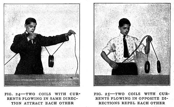 FIG. 24–TWO COILS WITH CURRENTS FLOWING IN SAME DIRECTION ATTRACT EACH OTHER
FIG. 25–TWO COILS WITH CURRENTS FLOWING IN OPPOSITE DIRECTIONS REPEL EACH OTHER
Ampère believed that electric currents are flowing around within the earth, and that the earth has a north and a south magnetic pole for the same reason that a coil of wire has magnetic poles; that these poles are caused by the currents flowing around in the earth just as the poles of the coil are caused by the current flowing around in the coil.
We do honor to the name of Ampère whenever we measure an electric current, for electric currents are measured in "amperes."
Arago
Another important discovery was made by a young Frenchman, François Arago, within a year of the time when Oersted and Ampère made their discoveries. The three great discoveries of these men were made in the years 1819 and 1820. The youth of Arago was full of adventure. He had assisted in making a survey in the Pyrenees, the haunt of daring robber-bands. Twice in his cabin he was visited by a chief of a robber-band who claimed to be a custom-house guard. On the second visit he said to the robber: "Your position is perfectly known to me. I know that you are not a custom-house guard. I have learned that you[70] are the chief of the robbers of the country. Tell me whether I have anything to fear from your confederates." The robber replied: "The idea of robbing you did occur to us; but, on the day that we molested an envoy from the French, they would direct against us several regiments of soldiers, and we are not so strong as they. Allow me to add that the gratitude which I owe you for the night's shelter is your surest guarantee."
At a later time, when war between Spain and France was threatened, he was accused of being a spy, and a mob was formed to put him out of the way. He escaped in disguise through the midst of the mob and boarded a Spanish ship. He was carried to Morocco, ran the gantlet of bloodthirsty Mussulmans in Algiers, escaped death by a hair's-breadth, and through it all clung to the papers which recorded the results of the survey in the mountains, and delivered them in safety to the office of the Bureau of Longitude in Paris.
Arago made a discovery which, with those of Oersted and Ampère, prepared the way for Faraday's great electrical[71] discoveries and the invention of the dynamo. He found that a plate of copper whirling above or below a magnetic needle will draw the needle after it (Fig. 26). He could make the speed of the whirling copper plate so great that the needle would whirl rapidly, following the copper plate. Faraday was the first to explain Arago's experiment.
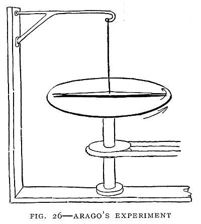 FIG. 26–ARAGO'S EXPERIMENT
When the copper plate whirls the magnet whirls also, though it does not touch the copper plate.
Faraday's First Electric Motor
Faraday's first electrical discovery was made soon after that of Arago. Oersted had proven that an electric current acts on a magnet. The magnet turns at right angles to the wire. Faraday saw that this is because the north pole of the magnet tries to go round the wire in one direction, and the south pole tries to go round in the opposite direction. He placed a magnet on end in a dish of mercury, with one pole of the magnet above the mercury, and found that the magnet would spin round a wire carrying a current. When the current acts on one pole of the magnet[72] only, the magnet spins round the wire (Fig. 27). So Faraday's first electrical discovery prepared the way for the electric motor.
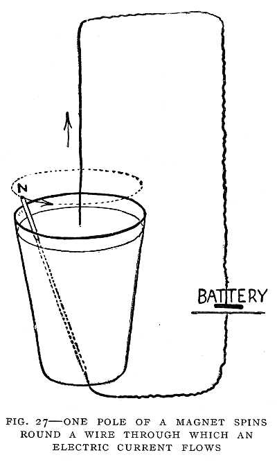
An Electric Current Produced by a Magnet
He had written in his note-book: "Convert magnetism into electricity." An electric current would magnetize iron. Would not a magnet produce an electric current? This was his problem.
He connected a coil of wire to an instrument that would tell when a current was flowing, and placed a magnet in the coil. Others had claimed, and Faraday at first believed, that a current would flow while the magnet lay quiet within the coil. But Faraday was alert for the unexpected, and the unexpected happened. For an instant, as he thrust the magnet into the coil, his instrument showed that a current was flowing. Again, as he drew the magnet quickly from the coil, a current flowed, but in the opposite direction (Fig. 28). From this simple experiment has grown the alternating-current machinery by which the power of Niagara is made to light cities and drive electric cars at a distance of many miles.
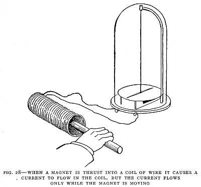 FIG. 28–WHEN A MAGNET IS THRUST INTO A COIL OF WIRE IT CAUSES A CURRENT TO FLOW IN THE COIL, BUT THE CURRENT FLOWS ONLY WHILE THE MAGNET IS MOVING
Drawing reproduced by permission of Joseph G. Branch.
A friend of Faraday, on learning of this discovery, wrote the following impromptu lines:
Was sure that Volta's lightnings play.
But how to draw them from the wire?
He took a lesson from the heart:
'Tis when we meet, 'tis when we part,
Breaks forth the electric fire."
A magnet will produce an electric current in a wire, but only when the magnet or the wire is in motion.
Detecting and Measuring an Electric Current
The instrument which Faraday used to detect a current was derived from Oersted's experiment. When a current flows in a north-and-south direction over a compass-needle, the needle swings round. When the current stops flowing[74] the needle swings back to the north-and-south position. The effect on the needle is stronger if the current flows through a coil of wire and the coil is placed in a north-and-south position around the needle (Fig. 29). The stronger the current flowing through the coil the farther the needle will turn from the north-and-south position.
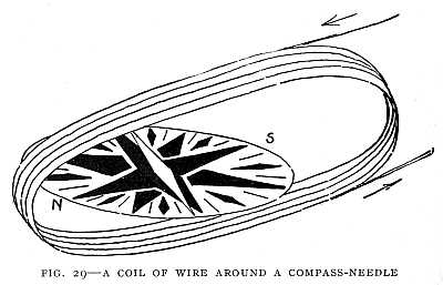 FIG. 29–A COIL OF WIRE AROUND A COMPASS-NEEDLE
The needle tells when a current is flowing, and how strong the current is.
The coil and the needle together are called a galvanometer, and may be used to tell when a current is flowing, and also to indicate the strength of the current.
An Electric Current Produced by the Magnetic Field of Another Current
Faraday had found that a current flowing around a piece of iron will make the iron a magnet, and that a magnet in motion will cause a current to flow in a wire. It seemed[75] to him that a second wire placed near the first should have a current produced in it without the presence of iron. He wound two coils of copper wire upon the same wooden spool. The wire of the two coils he separated with twine and calico. One coil was connected with a galvanometer, the other with a battery of ten cells, yet not the slightest turning of the needle could be observed. But he was not deterred by one failure. He raised his battery from ten cells to one hundred cells, but without avail. The current flowed calmly through the battery wire without producing, during its flow, any effect upon the galvanometer. During its flow was the time when an effect was expected.
Again the unexpected happened. At the instant of making contact with the battery there was a slight movement of the needle. When the contact was broken, another slight movement, but in the opposite direction to the first (Fig. 30). The current in one wire caused a current to flow in the other, but the current in the second wire continued for an instant only at the making and breaking of the contact with the battery. This was the beginning of the induction-coil used to-day in wireless telegraphy.
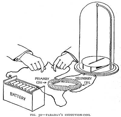 FIG. 30–FARADAY'S INDUCTION-COIL
Starting and stopping the battery current in the primary coil causes a changing magnetic field, and this causes a current to flow in the secondary coil.
Drawing reproduced by permission of Joseph G. Branch.
What was the secret of it? Simply this: that a current in one wire will cause a current to flow in another wire near it, but only while the current in the first wire is changing. That is, at the instant when the first wire is connected to the battery, or its connection broken, a current is induced in the second wire. There is no battery or other source of current connected to the second wire; but a current flows in this wire because it is near a wire in which a current is[76] rapidly starting and stopping. When these two wires are wound in coils, together they form an induction-coil. The wire which we have called the first wire forms the "primary" coil, and the one we have called the second wire forms the "secondary" coil. By repeatedly making and breaking the circuit in the primary coil we get an alternating current in[77] the secondary coil. Fig. 31 is from a photograph of some of the coils actually used by Faraday.
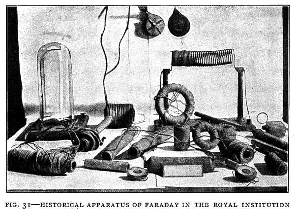 FIG. 31–HISTORICAL APPARATUS OF FARADAY IN THE ROYAL INSTITUTION
Some of Faraday's transformer coils are shown here. The instrument on the left in a glass case is his galvanometer.
Faraday's Dynamo
To invent a new electrical machine was Faraday's next aim. Arago's disk of copper whirling near a magnet had a current induced in it, so Faraday thought. It was the action of this induced current which caused the magnet to follow the whirling disk. Could the current in Arago's disk be collected and caused to flow through a wire? He placed a copper disk between the poles of a magnet. One galvanometer[78] wire passed around the axis of the disk, the other he held in contact with the edge. He whirled the disk. The galvanometer needle moved. A current was flowing in the disk as it whirled. The current from the whirling disk flowed through the galvanometer. Faraday had discovered the dynamo (Fig. 32).
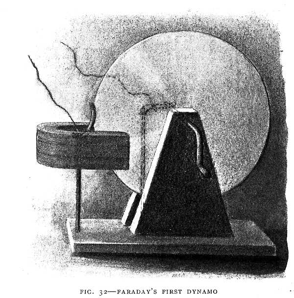 FIG. 32–FARADAY'S FIRST DYNAMO
A current flows in the copper disk as it whirls between the poles of the magnet.
By permission of Joseph G. Branch.]
All this work occupied but ten days in the autumn of 1831, though years of preparation had gone before. In these ten days the foundation was laid for the induction-coil, modern dynamo-electric machinery, and electric lighting. Fig. 33 shows the laboratory in which Faraday did this work.
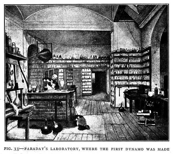 FIG. 33–FARADAY'S LABORATORY, WHERE THE FIRST DYNAMO WAS MADE
From the water-color drawing by Miss Harriet Moore.
Faraday continued to explore the field opened up before him. In one experiment two small pencils of charcoal lightly touching were connected to the ends of a secondary[80] coil. A spark passed between the charcoal points when the primary circuit was closed. This was the first transformer producing a tiny electric light (Fig. 34).
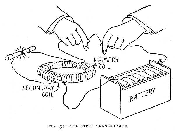
Faraday discovered the induction-coil, the dynamo, and the transformer, and he showed that, in each of these, it is magnetism which produces the electric current. He had discovered the secret when he obtained a current by thrusting a magnet into a coil of wire. The space about a magnet in which the magnet will attract iron he called the "magnetic field" (Figs. 35 and 36). In every case of magnetism causing an electric current to flow in a coil of wire, the coil is in a magnetic field, and the magnetic field is changing—that[81] is, the magnetic field is made alternately stronger and weaker, or the coil moves across the magnetic field. The point is that magnetism at rest will not produce an electric current. There must be a changing magnetic field or motion. In Faraday's dynamo a copper disk whirled between the poles[82] of a magnet and the whirling of the disk in the magnetic field caused an electric current. In the modern dynamo it is the whirling of a coil of wire in a magnetic field that causes a current to flow. In the induction-coil it is the change in the magnetic field that causes a current to flow in the secondary coil. A coil of wire with an electric current flowing through it will attract iron like a magnet. The primary coil with a current from a battery flowing through it acts in all respects like a magnet; but as soon as the current ceases to flow the magnetic field disappears—the coil is no longer a magnet. When we make and break the connection between the primary coil and the battery, then, we repeatedly make and destroy the magnetic field, and this changing magnetic field causes a current to flow in the secondary coil. The induction-coil is one form of transformer. We shall see later how the dynamo and the transformer developed in the nineteenth century.
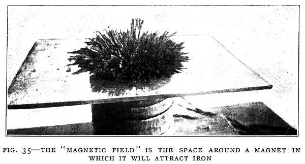 FIG. 35–THE "MAGNETIC FIELD" IS THE SPACE AROUND A MAGNET IN WHICH IT WILL ATTRACT IRON
The iron filings over the magnet arrange themselves along the "lines of force."
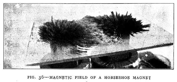
When a boy, Faraday had passed the current from his little battery through a jar of cistern-water, and saw in the water a "dense white cloud" descending from the positive wire, and bubbles arising from the negative wire. Something was being taken out of the water by the electric current. When he tried the experiment later in his laboratory, he found that, whenever an electric current is passed through water, bubbles of two gases, oxygen and hydrogen, rise through the water. He found that if the current is made stronger the bubbles are formed faster. The water in time disappears, for it has been changed or "decomposed" into the two gases.
It was the current from a battery that would decompose[83] water. The electricity from the electrical machine would do other things that he had never seen a battery current do. "Do the battery and the electrical machine produce different kinds of electricity, or is electricity one and the same in whatever way it is produced?" This was the query that troubled him. The answer to this question had been so uncertain that the effect of the voltaic battery had been termed "galvanism," while that of the friction machine retained the name "electricity."
Faraday tried many experiments in searching for an answer to this question. He found that the electricity of the machine will produce the same effect as that of a battery if the machine is compelled to discharge slowly. An electrical machine or a battery of Leyden jars can be made to give out an electric current, and this current will affect a magnetic needle in the same way that a battery current will. It will magnetize steel. If passed through water, it will decompose the water into the two gases oxygen and hydrogen. In short, a current from an electrical machine or a Leyden jar will do everything that a current from an electric battery will do. Faraday caused the Leyden jar to give a current instead of a spark by connecting the two metal coatings with a wet string. On the other hand, the discharge from a powerful electric battery will produce a spark and affect the human nerves in the same way as the discharge from the electrical machine. The same effects may be obtained from one as from the other.
In the discharge from the machine, a small quantity of electricity is discharged under high pressure, as water may be forced through a small opening by very high pressure.[84] The voltaic cell, on the other hand, furnishes a large quantity of electricity at low pressure, as a street may be flooded by a broken water-main though the pressure is low. In fact, the quantity of electricity required to decompose a grain of water is equal to that discharged in a stroke of lightning, while the action of a dilute acid on the one-hundredth part of an ounce of zinc in a battery yields electricity sufficient for a powerful thunder-storm.
Many tests were made, and the result was a convincing proof that electricity is the same whatever its source, the different effects being due to difference in pressure and quantity. "But in no case," said Faraday, "not even in those of the electric eel and torpedo, is there a production of electric power without something being used up to supply it."
Faraday's professional work would have made him wealthy. In one year he made £1000 ($5000), and the amount would have increased had he sold his services at their market value. But then there would have been no Faraday the discoverer. The world would have had to wait, no one knows how long, for the laying of the foundations of electrical industries. He chose to give up wealth for the sake of discovery. He gave up professional work with the exception of scientific adviser to Trinity House, the body which has charge of Great Britain's lighthouse service. Nor did he carry his discoveries to the point of practical application. As soon as he discovered one principle, he set out in pursuit of others, leaving the practical application to the future.
Faraday loved the beauty of nature. The sunset he[85] called the scenery of heaven. He saw the beauty of electricity, which he said lies not in its mystery, but in the fact that it is under law and within the control of the human intellect.
A Wonderful Law of Nature
Not long after Faraday made his first dynamo, Robert Mayer, a physician from Germany, was making a voyage to the East Indies which proved to be a voyage of discovery. He had sailed as the ship's physician, and after some months an epidemic broke out among the ship's company. In his treatment he drew blood from the veins of the arms. He was startled to see bright-red blood issue from the veins. He might almost have believed that he had opened an artery by mistake. It was soon explained to him by a physician who had lived long in the tropics that the blood in the veins of the natives, and of foreigners as well, in the tropics is of nearly the same color as arterial blood. In colder climates the venous blood is much darker than the arterial.
He reasoned upon this curious fact for some time, and came to the conclusion that the human body does not make heat out of nothing, but consumes fuel. The fuel is consumed in the blood, and there the heat is produced. In the tropics less heat is needed, less fuel is consumed, and therefore there is less change in the color of the blood.
When a man works he uses up fuel. If a blacksmith heats a piece of iron by hammering, the heat given to the iron and the heat produced in his body are together equal to the heat of the fuel consumed in his blood. The work a[86] man does, as well as the heat of his body, comes from the burning of the fuel in his blood.
What is true of a man is true of an engine. The work the engine does, as well as the heat it produces, comes from the heat of the fuel in the furnace. Mayer found that one hundred pounds of coal in a good working engine produces the same amount of heat as ninety-five pounds in an engine that is not working. In the working engine the heat of the five pounds of coal is used up in the work of running the engine, and therefore does not heat the engine. Heat that is used in running the engine is no longer heat, but work. So Mayer said the heat is not destroyed, but only changed into work. He said, further, that the work of running the engine may be changed again into heat.
Mayer's theory was opposed by many scientific men of Europe. One great scientist said to him that if his theory were correct water could be warmed by shaking. He remembered what the helmsman had remarked to him on the voyage to Java, that water beaten about by a storm is warmer than quiet sea-water; but he said nothing. He went to his laboratory, tried the experiment, and some weeks later returned, exclaiming: "It is so! It is so!" He had warmed water simply by shaking it.
These results mean that work or energy cannot be destroyed. Though it changes form in many ways, it is never destroyed. Neither can man create energy; he can only direct its changes as the engineer, by the motion of his finger in opening a valve, sets the locomotive in motion. He does not move the locomotive. He directs the energy already in the steam.[87]
Since the time of Galileo, men had caught now and then a glimpse of this great law. Galileo had stated his law of machines; that, when a machine does work, a man or a horse or some other power does an equal amount of work upon the machine. Count Rumford had performed his experiment with the cannon, showing that heat is produced by the work of a horse. Davy had proved that, in the voltaic battery, something must be used up to produce the current—the mere contact of the metals is not sufficient. Faraday had said that in no case is there a production of electrical power without something being used up to supply it. Mayer stated clearly this law of energy when he said that energy cannot be created or destroyed, but only changed from one form to another.
And yet inventors have not learned the meaning of this law. They continue trying to invent perpetual-motion machines—machines that will produce work from nothing. This is what a perpetual-motion machine would be if such a machine were possible. For a machine without friction is impossible, and friction means wasted work—work changed into heat. A machine to keep itself running and supply the work wasted in friction must produce work from nothing. The great law of nature is that you cannot get something for nothing. Whether you get work, heat, electricity, or light, something must be used up to produce it. For whatever you get out of a machine you must give an equivalent. This law cannot be evaded, and from it there is no appeal.[88]
Chapter V
GREAT INVENTIONS OF THE NINETEENTH CENTURY
The discoveries of Faraday prepared the way for the great inventions of the nineteenth century. By the middle of the century men knew how to control the wonderful power of electricity. They did not know what electricity is, nor do we know to-day, though we have made some progress in that direction; but to control it and make it furnish light, heat, and power was more important.
Before the inventions of James Watt made it possible to use steam-power, factories were built near falling water, so that water-power could be used. But the steam-engine made it possible to build great factories wherever a supply of water for the boilers could be obtained. Cities were built around the factories. Cities already great became greater. With the growth of cities the need of a new means of producing light and power made itself felt. Electricity promised to become the Hercules that should perform the tasks of the modern world.
Discovery gave way to invention. During the second half of the nineteenth century many great inventions were made and industries were developed, while discoveries were few until near the close of the century. Within this period[89] the great industries which characterize our modern civilization, and which arose out of the discoveries that science had made in the centuries preceding, attained a high degree of development. In this chapter we shall trace the applications of some of the discoveries with which we have now become familiar. This will lead us into the field of electrical invention, for we are dealing now with the beginning of the world's electrical age.
Electric Batteries
From the time of Volta to the time of Faraday the only means of producing an electric current was the "voltaic battery," so called in honor of Volta. The voltaic cell is the simplest form of electric battery. In this cell the zinc and copper plates are placed in sulphuric acid diluted with water. As the acid eats the zinc, hydrogen gas is formed. This gas collects in bubbles on the copper plate and weakens the current. The aim of inventors was to produce a steady current, to devise a battery in which no gas would collect on the copper plate. They saw the need of a battery that would give out a current of unchanging strength until the zinc or the acid was used up.
The first real improvement in the battery was made by Professor Daniell, of King's College, London. In the Daniell cell the zinc plate is in dilute sulphuric acid, and the copper plate is in a solution of blue vitriol or copper sulphate. Professor Daniell separated the two liquids by placing one of them in a tube formed of the gullet of an ox. This tube dipped into the other liquid. The hydrogen gas, as it was[90] formed by the acid acting on the zinc, could go through the walls of the tube, but was stopped by the copper sulphate, and copper was deposited on the copper plate. This copper deposit in no way interfered with the current, so that the current was not weakened until the zinc plate or one of the solutions was nearly consumed. A cup of porous earthenware is now used in Daniell cells to separate the liquids (Fig. 37). By placing crystals of blue vitriol in the battery jar, the solution of blue vitriol can be kept up to its full strength for a very long time. The zinc in time is consumed, and must be replaced.
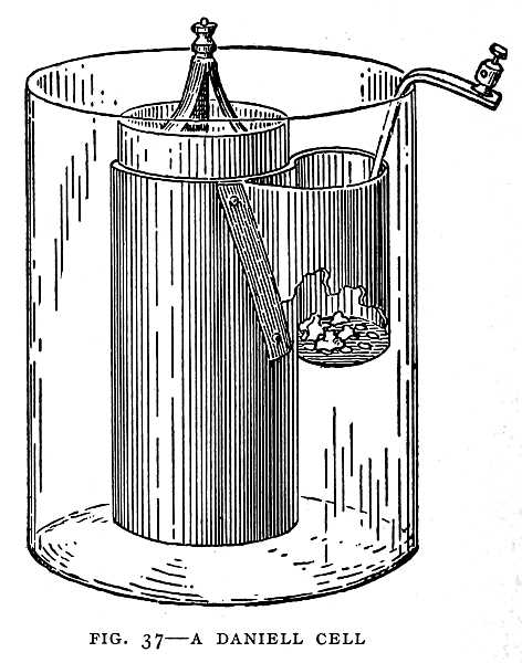
In the gravity cell (Fig. 38) the same materials are used as in the Daniell cell—copper in copper sulphate, and zinc in sulphuric acid; but there is no porous cup. The solutions are kept separate by gravity, the heavy copper sulphate being at the bottom. The gravity cell has until recently been extensively used in telegraphy, and continues in use in short-distance telegraphy and in automatic block signals. The gravity and Daniell cells are used for closed-circuit work—that is, for work in which the current is flowing almost constantly.
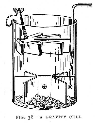
The Dry Battery
Another important improvement was the invention of the dry battery. You will remember that the first battery, the one invented by Volta, was a form of dry battery; but it was a very feeble battery compared with the dry batteries now in use, so that we may call the dry battery a new invention. The dry battery is falsely named. There can be no battery without a liquid. In the dry battery the zinc cup forming the outside of the cell is one of the plates of the cell (Fig. 39). The battery appears to be dry because the solution of sal ammoniac is absorbed by blotting-paper or other porous substance in contact with the[92] zinc. The inner plate is carbon, and this is surrounded by powdered carbon and manganese dioxide—the latter to remove the hydrogen gas which collects on the carbon plate. This gas weakens the current when the circuit has been closed for a short time, but is slowly removed when the circuit is broken. Thus the battery is said to "recover."
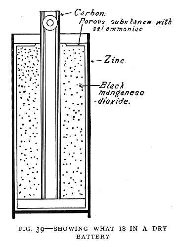
The dry cell will give a strong current, but for a short time only. It recovers, however, if allowed to rest. It can be used, therefore, only in "open-circuit" work—such as door-bell circuits, and some forms of fire and burglar alarm. A door-bell circuit is open nearly all the time, the current flowing only while the button is being pressed. Some forms of wet battery work in the same way as the dry battery, and are used like-wise for open-circuit work. In these batteries carbon and zinc plates in a solution of sal ammoniac are used, the same materials as in the dry battery. The only difference is that in the dry battery the solution is absorbed by some porous substance and the battery sealed so that it appears to be dry.[93]
The Storage Battery
One of the greatest improvements in electric batteries is the storage battery. A simple storage battery may be made by placing two strips of lead in sulphuric acid diluted with water and connecting the lead strips to a battery of Daniell cells or dry cells. In a short time one of the lead strips will be found covered with a red coating. The surface of this lead strip is no longer lead but an oxide of lead, somewhat like the rust that forms on iron. If the lead strips are now disconnected from the other battery and connected to an electric bell, the bell will ring. We have here two plates, one of lead and one of oxide of lead, in dilute sulphuric acid. This forms a storage battery.
The first storage battery was made of two sheets of lead rolled together and kept apart by a strip of flannel. The lead strips thus separated were immersed in dilute sulphuric acid. A current from another battery was passed through this cell for a long time—first in one direction, then in the other. This roughened the surface of the lead plates, so that the battery would hold a greater charge. The battery was then charged by passing a current through it in one direction only for a considerable length of time. Feeble cells were used for charging. It took days, and sometimes weeks, to charge the first storage batteries. Then the storage battery would give out a strong current lasting for a few hours. It slowly accumulated energy while being charged, and then gave out this energy rapidly in the form of a strong electric current. For this reason the storage battery was called an "accumulator."[94]
While charging the storage cell there was formed on the negative plate a coating of soft lead, and on the positive plate a coating of dark-brown oxide of lead. It was found better to apply these coatings to the lead plates before making up the battery. Later it was found that the battery would hold a still greater charge if the plates were made in the form of "grids" (Fig. 40), and the cavities filled with the active material—the negative with spongy lead, and the positive with dark-brown lead oxide. Some excellent commercial storage batteries are made from lead plates by the action of an electric current, very much as Planté made his batteries. Fig. 41 shows one of these plates.
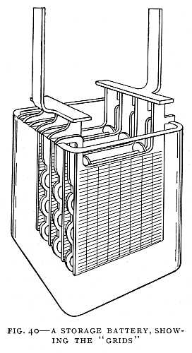
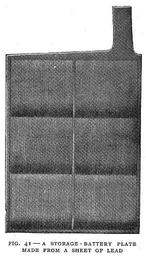
The storage battery does not store up electricity. It produces a current in exactly the same way as any other battery—by the action of the acid on the plates. When this action ceases it is no longer a battery, though it may be made one again by passing a current through it in the opposite direction from that which it gives out. In this[95] it differs from the voltaic battery, for when such a battery is run down it can be restored only by adding new solution or new plates. The storage battery is especially useful for "sparking" in gas or gasolene motors.
Edison has invented a storage battery that will do as much work as a lead battery of twice its weight. Edison's battery is intended especially for use in electric automobiles. By reducing the weight of the battery which the machine must carry the weight of the truck may also be reduced. In the Edison battery the positive plates are made of a grid of nickel-plated steel containing tubes filled with pure nickel. The negative plate consists of a nickel-plated steel grid containing an oxide of iron similar to common iron-rust.
After working a number of years on this battery and making nine thousand experiments, Edison thought he had it perfected, and indeed it was a great improvement[96] over the storage batteries that had been used—much lighter and cheaper, and more successful in operation. Two hundred and fifty automobiles were equipped with it, and it proved superior to lead batteries for this purpose. But it was not to Edison's liking. He threw the machinery, worth thousands of dollars, on the scrap-heap, and worked on for six years. He had then produced a battery as much better than the first as the first was better than the lead battery, and he was content to have the new battery placed on the market.
The Dynamo
For the purpose of lighting and power the electric battery proved too costly. Davy produced an arc light with a battery of four thousand cells. The arc was about four inches in length and yielded a brilliant light, but as the cost was six dollars a minute it was not thought practical. Attempts were made early in the century to use a battery current for power, but they failed because of the cost and the fact that no good working motor had been invented.
Light and power were needed. Electricity could supply both. But how overcome the difficulty of cost, and produce an electric current from burning coal or falling water? For answer man looked to the great discovery of Faraday and his "new electrical machine." Inventors in Germany, France, England, Italy, and America made improvements until from the disk dynamo of Faraday there had evolved the modern dynamo.
Electroplating and the telegraph are the only applications of the electric current that became factors in the[97] world's industry before the dynamo, yet in long-distance telegraphy and in electroplating to-day the dynamo is used. Without the dynamo, electric lighting, electric power, and electric traction as developed in the nineteenth century would have been impossible; in fact, the dynamo with the electric motor (which, as we shall see, is only a dynamo reversed) is master of the field.
The way had been prepared for the application of Faraday's discovery by William Sturgeon, an Englishman, and Joseph Henry, an American. Sturgeon discovered that soft iron is more quickly magnetized than steel, and found that the strength of an electromagnet can be greatly increased by making the core of a soft-iron rod and bending the rod into the form of a horseshoe (Fig. 42). The iron rod was coated with sealing-wax and wound with a single layer of copper wire, the turns of wire not touching. This was in 1825, before Faraday discovered the principle of the dynamo.
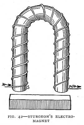
Professor Henry still further increased the strength of the electromagnet by covering the wire with silk, which made it possible to wind several layers of wire on the iron[98] core, and many times the length of wire that had been used by Sturgeon. Fig. 43 shows such a magnet. One of Henry's magnets weighed fifty-nine and a half pounds, and would hold up a ton of iron. Sturgeon said: "Professor Henry has produced a magnetic force which completely eclipses every other in the whole annals of magnetism." With Professor Henry's invention the electromagnet was ready for use in the dynamo. Fig. 44 shows a strong electromagnet.
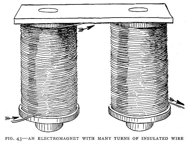
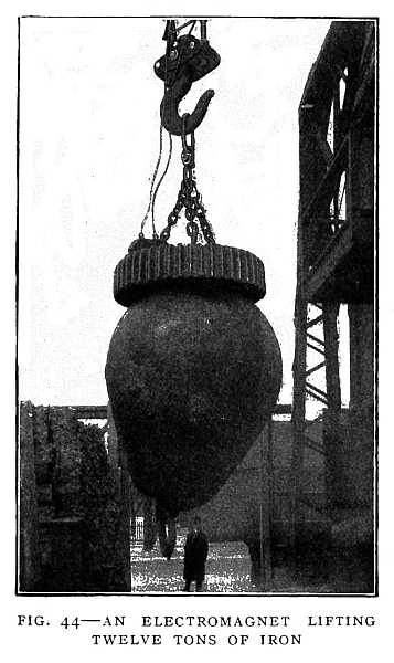
A moving magnet causes a current to flow in a coil, but a magnet at rest has no effect. A moving magnet is equal to a battery. In Faraday's experiments a current was induced in a coil of wire by moving a magnet in the coil or by[99] making and breaking the circuit in another coil wound on the same iron core. A current was induced in a metal disk by revolving it between the poles of a magnet. In every case there was motion in a magnetic field, or the field itself was changed. A changing magnetic field is equal to a moving magnet. What is needed to induce a current in a coil, whether it be in a dynamo, an induction-coil, or a transformer, is a changing magnetic field about the coil or motion of the coil in the magnetic field.
If fine iron filings are sprinkled over the poles of a magnet the filings arrange themselves in definite lines. This is a simple experiment which any boy can try for himself. Faraday called the lines marked out by the iron filings "lines of force" (the lines of force of a horseshoe magnet are shown in Fig. 36), because they indicate the direction in which the magnet pulls a piece of iron—that is, the direction of the magnetic force. Now, if a current is to be induced in a[100] wire, the wire must move across the lines of force. If the wire moves along the lines marked out by the iron filings, there will be no current. When a coil rotates between the poles of a magnet, the wire moves across the lines of force and a current is induced in the coil if the circuit is closed. This is the way a current is produced in a dynamo.
Faraday produced a current by rotating a coil between the poles of a steel magnet. He made a number of such machines, and used them with some success in producing lights for lighthouses, but the defects of these machines were so great that the lighting of a city or the development of power on a large scale was impractical. The electromagnet was needed to solve the problem.
Siemens' Dynamo
The war of 1866 between Austria and Prussia and the certainty of a coming struggle with France turned the attention of German inventors to the use of electricity in warfare. Werner von Siemens, an artillery officer, was improving an exploding device for mines. An electric current was needed to produce a spark or heat a wire to redness in the powder. Faraday had used a coil of wire turning between the poles of a steel magnet to produce a current. In England a coil turning between the poles of an electromagnet had been used, but the electromagnet received its current from another machine in which a steel magnet was used. Siemens found that the steel magnet could be dispensed with, and that a coil turning between the poles of an electromagnet could furnish the current for the[101] electromagnet. Two things are needed, then, to make a dynamo: an electromagnet and a coil to turn between the poles of that magnet. The rotating coil, which usually contains a soft-iron core, is called the "armature." The coil will furnish current for the magnet and some to spare; in fact, only a small part of the current induced in the coil is needed to keep the magnet up to its full strength, and the greater part of the current may be used for lighting or[102] power. The new machine was named by its inventor "the dynamo-electric machine." The name has since been shortened to "dynamo." The first practical problem which the dynamo solved was the construction of an electric exploding apparatus without the use of steel magnets or batteries. A dynamo with Siemens' armature is shown in Fig. 45.
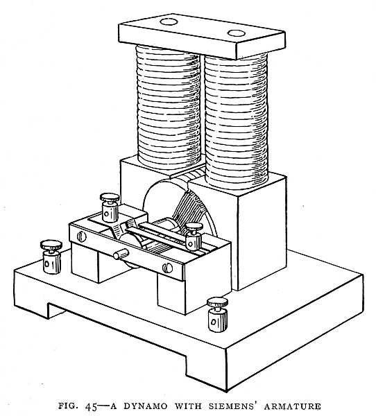
In his first enthusiasm the inventor dreamed of great things for the new machine, among others an electric street railway in Berlin. But the dynamo was not yet ready. The difficulty was the heating of the iron core of the armature, caused by the action of induced currents. There are induced currents in the iron core as well as in the coil, and, for the same reason, the coil and the iron core within it are both moving in a magnetic field. These little currents circling[103] round and round in the iron core produce heat. The rapid changing of the magnetism of the iron also heats the iron.
It remained for Gramme, in France, to apply the proper remedy. This remedy was an armature in which the coil was wound on an iron ring, invented by an Italian, Pacinotti. Gramme applied the principle discovered by Siemens to Pacinotti's ring, and produced the first practical dynamo for strong currents. This was in 1868. A ring armature is shown in Fig. 46. The first dynamo patented in the United States is shown in Fig. 47. This dynamo is only a curiosity.[104]
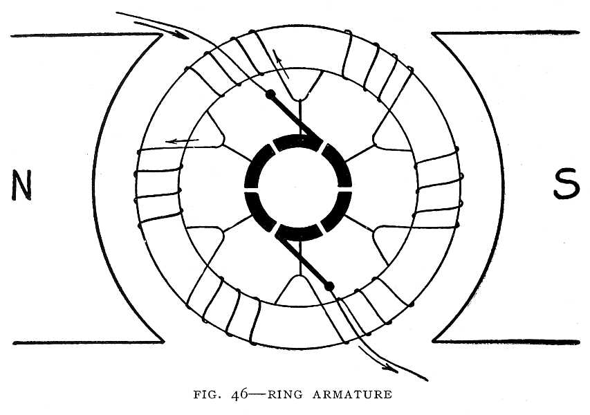
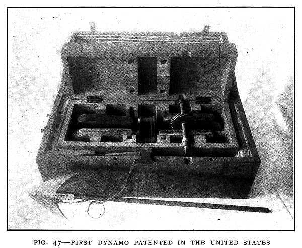 FIG. 47–FIRST DYNAMO PATENTED IN THE UNITED STATES
Intended to be used for killing whales.
Photo by Claudy.
The Drum Armature
An improvement in the Siemens armature was made four years later by Von Hefner-Alteneck, an engineer in the employ of Siemens. This improvement consisted in winding on the iron core a number of coils similar to the one coil of the Siemens armature, but wound in different directions. This is called the "drum armature" (Fig. 48). The heating of the core is prevented by building it up of a number of thin iron plates insulated from one another and by air-spaces within the core. The insulation prevents the small currents from flowing around in the core. The air-spaces serve for cooling. The drum armature was a great improvement over both the Siemens and the Gramme armatures. With the Siemens one-coil armature there is a point in each revolution at which there is no current. The current, therefore, varies during each revolution of the armature from zero to full strength. In the Gramme armature only half the wire, the part on the outside of the ring, receives the full effect of the magnetic field. The inner half is practically[105] useless, except to carry the current which is generated in the outer half. Both these difficulties are avoided in the drum armature. The dynamos of to-day are modifications of the two kinds invented by Siemens and Gramme. Many special forms have been designed for special kinds of work.
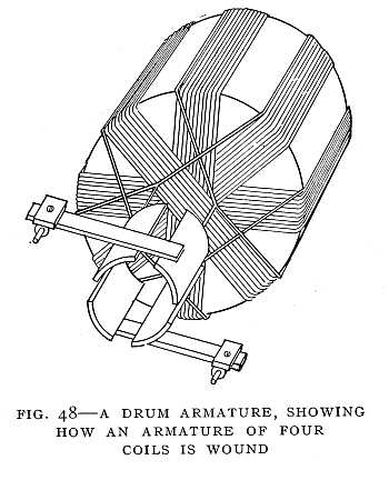
Edison's Compound-Wound Dynamo
Edison, in his work on the electric light and the electric railway, made some important improvements in the dynamo. The armature of a dynamo is usually turned by a steam-engine. Edison found that much power was wasted in the use of belts to connect the engine and the dynamo. He therefore connected the engine direct to the dynamo, placing the armature of the dynamo on the shaft of the engine. He also used more powerful field-magnets than had been used before. His greatest improvement, however, was in making the dynamo self-regulating, so that the dynamo will send out the strength of current that is needed. Such a dynamo will send out more current when more lights are turned on. Whether it supplies current for one light or a thousand, it sends out just the current that is needed—no more, no less. It will do this if no human being is near. An attendant is needed only to keep the machinery well oiled and see that each part is in working order. Edison brought about this improvement by his improved method of winding. This method is known as "compound winding."
To understand compound winding we must first understand two other methods of winding. In the series winding[106] (Fig. 49), all the current generated in the armature flows through the coils of the field-magnet. There is only one circuit. The same current flows through the coils of the magnet and through the outer circuit, which may contain lights or motors. Such a dynamo is commonly used for arc lights. It will not regulate itself. If left to itself it will give less electrical pressure when more pressure is needed. It requires a special regulator.
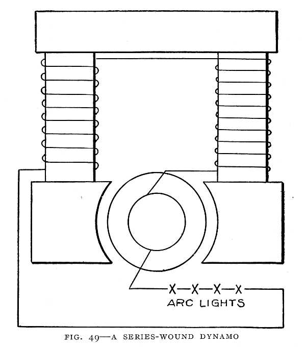
In the second form of winding the current is divided into[107] two branches. One branch goes through the coils of the field-magnet. The other branch goes through the line wire for use in lights or motors. This is called the "shunt winding" (Fig. 50). The shunt-wound dynamo is used for incandescent lights. It also requires a special regulator, for if left to itself it gives less electrical pressure when the pressure should be kept the same.
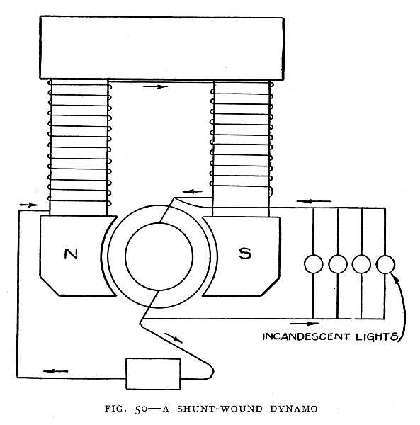
The compound winding (Fig. 51), which was first used by Edison, is a combination of the series and shunt windings.[108]
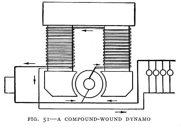
The current is divided into two branches. One branch goes only through the field-coils. The other branch goes through additional coils which are wound on the field-magnet, and also through the external circuit. Such a dynamo can be made self-regulating, so that it will give always the same electrical pressure whatever the number of lamps or motors thrown into the circuit. In maintaining always the same pressure it of course supplies more or less current, according to the amount of current that is needed. This is clear if we compare the flow of electric current with the flow of water. Open a water-faucet and notice how fast the water flows. Then open several other faucets connected with the same water-pipe. Probably the water will not flow so fast from the first faucet. That is because the pressure has been lowered by the flow of water from the other faucets. If we could make the water adjust its own pressure and keep the pressure always the same, then the water would always flow at the same rate through a faucet, no matter [110]how many other faucets were opened. This is what happens in the Edison compound-wound dynamo. Turn on one 16-candle-power carbon lamp. It takes about half an ampere of current. Turn on a hundred lamps connected to the same wires, and the dynamo of its own accord keeps the pressure the same, and supplies fifty amperes, or half an ampere for each lamp. With this invention of Edison the dynamo was practically complete, and ready to furnish current for any purpose for which current might be needed. Fig. 52 shows one of Edison's first dynamos. Fig. 53 shows a dynamo used for lighting a railway coach.
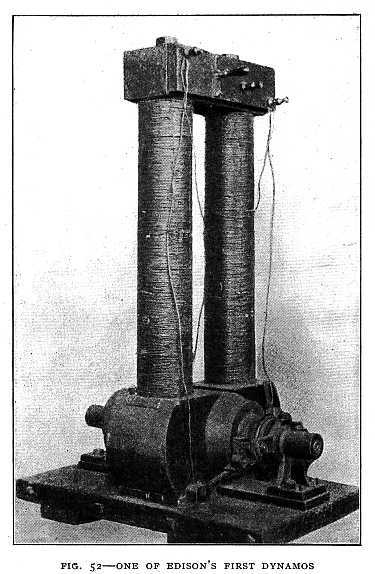

The dynamo furnishes current for the electric lights in the car. When the train is not running the current is furnished by a storage battery.
[111]Electric Power
It has been said that the nineteenth century was the age of steam, but the twentieth will be the age of electricity. Before the end of the nineteenth century, however, electric power had become a reality, and there remained only development along practical lines.
We must turn to Oersted, Ampère, and Faraday to find the beginning of electric power. In Oersted's experiment, motion of a magnet was produced by an electric current. Ampère found that electric currents attract or repel each other, and this because of their magnetic action. Faraday found that one pole of a magnet will spin round a wire through which a current is flowing. Here was motion produced by an electric current. These great scientists discovered the principles that were applied later by inventors in the electric motor.
A number of motors were invented in the early years of the century, but they were of no practical use. It was not until after the invention of the Gramme and Siemens dynamos that a practical motor was possible. It was found that one of these dynamos would run as a motor if a current were sent through the coils of the armature and the field-magnet; in fact, the current from one dynamo may be made to run another similar machine as a motor. Thus the dynamo is said to be reversible. If the armature is turned by a steam-engine or some other power, a current is produced. If a current is sent through the coils, the armature turns and does work. If the machine is used to supply an electric current, it is a dynamo. If used to do[112] work—as, for example, to propel a street-car and for that purpose receives a current—it is a motor. The same machine may be used for either purpose. In practice there are some differences in the winding of the coils of dynamos and motors, yet any dynamo can be used as a motor and any motor can be used as a dynamo. This discovery made it possible to transmit power to a distance with little waste as well as to divide the power easily. The current from one large dynamo may light streets and houses, and at the same time run a number of motors in factories or street-cars at great distances apart. A central-station dynamo may run the motors that propel hundreds of street-cars. Dynamos at Niagara furnish current for motors in Buffalo and other cities. One great scientist, who no doubt fore-saw the wonders of electricity which we know so well to-day, said that the greatest discovery of the nineteenth century was that the Gramme machine is reversible.
The First Electric Railway
The electric railway was made possible by the invention of the dynamo and the discovery that the dynamo is reversible. At the Industrial Exposition in Berlin in 1879 there was exhibited the first practical electric locomotive, the invention of Doctor Siemens. The locomotive and its passenger-coach were absurdly small. The track was circular, and about one thousand feet in length. This diminutive railway was referred to by an American magazine as "Siemens' electrical merry-go-round." But the electrical merry-go-round aroused great interest because of the possibilities it represented (Fig. 54).
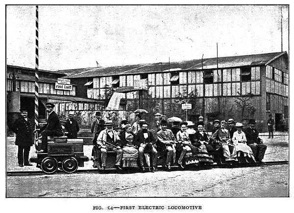
The current was generated by a dynamo in Machinery Hall, this dynamo being run by a steam-engine. An exactly similar dynamo mounted on wheels formed the locomotive. The current from the dynamo in Machinery Hall was used to run the other as a motor and so propel the car. The rails served to conduct the current. A third rail in the middle of the track was connected to one pole of the dynamo and the two outer rails to the other pole. A small trolley wheel made contact with the third rail. The rails were not insulated, but it was found that the leakage current was very small, even when the ground was wet.
The success of this experiment aroused great interest, not only in Germany, but in Europe and America. America's greatest inventor, Edison, took up the problem. Edison employed no trolley line or third rail, but only the two rails of the track as conductors, sending the current out through one rail and back through the other. Of course, this meant that the wheels must be insulated, so that the current could flow from one rail to the other only through the coils of the motor.
As in Siemens' experiment, the motor was of the same construction as the dynamo. The rails were not insulated, and it was found that, even when the track was wet, the loss of electric current was not more than 5 per cent. Edison found that he could realize in his motor 70 per cent. of the power applied to the dynamo, whereas the German inventor was able to realize only 60 per cent. The improvement was largely due to the improved winding. Edison was the first to use in practical work the compound-wound dynamo, and this was done in connection with his electric railway. Fig. 55 shows Edison's first electric locomotive.
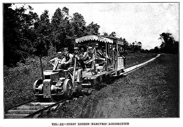
The question of gearing was a troublesome one. The armature shaft of the motor was at first connected by friction gearing to the axle of two wheels of the locomotive. Later a belt and pulleys were used. An idler pulley was used to tighten the belt. When the motor was started and the belt quickly tightened the armature was burned out. This happened a number of times. Then Mr. Edison brought out from the laboratory a number of resistance-boxes, placed them on the locomotive, and connected them in series with the armature. These resistances would permit only a small current to flow through the motor as it was starting, and so prevent the burning-out of the armature coils. The locomotive was started with the resistance-boxes in circuit, and after gaining some speed the operator would plug the various boxes out of circuit, and in that way increase the speed. When the motor is running there is a back-pressure, or a pressure that would cause a current to flow in the opposite direction from that which is running the motor. Because of this back-pressure the current which actually flows through the motor is small, and the resistance-boxes may be safely taken out of the circuit. Finding the resistance-boxes scattered about under the seats and on the platform as they were a nuisance, Mr. Edison threw them aside, and used some coils of wire wound on the motor field-magnet which could be plugged out of the circuit in the same way as the resistance-boxes. This device of Edison's was the origin of the controller, though in the controller now used on street-cars not only is the resistance cut out as the speed of the car increases, but the electrical connections of the motor are changed in such a way as to increase its [118]speed gradually. Fig. 56 shows Edison's first passenger locomotive.
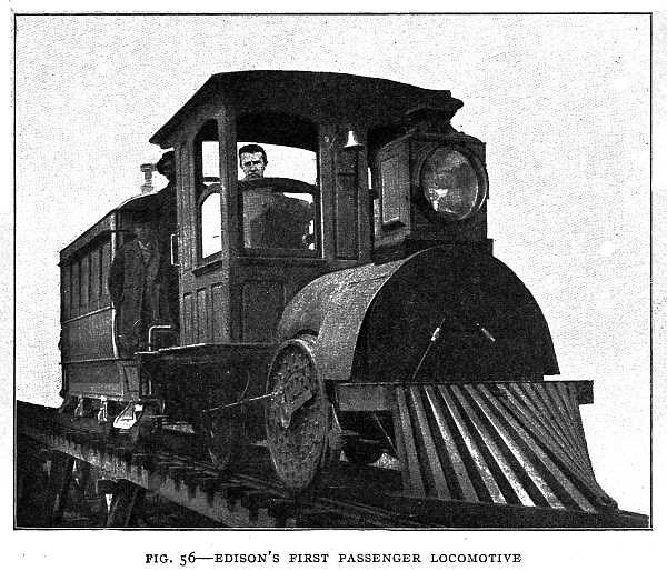
The news of the little electric railway at the Industrial Exposition in Berlin was soon noised abroad, and the German inventor received inquiries from all parts of the world, indicating that efforts would be made in other countries to develop practical electrical railways. The firm of Siemens & Halske therefore determined to build a line for actual traffic, not for profit, but that Germany might have the honor of building the first practical electric railway. The line was built between Berlin and Lichterfelde, a distance of about one and a half miles. A horse-car seating twenty-six persons was pressed into service. A motor was mounted between the axles, and a central-station dynamo exactly like the motor was installed. As in Edison's experimental railway, the two rails of the track were used to carry the current. This electric line replaced an omnibus line, and was immediately used for regular traffic, and thus the electric railway was launched upon its remarkable career. The first electric car used for commercial service is shown in Fig. 57.
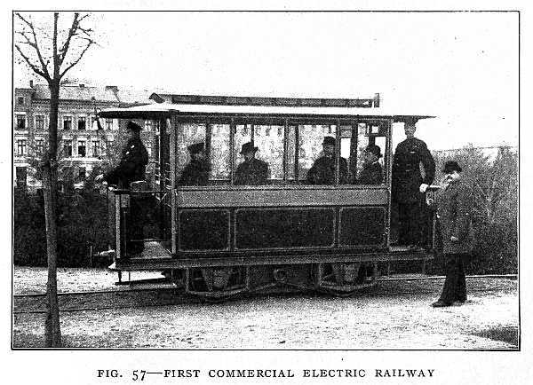
Electric Lighting
From the time when the night-watchman carried a lantern to the time of brilliantly lighted streets was less than a century. It was a time when the rapid growth of railways and commerce brought about a rapid growth of cities, and with the growth of cities the need of illumination. Factories must run at night to meet the world's demands. Commerce cannot stop when the sun sets. The centres of commerce must have light.[119]
During this time scientists were at work in their laboratories developing means for producing a high vacuum. They were able to pump the air out of a glass bulb until less than a millionth part of the air remained. They little dreamed that there was any connection between the high vacuum and the problem of lighting. Discoverers were at work bringing to light the principles now utilized in the dynamo. In the fulness of time these factors were brought together to produce an efficient system of lighting.
For a time gas replaced the lantern of the night-watchman, only to yield the greater portion of the field to its rival, electricity.[120]
The first efforts were in the direction of the arc light. From the earliest times the light given out by an electric spark had been observed. It was the aim of inventors to produce a continuous spark that should give out a brilliant light. It was thought for a time that the electric battery would solve the problem, but the cost of the battery current was too great. Again we are indebted to Faraday, for it was the dynamo that made electric lighting possible.
An arc light is produced by an electric current flowing across a gap between two sticks of carbon. The air offers very great resistance to the flow of electric current across this gap. Now whenever an electric current flows through something which resists its flow, heat is produced. The high resistance of the air-gap causes such intense heat that the tips of the carbons become white hot and give out a brilliant light. If examined through a smoked glass a beautiful blue arc of carbon vapor may be seen between the carbon tips. If the current flows in one direction only, one of the carbons, the positive, becomes hotter and brighter than the other.
In 1878 the streets of Paris were lighted with the "Jablochkoff candle," a form of arc light supplied with current by the Gramme machine. In the same year the Brush system of arc lighting was given to the public. This was the beginning of our present system of arc lighting.
The electric arc is suitable for lighting streets and for large buildings, but cannot be used for lighting houses. The light is too intense. One arc would furnish enough light for a number of houses if the light could be divided so that there might be just the right amount of light in[121] each room. But this is impossible with the electric arc. The Edison system of incandescent lighting was required to solve the problem of lighting houses by electricity.
In 1880 the Edison system was brought out for commercial use. Edison's problem was to produce a light that could be divided into a number of small lights, and one that would require less attention than the arc light. He tried passing a current through platinum wire enclosed in a vacuum. This gave a fairly good light, but was not wholly satisfactory. He sat one night thinking about the problem, unconsciously fingering a bit of lampblack mixed with tar which he had used in his telephone. Not thinking what he was doing, he rolled this mixture of tar and lampblack into a thread. Then he noticed what he had done, and the thought occurred to him: "Why not pass an electric current through this thread of carbon?" He tried it. A faint glow was the result. He felt that he was on the right track. A piece of cotton thread must be heated in a furnace in an iron mold, which would prevent the thread from burning by keeping out the air. Then all the other elements that were in the thread would be driven out and only the carbon remain. For three days he worked without sleep to prepare this carbon filament. At the end of two days he succeeded in getting a perfect filament, but when he attempted to seal it in the glass bulb it broke. He patiently worked another day, and was rewarded by securing a good carbon filament, sealed in a glass globe. He pumped the air out of this globe, sealed it, and sent a current through the carbon thread. He tried a weak current at first. There was a faint glow. He increased the current. The thread glowed [123]more brightly. He continued to increase the current until the slender thread of carbon, which would crumble at a touch, was carrying a current that would melt a wire of platinum strong enough to support a weight of several pounds. The carbon gave a bright light. He had found a means of causing the electric current to furnish a large number of small lights. Fig. 58 is an excellent photograph of Edison at work in his laboratory. Fig. 59 shows some of Edison's first incandescent lamps. He next set out in search of the best kind of carbon for the purpose. He carbonized paper and wood of various kinds—in fact, everything he could find that would yield a carbon filament. He tried the fibres of a Japanese fan made of bamboo, and found that this gave a better light than anything he had tried before. He then began the search for the best kind[124] of bamboo. He learned that there are about twelve hundred varieties of bamboo. He must have a sample of every variety. He sent men into every part of the world where bamboo grows. One man travelled thirty thousand miles and had many encounters with wild beasts in his search for the samples of bamboo. At last a Japanese bamboo was found that was better than any other. The search for the carbon fibre had cost about a hundred thousand dollars. Later it was found that a "squirted filament" could be made that worked as well as the bamboo fibre. This was made by dissolving cotton wool in a certain solution, and then squirting this solution through a small hole into a small tank containing alcohol. The alcohol causes the substance to set and harden, and thus forms a carbon thread the size of the hole. Fig. 60 shows the first commercial electric-lighting plant, which was installed on the steamship Columbia in 1880.
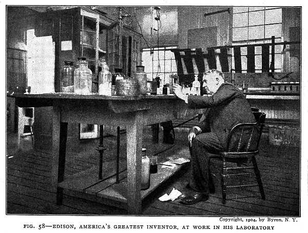 FIG. 58–EDISON, AMERICA'S GREATEST INVENTOR, AT WORK IN HIS LABORATORY
Copyright, 1904, by Byron, N. Y.
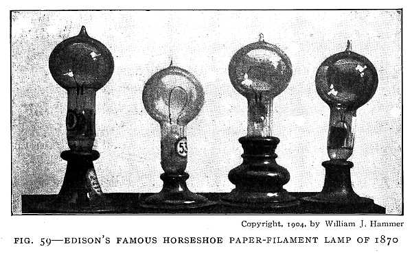
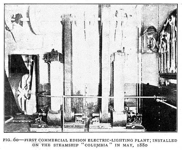 FIG. 60–FIRST COMMERCIAL EDISON ELECTRIC-LIGHTING PLANT; INSTALLED ON THE STEAMSHIP "COLUMBIA" IN MAY, 1880
The carbon thread in the incandescent light is heated to a white heat, and because it is so heated it gives out light. In air such a tiny thread of white-hot carbon would burn in a fraction of a second. The carbon must be in a vacuum, and so the air is pumped out of the light bulb with a special kind of air-pump invented not long before Edison began his work on the electric light. This pump is capable of taking out practically all the air that was in the bulb. Perhaps a millionth part of the original air remains.
A great invention is never completed by one man. It was to be expected that the electric light would be improved. A number of kinds of incandescent light have been devised, using different kinds of filaments and adapted to[125] a variety of uses. The original Edison carbon lamp, however, continues in use, being better adapted to certain purposes than the newer forms.
The mercury vapor light deserves mention as a special form of arc light. In the ordinary arc light the arc is formed of carbon vapor, and the light is given out from the tips of the white-hot carbons. In the mercury vapor light the light is given out from the mercury vapor which forms the arc. This arc may be of any desired length, and yields a soft, bluish-white light which is a near approach to daylight.[126]
The Telegraph
The need of some means of giving signals at a distance was early felt in the art of war. Flag signals such as are now used by the armies and navies of the world were introduced in the middle of the seventeenth century by the Duke of York, admiral of the English fleet, who afterward became James II. of England. Other methods of communicating at a distance were devised from time to time, but the distance was only that at which a signal could be seen or a sound heard. No means of communicating over very long distances was possible until the magnetic action of an electric current was discovered. When Oersted's discovery was made known men began to think of signalling to a distance by means of the action of an electric current on a magnetic needle. A current may be sent over a very long wire, and it will deflect a magnetic needle at the other end. The movements of the needle may be controlled by opening and closing the circuit, and a system of signals or an alphabet may be arranged. A number of needle telegraphs were invented, but they were too slow in action. Two other great inventions were needed to prepare the way for the telegraph. One was the electromagnet in the form developed by Professor Henry, a horseshoe magnet with many turns of silk-covered wire around the soft-iron core, so that a very feeble current will produce a magnet strong enough to move an armature of soft iron. The magnet has this strength because the current flows so many times around the iron core. Another need was that of a battery that could be depended on to give a constant current[127] for a considerable length of time. This need was met by the Daniell cell.
The electromagnet made the telegraph possible. The locomotive made it a necessity. Without the telegraph it would be impossible to control a railway system from a central office. A train after leaving the central station would be like a ship at sea before the invention of the wireless telegraph. Nothing could be known of its movements until it returned. The need of a telegraph was keenly felt in America when the new republic was extended to the Pacific Coast. An English statesman said, after the United States acquired California, that this marked the end of the great American Republic, for a people spread over such a vast area and separated by such natural barriers could not hold together. He did not know that the iron wire of the telegraph would bind the new nation firmly together.
The Morse telegraph system now in use throughout the civilized world was made possible by the work of Sturgeon and Henry. Sturgeon's electromagnet might have been used for telegraphy through very short distances, but Henry's magnet, with its coils of many turns of insulated wire, was needed for long-distance signalling. In one of the rooms of the Albany Academy, Professor Henry caused an electromagnet to sound a bell when the current was transmitted through more than a mile of wire. This might be called the first electromagnetic telegraph. But the application to actual practice was made by Morse, and the man who first makes the practical application of a principle is the true inventor.[128]
In 1832, on board the packet-ship Sully, Samuel F. B. Morse, an American artist, forty-one years of age, was returning from Europe. In conversation a Doctor Jackson referred to the electrical experiments of Ampère, which he had witnessed while in Europe, and, in reply to a question, said that electricity passes instantaneously over any known length of wire. The thought of transmitting words by means of the electric current at once took possession of the artist's mind. After many days and sleepless nights he showed to friends on board the drawings and notes he had made of a recording telegraph.
In New York, in a room provided by his brothers, he gave himself up to the working-out of his idea, sleeping little and eating the simplest food. Receiving an appointment as professor in the University of the City of New York, he moved to one of the buildings of that university and continued his experiments in extreme poverty, and at times facing starvation, as his salary depended on the tuition fees of his pupils.
A story told by one of his pupils describes his condition at the time.
"I engaged to become one of Morse's pupils. He had three others. I soon found that the professor had little patronage. I paid my fifty dollars; that settled one quarter's tuition. I remember, when the second was due, my remittance from home did not come as expected, and one day the professor came in and said, courteously:
"'Well, Strother, my boy, how are we off for money?'
"'Why, professor, I am sorry to say I have been disappointed; but I expect a remittance next week.'[129]
"'Next week!' he repeated, sadly; 'I shall be dead by that time.'
"'Dead, sir?'
"'Yes; dead by starvation!'
"I was distressed and astonished. I said, hurriedly: 'Would ten dollars be of any service?'
"'Ten dollars would save my life; that is all it would do.'"
The money was paid, all the student had, and the two dined together. It was Morse's first meal in twenty-four hours.
The Morse telegraph sounder (Fig. 61) consists of an electromagnet and a soft-iron armature. When no current is flowing the armature is held away from the magnet by a spring. When the circuit is closed a current flows through[130] the coils of the magnet and the armature is attracted, causing a click. When the circuit is broken the spring pulls the armature away from the magnet, causing another click. The circuit is made and broken by means of a key at the other end of the line. In Morse's first instrument (Fig. 62) the armature carried a pen, which was drawn across a ribbon of paper when the armature was attracted by the magnet. If the pen was held by the magnet for a very short time, a dot was made; if for a longer time, a dash. The pen was soon discarded, and the message taken by sound only. The Morse alphabet now in use was devised by a Mr. Vail, who assisted Morse in developing the telegraph. The thought occurred to Mr. Vail that he could get help from a printing-office in deciding the combinations of dots and dashes that should be used for the different letters. The letters requiring the largest spaces in the type-cases are the ones that occur most frequently, and for these letters he used the simplest combinations of dots and dashes.
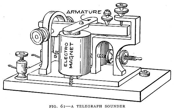
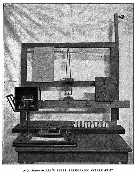 FIG. 62–MORSE'S FIRST TELEGRAPH INSTRUMENT
A pen was attached to the pendulum and drawn across the strip of paper by the action of the electromagnet. The lead type shown in the lower right-hand corner was used in making electrical contact when sending a message. The modern instrument shown in the lower left-hand corner is the one that sent a message around the world in 1896.
Photo by Claudy.
Morse repeatedly said that, if he could make his telegraph work through ten miles, he could make it work around the world. This promise of long-distance telegraphy he fulfilled by the use of the relay. The relay works in the same way as the sounder. The current coming over a long line may be too feeble to produce a click that can be easily heard, yet strong enough to magnetize the coils of the relay and cause the armature to close another circuit. This second circuit includes the sounder and a battery in the same station as the sounder, which we shall call "the local battery." The relay simply acts as a contact key, and closes the circuit of the local battery. Thus the current from the[131] local battery flows through the sounder and produces a loud click. Sometimes a relay is used to control a second very long circuit. At the farther end of the second circuit may be a sounder or a second relay which controls a third circuit. Any number of circuits may be thus connected by means of relays. This is a form of repeating system used for telegraphing over very long distances. Fig. 63 shows a circuit with relay and sounder.
[132]
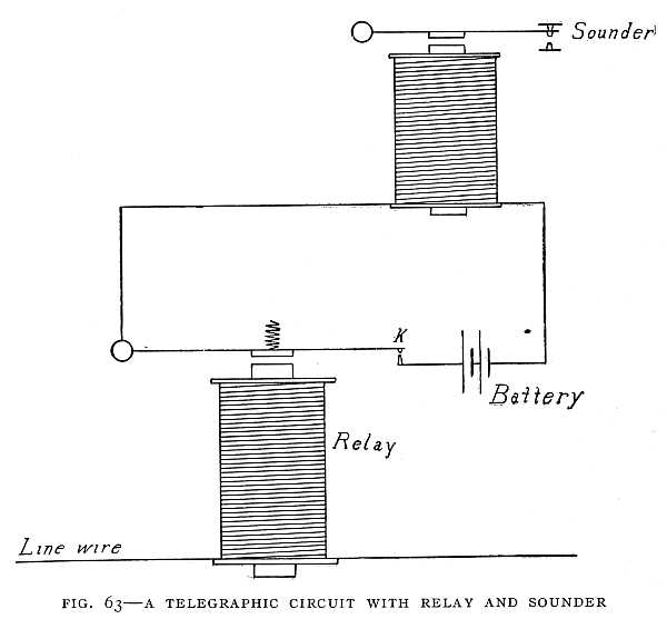
In the telegraphic circuit only one connecting wire is[133] needed. The earth, being a good conductor of electricity, is used as part of the circuit. It is necessary, therefore, to make a ground connection at each end of the line, the instruments being connected between the line wire and the earth. For long-distance telegraphy a current from a dynamo is used instead of a battery current. Fig. 64 shows a simple telegraphic circuit.
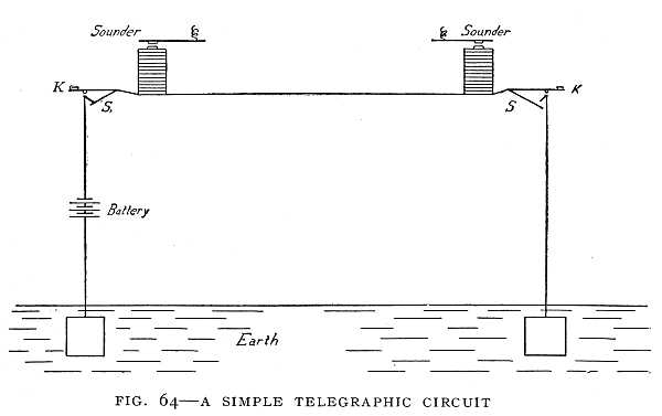 FIG. 64–A SIMPLE TELEGRAPHIC CIRCUIT
Two keys are shown at K K, and two switches at S S. When one key is to be used the switch at that station must be open, and the switch at the other station closed.
A telegraphic message travels with the speed of light, for the speed of electricity and the speed of light are the same. A telegraphic signal would go more than seven times around the earth in one second if it travelled on one continuous wire. The relays that must be used, however, cause some delay.[134]
In 1835 Morse's experimental telegraph was completed, and in 1837 it was exhibited to the public, but seven years more passed before a line was established for public use. Aid from Congress was necessary. Going to Washington, Morse exhibited his instrument in the halls of the Capitol, sending messages through ten miles of wire wound on a reel. The invention was ridiculed, but the inventor did not despair. A bill for an appropriation to establish a telegraphic line between Washington and Baltimore passed the House by a small majority. The last day of the session came. Ten o'clock at night, two hours before adjournment, and the Senate had not acted. A senator advised Morse to go home and think no more of it, saying that the Senate was not in sympathy with his project. He went to his hotel, counted his money, and found that he could pay his bill, buy his ticket home, and have thirty-seven cents left. All through his work he had firmly believed that a Higher Power was directing his work, and bringing to the world, through his invention, a new and uplifting force; and so when all seemed lost he did not lose heart.
In the morning a friend, Miss Ellsworth, called and offered her congratulations that the bill had been passed by the Senate and thirty thousand dollars appropriated for the telegraph. Being the first to bring the news of his success, Mr. Morse promised her that the first message over the new line should be hers. In about a year the line was completed, and Miss Ellsworth dictated the now famous message: "What hath God wrought!"
Soon afterward the Democratic Convention, in session in[135] Baltimore, received a telegraphic message from Senator Silas Wright, in Washington, declining the nomination for the Vice-Presidency, which had been tendered him. The convention refused to accept a message sent by telegraph, and sent a committee to Washington to investigate. The message was confirmed, and Morse and his telegraph became famous. Fig. 65 shows the first telegraph instrument used for commercial work.
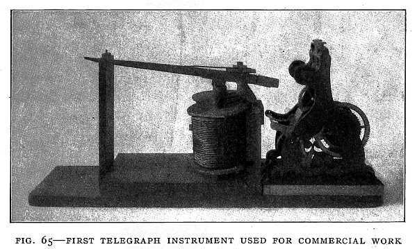
The desire to telegraph across the ocean came with the introduction of the telegraph on land. Bare wires in the air with glass insulators at the poles are used for land telegraphy, but bare wires in the water could not be used, for ocean water will conduct electricity. Something was needed to cover the wire, protect it from the water, and prevent the escape of the electric current. Just when it was needed[136] such a substance was discovered. In 1843, when Morse was working on his telegraph, it was found that the juice of a certain kind of tree growing in the Malayan Archipelago formed a substance somewhat like rubber but more durable, and especially suited to the insulation of wires in water. This substance is gutta-percha. Ocean cables are made of a number of copper wires, each wire covered with gutta-percha, the wires twisted together and protected with tarred rope yarn and an outer layer of galvanized iron wires. The earth is used for the return circuit, as in the land telegraph.
Duplex Telegraphy
The telegraph was a success, but many improvements were yet to be made. Economy of construction was the thing sought for. To make one wire do the work of two was accomplished by the invention of the duplex system. In duplex telegraphy two messages may be sent in opposite directions over the same wire at the same time. Let us take a look at some of the methods by which this is accomplished.
One method with a long name but very simple in its working is the differential system (Fig. 66). In the differential system the current from the home battery divides into two branches passing around the coils of the electromagnet in opposite directions. Now if these two branches are so arranged that the currents flowing through them are equal, the relay will not be magnetized, because one current would tend to make the end A a north pole, and the other current would tend to make the same end a south [138]pole. The result is that the relay coil is not magnetized, and does not attract the armature. But the current from the distant battery comes over one of these branches only, and will magnetize the relay. Hence, with a similar arrangement at the second station, two messages may be sent at the same time in opposite directions.
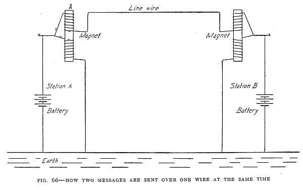
Another method not quite so simple in principle is the bridge method. When the key at station A (see Fig. 67) is closed, the current from the battery at station A divides at C, and if the resistances 1 and 2 are equal, and the resistance 3 is equal to the resistance of the line, no current will flow through the sounder. But if a current comes over the line from the distant station this current divides at D, and a part goes through the sounder, causing it to click. The sounder is not affected, therefore, by the current from the home battery, but is affected by the current from the distant battery. Therefore, a message may be sent and another received at the same time. If there is a similar arrangement at the other station, two messages may travel over the line in opposite directions at the same time.
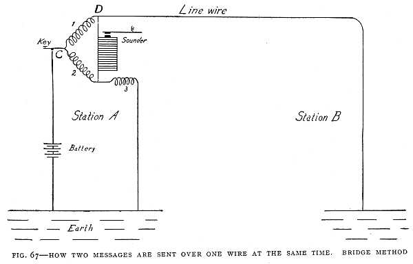
The differential method is used in land telegraphy, the bridge method almost exclusively in submarine telegraphy. The next step was a quadruplex system, by means of which four messages may be transmitted over one wire at the same time. The first quadruplex system was invented by Edison in 1874, and in four years it saved more than half a million dollars. Other systems have been invented which make it possible to send even a larger number of messages at one time over a single wire.
The Telephone
The idea of "talking by telegraph" began to grow in the minds of inventors soon after the Morse instrument came into use. The sound of the voice causes vibrations in the air. (This is simply shown in the string telephone. This telephone is made by stretching a thin membrane, such as thin sheepskin, or gold-beaters' skin, over a round frame of wood or metal. Two such instruments are connected by a string, the end of the string being fastened to the middle of the stretched membrane. The sound of the voice causes this membrane to vibrate. As the membrane moves rapidly back and forth, it pulls and releases the string, and so causes the membrane at the other end to vibrate and give out the sound. This is the actual carrying of the sound vibrations along the string.) In the telephone it is not sound vibrations but an electric current that travels over the line wire. The telephone message, therefore, travels with the speed of electricity, not with the speed of sound. If it travelled with the speed of sound in air, a message spoken in Chicago would be heard in New York one hour later; but we know that a message spoken in Chicago may be heard in New York the instant it is spoken.
The telephone, like the telegraph, depends on the electromagnet. The thought of inventors at first was to make the vibrations of a thin membrane, caused by the sound of the voice, open and close a telegraphic circuit. An electromagnet at the other end of the line would cause a thin membrane with a piece of soft iron attached to it to vibrate, just as the magnet in the telegraph receiver pulls and releases[141] the soft-iron armature as the circuit is made and broken. The thin membrane caused to vibrate in this way would give out the sound. A telephone on this principle was invented by Philip Reis, a schoolmaster in Germany. The transmitter was carved out of wood in the shape of a human ear, the thin membrane being in the position of the ear-drum. Musical sounds and even words were transmitted by this telephone, but it could never have been successful as a practical working telephone. The membrane in the receiver would vibrate with the same speed as the membrane in the transmitter, but sound depends on something more than speed of vibration.
The Bell telephone, as known to-day, began with a study of the human ear. Alexander Graham Bell was a teacher of the deaf. His aim was to teach the deaf to use spoken language, and for this purpose he wished to learn the nature of the vibrations caused by the voice. His plan was to cause the ear itself to trace on smoked glass the waves produced by the different letters of the alphabet, and to use these tracings in teaching the deaf. Accordingly, a human ear was mounted on a suitable support, the stirrup-bone removed, leaving two bones attached, and a stylus of wheat straw attached to one of the bones. The ear-drum, caused to vibrate by the sound, moved the two small bones and the pointer of straw, so that when he sang or talked to the ear delicate tracings were made on the glass.
This experiment suggested to Mr. Bell that a membrane heavier than the ear-drum would move a heavier weight. If the ear-drum, no thicker than tissue-paper, could move the bones of the ear, a heavier membrane might vibrate[142] a piece of iron in front of an electromagnet. He was at the same time devising a telegraph for transmitting messages by means of musical sounds. In this telegraph he was using an electromagnet in the transmitter and another electromagnet in the receiver. He attached the soft-iron armature of each electromagnet to a stretched membrane of gold-beaters' skin, expecting that the sound of his voice would cause the membrane of the transmitter to vibrate, and that, by means of the electromagnets, the membrane of the receiver would be made to vibrate in the same way (Fig. 68). At first he was disappointed, but after making[143] some changes in the armatures a distinct sound was heard in the receiver. Later the membrane was discarded, and a thin iron disk used with better effect.
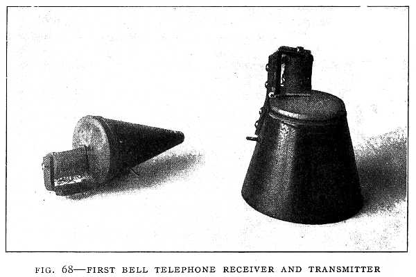 FIG. 68–FIRST BELL TELEPHONE RECEIVER AND TRANSMITTER
The receiver is on the left in the picture. A thin membrane of gold-beaters' skin tightly stretched and fastened with a cord can be seen on the end of the transmitter and of the receiver. An electromagnet is also shown over each membrane. This thin membrane, with a piece of soft iron attached, was used in place of the soft-iron disk of the modern receiver.
The story of Bell's struggles might seem like the repetition of the life story of many another great inventor. He knew that he had discovered something of great value to the world. He devoted his time to the perfecting of the telephone, neglecting his professional work and finally giving it up, that he might give his whole time to his invention. He was forced to endure poverty and ridicule. He was called "a crank who says he can talk through a wire." Men said his invention could never be made practical. Even after he succeeded in finding a few purchasers and some of the telephones were in actual use, people were slow to adopt it. The idea of talking at a piece of iron and hearing another piece of iron talk seemed like a kind of witchcraft.
In the telephone we see another use of the electromagnet. A very thin iron disk near the poles of an electromagnet forms the telephone receiver (Fig. 69). An electric current travels over the telephone wire. If the current grows[144] stronger, the magnet is made stronger and pulls the disk toward it. If the current grows weaker, the magnet becomes weaker and does not pull so hard on the disk. The disk then springs back from the magnet. If these changes take place rapidly the disk moves back and forth rapidly and gives out a sound. The sound of the voice at the other end of the line sets the disk in the mouthpiece vibrating. The vibrations of this disk cause the changes in the electric current flowing over the line-wire, and the changes in the electric current cause the disk of the receiver to vibrate in exactly the same way as the disk at the mouthpiece. Thus the words spoken into the mouthpiece may be heard at the receiver.
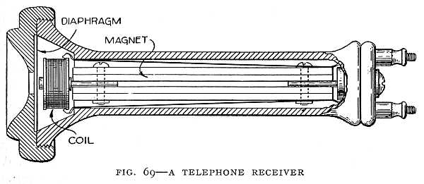
The transmitter used by Bell was like the receiver. Two receivers from the common telephone connected by two wires may be used as a telephone without batteries. Fig. 70 shows a complete telephone made of two receivers connected by two wires. The disk in one receiver which is now used as a transmitter is made to vibrate by the sound of the voice. Now when a piece of iron moves back and forth in a magnetic field it strengthens and weakens the field. So the magnetic field in the transmitter is rapidly changed by the movement of the iron disk. Now we have found that whenever a coil of wire is in a changing magnetic field a current is induced in the coil. The small coil in the transmitter, therefore, has a current induced in it. We have also found that when the magnetic field is made stronger the induced current flows in one direction, and when the field is made weaker the current flows in the opposite direction. Since the field in the transmitter is made alternately stronger[145] and weaker, the current in the coil flows first in one direction, then in the opposite direction—that is, we have an alternating current. This alternating current, of course, flows over the line-wire and through the coil in the receiver. In the receiver the alternating current will alternately strengthen and weaken the magnetic field, and as it does so the pull of the magnet on the iron disk is strengthened and weakened. The iron disk in the receiver, therefore, vibrates in exactly the same way as the disk in the transmitter, and so gives out a sound just like that which is acting on the transmitter.
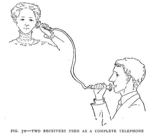
In the Blake transmitter, which is now commonly used, the disk moves a pencil of carbon which presses against another pencil of carbon. This varies the pressure between the two pencils of carbon. A battery current flows through the two carbons, and as the pressure of the carbons changes the strength of the current changes. When the carbons are pressed together more closely the current is stronger. When the pressure is less the current is weaker. We have, then, a varying current through the carbons. This current flows through the primary coil of an induction-coil, the secondary being connected to the line-wire. Now a current of varying strength in the primary induces an alternating current in the secondary. We have, then, an alternating current flowing over the line-wire. This alternating current acts on the magnetic field of the receiver in the way described before, causing the disk in the receiver to vibrate and give out the sound.
For long-distance work a carbon-dust transmitter (Fig. 71) is used. In this there are many granules of carbon, so that instead of two carbon-points in contact there are many. This makes the transmitter more sensitive.[147]
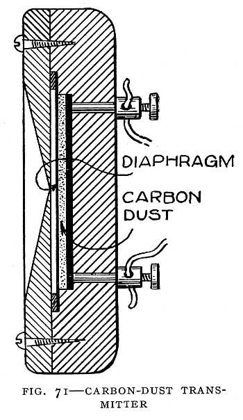
The strength of current required for the telephone is very small. To transmit a telephone message requires less than a hundred-millionth part of the current required for a telegraphic message. The work done in lifting the telephone receiver a distance of one foot, if changed into an alternating current, would be sufficient to keep up a sound in the receiver for a hundred thousand years. Because of its extreme sensitiveness the telephone requires a complete wire circuit. The earth cannot be used for the return circuit, as in the case of the telegraph. Disturbances in the earth, vibration, leakage currents from trolley lines, and so forth, would interfere seriously with the action of the telephone.
When the telephone was invented it was commonly remarked that it could not take the place of the telegraph in commerce, for the latter gave the merchant some evidence of a business transaction, while the telephone left no sign. There was a time when men feared to trust each other, but now large business deals are made by telephone; products of the farm, the factory, and the mine are bought and sold in immense quantities without a written contract or even the written evidence of a telegram. Thus the telephone has developed a spirit of business honor.
The Phonograph
The phonograph grew out of the telephone. It is said to be the only one of Edison's inventions that came by accident, yet only a man of genius would have seen the meaning of such an accident. He was singing into the mouthpiece of a telephone when the vibrations of the disk[148] caused a fine steel point to pierce one of his fingers held just behind the disk. This set him to thinking. If the sound of his voice could cause the disk to vibrate with force enough to pierce the skin, would it not make impressions on tin-foil, and so make a record of the voice that could be reproduced by passing the point rapidly over the same impressions? He gave his assistants the necessary instructions, and soon the first phonograph was made.
This disk in the phonograph is set in vibration by sound vibrations in the air in the same way as the disk in the telephone transmitter. Attached to the disk is a needle-point which, of course, vibrates with the disk. If a cylinder with a soft surface is turned rapidly under the steel point as it vibrates, impressions are made in the cylinder corresponding to the movements of the disk. The cylinder must move forward as it turns, so that its path will be a spiral. If, now, the stylus is placed at the starting-point and the cylinder turned rapidly the stylus will move rapidly up and down as it goes over the indentations in the cylinder, and so cause the metal disk to vibrate and give out a sound like that received at first. In the earliest phonographs the cylinder was covered with tin-foil. Later the so-called "wax records" came into use. These cylinders are not made of wax, but of very hard soap. Fig. 72 shows an instrument in which the sound of the voice caused a pencil-point to trace a wavy line on a cylinder. This instrument may be called a forerunner of the phonograph. Fig. 73 shows Edison's first phonograph with a modern instrument placed beside it for comparison.
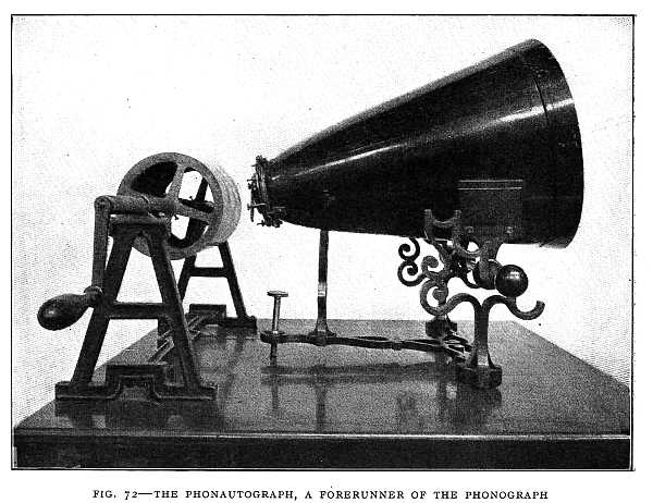
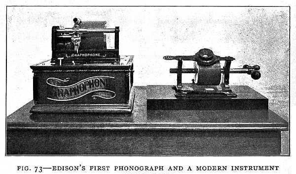
Gas-Engines
Cannons are the oldest gas-engines. Indeed, the principle of the cannon is the same as that of the modern gas-engine, the piston in the engine taking the place of the cannon-ball. The power in each case is obtained by explosion—in the cannon the explosion of powder, in the engine the explosion of a mixture of air and gas. Powder-engines with pistons were proposed in the seventeenth century, and some were actually built, but it proved too difficult to control them, and the idea of the gas-engine was abandoned for more than a hundred years.
The discovery of coal-gas near the close of the eighteenth century gave a new impetus to the gas-engine. John Barber, an Englishman, built the first actual gas-engine. He[151] used gas distilled from wood, coal, or oil. The gas, mixed with the proper proportion of air, was introduced into a tank which he called the exploder. The mixture was fired and issued out in a continuous stream of flame against the vanes of a paddle-wheel, driving them round with great force.
In 1804 Lebon, a French engineer, was assassinated, and the progress of the gas-engine set back a number of years, for this engineer had proposed to compress the mixture of gas and air before firing, and to fire the mixture by an electric spark. This is the method used in gas-engines to-day.
The first practical working gas-engine was invented by Lenoir, a Frenchman, in 1860. From this time to the end of the century the gas-engine developed rapidly, receiving a new impulse from the increasing demand for the motor-car.
The engine of the German inventors, Otto and Langen, brought out in 1876, marked the beginning of a new era. The greater number of engines used in automobiles to-day are of the kind known as the Otto cycle, or four-cycle, engine. This engine is called four-cycle because the piston makes four strokes for every explosion. There is one stroke to admit the mixture of gas and air to the cylinder, another to compress the gas and air, at the beginning of the third stroke the explosion takes place, and in the fourth stroke the burned-out gases are driven out of the cylinder. The working of the four-cycle gas-engine is made clear in Figs. 74, 75, 76, and 77.
[152]
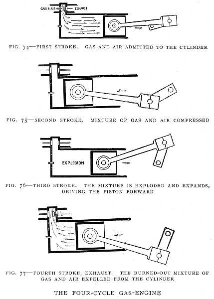 FIG. 74–FIRST STROKE. GAS AND AIR ADMITTED TO THE CYLINDER
FIG. 75–SECOND STROKE. MIXTURE OF GAS AND AIR COMPRESSED
FIG. 76–THIRD STROKE. THE MIXTURE IS EXPLODED AND EXPANDS, DRIVING THE PISTON FORWARD
FIG. 77–FOURTH STROKE, EXHAUST. THE BURNED-OUT MIXTURE OF GAS AND AIR EXPELLED FROM THE CYLINDER
THE FOUR-CYCLE GAS-ENGINE
In such a gas-engine the power is applied to the piston only in one stroke out of every four, while in the steam-engine the power is applied at every stroke. It would seem, therefore, that a steam-engine would do more work than a gas-engine for the same amount of heat, but such is not the case; in fact, a good gas-engine will do about twice as much work as a good steam-engine for the same amount of fuel. The reason is that the steam-engine wastes its heat. Heat is given to the condenser, to the iron of the boiler, to the connecting pipes and the air around them, while in the gas-engine the heat is produced in the cylinder by the explosion and the power applied directly to the piston-head. More than this, a steam-engine when at rest wastes heat; there must be a fire under the boiler if the engine is to be ready for use on short notice. When a gas-engine is at rest there is no fire, nothing is being used up, and yet the engine can be started very quickly. A gas-engine can be made much lighter than a steam-engine of the same horse-power. The automobile and the flying-machine require very light engines. Without the gas-engine the automobile would have remained imperfect and crude, while the flying-machine would have been impossible.
In a two-cycle gas-engine there is an explosion for every two strokes of the piston, or one explosion for every revolution of the crank-shaft. During one stroke the mixture of gas and air on one side of the piston is compressed and a new mixture enters on the opposite side of the piston. At the end of this stroke the compressed mixture is exploded, and power is applied to the piston during about one-fourth of the next stroke. During the remainder of the second stroke the burned-out gas escapes, and the fresh[154] mixture passes over from one side of the piston to the other ready for compression. The two-cycle engine is simpler in construction than the four-cycle, having no valves. It also has less weight per horse-power. The cylinder of a two-cycle engine is shown in Fig. 78.
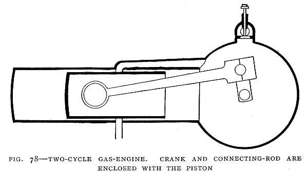
A steam-engine is self-starting. The engineer has only to turn the steam into the cylinder, but the gas-engine requires to be turned until at least one explosion takes place, for until there is an explosion of gas and air in the cylinder there is no power.
A gas-engine may have a number of cylinders. Four-cylinder and six-cylinder engines are common. In a four-cylinder, four-cycle engine, while one cylinder is on the power stroke the next is on the compression stroke, the third on the admission stroke, and the fourth on the exhaust stroke. Fig. 79 shows the Selden "explosion buggy" propelled[155] by a gas-engine. This machine was the forerunner of the modern automobile.
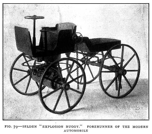
The Steam Locomotive
Late in the eighteenth century a mischievous boy put some water in a gun-barrel, rammed down a tight wad, and placed the barrel in the fire of a blacksmith's forge. The wad was thrown out with a loud report, and the boy's play-mate, Oliver Evans, thought he had discovered a new[156] power. The prank with the gun-barrel set young Evans thinking about the power of steam. It was not long until he read a description of a Newcomen engine. In the Newcomen engine, you will remember, it was the pressure of air, not the pressure of steam, that lifted the weight. Evans soon set about building an engine in which the pressure of steam should do the work. He is sometimes called the "Watt of America," for he did in America much the same work that Watt did in Scotland. Evans built the first successful non-condensing engine—that is, an engine in which the steam, after driving the piston, escapes into the air instead of into a condenser. The non-condensing engine made the locomotive possible, for a locomotive could not conveniently carry a condenser. Evans made a locomotive which travelled very slowly. He said, however: "The time will come when people will travel in stages moved by steam-engines from one city to another, almost as fast as birds can fly, fifteen or twenty miles an hour."
The inventor who made the first successful locomotive was George Stephenson, and it is worth noting that one of his engines, the "Rocket," possessed all the elements of the modern locomotive. He combined in the "Rocket" the tubular boiler, the forced draft, and direct connection of the piston-rod to the crank-pin of the driving-wheel.
The "Rocket" was used on the first steam railway (the Stockton & Darlington, in England), which was opened in 1825. There had been other railways for hauling coal by means of horses over iron tracks, and other locomotives that travelled over an ordinary road; but this was the first road[157] on which a steam-engine pulled a load over an iron track, the first real railroad. Fig. 80 shows the "Rocket" and two other early locomotives.
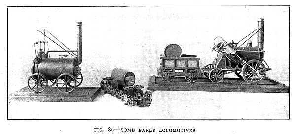
In order to build a railroad between Liverpool and Manchester for carrying both passengers and freight it was necessary to secure an act of Parliament. Stephenson was compelled to undergo a severe cross-examination by a committee of Parliament, who feared there would be great danger if the speed of the trains were as high as twelve miles an hour. He was asked:
"Have you seen a railroad that would stand a speed of twelve miles an hour?"
"Yes."
"Where?"
"Any railroad that would bear going four miles an hour. I mean to say that if it would bear the weight at four miles an hour it would bear it at twelve."
"Do you mean to say that it would not require a stronger railway to carry the same weight at twelve miles an hour?"
"I will give an answer to that. I dare say every person has been over ice when skating, or seen persons go over, and they know that it would bear them better at a greater velocity than it would if they went slower; when they go quickly the weight, in a measure, ceases."
"Would not that imply that the road must be perfect?"
"It would, and I mean to make it perfect."
For seven miles the road must be built over a peat bog into which a stone would sink to unknown depths. To convince the committee, however, and secure the act of Parliament was more difficult than to build the road. But [159]Stephenson was one of the men who do things because they never give up, and the road was built.
How a Locomotive Works
To understand how a locomotive works, let us consider how the steam is produced, how it acts on the piston, and how it is controlled. The steam is produced in a locomotive in exactly the same way that steam is produced in a tea-kettle. Now everybody knows that a quart of water in a tea-kettle with a wide bottom placed on a stove will boil more quickly than the same amount of water in a tea-pot with a narrow bottom. The greater the heating-surface—that is, the greater the surface of heated metal in contact with the water—the more quickly the water will boil and the more quickly steam can be produced. In a locomotive the aim is to use as large a heating-surface as possible. This is done by making the fire-box double and allowing the water to circulate in the space between the inner and outer parts, except underneath; also by placing tubes in the boiler through which the heated gases and smoke from the fire must pass. An ordinary locomotive contains two hundred or more of these tubes. The water surrounds these tubes, and is therefore in contact with a very large surface of heated metal. In some engines the water is in the tubes, and the heated gases surround the tubes.
The steam as it enters the cylinder should be dry—that is, it should not contain drops of water. This is accomplished by allowing the steam from the boiler to pass into a dome above the boiler. Here the steam, which is nearly[160] dry, enters a steam-pipe leading to the cylinder (Fig. 81). The steam is admitted to the cylinder by means of a slide-valve. From the diagram it can easily be seen that the valve admits steam first on one side of the piston, then on the other. It can also be seen that the valve closes the admission-port, and so cuts off the steam before the piston has made a full stroke. The steam that is shut up in the cylinder continues to expand and act on the piston. At the same time the valve opens the exhaust-port, allowing the steam to escape from the other side of the piston; but it closes this port before the piston has quite finished the stroke. The small quantity of steam thus shut up acts like a cushion to prevent the piston striking the end of the cylinder with too great force. The exhaust-steam escapes through a blast-pipe into the chimney, drives the air before it up the chimney, and thus makes a greater draft of air through the fire-box. This is called the forced draft. The escape of the exhaust-steam causes the puffing of the locomotive just after starting. After the engine is under way the engineer partly shuts off the steam by means of the reversing lever and the puffing is less noticeable.
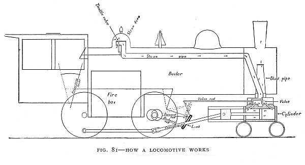
The action of the steam may be summed up as follows:
1. Steam admitted to the cylinder (admission).
2. Valve closes admission-port (cut-off).
3. Steam shut up in the cylinder expands, acting on the piston (expansion period).
4. Valve opens exhaust-port to allow used steam to escape (exhaust).
The devices for controlling the steam are the throttle-valve and the valve-gear. The throttle-valve is at the en[162]trance to the steam-pipe in the steam-dome. This valve is opened and closed by means of a rod in the engineer's cab.
Stephenson's link-motion valve-gear is used on most locomotives. The forward rod in the diagram is in position to act upon the valve-rod through the lever L. Suppose the reversing-lever is drawn back to the dotted line; then the forward rod will be raised and the backward rod will come into position to act on the lever L. If this is done while the locomotive is at rest the valve is moved through one-half a complete stroke. In the diagram the steam enters the cylinder on the right of the piston. After this movement of the valve the steam would enter on the left side of the piston. In the present position the locomotive would move forward, but if the valve is changed so as to admit steam to the left of the piston while the connecting-rod is in the position shown then the engine will move backward. Thus the direction can be controlled by the engineer in the cab. Of course, this can be done while the engine is in motion. The forward rod and the backward rod are each moved by an eccentric on the axle of the front driving-wheel. The two eccentrics are in opposite positions on the axle. An eccentric acts just like a crank, causing the rod to move forward and backward as the axle turns, and of course this motion is given to the valve-rod through the lever. When the link is set midway between the forward and the backward rod the valve cannot move. When the link is raised or lowered part way the valve makes a short stroke, and less steam is admitted to the cylinder than with a full stroke. In starting the locomotive the valve is set to make a full stroke.[163] When the train is under headway the valve is set for a short stroke to economize steam. The valve-gear and the throttle-valve together take the place of the governor in the stationary engine, but while the governor acts automatically these are controlled by the engineer.
In reality a locomotive is two engines, one on either side, connected to the same driving-wheels. But the two piston-rods are connected to the driving-wheels at points which are at right angles with each other, so that when the crank on one side is at the end of a stroke—the "dead centre"—that on the other side is on the quarter, either above or below the axle, ready for applying the greatest turning force.
The expansion-engine was designed to use more of the power of the steam than can be done in the single-cylinder engine. In the double expansion-engine the steam expands from one cylinder into another. The second cylinder must be larger in diameter than the first. In the triple expansion-engine the steam expands from the second cylinder into a third, still larger. The second and third cylinders use a large part of the power that would be wasted with only one cylinder.
The Turbine
One of the great inventions relating to steam-power is the steam-turbine. The water-turbine is equally useful in relation to water-power. The water-turbine and the steam-turbine work in very much the same way, the difference being due to the fact that steam expands as it drives the engine, while water drives it by its weight in falling, or by[164] its motion as it rushes in a swift stream or jet against the blades of the turbine.
The first steam-engine, that of Hero in the time of Archimedes, was a form of turbine (Fig. 82). It was driven by the reaction of the steam as it escaped into the air. The common lawn-sprinkler, that whirls as the water rushes through it, is a water-turbine that works in the same way. "Barker's Mill" is the name applied to a water-turbine that works like the lawn-sprinkler. As the water rushes out of the opening it pushes against the air. It cannot push against the air without pushing back at the same time. Never yet has any person or object in nature been able to push in one direction only. It cannot be done. If you push a cart forward you push backward against the ground at the same time. If there were nothing for you to push back against your forward push would not move the cart a hair's-breadth. If you doubt this, try to push a cart when you are standing on ice so slippery that you cannot get a foothold. It is the backward push of the water in the lawn-sprinkler and the backward push of the steam in Hero's engine that cause the machine to turn.[165]
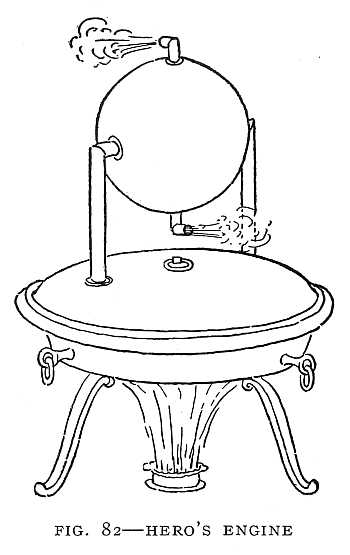
The turbines in common use for both water and steam power have curved blades. The reason for curving the blades can best be seen by referring to an early form of water-wheel. The best water-turbine is only an improved form of water-wheel. The first water-wheels had flat blades, and these answered very well so long as only a low power was needed and it was not necessary to save the power of the water. It was found, however, that there was a great waste of power in the wheel with flat blades. One inventor proposed to improve the wheel by curving the blades in such a way that the water would glide up the curve and then drop directly downward (Fig. 83). The water then gives up practically all of its power to the wheel and falls from the wheel. It would have no power to[166] move a second wheel. In this way he used practically all the power of the water. To save the power of the water by making all of the water strike the wheel at high speed the channel was made narrow just above the wheel, forming a mill-race. This applies to the undershot wheel. In the overshot wheel (Fig. 84) the power depends on the weight of the water and on its height. The water runs into buckets attached to the wheel, and, as it falls in these buckets, turns the wheel. The undershot wheel and the[167] mill-race represent a common form of turbine, that form in which the steam or the water is forced in a jet against a set of curved blades. Fig. 85 shows a steam-turbine run by a jet of steam. In the water-turbine there are two sets of blades. One set rotates, the other remains fixed. The use of the fixed blades is to turn the water and drive it in the right direction against the moving blades. In some forms of turbine there are more than two sets of blades. The steam, as it passes through, gives up some of its power to each set of blades until, after passing the last set, it has given up nearly all its power. The action of the steam in this turbine is somewhat like that in the expansion-engine, in which the steam gives up a portion of its power in each cylinder. Fig. 86 is from a photograph of a modern steam-turbine, and Fig. 87 is a drawing of the same turbine showing the course of the steam. Fig. 88 is a turbine that runs a large dynamo.
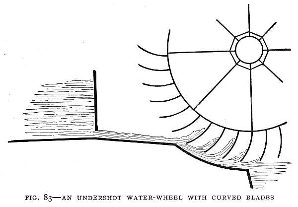
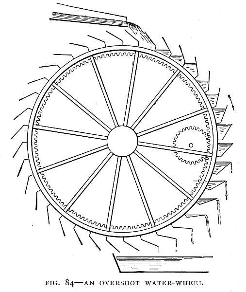
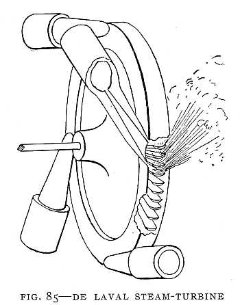
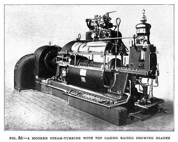
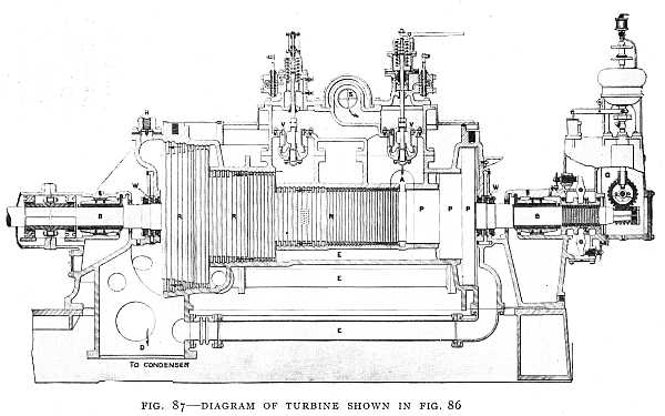
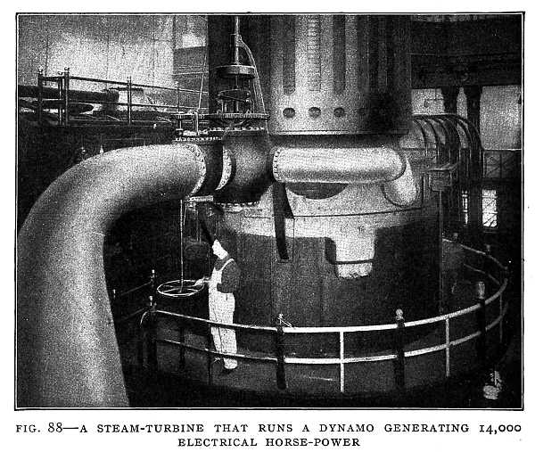 FIG. 88–A STEAM-TURBINE THAT RUNS A DYNAMO GENERATING 14,000 ELECTRICAL HORSE-POWER
The steam enters through the large pipe at the left.
In 1897, as the battle-ships of the British fleet were assembled to celebrate the Diamond jubilee of Queen Victoria, a little vessel a hundred feet long darted in and out among [170]the giant ships, defied the patrol-boats whose duty it was to keep out intruders, and raced down the lines of battle-ships at the then unheard-of speed of thirty-five knots an hour. It was the Turbinia, fitted with the Parsons turbine. This event marked the beginning of the modern turbine. It also marked the beginning of a revolution in steam propulsion.
The Parsons turbine does not use the jet method, but the steam enters near the centre of the wheel and flows[171] toward the rim, passing over a number of rows of curved blades. The Parsons turbine is used on the fastest ocean liners. The Lusitania, one of the fastest steamships in the first decade of the twentieth century, has two sets of high and low pressure turbines with a total of 68,000 horse-power.
The windmill is a form of turbine driven by the air. As the air rushes against the blades of the windmill, it forces them to turn. If the windmill were turned by some mechanical power, it would drive the air back, and we should have a blower. This is what we have in the electric fan, a small windmill driven by an electric motor so that it drives the air instead of being driven by it. The blades of the windmill and the electric fan are shaped very much like the screw propeller. The screw propeller, driven by an engine, would drive the water back if the ship were firmly anchored, just as the fan drives the air. But it cannot drive the water back without pushing forward on the ship at the same time, and this forward push propels the ship. It is difficult to attain what is now regarded as high speed with a single screw. With engines in pairs and two lines of shafting higher power can be used. The best steamers, therefore, are fitted with the twin-screw propeller. Some large steamers have three and some four screws.
The screw propellers of turbine steamships are made of small diameter, that they may rotate at high speed without undue waste of power. By the use of turbine engines and twin-screw propellers, the weight of the machinery has been greatly reduced. The old paddle-wheels, with low-pressure engines, developed only about two horse-power for each[172] ton of machinery. The turbine, with the twin-screw propeller, develops from six to seven horse-power for every ton of machinery. The modern steamer, with all its machinery and coal for an Atlantic voyage, weighs no more than the engines of the old paddle-wheel type and coal would weigh for the same horse-power. The steam-turbine and the twin-screw propeller have made rapid ocean travel possible.[173]
Chapter VI
THE TWENTIETH-CENTURY OUTLOOK
We have seen that the latter half of the nineteenth century was a time of invention. It was a time when the great discoveries of many centuries bore fruit in great inventions. It was thought by some scientists that all the great discoveries had been made, and that all that remained was careful work in applying the great principles that had been discovered. So far was this from being true that in the last ten years of the nineteenth century discoveries were made more startling, if possible, than any that had preceded. The nineteenth century not only brought forth many great inventions, but handed down to the twentieth century a series of discoveries that point the way to still greater inventions.
Air-Ships
For centuries men sailed over the water at the mercy of the wind. The sailing vessel is helpless in a storm. Early in the nineteenth century they learned to use the power of steam for ocean travel, and the wind lost its terrors. Late in the eighteenth century men learned to sail through the air in balloons even more at the mercy of the wind than the[174] sailing vessels on the ocean. More than a hundred years later they learned to propel air-ships in the teeth of the wind. The nineteenth century saw the mastery of the water. The twentieth is witnessing the mastery of the air.
The first balloon ascension was made in 1783, two men being carried over Paris by what Benjamin Franklin called a "bag of smoke." The balloon was a bag of oiled silk open at the bottom. In the middle of the opening was a grate in which bundles of fagots and sheaves of straw were burned. The heated air filled the balloon, and as the heated air was lighter than the air around it the balloon could rise and carry a load. Beneath the grate was a wicker car for the men. They were supplied with straw and fagots with which to feed the fire. When they wanted to rise higher they added fuel to heat the air in the balloon. When they wished to descend they allowed the fire to die out, so that the air in the balloon would cool. They could not guide the balloon, but drifted with the wind. That great philosopher Benjamin Franklin, who saw the ascension, said that the time might come when the balloon could be made to move in a calm and guided in a wind. In the second ascension bags of sand were taken as ballast, and the car was suspended from a net which enclosed the balloon. In this second ascension hydrogen gas was used in place of heated air.
The greatest height ever reached by a human being is about seven miles. This height was first reached in 1862 by two balloonists who nearly lost their lives in the adventure. At a height of nearly six miles one of the men became unconscious. The other tried to pull the valve-cord to allow[175] the gas to escape, but found that the cord was out of his reach. His hands were frozen, but he climbed out of the car into the netting of the balloon, secured the cord in his teeth, returned to the car, and threw the weight of his body on the cord. This opened the valve and the balloon descended.
Those who go to great heights now provide themselves with tanks of compressed oxygen. Then when the air becomes so thin and rare that breathing is difficult they can breathe from the oxygen tanks.
A captive balloon in war serves as an observation tower from which to observe the enemy. It is connected to the ground by a cable. This cable is wound on a drum carried by the balloon wagon. The balloon can be lowered or raised by winding or unwinding the cable.
The gas-bag is sometimes made of oiled silk, sometimes of two layers of cotton cloth with vulcanized rubber between. The cotton cloth gives the strength needed, and the rubber makes the bag gas-tight.
The most convenient gas for filling balloons is heated air, but the air cools rapidly and loses its lifting power. Coal-gas furnished by city gas-plants is sometimes used. This gas will lift about thirty-five pounds for every thousand cubic feet. A balloon holding thirty-five thousand cubic feet of coal gas will easily lift the car and three persons. The lightest gas is hydrogen. This gas will lift about seventy pounds for every thousand cubic feet. Hydrogen is made by the action of sulphuric acid and water on iron. If a bit of iron is thrown into a mixture of sulphuric acid and water bubbles of hydrogen gas will rise through the [177]liquid. This gas will burn if a lighted match is brought near.
A balloon without propelling or steering apparatus is not an air-ship. It may be raised by throwing out ballast or lowered by letting out gas, but further than this the aeronaut has no control over its movements. The balloon moves with the wind. No breeze is felt, for balloon and air move together. To the aeronaut the balloon seems to be in a dead calm. It is only when he catches sight of houses and trees and rivers darting past below that he realizes that the balloon is moving.
If a balloon has a propelling apparatus it may move against the wind, or it may outspeed the wind. A balloon with propelling and steering apparatus is called a "dirigible" balloon, which means a balloon that can be guided. Figs. 89 and 90 are from photographs of a "dirigible" used in the British army. Such a balloon is usually long and pointed like a spindle or a cigar. It is built to cut the air, just as a rowboat built for speed is long and pointed so that it may cut the water. The propeller acts like an electric fan. An electric fan drives the air before it, but the air pushes back on the fan just as much as the fan pushes forward on the air, and if the fan were suspended by a long cord it would move backward. So the large fan or screw propeller on an air-ship drives the air backward, and the air reacts and drives the ship forward. In the same way the screw-propeller of an ocean liner drives the vessel forward by the reaction of the water.
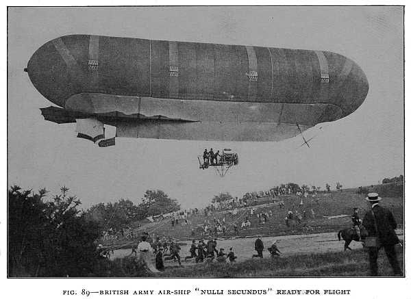
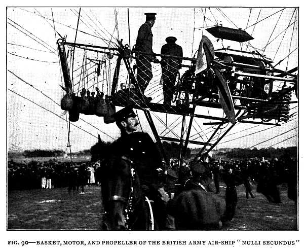
A balloon rises for the same reason that wood floats on water. The wood is lighter than water, and the water [179]holds it up. The balloon is lighter than air and the air pushes it up. The upward push of the air is just equal to the weight of the air that would fill the same space the balloon fills. The balloon can support a load that makes the whole weight of the balloon and its load together equal to the weight of the air that would fill the same space. For the balloon to rise the load must be somewhat lighter than this. A balloon may be made lighter than air by filling it with heated air or coal-gas. Hydrogen, however, is used in the better balloons and in air-ships of the "lighter than air" type.
The air-ship must, of course, use a very light motor. A steam-engine cannot be made light enough. Neither can an electric motor, if we add the weight of the storage battery that would be required. Air-ships have been propelled by both steam-engines and electric motors, but with low speed because of the weight of the engine or motor. The only successful motor for this purpose is the gasolene motor, which is a form of gas-engine using gas formed by the evaporation of gasolene.
The first air-ship that could be controlled and brought back to the starting-point was made in France, in 1885, by Captain Renard, of the French army. It was a cigar-shaped balloon, with a screw propeller run by an electric motor of eight horse-power. The ship attained a speed of thirteen miles an hour.
A more successful air-ship was that built by Santos Dumont. With this ship, in 1901, he won a prize of $20,000, which had been offered to the builder of the first air-ship that would sail round the Eiffel Tower in Paris from the Aerostatic[180] Park of Vaugirard, a distance of about three miles, and return in half an hour.
The balloon part of this air-ship was 112-1/2 feet long and 19-1/2 feet in diameter, holding about 6400 cubic feet of gas. The car was built of pine beams no larger in section than two fingers and weighing only 110 pounds. This car could be taken apart and put in a trunk. A gasolene automobile motor was used, and thus it is seen that the automobile aided in solving the problem of sailing through the air. It was the automobile that led to the construction of light and powerful gasolene motors. The car and motor were suspended from the balloon by means of piano wires, which at a short distance were invisible, so that the man in the car appeared in some mysterious way to follow the balloon. The ship was turned to the left or right by means of a rudder. It was made to ascend or descend by shifting the weight of a heavy rope that hung from the car, thus inclining the ship upward or downward.
Count Zeppelin, of Germany, constructed a much larger dirigible balloon than that of Santos Dumont. The balloon of the first Zeppelin air-ship was 390 feet in length, with a diameter of about 39 feet. It was divided into seventeen sections, each section being a balloon in itself. These sections serve the same purpose as the water-tight compartments of a battle-ship. An accident to one section would not mean the destruction of the entire ship. Within the balloon is a framework of aluminum rods extending from one end to the other and held in place by aluminum rings twenty-four feet apart. The balloon contains about 108,000 cubic feet of gas, and it costs about $2500 to fill it. One [182]filling of gas will last about three weeks. There are two cars, each about ten feet long, five feet wide, and three feet deep. The cars are connected by a narrow passageway made of aluminum wires and plates, making a walking distance of 326 feet—longer than the decks of many ocean steamers. A sliding weight of 300 kilograms (about 600 pounds) serves the same purpose as the guide-ropes in the Santos Dumont air-ship. By moving this weight forward or backward the ship is raised or lowered at the bow or stern, and thus caused to glide up or down. Anchor-ropes are carried for use in landing. The ship is propelled by[183] four screws, and guided by a number of rudders placed some in front and some in the rear. The first Zeppelin air-ship carried four passengers. The work of Dumont and Zeppelin has led the great powers to manufacture dirigible balloons for use in time of war. Fig. 91 shows one of the Zeppelin air-ships sailing over a lake.
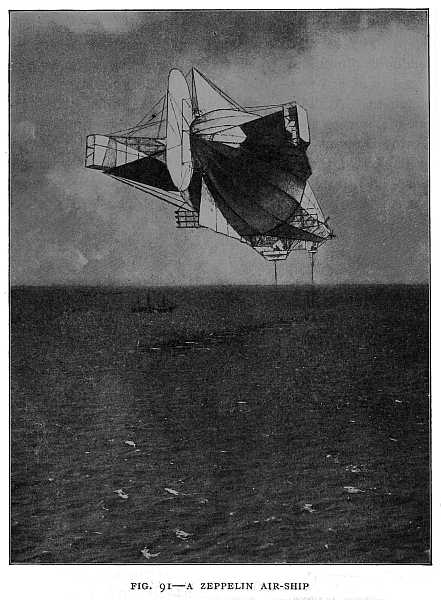
A larger air-ship, the Deutschland, built later by Count Zeppelin, was the first air-ship to be used for regular passenger service. The Deutschland is shown in Fig. 92. The Deutschland carried the crew and twenty passengers. It[184] operated for a time as a regular passenger air-ship between Friedrichshafen and Düsseldorf, a distance of three hundred miles. The Deutschland was wrecked in a storm on June 28, 1910, but it was successfully operated long enough to give Germany the honor of establishing the first air-ship line for regular passenger service. This is an honor perhaps equally as great as that of establishing the first commercial electric railway, which also belongs to Germany. An American army air-ship is shown in Fig. 93.
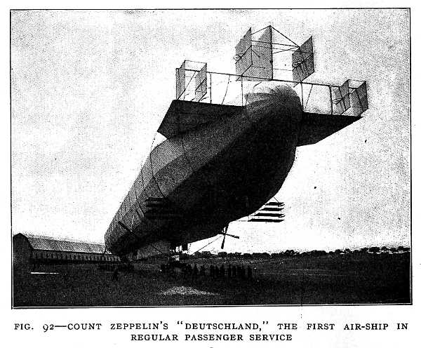
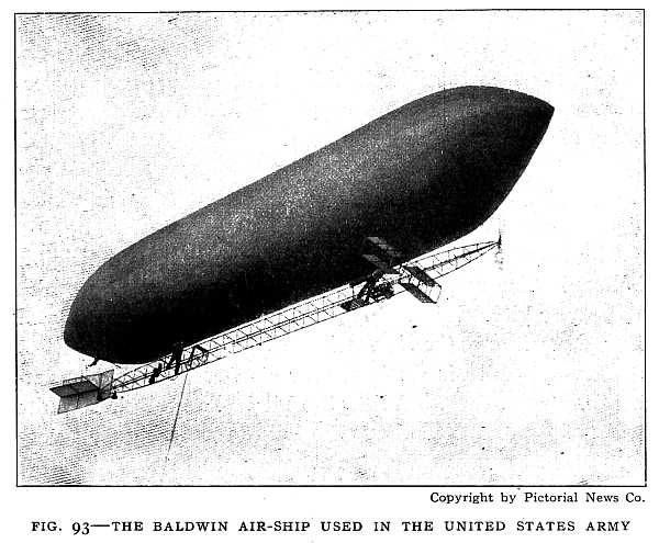
The Aeroplane
The aeroplane is a later development than the dirigible balloon. The aeroplane is heavier than air. So is a bird and so is a kite. What supports a kite or a bird as it soars? Every boy knows that the strings of a kite must be attached so that the kite is inclined and catches the wind underneath. Then the wind lifts the kite. In still air the kite will not fly unless the boy who holds the string runs very fast and so causes an artificial breeze to blow against the kite. In much the same way a hovering bird is held aloft by the wind. In a dead calm the bird must flap its wings to keep afloat. If the kite string is cut the kite tips over and drops to the earth because it has lost its balance. The lifting power of the wind is well shown in the man-lifting kites which are used in the British army service. In a high wind a large kite is used in place of a captive balloon. It is a box-kite made of bamboo and carries a passenger in a car, the car running on the cable which attaches the kite to the ground. Now suppose a kite with a motor and pro[186]peller in place of a string and a boy to run with it, and that the kite is able to balance itself, then it will sail against a wind of its own making and you have a flying-machine heavier than air.
The first aeroplane that would fly under perfect control of the operator was built by the Wright brothers at Dayton, Ohio. When they were boys, Bishop Wright gave his two sons, Orville and Wilbur, a toy flyer. From that time on the thought of flying through the air was in their minds. A few years later the death of Lilienthal, who was killed by a fall with his glider in Germany, stirred them, and they took up the problem in earnest. They read all the writings of Lilienthal and became acquainted with Mr. Octave Chanute, an engineer of Chicago who had made a successful glider. They soon built a glider of their own, and experimented with it each summer on the huge sand-dunes of the North Carolina coast.
A glider is an aeroplane without a propeller. With it one can cast off into the air from a great height and sail slowly to the ground. Before attempting to use a motor and propeller, the Wrights learned to control the glider perfectly. They had to learn how to prevent its being tipped over by the wind, and how to steer it in any direction. This took years of patient work. But the problem was conquered at last, and they attached a motor and propeller to the glider, and had an air-ship under perfect control and with the speed of an express-train. Their flyer of 1905, which made a flight of twenty-four miles at a speed of more than thirty-eight miles an hour, carried a twenty-five-horse-power gasolene motor, and weighed, with its load,[187] 925 pounds. Figs. 94 and 95 show the Wright air-ship in flight. Fig. 97 shows the mechanism.
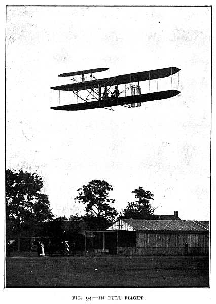
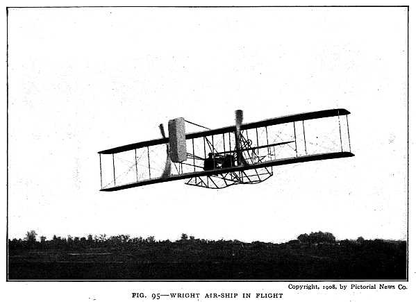
Copyright, 1908, by Pictorial News Co.
Rear view, showing propellers.
[188]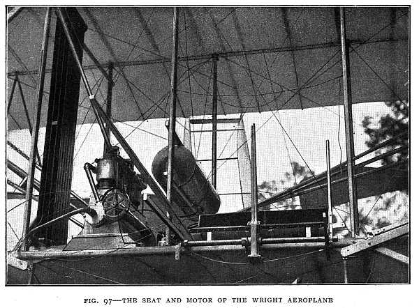
Photo by Pictorial News Co.
How the Wright Aeroplane Is Kept Afloat
The Wright aeroplane is balanced by a warping or twisting of the planes 1 and 2, which form the supporting surfaces (Fig. 96). If left to itself the machine would tip over like a kite when the string is cut and drop edgewise to the ground. Suppose the side R starts to fall. The corners a and e are raised by the operator while b and f are lowered, thus twisting the planes, as shown in the dotted lines of the figure. The side R then catches more wind than the side L. The wind exerts a greater lifting force on R than on L, and the balance is restored. The twist is then taken out of the machine by the operator. A ship when sailing on an even keel presents true unwarped planes to the wind.
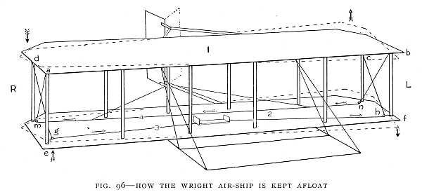 FIG. 96–HOW THE WRIGHT AIR-SHIP IS KEPT AFLOAT
This picture represents a glider. The motor-driven aeroplane is balanced by the warping of the planes in the same way as the glider.
The twisting is brought about by a pull on the rope 3, which is attached at d and c, and passes through pulleys at g and h. When the rope is pulled toward the left the right end is tightened and slack is paid out at the left end. This pulls down the corner d, and raises e. The corner a is raised by the post which connects a and e. The rope 4, passing from a to b through pulleys at m and n, is thus drawn toward a and pulls down the corner b. Thus a is raised and b is lowered. At the same time rope 4 turns the rear rudder to the left, as shown by the dotted lines, thus forcing the side R against the wind. Of course, if the left side of the machine starts to fall, the rope 3 is pulled toward the right, and all the movements take place [190]in the opposite direction. The ropes are connected to a lever, by which the operator controls the warping of the planes. These movements are possible because the joints are all universal, permitting movement in any direction. In whatever position the planes may be set, they are held perfectly rigid by the two ropes, together with others not shown in the figure. The machine is guided up or down by the front horizontal rudder.
When the aeroplane swings round a curve the outer wing is raised because it moves faster than the inner wing, and therefore has greater lifting force. Thus the aeroplane banks its own curves.
The Wright flying-machine is called a biplane because it has two principal planes, one above the other. A number of successful flying-machines have been built with only one plane, and these are called monoplanes. A monoplane that early became famous is that of Blériot (Fig. 98). The Blériot monoplane was the first flying-machine to cross the English Channel. This machine is controlled by a single lever mounted with a ball-and-socket coupling, so that it can move in any direction. When on the ground it is supported by three wheels like bicycle wheels, so that it does not require a track for starting, but can start anywhere from level ground. The Wright and the Blériot represent the two leading types of early successful flying-machines.
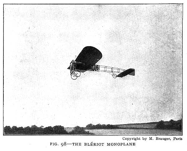
Submarines
Successful navigation beneath the surface of the water, though not carried to the extent imagined by Jules Verne, [192]was a reality at the beginning of the twentieth century. Instead of twenty thousand leagues under the sea, less than a hundred leagues had been accomplished, but no one can foretell what the future may have in store.
The principal use of the submarine is in war. It is a diving torpedo-boat, and acts under cover of water, as the light artillery on land is secured behind intrenchments. The weapon used by the submarine is the torpedo. The torpedo is itself a small submarine able to propel itself, and if started in the water toward a certain object, to go under water straight to the mark. It carries a heavy charge either[193] of guncotton or dynamite, which explodes when the torpedo strikes a solid object, such as a battle-ship. The first torpedo was intended to be steered from the shore by means of long tiller-ropes, and to be propelled by a steam-engine or by clockwork. The Whitehead fish torpedo, invented in 1866, is self-steering. At the head of the torpedo is a pointed steel firing-pin. When the torpedo strikes a ship or any rigid object this steel pin is driven against a detonator cap which is in the centre of the charge of dynamite. The blow causes the cap to explode, and the explosion of the cap explodes the dynamite. The torpedo is so arranged that it cannot explode until it is about thirty yards away from the ship from which it is fired. The steel pin cannot strike the cap until a small "collar" has been revolved off by a propeller fan, and this requires a distance of about thirty yards. The screw propeller is driven by compressed air. A valve which is worked by the pressure of the water keeps the torpedo at any depth for which the valve is set. The torpedo contains many ingenious devices for bringing it quickly to the required depth and keeping it straight in its course. One of these devices is the gyroscope, which will be described under the head of "spinning tops." Whitehead torpedoes are capable of running at a speed of over thirty-seven miles an hour for a range of two thousand yards and hitting the mark aimed at almost as accurately as a gun. The submarine boat carries a number of torpedoes, and has one torpedo-tube near the forward end from which to fire the torpedoes.
It would be very difficult for one submarine to fight another submarine, for the submarine when completely submerged[194] is blind. It could not see in the water to find its enemy. The torpedo-boat-destroyer is able to destroy a submarine by means of torpedoes, shells full of high explosives, or quick-firing guns. Advantage must be taken of the moment when the submarine comes to the surface to get a view of her enemy.
One of the great enemies of the submarine will probably be the air-ship, for while the submarine when under water cannot be seen from a ship on the surface, it can, under favorable conditions, be seen from a certain height in the air.
Most submarines use a gasolene motor for surface travel, and an electric motor run by a storage battery for navigation below the surface. The best submarines can travel at the surface like an ordinary boat, or "awash"—that is, just below the surface—with only the conning tower projecting above the water, or they can travel completely submerged.
The rising and sinking of the submarine depend on the principle of Archimedes. The upward push of the water is just equal to the weight of the water displaced. If the water displaced weighs more than the boat, then the upward push of the water is greater than the weight of the boat and the boat rises. However, the boat can be made to dive when its weight is just a little less than the weight of the water displaced. This is done by means of horizontal rudders which may be inclined so as to cause the boat to glide downward as its propeller drives it forward.
The magnetic compass is not reliable in a submarine with a hull made of steel. The electric motor used for propelling the boat under water also interferes with the action of[195] the compass, because of its magnetic field. The gyroscope, which we shall describe later, is not affected by magnetic action, and may take the place of the compass.
Water ballast is used, and when the submarine wishes to dive, water is admitted into the tanks until the boat is nearly heavy enough to sink of its own weight. It is then guided downward by the horizontal rudder. The submarine is driven by a screw propeller, and some submarines are lowered by means of a vertical screw. Just as a horizontal screw propels a vessel forward, so a vertical screw will propel it downward. When the submarine wishes to rise, it may do so by the action of its rudder, or the water may be pumped out of its tanks, when the water will raise[196] it rapidly. A submarine which is kept always a little lighter than water will rise to the surface in case of accident to its machinery. Figs. 99, 100, and 101 are from photographs of United States submarines.
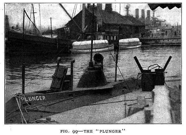
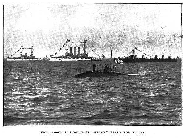
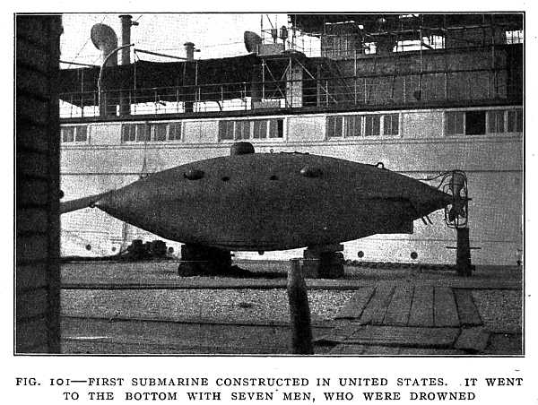 FIG. 101–FIRST SUBMARINE CONSTRUCTED IN UNITED STATES. IT WENT TO THE BOTTOM WITH SEVEN MEN, WHO WERE DROWNED
Photo by Pictorial News Co.
There is one kind of submarine built for peaceful pursuits which deserves mention. It is the Argonaut, invented by Simon Lake. This remarkable boat crawls along the bottom of the sea, but not at a very great depth. It is equipped with divers' appliances, and is used in saving wreckage. Divers can go out through the bottom of the boat, walk about on the sea bottom, and when through with their work re-enter the boat; all the while boat and men are, perhaps, a hundred feet below the surface. The divers' compartment, from which the divers go out into the water, is separated by an air-tight partition from the rest of the boat. Compressed air is forced into this compartment until the pressure of the air equals the pressure of the water outside. Then the door in the bottom is opened, and the air keeps the water out. The men in their diving-suits can then go out and in as they please.
For every boat there is a depth beyond which it must not go. The penalty for going beyond this depth is a battered-in vessel, for the pressure increases with the depth. Every time the depth is increased thirty-two feet the pressure is increased fifteen pounds on every square inch. Beyond a certain depth the vessel cannot resist the pressure. Submarines have been made strong enough to withstand the pressure at a depth of five thousand feet, or nearly a mile. Most submarines, however, cannot go deeper than a hundred and fifty feet.
[198]
Air is supplied to the occupants of the boat either from reservoirs containing compressed air or oxygen, or by means of chemicals which absorb the carbon dioxide produced in breathing and restore the needed quantity of oxygen to the air.
While the men in the boat cannot see in the water, they can see objects on the surface of the water, even when their boat is several feet below the surface, by means of the periscope. This is an arrangement of lenses and mirrors in a tube bent in two right angles, which projects a short distance above the surface and can be turned in any direction[199] (Fig. 102). Thus the boat, while itself nearly invisible, can have a clear view of the battle-ship which it is about to attack.
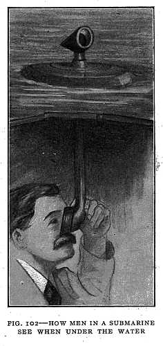
Some Spinning Tops that Are Useful
Every one knows that a top will stand upright only when it is spinning. Most tops when spinning will stand very rough treatment without being upset. The whip-top will stand a severe lashing. Spin a top upright and give it a knock. It will go round in a circle in a slanting position, and after a time will right itself. If the top is struck toward the south it will not bow toward the south but toward the east or west. In throwing a quoit, the quoit must be given a spinning motion or the thrower cannot be certain how it will alight. A coin thrown up with a spinning motion will not turn over. The quoit and the coin are like the top. They will not turn over easily when spinning. For the same reason a rifle bullet is set spinning by the spiral[200] grooves in the bore of the gun, and it goes straight to its mark. With a smooth-bore gun that does not set the bullet spinning the gunner cannot be sure of his aim.
It took a long time to discover that the spinning top is a useful machine. It is useful because of its steady motion, because it is difficult to turn over. It was discovered by Newton long ago that every moving object tries to keep on in the direction in which it is moving. A moving object always requires some force to change its direction. The spinning top is a beautiful illustration of this principle. The top that is most useful is the gyroscope top (Fig. 103). It is mounted on pivots so arranged that the top can turn in any direction within the frame that supports it. If the top is set spinning one may turn the frame in any direction, but the top does not change direction. The axis of the top will point in the same direction all the while the top is spinning, no matter how the supporting frame is moved about. The top will spin on a string. If attached inside[201] a box the box can be made to stand on one corner while the top is spinning.
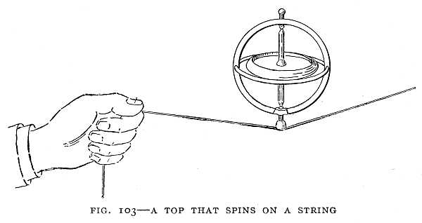
This top, which is so hard to upset, has been used in ships to prevent the ship being rolled by the waves. A large fly-wheel is mounted in the middle of the vessel on a horizontal axle. A fly-wheel is only a large top. It spins with a steady motion, and because of its larger size it is very much harder to overturn than a toy top. The fly-wheel in the ship resists the rolling force of the waves and steadies the ship, so that even with high waves the rolling can scarcely be felt. The waves do not so readily break over the ship when thus steadied by the revolving wheel.
The gyroscope is also used in some forms of torpedo to give the torpedo steady motion. By means of a spring released by a trigger the gyroscope within the torpedo is set spinning before the torpedo enters the water. The gyroscope keeps its direction unchanged, and as the torpedo turns one way or the other the gyroscope acts upon one or the other of two valves connected with the compressed-air chambers from which the screws of the torpedo are driven. The air thus set free by the gyroscope drives a piston-rod connected with a rudder in such a way as to right the torpedo. The torpedo goes through the water with a slightly zigzag motion, but never more than two feet out of the line in which it was aimed.
The Monorail-Car
Another use of the gyroscope is in the monorail-car. To make a car run on a single rail, with its weight above the[202] rail, was impossible until the use of the gyroscope was discovered. In the monorail-car invented by Brennan (Fig. 104) there are two gyroscopes, each weighing fifteen hundred pounds, driven at a speed of three thousand revolutions a minute by an electric motor. Each gyroscope wheel with its motor is mounted in an air-tight casing from which the air is pumped out. The wheel will run much more easily in a vacuum than in air, for the air offers very great resistance to its motion. The wheels are placed one on each side of the car with their axles horizontal. When the car starts to fall the spinning gyroscopes right it much as a spinning top rights itself if tipped to one side by a blow. If the wind tips the car to the left the gyroscopes incline to the right[203] until the car is again upright. If the load is heavier on the right side the car inclines itself toward the left just as a man leans to the left when carrying a load on his right shoulder. In rounding a curve the car leans to the inside of the curve just as a bicycle rider does, and as a railway train is made to do by laying the outer rail of the curve higher than the inner rail. Two gyroscopes spinning in opposite directions are necessary to keep the car from falling when rounding a curve.
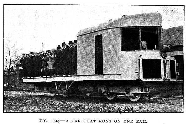
The gyroscope may be used in place of a compass. If it is set spinning in a north and south direction it will continue to spin in a north and south direction, no matter how the ship may turn. It is even more reliable than the compass, for it is not affected by magnetic action. Possibly some of the great inventions yet to be made will be new uses of the spinning top.
Liquid Air and the Greatest Cold
For a long time after men had learned the use of the furnace and could produce great heat, the greatest cold known was that of the mountain-top. Men wondered what would happen if air could be made colder than the frost of winter, but knew not how to bring about such a result. They wondered what things could be frozen that remain liquid or gaseous even in the cold of winter.
The first artificial cold was produced by a mixture of salt and ice, such as we now use in an ice-cream freezer. In time men learned other ways of producing great cold and even to manufacture ice in large quantities.[204]
The cold of liquid air is far greater than that of ice or even a freezing mixture of salt and ice. Liquid air is simply air that is so cold that it becomes a liquid just as steam when cooled forms water. Steam has only to be cooled to the temperature of boiling water, while air must be cooled to 314 degrees below zero on the Fahrenheit scale.
If it were possible for us to live in such a climate, and the world were cooled to the temperature of liquid air, we should have a curious world. Watch-springs might be made out of pewter, bells of tin, and piano wires of solder, for these metals are made stronger by the extreme cold of liquid air. There would be no air to breathe. Oceans and rivers would be frozen solid, and the air would form a liquid ocean about thirty-five feet deep. This ocean of liquid air would be kept boiling a long time by the heat of the ice beneath it, for ice is hot compared with liquid air. The ice would cool as it gave up its heat to the liquid air and in time become as cold as the liquid air itself.
Liquid air has been shipped thousands of miles in a double walled tin can, the space between the two walls being filled with felt. The felt protects the liquid air from the heat of the air without. The liquid air evaporates slowly, and escapes through a small opening at the top.
Professor Dewar, a successor of Faraday in the Royal Institution, invented the Dewar bulb, by means of which the evaporation of the liquid air is prevented. This bulb is a double-walled flask. In the space between the two walls of the flask is a vacuum. Now a vacuum is the best possible protection against heat. If we were to take a bottle full of air and pump out from the bottle all except[205] about a thousandth of a millionth of the air it contained at first we should have such a vacuum as that of the Dewar bulb. With such a vacuum around it ice could be kept from melting for many days even in the hottest weather, for no heat can go through a vacuum.
But the greatest cold is not the cold of liquid air. Liquid hydrogen is so cold that it freezes air. When a flask of liquid hydrogen is opened there is a small snow-storm of frozen air in the mouth of the flask. But even this is not the greatest cold. The liquid hydrogen may be frozen, forming a hydrogen snow whose temperature is 435 degrees below zero. This is nearly equal to the cold of the space beyond the earth's atmosphere, which is the greatest possible cold.
The Electric Furnace and the Greatest Heat
The greatest heat that has yet been produced artificially is that of the electric arc. The exact temperature of the electric arc is not known with certainty. It is known, however, that the temperature of the hottest part of the arc is not less than 6500 degrees Fahrenheit. When we compare this with the temperature of the hottest coal furnace, which is about 4000 degrees, we can very easily understand that something is likely to happen at the temperature of the electric arc that could not happen in an ordinary furnace.
If an electric arc is enclosed by something that will hold the heat in we have an electric furnace, and any substance placed in the furnace may be made nearly as hot as the[206] arc itself. In the electric furnace any substance, whether found in nature or prepared artificially, may be melted or vaporized.
It was Henri Moissan, Professor of Chemistry at the Sorbonne in Paris, who made the first great discoveries in the use of the electric furnace and produced the first artificial diamonds. The study of diamonds led Moissan to believe that in nature they are formed by the cooling of a melted mixture of iron and carbon. He could prepare such a mixture with his electric furnace, he thought, and so make diamonds like those of the diamond mines. So, with an electric furnace having electrodes as large as a man's wrist, a mixture of iron and charcoal in a carbon crucible, and a glass tank filled with water, Moissan set out to change the charcoal to diamonds. At a temperature of more than six thousand degrees the iron and charcoal were melted together. For a time of from three to six minutes the mixture was in the intense heat. Then the covering of the furnace was removed and the crucible with the melted mixture dropped into the tank of water. With some fear this was done for the first time, for it was not known what would happen when such a hot object was dropped into cold water. But no explosion occurred, only a violent boiling of the water, a fierce blazing of the molten mass, and then a gradual change of color from white to red and red to black. With boiling acids and other chemicals the refuse was removed, and the fragments that remained were found to be diamonds, small, it is true, so small that they could be seen only with the aid of a microscope, but giving promise of greater things to come. The outer crust of iron held [208]the melted charcoal under enormous pressure while it slowly cooled and formed the diamond crystals. The process of manufacturing diamonds is illustrated in Figs. 105, 106, and 107.
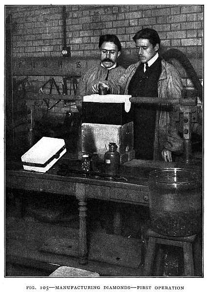 FIG. 105–MANUFACTURING DIAMONDS—FIRST OPERATION
Preparing the furnace. Charcoal and iron ore placed in a crucible and subjected to enormous heat electrically.
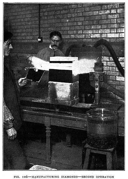
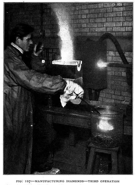 FIG. 107–MANUFACTURING DIAMONDS—THIRD OPERATION
Plunging the crucible into cold water. Observe the white-hot carbon just removed from the furnace.
The electric furnace has made possible the preparation of substances unknown before, and the production in large quantities at low cost of substances that before were too costly for general use. One of the best known of these substances is aluminum. With the discovery of the electric-furnace method of extracting aluminum from its ores, the price of aluminum fell from one hundred and twenty-four dollars per pound to twelve cents per pound.
Among the many uses of the electric furnace we may mention the preparation of calcium carbide, which is used in producing the acetylene light; carborundum, a substance almost as hard as diamond; and phosphorus, which is used in making the phosphorus match. It is used also to some extent in the manufacture of glass, and, in some cases, for extracting iron from its ores.
The Wireless Telegraph
A ship in a fog is struck by another ship. The water rushes in, puts out the fires in the boilers, the engines stop, the ship is helpless in mid-ocean in the darkness of the night. But the snapping of an electric spark is heard in one of the cabins. Soon another vessel steams alongside. The life-boats are lowered and every person is saved. The call for help had gone out over the sea in every direction for two hundred miles. Another ship had caught the signal and [210]hastened to the rescue, and the world realized that the wireless telegraph had robbed the sea of its terrors.
Without the curious combination of magnets, wires, and batteries on the first ship no signal could have been sent, and without such a combination on the second ship the signal would have passed unheeded. How was this combination discovered, and how does it work?
Faraday, as we have seen, discovered the principle of the induction-coil. With the induction-coil a powerful electric spark can be produced. The friction electrical machine was known long before the time of Faraday. Franklin proved that a stroke of lightning is like a spark from an electrical machine, only more powerful. These great discoverers did not know, however, that an electric spark sends out something like light which travels in all directions. They did not know it, because they had no eyes to see this strange light.
I will tell you a fable to make the meaning clear. There once lived a race of blind men. Not one of them could see. They built houses and cities, railroads and steamships, but they did everything by touch and sound. When they met they touched each other and spoke, and each man knew his friend by the sound of his voice. One day a wise man among them said he believed there was something besides the sound of the voice with which they could make signals to each other. Another wise man thought upon this matter for some time and brought forth a proof that there is something called light, though no man could see it. Another, wiser and more practical, invented an eye which any man could carry about with him and see the light [212]when he turned it in the direction from which the light was coming. Thereafter each man carried a light that flashed like the flashing of a firefly. Each man also carried an eye, and each could see his friend as well as hear the sound of his voice.
The fable is true. The light which no man had seen we now call electric waves. The eye with which any one can perceive this light is the receiving instrument of the wireless telegraph. The strange light flashed out whenever an electric spark passed from an electrical machine, a Leyden jar, an induction-coil, or as lightning in the clouds, but for hundreds of years this light was unseen. The human eye could not see it, and no artificial eye that would catch electric waves had been invented. A man in England, James Clerk-Maxwell, first proved that there is such a light. Heinrich Hertz, a German, first made an eye that would catch the waves from the electric spark, and the man who first perfected an eye with which one could catch the electric waves at a great distance and improved the instruments for sending out such waves was Marconi.
The fable is true, for electric waves are like the light from the sun. They go through space in all directions as light does. They will not merely go through air, but through what we call empty space, or a vacuum, as light will. If we think of waves somewhat like water waves, but not exactly like them, rushing through space, we have about as good a picture of electric waves as we can well form in our minds. As the light of a lamp goes out in all directions, so do the electric waves go out in all directions from the place where the electric spark passes. Since these waves go through[213] what we call empty space, we must think of something in that space and that it is not really empty. Examine an incandescent electric lamp. The bulb was full of air when the carbon thread was placed in it. The air was then pumped out until only about a millionth part remained. The bulb was then sealed at the tip and made air-tight. We say the space inside is a vacuum. If the bulb is broken there is a loud report as the air rushes in. Is the bulb really empty after the air is pumped out? Is anything left in the bulb around the carbon thread? Turn on the electric current and the carbon thread becomes white hot. The light from the white-hot carbon thread goes out through the vacuum. There is nothing in the vacuum that we can see or feel or handle, but something must be there to carry the light from the carbon thread. The light of the sun comes to the earth through ninety-three million miles of space. Is there anything between the earth and the sun through which this light can pass? Light, we know, is made up of waves, and we cannot think of waves going through empty space. There must be something between the sun and the earth. That something through which the light of the sun comes to the earth we call the ether. It is the ether that carries the light across the vacuum in the light bulb as well as from the sun to the earth. Electric waves used in wireless telegraphy go through this same ether. The light of the sun is made up of the same kind of waves, and we do not think it strange because it is so common. It is true we do not see light waves, but they affect our eyes so that by means of them we can see objects and perceive the flashing of a light. So with the wireless receiving instrument we[214] do not see the electric waves, but we perceive the flashing of the strange light. Electric waves and light travel with the same speed—186,000 miles in a second. A wireless message will go around the earth in about one-seventh of a second.
Electric waves will go through a brick wall as readily as sunlight will go through a glass window, but that is not so strange as it may seem. Red light will not go through blue glass. Blue glass holds back the red light, but lets the blue light go through. So the brick wall holds back common light, but allows the light which we call electric waves to go through.
Some waves on water are longer than others. So electric waves are longer than light waves. That is the only difference between them. In fact, the light of the sun is made up of very short electric waves. These short waves affect our eyes, but the longer electric waves do not. We are daily receiving the wireless-telegraph waves from the sun, which we call light. Electric waves used in wireless telegraphy vary from about six hundred feet to two miles in length, while the longest light waves that affect our eyes are only one thirty-three-thousandth of an inch in length.
The sensitive part of the Marconi receiving apparatus is the coherer. The first coherer was made in 1890 by Prof. Edward Branly, of the Catholic University of Paris. Very fine metal filings were enclosed in a tube of ebonite and connected in a circuit with a battery and a galvanometer. The filings have so high a resistance that no current flows. The waves from an electric spark, however, affect the filings so that they allow the current to flow. The electric waves[215] are said to cause the filings to cohere—that is, to cling together more closely. It is a peculiar form of electric welding. Branly discovered that a slight tapping of the tube loosens the filings and stops the flow of the current.
All that was needed for wireless telegraphy was at hand. Men knew how to produce electric waves of any desired length. They knew how they would act. A sensitive receiver had been discovered. There was needed the practical man who should combine the parts, improve details, and apply the wireless telegraph to actual use. This was the work of Guglielmo Marconi. In 1894, at the age of twenty, Marconi began his experiments on his father's estate, the Villa Grifone, Bologna, Italy. Fig. 108 is from a photograph of Marconi and his wireless sending and receiving instruments.
[216]
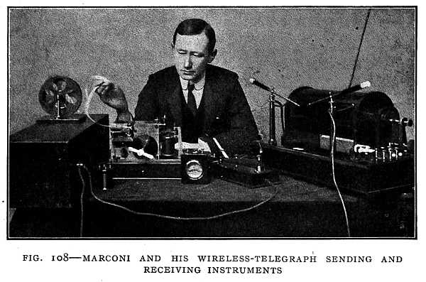
To Marconi, telegraphing through space without wires appears no more wonderful than telegraphing with wires. In the wire telegraph electric waves, which we then call an electric current, follow a wire somewhat as the sound of the voice goes through a speaking-tube. In the wireless telegraph the electric waves go out through space without any wire to guide them. The light and heat waves of the sun travel to us through millions of miles of space without requiring any conducting wire. That electric waves should go though space in the same way that light does is no more wonderful than that the waves should follow all the turns of a wire.
The sending instrument used by Marconi includes an induction-coil, one side of the spark-gap being connected to the earth and the other to a vertical wire (Fig. 109). There must be a battery of Leyden jars in the circuit of the secondary coil. The induction-coil may be operated by a storage battery or dynamo. The vertical wire, or antenna, is to the sending instrument what the sounding-board is to a violin. It is needed to increase the strength of the waves. In the wireless telegraph some wires must be used. It is called wireless because the stations are not connected by wires. The antenna for long-distance work consists of a network of overhead wires. When the key is pressed a rapid succession of sparks passes across the spark-gap. The antenna, or overhead wire, is thus made to send out electric waves. By pressing the key for a longer or shorter time, a longer or shorter series of waves may be produced and a correspondingly longer or shorter effect on the receiver. In this manner the dots and dashes of the Morse alphabet may be transmitted.[217]
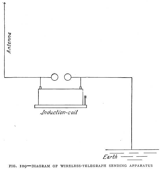
At the receiving station there are two circuits. One includes a coherer, a local battery, and a telegraph relay (Fig. 110). The other circuit, which is opened and closed by the relay, includes a recording instrument and a tapper. One end of the coherer is connected to the earth and the other to a vertical wire like that used for the transmitter. The[218] electric waves weld the filings in the coherer, and this closes the first circuit. The relay then closes the second circuit, the recording instrument records a dot or a dash, and the tapper strikes the coherer and breaks the filings apart ready for another stream of electric waves.
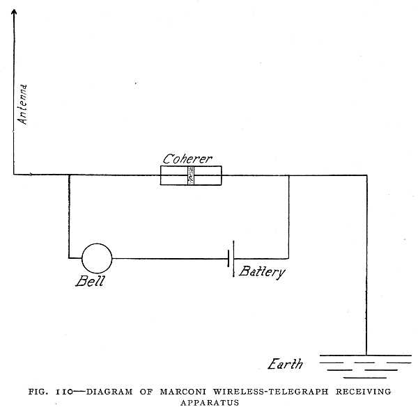 FIG. 110–DIAGRAM OF MARCONI WIRELESS-TELEGRAPH RECEIVING APPARATUS
The second circuit described in the text is not shown here. The relay and the second circuit would take the place of the electric bell. In the circuit as shown here the electric waves would cause the coherer to close the circuit and ring the bell.
With this arrangement it was possible to work only two stations at one time. Though stations were to be established in all the cities of Great Britain, only one message could be sent at one time, and all stations but one must keep silence, because a second series of waves would mingle with the first and confusion would result.
Marconi's next effort was to make it possible to send any number of messages at one time. This led to his system of tuning the sending and receiving instruments. With this system the receiving instrument will take a message only from a sending instrument with which it is in tune. It is possible, therefore, for any number of wireless-telegraph stations to operate at the same time, the waves crossing one another in all directions without interfering, each receiver responding to the waves intended for it. An ocean steamer can, with the tuned system, send one message and receive another from a different station at the same time.
Marconi's ambition was to send a wireless message across the Atlantic. Quietly he made his preparation, building at Poldhu, Cornwall, England, a more powerful transmitter than had yet been used. At noon on the 12th of December, 1901, he sat in a room of the old barracks on Signal Hill, near St. Johns, Newfoundland, waiting for a signal from England. His assistants at the Poldhu station were to telegraph across the ocean the letter "S" at certain times each day. On the table was the receiving apparatus, made very sensitive, and including a telephone receiver. A wire led out of the window to a huge kite, which the furious wind held four hundred feet above him. One kite and a balloon[220] used for supporting the antenna had been carried out to sea. He held the telephone receiver to his ear for some time. The critical time had come for which he had worked for years, for which his three hundred patents had prepared the way, and for which his company had erected the costly power station at Poldhu. Calmly he listened, his face showing no sign of emotion. Suddenly there sounded the sharp click of the tapper as it struck the coherer. After a short time Marconi handed the telephone receiver to his assistant. "See if you can hear anything," he said. A moment later, faintly and yet distinctly, came the three little clicks, the dots of the letter "S" tapped out an instant before in England. Marconi's victory was won.
A flying-machine can be equipped with a wireless-telegraph outfit, so that a man can telegraph while flying through the air. Two men are needed, one to operate the flying-machine, the other to send the telegraphic messages. This has been done with the Wright machine and with some dirigible balloons. Of course, the wireless instruments on the flying-machine cannot be connected to the ground. Instead of the ground connection there is a second antenna.—one antenna on each side of the spark-gap. While in the ordinary wireless instruments the discharge surges back and forth between the antenna and the earth, in the flying-machine wireless the discharge surges back and forth between the two antennæ. In the Wright machine, when equipped for wireless telegraphy, the two antennæ are placed one under the upper plane, the other under the lower plane of the flying-machine.[221]
More power is required for the wireless than for the wire telegraph. In the wire telegraph about one-hundredth horse-power is required to send a message one hundred and twenty miles. To send a message the same distance with the wireless requires about ten horse-power, or a thousand times as much as with the wire telegraph. This is because in the wireless telegraph the waves go out in all directions, and much of the power is wasted. In the wire telegraph the electric waves are directed along the wire and very little of the power is wasted. For the same reason a person's voice can be heard a long distance through a speaking-tube. The speaking-tube guides the sound and prevents it from scattering somewhat as the wire guides the electric waves.
The overhead wires of a wireless-telegraph station send out a "dark" light while a message is being sent. (See frontispiece.) Standing near the station on a dark night one can see nothing, but can hear only the terrific snapping of the electric discharge. The camera, however, shows that light goes out from the wires. It is light of shorter waves than any that the eye can perceive, but the sensitive film of the photographic plate makes it known to us.
The Wireless Telephone
In sending a message by the wire telegraph the current flows over the line wire when the key is pressed. When the key is released the current stops. The circuit is made and broken for every dot or dash. This we may call an interrupted current. Now we have seen that the attempt to invent a wire telephone using an interrupted current failed.[222] While one is talking over the wire telephone a current (alternating) must be flowing over the line wire. The sound of the voice does not make and break the circuit, but changes the strength of the current. This alternating current is wonderfully sensitive. It can vary in the rate at which it alternates or the number of alternations per second to correspond to sound of every pitch. It varies in strength to correspond to all the variations in the voice, and reproduces in the receiver not merely the words that are spoken but the quality of the voice, so that the voice of a friend can be recognized by telephone almost as well as if talking face to face.
The same things are true of the wireless telegraph and telephone. Instead of an electric current, let us say "a stream of electric waves." Then we may say of the wireless everything that we have said of the wire telegraph and telephone. In sending a message by wireless telegraph the stream of electric waves flows when the key is pressed and stops when the key is released. We have an interrupted stream of electric waves. But an interrupted stream of waves cannot be used for a wireless telephone any more than an interrupted current can be used for a wire-telephone. There must be a constantly flowing stream of electric waves, and these waves must be changed in strength and form by the sound of the voice. Fig. 111 shows a wireless-telephone receiver in which light is used to carry the message. The light acts on the receiver in such a way as to reproduce the sound.
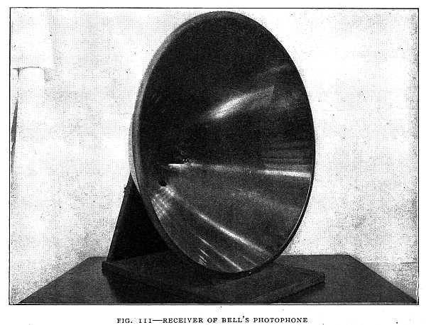
In the wireless-telegraph receiver the interrupted stream of electric waves makes and breaks the circuit of an electric battery. The wireless-telephone receiver must not make [224]and break a circuit, but it must be sensitive to all the changes in the electric waves. One such receiver is the audion, which we shall now describe.
The audion was invented by Dr. Lee de Forest. De Forest had taken the degree of Doctor of Philosophy at Yale University, having written his thesis for that degree on the subject of electric waves. He then entered the employ of the Western Electric Company in Chicago, and while in this position worked at night in his room on experiments with electric waves.
Here he found that a gas flame is sensitive to electric waves (Fig. 112). If a gas flame is made part of the circuit[225] of an electric battery, which includes also an induction-coil connected to a telephone receiver, then when a stream of electric waves comes along there is a click in the receiver. The waves change the resistance of the flame, and so change the strength of the current. The flame is a simple audion. It is the heated gas in the flame that responds to the electric waves.
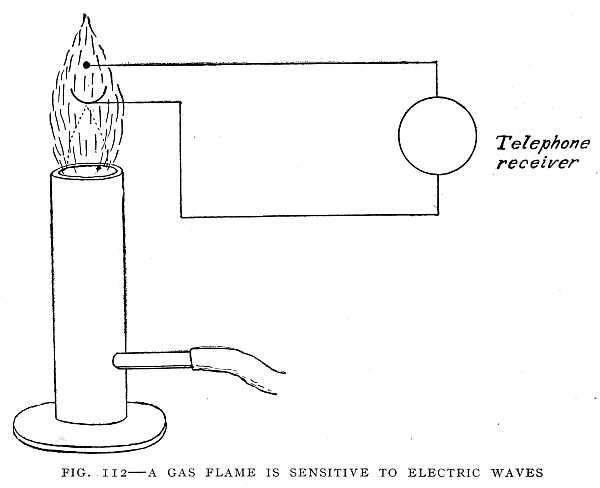
If instead of a gas flame an incandescent-light bulb is used having a metal filament, and on either side of the filament a small strip of platinum, a more sensitive receiver is obtained. This is the audion, which is the distinguishing feature of the De Forest wireless telegraph and wireless telephone. The metal filament is made white hot by the current from a storage battery. The vacuum in the bulb is about the same as that of the ordinary incandescent electric light. A very small quantity of gas is therefore left in the bulb. The electrified particles of gas respond more freely to electric waves in this bulb than in the gas flame.
The De Forest wireless telephone was adopted for use in the United States Navy shortly before the cruise around the world in 1908. Every ship in the navy was equipped with the wireless telephone, enabling the Admiral to talk with the officers of any vessel up to a distance of thirty-five miles. The wireless telephone in use on a battle-ship is shown in Fig. 113.
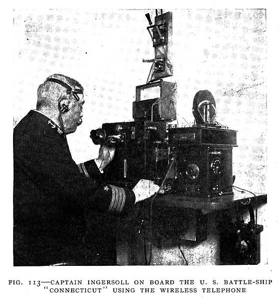 FIG. 113–CAPTAIN INGERSOLL ON BOARD THE U. S. BATTLE-SHIP "CONNECTICUT" USING THE WIRELESS TELEPHONE
Wonders of the Alternating Current
Before the days of the electric current, men used the power of falling water. The mill or factory using the water[226]-power was placed beside the fall. The water turned a great wheel, to which was connected the machinery of the mill, It was not until the invention of the dynamo and motor that water-power could be used at a great distance. If a hundred years ago a man had said that the time would come when a waterfall could turn the wheels of a mill a hundred miles away he would have been laughed at. Yet this very[227] thing has come to pass. Indeed, one waterfall may turn the wheels of many factories, run street-cars, and light cities up to a distance of a hundred miles and even more. The power of the falling water goes out over slender copper wires from a great dynamo near the fall to the motors in the factories and street-cars.
The falling water of Niagara has about five million horse-power. About the hundredth part of this power is now being used. The water, falling in a wheel-pit 141 feet deep, turns a great dynamo weighing 87,000 pounds with a speed of 250 turns per minute. A number of such dynamos are used supplying an alternating current at a pressure of 22,000 volts, the current alternating or changing direction twenty-five times per second. Such a pressure is too high for the motors and electric lights, but the current is carried at high pressure to the place where it is to be used and there transformed to a current of low pressure. In carrying a current over a long line, there is less loss if the current is carried at high pressure. With an alternating current this can be done and the current changed by means of a transformer to a current of low pressure.
A transformer is simply two coils of wire wound on an iron core. The simplest transformer is the form used by Faraday when he discovered electromagnetic induction. If instead of making and breaking a circuit that flows only in one direction as Faraday did, we cause an alternating current to flow through one of the coils, which we may call the primary, each time the current changes direction in the primary the magnetic field is reversed—that is, the end of the coil which was the north pole becomes the south pole.[228] This rapidly changing magnetic field induces a current in the secondary coil. Each time the magnetic field of the primary coil is reversed the current in the secondary changes direction. Thus an alternating current in the primary induces an alternating current in the secondary. One of these coils is of fine wire, which is wound a great many times around the iron. The other is of coarser wire wound only a few times around the iron. Suppose the current is to be changed from high pressure to low pressure. Then the high-pressure current from the line is made to flow through the coil of many turns, and a current of low pressure is given out from the coil of few turns. By changing the number of turns of wire in the coils we can make the pressure whatever we please. If the pressure or voltage of the secondary coil is less than that of the primary, we have a "step-down" transformer. On the other hand, if we send the current from the line wire through the coil of few turns, then we get a higher voltage from the secondary coil than that of the line wire, and we have a "step-up" transformer. The Niagara current is "stepped down" from 22,000 volts to 220 volts for use in motors.
An electric lamp may be lighted though not connected to any battery or dynamo, but connected only to a coil of wire (Fig. 114). More than this, the coil may be insulated so that no current can enter it from any other coil or wire, and yet the lamp can be lighted. This can be done only by means of an alternating current. If the coil to which the lamp is connected is held in the magnetic field of an alternating current, then another alternating current is induced in the coil, and this second current flows through the lamp.[229]
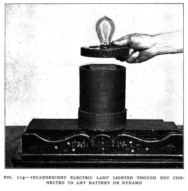
We have already learned that a changing magnetic field induces a current in a coil. Now the coil through which an alternating current is flowing has a changing magnetic field all around it, and if the lamp-coil is brought into this changing magnetic field an alternating current will flow through the coil and the lamp. The insulation on the lamp-coil does not prevent the magnetic field from acting,[230] though it does prevent a current from entering the coil. The current is induced in the coil itself, and does not enter it from any outside source.
The transformer works in the same way, the only difference being that in the transformer the two coils are on the same iron core. But in the transformer the two coils are insulated so that no current can flow from one coil to the other. When an alternating current and transformers are used, the current that lights the lamps in the houses or on the streets is not the current from the dynamo. It is a new[231] current induced in the secondary coil of the transformer by the magnetic field of the primary coil.
A peculiar transformer which produces an alternating current that changes direction millions of times in a second has been made by Nikola Tesla. This current will do many wonderful things which no ordinary current will do. It will light a room or run a motor without connecting wires. It has produced an electric discharge sixty-five feet in length (Figs. 115 and 116). Though this current is caused to flow by a pressure of millions of volts, it may be taken with safety through the human body. Strange as it may seem, the safety of this current is due to the high[232] pressure and the rapidity with which it changes direction. While the current used at Sing Sing in executing criminals has a pressure of about twenty-five hundred volts, a current having a pressure of a million volts and alternating hundreds of thousands or millions of times per second is harmless; With such a current the human body may become a "live wire," and an electric lamp to be lighted held in one hand while the other hand grasps the wire from the transformer.
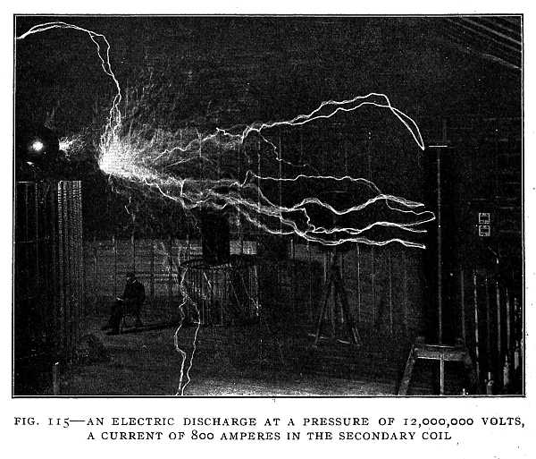 FIG. 115–AN ELECTRIC DISCHARGE AT A PRESSURE OF 12,000,000 VOLTS, A CURRENT OF 800 AMPERES IN THE SECONDARY COIL
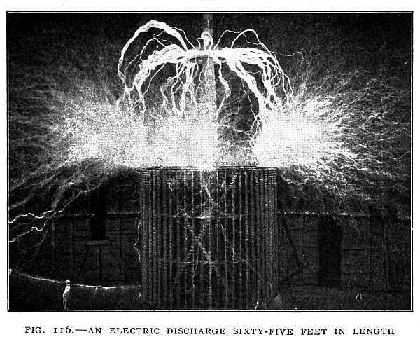
X-Rays and Radium
A strange light which passes through the human body as readily as sunlight through a window was discovered by Prof. Wilhelm Konrad Roentgen, of the University of Würzburg. This light, which Professor Roentgen named X-rays, is given out when an electric discharge at high pressure passes through a certain kind of glass tube from which the air has been pumped out until there is a nearly perfect vacuum.
X-rays were discovered by accident. Professor Roentgen was working at his desk with one of the glass tubes when he was called to lunch. He laid the tube with the electric discharge passing through it on a book. Returning from lunch he took a photographic plate-holder which was under the book and made some outdoor exposures with his camera. On developing the plates a picture of a key appeared on one of them. He was greatly puzzled at first, but after a search for the key found it between the leaves of the book. The strange light from the electric discharge in the glass tube had passed through the book and the hard-rubber slide of the plate-holder and made a shadow-picture [234]of the key on the photographic plate. He tried the strange light in many ways, and found that it would go through many objects. It would even go through the human body, so that shadow-pictures of the bones and organs of the body could be obtained. In Fig. 117 is shown a physician using X-rays. Fig. 118 is an X-ray photograph of the eye.
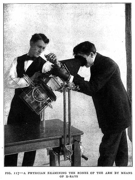
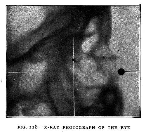 FIG. 118–X-RAY PHOTOGRAPH OF THE EYE
The eye is above and to the left of the larger black circle. The smaller black circle is a shot which has lodged back of the eye.
Not long after the discovery of X-rays it was discovered that light very much like the X-rays is given out by certain minerals. One of the most interesting and the best known of these is radium. Radium gives out a light somewhat like X-rays that will go through copper and other metals. It does many other strange things. It gives out heat as[235] well as light; so much heat, in fact, that it is always about five degrees warmer than the air around it. It continues to give out heat at such a rate that a pound of radium will melt a pound of ice every hour. It can probably keep this up for at least a thousand years. If this heat could be used in running an engine, a hundred pounds of radium would run a one-horse-power engine without stopping for many hundred years. The power of Niagara might be replaced by the power of radium if an engine that could use this power were invented. Fig. 119 is from a photograph made with radium.
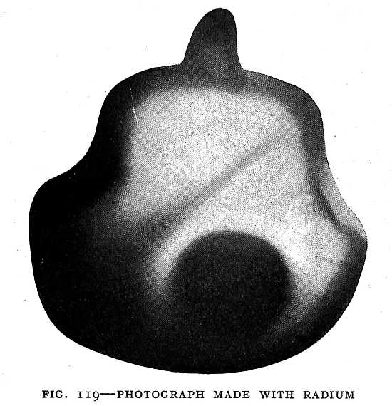 FIG. 119–PHOTOGRAPH MADE WITH RADIUM
A purse containing a coin. The strange light from the radium goes through the purse and the slide of the plate-holder and makes a shadow-picture.
The great inventor of the future may be able to use the heat of radium or some new power now unknown. We have seen how, through the toil of many years and the labors of many men, the great inventions of our age have come into being. It may be that we are now witnessing other great inventions in the making.[237]
APPENDIX
BRIEF NOTES ON IMPORTANT INVENTIONS
Aerial Navigation
First air balloon—Montgolfier Brothers, France, 1783.
First balloon ascension—Rozier, France, 1783.
First gas balloon—Charles, France, 1783.
First crossing of the English Channel in a balloon—Blanchard, 1785.
First successful dirigible balloon—La France, Renard and Krebs, France, 1884.
First successful motor-driven aeroplane—Wright Brothers, United States; date of patent, 1906.
First crossing of the English Channel by an aeroplane—Blériot, 1909.
First air-ship in regular passenger service—Count Zeppelin, Germany, 1910.
Agriculture
Plough with cast-iron mold-board and iron shares—James Small, Scotland, 1784.
Grain-threshing machine—Andrew Meikle, England, 1788.
McCormick reaper, first practical grain-harvesting machine—Cyrus H. McCormick, United States, 1831.
Self-raker for harvesters—McCormick, 1845.
Inclined platform and elevator in the reaper, to enable men binding the grain to ride with the machine—J. S. Marsh, United States, 1858.
Barbed-wire fence introduced—United States, 1861.
Self-binder, first automatic grain-binding device for the reaper—Jacob Behel, United States, 1864.
Sulky plough—B. Slusser, United States, 1868.[238]
Twine-binder for harvesters—M. L. Gorham, United States, 1873.
Improved self-binding reaper—Lock and Wood, United States, 1873.
Barbed-wire machine—Glidden and Vaughn, United States, 1874.
Rotary disk cultivator—Mallon, United States, 1878.
Steam-plough—W. Foy, United States, 1879.
Combined harvester and thresher—Matteson, United States, 1886.
Automobile mower—Deering Harvestor Company, United States, 1901.
Automobile
First steam-automobile—Cugnot, France, 1769.
First chain transmission of power in an automobile—Gurney, England, 1829.
Application of gas-engine to road vehicles, beginning of the modern motor-car—Gottlieb Daimler and Carl Benz working independently, Germany, 1886. Daimler's invention consisted of a two-cylinder air-cooled motor. It was taken up in 1889, by Panhard and Levassor, of Paris, who began immediately the construction of the motor-car. This was the beginning of the motor-car industry.
Bicycle
First bicycle—Branchard and Magurier, France, 1779.
Rear-driven chain safety bicycle—George W. Marble, United States, 1884.
Bicycles first equipped with pneumatic tires—1890.
Electrical Inventions
William Gilbert, England, 1540-1603, called "the father of magnetic philosophy," first to use the terms "electric force," "electric attraction," "magnetic pole."
First electrical machine, a machine for producing electricity by friction—Otto von Guericke, Germany, about 1681.
Discovery of conductors and insulators—Stephen Gray, England, 1696-1736.
First to discover that electric charges are of two kinds—Cisternay du Fay, France, 1698-1739; Du Fay was also the first to attempt an explanation of electrical action. He supposed that electricity consists of two fluids which are separated by friction,[239] and which neutralize each other when they combine. This theory was more fully set forth by Robert Symmer.
Leyden jar—Discovered first by Von Kleist in 1745. The same discovery was made and the Leyden jar brought to the attention of the public in 1746 by Pieter van Musschenbroek in Holland.
Lightning-rod—Benjamin Franklin, 1732.
Electroplating—Luigi Brugnatelli, Italy, 1805.
Voltaic arc, a powerful arc light produced with a battery current—Sir Humphry Davy, England, 1808.
Storage battery—Ritter, Germany, 1803. Platinum wires were dipped in water and a battery current passed through. Hydrogen collected on one wire and oxygen on the other. If the platinum wires were disconnected from the battery and connected with each other by a conductor, the two wires acted like the plates of a battery, and a current would flow for a short time in the new circuit.
Electromagnetism discovered—H. C. Oersted, Denmark, 1819.
Galvanometer, a coil of wire around a magnetic needle for measuring the strength of an electric current—Schweigger, Germany, 1820.
Motion of magnet produced by an electric current—M. Faraday, England, 1821.
Thermo-electricity, an electric current produced by heating the junction of two unlike metals—Discovered by Professor Seebeck England, 1821.
Principles of electrodynamics, motion produced by an electric current—Ampère, France. Announced in 1823.
Law of electric circuits, Ohm's law, current strength equals electromotive force divided by resistance of the circuit—George S. Ohm, Germany. Proven by experiment in 1826; mathematical proof published in 1827.
Magneto-electric induction, induction of electric currents by means of a magnetic field—M. Faraday, England, 1831.
Electric telegraph—Prof. S. F. B. Morse, United States, 1832.
First telegram sent in 1844—Morse.
Constant electric battery—J. P. Daniell, England, 1836.
First electric motor-boat—Jacobi, Russia, 1839.
Induction-coil—Rhumkorff, Germany, 1851.
Duplex telegraph, first practical system—Stearns, United States, about 1855-1860.
[240]
Storage battery, lead plates in sulphuric acid—Gaston Planté, France, 1859.
Telephone, make-and-break system, first electrical transmission of speech—Philip Reiss, Germany, 1860.
Atlantic cable laid—Cyrus W. Field, 1866.
Dynamo, armature coil rotates in the field of an electromagnet, armature supplies current for the electromagnet as well as for the external circuit—William Siemens, Germany, 1866.
Gramme ring armature for dynamo—Gramme, France, 1868.
Theory that light consists of electromagnetic waves—Clerk-Maxwell, England, 1873.
Quadruplex telegraph, sending four messages over one wire at the same time—Edison, 1873.
Siphon recorder for submarine telegraph, sensitive to very feeble currents—Sir William Thomson, England, 1874.
Telephone, varying current, first practical working telephone—Alexander Graham Bell, United States, 1876.
Electric candle, beginning of present arc light—Paul Jablochkoff, Russia, 1876.
Telephone transmitter of variable resistance—Emil Berliner and Edison working independently, United States, 1877. Edison used carbon contacts, Berliner used metal contacts.
Brush system of arc lighting—1878.
Incandescent electric lamp with carbon filament—Edison, 1878.
First electric locomotive—Siemens, Germany, 1879.
Blake telephone transmitter—Blake, United States, 1880.
Storage battery, lead grids filled with active material—Faure, France, 1881.
Electric Welding—Elihu Thompson, United States, 1886.
Electric Waves discovered by experiment—Heinrich Hertz, Germany, 1888.
Coherer for receiving electric Waves—Edward Branly, France, 1890.
X-rays—Discovered by Prof. W. C. Roentgen, Germany; announced to the public in 1895.
Wireless telegraphy—G. Marconi, Italy, 1896.
Nernst electric light, a clay capable of conducting electricity when heated is used; it becomes incandescent without a vacuum—Walter Nernst, Germany, 1897.
Radium discovered by Madame Curie, France, 1898.
[241]
Explosives
Gunpowder—Inventor and date unknown.
Guncotton—Schönbein, Germany, 1845.
Nitroglycerine—Sobrero, 1847.
Explosive gelatine—A. Nobel, France, 1863.
Dynamite—A. Nobel, France, 1866.
Smokeless powder—Vielle, France, 1866.
Firearms and Ordnance
Spirally grooved rifle barrel—Koster, England, 1620.
Breech-loading shot-gun—Thornton and Hall, United States, 1811.
The revolver; a device "for combining a number of long barrels so as to rotate upon a spindle by the act of cocking the hammer"—Samuel Colt, United States, 1836.
Breech gun-lock, interrupted thread—Chambers, United States, 1849.
Magazine gun—Walter Hunt, United States, 1849.
Breech-loading rifle—Maynard, United States, 1851.
Iron-clad floating batteries first used in Crimean War—1855.
Breech-loading ordnance—Wright and Gould, United States, 1858.
Revolving turret for floating batteries—Theodore Timby, United States, 1862.
First iron-clad floating battery propelled by steam: the Monitor—John Ericsson, United States, 1862.
Gatling gun—Dr. R. J. Gatling, United States, 1862.
Automatic shell-ejector for revolver—W. C. Dodge, United States, 1865.
Torpedo—Whitehead, United States, 1866.
Disappearing gun-carriage—Moncrief, England, 1868.
Rebounding gun-lock—L. Hailer, United States, 1870.
Magazine rifle—Lee, United States, 1879.
Hammerless gun—Greener, United States, 1880.
Gun silencer, to be attached to barrel of gun; gun can be fired without noise—Maxim, 1909.
Gas Used for Light and Power
Gas first used for illuminating purposes—William Murdoch, England, 1792.
First street gas-lighting in England—F. A. Winsor, 1814.[242]
Gas-meter—S. Clegg, England, 1815.
Water-gas, prepared by passing steam over white-hot anthracite coal—First produced in England in 1823.
Illuminating water-gas—Lowe, United States, 1875.
Gas-engine, 4-cycle, beginning of modern gas-engine—Otto and Langen, Germany, 1877.
Incandescent gas-mantle—Carl A. von Welsbach, Austria, 1887.
Iron and Steel
Blast-furnace, beginning of iron industry—Belgium, 1340.
Use of coke in blast-furnace—Abram Darby, England, about 1720.
Puddling iron—Henry Cort, England, 1783-84.
Process of making malleable-iron castings—Lucas, England, 1804.
Hot-air blast for iron furnaces—J. B. Neilson, Scotland, 1828.
The galvanizing of iron—Henry Craufurd, England, 1837.
Process of making steel, blowing air through molten pig-iron to burn out carbon, then adding spiegel iron; first production of cheap steel—Sir Henry Bessemer, England, 1855.
Regenerative furnace, a gas-furnace in which gas and air are heated before being introduced into the furnace, giving an extremely high temperature—William Siemens, England, 1856.
Open-hearth process of making steel—Siemens-Martin, England, 1856.
Nickel steel, much stronger than ordinary steel, used for armorplate—Schneider, United States, 1889.
Mining
Miners' safety-lamp—Sir Humphry Davy, England, 1815.
Compressed-air rock-drill—C. Burleigh, United States, 1866.
Diamond rock-drill, a tube of cast-steel with a number of black diamonds set at one end. The machine cuts a circular groove, leaving a core inside the tube. This core is brought to the surface with a rod, and the powdered rock is washed out by water forced down the tube and flowing up the sides of the hole. The drill does not have to stop for cleaning out—Herman, United States, 1854.
[243]
Photography
First photographic picture, not permanent—Thomas Wedgewood, England, 1791.
Daguerreotype, first developing process—Louis Daguerre, France, 1839.
First photographic portraits, daguerreotype process—Prof. J. W. Draper, United States, 1839.
Collodion process in photography—Scott Archer, England, 1849.
Photographic roll films—Melhuish, England, 1854.
Dry-plate photography—Dr. J. M. Taupenot, 1855.
Photographic emulsion, bromide of silver in gelatine, basis of present rapid photography—R. L. Maddox, England, 1871.
Hand photographic camera for plates—William Schmid, United States, 1881.
Printing
First printing with movable types in Europe and first printing-press—Guttenberg, Germany, about 1445.
Screw printing-press—Blaew, Germany, 1620.
First newspaper of importance—London Weekly Courant, 1625.
Stereotyping, making plates from casts of the type after it is set up—William Ged, Scotland, 1731.
First practical steam rotary printing-press, paper printed on both sides, 1800 impressions per hour—Frederick Koenig, Germany, 1814.
Printing from curved stereotype plates—H. Cowper, England, 1815.
Hoe's lightning press, 2000 impressions per hour—R. Hoe, United States, 1847.
Printing from a continuous web, paper wound in rolls, both sides printed at once—William Bullock, United States, 1865.
"Straightline newspaper perfecting" press, prints 100,000 eight-page papers per hour—Goss Company, United States.
Linotype machine. The operator uses a keyboard like that of a typewriter. The machine sets the matrices which correspond to the type, casts the type in lines from molten metal, delivers the lines of type on a galley, and returns the matrices to their appropriate tubes. It does the work of five men setting type in the ordinary way—Othmar Mergenthaler, United States, 1890.
[244]
Steam Navigation
First steamboat in the world—Papin, River Fulda, Germany, 1705.
First steamboat in America—John Fitch, Delaware River, 1783.
First passenger steamboat in the world, the Clermont—Robert Fulton, Hudson River, 1807.
First steamer to cross the Atlantic, the Savannah, built at New York—First voyage across the Atlantic, 1819.
The screw propeller first used on a steamboat—John Ericsson, United States, about 1836.
Compound engines adopted for steamers—1856.
First turbine-steamer, the Turbinia—Parsons, 1895.
First mercantile steam-turbine ship, the King Edward—Denny and Brothers, England, 1901.
Steam Used for Power and Land Transportation
First steam-engine with a piston—Denys Papin, France, 1690.
First practical application of the power of steam, pumping water—Thomas Savery, England, 1698.
Double-acting steam-engine and condenser—James Watt, Scotland, 1782.
Steam-locomotive first used to haul loads on a railroad—Richard Trevethick, England, 1804.
First passenger steam railway, the "Stockton & Darlington"—George Stephenson, England, 1825.
First steam-locomotive in the United States, the "Stourbridge Lion"—1829.
Link motion for locomotives—George Stephenson, England, 1833.
Steam-whistle, adopted for use on locomotives—George Stephenson, 1833.
Steam-hammer—James Nasmyth, Scotland, 1842.
Steam-pressure gauge—Bourdon, France, 1849.
Corliss engine—G. H. Corliss, United States, 1849.
First practical steam-turbine—C. A. Parsons, England, 1884.
Textile Industries
Flying shuttle, first important invention in weaving, leading to modern weaving machinery—John Kay, England, 1733.[245]
Spinning-jenny—James Hargreaves, England, 1763.
Power loom—James Cartwright, England, 1785.
Cotton-gin, for separating the seeds from the fibre, gave a new impetus to the cotton industry. The production of cotton increased in five years from 35,000 to 155,000 bales—Eli Whitney, United States, 1792.
Pattern loom, for the weaving of patterns—M. J. Jacquard, France, 1801.
Application of steam to the loom—William Horrocks, England, 1803.
Knitting-machine—Brunel, England, 1816.
Sewing-machine—Elias Howe, United States, 1846.
Mercerized cotton—John Mercer, England, 1850.
Process of making artificial silk—H. de Chardonnet, France, 1888.
Wood-Working
Circular wood-saw—Miller, England, 1777.
Wood-planing machine—Samuel Benthem, England, 1791.
Wood-mortising machine—M. J. Brunel, England, 1801.
Band wood-saw—Newberry, England, 1808.
Lathe for turning irregular wood forms—Thomas Blanchard, United States, 1819.
Improved planing-machine—William Woodworth, United States, 1828.
Miscellaneous
First fireproof safe—Richard Scott, England, 1801.
Steel pen, quill pen used up to this time—Wise, England, 1803.
First life-preserver—John Edwards, England, 1805.
Calculating machine—Charles Babbage, England, 1822.
First friction matches—John Walker, United States, 1827. Flint and steel were used for starting fires before matches were invented.
First portable steam fire-engine—Brithwaite and Ericsson, England, 1830.
Vulcanizing of rubber—Charles Goodyear, United States, 1839.
Pneumatic tire—R. W. Thompson, England, 1845.
Time-lock for safes—Savage, United States, 1847.
Match-making machinery—A. L. Denison, United States, 1850.[246]
American machine-made watches—United States, 1850.
Safety matches—Lundstrom, Sweden, 1855.
Sleeping-car—Woodruff, United States, 1856.
Printing-machine for the blind, origin of the typewriter—Alfred E. Beach, United States, 1856.
Cable-car—E. A. Gardner, United States, 1858.
Driven well, an iron tube with the end pointed and perforated driven into the ground—Col. N. W. Green, United States, 1861.
Passenger elevator—E. G. Otis, United States, 1861.
First practical typewriter—C. L. Sholes, United States, 1861.
Railway air-brake, use of air-pressure in applying brakes to the wheels of a car. A strong spring presses the brake against the wheels. Air acts against the spring and holds the brake away from the wheels. To apply the brake, air is allowed to escape, reducing the pressure and allowing the spring to act—George Westinghouse, United States, 1869.
Store-cash carrier—Dr. Brown, United States, 1875.
Roller flour-mills—F. Wegman, United States, 1875.
Kinetoscope, moving-picture machine—Edison, 1893.
[247]
INDEX
Aeroplane, 184.
Air-pressure, 23.
Air-pump, 20.
Air-ships, 173.
Air thermometer, 13.
Alternating current, wonders of, 225.
Amber, 8.
Ampère, 67, 111.
Arago, 69.
Archimedes, 1, 12;
inventions of, 7.
Archimedes' principle, 6, 12.
Arc light, 120.
Armature, 101, 103, 104.
Balloons, 174.
Barometer, mercury, 19, 25;
water, 23.
Battle of Syracuse, 2.
Bell, Alexander Graham, 141.
Blake transmitter, 146.
Blériot, 190.
Boyle, 23.
Branly, 214.
Cannon experiment, Rumford's, 59.
Cog-wheels, first used, 8.
Coherer, 214.
Colors in sunlight, 31.
Condenser in steam-engine, 40.
Conductors, electrical, 44.
Controller, 116.
Daniell cell, 89, 127.
Davy, 56, 61, 96.
De Forest, 224.
Diamonds, manufacturing, 206.
Drum armature, 104.
Dry battery, 91.
DuFay, 45.
Dumont, 179.
Duplex telegraphy, 136.
Dynamo, 55, 79, 81, 96, 99, 100, 105, 111;
series wound, 105;
shunt wound, 107;
compound wound, 108.
Edison, 95, 105, 114, 121.
Electrical machine, 23, 44, 45, 83.
Electric battery, 53, 62, 84, 89.
Electric charge, two kinds, 45.
Electric current, 50, 69, 73, 74, 82, 96;
magnetic action of, 66, 68;
produced by a magnet, 72.
Electric furnace, 205.
Electricity, 8, 50;
theories of, 49;
speed of, 133.
Electric lighting, 97, 118.
Electric motor, 71, 97, 111.
Electric power, 111.
Electric railway, 112.
Electric waves, 212.
Electromagnet, 100, 126, 143.
Electromagnetism, 65.
Faraday, 55, 63, 100, 111;
electrical discoveries, 64.
Force-pump, 8.
Franklin, 43, 45, 46, 65.
Galileo, 9, 63;
[248]experiment with falling shot, 12.
Galvani, 50.
Galvanometer, 74, 75.
Gas-engines, 150.
Glider, 186.
Governor, fly-ball, 42.
Gramme-ring armature, 103.
Gravitation, 30.
Gravity cell, 91.
Gray, Stephen, 44.
Guericke, 20, 35.
Gyroscope, 200.
Heat, 59.
Henry, Joseph, 97, 127.
Hero, 8, 164;
engine, 164.
Hiero, King of Syracuse, 1, 6.
Horse-power, 40.
Hydraulic press, 26.
Incandescent light, 121.
Indicator, 41.
Induction-coil, 76, 82, 99.
Induction, electrical, 74.
Insulators, 44.
Inventions of the ancient Greeks 7;
of the nineteenth century, 88.
Kite experiment, Franklin's, 46.
Kites, 27.
Leyden jar, 43.
Lightning-rod, 48.
Lines of force, 99.
Liquid air, 203.
Locomotive, electric, 114;
steam, 155.
Magdeburg, 21.
Magnetic field, 80, 99.
Magnets, 8, 130.
Marconi, 215.
Mayer, Robert, 61, 85.
Mercury vapor light, 125.
Microscope, 18.
Miner's safety lamp, 61.
Monorail car, 201.
Morse, 128.
Napoleon, 62.
Newcomen, 34, 36.
Newcomen's engine, 36.
Newton, 27.
Niagara, 227.
Oersted, 65, 71, 111, 126.
Papin, 35.
Papin's engine, 35.
Pascal, 25.
Pendulum clock, 10, 12.
Perpetual motion impossible, 87.
Phonograph, 147.
Principle of Work, 19.
Prism, 31.
Pump, 8, 19.
Radium, 232.
Reis, Philip, 141.
Relay, 130.
Roentgen, 232.
Royal institution, 56, 61.
Rumford, 57, 59.
Rumford's cannon experiment, 59.
Safety-lamp, 62.
Screw propeller, 171.
Siemens, 100.
Spinning tops, 199.
Steam-engine, 8, 25, 34.
Steam locomotive, 155.
Steam pressure, 23.
Stephenson, 156.
Storage battery, 93.
Sturgeon, 97, 127.
Submarines, 190.
Suction-pump, 8.
Symmer, Robert, 49.
Telegraph, 96, 126;
wireless, 208.
Telephone, 140;
wireless, 221.
Telescope, invention of, 15;
Newton's, 32.
Tesla, 231.
Thermometer, air, 13.
Torpedo, 192.
Torricelli, 19, 35.
Transformer, 80, 82, 99, 227.
Turbine, 163.
University of Padua, 13.
University of Pisa, 10, 12.
[249]
Valve-gear, 37, 162.
Volta, 53, 63, 89.
Voltaic battery, 53, 89.
Water-clock, 8, 29.
Water-wheel, 165.
Watt, James, 34.
Watt's engine, 38.
Wireless telegraph, 208.
Wright aeroplane, 188.
X-rays, 232.
Zeppelin, 180.
THE END