 Fig. 1.—Plan and Elevation of Two-Hopper Ejector Sand
Washing Plant.
Fig. 1.—Plan and Elevation of Two-Hopper Ejector Sand
Washing Plant.
The Project Gutenberg EBook of Concrete Construction, by
Halbert P. Gillette and Charles S. Hill

This eBook is for the use of anyone anywhere at no cost and with
almost no restrictions whatsoever.  You may copy it, give it away or
re-use it under the terms of the Project Gutenberg License included
with this eBook or online at www.gutenberg.org


Title: Concrete Construction
       Methods and Costs

Author: Halbert P. Gillette
        Charles S. Hill

Release Date: March 16, 2008 [EBook #24855]

Language: English

Character set encoding: ISO-8859-1

*** START OF THIS PROJECT GUTENBERG EBOOK CONCRETE CONSTRUCTION ***


Produced by Brian Sogard, Josephine Paolucci and the Online
Distributed Proofreading Team at http://www.pgdp.net.
Copyright. 1908
BY
The Myron C. Clark Publishing Co.
How best to perform construction work and what it will cost for materials, labor, plant and general expenses are matters of vital interest to engineers and contractors. This book is a treatise on the methods and cost of concrete construction. No attempt has been made to present the subject of cement testing which is already covered by Mr. W. Purves Taylor's excellent book, nor to discuss the physical properties of cements and concrete, as they are discussed by Falk and by Sabin, nor to consider reinforced concrete design as do Turneaure and Maurer or Buel and Hill, nor to present a general treatise on cements, mortars and concrete construction like that of Reid or of Taylor and Thompson. On the contrary, the authors have handled the subject of concrete construction solely from the viewpoint of the builder of concrete structures. By doing this they have been able to crowd a great amount of detailed information on methods and costs of concrete construction into a volume of moderate size.
Though the special information contained in the book is of most particular assistance to the contractor or engineer engaged in the actual work of making and placing concrete, it is believed that it will also prove highly useful to the designing engineer and to the architect. It seems plain that no designer of concrete structures can be a really good designer without having a profound knowledge of methods of construction and of detailed costs. This book, it is believed, gives these methods and cost data in greater number and more thoroughly analyzed than they can be found elsewhere in engineering literature.
The costs and other facts contained in the book have been collected from a multitude of sources, from the engineering journals, from the transactions of the engineering societies, from Government Reports and from the personal records of the authors and of other engineers and contractors. It is but fair to say that the great bulk of the matter contained in the book,[Pg iv] though portions of it have appeared previously in other forms in the authors' contributions to the technical press, was collected and worked up originally by the authors. Where this has not been the case the original data have been added to and re-analyzed by the authors. Under these circumstances it has been impracticable to give specific credit in the pages of the book to every source from which the authors have drawn aid. They wish here to acknowledge, therefore, the help secured from many engineers and contractors, from the volumes of Engineering News, Engineering Record and Engineering-Contracting, and from the Transactions of the American Society of Civil Engineers and the proceedings and papers of various other civil engineering societies and organizations of concrete workers. The work done by these journals and societies in gathering and publishing information on concrete construction is of great and enduring value and deserves full acknowledgment.
In answer to any possible inquiry as to the relative parts of the work done by the two authors in preparing this book, they will answer that it has been truly the labor of both in every part.
H. P. G.
C. S. H.
Chicago, Ill., April 15, 1908.
PAGE
CHAPTER I.—METHODS AND COST OF SELECTING AND PREPARING
MATERIALS FOR CONCRETE. 1
Cement: Portland Cement—Natural Cement—Slag Cement—Size and Weight of
Barrels of Cement—Specifications and Testing. Sand: Properties of Good
Sand—Cost of Sand—Washing Sand; Washing with Hose; Washing with Sand
Ejectors; Washing with Tank Washers. Aggregates: Broken
Stone—Gravel—Slag and Cinders—Balanced Aggregate—Size of
Aggregate—Cost of Aggregate—Screened and Crusher Run Stone for
Concrete—Quarrying and Crushing Stone—Screening and Washing Gravel.
CHAPTER II.—THEORY AND PRACTICE OF PROPORTIONING CONCRETE. 25
Voids: Voids in Sand; Effect of Mixture—Effect of Size of Grains—Voids
in Broken Stone and Gravel; Effect of Method of Loading; Test
Determinations; Specific Gravity; Effect of Hauling—Theory of the
Quantity of Cement in Mortar; Tables of Quantities in Mortar—Tables of
Quantities in Concrete—Percentage of Water in Concrete—Methods of
Measuring and Weighing; Automatic Measuring Devices.
CHAPTER III.—METHODS AND COSTS OF MAKING AND PLACING
CONCRETE BY HAND. 45
Loading into Stock Piles—Loading from Stock Piles—Transporting
Materials to Mixing Boards—Mixing—Loading and Hauling Mixed
Concrete—Dumping, Spreading and Ramming—Cost of
Superintendence—Summary of Costs.
CHAPTER IV.—METHODS AND COST OF MAKING AND PLACING
CONCRETE BY MACHINE. 61
Introduction—Conveying and Hoisting Devices—Unloading with Grab
Buckets—Inclines—Trestle and Car Plants—Cableways—Belt
Conveyors—Chutes—Methods of Charging Mixers—Charging by Gravity from
Overhead Bins; Charging with Wheelbarrows; Charging with Cars; Charging
by Shoveling; Charging with Derricks—Types of Mixers; Batch Mixers;
Chicago Improved Cube Tilting Mixer, Ransome Non-Tilting Mixer, Smith
Tilting Mixer; Continuous Mixers; Eureka Automatic Feed Mixer; Gravity
Mixers; Gilbreth Trough Mixer, Hains Gravity Mixer—Output of
Mixers—Mixer Efficiency.
CHAPTER V.—METHODS AND COST OF DEPOSITING CONCRETE
UNDER WATER AND OF SUBAQUEOUS GROUTING. 86
Introduction—Depositing in Closed Buckets; O'Rourke Bucket; Cyclopean
Bucket; Steubner Bucket—Depositing in Bags—Depositing Through a
Tremie; Charlestown Bridge; Arch Bridge Piers, France; Nussdorf Lock,
Vienna—Grouting Submerged Stone; Tests of H. F. White; Hermitage
Breakwater.
CHAPTER VI.—METHODS AND COST OF MAKING AND USING RUBBLE
AND ASPHALTIC CONCRETE. 98
Introduction—Rubble Concrete: Chattahoochee River Dam; Barossa
Dam, South Australia; other Rubble Concrete Dams, Boonton Dam,
Spier Falls Dam, Hemet Dam, Small Reservoir Dam, Boyd's Corner
Dam; Abutment for Railway Bridge; English Data, Tharsis & Calamas
Ry., Bridge Piers, Nova Scotia—Asphalt Concrete; Slope Paving for
Earth Dam; Base for Mill Floor.
CHAPTER VII.—METHODS AND COST OF LAYING CONCRETE IN
FREEZING WEATHER. 112
[Pg vi]Introduction—Lowering the Freezing Point of the Mixing Water; Common
Salt (Sodium Chloride):—Freezing Temperature Chart—Heating Concrete
Materials; Portable Heaters; Heating in Stationary Bins; Other Examples
of Heating Methods, Power Plant, Billings, Mont., Wachusett Dam,
Huronian Power Co. Dam, Arch Bridge, Piano, Ill., Chicago, Burlington &
Quincy R. R. Work, Heating in Water Tank—Covering and Housing the Work;
Method of Housing in Dam, Chaudiere Falls, Quebec; Method of Housing in
Building Work.
CHAPTER VIII.—METHODS AND COST OF FINISHING CONCRETE
SURFACES 124
Imperfectly Made Forms—Imperfect Mixing and
Placing—Efflorescence—Spaded and Troweled Finishes—Plaster and Stucco
Finish—Mortar and Cement Facing—Special Facing Mixtures for Minimizing
Form Marks—Washes—Finishing by Scrubbing and Washing—Finishing by
Etching with Acid—Tooling Concrete Surfaces—Gravel or Pebble Surface
Finish—Colored Facing.
CHAPTER IX.—METHODS AND COST OF FORM CONSTRUCTION 136
Introduction—Effect of Design on Form Work—Kind of Lumber—Finish and
Dimensions of Lumber—Computation of Forms—Design and
Construction—Unit Construction of Forms—Lubrication of
Forms—Falsework and Bracing—Time for and Method of Removing
Forms—Estimating and Cost of Form Work.
CHAPTER X.—METHODS AND COST OF CONCRETE PILE AND PIER
CONSTRUCTION 151
Introduction—Molding Piles in Place; Method of Constructing Raymond
Piles; Method of Constructing Simplex Piles; Method of Constructing
Piles with Enlarged Footings; Method of Constructing Piles
by the Compressol System; Method of Constructing Piers in Caissons—Molding
Piles for Driving—Driving Molded Piles: Method and Cost
of Molding and Jetting Piles for an Ocean Pier; Method of Molding
and Jetting Square Piles for a Building Foundation; Method of Molding
and Jetting Corrugated Piles for a Building Foundation; Method of
Molding and Driving Round Piles; Molding and Driving Square Piles
for a Building Foundation; Method of Molding and Driving Octagonal
Piles—Method and Cost of Making Reinforced Piles by Rolling.
CHAPTER XI.—METHODS AND COST OF HEAVY CONCRETE WORK
IN FORTIFICATIONS, LOCKS, DAMS, BREAKWATERS AND
PIERS 184
Introduction—Fortification Work: Gun Emplacement, Staten Island, N. Y.,
Mortar Battery Platform, Tampa Bay, Fla., Emplacement for Battery, Tampa
Bay, Fla.; U. S. Fortification Work—Lock Walls, Cascades Canal—Locks,
Coosa River, Alabama—Lock Walls, Illinois & Mississippi Canal—Hand
Mixing and Placing Canal Lock Foundations—Breakwater at Marquette,
Mich.—Breakwater, Buffalo, N. Y.—Breakwater, Port Colborne,
Ontario—Concrete Block Pier, Superior Entry, Wisconsin—Dam, Richmond,
Ind.—Dam at McCall Ferry, Pa.—Dam at Chaudiere Falls, Quebec.
CHAPTER XII.—METHODS AND COST OF CONSTRUCTING BRIDGE
PIERS AND ABUTMENTS 230
Introduction—Rectangular Pier for a Railway Bridge—Backing for
Bridge Piers and Abutments—Pneumatic Caissons, Williamsburg Bridge—Filling
Pier Cylinders—Piers, Calf Killer River Bridge—Constructing
21 Bridge Piers—Permanent Way Structures, Kansas City Outer Belt
& Electric Ry.—Plate Girder Bridge Abutments—Abutments and Piers,>
Lonesome Valley Viaduct—Hand Mixing and Wheelbarrow Work for
Bridge Piers.
CHAPTER XIII.—METHODS AND COST OF CONSTRUCTING RETAINING
WALLS 259
Introduction—Comparative Economy of Plain and Reinforced Concrete
[Pg vii]Walls—Form Construction—Mixing and Placing Concrete—Walls in
Trench—Chicago Drainage Canal—Grand Central Terminal, New
York, N. Y.—Wall for Railway Yard—Footing for Rubble Stone Retaining
Walls—Track Elevation, Allegheny, Pa.
CHAPTER XIV.—METHODS AND COST OF CONSTRUCTING CONCRETE
FOUNDATIONS FOR PAVEMENT 288
Introduction—Mixtures Employed—Distribution of Stock Piles—Hints on
Hand Mixing—Methods of Machine Mixing—Foundation for Stone Block
Pavement, New York, N. Y.—Foundation for Pavement, New Orleans,
La.—Foundation for Pavement, Toronto, Canada—Miscellaneous Examples of
Pavement Foundation Work—Foundation for Brick Pavement, Champaign,
Ill.—Foundation Construction using Continuous Mixers.—Foundation
Construction for Street Railway Track Using Continuous
Mixers—Foundation Construction Using Batch Mixers and Wagon
Haulage—Foundation Construction Using a Traction Mixer—Foundation
Construction Using a Continuous Mixer—Foundation Construction Using a
Portable Batch Mixer.
CHAPTER XV.—METHODS AND COST OF CONSTRUCTING SIDEWALKS,
PAVEMENTS, AND CURB AND GUTTER 307
Introduction—Cement Sidewalks: General Method of Construction—Bonding
of Wearing Surface and Base—Protection of Work from Sun and
Frost—Cause and Prevention of Cracks—Cost of Cement Walks; Toronto,
Ont.; Quincy, Mass.; San Francisco, Cal.; Cost in Iowa. Concrete
Pavement: Windsor, Ontario—Richmond, Ind. Concrete Curb and Gutter:
Form Construction—Concrete Mixtures and Concreting—Cost of Curb and
Gutter: Ottawa, Canada; Champaign, Ill.
CHAPTER XVI.—METHODS AND COST OF LINING TUNNELS AND
SUBWAYS 328
Introduction—Capitol Hill Tunnel, Pennsylvania R. R., Washington, D.
C.—Constructing Side Walls in Relining Mullan Tunnel—Lining a Short
Tunnel, Peekskill, N. Y.—Cascade Tunnel Great Northern Ry.—Relining
Hodges Pass Tunnel, Oregon Short Line Ry.—Lining a 4,000-ft.
Tunnel—Method of Mixing and Placing Concrete for a Tunnel
Lining—Gunnison Tunnel—New York Rapid Transit Subway—Traveling Forms
for Lining New York Rapid Transit Railway Tunnels—Subway Lining, Long
Island R. R., Brooklyn, N. Y.
CHAPTER XVII.—METHODS AND COST OF CONSTRUCTING ARCH
AND GIRDER BRIDGES 363
Introduction—Centers—Mixing and Transporting Concrete; Cableway
Plants; Car Plant for 4-Span Arch Bridge; Hoist and Car Plant for
21-Span Arch Viaduct; Traveling Derrick Plant for 4-Span Arch
Bridge—Concrete Highway Bridges Green County, Iowa—Highway Girder
Bridges—Molding Slabs for Girder Bridges—Connecticut Ave. Bridge,
Washington, D. C—Arch Bridges, Elkhart, Ind.—Arch Bridge, Plainwell,
Mich.—Five Span Arch Bridge—Arch Bridge, Grand Rapids, Mich.
CHAPTER XVIII.—METHODS AND COST OF CULVERT CONSTRUCTION 414
Introduction—Box Culvert Construction, C., B. & Q. R. R.—Arch Culvert
Costs, N. C. & St. L. Ry.; 18-ft. Arch Culvert; Six Arch Culverts 6 to
16-ft. Span; 14¾-ft. Arch Culvert—Culverts for New Construction,
Wabash Ry.—Small Arch Culvert Costs, Pennsylvania R. R.—26-ft. Span
Arch Culvert—12-ft. Culvert, Kalamazoo, Mich.—Method and Cost of
Molding Culvert Pipe.
CHAPTER XIX.—METHODS AND COST OF REINFORCED CONCRETE
BUILDING CONSTRUCTION 433
Introduction—Construction, Erection and Removal of Forms: Column Forms;
Rectangular Columns; Polygonal Columns; Circular Columns; Ornamental
Columns—Slab and Girder Forms; Slab and I-Beam Floors; Concrete Slab
and Girder Floors—Wall Forms—Erecting Forms—Removing Forms,
[Pg viii]Fabrication and Placing Reinforcement; Fabrication; Placing—Mixing,
Transporting and Placing Concrete: Mixing; Transporting; Bucket Hoists;
Platform Hoists; Derricks—Placing and Ramming—Constructing Wall
Columns for a Brick Building—Floor and Column Construction for a
Six-Story Building—Wall and Roof Construction for One-Story Car
Barn—Constructing Wall Columns for a One-Story Machine
Shop—Constructing One-Story Walls with Movable Forms and Gallows
Frames—Floor and Roof Construction for Four-Story Garage.
CHAPTER XX.—METHOD AND COST OF BUILDING CONSTRUCTION
OF SEPARATELY MOLDED MEMBERS 515
Introduction—Column, Girder and Slab Construction: Warehouses,
Brooklyn, N. Y.; Factory, Reading, Pa.; Kilnhouse, New Village, N.
J.—Hollow Block Wall Construction: Factory Buildings, Grand Rapids,
Mich.; Residence, Quogue, N. Y., Two-Story Building, Albuquerque, N.
Mex.; General Cost Data.
CHAPTER XXI.—METHODS AND COST OF AQUEDUCT AND SEWER
CONSTRUCTION 532
Introduction—Forms and Centers—Concreting—Reinforced Conduit, Salt
River Irrigation Works, Arizona—Conduit, Torresdale Filters,
Philadelphia, Pa.—Conduit, Jersey City Water Supply, Twin Tube Water
Conduit at Newark, N. J.—66-in. Circular Sewer, South Bend, Ind.—Sewer
Invert Haverhill, Mass.—29-ft. Sewer, St. Louis, Mo.—Sewer,
Middlesborough, Ky.—Intercepting Sewer, Cleveland, Ohio—Reinforced
Concrete Sewer, Wilmington, Del.—Sewer with Monolithic Invert and Block
Arch—Cost of Block Manholes—Cement Pipe Constructed in Place—Pipe
Sewer, St. Joseph, Mo.—Cost of Molding Small Cement Pipe—Molded Pipe
Water Main, Swansea, England.
CHAPTER XXII.—METHODS AND COST OF CONSTRUCTING RESERVOIRS
AND TANKS 588
Introduction—Small Covered Reservoir—500,000 Gallon Covered Reservoir,
Ft. Meade, So. Dak.—Circular Reservoir, Bloomington, Ill.—Standpipe at
Attleborough, Mass.—Gas Holder Tank, Des Moines, Iowa—Gas Holder Tank,
New York City—Lining a Reservoir, Quincy, Mass.—Relining a Reservoir,
Chelsea, Mass.—Lining Jerome Park Reservoir—Reservoir Floor, Canton,
Ill.—Reservoir Floor, Pittsburg, Pa.—Constructing a Silo—Grained Arch
Reservoir Roof—Grain Elevator Bins.
CHAPTER XXIII.—METHODS AND COST OF CONSTRUCTING ORNAMENTAL
WORK 636
Introduction—Separately Molded Ornaments: Wooden Molds; Iron Molds;
Sand Molding; Plaster Molds—Ornaments Molded in Place: Big Muddy
Bridge; Forest Park Bridge; Miscellaneous Structures.
CHAPTER XXIV.—MISCELLANEOUS METHODS AND COSTS 653
Introduction—Drilling and Blasting Concrete—Bench Monuments, Chicago,
III.—Pole Base—Mile Post—Bonding New Concrete to Old—Dimensions and
Capacities of Mixers—Data for Estimating Weight of Steel in Reinforced
Concrete; Computing Weight from Percentage of Volume; Weights and
Dimensions of Plain and Special Reinforcing Metals—Recipes for Coloring
Mortars.
CHAPTER XXV.—METHODS AND COST OF WATERPROOFING CONCRETE
STRUCTURES 667
Impervious Concrete Mixtures—Star Stetten Cement—Medusa Waterproofing
Compound—Novoid Waterproofing Compound—Impermeable Coatings and
Washes: Bituminous Coatings; Szerelmey Stone Liquid Wash; Sylvester
Wash; Sylvester Mortars; Hydrolithic Coating; Cement Mortar Coatings;
Oil and Paraffine Washes—Impermeable Diaphragms; Long Island R. R.
Subway; New York Rapid Transit Subway.
Concrete is an artificial stone produced by mixing cement mortar with broken stone, gravel, broken slag, cinders or other similar fragmentary materials. The component parts are therefore hydraulic cement, sand and the broken stone or other coarse material commonly designated as the aggregate.
At least a score of varieties of hydraulic cement are listed in the classifications of cement technologists. The constructing engineer and contractor recognize only three varieties: Portland cement, natural cement and slag or puzzolan cement. All concrete used in engineering work is made of either Portland, natural or slag cement, and the great bulk of all concrete is made of Portland cement. Only these three varieties of cement are, therefore, considered here and they only in their aspects having relation to the economics of construction work. For a full discussion of the chemical and physical properties of hydraulic cements and for the methods of determining these properties by tests, the reader is referred to "Practical Cement Testing," by W. Purves Taylor.
PORTLAND CEMENT.—Portland cement is the best of the hydraulic cements. Being made from a rigidly controlled artificial mixture of lime, silica and alumina the product of the best mills is a remarkably strong, uniform and stable material. It is suitable for all classes of concrete work and is the only variety of hydraulic cement allowable for reinforced concrete or for plain concrete having to endure hard[Pg 2] wear or to be used where strength, density and durability of high degree are demanded.
NATURAL CEMENT.—Natural cement differs from Portland cement in degree only. It is made by calcining and grinding a limestone rock containing naturally enough clayey matter (silica and alumina) to make a cement that will harden under water. Owing to the imperfection and irregularity of the natural rock mixture, natural cement is weaker and less uniform than Portland cement. Natural cement concrete is suitable for work in which great unit strength or uniformity of quality is not essential. It is never used for reinforced work.
SLAG CEMENT.—Slag cement has a strength approaching very closely that of Portland cement, but as it will not stand exposure to the air slag cement concrete is suitable for use only under water. Slag cement is made by grinding together slaked lime and granulated blast furnace slag.
SIZE AND WEIGHT OF BARRELS OF CEMENT.—The commercial unit of measurement of cement is the barrel; the unit of shipment is the bag. A barrel of Portland cement contains 380 lbs. of cement, and the barrel itself weighs 20 lbs.; there are four bags (cloth or paper sacks) of cement to the barrel, and the regulation cloth sack weighs 1½ lbs. The size of cement barrels varies, due to the differences in weight of cement and to differences in compacting the cement into the barrel. A light burned Portland cement weighs 100 lbs. per struck bushel; a heavy burned Portland cement weighs 118 to 125 lbs. per struck bushel. The number of cubic feet of packed Portland cement in a barrel ranges from 3 to 3½. Natural cements are lighter than Portland cement. A barrel of Louisville, Akron, Utica or other Western natural cement contains 265 lbs. of cement and weighs 15 lbs. itself; a barrel of Rosendale or other Eastern cement contains 300 lbs. of cement and the barrel itself weighs 20 lbs. There are 3¾ cu. ft. in a barrel of Louisville cement. Usually there are three bags to a barrel of natural cement.
As stated above, the usual shipping unit for cement is the bag, but cement is often bought in barrels or, for large works, in bulk. When bought in cloth bags, a charge is made of[Pg 3] 10 cts. each for the bags, but on return of the bags a credit of 8 to 10 cts. each is allowed. Cement bought in barrels costs 10 cts. more per barrel than in bulk, and cement ordered in paper bags costs 5 cts. more per barrel than in bulk. Cement is usually bought in cloth sacks which are returned, but to get the advantage of this method of purchase the user must have an accurate system for preserving, checking up and shipping the bags.
Where any considerable amount of cement is to be used the contractor will find that it will pay to erect a small bag house or to close off a room at the mixing plant. Provide the enclosure with a locked door and with a small window into which the bags are required to be thrown as fast as emptied. One trustworthy man is given the key and the task of counting up the empty bags each day to see that they check with the bags of cement used. The following rule for packing and shipping is given by Gilbreth.[A]
[A] "Field System," Frank B. Gilbreth. Myron C. Clark Publishing Co., New York and Chicago.
"Pack cement bags laid flat, one on top of the other, in piles of 50. They can then be counted easily. Freight must be prepaid when cement bags are returned and bills of lading must be obtained in duplicate or credit cannot be obtained on shipment."
The volumes given above are for cement compacted in the barrel. When the cement is emptied and shoveled into boxes it measures from 20 to 30 per cent more than when packed in the barrel. The following table compiled from tests made for the Boston Transit Commission, Mr. Howard Carson, Chief Engineer, in 1896, shows the variation in volume of cement measured loose and packed in barrels:
| Brand | Vol. Barrel cu. ft. | Vol. Packed cu. ft. | Vol. Loose cu. ft. | Per cent Increase in bulk |
| Portland. | ||||
| Giant | 3.5 | 3.35 | 4.17 | 25 |
| Atlas | 3.45 | 3.21 | 3.75 | 18 |
| Saylors | 3.25 | 3.15 | 4.05 | 30 |
| Alsen | 3.22 | 3.16 | 4.19 | 33 |
| Dyckerhoff | 3.12 | 3.03 | 4.00 | 33 |
Mr. Clarence M. Foster is authority for the statement that[Pg 4] Utica cement barrels measure 16¼ ins. across at the heads, 19½ ins. across the bilge, and 25¾ ins. in length under heads, and contain 3.77 cu. ft. When 265 lbs. of Utica natural hydraulic cement are packed in a barrel it fills it within 2½ ins. of the top and occupies 3.45 cu. ft., and this is therefore the volume of a barrel of Utica hydraulic cement packed tight.
In comparative tests made of the weights and volumes of various brands of cements at Chicago in 1903, the following figures were secured:
| Vol. per bbl., cu. ft. | Weight per bbl., lbs. | Weight per cu. ft. | ||
| Brand. | Loose. | Gross. | Net. | Loose, lbs. |
| Dyckerhoff | 4.47 | 395 | 369.5 | 83 |
| Atlas | 4.45 | 401 | 381 | 85.5 |
| Alpha | 4.37 | 400.5 | 381 | 86.5 |
| Puzzolan | 4.84 | 375 | 353.5 | 73.5 |
| Steel | 4.96 | 345 | 322.5 | 67.5 |
| Hilton | 4.64 | 393 | 370.5 | 79.5 |
SPECIFICATIONS AND TESTING—The great bulk of cement used in construction work is bought on specification. The various government bureaus, state and city works departments, railway companies, and most public service corporations have their own specifications. Standard specifications are also put forward by several of the national engineering societies, and one of these or the personal specification of the engineer is used for individual works. Buying cement to specification necessitates testing to determine that the material purchased meets the specified requirements. For a complete discussion of the methods of conducting such tests the reader is referred to "Practical Cement Testing" by W. Purves Taylor.
According to this authority a field testing laboratory will cost for equipment $250 to $350. Such a laboratory can be operated by two or three men at a salary charge of from $100 to $200 per month. Two men will test on an average four samples per day and each additional man will test four more samples. The cost of testing will range from $3 to $5 per sample, which is roughly equivalent to 3 cts. per barrel of[Pg 5] cement, or from 3 to 5 cts. per cubic yard of concrete. These figures are for field laboratory work reasonably well conducted under ordinarily favorable conditions. In large laboratories the cost per sample will run somewhat lower.
Sand constitutes from ⅓ to ½ of the volume of concrete; when a large amount of concrete is to be made a contractor cannot, therefore, afford to guess at his source of sand supply. A long haul over poor roads can easily make the sand cost more than the stone per cubic yard of concrete.
PROPERTIES OF GOOD SAND.—Engineers commonly specify that sand for concrete shall be clean and sharp, and silicious in character. Neither sharpness nor excessive cleanliness is worth seeking after if it involves much expense. Tests show conclusively that sand with rounded grains makes quite as strong a mortar, other things being equal, as does sand with angular grains. The admixture with sand of a considerable percentage of loam or clay is also not the unmixed evil it has been supposed to be. Myron S. Falk records[B] a number of elaborate experiments on this point. These experiments demonstrate conclusively that loam and clay in sand to the amount of 10 to 15 per cent. result in no material reduction in the strength of mortars made with this sand as compared with mortars made with the same sand after washing. There can be no doubt but that for much concrete work the expense entailed in washing sand is an unnecessary one.
[B] "Cements, Mortars and Concretes" By Myron S. Falk. Myron C. Clark Publishing Co., Chicago, Ill.
The only substitute for natural sand for concrete, that need be considered practically, is pulverized stone, either the dust and fine screenings produced in crushing rock or an artificial sand made by reducing suitable rocks to powder. As a conclusion from the records of numerous tests, M. S. Falk says: "It may be concluded that rock screenings may be substituted for sand, either in mortar or concrete, without any loss of strength resulting. This is important commercially, for it precludes the necessity of screening the dust from crushed rock and avoids, at the same time, the cost of procuring a natural sand to take its place."[Pg 6]
The principal danger in using stone dust is failure to secure the proper balance of different size grains. This is also an important matter in the choice of natural sands. Sand composed of a mixture of grains ranging from fine to coarse gives uniformly stronger mortars than does sand with grains of nearly one size, and as between a coarse and a fine sand of one size of grains the coarse sand gives the stronger mortar. Further data on the effect of size of grains on the utility of sand for concrete are given in Chapter II, in the section on Voids in Sand, and for those who wish to study in detail, the test data on this and the other matters referred to here, the authors recommend "Cements, Mortars and Concretes; Their Physical Properties," by Myron S. Falk.
COST OF SAND.—A very common price for sand in cities is $1 per cu. yd., delivered at the work. It may be noted here that as sand is often sold by the load instead of the cubic yard, it is wise to have a written agreement defining the size of a load. Where the contractor gets his sand from the pit its cost will be the cost of excavating and loading at the pit, the cost of hauling in wagons, the cost of freight and rehandling it if necessary, and the cost of washing, added together.
An energetic man working under a good foreman will load 20 cu. yds. of sand into wagons per 10-hour day; with a poor foreman or when laborers are scarce, it is not safe to count on more than 15 cu. yds. per day. With wages at $1.50 per day this will make the cost of loading 10 cts. per cubic yard. The cost of hauling will include the cost of lost team time and dumping, which will average about 5 cts. per cubic yard. With 1 cu. yd. loads, wages of team 35 cts. per hour, and speed of travel 2½ miles per hour, the cost of hauling proper is ½ ct. per 100 ft., or 27 cts. per mile. Assuming a mile haul, the cost of sand delivered based on the above figures will be 10 cts. + 5 cts. + ½ ct. per 100 ft. = 15 + 27 cts. = 42 cts. per cu. yd. Freight rates can always be secured and it is usually safe to estimate the weight on a basis of 2,700 lbs. per cubic yard. For a full discussion of the cost of excavating sand and other earths the reader is referred to "Earth Excavation and Embankments; Methods and Cost," by Halbert P. Gillette and Daniel J. Hauer.[Pg 7]
METHODS AND COST OF WASHING SAND.—When the available sand carries considerable percentages of loam or clay and the specifications require that clean sand shall be used, washing is necessary. The best and cheapest method of performing this task will depend upon the local conditions and the amount of sand to be washed.
Washing With Hose.—When the quantity of sand to be washed does not exceed 15 to 30 cu. yds. per day the simplest method, perhaps, is to use a hose. Build a wooden tank or box, 8 ft. wide and 15 ft. long, the bottom having a slope of 8 ins. in the 15 ft. The sides should be about 8 ins. high at the lower end and rise gradually to 3 ft. in height at the upper end. Close the lower end of the tank with a board gate about 6 ins. in height and sliding in grooves so that it can be removed. Dump about 3 cu. yds. of sand into the upper end of the tank and play a ¾-in. hose stream of water on it, the hose man standing at the lower end of the tank. The water and sand flow down the inclined bottom of the tank where the sand remains and the dirt flows over the gate and off with the water. It takes about an hour to wash a 3-cu. yd. batch, and by building a pair of tanks so that the hose man can shift from one to the other, washing can proceed continuously and one man will wash 30 cu. yds. per 10-hour day at a cost, with wages at $1.50, of 5 cts. per cubic yard. The sand, of course, has to be shoveled from the tank and this will cost about 10 cts. per cubic yard, making 15 cts. per cubic yard for washing and shoveling, and to this must be added any extra hauling and, if the water is pumped, the cost of pumping which may amount to 10 cts. per cubic yard for coal and wages. Altogether a cost of from 15 to 30 cts. per cubic yard may be figured for washing sand with a hose.
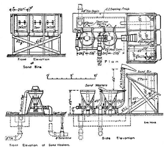
Fig. 1.—Plan and Elevation of Two-Hopper Ejector Sand
Washing Plant.
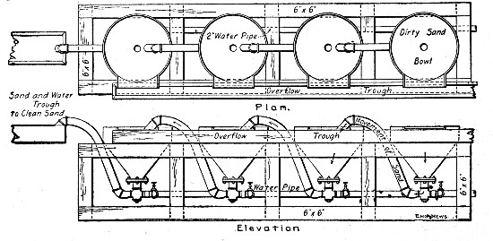 Fig. 2.—Plan and Elevation of Four-Hopper Ejector Sand
Washing-Plant.
Fig. 2.—Plan and Elevation of Four-Hopper Ejector Sand
Washing-Plant.
Washing With Sand Ejectors.—When large quantities of sand are to be washed use may be made of the sand ejector system, commonly employed in washing filter sand at large water filtration plants; water under pressure is required. In this system the dirty sand is delivered into a conical or pyramidal hopper, from the bottom of which it is drawn by an ejector and delivered mixed with water into a second similar hopper; here the water and dirt overflow the top of the hopper,[Pg 8] while the sand settles and is again ejected into a third hopper or to the stock pile or bins. The system may consist of anywhere from two to six hoppers. Figure 1 shows a two-hopper lay-out and Fig. 2 shows a four-hopper lay-out. In[Pg 9] the first plant the washed sand is delivered into bins so arranged, as will be seen, that the bins are virtually a third washing hopper. The clean sand is chuted from these bins directly into cars or wagons. In the second plant the clean sand is ejected into a trough which leads it into buckets handled by a derrick. The details of one of the washing hoppers for the plant shown by Fig. 1 are illustrated by Fig. 3.
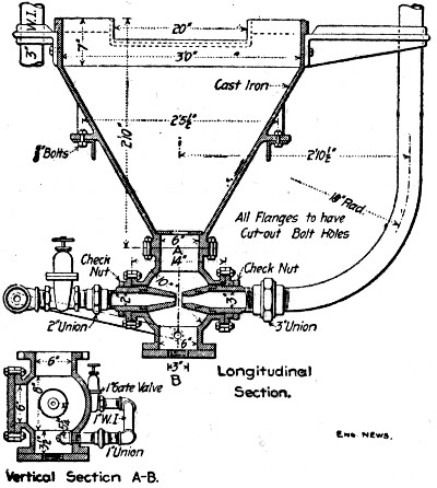 Fig. 3.—Details of Washing Hopper and Ejector for Plant
Shown by Fig. 1.
Fig. 3.—Details of Washing Hopper and Ejector for Plant
Shown by Fig. 1.
At filter plants the dirty sand is delivered mixed with water to the first hopper by means of ejectors stationed in the filters and discharging through pipes to the washers. When, as would usually be the case in contract work, the sand is delivered comparatively dry to the first hopper, this hopper must be provided with a sprinkler pipe to wet the sand. In studying the ejector washing plants illustrated it should be borne in mind that for concrete work they would not need to be of such permanent construction as for filter plants, the washers would be mounted on timber frames, underground piping would be done away with, etc.; at best, however, such plants are expensive and will be warranted only when the amount of sand to be washed is large.
The usual assumption of water-works engineers is that the volume of water required for washing filter sand is 15 times the volume of the sand washed. At the Albany, N. Y., filters the sand passes through five ejectors at the rate of 3 to 5 cu.[Pg 10] yds. per hour and takes 4,000 gallons of water per cubic yard. One man shovels sand into the washer and two take it away. Based on an output of 32 cu. yds. in 10 hours, Mr. Allen Hazen estimates the cost of washing as follows:
| 3 men, at $2 per day | $6.00 |
| 110,000 gallons of water, at $0.05 | 5.50 |
| ——— | |
| Total, 32 cu. yds., at 36 cts. | $11.50 |
Washing With Tank Washers.—Figure 4 shows a sand washer used in constructing a concrete lock at Springdale, Pa., in the United States government improvement work on the Allegheny river. The device consisted of a circular tank 9 ft. in diameter and 7 ft. high, provided with a sloping false bottom perforated with 1-in. holes, through which water was forced as indicated. A 7½×5×6-in. pump with a 3-in. discharge pipe was used to force water into the tank, and the rotating paddles were operated by a 7 h.p. engine. This apparatus washed a batch of 14 cu. yds. in from 1 to 2 hours at a cost of 7 cts. per cubic yard. The sand contained much fine coal and silt. The above data are given by Mr. W. H. Roper.
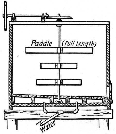 Fig. 4.—Details of Tank Washer Used at Springdale, Pa.
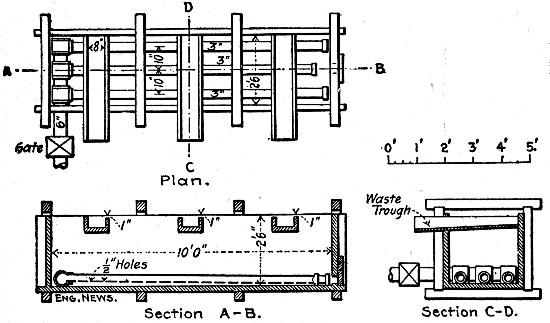 Fig. 5.—Details of Tank Washer Used at Yonkers, N. Y.
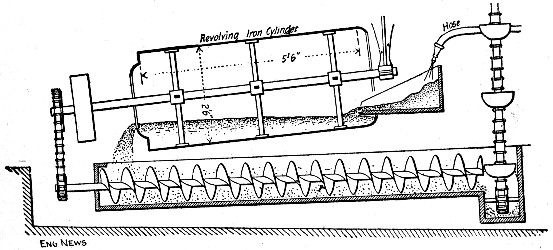 Fig. 6.—Details of Rotating Tank Sand Washer Used at
Hudson, N. Y.
Fig. 6.—Details of Rotating Tank Sand Washer Used at
Hudson, N. Y.
Another form of tank washer, designed by Mr. Allen Hazen, for washing bank sand at Yonkers, N. Y., is shown by Fig. 5. This apparatus consisted of a 10×2½×2½ ft. wooden box, with a 6-in. pipe entering one end at the bottom and there[Pg 11] branching into three 3-in. pipes, extending along the bottom and capped at the ends. The undersides of the 3-in. pipes were pierced with ½-in. holes 6 ins. apart, through which water under pressure was discharged into the box. Sand was shoveled into the box at one end and the upward currents of water raised the fine and dirty particles until they escaped through the waste troughs. When the box became filled with sand a sliding door at one end was opened and the batch discharged. The operation was continuous as long as sand was shoveled into the box; by manipulating the door the sand could be made to run out with a very small percentage of[Pg 12] water. Sand containing 7 per cent of dirt was thus washed so that it contained only 0.6 per cent dirt. The washer handled 200 cu. yds. of sand in 10 hours. The above data are given by F. H. Stephenson.
A somewhat more elaborate form of tank washer than either of those described is shown by Fig. 6. This apparatus was used by Mr. Geo. A. Soper for washing filter sand at Hudson, N. Y. The dirty sand was shoveled into a sort of hopper, from which it was fed by a hose stream into an inclined cylinder, along which it traveled and was discharged into a wooden trough provided with a screw conveyor and closed at both ends. The water overflowing the sides of the trough carried away the dirt and the clean sand was delivered by the screw to the bucket elevator which hoisted it to a platform, from which it was taken by barrows to the stock pile. A 4-h.p. engine with a 5-h.p. boiler operated the cylinder, screw, elevator and pump. Four men operated the washer and handled 32 cu. yds. of sand per day; with wages at $1.50 the cost of washing was 20 cts. per cubic yard.
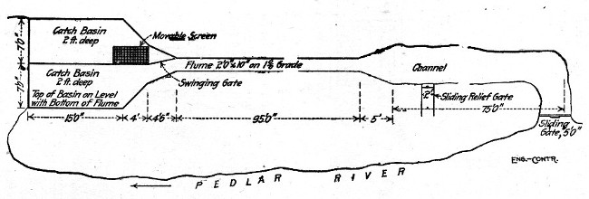 Fig. 7.—Arrangement of Sand Washing Plant at Lynchburg,
Va.
Fig. 7.—Arrangement of Sand Washing Plant at Lynchburg,
Va.
In constructing a concrete block dam at Lynchburg, Va., sand containing from 15 to 30 per cent. of loam, clay and[Pg 13] vegetable matter was washed to a cleanliness of 2 to 5 per cent of such matter by the device shown by Fig. 7. A small creek was diverted, as shown, into a wooden flume terminating in two sand tanks; by means of the swinging gate the flow was passed through either tank as desired. The sand was hauled by wagon and shoveled into the upper end of the flume; the current carried it down into one of the tanks washing the dirt loose and carrying it off with the overflow over the end of the tank while the sand settled in the tank. When one tank was full the flow was diverted into the other tank and the sand in the first tank was shoveled out, loaded into wagons, and hauled to the stock pile. As built this washer handled about 30 cu. yds. of sand per 10-hour day, but the tanks were built too small for the flume, which could readily handle 75 cu. yds. per day with no larger working force. This force consisted of three men at $1.50 per day, making the cost, for a 30 cu. yd. output, 15 cts. per cu. yd. for washing.
None of the figures given above includes the cost of handling the sand to and from the washer. When this involves much extra loading and hauling, it amounts to a considerable expense, and in any plan for washing sand the contractor should figure, with exceeding care, the extra handling due to the necessity of washing.
The aggregates commonly used in making concrete are broken or crushed stone, gravel, slag and cinders. Slag and cinders make a concrete that weighs considerably less than stone or gravel mixtures, and being the products of combustion are commonly supposed to make a specially fire resisting concrete; their use is, therefore, confined very closely to fireproof building work and, in fact, to floor construction for such buildings. Slag and cinder concretes are for this reason given minor consideration in this volume.
BROKEN STONE.—Stone produced by crushing any of the harder and tougher varieties of rock is suitable for concrete. Perhaps the best stone is produced by crushing trap rock. Crushed trap besides being hard and tough is angular and has an excellent fracture surface for holding cement; it also withstands heat better than most stone. Next to[Pg 14] trap the hard, tough, crystalline limestones make perhaps the best all around concrete material; cement adheres to limestone better than to any other rock. Limestone, however, calcines when subjected to fire and is, therefore, objected to by many engineers for building construction. The harder and denser sandstones, mica-schists, granites and syanites make good stone for concrete and occasionally shale and slate may be used.
GRAVEL.—Gravel makes one of the best possible aggregates for concrete. The conditions under which gravel is produced by nature make it reasonably certain that only the tougher and harder rocks enter into its composition; the rounded shapes of the component particles permit gravel to be more closely tamped than broken stone and give less danger of voids from bridging; the mixture is also generally a fairly well balanced composition of fine and coarse particles. The surfaces of the particles being generally smooth give perhaps a poorer bond with the cement than most broken stone. In the matter of strength the most recent tests show that there is very little choice between gravel and broken stone concrete.
SLAG AND CINDERS.—The slag used for concrete aggregate is iron blast furnace slag crushed to proper size. Cinders for aggregate are steam boiler cinders; they are best with the fine ashes screened out and should not contain more than 15 per cent. of unburned coal.
BALANCED AGGREGATE.—With the aggregate, as with the sand for concrete, the best results, other things being equal, will be secured by using a well-balanced mixture of coarse and fine particles. Usually the product of a rock crusher is fairly well balanced except for the very fine material. There is nearly always a deficiency of this, which, as explained in a succeeding section, has to be supplied by adding sand. Usually, also, the engineer accepts the crusher product coarser than screenings as being well enough balanced for concrete work, but this is not always the case. Engineers occasionally demand an artificial mixture of varying proportions of different size stones and may even go so far as to require gravel to be screened and reproportioned. This[Pg 15] artificial grading of the aggregate adds to the cost of the concrete in some proportion which must be determined for each individual case.
SIZE OF AGGREGATE.—The size of aggregate to be used depends upon the massiveness of the structure, its purpose, and whether or not it is reinforced. It is seldom that aggregate larger than will pass a 3-in. ring is used and this only in very massive work. The more usual size is 2½ ins. For reinforced concrete 1¼ ins. is about the maximum size allowed and in building work 1-in. aggregate is most commonly used. Same constructors use no aggregate larger than ¾ in. in reinforced building work, and others require that for that portion of the concrete coming directly in contact with the reinforcement the aggregate shall not exceed ¼ to ½ in. The great bulk of concrete work is done with aggregate smaller than 2 ins., and as a general thing where the massiveness of the structure will allow of much larger sizes it will be more economic to use rubble concrete. (See Chapter VI.)
COST OF AGGREGATE.—The locality in which the work is done determines the cost of the aggregate. Concerns producing broken stone or screened and washed gravel for concrete are to be found within shipping distance in most sections of the country so that these materials may be purchased in any amount desired. The cost will then be the market price of the material f. o. b. cars at plant plus the freight rates and the cost of unloading and haulage to the stock piles. If the contractor uses a local stone or gravel the aggregate cost will be, for stone the costs of quarrying and crushing and transportation, and, for gravel, the cost of excavation, screening, washing and transportation.
SCREENED OR CRUSHER-RUN STONE FOR CONCRETE.—Formerly engineers almost universally demanded that broken stone for concrete should have all the finer particles screened out. This practice has been modified to some considerable extent in recent years by using all the crusher product both coarse and fine, or, as it is commonly expressed, by using run-of-crusher stone. The comparative merits of screened and crusher-run stone for concrete work are questions[Pg 16] of comparative economy and convenience. The fine stone dust and chips produced in crushing stone are not, as was once thought, deleterious; they simply take the place of so much of the sand which would, were the stone screened, be required to balance the sand and stone mixture. It is seldom that the proportion of chips and dust produced in crushing stone is large enough to replace the sand constituent entirely; some sand has nearly always to be added to run-of-crusher stone and it is in determining the amount of this addition that uncertainty lies. The proportions of dust and chips in crushed stone vary with the kind of stone and with the kind of crusher used. Furthermore, when run-of-crusher stone is chuted from the crusher into a bin or pile the screenings and the coarse stones segregate. Examination of a crusher-run stone pile will show a cone-shaped heart of fine material enclosed by a shell of coarser stone, consequently when this pile of stone is taken from to make concrete a uniform mixture of fine and coarse particles is not secured, the material taken from the outside of the pile will be mostly coarse and that from the inside mostly fine. This segregation combined with the natural variation in the crusher product makes the task of adding sand and producing a balanced sand and stone mixture one of extreme uncertainty and some difficulty unless considerable expenditure is made in testing and reproportioning. When the product of the crusher is screened the task of proportioning the sand to the stone is a straightforward operation, and the screened out chips and dust can be used as a portion of the sand if desired. The only saving, then, in using crusher-run stone direct is the very small one of not having to screen out the fine material. The conclusion must be that the economy of unscreened stone for concrete is a very doubtful quantity, and that the risk of irregularity in unscreened stone mixtures is a serious one. The engineer's specifications will generally determine for the contractor whether he is to use screened or crusher-run stone, but these same specifications will not guarantee the regularity of the resulting concrete mixture; this will be the contractor's burden and if the engineer's inspection is rigid and the crusher-run product runs uneven for the reasons given above it will[Pg 17] be a burden of considerable expense. The contractor will do well to know his product or to know his man before bidding less or even as little on crusher-run as on screened stone concrete.
COST OF QUARRYING AND CRUSHING STONE.—The following examples of the cost of quarrying and crushing stone are fairly representative of the conditions which would prevail on ordinary contract work. In quarrying and crushing New Jersey trap rock with gyratory crushers the following was the cost of producing 200 cu. yds. per day:
| Per day. | Per cu. yd. | |
| 3 drillers at $2.75 | $ 8.25 | $0.041 |
| 3 helpers at $1.75 | 5.25 | 0.026 |
| 10 men barring out and sledging | 15.00 | 0.075 |
| 14 men loading carts | 21.00 | 0.105 |
| 4 cart horses | 6.00 | 0.030 |
| 2 cart drivers | 3.00 | 0.015 |
| 2 men dumping carts and feeding crusher | 3.00 | 0.015 |
| 1 fireman for drill boiler | 2.50 | 0.013 |
| 1 engineman for crusher | 3.00 | 0.015 |
| 1 blacksmith | 3.00 | 0.015 |
| 1 blacksmith helper | 2.00 | 0.010 |
| 1 foreman | 5.00 | 0.025 |
| 2 tons coal at $3.50 | 7.00 | 0.035 |
| 150 lbs. 40% dynamite at 15 cts. | 22.50 | 0.113 |
| ——— | ——— | |
| Total | $106.50 | $0.533 |
The quarry face worked was 12 to 18 ft., and the stone was crushed to 2-in. size. Owing to the seamy character of the rock it was broken by blasting into comparatively small pieces requiring very little sledging. The stone was loaded into one-horse dump carts, the driver taking one cart to the crusher while the other was being loaded. The haul was 100 ft. The carts were dumped into an inclined chute leading to a No. 5 Gates crusher. The stone was elevated by a bucket elevator and screened. All stone larger than 2 ins. was returned through a chute to a No. 3 Gates crusher for[Pg 18] recrushing. The cost given above does not include interest, depreciation, and repairs; these items would add about $8 to $10 more per day or 4 to 5 cts. per cubic yard.
In quarrying limestone, where the face of the quarry was only 5 to 6 ft. high, and where the amount of stripping was small, one steam drill was used. This drill received its steam from the same boiler that supplied the crusher engine. The drill averaged 60 ft. of hole drilled per 10-hr. day, but was poorly handled and frequently laid off for repairs. The cost of quarrying and crushing was as follows:
| 1 driller | $ 2.50 |
| 1 helper | 1.50 |
| 1 man stripping | 1.50 |
| 4 men quarrying | 6.00 |
| 1 blacksmith | 2.50 |
| ⅛ ton coal at $3 | 1.00 |
| Repairs to drill | .60 |
| Hose, drill steel and interest on plant | .90 |
| 24 lbs. dynamite | 3.60 |
| ——— | |
| Total | $20.10 |
| 1 engineman | $ 2.50 |
| 2 men feeding crusher | 3.50 |
| 6 men wheeling | 9.00 |
| 1 bin man | 1.50 |
| 1 general foreman | 3.00 |
| ⅓ ton coal at $3 | 1.00 |
| 1 gallon oil | .25 |
| Repairs to crusher | 1.00 |
| Repairs to engine and boiler | 1.00 |
| Interest on plant | 1.00 |
| ——— | |
| Total | $23.75 |
| Per day. | Per. cu. yd. | |
| Quarrying | $20.10 | $0.37 |
| Crushing | 23.75 | 0.39 |
| ——— | —— | |
| Total for 60 cu. yds. | $43.85 | $0.76 |
The "4 men quarrying" barred out and sledged the stone to sizes that would enter a 9×16-in. jaw crusher. The "6 men wheeling" delivered the stone in wheelbarrows to the crusher platform, the run plank being never longer than 150 ft. Two men fed the stone into the crusher, and a bin-man helped load the wagons from the bin, and kept tally of the loads. The stone was measured loose in the wagons, and it was found that the average load was 1½ cu. yds., weighing 2,400 lbs. per cu. yd. There were 40 wagon loads, or 60 cu. yds.[Pg 19] crushed per 10-hr. day, although on some days as high as 75 cu. yds. were crushed. The stone was screened through a rotary screen, 9 ft. long, having three sizes of openings, ½-in., 1¼-in. and 2¼-in. The output was 16% of the smallest size, 24% of the middle size, and 60% of the large size. All tailings over 2½ ins. in size were recrushed.
It will be noticed that the interest on the plant is quite an important item. This is due to the fact that, year in and year out, a quarrying and crushing plant seldom averages more than 100 days actually worked per year, and the total charge for interest must be distributed over these 100 days, and not over 300 days as is so commonly and erroneously done. The cost of stripping the earth off the rock is often considerably in excess of the above given cost, and each case must be estimated separately. Quarry rental or royalty is usually not in excess of 5 cts. per cu. yd., and frequently much less. The dynamite used was 40%, and the cost of electric exploders is included in the cost given. Where a higher quarry face is used the cost of drilling and the cost of explosives per cu. yd. is less. Exclusive of quarry rent and heavy stripping costs, a contractor should be able to quarry and crush limestone or sandstone for not more than 75 cts. per cu. yd., or 62 cts. per ton of 2,000 lbs., wages and conditions being as above given.
The labor cost of erecting bins and installing a 9×16 jaw crusher, elevator, etc., averages about $75, including hauling the plant two or three miles, and dismantling the plant when work is finished.
The following is a record of the cost of crushing stone and cobbles on four jobs at Newton, Mass., in 1891. On jobs A and B the stone was quarried and crushed; on jobs C and D cobblestones were crushed. A 9×15-in. Farrel-Marsondon crusher was used, stone being fed in by two laborers. A rotary screen having ½, 1 and 2½-in. openings delivered the stone into bins having four compartments, the last receiving the "tailings" which had failed to pass through the screen. The broken stone was measured in carts as they left the bin, but several cart loads were weighed, giving the following weights per cubic foot of broken stone:[Pg 20]
| —————Size.——————— | ||||
| ½-in. | 1-in. | 2½-ins. | Tailings. | |
| lbs. | lbs. | lbs. | lbs. | |
| Greenish trap rock, "A" | 95.8 | 84.3 | 88.3 | 91.0 |
| Conglomerate, "B" | 101.0 | 87.7 | 94.4 | .... |
| Cobblestones, "C" and "D" | 102.5 | 98.0 | 99.6 | .... |
A one-horse cart held 26 to 28 cu. ft. (average 1 cu. yd.) of broken stone; a two-horse cart, 40 to 42 cu. ft., at the crusher.
| ——————————Job.—————— | ||||
| A. | B. | C. | D. | |
| Hours run | 412 | 144 | 101 | 198 |
| Short tons per hour | 9.0 | 11.2 | 15.7 | 12.1 |
| Cu. yds. per hour | 7.7 | 8.9 | 11.8 | 9.0 |
| Per cent of tailings | 31.8 | 29.3 | 17.5 | 20.5 |
| Per cent of 2½-in. stone | 51.3 | 51.9 | 57.0 | 55.1 |
| Per cent of 1-in. stone | 10.2 | .... | .... | .... |
| Per cent of ½-in. stone or dust | 6.7 | 18.8 | 25.5 | 23.4 |
| ——————————Job.—————— | ||||
| A. | B. | C. | D. | |
| Explosives, coal for drill and repairs | $0.084 | $0.018 | .... | .... |
| Labor steam drilling | 0.092 | .... | .... | .... |
| Labor hand drilling | .... | 0.249 | .... | .... |
| Sharpening tools | 0.069 | 0.023 | .... | .... |
| Sledging stone for crusher | 0.279 | 0.420 | .... | .... |
| Loading carts | 0.098 | 0.127 | .... | $0.144 |
| Carting to crusher | 0.072 | 0.062 | $0.314 | 0.098 |
| Feeding crusher | 0.053 | 0.053 | 0.033 | 0.065 |
| Engineer of crusher | 0.031 | 0.038 | 0.029 | 0.036 |
| Coal for crusher | 0.079 | 0.050 | 0.047 | 0.044 |
| Repairs to crusher | 0.041 | .... | .... | 0.011 |
| Moving portable crusher | .... | 0.023 | .... | 0.019 |
| Watchman ($1.75 a day) | .... | 0.053 | 0.022 | 0.030 |
| ——— | ——— | ——— | ——— | |
| Total cost per cu. yd. | $0.898 | $1.116 | $0.445 | $0.447 |
| Total cost per short ton | 0.745 | 0.885 | 0.330 | 0.372 |
Note.—"A" was trap rock; "B" was conglomerate rock; "C" and "D" were trap and granite cobblestones. Common laborers on jobs "A" and "D" were paid $1.75 per 9-hr. day; on jobs "B" and "C," $1.50 per 9-hr. day; two-horse cart and driver, $5 per day; blacksmith, $2.50; engineer on crusher, $2 on job "A," $2.25 on "B," $2.00 on "C," $2.50 on "D"; steam driller received $3, and helper $1.75 a day; foreman, $3 a day. Coal was $5.25 per short ton. Forcite powder, 11⅓ cts. per lb.
For a full discussion of quarrying and crushing methods and costs and for descriptions of crushing machinery and plants the reader is referred to "Rock Excavation; Methods and Cost," by Halbert P. Gillette.
SCREENING AND WASHING GRAVEL.—Handwork is resorted to in screening gravel only when the amount to be screened is small and when it is simply required to separate the fine sand without sorting the coarser material into sizes. The gravel is shoveled against a portable inclined screen through which the sand drops while the pebbles slide down and accumulate at the bottom. The cost of screening by hand is the cost of shoveling the gravel against the screen divided by the number of cubic yards of saved material. In screening gravel for sand the richer the gravel is in fine material the cheaper will be the cost per cubic yard for screening; on the contrary in screening gravel for the pebbles the less sand there is in the gravel the cheaper will be the cost per cubic yard for screening. The cost of shoveling divided by the number of cubic yards shoveled is the cost of screening only when both the sand and the coarser material are saved. Tests made in the pit will enable the contractor to estimate how many cubic yards of gravel must be shoveled to get a cubic yard of sand or pebbles. An energetic man will shovel about 25 cu. yds. of gravel against a screen per 10-hour day and keep the screened material cleared away, providing no carrying is necessary.
A mechanical arrangement capable of handling a considerably larger yardage of material is shown by Fig. 8. Two men and a team are required. The team is attached to the scraper by means of the rope passing through the pulley at the top of the incline. The scraper is loaded in the usual manner, hauled up the incline until its wheels are stopped by blocks and then the team is backed up to slacken the rope and permit the scraper to tip and dump its load. The trip holding the scraper while dumping is operated from the ground. The[Pg 22] scraper load falls onto an inclined screen which takes out the sand and delivers the pebbles into the wagon. By erecting bins to catch the sand and pebbles this same arrangement could be made continuous in operation.
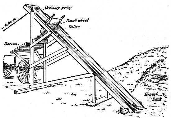 Fig. 8.—Device for Excavating and Screening Gravel and
Loading Wagons.
Fig. 8.—Device for Excavating and Screening Gravel and
Loading Wagons.
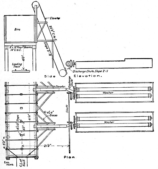 Fig. 9.—Gravel Washing Plant of 120 to 130 Cu. Yds., Per
Hour Capacity.
Fig. 9.—Gravel Washing Plant of 120 to 130 Cu. Yds., Per
Hour Capacity.
In commercial gravel mining, the gravel is usually sorted into several sizes and generally it is washed as well as screened. Where the pebbles run into larger sizes a crushing plant is also usually installed to reduce the large stones. Works producing several hundred cubic yards of screened and washed gravel per day require a plant of larger size and greater cost than even a very large piece of concrete work will warrant, so that only general mention will be made here of such plants. The commercial sizes of gravel are usually 2-in., 1-in., ½-in. and ¼-in., down to sand. No very detailed costs of producing gravel by these commercial plants are available. At the plant of the Lake Shore & Michigan Southern Ry., where gravel is screened and washed for ballast, the gravel is passed over a 2-in., a ¾-in., a ¼-in. and a ⅛-in. screen in turn and the fine sand is saved. About 2,000 tons are handled per day; the washed gravel, 2-in. to ⅛-in. sizes, represents from 40 to 65 per cent. of the raw gravel and costs from 23 to 30 cts. per cu. yd., for excavation, screening and[Pg 23] washing. The drawings of Fig. 9 show a gravel washing plant having a capacity of 120 to 130 cu. yds. per hour, operated by the Stewart-Peck Sand Co., of Kansas City, Mo. Where washing alone is necessary a plant of one or two washer units like those here shown could be installed without excessive cost by a contractor at any point where water is available. Each washer unit consists of two hexagonal troughs 18 ins. in diameter and 18 ft. long. A shaft carrying blades set spirally is rotated in each trough to agitate the gravel and force it along; each trough also has a fall of 6 ins. toward its receiving end. The two troughs are inclosed in a tank or box and above and between them is a 5-in. pipe having[Pg 24] ¾-in. holes 3 ins. apart so arranged that the streams are directed into the troughs. The water and dirt pass off at the lower end of the troughs while the gravel is fed by the screws into a chute discharging into a bucket elevator, which in turn feeds into a storage bin. The gravel to be washed runs from 2 ins. to ⅛-in. in size; it is excavated by steam shovel and loaded into 1½ cu. yd. dump cars, three of which are hauled by a mule to the washers, where the load is dumped into the troughs. The plant having a capacity of 120 to 130 cu. yds. per hour cost $25,000, including pump and an 8-in. pipe line a mile long. A 100-hp. engine operates the plant, and 20 men are needed for all purposes. This plant produces washed gravel at a profit for 40 cts. per cu. yd.
American engineers proportion concrete mixtures by measure, thus a 1-3-5 concrete is one composed of 1 volume of cement, 3 volumes of sand and 5 volumes of aggregate. In Continental Europe concrete is commonly proportioned by weight and there have been prominent advocates of this practice among American engineers. It is not evident how such a change in prevailing American practice would be of practical advantage. Aside from the fact that it is seldom convenient to weigh the ingredients of each batch, sand, stone and gravel are by no means constant in specific gravity, so that the greater exactness of proportioning by weight is not apparent. In this volume only incidental attention is given to gravimetric methods of proportioning concrete.
VOIDS.—Both the sand and the aggregates employed for concrete contain voids. The amount of this void space depends upon a number of conditions. As the task of proportioning concrete consists in so proportioning the several materials that all void spaces are filled with finer material the conditions influencing the proportion of voids in sand and aggregates must be known.
Voids in Sand.—The two conditions exerting the greatest influence on the proportion of voids in sand are the presence of moisture and the size of the grains of which the sand is composed.[Pg 26]
| Per cent of water in sand | 0 | 0.5 | 1 | 2 | 3 | 5 | 10 |
| Lbs. | Lbs. | Lbs. | Lbs. | Lbs. | Lbs. | Lbs. | |
| Weight per cu. yd. of fine sand and water | 3,457 | 2,206 | 2,085 | 2,044 | 2,037 | 2,035 | 2,133 |
| Weight per cu. yd. of coarse sand and water | 2,551 | 2,466 | 2,380 | 2,122 | 2,058 | 2,070 | 2,200 |
The volume of sand is greatly affected by the presence of varying percentages of moisture in the sand. A dry loose sand that has 45 per cent. voids if mixed with 5 per cent. by weight of water will swell, unless tamped, to such an extent that its voids may be 57 per cent. The same sand if saturated with water until it becomes a thin paste may show only 37½ per cent. voids after the sand has settled. Table I shows the results of tests made by Feret, the French experimenter. Two kinds of sand were used, a very fine sand and a coarse sand. They were measured in a box that held 2 cu. ft. and was 8 ins. deep, the sand being shoveled into the box but not tamped or shaken. After measuring and weighing the dry sand 0.5 per cent. by weight of water was added and the sand was mixed and shoveled back into the box again and then weighed. These operations were repeated with varying percentages of water up to 10 per cent. It will be noted that the weight of mixed water and sand is given; to ascertain the exact weight of dry sand in any mixture, divide the weight given in the table by 100 per cent. plus the given tabular per cent.; thus the weight of dry, fine sand in a 5 per cent. mixture is 2,035 ÷ 1.5 = 1,98 lbs. per cu. yd. The voids in the dry sand were 45 per cent. and in the sand with 5 per cent. moisture they were 56.7 per cent. Pouring water onto loose, dry sand compacts it. By mixing fine sand and water to a thin paste and allowing it to settle, it was found that the sand occupied 11 per cent. less space than when measured dry. The voids in fine sand, having a specific gravity of 2.65, were determined by measurement in a quart measure and found to be as follows:
| Sand not packed, per cent. voids | 44½ |
| Sand shaken to refusal, per cent. voids | 35 |
| Sand saturated with water, per cent. voids | 37½ |
Another series of tests made by Mr. H. P. Boardman, using Chicago sand having 34 to 40 per cent. voids, showed the following results:
| Water added, per cent. | 2 | 4 | 6 | 8 | 10 |
| Resulting per cent. increase | 17.6 | 22 | 19.5 | 16.6 | 15.6 |
Mr. Wm. B. Fuller found by tests that a dry sand, having[Pg 27] 34 per cent. voids, shrunk 9.6 per cent. in volume upon thorough tamping until it had 27 per cent. voids. The same sand moistened with 6 per cent. water and loose had 44 per cent. voids, which was reduced to 31 per cent. by ramming. The same sand saturated with water had 33 per cent. voids and by thorough ramming its volume was reduced 8½ per cent. until the sand had only 26¼ per cent. voids. Further experiments might be quoted and will be found recorded in several general treatises on concrete, but these are enough to demonstrate conclusively that any theory of the quantity of cement in mortar to be correct must take into account the effect of moisture on the voids in sand.
The effect of the size and the shape of the component grains on the amount of voids in sand is considerable. Feret's experiments are conclusive on these points, and they alone will be followed here. Taking for convenience three sizes of sand Feret mixed them in all the varying proportions possible with a total of 10 parts; there were 66 mixtures. The sizes used were: Large (L), sand composed of grains passing a sieve of 5 meshes per linear inch and retained on a sieve of 15 meshes per linear inch; medium (M), sand passing a sieve of 15 meshes and retained on a sieve of 50 meshes per linear inch, and fine (F), sand passing a 50-mesh sieve. With a dry sand whose grains have a specific gravity of 2.65, the weight of a cubic yard of either the fine, or the medium, or the large size, was 2,190 lbs., which is equivalent to 51 per cent. voids. The greatest weight of mixture, 2,840 lbs. per cu. yd., was an L6M0F4 mixture, that is, one composed of six parts large, no parts medium and 4 parts fine; this mixture was the densest of the 66 mixtures made, having 36 per cent. voids. It will be noted that the common opinion that the densest mixture is obtained by a mixture of gradually increasing sizes of grains is incorrect; there must be enough difference in the size of the grains to provide voids so large that the smaller grains will enter them and not wedge the larger grains apart. Turning now to the shape of the grains, the tests showed that rounded grains give less voids than angular grains. Using sand having a [Pg 28]composition of L5M3F2 Feret got the following results:
| —Per cent. Voids— | ||
| Kind of Grains. | Shaken. | Unshaken. |
| Natural sand, rounded grains | 25.6 | 35.9 |
| Crushed quartzite, angular grains | 27.4 | 42.1 |
| Crushed shells, flat grains | 31.8 | 44.3 |
| Residue of quartzite, flat grains | 34.6 | 47.5 |
The sand was shaken until no further settlement occurred. It is plain from these data on the effect of size and shape of grains on voids why it is that discrepancies exist in the published data on voids in dry sand. An idea of the wide variation in the granulometric composition of different sands is given by Table II. Table III shows the voids as determined for sands from different localities in the United States.
| Held by a Sieve. | A | B | C | E |
| No. 10 | 35.3% | |||
| No. 20 | 32.1 | 12.8% | 4.2% | 11% |
| No. 30 | 14.6 | 49.0 | 12.5 | 14 |
| No. 40 | ... | ... | 44.4 | ... |
| No. 50 | 9.6 | 29.3 | ... | 53 |
| No. 100 | 4.9 | 5.7 | ... | ... |
| No. 200 | 2.0 | 2.3 | ... | ... |
| —— | —— | —— | —— | |
| Voids | 33% | 39% | 41.7% | 31% |
Note.—A, is a "fine gravel" (containing 8% clay) used at Philadelphia. B, Delaware River sand. C, St. Mary's River sand. D, Green River, Ky., sand, "clean and sharp."
| Locality. | Authority. | Percent Voids. | Remarks. |
| Ohio River | W. M. Hall | 31 | Washed |
| Sandusky, O. | C. E. Sherman | 40 | Lake |
| Franklin Co., O. | C. E. Sherman | 40 | Bank |
| Sandusky Bay, O. | S. B. Newberry | 32.3 | ...... |
| St. Louis, Mo. | H. H. Henby | 34.3 | Miss. River |
| Sault Ste. Marie | H. von Schon | 41.7 | River |
| Chicago, Ill. | H. P. Broadman | 34 to 40 | ...... |
| Philadelphia, Pa | 39 | Del. River | |
| Mass. Coast | 31 to 34 | ...... | |
| Boston, Mass | Geo. Kimball | 33 | Clean |
| Cow Bay, L. I. | Myron S. Falk | 40½ | ...... |
| Little Falls, N. J. | W. B. Fuller | 45.6 | ...... |
| Canton, Ill. | G. W. Chandler | 30 | Clean |
Voids in Broken Stone and Gravel.—The percentage of voids in broken stone varies with the nature of the stone: whether it is broken by hand or by crushers; with the kind of crusher used, and upon whether it is screened or crusher-run[Pg 29] product. The voids in broken stone seldom exceed 52 per cent. even when the fragments are of uniform size and the stone is shoveled loose into the measuring box. The following records of actual determinations of voids in broken stone cover a sufficiently wide range of conditions to show about the limits of variation.
The following are results of tests made by Mr. A. N. Johnson, State Engineer of Illinois, to determine the variation in voids in crushed stone due to variation in size and to method of loading into the measuring box. The percentage of voids was determined by weighing the amount of water added to fill the box:
| Size. | Method of Loading. | Per cent. of Voids. |
| 3 in. | 20-ft. drop | 41.8 |
| 3 in. | 15-ft drop | 46.8 |
| 3 in. | 15-ft. drop | 47.2 |
| 3 in. | Shovels | 48.7 |
| 1½ in. | 20-ft. drop | 42.5 |
| 1½ in. | 15-ft. drop | 46.8 |
| 1½ in. | 15-ft. drop | 46.8 |
| 1½ in. | Shovels | 50.5 |
| ¾ in. | 20-ft. drop | 39.4 |
| ¾ in. | 15-ft. drop | 42.7 |
| ¾ in. | 15-ft. drop | 41.5 |
| ¾ in. | 15-ft. drop | 41.8 |
| ¾ in. | Shovels | 45.2 |
| ¾ in. | Shovels | 44.6 |
| ⅜ in. | Shovels | 41.0 |
| ⅜ in. | Shovels | 40.6 |
| ⅜ in. | Shovels | 41.0 |
The table shows clearly the effect on voids of compacting the stone by dropping it; it also shows for the ¾-in. and the ⅜-in. stone loaded by shovels how uniformly the percentages of voids run for stone of one size only. Dropping the stone 20 ft. reduced the voids some 12 to 15 per cent. as compared with shoveling.[Pg 30]
| Authority. | Percent Voids. | Remarks. |
| Sabin | 49.0 | Limestone, crusher run after screening out ⅛-in. and under. |
| " | 44.0 | Limsetone (1 part screenings mixed with 6 parts broken stone). |
| Wm. M. Black | 46.5 | Screened and washed, 2-ins. and under. |
| J. J. R. Croes | 47.5 | Gneiss, after screening out ¼-in. and under. |
| S. B. Newberry | 47.0 | Chiefly about egg size. |
| H. P. Broadman | 39 to 42 | Chicago limestone, crusher run. |
| " | 48 to 52 | " " screened into sizes. |
| Wm. M. Hall | 48.0 | Green River limestone, 2½-ins. and smaller dust screened out. |
| " | 50.0 | Hudson River trap, 2½-ins. and smaller, dust screened out. |
| Wm. B. Fuller | 47.6 | New Jersey trap, crusher run, 1/6 to 2.1 in. |
| Geo. A. Kimball | 49.5 | Roxbury conglomerate, ½ to 2½ ins. |
| Myron S. Falk | 48.0 | Limestone, ½ to 3 ins. |
| W. H. Henby | 43.0 | " 2-in size. |
| " | 46.0 | " 1½-in size |
| Feret | 53.4 | Stone, 1.6 to 2.4 ins. |
| " | 51.7 | " 0.8 to 1.6 in. |
| " | 52.1 | " 0.4 to 0.8 in. |
| A. W. Dow | 45.3 | Bluestone, 89% being 1½ to 2½ ins. |
| " | 45.3 | " 90% being 1/6 to 1½ in. |
| Taylor and Thompson | 54.5 | Trap, hard, 1 to 2½ ins. |
| " | 54.5 | " " ½ to 1 in. |
| " | 45.0 | " " 0 to 2½ in. |
| " | 51.2 | " soft, ¾ to 2 ins. |
| G. W. Chandler | 40.0 | Canton, Ill. |
| Emile Low | 39.0 | Buffalo limestone, crusher run, dust in. |
| C. M. Saville | 46.0 | Crushed cobblestone, screened into sizes. |
| ———Per cent Voids in——— | |||||
| Passing a ring of | 2.4" | 1.6" | 0.8" | Round | Broken |
| Held by a ring | 1.6" | 0.8" | 0.4" | Pebbles. | Stone. |
| Parts | 1 | 0 | 0 | 40.0 | 53.4 |
| " | 0 | 1 | 0 | 38.8 | 51.7 |
| " | 0 | 0 | 1 | 41.7 | 52.1 |
| " | 1 | 1 | 0 | 35.8 | 50.5 |
| " | 1 | 0 | 1 | 35.6 | 47.1 |
| " | 0 | 1 | 1 | 37.9 | 40.5 |
| " | 1 | 1 | 1 | 35.5 | 47.8 |
| " | 4 | 1 | 1 | 34.5 | 49.2 |
| " | 1 | 4 | 1 | 36.6 | 49.4 |
| " | 1 | 1 | 4 | 38.1 | 48.6 |
| " | 8 | 0 | 2 | 34.1 | .... |
Table IV gives the voids in broken stone as determined by various engineers; it requires no explanation. Table V, taken from Feret's tests, shows the effect of changes in granulometric composition on the amount of voids in both broken stone and gravel. Considering the column giving voids in stone it is to be noted first how nearly equal the voids are for stone of uniform size whatever that size be. As was the case with sand a mixture of coarse and fine particles gives the fewest voids; for stone an L1M0F1 mixture and for gravel an L8M0F2 mixture. Tamping reduces the voids in broken stone. Mr. Geo. W. Rafter gives the voids in clean, hand-broken limestone passing a 2½-in. ring as 43 per cent. after being lightly shaken and 37½ per cent. after being rammed. Generally speaking heavy ramming will reduce the voids in loose stone about 20 per cent.
It is rare that gravel has less than 30 per cent. or more than 45 per cent. voids. If the pebbles vary considerably in size so that the small fit in between the large, the voids may be as low as 30 per cent. but if the pebbles are tolerably uniform in size the voids will approach 45 per cent. Table V shows the effect of granulometric composition on the voids in gravel as determined by Feret. Mr. H. Von Schon gives the following granulometric analysis of a gravel having 34.1 per cent. voids:
| Retained on 1-in. ring, per cent. | 10.70 |
| Retained on ⅜-in. ring, per cent. | 23.65 |
| Retained on No. 4 sieve, per cent. | 8.70 |
| Retained on No. 10 sieve, per cent. | 17.14 |
| Retained on No. 20 sieve, per cent. | 21.76 |
| Retained on No. 30 sieve, per cent. | 6.49 |
| Retained on No. 40 sieve, per cent. | 5.96 |
| Passed a No. 40 sieve, per cent. | 5.59 |
| Passed a 1½-in ring, per cent. | 100.00 |
As mixtures of broken stone and gravel are often used the following determinations of voids in such mixtures are given. The following determinations were made by Mr. Wm. M. Hall for mixtures of blue limestone and Ohio River washed gravel:[Pg 32]
| Per cent. Stone. | Per cent. Gravel. | Per cent. Voids in Mix | |
| 100 | with | 0 | 48 |
| 80 | " | 20 | 44 |
| 70 | " | 30 | 41 |
| 60 | " | 40 | 38½ |
| 50 | " | 50 | 36 |
| 0 | " | 100 | 35 |
The dust was screened from the stone all of which passed a 2½-in. ring; the gravel all passed a 1½-in. screen. Using the same sizes of gravel and Hudson River trap rock, the results were:
| Per cent. Trap. | Per cent. Gravel. | Per cent. Voids in Mix. | |
| 100 | with | 0 | 50 |
| 60 | " | 40 | 38½ |
| 50 | " | 50 | 36 |
| 0 | " | 100 | 35 |
The weight of a cubic foot of loose gravel or stone is not an accurate index of the percentage of voids unless the specific gravity is known. Pure quartz weighs 165 lbs., per cu. ft., hence broken quartz having 40 per cent. voids weighs 165 × .60 = 99 lbs. per cu. ft. Few gravels are entirely quartz, and many contain stone having a greater specific gravity like some traps or a less specific gravity like some shales and sandstone. Tables VI and VII give the specific gravities of common stones and minerals and Table VIII gives the weights corresponding to different percentages of voids for different specific gravities.
| Trap, | Boston, Mass. | 2.78 |
| " | Duluth, Minn. | 2.8 to 3.0 |
| " | Jersey City, N. J. | 3.03 |
| " | Staten Island, N. Y. | 2.86 |
| Gneiss, | Madison Ave., N. Y. | 2.92 |
| Granite, | New London, Conn. | 2.66 |
| " | Greenwich, Conn. | 2.84 |
| " | Vinalhaven, Me. | 2.66 |
| " | Quincy, Mass. | 2.66 |
| " | Barre, Vt. | 2.65 |
| Limestone, | Joliet, Ill. | 2.56 |
| " | Quincy, Ill. | 2.51 to 2.57 |
| Limestone, (oolitic) | Bedford, Ind. | 2.25 to 2.45 |
| " | Marquette, Mich. | 2.34 |
| " | Glens Falls, N.Y. | 2.70 |
| " | Lake Champlain, N. Y. | 2.75 |
| Sandstone, | Portland, Conn. | 2.64 |
| " | Haverstraw, N. Y. | 2.13 |
| " | Medina, N. Y. | 2.41 |
| " | Potsdam, N. Y. | 2.60 |
| " | (grit) Berea, O. | 2.12 |
| Apatite | 2.92-3.25 |
| Basalt | 3.01 |
| Calcite, CaCO3 | 2.5-2.73 |
| Cassiterite, SnO2 | 6.4-7.1 |
| Cerrusite, PbCO3 | 6.46-6.48 |
| Chalcopyrite, CuFeS2 | 4.1-4.3 |
| Coal, anthracite | 1.3-1.84 |
| Coal, bituminous | 1.2-1.5 |
| Diabase | 2.6-3.03 |
| Diorite | 2.92 |
| Dolomite, CaMg (CO3)² | 2.8-2.9 |
| Felspar | 2.44-2.78 |
| Felsite | 2.65 |
| Galena, Pbs | 7.25-7.77 |
| Garnet | 3.15-4.31 |
| Gneiss | 2.62-2.92 |
| Granite | 2.55-2.86 |
| Gypsum | 2.3-3.28 |
| Halite (salt) NaCl | 2.1-2.56 |
| Hematite, Fe2O3 | 4.5-5.3 |
| Hornblende | 3.05-3.47 |
| Limonite, Fe3O4 (OH)6 | 3.6-4.0 |
| Limestone | 2.35-2.87 |
| Magnetite, Fe3O4 | 4.9-5.2 |
| Marble | 2.08-2.85 |
| Mica | 2.75-3.1 |
| Mica Schist | 2.5-2.9 |
| Olivine | 3.33-3.5 |
| Porphyry | 2.5-2.6 |
| Pyrite, FeS2 | 4.83-5.2 |
| Quartz, SiO2 | 2.5-2.8 |
| Quartzite | 2.6-2.7 |
| Sandstone | 2.0-2.78 |
| " Medina | 2.4 |
| " Ohio | 2.2 |
| " Slaty | 1.82 |
| Shale | 2.4-2.8 |
| Slate | 2.5-2.8 |
| Sphalerite, ZnS | 3.9-4.2 |
| Stibnite, Sb2S3 | 4.5-4.6 |
| Syenite | 2.27-2.65 |
| Talc | 2.56-2.8 |
| Trap | 2.6-3.0 |
| Weight in Lbs. per cu. yd. when Voids are | |||||||
| Specific Gravity. | Weight in Lbs. per cu. ft. | Weight in Lbs. per cu. yd. | 30% | 35% | 40% | 45% | 50% |
| 1.0 | 62.355 | 1,684 | 1,178 | 1,094 | 1,010 | 926 | 842 |
| 2.0 | 124.7 | 3,367 | 2,357 | 2,187 | 2,020 | 1,852 | 1,684 |
| 2.1 | 130.9 | 3,536 | 2,475 | 2,298 | 2,121 | 1,945 | 1,768 |
| 2.2 | 137.2 | 3,704 | 2,593 | 2,408 | 2,222 | 2,037 | 1,852 |
| 2.3 | 143.4 | 3,872 | 2,711 | 2,517 | 2,323 | 2,130 | 1,936 |
| 2.4 | 149.7 | 4,041 | 2,828 | 2,626 | 2,424 | 2,222 | 2,020 |
| 2.5 | 155.9 | 4,209 | 2,946 | 2,736 | 2,525 | 2,315 | 2,105 |
| 2.6 | 162.1 | 4,377 | 3,064 | 2,845 | 2,626 | 2,408 | 2,189 |
| 2.7 | 168.4 | 4,546 | 3,182 | 2,955 | 2,727 | 2,500 | 2,273 |
| 2.8 | 174.6 | 4,714 | 3,300 | 3,064 | 2,828 | 2,593 | 2,357 |
| 2.9 | 180.9 | 4,882 | 3,418 | 3,174 | 2,929 | 2,685 | 2,441 |
| 3.0 | 187.1 | 5,051 | 3,536 | 3,283 | 3,030 | 2,778 | 2,526 |
| 3.1 | 193.3 | 5,219 | 3,653 | 3,392 | 3,131 | 2,871 | 2,609 |
| 3.2 | 199.5 | 5,388 | 3,771 | 3,502 | 3,232 | 2,963 | 2,694 |
| 3.3 | 205.8 | 5,556 | 3,889 | 3,611 | 3,333 | 3,056 | 2,778 |
| 3.4 | 212.0 | 5,724 | 4,007 | 3,721 | 3,434 | 3,148 | 2,862 |
| 3.5 | 218.3 | 5,893 | 4,125 | 3,830 | 3,535 | 3,241 | 2,947 |
In buying broken stone by the cubic yard it should be remembered that hauling in a wagon compacts the stone by shaking it down and reduces the volume. Table IX shows the results of tests made by the Illinois Highway Commission to determine the settlement of crushed stone in wagon loads for different lengths of haul. The road over which the tests were made was a macadam road, not particularly smooth, but[Pg 34] might be considered as an average road surface. The wagon used was one with a dump bottom supported by chains, which were drawn as tight as possible, so as to reduce the sag to a minimum. It will be noticed that about 50 per cent. of the settlement occurs within the first 100 ft., and 75 per cent. of the settlement in the first 200 ft. Almost all of the settlement occurs during the first half mile, as the tests showed practically no additional settlement for distances beyond. Some of the wagons were loaded from the ground with shovels, others were loaded from bins, the stone having a 15-ft. drop, which compacted the stone a little more than where loaded with shovels, so that there was somewhat less settlement. But at the end of a half mile the density was practically the same, whatever the method of loading. The density at the beginning and at the end of the haul can be compared by the weight of a given volume of crushed stone. For convenience, the weight of a cubic yard of the material at the beginning of the haul and at the end was computed from the known contents of a wagon.
| Per cent Settlement for Hauling. | Weight per Cu. Yd. in Lbs. | |||||||||||
| Size. | Method of Loading. | 100' | 200' | 300' | 400' | 500' | 600' | 700' | ½ Mile | 1 Mile | At start. | At finish. |
| Screenings | 15 ft. drop | .... | ... | .... | .... | .... | .... | .... | 11.5 | 11.5 | 2,518 | 2,840 |
| Screenings | 15 ft. drop | .... | ... | .... | .... | .... | .... | .... | 12.6 | 12.6 | 2,518 | 2,886 |
| Screenings | 15 ft. drop | 7.3 | 8.3 | 8.9 | 9.2 | 9.5 | 10.1 | 10.1 | 11.2 | .... | 2,450 | 2,770 |
| Screenings | 15 ft. drop | 5.0 | 9.6 | 10.2 | 10.2 | 10.4 | 10.4 | 10.4 | 12.4 | .... | ,425 | 2,780 |
| 1½ inch | 15 ft. drop | ... | .... | .... | .... | .... | .... | .... | 11.5 | 11.5[C] | 2,305 | 2,600 |
| 1½ inch | 15 ft. drop | 5.3 | 6.2 | 7.1 | 7.7 | 7.9 | 8.0 | 8.3 | 9.2 | .... | 2,380 | 2,625 |
| 1½ inch | 15 ft. drop | 2.6 | 3.7 | 4.9 | 5.3 | 5.3 | 5.3 | 5.4 | 5.4 | .... | 2,450 | 2,600 |
| 1½ inch | Shovels | 3.5 | 4.1 | 4.8 | 5.3 | 5.3 | 5.7 | 6.5 | 7.25 | .... | 2,270 | 2,445 |
| 1½ inch | Shovels | ... | .... | .... | .... | .... | .... | .... | 12.6 | 12.6 | 2,305 | 2,642 |
| 3 inch | 15 ft. drop | ... | .... | .... | .... | .... | .... | .... | 10.1 | 10.1 | 2,376 | 2,638 |
| 3 inch | 15 ft. drop | 3.5 | 4.2 | 4.5 | 4.8 | 5.0 | 5.0 | 5.0 | 6.0 | .... | 2,360 | 2,505 |
| 3 inch | 15 ft. drop | 0.5 | 2.5 | 2.5 | 4.1 | 4.3 | 4.3 | 4.3 | 4.9 | .... | 2,470 | 2,595 |
| 3 inch | Shovels | ... | .... | .... | .... | .... | .... | .... | 12.6 | 12.6 | 2,270 | 2,601 |
| 3 inch | Shovels | 5.0 | 5.6 | 6.5 | 6.5 | 6.8 | 6.8 | 6.8 | 7.1 | .... | 2,335 | 2,510 |
[C] —Same per cent of settlement for two-mile haul.
THEORY OF THE QUANTITY OF CEMENT IN MORTAR AND CONCRETE.—All sand contains a large percentage of voids; in 1 cu. ft. of loose sand there is 0.3 to 0.5 cu. ft. of voids, that is, 30 to 50 per cent. of the sand is voids. In making mortar the cement is mixed with the sand and the flour-like particles of the cement fit in between the grains of sand occupying a part or all of the voids. The amount of cement required in a mortar will naturally depend upon the amount of voids in the particular sand with which it is mixed and since a correct estimate of the number of barrels of cement per cubic yard of mortar is very important, and since it is not always possible to make actual mixtures before bidding, rules based on various theories have been formulated for determining these quantities. In this volume the rule based on the theory outlined by one of the authors in 1901 will be followed. The following is a discussion of the authors' theory:
When loose sand is mixed with water, its volume or bulk is increased; subsequent jarring will decrease its volume, but still leave a net gain of about 10 per cent.; that is, 1 cu. ft. of dry sand becomes about 1.1 cu. ft. of damp sand. Not only does this increase in the volume of the sand occur, but, instead of increasing the voids that can be filled with cement, there is an absolute loss in the volume of available voids. This is due to the space occupied by the water necessary to bring the sand to the consistency of mortar; furthermore, there is seldom a perfect mixture of the sand and cement in practice, thus reducing the available voids. It is safe to call this reduction in available voids about 10 per cent.
When loose, dry Portland cement is wetted, it shrinks about 15 per cent, in volume, behaving differently from the sand, but it never shrinks back to quite as small a volume as it occupies when packed tightly in a barrel. Since barrels of different brands vary widely in size, the careful engineer or contractor will test any brand he intends using in large quantities, in order to ascertain exactly how much cement paste can be made. He will find a range of from 3.2 cu. ft. to 3.8 cu. ft. per barrel of Portland cement. Obviously the larger barrel may be cheaper though its price is higher. Specifications[Pg 36] often state the number of cubic feet that will be allowed per barrel in mixing the concrete ingredients, so that any rule or formula to be of practical value must contain a factor to allow for the specified size of the barrel, and another factor to allow for the actual number of cubic feet of paste that a barrel will yield—the two being usually quite different.
The deduction of a rational, practical formula for computing the quantity of cement required for a given mixture will now be given, based upon the facts above outlined.
| Let | p | = | number of cu. ft. cement paste per bbl., as determined by actual test. |
| n | = | number of cu. ft. of cement per bbl., as specified in the specifications. | |
| s | = | parts of sand (by volume) to one part of cement, as specified. | |
| g | = | parts of gravel or broken stone (by volume) to one part of cement, as specified. | |
| v | = | percentage of voids in the dry sand, as determined by test. | |
| V | = | percentage of voids in the gravel or stone, as determined by test. |
Then, in a mortar of 1 part cement to s parts sand, we have:
| n s | = | cu. | ft. | of | dry sand to 1 bbl. of cement. |
| n s v | = | " | " | " | voids in the dry sand. |
| 0.9 n s v | = | " | " | " | available voids in the wet sand. |
| 1.1 n s | = | " | " | " | wet sand. |
| p - 0.9 n s v | = | " | " | " | cement paste in excess of the voids. |
Therefore:
1.1 n s + (p - 0.9 n s v) = cu. ft. of mortar per bbl.
Therefore:
| 27 | 27 | |||
| N | = | ———————————— | = | —————————— |
| 1.1 n s + (p - 0.9 n s v) | p + n s (1.1 - 0.9 v) |
N being the number of barrels of cement per cu. yd. of mortar.
When the mortar is made so lean that there is not enough cement paste to fill the voids in the sand, the formula becomes:
| 27 | ||
| N | = | ——— |
| 1.1 n s |
A similar line of reasoning will give us a rational formula for determining the quantity of cement in concrete; but there is one point of difference between sand and gravel (or broken stone), namely, that the gravel does not swell materially in volume when mixed with water. However, a certain amount of water is required to wet the surface of the pebbles, and this water reduces the available voids, that is, the voids that can be filled by the mortar. With this in mind, the following deduction is clear, using the nomenclature and symbols above given:
| ng | = | cu. | ft. | of | dry gravel (or stone). |
| ng V | = | " | " | " | voids in dry gravel. |
| 0.9 ng V | = | " | " | " | "available voids" in the wet gravel. |
| p + n s (1.1 - 0.9 v) - 0.9 ng V | = | excess | of | mortar | over the available voids in the wet gravel. |
| ng + p + n s (1.1 - 0.9 v) - 0.9 ng V | = | cu. | ft. | of | concrete from 1 bbl. cement. |
| 27 | |||
| N | = | ——————————————————————— | |
| p + n s (1.1 - 0.9v) + ng (1 - 0.9 V) |
N being the number of barrels of cement required to make 1 cu. yd. of concrete.
This formula is rational and perfectly general. Other experimenters may find it desirable to use constants slightly different from the 1.1 and the 0.9, for fine sands swell more than coarse sands, and hold more water.
The reader must bear in mind that when the voids in the sand exceed the cement paste, and when the available voids in the gravel (or stone) exceed the mortar, the formula becomes:
| 27 | |
| N | = ——— |
| ng |
These formulas give the amounts of cement in mortars and concretes compacted in place. Tables X to XIII are based upon the foregoing theory, and will be found to check satisfactorily with actual tests.[Pg 38]
In using these tables remember that the proportion of cement to sand is by volume, and not by weight. If the specifications state that a barrel of cement shall be considered to hold 4 cu. ft., for example, and that the mortar shall be 1 part cement to 2 parts sand, then 2 barrel of cement is mixed with 8 cu. ft. of sand, regardless of what is the actual size of the barrel, and regardless of how much cement paste can be made with a barrel of cement. If the specifications fail to state what the size of a barrel will be, then the contractor is left to guess.
| Proportion of Cement to Sand | 1 to 1 | 1 to 1½ | 1 to 2 | 1 to 2½ | 1 to 3 | 1 to 4 |
| Bbls. | Bbls. | Bbls. | Bbls. | Bbls. | Bbls. | |
| Barrel specified to be 3.5 cu. ft. | 4.22 | 3.49 | 2.97 | 2.57 | 2.28 | 1.76 |
| " " " 3.8 " | 4.09 | 3.33 | 2.81 | 2.45 | 2.16 | 1.62 |
| " " " 4.0 " | 4.00 | 3.24 | 2.73 | 2.36 | 2.08 | 1.54 |
| " " " 4.4 " | 3.81 | 3.07 | 2.57 | 2.27 | 2.00 | 1.40 |
| Cu. yds. sand per cu. yd. mortar | 0.6 | 0.7 | 0.8 | 0.9 | 1.0 | 1.0 |
| Proportion of Cement to Sand | 1 to 1 | 1 to 1½ | 1 to 2 | 1 to 2½ | 1 to 3 | 1 to 4 |
| Bbls. | Bbls. | Bbls. | Bbls. | Bbls. | Bbls. | |
| Barrel specified to be 3.5 cu. ft. | 4.62 | 3.80 | 3.25 | 2.84 | 2.35 | 1.76 |
| " " " 3.8 " | 4.32 | 3.61 | 3.10 | 2.72 | 2.16 | 1.62 |
| " " " 4.0 " | 4.19 | 3.46 | 3.00 | 2.64 | 2.05 | 1.54 |
| " " " 4.4 " | 3.94 | 3.34 | 2.90 | 2.57 | 1.86 | 1.40 |
| Cu. yds. sand per cu. yd. mortar | 0.6 | 0.8 | 0.9 | 1.0 | 1.0 | 1.0 |
If the specifications call for proportions by weight, assume a Portland barrel to contain 380 lbs. of cement, and test the actual weight of a cubic foot of the sand to be used. Sand varies extremely in weight, due both to the variation in the per cent. of voids, and to the variation in the kind of minerals of which the sand is composed. A quartz sand having 35 per cent. voids weighs 107 lbs. per cu. ft.; but a quartz sand[Pg 39] having 45 per cent. voids weighs only 91 lbs. per cu. ft. If the weight of the sand must be guessed at, assume 100 lbs. per cu. ft. If the specifications require a mixture of 1 cement to 2 of sand by weight, we will have 380 lbs. (or 1 bbl.) of cement mixed with 2 × 380, or 760 lbs. of sand; and if the sand weighs 90 lbs. per cu. ft., we shall have 760 ÷ 90, or 8.44 cu. ft. of sand to every barrel of cement. In order to use the tables above given, we may specify our own size of barrel; let us say 4 cu. ft.; then 8.44 ÷ 4 gives 2.11 parts of sand by volume to 1 part of cement. Without material error we may call this a 1 to 2 mortar, and use the tables, remembering that our barrel is now "specified to be" 4 cu. ft. If we have a brand of cement that yields 3.4 cu. ft. of paste per bbl., and sand having 45 per cent. voids, we find that approximately 3 bbls. of cement per cu. yd. of mortar will be required.
| 1:2:4 | 1:2:5 | 1:2:6 | 1:2½:5 | 1:2½:6 | 1:3:4 | |
| Bbls. cement per cu. yd. concr't | 1.46 | 1.30 | 1.18 | 1.13 | 1.00 | 1.25 |
| Cu. yds. sand " " | 0.41 | 0.36 | 0.33 | 0.40 | 0.35 | 0.53 |
| Cu. yds. stone " " | 0.82 | 0.90 | 1.00 | 0.80 | 0.84 | 0.71 |
| Proportions by Volume. | 1:3:5 | 1:3:6 | 1:3:7 | 1:4:7 | 1:4:8 | 1:4:9 |
| Bbls. cement per cu. yd. concr't | 1.13 | 1.05 | 0.96 | 0.82 | 0.77 | 0.73 |
| Cu. yds. sand " " | 0.48 | 0.44 | 0.40 | 0.46 | 0.43 | 0.41 |
| Cu. yds. stone " " | 0.80 | 0.88 | 0.93 | 0.80 | 0.86 | 0.92 |
Note.—This table is to be used where cement is measured packed in the barrel, for the ordinary barrel holds 3.8 cu. ft.
It should be evident from the foregoing discussions that no table can be made, and no rule can be formulated that will yield accurate results unless the brand of cement is tested and the percentage of voids in the sand determined. This being so the sensible plan is to use the tables merely as a rough guide, and, where the quantity of cement to be used is very large, to make a few batches of mortar using the available brands of cement and sand in the proportions specified. Ten dollars spent in this way may save a thousand, even on a comparatively small job, by showing what cement and sand to select.[Pg 40]
It will be seen that Tables XII and XIII can be condensed into the following rule:
Add together the number of parts and divide this sum into ten, the quotient will be approximately the number of barrels of cement per cubic yard.
| Proportions by Volume. | 1:2:4 | 1:2:5 | 1:2:6 | 1:2½:5 | 1:2½:6 | 1:3:4 |
| Bbls. cement per cu. yd. concr't | 1.30 | 1.16 | 1.00 | 1.07 | 0.96 | 1.08 |
| Cu. yds. sand " " | 0.42 | 0.38 | 0.33 | 0.44 | 0.40 | 0.53 |
| Cu. yds. stone " " | 0.84 | 0.95 | 1.00 | 0.88 | 0.95 | 0.71 |
| Proportions by Volume. | 1:3:5 | 1:3:6 | 1:3:7 | 1:4:7 | 1:4:8 | 1:4:9 |
| Bbls. cement per cu. yd. concr't | 0.96 | 0.90 | 0.82 | 0.75 | 0.68 | 0.64 |
| Cu. yds. sand " " | 0.47 | 0.44 | 0.40 | 0.49 | 0.44 | 0.42 |
| Cu. yds. stone " " | 0.78 | 0.88 | 0.93 | 0.86 | 0.88 | 0.95 |
Note.—This table is to be used when the cement is measured loose, after dumping it into a box, for under such conditions a barrel of cement yields 4.4 cu. ft. of loose cement.
Thus for a 1:2:5 concrete, the sum of the parts is 1 + 2 + 5, which is 8; then 10 ÷ 8 is 1.25 bbls., which is approximately equal to the 1.30 bbls. given in the table. Neither is this rule nor are the tables applicable if a different size of cement barrel is specified, or if the voids in the sand or stone differ materially from 40 per cent. to 45 per cent. respectively. There are such innumerable combinations of varying voids, and varying sizes of barrel, that the authors do not deem it worth while to give other tables. The following amounts of cement per cubic yard of mortar were determined by test:
| Authority | Neat. | 1 to 1 | 1 to 2 | 1 to 3 | 1 to 4 | 1 to 5 | 1 to 6 | 1 to 7 | 1 to 8 |
| Bbls. | Bbls. | Bbls. | Bbls. | Bbls. | Bbls. | Bbls. | Bbls. | Bbls. | |
| Sabin | 7.40 | 4.17 | 2.84 | 2.06 | 1.62 | 1.33 | 1.14 | .... | .... |
| W. B. Fuller | 8.02 | 4.58 | 3.09 | 2.30 | 1.80 | 1.48 | 1.23 | 1.11 | 1.00 |
| H. P. Boardman. | 7.40 | 4.50 | 3.18 | 2.35 | .... | .... | .... | .... | .... |
The proportions were by barrels of cement to barrels of sand, and Sabin called a 380-lb. barrel 3.65 cu. ft., whereas Fuller called a 380-lb. barrel 3.80 cu. ft.; and Boardman called[Pg 41] a 380-lb. barrel 3.5 cu. ft. Sabin used a sand having 38 per cent. voids; Fuller used a sand having 45 per cent. voids; and Boardman used a sand having 38 per cent. voids. It will be seen that the cement used by Sabin yielded 3.65 cu. ft. of cement paste per bbl. (i. e. 27 ÷ 7.4), whereas the (Atlas) cement used by Fuller yielded 3.4 cu. ft. of cement paste per bbl. Sabin found that a barrel of cement measured 4.37 cu. ft. when dumped and measured loose. Mr. Boardman states a barrel (380 lbs., net) of Lehigh Portland cement yields 3.65 cu. ft. of cement paste; and that a barrel (265 lbs., net) of Louisville natural cement yields 3.0 cu. ft. of cement paste.
Mr. J. J. R. Croes, M. Am. Soc. C. E., states that 1 bbl. of Rosendale cement and 2 bbl. of sand (8 cu. ft.) make 9.7 cu. ft. of mortar, the extreme variations from this average being 7 per cent.
Frequently concrete is made by mixing one volume of cement with a given number of volumes of pit gravel; no sand being used other than the sand that is found naturally mixed with the gravel. In such cases the cement rarely increases the bulk of the gravel, hence Table XIV will give the approximate amount of cement, assuming 1 cu. yd. of gravel per cubic yard of concrete.
| Spc. Vol. of bbl. cu. ft. | Barrels of Cement per Cubic Yard of Concrete for Mixtures of | ||||||
| 1-5 | 1-6 | 1-7 | 1-8 | 1-9 | 1-10 | 1-12 | |
| 3.8 | 1.41 | 1.18 | 1.01 | 0.874 | 0.789 | 0.71 | 0.59 |
| 4.4 | 1.25 | 1.02 | 0.875 | 0.766 | 0.681 | 0.61 | 0.51 |
PERCENTAGE OF WATER IN CONCRETE.—Tests show that dry mixtures when carefully deposited and well tamped produce the stronger concrete. This superiority of dry mixtures it must be observed presupposes careful deposition and thorough tamping, and these are tasks which are difficult to have accomplished properly in actual construction work and which, if accomplished properly, require time and labor. Wet mixtures readily flow into the corners and angles of the forms and between and around the reinforcing bars with only a small amount of puddling and slicing and are,[Pg 42] therefore, nearly always used because of the time and labor saved in depositing and tamping. The following rule by which to determine the percentage of water by weight for any given mixture of mortar for wet concrete will be found satisfactory:
Multiply the parts of sand by 8, add 24 to the product, and divide the total by the sum of the parts of sand and cement.
For example if the percentage of water is required for a 1-3 mortar:
| (3 × 8) + 24 | ||
| —————— | = | 12. |
| 4 |
Hence the water should be 12 per cent. of the combined weight of cement and sand. For a 1-1 mortar the rule gives 16 per cent.; for a 1-2 mortar it gives 13½ per cent., and for a 1-6 mortar it gives 10.3 per cent.
To calculate the amount of water per cubic yard of 1-3-6 concrete for example the procedure would be as follows: By the above rule a 1-3 mortar requires
| (3 × 8) + 24 | ||
| —————— | = | 12 per cent. water. |
| 4 |
A 1-3-6 concrete, according to Table XII, contains 1.05 bbls. cement and 0.44 cu. yd. sand. Cement weighs 380 lbs. per barrel, hence 1.05 bbls. would weigh 380 × 1.05 = 399 lbs. Sand weighs 2,700 lbs. per cu. yd., hence 0.44 cu. yd. of sand would weigh 2,700 × 0.44 = 1,188 lbs. The combined weight of the cement and sand would thus be 399 + 1,188 = 1,587 lbs. and 12 per cent. of 1.587 lbs. is 190 lbs. of water. Water weighs 8.355 lbs. per gallon, hence 190 × 8.355 = 23 gallons of water per cubic yard of 1-3-6 concrete.
METHODS OF MEASURING AND WEIGHING.—The cement, sand and aggregate for concrete mixtures are usually measured by hand, the measuring being done either in the charging buckets or in the barrows or other receptacles used to handle the material to the charging buckets. The process is simple in either case when once the units of measurement are definitely stated. This is not always the case. Some engineers require the contractor to measure the sand and stone in the same sized barrel that the cement comes in, in which case 1 part of sand or aggregate usually means 3.5 cu. ft. Other engineers permit both heads of the barrel to be knocked out[Pg 43] for convenience in measuring the sand and stone, in which case a barrel means 3.75 cu. ft. Still other engineers permit the cement to be measured loose in a box, then a barrel usually means from 4 to 4.5 cu. ft. Cement is shipped either in barrels or in bags and the engineer should specify definitely the volume at which he will allow the original package to be counted, and also, if cement barrels are to be used in measuring the sand and stone, he should specify what a "barrel" is to be. When the concrete is to be mixed by hand the better practice is to measure the sand and stone in bottomless boxes of the general type shown by Fig. 10 and of known volume, and then specify that a bag of cement shall be called 1 cu. ft., 0.6 cu. ft., or such other fraction of a cubic foot as the engineer may choose. The contractor then has a definite basis on which to estimate the quantity of cement required for any specified mixture. The same is true if the measuring of the sand and stone be done in barrows or in the charging bucket. The volume of the bag or barrel of cement being specified the contractor has a definite and simple problem to solve in measuring his materials.
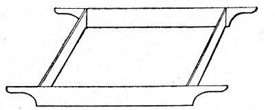 Fig. 10.—Bottomless Box for Measuring Materials in
Proportioning Concrete.
Fig. 10.—Bottomless Box for Measuring Materials in
Proportioning Concrete.
To avoid uncertainty and labor in measuring the cement, sand and stone or gravel various automatic measuring devices have been designed. A continuous mixer with automatic measuring and charging mechanism is described in Chapter XIV. Figure 11 shows the Trump automatic measuring device. It consists of a series of revolving cylinders, each opening onto a "table," which revolves with the cylinders, and of a set of fixed "knives," which, as the "tables" revolve, scrape off portions of the material discharged from each cylinder onto its "table." The illustration shows a set of two cylinders; for concrete work a third cylinder is added. The three tables are set one above the other, each with its storage cylinder, and being attached to the same spindle all revolve together. For[Pg 44] each table there is a knife with its own adjusting mechanism. These knives may be adjusted at will to vary the percentage of material scraped off.
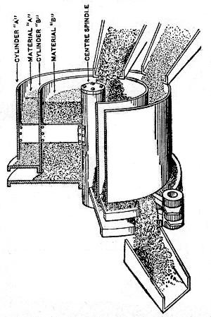 Fig. 11.—Sketch Showing Trump Automatic Measuring Device
for Materials in Proportioning Concrete.
Fig. 11.—Sketch Showing Trump Automatic Measuring Device
for Materials in Proportioning Concrete.
Automatic measuring devices are most used in connection with continuous mixers, but they may be easily adapted to batch mixers if desired. One point to be observed is that all of these automatic devices measure the cement loose and this must be allowed for in proportioning the mixture.
The making and placing of concrete by hand is divided into the following operations: (1) Loading the barrows, buckets, carts or cars used to transport the cement, sand and stone to the mixing board; (2) Transporting and dumping the material; (3) Mixing the material by turning with shovels and hoes; (4) Loading the concrete by shovels into barrows, buckets, carts or cars; (5) Transporting the concrete to place; (6) Dumping and spreading; (7) Ramming.
LOADING INTO STOCK PILES.—Stock piles should always be provided unless there is some very good reason to the contrary. They prevent stoppage of work through irregularities in the delivery of the material, and they save foreman's time in watching that the material is delivered as promptly as needed for the work immediately in hand. The location of the stock piles should be as close to the work as possible without being in the way of construction; forethought both in locating the piles and in proportioning their size to the work will save the contractor money.
The stone and sand will ordinarily be delivered in wagons or cars. If delivered in cars, effort should be made to secure delivery in flat cars when the unloading is to be done by shoveling; this is more particularly necessary for the broken stone. Stone can be shoveled from hopper bottom cars only with difficulty as compared with shoveling from flat bottom cars; the ratio is about 14 cu. yds. per day per man from hopper bottom cars as compared with 20 cu. yds. per day per man from flat bottom cars. When the cars can be unloaded through a trestle, hopper bottom cars should by all means be secured for delivering the stone. If the amount of work will justify the expense, a trestle may be built; often there is a railway embankment which can be dug away for a short distance[Pg 46] and the track carried on stringers to make a dumping place, from which the stone can be shoveled.
Sand can be dumped directly on the ground, but broken stone unless it is very small, ¾-in. or less, should always be dumped on a well made plank floor. A good floor is made of 2-in. plank, nailed to 4×6-in. mud sills, spaced 3 ft. apart, and well bedded in the ground. Loose plank laid directly on the ground settle unevenly and thus the smooth shoveling surface which is sought is not obtained; the object of the floor is to provide an even surface, along which a square pointed shovel can be pushed; it is very difficult to force such a shovel into broken stone unless it is very fine. A spading fork is a better tool than a shovel, with which to load broken stone from piles. A man can load from 18 to 20 cu. yds. of broken stone into wheelbarrows or carts in 10 hours when shoveling from a good floor, but he can load only 12 to 14 cu. yds. per day when shoveling from a pile without such a floor. It is a common thing to see stone unloaded from cars directly onto the sloping side of a railway embankment. This makes very difficult shoveling and results in a waste of stone. Stone can usually be delivered by a steel lined chute directly to a flooring located at the foot of the embankment; coarse broken stone if given a start when cast from a shovel will slide on an iron chute having a slope as flat as 3 or 4 to 1; sand will not slide on a slope of 1½ to 1. When chuting is not practicable it will pay often to shovel the stone into buckets handled by a stiff-leg derrick rather than to unload it onto the bank. Stock piles of ample storage capacity are essential when delivery is by rail, because of the uncertainty of rail shipments. When the contractor is taking the sand and stone direct from pit and quarry by wagon it is not necessary to have large stock piles.
LOADING FROM STOCK PILES.—In loading sand into wheelbarrows or carts with shovels a man will load 20 cu. yds. per 10-hour day if he is energetic and is working under a good foreman. Under opposite conditions 15 cu. yds. per man per day is all that it is safe to count on. A man shoveling from a good floor will load 20 cu. yds. of stone per 10-hour day; this is reduced to 15 cu. yds. per day if the stone is shoveled off the ground and to 12 cu. yds. per day if in addition the[Pg 47] management is poor. There are ordinarily in a cubic yard of concrete about 1 cu. yd. of stone and 0.4 cu. yd. of sand, so that the cost of loading the materials into barrows or carts, with wages at 15 cts. per hour and assuming 15 cu. yds. to be a day's work, would be:
| 1 cu. yd. stone loaded for | 10 cts. |
| 0.4 cu. yd. sand loaded for | 4 cts. |
| ——— | |
| Total | 14 cts. |
To this is to be added the cost of loading the cement. This will cost not over 2 cts. per cu. yd. of concrete; the total cost of loading concrete materials into barrows or carts, therefore, does not often exceed 16 cts. per cu. yd. of concrete.
TRANSPORTING MATERIALS TO MIXING BOARDS—Carrying the sand and stone from stock piles to mixing board in shovels should never be practiced. It takes from 100 to 150 shovelfuls of stone to make 1 cu. yd.; it, therefore, costs 50 cts. per cu. yd. to carry it 100 ft. and return empty handed, for in walking short distances the men travel very slowly—about 150 ft. per minute. It costs more to walk a half dozen paces with stone carried in shovels than to wheel it in barrows.
The most common method of transporting materials from stock piles to mixing boards is in wheelbarrows. The usual wheelbarrow load on a level plank runway is 3 bags of cement (300 lbs) or 3 cu. ft. of sand or stone. If a steep rise must be overcome to reach the mixing platform the load will be reduced to 2 bags (200 lbs.) of cement or 2 cu. ft. of sand or stone. A man wheeling a barrow travels at a rate of 200 ft. per minute, going and coming, and loses ¾ minute each trip dumping the load, fixing run planks, etc. An active man will do 20 to 25 per cent. more work than this, while a very lazy man may do 20 per cent. less. With wages at 15 cts. per hour, the cost of wheeling materials for 1 cu. yd. of concrete may be obtained by the following rule:
To a fixed cost of 4 cts. (for lost time) add 1 ct. for every 20 ft. of distance away from the stock pile if there is a steep rise in the runway, but if the runway is level, add 1 ct. for every 30 ft. distance of haul.[Pg 48]
Since loading the barrows, as given above, was 16 cts. per cu. yd., the total fixed cost is 16 + 4 = 20 cts. per cu. yd., to which is added 1 ct. for every 20 or 30 ft. haul depending on the grade of the runway.
The preceding figures assume the use of plank runways for the wheelbarrows. These should never be omitted, and the barrows wheeled over the ground. Even a hard packed earth path in dry weather is inferior to a plank runway and when the ground is soft or muddy the loss in efficiency of the men is serious. Where the runway must rise to the mixing board, give it a slope or grade seldom steeper than 1 in 8, and if possible flatter. Make a runway on a trestle at least 18 ins. wide, so that men will be in no danger of falling. See to it, also, that the planks are so well supported that they do not spring down when walked over, for a springy plank makes hard wheeling. If the planks are so long between the "horses" or "bents" used to support them, that they spring badly, it is usually a simple matter to nail a cleat across the underside of the planks and stand an upright strut underneath to support and stiffen the plank.
When two-wheeled carts of the type shown by Fig. 12 are used the runway requires two lines of planks.
Two-wheeled carts pushed by hand have been less used for handling concrete materials than for handling concrete, but for distances from 50 to 150 ft. from stock pile to mixing board such carts are probably cheaper for transporting materials than are wheelbarrows. These carts hold generally three wheelbarrow loads and they are handled by one man practically as rapidly and easily as is a wheelbarrow.
For all distances over 50 ft. from stock pile to mixing board, it is cheaper to haul materials in one-horse dump carts than it is in wheelbarrows. A cart should be loaded in 4 minutes and dumped in about 1 minute, making 5 minutes lost time each round trip. It should travel at a speed of not less than 200 ft. per minute, although it is not unusual to see variations of 15 or 20 per cent., one way or another, from this average, depending upon the management of the work. A one-horse cart will readily carry enough stone and sand to make ½ cu. yd. of concrete, if the roads are fairly hard and level; and a horse[Pg 49] can pull this load up a 10 per cent. (rise of 1 ft. in 10 ft.) planked roadway provided with cleats to give a foothold. If a horse, cart and driver can be hired for 30 cts. per hour, the cost of hauling the materials for 1 cu. yd. of concrete is given by the following rule:
To a fixed cost of 5 cts. (for lost time at both ends of haul) add 1 ct. for every 100 ft. of distance from stock pile to mixing board.
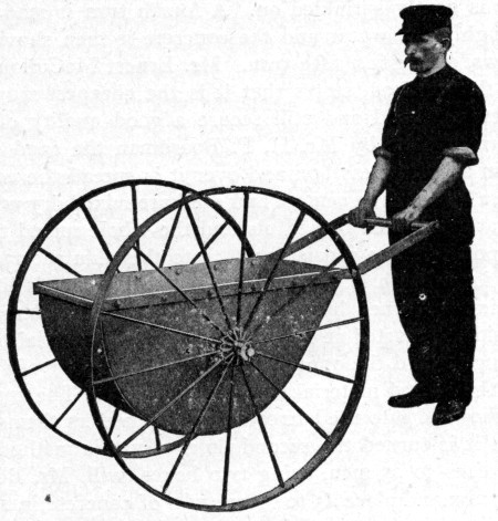 Fig. 12.—Two-Wheeled Ransome Cart for Hauling Concrete.
Where carts are used it is possible to locate the stock piles several hundred feet from the mixing boards without adding materially to the cost of the concrete. It is well, however, to have the stock piles in sight of the foreman at the mixing board, so as to insure promptness of delivery.
METHODS AND COST OF MIXING.—In mixing concrete by hand the materials are spread in superimposed layers on a mixing board and mixed together first dry and then with water by turning them with shovels or hoes. The number of turns, the relative arrangement of the layers, and the sequence of operations vary in practice with the notions of[Pg 50] the engineer controlling the work. No one mode of procedure in hand mixing can, therefore, be specified for general application; the following are representative examples of practice in hand mixing:
Measure the stone in a bottomless box and spread it until its thickness in inches equals its parts by volume. Measure the sand in a bottomless box set on the stone and spread the sand evenly over the stone layer. Place the cement on the sand and spread evenly. Turn the material twice with a square pointed shovel and then turn it a third time while water is gently sprinkled on. A fourth turn is made to mix thoroughly the water and the concrete is then shoveled into barrows, giving it a fifth turn. Mr. Ernest McCullough, who gives this method, states that it is the cheapest way to mix concrete by hand and still secure a good quality of output.
In work done by Mr. H. P. Boardman the sand is measured in a bottomless box and over it is spread the cement in an even layer. The cement and sand are mixed dry with hoes, the water is added in pailfuls and the whole mixed to a uniform porridge-like consistency. Into this thin mortar all the stone for a batch is dumped, the measuring box is lifted and the mixture turned by shovels. A pair of shovelers, one on each side, is started at one end turning the material back and working toward the opposite end. A second pair of shovelers takes the turned material and turns it again. The concrete is then shoveled into the barrows by the wheelers themselves as fast as it is turned the second time. By this method a good gang of 20 to 25 men, using two boxes, will, Mr. Boardman states, mix and place 45 to 60 cu. yds. of concrete in 10 hours, depending on the wheelbarrow travel necessary. Assuming a gang of 25 men, this is a rate of 1.8 to 2.4 cu. yds. per man per 10-hour day, concrete mixed and placed.
A method somewhat similar to the one just outlined is given by Mr. O. K. Morgan. A mixing board made of ⅞-in. matched boards nailed to 2×3-in. sills is used, with a mixing box about 8 ft. long, 4 ft. wide and 10 to 12 ins. deep. This box is set alongside the mixing board and in it the cement and sand are mixed first dry and then wet; a fairly wet mortar is made. Meanwhile the stone is spread in an even layer 6 ins.[Pg 51] thick on the mixing board and thoroughly drenched with water. The mortar from the mixing box is cast by shovels in a fairly even layer over the stone and the whole is turned two or three times with shovels, generally two turns are enough. Six men are employed; two prepare the mortar, while four get the stone in readiness, then all hands finish the operation.
The following method is given by Mr. E. Sherman Gould: Spread the sand in a thin layer on the mixing board and over it spread the cement. Mix dry with shovels, using four men, one at each corner, turning outward and then working back again. Over the dry sand and cement mixture spread the broken stone which has been previously wetted and on top of the stone apply water evenly. The water will thus percolate through the stone without splashing and evenly wet the sand and cement. Finally turn the whole, using the same number of men and the same mode of procedure as were used in dry mixing the sand and cement. Mr. Gould states that by this method the contractor should average 2 cu. yds. of mixed concrete per man per 10-hour day.
A novel method of hand mixing and an unusual record of output is described by Maj. H. M. Chittenden, U. S. A., in connection with the construction of a concrete arch bridge. The mixing was done by hand on a single board 25 ft. long and sloping slightly from one end to the other. The materials were dumped together on the upper end of the board. Sixteen men were stationed along the board, eight on each side. The first two men turned the mixture dry. Next to them stood a man who applied the water after each shovelful. The next mixers kept turning the material along and another waterman assisted in wetting it further down the board. The men at the end of the board shoveled the concrete into the carts which took it to the work. Each batch contained 18 cu. ft., or 0.644 cu. yd., and the rate of mixing was 10 cu. yds. per hour, or 6.25 cu. yds. per man per 10-hour day. The work of getting the materials properly proportioned to the mixing board is not included in this figure, but the loading of the mixed concrete is included.
It is plain from the foregoing, that specifications for hand mixing should always state the method to be followed, and[Pg 52] particularly the number of turns necessary. If these matters are not specified the contractor has to guess at the probable requirements of the engineer. The authors have known of inspectors demanding from 6 to 9 turns of the materials when specifications were ambiguous. It should also be made clear whether or not the final shoveling into the barrows or carts constitutes a turn, and whether any subsequent shoveling of the concrete into place constitutes a turn. Inspectors and foremen have frequent disputes over these questions.
Estimates of the cost of hand mixing may usually be figured upon the number of times that the materials are to be turned by shovels. A contractor is seldom required to turn the sand and cement more than three times dry and three times wet, and then turn the mortar and stone three times. A willing workman, under a good foreman, will turn over mortar at the rate of 30 cu. yds. in 10 hours, lifting each shovelful and casting it into a pile. With wages at $1.50 and six turns, this means a cost of 5 cts. per cubic yard of mortar for each turn; as there is seldom more than 0.4 cu. yd. of mortar in a cubic yard of concrete, we have a cost of 2 cts. per cubic yard of concrete for each turn that is given the mortar. So if the mortar is given six turns before the stone is added and then the stone and mortar are mixed by three turns we have: (2 cts. × 6) + (5 cts. × 3) = 12 + 15 = 27 cts. per cubic yard for mixing concrete. In pavement foundation work two turns of the mortar followed by two turns of the mortar and stone are considered sufficient. The cost of mixing per cubic yard of concrete is then (2 cts. × 2) + (5 cts. × 2) = 4 + 10 = 14 cts. per cubic yard of concrete. One specification known to the authors, requires six turns dry and three turns wet for the mortar; under such specifications the cost of mixing the mortar would be 50 per cent. higher than in the first example assumed. On the other hand, they have seen concrete mixed for street pavement foundation with only three turns before shoveling it into place. These costs of mixing apply to work done by diligent men; easy going men will make the cost 25 to 50 per cent greater.
LOADING AND HAULING MIXED CONCRETE.—Wheelbarrows and carts are employed to haul the mixed concrete[Pg 53] to the work. The loading of these with mixed concrete by shoveling costs less than the loading of the materials separately before mixing. While the weight is greater because of the added water the volume of the concrete is much less than that of the ingredients before mixing. Again the shoveling is done off a smooth board with the added advantage of having the material lubricated and, finally, the foreman is usually at this point to crowd the work. A good worker will load 12½ cu. yds. of concrete per 10-hour day, and with wages at $1.50 per day this would give a cost of 12 cts. per cu. yd. for loading.
Practically the same principles govern the transporting of concrete in barrows as govern the handling of the raw materials in them. The cost of wheeling concrete is practically the same as for wheeling the dry ingredients, so that the total cost of loading and wheeling may be estimated by the following rule:
To a fixed cost of 16 cts. for loading and lost time add 1 ct. for every 30 ft. of level haul.
Within a few years wheelbarrows have been supplanted to a considerable extent by hand carts of the general type shown by Fig. 12, which illustrates one made by the Ransome Concrete Machinery Co. The bowl of this cart has a capacity of 6 cu. ft. water measure. It is hung on a 1¼-in. steel axle; the wheels are 42 ins. in diameter with staggered spokes and 2-in. half oval tires. The top of the bowl is 29½ ins. from the ground. Owing to the large diameter of the wheels and the fact that no weight comes on the wheeler, as with a wheelbarrow, this cart is handled by one man about as rapidly and easily as is a wheelbarrow. It will be noted that the two ends of the bowl differ in shape; the handle is removable and can be attached to either end of the bowl. With the handle attached as shown the bowl can be inverted for discharging onto a pavement or floor; with the handle transferred to the opposite end the bowl is fitted for dumping into narrow beam or wall forms. The maximum load of wet concrete for a wheelbarrow is 2 cu. ft., and this is a heavy load and one that is seldom averaged—1 to 1½ cu. ft. is more nearly the general average. A cart of the above type will, therefore, carry from[Pg 54] 3 to 5 wheelbarrow loads, and on good runways, which are essential, may be pushed and dumped about as rapidly as a wheelbarrow. In succeeding pages are given records of actual work with hand carts which should be studied in this connection.
Portland cement concrete can be hauled a considerable distance in a dump cart or wagon before it begins to harden; natural cement sets too quickly to permit of its being hauled far. Portland cement does not begin to set in less than 30 minutes. On a good road, with no long, steep hills a team will haul a loaded wagon at a speed of about 200 ft. per minute; it, therefore, takes 6½ minutes to travel a quarter of a mile, 13 minutes to travel half a mile, and 26 minutes to travel a mile. Portland cement concrete can, therefore, be hauled a mile before it begins to set. The cost of hauling concrete in carts is about the same as the cost of hauling the raw materials as given in a preceding section.
When hand mixing is employed in building piers, abutments, walls, etc., the concrete often has to be hoisted as well as wheeled. A gallows frame or a mast with a pulley block at the top and a team of horses can often be used in such cases as described in Chapter XII for filling cylinder piers, or in the same chapter for constructing a bridge abutment. It is also possible often to locate the mixing board on high ground, perhaps at some little distance from the forms. If this can be done, the use of derricks may be avoided as above suggested or by building a light pole trestle from the mixing board to the forms. The concrete can then be wheeled in barrows and dumped into the forms. If the mixing board can be located on ground as high as the top of the concrete structure is to be, obviously a trestle will enable the men to wheel on a level runway. Such a trestle can be built very cheaply, especially where second-hand lumber, or lumber that can be used subsequently for forms is available. A pole trestle whose bents are made entirely of round sticks cut from the forest is a very cheap structure, if a foreman knows how to throw it together and up-end the bents after they are made. One of the authors has put up such trestles for 25 cts. per lineal foot of trestle, including all labor of cutting the round timber,[Pg 55] erecting it, and placing a plank flooring 4 ft. wide on top. The stringers and flooring plank were used later for forms, and their cost is not included. A trestle 100 ft. long can thus be built at less cost than hauling, erecting and taking down a derrick; and once the trestle is up it saves the cost of operating a derrick.
In conclusion, it should be remarked that the comparative economy for concrete work of the different methods of haulage described, does not depend wholly on the comparative transportation costs; the effect of the method of haulage on the cost of dumping and spreading costs must be considered. For example, if carts deliver the material in such form that the cost of spreading is greatly increased over what it would be were the concrete delivered in wheelbarrows, the gain made by cart haulage may be easily wiped out or even turned into loss by the extra spreading charges. These matters are considered more at length in the succeeding section.
DUMPING, SPREADING AND RAMMING.—The cost of dumping wheelbarrows and carts is included in the rules of cost already given, excepting that in some cases it is necessary to add the wages of a man at the dump who assists the cart drivers or the barrow men. Thus in dumping concrete from barrows into a deep trench or pit, it is usually advisable to dump into a galvanized iron hopper provided with an iron pipe chute. One man can readily dump all the barrows that can be filled from a concrete mixer in a day, say 150 cu. yds. At this rate of output the cost of dumping would be only 1 ct. per cu. yd., but if one man were required to dump the output of a small gang of men, say 25 cu. yds., the cost of dumping would be 6 cts. per cu. yd.
Concrete dumped through a chute requires very little work to spread it in 6-in. layers; and, in fact, concrete that can be dumped from wheelbarrows, which do not all dump in one place, can be spread very cheaply; for not more than half the pile dumped from the barrow needs to be moved, and then moved merely by pushing with a shovel. Since the spreader also rams the concrete, it is difficult to separate these two items. As nearly as the authors have been able to estimate this item of spreading "dry" concrete dumped from wheelbarrows[Pg 56] in street paving work, the cost is 5 cts. per cu. yd. If, on the other hand, nearly all the concrete must be handled by the spreaders, as in spreading concrete dumped from carts, the cost is fully double, or 10 cts. per cu. yd. And if the spreader has to walk even 3 or 4 paces to place the concrete after shoveling it up, the cost of spreading will be 15 cts. per cu. yd. For this reason it is apparent that carts are not as economical as wheelbarrows for hauling concrete up to about 200 ft., due to the added cost of spreading material delivered by carts.
The preceding discussion of spreading is based upon the assumption that the concrete is not so wet that it will run. Obviously where concrete is made of small stones and contains an excess of water, it will run so readily as to require little or no spreading.
The cost of ramming concrete depends almost entirely upon its dryness and upon the number of cubic yards delivered to the rammers. Concrete that is mixed with very little water requires long and hard ramming to flush the water to the surface. The yardage delivered to the rammers is another factor, because if only a few men are engaged in mixing they will not be able to deliver enough concrete to keep the rammers properly busy, yet the rammers by slow though continuous pounding may be keeping up an appearance of working. Then, again, it has been noticed that the slower the concrete is delivered the more particular the average inspector becomes. Concrete made "sloppy" requires no ramming at all, and very little spading. The authors have had men do very thorough ramming of moderately dry concrete for 15 cts. per cu. yd., where the rammers had no spreading to do, the material being delivered in shovels. It is rare indeed that spreading and ramming can be made to cost more than 40 cts. per cu. yd., under the most foolish inspection, yet one instance is recorded which, because of its rarity, is worth noting: Mr. Herman Conrow is the authority for the data: 1 foreman, 9 men mixing, 1 ramming, averaged 15 cu. yds. a day, or only 1½ cu. yds. per man per day, when laying wet concrete. When laying dry concrete the same gang averaged only 8 cu. yds. a day, there being 4 men ramming. With foreman at $2 and laborers at $1.50 a day, the cost was $2.12 per cu. yd. for labor[Pg 57] on the dry concrete as against $1.13 per cu. yd. for the wet concrete. Three turnings of the stone with a wet mortar effected a better mixture than four turnings with a dry mortar. The ramming of the wet concrete cost 10 cts. per cu. yd., whereas the ramming of the dry concrete cost 75 cts. per cu. yd. The authors think this is the highest cost on record for ramming. It is evident, however, that the men were under a poor foreman, for an output of only 15 cu. yds. per day with 10 men is very low for ordinary conditions. Moreover, the expensive amount of ramming indicates either poor management or the most foolish inspection requirements.
In conclusion it may be noted that if engineers specify a dry concrete and "thorough ramming," they would do well also to specify what the word "thorough" is to mean, using language that can be expressed in cents per cubic yard. It is a common thing, for example, to see a sewer trench specification in which one tamper is required for each two men shoveling the back-fill into the trench; and some such specific requirement should be made in a concrete specification if close estimates from reliable contractors are desired. Surely no engineer will claim that this is too unimportant a matter for consideration when it is known that ramming can easily be made to cost as high as 40 cts. per cu. yd., depending largely upon the whim of the inspector.
THE COST OF SUPERINTENDENCE.—This item is obviously dependent upon the yardage of concrete handled under one foreman and the daily wages of the foreman. If a foreman receives $3 a day and is bossing a job where only 12 cu. yds. are placed daily, we have a cost of 25 cts. per cu. yd. for superintendence. If the same foreman is handling a gang of 20 men whose output is 50 cu. yds., the superintendence item is only 6 cts. per cu. yd. If the same foreman is handling a concrete-mixing plant having a daily output of 150 cu. yds., the cost of superintendence is but 2 cts. per cu. yd. These elementary examples have been given simply because figures are more impressive than generalities, and because it is so common a sight to see money wasted by running too small a gang of men under one foreman.
Of all classes of contract work, none is more readily estimated day by day than concrete work, not only because it is[Pg 58] usually built in regular shapes whose volumes are easily ascertained at the end of each day, but because a record of the bags, or barrels, or batches gives a ready method of computing the output of each gang. For this reason small gangs of concrete workers need no foreman at all, provided one of the workers is given command and required to keep tally of the batches. If the efficiency of a gang of 6 men were to fall off, say, 15 per cent., by virtue of having no regular non-working foreman in charge, the loss would be only $1.35 a day—a loss that would be more than counterbalanced by the saving of a foreman's wages. Indeed, the efficiency of a gang of 6 men would have to fall off 25 per cent., or more, before it would pay to put a foreman in charge. In many cases the efficiency will not fall off at all, provided the gang knows that its daily progress is being recorded, and that prompt discharge will follow laziness. Indeed, one of the authors has more than once had the efficiency increased by leaving a small gang to themselves in command of one of the workers who was required to punch a hole in a card for every batch.
To reduce the cost of superintendence there is no surer method than to work two gangs of 18 to 20 men, side by side, each gang under a separate foreman who is striving to make a better showing than his competitor. This is done with marked advantage in street paving, and could be done elsewhere oftener than it is.
In addition to the cost of a foreman in direct charge of the laborers, there is always a percentage of the cost of general superintendence and office expenses to be added. In some cases a general superintendent is put in charge of one or two foremen; and, if he is a high-salaried man, the cost of superintendence becomes a very appreciable item.
SUMMARY OF COSTS.—Having thus analyzed the costs of making and placing concrete, we can understand why it is that printed records of costs vary so greatly. Moreover, we are enabled to estimate the labor cost with far more accuracy than we can guess it; for by studying the requirements of the specifications, and the local conditions governing the placing of stock piles, mixing boards, etc., we can estimate each item with considerable accuracy. The purpose, however, has not been solely to show how to predict the labor cost, but also to[Pg 59] indicate to contractors and their foremen some of the many possibilities of reducing the cost of work once the contract has been secured. An analysis of costs, such as above given, is the most effective way of discovering unnecessary "leaks," and of opening one's eyes to the possibilities of effecting economies in any given case.
To indicate the method of summarizing the costs of making concrete by hand, let us assume that the concrete is to be put into a deep foundation requiring wheeling a distance of 30 ft.; that the stock piles are on plank 60 ft. distant from the mixing board; that the specifications call for 6 turns of gravel concrete thoroughly rammed in 6-in. layers; and that a good sized gang of, say, 16 men (at $1.50 a day each), is to work under a foreman receiving $2.70 a day. We then have the following summary by applying the rules already given:
| Per cu. yd. concrete. | |
| Loading sand, stone and cement | $ .17 |
| Wheeling 60 ft. in barrows (4 + 2 cts.) | .06 |
| Mixing concrete, 6 turns at 5 cts. | .30 |
| Wheeling 30 ft. (4 + 1 ct.) | .05 |
| Dumping barrows (1 man helping barrowman) | .05 |
| Spreading and heavy ramming | .15 |
| ——— | |
| Total cost of labor | $.90 |
| Foreman, at $2.70 a day | .10 |
| ——— | |
| Grand total | $1.00 |
To estimate the daily output of this gang of 16 laborers proceed thus: Divide the daily wages of all the 16 men, expressed in cents, by the labor cost of the concrete in cents, the quotient will be the cubic yards output of the gang. Thus, 2,400 ÷ 90 is 27 cu. yds., in this case.
In street paving work where no man is needed to help dump the wheelbarrows, and where it is usually possible to shovel concrete direct from the mixing board into place, and where half as much ramming as above assumed is usually satisfactory, we see that the last four labor items instead of amounting to 12 + 5 + 5 + 15, or 37 cts., amount only to one-half of[Pg 60] the last item, one-half of 15 cts., or 7½ cts. This makes the total labor cost only 60 cts. instead of 90 cts. If we divide 2,400 cts. (the total day's wages of 16 men) by 60 cts. (the labor cost per cu. yd.), we have 40, which is the cubic yards output of the 16 men. This greater output of the 16 men reduces the cost of superintendence to 7 cts. per cu. yd.
The making and placing of concrete is virtually a manufacturing process. This process as performed by manual labor is discussed in the preceding chapter; it will be discussed here as it is performed by machinery. The objects sought in using machinery for making and placing concrete are: (1) The securing of a more perfectly mixed and uniform concrete, and (2) the securing of a cheaper cost of concrete in place. As in every other manufacturing process both objects cannot be obtained to the highest degree without co-ordinate and universal efficiency throughout in plant and methods. For example, the substitution of machine mixing for hand mixing will not alone ensure cheaper concrete. If all materials are delivered to the machine in wheelbarrows and if the concrete is conveyed away in wheelbarrows, the cost of making concrete even with machine mixers is high. On the other hand, where the materials are fed from bins by gravity into the mixer and when the mixed concrete is hauled away in cars, the cost of making the concrete may be very low. Making and placing concrete by machinery involves not one but several mechanical operations working in conjunction—in a word, a concrete making plant is required.
The mechanical equipment of a concrete making plant has four duties to perform. (1) It has to transport the raw materials from the cars or boats or pits and place them in the stock piles or storage bins; (2) it has to take the raw materials from stock and charge them to the mixer; (3) it has to mix the raw materials into concrete and discharge the mixture into transportable vehicles; and (4) it has to transport these vehicles from the mixer to the work and discharge them. As all these operations are interrelated component parts of one great[Pg 62] process, it is plain why one operation cannot lag without causing all the other operations to slow up.
The mechanical devices which may be used for each of these operations are various, and they may be combined in various ways to make the complete train of machinery necessary to the complete process. In this chapter we shall describe the character and qualities of each type of devices separately. The practicable ways of combining them to form a complete concrete making plant are best illustrated by descriptions and records of work of actual plants, and such descriptions and records for each class of structure considered in this book are given in the following chapters and may be found by consulting the index. In describing the various machines and devices we have made one classification for those used in handling raw materials and mixed concrete, for the reason that nearly all of them are suitable for either purpose.
UNLOADING WITH GRAB BUCKETS.—The orange-peel or clam-shell bucket is an excellent device for unloading sand or stone from cars or barges. The cost of unloading, including cleaning up the portions not reached by the bucket, is not more than from 2 to 5 cts. per cu. yd. A grab bucket of either of these types can be applied to any derrick. In unloading broken stone from barges at Ossining, N. Y., a Hayward clam-shell on a stiff-leg derrick unloaded 100 cu. yds. of broken stone per day from barge into wagons, with one engineman and one helper. In addition to the bucket work there was 24 hours' labor cleaning on each 500-cu. yd. barge load. The labor cost of unloading a 500-cu. yd. barge was as follows:
| Per Cu. Yd. | |
| One engineman, at $2.50 | 2.5 cts. |
| One helper, at $1.50 | 1.5 cts. |
| Labor cleaning, at $1.50 | 0.7 cts. |
| ———— | |
| Total cost per cubic yard | 4.7 cts. |
INCLINES.—Inclines to reach the tops of mixer and storage bins and the level of concrete work can be operated on about the following grades: For teams hauling wagons or cars, 2 per cent. maximum grade. A single heavy team will haul a 5-cu. yd. car, with ordinary bearings, weighing 2½ tons empty and 12 tons loaded, with ease on a 1½ per cent. grade,[Pg 63] and with some difficulty on a 2 per cent. grade. A locomotive will handle cars on a grade of from 4 to 5 per cent. For team haulage 20-lb. rails may be used, and for locomotives 30-lb. rails. Grades steeper than about 5 per cent. require cable haulage.
TRESTLE AND CAR PLANTS.—Trestle and car plants for handling both concrete materials and mixed concrete have a wide range of application and numerous examples of such plants are described in succeeding chapters, and are noted in the index at the end of the book. The following estimates of the cost of a trestle and car plant are given by Mr. Wm. G. Fargo. The work is assumed to cover an area of 100×200 ft. and to have three-fourths of its bulk below the economical elevation of the mixer, which stands within 50 ft. of the near side of the work. If the work is under 3,000 cu. yds. in bulk and there is a reasonable time limit for completion one mixer of 200 cu. yds. capacity per 10-hour day is assumed to be sufficient. The items of car plant cost will be about as follows:
| 150 ft. trestle, at $1.50 | $225 |
| 5 split switches with spring bridles, at $18 | 90 |
| 2 iron turntables, at $30 | 60 |
| 3⅔ cu. yd. steel cars with roller bearings | 190 |
| ——— | |
| Total | $565 |
The trestle assumed is double 24-in. gage track, 6 ft. on centers; stringers 6×8 ins.×22 to 24 ft.; ties 2×6 ins., 2½ ft. on centers; running boards 2×12 ins. for each track, and 12-lb. rails; trestle legs, average length 30 ft., of green poles at 5 cts. per foot. This outfit with repairs and renewals amounting to 10 per cent., is considered good for five season's work and the timber work for several jobs if not too far apart. The yearly rental on the basis of five seasons' work would be $124.30, or $1 per working day for a season of five months. Three cars delivering ½ cu. yd. batches can deliver 200 cu. yds. of concrete, an average of 100 ft. from the mixer in 10 hours. Five men, including a man tending switches and turntable and one man to help dump, can operate the plant. With wages at $1.75 per day the labor cost of handling 200 cu. yds. of concrete would be 4⅛cts. per cu. yd.[Pg 64]
CABLEWAYS.—Cableways arranged to span the work and if the area is wide to travel across the work at right angles to the span will handle concrete, concrete materials, forms, steel and supplies with great economy. They are particularly suitable for bridge and dam work, filter and reservoir work, building foundations and low buildings. The arrangement of a cableway plant for bridge work is described in Chapter XVII. A cableway of 800 ft. clear span on fixed towers 45 ft. high will cost complete from $4,500 to $5,000, and will handle 200 cu. yds. of concrete per 10-hour day. To put the cableway on traveling towers will cost about $1,000 more. In constructing the Pittsburg filtration work four traveling cableways from 250 to 600 ft. span were used. The towers were from 50 to 60 ft. in height and each traveled on a 5-rail track. The cableways were self-propelling. With conditions favorable each cableway delivered 300 cu. yds. of concrete per day. A cableway plant for heavy fortification work is described in Chapter XI.
BELT CONVEYORS.—Belt conveyors may be used successfully for handling both concrete materials and mixed concrete. For handling wet concrete the slope must be quite flat, and the belt must be provided with some means of cleaning off the sticky mortar paste. In several cases rotating brushes stationed at the end of the belt, where it turns over the tail pulley, have worked successfully; these brushes sweep the belt clean. Except for the cleaning device the ordinary arrangement of belt conveyor for dry materials serves for concrete.
In constructing a large gas works at Astoria, Long Island, near New York city, belt conveyors were used to handle both the sand, gravel and cement bags and the mixed concrete. The belt for handling sand and gravel is shown by Fig. 13. A derrick operating a clam-shell unloaded the sand and gravel into a small hopper, discharging into dump cars operated by a "dinky" up an incline, passing over sand and gravel storage bins. A 20-in. belt conveyor ran horizontally 105 ft. under the bins, then up an incline of 3.4 ft. in 125 ft. to feeding hoppers over the mixers. This conveyor received alternately sand and gravel by chute from the storage bins and bags of cement loaded by hand, and carried them to the feeding bins and mixer platform. The speed of the belt was 350 ft. per minute,[Pg 65] and it required 6 h.p. to operate it when carrying 100 tons per hour. The mixing was done in two Smith mixers, which turned out 70 cu. yds. or 35 cu. yds. each per hour. The mixed concrete was delivered onto a 50-ft. 24-in. belt conveyor traveling at a speed of 400 ft. per minute and dumping through a chute into cars. Only 1 h.p. was required to run the concrete conveyor. A rotating brush was used to keep the belt clean at the dumping end. It will be noted that only a small amount of power is required for operation.
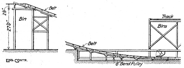 Fig. 13.—Belt Conveyor Transporting Sand and Gravel.
CHUTES.—Chutes of wood or iron are among the simplest and most efficient means of moving the cement, sand and stone and the mixed concrete when the ground levels permit such devices.
Bags of cement if given a start in casting will slide down a steel or very smooth wooden chute with a slope of 1 ft. in 5 or 6 ft. A wooden trough 12 ins. deep and 24 ins. wide with boards dressed on the inside may be used. When the inclination is steep and the fall is great, some device is necessary to diminish the velocity of descent; the following is an example of such a device which was successfully employed in a chute of the above dimensions, 400 ft. long and having a drop of 110 ft. This chute had a maximum inclination of 45° and its lower end curved to a horizontal tangent, running into the storehouse. Near the bottom of the chute a horizontal strip was nailed across the upper edges and to it was nailed the upper end of a 20 ft., 1×12-in. board, the lower end of which rested on the bottom of the chute. Several pieces of timber spiked to the upper side loaded the lower end of this board.[Pg 66] The cement bag in descending wedged itself into the angle between the chute and the board and lifted the latter, the spring of the board and the weight at the lower end offering enough resistance to cut down the velocity. After the chute had been in use for some time and had worn smooth it was found necessary to add two more brakes to check the bags.
Broken stone will slide down a steel or steel lined chute with a slope of 1 in 3 or 4 ft. if given a start in casting. Damp sand will not slide down a chute with a slope of 1½ in 1.
A wet cement grout will flow down a smooth plank chute, with a slope of 1 in 4 ft., and wet concrete will move on the same slope; comparatively dry concrete requires a slope of nearly 1 in 1, or 45°, to secure free movement. Mr. W. J. Douglas gives the following examples of conveying concrete by chute, prefaced by the statement that his experience indicates that concrete can thus be conveyed considerable distances without material injury if proper precautions are taken.
In the first case a semi-circular steel trough about 2 ft. wide and 1 ft. deep and 15 ft. long set on a slope of 45° was used. A lift gate of sheet steel was set in the chute about 2 ft. from the upper end. The concrete was allowed to accumulate behind this gate until a wheelbarrow load was had, when the batch was let loose by lifting the gate and was discharged into barrows at the bottom. In another case a vertical chute 15 ft. long, consisting of a 15-in. square box with a canvas end, was used. The concrete was dumped into the chute in batches of about 8 cu. ft.; two men at the bottom "cut down" the pile with hoes to keep it from coning and causing separation of the stone. In a third case a continuous mixer fed into a sheet iron lined rectangular chute about 2½ ft. wide and 1 ft. deep, with a vertical drop of 60 ft. on a slope of 1 in 1, or 45°. A gate was fixed in the chute 2 ft. from the top and at the bottom the chute fed into a pyramidal hopper 3 ft. square at the top, 1 ft. square at the bottom and 4½ ft. deep. This hopper was provided with a bottom gate and was set on legs so that its top was about 10 ft. above ground. As the concrete filled in the hopper was raised and the chute cut off. The hopper was kept full all the time and was discharged by bottom gate and spout into wheelbarrows. In a fourth case the apparatus shown by the sketch, Fig. 14, was used. The continuous[Pg 67] mixer discharged onto an 18-in. rubber conveyor belt on conical rollers and 18 ft. long. The inner end of the conveyor frame was carried on the ground at the edge of the pit and the outer end was supported by ropes from the top of a gallows frame standing on the pit bottom. The belt discharged over end into a vertical steel chute 12 ins. in diameter and 8 ft. long; this chute was fastened to the conveyor frame. Encircling and overlapping the 12-in. chute was a second slightly larger chute suspended by means of two ropes from the gallows frame. The bottom of this second chute was kept about 6 ins. below the top edges of a pyramidal hopper like the one described above. In operation the chutes and the hopper were kept filled with concrete so that the only drop of the concrete was 3 ft. from the conveyor belt into the topmost chute.
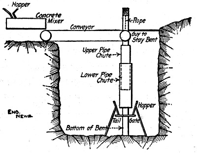 Fig. 14.—Belt Conveyor and Chute for Handling Concrete.
Concrete may be handled in long flat chutes by stationing men along the chute with shovels which they work like paddles to keep the mixture moving. In one case concrete was so handled in a chute 200 ft. long having a slope of 1 in 10 ft. The chute was a V-shaped trough made of 1×12-in. boards in sections 16 ft. long. The men paddling were stationed 10 ft. apart, so that with wages at $1.50 per day the cost would be 1½ cts. per cu. yd. for every 10 ft. the concrete was conveyed. In connection with this particular work we are informed that a Eureka continuous mixer was used. The gravel was dumped near the mixer and a team hitched to a drag scraper delivered the gravel alongside the mixer. Four men shoveled the gravel into the measuring hopper, but only two men worked at a time, shoveling for a period of 15 minutes[Pg 68] and then resting for a corresponding period while the other two men worked. In this manner the four men shoveled enough gravel to make 100 cu. yds. of concrete per day. A fifth man opened the cement bags and kept the cement hopper filled.
METHODS OF CHARGING MIXERS.—By charging is meant the process of delivering raw materials from stock into the mixer. Several methods are practiced and will be considered in the following order: (1) By gravity from overhead bins; (2) by wheelbarrow or hand cart (a) to charging chute and (b) to elevating charging hoppers; (3) by charging cars operated by cable or other means; (4) by shoveling directly into mixer; (5) by derricks or other hoists.
Charging by Gravity from Overhead Bins.—Chuting the sand and stone from overhead bins to the charging hopper is a simple, rapid and economical method of charging mixers. The bottoms of the bins should always be high enough above the charging floor to give ample head room for men to move about erect, and the length of chute may be anything reasonable more than this that conditions such as the side hill delivery of material may necessitate. When the mixer is located to one side of the bins the slope of the chute will have to be watched. Broken stone or pebbles will move on a comparatively flat slope but sand, particularly if damp, requires a steep chute. The measuring hopper is best kept entirely independent of the mixer so that it can be filled with a new charge while the mixer is turning and discharging the preceding batch. One man can attend the sand and cement chutes if they be conveniently arranged, and one man can open and empty the cement bags if they be stacked close at hand. A third man will level off the sand and stone in the measuring hopper and help in the chuting. A gang of this size will easily measure up a charge every 2 minutes when no delays occur.
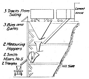 Fig. 15.—Side Hill Mixing Plant.
A number of plants charging by gravity from overhead bins are described in succeeding chapters and are referenced in the index. As a general example a side hill plant of conventional construction is shown by Fig. 15. The trestle work was made of 12×12-in. timbers and was approximately 40 ft. in height. Three tracks occupy the top platform. Under each track was[Pg 69] a material bin; one on each side for gravel and a middle bin for sand. The sand bin was divided by a partition into two compartments. These bins discharged into two measuring hoppers one gravel bin and one compartment of the sand bin into each hopper. Two cement chutes from the top platform provided for the delivery of the cement to the mixers, either directly from cars or from the cement storage house. The mixing was done in two Smith No. 5 mixers, one under each measuring hopper, and these mixers discharged by chutes into buckets on flat cars. Thus the concrete materials brought directly from a siding in car load lots to the top of the platform were handled entirely by gravity to the cars delivering the mixed concrete to the work. The gang operating the mixing plant, with the wages paid, was composed as follows: 1 foreman and engineer at $3 per day, 1 fireman at $2 per day and 15 laborers at $1.50 per day. With this gang the two mixers turned out 400 cu. yds. of concrete per day and, frequently, 800 cu. yds. in 24 hours. Taking these figures the labor cost from raw materials in cars on the platform to mixed concrete in cars on the delivery track was as follows:
| 1 foreman and engineer at $3 | $ 3.00 |
| 1 fireman at $2 | 2.00 |
| 15 laborers at $1.50 | 22.50 |
| —— | |
| Total labor | $27.50 |
Assuming 400 cu. yds. output, this gives a cost of $27.50 ÷ 400 = 6.875 cts. per cu. yd.[Pg 70]
Charging with Wheelbarrows.—The economics of wheelbarrow haulage are discussed in some detail in Chapter III. For machine mixer work the problem of loading, transporting and dumping is complicated by the greater rapidity with which the mixing is done and by the necessity, usually, of using inclines to reach the charging hopper level. The incline cuts down the output of the wheelers or in other words makes necessary a larger gang to handle the same amount of material. Conditions being the same, the height of the charging chute of the mixer determines the height of incline and the size of the charging gang, so that a mixer with a high charging level costs more to charge with wheelbarrows than does one with a low charging level. Exact figures of the increased cost of a few feet extra elevation of the wheelbarrow incline are not available, but some idea may be had from a brief calculation. The materials for a cubic yard of concrete will weigh about 3,700 lbs., so that to raise the materials for 100 cu. yds. of concrete, including weight of barrows, 1 ft. calls for about 400,000 ft. lbs. of work. A man will do about 800,000 ft. lbs. of useful work in a day, so that each foot of additional height of incline means an additional half-day's work for one man.
Wheeling to elevating charging hoppers obviates the use of inclines. Figure 19 shows a mixer equipped with such a hopper, and the arrangement provided for other makes of mixer is much similar. When the hopper is lowered ready to receive its load its top edge over which the wheelbarrows are dumped is from 12 to 14 ins. above ground level. The wheeling is all done on the level. The elevating bucket is operated by the mixer engine and is usually detachable. Where mixers have to be moved frequently, requiring the erection and moving of the incline each time, an elevating charging hopper is particularly useful; it can be hoisted clear of the ground and moved with the mixer, so that it is ready to use the moment that the mixer is set at its new station.
While the ordinary wheelbarrow is generally used for charging, better work can be done under some conditions by using special charging barrows of larger capacity and dumping from the end and ahead of the wheel. Two forms of charging barrow are shown by Figs. 16 and 17. The Acme[Pg 71] barrow will hold 4 cu. ft. and the Ransome barrow is made in 3 to 6 cu. ft. capacities. Where inclines are necessary these barrows can often be hauled up the incline by power. A sprocket chain in the plane of the incline and operated by the mixer engine is an excellent arrangement. A prong riveted to the rear face of the barrow and projecting downward is "caught into" the chain, which pulls the barrow to the top, the man following to dump and return for another load.
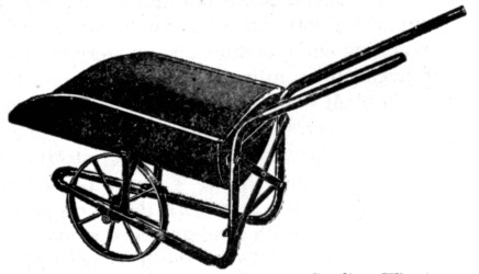 Fig. 16.—Forward Dump Charging Barrow, Sterling
Wheelbarrow Co.
Fig. 16.—Forward Dump Charging Barrow, Sterling
Wheelbarrow Co.
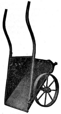 Fig. 17.—Forward Dump Charging Barrow, Ransome Concrete
Machinery Co.
Fig. 17.—Forward Dump Charging Barrow, Ransome Concrete
Machinery Co.
Charging with Cars.—Cars moved by cable, team or hand are a particularly economic charging device when the mixer is located a little distance from the stock piles or bins. Either separate cars for cement, sand and stone, each holding the proper amount of its material for a batch, can be used, or a single car containing enough of all three materials for a batch. The last arrangement is ordinarily more economical in time and labor, and in plant required. In either case the car serves as the measuring hopper, there being no further proportioning of the materials after they have been loaded into the car, and it must be arranged for measuring. Usually all that is necessary, where one car is used, is to mark the levels on the sides to which it is to be filled with sand and then stone; the car is run to the sand stock and filled to the level marked for sand and then to the stone stock and filled to the level marked for stone. The cement may be added to the charge either before or after it is run to the mixer as convenience in storing the cement stock dictates. Instead of having marks to show the proper proportions of sand and stone, the car is sometimes divided into two compartments, one for each material and each holding the proper proportion of its material when level full. This arrangement makes proper proportioning somewhat more certain, since the men charging the car cannot over-run the marks. In case separate cars are used for each material, they are simply filled level full or to mark, and dumped in succession into the feeding hopper. Trestle and car plant construction and costs are given in a preceding section.
Charging by Shoveling.—Charging by shoveling directly into the mixer is seldom practiced except in street work with continuous mixers or in charging gravity mixers of the trough type. Shoveling is not an economic method of handling materials where the work involves carrying in shovels, and it is only in a few classes of concrete work or in isolated, exceptional cases that charging with shovels does not involve carrying. The amount of material that men will load with shovels is given in Chapter III, and the reader who wishes a full discussion of the subject is referred to Gillette and Hauer, "Earth Excavation and Embankments; Methods and Cost."[Pg 73]
In charging continuous mixers with shovels the usual practice for mixers without automatic feed devices is to work from a continuous stock pile of sand, stone and cement spread in layers in the proper proportions. The shoveling is done in such a manner that each shovelful contains a mixture of cement, sand and stone, and so that the rate of delivery to the mixer is as uniform as possible. In charging mixers having automatic feed devices the sand and stone are simply shoveled into the sand and stone hoppers, whence they are fed automatically to the mixer. In charging gravity mixers by shoveling the method is essentially the same; the cement, sand and stone properly proportioned are spread in layers on the shoveling board at the head of the mixer and the mixture then shoveled into the mixer. In both of these cases mixing is performed to a certain extent by the shoveling, and in both the provision of the combination stock pile from which the men work involves labor which comes within the meaning of the term charging as we have used it here. Examples of street work in which the mixers were charged by shoveling are given in Chapter XIV.
Charging with Derricks.—When the stock piles are located close to the mixer and the plant is fixed or is not frequently moved derricks can be used economically for charging, particularly if the mixer be elevated so that inclines become expensive. The following mode of operation will be found to work well: Set the derrick so that its boom "covers" the sand and stone piles and the mixer, and provide it with three buckets so that there will always be one bucket at the stone pile and another at the sand pile while the third is being handled. The derrick swinging from the mixer, where it has discharged a bucket, drops the empty bucket at the stone pile and picks up the bucket standing there, which has received its proper charge of stone, and swings it to the sand pile and drops it to get its charge of sand. Here it picks up the bucket standing at the sand pile and which has its charges of both stone and sand, and swings it to the mixer. By this arrangement the work of the derrick and of the men filling the buckets is practically continuous. The buckets can be provided with marks on the inside to show the proper points to which to fill the stone and the sand or a partition may be[Pg 74] riveted in making a compartment for sand and another for stone. A special charging-bucket that is arranged with a wheel and detachable handles which permit it to be handled like a wheelbarrow is shown by Fig. 18. This bucket can be used to advantage where the stock piles are too far from the mixer for the derrick to reach both, the bucket being loaded and wheeled to within reach of the derrick.
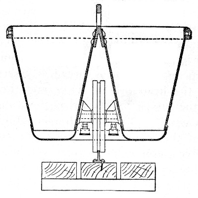 Fig. 18.—Charging Bucket With Wheel and Detachable
Handle.
Fig. 18.—Charging Bucket With Wheel and Detachable
Handle.
TYPES OF MIXERS.—There are two types of concrete mixing machines or concrete mixers as they are more commonly called: (1) Batch mixers and (2) continuous mixers. In mixers of the first type a charge of cement, sand, aggregate and water is put into the machine which mixes and discharges the batch before taking in another charge; charging, mixing and discharging is done in batches. In continuous mixers the cement sand, stone and water are charged into the machine in a continuous stream and the mixed concrete is discharged in another continuous stream. While all concrete mixers are either batch or continuous mixers, it is common practice because of their distinctive character to separate gravity mixers, whether batch or continuous, into a third type. In gravity mixers the concrete materials are made to mingle by falling through specially constructed troughs, or tubes, or hoppers. We shall describe mixers in this chapter as (1) batch mixers, (2) continuous mixers, and (3) gravity mixers. No attempt will be made, however, to describe all or even all the leading mixers of each type; a representative mixer or[Pg 75] two of each type will be described, enough to give an indication of the range of practice, and the reader referred to manufacturers' literature for further information.
Batch Mixers.—Batch mixers are made in two principal forms which may be designated as tilting and non-tilting mixers. In the first form the mixer drum is tilted as one would tilt a bucket of water to discharge the batch. In non-tilting mixers the mixer drum remains in one position, the batch being discharged by special mechanism which dips it out a portion at a time. In both forms the charge is put into the mixer as a unit and kept confined as a unit during the time of mixing, which may be any period wished by the operator.
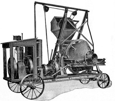 Fig. 19.—Chicago Improved Cube Concrete Mixer with
Elevating Charging Hopper.
Fig. 19.—Chicago Improved Cube Concrete Mixer with
Elevating Charging Hopper.
Chicago Improved Cube Tilting Mixer.—Figure 19 shows the improved cube mixer made by the Municipal Engineering & Contracting Co., Chicago, Ill. The drum consists of a cubical box with rounded corners and edges. This box has hollow gudgeons at two diagonally opposite corners and these gudgeons are open as shown to provide for charging[Pg 76] and discharging. The box is rotated by gears meshing with a circumferential rack midway between gudgeons and another set of gears operate to tilt the mixer. The inside of the box is smooth, there being no deflectors, as its shape is such as to fold the batch repeatedly and thus accomplish the mixing.
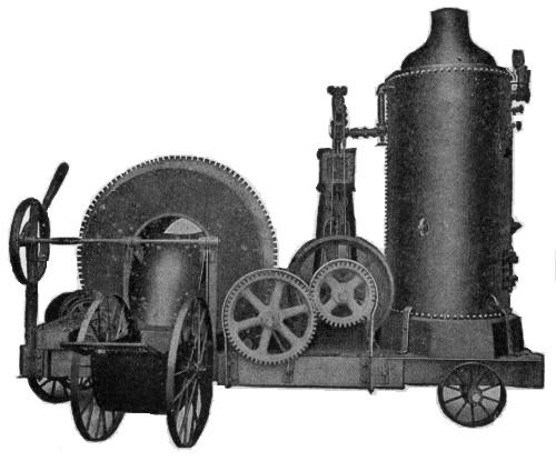 Fig. 20.—Ransome Concrete Mixer.
Ransome Non-Tilting Mixer.—Figure 20 shows a representative non-tilting mixer made by the Ransome Concrete Machinery Co., Dunellen, N. J. It consists of a cylindrical drum riding on rollers and rotated by a train of gears meshing with circumferential racks on the drum. The drum has a circular opening at each end; a charging chute enters one opening and a tilting discharge chute may be thrown into or out of the opposite opening. The cylindrical shell of the drum is provided inside with steel plate deflectors, which plow through and pick up and drop the concrete mixture as the drum revolves. The shape and arrangement of the deflectors are such that the batch is shifted back and forth axially across[Pg 77] the mixer. To discharge the batch the discharge chute is tilted so that its end projects into the mixer, in which position the material picked up by the deflectors drops back onto the chute and runs out. The discharge chute being independent of the mixing drum it can be thrown into and out of discharge position at will without stopping the rotation of the drum, and so can discharge any part or all of the batch at once. The top edge of the charging chute ranges from 30½ to 38 ins. in height above the top of the frame, varying with the size of the mixer.
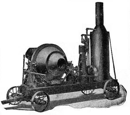 Fig. 21.—Smith Concrete Mixer.
Smith Tilting Mixer.—Figure 21 shows a tilting mixer, known as the Smith mixer, made by the Contractors' Supply & Equipment Co., Chicago, Ill. The drum consists of two truncated cones with their large ends fastened together and their small ends open for receiving the charge and discharge of the batch. The drum is operated by a train of gears meshing into a rack at mid-length where the cones join. In addition there is another set of gears which tilt the drum to make the concrete flow out of the discharge end. The inside of the drum is provided with steel plate deflectors, which plow through and pick and drop the concrete mixture shifting it back and forth axially in the process.[Pg 78]
Continuous Mixers.—Continuous mixers are those in which the cement, sand and stone are fed to the charging hopper in a continuous stream and the mixed concrete is discharged in another continuous stream. They are built in two principal forms. In one form the cement, sand and stone properly proportioned are shoveled directly into the mixing drum. In the other form these materials are dumped into separate charging hoppers and are automatically fed into the mixing drum in any relative proportions desired. One form of continuous mixer with automatic feed is described in the succeeding paragraph and another form is described in Chapter XIV. The continuous mixer without automatic feed consists simply of a trough with a rotating paddle shaft and its driving mechanism. The charging, the mixing and the discharging are done in what is virtually a succession of very small batches.
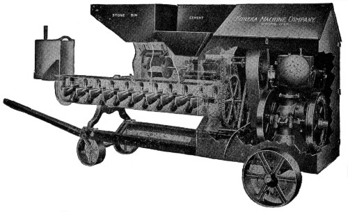 Fig. 22.—Eureka Automatic Feed Continuous Mixer.
Eureka Automatic Feed Mixer.—Figure 22 shows the construction of the continuous mixer built by the Eureka Machine Co., Lansing, Mich. The cement bin and feeder is the small one in the foreground. There is a pocketed cylinder revolving between concave plates, opening into the hopper above, from which the pockets in the feeder are filled, and discharging[Pg 79] directly into the mixing trough below. Back of this is shown the feeder for sand or gravel up to 2-in. screen size. This is a pocketed cylinder similar to that used in the cement feeder, except that it is larger, and instead of being provided on the discharge side with a concave plate, is surmounted by a roller, held by springs. This serves to cut off the excessive flow of material, but provides sufficient flexibility to allow the rough coarse material to be fed through the machine without its catching. The feeder for crushed stone is a similar construction on larger lines, to handle material up to 3-in. size. These several feeders can be set to give any desired mixture. On any material fit to be used in concrete, they will measure with an error of less than 5 per cent., an agitator being provided in the sand bin to prevent damp sand from bridging over the feeder, and preventing its action. The mixer consists of a trough, with a square shaft, on which are mounted 37 mixing paddles, which are slipped on in rotation, so as to form practically a continuous conveyor, but as each paddle is distinct, and is shaped like the mold board of a plow, the material, as it passes from one to the next, is turned over and stirred. Water is sprayed into the mass at the center of the trough. The result is a dry mix, followed by a wet mix. The mixing trough is made of heavy gage steel, well reinforced, and practically indestructible. To take care of the discharge of material while changing wheelbarrows, a hood is provided on the discharge end of the machine, which can be lowered, and will hold about a wheelbarrow load.
Gravity Mixers.—Gravity mixers are constructed in two general forms. The first form is a trough whose bottom or sides or both are provided with pegs, deflectors or other devices for giving the material a zig-zag motion as it flows down the trough. The second form consists of a series of hoppers set one above the other so that the batch is spilled from one into the next and is thus mixed.
The chief advantage claimed for gravity mixers is that no power is required to operate them. This is obviously so only in the sense that gravity mixers have no power-operated moving mechanism, and the fact should not be overestimated. The cost of power used in the actual performance of mixing is a very small item. The distance between feed and discharge[Pg 80] levels is always greater for gravity mixers than for machine mixers, and the power required to raise the concrete materials the excess height may easily be greater than the power required to operate a machine mixer. On the other hand the simplicity of the gravity mixer insures low maintenance costs.
Gilbreth Trough Mixer.—Figure 23 shows the construction of one of the best known makes of gravity mixers of the trough form. In operation the cement, sand and stone in the proper proportions are spread in superimposed layers on a shoveling board at hopper level and are then shoveled as evenly as possible into the hopper. From the hopper the materials flow down the trough, receiving the water about half way down, and are mixed by being cut and turned by the pins and deflectors. The trough of the mixer is about 10 ft. long.
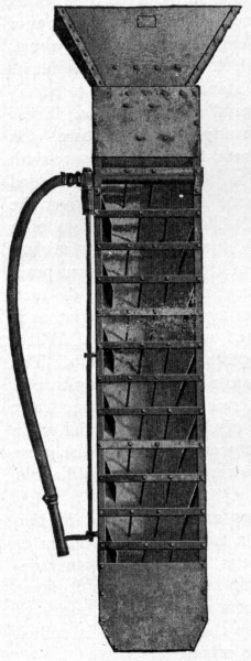 Fig. 23.—Gilbreth Gravity Mixer, Trough Form.
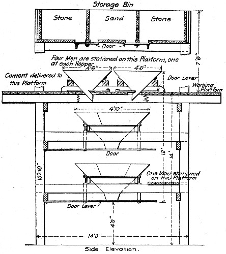 Fig. 24.—Hains Gravity Mixer, Fixed Hopper Form.
Hains Gravity Mixer.—The form of gravity mixer made by the Hains Concrete Mixer Co., Washington, D. C., is shown by Figs. 24 and 25. The charge passes through the hoppers in succession. Considering first the stationary plant, shown by Fig. 24, the four hoppers at the top have a combined capacity of one of the lower hoppers. Each top hopper is charged with cement, sand and stone in the order named and in the proper proportions. Water is then dashed over the tops of the filled hoppers and they are dumped simultaneously into the hopper[Pg 81] next below. This hopper is then discharged into the next and so on to the bottom. Meanwhile the four top hoppers have been charged with materials for another batch. It will be observed that (1) the concrete is mixed in separate batches and (2) the ingredients making a batch are accurately proportioned and begin to be mixed for the whole batch at once. The best arrangement is to have the top of the hopper tower carry sand and stone bins which chute directly into the top hoppers. In the telescopic mixer shown by Fig. 25 the purpose has been to provide a mixer which, hung from a derrick or cableway, will receive a charge of raw materials[Pg 82] at stock pile and deliver a batch of mixed concrete to the work, the operation of mixing being performed during the hoist to the work. By providing two mixers so that one can be charged while the other is being hoisted continuous operation is secured. The following are records of operation of stationary gravity mixers of this type.
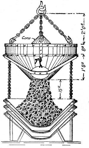 Fig. 25.—Hains Gravity Mixer, Telescoping Hopper Form.
In building a dock at Baltimore, Md., a plant consisting of two large hoppers and four charging hoppers with sand and stone bins above was used. One man at each large conical hopper tending the gates and two men charging the four pyramidal hoppers composed the mixer gang. A scow load of sand and another of stone were moored alongside the work and a clam-shell bucket dredge loaded the material from these barges into the mixer bins. Each batch was 25 cu. ft. of 1-2-5 concrete rammed in place. The men at the upper hoppers would empty a sack of cement in each, and then by opening gates in the bottom of the bins above, allow the necessary amounts of sand and stone to flow in, marks having been previously made on the sides of the hoppers to show the correct proportion of each of the ingredients. The amount of[Pg 83] water found by experience to be necessary, would then be dashed into the hoppers, and the charges allowed to run into the first cone hopper below. Refilling would begin at the top while the men were caring for the first charge in the lower hoppers. The process was thus continuous. The concrete was chuted directly into place from the bottom hopper. The record of output was 110 batches per 10-hour day. Wages of common labor were $1.50 per day. The labor cost per cubic yard of concrete in place was 35 cts.
In constructing the Cedar Grove reservoir at Newark, N. J., a Hains mixer made the following records of output:
| Cu. yds. | |
| Best output per 10-hour day | 403 |
| Average daily output for best month | 302 |
| Average daily output for whole job | 225 |
The stone, sand and cement were all raised by bucket elevators to the top of the high wooden tower that supported the bins and mixer. There were 10 men operating the mixer so that (exclusive of power, interest and depreciation) the labor cost of mixing averaged only 7 cts. per cu. yd.; during one month it was as low as 5 cts. per cu. yd. This does not include delivering the materials to the men at the mixer, nor does it include conveying the concrete away and placing it. The work was done by contract.
OUTPUT OF MIXERS.—With a good mixer the output depends upon the methods of conveying the materials to and from the mixer. Most makers of mixers publish capacities of their machines in batches or cubic yards output per hour; these figures may generally be taken as stating nearly the maximum output possible. Considering batch mixers, as being the type most commonly used, it may be assumed that where the work is well organized and no delay occurs in delivering the materials to the mixer that a batch every 2 minutes, or 300 batches in 10 hours, will be averaged, and there are a few records of a batch every 1½ minutes.
To illustrate to how great an extent the output of a mixer depends on the methods adopted in handling the materials to and from the mixer we compare two actual cases that came under the authors' observation. The mixers used were of the same size and make. In one case the stone was shoveled[Pg 84] into the charging hopper by four men and the sand and cement were delivered in barrows by four other men; six men took the concrete away in wheelbarrows. The output of the mixer was one batch every 5 minutes, or 120 batches, or 60 cu. yds., in 10 hours. In the other case the sand and the stone were chuted directly into the charging hopper from overhead bins and the mixer discharged into one-batch buckets on cars. The output of the mixer was one batch every 2 minutes, or 300 batches in 10 hours. In the first case the capacity of the mixer was limited by the ability of a gang of workable size to get the raw materials to and the mixed concrete away from the mixer. In the second case the capacity was limited only by the amount of mixing deemed necessary.
While the necessity of rapid charging of a mixer to secure its best output is generally realized it is often forgotten that the rapidity of discharge is also a factor of importance. The size of the conveyor by which the concrete is removed affects the time of discharge. By timing a string of wheelbarrows in line the authors have found that it takes about 7 seconds to fill each barrow; as a rule slight delays will increase this time to 10 seconds. With a load of 1 cu. ft. per barrow it requires 13 barrow loads to take away a ½ cu. yd. batch. This makes the time of discharging a batch 130 seconds, or say 2 minutes. The same mixer discharging into a batch size bucket will discharge in 15 to 20 seconds, saving at least 1½ minutes in discharging each batch.
MIXER EFFICIENCY.—Various attempts have been made to rate the efficiency of concrete mixers. In all cases a percentage basis of comparison has been adopted; arbitrary values are assigned to the several functions of a mixer, such as 40 per cent. for perfect mixing, 10 per cent. for time of mixing and 25 per cent. for control of water, the total being 100 per cent., and each mixer analyzed and given a rating according as it is considered to approach the full value of any function. Such percentage ratings are unscientific and misleading; they present definite figures for what are mere arbitrary determinations. The values assigned to the several functions are purely arbitrary in the first place, and in the second place the decision as to how near those values any mixer approaches are matters of personal judgment.[Pg 85]
The most efficient mixer is the one that gives the maximum product of standard quality at the least cost for production.
This rule recognizes the fact that in practical construction different standards of quality are accepted for different kinds of work. No engineer demands, for example, the same quality of mixture for a pavement base that he does for a reinforced concrete girder. If mixer A turns out concrete of a quality suitable for pavement base cheaper than does mixer B, then it is the more efficient mixer for the purpose, even though mixer B will make the superior quality of concrete required for a reinforced girder while mixer A will not. This method of determining efficiency holds accurate for any standard of quality that may be demanded.
Mixed concrete if emptied loose and allowed to sink through water is destroyed; the cement paste is washed away and the sand and stone settle onto the bottom more or less segregated and practically without cementing value. In fact, if concrete is deposited with the utmost care in closed buckets and there is any current to speak of a considerable portion of cement is certain to wash out of the deposited mass. Even in almost still water some of the cement will rise to the surface and appear as a sort of milky scum, commonly called laitance. Placing concrete under water, therefore, involves the distinctive task of providing means to prevent the washing action of the water. It is also distinguished from work done in air by the fact that it cannot be compacted by ramming, but the main problem is that of preventing wash during and after placing.
DEPOSITING IN CLOSED BUCKETS.—Special buckets for depositing concrete under water are made by several manufacturers of concrete buckets. These buckets vary in detail but are all similar in having doors to close the concrete away from the water and, generally, in being bottom dumping.
The bucket shown by Fig. 26 was designed by Mr. John F. O'Rourke, and is built by the Cockburn Barrow & Machine Co., of Jersey City, N. J. This bucket was used in depositing the concrete for the City Island Bridge foundations described in Chapter XII and also in a number of other works. It consists of a nearly cubical shell of steel open at top and bottom, and having heavy timbers rivetted around the bottom edges. The open top has two flat flap doors. Two similar doors hinged about midway of the sides close to form a V-shaped hopper bottom inside the shell and serve when open, to[Pg 87] close the openings in the sides of the shell. In loading the bucket the bottom doors are drawn inward and upward by the chains and held by a temporary key. The loaded bucket is then lifted by the bail and the key removed, since when suspended the pull on the bail holds the chains taut and the doors closed. As soon as the bucket rests on the bottom the pull of the concrete on the doors slides the bail down and the doors swing downward and back discharging the concrete. The timbers around the bottom edges keep the bucket from sinking into the deposited concrete, and the doors and shell exclude all water from the batch until it is finally in place.
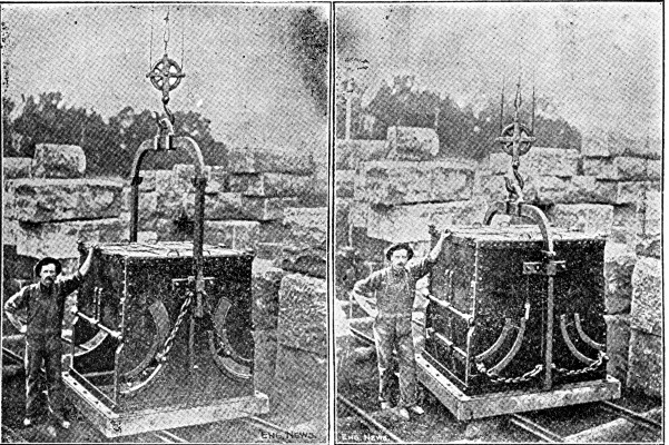 Fig. 26.—O'Rourke Bucket fur Depositing Concrete Under
Water.
Fig. 26.—O'Rourke Bucket fur Depositing Concrete Under
Water.
The subaqueous concrete bucket shown by Figs. 27 and 28 is made by the Cyclopean Iron Works Co., Jersey City, N. J. Fig. 27 shows the bucket suspended full ready for lowering; the cover is closed and latched and the bail is held vertical by the tag line catch A. Other points to be noted are the eccentric pivoting of the bail, the latch unlocking lever and roller B and C, and the stop D. In the position shown the bucket is lowered through the water and when at the proper depth just above bottom the tag line is given a sharp pull, uncatching the bail. The body of the bucket turns bottom side up,[Pg 88] revolving on the bail pivots, and just as the revolution is completed the bail engages the roller C on the latch unlocking lever and swings the lever enough to unlatch the top and allow it to swing down as shown by Fig. 28 and release the concrete. The stop D keeps the body of the bucket from swinging beyond the vertical in dumping.
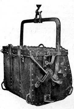 Fig. 27.—Cyclopean Bucket for Depositing Concrete Under
Water (Closed Position).
Fig. 27.—Cyclopean Bucket for Depositing Concrete Under
Water (Closed Position).
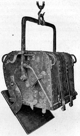 Fig. 28.—Cyclopean Bucket for Depositing Concrete Under
Water (Open Position).
Fig. 28.—Cyclopean Bucket for Depositing Concrete Under
Water (Open Position).
Figures 29 and 30 show the subaqueous concrete bucket made by the G. L. Stuebner Iron Works, Long Island City, N. Y., essentially the same bucket, omitting the cover and with a peaked bail, is used for work in air. For subaqueous work the safety hooks A are lifted from the angles B and wired to the bail in the position shown by the dotted lines, and a tag line is attached to the handle bar C. The bucket being filled and the cover placed is lowered through the water to the bottom and then discharged by a pull on the tag line.[Pg 89]
DEPOSITING IN BAGS.—Two methods of depositing concrete in bags are available to the engineer; one method is to employ a bag of heavy tight woven material, from which the concrete is emptied at the bottom, the bag serving like the buckets previously described simply as means of conveyance, and the other method is to use bags of paper or loose woven gunnysack which are left in the work, the idea being that the paper will soften or the cement will ooze out through the openings in the cloth sufficiently to bond the separate bagfuls into a practically solid mass.
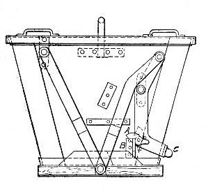 Fig. 29.—Stuebner Bucket for Depositing Concrete Under
Water (Closed Position).
Fig. 29.—Stuebner Bucket for Depositing Concrete Under
Water (Closed Position).
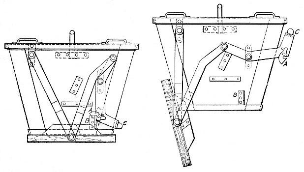 Fig. 30.—Stuebner Bucket for Depositing Concrete Under
Water (Open Position).
Fig. 30.—Stuebner Bucket for Depositing Concrete Under
Water (Open Position).
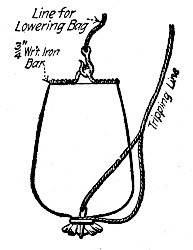 Fig. 31.—Bag for Depositing Concrete Under Water.
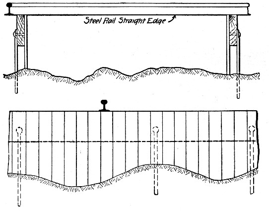 Fig. 32.—Form for Molding Footing for Block Concrete
Breakwater.
Fig. 32.—Form for Molding Footing for Block Concrete
Breakwater.
The bag shown by Fig. 31 was used to deposit concrete for leveling up a rough rock bottom and so provide a footing for a concrete block pier constructed in 1902 at Peterhead, N. B., by Mr. William Shield, M. Inst. C. E. Careful longitudinal profiles were taken of the rock bottom one at each edge of the footing. Side forms were then made in 20-ft. sections as shown by Fig. 32; the lagging boards being cut to fit the determined profile and the top of the longitudinal piece being flush with the top of the proposed footing. The concrete was filled in between the side forms and leveled off by the T-rail straight-edge. In placing the side forms the longitudinal pieces were placed by divers who were given the proper elevations by level rods having 10 to 15-ft. extension[Pg 90] pieces to raise the targets above the water surface. When leveled the side pieces were anchor-bolted as shown to the rock, the anchor-bolts being wedged into the holes to permit future removal. The concrete was then lowered in the bag shown by Fig. 31, the divers assisting in guiding the bag to position. The mouth of the bag being tied by one turn of a line having loops through which a wooden key is slipped to hold the line tight, a sharp tug on the tripping rope loosens the key and empties the bag. The bags used on this work had a capacity of 2¼ cu. ft. To permit the removal of the side forms after the concrete had hardened, a strip of jute sacking was spread against the lagging boards with a flap extending[Pg 91] 15 to 18 ins. under the concrete. The forms were removed by divers who loosened the anchor bolt wedges.
In placing small amounts of concrete for bridge foundations in Nova Scotia, bags, made of rough brown paper were used to hold the concrete. Each bag held about 1 cu. ft. The bags were made up quickly and dropped into the water one after the other so that the following one was deposited before the cement escaped from the former one. The paper was immediately destroyed by submersion and concrete remained. The bags cost $1.35 per hundred or 35 cts. per cu. yd. of concrete. Concrete was thus deposited in 18 ft. of water without a diver.
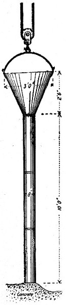 Fig. 33.—Steel Tremie for Depositing Concrete Under
Water.
Fig. 33.—Steel Tremie for Depositing Concrete Under
Water.
DEPOSITING THROUGH A TREMIE.—A tremie consists of a tube of wood or, better, of sheet metal, which reaches from above the surface to the bottom of the water; it is operated by filling the tube with concrete and keeping it full by successive additions while allowing the concrete to flow out gradually at the bottom by raising the tube slightly to provide the necessary opening. A good example of a sheet steel tremie is shown by Fig. 33. This tremie was used by Mr. Wm. H. Ward in constructing the Harvard Bridge foundations and numerous other subaqueous structures of concrete. In these works the tube was suspended from a derrick. Wheelbarrows filled the tube and hopper with concrete and kept them full; the derrick raised the tube a few inches and swung it gently so as to move it slowly over the area to be filled. Care being taken to keep the tube at one height, the concrete was readily deposited in even layers. Concrete thus deposited[Pg 92] in 18 ft. of water was found to be level and solid on pumping the pit dry.
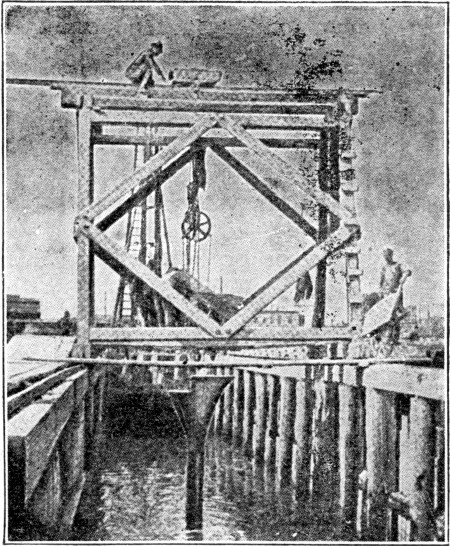 Fig. 34.—Tremie and Traveler Used at Charlestown, Mass.,
Bridge.
Fig. 34.—Tremie and Traveler Used at Charlestown, Mass.,
Bridge.
Another method of handling a tremie was employed in constructing the foundations for the Charlestown Bridge at Boston, Mass. Foundation piles were driven and sawed off under water. A frame was built above water and supported by a curbing attached to certain piles in the outer rows of the foundation reserved for this purpose. In this frame the vertical members were Wakefield sheet-piling plank, spaced 6 to 10 ft. apart, and connected by three lines of double waling bolted to the verticals at three different heights. This frame was lowered to the bottom so as to enclose the bearing piles. The posts or verticals were then driven, one by one, into the bottom, the frame being flexible enough to permit this. The spaces between the posts or verticals were then filled by sheet-piling and the frame was bolted to the curbing piles. This curbing afterward supported the traveler used in laying the concrete. Thus a coffer dam was formed to receive the concrete as shown in Fig. 34. The 1-2-5 concrete was deposited up to within 5½ ft. of the mean low water level, the[Pg 93] last foot being laid after water was pumped out. The tremie used to deposit the concrete was a tube 14 ins. in diameter at the bottom and 11 ins. at the neck, with a hopper at the top. It was made in removable sections, with outside flanges, and was suspended by a differential hoist from a truck moving laterally on a traveler, Fig. 34. The foot of the chute rested on the bottom until filled with concrete; then the chute was slowly raised and the concrete allowed to run but into a conical heap, more concrete being dumped into the hopper. As the truck moved across the traveler a ridge of concrete was made; then the traveler was moved forward and another parallel ridge was made. The best results were obtained when the layers were 2½ ft. thick, but layers up to 6 ft. thick were laid. If the layer was too thick, or uneven, or if the chute was moved or raised too quickly, the charge in the tube was "lost." This was objectionable because the charging of the chute anew resulted in "washing" the cement more or less out of the concrete until the chute was again filled. To reduce this objection the contractor was directed to dump some neat cement into the tube before filling with concrete. A canvass piston was devised which could be pushed ahead of the concrete when filling the chute. It consisted of two truncated cones of canvass, one flaring downward to force the water ahead, and the other flaring upward to hold the concrete. The canvass was stiffened and held against the sides of the chute by longitudinal ribs of spring steel wire; the waist was filled by a thick block of wood to which all the springs were attached; and to this block were connected additional steel guides to prevent overturning and a rope to regulate the descent. Very little water forced its way past this piston and it was a success, but as the cost was considerable and a piston was lost each time, its use was abandoned as the evil to be avoided did not justify the outlay.
The chute worked best when the concrete was mixed not quite wet enough to be plastic. If mixed too wet the charge was liable to be "lost," and if dry it would choke the chute. An excess of gravel permitted water to ascend in the tube; and an excess of sand tended to check the flow of concrete.
In constructing the piers for a masonry arch bridge in France in 1888 much the same method was followed, except[Pg 94] that a wooden tremie 16 ins. square made in detachable sections was used. This tremie had a hopper top and was also provided with a removable cap or cover for the bottom end, the latter device being intended to keep the water out of the tube and prevent "washing" the first charge of concrete. The piers were constructed by first driving piles and sawing them off several feet above the bottom but below water level, and then filling them nearly to their tops with broken stone. An open box caisson was then sunk onto the stone and embracing the pile tops and then filled around the outside with more broken stone. The caisson was then filled with concrete through the tremie which was handled by a traveling crane. The crane was mounted and traveled transversely of the pier on a platform which in turn moved along tracks laid lengthwise of the caisson. The tube was gradually filled with concrete and lowered, the detachable bottom of the tube was then removed, allowing the concrete to run out. The tube was first moved across the caisson and then downstream and back across the caisson, and this operation repeated until a 16-in. layer was completed. The tube was then raised 16 ins. and the operations repeated to form another layer. There was almost no laitance. From 90 to 100 cu. yds. were deposited daily.
Still another example of tremie work is furnished by the task of depositing a large mass of concrete under water in the construction of the Nussdorf Lock at Vienna. This lock has a total width of 92 ft. over all, and is 49.2 ft. clear inside. The excavation, which was carried to a depth of 26.24 ft. below water level, was made full width, between sheet piling, and the bottom was filled in with rammed sand and gravel, forming a kind of invert with its upper surface horizontal in the middle and sloping upwards a trifle at both sides. A mass of concrete having a total thickness of 13.12 ft. was built on this foundation in the center where the upper surfaces were 13.12 ft. below the water level. Concrete walls were carried up at the sides of the lock to a height of 3.28 ft.; these walls were 8.2 ft. thick. The methods used in placing the concrete were as follows: Three longitudinal rows of piles were driven on each side of the axis of the lock, these piles supporting a 6-rail track about 7 ft. above the water level. Three carriages spanning[Pg 95] the full width of the lock transversely moved on this track. Each carriage had three trolleys, one in each of the main panels of the transverse pile bends. These trolleys each carried a vertical telescopic tube, by means of which the concrete was deposited at the bottom of the lock. These tubes or chutes were of different lengths in the three carriages; the first ones deposited the concrete up to a level of 23 ft. below the surface; the next set deposited the concrete between that level and 19.7 ft., and the last set completed the subaqueous work up to the final height of 16.4 ft. below the surface. The tops of the tubes were level with a transverse track extending the full length of the carriage. The ends of these tracks just cleared the outside rows of piles, which, on one side of the lock, supported a distribution track parallel to the axis of the lock. Dump cars running on this distribution track delivered the concrete to smaller dump cars on the carriage tracks, and in turn these smaller cars dumped into either of these chutes on each carriage. The carriages were moved from end to end of the lock, the whole area of the lock coming under the nine chutes, inasmuch as each chute moved one-third the length of the carriage. The concrete was deposited in three horizontal layers 3.28 ft. thick, the layers being built in comparatively narrow banks, so that the different layers would key together and form a corrugated mass. The chutes were shortened as the concrete was deposited, three layers being placed successively. The main body of the bottom and the side walls were built by this method, and then the water was pumped out and a 2.3 ft. layer of concrete rammed over the bottom and completed with a finished surface 9 ft. thick.
GROUTING SUBMERGED STONE.—Masses of gravel, broken or rubble stone deposited under water may be cemented into virtually a solid concrete by charging the interstices with grout forced through pipes from the surface. Mr. H. F. White gives the following records of grouting submerged gravel:
In experiment No. 1 a reservoir 10 ft. square was filled to a depth of 18 ins. with clean gravel ballast (1½ to 2-in. size) submerged in water. A 2-in. gas pipe rested on the gravel and was surmounted with a funnel. A 1:1 Portland grout was poured in. After 21 days set the water was drawn off,[Pg 96] and it was found that the grout had permeated the ballast for a space of 8 ft. square at the bottom and 6 ft. square at the top, leaving a small pile of pure cement mortar 6 ins. high about the base of the pipe; 16 cu. ft. of cement and 16 cu. ft. of sand concreted 100 cu. yds. of ballast. In experiment No. 2, under the same conditions, a grout made of 1 part lime, 1 part surki (puzzulana or trass) and 1 part sand, was found to have spread over the entire bottom, 10 ft. square, rising 5 ins. on the sides, and making the concreted mass about 3½ ft. square at the top; 25 cu. ft. of the dry materials concreted 100 cu. ft. of ballast. In experiment No. 3 the ballast was 2½ ft. deep. A grout (using 8 cu. ft. of each ingredient) made as in experiment No. 2 covered the bottom, rose 14 ins. on the sides and made a top surface 4½ ft. square; 32 cu. ft. of the dry materials grouted 100 cu. ft. of ballast. In experiment No. 4 the ballast was of bats and pieces 3 or 4 ins. in size laid 7 ft. deep. A grout made as in experiment No. 2 (using 88 cu. ft. of each ingredient) concreted the whole mass to a depth of 6 ft. up the sides, and 2½ ft. square at the pipe on the surface of the ballast. Mr. White says that a grout containing more than 1 part of sand to 1 of Portland cement will not run freely through a 2-in. pipe, as the sand settles out and chokes the pipe. Even with 1:1 grout it must be constantly stirred and a steady flow into the pipe maintained. The lime-trass grout does not give the same trouble.
Mr. W. R. Knipple describes the work of grouting rubble stone and gravel for the base of the Hermitage Breakwater. This breakwater is 525 ft. long, 50 ft. wide at base and 42 ft. wide at top, and 68 ft. high, was built on the island of Jersey. Where earth (from 0 to 8½ ft. deep) overlaid the granite rock, it was dredged and the trench filled in with rubble stones and gravel until a level foundation was secured. Cement grout was then forced into this filling through pipe placed 8 to 10 ft. apart. The grouting was done in sections 12½ ft. long, from 7 to 10 days being taken to complete each. Upon this foundation concrete blocks, 4×4×9 to 12 ft., were laid in courses inclined at an angle of 68°. The first four courses were laid by divers, the blocks being stacked dry two courses high at a time. The joints below water were calked by divers and above water by masons, and a section was then grouted. When two[Pg 97] courses had been laid and grouted, two more courses were laid and grouted in turn, and so on. In places, grouting was done in 50 ft. of water. The grout should be a thick paste; a 30-ft. column of grout will balance a 60-ft. column of water.
Two kinds of concrete which vary in composition and character from the common standard mixtures of cement, sand and broken aggregate are extensively employed in engineering construction. These are rubble concrete and asphaltic concrete.
RUBBLE CONCRETE.—In constructing massive walls and slabs a reduction in cost may often (not always) be obtained by introducing large stones into the concrete. Concrete of this character is called rubble concrete, and the percentage of rubble stone contained varies from a few per cent. to, in some cases, over half of the volume. The saving effected comes partly from the reduction in the cement required per cubic yard of concrete and partly from the saving in crushing.
The saving in cement may be readily figured if the composition of the concrete and the volume of the added rubble stones be known. A 1-2½-5 concrete requires according to Table X in Chapter II 1.13 bbls. of cement per cubic yard. Assuming a barrel of cement to make 3.65 cu. ft. of paste, we have 3.65 × 1.13 = 4.12 cu. ft. of cement paste per cubic yard of 1-2½-5 concrete. This means that about 15 per cent. of the volume of the concrete structure is cement. If rubble stone be introduced to 50 per cent. of the volume, then the structure has about 7½ per cent. of its volume of cement. It is of interest to note in this connection that rubble masonry composed of 65 per cent. stone and 35 per cent. of 1-2½ mortar would have some 11½ per cent. of its volume made up of cement.
The saving in crushing is not so simple a determination. Generally speaking, the fact that a considerable volume of the concrete is composed of what, we will call uncrushed stone, means a saving in the stone constituent of one structure[Pg 99] amounting to what it would have cost to break up and screen this volume of uncrushed stone, but there are exceptions. For example, the anchorages of the Manhattan Bridge over the East River at New York city were specified to be of rubble concrete, doubtless because the designer believed rubble concrete to be cheaper than plain concrete. In this case an economic mistake was made, for all the rubble stone used had to be quarried up the Hudson River, loaded onto and shipped by barges to the site and then unloaded and handled to the work using derricks. Now this repeated handling of large, irregular rubble stones is expensive. Crushed stone as we have shown in Chapter IV can be unloaded from boats at a very low cost by means of clam shells. It can be transported on a belt conveyor, elevated by bucket conveyer, mixed with sand and cement and delivered to the work all with very little manual labor when the installation of a very efficient plant is justified by the magnitude of the job. Large rubble stones cannot be handled so cheaply or with so great rapidity as crushed stone; the work may be so expensive, due to repeated handlings, as to offset the cost of crushing as well as the extra cost of cement in plain concrete. On the other hand, the cost of quarrying rock suitable for rubble concrete is no greater than the cost of quarrying it for crushing—it is generally less because the stone does not have to be broken so small—so that when the cost of getting the quarried rock to the crusher and the crushed stone into the concrete comes about the same as getting the quarried stone into the structure it is absurd practice to require crushing. To go back then to our first thought, the question whether or not saving results from the use of rubble concrete, is a separate problem in engineering economics for each structure.
In planning rubble concrete work the form of the rubble stones as they come from the quarry deserves consideration. Stones that have flat beds like many sandstones and limestones can be laid upon layers of dry concrete and have the vertical interstices filled with dry concrete by tamping. It requires a sloppy concrete to thoroughly embed stones which break out irregularly. In the following examples of rubble concrete work the reader will find structures varying widely[Pg 100] enough in character and in the percentages of rubble used to cover most ordinary conditions of such work.
Where the rubble stones are very large it is now customary to use the term "cyclopean masonry" instead of rubble concrete. Many engineers who have not studied the economics of the subject believe that the use of massive blocks of stone bedded in concrete necessarily gives the cheapest form of masonry. We have already indicated conditions where ordinary concrete is cheaper than rubble concrete. We may add that if the quarry yields a rock that breaks up naturally into small sized blocks, it is the height of economic folly to specify large sized cyclopean blocks. Nevertheless this blunder has been frequently made in the recent past.
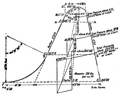 Fig. 35.—Diagram Cross-Section of Rubble Concrete Dam,
Chattahoochee River.
Fig. 35.—Diagram Cross-Section of Rubble Concrete Dam,
Chattahoochee River.
Chattahoochee River Dam.—The roll-way portion, 680 ft. long, of the dam for the Atlanta Water & Electric Power Co., shown in section by Fig. 35, was built of a hearting of rubble concrete with a fine concrete facing and a rubble rear wall. The facing, 12 ins. thick of 1-2-4 concrete, gave a smooth surface for the top and face of the dam, while the rubble rear wall enabled back forms to be dispensed with and, it was considered, made a more impervious masonry. The concrete matrix for the core was a 1-2-5 stone mixture made very wet. The rubble stones, some as large as 4 cu. yds., were bedded in the concrete by dropping them a few yards from a derrick and "working" them with bars; a well formed stone was readily settled 6 ins. into a 10-in. bed of concrete. The volume of rubble was from 33 to 45 per cent. of the total volume of the masonry. The 1-2-4 concrete facing was[Pg 101] brought up together with the rubble core, using face forms and templates to get the proper profile. The work was done by contract and the average was 5,500 cu. yds. of concrete placed per month.
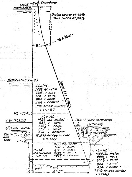 Fig. 36.—Cross-Section of Barossa Dam of Rubble
Concrete.
Fig. 36.—Cross-Section of Barossa Dam of Rubble
Concrete.
Barossa Dam, South Australia.—The Barossa Dam for the water-works for Gawler, South Australia, is an arch with a radius of 200 ft., and an arc length on top of 422 ft.; its height above the bed of the stream is 95 ft. Figure 36 is a cross-section of the dam at the center. The dam contains 17,975 cu. yds. of rubble concrete in the proportions of 2,215 cu. yds. of rubble stone to 15,760 cu. yds. of concrete; thus about 12.3 per cent. of the dam was of rubble. The concrete was mixed by weight of 1 part cement, 1½ parts sand, and a varying proportion of aggregate composed of 4½ parts 1¼ to[Pg 102] 2-in. stone, 2 parts ½ to 1¼-in. stone and 1 part ⅛ to ½-in. stone or screenings. The sand was one-half river sand and one-half crusher sand. The following shows the amounts by weight of the several materials for each of the several classes of concrete per cubic yard:
| ————Stone——— | ||||||
| Class. | Excess Mortar. | 1¼-2. | ½-1¼. | ⅛-½. | Sand. | Cement. |
| A | 7.5% | 1,500 | 661½ | 333¼ | 804 | 434 |
| B | 12.5 | 1,433⅓ | 637 | 318 | 858½ | 463 |
| C | 12.5 | 1,434 | 637 | 318½ | 859 | 474 |
| D | 15 | 1,402 | 623 | 312 | 884 | 484 |
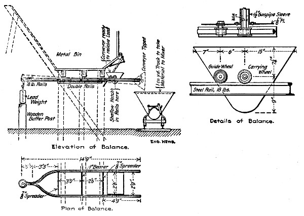 Fig. 37.—Apparatus Used for Weighing Concrete Materials
at Barossa Dam.
Fig. 37.—Apparatus Used for Weighing Concrete Materials
at Barossa Dam.
The average composition of the concrete was 1-1½-3½. Its cost per cubic yard in place including rubble was 38s 9d per cu. yd. or about $9.30. In proportioning the mixture on the work use was made of the device shown by Fig. 37 to weigh the aggregate. The measuring car is pushed back under the stone hopper chute until the wheels drop into shallow notches in the balanced track rails; stone is then admitted until the lead weight begins to rise, when the car is pushed forward and dumps automatically as indicated.[Pg 103]
Other Rubble Concrete Dams.—Rubble concrete containing from 55 to 60 per cent. rubble was used in constructing the Boonton Dam at Boonton, N. J. The stones used measured from 1 to 2½ cu. yds. each; the concrete was made so wet that when the stones were dropped into it, it flowed into every crevice. The materials were all delivered on cars, from which they were delivered to the dam by derricks provided with bull-wheels. On the dam there were 4 laborers and 1 mason to each derrick, and this gang dumped the concrete and joggled the rubble stones into it. Records of 125 cu. yds. per 10 hours, with one derrick, were made. With 35 derricks, 20 of which were laying masonry and 15 either passing materials or being moved, as much as 21,000 cu. yds. of masonry were laid in one month. The amount of cement per cubic yard of masonry is variously stated to have been 0.6 to 0.75 bbl. The stone was granite.
The Spier Falls Dam on the upper Hudson River was built of rubble concrete containing about 33 per cent. rubble stone. The concrete was a 1-2½-5 mixture, and the engineer states that about 1 bbl. of cement was used per cubic yard of rubble concrete. This high percentage of cement may be accounted for by the fact that there was a considerable amount of rubble masonry in cement mortar included in the total. The stones and concrete were delivered along the dam by cableways and stiff-leg derricks set on the downstream sloping face of the dam delivered them from the cableways into place. There were two laborers to each mason employed in placing the materials, wages being 15 and 35 cts. per hour, respectively. The labor cost of placing the materials was 60 cts. per cubic yard of masonry. The stone was granite.
Granite rubble laid in layers on beds of concrete and filled between with concrete was used in constructing the Hemet Dam in California. The concrete was a 1-3-6 mixture, and was thoroughly tamped under and between the stones. For face work the stones were roughly scabbled to shape and laid in mortar. The stone was taken from the quarry 400 ft. away and delivered directly on the dam by cableways; here two derricks handled the stone into place, the dam being only 246 ft. arc length on top, though it was 122½ ft. high. The cableways would take a 10-ton load; stones could be taken[Pg 104] from the quarry, hoisted 150 ft. and delivered to the work in 40 to 60 seconds. Common labor at $1.75 per day was used for all masonry except facing, where masons at $3.50 were employed. Cement cost delivered $5 per barrel, of which from $1 to $1.50 per barrel was the cost of hauling 23 miles by team over roads having 18 per cent. grades in places. Sand was taken from the stream bed and delivered to the work by bucket conveyor. "Under favorable conditions some of the masonry was put in for as low as $4 per cu. yd." There were 31,100 cu. yds. of masonry in the dam, which required 20,000 bbls. of cement, or 0.64 bbl. per cubic yard.
The following novel method of making rubble concrete was employed in enlarging two old dams and in constructing two new dams for a small water-works. The available time was short, the amount of work was too small and too scattered to justify the installation of a stone crusher, and suitable gravel was not at hand. Sufficient small boulders in old walls, and borrow pits and on surface of fields were available, and were used with thin Portland cement mortar. One part of Alpha or Lehigh cement and three parts sand were mixed dry at first and then wet with just enough water to make the resulting mortar flow by gravity. This mortar was shoveled into the forms continuously by one set of men while other men were throwing into the mortar in the forms the boulders which were cleaned and broken so as not to be more than 7 ins. long. In general the performance was continuous. Three mortar beds were placed parallel with, and against, one side of the forms, with spaces of about 4 ft. between the ends of the beds. The boulders were dumped on the opposite side of the forms. Two men shoveled in all the mortar and did nothing else. While they were emptying one bed the mortar was being mixed in the preceding bed by two other men and the materials placed in the third bed by still others. Another gang was continually throwing in the boulders and small stones and still another was breaking stone. One man should keep the mortar well stirred while the bed is being emptied. About 20 men were necessary to do all parts of the work. The forms were of 2-in. planed plank tongued and grooved. Especial pains were taken to make the forms tight, and all leaks that appeared were quickly stopped with dry cement. Some pains[Pg 105] were taken to prevent a flat side of large stones from coming in direct contact with the forms, but round boulders and small stones needed no care to prevent their showing in the finished work.
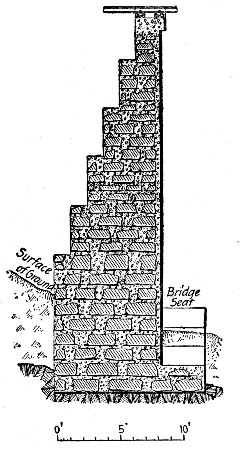 Fig. 38.—Bridge Abutment of Rubble Concrete.
In conclusion it is interesting to note, perhaps, the earliest use of rubble concrete for dam construction in this country in constructing the Boyd's Corner Dam on the Croton River near New York. This dam was begun in 1867 and for a time rubble concrete was used, but was finally discontinued, due to the impression that it might not be watertight. The specifications called for dry concrete to be thoroughly rammed in between the rubble stones, and to give room for this ramming the contractor was not permitted to lay any two stones closer together than 12 ins. As a result not more than 33 per cent. of the concrete was rubble.
Abutment for Railway Bridge.—Figure 38 shows a bridge abutment built of rubble concrete at a cost of about $4.50 per cu. yd. The concrete was a 1-2½-4½ mixture laid in 4-in. layers. On each layer were laid large rubble stones bedded[Pg 106] flat and spaced to give 6-in. vertical joints; the vertical joints were filled with concrete by ramming and then another layer of concrete placed and so on. A force of 28 men and a foreman averaged 40 cu. yds. of rubble concrete per day. The following is the itemized cost per cubic yard, not including forms, for 278 cu. yds:
| Item. | Per Cu. Yd. |
| 0.82 bbls. cement, at $2.60 | $2.14 |
| 0.22 cu. yd. sand, at $1.00 | 0.22 |
| 0.52 cu. yd. broken stone, at $0.94 | 0.49 |
| 0.38 cu. yd. rubble stone, at $0.63 | 0.24 |
| Water | 0.07 |
| Labor, at 15 cts. per hour | 1.19 |
| Foreman | 0.09 |
| ——— | |
| Total | $4.44 |
Some English Data on Rubble Concrete.—Railway work, under Mr. John Strain, in Scotland and Spain, involved the building of abutments, piers and arches of rubble concrete. The concrete was made of 1 part cement to 5 parts of ballast, the ballast consisting of broken stone or slag and sand mixed in proportions determined by experiment. The materials were mixed by turning with shovels 4 times dry, then 4 times more during the addition of water through a rose nozzle. A bed of concrete 6 ins. thick was first laid, and on this a layer of rubble stones, no two stones being nearer together than 3 ins., nor nearer the forms than 3 ins. The stones were rammed and probed around with a trowel to leave no spaces. Over each layer of rubble, concrete was spread to a depth of 6 ins. The forms or molds for piers for a viaduct were simply large open boxes, the four sides of which could be taken apart. The depth of the boxes was uniform, and they were numbered from the top down, so, that, knowing the height of a given pier, the proper box for the base could be selected. As each box was filled, the next one smaller in size was swung into place with a derrick. The following bridge piers for the Tharsis & Calanas Railway were built:[Pg 107]
| Name. | Length of Bridge. Ft. | Height of Piers. Ft. | No. of Spans. | Cu. Yds. in Piers. | Weeks to Build. |
| Tamujoso River | 435 | 28 | 12 | 1,737 | 14½ |
| Oraque | 423 | 31 | 11 | 1,590 | 15 |
| Cascabelero | 480 | 30 to 80 | 10 | 2,680 | 21 |
| No. 16 | 294 | 28 to 50 | 7 | 1,046 | 16½ |
| Tiesa | 165 | 16 to 23 | 8 | 420 | 4 |
It is stated that the construction of some of these piers in ordinary masonry would have taken four times as long. The rock available for rubble did not yield large blocks, consequently the percentage of pure concrete in the piers was large, averaging 70 per cent. In one case, where the stones were smaller than usual, the percentage of concrete was 76½ per cent. In other work the percentage has been as low as 55 per cent., and in still other work where a rubble face work was used the percentage of concrete has been 40 per cent.
In these piers the average quantities of materials per cubic yard of rubble concrete were:
448 lbs. (0.178 cu. yd.) cement.
0.36 cu. yd. sand.
0.68 cu. yd. broken stone (measured loose in piles).
0.30 cu. yd. rubble (measured solid).
Several railway bridge piers and abutments in Scotland are cited. In one of these, large rubble stones of irregular size and weighing 2 tons each were set inside the forms, 3 ins. away from the plank and 3 ins. from one another. The gang to each derrick was: 1 derrick man and 1 boy, 1 mason and 10 laborers, and about one-quarter of the time of 1 carpenter and his helper raising the forms. For bridges of 400 cu. yds., the progress was 12 to 15 cu. yds. a day. The forms were left in place 10 days.
To chip off a few inches from the face of a concrete abutment that was too far out, required the work of 1 quarryman 5 days per cu. yd. of solid concrete chipped off.
Concrete was used for a skew arch over the River Dochart, on the Killin Railway, Scotland. There were 5 arches, each of 30 ft. span on the square or 42 ft. on the skew, the skew being 45°. The piers were of rubble concrete. The concrete[Pg 108] in the arch was wheeled 300 ft. on a trestle, and dumped onto the centers. It was rammed in 6-in. layers, which were laid corresponding to the courses of arch stones. As the layers approached the crown of the arch, some difficulty was experienced in keeping the surfaces perpendicular. Each arch was completed in a day.
In a paper by John W. Steven, in Proc. Inst. C. E., the following is given:
| Concrete Per Cu. Yd. | Rubble Concrete Per Cu. Yd. | Per Cent. of Rubble in Rubble Concrete. | |
| Ardrossan Harbor | $6.00 | $5.00 | 20.0 |
| Irvine Branch | 7.00 | 3.68 | 63.6 |
| Calanas & Tharsis Ry | 7.08 | 3.43 | 30.3 |
Mr. Martin Murphy describes some bridge foundations in Nova Scotia. Rubble concrete was used in some of the piers. The rubble concrete consisted of 1 part cement, 2 parts sand, 1 part clean gravel, and 5 parts of large stones weighing 20 lbs. each and upwards. The sand, cement and gravel were turned three times dry and three times wet, and put into the forms. The rubble stones were bedded in the concrete by hand, being set on end, 2 or 3 ins. apart. No rubble stones were placed within 6 ins. of the forms, thus leaving a face of plain concrete; and the rubble stones were not carried higher than 18 ins. below the top of the pier. One cubic yard of this rubble concrete required 0.8 to 0.9 bbl. of cement.
ASPHALT CONCRETE.—Asphalt or tar concrete in which steam cinders or broken stone or gravel and sand are mixed with asphaltum or tar instead of cement paste are used to some extent in lining reservoirs, constructing mill floors, etc. Such mixtures differ in degree only from the mixtures used for asphalt street paving, for discussion of which the various books on paving and asphalts should be consulted. The two examples of asphalt concrete work given here are fairly representative of the mixtures and methods employed for concrete work as distinguished from asphalt work.
Slope Paving for Earth Dam.—Mr. Robert B. Stanton describes a small log dam faced upstream with earth, upon which was laid an asphalt concrete lining to make it water tight. The[Pg 109] stone was broken to 2-in. pieces, all the fines being left in and sufficient fine material added to fill the voids. The stone was heated and mixed in pans or kettles from a street paving outfit; and the asphaltum paste, composed of 4 parts California refined asphaltum and 1 part crude petroleum, was boiled in another kettle. The boiling hot paste was poured with ladles over the hot stone, and the whole mixed over the fire with shovels and hoes. The asphalt concrete was taken away in hot iron wheelbarrows, placed in a 4-in. layer rammed and ironed with hot irons. The concrete was laid in strips 4 to 6 ft. wide, the edges being coated with hot paste. After the whole reservoir was lined, it was painted with the asphalt paste, boiled much longer, until when cold it was hard and stone was broken to 2-in. pieces, all the fines being left in and sufficient fine material added to fill the voids. The stone was heated and mixed in pans or kettles from a street paving outfit; and the asphaltum paste, composed of 4 parts California refined asphaltum and 1 part crude petroleum, was boiled in another kettle. The boiling hot paste was poured with ladles over the hot stone, and the whole mixed over the fire with shovels and hoes. The asphalt concrete was taken away in hot iron wheelbarrows, placed in a 4-in. layer rammed and ironed with hot irons. The concrete was laid in strips 4 to 6 ft. wide, the edges being coated with hot paste. After the whole reservoir was lined, it was painted with the asphalt paste, boiled much longer, until when cold it was hard and brittle, breaking like glass under the hammer. This paste was put on very hot and ironed down. It should not be more than ⅛-in. thick or it will "creep" on slopes of 1½ to 1. After two hot summers and one cold winter there was not a single crack anywhere in the lining. A mixture of sand and asphalt will creep on slopes of 1½ to 1, but asphalt concrete will not. With asphalt at $20 a ton, and labor at $2 a day, the cost was 15 cts. a sq. ft. for 4-in. asphalt concrete. On a high slope Mr. Stanton recommends making slight berms every 6 ft. to support the concrete and prevent creeping. Asphalt concrete resists the wear of wind and water that cuts away granite and iron.
Base for Mill Floor.—In constructing 17,784 sq. ft. of tar concrete base for a mill floor, Mr. C. H. Chadsey used a sand, broken stone and tar mixture mixed in a mechanical mixer. The apparatus used and the mode of procedure followed were as follows:
Two parallel 8-in. brick walls 26 ft. long were built 4 ft. apart and 2½ ft. high to form a furnace. On these walls at one end was set a 4×6×2 ft. steel plate tar heating tank. Next to this tank for a space of 4×8 ft. the walls were spanned between with steel plates. This area was used for heating sand. Another space of 4×8 ft. was covered with 1½ in. steel rods arranged to form a grid; this space was used for heating the broken stones. The grid proved especially efficient, as it permitted the hot air to pass up through the stones, while a small cleaning door at the ground allowed the screenings which[Pg 110] dropped through the grid to be raked out and added to the mixture. A fire from barrel staves and refuse wood built under the tank end was sufficient to heat the tar, sand and stone.
For mixing the materials a Ransome mixer was selected for the reason that heat could be supplied to the exterior of the drum by building a wood fire underneath. This fire was maintained to prevent the mixture from adhering to the mixing blades, and it proved quite effective, though occasionally they would have to be cleaned with a chisel bar, particularly when the aggregate was not sufficiently heated before being admitted to the mixer. A little "dead oil" applied to the discharge chute and to the shovels, wheelbarrows and other tools effectually prevented the concrete from adhering to them.
The method of depositing the concrete was practically the same as that used in laying cement sidewalks. Wood strips attached to stakes driven into the ground provided templates for gaging the thickness of the base and for leveling off the surface. The wood covering consisted of a layer of 2-in. planks, covered by matched hardwood flooring. In placing the planking, the base was covered with a ¼-in. layer of hot pitch, into which the planks were pressed immediately, the last plank laid being toe-nailed to the preceding plank just enough to keep the joint tight. After a few minutes the planks adhered so firmly to the base that they could be removed only with difficulty. The hardwood surface was put on in the usual manner. The prices of materials and wages for the work were as follows:
| Pitch, bulk, per lb. | $ 0.0075 |
| Gravel, per cu. yd. | 1.50 |
| Spruce sub-floor, per M. ft. B. M. | 15.00 |
| Hardwood surface, per M. ft. B. M. | 33.00 |
| Laborers, per 10-hour day. | 1.50 |
| Foreman, per 10-hour day. | 4.00 |
| Carpenters, per 10-hour day. | 2.00 |
At these prices and not including a small administration cost or the cost of tools and plant, the cost of the floor consisting of 4½ ins. of concrete, 2 ins. of spruce sub-flooring and ⅞-in. hardwood finish was as follows per square foot:[Pg 111]
| Pitch | $0.04 |
| Gravel | 0.02 |
| Spruce, for sub-floor | 0.03 |
| Hardwood for surfacing | 0.035 |
| Labor, mixing | 0.03 |
| Labor, laying | 0.015 |
| Carpenter work | 0.025 |
| ——— | |
| Total per square foot | $0.195 |
Reinforced concrete work may be done in freezing weather if the end to be gained warrants the extra cost. Laboratory experiments show beyond much doubt that Portland cement concrete which does not undergo freezing temperatures until final set has taken place, or which, if frozen before it has set, is allowed to complete the setting process after thawing without a second interruption by freezing, does not suffer loss of ultimate strength or durability. These requirements for safety may be satisfied by so treating the materials or compounding the mixture that freezing will not occur at normal freezing temperature or else will be delayed until the concrete has set, by so housing in the work and artificially treating the inclosed space that its temperature never falls as low as the freezing point, or, by letting the concrete freeze if it will and then by suitable protection and by artificial heating produce and maintain a thawing temperature until set has taken place.
LOWERING THE FREEZING POINT OF THE MIXING WATER.—Lowering the freezing point of the mixing water is the simplest and cheapest method by which concrete can be mixed and deposited in freezing weather. The method consists simply in adding some substance to the water which will produce a brine or emulsion that freezes at some temperature below 32° F. determined by the substance added and the richness of the admixture. A great variety of substances may be added to water to produce low freezing brines, but in concrete work only those may be used that do little or no injury to the strength and durability of the concrete. Practice has definitely determined only one of these, namely, sodium chloride or common salt, though some others have been used successfully in isolated cases. A point to be borne in mind is that cold retards the setting of cement and that the use of[Pg 113] anti-freezing mixtures emphasizes this phenomenon and its attendant disadvantages in practical construction. The accompanying diagram, Fig. 39, based on the experiments of Tetmajer, show the effect on the freezing point of water by the admixtures of various substances that have been suggested for reducing the freezing point of mortar and concrete mixtures.
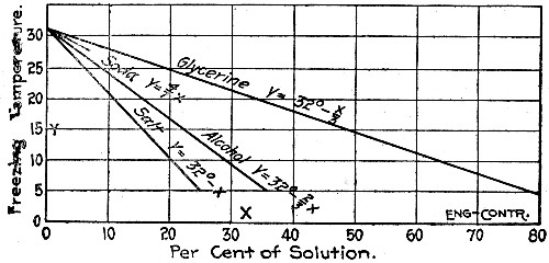 Fig. 39.—Diagram Showing Effect on Freezing Point of
Water by Admixture of Various Substances.
Fig. 39.—Diagram Showing Effect on Freezing Point of
Water by Admixture of Various Substances.
Common Salt (Sodium Chloride).—The substance most usually employed to lower the freezing point of water used in concrete is common salt. Laboratory experiments show that the addition of salt retards the setting and probably lowers the strength of cement at short periods, but does not, when not used to excess, injure the ultimate strength. The amount beyond which the addition of salt begins to affect injuriously the strength of cement is stated variously by various authorities. Sutcliffe states that it is not safe to go beyond 7 or 8 per cent. by weight of the water; Sabin places the safe figures at 10 per cent., and the same figure is given by a number of other American experimenters. A number of rules have been formulated for varying the percentage of salt with the temperature of the atmosphere. Prof. Tetmajer's rule as stated by Prof. J. B. Johnson, is to add 1 per cent. of salt by weight of the water for each degree Fahrenheit below 32°. A rule quoted by many writers is "1 lb. of salt to 18 gallons of water for a temperature of 32° F., and an increase of 1 oz. for each degree lower temperature." This rule gives entirely inadequate amounts to be effective, the percentage by weight of the water being about 1 per cent. The familiar rules of enough[Pg 114] salt to make a brine that will "float an egg" or "float a potato" are likewise untrustworthy; they call respectively, according to actual tests made by Mr. Sanford E. Thompson, for 15 per cent. and 11 per cent. of salt which is too much, according to the authorities quoted above, to be used safely. In practice an arbitrary quantity of salt per barrel of cement or per 100 lbs. of water is usually chosen. Preferably the amount should be stated in terms of its percentage by weight of the water, since if stated in terms of pounds per barrel of cement the richness of the brine will vary with the richness of the concrete mixture, its composition, etc. As examples of the percentages used in practice, the following works may be quoted: New York Rapid Transit Railway, 9 per cent. by weight of the water; Foster-Armstrong Piano Works, 6 per cent. by weight of the water. In summary, it would seem that if a rule for the use of salt is to be adopted that of Tetmajer, which is to add 1 per cent. by weight of the water for each degree Fahrenheit below 32°, is as logical and accurate as any. It should, however, be accompanied by the proviso that no more than 10 per cent. by weight of salt should be considered safe practice, and that if the frost is too keen for this to avail some other method should be adopted or the work stopped. It may be taken that each unit per cent. of salt added to water reduces the freezing temperature of the brine about 1.08° F.; a 10 per cent. salt brine will therefore freeze at 32° - 11° = 21° F. The range of efficiency of salt as a preventative of frost in mixing and laying concrete is, obviously, quite limited.
HEATING CONCRETE MATERIALS.—Heating the sand, stone and mixing water acts both to hasten the setting and to lengthen the time before the mixture becomes cold enough to freeze. At temperatures not greatly below freezing the combined effects are sufficient to ensure the setting of the concrete before it can freeze. More specific data of efficiency are difficult to arrive at. There are no test data that show how long it takes a concrete mixture at a certain temperature to lose its heat and become cold enough to freeze at any specific temperature of the surrounding air, and a theoretical calculation of this period is so beset with difficulties as to be impracticable. Strength tests of concrete made with heated materials have shown clearly enough that the heating has no[Pg 115] effect worth mentioning on either strength or durability. Either the water, the sand, the aggregate or all three may be heated; usually the cement is not heated but it may be if desired.
Portable Heaters.—An ordinary half cylinder of sheet steel set on the ground like an arch is the simplest form of sand heater. A wood fire is built under the arch and the sand to be heated is heaped on the top and sides. The efficiency of this device may be improved by closing one end of the arch and adding a short chimney stack, but even the very crude arrangement of sheets of corrugated iron bent to an arc will do good service where the quantities handled are small. This form of heater may be used for stone or gravel in the same manner as for sand. It is inexpensive, simple to operate and requires only waste wood for fuel, but unless it is fired with exceeding care the sand in contact with the metal will be burned. The drawings of Fig. 40 show the construction of a portable heater for sand, stone and water used in constructing concrete culverts on the New York Central & Hudson River Railroad. This device weighs 1,200 lbs., and costs about $50.
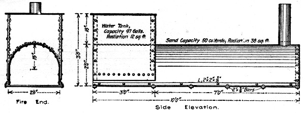 Fig. 40.—Portable Sand, Stone and Water Heater.
Heating in Stationary Bins.—The following arrangement for heating sand and gravel in large quantities in bins was employed in constructing the Foster-Armstrong Piano Works at Rochester, N. Y. The daily consumption of sand and gravel on this work was about 50 cu. yds. and 100 cu. yds., respectively. To provide storage for the sand and gravel, a bin 16 ft. square in projected plan was constructed with vertical sides and a sloping bottom as illustrated in Fig. 41. This bin was divided by a vertical partition into a large compartment[Pg 116] for gravel and a small compartment for sand and was provided with two grates of boiler tubes arranged as shown. These grates caused V-shaped cavities to be formed beneath in the gravel and sand. Into these cavities penetrated through one end of the bin 6-in. pipes from a hot air furnace and 1-in. pipes from a steam boiler. The hot air pipes merely pass through the wall but the steam pipes continue nearly to the opposite side of the bin and are provided with open crosses at intervals along their length. In addition to the conduits described there is a small pipe for steam located below and near the bottom of the bin. The hot air pipes connected with a small furnace and air was forced through them by a Sturtevant No. 6 blower. The steam pipes connected with the boiler of a steam heating system installed to keep the buildings warm during construction.
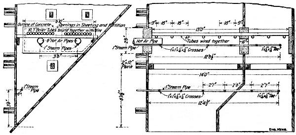 Fig. 41.—Bin Arrangement for Heating Sand and Stone.
Other Examples of Heating Materials.—In the construction of the power plant of the Billings (Mont.) Water Power Co., practically all of the concrete work above the main floor level was put in during weather so cold that it was necessary to heat both the gravel and water used. A sand heater was constructed of four 15-ft. lengths of 15-in. cast iron pipe, two in series and the two sets placed side by side. This gave a total length of 30 ft. for heating, making it possible to use the gravel from alternate ends and rendering the heating process continuous. The gravel was dumped directly on the heater, thus avoiding the additional expense of handling it a second time. The heater pipes were laid somewhat slanting, the fire being built in the lower end. A 10-ft. flue furnished sufficient[Pg 117] draft for all occasions. With this arrangement it was possible to heat the gravel to a temperature of 80° or 90° F. even during the coldest weather. Steam for heating the water was available from the plant. The temperature at which the concrete was placed in the forms was kept between 65° and 75° F. This was regulated by the man on the mixer platform by varying the temperature of the water to suit the conditions of the gravel. When the ingredients were heated in this manner it was found advisable to mix the concrete "sloppy," using even more water than would be commonly used in the so-called "sloppy" concrete. No difficulty was experienced with temperature cracks if the concrete, when placed, was not above 75° F. All cracks of this nature which did appear were of no consequence, as they never extended more than ½ in. below the surface. The concrete was placed in as large masses as possible. It was covered nights with sacks and canvas and, when the walls were less than 3 ft. in width, the outside of the forms was lagged with tar paper. An air space was always left between the surface of the concrete and the covering. Under these conditions there was sufficient heat in the mass to prevent its freezing for several days, which was ample time for permanent setting.
During the construction in 1902 of the Wachusett Dam at Clinton, Mass., for the Metropolitan Water Works Commission the following procedures were followed in laying concrete in freezing weather: After November 15 all masonry was laid in Portland cement, and after November 28 the sand and water were heated and salt added in the proportion of 4 lbs. per barrel of cement. The sand was heated in a bin, 16½×15½×10 ft. deep, provided with about 20 coils of 2-in. pipe, passing around the inside of the bin. The sand, which was dumped in the top of the bin and drawn from the bottom, remained there long enough to become warm. The salt for each batch of mortar was dissolved in the water which was heated by steam; steam was also used to thaw ice from the stone masonry. The laying of masonry was not started on mornings when the temperature was lower than 18° F. above zero, and not even with this temperature unless the day was clear and higher temperature expected. At the close of each day the masonry built was covered with canvas.[Pg 118]
In the construction of dams for Huronian Company's power development in Canada a large part of the concrete work in dams, and also in power house foundations, was done in winter, with the temperature varying from a few degrees of frost to 15 degrees below zero, and on several occasions much lower. No difficulty was found in securing good concrete work, the only precaution taken being to heat the mixing water by turning a ¾-in. steam pipe into the water barrel supplying the mixer, and, during the process of mixing, to use a jet of live steam in the mixer, keeping the cylinder closed by wooden coverings during the process of mixing. No attempt was made to heat sand or stone. In all the winter work care was taken to use only cement which would attain its initial set in not more than 65 minutes.
In constructing a concrete arch bridge at Plano, Ill., the sand and gravel were heated previous to mixing and the mixed concrete after placing was kept from freezing by playing a steam jet from a hose connected with the boiler of the mixer on the surface of the concrete until it was certain that initial set had taken place. Readings taken with thermometers showed that in no instance did the temperature of the concrete fall below 32° F. within a period of 10 or 12 hours after placing.
From experience gained in doing miscellaneous railway work in cold weather Mr. L. J. Hotchkiss gives the following:
"For thin reinforced walls, it is not safe to rely on heating the water alone or even the water and sand, but the stone also must be heated and the concrete when it goes into the forms should be steaming hot. For mass walls the stone need not be heated except in very cold weather. Where concrete is mixed in small quantities the water can be heated by a wood fire, and if a wood fire be kept burning over night on top of the piles of stone and sand a considerable quantity can be heated. The fire can be kept going during the day and moved back on the pile as the heated material is used. This plan requires a quantity of fuel which in most cases is prohibitive and is not sufficient to supply a power mixer. For general use steam is far better.
"A convenient method is to build a long wooden box 8 or 10 in. square with numerous holes bored in its sides. This is[Pg 119] laid on the ground, connected with a steam pipe and covered with sand, stone or gravel. The steam escaping through the holes in the box will heat over night a pile of sand, or sand and gravel, 8 or 10 ft. high. Perforated pipes can be substituted for boxes. Material can be heated more rapidly if the steam be allowed to escape in the pile than if it is confined in pipes which are not perforated. Crushed stone requires much more heat than sand or sand and gravel mixed because of the greater volume of air spaces. In many cases material which has already been unloaded must be heated. The expense of putting steam boxes or pipes under it is considerable. To avoid this one or more steam jets may be used, the end of the jet pipe being pushed several feet into the pile of material. If the jets are connected up with steam hose they are easily moved from place to place. It is difficult to heat stone in this way except in moderate weather.
"On mass work and at such temperatures as are met with in this latitude (Chicago, Ill.) it is not usually necessary to protect concrete which has been placed hot except in the top of the form. This can be done by covering the top of the form with canvas and running a jet of steam under it. If canvas is not available boards and straw or manure answer the purpose. If heat is kept on for 36 hours after completion, this is sufficient, except in unusually cold weather. The above treatment is all that is required for reinforced retaining walls of ordinary height. But where box culverts or arches carrying heavy loads must be placed in service as soon as possible, the only safe way is to keep the main part of the structure warm until the concrete is thoroughly hardened. Forms for these structures can be closed at the ends and stoves or salamanders kept going inside, or steam heat may be used. The outside may be covered with canvas or boards, and straw and steam jets run underneath. After the concrete has set enough to permit the removal of the outer forms of box culverts, fires may be built near the side walls and the concrete seasoned rapidly. Where structures need not be loaded until after the arrival of warm weather, heat may be applied for 36 hours, and the centering left in place until the concrete has hardened. Careful inspection of winter concrete should be made before loads are applied. In this connection it may be noted that[Pg 120] concrete which has been partly seasoned and then frozen, closely resembles thoroughly seasoned concrete. Pieces broken off with a smooth fracture through all the stones and showing no frost marks, when thawed out, can be broken with the hands."
In building Portland cement concrete foundations for the West End St. Ry., Boston, and the Brooklyn Heights R. R., much of the work was done in winter. A large watertight tank was constructed, of such size that three skips or boxes of stone could be lowered into it. The tank was filled with water, and a jet of steam kept the water hot in the coldest weather. The broken stone was heated through to the temperature of the water in a few minutes. One of the stone boxes was then hoisted out, and dumped on one side of the mixing machine, and then run through the machine with sand, cement and water. The concrete was wheeled to place without delay and rammed in 12-in. layers. The heat was retained until the cement was set. In severely cold weather the sand was heated and the mixing water also. A covering of hay or gunnysacks may be used.
COVERING AND HOUSING THE WORK.—Methods of covering concrete to protect it from light frosts such as may occur over night will suggest themselves to all; sacking, shavings, straw, etc., may all be used. Covering wall forms with tar paper nailed to the studding so as to form with the lagging a cellular covering is an excellent device and will serve in very cold weather if the sand and stone have been heated. From these simple precautions the methods used may range to the elaborate systems of housing described in the following paragraphs.
Method of Housing in Dam, Chaudiere Falls, Quebec.—In constructing a dam for the water power plant at Chaudiere Falls, P. Q., the work was housed in. The wing dam and its end piers aggregated about 250 ft. in length by about 20 ft. in width. A house 100 ft. long and 24 ft. wide was constructed in sections about 10 ft. square connected by cleats with bolts and nuts. This house was put up over the wing dam. It was 20 ft. high to the eaves, with a pitched roof, and the ends were closed up; in the roof on the forebay side were hatchways with sliding doors along the whole length. Small entrance[Pg 121] doors for the workmen were provided in the ends of the building. The house was heated by a number of cylindrical sheet-iron stoves about 18 ins. in diameter by 24 ins. high, burning coke; thermometers placed at different points in the shed gave warning to stop work when the temperature fell below freezing, which, however, rarely occurred. Mixing boards were located in the shed, and concrete, sand and broken stone were supplied in skipfuls by guy derricks located in the forebay, which passed the material through the hatchways in the roof, the proper hatchway being opened for the purpose and quickly closed. The mortar was first mixed on a board, and then a skip-load of stone was dumped into the middle of the batch and the whole well mixed. The water was made lukewarm by introducing a steam-jet into several casks which were kept full. The sand was heated outside in the forebay on an ordinary sand heater. The broken stone was heated in piles by a steam-jet; a pipe line on the ground was made up of short lengths of straight pipe alternating with T-sections—turned up. The stone was piled 3 to 4 ft. deep over the pipe and a little steam turned into the pipe. Several such piles kept going all the time supplied enough stone for the work; the stone was never overheated, and was moist enough not to dry out the mortar when mixed with it. In this manner the concreting was successfully carried on and the wing dam built high enough to keep high water out of the forebay.
Some danger from freezing was also encountered the next season, when the last part of the wing dam was being constructed. This work was done when the temperature was close to freezing, and it became necessary to keep the freshly placed concrete warm over night. This was done by covering the work loosely with canvas, under which the nozzle of a steam hose was introduced. By keeping a little steam going all night the concrete was easily kept above freezing temperature.
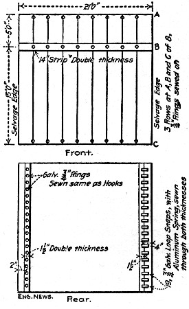 Fig. 42.—Canvas Curtain for Enclosing Open Walls.
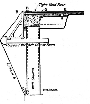 Fig. 43.—Sketch Showing Method of Applying Curtains to
Open Walls.
Fig. 43.—Sketch Showing Method of Applying Curtains to
Open Walls.
Method of Housing in Building Work.—The following method of housing in building work is used by Mr. E. L. Ransome. The feature of the system is that the enclosing structure is made up of a combination of portable units which can be used over and over again in different jobs. The construction is best explained in connection with sketches.[Pg 122]
Figure 43 shows a first floor wall column with the wall girder surmounting it and the connecting floor system. It will be seen that the open sides are enclosed by canvas curtains and the floor slab is covered with wood shutters. The curtains are composed of separate pieces so devised that they may be attached to each other by means of snaps and eyes; one of these curtain units is shown by Fig. 42. Referring now to Fig. 43, the curtain A is held by the tying-rings to a continuous string piece B, the upper portion or flap D being held down by a metal bar or other heavy object so as to lap over the floor covers E. The lower edge of the curtain is attached to the string piece C. The sketch has been made to show how the curtain adjusts itself to irregular projections such as the supports for a wall girder form; to prevent the curtain tearing on such projections it is well to cover or wrap the rough edges with burlap, bagging or other convenient material. The details of the wooden floor covers are shown by Fig. 44; they are constructed so as to give a hollow space between them[Pg 123] and the floor and holes are left in the floor slab as at H, Fig. 43, to permit the warm air from below to enter this hollow space. This warm air is provided by heating the enclosed story of the building by any convenient adequate means. In constructing factory buildings, 50×200 ft. in plan at Rochester, N. Y., Mr. Ransome used a line of ¾ to ⅜-in. steam pipe located at floor level and running around all four sides and a similar line running lengthwise of the building at the center, these pipes discharging live steam through openings into the enclosed space. In addition to the steam piping 10 braziers in which coke fires were kept were scattered around the floor. This equipment kept the enclosed story, 50×100 ft.×13 ft. high, at a temperature of 80° F. and at temperature of about 40° F. between the floor top and its board covering. The work was not stopped at any time because of cold and the temperatures outside ranged from zero to 10° above.
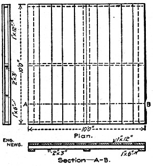 Fig. 44.—Portable Wooden Panels for Covering Floors.
Good design in concrete as well as in steel, masonry and wood, requires that the structure shall be good to look at. This means that the proportions must be good and that the surface finish must be pleasing. Good proportions are a matter of design but a pleasing surface finish is a matter of construction. Many, perhaps the majority of, concrete structures do not have a pleasing surface finish; the surface is irregular, uneven in texture, and stained or discolored or of lifeless hue. The reasons for these faults and the possible means of remedying them are matters that concern the construction engineer and the contractor.
Imperfections in the surface of concrete are due to one or more of the following causes: (1) Imperfectly made forms; (2) imperfectly mixed concrete; (3) carelessly placed concrete; (4) use of forms with dirt or cement adhering to the boards; (5) efflorescence and discoloration of the surface after the forms are removed.
IMPERFECTLY MADE FORMS.—In well mixed and placed concrete the film of cement paste which flushes to the surface will take the impress of every flaw in the surface of the forms. It will even show the grain marks in well dressed lumber. From this it will be seen how very difficult it is so to mold concrete that the surface will not bear evidence of the mold used. The task is impracticable of perfect accomplishment and the degree of perfection to which it can be carried depends upon the workmanship expended in form construction. Forms with a smooth and even surface are difficult and expensive to secure. It is impracticable in the first place to secure lagging boards dressed to exact thickness and in the second place it is impracticable to secure perfect carpenter work; joints cannot be got perfectly close and a nail omitted[Pg 125] here or there leaves a board free to warp. From this point on the use of imperfectly sized lumber and careless carpentry can go to almost any degree of roughness in the form work. Only approximately smooth and unmarked concrete surfaces can be secured in plain wooden forms and this only with the very best kind of form construction. So much for the limitations of form work in the matter of securing surface finish. These limitations may be reduced in various ways. Joint marks may be eliminated wholly or partly by pointing the joints with clay or mortar or by pasting strips of paper or cloth over them, or the whole surface of the lagging can be papered; by the use of oiled paper there will be little trouble from the paper sticking. Grain marks and surface imperfections can be reduced by oiling the lumber so as to fill the pores or by first oiling and then filling the coat of oil with fine sand blown or cast against the boards.
The preceding remarks are of course based on the assumption that as nearly as possible a smooth and even surface finish is desired. If something less than this is sufficient, and in many cases it is, form produced surface defects become negligible in the proportion that they do not exceed the standards of roughness and irregularity considered permissible by the engineer and these standards are individual with the engineer; what one considers excessive roughness and irregularity another may consider as amply even and smooth. The point to be kept in mind is that beyond a certain state of evenness and regularity form produced surfaces are impracticable to obtain, because to construct forms of the necessary perfection to obtain them costs far more than it does to employ special supplementary finishing processes.
Surface blemishes due to dirt or cement adhering to the form boards have no excuse if the engineer or contractor cares to avoid them. It is a simple matter to keep the lagging clean and free from such accumulations.
IMPERFECT MIXING AND PLACING.—Imperfectly mixed and placed concrete gives irregularly colored, pitted and honeycombed surfaces with here a patch of smooth mortar and there a patch of exposed stone. Careful mixing and placing will avoid this defect, or all chance of it may be eliminated by using surface coatings of special mixtures.[Pg 126] There is no great difficulty, however, in obtaining a reasonably homogeneous surface with concrete; the task merely requires that the mixing shall be reasonably uniform and homogeneous and that in placing this mixture the spading next to the lagging shall be done in such a way as to pull the coarse stones back and flush the mortar to the surface. Spading forks are excellent for this purpose. A better tool is a special spade made with a perforated blade; this special spade costs $3.
EFFLORESCENCE.—Efflorescence is the term applied to the whitish or yellowish accumulations which often appear on concrete surfaces. "Whitewash" is another name given to these blotches. Efflorescence is due to certain salts leaching out of the concrete and accumulating into thin layers where the water evaporates on the surface. These salts are most probably sulphates of calcium and magnesium, both of which are contained in many cements and both of which are slightly soluble in water. Efflorescence is very erratic in its appearance. Some concretes never exhibit it; in some it may not appear for several years, and in others it shows soon after construction and may appear in great quantities. The most effective way to prevent efflorescence would naturally be to use cements entirely free from sulphates, chlorides or whatever other soluble salts are the cause of the phenomenon, but the likelihood of engineers resorting to the trouble of such selection, except in rare instances, is not great, even if they knew what cements to select, so that other means must be sought. The most common place for efflorescence to appear in walls is at the horizontal junction of two days' work or where a coping is placed after the main body of the wall has been completed. The reason of this seems to be that the salt solutions seep down through the concrete until they strike the nearly impervious film of cement that forms on the top surface of the old concrete before the new is added, and then they follow along this impervious film to the face of the wall. The authors have suggested that this cause might be remedied by ending the day's work by a layer whose top has a slight slope down toward the rear of the wall or perhaps by placing all the concrete in similarly sloping layers. Mr. C. H. Cartlidge is authority for the statement that this leaching at joints can[Pg 127] be largely done away with by the simple process of washing the top surface of concrete which has been allowed to set over night by scrubbing it with wire brushes in conjunction with thorough flushing with a hose. But efflorescence frequently appears on the faces of walls built without construction joints and in which a wet concrete is puddled in and not tamped in layers, and here other means are obviously essential. Waterproofing the surface of the wall should be effective so long as the waterproofing lasts; indeed one of the claims made for some of these waterproofing compounds is that efflorescence is prevented. The various waterproofing mixtures capable of such use will be found described in Chapter XXV. Failing in any or all of these methods of preventing efflorescence the engineer must resort to remedial measures. The saline coating must be scraped, or chipped, or better, washed away with acids.
Efflorescence was removed from a concrete bridge at Washington, D. C, by using hydrochloric (muriatic) acid and common scrubbing brushes; 30 gals. of acid and 36 scrubbing brushes were used to clean 250 sq. yds. of concrete. The acid was diluted with 4 or 5 parts water to 1 of acid; water was constantly played with a hose on the concrete while being cleaned to prevent penetration of the acid. One house-front cleaner and 5 laborers were employed, and the total cost was $150, or 60 cts. per sq. yd. This high cost was due to the difficulty of cleaning the balustrades. It is thought that the cost of cleaning the spandrels and wing walls did not exceed 20 cts. per sq. yd. The cleaning was perfectly satisfactory. An experiment was made with wire brushes without acid, but the cost was $2.40 per sq. yd. The flour removed by the wire brushes was found by analysis to be silicate of lime. Acetic acid was tried in place of muriatic, but required more scrubbing.
SPADED AND TROWELED FINISHES.—With wet-concrete and ordinarily good form construction a reasonably good surface appearance can be obtained by spading and troweling. For doing the spading a common gardener's hoe, straightened out so that the blade is nearly in line with the handle will do good work. The blade of the tool is pushed down next to the lagging and the stone pulled back giving the[Pg 128] grout opportunity to flush to the face. Troweling, that is troweling without grout wash, requires, of course, that the concrete be stripped before it has become too hard to be worked. As troweling is seldom required except for tops of copings and corners it is generally practicable to bare the concrete while it is still fairly green. In this condition the edges of copings, etc., can be rounded by edging tools such as cement sidewalk workers use.
PLASTER AND STUCCO FINISH.—The ordinary concrete surface with a film-like cement covering will not hold plaster or stucco. To get proper adhesion the concrete surface must be scrubbed, treated with acid or tooled before the plaster or stucco is applied and this makes an expensive finish since either of the preliminary treatments constitutes a good finish by itself. When a coarse grained facing is made of very dry mixtures, as described in a succeeding section, it has been made to hold plaster very well on inside work. In general plaster and stucco finishes can be classed as uncertain even when the concrete surface has been prepared to take them, and when the concrete has not been so prepared such finishes can be classed as absolutely unreliable.
MORTAR AND CEMENT FACING.—Where a surface finish of fine texture or of some special color or composition is desired the concrete is often faced with a coat of mortar or, sometimes, neat cement paste or grout. Mortar facing is laid from 1 to 2 ins. thick, usually 1½-ins., the mortar being a 1-1, 1-2 or 1-3 mixture and of cement and ordinary sand where no special color or texture is sought. This facing often receives a future special finish as described in succeeding sections, but it is more usually used as left by the forms or at best with only a troweling or brushing with grout. Engineers nearly always require that the mortar facing and the concrete backing shall be constructed simultaneously. This is accomplished by using facing forms, two kinds of which are shown by Figs. 45 and 46. In use the sheet steel plates are placed on edge the proper distance back of the lagging and the space between them and the lagging is filled with the facing mortar. The concrete backing is then filled in to the height of the plate, which is then lifted vertically and the backing and facing thoroughly bonded by tamping them together. The form shown[Pg 129] by Fig. 46, though somewhat the more expensive, is the preferable one, since the attached ribs keep the plate its exact distance from the lagging without any watching by the men, while the flare at the top facilitates filling. The facing mortar has to be rather carefully mixed; it must be wet enough to work easily and completely into the narrow space and yet not be so soft that in tamping the backing the stones are easily forced through it. Also since the facing cannot proceed faster than the backing the mortar has to be mixed in small batches so that it is always fresh. A cubic yard of mortar will make 216 sq. ft. of 1½-in. facing. Cement facing is seldom made more than 1 in. thick. If placed as a paste the process is essentially the same as for placing mortar. When grout is used a form is not used; place and tamp the concrete in 6 to 8-in layers, then shove a common gardener's spade down between the concrete and the lagging and pull back the concrete about an inch and pour the opening full of grout and withdraw the spade. If this work is carefully done there will be very few stones showing when the forms are removed. When stiff pastes or mortars are used the contractor often places the facing by plastering the lagging just ahead of the concreting; this process requires constant watching to see that the plaster coat does not slough or peel off before it is backed up with concrete.
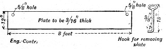 Fig. 45.—Form for Applying Cement Facing (Massachusetts
Highway Commission).
Fig. 45.—Form for Applying Cement Facing (Massachusetts
Highway Commission).
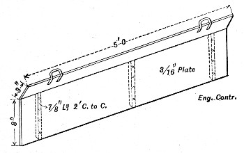 Fig. 46.—Form for Applying Cement Facing (Illinois
Central R. R.).
Fig. 46.—Form for Applying Cement Facing (Illinois
Central R. R.).
SPECIAL FACING MIXTURES FOR MINIMIZING FORM MARKS.—The ordinary facing mixture of mortar or cement is so fine grained and plastic that it readily takes the impress of every irregularity in the form lagging; where a particularly good finish is desired this makes necessary subsequent finishing treatments. To avoid these subsequent treatments and at the same time to reduce the form marks, special facing mixtures, which will not take the imprint of and which will minimize rather than exaggerate every imperfection in the forms, have been used with very considerable success in the concrete work done for the various Chicago, Ill., parks. The mixture used consists usually of 1 part cement, 3 parts fine limestone screenings and 3 parts ¾-in. crushed limestone; these materials are mixed quite dry so no mortar will flush to the surface when rammed hard. With moderately good form work the imprint of the joints is hardly noticeable and grain marks do not show at all. For thin building walls the special mixture is used throughout the wall, but for more massive structures it is used only for the facing.
GROUT WASHES.—Grout finishes serve only to fill the small pits and pores in the surface coating; cavities or joint lines, if any exist, must be removed by plastering or rubbing before the grout is applied or else by applying the grout by rubbing. In ordinary work the grout is applied with a brush after the holes have been plastered and the joint marks rubbed down. The grout to be applied with a brush should be about the consistency of whitewash; a 1 cement 2 sand mixture is a good one. Where a more perfect finish of dark color is desired the grout of neat cement and lampblack in equal parts may be applied as follows: Two coats with a brush, the second coat after the first has dried, and one coat by sweeping with a small broom. The broom marks give a slightly rough surface. Instead of a liquid grout a stiff grout or semi-liquid mortar applied with a trowel or float can be used. In this case the grout should be applied in a very thin coat and troweled or floated so that only the pores are filled and no body of mortar left on the surface or else it will scale off. A more expensive but very superior grout finish is obtained by rubbing[Pg 131] and scouring the wet grout into the surface with cement mortar bricks, carborundum bricks, or such like abrasive materials. A 1 cement 1 sand mortar brick, with a handle molded into it, and having about the dimensions of an ordinary building brick makes a good tool for rubbing down joint marks as well as for applying grout.
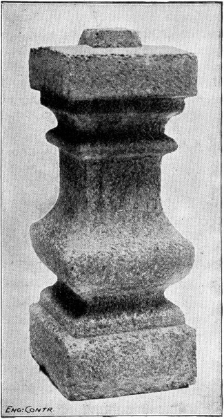 Fig. 47.—Concrete Baluster Finished by Scrubbing and
Washing.
Fig. 47.—Concrete Baluster Finished by Scrubbing and
Washing.
FINISHING BY SCRUBBING AND WASHING.—A successful finish for concrete structures consists in removing the forms while the concrete is green and then scrubbing the surface with a brush and water until the film of cement is removed and the clean sand or stone left exposed. This method has been chiefly used in concrete work done by the city of Philadelphia, Pa., Mr. Henry M. Quimby, Bridge Engineer. Figure 47 shows an example of scrubbed finish, but of course the texture or color of the surface will vary with the character of the face mixture and the hue of the sand or chips used. Warm tones can be secured by the use of crushed brick or red gravel; a dark colored stone with light sand gives a color much resembling granite; fine gravel or coarse sand gives a texture like sandstone. In much of this work done in Philadelphia a mixture composed of 1 part cement, 2 parts bank sand and 3 parts crushed and cleaned black, slaty shale from ⅜ to ¼ in. in size, has been used with good results both in appearance[Pg 132] and in durability. The scrubbing is done with an ordinary house scrubbing brush at the same time flushing the concrete with water from a sponge or bucket or, preferably, from a hose. In general the washing is done on the day following the placing of the concrete but the proper time depends upon the rapidity with which the concrete sets. In warm weather 24 hours after placing is generally about right, but in cold weather 48 hours may be required, and in very cold weather the concrete has been left to set a week and the scrubbing has been successful. With the concrete in just the proper condition a few turns of the brush with plenty of water will clean away the cement, but if a little too hard wire brushes must be used and if still harder a scouring brick or an ordinary brick with sand is necessary to cut the cement film. The process requires that the forms shall be so constructed that the lagging can be removed when the concrete has reached the proper age for treatment. Mr. Quimby sets the studs 8 to 12 ins. from the face and braces the lagging boards against them by cleats nailed so as to be easily loosened. His practice is to use boards in one width the full depth of the course and to nail a triangular bead strip to the face at each edge. These bead strips mark the joints between courses as shown by Fig. 48. When a "board" is taken off it is cleaned and oiled and reset for a new course by inserting the bottom bead strip in the half indentation left by the top bead in the concrete. This is, of course, for work of such size that one course is a day's work of concreting. In such work, two carpenters with[Pg 133] perhaps one helper will remove a course of "boards" say 100 ft. long in from 4 to 8 hours. While forms of the kind described cost more to construct there is a saving by repeated re-use of the lagging boards. The indentations or beads marking the courses serve perfectly to conceal the construction joints. The cost of scrubbing varies with the hardness of the concrete; when in just the right condition for effective work one man can scrub 100 sq. ft. in an hour; on the other hand it has taken one man a whole day to scrub and scour the same area when the concrete was allowed to get hard.
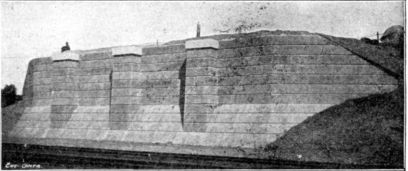 Fig. 48.—Concrete Abutment with Scrubbed Finish and
Course Marks.
Fig. 48.—Concrete Abutment with Scrubbed Finish and
Course Marks.
FINISHING BY ETCHING WITH ACID.—The acid etched or acid wash process of finishing concrete consists in first washing the surface with an acid preparation to remove the surface cement and expose the sand and stone, then with an alkaline solution to remove all free acid, and finally, with clear water in sufficient volume to cleanse and flush the surface thoroughly. The work can be done at any time after the forms are removed and does not require skilled labor; any man with enough judgment to determine when the etching has progressed far enough can do the work. This process has been very extensively used in Chicago by the South Park Commission, Mr. Linn White, Engineer. In this work the concrete is faced with a mixture of cement, sand and stone chips, any stone being used that is not affected by acid. Limestone is excluded. Where some color is desired the facing can be mixed with mineral pigments or with colored sand or stone chips. This acid wash process has been patented, the patentees being represented by Mr. J. K. Irvine, Sioux City, Ia.
TOOLING CONCRETE SURFACES.—Concrete surfaces may be bush-hammered or otherwise tool finished like natural stone, exactly the same methods and tools being used. Tooling must wait, however, until the concrete has become fairly hard. As the result of his experience in tooling some 43,000 sq. ft. of concrete, Mr. W. J. Douglas states that the concrete should be at least 30 days old and, preferably, 60 days old, if possible, when bush-hammered. There is a great variation in the costs given for tooling concrete. Mr. C. R. Neher states that a concrete face can be bush-hammered by an ordinary laborer at the rate of 100 sq. ft. in 10 hours or at a cost of[Pg 134] 1½ cts. per square foot with wages at 15 cts. per hour. Mr. E. L. Ransome states that bush-hammering costs from 1½ to 2½ cts. per square foot, wages of common laborers being 15 cts. per hour. The walls of the Pacific Borax Co.'s factory at Bayonne, N. J., were dressed by hand at the rate of 100 to 200 sq. ft. per man per day; using pneumatic hammer one man was able to dress from 300 to 600 sq. ft. per day. In constructing the Harvard Stadium the walls were dressed with pneumatic hammers fitted with a tool with a saw-tooth cutting blade like an ice chopper. Men timed by one of the authors on a visit to this work were dressing wall surface at the rate of 50 sq. ft. per hour, but the contractor stated that the average work per man per day was 200 sq. ft. Common laborers were employed. The average cost of bush-hammering some 43,000 sq. ft. of plain and ornamental blocks for the Connecticut Avenue Bridge at Washington, D. C, was 26 cts. per square foot. Both pneumatic tools and hand tooling were employed and the work of both is lumped in the above cost, but hand tooling cost about twice as much as machine tooling. The work was done by high-priced men, foremen stone cutters at $5 per day and stone cutters at $4 per day. Moreover a grade of work equal to the best bush-hammered stone work was demanded. Full details of the cost of this work are given in Chapter XVII. Mr. H. M. Quimby states that the cost of tooling concrete runs from 3 cts. to 12 cts. per square foot, according to the character and extent of the work and the equipment.
GRAVEL OR PEBBLE SURFACE FINISH.—An effective variation of the ordinary stone concrete surface is secured by using an aggregate of rounded pebbles of nearly uniform size and by scrubbing or etching remove the cement enough to leave the pebbles about half exposed at the surface. In constructing a bridge at Washington, D. C, the concrete was a 1-2-5 gravel mixture of 1½ to 2-in. pebbles for the spandrels and arch ring face and of 1-in. pebbles for the parapet walls. The forms were removed while the concrete was still green and the cement scrubbed from around the faces and sides of the pebbles using wire brushes and water. Tests showed that at 12 hours age the concrete was not hard enough to prevent the pebbles from being brushed loose and that at 36 hours age it was too hard to permit the mortar to be scrubbed away[Pg 135] without excessive labor; the best results were obtained when the concrete was about 24 hours old.
COLORED FACING.—Where occasion calls for concrete of a color or tint other than is obtained by the use of the ordinary materials either an aggregate of a color suitable for the purpose may be used or the mixture may be colored by the addition of some mineral pigment. The first method is by all odds the preferable one; it gives a color which will endure for all time and it in no way injures the strength or durability of the concrete. Mineral pigments may be secured from any of several well-known firms who make them for coloring concrete, and they may be had in almost every shade. Directions for using these colors can be had from the makers. All but a very few of these mineral colors injure the strength and durability of the concrete if used in amounts sufficient to produce the desired color and all of them fade in time. The best method of producing a colored mortar or concrete facing is to mix the cement with screenings produced by crushing a natural stone of the desired color.
Concrete being a plastic material when deposited requires molds or forms to give it the shape required and to maintain it in that shape until it has hardened to sufficient strength to require no exterior support. The material used in constructing forms is wood. Beyond the use of metal molds for building blocks for sewer construction and for ornamental and a few architectural shapes, iron and steel are used in form construction only as ties and clamps to hold parts of wood forms together—except in rare instances. A discussion of form construction, therefore, is essentially a discussion of wood forms.
Before taking up this discussion, however, attention deserves to be called to the opportunities for the development of metal forms. Lumber is costly and is growing more scarce and costly all the time. A substitute which can be repeatedly used and whose durability and salvage value are great presents itself in steel if only a system of form units can be devised which is reasonably adjustable to varying conditions. Cylindrical steel column molds have been used to some extent and are discussed in Chapter XIX. In Chapter XVI we describe a steel form for side walls of a tunnel lining. In some building work done in the northwest corrugated steel panels or sheets have been used as lagging for floor slab centers. A number of styles of metal forms or centers for sewer and tunnel work have been devised and used and are discussed in Chapter XXI. Despite this considerable use of metal for special forms nothing approaching its general use like wood has been attempted, and the field lies wide open for invention.
The economics of form construction deserve the most serious attention of the engineer and contractor. It is seldom that form work, outside of very massive foundation construction, costs less than 50 cts. per cubic yard of concrete in place, and[Pg 137] it is not unusual in the more complex structures for it to cost $5 per cubic yard of concrete in place. These costs include the cost of materials and of framing, handling and removing the forms but they do not embrace extremely high or low costs. It is evident without further demonstration that time spent in planning economic form construction for any considerable job of concrete work is time spent profitably.
In the following sections we review the general considerations which enter into all form work. Specific details of construction and specific costs of form work are given in succeeding chapters where each class of concrete work is discussed separately. This chapter is intended principally to familiarize the reader with general principles governing form work.
EFFECT OF DESIGN ON FORM WORK.—The designing engineer can generally aid largely in reducing the cost of form work if he will. This is particularly true in building work in which, also, form costs run high. By arranging his beam spacing and sizes with a little care he will enable the contractor to use his forms over and over and thus greatly reduce the expense for lumber. In the same way columns may be made of dimensions which will avoid frequent remaking of column forms. Panel recesses in walls may be made the thickness of a board or plank, instead of some odd depth that will require a special thickness of lumber, or beams may be made of such size that certain dimension widths of lumber can be used without splitting. In general, carpenter work costs more than concrete and where a little excess concrete may be contributed to save carpenter work it pays to contribute it. The figures given in Chapter XIX, showing the reduction in lumber cost coming from using the same material over a second or third time, should be studied in this connection. The leading firms of engineering-contractors which both design and construct reinforced concrete buildings fully realize these opportunities and take advantage of them, but the general practitioner, particularly if he be an architect, does not do so. The authors have personal knowledge of one building in which a slight change in spacing and dimensions of beams—a change that would have been of no architectural or structural significance—would have reduced the successful contractor's bid for the work by $10,000. The designing engineer[Pg 138] should hold it as a cardinal point in design that form work, and we will add here reinforcement also, should so far as possible be made interchangeable from bay to bay and from floor to floor.
KIND OF LUMBER.—The local market and the character of the work generally determine the kind of lumber to be used for forms. The hardwoods are out of the question for form construction because they cost too much and are too hard to work. Among the soft woods white pine costs too much for general use and hemlock is unreliable when exposed to the weather. This reduces the list generally available to spruce, Norway pine and the southern pines. Neither green nor kiln-dried lumber is so good as partially dry stuff, since the kiln-dried lumber swells and crushes or bulges the joints and green lumber does not swell enough to close the joints. Forms have to withstand, temporarily, very heavy loads, therefore, knots, shakes and rot must be watched after. The choosing of good lumber is a simple process and the contractor who wants to be able to rely on his forms will look after it carefully, without going to extremes which the work does not warrant.
FINISH AND DIMENSIONS OF LUMBER.—Dressing the lumber serves four important purposes: It permits the forms to be constructed more nearly true to line and surface; it permits tighter joint construction; it gives a smoother surface finish to the concrete, and it facilitates the removal and cleaning of the forms. Undressed lumber may be used for the backs of walls and abutments, for work below ground and wherever a smooth and true surface is unimportant; there are some contractors, however, who prefer lumber dressed on one side even for these purposes because of the smaller cost of cleaning. For floor and wall forms the lumber should always be dressed on one side; where the work is very particular both sides should be dressed, and in special cases the sides of the joists or studs against which the lagging lies may be dressed. For ordinary work a square edge finish does well enough but for fine face work a tongue and groove or bevel edge finish is preferable. The tongue and groove finish gives a somewhat tighter joint on first laying but it does not take up swelling or resist wear so well as the bevel edge finish.[Pg 139]
When ordering new lumber for forms the contractor will save much future work and waste if he does it from plans. Timber cut to length and width to go directly into the forms reduces both mill and carpenter work on the site, and in many cases it can be so ordered if ordered from plans. Waste is another item that is reduced by ordering from plans; with lumber costing its present prices crop ends run into money very rapidly. When old lumber from a previous job is to be used the contractor can only make the best of his stock, but even here form plans will result in saving. Sort and pile the old lumber according to sizes and make a schedule of the quantity of each size on hand; this schedule in the hands of the man who designs the forms and of the head carpenter will materially reduce waste and carpenter work. It is often possible especially in making concrete foundations for frame buildings to use lumber for forms which is subsequently used for floor beams, etc., in the building.
Contractors differ greatly in their ideas of the proper thickness of lumber to use for various parts of form work. Generally speaking 1¼ to 2-in. stuff is used for wall lagging held by studding and 1-in. stuff when built into panels; for floor lagging 1-in stuff with joists spaced up to 24 ins. or when built into panels; for column lagging 1¼ to 2-in. stuff; for sides of girders 1, 1¼, 1½ and 2-in. stuff are all used; and for bottoms of girders, 1½ and 2-in. stuff. These figures are by no means invariable as a study of the numerous examples of actual form work given throughout this book will show.
COMPUTATION OF FORMS.—If the minimum amount of lumber consistent with a given deflection is to be used in form work the sizes and spacing of the supporting members must be actually computed for the loading. As a practical matter of fact the amount of material used and the arrangement of the supports are often subject to requirements of unit construction, clearance, staging, etc., which supersede the matter of economical adaptation of material to loading. The designing of form work is at best, therefore, a compromise between rules of thumb and scientific calculation. In wall work empirical methods are nearly always followed. In girder and floor slab work, on the other hand, design is commonly based on computation.[Pg 140]
In the matter of loads the general practice is to assume the weight of concrete as a liquid at some amount which it is considered will also cover the weight of men, barrows, runways and current construction materials. The assumed weights vary. One prominent engineering firm assumes the load to be the dead weight of concrete as a liquid and the load due to placing and specifies that the forms shall be designed to carry this load without deflection. Mr. W. J. Douglas, Engineer of Bridges, Washington, D. C, assumes for lateral thrust on wall forms that concrete is a liquid of half its own weight, or 75 lbs. per cu. ft. Mr. Sanford E. Thompson, Consulting Engineer, Newton Highlands, Mass., assumes for dead load, weight of concrete including reinforcement as 154 lbs. per cu. ft., and for live load, 75 lbs. per sq. ft. on slabs and 50 lbs. per sq. ft. in figuring beam and girder forms and struts.
The assumed safe stresses in form work may be taken somewhat higher than is usual in timber construction, because of the temporary character of the load. In calculating beams the safe extreme fiber stress may be assumed at 750 lbs. per sq. in. The safe stress in pounds per square inch for struts or posts is shown by Table XV, compiled by Mr. Sanford E. Thompson. The sizes of struts given are those most commonly used in form work.
| —Dimensions of Strut.— | ||||
| Length Strut. | 3×4-in. | 4×4-in. | 6×6-in. | 8×8-in. |
| Feet. | Lbs. | Lbs. | Lbs. | Lbs. |
| 14 | ..... | 700 | 900 | 1,100 |
| 12 | 600 | 800 | 1,000 | 1,200 |
| 10 | 700 | 900 | 1,100 | 1,200 |
| 8 | 850 | 1,050 | 1,200 | 1,200 |
| 6 | 1,000 | 1,200 | 1,200 | 1,200 |
In using this table it must be borne in mind that bracing both ways reduces the length of a long strut. For example, if a strut 24 ft. long be divided into three panels by bracing the length of strut so far as the table is concerned is 8 ft.
As stated above wall forms are rarely computed. Experience has shown that the maximum spans of various thicknesses of lagging between supports are: 1-in. boards, 24 ins.;[Pg 141] 1½-in. plank, 4 ft., and 2-in. plank, 5 ft. Studding will vary in size from 2×4 to 4×6 ins., strutted and braced horizontally to meet conditions. Column forms, like wall forms, are rarely computed, yokes being spaced 2 ft. apart for 1¼-in. lagging up to 3 to 3½ ft. apart for 2-in. lagging.
Floor forms, including girder and slab forms, are computed on the basis of a maximum deflection and not on the basis of strength. Sagging forms are liable to rupture the beam or slab. The amount of deflection considered allowable varies from no deflection up to ⅜ to ½ in. Assuming the deflection, permissible thickness of the timber necessary to carry the load is determined by the formulas:
| d = 5 W l³ ÷ 384 E I | (1) |
and
| bh³ | |||
| I | = | —— | (2) |
| 12 |
Formula (1) is the familiar one for computing deflection for a beam supported (not fixed) at the ends. Mr. Sanford F. Thompson suggests using the constant {3/384}, which is an approximate mean between {1/384} that for beams with fixed ends and {5/384} that for beams with ends supported. Formula (1) then becomes
d = 3 W l³ ÷ 384 E I,
in which as above:
d = maximum deflection in inches.
W = total load on plank or joist.
l = length between supports in inches.
E = modulus of elasticity of lumber.
I = moment of inertia of cross-section.
b = breadth of lumber.
h = depth of lumber.
The deflection, d, being assumed formula (1) is solved for I, moment of inertia. Substituting the value of I in formula (2) we can readily estimate the size of joist or thickness of plank to use.—For spruce, yellow pine and the other woods commonly used in form work E may be taken equal to 1,300,000 lbs. per sq. in.
DESIGN AND CONSTRUCTION.—The main points to be kept in mind in the original design and construction of forms are: Economy in lumber, economy in carpenter work,[Pg 142] and economy in taking down, carrying and re-erecting. Economy in lumber is not merely the matter of using the least amount of lumber that will serve the purpose considering the form as an isolated structure. It may be possible to build a column form, for example, of very light material which will serve to mold a single column, but it is evident that we could better afford to use twice this amount of lumber if by doing so we obtained a form which could be used over again to mold a second column; no more lumber per column would be used while the cost of erecting a form already framed is less than the cost of framing a new form. Economy in lumber in form construction involves, therefore, recognition of the economies to be gained by repeated use of the lumber. A certain amount of additional sturdiness is required in the shape of heavier form lumber and stronger framing to provide for the wear and tear of repeated use, and it is always economy to provide it when repeated use is possible. The thing can be overdone, however; there is an economical limit to repeated use, as we demonstrate further on. In the matter of economy in carpenter work, a certain amount of extra work put into framing the forms to withstand the stress of repeated use is economically justifiable. Also carpenter work put into framing which substitutes clamps and wedges for nails is sound economy; generally speaking a skillful form carpenter is recognized by the scarcity of nails he uses. The possibility of reducing carpenter work by ordering lumber to length and width from plans has already been mentioned. It is possible often to go a step further by having certain standard panels, boxes, etc., made in regular shops. Piece work is often possible and will frequently reduce framing costs. In designing for economy in taking down, carrying and re-erecting forms a cardinal point should be that the work be such that it can be executed by common laborers. This result can be very nearly approached by careful design, even for form work that is quite complex, if a special gang is devoted to the work and trained a little in the various operations. Design the forms so that they come apart in units by simply removing bolts, clamps and wedges. They can then be taken down, carried and erected by common laborers with a skilled man in charge to meet emergencies and to true and line up the work.[Pg 143]
In the matter of details the joints deserve particular attention. In column and girder forms, generally, joints will be square or butt joints, and to get them tight the lumber must be dressed true to edge. Tight joints are considered essential by many not only to avoid joint marks but for the more important reason that otherwise, with wet mixtures, a honeycombed concrete is produced by leakage. Where tight joints are desired tongue and groove stock or stock cut with one edge beveled and the other square give the best results. The authors believe that the best general satisfaction will be got from the bevel edge stock placed so that the bevel edge of one board comes against the square edge of the next board; undue swelling then results in the bevel edge cutting into the adjacent square edge without bulging. Tongues and grooves suffer badly from breakage. As a matter of fact square edged stock, if well dressed and sized and well filled with moisture, can be used and is used with entire success in nearly all kinds of work. The leakage will be very slight with ordinarily good butt joints and so far as surface appearance goes joint marks are more cheaply and more satisfactorily eliminated by other means than attempting to get cabinet work in form construction. Where girder forms join columns or beams connect with girders and at the angles of floor slabs with beams the edges or corners of the forms should be rounded. The edges of beams and column corners will appear better if beveled; a triangular strip in the corners of the forms will provide this bevel. Forms and mold construction for ornamental work call for and are given special consideration in Chapter XXIII. In conclusion, the reader should study the specific examples of form construction for different purposes that are given throughout the book for hints as to special practice and details.
UNIT CONSTRUCTION OF FORMS.—Unit construction has a somewhat variable meaning in form work. In wall and tank work and in some other kinds of work unit construction means the use of form units which are gradually moved ahead or upward as the concreting progresses or of form units which are used one after another in continuous succession as the concreting progresses. In column, girder and floor work unit construction means the division of the form work as a[Pg 144] whole and also of the individual forms into independent structural units; thus in forms for a building the column forms may be independent of the girder forms and also each column and girder form be made up of several separate units. In all cases unit construction has for its purpose the use of the same form or at least the same form lumber over and over for molding purposes. Every time the use of the same form is repeated, the cost of form work per cubic yard of concrete placed is reduced. The theoretical limit of economical repetition is then the limit of endurance of the form, the practical limit, however, is something quite different. Most concrete work varies in form or dimensions often enough to prevent the use of the same forms more than a few times, and even if these variations did not exist the time element would enter to prevent the same form or form lumber being used more than a certain number of times. Unit construction to give repeated use of forming has, therefore, its economic limits. The significance of this conclusion does not lie in any novelty that it possesses but in the fact that for any piece of work it determines the labor that may profitably be expended in working out and constructing form units.
LUBRICATION OF FORMS.—All forms for concrete require a coating of some lubricant to prevent the concrete from adhering to the wood with which it comes in contact. Incidentally this coating tends to give a smoother surface to the concrete and to preserve the wood against damage by its alternate wetting and drying. The great value of lubrication is, however, that it reduces the cost of removing forms. The requisite of a good coating material is that it shall be thin enough to spread evenly and to fill the pores and grain of the wood. Crude oil or petroline makes one of the best coatings, but various other greasy substances will serve. Where the forms are not to be removed until the concrete has set hard a thorough wetting of the wood just before the concrete is placed is all the coating necessary. Any concrete adhering to forms should be thoroughly cleaned off before they are used again and the wood underneath given a special heavy coating.
FALSEWORKS AND BRACING.—The falseworks which support the forms proper and stagings for workmen, runways, material hoists, etc., do not call for any striking differences in[Pg 145] construction and arrangement from such work elsewhere. For wall forms inclined props reaching from ground to studding are used for walls of moderate height such as retaining walls, wing walls, and abutments. For building walls of some height a gallows frame arrangement or the common braced staging used by masons and carpenters is used. In building construction, however, movable forms are commonly employed for walls more than one story high and should always be employed above one story to save staging timber. Column forms are seldom braced unless erected without connecting girder or floor forms at their tops, and then only by diagonal props to the floor or ground. Girder and floor supports usually consist of uprights set under the girder form at intervals and occasionally under floor slab forms. The spacing of props and uprights will be regulated by the judgment of the foreman and boss carpenter; no general rule is applicable, except that enough lumber must be used to hold the forms rigid and true to line and level. The various illustrations of actual formwork which follow are the best guides to good practice.
TIME FOR AND METHOD OF REMOVING FORMS.—No exact time schedule for removing forms is wise in concrete work. Concrete which is mixed wet sets slower than dry concrete and concrete sets slower in cold weather than it does in warm weather. Again the time of removal is influenced by the risk taken by too early removal, and also by the nature of the stresses in the member to be relieved of support. In all cases the forms should be removed as soon as possible so that they can be used over again and so that the concrete may be exposed to the air to hasten hardening. The following suggestions as to time of removal are general and must be followed with judgment.
Using dry concrete in warm weather the forms for retaining walls, pedestals, isolated pillars, etc., can be removed in 12 hours; using wet or sloppy concrete the time will be increased to 24 hours. In cold weather the setting is further delayed and inspection is the only safe guide to follow. Very cold weather delays setting indefinitely. Forms for small arch work like sewers and culverts may be removed in 18 to 24 hours if dry concrete is used, and in 24 to 48 hours if wet concrete[Pg 146] is used. The time for removing large arch centers should not be less than 14 days for spans up to 50 ft. if the arch is back-filled at once; when the center is not to be used again it is better to let it stand 28 days. For very large arches the problem becomes a special one and is considered in Chapter XVII. In building construction the following schedule is a common one. Remove the column forms in 7 days and the sides of the girder forms and the floor lagging in 14 days leaving the bottom boards of the girder forms and their supports in place for 21 days.
As an example of individual practice the following requirements of a large firm of concrete contractors are given:
Walls in mass work, 1 to 3 days, or until the concrete will bear pressure of the thumb without indentation.
Thin walls, in summer, 2 days; in cold weather, 5 days.
Slabs up to 6-ft. span, in summer, 6 days; in cold weather, 2 weeks.
Beams and girders and long span slabs, in summer, 10 days or 2 weeks; in cold weather, 3 weeks to 1 month. If shores are left without disturbing them, the time of removal of the sheeting in summer may be reduced to 1 week.
Column forms, in summer, 2 days; in cold weather, 4 days, provided girders are shored to prevent appreciable weight reaching columns.
Conduits, 2 or 3 days, provided there is not a heavy fill upon them.
Arches, of small size, 1 week; for large arches with heavy dead load, 1 month.
The method of removing forms will vary in detail with the character of the structure. With proper design and lubrication of forms they will ordinarily come away from the concrete with a moderate amount of sledge and bar work. If the work will warrant it, have a special gang under a competent foreman for removing forms. The organization of this gang and the procedure it should follow will vary with the nature of the form work, and they are considered in succeeding chapters for each kind of work.
ESTIMATING AND COST OF FORM WORK.—It is common practice to record the cost of forms in cents per cubic yard of concrete, giving separately the cost of lumber and[Pg 147] labor. This should be done, but the process of analysis should be carried further. The records should be so kept as to show the first cost per 1,000 ft. B. M. of lumber, the number of times the lumber is used, the labor cost of framing, the labor cost of erecting and the labor cost of taking down, all expressed in M. ft. B. M. In this way only is it possible to compare the cost of forms on different kinds of concrete work, and thus only can accurate predictions be made of the cost of forms for concrete work having dimensions differing from work previously done. It is well, also, to make a note of the number of square feet of exposed concrete surface to which the forms are applied.
Some of the items mentioned demand brief explanation. Framing and erecting costs are kept separate for the reason that the framing is done only once, whereas the erecting occurs two or more times. The lumber cost, where the material is used more than once, can be computed in two ways. An example will illustrate the two modes of procedure. In one of the buildings described in Chapter XIX the lumber cost $30 per M. ft. B. M. and was used three times. As 34,000 ft. B. M. were required to encase the 200 cu. yds. of concrete in one floor, including columns, it would have required 34,000 ÷ 200 = 170 ft. B. M. of lumber at $30 per M. per cubic yard of concrete if it had been used only once. But since it was used three times we may call it 170 ft. B. M. at $10 per M. per cubic yard of concrete, or we may call it 170 ÷ 3 = 57 ft. B. M. at $30 per M. per cubic yard of concrete. The authors prefer the first method, due to the fact that it is 170 ft. B. M. that is handled and taken down each time and it is more consistent to have the lumber cost on the same basis thus:
| 170 ft. B. M. of lumber at $10 per M | $1.70 |
| 170 ft. B. M. handled at $2 per M | 0.34 |
| 170 ft. B. M. erected at $7 per M | 1.19 |
| —— | |
| Total 170 ft. B. M. per cu. yd | $3.23 |
Returning to our main thought, there are three ways of recording the cost of form work: (1) In cents per cubic yard of concrete; (2) in cents per square foot of concrete face to which forms are applied, and (3) in dollars per 1,000 ft. B. M. of lumber used. In all cases the cost of materials and of labor[Pg 148] should be kept separate. It is well if it can be done to attach a sketch of the forms to the record. So much for the general method of recording costs in form work.
In estimating the probable cost of forms for any job the following method will be found reliable: Having the total cubic yards of concrete in the work and the time limit within which the work must be completed determine the number of cubic yards that must be placed per day, making liberal allowances for delays. Next estimate the number of thousands of feet board measure of forms required to encase the concrete to be placed in a day. This will give the minimum amount of lumber required, for it is seldom permissible to remove the forms until the concrete has hardened over night. Now we come to the very important and puzzling question of the time element, particularly in work where it is possible to use the same forms or the same form lumber two or more times.
It has already been pointed out that wet concrete sets more slowly than dry concrete; that all concrete sets more slowly in cold than in warm weather, and that the support of forms is necessary a longer time for pieces subject to bending stress like arches and girders. General suggestions as to specific times for removing forms have also been given. Where the specifications state the time of removal the contractor has a definite guide, but where they do not, as is most often the case, he must depend very largely on judgment and previous experience. Another matter which deserves consideration is the use of the forms as staging for runways or tracks. Such use may result in forms having to stand on work for sake of their service as trestles much longer than there is any necessity so far as supporting the concrete is concerned. A derrick or cableway may often prove cheaper than tieing up form lumber by trying to make it serve the double purpose of a trestle.
The possibilities of repeated use of forms and of unit construction of forms have already been noted. This is the next point to be considered in estimating form lumber. At the expense of a little planning movable forms can be used to materially reduce the amount of lumber required. The reader is referred particularly to the chapters on retaining wall, conduit and building work for specific data on movable form work.[Pg 149]
Having estimated the amount of lumber required and the number of times it can be used the labor cost of framing, erecting and taking down can be figured. In ordinary retaining wall work forms will cost for framing and erection from $6 to $7 per M. ft. B. M. To tear down such forms carefully and to carry the lumber a short distance will cost some $1.50 to $2 per M. ft. B. M. We have then a cost of $7.50 to $9 per M. ft. B. M. for each time the forms are erected and torn down. Where movable panels are used and the forms not ripped apart and put together again each time there is of course only the cost of moving, which may run as low as 50 cts. per M. ft. B. M. Framing and erecting centers for piers will run about the same as for retaining wall. At this point it may be noted that in estimating the cost of forms for plain rectangular piers the following method will give very accurate results. Ascertain the surface area of the four sides of the pier. Multiply this area by 2, and the product will be the number of feet board measure of 2-in. plank required. Add 40 per cent. to this, and the total will be the number of feet board measure of 2-in. plank and of upright studs (4×6), spaced 2½ ft. centers. Sometimes 3×6-in. studs are used, and spaced 2 ft. centers, which requires practically the same percentage (40 per cent.) of timber for the studs as where 4×6-in. studs are used and spaced 2½ ft. centers. No allowance is made for timber to brace the studs, since, in pier work, it is customary to hold the forms together either with bolts or with ordinary No. 9 telegraph wire, which weighs 0.06 lb. per foot. The foregoing data can be condensed into a rule that is easily remembered:
Multiply the number of square feet surface area of the sides and ends of a concrete pier by 2.8, and the product will be the number of feet board measure required for sheet plank and studs for the forms.
If the form lumber can be used more than once, divide the number of feet board measure by the number of times that it can be used, to ascertain the amount to be charged to each pier. Forms can be erected and taken down for $8 per M. carpenters being paid $2.50 and laborers $1.50 a day. Since there are 2.8 ft. B. M. of forms per square foot of surface area of concrete to be sheeted, it costs 2¼ cts. for the labor of[Pg 150] carpenters per square foot of surface area to be sheeted. If lumber is worth $24 per M., and is used three times, then the lumber itself also costs 2¼ cts. per sq. ft. of surface area of concrete. By dividing the total number of cubic yards of concrete into the total number of square feet of area of surface to be sheeted with forms, the area per cubic yard is obtained. Multiply this area by 4½ cts., and the product is the cost per cubic yard for material in the forms (assumed to be used three times) and the labor of erecting it and taking it down.
The cost of framing and erection of forms for building work and of centers for large arches is a special problem in each case and is considered in the chapters devoted to those classes of work.
Two general methods of concrete pile construction are available for engineering work. By one method a hole is formed in the ground by driving a steel shell or by other special means and this hole is filled with concrete. By the other method the pile is molded in suitable forms and after becoming hard is driven as a wood or steel pile is driven. Piles constructed by the first method may be either plain or reinforced, but piles constructed by the second method are always reinforced to strengthen them for handling and driving. Concrete piers for foundation work are simply piles of enlarged diameter.
MOLDING PILES IN PLACE.—Molding piles in place requires the use of special apparatus, and this apparatus is to a very large degree controlled by patents. Pile work of this kind is thus generally done by concerns which control the use of the apparatus employed and the general contractor can undertake it only by permission of the proprietary companies. The methods of work followed and the cost of work are thus of direct interest only as general information.
Method and Cost of Constructing Raymond Piles.—The machinery and processes employed in the construction of Raymond concrete piles are patented and all piling work by this method is controlled by the Raymond Concrete Pile Co. As detail costs of construction are not given out by the company the following figures collected by the authors are subject to revision. They are believed to be fairly approximate, having in one case been obtained by personal watch on the work and in the other case from authentic records of the engineers on the work.
The pile is made as follows: A collapsible steel core 30 ft. long, 20 ins. diameter at the top and 6 ins. diameter at the[Pg 152] bottom, encased in a thin sheet steel shell, is driven into the ground by an ordinary pile driver. When it has reached the proper depth, a wedge is loosened, permitting the two sections of the core to come closer together so that the core can be pulled out of the hole, leaving the steel shell behind as a casing to prevent the sides from caving in. The shell is made of No. 20 gage steel, usually in four or more sections, which telescope one over the other. A nest of sections is slipped over the lower end of the core as it hangs in the leads, a rope is hitched around the outer section and the engine hoists away until the sections are "un-telescoped" and drawn snug onto the core. The rope is then unfastened and the driving begins. Figure 49 shows the usual pile driving rig used. The following are examples of pile construction in actual work:
Example I.—In this work, for a building foundation in New York City, the pile driver was mounted on a turntable, the framework of the turntable in turn resting on rollers traveling on timbers laid on the ground. The driver was moved along and rotated when necessary by ropes passing around the winch head of the engine. The driver had 50-ft. leads and a 3,100-lb. hammer operated by an ordinary friction clutch hoisting engine. The hammer blow was received by an oak block fitting into a recess at the top of the steel core. This block was so battered by the blows that it had to be renewed about every five or six piles driven. A ¾-in. wire rope passing over a 10-in. sheave lasted for the driving of 130 piles and then broke. When the work was first begun the crew averaged 10 piles per 10-hour day, but the average for the job was 13 piles per day, and the best day's work was 17 piles. The cost of labor and fuel per pile was as follows:
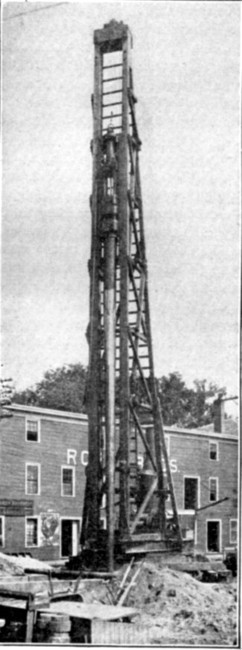 Fig. 49.—Pile Driver Rigged for Constructing Raymond
Concrete Piles.
Fig. 49.—Pile Driver Rigged for Constructing Raymond
Concrete Piles.
| 5 men on driver at $1.75 | $ 8.75 |
| 2 men handling shells at $1.75 | 3.50 |
| 1 engineman | 3.00 |
| 6 men mixing and placing concrete | 10.50 |
| 1 foreman | 5.00 |
| Coal and oil | 2.50 |
| ——— | |
| Total, 13 piles, at $2.55 | $33.25 |
Deducting the cost of placing the concrete we get a cost of $1.75 for driving the cores. The pile, 25 ft.[Pg 153] long, 6 ins. at the point and 18 ins. at the head, contains 21¼ cu. ft., or 0.8 cu. yd., of concrete, and has a surface area of 77 ft. As No. 20 steel weighs 1.3 lbs. per sq. ft., each shell[Pg 154] weighed approximately 100 lbs. The cost per pile may then be summarized as follows:
| 1.2 bbls. cement in 0.8 cu. yd., at $1.75 | $2.10 |
| 0.8 cu. yd. stone at $1.25 | 1.00 |
| ⅓ cu. yd. sand at $1.05 | 0.35 |
| 100 lbs. steel in shell at 3½ cts. | 3.50 |
| Labor and fuel as above | 2.55 |
| —— | |
| Total per pile (38 cts. per lin. ft.) | $9.50 |
This cost, it should be carefully noted, does not include cost of moving plant to and from work or general expenses.
Example II.—In constructing a building at Salem, Mass., 172 foundation piles, 14 to 37 ft. long, 6 ins. diameter at the point and 20 ins. diameter at the top, were constructed by the Raymond process. The general contractor made the necessary excavations and provided clear and level space for the pile driver, braced all trenches and pier holes, set stakes for the piles and gave all lines and levels. The piles were driven by a No. 2 Vulcan steam hammer with a 3,000-lb. plunger having a drop of 3 ft., delivering 60 blows per minute. Figure 49 shows the driver at work. Sixteen working days were occupied in driving the piles after the driver was in position. The greatest number driven in one day was 20, and the average was 11 piles per day. When in position for driving, the average time required to complete driving was 12 minutes. The total number of blows varied from about 310 to 360, the average being about 350. The piles were driven until the penetration produced by 8 to 10 blows equaled 1 in. When in full operation, a crew of 5 men operated the pile driver. Seven men were engaged in making the concrete and 5 men working upon the metal shells.
Assuming the ordinary organization and the wages given below, we have the following labor cost per day:
| 1 foreman at $5 | $ 5.00 |
| 1 engineman at $3 | 3.00 |
| 4 laborers on driver at $1.75 | 7.00 |
| 6 laborers making concrete at $1.75 | 10.50 |
| 5 laborers handling shells at $1.75 | 8.75 |
| ——— | |
| Total | $34.25 |
As 172 piles averaging 20 ft. in length were driven in 16 days, the total labor cost of driving, given by the figures above, is 16 × $34.25 = $548, or practically 16 cts. per lineal foot of pile driven.
The concrete used in the piles was a 1-3-5 Portland cement, sand and 1½-in. broken stone mixture. A 20-ft. pile of the section described above contains about 20 cu. ft. of concrete, or say 0.75 cu. yd. We can then figure the cost of concrete materials per pile as follows:
| 0.85 bbl. cement at $1.60 | $1.36 |
| 0.36 cu. yd. sand at $1 | 0.36 |
| 0.60 cu. yd. stone at $1.25 | 0.75 |
| —— | |
| Total per pile | $2.47 |
The steel shell has an area of about 72 sq. ft., and as No. 20 gage steel weighs 1.3 lbs. per sq. ft., its weight for each pile was about 94 lbs. Assuming the cost of coal, oil, etc., at $2.50 per day, we have the following summary of costs:
| Per lin. ft. of pile. | |
| Labor driving and concreting | $0.16 |
| Concrete materials | 0.123 |
| 94 lbs. steel shell at 3 cts. | 0.145 |
| Coal, oil, etc. | 0.011 |
| ——— | |
| Total | $0.439 |
The cost does not include interest on plant, cost of moving plant to and from work and general expenses.
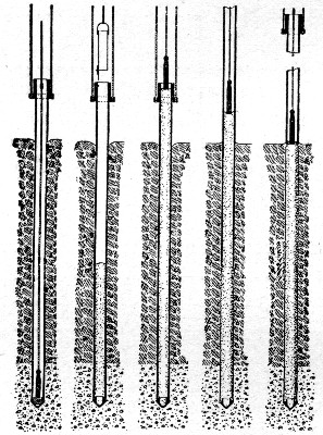 Fig. 50.—Sketch Showing Method of Constructing Simplex
Concrete Piles.
Fig. 50.—Sketch Showing Method of Constructing Simplex
Concrete Piles.
Method of Constructing Simplex Piles.—The apparatus employed in driving Simplex piles resembles closely the ordinary wooden pile driven, but it is much heavier and is equipped to pull as well as to drive. A 3,300-lb. hammer is used and it strikes on a hickory block set in a steel drive head which rests on the driving form or shell. This form consists of a ¾-in. steel shell 16 ins. in diameter made in a single 40-ft. length. Around the top of the shell a ½-in. thick collar or band 18 ins. deep is riveted by 24 1-in. countersunk rivets. This band serves the double purpose of preventing the shell being upset by the blows of the hammer and of giving a grip for fastening the pulling tackle. The bottom of the form or shell is provided[Pg 156] with a point. Two styles of point are employed. One style consists of two segments of a cylinder of the same size as the form, so cut that they close together to form a sort of clam shell point. In driving, the two jaws are held closed by the pressure of the earth and in pulling they open apart of their own weight to permit the concrete to pass them. This point, known as the alligator point, is pulled with the shell. It is suitable only for driving in firm, compact soil, in loose soil the pressure inward of the walls keeps the jaws partly closed and so contracts the diameter of the finished pile. The second style of point is a hollow cast iron point, 10 ins. deep and 16½ ins. in diameter, having a neck over which the driving form slips and an annular shoulder outside the neck to receive the circular edge of the shell. The projected sectional area of this point is 1.4 sq. ft. It is left in the ground when the form is withdrawn. The form is withdrawn by means of two 1-in. cables fastened to a steel collar which engages under the band at the top of the form. The cables pass in the channel leads on each side over the head of the driver and down in back to a pair of fivefold steel blocks, the lead line from which passes to one of the drums of the engine. In this manner the power of the drum is increased ten times and it is not unusual to[Pg 157] break the pulling cables when the forms are in hard ground. The general method of construction is about as shown by Fig. 50, being changed slightly to meet varying conditions. The form resting on a cast iron point is driven to hard ground. A heavy weight is then lowered into the form to make sure the point is loose. While the weight is at the bottom of the form a target is placed on its line at the top of the form, the purpose of which will be apparent later. The weight is then withdrawn. Given the length of the pile and sectional area, it is an easy matter to determine the volume of concrete necessary to fill the hole.
This amount is put into the form by means of a specially designed bottom dump bucket, which permits the concrete to leave it in one mass, reaching its destination with practically no disintegration. It will be noticed that when the full amount of concrete is in the form its surface is considerably above the surface of the ground. This is due to the fact that the thickness of the form occupies considerable space that is to be occupied by the concrete. The weight is now placed on top of the concrete and the form is pulled. The target previously mentioned now becomes useful. As the form is withdrawn the concrete settles down to occupy the space left by the walls of the form. Obviously this settlement should proceed at a uniform rate, and as it is difficult to watch the weight, the target on its line further up is of considerable help. By watching this target in connection with a scale on the leads of the driver, it can be readily told how the concrete in the form is acting. As another check, the target, just as the bottom of the form is leaving the ground should be level with the top of the form. This would indicate that the necessary amount of concrete has gone into the ground and that, other conditions being all right, the pile is a good one. In some grounds where the head of concrete in the form exerts a greater pressure than the back pressure or resistance of the earth, the concrete will be forced out into the sides of the hole, making the pile of increased diameter at that point and necessitating the use of more concrete to bring the pile up to the required level.
Method of Constructing Piles with Enlarged Footings.—A pile with an enlarged base or footing has been used in several[Pg 158] places by Mr. Charles R. Gow of Boston, Mass., who has patented the construction. A single pipe or a succession of pipes connected as the work proceeds is driven by hammer to the depths required. The material inside the shell is then washed out by a water jet to the bottom of the shell and then for a further distance below the shell bottom. An expanding cutter is then lowered to the bottom of the hole and rotated horizontally so as to excavate a conical chamber, the water jet washing the earth out as fast as it is cut away. When the chamber has been excavated the water is pumped out and the chamber and shell are filled with concrete. The drawings of Fig. 51 show the method of construction clearly. The chambering machine is used only in clay or other soil which does not wash readily. In soil which is readily washed the chamber can be formed by the jet alone. The practicability of this method of construction is stated by Mr. Gow to be limited to pipe sizes up to about 14 ins. in diameter.
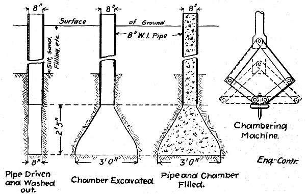 Fig. 51.—Sketch Showing Method of Constructing Concrete
Piles with Enlarged Footings.
Fig. 51.—Sketch Showing Method of Constructing Concrete
Piles with Enlarged Footings.
Method of Constructing Piles by the "Compressol" System.—The compressol system of concrete pile or pillar construction is a French invention that has been widely used abroad and which is controlled in this country by the Hennebique Construction Co., of New York, N. Y. The piles are constructed[Pg 159] by first ramming a hole in the ground by repeatedly dropping a conical "perforator" weighing some two tons. This perforator is raised and dropped by a machine resembling an ordinary pile driver. The conical weight gradually sinks the hole deeper and deeper by compacting the earth laterally; this lateral compression is depended upon so to consolidate the walls of the hole that they do not cave before the concrete can be placed. The concrete is deposited loose in the hole and rammed solid by dropping a pear-shaped weight onto it as it is placed. The view Fig. 52 shows the "perforator" and the tamping apparatus at work. Very successful work has been done abroad by this method.
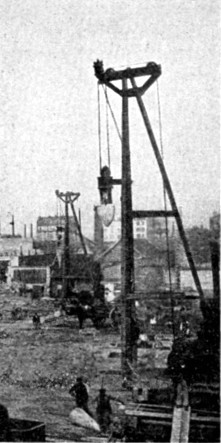 Fig. 52.—View of Apparatus Used in Constructing
Compressol Piles.
Fig. 52.—View of Apparatus Used in Constructing
Compressol Piles.
Method of Constructing Piers in Caissons.—For piles or pillars of diameters larger than say 18 ins. the use of driving shells and cores becomes increasingly impracticable. Concrete pillars of large size are then used. They are constructed by excavating and curbing a well or shaft and filling it with concrete. This construction has been most used in Chicago, Ill., for the foundations for heavy buildings, but it is of general[Pg 160] application where the sub-soil conditions are suitable. The method is not patented or controlled by patents in any particular, except that certain tools and devices which may be used are proprietary.
General Description.—The caisson method of construction is simple in principle. A well is dug by successive excavations of about 5 ft. each. After each excavation of 5 ft. is completed, wood lagging is placed around the sides and supported by internal steel rings, so that the soft ground around the excavation is maintained in its former position. The methods of excavating and removing the soil and of constructing the lagging are considered in detail further on. The caissons vary in diameter according to the load; some as large as 12 ft. in diameter have been sunk, but the usual diameter is 6 ft.; a caisson of 3 ft. in diameter is as small as a man can get into and work. When the pier goes to bed rock the caisson is made of uniform diameter from top to bottom, but where the pier rests on hardpan the bottom portion of the well is belled out to give greater bearing area. It is customary to load the piers about 20 tons per square foot.
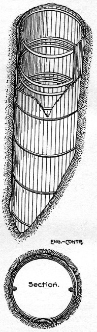 Fig. 53.—Curbing for Concrete Piers (Usual
Construction).
Fig. 53.—Curbing for Concrete Piers (Usual
Construction).
Caisson Construction.—The caisson construction, or more correctly the form of curbing most commonly used, is that indicated by the sketch, Fig. 53. The lagging is 2×6 in. or 3×6 in., stuff 5 ft. 4 ins. or 4 ft. long set vertically around the well and held in place by interior wrought iron rings. For a 6-ft. diameter caisson these hoops are ¾ by 3 ins.; they are made in two parts, which are bolted together as shown by Fig. 53. Generally there are two rings for each length of lagging; for 5-ft.[Pg 161] lagging they are placed about 9 ins. from each end. In some cases, however, engineers have specified three rings for the upper sections in soft clay and two rings for the sections in the hard ground lower down. The lagging used is not cut with radial edges, but is rough, square cut stuff; the rings, therefore, take the inward pressure altogether.
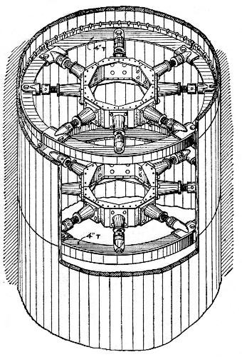 Fig. 54.—Curbing for Concrete Piers (Jackson Patent).
In some recent work done by the inventor use has been made of the caisson construction shown by Fig. 54 and patented by Mr. Geo. W. Jackson. In place of the plain rings a combination of T-beam ribs and jacks is used; this construction is clearly shown by the drawing. The advantages claimed for the construction are that it gives absolute security to the workmen and the work, that the lagging can be jacked tightly against the outer walls of the well, that the braces form a ladder by which the workmen can enter and leave the well, and that the possibility of shifting the bracing easily permits the concrete to be placed to the best advantage. On the[Pg 162] other hand the braces abstruct the clear working space of the caissons.
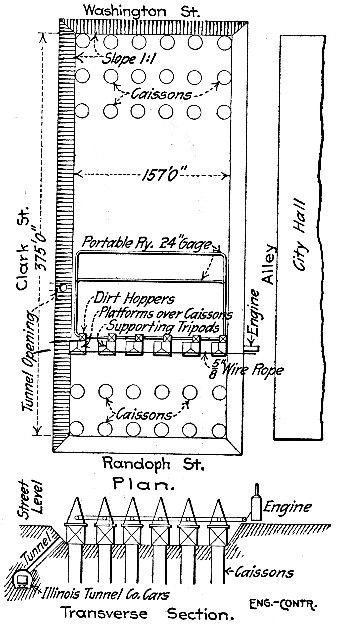 Fig. 55.—Layout of Plant for Concrete Pier Construction.
Cook County Court House Foundations.
Fig. 55.—Layout of Plant for Concrete Pier Construction.
Cook County Court House Foundations.
Excavating and Handling Material.—The excavation of the wells is done by hand, using shovels and picks, and, in the hardpan, special grubs made by A. J. Pement and George Racky, Chicago blacksmiths. The excavated material is hoisted out of the well in buckets made by the Variety Iron Works, of Chicago. For caissons which are not specified to go to rock it is considered more economical to do the hoisting by windlass derricks operated by hand. These derricks have four 6×6-in. legs and a 3×6-in. top piece. When the caissons go to rock the hoisting is done by power, so-called "cable set-ups" being used in most cases. To illustrate this method the following account of the foundation work for the Cook County Court House is given:
The Cook County Court House foundations consist of 126 caissons varying from 4 ft. to 10½ ft. in diameter and averaging$ 7½ ft. in diameter. They were sunk to rock at a depth of 115 ft. below street level. The work involved 22,000 cu. yds. of excavation and the placing in the caissons of 17,000 cu. yds. of concrete. Over 1,000 piles about 40 ft. long, that had formed the foundation of the old Court House built in 1875, were removed. These piles were found to be in good condition. The work was done by the George A. Fuller[Pg 163] Co., of Chicago, Ill., Contractors, with Mr. Edgar S. Belden Superintendent in Charge. The details which follow have been obtained from Mr. Belden.
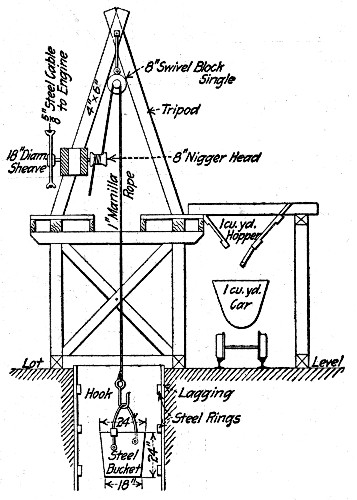 Fig. 56.—Section Showing Arrangement of Hoist for
Concrete Pier Construction.
Fig. 56.—Section Showing Arrangement of Hoist for
Concrete Pier Construction.
The foundation area was 157×375 ft., and was excavated to a depth of 15 ft. below the street surface before the caissons were started. The caissons, of which there were 126, were arranged in rows across the lot, there being from six to eight caissons in a row. The arrangement of the plant for the work is indicated by Fig. 55. One row of caissons formed a unit. A platform or "stand" was erected over each caisson and carried in its top a tripod fitted with a "nigger head" operated by a rope sheave. This arrangement is shown by Fig. 56. An engine on the bank operated by a rope drive all the tripod sheaves for a row of six or eight caissons. The arrangement is indicated by Fig. 55. The clay hoisted from the pits was dumped into 1 cu. yd. hoppers with which the stands were fitted, as shown by Fig. 56; when a hopper was full it was dumped into a car running on a 24-in. gage portable track.[Pg 164] Side dump Koppel cars of 1 cu. yd. capacity were used; they dumped their load into an opening connected with the tracks of the Illinois Tunnel Co., where the material passed into tunnel cars and was taken to the lake front about one mile away. As soon as one row of caissons was completed the stands, tripods, etc., which were made portable, were shifted to another row. At times as many as five units were in operation, sinking 40 caissons.
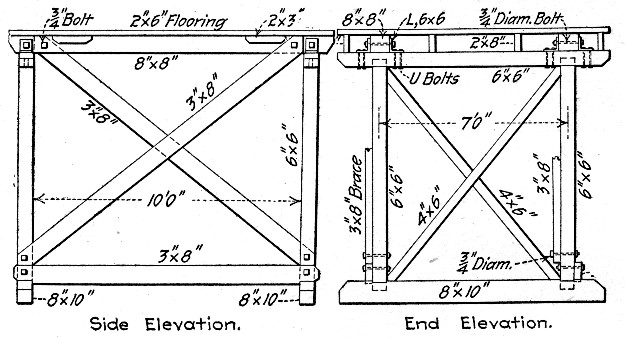
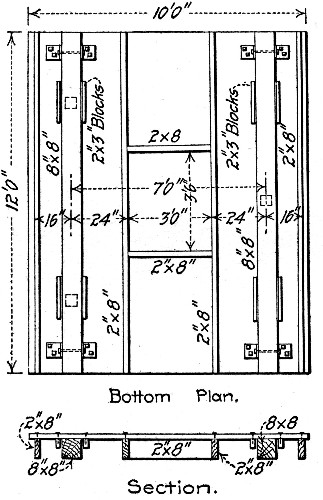 Fig. 57.—Details of Working Platform for Concrete Pier
Construction.
Fig. 57.—Details of Working Platform for Concrete Pier
Construction.
Fig. 56 shows the arrangement in detail at one caisson. In this work the lagging used was 3×6-in. maple, 5 ft. 4 ins. long, and was supported by 3×¾-in. steel hoops. The lagging was matched and dressed. The "nigger head," as will be[Pg 165] seen, is operated by a rope sheave on the same axle. As stated above, an endless rope drive operated all the "nigger heads" on a row of caissons. A 26-in. driving sheave was attached to an ordinary hoisting engine equipped with a governor. The driving rope was ⅝-in. steel. It was wrapped twice around the driving sheave and once around the "nigger head" sheaves. These latter were 18 ins. in diameter. For the hoists 1-in. Manila rope was used. The other details, the bucket, bucket hook, swivel block, etc., are made clear by the drawing. The platforms, tripods, etc., were of the standard dimensions and construction adopted by the contractors of the work. Detail drawings of the standard platform are given by Fig. 57. One of these platforms contains about 1,000 ft. B. M. of lumber. As will be seen, all connections are bolted, no nails being used anywhere. A platform can thus be taken down and stored or shipped and erected again on another job with very little trouble.
The plant described handled some 22,000 cu. yds. of excavated material on this work. Work was kept up night and day, working three 8-hour shifts. It took an average of 35 shifts to excavate one row of caissons. No figures of the working force or the cost of excavation of this work are available.
Mixing and Placing Concrete.—The placing of the concrete in the excavated wells is done by means of tremies, or, which is more usual, by simply dumping it in from the top, workmen going down to distribute it. The manner of mixing the concrete and of handling it to the caisson varies of course with almost every job. As an example of the better arranged mixing and handling plants the one used on the Cook County Court House work may be described. This plant is shown by the sketch, Fig. 58.
Bins for the sand and stone were built at one side of the lot on the sloping bank; their tops were level with the street surface and their bottoms were just high enough to permit their contents to be delivered by chutes into 1 cu. yd. cars. Wagons dumping through traps in the platform over the bin delivered the sand and stone. The sketches indicate the arrangement of the bins and mixer and the car tracks connecting them. The raw material cars were first run under the stone bin and[Pg 166] charged with the required proportion of stone, and then to the sand bin, where the required proportion of sand was chuted on top of the stone. The loaded car was then hauled up the incline and dumped into the hopper, where cement and water were added. A No. 2½ Smith mixer was used and discharged into cars which delivered their loads on tracks leading to the caissons. The same cars and portable tracks were used as had been used to handle the excavated material. In operation a batch of raw materials was being prepared in the hopper while the previous batch was being mixed and while the concrete car was delivering the still previous batch to the caissons. An average of 40 batches an hour mixed and put into the caissons was maintained with a force of 25 men. In all some 17,000 cu. yds. of concrete were mixed and deposited.
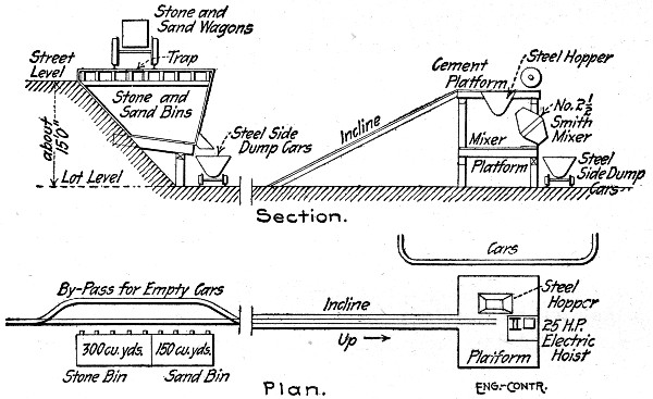 Fig. 58.—Arrangement of Concrete Making Plant, Concrete
Pier Construction.
Fig. 58.—Arrangement of Concrete Making Plant, Concrete
Pier Construction.
Cost of Caisson Work.—The following attempt to get at the cost of caisson work is based largely upon information obtained from Mr. John M. Ewen, John M. Ewen Co., Engineers and Builders, Chicago, Ill. Mr. Ewen says:
"My experience has taught me that it is almost impossible to determine any definite data of cost for this work. This is due to the fact that no two caisson jobs will average the same cost, notwithstanding the fact that the cost of material used and the labor conditions are exactly the same. This condition[Pg 167] is due to the great variety in texture of the soil gone through. For instance, it has come under my experience that in caissons of the same diameter on the same job it required but fifteen 8-hour shifts to reach bedrock in some of these, while it required as many as 21 to 25 shifts to reach rock in the others, rock being at the same elevation. In fact, the digging all the way to rock in some was the best that could be wished for, while in the others boulders and quicksand were encountered, and the progress was slower, and the cost consequently greater.
"Again, we have known it to require eight hours for two men to dig 8 ins. in hardpan in one caisson, while on a job going on at the same time and on the opposite corner of the street two men made progress of 2 ft. in 8 hours through apparently the same stuff, the depth of hardpan from grade being 61 ft. 6 ins. in both instances, and the quality of labor exactly the same.
"There have been more heavy losses among contractors due to the unexpected conditions arising in caisson digging than in any other item of their work, and I predict a loss to some of them that will be serious indeed if an attempt be made to base future bids for caisson work entirely upon the data kept by them on past work. If a contractor is fortunate enough to find the ordinary conditions existing in his caisson work, and by ordinary conditions I mean few boulders, no quicksand, ordinary hardpan and no gas, the following items may be considered safe for figuring caisson work:
"Figure that it will require from 22 to 25 shifts of 8 hours each to strike bedrock, bedrock being from 90 to 95 ft. below datum, and datum being 15 ft. below street grade; figure 2 diggers to the shift in all caissons over 5 ft. in diameter, 45 cts. per hour for each digger; figure 1 top man at 40 cts. per hour, and 1 mucker or common laborer at 30 cts. per hour for all caissons in which there are two diggers, and 1 top man less if 1 digger is in the caisson, which condition exists generally in caissons less than 5 ft. in diameter. Add the cost of ⅝-in. cable, tripods, sheaves, 1-in. Hauser laid line, nigger heads, ball-bearing blocks, etc., for rigging of the job. Lagging, which is 2×6 ins. and 3×6 ins. hemlock or some hard wood, in length of 5 ft. 4 ins. and 4 ft., is priced all the way from $20 to $22.50 and $21 to $24.50 per M. ft. B. M., respectively. The[Pg 168] price of caisson rings is $2.40 per 100 lbs. The cost of specially made grubs for digging in hardpan is about $26 per dozen. Shovels are furnished by the diggers themselves in Chicago, Ill. The cost of temporary electric light is $10 per caisson. This includes cost of cable, lamps, guards, etc. Add the cost of or rental of engine or motors for power.
"Some engineers specify three rings to be used to each set of lagging below the top set until hardpan is reached, then two rings for each of the remaining sets from hardpan to rock. This is, of course, to insure against disaster from great pressure of the swelling clay above the hardpan strata, and may or may not be necessary. These rings are ¾×3 ins. wrought iron.
"For caissons which are not specified to go to rock, it is not considered economical to rig up cable set-ups, but rather to use windlass derricks. In this case 1-in. Hauser laid line is used as the means of hoisting the buckets of clay out of the caisson, as is the case in cable set-ups, hand power being used on the windlass derricks instead of steam or electricity. The windlass derricks are made with four legs out of 6×6-in. yellow pine lumber. The top piece is generally a piece of 3×6-in. lagging. The cost of windlass and boxes is about $35 per dozen. Hooks for caisson buckets cost 45 cts. each. Caisson buckets cost $8 each.
"With the above approximate units as a basis, I have seen unit prices given per lineal foot in caisson work which ranged all the way from $12 to $16.50 for 6-ft. diameter caissons, larger and smaller sized caissons being graded in price according to their size. This unit price included rings, lagging, concrete, power, light, labor, etc."
From the above data the following figures of cost can be arrived at, assuming a 6-ft. caisson:
| Labor. | Per day. |
| 2 diggers in caisson, at $3.60 | $ 7.20 |
| 1 top man, at $3.20 | 3.20 |
| 1 mucker, at $2.40 | 2.40 |
| ——— | |
| $12.80 |
The depth sunk varies from 3½ to 8 ft. per 8-hour day, depending on the material. Assuming an average of 4 ft., we[Pg 169] have then 4 lin. ft. of caisson, or 2.8 cu. yds. excavated at a labor cost of $12.80, which is at the rate of $3.20 per lin. ft., or $4.57 per cu. yd. We now get the following:
| Per lin. ft. Caisson. | |
| 40 ft. B. M. (2×6-in. lagging) at $25 | $1.00 |
| 60 lbs. iron (¾×3-in. rings) at 2½ c. | 1.50 |
| 0.7 cu. yd. excavation at $4.57 | 3.20 |
| 0.7 cu. yd. muck hauled away at $1 | 0.70 |
| 0.7 cu. yd. concrete at $5 | 3.50 |
| Electric light | 0.10 |
| ——— | |
| Total | $10.00 |
If 3×6-in. lagging is used add 50 cts. per lin. ft. of caisson.
MOLDING PILES FOR DRIVING.—Piles for driving are molded like columns in vertical forms or like beams in horizontal forms. European constructors have a strong preference for vertical molding, believing that a pile better able to withstand the strain of driving is so produced; such lamination as results from tamping and settling is, in vertical molding, in planes normal to the axis of the pile and the line of driving stress. Vertical molding has been rarely employed in America and then only for molding round piles. The common belief is that horizontal molding is the cheaper method. In the ordinary run of work, where comparatively few piles are to be made, it is probably cheaper to use horizontal molds, but where a large number of piles is to be made, the vertical method has certain economic advantages which are worth considering.
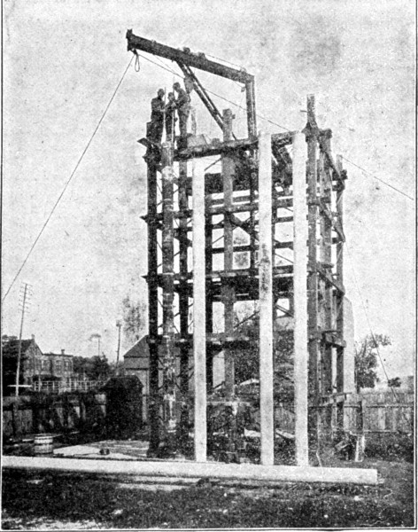 Fig. 59.—Plant for Vertical Molding of Concrete Piles.
Vertical molding necessitates a tower or staging to support the forms and for handling and placing the concrete; an example of such a staging is shown by Fig. 59. To counterbalance this staging, horizontal molding necessitates a molding platform of very solid and rigid construction if it is to endure continued and repeated use. In the matter of space occupied by molding plant, vertical molding has the advantage. A tower 40 ft. square will give ample space around its sides for 80 vertical forms for 12-in. piles and leaves 1 ft. of clear working space between each pair of forms. The ground area occupied by this tower and the forms is 1,764 sq. ft. With the same[Pg 170] spacing of molds a horizontal platform at least 25 × 160 ft. = 4,000 sq. ft., would be required for the molds for the same number of piles 25 ft. long. For round piles, vertical molding permits the use of sectional steel forms; horizontal forms for round piles are difficult to manage. For square piles vertical molding requires forms with four sides; horizontal forms for square piles consist of two side pieces only, the molding platform serving as the bottom and no top form being necessary. Thus, for square piles horizontal molding reduces the quantity of lumber per form by 50 per cent. The side forms for piles molded on their sides can be removed much sooner than can the forms for piles molded on end, so that the form material is more often released for reuse. The labor of assembling[Pg 171] and removing forms is somewhat less in horizontal molding than in vertical molding. Removing the piles from molding bed to storage yard for curing requires derricks or locomotive cranes in either case and as a rule this operation will be about as expensive in plant and labor in one case as in the other. In the ease and certainty of work in placing the reinforcement, horizontal molding presents certain advantages, the placing and working of the concrete around the reinforcement is also easier in horizontal molding. Mixing and transporting the concrete materials and the concrete is quite as cheap in vertical molding as in horizontal molding. If anything, it is cheaper with vertical molding, since the mixer and material bins can be placed within the tower or close to one side where a tower derrick can hoist and deposit the concrete directly into the molds. Car tracks, cars, runways and wheelbarrows are thus done away with in handling the concrete from mixer to molds. Altogether, therefore, the choice of the method of molding is not to be decided off-hand.
DRIVING MOLDED PILES.—Driving molded concrete piles with hammer drivers is an uncertain operation. It has been done successfully even in quite hard soils and it can be done if time is taken and the proper care is exercised. The conditions of successful hammer driving are: Perfect alignment of the pile with the line of stroke of the hammer; the use of a cushion cap to prevent shattering of the pile-head, and a heavy hammer with a short drop. The pile itself must have become well cured and hardened. At best, hammer driving is uncertain, however; shattered piles have frequently to be withdrawn and the builder is never sure that fractures do not exist in the portion of the pile that is underground and hidden. The actual records of concrete pile work given in succeeding sections illustrate successful examples of hammer driving. The plant required need not vary from that ordinarily used for driving wooden piles, except that more power must be provided for handling the heavier concrete pile and that means must be provided for holding the pile in line and protecting its head.
Sinking concrete piles by means of water jets is in all respect a process similar to that of jetting wooden piles. Examples of jetting are given in succeeding section. In rare cases,[Pg 172] driving shells, or sheaths have been used for driving molded piles.
Method and Cost of Molding and Jetting Piles for an Ocean Pier.—In reconstructing in reinforced concrete the old steel pier at Atlantic City, N. J., some 116 reinforced concrete piles 12 ins. in diameter were molded in air and sunk by jetting. The piles varied in length with the depth of the water, the longest being 34½ ft. Their construction is shown by Fig. 60, which also shows the floor girders carried by each pair of piles and forming with them a bent, and the struts bracing the bents together. In molding and driving the piles the old steel pier was used as a working platform.
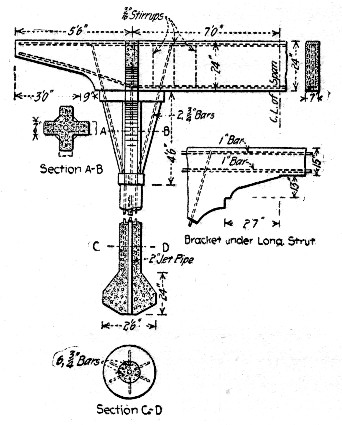 Fig. 60.—Concrete Pile for Pier at Atlantic City, N. J.
The forms for the piles were set on end on small pile platforms located close to the positions to be occupied by the piles and were braced to the old pier. The forms were of wood and the bulb point, the shaft and the knee braces were molded in one piece. Round iron rods were used for reinforcement. The concrete was composed of 1 part Vulcanite Portland cement, 2 parts of fine and coarse sand mixed and 4 parts of gravel 1 in. and under in size. The mixture was made wet and was puddled into the forms with bamboo fishing rods, which[Pg 173] proved very efficient in working the mixture around the reinforcing rods and in getting a good mortar surface. The concrete was placed in small quantities; it was mostly all hand mixed. The forms were removed in from 5 to 7 days, depending on the weather.
The piles were planned to be sunk by water jet and to this end had molded in them a 2-in. jet pipe as shown. They were sunk to depths of from 8 ft. to 14 ft. into the beach sand. Water from the city water mains at a pressure of 65 lbs. per sq. in. was used for jetting; this water was furnished under special ordinance at a price of $1 per pile, and a record of the amount used per pile was not kept. The piles were swung from the molding platforms and set by derricks and block and fall. The progress of jetting varied greatly owing to obstructions in places in the shape of logs, old iron pipes, etc. In some cases several days were required to get rid of a single pipe. In clear sand, with no obstruction, a 12-in. pile could be jetted down at the rate of about 8 ft. per hour, working 1 foreman and 6 men. The following is the itemized actual cost of molding and sinking a 26-ft. pile with bulb point and knee braces complete:
| Forms— | Cost per pile. | |
| Lumber, 340 ft. B. M. @ $30 | $10.20 | ... |
| Labor (carpenters @ $2.50 per day) | 12.00 | ... |
| Oil, nails, oakum, bolts, clamps, etc. | 1.20 | ... |
| ——— | ||
| $23.40 | $ 3.90 | |
| Times used | 6 | |
| Reinforcement— | ||
| 275 lbs. of plain ¾-in. steel rods @ 2 cts. per lb. | $ 5.50 | ... |
| Preparing and setting, 4/10 ct. per lb. | 1.10 | 6.60 |
| Jet Pipe— | ||
| 26½ ft. of 2-in. pipe @ 10 cts. per ft. in place. | 2.65 | ... |
| Setting Forms— | ||
| 6 men @ $2.50 per day = $15, set 4 piles | 3.75 | ... |
| Material— | ||
| 90/100 Cu. yds. gravel @ $1.50 per yd. | 1.35 | ... |
| 45/100 cu. yds. sand @ $1.50 per yd. | .67 | ... |
| 1.50 bbls. cement @ $1.60 | 2.40 | 4.42 |
| Labor— | ||
| Concrete and labor foreman | 3.00 | ... |
| 6 laborers, mixing and placing by hand, $1.75 each | 10.50 | ... |
| ——— | ||
| $13.50 | 3.38 | |
| Average number of piles concreted per day | 4 | |
| Removing Forms— | ||
| 4 men @ $2.50 remove and clean in half day 4 columns | 1.25 | ... |
| 1 man @ $2.25 plastering column with cement grout (4 per day) | .56 | ... |
| Jetting 10 ft. into Sand— | ||
| Foreman | $ 3.00 | ... |
| 4 men, $2.25 each, handling hose and traveler | 9.00 | ... |
| ——— | ||
| $12.00 | 3.00 | |
| Average number of piles jetted per day | 4 | ... |
| City water pressure used for jetting @ $1 per pile | ... | 1.00 |
| Superintendence @ $5.00 per day | ... | 1.25 |
| Caring for trestle, traveler, material, etc. | ... | 4.84 |
| ——— | ||
| Total cost per pile | $36.60 |
The pile being 26 ft. long, the cost in place was $1.41 per foot. Subtracting the cost of sinking amounting to $7.09 per pile, we have the cost of a 26-ft. pile molded and ready to sink coming to about $1.10 per foot. It should be noted that this is the cost for a pile of rather complicated construction; a plain cylindrical pile should be less expensive.
Method of Molding and Jetting Square Piles for a Building Foundation.—The foundation covered about an acre. The soil was a deposit of semi-fluid mud and quicksand overlying a very irregular rock bottom and encircled by a ledge of rock. The maximum depth of the mud pocket was 40 ft., and interspersed were floating masses of hard pan. Soundings were made at the locations of all piles; a ½-in. gas pipe was coupled to a hose fed by city pressure and jetted down to rock, the depth was measured, the sounding was numbered and the pile was molded to length and numbered like the sounding. In all 414 piles were required, ranging in length from 1½ to 40[Pg 175] ft.; all piles up to 6 ft. were built in place in wooden forms. The piles were 13 ins. square and were of 1-2½-4 concrete reinforced with welded wire fabric. A tin speaking tube was molded into each pile at the center. This tube was stopped about 10 ins. from the head and by means of an elbow and threaded nipple projected through the side of the pile to allow of attaching a pressure hose. The piles were handled to the pile driver, the hose attached and water supplied at 100 lbs. pressure by a pump. Churning the pile up and down aided the driving. A hammer was used to force the piles through the hard pan layers. A wooden follower was used to protect the pile head. A 2,800-lb. hammer falling 20 ft. did not injure the piles. One pile was given 300 blows with a 2,800-lb. hammer falling 12 ft., and when pulled was unbroken. It was found that 30 ft. piles and under could be picked up safely by one end; longer piles cracked at the center when so handled. These long piles were successfully handled by a long chain, one end being wrapped around the pile at the center and the other end similarly wrapped near the head; the hook of the hoisting fall was hooked into the loop of the chain and as the pile was hoisted the hook slipped along the chain toward the top gradually up ending the pile. The piles weighed 175 lbs. per lin. ft. It was attempted to mold the piles directly on the ground by leveling it off and covering it with tar paper, but the ground settled and the method proved impracticable.
Method of Molding and Jetting Piles for Building Foundations.—In a number of foundations Mr. Frank B. Gilbreth has used a polygonal pile, either octagonal or hexagonal, with the sides corrugated or fluted as indicated in Fig. 61. In longitudinal section these piles have a uniform taper from butt to point and have flat points. Each pile is cored in the center, the core being 4 ins. in diameter at the top and 2 ins. at the bottom end. On each of the octagon or hexagon sides the pile has a half-round flute usually from 2½ to 3 ins. in diameter. The principal object of these flutes or "corrugations" is to give passage for the escape to the surface of the water forced through the center core hole in driving the pile. They are also for the purpose of increasing the perimeter of the pile and thereby gaining greater surface for skin friction.[Pg 176]
The piles are reinforced longitudinally and transversely. On this particular job the reinforcement was formed with Clinton Electrically Welded Fabric, the meshes being 3 ins.×12 ins.; the longer dimension being lengthwise with the pile and of No. 3 wire; the horizontal or transverse reinforcement being of No. 10 wire. The meshes being electrically welded together, the reinforcement was got out from a wide sheet taking the form of a cone. No part of the reinforcement was closer than 1 in. from the outside of the concrete. In general only sufficient sectional area of material is put in the reinforcement to take the tensile stresses caused by the bending action when handling the pile preparatory to driving; more reinforcement than this only being necessary when the piles are used for wharves, piers or other marine structures, where a considerable length of pile is not supported sidewise or when they are subjected to bending stresses.
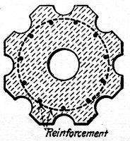 Fig. 61.—Cross-Section of Corrugated Reinforced Concrete
Pile.
Fig. 61.—Cross-Section of Corrugated Reinforced Concrete
Pile.
Molding.—The forms for molding the piles are made from 2-in. stuff, gotten out to the required dimensions, the corrugations being formed by nailing pieces on the inside whose section is the segment of a circle. The sides of the octagon are fastened to the ends through which the core projects some 6 or 8 ins. At times while the molding of the pile is in progress, the central core is given a partial turn to prevent the setting of the cement holding it fast and thereby preventing the final removal.
The stripping of the forms from the piles is usually done from 24 to 48 hours after molding, and from this time on great care is taken that there is a sufficient amount of moisture in the pile to permit of the proper action for setting of the cement. This is usually accomplished by covering the piles over with burlaps and saturating with water from a hose; the[Pg 177] operation of driving the pile not being attempted until the concrete is at least ten days old.
Driving.—The operation of driving corrugated concrete piles is somewhat similar to that for driving ordinary wooden piles by water jet, but a much heavier hammer with less drop is used. The jetting is accomplished by inserting a 2-in. pipe within the pile. This pipe is tapered at the bottom end to 1-in. diameter, forming a nozzle, and the water pressure used is about 120 lbs. per sq. in. As a rule, this pressure is obtained by the use of a steam pump which may be connected with the boiler which operates the pile driver, or with a separate steam supply. At the upper end of this 2-in. pipe an elbow is placed and a short length of pipe is connected to this and to the hose from the water supply.
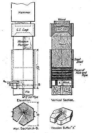 Fig. 62.—Cushion Cap for Driving Gilbreth Corrugated
Pile.
Fig. 62.—Cushion Cap for Driving Gilbreth Corrugated
Pile.
As it is not practicable to drop the hammer directly on the head of the concrete piles, the driving is accomplished by the use of a special cap, Fig. 62. This cap is about 3 ft. in height and the bottom end fits over the head of the pile. In one side of this cap is a slot from the outside to the center, which permits the 2-in. pipe, which supplies the water jet for driving the[Pg 178] pile, to project. The outside of this cap is formed with a steel shell, the inside has a compartment filled with rubber packing and the top has a wooden block which receives a blow from the hammer. In this way the head of the pile is cushioned, which prevents the blow of the hammer from bruising or breaking the concrete.
During the operation of driving, the water from the jet comes up on the outside of the pile and carries with it the material which it displaces in driving. This, with the assistance of the hammer, allows the pile to be driven in place, and, contrary to what might be supposed, after the operation of driving when the water has saturated into the ground or been drained away, this operation puddles the earth around the pile, so that after a few hours' time the skin friction is much more than it would be with the pile driven into more compact soil without the use of a jet.
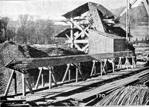 Fig. 63.—View Showing Method of Fabricating
Reinforcement for a Round Pile with Flattened Sides.
Fig. 63.—View Showing Method of Fabricating
Reinforcement for a Round Pile with Flattened Sides.
Method of Molding and Driving Round Piles.—In constructing a warehouse at Bristol, England, some 600 spirally-reinforced piles of the Coignet type were used. Coignet piles are in section circles with two longitudinal flat faces to facilitate guiding during driving; this section is the same as would be found by removing two thin slabs from opposite sides of a[Pg 179] timber pile. The reinforcement consists of longitudinal bars set around the periphery and drawn together to a point at one end and then inserted into a conical shoe; these longitudinal bars are wound spirally with a ¼-in. rod wire tied to the bars at every intersection. This spiral rod has a pitch of only a few inches, but to bind it in place and give rigidity to the skeleton it is wound by a second spiral with a reverse twist and a pitch of 4 or 5 ft. As thus constructed, the reinforcing frame is sufficiently rigid to bear handling as a unit. The piles used at Bristol were 14 to 15 ins. in diameter and 52 ft. long, and weighed about 4 tons gross each. The mixture used was cement, river sand and crushed granite.
Molding.—In molding Coignet piles the reinforcement is assembled complete as shown by Fig. 63 and then suspended as a unit in a horizontal mold constructed as shown by the cross-section Fig. 64. The concrete is deposited in the top opening and rammed and worked into place around the steel after which the opening is closed by the piece A. After 24 hours the curved side pieces B and C are removed and the pile is left on the sill D until hard enough to be shifted; a pile is considered strong enough for driving when about six weeks old.
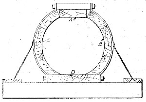 Fig. 64.—Form for Molding Round Pile with Flattened
Sides.
Fig. 64.—Form for Molding Round Pile with Flattened
Sides.
Driving.—Coignet piles at the Bristol work were handled by a traveling crane. The material penetrated was river mud and they were driven with a hammer weighing 2 tons gross; in driving the pile head was encircled by a metal cylinder into which fitted a wooden plunger or false pile with a bed of shavings and sawdust between plunger and pile head.
Molding and Driving Square Piles for a Building Foundation.—The Dittman Factory Building at Cincinnati, O., is[Pg 180] founded on reinforced concrete piles varying from 8 to 22 ft. in length. The piles were square in cross-section, with a 2-in. bevel on the edges; a 16-ft. pile was 10 ins. square at the point and 14 ins. square at the head, shorter or longer piles had the same size of point, but their heads were proportionally smaller or larger, since all piles were cast in the same mold by simply inserting transverse partitions to get the various lengths. Each pile was reinforced by four ¾-in. twisted bars, one in each corner, bound together by ¼-in hoops every 12 ins.. The bars were bent in at the point and inserted in a hollow pyramidal cast iron shoe weighing about 50 lbs. The concrete was a 1-2-4 stone mixture and the pile was allowed to harden four weeks before driving. They were cast horizontally in wooden molds which were removed after 30 hours.
Driving.—Both because of their greater weight and because of the care that had to be taken not to shatter the head, it took longer to adjust and drive one of these concrete piles than it would take with a wooden pile. The arrangement for driving the piles was as follows: A metal cap was set over the head of the pile, on this was set the guide cap having the usual wood deadener and on this was placed a wood deadener about 1 ft. long. The metal cap was filled with wet sand to form a cushion, but as the pile head shattered in driving the sand cushion was abandoned and pieces of rubber hose were substituted. With this rubber cushion the driving was accomplished without material damage to the pile head. The hammer used weighed 4,000 lbs. and the drop was from 4 to 6 ft. The blows per pile ranged from 60 up. The average being about 90. In some cases where the driving was hard it took over 400 blows to drive a 14-ft. pile. An attempt to drive one pile with a 16-ft. drop resulted in the fracture of the pile.
Method of Molding and Driving Octagonal Piles.—The piles were driven in a sand fill 18 ft. deep to form a foundation for a track scales in a railway yard. They were octagonal and 16 ins. across the top, 16 ft. long, and tapered to a diameter of 12 ins. at the bottom. They were also pointed for about a foot. The reinforcement consisted of four ½-in. Johnson corrugated bars spaced equally around a circle concentric with the center of the pile, the bars being kept 1½ ins. from the surface of the concrete. A No. 11 wire wrapped around the[Pg 181] outside of the bars secured the properties of a hooped-concrete column. The piles were cast in molds laid on the side. They were made of 1:4½ gravel concrete, and were seasoned at least three weeks before being driven.
An ordinary derrick pile driver, with a 2,500-lb. hammer falling 18 ft., was used in sinking them. A timber follower 6 ft. long and banded with iron straps at both ends was placed over the head of the pile to receive directly the hammer blows. The band on the lower end was 10 ins. wide and extended 6 ins. over the end of the follower. In this 6-in. space a thick sheet of heavy rubber was placed, coming between the head of the pile and the follower. Little difficulty was experienced in driving the piles in this manner, although 250 to 300 blows of the hammer were required to sink each pile. The driving being entirely through fine river sand there is every probability that any kind of piles would have been driven slowly. The heads of the first 4 or 5 piles were battered somewhat, but after the pile driver crew became familiar with the method of driving, no further battering resulted and the heads of most of the piles were practically uninjured.
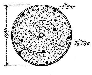 Fig. 65.—Cross-Section of Chenoweth Rolled Pile.
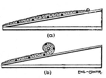 Fig. 66.—Diagram Showing Method of Rolling Chenoweth
Pile.
Fig. 66.—Diagram Showing Method of Rolling Chenoweth
Pile.
Method and Cost of Making Reinforced Concrete Piles by Rolling.—In molding reinforced concrete piles exceeding 30 or 40 ft. in length, the problem of molds or forms becomes a serious one. A pile mold 50 or 60 ft. long is not only expensive in first cost, but is costly to maintain, because of the difficulty of keeping the long lagging boards from warping. To overcome these difficulties a method of molding piles without[Pg 182] forms has been devised and worked out practically by Mr. A. C. Chenoweth, of Brooklyn, N. Y. This method consists in rolling a sheet of concrete and wire netting into a solid cylinder on a mandril, by means of a special machine. Fig. 65 is a sketch showing a cross-section of a finished pile, in which the dotted line shows the wire netting, the hollow circle is the gas pipe mandril, and the solid circles are the longitudinal reinforcing bars.
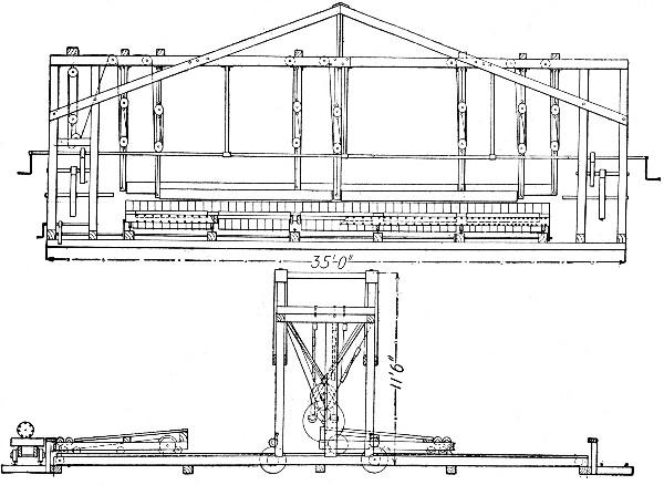 Fig. 67.—Machine for Rolling Chenoweth Piles.
In making the pile the netting is spread flat, with the reinforcing bars attached as shown at (a), Fig. 66, and is then covered with a layer of concrete. One edge of the netting is fastened to the platform, the other edge is attached to the winding mandril. The winding operation is indicated by sketch (b), Fig. 66. Fig. 67 shows the machine for rolling the pile. It consists of a platform and a roll. The platform is mounted on wheels and is so connected up that it moves back under the roll at exactly the circumferential speed of the roll; thus the forming pile is under constant, heavy pressure between the roll and platform. When the pile has been completely rolled it is bound at intervals by wire ties; the wire for these ties is carried on spools arranged under the edge of[Pg 183] the platform at intervals of 4 ins. for the first 10 ft. from the point and of 6 ins. for the remainder of the length. The binding is done by giving the pile two or three extra revolutions and then cutting and tying the wire; then by means of a long removable shelf which contains the flushing mortar, as the pile revolves it becomes coated on the outside with a covering that protects the ties and other surface metal. Finally the pile is rolled onto a suitable table to harden.
An exhibition pile rolled by the process described is 61 ft. long and 13 ins. in diameter. This pile was erected as a pole by hoisting with a tackle attached near one end and dragging the opposite end along the ground exactly as a timber pole would be erected. It was also suspended free by a tackle attached at the center; in this position the ends deflected 6 ins. Neither of these tests resulted in observable cracks in the pile. The pile contains eight 1-in. diameter steel bars 61 ft. long, one 2½-in. pipe also 61 ft. long, 366 sq. ft., or 40.6 sq. yds. ½-in. mesh 14 B. & S. gage wire netting, and 2 cu. yds. loose concrete. Its cost for materials and labor was as follows:
| Materials— | |
| Gravel, 28.8 cu. ft., at $1 per cu. yd. | $ 1.05 |
| Sand, 19.8 cu. ft., at $1 per cu. yd. | .73 |
| Cement, 3 bbls., at $1.60 per bbl. | 4.80 |
| Netting, 40.6 sq. yds., at 17½ cts. per sq. yd. | 7.10 |
| Rods, wire, etc., 1,826 lbs., at 2½ cts. per lb. | 45.65 |
| ———— | |
| Total | $59.33 |
| Mixing 2 cu. yds. concrete, four men one hour, at 15 cts. per hour | $ 0.60 |
| Placing concrete and netting, four men 30 mins., at 15 cts. per hour | .30 |
| Winding pile, four men 20 mins., at 15 cts. per hour | .20 |
| Removing pile, four men 10 mins., at 15 cts. per hour | .10 |
| ———— | |
| $1.20 | |
| Grand total | $60.53 |
This brings the cost of a pile of the dimensions given to about $1 per lin. ft.
The construction problem in building concrete structures of massive form and volume is chiefly a problem of plant arrangement and organization of plant operations. In most such work form construction is simple and of such character that it offers no delay to placing the concrete as rapidly as it can be produced. The same is true of the character of the structure, it is seldom necessary for one part of the work to wait on the setting and hardening of another part. As a rule, there is no reinforcement to fabricate and place and where there is it is of such simple character as not to influence the main task of mixing, handling, and placing concrete. Stated broadly, the contractor in such work generally has a certain large amount of concrete to manufacture, transport and deposit in a certain space with nothing to limit the rapidity of these operations, except the limitations of plant capacity and management. Installation and operation of mixing and conveying plant, then are matters to be considered carefully in heavy concrete work.
In the following sections we have given one or more examples of nearly every kind of heavy concrete work excepting bridge foundations and retaining walls, which are considered in Chapters XII and XIII, and except rubble concrete work, which is considered in Chapter VI. In each case so far as the available records made it possible, we have given an account of the plant used and of its operation.
FORTIFICATION WORK.—Concrete for fortification work consists very largely of heavy platforms and walls for gun foundations and enclosures and of heavily roofed galleries and chambers for machinery and ammunition. The work is very massive and in the majority of cases of simple[Pg 185] form. A large number of data are to be found in the reports of the Chief of Engineers, U. S. A., on all classes of fortification work, but the manner in which they are recorded makes close analysis of relative efficiencies of methods or of relative costs almost impossible. The following data are given, therefore, as examples that may be considered fairly representative of the costs obtained in fortification work done under the direction of army engineers; these data are not susceptible of close analysis because wages, working force, outputs, etc., are nearly always lacking.
Gun Emplacements, Staten Island, N. Y.—The work comprised 5,609 cu. yds. of concrete in two 12-in. gun emplacements, and 3,778 cu. yds. of concrete in two 6-in. gun emplacements. Concrete was mixed in a revolving cube mixer with the exception of 809 cu. yds. in the 6-in. emplacements which were mixed by hand at a cost of 56 cts. more per cubic yard than machine mixing cost. The body of the concrete was a 1-3-5 Portland cement, beach sand and broken trap rock mixture. The floors and upper surface of the concrete had a pavement consisting of 6 ins. of 1-3-5 concrete surfaced with 2 ins. of 1-3 mortar. Wages are not given, but for the time and place should have been about $1.50 per 8-hour day for common labor. The cost of materials was:
| Alpha Portland cement, per bbl. | $1.98 |
| Broken trap rock, per cu. yd. | 0.81 |
| 12-in. emplacement, hauling sand per cu. yd. | 0.175 |
| 6-in. emplacement, hauling sand per cu. yd. | 0.20 |
The cost of the concrete in place was as follows:
| Body Concrete—— | 12-in., per cu. yd. | 6-in., per cu. yd. |
| Cement, at $1.98 per bbl. | $2.546 | $2.546 |
| Broken stone, at 81 cts. per cu. yd. | 1.041 | 1.041 |
| Sand, at 17½ and 20 cts. per cu. yd. | 0.225 | 0.257 |
| Receiving and storing materials at 11.6 cts. per cu. yd. and 8.4 cts. per bbl. | 0.149 | 0.180 |
| Mixing, placing and ramming | 0.879 | 1.110 |
| Forms, lumber and labor | 0.477 | 0.950 |
| Superintendence and miscellaneous | 0.190 | 0.150 |
| ——— | ——— | |
| Total | $5.507 | $6.234 |
| Concrete Pavement— | ||
| Materials | $2.97 | $3.06 |
| Labor | 4.63 | 4.72 |
| ——— | ——— | |
| Total | $7.60 | $7.78 |
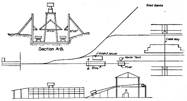 Fig. 68.—Sketch Plans of Concrete Making Plant for
Mortar Battery Platform.
Fig. 68.—Sketch Plans of Concrete Making Plant for
Mortar Battery Platform.
Mortar Battery Platform, Tampa Bay, Fla.—The platform [Pg 186]contained 8,994 cu. yds. of concrete composed of a mixture of Portland cement, sand, shells and broken stone. The broken stone and cement were brought in by vessel and the sand and shells were obtained from the beach near by. The plant for the work was arranged as shown by the sketch, Fig. 68. Sand, stone and shells were stored in separate compartments in the storage bins. Box cars, divided into compartments of such size that when each was filled with its proper material, the car would contain the proper proportions for one batch of concrete, were pushed by hand under the several compartments of the bin in succession until charged; then they were hooked to a cable and hauled to the platform over the mixer and dumped. The charge was then turned over with shovels and shoveled into the hopper of a continuous mixer, located beneath. Two cars were used for charging the mixer, running on separate tracks as shown. The mixer discharged into buckets set on flat cars, which were hauled by mules under the cableway, which then lifted and dumped the bucket and returned it empty to the car. By using three bucket cars, one[Pg 187] was always ready to receive the mixer discharge as soon as the preceding one had been filled, so that the mixer operated continuously. The cableway had a working span of 270 ft., the cable being carried by traveling towers 69 ft. high; the cableway was very easily operated back and forth along the work. The cableway complete, with 497 ft. of six-rail track for each tower, cost $4,700. The cost of materials and labor for the 8,994 cu. yds. of concrete was as follows:
| Per cu. yd. | |
| 1 bbl. cement at $2.46 | $2.46 |
| 0.89 cu. yd. stone, at $2.95 | 2.622 |
| 0.315 cu. yd. shells, at $0.45 | 0.142 |
| 0.51 cu. yd. sand, at $0.12 | 0.062 |
| Mixing and placing | 0.693 |
| ——— | |
| Total | $5.979 |
The above batch tamped in place to 30 cu. ft., or 1-1/9 cu. yds., which gives the cost as follows:
| Per cu. yd. | |
| Cost of concrete tamped in place | $5.381 |
| Cost of form work | 0.370 |
| ——— | |
| Total cost | $5.751 |
In the preceding prices of cement and stone, 59 cts. and 29 cts. per cubic yard, respectively, are included for storage. The costs of sand and shells are costs of screening and storing. Rough lumber for forms cost $10.25, and dressed lumber $12.75 per M. ft. B. M.
Emplacement for Battery, Tampa Bay, Fla.—The emplacement contained 6,654 cu. yds. of Portland cement, sand, shells and broken stone concrete. The plant arrangement is shown by Fig. 69. The sand and shells were got near the site, using an inclined cableway running from a 40-ft. mast near the mixer to a deadman at the shell bank. All the sand for the fill around the emplacement was obtained in the same way. The other materials were brought by vessel to a wharf, loaded by derrick onto cars operated by an endless cable, and taken to the work. The storage bins and mixing plant were operated much like those for the mortar battery work, previously[Pg 188] described. A cube mixer was used, and the concrete was handled from it to the work by a crane derrick covering a circle of 100 ft. in diameter. The cost of materials and concrete was as follows:
| Cement, plus 7 cts. for storage per bbl. | $ 2.532 |
| Stone, plus 38 cts. for storage per cu. yd. | 3.047 |
| Shells, excavating and storage. | 0.481 |
| Sand, excavating and storage. | 0.250 |
| Lumber, rough per M. ft. B. M. | 10.25 |
| Lumber, dressed per M. ft. B. M. | 12.75 |
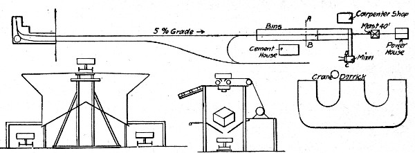 Fig. 69.—Sketch Plans of Concrete Making Plant for
Battery Emplacement.
Fig. 69.—Sketch Plans of Concrete Making Plant for
Battery Emplacement.
A batch made up as follows, tamped in place to a volume of 30 cu. ft. or 1-1/9 cu. yds.:
| 1 bbl. cement, at $2.532. | $ 2.532 |
| 0.315 cu. yd. shells, at $0.481. | 0.151 |
| 0.51 cu. yd. sand, at $0.25. | 0.130 |
| 0.89 cu. yd. stone, at $3.047. | 2.710 |
| Mixing and placing. | 0.761 |
| ———— | |
| Total for 30 cu. ft. | $ 6.284 |
This gives a cost per cubic yard of concrete in place as follows:
| Concrete in place, per cu. yd. | $ 5.655 |
| Forms, per cu. yd. of concrete. | 0.220 |
| ———— | |
| Total cost of concrete per cu. yd. | $ 5.875 |
United States Fortification Work.—The following methods and cost of mixing and placing concrete by hand and by cubical mixers is given by Mr. L. R. Grabill for U. S. Government fortification work done in 1899.
Hand Mixing and Placing.—The work was done by contract, using a 1 cement, 2 sand, 2 pebbles and 3 stone mixture turned four times. A board large enough for three batches at a time was used; one batch was being placed, one being mixed and one being removed at the same time so that the mixers moved without interval from one to the other. Two gangs were worked, each mixing 64 batches of 0.75 cu. yd., or 48 cu. yds. of concrete per day at the following cost:
| Hand Mixing 9,000 Cu. Yds.— | Per day. | Per cu. yd. |
| 6 men wheeling materials | $ 7.50 | $0.16 |
| 8 men mixing | 10.00 | 0.21 |
| 8 men wheeling away | 10.00 | 0.21 |
| 6 men placing and ramming | 7.50 | 0.16 |
| 1 pump man | 1.25 | 0.02 |
| 1 waterboy | 1.00 | 0.02 |
| 1 foreman | 2.00 | 0.04 |
| ——— | ——— | |
| Totals | $39.25 | $0.82 |
The entire cost of plant for this work was about $500.
Machine Mixing and Placing.—The concrete was mixed in a 4-ft. cubical mixer operated by a 12 hp. engine which also hauled the material cars up the incline to the mixer. These cars passed by double track under the material bins where the compartments of the car body were filled through trap doors; they then passed the cement house where the cement was placed on the load, then up the incline to the mixer and dumped, and then empty down an opposite incline. Seven turns of the mixer mixed the charge which was discharged into iron tubs on cars hauled by horses to two derricks whose booms covered the work. One gang by day labor mixed and placed 168 batches of 0.7 cu. yd., or 117.6 cu. yds. per day at the following cost:[Pg 190]
| Machine Mixing 4,000 Cu. Yds.— | Per day. | Per cu. yd. |
| 32 men at $1.25 | $40.00 | $0.34 |
| 1 pumpman | 1.25 | 0.01 |
| 1 teamster and horse | 2.00 | 0.02 |
| 2 waterboys at $1 | 2.00 | 0.02 |
| 1 engineman | 1.70 | 0.02 |
| 1 derrickman | 1.50 | 0.01 |
| 1 fireman | 1.50 | 0.01 |
| 1 foreman | 2.88 | 0.03 |
| Fuel (cement barrels largely) | 1.25 | 0.01 |
| ——— | ——— | |
| Totals | $54.08 | $0.47 |
The cost of the plant was about $5,000.
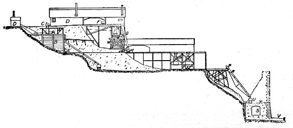 Fig. 70.—Concrete Making Plant for Constructing Lock
Walls, Cascades Canal.
Fig. 70.—Concrete Making Plant for Constructing Lock
Walls, Cascades Canal.
LOCK WALLS, CASCADES CANAL.—Four-fifths or 70,000 cu. yds. of lock masonry was concrete, the bulk of which was mixed and deposited by the plant shown by Fig. 70. The concrete was Portland cement, sand, gravel and broken stone. Cement was brought in in barrels by railway, stored and tested; from the store house the barrels were loaded onto cars and taken 250 ft. to a platform onto which the barrels were emptied and from which the cement was shoveled into the cement hopper and chuted to cars which took it to the charging hopper of the mixer. The stone was crushed from spalls and waste ends from the stone cutting yards, where stone for wall lining and coping and other special parts was prepared. These spalls and ends were brought in cars and[Pg 191] dumped into the hopper of a No. 5 Gates crusher, with a capacity of 30 tons per hour. From the crusher the stone passed to a 2½-in. screen, the pieces passing going to a bin below and the rejections going to a smaller Blake crusher and thence to the bin. The dust and small particles were not screened out. The sand and gravel were obtained by screening and washing pit gravel. The gravel was excavated and brought in cars to the washer. This consisted of a steel cylinder 2 ft. 6½ ins. in diameter and about 18 ft. long, having an inclination of 1 in. per foot. An axial gudgeon supported the cylinder at the lower end and it rested on rollers at the other end and at an intermediate point. The gravel was fed by hopper and chute into the upper end and into this same end a 3-in. perforated pipe projected and extended to about mid-length of the cylinder. The cylinder shell was solid and provided with internal fins for about half its length from the feed end. For the remainder of its length nearly to the end, the shell was perforated with 2½-in. holes. For a length of 4 ft. beyond mid-point it was encircled by a concentric screen of ⅛-in. holes, and this screen for 3 ft. of its length was encircled by another screen of 30 meshes to the inch. The pit mixture fed into the cylinder was gradually passed along by the combined inclination and rotation, being washed and screened in the process. The sand fell into one bin and the gravel into another, and the waste water was carried away by a flume. The large stones passed out through openings at the lower end of the shell and were chuted into cars. The cars came to the mixer as clearly shown by Fig. 70.
The stone and gravel cars were side dump and the cement car was bottom dump. The mixers were of the cube type 4 ft. on each edge and operated by a 7×12-in. double cylinder engine at nine revolutions per minute. The usual charge was 32 cu. ft. of the several ingredients, and it was found that 15 revolutions requiring about 1½ minutes were sufficient for mixing. The average work of one mixer was 17 batches or about 13 cu. yds. per hour, but this could be speeded up to 20 batches per hour when the materials were freely supplied and the output freely removed. Two cars took the concrete from the mixer to the hopper, from which it was fed to the work by chute. The hopper was mounted on a truck and the chute[Pg 192] was a wrought iron cylinder trussed on four sides and having a 45° elbow at the lower end to prevent scattering. The chute fed into a car running along the wall and distributing the material. It was found impracticable to move the chute readily enough to permit of feeding the concrete directly into place. As the concreting progressed upward the trestle was extended and the chute shortened. It was found that wear would soon disable a steel chute so that the main trussed cylinder had a smaller, cheaply made cylinder placed inside as a lining to take the wear and be replaced when necessary.
The plant described worked very successfully. Records based on 9,614.4 cu. yds. of concrete laid, gave the following:
| Cu. yds. | |
| Concrete mixed by hand | 1,777.0 |
| Concrete mixed by machine | 7,837.4 |
| Total concrete laid | 9,614.4 |
| Concrete placed by derricks | 2,372.0 |
| Concrete placed by chute | 7,242.4 |
| Concrete 1-2-4 mixture | 156.0 |
| Concrete 1-3-6 mixture | 1,564.0 |
| Concrete 1-4-8 mixture | 6,892.0 |
The average mixture was 1 cement, 3.7 sand, 4.8 gravel and 2.6 broken stone. The average product was 1.241 cu. yds. concrete per barrel of cement and 1.116 cu. yds. of concrete per cubic yard of stone and gravel. The average materials for 1 cu. yd. of concrete were: Cement 0.805 bbl., sand 0.456 cu. yd., gravel 0.579 cu. yd., and stone 0.317 cu. yd.
The cost of these 9,614.4 cu. yds. of concrete in place was:
| Hand Mixed and Placed by Derrick— | Per cu. yd. |
| Labor mixing 1,777 cu. yds | $1,072 |
| Repairs, fuel, etc | 0.016 |
| ——— | |
| Total cost mixing | $1,088 |
| Labor placing 2,372 cu. yds. | 0.6025 |
| Fuel, tramways, etc. | 0.1958 |
| ——— | |
| Total cost placing | $0.7983 |
| Machine Mixed and Placed by Chute— | |
| Labor mixing 7,837 cu. yds. | $0.388 |
| Repairs, fuel, etc | 0.046 |
| ——— | |
| Total cost mixing | $0.434 |
| Labor placing 7,242 cu. yds | 0.414 |
| Fuel, tramways, etc. | 0.045 |
| ——— | |
| Total cost placing | $0.459 |
| Materials and Supplies 9,614 cu. yds.— | |
| Timbering | $0.145 |
| Cement | 3.289 |
| Sand and gravel | 1.073 |
| Broken stone | 0.536 |
| Cement testing, repairs, etc. | 0.223 |
| ——— | |
| Total | $5,266 |
| Plant and Superintendence, 9,614 Cu. Yds.— | |
| Engineering, superintendence, repairs, etc. | $1,508 |
| 20% cost of plant | 0.165 |
| ——— | |
| Total | $1,673 |
The comparative cost of hand and machine mixing and handling was thus:
| Item— | Hand. | Machine. |
| Mixing per cu. yd. | $1.088 | $0.434 |
| Placing per cu. yd. | 0.798 | 0.459 |
| Materials, etc., per cu. yd. | 5.466 | 5.466 |
| Plant, etc., per cu. yd. | 1.673 | 1.right |
| ——— | ——— | |
| Totals | $9.025 | $8.032 |
The average total costs of all the concrete placed were:
| Mixing per cu. yd. | $0.555 |
| Placing per cu. yd. | 0.543 |
| Materials per cu. yd. | 5.266 |
| Plant, etc., per cu. yd. | 1.673 |
| ——— | |
| Total | $8.037 |
LOCKS, COOSA RIVER, ALABAMA.—The following methods and costs are given by Mr. Charles Firth for constructing lock No. 31 for the Coosa River canalization, Alabama. This lock is 420 ft. long over all, 322 ft. between quoins, 52 ft. clear width, 14.7 ft. lift and 8 ft. depth of water on sills; it contained 20,000 cu. yds. of concrete requiring 21,500 bbls. cement, half Alsen and half Atlas.
Figure 71 shows the concrete mixing plant, consisting of two 4×4 ft. cube mixer, driven by a 10×16-in. engine. The top floor of the mixer house stored the cement, 2,000 bbls. The concrete was a 1-3-5½ stone mixture. Each mixer charge consisted of 3 cu. ft. cement, 9 cu. ft. sand and 16.5 cu. ft. stone; the charge was turned over four times before and six times after watering at a speed not exceeding eight revolutions per minute. The average output of the plant was 200 cu. yds. per 8-hour day, or 100 cu. yds. per mixer, but it was limited by the means for placing.
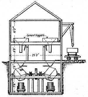 Fig. 71.—Concrete Mixing Plant for Lock Construction,
Coosa River, Alabama.
Fig. 71.—Concrete Mixing Plant for Lock Construction,
Coosa River, Alabama.
The concrete was mixed dry, deposited in 6 to 8-in. layers, and rammed with 30-lb. iron rammers with 6-in. square faces. For all exposed surfaces a 6-in. facing of 1-3 mortar was placed by setting 2×12-in. planks 4 ins. from the laggings, being kept to distance by 2×4-in. spacers, placing and ramming the concrete behind them, then withdrawing them, filling the 6-in. space with mortar and tamping it to bond with the concrete.[Pg 195] The walls were carried up in lifts, each lift being completed entirely around the lock before beginning the next; the first lift was 10.7 ft. high and the others 6 ft., except the last, which was 4.5 ft., exclusive of the 18-in. coping. The coping was constructed of separately molded blocks 3 ft. long, made of 1-2-3 concrete faced with 1-1 mortar and having edges rounded to 3 ins. radius.
In constructing the forms a row of 6×8-in. posts 24 ft. long and 5 to 7 ft. apart was set up along the inside of each wall and a similar row of posts 12 ft. long was set up along the outside. From the tops of the short posts 6×8-in. caps reached across the wall and were bolted to the long posts; these caps carried the stringers for the concrete car tracks. The lagging consisted of 3×10-in. planks dressed on all sides. The backs of the walls were stepped and as each step was completed the rear 12-ft. posts were lifted to a footing on its top and carried in the necessary distance. The front posts remained undisturbed until the wall was completed. The lagging was moved up as the filling progressed. As no tie bolts were permitted, these forms required elaborate bracing.
From the mixing plant, which was located on the bank above reach of floods, the concrete cars were dropped by elevator to the level of the track over the walls and then run along the wall and dumped onto platforms inside the forms and just below the track. This arrangement was adopted, because it was found that even a small drop separated the stone from the mortar. The concrete was shoveled from the platforms to place and rammed. The cars were bottom dumping with a single door hinged at the side; this door when swinging back struck the track stringers and jarred the form so that constant attention was necessary to keep it in line. It would have been much better to have had double doors swinging endwise of the car. Another point noted was that unless the track was high enough to give good head room at the close of a lift the placing and ramming were not well done.
The cost of 8,710 cu. yds. of concrete placed during 1895 by day labor employing negroes at $1 per 8-hour day was as follows per cubic yard:[Pg 196]
| 1 bbl. cement | $2.48 |
| 0.88 cu. yd. stone at $0.76 | 0.67 |
| 0.36 cu. yd. sand at $0.34 | 0.12 |
| Mixing, placing and ramming | 0.88 |
| Staging and forms | 0.42 |
| —— | |
| Total | $4.57 |
LOCK WALLS, ILLINOIS & MISSISSIPPI CANAL.—The locks and practically all other masonry for the Illinois & Mississippi Canal are of concrete. The following account of the methods and cost of doing this concrete work is taken from information published by Mr. J. W. Woermann in 1894 and special information furnished by letter. The decision to use concrete was induced by the fact that no suitable stone for masonry was readily available (the local stone was a flinty limestone, usually without bed, or, at best, in thin irregular strata, and cracked in all directions with the cracks filled with fire clay) while good sand and gravel and good stone for crushing were plentifully at hand. The concrete work done in 1893-4 comprised dam abutments, piers for Taintor gates and locks.
Dam Abutments.—Four dam abutments were constructed, three of which were L-shaped, with sides next to the river 40 ft. long and sides extending into the banks 20 ft. long; the top thickness was 3 ft., the faces were vertical and the backs stepped with treads of 14 to 16 ins., and the width of base was 0.4 of the height. Each of these abutments was built in four 30-cu. yd. sections, each section being a day's work. The forms consisted of 2×8-in. planks, dressed on both sides, 2×8-in. studs spaced 2 ft. on centers and 4×6-in. braces. For the first two of the four abutments, the forms were erected in sections, the alternate sections being first erected and filled. When these sections had hardened the forms were shifted to the vacant sections and lined up to and braced against the completed sections. This method did not give well aligned walls, so in subsequent work the forms were erected all at once.
The concrete was mixed by hand. The sand and cement were mixed dry, being turned four times and spread in a layer[Pg 197] Pebbles and broken stone previously wetted were spread over the sand and cement and the whole turned four times, the last turn being into wheelbarrows; about five common buckets of water were added during the mixing. The mixture sought was one that would ram without quaking. Two forms of rammers were used; for work next to forms a 4×6-in. rammer and for inside work 6-in diameter circular rammer weighing 20 lbs. The gang mixing and placing concrete consisted usually of:
| Item. | Per Day. | Per Cu. Yd. |
| 2 handling cement and sand | $ 3.00 | $0.10 |
| 3 filling barrows with aggregate | 4.50 | 0.15 |
| 8 mixing concrete | 12.00 | 0.40 |
| 2 shoveling concrete into barrows | 3.00 | 0.10 |
| 5 wheeling concrete to forms | 7.50 | 0.25 |
| 1 spreading concrete | 1.50 | 0.05 |
| 5 tamping concrete | 7.50 | 0.25 |
| ——— | —— | |
| Total, 26 men | $39.00 | $1.30 |
These cubic yard costs are based on 30 cu. yds. of wall completed per 8-hour day. The cost in detail of two abutments containing 254 cu. yds. was per cubic yard as follows:
| Item. | Per Cu. Yd. |
| 1.65 bbls. Portland (Germania) cement | $ 5.60 |
| 0.5 cu. yd. crushed stone | 2.07 |
| 0.24 cu. yd. gravel | 0.59 |
| 0.53 cu. yd. sand | 0.24 |
| Lumber, forms, warehouses, platforms[D] | 0.55 |
| Carpenter work[E] ($9 per M.) | 1.10 |
| Mixing and placing | 1.47 |
| 20 per cent. first cost of plant | 0.31 |
| Engineering and miscellanies | 0.31 |
| ——— | |
| Total | $12.24 |
[D] Charging ¼ of first cost of $18 per M. ft.
[E] Carpenters $3.50, laborers $1.50 per day; there was one laborer to two carpenters.
The large amount of cement 1.65 bbls. per cubic yard was due to facing the abutments with 8 ins. of 1-2 mortar. The concrete in the body of the wall was 1 cement, 2 sand, 2 gravel[Pg 198] and 2 broken stone mixture. A dry mixture was used and this fact is reflected in the cost of ramming, 25 cts. per cu. yd. The cost of mixing was also high.
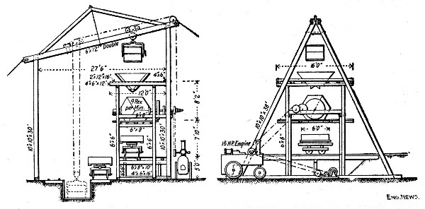 Fig. 72.—Concrete Mixing Plant for Lock Walls, Illinois
& Mississippi Canal.
Fig. 72.—Concrete Mixing Plant for Lock Walls, Illinois
& Mississippi Canal.
Piers for Taintor Gates.—The masonry at this point consisted of three piers 6×30 ft., and two abutments 30 ft. long, 6 ft. thick at base and 4 ft. thick at top, with wing walls; it amounted to 460 cu. yds. The feet of the inclined braces were set into gains in the horizontal braces and held by an 8-in. lag screw; after the posts were plumbed a block was lag-screwed at the upper end of each brace. These forms proved entirely satisfactory. The cost of the work per cubic yard was as follows:
| Item. | Per Cu. Yd. |
| 1.45 bbls. Portland cement | $4.330 |
| 0.55 cu. yd. crushed stone | 0.604 |
| 0.252 cu. yd. pebbles | 0.328 |
| 0.465 cu. yd. sand | 0.419 |
| 40,000 ft. B. M. lumber (¼ cost of $16 per M.) | 0.348 |
| Carpenter work on forms | 0.780 |
| Mixing and placing concrete | 1.909 |
| 20 per cent. cost of plant | 0.090 |
| Miscellaneous | 0.182 |
| ——— | |
| Total | $8.99 |
Mixing Plant.—The concrete for all the lock work of 1893-4 was mixed by the plant shown by Figs. 72 and 73. The mixer[Pg 199] plant proper consisted of a king truss carried by two A-frames of unequal height; under the higher end of the truss was a frame carrying a 4-ft. cubical mixer and under the lower end a pit for a charging box holding 40 cu. ft. This charging box was hoisted by ½-in. steel cable running through a pair of double blocks as shown; the slope of the lower chord of the truss was such that the cable hoisted the box and carried it forward without the use of any latching devices. On two sides of the pit were tracks from the sand and stone piles and on the other two sides were the cement platform and water tank. The charging box dumped into the hopper above the mixer and the mixer discharged into cars underneath. A 15-HP. engine operated the hoist by one pulley and the mixer by the other pulley. Nine revolutions of the mixer made a perfect mixture. The plant as illustrated was slightly changed as the result of experience in constructing the guard lock. The charging hopper was lowered 6 ins. and the space between the mixer and lower platform reduced by 9 ins.; diagonal braces were also inserted under the timbers carrying the mixer axles. This plant cost for framing and erection $300 and for[Pg 200] machinery delivered $706. The crushing plant shown by Fig. 73 consisted of a No. 2 Gates crusher delivering to a bucket elevator.
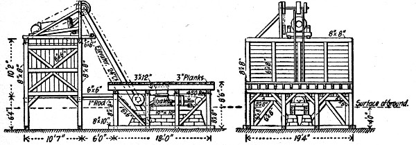 Fig. 73.—Stone Crushing Plant for Lock Walls, Illinois &
Mississippi Canal.
Fig. 73.—Stone Crushing Plant for Lock Walls, Illinois &
Mississippi Canal.
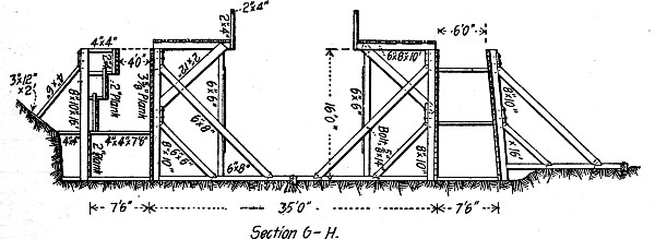 Fig. 74.—Forms for Guard Lock, Illinois & Mississippi
Canal.
Fig. 74.—Forms for Guard Lock, Illinois & Mississippi
Canal.
Guard Lock.—The forms employed in constructing the guard lock are shown by Fig. 74, and in this drawing the trestle and platform for the concrete cars are to be noted. The walls were concreted in sections. A batch of concrete consisted of 1 bbl. cement, 10 cu. ft. sand and 20 cu. ft. crushed stone. The average run per 8-hour day was 40 batches of facing and 60 batches concrete, representing 100 bbls. cement. The gang worked was as follows:
| Duty. | No. Men. | P. C. Cost. |
| Handling cement | 3 | 5.26 |
| Filling and pushing sand car | 5 | 8.77 |
| Filling and pushing stone car | 9 | 15.79 |
| Measuring water | 1 | 1.75 |
| Dumping bucket on top platform | 3 | 5.26 |
| Opening and closing door of mixer | 1 | 1.75 |
| Operating friction clutch | 1 | 1.76 |
| Attending concrete cars under mixer | 1 | 1.76 |
| Dumping cars at forms | 2 | 3.51 |
| Spreading concrete in forms | 3 | 5.26 |
| Tamping concrete in forms | 10 | 17.54 |
| Mixing mortar for facing | 6 | 10.53 |
| Finishing top of wall | 2 | 3.51 |
| Hauling concrete cars with 1 horse | 1 | 3.51 |
| Engineman operating hoist | 1 | 3.51 |
| Engineman operating engine | 1 | 3.51 |
| Foreman in charge of forms | 1 | 3.51 |
| General foreman | 1 | 3.51 |
| — | ——— | |
| Total | 52 | 100.00 |
The percentages of cost in this statement have been calculated by the authors upon the assumption that each laborer received one-half as much wages as each engineman, foreman and horse and driver per 8 hours, which would make the total daily wages equivalent to the wages of 57 men. Wages of common labor were $1.50 per day. Considering the size of the gang the output of 40 batches of mortar and 60 batches of concrete per day was very small. The total yardage of concrete[Pg 201] in the guard lock was 3,762 cu. yds., 2,212 cu. yds. in the walls and 1,550 cu. yds. in foundations, culverts, etc. Its cost per cubic yard was made up as follows:
| Item. | Total. | Per Cu. Yd. |
| 5,246 bbls. Portland cement | $15,604} | $4.170 |
| 152 bbls. natural cement | 84} | |
| 2,910 cu. yds. stone | 2,901 | 0.771 |
| 126 cu. yds. pebbles | 113} | 0.401 |
| 1,970 cu. yds. sand | 1,398} | |
| 145,000 ft. B. M. lumber (¼th cost) | 659 | 0.175 |
| Iron for forms, trestles, etc. | 90 | 0.024 |
| Coal, oil, miscellaneous | 327 | 0.087 |
| Carpenter work | 2,726 | 0.724 |
| Mixing and placing concrete | 6,693 | 1.780 |
| Pumping, engineering, misc. | 742 | 0.197 |
| 20 per cent of plant | 550 | 0.146 |
| ——— | ——— | |
| Total | $31,887 | $8.475 |
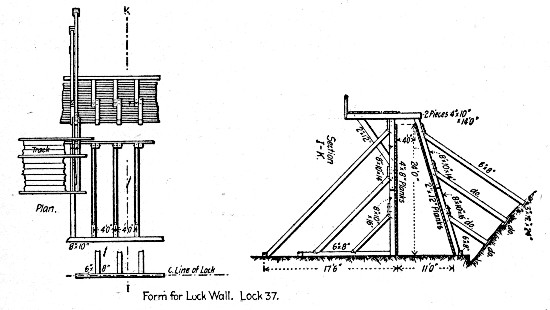 Fig. 75.—Forms for Regular Lock Walls, Illinois &
Mississippi Canal.
Fig. 75.—Forms for Regular Lock Walls, Illinois &
Mississippi Canal.
Lock No. 37.—The character of the forms used in constructing the lock walls is shown by Fig. 75. The walls were built in sections and work was continuous with three 8-hour shifts composed about as specified for the guard lock work except that one or two men were added in several places making the total number 58 men. The average output per shift was 65 batches of concrete and 31 batches of facing mortar. The cost of the work, comprising 3,767 cu. yds., was as follows:[Pg 202]
| Item. | Total. | Per Cu. Yd. |
| 4,564 bbls. Portland cement | $14,181 | $3.764 |
| 2,460 cu. yds. crushed stone | 4,521 | 1.200 |
| 250 cu. yds. pebbles | 325 | 0.086 |
| 1,750 cu. yds. gravel | 2,335 | 0.619 |
| 450 cu. yds. sand | 450 | 0.119 |
| 180,000 ft. B. M. lumber (¼th cost) | 990 | 0.236 |
| Fuel, light, repairs, etc. | 1,171 | 0.311 |
| Carpenter work | 2,526 | 0.671 |
| Pumping | 270 | 0.071 |
| Mixing and placing concrete | 6,170 | 1.632 |
| 20% cost of plant | 730 | 0.193 |
| ——— | ——— | |
| Total | $33,669 | $8.902 |
Lock No. 36.—The forms used were of the construction shown by Fig. 75. Three shifts were worked, each composed as specified for the guard lock, except that the number of tampers and spreaders was doubled, bringing the gang up to 65 men. The average output per gang per shift was 76 batches of concrete and 35 batches of facing mortar. The cost of 2,141 cu. yds. of concrete in this lock was as follows:
| Item. | Total. | Per Cu. Yd. |
| 3,010 bbls. Portland cement | $9,057 | $4.23 |
| 1,377 cu. yds. broken stone | 1,922 | 0.90 |
| 393 cu. yds. pebbles | 354 | 0.17 |
| 459 cu. yds. gravel | 310 | 0.15 |
| 500 cu. yds. sand | 889 | 0.42 |
| 150,000 ft. B. M. lumber (¼th cost) | 600 | 0.28 |
| Fuel, light, repairs, etc. | 253 | 0.68 |
| Carpenter work | 1,472 | 0.11 |
| Mixing and placing concrete | 3,897 | 1.82 |
| 20% cost of plant | 650 | 0.30 |
| ——— | —— | |
| Total | $19,404 | $9.06 |
The preceding data, made public by Mr. Woermann in 1894, are supplemented by the following information prepared for the authors:
"If any criticism was to be made of the concrete masonry erected in 1893 and 1894, it would probably be to the effect[Pg 203] that it was too expensive. The cost of the masonry erected during those two seasons was $8 to $9 per cu. yd. Our records showed that about 45 per cent. of this cost was for Portland cement alone, and moreover, that 40 per cent. of the total cement used at a lock was placed in the 8-in. facing and 5-in. coping. So in the seven locks erected in 1895 on the eastern section, the facing was reduced to 3 ins. and the proportions changed from 1-2 to 1-2½.
"In 1898 this cost received another severe cut, and Major Marshall's instructions stated that the facing should not exceed 1½ ins. in thickness nor be less than ¾-in., while the layer of fine material on top of the coping was to be only sufficient to cover the stone and gravel. The amount of sand was again increased so that the proportions were 1-3.
"The cost of the Portland cement concrete was likewise cheapened by increasing the amount of aggregates. On the earlier work the proportions were 1-2-2-3, while on the work in 1898 the proportions were 1-4-4. The cost of the walls was further cheapened by using Utica cement in the lower steps of the wall, with 2 ft. of Portland cement concrete on the face. The proportions used in the Utica cement concrete were 1-2½-2½. This lower step is one-third of the height, or about 7 ft.
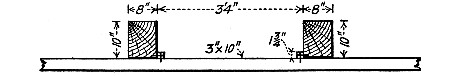 Fig. 76.—Sketch Showing Method of Attaching Lagging to
Studs, Illinois & Mississippi Canal.
Fig. 76.—Sketch Showing Method of Attaching Lagging to
Studs, Illinois & Mississippi Canal.
"The forms were of the same character as those used on the first locks, except that for lining the inner face, 3×10-in. hard pine planks were substituted for the 4×8-in. white pine. The hard pine was damaged less by the continuous handling, and the cost was practically the same. There was also an important change made in the manner of fastening the plank to the 8×10-in. posts. A strip 1¾ ins. square was thoroughly nailed to each post, once for all, with 20d. spikes, and the planking was then nailed from the outside, as shown in Fig. 76. This kept the face of the plank in a perfectly smooth condition, and prevented the formation of the little knobs on the face of[Pg 204] the concrete which represented all the old nail holes. This style of forming was also easier to take apart after the setting of the concrete. Rough pine planks, 2×12-in., were used for the back of the form, the same as before.
"In order to keep ahead of the concrete force it was necessary to use two gangs of carpenters, erecting the forms for the next two locks. Each gang consisted of about 20 carpenters (at $2.25) and 10 helpers (at $1.50); but men were transferred from one to the other, according to the stage of completion of the two locks. In addition to these two gangs, two carpenters were on duty with each concrete shift to put in the steps in the back of the forms. Sufficient lumber was required for the forms for three complete locks, and 14 locks (Nos. 8 to 21) were built.
"The same type of mixer has been used as on the earlier work at Milan, namely, a 4-ft. cubical steel box mounted on corners diagonally opposite. On account of the greater number of locks to be built on the eastern section, however, two mixers were found necessary, so that while the concrete force was at work at one lock, the carpenters and helpers were erecting the mixer at the next lock. The facing was mixed by hand. After turning over the dry cement and sand at least twice with shovels, the mixture was then cast through a No. 5 sieve, after which the water was incorporated slowly by the use of a sprinkling can so as to avoid washing. The secret of good concrete, after the selection of good materials, is thorough mixing and hard tamping. Each batch of concrete, consisting of about 1.2 cu. yds. in place, was turned in the mixer for not less than 2 mins. at the rate of 9 revolutions per minute. The amount of tamping is indicated by the fact that about 16 men out of 72 on each shift did nothing but tamp. The rammers used were 6 ins. square and weighed 33 lbs. The bottom of the rammer consisted of three ridges, each 1-in. in height, so as to make more bond between the successive layers.
"On the eastern section the top of the lock walls was higher above the ground, as a rule, than at the Milan locks, and the cars were run up an incline with a small hoisting engine. A 15-HP. portable engine and boiler operated the bucket hoist from one pulley, the mixer from the other pulley, and also furnished steam for the hoist which pulled the cars up the[Pg 205] incline. The incline made an angle of about 30° with the ground. The practice of carrying on two sections at once was continued the same as on the western section. Each main wall was systematically divided into 11 sections, making each section about 20 ft. long. The corners of the coping were dressed to a quadrant of about 3 ins. radius with a round trowel like those used on cement walks. In fact, the whole method of finishing the coping was the same as is used on concrete walks. The mortar was put on rather wet and then allowed to stand for about 20 mins. before finishing. This allowed the water to come to the surface and prevented the formation of the fine water cracks which are sometimes seen on concrete work. After its final set the coping was covered with several inches of fine gravel which was kept wet for at least a week.
"The last concrete laid during the season was in November, on Lock No. 21, and Aqueducts Nos. 2 and 3. Portions of these structures were built when the temperature was below freezing. The water was warmed to about 60° or 70° F., by discharging exhaust steam into the tank. Salt was used only in the facing, simply sufficient to make the water taste saline. The maximum amount used on the coldest night when the temperature was about 20° F. was 1½ per cent.
The concrete force on each shift was as follows:
| Men. | |
| Filling and pushing stone car | 10 |
| Filling and pushing gravel car | 8 |
| Measuring cement | 3 |
| Measuring water and cleaning bucket | 2 |
| Dumping bucket on top platform | 2 |
| Operating mixer | 2 |
| Loading concrete cars | 1 |
| Pushing and dumping cars on forms | 3 |
| Switchmen on forms | 2 |
| Spreading concrete in forms | 12 |
| Tamping concrete in forms | 16 |
| Mixing facing | 3 |
| Water boys | 2 |
| — | |
| Total laborers | 66 |
| Operating hoists | 2 |
| Finishing coping | 2 |
| Fireman | 1 |
| Sub-overseers | 2 |
| Overseer | 1 |
| — | |
| Total force | 74 |
The cost of material and labor at Lock No. 15 (10-ft. lift), which contains 2,559 cu. yds. of concrete, was as follows:
| Materials. | Per cu. yd. |
| 0.56 bbl. Portland cement (0.96 per cu. yd.) | $1.42 |
| 0.64 bbl. Utica cement (1.58 per cu. yd.) | .30 |
| 0.58 cu. yd. stone | 1.15 |
| 0.60 cu. yd. gravel | .52 |
| 14 ft. B. M. lumber[F] at $15 per M. | .21 |
| 0.6 lb. spikes | .01 |
| Coal (10 tons in all, at $1.70) | .01 |
| 0.35 gal. kerosene | .03 |
| —— | |
| Total materials | $3.65 |
| Labor. | |
| Erecting forms ($7 per M.) | .45 |
| Removing forms ($2 per M.) | .13 |
| Erecting and removing mixer ($161) | .06 |
| Loading and unloading materials at yards and lock sites | .23 |
| Track laying ($86) | .03 |
| Train service (narrow gage road) | .09 |
| Delivering materials to mixer | .28 |
| Mixing concrete | .11 |
| Depositing concrete | .21 |
| Tamping concrete | .21 |
| Mixing, depositing and tamping, 69 cu. yds. face mortar ($160) | .23 |
| General construction ($553) | .22 |
| —— | |
| Total labor | $2.25 |
[F] The lumber was used nearly five times, which accounts for its low cost per cu. yd.
There were 1,430 cu. yds. of Portland cement concrete. 69 cu. yds. of Portland cement mortar facing, and 1,059 cu. yds. of Utica cement concrete. The Portland concrete cost $6.43 per cu. yd.; the Utica concrete, $4.77 per cu. yd. The following is the cost of labor on Lock No. 20 (11-ft. lift.; 2,750 cu. yds.):
| Per cu. yd. | |
| Erecting forms ($7 per M.) | $.434 |
| Removing forms ($1.70 per M.) | .113 |
| Erecting and removing mixer ($151) | .058 |
| Loading and unloading at yards, lock sites, etc. | .614 |
| Tracks | .024 |
| Train service (narrow gage) | .016 |
| Pumping | .114 |
| Delivering material to mixer | .288 |
| Mixing concrete | .134 |
| Depositing concrete | .205 |
| Tamping concrete | .192 |
| Mixing, depositing and tamping, 85 cu. yds. face mortar | .071 |
| General construction | .246 |
| ——— | |
| Total | $2.509 |
COST OF HAND MIXING AND PLACING, CANAL LOCK FOUNDATION.—Mr. Geo. P. Hawley gives the following record of mixing and placing 4,000 cu. yds. of 1-4½ gravel concrete for the foundation of a lock constructed for the Illinois and Mississippi Canal in 1897. The concrete was mixed on 14×16-ft. board platforms, from which it was shoveled directly into place. The materials were brought to the board in wheelbarrows. Two boards were used, the usual gang for each being 4 men wheeling gravel, 4 men mixing, 1 man sprinkling, 2 men depositing and leveling and 2 men tamping. The two gangs were worked against each other. Ten hours constituted a day's work, and the average time and cost per cubic yard for mixing and placing were:[Pg 208]
| Cts. | |
| Foreman, 0.21 hr., at 30 cts | 6.30 |
| Laborers, 3.339 hrs., at 15 cts | 50.09 |
| Pump runner, 0.129 hr., at 20 cts | 3.58 |
| Water boy, 0.087 hr., at 7½ cts | 0.65 |
| —— | |
| Total labor per cu. yd., cents. | 60.62 |
BREAKWATER AT MARQUETTE, MICH.—The breakwater extends out from the shore and consists of a prism of concrete resting on timber cribs filled with stone. Originally the cribs carried a timber superstructure; this was removed to give place to the concrete work. A typical cross-section of the concrete prism is shown by Fig. 77; the prism is 23 ft. wide on the base. Farther in shore the base width was reduced to 20 ft., and in the shore section the prism was changed to a triangular trapezoid by continuing the first slope to the bottom cutting off the berm and second slope. The wooden structure was removed to a level 1 ft. below mean low water and on it a concrete footing approximately 2 ft. thick was constructed for the prism proper. This footing reached the full width of the crib and was constructed in various ways during the 5 years through which the work continued. At first the footing concrete was deposited loose under water by means of bottom dumping buckets; later the stone filling of the cribs was simply leveled up by depositing concrete in bags, and last toe and heel blocks were molded and set flush with the sides of the crib and filled between. Methods of construction and records of cost are reported for portions only of the work and these are given here.
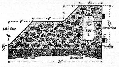 Fig. 77.—Cross Section of Marquette Breakwater.
Footing Placed under Water with Buckets.—Besides the material track which was constructed along the old wooden[Pg 209] structure the plant consisted of a mixing scow and a derrick scow, which were moored alongside the work. The sand, stone and cement were brought out in cars between working hours and stored on the mixing scow, enough for one day's work at a time. The derrick handled a 40-cu. ft. bottom dump bucket, which sat in a well on the mixing scow with its top flush with the deck. The concrete was mixed by hand on the deck and shoveled into the bucket; the bucket was then handled by the derrick to the crib and lowered and dumped under water. The gang consisted of 24 men, 1 foreman, 1 master laborer, 14 men shoveling and mixing, 3 men wheeling materials, 1 derrick man and 3 men placing and depositing concrete. No record of output of this gang is available. The cost of the concrete in place with wages $1.25 to $1.40 per day for common labor is given as follows:
| Materials. | Per cu. yd. |
| 1.21 bbls. (459 lbs.) cement at $2.20 | $2.657 |
| 1 cu. yd. stone at $1.58 | 1.580 |
| 0.5 cu. yd. sand at $0.50 | 0.250 |
| 2.02 lbs. burlap at $0.037 | 0.075 |
| Twine and needles | 0.005 |
| ——— | |
| Total materials | $4.567 |
| Labor. | |
| Loading scow with materials | $0.4114 |
| Mixing concrete | 0.8459 |
| Depositing concrete | 0.5242 |
| ——— | |
| Total labor | $1.7815 |
| Grand total | $6.348 |
These figures are based on some 757 cu. yds. of concrete footing. In explanation of the items of burlap, etc., it should be said that the cribs were carpeted with burlap to prevent waste of concrete into the stone fill.
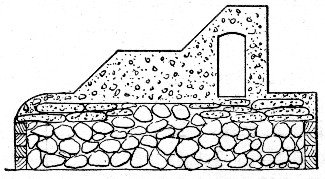 Fig. 78.—Cross Section of Marquette Breakwater Showing
Manner of Constructing Footing with Bags of Concrete.
Fig. 78.—Cross Section of Marquette Breakwater Showing
Manner of Constructing Footing with Bags of Concrete.
Leveling Off Cribs with Concrete in Bags.—The sketch, Fig. 78, shows the method of leveling off the cribs with concrete in bags. The concrete was mixed by hand on shore and filled into 8-oz. burlap bags, 6 ft. long and 80 ins. around, holding 2,000 lbs. The bags were filled while lying in position in a skip holding one bag. A skip was lifted by gallows frame and[Pg 210] tackle onto a car and run out to the work where the derrick scow handled the skip to the crib, lowered it into the water and dumped the bag. The cost of making and placing some 375 cu. yds. of concrete in bags is given as follows:
| Materials. | Total. | Per cu. yd. |
| 453 bbls. cement at $2.627 | $1,190.03 | $3.173 |
| 375 cu. yds. stone at $1.619 | 607.13 | 1.619 |
| 180 cu. yds. sand at $0.392 | 70.56 | 0.188 |
| 3,220 yds. burlap at $0.03304 | 106.39 | 0.283 |
| Twine and needles | 6.36 | 0.017 |
| ———— | ——— | |
| Total materials | $1,980.47 | $5.280 |
| Labor Mixing. | ||
| 108 hrs. master laborer at $0.21⅞ | $23.42 | $0.062 |
| 1,750 hrs. labor at $0.175 | 306.25 | 0.816 |
| Superintendence | 12.55 | 0.033 |
| ———— | ——— | |
| Total labor mixing | $ 342.22 | $0.911 |
| Labor transporting. | ||
| 306 hrs. labor at $0.175 | $53.55 | $0.142 |
| Superintendence | 5.25 | 0.014 |
| ———— | ——— | |
| Total labor transporting. | $58.80 | $0.156 |
| Labor Depositing. | ||
| 108 hrs. engineman at $0.25 | $27.00 | $0.072 |
| 108 hrs. master laborer at $0.21⅞ | 23.42 | 0.062 |
| 510 hrs. labor at $0.175 | 89.25 | 0.238 |
| Superintendence | 13.25 | 0.035 |
| ———— | ——— | |
| Total labor depositing | $ 152.92 | $0.407 |
| Grand total labor | $ 553.94 | $1.477 |
| Grand total materials and labor | $2,534.41 | $6.757 |
Molding Footing Blocks.—The blocks used at the toe of the prism were of the form and dimensions shown by Fig. 79. They were molded in a temporary shed heated to 50° to 65° F., and provided with a 2×8-in. dressed plank floor on 12×12-in. sills. The floor formed the bottoms of the block molds. Four molds were used, each consisting of four sides. Three laborers molded one block, 2.22 cu. yds. per day, wheeling, mixing, erecting and removing forms, placing concrete and doing all other work. The cost of making 40 blocks was recorded as follows:
| Materials. | Total. | Per cu. yd. |
| 126 bbls. cement at $2.75 | $346.50 | $3.893 |
| 88.9 cu. yds. screenings at $1.10 | 97.79 | 1.098 |
| 40.1 cu. yds. sand at $0.45 | 18.04 | 0.203 |
| 5 gals. oil at $0.65 | 3.25 | 0.036 |
| ——— | ——— | |
| Total materials | $465.58 | $5.230 |
| Labor. | ||
| 1,000 hrs. labor at $0.125 | $125.00 | $1.404 |
| Watchman | 29.15 | 0.327 |
| Labor cutting wood for fuel | 23.80 | 0.267 |
| Superintendence | 42.66 | 0.480 |
| ——— | ——— | |
| Total labor | $220.61 | $2.478 |
| Total labor and materials | $686.19 | $7.708 |
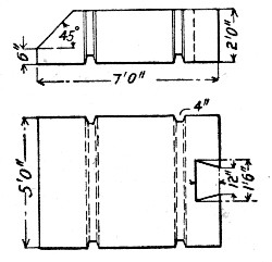 Fig. 79.—Details of Toe Blocks for Footing, Marquette
Breakwater.
Fig. 79.—Details of Toe Blocks for Footing, Marquette
Breakwater.
Molding Concrete Prism in Place.—The concrete prism was molded in alternate sections 10 ft. long; the form for the isolated sections consisted of eight pieces so constructed that when assembled in place and secured with bolts and turnbuckles the form was self-contained as to strength and required no outside support or bracing. The form once in place,[Pg 212] all that remained to be done was to fill it, the block with the gallery through it being molded in one operation. The forms for the connecting blocks consisted of two slope panels, a panel for the harbor face and the gallery form, the blocks previously molded making the other sides of the form. The concrete was mixed by hand on shore, conveyed to the work in 1 cu. yd. cars and shoveled into the forms, where it was rammed with 35-lb. rammers. The following record covers 1,231 cu. yds. of concrete prism. In this concrete some 214 cu. yds. of rubble stone were embedded. The costs given are as follows:
| Materials— | Total. | Per cu. yd. |
| 1,780 bbls. natural cement at $1.068 | $1,901.04 | $1.545 |
| 963½ cu. yds. stone at $1.619 | 1,559.91 | 1.267 |
| 53½ cu. yds. screenings at $0.392 | 20.97 | 0.017 |
| 485.6 cu. yds. sand at $0.392 | 190.36 | 0.154 |
| Miscellaneous materials | 78.15 | 0.063 |
| ———— | ——— | |
| Totals | $3,750.43 | $3.046 |
| Labor Mixing— | ||
| 254 hrs. master laborer at $0.21⅞ | $55.56 | $0.045 |
| 4,470 hrs. labor at $0.175 | 782.42 | 0.635 |
| Superintendence | 18.20 | 0.015 |
| ———— | ——— | |
| Total labor mixing | $ 856.18 | $0.695 |
| Labor Transporting and Placing— | ||
| 35 days overseer at $2.33⅓ | $81.67 | $0.066 |
| 1,949 hrs. labor at $0.175 | 342.07 | 0.277 |
| Superintendence | 34.98 | 0.028 |
| ——— — | ——— | |
| Total labor transporting and placing | $ 458.72 | $0.371 |
| Grand total, labor | $1,314.90 | 1.066 |
| Total labor and materials | $5,065.33 | 4.112 |
No charge is made under materials for rubble stone as the only cost for this was cost of handling and this is included in transporting and placing.
BREAKWATER, BUFFALO, N. Y.—The following methods and costs of mixing and placing some 2,561 cu. yds. of concrete are given by Mr. Emile Low, for 10 parapet wall sections[Pg 213] and 17 parapet deck sections for a breakwater at Buffalo, N. Y.
The concrete used was a 1 cement, 1 gravel, 1 sand grit and 4 unscreened broken stone. One bag of cement was assumed to measure 0.9 cu. ft. The voids in the sand grit and gravel were 27 per cent. and in the unscreened stone 39 per cent. The hardened concrete weighed 152 lbs. per cu. ft.
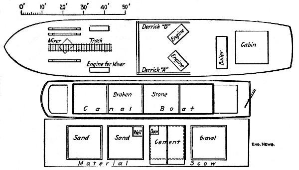 Fig. 80.—Sketch Plan of Concrete Mixing Plant for
Buffalo Breakwater.
Fig. 80.—Sketch Plan of Concrete Mixing Plant for
Buffalo Breakwater.
Figure 80 shows the arrangement of the mixing plant. The mixer was a 5-ft. cube mixer holding 125 cu. ft., mounted on a trestle and operated by a 9×12-in. horizontal engine taking steam from a 4×10-ft. locomotive boiler, also supplying steam to two derrick engines. The material scow contained two pockets for sand, one for gravel and one housed over for cement. Two inside cement men passed out the bags in lots of six to one outside cement man who cut and emptied them into the charging bucket. Three sand shovelers each loaded a 3.6 cu. ft. barrow and wheeled them tandem to the bucket, and two gravel men each loaded a 2.7 cu. ft. barrow and wheeled them tandem to the bucket. The broken stone was loaded by eight shovelers into another bucket, also containing 21.6 cu. ft. The two buckets were alternately hoisted and emptied into the mixer hopper, there being a dump man on the mixer who dumped the buckets and attended to the water supply. A charger put the mixer in operation and when the charge was mixed the car men dumped it into a skip resting on a[Pg 214] small car which was then run out on the track under the mixer to the derrick which handled the skip to the work. Derrick A handled the materials from the scows and derrick B handled the mixed concrete. The force on the derricks consisted of two enginemen, four tagmen and the fireman.
The ten parapet wall sections containing 841 cu. yds. were built in 46 hours, making 17 batches of 1.07 cu. yds., or 18.2 cu. yds. placed per hour. The 17 parapet deck sections containing 1,720 cu. yds. were built in 88 hours, making 18.8 batches of 1.08 cu. yds., or 19.5 cu. yds. placed per hour. For the parapet deck work the force was increased by 2 men handling materials and 1 man on the mixer. The labor cost of mixing and placing the concrete was as follows:
| Loading Gang— | Per day. | Per cu. yd. |
| 1 assistant foreman | 2.00 | $0.011 |
| 3 cement handlers | 5.25 | 0.029 |
| 3 sand shovelers | 5.25 | 0.029 |
| 2 gravel shovelers | 3.50 | 0.020 |
| 8 stone shovelers | 14.00 | 0.076 |
| 1 hooker on | 1.75 | 0.010 |
| ——— | ——— | |
| Totals | $31.75 | $0.175 |
| Mixer Gang— | ||
| 1 dumpman | $ 1.75 | $0.010 |
| 1 charging man | 1.75 | 0.010 |
| 2 car men | 3.50 | 0.020 |
| 2 enginemen at $3.25 | 6.50 | 0.035 |
| 4 tagmen at $2 | 8.00 | 0.044 |
| 1 fireman | 2.00 | 0.011 |
| ——— | ——— | |
| Totals | $23.50 | $0.130 |
| Wall Gang— | ||
| 1 Signalman | $ 1.75 | $0.010 |
| 1 dumper | 1.75 | 0.010 |
| 6 shovelers at $2 | 12.00 | 0.065 |
| 4 rammers | 7.00 | 0.038 |
| 1 foreman | 4.00 | 0.022 |
| ——— | —— | |
| Totals | $26.50 | $0.145 |
| Grand totals | $81.75 | $0.450 |
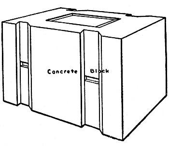 Fig. 81.—Concrete Blocks for Pier at Port Colborne
Harbor.
Fig. 81.—Concrete Blocks for Pier at Port Colborne
Harbor.
 Fig. 82.—Forms for Molding Blocks, Port Colborne Harbor
Pier.
Fig. 82.—Forms for Molding Blocks, Port Colborne Harbor
Pier.
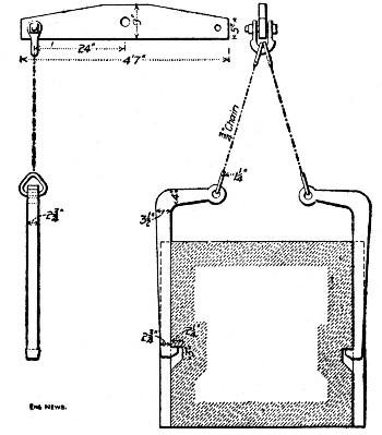 Fig. 83.—Device for Handling Blocks, Port Colborne
Harbor Pier.
Fig. 83.—Device for Handling Blocks, Port Colborne
Harbor Pier.
PIER CONSTRUCTION, PORT COLBORNE, ONT.—In constructing the new harbor at Port Colborne, Ont., on Lake Erie, the piers consisted of parallel rows of timber cribs set the width of the pier apart and filled in and between with stone blasted and dredged from the lake bottom in deepening the harbor. The tops of the cribs terminated below water level and were surmounted by concrete walls set on the outer edges. These walls were filled between with stone and the top of the filling was[Pg 216] floored part way or entirely across, as the case might be, with a thick concrete slab. The footings of the walls to just above the water level were made of concrete blocks 4½×4×7 ft., constructed as shown by Fig. 81. The wall above the footing course and the floor slab were of concrete molded in place. The concrete work consisted of molding and setting concrete blocks and of molding concrete wall and slab in place.
The blocks were molded on shore, shipped to the work on scows and set in place by a derrick. Figure 82 shows the construction of the forms for molding the blocks; the bottom tie rods passed through the partitions forming the ends of the molds. The sides were removed in 48 hours and used over again. Figure 83 shows the hooks used for handling the molded blocks. Considerable trouble was had in setting these blocks level and close jointed, owing to the difficulty of leveling up the stone filling under water.
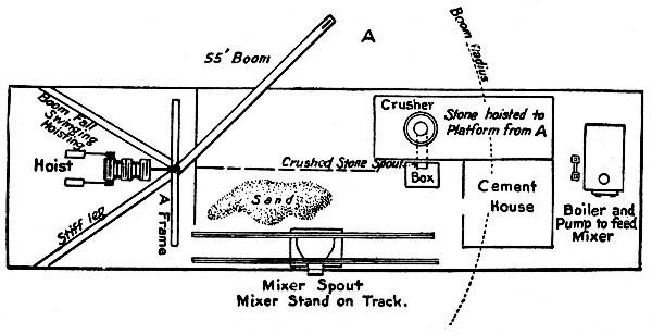 Fig. 84.—Scow Plant for Mixing and Placing Concrete,
Port Colborne Harbor Pier.
Fig. 84.—Scow Plant for Mixing and Placing Concrete,
Port Colborne Harbor Pier.
The mass concrete was mixed and placed by the scow plant, shown by Fig. 84. The scow was loaded with sufficient sand and cement for a day's work and towed to and moored alongside the pier. Forms were set for the wall on top of the block footing. These forms were placed in lengths of 60 to 75 ft. of wall and resembled the block forms with partitions omitted. The bottoms of the rear uprights were held by being wedged into the grooves in the blocks, and the bottoms of the front uprights were held by bolts resting on top of the blocks. The[Pg 217] tops of the uprights were held together across the wall by tie bolts. The forms being placed, the mode of procedure was as follows:
The crusher fed directly into a measuring box. After some 6 ins. of stone had run into the box the door of the crusher spout was closed. A wheelbarrow load of sand was spread over the stone in the box and over this were emptied and spread two or three bags of cement. Another layer of stone and then of sand and of cement were put in and these operations repeated until the box was full. The box was then hoisted and dumped into the hopper of a gravity mixer of the trough type which ran along a track on the scow and fed directly into the forms. The gang worked consisted of 1 foreman, 1 derrickman and 18 common laborers. This gang placed from 65 to 75 cu. yds. of concrete per day at a labor cost of 50 cts. per cu. yd.
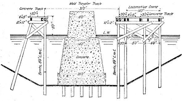 Fig. 85.—Cross-Section of Concrete Pier, Superior, Wis.
CONCRETE BLOCK PIER, SUPERIOR ENTRY, WIS.—The methods and cost of constructing a concrete pier 3,023 ft. long and of the cross-section shown by Fig. 85 at Superior entry, Wisconsin, are given in the following paragraphs.
Molds and Molding.—About 80 per cent. of the concrete was deposited in molds under water, according to a plan devised by Major D. D. Galliard, corps of engineers. In brief the concrete was built in place in two tiers of blocks, the lower tier resting directly on piles and being entirely under water and[Pg 218] the upper tier being almost entirely above water. As shown by Fig. 85, a pile trestle was built on each side of the proposed pier and a traveler for raising and lowering the molds spanned the space between trestles.
The molds were bottomless boxes built in four pieces, two sides and two ends, held together by tie rods. Fig. 86 shows an end and a side of one of the shallow water molds and Fig. 87 shows in detail the method of fastening the end to the side. It will be seen that the 1¼-in. turnbuckle rods pass through the ends of beams that bear against the outside of the mold. These tie rods have eyes at each end in which rods with wedge-shaped ends are inserted. The molds were erected on the trestle by a locomotive crane and were then lifted by the mold traveler, carried and lowered into place. The largest one of these molds with its iron ballast, weighed 40 tons. To remove a mold, after the block had hardened, the nuts on the wedge-ended rods were turned, thus pulling the wedge end from the eye of the tie rod and releasing the sides of the mold from the ends. The locomotive crane then raised the ends and sides, one at a time, and assembled them ready to be lowered again for the next block. The time required to remove one of these 40-ton molds, reassemble and set it again rarely exceeded 60 minutes and was sometimes reduced to 45 minutes.
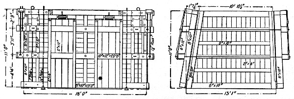 Fig. 86.—Mold for Concrete Block for Pier at Superior,
Wis.
Fig. 86.—Mold for Concrete Block for Pier at Superior,
Wis.
The concrete was deposited in alternate blocks and the molds described were for the first blocks; for the intermediate blocks molds of two side pieces alone were used, the blocks already in place serving in lieu of end pieces. The two side pieces were bolted together with three tie rods at each end; the tie rods were encased in a box of 1-in. boards 4×4 ins. inside[Pg 219] which served as a strut to prevent the sides from closing together and as a means of permitting the tie rods to be removed after the concrete had set. The mold was knocked down just as was the full mold described above and the boxes encasing the tie rods were left in the concrete.
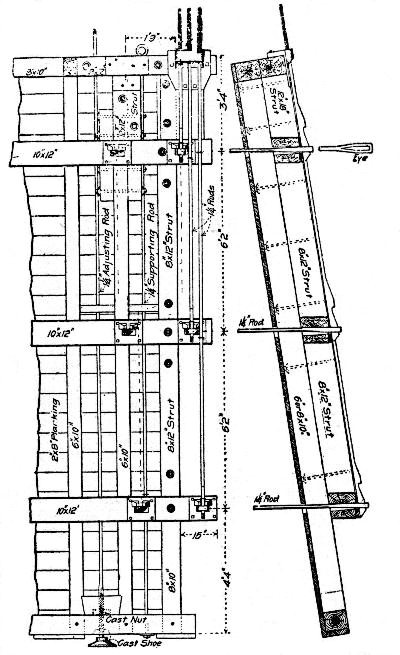 Fig. 87.—Device for Locking End and Side of Mold for
Concrete Blocks for Pier at Superior, Wis.
Fig. 87.—Device for Locking End and Side of Mold for
Concrete Blocks for Pier at Superior, Wis.
An important feature was the device for handling the molds; this, as before stated, was a traveler, which straddled the pier site, it having a gage of 31 ft. It carried a four-drum engine, the drums of which were actuated, either separately or together, by a worm gear so as to operate positively in lowering as well as in raising. The load was hung from four hooks, depending[Pg 220] by double blocks and ⅝-in. wire rope from four trolleys suspended from the trusses of the traveler; this arrangement allowed a lateral adjustment of the mold. The hoisting speed was 6 ft. per minute and the traveling speed 100 ft. per minute. The locomotive crane also deserves mention because it was mounted on a gantry high enough to permit material cars to pass under it on the same trestle, thus making it practicable to work two cranes.
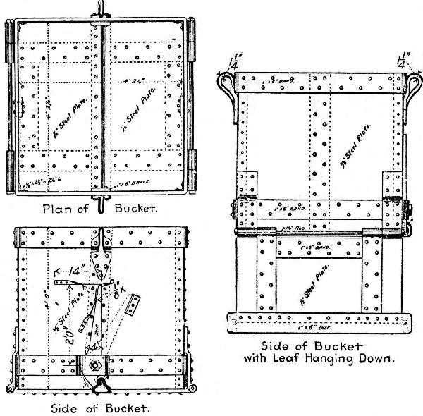 Fig. 88.—Bucket for Depositing Concrete Under Water for
Pier at Superior, Wis.
Fig. 88.—Bucket for Depositing Concrete Under Water for
Pier at Superior, Wis.
The concrete was received from the mixer into drop bottom buckets of the form shown by Fig. 88. The buckets were taken to the work four at once on cars, and there lifted by the locomotive crane and lowered into the mold where they were dumped by tripping a latch connected by rope to the crane. To prevent the concrete from washing, the open tops of the[Pg 221] buckets were covered with 3×4 ft. pieces of 12-oz. canvas in which were quilted 110 pieces of 1/16×1×3-in sheets of lead. Two covers were used on each bucket and were attached one to each side of the bucket top so as to fold over the top with a lap. This arrangement was entirely successful for its purpose.
Concrete Mixing.—The proportions of the subaqueous concrete were 1-2½-5 by volume, or 1-2.73-5.78 by weight, cement being assumed to weigh 100 lbs. per cu. ft.; the proportions of the superaqueous concrete were 1-3.12-6.25 by volume, or 1-3.41-7.22 by weight. The dry sand weighed 109.2 lbs. per cu. ft., the voids being 35.1 per cent.; the pebbles weighed 115.5 lbs. per cu. ft., the voids being 31 per cent.
The pebbles for the concrete were delivered by contract and were unloaded from scows by clam-shell bucket into a hopper. This hopper fed onto an endless belt conveyor which delivered the pebbles to a rotary screen. Inside this screen water was discharged under a pressure of 60 lbs. per sq. in. from a 4-in. pipe to wash the pebbles. From the screen the pebbles passed through a chute into 4-cu. yd cars which were hauled up an incline to a height of 65 ft. by means of a hoisting engine. The cars were dumped automatically, forming a stock pile. Under the stock pile was a double gallery or tunnel provided with eight chutes through the roof and from these chutes the cars were loaded and hauled by a hoisting engine up an inclined trestle to the bins above the concrete mixer. The sand was handled from the stock pile in the same manner. The cement was loaded in bags on a car in the warehouse, hauled to the mixer and elevated by a sprocket chain elevator.
Chutes from the bins delivered the materials into the concrete mixer, which was of the Chicago Improved Cube type, revolving on trunnions about an axial line through diagonal corners of the cube. The mixer possessed the advantage of charging and discharging without stopping. It was driven by a 7×10-in. vertical engine with boiler. The mixer demonstrated its ability to turn out a batch of perfectly mixed concrete every 1⅓ minutes. It discharged into a hopper provided with a cut-off chute which discharged into the concrete buckets on the cars.[Pg 222]
Labor Force and Costs.—In the operation of the plant 55 men were employed, 43 being engaged on actual concrete work and 12 building molds and appliances for future work. The work was done by day labor for the government and the cost of operation was as follows for one typical week, when in six days of eight hours each, the output was 1,383 cu. yds., or an average of 230 cu. yds. per day. The output on one day was considerably below the average on account of an accident to the plant, but this may be considered as typical.
| Pebbles from Stock Pile to Mixer— | Per cu. yd. |
| 4 laborers at $2 | $0.0348 |
| 1 engineman at $3 | 0.0131 |
| Coal, oil and waste at $1.03 | 0.0043 |
| Sand from Stock Pile to Mixer— | |
| 5 laborers at $2 | $0.0434 |
| 1 engineman at $2.50 | 0.0109 |
| Coal, oil and waste at $0.82 | 0.0035 |
| Cement from Warehouse to Mixer— | |
| 5 laborers at $2 | $0.0434 |
| Mixing Concrete— | |
| 1 engineman at $2.50 | $0.0109 |
| 1 mechanic at $2.50 | 0.0108 |
| Coal, oil and waste at $1.29 | 0.0056 |
| Transporting Concrete— | |
| 4 laborers at $2 | $0.0348 |
| 1 engineman at $3 | 0.0130 |
| Coal, oil and waste at $0.66 | 0.0028 |
| Depositing Concrete in Molds— | |
| 4 laborers at $2 | $0.0348 |
| 1 engineman at $3 | 0.0130 |
| 1 rigger at $3 | 0.0130 |
| Coal, oil and waste at $1.18 | 0.0051 |
| Assembling, Transporting, Setting and Removing Molds— | |
| 4 laborers at $2 | $0.0347 |
| 1 engineman at $3.25 | 0.0141 |
| 1 carpenter at $3 | 0.0130 |
| 1 mechanic at $2.50 | 0.0109 |
| Coal, oil and waste at $1.39 | 0.0060 |
| Care of Tracks— | |
| 1 laborer at $2 | $0.0086 |
| 1 mechanic at $2.50 | 0.0109 |
| Supplying Coal— | |
| 3 laborers at $2 | $0.0260 |
| Blacksmith Work— | |
| 1 laborer at $2 | $0.0086 |
| 1 blacksmith at $3.25 | 0.0141 |
| 1 waterboy at $0.75 | 0.0032 |
| ——— | |
| Total per cubic yard | $0.4473 |
| Add 75% of cost of administration | 0.1388 |
| ——— | |
| Total labor per cu. yd. | $0.5861 |
The total cost of each cubic yard of concrete in place was estimated to be as follows:
| Per cu. yd. | |
| Ten-elevenths cu. yd. pebbles at $1.085 | $0.9864 |
| Ten-twenty seconds cu. yd. sand at $0.00 | 0.0000 |
| 1 26 bbls. cement at $1.77 | 2.2302 |
| Labor as above given | 0.5861 |
| Cost of plant distributed over total yardage | 0.8400 |
| ——— | |
| Total | $4.6427 |
It will be noted that the sand cost nothing as it was dredged from the trench in which the pier was built, and paid for as dredging. The cost of the plant is distributed over this south pier and over the proposed north pier work on the basis of only 20 per cent. salvage value after the completion of both piers. It is said, however, that 80 per cent. is too high an allowance for the probable depreciation.
DAM, RICHMOND, INDIANA.—The dam shown in cross-section in Fig. 89 was built at Richmond, Ind. It was 120 ft. long and was built between the abutments of a dismantled bridge. The concrete was made in the proportion of 1 bbl. Portland cement to 1 cu. yd. of gravel; old iron was used for reinforcement. The foundations were put down by means of a cofferdam which was kept dry by pumping. On completion it was found that there was a tendency to scour in front of the apron and accordingly piling was driven and[Pg 224] the intervening space rip-rapped with large stone. Labor was paid as follows per day: Foreman, $3; carpenter, $2.50; cement finisher, $2; laborers, $1.50. The concrete was mixed by hand and wheeled to place in wheelbarrows. The cost of the work was as follows:
| Materials— | Per cu. yd. |
| 204 bbls. cement at $1.60 | $1.485 |
| Sand and gravel | 0.800 |
| Lumber | 0.610 |
| Tools, hardware, etc. | 0.445 |
| ——— | |
| Total materials | $3.34 |
| Labor— | |
| Clearing and excavating | $0.96 |
| Setting forms and mixing concrete | 1.01 |
| Pumping | 0.27 |
| ——— | |
| Total labor | $2.24 |
| Total materials and labor | $5.58 |
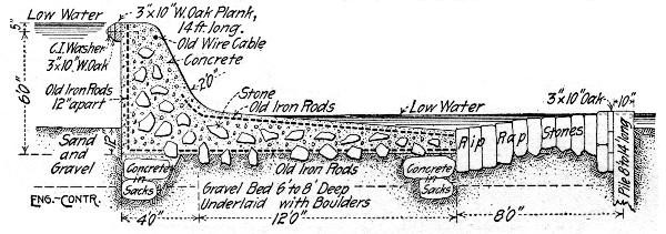 Fig. 89.—Concrete Dam at Richmond, Ind.
DAM AT ROCK ISLAND ARSENAL, ILLINOIS.—The dam was in the shape of an L with one side 192 ft. and the other side 208 ft. long; it consists of a wall 30½ ft. high, 3½ ft. wide at the top and 6½ ft. wide at the bottom with a counterfort every 16 ft., 26 in all. Each counterfort extended back 16 ft. and was 4 ft. thick for a height of 6 ft. and then 3 ft. thick. There were 3,500 cu. yds. of concrete in the work, which was done by day labor under the direction of the U. S. Engineer in charge.[Pg 225]
The forms consisted of front and back uprights of 8×10-in. stuff 24 ft. high, connected through the wall by ¾-in. rods which were left in the concrete. The lagging was 2×12-in. plank dressed down 1¾ ins. placed inside the uprights. These forms were built full height in 16-ft. sections with a counterfort coming at the center of each section. Each section contained 95 cu. yds. of concrete and was filled in a day's work. The concrete was a 1-4-7 mixture wet enough to quake when rammed. Run of crusher limestone was used of which 50 per cent. passed a 1-in. sieve, 17 per cent. a No. 3 sieve and 9 per cent. a No. 8 sieve. The concrete was mixed in Cockburn Barrow & Machine Co.'s screw-feed mixer which discharged into 2-in. plank skips 2 ft. wide 5⅓ ft. long and 14 ins. deep, holding ¼ cu. yd. These skips were taken on cars to a derrick crane overhanging the forms and by it hoisted and dumped into the forms. The derrick was moved along a track at the foot of the wall as the work progressed. The concrete was spread and rammed in 6-in. layers. The men were paid $1.50 per 8-hour's work and the work cost including footing, as follows:
| Item— | Total. | Per cu. yd. |
| Cement | $1,500.00 | $0.429 |
| Sand | 400.00 | 0.114 |
| Storing and hauling cement | 460.00 | 0.131 |
| Taking sand from barge to mixer | 96.00 | 0.027 |
| Crushing stone | 1,450.00 | 0.414 |
| Mixing concrete | 4,825.00 | 1.378 |
| Placing concrete | 1,670.00 | 0.477 |
| Lumber for forms, etc. | 600.00 | 0.171 |
| Erecting and taking down forms | 2,450.00 | 0.700 |
| ————— | ——— | |
| Totals | $13,451.00 | $3.841 |
DAM AT McCALL FERRY, PA.—The dam was 2,700 ft. long and 48 ft. high of the cross-section shown by Fig. 90 and with its subsidiary works required some 350,000 cu. yds. of concrete. The plant for mixing and placing the concrete was notable chiefly for its size and cost. Parallel to the dam, which extended straight across the river, and just below its toe a service bridge consisting of a series of 40-ft. concrete[Pg 226] arch spans was built across the river. This service bridge was 50 ft. wide and carried four standard gage railway tracks besides a traveling crane track of 44 ft. gage. This very heavy construction of a temporary structure was necessitated by the frequency of floods against which only a solid bridge could stand; it was considered cheaper in the long run to provide a bridge which would certainly last through the work than to chance a structure of less cost which would certainly go out with the floods. The concrete service bridge was designed to be destroyed by blasting when the dam had been completed. The method of construction was to build the dam in alternate 40 ft. sections, mixing the concrete on shore, taking it out along the service bridge in buckets on cars and handling the buckets from cars to forms by traveling cranes.
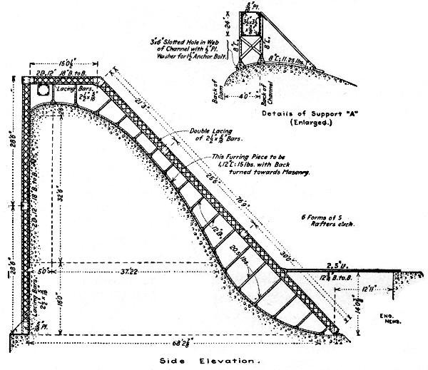 Fig. 90.—Steel Forms for McCall Ferry Dam.
The concrete mixing plant is shown by Fig. 91. Cars loaded with cement, sand and stone were brought in over the tracks carried on the wall tops of the bins and were unloaded respectively[Pg 227] into bins A, B and C, of which there were eight sets. Each set supplied material by means of measuring cars to a 1 cu. yd. Smith mixer. Two sets of cars were used for each mixer so that one could be loading while the other was charging. The mixers discharged into 1 cu. yd. buckets set two on a car and eight cars were hauled to the work in train by an 18-ton "dinky." At the work the buckets were picked up by the traveling cranes and the concrete dumped into the forms. Figure 90 shows the construction of the steel forms. Six sets of forms were used. Each set consisted of five frames spaced 10 ft. apart and braced together in the planes parallel to the dam, and each set molded 40 ft. of dam. The lagging consisted of wooden boxes 8½ ft. wide and 10 ft. long. For the vertical face of the dam these boxes were attached by bolts to the vertical post, for the curved face they were bolted to a channel bent to the curve and held by struts from the inclined post of the steel frame.
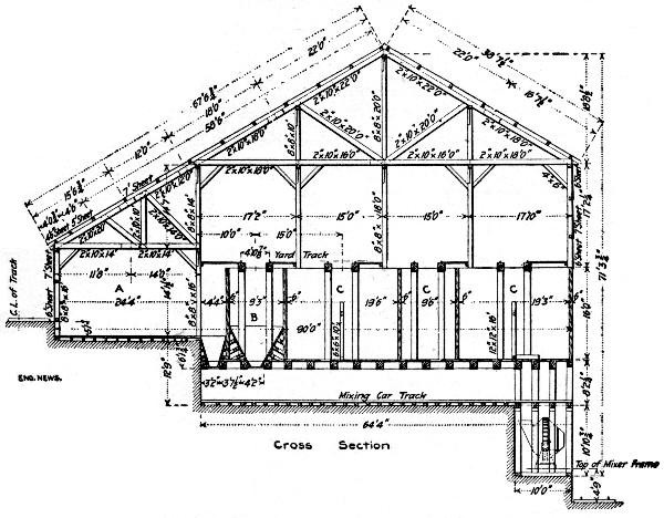 Fig. 91.—Concrete Mixing Plant for McCall Ferry Dam.
In construction the footing and the body of the dam to an elevation of 5 ft. above the beginning of the curve were built[Pg 228] continuously across the river; above this elevation the dam was built in alternate 40-ft. sections. The strut back to the service bridge shown in the lower right hand corner of Fig. 90, shows the manner of bracing the first 30-ft. section of the inclined post to hold the lagging for the continuous portion. The lagging was added a piece at a time as concreting progressed. The ends of each set of frames for a 40-ft. section were for the isolated sections closed by timber bulkheads carrying box forms to mold grooves into which the concrete of the intermediate sections would bond.
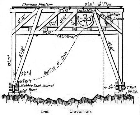 Fig. 92.—Traveler for Concreting Dam, Chaudiere Falls,
Quebec.
Fig. 92.—Traveler for Concreting Dam, Chaudiere Falls,
Quebec.
The concrete used was a 1-3-5 mixture, the stone ranging in size from 2 to 5 ins. Rubble stone from one man size to ½ ton were bedded in the concrete. The capacity of the concrete plant was 2,000 cu. yds. per day or about 250 cu. yds. per mixer per 10-hour day.
DAM, CHAUDIERE FALLS, QUEBEC.—The dam was 800 ft. long and from 16 to 20 ft. high, constructed of 1-2-4 concrete with rubble stone embedded. The rubble stones were separated at least 9 ins. horizontally and 12 ins. vertically and were kept 20 ins. from faces. At one point the rubble amounted to 40 per cent. of the volume, but the average for the dam was 25 to 30 per cent. The stone was broken at[Pg 229] the work, some by hand, but most by machine, all to pass a 2-in. ring. Hand-broken stone ran very uniform in size and high in voids, often up to 50 per cent. Stone broken by crusher with jaws 2 ins. apart would run 20 to 30 per cent. over 2 ins. in size and give about 45 per cent. voids; with crusher jaws 1½ ins. apart from 98 to 100 per cent. was under 2 ins. in size and contained about 42 per cent. of voids. It was found that if the crushers were kept full all the time the product was much smaller, particularly with Gates gyratory crusher, though a little more than rated power was required when the crusher was thus kept full. This practice secured increased economy in both quantity and quality of product. The concrete was made and placed by means of a movable traveler shown by Fig. 92. Concrete materials were supplied to the charging platform of the traveler by means of a traveling derrick moving on a parallel track. In placing the concrete on the rock bottom it was found necessary in order to secure good bond to scrub the rock with water and brooms and cover it with a bed of 2 ins. of 1-2 mortar. The method of concreting in freezing weather is described in Chapter VII.
The construction of piers and abutments for bridges is best explained by describing individual examples of such work. So far, in America, bridge piers have been nearly always of plain concrete and of form and section differing little from masonry piers; where reinforcement has been used at all it has consisted of a surface network of bars introduced chiefly to ensure monolithic action of the pier under lateral stresses. In Europe cellular piers of reinforced concrete have been much used. Plain concrete abutments differ little in form and volume from masonry abutments. Reinforced concrete abutments are usually of L-section with counterforts bracing the upright slab and bridge seat to the base slab.
Form work for reinforced abutments is somewhat complex; that for plain abutments and piers is of simple character, the only variations from plain stud and sheathing construction being in the forms for moldings and coping and for cut-waters. For piers of moderate height the form is commonly framed complete for the whole pier, but for high piers it is built up as the work progresses by removing the bottom boards and placing them at the top. Opposite forms are held together by wire ties through the concrete. Movable panel forms have been successfully employed, but they rarely cheapen the cost much. Sectional forms, which can be shifted from pier to pier where a number of piers of identical size are to be built, may frequently be used to advantage. An example of such use is given in this chapter.
Derricks are the recognized appliances for hoisting and placing the concrete in pier work; they are the only practicable appliance where the pier is high and particularly where it stands in water and mixing barges are employed. For abutment work and land piers of moderate height derricks and[Pg 231] wheelbarrow or cart inclines are both available and where much shifting of the derricks is involved the apparently more crude method compares favorably in cost.
The methods of placing concrete under water for pier foundations are described in Chapter V, and the use of rubble concrete for pier construction is illustrated by several examples in Chapter VI. The following examples of pier and abutment construction cover both large and small work and give a clear idea of current practice.
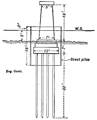 Fig. 93.—Pier and Cofferdam for a Railway Bridge.
COST OF CONSTRUCTING RECTANGULAR PIER FOR A RAILWAY BRIDGE.—This pier, Fig. 93, was built in water averaging 5 ft. deep. The cofferdam consisted of triple-lap sheet piling, of the Wakefield pattern, the planks being 2 ins. thick, and spiked together so as to give a cofferdam wall 6 ins thick. The cofferdam enclosed an area 14×20 ft., giving a clearance of 1 ft. all around the base of the concrete pier, and a clearance of 2 ft. between the cofferdam and the outer edge of the nearest pile. The cofferdam sheet piles were 18 ft. long, driven 11 ft. deep into sand, and projecting 2 ft. above the surface of the water.[Pg 232]
The concrete base resting on the foundation piles was 12×18 ft. The concrete pier resting on this base was 7×13 ft. at the bottom, and 5×11 ft. at the top. The pier supported deck plate girders. There were 100 cu. yds. of concrete in the pier and base.
The cost of this pier, which is typical of a large class of concrete pier work, has been obtained in such detail that we analyze it in detail, giving the costs of cofferdam construction and excavation as well as of mixing and placing the concrete.
| Setting up and taking down derrick and platform: | |
| 4 days foreman at $5.00 | $ 20.00 |
| ¾ days engineman at $3.00 | 2.25 |
| ¾ days blacksmith at $3.00 | 2.25 |
| ¾ days blacksmith helper at $2.00 | 1.50 |
| 22 days laborers at $2.00 | 44.00 |
| ——— | |
| Total | $ 70.00 |
| Cofferdam— | |
| 7 days foreman at $5.00 | $ 35.00 |
| 4 days engineman at $3.00 | 12.00 |
| 38 days laborers at $2.00 | 76.00 |
| 1 ton coal at $3.00 | 3.00 |
| ——— | |
| Total labor on 7,900 ft. B. M. at $16.00 | $126.00 |
| 7,900 ft. B. M. at $20.00 | 158.00 |
| ——— | |
| Total for 58 cu. yds. excavation | $284.00 |
| Wet Excavation— | |
| 1.8 days foreman at $5.00 | $ 9.00 |
| 1.5 days engineman at $3.00 | 4.50 |
| 9 days laborers at $2.00 | 18.00 |
| ½ ton coal at $3.00 | 1.50 |
| ——— | |
| Total labor on 58 cu. yds. at 57c. | $ 33.00 |
| Foundation Piles— | |
| 960 lin. ft. at 10c | $ 96.00 |
| 4 days setting up driver and driving 24 piles at $20 per day for labor and fuel | 80.00 |
| ——— | |
| Total | $176.00 |
| Concrete— | |
| 100 cu yds. stone at $1.00 | $100.00 |
| 40 cu. yds. sand at $0.50 | 20.00 |
| 100 bbls. cement at $2.00 | 200.00 |
| 5 days foreman at $5.00 | 25.00 |
| 50 days laborers at $2.00 | 100.00 |
| 5 days engineman at $3.00 | 15.00 |
| 2 tons coal at $3.00 | 6.00 |
| ——— | |
| Total, 100 cu. yds. at $4.66 | $466.00 |
| 8 days carpenters at $3.00 | 24.00 |
| 2,400 ft. B. M. 2-in. plank at $25.00 | 60.00 |
| 1,000 ft. B. M. 4×6-in. studs at $20.00 | 20.00 |
| Nails, wire, etc | 2.00 |
| ——— | |
| Total forms for 100 cu. yds. at $1.06 | $106.00 |
| Summary— | |
| Setting up derrick, etc. | $ 70.00 |
| Cofferdam (7,900 ft. B. M.) | 284.00 |
| Wet excavation (58 cu. yds.) | 33.00 |
| Foundation piles (24) | 176.00 |
| Concrete (100 cu. yds.) | 466.00 |
| Forms (3,400 ft. B. M.) | 106.00 |
| ———— | |
| Total | $1,135.00 |
| Transporting plant | 20.00 |
| 20 days rental of plant at $5.00 | 100.00 |
| ———— | |
| Total cost of pier | $1,252.00 |
Regarding the item of plant rental, it should be said that the plant consisted of a pile driver, a derrick, a hoisting engine, and sundry timbers for platforms. There was no concrete mixer. Hence an allowance $5 per day for use of plant is sufficient.
It will be noted that no salvage has been allowed on the lumber for forms. As a matter of fact, all this lumber was recovered, and was used again in similar work.
Referring to the cost of cofferdam work, we see that, in order to excavate the 58 cu. yds. inside the cofferdam, it was necessary to spend $284, or nearly $5 per cu. yd. before the actual excavation was begun. The work of excavating cost only 57 cts. per cu. yd., but this does not include the cost of[Pg 234] erecting the derrick which was used in raising the loaded buckets of earth, as well as in subsequently placing the concrete. The sheet piles were not pulled, in this instance, but a contractor who understands the art of pile pulling would certainly not leave the piles in the ground. A hand pump served to keep the cofferdam dry enough for excavating; but in more open material a power pump is usually required.
The above costs are the actual costs, and do not include the contractor's profits. His bid on the work was as follows:
| Piles delivered | 12 cts. per ft. |
| Piles driven | $5 each |
| Cofferdam | $37 per M. |
| Wet excavation | $1.00 per cu. yd. |
| Concrete | $8.00 per cu. yd. |
In order to ascertain whether or not these prices yielded a fair profit, it is necessary to distribute the cost of the plant transportation and rental over the various items. We have allowed $120 for plant transportation and rental, and $70 for setting up and taking down the plant, or $190 in all. The working time of the plant was as follows:
| Days. | Per cent. of time. | Prorated plant cost. | |
| Cofferdam | 7 | 39 | $74 |
| Excavation | 2 | 11 | 21 |
| Foundation piles | 4 | 22 | 42 |
| Concrete | 5 | 28 | 53 |
| — | —— | —— | |
| Totals | 18 | 100 | $190 |
As above given, the labor on the 7,900 ft. B. M. in the cofferdam cost $126, or $16 per M.; but this additional $74 of prorated plant costs, adds another $9 per M., bringing the total labor and plant to $25 per M., to which must be added the $20 per M. paid for the timber in the cofferdam, making a grand total of $45 per M. This shows that the contractor's bid of $37 per M. was much too low.
The labor on the excavation cost 57 cts. per cu. yd., to which must be added the prorated plant cost of $21 distributed over the 58 cu. yds., or 36 cts. per cu. yd., making a total of 93 cts. per cu. yd. This shows that the bid of $1 per cu. yd. was hardly high enough.[Pg 235]
The labor on the 24 foundation piles cost $80, or $3.33 each. The prorated plant cost is $42, or $1.75 per pile, which, added to $3.33, makes a total of $5.08. This shows that the bid of $5 Per pile for driving was too low. However there was a profit of 2 cts. per ft., or 80 cts. per pile, on the cost of piles delivered.
The concrete amounted to 100 cu. yds. Hence the prorated plant cost of $53 is equivalent to 53 cts. per cu. yd. Hence the total cost of the concrete was:
| Per cu. yd. | |
| Cement, sand and stone | $3.20 |
| Foreman (at $5) | 0.25 |
| Labor (at $2) | 1.00 |
| Engineman (at $3) | 0.15 |
| Coal (at $3) | 0.06 |
| Carpenters (at $3) | 0.24 |
| Forms (at $23.50, used once) | 0.80 |
| Wire, nails, etc | 0.02 |
| Prorated plant cost | 0.53 |
| —— | |
| Total | $6.25 |
Since the contract price for concrete was $8 per cu. yd., there was a good profit in this item.
BACKING FOR BRIDGE PIERS AND ABUTMENTS.—Six piers and two abutments of the City Island bridge were constructed in 1906 at New York city, of masonry backed with 1-2-4 concrete below and 1-3-5 concrete above high water. The piers and abutments were all sunk to rock or hard material by means of timber cofferdams. Table XVI gives the labor cost of mixing and placing the concrete backing for one abutment and three piers, after the materials were delivered on the scows. The concrete was mixed by a rectangular horizontal machine mixer and deposited by 2-cu. yd. bottom dump buckets handled by derrick scows and stiff leg derricks. The high cost of concreting on Pier 2 was due to the fact that the concrete was improperly deposited and had to be removed and the higher cost in Abutment 1 was probably due to the fact that the abutment was so long and narrow that it was difficult to handle the bucket.[Pg 236]
| Abutment No. 1. | Pier No. 2. | Pier No. 3. | Pier No. 4. | Summary. | ||||||||||||
| Wages per Hour. | No. hrs. | Total Cost | Cost per cu. yd. | No. hrs. | Total Cost | Cost per cu. yd. | No. hrs. | Total Cost | Cost per cu. yd. | No. hrs. | Total Cost | Cost per cu. yd. | Total Hrs. | Total cost. | Av. per cu. yd. | |
| Superintendent | 70 | 24 | $16.80 | $0.03 | 47 | $32.90 | $0.09 | 72 | $50.40 | $0.05 | 16 | $11.20 | $0.03 | 159 | $111.30 | $0.05 |
| Foreman | 35 | 160 | 56.00 | 0.09 | 128 | 44.80 | 0.13 | 324 | 113.40 | 0.12 | 54 | 18.90 | 0.06 | 666 | 233.10 | 0.11 |
| Laborers | 15-20 | 2555 | 383.25 | 0.65 | 2038 | 313.60 | 0.92 | 3513 | 526.95 | 0.56 | 940 | 141.00 | 0.44 | 9046 | 1364.90 | 0.62 |
| Engineman | 30 | 365 | 109.50 | 0.19 | 196 | 58.50 | 0.19 | 244 | 73.20 | 0.08 | 60 | 18.00 | 0.06 | 865 | 259.50 | 0.12 |
| Timekeeper | 40 | 86 | 34.40 | 0.06 | 46 | 18.40 | 0.06 | 81 | 32.40 | 0.04 | 10 | 4.00 | 0.01 | 223 | 89.20 | 0.04 |
PNEUMATIC CAISSONS, WILLIAMSBURG BRIDGE.—Mr. Francis L. Pruyn, Assoc. M. Am. Soc. C. E., gives the following costs of concreting the pneumatic caissons for the Brooklyn tower of the Williamsburg bridge at New York city. The work comprised the mixing and placing of some 13,637 cu. yds. of concrete in two caissons. Table XVII shows the itemized costs for one caisson and Table XVIII shows them for the other caisson. The methods of work were as follows:
After each caisson was built it was towed to its proper site, where it was held in place by temporary pile dock built completely around it. On these docks the concrete was placed; a 2 cu. yd. cubical mixer of the usual pattern being used for mixing. The concrete materials, consisting of sand, stone and cement was handled direct from barges alongside, into the mixer. The concrete was placed by a derrick located in the center of the caisson, which was a bad feature as the caisson was usually out of level and considerable difficulty was experienced in swinging the derrick. On the South caisson ¾ cu. yd. bottom dump buckets were used in placing the concrete, on the North caisson the size of these was increased to 1½ cu. yd. which reduced the cost of placing 15 cts. per cu. yd. There were placed in the South caisson 3,827 cu. yds. in 32 days of actual working time—120 cu. yds. per day of 10 hrs. The gross time was 2 months. On the North caisson 5,693 cu. yds. were placed in 46 days worked—124 cu. yds. per day. The gross time was 4 months.
The rates of labor were as follows per 10-hour day:
| Foreman | $5.00 |
| Assistant foreman | 2.50 |
| Hoisters | 2.50 |
| Fireman | 1.60 |
| Laborer | 1.50 |
Proportions concrete were 1: 2.5: 6.
The low price of sand in the North caisson was brought about by the finding of good building sand in the excavation for the anchorage, which work was done by the same contractor.
When the caissons had been sealed the iron material shafts were removed. This left holes 5 ft.×6 ft. extending from the[Pg 238] roof of the caisson up to Mean H.W. which were filled with concrete. These shaft holes were 80 ft. deep on the South caisson and 100 ft. deep on the North caisson. They were partially filled with water and the concrete had to be placed with considerable care. Wooden chutes were used on the South caisson; they rested on the caisson roof, were filled with concrete and then raised allowing concrete to flow out at the bottom. The shaft holes were too deep on the North caisson for chutes and 20 cu. ft. bottom dump buckets were used. They had to be lowered to bottom of shaft each trip before dumping, a slow operation, which greatly added to the cost. Proportion for concrete 1-2.5-6.
The proportion for concrete in working chamber was the same as for all other concrete. The specifications called for 6 in. of mortar, of 1 part of cement to 2½ parts of sand, between the concrete and all bearing areas; that is, under the cutting edge and directly under the roof of the working chamber. The concrete was mixed in the cubical mixer and dumped on the bottom door of the material lock, the top door of the lock was then closed, the bottom door opened and the concrete fell through the shaft to the working chamber. It was then shoveled by the sand hogs into place. A 6-in. space was left below all bearing surfaces into which damp mortar was tightly rammed. Concreting the South caisson took 10¼ working days of 24 hours, the gangs working night and day in twelve 2-hour shifts; 1,566 cu. yds. of concrete and mortar were placed, or at the rate of 140 cu. yds. per 24 hours. The gross time including Sundays was 14½ days. The sand hogs worked in shifts of 2 hours each and received $3.50 for the two hours work. The twelve foremen received 1 dollar more: the average gang consisted of 12 sand hogs.
On the North caisson the organization was much better, owing to the experience gained on the first caisson; and in spite of the fact that the sand hogs, on account of the increased depth, received $4.00 for 1½ hours' work, or an increase of $22.00 per man per 24 hrs. over that on the South caisson, the work was done for less money. There were placed 1,566 cu. yds. of concrete in 7 working days of 24 hrs., or at the rate of 224 cu. yds. per day. The gross time was 11½ days including Sundays. The average number of men in the[Pg 239] sand hog gangs was 18, with one foreman, who received $5 for 1½ hours work.
| South Caisson (3,827 cu. yds.). | ||||
| Materials. | Quantity. | Rate. | Amount. | |
| Cement | 4,480 | bbls. | $1.57 | $7,034.00 |
| Sand | 1,288 | cu. yds. | .60 | 773.00 |
| Broken stone | 3,421 | cu. yds. | 1.50 | 5,132.00 |
| Water | 36.00 | |||
| —————— | ——— | ———— | ||
| Total | 3,827 | cu. yds. | $3.39 | $12,975.00 |
| Labor. | ||||
| Mixing and placing | 3,827 | cu. yds. | $0.90 | $3,432.00 |
| Plant charges | 2,280.00 | |||
| Plant labor | 742.00 | |||
| —————— | ——— | ———— | ||
| Total plant | 3,827 | cu. yds. | $0.79 | $3,022.00 |
| —————— | ——— | ———— | ||
| Total cost | 3,827 | cu. yds. | $5.08 | $19,429.00 |
| General expenses, 10% | 3,827 | cu. yds. | .51 | 1,943.00 |
| —————— | ——— | ———— | ||
| Grand total | 3,827 | cu. yds. | $5.59 | $21,372.00 |
| COST OF CONCRETING SHAFTS. | ||||
| South Caisson. | ||||
| Materials. | Quantity. | Rate. | Amount. | |
| Concrete | 612½ | bbls. | $1.57 | $962.00 |
| Sand | 193 | cu. yds. | .40 | 77.00 |
| Stone | 493 | cu. yds. | 1.10 | 542.00 |
| —————— | ——— | ———— | ||
| Total | 541 | cu. yds. | $2.92 | $1,581.00 |
| Labor. | ||||
| Handling, mixing and placing | 541 | cu. yds. | $0.96 | $519.00 |
| Plant charges, etc. | 541 | cu. yds. | 1.06 | 576.00 |
| —————— | ——— | ———— | ||
| Total | 541 | cu. yds. | $4.94 | $2,676.00 |
| General expenses, 10% | 541 | cu. yds. | .49 | 267.00 |
| —————— | ——— | ———— | ||
| Grand total | 541 | cu. yds. | $5.43 | $2,943.00 |
| COST OF CONCRETE IN WORKING CHAMBERS. | ||||
| South Caisson. (1,435 cu. yds.) | ||||
| Materials. | Quantity. | Rate. | Amount. | |
| Cement for concrete | 1,666 | bbls. | $1.57 | $2,615.00 |
| Cement for mortar | 459 | bbls. | 1.57 | 720.00 |
| Sand for both | 670 | cu. yds. | .40 | 268.00 |
| Broken stone | 1,181 | cu. yds. | 1.10 | 1,299.00 |
| —————— | ——— | ———— | ||
| Total materials | 1,435 | cu. yds. | $3.42 | $4,902.00 |
| Labor. | ||||
| Top labor, mixing and placing | 1,435 | cu. yds. | $1.09 | $1,575.00 |
| Pneumatic labor | 1,435 | cu. yds. | 4.93 | 7,117.00 |
| Compressor house labor | 1,435 | cu. yds. | .19 | 275.00 |
| —————— | ——— | ———— | ||
| Total labor | 1,435 | cu. yds. | $6.21 | $8,967.00 |
| Plant. | ||||
| Coal at $2.40 per ton | 1,435 | cu. yds. | .10 | 140.00 |
| Concrete plant | 1,435 | cu. yds. | .79 | 1,145.00 |
| Pneumatic plant | 1.435 | cu. yds. | 1.05 | 1,522.00 |
| —————— | ——— | ———— | ||
| Total plant | 1,435 | cu. yds. | $1.94 | $2,807.00 |
| Totals | 1,435 | cu. yds. | $11.57 | $16,676.00 |
| General expenses, 10% | 1,435 | cu. yds. | 1.16 | 1,667.00 |
| —————— | ——— | ———— | ||
| Grand total | 1,435 | cu. yds. | $12.73 | $18,343.00 |
| COST OF CONCRETING CAISSON ABOVE ROOF (5,692 cu. yds.) | ||||
| Materials. | Quantity. | Rate. | Amount. | |
| Cement | 6,707½ | bbls. | $1.57 | $10,531.00 |
| Sand | 2,133 | cu. yds. | .40 | 845.00 |
| Broken stone | 4,938 | cu. yds. | 1.10 | 5,432.00 |
| Water | 51.00 | |||
| —————— | ——— | ———— | ||
| Total | 5,692 | cu. yds. | $2.96 | $16,859.00 |
| Labor. | ||||
| Mixing and placing | 5,692 | cu. yds. | $0.73 | $4,159.00 |
| Plant charges | 2,952.00 | |||
| Plant labor | 517.00 | |||
| —————— | ——— | ———— | ||
| Total | 5,692 | cu. yds. | $0.61 | $3,469.00 |
| Total cost | 5,692 | cu. yds. | $4.30 | $24,487.00 |
| General expenses, 10% | 5,692 | cu. yds. | .43 | 2,448.00 |
| Grand total | 5,692 | cu. yds. | $4.73 | $26,935.00 |
| COST OF CONCRETING SHAFTS. | ||||
| Materials. | Quantity. | Rate. | Amount. | |
| Cement | 614½ | bbls. | $1.57 | $965.00 |
| Sand | 204 | cu. yds. | .40 | 82.00 |
| Stone | 521 | cu. yds. | 1.10 | 574.00 |
| —————— | ——— | ———— | ||
| Total | 576 | cu. yds. | $2.82 | $1,621.00 |
| Labor. | ||||
| Mixing and placing | 576 | cu. yds. | 1.70 | 982.00 |
| Plant charges, etc. | 576 | cu. yds. | 1.36 | 795.00 |
| —————— | ——— | ———— | ||
| Total | 576 | cu. yds. | $5.88 | $3,398.00 |
| General expenses, 10% | 576 | cu. yds. | .59 | 339.00 |
| —————— | ——— | ———— | ||
| Grand total | 576 | cu. yds. | $6.47 | $3,737.00 |
| COST OF CONCRETING WORKING CHAMBERS (1,566 cu. yds.). | ||||
| Materials. | Quantity. | Rate. | Amount. | |
| Cement for concrete | 1,559 | bbls. | $1.51 | $2,446.00 |
| Cement for mortar | 442 | bbls. | 1.51 | $694.00 |
| Sand for both | 630 | cu. yds. | .40 | 252.00 |
| Broken stone | 1,380 | cu. yds. | 1.10 | 1,518.00 |
| —————— | ——— | ———— | ||
| Total | 1.566 | cu. yds. | $3.14 | $4,910.00 |
| Labor. | ||||
| Top labor, mixing and placing | 1,566 | cu. yds. | $0.78 | $1,198.00 |
| Pneumatic labor | 1,566 | cu. yds. | 4.91 | 7,694.00 |
| Compressor house labor | 1,566 | cu. yds. | .11 | 180.00 |
| —————— | ——— | ———— | ||
| Total labor | 1,566 | cu. yds. | $5.80 | $9,072.00 |
| Plant. | ||||
| Coal at $2.40 per ton | 1,566 | cu. yds. | .06 | 87.00 |
| Concrete plant | 1,566 | cu. yds. | .86 | 1,352.00 |
| Pneumatic plant | 1,566 | cu. yds. | .81 | 1,272.00 |
| —————— | ——— | ———— | ||
| Total plant | 1,566 | cu. yds. | $1.73 | $2,711.00 |
| —————— | ——— | ———— | ||
| Totals | 1,566 | cu. yds. | $10.67 | $16,693.00 |
| —————— | ——— | ———— | ||
| General expenses, 10% | 1,566 | cu. yds. | 1.06 | 1,669.00 |
| —————— | ——— | ———— | ||
| Grand total | 1,566 | cu. yds. | $11.73 | $18,362.00 |
COST OF FILLING PIER CYLINDERS.—The following costs were obtained in mixing and placing concrete in steel cylinder piers. The sand and gravel were wheeled 100 ft. to the mixing board at the foot of the cylinder, mixed and shoveled into wooden skips, hoisted 20 ft. by horsepower and dumped into the cylinder. The foreman worked on the mixing board and the men worked with great energy. The costs were as follows:
| Item— | Per day. | Per cu. yd. |
| 6 men wheeling materials and mixing at 15 cts. per hour | 9.00 | $0.45 |
| 2 men dumping skips and ramming at 15 cts. per hour | 3.00 | 0.15 |
| 1 team and driver at 40 cts. per hour | 4.00 | 0.20 |
| 1 foreman at 30 cts. per hour | 3.00 | 0.15 |
| —— | —— | |
| Totals | $19.00 | $0.95 |
PIERS, CALF KILLER RIVER BRIDGE.—The following methods and costs of building two new piers and extending three old piers with concrete are given by Mr. J. Guy Huff. The work was done by the railway company's masonry gangs. Figure 94 shows the arrangement of the several piers and the character of the work on each and Fig. 95 gives the detail dimensions of the three main piers.
The sand and aggregate, consisting of blast furnace slag, were unloaded from cars to platforms on a level with the top of rail, placed about 100 ft. south from the south end of the bridge. A cubical 1/6 cu. yd. mixer was used. This was operated by a gasoline engine, and was located on a platform about 50 ft. south of the south end pier. A tank near the mixer to supply water was elevated enough to get the desired head, and was kept filled by a pump run by another gasoline engine located down by the river bank. The cement house was located between the mixer platform and slag pile.[Pg 242]
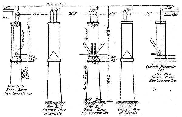 Fig. 94.—Diagram Arrangement of Piers, Calf Killer River
Bridge.
Fig. 94.—Diagram Arrangement of Piers, Calf Killer River
Bridge.
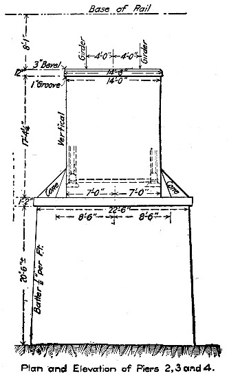 Fig. 95.—Details of Pier for Calf Killer Elver Bridge.
Slag and sand were delivered to the mixer by means of wheelbarrows. The mixer was so placed that it would dump onto a platform, and the concrete could then be shoveled into a specially designed narrow-gage car. This car ran on one rail of the main track and an extra rail outside. A turnout for clearing passing trains was provided at both ends of the bridge. The track over the bridge from the mixer had a descending grade of about 1 per cent., so that with a little start the concrete car would roll alone down to the required points on the bridge. Only in returning the empty cars to the mixer was it necessary to push them by hand, and then only for a distance of never more than 400 ft.
Over the piers on the bridge in the center of the concrete car track openings were sawed to let the concrete pass to the forms below. To get the concrete into the forms, there were used zig-zag chutes with arms about 10 ft. long, which sections were removed as the concrete in the forms was increased. These chutes were a convenience by their ends alternating from one side to the other as the arms were removed in coming up.
The cost of the concrete work was as follows:
| Unloading Material. | ||||
| Rate per day. | Total days worked. | Total. | Per cu. yd. concrete. | |
| Foreman | $3.40 | 5 | $17.00 | $0.04 |
| 11 laborers | 1.368/10 | 52 | 71.14 | .15 |
| —— | ||||
| Total for unloading material | $0.19 | |||
| Building Forms, Bins, Etc. | ||||
| Foreman | $3.40 | 18 | $61.20 | $0.14 |
| 9 carpenters | 2.25 | 166 | 373.50 | .81 |
| New lumber, 23.7 M. ft. at $17.80 | 421.86 | .92 | ||
| Old lumber, 6 M. ft. at $8.33 | 49.98 | .11 | ||
| —— | ||||
| Total for building forms, bins, etc. | $1.98 | |||
| Cofferdam Excavation (45 cu. yds.) | ||||
| Foreman | $3.40 | 8 | $27.20 | $0.06 |
| 9 laborers | 1.156/10 | 74½ | 86.12 | .19 |
| —— | ||||
| Total for cofferdam excavation | $0.25 | |||
| Cofferdam Concrete (37 cu. yds.) | ||||
| Foreman | $3.40 | 8 | $27.20 | $0.06 |
| 11 laborers | 1.363/10 | 79 | 107.68 | .23 |
| Cofferdam lumber, 2.25 M. ft. at $20.00 | 45.00 | .09 | ||
| —— | ||||
| Total for cofferdam concrete | $0.38 | |||
| Concrete Mixing and Placing. | ||||
| Foreman | $3.40 | 30 | $102.00 | $0.22 |
| 9 laborers | 1.156/10 | 282 | 325.99 | .71 |
| Cement, 452 bbls. at $1.55 | 701.00 | 1.52 | ||
| Slag, 437 cu. yds. at $0.20 | 87.40 | .19 | ||
| Sand, 220 cu. yds. at $0.30 | 66.00 | .14 | ||
| —— | ||||
| Total for mixing and placing | $2.78 | |||
| Taking Down Forms and Clearing Up. | ||||
| Foreman | $3.40 | 13 | $44.20 | $0.09 |
| 11 laborers | 1.17 | 1.43 | 107.31 | .36 |
| —— | ||||
| Total for taking down forms, etc. | $200.00 | $0.45 | ||
| Engineering and supervision | .43 | |||
| —— | ||||
| Grand total, 460 cu. yds. concrete | $6.46 | |||
The wages given are the average wages. The men worked a 10-hour day. The concrete was a 1-3-6 mixture. The cofferdam work was done in connection with the construction of the fourth pier, this pier being the only one coming in the bed of the river to be built entirely new. The work on this was started in water about 6 ft. deep. The 37 cu. yds. of concrete is included in the total of 460 cu. yds. in the above tabulation. By itself the cost of the cofferdam work, not including cost of cement, sand and slag was as follows:[Pg 245]
| Total. | Per cu. yd. Concrete. | |
| Lumber | $ 45.00 | $1.21 |
| Labor, excavating | 113.32 | 3.06 |
| Labor, concrete | 134.88 | 3.64 |
| —— | ||
| Total 37 cu. yds. concrete | $7.91 |
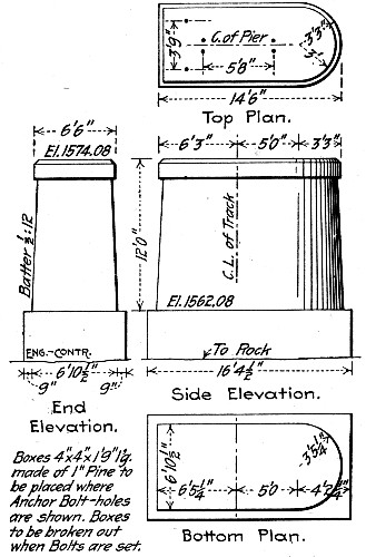 Fig. 96.—Details of Piers for K. C., M. & O. Ry.
Bridge.
Fig. 96.—Details of Piers for K. C., M. & O. Ry.
Bridge.
METHOD AND COST OF CONSTRUCTING 21 BRIDGE PIERS.—The following account of the methods and cost of constructing 21 concrete piers for a railway bridge consisting of 20 50-ft. plate girder spans has been compiled from records kept by Mr. W. W. Colpitts, Assistant Chief Engineer, Kansas City, Mexico & Orient Ry. The shape and dimensions of the piers are shown by Fig. 96 and Fig. 97 shows the construction of the forms. Sheet pile cofferdams to solid rock were used for constructing the foundations.
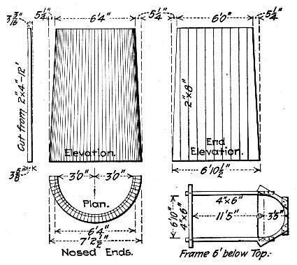 Fig. 97.—Forms for Piers for K. C., M. & O. Ry. Bridge.
The 1-3-5 concrete was mixed in a Smith mixer having a batch capacity of 9 cu. ft. The mixer was located on the[Pg 246] slope of the embankment approach, with the main track at its rear and facing a temporary material track. This temporary track turned out from the main track about 500 ft. beyond the mixer and extended diagonally down the embankment approach on a 3 per cent. grade and across the river bottom alongside the pier sites. The portion of the track in the river bottom was supported on bents of spliced ties, jetted to the rock, and wired to the cofferdam to avoid the danger of loss in case of high water. The sand and crushed rock were delivered by cars from the main line track, immediately above the mixer, and the cement was stored in a shanty at one side of the mixer. The concrete materials and machinery were, in this manner, very conveniently located for rapid work and well above the high water line. The concrete was transported to the pier sites in improvised dump boxes, set on push cars. These dump boxes were hinged longitudinally and discharged directly into the cofferdams. The grade of the temporary track carried the push cars by gravity to the cofferdams and they were returned by teams, for which purpose a straw and brush road had been built paralleling the track. As the work progressed farther into the stream, more cars were added properly to balance the work. While the concrete in the base was still fresh, a number of steel reinforcing bars, 8[Pg 247] ft. in length, were set in place along each end to insure a good bond between the base and shaft.
In general, the work of putting in the bases was organized so that about the same time was required in filling a cofferdam with concrete, in excavating the sand from the next, and in driving the sheet piling for the third. These three operations were thus carried on simultaneously and, although interruptions in one part of the work or the other occurred frequently, the gangs were interchangeable and no appreciable loss was suffered, except in time, because of such delays.
In piers 19 and 20, where the rock was from 17 to 19 ft. below the surface, some difficulty was encountered due to the presence of fissures in the rock, from which it was necessary to remove the sand to fill with concrete. In such cases, the larger leaks were stopped as much as possible by driving sheet piles against the outside face of the cofferdam and into the fissures, and the smaller leaks by manure in canvas bags rammed into the openings.
Upon the completion of all the bases, the forms for several shafts were set in position and the work of filling with concrete proceeded as in the case of the bases, except that a derrick erected on a flat car and stationed at the pier was utilized to raise the dump boxes in depositing the concrete in the forms. As soon as the concrete in one shaft had set sufficiently to permit of it, the forms were removed and placed on the pier ahead. Four sets of forms were used for the shafts.
The following are the average prices paid for materials and labor:
Materials.—Lumber for forms, etc., $16.50 per M. ft., B. M.; cement, Kansas Portland, $1.50 per bbl.; broken limestone, 45c per cu. yd.; sand, Arkansas River, 15c per ton.
Labor.—General foreman, $110 per month; assistant foreman, $75 per month; timekeeper, $60 per month; riveters, 35c per hour; blacksmith, 30c per hour; blacksmith assistant, 20c per hour; carpenters, 22½c and 25c per hour; enginemen, 25c per hour; firemen, 20c per hour; night watchman, 20c per hour; laborers, 17½c and 20c per hour; team (including driver), 40c per hour. The prices quoted for lumber, cement, limestone and sand are prices f. o. b., Louisiana, Iola, Kan., El Dorado, Kan., and Wichita, Kan.[Pg 248]
The total and unit cost of constructing the concrete piers and abutments and of erecting the steel superstructure are given in the following tabulation. Altogether there was about 2,300 cu. yds. of concrete in the substructure, most of which, as stated above, was a 1-3-5 mixture.
| Machinery and Supplies. | |
| Concrete mixer, 20% of cost | $ 152.10 |
| Supplies, freight, hauling, setting up | 505.04 |
| ———— | |
| Total | $ 657.14 |
| Centrifugal sand pump, 20% of cost | $ 27.00 |
| Supplies, freight, hauling, setting up | 277.50 |
| Rent of traction engine to operate | 83.25 |
| ———— | |
| Total | $ 387.75 |
| Water pump and pipe, 20% of cost | $ 29.00 |
| Supplies, freight, hauling, setting up | 177.32 |
| ———— | |
| Total | $ 206.32 |
| Pile driver engine, 20% of cost | $ 100.00 |
| Supplies, freight, hauling, setting up | 243.65 |
| ———— | |
| Total | $ 343.65 |
| ———— | |
| Grand total | $1,594.86 |
| Cofferdams. | |
| Materials, lumber and nails | $1,285.26 |
| Freight and train haul | 306.33 |
| Labor making piles | 696.82 |
| Labor driving piles | 1,384.05 |
| ———— | |
| Total | $3,672.46 |
The sheet piling took 63,500 ft. B. M. of lumber; the cost per 1,000 ft. B. M. for the sheet piling was then:
| Materials, lumber and nails | $ 20.08 |
| Freight and haulage | 4.82 |
| Labor making piles | 10.97 |
| Labor driving piles | 21.80 |
| ———— | |
| Total | $ 57.67 |
| Forms, Platforms and Runways. | |
| Lumber, hardware, etc. | $224.59 |
| Freight and train haul. | 40.20 |
| Labor making, removing and placing. | 556.51 |
| ———— | |
| Total | $821.30 |
| Concrete Materials. | |
| Cement, freight, unloading and storing. | $4,617.48 |
| Sand, freight, unloading, etc. | 1,336.05 |
| Broken stone, freight, unloading, etc. | 2,026.92 |
| ———— | |
| Total | $7,980.45 |
This gives us for 2,300 cu. yds. of concrete a cost of $3.47 per cu. yd. for materials, including freight, storage, and unloading charges of all kinds. A line on the proportion of the cost contributed by these latter items may be got by taking the prices of the materials f. o. b. at the places of production and assuming the proportions for a 1-3-5 concrete. According to tables in Chapter II, a 1-3-5 broken stone concrete requires per cubic yard 1.13 bbls. cement, 0.48 cu. yd. sand and 0.80 cu. yd. broken stone. We have then:
| 1.13 bbls. cement, at $1.50 | $1.69 |
| 0.48 cu. yd. sand, at 20c | .10 |
| 0.80 cu. yd. stone, at 45c | .36 |
| —— | |
| Total | $2.15 |
This leaves a charge of $1.32 per cubic yard of concrete for freight and handling materials. The cost of mixing concrete and placing it in the forms was $3,490.87, or $1.52 per cu. yd. We have then:
| Cost of concrete materials per cu. yd. | $3.47 |
| Cost of mixing and placing concrete. | 1.52 |
| —— | |
| Total. | $4.99 |
The miscellaneous expenses of the work comprised:
| Watchman, tools, telephone, etc. | $ 722.48 |
| Shanties, furnishings, supplies, etc. | 829.04 |
| ———— | |
| Total. | $1,551.52 |
To this has to be added $1,134.28, the cost of excavating the cofferdams. The total and unit costs of the different items of the concrete substructure work can now be summarized as follows:
| Item. | Total. | Per cu. yd. |
| Machinery and supplies | 1,594.86 | $ .69 |
| Cofferdams | 3,672.49 | 1.60 |
| Forms, etc | 821.30 | .36 |
| Concrete materials | 7,980.45 | 3.47 |
| Mixing and placing concrete | 3,490.87 | 1.53 |
| Excavating cofferdams | 1,134.28 | .49 |
| Miscellaneous | 1,551.52 | .67 |
| ————— | —— | |
| Total | $20,245.74 | $8.81 |
COST OF PERMANENT WAY STRUCTURES KANSAS CITY OUTER BELT & ELECTRIC RY.—The following cost of concrete work including retaining walls, abutments and box culverts, for the permanent way of the Kansas City Outer Belt & Electric Ry., is given by Mr. W. W. Colpitts. These figures are of particular interest, for the variation in prices of materials during the two-year period while work was in progress and as giving the average cost of the work on the whole line as well as for individual structures. The culverts were all box culverts with wing walls and the abutments were for girder bridges. Walls and abutments were of L section with triangular or trapezoidal counterforts at the back between base slab and coping. The form work was thus rather complex.
All work was reinforced concrete, and was done by contract under the following conditions: The work of preparing foundations, including excavation, pile driving, diversions of streams, etc., was done by the railroad company, which also bore one-half the cost of keeping foundations dry while forms were being built and concrete placed. The railroad company also furnished the reinforcing bars at the site of each opening. The concrete work was let at $9 per cu. yd., which figure covered all the labor and materials necessary to complete the work, other than the exceptions mentioned. The concrete proportions were 1-3-5. The cement used was Iola Portland[Pg 251] and Atlas Portland. The sand was obtained from the bed of the Kansas River in Kansas City. The rock used was crushed limestone, passing a 2-in. ring and freed from dust by screening. Corrugated reinforcing bars, having an elastic limit of from 50,000 to 60,000 lbs. per sq. in., manufactured by the Expanded Metal & Corrugated Bar Co. of St. Louis, Mo., were used exclusively. The concrete in the smaller structures was mixed by hand, in the larger by a No. 1 Smith mixer. In the first structures built 2-in. form lumber was used, with 2 by 6-in. studs placed 3 ft. on centers. This was abandoned later for 1-in. lumber with 2 by 6-in. studs, 12 ins. on centers, and was found to be more satisfactory in producing a better face. The structures were built in the period from April, 1905, to May, 1907.
The cost of materials and the wages paid labor were as follows:
| Cement— | ||
| Per barrel at structure, April, 1905 | $1.25 | |
| Per barrel at structure, April, 1907 | 1.92 | |
| Average cost per barrel at mill | 1.42 | |
| Freight per barrel | 0.21 | |
| Hauling 1½ miles and storage | 0.12 | |
| Average cost at structure | 1.75 | |
| Average cost per cu. yd. concrete (1.1 bbls.) | 1.93 | |
| Sand— | ||
| Per cu. yd. at structure, April, 1905 | $0.625 | |
| Per cu. yd. at structure, April, 1907 | 0.75 | |
| Average cost per cu. yd., river bank | 0.30 | |
| Freight per cu. yd | 0.22 | |
| Hauling 1½ miles | 0.20 | |
| Average cost at structure | 0.72 | |
| Average cost per cu. yd. concrete (½ cu. yd.) | 0.36 | |
| Stone— | ||
| Per cu. yd. at structure, April, 1905 | $1.10 | |
| Per cu. yd. at structure, April, 1907 | 1.75 | |
| Average cost per cu. yd. at crusher | 0.65 | |
| Hauling 4 miles | 0.84 | |
| Average cost at structure | 1.49 | |
| Average cost per cu. yd. concrete (0.9 cu. yd.) | 1.34 | |
| Lumber— | ||
| Per M. ft. at structure, April, 1905 | $15.00 | |
| Per M. ft. at structure, April, 1907 | 22.50 | |
| Average cost per M. at structure | 19.00 | |
| Average cost per cu. yd. concrete | 0.49 | |
| Labor— | Max. | Min. |
| Common labor, cts. per hour | 20 | 17 |
| Carpenters, cts. per hour | 40 | 30 |
With these prices and wages the average cost of concrete work for the whole line was:
| Item. | Per cu. yd. |
| Form building and removing | $1.98 |
| Mixing and placing concrete | 0.74 |
| Placing reinforcement | 0.10 |
| Wire, nails, water, etc. | 0.20 |
| 1.1 bbls. cement at $1.75 | 1.93 |
| ½ cu. yd. sand at $0.72 | 0.36 |
| 0.9 cu. yd. stone at $1.49 | 1.34 |
| Lumber for forms | 0.49 |
| ——— | |
| Total | $7.14 |
The following are the costs of specific structures built at different times:
| Per cu. yd. | |
| Cement | $1.37 |
| Sand | .34 |
| Stone | 1.10 |
| Labor | 2.48 |
| Lumber | .76 |
| Miscellaneous | .18 |
| Total | $6.23 |
| Per cu. yd. | |
| Cement | $1.78 |
| Sand | .35 |
| Stone | 1.35 |
| Lumber | .74 |
| Labor | 2.75 |
| Miscellaneous | .16 |
| —— | |
| Total | $7.13 |
| Per cu. yd. | |
| Cement | $1.92 |
| Sand | .32 |
| Stone | 1.74 |
| Lumber | .98 |
| Labor | 2.96 |
| Miscellaneous | .16 |
| —— | |
| Total | $8.08 |
COST OF PLATE GIRDER BRIDGE ABUTMENTS.—The following record of the construction of 20 abutments for 10 four-track plate girder bridges over streets in Chicago, Ill., are given by Mr. W. A. Rogers. The work was done between May 1 and Oct. 1, 1898, in which time 8,400 cu. yds. of concrete were placed, all the work being done by company labor. The forms were made of 2-in. plank and 6×6-in. posts bolted together at the top and bottom with ¾-in. rods. The lumber was used over and over again. When the dressed plank became too poor for the face it was used for the back. The concrete was 1 Portland cement, 3 gravel and 4 to 4½ limestone (crusher run up to 3-in. size). A mortar face 1½ ins. thick was built up with the rest of the concrete. The concrete was made quite wet, and each man ramming averaged 18 cu. yds. a day rammed. The concrete was mixed by a machine of the Ransome type, operated by a 12-HP. portable gasoline engine. The load was very light for the engine, and 8 HP. would have been sufficient. The engine made 235 revolutions per minute, and the pulley wheels were proportioned so that the mixer[Pg 254] made 12 revs, per minute. One gallon of gasoline was used per hour, and the mixing was carried on day and night so as not to give the concrete time to set. The time required for each batch was 2 to 3 mins., and about ½ cu. yd. of concrete was delivered per batch. The average output was 70 cu. yds. per 10-hr, shift, with a crew of 28 men; but as high as 96 cu. yds. were mixed in 10 hrs. The concrete was far superior to hand mixed concrete. The water for the concrete was measured in an upright tank and discharged by a pipe into the mixer. The sand and stone were delivered to the mixer in wheelbarrows, and the concrete was taken away in wheelbarrows. No derricks were used at all. Each wheelbarrow of concrete was raised by a rope passing over a pulley at the top of a gallows frame, one horse and a driver serving for this raising. A small gasoline hoisting engine would have been more satisfactory than the horse which was worked to its full capacity. After the barrows were raised (12 ft.), they were wheeled to the abutment forms and dumped. The empty wheelbarrows were lowered by hand, by means of a rope passing over a sheave and provided with a counterweight to check the descent of the barrow. The cost of the concrete (built by company labor) was as follows:
| Per cu. yd. | |
| Cement, gravel and stone delivered | $3.28 |
| Material in forms (used many time) | .11 |
| Carpenters building and taking down forms | .34 |
| Labor | 1.18 |
| —— | |
| Total per cu. yd | $4.91 |
The labor cost includes moving plant from one bridge to the next, building runways, gasoline for engine, oil for lights at night and unloading materials, as well as mixing, transporting and placing concrete. Wages were $1.75 per 10-hour day for laborers and $2.50 for carpenters.
COST OF ABUTMENTS AND PIERS, LONESOME VALLEY VIADUCT.—Mr. Gustave R. Tuska gives the following on the concrete substructure of the Lonesome Valley Viaduct, near Knoxville, Tenn. There were two U-shaped abutments and 36 concrete piers made of a light limestone that deteriorates rapidly when used for masonry. Derricks[Pg 255] were not needed as would have been the case with masonry piers, and colored labor at $1 for 11 hrs. could be used. The piers were made 4 ft. square on top, from 5 to 16 ft. high, and with a batter of 1 in. to the foot. The abutments average 26 ft. high, 26 ft. long on the face, with wing walls 27 ft. long; the wall at the bridge seat is 5 ft. thick, and the wing walls are 3½ ft. wide on top. Batters are 1 in. to the foot.
The forms were made of 2-in. tongued and grooved plank, braced by posts of 2×10-in. plank placed 3 ft. c. to c. for the abutments, and at each corner for the piers. At the corners one side was dapped into the other, so as to prevent leakage of cement. The posts were braced by batter posts from the earth. For the piers a square frame was dropped over the forms and spiked to the posts. The abutment forms were built up as the concreting progressed. The north abutment forms were made in sections 6 ft. high, held by ¾-in. bolts buried in the concrete. The lower sections were removed and used again on the upper part of the work, thus saving plank. The inside of forms was painted with a thin coat of crude black oil. The same form was used for several piers.
The concrete was 1-2-5, the barrel being the unit of measure, making about ¾ cu. yd. of concrete per batch. The mortar was mixed with hoes, but shovels were used to mix in the stone. By passing the blade of a shovel between the form and the concrete, the stone was forced back and a smooth mortar face was secured. Rammers weighing 30 to 40 lbs. were used for tamping. Two days after the completion of a pier the forms were removed. The concrete was protected from the sun by twigs, and was watered twice a day for a week. It was found by actual measurement that 1 cu. yd. Of concrete (1-2-5), the ingredients being measured in barrels, consisted of 1¼ bbls. of Atlas cement, 10 cu. ft. of sand, and 26½ cu. ft. of stone. The total amount of concrete was 926 cu. yds. of which two-thirds was in the two abutments. The work was done (in 1894) by contract, for $7 per cu. yd., cement costing $2.80 per bbl., sand 30 cts. per cu. yd., and wages $1 a day. A slight profit was made at this price. A gang of 15 men and a foreman would mix and lay about 40 cu. yds. in 11 hrs. when not delayed by lack of materials. The cost of making the concrete, with wages at $1 a day, was:[Pg 256]
| Cts. per cu. yd. | |
| 1 man filling sand barrels and handling water | 2.7 |
| 2 men filling rock barrels | 5.4 |
| 4 men mixing sand and cement | 10.6 |
| 4 men mixing stone and mortar | 10.6 |
| 2 men wheeling concrete | 5.3 |
| 1 man spreading concrete | 2.7 |
| 1 man tamping | 2.7 |
| 1 foreman | 5.0 |
| —— | |
| Total labor | 45.0 |
COST OF HAND MIXING AND WHEELBARROW WORK FOR FOUR BRIDGE PIERS.—The following figures of the cost of hand-mixed concrete for bridge piers and abutments are given by Mr. Fred R. Charles of Richmond, Ind. The figures cover three jobs. All concrete was mixed by hand and with one exception noted below was moved to place in wheelbarrows. The concrete was a 1-2½-5½ mixture. In this connection it is well to note that in one or two of the jobs where the proportion of the aggregate seems too small for the yardage of concrete the difference is accounted for by the fact that large stones were placed in the foundations, these stone being on the ground and costing nothing but the labor to throw them in.
Job I.—The first job consisted of the construction of one abutment and six piers for a bridge over the Miami River at Fernald, O. The stone was procured on the site and crushed by a portable crusher run by a traction engine. The rough stone cost 10 cts. a cubic yard, and this, with the cost of handling, fuel and hire of engine and crusher, made the cost of crushed stone about $1 per cu. yd. Sand was obtained close to the work, but the cement had to be teamed 10 miles. Labor was paid $1.75 per day. The cost of materials and labor per cubic yard of concrete in place was as follows:[Pg 257]
| Item. | Per cu. yd. |
| 1.16 bbls. cement at $2.10 | $1.58 |
| Sand | 0.35 |
| Stone | 0.75 |
| Lumber | 0.64 |
| Tools, hardware, etc. | 0.20 |
| Labor (including 15 cts. per cu. yd. for pumping) | 2.78 |
| —— | |
| Total materials and labor | $6.30 |
Job II.—The second job was the construction of two abutments containing 434 cu. yds. of concrete for a viaduct at Ernst Street, Cincinnati, O. The abutments were constructed at the street and the excavation was clay and shale. Labor received $1.75 per day. The cost of materials and labor per cubic yard of concrete in place was as follows:
| Materials— | Per cu. yd. |
| 376 bbls. cement at $1.70 | $1.48 |
| 224 cu. yds. sand at $1.20 | 0.64 |
| 255 cu. yds. stone at $1.55 | 1.00 |
| Lumber | 0.40 |
| Tools, hardware, etc. | 0.06 |
| Total materials | $3.58 |
| Labor— | |
| Clearing and excavating | $1.12 |
| Mixing and placing concrete | 1.13 |
| Building forms, etc. | 0.25 |
| —— | |
| Total labor | $2.50 |
| Total labor and materials | $6.08 |
Job III.—This job consisted in placing 570 cu. yds. of concrete in the pedestals for a viaduct at Quebec Avenue, Cincinnati, O. The pedestals were 5 ft. square on top and from 8 to 20 ft. high. The location of the work was very inconvenient for the delivery of materials, all materials having to be teamed or wheeled. Labor was paid $1.75 per day. The cost of labor and materials per cubic yard of concrete in place was as follows:[Pg 258]
| Item. | Per cu. yd. |
| 500 bbls. cement at $1.60 | $1.40 |
| 239 cu. yds. sand at $1.25 | 0.53 |
| 560 cu. yds. stone at $1.88 | 1.84 |
| Lumber | 0.38 |
| Tools, hardware, etc. | 0.05 |
| Labor | 2.96 |
| —— | |
| Total labor and materials | $7.16 |
Job IV.—This job consisted in placing 2,111 cu. yds. of concrete in a railway viaduct at Cincinnati, O. For one pier 56 ft. high the concrete was raised to place by a derrick; for the remainder of the work it was wheeled or teamed to place. Labor was paid $1.75 per day. The cost of labor and materials per cubic yard of concrete in place was as follows:
| Item. | Per cu. yd. |
| 1,908 bbls. cement at $1.60 | $1.44 |
| 1,105 cu. yds. sand at $1.95 | 0.50 |
| 1,468 cu. yds. stone at $1.48 | 1.03 |
| Lumber | 0.54 |
| Tools, hardware, etc. | 0.25 |
| Water | 0.03 |
| Labor | 3.44 |
| —— | |
| Total labor and materials | $7.23 |
Concrete retaining walls may for construction purposes be divided into two classes: Plain concrete walls of gravity section and reinforced concrete walls consisting of a thin slab taking the thrust of the earth as a cantilever anchored to a base slab or as a flat beam between counterforts. The reinforced wall requires much less concrete for a given height than does the plain, gravity wall, but the concrete is more expensive owing to the reinforcement and to the more complex form of construction, and, in some measure, to the greater cost of placing the mixture in narrow forms and around reinforcement. It is common, too, to require a richer concrete for the reinforced than for the plain wall.
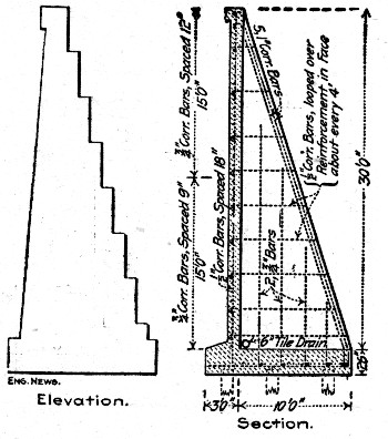 Fig. 98.—Comparison of Plain and Reinforced Sections for
Retaining Walls (C. E. Graff).
Fig. 98.—Comparison of Plain and Reinforced Sections for
Retaining Walls (C. E. Graff).
COMPARATIVE ECONOMY OF PLAIN AND REINFORCED CONCRETE WALLS.—Prior to the construction of some 2,000 ft. of retaining wall ranging in height from 2 ft.[Pg 260] to 38 ft., at Seattle, Wash., calculation was made by the engineers of the Great Northern Ry. to determine the comparative economy of plain concrete and reinforced concrete sections. The sections assumed were those shown by Fig. 98, and comparisons were made at heights of 10, 20, 30 and 40 ft., with the following results:
| Height in | Plain. | Reinforced. | Per cent. |
| feet. | Cu. yds. per ft. | Cu. yds. per ft. | Saving. |
| 10 | 1.63 | 1.29 | 20.4 |
| 20 | 4.08 | 2.59 | 36.4 |
| 30 | 8.40 | 4.73 | 43.3 |
| 40 | 14.70 | 8.07 | 45.0 |
The saving in concrete increased as the height of the wall increased; for a 40-ft. wall reinforced concrete at nearly double the cost per cubic yard in place would be as cheap as plain concrete.
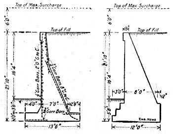 Fig. 99.—Comparison of Plain and Reinforced Sections for
Retaining Wall (F. F. Sinks).
Fig. 99.—Comparison of Plain and Reinforced Sections for
Retaining Wall (F. F. Sinks).
Taking substantially the section of reinforced wall being used on the Chicago track elevation work of the Chicago, Burlington & Quincy R. R., and comparing it with a plain wall as shown by Fig. 99, Mr. F. F. Sinks obtained the following results:
| Plain Wall, Cost per Lineal Foot— | |
| 4.8 cu. yds. concrete at $4 | $19.20 |
| 115 ft. B. M. of forms at $31 | 3.56 |
| ——— | |
| Total 4.8 cu. yds. at $4.74 | $22.76 |
| Reinforced Wall, Cost per Lineal Foot— | |
| 3.46 cu. yds. concrete at $4.10 | $14.18 |
| 115 ft. B. M. of forms at $31 | 3.56 |
| 109 lbs. reinforcing steel at 3¼ cts. | 3.54 |
| 1.34 cu. yds. extra fill at 20 cts. | 0.27 |
| 0.32 cu. yd. extra excavation at 20 cts. | 0.06 |
| —— | |
| Total, 3.46 cu. yds. concrete at $6.25 | $21.61 |
The saving in this case was $1.15 per lineal foot of wall with the unit cost of reinforced concrete in place 24 per cent. greater than the unit cost of plain concrete. It will be noted that there is some 28 per cent. less concrete per lineal foot of wall in the reinforced section and also that this section is so designed that the form work is about as simple for one section as for the other. Another point to be noticed is that there is no saving in excavation by using a reinforced section instead of a gravity section, in fact the excavation runs slightly more for the reinforced section.
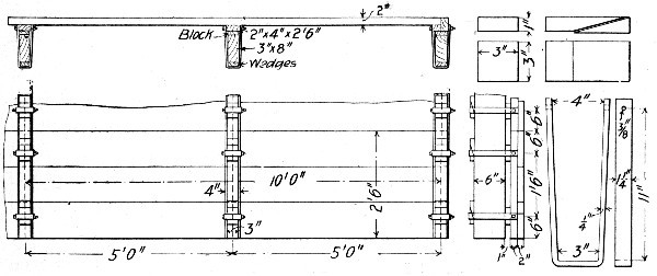 Fig. 100.—Forms for Retaining Wall Work, N. Y. C. & H.
R. R. R.
Fig. 100.—Forms for Retaining Wall Work, N. Y. C. & H.
R. R. R.
FORM CONSTRUCTION.—Retaining wall work often affords an opportunity for constructing the forms in panels and this opportunity should be taken advantage of when possible. Several of the walls described later give examples of form work that may be studied with profit in this respect.
Figure 100 shows a panel form construction employed on the New York Central & Hudson River R. R. The 3×8-in. studs are erected, care being taken to get them in proper line and to true batter and also to brace them rigidly by diagonal props. Generally the studding is erected for a section of wall[Pg 262] 50 ft. long at one time. The lagging, made in panels 2½ ft. wide and 10 ft. long, by nailing 2-in. plank to 2×4-in. cleats, is attached to the studding a panel at a time and beginning at the bottom, by means of the straps, wedges and blocks shown. Five bottom panels making a form 2½ ft. high and 50 ft. long are placed first. When the concrete has been brought up nearly to the top of these panels, a second row of panels is placed on top of the first. When it is judged that the concrete is hard enough the lowermost panels are loosened and made free by removing the wedges, blocks and straps and the panels are drawn out endwise from behind the studding and used over again for one of the upper courses. The small size of the panels makes it practicable to lay bare the concrete while it is yet soft enough to work with a float or to finish by scrubbing as described in Chapter VIII. In cases where this object is not sought, panels of much larger size may be used. Working with panels 2¼×12½ ft. of 2-in. plank it was found that each panel could be used 16 times before becoming unfit for further use, but as, owing to the nicety of molded surface demanded, panels were discarded when showing comparatively small blemishes, this record cannot be taken as a true indication of the life of such forms. These panel forms are used by the railway named for long abutments and piers as well as for retaining walls.
A different type of sectional form construction is illustrated by Figs. 101 and 102. It has been extensively used for retaining wall work by the Chicago, Burlington & Quincy R. R. The studding and waling are framed in units as shown. The lagging is framed in panels for the rear of the wall, for the face of the coping, and for the inclined toe of the wall, and is ordinary sheathing boards for the main face of the wall. The make-up of the several panels is shown by the drawings. The reason for using ordinary sheathing instead of panels for the face of the wall is stated by Mr. L. J. Hotchkiss, Assistant Bridge Engineer, to be that "the sections become battered and warped with use, do not fit closely together, and leave the wall rough when they are removed." The manner of bracing the form and of anchoring it down against the up-thrust of the wet concrete is shown by Fig. 102.[Pg 263]
Two other examples of sectional form construction are given in the succeeding descriptions of work for the Grand Central Station terminal in New York City and for the Chicago Drainage Canal. In the former work it is notable that panels 51×20 ft. were used, being handled by locomotive crane. The panels used on the drainage canal work and in the forms previously described are of sizes that can be taken down and erected by hand, and the means of handling them should always be given consideration in deciding on the sizes to be adopted for form panels not only in wall construction but in any other class of work where sectional forms may be used. Wet spruce or yellow pine will weigh 4½ lbs. per ft. B. M., so that a panel 10×2½ ft. made of 2-in. plank and three 2×4-in. battens will weigh some 225 lbs. In form work where the panels are removed and re-erected in succession facility in handling is an important matter. When one figures that he may handle both the concrete and the form panels with it a cableway or a locomotive crane becomes a tool well worth considering in heavy wall work.
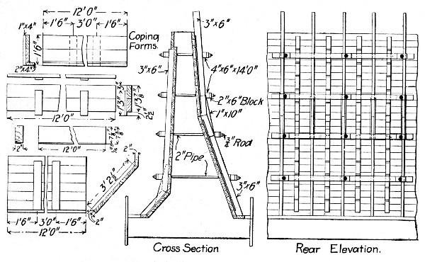 Fig. 101.—Forms for Retaining Wall Work, C., B. & Q. R.
R.
Fig. 101.—Forms for Retaining Wall Work, C., B. & Q. R.
R.
Three details in retaining wall form work that are often sources of annoyance out of proportion to their magnitude are alignment, coping construction and wall ties. Small variations from line in the face of the wall are seldom noticeable,[Pg 264] but a wavy coping shows at a glance. For this reason it is often wise to build the coping after the main body of the wall has been stripped, or if both are built together to provide in the forms some independent means of lining up the coping molds. In the form shown by Fig. 101 the latter is done by bracing the coping panel so as to permit it to be set and lined up independently of the main form. A separate form for molding the coping after the main body of the wall is completed may be constructed as shown by Fig. 103. Bolts at B and C permit the yokes to be collapsed and the form to be shifted ahead as the work advances. This mold provides for beveling the top edges of the coping and also the edge of the overhang, and the beveling or rounding of these edges should never be omitted where a neat appearance is desired. It is not essential, however, that this finishing be done in the molds. By stripping the concrete while it is still pliable the edges can be worked down by the ordinary cement sidewalk edger.
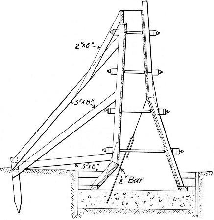 Fig. 102.—Sketch Showing Method of Bracing Form Shown by
Fig. 101.
Fig. 102.—Sketch Showing Method of Bracing Form Shown by
Fig. 101.
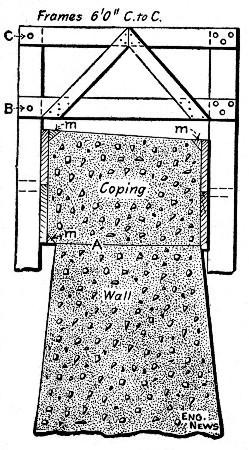 Fig. 103.—Sectional Form for Constructing Coping.
Wall ties are commonly used to hold the face and back forms to proper spacing, but occasionally they are not permitted. In the latter case the bracing must be arranged to hold the forms from tipping inward as well as from being thrust outward. A good arrangement is that shown by Fig. 102. In fastening the forms with ties the choice is usually between long bolts which are removed when the molds are taken down and wire ties which are left embedded in the concrete. The selection to be made depends upon the character of the work. When sectional forms are used like the one shown by Fig. 101, for long stretches of wall of nearly uniform cross-section bolts are generally more economical and always more secure. If the bolts are sleeved with scrap gas pipe having the ends corked with waste the bolts can be removed ordinarily without difficulty. To make the pipe sleeve serve also as a spacer the end next the face may be capped with a wooden washer which is removed and the hole plastered when the forms are taken down. With bolt ties the forms can be filled to a depth of 15 to 20 ft with sloppy concrete. This is hardly safe with wire ties unless more wire and better tieing are employed than is usual. It takes four strands of No. 10 to give the same working stress as a ½-in. threaded rod and the tieing in of four strands of wire so that they will[Pg 266] be without slack and give is a task requiring some skill. Bolts are much more easily placed and made tight. In the matter of cost of metal left in the wall, the question is between the cost of scrap gas pipe and of wire; the pound price of the wire is greater but fewer pounds are used and the metal is in more convenient shape to cut to length and to handle. This convenience in shaping the tie to the work gives the advantage to wire ties for isolated jobs or jobs which involve a continual change in the length and spacing of the ties. In general the contractor will find bolts preferable where sectional forms are used and wire ties preferable when using continuous forms.
One objection urged against the use of wire ties is that the metal is exposed at the face of the work when they are clipped off unless the concrete is chipped and the cavity plastered. To obviate this objection various forms of removable "heads" have been devised. Two such devices are shown by Figs. 104 and 105. In both the bolt is unscrewed, leaving the "heads" embedded. The head shown by Fig. 104 has the advantage that it can be made by any blacksmith, while the head shown by Fig. 105 is a special casting.
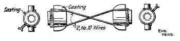 Fig. 104.—Tie for Wall Forms.
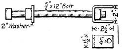 Fig. 105.—Tie for Wall Forms.
MIXING AND PLACING CONCRETE.—Where a long stretch of wall is to be built the system of mixing and handling the concrete must be capable of being shifted along the work. For isolated walls of short length this problem is a simpler one. Where the mixer can be installed on the bank above, wheeling to chutes reaching down to the work is the best solution. As shown in Chapter IV concrete can be successfully and economically chuted to place to a greater extent than most contractors realize. Where the mixer has to be installed at the foot of the wall wheelbarrow inclines, derricks, gallows frames, etc., suggest themselves as means of handling the concrete. It is not this class of work, however, but the long[Pg 267] stretches of heavy section walls such as occur in depressed or elevated railway work in cities that call for thought in the arrangement and selection of mixing and handling plant.
In building the many miles of retaining wall in the work of doing away with grade crossings in Chicago, Ill., trains made up of a mixer car and several material cars have been used. The mixer is mounted on a flat car set at the head of the train and is covered by a decking carrying two charging hoppers set above the mixer. The material cars are arranged behind, the sand and stone or gravel being in gondola cars. Portable brackets hooked to the sides of the gondola cars carry runways for wheelbarrows. Sand and stone or gravel are wheeled to the charging hoppers, the work being continuous since one hopper is being filled while the other is being discharged into the mixer. The mixer discharges either into a chute, wheelbarrows or buckets. The foregoing is the general arrangement; it is modified in special instances, as is mentioned further on. The chief objection to the method is the difficulty of loading the wheelbarrows standing on runways level with the tops of the gondola sides. The lift from the bottom of the car is excessive, and as pointed out previously, shoveling stone or gravel by digging into it from the top is a difficult task.
The delivery of the concrete into the forms was accomplished by chute where possible, otherwise by wheelbarrows or cranes, and in one case by belt conveyor. In the last instance the mixer car was equipped with a Drake continuous mixer and was set in front. Behind it came three or four gondola cars of sand and stone, and at the rear end a box car of cement. All material was wheeled on side runways to two charging hoppers over the mixer. The mixer discharged onto a belt conveyor carried by a 25-ft. boom guyed to an A-frame on the car and pivoted at the car end to swing 180° by means of a tag line. The outer end of the conveyor was swung over the forms. A ¾-in. wire rope wrapped eight times around two drums on the mixer car and passing through slots in the floor to anchors placed one 500 ft. in front and one 500 ft. to the rear enabled the train to be moved back and forth along the work. This scheme of self-propulsion saved the hire of a locomotive. In another case the mixer was discharged[Pg 268] into buckets which were handled by a crane traveling back and forth along a track laid on two flat cars.
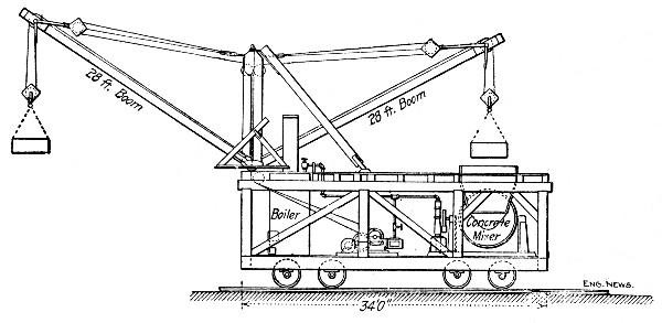 Fig. 106.—Side Elevation of Traveling Mixer Plant,
Galveston Sea Wall.
Fig. 106.—Side Elevation of Traveling Mixer Plant,
Galveston Sea Wall.
Another type of movable mixer plant used in constructing a sea-wall some 3½ miles long at Galveston, Tex., is shown by Figs. 106 and 107. Two of these machines mixed and placed some 127,000 cu. yds. of concrete, in 1 cu. yd. batches. Two 12-HP. engines operated the derricks and one 16-HP. engine operated the Smith mixer; all engines took steam from a 50-HP. boiler. The rated capacity of each machine was 300 to 350 cu. yds. per day. The method of operation is clearly indicated by the drawings.
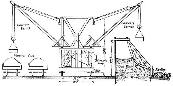 Fig. 107.—End Elevation of Traveling-Mixer, Galveston
Sea Wall.
Fig. 107.—End Elevation of Traveling-Mixer, Galveston
Sea Wall.
Placing the concrete in the forms is generally required to be done in layers; with wet mixtures this means little more than distributing the concrete somewhat evenly along the wall and slicing and puddling it to get rid of air and prevent segregation. Where mortar facing is required the face form described in Chapter VIII may be used. A reasonably good surface can be secured without mortar facing by spading the face. With dry concrete, placing and ramming in layers, calls for such care as is necessary in dry concrete work everywhere. Where new concrete has to be placed on concrete placed the day before, good bond may be secured and the chance of efflorescence be reduced by the methods described in Chapter VIII.
WALLS IN TRENCH.—In canal excavation, in subway work in cities, and the like, it is often necessary to dig trenches and build retaining walls in them before excavating the core of earth between the walls. The following examples of such work are taken from personal records:
Example I.—A Smith mixer was used, the concrete being delivered where wanted by a Lambert cableway of 400 ft. span. The broken stone and sand were delivered near the work in hopper-bottom cars which were dumped through a trestle onto a plank floor. Men loaded the material into one-horse dump carts which hauled it 900 ft. to the mixer platform. This platform was 24×24 ft. square, and 5 ft. high, with a planked approach 40 ft. long and contained 7,300 ft. B. M. The stone and sand were dumped at the mouth of the mixer and shoveled in by 4 men. Eight men, working in pairs, loaded the broken stone into the carts, and 2 men loaded the sand. Each cart was loaded with about 70 shovelfuls of stone on top of which 35 shovelfuls of sand were thrown. It took 3 to 5 minutes to load on the stone and 1 minute to load the sand. The carts traveled very slowly, about 150 ft. a minute—in fact, all the men on the job, including the cart drivers, were slow. After mixing, the concrete was dumped into iron buckets holding 14 cu. ft. water measure, making about ½ cu. yd. in a batch. The buckets were hooked on to the cableway and conveyed where wanted in the wall. Steam for running the mixer was taken from the same boiler that supplied the cableway engine. The average output of this plant was 100[Pg 270] cu. yds. of concrete per 10-hour day, although on many days the output was 125 cu. yds., or 250 batches. The cost of mixing and placing was as follows, on a basis of 100 cu. yds. per day:
| Per day. | Per cu. yd. | |
| 8 men loading stone into carts | $12.00 | $ .12 |
| 2 men loading sand into carts | 3.00 | .03 |
| 1 cart hauling cement | 3.00 | .03 |
| 8 carts hauling stone and sand | 24.00 | .24 |
| 4 men loading mixer | 6.00 | .06 |
| 1 man dumping mixer | 1.50 | .01 |
| 2 men handling buckets at mixer | 3.00 | .03 |
| 6 men dumping buckets and ramming | 9.00 | .09 |
| 12 men making forms at $2.50 | 30.00 | .30 |
| 1 cable engineman | 3.00 | .03 |
| 1 fireman | 2.00 | .02 |
| 1 foreman | 6.00 | .06 |
| 1 waterboy | 1.00 | .01 |
| 1 ton coal for cableway and mixer | 4.00 | .04 |
| ——— | —— | |
| Total | $107.50 | $1.07 |
In addition to this cost of $1.07 per cu. yd. there was the cost of moving the whole plant for every 350 ft. of wall. This required 2 days, at a cost of $100, and as there were about 1,000 cu. yds. of concrete in 350 ft. of wall 16 ft. high, the cost of moving the plant was 10 cts. per cu. yd. of concrete, bringing the total cost of mixing and placing up to $1.17 per cu. yd. As above stated, the whole gang was slow.
The labor cost of making the forms was high, for such simple and heavy work, costing $10 per M. of lumber placed each day. The forms were 2-in. sheeting plank held by 4×6-in. upright studs 2½ ft. apart, which were braced against the sides of the trench. The face of the forms was dressed lumber and all cracks were carefully puttied and sandpapered.
The above costs relate only to the massive part of the wall and not the cost of putting in the facing mortar, which was excessively high. The face mortar was 2 ins. thick, and about 3½ cu. yds. of it were placed each day with a force of 8 men! Two of these men mixed the mortar, 2 men wheeled it in barrows[Pg 271] to the wall, 2 men lowered it in buckets, and 2 men put it in place on the face of the wall. If we distribute this labor cost on the face mortar over the 100 cu. yds. of concrete laid each day, we have another 12 cts. per cu. yd.; but a better way is to regard this work as a separate item, and estimate it as square feet of facing work. In that case these 8 men did 500 sq. ft. of facing work per day at a cost of nearly 2-½ cts. per sq. ft. for labor.
Example II.—The building of a wall similar to the one just described was done by another gang as follows: The stone and sand were delivered in flat cars provided with side boards. In a stone car 5 men were kept busy shoveling stone into iron dump buckets having a capacity of 20 cu. ft. water measure. Each bucket was filled about two-thirds full of stone, then it was picked up by a derrick and swung over to the next car which contained sand, where two men filled the remaining third of the bucket with sand. The bucket was then lifted and swung by the derrick over to the platform of the mixer where it was dumped and its contents shoveled by four men into the mixer, cement being added by these men. The mixer was dumped by two men, loading iron buckets holding about ½ cu. yd. of concrete each, which was the size of each batch. A second derrick picked up the concrete bucket and swung it over to a platform where it was dumped by one man; then ten men loaded the concrete into wheelbarrows and wheeled it along a runway to the wall. One man assisted each barrow in dumping into a hopper on the top of a sheet-iron pipe which delivered the concrete. The two derricks were stiff-leg derricks with 40-ft. booms, provided with bull-wheels, and operated by double cylinder (7×10-in.) engines of 18-HP. each. About 1 ton of coal was burned daily under the boiler supplying steam to these two hoisting engines. The output of this plant was 200 batches or 100 cu. yds. of concrete per 10-hr. day, when materials were promptly supplied by the railroad; but delays in delivering cars ran the average output down to 80 cu. yds. per day.
On the basis of 100 cu. yds. daily output, the cost of mixing and placing the concrete was as follows:[Pg 272]
| Per day. | Per cu. yd. | |
| 5 men loading stone | $ 7.50 | $.07½ |
| 2 men loading sand | 3.00 | .03 |
| 4 men charging mixer | 6.00 | .06 |
| 2 men loading concrete into buckets | 3.00 | .03 |
| 1 man dumping concrete from buckets | .50 | .01½ |
| 10 men loading and wheeling concrete | .00 | .15 |
| 1 man dumping wheelbarrows | 1.50 | .01½ |
| 3 men spreading and ramming | 4.50 | .04½ |
| 2 enginemen | 5.00 | .05 |
| 1 fireman | 2.00 | .02 |
| 1 waterboy | 1.00 | .01 |
| 1 foreman | 6.00 | .06 |
| 10 men making forms | 25.00 | .25 |
| 1 ton coal | 4.00 | .04 |
| ——— | —— | |
| Total | 85.00 | $.85 |
In addition there were 8 men engaged in mixing and placing the 2-in. facing of mortar as stated above.
CHICAGO DRAINAGE CANAL.—The method and cost of constructing some 20,000 ft. of concrete wall by contract in building the Chicago Drainage Canal is compiled from records kept by Mr. James W. Beardsley. The work was done on two separate sections, Section 14 and Section 15. In both cases a 1-1½-4 natural cement concrete was used with a 3-in. facing and a 3-in. coping of 1-3 Portland cement mortar.
Section 14.—The average height of the wall was 10 ft., and the thickness at base was one-half the height. The stone for the concrete was obtained from the spoil bank of the canal, loaded into wheelbarrows and wheeled about 100 ft. to the crusher; some was hauled in wagons. An Austin jaw crusher was used, and it discharged the stone into bins from which it was fed into a Sooysmith mixer. The crusher and the mixer were mounted on a flat car. Bucket elevators were used to raise the stone, sand and cement from their bins to the mixer; the buckets were made of such size as to give the proper proportions of ingredients, as they all traveled at the same speed. Only two laborers were required to look after the elevators. The sand and cement were hauled by teams and dumped into[Pg 273] the receiving bins. There were 23,568 cu. yds. on Section 14 and the cost was as follows:
| Typical force. | Wages per 10 hrs. | Cost per cu. yd. | |
| General force: | |||
| Superintendent | 1.0 | $5.00 | $0.026 |
| Blacksmith | 1.1 | 2.75 | 0.016 |
| Timekeeper | 0.5 | 2.50 | 0.007 |
| Watchman | 0.6 | 2.00 | 0.007 |
| Waterboys | 3.9 | 1.00 | 0.022 |
| Wall force: | |||
| Foreman | 0.9 | 2.50 | 0.013 |
| Laborers | 8.6 | 1.50 | 0.073 |
| Tampers | 2.3 | 1.75 | 0.022 |
| Mixer force: | |||
| Foreman | 1.2 | 2.50 | 0.017 |
| Enginemen | 1.8 | 2.50 | 0.025 |
| Laborers | 6.7 | 1.50 | 0.057 |
| Pump runner | 1.0 | 2.00 | 0.010 |
| Mixing machines | 1.7 | 1.25 | 0.012 |
| Timber force: | |||
| Foreman | 0.6 | 2.50 | 0.008 |
| Carpenters | 4.7 | 2.50 | 0.057 |
| Laborers | 1.2 | 1.50 | 0.010 |
| Helpers | 5.3 | 2.50 | 0.075 |
| Hauling force: | |||
| Laborers | 2.6 | 1.75 | 0.026 |
| Teams | 6.3 | 3.25 | 0.116 |
| Crushing force: | |||
| Foreman | 0.5 | 2.50 | 0.007 |
| Engineman | 1.7 | 2.50 | 0.023 |
| Laborers | 3.5 | 1.50 | 0.032 |
| Austin crushers | 1.7 | 1.20 | 0.011 |
| Loading stone: | |||
| Foreman | 1.7 | 2.50 | 0.023 |
| Laborers | 32.9 | 1.50 | 0.280 |
| ——— | |||
| Total for crushing, mixing and placing | $0.975 |
The daily costs charged to the mixers and crushers include the cost of coal, at $2 a ton, and the cost of oil.
The gang "loading stone" apparently did a good deal of sledging of large stones, and they also wheeled a large part of it in barrows to the crusher.
The plant cost $9,600, distributed as follows:
| 2 jaw crushers | $3,000 |
| 2 mixers | 3,000 |
| Track | 1,260 |
| Lumber | 500 |
| Pipe | 840 |
| Sheds | 400 |
| Pumps | 600 |
| —— | |
| Total | $9,600 |
If this first cost of the plant were distributed over the 23,568 cu. yds. of concrete it would amount to 41 cts. per cu. yd.
The cost of the concrete was as follows:
| Per cu. yd. | |
| Utica cement, at $0.65 per bbl. | $0.863 |
| Portland cement, at $2.25 per bbl. | 0.305 |
| Sand, at $1.35 per cu. yd. | 0.465 |
| Stone and labor, as above given | 0.975 |
| ——— | |
| Total | $2.608 |
| First cost of plant | $0.407 |
Section 15.—The conditions on this section were much the same as on Section 14, just described, except that the limestone was quarried from the bed of the canal, and was crushed in a stationary crusher, No. 7 Gates. The stone was hauled 1,000 ft. to the crusher on cars drawn by a cable from a hoisting engine. The output of this crusher averaged 210 cu. yds. per day of 10 hrs. The crushed stone was hauled in dump cars, drawn by a locomotive, to the mixers. Spiral screw mixers mounted on flat cars were used, and they delivered the concrete to belt conveyors which delivered the concrete into the forms.
The forms on Section 15 (and on Section 14 as well) consisted of upright posts set 8 ft. apart and 9 ins. in front of the[Pg 275] wall, held at the toe by iron dowels driven into holes in the rock, and held to the rear posts by tie rods. The plank sheeting was made up in panels 2 ft. wide and 16 ft. long, and was held up temporarily by loose rings which passed around the posts which were gripped by the friction of the rings. These panels were brought to proper line and held in place by wooden wedges. After the concrete had set 24 hrs. the wedges were struck, the panels removed and scraped clean ready to be used again.
The cost of quarrying and crushing the stone, and mixing the concrete on Section 15 was as follows:
| Typical force. | Wages per 10 hrs. | Cost per cu. yd. | |
| General force— | |||
| Superintendent | 1.0 | $5.00 | $0.024 |
| Blacksmith | 0.9 | 2.75 | 0.011 |
| Teams | 1.7 | 3.00 | 0.025 |
| Waterboy | 4.5 | 1.00 | 0.022 |
| Wall force— | |||
| Foreman | 1.1 | 2.50 | 0.010 |
| Laborers | 14.4 | 1.50 | 0.105 |
| Tampers | 0.1 | 1.75 | 0.001 |
| Mixer force— | |||
| Foreman | 2.1 | 2.50 | 0.026 |
| Enginemen | 2.1 | 2.50 | 0.022 |
| Laborers | 23.1 | 1.50 | 0.180 |
| Mixing machines | 2.1 | 1.25 | 0.022 |
| Timber force— | |||
| Carpenters | 0.8 | 3.00 | 0.013 |
| Laborers | 0.7 | 1.50 | 0.005 |
| Helpers | 10.2 | 2.50 | 0.125 |
| Hauling force— | |||
| Foreman | 0.7 | 2.50 | 0.009 |
| Enginemen | 1.4 | 2.50 | 0.019 |
| Fireman | 0.4 | 1.75 | 0.003 |
| Brakeman | 2.2 | 2.00 | 0.018 |
| Teams | 0.4 | 3.25 | 0.007 |
| Laborers | 1.5 | 1.50 | 0.010 |
| Locomotives | 1.4 | 2.25 | 0.015 |
| Crushing force— | |||
| Foreman | 1.0 | 2.50 | 0.014 |
| Enginemen | 1.0 | 2.50 | 0.014 |
| Laborers | 11.1 | 1.50 | 0.081 |
| Firemen | 1.0 | 1.75 | 0.008 |
| Gyratory crusher | 1.0 | 2.25 | 0.011 |
| Quarry force— | |||
| Foreman | 1.2 | 2.50 | 0.012 |
| Laborers | 19.0 | 1.50 | 0.140 |
| Drillers | 1.8 | 2.00 | 0.017 |
| Drill helpers | 1.8 | 1.50 | 0.013 |
| Machine drills | 1.8 | 1.25 | 0.011 |
| ——— | |||
| Total | $0.993 |
The first cost of the plant for this work on Section 15 was $25,420, distributed as follows:
| 1 crusher, No. 7 Gates | $12,000 |
| Use of locomotive | 2,200 |
| Car and track | 5,300 |
| 3 mixers | 3,000 |
| Lumber | 1,200 |
| Pipe | 720 |
| Small tools | 1,000 |
| ——— | |
| Total | $25,420 |
This $25,420 distributed over the 44,811 cu. yds. of concrete amounts to 57 cts. per cu. yd.
It will be noted that 2 mixers were kept busy. Their average output was 100 cu. yds. each per day, which is the same as for the mixers on Section 14.
The total cost of concrete on Section 15 was as follows:
| Per cu. yd. | |
| Labor quarrying, crushing and mixing | $0.991 |
| Explosives | 0.083 |
| Utica cement, at $0.60 per bbl. | 0.930 |
| Portland cement, at $2.25 per bbl. | 0.180 |
| Sand, at $1.35 per cu. yd. | 0.476 |
| ——— | |
| Total | $2,660 |
| First cost of plant | $0.567 |
It is not strictly correct to charge the full first cost of the plant to the work as it possessed considerable salvage value at the end.
Comparison.—For the purpose of comparing Sections 14 and 15 the following summary is given of the cost per cubic yard of concrete:
| Sec. 14. | Sec. 15. | |
| General force | $0.078 | $0.082 |
| Wall force | 0.108 | 0.116 |
| Mixing force | 0.121 | 0.250 |
| Timbering force | 0.150 | 0.140 |
| Hauling force | 0.142 | 0.081 |
| Crushing force | 0.073 | 0.128 |
| Quarry force | 0.303 | 0.275 |
| Cement, natural | 0.863 | 0.930 |
| Cement, Portland | 0.305 | 0.180 |
| Sand | 0.465 | 0.476 |
| Plant (full cost) | 0.407 | 0.567 |
| ——— | ——— | |
| Total | $3.015 | $3.225 |
It should be remembered that on Section 14 there was no drilling and blasting of the rock, but that the "quarry force" not only loaded but hauled the stone to the crusher. The cost of mixing on Section 15 is higher than on Section 14 because the materials were dumped on platforms and shoveled into the mixer, instead of being discharged from bins into the mixer as on Section 14.
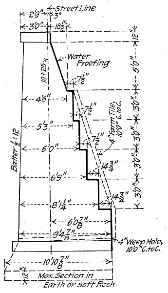 Fig. 108.—Cross Section of Retaining Wall. New York
Central Terminal Work.
Fig. 108.—Cross Section of Retaining Wall. New York
Central Terminal Work.
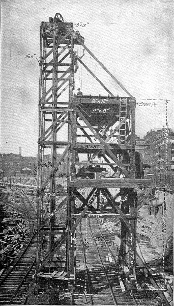 Fig. 109.—Portable Concrete Mixing Tower, N. Y. Central
Terminal Work.
Fig. 109.—Portable Concrete Mixing Tower, N. Y. Central
Terminal Work.
GRAND CENTRAL TERMINAL, NEW YORK, N. Y.—In building a retaining wall of the cross-section, shown in Fig. 108, a traveling tower moving on tracks parallel to the wall contained the concrete mixing plant. The construction of the tower is shown in Fig. 109. The tower had two platforms, one at the top carrying two 10-cu. yd. bins for sand and stone and the other directly below carrying 40 cu. ft. (4 cu. ft. cement, 12 cu. ft. sand and 24 cu. ft. stone) Ransome mixer driven by a 30 H.P. motor and a Lidgerwood motor hoist. The elevator tower carried two 40-cu. ft. Ransome dumping buckets traveling in guides and dumping automatically into the bins. These buckets were operated by the Lidgerwood motor hoist on the mixer platform. Sand and broken stone[Pg 278] on flat cars were brought alongside the tower. The sand was shoveled direct from the car into the sand bucket, but the broken stone was shoveled into wheelbarrows which were wheeled over a light bridging from car to bucket and dumped. Wheelbarrows were used for handling the stone chiefly because the capacity of the plant was so great that enough men could not be worked in the limited space around the bucket to keep up the supply by shoveling. The wheelbarrow work added materially to the cost. Cement was carried from the cars to the sand bucket, hoisted and stored on the mixer platform which provided storage room for 100 bags. A 1-3-6 mixture was used; the sand and stone were chuted directly from the bins to the charging hopper and the cement was charged by hand. The mixed concrete was delivered to two 1 cu. yd. dump cars running on a 2-ft. gage track laid in sections on the[Pg 279]cross pieces connecting the uprights of the forms. The track had no switches, so that one car had to wait for the other. Four men were required to push each car and two more men assisted in dumping the car and kept the track clear. The wall was built in sections 51 ft. long, each containing 250 cu. yds. One of these sections was filled in 8 hours with ease and by a little hustling a section was filled in 6¾ hours, which is at the rate of 37 cu. yds. of concrete per hour. Working 8 hours per day the cost of mixing, transporting and placing concrete with this mixing plant, with wages for common labor of $1.50 per day, was as follows:
| Total. | Per cu. yd. | |
| 2 men carrying cement | $3.00 | $0.012 |
| 6 men shoveling sand | 9.00 | 0.036 |
| 17 men shoveling stone | 25.00 | 0.100 |
| 11 men wheeling stone | 16.00 | 0.064 |
| 2 men at stone and sand bins | 3.00 | 0.012 |
| 2 men opening cement bags | 3.00 | 0.012 |
| 1 man dumping hopper | 1.50 | 0.006 |
| 1 man dumping mixer | 1.50 | 0.006 |
| 1 man cleaning chute, mixer, etc. | 1.50 | 0.006 |
| 1 motorman or engineer | 3.00 | 0.012 |
| ——— | ——— | |
| Total labor mixing | $66.50 | $0.266 |
| 8 men pushing 2 cars | 12.00 | 0.048 |
| 2 men cleaning track, etc. | 3.00 | 0.012 |
| 7 men spading concrete | 10.50 | 0.042 |
| ——— | ——— | |
| Total labor transporting, placing | $ 25.50 | $0.102 |
| 1 foreman | 5.00 | 0.020 |
| Electricity estimated | 7.00 | 0.028 |
| ——— | ——— | |
| Total general | $ 12.00 | $0.048 |
| Grand total | $104.00 | $0.416 |
It will be noted that the cost of shoveling and wheeling the broken stone amounts to 16.4 cts. per cu. yd., or nearly 40 per cent. of the total cost of mixing and placing. The cost of spading the concrete is also high for a sloppy mixture, but is probably accounted for by the fact that the concrete had to be spaded so as to have 2 or 3 ins. of clear mortar next the[Pg 281] forms. The forms used in constructing the wall are shown by Figs. 110 and 111. They were made in panels 51 ft. long and a locomotive crane was used to shift the panels. This crane worked handling forms only a small part of the time, but a form gang of 10 carpenters was kept busy all of the time moving and reassembling. Assuming the work of the crane to amount to $5 per day and the wages of the carpenter gang to amount to $25, we get a cost of 12 cts. per cubic yard of concrete for shifting forms. It should be noted carefully that the costs given for this work do not include cost of materials, interest on plant, superintendence and other items.
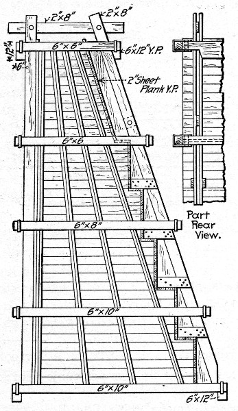 Fig. 110.—End View of Forms for Retaining Wall, New York
Central Terminal Work.
Fig. 110.—End View of Forms for Retaining Wall, New York
Central Terminal Work.
WALL FOR RAILWAY YARD.—For building a retaining wall 7 ft. high, forms were made and placed by a carpenter and helper at $8 per M., wages being 35 cts. and 20 cts. an hour, respectively. Concrete materials were dumped from wagons alongside the mixing board. Ramming was unusually thorough. Foreman expense was high, due to small number in gang; 2 cu. yds. were laid per hour by the gang.
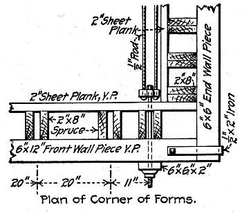 Fig. 111.—Corner Detail of Retaining Wall Forms, New
York Central Terminal Work.
Fig. 111.—Corner Detail of Retaining Wall Forms, New
York Central Terminal Work.
| Per day. | Per cu. yd. | |
| 7 mixers, 15 cts. per hour | $10.50 | $0.53 |
| 2 rammers, 15 cts. per hour | 3.00 | 0.15 |
| 1 foreman 30 cts. per hr., 1 waterboy 5 cts. | 3.50 | 0.17 |
| ——— | ——— | |
| Total labor | $17.00 | $0.85 |
The total cost was as follows per cubic yard:
| Per cu. yd. | |
| 0.8 bbls. Portland cement, at $2 | $1.60 |
| Sand | 0.30 |
| Gravel | 0.70 |
| Labor mixing and placing | 0.85 |
| Lumber for forms, at $16 per M. | 0.56 |
| Labor on forms, at $8 per M. | 0.28 |
| ——— | |
| Total, per cubic yard | $4.29 |
The sheathing plank for the forms was 2-in. hemlock.[Pg 283]
CONCRETE FOOTING FOR RUBBLE MASONRY RETAINING WALL.—In constructing a footing for a retaining wall at Grand Rapids, Mich., a 1-2½-5 natural cement concrete was used. It was found that 1 cu. yd. of concrete was equivalent to 29.8 cu. ft. of material composed of 3.6 cu. ft. or 1.1 bbls. of cement, 8.4 cu. ft. or 2.7 bbls. of sand and 17.8 cu. ft. or 5.5 bbl. of broken stone. The labor cost of 15.5 cu. yds. of concrete was as follows:
| Item. | Total. | Per cu. yd. |
| Foreman, 14 hours at 40 cts. | $ 5.60 | $0.3613 |
| Foreman, 20 hours at 22.5 cts. | 4.50 | 0.2903 |
| Laborers, 49 hours at 12.5 cts. | 6.11 | 0.3942 |
| Mason, 2 hours at 35 cts. | 0.70 | 0.0451 |
| ——— | ———— | |
| Total labor | $16.91 | $1.0909 |
All material was furnished by the railway company, the contractor furnishing labor only; his contract price for this was $1 per cu. yd.
TRACK ELEVATION, ALLEGHENY, PA.—The wall was 6,100 ft. long and 75 per cent. was on curves. The first wall built had a top width of 2½ ft. and a bottom width of 0.4 the height with the back on a smooth batter. Later the back was stepped and last the wall was proportioned as follows: Calling the height from top of foundation to under coping, then width of base was 0.45 (h + 3), the top measuring 2½ ft. The back was arranged in steps 24 ins., 30 ins. and 36 ins. high, and the thickness of wall at each step was, calling h equal to height of step from base, 0.45 (h + 3). Several forms of expansion joints were tried. The first was tarred paper extending through the wall every 50 ft.; the second was ½-in. boards running through the wall every 50 ft.; the third was ½-in. board extending 2 ft. into the wall, with a ¼-in. cove at the angles, every 25 ft. The third construction gave perfect satisfaction.
A 1-2-5 natural cement and a 1-3-6 Portland cement concrete mixed fairly wet were used. The concrete was laid in 8-in. courses and faced with a 1-2 mortar. The forms were 2-in. white pine faced and jack planed on the edges; upon removal of the forms board marks and other defects were removed[Pg 284] and a wash of neat cement was applied. One contractor used hand mixing. The sand and gravel were measured in wheelbarrows and wheeled onto the platform; the sand and cement were spread in thin layers, one over the other, and thoroughly mixed dry; the gravel was then spread over the mixture, the whole was shoveled into barrows or the pit again shoveled into place and rammed. The other contractor used a cubical mixer. A charging box holding 1¼ cu. yds. and graduated to show the correct proportions of sand and gravel was filled by shoveling; cement was placed on top and the box hoisted and dumped into the mixer. A barrel holding the correct amount of water was emptied into the mixer which was turned 10 or 15 times and discharged into cars. The costs of mixing by hand and by machine were as follows:
| Hand mixing. | Total. | Per cu. yd. |
| ½ foreman at $3 | $ 1.50 | $0.025 |
| 3 men wheeling barrows at $1.50 | 4.50 | 0.075 |
| 10 men wheeling materials at $1.50 | 15.00 | 0.250 |
| 3 men mixing sand and gravel at $1.50 | 4.50 | 0.075 |
| 6 men mixing concrete at $1.50 | 9.00 | 0.150 |
| 1 man sprinkling at $1.50 | 1.50 | 0.025 |
| ——— | ——— | |
| Total | $36.00 | $0.600 |
The output of the hand mixing gang was 60 cu. yds. per day.
| Machine mixing. | Total. | Per cu. yd. |
| 1 foreman at $3.50 | $ 3.50 | $0.035 |
| 1 stationary engineer at $3 | 3.00 | 0.030 |
| ½ foreman at $1.75 | 0.87 | 0.009 |
| 15 men loading charging bucket at $1.50 | 22.50 | 0.225 |
| 2 men dumping charging bucket at $1.75 | 3.50 | 0.035 |
| 2 tagmen at $2, ½ time | 2.00 | 0.020 |
| 1 man at trap at $2, ½ time | 1.00 | 0.010 |
| ——— | ——— | |
| Total | $36.37 | $0.364 |
The output of the cubical mixer was 100 cu. yds. per day.
The costs of placing concrete in the forms above the foundation by hand below 12 ft., and by cars and derricks any height, were as follows:[Pg 285]
| By hand (barrows) below 12 ft. | Total. | Per cu. yd. |
| 4 men loading concrete at $1.50 | $ 6.00 | $0.100 |
| 1 foreman ½ time at $3 | 1.50 | 0.025 |
| 10 men wheeling at $1.50 | 15.00 | 0.250 |
| 1 man scraping barrows at $1.50 | 1.50 | 0.025 |
| 2 men placing concrete at $1.50 | 3.00 | 0.050 |
| 1 man placing mortar face at $1.50 | 1.50 | 0.025 |
| 2 men mixing and carrying mortar at $1.50 | 3.00 | 0.050 |
| ——— | ——— | |
| Total | $31.50 | $0.525 |
| By cars and derricks— | ||
| 1 horse and driver at $3 | $ 3.00 | $0.030 |
| 2 men dumping concrete ½ time at $1.50 | 1.50 | 0.015 |
| 1 fireman ½ time at $1.75 | 0.88 | 0.009 |
| 3 tagmen at $1.50 | 4.50 | 0.045 |
| 8 men placing and ramming conc. at $1.50 | 12.00 | 0.120 |
| 2 men mixing mortar at $1.50 | 3.00 | 0.030 |
| 2 men placing mortar at $1.50 | 3.00 | 0.030 |
| 2 men carrying mortar at $1.50 | 3.00 | 0.030 |
| 1 foreman at $3 | 3.00 | 0.030 |
| 1 stationary engineer at $3 | 3.00 | 0.030 |
| 2 men attending hook at $1.50 | 3.00 | 0.030 |
| ——— | ——— | |
| Total | $39.88 | $0.399 |
The costs of placing concrete in the foundations were as follows:
| By hand— | Total. | Per cu. yd. |
| 1 foreman ½ time at $3 | $ 1.50 | $0.025 |
| 4 men shoveling concrete at $1.50 | 6.00 | 0.100 |
| 1 man placing concrete at $1.50 | 1.50 | 0.025 |
| 1 man ramming concrete at $1.50 | 1.50 | 0.025 |
| ——— | ——— | |
| Total | $10.50 | $0.175 |
| By machine— | ||
| 1 horse and driver at $3 | $ 3.00 | $0.030 |
| 3 men pushing and unloading car at $1.50 | 4.50 | 0.045 |
| 5 men placing and ramming at $1.50 | 7.50 | 0.075 |
| 1 foreman at $3 | 3.00 | 0.030 |
| 2 men dumping mixer at $1.50 | 3.00 | 0.030 |
| ——— | ——— | |
| Total | $21.00 | $0.210 |
COST OF RETAINING WALL.—The following figures of the cost of a concrete retaining wall are given by C. C. Williams:
| Cost of Material. | ||
| Kind and amount of material— | Unit Price. | Cost. |
| Stone, 441 tons | $ .70 | $308.70 |
| Sand, 182.5 yds. | .55 | 100.37 |
| Cement, 536 bbls. | .85 | 453.60 |
| ——— | ||
| Total | $862.67 | |
| Lumber ¾ value | $205.33 | |
| Wheelbarrows, ¾ value, 6 at $3.50 | 15.75 | |
| ——— | ||
| Total | $221.08 | |
| Excavation— | ||
| Labor, 4,002 hours at 15 cts. | $600.30 | |
| Carts, 800 hours at 12½ cts. | 100.00 | |
| Foreman, 460 hours at 35 cts. | 171.00 | |
| Waterboy, 240 hours at 10 cts. | 24.00 | |
| ——— | ||
| Total | $895.30 | |
| Concrete— | ||
| Labor, 2,398 hours at 15 cts. | $359.70 | |
| Foreman, 224 hours at 35 cts. | 77.40 | |
| ——— | ||
| Total | $437.10 | |
| Handling material— | ||
| Unloading cars, 380 hours at 15 cts. | $ 57.00 | |
| Foreman, 40 hours at 35 cts. | 14.00 | |
| ——— | ||
| Total | $ 71.00 | |
| Forms— | ||
| Carpenters, 997 hours at 22½ cts. | $224.33 | |
| Work to support bridge— | ||
| Carpenters, 542 hours at 22½ cts. | $121.95 | |
| Labor, 458 hours at 15 cts. | 68.70 | |
| ——— | ||
| Total | $190.65 | |
| [Pg 287] | ||
| Superintendence and office— | ||
| Superintendent, 30 hours at 50 cts. | $15.00 | |
| Office | 20.00 | |
| ———— | ||
| Total | $35.00 | |
| ———— | ||
| Grand total | $2,937.13 | |
| Proportional costs— | |||
| Item. | Cost. | Cost Per Yard of Concrete. | Per Cent. of Total Cost. |
| Concrete materials | $ 862.67 | $2.02 | 46.7 |
| Laying concrete | 437.10 | 1.03 | 23.4 |
| Lumber | 205.33 | .48 | 11.3 |
| Building forms | 224.33 | .53 | 12.3 |
| Handling material | 71.00 | .17 | 03.8 |
| Wheelbarrows | 15.75 | .04 | 01.0 |
| Supt., etc. | 35.00 | .07 | 01.5 |
| ———— | —— | ——— | |
| Total | $1,851.18 | $4.34 | 100.00 |
| Work on bridge | 190.65 | ||
| Excavation | 895.30 | ||
| ———— | |||
| $2,937.13 |
Contractor's skill or want of skill in systematizing and managing labor counts as high in street work as in any class of concrete construction. As previously demonstrated, the cost of mixing is a very small portion of the labor cost of concrete in place; the costs of getting the materials to the mixer and the mixed concrete to the work are the big items, and in street work the opportunity for increasing the cost of these items through mismanagement is magnified by the large area of operations involved per cubic yard of concrete placed. One cubic yard of concrete makes 6 sq. yds. of 6-in. pavement foundations and 100 cu. yds. of concrete make a 6-in. foundation for 300 ft. of 30-ft. street, while 4 to 5 cu. yds. will build 100 ft. of ordinary curb and gutter. Thus the haulage per cubic yard is considerable at best, and lack of plan in distributing stock piles and handling the concrete can easily result in such increased haulage expenses as to change a possible profit into a certain loss. A little thought and skill in planning street work pays a good profit.
MIXTURES EMPLOYED.—A comparatively lean concrete will serve for pavement foundations; mixtures of 1-4-8 Portland cement or 1-2-5 natural cement are amply good and it is folly, ordinarily, to employ richer mixtures. Until recently, natural cement has been used almost exclusively; a 1-2-5 natural cement mixture requires about 1.15 bbls. of cement per cubic yard of concrete. A 1-4-8 Portland cement mixture requires about 0.7 bbl. of cement per cubic yard. In the opinion of the authors a considerably leaner mixture of Portland concrete is sufficiently good when it is well mixed in machine mixers—for a 6-in., foundation 0.5 bbl. per cu. yd. The mixtures actually employed are proportioned about as stated and their cost, or that of any other common mixture,[Pg 289] may easily be computed from Tables XII and XIII, giving for different mixtures the quantities of cement, sand and stone per cubic yard of concrete; the product of these quantities and the local prices of materials in the stock piles gives the cost. When the concrete is mixed by hand the ordinary labor cost of foundations is 0.4 to 0.5 of a 10-hour day's wages per cubic yard of concrete; occasionally it may be as low as 0.3 of a day's wages where two mixing gangs are worked side by side under different foremen and with an exacting contractor. Data for machine mixing are too few to permit a similar general statement for machine work, but in one case coming under the authors' observation, the cost figured out to a little less than 0.2 of a day's wages per cubic yard.
DISTRIBUTION OF STOCK PILES.—Assuming a 30-ft. street and a 1-3-5 concrete laid 6 ins. thick, the quantities of concrete materials required per lineal foot of street are: Cement 0.60 bbl., sand 0.27 cu. yd., stone 0.44 cu. yd. The stock piles should be so distributed that each supplies enough materials for a section of foundation reaching half way to the next adjacent stock pile on each side, and they should not contain more or less material, otherwise a surplus remains to be cleaned up or a deficiency to be supplied by borrowing from another pile. A little care will ensure the proper distribution and it is well paid for in money saved by not rehandling surplus or borrowed materials. For a given mixture and a given width and thickness of foundation, the sizes of the stock piles are determined by their distance apart and this will depend upon whether hand or machine mixing is employed and upon the means adopted for hauling the raw materials and the mixed concrete. It is worth while always in stock piles of any size, to lay a flooring of plank particularly under the stone pile; if dumped directly on the ground it costs half as much again to handle stone. Current practice warrants everything from a continuous bank, to piles from 1,000 to 1,500 ft. apart, in the spacing of stock piles.
HINTS ON HAND MIXING.—All but a small percentage of the concrete annually laid in street work is hand mixed. The authors are confident that this condition will disappear as contractors learn more of the advantages of machine mixing, but it prevails at present. The general economics of hand[Pg 290] mixing are discussed in Chapter II; in street work as before stated, the big items of labor cost are the costs of handling materials and the data in Chapter II on these processes deserve special attention. It is particularly worth noting that it is seldom economical to handle materials in shovels where carrying is necessary; it is a common thing in street work to see an attempt to get the stock piles so close to the mixing board that the material can be handled with shovels, and this is nearly always an economic error. Street work is readily measured; in fact, its progress can be seen at a glance, and advantage can often be taken of this fact to profit by the rivalry of separate gangs. The authors have known of the labor costs being reduced as much as 25 per cent., due to pitting one gang against another where each could see the progress made by the other.
METHODS OF MACHINE MIXING.—Concrete mixers have been slow to replace handwork in laying pavement foundations. In explanation of this fact it is asserted: (1) That frequent shifting of the mixer causes too much lost time, and (2) that the principal item of labor cost in street work is the conveying of materials to and from the mixer, and this item is the same whether hand or machine mixing be employed. The records of machine mixer work given elsewhere in this chapter go far, in the opinion of the authors, toward disproving the accuracy of both assertions. If the machine used and the methods of work employed are adapted to the conditions of street work, machine mixing can be employed to decided advantage.
A continuous and large output is demanded in a mixer for street work; the perfection of the mixing is within limits a minor consideration. This at once admits for consideration types of mixers whose product is classed as unsuitable for reinforced concrete work, and also admits of speeding up the output of the better types to a point beyond that at which they turn out their most perfect product. Keeping these facts in mind either of the following two systems of work may be employed: (1) Traction plants which travel with the work and deposit concrete in place, or so nearly in place that little shoveling is necessary; (2) portable plants which are set up at wide intervals along the work and which discharge the[Pg 291] concrete into carts or dump wagons which distribute it to the work.
The secret of economic work with plants of the class cited first is the distribution of the stock piles so as practically to eliminate haulage from stock pile to mixer. The mixer backs away from the work, its discharge end being toward the work and its charging end away from it. Then deposit the materials so as to form a continuous stock pile along the center of the street; the mixer moving backward from the completed foundation keeps close to the materials and if the latter are uniformly distributed in the pile the great bulk of the charging is done by shoveling direct into the charging bucket. The point to be watched here is that the shovelers do not have to carry the materials; separate stock piles within moderate hauling distance by wheelbarrows are a far more economic arrangement than a continuous pile so irregularly distributed that much of the material has to be carried even a few paces in shovels.
Economic work with plants of the second class depends upon efficient and adequate means of hauling the mixed concrete to the work. The plant should not be shifted oftener than once in 1,000 to 2,000 ft., or, say, four city blocks. This does away with the possibility of wheelbarrow haulage; large capacity hand or horse carts must be employed. With 6 cu. ft. hand carts, such as the Ransome cart, a haul of 500 ft. each way from the mixer is possible and with horse carts, such as the Briggs, this economic distance is increased to 1,000 ft. each way from the mixer. The mixer must be close to the stock pile and it will pay to make use of improved charging devices. A 6-in. foundation for 2,000 ft. of 30-ft. street calls for 667 cu. yds. of concrete, and if both sides are curbed at the same time, 100 cu. yds. more are added, or 767 cu. yds. in all; where intersecting streets are to be paved in both directions from the mixer plant these amounts are doubled. A very small saving per cubic yard due to mechanical handling of the materials to the mixer amounts to the interest on a considerable investment in such plant. A point that should not be forgotten is that carts such as those named above spread the concrete in dumping so that little or no shoveling is required.[Pg 292]
FOUNDATION FOR STONE BLOCK PAVEMENT, NEW YORK, N. Y.—Mr. G. W. Tillson, in "Street Pavements and Paving Materials," p. 204, gives the following data on the cost of granite block pavement in New York City in 1899. The day was 10 hours long:
| Concrete gang— | Per day. | Per sq. yd. | Per cu. yd. |
| 1 foreman | $ 3.00 | $0.0125 | $0.075 |
| 8 mixers on two boards, at $1.25 | 10.00 | 0.0416 | 0.250 |
| 4 wheeling stone and sand, at $1.25. | 5.00 | 0.0208 | 0.125 |
| 1 carrying cement and supplying water, at $1.25 | 1.25 | 0.0051 | 0.031 |
| 1 ramming, at $1.25 | 1.25 | 0.0051 | 0.031 |
| ——— | ——— | ——— | |
| Total, 240 sq. yds. (40 cu. yds.). | $20.50 | $0.0851 | $0.512 |
The concrete was shoveled direct from the mixing boards to place.
| Cost 1-2-4 concrete— | Per cu. yd. |
| 1⅓ bbls. natural cement, at $0.90 | $1.20 |
| 0.95 cu. yd. stone, at $1.25 | 1.19 |
| 0.37 cu. yd. sand, at $1.00 | 0.37 |
| Labor | 0.51 |
| —— | |
| $3.27 |
In laying 5,167 sq. yds. of granite block pavement on one job in New York City in 1905, the authors' records show that one laborer mixed and laid 1.3 cu. yds. of concrete per day in a 6-in. foundation; this is a very small output. The work was done by contract and the labor cost was as follows:
| Item. | Total. | Per sq. yd. | Per cu. yd. |
| 28½ days foreman at $3.50 | $ 99.75 | $0.0193 | $0.118 |
| 399 days laborers at $1.75 | 698.25 | 0.1351 | 0.826 |
| ——— | ——— | ——— | |
| $798.00 | $0.1544 | $0.944 |
The average day's wages was $1.86, so that the labor cost was about 0.5 of a day's wages per cubic yard of concrete.
FOUNDATION FOR PAVEMENT, NEW ORLEANS. LA.—Mr. Alfred E. Harley states that in laying concrete foundations for street pavement in New Orleans, a day's work,[Pg 293] in running three mixing boards, covering the full width of the street, averaged 900 sq. yds., 6 ins. thick, or 150 cu. yds., with a gang of 40 men. With wages assumed to be 15 cts. per hour the labor cost was:
| Cts. per cu. yd. | |
| 6 men wheeling broken stone | 6 |
| 3 men wheeling sand | 3 |
| 1 man wheeling cement | 1 |
| 2 men opening cement | 2 |
| 7 men dry mixing | 7 |
| 8 men taking concrete off | 8 |
| 3 men tamping | 3 |
| 3 men grading concrete | 3 |
| 1 man attending run planks | 1 |
| 3 water boys | 1 |
| 2 extra men and 1 foreman | 4 |
| — | |
| Total labor cost | 39 cts. |
FOUNDATIONS FOR STREET PAVEMENT, TORONTO, CANADA.—The following cost of a concrete base for pavements at Toronto has been abstracted from a report (1892) of the City Engineer, Mr. Granville C. Cunningham. The concrete was 1-2½-7½ Portland; 2,430 cu. yds. were laid, the thickness being 6 ins., at the following cost per cubic yard:
| 0.77 bbl. cement, at $2.78 | $2.14 |
| 0.76 cu. yd. stone, at $1.91 | 1.45 |
| 0.27 cu. yd. sand and gravel, at $0.80 | 0.22 |
| Labor (15 cts. per hr) | 1.03 |
| —— | |
| Total | $4.84 |
Judging by the low percentage of stone in so lean a mixture as the above, the concrete was not fully 6 ins. thick as assumed by Mr. Cunningham. Note that the labor cost was 1½ to 2 times what it would have been under a good contractor.
MISCELLANEOUS EXAMPLES OF PAVEMENT FOUNDATION WORK.—The following records of pavement foundation work are taken from the note and time books of one of the authors:
Case 1.—Laying 6-in. pavement foundation; stone delivered and dumped upon 2-in. plank laid to receive it. Sand and[Pg 294] stone were dumped along the street, so that the haul in wheelbarrows to mixing board Was about 40 ft. Two gangs of men worked under separate foremen, and each gang averaged 4.5 cu. yds. concrete per hour. The labor cost was as follows for 45 cu. yds. per gang:
| Per day. | Per cu. yd. | |
| 4 men filling barrows with stone and sand ready for the mixers, wages 15 cts. per hour | $6.00 | $0.13 |
| 10 men, wheeling, mixing and shoveling to place (3 or 4 steps), wages 15 cts. per hour | 15.00 | 0.33 |
| 2 men ramming, wages 15 cts. per hour | 3.00 | 0.07 |
| 1 foreman at 30 cts. per hour and 1 water boy, 5 cts | 3.50 | 0.08 |
| —— | —— | |
| Total | $27.50 | $0.61 |
Case II.—Sometimes it is desirable to know every minute detail cost, for which purpose the following is given:
| Per cu. yd. | ||
| Day's labor. | Cost. | |
| 3 men loading stones into barrows | $0.06 | $0.09 |
| 1 man loading sand into barrows | 0.02 | 0.03 |
| 2 men ramming | 0.04 | 0.06 |
| 1 foreman and 1 water boy equivalent to | 0.035 | 0.05 |
| Wheeling sand and cement to mixing board | 0.02 | 0.03 |
| Wheeling stone to mixing board | 0.026 | 0.04 |
| 9 men mixing mortar | 0.013 | 0.02 |
| Mixing stone and mortar | 0.049 | 0.07 |
| Placing concrete (walking 15 ft.) | 0.072 | 0.11 |
| ——— | —— | |
| Total | $0.335 | $0.50 |
In one respect this is not a perfectly fair example (although it represents ordinary practice), for the mortar was only turned over once in mixing instead of three times, and the stone was turned only twice instead of three or four times. Water was used in great abundance, and by its puddling action probably secured a very fair mixture of cement and sand, and in that way secured a better mixture than would be expected[Pg 295] from the small amount of labor expended in actual mixing. About 9 cts. more per cu. yd. spent in mixing would have secured a perfect concrete without trusting to the water.
Case III.—Two gangs (34 men) working under separate foremen averaged 600 sq. yds., or 100 cu. yds. of concrete per 10-hour day for a season. This is equivalent to 3 cu. yds. per man per day. The stone and sand were wheeled to the mixing board in barrows, mixed and shoveled to place. Each gang was organized as follows:
| Per day. | Per cu. yd. | |
| 4 men loading barrows | $ 6.00 | $0.12 |
| 9 men mixing and placing | 13.50 | 0.27 |
| 2 men tamping | 3.00 | 0.06 |
| 1 foreman | 2.50 | 0.05 |
| ——— | —— | |
| Total | $25.00 | $0.50 |
These men worked with great rapidity. The above cost of 50 cts. per cu. yd. is about as low as any contractor can reasonably expect to mix and place concrete by hand in pavement work.
Case IV.—Two gangs of men, 34 in all, working side by side on separate mixing boards, averaged 720 sq. yds., or 120 cu. yds., per 10-hour day. Each gang was organized as follows:
| Per day. | Per cu. yd. | |
| 6 men loading and wheeling | $ 9.00 | $0.15 |
| 8 men mixing and placing | 12.00 | 0.20 |
| 2 men tamping | 3.00 | 0.05 |
| 1 foreman | 3.00 | 0.05 |
| ——— | —— | |
| Total | $27.00 | $0.45 |
Instead of shoveling the concrete from the mixing board into place, the mixers loaded it into barrows and wheeled it to place. The men worked with great rapidity.
Mr. Irving E. Howe gives the cost of a 6-in. foundation of 1-3-5 natural cement at Minneapolis, Minn., in 1897, as $2.80 per cu. yd., or $0.467 per sq. yd. Cement cost 76 cts. per barrel and stone and sand cost delivered $1.15 and 30 cts. respectively. Mixers received $1.75 per day.[Pg 296]
Mr. Niles Meriwether gives the cost of materials and labor for an 8-in. foundation constructed by day labor (probably colored) at Memphis, Tenn., in 1893, as follows:
| Per sq. yd. | |
| Natural cement at $0.74 per bbl | $0.195 |
| Sand at $1.25 per cu. yd | 0.075 |
| Stone at $1.87 per cu. yd | 0.355 |
| Labor mixing and placing | 0.155 |
| —— | |
| Total | $0.780 |
Labor was paid $1.25 to $1.50 per 8-hour day and 1.16 bbls. of cement were used per cubic yard of concrete. The cost of materials, as will be noted, was high and the labor seems to have been inefficient.
FOUNDATIONS FOR BRICK PAVEMENT, CHAMPAIGN, ILL.—The concrete foundation for a brick pavement constructed in 1903 was 6 ins. thick; the concrete used was composed of 1 part natural cement, 3 parts of sand and gravel, and 3 parts of broken stone. All the materials were mixed with shovels, and were thrown into place from the board upon which the mixing was done. The material was brought to the steel mixing board in wheelbarrows from piles where it had been placed in the middle of the street, the length of haul being usually from 30 to 60 ft. The foundation was 6 ins. thick and it cost as follows for materials and labor:
| Cost per cu. yd. | |
| 1.2 bbls. cement, at $0.50 | $0.600 |
| 0.6 cu. yd. sand and gravel, at $1 | 0.600 |
| 0.6 cu. yd. broken stone, at $1.40 | 0.840 |
| 6 men turning with shovels, at $2 | 0.080 |
| 4 men throwing into place, at $2 | 0.053 |
| 2 men handling cement, at $1.75 | 0.023 |
| 1 man wetting with hose, at $1.75 | 0.012 |
| 2 men tamping, at $1.75 | 0.023 |
| 1 man leveling, at $1.75 | 0.012 |
| 6 men wheeling stone, at $1.75 | 0.070 |
| 4 men wheeling gravel, at $1.75 | 0.047 |
| 1 foreman, at $4 | 0.027 |
| ——— | |
| $2.387 |
This is practically 40 cts. per sq. yd., or $2.40 per cu. yd. of concrete for materials and labor. It is evident from the above quantities that a cement barrel was assumed to hold about 4.5 cu. ft., hence the cement was measured loose in making the 1-3-3 concrete. The accuracy of the quantities given is open to serious doubt. It will also be noted that the labor cost of making and placing the concrete was only 35 cts. per cu. yd., wages being nearly $1.85 per day. This is so remarkably low that some mistake would seem to have been made in the measurement of the work. The authors do not hesitate to say that no gang of men ever made any considerable amount of concrete by hand at the rate of 5.75 cu. yds. per man per day.
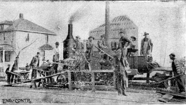 Fig. 112.—Foote Continuous Mixer Arranged for Pavement
Foundation Work.
Fig. 112.—Foote Continuous Mixer Arranged for Pavement
Foundation Work.
FOUNDATION CONSTRUCTION USING CONTINUOUS MIXERS.—The following are records of two jobs of pavement foundation work using continuous mixers with one-horse concrete carts in one instance and wheelbarrows in the other instance. The mixer used was the Foote mixer, as arranged for the work being described it is shown by Fig. 112. One particular advantage of this and similar mixers for street work is that no proportioning or measuring of the materials is required of the men. The mixers are provided with an automatic measuring device, by means of which any desired proportion of cement, sand and stone is delivered to the mixing trough. The mixer is mounted on trucks, and[Pg 298] the hoppers that receive the sand and stone are comparatively low down. The sand can be wheeled in barrows up a run plank and dumped into a hopper on one side of the mixer, and in like manner the gravel or broken stone can be delivered into a hopper on the other side. The cement is delivered in bags or buckets to a man who dumps it into a cement hopper directly over the mixer. All that the operator needs to attend to is to see that the men keep the hoppers comparatively full. The records of work on the two jobs mentioned are as follows:
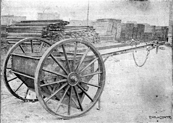 Fig: 113.—Briggs Cart Distributing Concrete for Pavement
Foundation.
Fig: 113.—Briggs Cart Distributing Concrete for Pavement
Foundation.
Job I.—The sand was delivered from the stock pile by a team hitched to a drag scraper, and was dumped alongside the mixer where two men shoveled it into the hopper. On the same job the concrete was hauled away from the mixer in Briggs' concrete carts. With a gang of 30 men and 2 to 4 horses hauling concrete in Briggs' carts, the contractor averaged 1,200 sq. yds., or 200 cu. yds., per day of 10 hours. With wages of laborers at 15 cts. per hour, and a single horse at the same rate, the cost of labor was 26 cts. per cu. yd., or less than 4½ cts. per sq. yd. of concrete base 6 ins. thick. The coal was a nominal item, and did not add 1 ct. per cu. yd. to the cost.[Pg 299] In this case the mixer was set up on a side street and the concrete was hauled in the carts for a distance of a block each way from the mixer. At first four carts were used, but as the concreting approached the mixer, less hauling was required, and finally only two carts were used. An illustration of a Briggs cart is given by Fig. 113; it is hauled by one horse, which the driver leads, and is dumped by an ingenious device operated from the horse's head. The cart dumps from the bottom and spreads the load in a layer about 8 or 9 ins. thick, so that no greater amount of shoveling is necessary than when barrows are used. It took about 20 seconds for the cart to back up and get its load and about 5 seconds to dump and spread the load.
Job II.—In this job the mixer was charged with wheelbarrows and wheelbarrows were also employed to take the mixed concrete to the work, the mixer being moved forward at frequent intervals. The stock piles were continuous, sand on one side of the street and stone on the other side. A 1-3-6 Portland cement concrete was used, a very rich mixture for a 6-in. foundation. The organization of the working gang was as follows:
| Men loading and wheeling gravel | 8 |
| Men assisting in loading gravel | 2 |
| Man dumping barrows into hopper | 1 |
| Men loading and wheeling sand | 3 |
| Man dumping barrows into hopper | 1 |
| Men wheeling concrete in barrows | 7 |
| Men spreading concrete | 3 |
| Men tamping concrete | 2 |
| Man pouring cement into hopper | 1 |
| Man operating mixer | 1 |
| Man shoveling spilled concrete | 1 |
| Man opening cement bags | 1 |
| Engineer | 1 |
| — | |
| Total men in gang | 32 |
The average day's output of this gang was 150 cu. yds., or 900 sq. yds. in 8 hours; but on the best day's work the output was 200 cu. yds., or 1,200 sq. yds. in 8 hours, which is a remarkable record for 32 men and a mixer working only 8 hours.[Pg 300]
The following is the labor cost of 8,896 sq. yds. of 4½-in. concrete foundation for an asphalt pavement constructed in New York City in 1904:
| Item. | Per sq yd. |
| Foreman at $3.75 | $0.030 |
| Laborers at $1.50 | 0.242 |
| Teams at $5 | 0.040 |
| Steam engine at $3.50 | 0.028 |
| ——— | |
| Total | $0.340 |
The concrete was a 1-3-6 mixture and was mixed in a Foote mixer. These costs are compiled from data collected by the authors.
FOUNDATION CONSTRUCTION FOR STREET RAILWAY TRACK USING CONTINUOUS MIXERS.—The following account of the methods and cost of constructing a concrete foundation for street railway track at St. Louis, Mo., is compiled from information published by Mr. Richard McCulloch. The work was done by day labor by the United Railways Co., in 1906. Figure 114 shows the concrete construction. A 1-2½-6½ Portland cement, broken stone concrete mixed by machine was used.
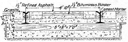 Fig. 114.—Concrete Foundation for Street Railway Track.
The material for the concrete was distributed on the street beside the tracks in advance of the machine, the sand being first deposited, then the crushed rock piled on that, and finally the cement sacks emptied on top of this pile. The materials were shoveled from this pile into the concrete mixing machine without any attempt at hand mixing on the street. Great care was taken in the delivery of materials on the street to have exactly the proper quantity of sand, rock and cement, so that there would be enough for the ballasting of the track to the[Pg 301] proper height and that none would be left over. Each car was marked with its capacity in cubic feet, and each receiver was furnished with a table by which he could easily estimate the number of lineal feet of track over which the load should be distributed.
The concrete mixing machines were designed and built in the shops of the United Railways Co. Three machines were used in this work, one for each gang. The machine is composed of a Drake continuous worm mixer, fed by a chain dragging in a cast-iron trough. The trough is 36 ft. long, so that there is room for 14 men to shovel into it. Water is sprayed into the worm after the materials are mixed dry. This water was obtained from the fire plugs along the route. In the first machine built, the Drake mixer was 8 ft. long. In the two newer machines the mixer was 10 ft. long. Both the conveyor and the mixer were motor driven, current being obtained for this purpose from the trolley wire overhead. Two types of machines were used, one in which the conveyor trough was straight and 45 in. above the rail, and the other in which the conveyor trough was lowered back of the mixer, being 25 in. above the rail. The latter type had the advantage of not requiring such a lift in shoveling, but the trough is so low that a motor truck cannot be placed underneath it. In the high machine the mixer is moved forward by a standard motor truck under the conveyor. In the low machine the mixer is moved by a ratchet and gear on the truck underneath the mixer. A crew of 27 men is required to work each machine, and under average conditions concrete for 80 lin. ft. of single track, amounting to 22 cu. yds., can be discharged per hour.
The costs of the concrete materials delivered per cubic yard of concrete were: Cement, per barrel, $1.70; sand, per cu. yd., $0.675, and stone, per cu. yd., $0.425. The cost of the concrete work per cubic yard and per lineal foot of track was as follows:
| Item. | Per lin. ft. | Per cu. yd. |
| Concrete materials | $0.791 | $2.92 |
| Labor mixing and placing | 0.071 | 0.26 |
| ——— | —— | |
| Total labor and materials | $0.862 | $3.18 |
FOUNDATION CONSTRUCTION USING BATCH MIXERS AND WAGON HAULAGE, ST. LOUIS, MO.—The following record of the method and cost of laying a concrete foundation for street pavement using machine mixing and wagon haulage is given by Mr. D. A. Fisher. The foundation was 6 ins. thick. The gravel was dumped from wagons into a large hopper, raised by a bucket elevator into bins, and drawn off through gates into receiving hoppers on the charging platform where the cement was added. The receiving hoppers discharged into the mixers, which discharged the mixed concrete into a loading car that dumped into wagons, which delivered it on the street where wanted. The longest haul in wagons was 30 mins., but careful tests showed that the concrete had hardened well. The wagons were patent dump wagons of the drop-bottom type. Mr. Fisher says:
"You may consider the following figures a fair average of the plant referred to, working to its capacity. To these amounts, however, must be added the interest on the investment, the cost of wrecking the plant and the depreciation of the same, superintendence, and the pay roll that must be maintained in wet weather. I am assuming the street as already brought to grade and rolled.
"With labor at $1.75 per day of 10 hours, teams at $4, engineer and foremen at $3, and engine at $5 per day, concrete mixed and put in place by the above method costs:
| Per cu. yd. | |
| To mix | $0.12 to $0.15 |
| To deliver to street | 0.10 to 0.14 |
| To spread and tamp in place | 0.08 to 0.11 |
| ——————— | |
| Total | $0.30 to $0.40 |
"The mixers are No. 2½ Smith, sold by the Contractors' Supply Co., Chicago, Ill., and a ½ yd. cube, sold by Municipal Engineering & Contracting Co., Chicago.
"The above figures are on the basis of a batch every 2 minutes, which is easily maintained by using the loading car, as by this means there will be no delay in the operation of the plant owing to the irregularity of the arrival of the teams.
"My experience leads me to believe that a better efficiency can be obtained by using mixers of 1 cu. yd. capacity, and that[Pg 303] the batch mixer is the only type of machine where any certainty of the proportion of the mixture is realized."
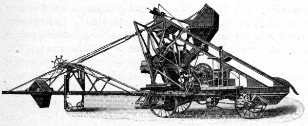 Fig. 115.—Chicago Improved Cube Traction Mixer for
Pavement Foundation.
Fig. 115.—Chicago Improved Cube Traction Mixer for
Pavement Foundation.
FOUNDATION CONSTRUCTION USING A TRACTION MIXER.—In laying a 6-in. foundation for an asphalt pavement in Buffalo, N. Y., an average of 100 sq. yds., or 16.6 cu. yds., of concrete in place was made per hour using the traction mixer shown by Fig. 115. This mixer was made by the Municipal Engineering & Contracting Co., of Chicago, Ill., and consisted of one of that company's improved cube mixers operated by a gasoline engine and equipped with the regulation mechanical charging device and also with a swinging conveyor to deliver the mixed concrete to the work. The feature of the apparatus in its application to paving work is the conveyor. This was 25 ft. long and pivoted at the mixer end so as to swing through an arc of 170°. The mixer discharged into a skip or bucket traveling on the conveyor frame and discharging over the end spreading its load anywhere within a radius of 25 ft. In operation the mixer traveled along the center of the street, backing away from the finished foundation and toward the stock pile, which was continuous and was deposited along the center of the street. The bulk of the sand and stone was thus shoveled direct into the charging bucket and the remainder was wheeled to the bucket in barrows. As the charging bucket is only 14 ins. high the barrows could be dumped directly into it from the ground. The gang worked was 17 including a foreman and one boy, and[Pg 304] with this gang 100 sq. yds. of 6-in. foundation was laid per hour. Assuming an average wage of 20 cts. an hour the cost of mixing and placing the foundation concrete was 3.4 cts. per sq. yd. or 20.4 cts. per cu. yd. for labor alone.
FOUNDATION CONSTRUCTION USING CONTINUOUS MIXER.—The foundation was 6 ins. thick for an asphalt pavement and was laid in Chicago, Ill. The concrete used was exceptionally rich for pavement foundation work, it being a 1-3-6 Lehigh Portland cement, broken stone mixture. The mixing was done by machine, a mixer made by the Buffalo Concrete Mixer Co., Buffalo, N. Y., being used. This mixer was equipped with an elevating charging hopper and was operated as a continuous mixer. The mixer was mounted on wheels and was pulled along the center of the street ahead of the work with its discharge end toward the work. Moves of about 25 to 30 ft. were made, the mixer being pulled ahead for this distance each time that the concrete came up to its discharge end. The stock piles were continuous, sand on one side and stone on the other side of the street. Cement was stored in a pile at each end of the block. All materials were wheeled from stock piles to mixer in wheelbarrows. The men wheeling sand and stone loaded their own barrows, wheeled them to the mixer and discharged them directly into the elevating hopper. No runways were used, the barrows being wheeled directly on the ground. The cement was brought in barrows, two or three bags being a load, and dumped alongside a cement box which was located close to and at one side of the elevating hopper. A man untied the bags and emptied them into the cement box and another man scooped the cement out of the box in bucketfuls and emptied it over the sand and stone in the elevating hopper. The mixer discharged onto a sheet iron shoveling board, and the concrete was carried in shovels from shoveling board to place, the length of carry being a maximum of 25 to 30 ft. Two men were required to pull down the cone of concrete at the discharge end of the mixer and to keep the stone from separating and rolling down the sides. The gang was organized as follows:[Pg 305]
| No. Men. | |
| Loading and wheeling stone | 10 |
| Loading and wheeling sand | 3 to 4 |
| Loading and wheeling cement | 2 |
| Untieing and emptying cement bags | 1 |
| Charging cement to hopper | 1 |
| Operating mixer and hopper | 1 |
| Pulling down and tending discharge | 2 |
| Carrying concrete in shovels | 8 |
| Spreading concrete | 2 |
| Tamping concrete | 2 |
| Sweeping concrete | 1 |
| General laborers | 3 |
| Foreman | 1 |
| Watchman | 1 |
| Timekeeper | 1 |
| — | |
| Total gang | 40 |
This gang averaged 1,000 sq. yds. of 6-in. foundation per 10-hour day; a maximum of 1,400 sq. yds. was laid in a day. We have thus an average of 167 cu. yds. and a maximum of 234 cu. yds. of concrete foundation mixed and placed per 10-hour day. At an average wage of $2 per day the average labor cost of mixing and placing concrete was 48 cts. per cu. yd. or 8 cts. per sq. yd. of 6-in. foundation. It was stated that the gang was larger by three men than was ordinarily used owing to certain extra work being done at the time that the above figures were collected. Taking out three extra men and the timekeeper and watchman we get 34 men actually working in mixing and placing concrete. This reduced gang gives us a labor cost for mixing and placing of about 41 cts. per cu. yd. or 6.8 cts. per sq. yd. of 6-in. foundation.
FOUNDATION CONSTRUCTION USING A BATCH MIXER.—The following figures are an average of several jobs using a Ransome ½-cu. yd. mixer for constructing 6-in. foundations. The mixer was moved 1,000 ft. at a time and the work conducted 500 ft. in each direction from each station. The concrete materials were delivered from stock pile to mixer in wheelbarrows and the mixed concrete was hauled to the work in two-wheeled Ransome carts. Run planks were laid[Pg 306] for the carts and one man readily pushed a cart holding 6 cu. ft. The men had to work fast on the long haul but had an easy time when the haul was short. The organization of the gang was as follows, wages being $1.50 per day:
| 10 men loading and wheeling stone | $15.00 |
| 4 men loading and wheeling sand | 6.00 |
| 2 men handling cement | 3.00 |
| 1 fireman | 2.00 |
| 1 man dumping mixer | 1.50 |
| 5 men wheeling carts | 7.50 |
| 3 men spreading and ramming | 4.50 |
| 1 foreman | 3.50 |
| ——— | |
| Total wages per day | $43.00 |
This gang averaged 1,080 sq. yds. of 6-in. foundation or 180 cu. yds. of concrete in place per day which gives a labor cost of 24 cts per cu. yd. or 4 cts. per sq. yd. for mixing and placing.
Next to pavement foundations the most extensive use of concrete in street work is for cement walks and concrete curb and gutter. Usually the mixing and placing of the concrete is hand work, practically the only exceptions being where pavement base, curbing and sidewalks are built all at once, using machine mixers. The same objections that have been raised to machine mixers in laying pavement foundation are raised against them for curb and walk construction, and owing to the much smaller yardage per lineal foot of street in walk and curb work these objections carry more force than they do in case of paving work. Another argument against the use of mixers is that both walk and curb and gutter work involve the use of forms and the application of mortar finish, the placing of which are really the limiting factors in the rate of progress permissible, and this rate is too slow to consume an output necessary to make a mixer plant economical as compared with hand mixing where so much transportation is involved. Concrete sidewalk and curb work are essentially hand mixing work; they, therefore, involve a careful study of the economies of hand mixing and wheelbarrow haulage which are fully discussed in Chapter II.
Sidewalk construction consists in molding on a suitably prepared sub-base a concrete slab from 3½ to 7½ ins. thick, depending on practice, and finishing its top surface with a ½ to 1½-in. wearing surface of cement mortar.
GENERAL METHOD OF CONSTRUCTION.—The excavation and preparation of the sub-grade call for little notice beyond the warning that they should never be neglected. The authors have seen many thousands of feet of cement walk laid in the middle West in which the sub-base was placed directly[Pg 308] on the natural sod, often covered with grass and weeds a foot high. Such practice is wholly vicious. The sod should always be removed and the surface soil excavated to a depth depending upon the climate and nature of the ground and the foundation bed well tamped. From 4 to 6 ins. depth of excavation will serve where the soil is reasonably hard and there are no heavy frosts; with opposite conditions a 12-in. excavation is none too deep. The thickness of the broken stone, gravel, cinder or sand sub-base should likewise be varied with the character of the soil, the conditions of natural drainage and the prevalence of frost. In well drained sandy soils 6 to 8 ins. of sub-base are sufficient, but in clayey soils with poor natural drainage the sub-base should be from 10 to 12 ins. thick at least; the local conditions will determine the thickness of sub-base necessary and in places it may be desirable to provide by artificial drainage against the accumulation of water under the concrete. Tile drains are better and cheaper than excessively deep foundations. The thorough tamping of the sub-base is essential to avoid settling and subsequent cracking of the concrete slab. This is a part of sidewalk work which is often neglected.
Portland cement concrete, sand and broken stone or gravel mixtures in the proportions of 1-3-5 and 1-3-6 are used for base slabs. For walks up to 7 ft. wide the slab is made 3½ ins. thick for residence streets and 4½ to 5 ins. thick for business streets; for wider walks the thickness is increased to 7 ins. for 8-ft. width and 7½ ins. for 9 to 10-ft. width. Roughly the thickness of the walk in inches (base and top together) is made about equal to its width in feet. The concrete is deposited in a single layer and tamped thoroughly, either in separate blocks behind suitable forms or in a continuous slab which is while fresh cut through to make separate blocks. For walks up to 8 ft. wide the slab is divided by transverse joints spaced about the width of the walk apart, but for the wider walks the safety of this division depends upon the thickness of the base; an 8-ft. walk with a 5-in. base can safely be laid with joints 8 ft. apart, but if the slab is only 4 ins. thick it had better be laid in 4×4-ft. squares. The mode of procedure in base construction is as follows:[Pg 309]
The sub-base being laid, side forms held by stakes are placed as shown by Fig. 116, with the top edges of the boards exactly to the grade of the top surface of the finished walk. The concrete is then deposited between these side forms and tamped until it is brought up to the level marked by the templet A. If the plan is to deposit the base in sections transverse plates of ⅜ to ¼ in. steel are set across the walk between the side boards at proper intervals and the concrete tamped behind them; sometimes the concreting is done in alternate blocks. When the steel plate is withdrawn an open joint is left for expansion and contraction. Where the plan is to lay the base in one piece which is afterwards cut into blocks, the cutting is done with a spade or cleaver.
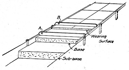 Fig. 116.—Sketch Showing Method of Constructing Cement
Walks.
Fig. 116.—Sketch Showing Method of Constructing Cement
Walks.
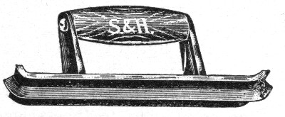 Fig. 117.—"Jointer" for Cement Sidewalk Work.
Portland cement mortar mixed 1 to 1½ to 1 to 2 is used for the wearing surface, and is laid from ½ in. to 1½ ins. thick, depending upon the width of the walk and the thickness of the base. As a rule the mortar is mixed rather stiff; it is placed with trowels in one coat usually, but sometimes in two coats, and less often by tamping. The mortar coat is brought up flush with the top edges of the side forms by means of the templet B, and the top finished by floating and troweling.[Pg 310] The wearing coat is next divided into sections corresponding with the sections into which the base is divided, by cutting through it with a trowel guided by a straight edge and then rounding the edges of the cut with a special tool called a jointer and shown by Fig. 117. An edger, Fig. 118, is then run around the outside edges of the block to round them. The laying of the mortar surface must always follow closely the laying of the base so that the two will set together.
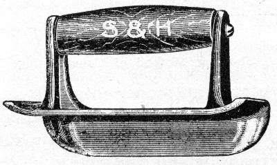 Fig. 118.—"Edger" for Cement Sidewalk Work.
BONDING OF WEARING SURFACE AND BASE.—Trouble in securing a perfect bond between the wearing surface and the base usually comes from one or more of the following causes: (1) Applying the surface after the base concrete has set. While several means are available for bonding fresh to old concrete as described in Chapter XXIV, the better practice is not to resort to them except in case of necessity but to follow so close with the surfacing that the base will not have had time to take initial set. (2) Poor mixing and tamping of this base concrete. (3) Use of clayey gravel or an accumulation of dirt on the surface. In tamping clayey gravel the water flushes the clay to the surface and prevents the best bond. (4) Poor troweling, that is failure to press and work the mortar coat into the base concrete. Some contractors advocate tamping the mortar coat to obviate this danger. Conversely, to make the surface coat adhere firmly to the base it must be placed before the base concrete has set; the base concrete must be thoroughly cleaned or kept clean from surface dirt; the surface coat must be tamped or troweled forcibly into the base concrete so as to press out all air and the film of water which collects on top of the concrete base.[Pg 311]
PROTECTION OF WORK FROM SUN AND FROST.—Sun and frost cause scaling and hair cracks. For work in freezing weather the water, sand and gravel should be heated or salt used to retard freezing until the walk can be finished; it may then be protected from further action of the frost by covering it first with paper and then with a mattress of sawdust, shavings or sand and covering the whole with a tarpaulin. Methods of heating concrete materials and rules for compounding salt solutions are given in Chapter VII. The danger from sun arises from the too rapid drying out of the surface coating; the task then is to hold the moisture in the work until the mixture has completely hardened. Portable frames composed of tarpaulin stretched over 2×4-in. strips may be laid over the finished walk to protect it from the direct rays of the sun; these frames can be readily removed to permit sprinkling. Practice varies in the matter of sprinkling, but it is the safe practice in hot weather to sprinkle frequently for several days. Moisture is absolutely necessary to the perfect hardening of cement work and a surplus is always better than a scarcity. In California the common practise is to cover the cement walk, as soon as it has hardened, with earth which is left on for several days.
CAUSE AND PREVENTION OF CRACKS.—Cracks in cement walks are of two kinds, fractures caused by any one of several construction faults and which reach through the surface coating or through both surface and base, and hair cracks which are simply skin fractures. Large cracks are the result of constructive faults and one of the most common of these is poor foundation construction; other causes are poor mixing and tamping of the base, too large blocks for thickness of the work, failure to cut joints through work. Hair cracks are the result of flushing the neat cement to the surface by excessive troweling or the use of too wet a mixture. The prevention of cracks obviously lies in seeing that the construction faults cited do not exist. If expansion joints are not provided, a long stretch of cement walk will expand on a hot day and bulge up at some point of weakness breaking the walk.
COST OF CEMENT WALKS.—The cost of cement walks is commonly estimated in cents per square foot, including the necessary excavation and the cinder or gravel foundation.[Pg 312] The excavation usually costs about 13 cts. per cu. yd., and if the earth is loaded into wagons the loading costs another 10 cts. per cu. yd., wages being 15 cts. per hr. The cost of carting depends upon the length of haul, and may be estimated from data given in Chapter III. If the total cost of excavation is 27 cts. per cu. yd., and if the excavation is 12 ins. deep, we have a cost of 1 ct. per sq. ft. for excavation alone. Usually the excavation is not so deep, and often the earth from the excavation can be sold for filling lots.
In estimating the quantity of cement required for walks, it is well to remember that 100 sq. ft. of walk 1 in. thick require practically 0.3 cu. yd. concrete. If the concrete base is 3 ins. thick, we have 0.3 × 3, or 0.9 cu. yd. per 100 sq. ft. of walk. And by using the tables in Chapter II we can estimate the quantity of cement required for any given mixture. In cement walk work the cement is commonly measured loose, so that a barrel can be assumed to hold 4.5 cu. ft. of cement. If the barrel is assumed to hold 4.5 cu. ft., it will take less than 1 bbl. of cement to make 1 cu. yd. of 1-3-6 concrete; hence it will not require more than 0.9 bbl. cement, 0.9 cu. yd. stone, and 0.45 cu. yd. sand per 100 sq. ft. of 3-in. concrete base. The 1-in. wearing coat made of 1-1½ mortar requires about 3 bbls. of cement per cu. yd., if the barrel is assumed to hold 4.5 cu. ft., and since it takes 0.3 cu. yd. per 100 sq. ft., 1 in. thick, we have 0.3 × 3, or 0.9 bbl. cement per 100 sq. ft. for the top coat. This makes a total of 1.8 bbls. per 100 sq. ft., or 1 bbl. makes 55 sq. ft. of 4-in. walk.
As the average of a number of small jobs, the authors' records show the following costs per sq. ft. of 4-in. walk such as just described:
| Cts. per sq. ft. | |
| Excavating 8 ins. deep | 0.65 |
| Gravel for 4-in. foundation, at $1.00 per cu. yd. | 1.20 |
| 0.018 bbl. cement, at $2.00 | 3.60 |
| 0.009 cu. yd. broken stone, at $1.50 | 1.35 |
| 0.006 cu. yd. sand, at $1.00 | 0.60 |
| Labor making walk | 1.60 |
| —— | |
| Total cents | 9.00 |
This is 9 cts. per sq. ft. of finished walk. The gangs that built the walk were usually two masons at $2.50 each per 10-hr. day with two laborers at $1.50 each. Such a gang averaged 500 sq. ft. of walk per day.
Cost at Toronto, Ont.—Mr. C. H. Rust, City Engineer, Toronto, Ont., gives the following costs of constructing concrete sidewalks by day labor. The sidewalks have a 4-in. foundation of coarse gravel or soft coal cinders, thoroughly consolidated by tamping or rolling, upon which is placed a 3½-in. layer of concrete composed of 1 part Portland cement, 2 parts clean, sharp, coarse sand, and 5 parts of approved furnace slag, broken stone or screened gravel. The wearing surface is 1 in. thick, or 1 part Portland cement, 1 part clean, sharp, coarse sand, and 3 parts screened pea gravel, crushed granite, quartzite or hard limestone. Costs are given of a 6-ft. and a 4-ft. walk as follows:
| COST OF 6 FT. SIDEWALK. | |
| Item. | Per 100 sq. ft. |
| Labor | $ 5.59 |
| Cement, 1.66 bbls., at $1.54 | 2.49 |
| Gravel, 2.7 cu. yds., at $0.80 | 2.21 |
| Sand, 0.46 cu. yd., at $0.80 | 0.37 |
| Water | 0.05 |
| —— | |
| Total | $10.71 |
| COST OF 4 FT. SIDEWALK. | |
| Item. | Per 100 sq. ft. |
| Labor | $ 6.73 |
| Cement, 2.04 bbls., at $1.54 | 3.15 |
| Gravel, 2.06 cu. yds., at $0.80 | 1.65 |
| Sand, 0.49 cu. yd., at $0.80 | 0.39 |
| Water | 0.07 |
| —— | |
| Total | $11.99 |
The rates of wages and the number of men employed were as follows: 1 foreman, at $3.50 per day; 1 finisher, at 30 cts. per hour; 1 helper, at 22 cts. per hour; 15 laborers, at 20 cts. per hour.[Pg 314]
Cost at Quincy, Mass.—The following costs are given by Mr. C. M. Saville for constructing 695 sq. yds. of granolithic walk around the top of the Forbes Hill Reservoir embankment at Quincy, Mass. This walk was laid on a broken stone foundation 12 ins. thick; the concrete base was 4 ins. thick at the sides and 5 ins. thick at the center; the granolithic finish was 1 in. thick. The walk was 6 ft. wide and was laid in 6-ft. sections, a steel plate being used to keep adjacent sections entirely separate. The average gang was 6 men and a team on the base and 2 masons and 1 tender on the finish. The average length of walk finished per day was 60 ft. The cost was as follows:
| Stone Foundation: | Per cu. yd. | Per sq. ft. |
| Broken stone for 12-in. foundation | $ 0.40 | $0.015 |
| Labor placing at 15 cts. per hour | 1.50 | 0.056 |
| —— | ——— | |
| Totals | $ 1.90 | $0.071 |
| Concrete Base 4½ ins. Thick: | ||
| 1.22 bbls. cement per cu. yd. at $1.53 | $ 1.87 | $0.026 |
| 0.50 cu. yd. sand per cu. yd. at $1.02 | 0.51 | 0.007 |
| 0.84 cu. yd. stone per cu. yd. at $1.57 | 1.32 | 0.019 |
| Labor (6 laborers, 1 team) | 3.48 | 0.050 |
| —— | —— | |
| Total for 90 cu. yds. | $ 7.18 | $0.102 |
| Granolithic Finish 1 in. Thick: | ||
| 4 bbls. cement per cu. yd. at $1.53 | $ 6.12 | $0.019 |
| 0.8 cu. yd. sand at $1 | 0.80 | 0.002 |
| Lampblack | 0.29 | 0.001 |
| Labor (2 masons, 1 helper) | 6.36 | 0.016 |
| —— | —— | |
| Totals | $13.57 | $0.038 |
The two masons received $2.25 per day each and their helper $1.50 per day, and they averaged 360 sq. ft. per day, which made the cost 1⅔ cts. per sq. ft. for labor laying granolithic finish. The cost of placing the foundation stone is very high and the cost of concrete base also runs unusually high, the reasons for these high costs are not evident.
Cost at San Francisco.—Mr. George P. Wetmore, of the contracting firm of Cushing & Wetmore, San Francisco, gives the following figures relating to sidewalk work in that city.[Pg 315] The foundations of cement walks in the residence district of San Francisco are 2½ ins. thick, made of 1-2-6 concrete, the stone not exceeding 1 in. in size. The wearing coat is ½ in. thick, made of 1 part cement to 1 part screened beach gravel. The cement is measured loose, 4.7 cu. ft. per barrel. The foundation is usually laid in sections 10 ft. long; the width of sidewalks is usually 15 ft. The top coat is placed immediately, leveled with a straight edge and gone over with trowels till fairly smooth. After the initial set and first troweling, it is left until quite stiff, when it is troweled again and polished—a process called "hard finishing." The hard finish makes the surface less slippery. The surface is then covered with sand, and watered each day for 8 or 10 days. The contract price is 9 to 10 cts. per sq. ft. for a 3-in. walk; 12 to 14 cts. for a 4-in. walk having a wearing coat ¾ to 1-in. thick. A gang of 3 or 4 men averages 150 to 175 sq. ft. per man per day of 9 hrs. Prices and wages are as follows:
| Cement, per bbl. | $2.50 |
| Crushed rock, per cu. yd. | 1.75 |
| Gravel and sand for foundation, per cu. yd. | 1.40 |
| Gravel for top finish, per cu. yd. | 1.75 |
| Finisher wages, best, per hr. | 0.40 |
| Finisher helper, best, per hr. | 0.25 |
| Laborer, best, per hr. | 0.20 |
Cost in Iowa.—Mr. L. L. Bingham sent out letters to a large number of sidewalk contractors in Iowa asking for data of cost. The following was the average cost per square foot as given in the replies:
| Cts. per sq. ft. | |
| Cement, at $2 per bbl. | 3.6 |
| Sand and gravel | 1.5 |
| Labor, at $2.30 per day (average) | 2.2 |
| Incidentals, estimated | 0.7 |
| — | |
| Total per sq. ft | 8.0 |
This applies to a walk 4 ins. thick, and includes grading in some cases, while in other cases it does not. Mr. Bingham writes that in this respect the replies were unsatisfactory. He also says that the average wages paid were $2.30 per man per day. It will be noted that a barrel of cement makes 55½ sq.[Pg 316] ft. of walk, or it takes 1.8 bbls. per 100 sq. ft. The average contract price for a 4-in. walk was 11½ cts. per sq. ft.
Concrete pavement is constructed in all essential respects like cement sidewalk. The sub-soil is crowned and rolled hard, then drains are placed under the curbs; if necessary to secure good drainage a sub-base of gravel, cinders or broken stone 4 to 8 ins. thick is laid and compacted by rolling. The foundation being thus prepared a base of concrete 4 to 5 ins. thick is laid and on this a wearing surface 2 to 3 ins. thick. As showing specific practice we give the construction in two cities which have used concrete pavement extensively.
Windsor, Ontario.—The street is first excavated to the proper grade and crown and rolled with a 15-ton roller. Tile drains are then placed directly under the curb line and a 6×16-in. curb is constructed, vising 1-2-4 concrete faced with 1-2 mortar. Including the 3-in. tile drain this curb costs the city by contract 38 cts. per lin. ft. The pavement is then constructed between finished curbs, as shown by Fig. 119.
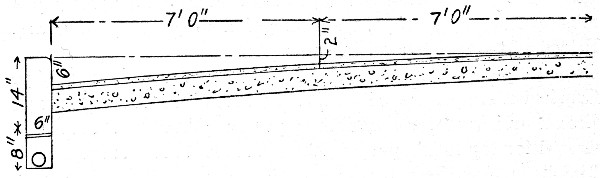 Fig. 119.—Concrete Pavement. Windsor, Canada.
The fine profile of the sub-grade is obtained by stretching strings from curb to curb, measuring down the required depth and trimming off the excess material. The concrete base is then laid 4 ins. thick. A 1-3-7 Portland cement concrete is used, the broken stone ranging from ¼ in. to 3 ins. in size, and it is well tamped. This concrete is mixed by hand and as each batch is placed the wearing surface is put on and finished. The two layers are placed within 10 minutes of each other, the purpose being to secure a monolithic or one-piece slab. The top layer consists of 2 ins. of 1-2-4 Portland cement and screened gravel, ¼ in. to 1 in., concrete. This layer is put on rather wet, floated with a wooden float and troweled with a[Pg 317] steel trowel while still wet. Some 20,500 sq. yds. of this construction have been used and cost the city by contract:
| Per sq. yd. | |
| Bottom 4-in. layer 1-3-7 concrete | $0.57 |
| Top 2-in. layer 1-2-4 concrete | 0.32 |
| Excavation | 0.10 |
| —— | |
| Total | $0.99 |
This construction was varied on other streets for the purpose of experiment. In one case a 4-in. base of 1-3-7 stone concrete was covered with 2 ins. of 1-2-2 gravel concrete. In other cases the construction was: 4-in. base of 1-3-7 stone concrete; 1½-in. middle layer of 1-2-4 gravel concrete, and ½-in. top layer of 1-2 sand mortar. All these constructions have been satisfactory; the pavement is not slippery. The cost to the city by contract for the three-layer construction has in two cases been as follows:
| Church St., 8,000 sq. yds.: | Per sq. yd. |
| 4-in. base 1-3-7 concrete | $0.57 |
| 1½-in. 1-2-4 and ½-in 1-2 mixture | 0.32 |
| Excavation | 0.10 |
| —— | |
| Total | $0.99 |
| Albert and Wyandotte Sts., 400 sq. yds.: | Per sq. yd. |
| 4-in. base 1-3-7 concrete | $0.66 |
| 1½-in. 1-2-4 and ½-in. 1-2 mixture | 0.39 |
| Excavation | 0.10 |
| —— | |
| Total | $1.15 |
The cost of materials and rates of wages were about as follows:
| Portland cement f. o. b. cars Windsor, per bbl. | $2.05 |
| River sand, per cu. yd. | 1.15 |
| River gravel, screened, per cu. yd. | 1.25 |
| Crushed limestone, ¼ to 3 ins., per ton | 1.15 |
| Labor, per day | 1.75 to 2.00 |
At these prevailing prices the contractor got a fair profit at the contract price of $1.15; at 99 cts., any profit is questionable, according to City Engineer George S. Hanes, who gives[Pg 318] us the above records. Expansion joints are located from 20 to 80 ft. apart and are filled with tar.
Richmond, Ind.—The first concrete pavement was built in 1896 and since then it has been used extensively, especially for wide alleys and narrow streets where traffic is heavy and concentrated in small space. The method of construction has varied from time to time but the construction shown by Fig. 120 is fairly representative. Usually a 1-3-5 concrete is used for the base, 5 ins. thick, and a 1-2 mortar for the top coat, 1½ ins. thick. In 1904 this pavement cost the city by contract 16 cts. per sq. ft. or $1.54 per sq. yd, with wages and prices as follows: Stone on the work, $1.25 per cu. yd.; gravel and sand, $0.75 per cu. yd.; cement, $2.25 per barrel; common laborers, 16½ cts. per hour, and cement finishers, 40 cts. per hour.
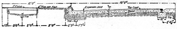 Fig. 120.—Concrete Pavement, Richmond, Ind.
Current practice varies materially in constructing concrete curb and gutter. The more common practice is to lay the curb and water table in one piece, or as a monolith, but this is by no means universal practice. In much work the curb wall and the water table slab are constructed separately, the construction joint being sometimes horizontal where the curb wall sits on the slab and sometimes vertical where the water table butts against the wall. Again it is the common practice to construct curb and gutter in sections, laid either alternately or in succession, separated by sand joints to provide for expansion and contraction, but this is not universal practice, much of such work being constructed as a continuous wall with no provision for temperature movements except the natural breaks at driveways. All of these types of construction appear to have given reasonable satisfaction, but exact data for a final comparison are not available, so that we are forced to reason on general principles. Such a course of reasoning indicates that the best results should be expected where the[Pg 319] curb and water table are built in one piece and in sections of reasonable length separated by expansion joints.
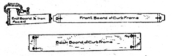 Fig. 121.—Box Form for Concrete Curb.
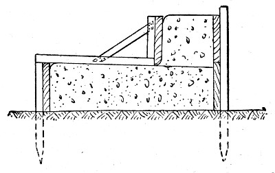 Fig. 122.—Continuous Form for Concrete Curb.
FORM CONSTRUCTION.—The form construction for curb and gutter work is determined by the general plan of construction followed,—whether monolithic or two-piece construction. In monolithic construction two types of forms are employed, sectional or box forms and continuous forms. A good example of box form is shown by Fig. 121. This form was designed for a curb 14 ins. high at the back, 6 ins. high in front and 24 ins. from face of curb to outer edge of gutter, constructed in sections 7 ft. long. The form, it will be observed, is a complete box, in which alternate sections of curb are molded and after having set are filled between using the same form but dispensing with the end boards which are replaced by the completed sections of curb. A fairly representative example of continuous form is shown by Fig. 122; in this construction a continuous line of plank is set to form the back of the curb and another line to form the face of the gutter slab, both lines being held in place by stakes. When the gutter slab concrete has been placed and surfaced the form for the front of the curb is set as shown and the upper portion of the curb wall concreted behind it. The method in detail of constructing curb and gutter, with this type of form, at Ottawa, Ont., is described in a succeeding section. Here the[Pg 320] joints were formed by inserting a partition of ⅜-in. boiler plate every 12 ft., which was withdrawn just previous to finishing up the surface; the sections between partitions were concreted continuously. Another method is to make the partitions of plank, concrete every other section, then remove the partition plank and concrete the remaining spaces against the previously finished work. A different method of supporting the plank forming the face of the curb wall, is to clamp it to the back form (Fig. 123), spacers being inserted to keep the two their proper distances apart. The forms shown by Figs. 121 to 123 are for monolithic curb and gutter. In two-piece construction where the curb wall is constructed on the finished gutter slab practically the same method of construction is employed as is illustrated by Fig. 122 except that no attempt is made to concrete the curb wall before the slab concrete has begun to set. The more common and the preferable method of two-piece construction is illustrated by Fig. 124; the curb proper is built first using the simple box form shown at the right hand, then the water table is built using the completed curb as the form for the back and a board held by stakes as a form for the front. This board is set with its top edge exactly to the grade of the finished water table so as to serve as a guide for one end of the template, the other end of[Pg 321] which rides on the top of the finished curb wall. Forms for curves at street intersections are best constructed by driving stakes to the exact arc of the curve and bending a ⅜-in. steel plate around them or bending and nailing ⅞×1¼-in. strips. Soaking the wood strips thoroughly will make them bend easily. The cost of form work in constructing curb and gutter is chiefly labor cost in erecting and taking down the forms.
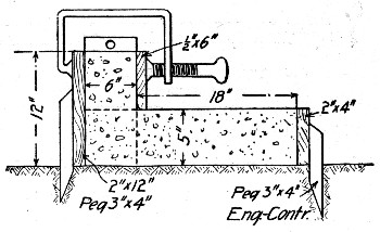 Fig. 123.—Continuous Form for Concrete Curb.
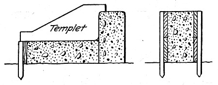 Fig. 124.—Form for Two-Piece Curb Construction.
CONCRETE MIXTURES AND CONCRETING.—The curb body is usually made of a 1-3-5 or 6 concrete and the curb finish of a 1-2 mortar. Portland cement is employed almost exclusively. The concrete mixture commonly used is of such consistency that thorough ramming is necessary to flush the cement to the surface. The cubical contents of combined curb and gutter of the forms illustrated will run from 3 to 5 cu. yds. per 100 ft., and about one-eighth of this will be facing mortar 1 in. thick; thus a curb running 5 cu. yds. per 100 ft. will contain per 100 ft. about 0.83 cu. yd. of mortar and 4.17 cu. yds. of concrete. The usual method of concreting is to erect the forms for the back of the curb wall and the front of the gutter slab and concrete to the height of the water table clear across; then shape the exposed top of the water table to section and place the mortar finish, and then erect the face form for the gutter wall, bring the concrete backing and vertical face finish up together and, finally, finish the top. The finish coat is placed by troweling on the horizontal surfaces; on the vertical face of the curb wall it may be placed in any one of several ways. Frequently the mortar coat is simply plastered against the face board and filled behind with concrete. Another method is to lay a 1-in. board against the inside of the form, concrete behind it, then withdraw the board, fill the space with mortar and tamp concrete and mortar to a thorough bond. The special face forms shown in Chapter VIII may be used in place of the board. The securing of a good bond between the backing concrete and the mortar facing is governed by the same conditions that govern sidewalk work.
COST OF CURB AND GUTTER.—The cost of concrete curb and gutter is commonly estimated in cents per lineal foot. The cost of excavating, loading and carting will run about the same per cubic yard as for sidewalks. Excavating the trench[Pg 322] and preparing the sub-grade usually runs from ½ ct. to 2 cts. per foot of curb, but sometimes it amounts to 3 cts. Placing the sub-base will cost for placing and tamping 1 ct. per ft., to which is to be added the cost of materials; a 6-in. sub-base 30 ins. wide contains 4.7 cu. yds., tamped measure, of materials per 100 ft. The amount of materials per foot depends upon the cross-section of the curb; it equals in cubic yards the area of cross-section in square feet divided by 27, and of this volume about one-eighth will be 1-2 mortar and seven-eighths 1-3-6 concrete. The tables in Chapter II give the amounts of materials per cubic yard of these mixtures; the product of these quantities and the cost of the materials on the ground gives the cost. The labor cost of mixing and placing, including the form work, will run from 10 to 14 cts. per foot. In round figures curb and gutter of the section shown in the accompanying illustrations may be estimated to cost in the neighborhood of 40 cts. per lineal foot. The following sections give records of cost of individual jobs of curb and gutter construction.
Cost at Ottawa, Canada.—The method and cost of constructing 1,326 ft. of concrete curb and gutter at Ottawa, Ont., are given in some detail by Mr. G. H. Richardson, Assistant City Engineer, in the annual report of the City Engineer for 1905. We have remodeled the description and rearranged the figures of cost in the following paragraphs.
The concrete curb was built before doing any work on the roadway, and the first task was the excavation of a trench 2½ ft. wide and averaging 1 ft. 8 ins. in depth through light red sand. On the bottom of this trench there was placed a foundation of stone spalls 8 ins. thick; in width this foundation reached from 3 ins. back of the curb to 6 ins. beyond the front of the water table. The curb was made 5 ins. thick and ran from 10 ins. to 5½ ins. in height, and the water table was 14 ins. wide and 4 ins. thick, with a fall of 1¼ ins. from front to back. The concrete used was a mixture of 1 Portland cement, 3 sand, 3⅝-in. screened limestone, and 4 2-in. stone. It was deposited in forms and tamped to bring the water to the face and then smoothed with a light troweling of stiff mortar.
The forms were constructed by first setting pickets and nailing to them a back board 2 ins. thick and 12 ins. wide and a[Pg 323] front board 2 ins. thick and 6 ins. wide. The concrete for the water table was deposited in this form in sections and brought to surface by straight edge riding on wooden strips nailed across the form and properly set to slope, etc. After the water table had been troweled down and brushed a 1×10-in. board was set to mold the front face of the curb. This board was sustained by small "knee frames" made of three pieces of 1×2-in. stuff, one conforming to the slope of the water table and long enough to extend beyond the front of the 2×6-in. front board, a second standing plumb and bearing against the 1×10-in. face board, and the third forming a small corner brace between the two former to hold them in their proper relative positions. The 1×10-in. face board, etc., was separated from the 2×12-in. back board by a 5-in. block at each end, and then braced by the knee frames every 3 or 4 ft. In this way it was possible to bring this 1×10-in. board into perfect line by moving the knee braces in or out, and when correct nailing them to the 2×6-in. front board. The 1×10-in. face board being in position and braced and lined, the curb material was thoroughly tamped in, and when ready was troweled and brushed on the top, a small round being worked onto the top front corner with the trowel.
Expansion joints were provided for by building into the curb every 12 ft., a piece of ⅜-in. boiler plate, which was afterward withdrawn and the joint filled with sand and faced over. As soon as the concrete had set sufficiently the face board was taken down and face of curb finished and brushed, the fillet between curb and water table being finished to 2½ ins. radius. Circular curb and gutter of same construction was built at each corner, ½-in. basswood being used for forms, instead of 2×1-in. lumber.
In addition to the actual construction of curb and gutter the cost given below includes the cleaning up of the street, spreading or removal of all surplus material from excavation, and the extension of all sidewalks out to the curbs at the corners. It was also necessary to maintain a watchman on this work, which duty, under ordinary circumstances, would be done by the general watchman. The total length built was 1,326 ft., of which 1,209 ft. is straight and 117 ft. curved to a 12-ft. radius.[Pg 324]
The rates of wages paid were $2 for horse and cart, $1.65 for watchman, and an average of $1.90 per day for labor, including foreman; all for nine hours' work per day. The working force consisted of foreman, finisher, handy man. four concrete men, and three laborers.
The labor cost of the work was as follows:
| Item. | Total. | Per ft. cts. | P. C. of total. |
| Excavation and setting boards | $ 88.90 | 6.7 | 30 |
| Laying stone foundation | 43.30 | 3.3 | 14 |
| Concreting | 61.30 | 4.6 | 20 |
| Finishing | 45.15 | 3.4 | 15 |
| Carting | 9.85 | 0.76 | 3 |
| Watchman | 25.00 | 1.89 | 8 |
| Clearing up | 13.60 | 1.04 | 4 |
| Extras (sidewalk extensions) | 17.23 | 1.31 | 6 |
| ——— | —— | — | |
| Total | $304.33 | 23.00 | 100 |
The cost of materials for curb and foundation were as follows:
| Total. | Per lin. ft. cts. | |
| 171.112 tons spalls | $102.93 | 7.76 |
| 42 tons 2-in. stone | 41.16 | 3.09 |
| 30.8 tons ⅝-in. stone | 42.57 | 3.21 |
| 33,000 lbs. cement | 161.70 | 12.19 |
| 24 cu. yds. sand | 19.20 | 1.45 |
| ——— | —— | |
| Total | $367.56 | 27.70 |
The cost of supplies and tools was as follows:
| 1,000 ft. B. M. 2×12 boards charged off | $ 9.25 |
| 500 ft. B. M. 2×6 boards charged off | 4.12 |
| 1,000 ft. B. M. 1×10 boards charged off | 14.25 |
| ½-in. basswood | 4.30 |
| ½ keg 3-in. nails | 1.42 |
| ½ keg 4-in. nails | 1.43 |
| Pickets | 3.25 |
| Tools charged off | 3.15 |
| ——— | |
| Total | $41.17 |
This total, when divided by 1,326 lin. ft. of curb, gives the cost per lineal foot as about 3 cts. We can now summarize as follows:
| Item. | Total. | Per lin. ft. | P. C. of total. |
| Labor | $304.33 | 23 | 43 |
| Material | 367.56 | 28 | 51 |
| Supplies | 41.17 | 3 | 6 |
| ——— | —— | — | |
| Total | $713.06 | $0.54 | 100 |
As indicated above, on more extensive work the costs of carting, watchman, cleaning up, and extras would be avoided. They cost on this work 5 cts. and the work could therefore be done for 49 cts. if no such charges were included. On such work also the charge for supplies would be lower per foot and on any future work the labor cost could be materially lowered, this curb having been somewhat of an experiment as to method of construction. It is thought that with no charges for carting, cleaning, watchman, and extras, and with the experience obtained, this curb could be built for about 46 cts. The proportions adopted and the method of construction followed, produce a very strong, dense, homogeneous curb and gutter.
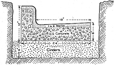 Fig. 125.—Concrete Curb and Gutter at Champaign, Ill.
Cost at Champaign, Ill.—The following costs were recorded by Mr. Charles Apple, and relate to work done at Champaign, Ill., in 1903. The work was done by contract, at 45 cts. per lin. ft. of the curb and gutter shown in Fig. 125.[Pg 326]
The concrete curb and gutter was built in a trench as shown in the cut. The earth was removed from this trench with pick and shovel at a rate of 1 cu. yd. per man per hour. The concrete work was built in alternate sections, 7 ft. in length. A continuous line of planks was set on edge to form the front and back of the concrete curb and gutter; and wood partitions staked into place, were used. The cost of the work was as follows:
| Item. | No. of men. | Total wages. | Cost per 100 ft. |
| Opening trench, 18×30-in. | 2 | $3.50 | $2.43 |
| Placing and tamping cinders | 2 | 3.50 | 1.00 |
| Setting forms: | |||
| Boss setter | 1 | 3.00 | ... |
| Assistant setter | 1 | 2.00 | ... |
| Laborer | 1 | 1.75 | ... |
| — | —— | —— | |
| 3 | $6.75 | $1.69 | |
| Mixing and placing concrete: | |||
| Clamp man | 1 | $1.75 | ... |
| Wheelers | 3 | 5.25 | ... |
| Mixing concrete | 4 | 7.00 | ... |
| Mixing finishing coat | 2 | 3.50 | ... |
| Tampers | 1 | 1.75 | ... |
| Finishing: | |||
| Foreman and boss finisher | 1 | 4.00 | ... |
| Assistant finisher | 1 | 3.00 | ... |
| Water boy | 1 | .50 | ... |
| — | ——— | —— | |
| Total making concrete | 14 | $26.75 | $7.64 |
| Total for labor per 100 ft | $12.76 | ||
| Materials for 100 lin. ft.: | Quantity. | Price. | |
| Portland cement | 8⅓ bbls. | $1.85 | $15.42 |
| Cinders | 7.5 yds. | .50 | 3.75 |
| Gravel | 2.5 yds. | 1.00 | 2.50 |
| Broken stone | 2.5 yds. | 1.40 | 3.50 |
| Sand | 1.0 | 1.00 | 1.00 |
| Total for material per 100 ft | $26.17 | ||
| Total for material and labor per 100 ft. | $38.93 |
This is the total cost, exclusive of lumber, tools, interest, profits, etc., and it is practically 40 cts. per lin. ft.
In 100 lin. ft. of curb and gutter there were 4.6 cu. yds. of concrete and mortar facing, 4 cu. yds. of which were concrete; hence the 9 men in the concrete gang laid 14 cu. yds. of concrete per day, whereas the 4 men mixing and placing the mortar finishing laid only 2½ cu. yds. of mortar per day, assuming that the mortar finishing averaged just 1 in. thick. Since these 4 men (2 mixers and 2 finishers) received $10.50 a day, it cost more than $4 per cu. yd. to mix and place the 1-2 mortar, as compared with $1.41 per cu. yd. for mixing and placing the concrete. The concrete was built in alternate sections 7 ft. long. The 3 men placing forms averaged 400 lin. ft. a day, so that the cost of placing the forms was $1 per cu. yd. of concrete. The 2 men placing and tamping cinders averaged 16 cu. yds. of cinders per day, or 8 cu. yds. per man. This curb and gutter was built by contract at 45 cts. per lin. ft.
For several jobs, in which a curb and gutter essentially the same as shown in Fig. 125 was built, our records show a general correspondence with the above given data of Mr. Apple. Our work was done with smaller gangs, 1 mason and 2 laborers being the ordinary gang. Such a gang would lay 80 to 100 lin. ft. of curb and gutter per 10-hr. day, at the following cost:
| 1 mason at $2.50 | $2.50 |
| 2 laborers at $1.50 | 3.00 |
| —— | |
| Total | $5.50 |
This made a cost of 5½ to 7 cts. per lin. ft. for labor, and it did not include the cost of digging a trench to receive the curb and gutter.
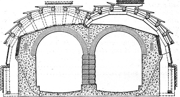 Fig. 126.—Section Showing Lining for Capitol Hill
Tunnel. Washington, D. C.
Fig. 126.—Section Showing Lining for Capitol Hill
Tunnel. Washington, D. C.
Tunnel lining work is of two distinct classes: Lining work, done during original construction and relining of tunnels in service. The methods of work to be adopted and the cost of work will be different in the two cases. In relining work the costs are increased by the necessity of providing for the movement of trains and by the delays due to these movements and also by the labor of removing the old lining and, often, of enlarging the excavation. Comparatively few published figures are available on the cost of concrete tunnel lining, and such as exist are commonly incomplete. The common practice is to record the cost as so much per lineal foot of tunnel. This should be done, but the record should also show the cost per cubic yard of concrete in the lining. The notions of engineers vary as to the proper thickness of lining to use and this dimension also varies with the character of the ground. One tunnel lining may easily contain twice as many cubic yards of concrete per lineal foot of lining as another tunnel contains.[Pg 329]
The two problems in form construction for tunnel work are: First, to construct the form work so that it does not interfere with train movements, and, second, to construct it so that it can be taken down, transported and re-erected and thus used over and over. The examples of practice given in the succeeding sections are the best instructions that can be laid before the reader in regard to possible ways of solving these problems and, also, the problem of handling the concrete and other materials to the work.
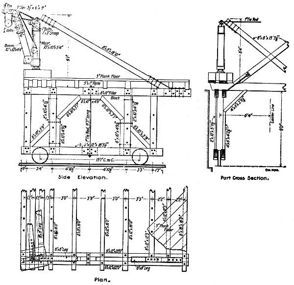 Fig. 127.—Traveling Derrick for Constructing Side and
Center Walls, Capitol Hill Tunnel.
Fig. 127.—Traveling Derrick for Constructing Side and
Center Walls, Capitol Hill Tunnel.
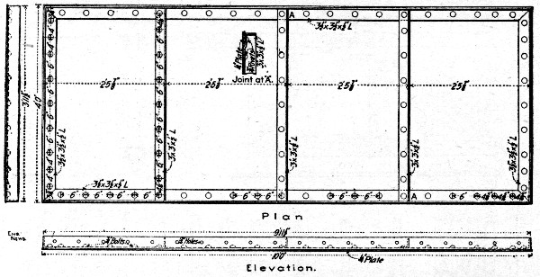 Fig. 128.—Steel Forms for Side Walls for Capitol Hill
Tunnel.
Fig. 128.—Steel Forms for Side Walls for Capitol Hill
Tunnel.
METHOD OF LINING CAPITOL HILL TUNNEL, PENNSYLVANIA R. R., WASHINGTON, D. C.—The tunnel through Capitol Hill for the Pennsylvania R. R. approach to its new Union Station at Washington, D. C, is a two-track, double tube tunnel 4,000 ft. long through earth. Figure[Pg 330] 126 shows the lining construction; it consists of stone masonry center wall, mass concrete inverts and side walls and a brick roof arch backed with concrete. For building the center and side walls the traveling derrick shown by Fig. 127 was employed. This traveler moved ahead with the work on a 14-ft. gage track and it handled the stone and concrete buckets from the material cars to the workmen on the walls. In connection with the derrick in the concrete side wall construction use was made of steel plate forms for the inside faces of the walls. These forms were made of 4×10 ft. sections of steel plate, constructed as shown by Fig. 128, and connected together by bolting through the flanges. The steel forms were erected by hand in advance of the derrick, 20 ft. of form on each side at a time. The concrete buckets were brought into the tunnel on cars hauled by electric motors from the mixing plant at the portal, and the buckets were lifted by the derricks and emptied into the forms. The side walls were concreted to the springing line and then the five-ring brick roof arches were constructed on traveling centers and in 20-ft. sections. The remainder of the concrete was then placed over the arches by means of the special back-filling machine, shown by Fig. 129. This machine also handled the earth used to fill behind the masonry. It consisted of a platform mounted on wheels and of the same general construction as the derrick platform. On the forward end of this platform a stationary hoist was mounted and behind this a belt conveyor platform.[Pg 331]
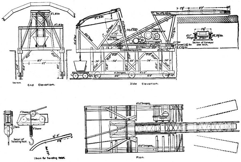 Fig. 129.—Device for Placing Concrete Back Filling for
Roof Arch, Capitol Hill Tunnel.
Fig. 129.—Device for Placing Concrete Back Filling for
Roof Arch, Capitol Hill Tunnel.
The latter structure was pivoted near the forward end so that it could swing right and left on a circular track under its rear end. It carried a 30-cu. ft. hopper on its forward end, from under which a belt conveyor ascended an incline toward the rear and was carried back into the space behind the roof arch on a cantilever arm. In operating the back-filling machine the material bucket was lifted from the car below, carried back on the trolley beam until over the hopper and then dumped by hand into the hopper. From the hopper the material dropped onto the conveyor belt and was carried back over the arch and dumped in place ready for tamping. The trolley beam of the hoist was so arranged that the hoisting movement was vertical until the bucket hit the trolley and was then up and backward until the stop at the end of the trolley beam was reached. This point was directly over the hopper. Hoisting was done by a Lambert engine, driven by a 15 H.P. electric motor. The conveyor belt was 20 ins. wide and was operated at a speed of 180 ft. per minute by a 7½ H.P. electric motor. The machine required two men to operate and was considered to save the labor of twelve shovelers.
METHOD OF CONSTRUCTING SIDE WALLS IN RELINING THE MULLAN TUNNEL.—The Mullan Tunnel, 3,850 ft. long, on the Northern Pacific Ry., about 20 miles west of Helena, Mont., had its original timber lining replaced in 1894 with a lining consisting of concrete side walls and a brick roof arch. The construction of the old and new linings is shown by Fig. 130. The method of constructing the side walls was as follows:
The original timbering consisted of sets of 12×12-in. posts carrying five segment arches of 12×12-in. timbers joined by ½-in. dowels. For a portion of the lining the posts carried plates on which the arches set; elsewhere the arches rested directly on the post tops. The arches and posts carried 4-in. lagging filled behind with cordwood. The timber lining was removed to make place for the new work in the manner shown by Fig. 130. When there were no plates a 7-ft. section AB was first prepared by removing one post and supporting the undermined arch ribs by struts SS. The timbering in this section was cut out and excavation made for the wall footing. Two temporary posts FF were then set up, fastened by hook[Pg 333] bolts L and lagged behind to make the wall form. Several of these 7-ft. sections were cut out at once, each two being separated by a 5-ft. section of timbering. The mortar car shown in Fig. 130 was then run alongside the sections in order and enough 1-3 mortar was run by chute into each to make an 8-in. layer. As the car moved ahead to succeeding sections enough broken stone was shoveled into the last preceding section to take up the mortar. The walls were thus built in 8-in. layers and became hard enough to support the arches in from 10 to 14 days. The arches were then allowed to take footing on the wall, and the posts of the remaining 5-ft. sections were removed and the concrete wall built up as for the 7-ft. sections. Where the posts carried wall plates the struts SS were not needed, the wall plate supporting the undermined post as a beam. English Portland cement was used and the concrete mixture was about 4 parts mortar to 5 parts broken stone—a very rich mixture. The average progress was about 30 ft., or 45 cu. yds. of side wall per working day; the average cost of the walls, including everything, was $8 per cu. yd. of concrete. The brick arch cost $17 per cu. yd. Mr. H. C. Relf is authority for these figures.
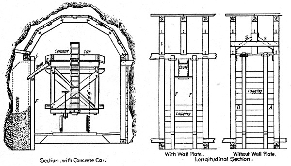 Fig. 130.—Sketches Showing Method of Lining Mullan
Tunnel.
Fig. 130.—Sketches Showing Method of Lining Mullan
Tunnel.
METHOD AND COST OF LINING A SHORT TUNNEL, PEEKSKILL, N. Y.—The following methods and costs of lining a double track railway tunnel 275 ft. long near[Pg 334] Peekskill, N.Y., are given by Mr. Geo. W. Lee. In presenting these data it is important to note that while some of the methods described are applicable to so short a tunnel they could not be used on a long tunnel. Figure 131 is a cross-section of the tunnel showing the lining. The tunnel was through rock, which stood up without timbering, and the rock section was excavated from 6 ins. to 3 ft. outside the lining. A 1-2-4 concrete using crusher run stone below 1 in. in size was used for the lining and portal head wall coping and a 1-3-6 concrete for the portal head walls proper. The cost of the portal head walls is included in the costs given further on.
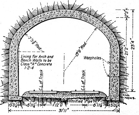 Fig. 131.—Cross-Section of Peekskill Tunnel, Showing
Lining.
Fig. 131.—Cross-Section of Peekskill Tunnel, Showing
Lining.
The side wall foundation trenches were first excavated from 1 to 3 ft. deep and footing concreted and leveled up, the back of the footing being carried up against the rock and the front lined to forms giving a 12-in. offset to the side wall. The footings contained 200 cu. yds. of concrete. Platforms 25 ft. square and level with the springing lines were then erected at each end of the tunnel. A derrick was placed at each platform to handle skips between it and the material tracks which ran underneath and through the tunnel with a turnout at each end for switching back empty cars. A 60 H.P. portable boiler supplied steam for the derrick engines and a pump. The wall forms were built and erected in panels 12 ft. long; these panels[Pg 335] had 4×6-in. plates and sills, 4×4-in. studs 3 ft. on centers and 2-in. dressed and matched spruce sheeting. Four panels were set up, two on each side, midway of the tunnel and braced to the tunnel track. Wheelbarrow runways carried on bents were built from the platforms to the forms, one from one platform to one side, another from the other platform to the opposite side. Temporary bulkheads were erected to close the ends of the forms and they were filled. Meanwhile carpenters were setting other panels at each end of the two first erected on each side. After 24 hours the panels first set were taken down and moved ahead and the processes described continued until the full length of side wall was completed. The side walls were not concreted back to the rock; back forms of 1-in. hemlock were used and the space remaining was filled with spalls. The side walls contained 692 cu. yds. of concrete.
Arch forms were erected for 96 ft. at the center of the tunnel, using 12-ft. lagging, so that sections of this length could be taken down and moved ahead, nine at each end. The lagging was first laid to a height of 3 ft. above the springing line on each side and the concrete dumped directly in place from runways laid on the lower chords of the arch ribs, which were placed 4 ft. apart. When the concrete reached a height too great for direct discharge into the forms it was dumped on the runway and passed over with shovels. On the upper portion of the ring the concrete was first shoveled to a platform erected on the center posts of the ribs about 2 ft. below the crown and then passed in on the lagging which was laid in 4-ft. instead of 12-ft. lengths at this stage of the work. As soon as each section of arch ring was completed it was waterproofed with six layers of tar paper laid in hot tar and then packed behind with spalls. The arch centers were struck in a comparatively short time; in one instance they were struck 90 hours after the last concrete was placed and no settlement was apparent. The arch forms stuck so fast to the concrete, however, that they had to be jacked down by chiseling out the lagging so as to get a bearing on the arch concrete and by nailing thrust blocks to the rib posts. The section was then hauled ahead by passing the main fall of the derrick through a snatch block on the first rib. When hauled clear of the lining all but the first 3-ft. of lagging on each side was removed;[Pg 336] they were then jacked into position. The arch ring contained 932 cu. yds. of concrete.
Including the portal head walls 1,948 cu. yds. of concrete were laid at the following costs for labor and materials:
| Item. | Total. | Per cu. yd. |
| Cement at $1.63 per bbl. | $ 5,755.50 | $2.951 |
| Sand at $0.75 per cu. yd. | 662.94 | 0.339 |
| Stone at $0.80 per cu. yd. | 1,303.20 | 0.668 |
| Lumber— | ||
| Mixing platforms and runways | 336.89 | 0.174 |
| Ribs, including hand sawing | 234.10 | 0.120 |
| Backing boards | 134.44 | 0.069 |
| Lagging | 341.04 | 0.176 |
| Sheathing | 268.49 | 0.137 |
| Plates, sills, studs, braces | 182.75 | 0.093 |
| Coal | 118.73 | 0.061 |
| Oil | 16.12 | 0.008 |
| Hardware, nails, spikes, etc. | 224.39 | 0.118 |
| Tools | 181.10 | 0.093 |
| Freight on stone, cement, etc. | 3,089.86 | 1.584 |
| Labor of all kinds | 8,036.31 | 4.121 |
| ————— | ——— | |
| Total | $20,885.86 | $10.712 |
METHOD OF LINING CASCADE TUNNEL, GREAT NORTHERN RY.—The Cascade Tunnel, 13,813 ft. long, built in 1897-1900, was lined throughout with concrete from 24 ins. to 3½ ft. thick, mixed and placed in the following manner: It was necessary to place the lining without interfering with the transportation of materials and excavated material to and from the work ahead. The arrangement adopted to secure this end is shown by Fig. 132. A platform 500 ft. long was constructed at the elevation of the wall plates; the rear end of this platform was reached by an incline, up which the cars loaded with concrete were hauled by an air hoist and cable and delivered to any point on this platform. While each 500 ft. of tunnel was being concreted, the next 500 ft. of platform in advance was being built, with its approach incline, so that there was no delay in the work.
Complete concrete plants were installed at each portal, advantage being taken of the side hills of the approach into the[Pg 337] mountain to handle as much material as possible by gravity. Each plant was equipped with a No. 6 Gates crusher, 40-in.×8-ft. rock screens, and 16-in.×16-ft. screw concrete mixers. Large storage bins for the cement, sand and stone were built adjacent to the mixer plant. A 1-3-5 concrete was used. The stone was crushed from the best rock obtained in the tunnel excavation. This rock was loaded into the regular muck cars, taken to the portal by electric motors, and then dumped into other cars below the level of the muck cars. These cars were hauled by hoisting engine and cable to the crusher floor and then dumped and sorted to avoid danger from pieces of unexploded dynamite. It was then run through the crushers, washers and screens to the stone bin and thence to the mixers. The mixed concrete was discharged into cars on the level of the muck car tracks and these cars were taken by motor into the tunnel to the incline, up which they were hauled by cable and dumped on the platform. From the platform the concrete was shoveled into the wall forms or onto the centers as desired.
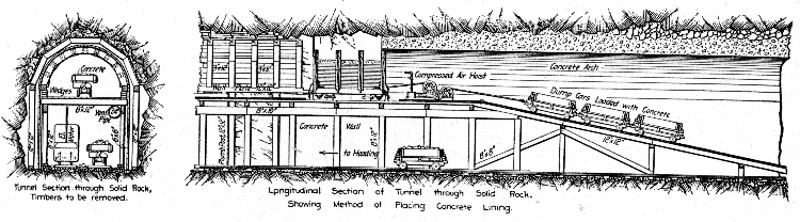 Fig. 132.—Traveling Platform Used in Lining Cascade
Tunnel.
Fig. 132.—Traveling Platform Used in Lining Cascade
Tunnel.
The walls were concreted in alternate 12-ft. sections, the weight on the timber arch thus being gradually transferred from the plumb posts to the walls. The roof arch was also built in 12-ft. sections, the centers being[Pg 338] in sections of corresponding length which were moved forward on dollies and jacked up as the work advanced. Ten sections of centering were used at each end. An average of 7 bbls. of cement were used per lineal foot of lining. The average monthly progress of lining was about 600 ft. at each end. The concrete lining cost $44 per lin. ft. of tunnel, done by company forces.
METHOD OF RELINING HODGES PASS TUNNEL, OREGON SHORT LINE RY.—The centers and side wall forms and the methods of work adopted in relining the Hodges Pass tunnel on the Oregon Short Line Ry. are explained in the accompanying illustrations. This tunnel is 1,425.8 ft. long and when constructed in 1882 was lined with timber. The new lining consists of concrete side walls carrying a brick roof arch. Both the old and the new linings are shown in the drawings. The tunnel is through a variety of rock and clay strata, and through the soft strata an invert was required. Altogether about one-third of the length of the tunnel was provided with an invert. It will be noted also that the new lining occupies materially more space than the old; this made necessary considerable excavation in enlarging the section.
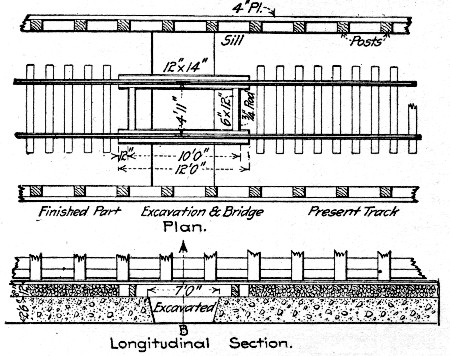 Fig. 133.—Method of Placing Invert Concrete, Hodges'
Pass Tunnel.
Fig. 133.—Method of Placing Invert Concrete, Hodges'
Pass Tunnel.
The work of relining consisted of three operations, viz., the invert construction, the construction of the side walls and the arch construction.[Pg 339]
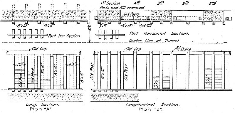 Fig. 134.—Method of Constructing Concrete Side Walls,
Hodges' Pass Tunnel.
Fig. 134.—Method of Constructing Concrete Side Walls,
Hodges' Pass Tunnel.
The form of the invert is shown in Fig. 136. It, of course, had to be constructed without entailing a break in the track, and the method adopted was as follows: The ties and ballast were removed from a section of track about 12 ft. long and in their place was substituted the timber frame shown in Fig. 133. Under the middle portion of this frame a trench reaching clear across the tunnel and having a width of 6 to 7 ft. in the direction of the track was excavated to sub-grade of the[Pg 340] invert. The concrete was filled into this trench, formed to shape on top, and allowed to harden. The bridging frame was then taken out and the ties and ballast were replaced. Another section of track was then bridged, trenched and concreted and so on until the length of invert required was constructed.
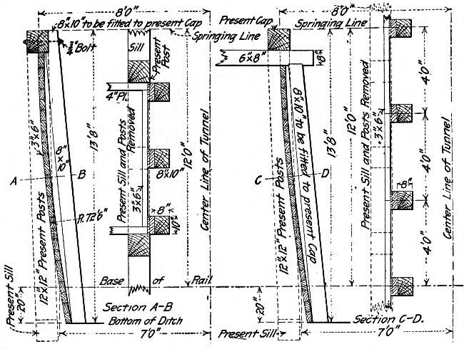 Fig. 135.—Side Wall Forms for Plans A and B, Fig. 134.
The side wall construction was a more complex operation. It comprised first the removal of the old lining, the enlarging excavation and the form erection and concreting. Two methods of performing this task were employed. Both are illustrated in Fig. 134. By the first method, designated as Plan A, the concreting was done continuously in sections of considerable[Pg 341] length. The forms used are shown in detail by Fig. 135. By the second method, the concreting was done in alternate short panels. This method is designated Plan B on the drawings, Fig. 134. The forms used are shown in detail by Fig. 135. The only difference in the form construction for the two plans is in the connection of the posts at the top.
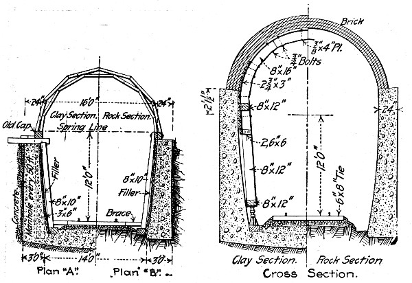 Fig. 136.—General Plan of Centers for Roof Arch, Hodges'
Pass Tunnel.
Fig. 136.—General Plan of Centers for Roof Arch, Hodges'
Pass Tunnel.
The construction of the centering for the roof arch is shown by Figs. 136 and 137, Fig. 137 giving detail dimensions of the ribs and lagging. The center, as shown by Fig. 136, consisted of four ribs spaced 3 ft. on centers. Each rib consists of two side posts and an arch piece. The side posts on each side are connected at the bottoms by a sill and at the top by a cap. Jacks between the sill and a mud sill laid on the concrete invert or in the ditch held the center in place during arch construction. Lowering these jacks dropped the center onto trucks traveling on the mud sills. Thus the center was moved along as the work progressed. As will be noted from Figs. 134 and 135, the side wall forms carried the work only to the bottoms of the old caps. The arch center completed the concrete wall work and the roof arch. Only about one-third of the new lining had the brick arch, as shown by the drawings;[Pg 343] in the remaining two-thirds the concrete was carried up much further on each side; in fact, the brickwork constituted only the top third of the arch.
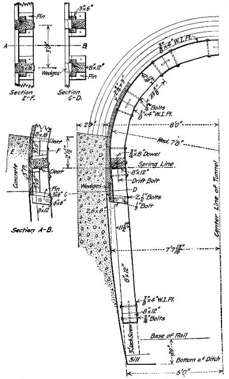 Fig. 137.—Details of Centers for Roof Arch, Hodges' Pass
Tunnel.
Fig. 137.—Details of Centers for Roof Arch, Hodges' Pass
Tunnel.
In describing the forms and centers we have left much of the explanation to the drawings. These show all dimensions and details, and indicate in a measure the mode of procedure. The work done consisted of excavation enlarging the section, of removing the old timber lining and of the form work, concreting and bricklaying for the new lining. All of it above convenient reach from the ground was done from a movable staging formed by a deck fixed on a flat car so as to be adjustable in height. The concrete was mixed by hand on this car platform and shoveled directly into the forms, the platform being raised as the work increased in height. The concrete used was a 1-3-5 mixture of 2½-in. broken stone.
The organization of the working force is not easily stated since the work was done as the traffic permitted and varied with the conditions. Generally from 12 to 16 men were all that could be employed to advantage. Complete records of cost were kept, but they were destroyed by fire, so that the only figures available on this point are the totals. These are as follows:
| Item. | Totals. | Per lin. ft. |
| Labor | $21,129 | $14.81 |
| Materials | 13,939 | 9.77 |
| ——— | ——— | |
| Total | $35,068 | $24.58 |
These amounts average the cost of the invert, which was required for about one-third of the length, over the whole tunnel.
RELINING A SHORT TUNNEL.—The following figures show the cost of relining with concrete a timber lined railway tunnel. The concrete side walls were 14 ft. high and had an average thickness of 2½ ft. Therefore each side wall averaged nearly 1.3 cu. yds. per lin. ft., and the two walls averaged 2.59 cu. yds. per lin. ft. of tunnel. The concrete was mixed 1-3-5, being, we believe, unnecessarily rich in cement. The average amount of concrete placed in the walls per day was 50 cu. yds.[Pg 344]
| Cost of Side Walls. | |
| Materials— | Per cu. yd. |
| 1.33 bbl. cement at $2.00 | $2.66 |
| 0.5 cu. yd. sand at 0.18 | 0.09 |
| 0.75 cu. yd. stone at 0.55 | 0.41 |
| ——— | |
| Total | $3.16 |
| Labor on concrete— | |
| 0.01 day foreman at $5.00 | $0.05 |
| 0.03 day foreman at $3.00 | 0.09 |
| 0.03 day engineman at $3.00 | 0.09 |
| 0.35 day laborer at $1.75 | 0.61 |
| ------- | ——— |
| 0.42 Total | $0.84 |
| Labor, removing timber, building forms, excavating, etc.— | |
| 0.02 day foreman at $5.00 | $0.10 |
| 0.05 day foreman at $3.00 | 0.15 |
| 0.40 day laborer at $1.75 | 0.70 |
| ------- | ——— |
| 0.47 Total | $0.95 |
| Miscellaneous— | |
| 0.02 day engineer and superintendent at $5.00 | $0.10 |
| Falsework and forms, timber and iron | 0.07 |
| Tools, light, etc. | 0.10 |
| Interest and depreciation of $1,800 plant at 20% per annum 0.09 | |
| Train service, 0.03 day work train at $25 | 0.75 |
| Summary concrete side walls— | Per cu. yd. |
| Materials | $3.16 |
| Labor on concrete | 0.84 |
| Labor removing timber, etc. | 0.95 |
| Train service | 0.75 |
| Miscellaneous | 0.34 |
| ——— | |
| Total | $6.04 |
In the two side walls there were 2.59 cu. yds. of concrete per lin. ft. of tunnel, hence the cost of the side walls was $6.04 × $2.59 = $15.64 per lin. ft. of tunnel.[Pg 345] The concrete arch varied in thickness, averaging from 14 to 20 ins. at the springing line to 8 to 14 ins. at the crown. The arch averaged 1.2 cu. yds. per lin. ft. of tunnel. About 20 cu. yds. of arch were placed per day. The arch concrete was mixed 1-3-5 and the cost was as follows:
| Cost of Concrete Arch. | |
| Materials— | Per cu. yd. |
| 1.36 bbls. cement, $2.00 | $2.72 |
| 0.05 cu. yd. sand, 0.18 | 0.09 |
| 0.75 cu. yd. stone, 0.55 | 0.41 |
| ——— | |
| Total | $3.22 |
| 1.8 cu. yds. dry rock backing at 0.55 | $0.99 |
| Labor on concrete— | |
| 0.02 day foreman at $5.00 | $0.10 |
| 0.12 day foreman at 3.00 | 0.36 |
| 0.88 day laborer at 1.75 | 1.54 |
| ——— ——— | ——— |
| 1.02 Total $1.96 | $2.00 |
| Labor placing 1.08 cu. yds. rock backing— | |
| 0.01 day foreman at $5.00 | $0.05 |
| 0.51 day foreman at 3.00 | 0.15 |
| 0.55 day laborer at 1.75 | 0.96 |
| ——— ——— | ——— |
| 0.61 Total $1.90 | $1.16 |
| Labor removing timbers, forms, excavations, etc.— | |
| 0.02 day foreman at $5.00 | $0.10 |
| 0.04 day foreman at 3.00 | 0.12 |
| 0.06 day carpenter at 2.50 | 0.15 |
| 0.40 day laborer at 1.75 | 0.70 |
| ——— ——— | ——— |
| 0.52 Total $2.06 | $1.07 |
| Train service— | |
| 0.06 day at $25 | $1.50 |
| Miscellaneous— | |
| Engineering and superintendence. | .07 |
| Falsework, timber and iron | .13 |
| Tools, light, etc | .12 |
| [Pg 346] | |
| Interest and depreciation, $1,800 plant, 20% per annum | 0.09 |
| Summary concrete arch— | |
| Concrete materials | $3.22 |
| Dry rock backing (1.8 c. y.) | 0.99 |
| Labor and concrete | 2.00 |
| Labor placing 1.8 cu. yds. rock backing | 1.16 |
| Labor removing timber, etc | 1.07 |
| Train service hauling materials | 1.50 |
| Engineering and superintendence | 0.07 |
| Falsework, timber and iron | 0.13 |
| Tools, light, etc. | 0.12 |
| Interest and depreciation plant | 0.09 |
| ——— | |
| Grand total | $10.35 |
It will be noted that the "train service" is an item that really should be considered as a part of the cost of the materials, for the cost of the sand and stone is the cost f. o. b. cars at the sand pit and at the quarry, to which should be added the cost of hauling them to the tunnel—to-wit, the "train service."
Summing up, we have the following as the cost per lineal foot for lining this single-track tunnel with concrete: Per lin. ft.
| 2.59 cu. yds. side walls at | $6.04 | $15.64 |
| 1.20 cu. yds. arch at | 10.33 | 12.40 |
| ——— | ——— | ——— |
| 3.79 cu. yds. Total | $9.38 | $28.04 |
It should be remembered that the higher cost of the arch concrete is due in large measure to the fact that 1.8 cu. yds. of dry rock packing above the arch are included in the cost of the concrete. Strictly speaking, this dry rock packing should not be charged against the arch concrete, and, segregating it, we have the following:
| Per lin. ft. | ||
| 2.59 cu. yds. concrete side walls at | $6.04 | $15.64 |
| 1.20 cu. yds. concrete arch at | 8.18 | 9.82 |
| 2.16 cu. yds. dry rock at | 0.55 | 1.19 |
| Labor placing 2.16 cu. yds. at | 0.64 | 1.39 |
| ——— | ||
| Total | $28.04 |
This is a much more rational analysis of the cost and a still further reduction in the cost of the arch concrete might be[Pg 347] made by prorating the train service item ($1.50 per cu. yd. concrete). At least half of this train service should be charged to the dry rock backing, for there are 1.25 cu. yds. of sand and broken stone to 1.80 cu. yds. of dry rock backing.
The amount of this dry rock backing, or packing, varies greatly in different parts of a tunnel. In the first half of this tunnel it averaged 1.8 cu. yds. per lin. ft., while in the second half it averaged nearly 2.4 cu. yds. per lin. ft.
METHOD OF MIXING AND PLACING CONCRETE FOR A TUNNEL LINING.—The tunnel known as the Burton tunnel is located on the Jasper-French Lick extension of the Southern Ry., and about 4 miles from French Lick, Ind. It is a single track tunnel 2,200 ft. long with 300 ft. at one end on a 4°-30' curve and 1,900 ft. on tangent. The material penetrated was slate and loose rock, requiring solid timbering throughout. This timbering is shown by Fig. 138, which also shows the concrete lining; the timbering was embedded in the concrete lining.
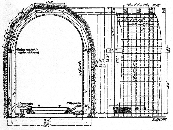 Fig. 138.—Sections Showing Concrete Lining for Burton
Tunnel.
Fig. 138.—Sections Showing Concrete Lining for Burton
Tunnel.
The original timber lining was composed as follows: Posts 10×12 ins. and spaced 3 ft. apart were set on 3×12-in. sills[Pg 348] and carried 10×12-in. wall plates which supported 10×12-in. segmental arch ribs spaced 3 ft. apart. The lagging behind the posts was 3×6-in. stuff and the lagging over the arch ribs was 4×6-in. stuff. The section of the concrete lining is shown by Fig. 138, it required 4,132 cu. yds. of concrete and 161.43 lbs. of reinforcement per lin. ft. The concrete was a 1-2½-5 crushed stone—between 2 in. and ¼ in. size—mixture; it required 1.16 bbls. of cement, 0.52 cu. yds. sand and 0.92 cu. yds. of stone per cubic yard of concrete. The amount of reinforcement per cubic yard of concrete was 39.1 lbs.
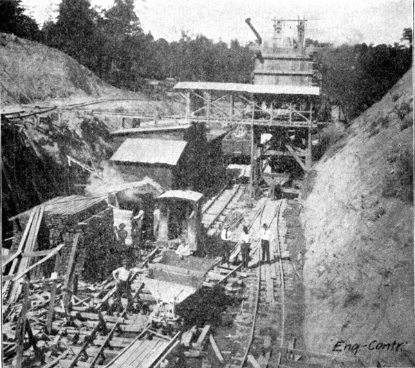 Fig. 139.—View of Mixer Plant Showing Car Tracks, Burton
Tunnel.
Fig. 139.—View of Mixer Plant Showing Car Tracks, Burton
Tunnel.
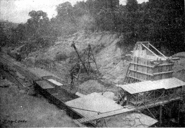 Fig. 140.—View of Mixer Plant Showing Method of
Unloading Materials, Burton Tunnel.
Fig. 140.—View of Mixer Plant Showing Method of
Unloading Materials, Burton Tunnel.
All the concrete was mixed and handled from one end of the tunnel. The mixing plant was located in the approach cut at one end. A standard gage main track ran through the cut. About 20 ft. in the clear to one side of this track a trestle 500 ft. long was built, carrying an 18-ft. gage derrick track and a[Pg 349] narrow gage 3-cu. yd. dump car track. A stiff leg derrick operating a 1 cu. yd. orange peel or a 1½ cu. yd. clam-shell Hayward bucket was mounted on a carriage traveling on the 18-ft. gage track. The side of the trestle nearest the railway track was sheeted vertically and the space between this sheeting and the track was floored over at track level for stock piles. Near the end of the trestle toward the tunnel and on the same side of the track was the mixer plant. This consisted of two 85 cu. yd. bins, one for sand and one for stone, carried by a tower so that their bottoms were 25 ft. above track level. Below the bins was a charging platform pierced by a measuring hopper. Below the measuring hopper was a 1½ cu. yd. cubical mixer and below the mixer was a 3-ft. gage track for 1½ cu. yd. Koppel side dump cars. To the rear of the tower at ground level there was a 20-cu. yd. sand bin and a 20-cu. yd. stone bin set side by side with a continuous bucket elevator leading from each to the corresponding bin on the tower. The cement house was located directly across the railway track from the tower. At the side of the cement house nearest the track there was an inclined bag elevator leading[Pg 350] up to a bridge spanning the railway track at the level of the charging floor of the mixer plant. On this bridge ran a car for carrying bags of cement. The plant as described is shown by Figs. 139 and 140.
In operation the derrick unloaded the stone and sand cars by means of the Hayward buckets either into the bins at the feet of the bucket elevators or onto stock piles on the flooring beside the trestle. When put into stock piles the materials had to be reloaded by derrick into the 3 cu. yd. cars on the trestle narrow gage track and carried by these cars to the elevator boots. The sand and stone were chuted from the tower bins directly into the charging hopper below. Here the cement bags, brought across the bridge on the car into which they were loaded directly by the bag elevator, were opened and the cement added to the sand and stone. The charge was then dropped into the mixer and from the mixer the batch dropped into the Koppel concrete cars.
In the tunnel a traveling platform was constructed on two standard gage flat cars so coupled that a platform 100 ft. long and slightly narrower than the clear space between side wall forms was obtained. Connecting the end of the platform toward the mixing plant was a rampe or inclined platform mounted on wheels. The Koppel car tracks from the mixer were carried up the incline and the full length of the level platform. The cars were hauled to the foot of the incline by a light locomotive. A cable was then hooked to them; this cable was run through a block on the level platform, its free end coming back to the locomotive, which thus pulled the cars up the incline by moving back toward the mixer. On the level platform the cars were pushed by hand and dumped on the floor, whence the concrete was shoveled into the forms.
The platform construction deserves mention in the particular that it provided for adjusting the platform vertically. At each corner of the car a vertical post some 7 or 8 ft. high was set up. The side stringers of the platform carried two vertical posts at each end; these two posts were spaced just far enough apart to slide over the corner post, one on each side of it. A block at the top of the corner posts with the hoist line connected to the bottoms of the platform posts and the lead line going to a winch head, thus made it possible to lift the platform[Pg 351] any distance within the height of the vertical post guide and hold it there by blocking under the posts. The arrangement is shown roughly by the sketch, Fig. 141. There was block and tackle for each corner post and a winch at each end of the car. The vertical movement of the platform was between 6 and 7 ft.
The floor was cemented first, then the side walls and finally the roof arch. Floor construction was begun at the portal farthest from the mixing plant. Koppel car tracks were laid through the tunnel and the concrete was dumped from them directly on the ground. The cars were hauled by a light locomotive. As the concreting advanced the dump car track was raised and suspended from timbers across tunnel so that the concrete could be placed under it. As fast as the floor hardened the permanent standard gage track was laid and a temporary third rail placed to give also a dump car track.
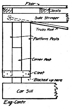 Fig. 141.—Sketch Showing Telescopic Support for
Concreting Platform, Burton Tunnel.
Fig. 141.—Sketch Showing Telescopic Support for
Concreting Platform, Burton Tunnel.
When the floor had been finished the side walls were constructed, using the traveling platform and beginning at the far portal. The wall forms consisted of 4×6-in. studs, spaced 3 ft. apart and carrying 2×12-in. lagging. A 6×6-in. waling outside the studs at about mid-height held the studs to the timbering by lag bolts reaching through the wall to the 10×12-in. posts. A strip of plank nailed across wall between stud and post held the form at the top. Wall forms were erected for 100 ft. of wall at a time. These forms required about 45 ft.[Pg 352] B. M. lumber per lineal foot of form on one side or 90 ft. B. M. for both sides. Two sets of side wall forms or 200 ft. of wall forming were built, and used over and over again. The concrete was shoveled into the wall forms from the traveling platform, the lagging being placed a board at a time as the work progressed upward and the platform being elevated as required, its final position being at about springing line level. When 100 ft. of side walls had been completed the traveling platform was moved ahead for another 100-ft. section.
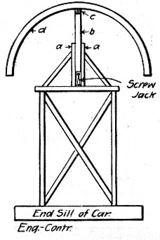 Fig. 142.—Sketch Showing Device for Removing Centering
Ribs, Burton Tunnel.
Fig. 142.—Sketch Showing Device for Removing Centering
Ribs, Burton Tunnel.
The centers consisted of 6×12-in. ribs, made up of 3×12-in. plank. The feet of the ribs rested on folding wedges on 6×12-in. wall plates, supported by 6×6-in. posts setting close against the finished wall. The ends of the ribs were held from closing in by 6×6-in. walings, one on each side, lag-bolted through the lining to the timbering. The centering required about 315 ft. B. M. of lumber per lineal foot of center. The method of removing the centers was novel. A flat car had erected on it a narrow working platform high enough to reach well up into the arch. Along this platform at the center was erected a sort of "horse," which could be elevated and lowered by jacks. The sketch, Fig. 142, shows the arrangement. At each end and at the middle of the platform two guide posts a a were erected and braced upright. Between these guide posts set plunger posts which were raised and lowered by screw jacks. The three plunger posts carried a longitudinal timber[Pg 353] c. The car was run under the ribs of centering to be removed and the timber c raised by working the jacks until it came to close bearing under the ribs d. The railings and the wedges at the foot of the ribs were then removed, leaving the ribs hanging on the timber c. This timber was then jacked down to clear the lining and the ribs rotated horizontally on the point of suspension as a pivot until their ends swung in over the platform. The car was then moved ahead to where the centers were to be used again; the ribs were rotated back to their normal position across tunnel; the timber c was jacked up, and the wedges and railings placed at the first of the ribs.
The concreting on the roof arch was begun at the portal. Two shifts were worked and 42 ft. of arch were concreted each shift.
METHOD AND COST OF LINING GUNNISON TUNNEL.—The costs are for concrete in place in the side walls and the arch of the tunnel, for a length of 440 lin. ft. The quantity of concrete considered in estimating the cost per cubic yard was 616 cu. yds. The material was mixed and placed in ½ cu. yd. batches, the proportion of the mixtures being 1-2.2-4.4. The final cost includes the labor of excavating and screening gravel and sand, the hauling of the same from the bins at the pit to the storage bins at the main shaft, the care of the chutes in the shaft and the mixing of the concrete in the tunnel at the bottom of the shaft, the transportation of the concrete from the mixer to the traveler, the deposition of the concrete, the setting up and taking down of forms and the cost of the cement. It does not include the construction of the gravel pit chutes that hold the screens, the building of the road from the gravel pit to the storage bins at the shaft, the concrete mixer and its installation, the traveler and its installation, the cost of material and labor in the construction of the concrete forms, the requisite power to run the machinery and other expenses of a similar nature.
The gravel used for the concrete was obtained from a pit situated on top of a hill not far from the main shaft leading down to the tunnel. This gravel bed contains very closely the proper proportions of sand and gravel for the concrete aggregates. The gravel was excavated and loaded by hand into side dump cars of 35 cu. ft. capacity. These cars were run to[Pg 354] the edge of the hill where the gravel was dumped upon a screen from which it ran by gravity, passing thence into storage bins. From the storage bins the sand and gravel were drawn off into dump wagons having a capacity of 2 cu. yds. and hauled a distance of one-half mile to a second set of storage bins located at the top of the shaft leading into the tunnel. The road from the storage bins at the gravel pit to the storage bins at the head of the shaft was down grade. A two-horse team could readily haul 2 cu. yds. of gravel over this road. The storage bins at the top of the shaft leading into the tunnel communicated with the measuring boxes at the bottom of the shaft by means of chutes. The measuring boxes discharged directly into tram cars. The average length of haul from the mixer to the place of deposition of concrete was about 4,500 ft.
The concrete was placed in the side walls by means of a traveler, which was so operated in the tunnel as to allow the passage of the concrete trains beneath it. The traveler was 64 ft. long and was provided with a slow motion electric hoist, by which the cars containing the concrete were elevated to the top of the traveler and thence transferred to any desired position. The concrete was dumped from these cars into boxes where any remixing or tempering that was required was done, after which the concrete was shoveled directly into the forms. The entire operation of handling the materials of the concrete, it will be seen, utilized gravity to the greatest possible degree.
In order to get a good average cost per cubic yard for handling gravel and sand, this analysis has been based on five months' operation, from November, 1906, to March, 1907. In these five months there were 4,123 cu. yds. of sand and gravel handled. The concrete considered was placed during the month of March. Below is given the distribution of the cost of the concrete as to the specified divisions of the work and as to the class of work involved in each division. Measurements taken at the mixer show that each cubic yard of concrete contained 0.74 cu. yds. of gravel, 0.445 cu yds. of sand and 5.6 sacks of Portland cement. The total of the aggregates is, therefore, 1.185 cu. yds. per cubic yard of concrete. The cement costs $0.62 per sack on the work, making a cost of $3.472 per cubic yard of concrete.[Pg 355]
Excavating and screening 4,123 cu. yds. gravel—
| Total cost. | Per cu. yd. gravel. | |
| Foreman, 66⅞ days at $3.04 | $ 203.30 | $0.049 |
| Labor, 397½ days at $2.56 | 1,017.60 | 0.247 |
| Labor, 116¼ days at $2.08 | 241.80 | 0.059 |
| ———— | ——— | |
| Total | $1,462.70 | $0.355 |
| Hauling 4,123 cu. yds. gravel and sand— | ||
| 2-horse team and driver, 210 days at $3.60 | $756.00 | $0.183 |
| 2-horse team and driver, 4½ days at $4 | 18.00 | 0.005 |
| ——— | ——— | |
| Total | $774.00 | $0.188 |
As there were 1.185 cu. yds. of gravel per cubic yard of concrete the cost of gravel per cubic yard of concrete was for—
| Excavating and screening (1.185 × $0.355) | $0.421 |
| Hauling (1.185 × $0.188) | 0.223 |
| ——— | |
| Total | $0.644 |
Adding to this the cost of cement $0.62 × 5.6 = $3.472, we have $0.644 + $3.472 = $4.116, as the cost of concrete materials per cubic yard of concrete. The cost of labor, mixing and placing was as follows for 616 cu. yds.:
| Mixing 616 cu. yds. concrete— | Total cost. | Per cu. yd. concrete. |
| Superintendent, 2 days at $5.83⅓ | $ 11.67 | $0.020 |
| Foreman, 1 day at $4.50 | 4.50 | 0.007 |
| Labor, 45 days at $3.04 | 130.72 | 0.215 |
| Labor, 93 days at $2.56 | 238.08 | 0.381 |
| Hoist engineer, 34 days at $3.52 | 119.68 | 0.196 |
| ——— | ——— | |
| Total | $504.65 | $0.819 |
| Transporting 616 cu. yds. concrete— | ||
| Superintendent, 1 day at $5.83⅓ | $ 5.83 | $0.009 |
| Foreman, 1 day at $4.50 | 4.50 | 0.007 |
| Motorman, 34 days at $3.04 | 103.36 | 0.175 |
| Brakeman, 34 days at $2.56 | 87.04 | 0.135 |
| ——— | ——— | |
| [Pg 356] | ||
| Total | $200.73 | $0.326 |
| Depositing 616 cu. yds. concrete— | ||
| Superintendent, 4 days at $5.83⅓ | $ 23.33 | $0.038 |
| Foreman, 4 days at $4.50 | 18.00 | 0.029 |
| Foreman, 68 days at $3.04 | 200.72 | 0.326 |
| Labor, 238½ days at $2.56 | 610.56 | 0.991 |
| ——— | ——— | |
| Total | $852.61 | $1.384 |
| Setting and moving forms— | ||
| Superintendent, 2 days at $5.83⅓ | $ 11.67 | $0.018 |
| Foreman, 2 days at $4.50 | 9.00 | 0.014 |
| Carpenter foreman, 10 days at $5 | 50.00 | 0.080 |
| Carpenter, 13 days at $3.20 | 41.60 | 0.067 |
| Labor, 49 days at $3.04 | 148.96 | 0.241 |
| Labor, 19 days at $2.56 | 48.64 | 0.078 |
| ——— | ——— | |
| Total | $309.87 | $0.498 |
Summarizing we have the following cost:
| Materials— | |
| Cement, 5.6 bags at $0.62 | $3.472 |
| Gravel (excavating and screening) | 0.421 |
| Hauling gravel and sand | 0.223 |
| ——— | |
| Total, materials | $4.116 |
| Labor— | |
| Mixing concrete | $0.819 |
| Transporting concrete | 0.326 |
| Depositing concrete | 1.394 |
| Setting and moving forms | 0.498 |
| ——— | |
| Total, labor | $3.037 |
| Grand Total | $7.153 |
COST OF CONCRETE WORK IN LINING NEW YORK RAPID TRANSIT SUBWAY.—The costs given here refer alone to the concrete work in constructing the jack arch and steel beam lining of the original standard subway. Figure 143 shows the character of this construction. Arch panel forms were set up between the wall beams and hung from the floor beams and filled behind and above with 1-2-4 trap rock concrete. The form panels were used over and over and the[Pg 357] concrete was machine mixed. Common labor was paid $1.50 per 8-hour day; foremen, $3; carpenters, $3; enginemen, $3.50; and masons, $4. The costs cover three sections and are in each case the averages for the whole section. They are, we believe, the only itemized costs that have been published for concrete work on this road.
Two-Track Subway.—In this section of two-track subway there were 8,827 cu. yds. of foundation concrete and 6,664 cu. yds. of concrete in wall and roof arches. The two classes of work cost as follows:
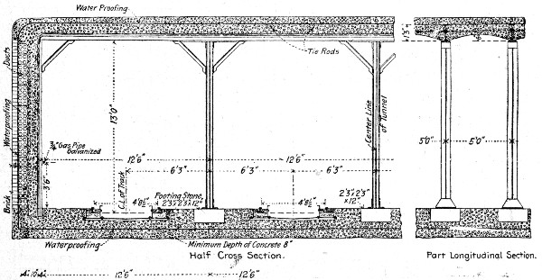 Fig. 143.—Cross-Section of New York Rapid Transit
Subway.
Fig. 143.—Cross-Section of New York Rapid Transit
Subway.
| Foundations— | Total. | Per cu. yd. |
| Labor mixing | $ 4,669 | $0.53 |
| Labor placing | 5,142 | 0.58 |
| Materials and plant | 211 | 0.02 |
| Cement, sand, stone, etc. | 30,719 | 3.48 |
| ———— | ——— | |
| Total | $40,741 | $4.61 |
| Roof and side walls— | ||
| Labor mixing | $ 5,444 | $0.82 |
| Labor placing | 5,623 | 0.84 |
| Labor setting forms | 14,746 | 2.21 |
| Labor plastering arches | 431 | 0.06 |
| Materials and plant | 1,176 | 0.18 |
| Cement, sand, stone, etc. | 23,888 | 3.58 |
| ———— | ——— | |
| Total | $51,308 | $7.69 |
Averaging the work we have 15,491 cu. yds. of concrete placed at a cost of $5.94 per cu. yd.
Four-Track Subway.—On two sections of four-track subway the labor cost of mixing and placing concrete similarly divided was as follows:
| Section A. | Section B. | |
| Foundations— | Per cu. yd. | Per cu. yd. |
| Labor mixing | $0.97 | $0.94 |
| Labor placing | 0.96 | 0.95 |
| Power | 0.14 | 0.16 |
| ———— | ———— | |
| Total | $2.07 | $2.05 |
| Roof and side walls— | ||
| Labor mixing | $0.79 | $0.91 |
| Labor placing | 0.85 | 0.94 |
| Labor setting forms | 2.01 | 1.20 |
| Labor plastering arches | 0.16 | 0.23 |
| Power | 0.28 | 0.15 |
| ——— | ——— | |
| Total | $4.09 | $3.43 |
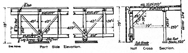 Fig. 144.—Traveling Form for Side Walls, New York Subway
Tunnels.
Fig. 144.—Traveling Form for Side Walls, New York Subway
Tunnels.
TRAVELING FORMS FOR LINING NEW YORK RAPID TRANSIT RY. TUNNELS.—In constructing the tunnels under Park Ave. and under the north end of Central Park for the New York Rapid Transit Ry., traveling centers and side wall forms were used for the concrete lining. The mixing plants were installed in the shafts and consisted generally of gravity mixers charged at the surface and discharging into skip cars running on the tunnel floor.
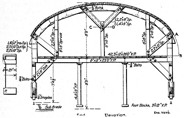 Fig. 145.—Traveling Form for Roof Arch. New York Subway
Tunnels.
Fig. 145.—Traveling Form for Roof Arch. New York Subway
Tunnels.
The forms used in the Park Ave. tunnel are shown by Figs. 144 and 145; those used in the Central Park tunnel differed only in details. The method of work was slightly different[Pg 359] in the two tunnels, but was substantially as follows: Three platforms mounted on wheels were used in each set and two sets were employed. Ahead came a traveler carrying the side wall forms, next came a shorter traveler carrying a derrick, and last came the traveler carrying the roof centers. The arrangement as operated in the Central Park tunnel is shown by Fig. 146. In the Park Ave. tunnel the "bridges" were dispensed with, the skips being hoisted through the open end bays of the derrick car and set directly on the cars on the center traveler.
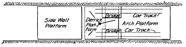 Fig. 146.—Sketch Plan of Traveling Forms, New York
Subway Tunnels.
Fig. 146.—Sketch Plan of Traveling Forms, New York
Subway Tunnels.
The traveler carrying the side wall forms was set in position and blocked, the grade and line being given by the track rails, which had been set exactly for that purpose. The side wall forms differed slightly in the two tunnels; those for the Park Ave. tunnel shown by Fig. 144 formed the vertical portion[Pg 360] of the wall only so that when the arch forms, Fig. 145, followed a space A B was left which had to be molded by separate sector-like forms. The side wall forms for the Central Park work were constructed as shown by Fig. 147, being curved at the top to merge into the arch centers. In the Park Ave. work the wall studs were adjusted in or out by means of wedges and slotted bolt holes. In the Central Park work the studs A Fig. 145 were hung by ¾-in. bolts from the pieces B spiked to line onto the cross-braces. The bottom was then lined up by means of wedges at D. The side wall studs being lined up, the bottom lagging boards were placed and filled behind by shoveling the concrete into them direct from skip cars on the adjacent tracks on the tunnel floor. In this way the side walls were built up to the tops of the forms.
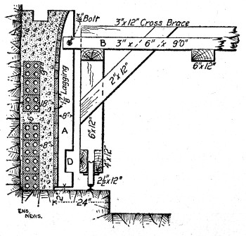 Fig. 147.—Sketch Showing Detail of Side Wall Forms. New
York Subway Tunnels.
Fig. 147.—Sketch Showing Detail of Side Wall Forms. New
York Subway Tunnels.
As soon as the side wall concrete had set the forms were struck and the traveler was moved ahead and set for another section of wall. The derrick and roof arch travelers were then moved into position between the finished walls, and the arch traveler was jacked up and aligned. Skip cars coming from the mixer were run under the derrick traveler, where the skips were lifted by the derrick and set on the platform cars to be run alongside the work. The arch lagging was placed a piece at a time and filled behind by shoveling direct from the skips. As the crown was approached the lagging was placed in short lengths and filled in over the ends, the concrete being shoveled in two lifts; in Fig. 145 the line C D indicates[Pg 361] the position of the shoveling board. The centers were struck by lowering the jack supported traveler down onto the track rails.
COST OF MIXING AND PLACING SUBWAY LINING, LONG ISLAND R. R., BROOKLYN, N. Y.—The subway carrying the two tracks of the Long Island R. R. under Atlantic Ave., in Brooklyn, New York city, has a lining consisting of an invert arch 12 ins. thick at the center, side walls 4½ ft. thick at the base and 3 ft. thick at the top, and a roof of jack arches between steel I-beams 5 ft. apart. The dimensions inside the concrete are 16×20 ft. A 1-8 mixture of cement, sand, gravel and stone was used in the floor and walls and a 1-6 mixture of the same materials in the jack arches. A bag of cement was called 1 cu. ft., so that a barrel was 4 cu. ft. A Hains gravity mixer and a batch mixer were used and careful records were kept of all quantities.
General Data.—During 1903, about 13,880 cu. yds. of the 1-8 concrete were placed, 90 per cent. of which was mixed in the gravity mixer and 10 per cent. in the batch mixer. Of the 1-6 concrete 5,320 cu. yds. were placed, 85 per cent, of which was mixed in the gravity mixer and 15 per cent, in the batch mixer.
Gravity Mixer Work.—During 1903, there were 16,940 cu. yds. of concrete mixed in gravity mixers, requiring 2,860 days' labor mixing and 4,000 days' labor placing. Wages were $1.50 a day and the cost was 26 cts. per cu. yd. for mixing and 33 cts. for placing, making a total of 59 cts. per cu. yd. During the month of August when 2,800 cu. yds. were mixed the cost was as low as 24 cts. for mixing, plus 22 cts. for placing, or a total of 46 cts. per cu. yd. for mixing and placing. The mixer averaged about 113 cu. yds. per day with a gang of 19 men mixing and 26 men placing. The average size of batch was 0.46 cu. yd. In 1904, 20,000 cu. yds. were mixed in 190 days, worked with a gang of 19 men mixing; the gang placing consisted of 25 men. The cost was as follows:
| Item. | Total. | Per cu. yd. |
| 2,950 days labor mixing | $ 4,870 | 24 cts. |
| 4,760 days labor placing | 7,300 | 36 cts. |
| ———— | ———— | |
| Total | $12,170 | 60 cts. |
During the best month of 1904, the labor cost was 16 cts. for mixing and 29 cts. for placing, or a total of 45 cts. per cu. yd.
Batch Mixer Work.—During 1903 the batch mixer mixed 2,390 cu. yds. in 970 labor days mixing and 740 labor days placing at a cost of 59 cts. per cu. yd. for mixing and 55 cts. per cu. yd. for placing, or a total of $1.04 per cu. yd. During the month of June the cost was as low as 40 cts. for mixing and 30 cts. for placing, or 70 cts. per cu. yd. for mixing and placing. The wages paid were $1.50 per day and the average gangs were 11 men mixing and 14 men placing; the average batch mixed was 0.57 cu. yd. and the average output was 35 cu. yds. per day. During 1904, the mixer worked 153 days and averaged 46 cu. yds. per day; the average size of batch was 0.44 cu. yd. The average gangs were 13 men mixing and 11 men placing. The labor cost of 7,000 cu. yds. was as follows:
| Item. | Total. | Per cu. yd. |
| 1,910 days labor mixing | $3,175 | 45 cts. |
| 1,740 days labor placing | 2,660 | 38 cts. |
| ——— | ———— | |
| Total | $5,835 | 83 cts. |
Haulage.—The costs given comprise in mixing, the cost of delivering the materials to the mixer, and, in placing, the cost of hauling the concrete away. A Robins belt conveyor was used to deliver materials to the gravity mixer and this accounts, in a large measure, for the lower cost of mixing by gravity. The mixed concrete was hauled from both mixers in dump cars pushed by men.
Form Work.—The labor cost of forms for 19,300 cu. yds. of concrete placed in 1903 was $16,800, or 87 cts. per cu. yd. of concrete. The total labor days consumed on form work was 6,340 at $2.70 per day. The total cost of concrete in place for mixing, placing and form work was $1.46 per cu. yd., not including lumber in forms, fuel, interest and depreciation.
The construction problems in arch and girder bridges of moderate spans are simple, and with the exception of center construction and arrangement of plant for making and placing concrete, are best explained by citing specific examples of bridge work. This is the arrangement followed in this chapter.
CENTERS.—The construction of centers is no less important a task for concrete arches than for stone arches. This means that success in the construction of concrete arches depends quite as much upon the sufficiency of the center construction as it does upon any other portion of the work. The center must, in a word, remain as nearly as possible invariable in level and form from the time it is made ready for the concrete until the time it is removed from underneath the arch, and, when the time for removal comes, the construction must be such that that operation can be performed with ease and without shock or jar to the masonry. The problem of center construction is thus the two-fold one of building a structure which is immovable until movement is desired and then moves at will. Incidentally these requisites must be obtained with the least combined expenditure for materials, framing, erection and removal, and with the greatest salvage of useful material when the work is over. The factors to be taken count of are it, will be seen, numerous and may exist in innumerable combinations.[Pg 364]
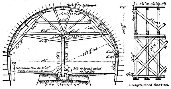 Fig. 148.—Center for 50 ft. Arch Span (Supported).
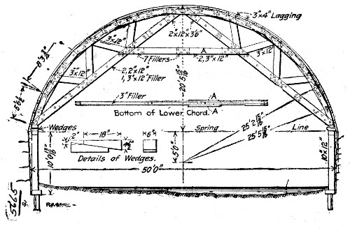 Fig. 149.—Center for 50-ft. Arch Span (Cocket).
Centers may be classified into two types: (1). Centers whose supports must be arranged so as to leave a clear opening under the center for passing craft or other purposes, and (2) centers whose supports can be arranged in any way that judgment and economy dictate. Centers of the first class are commonly called cocket centers. As examples of a cocket and of a supported center and also as examples of well thought out center design we give the two centers shown by Figs. 148 and 149, both designed for a 50-ft. span segmental arch by the same engineer. The development of the center shown by Fig. 148 into the cocket center shown by Fig. 149 is plainly traceable from the drawings. In respect to the center shown by Fig. 149 which was the construction actually adopted we are informed that 16,464 ft. B. M. were required for a center 36 ft. long, that the framing cost about $12 per M. ft. B. M., with carpenters' wages at $4 per day, and that the cost of bolts and nuts was about $1.50 per M. ft. B. M. With lumber at $20 per M. ft. B. M., this center framed and erected would[Pg 365] cost about $35 per M. ft. B. M. As an example of framed centers for larger spans we show by Fig. 158 the centers for the Connecticut Avenue Bridge at Washington, D. C., with costs and quantities; other references to costs are contained in the index.
A center of very economical construction is shown by Fig. 159, and is described in detail in the accompanying text. The distinctive feature of this center is the use of lagging laid lengthwise of the arch and bent to curve. Another example of this form of construction may be found in a 3-span arch bridge built at Mechanicsville, N. Y., in 1903. The viaduct was 17 ft. wide over all, and consisted of two 100-ft. spans and one 50-ft. span. Pile bents were driven to bed rock, the piles being spaced 6 ft. apart and the bents 10 ft. apart. Each bent was capped with 10×12-in. timber. On these caps were laid four lines of 10×12-in. stringers, and 8×10-in. posts 3 ft. apart were erected on these stringers, and each set of four posts across the arch was capped with 8×10-in timbers the ends of which projected 3 ft. beyond the faces of the arch. The tops of these cross caps were beveled to receive the lagging which was put on parallel with the center line of the viaduct, sprung down and nailed to the caps. This lagging consisted of rough 1-in. boards for a lower course, on top of which was laid 1-in. boards dressed on the upper sides. Hardwood wedges were used under the posts for removing the centers. In the centers, forms and braces for the three arches there were used 140,000 ft. B. M. of lumber. The structure contained 2,500 cu. yds. of concrete.
Another type of center that merits consideration in many places is one developed by Mr. Daniel B. Luten and used by him in the construction of many arches of the Luten type of reinforced concrete arch. The particular feature of this type of arch is that in shallow streams for bridges of ordinary span the ends of the arch ring are tied together across stream by a slab of concrete reinforced to take tension. This slab is intended to serve the double purpose of a tie to keep the arch from spreading and thus reduce the weight of abutments and of a pavement preventing scour and its tendency to undermine the abutments. Incidentally this concrete slab, which is[Pg 366] built first, serves as a footing for the supports carrying the arch center.
As an illustration of the center we choose a specific structure. In building a 95-ft. span, 11-ft. 1-in. rise arch bridge at Yorktown, Ind., in 1905, the centers were designed so as to avoid the use of sand boxes or wedges. Ribs of 2×12-in. pieces cut to the arc of the arch soffit were supported on uprights standing on the concrete stream bed pavement. The uprights were so proportioned by Gordon's formula for columns that without bracing they would be too light to support the load of concrete and earth filling that was to come upon them, but when braced at two points dividing the uprights approximately into thirds they would support their loading rigidly and without buckling. The design in detail was as follows: The uprights near the middle of the span were about 15 ft. long and were spaced 7 ft. apart across the stream and 3 ft. apart across the bridge. Each upright then was to support a loading of concrete of 7 ft.×3 ft.×26 ins. and an earth fill 1 ft.×7 ft.×3 ft., or a total load of about 9,000 lbs. Applying Gordon's formula for struts with free ends,
| f S | ||
| P | = | ——————————————————— |
| l² | ||
| I + ——————— | ||
| 125h² |
where P is the total load = 9,000 lbs., f is fibre stress for oak—1,600 lbs., l is length of strut in inches and h is least diameter of strut in inches, it was found that for a length of 15 ft. a 7×7-in. upright would be required to satisfy the formula, but for a length of 5 ft., which would result from bracing each strut at two points, a 4×4-in. timber satisfied the formula. Therefore, 4×4-in. timbers braced at two points were used for the longest uprights. About 30 days after the completion of the arch the bracing was removed from the uprights, beginning at the ends of the span and working towards the middle. As the bracing was being removed the uprights gradually yielded, buckling from 4 to 6 ins. from the vertical and allowing the arch to settle about ¼ in. at the crown. This type of center has been successfully employed in a large number of bridges.[Pg 367]
Figure 150 shows a center for a 125-ft. span parabolic arch with the amount and character of the stresses indicated and with a diagram of the actual deflections as measured during the work.
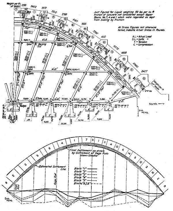 Fig. 150.—Center for 125-ft. Span Parabolic Arch with
Diagram of Deflections.
Fig. 150.—Center for 125-ft. Span Parabolic Arch with
Diagram of Deflections.
In calculating centers of moderate span there is seldom need of more than the simple formulas and tables given in Chapter IX. When the spans become larger, and particularly when they become very large—over 200 ft.—the problem of calculating[Pg 368] centers becomes complex. None but an engineer familiar with statics and the strengths of materials and knowing the efficiency of structural details should be considered for such a task. Such computations are not within the intended scope of this book, and the design of large centers will be passed with the presentation of a single example, the center for the Walnut Lane Bridge at Philadelphia, Pa.
The main arch span of the Walnut Lane Bridge consists of twin arches spaced some 16 ft. apart at the crowns and connected across by the floor. Each of the twin arch rings has a span of 232 ft. and a rise of 70¼ ft., is 9½ ft. thick and 21½ ft. wide at the skewback and 5½ ft. thick and 18 ft. wide at the crown. The plan was to build a center complete for one arch ring and then to shift it along and re-use it for building the other arch ring. The centering used is shown in diagram by Fig. 151. It consists of five parts: (1) Six concrete piers running the full width of the bridge upon which the structure was moved; (2) a steel framework up to E G, called the "primary bent"; (3) a separate timber portion below the heavy lines E I and W' I'; (4) the "main staging" included in the trapezoid E I W' I', and (5) the "upper trestle" extending from I I' to the intrados.
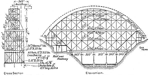 Fig. 151.—Center for 232-ft. Span Arch at Philadelphia,
Pa.
Fig. 151.—Center for 232-ft. Span Arch at Philadelphia,
Pa.
The primary bent consists of four I-beam post bents having channel chords, the whole braced together rigidly by angles. Each bent is carried on 1½ ft.×6 in. steel rollers running on a track of 19×½ in. plate on top of the concrete piers. Between[Pg 369] the primary bents and the main staging, and also between the main staging and the upper trestles are lifting devices. The mode of operation planned is as follows: When the center has been erected as shown and the arch ring concreted the separate stagings under K I and K' I' are taken down. Next the portions under the lines I E and I' W' will be taken down and erected under the second arch. Finally the remainder of the center will be shifted sidewise on the rollers to position under the second arch.
MIXING AND TRANSPORTING CONCRETE.—The nature of the plant for mixing and handling the concrete in bridge work will vary not only with varying local conditions but with the size and length of the bridge. For single span structures of moderate size the concrete can be handled directly by derricks or on runways by carts and wheelbarrows. For bridges of several spans the accepted methods of transport are cableways, cars and cars and derricks. Typical examples of each type of plant are given in the following paragraphs, and also in the succeeding descriptions of the Connecticut Avenue Bridge at Washington, D. C., and of a five-span arch bridge.
Cableway Plants.—The bridge was 710 ft. long between abutments and 62 ft. wide; it had a center span of 110 ft., flanked on each side by a 100-ft., a 90-ft. and an 80-ft. span. The mixing plant was located at one end of the bridge and consisted of a Drake continuous mixer, discharging one-half at the mixer and one-half by belt conveyor to a point 50 ft. away, so as to supply the buckets of two parallel cableways. The mixer output per 10-hour day was 400 cu. yds. and the mixing plant was operated at a cost of $27 per day, making the cost of mixing alone 6¾ cts. per cu. yd. The sand and gravel were excavated from a pit 4½ miles away and delivered by electric cars to the bridge site at a cost of 50 cts. per cu. yd. Two 930-ft. span Lambert cableways set parallel with the bridge, one 25 ft. each side of the center axis, were used to deliver the concrete from mixer to forms. The cableway towers were 70 ft. high and the cables had a deflection of 35 ft.; they were designed for a load of 7 tons, but the average load carried was only 3 or 4 tons. These cableways handled practically all the materials used in the construction[Pg 370] of the bridge. They delivered from mixer to the work 400 cu. yds. of concrete 450 ft. in 10 hours at a cost of 2 cts. per cu. yd. for operation.
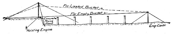 Fig. 151a.—Cableway for Concreting Bridge Piers.
Another example of cableway arrangement for concreting bridge piers is shown by Fig. 151a. The river was about 800 ft. wide, about 3 ft. deep and had banks about 20 ft. high. The piers were about 21 ft. high. The towers for the cableway consisted of a 55-ft. derrick without boom, placed near the bank on the center line of the piers and well guyed and a two-leg bent placed in the middle of the river and held in place by four cable guys anchored to the river bottom. A ¾-in. steel hoisting cable was stretched from a deadman on shore, about 150 ft. back of the derrick, and followed along the center line of the piers, past the derrick just clearing it, to the bent in the middle of the river. At the top of this bent was a 16-in. cable block. Through this block the cable passed down and was made fast to a weight, consisting of a skip loaded with concrete until the cable had the required tension, and a pitch of 18 to 20 ft. from center of river to anchor on shore. In order to secure the required pitch from the shore to the river bent the boom fall of the derrick was hooked onto the cable at the foot of the mast, and then, by going ahead on the single drum hoisting engine, was raised to the mast head. This gave the cable a pitch of 18 to 20 ft. from mast head to top of bent in river. The carriage vised on the cableway consisted of two 16-in. cable sheaves with iron straps, forming a triangle, with a chain hanging from the bottom point, to which was attached the 5 cu. ft. capacity concrete bucket. The concrete was mixed on a platform at the foot of the mast. When ready for operation the chain on the carrier was hooked to the bucket of concrete, the engine started, and both bucket and cable raised, the former running by gravity to the pier. The speed of descent was governed by the height to which the cable was[Pg 371] raised on the derrick, and as the bucket neared the dumping point the engine was slacked off and the cable leveled. The bucket was dumped by a man on a staging erected on the pier form. For the return of the bucket the engine was slacked off and the weight on the river bent would pull the cable tight so that the pitch would be toward the shore and the bucket could run down the grade to the mixing platform, the speed being governed as before by leveling the cable. When the piers were completed to the middle of the river the engine and derrick were taken over to opposite side of the river, the bent being left in the middle, and the work continued. By using the extreme grade of the cable it was found that the bucket would run from the platform to the bent (400 ft.) in less than 35 seconds.
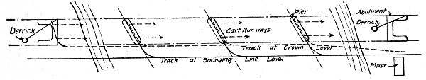 Fig. 152.—Sketch Showing Car and Trestle Plant for
Concreting an Arch Bridge.
Fig. 152.—Sketch Showing Car and Trestle Plant for
Concreting an Arch Bridge.
Car Plant for 4-Span Arch Bridge.—The bridge had four 110-ft. skew spans, and a total length of 554 ft. The mixing plant was located alongside one abutment on a side hill so that sand and stone could be stored on the slope above. The mixer was set on a platform high enough to clear cars below. Above it and to the rear a charging platform reached back to the stone and sand piles. Side dump cars running on a track on the charging platform took sand and stone to the mixer and cement was got from a cement house at charging platform level. The concrete for the abutment adjacent to the mixer was handled in buckets by a guy derrick. A trestle, Fig. 152, was then built out from the mixer to the first pier; this trestle was so located as to clear the future bridge about 20 ft. and was carried out from shore parallel to the bridge until nearly opposite the pier site, where it was swung toward and across the pier. The concrete was received from the mixer in bottom dump push cars; these cars were run out over the pier site and dumped. When the first pier had been concreted to springing line level, the main trestle was extended to opposite the second[Pg 372] pier and the branch track was removed from over the first pier and placed over the second pier. This operation was repeated for the third pier. The last extension of the main track was to the far shore abutment, where the bodies of the cars were hoisted by derrick and dumped into the abutment forms. The derrick was the same one used for the first abutment having been moved and set up during the construction of the intermediate piers. To construct the arches a second trestle was built composed partly of new work and partly of the staging for the arch centers. This trestle rose on an incline from the mixer to the first pier across which it was carried at approximately crown level of the arch. The concrete for the portion of the pier above springing line and for the lower portions of the haunches was dumped direct from the cars. For the upper parts of the arch the concrete was brought to the pier track in two-wheel carts on push cars and thence these carts were taken along the arch toward shore on runways. When the first arch had been concreted the second trestle was extended to pier two and the operation repeated to concrete the second arch.
Hoist and Car Plant for 21-Span Arch Viaduct.—The double track concrete viaduct replaced a single track steel viaduct, being built around and embedding the original steel structure which was maintained in service. The concrete viaduct consisted of 21 spans of 26 ft., 7 spans of 16 ft., and 2 spans of 22 ft. With piers it required about 15,000 cu. yds. of concrete. Two Ransome concrete hoists, one on each side of the original steel structure near one end, were supplied with concrete by a No. 4 Ransome mixer. The mixer discharged direct into the bucket of one hoist and by means of a shuttle car and chute into the bucket of the other hoist.
The shuttle car ran from the mixer up an incline laid with two tracks, one narrow gage and one wide gage, having the same center line. The car was open at the front end and its two rear wheels rode on the broad gage rails and its two forward wheels rode on the narrow gage rails. At the top of the incline the narrow gage rails pitched sharply below the grade of the broad gage rails so that the rear end of the car was tilted up enough to pour the concrete into a chute which[Pg 373] led to the bucket of the hoist. The sand and gravel bins were elevated above the mixer and received their materials from cars which dumped directly from the steel viaduct.
The hoist buckets discharged into two hoppers mounted on platforms on the old viaduct. These platforms straddled two narrow gage tracks, one on each side of the old viaduct parallel to and clearing the main track. These side tracks were carried on the cantilever ends of long timbers laid across the old viaduct between ties. At street crossings the overhanging ends of the long timbers were strutted diagonally down to the outside shelf of the bottom chords of the plate girder spans. Six cars were used and the concrete was dumped by them directly into the forms; the fall from the track above being in some cases 40 ft. The hoists and shuttle car were operated by an 8½×12-in. Lambert derrick engine, the boiler of which also supplied steam to the mixer engine. The concrete cars were operated by cable haulage by two Lambert 7×10-in. engines.
The labor force employed in mixing and placing concrete, including form work, was 45 men, and this force placed on an average 200 cu. yds. of concrete per day. Assuming wages we get the following costs of different parts of the work for labor above:
| Item. | Per day. | Per cu. yd. |
| 1 timekeeper at $2.50 | $ 2.50 | $0.0125 |
| 1 general foreman at $5 | 5.00 | 0.0250 |
| 3 enginemen at $5 | 15.00 | 0.0750 |
| 1 carpenter foreman at $4 | 4.00 | 0.0200 |
| 12 carpenters at $3.50 | 42.00 | 0.2100 |
| 1 foreman at $4 | 4.00 | 0.0200 |
| 8 men mixing and transporting at $1.75 | 14.00 | 0.0700 |
| 13 men placing concrete at $1.75 | 22.75 | 0.1137 |
| 1 foreman finishing at $4 | 4.00 | 0.0200 |
| 4 laborers finishing at $1.75 | 7.00 | 0.0350 |
| ——— | ——— | |
| 45 men at $2.70 | $120.25 | $0.6012 |
It is probable that the carpenter work includes merely shifting and erecting forms and not the first cost of framing centers. No materials, of course, are included. It should be kept in mind that while the output and labor force are exact the wages are assumed.
Traveling Derrick Plant for 4-Span Arch Bridge.—The bridge consisted of four 70-ft. arch spans and was built close alongside an old bridge which it was ultimately to replace. The approach from the west was across a wide flat; at the east the ground rose more abruptly from the stream. Conditions prevented the use of a long spur track and also made it necessary to install all plant at and to handle all material from the west bank. A diagram sketch of the arrangement adopted is shown by Fig. 153.
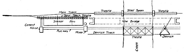 Fig. 153.—Sketch Showing Traveling Derrick Plant for
Concreting an Arch Bridge.
Fig. 153.—Sketch Showing Traveling Derrick Plant for
Concreting an Arch Bridge.
The track from the west approached the existing bridge on an embankment 25 ft. high. A spur track 175 ft. long from clear post to end was built on trestle as shown. The cement house and mixer platform were placed at the foot of the embankment at opposite ends of the spur track. Between the two the slope of the embankment was sheeted with 1-in. boards and a timber bulkhead 4 ft. high was built along the toe of the sheeting. Stone, sand and coal were stored behind the bulkhead on the sheeting. A runway close to the bulkhead connected the cement house with the mixer platform, all materials to the mixer being wheeled in barrows on this runway. A ¾-cu. yd. Smith mixer was set on a platform 5 ft. above ground with its discharge end toward the stream. Beginning under this platform a service track was carried across the flat and stream to the extreme end of the east abutment. This track consisted of three rails, two rails 4 ft. apart next to the work and a third rail 25 ft. from the first. The 4-ft. gage[Pg 375] provided for cars carrying concrete buckets from the mixer and the 25-ft. gage provided for a traveling derrick; 18-lb. rails were used and they proved to be too light, 40-lb. rails are suggested. The derrick consisted of a triangular platform carrying a stiff leg derrick with a 25-ft. mast and mounted on five wheels. The wheels were double flange 16 ins. diameter and cost $30 each, being the most expensive part of the derrick. The derrick was made on the ground and took four carpenters between 3 and 4 days to build. Derrick and 350 ft. of service track, including pole trestle across the stream, cost between $600 and $800. The derrick was moved by means of a cable wrapped around one spool of the Flory double-drum hoisting engine and leading forward and back to deadmen set at opposite ends of the service track. Cars carrying concrete buckets were run out on the 4-ft. gage track and the buckets were hoisted by the derrick and dumped into a ½-cu. yd. car running on a movable transverse track across the bridge. This transverse track was necessary to handle the concrete to the far side of the work, the derrick being set too low and the boom being too short to reach. The derrick was used to handle material excavated from the pier foundations and also to tear down the centers and spandrel forms. Some rather general figures on the cost of this bridge are given by Mr. H. C. Harrison, the contractor. They are:
| Materials: | Total. |
| 6,000 bbls. cement at $2.05 | $12,300 |
| 2,500 cu. yds. sand at $0.80 | 2,000 |
| 5,000 cu. yds. stone at $0.85 | 4,250 |
| 260 M. ft. B. M. lumber at $17 | 4,420 |
| ——— | |
| Total | $22,970 |
| Labor: | |
| Cofferdams, excavation and pumping | $ 3,000 |
| Forms, falseworks and centers | 2,000 |
| Mixing and placing concrete | 4,000 |
| Placing reinforcement | 400 |
| Removing falseworks, forms, etc. | 1,200 |
| One coat pitch and paper | 150 |
| Building plant, etc. | 2,250 |
| ——— | |
| Total | $13,000 |
Mr. Harrison states that including plant cost, delays, floods and incidentals the cost per cubic yard of concrete was $8 and that excluding these items the cost was $6 per cu. yd.
COST OF CONSTRUCTING CONCRETE HIGHWAY BRIDGE, GREENE COUNTY, IOWA.—The following is the itemized cost of constructing a reinforced concrete slab highway bridge, one of several built by the Highway Commissioners of Greene County, Iowa, in 1906. The figures are given by Messrs. Henry Haag and D. E. Donovan, the last being the foreman of the concrete gang doing the work. All bridges consist of 10 to 12-in. slabs reinforced with old steel rails and of abutments and wing walls reinforced with old rods, bars or angles selected from junk. This junk metal cost 0.6 cts. per pound and the rails cut to length cost 1.15 cts. per pound f. o. b. cars. The work was done by a special gang, the men receiving $1.50 per day and board. As a rule the footings were made 2 ft. wide and as high as need be to get above the water and dirt. Before the footing concrete set steel rods, bars or angles were placed; they were long enough to reach the height of the wall and 3 to 6 ins. into the slab. The forms for the abutment and wing walls and for the floor slab were then erected complete before any more concrete was placed. No carpenter was employed, every man on the job having been taught to take his certain place in the work, then, the forms being erected, every man had his particular place in the work of mixing and placing the concrete. The foreman saw that the reinforcement was properly placed and watched over the accuracy of the work generally. The concrete was allowed to set on the centers for from 30 to 40 days; the other form work was taken down after three days and travel over the bridge permitted after three or four days. The concrete was mixed wet. The bridge whose cost is given was 22 ft. wide and 16 ft. span with 2-ft. wing walls.
The foundations are 4 ft. deep and 2½ ft. wide. The walls on top of the foundations are 7 ft. high, 18 ins. wide at the base, and battered up to 14 ins. at the top for wings and 12 ins. at top for walls. The floor is 22 ft. by 18 ft. and 1 ft. thick. The wheel guard is 12 ins. thick by 14 ins. wide and 32 ft. long. The itemized cost of this bridge, containing 73 cu. yds. of concrete, is as follows:[Pg 377]
| Materials. | Total. | Per cu. yd. |
| 70 cu. yds. gravel at 70 cts | $ 49.00 | $0.6726 |
| 10 cu. yds. broken stone at 70 cts | 7.00 | 0.0959 |
| 75 bbls. cement at $2.20 | 165.00 | 2.2603 |
| 7,000 lbs. steel rails at 1.15 cts | 80.50 | 1.1027 |
| 1,000 lbs. junk rails at 0.6 cts | 6.00 | 0.0819 |
| 200 ft. B. M. lumber wasted at $29 | 5.80 | 0.0794 |
| 15 lbs. nails at 3 cts | 0.45 | 0.0061 |
| Labor and Supplies: | ||
| 2 days excavation at $14 | 28.00 | 0.3835 |
| ¾ day foundation at $14 | 10.00 | 0.1369 |
| 1½ days building forms at $14 | 21.00 | 0.2876 |
| 2 days filling forms at $14 | 28.00 | 0.3835 |
| Hauling lumber and tools | 8.00 | 0.1096 |
| Hauling cement and tools | 18.00 | 0.2465 |
| Taking off forms | 2.30 | 0.0315 |
| 1,000 lbs. coal at $4 per ton | 2.00 | 0.0274 |
| ——— | ——— | |
| Total cost | $431.05 | $5.9054 |
In round figures the cost per cubic yard of concrete in the finished bridge was $5.90. Summarizing we have the following cost per cubic yard of concrete in place:
| Item. | Per cu. yd. |
| Cement | $2.26 |
| Steel | 1.22 |
| Lumber | 0.22 |
| Gravel and stone | 0.76 |
| Labor | 1.41 |
| Coal | 0.03 |
| —— | |
| Total | $5.90 |
The average cost of concrete in place for all the work done in Greene County by day labor was $6.25 per cu. yd. In the job itemized above the bank caved in, causing an extra expense for removing the earth. The gravel used in this bridge was very good clean river gravel.
METHOD AND COST OF CONSTRUCTING TWO HIGHWAY GIRDER BRIDGES.—The following account of the methods and costs of constructing two slab and beam[Pg 378] highway bridge decks on old masonry abutments is taken from records kept by Mr. Daniel J. Hauer. The first bridge was a single span 15 ft. long that replaced wooden stringers and floor that had become unsafe; the second was two short spans of a steel bridge that was too light for the traffic of the road, and it was torn down and moved elsewhere, by the county authorities. The work was done by contract, and in each case consisted of building the reinforced floor and girders on the old masonry walls that were in good condition. While the work was going on traffic was turned off the bridges, fords being used instead. Figure 154 shows a sketch of the cross-section of the floor and girders. In Example I the girders had a depth below the floor of 12 ins. and were of the same width. In Example II the girders were 14 ins. wide and had a depth below the floor of 18 ins. The floors on both bridges were 6 ins. thick. Kahn bars were used for reinforcement.
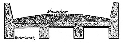 Fig. 154.—Cross-Section of Concrete Girder Bridge.
Example I.—This bridge was but little more than 5 ft. above the stream, which was shallow and not over 7 ft. wide, unless swollen by floods. The bottom for several hundred feet on either side of the bridge was covered with coarse sand and gravel, that had pebbles in it from the size of a goose egg down. This was taken from the stream by men with picks and shovels and hauled to the site of the work with wheelbarrows, and then screened so as to separate the gravel from the sand. As it was found that the sand was so coarse that it would take more cement than the specifications called for in a 1-2½-5 mixture, some much finer sand was bought and mixed with it. For the privilege of taking the sand from the stream $1 was paid the property owner. This was done to get a receipt and release from him, rather than as an attempt to pay royalty on the gravel and sand. This dollar is included in the cost of the labor in getting these materials.[Pg 379]
The cost of materials per cubic yard for the bridge was as given below, the mixture being as stated above. The cement cost $1.40 per barrel, delivered at the bridge.
| Per Cu. Yd. | |
| Steel | $2.50 |
| Gravel and sand | .75 |
| Sand (bought) | .30 |
| Cement | 1.57 |
| —— | |
| Per cubic yard | $5.12 |
It is of interest to note the cost of the gravel and sand, as this includes the cost of digging it, wheeling it in a wheelbarrow an average distance of 100 ft., and then screening it and putting it in two stock piles. The proportion of bought sand used with the creek sand was one-half.
The old wooden floor and stringers had to be torn down. This was done at a cost of $1.30 per M. ft. B. M., and furnished 60 per cent. of the lumber needed for forms. The floor boards were 3-in. yellow pine planks, and the stringers 6×12-in. timbers, rather heavy, but money was saved by using them. The 6×12-in. timbers were used for props for the centering. Additional lumber was bought, delivered at the site of the bridge, for $20.84 per M. ft. B. M.
In framing and erecting the forms the carpenter had laborers helping him, he doing only carpenter's work, the laborers carrying and lifting all pieces wherever possible. The carpenter's work was about 40 per cent. of the total labor cost, which was as follows per cubic yard of concrete:
| Tearing down old bridge | $0.08 |
| Lumber | .85 |
| Nails | .15 |
| Labor, carpenter | .77 |
| Labor, laborers | .96 |
| —— | |
| $2.81 |
The forms were torn down by laborers, with the assistance of a man and his helper, who were given the boards for this labor and to haul them away. This reduced this item somewhat, as it only amounted to 20 cts. per cu. yd.[Pg 380]
The cost of the forms per thousand feet board measure was:
| New lumber | $20.82 |
| Nails | 1.44 |
| Labor, carpenter | 7.60 |
| Labor, laborers | 9.50 |
| Tearing down | 2.00 |
| ——— | |
| $41.36 |
All the men, including the carpenter, worked 10 hours per day, and were paid at the following rates:
| Carpenter | $2.50 |
| Sub-foreman | 2.00 |
| Laborers | 1.50 |
A regular foreman was not employed, but an intelligent and handy workman was given 50 cts. additional to lead the men and look after them when the contractor was not present.
A gang of six men did the work of mixing and placing, and as the stock piles were close by the mixing board no extra men were needed to handle materials. Water was secured from the stream in buckets for mixing. The mixture was made very wet. The cost per cubic yard for the entire structure was as follows:
| Preparing for mixing | $0.04 |
| Cleaning out forms | .06 |
| Handling steel | .03 |
| Mixing and placing | 1.15 |
| Ramming | .23 |
| —— | |
| $1.51 |
The cost of the contractor's expense of bidding, car fare, etc., is listed under general expense, and gives a total cost per cubic yard of:
| Materials | $ 5.12 |
| Erecting forms | 2.81 |
| Tearing down forms | .20 |
| Labor | 1.51 |
| General expense | 2.00 |
| ——— | |
| $11.64 |
Example II.—For this bridge both the stone and sand had to be bought. The bridge floor was nearly 14 ft. above the bottom of the stream, which was shallow. The wages paid were as follows for a 10-hour day:
| Foreman | $3.00 |
| Laborers | 1.50 |
Carpenters were paid $3 for an 8-hour day and time and a half for all overtime, which they frequently made.
For the girders a 1-2-4 mixture was used. The cement, delivered at the bridge, cost $1.21 per barrel, there being 8 cts. a barrel storage and 8 cts. a barrel for hauling included in this. The sand was paid for at an agreed price per cartload delivered, which averaged $1.34 per cu. yd. The stone was crushed so as to pass a 1½-in. ring in all directions. It was delivered at the bridge for $2.75 per cu. yd. This makes the cost per cubic yard for materials as follows:
| Steel | $1.41 |
| Cement | 2.18 |
| Sand | .67 |
| Stone | 2.75 |
| —— | |
| $7.01 |
For the floor a 1-3-5 mixture was used, making a cost for material of:
| Steel | $1.02 |
| Cement | 1.69 |
| Sand | .67 |
| Stone | 2.75 |
| —— | |
| $6.13 |
Two-inch rough pine boards were used to make the troughs for the girders, while 1-in. rough boards were used for the floors. These were all supported by 3×4-in. pine scantlings. This lumber cost delivered $17.50 per M. ft. B. M. Carpenters did all the framing, and erected it with the help of laborers. All the carrying of the lumber was done by laborers. This reduced the cost of the work, as the laborers' wages amounted[Pg 382] to one-third of the whole cost. As soon as the forms were all in place, which was before the mixing of concrete commenced, the carpenters were discharged. The cost per cubic yard for forms was:
| Lumber | $2.82 |
| Nails | .05 |
| Labor, carpenters | 1.24 |
| Laborers | .62 |
| —— | |
| $4.73 |
The tearing down of the forms was done entirely by laborers at a cost of 61 cts. per cu. yd.
On concrete work it is also advisable to keep the cost of forms per thousand feet board measure, so as to have such data for estimating on new work. The cost per M. ft. on this job was:
| Lumber | $17.50 |
| Nails | .30 |
| Labor, carpenters | 7.65 |
| Laborers | 3.85 |
| Tearing down | 3.80 |
| ——— | |
| $33.10 |
The concrete was mixed by hand, water being carried in buckets from the creek. Ten to twelve men were worked in the gang under a foreman, and the concrete was wheeled from the mixing board to the forms in wheelbarrows. The mixture was made wet enough to run. The cost per cubic yard for the girders in detail was as follows:
| Foreman | $0.41 |
| Preparing for mixing | 0.14 |
| Cleaning out forms | 0.07 |
| Handling materials | 0.30 |
| Handling and placing steel | 0.40 |
| Mixing and placing | 0.87 |
| Ramming | 0.45 |
| —— | |
| $2.64 |
The cost of labor for the floor was:
| Foreman | $0.28 |
| Preparing for mixing | 0.08 |
| Cleaning out forms | 0.05 |
| Handling materials | 0.14 |
| Handling and placing steel | 0.08 |
| Mixing and placing | 0.87 |
| Ramming | 0.36 |
| —— | |
| $1.86 |
This gives a total cost per cubic yard for the concrete in the girders in the completed bridge as follows:
| Materials | $ 7.01 |
| Erecting forms | 4.73 |
| Tearing down forms | 0.61 |
| Labor | 2.57 |
| General expense | 1.60 |
| ——— | |
| $16.52 |
The cost per cubic yard for the floor was:
| Materials | $ 6.13 |
| Erecting forms | 4.73 |
| Tearing down forms | 0.61 |
| Labor | 1.86 |
| General expense | 1.60 |
| ——— | |
| $14.93 |
Included with this is an item for general expense, being expenses of the contractor in bidding on the work, car fare, and other items of expense in looking after the contract.
It will be noticed that a record is here given of three different mixtures and that the labor cost of mixing and placing increases with the richness of the mixture. This is because it takes a greater number of batches to the cubic yard. Record has also been given of cost of preparing the mixing board and other work necessary to start and clean up each day; also when stock piles could not be arranged close to the mixing board, of the cost of handling the materials. These items, it will be noticed, are large enough to be considered in estimating[Pg 384] on new work. The cost of sweeping and cleaning out the forms has also been listed, as this work is extremely important.
The cost of the reinforcing steel is given in with the materials, but the labor of handling it and placing it in the forms is listed under labor. This naturally varies with the amount of steel needed, and with the Kahn bar it will vary from 10 cts. to 75 cts. per cubic yard, as the prongs of the bar must be bent into proper position and at times straightened, when bent in shipment. This cost seems large, but it is done with the ordinary labor, while with round rods a large amount of blacksmith work has to be done and a smith and his helper frequently must place them. The patent bars are all lettered and numbered as structural steel is, and can be placed under the direction of the foreman.
One striking lesson can be learned from the forming. It will be noticed that the cost for common labor for handling and helping to erect the forms was much larger in Example I than in Example II, although the bridge was higher in the latter instance. This was caused by the heavy timber that was used, and equaled an extra cost nearly 50 per cent. of the price of new lumber. It certainly speaks volumes against the use of unnecessarily heavy timber for concrete forms.
In bridge work the height of the floor above the stream to some extent governs the cost of the forms. This is made so by the extra lumber needed as props or falsework to support the forming, and also by the fact that men at some height above the ground do not work as quickly or as readily as they do nearer the ground. For high and long spans a derrick is sometimes needed for the work of placing the centering.
On these jobs the concrete was made so wet that with the proper tamping and cutting of the concrete in the forms the surfaces were so smooth that no plastering was needed.
MOLDING SLABS FOR GIRDER BRIDGES.—The bridges carry railway tracks across intersecting streets; the slabs rest on two abutments and three rows of columns so that there are two 24¼-ft. spans over the street roadway and one 10¾-ft. span over each sidewalk. The larger slabs were 24 ft. 3 ins. long, 33 ins. thick and 7 ft. wide; each contained[Pg 385] 16¾ cu. yds. of concrete and weighed 36¾ tons. The smaller slabs were 10 ft. 9 ins. long, 17 ins. thick and 7 ft. wide; each contained 3.65 cu. yds. of concrete and weighed 7.8 tons. The weights were found by actual weighing. They make the weight of the reinforced slab between 160 and 162 lbs. per cu. ft. The concrete was generally 1 part cement and 4 parts pit gravel. The reinforcement consisted of corrugated bars. The method of molding was as follows:
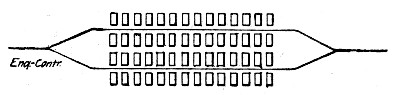 Fig. 155.—Arrangement of Tracks and Forms for Molding
Slabs for Girder Bridge.
Fig. 155.—Arrangement of Tracks and Forms for Molding
Slabs for Girder Bridge.
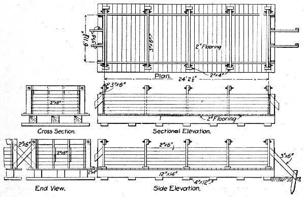 Fig. 156.—Form for Molding Slabs for Girder Bridge.
A cinder fill yard was leveled off and tamped, then the forms were set up on both sides of two lines of railway track arranged as shown by Fig. 155. The exact construction of the forms for one of the larger slabs is shown by Fig. 156. The side and end pieces were so arranged as to be easily taken down and erected for repeated use. About 100 floors were used and they had to be leveled up each time used as the lifting of the hardened slab disarranged them. The side and[Pg 386] end pieces were removed in about a week or ten days, but the slabs stood on the floor 90 days, being wetted each day for two weeks after molding.
The plant for mixing and handling the concrete was mounted on cars. A flat car had a rotary drum mixer mounted on a platform at its forward end. Beneath the mixer was a hopper provided with a deflector which directed the concrete to right or left as desired. Under the hopper were the ends of two inclined chutes extending out sidewise beyond the car—one to the right and one to the left—and over the slab molds on each side. Above the mixer was another platform containing a charging hopper, and from the rear of this platform an incline ran down to the rear end of the car and then down to the track rails. A car loaded with cement and gravel in the proper proportions was hauled up the incline by cable operated by the mixer engine, until it came over the topmost hopper into which it was dumped. This hopper directed the charge into the mixer below; the mixer discharged its batch into the hopper beneath from which it flowed right or left as desired into one of the chutes and thence into the mold. The chutes reached nearly the full length of the molds and discharged as desired over the ends into the far end of the mold or through a trap over the end of the mold nearest the car.
To the rear of the mixer car came a cement car provided with a platform overhanging its forward end. Two hoppers were set in this platform each holding a charge for one batch. Coupled behind the cement cars came three or four gravel cars. These were gondola cars and plank runways were laid along their top outer edges making a continuous runway for wheelbarrows on each side from rear of train to front of cement car. The sand and gravel were wheeled to the two measuring hoppers and the cement was handed up from the car below and added, the charge was then discharged into the dump car below and the car was hauled up the incline to the mixer as already described. Two measuring hoppers were used so that one was being filled while the other was emptied, thus making the work continuous.
The molding gang consisted of 33 laborers, two foremen and one engineman. This gang averaged 7 of the large slabs per 10-hour day and at times made as many as 9 slabs. When[Pg 387] molding small slabs an average of 12 were made per day. This record includes all delays, moving train, switching gravel cars on and off, building runways, etc. The distribution of the men was about as follows:
| Handling Materials: | No. Men. |
| Shoveling gravel into wheelbarrows | 9 |
| Wheeling gravel to measuring hoppers | 9 |
| Emptying cement into measuring hoppers | 2 |
| Handling cement to men emptying | 1 |
| In charge of loading dump car | 1 |
| On top of cement car | 1 |
| Sub-foreman in charge | 1 |
| Mixing and Placing: | |
| Engineer | 1 |
| In charge of mixer | 1 |
| Hoeing and spreading in mold | 2 |
| Spading in mold | 2 |
| Finishing sides of block | 2 |
| General laborers | 3 |
| Foreman in charge | 1 |
| — | |
| Total men | 36 |
This gang mixed and placed concrete for 7 blocks or 117¼ cu. yds. of concrete per day. Assuming an average wage of $2 per day the cost of labor mixing and placing was 61.4 cts. per cu. yd. or $10.28 per slab. It is stated that the slabs cost $11.80 per cu. yd. on storage pile. This includes labor and materials (concrete and steel); molds; loading into cars with locomotive crane, hauling cars to storage yard and unloading with crane into storage piles, and inspection, incidentals, etc. To load the slabs into cars from storage piles, transport them to the work and place them in position is stated to have cost $2 per cu. yd. The slabs were placed by means of a locomotive crane being swung from the flat cars directly into place.
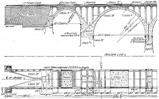 Fig. 157.—Sections Showing Construction of Connecticut
Ave. Bridge.
Fig. 157.—Sections Showing Construction of Connecticut
Ave. Bridge.
METHOD AND COST OF CONSTRUCTING CONNECTICUT AVE. BRIDGE, WASHINGTON, D. C.—The Connecticut Ave. Bridge at Washington, D. C., consists of nine 150-ft. spans and two 82-ft. spans, one at each end, all full centered arches of mass concrete trimmed with tool-dressed concrete blocks. Figure 157 is a part sectional plan[Pg 389] and elevation of the bridge, showing both the main and spandrel arch construction. This bridge is one of the largest concrete arch bridges in the world, being 1,341 ft. long and 52 ft. wide, and containing 80,000 cu. yds. of concrete. Its total cost was $850,000 or $638.85 per lin. ft., or $10.63 per cu. yd. of masonry. It was built by contract, with Mr. W. J. Douglas as engineer in charge of construction. The account of the methods and cost of construction given here has been prepared from information obtained from Mr. Douglas and by personal visits to the work during construction.
General Arrangement of the Plant.—The quarry from which the crushed stone for concrete was obtained was located in the side of the gorge at a point about 400 ft. from the bridge. Incidentally, it may be added, the fact that the contractor had an option on this quarry gave him an advantage of some $30,000 over the other bidders. The stone from the quarry was hoisted about 50 ft. by derricks and deposited in cars which traveled on an incline to a Gates gyratory crusher, into which they dumped automatically. The stone from the crusher dropped into a 600-cu. yd. bin under the bottom of which was a tunnel large enough for a dump car and provided with top gates by which the stone above could be dropped into the cars. The cars were hauled by cable to the mixer storage bin and there discharged. Sand was brought in by wagons and dumped onto a platform about 50 ft. higher than the bottom of the main stone bin. A tunnel exactly similar to that under the stone bin was carried under the sand storage platform. The sand car was hauled from this tunnel by cable to the mixer storage bin using the same cable as was used for the stone cars, the cable being shifted by hand as was desired. Cement was delivered to the mixer platform from the crest of the bluff by means of a bag chute.
The mixer used was one of the Hains gravity type. It had four drops and was provided with four mixing hoppers at the top. The concrete was made quite wet. The proportions of sand and water were varied to suit the stone according to its wetness and the percentage of dust carried by it. The head mixer regulated the proportions and his work was checked by the government inspector. From the bottom hopper the mixed concrete dropped into a skip mounted on a car.[Pg 390]
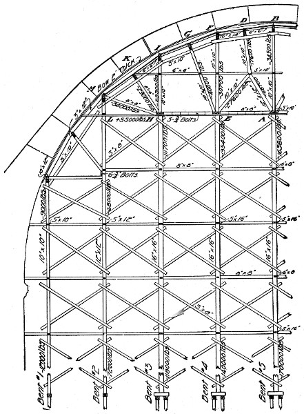 Fig. 158.—Center for Connecticut Ave. Bridge
(Elevation).
Fig. 158.—Center for Connecticut Ave. Bridge
(Elevation).
To distribute the skip cars along the work a trestle was built close alongside the bridge and at about springing line level. This trestle had a down grade of about 2 per cent. from the mixer. Derricks mounted along the centering and on the block molding platform lifted the skips from the cars and deposited them where the concrete was wanted. The skip cars[Pg 391] were large enough for three skips but only two were carried so that the derricks could save time by depositing an empty skip in the vacant space and take a loaded skip away with one full swing of the boom. Altogether nine derricks were used in the bridge, four having 70-ft. booms and five having 90-ft. booms. These derricks were jacked up as the work progressed.
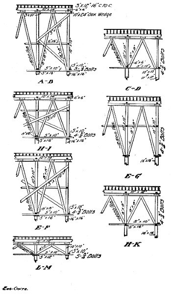 Fig. 158.—Center for Connecticut Ave. Bridge
(Details).
Fig. 158.—Center for Connecticut Ave. Bridge
(Details).
Forms and Centers.—The forms for wall and pier work consisted of 1-in. lagging held in place by studs about 2 ft. on centers and they in turn supported by wales which were connected through the walls by bolts, the outer portions of which were removed when the forms were taken down.
The centers for the five 150-ft. arches were all erected at one time; those for the 82-ft. arches were erected separately. The seven centers required 1,500,000 ft. B. M. of lumber or 1,404 ft. B. M. per lineal foot of bridge between abutments, or 1,640 ft. B. M. per lineal foot of arch span. The centers for the main arch spans are shown in detail by Fig. 158; this drawing shows the sizes of all members and the maximum stresses to which they were subjected from the loading indicated, that is the arch ring concrete. The centers as a rule rested on pile foundations. Four piles to each post were used for the intermediate posts and two piles for the posts in the two rows next the piers. Concrete foundations, however, were put in Rock Creek and on the line of Woodley Lane Bridge where it was impracticable to drive piles. As considerable difficulty was experienced in driving the piles, the ground consisting mostly of rotten rock, it is thought that it would have cost less if the contractor had used concrete footings throughout.
Some of the costs of form work and centering are given. The cost of lumber delivered at the bridge site was about as follows:
| M. ft. B. M. | |
| Rough Virginia pine | $25 |
| Dressed Virginia pine lagging | 23 |
| Rough Georgia, sizes up to 12×12 ins. | 33 |
| Rough Georgia, sizes over 12×12 ins. | 35 |
| Rough oak lumber | 35 |
The following wages were paid: Foreman carpenter, $3.50; carpenters, $2 to $3; laborers, $1.70, with a few at $1.50. An 8-hour day was worked.
The cost, of formwork is given in summary as follows:
| Lagging per M. ft. (used twice): | |
| Lumber at $23 | $11.50 |
| Erection | 15.00 |
| ——— | |
| Total cost erected | $26.50 |
| Studding and rough boards used in place of lagging per M. ft. (used twice): | |
| Lumber at $25 | $12.50 |
| Erection | 10.00 |
| ——— | |
| Total cost erected | $22.50 |
| Wales per M. ft. (used six times): | |
| Lumber at $36 | $ 6.00 |
| Erection | 10.00 |
| ——— | |
| Total cost erected | $16.00 |
The total cost of the main arch span centers to the District of Columbia was $54,000 or $59 per lineal foot of arch span, or $37.33 per M. ft. B. M. The cost of center erection and demolition was as follows:
| Erection below springing line per M. ft. | $15 |
| Erection above springing line per M. ft. | 25 |
| Demolition | 5 |
The salvage on the centers amounted to $11 per M. ft. B. M.
The spandrel arch centers were each used twice and cost per M. ft. B. M. for
| Lumber at $25 per M. ft. | $12.50 |
| Erecting at $25 per M. ft. | 25.00 |
| Moving at $5 per M. ft. | 5.00 |
| Total per M ft. | 42.50 |
Molding Concrete Blocks.—The bridge is trimmed throughout with molded concrete blocks, comprising belt courses, quoin stones, chain stones, ring stones, brackets and dentils. The blocks were made of a 1-2-4½ concrete faced with a 1-3 mixture of Dragon Portland cement and bluestone screenings from ⅜-in. size to dust. They were cast in wooden molds with collapsible sides held together by iron rods. Each mold was provided with six bottoms so that the molded block could be left standing on the bottom to harden while the side pieces were being used for molding another block. The molding was done on a perfectly level and tight floor on mud sills, the perfect level of the molding platform having been found to be an important factor in securing a uniform casting. The blocks were molded with the principal showing face down and the secondary showing faces vertical. The facing mortar was[Pg 394] placed first and then the concrete backing. Care was taken to tamp the concrete so as to force the concrete stone into but not through the facing. Mr. Douglas remarks that the back of the block should always be at the top in molding since the laitance or slime always flushes to the surface making a weak skin which will develop hair cracks. In this work the backs of the blocks were mortised by embedding wooden cubes in the wet concrete and removing them when the concrete had set. These mortises bonded the blocks with the mass concrete backing. The blocks were left to harden for at least 30 days and preferably for 60 days and were then bush hammered on the showing faces, some of the work being done by hand and some with pneumatic tools.
Some precautions necessary in the molding and handling of large concrete blocks were discovered in this work and merit mention. In designing blocks for molding it is necessary to avoid thin flanges or the flanges will crack and break off; blocks molded with a 2¼ in. flange projecting 1¾ ins. gave such trouble from cracking on this work that a flange 5 ins. thick was substituted. Provide for the method of handling the block so that dog or lewis holes will not come in the showing faces. Dog holes can be made with a pick when the concrete is three or four weeks old. When it is not practicable to use dogs, two-pin lewises can be used. The lewis holes should be cast in the block and should be of larger size than for granite; they should not be located too near the mortar faces. In turning blocks it is necessary to provide some sort of cushion for them to turn on or broken arrises will result. When the work will permit, it is desirable to round the arrises to about a ⅜-in. radius.
The following general figures of the cost of block work are available. Foreman cutters were paid $5 per day; foreman concrete workers $3 per day; stonecutters $4 per day; concrete laborers $1.70 per day, and common laborers $1.50 to $1.70 per day. Plain and ornamental blocks cost about the same, the large size of the ornamental blocks bringing down the cost. The following is given as the average cost of block work per cubic yard:[Pg 395]
| Cement | $ 1.95 |
| Sand | 0.35 |
| Stone | 1.14 |
| Forms, lumber and making | 0.80 |
| Mixing and placing concrete | 1.50 |
| Dressing | 4.73 |
| Handling and setting | 2.00 |
| Superintendence, plant, incidentals at 25 per cent. | 3.12 |
| Condemnation at 5 per cent. | 0.78 |
| ——— | |
| Total cost blocks in place | $16.37 |
It will be seen that the largest single item in the above summary of costs is the item of dressing. This was done, as stated above, partly by hand and partly by pneumatic tools. Hand tooling cost about twice as much as machine tooling, but its appearance was generally better. The average cost of tooling the several forms of blocks is shown by Table XIX. For 42,190 sq. ft. the average cost was 26 cts. per sq. ft. or $2.34 per sq. yd., or $4.73 per cu. yd. of block work. This tooling was done by stone cutters, and was unusually high in cost.
Mass Concrete Work.—All parts of the bridge except the molded block trim were built of concrete deposited in place. Briefly, the molded blocks were set first and then backed up with the mass concrete deposited in forms and on centers. The only features of this work that call for particular description are those in connection with the main arch ring and the spandrel arch construction.
The main arch rings were concreted in transverse sections; Fig. 158 shows the size and order of construction of these sections. Back forms were necessary up to an angle of 45° from the spring line after which the concrete was made somewhat drier and back forms were not used. After Sections 1, 2, 3 and 4 had been concreted they were allowed to set and then the struts and back forms were taken out and the intervening sections were concreted. The large Sections 6 and 7 were concreted in five sections each, in order to permit the taking out of the timber struts supporting the sections above. The concrete in all sections was placed in horizontal layers as a rule and it is the judgment of the engineers in charge of this work that this is the preferable method.[Pg 396]
| Description. 1: 2: 4½ Concrete Backing. 1: 3 (Mortar Face). | Per Cubic Foot. | Per Superficial Foot of Showing Face. | ||||||
| Total Number Stones Cut. | Number cubic feet in each. | Total cubic feet cut. | Cost per cubic foot. | Superficial feet in each. | Total superficial feet. | Cost per superficial foot. | Number Super. ft. to one cubic foot. | |
| Brackets under Lamps and Rail Posts (Cap and Base) | 344 | 16.0 | 5,500 | $0.27 | 10.5 | 3,630 | $0.41 | 0.66 |
| Moulding under coping | 770 | 5.9 | 4,560 | 0.30 | 3.8 | 2,930 | 0.47 | 0.64 |
| Dentils between Moulding | 520 | 5.5 | 2,860 | 0.20 | 8.0 | 4,160 | 0.14 | 1.45 |
| Coping | 494 | 61.2 | 30,220 | 0.12 | 35.4 | 17,490 | 0.21 | 0.58 |
| Pedestal (3 courses) | 162 | 27.2 | 4,400 | 0.15 | 14.1 | 2,290 | 0.29 | 0.52 |
| Rail Posts (Top and Base) | 296 | 7.1 | 2,100 | 0.50 | 17.3 | 5,100 | 0.21 | 2.43 |
| Lamp Posts and Parapets over Piers (Top and Base) | 248 | 22.9 | 5,690 | 0.17 | 26.5 | 6,580 | 0.15 | 1.16 |
| Average of above—Totals | 2,834 | 19.5 | 55,330 | $0.17 | 14.8 | 43,190 | $0.26 | 0.77 |
| Description. | Cost Delivered on Mixer. | |||||
| Proportions. | Average Yardage for Days Run. | Cement. | Sand. | Stone. | Total Materials. | |
| Class A, in Piers | 1:2:4½ | 150 | 1.65 | 0.39 | 1.08 | 3.12 |
| Class A, in Arches | 1:2:4½ | 200 | 1.65 | 0.39 | 1.08 | 3.11 |
| Class B, in Piers —Solid Work | 1:3:6 | 160 | 1.40 | 0.42 | 1.23 | 3.05 |
| Class B, in Piers —Hollow Work | 1:3:6 | 110 | 1.40 | 0.42 | 1.23 | 3.05 |
| Class B, in Spandrel Walls | 1:3:6 | 110 | 1.40 | 0.42 | 1.23 | 3.05 |
| Class B, in Spandrel Arches | 1:3:6 | 200 | 1.40 | 0.42 | 1.23 | 3.05 |
| Class B, in Abutments | 1:3:6 | 150 | 1.40 | 0.42 | 1.23 | 3.05 |
| Class C, Filling over Bridge | 1:3:10 | 145 | 0.90 | 0.31 | 1.30 | 2.51 |
| Description. | Cost of Mixing and Placing. | ||
| Mixing. | Placing | Total Mixing and Placing | |
| Class A, in Piers | 0.09 | 0.21 | 0.30 |
| Class A, in Arches | 0.05 | 0.28 | 0.33 |
| Class B, in Piers —Solid Work | 0.09 | 0.18 | 0.27 |
| Class B, in Piers —Hollow Work | 0.11 | 0.36 | 0.47 |
| Class B, in Spandrel Walls | 0.11 | 0.40 | 0.51 |
| Class B, in Spandrel Arches | 0.07 | 0.26 | 0.33 |
| Class B, in Abutments | 0.11 | 0.24 | 0.35 |
| Class C, Filling over Bridge | 0.11 | 0.28 | 0.39 |
| Description. | Cost of Form Work. | ||||
| Erecting. | Taking Down | Lumber. | Total Form Work | Total Cost per Cubic Yard.[G] | |
| Class A, in Piers | 0.17 | 0.05 | 0.16 | 0.38 | $3.80 |
| Class A, in Arches | 0.08 | 0.03 | 0.10 | 0.21 | 3.66 |
| Class B, in Piers —Solid Work | 0.17 | 0.05 | 0.16 | 0.38 | 3.70 |
| Class B, in Piers —Hollow Work | 0.77 | 0.25 | 0.64 | 1.66 | 5.18 |
| Class B, in Spandrel Walls | 0.85 | 0.28 | 0.73 | 1.86 | 5.42 |
| Class B, in Spandrel Arches | 0.94 | 0.30 | 0.86 | 2.10 | 5.48 |
| Class B, in Abutments | 0.10 | 0.03 | 0.12 | 0.25 | 3.65 |
| Class C, Filling over Bridge | 0.00 | 0.00 | 0.00 | .... | 2.90 |
[G] Add 25% to the cost here tabulated for superintendence, plant and incidentals.
Considerable difficulty was experienced in building the large arches with a concrete block facing on account of the fact that the edges of the blocks are liable to chip off when any concentrated pressure is brought on them. In order to permit the ring of blocks to deform as the centering settled under its[Pg 397] load, sheet lead was placed in the joints between blocks at the points corresponding with the construction joints between sections of the mass concrete backing. The deflection of the centers at the crown was a maximum of 3¼ ins. and a minimum of 2½ ins.
| Engineering. | Inspection. | |||
| Kind of Work. | Total. | Unit. | Total. | Unit. |
| Class A, concrete, 23,500 cu. yds | $3,055.00 | $0.13 | $1,762.50 | $0.075 |
| Class B, concrete, 36,580 cu. yds | 3,658.00 | 0.10 | 1,646.10 | 0.045 |
| Class C, concrete, 2,150 cu. yds | 107.50 | 0.05 | 53.75 | 0.025 |
| Class D, concrete, 6,250 cu. yds | 1,875.00 | 0.30 | 4,687.50 | 0.75 |
| 1,000 M. ft. B. M. centering | 1,000.00 | 1.00 | 440.00 | 0.44 |
| Cement, 73,000 barrels | 365.00 | 0.005 | 730.00 | 0.01 |
| Earth filling, 50,000 cu. yds | 1,000.00 | 0.02 | 500.00 | 0.01 |
The centering of the main arches was not struck until the spandrel arches and all the work above the main arches to the bottom of the coping had been completed. The first and third spandrel arch on each side of the piers was made with an expansion joint in the crown. To permit further of the adjustment of the portion of the masonry above the backs of the main arches, the crown of the middle arch of each set of spandrel arches was left unconcreted until the center of the main arches had been struck. It may be noted here that the expansion joints in the first and third arches were carried up through the dentils and coping, and observations show that these joints are about ⅛ in. larger in winter than in summer.
The cost of the mass concrete work is shown in Table XX. These figures are based on the wages already quoted and the following: Foreman riggers, $4.50; riggers, $1.50 to $1.75 and $2; skilled laborers, $2; engineers, $3.50. The detail cost of engineering and inspection is shown in Table XXI.
ARCH BRIDGES, ELKHART, IND.—At the new Elkhart, Ind., yards of the Lake Shore & Michigan Southern Ry. the tracks are carried over a city street by concrete arches 40, 60 and 160 ft. long. These arches all have a span of 30 ft., a height of 13 ft. and a ring thickness at crown of 28 ins. The[Pg 398] reinforcement consists of arch and transverse bars; the arch bars are spaced 6 ins. on centers 2½ ins. from both extrados and intrados, and the transverse bars are spaced 24 ins. on centers inside both lines of arch bars. The proportions of the concrete were generally 1 cement, 3 gravel and 6 stone. The gravel was a material dug from the foundations and was about 50 per cent. sand and 50 per cent. gravel, ranging up to the size of pigeons' eggs. The concrete was machine mixed and was mixed very wet.
The work was done by the railway company's forces, and Mr. Samuel Rockwell, Assistant Chief Engineer, gives the following figures of cost:
| Total. | Per cu. yd. | |
| Temporary buildings, trestles, etc. | $ 752.33 | $0.15 |
| Machinery, pipe fittings, etc. | 416.34 | 0.08 |
| Sheet piling and boxing | 1,006.12 | 0.21 |
| Excavation and pumping | 1,619.74 | 0.33 |
| Arch centers and boxing | 3,528.92 | 0.73 |
| ———— | —— | |
| Total | $7,323.45 | $1.50 |
| Concrete masonry: | ||
| Cement | 8,860.55 | 1.84 |
| Stone | 1,788.50 | 0.36 |
| Sand | 240.00 | 0.05 |
| Drain tile | 103.03 | 0.02 |
| Labor | 8,091.41 | 1.68 |
| ————— | —— | |
| Total concrete | $19,083.49 | $3.95 |
| Steel reinforcing rods | $ 3,028.39 | $0.63 |
| Engineering, watching, etc. | 508.40 | 0.11 |
| ————— | —— | |
| Grand total (4,833 cu. yds. concrete) | $29,943.73 | $6.19 |
ARCH BRIDGE, PLAINWELL, MICH.—The following figures of cost of a reinforced concrete arch bridge are given by Mr. P. A. Courtright. The bridge crosses the Kalamazoo River at Plainwell, Mich., and is 446 ft. long over all with seven arches of 54 ft. span and 8 ft. rise. The arch rings were[Pg 399] reinforced with 4-in., 6-lb. channels bent to a radius of 70 ft. and spaced 1.9 ft. c. to c. The contract price of the bridge was $19,900.
The concrete was made of Portland cement and a natural mixture of sand and gravel in the proportions of 1-8 for the foundations, 1-6 for arches and spandrel walls and 1-4 for the parapet wall. The proportions were determined by measure; the wagon boxes being built to hold a cubic yard of sand and gravel. A sack of cement was taken as 1 cu. ft. For foundations the pit mixture was used without screening; stones over 4 ins. in diameter being thrown out at the pit or on the mixing board. For the arches and spandrel walls the gravel was passed over a 2-in. mesh screen on the wagon box. The aggregate for the parapet walls was screened to 1 in. largest diameter. The concrete was mixed in a McKelvey continuous mixer which turned the material eight times. The mode of procedure was as follows: The gravel was loaded upon wagons in the pit and hauled to a platform at the intake of the mixer. Half of the cement required in the concrete was then spread over the top of the load in the wagon box and the whole was dumped through the bottom of the wagon box onto the platform and spread with shovels. The remainder of the cement was spread over the mixture and the whole was shoveled by one man to a second man who shoveled it into the mixer. Water was added after the mixture had passed about one-third of the way through the mixer. The mixer delivered the concrete directly into wheelbarrows, by which it was delivered to the work. The concrete was spread in layers from 2 to 4 ins. in thickness and thoroughly rammed with iron tampers; two men were employed tamping for each man shoveling. The arches were concreted in three longitudinal sections, each section constituting a day's work. The work was done in 1903 and the concrete cost for mixing and placing:
| Labor: | Per day. | Per cu. yd. |
| 13 men at $1.80 | $23.40 | $0.78 |
| Engine and mixer | 5.00 | 0.17 |
| 1 team | 3.00 | 0.10 |
| 1 foreman | 3.00 | 0.10 |
| ——— | —— | |
| [Pg 400] | ||
| Totals for labor | $34.40 | $1.15 |
| Materials: | ||
| 0.65 bbl. cement at $2 | $1.30 | |
| 0.9 cu. yd. gravel at $0.50 | 0.45 | |
| —— | ||
| Total for materials | $1.75 | |
| Grand total | $2.90 |
METHODS AND COST OF CONSTRUCTING A FIVE-SPAN ARCH BRIDGE.—This bridge consisted of five elliptical arch spans of 40, 45, 60, 87 and 44 ft., carried on concrete piers. The arch rings were 12 ins. thick at the crowns and 18 ins. thick 5 ft. from the centers of piers and carried 4-in. spandrel walls; there were 1,000 cu. yds. of concrete in the arches and 600 cu. yds. in the piers. Each arch ring was reinforced by a grillage of longitudinal and transverse rods.
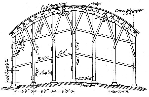 Fig. 159.—End View of Center for Short Elliptical Arch
Spans.
Fig. 159.—End View of Center for Short Elliptical Arch
Spans.
Forms and Centers.—Figure 159 is an end view of the center arch. It consists of a series of bents, 6 ft. c. to c., the posts of each bent being 5 ft. c. to c. These posts are made of 2×6-in. Washington fir. Upon the heads of the posts rest 2×6-in. stringers, extending from bent to bent. Resting on these stringers are wooden blocks, or wedges, which support a series of cross-stringers, also of 2×6-in. stuff, spaced 2 ft. c. to c.[Pg 401] On top of these cross-stringers rest the sheeting planks, which are 1×6-in. stuff, dressed on the upper side, and bent to the curve of the arch. This sheeting plank was not tongue and grooved, and a man standing under it, after it is nailed in place, could see daylight through the cracks. It looked as if it would leak like a sieve, and let much of the wet concrete mortar flow through the cracks, but, as a matter of fact, scarcely any escapes. Figure 160 shows a front view of a bent, and indicates the manner of sway bracing it with 1×4-in. stuff. Figure 161 shows the outer forms for the parapet wall, or concrete hand railing, and it will be noted that the cross-stringers are allowed to project about 3 ft. so as to furnish a place to fasten the braces which hold the upright studs. The inner forms for the parapet wall are shown in dotted lines. They are not put in place until all the concrete arch is built. Then they are erected and held to the outer forms by wire, and are sway braced to wooden cleats nailed to the top surface of the concrete arch.
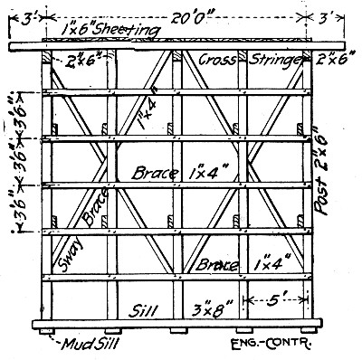 Fig. 160.—Front View of Center for Short Elliptical Arch
Spans.
Fig. 160.—Front View of Center for Short Elliptical Arch
Spans.
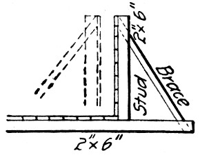 Fig. 161.—Form for Parapet Wall for Arch Bridge.
For the five spans the total amount of lumber in the centers was in round figures 28 M. ft., distributed about as follows:
| Item. | Ft. B. M. |
| 1×6-in. sheeting | 5,600 |
| 2×6-in. longitudinal stringers | 2,600 |
| 2×6-in. cross stringers | 2,600 |
| 2×6-in. posts | 4,000 |
| 3×8-in. sills | 1,500 |
| 1×4-in. braces | 3,000 |
| Outer forms for spandrel walls | 4,000 |
| Inner forms for spandrel walls | 4,000 |
| ——— | |
| Total | 27,300 |
The aggregate span length of the arches was 276 ft., so that a little less than 100 ft. B. M. of lumber was used for centering per lineal foot of span. The superintendent at $5 per day and five carpenters at $3.50 per day erected the five centers in 18 days at a cost of $400, or a trifle more than $14 per M. ft. B. M.; the cost of taking down the centers was $2 per M. ft. B. M., and the lumber for the centers cost $24 per M. ft. B. M. making a grand total of $40 per M. ft. B. M. for materials and labor. As there were 1,000 cu. yds. of concrete in the arches and spandrels, the cost of centers and forms was $1.12 per cu. yd. This form lumber was, however, after taking down, used again in erecting a reinforced concrete building. Assuming that the lumber was used only twice, the cost of centers and forms for these five arches was less than 80 cts. per cu. yd. of concrete.
Shaping and Placing Reinforcement.—The 60 and 87-ft. spans were reinforced with 32 1-½-in. round longitudinal rods held in place by ½-in. square transverse rods wired at the intersections; the reinforcement of the smaller spans was exactly the same except that 1-in. diameter rods were used. To bend the longitudinal rods to curve, planks were laid on the ground roughly to the curve of the arch; the exact curve was marked on these planks and large spikes were driven part way into the planks along this mark. The end of a rod was then fastened by spiking it against the first projecting spike head[Pg 403] and three men taking hold of the opposite end and walking it around until the rod rested against all the spikes on the curve. It took three men two 8-hour days to bend 46,000 lbs. of rods. Their wages were $2.50 each per day, making the cost of bending 0.03 ct. per pound, or 60 cts. per ton. It took a man 5 mins. to wire a cross rod to a longitudinal rod. With wages at $2.50 per day the cost of shaping and placing the reinforcement per ton was as follows:
| Item. | Per ton. |
| Bending rods | $0.60 |
| Shearing rods to lengths | 0.40 |
| Carrying rods onto bridge | 0.40 |
| Placing and wiring rods | 2.35 |
| —— | |
| Total | $3.75 |
Including superintendence the labor cost was practically $4 per ton, or 0.2 cts. per lb. Altogether 66,000 lbs. of steel was used for reinforcing 1,000 cu. yds. of concrete, or 66 lbs. per cu. yd. The cost of steel delivered was 2 cts. per lb., and the cost of shaping and placing it 0.2 ct. per lb., a total of 2.2 cts. per lb. or 2.2 × 66 = $1.45 per cu. yd. of concrete.
Mixing and Placing Concrete.—A Ransome mixer holding a half-yard batch was used. The mixer was driven by an electric motor. The concrete for the piers was a mixture of 1 part Portland cement to 7 parts gravel; for the arches, the concrete was mixed 1 to 5. The gravel was piled near the mixer, a snatch team being used to assist the wagons in delivering the gravel into a pile as high as possible. Run planks supported on "horses" were laid horizontally from the mixer to the gravel, so that big wheelbarrow loads could be handled. The barrows were loaded with long-handled shovels, and the men worked with great vigor, as is shown by the fact that four men, shoveling and wheeling, delivered enough gravel to the mixer in 8 hrs. to make 100 cu. yds. of concrete. We have, therefore, estimated on a basis of six men instead of four. The mixer crew was organized as follows:[Pg 404]
| Per day. | |
| 6 men shoveling and wheeling | $12 |
| 2 men handling cement | 4 |
| 1 man handling water | 2 |
| 1 man dumping concrete | 2 |
| 2 men handling dump cars | 4 |
| 2 men handling hoisting rope | 4 |
| 4 men spreading and ramming concrete | 8 |
| 1 engineman | 4 |
| 1 foreman | 5 |
| Fuel, estimated | 3 |
| — | |
| Total | $48 |
The output of this crew was 100 cu. yds. per day. The concrete was hauled from the mixer in two small dump cars, each having a capacity of 10 cu. ft. The average load in each car was ¼ cu. yd. Ordinary mine cars were used, of the kind which can be dumped forward, or on either side. The cars were hauled over tracks having a gage of 18 ins. The rails weighed 16 lbs. per yard, and were held by spikes ¼×2½ ins. Larger spikes would have split the cross-ties, which were 3×4 ins. Only one spike was driven to hold each rail to each tie, the spikes being on alternate sides of the rail in successive ties. No fish plates or splice bars were used to join the rails, which considerably simplifies the track laying.
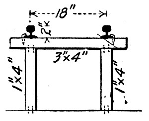 Fig. 162.—Trestle for Service Track.
Two lines of track were laid over the bridge. The tracks were supported by light bents, the cross-tie forming the cap of each bent, as shown in Fig. 162. The bents were spaced 3 ft. apart. There were two posts to each bent, toe-nailed at the top of the tie, and at the bottom to the arch sheeting plank. Two men framed these crude bents and laid the two rails at the rate of 150 lin. ft. of track per day, at a cost of[Pg 405] 4 cts. per lin. ft. of track. As stated, there were two tracks, one on each side of the bridge, but they converged as they neared the concrete mixer, so that a car coming from either track could run under the discharge chute of the mixer; Fig. 163 shows the arrangement of the tracks at the mixer. The part of each rail from A to B (6 ft. long) was free to move by bending at A, the rail being spiked rigidly to the tie at A, leaving its end at B free to move. To move the end B, so as to switch the cars, a home-made switch was improvised, as shown in Figs. 163 and 164.
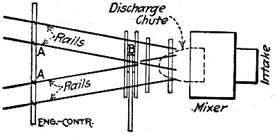 Fig. 163.—Arrangement of Service Tracks at Mixer.
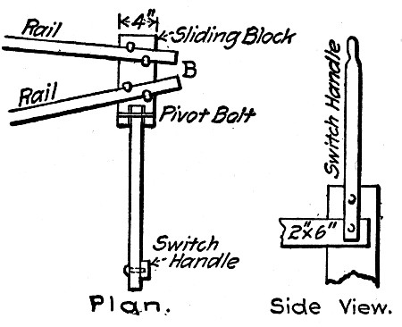 Fig. 164.—Improvised Switch for Service Cars, General
Plan.
Fig. 164.—Improvised Switch for Service Cars, General
Plan.
It will be remembered that this bridge was a series of five arches. There was a steep grade from the two ends of the bridge to the crown of the center arch. Hence the two railway tracks ascended on a steep grade from the mixer for about 175 ft., then they descended rapidly to the other end of the bridge. Hence to haul the concrete cars up the grade by using a wire cable, it was necessary to anchor a snatch block at the center of the bridge. This was done by erecting a short[Pg 406] post, the top of which was about a foot above the top of the rails. The post stood near the track, and was guyed by means of wires, and braced by short inclined struts. To the top of the post was lashed the snatch block through which passed the wire rope. Fig. 165 shows this post, P. About 10 ft. from the post P, on the side toward the mixer, another post, Q, was erected, and a snatch block fastened to it. When the hoisting engine, which was set near the concrete mixer, began hauling the car along the track, a laborer would follow the car. Just before the car reached the post Q, he would unhook the hoisting rope from the front end of the car, then push the car past the post Q, and hook the hoisting rope to the rear of the car. The car would then proceed to descend in the direction T, being always under the control of the wire rope, except during the brief period when the car was passing the post Q. Each of the two cars was provided with its own hoisting rope, and one engineer, operating a double drum hoist, handled the cars. The hoist was belted to an 8 HP. gasoline engine, no electric motor being available for the purpose.
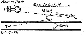 Fig. 165.—General Plan of Rope Haulage System.
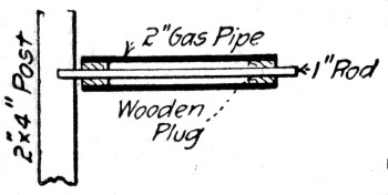 Fig. 166.
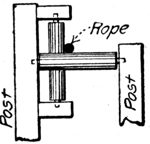 Fig. 167. Details of Haulage Rope Guides.
Where hauling is done in this manner with wire ropes, it is necessary to support the ropes by rollers wherever they would rub against obstructions. A cheap roller can be made by taking a piece of 2-in. gas pipe about a foot long, and driving a wooden plug in each end of the gas pipe. Then bore a hole through the center of the wooden plugs and drive a 1-in.[Pg 407] round rod through the holes, as shown in Fig. 166. The ends of this rod are shoved into holes bored into plank posts, which thus support the roller. Where the rope must be carried around a more or less sharp corner, it is necessary to provide two rollers, one horizontal and the other vertical, as shown in Fig. 167.
When conveying concrete to a point on the bridge about 300 ft. from the mixer, a dump car would make the round trip in 3 mins., about ¼ min. of its time being occupied in loading and another ¼ min. in dumping. One man always walked along with each car, and another man helped pull the wire rope back.
Including the cost of laying the track and installing the plant, the cost of mixing and placing the 1,600 cu. yds. of concrete was only 55 cts. per cu. yd., in spite of the high wages paid. However, the men were working for a contractor under a very good superintendent.
Summing up the cost of the concrete in the arches of this bridge, we have:
| Per cu. yd. | |
| 1.35 bbl. cement at $3 | $4.05 |
| 1 cu. yd. gravel at $1 | 1.00 |
| 66 lbs. of steel in place at 2.2 cts. | 1.45 |
| Centers in place (lumber used once) | 1.12 |
| Labor, mix and place concrete | 0.55 |
| —— | |
| Total | $8.17 |
The cost of the nails, wire, excavation and plant rental is not available, but could not be sufficient to add more than 10 cts. per cu. yd. under the conditions that existed in this case.
CONCRETE RIBBED ARCH BRIDGE AT GRAND RAPIDS, MICH.—The bridge consisted of seven parabolic arch ribs of 75 ft. clear span and 14 ft. rise. The five ribs under the 21-ft roadway were each 24 ins. thick, 50 ins. deep at skewbacks and 25 ins. deep at crown; the two ribs under the sidewalks were 12 ins. thick and of the same depth as the main ribs. Each rib carried columns which supported the deck slab. Columns and ribs were braced together across-bridge by struts and webs. All structural parts of the bridge[Pg 408] were of concrete reinforced by corrugated bars. The abutments were hollow boxes with reinforced concrete shells tied in by buttresses and filled with earth. There were in the bridge including abutments 884 cu. yds. of concrete and 62,000 lbs. of reinforcing metal, or about 70 lbs. of reinforcing metal per cu. yd. of concrete. Of the 884 cu. yds. of concrete 594 cu. yds. were contained in the abutments and wing walls and 290 cu. yds. in the remainder of the structure. (Fig. 168.)
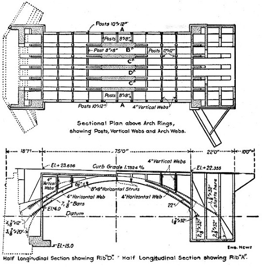 Fig. 168.—Details of Ribbed Arch Bridge.
Centers.—The center for the arch consisted of 4-pile bents spaced about 12 ft. apart in the line of the bridge. The piles were 12×12 in.×24 ft. yellow pine and they were braced together in both directions by 2×10-in. planks. Each bent carried a 3×12-in. plank cap. Maple folding wedges were set in these caps over each pile and on them rested 12×12-in. transverse[Pg 409] timbers, one directly over each bent. These 12×12-in. transverse timbers carried the back pieces cut to the curve of the arch. The back pieces were 2×12-in. plank, two under each sidewalk rib and four under each main rib of the arch. The back pieces under each rib were X-braced together. The lagging was made continuous under the ribs but only occasional strips were carried across the spaces between ribs. This reduced the amount of lagging required but made working on the centers more difficult and resulted in loss of tools from dropping through the openings. Work on the centers and forms was tiresome owing both to the difficulty of moving around on the lagging and to the cramped positions in which the men labored. Carpenters were hard to keep for these reasons.
Concrete.—A 1-7 bank gravel concrete was used for the abutments and a 1-5 bank gravel concrete for the other parts of the bridge. The concrete was mixed in a cubical mixer operated by electric motor and located at one end of the bridge. The mixed concrete was taken to the forms in wheelbarrows. The mixture was of mushy consistency. No mortar facing was used, but the exposed surfaces were given a grout wash. In freezing weather the gravel and water were heated to a temperature of about 100° F.; when work was stopped at night it was covered with tarred felt, and was usually found steaming the next morning.
Cost of Work.—The cost data given here are based on figures furnished to us by Geo. J. Davis, Jr., who designed the bridge and kept the cost records. Mr. Davis states that the unit costs are high, because of the adverse conditions under which the work was performed. The work was done by day labor by the city, the men were all new to this class of work, the weather was cold and there was high water to interfere, and work was begun before plans for the bridge had been completed, so that the superintendent could not intelligently plan the work ahead. Cost keeping was begun only after the work was well under way. Many of the items of cost are incomplete in detail.
The following were the wages paid and the prices of the materials used:[Pg 410]
| Materials and Supplies: | |
| No. 1 hemlock matched per M. ft. | $20 |
| No. 1 hemlock plank per M. ft. | 17 |
| No. 2 Norway pine flooring per M. ft. | 19 |
| No. 2 yellow pine flooring per M. ft. | 20 |
| 12×12-in.×16-ft. yellow pine per M. ft. | 29 |
| 12×12-in.×24-ft. yellow pine, piling per M. ft. | 27 |
| Maple wedges per pair | 50 cts. |
| ½-in. corrugated bars per lb. | 2.615 cts. |
| ¾-in. corrugated bars per lb. | 2.515 cts. |
| ⅞-in. corrugated bars per lb. | 2.515 cts. |
| Coal per ton | $4 |
| Electric power per kilowatt | 6 cts. |
| Medusa cement per bbl. | $1.75 |
| Aetna cement per bbl. | 1.05 |
| Bank gravel per cu. yd. | 0.85 |
| Sand per cu. yd. | 0.66 |
| Carpenters per day | $3 to 3.50 |
| Common labor per day | 1.75 |
The summarized cost of the whole work, with such detailed costs as the figures given permit of computation, was as follows:
| General Service: | Total. | Per cu. yd. |
| Engineering | $451 | $0.512 |
| Miscellaneous | 75 | 0.084 |
| Pumping: | Total 110 days. | |
| Coal at $4 per ton | $210 | |
| Machinery, tools and cartage | 283 | |
| Labor | 497 | |
| —— | ||
| Total | $990 |
This gives a cost of $9 per day for pumping.
| Excavation: | Total cost. | P. C. Total. |
| Timber cartage, etc. | $ 375 | 17.6 |
| Tools | 69 | 3.3 |
| Labor at $1.75 | 1,687 | 79.1 |
| ——— | —— | |
| Total | $2,131 | 100.0 |
| [Pg 411] | ||
| Filling 5,711 cu. yds.: | Total. | Per cu. yd. |
| Earth | $1,142 | $0.20 |
| Labor including riprapping | 396 | 0.07 |
| ——— | —— | |
| Total | $1,538 | $0.27 |
| Removing Old Wing Walls: | Total. | |
| Labor and dynamite | $ 346 | |
| Tools and sharpening | 64 | |
| —— | ||
| Total | $ 410 | |
| Hand Rail, 150 ft.: | Total. | Per lin. ft. |
| Material | $ 278 | $1.85 |
| Labor | 29 | 0.19 |
| —— | —— | |
| Total | $ 307 | $2.04 |
| Wood Block Pavement, 296 sq. yds.: | Total. | Per sq. yd. |
| Labor | 57 | 0.19 |
| —— | —— | |
| Total | $ 752 | $2.54 |
| Steel, 62,000 lbs.: | Total. | Per lb. |
| Corrugated bars, freight, etc. | $1,498 | 2.41 cts. |
| Plain steel, wire, etc. | 75 | 0.12 cts. |
| Blacksmithing, tools and placing | 438 | 0.71 cts. |
| ——— | —— | |
| Total | $2,011 | 3.24 cts. |
| Centering: | Total. | Concrete. Per cu. yd. |
| Lumber and piles | $ 332 | $1.14 |
| Labor | 272 | 0.95 |
| —— | —— | |
| Total | $ 604 | $2.09 |
| Total. | Per cu. yd. | |
| Forms | $ 3,312 | $ 3.75 |
| Concrete | 5,532 | 6.25 |
| ——— | ——— | |
| Grand total | $18,113 | $20.50 |
In more detail the cost of the various items of concrete work was as follows for the whole structure, including abutments, wing walls and arch containing 884 cu. yds.:
| Form Construction: | Total. | Per cu. yd. |
| Lumber and cartage | $1,547 | $1.75 |
| Nails and bolts | 129 | 0.15 |
| Tools | 110 | 0.12 |
| Labor, erecting and removing | 1,526 | 1.72 |
| ——— | —— | |
| Total | $3,312 | $3.74 |
| Materials: | ||
| Aetna cement at $1.05 | $1,218 | $1.37 |
| Medusa cement at $1.75 | 499 | 0.56 |
| Sand at 66 cts. per cu. yd. | 37 | 0.04 |
| Gravel at 85 cts. per cu. yd. | 915 | 1.04 |
| ——— | —— | |
| Total materials | $2,669 | $3.01 |
| Mixing: | ||
| Machinery and supplies | $ 549 | $0.62 |
| Power at 6 cts. per kw. | 52 | 0.06 |
| Tools | 22 | 0.02 |
| Labor | 737 | 0.83 |
| —— | —— | |
| Total mixing | $1,360 | $1.53 |
| Placing concrete | $ 609 | $0.69 |
| Tamping concrete | $ 481 | $0.54 |
| Heating Concrete: | ||
| Apparatus and cartage | $ 47 | $0.05 |
| Fuel | 96 | 0.11 |
| Labor | 270 | 0.31 |
| —— | —— | |
| Total heating | $ 413 | $0.47 |
| Grand total | $8,844 | $9.98 |
Considering the abutment and wing wall work, comprising 594 cu. yds., separately, the cost was as follows:
| Forms: | Per cu. yd. |
| Materials | $1.20 |
| Labor | 1.09 |
| —— | |
| Total | $2.29 |
| Concrete: | |
| Materials | $2.92 |
| Labor | 2.38 |
| —— | |
| Total | $5.30 |
| Heating water and gravel | $0.70 |
| Grand total | $8.29 |
Considering the arch span, comprising 290 cu. yds., separately, the cost was as follows:
| Forms: | Per cu. yd. |
| Materials | $3.70 |
| Labor | 3.03 |
| —— | |
| Total | $6.73 |
| Concrete: | |
| Materials | $3.22 |
| Labor | 3.57 |
| Total | $6.79 |
| Grand total | $13.52 |
Culvert work is generally located on the line of a railway or a highway, so that the facilities for getting plant and materials onto the work are the best, and as culverts are in most cases through embankment, under trestle or in trench below the ground level the advantage of gravity is had in handling materials to mixer and to forms. Ordinarily individual culverts are not long enough for any material economy to be obtained by using sectional forms unless these forms are capable of being used on other jobs which may occasionally be the case where standard culvert sections have been adopted by a railway or by a state highway commission. Various styles of sectional forms for curvelinear sections are given in Chapter XXI, and centers suitable for large arch culverts are discussed in Chapter XVII. Figure 169 shows an economic form for box sections; it can be made in panels or with continuous lagging as the prospects of reuse in other work may determine. For curvelinear sections of small size some of the patented metal forms have been successfully used.
BOX CULVERT CONSTRUCTION, C., B. & Q. R. R.—Mr. L. J. Hotchkiss gives the following data. Box sections of the type shown by Fig. 169 are used mostly; they range in size from single 4×4-ft. to double 20×20-ft. and triple 16×20-ft. boxes. These boxes are more simple in design and construction than arches, and for locations requiring piles they are less expensive. The form work is plain and the space occupied is small as compared with arches, so that excavation, sheeting and pumping are less and the culvert can be put through an embankment or under a trestle with less disturbance of the original structure. Finally, less expensive foundations are required.[Pg 415]
For small jobs where it does not pay to install a power mixer a hand power mixer mounted on a frame carried by two large wheels has been found at least as efficient as hand mixing; more convenient and easier on the men. The machine is turned by a crank driving a sprocket chain; it is charged at the stock piles and then hauled to the forms to be discharged. Local conditions determine the capacity of power mixer to be used. Difficulties in supplying material or in taking away the concrete may readily reduce the output of a large machine to that of one much smaller, and the small machine is cheaper in first cost and in installation and operation. Where the yardage is sufficient to justify the installation of equipment for handling the materials and output of a large mixer it is found preferable to a small one, as the increase in plant charges is not proportionately so great as the increase in the amount of concrete handled. Again it may occur on a small job that the concrete must be taken a long distance from the mixer, that a large batch can be moved as quickly and as easily as a small one and the time consumed in doing it is sufficient for the charging and turning of a large mixer before the concrete car or bucket returns to it. Here a large mixer, while it may stand idle part of the time, is still economic.
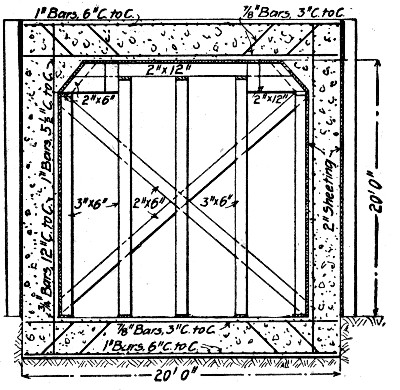 Fig. 169.—Box Culvert and Form, C., B. & Q. R. R.
The plant lay-outs vary with the local conditions, as the following will show. In one case of a culvert located under a high, short trestle the following arrangement of plant was employed: A platform located on each side of the approach[Pg 416] embankment about 8 ft. below the ties was built of old bridge timbers. A track was laid on each platform and ran out over a mixer located on the end slope of the embankment. Two mixers, one for each platform, were used. From each mixer a track led out over the culvert form and a track along the top of this form ran the full length of the culvert. Gravel and sand were dumped from cars onto the side platforms and thence shoveled into small bottom dump cars, which were pushed out over the mixer and dumped directly into it. Cars on the short tracks from mixers to culvert form took the mixed concrete and dumped it into the distributing cars traveling along the form. The cars were all hand pushed.
An entirely different lay-out was required in case of a long box culvert located in a flat valley some 600 ft. from the track. A platform was built at the foot of the embankment with its outer edge elevated high enough to clear two tracks carrying 5 cu. yd. dump cars. The sand and gravel was dumped from cars onto the side of the embankment, running down onto the platform so that scraper teams moved it to holes in the platform where it fell into the dump cars. These cars were hauled by cable from the mixer engine and dumped at the foot of an inclined platform leading to a hopper elevated sufficiently to let a 1½ cu. yd. dump car pass under it. A team operating a drag scraper by cable moved the material up the inclined platform into the hopper, whence it fell directly into the car to which cement was added at the same time. The charging car was then pulled by the mixer engine up another incline, at the top of which it dumped into the mixer. The concrete car was hauled up another incline to a track carried on the forms and reaching the full length of the culvert work.
The placing of the reinforcement is given close supervision. When a wet concrete is used it is found necessary to securely fasten the bars in place to prevent them being swept out of place by the rush of the concrete. A method of supporting the invert bars is shown by Fig. 169; 2×2-in. stakes are large enough and they need never be spaced closer than 6 ft. The longitudinal bars are held on the stakes by wire nails bent over and the transverse bars are wired to them at intersections by stove pipe wire. The vertical wall bars are placed by[Pg 417] thrusting the ends into the soft footing concrete and nailing them to a horizontal timber at the top; the horizontal wall bars are wired at intersections to the verticals. In the roof slab the stakes are replaced by metal chairs, or by small notched blocks of concrete.
The form construction is shown by Fig. 169. It is not generally made in panels, since, as the work runs, the locations of boxes of the same size are usually so far apart that transportation charges are greater than the saving due to use a second time. No general rule is followed in removing forms, but they can usually be taken down when the concrete is a week old.
The boxes are built in sections separated by vertical joints, one section being a day's work. The vertical joints are plain butt joints; tongue and groove joints give trouble by the tenons cracking off in the planes of the joints. A wet mixture is used and smooth faces obtained by spading.
ARCH CULVERT COSTS, N. C. & ST. L. RY.—The cost of arch culvert construction for the Nashville, Chattanooga & St. Louis Ry. is recorded in a number of cases as follows:
18-ft. Arch Culvert.—Mr. H. M. Jones is authority for the following data: An 18-ft. full-centered arch culvert was built by contract, near Paris, Tenn. The culvert was built under a trestle 65 ft. high, before filling in the trestle. The railway company built a pile foundation to support a concrete foundation 2 ft. thick, and a concrete paving 20 ins. thick. The contractors then built the culvert which has a barrel 140 ft. long. No expansion joints were provided, which was a mistake for cracks have developed about 50 ft. apart. The contractors were given a large quantity of quarry spalls which they crushed in part by hand, much of it being too large for the concrete. The stone was shipped in drop-bottom cars and dumped into bins built on the ground under the trestle. The sand was shipped in ordinary coal cars, and dumped or shoveled into bins. The mixing boards were placed on the surface of the ground, and wheelbarrow runways were built up as the work progressed. The cost of the 1,900 cu. yds. of concrete in the culverts was as follows per cu. yd.:[Pg 418]
| 1.01 bbls. Portland cement | $2.26 |
| 0.56 cu. yds. of sand, at 60 cts. | .32 |
| Loading and breaking stone | .25 |
| Lumber, centers, cement house and hardware | .64 |
| Hauling materials | .04 |
| Mixing and placing concrete | 1.17 |
| Carpenter work | .19 |
| Foreman (100 days at $2.50) | .13 |
| Superintendent (100 days at $5.50) | .29 |
| ——— | |
| Total per cu. yd. | $5.29 |
It will be seen that only 19 cu. yds. of concrete were placed per day with a gang that appears to have numbered about 21 laborers, who were negroes receiving about $1.10 per day. This was the first work of its kind that the contractors had done. It will be noticed that the cost of 42 cts. per cu. yd. for superintendence and foremanship was unnecessarily high.
Six Arch Culverts 5 ft. to 16 ft. Span.—All these arches were built under existing trestles, and in all cases, except No. 2, bins were built on the ground under the trestle and the materials were dumped from cars into the bins, loaded and delivered from the bins in wheelbarrows to the mixing boards, and from the mixing boards carried in wheelbarrows to place. Negro laborers were used in all cases, except No. 5, and were paid 90 cts. a day and their board, which cost an additional 20 cts.; they worked under white foremen who received $2.50 to $3 a day and board. In culvert No. 5, white laborers, at $1.25 without board, were used. There were two carpenters at $2 a day and one foreman at $2.50 on this gang, making the average wage $1.47 each for all engaged. The men were all green hands, in consequence of which the labor on the forms in particular was excessively high. The high rate of daily wages on culverts Nos. 1 and 3 was due to the use of some carpenters along with the laborers in mixing concrete. The high cost of mixing concrete on culvert No. 2 was due to the rehandling of the materials which were not dumped into bins but onto the concrete floor of the culvert and then wheeled out and stacked to one side. The cost of excavating and back-filling at the site of each culvert is not included in the table, but it ranged from 70 cts. to $2 per cu. yd. of concrete.[Pg 419]
| No. of culvert | 1 | 2 | 3 | 4 | 5 | 6 |
| Span of culvert | 5 ft. | 7.66 ft. | 10 ft. | 12 ft. | 12 ft. | 16 ft. |
| Cu. yds. of concrete. | 210 | 199 | 354 | 292 | 406 | 986 |
| Ratio of cement to stone | 1:5.5 | 1:6.5 | 1:5.8 | 1:5.8 | 1:6.1 | 1:6.5 |
| Increase of concrete over stone | 16.0% | 9.9% | 6.3% | 12.3% | 8.3% | 5.3% |
| Bbls. cement per cu. yd. | 1.02 | 0.90 | 1.06 | 1.01 | 1.00 | 1.09 |
| Cu. yds. sand per cu. yd. | 0.43 | 0.49 | 0.44 | 0.46 | 0.46 | 0.47 |
| Cu. yds. stone per cu. yd. | 0.86 | 0.90 | 0.95 | 0.89 | 0.94 | 0.94 |
| Total day labor (inc. foremen and supt.) | 702 | 607 | 784 | 726 | 768 | 1,994 |
| Av. wages per day (inc. foremen and supt.) | $1.61 | $1.33 | $1.59 | $1.19 | $1.47 | $1.46 |
| Cost per cu. yd.— | ||||||
| Cement | 2.18 | 1.94 | 2.27 | 1.82 | 2.11 | 2.01 |
| Sand | 0.17 | 0.20 | 0.18 | 0.18 | 0.19 | 0.14 |
| Stone | 0.52 | 0.52 | 0.47 | 0.54 | 0.47 | 0.58 |
| Lumber | 0.88 | 0.43 | 0.48 | 0.43 | 0.31 | 0.57 |
| Unload, materials | 0.23 | 0.17 | 0.18 | 0.18 | 0.16 | |
| Building forms | 1.07 | 0.33 | 0.62 | 0.47 | 0.72 | 0.41 |
| Mixing & placing | 1.59 | 1.74 | 1.69 | 1.35 | 1.23 | 1.26 |
| ——— | ——— | ——— | ——— | —— | —— | |
| Total per cu. yd. | $6.64 | $5.33 | $5.89 | $4.97 | $5.19 | $4.97 |
14-ft. 9-in. Arch Culvert.—Mr. W. H. Whorley gives the following methods and cost of constructing a 12-ft. full centered arch culvert 204 ft. long. The culvert was built in three sections, separated by vertical transverse joints to provide for expansion; the end sections were each 61 ft. long and the center section was 70 ft. long. Fig. 170 is a cross-section at the center; for the end sections the height is 14 ft. 9 ins., the crown thickness is 1 ft. 9 ins., and the side walls at their bases[Pg 420] are 5 ft. thick. The concrete was a 1-3-6 mixture, using slag aggregate for part of the work and stone aggregate for a part. The culvert was built underneath a trestle which was afterwards filled in.
Mixing and Handling Concrete.—The height of the track above the valley permitted the mixing plant to be so laid out that all material was moved by gravity from the cars in which it was shipped until finally placed in the culvert. Sand and aggregate were received in drop bottom cars and were unloaded into bins in the trestle. These bins had hopper bottoms with chutes leading to a wheeling platform, which was placed between two trestle bents and extended over a mixer placed outside the trestle. The cement house was erected alongside the trestle at the wheeling platform level and a chute from an unloading platform at track level to the opposite end of the house enabled the bags to be handled directly from the car to the chute and thence run by gravity to the cement house. Sand and aggregate were chuted from the bins into wheelbarrows, wheeled about 23 ft., and dumped into a hopper over the mixer. Water was pumped by a gasoline engine from a well just below the trestle to a tank on the trestle, whence it was fed to the mixer by a flexible connection, a valve so regulating the flow that the necessary amount was delivered in the time required to mix a batch.
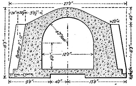 Fig. 170.—Section of Arch Culvert, N., C. & St. L. R.
R.
Fig. 170.—Section of Arch Culvert, N., C. & St. L. R.
R.
The mixer was a No. 5 Chicago Improved Cube Mixer, operated by a gasoline engine; a larger size would have been preferable since a batch required only two-thirds of a bag of cement which had to be measured which required the services of an additional man. The mixer was in operation 194 hours and mixed 7,702 batches (1,217 cu. yds.), or a batch every 87 seconds, or 6.3 cu. yds. per hour. During the last ten days it mixed a batch every 78 seconds while running. The best short record made was 291 batches in five hours, or one batch every 63 seconds, this being at the rate of 58 batches equal to 9.2 cu. yds. of concrete in place per hour, or nearly 1/6 cu. yd. per batch. It took about ½ minute to mix the concrete and about the same length of time to charge and discharge the mixer.
To convey the concrete from the mixer to the culvert walls a 1 cu. yd. drop bottom car was used. This car ran on 30-in. gage tracks carried on a trestle straddling the culvert walls and having its floor high enough to clear the arch. A track ran lengthwise of the trestle over each culvert wall, and a cross track intersecting both with turntables ran to the mixer. Three men handled the car, a round trip to the extreme end of the trestle being made in about 3 minutes. In the meantime the mixer was discharging into a small hopper which unloaded into the car on its return. One only of the three sections, of the culvert was built at a time, both walls being brought up together. After a point had been reached about 2 ft. above the springing on both walls, one track was removed and the other was shifted to the center of the trestle.
Forms.—There was used in the forms 15,000 ft. B. M. of 2-in. dressed lagging for face work, 21,000 ft. B. M. rough lumber for back work, and old car sills for studding. No charge was made for studding except the cost of loading, the cost of the remaining lumber was $16 per M. for dressed and $12.50 per M. for rough. A credit of one-third the cost was allowed for the old material recovered. The total cost of the labor of erecting the material in forms, bins and platforms was $666. The work was done by a bridge crew of white men, the[Pg 422] average rate of wages per man, including the bridge foreman's time, being $2.20 per day. In addition a mason at $3.50 per day and a carpenter at $2.25 per day worked with the bridge crew in erecting forms.
Cost.—The cost of the 1,217 cu. yds. of concrete in the culvert was as follows:
| Item. | Per cu. yd. |
| 1.08 bbls. cement at $1.72 | $1.85 |
| 0.47 cu. yd. sand at 30 cts. | 0.14 |
| 0.25 cu. yd. broken stone at 51 cts. | 0.13 |
| 0.8 cu. yd. slag at 26 cts. | 0.21 |
| Lumber in forms, etc. | 0.30 |
| Miscellaneous materials | 0.05 |
| Labor, unloading materials | 0.11 |
| Labor, mixing and placing concrete | 0.42 |
| Labor, building forms | 0.55 |
| Labor, not classified | 0.18 |
| Labor, excavating 40 cts. per cu. yd. | 0.28 |
| Labor, back filling and tearing down forms | 0.10 |
| —— | |
| Total | $4.32 |
CULVERTS FOR NEW CONSTRUCTION, WABASH RY.—The following data relate to culvert work carried out in constructing the Pittsburg extension of the Wabash Ry. in 1903. All the work was done by contract.
Plant I: This plant was located on a hillside with the crushing bins above the loading floor or platform which extended over the top of the mixer, so that the crushed stone could be drawn directly from the chutes of the bins and wheeled to the mixer. The sand was hauled up an incline in one-horse carts and dumped on this floor, and was also wheeled in barrows to the mixer. The proportions used were 4 bags of cement, 4 barrows of sand and stone dust and 7 barrows of crushed stone. A ⅞-cu. yd. mixer was used and it averaged 40 cu. yds. per 10-hour day at the following cost for labor:[Pg 423]
| Item. | Per day. | Per cu. yd. |
| 1 foreman | $ 3.00 | $0.08 |
| 3 men charging with barrows | 4.50 | 0.11 |
| 1 man attending engine and mixer | 2.50 | 0.06 |
| 2 men loading concrete barrows | 3.00 | 0.08 |
| 4 men wheeling concrete barrows (100 ft.) | 6.00 | 0.15 |
| 4 men ramming concrete | 6.00 | 0.15 |
| 4 men wheeling and bedding rubble stones | 6.00 | 0.15 |
| ——— | —— | |
| Totals | $31.00 | $0.78 |
Assuming ⅓ ton of coal per day at $3 per ton, we have 2 cts. more per cubic yard for fuel.
Plant II.—At this plant a Smith mixer was used with a loading floor 4 ft. above the ground, this low platform being made possible by having a hole or sump in which the skip receiving the concrete was set. A derrick handled the skips between the sump and the work. The batch was made up of 2 bags of cement, 2 barrows of sand and 4 barrows of stone. The output was 50 cu. yds. per day of 10 hours at the following cost:
| Item. | Per day. | Per cu. yd. |
| 1 man feeding mixer | $1.50 | $0.03 |
| 1 mixer runner | 2.50 | 0.05 |
| 1 derrick engineman | 2.50 | 0.05 |
| 2 tagmen swinging and dumping | 3.00 | 0.06 |
| 6 men wheeling materials | 9.00 | 0.18 |
| 2 men tamping concrete | 3.00 | 0.06 |
| 1 foreman | 3.00 | 0.06 |
| ——— | —— | |
| Totals | $24.50 | $0.49 |
The cost of fuel would add about 3 cts. per cubic yard to this amount.
SMALL ARCH CULVERT COSTS, PENNSYLVANIA R. R.—Mr. Alex. R. Holliday gives the following figures of cost of small concrete culvert work carried out under his direction. The culvert section used is shown in Fig. 171. This section gives a slightly larger waterway than a 36-in. cast iron[Pg 424] pipe. Eight culverts, having an aggregate length of 306 ft. were built, using a mixture of Portland cement and limestone and screenings. Each culvert had a small spandrel wall at each end.
The work was done by a gang of six men, receiving the following wages:
| Foreman, | cents | per | hour | 27.5 |
| Assistant | " | " | " | 17.5 |
| Laborers | " | " | " | 15.0 |
| Teams | " | " | " | 35.0 |
The materials were hauled about 1 mile from railway to site of work. Cement, including freight and haulage, cost $1.97 per barrel. Limestone and screenings cost 50 cts. per cu. yd. f. o. b. at quarry. No freight charges are included in cost of any of the materials except cement. The cost of the 306 ft. of culvert was as follows:
| Item. | Total. | Per lin. ft. | Per cu. yd. |
| Labor | $443.14 | $1.45 | $3.35 |
| Stone and screenings | 78.50 | 0.25 | 0.60 |
| Cement | 307.53 | 1.01 | 2.34 |
| Forms | 12.00 | 0.04 | 0.09 |
| ——— | —— | —— | |
| Total | $841.17 | $2.75 | $6.38 |
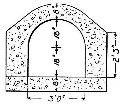 Fig. 171.—Small Culverts, Pennsylvania R. R.
26-FT SPAN ARCH CULVERT.—The culvert was 62 ft. long and 26-ft. span and was built of 1-8 and 1-10 concrete mixed by hand. The wages paid were: General foreman, 40 cts. per hour; foreman, 25 cts. per hour; carpenters, 22½ to 25 cts. per hour, and laborers, 15 cts. per hour. The cost of the concrete in place, exclusive of excavation but including wing walls and parapet, was as follows:[Pg 425]
| Per cu. yd. | |
| 0.96 bbl. cement, at $1.60 | $1.535 |
| 1.03 tons coarse gravel, at $0.19 | 0.195 |
| 0.40 tons fine gravel, at $0.21 | 0.085 |
| 0.32 tons sand, at $0.36 | 0.115 |
| Tools, etc. | 0.078 |
| Lumber for forms and centers | 0.430 |
| Carpenter work on forms (23 cts. hr.) | 0.280 |
| Carpenter work platforms and buildings | 0.050 |
| Preparing site and cleaning up | 0.210 |
| Changing trestle | 0.085 |
| Handling materials | 0.037 |
| Mixing and laying, av. 15½ cts. per hr. | 1.440 |
| ——— | |
| Total per cu. yd | $4.540 |
There were 1,493 cu. yds. of concrete in the work. The excavation cost $463 and the total cost was $7,243.
COST OF RAILWAY CULVERT.—The culvert was for a single track railway and contained 113 cu. yds. of concrete and required 36 cu. yds. of excavation. The figures are given by C. C. Williams as follows:
| Cost of Material. | |||
| Kind and Amount of Material. | Unit Price. | Cost. | |
| Stone, 113.2 tons | $.70 | $ 79.24 | |
| Sand, 46.8 yds. | .55 | 25.74 | |
| Cement, 137 bbls. | .85 | 116.45 | |
| ——— | |||
| Total | $221.43 | ||
| Lumber | 52.50 | ||
| Rail and bolts | 36.60 | ||
| ——— | |||
| Total | $ 89.10 | ||
| Excavation. | |||
| Labor, 189 hours at .15 | $ 28.35 | ||
| Foreman, 60 hours at .30 | 18.00 | ||
| ——— | |||
| [Pg 426] | |||
| Total | $ 46.35 | ||
| Concrete. | |||
| Labor, 683 hours at .15 | $102.45 | ||
| Foreman, 130 hours at .30 | 39.00 | ||
| ——— | |||
| Total | $141.45 | ||
| Forms. | |||
| Carpenters, 313 hours at .225 | $ 70.42 | ||
| Labor, 30 hours at .15 | 4.50 | ||
| ——— | |||
| Total | $ 74.92 | ||
| Handling Materials. | |||
| Moving material, 245 hours at .15 | $ 36.75 | ||
| Unloading material, 95 hours at .15 | 14.25 | ||
| Foreman, 20 hours at .30 | 6.00 | ||
| ——— | |||
| Total | $ 57.00 | ||
| Superintendence and Office. | |||
| Superintendent, 6 hours at .50 | $ 3.00 | ||
| Office | 10.00 | ||
| ——— | |||
| Total | $ 13.00 | ||
| ——— | |||
| Grand total | $643.25 | ||
| Proportional Costs. | |||
| Item. | Cost. | Cost Per Yard Concrete. | Per cent. of Total Cost of Concrete. |
| Concrete material | $221.43 | $1.96 | 7.1 |
| Laying concrete | 141.45 | 1.25 | 23.6 |
| Lumber | 52.50 | .46 | 08.7 |
| Rail and bolts | 36.60 | .32 | 06.1 |
| Building forms | 74.92 | .67 | 13.3 |
| Handling material | 56.90 | .50 | 09.0 |
| Superintendent and office | 13.00 | .12 | 02.2 |
| —— | ——— | ||
| Total | $5.28 | 100.00 | |
| Excavation | 46.35 | 1.28 | |
| ——— | |||
| [Pg 427] | |||
| Total | $643.15 | ||
| Contractor's Receipts. | |||
| 113 yds. concrete at $5.95 | $672.35 | ||
| 36 yds. excavation at .30 | 10.80 | ||
| ——— | |||
| Total | $683.15 | ||
| Total cost | 643.15 | ||
| ——— | |||
| Profit, 5.9% of contract price | $ 40.00 | ||
12-FT. CULVERT, KALAMAZOO, MICH.—A portion 1,080 ft. long of a new channel built in 1902-3 for a small stream flowing through the city of Kalamazoo, Mich., was constructed as an arch culvert of the form shown by Fig. 172. The concrete section is reinforced on the lines indicated by a double layer of woven steel wire fabric. The concrete was approximately a 1 cement, 6 sand and gravel mixture.
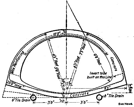 Fig. 172.—Cross-Section of Culvert at Kalamazoo, Mich.
The centers were built in sections 12½ ft. long of the form and construction shown by Fig. 173, and a sufficient number was provided to lay twelve sections of invert and six sections of arch. The arch centers were arranged to be uncoupled at the crown; this with the hinges at the quarter points permitted the two halves to be separated and each half to be folded so that it could be carried from the rear of the work through the forms still in place and erected again for new work. When in place the center ribs rested on the side forms which set on the invert concrete and are braced apart by the hinged cross-strut. This cross-strut was the key that bound[Pg 428] the whole structure together; the method of removing this key is indicated by Fig. 174. From his experience with these centers the engineer of the work, Mr. Geo. S. Pierson, remarks:
"In work of this kind it is very important to have the centering absolutely rigid so it will not spring when concrete is being tamped against it and thus weaken the cohesion of the concrete. It is also important to have the arrangement such that all the centering can be removed without straining or jarring the fresh concrete. The centers were generally removed in about three or four days after the concrete arch was in place."
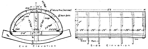 Fig. 173.—Center for Culvert at Kalamazoo, Mich.
The invert concrete was brought to form by means of templates, Fig. 173, and straight edges. The side forms were then placed and braced apart by the struts and concreting continued to the skewback plane indicated in Fig. 173. The arch form was then placed; it rested at the edges on the side forms and was further supported by center posts bearing on boards laid on the bottom of the invert. A template, Fig. 175, was used to get the proper thickness and form of arch ring. Outside forms were used to confine the concrete at the haunches but nearer the crown they were not required.
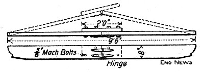 Fig. 174.—Hinged Cross Strut for Center for Culvert at
Kalamazoo, Mich.
Fig. 174.—Hinged Cross Strut for Center for Culvert at
Kalamazoo, Mich.
Much of the work was done when the thermometer, during working hours, ranged from 12° to 25° above zero. When the temperature was below freezing, hot water was used in mixing the concrete and on a few of the coldest days salt was dissolved in the water. In addition each section of the work was covered with oiled canvas as soon as completed, and the conduit was kept closed so far as was practicable to retain the heat. Concreting was never stopped on account of cold weather.
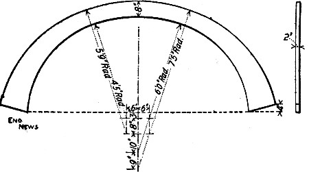 Fig. 175.—Templet for Arch Ring for Culvert at
Kalamazoo, Mich.
Fig. 175.—Templet for Arch Ring for Culvert at
Kalamazoo, Mich.
Account was kept of the cost of all work, and the figures obtained are given in the following tables:
| Labor Force, Materials Used and Progress of Work. | |
| Average progress per day in feet | 18.0 |
| Greatest number of feet laid in one day | 28 |
| Average number of laborers per day mixing and wheeling | 10.04 |
| Average number of laborers per day placing concrete | 5 |
| Average number of laborers per day setting up forms | 4.57 |
| Cubic yards of concrete mixed and wheeled per day per man | 1.96 |
| Cubic yards of concrete placed per day per man | 3.54 |
| Cubic yards of concrete per lin. ft. | 0.95 |
| Barrels of cement per lin. ft. | 1.18 |
| Barrels of cement per cu. yd. | 1.24 |
| [Pg 430] | |
| Proportion of cement to sand and gravel | 1-6 |
| Itemized Cost per Lineal Foot. | |
| Sand and gravel | $0.42 |
| Cement | 2.44 |
| Mixing and wheeling concrete | 0.98 |
| Labor placing concrete | 0.47 |
| Forms and templates | 0.30 |
| Metal fabric | 0.39 |
| Setting up forms | 0.43 |
| Finishing | 0.09 |
| Tools, general and superintendence | 0.43 |
| —— | |
| Total per lineal foot | $5.95 |
The cost per cubic yard was thus $6.26. Wages were $1.75 per day.
METHOD AND COST OF MOLDING CULVERT PIPE, CHICAGO & ILLINOIS WESTERN R. R.—During 1906, the Chicago & Illinois Western R. R., Mr. O. P. Chamberlain, Chief Engineer, built a number of culverts of concrete pipe with an interior diameter of 4 ft., and 6-in. shells. Fig. 176 shows the forms in which the pipe was molded. Both forms are of ordinary wooden tank construction. The inner form has one wedge-shaped loose stave which is withdrawn after the concrete has set for about 20 hours, thus collapsing the inner form and allowing it to be removed. The outer form is built in two pieces with 2×⅝-in. semi-circular iron hoops on the outside, the hoops having loops at the ends. The staves are fastened to the hoops by wood screws 1¾ ins. long driven from the outside of the hoop. When the two sides of the outer form are in position, the loops on one side come into position just above the loops on the other side, and four ¾-in. steel pins are inserted in the loops to hold the two sides together while the form is being filled with concrete and while the concrete is setting. After the inner form has been removed, the two pins in the same vertical line are removed and the form opened horizontally on the hinges formed by the loops and pins on the opposite side. The inner and outer forms are then ready to be set up for building another pipe.[Pg 431]
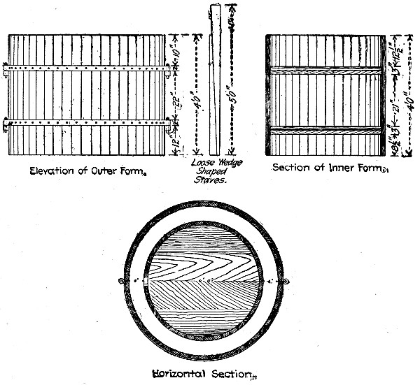 Fig. 176.—Form for Molding Culvert Pipe.
The concrete used in manufacturing these pipes was composed of American Portland cement, limestone screenings and crushed limestone that has passed through a ¾-in. diameter screen after everything that would pass through a ½-in. diameter screen had been removed. The concrete was mixed in the proportions of one part cement to three and one-half parts each of screenings and crushed stone. All work except the building of the forms was performed by common laborers. In his experimental work Mr. Chamberlain used two laborers, one of whom set the forms, and filled them and the other of whom mixed the concrete. The pipes were left in the forms till the morning of the day after molding. The two laborers removed the forms filled the day before, the first thing in the morning, and proceeded to refill them. The average time the concrete was allowed to set before the forms were removed was 16 hours. Mr. Chamberlain believes that with three men[Pg 432] and six forms the whole six forms could be removed and refilled daily. Based on the use of only two forms with two laborers removing and refilling them each day, and on the assumption that a single set of forms costing $40 can be used only 50 times before being replaced, Mr. Chamberlain estimates the cost of molding 4-ft. pipes as follows:
| 2 per cent, of $40 for forms | $0.80 |
| 1.1 cu. yds. stone and screenings at $1.85 | 2.04 |
| 0.8 bbls. cement at $2.10 | 1.68 |
| 10 hours' labor at 28 cts. | 2.80 |
| —— | |
| Total per pipe | $7.32 |
This gives a cost of $1.83 per lineal foot of pipe or practically $7 per cu. yd. of concrete. The pipe actually molded cost $2.50 per lin ft., or $9.62 per cu. yd. of concrete, owing to the small scale on which the work was carried on—the laborers were not kept steadily at work.
The pipes were built under a derrick and loaded by means of the derrick upon flat cars for transportation. At the culvert site they were unloaded and put in by an ordinary section gang with no appliances other than skids to remove the pipes from the cars. As each four-foot section of this pipe weighs about two tons, it was not deemed expedient to build sections of a greater length than 4 ft., to be unloaded and placed by hand. On a trunk line, however, where a derrick car is available for unloading and placing the pipes, there is no reason why they should not be built in 6 or 8-ft. sections.
If we set aside concrete block construction, virtually all concrete used in building construction is reinforced; plain monolithic or mass concrete now, as in the past, is one of the secondary building materials. It is reinforced concrete building construction that is discussed in this chapter. In no class of concrete work is the contractor's responsibility for the successful outcome of the work greater than in reinforced concrete building construction. No degree of excellence in design can make up for incompetent, careless or dishonest work in construction. This is true not merely in the general way that it is true of all engineering construction—it is true in a special way peculiar to the material. Except for the reinforcing steel, the contractor for concrete building work has no guarantee of the quality of any element of his work except his own faithful care in performing every task that combines to produce that element. The quality of his concrete depends upon the care with which he has chosen his cement, sand and stone, and on the perfection with which he has incorporated them into a homogeneous mixture. The quality of his beam or column, then, depends upon the care with which the concrete is placed in position with the reinforcement and with which the supporting forms are maintained until the member is amply strong to do without support. There is no certainty of any detail except the certainty that is had by performing every part of the work as experience has taught that it should be performed if perfect results are to be attained. We have dwelt thus emphatically on the responsibility in concrete building work of the contractor for the reason that in the past it has been upon the contractor that the burden of failure has been generally shifted.[Pg 434]
The construction work of buildings is divided into (1) construction, erection and removal of forms; (2) fabrication and placing of reinforcement; (3) mixing, transporting and placing concrete.
The stereotyped text-book statement that forms must be true to dimensions and shape and rigid enough in construction to maintain this condition under all loads that they have to sustain mentions only one of the factors that the constructing engineer or the contractor has to keep in mind in designing such forms. His design must be made true and rigid at the least possible cost for first construction of lumber and carpenter work; it must be made with the plan in mind of using either the same forms as a whole or the same form material several times in one structure; it must be made with a view to convenience in taking down, carrying and re-erecting the forms the second or third time; and it must be made with the object in sight of securing the greatest salvage value either in forms fit for use again or in form lumber that can be sold or worked up for other purposes.
The general conditions governing the computation and design of economic form work are discussed in Chapter IX.
COLUMN FORMS.—Concrete columns are usually square or rectangular in section, with, commonly, chamfered or beveled corners. The popularity of these sections is due very largely to the simplicity of the forms required. When hooped reinforcement is used, the column section is always circular or polygonal. Hollow sections, T-section and channel sections are rarely employed and then only for wall columns.
Column forms should be made in units which can readily be assembled, taken apart and re-assembled. The number, arrangement and size of the units are determined by the shape and size of the column and the means adopted for handling the forms. For square or rectangular columns there will be usually four units of lagging, one for each side, plus the number of clamps or yokes used to bind the sides together. Yokes or clamps will seldom be spaced over 3 ft. apart unless very heavy lagging is used; 2 ft. spacing for yokes is common.[Pg 435] For circular columns two units of lagging are necessary and this is the number commonly used; the yokes or hoops are spaced about as for rectangular columns. Metal forms can be used to good advantage for cylindrical columns. Forms for polygonal columns are difficult to construct in convenient units. Forms built complete a full story high and concreted from the top are essential where wet and sloppy concretes are used. In Europe, where comparatively dry concretes are employed and where the reinforcement is commonly placed a piece at a time as concreting progresses, three sides of a rectangular form are erected full height and the fourth side is built up as the concrete and metal are placed. This construction is now less common, even abroad, than it was, since wetter mixtures are coming to be approved by European engineers to a greater extent now than formerly. It is a time consuming method and with wet mixtures it has nothing to recommend it. For lagging 1¼ and 2-in. plank are commonly used; with yokes spaced 2 ft. apart the lighter plank is amply strong and reduces the weight of the units to be handled as well as the amount of form lumber required.
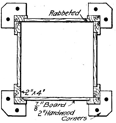 Fig. 177.—Form for Rectangular Column for Factory
Building, Cincinnati, O.
Fig. 177.—Form for Rectangular Column for Factory
Building, Cincinnati, O.
Column forms should always be constructed with an opening at the bottom by means of which the reinforcement can be adjusted and sawdust, shavings and other material cleaned out.
Rectangular Columns.—The form shown in section by Fig. 177 was used in constructing a factory building at Cincinnati, O. Two 2×4-in. studs at each corner carry the horizontal side lagging boards and are clamped together by yokes[Pg 436] composed of four hardwood corner saddles connected around the form by a hooked rod with center turnbuckle on each side. No nails are used in assemblying the parts; the same studding and yokes serve for several sizes of column, the lagging alone being changed. The lumber required for studding is 5½ ft. B. M. per foot of column length. The lumber required for lagging, using 1 in. boards, would be 2⅔ ft. B. M. for a 12-in. column, and ⅔ ft. B. M. would be added for every 2-in. increase in size of the column. About 3½ ft. B. M. is required for each set of four corner saddles. With the studs rabbeted at the mill, the carpenter work is reduced to the simple task of sawing the boards and struts to length. The form is taken down by simply unscrewing the turnbuckles; it can be erected by common labor in charge of one carpenter to attend to the plumbing and truing-up. The form can be used over and over and for columns of different sizes without change except in the length of the lagging boards.
The form shown by Fig. 178 was used in constructing a nine-story warehouse at St. Paul, Minn.; it is a design which has become almost standard with a number of large building contractors. In this construction lagging boards the full length of the column are used and are held without nails by yokes. The yokes consist of two heads of wood held together by threaded rods with nuts; between the rods and the lagging are struts or blocks serving both as spacers and to hold the lagging to plane and surface. The yoke proper is adjustable to the extent of the threaded portions of the tie rods. It is to be noticed that the lagging boards are not connected by battens or cleats, therefore, two or three widths of stock serve for all ordinary changes in size of columns and carpenter work is limited to sawing them to length. Furthermore as the boards are full column length, their salvage value when removed from the forms is high. Common laborers under a carpenter foreman can assemble and erect the form. For a 12-in. column and using 3×4-in. yokes spaced 2 ft. apart and 1¼-in. lagging, this form requires about 12 ft. B. M. of lumber per foot length of column. The column form shown by Fig. 226 for the six-story building described in a succeeding section differs from the one described only in the details[Pg 437] of the yoke construction. In place of the struts between the wooden heads of the yoke a cleat is nailed across the projecting ends which has to be pried loose every time the yoke is removed and nailed into place again every time the yoke is put onto another form; these repeated nailings soon destroy the yoke heads. This form as constructed requires about 8¾ ft. B. M. of lumber per foot length of 12-in. column, which is 3¼ ft. B. M. less than is required for the form shown by Fig. 177. The saving comes entirely in the yoke construction.
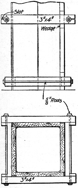 Fig. 178—Form for Rectangular Column for Warehouse at
St. Paul, Minn.
Fig. 178—Form for Rectangular Column for Warehouse at
St. Paul, Minn.
The form shown by Fig. 238 is of the same general type as are the two just described, the chief difference in detail being in the yoke construction and in the forming of the lagging boards into a panel or unit for each side by means of battens. This panel construction makes a lagging unit which is more convenient to handle, but less convenient to adapt to changes in size of column. The salvage value of the lumber is also reduced by the nailing. Assuming 1¼-in. lagging and a yoke spacing of 2 ft., to permit direct comparison, this form requires 10½ ft. B. M. of lumber per foot length of 12-in. column as compared with 12 ft. B. M. for the form shown by Fig. 177 and 8¾ ft B. M. for the form shown by Fig. 178. As actually constructed with 2-in. lagging the form shown by Fig. 238 requires about 14 ft. B. M. of lumber per foot length of 12-in. column.
The French constructor, Hennebique, uses the column form construction shown by Fig. 179. Three sides of the forms are built full length of vertical plank and the fourth is built up of horizontal lagging nailed on a board at a time as concreting progresses. In place of rectangular yokes, steel clamps of special form are used to hold the lagging in place. To tear[Pg 438] down this form requires drawing the nails in the horizontal lagging and the knocking loose of the clamps. The vertical lagging is of necessity connected by battens into panels to make it possible to hold it in place by the form of clamp used. Assuming 2-in. vertical lagging with ⅞×3-in. battens every 3 ft., and ⅞-in. horizontal lagging this form requires about 12 ft. B. M. of lumber for every foot length of 12-in. column. This form seems to offer no particular merits to American eyes: there is practically no saving in lumber over forms with rectangular yokes and the clamp shown, while adjustable, is not nearly so rigid and secure a bond for the lagging as is a good yoke.
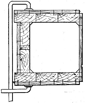 Fig. 179.—Form Used by Mr. Hennebique for Rectangular
Columns.
Fig. 179.—Form Used by Mr. Hennebique for Rectangular
Columns.
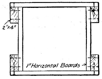 Fig. 180.—Form for Rectangular Column for a Factory
Building, New York City.
Fig. 180.—Form for Rectangular Column for a Factory
Building, New York City.
The form shown by Fig. 180 is an extreme example of nailed construction throughout, no yokes or clamps being used. It was used in constructing a factory building in New York City.[Pg 439] Horizontal lagging nailed to vertical studs was used for all four sides; three sides were built up full height and the fourth side was placed a board at a time as concreting progressed. This form required 7⅓ ft. B. M. of lumber per foot length of 12-in. column, which is probably about as low in lumber as column form construction can be got. The labor of tearing down and re-erecting the form would be high as also would the waste of lumber. Nailed forms of this type are rarely used.
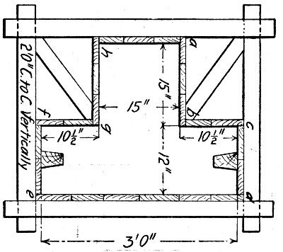 Fig. 181.—Form for T-Section Wall Column.
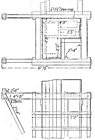 Fig. 182.—Form for Corner Wall Column.
The form shown by Fig. 181 was used for molding T-section wall columns for a power station. It is noteworthy for its section; because of the provision for molding grooves in the two sides to which the curtain walls join, and because of the manner in which three of the eight sides were built up as the concreting progressed. The sides a b c, d e and f g h were erected in full column units and the sides c d, e f and h a were erected in sections 2 ft. high as concreting progressed. The yokes were spaced 2 ft. apart. Using 1¼-in. stuff for yokes and lagging this form as built required about 16 ft. B. M. per foot length of column. Except for the beveling of the mold for the curtain wall recesses, the framing is all plain saw and hammer work.
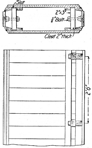 Fig. 183.—Core Form for Hollow Column.
A corner wall column form is shown by Fig. 182 and as this was an example of hollow column work the section of the concrete within the form is shown. Forms of this shape and of T-section are properly classed as special form work so that[Pg 441] the examples given here are helpful merely as indicating general methods that may be followed. This particular form required 15¾ ft-B. M. of ⅞-in. lagging per foot of column length, and, neglecting the special top frame, about 16 ft. B. M. of "staging" per foot to support the lagging. The core forms for molding the hollow spaces in the columns of this particular building are shown in Fig. 183. The cross pieces or keys carried on the ⅝-in. bolts as pivots are revolved a quarter turn to slip clear of the slots and permit the sides to close together and free the core for withdrawal. In many cases the contractor will find it preferable to use thin sheet metal core molds or light wooden cores and leave them in place. In one case known to the authors where hollow wall columns were used as hot air ducts for a heating system the duct was laid up of one row of bricks, encircled by the column form and the annular space concreted around the brick duct as a core. The rare use of irregular columns makes form and core construction for them a special problem requiring special detailed estimates in each case. The channel section wall column form shown by Fig. 230 is a case in point; here the form became practically a portable mold for duplicating columns as many times as was desired.
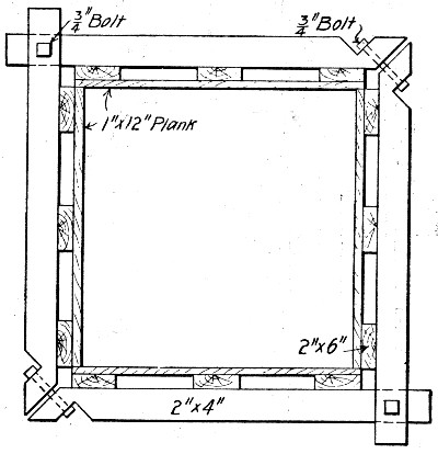 Fig. 184.—Form for Large Rectangular Columns.
As an example of form work for very large columns or pillars that shown by Fig. 184 is particularly good; it was used for constructing eight 3-ft. square pillars for a water[Pg 442] tank tower. The lagging consists of four panels made by nailing horizontal boards to vertical studs. The panels are clamped together by rectangular yokes spaced 3 ft. apart. There are nearly 27½ ft. B. M. of lumber per foot length of 3-ft. column in this form.
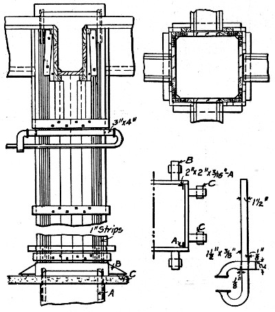 Fig. 185.—Adjustable Form for Rectangular Columns.
The form shown by Fig. 185 was used by Mr. R. W. Maxton in constructing a large factory building at St. Louis, Mo., and is notable for the means adopted for centering the forms and for reducing their lateral dimensions to fit them for molding the decreasingly smaller columns of the upper floors. To center the forms the short angles A A are molded into the concrete so as to project slightly above the tops of the floor slab. Also the pieces of wood C are molded into the floor slab. The form is set over the angles and lined up truly by nailing the blocks B to the blocks C. It will be noticed also that the column mold bears only at the four corners the lagging being cut away somewhat on each side so as to afford an opening for cleaning. The lagging for the sides of the column mold is battened together to form four units or panels which are held together by iron clamps of the form shown.[Pg 443] Lag screws are used everywhere in place of nails. The notable feature, however, is the piecing out of the lagging panels with 1-in. strips, one or more of which can be ripped off on each side to reduce the size of the forms as the columns grow smaller toward the top of the building.
Polygonal Columns.—Forms for polygonal columns require more lumber and more carpenter work and are less susceptible of ready arrangement into units than forms for rectangular columns. There is no approach to a uniform practice in their construction and the few forms shown here are merely specific examples.
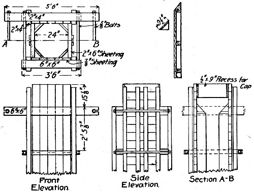 Fig. 186.—Form for Octagonal Column for a Factory
Building.
Fig. 186.—Form for Octagonal Column for a Factory
Building.
The form shown by Fig. 186 was used for interior columns of octagonal section with hooped reinforcement for a factory building. This form for a 12-ft. octagonal column 24 ins. across between sides requires approximately 325 ft. B. M. of lumber. The form shown by Fig. 187 was used by the same engineer in another building; it is, as will be noted, in four units coming apart in joints at diagonally opposite corners. This form for an octagonal column 18 in. across between sides required about 13 ft. B. M. of lumber per foot of column length, with yokes spaced 3½ ft. apart.[Pg 444]
The form shown by Fig. 188 was used in a large warehouse at Chicago, Ill. It will be noted from the dotted lines that one yoke clamps the sides a a, the next the sides b b and so on. This does away with triangular blocking to hold the corner boards that is used in the form shown by Fig. 187. Six pairs of yokes were used for each column so that the yoke spacing was about 2 ft. With 2×6-in. yokes and 1½-in lagging a form for a column 18 ins. between sides would require some 17 ft. B. M. per foot of column length.
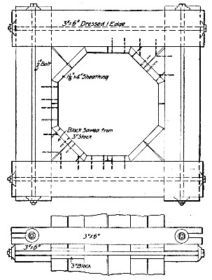 Fig. 187.—Form for Octagonal Column for Factory
Building.
Fig. 187.—Form for Octagonal Column for Factory
Building.
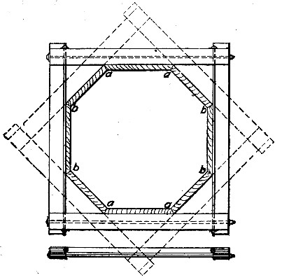 Fig. 188.—Form for Octagonal Column for a Warehouse,
Chicago, Ill.
Fig. 188.—Form for Octagonal Column for a Warehouse,
Chicago, Ill.
Circular Columns.—Circular columns have been most frequently molded in steel forms, and these are by all odds the best for general work. Made in two parts of sheet steel and in sections that are set end to end one on another a form is obtained which is easy to erect, remove and transport. Wood forms for circular columns are rather clumsy affairs and are expensive to construct. Such a form, Fig. 190, is described in the succeeding section; another is shown by Fig. 189. This form was used successfully for filling and encasing steel columns for a fireproof building in Chicago, Ill., and is a favorite circular form construction in Europe. It is apparent that the hooping needs to be very heavy and that the form is one that will be hard to handle and rather expensive to make.
In several instances, where hooped reinforcement has been used, the hooping has been wrapped with, or made of, expanded metal or other mesh-+work, and the concrete deposited inside the cylinder thus formed, without other form work. A six-story factory building in Brooklyn, N. Y., was built with circular interior columns from 28 ins. to 12 ins. in diameter, reinforced by a cylinder of No. 10 3-in. mesh expanded metal, stiffened lengthwise by four round rods 1 in. in diameter for larger columns to ½ in. in diameter for smaller columns. This reinforcement was set in place and wrapped with No. 24 ½-in. mesh metal lath, and the cylinder was filled with concrete and plastered outside. A moderately dry concrete is essential for such construction.
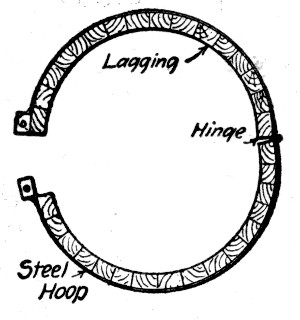 Fig. 189.—Form for Circular Column.
The method of molding shells with the hooping embedded described for the Bush terminal factory work in another section is another way of avoiding form work of the usual type.
Light steel forms as well as the special construction noted must be supplemented by staging to hold them in line and to carry the ends of the girder forms that are ordinarily carried[Pg 446] by the column forms. Four uprights arranged around the column so as to come under the connecting girders are commonly used; they are set close enough to the column to hold the form plumb by means of blocks or wedges.
Ornamental Columns.—Forms for ornamental columns call for special design and construction. For many purposes, such as porch and portico work, the best plan is to mold the columns separately and erect them as stone columns of like character are erected. Metal forms of various patterns are made by firms manufacturing concrete block molds and can be purchased from stock or made to order. Where the column is to be molded in place form construction becomes a matter of pattern making, the complexity and cost of which depends entirely upon the architectural form and ornament to be reproduced. The molding of ornament and architectural forms in concrete is discussed in Chapter XXIII, and the two examples of ornamental column form work given here from recent work indicate the task before the builder.
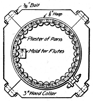 Fig. 190.—Form for Molding Fluted Cylindrical Column.
The form shown by Fig. 190 was used for molding in place fluted columns used in a court house constructed at Mineola, N. Y. The lagging in the form of staves forms a 24-sided polygon and is held in position by hoops and yokes. The molds for the flutes were formed by inserting screws from the outside so as to penetrate the staves and molding half-round ribs of plaster of Paris over them by means of the simple device shown. To dismantle the form the screws were removed and the lagging taken down leaving the plaster of[Pg 447] Paris in place as a protection to the thin edges until the final finishing of the building.
The methods illustrated by Fig. 191 were employed in molding columns in place for a church at Oak Park, Ill. The bottom portions of these columns were plain square sections molded in place in square molds. The top portions were heavily paneled. The four corner segments were cast in glue molds backed by wood with wires embedded as shown. After becoming hard they were set on end on the plain column and tied and braced as shown. The side openings were then closed by wooden forms and the interior space was filled with concrete. The surface facing for these columns was bird's-eye gravel and cement, with very little sand, mixed very dry and placed and tamped with the coarse concrete backing.
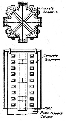 Fig. 191.—Form for Ornamental Column for Church at Oak
Park, Ill.
Fig. 191.—Form for Ornamental Column for Church at Oak
Park, Ill.
SLAB AND GIRDER FORMS.—Slab and girder construction for roofs and floors is of three kinds: (1) Concrete slab and steel beam construction in place; (2) concrete slab and girder construction in place (3) separately molded slab and beam construction. The third method of construction is distinct from the others in respect to form work as well as other details and is considered separately in Chapter XX.[Pg 448]
Slab and I-Beam Floors.—Centers for floor slabs between steel I-beams are made by suspending joists from the beam flanges and covering them with lagging. Frequently the joists and lagging are framed together into panels of convenient size for carrying and erecting. The construction is a simple one in either case where slabs without haunches or plain arches form the filling between beams. Figure 192 shows an arch slab center; plain hook bolts, with a nut on the lower end, passing through holes in the joists are more commonly employed. For 1-in. lagging the joist spacing is 2 ft., for 1½-in lagging, 4 ft., and for 2-in. lagging, 5 ft.
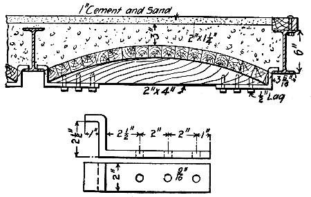 Fig. 192.—Form for Arch Slab Between I-Beams.
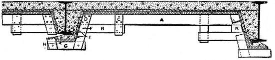 Fig. 193.—Form for Flat Slab Floor Between I-Beams.
A more complex centering is required where the slab has to be haunched around the I-beams. The center shown by Fig. 193 was designed by Mr. W. A. Etherton for the floor construction of the U. S. Postoffice Building erected at Huntington, W. Va., in 1905. The center consists essentially of the pieces A (2×4 ins. for spans not exceeding 6 ft.) and the 2×3-in. triggers B, which rest on the lower flanges of the floor beams and thus support the forms. The trigger is secured at one end to the piece A by a 1×3-in. cleat C and at the other end by 1×3-in. cleats D on either side of A, which[Pg 449] serve also as supports for the batter boards E. The six-penny nail F is but partly driven and it is to be drawn before removing the forms. When the supports of the beams are not fireproofed the cleats D extend to the bottom of the trigger B, but otherwise one cleat extends lower to secure the cross-strip G. To remove the forms, draw the partly driven nail F; knock off the strip G or loosen it enough to draw the nails in B; pull the triggers on one beam, and the forms will drop. If the soffit board H is used it is necessary first to remove the strip G. For larger beams use the spacing blocks H as shown; for smaller beams omit the trigger B and extend A to rest on the flange of the beam, then to remove the form A must be cut preferably near the beam.
No complete records of the cost of these forms were obtained, but the following partial information is furnished by Mr. Etherton: Considering a panel 6 ft. span by 19 ft. long on 15-in. I-beams, the lumber consisting of 1-in. boards supported by 2×4-in. cross-pieces on 2×3-in. triggers spread 3 ft. on centers, soffit of beams not fireproofed, it required one carpenter five hours at 30 cts. per hour to complete the panel. Figuring from this alone I should say that 10 cts. per sq. yd. is a fair estimate for carpenter work. In working over the forms for another floor the 1-in. boards require more time to handle and I should say that the saving in cost of work over the first floor would be not over 2 cts. per sq. yd. Two laborers moved their scaffolding and took down the forms from three completed panels of 13 sq. yds. each in one hour. Smaller panels require a longer time per yard. Counting for the proper piling of lumber I should allow one hour for one man to take down the forms for a 13-sq. yd. panel when conditions are the best. We contracted with two laborers to remove the forms from the third floor and roof and pile them in good shape on the ground just outside of the building for an amount averaging about 4½ cts. per sq. yd., and the men made but small wages on the contract. The lumber was used on three floors and the roof, and the best of the 1-in. boards and all of the 2×4-in. and 2×3-in. stuff were used on a second job. For a safe estimate based on the data secured I should figure the cost of labor and materials for a three or four-story building about as follows:[Pg 450]
| Per sq. yd. | |
| Lumber at $20 per thousand | 28 cts. |
| Carpenter work at 30 cts. per hour | 10 cts. |
| Labor tearing down at 15 cts. per hour | 4 cts. |
| ——— | |
| Total per square yard | 42 cts. |
Figure 194 shows an arrangement of centering between steel beams which is novel in that it provides for molding a slab with girders. The form was used in building the roof of a locomotive roundhouse. This roundhouse was of the usual circular form and had a radial width of 80 ft. Each radial roof girder, which was an 18-in. I-beam was carried by an outside wall pier and three I-beam columns encased in concrete. The space between main roof girders was spanned by reinforced concrete girders and roof slab. The center illustrated was employed for molding the concrete girders and slab, and carries out the idea of making a stiff and light center for considerable spans of slab without support by staging. The truss construction of the frames supporting the girder box will be noted.
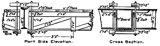 Fig. 194.—Form for Slab and Girder Floor Between
I-Beams
Fig. 194.—Form for Slab and Girder Floor Between
I-Beams
Concrete Slab and Girder Floors.—The construction of forms for this type of floor should be such that the slab centers and the sides of the girder molds can be removed without disturbing the bottoms of the girder molds. This permits the beams to be supported as long as desirable and at the same time releases the greater part of the form work for use again. It is of advantage also to lay bare the concrete as soon as possible to the hardening action of the free air. The slabs may be similarly supported by uprights wedged up against plank caps; no very great amount of lumber is required for[Pg 451] this staging and it gives a large assurance of safety. It is well also to give the girder molds a camber or to crown them to allow for settling of the falsework.
The form shown by Fig. 195 was used in constructing girders from 14 to 23 ft. long in a factory building at Cincinnati, O. The sides are separate from the bottom, being supported at the ends by cleats on the column form and at intermediate points by struts under the yokes. The floor lagging is carried by 2×4-in. stringers supported by the yokes. Uprights set under the bottom plank keep the girder supported after the sides and slab centers are removed. It will be noted that the form is given a camber of 1-in. The structural details are evident from the drawing. The form shows a method of molding a bracket for wind bracing; a simple modification fits it for molding girders without brackets. A rough computation gives 10 ft. B. M. of lumber per lineal foot of girder form as shown.
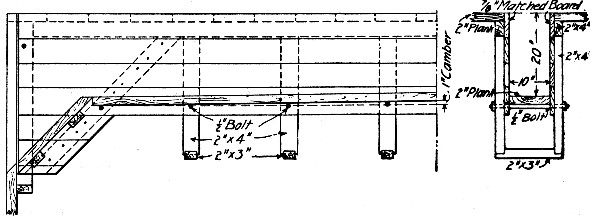 Fig. 195.—Girder and Slab Form for Factory Building,
Cincinnati, O.
Fig. 195.—Girder and Slab Form for Factory Building,
Cincinnati, O.
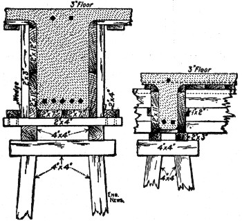 Fig. 196.—Girder and Beam Forms for Factory Building,
Beverly, Mass.
Fig. 196.—Girder and Beam Forms for Factory Building,
Beverly, Mass.
The form construction shown in Fig. 196 was employed in building the slab and girder floors for the United Shoe Machinery Co.'s factory at Beverly, Mass. In these buildings the main girders cross the building at 20-ft. intervals and midway between the main girders is a bridging beam also reaching across the building. Floor beams span the 10-ft. spaces between bridging beams and main girders at intervals of 3 and 4 ft. Referring first to the main girder form, tall horses are set up at 3-ft. intervals and connected by stringers laid on the caps. These stringers carry a cross piece, with a cleat at each end, over each horse. The bottom boards of the mold rest on these cross pieces and the side pieces are set up between verticals wedged tight between the cleats. The beam molds are a modification of the girder molds. The slab centers consist of panels just large enough to span the openings between beams and girders and composed of 1-in. boards fastened together by four 1×5-in. cleats. Except in attaching the quarter round and triangular moldings for fillets no nailing is necessary in erecting and taking down the forms.
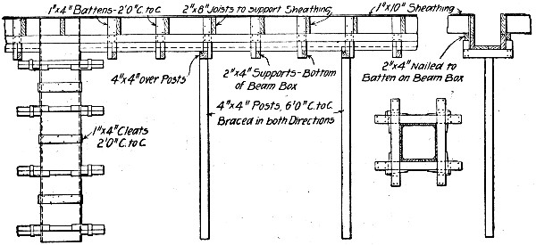 Fig. 197.—Girder and Slab Form for Concrete Building
Work.
Fig. 197.—Girder and Slab Form for Concrete Building
Work.
The form construction shown by Fig. 197 is one used by a large firm of reinformed concrete builders. The slab centers can be struck and the sides of the girder mold removed without disturbing the support for the bottom of the beam. This form runs quite low in lumber, requiring for a 9×12-in. beam box including posts some 9 ft. B. M. per lineal foot of box. The joists and lagging as shown require about 2 ft. B. M. per square foot of floor slab. The practice is to give these girder boxes a camber of ½-in. in 10 ft.[Pg 453]
The construction shown by Fig. 198 is designed to provide adjustability, to enable quick erection and removal and to do away with all nailing. The construction is as follows: Wooden posts carry at their tops steel T-beam cross-arms knee braced to the posts by steel straps. The cross-arms carry the two jaws of a clamp, each consisting of a vertical plate, and two diagonal braces, slotted so as to slide on the T-beam. A cut nail or other piece of metal driven into the slots fastens the jaws on the T-beam. The cross-arms carry the bottom boards of the girder molds and the vertical plates of the jaws support the side pieces. A blocking piece slipped between the braces carries the end of the joist for the floor slab centers. This form is the invention of Mr. W. H. Dillon and was used in constructing the nine-story, 260×150-ft. wholesale hardware store Of Farwell, Osman & Kirk Co., St. Paul, Minn.
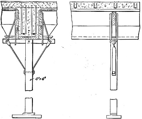 Fig. 198.—Girder and Slab Form for Warehouse at St.
Paul, Minn.
Fig. 198.—Girder and Slab Form for Warehouse at St.
Paul, Minn.
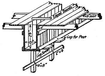 Fig. 199.—Girder and Slab Form for Factory Building, New
York, N. Y.
Fig. 199.—Girder and Slab Form for Factory Building, New
York, N. Y.
The form shown by Fig. 199 was used in constructing a factory building in Long Island City, N. Y., and it is given here chiefly for the purpose of exhibiting the unnecessary complexity of form work. Comparing this form with that of[Pg 454] nearly any of the preceding designs will bring out the point. The design, however, was one of the earlier ones to recognize the advantage of stripping the slab centers and the sides of the girder boxes without disturbing the bottom plank of the boxes or the staging. The drawing shows the independent support of the bottom board and side pieces of the girder mold on the transverse caps of the staging posts. These posts are 6×8 ins. in section and are spaced from 6 to 8 ft. apart. Briefly described the bottom board is a single plank from 1 to 3 ins. thick, to which the side pieces are lag-screwed at the bottom. The side pieces are panels composed of 4×⅞-in. vertical boards nailed to top and bottom 2×4-in. horizontal timbers. A third horizontal timber near the top serves as a seat for the ends of the joists carrying the slab lagging and is braced from the bottom horizontal by vertical stiffeners. The edge boards of the slab lagging are nailed to the top edges of the side pieces of the girder mold and the tops of these side pieces are connected across the trough by strips of board; all the slab lagging boards except those at the edges of the girder molds are laid loose. In the building referred to, after the floor concrete had set about seven days the joists carrying the slab lagging were turned a quarter over thus dropping the slab form about 2 ins. A few days later the joists and lagging were taken down and the side pieces of the girder mold were unscrewed and removed. The bottom board and staging posts were left in position about three weeks longer and then dropped about 1 in. by removing fillers from the staging post caps. In another week the bottom boards and staging posts were taken down. This construction of form[Pg 455] and method of removing it permitted the concrete to be stripped so that the air could get at it as fast as it was safe to take the support from any part and at the same time kept the supports in such position that they form a safety platform in case of collapse. A more important advantage is that the form timber can be removed as fast as any part of it is free and used again. Thus the lagging boards and joists and the side pieces for the girder molds were free for use again about every two weeks and yet the main supports of the girders were undisturbed until they were fully a month old.
Other examples of girder and slab forms are shown in the succeeding sections describing the construction of a six-story building and of a garage constructed at Philadelphia, Pa.
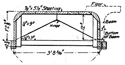 Fig. 200.—Collapsible Core Forms for Girder and Slab
Floors.
Fig. 200.—Collapsible Core Forms for Girder and Slab
Floors.
Another type of slab and girder form construction that deserves brief mention because of its variation from usual practice and also because of its extensive use by one prominent builder is shown by Fig. 200. Cores, or inverted boxes, with four vertical sides and rounded corners, are set side by side, with ends on stringers carried by the column forms, at intervals wide enough to enable the beam to be molded between. A plank resting on cleats on the sides of the cores forms the bottom of the beam mold. The main girders are molded in similar spaces between the ends of the cores in one panel and of those in the next panel. To permit the core to be loosened readily it is hinged; when in place spacers inside the core keep the sides from closing. These are knocked out, the core sides close together and the core is removed for use in another place. Cores similar to these were used in molding the ribbed floor for the Bush terminal factory building described in a succeeding section. These cores are capable of repeated use so that while they are somewhat expensive to frame they give[Pg 456] a very low cost of form work when the beam and girder spacing is arranged largely in duplicate from floor to floor. It will ordinarily be cheaper to have these cores made to pattern by regular woodworking shops, and shipped to the building ready to erect.
WALL FORMS.—Wall work in modern commercial and manufacturing buildings, when we come to eliminate windows and wall columns and girders, is confined very largely to isolated curtain wall panels between windows and framework. In such buildings, therefore, wall forms consist merely of wooden panels, one for each face of the wall, constructed to fit the spaces to be walled up. Where these spaces are duplicated from bay to bay or story to story the same form panels will serve repeatedly. For residences and other buildings having greater proportionate area of blank wall the builder has a choice between continuous forms carried by staging and movable panel forms.
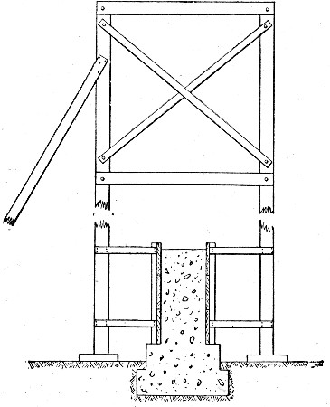 Fig. 201.—Continuous Form for Wall Construction.
For one and two-story buildings, with the usual variation in architectural detail, panel work and window work, the continuous form has many advantages, and the superior economy[Pg 457] of movable panels in retaining and other plain wall work is by no means always true here. One good type of continuous wall form construction is shown by Fig. 201. The gallows frames are spaced about 6 ft. apart along the wall and connected by horizontal stringers nailed to the uprights or by diagonal bracing. Each frame may be made up of 6×6-in. posts connected by 2×4-in. cross-struts and diagonals with bolted connections so that the frame can be taken down and put together easily and so that the bracing can be removed as the wall is built upward. The other details of the form work are shown by the drawing. This construction leaves a clear space for placing the concrete and the cross pieces give support to runways; it has been successfully used in a large amount of low building work.
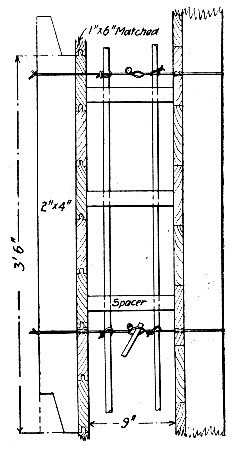 Fig. 202.—Sectional Form for Wall Construction.
Movable panel forms are of great variety in detail but are generally of either one or the other types shown by Figs. 202 to 204.
The form shown by Fig. 202 was used in constructing a church at Oak Park, Ill. For the back of the wall it consists of continuous lagging held by 2×4 studs. For the face[Pg 458] 1×6-in. lagging 12 ft. long was nailed to 2×4-in. studs to form panels. It will be noted that the ends of the studs are scarfed so as to interlock in succeeding panels. This construction also shows a method of supporting the reinforcing bars inside the form.
The form shown by Fig. 203 was used in constructing a large factory building, and consisted of two side pieces or panels 3 ft. high and 16 ft. long, the distance between wall columns. For the first course these were seated on the carefully leveled and rammed ground and securely braced by inclined or horizontal struts inside and outside of the building. After the concrete had set for three days the molds were loosened and lifted until the lower edges were 2 ins. below the top of the concrete and there they were held by horizontal bolts through their lower edges and across the top of the concrete by ties nailed across their tops every 3 ft. and by bracing to the falseworks supporting the column and floor forms. The cross bolts passed through pasteboard sleeves which were left permanently embedded in the wall. By starting the molds level and finishing each course level with their tops no difficulty was had in keeping the forms plumb and to level as they were moved upward. This type of form has to be exteriorly braced to staging or adjacent column forms, etc.
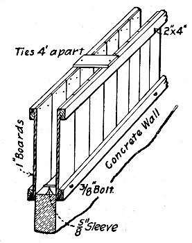 Fig. 203.—Sectional Form for Wall Construction.
The type of movable panel form shown by Fig. 204 depends for all support on the wall alone. The sketch shows the form filled ready to be shifted upward; this operation consists in[Pg 459] removing the bottom bolts and loosening the top bolts enough to permit the studs to be slid upward the full length of the slots. The lagging boards left free are then removed and placed on top and the bolts are tightened, completing the form for another section of wall.
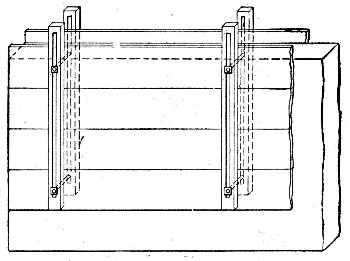 Fig. 204.—Movable Panel Form for Wall Construction.
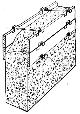 Fig. 205.—Sullivan's Plank Holders for Wall Forms.
A type of wall form construction intended to do away with studding and bracing is illustrated by Figs. 205 and 206. In both cases metal plank holders are used in place of studs, and practically the only difference between the two is in the shape and material of the holders. The mode of procedure is to work in horizontal courses one plank high around the wall, removing the bottom plank and placing it on top as each new course is begun after the first few courses have been laid.[Pg 460] Using the arrangement shown by Fig. 205 in constructing a building 100×54 ft. in plan and 36 ft. high with 12-in. walls, a height of two 12×2-in planks was all the form work that was ever necessary at any one time, so that the amount of form lumber required for the building was 2,464 ft. B. M. plus 205 ft. B. M. of 2×4-in. flooring strip, or altogether 2,669 ft. B. M., or 0.24 ft. B. M. per square foot of exterior wall surface, or 6½ ft. B. M. per cubic yard of concrete. This same form lumber with 16 additional plank was then used to construct a building 100×100 ft.×16 ft. high, so that some 3,000 ft. of form lumber sufficed for 17,548 sq. ft. (exterior surface) of wall or for 617 cu. yds. of concrete in 12-in. wall, which gives 0.17 ft. B. M. per square foot or 4.8 ft. B. M. per cubic yard of concrete.
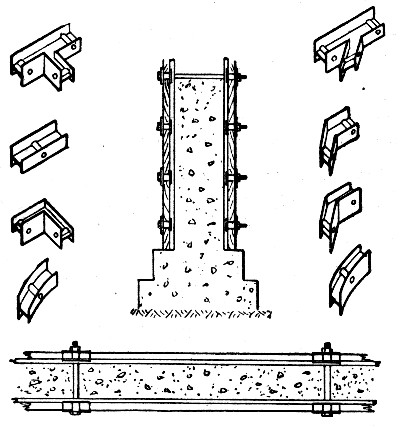 Fig. 206.—Farrell's Plank Holders for Wall Forms.
ERECTING FORMS.—The organization of the erecting gang will depend very largely on the manner in which the forms have been constructed. If they have been constructed in sections which go together with wedges and clamps common laborers with a foreman carpenter in charge to direct and to line and level the work will do the erecting, but if they have to be largely built in place carpenters are necessary for all the work except carrying and handing. There should be at least one foreman for every 15 to 20 men and a head foreman in charge of all form work. The mode of procedure will differ for every job, but the following general directions apply to all work in greater or less measure.[Pg 461]
Clamps, bolts and wedges and not nails should be used wherever possible in assembling parts of forms in erection; these devices are not only quickly and easily applied in erection but they are just as quickly and easily loosened in taking down forms and they can be loosened without jarring the concrete member.
Lining girder forms and lining and plumbing column and wall forms is high-class carpenter work and should be directed by competent carpenters. A column or girder which is out of line or plumb not only looks bad but may be required to be removed and corrected by the engineer. The expense for one such correction will be many times that which would have been involved by proper care in the first place.
Supports or staging for the forms should be used freely and well braced in both directions. Uprights should be set on wedges and bear against a cap piece and on a sill piece to distribute the load.
Erect, line and plumb the column forms first; then erect, line and level the girder forms and set the girder staging, and finally erect and level the slab centers and their supports.
Leave the foot of each column form open on one side at the bottom so that the column reinforcement can be adjusted and connected up and so that a clear view can be had through the form to detect any object that may have fallen into the form and become wedged; this same opening makes it possible to clean the form.
Give the forms a final inspection before concreting to check line and level, to close open joints and to tighten up clamps and wedges. Finally clean each form and wet it down thoroughly before placing the concrete—do this just before placing the concrete.
REMOVING FORMS.—Good judgment and extreme care are essential in removing centers. It goes without saying that forms should never be removed until the concrete has set and hardened to such strength that it will sustain its own dead weight and such live load as may come upon it during construction. The determination of this condition is the matter that calls for knowledge and judgment. Some cements set and harden more rapidly than others, and concrete hardens[Pg 462] more and more slowly as the temperature falls. These and other circumstances must all be taken into account in deciding upon the safe time for removal. Many large contractors mold a cube of concrete for each day's work and leave it standing on the finished floor exposed to the same conditions as the concrete in the forms; examination of this sample block gives a line on the condition of the concrete in the work and on the probable safety of removing the forms at any time. In all cases it should be the superintendent's duty to determine when to remove forms, and he should satisfy himself by personal inspection that the concrete is in condition to stand without support. It is also wise at least as a matter of precaution for the contractor to secure the engineer's or the architect's approval before removing any formwork.
Care in removing forms is essential for the reason that green concrete is particularly susceptible to injury from shock or sudden strain. It is well, therefore, to have a separate gang always doing the work. These men will in a few days become trained under an experienced foreman so that they will not only do the work with greater safety but also more rapidly. This gang should, furthermore, be required to follow a regular system in its work; a system which may not be departed from without direct orders from the superintendent. An example of such a system is outlined below.
The time of beginning this work of removal shall be given by the superintendent. In warm, dry weather, with other conditions favorable, removal may be begun after seven days. Then the following schedule may be followed: At the end of seven days remove the sides of the column forms. This gives an opportunity to determine the soundness of the column casting and also serves the further desirable purpose of baring the concrete to the curing and hardening action of the air. At the end of 14 days loosen the wedges of the posts supporting the slab centers and drop these centers a couple of inches: leave the centers in this position for another day, meanwhile examining the tops of the slabs to note their condition. Then remove the sides of the beam molds and the slab centers, replacing the latter with temporary uprights supporting a plank bearing against the underside of the slab. This precaution is often neglected and with very little reason considering the[Pg 463] importance of the safeguard thus secured. Ordinarily the shores need not be left in place more than a week, so that the amount of lumber thus tied up is small. At the end of three weeks remove the uprights under the beam and girder molds and strip the bottom plank. In this schedule it is assumed that the floor is free from any great load and that no unusual loading is put upon it; if a load of any consequence is to come on the floor the shores and uprights should be left in place longer. No schedule of removal can be blindly followed, and that given above is certain only when the conditions are right and as stated.
The amount of reinforcing steel used varies from 50 lbs. to 275 lbs. per cu. yd. of concrete; the highest figure will be had only in very heavy work and where very heavily reinforced raft foundations are employed, and the lowest only in one-story buildings consisting of walls and roof. A fair average is perhaps 150 lbs. per cu. yd. The cost of fabricating and placing reinforcement will run from ⅓ ct. to 1½ cts. per pound, but the last figure is exceedingly high; ¾ ct. per pound for fabricating and placing is a reasonable labor charge.
Contractors frequently have their choice whether the steel shall be fabricated into frames and placed as units or whether it shall be placed in separate bars. For girders and columns the difference in cost of the two methods is not so very great for steel in place when the fabrication is done in the field. The unit frames cost considerably more than separate bars to fabricate, but the cost of handling and placing them in the forms is materially less; on an average the differences balance each other. Where the frames are made up in regular mills unit frames generally cost less to fabricate and place than do separate bars. The use of unit frames in wall and floor slab reinforcement is generally more expensive than the use of separate bars. The chief gain that comes from the use of unit frames is the gain due to the certainty that the reinforcing bars, stirrups, etc., are all there and are properly spaced and placed.[Pg 464]
FABRICATION.—Fabrication includes all the work necessary to prepare the reinforcement ready to place in the forms. It amounts to very little where separate bar types of reinforcement are used. Plain bending and shearing operations comprise the whole task. Where the beam or column reinforcement has to be made up into complete frames which can be handled and placed as units this task is more complex and considerable apparatus is essential to rapid and economical work. For this reason it is wise usually to contract with some metal working shop to assemble and connect up the various units and to furnish them ready for installation. In many cases these unit frame types of reinforcement are patented and the proprietors contract to fabricate and furnish them complete according to the plans of the engineer or architect. Even where the frame construction is not so controlled it will be economy generally to have the fabrication done at regular shops where the necessary tools and skilled workmen are had. In any case the bars should be ordered cut to length at the mill so far as possible.
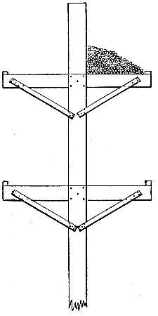 Fig. 207.—Rack for Storing Reinforcing Bars.
Assuming the fabrication to be done in the field, the mode of procedure will be as follows: Order the bars or rods to be shipped in bundles of corresponding sizes and lengths of pieces with each bundle tagged with its proper shop number or mark. The bundles should weigh about 200 lbs.; this is a load easily handled by two men and so long as possible all handling should be done in the original package, for when once broken it is very hard to get men to carry a full load. As received, the bars of each size and length should be stored by themselves. For ordinary bars not having long prongs a rack of the general form shown by Fig. 207 serves the purpose excellently. When a great deal of metal must be kept stored for some time it is wise to roof over the racks, not only to protect the metal from rain and snow, but to enable the men to work dry shod in stormy weather. Usually it will pay to have one man whose sole duty it is to receive and check all metal and to attend to its systematic arrangement on the racks; this same man will also direct the removal of the metal to the shop where it is bent and otherwise worked up, and can, if he is competent, earn his pay many times over in time saved all along the line in handling and working up the reinforcement. The authors have seen enough time wasted in hauling over and rehandling metal in piles to get at what was wanted to pay for shed, racks and the wages of a storekeeper several times during a moderate sized job. In large work provide the storekeeper with a schedule showing the order in which the metal is wanted for the work so that he can arrange it in that order and can check up his receipts from the mills and report missing items in time for the deficit to be made up before some part of the work has to be stopped because of material missing. System in receiving and storing the metal is absolutely essential to rapid and accurate work at the bending and erecting tables.
The work done on the metal consists chiefly of bending. The metal can usually be bent cold, but for sizes 1½-in. and upward some makes of bars require heating; this can be done by laying the bars side by side on the ground and arranging sticks and shavings on top of them in a strip 18 ins. to 2 ft. wide across the portion where the bend is to be. Only moderate heating is usually required. Ordinary bending is a simple[Pg 466] process and can be done with very simple apparatus. Figures 208, 209 and 210 show frequently used devices, any of which can be made by an ordinary carpenter. For heavy bars, 1½ and 2 ins., the device shown by Fig. 210, with its heavy, swinging beam, is particularly efficient. An example of more elaborate methods is had in the following description of the processes employed in fabricating girder frames and hooped column reinforcement for a large factory building. The building was 500×75 ft., with six stories and a basement, built for the Bush Terminal Co., Brooklyn, N. Y., in 1905. Three longitudinal rows of round columns and two rows of rectangular wall columns carry heavy longitudinal girders supporting floor slabs with corrugated undersides as shown by Fig. 211, which also shows the floor slab reinforcement. About 12,000 cu. yds. of concrete and 1,000 tons of reinforcing steel were required; hence 167 lbs. of steel were required for each cubic yard of concrete. The floors, however, were designed to carry a load of 800 lbs. per sq. ft. The particular feature of interest in this building was the fabrication of all the column and girder reinforcement into unit frames and cylinders in temporary workshops on the site.
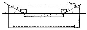 Fig. 208.—Table for Bending Reinforcing Bars.
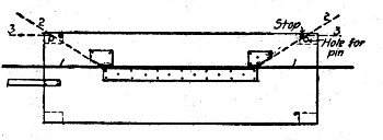 Fig. 209.—Table for Bending Reinforcing Bars.
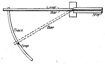 Fig. 210.—Table for Bending Reinforcing Bars.
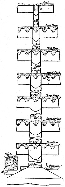 Fig. 211.—Column and Floor Slab Construction for Factory
Building.
Fig. 211.—Column and Floor Slab Construction for Factory
Building.
The circular interior columns, varying from 30 ins. to 12 ins., in diameter were molded in permanent shells of cinder concrete. The shells were made in sections about 30 ins. long, with walls 1½ ins. thick, which were set one on another with mortar joints to form the column mold. In fabricating the shells the first step was to wind a helix of steel wire on a collapsible mandrel about 4 ft. long; the mandrel was set with the axis horizontal and was revolved by hand, the wire being fed on also by hand and under a slight tension. After the wire helix was completed it was wrapped with a sheet of expanded metal, the longitudinal edges of which lapped a few inches and were tied by wire ties. The expanded metal covering was also wire tied to the helix. Each of these cylinders of expanded metal and wire was 30 ins. long and formed the inner mold for making the shell. The outer mold consisted of a sheet metal cylinder in two parts assembled and supported by wooden yokes and framework. The two molds were assembled on a plank platform, one inside the other, and about a common center. The annular space was then filled with a 1-5 cinder concrete mixed moderately dry so that while it would exude slightly through the expanded metal mesh it would not waste to any extent. After from 18[Pg 468] to 24 hours the outer mold was removed for reuse and the shell was left standing on the molding platform until safe to handle. The larger shells, 30×30×1½ ins., weighed about 150 lbs. each.
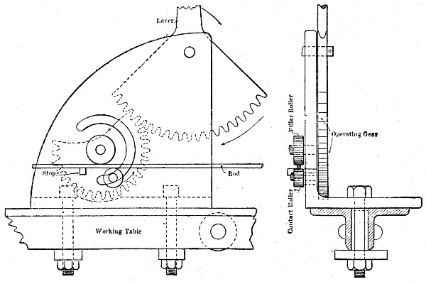 Fig. 212.—Device for Bending Reinforcing Rods.
Some 2,000,000 lbs. of plain round steel rods from ¼ in. to 1½ ins. in diameter were required for reinforcing the concrete. For the main girders these rods were cut, bent and assembled into frames or trusses which were placed as units. The main rods were ordered cut to length, but the stirrup rods were ordered in lengths of 20 ft. and cut to lengths as required. The rods were brought to the work in carload lots and were stored according to lengths and sizes in racks under sheds. Another shed was provided for the steelworkers, who cut and bent the rods and assembled the girder frames ready for the workmen on the building. There were about 50 different patterns of frames required. They were made entirely by hand. For bending large size rods, heavy compound levers were used; the lighter rods were bent by the device shown in Fig. 212. The assembling of the trusses was accomplished as shown by Fig. 213, using the steel framework of the erection shed as a staging. Across the horizontals of the framework were placed two false temporary top chord bars marked[Pg 469] to the stirrup spacing of the truss being assembled. On these bars, at the spaces marked, were suspended stirrups with their lower ends hooked. The lower chord bars were then suspended in the stirrup hooks and the whole assemblage of bars and stirrups was then clamped rigid by the lever bars and intermediate clamps. The loop ends of the stirrups were then bent by special wrenches to the position shown at 2, then closed by hammering to the position shown at 3, and finally they were wire tied. The process was a simple one, and by adopting a regular routine the men became so expert that two of them could complete many trusses in a working day. The contract price for shaping the steel and assembling it into frames was 1 ct. per lb.; the cost of the work to the contractor has been stated by Mr. E. P. Goodrich, Engineer, Bush Terminal Co., to have been about ¾ ct. per lb. The cost of placing the steel in the building was ¼ ct. per lb.
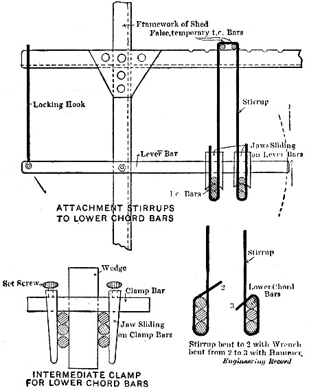 Fig. 213.—Sketches Showing Methods of Fabricating Girder
Reinforcing Frames.
Fig. 213.—Sketches Showing Methods of Fabricating Girder
Reinforcing Frames.
PLACING.—With unit frame reinforcement the number, size and location of the bars have been made certain in the shops where the frames are fabricated so that the erector has nothing to do but to line and level up the frames in the forms, place such temporary braces as are needed to hold them true, and make the end connections with abutting frames. Such frames are usually provided with "chairs" to hold the bottom bars up from the form so that little bracing or none is required. With separate bar reinforcement the erector may either place the reinforcement complete in the form by wire-tying the bars to each other, to temporary braces or templates and to the forms, or he may insert the various pieces of reinforcement in the concrete as the pouring advances, depending on the surrounding concrete to retain them where inserted. Generally a combination of both methods is employed.
The processes in detail of placing reinforcement are particularized in several places in other sections; they will differ for nearly every job. Here, therefore, general rules only will be given.
(1) See that the correct number and size of reinforcing bars, splices and stirrups are used and that they are spaced and placed strictly according to the working plans.
(2) Bars must be properly braced, supported and otherwise held in position so that the pouring of the concrete will not displace them.
(3) Splices are the critical parts of column reinforcement. See that the bars butt squarely at the ends and are held by pipe sleeves or wired splice bars; see that the longitudinal rods are straight and vertical; see that the horizontal ties or hooping are tight and accurately spaced. When the reinforcement is built up inside the form one side is left open for the work; ordinarily the column reinforcement will be fabricated into unit frames, then an opening in the form at the bottom to permit splicing will suffice.
(4) Take extreme care that beam and girder reinforcement is placed so that the bottom bars lie well above the bottom board of the mold; use metal or concrete block chairs for this purpose.[Pg 471]
(5) See that the end connections and bearings of beam and girder frames are connected up and have the bearings called for by the plans.
(6) See that line and level of all bars and of the reinforcement as a whole are accurate; make particularly certain that expanded metal or other mesh-work reinforcement lies smooth and straight.
(7) Give all reinforcement a final inspection just previous to pouring the concrete; this is particularly essential where the reinforcement is placed some time in advance of the concreting.
A reinforced concrete building requires from 0.2 to 0.5 cu. yd. of concrete per 100 ft. of cubical volume of the building, assuming walls, floors and roof to be all of concrete. The amount of concrete to be mixed, transported and placed is, therefore, large enough, even for a building of moderate dimensions, to warrant close study of and careful planning for this portion of the work. A few general principles can be set down, but as a rule there is one best way for each building and that way must be determined by individual conditions.
MIXING.—Concrete for building work has to be of superior quality so that no chances may be taken either in the process of mixing or with the type of mixer employed. Machine mixing and batch mixers should always be employed. Machine mixing gives generally a more homogeneous and uniform concrete than does hand mixing and is cheaper. Batch mixers are generally superior and more reliable than continuous mixers where a uniformly well mixed concrete is required. The capacity of the mixing plant is determined by the amount of concrete to be placed and the time available for placing it. Its division and arrangement is determined by the area of the work and the type and arrangement of the plant for transporting the materials and the mixed concrete. The following general principles may be laid down: Make the most use possible of gravity; it is frequently economy to carry all materials to the top of bins from which point they can move by gravity down through the mixer to the hoist buckets, and where[Pg 472] natural elevations or basement floors below street level permit gravity handling they should be taken advantage of. The mixing should be done as near the place of concreting as practicable; in building work this is the point on the ground which is directly under the forms being filled. It is, of course, impracticable to secure so direct a route as this from mixer to forms, but it can be more or less closely approached; using two mixers, for example, one at the front and one at the rear of a building cuts down the haul from hoist to forms one-half. Other ways will suggest themselves upon a little thought. In the matter of the mixing itself, it must never be forgotten that a batch of concrete without cement which goes into a girder or column will result in the failure of that member and possibly the failure of the building. In massive concrete work a batch without cement will not endanger the stability of the structure, but in column and floor work in buildings it is certain disaster. Formanship at the mixer is, therefore, highly important and a cement man who realizes the responsibility of his task is equally important.
TRANSPORTING.—Transporting the mixed concrete is divided into three operations—delivering concrete from mixer to hoist, hoisting, and delivering hoisted concrete to the forms. The delivery from mixer to hoist may be by direct discharge into hoist bucket, by carts or wheelbarrows, or by cars carrying concrete or concrete buckets. Hoisting may be done by platform hoists or elevators, by bucket hoists, or by derricks. Handling from hoist to form may be direct in buckets, by carts or wheelbarrows, or by cars. These several methods can be worked in various combinations, and the following examples of plants show such combinations as are most typical of current practice.
In any system of transportation it is getting the concrete to the hoist and from hoist to form that eats up the money. Hoisting makes but a small part of the total transportation cost, and, moreover, the difference in cost of operation for different hoists is very small. Mr. E. P. Goodrich states that on three buildings the actual costs for the hoists installed and removed after the completion of the work were as follows:[Pg 473]
| Platform hoist | $330 |
| Bucket hoist | 465 |
| Derrick | 225 |
In figuring on the form of hoist to be adopted, the capability of the hoist for general service has to be kept in mind. Platform hoists and derricks can be used for hoisting form lumber and reinforcing steel as well as for hoisting concrete, while bucket hoists cannot be so used except where they may be fitted with special carriages for lumber or steel. On the other hand, the bucket hoist is usually the quickest method of hoisting concrete, and it can readily be extended upward as the work progresses. The last is true also of platform hoists. The use of derricks necessitates frequent shifting for high work or else the building of expensive staging to raise the derrick into a position to command the final height of the building. The probable costs of moving and extending must be allowed for in choosing the hoist to be used.
Direct discharge of the mixer into the hoisting bucket is, of course, the ideal manner of transporting the concrete from mixer to hoist, and this can generally be obtained by planning, particularly where bucket hoists or derricks are employed. For platform hoists direct discharge is impossible; it can be somewhat closely approached, however, where conditions permit car tracks to be laid on the floors being built, so that a car holding a batch of concrete can be run onto the platform, hoisted and then run to shoveling boards near the forms that are being filled. The successful use of such an arrangement of car tracks is described in Chapter XX, but it was for handling concrete blocks. A direct discharge from hoisting bucket to forms is frequently possible where derricks are used for hoisting, but with bucket and platform hoists, wheeling or carting is necessary.
Where wheeling or carting has to be done either at the bottom or at the top of the hoist, or at both points, a great factor in the economy of work is the arranging of the operations in cycles. For example, in wheeling concrete to forms from a hopper fed by a bucket hoist, arrange the runways so that each man makes a circuit, passing by the form at one end and by the hopper at the other end, and goes and comes by a different route. The speed gained by avoiding confusion and[Pg 474] delay saves many times the additional cost of runways which is small. In fact it is economy to employ a few extra men to arrange runways and keep them clean, because of the additional speed thus gained. Good organization effects more economy than special methods of hoisting as far as the labor of handling the concrete is concerned.
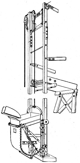 Fig 214.—Bucket Hoist for Building Work
(Wallace-Lindesmith).
Fig 214.—Bucket Hoist for Building Work
(Wallace-Lindesmith).
Bucket Hoists.—A bucket hoist construction which has been extensively used in building work on the Pacific coast is shown by the drawings of Figs. 214 to 216. Two T-bar guides made in sections connected by fishplates furnish a track for an automatic dumping bucket hoisted and lowered by steel cable from engine on the ground to head sheaves as shown. The sectional construction of the T-bar guides permits the hoist to be any height desired, it being lengthened and shortened by adding and taking out sections. The bucket is dumped automatically at any point desired by means of a tripping device attached to a chute which receives the contents of the bucket and delivers them to carts, wheelbarrows, or other receptacle. The hoist is set outside of the building with the mixer arranged, if possible, to discharge directly into the bucket. By setting the guide frame in a pit or on blocking any height of edge of bucket can be secured. The buckets are ordinarily 13½ or 20 cu. ft. capacity. It is recommended, when greater hoisting capacity is necessary, to use two hoists set side by side and operated by one cable in the same manner[Pg 475] as double wheelbarrow cages; as the weight of one bucket counterbalances the weight of the other, the power required for hoisting is reduced. To adapt this hoist to handling form lumber the bucket is replaced by the lumber carriage shown by Fig. 216; this carriage discharges over the head of the mixer and the spring buffer shown by Fig. 214 is to take the shock of the rising carriage. This buffer is omitted when concrete only is to be hoisted. In one case this device has hoisted 520 batches of 12 cu. ft. each to the fourth floor in 8 hours, or nearly 19 cu. yds. per hour. In another case 65 trips per hour were averaged to the fifth floor with a 12-cu. ft. load each trip; this is nearly 30 cu. yds. per hour. With the lumber carriage 8 men have unloaded 14,000 ft. B. M. of 2×10-in. stuff from car to the second floor and distributed it in 43 minutes. A ½-cu. yd. combination outfit for concrete and lumber, with 40 ft. of guide track, weighs 1,750 lbs., without the lumber carriage the outfit weighs 1,600 lbs. This hoist is made by the Wallace-Lindesmith Co., Los Angeles, Cal.
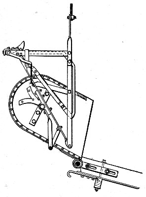 Fig, 215.—Wallace-Lindesmith Hoist Bucket in Discharging
Position.
Fig, 215.—Wallace-Lindesmith Hoist Bucket in Discharging
Position.
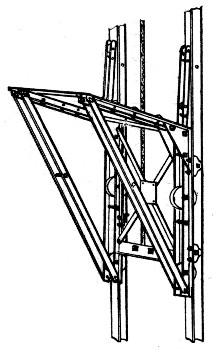 Fig. 216.—Lumber Carriage for Wallace-Lindesmith Hoist.
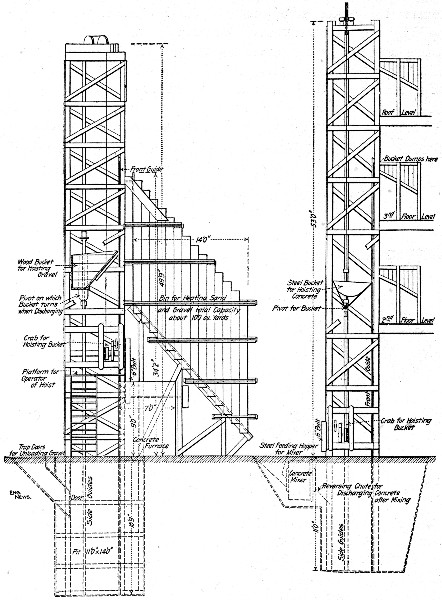 Fig. 217.—Mixer Plant with Gravity Feed from Material
Bins to Hoisting Bucket.
Fig. 217.—Mixer Plant with Gravity Feed from Material
Bins to Hoisting Bucket.
A popular construction for automatic bucket hoists is that shown by Figs. 217 and 218 by Mr. E. L. Ransome. The bucket is held upright by guides at its front and rear edges; to[Pg 476] dump it a section of the front guide is removed at the desired dumping point which allows the bucket to overturn as shown. A friction crab hoist operated from the mixer engine runs the bucket. The mixer is located as shown. Figure 218 shows the foot of the hoist set in a pit with the mixer at surface level, but the hoist can be set on the surface and the mixer[Pg 477] mounted on a platform. In the latter case a charging bucket, traveling from stock pile up an inclined track to the mixer platform, is generally used. A hoist like that illustrated, equipped with a ½-cu. yd. Ransome mixer, will cost about $1,500 and will deliver 15 cu. yds. of concrete per hour. Mr. F. W. Daggett gives the following figures of the cost of operation:
| Mixing Gang: | |
| Total 1 hr. | |
| 1 mixer foreman, also engineer, 25c. | $.25 |
| 1 man charging mixer, 20c. | .20 |
| 1 man running hoist, 20c. | .20 |
| 2 men wheeling sand, 17½c. | .35 |
| 4 men wheeling and shoveling stone, 17½c. | .70 |
| 1 man helping up runway, 17½c. | .17½ |
| 2 men carrying cement, 17½c. | .35 |
| Gang Placing Cement: | |
| 1 foreman, 25c. | .25 |
| 9 men wheeling concrete, 17½c. | 1.57½ |
| 3 men tamping concrete, 17½c. | .52½ |
| 1 man filling carts, 17½c. | .17½ |
| ——— | |
| Total labor cost per hour | $4.75 |
| Fuel, etc. | .50 |
| ——— | |
| 5.25 | |
This gives a cost of 35 cts. per cu. yd. for mixing and placing concrete.
In this particular case the mixer was charged by wheelbarrows. Frequently the stone and sand bins can be arranged to chute the materials directly into the charging hopper as shown by Fig. 217. In place of barrows two-wheeled carts of the type shown by Fig. 12 can be used. Mention has already been made of operating the charging bucket on an incline from stock pile to mixer. Such arrangements are described in Chapter IV.
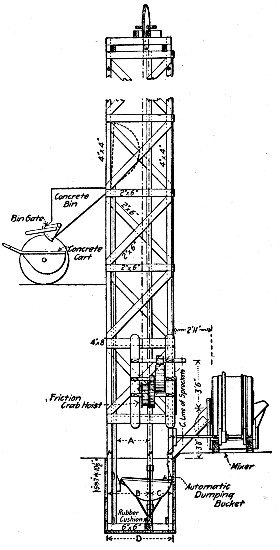 Fig. 218—Bucket Hoist for Building Work (Ransome).
In constructing a 9-story store at St. Paul, Minn., the concrete was hoisted by continuous bucket elevators. A lay-out of the construction plant is shown by Fig. 219. In the alley near the center of the north side of the building the surface grade was about 6 ft. above the third story level. A hopper[Pg 478] was constructed at grade and provided with two chutes running to the basement. These chutes discharged on opposite sides of a vertical partition separating the sand and stone bins, and by closing either chute at its top by a suitably arranged deflector plate either sand or stone could be dumped into the same hopper and chuted to its proper bin. Cement was brought to the work in cars over the tracks shown and was wheeled from the cars over runways leading to the charging platforms near each mixer. Other runways connecting with these platforms provided for wheeling the sand and stone to the mixers. The runways were placed at the proper height to permit the barrows to be emptied directly into the charging hoppers. Two Smith mixers were used, located as shown, and each discharged through a chute into one of the bucket elevator boots. There were two elevators which were "raised" two stories at a move as the work progressed. Each elevator discharged into a hopper holding 1½ batches, and from these hoppers the concrete was fed into wheelbarrows and wheeled to the forms. The bucket elevators were carried no higher than the eighth floor. When this floor had been completed the hoppers were moved down to the fifth floor and the wheelbarrows were taken to platform elevators and[Pg 479] carried to the remaining floors and roof. Special 4-cu. ft. wheelbarrows were used for handling the concrete. A maximum of 155 cu. yds. of concrete was mixed, transported and placed in a 10-hour day with a gang of 28 men.
Platform Hoists.—The common builders' hoist or elevator, operating single or double platforms or cages, needs no special description. The wheelbarrow, cart or car containing the concrete is run onto the platform, hoisted and then run to the forms. The chief advantage of this device in concrete work is that it will handle all classes of material without any change of carriage or arrangement, it can thus be used for handling form lumber and reinforcing steel as well as for handling concrete.
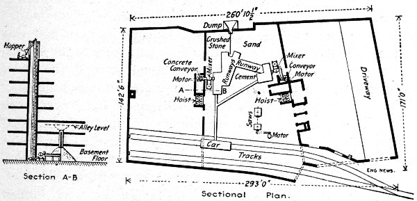 Fig. 219.—Plan of Concrete Mixing and Handling Plant for
9-Story Building.
Fig. 219.—Plan of Concrete Mixing and Handling Plant for
9-Story Building.
Derricks.—The use of derricks for hoisting in concrete building work is limited by the necessity of supporting them independently of the structure being built; the formwork or the completed concrete work cannot be utilized to carry derricks during construction. For low structures the derrick can be set on the ground, but for high buildings a supporting tower or staging is necessary. The arrangement of such falsework can be illustrated best by specific examples.
In constructing a 7-story factory at Cincinnati, O., concrete was mixed on the ground and hoisted by a derrick with an 80-ft. boom mounted on a tower 55 ft. high. The derrick was located to one side of the building. For the lower floors the boom swing covered so large an area that the bucket was dumped at various places, but for the upper floors it was found[Pg 480] more economical to dump buckets into a hopper from which wheelbarrows were filled. By this plan less time was consumed in placing the bucket and no tag rope man was required, as the engineman could swing the boom to a certain point on the wall which would bring the bucket directly over the hopper. A Smith mixer discharged directly into derrick buckets, which rested on a track long enough to hold two buckets. The buckets were filled and emptied alternately by shuttling the truck and attaching first one and then the other to the derrick.
In constructing an 11-story and basement office building in New York City a four-legged tower starting from the bottom of the excavation was erected at about the center of the lot. It was built of timber and extended upward as the progress of the work demanded until it overtopped the roof 11 stories above the street. The tower was square in plan and was divided into stories corresponding approximately to the several stories of the building. A floor was constructed in the tower at each story to be used in storing materials. For hoisting a 75-ft. boom was swung from each leg of the tower, each boom being operated by a separate engine and having a nominal capacity of 5 tons. The four booms covered the whole building area and were kept about two stories above the work by being shifted upward as the work progressed. This arrangement of derricks was used to handle the steel, lumber and concrete, the building being built up around the tower, which was so located that its only interference with the building structure was in the shape of square holes left in the floor slabs to accommodate the tower legs.
In constructing an 8-story warehouse covering some three acres of ground in Chicago, Ill., the derrick plant shown by Figs. 220 to 222 was installed. Some 7,500 tons of reinforcing steel, 125,000 cu. yds. of concrete and 4,000,000 ft. of form lumber had to be handled. Incidentally it is worth noting that there were about 120 lbs. of reinforcing steel and 32 ft. B. M. of form lumber used per cubic yard of concrete.
The controlling conditions governing the arrangement and character of the construction plant were as follows: The building, to be built entirely of reinforced concrete, was 135 ft. high. Its west front abutted on the river and its south front[Pg 481] on the street; at the north end there was some ground available for plant and along the east front there was a strip about 20 ft. wide between the building wall and the main line tracks of a railway. At best, therefore, the area outside of the building and available for plant and storage was limited, while inside the building area the contractor was confronted by the insistence of the architect that an unbroken monolithic construction be obtained as nearly as possible, by reducing the floor openings for construction work to a minimum. The sketch plan, Fig. 220, shows the plant designed to meet the conditions.
To get the large amount of construction material onto the work a side track was built along the 20-ft. area on the east side of the building and another was turned into the area at the north end of the building. These side tracks handled all construction materials coming onto the work. Over the first there were built two sets of storage bins for sand and gravel and all concrete materials brought in in carload lots are unloaded at these two points, as will be described further on. Lumber for forms and steel for reinforcement shipped in similar manner were taken by the second siding to the lumber yard and steel mill at the north end of the building.
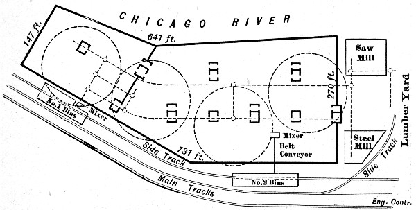 Fig. 220.—Plan of Concrete Mixing and Handling Plant for
Large Warehouse Building.
Fig. 220.—Plan of Concrete Mixing and Handling Plant for
Large Warehouse Building.
The raw materials after being worked up in the mixer plants and the saw and steel mills were distributed over the work by an industrial railway. The track system of this railway is shown by the dotted lines; it was located on the basement[Pg 483] floor, with rampes leading to the No. 1 mixer plant and to the saw and steel mill tracks. The two main lines of track passed close to or under the elevator and stairway shaft openings in the several floors. This permitted the derrick buckets, lowered and hoisted through the shafts, to be loaded directly from the car tracks. All mixed concrete, forms and reinforcing frames were distributed by this railway to the several shafts and thence hoisted and placed by the derrick plant.
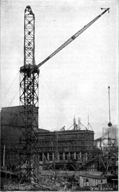 Fig. 221.—Derrick for Handling Concrete for Large
Warehouse Building.
Fig. 221.—Derrick for Handling Concrete for Large
Warehouse Building.
The derrick plant consisted of four derricks arranged as shown by the circles in Fig. 220. The view, Fig. 221 shows the first derrick installed and illustrates the general construction quite clearly. Briefly the derrick consisted of a vertical steel-work tower 10 ft. square and 85 ft. high, within which operated a steel mast 135 ft. high and carrying an 80-ft. boom connected just above the tower. The mast was pivoted at the bottom and had rollers turning against a horizontal ring inside the tower at the top. It was operated by a bull wheel above the top of the tower, the turning ropes running down inside the mast to the foot block and thence horizontally to the operating motor. The topping and hoisting lines also followed this route. The top of the tower was guyed by four ropes to anchorages in the basement floor. The boom commanded a circle 170 ft. in diameter and could lift 150 ft. above the base of the mast. The derrick was operated by a 25-HP. double drum electric hoist with a derrick swinging spool; this hoist was set on the basement floor. It will be noted that the guys are below the bull wheel so that the boom has a clear swing through a complete circle.
As stated above, four of these derricks were employed. Together they did not cover the entire building area, but by the use of a derrick bucket so designed that it could be used as a storage bin for feeding wheelbarrows, it was found possible to keep the number of derricks down to four.
This derrick plant possessed several advantages of importance. In the first place the derricks would handle all classes of material—concrete, forms, steel frames—equally well and could be transferred from one class of work to the other with practically no delay. In the second place, for a large area of the building, they handled the material from the basement direct to the place it was to occupy in the work, and did it in[Pg 484] one operation. Finally they permitted the handling and erection of the forms and reinforcement in large units. Thus a column form would be assembled complete at the mill, moved as a unit by car to the proper shaft and then hoisted and set in place as a unit by the derrick. Girder forms, floor slab forms, girder and column reinforcing, etc., could be similarly assembled and handled. The derricks occupied only the area of four floor panels, the remainder of the area of each floor was left unobstructed for the work to be done. No materials or supplies needed be stored on the floors until they were in perfect condition to accommodate them, and not then, even, so far as the prosecution of form erection and concreting were concerned.
The sand and gravel for concrete were brought in by bottom or side dump gondola cars from pits located about 30 miles out on the Chicago, Milwaukee & St. Paul Ry. The cars were switched onto the main side track and unloaded under the bins which straddle this track. A receiving hopper, with its top at rail level and long enough to permit two cars to be unloaded at once, received the sand or gravel and distributed it through twelve gate openings onto an 18-in. horizontal belt conveyor 65 ft. long. This conveyor discharged into a second conveyor, 133 ft. long, which ran up a 22° incline, extending away from the bins and discharged onto a third conveyor 117 ft. long, which doubled back on a 22° incline reaching to and over the top of the bins. This third conveyor had two fixed trippers and an end discharge to distribute its cargo. All three conveyors were operated by a 35-HP. motor located at the junction of the two inclined conveyors, both of which were driven from the same shaft. A chain belt from the idler shaft of the first incline conveyor to the driving shaft of the horizontal conveyor operated that unit of the plant. This belt was operated as a cross belt by reversing alternate links. No manual labor was required to handle the sand and gravel from the cars to the storage bins.
The mixer arrangement at the two bins differed. At the No. 1 bins the mixer was located as shown in Fig. 220, close to the bin. Chutes led directly from the sand and gravel bins to the charging hopper and the bags of cement were stacked alongside this hopper. The mixer discharged either directly into[Pg 485] the bucket of the first derrick or into cars for transportation on the railways. At the No. 2 bins a belt conveyor took the concrete materials down into the basement to a mixer located close enough to one of the distribution tracks to permit it to discharge directly into the cars.
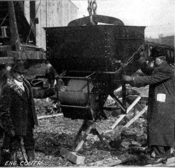 Fig. 222.—Special Concrete Bucket for Large Warehouse
Building.
Fig. 222.—Special Concrete Bucket for Large Warehouse
Building.
The derrick buckets by which the concrete was hoisted and handled to the work were of special construction. A bucket was desired which would serve several distinct purposes. It must first be able to hold a full mixer batch of material, since, with the derrick arrangement, economy in hoisting necessitated hoisting in large units and also because storage capacity was required of the bucket for wheelbarrow work. The four derricks did not command the entire area of a floor; there were corners and other irregular areas outside of the circles covered by the several booms over which the concrete must be distributed[Pg 486] by barrows or carts. A bucket large enough to supply the barrows, while a second bucket was being lowered, charged from the mixer and hoisted, was required. In the second place, a bucket was required whose contents could be discharged all at once or in smaller portion at will. Finally a bucket was desired which could be made to distribute its load along a narrow girder form or in a thin sheet for a floor slab.
To meet these requirements the bucket shown in Fig. 222 was designed. It held 42 cu. ft., or about 1.55 cu. yds. of concrete. It had a hopper bottom terminating in a short rectangular discharge spout closed by a lever operated under cut gate, which could be opened as much or as little as desired. To the underside of the bucket there was attached a four-leg frame in which the bucket stood when not suspended. Ordinarily, that is within the circles commanded by the derricks, the buckets were discharged suspended and directly into the forms, the character of the discharge gate permitting a thin sheet to be spread for floor slabs or a narrow girder or wall form to be filled without spilling or shock. For wheelbarrow work outside the reach of the derricks the mode of procedure was as follows: A timber platform about 3 ft. high and having room for standing two buckets was set just on the edge of the circle commanded by the derrick boom. Two buckets were used. A full bucket was hoisted and set on the platform, with its spout overhanging. This bucket served as a storage bin for feeding the wheelbarrows while the second bucket was being lowered, charged and hoisted to take its place on the platform, and serve in turn as a storage hopper.
PLACING AND RAMMING.—A wet concrete is usually used in building work except on occasions, for exterior wall work and except for pitch roof work, where a wet mixture would run down the slope. Placing and tamping are therefore, essentially pouring and puddling operations. The pouring should be done directly from the barrows, carts, or buckets if possible; dumping onto shoveling boards and shoveling makes an extra operation and increases the cost by the wages of the shoveling gang. Where shoveling boards are necessary, take care that they are placed close to the forms being filled, as it is wasteful of time to carry concrete in shovels, even for[Pg 487] a half dozen paces. Before pouring any concrete, the inside of the forms should be wet down thoroughly with a hose or sprinkler, if a hose stream is not available. The final inspection of forms and reinforcement just before concreting will have made certain that they are ready for the concrete, so far as line and level of forms and presence and proper arrangement of the reinforcement are concerned, but the concrete foreman must watch that no displacement occurs in pouring and puddling, and must make certain particularly that the forms are clean.
In pouring columns it is essential that the operation be continuous to the bottom of the beam or girder. It is also advisable to pour columns several hours ahead of the girders. Puddling should be thorough, as its purpose is to work the concrete closely around the reinforcement and into the angles of the mold and to work out air bubbles. A tool resembling a broad chisel is one of the best devices for puddling or slicing. In slab and girder construction, the pouring should be continuous from bottom of girder to top of slab. Work should never be stopped-off at horizontal planes. As in columns, careful puddling is essential in pouring beams. In slab work, the concrete is best compacted by tamping or rolling. A broad faced rammer should be used for tamping wet concrete, or a wooden roller covered with sheet steel, weighing about 250 lbs., and having a 30-in. face.
Theoretically, concreting should be a continuous operation, but practically it cannot be made so. Bonding fresh concrete to concrete that has hardened, though it has been done with great perfection by certain methods as described in Chapter XXIV, must still be held as uncertain. Ordinarily, at least, a plane of weakness exists where the junction is made and in stopping off work it should be done where these planes of weakness will cause the least harm. Experts are by no means agreed on the best location of these planes, but the following is recognized good practice. Work once started, pouring a column, should not be stopped until the column is completed to the bottom of the girder. For beams and girders; stop concrete at center of girder with a vertical face at right angles to the girder, or directly over the center of the columns; in beams connecting with girders, stop concrete at center of[Pg 488] span, or directly over center of connecting girder; stop always with a vertical face and never with a sloping face, and never with a girder partly filled. For slabs; stop concrete at center of span, or directly over middle of supporting girder or beam; stop always with vertical joints. If for any cause work must be stopped at other points, than those stated, the fresh concrete and the hardened concrete must be bonded by one of the methods described in Chapter XXIV.
CONSTRUCTING WALL COLUMNS FOR A BRICK BUILDING.—The columns, 12 in number, were constructed to strengthen the brick walls of a power station and were built as shown by Figs. 223 and 224, one at a time. The staging, 50 ft. high and 4×6 ft. in plan, was erected against the wall which had been shored, a portion of the wall was cut out and forms erected and the concrete column substituted for the section of wall which was removed. The staging was then moved into position for another column.
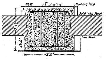 Fig. 223.—Section of Rectangular Wall Column.
Two men, with sledge and drill, cut out the brick work amounting to about 12 cu. yds. for each column in 15 hours, at a cost of about 70 cts. per cu. yd., including removal to the street. The cost of moving and re-erecting the scaffolding was $2.94 per each move. The character of the reinforcement is shown by Fig. 223; it was erected as the concreting progressed, the main bars being in sections 15 ft. long, spliced with and distanced by side bars and cross bolts at the splices.
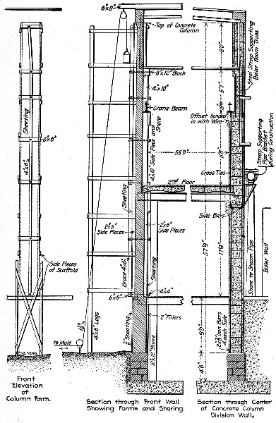 Fig. 224.—Staging and Forms Used in Building Column
Shown by Fig. 223.
Fig. 224.—Staging and Forms Used in Building Column
Shown by Fig. 223.
The concrete was hand mixed in 6-cu. ft. batches at the foot of the column, by three men with a fourth turning over and filling the buckets. The buckets, 12 ins. in diameter and 16 ins. high, were hoisted by a pulley line arranged as shown and pulled by a mule driven by a man, at $1 per day for the mule and $1.50 for the man, the cost of hoisting being 25 to 40[Pg 490] cts. per cu. yd., depending on the rapidity of the man inside the form. This man tamped the concrete which was emptied from the buckets by a man on the scaffolding. Each batch raised the level in the form 15 ins., and between batches a set of ties for the column rods was placed by the man during the tamping. It took from 1½ to 2 days to concrete a column of 12 cu. yds. The concrete was a 1-3.8-5.7 limestone screenings mixture, mixed wet enough to be easily pushed into the forms and worked around the reinforcement. The form construction is shown by Fig. 224. The form for one column required 650 ft. B. M. of lumber, and on an average, each form was used twice. As a matter of fact, the side strips and outside braces were used three times, while much of the ⅞-in. sheathing was destroyed by being used once. The lumber for shoring cost $23 per M. ft. B. M., and the light lumber for forms cost $18 per M. ft. B. M. All lumber was yellow pine. All labor was negro, at 15 cts. per hour; foremen who worked. 22½ cts. per hour. The cost of the several parts of the work compiled from records furnished by Mr. Keith O. Guthrie, engineer in charge, was as follows:
| Concrete. | Cost per column | Cost per cu. yd. |
| Lumber for forms | $ 4.81 | $0.40 |
| Setting up and removing forms | 11.32 | 0.95 |
| Cement, 10.17 bbls. at $2.40 | 24.40 | 2.03 |
| Sand, 5.87 yds. at $0.90 | 5.28 | 0.44 |
| Stone, 8.75 yds. at $1.35 | 10.94 | 0.91 |
| Mixing and wheeling | 15.73 | 1.31 |
| Hoisting by mule with driver | 4.80 | 0.40 |
| Handling bucket on scaffold | 2.93 | 0.25 |
| Tamping inside column | 2.93 | 0.25 |
| Painting with grout | 3.89 | 0.32 |
| Clearing away rubbish | 1.97 | 0.16 |
| Rigging, etc. | 2.64 | 0.21 |
| Tools | 0.59 | 0.05 |
| Moving scaffold | 2.94 | 0.25 |
| Moving mix board and rigging hoist | 1.62 | 0.14 |
| ——— | —— | |
| Total cost of concrete | $96.79 | $8.07 |
| Reinforcement. | Cost per column. | Cost cts. per lb. of bars. |
| Iron bars, 1,034 lbs. | $20.68 | $2.00 |
| Drilling iron bars | 1.44 | 0.14 |
| Setting iron bars in place | 1.23 | 0.12 |
| Bolts for splicing and spacing | 3.98 | 0.40 |
| Wire cross ties at 2-½, cts. lb. | 1.39 | 0.14 |
| Labor forming 130 cross ties | 1.13 | 0.11 |
| ——— | —— | |
| Total cost of iron and steel | $29.85 | $2.91 |
| Summary of Cost. | ||
| Per column. | Per cu. yd. | |
| Concrete in place | $96.79 | $8.07 |
| Steel in place | 29.85 | 2.49 |
| Cutting out and removing brick | 8.36 | 0.70 |
| Shoring floors and roof, labor | 5.87 | 0.49 |
| Ditto for lumber used 3 times | 3.44 | 0.29 |
| ——— | ——— | |
| Total | $144.31 | $12.04 |
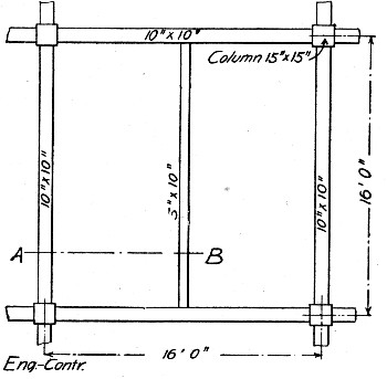 Fig. 225.—Girder Plan for 6-Story Building.
FLOOR AND COLUMN CONSTRUCTION FOR SIX-STORY BUILDING.—The building was 91×112 ft.; 56 columns spaced 16 ft. apart carried the girder system shown by Fig. 225, which in turn supported a 3½-in. floor slab. The walls and partitions were not concrete. The following records were kept by the authors:[Pg 492]
Forms.—The column forms were built as shown by Fig. 226. The boards were 1½-in. stuff, surfaced on four sides; the yokes were spaced 2 ft. apart. The 1×6-in. pieces were nailed to the 2×4's with 8-d. nails with heads left projecting for easy pulling. The girder forms, Fig. 227, rested on the column forms and on intermediate posts half-way between columns. These intermediate posts were 3×4's with 4×4×12-in. head blocks nailed to their tops and wedges under their bottoms. The girder molds were 1½-in. stuff, and to the side pieces were nailed 1×4-in. cleats; the bottom and side pieces were connected by ⅜×4-in. lag screws spaced 28 ins. apart. The floor slab stringers were carried on the 1×4-in. cleats; they were spaced 28 ins. apart and were not nailed; neither were the 1×6-in. lagging boards nailed to the stringers. The point to be noted is the design and construction of the forms so that they could be put together and taken apart easily. The lumber required for forms for one floor 91×112 ft., or, say, 10,200 sq. ft., was as follows:
| Lumber for columns, ft. B. M. | 9,000 |
| Lumber for 10×10-in. beams, ft. B. M. | 7,600 |
| Lumber for 5×10-in. beams, ft. B. M. | 2,700 |
| Intermediate 3×4-in. posts, ft. B. M. | 1,000 |
| Lagging, 1×6-in. boards, ft. B. M. | 9,000 |
| Stringers, 3×4 ins., ft. B. M. | 4,500 |
| ——— | |
| Total ft. B. M. | 33,800 |
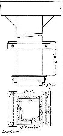 Fig. 226.—Column Form for 6-Story Building.
In round numbers, we can say that 34,000 ft. B. M. of lumber were used for 10,000 sq. ft. of floor area, or 3.4 ft. B. M. per 1 sq. ft. Enough forms were provided to erect two complete floors; the forms for the lower floor being removed and erected again for the second floor above, thus using all the[Pg 493] lumber three times. With carpenters at $3.50 for 8 hours, the forms were framed ready for erection for $4 per M. ft. B. M. The lumber framed ready to erect cost them:
| Lumber, cost per M. ft. B. M. | $26.00 |
| Labor, framing per M. ft. B. M. | 4.00 |
| ——— | |
| Total per M. ft. B. M. | $30.00 |
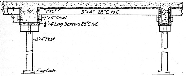 Fig. 227.—Girder and Slab Forms for 6-Story Building.
Since the lumber was used three times, $30 ÷ 3 = $10 is the charge against each 1,000 ft. B. M. needed to encase the concrete on a floor. There were nearly 34,000 ft. B. M. per floor, hence the cost of lumber ready for erection was $340 per floor. There were as shown below, 200 cu. yds. of concrete per floor, so that the cost was $340 ÷ 200 = $1.70 per cu. yd. of concrete for forms ready for erection. It took a gang of 5 men 7 days to tear down and carry up the forms for one floor; hence 5 × $2 × 7 = $70 per floor, or practically $2 per M. ft. B. M., or $0.35 per cu. yd. of concrete for taking down and carrying forms two stories. It took a gang of 10 carpenters 7 days to erect these forms, which at $3.50 per day was $245 per floor, or $7 per M. ft. B. M., or $1.20 per cu. yd. of concrete.
Concrete.—The amount of concrete per floor was as follows:
| Floor slab 3½ ins. thick, 10,200 sq. ft. | 110 cu. yds. |
| Beams, 10×10 ins. | 40 cu. yds. |
| Beams, 5×10 ins. | 20 cu. yds. |
| Columns, 15×15 ins. (average) | 30 cu. yds. |
| —————— | |
| Total concrete per floor | 200 cu. yds. |
A concrete mixer, a hoist and a gang of 14 men mixed and placed the concrete for a floor in 7 days. At $2 per day for labor this gives 14 × 7 × $2 = $196, or say $1 per cu. yd. for mixing and placing the concrete.
Reinforcement.—In each of the 10×10-in. beams there were 4, 1-in. round rods, 2 straight and 2 bent, and stirrups of ⅛×1-in. straps spaced 5 ins. apart at columns and 15 ins. at the center. In each 5×10-in. beam there was half as much steel as in a 10×10-in. beam. The floor slab reinforcement consisted of ¼-in. rods spaced 5 ins. apart and 2 cross-rods in 7-ft. panel. The column reinforcement consisted of 4 rods averaging 1 in. in diameter. In round numbers the amount of steel required for each floor was, therefore, as follows:
| Lbs. steel rods in 10×10-in. beams | 16,200 |
| Lbs. steel rods in 5×10-in. beams | 4,000 |
| Lbs. stirrups in beams | 3,000 |
| Lbs. steel rods in floor slabs | 3,800 |
| Lbs. steel rods in columns | 1,400 |
| ——— | |
| Total pounds steel per floor | 28,400 |
This is equivalent to 142 lbs. of steel per cubic yard of concrete, or about 1 per cent of the total volume of reinforced concrete was steel. The steel in the beams was about 3 per cent. It required a gang of 5 laborers 7 days at $2.25 per day, to bend and place the steel for each floor or $86 for labor on 28,400 lbs. of steel. This is equivalent to 0.3 ct. per lb., or 45 cts. per cu. yd. of concrete.
Summary of Costs.—Summarizing the figures given we have the following cost per cubic yard of concrete in floors and columns:[Pg 495]
| Per cu. yd. | |
| 142 lbs. steel at 2½ cts. | $ 3.55 |
| 1 bbl. cement | 2.50 |
| 1 cu. yd. gravel | 1.10 |
| ½ cu. yd. sand | 0.55 |
| 170 ft. B. M. lumber ready to erect at $10 (⅓ of $30) | 1.70 |
| 170 ft. B. M. torn down at $2 | 0.35 |
| 170 ft. B. M. erected by carpenters at $7 | 1.20 |
| Mixing and placing concrete | 1.00 |
| Shaping and placing steel | 0.45 |
| Superintendence | 0.25 |
| ——— | |
| Total | $12.65 |
WALL AND ROOF CONSTRUCTION FOR ONE-STORY CAR BARN.—The barn was 50 ft. wide and 190 ft. long, divided into three rooms by two transverse partitions and covered with a 4-in. roof having a pitch of ½ in. per foot. The main walls were 12 ins. thick and the partition walls 10 ins. thick. The main room 110 ft. long had four car tracks its whole length with pits under each and a 6-in. reinforced concrete floor slab between. The floor girders, one under each rail, were 12 ins. square, each reinforced by three 1¾-in. rods, and were carried on 12×12-in. pillars. The total yardage of concrete was 874 cu. yds. divided as follows:
| Walls and foundations, cu. yds. | 614 |
| Pillars and girders in track pits, cu. yds. | 44 |
| Reinforced floors, cu. yds. | 55 |
| Roof | 160 |
| —— | |
| Total, cu. yds. | 873 |
A 1-2½-5 concrete was used for floors, roofs and girders and a 1-3-6 concrete for foundations and walls. There were 26½ tons of reinforcing steel, or 61 lbs. per cu. yd., or 0.45 per cent. of the volume of the concrete was steel. The wages paid were: Foreman, $2.50; blacksmith, $2; engineer, $1.75; laborers, $1.50; two-horse team and driver, $3.67; one-horse team and driver, $2.92; carpenter, $2.25; carpenters worked 9 hours; all others 10 hours.
Forms.—Carpenters framed and erected forms and common laborers under foreman carpenter took them down. Lagging was all 2-in. stuff and uprights 3×4-in. stuff. Props for roof[Pg 496] forms were 18-ft. round timber procured on the job. They were 6 ins. in diameter at the top and cost 50 cts. each, 91 being used. These props are not included in the lumber listed below, but their cost is included in the costs given. No record was kept of the number of times the lumber was used, but as 54,643 ft. B. M. were bought and about twice this much would be needed to enclose the concrete if used only once, we will assume that all lumber was used twice. Including the props there were about 60,000 ft. B. M., or 70 ft. B. M. per cu. yd. of concrete. The cost of the lumber was $1,520.86, and the cost of labor on the forms was $1,660.60, so that the cost of forms was:
| Item. | Per cu. yd. | Per M. ft. | Per sq. ft. |
| Lumber | $1.74 | $13.50 | $0.038 |
| Labor | 1.90 | 14.07 | 0.041 |
| —— | ——— | ——— | |
| Total | $3.64 | $27.57 | $0.079 |
If the lumber had been used only once the cost per cubic yard would have been $5.38, and per M. ft. B. M., $41.07.
Concrete.—A railway track was run the full length of the building upon what was eventually the fourth track of the car barn and a Ransome mixer was set up as close to the track as possible allowing a platform to be built between it and the track. Cars were brought up to this platform and the materials handled by wheelbarrows direct from cars to mixer. Both platform and mixer were moved twice as the work progressed. The concrete was taken by wheelbarrows on runways to the side walls. For the roof it was hoisted by a horse by means of a mast having an arm with a three-quarters swing; the barrows were hoisted direct using a hook for the wheel and two rings for the handles.
The cost of the concrete for materials was:
| 1.1 bbl. cement at $1.21, per cu. yd. | $1.33 |
| ¾ ton sand at 75 cts., per cu. yd. | 0.55 |
| Aggregate, per cu. yd. | 0.88 |
| 61 lbs. steel at 1.9 cts., per cu. yd. | 1.15 |
| Lumber, 70 ft. B. M. at $27, per cu. yd. | 1.74 |
| —— | |
| Total per cu. yd. | $5.65 |
The cost of labor per cubic yard was:
| Forms, per cu. yd. | $1.900 |
| Mixing, per cu. yd. | 0.210 |
| Placing, per cu. yd. | 0.310 |
| Finishing, per cu. yd. | 0.143 |
| Handling cement, per cu. yd. | 0.017 |
| Handling sand, per cu. yd. | 0.104 |
| Handling steel, per cu. yd. | 0.270 |
| Handling aggregate, per cu. yd. | 0.222 |
| Coal, at $4.25 per ton, per cu. yd. | 0.010 |
| Foreman, per cu. yd. | 0.133 |
| Teams and laying pipe line, per cu. yd. | 0.087 |
| ——— | |
| Total, per cu. yd. | $3.406 |
Summarizing, we have the following cost per cubic yard:
| Concrete materials, per cu. yd. | $2.76 |
| Labor mixing and placing concrete | 1.01 |
| Forms, materials and labor | 3.64 |
| Reinforcement, materials and labor | 1.42 |
| Fuel, foreman and pipe line labor | 0.23 |
| —— | |
| Total, per cu. yd. | $9.06 |
The cost for handling steel, making stirrups, welding, etc., was $8.90 per ton, or 0.45 ct. per lb.
CONSTRUCTING WALL COLUMNS FOR A ONE-STORY MACHINE SHOP.—The building was 53×600 ft.; each side wall consisted of 40 columns of channel section carried on footings of channel section somewhat heavier than that of the column. The columns were spaced 15 ft. on centers and each was 7½ ft. wide so that there were 7½ ft. spaces between columns, which were filled with 3-in. curtain walls extending 7½ ft. above the floor. Figures 228 and 229 show the column and footing construction. Each column contained 125 cu. ft., or 4.63 cu. yds. of 1-3-5 1-in. crushed slag concrete above the footing and the costs given here relate only to the columns above footings. In the 80 columns there were 370 cu. yds. of concrete.[Pg 498]
Forms.—A column form is shown by Fig. 230; it contains approximately 1,000 ft. B. M. of lumber. Ten of these forms were used, so that 10,000 ft. B. M. of form lumber were required for 370 cu. yds. of concrete, or 27 ft. B. M. per cu. yd. of concrete. Each column had a superficial area excluding ends of about 420 sq. ft., so that 420 × 80 = 33,600 sq. ft. was the superficial area of all the columns and 10,000 ft. B. M. ÷ 33,600 sq. ft. = 0.3 ft. B. M., or, say, ⅓ft. B. M., of form lumber was used per square foot of concrete enclosed. The cost of the forms per 1,000 ft. B. M., and, therefore, per form, was:
| Lumber, 1,000 ft. B. M., at $31.75 | $31.75 |
| Labor constructing form | 16.39 |
| ——— | |
| Total per 1,000 ft. B. M. | $48.14 |
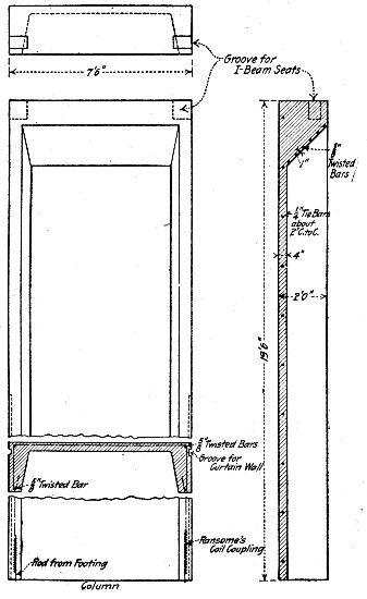 Fig. 228.—Channel Section Wall Column for Factory
Building.
Fig. 228.—Channel Section Wall Column for Factory
Building.
This gives us a cost per cubic yard of concrete for materials and labor constructing forms of $480 ÷ 370 = $1.30, and per square foot of outside wall area of $480 ÷ (146 × 80) = 4.1 cts.
The erection and taking down of the forms, owing to the weight of some of the pieces, was done by means of special derricks. The footings were brought to within ½ in. of grade and a tenon form of the exact shape of the channel section of the column was placed on top and filled with grout to a depth of 1 in. These tenons served as guides in setting the column forms, and proved to be much quicker and more accurate than points.
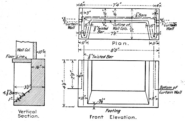 Fig. 229.—Footing for Wall Column Shown by Fig. 228.
The forms were assembled on the ground and erected by a 35-ft. A-frame derrick mounted on wheels. The construction is shown by Fig. 231. This derrick had a capacity of about 4 tons and carried a Ransome friction crab hoist driven by a 5 h.p. Meitz & Weiss kerosene oil engine. It was the practice to set a number of forms before filling any. This enabled the carpenter gang to be plumbing up the first form while the erecting gang were setting others. The forms had to be very securely guyed and braced to withstand the impact of the falling concrete. Very little trouble was had in keeping them well lined up.[Pg 500]
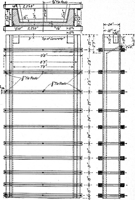 Fig. 230.—Form for Molding Wall Column Shown by Fig.
228.
Fig. 230.—Form for Molding Wall Column Shown by Fig.
228.
Two gangs were employed in assembling forms and a portion of the men in each gang also shaped and placed the reinforcement and placed and tamped the concrete in the forms so that no exact division of labor is possible. The organization of these gangs and the wages paid were as follows:
| Derrick Gang: | |
| 1 foreman, at 36 cts. per hour | $ 3.94 |
| 1 crabman, at 30 cts. per hour | 2.70 |
| 2 topmen, at 27 cts. per hour | 4.86 |
| 2 bottom men, at 23 cts. per hour | 4.14 |
| ——— | |
| Total per 9-hour day | $15.64 |
| Assembling Gang: | |
| 1 boss carpenter, at 47 cts. per hour | $ 4.23 |
| 2 carpenters, at 36 cts. per hour | 6.48 |
| 2 carpenters, at 30 cts. per hour | 5.40 |
| 2 carpenters' helpers, at 25 cts. per hour | 4.50 |
| 4 men forming and placing reinforcing steel | |
| and rethreading bolts, at 23 cts. per hour | 8.28 |
| ——— | |
| Total per 9-hour day | $28.89 |
| ——— | |
| Grand total | $44.53 |
These gangs assembled and erected the molds and concreted 80 columns in 22 working days, including 2 days lost on account of cold weather, so that 4 columns were completed per day of 9 hours. We can subdivide the cost as follows:
| Item. | Per cu. yd. |
| Erecting forms and concreting | $0.81 |
| Assembling forms and reinforcement | 1.56 |
| —— | |
| Total | $2.37 |
Charging the 4 men placing reinforcement and rethreading bolts to forming and placing reinforcement alone we can figure the cost of fabrication and erection of reinforcement very closely. There were 160 lbs. of reinforcing steel in each column, hence $8.28 ÷ (160 × 4) = 1.3 cts., was the cost per pound of forming and placing it. This includes handling.[Pg 502]
The stripping of the forms was carried on by another gang using a derrick similar to the first one described, except it could be of lighter construction as it had to handle only the separate parts of each form and not the forms assembled. The derrick shown in Fig. 232 was a 33-ft. A-frame, with wheels at the bottom of each leg. It had a friction crab hoist driven by an electric motor, both of which were fastened to the derrick frame between the shear legs.
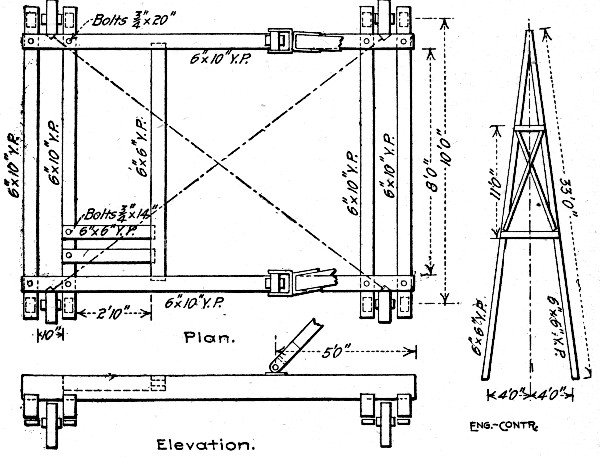 Fig. 231.—Derrick for Erecting Wall Column Forms Shown
by Fig. 230.
Fig. 231.—Derrick for Erecting Wall Column Forms Shown
by Fig. 230.
The operation of stripping required only four men and the crabman. The outside flat panel was removed first, and left leaning up against the concrete while the inside trough shaped panel was pried loose and lowered onto the ground with its inside face uppermost. The side panels being comparatively light, were stripped without the use of the derrick, and these panels were assembled on the ground with the inside piece. The derrick then picked up the outside panel again, and placed it in its proper place. After the bolts were put in place, the assembled form was moved on rollers to another[Pg 503] point in the line of columns where it was again erected. The arrangement of derricks for erecting and stripping forms is shown in Fig. 233.
The gang stripping forms was made up as follows:
| 1 foreman, at 30 cts. per hour | $ 2.70 |
| 1 crabman, at 27 cts. per hour | 2.43 |
| 1 topman, at 27 cts. per hour | 2.43 |
| 2 bottom men, at 23 cts. per hour | 4.14 |
| ——— | |
| Total per 9-hour day | $11.70 |
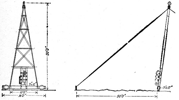 Fig. 232.—Derrick for Stripping Wall Column Forms Shown
by Fig. 230.
Fig. 232.—Derrick for Stripping Wall Column Forms Shown
by Fig. 230.
This gang of five men stripped 4 columns containing 18.52 cu. yds. of concrete each day, so that the cost of stripping was $11.70 ÷ 18.52 = 62.7 cts. per cu. yd.
Concrete.—The concrete was mixed in a No. 2 Ransome mixer and delivered to the work in Ransome concrete carts. These carts were pushed along a runway which terminated in a slight incline under the derrick so that their contents could be emptied into the derrick buckets.
The concrete was hoisted in an 8-ft. bottom dump bucket, using the derrick described above. It was necessary to stir up the concrete thoroughly with long-handled slicers as it was being deposited in order to prevent segregation. This expedient combined with a wet mixture and tight molds was found to overcome this difficulty very effectually.[Pg 504]
The gang mixing and wheeling concrete was made up as follows:
| 1 mixer foreman and engineer at 27 cts. per hour | $ 2.43 |
| 4 laborers charging mixer at 18 cts per hour | 6.48 |
| 4 laborers wheeling concrete at 18 cts. per hour | 6.48 |
| ——— | |
| Total per 9-hour day | $15.39 |
This gang mixed and wheeled concrete for four columns, or 18.52 cu. yds., hence the cost per cubic yard was 82.6 cts.
With cement at $1.60 per bbl., sand at $1 per cu. yd. and slag at $1.10 per cu. yd. the cost of materials per cubic yard of concrete was $3.
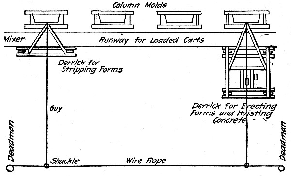 Fig. 233.—Arrangement of Derricks for Erecting and
Stripping Forms.
Fig. 233.—Arrangement of Derricks for Erecting and
Stripping Forms.
Summarizing the above figures we have the following cost per cubic yard of concrete in place:
| Item. | Per cu. yd. |
| Concrete materials | $3.00 |
| Reinforcing steel | 0.73 |
| Forms, lumber and framing | 1.30 |
| Forms, erecting and concreting | 0.81 |
| Forms, assembling and reinforcement | 1.56 |
| Forms, stripping | 0.63 |
| Mixing and wheeling concrete | 0.83 |
| —— | |
| Total | $8.86 |
CONSTRUCTING ONE-STORY WALLS WITH MOVABLE FORMS AND GALLOWS FRAMES.—In constructing the walls for an 85×30-ft. factory building at Old Bridge, N. J., Mr. A. E. Budell made use of movable forms and gallows frames to construct the curtain walls and columns in one piece. Each side wall was built its full height in successive 50-ft. lengths by depositing the concrete between two forms which were moved upward as the concreting progressed. Fig. 234 indicates the mode of procedure. The form was raised and lowered by means of two gallows frames fitted with blocks and tackle. A steel cable, with a trolley affixed, extending from one frame to the other, provided a convenient mode of hoisting material to the form, and the gallows frames took the place of ladders for climbing onto the structure. No scaffolding whatever was used and only one man was required overhead to dump the buckets and tamp the concrete into place.
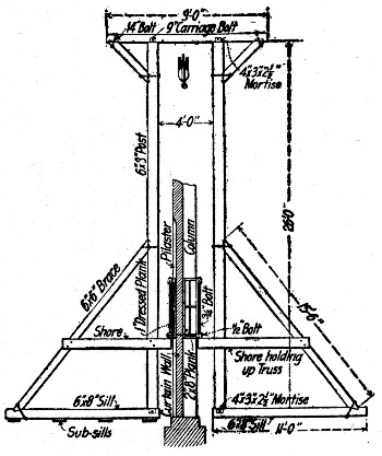 Fig. 234.—Gallows Frame Supporting Wall Form Panels for
One-Story Building.
Fig. 234.—Gallows Frame Supporting Wall Form Panels for
One-Story Building.
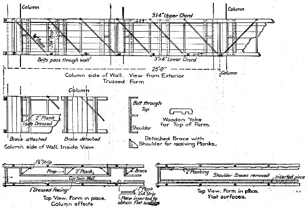 Fig. 235.—Details of Wall Form Panel for One-Story
Building.
Fig. 235.—Details of Wall Form Panel for One-Story
Building.
The two walls were carried up simultaneously, one form being shifted into place and filled while the other was left in place until the concrete was sufficiently hard. It was found that 18 hours was amply sufficient to allow the concrete to set[Pg 506] hard, after which the form was removed and lifted to a higher level. Thus the men were continuously engaged in lifting and filling first one form and then the other. The average length of time required to remove, raise and fill one form was 5 to 6 hours. Thus, two forms could be raised and filled almost every day. The construction of the forms and of the[Pg 507] gallows frames is shown by Figs. 234 and 235. The cost of one set of forms and gallows frames was as follows:
| 320 ft. B. M. of 2×10 in.×10 ft. plank at $34 | $ 10.88 |
| 150 ft. B. M. of 3×4 in.×16 ft. spruce at $33 | 5.25 |
| 135½ ft. B. M. 1×8 in. yellow pine at $30 | 4.08 |
| 335 ft. B. M. 1¼×6 in. spruce at $33 | 11.05 |
| 4 posts 6×8 in.×26 ft. = 416 ft. B. M. at $30 | 12.48 |
| 4 sills 6×8 ins.×16 ft., 2 caps 6×6 ins.×9 ft., | |
| 4 braces 6×6 ins.×16 ft. = 490 ft. B. M. at $30. | 14.70 |
| 3 pieces 3×10 ins.×20 ft. = 150 ft. B. M. at $30 | 4.50 |
| ——— | |
| Total lumber (1,996.5 ft. B. M.) | $ 62.94 |
| Accessories: | |
| Bolts for trussing, 675 lbs. at 2 cts. | $ 13.50 |
| Iron guy rope and clips | 7.00 |
| Blocks | 8.00 |
| One coil of ¾-in. rope | 28.00 |
| ——— | |
| Total accessories | $ 56.50 |
| Labor making one outfit: | |
| 2 men, 8 days, at $2.75 per 9 hrs. | $ 44.00 |
| ——— | |
| Grand total | $163.44 |
This sum covered the cost of forms for one side of the building 85 ft. long and containing 150 cu. yds. of concrete, hence the cost of forms was in round figures $1.10 per cu. yd. of concrete. Each cubic yard of concrete required 1,997 ÷ 150 = 13⅓ ft. B. M. of form lumber.
The concrete was a 1-2½-4½ mixture. A careful record for 15 days, showed an average of 2.8 cu. yds. of concrete placed in 6 hours by a gang of 6.3 men. From this we can figure the cost of concrete in place to be about as follows:
| 2.8 cu. yds. concrete at $3 for materials | $ 8.40 |
| 6.3 men 6 hours at 15 cts. | 5.67 |
| 1 foreman 6 hours at $4 per day | 2.00 |
| ——— | |
| Total per cu. yd. | $16.07 |
Thus the cost of concrete in place was $16.07 ÷ 2.8 = $5.73 per cu. yd. Adding the cost of forms we get $5.73 + $1.10 = $6.83 per cu. yd. as the cost for labor and materials in constructing forms and mixing and placing concrete.
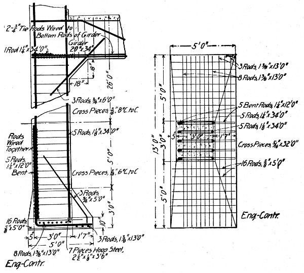 Fig. 236.—Detail of Column and Cantilever Column Footing
for Four-Story Garage.
Fig. 236.—Detail of Column and Cantilever Column Footing
for Four-Story Garage.
Offsets and molding decorations were easily made, although they were quite numerous on the building in question, at least more so than would ordinarily be the case in mill building construction. The offset of 1 ft. at every column was made very readily by sliding wooden shoulder pieces into place on the inner face of the form, which pieces in turn received 2-in. faced planking, the latter being slid into place from above. Thus the entire system was collapsible and small alterations were easily made whenever the form was shifted. Flat surfaces or offsets could be obtained at will by either removing or setting in the shoulder pieces. Molding effects were made on the front face of the wall by tacking molding strips to the[Pg 509] form wherever necessary. The entire work was done with common labor and the finished building presented a smooth, homogeneous surface which required very little dressing.
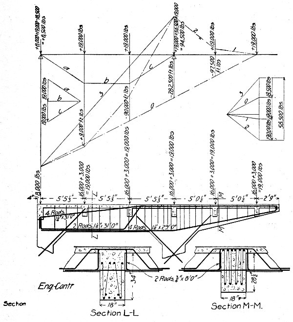 Fig. 237.—Details of Cantilever Girders for Mezzanine
Floor for Four-Story Garage.
Fig. 237.—Details of Cantilever Girders for Mezzanine
Floor for Four-Story Garage.
FLOOR AND ROOF CONSTRUCTION FOR FOUR-STORY GARAGE.—The building was 53×200 ft., and 4 stories high, with provision for 2 additional stories in the design of footings and columns. Two rows of wall columns connected by transverse girders carrying the floor and roof slabs made a comparatively simple construction, except for a mezzanine floor carried on cantilever beams and except for the[Pg 510] use of cantilever footings; these two special details are shown by Figs. 236 and 237. The amount of concrete in the building was 1,910 cu. yds., distributed as follows:
| Cu. yds. | |
| Footings, reinforced | 190 |
| Columns, reinforced | 450 |
| Floors and roof, reinforced | 1,100 |
| Floor on ground, not reinforced | 170 |
| —— | |
| Total | 1,910 |
The amount of reinforcing metal used was 237 tons, distributed as follows:
| Item. | Tons. | Lbs. per cu. yd. |
| Footings | 42 | 442 |
| Columns | 20 | 90 |
| Floors and roof | 175 | 318 |
| — | — | |
| Total and average | 237 | 272 |
This is equivalent to 2 per cent. of steel in 1,910 - 170 = 1,740 cu. yds.
Forms.—The total area of concrete covered by forms (1,740 cu. yds.) was 94,000 sq. ft., distributed as follows:
| Footings, sq. ft. | 4,000 |
| Columns, sq. ft. | 20,000 |
| Floors and girders, sq. ft. | 70,000 |
| ——— | |
| Total, sq. ft. | 94,000 |
For the work 50,000 ft. B. M. of old lumber was used and 170,000 ft. B. M. of new lumber was bought, the cost being as follows:
| 50 M. ft. B. M. at $13 per M. | $ 650 |
| 170 M. ft. B. M. at $26 per M. | 4,420 |
| ——— | |
| 220 M. ft. B. M. at $23 | $5,070 |
This is equivalent to 126 ft. B. M. per cu. yd. of concrete. New forms were made for each floor except the sides of the girder molds which were re-used so far as they would fit, but the roof forms were made from lumber used for the floors.[Pg 511] In all no more than 20 per cent of the form lumber was used a second time. In round figures new lumber was required for 80,000 sq. ft. of concrete; this gives a cost for lumber of 6.4 cts. per sq. ft. The construction of the column and floor forms is shown by Fig. 238. A force of 15 carpenters at $4.40 per day under a foreman at $35 per week erected and tore down forms; the carrying was done by laborers at $1.70 per day working under a foreman at $35 per week; carpenters worked an 8-hour and laborers a 10-hour day. Forms for one floor were framed and erected in 8 to 10 days. The cost of forms for 1,740 cu. yds. and 80,000 sq. ft. of concrete and per M. ft. B. M. was as follows:
| Item. | Per cu. yd. | Per sq. ft. | Per M. ft. |
| Lumber | $2.90 | $0.064 | $23.00 |
| Framing, erecting and removing. | 2.00} | 0.057 | 15.67 |
| Handling lumber | 1.10} | 8.70 | |
| —— | ——— | ——— | |
| Totals | $6.00 | $0.121 | $47.37 |
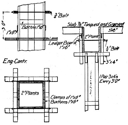 Fig. 238.—Column and Floor Forms for Four-Story Garage.
The lumber had a considerable salvage value which is not allowed for in the above figures.[Pg 512]
Concrete.—The concrete was a Portland cement, ¾-in. trap rock mixture, mixed wet in two Chicago Improved Cube Mixers equipped with charging buckets. The mixers were located on the ground floor, one at the rear and one at the front of the building, both discharging directly to a hoist. With a gang of 30 men at $1.70 per 10-hour day under a foreman at $35 per week a floor was concreted in 2 days, the columns being concreted the first day and the floor being concreted the second day. The labor cost for mixing and placing concrete and for fabricating and setting reinforcement was as follows:
| Item. | Per cu. yd. |
| Mixing and placing concrete | $1.95 |
| Erecting and setting steel | 2.05 |
| —— | |
| Total | $4.00 |
The cost of concreting includes the cost of granolithic surface for the floor slabs. The girder reinforcement was made up into unit frames and the frames were set as a unit, horses set over the molds being used to suspend and lower them into place. The cost of $2.05 per cu. yd. is equivalent to ¾ ct. per lb. Summarizing, we have the following cost for materials and labor on forms and for labor mixing and placing concrete and reinforcement:
| Per cu. yd. | |
| Lumber for forms | $ 2.90 |
| Labor on forms | 3.10 |
| Labor on concrete | 1.95 |
| Labor on steel | 2.05 |
| —— | |
| Total | $10.00 |
This $10 total does not include the cost of the concrete nor of the steel.
This chapter deals exclusively with the methods and cost of molding and erecting separately molded wall blocks, girders, columns and slabs. The structural advantages and disadvantages of this type of construction as compared with monolithic construction will not be considered. The data given in succeeding paragraphs show how separate piece work has been done and what it has actually cost to do it in a number of instances.
COLUMN, GIRDER AND SLAB CONSTRUCTION.—European engineers have developed several styles of open web or hollow girder and column shapes, but in America solid columns and girders have been used except in the comparatively few cases where one of the European constructions has been introduced by its American agents.
Warehouses, Brooklyn, N. Y.—In constructing a series of warehouses in Brooklyn, N. Y., the columns and girders were molded in forms on the ground. For molding the columns, forms consisting of two side pieces and one bottom piece, were used, saving 25 per cent. in the amount of lumber required for a column form, and doing away with yokes and bolts, since only simple braces were required to hold the side forms in place. It was found that the side forms could readily be removed in 24 to 48 hours, thus considerably reducing the time that a considerable portion of the form lumber was tied up. It was figured by Mr. E. P. Goodrich, the engineer in charge of this work, that this possible re-use of form lumber reduced the amount required another 50 per cent. as compared with molding in place. Girders were molded like columns in three-sided forms; the saving in form work was somewhat less than in the case of columns, but it was material. In general, Mr. Goodrich states, the cost of hoisting and placing molded concrete[Pg 514] members is higher per yard than when the concrete is placed wet. That is in mass before it is hardened.
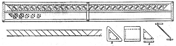 Fig. 239.—Sketch Showing Forms and Reinforcement for
Visintini Girder.
Fig. 239.—Sketch Showing Forms and Reinforcement for
Visintini Girder.
Factory, Reading, Pa.—In constructing a factory at Reading, Pa., an open or lattice web type of girder invented by Mr. Franz Visintini and extensively used in Austria was adopted; columns were molded in place in the usual manner with bracket tops to form girder seats. The girders were reinforced with three trusses made up of top and bottom chord rods connected by diagonal web rods; one truss was located at the center of the beam and one at each side. The method of molding was as follows: The trusses were made by cutting the chord rods to length and threading the web diagonals and verticals onto them. To permit threading the web pieces were bent, when rods were used, with an eye at each end; when straps were used the ends were punched with holes. The work was very simple and was done mostly by boys in the machine shop of the company for which the building was being erected. The girders were molded two at a time in forms constructed as shown by the sketch. Fig. 239. A form consisted of a center board, two side boards, two end pieces and the proper number of cast iron cores, all clamped together by three yokes. Triangular cast iron plates, A, were screwed to the bottom boards for spacers. The side, center and end boards were then set up and the end clamps were placed. The cast iron hollow cores, B, were then set over the spacers, and the form was ready for pouring. A layer of concrete was placed in the bottom of the mold and the first side truss was placed; the concrete was then brought half way up and the middle truss was placed; concreting was then continued up to the plane of the second side truss which was placed and covered. Cores and forms were all cleaned and greased each time they were[Pg 515] used. The cores were removed first by means of a lever device and generally within three or four hours after the concrete was placed. The remainder of the form was taken down in two to four days and the beam removed.
Kilnhouse, New Village, N. J.—In constructing a kiln house for a cement works one story columns with bracket tops and 50-ft. span roof girders were molded on the ground and erected as single pieces. The columns by rough calculation averaged about 2 cu. yds. of concrete and 675 lbs. of reinforcement each or about 337 lbs. of steel per cubic yard. The girders averaged by similar calculation 5 cu. yds. of concrete and 2,260 lbs. of steel, or 452 lbs. per cubic yard of concrete. The average weight of columns was thus not far from 41.3 tons and of girders fully 11 tons.
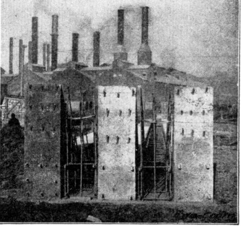 Fig. 240.—Arrangement for Molding Ten Single-Bracket
Columns.
Fig. 240.—Arrangement for Molding Ten Single-Bracket
Columns.
Several combinations of arrangements were used for molding the columns and girders. For wall columns having one bracket the arrangement shown by Fig. 240 was adopted. The concrete slab molding platform was covered with paper, and on this the two outside and the middle columns were cast in forms. When those columns had set the forms were removed, the intervening spaces were papered and the two remaining columns were cast. Ten columns, five sets of two columns in line, were cast on each base. The remaining columns[Pg 516] were cast in combination with girders as shown by Fig. 241. The two outside lines of columns (1) were molded in forms, allowed to stand until set and then stripped. Using a column surmounted by a shallow side form for one side and a full depth side form for the other side molds were fashioned for the two outside girders, Nos. 2 and 3. One full depth side form and the side of girder No. 2 formed the mold for girder No. 4. Girder No. 5 was then molded between girders No. 3 and No. 4.
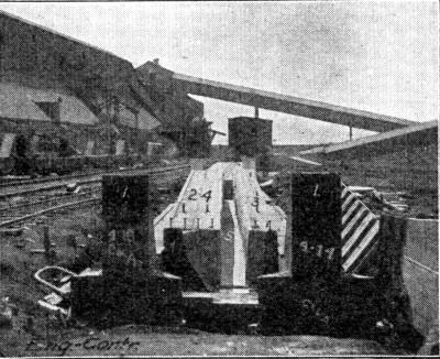 Fig. 241.—Arrangement for Molding Four Four-Bracket
Columns and Four Roof Girders
Fig. 241.—Arrangement for Molding Four Four-Bracket
Columns and Four Roof Girders
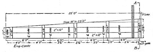 Fig. 242.—Forms for 50-ft. Roof Girders.
The construction of the girder forms is shown by Fig. 242. This drawing shows one of the four main sections making up a complete form. A full size form of this construction contained about 1,100 ft. B. M. of lumber, and three were built, so that 3,300 ft. B. M. of form lumber were used for molding 20 girders, or 33 ft. B. M. per cubic yard of concrete. A full[Pg 517] size column form contained about 225 ft. B. M. of lumber, and eight were constructed, so that 1,800 ft. B. M. of form lumber were used for molding 56 columns, or about 16 ft. B. M. per cubic yard of concrete.
The following was the cost of erecting a full column form including lining, plumbing, bracing and yoking, but excluding lumber and original construction:
| 1 carpenter, 3 hrs., at $0.25 | $0.750 |
| 1 helper, 3 hrs., at $0.175 | 0.525 |
| 1 helper, 1 hr., at $0.175 | 0.175 |
| 1-5 boss carpenter, 3 hrs., at $0.30 | 0.180 |
| ——— | |
| Total | $1.630 |
This gives a cost of $7.25 per M. ft. B. M. for erecting column forms.
The cost of erecting a full size girder form including lining, plumbing, bracing and setting six bolts was as follows:
| 2 carpenters, 5 hrs., at $0.25 | $2.50 |
| 2 helpers, 5 hrs., at $0.175 | 1.75 |
| 2 laborers, ½ hr., at $0.15 | 0.15 |
| ¼ boss carpenter, at $0.30 | 0.375 |
| ——— | |
| Total | $4.775 |
This gives a cost of $4.35 per M. ft. B. M. for erecting girder forms.
The reinforcement was erected inside the forms for both columns and girders. The cost of erection for one column was:
| 2 laborers, 4 hrs., at $0.15 | $1.20 |
| ⅓ foreman, 4 hrs., at $0.225 | 0.30 |
| —— | |
| Total | $1.50 |
This gives a cost of about 0.22 cts. per pound for erecting column reinforcement, including the bending of the horizontal ties or hoops. The girder reinforcement was erected by piece work at a cost of $1.80 per girder—or about 0.08 ct. per pound.[Pg 518]
The concrete used was a 1-6 mixture of Portland cement and crusher run stone all passing a ½-in. sieve and 10 per cent. passing a 200 mesh sieve. No trouble was had in handling this fine aggregate. It was mixed in a Ransome mixer, elevated so as to deliver the batches into cars on a standard gage track. This track ran between the base slabs on which the molding was done. Each car held about 3 cu. yds. and discharged through a side gate and spout directly into the forms, the mixture being made so wet that it would flow readily. The company used its own cement and stone for concrete and charged up the cement at $1 per barrel and the stone at 60 cts. per cubic yard. At these prices, and assuming that a cubic yard of concrete of the mixture above described would contain about 1.25 bbl. of cement and 1.5 cu. yd. of stone, we have the following cost of materials per cubic yard of concrete:
| 1.25 bbls. of cement, at $1 | $1.25 |
| 1.5 cu. yds. stone, at $0.60 | 0.90 |
| —— | |
| Total | $2.15 |
The actual cost of mixing the concrete and delivering it to the cars was as follows:
| Item. | Per cu. yd. |
| 1 foreman, at 20 cts per hour | $0.0300 |
| 3 men shoveling stone, at 15 cts. per hour | 0.0675 |
| 3 men filling hopper, at 15 cts. per hour | 0.0675 |
| 1 man bringing cement, at 18 cts. per hour | 0.0225 |
| 1 man dumping cement, at 15 cts. per hour | 0.0225 |
| 9 h.p., at ½ ct. per h.p. hour | 0.0450 |
| Superintendence, repairs, etc. | 0.0270 |
| ——— | |
| Total | $0.2820 |
The cost of hauling the concrete from mixer to forms ran about 2.7 cts. per cubic yard, so that we have a cost for concrete in place of:
| Concrete materials, per cu. yd. | $2.150 |
| Mixing concrete, per cu. yd. | 0.281 |
| Hauling concrete, per cu. yd. | 0.027 |
| ——— | |
| Total cost, per cu. yd. | $2.458 |
The cost, then, per column or girder molded, assuming that it was necessary to erect a full form, was about as follows:
| Columns: | |
| 2 cu. yds. concrete, at $2.46 | $ 4.92 |
| 675 lbs. steel, at 2½ cts. | 16.77 |
| Erecting steel, at 0.22 ct. per lb. | 1.50 |
| Erecting forms | 1.63 |
| ——— | |
| Total | $24.82 |
| Girders: | |
| 5 cu. yds. concrete, at $2.46 | $12.30 |
| 2,260 lbs. steel, at 2½ cts. | 56.50 |
| Erecting steel, at 0.08 ct. per lb. | 1.80 |
| Erecting forms | 4.77 |
| —— | |
| Total | $75.37 |
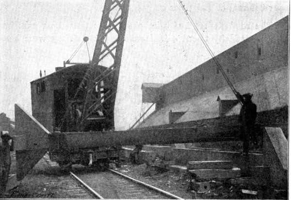 Fig. 243.—View Showing Method of Hoisting Molded
Columns.
Fig. 243.—View Showing Method of Hoisting Molded
Columns.
These figures give a unit cost of $12.41 per cu. yd. for molded columns, and of $15.07 per cu. yd. for molded girders,[Pg 520] The columns were erected by a Browning locomotive crane, which lifted and carried them to the work and up-ended them into place. To facilitate lifting the columns from the molding bed a 1½-in. pipe 8 ins. long was cast into both ends; pins inserted into these sockets provided hitches for the tackle. The column was lifted off the molding bed and blocked up, then iron clamps were attached, one at each end, as shown by Fig. 243. A gang of 1 foreman and 14 men erected from 5 to 7, or an average of 6 columns per 10-hour day. The average wages of the erecting gang were 21 cts. per hour. The cost then of column erection was (14 × $2.10) ÷ 6 = $5.25 per column, or $2.63 per cu. yd. of concrete.
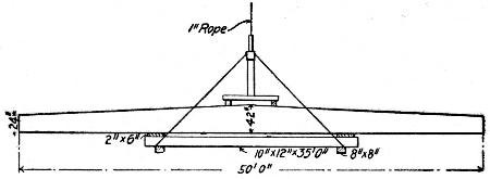 Fig. 244.—Sketch Showing Sling for Erecting 50-ft. Roof
Girders.
Fig. 244.—Sketch Showing Sling for Erecting 50-ft. Roof
Girders.
The roof girders had 1-in. eye-bolts 24 ins. long cast into them vertically about 4 ft. from the ends. They were lifted off the molding bed by tackle by the locomotive crane to these eye-bolts and blocked up to permit the adjustment of the sling. This sling is shown by the sketch, Fig. 244, and as will be observed acts as a truss. At first it was used without the vertical, but the cantilever action of the unsupported ends caused cracks. The girders were loaded onto cars by the locomotive crane and taken to the work, where they were hoisted and placed by a gin pole. The girder erecting gang consisted of 1 foreman and 14 men, working a 10-hour day at 21 cts. per hour. This gang erected four girders per day, at a cost of (15 × $2.10) ÷ 4 = $7.87 per girder, or $1.57 per cu. yd. of concrete.
The cost of girders and columns in place was thus about as follows:[Pg 521]
| Columns: | Per unit. | Per cu. yd. |
| Molding | $25.00 | $12.50 |
| Erecting | 5.25 | 2.63 |
| ——— | ——— | |
| Totals | $30.25 | $15.13 |
| Girders: | ||
| Molding | $75.00 | $15.00 |
| Erecting | 7.87 | 1.57 |
| ——— | ——— | |
| Totals | $82.87 | $16.57 |
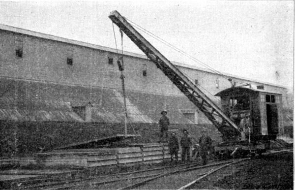 Fig. 245.—View Showing Method of Handling Roof Slabs.
In this same building the roof was composed of 12×6¼ ft.×4-in. slabs molded in tiers; a slab was molded and when hard was carpeted with paper and the form moved up and a second slab molded on top of the first. This operation was repeated until a tier of slabs had been molded. By molding each slab with a 3-in. overlap, as shown by Fig. 245, they could be easily separated by lifting on hooks inserted under the overhanging ends. Each slab contained 0.925 cu. yd. of concrete and about 116¾ lbs. of reinforcement. The cost of molding one roof slab, including materials, forms and labor, was as follows:[Pg 522]
| Materials: | Per slab. | Per cu. yd. |
| 1 bbl. cement, at $1 | $1.000 | $1.081 |
| 1.06 tons stone, at $0.60 | 0.636 | 0.687 |
| 116¾ lbs. steel, at 2¼ cts. | 2.647 | 2.862 |
| ——— | ——— | |
| Total | $4.283 | $4.630 |
| Forms: | ||
| Lumber and making | $0.104 | $0.112 |
| 92 sq. ft. paper, at 33⅓ cts. per 500 sq. ft. | 0.055 | 0.059 |
| Labor erecting and removing | 0.5625 | 0.608 |
| ——— | ——— | |
| Total | $0.7215 | $0.779 |
| Mixing, Hauling and Placing: | ||
| Mixing | $0.222 | $0.240 |
| Hauling | 0.025 | 0.027 |
| Placing concrete and steel | 0.170 | 0.183 |
| ——— | ——— | |
| Total | $0.417 | $0.450 |
| General Expenses: | ||
| Housing and heating | $0.700 | $0.757 |
| Superintendence, power, etc. (10%) | 0.612 | 0.661 |
| ——— | ——— | |
| Total | $1.312 | $1.418 |
| Grand totals | $6.7335 | $7.277 |
The roof slabs were raised from the casting beds by means of the locomotive crane and hooks, as shown by Fig. 245, and loaded onto cars; eight slabs made a carload. The cars were run to the work, where the gin poles hoisted the slabs one at a time to cars running on a track built on timbers laid on top of the roof girders. A small derrick on rafters picked the slabs from the hand car and set them in place. A gang of 15 men erected from 18 to 20 slabs per 10-hour day. With average wages at 21 cts. per hour the cost of erection was (15 × $2.10) ÷ 19 = $1.66 per slab, or $1.79 per cu. yd. The total cost of slabs in place was thus:[Pg 523]
| Item. | Per slab. | Per cu. yd. |
| Molding | $6.73 | $7.27 |
| Erecting | 1.66 | 1.79 |
| —— | —— | |
| Total | $8.39 | $9.06 |
In studying these cost figures their limitations must be kept in mind. Because of the character of the available data quantities had in several cases to be estimated from the working drawings. The cost of lumber for and of framing column and girder forms is not included, but this is partly balanced at least by the assumption that each form was erected complete for each column and girder, which was not the case, as has been stated. Cost of plant is not included nor is cost of shoring the columns until girders and struts were placed, nor are several minor miscellaneous items.
HOLLOW BLOCK WALL CONSTRUCTION.—Three general processes of molding hollow wall blocks of concrete are employed: (1) A dry mixture is heavily tamped into a mold and the block is immediately released and set aside for curing; (2) a liquid is poured into molds, where the block remains until hard: (3) a medium wet mixture is compressed into a mold by hydraulic presses or other means of securing great pressure. The molds used may be simple wooden boxes with removable sides or mechanical molds of comparative complexity. Generally mechanical molds, or concrete block machines as they are commonly called, will be used. There are a score or more kinds of block machines all differing in construction and mode of operation. None of them will be described here, but those interested may consult "Concrete Block Manufacture" by H. H. Rice or "Manufacture of Concrete Blocks and Their Use in Building Construction" by H. H. Rice, Wm. M. Torrance and others.
Factory Buildings, Grand Rapids, Mich.—The buildings ranged from one to four stories high and altogether occupied some 74,000 sq. ft. of ground. The owners installed a block making plant fully equipped with curing racks, two Ideal machines, two National concrete mixers, 5 h.p. gasoline engine, platens, tools and a Chase industrial railway.[Pg 524]
The walls were constructed of 24-in. square pilasters of blocks arranged as shown by Fig. 246, connected by curtain wall belt courses of single blocks. The blocks were 8×8×16 ins., and after molding the faces were bush hammered and the edges tooled. The pilasters, consisting of four blocks laid around an 8×8-in. hollow space, were solidified by pouring the 8×8-in. space and all but the three outside block cavities with wet concrete. The interior of the building was of regulation mill construction, and as the pilasters reached the heights for beam supports cast iron plates with downward flanges were set in the concrete. These plates had a cast pin projecting upward to fasten the beam end.
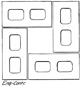 Fig. 246.—Concrete Block Pilaster for a Factory
Building.
Fig. 246.—Concrete Block Pilaster for a Factory
Building.
The materials used for the block were Sandusky Portland cement and ¾-in. bank gravel well balanced from fine to coarse. The blocks were molded with 1-3 mortar faces, the mortar being waterproofed by a mixture of Medusa waterproofing compound. All concrete was machine mixed. The men operating the block machines were paid 1 ct. for each block molded, so that their pay depended upon the energy with which they worked. The men handling materials and engaged in handling and curing the blocks were paid $1.75 per day. The gravel was shoveled from the railway cars onto the screens and from the screen piles to the mixers. The gang was organized as follows:[Pg 525]
| Item. | Per day. |
| 8 men handling materials, at $1.75 | $14.00 |
| 5 men operating molds, at 1 ct. per block | 15.00 |
| 1 man mixing facing mortar, at $1.75 | 1.75 |
| 2 men loading blocks onto trucks, at $1.75 | 3.50 |
| 2 men unloading blocks from trucks, at $1.75 | 3.50 |
| 3 men sprinkling blocks, at $1.75 | 5.25 |
| ——— | |
| Total, 21 men molding and curing blocks | $43.00 |
The average daily run was 1,500 blocks, or 300 blocks per machine.
This output was easily maintained after the gang got broken in; sometimes it ran higher and sometimes lower, but the average was as given. The men operating the block machines thus earned $3 each per day. The labor cost of molding and curing per block was thus 2.87 cts. As the blocks had about 25 per cent. hollow space, each block 8×8×16 ins. contained 0.45 cu. ft. of concrete; a cubic yard of concrete, therefore, made 60 blocks, so that the labor cost of making the blocks was 60 × 2.87 cts. = $1.72 per cubic yard. This cost does not include foreman's time, materials, interest, depreciation or general expenses. It was estimated by the owners that the blocks cost them 9 cts. apiece cured, or about $5.40 per cubic yard of concrete. This 9 cts. evidently includes materials and labor alone.
Upon removal from the molds the blocks were loaded onto cars, taken to a large shed and there unloaded onto shelving arranged to hold five rows of blocks one above the other, two blocks opposite each other on each shelf. The blocks were left in the shed 24 to 48 hours to get the preliminary set, then they were loaded on small cars and taken to the yard, where they were removed from the cars and stacked. They were sprinkled every day for six days, being kept covered meanwhile with oiled cotton cloth. The labor costs given above include molding, sprinkling and handling the blocks up to this point.
To lay the blocks they were again loaded on cars and run to an elevator in a wooden tower outside the building. The elevator lifted the car to the floor on which the blocks were to be used, where it was run off onto a track reaching the full[Pg 526] length of the building. The blocks were unloaded directly behind the masons. Where the walls were high enough for scaffolding the blocks were unloaded directly onto the first scaffold and, when necessary, handed up to the scaffolds above. The masons employed were regular stone masons receiving the regular scale of wages of $3.50 per day. The number of blocks laid by each mason was 125 per day in building pilasters and 200 per day in building plain wall. Sometimes 250 blocks per day per man were laid in plain wall work. The cost per block of laying above was thus 2.8 cts. pilasters and 1.75 cts. in plain wall. This cost does not include transporting the blocks from yard or of handling them to the scaffold behind the masons, nor does it include the cost of materials and labor for mixing and delivering mortar.
One of the features of this work was the method of transporting the blocks by cars. A complete system of tracks was provided covering the block plant and yard, the building sites and the several floors of the buildings themselves. All blocks and other materials were transported by cars running on these tracks, both cars and tracks being of the type made by the Chase Foundry & Manufacturing Co. of Columbus, Ohio.
Residence, Quogue, N. Y.—The following record of methods and cost of constructing a concrete block residence is furnished by Mr. Noyes F. Palmer: A mixture of sand and pebbles was had on the site; screening was necessary merely to sort out the odd size stones. A mixture of 1 cement and 5 sand was really a 1-2-3 mixture, the 2 being the finest grades of sand and the 3 being various gravel sizes—none too large, none too small—so that the proportion was 2/5 fine sand and 3/5 gravel.
The concrete was hand mixed, and as the gravel had always just been excavated it contained moisture and did not have to be wetted. The sand and gravel were mixed and turned three or four times and spread out thin, and the cement was carefully spread over them in a uniform layer. The mass was then turned three or four times until the eye could detect no difference in color; that is, each grain large enough for the eye to discern seemed to be coated with cement. After this dry mixing, water was added in a fine spray—not a deluge[Pg 527] from a pail—but only enough to moisten the mixture. The mass was then turned three or four times. The mixture was then shoveled into the mold, no special face mixture being used, so as to about half fill it, and was then tamped by two men, one standing on each side of the machine. Altogether three layers of material were so placed and tamped and then a shovelful of sand and cement mixture was spread over the top to permit an even "strike-off."
As each block was molded it was carried on the working plate and set down on skids properly spaced to fit the marks on the plate. This is an important detail and Mr. Palmer comments on it as follows: "The writer saw inexperienced men careless about it and who would break the backs of many blocks by not having the skids properly placed. After the blocks have been at rest for half an hour commence to spray them with a revolving garden sprinkler or by carefully wetting with a sprinkling pot on the center of the block only. The blocks should not be allowed to dry out for at least ten days after removal from the working plate. The removal from the working plate can be done the morning after molding and should never be done before even if the block was made in the morning. In removing the green block from the skids let there be cones of sand between the rows of blocks and up-end each working plate so as to let the end of the block come upon the sand cushion. Don't twist and turn the block, and to remove the working plate pass a stick through the core holes in both block and plate so that the plate will not fall when loosened. A slight rap on the center of the plate will loosen it. As soon as the blocks are up-ended commence the spraying and soak the sand underneath the block. It may seem unnecessary to dwell on these points so long, but barrels of cement and barrels of money have been wasted by neglecting to supply the hardening block with water. Curing is just as important as molding in making concrete blocks."
The block construction had been detailed by the architect from cellar to roof, so that it was known beforehand how many blocks of given size were to be made. The unit of length was 32 ins.; this afforded fractional parts of 8 ins., 16 ins. and 24 ins., therefore all openings were in multiples of 8 ins. Odd sizes were made, by inserting "blanks" in the mold[Pg 528] box, to inches or fractions of an inch if desired. This unit length was less mortar joints, while the unit of height was 9 ins., or the same as four ordinary bricks with joints. The floor levels were calculated in multiples of 9 ins., so that the wall could be finished all around where the beams were to be seated. This beam course was made of solid blocks; that is, no cores were used in molding them. With the machine used no change was required to mold these solid blocks except to remove the cores. The core holes in the working plate were simply covered with pieces of tin. The shape of the block was the same and the same materials were used.
The best record in making blocks for this work was 30 blocks, 8×9×32 ins., in one hour, working six men, three mixing and three on the machine, and using one barrel of cement for 16 blocks. This was a record run, however, a fair average being 20 blocks per hour, or 200 per ten hours, which was the day worked. We have then the cost of making blocks as follows:
| 1 foreman, at $2.50 | $ 2.50 |
| 5 helpers, at $2 | 10.00 |
| 13 barrels cement, at $2 | 26.00 |
| 10 cu. yds. sand and gravel, at $1 | 10.00 |
| Interest and depreciation on machine | 2.00 |
| ——— | |
| Total for 200 blocks | $50.50 |
This gives a cost per block of $50.50 ÷ 200 = 25¼ cts. The displacement in the wall of each block is 1.75 cu. ft., or the same as 30 bricks.
The cost of laying blocks is the most uncertain item in the whole industry. Mr. Palmer states that he has known of instances where it cost only 5 cts. per block and of other instances where, because of the difficulty of getting help and its inexperience, it cost 15 cts. per block. In this particular building one mason and three helpers laid 100 blocks per day. The building had no long walls, but it did have many turns. The cost of laying, then, was as follows:[Pg 529]
| 1 mason, at $4 | $ 4.00 |
| 3 helpers, at $2 | 6.00 |
| —— | |
| Total for 100 blocks | $10.00 |
This gives a cost for laying of 10 cts. per block. We have, then:
| Making 2,000 blocks | $505 |
| Laying 2,000 blocks | 200 |
| —— | |
| Total | $705 |
This gives a cost of 35¼ cts. per block for making and laying.
The use of a derrick for laying the blocks proved a considerable item of economy in this work. This derrick cost $50 and two men could mount and move it on the floor beams. It had a boom reaching out over the wall and was operated by a windlass. A plug and feather to fit the center 6-in. hole in the block was used for hoisting the blocks. By this means blocks only seven days old were laid without trouble. It may be noted that the walls were kept drenched with water to make sure that the blocks did not dry out until they were at least 28 days old. In laying the blocks a thin lath was used to keep the mortar back about one inch from the face. This precaution will prevent much labor in cleaning the walls from mortar slobber.
Two-Story Building, Albuquerque, N. M.—The following record of cost of making 9×10×32-in. hollow blocks in a Palmer machine and of laying 2,000 of them in two-story building walls is given by Mr. J. M. Ackerman. Sand cost 60 cts. per cu. yd., and cement cost $3 per barrel. Lime cost 30 cts. per bushel. One barrel of cement made 20 blocks, using a 1-4 sand mixture. In making 2,000 blocks about 100 blocks, or 5 per cent., were lost by blocks breaking in hauling from yard to building or by cutting blocks to fit the work. The blocks were molded by piece work for 5 cts per block, all materials, tools and plant being supplied to the molders. Three men with one machine made from 100 to 150 blocks per day. The cost was as follows:[Pg 530]
| Item. | Per block. |
| Cement, at $3 per bbl. | $0.15 |
| Molding, at 5 cts. per block | 0.05 |
| Sand, at 60 cts. per cu. yd. | 0.03 |
| Carting, yard to building | 0.02 |
| Lime and sand for mortar | 0.03 |
| Laying in wall | 0.10 |
| Loss in making and cutting | 0.01 |
| —— | |
| Total | $0.39 |
As each block gave 9 × 32 = 288 sq. ins., or 2 sq. ft., of wall surface, the cost of the wall per square foot was 19.5 cts. Assuming 40 per cent. hollow space, each block contained 1 cu. ft. of concrete, which cost 23 cts., or $6.21 per cu. yd., for materials and molding. Blocks in the wall cost $10.55 Per cu. yd. of concrete.
General Cost Data.—The following data are given by Prof. Spencer B. Newberry. The average weights of three sizes of hollow blocks are as follows:
| Size, ins. | P. C. Hollow Space. | Weight, lbs. |
| 8×9×32 | 33⅓ | 120 |
| 10×9×32 | 33⅓ | 150 |
| 12×9×32 | 33⅓ | 180 |
Costs of materials are assumed as follows:
| Item. | Per 100 lbs. |
| Cement, at $1.50 per bbl. | $0.40 |
| Hydrated lime, at $5 per ton | $0.25 |
| Sand, gravel or screenings, at 25 cts. per ton | $0.012 |
Mixed in batches of 750 lbs., sufficient for six 8-in. or four 12-in. blocks, the cost of materials per batch and per block will be for a 1-4 mixture as follows:
| Item. | Per Batch. | 8-in. Block. | 12-in. Block. |
| 150 lbs. cement | $0.60 | $0.10 | $0.15 |
| 600 lbs. sand | 0.072 | 0.012 | 0.018 |
| ——— | ——— | ——— | |
| Total | $0.672 | $0.112 | $0.168 |
In general a factory producing 600 8-in. blocks per day will require 25 men to operate it. At an average wage of $1.80 per day the following is considered as a fair estimate of cost:[Pg 531]
| Item. | Per Day. | Per Block. |
| Materials for 600 blocks | $ 60 | $0.10 |
| 25 men, at $1.80 | 45 | 0.075 |
| Repairs | 10 | 0.017 |
| Office and miscellaneous | 20 | 0.034 |
| —— | ——— | |
| Total | $135 | $0.226 |
This gives for 8×9×32-in. blocks a cost of about $6.78 per cu. yd. of concrete for materials and molding or of 11.3 cts. per sq. ft. of face.
Mr. L. L. Bingham gives the following as the average cost per square foot of face for 10-in. wall from data collected from a large number of block manufacturers operating in Iowa in 1905:
| Cement at $1.60 per bbl. | 4.5 cts. |
| Sand | 2.0 cts. |
| Labor at $1.83 per day | 3.8 cts. |
| ———— | |
| Total cost per square foot | 10.3 cts. |
Assuming one-third hollow space, the cost for materials and molding was $5.05 per cu. yd. of concrete not including interest, depreciation, repairs, superintendence or general expenses.
Aqueducts and sewers in concrete are of three kinds: (1) Continuous monolithic conduits, (2) conduits laid up with molded concrete blocks, and (3) conduits made up of sections of molded pipe. Block conduits and conduits of molded pipe are rare in America compared with monolithic construction; examples of each are, however, given in succeeding sections, where forms, methods of molding, etc., are described. The following discussion refers to monolithic construction alone.
FORMS AND CENTERS.—Forms and centers for conduit work have to meet several requirements. They have to be rigid enough not only to withstand the actual loads coming on them, but to keep from being warped by the alternate wetting and drying to which they are subjected. They have also to be constructed to give a smooth surface to the conduit. To be economical, they have to be capable of being taken down, moved ahead and re-erected quickly and easily. The carpenter costs run high in constructing conduit forms, so that each form has to be made the most of by repeated use.
Three different constructions of traveling forms are described in the succeeding sections. For small work, such forms appear to offer certain advantages, but for conduits of considerable size their convenience and economy are uncertain. The experience with the large traveling form employed on the Salt River irrigation works in Arizona was, when all is said, rather discouraging. The authors believe that for work of any size where the concrete must be supported for 24 hours or more, forms of sectional construction will prove cheaper and more expeditious than any traveling form so far devised.[Pg 533]
No class of concrete work, perhaps, offer so good an opportunity for the use of metal forms as does conduit work. The smooth surface left by metal forms is particularly advantageous, and there is a material reduction in weight and a large increase in durability due, both to the lack of wear and to freedom from warping. Steel forms of the Blaw type shown by Fig. 247, have been used for conduits up to 25 ft. in diameter. The form illustrated, Fig. 247, was for a 12-ft. 3-in. sewer; in this case a roof form alone was used, but full circular and egg-shape forms are made. The Blaw collapsible Steel Centering Co., of Pittsburg, Pa., make and lease steel forms of this type.
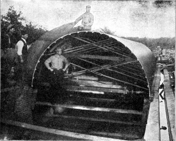 Fig. 247.—Blaw Collapsible Steel Centering for Conduit
Construction.
Fig. 247.—Blaw Collapsible Steel Centering for Conduit
Construction.
Sectional wooden forms for conduits of large diameters are shown by the drawings in several of the succeeding sections. Figures 248 and 249 show such forms for small diameters. The form shown by Fig. 248 is novel in the respect that after being assembled a square timber was passed through it lengthwise, occupying the holes B and having its ends projecting[Pg 534] and rounded to form gudgeons. The form was mounted with these gudgeons resting on horses, so that it could be rotated and thus wound with a narrow strip of thin steel plate. Thus sheathed, the form was lowered into the trench and the concrete was placed around it. When the arch had been turned, the wedges A were driven in until the ribs C dropped into the slots a and clear of the steel shell; the arch form was then pulled out and finally the invert form, leaving the steel shell in place to hold the concrete until hard. The strip of steel was then removed by pulling on one end until it unwound like cord from the inside of a ball of twine. Steel strips 6 ins. wide and 1/24 in. thick were used successfully in constructing a 5-ft. egg-shaped sewer in Washington, D. C. The forms were made in sections 16 ft. long, and were taken out as soon as the concrete had been placed.
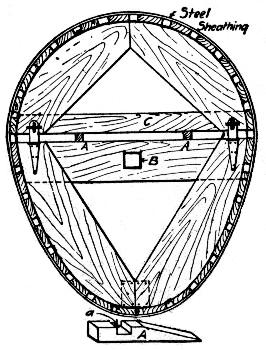 Fig. 248.—Sectional Steel Wrapped Wooden Form for
Conduit Construction.
Fig. 248.—Sectional Steel Wrapped Wooden Form for
Conduit Construction.
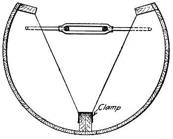 Fig. 249.—Invert Form for Conduit Construction.
The form shown by Fig. 249, is an invert form, used in constructing the sewer shown by Fig. 249, built at Medford, Mass., in 1902, by day labor. The concrete was 1-3-6 gravel. The forms for the invert were made collapsible and in 10-ft. lengths. The two halves were held together by iron clamps and hook rods. The morning following the placing of the concrete the hook rods were removed and turnbuckle hooks were put in their places, so that by tightening the turnbuckle the forms were carefully separated from the concrete. The concrete was then allowed to stand 24 hours, when the arch centers were set in place. These centers were made of ⅞×1½-in. lagging on 2-in. plank ribs 2 ft. apart, and stringers on each side. Wooden wedges on the forward end of each section supported the rear end of the adjoining section. The forward end of each section was supported by a screw jack placed under a rib 2 ft. from the front end. To remove the centers, the rear end of a small truck was pushed under the section about 18 ins.; an adjustable roller was fastened by a thumb screw to the forward rib of the center; the screw jack was lowered allowing the roller to drop on a run board on top of the truck; the truck was then pulled back by a tail rope until the adjustable roller ran off the end of the truck; whereupon the truck was pulled forward drawing the center off the supporting wedges of the rear section. Each lineal foot of sewer required 1¼ cu. yds. of excavation which cost 74.2 cts. per foot, and 1 cu. ft. of brick arch which cost $12.07 per cu. yd., or 44.2 cts. per lineal foot of sewer. The invert required 4 cu. ft. of concrete per foot, which cost as follows:
| Item. | Per cu. yd. |
| Portland cement at $2.15 per bbl. | $2.292 |
| Labor mixing and placing | 3.017 |
| Cost of forms | 0.187 |
| Labor screening gravel | 0.471 |
| Carting | 0.592 |
| Miscellaneous | 0.146 |
| ——— | |
| Total | $6.705 |
The cost of the invert was thus $1.002 per lin. ft. of sewer.[Pg 536]
Collapsible metal forms for manholes and catch basins are made by several firms which make block and pipe molds. A cylindrical wooden form construction is shown by Fig. 250. The outside form consists of three segments of a cylinder made of 2-in. lagging bolted to hoops. Bent lugs on the ends of the hoops, were provided with open top slots and were bolted together through 1×⅜-in. bars which extended the full length of the form between lugs. The assembled form was collapsed by pulling up on the bars, thus lifting the bolts out of the slots. The inner mold is also made in three sections with strap hinges at two of the joints and at the third joint a wedge-shaped stave. The other details are shown by the drawing. To mold the top of the basin two cone-shaped forms are used, an outer form made in one piece and an inner form made in sections. Some 26 catch basins were built in Keney Park, Hartford, Conn., by Mr. H. G. Clark, at a cost of $7 apiece for concrete in place, and there was closely 1 cu. yd. of concrete in each.
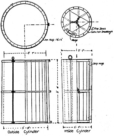 Fig. 250.—Form for Circular Catch Basin or Manhole.
CONCRETING.—Except for pipes of small diameter, the concreting is done in sections, each section being a day's work. Continuity of construction has not proved successful, except for pipes of moderate size, in the few cases where it has been tried. Examples of continuous construction methods are given in succeeding sections. Methods of molding and laying cast concrete pipe are also best shown by the specific examples given further on. In concreting large diameters, the work may be done by molding successive full barrel sections, or by molding first the invert and then the roof arch, each in sections. The engineer's specifications generally stipulate which plan is to be followed. Construction joints between sections are molded by bulkhead forms framed to produce the type of joint designed by the engineer; the most common type is the tongue and groove joint.
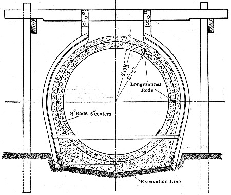 Fig. 251.—Cross-Section of Pinto Creek Irrigation
Conduit.
Fig. 251.—Cross-Section of Pinto Creek Irrigation
Conduit.
For small diameters built with traveling forms, a comparatively dry concrete is essential, but when the centers are left in place until the concrete has set, a wet mixture is preferable, as it is more easily placed and worked around the reinforcement in the thin shells. Mixers are commonly specified even for small work, because of their generally more uniform and homogeneous product. Portable mixers hauled along the bank and discharging into the forms through chutes, furnish a cheap and rapid arrangement where the section being built has a considerable yardage. The examples given in succeeding sections present various methods of mixing and placing concrete in conduit work.
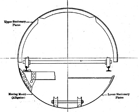 Fig. 252.—Traveling Form for Pinto Creek Conduit.
REINFORCED CONDUIT, SALT RIVER IRRIGATION WORKS, ARIZONA.—The pipe had the cross-section shown by Fig. 251, and formed a syphon carrying water under the bed of a creek. The concrete was a 1-2½-4 fine gravel mixture, mixed by hand on boards 150 ft. apart along the line. The shell was reinforced as shown.[Pg 539]
The forms consisted of an outside form constructed as shown by Fig. 251, by inserting 2½-in.×5½ ft. lagging strips in the metal ribs. The inside form was designed to permit continuous work by moving the form ahead as the concreting progressed. It consisted as shown by Fig. 252, of an invert form on which an arch form was carried on rollers. The invert form was pulled along by cable from a horsepower whim set ahead, being steered, aligned and kept to grade by being slid on a light wooden track. It had the form of a long half cylinder, with its forward end beveled off to form a scoop-like snout. The arch center consisted of semi-circular rings 2 ft. long, set one at a time as the work required. Each ring, when set, was flange-bolted to the one behind, and each was hinged at three points on the circumference to make it collapsible. In operation, the invert form was intended to be pulled ahead and the arch rings to be placed one after another in practically a continuous process. So that the arch rings might continue supported after the invert form was drawn out from under them, invert plates similar to the arch plates were inserted one after another in place of the shell of the invert form. The plan provided very nicely for continuous work, but continuous work was found impracticable for all but about 2,500 ft. of the 6,000 ft. of conduit built. The reason for this seems to have been at least in a great measure, the slow setting cement made at the cement works established by the Government, at Roosevelt. In building the first 300 ft. of conduit, a commercial cement was used and a progress of 120 lin. ft. of pipe per 24 hours was easily made. This work was done in June. Later, but still in warm weather, using the Government cement and 70 ft. of arch plates, not more than 70 ft. of pipe could be completed in 24 hours; if the plates were taken down sooner, patches of concrete fell out or peeled off with them. As the weather grew colder, this difficulty increased, until finally, the idea of continuous work was abandoned and for some 3,500 ft. of conduit only one 8-hour shift per day was worked. In December and January the plates had to remain in place three days, so that the progress was only 24 ft. per day; in warm weather this rate was increased to 40 ft. per day.[Pg 540]
Costs were kept on two sections of one of the lines and the figures shown in the accompanying table were obtained.
A gang consisted of a foreman at $175 per month, a sub-foreman at $3.50 per day, and the following laborers at $2.50 per day: one bending the reinforcement rings; two placing the reinforcement; four taking down, moving and erecting the stationary plates; four placing the concrete and outside lagging; two wheeling concrete; six mixing concrete; one wheeling sand and gravel; one watering the finished pipe; four laying track for the steering apparatus, moving the superstructure and hangers, mixing boards, runways, etc.; one pointing and finishing inside the pipe; and one on the whim and doing miscellaneous work. The labor was principally Mexican, and only fairly efficient.
It is important to note that the costs given in the table are labor costs only of mixing and placing concrete and moving forms; they do not include engineering, first cost of forms, concrete materials, reinforcement or grading.
| Wages Per Day. | May, '06. 714 Lin. Ft. Cost. | July, '06. 1,009 Lin. Ft. Cost. | Cost Per Lin. Ft. | Per Cu. Yd. | |
| 4 men Laying track for steering alligator | $5.00 | $71.48 | $43.98 | $0.0670 | $0.16 |
| 4 men Moving and erecting superstructure | 5.00 | 299.94 | 358.44 | 0.3821 | 0.93 |
| 4 men Moving plates | 10.00 | 202.50 | 253.44 | 0.2646 | 0.65 |
| Repairs to alligator | 58.50 | 2.50 | 0.0354 | 0.08 | |
| 1 man Bending rings | 2.50 | 32.87 | 59.87 | 0.0538 | 0.13 |
| 2 men Placing reinforcement | 5.00 | 126.94 | 138.13 | 0.1538 | 0.38 |
| 12 men Mixing and placing concrete | 30.00 | 709.68 | 949.74 | 0.9631 | 2.34 |
| 1 man Watering finished pipe. | 2.50 | 45.00 | 78.27 | 0.0716 | 0.17 |
| 1 man Painting and brush-coating inside | 2.50 | 96.50 | 117.37 | 0.1241 | 0.31 |
| Blacksmith's work | 30.00 | 25.00 | 0.0319 | 0.08 | |
| 1 man Whim | 2.50 | 23.87 | 28.75 | 0.0306 | 0.07 |
| 1 man Screening and hauling sand and gravel | 2.50 | 183.13 | 300.00 | 0.2804 | 0.68 |
| ———— | ———— | ——— | —— | ||
| Total | $1,880.41 | $2,335.49 | $2.4584 | $5.98 |
CONDUITS, TORRESDALE FILTERS, PHILADELPHIA, PA.—At the Torresdale plant of Philadelphia filtration system the clear water conduits are reinforced concrete. The following description is composed from information furnished the authors in 1904 by the Bureau of Filtration, Mr. John W. Hill, then chief engineer. The lengths of the several conduits[Pg 541] are as follows: 576 ft. of 7½-ft., 782 ft. of 8-ft., 1,050 ft. of 9-ft., and 1,430 ft. of 10-ft. horseshoe conduit. All sizes of conduit have the same cross-sectional form—the cross-section of the 9-ft. conduit is shown by Fig. 253, and all are reinforced by expanded metal arranged as indicated. The concrete is a 1-3-5, ¾-in. stone mixture. The conduits were first designed with circular sections, but before construction had been begun on these plans, experience had been obtained in building a circular sewer that made a change to the horseshoe section appear desirable. In the circular sewer work, great difficulty had been found in properly placing and ramming the concrete in the lower quarters of the circular section.
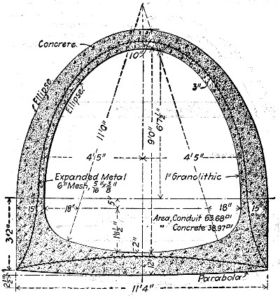 Fig. 253.—Section of 9-ft. Conduit, Philadelphia Filter
Plant.
Fig. 253.—Section of 9-ft. Conduit, Philadelphia Filter
Plant.
Forms.—The forms used for the several sizes of conduit were all of the same general type, but improvements in detail were made as successive sizes were built. The last form to be designed was that for the 9-ft. section and this was the best one; it is shown by Fig. 254. The forms were built in sections from 12 ft. to 13½ ft. long. They were covered with No. 27 galvanized sheet iron, and this covering was found of advantage both in giving a smooth finish and in prolonging the[Pg 542] life of the centers. The important feature is the construction in sections which could be set up and broken down by simply inserting and removing the connecting bolts. Three sets of forms were made for each size of conduit.
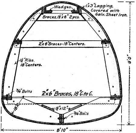 Fig. 254.—Form for 9-ft. Conduit Philadelphia Filter
Plant.
Fig. 254.—Form for 9-ft. Conduit Philadelphia Filter
Plant.
Procedure of Work.—The first operation in building a section of conduit was to set to exact line and grade and the length of the form in advance of the finished work the bulkhead shown by Fig. 255. In this space the invert concrete was deposited and formed to a plane 1 in. below the finished invert bottom. The two bottom sections of the form were then assembled and located by bolting one end to the last preceding form and inserting the other end into the bulkhead. About two tons of pig iron were then placed on the invert form to keep it from floating while the liquid granolithic mixture was being poured into the 1-in. space between the form and the invert concrete. In building up the sides a facing form was used for placing the granolithic finish. This consisted of "boards" of sheet steel ribbed transversely on one side with ¾-in. pipe and on the other side with 1½-in. pipe. Two boards were used on each haunch, slightly lapping in the center, as follows: The board was placed with the small ribs against[Pg 543] the form and the larger ribs kept the expanded metal just 3 ins. from the face of the form. A 6-in. depth of concrete was placed between the metal board and the outside form or planks, then 6 ins. of granolithic was poured into the 1-in. space between the center and the board and finally the board was raised 6 ins. and the concrete and granolithic mixture tamped together. With the board in its new position, another layer of concrete and granolithic was placed. Toward the crown the granolithic mixture was made stiff and simply plastered onto the mold. The expanded metal was cut into sheets corresponding to the length of the sides of the form and lapped 6 ins. in all directions; the bulkhead having a slot as shown to permit the metal to project 6 ins. from the face of the concrete in order to tie two sections together and also having a rib which formed a mortise in the face of the shell of concrete to key it to the succeeding section.
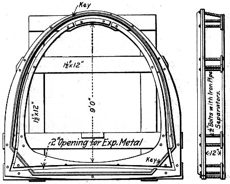 Fig. 255.—Bulkhead Form for Conduits, Philadelphia
Filter Plant.
Fig. 255.—Bulkhead Form for Conduits, Philadelphia
Filter Plant.
All the conduits were built in sections from 12 ft. to 13½ ft. long, and there was very little, if any, difference in the labor required to build a section, in from eight to ten hours, of any of the three sizes. One foreman and 18 men on the top of the trench mixed and handled the concrete and granolithic mortar while one foreman, one carpenter and seven men in the trench set the forms and placed and rammed the concrete for one section in generally eight hours. About one-third[Pg 544] of the concrete for the whole work was mixed in a portable cubical mixer of ½ cu. yd. capacity, and the remainder was mixed by hand. Owing to the relatively small amount of concrete used per day, about 20 cu. yds., it was found that there was practically no difference in the cost of machine mixing and of hand mixing. The 9-ft. conduit as an average of the three sizes, contained 20 cu. yds. of concrete, 1,200 sq. ft. of expanded and required 125 bags of cement for a section 13½ ft. long. The cost of the work excluding excavation and profit, but including forms, metal, concrete materials and labor, was about $10.50 per cu. yd.
CONDUIT, JERSEY CITY WATER SUPPLY.—In constructing the 8½-ft. reinforced concrete conduit for the Jersey City water supply, use was made of forms without bottoms. Each form was made of segmental sections 12½ ft. long of wood covered with sheet steel. They were set end to end in the trench, resting on 6-in. concrete cubes which were finally permanently embedded in the invert concrete. In each form there was a scuttle about 2 ft. square at the crown, and the bottom was open between the curves of the invert haunches. The form being set and greased and the reinforcement placed, the concrete was deposited on the outside and forced by means of tamping bars down the curve of the invert haunches until it filled the whole space between the form and the earth and appeared at the edges of the bottom opening in the form. Concrete was then thrown through the scuttle and the invert screeded into shape. The concreting of the sides and crown of the arch was then completed, using outside forms except for about 5 ft. of the crown, the scuttle, of course, being closed by a fitted cover. The centers were left in place about 48 hours. The concrete was a 1 cement 7 sand and run of the crusher 2-in. broken stone mixture, and was made so wet that it would flow down an incline of 1 on 8. The mixing was done in portable Ransome mixers, set on the trench bank alongside the work and discharging by chute into dished shoveling boxes provided with legs to set on the erected forms. Coal scoops were used in shoveling from the box into the forms and were found superior to shovels in keeping the relative proportions of water and solids constant.[Pg 545]
TWIN TUBE WATER CONDUIT AT NEWARK, N. J.—In constructing the Cedar Grove Reservoir, at Newark, N. J., two conduits side by side were built across the bottom from gate house to tunnel outlet. A section of one of the conduits showing the form construction and the arrangement of the reinforcement is given by Fig. 256. The concrete was a 1-2-5 1½-in. stone mixture and the reinforcement was No. 10 3-in. mesh expanded metal. The method and cost of construction are given as follows, by Mr. G. C. Woollard, the engineer for the contractors.
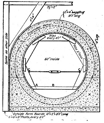 Fig. 256.—Conduit for Cedar Grove Reservoir, Newark. N.
J.
Fig. 256.—Conduit for Cedar Grove Reservoir, Newark. N.
J.
"The particular thing that was insisted upon by both Mr. M. R. Sherrerd, the chief engineer of the Newark Water Department and Mr. Carlton E. Davis, the resident engineer at Cedar Grove Reservoir, in connection with these conduits, was that they be built without sections in their circumference, that the whole of the circumference of any one section of the length should be constructed at one time. They were perfectly willing to allow us to build the conduit in any length section we desired, so long as we left an expansion joint occasionally which did not leak.[Pg 546]
"The good construction of these conduits was demonstrated later, when the section stood 40 lbs. pressure to the square inch, and, in addition, I may say that these conduits have not leaked at all since their construction. This shows the wisdom of building the conduit all round in one piece, that is, in placing the concrete over the centers all at one time, instead of building a portion of it, and then completing that portion later, after the lower portion had had an opportunity to set.
"The centers which I designed on this work were very simple and inexpensive, as will be gathered from the cost of the work, when I state that this conduit, which measured only 0.8 cu. yd. of concrete to the lineal foot of single conduit, cost only $6.14 per cu. yd., built with Atlas cement, including all labor and forms and material, and expanded metal. The forms were built in 16 ft. lengths, each 16 ft. length having five of the segmental ribbed centers such as are shown in Fig. 256, viz., one center at each end and three intermediate centers in the length of 16 ft. These segments were made by a mill in Newark and cost 90 cts. apiece, not including the bolts. We placed the lagging on these forms at the reservoir, and it was made of ordinary 2×4 material, surfaced on both sides, with the edges beveled to the radius of the circle. These pieces of 2×4 were nailed with two 10d. nails to each segment. The segments were held together by four ½-in. bolts, which passed through the center, and 1½-in. wooden tie block. There was no bottom segment to the circle. This was left open, and the whole form held apart by a piece, B, of 3×2 spruce, with a bolt at each end bolted to the lower segment on each side.
"The outside forms consisted of four steel angles to each 16 ft. of the conduit, one on each end, and two, back to back, in the middle of each 16 ft. length. These angles were 2×3, with the 2-in. side on the conduit, and the 3-in. side of the angle had small lugs bolted on it at intervals, to receive the 2×12 plank, which was slipped down on the outside of the conduit, as it was raised in height. The angles were held from kicking out at the bottom by stakes driven into the ground, and held together at the top by a 2½-in. tie-rod.[Pg 547]
"The conduit was 8 ins. thick, save at the bottom, where it was 12 ins. The reason for the 12 ins. at the bottom was that the forms had to have a firm foundation to rest on, in order to put all the weight required by the conduit on them in one day or at one time, without settling. We therefore excavated the conduit to grade the entire length, and deposited a 4-in. layer of concrete to level and grade over the entire length of the conduit line. This gave us a good, firm foundation, true and accurate to work from, and this is the secret of the good work which was done on these conduits. If you examine them, you will say that they are one of the neatest jobs of concrete in this line that has been built, especially with regard to the inside, which is true, level and absolutely smooth. [The authors can confirm this statement.] When the conduit is filled with water, it falls off with absolutely no point where water stands in the conduit, owing to its being out or the proper amount of concrete not being deposited.
"The centers were placed in their entirety on a new length of conduit to be built, resting upon four piles of brick, two at each end as shown. The first concrete was placed in the forms at the point marked X and the next concrete was dropped in through a trap door cut in the roof of the conduit form at the point marked Y. This material was dropped in to form the invert, and this portion was shaped by hand with trowels and screeded to the exact radius of the conduit. The concrete was then placed continuously up the sides, and boards were dropped in the angles which I have mentioned, and which served as outside form holders till the limit was reached at the top, where it was impossible to get the concrete in under the planking and thoroughly tamped. At this point the top was formed by hand and with screeds.
"Each 16-ft. length of this conduit was made with opposite ends male and female respectively, that is, we had a small form which allowed the concrete to step down at one end to 3 ins. in thickness for 8 ins. back from the end of the section, and on the other end of the section it allowed it to step down to 3 ins. in thickness in exactly the opposite way, making a scarf joint. This was not done at every 16 ft. length, unless only 16 ft. were placed in one day. We usually placed 48 ft.[Pg 548] a day at one end of the conduit with one gang of men. This was allowed to set 24 hours, and, whatever length of conduit was undertaken in a day, was absolutely completed, rain or shine, and the gang next day resumed operations at the other end of the conduit on another 48 ft. length. This was completed, no matter what the weather conditions were, and, towards the close of this day the forms placed on the preceding day were being drawn and moved ahead.
"The method used in moving these forms ahead for another day's work is probably one of the secrets of the low cost of this work, and it is one which we have never seen employed before. The bolt at A, Fig. 256, was taken out, and the tie brace B thrown up. We had hooks at the points C. A turnbuckle was thrown in, catching these hooks, and given several sharp turns, causing the entire form to spring downward and inwards, which gave it just enough clearance to be carried forward, without doing any more striking of forms than pulling the bolt at A. This method of pulling the forms worked absolutely satisfactorily, and never gave any trouble, and we were able to move the forms very late in the day and get them all set for next day's work, giving all the concrete practically 24 hours' set, as we always started concreting in the morning at the furthest end of the form set up and at the greatest distance from the old concrete possible in the 48 ft. length, as the furthest form had, of course, to be moved first, it being impossible to pass one form through the other.
"Six 16-ft. sections of these forms were built, and three were used each day on each end, as shown by the diagram MN, Fig. 256, which gives the day for the month for the completion of each of seven 48-ft. sections.
"A gang of men simply shifted on alternate days from end to end of the conduit, although several sections were in progress at one time; and of course, finally, when a junction was made between any division, say of 1,000 ft. to another 1,000 ft., one small form was left in at this junction inside of the conduit, and had to be taken down and taken out the entire length of the conduit.
"The centers for a 16-ft. length of this conduit cost complete for labor and material, $18.30, but they were used over and over again; and, after this conduit was completed, they[Pg 549] were taken away for use at other points, so that the cost is hardly appreciable, and the only charge to centers that we made after the first cost of building the centers, was on account of moving them daily. Part of this conduit was built double (two 6-ft. conduits) and part single, the only difference being that, where the double conduit was built, two forms were placed side by side, and not so much was undertaken in one day.
"These conduits, when completed and dried out, rung exactly like a 60-in. cast-iron pipe, when any one walked through them or stamped on the bottom."
Mr. Woollard gives the following analysis of the cost per cubic yard of the concrete-steel conduit above described:
| Per cu. yd. | |
| 1.3 bbl. cement | $1.43 |
| 10 cu. ft. sand | 0.35 |
| 25 cu. ft. stone | 1.10 |
| 26 sq. ft. expanded metal, at 3 cts. | 0.78 |
| Loading and hauling materials 2,000 ft. to the mixing board (team at $4.50) | 0.50 |
| Labor mixing, placing, and ramming | 1.38 |
| Labor moving forms | 0.60 |
| —— | |
| Total | $6.14 |
Wages were 17½ cts. per hr. for laborers and 50 cts. per hr. for foremen. The concrete was 1-2-5, a barrel being assumed to be 3.8 cu. ft. The concrete was mixed by hand on platforms alongside the conduit. The cost of placing and ramming was high, on account of the expanded metal, the small space in which to tamp, and to the screeding cost. When forms were moved they were scraped and brushed with soft soap before being used again.
From Mr. Morris R. Sherrerd, Engineer and Superintendent, Department of Water, Newark, N. J., we have received the following data which differ slightly from those given by Mr. Woollard. The differences may be explained by the fact that the cost records were made at different times. Mr. Sherrerd states (Sept. 26, 1904,) that each batch contains 4 cu. ft. of cement, 8 cu. ft. of sand, and 20 cu. ft. of stone, making 22 cu. ft. of concrete in place. One bag of cement is assumed to[Pg 550] hold 1 cu. ft. He adds that a 10-hour day's work for a gang is 63 lin. ft. of single 6-ft. conduit containing 47.4 cu. yds. of concrete and 1,260 sq. ft. of expanded metal. This is equivalent to ¾ cu. yd. of concrete per lin. ft. The total cost of material for one complete set of forms 64 ft. long was $160; and there were 7 of these sets required to keep two gangs of men busy, each gang building 63 lin. ft. of conduit a day. Since the total length of the conduit was 3,850 ft., the first cost of the material in the forms was 18 cts. per lin. ft.
Cost of Labor on 6-ft. Conduit:
| Per day. | Per cu. yd. | |
| 1 foreman on concrete | $ 3.35 | $0.07 |
| 1 water boy | 0.75 | 0.01 |
| 11 men mixing at $1.75 | 19.25 | 0.39 |
| 5 men mixing at $1.50 | 7.50 | 0.16 |
| 4 men loading stone at $1.40 | 5.60 | 0.12 |
| 4 men wheeling stone at $1.40 | 5.60 | 0.12 |
| 2 men loading sand at $1.40 | 2.80 | 0.06 |
| 2 men wheeling sand at $1.40 | 2.80 | 0.06 |
| 1 man placing concrete at $1.75 | 1.75 | 0.04 |
| 6 men placing concrete at $1.50 | 9.00 | 0.19 |
| 2 men supplying water at $1.50 | 3.00 | 0.06 |
| 1 man placing expanded metal at $2. | 2.00 | 0.04 |
| 1 man placing expanded metal at $1.50 | 1.50 | 0.03 |
| ——— | —— | |
| Total labor on concrete | $64.90 | $1.35 |
Cost of Labor Moving Forms:
| Per day. | Per cu. yd. | |
| 4 carpenters placing forms | $13.00 | $0.27 |
| 2 helpers placing forms | 4.00 | 0.08 |
| 1 carpenter putting up boards for outside forms | 2.75 | 0.06 |
| 1 helper putting up boards for outside forms | 2.25 | 0.05 |
| 2 helpers putting up boards for outside forms | 3.50 | 0.07 |
| 1 team hauling timber | 4.50 | 0.09 |
| 1 helper hauling lumber | 1.75 | 0.04 |
| ——— | —— | |
| Total labor moving | $31.75 | $0.66 |
It will be noted that it required two men to bend and place the 700 lbs., or 1,260 sq. ft., of expanded metal required for 63 lin. ft. of conduit per day, which is equivalent to ½c per lb., or 3 cts. per sq. ft., for the labor of shaping, placing and fastening the metal.
CIRCULAR SEWER, SOUTH BEND, INDIANA.—In building 2,464 ft. of 66-in. circular reinforced concrete sewer at South Bend, Ind., in 1906, the method of construction illustrated in Figs. 257, 258 and 259 was employed. The sewer has a 9-in. shell buttressed on the sides and is reinforced every 12 ins. by a 3/16×1-in. peripheral bar in the sides and roof and 3 ins. in from the soffit. Each bar is composed of three pieces, two side pieces from 15 ins. below to 6 ins. above springing lines and a connecting roof bar attached to the side bars by cotter pins. Two grades of concrete were used, a 1-3-6 bank gravel concrete for the invert and a 1-2-4 bank gravel concrete for the arch. The invert was given a ½-in. plaster coat of 1-1 mortar as high as the springing lines.
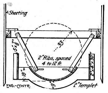 Fig. 257.—Form for South Bend Sewer (First Stage).
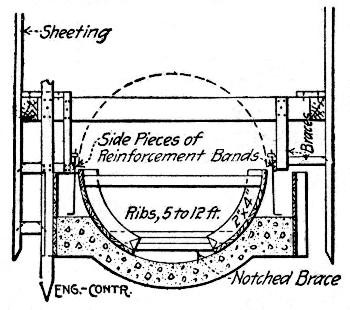 Fig. 258.—Form for South Bend Sewer (Second Stage).
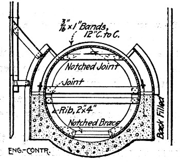 Fig. 259.—Form for South Bend Sewer (Third Stage).
Forms and Concreting.—In constructing the sewer the trench was excavated so as to give a clearance of 1 ft. on each side and was sheeted as shown by Fig. 257. The sewer was built in 12 ft. sections as follows: The bottom of the trench was shaped as nearly as possible to the grade and shape of the base of the sewer. Four braces to each 12 ft. section were then nailed across the trench between the lowest rangers on the trench sheeting. A partial form consisting of a vertical[Pg 552] row of lagging was set on each of the outside lines of the sewer barrel as shown by Fig. 257. Each section of this lagging was held by stakes driven into the trench bottom and nailed at their tops to the cross braces as shown by Fig. 258. A template for the invert was then suspended from the cross braces by pieces nailed to the four ribs of the template and to the cross braces as shown by Fig. 257. The concrete was now placed and carried to the top of the template, which was then removed. The side pieces of the reinforcing bars were then set and fastened as shown by Fig. 258. The side forms extending up to the springing lines were then placed. They were held in position by braces nailed to their ribs at the tops and by other braces fitting into notches in the ends of their ribs at the bottom. The concrete was then carried up to the springing lines, the arch centers in two pieces were placed; the arch bar of the reinforcement was placed and the[Pg 553] extrados forms erected up to the 45° lines, all as shown by Fig. 259. The placing of the arch concrete completed the sewer barrel. The outside forms and bracing were removed about 24 hours after the completion of the arch and back filling the trench was begun immediately, but the inside forms were left in place for two weeks; they were then removed by the simple process of knocking out the notched braces. By building several lengths of invert first and following in succession by the side wall construction and then by the arch construction, the form erection and the concreting proceeded without interruption by each other. It was also found that, by making bends in the form of polygons with 10 ft. sides instead of in the form of curves, there was a material saving in expensive form work. To overcome the friction of the angles in such bends an additional fall was provided at these places. All concrete was made in a Smith mixer mounted on trucks so that it could be moved along the bank of the trench and discharging into a trough leading to the work.
Labor Force and Cost.—With a gang of 12 men from 24 to 36 ft. of sewer was built per 10-hour day, working only part of the time on actual concreting. The disposition of the force mixing and laying concrete and the wages were as follows:
| Item. | Per day. |
| Six wheelers, at 18.5 cts. per hour | $11.10 |
| One mixer, at 22.5 cts. per hour | 2.25 |
| One dumper, at 18.5 cts. per hour | 1.85 |
| Four placers, at 22.5 cts. per hour | 9.00 |
| ——— | |
| Total | $24.20 |
There were 0.594 cu. yd. of concrete per lineal foot of sewer and its cost is given as follows:[Pg 554]
| Item. | Per cu. yd. |
| Cost of gravel | $0.774 |
| Cost of sand | 0.36 |
| Cost of cement | 1.50 |
| Cost of steel reinforcement | 0.84 |
| Cost of labor, mixing and placing concrete | 1.094 |
| Cost of moving forms, templates, etc. | 0.757 |
| Cost of forms, templates, etc. | 0.589 |
| Cost of finishing, plastering, etc. | 0.639 |
| Cost of tools and general expenses | 0.841 |
| ——— | |
| Total | $7.394 |
SEWER INVERT, HAVERHILL, MASS.—In constructing sewers with concrete inverts at Haverhill, Mass., in 1905, use was made of the traveling form or mold shown by Fig. 260. The form consists of an inner and an outer shell, the annular space between which forms the mold; in operation the annular space is filled with concrete, then the outer shell is pulled ahead from underneath, leaving the inner shell in place. A second inner shell is then adjusted to the outer shell in its new position, the annular mold is concreted and the outer shell again pulled ahead. Continued repetition of the operations described completes the invert. The merit of the device lies in the fact that the inner shell is not moved until the concrete has attained some degree of rigidity; when, in such devices, the inner mold is slid ahead on the green concrete it is likely so to "drag" forward the material that a rough and pitted surface results.
Mold Construction.—Referring to the drawings of Fig. 260, A is the outer mold of sheet steel bent to the required shape of the outer surface of the conduit to be constructed. A rib, or angle, B, is riveted to the inside of the mold at its front end and a diaphragm C of plank is securely fastened to the rear side of the rib. The opposite or rear end of the mold is open. Angles D forming tracks are riveted inside the mold a short distance below the edges and reaching their full length. The inner mold comprises a steel shell E curved to the form of the inside of the conduit; inside this steel shell is a reinforcing lagging, and at each end there is a wooden diaphragm F. Passing through both end[Pg 555] diaphragms and having its ends flush with the end planes of the mold is a timber G. Rearward projecting lips e are secured to the lagging at the rear end of the mold and on each side of the timber G. The diaphragms F have each two arms f which project horizontally beyond the surface of the inner mold and engage the tracks D; locking dogs H are pivoted to the arms f so as to hook under the track angles D and hold the inner form from rising. Setting on the inner mold is an inverted V-shaped deflector I; its edges are flush with the sides of the mold and its purpose is to facilitate the placing of the concrete. There is also a movable diaphragm K, fitting loosely inside the outer mold A and bearing against the end of the inner mold E. The length of the inner mold E is about one-half that of the outer mold A; as a rule several inner molds are provided with one outer mold.
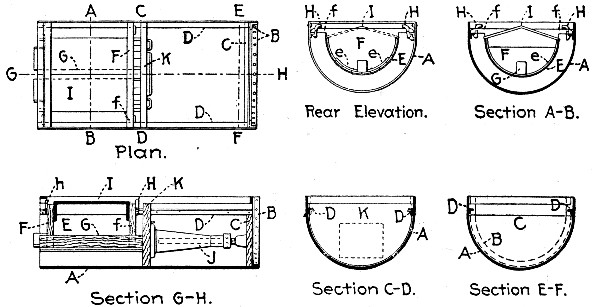 Fig. 260.—Traveling Invert Form for Sewer Construction.
Mode of Operation.—In using the device described the outer mold A is first placed in the trench with its rear end at the end of the trench. An inner mold E is then suspended on the tracks of the outer mold and locked therein by the dogs H, with its rear end flush with the rear end of the outer mold. The partition K is then placed in position against the forward end of the inner mold and a jack J of any suitable form is interposed between diaphragms K and C, the jack being extended sufficiently to press diaphragm K firmly against the front end of the inner mold. The deflector I is next placed in position on the inner mold and the concrete is forced down with an iron rammer between the two molds, so as to fill completely[Pg 556] the annular space. The deflector aids in directing the concrete into this space, as will be obvious. After the mold has been filled and the concrete compacted as much as possible, the jack is operated to separate the diaphragms K and C, and as the partition K is pressed against one end of the mass of concrete which has been laid, the opposite end of which abuts against the end of the trench, it follows that any backward movement of the diaphragm K will compress the concrete. This movement will be practically inappreciable in distance, but enough to compact thoroughly the concrete and fill any voids. The action of the jack will also push forward the diaphragm C and the outer mold A, the latter being withdrawn from beneath the inner mold and the newly laid concrete, the tracks D of the outer mold being drawn from beneath the arms f of the inner mold, leaving the latter behind resting on the freshly laid concrete. Further compression of the concrete after it has been left by the outer mold will fill the spaces between the inner mold and the surface of the trench. The outer mold is moved forward in this manner a distance equal to the length of the inner mold, and then the diaphragm K is drawn forward and another inner mold is lowered into the outer mold exactly as was the first one. The jack is then placed, the concrete deposited and the outer mold again advanced exactly as before. As the outer mold advances, the inner molds become disengaged one after another and are set ahead; in practice, enough inner molds are provided to enable the concrete to harden sufficiently to keep its position when it becomes necessary to take up successively the rearmost molds and place them ahead.
Haverhill Sewer Work.—The work at Haverhill, Mass., previously mentioned in which the form just described was used, was a 24-in. circular sewer with 6-in. walls. The outer form was 36 ins. in diameter and 6 ft. 2 ins. long; the inner form was 24 ins. in diameter and 3 ft. long. Angle B was 3 ins. and the track angles D were 1½ ins.; diaphragm K was made of two thicknesses of 3-in. plank and diaphragm C of one thickness of 3-in. plank, the other diaphragms were of 2-in. plank. The shells of the molds were of ¼-in. steel plate; the jack was an ordinary screw jack. Eight inner molds were used.[Pg 557]
The form used at Haverhill was built by the city carpenter, the metal portions being made in a boiler shop. Its cost was not ascertained, but was, it is thought, about $75. The concrete used was a 1-3-5 stone mixture, with cement costing $2 per barrel, sand $1.50 per load of 36 cu. ft., and stone $2.50 per load of 36 cu. ft. The men were paid 25 cts. per hour. Records kept on 265 ft. of invert, or, theoretically, 19.3 cu. yds. of concrete, gave the following figures:
| Per lin. ft. | Per cu. yd. | |
| Labor, setting and moving forms, 42 hours, at 25 cts. | $0.05 | $0.67 |
| Labor, mixing, placing and wheeling concrete, 179 hours, at 25 cts. | 0.16 | 2.19 |
| —— | —— | |
| Total labor cost | $0.21 | $2.86 |
With the ordinary 1-3-5 mixture the cost of materials would run about as follows:
| Per cu. yd. | |
| Cement, 0.96 bbl., at $2. | $1.92 |
| Sand, 0.47 cu. yd., at $1.13 | 0.53 |
| Stone, 0.78 cu. yd., at $1.88 | 1.47 |
| —— | |
| Total cost materials | $3.92 |
Two men were worked in the trench, one alternately ramming the concrete into place and working the jack, and the other shaping the trench ahead and assisting in bringing the rear forms ahead.
The form described was invented by Mr. Robert R. Evans, of Haverhill, Mass., and has been patented by him.
29-FT. SEWER, ST. LOUIS, MO.—The following account of the method and cost of constructing 162 ft. of very large sewer section at St. Louis, Mo., is compiled from information furnished by Mr. Curtis Hill.
The cross-section of the sewer is given by Fig. 261, which also shows the arrangement of the reinforcing bars. Johnson corrugated bars, old style, are used for reinforcement. The sections of the various reinforcing bars are: Longitudinal bars, 0.18 sq. in.; invert bars, 0.7 sq. in., and arch bars, 0.7[Pg 558] sq. in. The spacing of the bars and the arrangement of the splices are indicated on the drawings of Fig. 261. All splices have a lap of 36 ins. Some gravel concrete has been used in the invert, but most of the concrete has been crushed limestone and Mississippi River channel sand. The proportions were 1-3-6 in the invert and 1-2-5 in the arch. The arch was computed by Prof. Greene's method. The ultimate strength of concrete in compression was taken as 2,000 lbs. per sq. in. and the working strength at 500 lbs. per sq. in. The elastic limit of the reinforcing bars was taken at 50,000 lbs.
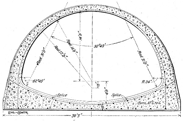 Fig. 261.—Harlem Creek Sewer, St. Louis, Mo.
The trenching was done by wheel scrapers to the amount of waste. Then a cableway was erected spanning the entire length of the section and the remainder of the material taken out. The last 4 or 5 ft. in depth were in limestone and the excavated rock was taken by cableway to dump carts which took it to the crusher and returned with crushed rock to be used for concrete. This rock foundation was taken advantage of to reduce the amount of invert concrete.[Pg 559]
In constructing the sewer proper the invert was first concreted to template to the height shown in Fig. 262. The arch forms were then placed as shown in Fig. 262, and the roof arch concreted. Both templates and arch forms were constructed of wood. The arch forms were moved ahead on iron rails and jacked into place. The ribs were 2×10-in. pieces and were spaced 4 ft. on centers; the lagging was 2-in. tongue and grooved stuff and was smeared with crude oil. The reinforcing bars shown in Fig. 261 were bent to proper radius by means of a wagon tire bender and were held in place by templates. The concrete was all mixed by two Chicago Improved Cube mixers operated by electric power.
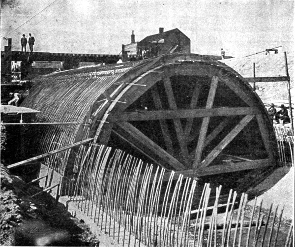 Fig. 262.—Center for Harlem Creek Sewer.
The cost records of constructing the section of 29-ft. sewer so far built are not susceptible of complete analysis, but the following figures can be given. The prices of materials were as follows:[Pg 560]
| Cement, per barrel | $1.80 |
| Sand, per cubic yard | 0.75 |
| Broken stone, per cubic yard | 1.00 |
| Reinforcing bars, per pound | 0.02 |
| Vitrified brick, per 1,000 | 12.00 |
The wages paid different classes of labor were:
| Per hour. | |
| Firemen | $0.50 |
| Laborers | 0.175 |
| Laborers | 0.20 |
| Laborers | 0.25 |
| Laborers | 0.28 |
| Laborers | 0.3025 |
| Bricklayers | 0.66⅔ |
| Helpers | $0.25 |
| Carpenters | 0.55 |
| Engineers | 0.50 |
| Timekeepers | 0.25 |
| Watchmen | 0.175 |
| Hostlers | 0.175 |
| Teams | 0.60 |
Taking up the several items of work in order, the excavation amounted to 21,400 cu. yds., of which 1,400 cu. yds. were rock excavation. The cost of excavation was as follows:
| Total. | Per cu. yd. | |
| Earth, excavation | $7,640 | $0.38 |
| Earth bracing | 2,000 | 0.10 |
| Rock excavation | 1,400 | 1.00 |
| Rock, dynamite, tools, etc. | 560 | 0.40 |
The cost of crushing the excavated rock and returning it to the mixer was $1 per cu. yd.
The cost of the concrete work was as follows:
| Per cu. yd. | |
| 1.30 bbl. cement at $1.80 | $2.34 |
| .044 cu. yd. sand at 75 cts. | 0.33 |
| 1 cu. yd. broken stone at $1 | 1.00 |
| —— | |
| Total concrete materials | $3.67 |
There were 1,600 cu. yds. of concrete placed at a cost of for:
| Total. | Per cu. yd. | |
| Mixing and placing | $1,180 | $0.7375 |
| Forms | 2,000 | 1.25 |
| Moving forms | 400 | 0.25 |
| ——— | ——— | |
| Total for forms and labor | $3,580 | $2.2375 |
For reinforcing the concrete 86,600 lbs. of steel, or about 55 lbs. per cu. yd. were used. The cost of placing and bending this steel was as follows:
| Total. | Per lb. | |
| Cost of placing | $172 | 0.1986 ct. |
| Cost of bending | 52 | 0.06 ct. |
We can now summarize the cost of the concrete work proper of this sewer as follows:
| Items. | Per cu. yd. |
| Cement, sand and stone | $3.67 |
| 55 lbs. steel at 2 cts. | 1.10 |
| Forms, labor and materials | 1.25 |
| Mixing and placing concrete labor | 0.74 |
| Placing steel at 0.1986 ct. per lb. | 0.11 |
| Bending steel at 0.06 ct. per lb. | 0.03 |
| Moving forms | 0.25 |
| —— | |
| Total labor and materials | $7.15 |
To get the total cost of the sewer proper we must add the cost of the vitrified brick invert paving. There were 71 cu. yds. of this paving and its cost was as follows:
| Per cu. yd. | |
| 0.6 bbls. cement at $1.80 | $1.08 |
| 0.25 cu. yd. sand at 75 cts. | 0.19 |
| 450 bricks at $12 per M. | 5.40 |
| Labor laying, 71 cu. yds. at $180.33 | 2.54 |
| —— | |
| Total | $9.21 |
None of the preceding figures includes the plant charges. The plant cost $12,000 and the cost of running it during the work described was $2,000. In explanation it should be noted that the plant served for building some 1,340 lin. ft. of 27-ft. sewer as well as for the section described.
SEWER AT MIDDLESBOROUGH, KY.—In constructing an oval sewer 4 ft. high at Middlesborough, Ky., two steel forms in 10-ft. sections were used. As shown in Fig. 263, T-iron ribs were spaced 5 ft. apart, fastened together at the top by longitudinal angle irons, and at the bottom by a sheet of steel 22 ins. wide, forming the bottom of the invert. The[Pg 562] lagging for the sides consists of movable 5-ft. lengths of channel iron, secured by sliding bolts. After the bottom of the trench has been roughly shaped with concrete, a 10-ft. section of invert forms is lowered and suspended by the cross-beams, and the space beneath packed with concrete; then a channel iron is slid into place and bolted, and concrete packed behind it, and so on until the invert is made. The next 10-ft. section is then built while the first is hardening. Upon the completion of the second section, the channel iron sides of the first section are removed, and then the rib framework is lifted out. Wood arch centers are then put in place and an inch of 1:2 plaster spread over the lagging before placing the concrete for the arch, which is 6 ins. thick.
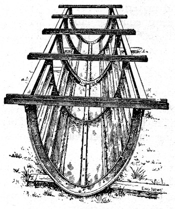 Fig. 263.—Invert Form for Sewer Construction.
The cost per 100 ft. of this sewer was as follows (prices being assumed for cement and labor):
| Bottom concrete. | Cost per 100 ft. |
| 18.5 bbls. cement, at $1.50 | $ 27.75 |
| 2.7 cu. yds. sand, at $1.00. | 2.70 |
| 15 cu. yds. stone, at $1.00 | 15.00 |
| [Pg 563] | |
| 17 days labor, at $1.50 | 25.50 |
| 25.25 bbls. cement, at $1.50 | 37.85 |
| 7.5 cu. yds. sand, at $1.00 | 7.50 |
| 22 days labor, at $1.50 | 33.00 |
| Sewer Arch. | |
| 26 bbls. cement, at $1.50 | 39.00 |
| 3.9 cu. yds. sand, at $1.00 | 3.90 |
| 13.6 cu. yds. stone, at $1.00 | 13.60 |
| 21 days labor, at $1.50 | 31.50 |
| ——— | |
| Cost per 100 ft. | $237.30 |
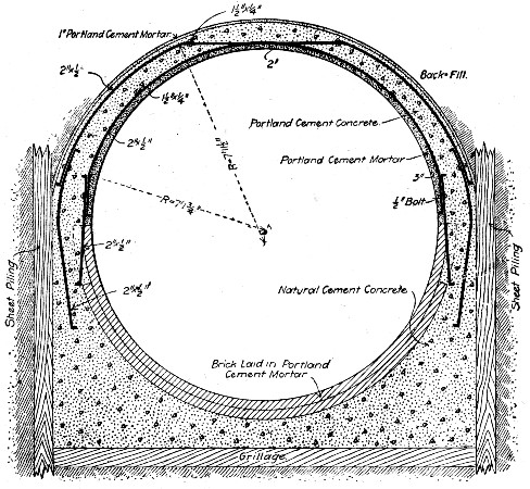 Fig. 264.—Sewer at Cleveland, Ohio.
INTERCEPTING SEWERS, CLEVELAND, O.—An intercepting sewer some 3½ miles long, of the form and construction shown in Fig. 264, was built at Cleveland, Ohio, in 1904. The construction consists of a plain concrete invert lined with two courses of shale bricks, and having two rows of anchor bars set in the side walls so that the bars of one row are staggered with respect to those of the other row. The anchor bars are 2-in. steel, and are spaced 30 ins. apart[Pg 564] in each row. To the anchor bars are bolted arch reinforcing bars arranged as shown, and these arch bars have bolted to them eight lines of 1½×¼-in. longitudinal bars. A natural cement concrete is used for the invert and side walls. The arch is Portland cement concrete of normally a 1-3-7½, 1½-in. screened stone mixture, but where the voids in the broken stone exceeded 40 per cent., it is a 1-3-6 mixture. The invert bricks are laid in Portland cement mortar and the arch has a mortar lining and is waterproofed with 1-in. of mortar on top.
Forms.—Separate forms were used for the invert and for the arch ring. Regarding these, the engineer, Mr. Walter C. Parmley, remarks:
One of the first forms used in the sewer was like a piece of segmental arch centering inverted, and with the lagging nailed fast to the ribs. The trouble with this form is that it is difficult to tamp concrete under the bottom portion of the form, and hence a very rough surface is produced. Much better results were obtained by omitting the lagging boards on the bottom and at the sides till a point was reached where the inclination of the concrete surface was about 45°. The concrete for the bottom could then be worked down between the ribs, thorough tamping done, and a good surface obtained. The ribs serve as a guide, so that the workman produces the proper shape. From this point up to the vertical, good results can be secured with the ribs attached to the lagging. Some contractors found it more convenient to use ribs that were connected with each other by a skeleton framework only, and then to slip the lagging in, one piece at a time. For some of the sewers, in which the brick lining was not carried quite up to the spring line, a separate side form of skeleton ribs and loose lagging was set upon brace legs bearing on the bottom of the invert. This form carried the concrete from about 2 ft. below to about 2 ft. above the springing line. The arch ribs then became segmental and rested upon the middle braces. This method has the advantage of using ribs that are lighter and more easily handled than those that are semi-circular. For arch centering, it is necessary and convenient to use independent ribs and loose lagging, for the centers can then be carried forward piece-meal,[Pg 565] the falsework upholding the green arch and re-erected at the advance end of the work. In these matters each contractor prefers to use his own ingenuity, and so long as the work is properly built, the engineer can well give him considerable latitude as to use of methods. One thing, however, the engineer must insist upon—that all centering and falsework be as nearly rigid as possible. Even a slight settlement of the centers at the crown under the load of concrete and back-fill will cause the arch to kick out at the quarters, and if the green concrete arch is not cracked at the crown, it will be crushed on the inside, about half way between the crown and springing line. A reinforced arch is no more immune to this danger than is a plain concrete arch. However, with a few days of hardening, although the damage may be serious, the danger of actual collapse is less. A point to be guarded against, especially in reinforced construction, is any foolish act on the part of contractor or workman, due to his overconfidence in the strength of the structure because it contains embedded steel.
The mode of procedure in constructing the arch ring was to erect the centers with lagging complete. The lagging was then covered with building paper waterproofed with paraffine. The arch reinforcing bars were then bolted to the anchor bars and the longitudinals connected up. The lining of Portland cement mortar was first laid on the lagging. Before this mortar had set, concrete was rammed in between it and the sheeting to a height of 18 ins. above the springing line, and then the remainder of the concrete placed without outside forms. The top of the arch ring was finally finished with a 1-in. mortar coat. In regard to the concrete, Mr. Parmley remarks:
"Concrete will flush up to the forms and produce a better surface, and the voids in the stone will be much better filled if it is so wet as to require but little tamping; moreover there is less danger of obtaining a weak, porous wall should a workman neglect thorough tamping, than there is where only a moist mixture is used. It is also to the contractor's interest to use wet concrete for much less labor is required in mixing and placing it. Small broken stone or gravel is preferable in concrete for sewers. The walls being comparatively thin,[Pg 566] unless there be a considerable excess of mortar, if coarse stones are used, the concrete will be honeycombed with voids. The stones should be well graded in size from large to fine, but the largest fragments should not exceed 1½ ins. in greatest dimension."
Cost.—A number of records of cost of constructing short sections of the sewer described are given by Mr. Parmley, as follows:
| Labor placing anchor bars. | Per day. |
| 1 man, at $3.50 | $3.50 |
| 1 man, at $1.75 | 1.75 |
| 4 hours carrying steel at 20 cts. | 0.80 |
| —— | |
| $6.05 |
The anchor bars were placed for 40 lin. ft. of sewer, or about 1,504 lbs. of metal at a cost of 0.4 ct. per lb.
The concreting gang for the sides consisted of:
| 5 men wheeling and mixing at $1.75 | $8.75 |
| 1 man tamping | 1.75 |
| ⅔ time man lowering brick and concrete at $2.25 | 1.50 |
| 1 man carrying concrete | 1.75 |
| ——— | |
| $13.75 |
This gang built the side wall for 40 ft. of sewer daily, or 13 cu. yds. Cost of labor per cu. yd. was, therefore, $1.06. The concrete was tamped behind the brick lining as the latter was built up by the mason.
Cost of single ring brick lining at sides:
| 2 masons at 70 cents per hour | $1.20 |
| 1 man mixing mortar | 2.25 |
| ⅓ time man lowering at $2.25 | 0.75 |
| 3 men wheeling sand, filling buckets and dumping | 5.25 |
| ——— | |
| Total labor for 40 lin. ft. of sewer | $19.45 |
| Quantity of brick masonry laid, cu. yd. | 6.38 |
| Labor per cu. yd. | 3.05 |
An account was kept of labor performed on 85 lin. ft. of arch work, or 14 1-6 ft. daily. The force was as follows:[Pg 567]
| 1 man putting mortar lining on centering | $1.75 |
| 2 men mixing mortar, screening and wheeling sand | 3.50 |
| 1 man tamping concrete | 1.75 |
| 8 men on mixing board at $1.75 | 14.00 |
| ——— | |
| $21.00 | |
| No. cu. yd. placed daily | 25.64 |
| Labor per cu. yd. | 0.82 |
| Placing centering and arch bars: | |
| 2 men at $1.75 | $3.50 |
| 1 man at $3.50 | 3.50 |
| —— | |
| $7.00 |
Costs, for 14 1-6 ft. daily, $0.49 per lin. ft.
As nearly as could be judged, about two-thirds of the labor was used in erecting the centering and one-third in putting the steel in place. The amount of steel placed daily was 785 lbs., at cost, therefore, of 0.3 of a cent per lb., and the cost of erecting and moving centers, $0.33 per lin. ft. of arch.
Another record of 39.27 ft. on a curve, gave for the cost of the brick work at sides the same result as above, but the inspector's record of men working on concrete backing at sides showed a less cost, as follows:
| 4 men mixing at $1.75 | $7.00 |
| ⅔ time man lowering at $2.25 | 1.50 |
| 1 man in bottom | 1.75 |
| —— | |
| $10.25 |
They placed 12.7 cu. yd. at a cost of $0.81 per cu. yd. This figure probably more nearly represents the average cost than the $1.06 reported in the first instance.
The cost of placing the anchor bars on straight sewer, representing average progress, at another time, was found to be:
| 1 man | $3.50 |
| 1 man | 1.75 |
| —— | |
| $5.25 |
They placed the steel for 44 ft. of sewer or 1,650 lb. at a cost of 0.32 of a cent per lb.[Pg 568]
Further notes for 6 days' work, when it seemed to represent as nearly as possible the general average for the whole were:
Labor on arch concrete:
Daily progress was 13 1-6 ft.
| The force employed was: | |
| 7 men making concrete, at $1.75 | $12.25 |
| 1 man plastering the center | 1.75 |
| 1 man mixing mortar | 2.00 |
| 1 man tamping | 1.75 |
| —— | |
| $17.75 |
On straight arch work they placed 24.1 cu. yd. daily at a cost of $0.74 per cu. yd. In three days' work on a curve, the same gang placed 26.37 cu. yd. daily at a cost of $0.675 per cu. yd.
On centering and steel for arch, three men kept up with the regular progress of the arch-concreting gang. The cost, therefore, is:
| 1 man | $3.50 |
| 2 men at $1.75 | 3.50 |
| —— | |
| $7.00 |
They averaged 13 ft. daily, or at a total cost of about $0.54 per lin. ft. of sewer.
Two-thirds of this labor was on the centering or $0.36 per lin. ft. of arch; $0.18 per lin. ft. placed the steel ready for embedding, or about 55.5 lb. per ft. of arch, at a cost of 0.32 of a cent per lb.
For the double ring brick lining at the bottom, the regular daily rate of progress was 28 ft. or 11.15 cu. yd. with:
| 2 bricklayers | $11.20 |
| 5 men at $1.75 | 8.75 |
| 1 man at $2.25 | 2.25 |
| —— | |
| $22.20 |
or at a cost of $1.98 per cu. yd. This is given only because it is of interest in connection with the cost of the concrete.[Pg 569]
Other observations on cost of placing steel skeleton and concrete did not vary materially from the figures given. It will be observed that no charge for superintendence or anything for the general expenses is included in the estimates of cost. These charges were, of course, impossible to obtain. On another contract with machine mixing, as high as 36 lin. ft. of 13 ft. 6 in. arch were built in a day, but no data as to cost were taken, though it was evidently less than for the work with hand-mixed concrete.
REINFORCED CONCRETE SEWER AT WILMINGTON, DEL.—Records of a notable job of sewer construction at Wilmington, Del., in 1903, are furnished by Mr. T. Chalkley Hatton. The sewer was built by day labor for the city; its cross-section at various points is shown by Fig. 265. The cross-section of sewers in trenches deep enough to cover the arch are marked "deep cutting"; the sections where the arch projects above the ground surface are marked "light cutting." The section through the marsh was 700 ft. long, the cutting being 8 ft. deep, and at high tide the marsh was flooded 1 to 4 ft. The material was a soft mud that would pull a tight rubber boot from a workman's foot. The cost of this marsh excavation including cofferdams, underdraining, pumping, etc., was $4.60 per cu. yd. For 1,100 ft. the 9¼ ft. sewer was through a cut 22 to 34 ft. deep, the material being clay underlaid by granite. A Carson-Lidgerwood cableway was used. Although the crown of the arch was but 8 ins. thick, it withstood the shock of dumping 1 cu. yd. buckets of earth and rock from heights of 3 to 10 ft.; and the weight of 25 ft. of loose filling caused no cracks in the concrete.
Concrete was placed in 4-in. layers (the depth of the lagging) and well rammed, since it was found that "wet" concrete left small honeycombed spaces on the inner surface. Concrete for the invert was 1-2-6, the stone being 1½-in. and smaller, and the sand being crusher dust. The arch was 1-2-5.
The reinforcing metal used in the 9½-ft. sewer was No. 6 expanded metal, 6-in. mesh, in sheets 8×5½ ft., supplied by Merritt & Co., of Philadelphia. A single layer was placed around the sewer, 2 ins. from the inner surface, its position[Pg 570] being carefully maintained by the men ramming, and with but little difficulty as the sheets were first bent to the radius of the circle. Each sheet was lapped one mesh (6 ins.) over its neighbor at both ends and sides, and no sheets were wired except the top ones, which were liable to displacement by men walking over them.
 Fig. 265.—Cross-Sections of Sewer at Wilmington, Del.
The metal used on the rest of the work was a wire-woven fabric furnished by the Wight-Easton-Townsend Co., of New York. This fabric comes in rolls 5½ ft. wide and 100 ft. to the roll. The wire is No. 8, with a 6×4-in. mesh. This fabric was placed by first cutting the sheets to the required length to surround the sewer entirely, embedding it in the concrete as fast as concrete was placed, in the same manner as was done with the expanded metal except over the center where, on account of its pliability, the fabric was held the proper distance from the lagging by a number of 2-in. blocks which were removed as the concrete was placed. The wire cloth, being all in one sheet, can be placed a little more expeditiously than expanded metal, but, on the other hand, the expanded metal holds its position better in the concrete, since it is more rigid.
We quote now from Mr. Hatton's letter: "The major portion of concrete was mixed by machine at a cost of 66 cts. per yard, including wheeling to place, coal and running of mixing machine, wages being $1.50 per day of 8 hrs, Stone was delivered alongside of machine and all material had to be wheeled in barrows upon the platform, and after mixing to the sewer. Placing and ramming concrete around the forms cost 39 cts. per cu. yd., additional. Setting forms in invert cost 2 cts. per cu. yd., setting centers 7 cts. per cu. yd. Cost of setting forms and centers includes placing steel metal. Each lineal foot of 9¼ ft. sewer contained 1 cu. yd. of concrete, although the section only calls for 0.94 cu. yd. The excess was usually wasted by falling over sides of forms or being made too thick at crown.
"This yard of 1-2-5 concrete cost in place as follows (record taken as an average of several-days' run):
| Cement, 1.31 bbls. at $1.30 | $1.703 |
| Stone, 0.84 cu. yds. at $1.21 | 1.016 |
| Stone dust, 0.42 cu. yd. at $1.21 | 0.508 |
| Labor at 18¾ cts. per hour | 0.987 |
| Labor setting forms and setting metal | 0.045 |
| Cost of forms (distributed over 1,800 ft. of sewer) | 0.082 |
| 40 sq. ft. expanded metal at 4¼ cts. | 1.700 |
| Labor plastering invert | 0.070 |
| ——— | |
| Cost per ft., or per cu. yd. | $6.111 |
"The forms for the invert were made of 2-in. rough hemlock boards cut out 4 ins. less diameter than the diameter of the sewer, except for 18 ins. at the bottom of the form which coincided with the inside form of sewer. The bottom of the sewers was laid to the bottom of this form before it was set. Then the lagging, consisting of 2×6-in.×16-ft. hemlock planed, was placed against each side of the form, one at a time, and the concrete brought to the line of this top in 6-in. layers until the whole invert was finished. These forms were set in 16-ft. sections, five to each section.
"The centers consisted of seven ribs of 2-in. hemlock upon which was nailed 1½-in. lagging, 2 ins. wide, tongued and grooved, and were 16 ft. long, non-collapsible, but had one wing on each side, 9 ins. wide, which could be wedged out to fit any inaccuracies in the invert. We used four of these centers setting two at each operation and worked from two ends. We left the centers in for 18 hours before drawing.
"The cost of the concrete on the smaller sewers was the same as are the larger sewers, but the steel metal cost less, as it was wire woven metal that cost 2½ cts. per sq. ft. It was much easier handled and cut to no waste as it came in long rolls and was very pliable.
"After training our men, which occupied about one week or 10 days, we had no difficulty in getting the concrete well placed around the metal, preserving the proper location of the latter, which, however, bore constant watching, as a careless workman would often take the temporary supporting blocks and allow the metal to rest against the wooden center, in which case the metal would show through the surface inside of the sewer. The metal was kept 2 ins. away from the inside forms and the arch. To keep it at this location we had several 2-in. wooden blocks cut which were slipped under the wire or expanded metal and as soon as some concrete was pushed under the wire at this point the block was removed.
"After the forms were removed the invert needed plastering, but the arch was practically like a smoothly plastered wall except where it joined the invert, where it frequently showed the result of too much hurry in depositing the first[Pg 573] loads of concrete on the arch. We remedied this by requiring less concrete to be deposited at the start, thus giving the rammers time to place the material properly.
"An interesting result was obtained in the smoothness of the inside surface by using a mixture of different sized stones. When ¾-in. stones or smaller were used in the arch, the inside was honeycombed; but, where 1 to 1½-in. stones (nothing smaller) were used, the inside was perfectly smooth, and the same was true of the invert, showing that the use of larger stones is an advantage and secures more monolithic work. When the run of the crusher from 1½ to ¾-in. stones was used the work was not at all satisfactory.
"The difference in cost of mixing by hand and machine is practically nothing on this kind of work. As the moving of the machine to keep pace with the progress of the work equals the extra cost of mixing by hand when the mixing can be done close to the point where the cement is being placed."
The total cost of the sewers, including excavation, etc., was:
| Cost per lin. ft. | |
| 9¼-ft. sewer through marsh | $32.00 |
| 9¼-ft. sewer in cut averaging 24½ ft. | 24.00 |
| 6½-ft. sewer in cut averaging 12 ft. | 10.00 |
| 5-ft. sewer in cut averaging 11½ ft. | 6.70 |
SEWER WITH MONOLITHIC INVERT AND BLOCK ARCH.—The following records of construction for a sewer built at Coldwater, Mich., in 1901, are given by Mr. H. V. Gifford. The sewer had a monolithic invert and a block arch.
The sewer was circular, having an inner diameter of 42 ins., the thickness of the invert and the arch alike was 8 ins. Figure 266 is a cross-section. The concrete was 1 of Portland cement to 6 of gravel. There were 11 concrete blocks in the ring of the arch, each block being 24 ins. long, 8 ins. thick, 8 ins. wide on the outside of the arch and 5¾ ins. wide on the inside of the arch. A block weighed 90 lbs. which was too heavy for rapid laying; blocks 18 ins. long would have been better. Some 8,500 blocks were made. Molds were of 2-in. lumber, lined with tin, for after a little use it was found the[Pg 574] concrete would stick to the wood when the mold was removed. The four sides of the mold formed the extrados, the intrados, and the two ends of the block; the other two sides being left open. When put together the mold was laid upon a 1-in. board, 12×30 ins., reinforced by cleats across the bottom. The sides of the molds were held together with screws or wedge clamps. When the blocks had set, the sides of the molds were removed, and the blocks were left on the 12×30-in. boards for 3 days, then piled up, being watered several times each day for a week.
A gang of 14 men made the blocks; 2 screening gravel through 1-in. mesh screen; 4 mixing concrete; 4 molders; 3 shifting and watering blocks, and 1 foreman. With a little practice each molder could turn out 175 blocks a day; and since each block measured ¾ cu. ft., the output of the 14 men was 19½ cu. yds. a day. Mr. Gifford informs us that the wages were $1.50 a day for all the men, except the foreman. The daily wages of the 14 men were $22, so that the labor of making the blocks was $1.10 per cu. yd.
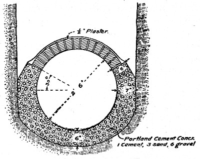 Fig. 266.—Sewer with Monolithic Invert and Block Arch.
Each batch of concrete, containing ½ bbl. of Portland cement costing $1.35 per bbl., made 18 blocks. (1 bbl. per cu. yd.) Since the gravel cost nothing, except the labor of screening it, the total cost of each block was 11 to 12 cts., which includes 0.85 cent for use of molds and mold boards, which were an entire loss. At 12 cts. per block the cost was $4.32 per cu. yd.[Pg 575]
The contract price was $3 per lin. ft. of this sewer, as against a bid of $3.40 per ft. for a brick sewer.
When the trenching had reached to the level of the top of the invert, two rows of stakes were driven in the bottom, stakes being 6 ft. apart in each row, and rows being a distance apart ¼-in. greater than the outer diameter of the sewer. These stakes were driven to such a grade that the top of a 2×4-in. cap or "runner" set edgewise on top of them was at the proper grade of the top of the invert. The excavation for the invert was then begun, and finished to the proper curve by the aid of a templet drawn along the 2×4-in. runners. In gravel it was impossible to hold the true curve of the invert bottom. Concrete was then placed for the invert. To hold up the sides of the invert concrete, a board served as a support for the insides, but regular forms were more satisfactory in every respect except that they were in the way of the workmen. A form was tried, its length being 6 ft. It was built like the center for an arch, except that the sheeting was omitted on the lower part of the invert. It was suspended from the cross-pieces resting on the "runners." After the concrete had been rounded in place, the form was removed and the invert trued up. This form worked well in soil that could be excavated a number of feet ahead, so that the forms could be drawn ahead instead of having to be lifted out; but in soil, where the concreting must immediately follow the excavation for the invert, the form is in the way. The invert was trued up by drawing along the runners a semi-circular templet having a radius of 21½ ins. Then a ½-in. coat of 1-2 mortar was roughly troweled on the green concrete. Another templet having a 21-in. radius was then drawn along the runners to finish the invert.
When the plaster had hardened, two courses of concrete blocks were laid on each shoulder of the invert, using a 1-2-¼ mortar, the ¼ part being lime paste. The lime made the mortar more plastic and easier to trowel. Then the form for the arch was placed, and as each 8-ft. section of the arch was built, a grout of 1-1 mortar was poured over the top to fill the joints. Earth was thrown on each shoulder and tamped, and the center moved ahead.[Pg 576]
Common laborers were used for all the invert work, except the plastering which was done by masons who were paid 30 cts. per hr. Masons were also used to lay the concrete blocks in the arch. Mr. Gifford states that two masons would lay at the rate of 100 lin. ft. of arch per day, if enough invert were prepared in advance. As there were 11 blocks in the ring of the arch, this rate would be equivalent to 7½ cu. yds. of arch laid per mason per day.
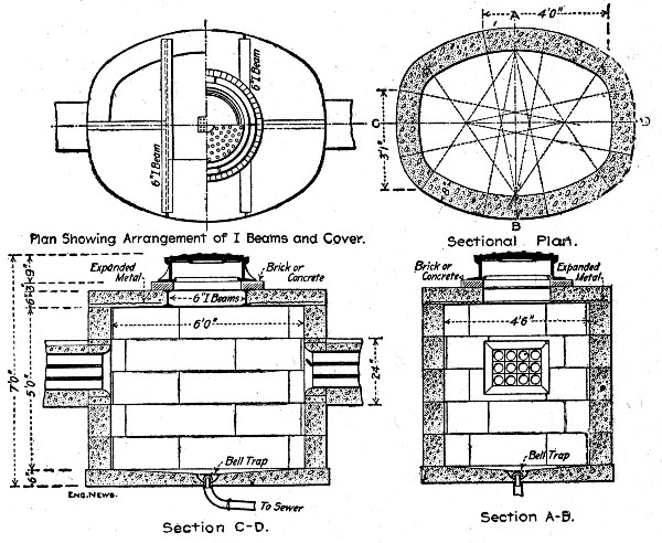 Fig. 267.—Concrete Block Manhole.
COST OF BLOCK MANHOLES.—The following costs of constructing concrete block manholes for electric conduit at Rye, N. Y., were recorded by Mr. Hugh C. Baker, Jr. The arrangement of the blocks, their size and shape and the dimensions of the completed manholes are shown by Fig. 267. The blocks were molded of 1-2-5¾-in. broken stone concrete in 30 wooden molds made by a local carpenter at a cost of from $3.50 to $12 each. The concrete was placed in the molds very wet, with very little tamping, and was allowed to set for seven days before the blocks were moved to the work.[Pg 577] The molds were left in place from 24 to 36 hours. With the facilities at hand six complete sets of top blocks were made each day by four men, when no wall blocks were being made, and half a set (15) wall blocks and two sets of top blocks were made each day by four men. The cost of the block manholes complete was as follows, per manhole:
| 30 wall blocks, 2½ cu. yds. | $21.00 |
| 6 cover blocks, 1½ cu. yds. reinforced | 4.27 |
| I-beams for cover, in place | 5.40 |
| Supervision, freight, hauling 5.6 tons concrete | 9.38 |
| Labor placing cover, 3 hrs. at 15 cts. | 0.45 |
| Labor placing walls, 20 hrs. at 15 cts. | 3.00 |
| ——— | |
| Total, exclusive of iron cover | $43.50 |
CEMENT PIPE, CONSTRUCTED IN PLACE.—In constructing 8-in. cement sewer for the Foster Armstrong Piano Co.'s works at Rochester, N. Y., a gang of seven men averaged 300 ft. of pipe per 10-hour day, using a Ransome pipe mold. The mold is shown by Fig. 268. It is made of sheet steel, with an inner core 10 ft. long, the front end of which is surrounded with a sheet steel shell that serves as an outer form for the pipe. The mortar mixed rather dry was packed into the annular space between core and shell by one man, using a short wooden rammer. A second man kept the mold slowly moving forward by operating the lever, which by means of a ratchet and drum winds up a wire rope stretched ahead to a deadman in the trench bottom. As the mold moves ahead it leaves behind it the cement pipe. A third man carefully filled under the invert and over the haunches of the green pipe with earth to give it support. The following was the itemized cost per day, 300 ft. of pipe laid:
| 6 men at $1.70 per 10-hour day | $10.20 |
| 1 foreman | 3.00 |
| 3 bbls. cement at $1.25 | 3.75 |
| 3.3 cu. yds. sand at 85 cts. | 2.80 |
| Water | 0.15 |
| ——— | |
| Total for 300 lin. ft. | $19.90 |
This is equivalent to 6.63 cts. per lin. ft. of pipe.[Pg 578]
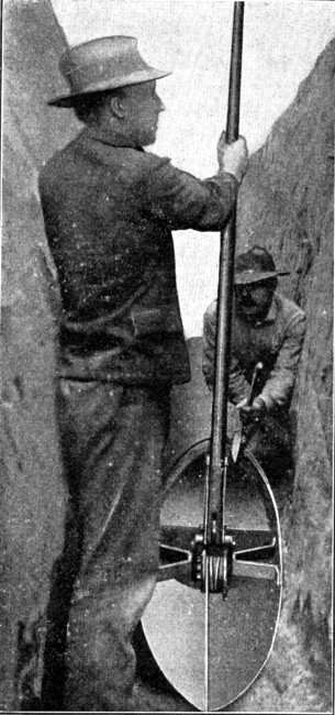 Fig. 268.—Ransome Continuous Mold for Concrete Pipe
Construction.
Fig. 268.—Ransome Continuous Mold for Concrete Pipe
Construction.
In Trans. C. E., Vol. 31, 1894, p. 153, James D. Schuyler gives the cost of cement pipe made by the Ransome system for the Denver Water Works. There is a wrought iron shell of the size of the inner diameter of the pipe forming the inner mold. To this shell is attached a "leader" and "saddle" of larger diameter forming the outer mold. These molds are[Pg 579] drawn slowly along the trench by a cable and horse whim, and the concrete is shoveled continuously into the core space between the molds and rammed on a long incline. The top half, or arch, of the pipe is supported by sheet iron plates (2 ft. wide), placed one after another on the forward end of the mold; and, being clamped together at the top and sides, remain in position after the mold is slid out from under them. After the mold has passed along, these iron plates are supported by upright sticks and by horizontal clamping rods. The plates are left in place for 24 to 48 hrs. The concrete, made 1-3½, river sand and gravel, was machine mixed. A gang of 30 men mixed, wheeled, shoveled and tamped the concrete, attended to the plates, cleaning and greasing them, etc. This gang would make short runs at the rate of 900 lin. ft. of pipe a day, but counting stoppages, the average rate was 300 ft. a day. The inner diameter of the pipe was 38 ins., and its bottom was molded flat for a width of 18 ins. The concrete shell was 2½ to 3 ins. thick. The pipe was washed with pure cement grout, applied with brushes after removing the iron plates. With cement at $3.75 per bbl., gravel at $1.25 per cu. yd., and labor at $1.75 to $2 per day, the cost of this pipe was $1.35 to $1.50 per ft., after the gang was well organized.
PIPE SEWER, ST. JOSEPH, MO.—In constructing extensions to 36-in., 42-in., 48-in. and 72-in. sewers at St. Joseph, Mo., reinforced concrete pipe of the form shown by Fig. 269 was employed. The thickness of shell for the various sizes was 4 ins., 4½ ins., 5 ins., and 7 ins. All sizes were made in 3-ft. lengths, one end of which is rebated and beveled to form a spigot and the other end of which is chamfered on the inner edge to receive the bevel of the spigot. This jointing leaves a circumferential groove, into which the hooked ends of the longitudinal reinforcing bars project in such a way that a circular hoop can be threaded through them to connect successive lengths. The reinforcement is of the same form for all sizes of pipe, but seven longitudinals were used in the 72-in. size and five for all smaller sizes; the circumferential bars were in all cases spaced one 9 ins. from each end. The pipe, as described, is the standard pipe made by the Reinforced[Pg 580] Concrete Pipe Co., of Jackson, Mich., and is covered by patents. The practice of this company is to manufacture the pipe itself on the ground and furnish it to the contractor. It does not contract to build sewers nor does it dispose of rights to manufacture to contractors.
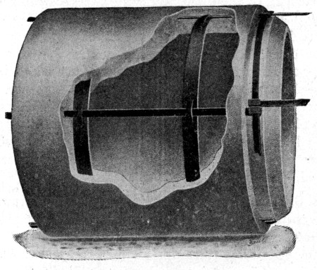 Fig. 269.—Jackson Concrete Sewer Pipe.
Pipe Molding.—The pipe is molded endwise. A bottom plate so shaped as to form the hub or receiving end of the pipe is set up. On the upper or inner flange of this cast iron bottom plate is set the core defining the inside diameter of the pipe; this core is in four segments of sheet steel. The longitudinal reinforcing bars are next inserted in slots in the bottom plate and the outside form of sheet steel is then set up on the lower and outer flange of the bottom plate. Spacing clips on the top edge of the outer shell hold the tops of the reinforcing bars in position. The concrete is then shoveled into the annular mold and tamped until it reaches the level for the first circumferential reinforcing bar; this is then placed by removing the spacing clips, threading the hoop over the longitudinal bars and sliding it down to position. Filling and tamping then proceeds until the second hoop is to be placed; this is placed exactly like the first, and filling and tamping then proceeds until the mold is filled. At the St.[Pg 581] Joseph work a 1-2-3 mixture, with crushed limestone aggregate ranging from pea size to 1-in. stone was used. The molding was done in tents which were heated by coke fires in salamanders in freezing weather.
Pipe Laying.—In laying, the pipes are handled and lowered into position just as are cast iron water pipe. Successive lengths are placed by inserting the spigot ends into the chamfered hub ends and then threading the tie hoop through the hooked ends of the projecting longitudinal reinforcing bars. A strip of galvanized iron is then passed under the pipe and bent up so as to girdle the circumferential groove except for a space at the top; the groove is then poured with a wet 1-2 cement mixture, which, when hardened, completes the joint.
COST OF MOLDING SMALL CEMENT PIPE.—Mr. Albert E. Wright gives the following account of the method and cost of molding and laying 6 to 12-in. cement pipe for irregular work at Irrigon, Ore.: The pipe was 6 to 12 ins. inside, made of Portland cement and clean, sharp sand of all sizes up to very coarse. The mortar was mixed rather dry, but very thoroughly, using 14.1 cu. ft. of sand to 1 bbl. of cement, or very closely a 1 to 4 mixture. From six to seven buckets of water were used to each barrel of cement, except for the 6-in. pipe, for which the mortar had to be made somewhat stiffer in order to remove the inner form, which was not made collapsible as in the larger sizes.
The forms were sheet iron cylinders with a longitudinal lap joint that could be expanded after molding the pipe, and removed without injuring the soft mortar. The inner form was self-centering, so that there was little variation in the thickness of the pipe.
Four men were required in making cement pipe by hand; one mixed the mortar, and wheeled it to the place of work; another threw it into the form a little at a time with a hand scoop; a third rammed it with a tamping iron, and a fourth kept the new pipe sprinkled, and applied a coat of neat cement slurry to the inside when it was sufficiently hard. In molding, the form of the bell at the bottom was secured by an iron ring that was first dropped into the form, and the reverse or convex form at the top was made with a second[Pg 582] ring. While still in its form the pipe was rolled or lifted into its place in the drying yard, and the form was then carefully removed. A very slight blow in removing the form would destroy the pipe, and a considerable number, especially of the larger sizes, collapsed in this way, and had to be remolded. To avoid handling, the pipe was stacked on end a few feet from the place of mixing, the form being moved as the yard filled with pipe. One crew of four men could make about 250 joints or 500 lin. ft. of pipe a day.
As soon as hard enough, the pipe was turned end for end, and was then kept wet for several weeks before being laid. The coating of neat cement on the inside was applied with a short whitewash brush, and was a small item in the cost.
In laying, the trench was carefully finished to grade in order to have the joints close nicely, and the ends were well wet with a brush. The mason then spread mortar, mixed 1 to 2, on the end of the pipe, and laid a bed of mortar at the bottom of the joint. He then jammed the section into place, and swabbed out the inside of the joint with a stiff brush, to insure a smooth passage for the water. A band or ring of mortar was spread round the outside of the joint as an additional reinforcement. One barrel of cement would joint about 300 sections of pipe. The materials cost as follows: Portland cement, per bbl., $4.45; labor, per day, $2; foremen, per day. $2.50 to $3; hauling, per load mile (1 cu. yd.), 20 cts.; sand, free at pit; water, free.
The pipe was all of a 1-4 sand and cement mortar, and the amount of cement in one foot of pipe was arrived at by assuming that where the sand has voids in excess of the cement used, the mortar will occupy 1.1 (see Chapter II) times the space of the dry sand, which yields the following formula:
Where—
c = cost per bbl. of cement, or $4.45.
n = cu. ft. in one bbl. (taken at 3.5 here).
s = ratio of sand to cement, or 4.
d = inside diameter in inches.
t = thickness of pipe in inches.
l = length of pipe considered, or 1 ft. here.
Then:
| c × l × π × (dt + t²) | ||
| Cement-cost per foot | = | ——————————————, |
| n × s × 1.1 × 144 |
which gives here =
| 4.45 × 1 × 3.142(dt + t²) | ||
| ——————— | = | 0.00631(dt + t²). |
| 3.5 × 4 × 1.1 × 144 |
This gave the following cement costs per lineal foot:
| Diameter, ins. | Thickness, ins. | Cost per foot. |
| 6 | 1¼ | $0.0571 |
| 8 | 1¼ | 0.0730 |
| 10 | 1⅜ | 0.0998 |
| 12 | 1½ | 0.1278 |
The sand cost was based on 15 cts. per cubic yard for loading, and a haul of two miles of 1 cu. yd. to the load, making five trips per day, at $4 for man and team. It bears a constant ratio to cement cost, being 11.2 per cent. of the cement cost. The labor cost of making was based on the foreman's estimate that a foreman, tamper, mortar mixer, and water man should finish 250 joints a day of 6 or 8-in. pipe. For the 10 and 12-in. pipe, the labor was assumed to be greater in proportion to the material. The foreman was taken at $3, one man at $2.50 and two at $2. The cement for painting the inside was neglected. Hauling the pipe to place was taken at twice the cost of hauling the sand per mile, and a haul of 4 miles was assumed. The cost of laying was based on a foreman's estimate of 2 cts. per foot for trench, and that one man to lay, one man to plaster the joints, one helper and one man to back-fill would lay 600 ft. per day of 6 or 8-in. pipe. The larger sizes were assumed to cost more in proportion to their material.
These various costs gave the following results for small size pipe:[Pg 584]
| —Cost per foot for— | ||||
| 6-in. pipe. | 8-in. pipe. | 10-in. pipe. | 12-in. pipe. | |
| Cement | $0.057 | $0.073 | $0.099 | $0.128 |
| Sand | 0.006 | 0.008 | 0.011 | 0.014 |
| Labor | 0.019 | 0.019 | 0.026 | 0.034 |
| Hauling | 0.024 | 0.032 | 0.044 | 0.056 |
| Laying | 0.024 | 0.024 | 0.032 | 0.042 |
| Trench | 0.020 | 0.020 | 0.020 | 0.020 |
| ——— | ——— | ——— | ——— | |
| Totals. | $0.15 | $0.176 | $0.232 | $0.294 |
The above costs show that the pipe in place costs about twice as much as pipe in the yard, even with cement at $4.45.
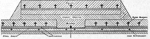 Fig. 270.—Bordenave Pipe for Swansea, England, Water
Works.
Fig. 270.—Bordenave Pipe for Swansea, England, Water
Works.
MOLDED PIPE WATER MAIN, SWANSEA, ENGLAND.—As a good example of foreign practice in molded pipe conduit work a water main constructed at Swansea, England, has been selected. This pipe line had to operate under a head of 185 ft.; it was constructed under the patents of the French engineer, Mr. R. Bordenave, who has built many miles of the same type of conduit on the Continent.
Fig. 270 shows the construction of the pipe, the drawing being a part longitudinal section through the shell at the joint. The pipe consists of an inner and an outer reinforcement separated by a sheet steel tube and all embedded in a 1-2 mortar. Both inner and outer reinforcements consists of longitudinal bins of cruciform (+) section wound by a spiral bar of the same section wired to them at every intersection. Only the outer reinforcement and the steel tube are considered in calculating the strength of the pipe, the inner reinforcement being considered as simply supporting the mortar.[Pg 585]
Fabrication of Reinforcement.—The steel tube is made of 1 mm. (0.04 in.) thick sheets of steel bent to a cylinder and jointed longitudinally by welded butt joints, welded by a blow pipe using acetylene and oxygen. Tests of this welded joint by R. H. Wyrill, Waterworks Engineer, Swansea, showed it to be quite as strong as the unwelded steel cut from the shell. The circumferential joints of the tube were made by turning up the edges of the sheets and welding them; this gives a flexible watertight joint. The tube was made in lengths of 9 ft. 9½ ins. and its ends were turned up all around; just back from the turned-up ends a vertical sheet steel collar was welded to the tube to form a strip end for the external coating. These details are shown in Fig. 270. When the tube for a length of pipe is completed the inside shell reinforcement previously made is slipped into it and the outside shell reinforcement is formed on it as a mandril, as shown by Fig. 271.
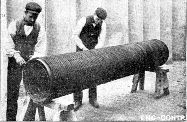 Fig. 271.—Applying External Reinforcement to Bordenave
Pipe.
Fig. 271.—Applying External Reinforcement to Bordenave
Pipe.
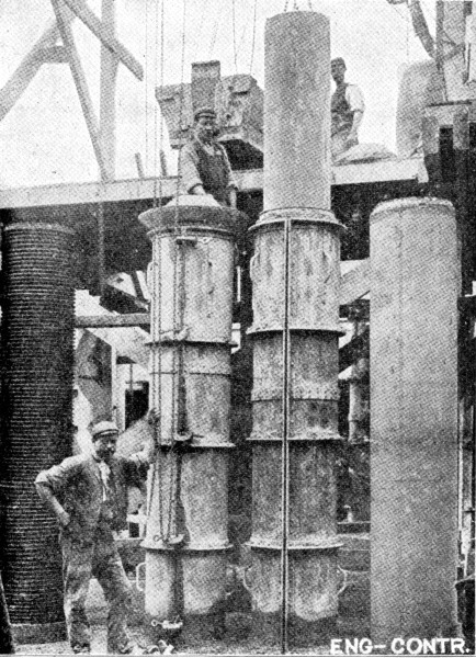 Fig. 272.—Casting Bordenave Pipe at Swansea, England.
Molding.—When the three positions of the steel skeleton were completed, as shown by Fig. 271, they were set on curved wooden curbs made to the exact shape necessary to center them and preserve the correct thickness of cement coating. A collapsible core was lowered into position in the inside, and a two-part sheet steel mold was erected outside; the space between core and mold was then poured with a thin mortar of one part Portland cement to two parts clean river sand. During the process of pouring, the outer steel mold is sharply struck with wooden mallets to facilitate the escape of air bubbles. The mortar was mixed on an elevated traveling platform which is shown in Fig. 272, which also shows a completed pipe, a core being withdrawn, a filled mold and a section of reinforcement set up. The difficult feature of the molding process was found to be the determination of the time for withdrawing the core and removing the exterior mold; the time of setting of the mortar was different in warm[Pg 587] and in cool weather and varied with the wetness of the mixture, the brand of cement, etc. By using a single brand of cement that ran very uniform in quality and time of setting it was possible, however, for the workmen, after a little practice, to gage very accurately the correct time for removing the molds. With four sets of molds a gang of eight men would curb 16 pipes per day under favorable conditions, but when the temperature was low it was not possible to make more than six or eight pipes. The pipes were allowed to stand four or five days after the removal of the mold; they could then be removed by a crane and laid in stock until used. It was found advisable to let the pipes age about four weeks before laying; by this time, it is stated, they would stand as much rough usage as cast iron pipe.
Laying.—The pipes were laid much in the same way as cast-iron pipes are laid; they were each 9 ft. 9½ ins. long and weighed each about 12 cwt., and were handled by ordinary tackle. In laying, the pipes were adjusted end to end and the joint enclosed by a temporary steel ring inside which the bitumen seal, Fig. 270, was run and allowed to set when the steel ring was removed. The joint was then encircled by a collar of similar construction to the pipe itself and the space between collar and pipe was poured with cement mortar. About ten lengths of pipe were laid per day by one gang of men, one jointer and his assistant making all the cement and bitumen joints as fast as the gang could lay the pipes.
Floor, wall and roof work of structurally very simple character sum up the task of the constructor in reservoir and tank construction. The only intricacy involved lies in form design and construction for cylindrical tank work. Several examples of such work are given in this chapter, and in each the construction and handling of the forms are described. To repeat details here would serve no purpose, but one general instruction may be enunciated. No care is too great which ensures rigidity and invariable form, both in the construction of the individual form units and in the assembling of these units into the complete form. This is particularly true of cylindrical tank work and especially high cylindrical tank work where the forms are moved upward as the work progresses. To the designer it may be suggested that any beauty he may gain by giving the walls of his standpipe a batter is paid in the extra cost of form work.
Concreting in tank work is expensive. The reasons are two. The work has to be done in a narrow space, commonly pretty well filled with a network of steel rods or bars. Again the work has to be done uniformly well, not only for appearance sake but because of the necessity of watertightness. Making a reservoir watertight is, when all things are said, the one difficult constructional task in tank work and the contractor who accepts the task lightly courts trouble. Exceptionally good concreting is essential in tank work if watertightness is to be secured.
The illustration of these general admonitions will be found in the specific examples of tank and reservoir work which follow.[Pg 589]
SMALL COVERED RESERVOIR.—The reservoir was designed to hold 75,000 gallons of water for fire purposes. As it is of a type which is certain to be frequently constructed and as we have personal knowledge of the costs recorded we describe the work in some detail. The specifications stipulated that the reservoir must be absolutely watertight and that the roof should be capable of sustaining a load of 300 tons evenly distributed and a live load of 5,000 lbs. on two wheels. Figure 273 shows a plan, Fig. 274 a longitudinal section, Fig. 275 a transverse section and Fig. 276 the column construction.
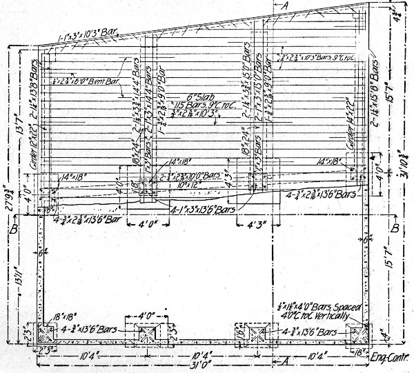 Fig. 273.—Sectional Plan of 75,000-Gallon Reservoir.
Quantities of Work.—The excavation called for the removal of 579 cu. yds. of earth. There were 83 cu. yds. of concrete in the structure, although the plans called for less, the additional amount being used in increasing the two 4-in. walls to 6-in. and increasing the bottom and top, on one end,[Pg 590] so as to give perfect drainage. The yardage was divided as follows:
| Cu. yds. | |
| Footings | 3.5 |
| Columns | 6.8 |
| Sides | 22.6 |
| Girders | 11.0 |
| Top | 20.0 |
| Floor | 19.1 |
| —— | |
| Total | 83.0 |
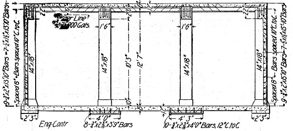 Fig. 274.—Longitudinal Section of 75,000-Gallon
Reservoir.
Fig. 274.—Longitudinal Section of 75,000-Gallon
Reservoir.
A manhole had to be put in the top and a sump in the bottom. Several pipes also had to be placed in the concrete. None of these details is shown on the plan. The structure had to be waterproofed.
Excavation.—The excavation was made with pick and shovel and the material hauled away in carts, the distance to the dump being 700 ft. The top was shoveled directly into the carts, while the rest was handled two and three times. When the reservoir was finished dirt had to be filled in around the sides and puddled.
Wages.—The following rates of wages were paid on the job:
| Foreman | $3.00 |
| Carpenter | 3.50 |
| Carts and driver | 3.50 |
| Laborers | 1.50 |
The carpenters worked 8 hours a day and were paid time and a half for overtime. The rest worked ten hours per day and were paid regular rates for overtime.
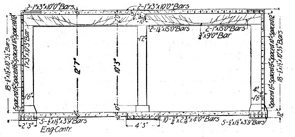 Fig. 275.—Transverse Section of 75,000-Gallon
Reservoir.
Fig. 275.—Transverse Section of 75,000-Gallon
Reservoir.
Forms.—Carpenters framed and erected the forms, but laborers did all the carrying for them. Laborers also tore down the forms. For the girders and columns 2-in. boards were used, but for the sides 1-in. boards with 3×4-in. scantlings were used. The props for supporting the girder and top forms were 3×4. Except for columns and girders and some props, all the forming was used three times. The lumber cost:
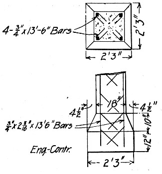 Fig. 276.—Column Construction for 75,000-Gallon
Reservoir.
Fig. 276.—Column Construction for 75,000-Gallon
Reservoir.
| 400 ft. B. M. at $24 | $ 9.60 |
| 8,000 ft. B. M. at $18 | 144.00 |
| ——— | |
| Total | $153.60 |
This makes an average price per 1,000 ft. of about $18.30, which price we shall use in giving costs.
The cost of framing and erecting the forms was $167.27 for the sides, columns, girders and top. In the forms for the sides, forming was only used on one side of the concrete for two sides, the earth bank being used for the other side of the forms, but on the other two sides the banks had caved in, and forming was used on both sides of the wall. The cost per cubic yard for forms was:
| Lumber | $2.54 |
| Framing and erecting | 2.77 |
| Tearing down | .54 |
| —— | |
| Total | $5.85 |
This cost is for the yardage of 60.4 on which forms were actually used. For the total yardage in the tank the cost was:
| Lumber | $1.85 |
| Framing and erecting | 2.01 |
| Tearing down | .40 |
| —— | |
| Total | $4.26 |
The common labor cost of assisting to erect the forms was 15 per cent of the total. Nothing is allowed for foreman, for the contractor acted as his own foreman.
The cost of forms per 1,000 ft. for the amount of lumber purchased was:
| Lumber | $18.30 |
| Framing and erecting | 19.90 |
| Tearing down | 4.00 |
| ——— | |
| Total | $42.20 |
As the lumber was used three times, the cost per thousand for all work and materials on the forms would be just one-third of this—namely: $14.06.[Pg 593]
Since the framing, erecting and tearing down cost $19.90 plus $4, or $23.90 per M. ft. B. M. purchased, and since the lumber was used three times, the labor cost nearly $8 per M. each time that the lumber was used. It will be noted that 8,400 ft. B. M. were required for the 83 cu. yds. of concrete, or a trifle more than 100 ft. B. M. per cubic yard.
It will be of interest to see the labor costs of forms for the various parts of the structure.
For the sides the cost of framing and erecting the forms was $4.19 per cubic yard. Of this cost 4 per cent. was for common labor and the rest for carpenters. The tearing down cost 47 cts. per cubic yard. For the columns the erecting was $2.35, of which 1 per cent. was for common labor. The tearing down cost 47 cts. For the girders and top the erecting cost $1.83, of which 35 per cent. was common labor. The tearing down cost 61 cts. per cubic yard. A summary would show:
| Sides per cu. yd. | Columns per cu. yd. | Girders and top per cu. yd. | |
| Framing and erecting | $4.19 | $2.35 | $1.83 |
| Tearing down | .47 | .47 | .61 |
| —— | —— | —— | |
| Total | $4.66 | $2.82 | $2.44 |
The greater cost of the columns forms over the girders and top was due to the fact that the columns forms were handled almost exclusively by the carpenters, and also in setting them great care and much time had to be used to get them plumb and in line. The cost of the forms for the sides was about twice as great as that for the top and girders. The reasons for this are evident. The walls had forms on both sides, while the top needed forming only underneath it, the area covered on the forms being about 2,200 sq. ft. as compared to 1,000 sq. ft. The side forms had to be set plumb and kept so. The framing was done ahead, but nearly half of the lumber in the sides was erected as the concrete was being put in place. The forms for the top were all put in place before any concreting was done on the top, and the carpenters discharged. A much larger per cent. of common labor could be used in placing forms for top and girders than on the sides. The[Pg 594] props were nearly all put in place by laborers. The extra cost of tearing down the forms for the top was due to the fact that the lumber all had to be handled one piece at a time through a small manhole in the top, and carried about 150 ft. to be piled.
To all the costs for forming should be added 6 cts. per cubic yard for nails, wire and lines used on the forms.
Concrete.—The mixtures varied for the different members. The cost of materials was as follows:
| Cement, 110 bbls. @ $1.12 | $123.20 |
| ¾-in. stone, 80 cu. yds., @ $1.86 | 148.80 |
| Gravel, 3 cu. yds., @ $1.33 | 4.00 |
| Sand, 42 cu. yds., @ $1.20 | 50.40 |
The sides were first put in place, then the center columns were built, following which the bottom was placed. Then the forms were erected for the top and the girders, and these cast. In building the sides, one side and half of the two ends were built at one time, and then forms erected for the other half of the sides. For the sides the mixing was done in the bottom of the reservoir. For the rest of the structure it was done on the ground, the mixing board being along side of the reservoir. The labor cost of the concrete work for the various members and the average per cubic yard was as follows:
| Sides. | Columns and Footings. | Bottom. | Girders. | Top. | Average. | |
| Cubic yards | 22.6 | 10.3 | 19.1 | 11 | 20.0 | 83. |
| Preparing and cleaning up | $0.166 | $0.060 | ... | $0.095 | ... | $0.065 |
| Handling materials | 1.022 | .306 | $0.070 | .198 | $0.187 | .404 |
| Cleaning out forms | .040 | ... | ... | .070 | .053 | .032 |
| Mixing and placing | 1.542 | .728 | .353 | .792 | 1.080 | .952 |
| Ramming | 1.090 | .540 | .455 | .450 | .597 | .673 |
| Handling steel | .890 | .020 | ... | .395 | .083 | .324 |
| ——— | ——— | ——— | ——— | ——— | ——— | |
| Total | $4.750 | $1.654 | $0.878 | $2.000 | $2.000 | $2.450 |
The total cost of labor was $203.35. The mixing was done entirely by hand. Some plastering was done to the walls after the forms were taken off, and the sides and bottom were washed with a brush with cement and water. The plastering cost $6.60, including a barrel of cement and the washing or grouting, two coats, cost $9.10, including a barrel of cement. This added a cost of 19 cts. per cubic yard to the concrete work, making the total cost per cubic yard $2.65.
It was a mistake to have mixed the concrete for the sides in the bottom of the reservoir, as it made two handlings[Pg 595] of the materials and compelled all the concrete to be raised by hand to place it in the forms. This accounts for the high cost of these two items.
The handling of the steel was high for the side walls, as it was all separated and put into piles for the different panels and members in getting it out of the pile for the sides. The rammers not only rammed the concrete but they also bent down the prongs of the steel to get them in place in the narrow forms, and afterwards had to pull out these prongs. This had to be done for every piece of steel used, and readily doubled the cost of ramming. The high cost of ramming the top was caused by the fact that the 6 ins. of concrete had to be placed in three layers and each rammed. The steel handling was high on account of the prongs entangling the pieces with others, making them hard to handle. The cost of handling steel per ton was about $4, or 0.2 ct. per pound. The steel was all handled by common laborers.
The stock piles of material had to be made along a street and alley and thus caused the material to be handled in wheelbarrow several hundred feet.
The preparing to mix concrete, the cleaning up afterwards and the cleaning out of forms are items that are seldom kept separate from the others.
The cost of mixing and placing is high, owing to the fact that working space was small and the mixers had to wait until the concrete was taken off the board and placed in the forms before starting another batch. This also meant an increased cost in the ramming, as the rammers were idle some time waiting for a new batch to be mixed.
The total cost of concrete, including labor and materials, per cubic yard on a basis of the 83 cu. yds. was:
| Per cu. yd. | |
| Cement, 1⅓ bbls., @ $1.12 | $ 1.49 |
| Stone, 1 cu. yd. | 1.86 |
| Sand ½ cu. yd. | .60 |
| Steel | 4.76 |
| Forms, 100 ft. B. M., @ $18.30 | 1.85 |
| Labor on forms | 2.41 |
| Labor on concrete and steel | 2.65 |
| ——— | |
| Total | $15.62 |
The cost of a foreman is not included in this, as the contractor looked after the men himself.
Waterproofing.—The waterproofing of the structure proved a serious problem. It was thought at first that the concrete itself would be nearly water tight, but the tank leaked like a sieve. After considering several methods, an agent of a European waterproofing mixture prevailed upon those interested to try his compound. To apply it, the walls had to be dry, so a large coal burning stove was put in the reservoir and a fire kept up day and night. While this drying process was going on several light falls of snow occurred, and this had to be cleared away to make the walls and roof dry. Two coats of the mixture were applied according to the agent's instructions, and the reservoir was tested. The water fell nearly half a foot in an hour's time.
Then a waterproofing contractor agreed to make the reservoir water tight with paper and tar, by applying it on the inside. Three thicknesses of paper were laid on the bottom and run well up on the sides, each layer of paper being well covered with a preparation of tar. Upon testing it, it was found that the leaking had been reduced about 50 per cent. A preparation of asphalt was then placed over this, but upon a third test the tank still leaked. As the sub-contractor had verbally agreed to make it water tight for $125, only this amount was paid him. After this last test he refused to do any more work.
After these attempts the sides of the reservoir were exposed on the outside by excavating around it, and a one-brick-wall built up a few inches from the concrete. This space was filled in with rich cement mortar and the ground once more filled in around the structure. This work and the materials used in it cost $1,240. Upon a fourth test the reservoir was found to be water tight. Thus more than a third of the cost of the entire work was in waterproofing the structure, and this made the contract a money losing one, as this heavy cost was not anticipated.
Several items of miscellaneous work are listed in the total cost of the reservoir, such as filling in and puddling around reservoir and replacing cobble paving. The top of the structure[Pg 597] was used as a bin for the storage of coal. For this purpose eight I-beams were embedded in concrete around the top to be used as posts for the sides of the bin. The cost of placing these is given.
Total Cost.—The cost of the structure without any profits was:
| 579 cu. yds. excavation @ $.896 | $ 529.65 |
| Steel | 395.00 |
| Crushed stone | 148.80 |
| Gravel | 4.00 |
| Sand | 50.40 |
| Cement | 123.20 |
| Lumber | 153.60 |
| Labor on forms | 200.09 |
| Labor on concrete | 203.35 |
| Plastering | 6.60 |
| Sides and bottom | 9.10 |
| Nails, wire, etc. | 4.98 |
| Bailing water | 21.19 |
| Building temporary fence | 1.65 |
| Extra excavation for forms, footings, etc. | 13.90 |
| Setting I-beams in concrete | 17.65 |
| Filling in and pudding around reservoir | 34.47 |
| Replacing cobble paving | 4.30 |
| Hauling tools | 3.60 |
| Heating reservoir and handling snow | 14.50 |
| Waterproof mixture | 29.00 |
| Labor applying it | 9.74 |
| Applying paper and tar, labor and materials | 125.00 |
| Labor and materials of final waterproofing | 1,240.00 |
| Tools | 48.75 |
| General expense | 210.00 |
| ———— | |
| Total | $3,602.52 |
COVERED RESERVOIR, AT FORT MEADE, SOUTH DAKOTA.—The following account of the method and cost of constructing a 500,000-gallon reservoir is compiled from information furnished by Mr. Samuel H. Lea, M. Am. Soc. C. E. As shown by Fig. 277, the reservoir consists of two equal compartments, each 50×60 ft. inside dimensions,[Pg 598] with rounded corners. Both compartments are covered with a 3-in. slab roof carried on the walls and interior columns.
The concrete was a 1-2-4 Portland cement, sand and broken stone mixture, mixed by hand on a movable platform. A concrete gang consisted of four men who were each paid $2.75 per day. They wheeled the materials from the supply piles to the mixing platform, mixed the concrete and deposited it in place. During the construction of the footings and floor two concrete gangs were employed, but after the walls were started, one gang only was required for concrete work; the other gang was then put to work assisting the carpenters.
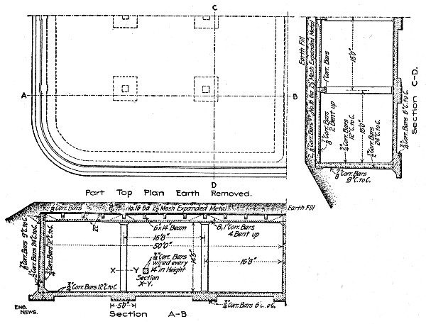 Fig. 277.—Reservoir at Ft. Meade, S. D.
The sand and stone were wheeled to the platform in iron wheelbarrows of 2½ cu. ft. capacity. The cement was in ¼-bbl. sacks and each sack was taken as 1 cu. ft. Each batch of concrete contained the following quantity of material:
| 2½ sacks of cement | 2½ cu. ft. |
| 2 wheelbarrows of sand | 5 cu. ft. |
| 4 wheelbarrows of stone | 10 cu. ft. |
The quantities of sand and stone were adjusted so as to form the proper proportion for making a dense concrete.[Pg 599] From time to time, as the work progressed, experiments were made to determine the percentage of voids both in the sand and the crushed stone; and, in this way, uniformity in composition was secured. The mixture was made quite wet in order to insure a free flow around the reinforcing bars. On account of the narrow space inside the forms and the number of reinforcing bars therein care was taken to cause the mixture to be well distributed throughout. The wet concrete was well spaded in an effort to secure a smooth surface next to the forms. This was generally accomplished, but some rough places which showed after the removal of the forms required patching up.
In constructing the footings some concrete was first deposited in place and the metal reinforcement was embedded therein. For the floor reinforcement the lower bars were carefully embedded in the concrete after it had been brought to a suitable height; the upper bars were then placed crosswise upon the lower ones and kept in position until the remainder of the concrete had been deposited around and over them. In the wall footings a depression or groove, several inches deep, was left under the wall space for its entire length. This ensured a good bond between the wall proper and the footing.
The concrete floor in each compartment was built in one continuous operation, the object being to secure a practically monolithic construction. The lower reinforcing bars in the floor were embedded at the proper depth in the fresh concrete and the upper bars were then placed crosswise upon the lower ones; the two sets were then wired together at a sufficient number of places to prevent displacement while the remaining concrete was being deposited around and over them.
The reinforcement for the walls and columns was erected in place upon the footings and formed a steel skeleton around which the forms were erected. The upright bars in the walls were held together and at the proper distance apart by means of templates consisting of wooden strips in which holes were bored at suitable intervals to receive the bars. The templates were maintained in a horizontal position and were moved upward as the concrete advanced in height. The horizontal[Pg 600] reinforcing bars were wired in place to the upright bars; they were placed in position ahead of the concreting as the wall was built up.
The corrugated bars in beam and girders were placed in position in the forms and held up by blocks which were removed as the forms were filled with concrete. The expanded metal reinforcement for the roof slab was placed so as to be close to the lower face of the slab, but far enough up to be entirely enveloped in the concrete.
The wall forms were made of 2-in. planks, surfaced on the inner side and placed horizontally on edge. They were held in place by 4×4-in. posts spaced at intervals of about 4 ft., in pairs on opposite sides of the wall. The posts were firmly braced on the outside; they were prevented from spreading by connecting wires passing through the wall space between the edges of adjacent planks. At the rounded corners of the reservoir the pairs of posts were spaced about two feet apart and the curve was made by springing thin boards into place to fit the curve and nailing them to the posts. The posts were high enough to reach to the top of the wall; the siding was built up one plank at a time as the concrete work progressed. Column forms were made of 2-in. planks on end, extending from floor to girder. Three sides were enclosed and one side was left open to receive the concrete; this side was closed up as the concreting advanced in height.
The beam and girder forms were open troughs of the required dimensions, made of 2-in. plank, surfaced on inner faces. The form of centering for the roof slab consisted of a smooth, tight floor of 2-in. planks, extending between the open tops of column, beam and girder forms over the entire area between enclosing walls of the reservoir. The centering and the beam and girder forms were supported by 6×6-in. posts resting upon the floor below.
The regular carpenter gang consisted of a foreman carpenter at $5 per day, a carpenter at $3.50 per day, and two helpers at $2.75 per day. During the early concrete work of making footings and floor, where forms were not required, the carpenter force was employed in erecting the steel skeleton for the walls. The upright bars were placed in position and secured by temporary wooden stays extending from the upper[Pg 601] portion of bars to the surface of ground outside of excavation. These stays were removed after concreting had advanced to a sufficient height to hold the steel securely in place.
The wages paid the concrete gang which mixed and placed all the concrete and the carpenter gang which constructed and erected the forms and placed the reinforcement have been given above. The costs of construction materials on the site were:
| Cement, per barrel | $2.57 |
| Sand, per cu. yd. | 1.80 |
| Stone, per cu. yd. | 3.15 |
| Lumber, per M. ft. B. M. | 27.50 |
The quantities in the completed concrete structure were as follows:
| Total volume of concrete in reservoir | 704.71 cu. yds. |
| Total volume of steel reinforcement in reservoir. | 5.57 cu. yds. |
| —————— | |
| Total volume of material in completed structure. | 710.28 cu. yds. |
| The steel was, therefore, about 0.8%. | |
| Volume of material in structure exclusive of roof slab | 648.35 cu. yds. |
| Volume of material in roof slab | 61.93 cu. yds. |
| —————— | |
| Total | 710.28 cu. yds. |
The cost of the structure per cubic yard of concrete, exclusive of the roof slab, was as follows:
| Item. | Per cu. yd. |
| Crushed stone | $ 3.168 |
| Sand | .842 |
| Cement | 3.859 |
| Reinforcement | 4.959 |
| Labor, mixing and placing concrete | 1.721 |
| Forms, labor and material | 2.960 |
| ——— | |
| Total | $17.509 |
In constructing the roof slab the expanded metal reinforcement raised the unit cost. For this portion of the work the costs were:[Pg 602]
| Item. | Per cu. yd. |
| Expanded metal reinforcement | $ 5.241 |
| Other items, same as above | 12.550 |
| ——— | |
| Total | $17.791 |
The floor and the inside surface of reservoir walls were covered with a coating of cement mortar composed of one part Portland cement and one part sand. The wall plastering was from ½ in. to ¾ in. thick; it was applied in two coats. The floor finish was laid in alternate strips about 1 in. thick and 3 ft. wide. After the strips first laid had hardened the remaining strips were laid, the edges being grouted to ensure tight joints.
The outside of walls and roof was covered with a coating of tar which was heated in an open kettle to a temperature of about 360º F. and then applied with a brush or mop.
The cost of wall and floor plastering was 44.4 cts. per square yard, itemized as follows:
| Cement | 26.4 cts. |
| Sand | 2.6 cts. |
| Labor | 15.4 cts. |
| ———— | |
| Total | 44.4 cts. |
The cost of outside waterproofing was 4 cts. per square yard, distributed as follows:
| Material | 2.5 cts. |
| Labor | 1.5 cts |
| ——— | |
| Total | 4.0 cts. |
While some of the cost items are apparently high when compared with the cost of similar work in other places, it should be remembered that the isolated locality and the local conditions were unfavorable for low cost. Owing to the isolated location of the reservoir with respect to large markets and also to local sources of supply the cost of material and labor was quite high. All construction material, except some of the stone for crushing, had to be hauled over a mountain road from 3 to 4 miles to the top of the hill selected for the reservoir site. Labor was scarce and commanded a wage of[Pg 603] $2.50 per day for ordinary work; the laborers mixing concrete were paid $2.75 per day. Another source of much relative expense was the high cost of lumber and carpenter work on the forms. On account of the thinness of the walls and roof, the cost of lumber and labor required per cubic yard of concrete was considerable. A part of the lumber was used the second time in forms, but it was found impracticable to delay the work by waiting for the concrete to harden before beginning the new portions of the walls. This lumber was sold after the completion of the work, but the salvage was inconsiderable, amounting to less than 10 per cent. of the original cost.
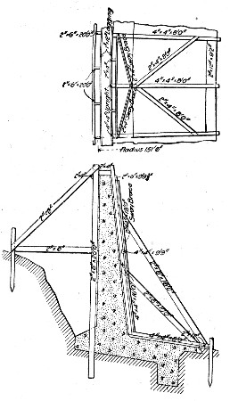 Fig. 278.—Reservoir Forms. Bloomington, Ill.
CIRCULAR RESERVOIR, BLOOMINGTON, ILL.—An open circular reinforced concrete reservoir was constructed in 1905-6 for the water-works of Bloomington, Ill. This reservoir is 300 ft. in diameter, 15 ft. deep at the circular wall and 25 ft. deep at the center of the spherical bottom. The wall construction is shown clearly by Fig. 278, and the floor is a 6-in. spherical slab reinforced by a mat of ¼-in. round[Pg 604] rods placed 6 ins. on centers in both directions. The wall reinforcement is corrugated bars. Neither the wall nor the bottom has expansion joints.
Concrete.—The specifications required not less than 1 part Portland cement to 2 parts sand and 5 parts clean gravel, and stipulated that there should always be more than enough cement to fill the voids in the sand more than enough mortar to fill the voids in the gravel. The proportions were varied, depending on the character of the available material and on the location the concrete was to occupy. The stipulations regarding the minimum quantities of cement and mortar were, however, always at least fulfilled. A 1-3-4 mixture of cement, broken stone and gravel was largely used in the footing and wall. The gravel was fine and contained 40 to 50% of sand; the broken stone was the crusher-run, with the dust screened out, and the maximum-sized pieces not larger than those which would pass a 2-in. screen. The mortar facing on the front face of the wall was made of 1 part cement to 4 parts fine gravel, containing sand. Some gravel from the excavation was used in the concrete for the floor. This gravel was so fine that about one-quarter of it was replaced with broken stone and the mixture made 1-6. Both faces of the wall were painted with a 1-1 mixture of cement and sand; the inner face was also painted with a 1-1 mixture of waterproof Star Stettin Portland cement and sand. The sidewalk finish on the surface of the floor consisted of 1-1½ mortar.
Mixing and Handling.—The concrete mixing plant was set up outside of the site of the reservoir along a side track from the railroad. The concrete materials were delivered on the side track, except some gravel from the excavation that was used. A Foote portable continuous mixer was used in making the concrete for the wall footings and the wall. It was mounted so it could discharge into dump cars on a service track laid on the ground. A double hopper was built up over the mixer, one compartment for sand and one for broken stone. The end of a service track leading from the side track was laid on an inclined trestle up to a floor level with the top of this double hopper, the materials being hauled in dump cars from the side track to the hopper. The service track from the mixer extended entirely around the wall, and 10 ft.[Pg 605] from it, on the embankment made there with earth from the trench for the wall-footing. The concrete was dumped from the cars on the service track to portable shoveling platforms near the point where work on the wall was in progress. It was shoveled by hand from these platforms to place in the forms as the presence of the reinforcement bars in the narrow forms precluded dumping in large quantities. The footing was built without forms up to the right-angle joint between it and the base of the wall at the front, and to the top of the 45° slope on its rear face. A layer of concrete 2.5 in. thick was first placed in the completed trench. The reinforcement bars near the bottom were then laid on this green concrete, the vertical bars near the front face of the wall usually being erected at the same time. The concrete in the toe of the footing and in the footing proper up to the top layer of reinforcement was then laid. After the top layer of reinforcing bars had been laid, the footing was completed, except for a top layer about 2 ins. thick at the base of the front face of the wall and 15 ins. thick at the toe of the footing. This left a strip of surface about 6 ft. wide, sloping at about 1 in 6 from the wall toward the center of the reservoir, and furnished the widest and best possible bond for the joint which had to be made when floor was laid.
Location and Construction of Forms and Wall.—The design of the wall of the reservoir, although simple in itself, required unusually accurate work in the location and construction of the forms for it. The location was made with very little difficulty, however, by an arrangement devised by the contractor which enabled the foreman, without the aid of an engineer, to set the necessary grade and reference stakes. A post, 10 ins. in diameter, was set very accurately and firmly in the ground at the center of the reservoir. This post was sawed off squarely on top so that the line of collimation of an engineer's transit set on it without a tripod would be exactly at the grade of the top of the completed wall of the reservoir. A 200-ft. steel tape was used to measure the radial distance from a nail in the center post to the posts of the back, or outside forms for the wall. In the form for the back face of the wall 2×6-in. posts, spaced one one-hundredth of the circumference apart, were set considerably in advance of any concrete[Pg 606] work, and were made the basis of all measurement in building the forms. The forms as originally planned are shown in Fig. 278.
The wall, when started, was built continuously in both directions from the starting point. The back forms consisted of planks for lagging nailed to vertical posts, which were accurately set and firmly braced. The front forms were made in lengths equal to one one-hundredth of the circumference of the reservoir, and when set up were fastened to the back forms. Twenty-one of these front form sections were built and all set up at once. Concrete was filled in between the front and back forms, starting at the central form, and was rammed in inclined layers, sloping, at about 1 on 6, both ways towards the end forms. This method was adopted in order that the concrete might be laid continuously and without joints. The lagging of 1-in. boards on the vertical portion of the sections was nailed to the vertical posts, and was carried up just ahead of the concrete filling.
When the concrete had reached the top of the central one of the 21 sections of the forms, and the concrete in that section had set sufficiently, the section was broken up and removed, leaving two sets of 10 sections of the forms. Subsequently the other forms could be removed in turn as desired without being broken up. As the filling-in proceeded between the two sets of 10 forms each, the form in each set nearest the starting point was removed, carried forward, and put in place at the other end of its set of forms. Twelve men were required to take down and transport one of the front form sections.
In setting up a front form, its inner toe was firmly supported by a stake driven into the ground and by the horizontal board, nailed transversely under the bottom 4×4-in. horizontal stringers, which rested on the ground. The upper part of the form was then securely fastened to the 2×6-in. posts of the back forms by temporary wooden connecting strips, which were removed as the concrete filling was carried up. The sections of the front forms were also securely tied to each other.[Pg 607]
A facing of gravel concrete, rich in cement and with no pebbles larger than ½-in. was placed on the front face of the wall, extending from the back edges of the vertical reinforcing bars to the surface. A sheet-iron plate, about 8 ins. wide by 5 ft. long, was placed vertically just back of those bars. The concrete was shoveled in loose to the top of these iron plates, and then the mortar was poured in between the latter and the front face forms from buckets. The iron plates were next drawn by handles attached to them, and the mortar and concrete tamped together before either had set. In making joints, the old concrete surfaces were always brushed and wet down, and, if necessary slushed with a grout of neat cement before new concrete was laid on them.
Construction of Floor.—The excavation over the site of the reservoir floor was brought accurately to grade 6 ins. below the surface of the finished concrete by hand after the scoop-bucket excavator had passed over. In making the excavation the levels were given on radial lines drawn from the ends of the 10-ft. sections of the wall to the center. A rod, on which the elevations of the sub-grade at every 10 ft. from the wall to the center of the reservoir were clearly marked, was used in connection with a transit on the center post in locating the elevations of different points in the reservoir floor. By using this method the elevations required were easily found by the foreman in charge without the assistance of an engineer. When the work approached the center, the post was removed and the transit was placed on a portable pedestal which was set on points of known elevation on the finished concrete.
The slanting surface left on the top of the footing inside the wall formed, together with the projecting reinforcement rods, an excellent bond between the concrete of the wall and that of the floor, when the latter was laid. A circular strip of the floor, 16 ft. wide, was put down next to the wall first, and the remainder of the floor was laid according to the progress of the excavation. The lower 3½ ins, of the concrete was usually first spread out over an area 12 or 16 ft. square, then the reinforcement was placed, and after that the top 2 ins. of concrete and a ½-in. sidewalk finish surface were laid.[Pg 608]
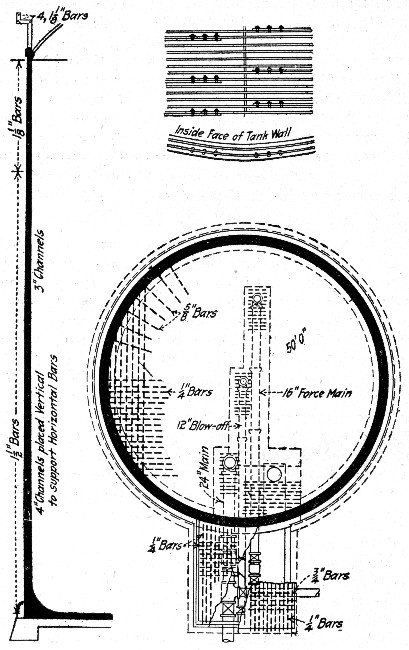 Fig. 279.—Standpipe at Haverhill, Mass.
The ¼-in. rods in the bottom are 6-ins. on centers in both directions. They were in 12 and 16-ft. lengths and were partly woven together in mats before being placed. The rods in one direction were all laid out and woven with four or[Pg 609] five of those in the other direction, the joints being tied with small wire. The remaining cross rods were laid after the mat had been placed. The mats were overlapped 1 ft. This method of placing proved economical and efficient, giving at the same time something permanent on which to lay the remaining concrete.
STANDPIPE AT ATTLEBOROUGH, MASS.—The stand pipe was 50 ft. in diameter and 106 ft. high inside, with walls 18 ins. thick at the bottom and 8 ins. thick at the top. Figure 279 shows the general arrangement of the reinforcement. Round bars of 0.4 carbon steel were used; the bars came in 56½-ft. lengths, so that three lengths with laps of 30 ins., made a complete ring around the tank. The concrete was a 1-2-4 mixture of ¼ to 1½-in. broken stone with screenings used as portion of sand.
The floor was built first, and on it was erected a tower to a height of 60 ft. and a derrick with a 40-ft. boom was set on its top. The derrick was operated by an engine on the ground which also had a revolving gear attached. When the work had reached the top of this tower, the tower was raised to 110 ft. in height and the derrick shifted to the new elevation. The forms were convex and concave sections 7½ ft. high and about 11 ft. long. The concave or outside forms were made in 16 panels, with horizontal ribs and vertical lagging; two complete rings of panels were used. The panels were joined into a ring by clamps across the joints, this clamping action and the friction of the concrete holding them in place. The inside forms consisted of vertical ribs carrying horizontal lagging put in place a piece at a time as the filling proceeded. They were supported by staging from the derrick tower. The remaining plant comprised a Sturtevant roll jaw crusher feeding to screens which discharged fines below ¼-in. into one bin, medium stone into another bin and coarse stone into a third bin. These bins fed to the measuring hopper of a Smith mixer, which discharged into the derrick bucket.
The mode of procedure was as follows: The reinforcing rings were erected to a height of 7½ ft. The bars were bent by being pulled through a tire binder and around a curved templet by a steam engine. The bending gave some trouble,[Pg 610] due, it was thought, to the stiffness of the high carbon steel. Vertical channels 4 ins. deep were set with webs in radial planes or across wall at four points in the circumference. The flanges of these channels were punched exactly to the vertical spacing of the reinforcing rings. Through the punched holes were passed short bars on the opposite ends of which the reinforcing rings were supported and wired. The three sections of rod of which each ring was composed, were lapped 30 ins. and connected by Crosby clips. Considerable difficulty was had in holding the reinforcing rings in line by the method employed; it is stated by the engineer that a greater number than four channels would have been much better.
The reinforcement being in place, an inside and an outside ring of forms was erected. Concreting was then carried on simultaneously from four points on the circumference and a ring 7½ ft. high was concreted in one operation. Several facts were brought out in the concreting; careful and conscientious spading was necessary to get a smooth dense surface; a too wet mixture allowed the stone to settle and segregate; care was necessary in this thin wall containing two rings of bars to keep the stone from wedging among and around the bars and thus causing voids. The engineer states that for this reason the substitution of mortar for concrete in tank walls is worth considering. He estimates that in this work, costing $35,000, that the use of a 1-2 mortar in place of the 1-2-4 concrete would have increased the cost by $2,300, a 1-2½ mortar by $1,500, and a 1-3 mortar by $750. It was also found that there was danger from a movement of the reinforcement in the concrete and of the forms in placing the concrete.
When a ring of wall 7½ ft. high had been concreted, the reinforcement was placed as before described for another ring. The two rings of forms below those just filled were removed from the wall, hoisted up and set in place on top. These two operations of placing reinforcement and setting forms for another ring of wall took three days, so that the top surface of the wall to which new concrete was to be added, had become hard. This hard surface was very thoroughly washed and then coated with neat cement immediately before depositing the fresh concrete. Water was admitted to the tank[Pg 611] as the work progressed, being kept about 20 ft. below the work in progress. Numerous small leaks developed, but only two were large enough for the water to squirt beyond the face of the wall. These leaks appeared to grow smaller as time went on. To do away with them entirely, the inside wall was plastered. The first coat of plaster was not successful in stopping the leaks, so the standpipe was emptied and replastered, five coats being used in the lower 20 ft. This did not serve so resort was had to a Sylvester wash. A boiling hot solution of 12 ozs. to the gallon of water of pure olive oil castile soap was applied to the dry wall. In 24 hours this was followed with a 2 ozs. to the gallon solution of alum applied at normal temperature. Four coats of each solution were applied, which reduced the leakage to a small amount. To do away with all leakage another four-coat application of Sylvester wash was used.
Details of the cost of the work are not available. There were 770 cu. yds. of concrete in the walls and 185 tons of steel bars. Altogether 3,000 Crosby clips, costing $1,100 were used. The cost of the concrete in place was about as follows:
| Cement, per cu. yd. of concrete | $ 4.80 |
| Sand and stone, per cu. yd. of concrete | 3.90 |
| Mixing, per cu. yd. of concrete | 0.40 |
| Placing, per cu. yd. of concrete | 2.20 |
| Forms, per cu. yd. of concrete | 2.65 |
| ——— | |
| Total per cu. yd. of concrete | $13.95 |
GAS HOLDER TANK, DES MOINES, IOWA.—The tank was 84 ft. in diameter and 21 ft. 5 ins. deep. It had a horizontal floor 16 ins. thick 5 ft. below ground level and a wall 21 ft. high, 18 ins. thick at base and 12 ins. thick at top under coping and with alternate pilasters and piers around the outside. The concrete for the floor was a 1-2½-5 2-in. stone mixture and the concrete for the walls was a 1-2-4 1-in. stone mixture. The floor was constructed first, with a circular channel for the wall footing, and then the wall was constructed.[Pg 612]
Piles were driven in the bottom and their heads cut to level and filled around with tamped cinders. Two circumferential rows of posts were driven around the edge so that a pair of posts, one inner and one outer, came on each radius through a wall pilaster or pier. These posts served primarily to carry the frames for the wall forms and secondarily for holding the forms for the circular wall footing channel as shown by the sketch Fig. 280. The floor concrete was put in in diamond-shaped panels between forms, whose top edges were set to floor level. Each form was designed to make a groove in the edge of the slab so that adjacent slabs would bond with it. The concrete was wheeled to place in barrows, thoroughly tamped, roughly floated to surface and finally given a trowel finish.
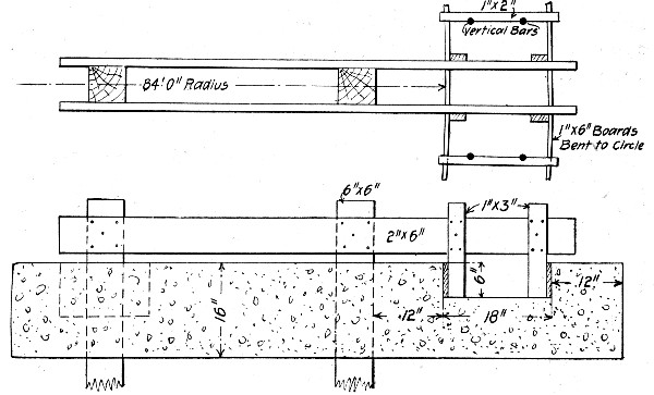 Fig. 280.—Forms for Constructing Channel for Wall in
Reservoir Floor.
Fig. 280.—Forms for Constructing Channel for Wall in
Reservoir Floor.
To construct the walls, the posts before mentioned, were cut off to exact level 6 ins. above the finished floor. A bent for the wall forms was then erected on each radial pair as shown by Fig. 281. The bents were erected by hand and carefully plumbed and lined up, both radially and circumferentially. The pier and pilaster forms were then erected across wall opposite each bent as shown by Fig. 281. The forms for the wall between pilasters and piers consisted of[Pg 613] panels 4 ft. high.
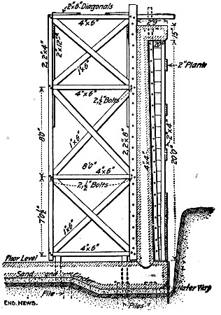 Fig. 281.—Frame for Forms for Circular Reservoir Wall.
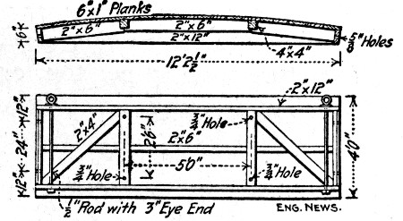 Fig. 282.—Form Panels for Circular Reservoir Wall.
A panel for the inner face of the wall is shown by Fig. 282, the panel for the outer face was similar in construction but was, of course, concave instead of convex. Enough panels of each kind were made to reach entirely around the tank. The inside panels were bolted at the ends to the uprights of the bents; the outside panels were similarly lag screwed to the uprights of the pier and pilaster forms; Fig. 281 shows the holes for bolts and lag screws. The spaces between ends of inside panels in front of the bents was closed by a ½×6-in. steel plate the full height of the wall; this plate was bolted to the bents and had anchor bolts every 3 ft., reaching into the wall. This anchoring of the plate to the wall permitted the diagonal bracing of the bents to be[Pg 614] removed to allow runways to be laid on the cross-pieces, since the plate held firmly the bent post to which it was bolted as indicated by Fig. 283. A complete circle of inside and outside forms was erected and filled, then the forms were raised 3 ft. by block and tackle from cross timbers across wall between bent and pilaster form, and this depth concreted and the forms raised again. The forms were oiled on the faces coming against the concrete. It took about half a day to raise and set a complete circle of forms. The concrete was mixed outside the tank and was wheeled up inclines and dumped onto runways laid on the cross pieces of the bents and then loaded and wheeled to place. The runway was raised to successive horizontals as the work progressed.
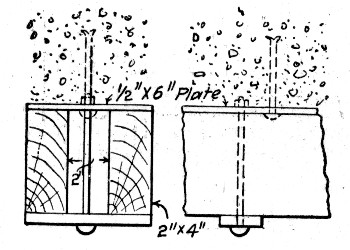 Fig. 283.—Sketch Showing Filler for Joint Between Form
Panels.
Fig. 283.—Sketch Showing Filler for Joint Between Form
Panels.
Only a few general cost figures are available. The labor for mixing and placing concrete was as follows:
| For floor, per cu. yd. | 3.4 hrs. |
| For walls, per cu. yd. | 5.2 hrs. |
| For cornice, per cu. yd. | 5.4 hrs. |
The cost of unloading the reinforcing steel from cars and placing it in the structure was $7 per ton, or 0.35 ct. per lb. The cost of form lumber, framing, erecting and taking down forms was 9 cts. per square foot of wall covered.
GAS HOLDER TANK, NEW YORK CITY.—The tank for the Central Union Gas Co.'s gas holder at 136th St. and Locust Ave. has an interior diameter of 189 ft. and a depth of 41 ft. 6 ins. The exterior wall is 42 ft. 6 ins. deep, 5 ft. 6 ins. thick at the base and 4 ft. 6 ins. thick at the top; concentric with it and 11 ft. 6 in. away is the interior wall 166 ft. in external diameter and 16 ft. 6 ins. high with a uniform[Pg 615] thickness of 2 ft. 6 ins. The bottom of the tank enclosed by the interior wall is a truncated cone whose base is at the level of the wall top. Fig. 284 shows the arrangement.
It was specified that the diameter of this tank should not vary more than 2 ins. and that the exterior wall should not vary more than 1 in. from the vertical. The main form was a circular drum whose exterior face formed the inner face of the main wall. Its framework consisted of 40 vertical trusses or radial frames 6 ft. deep and 42 ft. high set equidistant around the tank, these trusses being braced together on both edges by circumferential timbers. Radial horizontal pieces nailed across the radial frames and projecting beyond their faces carried vertical iron guide strips against which the movable panels of lagging were seated. These panels were cylindrical segments 5 ft. high and long enough to span between two radial frames or 14 ft. 11⅝ ins. The panels were adjusted radially by wedges to give ⅛ in. clearance in respect to inner face of wall; enough of them were made to form a complete circle and they were set with 1-in. clearance between vertical edges of adjacent panels to allow for swelling when wetted.
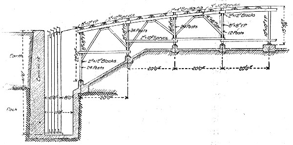 Fig. 284.—Section of Gas Holder Tank, New York City.
The concrete bottom of the annular space between walls was first constructed. On this floor were set 6×6-in.×8-ft. sills for the radial frames; these were located accurately by transit. The radial frames were then set on the sills by a derrick, adjusted to exact radial position by a measuring wire[Pg 616] swiveled to the center point of the tank and plumbed by transit. A complete circle of lagging panels was then adjusted to the frames at the bottom of the trench. For concreting, the wall was divided circumferentially into three sections. These sections were separately concreted to the top of the lagging panels, that is to a height of 5 ft. After the concrete had set 48 hours the panels were hoisted 4 ft., so that their lower edges still overlapped the concrete 12 ins., and another ring of wall was concreted. This procedure was repeated until the wall was completed. The back of the wall was formed against the side of the trench where possible and in other places against rough board lagging held in position in any convenient way.
For handling the concrete, four equidistant panels of the form framework were converted into double compartment elevator shafts providing for two balanced cars controlled by a sheave provided with a friction brake. Three mixers supplied concrete to these elevators. Considering a single elevator, two barrows of concrete were wheeled from the mixer onto the car at the top of the elevator frame, the friction brake was released and the loaded car descended to the work hoisting at the same time its twin car loaded with two empty barrows. The elevators distributed to wheeling platforms cantilevered out from the outer face of the framework and located successively 5 ft., 15 ft., 20 ft., etc., above the bottom of the trench. On these platforms the concrete was distributed as required, the maximum wheeling distance being never over one-eighth the circumference of the tank. The concrete was mixed very wet and deposited in 6-in. layers.
The inner and outer surfaces of the wall were both painted with two coats of stiff cement grout neat, and in addition the inner surface was rubbed smooth by carborundum brick. Regarding this finishing work Mr. Howard Bruce, Engineer of Construction, writes:
"The scouring was done on each section of the wall immediately after the forms supporting these sections had been removed. The object was to rub this interior surface with carborundum before the surface of the concrete had taken its final set. By rubbing the concrete at this stage and at the same time applying with a brush a coating of neat cement[Pg 617] grout, we believe the face of the concrete was made more or less impermeable, as examination shows the pores of the concrete are very largely filled up. We have no accurate figures as to the cost per square yard of this treatment, but one can readily see that this cost would be insignificant as compared with the possible improvement of the work. The carborundum brick was selected on account of its hardness. I believe practically any stone would answer the same purpose. In addition to filling the pores of the concrete, this treatment gives the surface a good smooth finish."
LINING A RESERVOIR, QUINCY, MASS.—The following methods and costs are given by Mr. C. M. Saville, M. Am. Soc. C. E., for lining the Forbes Hill Reservoir at Quincy, Mass. This reservoir is 100×280 ft. on the floor, with side slopes of 1 on 1.75, and was built by contract in 1900-1901.
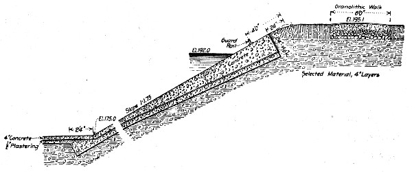 Fig. 285.—Section of Reservoir Lining, Quincy, Mass.
Figure 285 is a section of the concrete lining; the bottom layer for the floor was a 1-2-5 natural cement concrete, and for the sides a 1-2½-6½ Portland cement concrete; the top layer on both floor and sides was a 1-2½-4 Portland cement concrete; 2½-in. stone was the maximum size allowed in any concrete and 1½-in. the maximum allowed in the top layer. Smaller stone was used for special surface work, as noted further on. The stone was cobbles turned up in the excavation work and had to be gathered from scattered piles and washed before crushing. A 9×15 Farrel crusher, operated by a 12 HP. engine did the crushing; it was rated at 125 tons[Pg 618] a day, but averaged only about 40 tons. The fine dust was screened out and the remainder discharged into a 30-cu. yd., three-compartment bin, one compartment for stone less than 1½ ins., another for 1½ to 2½-in. stone and a third for returns. The stone had 46 per cent. voids and weighed 95 lbs. per cu. ft. The sand was of excellent quality. Atlas and Beach's Portland and Hoffman natural cement were used.
All concrete was mixed and placed by hand, the concrete gang consisting generally of 1 sub-foreman, 2 men measuring materials, 2 men mixing mortar, 3 men turning concrete three times, 3 men wheeling concrete, 1 man placing concrete and 2 men ramming concrete. Two gangs were ordinarily employed, each mixing and placing about 20 cu. yds. per day, or 1.43 cu. yds. per man per day. The materials (sand and stone) were measured in bottomless boxes, the following sizes being used:
| —Sand Box— | —Stone Box— | |||
| Prop. of Mix. | Size. | Vol. cu. ft. | Size. | Vol. cu. ft. |
| 1-2½-4[H] | 2'9"×2'×1'8" | 9.25 | 5'×4'5½" | 14.8 |
| 1-3-6[H] | 2'9"×2'×2' | 11.1 | 5'×6'8" | 22.2 |
| 1-2-5 | 2'9"×2'×1'4" | 7.4 | 5'×6'6⅝" | 18.5 |
| 1-2½-6½ | 2'9"×2'×1'8" | 9.25 | 5'×7'2½" | 24.05 |
[H] These mixtures were used for gate house and standpipe foundation work.
The bottom layer was placed in a continuous sheet; the top layer was laid in 10-ft. squares on the floor and in 8×10-ft. squares on the sides; these squares alternated in both directions, one-half being first laid and allowed to set. In laying the sides the surface was left 1 in. low and then before the concrete had set was brought to plane by a 1-in. layer of 1-2½-4 mixture using stone and stone dust less than ⅜ in. The concrete for the floor was mixed rather wet and rammed until it quaked; on the sides a drier mixture was necessary to prevent flow. The cost of the lining concrete was as follows:[Pg 619]
| Bottom Layer on Floor: 1-2-5 Mixture: | |
| 1.25 bbls. natural cement at $1.08 | $1.350 |
| 0.34 cu. yd. sand at $1.02 | 0.347 |
| 0.86 cu. yd. stone at $1.57 | 1.350 |
| 4½ ft. B. M. lumber at $20 per M. | 0.090 |
| Labor, on forms | 0.100 |
| Labor mixing and placing | 1.170 |
| Labor general expenses | 0.080 |
| ——— | |
| Total | $4.487 |
| Bottom Layer on Sides: 1-2½-6½ Mixture: | |
| 1.08 bbl. Portland cement at $1.53 | $1.652 |
| 0.37 cu. yd. sand at $1.02 | 0.377 |
| 0.96 cu. yd. stone at $1.57 | 1.507 |
| Lumber for forms (about 1 ft. B. M.) at $20 | 0.016 |
| Labor, on forms. | 0.121 |
| Labor, mixing and placing | 1.213 |
| Labor, general expenses | 0.177 |
| ——— | |
| Total | $5.063 |
| Top Layer on Floor and Sides: 1-2½-4 Mixture: | |
| 1.37 bbls. Portland cement at $1.53 | $2.09 |
| 0.47 cu. yd. sand at $1.02 | 0.48 |
| 0.75 cu. yd. stone at $1.57 | 1.17 |
| 12½ ft. B. M. form lumber at $20 per M. | 0.25 |
| Labor, on forms | 0.26 |
| Labor, mixing and placing | 1.530 |
| Labor, general expenses | 0.150 |
| ——— | |
| Total | $5.93 |
The side finish with 1-2½-4 concrete of ⅜-in. stone cost $0.154 per sq. yd. 1 in. thick. This work was done by a gang of 3 plasterers and 3 helpers.
The layer of plaster between the concrete layers was put down on 4-ft. strips and finished similarly to the surface of a granolithic walk. This layer consisted of 1-2 mortar finished with a 4-1 mortar. To keep the plaster from cracking it was covered with strips of coarse burlap soaked in water; this precaution was not entirely successful, some cracks appeared[Pg 620] and had to be grouted. Three gangs, each consisting of 1 plasterer and 1 helper, did the plastering, each gang laying about 700 sq. yds. per day. The cost of the plaster layer was as follows:
| Item. | Per 100 sq. ft. | Per sq. yd. | Per cu. yd. |
| Cement at $1.53 | $1.15 | $0.103 | $7.42 |
| Sand at $1.02 | 0.13 | 0.012 | 0.86 |
| Burlap | 0.02 | 0.002 | 0.14 |
| Labor | 0.92 | 0.083 | 6.00 |
| —— | ——— | ——— | |
| Totals | $2.22 | $0.200 | $14.42 |
It will be noted that it took over 5 bbls. of cement per cubic yard, and that the labor cost was $6 per cubic yard.
RELINING A RESERVOIR, CHELSEA, MASS.—The following account of relining the Powder Horn Hill Reservoir at Chelsea, Mass., is taken from a paper by Mr. C. M. Saville. This reservoir which holds about 1,000,000 gallons is oval in shape, 98×175 ft. at the top, 68×148 ft. at the bottom and 15 ft. deep, with side slopes about 1 on 1. The work was done by day labor. For sake of completeness the costs of excavation and back-filling are given here as well as the concrete costs.
The top of the bank was too narrow to allow the use of carts and an 18-in. gage railroad was decided upon as most convenient for handling materials. A 65-ft. boom derrick with a 70-ft. mast was used for removing the excavated material and for depositing concrete. The derrick was operated by a 15-h.p. double drum hoisting engine, was held in place by six wire guy ropes, and had a reach such that only one moving was necessary after it was placed. The engine and derrick were set up on the floor of the reservoir, and the work of excavation was begun at about the middle of the south side. In order to facilitate the work, a platform supported on A frames was set up. These frames were spaced about 15 ft. apart and rested on the bottom and slope of the reservoir, being held in place by bolts driven into the floor.
The paving blocks on the top of the slope were removed and piled up to be taken away. The old lining and the material excavated from the bank were shoveled into the scale pan of[Pg 621] the derrick, hoisted to the cars on the top of the bank, and then run by gravity to a dump a short distance down the hillside. Here the cars were run out on a rough trestle, the load dumped, and the empties hauled back to the work by a rope carried through pulleys to the winch head on the hoisting drum of the engine.
For the storage of some of the materials, two small portable storehouses were set up—one 8×10×7 ft., the other 11×16 x 7 ft. The bulky portions, such as cement, sand, and stone, were delivered as necessary, a few days' supply only being kept on hand. A branch from the railroad was so arranged that it passed the storehouses and stone piles, while the sand was piled close to the concrete mixing board. The intention on the work was to do nothing by hand that could possibly be done by steam, except that all of the concrete was mixed by hand. As great a proportion of water was used as could be done without causing the material to slide when rammed in place.
The lower layer of concrete was of the proportion by volume of 1 cement, 2½ sand, and 6½ crushed stone (sizes from ¾ to 1½ ins.). This was rather a lean mixture, and as it could not be rammed enough to flush all over, the surface was finished where necessary by a thick mortar made in the proportion of 1 cement to 6 sand, and applied with heavy brushes. Before placing any of the concrete, the bank back of the old concrete left in place was thoroughly rammed with iron railroad tampers, and the edge of the old concrete was scrubbed with water and a stiff brush and then coated with 1 to 4 grout, which was allowed to fill in the angle between the concrete and the slope. Just before placing the concrete the earth bank was well wet in order that moisture might not be drawn from the concrete while it was soft.
In order to make the new lining as waterproof as possible, a layer of asphalt was placed on top of the lower layer of concrete and brought up on the exposed edge of the old layer at the bottom of the new work. This, it was expected would make an elastic and watertight joint between the new and the old work.[Pg 622]
Venezuela asphalt, "Crystal Brand," was used, being poured upon the top of the concrete layer and allowed to run down the slope, care being taken that the concrete was entirely and perfectly covered. After the first layer of asphalt was cool, a second layer was similarly applied, and the resulting sheet was about ¼ in. thick. Any inclination to crawl down the slope when exposed to the sun was readily stopped by throwing on a pailful of cold water. A most particular part of this work was to get the asphalt as hot and liquid as possible and yet not burn it. All of the concrete was protected from the sun and kept damp by being covered with strips of burlap, which were moistened by sprinkling.
The upper layer of concrete was composed of a much richer mixture of concrete than that used in the bottom layer, the proportions by volume being 1 cement, 1¼ sand, 1¼ stone dust, and 4 broken stone of the sizes mentioned above. On account of the steep slope it was possible to do only a little ramming, and the material was laid as wet as possible. To make this layer more impervious and also to obtain a smooth surface, the concrete was left about an inch below and a finish coat applied by expert granolithic finishers. This coating was applied as soon as it was possible to do so after the main layer was in place, but on account of the steepness and the liability of the wet concrete to flow, care had to be taken not to begin work too soon.
The top finishing coat was made in the proportion of 1 part cement, 1⅔ part sand, and 3⅓ parts stone dust. In order to help in bonding, the last ramming on the concrete was done with rammers studded with pieces of iron about 1 in. long and ½ in. deep.
The finishing was done in three operations: The material was spread on the concrete and thoroughly worked into it by the finishers, using rough wooden floats; after this it was gone over and partially smoothed down with a thin steel float; and finally it was worked to give the finished appearance and an impervious surface.
The under layer of concrete was placed in a continuous sheet. The upper layer was put down in alternate strips, 10 ft, long (the whole length of the layer) and 5 ft. wide. These blocks were built up in forms, which were not removed until[Pg 623] the concrete had set. Finally, the back or edge of the block toward the bank was well wet and thoroughly plastered, to prevent, as far as possible, the infiltration of any water. The plaster was mixed in the proportion of 1 part cement to 4 parts sand. When the forms were wholly removed, the space between the concrete and the bank was refilled, to within about 6 ins. of the top, with a clayey material previously excavated, and the space was filled and graded to the top of the bank with loam. During the work two holidays intervened; the men were also transported to and from the work. Charges were made for these items, amounting to $209.77, and this sum, together with the cost of installing the plant ($716.03) are proportionally charged against the work as follows:
| Per cent. | Total. | Per cu. yd. | |
| Excavation | 70.3 | $651 | $2.17 |
| Lower concrete | 12 | 111 | 1.16 |
| Upper concrete | 15.4 | 143 | 1.11 |
| Back fill | 2.3 | 21 | .28 |
The detailed cost of repairing the reservoir lining is given in the following tabulations:
| Excavation. | ||||
| Rate. | Per cu. yd. | |||
| Foreman | 9 5/9 | days | $4.00 | $0.13 |
| Engineman | 12 3/9 | days | 3.00 | .12 |
| Carpenter | 2 | days | 2.67 | .02 |
| Laborers | 9 6/9 | days | 2.25 | .07 |
| Laborers | 110 2/9 | days | 2.00 | .73 |
| Laborers | 46 5/9 | days | 1.75 | .27 |
| Derrick | 12 3/9 | days | 3.75 | .15 |
| Rails and cars | 11 2/9 | days | 0.40 | .02 |
| Stove coal | 3.05 | tons | 6.50 | .07 |
| Egg coal | .95 | tons | 6.25 | .02 |
| —— | ||||
| Total, 300 cu. yds. | 1.60 | |||
| Estimated proportionate charge for plant installation and holidays | 2.17 | |||
| —— | ||||
| Grand total | 3.77 | |||
| [Pg 624] | ||||
| Lower Layer Concrete. | ||||
| Rate. | Per cu. yd. | |||
| Foreman | 3 7/9 | days | $4.00 | $0.16 |
| Engineer | 2 3/9 | days | 3.00 | 0.07 |
| Carpenters | 7 | days | 2.67 | 0.20 |
| Laborers | 1 7/9 | days | 2.25 | 0.06 |
| Laborers | 89 | days | 2.00 | 1.87 |
| Laborers | 4 | days | 1.75 | 0.07 |
| Derrick and engine | 2 3/9 | days | 3.75 | 0.08 |
| Rails and cars | 2 2/9 | days | 0.40 | 0.01 |
| Cement | 106⅜ | bbls. | 1.35 | 1.50 |
| Sand | 37.4 | cu.yds. | 1.10 | 0.43 |
| Broken stone | 117.9 | tons | 1.35 | 1.67 |
| Egg coal | .41 | tons | 6.25 | 0.03 |
| Lumber | 1.3 | M. ft. | 21.00 | 0.28 |
| —— | ||||
| Total, 95.5 cu. yds. | $6.43 | |||
| Estimated proportionate charge for plant installation and holidays | 1.16 | |||
| —— | ||||
| Grand total | $7.59 | |||
| Upper Layer Concrete. | ||||
| Rate. | Per cu. yd. | |||
| Foreman | 6 7/9 | days | $4.00 | $0.21 |
| Engineer | 1 8/9 | days | 3.00 | 0.04 |
| Carpenter | 18 5/9 | days | 2.67 | 0.38 |
| Laborers | 1 7/9 | days | 2.25 | 0.03 |
| Laborers | 119 5/9 | days | 2.00 | 1.85 |
| Derrick and engine | 1 8/9 | days | 3.75 | 0.05 |
| Rails and cars | 8 3/9 | days | 0.40 | 0.03 |
| Cement | 176½ | bbls. | 1.35 | 1.86 |
| Sand | 30.2 | cu. yds. | 1.10 | 0.26 |
| Stone dust | 41.6 | tons | 1.50 | 0.48 |
| Broken stone | 122.8 | tons | 1.35 | 1.28 |
| Egg coal | .2 | tons | 6.25 | 0.00 |
| Lumber | 4 | M. ft. | 21.00 | 0.65 |
| Burlap | 300 | yds. | 0.04½ | 0.10 |
| Nails | 170 | lbs. | 0.05 | 0.03 |
| [Pg 625] | ||||
| —— | ||||
| Total, 129.2 cu. yds. | $7.25 | |||
| Estimated proportionate charge for plant installation and holidays | 1.11 | |||
| —— | ||||
| Grand total | $8.36 | |||
| Back Plaster. | ||||
| Rate. | Per cu. yd. | |||
| Plasterer | 3 8/9 | days | $5.40 | $0.08½ |
| Plasterer | 8/9 | days | 6.00 | 0.02 |
| Plasterer | 5 5/9 | days | 4.50 | 0.09 |
| Laborers | 9 3/9 | days | 2.25 | 0.08½ |
| Laborers | 3/9 | days | 2.00 | 0.00 |
| Cement | 6 | bbls. | 1.35 | 0.03 |
| Sand | 3.3 | cu. yds. | 1.10 | 0.01 |
| —— | ||||
| Total, 262 sq. yds. | 0.32 | |||
| Surfacing. | ||||
| Rate. | Per cu. yd. | |||
| Plasterer | 7 6/9 | days | $5.40 | $0.09 |
| Plasterer | 2 1/9 | days | 6.00 | 0.03 |
| Plasterer | 9 4/9 | days | 4.50 | 0.09 |
| Laborers | 12 8/9 | days | 2.25 | 0.06 |
| Laborers | 2 4/9 | days | 2.00 | 0.01 |
| Cement | 22¼ | bbls. | 1.35 | 0.06 |
| Sand | 5.07 | cu. yds. | 1.10 | 0.02 |
| Stone dust | 14 | tons | 1.50 | 0.04 |
| —— | ||||
| Total, 460 sq. yds. | $0.40 | |||
| Asphalt. | ||||
| Rate. | Per cu. yd. | |||
| Foreman | 1/9 | days | $4.00 | $0.00 |
| Asphalt man | 11 | days | 2.00 | 0.05 |
| Laborers | 6 | days | 2.00 | 0.02½ |
| Asphalt kettle | 11 | days | 1.50 | 0.03½ |
| Asphalt | 3.9 | tons | 30.00 | 0.25 |
| Asphalt mops | 3.00 | 0.01 | ||
| —— | ||||
| Total, 464 sq. yds. | $0.37 | |||
| [Pg 626] | ||||
| Back Filling. | ||||
| Rate. | Per cu. yd. | |||
| Foreman | 1 3/9 | days | $4.00 | $0.07 |
| Laborers | 23 3/9 | days | 2.00 | 0.62 |
| Laborers | 9 | days | 1.75 | 0.21 |
| Rails and cars. | 2 2/9 | days | 0.40 | 0.02 |
| Loam | 27 5/9 | cu. yds. | 1.25 | 0.46 |
| —— | ||||
| Total, 75 cu. yds. | $1.38 | |||
| Estimated proportionate charge for installing plant and holidays | $0.28 | |||
| —— | ||||
| Grand total | $1.66 | |||
| Installing Plant. | ||||
| Total. | ||||
| Foreman | 15 4/9 | days | $4.00 | $61.78 |
| Sub-foreman | 1 | day | 3.00 | 3.00 |
| Engineer | 8 4/9 | days | 3.00 | 25.33 |
| Carpenter | 3 | days | 2.67 | 8.00 |
| Watchman | 42 | days | 2.00 | 84.00 |
| Laborers | 17 4/9 | days | 2.25 | 38.36 |
| Laborers | 149 8/9 | days | 2.00 | 299.78 |
| Double team | 10½ | days | 5.00 | 52.50 |
| Single team | 6 | days | 2.00 | 12.00 |
| Single team | 1 | day | 3.50 | 3.50 |
| Teaming (total) | 53.00 | |||
| Derrick and engine. | 11 4/9 | days | 3.75 | 49.92 |
| Rails and cars | 8 2/9 | days | 0.40 | 3.29 |
| Broken stone | 7.05 | tons | 1.35 | 9.52 |
| Egg coal | .6 | ton | 6.25 | 3.75 |
| Kerosene | 30 | gal. | 0.11 | 3.30 |
| Oil | 4 | gal. | 0.25 | 1.00 |
| Spikes | 220 | lbs. | 0.05 | 11.00 |
| ——— | ||||
| Total | $723.03 | |||
The cost of the concrete work in the lower and upper layers can be still further detailed as shown below:[Pg 627]
| Lower Layer Concrete. | ||||
| 95.5 cu. yds., 1-2½-6½ concrete. | ||||
| Materials: | Rate. | Per cu. yd. | ||
| Atlas cement | 1.11 | bbl. | $1.35 | $1.50 |
| Sand | .39 | cu. yd. | 1.10 | 0.43 |
| Broken stone (.97 cu. yd.) | 1.23 | tons | 1.35 | 1.66 |
| Miscellaneous, plant, coal, etc. | 1.28 | |||
| Labor: | ||||
| Mixing and placing | $2.09 | |||
| Carpenter work on forms at $24.00 per M. | .34 | |||
| —— | ||||
| Total per cu. yd. in place | $7.30 | |||
| Upper Layer Concrete. | ||||
| 129.2 cu. yds., 1-1¼-1¼-4 concrete. | ||||
| Materials: | Rate. | Per cu. yd. | ||
| Atlas cement | 1.37 | bbl. | $1.35 | $1.85 |
| Sand | .24 | cu. yd. | 1.10 | 0.26 |
| Stone dust (.25 cu. yd.) | .32 | ton | 1.50 | 0.48 |
| Broken stone (.75 cu. yd.) | .96 | ton | 1.35 | 1.30 |
| Lumber | 0.31 | M. ft. | 21.00 | 0.65 |
| Miscellaneous, plant, etc. | 1.32 | |||
| Labor: | ||||
| Mixing and placing | 1.85 | |||
| Carpenter work on forms at $21.00 per M. | 0.66 | |||
| —— | ||||
| Total per cu. yd. in place | $8.37 |
The following approximate labor costs are also given: Transporting, erecting and removing derrick, $260.85. Equivalent time: Foreman, 6 days; engineer, 4 days; laborer, 85 days.
Transporting, laying and removing track, $125.03. Equivalent time: Foreman, 4 days; laborer, 40 days.
Caring for dump and disposing of surplus by rough grading, $70.28. Equivalent time: Foreman, 1 day; laborer, 33 days.
The total cost of the work was $3,503.66, divided up as follows:[Pg 628]
| Excavation | $480.79 | |
| Lower layer concrete | 614.15 | |
| Upper layer concrete | 937.94 | |
| Back plaster | 84.73 | |
| Surfacing | 186.04 | |
| Asphalting | 170.94 | |
| Back filling | 103.27 | |
| Installing plant | 716.03 | |
| Transportation and holidays | 209.77 | |
| ———— | ||
| Grand total | $3,503.66 |
LINING JEROME PARK RESERVOIR.—The bottom of the reservoir that was lined covered 250 acres, and the concrete lining was 6 ins. thick. The lining was laid in alternate strips 16 ft. wide between forms set to grade. The concrete was mixed in 18 Ransome mixers provided with charging hoppers and mounted on trucks without boilers. Steam was supplied to the mixer engines from the boilers of the contractor's locomotives. One locomotive supplied steam for three or four mixers. Tracks were laid in parallel lines across the reservoir bottom from 150 to 200 ft. apart. Sand and stone were hauled in on these tracks. The sand was dumped in stock piles at intervals; the stone was shoveled from the cars directly into the charging hopper and the sand was delivered by wheelbarrows to the same hopper. Four men shoveled the stone for each mixer. To deliver the concrete from the mixer to the work required six men with wheelbarrows. Two men leveled off the concrete discharged by the barrows and two other men floated the surface by means of a straight-edge spanning the 16-ft. strips and riding on the forms. By using a wet but not sloppy concrete and moving the straight-edge back and forth a good surface was secured. The gang mixing and placing consisted of 20 men for each mixer and 18 gangs laid approximately 1½ acres per 10-hour day. The gang organization and wages were as follows:[Pg 629]
| Item. | Per 10 hours. |
| 4 men shoveling stone at $1.50 | $ 6.00 |
| 2 men wheeling sand at $1.50 | 3.00 |
| 2 men delivering cement at $1.50 | 3.00 |
| 1 man dumping mixer at $1.50 | 1.50 |
| 1 man tending engine and water at $1.50 | 1.50 |
| 6 men wheeling concrete at $1.50 | 9.00 |
| 2 men spreading concrete at $1.50 | 3.00 |
| 2 men leveling concrete at $1.50 | 3.00 |
| 1 foreman | 3.00 |
| ——— | |
| Total per day | $33.00 |
These costs do not include the fraction of a day's labor for fireman or the cost of fuel.
RESERVOIR FLOOR, CANTON, ILL.—The following costs are given by Mr. G. W. Chandler for lining the bottom of a 160×80-ft. reservoir with corners of 20-ft. radius and vertical brick sidewalls. A 1-3½-7½ crushed stone concrete was used; it was mixed by hand in batches of 2.7 cu. ft. cement, 9 cu. ft. sand and 20¼ cu. ft. stone. The sand and stone were measured separately, the sand and cement mixed dry, then shoveled into a pile with the rock, well wetted, shoveled over again and then shoveled into wheelbarrows. The stone had 40 per cent. voids and the sand 30 per cent. voids. The lining was 10 ins. thick including a ¾-in. coat of 1-2¼ mortar spread and worked smooth with a trowel. The cost per cubic yard of the lining in place was as follows:
| 0.856 bbl. cement at $2.50 | $2.14 |
| 10.1 bu. sand (100 lbs. per bu.) at 5¾ cts | 0.58 |
| 0.857 cu-yd-stone at $2.17 | 1.86 |
| Labor, mixing and placing at 19 cts. per hr. | 0.80 |
| —— | |
| Total | $5.38 |
RESERVOIR FLOOR, PITTSBURG, PA.—The following methods and costs of laying a reservoir floor are given by Mr. Emile Low, M. Am. Soc. C. E., for the Hiland Reservoir constructed at Pittsburg, Pa., in 1884, by contract. There were 7,681 cu. yds. of concrete in the floor which was 5 ins. thick and laid on a clay puddle foundation.[Pg 630]
Natural cement costing $1.35 per barrel was used. The broken stone varied in weight from 147 to 152 lbs. per cu. ft.; it was quarried and hauled 20 miles by rail and then unloaded into small cars and hauled ½ mile to the reservoir. The cost of the stone per cubic yard delivered was:
| Quarrying, per cu. yd. | $0.45 |
| Breaking, per cu. yd. | 0.35 |
| Transporting, per cu. yd. | 0.50 |
| Total | $1.30 |
The sand was obtained on the site at the cost of excavation, or 1¼ cts. per bushel.
The method of proportioning and mixing the concrete was as follows: Platforms 10×16 ft. of 2-in. plank were laid on the puddle foundation and by these were set 5×4×1½-ft. boxes on legs. Into these boxes 1 bbl. of cement and 2 bbls. of sand were emptied and thoroughly mixed dry, then mixed with water to a thin grout. Five barrels of stone were placed on the platform and thoroughly wetted; the grout was then emptied over the stone and the two turned over three times with shovels. The concrete was rammed until the mortar flushed to the surface. The following costs cover various periods as follows:
| Two Days Work (101 cu. yds.): | Total. | Per cu. yd. |
| 27 laborers, 2 days, at $1.25 | $72.90 | $0.7217 |
| 1 foreman, 2 days, at $2.50 | 5.00 | 0.0495 |
| ——— | ——— | |
| Total | $77.90 | $0.7712 |
| One Month's Work (1,302 cu. yds.): | ||
| 642 days, laborers, at $1.35 | $ 866.70 | $0.6649 |
| 17 days, water boy, at $0.60 | 10.20 | 0.0078 |
| 22 days, foreman, at $2.50 | 55.00 | 0.0421 |
| ——— | ——— | |
| Total | $931.90 | $0.7148 |
| Total Work (7,861 cu. yds.): | ||
| Quarrying stone | $0.45 | |
| Transporting stone | 0.50 | |
| Breaking stone | 0.35 | |
| 1⅓ bbl. natural cement | 1.80 | |
| 8 bu. sand | 0.10 | |
| Water | 0.05 | |
| Labor mixing and laying at $1.25 | 0.75 | |
| Incidentals | 0.05 | |
| —— | ||
| Total | $4.05 |
The contract price was $6 per cu. yd.
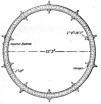 Fig. 286.—Form for Constructing Silo.
CONSTRUCTING A SILO.—The form construction shown in Fig. 286 was employed in building a silo 28 ft. high, 22 ft. 3 ins. interior diameter, and having 6-in. walls. The bottom of the silo was made 9 ins. thick and set 2 ft. below the surface. The reinforcement consisted of ten 2½×3/16-in. rings spaced equally in the lower half and of woven wire fencing in the upper half. The iron rings were hoops removed from an old wooden silo. The concrete was a 1-6 mixture of Portland cement and sandy gravel. Figure 286 is a section through the forms. There were twenty T-shaped posts, which extended perpendicularly from the ground to a height of 28 ft., being secured at top and bottom by a system of guy ropes and posts. The rings, of which there are four, two inside and two outside, were built of[Pg 632] weather boards with their edges reversed. Four thicknesses of board were used in each ring. The curbing consisted of 2×8-in. sticks 4 ft. long. Wedges driven between the vertical posts and the rings held the latter in place. When the forms were to be removed the wedges were knocked out and the rings sprung enough to permit the removal of the curbing. The rings were then pushed up and fastened in place for another section. The average rate of progress was one 4-ft. section per day. The forms were filled in the afternoon and moved up the following forenoon. Five-foot sections could have been built just as readily.
The work was all done by farm laborers hired by the month and 100 man-days of such labor were required, excluding seven days work of a mason brushing and troweling the surface. The cost of the work, not including the old hoop iron or the old lumber used in forms, was as follows:
| Item. | Total. | Per cu. yd. |
| Cement | $100.00 | $2.62 |
| Gravel and sand | 35.00 | 0.92 |
| 1 20-rod roll of fencing | 5.20 | 0.01 |
| New lumber | 18.00 | 0.47 |
| 100 days labor at $1.75 | 175.00 | 4.60 |
| 7 days mason troweling at $3.50 | 24.50 | 0.64 |
| ——— | —— | |
| Total, 38.2 cu. yds. | $357.70 | $9.26 |
The external area of the silo is 1,950 sq. ft., which makes the cost of brushing and troweling 1¼ cts. per sq. ft. There were about 2,300 ft. B. M. of lumber used in the forms, or about 61 ft. B. M. per cu. yd. of concrete.
GROINED ARCH RESERVOIR ROOF.—The following data are given by Mr. Allen Hazen and Mr. William B. Fuller, in Trans. Am. Soc. C. E. 1904. The concrete was mixed in 5-ft. cubical mixers in batches of 1.6 cu. yds. at the rate of 200 cu. yds. per mixer day. One barrel of cement, 380 lbs. net, assumed to be 3.8 cu. ft., was mixed with three volumes of sand weighing 90 lbs. per cu. ft., and five volumes of gravel weighing 100 lbs. per cu. ft. and having 40 per cent voids. On the average 1.26 bbls. of cement were required per cu. yd. The conveying plant consisted of two trestles (each 900[Pg 633] ft. long) 730 ft. apart, supporting four cableways. The cables were attached to carriages, which ran on I-beams on the top of the trestles. Rope drives were used to shift the cableways along the trestle. Three-ton loads were handled in each skip. The installation of this plant was slow, and its carrying capacity was less than expected. It was found best to deliver the skips of concrete to the cableway on small railway track, although the original plan had been to move the cableways horizontally along the trestle at the same time that the skip was traveling.
The cost of mixing and placing the concrete was as follows:
| Per cu. yd. | |
| Measuring, mixing and loading | $0.20 |
| Transporting by rail and cables | 0.12 |
| Laying and tamping floors and walls including setting forms | 0.22 |
| —— | |
| Total | $0.54 |
The cost of laying and tamping the concrete on the vaulting was 14 cts. per cu. yd. The vaulting is a groined arch 6 ins. thick at the crown and 2½ ft. thick at the piers.
The lumber of the centering for the vaulting was spruce for the ribs and posts, and 1-in. hemlock for the lagging. The centering was all cut by machinery, the ribs put together to a template, and the lagging sawed to proper bevels and lengths. The centers were made so that they could be taken down in sections and used again. The cost of centering was as follows:
| Labor on centers covering 62,560 sq. ft. | |
| Foreman, 435 hrs. at 35 cts. | $152.25 |
| Carpenters, 4,873 hrs. at 22½ cts. | 1,096.42 |
| Laborers, 3,447 hrs. at 15 cts. | 517.05 |
| Painters, 577 hrs. at 15 cts. | 86.55 |
| Teaming, 324 hrs. at 40 cts. | 121.60 |
| ———— | |
| Total labor building centers, 313 M. at $6.37 | $1,973.87 |
| [Pg 634] | |
| Materials for centers covering 62,560 sq. ft. | |
| 313,000 ft. B. M. lumber, at $18.20 | $5,700.00 |
| 3,700 lbs. nails, at 3 cts. | 111.00 |
| 8 bbls. tar, at $3 | 24.00 |
| ———— | |
| Total | $5,835.00 |
These centers covered two filters, each having an area of 121⅓×258 ft. There were six more filters of the same size, for which the same centers were used. The cost of taking down, moving and putting up these centers (313 M.) three times was as follows:
| Foreman, 2,359 hrs. at 35 cts. | $825.65 |
| Carpenters, 12,766 hrs. at 22½ cts. | 2,872.35 |
| Laborers, 24,062 hrs. at 15 cts. | 3,609.30 |
| Team, 430 hrs. at 40 cts. | 172.00 |
| 3,000 ft. B. M. lumber, at $20 | 60.00 |
| 3,000 lbs. nails, at 3 cts. | 90.00 |
| ———— | |
| Total cost of moving centers to cover 196,660 sq. ft. | $7,629.30 |
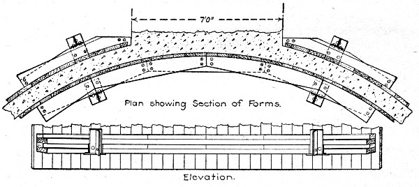 Fig. 287.—Forms for Constructing Grain Elevator Bins.
The cost of moving the centers each time was $8.10 per M., showing that they were practically rebuilt; for the first building of the centers, as above shown, cost only $6.37 per M. In other words, the centers were not designed so as to be moved in sections as they should have been. Although the centers were used four times in all, the lumber was in fit condition for further use. The cost of the labor and lumber[Pg 635] for the building and moving of these centers for the 8 filter beds, having a total area of 259,220 sq. ft., was $15,438, or 6 cts. per sq. ft.
GRAIN ELEVATOR BINS.—In constructing cylindrical bins 30 ft. in diameter and 90 ft. high for a grain elevator the forms shown by Fig. 287 were used. For the inside wall a complete ring of lagging 4 ft. high nailed to circular horizontal ribs of 2×8-in. planks was used. For the outside wall two, three or four segments fitting the clear spaces between adjoining tanks were used, these panel segments being also 4 ft. high. The inside and outside rings were held together by yokes constructed as shown, and bolted to the inner and outer ribs. A staging built up inside the tank carried jack screws, on which were seated the inner legs of the yokes.
The safest rule for ornamental work is to leave its construction to those who make a specialty of such work. This is perfectly practicable in most concrete structures having ornament. Bridge railings can be and usually are made up of separately molded posts, balusters, bases and rail. Ornamental columns in building work, keystones, medallions, brackets, dentils, rosettes, and cornice courses can be similarly molded and placed in the structure as the monolithic work reaches the proper points. The general constructor, therefore, can readily delegate these special parts of his concrete bridge or building to specialists at frequently less cost to himself and nearly always with greater certainty of good results than if he installed molds and organized a trained gang for doing the work.
Good concrete ornament is not alone a matter of good design. It is also a matter of skilled construction. Nearly anyone can mold an ornament, but few can mold an ornament which is durable. To produce clean, sharp lines and arises which will endure, the molder must have special knowledge and familiarity with the action of cement and of concrete mixtures, both in molding and on exposure to the elements. This is knowledge that the general concrete worker rarely possesses but which the ornament molder does possess if he knows his business. Special work is always best left to the specialist.
While the more intricate ornamental work is best done by sub-contract, so far at least as the actual molding of the ornaments is concerned, there is a large amount of simple paneling and molding which the general practitioner not only can do but must do. Knowledge of the best methods of doing[Pg 637] such work is essential and it is also essential that the constructor should know in a general way of the special methods of molding intricate ornaments.
SEPARATELY MOLDED ORNAMENTS.—The cement for ornamental work must be strong and absolutely sound. Where an especially light color is wished a light colored cement is desirable. So called white cements are now being manufactured. Lafarge cement, a light colored, non-staining cement made in France, gives excellent results. Of American cements, Vulcanite cement has a light color, and next to it in this respect comes Whitehall cement. A light colored ornament can, however, be secured with any cement by using white sand or marble or other white stone screenings. Some authorities advocate this method of securing light colored blocks as always cheaper and usually superior to the use of special cements. The choice between the two methods will be governed by the results sought; where as nearly as possible a pure white is desired it stands to reason that a white or nearly white cement will give the better results.
In the matter of sand and aggregate for ornamental work, the kinds used will ordinarily be the kinds that are available. They must conform in quality to the standard requirements of such materials for concrete work. Where special colors or tints are wanted they can be secured by using for sand and aggregate screenings from stones of the required color. This is in all respects the best method of securing colored blocks, as the color will not fade and the concrete is not weakened. A great variety of pigments are made for coloring concrete; these colors all fade in time, and with few exceptions they all weaken the concrete. The mixtures used in ornamental work will depend upon the detail of the ornament and upon whether color is or is not required. Generally a rich mixture of cement and sand or fine stone screenings will be used for the surface and will be backed with the ordinary concrete mixture. A surface mixture of fine material is necessary where clear, sharp lines and edges or corners are demanded.
The molds used for ornament are wooden molds, iron molds, sand molds and plaster of Paris and special molds.[Pg 638] Each kind has its field of usefulness, and its advantages over the others. They will be considered briefly in the order named.
Wooden Molds.—Wooden molds are perhaps the best for general work where plain shapes and not too delicate ornamentation are wanted. They give the best results only with a quite dry and rather coarse grained surface mixture. If a wet mixture is used such water as flushes to the surface cannot escape and small pits and holes are formed, which necessitates grout or other finishing. The following are examples of wooden mold work:
In constructing a five-span reinforced concrete arch bridge at Grand Rapids, Mich., in 1904, the railings and ornamental parts of the bridge, such as keystones, brackets, consols, dentiles and panels, were cast in molds and set in place much as cut stone would be. Special molds were employed for each of these different shapes. These molds were plastered with an earth damp mortar composed of 1 part cement and 2½ parts fine sand, which was followed up with a backing of wet concrete composed of 1 part cement, 2 parts sand and 3 parts broken stone passing a ¾-in. ring. The facing mortar was made 1½ ins. thick. The castings cannot be told from dressed stone at a few feet distance.
The part elevation and sections in the drawings of Fig. 288 show the arrangement of the various castings to form the completed railing, coping, etc. To specify, A is the arch ring, B the brackets, C the coping, and D, E, F, respectively, the base, balusters and rail of the bridge railing. The blocks G and H show the keystone and railing post. The forms or molds for each of these parts are shown by the other drawings of Fig. 288. A description of each of these forms follows:
The keystones were molded in wooden forms, consisting of one piece, a, forming the top and front; of two side pieces, f, of a bottom consisting of two parts, b and c; and of a back piece, g. The back and side pieces are stiffened with 2×3½-in. pieces, and the front, sides and back are held together by yokes or clamps. The front of the mold was the only portion calling for particular work, and this was made of boards laminated together.[Pg 639]
The bracket molds consisted of two side pieces provided with grooves for receiving the front and back pieces, and with slots for tie rods clamping the whole mold together. It will be noted also that the side pieces had nailed to them inside a beveled strip to form a groove in each side of the cast block. The purpose of this groove was to provide a bond to hold the bracket more firmly in the adjoining concrete of the wall. The bottom of the mold was formed by a 2-in. plank, and when the concrete had been tamped in place the forms were removed, and the bracket was left on the bottom to set. It may be noted here that a goodly number of the brackets showed a crack at the joint marked x caused by tamping at the point y. In construction the bracket castings were set at proper intervals on the spandrel walls, which had been completed up to the level of the line X Y. The coping course was then built up around the bracket blocks to the level of the bottom of the railing base.
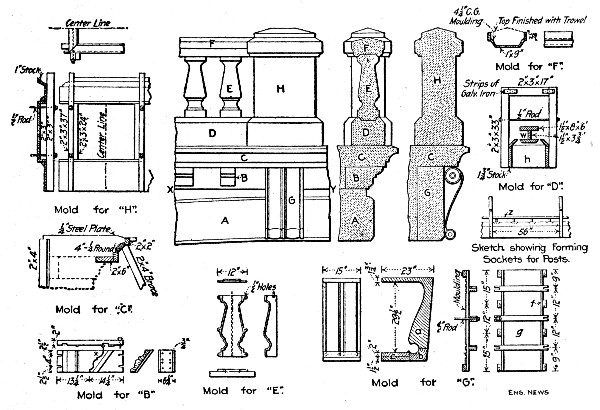 Fig. 288.—Molds for Railings and Ornaments for Concrete
Arch Bridge.
Fig. 288.—Molds for Railings and Ornaments for Concrete
Arch Bridge.
The mold or form for the coping course was designed to build the coping in successive sections, and was built up around the bracket blocks, and supported from the centers as shown by the drawings. To form the expansion joints in the[Pg 640] coping course there were inserted across the mold at proper intervals a short iron plate ¼ in. thick, cut to fit. The cutting of this plate was found to be a slow operation.
The forms for the base of the railing (Section D) consisted of 1¾-in. stock for the sides, and ¾-in. stock for the slopes. They extended across the arch, and were held together by a very simple though very efficient clamp. This consisted of two 2×3×33-in. pieces nailed to a 2×3×17-in. piece by means of galvanized iron strips. About half-way down the long pieces, a ½-in. rod was run through, and secured up against blocks, h, placed about 56 ins. apart. These blocks were removed as the concrete was put in place. It will be noticed from the cross-section of the railing that the balusters are set into sockets formed in the top of the base course. These sockets were formed by means of the mold shown at W and Z.
In casting the balusters, Section (E), a ⅜-in. cast iron mold, consisting of four iron sides and an iron top, was used. Originally there were two end plates of iron, but it was found more convenient to have the bottom one of wood and allow the cast spindle to stand and set. The mold was held together by ½-in. bolts. It would have been more practical to have had the side casting composed of two parts.
The form for the railing is built up around the tops of the spindles. The bottom piece is 1×9 ins., to which 4¼-in. ogee molding is nailed. The sides are of 1-in. stock, and are clamped together. The top is finished off with a trowel.
The mold for the posts is made in four parts, which fit together at the top and bottom by a bevel joint, as shown in the one-fourth section. The broad sides rest against the narrow ones, and are held against the same by means of ½-in. rods running through 2×3-in. stock: 2-in. projections of the broad sides facilitate the removal of the form from the completed post.
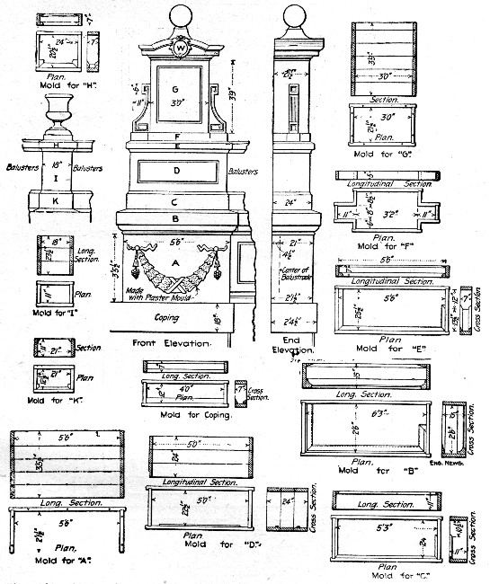 Fig. 289.—Molds for Ornamental Railing Posts for
Concrete Facade for Bridge.
Fig. 289.—Molds for Ornamental Railing Posts for
Concrete Facade for Bridge.
In constructing a concrete facade for a plate girder bridge at St. Louis. Mo., the railing above the base was constructed of separately molded blocks as follows: The balusters were cast in plaster molds. To make these molds a box square in[Pg 641] plan and the height of the baluster was constructed of wood and cut vertically into three sections. The inside lateral dimensions of this box were made 6 ins. greater than the largest dimension of the baluster. A full size wooden pattern of the baluster was set up and the three sections of the box were set around it. Sheets of thin galvanized metal, with their inner edges cut to conform to the curves of the baluster, were inserted in the joints of the assembled box so as to divide the vacant space between the pattern and the box into vertical sections.[Pg 642]
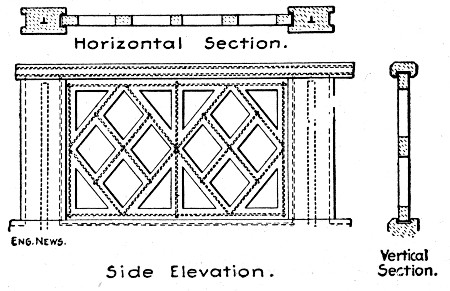 Fig. 290.—Railing for Arch Bridge.
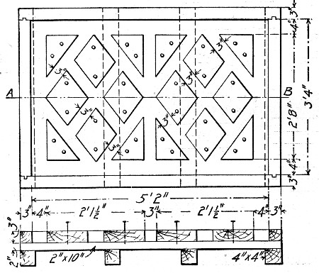 Fig. 291.—Form for Lattice Panels Shown by Fig. 290.
A mixture of 1 part Portland cement and 1 part plaster of Paris, made wet, was then poured around the pattern until the box was filled. When this mixture had become hard, the box was taken down, leaving a plaster and cement casing separated into three parts by the sheets of galvanized metal. This casing was separated from the pattern and given a coat of shellac on the inside. Four or five molds of this description were cast. To cast a baluster, the sections were assembled and a ½-in. corrugated bar was set vertically in the center. A mixture of 1 part Portland cement and 3 parts sand was then poured into the mold and allowed to harden. The molds for the urns on the railing post and the balls on the end posts were made in exactly the same[Pg 643] manner as the baluster molds. The construction of the railing posts is shown by the drawings of Fig. 289. Referring first to the end posts, it will be seen that they were molded in place in seven sections marked A, B, C, D, E, F and G. The construction of the mold for each section is shown by the correspondingly lettered detail. The intermediate posts were built up of the separately molded pieces I, K and H. The costs of molding the several parts were: Balusters, 60 cts. each; hand rail, 40 cts. per lin. ft. The six intermediate posts cost $12 each, and the four end or newel posts cost $75 each.
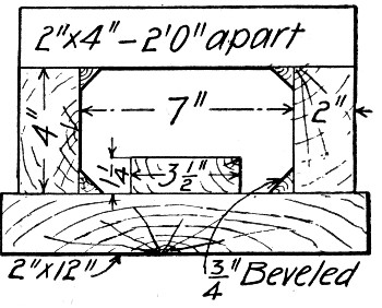 Fig. 292.—Form for Hand Rail Shown by Fig. 290.
In constructing the 72-ft. span-ribbed arch bridge over Deer Park Gorge, near La Salle, Ill., a hand railing of the design shown by Fig. 290, was used. In constructing this railing, the posts were molded in place, but the open work panels between posts and the hand rail proper were molded separately and set in place between the posts as indicated. For molding the panels a number of boxes constructed as shown by Fig. 291, were used. These were simple rectangular boxes on the bottom boards of which were nailed blocks of the proper shape and in the proper position to form the openings in the railing. The bottom of the form was first plastered with mortar, then the concrete was filled in and plastered on top. As soon as the concrete had begun to set the blocks were removed so that final setting could take place without danger of cracking. When the concrete had set so that the panel could be safely handled, it was removed from the form and stored until wanted. The hand rail for each side was molded in two pieces in forms constructed as shown by Fig. 292. The total cost of the railing in place was about $2 per lineal[Pg 644] foot. The concrete was a 1-2-4 mixture of screenings and ⅞-in. broken stone.
Iron Molds.—Iron molds have the same disadvantages as wooden molds in the use of wet mixtures. They can be made to mold more intricate ornaments, and in the matter of durability, are, of course, far superior to wood. Iron molds can be ordered cast to pattern in any well equipped foundry. Many firms making block machines also make standard column, baluster, ball and base, cornice, and base molds of various sizes and patterns. These molds are made in two, three or more sections which can be quickly locked together and taken apart. A column mold, for example, will consist of a mold for the base, another for the shaft, and a third for the capitol, each in collapsible sections. Where the pattern of the shaft changes in its height, two shaft molds are commonly used, one for each pattern. Prices of iron molds are subject to variation, but the following are representative figures: Plain baluster molds 14 to 18 ins. high, $7.50 to $10 each; fluted square balusters, 14 to 18 ins. high, $10, each; ball and base, 10 to 18-in. balls, $15 to $25 each; fluted Grecian column, base, capitol and one shaft molds, $30; Renaissance column, base, capitol and two shaft molds, $45.
Sand Molding.—Molding concrete ornaments in sand is in all respects like molding iron castings in a foundry. Sand molding gives perhaps the handsomest ornament of any kind of molding process, the surface texture and detail of the block being especially fine. It is, however, a more expensive process than molding in wooden or iron molds, since a separate mold must be made for each piece molded. The process was first employed and patented in 1899, by Mr. C. W. Stevens, of Harvey, Ill., and for this reason it is often called the Stevens process. Sand molded ornaments and blocks are made by a number of firms to order to any pattern. The process as employed at the works of the Roman Stone Co., of Toronto, Ont., is as follows: The stone employed for aggregate, is a hard, coarse, crystalline limestone of a light grey color, being practically 97 per cent. calcium carbonate, with a small percentage of iron, aluminia and magnesia. Nothing but carefully selected quarry clippings are used and these are crushed and[Pg 645] ground at the factory and carefully screened into three sizes, the largest about the size of a kernel of corn. Daily granulometric tests are made of the crusher output to regulate the amount of each size got from the machines. It has been found that next in importance to properly graded aggregates is the gaging of the amount of water used in the mixture. This is done by an automatically filled tank into which lead both hot and cold water and in which is fixed a thermometer to properly regulate the temperature. In gaging the mix about 20% of water is used, but of course when the cast is made the surplus is immediately drawn off into the sand, where it is retained and serves as a wet blanket to protect the cast and supply it with the proper amount of water during crystallization. Experiments seem to indicate that about 15% by weight gives the greatest amount of strength of mortar at the age of six months, while, giving less strength at shorter time tests than mortar gaged with a smaller percentage of water.
The method of handling the mix and casting is quite simple and almost identical with the practice in iron foundries. The mixture is made in a batch mixer to about the same consistency as molasses, from which it is poured into a mechanical agitator and carried about the foundry by a traveling crane. This agitator is so constructed that it keeps the materials in motion constantly and prevents their segregation. In each cast is inserted the proper reinforcing rods, lifting hooks and tie rods, and the casts are allowed to remain for a proper period in the wet sand after they are poured; they are then taken to the seasoning room which is kept at as constant a temperature as it is practical to maintain. Each cast is marked with the number which determines its location in the building and the date it was cast, and it is then kept in the storage shed a fixed time before shipping.
Records are kept of each cast made and the company is able to get, as in mills rolling structural steel, the exact number and location of all casts made from the same mix. Careful records are always kept of the tests of cement and material, and test cubes are made from each consignment of cement so tested; in this way all danger of defective stone through inferior[Pg 646] cement is eliminated. The patterns used in making the molds and the method of molding are quite similar to ordinary iron foundry practice except that the sand used is of special nature. The finish of the stone is generally tooled finish molded in the sand, the different textures of natural stone being produced by the veneering of the pattern with thin strips of wood which are run through a machine producing the different finishes. Each stone is provided with setting hooks cast in the blocks which take the place of the ordinary lewis holes used in cut stone.
Plaster Molds.—Plaster of Paris molds are made from clay, gelatin or other patterns in the usual manner adopted by sculptors. They are particularly adapted to fine line and under cut ornaments. The concrete is poured into the plaster mold and after the cement has become hard, the plaster is broken or chiseled away, leaving the concrete exposed. Two examples of excellent work in intricate concrete ornaments are furnished by the power house for the Sanitary District of Chicago, and by the State Normal School building, at Kearney, Neb. In the power house, the ornamental work consisted of molded courses, cornice work; and particularly of heavy capitals for pilasters. These capitals were very heavy, being 7½ ft. long and of the Ionic design. These were made from plaster molds; made so as to be taken apart or knocked down and to release in this way, perfectly. There were also scrolls, keystones and arches in curved design over all of the 40 windows. None of this ornament was true under cut work. In building the Normal School building, Corinthian capitals, in quarters, halves, corners and full rounds were made in plaster molds. There were some 30 of these capitols. They were made in solid plaster molds; the molds having been cast in gelatine molds, one for each capitol. Into these, the concrete was tamped, made very wet, and after the concrete had hardened, the plaster cast was chiseled away. This was very easily accomplished. These capitols were true Corinthians, having all the floriation and under-cut usually seen in such capitols.[Pg 647]
ORNAMENTS MOLDED IN PLACE.—Molding ornaments in place is usually, and generally should be, confined to belt courses, cornices, copings and plain panels. Relief work, like keystones, scrolls or rosettes, can be molded in place if desired, by setting plaster molds in the wooden forms at the proper points. This method is often advantageous in bridge work, where comparatively few ornaments are required, such as keystones.
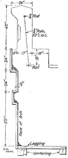 Fig. 293.—Spandrel Wall Mold for Arch Bridge.
The construction of forms for ornamental work in place is best described by taking specific examples. Figure 293, shows the face form for the arch ring, spandrel wall and cornice or coping course of the Big Muddy River Bridge on the Illinois Central R. R. The section is taken near the crown of the arch. The lagging only is shown; this was, of course, backed with studding. The point to be noted in this form is the avoidance of any approach to under cut work; there are, in fact, very few straight cut details. This brings up a point that must be carefully watched if trouble is to be avoided, namely, the construction of the form work in sections which can be removed without fracturing the ornament. To illustrate by an assumed example, supposing it is required to mold the wall and cornice shown by Fig. 294. It is clear that if the backing studs are in single pieces, notched as shown, the forms cannot be removed without fracturing at least the corner A. If the studs and lagging be constructed in two parts, separated along the line a b, the form is possible of removal if[Pg 648] great care is used without damage to the concrete. The construction shown by this sketch does not greatly exaggerate matters. Figure 295 shows a wall form that has been given several times as a presumably good example in which, as will be seen it is impossible to remove the board a, without breaking the concrete even if the narrow face were not broken by the swelling of the lumber before ever it became time to take down the forms.
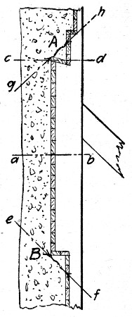 Fig. 294.—Diagram Illustrating Details of Mold
Construction.
Fig. 294.—Diagram Illustrating Details of Mold
Construction.
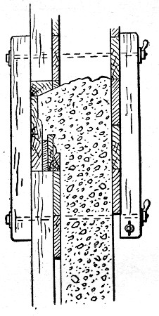 Fig. 295.—Example of Poor Wall Form Construction.
This matter of making provision for the swelling of the forms is another point to be watched. Referring again to Fig. 294 it will be seen that the swelling of the lagging, even if the cornice instead of being under cut at A were straight cut on the line c d, is liable so to crowd the lagging into the corner A and B that the concrete is cracked along the lines e f or g h. A suggested remedy for this danger is shown by Fig. 296. At a distance of every 3 or 4 ft. insert a narrow piece of lagging a and behind these lagging strips cut notches b in the studs. When the concrete has got its initial set pull back the lagging strip a into the notches b, leaving an open joint to provide for expansion due to swelling.[Pg 649]
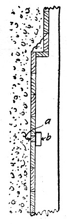 Fig. 296.—Notched Studding for Removal of Lagging Board
to Permit Swelling.
Fig. 296.—Notched Studding for Removal of Lagging Board
to Permit Swelling.
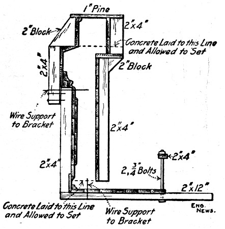 Fig. 297.—Form for Concrete Facade Shown by Fig. 298.
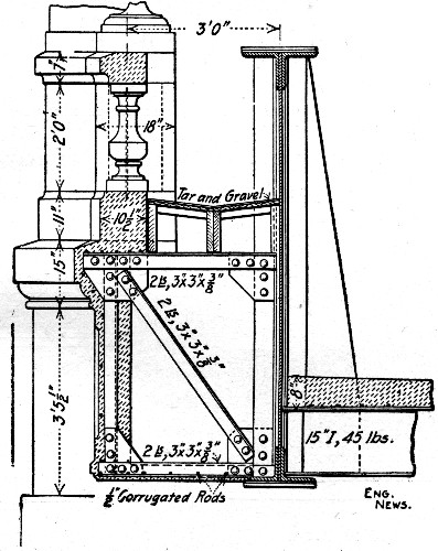 Fig. 298.—Concrete Facade for Plate Girder Bridge.
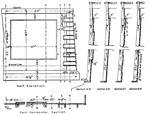 Fig. 299.—Forms for Curved Concrete Abutments.
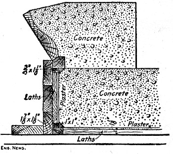 Fig. 300.—Cornice Form.
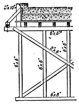 Fig. 301.—Method of Supporting Cornice Form Shown by
Fig. 300.
Fig. 301.—Method of Supporting Cornice Form Shown by
Fig. 300.
In constructing a concrete facade for a plate girder bridge at St. Louis, Mo., the form shown by Fig. 297 was used. The completed facade is shown by Fig. 298. The ceiling slab was first built and allowed to set and then the forms were erected for the frieze and coping. After these were molded the forms were continued upward as shown for the base of the railing. Above this point the several parts were separately molded as shown by Fig. 285 previously described. Molded in this manner the ceiling cost 25 cts. per sq. ft.; the frieze and coping cost $2 per lin. ft., and the railing base cost 45 cts. per[Pg 651] lin. ft. In constructing the concrete abutments of this same structure use was made of the forms shown by Fig. 299. These abutments had curved wing walls and for molding these girts cut to the radii of the curves were fastened to the studs and vertical lagging was nailed to the girts. All the lagging was tongue and groove stuff.
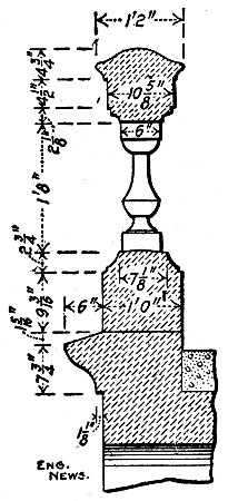 Fig. 302.—Cornice and Balustrade for Arch Bridge.
In constructing an open spandrel arch bridge at St. Paul, Minn., the cornice form shown by Fig. 300, supported as shown by Fig. 301, was used. The particular feature of this form was the use of a lath and plaster lining to the lagging. This lining was used for all exposed surfaces of the bridge. So called patent lath consisting of boards with parallel dovetail grooves and ridges was used. This was plastered with cement mortar and the concrete was deposited directly against the plaster after smearing the plaster surface with boiled linseed oil. This lining is stated to have given an excellent surface finish to the concrete. It cost 55 cts. per sq. ft. for materials and labor. A section of the balustrade and cornice is shown by Fig. 302. The posts, balusters and railing were molded separately. The balusters were molded in zinc molds. At[Pg 652] first some trouble was had in getting good casts on account of air pockets. This was largely done away with by filling the mold as compactly as possible and then driving a ¾-in. iron rod through the center vertically; this rod crowded the concrete into all parts of the mold and also served to strengthen the baluster. The baluster molds were made in two parts; this proved a mistake—three parts would have been better.
The following cost data comprise such miscellaneous items as do not properly come in the preceding chapters. They are given not as including all the miscellaneous purposes for which concrete is used but as being such items of costs as were secured in collecting the more important data given in preceding sections.
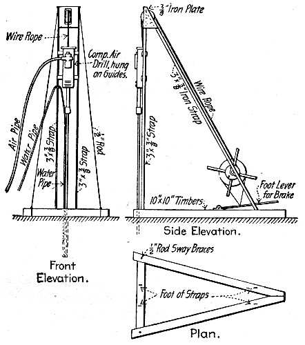 Fig. 303.—Device for Drilling Green Concrete.
DRILLING AND BLASTING CONCRETE.—Concrete is exceedingly troublesome material in which to drill deep holes, and this statement is particularly true if the concrete is green.[Pg 654] The following mode of procedure proved successful in drilling 1½-in. anchor bolt holes 6 ft. and over in depth in green concrete. The apparatus used is shown by Fig. 303, re-drawn from a rough sketch made on the work by one of the authors, and only approximately to scale. The drill is hung on a small pile driver frame, occupying exactly the position the hammer would occupy in a pile driver, and is raised and lowered by a hand windlass. By this arrangement a longer drill could be used than with the ordinary tripod mounting and less changing of drills was necessary. A wide flare bit was used, permitting a small copper pipe to be carried into the hole with the drill; through this pipe water was forced under pressure, carrying off the chips so rapidly that no wedging was possible. By this device drilling which had previously cost over 25 cts. a hole was done at a cost of less than 5 cts. a hole.
In removing an old cable railway track in St. Louis, Mo., holes 8 ins. deep were drilled in the concrete with a No. 2 Little Jap drill, using a 1¼-in. bit and air at 90 lbs. pressure. A dry hole was drilled, the exhaust air from the hollow drill blowing the dust from the hole keeping it clean. The concrete was about 18 years old and very hard. Two holes across track were drilled, one 10 ins. inside each rail; lengthwise of the track the holes were spaced 24 ins. apart, or four pairs of holes between each pair of yokes.
Common labor was used to run the drills and very little mechanical trouble was experienced. Three cars were fitted up, one for each gang, each car being equipped with a motor-driven air compressor, water for cooling the compressors being obtained from the fire plugs along the route. The air compressors were taken temporarily from those in use in the repair shops, no special machines being bought for the purpose. Electricity for operating the air compressor motors was taken from the trolley wire over the tracks. The car was moved along as the holes were drilled, air being conveyed from the car to the drills through a flexible hose. Two drills were operated normally from each car. One of the air compressors was exceptionally large and at times operated four drills. The total number of holes drilled in the reconstruction of the track was 31,000. The total feet of hole drilled was 20,700 ft.[Pg 655]
With the best one of the plants operating two to three drills 30 8-in. holes, or 20.3 ft. of hole, were drilled per hour per drill at a labor cost of 2.7 cts. per foot.
For blasting, a 0.1-lb. charge of 40 per cent. dynamite was used in each hole. A fulminating cap was used to explode the charge, and 12 holes were shot at one time by an electric firing machine. The dynamite was furnished from the factory in 0.1-lb. packages, and all the preparation necessary on the work was to insert the fulminating cap in the dynamite, tamp the charge into the hole and connect the wires to the firing machine. In order to prevent any damage being done by flying rocks at the time of the explosion, each blasting gang was supplied with a cover car, which was merely a flat car with a heavy bottom and side boards. When a charge was to be fired, this car was run over the 12 holes and the side boards let down, so that the charge was entirely covered. This work was remarkably free from accidents. There were no personal accident claims whatever, and the total amount paid out for property damages for the whole six miles of construction was $685. Most of this was for glass broken by the shock of explosion. There was no glass broken by flying particles. The men doing this work, few of whom had ever done blasting before, soon became very skillful in handling the dynamite, and the work advanced rapidly. The report made by the firing of the 12 holes was no greater than that made by giant fire-crackers.
For the drilling and blasting the old rail had been left in place to carry the air compressor car and the cover car. After the blasting, this rail was removed and the concrete, excavated to the required depth. In most cases the cable yokes had been broken by the force of the blast. Where these yokes had not been broken, they were knocked out by blows from pieces of rail. The efficacy of the blasting depended largely upon the proper location of the hole. Where the holes had been drilled close to the middle of the concrete block, so that the dynamite charge was exploded a little below the center of gravity of the section, the concrete was well shattered and could be picked out in large pieces. Where the hole had been located too close to either side of the concrete block, however,[Pg 656] the charge would blow out at one side and a large mass of solid concrete would be left intact on the other side. The total estimated quantity of concrete blasted was 6,558 cu. yds., or 0.2 cu. yd. of concrete per lineal foot of track. The cost of the dynamite delivered in 0.1 lb. packages was 13 cts. per pound. The exploders cost $0.0255 each.
The cost of drilling and blasting was as follows:
| Item. | Per mile. | Per lin. ft. | Per cu. yd. |
| Labor, drilling | $ 89.76 | $0.017 | $0.085 |
| Blasting labor and materials. | 285.12 | 0.054 | 0.268 |
| ——— | ——— | ——— | |
| Total drilling and blasting. | $374.88 | $0.071 | $0.353 |
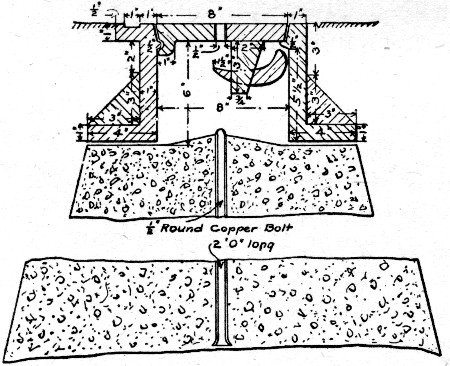 Fig. 304.—Bench Monument, Chicago, Ill.
The cost of blasting with labor and materials, separately itemized, was as follows, per cubic yard:
| Dynamite and exploders | $0.192 |
| Labor | 0.076 |
| ——— | |
| Total | $0.268 |
Two cubic yards of concrete were blasted per pound of dynamite.
BENCH MONUMENTS, CHICAGO, ILL.—The standard bench monuments, Fig. 304, used in Chicago, Ill., are mostly placed in the grass plot between the curb and the lot line, so that the top of the iron cover comes just level with the street grade or flush with the surface of the cement walk. The monument consists of a pyramidal base 6 ft. high[Pg 657] and 42 ins. square at the bottom, with a ¼-in.×2-ft. copper rod embedded, and of a cast iron top and cover constructed as shown by the drawing. Mr. W. H. Hedges, Bench and Street Grade Engineer, Department of Public Works, Chicago, Ill., gives the following data regarding quantities and cost. The materials required for each monument are: 1.78 cu. yd. crushed stone, 0.6 cu. yd. torpedo sand, 1½ bbls. cement, 60 ft. B. M. lumber, one ¼×24-in. copper rod, one top and cover. A gang consisting of 1 foreman, 4 laborers and 2 teams construct from one to three monuments per day, the average number being two per 8-hour day. In 1906 the average cost of the monuments was $24.12 each, based on above material and labor charges.
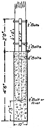 Fig. 305.—Base for Wooden Pole.
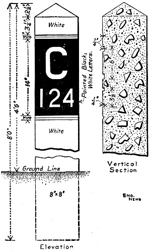 Fig. 306.—Mile Post, Chicago & Eastern Illinois Ry.
POLE BASE.—Figure 305 shows a concrete base for transmission line poles invented by Mr. M. H. Murray, of Bakersfield, Cal., and used by the Power Transit & Light Co. of that city. These bases are molded and shipped to the work ready[Pg 658] for placing. They weigh about 420 lbs. each. One base requires 37½ lbs. of 2×¼-in. steel bar, 40 lbs. of Portland cement, 3 cu. ft. of broken stone or gravel and enough sand to fill the form or mold, which is 10×10 ins. by 4½ ft. Unskilled labor is employed in the molding and two men can mold ten bases per 8-hour day. The cost of molding is as follows per base:
| 2 men at $2 per day | $0.40 |
| Brace irons per set | 2.50 |
| 1-9 cu. yd. stone at $4.05 | 0.45 |
| 40 lbs. cement at 1½ cts. | 0.60 |
| Sand | 0.15 |
| —— | |
| Total cost | $4.10 |
Two men at $2 per day each set five bases in eight hours, making the cost of setting 80 cts. per base. The bases were sunk to a depth of 3 ft. 3 ins. In many cases they were placed under poles without interrupting service by sawing off the pole, dropping it into the ground, placing the new base and setting the sawed-off pole on it and bolting up the straps.
MILE POST, CHICAGO & EASTERN ILLINOIS R. R.—The dimensions of the post are shown by Fig. 306. Each post weighs 498 lbs. They are made when other concrete work is being done. The form is laid flat, with the molds for the letters on the bottom, and bottom and sides are plastered with mortar, which is backed up with a 1-1-2 stone concrete. The cost of the post is given as follows:
| ¼ barrel of cement at $2 | $0.50 |
| 267 lbs. crushed stone | 0.01 |
| 133 lbs. sand | 0.01 |
| 1⅓ hours labor at 15 cts. | 0.20 |
| ⅓ hour carpenter changing letters at 25 cts. | 0.08 |
| Coloring cement | 0.02 |
| —— | |
| Total | $0.82 |
BONDING NEW CONCRETE TO OLD.—Concrete which has set hard has a surface skin or glaze to which fresh concrete will not adhere strongly unless special effort is made to perfect the bond. Various ways of doing this are practiced. The most common is to clean the hardened surface from all loose material and give it a thorough wash of cement grout against which the fresh concrete is deposited and rammed before the grout has had time to set. Washing the old surface with a hose or scrubbing it with a brush and water improves the bond, as does also the hard tamping of the concrete immediately over the joint. Mortar may be used in place of grout. The thorough cleansing of the surface is, however, quite as essential as the bonding coat, in fact in the opinion of the authors it is more essential. As a rule, a good enough joint for ordinary purposes can be got by tamping the fresh concrete directly against the old concrete, without grout or mortar coating, if the surface of the latter is thoroughly cleaned by scrubbing and flushing. The secret of securing a good bond between fresh concrete and concrete that has set lies largely in getting rid of the glaze skin and the slime and dust which forms on it. Washing will go far toward doing this. The glaze skin can be removed entirely by acid solutions, but the acid wash must be flushed free from the surface before placing the fresh concrete. Ransomite, made by the Ransome Concrete Machinery Co., Dunellen, N. J., is a prepared acid wash which to the authors' knowledge has given excellent success in a number of cases. The glaze coat can also be removed by picking the hardened surface, but the picking should be followed by washing to remove all loose chips and dust.
DIMENSIONS AND CAPACITIES OF MIXERS.—In planning plant lay-outs it is often desirable to know the sizes, capacities, etc., of various mixers in order to make preliminary estimates. Tables XXII to XXXIII give these data for a number of the more commonly employed machines. The Eureka, the Advanced and the Scheiffler mixers are continuous mixers and the others are batch mixers.[Pg 660]
| Height ground to hopper top | 3'6" |
| Width over all | 3'6" |
| Length over all on trucks | 10'6" |
| Capacity per hour, cu. yds. | 25 to 75 |
| Horsepower, engine | 2 |
| Weight: | |
| On trucks, without power, lbs. | 1,700 |
| On trucks, steam engine | 2,000 |
| On trucks, gas engine | 2,200 |
| On trucks, steam engine and boiler | 2,500 |
| Mixer Number. | No. 2. | No. 2½. | No. 3. |
| Dimensions of hopper, ins. | 55×33 | 53×33 | 60×40 |
| Height, from ground to top of hopper, ins. | 43 | 43 | 48 |
| Width over all on trucks, ins. | 46 | 46 | 46 |
| Length over all on trucks, ins. | 126 | 126 | 132 |
| Hourly capacity in cubic yards | 5-6 | 8 | 12-15 |
| Horsepower required, gasoline engine | 2 | 3 | 4 |
| Horsepower required, steam engine. | 3 | 4 | |
| Weights: | |||
| On trucks, without power, lbs. | 2,400 | 2,900 | 3,300 |
| On trucks, gasoline engine, lbs. | 3,000 | 3,600 | 4,500 |
| On trucks, steam engine, lbs. | 2,800 | 3,330 | 4,000 |
| On trucks, steam engine and boiler, lbs. | 3,500 | 3,700 | 4,800 |
| Mixer Number | No. 81 | No. 82 | No. 83 | No. 84 | No. 25 | No. 23 | |
| Size hoppers, ins. | Sand | 18"×25½" | ... | ... | 18"×25½" | 18"×25½" | 18"×25½" |
| Cement | 17"×25½" | do | do | 17"×25½" | 17"×25½" | 17"×25½" | |
| Stone | 30"×25" | ... | ... | 30"×25" | ... | ... | |
| Height, ground to hopper top | 49" | 49" | 49" | 49" | 49" | 49" | |
| Width over all on trucks | 40" | 40" | 40" | 40" | 40" | 40" | |
| Length over all on trucks | 12'-9" | 10'-0" | 10'-0" | 10'-0" | 8'-0" | 8'-0" | |
| Capacity per hour, cu. yds. | 10 to 18 | 10 to 18 | 10 to 18 | 10 to 18 | 10 to 18 | 2 to 4 | |
| Engine horsepower | 3 stm. | 3 stm. | 3½ gas | 3 el. motr | Pulley. | Hand. | |
| Boiler horsepower | 4 | ... | ... | 1,980 | 1,400 | 1,400 | |
| Weight on trucks, no power | 1,980 | 1,980 | 1,980 | ... | ... | ... | |
| Weight trucks steam engine | 2,800 | ... | ... | ... | ... | ... | |
| Weight trucks gas engine | ... | ... | 2,300 | ... | ... | ... | |
| Weight trucks, eng. and boiler | 3,000 | ... | ... | ... | ... | ... |
| Mixer Number. | No. 0. | No. 1. | No. 2. | No. 3. |
| Size batch, cu. ft. | 3 | 7 | 11 | 24 |
| Capacity per hour, cu. yds. | 2½ | 5 | 8 | 20 |
| Speed revs. per min. | 30 | 30 | 25 | 19 |
| Weight on Skids: | ||||
| With pulley, lbs. | 480 | 800 | 900 | 2,000 |
| With engine, lbs. | 800 | 1,550 | 2,050 | 3,500 |
| With eng. and boiler, lbs. | ... | 2,170 | 2,900 | 4,000 |
| Weight on Wheels: | ||||
| With engine, lbs. | 1,100 | 2,200 | 3,450 | 4,700 |
| With engine and boiler, lbs. | ... | 3,570 | 4,750 | 5,200 |
| Engine: | ||||
| Size cylinder, ins. | 4×6 | 3½×4½ | 4×5 | 5×6½ |
| Rated horsepower | 1½ | 4 | 5 | 6 |
| Boiler: | ||||
| Size, ins. | ... | 24×60 | 26×60 | 30×60 |
| Rated horsepower | 5 | 6 | 8 | |
| Outside dimensions on skids | 2'9"×4' | 3'4"×5'6" | 4'×6' | 6'×9' |
| Total height on skids | 3'8" | 4'6" | 5' | 5'6" |
| Mixer number. | No. 1. | No. 2. | No. 3. | No. 4. |
| Size batch, cu. ft. | 10 to 14 | 20 | 30 | 40 |
| Capacity per hr., cu. yds. | 10 | 20 | 30 | 40 |
| Speed, Revs. per min. | 16 | 15 | 14½ | 14 |
| Weight on Skids: | ||||
| Pulley or gear, lbs. | 3,300 | 3,650 | 5,900 | 7,400 |
| With engine, lbs. | 4,600 | 5,050 | 7,700 | 9,250 |
| With engine and boiler, lbs. | 6,450 | 8,700 | 12,200 | 14,700 |
| Weight on Wheels: | ||||
| With engine, lbs. | 5,100 | 5,550 | 8,200 | 9,750 |
| With engine and boiler, lbs. | 6,950 | 9,200 | 12,700 | 15,000 |
| Engines: | ||||
| Size cylinder, ins. | 6×6 | 7×7 | 8×8 | 9×9 |
| Rated horsepower | 7 | 10 | 14 | 20 |
| Boiler: | ||||
| Size, ins. | 36×69 | 42×75 | 42×87 | 48×93 |
| Rated horsepower | 10 | 15 | 20 | 30 |
| Mixer number. | No. "Handy." | No. 6. | No. 11. | No. 17. | No. 22. | No. 33. | No. 64. |
| Size batch, cu. ft. | 2½ | 6 | 11 | 17 | 22 | 33 | 64 |
| Capacity per hr., cu. yds. | 5½ | 13 | 24 | 40 | 50 | 70 | 120 |
| Speed, revs. per min. | 24 | 20 | 18 | 17 | 16 | 15 | 12 |
| Weight on Skids: | |||||||
| Pulley or gear, lbs. | 1,000 | 1,900 | 2,800 | 5,000 | 7,000 | 9,600 | 19,000 |
| With engine, lbs. | 2,500 | 3,600 | 6,100 | 8,200 | 12,000 | ||
| With eng. and boiler, lbs. 3,100 | 4,300 | 7,800 | 10,000 | 16,000 | |||
| Weight on Wheels: | |||||||
| With engine, lbs. | 1,400 | 3,200 | 4,500 | 7,100 | 9,500 | 15,000 | |
| With eng. and boiler, lbs. | 4,000 | 6,000 | 8,800 | 10,300 | 17,000 | ||
| Engine: | |||||||
| Size cylinder, ins. | 4×4 | 6×6 | 6½×7 | 7×8 | 8×9 | ||
| Rated horsepower | 2 | 3 | 6 | 8 | 12 | 15 | 30 |
| Boiler, rated horsepower | 4 | 8 | 10 | 15 | 18 | 35 | |
| Width over all | 4'-5" | 5'-10" | 7'-1" | 7'-8" | 8'-6" | 9'-8" | |
| Length over all | 4'-10" | 6'-9" | 8'-0" | 8'-10" | 10'-2" | 13'-6" | |
| Height bot. sill to charging hopper | 3'-4¼" | 3'-5" | 3'-10" | 4'-7" | 5'-0" | 5'-9" | |
| Additional height on wheels | 9⅞" | 1'-5⅛" | 1'-5⅛" | 6⅜" | 5½" |
| Mixer number. | No. 0. | No. 1. | No. 2. | No. 3. | No. 4. |
| Size batch, cu. ft. | 7 to 8 | 10 | 13 | 16 | 20 |
| Cap. per hr., cu. yds. | 15 | 20 | 25 | 30 | 40 |
| Speed, revs. per min. | 12 | 10 | 10 | 10 | 10 |
| Weight on Skids: | |||||
| With engine, lbs. | 1,375 | 1,650 | 1,700 | 1,975 | 2,100 |
| With eng. and boiler, lbs. | 2,575 | 2,950 | 3,000 | 3,775 | 3,900 |
| Weight on Wheels: | |||||
| With engine, lbs. | 1,775 | 2,050 | 2,200 | 2,475 | 2,600 |
| With eng. and boiler, lbs. | 2,900 | 3,350 | 3,400 | 4,250 | 4,350 |
| Engine: | |||||
| Size cylinder, ins. | 4×4 | 5×5 | 5×5 | 6×6 | 6×6 |
| Rated horsepower | 3 | 5 | 5 | 7 | 7 |
| Boiler: | |||||
| Size inside | 24"×4' | 24"×6' | 24"×6' | 30"×6' | 30"×6' |
| Rated horsepower | 4 | 6 | 6 | 9 | 9 |
| Out. dimensions on skids | 40" | 40" | 40" | 48" | 48" |
| Total height | 50" | 56" | 56" | 56" | 62" |
| Height fr. ground on trucks: | |||||
| Charging, ins. | 20 | 20 | 20 | 20 | 20 |
| Discharging, ins. | 30 | 30 | 30 | 30 | 30 |
| Number of mixer. | No. 00. | No. 0. | No. 1. | No. 2. |
| Standard charge in cu. ft. cement | ½ | 1 | 1 | 2 |
| " " Sand | 1½ | 2½ | 4 | 8 |
| " " stone | 3 | 5 | 8 | 16 |
| Total unmixed batch in cu. ft | 5 | 8½ | 13 | 26 |
| Mixed concrete per batch, loose in cu. ft. | 3½ | 6 | 9 | 18 |
| Cubic yards of unmixed material per hour, 45 batches per hour | 8 | 14 | 21 | 42 |
| Cubic yards of mixed concrete per hour, 45 batches per hour | 6 | 10 | 15 | 30 |
| Minimum horsepower required | 2 | 4 | 6 | 8 |
| Revolutions of driving pulley per min | 200 | 190 | 185 | 170 |
| Revolutions of drum per min | 20 | 18 | 15 | 13 |
| Diameter and face of driving pulley | 20×3½ | 20×4½ | 24×5½ | 28×6½ |
| Weight: | ||||
| On skids with pulley, lbs. | 1,550 | 2,150 | 2,900 | 4,850 |
| On truck with pulley or gears, lbs. | 1,800 | 2,550 | 3,500 | 5,150 |
| On skids with st. engine only, lbs. | ... | 2,400 | 3,400 | 4,600 |
| On truck with st. engine only | ... | 2,900 | 4,000 | 5,300 |
| On skids with st. eng. and boiler, lbs. | ... | 2,800 | 4,700 | 6,000 |
| On truck with st. eng. and boiler, lbs. | 2,400 | 4,200 | 5,750 | 7,850 |
| On skids with gasoline engine, lbs. | 2,000 | 3,500 | 5,000 | 6,500 |
| On truck with gasoline engine, lbs. | 2,400 | 4,300 | 5,800 | 7,800 |
| Mixer number. | No. 0-B. | No. 1-B. | No. 2-B. | No. 3-B. |
| Capacity per charge, in cu. ft | 7 | 11 | 22 | 27 |
| Capacity per hour in cu. yds | 7 | 14 | 25 | 30 |
| Horsepower, steam engine | 4 | 6 | 8 | 10 |
| Horsepower, steam boiler | 5 | 8 | 10 | 14 |
| Horsepower, gasoline engine | 4 | 6 | 10 | 12 |
| Horsepower, electric motor | 5 | 6 | 7½ | 10 |
| Speed of drum | 20 | 17 | 15 | 15 |
| Speed of intermediate shaft | 132 | 108 | 75 | 75 |
| Weight of mixer on skids | 1,800 | 2,800 | 5,200 | 5,500 |
| Weight of mixer on skids, with steam eng. | 2,300 | 3,550 | 6,500 | 7,000 |
| Weight of mixer on skids, with steam engine and boiler | 3,300 | 5,000 | 8,000 | 9,300 |
| Weight of mixer on skids, gasoline engine and housing | 3,000 | 4,400 | 7,500 | 8,600 |
| Weight of trucks with pole | 400 | 600 | 850 | 950 |
| Weight of automatic loading bucket complete | 500 | 700 | 1,000 | 1,100 |
| Weight of mixing through complete | 200 | 250 | 400 | 400 |
| Mixer number. | No. 0. | No. 1. | No. 2. | No. 2½. | No. 4. | No. 5. |
| Stand. charge cu. ft. Cement | 1 | 1 | 2 | 2 | 3 | 4 |
| " " " Sand | 2½ | 4 | 6 | 7½ | 10½ | 14 |
| " " " Stone | 5 | 8 | 12 | 15 | 21 | 28 |
| Total unmixed per batch, cu. ft. | 8½ | 13 | 20 | 24½ | 34½ | 46 |
| Mixed material per batch (loose), cu. ft. | 6 | 9 | 13½ | 16½ | 22 | 30 |
| Cubic yards mixed per hour, up to | 9 | 20 | 30 | 39 | 46 | 62 |
| Power required—H.P. | 4 | 6 | 8 | 10 | 15 | 19 |
| Revs. per minute of driving pulley | 218 | 180 | 173 | 162 | 160 | 125 |
| Diameter and face of driving pulley, ins. | 20×4½ | 24×5½ | 28×5½ | 28×6½ | 36×6½ | 48×7½ |
| Weight on skids with pulley only, lbs. | 1,740 | 2,500 | 3,600 | 4,400 | 6,200 | 7,900 |
| Weight on truck with pulley or gears, lbs. | 2,200 | 3,650 | 4,750 | 5,500 | 7,400 | .... |
| Weight on truck with steam eng. & boil., lbs. | 3,750 | 5,600 | 7,200 | 8,600 | 11,400 | .... |
| Weight on truck with gasoline engine, lbs | 4,000 | 5,100 | 7,400 | 9,300 | .... | .... |
| Mixer number. | No. 4. | No. 5. | No. 6. | No. 7. |
| Maximum charge, cu. ft. | 6 | 10 | 12 | 16 |
| Cubic yards mixed per day (10 hrs.) up to | 60 | 190 | 130 | 180 |
| Weight on skids with pulley (approx.) | 1,600 | 2,200 | 3,500 | 4,000 |
| Weight on skids with steam engine and boiler (approx.) | 3,100 | 3,900 | 5,500 | 6,200 |
| Weight on skids with gasoline engine (approx.) | 2,900 | 3,900 | 5,100 | 5,700 |
| Weight on trucks with steam engine and boiler (approx.) | 3,600 | 4,600 | 6,000 | 7,000 |
| Weight on trucks with gasoline engine (approx.) | 3,400 | 4,650 | 5,700 | 6,750 |
DATA FOR ESTIMATING THE WEIGHT OF STEEL IN REINFORCED CONCRETE.—Architects' and engineers' plans record the steel used in reinforced concrete in various ways. Sometimes complete schedules of shapes, dimensions and weights of the various reinforcing elements are drawn up and submitted to bidders with the plans. In such cases the estimating is usually a simple problem for the contractor. In other cases the amount of steel that will be required is stated as a percentage of the volume of the concrete. In still other cases the detail drawings merely show the number, location and dimensions of the reinforcing bars, stirrups, etc., and the contractor has to compile from them his own schedule of quantities. The following tables and discussion will aid the contractor in making his estimates. Before proceeding with these data, however, the authors would strongly advise that to facilitate rapid estimating the contractor should keep accurate records of all reinforced concrete structures in such form as to show the percentages of steel used. In doing this, however, he should be careful to separate the foundations, etc., which are not reinforced from the superstructure which is reinforced. A reinforced concrete arch bridge, for example, usually rests on piers and abutments which are not reinforced. Do not lump together all the concrete in recording the weight of reinforcement used, but separate the reinforced arch from the unreinforced portions.
Method of Computing Weight from Percentage of Volume.—In a cubic yard of concrete there is 1 per cent. of 27 cu. ft. or 0.27 cu. ft. of steel if the reinforcement is 1 per cent. Now a cubic foot of steel weighs 490 lbs., but for all practical purposes we can call it 500 lbs. Hence reinforced concrete containing 1 per cent. of steel has 0.27 × 500 = 135 lbs. per cubic yard. Table XXXIII has been computed in this manner; knowing the price of steel it is a matter of simple multiplication[Pg 664] to estimate from the table the cost of steel for any percentage of reinforcement.
Weights and Dimensions of Plain and Special Reinforcing Metals.—Steel for reinforcement is used in the shape of plain round and square bars, deformed bars, woven and welded netting and metal mesh of various sorts. Tables XXXIV to XXXVII show the weights, dimensions, etc., of these various metals.
| Per cent of steel. | Lbs. steel Per cu. ft. | Lbs. steel Per cu. yd. |
| 0.20 | 1.00 | 27.0 |
| 0.25 | 1.25 | 33.8 |
| 0.30 | 1.50 | 40.5 |
| 0.35 | 1.75 | 47.3 |
| 0.40 | 2.00 | 54.0 |
| 0.45 | 2.25 | 60.8 |
| 0.50 | 2.50 | 67.5 |
| 0.55 | 2.75 | 74.3 |
| 0.60 | 3.00 | 81.0 |
| 0.65 | 3.25 | 87.5 |
| 0.70 | 3.50 | 94.5 |
| 0.75 | 3.75 | 101.3 |
| 0.80 | 4.00 | 108.0 |
| 0.85 | 4.25 | 114.8 |
| 0.90 | 4.50 | 121.5 |
| 0.95 | 4.75 | 128.3 |
| 1.00 | 5.00 | 135.0 |
| Thickness or diameter in inches | Weight of square bars. Lbs. per ft. | Weight of round rods. Lbs. per ft. |
| 1/16 | 0.013 | 0.010 |
| ⅛ | 0.053 | 0.042 |
| 3/16 | 0.119 | 0.094 |
| ¼ | 0.212 | 0.167 |
| 5/16 | 0.333 | 0.261 |
| ⅜ | 0.478 | 0.376 |
| 7/16 | 0.651 | 0.511 |
| ½ | 0.850 | 0.668 |
| 9/16 | 1.076 | 0.845 |
| ⅝ | 1.328 | 1.043 |
| 11/16 | 1.607 | 1.262 |
| ¾ | 1.913 | 1.502 |
| ⅞ | 2.608 | 2.044 |
| 1 | 3.400 | 2.670 |
| 1⅛ | 4.303 | 3.380 |
| 1¼ | 5.312 | 4.172 |
| 1½ | 7.650 | 6.008 |
| 1¾ | 10.404 | 4.178 |
| 2 | 13.600 | 10.68 |
| Mesh, inches. | Sectional area sq. ins. per ft. width. | Weight, lbs. per sq. ft. | |
| Standard | ½ | 0.209 | 0.74 |
| Standard | ¾ | 0.225 | 0.80 |
| Standard | 1½ | 0.207 | 0.70 |
| Standard | 2 | 0.166 | 0.56 |
| Standard | 3 | 0.083 | 0.28 |
| Light | 3 | 0.148 | 0.50 |
| Standard | 3 | 0.178 | 0.60 |
| Heavy | 3 | 0.267 | 0.90 |
| Extra heavy | 3 | 0.356 | 1.20 |
| Standard | 3 | 0.400 | 1.38 |
| Standard | 3 | 0.600 | 2.07 |
| Old style | 4 | 0.093 | 0.42 |
| Standard | 6 | 0.245 | 0.84 |
| Heavy | 6 | 0.368 | 1.26 |
| Size No. | Section area per ft. width sq. ins. | Weight per sq. ft. lbs. |
| 2 | 0.54 | 2.13 |
| 3 | 0.36 | 1.43 |
| 4 | 0.27 | 1.08 |
| 5 | 0.22 | 0.87 |
| 6 | 0.18 | 0.72 |
| 7 | 0.15 | 0.62 |
| 8 | 0.14 | 0.55 |
| Size ins. | Weight, lbs. per ft. | Area sq. ins. | Size ins. | Weight, lbs. per ft. | Area sq. ins. |
 Ransome Twisted Bar.
 | 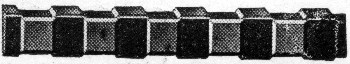 New Style Corrugated Bar.
 | ||||
| ¼ | 0.212 | 0.063 | ¼ | 0.24 | 0.06 |
| ½ | 0.85 | 0.25 | ½ | 0.85 | 0.25 |
| ⅝ | 1.32 | 0.319 | ⅝ | 1.33 | 0.39 |
| ¾ | 1.91 | 0.563 | ¾ | 1.91 | 0.56 |
| ⅞ | 2.6 | 0.765 | ⅞ | 2.60 | 0.77 |
| 1 | 3.4 | 1.000 | 1 | 3.40 | 1.00 |
| 1¼ | 5.3 | 1.563 | 1¼ | 5.30 | 1.56 |
 Diamond Bar. Diamond Bar. | 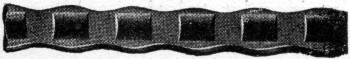 Universal Corrugated Bar.
 | ||||
| ½ | 0.85 | 0.25 | ¼×1 | 0.73 | 0.19 |
| ⅝ | 1.33 | 0.39 | 5/16×1¼ | 1.18 | 0.32 |
| ¾ | 1.91 | 0.56 | ⅜×1⅜ | 1.35 | 0.41 |
| ⅞ | 2.60 | 0.76 | ⅜×1¾ | 1.97 | 0.54 |
| 1 | 3.40 | 1.00 | ⅜×2 | 2.27 | 0.65 |
| 1¼ | 5.31 | 1.56 | ⅜×2½ | 2.85 | 0.80 |
| —No. 1 Mill— | 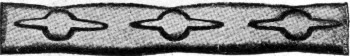 Thatcher Bulb Bar.
 | —No. 2 Mill.— | |||
| ¼ | 0.16 | 0.047 | ... | ... | ... |
| ½ | 0.61 | 0.18 | ½ | 0.58 | 0.17 |
| ⅝ | 0.95 | 0.28 | ⅝ | 0.92 | 0.27 |
| ¾ | 1.39 | 0.41 | ¾ | 1.34 | 0.39 |
| ⅞ | 1.87 | 0.55 | ⅞ | 1.79 | 0.53 |
| 1 | 2.42 | 0.71 | 1 | 2.32 | 0.68 |
| 1¼ | 3.74 | 1.10 | 1¼ | 3.55 | 1.04 |
| 1½ | 5.30 | 1.56 | 1½ | 5.20 | 1.53 |
| 1¾ | 7.07 | 2.08 | .... | .... | .... |
| [Pg 666] | |||||
| 2 | 9.02 | 2.65 | .... | .... | .... |
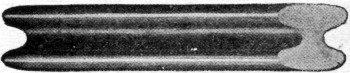 Monolith Bar.
 | 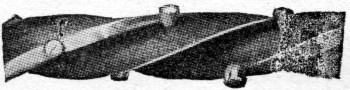 Twisted Lug Bar.
 | ||||
| 0.4 | 0.55 | 0.25 | ¼ | 0.222 | 0.625 |
| ½ | 0.85 | 0.32 | ½ | 0.87 | 0.250 |
| ... | .... | .... | ⅝ | 1.35 | 0.3906 |
| ... | .... | .... | ¾ | 1.94 | 0.5625 |
| 0.8 | 2.18 | 0.64 | ⅞ | 2.64 | 0.7656 |
| 1 | 3.37 | 1.00 | 1 | 3.45 | 1.00 |
| ... | .... | .... | 1¼ | 5.37 | 1.5625 |
| 1½ | 7.75 | 2.25 | 1½ | 7.70 | 2.25 |
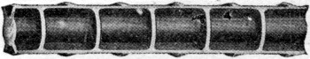 Cup Bar
 | |||||
| ⅜ | 0.48 | .... | |||
| ½ | 0.86 | .... | |||
| ⅝ | 1.35 | .... | |||
| ¾ | 1.95 | .... | |||
| ⅞ | 2.65 | .... | |||
| 1 | 3.46 | .... | |||
| 1 ⅛ | 4.38 | .... | |||
| 1¼ | 4.51 | .... | |||
RECIPES FOR COLORING MORTARS.—The following recipes for coloring cement mortar have been found reliable; the weights given being weight of coloring matter per bag of cement and for a 1-2 mortar:
Brown Stone: 4 to 5 lbs. brown ochre or ½ lb. best quality roasted iron oxide.
Buff Stone: 4 lbs. yellow ochre.
Red Stone: 5 lbs. raw violet iron oxide.
Bright Red Stone: 5½ to 7 lbs. English or Pompeiian red.
Blue Stone: 2 lbs. ultramarine blue.
Dark Blue Stone: 4 lbs. ultramarine blue.
Slate: Lamp black ½ lb. light slate; 4 lbs. dark blue slate.
Light Terra Cotta: 2 lbs. Chattanooga iron ore.
Resistance to penetration by water is desirable in all concrete structures, and is essential in such structures as tanks, reservoirs, vaults, subways, basements and roofs. Concrete, as it is ordinarily made, is pervious to water, hence to secure concrete structures through which water will not penetrate some method of waterproofing the concrete must be employed. Many methods have been proposed and are being used; none of these methods is without faults, the best one of them has not yet been determined, and the evidence available as to their comparative merits is biased and conflicting. For these reasons any discussion of waterproofing for concrete is at the present time bound to be unsatisfactory.
Methods of waterproofing may be roughly classified as follows: (1) Use of mixtures so proportioned as to be impervious; (2) admixture of substances designed to produce impermeability; (3) use of waterproof coatings, washes or diaphragms. In succeeding sections enough examples of each method are given to indicate current practice; no attempt has been made to catalog all the waterproofing substances and systems being promoted—there are too many of them.
The art of waterproofing concrete is in a transition stage. Outside of the manufacturers of waterproofing material the art has received serious study by comparatively few persons. No comparative tests by independent investigators are available. Practical experience with most of the materials used has not extended over a long enough period of time to permit true conclusions to be drawn. Students of the subject are not even agreed upon the broad questions whether it is better to work toward developing an impervious concrete or toward perfecting a waterproof covering for concrete. On the minor subdivisions there is no agreement at all.[Pg 668]
In the present state of the art one can lay fast hold to only three things. The first is that waterproofing is one component of a system of drainage; the second is that structures must, to get the best results, be designed with the fact in mind that waterproofing is a component structural element, and the third is that skilled and conscientious workmanship are essential elements in the success of all waterproofing materials and methods.
IMPERVIOUS CONCRETE MIXTURES.—The compounding of the regular concrete materials so as to produce an impervious concrete has been made the subject of numerous experiments. The most elaborate of these experiments were those conducted over a period of five years by Mr. Feret, of the Boulogne (France) Laboratory of the Ponts et Chaussees. Feret's experiments led him to the following conclusions:
"That in all mortars of granulometric composition the most permeable are those which contain the least quantity of cement.
"Of all mortars of the same richness, but of varying granulometric composition, those which contain very few fine grains are much more permeable. They are the more so where, with equal proportions of the fine grains, the coarse grains predominate more in relation to the grains of medium size.
"The minimum permeability is found in mortars where the proportion of medium-sized grains is small, and the coarse and fine grains are about equal to each other."
Mr. Feret also found that permeability decreased with time and that wet mixtures were less permeable than dry mixtures.
Tests made by Messrs. J. B. McIntyre and A. L. True at the Thayer School of Civil Engineering in 1902 gave the following results:
All the specimens composed of 1-1 mortar in the proportions of 30, 35, 40 and 45 per cent. of the whole mass were impermeable. Some of the specimens composed of 1-2 mortar in the proportions of 40 and 45 per cent. were also impermeable, as well as the 1-2-4 and 1-2½-4 mixtures. All other mixtures leaked at the high pressure (80 lbs. per sq. in.) and in a general way exhibited a degree of imperviousness in direct proportion[Pg 669] to the proportion of mortar in them, with the lower pressures from 20 lbs. per sq. in. up as well as for the 80-lb. pressure.
Other tests confirm those cited. In general we may conclude that those mixtures richest in cement and mortar are the most impervious. It is doubtless practicable by exercising proper care to proportion, mix and place a concrete mixture which will be so nearly impervious that visible leakage will be small. The task, however, is one difficult to perform in actual construction work, and its accomplishment is never certain.
STAR STETTIN CEMENT.—Star Stettin cement is a Portland cement made by grinding a clinker which has been "impregnated" with substances which impart waterproofing properties to the ground product. The process is the invention of Richard Liebold, and the cement is made by the Star Stettin Portland Cement Works, Stettin, Germany. It is asserted that a 1-4 fine sand mortar made with this cement is impervious. To use it the ordinary precautions adopted in the employment of Portland cement are necessary, and in addition the following: The cement must be mixed with moist instead of dry sand before the water is added; the sand should be clean, sharp and fine of grain; the mortar must be more perfectly mixed than ordinarily, and somewhat more water should be used than is ordinarily used. Perfectly even mixing is essential to the best results.
MEDUSA WATERPROOFING COMPOUND.—This compound is a dry powder which is mixed with the cement in proportions of from 1 per cent. to 2 per cent. by weight, or from 4 lbs. to 8 lbs. per barrel of cement. The compound costs 12 cts. per lb., so that its addition increases the cost from 48 to 96 cts. per barrel of cement. Thorough mixing of the compound with the cement is of the utmost importance, otherwise none but the ordinary precautions in the use of Portland cement is necessary. Absorption tests on concrete blocks treated and untreated with the compound and nine months old have shown the absorbtion of treated blocks to be about one-fourth or one-fifth that of untreated blocks. The compound is made by the Sandusky Portland Cement Co., Sandusky, Ohio.[Pg 670]
NOVOID WATERPROOFING COMPOUND.—This compound is a dry powder which is mixed dry with the cement in the proportion of 1 to 2 per cent. by weight or about 1 to 2 lbs. per bag of cement. The compound costs 12 cts. per pound or about from 48 to 96 cts. per barrel of cement. Directions for making waterproofing mortar are: To 100 lbs. of Portland cement add 2 to 2½ lbs. of compound and 200 lbs. of clean and sharp sand and mix the materials dry and very thoroughly. The water is then added in the proportion necessary to make a good working mortar and the mortar mixed and applied in the ordinary manner. Used as a wash 2 lbs. of compound are thoroughly mixed dry with a bag of cement. Any portion of the mixture is then mixed with water to produce a creamy grout, which is applied to a thoroughly wet surface with a brush. This compound is made by The Abbey-Dodge-Brooks Concrete Co., Newark, N. J.
IMPERMEABLE COATINGS AND WASHES.—The most common means employed for rendering concrete structures waterproof is to coat or wash the surface with some substance itself impervious to water or having the property of closing the pores of the surface skin of concrete so that water cannot penetrate.
Bituminous Coatings.—Bituminous coatings of one composition or another are among the most commonly used of impermeable coatings. The bituminous compound is used both alone and in combination with layers of a fabric of some sort to form the coating. Where bituminous coatings are used on surfaces exposed to the sun and frost attention must be given to the fact that a compound of different properties is required where the range of temperature is great than is required where this range is smaller. Asphalt, for example, should have a flow point of 212° F. and a brittle point of -15° F. when exposed directly to sun and frost as compared with say a flow point of 185° F. and a brittle point of 0° F. when covered from the direct action of sun and frost. Another point to be kept in mind particularly in using exterior coatings is that the concrete surface must be properly prepared[Pg 671] to receive the coating or else it will peel off. The following are examples from actual practice of waterproofing with bituminous coatings.
The following method of waterproofing with asphalt coating is given by W. H. Finley: The asphalt used must be of the best grade, free from coal tar or any of its products, and must not volatilize more than 0.5 per. cent, under a temperature of 100° F. for 10 hours. It must not be affected by a 20 per cent. solution of ammonia, a 35 per cent. solution of hydrochloric acid, a 25 per cent. solution of sulphuric acid, or a saturated solution of sodium chloride. For structures underground a flow point of 185° F. and a brittle point of 0° F. shall be required. If the surface cannot be made dry and warm it should first be coated with an asphalt paint made of asphalt reduced with naphtha. The asphalt should be heated in a kettle to a temperature not exceeding 450° F. It has been cooked enough when a piece of wood can be inserted and withdrawn without the asphalt clinging to it. The first coat should consist of a thin layer poured from buckets on the prepared surface and thoroughly mopped over. The second coat should consist of a mixture of clean sand and screenings, free from earthy admixtures, previously heated and dried, and asphalt, in the proportion of 1 of asphalt to 3 or 4 of sand or screenings by volume. This is to be thoroughly mixed in the kettle and then spread out on the surface with warm smoothing irons, such as are used in laying asphalt streets. The finishing coat should consist of pure hot asphalt spread thinly and evenly over the entire surface, and then sprinkled with washed roofing gravel, torpedo sand, or stone screenings, to harden the top. The thickness of the coating will depend on the character of the work and may vary from ¾ in. to 2 ins. in thickness.
Several firms manufacture and sell ready made priming paints and mastics for waterproofing concrete by substantially the above method. Sarco compounds made by the Standard Asphalt & Rubber Co., of Chicago, Ill., are examples. Sarco waterproofing is a compound analyzing 99.7 per cent. pure bitumen and having a range of ductility of 200° F. In waterproofing large car barn roofs of concrete in Chicago, the concrete[Pg 672] was first swept clean and a coat of priming compound was thoroughly brushed in. On the priming coat was mopped a coat of waterproofing compound, applied hot, and covered with a layer of fine sand. The thickness of the completed coating was 1/16 in. Where a heavier waterproofing is necessary the waterproofing compound is covered with one or more ⅝-in. coats of Sarco mastic.
The following bituminous coatings have been used in waterproofing concrete fortifications by the U. S. Army Engineers:
Mobile, Ala.—The top of the concrete was covered with a thin coat of 1-2 cement mortar and given a rough trowel finish. As soon as the surface was dry it was covered with a layer of asphalt mastic 1 in. thick and rubbed down to a finish with dry sand and cement in equal parts. To prepare the mastic take 500 lbs. of Diamond T asphalt mastic, broken into small pieces, 30 lbs. of Diamond T asphalt flux, and 5 lbs. of petroleum residuum oil. When thoroughly melted add 400 lbs. clean, dry torpedo gravel previously heated. Stir gravel and asphalt until thoroughly mixed at a temperature of about 375° F.
Key West, Fla.—The top of the concrete was covered with smooth plaster, proper slope for drainage being given. Above this two layers of asphalt of an aggregate thickness of ¾ in. were applied. The composition of the asphalt was as follows: 440 lbs. rock asphalt mastic, 3 gallons coal tar, and 5 gallons silicious sand.
Delaware River Defenses.—The concrete was waterproofed with coal tar and sand. The tar was made hot and applied to the surfaces with rubber squeegees and then sanded. Joints were filled with the hot tar. A surplus of sand was left on for a few days and then swept off. One barrel of coal tar covered 2,279 sq. ft. with one coat and cost $4.25 per barrel delivered. The cost including material and labor was 0.74 ct. per sq. ft.
San Francisco Harbor.—The roof had a pitch of about 3 in 20 and was covered with an earth fill. The concrete was troweled to a fairly smooth surface, was mopped with a heavy coat of roofing asphaltum, or mastic, then covered with the heaviest grade roofing felt laid 3 ply, starting at the coping of the[Pg 673] parade wall and made 4 ply in the gutter. On this assumed watertight surface 3-in. book tile was laid with joints normal to the gutter and cemented. The purpose of the tile was to afford a free passage for the water as soon as it met the roof. The expectations were fully realized and no water, or even a sign of moisture, has appeared in this battery, or at another of the same type since built, after a fair test of time.
The total cost of the work, including mastic, felt and tile, was 17 cts. per sq. ft. for 6,200 sq. ft. covering three roofs.
In conclusion it may be noted that any of the methods of constructing impermeable diaphragms can be used for constructing impermeable coatings.
Szerelmey Stone Liquid Wash.—This wash has been used in England for waterproofing and preserving masonry for some 20 years. It is a thin liquid compound which is applied to the surface with a brush. The stone or concrete surface is required to be dry and thoroughly clean, with all scale and loose particles removed. The standard treatment is three coats; 1 gallon of liquid is in most cases sufficient for treating (three coats) 25 sq. yds., but in exceptionally bad cases 1 gallon for 15 sq. yds. has been found necessary. The precautions necessary for the successful use of the liquid are: It must be well stirred; it must be applied to a perfectly dry, clean surface, and it must be well rubbed into the masonry. The American agency for the liquid is Szerelmey & Co., Washington, D. C.
Sylvester Wash.—Waterproofing with Sylvester wash consists in applying alternately to the concrete surface a soap solution wash and an alum solution wash. The soap solution is applied first, and it must be applied hot and to a dry surface; the alum solution is applied second and 24 hours after the soap solution and is applied cold. This constitutes one treatment. After 24 hours a second treatment may be given, and as many treatments may be given as necessary. In some cases as many as six treatments have been employed. The proportions of the solutions used in practice vary. In waterproofing the standpipe described in Chapter XXII the soap solution consisted of 12 oz. pure Castile olive oil soap per gallon of water, and the alum solution consisted of 2 oz. of[Pg 674] alum per gallon of water. In repairing the bottom of a reservoir lined with 4 to 6 ins. of concrete the following solutions were used: ¾ lb. Olean soap to 1 gallon of water and ½ lb. alum to 4 gallons of water. Both alum and soap were well dissolved and the soap solution was boiled. The boiling hot soap solution was applied on the clean, dry concrete; 24 hours later the alum wash was applied cold. This treatment was repeated after 24 hours. Two men applied the solutions, using whitewash brushes, while a third man carried pails of the solution. In making the soap solution two men attended four kettles, one man kept up fires, two men carried solution to men applying it. The alum solution required fewer men, being made cold in barrels. After applying the second soap wash to the concrete slopes, the men had to be held by ropes to keep from slipping. The rope was placed around two men, who started work at the top of the slope, a third man paying out the rope. The work was done in 8½ days and cost as follows:
| Labor: | |
| 1,140 hours labor at 15 cts. | $171.00 |
| 83 hours foreman at 30 cts. | 24.90 |
| 83 hours waterboy at 6 cts. | 4.98 |
| Add for superintendence 15% | 30.13 |
| ——— | |
| Total labor | $231.01 |
| Materials: | |
| 900 lbs. Olean soap at 4⅓ cts. | $ 39.00 |
| 210 lbs. alum at 3 cts. | 6.30 |
| 6 10-in. whitewash brushes at $2.25 | 13.50 |
| 6 stable brushes at $1.25 | 7.50 |
| ——— | |
| Total materials | $ 66.30 |
| Total labor and materials | $297.31 |
This covered 131,634 sq. ft., hence the cost of the two coats of soap and alum was $2.26 per 1,000 sq. ft., or 0.23 ct. per sq. ft.
The ordinary Sylvester wash, as described above, has been modified with success on Government fortification work as follows: To 2 gals. of water add 1 lb. concentrated lye and[Pg 675] 5 lbs. alum and mix until completely dissolved. This is a concentrated stock solution. In use 1 pt. of solution and 10 lbs. of cement are mixed with enough water to make a mixture that will lather freely under the brush. Two coats of this wash are applied, the second at any time after the first is dry, and the first as soon as the forms are removed from the concrete. The wash should be applied to a wet surface, if the concrete is dry it should be wet down with a brush ahead of the wash.
Sylvester Mortars.—In this class of coatings the alum and soap are added to the mortar which is used for facing. A successful recipe for such a mortar is given as follows: To 1 part cement and 2 parts sand add ¾ lb. of pulverized alum for each cubic foot of sand and mix these ingredients dry; then add the proper quantity of water, in which has been dissolved ¾ lb. of soap to the gallon, and mix the mortar thoroughly. Such a mortar is but slightly inferior in strength to ordinary mortar of the same proportions. In plastering a clear water well to prevent leaking a 1-2 mortar was made as follows: 1¼ lbs. of soap were dissolved in 15 gallons of water and 3 lbs. of powdered alum were mixed with 1 bag of cement. Two coats of plaster of an aggregate thickness of ½ in. were applied and completely stopped the leaking. The cost of this treatment was as follows:
| 2 lbs. soap (with 24 gals. water) at 7½ cts. | $0.15 |
| 12 lbs. alum at 3½ cts. | 0.42 |
| ——— | |
| Total per barrel of cement | $0.57 |
In lining a new reservoir near Wilmerding, Pa., a mortar was made as follows: A stock solution of 2 lbs. caustic potash and 5 lbs. alum to 10 quarts of water was made in barrel lots, from which 3 quarts were taken for each batch of 2 bags of cement and 4 bags of sand. A batch of mortar covered an area 6×8 ft. with a 1-in. coat. The extra cost of the waterproofing was:[Pg 676]
| 100 lbs. caustic potash at 10 cts. | $10.00 |
| 70 lbs. caustic potash at 9 cts. | 6.30 |
| 960 lbs. alum at 3½, 3¾ and 4 cts. | 34.38 |
| 60 hours mixing at 15 cts. | 9.00 |
| Freight, express and haulage | 11.50 |
| ——— | |
| Total for 74,800 sq. ft. | $71.18 |
This gives a cost of 95 cts. per 1,000 sq. ft., or less than 0.1 ct. per sq. ft. It was found that if less than 2 parts of sand to 1 part of cement was used the mortar cracked badly in setting. Clean sand was imperative, as any organic impurities soon decomposed, leaving soft spots. Do not use an excess of potash; a slight excess of alum, however, does not decrease the strength of the mortar.
Hydrolithic Coating.—This waterproofing is a dry mortar composed by mixing a cementing compound with sand, and sold dry in sacks containing 96 lbs. each. The dry mortar is mixed with water to proper consistency for plastering, and is applied as a plaster to the surfaces to be waterproofed. The dry mortar is mixed with water to a grout of the consistency of thick cream and then this grout is stiffened to the proper consistency by adding more dry mortar. Thoroughness of mixing is absolutely essential. The concrete surface is prepared by picking and scoring sufficiently to get a fresh surface and washing away all chips, dust and loose material, or instead of picking in new work the outer skin may be removed by a 1 to 9 muriatic acid solution and then washed free of all acid and scrubbed with wire brushes. After preparing the fresh surface it is well wetted; in fact water soaked, so that, while not oozing moisture it will absorb no more water. The mixed mortar is then applied with a trowel in a workmanlike manner. In mixing, no more than 8 gallons of water per barrel of mortar should be used. The coatings used are ⅜ to ⅝ in. for walls and ½ to ¾ in. for floors. The following estimate of cost is made by the manufacturers, the E. J. Winslow Co., Chicago, Ill. The figures are presented with the understanding that they are to be considered merely as average costs for waterproofing, without special construction, and subject[Pg 677] to change in accordance with local conditions, and to the time of year when the work will need to be performed:
| Per sq. ft. | |
| To prepare surfaces to receive "coating" may cost the contractor | 5½ cts. |
| The coating material, f. o. b. Chicago, may cost the contractor | 4½ cts. |
| The labor of application may cost the contractor | 7½ cts. |
| Administration and incidental expenses may cost the contractor | 7½ cts. |
| ———— | |
| 25 cts. |
The lowest price yet asked for work was 20 cts., and the highest, 55 cts., these two prices representing the opposite extremes of conditions that different jobs will present.
Cement Mortar Coatings.—Rich cement mortar mixtures offer considerable resistance to penetration by water and when well made may be used with a fair degree of success to waterproof ordinary concrete. European engineers make wide use of mortar coatings for waterproofing tanks and reservoirs and appear to have good success with them. The experience in this country is that no great reliance can be placed on them, where the pressures are at all large. Records of work done show both successes and failures, with no apparent reason for either so far as composition of mortar or quality of workmanship goes. A rich mortar plaster will reduce leakage, and may prevent it entirely, but it is uncertain how far it will prove water tight.
Oil and Paraffin Washes.—The theory of the use of oil and paraffin washes is that the material soaks into the concrete and closes the surface pores against the penetration of water. Paraffin has been quite widely used for preserving stone masonry walls for buildings. It is applied hot, and in the best practice is applied to a dry heated surface. Concerns doing such work on buildings have portable devices for heating the masonry. Oil is sometimes applied hot but is more often flushed onto the surface and allowed to soak in as it will.[Pg 678]
IMPERMEABLE DIAPHRAGMS.—The most generally employed method of waterproofing concrete structures, with the possible exception of painting and coating methods, is to embed in the wall, roof and floor slabs a diaphragm that is impervious to water. Such diaphragms are usually composed of layers of waterproof felt or paper cemented together and to the concrete by asphalt, coal tar pitch or patented cementing compound. Another construction consists of a layer of asphaltic compound between two layers of cement mortar. In some cases also the combination felt and cementing compound diaphragm is further strengthened by placing it between layers of mortar. In wall work the diaphragm is frequently applied to the face of a single layer brick wall and the concrete filled against it. The brick wall may be further waterproofed by laying the brick in hot asphalt instead of in mortar.
Within the last few years a number of firms have devoted their efforts to producing special fabrics (felts or papers) and special cementing compounds designed to be used with the fabrics for waterproofing concrete. These fabrics and cements are in most cases superior in toughness, flexibility, ease of application, etc., to the ordinary roofing and waterproofing fabrics designed originally for general building purposes.
Long Island R. R. Subway.—In constructing the Long Island R. R. subway the roof was waterproofed according to specifications as follows: After the roof concrete was crowned, brought to a smooth surface and thoroughly dried, it was swabbed over with hot melted "medium hard" coal tar pitch to an even thickness of not less than 1-16 in. Immediately upon the first coat of pitch and while it was still melted was laid a covering of single-ply roofing felt, with the sheets lapping 4 ins. on all cross joints and 12 ins. on longitudinal joints. This felt was in turn mopped with pitch, and upon that again was laid another layer of roofing felt, which was given a final coating of pitch. The pitch used was of a grade somewhat softer than that used for roofing purposes, or such as would soften at a temperature of 60° F. and melt at a temperature of 100° F. The felt used consisted of pure wood paper pulp or asbestos pulp, which had been thoroughly[Pg 679] treated and soaked in refined coal tar and which weighed for single ply at least 15 lbs. per 100 sq. ft.
After the waterproofing with pitch and felt had thoroughly hardened it was plastered over with a trowel with a 1-in. layer of Portland cement mortar, laid in uniform squares, in every respect similar to the plaster on top of granolithic pavement. The dimensions of the squares were 5×5 ft. Their purpose was to take up expansion and contraction in the coating.
During the year 1903, there were laid 9,056 sq. yds. of the waterproofing described. The labor cost of placing the two layers of felt and the three coats of pitch was as follows: 206 days labor at a cost of $498 (or an average of $2.41 per day) for the 9.056 sq. yds., which is equivalent to 5½ cts. per sq. yd. for labor. Since this is for two layers of felt the labor cost was 2¾ cts. per sq. yd. of single layer. The labor cost of mixing and placing the 1-in. mortar covering was as follows: It required 589 days at a cost of $1,306 (or an average of $2.22 per day) to place 9,056 sq. yds., which is equivalent to 14½ cts. per sq. yd. The total cost of labor for two layers of tar felt and the layer of cement mortar was, therefore, 20 cts. per sq. yd.
New York Rapid Transit Subway.—The waterproofing consisted of alternate layers of asbestos felt and asphalt laid on the concrete and covered with concrete. A coat of hot asphalt was laid on the concrete and on this a layer of felt, then another coat of asphalt and another layer of felt, and so on until the required number of layers of felt, from 2 to 6, were laid with asphalt between and on top and bottom. Natural asphalt containing not less than 95 per cent bitumen was specified. The felt was required to weigh 10 lbs. per 100 sq. ft. In constructing sidewalls the alternative was allowed of placing the waterproofing layer between a 4-in. outside wall of brick laid in asphalt and the concrete lining. On two sections of the work the actual cost of waterproofing was as follows:[Pg 680]
| 98,074 sq. yds. Single-Ply Felt. | Per sq. yd. |
| Labor laying | $0.05 |
| Materials and plant | 0.10 |
| ——— | |
| Total | $0.15 |
| 1,337 cu. yds. Brick in Asphalt: | Per cu. yd. |
| Labor laying | $6.32 |
| Materials and plant | 11.48 |
| ——— | |
| Total | $17.80 |
A
Abutment Construction
Cost of
Bridges Over City Streets 254
Ernst St. Bridge, Cincinnati, O. 257
Kansas City Outer Belt & Electric Ry. 253
Lonesome Valley Viaduct 256
Railway Bridge 106
Methods of
Bridges over City Streets 253
Illinois & Mississippi Canal 196, 197
Lonesome Valley Viaduct 254, 255
Railway Bridge 105, 250
Summary of 230
Aggregates
Balanced, Value of 14
Broken Stone 13
Cinders 14
Cost of 15
Gravel 14
Heating (See Heating Aggregates)
Kinds Used 13
Measuring, Methods of 42
Open Box 42, 50
Trump Automatic Measurer 44
Quantities in Concrete, Test Determinations 192
Screened or Crusher Run, Stone for 15
Sizes Used 15
Slag 14
Voids in 25
Weighing, Apparatus for 102
Aqueduct Construction
Cost of
Cedar Grove Reservoir 549, 550
Salt River Irrigation Work 540
Methods of
Cast Pipe Swansea, England 584
Cedar Grove Reservoir 545
Jersey City Water Supply 544
Salt River Irrigation Works 538
Torresdale Filters 540
Asphalt Concrete
Definition of 108
Furnace for Heating 109, 110
Machine Mixing of 111
Asphalt Concrete Construction
Cost of
Base for Mill Floor 110, 111
Slope Paving for Dam 109
Methods of
Base for Mill Floor
Slope Paving for Dam 108, 109
B
Bags (See Cement Bags)
Depositing Concrete Under Water 89, 90
Barrels (See Cement Barrels)
Belt Conveyors
Capacity of 65
Gas Works Foundations, Astoria, N. Y. 64
Horse Power Required 65
Bench Monuments
Construction of 656
Cost of 657
Blasting Concrete 655
Bonding New Concrete to Old 659
Breakwater Construction
Cost of
Buffalo, N. Y. 214
Marquette, Mich. 209, 212
Methods of
Buffalo, N. Y. 212, 214
Marquette, Mich. 208, 212
Bridge Centers (See Centers)
Bridge Construction
Cost of
Arch Viaduct 373
Connecticut Ave. Bridge 392, 397
Elkhart, Ind., Arch 398
Five Span Arch 407
Girder Highway 377, 379
Grand Rapids Bridge 410, 413
Molded Slab Girders 387
Plainwell, Mich., Arch 399
Railway Bridge 375
Methods of
Connecticut Ave. Bridge 387
Elkhart, Ind., Arch 397
Five Span Arch 400
Girder Highway 367, 377
Grand Rapids, Mich., Arch 407
Molded Slab Girders 384
Plainwell, Mich., Arch 398
Bridge Pier Construction
Cost of
Calf Killer River Bridge 243, 245
City Island Bridge 236
Miami River Bridge 257
[Pg 682]Steel Cylinder 241
Viaducts, Cincinnati, O. 258
Williamsburg Bridge 230, 231
Methods of
Calf Killer River Bridge 241, 245
City Island Bridge 235
K. C., M. & O. Ry. 245, 250
Lonesome Valley Viaduct 254, 255
Miami River Bridge 256
Nova Scotia Railways 108
Railway Bridge 231, 235
Scottish Railways 107, 108
Summary of 230
Tharsis & Calamas Ry. 106, 107
Williamsburg Bridge 237, 241
Broken Stone
Crushing (See Stone Crushing)
Quarrying (See Quarrying)
Rocks for, Best 13
Shoveling (See Shoveling)
Screened or Crusher Run 15
Voids in
Amount of 29, 30
Effect of Granulometric Composition 30
Effect of Hauling 33, 34
Effect of Loading 29
Variation, Causes of 28
Weight no Index 32
Weight of 32, 33
Building Construction
Cost of
Four-Story Garage 510
Wall Columns for Power Station 490
Walls for Factory Building 507
Divisions of Work 433
Methods of
Four-Story Garage 509
One-Story Car Barn 495
Six-Story Building 491
Wall Columns 488
Walls for Factory Building 505
C
Cableways
Capacity of 64
Construction of Bridge Work 369
Cost of 64
Fortification Work 186
Retaining Wall Work 269
Cars
Mixer Charging 72
Carts (See Concrete Carts, Horse Carts)
Cement
Classification of 1
Natural Definition of 2
Portland, Definition of 1
Quantity in Concrete
Formula for Computing 37
Rule for Figuring 40
Tables Showing 39, 40, 41
Quantity in Mortar
Formula for Computing 36
Tables Showing 38
Test Determinations 40, 41
Theory of 35
Shrinkage by Wetting 35
Slag, Definition of 2
Weight 2, 4
Cement Bags
Capacity of 2
Packing for Shipment 3
Rebate on 3
Storage House for 3
Cement Barrels
Capacity of 2, 3, 4
Dimensions of 4
Cement Specifications 4
Cement Testing, Cost of 4
Centers
Computation of
Luten Arch 566
Construction of
Conditions Governing 363
Cocket, 50 ft. Span 364
Connecticut Ave. Bridge 392
Five Span Arch 400
Grand Rapids Bridge 408
Luten Arch 365
Mechanicsville Bridge 365
Parabolic Arch 366
Supported, 50 ft. Span 364
Walnut Lane Bridge 368
Cost of
Connecticut Ave. Bridge 392, 393
Deflection of
Test Determinations 367
Types of 363
Charging Barrows
Ransome, Description 71
Sterling, Description 71
Charging Buckets
Wheeled 74
Charging Mixer
Cost of 270, 272
Gravity from Bins 69
Methods of
Car Plants 72
Charging Barrows 70, 71
Derricks and Buckets 73
Elevating Charging Hoppers 70
Enumeration 68
Gravity from Bins 68, 69
Shoveling 72, 73
Wheelbarrows 70
Wheeled Bucket for 74
Chutes
Cement Bag, Construction of 65
Concrete. Examples of 66, 67, 68
Working Gradients 65, 66
Cinders 15
Cofferdam Construction
Cost of Bridge Pier 232
Coloring Concrete, Recipes for 666
Colors for Mortar, Recipes for 666
Concrete
Asphalt (See Asphalt Concrete)
Definition of 1
Depositing (See Depositing Concrete)
Mixers (See Mixers)
Mixing (See Mixing Concrete)
[Pg 683]Proportioning, Methods of 25
Concrete Bucket
Side Dumping 486
Subaqueous
Cyclopean 87
O'Rourke 86
Stuebner 88
Concrete Block
Molding (See Molding Concrete Blocks)
Sling for Handling 216
Concrete Cars
Lock Work, Coosa River 195
Concrete Carts
Hand, Capacity of 53, 54
Horse, Briggs 298
Ransome Two-Wheeled 53
Culvert Construction
Characteristics of 414
Cost of
Arch 26 ft. Span 425
Arch, N., C. & St. L. Ry. 418, 419, 422
Kalamazoo, Mich. 430
Kansas City Outer Belt & Electric Ry. 252
Pennsylvania R. R. 424
Methods of
Arch, N., C. & St. L. Ry. 417
Arch, Wabash Ry. 422
Box, C., B. & Q. R. R. 414
Kalamazoo, Mich. 427
Pennsylvania R. R. 423
Curb and Gutter Construction
Cost of
Champaign, Ill. 326
Estimating 321
Ottawa. Ont. 324
Methods of
Champaign, Ill. 325
General Discussion 321
Kinds of 318
Ottawa, Ont. 321
Curbing, Wood for Shafts 160, 161
D
Dam Construction
Cost of
Hemet 104
Richmond, Ind. 224
Rock Island, Ill. 225
Spier Falls 103
Methods of
Barossa Dam 101
Boonton, N. J., Dam 103
Boyds Corner Dam 105
Chaudiere Falls, Quebec 228
Chattahoochee River Dam 100
Hemet Dam 103, 104
McCall Ferry, Pa. 225, 228
Richmond, Ind. 223
Rock Island, Ill. 224, 225
Spier Falls Dam 103
Water Works Reservoir 104
Depositing Concrete
Subaqueous
Bags
Bridge Foundations 91
Marquette Breakwater 209, 210
Peterhead Pier 89, 90
Buckets
Marquette Breakwater. 208, 209
Pier Construction 222
Characteristics of 86
Closed Buckets 86, 87, 88
Tremie
Charlestown Bridge Foundations 92, 93
Masonry Bridge Foundations, France 93, 94
Harvard Bridge Foundations 91
Nussdorf Lock Foundations 94, 95
Drilling Concrete, Drill Mounting for 653
Dumping Concrete
Cost of
Wheelbarrows 55
Methods of
Chutes 55
Wheelbarrows 55
Dump Wagons for Transporting Concrete 54
E
Efflorescence
Causes of 126
Preventing, Methods of 126, 127
Removing, Cost of 127
Ejecters for Washing Sand 7
Erecting Derrick
Cost of Bridge Pier 232
Erecting Forms
Derrick for 501
Directions for Building Work 460
Erecting Molded Columns
Cost of 520
Methods of 520
Erecting Molded Roof Slabs
Cost of 522
Excavating Cofferdams
Cost of 232, 244, 250
F
Fabricating Reinforcement
Bending Machine for 468
Bending Tables for 466
Methods of
Building Work 464
Five Span Arch Bridge 402
Falseworks in Form Construction 144
Finishing Concrete Surfaces
Methods of
Acid Etching and Washing 133
Careful Mixing and Placing
Concrete 125, 126
Coloring 135
Form Construction 124, 125
Grout Washing 130
Mortar Facing 128, 129
Plastering 128
Scrubbing and Washing 131, 132, 133, 134
Spading and Troweling 127, 128
Special Facing Mixtures 130
Stuccoing 128
Tooling 133, 134
[Pg 684]Washed Gravel or Pebble 134
Form Construction
Cost of
Aqueduct, Cedar Grove Reservoir 550
Arch Culverts 418, 419, 422, 425, 430
Battery Emplacement 188
Bridge Abutment 257
Bridge 233, 235, 250
Bridge Pier Work 243
Building Work 493, 496, 501, 503, 507, 511
Connecticut Ave. Bridge 392, 393
Dam Rock Island, Ill. 225
Effect of Design on 137
Estimating, Method of 146, 147, 148, 149
Girder for Separate Casting 517
Girder Highway Bridge 377, 380, 382
Grand Rapids Bridge 412
Guard Lock, Ill., & Miss. Canal 201
Gun Emplacements 185
Lock, Coosa River 196
Lock, Ill. & Miss. Canal 202, 206, 207
Mortar Battery Platform 187
Permanent Way Structures 252
Piers for Taintor Gates 198
Pier Superior Entry, Wis. 222
Reservoir for Fire Protection 591, 592, 593
Retaining Walls 273, 275
Retaining Wall Work 270, 272
Slab and I-Beam Floors 450
Subway Lining 362
Economics of 136
Falseworks and Bracing 144, 145
Methods of
Aqueduct, Cedar Grove Reservoir 546
Aqueduct Torresdale Filters 541
Arch Culvert 427
Arch Culverts 421
Blocks for Lake Pier 216
Blocks Molded Under Water 217-219
Box Culverts 417
Bridge Piers 255
Building Work 492, 495
Cement Pipe Molded in Place 577
Circular Columns 445
Columns 434
Connecticut Ave. Bridge 392
Coping for Walls 264
Culvert Pipe 431
Curb and Gutter 319, 321, 323
Dam Abutments 196
Dam, Rock Island, Ill. 228
Five Span Arch Bridge 400
Gasholder Tank 612
Girder for Separate Casting 516
Guard Lock, Ill. & Miss. Canal 200
Lock, Coosa River 195
Lock, Ill. & Miss. Canal 201, 203
Manhole Hartford, Conn. 536
Marquette Breakwater 211, 212
Ornamental Columns 446, 447
Piers for Taintor Gates 198
Polygonal Columns 443, 444
Rectangular Columns 435, 443, 490, 492, 511
Reservoir Bloomington, Ill. 605
Reservoir, Ft. Meade, S. Dak. 600
Retaining Wall, C., B. & Q. R. R. 262
Retaining Wall, Chicago Drainage Canal 275
Retaining Wall, Grand Central Terminal 281
Retaining Walls, N. Y. C. & H. R. R. R. 261, 262
Salt River Aqueduct 539
Sewer, Cleveland, O. 564
Sewer Invert, Haverhill, Mass. 554
Sewer, Invert, Medford, Mass. 535
Sewer, Invert, Middlesborough, Ky. 561
Sewer, South Bend, Ind. 551
Sewer, Wilmington, Del. 572
Sidewalks 309
Six-Story Building 492
Slab and Girder Floors 450, 456, 492
Slab and I-Beam Floors 448, 450
Slab Girders 385
Steel for Conduits 533
Steel, McCall Ferry Dam 227, 228
Steel Sheathed Collapsible for Conduits 533
Tunnel Centers 335, 341, 352, 358
Tunnel Sidewalls 330, 335, 340, 351, 358
Wall 456, 460, 505
Wall Columns for Factory 498
Computation, Methods of 140, 141
Design
Considerations in 141
Details Entering 142, 143
Lubrication, Methods of 144
Lumber
Dressing, Purpose of 138
Finish and Dimensions 138, 139
Kinds Suitable 138
Mortar Facing 129
Pile
Round 179
Rectangular Pier
Cost of, Rule for Calculating 14
Removing, Time of, Directions for 145, 146
Unit Construction, Purposes of 143
Steel, Opportunity for Development 136
Fortification Construction
Cost of
Battery Emplacement 188, 189, 190
Gun Emplacements 185
[Pg 685]Mortar Battery Platform 187
Methods of
Battery Emplacement 187, 189
Gun Emplacements 185
Mortar Battery Platform 186
Foundation Construction
Street Railway
Cost of Continuous Mixer 301
Methods of Continuous Mixer 300, 301
Freezing Weather, Laying Concrete in 112
G
Grain Elevator Bins
Construction, Methods of 635
Gravel
Characteristics of 14
Commercial Sizes of 22
Screening and Washing Plants 23
Screening (See Screening Gravel)
Voids in
Amount of 30, 31
Effect of Granulometric Composition 29, 30
Weight no Index 32
Amount of 31, 32
Grouting Under Water
Hermitage Breakwater 96
Tests of Efficiency of 95
H
Heating Aggregates
Efficiency of 114
Methods of
Bridge Work, Plano, Ill. 118
Chicago, Burlington & Quincy R. R. 118
Hot Water Tanks 120
Huronian Power Co.'s Dam Work 118
Portable Combination Heater 115
Stationary Bin Outfits 115, 116
Steam Box 119
Steam Jets 119
Wachusett Dam Work 117
Water Power Plant, Billings, Mont. 116, 117
Hoists
Gallows, Frame and Horse 54
Ransome 476
Wallace-Lindesmith 474
Housing Concrete Work
Methods of
Chicago, Burlington & Quincy R. R. 119
Dam, Chaudiere Falls, Quebec 120, 121
Portable Unit System for Buildings 122, 123
I
Inclines
Grades of 62
L
Laying Concrete Blocks
Cost of 526, 529
Loading Concrete
Characteristic Features 53
Rate of 53
Loading Materials
Cost of
Shoveling into Wheelbarrows 47
Rate of 6
Lock Construction
Cost of
Coosa River 196
Ill. & Miss. Canal 200, 202, 205, 207
Cascades Canal 190, 191, 192, 193
Coosa River 194, 195
Ill. & Miss. Canal 200, 207
Lock Foundation 207
M
Manhole Construction
Cost of
Rye, N. Y. 577
Methods of
Rye, N. Y. 576
Mixers
Batch
Chicago 662
Chicago Improved Cube 75, 661
Cropp 661
Forms of 75
Koehring 662
Polygon 663
Ransome 75, 661
Rate of Output 83, 84
Smith 77, 662
Snell 660
Charging (See Charging Mixers)
Continuous
Advanced 660
Eureka Automatic Feed 78, 660
Forms of 78
Foote 297
Scheiffler 660
Efficiency of
Rating, Methods of 84, 85
Gravity
Forms of 79
Gilbreth Trough 80
Hains, Fixed Hopper 80, 81
Hains, Telescoping Hopper 81
Output
Conditions Affecting 83, 84
Hains Gravity 83
Types of 74
Mixing Concrete
Hand
Cost of
Abutment Construction 197
Culvert Work 428, 430
Fortification Work 189
Girder Highway Bridge 380, 382
[Pg 686]Lock, Cascades Canal 192
Marquette Breakwater, 209, 210, 212
Retaining Wall, Allegheny 284
Superintendence, 57, 58
Cost of, 52, 59
Methods of Abutment Construction, 196, 197
Examples from Practice, 49
Fortification Work, 189
Lock Foundation, 207
Marquette Breakwater, 209
Retaining Wall, Allegheny, 283, 284
Rates of, 50, 51, 52
Specific Directions, Necessity, 51, 52
Machine
Cost of, 361, 362, 518
Buffalo Breakwater, 214
Building Work, 504, 507, 511
Dam Work, Rock Island, Ill., 225
Fortification Work, 190
Hains Gravity Mixer, 83
Lock, Cascades Canal, 193
Lock, Ill. & Miss. Canal, 206, 207
Pier, Superior Entry, Wis., 222
Retaining Wall, Allegheny, 284
Retaining Wall Work, 270, 273, 275
Methods of
Bridge Abutment Work, 253, 254
Building Work, 471
Fortification Work, 189
Hains Gravity Mixer, 82, 83
Operations Enumerated, 61
Piers in Caissons, 165, 166
Mixing Plants
Construction
Battery Emplacement, 187, 188
Bridge Construction, 369, 371, 372, 374, 386, 389, 403.
Culvert Work, 415, 416, 418, 420, 422, 423
Dam, McCall Ferry, Pa., 226
Lock, Cascades Canal, 190, 191
Lock Work, Coosa River, 194
Lock Work, Ill. & Miss. Canal, 198, 199, 204
Pier Work, Superior, Wis., 221
Retaining Wall, Grand Central Terminal, 277
Scow, Port Colborne Harbor, 216, 217
Traveling, Chaudiere Falls Dam, 228
Traveling, Chicago Track Elevation, 267
Traveling, Galveston Sea Wall, 268
Cost of
Lock Work, Ill. & Miss. Canal, 199
Retaining Walls, Chicago Drainage Canal, 274
Mixing Water
Reducing Freezing Point
Methods of, 112
Salt (Sodium Chloride), 113
Solutions for, Composition of, 113
Molding Blocks
Cost of, 524, 528, 530, 531
Marquette Breakwater, 211
Connecticut Ave. Bridge, 395
Separate Casting, 519
Methods of, 523, 526
Connecticut Ave. Bridge, 393
Marquette Breakwater, 211
Pier, Port Colbourne Harbor, 215
Separate Casting, 513, 515
Molding Cement Pipe
Cost of
Irrigon, Ore., 584
Ransome Mold, 577, 579
Methods of
Irrigon, Ore., 581
Ransome Mold, 577
Molding Culvert Pipe
Cost of
Chic. & En. Ill. R. R., 432
Methods of
Chic. & En. Ill. R. R., 430
Molding Girders
Cost of
Separate Casting, 519
Methods of
Separate Casting, 513, 514, 515
Molding Piles
Forms for (See Forms)
Methods of
Corrugated Polygonal, 176
Round, 179
Plant Arrangements for, 169
Cost of, 522
Molding Roof Slabs
Methods of, 521
Mortar Facing
Cost of
Lock, Ill. Miss. Canal, 206
Forms for, 129
N
Natural Cement (See Cement)
O
Ornament Construction
Methods of
Iron Molds, 644
Molding in Place, 647
Plaster Molds, 646
Sand Molding, 644
Wooden Molds, 637
P
Pavement Base Construction
Cost of
Batch Mixer, 306
Batch Mixer and Wagon Haulage, 302
Brick, Champaign, Ill., 296
[Pg 687]Continuous Mixers, 298, 300, 305
Miscellaneous Examples 294, 295, 296
New Orleans 293
Stone Block, New York 292
Toronto, Ont. 293
Traction Mixer 304
Methods of
Batch Mixer 305
Batch Mixer and Wagon Haulage 302
Continuous Mixers 297-300, 304
Hand Mixing 290
Machine Mixing 290, 291
Traction Mixer 303
Mixtures Employed 288
Organization for 288
Stock Pile Distribution 289
Pavement Construction
Cost of
Fortification Work 186
Richmond, Ind. 318
Windsor, Ont. 317
Methods of
Richmond, Ind. 318
Windsor, Ont. 316
Pier Construction
Cost of
Lonesome Valley Viaduct 255
Superior Entry, Wis. 222, 223
Taintor Gates 198
Methods of
Port Colborne Harbor 215-217
Superior Entry, Wis. 217-223
Piers in Caissons
Construction of
Methods of 159-168
Cost of 168, 169
Pile Construction. (See Molding Piles, Pile Driving.)
Cost of
Ocean Pier 173, 174
Raymond Process 152, 154, 155
Methods of
Building Foundation Work 174, 175, 178, 179
Compressed Process 158, 159
Enumeration of 151
Molding in Forms 161-170, 172, 179, 180
Molding in Place 151
Ocean Pier 172, 173
Raymond Process 152
Rolling Process 181
Simplex Process 155, 156, 157
Spread Footing Process 157, 158
Track Scales 181
Pile Driving
Conditions Requisite for
Cost of
Ocean Pier 173, 174
Methods of
Corrugated Polygonal 177, 178
Hammer 179, 180, 181
Water Jetting 172, 177
Pile Driving Caps 177, 178, 180
Pile Rolling Machine 182
Piles (See Molding Piles)
Construction
Compressol Process 158, 159
Octagonal 180
Rolling Process 181
Round Piles 178, 179
Spread Footing Process 157, 158
Square 179, 180
Cost of
Rolling Process 183
Driving (See Pile Driving)
Handling, Sling for 175
Raymond
Construction, Method of 151, 152
Cost of 152, 154, 155
Simplex
Construction, Methods of 155, 156, 157
Placing Concrete
Cost of
Bags, Under Water 210
Belt Conveyors 275
Buckets Under Water 209
Buffalo Breakwater 214
Car and Trestle Plant 196, 201, 202, 206, 207, 244,280, 422
Cars and Chute 193
Cars and Derrick 285
Derricks 192, 233, 235
Port Colborne Harbor 217
Pneumatic Caissons 230
Retaining Wall Work 270, 272
Steel Cylinder Pier 241
Subaqueous Buckets 223
Wheelbarrows 189, 197, 198, 257, 285, 418, 419, 423
Methods of
Building Work 486
Locks Coosa River 194
Pneumatic Caissons 237, 238
Retaining Wall Work 266
Sewer Work 537
Placing Reinforcement
Cost of
Building Work 494
Directions for 470
Permanent Way Structures 252
Pole Base, Cost of 658
Portland Cement (See Cement)
Proportioning Concrete (See Concrete)
Q
Quarrying
Cost of
Limestone 18, 276
Trap Rock 17
Methods of
Limestone 18
Trap Rock 17
R
Ramming Concrete (See also Placing Concrete)
Cost of 423
Conditions Governing 56
Examples from Practice 56, 57
Pavement Base 292, 294
Methods of
Piers, Lonesome Valley Viaduct 255
[Pg 688]Specific Directions, Necessity of 57
Raymond Piles (See Piles)
Reinforcement
Weight in Concrete
Tables for Estimating, 663-665
Removing Forms
Derrick for, 502
Methods of
Building Work, 461
Time for
Building Work, 462
Reservoir Construction
Cost of
Covered for Fire Protection, 594, 595
Ft. Meade, S. Dak., 601
Methods of
Bloomington, Ill., 603
Covered for Fire Protection, 588
Fort Meade, S. Dak., 597
Reservoir Lining
Cost of
Canton, Ill., 629
Chelsea, Mass., 623
Jerome Park, 628
Pittsburg, Pa., 630
Quincy, Mass., 619
Methods of
Chelsea, Mass., 620
Jerome Park, 628
Quincy, Mass., 617
Reservoir Roof, Cost of 632
Retaining Wall Construction
Cost of, 286
Chicago Drainage Canal, 273-277
Footing for Masonry, 283
Grand Central Terminal, 280
Railway Yard, 282
Methods of
Allegheny Track Elevation, 283
Chicago Drainage Canal, 272-277
Grand Central Terminal, 277-281
Subway in Trench, 269, 270
Retaining Walls
Comparison of Plain and Reinforced, 260, 261
Types of, 259
Rubble Concrete Construction
Cement, Saving in, 98
Cost of
Abutment, Railway Bridge, 106
Hemet Dam, 104
Spier Falls Dam, 103
Economy, Limitations to, 98, 99
Methods of
Abutment, Railway Bridge, 105
Barossa Dam, 101
Boonton Dam, 103
Bridge Piers, Nova Scotia, 108
Bridge Piers, Scotland, 107, 108
Bridge Piers, Spain, 106, 107
Chattahoochee River Dam, 100
Dams for Waterworks, 104, 105
Hemet Dam, 103, 104
Spier Falls Dam, 103
Percentages Rubble Stone, 100, 101, 103, 105, 108
Shape of Stones for, 99
Runway Construction, Methods of, 48
S
Salt
Percentages in Mixing Water, 114
Sand
Balanced, Value of, 6
Cleanness, Value of, 5
Cost of
Excavating and Loading, 6
Granulometric Composition, 28
Prices Charged for, 6
Sharpness, Value of, 5
Substitutes for, 5
Voids in
Amount of, 26, 28
Conditions Affecting, 25
Effect of Moisture, 25
Effect of Size of Grains, 27
Volume in Concrete, 5
Weight of, 6, 26
Sand Washing
Cost of
Ejector Method, 10
Hose Method, 7
Tank Method, 13
Methods of
Ejectors, 7
Hose, 7
Tank, 10
Rate of
Ejector Method, 9
Hose Method, 7
Tank Method, 10, 12, 13
Water Required
Ejector Method, 9
Sand Washing Plants, 7-13
Screening Gravel
Cost of
L. S. & M. S. Ry., 22
Stewart-Peck Sand Co., 24
Methods of
Handwork, 19
Lock, Cascades Canal, 191
Scraper into Wagons, 21
Stewart-Peck Sand Co, 23
Sewer Construction
Cost of
Cleveland, O., 566
Coldwater, Mich., 574
Haverhill, Mass., 557
Medford, Mass., 535
Middlesborough, Ky., 562
St. Louis, Mo., 560, 561
South Bend, Ind., 554
Wilmington, Del., 571, 573
Methods of
Cleveland, O., 563
Coldwater, Mich., 573
Haverhill, Mass., 554
Medford, Mass., 535
Middlesborough, Ky., 561
Pipe, St. Joseph, Mo., 579
St. Louis, Mo., 558
South Bend, Ind., 551
Wilmington, Del., 569
Shoveling
Cost of
Concrete into Barrows, 197
Rate of
[Pg 689]Broken Stone from Piles, 46
Broken Stone from Shoveling Boards, 46
Broken Stone from Cars, 45
Gravel Against Screens, 21
Sand into Wheelbarrows, 46
Shoveling Boards Wooden, for Broken Stone, 46
Sidewalk Construction
Cost of
Estimation of, 311, 312
Quincy, Mass., 314
San Francisco, Cal., 315
Toronto, Ont., 313
Methods of
Bonding Wearing Surface to Base, 310
Edger for, 310
General Discussion, 307
Points for, 310
Prevention of Cracks, 311
Protection from Weather, 311
Quincy, Mass., 314
Toronto, Ont., 313
San Francisco, Cal., 314
Silo Construction
Cost of, 632
Methods of, 631
Slag, 14
Slag Cement (See Cement)
Specific Gravity, Stone, Various, 32, 33
Spreading Concrete
Cost of, 197
Effect of Method of Dumping on, 55
Standpipe Construction
Cost of
Attleborough, Mass., 611
Methods of
Attleborough, Mass., 609
Stock Piles
Capacity of, 46
Distribution, Pavement Work, 289
Purposes of, 45
Stone
Specific Gravity, 32, 33
Stone Crushing
Cost of
Cobblestone, 20
Limestone, 18, 225, 273, 276
Trap Rock, 17
Methods of
Cobblestone, 19
Limestone, 18
Trap Rock, 17
Stone Crushing Plant
Construction
Lock Work. Ill. & Miss. Canal, 200
Stone Dust, Value for Mortar, 5
Storing Materials, Cost of, 185, 225
Subway Lining
Cost of
Long Island R. R., 361
New York Rapid Transit Ry, 357, 358
Methods of
Long Island R. R., 361
New York Rapid Transit Ry., 356
Superintendence
Cost of, 57, 58, 185, 193, 197, 210, 211, 212, 273, 275, 397
T
Tamping Concrete
Cost of, 197
Lock, Ill. & Miss. Canal, 206, 207
Method of
Lock, Ill. & Miss. Canal, 204
Tank Construction
Methods of
Gas Holder, Des Moines, Ia., 609
Gas Holder, New York, 614
Tooling Concrete
Cost of, 394, 396
Transporting Concrete
Cost of
Cableways, 270
Cars, 280
Chutes, 67
Cars and Derricks, 285
Car and Trestle Plant, 63, 210, 212, 222
Wheelbarrows, 53, 189, 197, 272, 285, 293, 294, 296
Methods of
Belt Conveyors (See also Belt Conveyors), 64-65
Bucket Hoists, 474
Building Work, 472
Cableways, 64, 186, 289, 369, 370
Cars, 404, 421
Cars and Chute, 191, 192
Car and Trestle, 63, 243, 246, 377
Chutes (see also Chutes), 66, 67, 68
Derricks, 479
Dump Wagons, 54
Effect on Placing, 54
Enumeration of, 52
Hand Costs, 53
Hoist and Cars, 372
Platform Hoists, 479
Pulley and Horse, 489
Traveling Derrick Plant, 374
Trestle Runways, 54
Wheelbarrows, 53
Transporting Materials
Cars for, 45
Cost of
Bridge Pier Work, 243
Cars, 275
Car and Trestle Plant, 222
Dam, Rock Island, Ill., 225
Horse Carts, 49, 270, 273
Lock, Ill. & Miss. Canal, 206, 207
Wheelbarrows, 47, 48, 189, 197, 214, 280, 292, 293, 294, 296, 419
Methods of
Belt Conveyors (see also Belt Conveyors), 64-65
Cableways, 64, 269
Carrying in Shovels, 47
Chutes (see also Chutes), 46, 65, 66
[Pg 690]Hand Carts, 48
Horse Carts 48
Indians 62
Shoveling to Derrick Buckets 46
Trestle and Car Plants 63
Wheelbarrows 47
Trestle Runways, Cost of 54, 55
Trestles
Car, Cost of 63
Structural Details 63
Tunnel Construction (See Tunnel Lining)
Tunnel Lining
Backfilling Machine for 330
Cost of
Cascade Tunnel 338
Gunnison Tunnel 355
Hodges Pass Tunnel 345
Mullan Tunnel 333
Peekskill Tunnel 336
Short Railway 344
Methods of
Burton Tunnel 347
Capitol Hill, Washington, D. C. 329
Cascade Tunnel 336
General Discussion 328
Gunnison Tunnel 353
Hodges Pass Tunnel 338
Mullan Tunnel 332
Peekskill, N. Y. 333
Mortar Car for 333
Removing Old, Methods of 332
Traveling Derrick for 330
Traveling Platform for 337, 350
U
Unloading Materials
Cost of
Grab Buckets 62
Methods of
Grab Buckets 62
V
Voids (See also Gravel, Sand, Stone)
Conditions Governing 25
W
Wall Ties
Construction of 265
Washing Gravel
Cost of
L. S. & M. S. Ry. 22
Stewart-Peck Sand Co. 24
Washing Gravel
Methods of
Lock, Cascades Canal 191
Stewart-Peck Sand Co. 23
Water
Quantity in Concrete
Rule for Figuring 42
Waterproofing
Cost of
Hydrolithic Coating 677
Long Island R. R. Subway 679
New York Subway 680
Sylvester Mortar 675
Sylvester Wash 674
Methods of
Bituminous Coatings 670
Covered Reservoir for Fire Service 596
Hydrolithic Coating 676
Impervious Mixtures 668
Long Island R. R. Subway 678
Medusa Compound 669
Moisture Coatings 677
New York Subway 679
Novoid Compound 670
Oil and Paraffin Washes 677
Star Stellen Cement 669
Sylvester Mortar 675
Sylvester Wash 673
Szerelmey Wash 673
Wheelbarrows
Loads for 47
End of the Project Gutenberg EBook of Concrete Construction, by
Halbert P. Gillette and Charles S. Hill

*** END OF THIS PROJECT GUTENBERG EBOOK CONCRETE CONSTRUCTION ***

***** This file should be named 24855-h.htm or 24855-h.zip *****
This and all associated files of various formats will be found in:
        http://www.gutenberg.org/2/4/8/5/24855/

Produced by Brian Sogard, Josephine Paolucci and the Online
Distributed Proofreading Team at http://www.pgdp.net.


Updated editions will replace the previous one--the old editions
will be renamed.

Creating the works from public domain print editions means that no
one owns a United States copyright in these works, so the Foundation
(and you!) can copy and distribute it in the United States without
permission and without paying copyright royalties.  Special rules,
set forth in the General Terms of Use part of this license, apply to
copying and distributing Project Gutenberg-tm electronic works to
protect the PROJECT GUTENBERG-tm concept and trademark.  Project
Gutenberg is a registered trademark, and may not be used if you
charge for the eBooks, unless you receive specific permission.  If you
do not charge anything for copies of this eBook, complying with the
rules is very easy.  You may use this eBook for nearly any purpose
such as creation of derivative works, reports, performances and
research.  They may be modified and printed and given away--you may do
practically ANYTHING with public domain eBooks.  Redistribution is
subject to the trademark license, especially commercial
redistribution.


*** START: FULL LICENSE ***

THE FULL PROJECT GUTENBERG LICENSE
PLEASE READ THIS BEFORE YOU DISTRIBUTE OR USE THIS WORK

To protect the Project Gutenberg-tm mission of promoting the free
distribution of electronic works, by using or distributing this work
(or any other work associated in any way with the phrase "Project
Gutenberg"), you agree to comply with all the terms of the Full Project
Gutenberg-tm License (available with this file or online at
http://gutenberg.org/license).


Section 1.  General Terms of Use and Redistributing Project Gutenberg-tm
electronic works

1.A.  By reading or using any part of this Project Gutenberg-tm
electronic work, you indicate that you have read, understand, agree to
and accept all the terms of this license and intellectual property
(trademark/copyright) agreement.  If you do not agree to abide by all
the terms of this agreement, you must cease using and return or destroy
all copies of Project Gutenberg-tm electronic works in your possession.
If you paid a fee for obtaining a copy of or access to a Project
Gutenberg-tm electronic work and you do not agree to be bound by the
terms of this agreement, you may obtain a refund from the person or
entity to whom you paid the fee as set forth in paragraph 1.E.8.

1.B.  "Project Gutenberg" is a registered trademark.  It may only be
used on or associated in any way with an electronic work by people who
agree to be bound by the terms of this agreement.  There are a few
things that you can do with most Project Gutenberg-tm electronic works
even without complying with the full terms of this agreement.  See
paragraph 1.C below.  There are a lot of things you can do with Project
Gutenberg-tm electronic works if you follow the terms of this agreement
and help preserve free future access to Project Gutenberg-tm electronic
works.  See paragraph 1.E below.

1.C.  The Project Gutenberg Literary Archive Foundation ("the Foundation"
or PGLAF), owns a compilation copyright in the collection of Project
Gutenberg-tm electronic works.  Nearly all the individual works in the
collection are in the public domain in the United States.  If an
individual work is in the public domain in the United States and you are
located in the United States, we do not claim a right to prevent you from
copying, distributing, performing, displaying or creating derivative
works based on the work as long as all references to Project Gutenberg
are removed.  Of course, we hope that you will support the Project
Gutenberg-tm mission of promoting free access to electronic works by
freely sharing Project Gutenberg-tm works in compliance with the terms of
this agreement for keeping the Project Gutenberg-tm name associated with
the work.  You can easily comply with the terms of this agreement by
keeping this work in the same format with its attached full Project
Gutenberg-tm License when you share it without charge with others.

1.D.  The copyright laws of the place where you are located also govern
what you can do with this work.  Copyright laws in most countries are in
a constant state of change.  If you are outside the United States, check
the laws of your country in addition to the terms of this agreement
before downloading, copying, displaying, performing, distributing or
creating derivative works based on this work or any other Project
Gutenberg-tm work.  The Foundation makes no representations concerning
the copyright status of any work in any country outside the United
States.

1.E.  Unless you have removed all references to Project Gutenberg:

1.E.1.  The following sentence, with active links to, or other immediate
access to, the full Project Gutenberg-tm License must appear prominently
whenever any copy of a Project Gutenberg-tm work (any work on which the
phrase "Project Gutenberg" appears, or with which the phrase "Project
Gutenberg" is associated) is accessed, displayed, performed, viewed,
copied or distributed:

This eBook is for the use of anyone anywhere at no cost and with
almost no restrictions whatsoever.  You may copy it, give it away or
re-use it under the terms of the Project Gutenberg License included
with this eBook or online at www.gutenberg.org

1.E.2.  If an individual Project Gutenberg-tm electronic work is derived
from the public domain (does not contain a notice indicating that it is
posted with permission of the copyright holder), the work can be copied
and distributed to anyone in the United States without paying any fees
or charges.  If you are redistributing or providing access to a work
with the phrase "Project Gutenberg" associated with or appearing on the
work, you must comply either with the requirements of paragraphs 1.E.1
through 1.E.7 or obtain permission for the use of the work and the
Project Gutenberg-tm trademark as set forth in paragraphs 1.E.8 or
1.E.9.

1.E.3.  If an individual Project Gutenberg-tm electronic work is posted
with the permission of the copyright holder, your use and distribution
must comply with both paragraphs 1.E.1 through 1.E.7 and any additional
terms imposed by the copyright holder.  Additional terms will be linked
to the Project Gutenberg-tm License for all works posted with the
permission of the copyright holder found at the beginning of this work.

1.E.4.  Do not unlink or detach or remove the full Project Gutenberg-tm
License terms from this work, or any files containing a part of this
work or any other work associated with Project Gutenberg-tm.

1.E.5.  Do not copy, display, perform, distribute or redistribute this
electronic work, or any part of this electronic work, without
prominently displaying the sentence set forth in paragraph 1.E.1 with
active links or immediate access to the full terms of the Project
Gutenberg-tm License.

1.E.6.  You may convert to and distribute this work in any binary,
compressed, marked up, nonproprietary or proprietary form, including any
word processing or hypertext form.  However, if you provide access to or
distribute copies of a Project Gutenberg-tm work in a format other than
"Plain Vanilla ASCII" or other format used in the official version
posted on the official Project Gutenberg-tm web site (www.gutenberg.org),
you must, at no additional cost, fee or expense to the user, provide a
copy, a means of exporting a copy, or a means of obtaining a copy upon
request, of the work in its original "Plain Vanilla ASCII" or other
form.  Any alternate format must include the full Project Gutenberg-tm
License as specified in paragraph 1.E.1.

1.E.7.  Do not charge a fee for access to, viewing, displaying,
performing, copying or distributing any Project Gutenberg-tm works
unless you comply with paragraph 1.E.8 or 1.E.9.

1.E.8.  You may charge a reasonable fee for copies of or providing
access to or distributing Project Gutenberg-tm electronic works provided
that

- You pay a royalty fee of 20% of the gross profits you derive from
     the use of Project Gutenberg-tm works calculated using the method
     you already use to calculate your applicable taxes.  The fee is
     owed to the owner of the Project Gutenberg-tm trademark, but he
     has agreed to donate royalties under this paragraph to the
     Project Gutenberg Literary Archive Foundation.  Royalty payments
     must be paid within 60 days following each date on which you
     prepare (or are legally required to prepare) your periodic tax
     returns.  Royalty payments should be clearly marked as such and
     sent to the Project Gutenberg Literary Archive Foundation at the
     address specified in Section 4, "Information about donations to
     the Project Gutenberg Literary Archive Foundation."

- You provide a full refund of any money paid by a user who notifies
     you in writing (or by e-mail) within 30 days of receipt that s/he
     does not agree to the terms of the full Project Gutenberg-tm
     License.  You must require such a user to return or
     destroy all copies of the works possessed in a physical medium
     and discontinue all use of and all access to other copies of
     Project Gutenberg-tm works.

- You provide, in accordance with paragraph 1.F.3, a full refund of any
     money paid for a work or a replacement copy, if a defect in the
     electronic work is discovered and reported to you within 90 days
     of receipt of the work.

- You comply with all other terms of this agreement for free
     distribution of Project Gutenberg-tm works.

1.E.9.  If you wish to charge a fee or distribute a Project Gutenberg-tm
electronic work or group of works on different terms than are set
forth in this agreement, you must obtain permission in writing from
both the Project Gutenberg Literary Archive Foundation and Michael
Hart, the owner of the Project Gutenberg-tm trademark.  Contact the
Foundation as set forth in Section 3 below.

1.F.

1.F.1.  Project Gutenberg volunteers and employees expend considerable
effort to identify, do copyright research on, transcribe and proofread
public domain works in creating the Project Gutenberg-tm
collection.  Despite these efforts, Project Gutenberg-tm electronic
works, and the medium on which they may be stored, may contain
"Defects," such as, but not limited to, incomplete, inaccurate or
corrupt data, transcription errors, a copyright or other intellectual
property infringement, a defective or damaged disk or other medium, a
computer virus, or computer codes that damage or cannot be read by
your equipment.

1.F.2.  LIMITED WARRANTY, DISCLAIMER OF DAMAGES - Except for the "Right
of Replacement or Refund" described in paragraph 1.F.3, the Project
Gutenberg Literary Archive Foundation, the owner of the Project
Gutenberg-tm trademark, and any other party distributing a Project
Gutenberg-tm electronic work under this agreement, disclaim all
liability to you for damages, costs and expenses, including legal
fees.  YOU AGREE THAT YOU HAVE NO REMEDIES FOR NEGLIGENCE, STRICT
LIABILITY, BREACH OF WARRANTY OR BREACH OF CONTRACT EXCEPT THOSE
PROVIDED IN PARAGRAPH F3.  YOU AGREE THAT THE FOUNDATION, THE
TRADEMARK OWNER, AND ANY DISTRIBUTOR UNDER THIS AGREEMENT WILL NOT BE
LIABLE TO YOU FOR ACTUAL, DIRECT, INDIRECT, CONSEQUENTIAL, PUNITIVE OR
INCIDENTAL DAMAGES EVEN IF YOU GIVE NOTICE OF THE POSSIBILITY OF SUCH
DAMAGE.

1.F.3.  LIMITED RIGHT OF REPLACEMENT OR REFUND - If you discover a
defect in this electronic work within 90 days of receiving it, you can
receive a refund of the money (if any) you paid for it by sending a
written explanation to the person you received the work from.  If you
received the work on a physical medium, you must return the medium with
your written explanation.  The person or entity that provided you with
the defective work may elect to provide a replacement copy in lieu of a
refund.  If you received the work electronically, the person or entity
providing it to you may choose to give you a second opportunity to
receive the work electronically in lieu of a refund.  If the second copy
is also defective, you may demand a refund in writing without further
opportunities to fix the problem.

1.F.4.  Except for the limited right of replacement or refund set forth
in paragraph 1.F.3, this work is provided to you 'AS-IS' WITH NO OTHER
WARRANTIES OF ANY KIND, EXPRESS OR IMPLIED, INCLUDING BUT NOT LIMITED TO
WARRANTIES OF MERCHANTIBILITY OR FITNESS FOR ANY PURPOSE.

1.F.5.  Some states do not allow disclaimers of certain implied
warranties or the exclusion or limitation of certain types of damages.
If any disclaimer or limitation set forth in this agreement violates the
law of the state applicable to this agreement, the agreement shall be
interpreted to make the maximum disclaimer or limitation permitted by
the applicable state law.  The invalidity or unenforceability of any
provision of this agreement shall not void the remaining provisions.

1.F.6.  INDEMNITY - You agree to indemnify and hold the Foundation, the
trademark owner, any agent or employee of the Foundation, anyone
providing copies of Project Gutenberg-tm electronic works in accordance
with this agreement, and any volunteers associated with the production,
promotion and distribution of Project Gutenberg-tm electronic works,
harmless from all liability, costs and expenses, including legal fees,
that arise directly or indirectly from any of the following which you do
or cause to occur: (a) distribution of this or any Project Gutenberg-tm
work, (b) alteration, modification, or additions or deletions to any
Project Gutenberg-tm work, and (c) any Defect you cause.


Section  2.  Information about the Mission of Project Gutenberg-tm

Project Gutenberg-tm is synonymous with the free distribution of
electronic works in formats readable by the widest variety of computers
including obsolete, old, middle-aged and new computers.  It exists
because of the efforts of hundreds of volunteers and donations from
people in all walks of life.

Volunteers and financial support to provide volunteers with the
assistance they need, is critical to reaching Project Gutenberg-tm's
goals and ensuring that the Project Gutenberg-tm collection will
remain freely available for generations to come.  In 2001, the Project
Gutenberg Literary Archive Foundation was created to provide a secure
and permanent future for Project Gutenberg-tm and future generations.
To learn more about the Project Gutenberg Literary Archive Foundation
and how your efforts and donations can help, see Sections 3 and 4
and the Foundation web page at http://www.pglaf.org.


Section 3.  Information about the Project Gutenberg Literary Archive
Foundation

The Project Gutenberg Literary Archive Foundation is a non profit
501(c)(3) educational corporation organized under the laws of the
state of Mississippi and granted tax exempt status by the Internal
Revenue Service.  The Foundation's EIN or federal tax identification
number is 64-6221541.  Its 501(c)(3) letter is posted at
http://pglaf.org/fundraising.  Contributions to the Project Gutenberg
Literary Archive Foundation are tax deductible to the full extent
permitted by U.S. federal laws and your state's laws.

The Foundation's principal office is located at 4557 Melan Dr. S.
Fairbanks, AK, 99712., but its volunteers and employees are scattered
throughout numerous locations.  Its business office is located at
809 North 1500 West, Salt Lake City, UT 84116, (801) 596-1887, email
business@pglaf.org.  Email contact links and up to date contact
information can be found at the Foundation's web site and official
page at http://pglaf.org

For additional contact information:
     Dr. Gregory B. Newby
     Chief Executive and Director
     gbnewby@pglaf.org


Section 4.  Information about Donations to the Project Gutenberg
Literary Archive Foundation

Project Gutenberg-tm depends upon and cannot survive without wide
spread public support and donations to carry out its mission of
increasing the number of public domain and licensed works that can be
freely distributed in machine readable form accessible by the widest
array of equipment including outdated equipment.  Many small donations
($1 to $5,000) are particularly important to maintaining tax exempt
status with the IRS.

The Foundation is committed to complying with the laws regulating
charities and charitable donations in all 50 states of the United
States.  Compliance requirements are not uniform and it takes a
considerable effort, much paperwork and many fees to meet and keep up
with these requirements.  We do not solicit donations in locations
where we have not received written confirmation of compliance.  To
SEND DONATIONS or determine the status of compliance for any
particular state visit http://pglaf.org

While we cannot and do not solicit contributions from states where we
have not met the solicitation requirements, we know of no prohibition
against accepting unsolicited donations from donors in such states who
approach us with offers to donate.

International donations are gratefully accepted, but we cannot make
any statements concerning tax treatment of donations received from
outside the United States.  U.S. laws alone swamp our small staff.

Please check the Project Gutenberg Web pages for current donation
methods and addresses.  Donations are accepted in a number of other
ways including checks, online payments and credit card donations.
To donate, please visit: http://pglaf.org/donate


Section 5.  General Information About Project Gutenberg-tm electronic
works.

Professor Michael S. Hart is the originator of the Project Gutenberg-tm
concept of a library of electronic works that could be freely shared
with anyone.  For thirty years, he produced and distributed Project
Gutenberg-tm eBooks with only a loose network of volunteer support.


Project Gutenberg-tm eBooks are often created from several printed
editions, all of which are confirmed as Public Domain in the U.S.
unless a copyright notice is included.  Thus, we do not necessarily
keep eBooks in compliance with any particular paper edition.


Most people start at our Web site which has the main PG search facility:

     http://www.gutenberg.org

This Web site includes information about Project Gutenberg-tm,
including how to make donations to the Project Gutenberg Literary
Archive Foundation, how to help produce our new eBooks, and how to
subscribe to our email newsletter to hear about new eBooks.