*** START OF THE PROJECT GUTENBERG EBOOK 11753 ***
Experimental Determination of the Velocity of Light
Made at the U.S. Naval Academy, Annapolis.
By
Albert A. Michelson,
Master U.S. Navy.
Note.
The probability that the most accurate method of determining the solar
parallax now available is that resting on the measurement of the velocity
of light, has led to the acceptance of the following paper as one of the
series having in view the increase of our knowledge of the celestial
motions. The researches described in it, having been made at the United
States Naval Academy, though at private expense, were reported to the
Honorable Secretary of the Navy, and referred by him to this Office. At
the suggestion of the writer, the paper was reconstructed with a fuller
general discussion of the processes, and with the omission of some of the
details of individual experiments.
To prevent a possible confusion of this determination of the velocity of
light with another now in progress under official auspices, it may be
stated that the credit and responsibility for the present paper rests with
Master Michelson.
Simon Newcomb,
Professor, U.S. Navy,
Superintendent Nautical Almanac.
Nautical Almanac Office,
Bureau of Navigation,
Navy Department,
Washington, February 20, 1880.
Experimental Determination of the Velocity of Light.
By Albert A. Michelson, Master, U.S.N.
Introduction.
In Cornu's elaborate memoir upon the determination of the velocity of
light, several objections are made to the plan followed by Foucault, which
will be considered in the latter part of this work. It may, however, be
stated that the most important among these was that the deflection was too
small to be measured with the required degree of accuracy. In order to
employ this method, therefore, it was absolutely necessary that the
deflection should be increased.
In November, 1877, a modification of Foucault's arrangement suggested
itself, by which this result could be accomplished. Between this time and
March of the following year a number of preliminary experiments were
performed in order to familiarize myself with the optical arrangements.
The first experiment tried with the revolving mirror produced a deflection
considerably greater than that obtained by Foucault. Thus far the only
apparatus used was such as could be adapted from the apparatus in the
laboratory of the Naval Academy.
At the expense of $10 a revolving mirror was made, which could execute 128
turns per second. The apparatus was installed in May, 1878, at the
laboratory. The distance used was 500 feet, and the deflection was about
twenty times that obtained by Foucault.[1]
[Footnote 1: See Proc. Am. Assoc. Adv. Science, Saint Louis meeting.]
These experiments, made with very crude apparatus and under great
difficulties, gave the following table of results for the velocity of
light in miles per second:
| 186730 |
| 188820 |
| 186330 |
| 185330 |
| 187900 |
| 184500 |
| 186770 |
| 185000 |
| 185800 |
| 187940 |
| ------ |
Mean 186500 ± 300 miles per second,
or 300140 kilometers per second. |
In the following July the sum of $2,000 was placed at my disposal by a
private gentleman for carrying out these experiments on a large scale.
Before ordering any of the instruments, however, it was necessary to find
whether or not it was practicable to use a large distance. With a distance
(between the revolving and the fixed mirror) of 500 feet, in the
preliminary experiments, the field of light in the eye-piece was somewhat
limited, and there was considerable indistinctness in the image, due to
atmospheric disturbances.
Accordingly, the same lens (39 feet focus) was employed, being placed,
together with the other pieces of apparatus, along the north sea-wall of
the Academy grounds, the distance being about 2,000 feet. The image of the
slit, at noon, was so confused as not to be recognizable, but toward
sunset it became clear and steady, and measurements were made of its
position, which agreed within one one-hundredth of a millimeter. It was
thus demonstrated that with this distance and a deflection of 100
millimeters this measurement could be made within the ten-thousandth part.
In order to obtain this deflection, it was sufficient to make the mirror
revolve 250 times per second and to use a "radius" of about 30 feet. In
order to use this large radius (distance from slit to revolving mirror),
it was necessary that the mirror should be large and optically true; also,
that the lens should be large and of great focal length. Accordingly the
mirror was made 1¼ inches in diameter, and a new lens, 8 inches in
diameter, with a focal length of 150 feet was procured.
In January, 1879, an observation was taken, using the old lens, the mirror
making 128 turns per second. The deflection was about 43 millimeters. The
micrometer eye-piece used was substantially the same as Foucault's, except
that part of the inclined plate of glass was silvered, thus securing a
much greater quantity of light. The deflection having reached 43
millimeters, the inclined plate of glass could be dispensed with, the
light going past the observer's head through the slit, and returning 43
millimeters to the left of the slit, where it could be easily observed.
Thus the micrometer eye-piece is much simplified, and many possible
sources of error are removed.
The field was quite limited, the diameter being, in fact, but little
greater than the width of the slit. This would have proved a most serious
objection to the new arrangement. With the new lens, however, this
difficulty disappeared, the field being about twenty times the width of
the slit. It was expected that, with the new lens, the image would be less
distinct; but the difference, if any, was small, and was fully compensated
by the greater size of the field.
The first observation with the new lens was made January 30, 1879. The
deflection was 70 millimeters. The image was sufficiently bright to be
observed without the slightest effort. The first observation with the new
micrometer eye-piece was made April 2, the deflection being 115
millimeters.
The first of the final series of observations was made on June 5. All the
observations previous to this, thirty sets in all, were rejected. After
this time, no set of observations nor any single observation was omitted.
Theory of New Method.
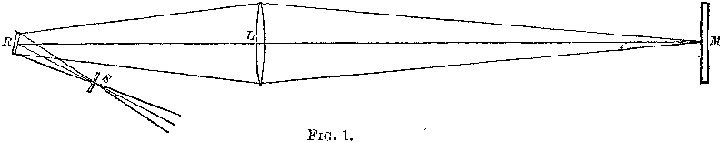
Let S, Fig. 1, be a slit, through which light passes, falling on R, a
mirror free to rotate about an axis at right angles to the plane of the
paper; L, a lens of great focal length, upon which the light falls which
is reflected from R. Let M be a plane mirror whose surface is
perpendicular to the line R, M, passing through the centers of R, L, and
M, respectively. If L be so placed that an image of S is formed on the
surface of M, then, this image acting as the object, its image will be
formed at S, and will coincide, point for point, with S.
If, now, R be turned about the axis, so long as the light falls upon the
lens, an image of the slit will still be formed on the surface of the
mirror, though on a different part, and as long as the returning light
falls on the lens an image of this image will be formed at S,
notwithstanding the change of position of the first image at M. This
result, namely, the production of a stationary image of an image in
motion, is absolutely necessary in this method of experiment. It was first
accomplished by Foucault, and in a manner differing apparently but little
from the foregoing.
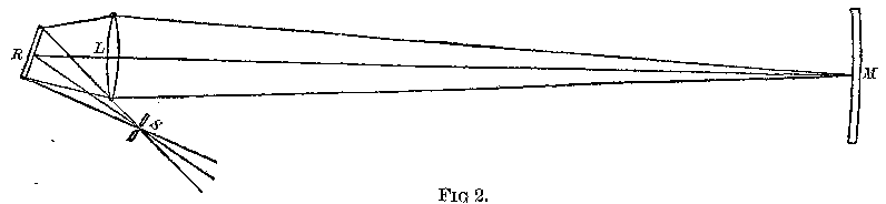
In his experiments L, Fig. 2, served simply to form the image of S at M,
and M, the returning mirror, was spherical, the center coinciding with the
axis of R. The lens L was placed as near as possible to R. The light
forming the return image lasts, in this case, while the first image is
sweeping over the face of the mirror, M. Hence, the greater the distance
RM, the larger must be the mirror in order that the same amount of light
may be preserved, and its dimensions would soon become inordinate. The
difficulty was partly met by Foucault, by using five concave reflectors
instead of one, but even then the greatest distance he found it
practicable to use was only 20 meters.
Returning to Fig. 1, suppose that R is in the principal focus of the lens
L; then, if the plane mirror M have the same diameter as the lens, the
first, or moving image, will remain upon M as long as the axis of the
pencil of light remains on the lens, and this will be the case no matter
what the distance may be.
When the rotation of the mirror R becomes sufficiently rapid, then the
flashes of light which produce the second or stationary image become
blended, so that the image appears to be continuous. But now it no longer
coincides with the slit, but is deflected in the direction of rotation,
and through twice the angular distance described by the mirror, during
the time required for light to travel twice the distance between the
mirrors. This displacement is measured by the tangent of the arc it
subtends. To make this as large as possible, the distance between the
mirrors, the radius, and the speed of rotation should be made as great as
possible.
The second condition conflicts with the first, for the radius is the
difference between the focal length for parallel rays, and that for rays
at the distance of the fixed mirror. The greater the distance, therefore,
the smaller will be the radius.
There are two ways of solving the difficulty: first, by using a lens of
great focal length; and secondly, by placing the revolving mirror within
the principal focus of the lens. Both means were employed. The focal
length of the lens was 150 feet, and the mirror was placed about 15 feet
within the principal focus. A limit is soon reached, however, for the
quantity of light received diminishes very rapidly as the revolving mirror
approaches the lens.
Arrangement and Description of Apparatus.
Site and Plan.
The site selected for the experiments was a clear, almost level, stretch
along the north sea-wall of the Naval Academy. A frame building was
erected at the western end of the line, a plan of which is represented in
Fig. 3.
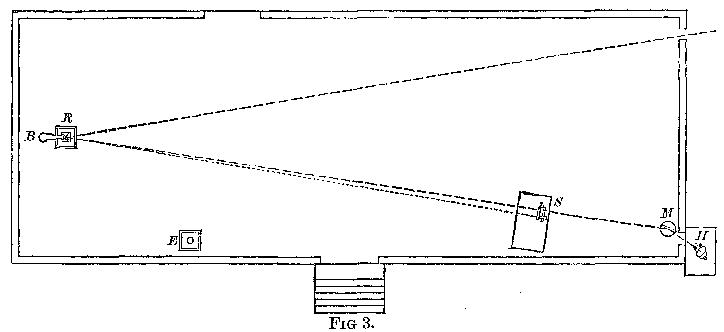
The building was 45 feet long and 14 feet wide, and raised so that the
line along which the light traveled was about 11 feet above the ground. A
heliostat at H reflected the sun's rays through the slit at S to the
revolving mirror R, thence through a hole in the shutter, through the
lens, and to the distant mirror.
The Heliostat.
The heliostat was one kindly furnished by Dr. Woodward, of the Army
Medical Museum, and was a modification of Foucault's form, designed by
Keith. It was found to be accurate and easy to adjust. The light was
reflected from the heliostat to a plane mirror, M, Fig. 3, so that the
former need not be disturbed after being once adjusted.
The Revolving Mirror.
The revolving mirror was made by Fauth & Co., of Washington. It consists
of a cast-iron frame resting on three leveling screws, one of which was
connected by cords to the table at S, Fig. 3, so that the mirror could be
inclined forward or backward while making the observations.
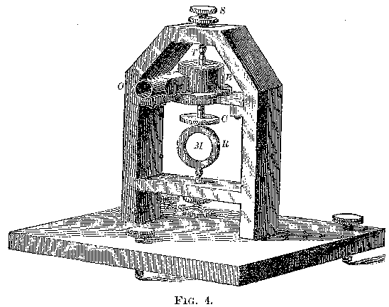
Two binding screws, S, S, Fig. 4, terminating in hardened steel conical
sockets, hold the revolving part. This consists of a steel axle, X, Y,
Figs. 4 and 5, the pivots being conical and hardened. The axle expands
into a ring at R, which holds the mirror M. The latter was a disc of plane
glass, made by Alvan Clark & Sons, about 1¼ inch in diameter and 0.2 inch
thick. It was silvered on one side only, the reflection taking place from
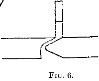
the outer or front surface. A species of turbine wheel, T, is held on the
axle by friction. This wheel has six openings for the escape of air; a
section of one of them is represented in Fig 6.
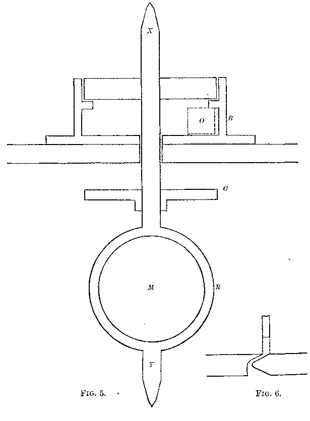
Adjustment of the Revolving Mirror.
The air entering on one side at O, Fig. 5, acquires a rotary motion in the
box B, B, carrying the wheel with it, and this motion is assisted by the
reaction of the air in escaping. The disc C serves the purpose of bringing
the center of gravity in the axis of rotation. This was done, following
Foucault's plan, by allowing the pivots to rest on two inclined planes of
glass, allowing the arrangement to come to rest, and filing away the
lowest part of the disc; trying again, and so on, till it would rest in
indifferent equilibrium. The part corresponding to C, in Foucault's
apparatus, was furnished with three vertical screws, by moving which the
axis of figure was brought into coincidence with the axis of rotation.
This adjustment was very troublesome. Fortunately, in this apparatus it
was found to be unnecessary.
When the adjustment is perfect the apparatus revolves without giving any
sound, and when this is accomplished, the motion is regular and the speed
great. A slight deviation causes a sound due to the rattling of the pivots
in the sockets, the speed is very much diminished, and the pivots begin to
wear. In Foucault's apparatus oil was furnished to the pivots, through
small holes running through the screws, by pressure of a column of
mercury. In this apparatus it was found sufficient to touch the pivots
occasionally with a drop of oil.
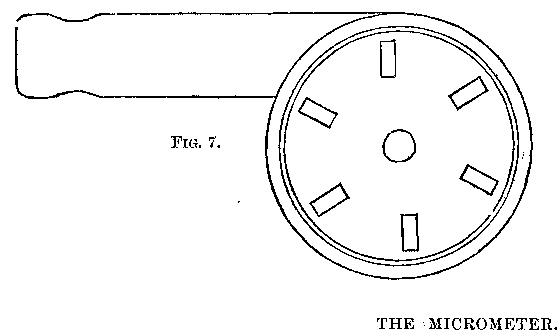
Fig. 7 is a view of the turbine, box, and supply-tube, from above. The
quantity of air entering could be regulated by a valve to which was
attached a cord leading to the observer's table.
The instrument was mounted on a brick pier.
The Micrometer.
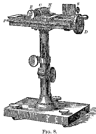
The apparatus for measuring the deflection was made by Grunow, of New
York.
This instrument is shown in perspective in Fig. 8, and in plan by Fig. 9.
The adjustable slit S is clamped to the frame F. A long millimeter-screw,
not shown in Fig. 8, terminating in the divided head D, moves the carriage
C, which supports the eye-piece E. The frame is furnished with a brass
scale at F for counting revolutions, the head counting hundredths. The
eye-piece consists of a single achromatic lens, whose focal length is
about two inches. At its focus, in H, and in nearly the same plane as the
face of the slit, is a single vertical silk fiber. The apparatus is
furnished with a standard with rack and pinion, and the base furnished
with leveling screws.
Manner of Using the Micrometer.
In measuring the deflection, the eye-piece is moved till the cross-hair
bisects the slit, and the reading of the scale and divided head gives the
position. This measurement need not be repeated unless the position or
width of the slit is changed. Then the eye-piece is moved till the
cross-hair bisects the deflected image of the slit; the reading of scale
and head are again taken, and the difference in readings gives the
deflection. The screw was found to have no lost motion, so that readings
could be taken with the screw turned in either direction.
Measurement of Speed of Rotation.
To measure the speed of rotation, a tuning-fork, bearing on one prong a
steel mirror, was used. This was kept in vibration by a current of
electricity from five "gravity" cells. The fork was so placed that the
light from the revolving mirror was reflected to a piece of plane glass,
in front of the lens of the eye-piece of the micrometer, inclined at an
angle of 45°, and thence to the eye. When fork and revolving mirror are
both at rest, an image of the revolving mirror is seen. When the fork
vibrates, this image is drawn out into a band of light.
When the mirror commences to revolve, this band breaks up into a number of
moving images of the mirror; and when, finally, the mirror makes as many
turns as the fork makes vibrations, these images are reduced to one, which
is stationary. This is also the case when the number of turns is a
submultiple. When it is a multiple or simple ratio, the only difference is
that there are more images. Hence, to make the mirror execute a certain
number of turns, it is simply necessary to pull the cord attached to the
valve to the right or left till the images of the revolving mirror come to
rest.
The electric fork made about 128 vibrations per second. No dependence was
placed upon this rate, however, but at each set of observations it is
compared with a standard Ut3 fork, the temperature being noted at the
same time. In making the comparison the sound-beats produced by the forks
were counted for 60 seconds. It is interesting to note that the electric
fork, as long as it remained untouched and at the same temperature, did
not change its rate more than one or two hundredths vibrations per second.
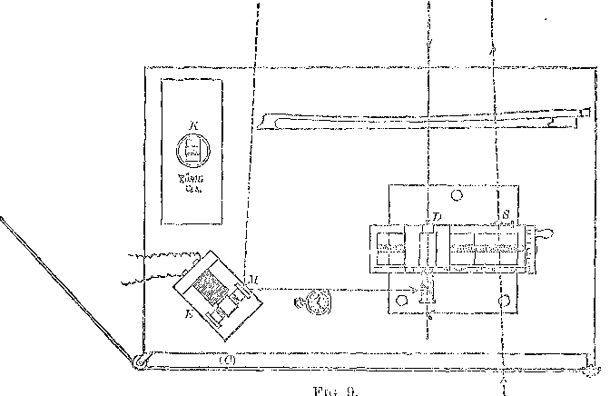
The Observer's Table.
Fig. 9 Represents The Table At Which The Observer Sits. The Light From The
Heliostat Passes Through The Slit At S, Goes To The Revolving Mirror, &c.,
And, On Its Return, Forms An Image Of The Slit At D, Which Is Observed
Through The Eye-piece. E Represents The Electric Fork (the Prongs Being
Vertical) Bearing The Steel Mirror M. K Is The Standard Fork On Its
Resonator. C Is The Cord Attached To The Valve Supplying Air To The
Turbine.
The Lens.
The lens was made by Alvan Clark & Sons. It was 8 inches in diameter;
focal length, 150 feet; not achromatic. It was mounted in a wooden frame,
which was placed on a support moving on a slide, about 16 feet long,
placed about 80 feet from the building. As the diameter of the lens was so
small in comparison with its focal length, its want of achromatism was
inappreciable. For the same reason, the effect of "parallax" (due to want
of coincidence in the plane of the image with that of the silk fiber in
the eye-piece) was too small to be noticed.
The Fixed Mirror.
The fixed mirror was one of those used in taking photographs of the
transit of Venus. It was about 7 inches in diameter, mounted in a brass
frame capable of adjustment in a vertical and a horizontal plane by screw
motion. Being wedge-shaped, it had to be silvered on the front surface. To
facilitate adjustment, a small telescope furnished with cross-hairs was
attached to the mirror by a universal joint. The heavy frame was mounted
on a brick pier, and the whole surrounded by a wooden case to protect it
from the sun.
Adjustment of the Fixed Mirror.
The adjustment was effected as follows: A theodolite was placed at about
100 feet in front of the mirror, and the latter was moved about by the
screws till the observer at the theodolite saw the image of his telescope
reflected in the center of the mirror. Then the telescope attached to the
mirror was pointed (without moving the mirror itself) at a mark on a piece
of card-board attached to the theodolite. Thus the line of collimation of
the telescope was placed at right angles to the surface of the mirror. The
theodolite was then moved to 1,000 feet, and, if found necessary, the
adjustment was repeated. Then the mirror was moved by the screws till its
telescope pointed at the hole in the shutter of the building. The
adjustment was completed by moving the mirror, by signals, till the
observer, looking through the hole in the shutter, through a good
spy-glass, saw the image of the spy-glass reflected centrally in the
mirror.
The whole operation was completed in a little over an hour.
Notwithstanding the wooden case about the pier, the mirror would change
its position between morning and evening; so that the last adjustment had
to be repeated before every series of experiments.
Apparatus for Supplying and Regulating the Blast of Air.
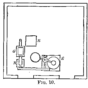
Fig. 10 represents a plan of the lower floor of the building. E is a
three-horse power Lovegrove engine and boiler, resting on a stone
foundation; B, a small Roots' blower; G, an automatic regulator. From this
the air goes to a delivery-pipe, up through the floor, and to the turbine.
The engine made about 4 turns per second and the blower about 15. At this
speed the pressure of the air was about half a pound per square inch.
The regulator, Fig. 11, consists of a strong bellows supporting a weight
of 370 pounds, partly counterpoised by 80 pounds in order to prevent the
bellows from sagging. When the pressure of air from the blower exceeds the
weight, the bellows commences to rise, and, in so doing, closes the
valve V.
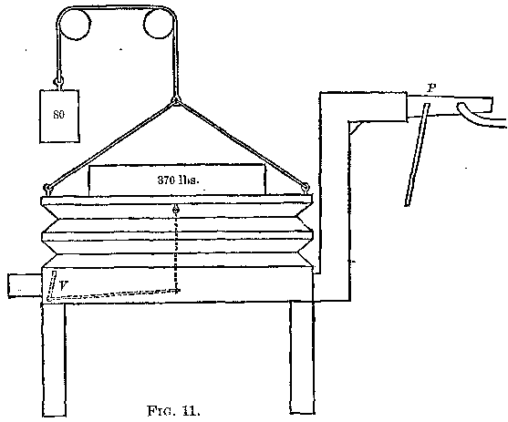
This arrangement was found in practice to be insufficient, and the
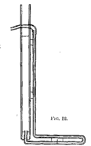
following addition was made: A valve was placed at P, and the pipe was
tapped a little farther on, and a rubber tube led to a water-gauge, Fig
12. The column of water in the smaller tube is depressed, and, when it
reaches the horizontal part of the tube, the slightest variation of
pressure sends the column from one end to the other. This is checked by an
assistant at the valve; so that the column of water is kept at about the
same place, and the pressure thus rendered very nearly constant. The
result was satisfactory, though not in the degree anticipated. It was
possible to keep the mirror at a constant speed for three or four seconds
at a time, and this was sufficient for an observation. Still it would have
been more convenient to keep it so for a longer time.
I am inclined to think that the variations were due to changes in the
friction of the pivots rather than to changes of pressure of the blast of
air.
It may be mentioned that the test of uniformity was very delicate, as a
change of speed of one or two hundredths of a turn per second could easily
be detected.
Method Followed in Experiment.
It was found that the only time during the day when the atmosphere was
sufficiently quiet to get a distinct image was during the hour after
sunrise, or during the hour before sunset. At other times the image was
"boiling" so as not to be recognizable. In one experiment the electric
light was used at night, but the image was no more distinct than at
sunset, and the light was not steady.
The method followed in experiment was as follows: The fire was started
half an hour before, and by the time everything was ready the gauge would
show 40 or 50 pounds of steam. The mirror was adjusted by signals, as
before described. The heliostat was placed and adjusted. The revolving
mirror was inclined to the right or left, so that the direct reflection
of light from the slit, which otherwise would flash into the eye-piece at
every revolution, fell either above or below the eye-piece.[2]
[Footnote 2: Otherwise this light would overpower that which forms the
image to be observed. As far as I am aware, Foucault does not speak of
this difficulty. If he allowed this light to interfere with the
brightness of the image, he neglected a most obvious advantage. If he
did incline the axis of the mirror to the right or left, he makes no
allowance for the error thus introduced.]
The revolving mirror was then adjusted by being moved about, and inclined
forward and backward, till the light was seen reflected back from the
distant mirror. This light was easily seen through the coat of silver on
the mirror.
The distance between the front face of the revolving mirror and the
cross-hair of the eye-piece was then measured by stretching from the one
to the other a steel tape, making the drop of the catenary about an inch,
as then the error caused by the stretch of the tape and that due to the
curve just counterbalance each other.
The position of the slit, if not determined before, was then found as
before described. The electric fork was started, the temperature noted,
and the sound-beats between it and the standard fork counted for 60
seconds. This was repeated two or three times before every set of
observations.
The eye-piece of the micrometer was then set approximately[3] and the
revolving mirror started. If the image did not appear, the mirror was
inclined forward or backward till it came in sight.
[Footnote 3: The deflection being measured by its tangent, it was
necessary that the scale should be at right angles to the radius (the
radius drawn from the mirror to one or the other end of that part of
the scale which represents this tangent). This was done by setting the
eye-piece approximately to the expected deflection, and turning the
whole micrometer about a vertical axis till the cross-hair bisected the
circular field of light reflected from the revolving mirror. The axis
of the eye-piece being at right angles to the scale, the latter would
be at right angles to radius drawn to the cross-hair.]
The cord connected with the valve was pulled right or left till the images
of the revolving mirror, represented by the two bright round spots to the
left of the cross-hair, came to rest. Then the screw was turned till the
cross-hair bisected the deflected image of the slit. This was repeated
till ten observations were taken, when the mirror was stopped, temperature
noted, and beats counted. This was called a set of observations. Usually
five such sets were taken morning and evening.
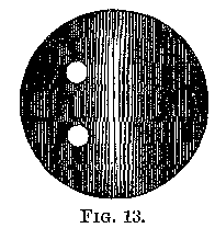
Fig. 13 represents the appearance of the image of the slit as seen in the
eye-piece magnified about five times.
Determination of The Constants.
Comparison of the Steel Tape with the Standard Yard.
The steel tape used was one of Chesterman's, 100 feet long. It was
compared with Wurdeman's copy of the standard yard, as follows:
Temperature was 55° Fahr.
The standard yard was brought under the microscopes of the comparator; the
cross-hair of the unmarked microscope was made to bisect the division
marked o, and the cross-hair of the microscope, marked I, was made to
bisect the division marked 36. The reading of microscope I was taken, and
the other microscope was not touched during the experiment. The standard
was then removed and the steel tape brought under the microscopes and
moved along till the division marked 0.1 (feet) was bisected by the
cross-hair of the unmarked microscope. The screw of microscope I was then
turned till its cross-hair bisected the division marked 3.1 (feet), and
the reading of the screw taken. The difference between the original
reading and that of each measurement was noted, care being taken to regard
the direction in which the screw was turned, and this gave the difference
in length between the standard and each succesive portion of the steel
tape in terms of turns of the micrometer-screw.
To find the value of one turn, the cross-hair was moved over a millimeter
scale, and the following were the values obtained:
Turns of screw of microscope I in 1mm—
| 7.68 | 7.73 | 7.60 | 7.67 |
| 7.68 | 7.62 | 7.65 | 7.57 |
| 7.72 | 7.70 | 7.64 | 7.69 |
| 7.65 | 7.59 | 7.63 | 7.64 |
| 7.55 | 7.65 | 7.61 | 7.63 |
|
Mean =7.65 |
|
Hence one turn = 0.1307mm. |
|
or = 0.0051 inch. |
The length of the steel tape from 0.1 to 99.1 was found to be
greater than 33 yards, by 7.4 turns =.96mm | +.003 feet. |
| Correction for temperature | +.003 feet. |
| Length | 100.000 feet. |
| | -------------- |
| Corrected length | 100.006 feet. |
Determination of the Value of Micrometer.
Two pairs of lines were scratched on one slide of the slit, about 38mm
apart, i.e., from the center of first pair to center of second pair. This
distance was measured at intervals of 1mm through the whole length of the
screw, by bisecting the interval between each two pairs by the vertical
silk fiber at the end of the eye-piece. With these values a curve was
constructed which gave the following values for this distance, which we
shall call D′:
Turns of screw.
| At | 0 | of scale D′ | =38.155 |
| 10 | of scale D′ | 38.155 |
| 20 | of scale D′ | 38.150 |
| 30 | of scale D′ | 38 150 |
| 40 | of scale D′ | 38.145 |
| 50 | of scale D′ | 38.140 |
| 60 | of scale D′ | 38.140 |
| 70 | of scale D′ | 38.130 |
| 80 | of scale D′ | 38.130 |
| 90 | of scale D′ | 38.125 |
| 100 | of scale D′ | 38.120 |
| 110 | of scale D′ | 38.110 |
| 120 | of scale D′ | 38.105 |
| 130 | of scale D′ | 38.100 |
| 140 | of scale D′ | 38.100 |
Changing the form of this table, we find that,—
| For the first |
| 10 | turns the average value of D′ is | 38.155 |
| 20 | turns | 38.153 |
| 30 | turns | 38.152 |
| 40 | turns | 38.151 |
| 50 | turns | 38.149 |
| 60 | turns | 38.148 |
| 70 | turns | 38.146 |
| 80 | turns | 38.144 |
| 90 | turns | 38.142 |
| 100 | turns | 38.140 |
| 110 | turns | 38.138 |
| 120 | turns | 38.135 |
| 130 | turns | 38.132 |
| 140 | turns | 38.130 |
On comparing the scale with the standard meter, the temperature being
16°.5 C., 140 divisions were found to = 139.462mm. This multiplied by
(1 + .0000188 × 16.5) = 139.505mm.
One hundred and forty divisions were found to be equal to 140.022 turns
of the screw, whence 140 turns of the screw = 139.483mm, or
1 turn of the screw = 0.996305mm.
This is the average value of one turn in 140.
But the average value of D, for 140 turns is, from the preceding table,
38.130.
Therefore, the true value of D, is 38.130 × .996305mm, and the average
value of one turn for 10, 20, 30, etc., turns, is found by dividing 38.130
× .996305 by the values of D;, given in the table.
This gives the value of a turn—
| | | mm. |
|---|
| For the first | 10 | turns | 0.99570 |
| 20 | turns | 0.99570 |
| 30 | turns | 0.99573 |
| 40 | turns | 0.99577 |
| 50 | turns | 0.99580 |
| 60 | turns | 0.99583 |
| 70 | turns | 0.99589 |
| 80 | turns | 0.99596 |
| 90 | turns | 0.99601 |
| 100 | turns | 0.99606 |
| 110 | turns | 0.99612 |
| 120 | turns | 0.99618 |
| 130 | turns | 0.99625 |
| 140 | turns | 0.99630 |
Note.—The micrometer has been sent to Professor Mayer, of Hoboken, to
test the screw again, and to find its value. The steel tape has been sent
to Professor Rogers, of Cambridge, to find its length again. (See page
145.)
Measurement of the Distance between the Mirrors.
Square lead weights were placed along the line, and measurements taken
from the forward side of one to forward side of the next. The tape rested
on the ground (which was very nearly level), and was stretched by a
constant force of 10 pounds.
The correction for length of the tape (100.006) was +0.12 of a foot.
To correct for the stretch of the tape, the latter was stretched with a
force of 15 pounds, and the stretch at intervals of 20 feet measured by a
millimeter scale.
mm.
| At | 100 | feet the stretch was | 8.0 |
| 80 | feet the stretch was | 5.0 |
| 60 | feet the stretch was | 5.0 |
| 40 | feet the stretch was | 3.5 |
| 20 | feet the stretch was | 1.5 |
| --- | | --- |
| 300 | | 23.00 |
| Weighted mean | = | 7.7 mm. |
| For 10 pounds, stretch | = | 5.1 mm. |
| | = | 0.0167 feet. |
| Correction for whole distance | = | +0.33 feet. |
The following are the values obtained from five separate measurements of
the distance between the caps of the piers supporting the revolving mirror
and the distant reflector; allowance made in each case for effect of
temperature:
| 1985.13 | feet. |
| 1985.17 | feet. |
| 1984.93 | feet. |
| 1985.09 | feet. |
| 1985.09 | feet. |
| ------- |
| Mean = | 1985.082 | feet. |
| +.70. | Cap of pier to revolving mirror. |
| +.33. | Correction for stretch of tape. |
| +.12. | Correction for length of tape. |
| -------- |
| 1986.23. | True distance between mirrors. |
Rate of Standard Ut3 Fork.
The rate of the standard Ut3 fork was found at the Naval Academy, but as
so much depended on its accuracy, another series of determinations of its
rate was made, together with Professor Mayer, at the Hoboken Institute of
Technology.
Set of determinations made at Naval Academy.
The fork was armed with a tip of copper foil, which was lost during the
experiments and replaced by one of platinum having the same weight,
4.6 mgr. The fork, on its resonator, was placed horizontally, the platinum
tip just touching the lampblacked cylinder of a Schultze chronoscope. The
time was given either by a sidereal break-circuit chronometer or by the
break-circuit pendulum of a mean-time clock. In the former case the
break-circuit worked a relay which interrupted the current from three
Grove cells. The spark from the secondary coil of an inductorium was
delivered from a wire near the tip of the fork. Frequently two sparks near
together were given, in which case the first alone was used. The rate of
the chronometer, the record of which was kept at the Observatory, was very
regular, and was found by observations of transits of stars during the
week to be +1.3 seconds per day, which is the same as the recorded rate.
Specimen of a Determination of Rate of Ut3 Fork.
Temp.=27° C. Column 1 gives the number of the spark or the number of the
second. Column 2 gives the number of sinuosities or vibrations at the
corresponding second. Column 3 gives the difference between 1 and 11, 2
and 12, 3 and 13, etc.
July 4, 1879.
| 1. | 0.1 | 2552.0 |
| 2. | 255.3 | 2551.7 |
| 3. | 510.5 | 2551.9 |
| 4. | 765.6 | 2551.9 |
| 5. | 1020.7 | 2552.1 |
| 6. | 1275.7 | 2552.0 |
| 7. | 1530.7 | 2551.8 |
| 8. | 1786.5 | 2551.4 |
| 9. | 2041.6 | 2551.7 |
| 10. | 2297.0 | 2551.5 |
| | ------- |
| 11. | 2552.1 | 255.180 | = mean ÷ 10. |
| 12. | 2807.0 | + .699 | = reduction for mean time. |
| 13. | 3062.4 | + .003 | = correction for rate. |
| 14. | 3317.5 | + .187 | = correction for temperature. |
| | ------- |
| 15. | 3572.8 | 256.069 | = number of vibrations per second at 65° Fahr. |
| 16. | 3827.7 |
| 17. | 4082.5 |
| 18. | 4335.9 |
| 19. | 4593.3 |
| 20. | 4848.5 |
The correction for temperature was found by Professor Mayer by counting
the sound-beats between the standard and another Ut3 fork, at different
temperatures. His result is +.012 vibrations per second for a diminution
of 1° Fahr. Using the same method, I arrived at the result +.0125.
Adopted +.012.
Résumé of determinations made at Naval Academy.
In the following table the first column gives the date, the second gives
the total number of seconds, the third gives the result uncorrected for
temperature, the fourth gives the temperature (centigrade), the fifth
gives the final result, and the sixth the difference between the greatest
and least values obtained in the several determinations for intervals of
ten seconds:
| July | 4 | 20 | | 255.882 | 27.0 | 256.069 | 0.07 |
| 5 | 19 | | 255.915 | 26.4 | 256.089 | 0.05 |
| 5 | 18 | | 255.911 | 26.0 | 256.077 | 0.02 |
| 6 | 21 | | 255.874 | 24.7 | 256.012 | 0.13 |
| 6 | 9 | | 255.948 | 24.8 | 256.087 | 0.24 |
| 7 | 22 | | 255.938 | 24.6 | 256.074 | 0.05 |
| 7 | 21 | | 255.911 | 25.3 | 256.061 | 0.04 |
| 8 | 20 | | 255.921 | 26.6 | 256.100 | 0.02 |
| 8 | 20 | | 255.905 | 26.6 | 256.084 | 0.06 |
| 8 | 20 | | 255.887 | 26.6 | 256.066 | 0.03 |
| | | | | | ------- |
| | | | | Mean = | 256.072 |
In one of the preceding experiments, I compared the two Vt3 forks while
the standard was tracing its record on the cylinder, and also when it was
in position as for use in the observations. The difference, if any, was
less than .01 vibration per second.
Second determination.
(Joint work with Professor A.M. Mayer, Stevens Institute, Hoboken.)
The fork was wedged into a wooden support, and the platinum tip allowed to
rest on lampblacked paper, wound about a metal cylinder, which was rotated
by hand Time was given by a break-circuit clock, the rate of which was
ascertained, by comparisons with Western Union time-ball, to be 9.87
seconds. The spark from secondary coil of the inductorium passed from the
platinum tip, piercing the paper. The size of the spark was regulated by
resistances in primary circuit.
The following is a specimen determination:
Column 1 gives the number of the spark or the number of seconds. Column 2
gives the corresponding number of sinuosities or vibrations. Column 3
gives the difference between the 1st and 7th ÷ 6, 2nd and 8th ÷ 6, etc.
| 1 | 0.3 | 255.83 |
| 2 | 256.1 | 255.90 |
| 3 | 511.7 | 255.90 |
| 4 | 767.9 | 255.93 |
| 5 | 1023.5 | 255.92 |
| 6 | 1289.2 | 256.01 |
| 7 | 1535.3 | 255.95 |
| | ------- |
| 8 | 1791.5 | 255.920 | = mean. |
| 9 | 2047.1 | - .028 | = correction for rate. |
| | ------- |
| 10 | 2303.5 | 255.892 |
| 11 | 2559.0 | + .180 | = correction for temperature. |
| | ------- |
| 12 | 2825.3 | 256.072 | = number of vibrations per second at 65° Fahr. |
| 13 | 3071.0 |
In the following résumé, column 1 gives the number of the experiments.
Column 2 gives the total number of seconds. Column 3 gives the result not
corrected for temperature. Column 4 gives the temperature Fahrenheit.
Column 5 gives the final result. Column 6 gives the difference between the
greatest and least values:
| 1 | 13 | 255.892 | 80 | 256.072 | 0.18 |
| 2 | 11 | 255.934 | 81 | 256.126 | 0.17 |
| 3 | 13 | 255.899 | 81 | 256.091 | 0.12 |
| 4 | 13 | 255.988 | 75 | 256.108 | 0.13 |
| 5 | 11 | 255.948 | 75 | 256.068 | 0.05 |
| 6 | 12 | 255.970 | 75 | 256.090 | 0.05 |
| 7 | 12 | 255.992 | 75 | 256.112 | 0.20 |
| 8 | 11 | 255.992 | 76 | 256.124 | 0.03 |
| 9 | 11 | 255.888 | 81 | 256.080 | 0.13 |
| 10 | 13 | 255.878 | 81 | 256.070 | 0.13 |
| | | | | ------- |
| | | Mean = | 256.094 |
Effect of Support and of Scraping.
The standard Vt3 fork held in its wooden support was compared with
another fork on a resonator loaded with wax and making with standard about
five beats per second. The standard was free from the cylinder. The beats
were counted by coincidences with the ⅕ second beats of a watch.
Specimen.
Coincidences were marked—
| At 32 | seconds. |
| 37 | seconds. |
| 43.5 | seconds. |
| 49 | seconds. |
| 54.5 | seconds. |
| 61.5 | seconds. |
| 61.5 - 32 | = 29.5. |
| 29.5 ÷ 5 | = 5.9 = | time of one interval. |
Résumé.
| 1 | 5.9 |
| 2 | 6.2 |
| 3 | 6.2 |
| 4 | 6.2 |
| ---- |
| Mean = | 6.13 | = time of one interval between coincidences. |
In this time the watch makes 6.13×5 = 30.65 beats, and the forks make
30.65 + 1 = 31.65 beats.
Hence the number of beats per second is 31.65 ÷ 6.13 = 5.163.
Specimen.
Circumstances the same as in last case, except that standard Vt3 fork was
allowed to trace its record on the lampblacked paper, as in finding its
rate of vibration.
Coincidences were marked at—
| 59 | seconds. |
| 04 | seconds. |
| 10.5 | seconds. |
| 17 | seconds. |
| |
| 77 - 59 = 18. |
| 18 ÷ 3 = 6.0 = time of one interval. |
Résumé.
| No. | 1 6.0 | seconds. | 6.31 × 5 = 31.55 |
| | 2 6.0 | seconds. | + 1.00 |
| | 3 6.7 | seconds. | ---- |
| | 4 6.3 | seconds. |
| | 5 6.5 | seconds. | 32.55 |
| | 6 6.7 | seconds. | 32.55 ÷ 6.31 = 5.159 |
| | 7 6.0 | seconds. | With fork free 5.163 |
| | ---- | | ----- |
| Mean = | 6.31 | seconds | Effect of scrape = - .044 |
Specimen.
Circumstances as in first case, except that both forks were on their
resonators.
Coincidences were observed at—
| 21 | seconds. |
| 28 | seconds. |
| 36 | seconds. |
| 44 | seconds. |
| 51 | seconds. |
| 60 | seconds. |
| 60 - 21 = 39 |
| 39 ÷ 5 = 7.8 = | time of one interval. |
Résumé.
| No. | 1 | 7.8 | seconds. | 7.42 × 5 = | 37.10 |
| | 2 | 7.1 | seconds. | + | 1.00 |
| | 3 | 7.6 | seconds. | | ----- |
| | 4 | 7.4 | seconds. | | 38.10 |
| | 5 | 7.2 | seconds. | 38.10 ÷ 7.42 = | 5.133 |
| | | ---- | | (Above) | 5.159 |
| | | | | | ----- |
| | Mean = | 7.42 | seconds. Effect of support and scrape = | - .026 |
| |
| Mean of second determination was | 256.094 |
| Applying correction (scrape, etc.) | - .026 |
| | ------- |
| Corrected mean | 256.068 |
| Result of first determination | 256.072 |
| | ------- |
| Final value | 256.070 |
Note—The result of first determination excludes all work except the
series commencing July 4. If previous work is included, and also the
result first obtained by Professor Mayer, the result would be 256.089.
| 256.180 |
| 256.036 |
| 256.072 |
| 256.068 |
| ------- |
| Mean = | 256.089 |
The previous work was omitted on account of various inaccuracies and want
of practice, which made the separate results differ widely from each
other.
The Formulæ.
The formulæ employed are—
| d′ |
| (1) tan φ = | ----- |
| r |
| |
| 2592000″ × D × n |
| (2) V = | ----------------- |
| φ″ |
| |
| φ = | angle of deflection. |
| d′ = | corrected displacement (linear). |
| r = | radius of measurement. |
| D = | twice the distance between the mirrors. |
| n = | number of revolutions per second. |
| α = | inclination of plane of rotation |
| d = | deflection as read from micrometer. |
| B = | number of beats per second between electric Vt₂ fork and
standard Vt3 |
| Cor = | correction for temperature of standard Vt3. |
| V = | velocity of light. |
| T = | value of one turn of screw. (Table, page 126.) |
Substituting for d, its value or d×T×sec α (log sec α = .00008), and
for D its value 3972.46, and reducing to kilometers, the formulæ become—
| | dT |
| (3) tan φ = | c′ | ----; | log c′ = .51607 |
| | r |
| |
| n |
| (4) V = c ---; | log c = .49670 |
| φ |
| |
| D and r are expressed in feet and d′ in millimeters. |
| Vt3 fork makes 256.070 vibrations per second at 65° Fahr. |
| D = | 3972.46 feet. |
| tan α = | tangent of angle of inclination of plane of rotation = 0.02
in all but the last twelve observations, in which it was 0.015. |
| log c′ = | .51607 (.51603 in last twelve observations.). |
| log c = | .49670. |
The electric fork makes ½(256.070 + B + cor.) vibrations per second,
and n is a multiple, submultiple, or simple ratio of this.
Observations.
Specimen Observation.
June 17. sunset. Image good; best in column (4).
The columns are sets of readings of the micrometer for the deflected image
of slit.
| 112.81 | 112.80 | 112.83 | 112.74 | 112.79 |
| 81 | 81 | 81 | 76 | 78 |
| 79 | 78 | 78 | 74 | 74 |
| 80 | 75 | 74 | 76 | 74 |
| 79 | 77 | 74 | 76 | 77 |
| 82 | 79 | 72 | 78 | 81 |
| 82 | 73 | 76 | 78 | 77 |
| 76 | 78 | 81 | 79 | 75 |
| 83 | 79 | 74 | 83 | 82 |
| 73 | 73 | 76 | 78 | 82 |
| ------- | ------- | ------- | ------- | ------- |
| Mean = | 112.801 | 112.773 | 112.769 | 112.772 | 112.779 |
| Zero = | 0.260 | 0.260 | 0.260 | 0.260 | 0.260 |
| ------- | ------- | ------- | ------- | ------- |
| d = | 112.451 | 112.513 | 112.509 | 112.512 | 112.519 |
| Temp = | 77° | 77° | 77° | 77° | 77° |
| B = | + 1.500 |
| Corr = | - .144 |
| ------- |
| + 1.365 |
| 256.070 |
| ------- |
| n = | 257.426 | 257.43 | 257.43 | 257.43 | 257.43 |
| r = | 28.157 | 28.157 | 28.157 | 28.157 | 28.157 |
The above specimen was selected because in it the readings were all taken
by another and noted down without divulging them till the whole five sets
were completed.
The following is the calculation for V:
| 2d, 3d, |
|---|
| 1st set. | and 4th sets. | 5th set. |
|---|
| log | c′ = | 51607 | 51607 | 51607 |
| " | T = | 99832 | 99832 | 99832 |
| " | d = | 05131 | 05119 | 05123 |
| | ------- | ------- | ------- |
| | 56570 | 56558 | 56562 |
| " | r = | 44958 | 44958 | 44958 |
| | ------- | ------- | ------- |
| " | tan φ = | 11612 | 11600 | 11604 |
| φ = | 2694″.7 | 2694″.1 | 2694″.3 |
| " | c = | 49670 | 49670 | 49670 |
| " | n = | 41066 | 41066 | 41066 |
| | ------- | ------- | ------- |
| | 90736 | 90736 | 90736 |
| " | φ = | 43052 | 43042 | 43046 |
| | ------- | ------- | ------- |
| " | V = | 47684 | 47694 | 47690 |
| V = | 299800 | 299880 | 299850 |
In the following table, the numbers in the column headed "Distinctness of
Image" are thus translated: 3, good; 2, fair; 1, poor. These numbers do
not, however, show the relative weights of the observations.
The numbers contained in the columns headed "Position of Deflected Image,"
"Position of Slit," and displacement of image in divisions were obtained
as described in the paragraph headed "Micrometer," page 120.
The column headed "B" contains the number of "beats" per second between
the electric Vt₂ fork and the standard Vt3 as explained in the paragraph
headed "Measurement of the Speed of Rotation." The column headed "Cor."
contains the correction of the rate of the standard fork for the
difference in temperature of experiment and 65° Fahr., for which
temperature the rate was found. The numbers in the column headed "Number
of revolutions per second" were found by applying the corrections in the
two preceding columns to the rate of the standard, as explained in the
same paragraph.
The "radius of measurement" is the distance between the front face of the
revolving mirror and the cross-hair of the micrometer.
The numbers in the column headed "Value of one turn of the screw" were
taken from the table, page 127.
| Date. |
Distinctness of image. |
Temperature, Fahr. |
Position of deflected image. |
Position of slit. |
Displacement of image in divisions. |
Difference between greatest and least values. |
B. |
Cor. |
Number of revolutions per second. |
Radius of measurement, in feet. |
Value of one turn of the screw. |
Velocity of light in air, in kilometers. |
Remarks. |
|---|
| June 5 | 3 | 76 | 114.85 | 0.300 | 114.55 | 0.17 | 1.423 | -0.132 | 257.36 | 28.672 | 0.99614 | 299850 | Electric light. |
| June 7 | 2 | 72 | 114.64 | 0.074 | 114.56 | 0.10 | 1.533 | -0.084 | 257.52 | 28.655 | 0.99614 | 299740 | P.M. Frame inclined at various angles |
| June 7 | 2 | 72 | 114.58 | 0.074 | 114.50 | 0.08 | 1.533 | -0.084 | 257.52 | 28.647 | 0.99614 | 299900 | P.M. Frame inclined at various angles |
| June 7 | 2 | 72 | 85.91 | 0.074 | 85.84 | 0.12 | 1.533 | -0.084 | 193.14 | 28.647 | 0.99598 | 300070 | P.M. Frame inclined at various angles |
| June 7 | 2 | 72 | 85.97 | 0.074 | 85.89 | O.07 | 1.533 | -0.084 | 193.14 | 28.650 | 0.99598 | 299930 | P.M. Frame inclined at various angles |
| June 7 | 2 | 72 | 114.61 | 0.074 | 114-53 | 0.07 | 1.533 | -0.084 | 257.42 | 28.650 | 0.99614 | 299850 | P.M. Frame inclined at various angles |
| June 9 | 3 | 83 | 114.54 | 0.074 | 114.47 | 0.07 | 1.533 | -0.216 | 257.39 | 28.658 | 0.99614 | 299950 | P.M. Frame inclined at various angles |
| June 9 | 3 | 83 | 114.54 | 0.074 | 114.46 | 0.10 | 1.533 | -0.216 | 257.39 | 28.658 | 0.99614 | 299980 | P.M. Frame inclined at various angles |
| June 9 | 3 | 83 | 114.57 | 0.074 | 114.47 | 0.08 | 1.533 | -0.216 | 257.39 | 28.662 | 0.99614 | 299980 | P.M. Frame inclined at various angles |
| June 9 | 3 | 83 | 114.57 | 0.074 | 114.50 | 0.06 | 1.533 | -0.216 | 257.39 | 28.660 | 0.99614 | 299880 | P.M. Frame inclined at various angles |
| June 9 | 2 | 83 | 114.61 | 0.074 | 114.53 | 0.13 | 1.533 | -0.216 | 257.39 | 28.678 | 0.99614 | 300000 | P.M. Frame inclined at various angles |
| June 10 | 2 | 90 | 114.60 | 0.074 | 114.52 | 0.11 | 1.517 | -0.300 | 257.29 | 28.685 | 0.99614 | 299980 | P.M. |
| June 10 | 2 | 90 | 114.62 | 0.074 | 114.54 | 0.08 | 1.517 | -0.300 | 257.29 | 28.685 | 0.99614 | 299930 | P.M. |
| June 12 | 2 | 71 | 114.81 | 0.074 | 114.74 | 0.09 | 1.450 | -0.072 | 257.45 | 28.690 | 0.99614 | 299650 | A.M. |
| June 12 | 2 | 71 | 114.78 | 0.074 | 114.70 | 0.05 | 1.450 | -0.072 | 257.45 | 28.690 | 0.99614 | 299760 | A.M. |
| June 12 | 1 | 71 | 114.76 | 0.074 | 114.68 | 0.09 | 1.450 | -0.072 | 257.45 | 28.690 | 0.99614 | 299810 | A.M. |
| June 13 | 3 | 72 | 112.64 | 0.074 | 112.56 | 0.09 | 1.500 | -0.084 | 257.49 | 28.172 | 0.99614 | 300000 | A.M. |
| June 13 | 3 | 72 | 112.63 | 0.074 | 112.56 | 0.10 | 1.500 | -0.084 | 257.49 | 28.172 | 0.99614 | 300000 | A.M. |
| June 13 | 2 | 72 | 112.65 | 0.074 | 112.57 | 0.08 | 1.500 | -0.084 | 257.49 | 28.172 | 0.99614 | 299960 | A.M. |
| June 13 | 3 | 79 | 112.82 | 0.260 | 112.56 | 0.06 | 1.517 | -0.168 | 257.42 | 28.178 | 0.99614 | 299960 | P.M. |
| June 13 | 3 | 79 | 112.82 | 0.260 | 112.56 | 0.13 | 1.517 | -0.168 | 257.42 | 28.178 | 0.99614 | 299960 | P.M. |
| June 13 | 3 | 79 | 112.83 | 0.260 | 112.57 | 0.07 | 1.517 | -0.168 | 257.42 | 28.178 | 0.99614 | 299940 | P.M. |
| June 13 | 3 | 79 | 112.82 | 0.260 | 112.56 | 0.06 | 1.517 | -0.168 | 257.42 | 28.178 | 0.99614 | 299960 | P.M. |
| June 13 | 3 | 79 | 112.83 | 0.260 | 112.57 | 0.11 | 1.517 | -0.168 | 257.42 | 28.178 | 0.99614 | 299940 | P.M. |
| June 13 | 3 | 79 | 113.41 | 0.260 | 113.15 | 11 | 1.517 | -0.168 | 258.70 | 28.152 | 0.99614 | 299880 | P.M. Set micrometer and counted oscillations. |
| June 13 | 3 | 79 | 112.14 | 0.260 | 111.88 | 6 | 1.517 | -0.168 | 255.69 | 28.152 | 0.99614 | 299800 | Oscillations of image of revolving mirror. |
| June 14 | 1 | 64 | 112.83 | 0.260 | 112.57 | 0.12 | 1.500 | +0.012 | 257.58 | 28.152 | 0.99614 | 299850 | A.M. |
| June 14 | 1 | 64 | 112.83 | 0.260 | 112.57 | 0.05 | 1.517 | +0.012 | 257.60 | 28.152 | 0.99614 | 299880 | A.M. |
| June 14 | 1 | 65 | 112.81 | 0.260 | 112.55 | 0.11 | 1.517 | 0.000 | 257.59 | 28.152 | 0.99614 | 299900 | A.M. |
| June 14 | 1 | 66 | 112.83 | 0.260 | 112.57 | 0.09 | 1.517 | -0.012 | 257.57 | 28.152 | 0.99614 | 299840 | A.M. |
| June 14 | 1 | 67 | 112.83 | 0.260 | 112.57 | 0.12 | 1.517 | -0.024 | 257.56 | 28.152 | 0.99614 | 299830 | A.M. |
| June 14 | 1 | 84 | 112.78 | 0.260 | 112.52 | 0.06 | 1.517 | -0.228 | 257.36 | 28.159 | 0.99614 | 299790 | P.M. Readings taken by Lieut. Nazro. |
| June 14 | 1 | 85 | 112.76 | 0.260 | 112.50 | 0.08 | 1.500 | -0.240 | 257.33 | 28.159 | 0.99614 | 299810 | P.M. Readings taken by Lieut. Nazro. |
| June 14 | 1 | 84 | 112.72 | 0.260 | 112.46 | 0.08 | 1.483 | -0.228 | 257.32 | 28.159 | 0.99614 | 299880 | P.M. Readings taken by Lieut. Nazro. |
| June 14 | 1 | 84 | 112.73 | 0.260 | 112.47 | 0.09 | 1.483 | -0.228 | 257.32 | 28.159 | 0.99614 | 299880 | P.M. |
| June 14 | 1 | 84 | 112.75 | 0.260 | 112.49 | 0.09 | 1.483 | -0.228 | 257.32 | 28.129 | 0.99614 | 299830 | P.M. |
| June 17 | 2 | 62 | 112.85 | 0.260 | 112.59 | 0.09 | 1.517 | +0.036 | 257.62 | 28.149 | 0.99614 | 299800 | A.M. |
| June 17 | 2 | 63 | 112.84 | 0.260 | 112.58 | 0.06 | 1.500 | +0.024 | 257.59 | 28.149 | 0.99614 | 299790 | A.M. |
| June 17 | 1 | 64 | 112.85 | 0.260 | 112.59 | 0.07 | 1.500 | +0.012 | 257.58 | 28.149 | 0.99614 | 299760 | A.M. |
| June 17 | 3 | 77 | 112.80 | 0.260 | 112.54 | 0.07 | 1.500 | -0.144 | 257-43 | 28.157 | 0.99614 | 299800 | P.M. Readings taken by Mr. Clason. |
| June 17 | 3 | 77 | 112.77 | 0.260 | 112.51 | 0.08 | 1.500 | -0.144 | 257.43 | 28.157 | 0.99614 | 299880 | P.M. Readings taken by Mr. Clason. |
| June 17 | 3 | 77 | 112.77 | 0.260 | 112.51 | 0.11 | 1.500 | -0.144 | 257.43 | 28.157 | 0.99614 | 299880 | P.M. Readings taken by Mr. Clason. |
| June 17 | 3 | 77 | 112.77 | 0.260 | 112.51 | 0.09 | 1.500 | -0.144 | 257.43 | 28.157 | 0.99614 | 299880 | P.M. Readings taken by Mr. Clason. |
| June 17 | 3 | 77 | 112.78 | 0.260 | 112.52 | 0.08 | 1.500 | -0.144 | 257 43 | 28.157 | 0.99614 | 299860 | P.M. Readings taken by Mr. Clason. |
| June 18 | 1 | 58 | 112.90 | 0.265 | 112.64 | 0.07 | 1.500 | +0.084 | 257.65 | 28.150 | 0.99614 | 299720 | A.M. |
| June 18 | 1 | 58 | 112.90 | 0.265 | 112.64 | 0.10 | 1.500 | +0.084 | 257.65 | 28.150 | 0.99614 | 299720 | A.M. |
| June 18 | 1 | 59 | 112.92 | 0.265 | 112.66 | 0.07 | 1.483 | +0.072 | 257.62 | 28.150 | 0.99614 | 299620 | A.M. |
| June 18 | 2 | 75 | 112.79 | 0.265 | 112.52 | 0.09 | 1.483 | -0.120 | 257-43 | 28.158 | 0.99614 | 299860 | P.M. |
| June 18 | 2 | 75 | 112.75 | 0.265 | 112.48 | 0.10 | 1.483 | -0.120 | 257-43 | 28.158 | 0.99614 | 299970 | P.M. |
| June 18 | 2 | 75 | 112.76 | 0.265 | 112.49 | 0.08 | 1.483 | -0.120 | 257-43 | 28.158 | 0.99614 | 299950 | P.M. |
| June 20 | 3 | 60 | 112.94 | 0.265 | 112.67 | 0.07 | 1.517 | +0.063 | 257.65 | 28.172 | 0.99614 | 299880 | A.M. |
| June 20 | 3 | 61 | 112.92 | 0.265 | 112.65 | 0.09 | 1.517 | +0.048 | 257.63 | 28.172 | 0.99614 | 299910 | A.M. |
| June 20 | 2 | 62 | 112.94 | 0.265 | 112.67 | 0.07 | 1.517 | +0.036 | 257.62 | 28.172 | 0.99614 | 299850 | A.M. |
| June 20 | 2 | 63 | 112.93 | 0.265 | 112.66 | 0.03 | 1.517 | +0.024 | 257.61 | 28.172 | 0.99614 | 299870 | A.M. |
| June 20 | 2 | 78 | 133.48 | 0.265 | 133.21 | 0.13 | 1.450 | -0.156 | 257.36 | 33.345 | 0.99627 | 299840 | P.M. |
| June 20 | 2 | 79 | 133.49 | 0.265 | 133.23 | 0.09 | 1.500 | -0.168 | 257.40 | 33.345 | 0.99627 | 299840 | P.M. |
| June 20 | 2 | 80 | 133.49 | 0.265 | 133.22 | 0.07 | 1.500 | -0.180 | 257.39 | 33.345 | 0.99627 | 299850 | P.M. |
| June 20 | 2 | 79 | 133.50 | 0.265 | 133.24 | 0.13 | 1.483 | -0.168 | 257.39 | 33.345 | 0.99627 | 299840 | P.M. |
| June 20 | 2 | 79 | 133.49 | 0.265 | 133.22 | 0.06 | 1.483 | -0.168 | 257.38 | 33.345 | 0.99627 | 299840 | P.M. |
| June 20 | 2 | 79 | 133.49 | 0.265 | 133.22 | 0.10 | 1.483 | -0.168 | 257.38 | 33.345 | 0.99627 | 299840 | P.M. |
| June 21 | 2 | 61 | 133.56 | 0.265 | 133.29 | 0.12 | 1.533 | +0.048 | 257.65 | 33.332 | 0.99627 | 299890 | A.M. |
| June 21 | 2 | 62 | 133.58 | 0.265 | 133.31 | 0.08 | 1.533 | +0.036 | 257.64 | 33.332 | 0.99627 | 299810 | A.M. |
| June 21 | 2 | 63 | 133.57 | 0.265 | 133.31 | 0.09 | 1.533 | +0.024 | 257.63 | 33.332 | 0.99627 | 299810 | A.M. |
| June 21 | 2 | 64 | 133.57 | 0.265 | 133.30 | 0.11 | 1.533 | +0.012 | 257.61 | 33.332 | 0.99627 | 299820 | A.M. |
| June 21 | 2 | 65 | 133.56 | 0.265 | 133.30 | 0.13 | 1.533 | 0.000 | 257.60 | 33.332 | 0.99627 | 299800 | A.M. |
| June 21 | 3 | 80 | 133.48 | 0.265 | 133.21 | 0.06 | 1.533 | -0.180 | 257.42 | 33.330 | 0.99627 | 299770 | P.M. |
| June 21 | 3 | 81 | 133.46 | 0.265 | 133.19 | 0.10 | 1.500 | -0.192 | 257.38 | 33.330 | 0.99627 | 299760 | P.M. |
| June 21 | 3 | 82 | 133.46 | 0.265 | 133.20 | 0.05 | 1.500 | -0.204 | 257.37 | 33.330 | 0.99627 | 299740 | P.M. |
| June 21 | 3 | 82 | 133.46 | 0.265 | 133.20 | 0.08 | 1.517 | -0.204 | 257.38 | 33.330 | 0.99627 | 299750 | P.M. |
| June 21 | 3 | 81 | 133.46 | 0.265 | 133.19 | 0.08 | 1.500 | -0.192 | 257.38 | 33.330 | 0.99627 | 299760 | P.M. |
| June 23 | 3 | 89 | 133.43 | 0.265 | 133.16 | 0.08 | 1.542 | -0.288 | 257.32 | 33.345 | 0.99627 | 299910 | P.M. |
| June 23 | 3 | 89 | 133.42 | 0.265 | 133.15 | 0.06 | 1.550 | -0.288 | 257.33 | 33.345 | 0.99627 | 299920 | P.M. |
| June 23 | 3 | 90 | 133.43 | 0.265 | 133.17 | 0.09 | 1.550 | -0.300 | 257.32 | 33.345 | 0.99627 | 299890 | P.M. |
| June 23 | 3 | 90 | 133.43 | 0.265 | 133.16 | 0.07 | 1.533 | -0.300 | 257.30 | 33.345 | 0.99627 | 299860 | P.M. |
| June 23 | 3 | 90 | 133.42 | 0.265 | 133.16 | 0.07 | 1.517 | -0.300 | 257.29 | 33.345 | 0.99627 | 299880 | P.M. |
| June 24 | 3 | 72 | 133.47 | 0.265 | 133.20 | 0.15 | 1.517 | -0.084 | 257.50 | 33.319 | 0.99627 | 299720 | A.M. |
| June 24 | 3 | 73 | 133.44 | 0.265 | 133.17 | 0.04 | 1.517 | -0.096 | 257.49 | 33.319 | 0.99627 | 299840 | A.M. |
| June 24 | 3 | 74 | 133.42 | 0.265 | 133.16 | 0.11 | 1.517 | -0.108 | 257.48 | 33.319 | 0.99627 | 299850 | A.M. |
| June 24 | 3 | 75 | 133.42 | 0.265 | 133.16 | 0.06 | 1.517 | -0.120 | 257.47 | 33.319 | 0.99627 | 299850 | A.M. |
| June 24 | 3 | 76 | 133.44 | 0.265 | 133.18 | 0.10 | 1.517 | -0.132 | 257.45 | 33.319 | 0.99627 | 299780 | A.M. |
| June 26 | 2 | 86 | 133.42 | 0.265 | 133.15 | 0.05 | 1.508 | -0.252 | 257.33 | 33.339 | 0.99627 | 299890 | P.M. |
| June 26 | 2 | 86 | 133.44 | 0.265 | 133.17 | 0.08 | 1.508 | -0.252 | 257.33 | 33.339 | 0.99627 | 299840 | P.M. |
| June 27 | 3 | 73 | 133.49 | 0.265 | 133.22 | 0.11 | 1.483 | -0.096 | 257.46 | 33.328 | 0.99627 | 299780 | A.M. |
| June 27 | 3 | 74 | 133.47 | 0.265 | 133.20 | 0.06 | 1.483 | -0.108 | 257.44 | 33.328 | 0.99627 | 299810 | A.M. |
| June 27 | 3 | 75 | 133.47 | 0.265 | 133.21 | 0.09 | 1.483 | -0.120 | 257.43 | 33.328 | 0.99627 | 299760 | A.M. |
| June 27 | 3 | 75 | 133.45 | 0.265 | 133.19 | 0.09 | 1.467 | -0.120 | 257.42 | 33.328 | 0.99627 | 299810 | A.M. |
| June 27 | 3 | 76 | 133.47 | 0.265 | 133.20 | 0.08 | 1.483 | -0.132 | 257.42 | 33.328 | 0.99627 | 299790 | A.M. |
| June 27 | 3 | 76 | 133.45 | 0.265 | 133.19 | 0.10 | 1.483 | -0.132 | 257.42 | 33.328 | 0.99627 | 299810 | A.M. |
| June 30 | 2 | 85 | 35.32 | 135.00 | 99.68 | 0.05 | 1.500 | -0.240 | 193.00 | 33.274 | 0.99645 | 299820 | P.M. Mirror inverted. |
| June 30 | 2 | 86 | 35.34 | 135.00 | 99.67 | 0.06 | 1.508 | -0.252 | 193.00 | 33.274 | 0.99645 | 299850 | P.M. Mirror inverted. |
| June 30 | 2 | 86 | 35.34 | 135.00 | 99.66 | 0.10 | 1.508 | -0.252 | 193.00 | 33.274 | 0.99645 | 299870 | P.M. Mirror inverted. |
| June 30 | 2 | 86 | 35.34 | 135.00 | 99.66 | 0.09 | 1.517 | -0.252 | 193.00 | 33.274 | 0.99645 | 299870 | P.M. Mirror inverted. |
| July 1 | 2 | 83 | 02.17 | 135.145 | 132.98 | 0.07 | 1.500 | -0.216 | 257.35 | 33.282 | 0.99627 | 299810 | P.M. Mirror inverted. |
| July 1 | 2 | 84 | 02.15 | 135.145 | 133.00 | 0.09 | 1.500 | -0.228 | 257.34 | 33.282 | 0.99627 | 299740 | P.M. Mirror inverted. |
| July 1 | 2 | 86 | 02.14 | 135.145 | 133.01 | 0.06 | 1.467 | -0.252 | 257.28 | 33.311 | 0.99627 | 299810 | P.M. Mirror inverted. |
| July 1 | 2 | 86 | 02.14 | 135.145 | 133.00 | 0.08 | 1.467 | -0.252 | 257.28 | 33.311 | 0.99627 | 299940 | P.M. Mirror inverted. |
| July 2 | 3 | 86 | 99.85 | 0.400 | 99.45 | 0.05 | 1.450 | -0.252 | 192.95 | 33.205 | 0.99606 | 299950 | P.M. Mirror erect. |
| July 2 | 3 | 86 | 66.74 | 0.400 | 66.34 | 0.03 | 1.450 | -0.252 | 128.63 | 33.205 | 0.99586 | 299800 | P.M. Mirror erect. |
| July 2 | 3 | 86 | 50.16 | 0.400 | 47.96 | 0.07 | 1.467 | -0.252 | 96.48 | 33.205 | 0.99580 | 299810 | P.M. Mirror erect. |
| July 2 | 3 | 85 | 33.57 | 0.400 | 33.17 | 0.06 | 1.450 | -0.240 | 64.32 | 33.205 | 0.99574 | 299870 | P.M. Mirror erect. |
In the last two sets of June 13, the micrometer was fixed at 113.41 and
112.14 respectively. The image was bisected by the cross-hair, and kept as
nearly as possible in this place, meantime counting the number of seconds
required for the image of the revolving mirror to complete 60
oscillations. In other words, instead of measuring the deflection, the
speed of rotation was measured. In column 7 for these two sets, the
numbers 11 and 6 are the differences between the greatest and the smallest
number of seconds observed.
In finding the mean value of V from the table, the sets are all given the
same weight. The difference between the result thus obtained and that from
any system of weights is small, and may be neglected.
The following table gives the result of different groupings of sets of
observations. Necessarily some of the groups include others:
| Electric light (1 set) | 299850 |
| Set micrometer counting oscillations (2) | 299840 |
| Readings taken by Lieutenant Nazro (3) | 299830 |
| Readings taken by Mr. Clason (5) | 299860 |
| Mirror inverted (8) | 299840 |
| Speed of rotation, 192 (7) | 299990 |
| Speed of rotation, 128 (1) | 299800 |
| Speed of rotation, 96 (1) | 299810 |
| Speed of rotation, 64 (1) | 299870 |
| Radius, 28.5 feet (54) | 299870 |
| Radius, 33.3 feet (46) | 299830 |
| Highest temperature, 90° Fahr. (5) | 299910 |
| Mean of lowest temperatures, 60° Fahr. (7) | 299800 |
| Image, good (46) | 299860 |
| Image, fair (39) | 299860 |
| Image, poor (15) | 299810 |
| Frame, inclined (5) | 299960 |
| Greatest value | 300070 |
| Least value | 299650 |
| Mean value | 299852 |
| Average difference from mean | 60 |
| Value found for π | 3.26 |
| Probable error | ± 5 |
Discussion of Errors.
The value of V depends on three quantities D, n, and φ. These will now be
considered in detail.
The Distance.
The distance between the two mirrors may be in error, either by an
erroneous determination of the length of the steel tape used, or by a
mistake in the measurement of the distance by the tape.
The first may be caused by an error in the copy of the standard yard, or
in the comparison between the standard and the tape. An error in this
copy, of .00036 inch, which, for such a copy, would be considered large,
would produce an error of only .00001 in the final result. Supposing that
the bisections of the divisions are correct to .0005 inch, which is a
liberal estimate, the error caused by supposing the error in each yard to
be in the same direction would be only .000014; or the total error of the
tape, if both errors were in the same direction, would be 000024 of the
whole length.
The calculated probable error of the five measurements of the distance
was ±.000015; hence the total error due to D would be at most .00004. The
tape has been sent to Professor Rogers, of Cambridge, for comparison, to
confirm the result.
The Speed of Rotation.
This quantity depends on three conditions. It is affected, first, by an
error in the rate of the standard; second, by an error in the count of the
sound beats between the forks; and third, by a false estimate of the
moment when the image of the revolving mirror is at rest, at which moment
the deflection is measured.
The calculated probable error of the rate is .000016. If this rate should
be questioned, the fork can be again rated and a simple correction
applied. The fork is carefully kept at the Stevens Institute, Hoboken, and
comparisons were made with two other forks, in case it was lost or
injured.
In counting the sound beats, experiments were tried to find if the
vibrations of the standard were affected by the other fork, but no such
effect could be detected. In each case the number of beats was counted
correctly to .02, or less than .0001 part, and in the great number of
comparisons made this source of error could be neglected.
The error due to an incorrect estimate of the exact time when the images
of the revolving mirror came to rest was eliminated by making the
measurement sometimes when the speed was slowly increasing, and sometimes
when slowly decreasing. Further, this error would form part of the
probable error deduced from the results of observations.
We may then conclude that the error, in the measurement of n, was less
than .00002.
The Deflection.
The angle of deflection φ was measured by its tangent, tan φ = d/r; d was
measured by the steel screw and brass scale, and r by the steel tape.
The value of one turn of the screw was found by comparison with the
standard meter for all parts of the screw. This measurement, including the
possible error of the copy of the standard meter, I estimate to be correct
to .00005 part. The instrument is at the Stevens Institute, where it is to
be compared with a millimeter scale made by Professor Rogers, of
Cambridge.
The deflection was read to within three or four hundredths of a turn at
each observation, and this error appears in the probable error of the
result.
The deflection is also affected by the inclination of the plane of
rotation to the horizon. This inclination was small, and its secant varies
slowly, so that any slight error in this angle would not appreciably
affect the result.
The measurement of r is affected in the same way as D, so that we may
call the greatest error of this measurement .00004. It would probably be
less than this, as the mistakes in the individual measurements would also
appear in the probable error of the result.
The measurement of φ was not corrected for temperature. As the corrections
would be small they may be applied to the final result. For an increase of
1° F. the correction to be applied to the screw for unit length would
be -.0000066. The correction for the brass scale would be +.0000105, or
the whole correction for the micrometer would be +.000004. The correction
for the steel tape used to measure r would be +.0000066. Hence the
correction for tan. φ would be -.000003 t. The average temperature of the
experiments is 75°.6 F. 75.6-62.5 = 13.1. -.000003×13.1 = -.00004
Hence φ should be divided by 1.00004, or the final result should be
multiplied by 1.00004. This would correspond to a correction of +12
kilometers.
The greatest error, excluding the one just mentioned, would probably be
less than .00009 in the measurement of φ.
Summing up the various errors, we find, then, that the total constant
error, in the most unfavorable case, where the errors are all in the same
direction, would be .00015. Adding to this the probable error of the
result, .00002, we have for the limiting value of the error of the final
result ±.00017. This corresponds to an error of ±51 kilometers.
The correction for the velocity of light in vacuo is found by multiplying
the speed in air by the index of refraction of air, at the temperature of
the experiments. The error due to neglecting the barometric height is
exceedingly small. This correction, in kilometers, is +80.
Final Result.
| The mean value of V from the tables is | 299852 |
| Correction for temperature | +12 |
| | ------------ |
| Velocity of light in air | 299864 |
| Correction for vacuo | 80 |
| | ------------ |
| Velocity of light in vacuo | 299944±51 |
The final value of the velocity of light from these experiments is
then—299940 kilometers per second, or 186380 miles per second.
Objections Considered.
Measurement of the Deflection.
The chief objection, namely, that in the method of the revolving mirror
the deflection is small, has already been sufficiently answered. The same
objection, in another form, is that the image is more or less indistinct.
This is answered by a glance at the tables. These show that in each
individual observation the average error was only three ten-thousandths of
the whole deflection.
Uncertainty of Laws of Reflection and Refraction in Media in Rapid
Rotation.
What is probably hinted at under the above heading is that there may be a
possibility that the rapid rotation of the mirror throws the reflected
pencil in the direction of rotation. Granting that this is the case, an
inspection of Fig. 14 shows that the deflection will not be affected.
In this figure let m m be the position of the mirror when the light
first falls on it from the slit at a, and m′ m′ the position when the
light returns.
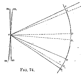
From the axis o draw op op, perpendicular to m m and to m′ m′,
respectively. Then, supposing there is no such effect, the course of the
axis of the pencil of light would be a o c mirror c o a′. That is, the
angle of deflection would be a o a′, double the angle p o p′. If now
the mirror be supposed to carry the pencil with it, let o c′ be the
direction of the pencil on leaving the mirror m m; i.e., the motion of
the mirror has changed the direction of the reflected ray through the
angle c o c′. The course would then be a o c, mirror c′ o. From o
the reflection would take place in the direction a″, making the angles
c′ o p, and p′ o a″ equal. But the angle c o c′ must be added to p
o a″, in consequence of the motion of the mirror, or the angle of
deviation will be a o a″ + c o c′; or a o a″ + c o c′ = d. (1)
By construction—
c o p′ = p′ o a′ (2)
c′ o p′ = p′ o a″ (3)
Subtracting (3) from (2) we have—
c o p′ - c′ o p′ = p′ o a′ - p′ o a″, or
c o c′ = a′ o a″
Substituting a′ o a″ for c o c′ in (1) we have—
a o a″ + a′ o a″ = a o a′ = d.
Or the deflection has remained unaltered.
Retardation Caused by Reflection.
Cornu, in answering the objection that there may be an unknown retardation
by reflection from the distant mirror, says that if such existed the error
it would introduce in his own work would be only 1/7000 that of Foucault,
on account of the great distance used, and on account of there being in
his own experiments but one reflection instead of twelve.
In my own experiments the same reasoning shows that if this possible error
made a difference of 1 per cent. in Foucault's work (and his result is
correct within that amount), then the error would be but .00003 part.
Distortion of the Revolving Mirror.
It, has been suggested that the distortion of the revolving mirror, either
by twisting or by the effect of centrifugal force, might cause an error in
the deflection.
The only plane in which the deflection might be affected is the plane of
rotation. Distortions in a vertical plane would have simply the effect of
raising, lowering, or extending the slit.
Again, if the mean surface is plane there will be no effect on the
deflection, but simply a blurring of the image.
Even if there be a distortion of any kind, there would be no effect on the
deflection if the rays returned to the same portion whence they were
reflected.
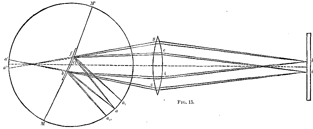
The only case which remains to be considered, then, is that given in Fig.
15, where the light from the slit a, falls upon a distorted mirror, and
the return light upon a different portion of the same.
The one pencil takes the course a b c d e f a′, while the other follows
the path a f g h i b a′.
In other words, besides the image coinciding with a, there would be two
images, one on either side of a, and in case there were more than two
portions having different inclinations there would be formed as many
images to correspond. If the surfaces are not plane, the only effect is to
produce a distortion of the image.
As no multiplication of images was observed, and no distortion of the one
image, it follows that the distortion of the mirror was too small to be
noticed, and that even if it were larger it could not affect the
deflection.
The figure represents the distorted mirror at rest, but the reasoning is
the same when it is in motion, save that all the images will be deflected
in the direction of rotation.
Imperfection of the Lens.
It has also been suggested that, as the pencil goes through one-half of
the lens and returns through the opposite half, if these two halves were
not exactly similar, the return image would not coincide with the slit
when the mirror was at rest. This would undoubtedly be true if we consider
but one-half of the original pencil. It is evident, however, that the
other half would pursue the contrary course, forming another image which
falls on the other side of the slit, and that both these images would come
into view, and the line midway between them would coincide with the true
position. No such effect was observed, and would be very unlikely to
occur. If the lens was imperfect, the faults would be all over the
surface, and this would produce simply an indistinctness of the image.
Moreover, in the latter part of the observations the mirror was inverted,
thus producing a positive rotation, whereas the rotation in the preceding
sets was negative. This would correct the error mentioned if it existed,
and shows also that no constant errors were introduced by having the
rotation constantly in the same direction, the results in both cases being
almost exactly the same.
Periodic Variations in Friction.
If the speed of rotation varied in the same manner in each revolution of
the mirror, the chances would be that, at the particular time when the
reflection took place, the speed would not be the same as the average
speed found by the calculation. Such a periodic variation could only be
caused by the influence of the frame or the pivots. For instance, the
frame would be closer to the ring which holds the mirror twice in every
revolution than at other times, and it would be more difficult for the
mirror to turn here than at a position 90° from this. Or else there might
be a certain position, due to want of trueness of shape of the sockets,
which would cause a variation of friction at certain parts of the
revolution.
To ascertain if there were any such variations, the position of the frame
was changed in azimuth in several experiments. The results were unchanged
showing that any such variation was too small to affect the result.
Change of Speed of Rotation.
In the last four sets of observations the speed was lowered from 256 turns
to 192, 128, 96, and 64 turns per second. The results with these speeds
were the same as with the greater speed within the limits of errors of
experiment.
Bias.
Finally, to test the question if there were any bias in taking these
observations, eight sets of observations were taken, in which the readings
were made by another, the results being written down without divulging
them. Five of these sets are given in the "specimen," pages 133-134.
It remains to notice the remarkable coincidence of the result of these
experiments with that obtained by Cornu by the method of the "toothed
wheel."
Cornu's result was 300400 kilometers, or as interpreted by Helmert 299990
kilometers. That of these experiments is 299940 kilometers.
Postscript.
The comparison of the micrometer with two scales made by Mr. Rogers, of
the Harvard Observatory, has been completed. The scales were both on the
same piece of silver, marked "Scales No. 25, on silver. Half inch at
58° F., too short .000009 inch. Centimeter at 67° F., too short .00008 cm."
It was found that the ratio .3937079 could be obtained almost exactly, if,
instead of the centimeter being too short, it were too long by .00008
cm. at 67°.
On this supposition the following tables were obtained. They represent the
value of one turn of the micrometer in millimeters.
Table 1 is the result from centimeter scale.
Table 2 is the result from half-inch scale.
Table 3 is the result from page 31.
It is seen from the correspondence in these results, that the previous
work is correct.
| (1) | (2) | (3) |
|---|
| From 0 to | 13 | .99563 | .99562 | .99570 |
| 25 | .99562 | .99564 | .99571 |
| 38 | .99560 | .99572 | .99576 |
| 51 | .99567 | .99578 | .99580 |
| 64 | .99577 | .99586 | .99585 |
| 76 | .99582 | .99590 | .99592 |
| 89 | .99590 | .99598 | .99601 |
| 102 | .99596 | .99608 | .99605 |
| 115 | .99606 | .99614 | .99615 |
| 128 | .99618 | .99622 | .99623 |
| 140 | .99629 | .99633 | .99630 |
*** END OF THE PROJECT GUTENBERG EBOOK 11753 ***