The Project Gutenberg EBook of Scientific American Supplement, No. 446,
July 19, 1884, by Various

This eBook is for the use of anyone anywhere at no cost and with
almost no restrictions whatsoever.  You may copy it, give it away or
re-use it under the terms of the Project Gutenberg License included
with this eBook or online at www.gutenberg.org


Title: Scientific American Supplement, No. 446, July 19, 1884

Author: Various

Release Date: March 1, 2004 [EBook #11385]

Language: English

Character set encoding: ISO-8859-1

*** START OF THIS PROJECT GUTENBERG EBOOK SCIENTIFIC AMERICAN SUPP. 446 ***


Produced by Jon Niehof, Don Kretz, Juliet Sutherland, Charles Franks
and the DP Team
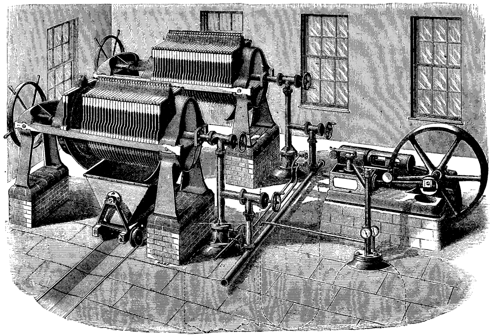
Hitherto it has been found that of all the appliances and methods for separating the liquid from the solid matters, whether it is in the case of effluents from tanneries and other manufactories, or the ocherous and muddy sludges taken from the settling tanks in mines, some of which contain from 90 to 95 per cent. of water, the filter press is the best and the most economical, and it is to this particular process that Messrs. Johnson's exhibits at the Health Exhibition, London, chiefly relate. Our engravings are from The Engineer. A filter press consists of a number of narrow cells of cast iron, shown in Figs. 3 and 4, held together in a suitable frame, the interior frames being provided with drainage surfaces communicating with outlets at the bottom, and covered with a filtering medium, which is generally cloth or paper. The interior of the cells so built up are in direct communication with each other, or with a common channel for the introduction of the matter to be filtered, and as the only exit is through the cloth or paper, the solid portion is kept back while the liquid passes through and escapes by the drainage surfaces to the outlets. The cells are subjected to pressure, which increases as the operation goes on, from the growing resistance offered by the increasing deposit of solid matter on the cloths; and it is therefore necessary that they should be provided with a jointing strip around the outside, and be pressed together sufficiently to prevent any escape of liquid. In ordinary working both sides of the cell are exposed to the same pressure, but in some cases the feed passages become choked, and destroy the equilibrium. This, in the earlier machines, gave rise to considerable annoyance, as the diaphragms, being thin, readily collapsed at even moderate pressures; but recently all trouble on this head has been obviated by introducing the three projections near the center, as shown in the cuts, which bear upon each other and form a series of stays from one end of the cells to the other, supporting the plates until the obstruction is forced away. We give an illustration below showing the arrangement of a pair of filter presses with pneumatic pressure apparatus, which has been successfully applied for dealing with sludge containing a large amount of fibrous matter and rubbish, which could not be conveniently treated with by pumps in the ordinary way. The sludge is allowed to gravitate into wrought iron receivers placed below the floor, and of sufficient size to receive one charge. From these vessels it is forced into the presses by means of air compressed to from 100 lb. to 120 lb. per square inch, the air being supplied by the horizontal pump shown in the engraving. The press is thus almost instantaneously filled, and the whole operation is completed in about an hour, the result being a hard pressed cake containing about 45 per cent. of water, which can be easily handled and disposed of as required. The same arrangement is in use for dealing with sewage sludge, and the advantages of the compressed air system over the ordinary pumps, as well as the ready and cleanly method of separating the liquid, will probably commend itself to many of our readers. We understand that from careful experiments on a large scale, extending over a period of two years, the cost of filtration, including all expenses, has been found to be not more than about 6d. per ton of wet sludge. A number of specimens of waste liquors from factories with the residual matters pressed into cakes, and also of the purified effluents, are exhibited. These will prove of interest to many, all the more so since in some instances the waste products are converted into materials of value, which, it is stated, will more than repay for the outlay incurred.
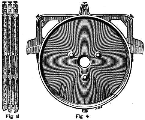
Fig. 3. Fig 4.
Another application of the filter press is in the Porter-Clark process of softening water, which is shown in operation. We may briefly state that the chief object is to precipitate the bicarbonates of lime and magnesia held in solution by the water, and so get rid of what is known as the temporary hardness. To accomplish this, strong lime water is introduced in a clear state to the water to be softened, the quantity being regulated according to the amount of bicarbonates in solution. The immediate effect of this is that a proportion of the carbonic acid of the latter combines with the invisible lime of the clear lime water, forming a chalky precipitate, while the loss of this proportion of carbonic acid also reduces the invisible bicarbonates into visible carbonates. The precipitates thus formed are in the state of an impalpable powder, and in the original Clark process many hours were required for their subsidence in large settling tanks, which had to be in duplicate in order to permit of continuous working. By Mr. Porter's process, however, this is obviated by the use of filter presses, through which the chalky water is passed, the precipitate being left behind, while, by means of a special arrangement of cells, the softened and purified water is discharged under pressure to the service tanks. Large quantities can thus be dealt with, within small space, and in many cases no pumping is required, as the resistance of the filtering medium being small, the ordinary pressure in the main is but little reduced. One of the apparatus exhibited is designed for use in private mansions, and will soften and filter 750 gallons a day. In such a case, where it would probably be inconvenient to apply the usual agitating machinery, special arrangements have been made by which all the milk of lime for a day's working is made at one time in a special vessel agitated by hand, on the evening previous to the day on which it is to be used. Time is thus given for the particles of lime to settle during the night. The clear lime water is introduced into the mixing vessel by means of a charge of air compressed in the top of a receiver, by the action of water from the main, the air being admitted to the milk of lime vessel through a suitable regulating valve. A very small filter suffices for removing the precipitate, and the clear, softened water can either be used at once, or stored in the usual way. The advantages which would accrue to the community at large from the general adoption of some cheap method of reducing the hardness of water are too well known to need much comment from us.
According to K. Lintner, the worst features of the present system of malting are the inequalities of water and temperature in the heaps and the irregular supplies of oxygen to, and removal of carbonic acid from, the germinating grain. The importance of the last two points is demonstrated by the facts that, when oxygen is cut off, alcoholic fermentation--giving rise to the well-known odor of apples--sets in in the cells, and that in an atmosphere with 20 per cent. of carbonic acid, germination ceases. The open pneumatic system, which consists in drawing warm air through the heaps spread on a perforated floor, should yield better results. All the processes are thoroughly controlled by the eye and by the thermometer, great cleanliness is possible, and the space requisite is only one-third of that required on the old plan. Since May, 1882, this method has been successfully worked at Puntigam, where plant has been established sufficient for an annual output of 7,000 qrs. of malt. The closed pneumatic system labors under the disadvantages that from the form of the apparatus germination cannot be thoroughly controlled, and cleanliness is very difficult to maintain, while the supply of oxygen is, as a rule, more irregular than with the open floors.
IMPROVED PNEUMATIC FILTERING PRESSES.
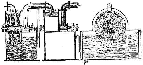
The washer is an appliance intended to condense and clean gas, which, on leaving the hydraulic main, holds in suspension a great many properties that are injurious to its illuminating power, and cannot, if retained, be turned to profitable account. This cleaning process is not difficult to carry out effectually; and most of the appliances invented for the purpose would be highly efficacious if they did not in other respects present certain very serious inconveniences. The passage of the gas through a column of cold water is, of course, sufficient to condense it, and clear it of these injurious properties; but this operation has for its immediate effect the presentation of an obstacle to the flow of the gas, and consequently augmentation of pressure in the retorts. In order to obviate this inconvenience (which exists notwithstanding the use of the best washers), exhausters are employed to draw the gas from the retorts and force it into the washers. There is, however, another inconvenience which can only be remedied by the use of a second exhauster, viz., the loss of pressure after the passage of the gas through the washer--a loss resulting from the obstacle presented by this appliance to the steady flow of the gas. Now as, in the course of its passage through the remaining apparatus, on its way to the holder, the gas will have to suffer a considerable loss of pressure, it is of the greatest importance that the washer should deprive it of as little as possible. It will be obvious, therefore, that a washer which fulfills the best conditions as far as regards the cleaning of the gas will be absolutely perfect if it does not present any impediment to its flow. Such an appliance is that which is shown in the illustration on next page. Its object is, while allowing for the washing being as vigorous and as long-continued as may be desired, to draw the gas out of the retorts, and, having cleansed it perfectly from its deleterious properties, to force it onward. The apparatus consequently supplies the place of the exhauster and the scrubber.
The new washer consists of a rectangular box of cast iron, having a half-cylindrical cover, in the upper part of which is fixed a pipe to carry off the gas. In the box there is placed horizontally a turbine, the hollow axis of which serves for the conveyance of the gas into the vessel. For this purpose the axis is perforated with a number of small holes, some of which are tapped, so as to allow of there being screwed on to the axis, and perpendicularly thereto, a series of brooms made of dog grass, and having their handles threaded for the purpose. These brooms are arranged in such a way as not to encounter too great resistance from contact with the water contained in the vessel, and so that the water cast up by them shall not be all thrown in the same direction. To obviate these inconveniences they are fixed obliquely to the axis of the central pipe, and are differently arranged in regard to each other. A more symmetrical disposition of them could, however, be adopted by placing them zigzag, or in such a way as to form two helices, one of which would move in a particular direction, and the other in a different way. The central pipe, furnished with its brooms, being set in motion by means of a pulley fixed upon its axis (which also carries a flywheel), the gas, drawn in at the center, and escaping by the holes made in the pipe, is forced to the circumference of the vessel, where it passes out.
The effect of this washer is first, to break up the current of gas, and then force it violently into the water; at the same time sending into it the spray of water thrown up by the brooms. This double operation is constantly going on, so that the gas, having been saturated by the transfusion into it of a vigorous shower of water (into the bulk of which it is subsequently immersed), is forced, on leaving the water, to again undergo similar treatment. The same quantity of gas is therefore several times submitted to the washing process, till at length it finds its way to the outlet, and makes its escape. The extent to which the washing of the gas is carried is, consequently, only limited by the speed of the apparatus, or rather by the ratio of the speed to the initial pressure of the gas. This limit being determined, the operation may be continued indefinitely, by making the gas pass into several washers in succession. There is, therefore, no reason why the gas should not, after undergoing this treatment, be absolutely freed of all those properties which are susceptible of removal by water. In fact, all that is requisite is to increase the dimensions of the vessel, so as to compel the gas to remain longer therein, and thus cause it to undergo more frequently the operation of washing. These dimensions being fixed within reasonable limits, if the gas is not sufficiently washed, the speed of the apparatus may be increased; and the degree of washing will be thereby augmented. If this does not suffice, the number of turbines may be increased, and the gas passed from one to the other until the gas is perfectly clean. This series of operations would, however, with any kind of washer, result in thoroughly cleansing the gas. The only thing that makes such a process practically impossible is the very considerable or it may be even total loss of pressure which it entails. By the new system, the loss of pressure is nil, inasmuch as each turbine becomes in reality an exhauster. The gas, entering the washer at the axis, is drawn to the circumference by the rotatory motion of the brooms, which thus form a ventilator. It follows, therefore, that on leaving the vessel the gas will have a greater pressure than it had on entering it; and this increase of pressure may be augmented to any desired extent by altering the speed of rotation of the axis, precisely as in the case of an exhauster.
Forcing the gas violently into water, and at the same time dividing the current, is evidently the most simple, rational, and efficient method of washing, especially when this operation is effected by brooms fixed on a shaft and rotated with great speed. Therefore, if there had not been this loss of pressure to deal with--a fatal consequence of every violent operation--the question of perfect washing would probably have been solved long ago. The invention which I have now submitted consists of an arrangement which enables all loss of pressure to be avoided, inasmuch as it furnishes the apparatus with the greatest number of valuable qualities, whether regarded from the point of view of washing or that of condensation.
Longitudinal Section. Elevation. Transverse Section.
Referring to the illustration, the gas enters the washer by the pipe, A, which terminates in the form of a [Symbol: inverted T]. One end (a) of this pipe is bolted to the center of one of the sides of the cylindrical portion of the case, in which there is a hole of similar diameter to the pipe; the other (a') being formed by the face-plate of a stuffing-box, B, through which passes the central shaft, C, supported by the plummer-block, D, as shown. This shaft has upon its opposite end a plate perforated with holes, E, which is fixed upon the flange of a horizontal pipe, F. This pipe is closed at the other end by means of a plate, E', furnished with a spindle, supported by a stuffing-box, B', and carrying a fly-wheel, G. The central pipe, F, is perforated with a number of small holes. The gas entering by the pipe, A, makes its way into the central pipe through the openings in the plate, E, and passes into the cylindrical case through the small holes in the central pipe, which carries the brooms, H. These are caused to rotate rapidly by means of the pulley, I; and thus a constant shower of water is projected into the cylindrical case. When the gas has been several times subjected to the washing process, it passes off by the pipe, K. Fresh cold water is supplied to the vessel by the pipe, L; and M is the outlet for the tar.--Journal of Gas Lighting.
[Footnote: A paper read before the Engineers' Club of St. Louis, 1884.]
In the history of the world the utilization of the wind as a motive power antedates the use of both water and steam for the same purpose.
The advent of steam caused a cessation in the progress of wind power, and it was comparatively neglected for many years. But more recently attention has been again drawn to it, with the result of developing improvements, so that it is now utilized in many ways.
The need in the West of a motive power where water power is rare and fuel expensive has done much to develop and perfect wind mills.
Wind mills, as at present constructed in this country, are of recent date.
The mill known as the "Eclipse" was the first mill of its class built. It is known as the "solid-wheel, self-regulating pattern," and was invented about seventeen years ago. The wind wheel is of the rosette type, built without any joints, which gives it the name "solid wheel," in contradistinction to wheels made with loose sections or fans hinged to the arms or spokes, and known as "section wheel mills."
The regulation of the Eclipse mill is accomplished by the use of a small adjustable side vane, flexible or hinged rudder vane, and weighted lever, as shown in Plate 1 (on the larger sizes of mills iron balls attached to a chain are used in place of the weighted lever). The side vane and weight on lever being adjustable, can be set to run the mill at any desired speed.
Now you will observe from the model that the action of the governing mechanism is automatic. As the velocity of the wind increases, the pressure on the side vane tends to carry the wind wheel around edgewise to the wind and parallel to the rudder vane, thereby changing the angle and reducing the area exposed to the wind; at the same time the lever, with adjustable weight attached, swings from a vertical toward a horizontal position, the resistance increasing as it moves toward the latter position. This acts as a counterbalance of varying resistance against the pressure of the wind on the side vane, and holds the mill at an angle to the plane of the wind, insuring thereby the number of revolutions per minute required, according to the position to which the governing mechanism has been set or adjusted.
If the velocity of the wind is such that the pressure on the side vane overcomes the resistance of the counter weight, then the side vane is carried around parallel with the rudder vane, presenting only the edge of the wind wheel or ends of the fans to the wind, when the mill stops running.
This type of mill presents more effective wind receiving or working surface when in the wind, and less surface exposed to storms when out of the wind, than any other type of mill. It is at all times under the control of an operator on the ground.
A 22-foot Eclipse mill presents 352 square feet of wind receiving and working surface in the wind, and only 9½ square feet of wind resisting surface when out of the wind.
Solid-wheel mills are superseding all others in this country, and are being exported largely to all parts of the world, in sizes from 10 to 30 feet in diameter. Many of these mills have withstood storms without injury, where substantial buildings in the immediate vicinity have been badly damaged. I will refer to some results accomplished with pumping mills:
In the spring of 1881 there was erected for Arkansas City, Kansas, a 14-foot diameter pumping wind mill; a 32,000-gallon water tank, resting on a stone substructure 15 feet high, the ground on which it stands being 4 feet higher than the main street of the town. One thousand four hundred feet of 4-inch wood pipe was used for mains, with 1,200 feet of 1½-inch wrought iron pipe. Three 3-inch fire hydrants were placed on the main street. The wind mill was located 1,100 feet from the tank, and forced the water this distance, elevating it 50 feet. We estimate that this mill is pumping from 18,000 to 20,000 gallons of water every twenty-four hours. We learned that these works have saved two buildings from burning, and that the water is being used for sprinkling the streets, and being furnished to consumers at the following rates per annum: Private houses, $5; stores, $5; hotels, $10; livery stables, $15. At these very low rates, the city has an income of $300 per annum. The approximate cost of the works was $2,000. This gives 15 per cent. interest on the investment, not deducting anything for repairs or maintenance, which has not cost $5 per annum so far.
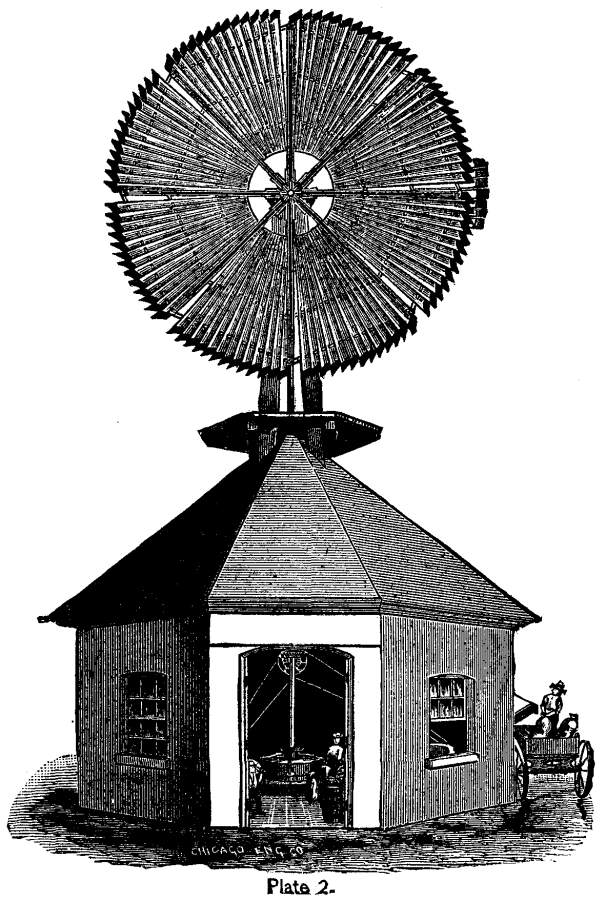
Plate 2. THE ECLIPSE WIND MILL.
In June, 1883, a wind water works system was erected for the city of McPherson, Kansas, consisting of a 22-foot diameter wind mill on a 75-foot tower, which pumps the water out of a well 80 feet deep, and delivers it into a 60,000-gallon tank resting on a substructure 43 feet above the ground. Sixteen hundred feet of 6-inch and 300 feet of 4-inch cast iron pipe furnish the means of distribution; eight 2½-inch double discharge fire hydrants were located on the principal streets. A gate valve was placed in the 6-inch main close to the elbow on lower end of the down pipe from the tank. This pipe is attached to the bottom of the tank; another pipe was run up through the bottom of tank 9 feet (the tank being 18 feet deep), and carried down to a connection with the main pipe just outside the gate valve. The operation of this arrangement is as follows:
The gate valve being closed, the water cannot be drawn below the 9-foot level in tank, which leaves about 35,000 gallons in store for fire protection, and is at once available by opening the gate valve referred to. The tank rests on ground about 5 feet above the main streets, which gives a head of 57 feet when the tank is half full. The distance from tank to the farthest hydrant being so short, they get the pressure due to this head at the hydrant, when playing 2-inch, or 1-1/8-inch streams, with short lines of 2½-inch hose; this gives fair fire streams for a town with few if any buildings over two stories high. It is estimated that this mill is pumping from 30,000 to 38,000 gallons on an average every twenty-four hours. There is an automatic device attached to this mill, which stops it when the tank is full, but as soon as the water in the tank is lowered, it goes to pumping again. The cost of these works complete to the city was a trifle over $6,000.
In November last a wind mill 18 feet in diameter was erected over a coal mine at Richmond, in this State. The conditions were as follows:
The mine produces 11,000 gallons of water every twenty-four hours. The sump holds 11,000 gallons. Two entries that can be dammed up give a storage of 16,500 gallons, making a total storage capacity of 27,500 gallons. It takes sixty hours for the mine to produce this quantity of water, which allows for days that the wind does not blow. The average elevation that the water has to be raised is 65 feet, measuring from center of sump to point of delivery. A record of ninety days shows that this mill has kept the mine free from water with the exception of 6,000 gallons, which was raised in the boxes that the coal is raised in. The location is not good for a wind mill, as it stands in a narrow ravine or valley a short distance from its mouth, which terminates at the bottom lands of the Missouri River. This, taken in connection with the fact that the grit in the water cuts the pump plunger packing so fast that in a short time the pump will not work up to its capacity, accounts for the apparent small amount of power developed by this mill.
There has been some discussion of late in regard to the horse power of wind mills, one party claiming that they were capable of doing large amounts of grinding and showing a development of power that was surprising to the average person unacquainted with wind mills, while the other party has maintained that they were not capable of developing any great amount of power, and has cited their performance in pumping water to sustain his argument. My experience has has led me to the conclusion that pumping water with a wind mill is not a fair test of the power that it is capable of developing, for the following reasons:
A pumping wind mill is ordinarily attached to a pump of suitable size to allow the mill to run at a mean speed in an 8 to 10 mile wind. Now, if the wind increases to a velocity of 16 to 20 miles per hour, the mill will run up to its maximum speed and the governor will begin to act, shortening sail before the wind attains this velocity. Therefore, by a very liberal estimate, the pump will not throw more than double the quantity that it did in the 8 to 10 mile wind, while the power of the mill has quadrupled, and is capable of running at least two pumps as large as the one to which it is attached. As the velocity of the wind increases, this same proportion of difference in power developed to work done holds good.
St. Louis is not considered a very windy place, therefore the following table may be a surprise to some. This table was compiled from the complete record of the year 1881, as recorded by the anemometer of the United States Signal Office on the Mutual Life Insurance Building, corner of Sixth and Locust streets, this city. It gives the number of hours each month that the wind blew at each velocity, from 6 to 20 miles per hour during the year; also the maximum velocity attained each month.
Complete Wind Record at St. Louis for the Year 1881.
_______________________________________________________________________________
      |No.    |No.    |No.    |No.    |No.    |No.    |No.    |No.    |
      |hours  |hours  |hours  |hours  |hours  |hours  |hours  |hours  |Maximum
      |wind   |wind   |wind   |wind   |wind   |wind   |wind   |wind   |velocity
YEAR  |blew 6 |blew 8 |blew 10|blew 12|blew 14|blew 16|blew 18|blew 20|during
1881. |miles  |miles  |miles  |miles  |miles  |miles  |miles  |miles  |each
MONTHS|or over|or over|or over|or over|or over|or over|or over|or over|month.
______|_______|_______|_______|_______|_______|_______|_______|_______|____
      |H.   M.|H.   M.|H.   M.|H.   M.|H.   M.|H.   M.| H.  M.| H.  M.|
Jan.  | 545 45| 429 45| 289 00| 198 15| 131 30|  87 15|  56 00|  38 45| 31
Feb.  | 619 30| 533 15| 449 15| 374 15| 287 00| 207 15| 151 15| 110 30| 32
March.| 604 15| 534 30| 449 45| 368 45| 296 30| 243 45| 191 00| 158 45| 37
April.| 577 15| 468 45| 342 45| 359 30| 175 00| 121 00|  62 45|  36 00| 28
May.  | 553 00| 375 00| 226 15| 138 00|  74 45|  42 30|  23 45|  11 30| 31
June. | 614 15| 463 45| 303 30| 215 15| 123 45|  76 30|  29 45|  17 45| 32
July. | 556 45| 378 00| 228 15| 136 15|  55 30|  22 30|   6 00|   2 30| 22
Aug.  | 536 30| 345 00| 176 00|  80 30|  35 45|  22 15|  17 15|  15 00| 34
Sept. | 564 15| 445 45| 326 45| 224 45| 145 30|  96 45|  70 00|  46 45| 30
Oct.  | 617 30| 501 45| 368 45| 363 00| 170 00|  93 45|  40 30|  27 45| 27
Nov.  | 642 45| 537 30| 428 45| 328 30| 226 00| 151 45| 100 30|  74 00| 30
Dec.  | 592 15| 516 30| 390 00| 308 45| 224 45| 167 45| 110 45|  67 00| 30
------+-------+-------+-------+-------+-------+-------+-------+-------+-----
Totals|7,024  |5,529  |3,981  |2,995  |1,946  |1,335  | 868   | 606   | --
      |     00|     30|     00|     45|     00|     00|     30|     15|
Max.  |       |       |       |       |       |       |       |       |
for   | ----- | ----- | ----- | ----- | ----- | ----- | ----- | ----- | 37
year  |       |       |       |       |       |       |       |       |
______|_______|_______|_______|_______|_______|_______|_______|_______|____
The location of a mill has a great deal to do with the results attained. Having had charge of the erection of a large number of these mills for power purposes, I will refer to a few of them in different States, giving the actual results accomplished, and leaving you to form your own opinion as to the power developed.
In 1877 a 25-foot diameter mill was erected at Dover, Kansas, a few miles southwest of Topeka. It was built to do custom flour and feed grinding, also corn shelling, and is in successful operation at the present time. We have letters frequently from the owner; one of recent date states that it has stood all of the "Kansas zephyrs," never having been damaged as yet. On an average it shells and grinds from 6 to 10 bushels of corn per hour, and runs a 14 inch burr stone, grinding wheat at the same time. During strong winds it has shelled and ground as high as 30 bushels of corn per hour. Plate 2 is from a photograph of this mill and building as it stands. One bevel pinion is all the repairs this mill has required.
In the spring of 1880 there was erected a 25-foot diameter mill at Harvard, Clay County, Neb. After this mill had been running nineteen months, we received the following report from the owner:
"During the nineteen months we have been running the wind mill, it has cost us nothing for repairs. We run it with a two-hole corn sheller, a set of 16-inch burr stones, and an elevator. We grind all kinds of feed, also corn meal and Graham flour. We have ground 8,340 bushels, and would have ground much more if corn had not been a very poor crop here for the past two seasons; besides, we have our farm to attend to, and cannot keep it running all the time that we have wind. We have not run a full day at any time, but have ground 125 bushels in a day. When the burr is in good shape we can grind 20 bushels an hour, and shell at the same time in the average winds that we have. The mill has withstood storms without number, even one that blew down a house near it, and another that blew down many smaller mills. It is one of the best investments any one can make."
The writer saw this mill about sixty days ago, and it is in good shape, and doing the work as stated. The only repairs that it has required during four years was one bevel pinion put on this spring.
The owner of a 16-foot diameter mill, erected at Blue Springs. Neb., says that "with a fair wind it grinds easily 15 bushels of corn per hour with a No. 3 grinder, also runs a corn-sheller and pump at the same time, and that it works smoothly and is entirely self-regulating."
The No. 3 grinder referred to has chilled iron burrs, and requires from 3 to 4 horse-power to grind 15 bushels of corn per hour. Of one of these 16-foot mills that has been running since 1875 in Northern Illinois, the owner writes: "In windy days I saw cord-wood as fast as the wood can be handled, doing more work than I used to accomplish with five horses."
The owner of one of these mills, 20 feet in diameter, running in the southwestern part of this State, writes that he has a corn-sheller and two iron grinding mills with 8-inch burrs attached to it; also a bolting device; that this mill is more profitable to him than 80 acres of good corn land, and that it is easily handled and has never been out of order. The following report on one of these 16-foot mills, running in northern Illinois, may be of interest: This mill stands between the house and barn. A connection is made to a pump in a well-house 25 feet distant, and is also arranged to operate a churn and washing machine. By means of sheaves and wire cable, power is transmitted to a circular saw 35 feet distant. In this same manner power is transmitted to the barn 200 feet distant, where connection is made to a thrasher, corn-sheller, feed-cutter, and fanning-mill. The corn-sheller is a three horse-power, with fan and sacker attached. Three hundred bushels per day has been shelled, cleaned, and sacked. The thrashing machine is a two horsepower with vibrating attachment for separating straw from grain. One man has thrashed 300 bushels of oats per day, and on windy days says the mill would run a thrasher of double this capacity. The saw used is 18 inches diameter, and on windy days saws as much wood as can be done by six horses working on a sweep power. The owner furnishes the following approximate cost of mill with the machinery attached and now in use on his place:
  1 16-foot power wind mill, shafting, and tower.    $385
  1 Two horse thrasher.                                70
  1 Three horse sheller.                               38
  1 Feed grinder.                                      50
  1 18-inch saw, frame and arbor.                      40
  1 Fanning mill.                                      25
  1 Force pump.                                        27
  1 Churn.                                              5
  1 Washing machine.                                   15
  Belting, cables, and pulleys.                        45
                                                     ----
                                       Total.        $700
The following facts and figures furnished by the owner will give a fair idea of the economic value of this system, as compared with the usual methods of doing the same work. On the farm where it is used, there are raised annually an average of sixty acres of oats, fifty acres of corn, twenty acres of rye, ten acres of buckwheat.
                                                   Bushels.
  The oats average, say 30 bushels per acre.        1,800
  Corn        "         30    "        "            1,500
  Rye         "         20    "        "              400
  Buckwheat   "         20    "        "              200
  Grinding for self and others.                     1,000


  It will cost to thrash this grain, shell the corn, and
    grind the feed with steam power.                 $285
  And sawing wood, 12½ cords.                          18
  Pumping, one hour per day, 365 days.                 36
  Churning, half hour per day, 200 days.               10
  Washing, half day per week, 26 days.                 26
                                                     ----
                                     Total.          $375
This amount is saved, and more too, as one man, by the aid of the wind mill, will do this work in connection with the chores of the farm, and save enough in utilizing foul weather to more than offset his extra labor, cost of oil, etc., for the machinery. The amount saved each year is just about equal to the cost of a good man. Cost of outfit, $700--just about equal to the cost of a good man for two years, consequently, it will pay for itself in two years. Fifteen years is a fair estimate for the lifetime of mill with ordinary repairs.
The solid-wheel wind mill has never been built larger than 30 feet in diameter. For mills larger than this, the latest improved American mill is the "Warwick" pattern.
A 30-foot mill of this pattern, erected in 1880, in northwestern Iowa, gave the following results, as reported by the owner:
"Attachments as follows: One 22-inch burr; one No. 4 iron feed-mill; one 26-inch circular saw; one two-hole corn-sheller; one grain elevater; a bolting apparatus for fine meal, buckwheat and graham, all of which are run at the same time in good winds, except the saw or the iron mill; they being run from the same pulley can run but one at a time. With all attached and working up to their full capacity, the sails are often thrown out of the wind by the governors, which shows an immense power. The machines are so arranged that I can attach all or separately, according to the wind. With the burr alone I have ground 500 bushels in 48 consecutive hours, 100 bushels of it being fine meal. I have also ground 24 full bushels of fine meal for table use in two hours. This last was my own, consequently was not tolled. This was before I bought the iron mill, and now I can nearly double that amount. I saw my fire wood for three fires; all my fence posts, etc. My wood is taken to the mill from 12 to 15 feet long, and as large as the saw will cut by turning the stick, consequently the saw requires about the same power as the burrs. With a good sailing breeze I have all the power I need, and can run all the machinery with ease. Last winter I ground double the amount of any water mill in this vicinity. I have no better property than the mill."
A 40-foot mill, erected at Fowler, Indiana, in 1881, is running the following machinery:
"I have a universal wood worker, four side, one 34-inch planer, jig saw, and lathe, also a No. 4 American grinder, and with a good, fair wind I can run all the machines at one time. I can work about four days and nights each week. It is easy to control in high winds."
A 60-foot diameter mill of similar pattern was erected in Steel County, Minnesota, in 1867. The owner gives the following history of this mill:
"I have run this wind flouring mill since 1867 with excellent success. It runs 3 sets of burrs, one 4 feet, one 3½ feet, and one 33 inches. Also 2 smutters, 2 bolts, and all the necessary machinery to make the mill complete. A 15-mile wind runs everything in good shape. One wind wheel was broken by a tornado in 1870, and another in 1881 from same cause. Aside from these two, which cost $250 each, and a month's lost time, the power did not cost over $10 a year for repairs. In July, 1833, a cyclone passed over this section, wrecking my will as well as everything else in its track, and having (out of the profits of the wind mill) purchased a large water and steam flouring mill here, I last fall moved the wind mill out to Dakota, where I have it running in first-class shape and doing a good business. The few tornado wrecks make me think none the less of wind mills, as my water power has cost me four times as much in 6 years as the wind power has in 16 years."
There are very few of these large mills in use in this country, but there are a great many from 14 to 30 feet in diameter in use, and their numbers are rapidly increasing as their merits become known. The field for the use of wind mills is almost unlimited, and embraces pumping water, drainage, irrigation, elevating, grinding, shelling, and cleaning grain, ginning cotton, sawing wood, churning, running stamp mills, and charging electrical accumulators. This last may be the solution of the St. Louis gas question.
In the writer's opinion the settlement of the great tableland lying between the Mississippi Valley and the Rocky Mountains, and extending from the Gulf of Mexico to the Red River of the North, would be greatly retarded, if not entirely impracticable, in large sections where no water is found at less than 100 to 500 feet below the surface, if it were not for the American wind mill; large cattle ranges without any surface water have been made available by the use of wind mills. Water pumped out of the ground remains about the same temperature during the year, and is much better for cattle than surface water. It yet remains in the future to determine what the wind mill will not do with the improvements that are being made from to time.
It is here shown as mounted on a torpedo launch and ready for action. The shell or projectile is fired by compressed air, admitted from an air reservoir underneath by a simple pressure of the gunner's finger over the valve. The air passes up through the center of the base, the pipe connecting with one of the hollow trunnions. The valve is a continuation of the breech of the gun. The smaller cuts illustrate Lieutenant Zalinski's plan for mounting the gun on each side of the launch, by which plan the gun after being charged may have the breech containing the dynamite depressed, and protected from shots of the enemy by its complete immersion alongside the launch; and, if necessary, may be discharged from this protected position. The gun is a seamless brass tube of about forty feet in length, manipulated by the artillerist in the manner of an ordinary cannon. Its noiseless discharge sends the missile with great force, conveying the powerful explosive within it, which is itself discharged internally upon contact with the deck of a vessel or other object upon which it strikes, through the explosion of a percussion fuse in the point of the projectile. A great degree of accuracy has been obtained by the peculiar form of the projectile.
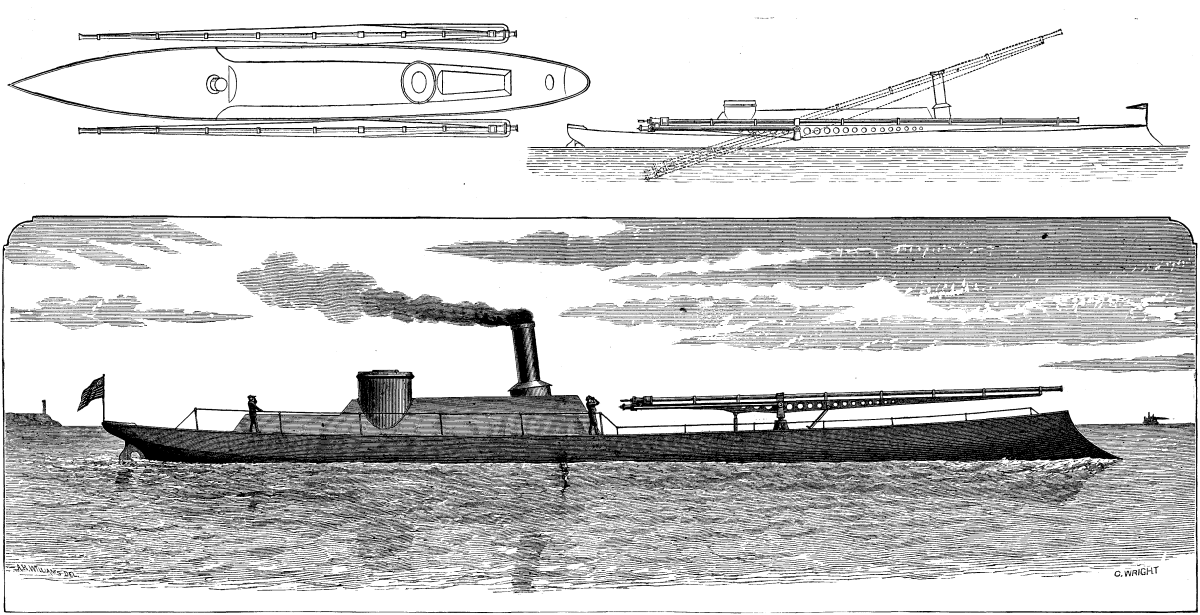
PNEUMATIC DYNAMITE GUN TORPEDO VESSEL.
The projectile consists of a thin metal tube, into which the charge is inserted, and a wooden sabot which closes it at the rear and flares out until its diameter equals that of the bore of the gun. The forward end of the tube is pointed with some soft material, in which is embedded the firing pin, a conical cap closing the end. A cushion of air is interposed at the rear end of the dynamite charge, to lessen the shock of the discharge and prevent explosion, until the impact of the projectile forces the firing pin in upon the dynamite and explodes it. Many charges have been successfully fired at Fort Hamilton, N.Y. As the center of gravity is forward of the center of figure in the projectile, a side wind acting upon the lighter rear part would tend to turn the head into the wind and thus keep it in the line of its trajectory. A range of 1¼ miles has been attained with the two inch gun, with a pressure of 420 lb. to the square inch, and one of three miles is hoped for with the larger gun and a pressure of 2,000 lb.
A novel device in connection with rope pulley blocks is illustrated in the annexed engravings, the object of the appliance being to render it possible to leave a weight suspended from a block without making the tail of the rope fast to some neighboring object. By this arrangement the danger of the rope slipping loose is avoided, and absolute security is attained, without the necessity of lowering the weight to the ground. The device itself is a friction brake, constructed in the form of a clip with holes in it for the three ropes to pass through. It is made to span the block, and is secured partly by the pin or bolt upon which the sheaves run, and partly by the bottom bolt, which unites the cheeks of the block. Thus the brake is readily attachable to existing blocks. The inner half of the clip or brake is fixed solidly to the block, while the outer half is carried by two screws, geared together by spur-wheels, and so cut that although rotating in opposite directions, their movements are equal and similar. One of the screws carries a light rope-wheel, by which it can be rotated, the motion being communicated to the second screw by the toothed wheels. When the wheel is rotated in the right direction the loose half of the clip is forced toward the other half, and grips the ropes passing between the two so powerfully that any weight the blocks are capable of lifting is instantly made secure, and is held until the brake is released.
A light spiral spring is placed on each of the screws, in order to free the brake from the rope the moment the pressure is released. The hand rope has a turn and a half round the pulley, and this obviates the need of holding both ends of it, and thus leaves one hand free to guide the descending weight, or to hold the rope of the pulley blocks. Engineering says these brakes are very useful in raising heavy weights, as the lift can be secured at each pull, allowing the men to move hands for another pull, and as they are made very light they do not cause any inconvenience in moving or carrying the blocks about. Manufactured by Andrew Bell & Co., Manchester.
We have from time to time given accounts in this journal of the system of towage by hauling on a submerged wire rope, first experimented upon by Baron O. De Mesnil and Mr. Max Eyth. On the river Rhine the system has been for many years in successful operation; it has also been used for several years on the Erie Canal in this State. We publish from Engineering a view of one of the wire rope tug boats of the latest pattern adopted for use on the Rhine.
The Cologne Central Towing Company (Central Actien-Gesellschaft für Tauerei und Schleppschifffahrt), by whom the wire rope towage on the Rhine is now carried on, was formed in 1876, by an amalgamation of the Rührorter und Mulheimer Dampfschleppshifffahrt Gesellschaft and the Central Actien-Gesellschaft fur Tauerei, and in 1877 it owned eight wire rope tugs (which it still owns) and seventeen paddle tugs. The company so arranges its work that the wire rope tugs do the haulage up the rapid portion of the Rhine, from Bonn to Bingen, while the paddle tugs are employed on the quieter portion of the river extending from Rotterdam to Bonn, and from Bingen to Mannheim.

ROPE PULLEY FRICTION BRAKE.
The leading dimensions of the eight wire rope tugs now worked by the company are as follows:
                             Tugs No. I. to     Tugs No. V. to
                                  IV.                VIII.
                            Meters.  ft. in.  Meters.   ft. in.
  Length between
  perpendiculars             39    = 126  0     42    = 137 10
  Length over all            42.75 = 140  3     45.75 = 150  1
  Extreme breadth             7.2  =  28  8      7.5  =  24  5
  Height of sides             2.38 =   7 11      2.38 =   7 11
  Depth of keel               0.12 =   0  5      0.15 =   0  6
All the boats are fitted with twin screws, 1.2 meters (3 feet 11¼ inches) in diameter, these being used on the downstream journey, and also for assisting in steering while passing awkward places during the journey up stream. They are also provided with water ballast tanks, and under ordinary circumstances they have a draught of 1.3 to 1.4 meters (4 feet 3 inches to 4 feet 7 inches), this draught being necessary to give proper immersion to the screws. When the water in the Rhine is very low, however, the water ballast is pumped out and the tugs are then run with a draught of 1 meter (3 feet 3 3/8 inches), it being thus possible to keep them at work when all other towing steamers on the Rhine are stopped. This happened in the spring of 1882.
Referring to our engraving, it will be seen that the wire rope rising from the bed of the river passes first over a large guide pulley, the axis of which is carried by a substantial wrought iron swinging bracket, this bracket being so pivoted that while the pulley is free to swing into the line on which the rope is approached by the vessel, yet the rope on leaving the pulley is delivered in a line which is tangential to a second guide pulley placed further aft and at a lower level. This last named guide pulley does not swing, and from it the rope is delivered to the clip drum, over which it passes. From the clip drum the rope passes under a third guide pulley; this pulley swings on a bracket having a vertical axis. This third pulley projects down below the keel of the tug boat, so that the rope on leaving it can pass under the vessel without fouling. Suitable recesses are formed in the side of the tug boat to accommodate the swinging pulleys, while the bow of the boat is sloped downward nearly to the water line, as shown, so as to allow of the rising part of the rope swinging over it if necessary.
The hauling gear with which the tug is fitted consists of a pair of condensing engines with cylinders 14.17 inches in diameter and 23.62 inches stroke, the crankshaft carrying a pinion which gears into a spur wheel on an intermediate shaft, this shaft again carrying a pinion which gears into a large spur wheel fixed on the shaft which carries the clip drum. In the arrangement of hauling gear above described the ratio of the gear is 1:8.44, in the case of tugs Nos. I. to IV.; while in tugs Nos. V. to VIII. the proportion has been made 1:11.82. In tugs I. to IV. the diameter of the clip drum is 2.743 meters (9 feet), while in the remaining tugs it is 3.056 meters (10 feet).
From some interesting data which have been placed at our disposal by Mr. Thomas Schwarz, the manager of the Central Actien-Gesellschaft fur Tauerei und Schleppschifffahrt, we learn that in the tugs Nos. I. to IV. the hauling machine develops on an average 150 indicated horse, while in the tugs No. V. to VIII. the power developed averages 180 indicated horse power. The tugs forming the first named group haul on an average 2,200 tons of cargo, contained in four wooden barges, at a speed of 4½ kilometers (2.8 miles) per hour, against a stream running at the rate of 6½ kilometers (4.05 miles) per hour, while the tugs Nos. V. to VIII. will take a load of 2,600 tons of cargo in the same number of wooden barges at the same speed and against the same current. In iron barges, about one and a half times the quantity of useful load can be drawn by a slightly less expenditure of power.
The average consumption of coal per hour is, for tugs Nos. I. to IV., 5 cwt, and for tugs Nos. V. to VIII., 6 cwt.; and of this fuel a small fraction (about one-sixth) is consumed by the occasional working of the screw propellers at sharp bends. The fuel consumption of the wire rope tugs contrasts most favorably with that of the paddle and screw tugs employed on the Rhine, the best paddle tugs (with compound engines, patent wheels, etc.) burning three and a half times as much; the older paddle tugs (with low pressure non-compound engines), four and a half times as much; and the latest screw tugs, two and a half times as much coal as the wire rope tugs when doing the same work under the same circumstances. The screw tugs just mentioned have a draught of 2½ meters (8 feet 2½ inches), and are fitted with engines of 560 indicated horse power.
During the years 1879, 1880, and 1881, the company had in use fourteen paddle tugs and ten eight-wire rope tugs, both classes being--owing to the state of trade--about equally short of work. The results of the working during these years were as follows:
  ================================================================
                  |       |  Freight   |  Cost of    | Degree
                  |       |  hauled    |  haulage in |   of
  Class of tugs.  | Year. |    in      |  pence per  | occupation.
                  |       | ton-miles. |  ton-mile.  |
  ----------------------------------------------------------------
  Paddle          | 1879  | 31,862,858 |   0.1272    |  0.686
    "             | 1880  | 31,467,422 |   0.1305    |  0.638
    "             | 1881  | 28,627,049 |   0.1245    |  0.537
  Wire Rope       | 1879  | 15,407,935 |   0.1167    |  0.614
     "            | 1880  | 17,289,706 |   0.1056    |  0.615
     "            | 1881  | 17,593,181 |   0.0893    |  0.536
  ================================================================
The last column in the above tabular statement, headed "Degree of Occupation," may require some explanation. It is calculated on the assumption that a tug could do 3,000 hours of work per annum, and this is taken as the unit, the time of actual haulage being counted as full time, and of stoppages as half time. The expenses included in the statement of cost of haulage include all working expenses, repairs, general management, and depreciation. The accounts for 1882, which are not completely available at the time we are writing, show much better results than above recorded, there being a considerable reduction of cost, while the freight hauled amounted to a total of 54,921,965 ton-miles.
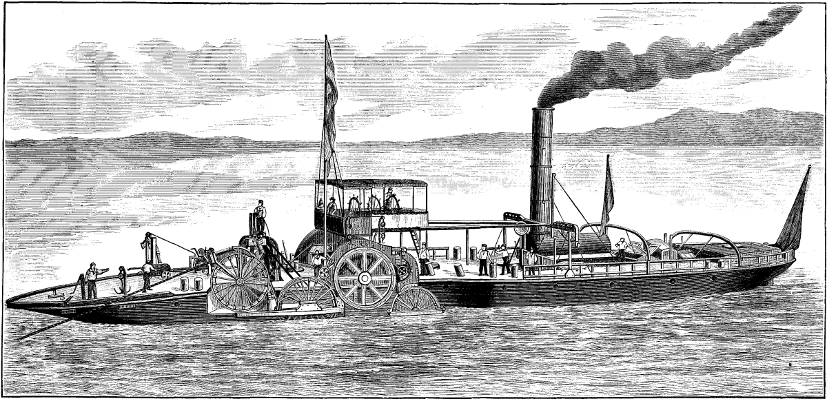
WIRE ROPE TUG BOAT, RIVER RHINE.
As regards the wear of the rope, we may state that the relaying of the first rope between St. Goar and Bingen was taken in hand in September, 1879, while that between Obercassel and Bingen was partially renewed the same year, the renewal being completed in May, 1880, after the rope had been in use since the beginning of 1876. The second rope between Bonn and Bingen, a length of 74¾ miles, is of galvanized wire, has now been 2¾ years in use, during which time there have been but three fractures. The first rope laid was not galvanized, and it suffered nine fractures during the first three years of its use. The first rope, we may mention, was laid in lengths of about a mile spliced together, while the present rope was supplied in long lengths of 7½ miles each, so that the number of splices is greatly reduced. According to the report of the company for the year 1880, the old rope when raised realizes about 16 per cent. of its original value, and allowing for this, it is calculated that an allowance of 18.7 per cent. per annum will cover the cost of rope depreciation and renewals. Altogether the results obtained on the Rhine show that in a rapid stream the economic performances of wire rope tugs compare most favorably with those of either paddle or screw tug boats, the more rapid the current to be contended against the greater being the advantage of the wire rope haulage.
Hay-ropes are used for many purposes, their principal use being in the foundry for core-making; but they also find a large application for packing ironmongery and furniture. The inventor is James Pollard, of the Atlas Foundry, Burnley.
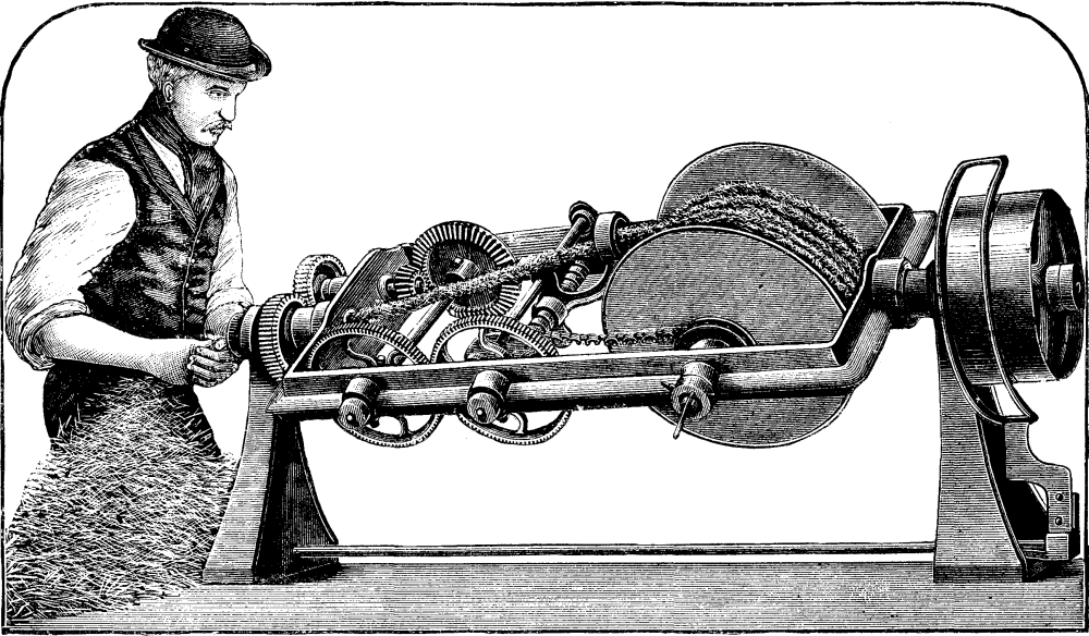
HAY ROPE MACHINE.
The chief part of the mechanism is carried in an open frame, having journals attached to its two ends, which revolve in bearings. The frame is driven by the rope pulley. The journal at the left hand is hollow; the pinion upon it is stationary, being fixed to the bracket of bearing. The pinion gearing into it is therefore revolved by the revolution of the frame, and through the medium of bevel wheels actuates a transverse shaft, parallel to which rollers, and driven by wheels off it, is a double screw, which traverses a "builder" to and fro across the width of frame. The builder is merely the eye through which the band passes, and its office is to lay the band properly on the bobbin. The latter is turned to coil on the band by a pitch chain from the builder screw, the motion being given through a friction clutch, to allow for slip as the bobbin or coil gets larger, for obviously the bobbin as it gets larger is not required to turn so fast to coil up the band produced as when it is smaller. If the action is studied, it will be seen that the twist is put in between the bobbin and the hollow journal, and every revolution of the frame puts in one turn for the twist. The hay is fed to the machine through the hollow journal already mentioned. By suitably proportioning the speed of feed-rollers and the revolutions of the frame, which is easily accomplished by varying the wheels on the left hand of frame, bands of any degree of hardness or softness may be produced. The machine appears to be simple and not liable to get deranged. It may be after a little practice attended to by a laborer, and is claimed by its maker to be able to produce 400 yards of band per hour. The frame makes about 180 revolutions per minute, that is, this is the number of turns put into the twist in this time. The machine can make a bundle about 200 yards long, which can be removed off the bobbin without unwinding with the greatest facility.--Mech. World.
The river Lee flows through the city of Cork in two branches, which diverge just above the city, and are reunited at the Custom House, the central portion of the city being situated upon an island between the two arms of the river, both of which are navigable for a short distance above the Custom House, and are lined with quays on each side for the accommodation of the shipping of the port.
The Anglesea bridge crosses the south arm of the river about a quarter of a mile above its junction with the northern branch, and forms the chief line of communication from the northern and central portions of the city to the railway termini and deep-water quays on the southern side of the river.
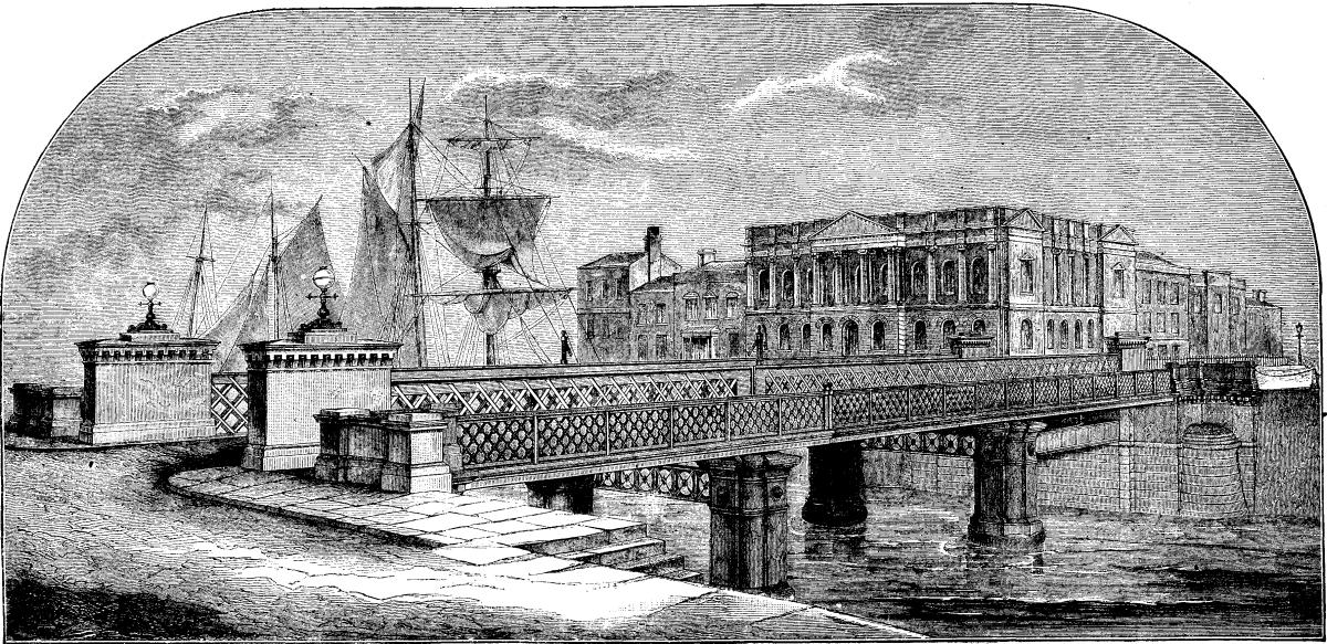
THE NEW ANGLESEA BRIDGE, CORK.
The new swing bridge occupies the site of an older structure which had been found inadequate to the requirements of the heavy and increasing traffic, and the foundations of the old piers having fallen into an insecure condition, the construction of a new opening bridge was taken in hand jointly by the Corporation and Harbor Commissioners of Cork.
The new bridge, which has recently been completed, is of a somewhat novel design, and the arrangement of the swing-span in particular presents some original and interesting features, which appear to have been dictated by a careful consideration of the existing local conditions and requirements.
On each side of the river, both above and below the bridge, the quays are ordinarily lined with vessels berthed alongside each of the quays, and as the river is rather narrow at this point, the line of fairway for vessels passing through the bridge is confined nearly to the center of the river. This consideration, together with some others connected with the proposed future deepening of the fairway, rendered it very desirable to locate the opening span nearly in the center of the river, as shown in the general plan of the situation, which we publish herewith. At the same time it was necessary to avoid any encroachment upon the width of the existing quays, which form important lines of communication for vehicular and passenger traffic along each side of the river, and to and from the railway stations. Again, it was necessary to preserve the full existing width of waterway in the river itself, which is sometimes subjected to heavy floods.
These considerations evidently precluded the construction of a central pier and double-armed swing bridge, and on the other hand they also precluded the construction of any solid masonry substructure for the turntable, either upon the quay or projected into the river. To meet these several conditions the bridge has been designed in the form of a three-span bridge, that is to say, it is only supported by the two abutments and two intermediate piers, each consisting of a pair of cast-iron cylinders or columns, as shown by the dotted circles upon the general plan.
The central opening is that which serves for the passage of vessels. The swing bridge extends over two openings, or from the north abutment to the southern pier, its center of revolution being situated over the center of the northern span, and revolves upon a turntable, which is carried upon a lower platform or frame of girders extending across the northern span of the bridge. The southern opening is spanned by an ordinary pair of lattice girders in line with the girders and superstructure of the swing bridge.
We propose at an early date to publish further details of this bridge, and the hydraulic machinery by which it is worked.
We present a perspective view of the bridge as seen from the entrance to the exhibition building, which is situated in close proximity to the southern end of the bridge.--Engineering.
[Footnote: Paper read before the Institution of Mechanical Engineers.]
Narrow gauge railways have been known for a very long time in Great Britain. The most familiar lines of this description are in Wales, and it is enough to instance the Festiniog Railway (2 feet gauge), which has been used for the carriage of passengers and goods for nearly half a century. The prosperous condition of this railway, which has been so successfully improved by Mr. James Spooner and his son, Mr. Charles Spooner, affords sufficient proof that narrow gauge railways are not only of great utility, but may be also very remunerative.
In Wales the first narrow gauge railway dates from 1832. It was constructed merely for the carriage of slates from Festiniog to Port-Madoc, and some years later another was built from the slate quarries at Penrhyn to the port of Bangor. As the tract of country traversed by the railways became richer by degrees, the idea was conceived of substituting locomotives for horses, and of adapting the line to the carriage of goods of all sorts, and finally of passengers also.
But these railways, although very economical, are at the same time very complicated in construction. Their arrangements are based upon the same principles as railways of the ordinary gauge, and are not by any means capable of being adapted to agriculture, to public works, or to any other purpose where the tracks are constantly liable to removal. These permanent narrow gauge lines, the laying of which demands the service of engineers, and the maintenance of which entails considerable expense, suggested to M. Decauville, Aîne, farmer and distiller at Petit-Bourg, near Paris, the idea of forming a system of railways composed entirely of metal, and capable of being readily laid. Cultivating one of the largest farms in the neighborhood of Paris, he contemplated at first nothing further than a farm railroad; and he contrived an extremely portable plant, adapted for clearing the land of beetroot, for spreading manure, and for the other needs of his farm.
From the beginning in his first railroads, the use of timber materials was rigidly rejected by him; and all parts, whether the straight or curved rails, crossings, turntables, etc., were formed of a single piece, and did not require any special workman to lay them down. By degrees he developed his system, and erected special workshops for the construction of his portable plant; making use of his farm, and some quarries of which he is possessed in the neighborhood, as experimental areas. At the present time this system of portable railways serves all the purposes of agriculture, of commerce, of manufactures, and even those of war.
Within so limited a space it would be impossible to give a detailed description of the rails and fastenings used in all these different modes of application. The object of this paper is rather to direct the attention of mechanical engineers to the various uses to which narrow gauge portable railways may be put, to the important saving of labor which is effected by their adoption, and to the ease with which they are worked.
The success of the Decauville railway has been so rapid and so great that many inventors have entered the same field, but they have almost all formed the idea of constructing the portable track with detachable sleepers. There are thus, at present, two systems of portable tracks: those in which the sleepers are capable of being detached, and those in which they are not so capable.
The portable track of the Decauville system is not capable of so coming apart. The steel rails and sleepers are riveted together, and form only one piece. The chief advantage of these railways is their great firmness; besides this, since the line has only to be laid on the surface just as it stands, there are not those costs of maintenance which become unavoidable with lines of which the sleepers are fixed by means of bolts, clamps, or other adjuncts, only too liable to be lost. Moreover, tracks which are not capable of separation are lighter and therefore more portable than those in which the sleepers are detachable.
With regard to sleepers, a distinction must be drawn between those which project beyond the rails and those which do not so project. M. Decauville has adopted the latter system, because it offers sufficient strength, while the lines are lighter and less cumbersome. Where at first he used flat iron sleepers, he now fits his lines with dished steel sleepers, in accordance with Figs. 1 and 2.
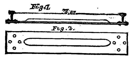
Fig. 1. Fig. 2.
This sleeper presents very great stiffness, at the same time preserving its lightness; and the feature which specially distinguishes this railway from others of the same class is not only its extreme strength, but above all its solidity, which results from its bearing equally upon the ground by means of the rail base and of the sleepers.
In special cases, M. Decauville provides also railroads with projecting sleepers, whether of flat steel beaten out and rounded, or of channel iron; but the sleeper and the rail are always inseparable, so as not to lessen the strength, and also to facilitate the laying of the line. If the ground is too soft, the railway is supported by bowl sleepers of dished steel, Figs. 3 and 4, especially at the curves; but the necessity for using these is but seldom experienced. The sleepers are riveted cold. The rivets are of soft steel, and the pressure with which this riveting is effected is so intense that the sleepers cannot be separated from the rails, even after cutting off both heads of the rivets, unless by heavy blows of the hammer, the rivets being driven so thoroughly into the holes made in the rails and sleepers that they fill them up completely.
The jointing of the rails is excessively simple. The rail to the right hand is furnished with two fish-plates; that to the left with a small steel plate riveted underneath the rail and projecting 1¼ in. beyond it. It is only necessary to lay the lengths end to end with one another, making the rail which is furnished with the small plate lie between the two fish-plates, and the junction can at once be effected by fish-bolts. A single fish-bolt, passing through the holes in the fish-plates, and through an oval hole in the rail end, is sufficient for the purpose.
With this description of railway it does not matter whether the curves are to the right or to the left. The pair of rails are curved to a suitable radius, and can only need turning end for end to form a curve in the direction required. The rails weigh 9 lb., 14 lb., 19 lb., and 24 lb. per running yard, and are very similar to the rails used on the main railways of France, except that their base has a proportionally greater width. As to the strength of the rail, it is much greater in proportion to the load than would at first sight be thought; all narrow-gauge railways being formed on the principle of distributing the load over a large number of axles, and so reducing the amount on each wheel. For instance, the 9 lb. rail used for the portable railway easily bears a weight of half a ton for each pair of wheels.
The distance between the rails differs according to the purpose for which they are intended. The most usual gauges are 16in., 20 in., and 24in. The line of 16 in. gauge, with 9 lb. rails, although extremely light, is used very successfully in farming, and in the interior of workshops.
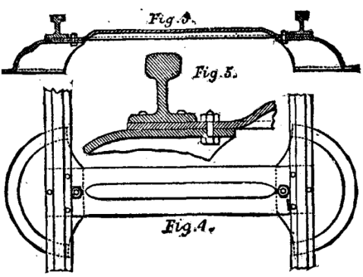
Fig. 3. Fig. 4. Fig. 5.
A length of 16 ft. 5 in. of 9 lb. steel rail, to 16 in. gauge, with sleepers, etc., scarcely weighs more than 1 cwt., and may therefore be readily carried by a man placing himself in the middle and taking a rail in each hand.
Those members of the Institution who recently visited the new port of Antwerp will recollect having seen there the portable railway which Messrs. Couvreux and Hersetit had in use; and as it was these works at the port of Antwerp that gave rise to the idea of this paper, it will be well to begin with a description of this style of contractor's plant.
The earth in such works may be shifted by hand, horsepower, or locomotive. For small works the railway of 16 in. gauge, with the 9 lb. rails, is commonly used, and the trucks carry double equilibrium tipping-boxes, containing 9 to 11 cubic feet. These wagons, having tipping-boxes without any mechanical appliances, are very serviceable; since the box, having neither door nor hinge, is not liable to need repairs.
This box keeps perfectly in equilibrium upon the most broken up roads. To tip it up to the right or the left, it must simply be pushed from the opposite side, and the contents are at once emptied clean out. In order that the bodies of the wagons may not touch at the top, when several are coupled together, each end of the wagon is furnished with a buffer, composed of a flat iron bar cranked, and furnished with a hanging hook.
Plant of this description is now being used in an important English undertaking at the port of Newhaven, where it is employed not only on the earthworks, but also for transporting the concrete manufactured with Mr. Carey's special concrete machine.
These little wagons, of from 9 to 11 cubic feet capacity, run along with the greatest ease, and a lad could propel one of them with its load for 300 yards at a cost of 3d. per cube yard. In earthworks the saving over the wheel-barrow is 80 per cent., for the cost of wagons propelled by hand comes to 0.1d. per cube yard, carried 10 yards, and to go this distance with a barrow costs ½d. A horse draws without difficulty, walking by the side of the line, a train of from eight to ten trucks on the level, or five on an incline of 7 per cent. (1 in 14).
One mile of this railway, 16 in. gauge and 9 lb. steel rail, with sixteen wagons, each having a double equilibrium tipping box containing 11 cubic feet, and all accessories, represents a weight of 20 tons--a very light weight, if it is considered that all the materials are entirely of metal. Its net cost price per mile is 450l., the wagons included.
Large contracts for earthwork with horse haulage are carried on to the greatest advantage with the railway of 20 in. gauge and 14 lb. rails. The length of 16 ft. 5 in. of this railway weighs 170 lb., and so can easily be carried by two men, one placing himself at each end. The wagons most in use for these works are those with double equilibrium tipping boxes, holding 18 cubic feet. These are at present employed in one of the greatest undertakings of the age, namely, the cutting of the Panama Canal, where there are used upward of 2,700 such wagons, and more than 35 miles of track.
A mile of these rails of 20 in. gauge with 14 lb. rails, together with sixteen wagons of 18 cubic feet capacity, with appurtenances, costs about 6601., and represents a total weight of 33 tons.
This description of material is used for all contracts exceeding 20,000 cubic yards.
A very curious and interesting use of the narrow-gauge line, and the wagons with double equilibrium tipping-box, was made by the Societe des Chemins de Fer Sous-Marins on the proposed tunnel between France and England. The line used is that of 16 in. gauge, with 9 lb. rails.
The first level of the tunnel, which was constructed by means of a special machine by Colonel Beaumont, had only a diameter of 2.13 m. (7 ft.); the tipping boxes have therefore a breadth of only 2 ft., and contain 7¼ cubic feet. The boxes are perfectly balanced, and are most easily emptied. The wagons run on two lines, the one being for the loaded trains, and the other for the empty trains.
The engineers and inspectors, in the discharge of their duties, make use of the Liliputian carriages. The feet of the travelers go between the wheels, and are nearly on a level with the rails; nevertheless, they are tolerably comfortable. They are certainly the smallest carriages for passengers that have ever been built; and the builder even prophesies that these will be the first to enter into England through the Channel Tunnel.
One of the most important uses to which a narrow gauge line can be put is that of a military railway. The Dutch, Russian, and French Governments have tried it for the transporting of provisions, of war material, and of the wounded in their recent campaigns. In Sumatra, in Turkestan, and in Tunis these military railroads have excited much interest, and have so fully established their value that this paper may confine itself to a short description.
The campaign of the Russians against the Turcomans presented two great difficulties; these were the questions of crossing districts in which water was extremely scarce or failed entirely, and of victualing the expeditionary forces. This latter object was completely effected by means of 67 miles of railway, 20 in. gauge, 14 lb. steel rails, with 500 carriages for food, water, and passengers. The rails were laid simply on the sand, so that small locomotives could not be used, and were obliged to be replaced by Kirghiz horses, which drew with ease from 1,800 lb. to 2,200 lb. weight for 25 miles per day.
In the Tunisian war this railroad of 20 in. gauge, 14 lb. rail, was replaced by that of two ft. gauge, with 14 lb. and 19 lb. rails. There were quite as great difficulties as in the Turcoman campaign, and the country to be crossed was entirely unknown. The observations made before the war spoke of a flat and sandy country. In reality a more uneven country could not be imagined; alternating slopes of about 1 in 10 continually succeeded each other; and before reaching Kairouan 7½ miles of swamp had to be crossed. Nevertheless the horses harnessed to the railway carriages did on an average twelve to seventeen times the work of those working ordinary carriages. In that campaign also, on account of the steep ascents, the use of locomotives had to be given up. The track served not only for the conveying of victuals, war material, and cannon, but also of the wounded; and a large number of the survivors of this campaign owe their lives to this railway, which supplied the means of their speedy removal without great suffering from the temporary hospitals, and of carrying the wounded to places where more care could be bestowed upon them.
The carriages which did duty in this campaign are wagons with a platform entirely of metal, resting upon eight wheels. The platform is 13 ft. 1 in. in length, and 3 ft. 11 in. in width. The total length with buffers is 14 ft. 9 in. This carriage may be at will turned into a goods wagon or a passenger carriage for sixteen persons, with seats back to back, or an ambulance wagon for eight wounded persons.
For the transport of cannon the French military engineers have adopted small trucks. A complete equipage, capable of carrying guns weighing from 3 to 9 tons, is composed of trucks with two or three axles, each being fitted with a pivot support, by means of which it is made possible to turn the trucks, with the heaviest pieces of ordnance, on turntables, and to push them forward without going off the rails at the curves.
The trucks which have been adopted for the service of the new forts in Paris are drawn by six men, three of whom are stationed at each end of the gun, and these are capable of moving with the greatest ease guns weighing 9 tons.
The narrow-gauge railway was tested during the war in Tunis more than in any preceding campaign, and the military authorities decided, after peace had been restored in that country, to continue maintaining the narrow-gauge railways permanently; this is a satisfactory proof of their having rendered good service. The line from Sousse to Kairouan is still open to regular traffic. In January, 1883, an express was established, which leaves Sousse every morning and arrives at Kairouan--a distance of forty miles--in five hours, by means of regularly organized relays. The number of carriages and trucks for the transport of passengers and goods is 118.
The success thus attained by the narrow-gauge line goes far to prove how unfounded is the judgment pronounced by those who hold that light railways will never suffice for continuous traffic. These opinions are based on certain cases in the colonies, where it was thought fit to adopt a light rail weighing about 18 lb. to 27 lb. per yard, and keeping the old normal gauge. It is nevertheless evident that it is impossible to construct cheap railways on the normal gauge system, as the maintenance of such would-be light railways is in proportion far more costly than that of standard railways.
The narrow gauge is entirely in its right place in countries where, as notably in the case of the colonies, the traffic is not sufficiently extensive to warrant the capitalization of the expenses of construction of a normal gauge railway.
Quite recently the Eastern Railway Company of the province of Buenos Ayres have adopted the narrow gauge for connecting two of their stations, the gauge being 24 in. and the weight of the rails 19 lb. per yard. This company have constructed altogether six miles of narrow-gauge road, with a rolling stock of thirty passenger carriages and goods trucks and two engines, at a net cost price of 7,500l., the engines included. This line works as regularly as the main line with which it is connected. The composite carriages in use leave nothing to be desired with regard to their appearance and the comforts they offer. Third-class carriages, covered and open, and covered goods wagons, are also employed.
All these carriages are constructed according to the model of those of the Festiniog Railway. The engines weigh 4 tons, and run at 12½ miles per hour for express trains with a live load of 16 tons; while for goods trains carrying 35 tons the rate is 7½ miles an hour.
Another purpose for which the narrow-gauge road is of the highest importance in colonial commerce is the transport of sugar cane. There are two systems in use for the service of sugar plantations:
1. Traction by horses, mules, or oxen.
2. Traction by steam-engine.
In the former case, the narrow gauge, 20 in. with 14 lb. rails, is used, with platform trucks and iron baskets 3 ft. 3 in. long.
The use of these wagons is particularly advantageous for clearing away the sugar cane from the fields, because, as the crop to be carried off is followed by another harvest, it is important to prevent the destructive action of the wheels of heavily laden wagons. The baskets may be made to contain as much as 1,300 lb. of cane for animal traction, and 2,000 lb. for steam traction. In those colonies where the cane is not cut up into pieces, long platform wagons are used entirely made of metal, and on eight wheels. When the traction is effected by horses or mules, a chain 14½ ft. long is used, and the animals are driven alongside the road. Oxen are harnessed to a yoke, longer by 20 in. to 24 in. than the ordinary yoke, and they are driven along on each side of the road.
On plantations where it is desirable to have passenger carriages, or where it is to be foreseen that the narrow-gauge line maybe required for the regular transport of passengers and goods, the 20 in. line is replaced by one of 24 in.
The transport of the refuse of sugar cane is effected by means of tilting basket carts; the lower part of which consists of plate iron as in earthwork wagons, while the upper part consists of an open grating, offering thus a very great holding capacity without being excessively heavy. The content of these wagons is 90 cubic feet (2,500 liters). To use it for the transport of earth, sand, or rubbish, the grating has merely to be taken off. In the case of the transport of sugar cane having to be effected by steam power, the most suitable width of road is 24 in., with 19 lb. rails; and this line should be laid down and ballasted most carefully. The cost of one mile of the 20 in. gauge road, with 14 lb. rails, thirty basket wagons, and accessories for the transport of sugar cane, is 700l., and the total weight of this plant amounts to 35 tons.
Owing to the great lightness of the portable railways, and the facility with which they can be worked, the attention of explorers has repeatedly been attracted by them. The expedition of the Ogowe in October, 1880, that of the Upper Congo in November, 1881, and the Congo mission under Savorgnan de Brazza, have all made use of the Decauville narrow-gauge railway system.
During these expeditions to Central Africa, one of the greatest obstacles to be surmounted was the transport of boats where the river ceased to be navigable; for it was then necessary to employ a great number of negroes for carrying both the boats and the luggage. The explorers were, more or less, left to the mercy of the natives, and but very slow progress could be made.
On returning from one of these expeditions in Africa, Dr. Balay and M. Mizon conceived the idea of applying to M. Decauville for advice as to whether the narrow-gauge line might not be profitably adapted for the expedition. M. Decauville proposed to them to transport their boats without taking them to pieces, or unloading them, by placing them on two pivot trollies, in the same manner as the guns are transported in fortifications and in the field. The first experiments were made at Petit-Bourg with a pleasure yacht. The hull, weighing 4 tons, was placed on two gun trollies, and was moved about easily across country by means of a portable line of 20 in. gauge, with 14 lb. rails. The length of the hull was about 45 ft., depth 6 ft. 7 in., and breadth of beam 8 ft. 2 in., that is to say, five times the width of the narrow-gauge, and notwithstanding all this the wheels never came off the line. The sections of line were taken up and replaced as the boat advanced, and a speed of 1,100 yards per hour was attained. Dr. Balay and M. Mizon declared that the result obtained exceeded by far their most sanguine hopes, because during their last voyage, the passage of the rapids had sometimes required a whole week for 1,100 yards (1 kilometer), and they considered themselves very lucky indeed if they could attain a speed of one kilometer per day. The same narrow gauge system has since been three times adopted by African explorers, on which occasions it was found that the 20 in. line, with 9 lb. or 14 lb. rails, was the most suitable for scientific expeditions of this nature.
The trucks used are of the kind usually employed for military purposes, with wheels, axles, and pivot bearings of steel; on being dismounted the bodies of the two trucks form a chest, which is bolted together and contains the wheels, axles, and other accessories. The total weight of the 135 yards of road used by Dr. Balay and M. Mizon during their first voyage was 2,900 lb., and the wagons weighed 5,000 lb. Hence the expedition had to carry a supplementary weight of 3½ tons; but at any given moment the material forming this burden became the means of transporting, in its turn, seven boats, representing a total weight of 20 tons.
It is impossible to enumerate in this paper all the various kinds of wagons and trucks suitable for the service of iron works, shipyards, mines, quarries, forests, and many other kinds of works; and we therefore limit ourselves to mentioning only a few instances which suffice to show that the narrow gauge can be applied to works of the most varied nature and under the most adverse circumstances possible.
It therefore only remains to mention the various accessories which have been invented for the purpose of completing the system. They consist of off-railers, crossings, turntables, etc.
The off railer is used for establishing a portable line, at any point, diverging to the right or left of a permanent line, and for transferring traffic to it without interruption. It consists of a miniature inclined plane, of the same height at one end as the rail, tapering off regularly by degrees toward the other end. It is only necessary to place the off-railer (which, like all the lengths of rail of this system, forms but one piece with its sleepers and fish-plates) on the fixed line, adding a curve in the direction it is intended to go, and push the wagons on to the off-railer, when they will gradually leave the fixed line and pass on the new track.
The switches consist of a rail-end 49 in. in length, which serves as a movable tongue, placed in front of a complete crossing, the rails of which have a radius of 4, 6, or 8 meters; a push with the foot suffices to alter the switch. There are four different models of crossings constructed for each radius, viz.:
1. For two tracks with symmetrical divergence.
2. For a curve to the right and a straight track.
3. For a curve to the left and a straight track.
4. For a meeting of three tracks.
When a fixed line is used, it is better to replace the movable switch by a fixed cast-iron switch, and to let the workmen who drive the wagon push it in the direction required. Planed switch tongues are also used, having the shape of those employed on the normal tracks, especially for the passage of small engines; the switches are, in this case, completed by the application of a hand lever.
The portable turntable consists of two faced plates laid over the other, one of thick sheet iron, and the other of cast iron. The sheet-iron plate is fitted with a pivot, around which the cast iron one is made to revolve; these plates may either be smooth, or grooved for the wheels. The former are used chiefly when it is required to turn wagons or trucks of light burden, or, in the case of earthworks, for trucks of moderate weight. These plates are quite portable; their weight for the 16 in. gauge does not exceed 200 lb. For engineering works a turntable plate with variable width of track has been designed, admitting of different tracks being used over the same turntable.
When turntables are required for permanent lines, and to sustain heavy burdens, turntables with a cast iron box are required, constructed on the principle of the turntables of ordinary railways. The heaviest wagons may be placed on these box turntables, without any portion suffering damage or disturbing the level of the ground. In the case of coal mines, paper mills, cow houses with permanent lines, etc., fixed plates are employed. Such plates need only be applied where the line is always wet, or in workshops where the use of turntables is not of frequent occurrence. This fixed plate is most useful in farmers' stables, as it does not present any projection which might hurt the feet of the cattle, and is easy to clean.
The only accident that can happen to the track is the breaking of a fish-plate. It happens often that the fish-plates get twisted, owing to rough handling on the part of the workmen, and break in the act of being straightened. In order to facilitate as much as possible the repairs in such cases, the fish-plates are not riveted by machinery, but by hand; and it is only necessary to cut the rivets with which the fish-plate is fastened, and remove it if broken: A drill passed through the two holes of the rail removes all burrs that may be in the way of the new rivet. No vises are required for this operation; the track to be repaired is held by two workmen at a height of about 28 in. above the ground, care being taken to let the end under repair rest on a portable anvil, which is supplied with the necessary appliances. The two fish-plates are put in their place at the same time, the second rivet being held in place with one finger, while the first is being riveted with a hammer; if it is not kept in its place in this manner it may be impossible to put it in afterward, as the blows of the hammer often cause the fish-plate to shift, and the holes in the rail are pierced with great precision to prevent there being too much clearance. No other accident need be feared with this line, and the breakage described above can easily be repaired in a few minutes without requiring any skilled workman.
The narrow-gauge system, which has recently received so great a development on the Continent, since its usefulness has been demonstrated, and the facility with which it can be applied to the most varied purposes, has not yet met in England with the same universal acceptance; and those members of this Institution who crossed the sea to go to Belgium were, perhaps, surprised to see so large a number of portable railways employed for agricultural and building purposes and for contractors' works. But in the hands of so practical a people it may be expected that the portable narrow gauge railway will soon be applied even to a larger number of purposes than is the case elsewhere.
The machine represented in the annexed engravings consists of a movable inductor, whose alternate poles pass in front of an armature composed of a double number of oblong and flat bobbins, that are affixed to a circle firmly connected with the frame. There is a similar circle on each side of the inductor. The armature is stationary, and the wires that start from the bobbins are connected with terminals placed upon a wooden support that surmounts the machine.
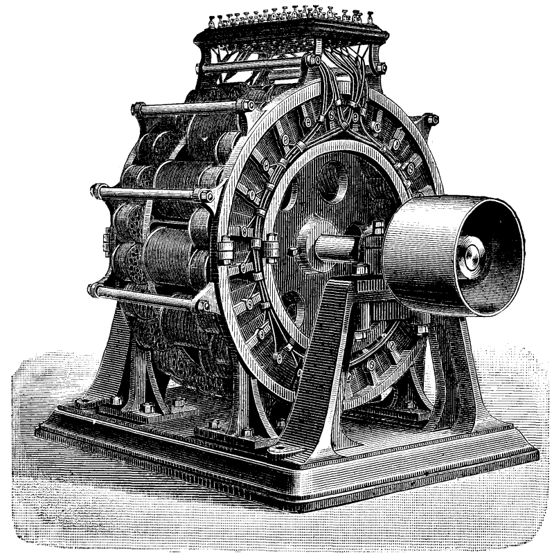
GERARD'S ALTERNATING ELECTRIC MACHINE.
This arrangement allows of every possible grouping of the currents according to requirements. Thus, the armature may be divided into two currents, so as to allow of carbons 30 mm. in diameter being burned, or else so as to have four, eight, twelve, twenty-four, or even forty-eight distinct circuits capable of being used altogether or in part.
This machine has been studied with a view of rendering the lamps independent; and there may be produced with it, for example, a voltaic arc of an intensity of from 250 to 600 carcels for the lighting of a courtyard, or it may be used for producing arcs of less intensity for shops, or for supplying incandescent lamps. As each of the circuits is independent, it becomes easy to light or extinguish any one of the lamps at will. Since the conductors are formed of ordinary simple wires, the cost attending the installation of 12 or 24 lamps amounts to just about the same as it would in the case of a single cable.
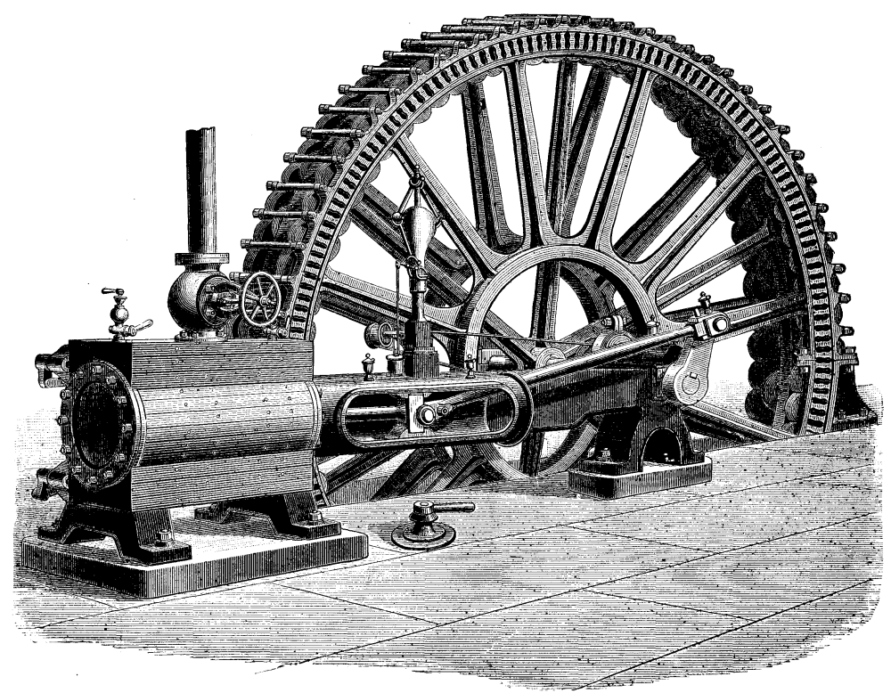
GERARD'S 250 H.P. DIRECT CONNECTION ALTERNATING CURRENT STEAM DYNAMO-ELECTRIC MACHINE.
One of the annexed cuts represents a Corliss steam engine connected directly with an alternating current machine of the system under consideration. According to the inventor, this machine is capable of supplying 1,000 lamps of a special kind, called "slide lamps," and a larger number of incandescent ones.--Revue Industrielle.
Since 1838 much has been done toward increasing the carrying capacity of a single wire. In response to your invitation I will relate my experience upon the Postal's large coppered wire, in an effort to transmit 800 words per minute over a 1,000 mile circuit, and add my mite to the vast sum of knowledge already possessed by electricians.
As an introduction, I shall mention a few historical facts, but do not propose to write in this article even a short account of the different automatic systems, and I must assume that my readers are familiar with modern automatic machines and appliances.
In 1870, upon the completion of the Automatic Company's 7 ohm wire between New York and Washington, it happened that Prof. Moses G. Farmer was in the Washington office when the first message was about to be sent, and upon being requested, he turned the "crank" and transmitted the message to New York, at the rate of 217 words per minute.
Upon his return to New York he co-operated with Mr. Prescott in experiments on W.U. wires, their object being to determine what could be done on iron wires with the Bain system. A good No. 8 wire running from New York to Boston was selected, reinsulated, well trimmed, and put in first-class electrical condition, previous to the test. The "Little" chemical paper was used.
The maximum speed attained on this wire was 65 words per minute.
About the same time George H. Grace used an electro magnet on the automatic line with such good effect that the speed on the New York-Washington circuit was increased to 450 words per minute.
Then a platina stylus or pen was substituted for the iron pen in connection with iodide paper, and the speed increased to 900 words per minute.
In 1880, upon the completion of the Rapid Company's 6 ohm wire, between New York and Boston, 1,200 words per minute were transmitted between the cities above named.
In 1882, I was employed by the Postal Telegraph Company to put the Leggo automatic system into practical shape, and, if possible, transmit 800 words per minute between New York and Chicago.
It was proposed to string a steel-copper wire, the copper on which was to weigh 500 lb. to the mile.
When complete, the wire was rather larger than No. 3, English gauge, but varied in diameter, some being as large as No. 1, and it averaged 525 lb. of copper per mile and = 1.5 ohms. The surface of this wire was, however, large.
Dr. Muirhead estimated its static capacity at about 10 M.F., which subsequent tests proved to be nearly correct.
It will be understood that this static capacity stood in the way of fast transmission.
Resistance and static capacity are the two factors that determine speed of signaling.
The duration of the variable state is in proportion to the square of the length of the conductor, so that the difficulties increase very greatly as the wire is extended beyond ordinary limits. According to Prescott, "The duration of the variable condition in a wire of 500 miles is 250,000 times as long as in a wire of 1 mile."
In other words, a long line retains a charge, and time must be allowed for at least a falling off of the charge to a point indicated by the receiving instrument as zero.
In the construction of the line care was taken to insure the lowest possible resistance through the circuit, even to the furnishing of the river cables with conductors weighing 500 lb. per mile.
Ground wires were placed on every tenth pole.
When the first 100 miles of wire had been strung, I was much encouraged to find that we could telegraph without any difficulty past the average provincial "ground," provided the terminal grounds were good.
When the western end of this remarkable wire reached Olean, N.Y., 400 miles from New York, my assistant, Mr. S.K. Dingle, proceeded to that town with a receiving instrument, and we made the first test.
I found that 800 words, or 20,000 impulses, per minute, could be transmitted in Morse characters over that circuit without compensation for static.
In other words, the old Bain method was competent to telegraph 800 words per minute on the 400 miles of 1.5 ohm wire.
The trouble began, however, when the wire reached Cleveland, O., about 700 miles from New York.
Upon making a test at Cleveland, I found the signals made a continuous black line upon the chemical paper. I then placed both ends of the wire to earth through 3,000 ohms resistance, and introduced a small auxiliary battery between the chemical paper and earth.
The auxiliary or opposing battery was placed in the same circuit with the transmitting battery, and the currents which were transmitted from the latter through the receiving instrument reached the earth by passing directly through the opposing battery.
The circuit of the opposing battery was permanently completed, independently of the transmitting apparatus, through both branch conductors and artificial resistances.
The auxiliary battery at the receiving station normally maintained upon the main line a continuous electric current of a negative polarity, which did not produce a mark upon the chemical paper.
When the transmitting battery was applied thereto, the excessive electro-motive force of the latter overpowered the current from the auxiliary battery and exerted, by means of a positive current, an electro-chemical action upon the chemical receiving paper, producing a mark.
Immediately upon the interruption of the circuit of the transmitting battery, the unopposed current from the auxiliary battery at the receiving station flowed back through the paper and into the main line, thereby both neutralizing the residual or inductive current, which tended to flow through the receiving instrument, and serving to clear the main line from electro-static charge.
The following diagram illustrates my method:
Referring to this diagram, A and B respectively represent a transmitting and a receiving station of an automatic telegraph. These stations are united in the usual manner by a main line, L. At the transmitting station, A, is placed a transmitting battery, E, having its positive pole connected by a conductor, 2, with the metallic transmitting drum, T. The negative pole of the battery, E, is connected with the earth at G by a conductor, 1. A metallic transmitting stylus, t, rests upon the surface of the drum, T, and any well known or suitable mechanism may be employed for causing an automatic transmitting pattern slip, P, to pass between the stylus and the drum. The transmitting or pattern slip, P, is perforated with groups of apertures of varying lengths and intervals as required to represent the dispatch which it is desired to transmit, by an arbitrary system of signs, such, for example, as the Morse telegraphic code.
At the receiving station, B, is placed a recording apparatus, M, of any suitable or well known construction. A strip of chemically prepared paper, N, is caused to pass rapidly and uniformly between the drum, M', and the stylus, m, of this instrument in a well known manner. The drum, M', is connected with the earth by conductors, 4 and 3, between which is placed the auxiliary battery, E, the positive or marking pole of this battery being connected with the drum and the negative pole with the earth. The electro-motive force of the battery, E', is preferably made about one-third as great as that of the battery, E.
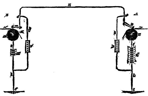
Extending from a point, o, in the main line, near the transmitting station, to the earth at G, is a branch conductor, l, containing an adjustable artificial resistance, R. A similar conductor, ll, extends from a point, o', near the receiving terminal of the line, L, to the conductor, 3, in which an artificial resistance, R', is also included, this resistance being preferably approximately equal to the resistance, R. The proportions of the resistance of the main line and the artificial resistances which I prefer to employ may be approximately indicated as follows: Assuming the resistance of the main line to be 900 ohms, the resistance, R, and R', should be each about 3,000 ohms. The main battery, E, should then comprise about 90 cells, and the auxiliary battery, E', 30 cells.
The operation of my improved system is as follows: While the apparatus is at rest a constant current from the battery, E', traverses the line, L, and the branch conductors, l, and ll, dividing itself between them, in inverse proportion to their respective resistances, in accordance with the well-known law of Ohm. When the transmitting pattern strip, P, is caused to pass between the roller, T, and the stylus, t, electric impulses will be transmitted upon the line, L, from the positive pole of the battery, E, which will traverse the main line, L, the two branch lines, l, and ll, and their included resistances, and also the receiving instrument, M. The greater portion of this current will, however, on account of the less resistance offered, traverse the receiving instrument, M, and the auxilary battery, E'. The current from the last-named battery will thus be neutralized and overpowered, and the excess of current from the main battery, E, will act upon the chemically prepared paper and record in the form of dots and dashes or like arbitrary characters the impulses which are transmitted.
Immediately on the cessation of each impulse, the auxiliary battery, E', again acts to send an impulse of positive polarity through the receiving paper and stylus in the reverse direction and through the line, L, which returns to the negative pole of the battery by way of the artificial resistances, R and R'. Such an impulse, following immediately upon the interruption of the circuit of the transmitting battery, acts to destroy the effect of the "tailing" or static discharge of the line, L, upon the receiving instrument, and also to neutralize the same throughout the line. By thus opposing the discharge of the line by a reverse current transmitted directly through the chemical paper, a sharply defined record will in all cases be obtained; and by transmitting the opposing impulse through the line, the latter will be placed in a condition to receive the next succeeding impulse and to record the same as a sharply defined character.
This arrangement was made on the New York-Cleveland circuit, and the characters were then clearly defined and of uniform distinctness. The speed of transmission on this circuit was from 1,000 to 2,000 words per minute.
Upon the completion of the wire to Chicago, total distance 1,050 miles, including six miles of No. 8 iron wire through the city, the maximum speed was found to be 1,200 words per minute, and to my surprise the speed was not affected by the substitution of an underground conductor for the overhead wire.
The underground conductor was a No. 16 copper wire weighing 67 pounds per mile, in a Patterson cable laid through an iron pipe.
I used 150 cells of large Fuller battery on the New York-Chicago circuit, and afterward with 200 cells in first class condition, transmitted 1,500 words, or 37,000 impulses, per minute from 49 Broadway, New York, to our test office at Thirty-ninth Street, Chicago.
The matter was always carefully counted, and the utmost care taken to obtain correct figures.
It may be mentioned as a curious fact that we not only send 1,200 words per minute through 1,050 miles of overhead wire and five miles of underground cable, but also through a second conductor in No. 2 cable back to Thirty-ninth Street, and then connected to a third underground conductor in No. 1 cable back to Chicago main office, in all about fifteen miles of underground, through which we sent 1,200 words per minute and had a splendid margin.--Electrical World.
[ELECTRICAL REVIEW].
A careful examination of the opinions of scientific men given in the telephone cases--before Lord McLaren in Edinburgh and before Mr. Justice Fry in London--leads me to the conclusion that scientific men, at least those whose opinions I shall quote, are not agreed as to what is the action of the carbon microphone.
In the Edinburgh case, Sir Frederick Bramwell said: "The variations of the currents are effected so as to produce with remarkable fidelity the varied changes which occur, according as the carbon is compressed or relieved from compression by the gentle impacts of the air set in motion by the voice."
"The most prominent quality of carbon is its capability, under the most minute differences of pressure, to enormously increase or decrease the resistances of the circuit." "That the varying pressure of the black tension-regulator (Edison's) is sufficient to cause a change in the conducting power." Sir Frederick also said "he could not believe that the resistance was varied by a jolting motion; could not conceive a jolting motion producing variation and difference of pressure, and such an instrument could not be relied on, and therefore would be practically useless."
Sir William Thomson, in the same case, said: "The function of the carbon is to give rise to diminished resistance by pressure; it possesses the quality of, under slight degrees of pressure, decreasing the resistance to the passage of the electric current;" and, also, "the jolting motion would be a make-and-break, and the articulate sounds would be impaired. There can be no virtue in a speaking telephone having a jolting motion." "Delicacy of contact is a virtue; looseness of contact is a vice." "Looseness of contact is a great virtue in Hughes' microphone;" and "the elements which work advantages in Hughes' are detrimental to the good working of the articulating instrument."
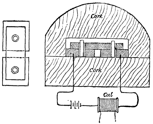
Fig. 1.
Mr. Falconer King said: "There would be no advantage in having a jolting motion; the jolting motion would break the circuit and be a defect in the speaking telephone," and "you must have pressure and partially conducting substances."
Professor Fleeming Jenkin said, "The pressure of the carbons is what favors the transmission of sound."
All the above named scientific men agree that variations of a current passing through a carbon microphone are produced by pressure of the carbons against one another, and they also agree that a jolting motion could not be relied upon to reproduce articulate speech.
Mr. Conrad Cooke said, "The first and most striking principle of Hughes' microphone is a shaking and variable contact between the two parts constituting the microphone." "The shaking and variable contact is produced by the movable portion being effected by sound." "Under Hughes' system, where gas carbon was used, the instruments could not possibly work upon the principle of pressure." "I am satisfied that it is not pressure in the sense of producing a change of resistance." "I do not think pressure has anything to do with it."
Professor Blyth said: "The Hughes microphone depends essentially upon the looseness or delicacy of contact." "I have heard articulate speech with such an instrument without a diaphragm." "There is no doubt that to a certain extent there must be a change in the number of points of surface contact when the pencil is moved." "The action of the Hughes microphone depends more or less upon the looseness or delicacy of the contact and upon the changes in the number of points of surface contact when the pencil is moved."
Mr. Oliver Heaviside, in The Electrician of 10th February last, writes: "There should be no jolting or scraping." "Contacts, though light, should not be loose."
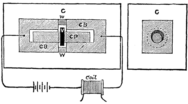
Fig. 2.
A writer, who signs "W.E.H.," in The Electrician of 24th February last, says: "The variation of current arises from a variation of conductivity between the electrodes, consequent upon the variation of the closeness or pressure of contact;" and also, "there must be a variation of pressure between the electrodes when the transmitter is in action."
It seems, then, that some scientific men agree that variation of pressure is required to produce action in a microphone, and some of them admit that a microphone with loose contacts will transmit articulate speech, while others deny it, and some admit that a jolting or shaking motion of the parts of the microphone does not interfere with articulate speech, while others say such motion would break the circuit, and cannot be relied on.
I will now describe two microphones in which there is a shaking or jolting motion, and loose contacts, and no variation of pressure of the carbons against one another, and both of these microphones when used with an induction coil and battery give most excellent articulation. One of these microphones is made as follows: Two flat plates of carbon are secured to a block of cork, insulated from each other; into a hole of each carbon a pin of carbon fits loosely, projecting above the carbons; another flat piece of carbon, having two holes in it, bridges over the two lower carbons, being kept in its place by the pins of carbon which fit loosely in the holes in it, the bottom carbons being connected with the battery; a block of cork has a flat side of it cut out so as when secured to the lower cork the carbons will not come in contact with it, yet be close enough to it to keep the carbons from falling apart. The cork covering the carbons forms a dome.
Any good telephone receiver when used in connection with this microphone, reproduces articulate speech with remarkable distinctness, especially hissing sounds, and with a loud and full tone.
A description of this microphone was published in La Lumiere Electrique, of 15th April, 1882, and a drawing thereof on 29th April of same year.
Another form of microphone is made as follows: Two blocks of gas carbon, C, B, each about one and a half inches long and one inch square, having each a circular hole one and a quarter inches deep and half inch in diameter; these two blocks are embedded in a block of cork, C, about one-quarter of an inch apart, these holes facing each other, each block forming a terminal of the battery and induction coil; a pencil of carbon, C, P, about three-eighths of an inch in diameter, and two inches long, having a ring of ebonite, V, fixed around its center, is placed in the holes of the two fixed blocks; the ebonite ring fitting loosely in between the two blocks so as to prevent the pencil from touching the bottom of the holes in the blocks. The space between the blocks is closed with wax, W, to exclude the air, but not to touch the ring on the pencil. A block of cork fitting close to the carbon blocks on all sides is then firmly secured to the other block of cork. The microphone should lie horizontally or at a slight angle.
This microphone produces in any good telephone perfect articulation in a loud and full tone. In these microphones there is certainly "looseness and delicacy of contact," and there is a "jolting or shaking motion," and it does not seem possible that there can be any "pressure of one carbon against another."
I repeat the question I asked at the beginning of this communication, and hope that it may elicit from you, or some of our scientific men, an explanation of the theory of the action of this form of microphone.
W.C. BARNEY.
This apparatus, which is shown by Figs. 1, 2, and 3, consists of a wooden case, A, of oblong shape, closed by a lid fixed by hinges to the top or one side of the case. The lid is actually a frame for holding a piece of wire gauze, L L, through which the sound waves from the voice can pass. In the case a flat shallow box, E F (or several boxes), is placed, on the lid of which the carbon microphone, D C (Figs. 1 and 3), which is of the ordinary construction, is placed. The box is of thin wood, coated inside with petroleum lamp black, for the purpose of increasing the resonance. It is secured in two lateral slides, fixed to the case. The bottom of the box is pierced with two openings, resembling those in a violin (Fig. 2). Lengthwise across the bottom are stretched a series of brass spiral springs, G G G, which are tuned to a chromatic scale. On the bottom of the case a similar series of springs, not shown, are secured. The apparatus is provided with an induction coil, J, which is connected to the microphone, battery, and telephone receiver (which may be of any known description) in the usual manner.
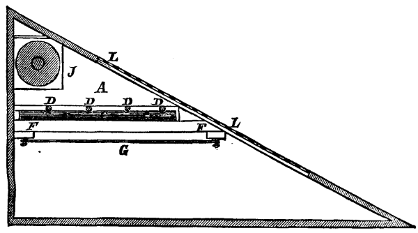
Fig. 1.
The inventors claim that the use of the vibrating springs give to the transmitter an increased power over those at present in use. They state that the instrument has given very satisfactory results between Ostende and Arlon, a distance of 314 kilometers (about 200 miles). It does not appear, however, that microphones of the ordinary Gower-Bell type, for example, were tried in competition with the new invention, and in the absence of such tests the mere fact that very satisfactory results were obtained over a length of 200 miles proves very little. With reference to a statement that whistling could be very clearly heard, we may remark that experience has many times proved that the most indifferent form of transmitter will almost always respond well and even powerfully to such forms of vibration.--Electrical Review.
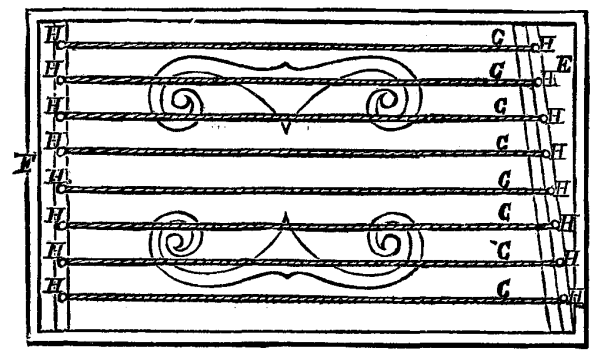
Fig. 2.
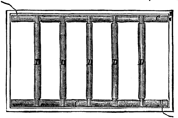
Fig. 3.
We are going to make known to our readers two new styles of electric lighters whose operation is sure and quick, and the use of which is just as economical as that of those quasi-incombustible little pieces of wood that we have been using for some years under the name of matches.
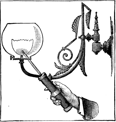
Fig. 1.--MODE OF USING THE GAS LIGHTER.
The first of these is a portable apparatus designed for lighting gas burners, and is based upon the calorific properties of the electric spark produced by the induction bobbin. Its internal arrangement is such as to permit of its being used with a pile of very limited power and dimensions. The apparatus has the form of a rod of a length that may be varied at will, according to the height of the burner to be lighted, and which terminates at its lower part in an ebonite handle about 4 centimeters in width by 20 in length (Fig. 1). This handle is divided into two parts, which are shown isolatedly in Fig. 2, and contains the pile and bobbin. The arrangement of the pile, A, is kept secret, and all that we can say of it is that zinc and chloride of silver are employed as a depolarizer. It is hermetically closed, and carries at one of its extremities a disk, B, and a brass ring, C, attached to its poles and designed to establish a communication between the pile and bobbin when the two parts of the apparatus are screwed together. To this end, two elastic pieces, D and E, fit against B and C and establish a contact. It is asserted that the pile is capable of being used 25,000 times before it is necessary to recharge it. H is an ebonite tube that incloses and protects the induction bobbin, K, whose induced wire communicates on the one hand with the brass tube, L, and on the other with an insulated central conductor, M, which terminates at a point very near the extremity of the brass tube. The currents induced in this wire produce a series of sparks between the tube, L, and the rod, M, which light the gas when the extremity of the apparatus is placed in proximity with the burner.
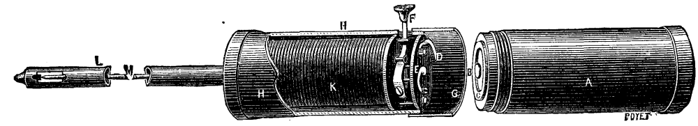
Fig. 2. MECHANISM OR THE INDUCTION SPARK GAS LIGHTER.
The ingenious and new part of the system lies in the mode of exciting the induced currents. When the extremity of the tube, L, is brought near the gas burner that is to be lighted, it is only necessary to shove the botton, F, from left to right in order to produce a limited number of sparks sufficient to effect the lighting. The motion of the button has not for effect, as might be believed, the closing of the circuit of the pile upon the inducting circuit of the bobbin. In fact in its normal position, the vibrator is distant from its contact, and the closing of the circuit would produce no action. The motion of F produces a mechanical motion of the spring of the vibrator, which latter acts for a few instants and produces a certain number of contacts that give rise to an equal number of sparks. Owing to this arrangement, the expenditure of electric energy required by each lighting is limited; and, an another hand, the vibrator, which would be incapable of operating if it had to be set in motion by the direct current from the pile, can be actuated mechanically. As the motion of the vibrator is derived from the hand of the operator, and not from the pile, it will be comprehended that the latter can, everything being equal, produce a larger number of lightings than an ordinary bobbin and vibrator.
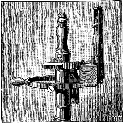
Fig. 3.--INCANDESCENT GAS LIGHTER.
Dr. Naret's Fiat Lux (Fig. 3) is simpler in its operation, and cheaper of application, since it takes its current from the ordinary piles that supply domestic call-bells. It consists essentially of a fine platinum wire supported by a tilting device in connection with the two poles of a pile composed of three Leclanche elements. Upon exerting a vertical pressure on the button placed to the left of the apparatus, either directly or by means of a cord, we at the same time turn the cock and cause the platinum spiral to approach, and the latter then becomes incandescent as a consequence of the closing of the circuit of the pile. After the burner is lighted it is only necessary to leave the apparatus to itself. The cock remains open, the spiral recedes from the burner, the circuit opens anew, and the burner remains lighted until the gas is turned off. This device, then, is particularly appropriate in all cases where there is a pressing need of light, for a single maneuver suffices to open the cock and effect a lighting of the burner.--La Nature.
On the 8th of June. 1874, Tresca presented to the French Academy some considerations respecting the distribution of heat in forging a bar of platinum, and stated the principal reasons which rendered that metal especially suitable for the purpose. He subsequently experimented, in a similar way, with other metals, and finally adopted Senarmont's method for the study of conductibility. A steel or copper bar was carefully polished on its lateral faces, and the polished portion covered with a thin coat of wax. The bar thus prepared was placed under a ram, of known weight, P, which was raised to a height, H, where it was automatically released so as to expend upon the bar the whole quantity of work T=PH, between the two equal faces of the ram and the anvil. A single shock sufficed to melt the wax upon a certain zone and thus to limit, with great sharpness, the part of the lateral faces which had been raised during the shock to the temperature of melting wax. Generally the zone of fusion imitates the area comprised between the two branches of an equilateral hyperbola, but the fall can be so graduated as to restrict this zone, which then takes other forms, somewhat different, but always symmetrical. If A is the area of this zone, b the breadth of the bar, d the density of the metal, c its capacity for heat, and t-t0 the excess of the melting temperature of wax over the surrounding temperature, it is evident that, if we consider A as the base of a horizontal prism which is raised to the temperature t, the calorific effect may be expressed by:
Ab x d x C(t-t0);
and on multiplying this quantity of heat by 425 we find, for the value of its equivalent in work,
T' = 425 AbdC(t-t0).
On comparing T' to T we may consider the experiment as a mechanical operation, having a minimum of:
T'/T = (425/PH)AbdC(t-t0).
After giving diagrams and tables to illustrate the geometrical disposition of the areas of fusion, Tresca feels justified in concluding that the development of heat depends upon the form of the faces and the intensity of the shock; that the points of greatest heat correspond to the points of greatest flow of the metal, and that this flow is really the mechanical phenomenon which gives rise to the calorific phenomenon; that for action sufficiently energetic and for bars of sufficient dimensions, about 0.8 of the labor expended on the blow may be found again in the heat; that the figures formed in the melted wax for shocks of less intensity furnish a kind of diagram of the distribution of the heat and of the deformation in the interior of the bar, but that the calculation of the coefficient of efficiency does not yield satisfactory results in the case of moderate blows.--Comptes Rendus.
[Footnote: Read at an evening meeting of the Pharmaceutical Society, March 5, 1884.]
From time to time, during the past twelve years, paragraphs have appeared in newspapers and other periodicals tending in effect to warn the public at least against the indiscriminate use of canned foods. And whenever there has been any foundation in fact for such cautions, it has commonly rested on the alleged presence and harmfulness of tin in the food. At the worst, the amount of tin present has been absurdly small, affording an opportunity for one literary representative of medicine to state that before a man could be seriously affected by the tin, even if it occurred in the form of a compound of the metal, he would have to consume at a meal ten pounds of the food containing the largest amount of tin ever detected.
But the greatest proportions of tin thus referred to are, according to my experiments, far beyond those ever likely to be actually present in the food itself in the form of a compound of tin; present, that is to say, on account of the action of the fluids or juices of the food on the tin of the can. Such action and such consequent solution of the tin, and consequent admixture of a possibly assimilable compound of tin with the food, in my opinion never occurs to an extent which in relation to health has any significance whatever. The occurrence of tin, not as a compound, but as the metal itself, is, if possible, still less important.
During the last fifteen years I have frequently examined canned foods, not only with respect to the food itself as food, and to the process of canning, but with regard to the relation of the food to, or the influence if any of the metal of, the can itself. So lately as within the past two or three months I have examined sixteen varieties of canned food for metals, with the following results:
                                  Decimal parts of
                                    a grain of tin
                                 (or other foreign
                                 metal) present in
  Name of article               a quarter of a lb.
  examined.


  Salmon                               none.
  Lobsters                             none.
  Oysters                              0.004
  Sardines                             none.
  Lobster paste                        none.
  Salmon paste                         none.
  Bloater paste                        0.002
  Potted beef                          none.
  Potted tongue                        none.
  Potted "Strasbourg"                  none.
  Potted ham                           0.002
  Luncheon tongue                      0.003
  Apricots                             0.007
  Pears                                0.003
  Tomatoes                             0.007
  Peaches                              0.004
These proportions of metal are, I say, undeserving of serious notice. I question whether they represent more than the amounts of tin we periodically wear off tin saucepans in preparing food--a month ago I found a trace of tin in water which had been boiled in a tin kettle--or the silver we wear off our forks and spoons. There can be little doubt that we annually pass through our systems a sensible amount of such metals, metallic compounds, and other substances that do not come under the denomination of food; but there is no evidence that they ever did or are ever likely to do harm or occasion us the slightest inconvenience. Harm is far more likely to come to us from noxious gases in the air we breathe than from foreign substances in the food we eat.
But whence come the much less minute amounts of tin--still harmless, be it remembered--which have been stated to be occasionally present in canned foods? They come from the minute particles of metal chipped off from the tin sheets in the operations of cutting, bending, or hammering the parts of the can, or possibly melted off in the operations necessary for the soldering together of the joints of the can. Some may, perhaps, be cut, off by the knife in opening a can. At all events I not unfrequently find such minute particles of metal on carefully washing the external surfaces of a mass of meat just removed from a can, or on otherwise properly treating canned food with the object of detecting such particles. The published processes for the detection of tin in canned food will not reveal more than the amounts stated in the table, or about those amounts; that is to say, a few thousandths or perhaps two or three hundredths of a grain, if this precaution be adopted. If such care be not observed, the less minute amounts may be found. I did not detect any metallic particles in the twelve samples of canned food just mentioned, but during the past few years I have occasionally found small pieces of metal, perhaps amounting in some of the cases to a few tenths of a grain per pound. Now and then small shot-like pieces of tin, or possibly solder, may be met with; but no one has ever found, to my knowledge, such a quantity of actual metallic tin, tinned iron, or solder as, from the point of view of health, can have any significance whatever.
The largest amount of tin I ever detected in actual solution in food was in some canned soup, containing a good deal of lemon juice. It amounted to only three-hundredths of a grain in a half pint of the soup as sent to table. Now, Christison says that quantities of 18 to 44 grains of the very soluble chloride of tin were required to kill dogs in from one to four days. Orfila says that several persons on one occasion dressed their dinner with chloride of tin, mistaking it for salt. One person would thus take not less than 20 to 30 grains of this soluble compound of tin. Yet only a little gastric and bowel disturbance followed, and from this all recovered in a few days. Pereira says that the dose of chloride of tin as an antispasmodic and stimulant is from 1/16 to ½ a grain repeated two or three times daily. Probably no article of canned food, not even the most acid fruit, if in a condition in which it can be eaten, has ever contained, in an ordinary table portion, as much of a soluble salt of tin as would amount to a harmless or useful medicinal dose.
Metallic particles of tin are without any effect on man. A thousand times the quantity ever found in a can of tinned food would do no harm.
Food as acid as say ordinary pickles would dissolve tin. Some manufacturers once proposed using tin stoppers to their bottles of pickles. But the tin was slowly dissolved by the acid of the vinegar. These pickles, however, had a distinctly nasty "metallic" flavor. The idea was abandoned. Probably any article of food containing enough tin to disagree with the system would be too nasty to eat. Purchasers of food may rest assured that the action taken by this firm would be that usually followed. It is not to the interest of manufacturers or other venders to offend the senses of purchasers, still less to do them actual harm, even if no higher motive comes into force.
In the early days of canning, it is just possible that the use of "spirits of salt" in soldering may have resulted in the presence of a little stannous, plumbous, or other chloride in canned food; but such a fault would soon be detected and corrected, and as a matter of fact, resin-soldering is to my knowledge more generally employed--indeed, for anything I know to the contrary, is exclusively employed--in canning food. Any resin that trained access would be perfectly harmless. It is just possible, also, that formerly the tin itself may have contained lead, but I have not found any lead in the sheet tin used for canning of late years.
In conclusion: 1. I have never been able to satisfy myself that a can of ordinary tinned food contains even a useful medicinal dose of such a true soluble compound of tin as is likely to have any effect on man. 2. As for the metal itself, that is the filings or actual metallic particles or fragments, one ounce is a common dose as a vermifuge; harmless even in that quantity to man, and not always so harmful as could be desired to the parasites for whose disestablishment it is administered. One ounce might be contained in about four hundredweight of canned food. 3. If a possibly harmful quantity of a soluble compound, of tin be placed in a portion of canned food, the latter will be so nasty and so unlike any ordinary nasty flavor, so "metallic," in fact, that no sane person will eat it. 4. Respecting the globules of solder (lead and tin) that are occasionally met with in canned food, I believe most persons detect them in the mouth and remove them, as they would shots in game. But if swallowed, they do no harm. Pereira says that metallic lead is probably inert, and that nearly a quarter of a pound has been administered to a dog without any obvious effects. He goes on to say that as it becomes oxidized it occasionally acquires activity, quoting Paulini's statement that colic was produced in a patient who had swallowed a leaden bullet. To allay alarm in the minds of those who fear they might swallow pellets of solder, I may add that Pereira cites Proust for the assurance that an alloy of tin and lead is less easily oxidized than pure lead. 5. Unsoundness in meat does not appear to promote the corrosion or solution of tin. I have kept salmon in cans till it was putrid, testing it occasionally for tin. No trace of tin was detected. Nevertheless, food should not be allowed to remain for a few days, or even hours, in saucepans, metal baking pans, or opened tins or cans, otherwise it may taste metallic. 6. Unsound food, canned or uncanned, may, of course, injure health, and where canned food really has done harm, the harm has in all probability been due to the food and not to the can. 7. What has been termed idiosyncrasy must also be borne in mind. I know a man to whom oatmeal is a poison. Some people cannot eat lobsters, either fresh or tinned. Serious results have followed the eating of not only oatmeal or shell fish, but salmon and mutton; hydrate (misreported nitrate) of tin being gratuitously suggested as being contained in the salmon in one case. Possibly there were cases of idiosyncrasy in the eater, possibly the food was unsound, possibly other causes altogether led to the results, but certainly, to my mind, the tin had nothing whatever to do with the matter.
In my opinion, given after well weighing all evidence hitherto forthcoming, the public have not the faintest cause for alarm respecting the occurrence of tin, lead, or any other metal in canned foods.--Phar. Jour, and Trans., March 8, 1884, p. 719.
[In reference to Prof. Attfield's statement contained in the closing paragraph, we remark: It is well known that mercury is an ingredient of the solder used in some canning concerns, as it makes an easier melting and flowing solder. In THE SCIENTIFIC AMERICAN for May 27, 1876, in a report of the proceedings of the New York Academy of Science, will be seen the statement of Prof. Falke, who found metallic mercury in a can of preserved corn beef, together with a considerable quantity of albuminate of mercury.--EDS. S.A.]
The house shown in the illustration was lately erected from the designs of Mr. Charles Bell, F.R.I.B.A. Although sufficiently commodious, the cost has been only about 1,050l.--The Architect.
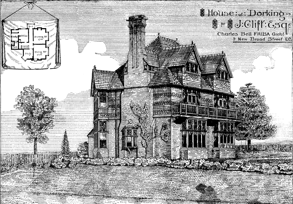
SUGGESTIONS IN ARCHTECTURE.--AN ENGLISH COTTAGE. COST, $5,250.
Valerianate of cerium in the vomiting of pregnancy is recommended by Dr. Blondeau in a communication to the Societe de Therapeutique. He gives it in doses of 10 centigrammes three times a day.--Medical Record.
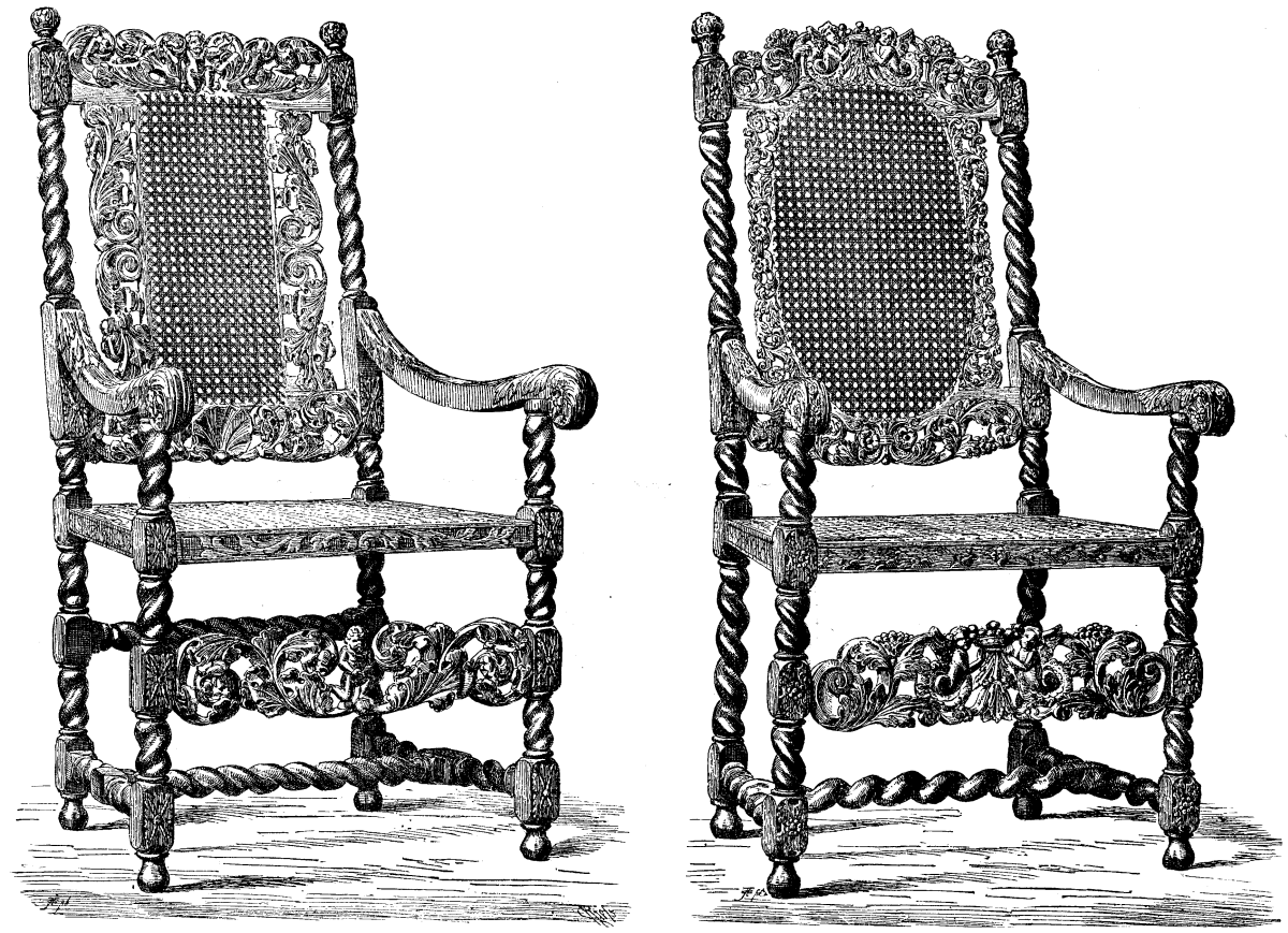
ARM CHAIR IN THE LOUVRE COLLECTION, PARIS; FLENISH RENAISSANCE.--From The Workshop.
If there is one point more than another in which the exuberant youth and vitality of the American nation is visible it is in that of education, the provision for which is on a most generous scale, carried out with a determination at which the older countries of the Eastern Hemisphere have only arrived by slow degrees and painful experience. Of course the Americans, being young, and having come to the fore, so to speak, full-fledged, have been able to profit by the lessons which they have derived from their neighbors--though it is none the less to their credit that they have profited so well and so quickly. Technical and industrial education has received a more general recognition, and been developed more rapidly, than the general education of the country, partly for the reason that there is no uniform system of the latter throughout the States, but that each individual State and Territory does that which is right in its own eyes. The principal reason, however, is that to possess the knowledge, how to work is the first creed of the American, who considers that the right to obtain that knowledge is the birthright of every citizen, and especially when the manual labor has to be supplemented by a vigorous use of brains. The Americans as a rule do not like heavy or coarse manual labor, thinking it beneath them; and, indeed, when they can get Irish and Chinese to do it for them, perhaps they are not far wrong. But the idea of idleness and loafing is very far from the spirit of the country, and this is why we see the necessity for industrial education so vigorously recognized, both as a national duty, and by private individuals or communities of individuals.
From whatever source it is provided, technical education in the United States comes mainly within the scope of two classes of institutions, viz., agricultural and mechanical colleges; although the two are, as often as not, combined under one establishment, and particularly it forms the subject of a national grant. Indeed, it may be said that the scope of industrial education embraces three classes: the farmer, the mechanic, and the housekeeper; and in the far West we find that provision is made for the education of these three classes in the same schools, it being an accepted idea in the newer States that man and woman (the housekeeper) are coworkers, and are, therefore, entitled to equal and similar educational privileges. On the other hand, in the more conservative East and South, we find that the sexes are educated distinct from each other. In the East, there is generally, also, a separation of subjects. In Massachusetts, for instance, the colleges of agriculture and mechanics are separate affairs, the students being taught in different institutions, viz., the agricultural college and the institute of technology. In Missouri the separation is less defined, the School of Mines and Metallurgy being the, only part that is distinct from the other departments of the University.
One of the chief reasons for the necessity for hastening the extension of technical education in America was the almost entire disappearance of the apprenticeship system, which, in itself, is mainly due to the subdivision of labor so prevalent in the manufacture of everything, from pins to locomotives. The increased use of machinery, the character of which is such as often to put an end to small enterprises, has promoted this subdivision by accumulating workmen in large groups. The beginner, confining himself to one department, is soon able to earn wages, and so he usually continues as he begins. Mr. C.B. Stetson has written on this subject with great force and earnestness, and it will not be amiss to quote a sentence as to the advantages enjoyed by the technically workman. He says that "it is the rude or dexterous workman, rather than the really skilled one, who is supplanted by machinery. Skilled labor requires thinking; but a machine never thinks, never judges, never discriminates. Though its employment does, indeed, enable rude laborers to do many things now which formerly could only be done by dexterous workmen, it is clear that its use has decidedly increased the relative demand for skilled labor as compared with unskilled, and there is abundant room for an additional increase, if it is true, as declared by the most eminent authority, that the power now expended can be readily made to yield three or four times its present results, and ultimately ten or twenty times, when masters and workmen can be had with sufficient intelligence and skill for the direction and manipulation of the tools and machinery that would be invented."
The establishment of colleges and universities by the aid of national grants has depended very much for their character upon the industrial tendencies of the respective States, it being understood that the land grants have principally been given to those of the newer States and Territories which required development, although some of the institutions of the older States on the Atlantic seaboard have also been recipients of the same fund, which in itself only dates from an act of Congress in 1862. In California and Missouri, both States abounding in mineral resources, there are courses in mining and metallurgy provided in the institutions receiving national aid. In the great grain-producing sections of the Mississippi Valley the colleges are principally devoted to agriculture, whereas the characteristic feature of the Iowa and Kansas schools is the prominence given to industries.
We need not devote attention to the aims and arrangements of the agricultural colleges proper, but will pass at once to those which deal with the mechanical arts, dealing first of all with those that are assisted by the national land grant. Taking them alphabetically, we have first the State Agricultural College of Colorado, in the mechanical and drawing department of which shops for bench work in wood and iron and for forging have been recently erected, this institution being one of the newest in America. In the Illinois Industrial University the student of mechanical engineering receives practice in five shops devoted to pattern-making, blacksmithing, moulding and founding, benchwork for iron, and machine tool-work for iron. In the first shop the practice consists of planing, chiseling, turning, and the preparation of patterns for casting. The ordinary blacksmithing operations take place in the second shop, and those of casting in the third. In the fourth there is, first of all, a course of freehand benchwork, and afterward the fitting of parts is undertaken. In the fifth shop all the fundamental operations on iron by machinery are practiced, the actual work being carefully outlined beforehand by drawings. This department of the University consists, in point of fact, of three separate schools, destined to qualify the student for every kind of engineering--mining, railway, mechanical, and architectural. In addition to the shops and machine rooms, there are well furnished cabinets of geological and mineralogical specimens, chemical laboratories for assaying and metallurgy, stamp mill, furnaces, etc., and, in fact, every known vehicle for practical instruction. The school of architecture prepares students for the building profession. Among the subjects in this branch are office work and shop practice, constructing joints in carpentry and joinery, cabinet making and turning, together with modeling in clay. The courses in mathematics, mechanics and physics are the same as those in the engineering school; but the technical studies embrace drawing from casts, wood, stone, brick, and iron construction, turners' work, slating, plastering, painting, and plumbing, architectural drawing and designing, the history and aesthetics of architecture, estimates, agreements specification, heating, lighting, draining, and ventilation. The student's work from scale drawing occupies three terms, carpentry and joinery being taught in the first year, turning and cabinet making in the second, metal and stone work in the third. A more condensed course, known as the builder's course, is given to those who can only stop one year. The machine shop has a steam engine of 16 horse power, two engines and three plain lathes, a planer, a large drill press, a pattern shop, a blacksmith's shop, all of the machinery having been built on the spot. The carpenter's shop is likewise supplied with necessary machine tools, such as saws, planers, tenoning machine, whittlers, etc., the power being furnished by the machine shop. At the date of the last University report, there were 41 students in the courses of mechanical engineering, 41 in those of civil engineering, 3 in mining engineering, and 14 in architecture. Tuition is free in all the University classes, though each student has to pay a matriculation fee of $10, and the incidental expenses amount to about $23 annually. He is charged for material used or apparatus broken, but not for the ordinary wear and tear of instruments. It should be mentioned that the endowment of the Illinois Industrial University is from scrip received from the Government for 480,000 acres of land, of which 454,460 have been sold for $319,178. The real estate of the University, partly made up by donations and partly by appropriations made in successive sessions by the State of Illinois, is estimated at $450,000.
The Purdue University in Indiana, named after its founder, who gave $150,000, which was supplemented by another $50,000 from the State and a bond grant of 390,000 acres, also provides a very complete mechanical course, with shop instruction, divided as follows:
  Bench working in wood    for 12 weeks, or 120 hours.
  Wood-turning              "   4   "     "  40  "
  Pattern-making            "  12   "     " 120  "
  Vise-work in iron         "  10   "     " 100  "
  Forging in iron and steel "  18   "     " 180  "
  Machine tool-work in iron "  20   "     " 200  "
The course in carpentry and joinery embraces: 1. Exercising in sawing and planing to dimensions. 2 Application, or box nailed together. 3 Mortise and tenon joints; a plain mortise and tenon; an open dovetailed mortise and tenon (dovetailed halving); a dovetailed keyed mortise and tenon. 4. Splices. 5. Common dovetailing. 6. Lap dovetailing and rabbeting. 7. Blind or secret dovetail. 8. Miter-box. 9. Carpenter's trestle. 10. Panel door. 11. Roof truss. 12. Section of king-post truss roof. 13. Drawing model.
The course in wood turning includes: 1. Elementary principles: first, straight turning; second, cutting in; third, convex curves with the chisel; fourth, compound curves formed with the gouge. 2. File and chisel handles. 3. Mallets. 4. Picture frames (chuck work). 5. Card receiver (chuck work). 6. Watch safe (chuck work). 7. Ball.
In the pattern-making course the student is supposed to have some skill in bench and lathe work, which will be increased; the direct object being to teach what forms of pattern are in general necessary, and how they must be constructed in order to get a perfect mould from them. The character of the work differs each year. For instance, for the last year, besides simpler patterns easily drawn from the sand, such as glands, ball-cranks, etc., there were a series of flanged pipe-joints for 2½ in. pipes, including the necessary core boxes; also pulley patterns from 6 in. to 10 in. diameter, built in segments for strength, and to prevent warping and shrinkage; and, lastly, a complete set of patterns for a three horse-power horizontal steam engine, all made from drawings of the finished piece. In the vise work in iron, the chief requirements are these: 1, given a block of cast iron 4 in. by 2 in. by 1½ in. in thickness, to reduce the thickness ¼ in. by chipping, and then finishing with the file; 2, to file a round hole square; 3, to file a round hole into elliptical; 4, given a 3 in. cube of wrought iron, to cut a spline 3 in. by 3/8 in. by ¼ in., and second, when the under side is a one half round hollow--these two cuts involve the use of the cope chisel and the round nose chisel, and are examples of very difficult chipping; 5, round tiling or hand-vise work; 6, scraping; 7, special examples of fitting. In the forging classes are elementary processes, driving, bending, and upsetting; courses in welding; miscellaneous forging; steel forging, including hardening and tempering in all its details.
It is worth mentioning that in the industrial art school of the Purdue University there were 13 of the fair sex as students, besides one in the chemical school, and two going through the mechanical courses just detailed, showing that the scope of woman's industry is less limited in America than in England. The Iowa State Agricultural College has also two departments of mechanical and civil engineering, the former including a special course of architecture. The workshop practice, which occupies three forenoons of 2½ hours each per week, is, however, of more general character, and is not pursued with such a regard to any special calling as in the case of the Purdue University.
The Kansas State Agricultural College has a course of carpentry, though designed rather more to meet the everyday necessities of a farmer's life. In fact, all the students are obliged to attend these classes, and take the same first lessons in sawing, planing, lumber dressing, making mortises, tenons, and joints, and in general use of tools--just the kind of instruction that every English lad should have before he is shipped off to the Colonies. This farmer's course in the Kansas College provides for a general training in mechanical handiwork, but facilities are given also to those who wish to follow out the trade, and special instruction is provided in the whole range of work, from framing to stair-building, as also in iron work, such as ordinary forging, filing, tempering, etc. Of the students attending this college, 75 percent, are from farmers' homes, and the majority of the remainder from the families of mechanics and tradesmen.
The State College of Maine provides courses for both civil and mechanical engineers, and has two shops equipped according to the Russian system. Forge and vise work are taught in them, though it is not the object of the college so much to teach the details of any one trade as to qualify students by general knowledge to undertake any of them afterward. A much more complete and thorough technical education is given in the Massachusetts Institute of Technology at Boston, where there are distinct classes for civil, mechanical, mining, geological, and architectural engineering. The following are the particulars of the instruction in the architectural branch, which commences in the student's second year, with Greek, Roman, and Mediæval architectural history, the Orders and their applications, drawing, sketching, and tracing, analytic geometry, differential calculus, physics, descriptive geometry, botany, and physical geography. In the third year the course is extended to the theory of decoration, color, form, and proportion; conventionalism, symbolism, the decorative arts, stained glass, fresco painting, tiles, terra-cotta, original designs, specifications, integral calculus, strength of materials, dynamics, bridges and roofs, stereotomy. In the fourth year the student is turned out a finished architect, after a course of the history of ornament, the theory of architecture, stability of structure, flow of gases, shopwork (carpentry), etc.
The number of students in this very comprehensive Institute of Technology was, by the latest report, 390, of whom 138 were undergoing special courses, 39 were in the schools of mechanical art, and 49 in the Lowell School of Practical Design. Tuition is charged at the rate of 200 dols. for the institute proper, and 150 dols. for the mechanical schools, the average expenses per student being about 254 dols. There are 10 free scholarships, of which two are given for mechanical art. The Lowell School has been established by the trustee of the Lowell Institute to afford free technical education, under the auspices of the Institute of Technology, to both sexes--a large number of young women availing themselves of it in connection with their factory work at Lowell. The courses include practical designs for manufactures, and the art of making patterns for prints, delaines, silks, paperhangings, carpets, oilcloth, etc., and the school is amply provided with pattern looms. Indeed, the whole of the appliances for practical teaching at the Institute are on such a complete scale that at the risk of being a little tedious it is as well to enumerate them. They comprise laboratories devoted to chemistry, mineralogy, metallurgy, and industrial chemistry; there are also microscopic, spectroscopic, and organic laboratories. In other branches there are laboratories and museums of steam engineering, mining, and metallurgy, biology and architecture, together with an observatory, much used in connection with geodesy and practical astronomy. The steam engineering laboratory provides practice in testing, adjusting, and managing steam machinery. The appliances in connection with mining and metallurgy include a five-stamp battery, Blake crusher, automatic machine jigs, an engine pulverizer, a Root and a Sturtevant blower, with blast reverberating, wasting, cupellation, and fusion furnaces, and all other means for reducing ores. The architectural museum contains many thousand casts, models, photographs, and drawings. The shops for handwork are large and well arranged, and include a vise-shop, forge shop, machine, tool, and lathe shops, foundry, rooms for pattern making, weaving, and other industrial institutions. The vise-shop contains four heavy benches, with 32 vises attached, giving a capacity for teaching 128 students the course every ten weeks, or 640 in a year of fifty weeks. The forge-shop has eight forges. The foundry has 16 moulding benches, an oven for core baking, and a blast furnace of one-half ton capacity. The pattern-weaving room is provided with five looms, one of them in 20-harness, and 4-shuttle looms, and another an improved Jacquard pattern loom. It may safely be said that there is nor an establishment in the world better equipped for industrial and technical education than this Institute of Massachusetts.--London Building News.
IVORY GETTING SCARCE.--The stock of ivory in London is estimated at about forty tons in dealers' private warehouses, whereas formerly they usually held about one hundred tons. One fourth of all imported into England goes to the Sheffield cutlers. No really satisfactory substitute for ivory has been found, and millions await the discoverer of one. The existing substitutes will not take the needed polish.
Fakirs are religious mendicants who, for the purpose of exciting the charity of the public, assume positions in which it would seem impossible that they could remain, submit themselves to fearful tortures, or else, by their mode of living, their abstinence, and their indifference to inclement weather and to external things, try to make believe that, owing to their sanctity, they are of a species superior to that of common mortals.
In the Indies, these fakirs visit all the great markets, all religious fetes, and usually all kinds of assemblages, in order to exhibit, themselves. If one of them exhibits some new peculiarity, some curious deformity, a strange posture, or, finally, any physiological curiosity whatever that surpasses those of his confreres, he becomes the attraction of the fete, and the crowd surrounds him, and small coin and rupees begin to fall into his bowl.
Fakirs, like all persons who voluntarily torture themselves, are curious examples of the modifications that will, patience, and, so to speak, "art" can introduce into human nature, and into the sensitiveness and functions of the organs. If these latter are capable of being improved, of having their functions developed and of acquiring more strength (as, for example, the muscles of boxers, the breast of foot racers, the voice of singers, etc.), these same organs, on the contrary, can be atrophied or modified, and their functions be changed in nature. It is in such degradation and such degeneration of human nature that fakirs excel, and it is from such a point of view that they are worth studying.
We may, so to speak, class these individuals according to the grades of punishments that they inflict upon themselves, or according to the deformities that they have caused themselves to undergo. But, as we have already said, the number of both of these is extremely varied, each fakir striving in this respect to eclipse his fellows. It is only necessary to open a book of Indian travel to find descriptions of fakirs in abundance; and such descriptions might seem exaggerated or unlikely were they not so concordant. The following are a few examples:
Immovable fakirs.--The number of these is large. They remain immovable in the spot they have selected, and that too for an exceedingly long period of time. An example of one of these is cited who remained standing for twelve years, his arms crossed upon his breast, without moving and without lying or sitting down. In such cases charitable persons always take it upon themselves to prevent the fakir from dying of starvation. Some remain sitting, immovable, and apparently lifeless, while others, who lie stretched out upon the ground, look like corpses. It may be easily imagined what a state one of these beings is in after a few months or years of immobility. He is extremely lean, his limbs are atrophied, his body is black with filth and dust, his hair is long and dishevelled, his beard is shaggy, his finger and toe nails have become genuine claws, and his aspect is frightful. This, however, is a character common to all fakirs.
We may likewise class among the immovables those fakirs who cause themselves to be interred up to the neck, and who remain thus with their head sticking out of the ground either during the entire time the fair or fete lasts or for months and years.
Anchylotic Fakirs.--The number of fakirs who continue to hold one or both arms outstretched is very large in India. The following description of one of them is given by a traveler: "He was a goussain--a religious mendicant--who had dishevelled hair and beard, and horrible tattooings upon his face, and, what was most hideous, was his left arm, which, withered and anchylosed, stuck up perpendicularly from the shoulder. His closed hand, surrounded by straps, had been traversed by the nails, which, continuing to grow, had bent like claws on the other side. Finally, the hollow of this hand, which was filled with earth, served as a pot for a small sacred myrtle."
Other fakirs hold their two arms above their head, the hands crossed, and remain perpetually in such a position. Others again have one or both arms extended. Some hang by their feet from the limb of a tree by means of a cord, and remain head downward for days at a time, with their face uncongested and their voice clear, counting their beads and mumbling prayers.
One of the most remarkable peculiarities of fakirs is the faculty that certain of them possess of remaining entirely buried in vaults and boxes, and inclosed in bags, etc., for weeks and months, and, although there is a certain deceit as regards the length of their absolute abstinence, it nevertheless seems to be a demonstrated fact that, after undergoing a peculiar treatment, they became plunged into a sort of lethargy that allows them to remain for several days or weeks without taking food. Certain fakirs that have been interred under such conditions have, it appears, passed ten months or a year in their grave.
Tortured Fakirs.--Fakirs that submit themselves to tortures are very numerous. Some of them perform exercises analogous to those of the Aissaoua. Mr. Rousselet, in his voyage to the Indies, had an opportunity of seeing some of these at Bhopal, and the following is the picturesque description that he gives of them: "I remarked some groups of religious mendicants of a frightfully sinister character. They were Jogins, who, stark naked and with dishevelled hair, were walking about, shouting, and dancing a sort of weird dance. In the midst of their contortions they brandished long, sharp poniards, of a special form, provided with steel chains. From time to time, one of these hallucinated creatures would drive the poniard into his body (principally into the sides of his chest), into his arms, and into his legs, and would only desist when, in order to calm his apparent fury, the idlers who were surrounding him threw a sufficient number of pennies to him."
At the time of the feast of the Juggernaut one sees, or rather one did see before the English somewhat humanized this ceremony, certain fakirs suspended by their flesh from iron hooks placed along the sides of the god's car. Others had their priests insert under their shoulder blades two hooks, that were afterward fixed to a long pole capable of pivoting upon a post. The fakirs were thus raised about thirty feet above ground, and while being made to spin around very rapidly, smilingly threw flowers to the faithful. Others, again, rolled over mattresses garnished with nails, lance-points, poniards, and sabers, and naturally got up bathed in blood. A large number cause 120 gashes (the sacred number) to be made in their back and breast in honor of their god. Some pierce their tongue with a long and narrow poniard, and remain thus exposed to the admiration of the faithful. Finally, many of them are content to pass points of iron or rods made of reed through folds in their skin. It will be seen from this that fakirs are ingenious in their modes of exciting the compassion and charity of the faithful.
Elsewhere, among a large number of savage tribes and half-civilized peoples, we find aspirants to the priesthood of the fetiches undergoing, under the direction of the members of the religious caste that they desired to enter, ordeals that are extremely painful. Now, it has been remarked for a long time that, among the neophytes, although all are prepared by the same hands, some undergo these ordeals without manifesting any suffering, while others cannot stand the pain, and so run away with fright. It has been concluded from this that the object of such ordeals is to permit the caste to make a selection from among their recruits, and that, too, by means of anesthetics administered to the chosen neophytes.
In France, during the last two centuries, when torturing the accused was in vogue, some individuals were found to be insensible to the most fearful tortures, and some even, who were plunged into a species of somnolence or stupefaction, slept in the hands of the executioner.
What are the processes that permit of such results being reached? Evidently, we cannot know them all. A certain number are caste, sect, or family secrets. Many are known, however, at least in a general way. The processes naturally vary, according to the object to be attained. Some seem to consist only in an effort of the will. Thus, those fakirs who remain immovable have no need of any special preparation to reach such a result, and the same is the case with those who are interred up to the neck, the will alone sufficing. Fakirs probably pass through the same phases that invalids do who are forced to keep perfectly quiet through a fracture or dislocation. During the first days the organism revolts against such inaction, the constraint is great, the muscles contract by starts, and then the patient gets used to it; the constraint becomes less and less, the revolt of the muscles becomes less frequent, and the patient becomes reconciled to his immobility. It is probable that after passing several months or years in a state of immobility fakirs no longer experience any desire to change their position, and even did they so desire, it would be impossible owing to the atrophy of their muscles and the anchylosis of their joints.
Those fakirs who remain with one or several limbs immovable and in an abnormal position have to undergo a sort of preparation, a special treatment; they have to enter and remain two or three mouths in a sort of cage or frame of bamboo, the object of which is to keep the limb that is to be immobilized in the position that it is to preserve. This treatment, which is identical with the one employed by surgeons for curing affections of the joints, has the effect of soldering or anchylosing the articulation. When such a result is reached, the fakir remains, in spite of himself and without fatigue, with outstretched arms, and, in order to cause them to drop, he would have to undergo a surgical operation.
As for those voluntary tortures that cause an effusion of blood, the insensibility of those who are the victims of it is explainable when we reflect that India is the country par excellence of anæsthetic plants. It produces, notably, Indian hemp and poppy, the first of which yields hashish and the other opium. Now it is owing to these two narcotics, taken in a proper dose, either alone or combined according to a formula known to Hindoo fakirs and jugglers, but ignored by the lower class, that the former are able to become absolutely insensible themselves or make their adepts so.
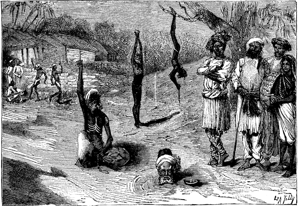
INDIAN FAKIRS IN VARIOUS POSITIONS.
There is, especially, a liquor known in the Indian pharmacopoeia under the name of bang, that produces an exciting intoxication accompanied with complete insensibility. Now the active part of bang consists of a mixture of opium and hashish. It was an analogous liquor that the Brahmins made Indian widows take before leading them to the funeral pile. This liquor removed from the victims not only all consciousness of the act that they were accomplishing, but also rendered them insensible to the flames. Moreover, the dose of the anæsthetic was such that if, by accident, the widow had escaped from the pile (something that more than once happened, thanks to English protection), she would have died through poisoning. Some travelers in Africa speak of an herb called rasch, which is the base of anæsthetic preparations employed by certain Arabian jugglers and sorcerers.
It was hashish that the Old Man of the Mountain, the chief of the sect of Assassins, had recourse to for intoxicating his adepts, and it was, it is thought, by the use of a virulent solanaceous plant--henbane, thornapple, or belladonna--that he succeeded in rendering them insensible. We have unfortunately lost the recipe for certain anæsthetics that were known in ancient times, some of which, such as the Memphis stone, appear to have been used in surgical operations. We are also ignorant of what the wine of myrrh was that is spoken of in the Bible.
We are likewise ignorant of the composition of the anæsthetic soap, the use of which became so general in the 15th and 16th centuries that, according to Taboureau, it was difficult to torture persons who were accused. The stupefying recipe was known to all jailers, who, for a consideration, communicated it to prisoners. It was this use of anæsthetics that gave rise to the rule of jurisprudence according to which partial or general insensibility was regarded as a certain sign of sorcery. We may cite a certain number of preparations, which vary according to the country, and to which is attributed the properly of giving courage and rendering persons insensible to wounds inflicted by the enemy. In most cases alcohol forms the base of such beverages, although the maslach that Turkish soldiers drink just before a battle contains none of it, on account of a religious precept. It consists of different plant-juices, and contains, especially, a little opium. Cossacks and Tartars, just before battle, take a fermented beverage in which has been infused a species of toadstool (Agaricus muscarius), and which renders them courageous to a high degree.
As well known, the old soldiers of the First Empire taught the young conscripts that in order to have courage and not feel the blows of the enemy, it was only necessary to drink a glass of brandy into which gunpowder had been poured.--La Nature.
[SCHOOL OF MINES QUARTERLY.]
In the Quarterly for March, 1880, a paper was published on "The Origin and Classification of Ore Deposits," which treated, among other things, of mineral veins. These were grouped in three categories, namely: 1. Gash Veins; 2. Segregated Veins; 3. Fissure Veins; and were defined as follows:
Gash Veins.--Ore deposits confined to a single bed or formation of limestone, of which the joints, and sometimes planes of bedding, enlarged by the solvent power of atmospheric water carrying carbonic acid, and forming crevices, galleries, or caves, are lined or filled with ore leached from the surrounding rock, e.g., the lead deposits of the Upper Mississippi and Missouri.
Segregated Veins.--Sheets of quartzose matter, chiefly lenticular and conforming to the bedding of the inclosing rocks, but sometimes filling irregular fractures across such bedding, found only in metamorphic rocks, limited in extent laterally and vertically, and consisting of material indigenous to the strata in which they occur, separated in the process of metamorphism, e.g., quartz ledges carrying gold, copper, iron pyrites, etc., in the Alleghany Mountains, New England, Canada, etc.
Fissure Veins.--Sheets of metalliferous matter filling fissures caused by subterranean force, usually in the planes of faults, and formed by the deposit of various minerals brought from a lower level by water, which under pressure and at a high temperature, having great solvent power, had become loaded with matters leached from different rocks, and deposited them in the channels of escape as the pressure and temperature were reduced.
Since that article was written, a considerable portion of several years has been spent by the writer continuing the observations upon which it was based. During this time most of the mining centers of the Western States and Territories, as well as some in Mexico and Canada, were visited and studied with more or less care. Perhaps no other portion of the earth's surface is so rich in mineral resources as that which has been covered by these observations, and nowhere else is to be found as great a variety of ore deposits, or those which illustrate as well their mode of formation. This is so true that it maybe said without exaggeration that no one can intelligently discuss the questions that have been raised in regard to the origin and mode of formation of ore bodies without transversing and studying the great mining belt of our Western States and Territories.
The observations made by the writer during the past four years confirm in all essentials the views set forth in the former article in the Quarterly, and while a volume might be written describing the phenomena exhibited by different mines and mining districts, the array of facts thus presented would be, for the most part, simply a re-enforcement of those already given.
The present article, which must necessarily be short, would hardly have a raison d'etre except that it affords an opportunity for an addition which should be made to the classes of mineral veins heretofore recognized in this country, and it seems called for by the recent publication of theories on the origin of ore deposits which are incompatible with those hitherto presented and now held by the writer, and which, if allowed to pass unquestioned, might seem to be unquestionable.
Certain ore deposits which have recently come under my observation appear to correspond very closely with those that Von Cotta has taken as types of his class of "bedded veins," and as no similar ones have been noticed by American writers on ore deposits they have seemed to me worthy of description.
These are zones or layers of a sedimentary rock, to the bedding of which they are conformable, impregnated with ore derived from a foreign source, and formed long subsequent to the deposition of the containing formation. Such deposits are exemplified by the Walker and Webster, the Piñon, the Climax, etc., in Parley's Park, and the Green-Eyed Monster, and the Deer Trail, at Marysvale, Utah. These are all zones in quartzite which have been traversed by mineral solutions that have by substitution converted such layers into ore deposits of considerable magnitude and value.
The ore contained in these bedded veins exhibits some variety of composition, but where unaffected by atmospheric action consists of argentiferous galena, iron pyrites carrying gold, or the sulphides of zinc and copper containing silver or gold or both. The ore of the Walker and Webster and the Piñon is chiefly lead-carbonate and galena, often stained with copper-carbonate. That of the Green Eyed Monster--now thoroughly oxidized as far as penetrated--forms a sheet from twenty to forty feet in thickness, consisting of ferruginous, sandy, or talcose soft material carrying from twenty to thirty dollars to the ton in gold and silver. The ore of the Deer Trail forms a thinner sheet containing considerable copper, and sometimes two hundred to three hundred dollars to the ton in silver.
The rocks which hold these ore deposits are of Silurian age, but they received their metalliferous impregnation much later, probably in the Tertiary, and subsequent to the period of disturbance in which they were elevated and metamorphosed. This is proved by the fact that in places where the rock has been shattered, strings of ore are found running off from the main body, crossing the bedding and filling the interstices between the fragments, forming a coarse stock-work.
Bedded veins may be distinguished from fissure veins by the absence of all traces of a fissure, the want of a banded structure, slickensides, selvages, etc.; from gash veins and the floors of ore which often accompany them, as well as from segregated veins, they are distinguished by the nature of the inclosing rock and the foreign origin of the ore. Sometimes the plane of junction between two contiguous sheets of rock has been the channel through which has flowed a metalliferous solution, and the zone where the ore has replaced by substitution portions of one or both strata. These are often called blanket veins in the West, but they belong rather to the category of contact deposits as I have heretofore defined them. Where such sheets of ore occupy by preference the planes of contact between adjacent strata, but sometimes desert such planes, and show slickensided walls, and banded structure, like the great veins of Bingham, Utah, these should be classed as true fissure veins.
The recently published theories of the formation of mineral veins, to which I have alluded, are those of Prof. Von Groddek[1] and Dr. Sandberger,[2] who attribute the filling of veins to exudations of mineral solutions from the wall rocks (i.e., lateral secretions), and those of Mr. S.F. Emmons,[3] and Mr. G.F. Becker,[4] who have been studying, respectively, the ore deposits of Leadville and of the Comstock, by whom the ores are credited to the leaching of adjacent igneous rocks.
[Footnote 1: Die Lehre von den Lagerstatten der Erze, von Dr. Albrecht von Groddek, Leipzig. 1879.]
[Footnote 2: Untersuchungen uber Erzgange, von Fridolin Sandberger, Weisbaden, 1882.]
[Footnote 3: Geology and Mining Industry of Leadville, Annual Report, Director U.S. Geol. Surv., 1881.]
[Footnote 4: Geology of the Comstock Lode and Washoe District, G.F. Becker, Washington, 1883.
It is but justice to Messrs. Becker and Emmons to say that theirs are admirable studies, thorough and exhaustive, of great interest and value to both mining engineers and geologists, and most creditable to the authors and the country. No better work of the kind has been done anywhere, and it will detract little from its merit even if the views of the authors on the theoretical question of the sources of the ores shall not be generally adopted.]
The lack of space must forbid the full discussion of these theories at the present time, but I will briefly enumerate some of the facts which render it difficult for me to accept them.
First, the great diversity of character exhibited by different sets of fissure veins which cut the same country rock seems incompatible with any theory of lateral secretion. These distinct systems are of different ages, of diversified composition, and have evidently drawn their supply of material from different sources. Hundreds of cases of this kind could be cited, but I will mention only a few; among others the Humboldt, the Bassick, and the Bull Domingo, near Rosita and Silver Cliff, Colorado. These are veins contained in the same sheet of eruptive rock, but the ores are as different as possible. The Humboldt is a narrow fissure carrying a thin ore streak of high grade, consisting of sulphides of silver, antimony, arsenic, and copper; the Bassick is a great conglomerate vein containing tellurides of silver and gold, argentiferous galena, blende, and yellow copper; the Bull Domingo is also a great fissure filled with rubbish containing ore chimneys of galena with tufts of wire silver. I may also cite the Jordan, with its intersecting and yet distinct and totally different veins; the Galena, the Neptune, and the American Flag, in Bingham Canon, Utah; and the closely associated yet diverse system of veins the Ferris, the Washington, the Chattanooga, the Fillmore, etc., in Bullion Canon at Marysvale. In these and many other groups which have been examined by the writer, the same rocks are cut by veins of different ages, having different bearings, and containing different ores and veinstones. It seems impossible that all these diversified materials should have been derived from the same source, and the only rational explanation of the phenomena is that which I have heretofore advocated, the ascent of metalliferous solutions from different and deep seated sources.
Another apparently unanswerable argument against the theory of lateral secretion is furnished by the cases where the same vein traverses a series of distinct formations, and holds its character essentially unaffected by changes in the country rock. One of many such may be cited in the Star vein at Cherry Creek, Nevada, which, nearly at right angles to their strike, cuts belts of quartzite, limestone, and slate, maintaining its peculiar character of ore and gangue throughout.
This and all similar veins have certainly been filled with material brought from a distance, and not derived from the walls.
The arguments against the theory that mineral veins have been produced by the leaching of superficial igneous rocks are in part the same as those already cited against the general theory of lateral secretion. They may be briefly summarized as follows:
1. Thousands of mineral veins in this and other countries occur in regions remote from eruptive rocks. Into this category come most of those of the eastern half of the Continent, viz., Canada, New England, the Alleghany belt, and the Mississippi Valley. Among those I will refer only to a few selected to represent the greatest range of character, viz., the Victoria lead mine, near Sault Ste. Marie, the Bruce copper mine on Lake Huron, the gold-bearing quartz veins of Madoc, the Gatling gold vein of Marmora, the Acton and the Harvey Hill copper mines of Canada, the copper veins of Ely, Vermont, and of Blue Hills, Maine, the silver-bearing lead veins of Newburyport, Mass.; most of the segregated gold veins of the Alleghany belt, the lead veins of Rossie, Ellenville, and at other localities farther South; the copper bearing veins of Virginia, North Carolina, and Tennessee; the veins carrying argentiferous galena in Central Kentucky and in Southern Illinois; the silver, copper, and antimony veins of Arkansas; and the lead and zinc deposits of Missouri and the Upper Mississippi.
In these widely separated localities are to be found fissure, segregated, and gash veins, and a great diversity of ores, which have been derived, sometimes from the adjacent rocks--as in the segregated veins of the Alleghany belt and the gash veins of the Mississippi region--and in other cases--where they are contained in true fissure veins--from a foreign source, but all deposited without the aid of superficial igneous rocks, either as contributors of matter or force.
2. In the great mineral belt of the Far West, where volcanic emanations are so abundant, and where they have certainly played an important part in the formation of ore deposits, the great majority of veins are not in immediate contact with trap rocks, and they could not, therefore, have furnished the ores.
A volume might be formed by a list of the cases of this kind, but I can here allude to a few only, most of which I have myself examined, viz.:
(a.) The great ore chambers of the San Carlos Mountains in Chihuahua, the largest deposits of ore of which I have any knowledge. These are contained in heavy beds of limestone, which are cut in various places by trap dikes, which, as elsewhere, have undoubtedly furnished the stimulus to chemical action that has resulted in the formation of the ore bodies, but are too remote to have supplied the material.
(b.) The silver mines of Santa Eulalia, in Chihuahua, from which during the last century one hundred and twelve millions of dollars were taken, opened on ore deposits situated in Cretaceous limestones like those of San Carlos, and apparently similar ore-filled chambers; an igneous rock caps the hills in the vicinity, but is nowhere in contact or even proximity to the ore bodies. (See Kimball, Amer. Jour. Sci,. March, 1870.)
(c.) The great chambers of Tombstone, and the copper veins of the Globe District, the Copper Queen, etc., in Arizona.
(d.) The large bodies of silver-ore at Lake Valley, New Mexico; chambers in limestone, like c.
(e.) The Black Hawk group of gold mines, the Montezuma, Georgetown, and other silver mines in the granite belt of Colorado.
(f.) The great group of veins and chambers in the Bradshaw, Lincoln, Star, and Granite districts of Southern Utah, where we find a host of veins of different character in limestone or granite, with no trap to which the ores can be credited.
(g.) The Crismon Mammoth vein of Tintic.
(h.) The group of mines opened on the American Fork, on Big and Little Cottonwood, and in Parley's Park, including the Silver Bell, the Emma, the Vallejo, the Prince of Wales, the Kessler, the Bonanza, the Climax, the Piñon, and the Ontario. (The latter, the greatest silver mine now known in the country, lies in quartzite, and the trap is near, but not in contact with the vein.)
(i.) In Nevada, the ore deposits of Pioche, Tempiute, Tybo, Eureka, White Pine, and Cherry Creek, on the east side of the State, with those of Austin, Belmont, and a series too great for enumeration in the central and western portions.
(j.) In California, the Bodie, Mariposa, Grass Valley, and other mines.[1]
(k.) In Idaho, those of the Poor Man in the Owyhee district, the principal veins of the Wood River region, the Ramshorn at Challis, the Custer and Charles Dickens, at Bonanza City, etc.
[Footnote 1: See Redmond's Report (California Geol. Survey Mining Statistics, No 1), where seventy-seven mines are enumerated, of which three are said to be in "porphyritic schist," all the others in granite, mica schist, clay, slate, etc.]
In nearly all these localities we may find evidence not only that the ore deposits have not been derived from the leaching of igneous rocks, but also that they have not come from those of any kind which form the walls of the veins.
The gold-bearing quartz veins of Deadwood are so closely associated with dikes of porphyry, that they may have been considered as illustrations of the potency of trap dikes in producing concentration of metals. But we have conclusive evidence that the gold was there in Archæan times, while the igneous rocks are all of modern, probably of Tertiary, date. This proof is furnished by the "Cement mines" of the Potsdam sandstone. This is the beach of the Lower Silurian sea when it washed the shores of an Archæan island, now the Black Hills. The waves that produced this beach beat against cliffs of granite and slate containing quartz veins carrying gold. Fragments of this auriferous quartz, and the gold beaten out of them and concentrated by the waves, were in places buried in the sand beach in such quantity as to form deposits from which a large amount of gold is now being taken. Without this demonstration of the origin and antiquity of the gold, it might very well have been supposed to be derived from the eruptive rock.
Strong arguments against the theory that the leaching of superficial igneous rocks has supplied the materials filling mineral veins, are furnished by the facts observed in the districts where igneous rocks are most prevalent, viz.: (1.) Such districts are proverbially barren of useful minerals. (2.) Where these occur, the same sheet of rock may contain several systems of veins with different ores and gangues.
The great lava plain of Snake River, the Pedrigal country of eastern Oregon, Northern California and Mexico are without valuable ore deposits. The same may be said of the Pancake Range and other mountain chains of igneous rock in Nevada, while the adjacent ranges composed of sedimentary rocks are rich in ore deposits of various kinds. A still stronger case is furnished by the Cascade Mountains, which, north of the California line, are composed almost exclusively of erupted material, and yet in all this belt, so far as now known, not a single valuable mine has been opened. In contrast with this is the condition of things in California, where the Sierra Nevada is composed of metamorphic rocks which have been shown to be the repositories of vast quantities of gold, silver, and copper. Cases belonging to this category may be found at Rosita and Silver Cliff, where the diversity in the ores of the mines already enumerated can hardly be reconciled with the theory of a common origin. At Lake City the prevailing porphyry holds the veins of the Ute and Ulay and the Ocean Wave mines, which are similar, and the Hotchkiss, the Belle, etc., entirely different.
We have no evidence that any volcanic eruption has drawn its material from zones or magmas especially rich in metals or their ores, and on the contrary, volcanic districts, like those mentioned, and regions, such as the Sandwich Islands, where the greatest, eruptions have taken place, are poorest in metalliferous deposits.
All the knowledge we have of the subject justifies the inference that most of the igneous rocks which have been poured out in our Western Territories are but fused conditions of sediments which form the substructure of that country. Over the great mineral belt which lies between the Sierra Nevada and the front range of the Rocky Mountains, and extends not only across the whole breadth of our territory, but far into Mexico, the surface was once underlain by a series of Palaeozoic sedimentary strata not less than twenty to thirty thousand feet in thickness; and beneath these, at the sides, and doubtless below, were Archæun rocks, also metamorphosed sediments. Through these the ores of the metals were generally though sparsely distributed. In the convulsions which have in recent times broken up this so long quiet and stable portion of the earth's crust (and which have resulted in depositing in thousands of cracks and cavities the ores we now mine), portions of the old table-land were in places set up at high angles forming mountain chains, and doubtless extending to the zone of fusion below. Between these blocks of sedimentary rocks oozed up through the lines of fracture quantities of fused material, which also sometimes formed mountain chains; and it is possible and even probable that the rocks composing the volcanic ridges are but phases of the same materials that form the sedimentary chains There is, therefore, no a priori reason why the leaching of one group should furnish more ore than the other; but, as a matter of fact, the unfused sediments are much the richer in ore deposits. This can only be accounted for, in my judgment, by supposing that they have been the receptacles of ore brought from a foreign source; and we can at least conjecture where and how gathered. We can imagine, and we are forced to conclude, that there has been a zone of solution below, where steam and hot water, under great pressure, have effected the leaching of ore-bearing strata, and a zone of deposition above, where cavities in pre-existent solidified and shattered rocks became the repositories of the deposits made from ascending solutions, when the temperature and pressure were diminished. Where great masses of fused material were poured out, these must have been for along time too highly heated to become places of deposition; so long indeed that the period of active vein formation may have passed before they reached a degree of solidification and coolness that would permit their becoming receptacles of the products of deposition. On the contrary, the masses of unfused and always relatively cool sedimentary rocks which form the most highly metalliferous mountain ranges (White Pine, Toyabe, etc.) were, throughout the whole period of disturbance, in a condition to become such repositories. Certainly highly heated solutions forced by an irresistible vis a tergo through rocks of any kind down in the heated zone, would be far more effective leaching agents than cold surface water with feeble solvent power, moved only by gravity, percolating slowly through superficial strata.
Richthofen, who first made a study of the Comstock lode, suggests that the mineral impregnation of the vein was the result of a process like that described, viz., the leaching of deep-seated rocks, perhaps the same that inclose the vein above, by highly heated solutions which deposited their load near the surface. On the other hand, Becker supposes the concentration to have been effected by surface waters flowing laterally through the igneous rocks, gathering the precious metals and depositing them in the fissure, as lateral secretion produces the accumulation of ore in the limestone of the lead region. But there are apparently good reasons for preferring the theory of Richthofen: viz., first, the veinstone of the Comstock is chiefly quartz, the natural and common precipitate of hot waters, since they are far more powerful solvents of silica than cold. On the contrary, the ores deposited from lateral secretion, as in the Mississippi lead region, at low temperature contain comparatively little silica; second, the great mineral belt to which reference has been made above is now the region where nearly all the hot springs of the continent are situated. It is, in fact, a region conspicuous for the number of its hot springs, and it is evident that these are the last of the series of thermal phenomena connected with the great volcanic upheavals and eruptions, of which this region has been the theater since the beginning of the Tertiary age. The geysers of Yellowstone Park, the hot springs of the Wamchuck district in Oregon, the Steamboat Springs of Nevada, the geysers of California, the hot springs of Salt Lake City, Monroe, etc., in Utah, and the Pagosa in Colorado, are only the most conspicuous among thousands of hot springs which continue in action at the present time. The evidence is also conclusive that the number of hot springs, great as it now is in this region, was once much greater. That these hot springs were capable of producing mineral veins by material brought up in and deposited from their waters, is demonstrated by the phenomena observable at the Steamboat Springs, and which were cited in my former article as affording the best illustration of vein formation.
The temperature of the lower workings of the Comstock vein is now over 150°F., and an enormous quantity of hot water is discharged through the Sutro Tunnel. This water has been heated by coming in contact with hot rocks at a lower level than the present workings of the Comstock lode, and has been driven upward in the same way that the flow of all hot springs is produced. As that flow is continuous, it is evident that the workings of the Comstock have simply opened the conduits of hot springs, which are doing to-day what they have been doing in ages past, but much less actively, i.e., bringing toward the surface the materials they have taken into solution in a more highly heated zone below. Hence it seems much more natural to suppose that the great sheets of ore-bearing quartz now contained in the Comstock fissure were deposited by ascending currents of hot alkaline waters, than by descending currents of those which were cold and neutral The hot springs are there, though less copious and less hot than formerly, and the natural deposits from hot waters are there. Is it not more rational to suppose with Richthofen that these are related as cause and effect, rather than that cold water has leached the ore and the silica from the walls near the surface? Mr. Becker's preference for the latter hypothesis seems to be due to the discovery of gold and silver in the igneous rocks adjacent to the vein, and yet, except in immediate contact with it, these rocks contain no more of the precious metals than the mere trace which by refined tests may be discovered everywhere. If, as we have supposed, the fissure was for a long time filled with a hot solution charged with an unusual quantity of the precious metals, nothing would be more natural than that the wall rocks should be to some extent impregnated with them.
It will perhaps illuminate the question to inquire which of the springs and water currents of this region are now making deposits that can be compared with those which filled the Comstock and other veins. No one who has visited that country will hesitate to say the hot and not the cold waters. The immense silicious deposits, carrying the ores of several metals, formed by the geysers of the Yellowstone, the Steamboat Springs, etc., show what the hot waters are capable of doing; but we shall search in vain for any evidence that the cold surface waters have done or can do this kind of work.
At Leadville the case is not so plain, and yet no facts can be cited which really prove that the ore deposits have been formed by the leaching of the overlying porphyry rather than by an outflow of heated mineral solutions along the plane of junction between the porphyry and the limestone. Near this plane the porphyry is often thoroughly decomposed, is somewhat impregnated with ore, and even contains sheets of ore within itself; but remote from the plane of contact with the limestone, it contains little diffused and no concentrated ore. It is scarcely more previous than the underlying limestones, and why a solution that could penetrate and leach ores from it should be stopped at the upper surface of the blue limestone is not obvious; nor why the plane of junction between the porphyry and the blue limestone should be the special place of deposit of the ore.
If the assays of the porphyry reported by Mr. Emmons were accurately made, and they shall be confirmed by the more numerous ones necessary to settle the question, and the estimates he makes of the richness of that rock be corroborated, an unexpected result will be reached, and, as I think, a remarkable and exceptional case of the diffusion of silver and lead through an igneous rock be established.
It is of course possible that the Leadville porphyries are only phases of rocks rich in silver, lead, and iron, which underlie this region, and which have been fused and forced to the surface by an ascending mass of deeper seated igneous rock; but even if the argentiferous character of the porphyry shall be proved, it will not be proved that such portions of it as here lie upon the limestone have furnished the ore by the descending percolation of cold surface waters. Deeper lying masses of this same silver, lead, and iron bearing rock, digested in and leached by hot waters and steam under great pressure, would seem to be a more likely source of the ore. If the surface porphyry is as rich in silver as Mr. Emmous reports it to be, it is too rich, for the rock that has furnished so large a quantity of ores as that which formed the ore bodies which I saw in the Little Chief and Highland Chief mines, respectively 90 feet and 162 feet thick, should be poor in silver and iron and lead, and should be rotten from the leaching it had suffered, but except near the ore-bearing contact it is compact and normal.
Such a digested, kaolinized, desilicated rock as we would naturally look for we find in the porphyry near the contact; and its condition there, so different from what it is remote from the contact, seems to indicate an exposure to local and decomposing influences, such indeed as a hot chemical solution forced up from below along the plane of contact would furnish.
It is difficult to understand why the upper portions of the porphyry sheet should be so different in character, so solid and homogeneous, with no local concentrations or pockets of ore, if they have been exposed to the same agencies as those which have so changed the under surface.
Accepting all the facts reported by Mr. Emmons, and without questioning the accuracy of any of his observations, or depreciating in any degree the great value of the admirable study he has made of this difficult and interesting field, his conclusion in regard to the source of the ore cannot yet be insisted on as a logical necessity. In the judgment of the writer, the phenomena presented by the Leadville ore deposits can be as well or better accounted for by supposing that the plane of contact between the limestone and porphyry has been the conduit through which heated mineral solutions coming from deep seated and remote sources have flowed, removing something from both the overlying and underlying strata, and by substitution depositing sulphides of lead, iron, silver, etc., with silica.
The ore deposits of Tybo and Eureka in Nevada, of the Emma, the Cave, and the Horn Silver [1] mines in Utah, have much in common with those of Leadville, and it is not difficult to establish for all of the former cases a foreign and deep seated source of the ore. The fact that the Leadville ore bodies are sometimes themselves excavated into chambers, which has been advanced as proof of the falsity of the theory here advocated, has no bearing on the question, as in the process of oxidation of ores which were certainly once sulphides, there has been much change of place as well as character; currents of water have flowed through them which have collected and redeposited the cerusite in sheets of "hard carbonate" or "sand carbonate," and have elsewhere produced accumulations of kerargyrite, perhaps thousands of years after the deposition of the sulphide ores had ceased and the oxidation had begun. In the leaching and rearrangement of the ore bodies, nothing would be more natural than that accumulations in one place should be attended by the formation of cavities elsewhere.
[Footnote 1: The Horn Silver ore body lies in a fault fissure between a footwall of limestone and a hanging wall of trachyte, and those who consider the Leadville ores as teachings of the overlying porphyry would probably also regard the ore of the Horn Silver mine as derived from the trachyte hanging wall; but three facts oppose the acceptance of this view, viz., let, the trachyte, except in immediate contact with the ore body, seems to be entirely barren; 2d, the Horn Silver ore "chimney," perhaps fifty feet thick, five hundred feet wide, and of unknown depth, is the only mass of ore yet found in a mile of well marked fissure; and 3d, the Carbonate mine opened near by in a strong fissure with a bearing at right angles to that of the Horn Silver, and lying entirely within the trachyte, yields ore of a totally different kind. Both are opened to the depth of seven hundred feet with no signs of change or exhaustion. If the ore were derived from the trachyte, it should be at least somewhat alike in the two mines, should be more generally distributed in the Horn Silver fissure, and might be expected to give out at, no great depth.
If deposited by solutions coming from deep and different sources, the observed differences in character would be natural; it would accumulate as we find it in the channels of outflow, and would be as time will probably prove it, perhaps variable in quantity, but indefinitely continuous in depth.]
Another question which suggests itself in reference to the Leadville deposits is this: If the Leadville ore was once a mass of sulphides derived from the overlying porphyry by the percolation of surface waters, why has the deposit ceased? The deposition of galena, blende, and pyrite in the Galena lead mines still continues. If the leaching of the Leadville porphyry has not resulted in the formation of alkaline sulphide solutions, and the ore has come from the porphyry in the condition of carbonate of lead, chloride of silver, etc., then the nature of the deposition was quite different from that of the similar ones of Tybo, Eureka, Bingham, etc., which are plainly gossans, and indeed is without precedent. But if the process was similar to that in the Galena lead region, and the ores were originally sulphides, their formation should have continued and been detected in the Leadville mines.
For all these reasons the theory of Mr. Emmons will be felt to need further confirmation before it is universally adopted.
From what has gone before it must not be inferred that lateral secretion is excluded by the writer from the list of agencies which have filled mineral veins, for it is certain that the nature of the deposit made in the fissure has frequently been influenced by the nature of the adjacent wall rock. Numerous cases may be cited where the ores have increased or decreased in quantity and richness, or have otherwise changed character in passing from one formation to another; but even here the proof is generally wanting that the vein materials have been furnished by the wall rocks opposite the places where they are found.
The varying conductivity of the different strata in relation to heat and electricity may have been an important factor. Trap dikes frequently enrich veins where they approach or intersect them, and they have often been the primum mobile of vein formation, but chiefly, if not only, by supplying heat, the mainspring of chemical action. The proximity of heated masses of rock has promoted chemical action in the same way as do the Bunsen burners or the sand baths in the laboratory; but no case has yet come under my observation where it was demonstrable that the filling of a fissure vein had been due to secretion from igneous or sedimentary wall rocks.
In the Star District of Southern Utah the country rock is Palæozoic limestone, and it is cut by so great a number and variety of mineral veins that from the Harrisburg, a central location, a rifle shot would reach ten openings, all on as many distinct and different veins (viz., the Argus, Little Bilk, Clean Sweep, Mountaineer, St. Louis, Xenia, Brant, Kannarrah, Central, and Wateree). The nearest trap rock is half a mile or more distant, a columnar dike perhaps fifteen feet in thickness, cutting the limestone vertically. On either side of this dike is a vein from one to three feet in thickness, of white quartz with specks of ore. Where did that quartz come from? From the limestone? But the limestone contains very little silica, and is apparently of normal composition quite up to the vein. From the trap? This is compact, sonorous basalt, apparently unchanged; and that could not have supplied the silica without complete decomposition.
I should rather say from silica bearing hot waters that flowed up along the sides of the trap, depositing there, as in the numerous and varied veins of the vicinity, mineral matters brought from a zone of solution far below.
To summarize the conclusions reached in this discussion. I may repeat that the results of all recent as well as earlier observations has been to convince me that Richthofen's theory of the filling of the Comstock lode is the true one, and that the example and demonstration of the formation of mineral veins furnished by the Steamboat Springs is not only satisfactory, but typical.
[NATURE.]
On May 13, 1883, I chanced to enter a meadow a few miles above Washington, on the Virginia side of the Potomac, at the head of a small stream emptying into the river. It was between two hills, at an elevation of 100 feet above the Potomac, and about a mile from the river. Here I saw many clayey mounds covering burrows scattered over the ground irregularly both upon the banks of the stream and in the adjacent meadow, even as far as ten yards from the bed of the brook. My curiosity was aroused, and I explored several of the holes, finding in each a good-sized crayfish, which Prof. Walter Faxon identified as Cambarus diogenes, Girard (C. obesus, Hagen), otherwise known as the burrowing crayfish. I afterward visited the locality several times, collecting specimens of the mounds and crayfishes, which are now in the United States National Museum, and making observations.
At that time of the year the stream was receding, and the meadow was beginning to dry. At a period not over a month previous, the meadows, at least as far from the stream as the burrows were found, had been covered with water. Those burrows near the stream were less than six inches deep, and there was a gradual increase in depth as the distance from the stream became greater. Moreover, the holes farthest from the stream were in nearly every case covered by a mound, while those nearer had either a very small chimney or none at all, and subsequent visits proved that at that time of year the mounds were just being constructed, for each time I revisited the place the mounds were more numerous.
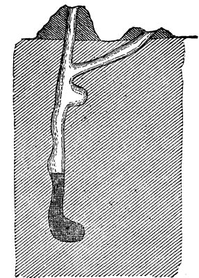
Fig. 1 Section of Crayfish burrow
The length, width, general direction of the burrows, and number of the openings were extremely variable, and the same is true of the mounds. Fig. 1 illustrates a typical burrow shown in section. Here the main burrow is very nearly perpendicular, there being but one oblique opening having a very small mound, and the main mound is somewhat wider than long. Occasionally the burrows are very tortuous, and there are often two or three extra openings, each sometimes covered by a mound. There is every conceivable shape and size in the chimneys, ranging from a mere ridge of mud, evidently the first foundation, to those with a breadth one-half the height. The typical mound is one which covers the perpendicular burrow in Fig. 1, its dimensions being six inches broad and four high. Two other forms are shown in Fig. 2. The burrows near the stream were seldom more than six inches deep, being nearly perpendicular, with an enlargement at the base, and always with at least one oblique opening. The mounds were usually of yellow clay, although in one place the ground was of fine gravel, and there the chimneys were of the same character. They were always circularly pyramidal in shape, the hole inside being very smooth, but the outside was formed of irregular nodules of clay hardened in the sun and lying just as they fell when dropped from the top of the mound. A small quantity of grass and leaves was mixed through the mound, but this was apparently accidental.
The size of the burrows varied from half an inch to two inches in diameter, being smooth for the entire distance, and nearly uniform in width. Where the burrow was far distant from the stream, the upper part was hard and dry. In the deeper holes I invariably found several enlargements at various points in the burrow. Some burrows were three feet deep, indeed they all go down to water, and, as the water in the ground lowers, the burrow is undoubtedly projected deeper. The diagonal openings never at that season of the year have perfect chimneys, and seldom more than a mere rim. In no case did I find any connection between two different burrows. In digging after the inhabitants I was seldom able to secure a specimen from the deeper burrows, for I found that the animal always retreated to the extreme end, and when it could go no farther would use its claws in defense. Both males and females have burrows, but they were never found together, each burrow having but a single individual. There is seldom more than a pint of water in each hole, and this is muddy and hardly suitable to sustain life.
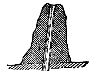
Fig. 2 Crayfish Mound
The neighboring brooks and springs were inhabited by another species of crayfish, Cambaras bartonii, but although especial search was made for the burrowing species, in no case was a single specimen found outside of the burrows. C. bartonii was taken both in the swiftly running portions of the stream and in the shallow side pools, as well as in the springs at the head of small rivers. It would swim about in all directions, and was often found under stones and in little holes and crevices, none of which appeared to have been made for the purpose of retreat, but were accidental. The crayfishes would leave these little retreats whenever disturbed, and swim away down stream out of sight. They were often found some distance from the main stream under rocks that had been covered by the brook at a higher watermark; but although there was very little water under the rocks, and the stream had not covered them for at least two weeks, they showed no tendency to burrow. Nor have I ever found any burrows formed by the river species Cumbarus affinis. although I have searched over miles of marsh land on the Potomac for this purpose.
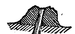
Fig. 2 Crayfish Mound (shorter)
The brook near where my observations were made was fast decreasing in volume, and would probably continue to do so until in July its bed would be nearly dry. During the wet seasons the meadow is itself covered. Even in the banks of the stream, then under water, there were holes, but they all extended obliquely without exception, there being no perpendicular burrows and no mounds. The holes extended in about six inches, and there was never a perpendicular branch, nor even an enlargement at the end. I always found the inhabitant near the mouth, and by quickly cutting off the rear part of the hole could force him out, but unless forcibly driven out it would never leave the hole, not even when a stick was thrust in behind it. It was undoubtedly this species that Dr. Godman mentioned in his "Rambles of a Naturalist," and which Dr. Abbott (Am. Nal., 1873, p. 81) refers to C. bartonii. Although I have no proof that this is so, I am inclined to believe that the burrowing crayfishes retire to the stream in winter and remain there until early spring, when they construct their burrows for the purpose of rearing their young and escaping the summer droughts. My reason for saying this is that I found one burrow which on my first visit was but six inches deep, and later had been projected to a depth at least twice as great, and the inhabitant was an old female.
I think that after the winter has passed, and while the marsh is still covered with water, impregnation takes place and burrows are immediately begun. I do not believe that the same burrow is occupied for more than one year, as it would probably fill up during the winter. At first it burrows diagonally, and as long as the mouth is covered with water is satisfied with this oblique hole. When the water recedes, leaving the opening uncovered, the burrow must be dug deeper, and the economy of a perpendicular burrow must immediately suggest itself. From that time the perpendicular direction is preserved with more or less regularity. Immediately after the perpendicular hole is begun, a shorter opening to the surface is needed for conveying the mud from the nest, and then the perpendicular opening is made. Mud from this, and also from the first part of the perpendicular burrow, is carried out of the diagonal opening and deposited on the edge. If a freshet occurs before this rim of mud has had a chance to harden, it is washed away, and no mound is formed over the oblique burrow.
After the vertical opening is made, as the hole is bored deeper, mud is deposited on the edge, and the deeper it is dug the higher the mound. I do not think that the chimney is a necessary part of the nest, but simply the result of digging. I carried away several mounds, and in a week revisited the place, and no attempt had been made to replace them; but in one case, where I had in addition partly destroyed the burrow by dropping mud into it, there was a simple half rim of mud around the edge, showing that the crayfish had been at work; and as the mud was dry the clearing must have been done soon after my departure. That the crayfish retreats as the water in the ground falls lower and lower is proved by the fact that at various intervals there are bottled-shaped cavities marking the end of the burrow at an earlier period. A few of those mounds farthest from the stream had their mouths closed by a pellet of mud. It is said that all are closed during the summer months.
How these animals can live for months in the muddy, impure water is to me a puzzle. They are very sluggish, possessing none of the quick motions of their allied C. bartonii, for when taken out and placed either in water or on the ground, they move very slowly. The power of throwing off their claws when these are grasped is often exercised. About the middle of May the eggs hatch, and for a time the young cling to the mother, but I am unable to state how long they remain thus. After hatching they must grow rapidly, and soon the burrow will be too small for them to live in, and they must migrate. It would be interesting to know more about the habits of this peculiar species, about which so little has been written. An interesting point to settle would be how and where it gets its food. The burrow contains none, either animal or vegetable. Food must be procured at night, or when the sun is not shining brightly. In the spring and fall the green stalks of meadow grasses would furnish food, but when these become parched and dry they must either dig after and eat the roots, or search in the stream. I feel satisfied that they do not tunnel among the roots, for if they did so these burrows would be frequently met with. Little has as yet been published upon this subject, and that little covers only two spring months--April and May--and it would be interesting if those who have an opportunity to watch the species during other seasons, or who have observed them at any season of the year, would make known their results.
RALPH S. TARR
Who of us has not, in a partially darkened room, seen the rays of the sun, as they entered through apertures or chinks in the shutters, exhibit their track by lighting up the infinitely small corpuscles contained in the air? Such corpuscles always exist, except in the atmosphere of lofty mountains, and they constitute the dust of the air. A microscopic examination of them is a matter of curiosity. Each flock is a true museum (Fig. 1), wherein we find grains of mineral substances associated with organic debris, and germs of living organisms, among which must be mentioned the microbes.
Since the splendid researches of Mr. Pasteur and his pupils on fermentation and contagious diseases, the question of microbes has become the order of the day.
In order to show our readers the importance of the study of the microbes, and the results that may be reached by following the scientific method created by Mr. Pasteur, it appears to us indispensable to give a summary of the history of these organisms. In the first place, what is a microbe? Although much employed, the word has not been well defined, and it would be easy to find several definitions of it. In its most general sense, the term microbe designates certain colorless algæ belonging to the family Bacteriaceæ, the principal forms of which are known under the name of Micrococcus. Bacterium, Bacillus. Vibrio, /Spirillum, etc.
In order to observe these different forms of Bacteriaceæ it is only necessary to examine microscopically a drop of water in which organic matter has been macerated, when there will be seen Micrococci (Fig. 2, I.)looking like spherical granules, Bacteria in the form of very short rods, Bacilli (Fig. 2, V.), Vibriones (Fig. 2, IV.,) moving their straight or curved filaments, and Spirilli (Fig. 2, VI.), rolled up spirally. These varied forms are not absolutely constant, for it often happens in the course of its existence that a species assumes different shapes, so that it is difficult to take the form of these algæ as a basis for classifying them, when all the phases of their development have not been studied.
The Bacteriaceæ are reproduced with amazing rapidity. If the temperature is proper, a limpid liquid such as chicken or veal broth will, in a few hours, become turbid and contain millions of these organisms. Multiplication is effected through fission, that is to say, each globule or filament, after elongating, divides into two segments, each of which increases in its turn, to again divide into two parts, and so on (Fig. 2, I. b). But multiplication in this way only takes place when the bacteria are placed in a proper nutritive liquid; and it ceases when the liquid becomes impoverished and the conditions of life become difficult. It is at this moment that the formation of spores occurs--reproductive bodies that are destined to permit the algæ to traverse, without perishing, those phases where life is impossible. The spores are small, brilliant bodies that form in the center or at the extremity of each articulation or globule of the bacterium (Fig. 2, II. l), and are set free through the breaking up of the joints. There are, therefore, two phases to be distinguished in the life of microbes--that of active life, during which they multiply with great rapidity, are most active, and cause sicknesses or fermentations, and that of retarded life, that is to say, the state, of resting spores in which the organisms are inactive and consequently harmless. It is curious to find that the resistance to the two causes of destruction is very different in the two cases.
In the state of active life the bacterides are killed by a temperature of from 70 to 80 degrees, while the spores require the application of a temperature of from 100 to 120 degrees to kill them. Oxygen of a high pressure, which is, as well known from Bert's researches, a poison for living beings, kills many bacteria in the state of active life, but has no influence upon their spores.
In a state of active life the bacteriae are interesting to study. The absence of green matter prevents them from feeding upon mineral matter, and they are therefore obliged to subsist upon organic matter, just as do plants that are destitute of chlorophyl (such as fungi, broomrapes, etc.). This is why they are only met with in living beings or upon organic substances. The majority of these algae develop very well in the air, and then consume oxygen and exhale carbonic acid, like all living beings. If the supply of air be cut off, they resist asphyxia and take the oxygen that they require from the compounds that surround them. The result is a complete and rapid decomposition of the organic materials, or a fermentation. Finally, there are even certain species that die in the presence of free oxygen, and that can only live by protecting themselves from contact with this gas through a sort of jelly. These are ferments, such as Bacillus amylobacter, or butyric ferment, and B. septicus, or ferment of the putrefaction of nitrogenized substances.
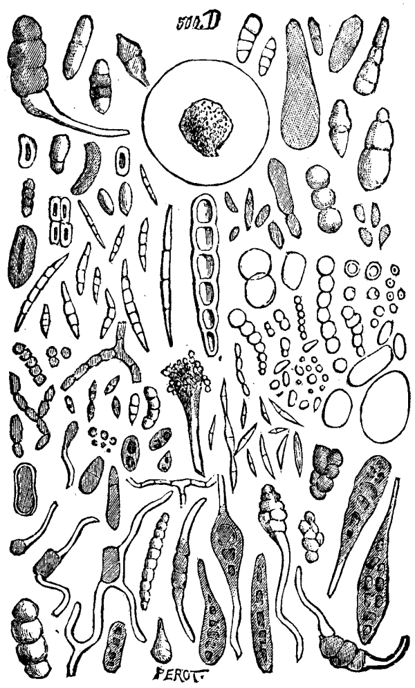
FIG. 1.--ATMOSPHERIC DUST.
These properties explain the regular distribution of bacteria in liquids exposed to the air. Thus, in water in which plants have been macerated the surface of the liquid is occupied by Bacillus subtilis. which has need of free oxygen in order to live, while in the bulk of the liquid, in the vegetable tissues, we find other bacteria, notably B. amylobacter, which lives very well by consuming oxygen in a state of combination. Bacteria, then, can only live in organic matters, now in the presence and now in the absence of air.
What we have just said allows us to understand the process of cultivating these organisms. When it is desired to obtain these algae, we must take organic matters or infusions of such. These liquids or substances are heated to at least 120° in order to kill the germs that they may contain, and this is called "sterilizing." In this sterilized liquid are then sown the bacteria that it is desired to study, and by this means they can be obtained in a state of very great purity.
The Bacteriaceae are very numerous. Among them we must distinguish those that live in inert organic matters, alimentary substances, or debris of living beings, and which cause chemical decompositions called fermentations. Such are Mycoderma aceti, which converts the alcohol of fermented beverages into vinegar; Micrococcus ureae, which converts the urea of urine into carbonate of ammonia, and Micrococcus nitrificans, which converts nitrogenized matters into intrates, etc. Some, that live upon food products, produce therein special coloring matters; such are the bacterium of blue milk, and Micrococcus prodigiosus (Fig. 2, I.), a red alga that lives upon bread and forms those bloody spots that were formerly considered by the superstitious as the precursors of great calamities.
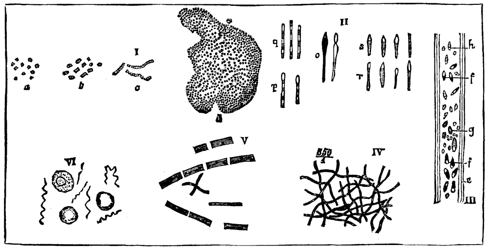
Fig. 2.--VARIOUS MICROBES. (Highly magnified.)
Another group of bacteria has assumed considerable importance in pathology, and that is the one whose species inhabit the tissues of living animals, and cause more or less serious alterations therein, and often death. Most contagious diseases and epidemics are due to algæ of this latter group. To cite only those whose origin is well known, we may mention the bacterium that causes charbon, the micrococcus of chicken cholera, and that of hog measles.
It will be seen from this sketch how important the study of these organisms is to man, since be must defend his body against their invasions or utilize them for bringing about useful chemical modifications in organic matters.
Our Servants.--We scarcely know what services microbes may render us, yet the study of them, which has but recently been begun, has already shown, through the remarkable labors of Messrs. Pasteur, Schloesing and Muntz, Van Tieghem, Cohn, Koch, etc., the importance of these organisms in nature. All of us have seen wine when exposed to air gradually sour, and become converted into vinegar, and we know that in this case the surface of the liquid is covered with white pellicles called "mother of vinegar." These pellicles are made up of myriads of globules of Mycoderma aceti. This mycoderm is the principal agent in the acidification of wine, and it is it that takes oxygen from the air and fixes it in the alcohol to convert it into vinegar. If the pellicle that forms becomes immersed in the liquid, the wine will cease to sour.
The vinegar manufacturers of Orleans did not suspect the role of the mother of vinegar in the production of this article when they were employing empirical processes that had been established by practice. The vats were often infested by small worms ("vinegar eals") which disputed with the mycoderma for the oxygen, killed it through submersion, and caused the loss of batches that had been under troublesome preparation for months. Since Mr. Pasteur's researches, the Mycoderma aceti has been sown directly in the slightly acidified wine, and an excellent quality of vinegar has thus been obtained, with no fear of an occurrence of the disasters that accompanied the old process.
Another example will show us the microbes in activity in the earth. Let us take a pinch of vegetable mould, water it with ammonia compounds, and analyze it, and we shall find nitrates therein. Whence came these nitrates? They came from the oxidation of the ammonia compounds brought about by moistening, since the nitrogen of the air does not seem to combine under normal conditions with the surrounding oxygen. This oxidation of ammonia compounds is brought about, as has been shown by Messrs. Schloesing and Muntz, by a special ferment, the Micrococcus nitrificans, that belongs to the group of Bacteriacæ. In fact, the vapors of chloroform, which anesthetize plants, also prevent nitrification, since they anaesthetize the nitric ferment. So, too, when we heat vegetable humus to 100°, nitrification is arrested, because the ferment is killed. Finally, we may sow the nitric ferment in calcined earth and cause nitrification to occur therein as surely as we can bring about a fermentation in wine by sowing Mycoderma aceti in it.
The nitric ferment exists in all soils and in all latitudes, and converts the ammoniacal matters carried along by the rain into nitrates of a form most assimilable by plants. It therefore constitutes one of the important elements for fertilizing the earth.
Finally, we must refer to the numerous bacteria that occasion putrefaction in vegetable or animal organisms. These microbes, which float in the air, fall upon dead animals or plants, develop thereon, and convert into mineral matters the immediate principles of which the tissues are composed, and thus continually restore to the air and soil the elements necessary for the formation of new organic substances. Thus, Bacillus amylobacter (Fig. 2, II.), as Mr. Van Tieghem has shown, subsists upon the hydrocarbons contained in plants, and disorganizes vegetable tissues in disengaging hydrogen, carbonic acid, and vegetable acids. Bacterium roseopersicina forms, in pools, rosy or red pellicles that cover vegetable debris and disengage gases of an offensive odor. This bacterium develops in so great quantity upon low shores covered with fragments of algæ as to sometimes spread over an extent of several kilometers. These microbes, like many others, continuously mineralize organic substances, and thus exhibit themselves as the indispensable agents of the movement of the matter that incessantly circulates from the mineral to the organic world, and vice versa.--Science et Nature.
Palms sprouted from seeds kept warm by contact of the vessel with the water boiler of a kitchen range are grown by a man in New York.
The following epitaph was written by a Dr. Godfrey, who died in Dublin in 1755:
  Here lieth, to digest macerate, and amalgamate into clay,
  In Batneo Arenæ,
  Stratum super Stratum
  The Residuum, Terra damnata and Caput Mortuum,
  Of BOYLE GODFREY, Chymist and M.D.
  A man who in this Earthly Laboratory pursued various
  Processes to obtain Arcanum Vitæ,
  Or the Secret to Live;
  Also Aurum Vitæ,
  or the art of getting rather than making gold.
  Alchymist-like, all his Labour and Projection,
  as Mercury in the Fire, Evaporated in Fume when he
  Dissolved to his first principles.
  He departed as poor
  as the last drops of an Alembic; for Riches are not
  poured on the Adepts of this world.
  Though fond of News, he carefully avoided the
  Fermentation, Effervescence, and Decrepitation of this
  life. Full seventy years his Exalted Essence
  was hermetically sealed in its Terrene Matrass; but the
  Radical Moisture being exhausted, the Elixir Vitæ spent,
  And exsiccate to a Cuticle, he could not suspend
  longer in his Vehicle, but precipitated Gradatim, per
  Campanam, to his original dust.
  May that light, brighter than Bolognian Phosphorus,
  Preserve him from the Athanor, Empyreuma, and Reverberatory
  Furnace of the other world,
  Depurate him from the Fæces and Scoria of this,
  Highly Rectify and Volatilize, his æthereal spirit,
  Bring it over the Helm of the Retort of this Globe, place
  in a proper Recipient or Crystalline orb,
  Among the elect of the Flowers of Benjamin; never to
  be saturated till the General Resuscitation, Deflagration,
  Calcination, and Sublimation of all things.
The first time we saw flowers of this beautiful new climbing plant (about a year ago) we thought that it was a white-flowered variety of the favorite old Ipomæa Horsfalliæ, as it so nearly resembles it. It has, however, been proved to be a distinct new species, and Dr. Masters has named it in compliment to Mr. Thomson of Edinburgh. It differs from I. Horsfalliæ in having the leaflets in sets of threes instead of fives, and, moreover, they are quite entire. The flowers, too, are quite double the size of those of Horsfalliæ, but are produced in clusters in much the same way; they are snow-white. This Ipomæa is indeed a welcome addition to the list of stove-climbing plants, and will undoubtedly become as popular as I. Horsfalliæ, which may be found in almost every stove. It is of easy culture and of rapid growth, and it is to be hoped that it is as continuous in flowering as Horsfalliæ. It is among the new plants of the year now being distributed by Mr. B.S. Williams, of the Victoria Nurseries, Upper Holloway.--The Garden.
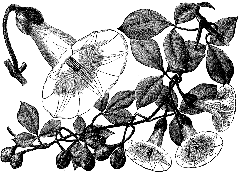
A NEW STOVE CLIMBER. IPOMÆA THOMSONIANA.
Isis was supposed to have introduced wheat into Egypt, Demeter into Greece, and the Emperor Chin-Wong into China, about 3000 B.C. In Europe it was cultivated before the period of history, as samples have been recovered from the lacustrine dwellings of Switzerland.
The first wheat raised in the "New World" was sown by the Spaniards on the island of Isabella, in January, 1494, and on March the 30th the ears were gathered. The foundation of the wheat harvest of Mexico is said to have been three or four grains carefully cultivated in 1530, and preserved by a slave of Cortez. The first crop of Quito was raised by a Franciscan monk in front of the convent. Garcilasso de la Vega affirms that in Peru, up to 1658, wheaten bread had not been sold in Cusco. Wheat was first sown by Goshnold Cuttyhunk, on one of the Elizabeth Islands in Buzzard's Bay, off Massachusetts, in 1602, when he first explored the coast. In 1604, on the island of St. Croix, near Calais, Me., the Sieur de Monts had some wheat sown which flourished finely. In 1611 the first wheat appears to have been sown in Virginia. In 1626, samples of wheat grown in the Dutch Colony at New Netherlands were shown in Holland. It is probable that wheat was sown in the Plymouth Colony prior to 1629, though we find no record of it, and in 1629 wheat was ordered from England to be used as seed. In 1718 wheat was introduced into the valley of the Mississippi by the "Western Company." In 1799 it was among the cultivated crops of the Pimos Indians of the Gila River, New Mexico.
According to Bunzener and Fries (Zeitschrift fur das gesammte Brauwesen), a thick, sirupy starch paste prepared with a boiling one per cent solution of salicylic acid is only very slowly saccharified, and on cooling deposits crystalline plates of starch. For the determination of starch in barley the finely-ground sample is boiled for three-quarters of an hour with about thirty times its weight of a one per cent solution of salicylic acid, the resulting colorless opalescent liquid filtered with the aid of suction, and the starch therein inverted by means of hydrochloric acid. The dextrose formed is estimated by Fehling's solution. The results are one to two per cent higher than when the starch is brought into solution by water at 135° C.
A catalogue, containing brief notices of many important scientific papers heretofore published in the SUPPLEMENT, may be had gratis at this office.
Terms of Subscription, $5 a Year.
Sent by mail, postage prepaid, to subscribers in any part of the United States or Canada. Six dollars a year, sent, prepaid, to any foreign country.
All the back numbers of THE SUPPLEMENT, from the commencement, January 1, 1876, can be had. Price, 10 cents each.
All the back volumes of THE SUPPLEMENT can likewise be supplied. Two volumes are issued yearly. Price of each volume, $2.50, stitched in paper, or $3.50, bound in stiff covers.
COMBINED RATES--One copy of SCIENTIFIC AMERICAN and one copy of SCIENTIFIC AMERICAN SUPPLEMENT, one year, postpaid, $7.00.
A liberal discount to booksellers, news agents, and canvassers.
MUNN & CO., Publishers,
361 Broadway, New York, N. Y.
In connection with the Scientific American, Messrs. MUNN & Co. are Solicitors of American and Foreign Patents, have had 39 years' experience, and now have the largest establishment in the world. Patents are obtained on the best terms.
A special notice is made in the Scientific American of all Inventions patented through this Agency, with the name and residence of the Patentee. By the immense circulation thus given, public attention is directed to the merits of the new patent, and sales or introduction often easily effected.
Any person who has made a new discovery or invention can ascertain, free of charge, whether a patent can probably be obtained, by writing to MUNN & Co.
We also send free our Hand Book about the Patent Laws, Patents, Caveats. Trade Marks, their costs, and how procured. Address
MUNN & CO., 361 Broadway, New York.
Branch Office, cor. F and 7th Sts., Washington, D. C.
End of the Project Gutenberg EBook of Scientific American Supplement, No.
446, July 19, 1884, by Various

*** END OF THIS PROJECT GUTENBERG EBOOK SCIENTIFIC AMERICAN SUPP. 446 ***

***** This file should be named 11385-h.htm or 11385-h.zip *****
This and all associated files of various formats will be found in:
        https://www.gutenberg.org/1/1/3/8/11385/

Produced by Jon Niehof, Don Kretz, Juliet Sutherland, Charles Franks
and the DP Team


Updated editions will replace the previous one--the old editions
will be renamed.

Creating the works from public domain print editions means that no
one owns a United States copyright in these works, so the Foundation
(and you!) can copy and distribute it in the United States without
permission and without paying copyright royalties.  Special rules,
set forth in the General Terms of Use part of this license, apply to
copying and distributing Project Gutenberg-tm electronic works to
protect the PROJECT GUTENBERG-tm concept and trademark.  Project
Gutenberg is a registered trademark, and may not be used if you
charge for the eBooks, unless you receive specific permission.  If you
do not charge anything for copies of this eBook, complying with the
rules is very easy.  You may use this eBook for nearly any purpose
such as creation of derivative works, reports, performances and
research.  They may be modified and printed and given away--you may do
practically ANYTHING with public domain eBooks.  Redistribution is
subject to the trademark license, especially commercial
redistribution.


*** START: FULL LICENSE ***

THE FULL PROJECT GUTENBERG LICENSE
PLEASE READ THIS BEFORE YOU DISTRIBUTE OR USE THIS WORK

To protect the Project Gutenberg-tm mission of promoting the free
distribution of electronic works, by using or distributing this work
(or any other work associated in any way with the phrase "Project
Gutenberg"), you agree to comply with all the terms of the Full Project
Gutenberg-tm License (available with this file or online at
https://gutenberg.org/license).


Section 1.  General Terms of Use and Redistributing Project Gutenberg-tm
electronic works

1.A.  By reading or using any part of this Project Gutenberg-tm
electronic work, you indicate that you have read, understand, agree to
and accept all the terms of this license and intellectual property
(trademark/copyright) agreement.  If you do not agree to abide by all
the terms of this agreement, you must cease using and return or destroy
all copies of Project Gutenberg-tm electronic works in your possession.
If you paid a fee for obtaining a copy of or access to a Project
Gutenberg-tm electronic work and you do not agree to be bound by the
terms of this agreement, you may obtain a refund from the person or
entity to whom you paid the fee as set forth in paragraph 1.E.8.

1.B.  "Project Gutenberg" is a registered trademark.  It may only be
used on or associated in any way with an electronic work by people who
agree to be bound by the terms of this agreement.  There are a few
things that you can do with most Project Gutenberg-tm electronic works
even without complying with the full terms of this agreement.  See
paragraph 1.C below.  There are a lot of things you can do with Project
Gutenberg-tm electronic works if you follow the terms of this agreement
and help preserve free future access to Project Gutenberg-tm electronic
works.  See paragraph 1.E below.

1.C.  The Project Gutenberg Literary Archive Foundation ("the Foundation"
or PGLAF), owns a compilation copyright in the collection of Project
Gutenberg-tm electronic works.  Nearly all the individual works in the
collection are in the public domain in the United States.  If an
individual work is in the public domain in the United States and you are
located in the United States, we do not claim a right to prevent you from
copying, distributing, performing, displaying or creating derivative
works based on the work as long as all references to Project Gutenberg
are removed.  Of course, we hope that you will support the Project
Gutenberg-tm mission of promoting free access to electronic works by
freely sharing Project Gutenberg-tm works in compliance with the terms of
this agreement for keeping the Project Gutenberg-tm name associated with
the work.  You can easily comply with the terms of this agreement by
keeping this work in the same format with its attached full Project
Gutenberg-tm License when you share it without charge with others.

1.D.  The copyright laws of the place where you are located also govern
what you can do with this work.  Copyright laws in most countries are in
a constant state of change.  If you are outside the United States, check
the laws of your country in addition to the terms of this agreement
before downloading, copying, displaying, performing, distributing or
creating derivative works based on this work or any other Project
Gutenberg-tm work.  The Foundation makes no representations concerning
the copyright status of any work in any country outside the United
States.

1.E.  Unless you have removed all references to Project Gutenberg:

1.E.1.  The following sentence, with active links to, or other immediate
access to, the full Project Gutenberg-tm License must appear prominently
whenever any copy of a Project Gutenberg-tm work (any work on which the
phrase "Project Gutenberg" appears, or with which the phrase "Project
Gutenberg" is associated) is accessed, displayed, performed, viewed,
copied or distributed:

This eBook is for the use of anyone anywhere at no cost and with
almost no restrictions whatsoever.  You may copy it, give it away or
re-use it under the terms of the Project Gutenberg License included
with this eBook or online at www.gutenberg.org

1.E.2.  If an individual Project Gutenberg-tm electronic work is derived
from the public domain (does not contain a notice indicating that it is
posted with permission of the copyright holder), the work can be copied
and distributed to anyone in the United States without paying any fees
or charges.  If you are redistributing or providing access to a work
with the phrase "Project Gutenberg" associated with or appearing on the
work, you must comply either with the requirements of paragraphs 1.E.1
through 1.E.7 or obtain permission for the use of the work and the
Project Gutenberg-tm trademark as set forth in paragraphs 1.E.8 or
1.E.9.

1.E.3.  If an individual Project Gutenberg-tm electronic work is posted
with the permission of the copyright holder, your use and distribution
must comply with both paragraphs 1.E.1 through 1.E.7 and any additional
terms imposed by the copyright holder.  Additional terms will be linked
to the Project Gutenberg-tm License for all works posted with the
permission of the copyright holder found at the beginning of this work.

1.E.4.  Do not unlink or detach or remove the full Project Gutenberg-tm
License terms from this work, or any files containing a part of this
work or any other work associated with Project Gutenberg-tm.

1.E.5.  Do not copy, display, perform, distribute or redistribute this
electronic work, or any part of this electronic work, without
prominently displaying the sentence set forth in paragraph 1.E.1 with
active links or immediate access to the full terms of the Project
Gutenberg-tm License.

1.E.6.  You may convert to and distribute this work in any binary,
compressed, marked up, nonproprietary or proprietary form, including any
word processing or hypertext form.  However, if you provide access to or
distribute copies of a Project Gutenberg-tm work in a format other than
"Plain Vanilla ASCII" or other format used in the official version
posted on the official Project Gutenberg-tm web site (www.gutenberg.org),
you must, at no additional cost, fee or expense to the user, provide a
copy, a means of exporting a copy, or a means of obtaining a copy upon
request, of the work in its original "Plain Vanilla ASCII" or other
form.  Any alternate format must include the full Project Gutenberg-tm
License as specified in paragraph 1.E.1.

1.E.7.  Do not charge a fee for access to, viewing, displaying,
performing, copying or distributing any Project Gutenberg-tm works
unless you comply with paragraph 1.E.8 or 1.E.9.

1.E.8.  You may charge a reasonable fee for copies of or providing
access to or distributing Project Gutenberg-tm electronic works provided
that

- You pay a royalty fee of 20% of the gross profits you derive from
     the use of Project Gutenberg-tm works calculated using the method
     you already use to calculate your applicable taxes.  The fee is
     owed to the owner of the Project Gutenberg-tm trademark, but he
     has agreed to donate royalties under this paragraph to the
     Project Gutenberg Literary Archive Foundation.  Royalty payments
     must be paid within 60 days following each date on which you
     prepare (or are legally required to prepare) your periodic tax
     returns.  Royalty payments should be clearly marked as such and
     sent to the Project Gutenberg Literary Archive Foundation at the
     address specified in Section 4, "Information about donations to
     the Project Gutenberg Literary Archive Foundation."

- You provide a full refund of any money paid by a user who notifies
     you in writing (or by e-mail) within 30 days of receipt that s/he
     does not agree to the terms of the full Project Gutenberg-tm
     License.  You must require such a user to return or
     destroy all copies of the works possessed in a physical medium
     and discontinue all use of and all access to other copies of
     Project Gutenberg-tm works.

- You provide, in accordance with paragraph 1.F.3, a full refund of any
     money paid for a work or a replacement copy, if a defect in the
     electronic work is discovered and reported to you within 90 days
     of receipt of the work.

- You comply with all other terms of this agreement for free
     distribution of Project Gutenberg-tm works.

1.E.9.  If you wish to charge a fee or distribute a Project Gutenberg-tm
electronic work or group of works on different terms than are set
forth in this agreement, you must obtain permission in writing from
both the Project Gutenberg Literary Archive Foundation and Michael
Hart, the owner of the Project Gutenberg-tm trademark.  Contact the
Foundation as set forth in Section 3 below.

1.F.

1.F.1.  Project Gutenberg volunteers and employees expend considerable
effort to identify, do copyright research on, transcribe and proofread
public domain works in creating the Project Gutenberg-tm
collection.  Despite these efforts, Project Gutenberg-tm electronic
works, and the medium on which they may be stored, may contain
"Defects," such as, but not limited to, incomplete, inaccurate or
corrupt data, transcription errors, a copyright or other intellectual
property infringement, a defective or damaged disk or other medium, a
computer virus, or computer codes that damage or cannot be read by
your equipment.

1.F.2.  LIMITED WARRANTY, DISCLAIMER OF DAMAGES - Except for the "Right
of Replacement or Refund" described in paragraph 1.F.3, the Project
Gutenberg Literary Archive Foundation, the owner of the Project
Gutenberg-tm trademark, and any other party distributing a Project
Gutenberg-tm electronic work under this agreement, disclaim all
liability to you for damages, costs and expenses, including legal
fees.  YOU AGREE THAT YOU HAVE NO REMEDIES FOR NEGLIGENCE, STRICT
LIABILITY, BREACH OF WARRANTY OR BREACH OF CONTRACT EXCEPT THOSE
PROVIDED IN PARAGRAPH F3.  YOU AGREE THAT THE FOUNDATION, THE
TRADEMARK OWNER, AND ANY DISTRIBUTOR UNDER THIS AGREEMENT WILL NOT BE
LIABLE TO YOU FOR ACTUAL, DIRECT, INDIRECT, CONSEQUENTIAL, PUNITIVE OR
INCIDENTAL DAMAGES EVEN IF YOU GIVE NOTICE OF THE POSSIBILITY OF SUCH
DAMAGE.

1.F.3.  LIMITED RIGHT OF REPLACEMENT OR REFUND - If you discover a
defect in this electronic work within 90 days of receiving it, you can
receive a refund of the money (if any) you paid for it by sending a
written explanation to the person you received the work from.  If you
received the work on a physical medium, you must return the medium with
your written explanation.  The person or entity that provided you with
the defective work may elect to provide a replacement copy in lieu of a
refund.  If you received the work electronically, the person or entity
providing it to you may choose to give you a second opportunity to
receive the work electronically in lieu of a refund.  If the second copy
is also defective, you may demand a refund in writing without further
opportunities to fix the problem.

1.F.4.  Except for the limited right of replacement or refund set forth
in paragraph 1.F.3, this work is provided to you 'AS-IS' WITH NO OTHER
WARRANTIES OF ANY KIND, EXPRESS OR IMPLIED, INCLUDING BUT NOT LIMITED TO
WARRANTIES OF MERCHANTIBILITY OR FITNESS FOR ANY PURPOSE.

1.F.5.  Some states do not allow disclaimers of certain implied
warranties or the exclusion or limitation of certain types of damages.
If any disclaimer or limitation set forth in this agreement violates the
law of the state applicable to this agreement, the agreement shall be
interpreted to make the maximum disclaimer or limitation permitted by
the applicable state law.  The invalidity or unenforceability of any
provision of this agreement shall not void the remaining provisions.

1.F.6.  INDEMNITY - You agree to indemnify and hold the Foundation, the
trademark owner, any agent or employee of the Foundation, anyone
providing copies of Project Gutenberg-tm electronic works in accordance
with this agreement, and any volunteers associated with the production,
promotion and distribution of Project Gutenberg-tm electronic works,
harmless from all liability, costs and expenses, including legal fees,
that arise directly or indirectly from any of the following which you do
or cause to occur: (a) distribution of this or any Project Gutenberg-tm
work, (b) alteration, modification, or additions or deletions to any
Project Gutenberg-tm work, and (c) any Defect you cause.


Section  2.  Information about the Mission of Project Gutenberg-tm

Project Gutenberg-tm is synonymous with the free distribution of
electronic works in formats readable by the widest variety of computers
including obsolete, old, middle-aged and new computers.  It exists
because of the efforts of hundreds of volunteers and donations from
people in all walks of life.

Volunteers and financial support to provide volunteers with the
assistance they need, is critical to reaching Project Gutenberg-tm's
goals and ensuring that the Project Gutenberg-tm collection will
remain freely available for generations to come.  In 2001, the Project
Gutenberg Literary Archive Foundation was created to provide a secure
and permanent future for Project Gutenberg-tm and future generations.
To learn more about the Project Gutenberg Literary Archive Foundation
and how your efforts and donations can help, see Sections 3 and 4
and the Foundation web page at https://www.pglaf.org.


Section 3.  Information about the Project Gutenberg Literary Archive
Foundation

The Project Gutenberg Literary Archive Foundation is a non profit
501(c)(3) educational corporation organized under the laws of the
state of Mississippi and granted tax exempt status by the Internal
Revenue Service.  The Foundation's EIN or federal tax identification
number is 64-6221541.  Its 501(c)(3) letter is posted at
https://pglaf.org/fundraising.  Contributions to the Project Gutenberg
Literary Archive Foundation are tax deductible to the full extent
permitted by U.S. federal laws and your state's laws.

The Foundation's principal office is located at 4557 Melan Dr. S.
Fairbanks, AK, 99712., but its volunteers and employees are scattered
throughout numerous locations.  Its business office is located at
809 North 1500 West, Salt Lake City, UT 84116, (801) 596-1887, email
business@pglaf.org.  Email contact links and up to date contact
information can be found at the Foundation's web site and official
page at https://pglaf.org

For additional contact information:
     Dr. Gregory B. Newby
     Chief Executive and Director
     gbnewby@pglaf.org

Section 4.  Information about Donations to the Project Gutenberg
Literary Archive Foundation

Project Gutenberg-tm depends upon and cannot survive without wide
spread public support and donations to carry out its mission of
increasing the number of public domain and licensed works that can be
freely distributed in machine readable form accessible by the widest
array of equipment including outdated equipment.  Many small donations
($1 to $5,000) are particularly important to maintaining tax exempt
status with the IRS.

The Foundation is committed to complying with the laws regulating
charities and charitable donations in all 50 states of the United
States.  Compliance requirements are not uniform and it takes a
considerable effort, much paperwork and many fees to meet and keep up
with these requirements.  We do not solicit donations in locations
where we have not received written confirmation of compliance.  To
SEND DONATIONS or determine the status of compliance for any
particular state visit https://pglaf.org

While we cannot and do not solicit contributions from states where we
have not met the solicitation requirements, we know of no prohibition
against accepting unsolicited donations from donors in such states who
approach us with offers to donate.

International donations are gratefully accepted, but we cannot make
any statements concerning tax treatment of donations received from
outside the United States.  U.S. laws alone swamp our small staff.

Please check the Project Gutenberg Web pages for current donation
methods and addresses.  Donations are accepted in a number of other
ways including including checks, online payments and credit card
donations.  To donate, please visit: https://pglaf.org/donate


Section 5.  General Information About Project Gutenberg-tm electronic
works.

Professor Michael S. Hart was the originator of the Project Gutenberg-tm
concept of a library of electronic works that could be freely shared
with anyone.  For thirty years, he produced and distributed Project
Gutenberg-tm eBooks with only a loose network of volunteer support.

Project Gutenberg-tm eBooks are often created from several printed
editions, all of which are confirmed as Public Domain in the U.S.
unless a copyright notice is included.  Thus, we do not necessarily
keep eBooks in compliance with any particular paper edition.

Each eBook is in a subdirectory of the same number as the eBook's
eBook number, often in several formats including plain vanilla ASCII,
compressed (zipped), HTML and others.

Corrected EDITIONS of our eBooks replace the old file and take over
the old filename and etext number.  The replaced older file is renamed.
VERSIONS based on separate sources are treated as new eBooks receiving
new filenames and etext numbers.

Most people start at our Web site which has the main PG search facility:

     https://www.gutenberg.org

This Web site includes information about Project Gutenberg-tm,
including how to make donations to the Project Gutenberg Literary
Archive Foundation, how to help produce our new eBooks, and how to
subscribe to our email newsletter to hear about new eBooks.

EBooks posted prior to November 2003, with eBook numbers BELOW #10000,
are filed in directories based on their release date.  If you want to
download any of these eBooks directly, rather than using the regular
search system you may utilize the following addresses and just
download by the etext year.

     https://www.gutenberg.org/etext06

    (Or /etext 05, 04, 03, 02, 01, 00, 99,
     98, 97, 96, 95, 94, 93, 92, 92, 91 or 90)

EBooks posted since November 2003, with etext numbers OVER #10000, are
filed in a different way.  The year of a release date is no longer part
of the directory path.  The path is based on the etext number (which is
identical to the filename).  The path to the file is made up of single
digits corresponding to all but the last digit in the filename.  For
example an eBook of filename 10234 would be found at:

     https://www.gutenberg.org/1/0/2/3/10234

or filename 24689 would be found at:
     https://www.gutenberg.org/2/4/6/8/24689

An alternative method of locating eBooks:
     https://www.gutenberg.org/GUTINDEX.ALL