Project Gutenberg's Scientific American Supplement, No. 417, by Various

This eBook is for the use of anyone anywhere at no cost and with
almost no restrictions whatsoever.  You may copy it, give it away or
re-use it under the terms of the Project Gutenberg License included
with this eBook or online at www.gutenberg.org


Title: Scientific American Supplement, No. 417

Author: Various

Posting Date: October 10, 2012 [EBook #9163]
Release Date: October, 2005
First Posted: September 10, 2003

Language: English

Character set encoding: ISO-8859-1

*** START OF THIS PROJECT GUTENBERG EBOOK SCIENTIFIC AMERICAN SUPPL., NO. 417 ***


Produced by J. Paolucci, D. Kretz, J. Sutherland, and
Distributed Proofreaders
[Footnote: A paper read at the Society of Telegraph Engineers and Electricians on the 8th November, 1883]
In my presidential address, which I had the pleasure of reading before this society at our first meeting this year, I called attention, somewhat hurriedly, to the results of a few of my experiments on induction, and at the same time expressed a hope that at a future date I might be able to bring them more prominently before you. That date has now arrived, and my endeavor this evening will be to demonstrate to you by actual experiment some of what I consider the most important results obtained. My desire is that all present should see these results, and with that view I will try when practicable to use a mirror reflecting galvanometer instead of a telephone. All who have been accustomed to the use of reflecting galvanometers will readily understand the difficulty, on account of its delicacy, of doing so where no special arrangements are provided for its use; but perhaps with a little indulgence on your part and patience on mine the experiments may be brought to a successful issue.
VOLTA-ELECTRIC INDUCTION.
Reliable records extending over hundreds of years show clearly with what energy and perseverance scientific men in every civilized part of the world have endeavored to wrest from nature the secret of what is termed her "phenomena of magnetism," and, as is invariably the case under similar circumstances, the results of the experiments and reasoning of some have far surpassed those of others in advancing our knowledge. For instance, the experimental philosophers in many branches of science were groping as it were in darkness until the brilliant light of Newton's genius illumined their path. Although, perhaps, I should not be justified in comparing Oersted with Newton, yet he also discovered what are termed "new" laws of nature, in a manner at once precise, profound, and amazing, and which opened a new field of research to many of the most distinguished philosophers of that time, who were soon engaged in experimenting in the same direction, and from whose investigations arose a new science, which was called "electro-dynamics." Oersted demonstrated from inductive reasoning that every conductor of electricity possessed all the known properties of a magnet while a current of electricity was passing through it. If you earnestly contemplate the important adjuncts to applied science which have sprung from that apparently simple fact, you will not fail to see the importance of the discovery; for it was while working in this new field of electro-magnetism that Sturgeon made the first electro-magnet, and Faraday many of his discoveries relating to induction.
Soon after the discovery by Oersted just referred to, Faraday, with the care and ability manifest in all his experiments, showed that when an intermittent current of electricity is passing along a wire it induces a current in any wire forming a complete circuit and placed parallel to it, and that if the two wires were made into two helices and placed parallel to each other the effect was more marked. This Faraday designated "Volta-electric induction," and it is with this kind of induction I wish to engage your attention this evening; for it is a phenomenon which presents some of the most interesting and important facts in electrical science.
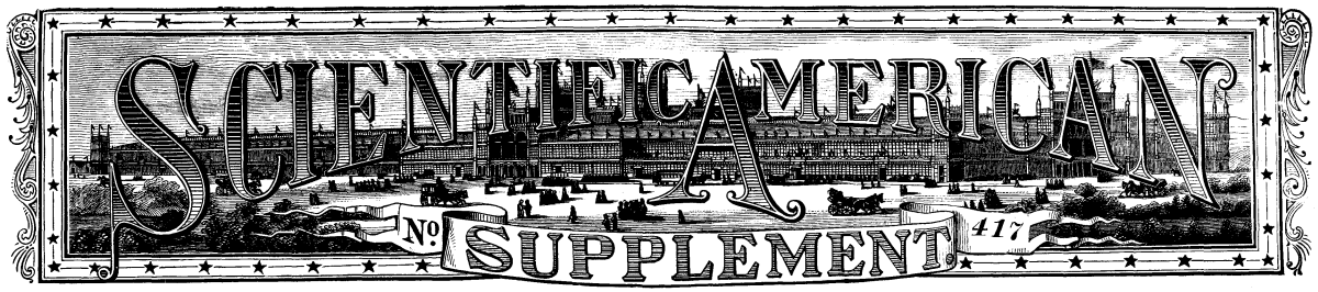
Here are two flat spirals of silk-covered copper wire suspended separately, spider-web fashion, in wooden frames marked respectively A and B. The one marked A is so connected that reversals at any desired speed per minute from a battery of one or more cells can be passed through it. The one marked B is so connected to the galvanometer and a reverser as to show the deflection caused by the induced currents, which are momentary in duration, and in the galvanometer circuit all on the same side of zero, for as the battery current on making contact produces an induced current in the reverse direction to itself, but in the same direction on breaking the contact, of course the one would neutralize the other, and the galvanometer would not be affected; the galvanometer connections are therefore reversed with each reversal of the battery current, and by that means the induced currents are, as you perceive, all in the same direction and produce a steady deflection. The connections are as shown on the sheet before you marked 1, which I think requires no further explanation.
Before proceeding, please to bear in mind the fact that the inductive effects vary inversely as the square of the distance between the two spirals, when parallel to each other; and that the induced current in B is proportional to the number of reversals of the battery current passing through spiral A, and also to the strength of the current so passing. Faraday's fertile imagination would naturally suggest the question, "Is this lateral action, which we call magnetism, extended to a distance by the action of intermediate particles?" If so, then it is reasonable to expect that all substances would not be affected in the same way, and therefore different results would be obtained if different media were interposed between the inductor and what I will merely call, for distinction, the inductometer.
With a view to proving this experimentally, Faraday constructed three flat helices and placed them parallel to each other a convenient distance apart. The middle helix was so arranged that a voltaic current could be sent through it at pleasure. A differential galvanometer was connected with the other helices in such a manner that when a voltaic current was sent through the middle helix its inductive action on the lateral helices should cause currents in them, having contrary directions in the coils of the galvanometer. This was a very prettily arranged electric balance, and by placing plates of different substances between the inductor and one of the inductometers Faraday expected to see the balance destroyed to an extent which would be indicated by the deflection of the needle of the galvanometer. To his surprise he found that it made not the least difference whether the intervening space was occupied by such insulating bodies as air, sulphur, and shellac, or such conducting bodies as copper and the other non-magnetic metals. These results, however, did not satisfy him, as he was convinced that the interposition of the non-magnetic metals, especially of copper, did have an effect, but that his apparatus was not suitable for making it visible. It is to be regretted that so sound a reasoner and so careful an experimenter had not the great advantage of the assistance of such suitable instruments for this class of research as the mirror-galvanometer and the telephone. But, although he could not practically demonstrate the effects which by him could be so clearly seen, it redounds to his credit that, as the improvement in instruments for this kind of research has advanced, the results he sought for have been found in the direction in which he predicted.
A and B will now be placed a definite distance apart, and comparatively slow reversals from ten Leclanché cells sent through spiral A; you will observe the amount of the induced current in B, as shown on the scale of the galvanometer in circuit with that spiral. Now midway between the two spirals will be placed a plate of iron, as shown in Plate 2, and at once you observe the deflection of the galvanometer is reduced by less than one half, showing clearly that the presence of the iron plate is in some way influencing the previous effects. The iron will now be removed, but the spirals left in the same position as before, and by increasing the speed of the reversals you see a higher deflection is given on the galvanometer. Now, on again interposing the iron plate the deflection falls to a little less than one-half, as before. I wish this fact to be carefully noted.
The experiment will be repeated with a plate of copper of precisely the same dimensions as the iron plate, and you observe that, although the conditions are exactly alike in both cases, the interposition of the copper plate has apparently no effect at the present speed of the reversals, although the interposition of the iron plate under the same conditions reduced the deflection about fifty per cent. We will now remove the copper plate, as we did the iron one, and increase the speed of the reversals to the same as in the experiment with the iron, and you observe the deflection on the galvanometer is about the same as it was on that occasion. Now, by replacing the copper plate to its former position you will note how rapidly the deflection falls. We will now repeat the experiment with a plate of lead; you will see that, like the copper, it is unaffected at the low speed, but there the resemblance ceases; for at the high speed it has but very slight effect. Thus these metals, iron, copper, and lead, appear to differ as widely in their electrical as they do in their mechanical properties. Of course it would be impossible to obtain accurate measurements on an occasion like the present, but careful and reliable measurements have been made, the results of which are shown on the sheet before you, marked 3.
It will be seen by reference to these results that the percentage of inductive energy intercepted does not increase for different speeds of the reverser in the same rate with different metals, the increase with iron being very slight, while with tin it is comparatively enormous. It was observed that time was an important element to be taken into account while testing the above metals, that is to say, the lines of force took an appreciable time to polarize the particles of the metal placed in their path, but having accomplished this, they passed more freely through it.
Now let us go more minutely into the subject by the aid of Plate IV., Figs. 1 and 2. In Fig. 1 let A and B represent two flat spirals, spiral A being connected to a battery with a key in circuit and spiral B connected to a galvanometer; then, on closing the battery circuit, an instantaneous current is induced in spiral B. If a non-magnetic metal plate half an inch thick be placed midway between the spirals, and the experiment repeated, it will be found that the induced current received by B is the same in amount as in the first case. This does not prove, as would at first appear, that the metal plate fails to intercept the inductive radiant energy; and it can scarcely be so, for if the plate is replaced by a coil of wire, it is found that induced currents are set up therein, and therefore inductive radiant energy must have been intercepted. This apparent contradiction may be explained as follows:
In Fig. 2 let D represent a source of heat (a vessel of boiling water for instance) and E a sensitive thermometer receiving and measuring the radiant heat. Now, if for instance a plate of vulcanite is interposed, it cuts off and absorbs a part of the radiant heat emitted by D, and thus a fall is produced in the thermometer reading. But the vulcanite, soon becoming heated by the radiant heat cut off and absorbed by itself, radiates that heat and causes the thermometer reading to return to about its original amount. The false impression is thus produced that the original radiated heat was unaffected by the vulcanite plate; instead of which, as a matter of fact, the vulcanite plate had cut off the radiant heat, becoming heated itself by so doing, and was consequently then the radiating body affecting the thermometer.
The effect is similar in the case of induction between the two spirals. Spiral A induces and spiral B receives the induced effect. The metal plate being then interposed, cuts off and absorbs either all or part of the inductive radiant energy emitted by A. The inductive radiant energy thus cut off, however, is not lost, but is converted into electrical energy in the metal plate, thereby causing it to become, as in the case of the vulcanite in the heat experiment, a source of radiation which compensates as far as spiral B is concerned for the original inductive radiant energy cut off. The only material difference noticeable in the two experiments is that in the case of heat the time that elapses between the momentary fall in the thermometer reading (due to the interception by the vulcanite plate of the radiant beat) and the subsequent rise (due to the interposing plate, itself radiating that heat) is long enough to render the effect clearly manifest; whereas in the case of induction the time that elapses is so exceedingly short that, unless special precautions are taken, the radiant energy emitted by the metal plate is liable to be mistaken for the primary energy emitted by the inducing spiral.
The current induced in the receiving spiral by the inducing one is practically instantaneous; but on the interposition of a metal plate the induced current which, as before described, is set up by the plate itself has a perceptible duration depending upon the nature and mass of metal thus interposed. Copper and zinc produce in this manner an induced current of greater length than metals of lower conductivity, with the exception of iron, which gives an induced current of extremely short duration. It will therefore be seen that in endeavoring to ascertain what I term the specific inductive resistance of different metals by the means described, notice must be taken of and allowance made for two points. First, that the metal plate not only cuts off, but itself radiates; and secondly, that the duration of the induced currents radiated by the plates varies with each different metal under experiment.
This explains the fact before pointed out that the apparent percentage of inductive radiant energy intercepted by metal plates varies with the speed of the reversals; for in the case of copper the induced current set up by such a plate has so long a duration that if the speed of the reverser is at all rapid the induced current has not time to exhaust itself before the galvanometer is reversed, and thus the current being on the opposite side of the galvanometer tends to produce a lower deflection. If the speed of the reverser be further increased, the greater part of the induced current is received on the opposite terminal of the galvanometer, so that a negative result is obtained.
We know that it was the strong analogies which exist between electricity and magnetism that led experimentalists to seek for proofs that would identify them as one and the same thing, and it was the result of Professor Oersted's experiment to which I have already referred that first identified them.
Probably the time is not far distant when it will be possible to demonstrate clearly that heat and electricity are as closely allied; then, knowing the great analogies existing between heat and light, may we not find that heat, light, and electricity are modifications of the same force or property, susceptible under varying conditions of producing the phenomena now designated by those terms? For instance, friction will first produce electricity, then heat, and lastly light.
As is well known, heat and light are reflected by metals; I was therefore anxious to learn whether electricity could be reflected in the same way. In order to ascertain this, spiral B was placed in this position, which you will observe is parallel to the lines of force emitted by spiral A. In this position no induced current is set up therein, so the galvanometer is not affected; but when this plate of metal is placed at this angle it intercepts the lines of force, which cause it to radiate, and the secondary lines of force are intercepted and converted into induced currents by spiral B to the power indicated by the galvanometer. Thus the phenomenon of reflection appears to be produced in a somewhat similar manner to reflection of heat and light. The whole arrangement of this experiment is as shown on the sheet before you numbered 5, which I need not, I think, more fully explain to you than by saying that the secondary lines of force are represented by the dotted lines.
Supported in this wooden frame marked C is a spiral similar in construction to the one marked B, but in this case the copper wire is 0.044 inch in diameter, silk-covered, and consists of 365 turns, with a total length of 605 yards; its resistance is 10.2 ohms, the whole is inclosed between two thick sheets of card paper. The two ends of the spiral are attached to two terminals placed one on either side of the frame, a wire from one of the terminals is connected to one pole of a battery of 25 Leclanche cells, the other pole being connected with one terminal of a reverser, the second terminal of which is connected to the other terminal of the spiral.
Now, if this very small spiral which is in circuit with the galvanometer and a reverser be placed parallel to the center of spiral C, a very large deflection will be seen on the galvanometer scale; this will gradually diminish as the smaller spiral is passed slowly over the face of the larger, until on nearing the edge of the latter the smaller spiral will cease to be affected by the inductive lines of force from spiral C, and consequently the galvanometer indicates no deflection. But if this smaller spiral be placed at a different angle to the larger one, it is, as you observe by the deflection of the galvanometer, again affected. This experiment is analogous to the one illustrated by diagram 6, which represents the result of an experiment made to ascertain the relative strength of capability or producing inductive effects of different parts of a straight electro-magnet.
A, Fig. 1, represents the iron core, PP the primary coil, connected at pleasure to one Grove cell, B, by means of the key, K; S, a small secondary coil free to move along the primary coil while in circuit with the galvanometer, G. The relative strength of any particular spot can be obtained by moving the coil, S, exactly over the required position. The small secondary coil is only cut at right angles when it is placed in the center of the magnet, and as it is moved toward either pole so the lines of force cut it more and more obliquely. From this it would appear that the results obtained are not purely dependent upon the strength of the portion of the magnet over which the secondary coil is placed, but principally upon the angle at which the lines of force cut the coil so placed. It does not follow, therefore, that the center of the magnet is its strongest part, as the results of the experiments at first sight appear to show.
It was while engaged on those experiments that I discovered that a telephone was affected when not in any way connected with the spiral, but simply placed so that the lines of force proceeding from the spiral impinged upon the iron diaphragm of the telephone. Please to bear in mind that the direction of the lines of force emitted from the spiral is such that, starting from any point on one of its faces, a circle is described extending to a similar point on the opposite side. The diameter of the circles described decreases from infinity as the points from which they start recede from the center toward the circumference. From points near the circumference these circles or curves are very small. To illustrate this to you, the reverser now in circuit with spiral C will be replaced by a simple make and break arrangement, consisting on a small electro-magnet fixed between the prongs of a tuning-fork, and so connected that electro-magnet influences the arms of the fork, causing them to vibrate to a certain pitch. The apparatus is placed in a distant room to prevent the sound being heard here, as I wish to make it inductively audible to you. For that purpose I have here a light spiral which is in circuit with this telephone. Now, by placing the spiral in front of spiral C, the telephone reproduces the sound given out by the tuning-fork so loudly that I have no doubt all of you can hear it. Here is another spiral similar in every respect to spiral C. This is in circuit with a battery and an ordinary mechanical make and break arrangement, the sound given off by which I will now make audible to you in the same way that I did the sound of the tuning-fork. Now you hear it. I will change from the one spiral to the other several times, as I want to make you acquainted with the sounds of both, so that you will have no difficulty in distinguishing them, the one from the other.
There are suspended in this room self-luminous bodies which enable us by their rays or lines of force to see the non-luminous bodies with which we are surrounded. There are also radiating in all directions from me while speaking lines of force or sound waves which affect more or less each one of you. But there are also in addition to, and quite independent of, the lines of force just mentioned, magnetic lines of force which are too subtle to be recognized by human beings, consequently, figuratively, we are both blind and deaf to them. However, they can be made manifest either by their notion on a suspended magnet or on a conducting body moving across them; the former showing its results by attraction and repulsion, the latter by the production of an electric current. For instance, by connecting the small flat spiral of copper wire in direct circuit with the galvanometer, you will perceive that the slightest movement of the spiral generates a current of sufficient strength to very sensibly affect the galvanometer; and as you observe, the amplitude of the deflection depends upon the speed and direction in which the spiral is moved. We know that by moving a conductor of electricity in a magnetic field we are able to produce an electric current of sufficient intensity to produce light resembling in all its phases that of solar light; but to produce these strong currents, very powerful artificial magnetic fields have to be generated, and the conductor has to be moved therein at a great expenditure of heat energy. May not the time arrive when we shall no longer require these artificial and costly means, but have learned how to adopt those forces of nature which we now so much neglect? One ampere of current passing through an ordinary incandescent lamp will produce a light equal to ten candles, and I have shown that by simply moving this small flat spiral a current is induced in it from the earth's magnetic field equal to 0.0007 ampere. With these facts before us, surely it would not be boldness to predict that a time may arrive when the energy of the wind or tide will be employed to produce from the magnetic lines of force given out by the earth's magnetism electrical currents far surpassing anything we have yet seen or of which we have heard. Therefore let us not despise the smallness of the force, but rather consider it an element of power from which might arise conditions far higher in degree, and which we might not recognize as the same as this developed in its incipient stage.
If the galvanometer be replaced by a telephone, no matter how the spiral be moved, no sound will be heard, simply because the induced currents produced consist of comparatively slow undulations, and not of sharp variations suitable for a telephone. But by placing in circuit this mechanical make and break arrangement the interruptions of the current are at once audible, and by regulating the movement of the spiral I can send signals, which, if they had been prearranged, might have enabled us to communicate intelligence to each other by means of the earth's magnetism. I show this experiment more with a view to illustrate the fact that for experiments on induction both instruments are necessary, as each makes manifest those currents adapted to itself.
The lines of force of light, heat, and sound can be artificially produced and intensified, and the more intense--they are the more we perceive their effects on our eyes, ears, or bodies. But it is not so with the lines of magnetic force, for it matters not how much their power is increased--they appear in no way to affect us. Their presence can, however, be made manifest to our eyes or ears by mechanical appliances. I have already shown you how this can be done by means of either a galvanometer or a telephone in circuit with a spiral wire.
I have already stated that while engaged in these experiments I found that as far as the telephone was concerned it was immaterial whether it was in circuit with a spiral or not, as in either case it accurately reproduced the same sounds; therefore, much in the same way as lenses assist the sight or tubes the hearing, so does the telephone make manifest the lines of intermittent inductive energy. This was quite a new phenomenon to me, and on further investigation of the subject I found that it was not necessary to have even a telephone, for by simply holding a piece of iron to my ear and placing it close to the center of the spiral I could distinctly hear the same sounds as with the telephone, although not so loud. The intensity of the sound was greatly increased when the iron was placed in a magnetic field. Here is a small disk of iron similar to those used in telephones, firmly secured in this brass frame; this is a small permanent bar magnet, the marked end of which is fixed very closely to, but not touching, the center of the iron disk. Now, by applying the disk to my ear I can hear the same sounds that were audible to all of you when the telephone in circuit with a small spiral was placed in front of and close to the large spiral. To me the sound is quite as loud as when you heard it; but now you are one and all totally deaf to it. My original object in constructing two large spirals was to ascertain whether the inductive lines of force given out from one source would in any way interfere with those proceeding from another source. By the aid of this simple iron disk and magnet it can be ascertained that they do in no way interfere with each other; therefore, the direction of the lines proceeding from each spiral can be distinctly traced. For when the two spirals are placed parallel to each other at a distance of 3 ft. apart, and connected to independent batteries and transmitters, as shown in Plate 7, each transmitter having a sound perfectly distinct from that of the other, when the circuits are completed the separate sounds given out by the two transmitters can be distinctly heard at the same time by the aid of a telephone; but, by placing the telephone in a position neutral to one of the spirals, then only the sound proceeding from the other can be heard. These results occur in whatever position the spirals are placed relatively to each other, thus proving that there is no interference with or blending of the separate lines of force. The whole arrangement will be left in working order at the close of the meeting for any gentlemen present to verify my statements or to make what experiments they please.
In conclusion, I would ask, what can we as practical men gather from these experiments? A great deal has been written and said as to the best means to secure conductors carrying currents of very low tension, such as telephone circuits, from being influenced by induction from conductors in their immediate vicinity employed in carrying currents of comparatively very high tension, such as the ordinary telegraph wires. Covering the insulated wires with one or other of the various metals has not only been suggested but said to have been actually employed with marked success. Now, it will found that a thin sheet of any known metal will in no appreciable way interrupt the inductive lines of force passing between two flat spirals; that being so, it is difficult to understand how inductive effects are influenced by a metal covering as described.
Telegraph engineers and electricians have done much toward accomplishing the successful working of our present railway system, but still there is much scope for improvements in the signaling arrangements. In foggy weather the system now adopted is comparatively useless, and resource has to be had at such times to the dangerous and somewhat clumsy method of signaling by means of detonating charges placed upon the rails. Now, it has occurred to me that volta induction might be employed with advantage in various ways for signaling purposes. For example, one or more wire spirals could be fixed between the rails at any convenient distance from the signaling station, so that when necessary intermittent currents could be sent through the spirals; and another spiral could be fixed beneath the engine or guard's van, and connected to one or more telephones placed near those in charge of the train. Then as the train passed over the fixed spiral the sound given out by the transmitter would be loudly reproduced by the telephone and indicate by its character the signal intended.
One of my experiments in this direction will perhaps better illustrate my meaning. The large spiral was connected in circuit with twelve Leclanche cells and the two make and break transmitters before described. They were so connected that either transmitter could be switched into circuit when required, and this I considered the signaling station. This small spiral was so arranged that it passed in front of the large one at the distance of 8 in. and at a speed of twenty-eight miles per hour. The terminals of the small spiral were connected to a telephone fixed in a distant room, the result being that the sound reproduced from either transmitter could be clearly heard and recognized every time the spirals passed each other. With a knowledge of this fact I think it will be readily understood now a cheap and efficient adjunct to the present system of railway signaling could be obtained by such means as I have ventured to bring to your notice this evening.
Thus have I given you some of the thoughts and experiments which have occupied my attention during my leisure. I have been long under the impression that there is a feeling in the minds of many that we are already in a position to give an answer to almost every question relating to electricity or magnetism. All I can say is, that the more I endeavor to advance in a knowledge of these subjects, the more am I convinced of the fallacy of such a position. There is much yet to be learnt, and if there be present either member, associate, or student to whom I have imparted the smallest instruction, I shall feel that I have not unprofitably occupied my time this evening.
[Footnote: Introductory address delivered to the Class of Engineering, University of Edinburgh, October 30, 1883.]
"The transmission of vehicles by electricity to a distance, independently of any control exercised from the vehicle, I will call Telpherage." These words are quoted from my first patent relating to this subject. The word should, by the ordinary rules of derivation, be telphorage; but as this word sounds badly to my ear, I ventured to adopt such a modified form as constant usage in England for a few centuries might have produced, and I was the more ready to trust to my ear in the matter because the word telpher relieves us from the confusion which might arise between telephore and telephone, when written.
I have been encouraged to choose Telpherage as the subject of my address by the fact that a public exhibition of a telpher line, with trains running on it, will be made this afternoon for the first time.
You are, of course, all aware that electrical railways have been run, and are running with success in several places. Their introduction has been chiefly due to the energy and invention of Messrs. Siemens. I do not doubt of their success and great extension in the future--but when considering the earliest examples of these railways in the spring of last year, it occurred to me that in simply adapting electric motors to the old form of railway and rolling stock, inventors had not gone far enough back. George Stephenson said that the railway and locomotive were two parts of one machine, and the inference seemed to follow that when electric motors were to be employed a new form of road and a new type of train would be desirable.
When using steam, we can produce the power most economically in large engines, and we can control the power most effectually and most cheaply when so produced. A separate steam engine to each carriage, with its own stoker and driver, could not compete with the large locomotive and heavy train; but these imply a strong and costly road and permanent way. No mechanical method of distributing power, so as to pull trains along at a distance from a stationary engine, has been successful on our railways; but now that electricity has given us new and unrivaled means for the distribution of power, the problem requires reconsideration.
With the help of an electric current as the transmitter of power, we can draw off, as it were, one, two, or three horse-power from a hundred different points of a conductor many miles long, with as much ease as we can obtain 100 or 200 horse-power at any one point. We can cut off the power from any single motor by the mere break of contact between two pieces of metal; we can restore the power by merely letting the two pieces of metal touch; we can make these changes by electro magnets with the rapidity of thought, and we can deal as we please with each of one hundred motors without sensibly affecting the others. These considerations led me to conclude, in the first place, that when using electricity we might with advantage subdivide the weight to be carried, distributing the load among many light vehicles following each other in an almost continuous stream, instead of concentrating the load in heavy trains widely spaced, as in our actual railways. The change in the distribution of the load would allow us to adopt a cheap, light form of load. The wide distribution of weight, entails many small trains in substitution for a single heavy train; these small trains could not be economically run if a separate driver were required for each. But, as I have already pointed out, electricity not only facilitates the distribution of power, but gives a ready means of controlling that power. Our light, continuous stream of trains can, therefore, be worked automatically, or managed independently of any guard or driver accompanying the train--in other words, I could arrange a self-acting block for preventing collisions. Next came the question, what would be the best form of substructure for the new mode of conveyance? Suspended rods or ropes, at a considerable height, appeared to me to have great advantages over any road on the level of the ground; the suspended rods also seemed superior to any stiff form of rail or girder supported at a height. The insulation of ropes with few supports would be easy; they could cross the country with no bridges or earth-works; they would remove the electrical conductor to a safe distance from men and cattle; cheap small rods employed as so many light suspension bridges would support in the aggregate a large weight. Moreover, I consider that a single rod or rail would present great advantages over any double rail system, provided any suitable means could be devised for driving a train along a single track. (Up to that time two conductors had invariably been used.) It also seemed desirable that the metal rod bearing the train should also convey the current driving it. Lines such as I contemplated would not impede cultivation nor interfere with fencing. Ground need not be purchased for their erection. Mere wayleaves would be sufficient, as in the case of telegraphs. My ideas had reached this point in the spring of 1882, and I had devised some means for carrying them into effect when I read the account of the electrical railway exhibited by Professors Ayrton and Perry. In connection with this railway they had contrived means rendering the control of the vehicles independent of the action of the guard or driver; and this absolute block, as they called their system, seemed to me all that was required to enable me at once to carry out my idea of a continuous stream of light, evenly spaced trains, with no drivers or guards. I saw, moreover, that the development of the system I had in view would be a severe tax on my time and energy; also that in Edinburgh I was not well placed for pushing such a scheme, and I had formed a high opinion of the value of the assistance which Professors Ayrton and Perry could give in designs and inventions.
Moved by these considerations, I wrote asking Professor Ayrton to co-operate in the development of my scheme, and suggesting that he should join with me in taking out my first Telpher patent. It has been found more convenient to keep our several patents distinct, but my letter ultimately led to the formation of the Telpherage Company (limited), in which Professor Ayrton, Professor Perry, and I have equal interests. This company owns all our inventions in respect of electric locomotion, and the line shown in action to-day has been erected by this company on the estate of the chairman--Mr. Marlborough R. Pryor, of Weston. Since the summer of last year, and more especially since the formation of the company this spring, much time and thought has been spent in elaborating details. We are still far from the end of our work, and it is highly probable what has been done will change rapidly by a natural process of evolution. Nevertheless, the actual line now working does in all its main features accurately reproduce my first conception, and the general principles I have just laid down will, I think, remain true, however great the change in details may be.
The line at Weston consist of a series of posts, 60 ft. apart, with two lines of rods or ropes, supported by crossheads on the posts. Each of these lines carries a train; one in fact is the up line, and the other the down line. Square steel rods, round steel rods, and steel wire ropes are all in course of trial. The round steel rod is my favorite road at present. The line is divided into sections of 120 ft. or two spans, and each section is insulated from its neighbor. The rod or rope is at the post supported by cast-iron saddles, curved in a vertical plane, so as to facilitate the passage of the wheels over the point of support. Each alternate section is insulated from the ground; all the insulated sections are in electrical connection with one another--so are all the uninsulated sections. The train is 120 ft. long--the same length as that of a section. It consists of a series of seven buckets and a locomotive, evenly spaced with ash distance pieces--each bucket will convey, as a useful load, about 2½ cwt., and the bucket or skep, as it has come to be called, weighs, with its load, about 3 cwt. The locomotive also weighs about 3 cwt. The skeps hang below the line from one or from two V wheels, supported by arms which project out sideways so as to clear the supports at the posts; the motor or dynamo on the locomotive is also below the line. It is supported on two broad flat wheels, and is driven by two horizontal gripping wheels; the connection of these with the motor is made by a new kind of frictional gear which I have called nest gear, but which I cannot describe to-day. The motor on the locomotive as a maximum 1½ horse-power when so much is needed. A wire connects one pole of the motor with the leading wheel of the train, and a second wire connects the other pole with the trailing wheel; the other wheels are insulated from each other. Thus the train, wherever it stands, bridges a gap separating the insulated from the uninsulated section. The insulated sections are supplied with electricity from a dynamo driven by a stationary engine, and the current passing from the insulated section to the uninsulated section through the motor drives the locomotive. The actual line is quite short, and can only show two trains, one on the up and one on the down line; but with sufficient power at the station any number of trains could be driven in a continuous stream on each line. The appearance is that of a line of buckets running along a single telegraph wire of large size. A block system is devised and partly made, but is not yet erected. It differs from the earlier proposals in having no working parts on the line. This system of propulsion is called by us the Cross Over Parallel Arc. Other systems of supplying the currents, devised both by Professors Ayrton and Perry and myself, will be tried on lines now being erected; but that just described gives good results. The motors employed in the locomotives were invented by Messrs. Ayrton and Perry. They are believed to have the special advantage of giving a larger power for a given weight than any others. One weighing 99 lb. gave 1½ horse-power in some tests lately made. One weighing 36 lb. gave 0.41 horse-power.
No scientific experiments have yet been made on the working of the line, and matters are not yet ripe for this--but we know that we can erect a cheap and simple permanent way, which will convey a useful load of say 15 cwt. on every alternate span of 130 feet. This corresponds to 16½ tons per mile, which, running at five miles per hour, would convey 92½ tons of goods per hour. Thus if we work for 20 hours, the line will convey 1850 tons of goods each way per diem, which seems a very fair performance for an inch rope. The arrangement of the line with only one rod instead of two rails diminishes friction very greatly. The carriages run as light as bicycles. The same peculiarity allows very sharp curves to be taken, but I am without experimental tests as yet of the limit in this respect. Further, we now know that we can insulate the line satisfactorily, even if very high potentials come to be employed. The grip of the locomotive is admirable and almost frictionless, the gear is silent and runs very easily. It is suited for the highest speeds, and this is very necessary, as the motors may with advantage, run at 2,000 revolutions per minute.
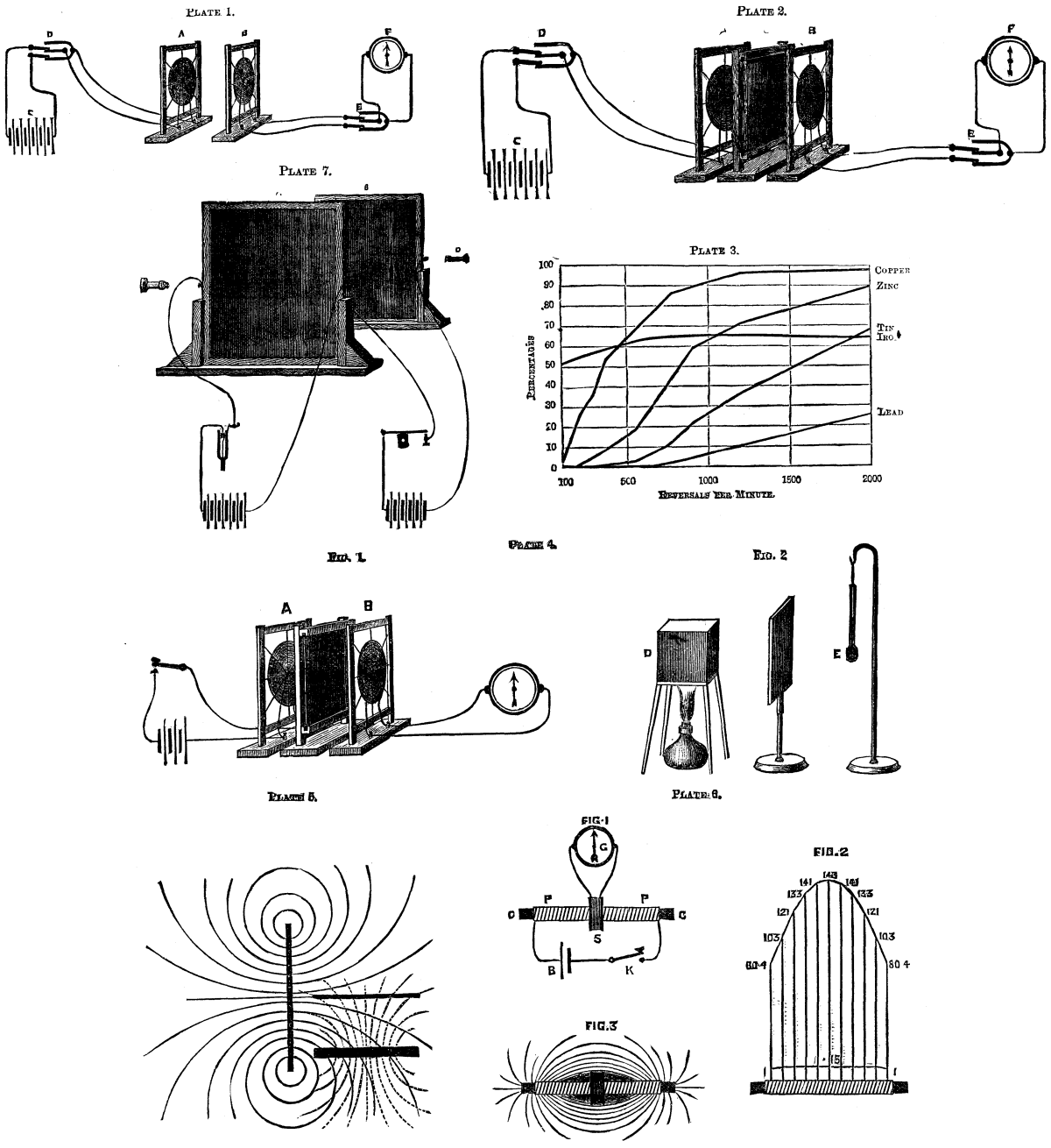
One of the hinderances to the production of a regular and steady light in electric illumination is the absence of perfect uniformity in the carbons. This defect has more than once been pointed out by us, and we are glad to notice any attempt to remedy an admitted evil. To this end we illustrate above a machine for manufacturing carbons, invented by William Cunliffe. The object the inventor has in view is not only the better but the more rapid manufacture of carbons, candles, or electrodes for electric lighting or for the manufacture of rods or blocks of carbon or other compressible substances for other purposes, and his invention consists in automatic machinery whereby a regular and uniform pressure and compression of the carbon is obtained, and the rods or blocks are delivered through the formers, in a state of greater density and better quality then hitherto. The machine consists of two cylinders, A A', placed longitudinally, as shown at Fig. 1, and in reversed position in relation to each other. In each cylinder works a piston or plunger, a, with a connecting rod or rods, b; in the latter case the ends of the rods have right and left handed threads upon which a sleeve, c, with corresponding threads, works. This sleeve, c, is provided with a hand wheel, so that by the turning it the stroke of the plungers, a a, and the size of the chambers, A A', is regulated so that the quantity of material to be passed through the dies or formers is thereby determined and may be indicated. In front of the chambers, A A', are fixed the dies or formers, d d, which may have any number of perforations of the size or shape of the carbon it is intended to mould. The dies are held in position by clamp pieces, e e, secured to the end of the chambers A A', by screws, and on each side of these clamp pieces are guides, with grooves, in which moves a bar with a crosshead, termed the guillotine, and which moves across the openings of the dies, and opening or closing them. Near the front end of the cylinders are placed small pistons or valves, f f, kept down in position by the weighted levers, g g (see Fig. 2, which is drawn to an enlarged scale), which, when the pressure in the chamber exceeds that of the weighted levers connected to the safety valve, f, the latter is raised and the guillotine bar, h, moved across the openings of the dies by the connecting rods, h', thereby allowing the carbon to be forced through the dies. In the backward movement of the piston, a, a fresh supply of material is drawn by atmospheric pressure through the hoppers, B B', alternately. At the end of the stroke the arms of the rocking levers (which are connected by tension rods with the tappet levers) are struck by the disk wheel or regulator, the guillotine is moved back and replaced over the openings of the dies, ready for the next charge, as shown. The plungers are operated by hydraulic, steam, compressed air, or other power, the inlet and outlet of such a pressure being regulated by a valve, an example of which is shown at Fig. 1, and provided with the tappet levers, i i, hinged to the valve chest, C, as shown, and attached to spindles, i' i', operating the slide valves, and struck alternately at the end of each stroke, thus operating the valves and the guillotine connections, i² and i³. The front ends of the cylinders may be placed at an angle for the more convenient delivery of the moulded articles.--Iron.
MACHINE FOR MAKING ELECTRIC LIGHT CARBONS
There has lately been held, at No. 31 Lombard Street, London, a private exhibition of the Holmes and Burke primary galvanic battery. The chief object of the display was to demonstrate its suitability for the lighting of railway trains, but at the same time means were provided to show it in connection with ordinary domestic illumination, as it is evident that a battery will serve equally as well for the latter as for the former purpose. Already the great Northern express leaving London at 5:30 P.M. is lighted by this means, and satisfactory experiments have been made upon the South-western line, while the inventors give a long list of other companies to which experimental plant is to be supplied. The battery shown, in Lombard Street consisted of fifteen cells arranged in three boxes of five cells each. Each box measured about 18 in. by 12 in. by 10 in., and weighed from 75 lb. to 100 lb. The electromotive force of each cell was 1.8 volts and its internal resistance from 1/40 to 1/50 of an ohm, consequently the battery exhibited had, under the must favorable circumstances, a difference of potential of 27 volts at its poles, and a resistance of 0.3 ohm.
When connected to a group of ten Swan lamps of five candle power, requiring a difference of potential of 20 volts, it raised them to vivid incandescence, considerably above their nominal capacity, but it failed to supply eighteen lamps of the same kind satisfactorily, showing that its working capacity lay somewhere between the two. A more powerful lamp is used in the railway carriages, but as there was only one erected it was impossible to judge of the number that a battery of the size shown would feed. Engineering says the trial, however, demonstrated that great quantities of current were being continuously evolved, and if, as we understood, the production can be maintained constant for about twenty-four hours without attention, the new battery marks a distinct step in this kind of electric lighting. Of the construction of the battery we unfortunately can say but little, as the patents are not yet completed, but we may state that the solid elements are zinc and carbon, and that the novelty lies in the liquid, and in the ingenious arrangement for supplying and withdrawing it.
Ordinarily one charge of liquid will serve for twenty-four hours working, but this, of course, is entirely determined by the space provided for it. It is sold at sevenpence a gallon, and each gallon is sufficient, we are informed, to drive a cell while it generates 800 ampere hours of current, or, taking the electromotive force at 1.8 volts, it represents (800 x 1.8) / 746 = 1.93 horse-power hours. The cost of the zinc is stated to be 35 per cent. of that of the fluid, although it is difficult to see how this can be, for one horse-power requires the consumption of 895.2 grammes of zinc per hour, or 1.96 lb., and this at 18l. per ton, would cost 1.93 pence per pound, or 3.8 pence per horse-power hour. This added to 3.6 pence for the fluid, would give a total of 7.4 pence per horse-power per hour, and assuming twenty lamps of ten candle power to be fed per horse-power, the cost would be about one-third of a penny per hour per lamp.
Mr Holmes admits his statement of the consumption of zinc does not agree with what might be theoretically expected but he bases it upon the result of his experiments in the Pullman train, which place the cost at one farthing per hour per light. At the same time he does not profess that the battery can compete in the matter of cost with mechanically generated currents on a large scale, but he offers it as a convenient means of obtaining the electric light in places where a steam engine or a gas engine is inadmissible, as in a private house, and where the cost of driving a dynamo machine is raised abnormally high by reason of a special attendant having to be paid to look after it.
But he has another scheme for the reduction of the cost, to which we have not yet alluded, and of which we can say but little, as the details are not at present available for publication. The battery gives off fumes which can be condensed into a nitrogenous substance, valuable, it is stated, as a manure, while the zinc salts in the spent liquid can be recovered and returned to useful purposes. How far this is practicable it is at present impossible to say, but at any rate the idea represents a step in the right direction, and if the electricians can follow the example of the gas manufacturers and obtain a revenue from the residuals of galvanic batteries, they will greatly improve their commercial position. There is nothing impossible in the idea, and neither is it altogether novel, although the way of carrying it out may be. In 1848, Staite, one of the early enthusiasts in electric lighting, patented a series of batteries from which he proposed to recover sulphate, nitrate, and chloride of zinc, but we never heard that he obtained any success.
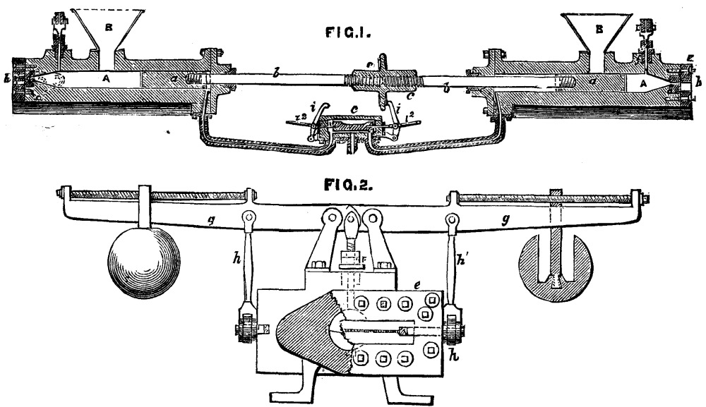
The original electric railway laid down by Messrs. Siemens and Halske at Berlin seems likely to be the parent of many others. One of the most recent is the underground electric line laid down by the firm in the mines of Zankerodain Saxony. An account of this railway has appeared in Glaser's Annalen, together with drawings of the engine, which we are able to reproduce. They are derived from a paper by Herr Fischer, read on the 19th December, 1882, before the Electro-Technical Union of Germany. The line in question is 700 meters long--770 yards--and has two lines of way. It lies 270 meters--300 yards--below the surface of the ground. It is worked by an electric locomotive, hauling ten wagons at a speed of 12 kilometers, or 7½ miles per hour. The total weight drawn is eight tons. The gauge is a narrow one, so that the locomotive can be made of small dimensions. Its total length between the buffer heads is 2.43 meters; its height 1.04 meters; breadth 0.8 meter; diameter of wheels, 0.34 meter. From the rail head to the center of the buffers is a height of 0.675 meter; and the total weight is only 1550 kilogrammes, or say 3,400 lb. We give a longitudinal section through the locomotive. It will be seen that there is a seat at each end for the driver, so that he can always look forwards, whichever way the engine may be running. The arrangements for connection with the electric current are very simple. The current is generated by a dynamo machine fixed outside the mine, and run by a small rotary steam engine, shown in section and elevation, at a speed of 900 revolutions per minute. The current passes through a cable down the shaft to a T-iron fixed to the side of the heading. On this T-iron slide contact pieces which are connected with the electric engine by leading wires. The driver by turning a handle can move his engine backward or forward at will. The whole arrangement has worked extremely well, and it is stated that the locomotive, if so arranged, could easily do double its present work; in other words, could haul 15 to 16 tons of train load at a speed of seven miles an hour. The arrangements for the dynamo machine on the engine, and its connection with the wheels, are much the same as those used in Sir William Siemens' electric railway now working near the Giant's Causeway.--The Engineer.
THE SIEMENS ELECTRIC RAILWAY AT ZANKERODA MINES.
Lebon, in the certificate dated 1801, in addition to his first patent, described and illustrated a three-cylinder gas-engine in which an explosive mixture of gas and air was to have been ignited by an electric spark. This is a curious anticipation of the Lenior system, not brought out until more than fifty years later; but there is no evidence that Lebon ever constructed an engine after the design referred to. It is an instructive lesson to would-be patentees, who frequently expect to reap immediate fame and fortune from their property in some crude ideas which they fondly deem to be an "invention," to observe the very wide interval that separates Lebon from Otto. The idea is the same in both cases; but it has required long years of patient work, and many failures, to embody the idea in a suitable form. It is almost surprising, to any one who has not specially studied the matter, to discover the number of devices that have been tried with the object of making an explosion engine, as distinguished from one deriving its motive power from the expansion of gaseous fluids. A narrative of some of these attempts has been presented to the Societe des Ingenieurs Civils; mostly taken in the first place from Stuart's work upon the origin of the steam engine, published in 1820, and now somewhat scarce. It appears from this statement that so long ago as 1794, Robert Street described and patented an engine in winch the piston was to be driven by the explosion of a gaseous mixture whereof the combustible element was furnished by the vaporization of terebenthine (turpentine) thrown upon red hot iron. In 1807 De Rivaz applied the same idea in a different manner. He employed a cylinder 12 centimeters in diameter fitted with a piston. At the bottom of the cylinder there was another smaller one, also provided with a piston. This was the aspirating cylinder, which drew hydrogen from an inflated bag, and mixed it with twice its bulk of air by means of a two-way cock. The ignition of the detonating mixture was effected by an electric spark. It is said that the inventor applied his apparatus to a small locomotive.
In 1820 Mr. Cecil, of Cambridge, proposed the employment of a mixture of air and hydrogen as a source of motive power; he gave a detailed account of his invention in the Transactions of the Cambridge Philosophical Society, together with some interesting theoretical considerations. The author observes here that an explosion may be safely opposed by an elastic resistance--that of compressed air, for example--if such resistance possesses little or no inertia to be brought into play; contrariwise, the smallest inertia opposed to the explosion of a mixture subjected to instantaneous combustion is equivalent to an insurmountable obstacle. Thus a small quantity of gunpowder, or a detonating mixture of air and hydrogen, may without danger be ignited in a large closed vessel full of air, because the pressure against the sides of the vessel exerted by the explosion is not more than the pressure of the air compressed by the explosion. If a piece of card board, or even of paper, is placed in the middle of the bore of a cannon charged with powder, the cannon will almost certainly burst, because the powder in detonating acts upon a body in repose which can only be put in motion in a period of time infinitely little by the intervention of a force infinitely great. The piece of paper is therefore equivalent to an insurmountable obstacle. Of all detonating mixtures, or explosive materials, the most dangerous for equal expansions, and the least fitted for use as motive power, are those which inflame the most rapidly. Thus, a mixture of oxygen and hydrogen, in which the inflammation is produced instantaneously, is less convenient for this particular usage than a mixture of air and hydrogen, which inflames more slowly. From this point of view, ordinary gunpowder would make a good source of motive power, because, notwithstanding its great power of dilatation, it is comparatively slow of ignition; only it would be necessary to take particular precautions to place the moving body in close contact with the powder. Cecil pointed out that while a small steam engine could not be started in work in less than half an hour, or probably more, a gas engine such as he proposed would have the advantage of being always ready for immediate use. Cecil's engine was the first in which the explosive mixture was ignited by a simple flame of gas drawn into the cylinder at the right moment. In the first model, which was that of a vertical beam engine with a long cylinder of comparatively small diameter, the motive power was simply derived from the descent of the piston by atmospheric pressure; but Mr. Cecil is careful to state that power may also be obtained directly from the force of the explosion. The engine was worked with a cylinder pressure of about 12 atmospheres, and the inventor seems to have recognized that the noise of the explosions might be an objection to the machine, for he suggests putting the end of the cylinder down in a well, or inclosing it in a tight vessel for the purpose of deadening the shock.
It is interesting to rescue for a moment the account of Mr. Cecil's invention from the obscurity into which it has fallen--obscurity which the ingenuity of the ideas embodied in this machine does not merit. It is probable that in addition to the imperfections of his machinery, Mr. Cecil suffered from the difficulty of obtaining hydrogen at a sufficiently low price for use in large quantities. It does not transpire that the inventor ever seriously turned his attention to the advantages of coal gas, which even at that time, although very dear, must have been much cheaper than hydrogen. Knowing what we do at present, however, of the consumption of gas by a good engine of the latest pattern, it may be assumed that a great deal of the trouble of the gas engine builders of 60 years ago arose from the simple fact of their being altogether before their age. Of course, the steam engine of 1820 was a much more wasteful machine, as well as more costly to build than the steam engine of to-day; but the difference cannot have been so great as to create an advantage in favor of an appliance which required even greater nicety of construction. The best gas-engine at present made would have been an expensive thing to supply with gas at the prices current in 1820, even if the resources of mechanical science at that date had been equal to its construction; which we know was not the case. Still, this consideration was not known, or was little valued, by Mr. Cecil and his contemporaries. It was not long, however, before Mr. Cecil had to give way before a formidable rival; for in 1823 Samuel Brown brought out his engine, which was in many respects an improvement upon the one already described. It will probably be right, however, to regard the Rev. Mr. Cecil, of Cambridge, as the first to make a practicable model of a gas-engine in the United Kingdom.--Journal of Gas Lighting.
Alabama has 2,118 factories, working 8,248 hands, with a capital invested of $5,714,032, paying annually in wages $2,227,968, and yielding annually in products $13,040,644.
[Footnote: For previous article see SUPPLEMENT 367.]
The moving of a belfry was effected in 1776 by a mason who knew neither how to read nor write. This structure was, and still is, at Crescentino, upon the left bank of the Po, between Turin and Cazal. The following is the official report on the operation:
"In the year 1776, on the second day of September, the ordinary council was convoked, ... as it is well known that, on the 26th of May last, there was effected the removal of a belfry, 7 trabucs (22.5 m.) or more in height, from the church called Madonna del Palazzo, with the concurrence and in the presence and amid the applause of numerous people of this city and of strangers who had come in order to be witnesses of the removal of the said tower with its base and entire form, by means of the processes of our fellow-citizen Serra, a master mason who took it upon himself to move the said belfry to a distance of 3 meters, and to annex it to a church in course of construction. In order to effect this removal, the four faces of the brick walls were first cut and opened at the base of the tower and on a level with the earth. Into the apertures from north to south, that is to say in the direction that the edifice was to take, there were introduced two large beams, and with these there ran parallel, external to the belfry and alongside of it, two other rows of beams of sufficient length and extent to form for the structure a bed over which it might be moved and placed in position in the new spot, where foundations of brick and lime had previously been prepared.
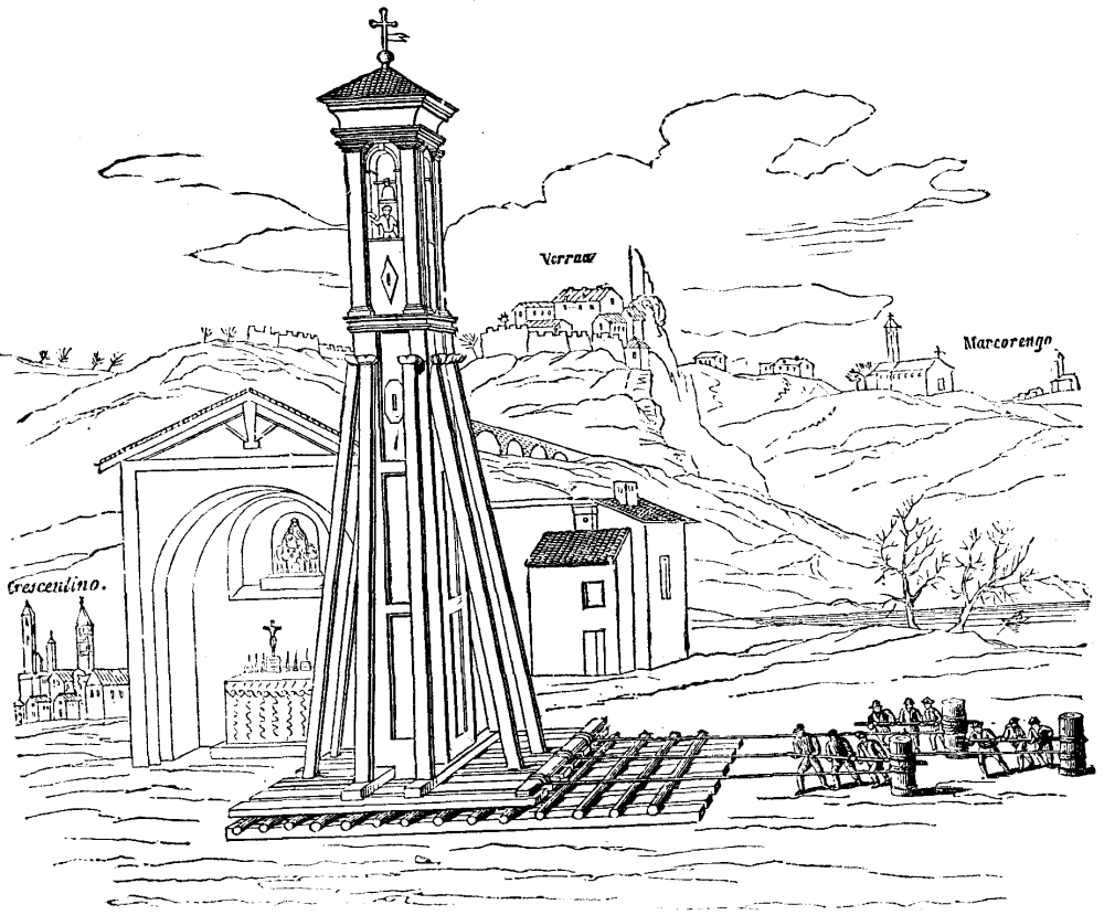
FIG. 1.--REMOVAL OF A BELFRY AT CRESCENTINO IN 1776
"Upon this plane there were afterward placed rollers 3½ inches in diameter, and, upon these latter, there was placed a second row of beams of the same length as the others. Into the eastern and western apertures there were inserted, in cross-form, two beams of less length.
"In order to prevent the oscillation of the tower, the latter was supported by eight joists, two of these being placed on each side and joined at their bases, each with one of the four beams, and, at their apices, with the walls of the tower at about two-thirds of its height.
"The plane over which the edifice was to be rolled had an inclination of one inch. The belfry was hauled by three cables that wound around three capstans, each of which was actuated by ten men. The removal was effected in less than an hour.
"It should be remarked that during the operation the son of the mason Serra, standing in the belfry, continued to ring peals, the bells not having been taken out.
"Done at Crescentino, in the year and on the day mentioned."
A note communicated to the Academie des Sciences at its session of May 9, 1831, added that the base of the belfry was 3.3 m. square. This permits us to estimate its weight at about 150 tons.
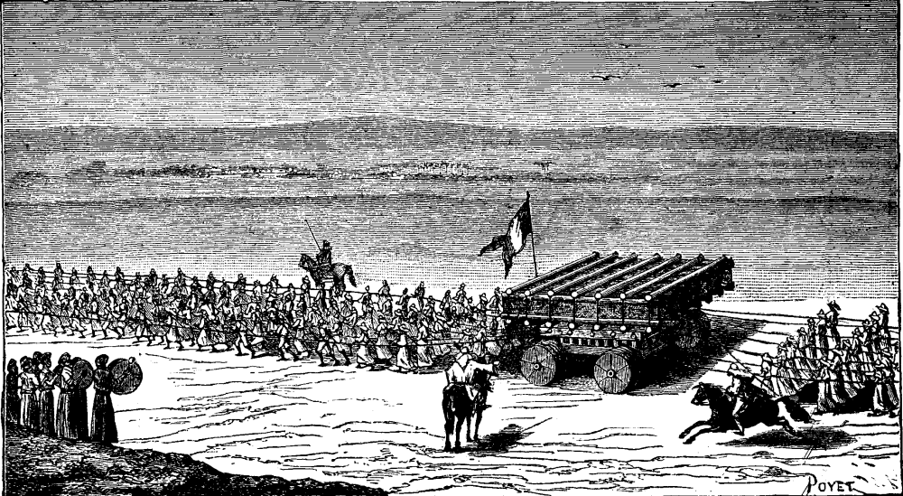
FIG. 2.--MOVING THE WINGED BULLS FROM NINEVEH TO
MOSUL
IN 1854
Fig. 1 shows the general aspect of the belfry with its stays. This is taken from an engraving published in 1844 by Mr. De Gregori, who, during his childhood, was a witness of the operation, and who endeavored to render the information given by the official account completer without being able to make the process much clearer.
In 1854 Mr. Victor Place moved overland, from Nineveh to Mosul, the winged bulls that at present are in the Assyrian museum of the Louvre, and each of which weighs 32 tons. After carefully packing these in boxes in order to preserve them from shocks, Place laid them upon their side, having turned them over, by means of levers, against a sloping bank of earth That he afterward dug away in such a manner that the operation was performed without accident. He had had constructed an enormous car with axles 0.25 m. in diameter, and solid wheels 0.8 m. in thickness (Fig. 2). Beneath the center of the box containing the bull a trench was dug that ran up to the natural lever of the soil by an incline. This trench had a depth and width such that the car could run under the box while the latter was supported at two of its extremities by the banks. These latter were afterward gradually cut away until the box rested upon the car without shock. Six hundred men then manned the ropes and hauled the car with its load up to the level of the plain. These six hundred men were necessary throughout nearly the entire route over a plain that was but slightly broken and in which the ground presented but little consistency.
The route from Khorsabad to Mosul was about 18 kilometers, taking into account all the detours that had to be made in order to have a somewhat firm roadway. It took four days to transport the first bull this distance, but it required only a day and a half to move the other one, since the ground had acquired more compactness as a consequence of moving the first one over it, and since the leaders had become more expert. The six hundred men at Mr. Place's disposal had, moreover, been employed for three months back in preparing the route, in strengthening it with piles in certain spots and in paving others with flagstones brought from the ruins of Nineveh. In a succeeding article I shall describe how I, a few years ago, moved an ammunition stone house, weighing 50 tons, to a distance of 35 meters without any other machine than a capstan actuated by two men.--A. De Rochas, in La Nature.
[NATURE.]
In the address delivered by Mr. Westmacott, President of the Institution of Mechanical Engineers to the English and Belgian engineers assembled at Liege last August, there occurred the following passage: "Engineering brings all other sciences into play; chemical or physical discoveries, such as those of Faraday, would be of little practical use if engineers were not ready with mechanical appliances to carry them out, and make them commercially successful in the way best suited to each."
We have no objection to make to these words, spoken at such a time and before such an assembly. It would of course be easy to take the converse view, and observe that engineering would have made little progress in modern times, but for the splendid resources which the discoveries of pure science have placed at her disposal, and which she has only had to adopt and utilize for her own purposes. But there is no need to quarrel over two opposite modes of stating the same fact. There is need on the other hand that the fact itself should be fairly recognized and accepted, namely, that science may be looked upon as at once the handmaid and the guide of art, art as at once the pupil and the supporter of science. In the present article we propose to give a few illustrations which will bring out and emphasize this truth.
We could scarcely find a better instance than is furnished to our hand in the sentence we have chosen for a text. No man ever worked with a more single hearted devotion to pure science--with a more absolute disregard of money or fame, as compared with knowledge--than Michael Faraday. Yet future ages will perhaps judge that no stronger impulse was ever given to the progress of industrial art, or to the advancement of the material interests of mankind, than the impulse which sprang from his discoveries in electricity and magnetism. Of these discoveries we are only now beginning to reap the benefit. But we have merely to consider the position which the dynamo-electric machine already occupies in the industrial world, and the far higher position, which, as almost all admit, it is destined to occupy in the future, in order to see how much we owe to Faraday's establishment of the connection between magnetism and electricity. That is one side of the question--the debt which art owes to science. But let us look at the other side also. Does science owe nothing to art? Will any one say that we should know as much as we do concerning the theory of the dynamo-electric motor, and the laws of electro-magnetic action generally, if that motor had never risen (or fallen, as you choose to put it) to be something besides the instrument of a laboratory, or the toy of a lecture room? Only a short time since the illustrious French physicist, M. Tresca, was enumerating the various sources of loss in the transmission of power by electricity along a fixed wire, as elucidated in the careful and elaborate experiments inaugurated by M. Marcel Deprez, and subsequently continued by himself. These losses--the electrical no less than the mechanical losses--are being thoroughly and minutely examined in the hope of reducing them to the lowest limit; and this examination cannot fail to throw much light on the exact distribution of the energy imparted to a dynamo machine and the laws by which this distribution is governed. But would this examination ever have taken place--would the costly experiments which render it feasible ever have been performed--if the dynamo machine was still under the undisputed control of pure science, and had not become subject to the sway of the capitalist and the engineer?
Of course the electric telegraph affords an earlier and perhaps as good an illustration of the same fact. The discovery that electricity would pass along a wire and actuate a needle at the other end was at first a purely scientific one; and it was only gradually that its importance, from an industrial point of view, came to be recognized. Here again art owes to pure science the creation of a complete and important branch of engineering, whose works are spread like a net over the whole face of the globe. On the other hand our knowledge of electricity, and especially of the electrochemical processes which go on in the working of batteries, has been enormously improved in consequence of the use of such batteries for the purposes of telegraphy.
Let us turn to another example in a different branch of science. Whichever of our modern discoveries we may consider to be the most startling and important, there can I think be no doubt that the most beautiful is that of the spectroscope. It has enabled us to do that which but a few years before its introduction was taken for the very type of the impossible, viz., to study the chemical composition of the stars; and it is giving us clearer and clearer insight every day into the condition of the great luminary which forms the center of our system. Still, however beautiful and interesting such results may be, it might well be thought that they could never have any practical application, and that the spectroscope at least would remain an instrument of science, but of science alone. This, however, is not the case. Some thirty years since, Mr. Bessemer conceived the idea that the injurious constituents of raw iron--such as silicon, sulphur, etc.--might be got rid of by simple oxidation. The mass of crude metal was heated to a very high temperature; atmospheric air was forced through it at a considerable pressure; and the oxygen uniting with these metalloids carried them off in the form of acid gases. The very act of union generated a vast quantity of heat, which itself assisted the continuance of the process; and the gas therefore passed off in a highly luminous condition. But the important point was to know where to stop; to seize the exact moment when all or practically all hurtful ingredients had been removed, and before the oxygen had turned from them to attack the iron itself. How was this point to be ascertained? It was soon suggested that each of these gases in its incandescent state would show its own peculiar spectrum; and that if the flame rushing out of the throat of the converter were viewed through a spectroscope, the moment when any substance such as sulphur, had disappeared would be known by the disappearance of the corresponding lines in the spectrum. The anticipation, it is needless to say, was verified, and the spectroscope, though now superseded, had for a time its place among the regular appliances necessary for the carrying on of the Bessemer process.
This process itself, with all the momentous consequences, mechanical, commercial, and economical, which it has entailed, might be brought forward as a witness on our side; for it was almost completely worked out in the laboratory before being submitted to actual practice. In this respect it stands in marked contrast to the earlier processes for the making of iron and steel, which were developed, it is difficult to say how, in the forge or furnace itself, and amid the smoke and din of practical work. At the same time the experiments of Bessemer were for the most part carried out with a distinct eye to their future application in practice, and their value for our present purpose is therefore not so great. The same we believe may be said with regard to the great rival of the Bessemer converter, viz., the Siemens open hearth; although this forms in itself a beautiful application of the scientific doctrine that steel stands midway, as regards proportion of carbon, between wrought iron and pig iron, and ought therefore to be obtainable by a judicious mixture of the two. The basic process is the latest development, in this direction, of science as applied to metallurgy. Here, by simply giving a different chemical constitution to the clay lining of the converter, it is found possible to eliminate phosphorus--an element which has successfully withstood the attack of the Bessemer system. Now, to quote the words of a German eulogizer of the new method, phosphorus has been turned from an enemy into a friend; and the richer a given ore is in that substance, the more readily and cheaply does it seem likely to be converted into steel.
These latter examples have been taken from the art of metallurgy; and it may of course be said that, considering the intimate relations between that art and the science of chemistry, there can be no wonder if the former is largely dependent for its progress on the latter. I will therefore turn to what may appear the most concrete, practical, and unscientific of all arts--that, namely, of the mechanical engineer; and we shall find that even here examples will not fail us of the boons which pure science has conferred upon the art of construction, nor even perhaps of the reciprocal advantages which she has derived from the connection.
The address of Mr. Westmacott, from which I have already taken my text, supplies in itself more than one instance of the kind we seek--instances emphasized by papers read at the meeting where the address was spoken. Let us take, first, the manufacture of sugar from beetroot. This manufacture was forced into prominence in the early years of this century, when the Continental blockade maintained by England against Napoleon prevented all importation of sugar from America; and it has now attained very large dimensions, as all frequenters of the Continent must be aware. The process, as exhaustively described by a Belgian engineer, M. Melin, offers several instances of the application of chemical and physical science to practical purposes. Thus, the first operation in making sugar from beetroot is to separate the juice from the flesh, the former being as much as 95 per cent. of the whole weight. Formerly this was accomplished by rasping the roots into a pulp, and then pressing the pulp in powerful hydraulic presses; in other words, by purely mechanical means. This process is now to a large extent superseded by what is called the diffusion process, depending on the well known physical phenomena of endosmosis and exosmosis. The beetroot is cut up into small slices called "cossettes," and these are placed in vessels filled with water. The result is that a current of endosmosis takes place from the water toward the juice in the cells, and a current of exosmosis from the juice toward the water. These currents go on cell by cell, and continue until a state of equilibrium is attained. The richer the water and the poorer the juice, the sooner does this equilibrium take place. Consequently the vessels are arranged in a series, forming what is called a diffusion battery; the pure water is admitted to the first vessel, in which the slices have already been nearly exhausted, and subtracts from them what juice there is left. It then passes as a thin juice to the next vessel, in which the slices are richer, and the process begins again. In the last vessel the water which has already done its work in all the previous vessels comes into contact with fresh slices, and begins the operation upon them. The same process has been applied at the other end of the manufacture of sugar. After the juice has been purified and all the crystallizable sugar has been separated from it by boiling, there is left a mass of molasses, containing so much of the salts of potassium and sodium that no further crystallization of the yet remaining sugar is possible. The object of the process called osmosis is to carry off these salts. The apparatus used, or osmogene, consists of a series of trays filled alternately with molasses and water, the bottoms being formed of parchment paper. A current passes through this paper in each direction, part of the water entering the molasses, and part of the salts, together with a certain quantity of sugar, entering the water. The result, of thus freeing the molasses from the salts is that a large part of the remaining sugar can now be extracted by crystallization.
Another instance in point comes from a paper dealing with the question of the construction of long tunnels. In England this has been chiefly discussed of late in connection with the Channel Tunnel, where, however, the conditions are comparatively simple. It is of still greater importance abroad. Two tunnels have already been pierced through the Alps; a third is nearly completed; and a fourth, the Simplon Tunnel, which will be the longest of any, is at this moment the subject of a most active study on the part of French engineers. In America, especially in connection with the deep mines of the Western States, the problem is also of the highest importance. But the driving of such tunnels would be financially if not physically impossible, but for the resources which science has placed in our hands, first, by the preparation of new explosives, and, secondly, by methods of dealing with the very high temperatures which have to be encountered. As regards the first, the history of explosives is scarcely anything else than a record of the application of chemical principles to practical purposes--a record which in great part has yet to be written, and on which we cannot here dwell. It is certain, however, that but for the invention of nitroglycerine, a purely chemical compound, and its development in various forms, more or less safe and convenient, these long tunnels would never have been constructed. As regards the second point, the question of temperature is really the most formidable with which the tunnel engineer has to contend. In the St. Gothard Tunnel, just before the meeting of the two headings in February, 1880, the temperature rose as high as 93° Fahr. This, combined with the foulness of the air, produced an immense diminution in the work done per person and per horse employed, while several men were actually killed by the dynamite gases, and others suffered from a disease which was traced to a hitherto unknown species of internal worm. If the Simplon Tunnel should be constructed, yet higher temperatures may probably have to be dealt with. Although science can hardly be said to have completely mastered these difficulties, much has been done in that direction. A great deal of mechanical work has of course to be carried on at the face or far end of such a heading, and there are various means by which it might be done. But by far the most satisfactory solution, in most cases at least, is obtained by taking advantage of the properties of compressed air. Air can be compressed at the end of the tunnel either by steam-engines, or, still better, by turbines where water power is available. This compressed air may easily be led in pipes to the face of the heading, and used there to drive the small engines which work the rock-drilling machines, etc. The efficiency of such machines is doubtless low, chiefly owing to the physical fact that the air is heated by compression, and that much of this heat is lost while it traverses the long line of pipes leading to the scene of action. But here we have a great advantage from the point of view of ventilation; for as the air gained heat while being compressed, so it loses heat while expanding; and the result is that a current of cold and fresh air is continually issuing from the machines at the face of the heading, just where it is most wanted. In consequence, in the St. Gothard, as just alluded to, the hottest parts were always some little distance behind the face of the heading. Although in this case as much as 120,000 cubic meters of air (taken at atmospheric pressure) were daily poured into the heading, yet the ventilation was very insufficient. Moreover, the high pressure which is used for working the machines is not the best adapted for ventilation; and in the Arlberg tunnel separate ventilating pipes are employed, containing air compressed to about one atmosphere, which is delivered in much larger quantities although not at so low a temperature. In connection with this question of ventilation a long series of observations have been taken at the St. Gothard, both during and since the construction; these have revealed the important physical fact (itself of high practical importance) that the barometer never stands at the same level on the two sides of a great mountain chain; and so have made valuable contributions to the science of meteorology.
Another most important use of the same scientific fact, namely, the properties of compressed air, is found in the sinking of foundations below water. When the piers of a bridge, or other structure, had to be placed in a deep stream, the old method was to drive a double row of piles round the place and fill them in with clay, forming what is called a cofferdam. The water was pumped out from the interior, and the foundation laid in the open. This is always a very expensive process, and in rapid streams is scarcely practicable. In recent times large bottomless cases, called caissons, have been used, with tubes attached to the roof, by which air can be forced into or out of the interior. These caissons are brought to the site of the proposed pier, and are there sunk. Where the bottom is loose sandy earth, the vacuum process, as it is termed, is often employed; that is, the air is pumped out from the interior, and the superincumbent pressure then causes the caisson to sink and the earth to rise within it. But it is more usual to employ what is called the plenum process, in which air under high pressure is pumped into the caisson and expels the water, as in a diving bell. Workmen then descend, entering through an air lock, and excavate the ground at the bottom of the caisson, which sinks gradually as the excavation continues. Under this system a length of some two miles of quay wall is being constructed at Antwerp, far out in the channel of the river Scheldt. Here the caissons are laid end to end with each other, along the whole curve of the wall, and the masonry is built on the top of them within a floating cofferdam of very ingenious construction.
There are few mechanical principles more widely known than that of so-called centrifugal force; an action which, though still a puzzle to students, has long been thoroughly understood. It is, however, comparatively recently that it has been applied in practice. One of the earliest examples was perhaps the ordinary governor, due to the genius of Watt. Every boy knows that if he takes a weight hanging from a string and twirls it round, the weight will rise higher and revolve in a larger circle as he increases the speed. Watt saw that if he attached such an apparatus to his steam engine, the balls or weights would tend to rise higher whenever the engine begun to run faster, that this action might be made partly to draw over the valve which admitted the steam, and that in this way the supply of steam would be lessened, and the speed would fall. Few ideas in science have received so wide and so successful an application as this. But of late years another property of centrifugal force has been brought into play. The effect of this so-called force is that any body revolving in a circle has a continual tendency to fly off at a tangent; the amount of this tendency depending jointly on the mass of the body and on the velocity of the rotation. It is the former of these conditions which is now taken advantage of. For if we have a number of particles all revolving with the same velocity, but of different specific gravities, and if we allow them to follow their tendency of moving off at a tangent, it is evident that the heaviest particles, having the greatest mass, will move with the greatest energy. The result is that, if we take a mass of such particles and confine them within a circular casing, we shall find that, having rotated this casing with a high velocity and for a sufficient time, the heaviest particles will have settled at the outside and the lightest at the inside, while between the two there will be a gradation from the one to the other. Here, then, we have the means of separating two substances, solid or liquid, which are intimately mixed up together, but which are of different specific gravities. This physical principle has been taken advantage of in a somewhat homely but very important process, viz., the separation of cream from milk. In this arrangement the milk is charged into a vessel something of the shape and size of a Gloucester cheese, which stands on a vertical spindle and is made to rotate with a velocity as high as 7,000 revolutions per minute. At this enormous speed the milk, which is the heavier, flies to the outside, while the cream remains behind and stands up as a thin layer on the inside of the rotating cylinder of fluid. So completely does this immense speed produce in the liquid the characteristics of a solid, that if the rotating shell of cream be touched by a knife it emits a harsh, grating sound, and gives the sensation experienced in attempting to cut a stone. The separation is almost immediately complete, but the difficult point was to draw off the two liquids separately and continuously without stopping the machine. This has been simply accomplished by taking advantage of another principle of hydromechanics. A small pipe opening just inside the shell of the cylinder is brought back to near the center, where it rises through a sort of neck and opens into an exterior casing. The pressure due to the velocity causes the skim milk to rise in this pipe and flow continuously out at the inner end. The cream is at the same time drawn off by a similar orifice made in the same neck and leading into a different chamber.
Centrifugal action is not the only way in which particles of different specific gravity can he separated from each other by motion only. If a rapid "jigging" or up-and-down motion be given to a mixture of such particles, the tendency of the lighter to fly further under the action of the impulse causes them gradually to rise to the upper surface; this surface being free in the present case, and the result being therefore the reverse of what happens in the rotating chamber. If such a mixture be examined after this up-and down motion has gone on for a considerable period, it will be found that the particles are arranged pretty accurately in layers, the lightest being at the top and the heaviest at the bottom. This principle has long been taken advantage of in such cases as the separation of lead ores from the matrix in which they are embedded. The rock in these cases is crushed into small fragments, and placed on a frame having a rapid up-and-down-motion, when the heavy lead ore gradually collects at the bottom and the lighter stone on the top. To separate the two the machine must be stopped and cleared by hand. In the case of coal-washing, where the object is to separate fine coal from the particles of stone mixed with it, this process would be very costly, and indeed impossible, because a current of water is sweeping through the whole mass. In the case of the Coppee coal-washer, the desired end is achieved in a different and very simple manner. The well known mineral felspar has a specific gravity intermediate between that of the coal and the shale, or stone, with which it is found intermixed. If, then, a quantity of felspar in small fragments is thrown into the mixture, and the whole then submitted to the jigging process, the result will be that the stone will collect on the top, and the coal at the bottom, with a layer of felspar separating the two. A current of water sweeps through the whole, and is drawn off partly at the top, carrying with it the stone, and partly at the bottom, carrying with it the fine coal.
The above are instances where science has come to the aid of engineering. Here is one in which the obligation is reversed. The rapid stopping of railroad trains, when necessary, by means of brakes, is a problem which has long occupied the attention of many engineers; and the mechanical solutions offered have been correspondingly numerous. Some of these depend on the action of steam, some of a vacuum, some of compressed air, some of pressure-water; others again ingeniously utilize the momentum of the wheels themselves. But for a long time no effort was made by any of these inventors thoroughly to master the theoretical conditions of the problem before them. At last, one of the most ingenious and successful among them, Mr. George Westinghouse, resolved to make experiments on the subject, and was fortunate enough to associate with himself Capt. Douglas Galton. Their experiments, carried on with rare energy and perseverance, and at great expense, not only brought into the clearest light the physical conditions of the question (conditions which were shown to be in strict accordance with theory), but also disclosed the interesting scientific fact that the friction between solid bodies at high velocities is not constant, as the experiments of Morin had been supposed to imply, but diminishes rapidly as the speed increases--a fact which other observations serve to confirm.
The old scientific principle known as the hydrostatic paradox, according to which a pressure applied at any point of an inclosed mass of liquid is transmitted unaltered to every other point, has been singularly fruitful in practical applications. Mr. Bramah was perhaps the first to recognize its value and importance. He applied it to the well known Bramah press, and in various other directions, some of which were less successful. One of these was a hydraulic lift, which Mr. Bramah proposed to construct by means of several cylinders sliding within each other after the manner of the tubes of a telescope. His specification of this invention sufficiently expresses his opinion of its value, for it concludes as follows: "This patent does not only differ in its nature and in its boundless extent of claims to novelty, but also in its claims to merit and superior utility compared with any other patent ever brought before or sanctioned by the legislative authority of any nation." The telescope lift has not come into practical use; but lifts worked on the hydraulic principle are becoming more and more common every day. The same principle has been applied by the genius of Sir William Armstrong and others to the working of cranes and other machines for the lifting of weights, etc.; and under the form of the accumulator, with its distributing pipes and hydraulic engines, it provides a store of power always ready for application at any required point in a large system, yet costing practically nothing when not actually at work. This system of high pressure mains worked from a central accumulator has been for some years in existence at Hull, as a means of supplying power commercially for all the purposes needed in a large town, and it is at this moment being carried out on a wider scale in the East End of London.
Taking advantage of this system, and combining with it another scientific principle of wide applicability, Mr. J.H. Greathead has brought out an instrument called the "injector hydrant," which seems likely to play an important part in the extinguishing of fires. This second principle is that of the lateral induction of fluids, and may be thus expressed in the words of the late William Froude: "Any surface which in passing through a fluid experiences resistance must in so doing impress on the particles which resist it a force in the line of motion equal to the resistance." If then these particles are themselves part of a fluid, it will result that they will follow the direction of the moving fluid and be partly carried along with it. As applied in the injector hydrant, a small quantity of water derived from the high pressure mains is made to pass from one pipe into another, coming in contact at the same time with a reservoir of water at ordinary pressure. The result is that the water from the reservoir is drawn into the second pipe through a trumpet-shaped nozzle, and may be made to issue as a stream to a considerable height. Thus the small quantity of pressure-water, which, if used by itself, would perhaps rise to a height of 500 feet, is made to carry with it a much larger quantity to a much smaller height, say that of an ordinary house.
The above are only a few of the many instances which might be given to prove the general truth of the fact with which we started, namely, the close and reciprocal connection between physical science and mechanical engineering, taking both in their widest sense. It may possibly be worth while to return again to the subject, as other illustrations arise. Two such have appeared even at the moment of writing, and though their practical success is not yet assured, it may be worth while to cite them. The first is an application of the old principle of the siphon to the purifying of sewage. Into a tank containing the sewage dips a siphon pipe some thirty feet high, of which the shorter leg is many times larger than the longer. When this is started, the water rises slowly and steadily in the shorter column, and before it reaches the top has left behind it all or almost all of the solid particles which it previously held in suspension. These fall slowly back through the column and collect at the bottom of the tank, to be cleared out when needful. The effluent water is not of course chemically pure, but sufficiently so to be turned into any ordinary stream. The second invention rests on a curious fact in chemistry, namely, that caustic soda or potash will absorb steam, forming a compound which has a much higher temperature than the steam absorbed. If, therefore, exhaust-steam be discharged into the bottom of a vessel containing caustic alkali, not only will it become condensed, but this condensation will raise the temperature of the mass so high that it may be employed in the generation of fresh steam. It is needless to observe how important will be the bearing of this invention upon the working of steam engines for many purposes, if only it can be established as a practical success. And if it is so established there can be no doubt that the experience thus acquired will reveal new and valuable facts with regard to the conditions of chemical combination and absorption, in the elements thus brought together.
WALTER R. BROWNE.
One of the most remarkable and interesting mechanical arrangements at the Imperial Navy Yard at Kiel, Germany, is the iron clad plate bending machine, by means of which the heavy iron clad plates are bent for the use of arming iron clad vessels.
Through the mechanism of this remarkable machine it is possible to bend the strongest and heaviest iron clad plates--in cold condition--so that they can be fitted close on to the ship's hull, as it was done with the man-of-war ships Saxonia, Bavaria, Wurtemberg, and Baden, each of which having an iron strength of about 250 meters.
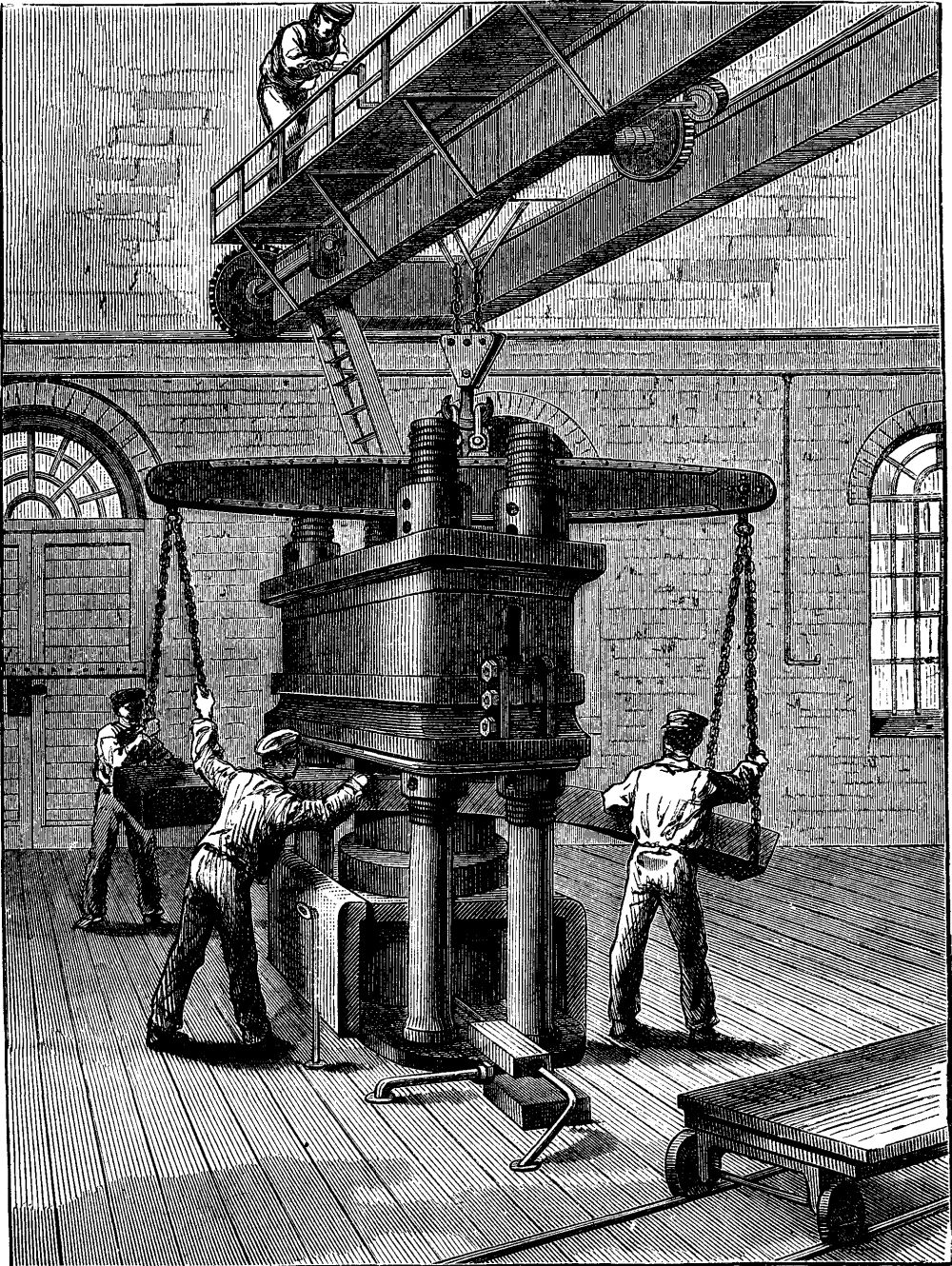
IMPROVED HYDRAULIC PLATE PRESS.
One may make himself a proximate idea of the enormous power of pressure of such a machine, if he can imagine what a strength is needed to bend an iron plate of 250 meters thickness, in cold condition; being also 1.5 meters in width, and 5.00 meters in length, and weighing about 14,555 kilogrammes, or 14,555 tons.
The bending of the plates is done as follows: As it is shown in the illustration, connected herewith, there are standing, well secured into the foundation, four perpendicular pillars, made of heavy iron, all of which are holding a heavy iron block, which by means of female nut screws is lifted and lowered in a perpendicular direction. Beneath the iron block, between the pillars, is lying a large hollow cylinder in which the press piston moves up and down in a perpendicular direction. These movements are caused by a small machine, or, better, press pump--not noticeable in the illustration--which presses water from a reservoir through a narrow pipe into the large hollow cylinder, preventing at the same time the escape or return of the water so forced in. The hollow cylinder up to the press piston is now filled with water, so remains no other way for the piston as to move on to the top. The iron clad plate ready to undergo the bending process is lying between press piston and iron block; under the latter preparations are already made for the purpose of giving the iron clad plate such a form as it will receive through the bending process. After this the press piston will, with the greatest force, steadily but slowly move upward, until the iron clad plate has received its intended bending.
Lately the hydraulic presses are often used as winding machines, that is, they are used as an arrangement to lift heavy loads up on elevated points.
The essential contrivance of a hydraulic press is as follows:
One thinks of a powerful piston, which, through, human, steam, or water power, is set in a moving up-and-down motion. Through the ascent of the piston, is by means of a drawing pipe, ending into a sieve, the water absorbed out of a reservoir, and by the lowering of the piston water is driven out of a cylinder by means of a narrow pipe (communication pipe) into a second cylinder, which raises a larger piston, the so-called press piston. (See illustration.)
One on top opening drawing valve, on the top end of the drawing pipe prevents the return of the water by the going down of the piston; and a barring valve, which is lifted by the lowering of the piston, obstructs the return of the water by the ascent of the piston, while the drawing valve is lifted by means of water absorbed by the small drawing pipe.--Illustrirte Zeitung.
Uber Land und Meer, which is one of the finest illustrated newspapers published in Germany, gives the following: We recently gave our readers an insight into the establishment of Uber Land und Meer, and to-day we show them the machine which each week starts our paper on its journey around the world--a machine which embodies the latest and greatest progress in the art of printing. The following illustration represents one of the three fast presses which the house of Hallberger employs in the printing of its illustrated journals.
With the invention of the cylinder press by Frederick König was verified the saying that the art of printing had lent wings to words. Everywhere the primitive hand-press had to make way for the steam printing machine; but even this machine, since its advent in London in 1810, has itself undergone so many changes that little else remains of König's invention than the principle of the cylinder. The demands of recent times for still more rapid machines have resulted in the production of presses printing from a continuous roll or "web" of paper, from cylinders revolving in one given direction. The first of this class of presses (the "Bullock" press) was built in America. Then England followed, and there the first newspaper to make use of one was the Times. The Augsburg Machine Works were the first to supply Germany with them, and it was this establishment which first undertook to apply the principle of the web perfecting press (first intended for newspaper work only, where speed rather than fine work is the object sought) to book printing, in which far greater accuracy and excellence is required, and the result has been the construction of a rotary press for the highest grade of illustrated periodical publications, which meets all the requirements with the most complete success.
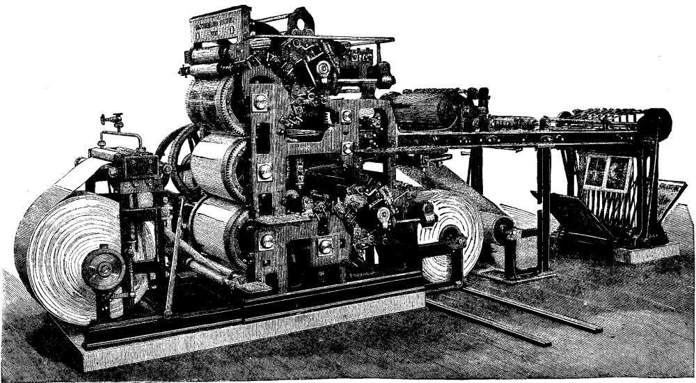
IMPROVED FAST PRINTING PRESS FOR ENGRAVERS
The building of rotary presses for printing illustrated papers was attempted as early as 1874 or 1875 in London, by the Times, but apparently without success, as no public mention has ever been made of any favorable result. The proprietor of the London Illustrated News obtained better results. In 1877 an illustrated penny paper, an outgrowth of his great journal, was printed upon a rotary press which was, according to his statement, constructed by a machinist named Middleton. The first one, however, did not at all meet the higher demands of illustrated periodical printing, and, while another machine constructed on the same principle was shown in the Paris Exposition of 1878, its work was neither in quality nor quantity adequate to the needs of a largely circulated illustrated paper. A second machine, also on exhibition at the same time, designed and built by the celebrated French machinist, P. Alauzet, could not be said to have attained the object. Its construction was undertaken long after the opening of the Exposition, and too late to solve the weighty question. But the half-successful attempt gave promise that the time was at hand when a press could be built which could print our illustrated periodicals more rapidly, and a conference with the proprietors of the Augsburg Machine Works resulted in the production by them of the three presses from which Uber Land und Meer and Die Illustrirte Welt are to-day issued. As a whole and in detail, as well as in its productions, the press is the marvel of mechanic and layman.
As seen in the illustration, the web of paper leaves the roll at its right, rising to a point at the top where it passes between two hollow cylinders covered with felt and filled with steam, which serve to dampen the paper as may be necessary, the small hand-wheel seen above these cylinders regulating the supply of steam. After leaving these cylinders the paper descends sloping toward the right, and passes through two highly polished cylinders for the purpose of recalendering. After this it passes under the lowest of the three large cylinders of the press, winds itself in the shape of an S toward the outside and over the middle cylinder, and leaves the press in an almost horizontal line, after having been printed on both sides, and is then cut into sheets. The printing is done while the paper is passing around the two white cylinders. The cylinder carrying the first form is placed inside and toward the center of the press, only a part of its cog-wheel and its journal being shown in the engraving. The second form is placed upon the uppermost cylinder, and is the outside or cut form. Each one of the form cylinders requires a separate inking apparatus. That of the upper one is placed to the right at the top, and the bottom one is also at the right, but inside. Each one has a fountain the whole breadth of the press, in which the ink is kept, and connected with which, by appropriate mechanism, is a system of rollers for the thorough distribution of the ink and depositing it upon the forms.
The rapidity with which the impressions follow each other does not allow any time for the printing on the first side to dry, and as a consequence the freshly printed sheet coming in contact with the "packing" of the second cylinder would so soil it as to render clean printing absolutely impossible. To avoid this, a second roll of paper is introduced into the machine, and is drawn around the middle cylinder beneath the paper which has already been printed upon one side, and receives upon its surface all "offset," thus protecting and keeping perfectly clean both the printed paper and the impression cylinder. This "offset" web, as it leaves the press, is wound upon a second roller, which when full is exchanged for the new empty roller--a very simple operation.
The machines print from 3,500 to 4,000 sheets per hour upon both sides, a rate of production from twenty-eight to thirty-two times as great as was possible upon the old-fashioned hand-press, which was capable of printing not more than 250 copies upon one side in the same time.
The device above described for preventing "offset" is, we believe, the invention of Mr. H.J. Hewitt, a well known New York printer, 27 Rose Street.
Five new cannons, the largest yet manufactured in France, have been successfully cast in the foundry of Ruelle near Angouleme. They are made of steel, and are breech loading. The weight of each is 97 tons, without the carriage. The projectile weighs 1,716 pounds, and the charge or powder is 616 pounds. To remove them a special wagon with sixteen wheels has had to be constructed, and the bridges upon the road from Ruelle to Angouleme not being solid enough to bear the weight of so heavy a load, a special roadway will be constructed for the transport of these weapons, which are destined for coast defences and ironclads.
The illustration represents a house recently reconstructed. The dining-room wing was alone left in the demolition of the old premises, and this part has been decorated with tile facings, and otherwise altered to be in accordance with the new portion. The house is pleasantly situated about a mile from Stoke Church of historic fame, in about 15 acres of garden, shrubbery, and meadow land. The hall and staircase have been treated in wainscot oak, and the whole of the work has been satisfactorily carried out by Mr. G. Almond, builder, of Burnham, under the superintendence of Messrs. Thurlow & Cross, architects.--The Architect.

WOODLANDS, STOKE POGES, BUCKS
The following article appeared in a recent number of the London Times:
The subject of the cultivation and commercial utilization of the China grass plant, or rhea, has for many years occupied attention, the question being one of national importance, particularly as affecting India. Rhea which is also known under the name of ramie, is a textile plant which was indigenous to China and India. It is perennial, easy of cultivation, and produces a remarkably strong fiber. The problem of its cultivation has long being solved, for within certain limits rhea can be grown in any climate. India and the British colonies offer unusual facilities, and present vast and appropriate fields for that enterprise, while it can be, and is, grown in most European countries. All this has long been demonstrated; not so, however, the commercial utilization of the fiber, which up to the present time would appear to be a problem only partially solved, although many earnest workers have been engaged in the attempted solution.
There have been difficulties in the way of decorticating the stems of this plant, and the Indian Government, in 1869, offered a reward of £5,000 for the best machine for separating the fiber from the stems and bark of rhea in its green or freshly cut state. The Indian Government was led to this step by the strong conviction, based upon ample evidence, that the only obstacle to the development of an extensive trade in this product was the want of suitable means for decorticating the plant. This was the third time within the present century that rhea had become the subject of official action on the part of the Government, the first effort for utilizing the plant dating from 1803, when Dr. Roxburg started the question, and the second from 1840, when attention was again directed to it by Colonel Jenkins.
The offer of £5,000, in 1869, led to only one machine being submitted for trial, although several competitors had entered their names. This machine was that of Mr. Greig, of Edinburgh, but after careful trial by General (then Lieutenant Colonel) Hyde it was found that it did not fulfill the conditions laid down by the Government, and therefore the full prize of £5,000 was not awarded. In consideration, however, of the inventor having made a bona fide and meritorious attempt to solve the question, he was awarded a donation of £1,500. Other unsuccessful attempts were subsequently made, and eventually the offer of £5,000 was withdrawn by the Government.
But although the prize was withdrawn, invention did not cease, and the Government, in 1881, reoffered the prize of £5,500. Another competition took place, at which several machines were tried, but the trials, as before, proved barren of any practical results, and up to the present time no machine has been found capable of dealing successfully with this plant in the green state. The question of the preparation of the fiber, however, continued to be pursued in many directions. Nor is this to be wondered at when it is remembered that the strength of some rhea fiber from Assam experimented with in 1852 by Dr. Forbes Royle, as compared with St. Petersburg hemp, was in the ratio of 280 to 160, while the wild rhea from Assam was as high as 343. But, above and beyond this, rhea has the widest range of possible applications of any fiber, as shown by an exhaustive report on the preparation and use of rhea fiber by Dr. Forbes Watson, published in 1875, at which date Dr. Watson was the reporter on the products of India to the Secretary of State, at the India Office. Last year, however, witnessed the solution of the question of decortication in the green state in a satisfactory manner by M.A. Favier's process, as reported by us at the time.
This process consists in subjecting the plant to the action of steam for a period varying from 10 to 25 minutes, according to the length of time the plant had been cut. After steaming, the fiber and its adjuncts were easily stripped from the wood. The importance and value of this invention will be realized, when it is remembered that the plant is cultivated at long distances from the localities where the fiber is prepared for the market. The consequence is, that for every hundredweight of fiber about a ton of woody material has to be transported. Nor is this the only evil, for the gummy matter in which the fiber is embedded becomes dried up during transport, and the separation of the fiber is thus rendered difficult, and even impossible, inasmuch as some of the fiber is left adhering to the wood.
M. Favier's process greatly simplifies the commercial production of the fiber up to a certain point, for, at a very small cost, it gives the manufacturer the whole of the fiber in the plant treated. But it still stops short of what is required, in that it delivers the fiber in ribbons, with its cementitious matter and outer skin attached. To remove this, various methods have been tried, but, as far as we are aware, without general success--that is to say, the fiber cannot always be obtained of such a uniformly good quality as to constitute a commercially reliable article. Such was the position of the question when, about a year ago, the whole case was submitted to the distinguished French chemist, Professor Fremy, member of the Institute of France, who is well-known for his researches into the nature of fibrous plants, and the question of their preparation for the market. Professor Fremy thoroughly investigated the matter from a chemical point of view, and at length brought it to a successful and, apparently, a practical issue.
One great bar to previous success would appear to have been the absence of exact knowledge as to the nature of the constituents of that portion of the plant which contains the fiber, or, in other words, the casing or bark surrounding the woody stem of the rhea. As determined by Professor Fremy, this consists of the cutose, or outer skin, within which is the vasculose containing the fiber and other conjoined matter, known as cellulose, between which and the woody stem is the pectose, or gum, which causes the skin or bark, as a whole, fiber included, to adhere to the wood. The Professor, therefore, proceeded to carefully investigate the nature of these various substances, and in the result he found that the vasculose and pectose were soluble in an alkali under certain conditions, and that the cellulose was insoluble. He therefore dissolves out the cutose, vasculose, and pectose by a very simple process, obtaining the fiber clean, and free from all extraneous adherent matter, ready for the spinner.
In order, however, to insure as a result a perfectly uniform and marketable article, the Professor uses various chemicals at the several stages of the process. These, however, are not administered haphazard, or by rule of thumb, as has been the case in some processes bearing in the same direction, and which have consequently failed, in the sense that they have not yet taken their places as commercial successes. The Professor, therefore, carefully examines the article which he has to treat, and, according to its nature and the character of its components, he determines the proportions of the various chemicals which he introduces at the several stages. All chance of failure thus appears to be eliminated, and the production of a fiber of uniform and reliable quality removed from the region of doubt into that of certainty. The two processes of M. Favier and M. Fremy have, therefore, been combined, and machinery has been put up in France on a scale sufficiently large to fairly approximate to practical working, and to demonstrate the practicability of the combined inventions.
The experimental works are situated in the Route d'Orleans, Grand Montrouge, just outside Paris, and a few days ago a series of demonstrations were given there by Messrs. G.W.H. Brogden and Co., of Gresham-house, London. The trials were carried out by M. Albert Alroy, under the supervision of M. Urbain, who is Professor Fremy's chief assistant and copatentee, and were attended by Dr. Forbes Watson, Mr. M. Collyer, Mr. C.J. Taylor, late member of the General Assembly, New Zealand, M. Barbe, M. Favier, Mr. G. Brogden, Mr. Caspar, and a number of other gentlemen representing those interested in the question at issue. The process, as carried out, consists in first treating the rhea according to M. Favier's invention. The apparatus employed for this purpose is very simple and inexpensive, consisting merely of a stout deal trough or box, about 8 ft. long, 2 ft. wide, and 1 ft. 8 in. deep. The box has a hinged lid and a false open bottom, under which steam is admitted by a perforated pipe, there being an outlet for the condensed water at one end of the box. Into this box the bundles of rhea were placed, the lid closed, steam turned on, and in about twenty minutes it was invariably found that the bark had been sufficiently softened to allow of its being readily and rapidly stripped off by hand, together with the whole of the fiber, in what may be called ribbons. Thus the process of decortication is effectively accomplished in a few minutes, instead of requiring, as it sometimes does in the retting process, days, and even weeks, and being at the best attended with uncertainty as to results, as is also the case when decortication is effected by machinery.
Moreover, the retting process, which is simply steeping the cut plants in water, is a delicate operation, requiring constant watching, to say nothing of its serious inconvenience from a sanitary point of view, on account of the pestilential emanations from the retteries. Decortication by steam having been effected, the work of M. Favier ceases, and the process is carried forward by M. Fremy. The ribbons having been produced, the fiber in them has to be freed from the mucilaginous secretions. To this end, after examination in the laboratory, they are laid on metal trays, which are placed one above the other in a vertical perforated metal cylinder. When charged, this cylinder is placed within a strong iron cylinder, containing a known quantity of water, to which an alkali is added in certain proportions. Within the cylinder is a steam coil for heating the water, and, steam having been turned on, the temperature is raised to a certain point, when the cylinder is closed and made steam-tight. The process of boiling is continued under pressure until the temperature--and consequently the steam pressure--within the cylinder has attained a high degree.
On the completion of this part of the process, which occupies about four hours, and upon which the success of the whole mainly depends, the cementitious matter surrounding the fiber is found to have been transformed into a substance easily dissolved. The fibrous mass is then removed to a centrifugal machine, in which it is quickly deprived of its surplus alkaline moisture, and it is then placed in a weak solution of hydrochloric acid for a short time. It is then transferred to a bath of pure cold water, in which it remains for about an hour, and it is subsequently placed for a short time in a weak acid bath, after which it is again washed in cold water, and dried for the market. Such are the processes by which China grass may become a source of profit alike to the cultivator and the spinner. A factory situate at Louviers has been acquired, where there is machinery already erected for preparing the fiber according to the processes we have described, at the rate of one ton per day. There is also machinery for spinning the fiber into yarns. These works were also visited by those gentlemen who were at the experimental works at Montrouge, and who also visited the Government laboratory in Paris, of which Professor Fremy is chief and M. Urbain sous-chef, and where those gentlemen explained the details of their process and made their visitors familiar with the progressive steps of their investigations.
With regard to the rhea treated at Montrouge, we may observe that it was grown at La Reolle, near Bordeaux. Some special experiments were also carried out by Dr. Forbes Watson with some rhea grown by the Duke of Wellington at Stratfield-saye, his Grace having taken an active interest in the question for some years past. In all cases the rhea was used green and comparatively freshly cut. One of the objects of Dr. Watson's experiments was, by treating rhea cut at certain stages of growth, to ascertain at which stage the plant yields the best fiber, and consequently how many crops can be raised in the year with the best advantage.
This question has often presented itself as one of the points to be determined, and advantage has been taken of the present opportunity with a view to the solution of the question. Mr. C.J. Taylor also took with him a sample of New Zealand flax, which was successfully treated by the process. On the whole, the conclusion is that the results of the combined processes, so far as they have gone, are eminently satisfactory, and justify the expectation that a large enterprise in the cultivation and utilization of China grass is on the eve of being opened up, not only in India and our colonies, but possibly also much nearer home.
This new heating apparatus consists of a cast iron box, E, provided with an inclined cover, F, into which are fixed 100 copper tubes that are arranged in several lines, and form a semi-cylindrical heating surface. The box, E, is divided into two compartments (Fig. 5), so that the air and gas may enter simultaneously either one or both of the compartments, according to the quantity of heat it is desired to have. Regulation is effected by means of the keys, G and G', which open the gas conduits of the solid and movable disk, H, which serves as a regulator for distributing air through the two compartments. This disk revolves by hand and may be closed or opened by means of a screw to which it is fixed.
Beneath the tubes that serve to burn the mixture of air and gas, there is placed a metallic gauze, I, the object of which is to prevent the flames from entering the fire place box. These tubes traverse a sheet iron piece, J, which forms the surface of the fire place, and are covered with a layer of asbestos filaments that serve to increase the calorific power of the apparatus.
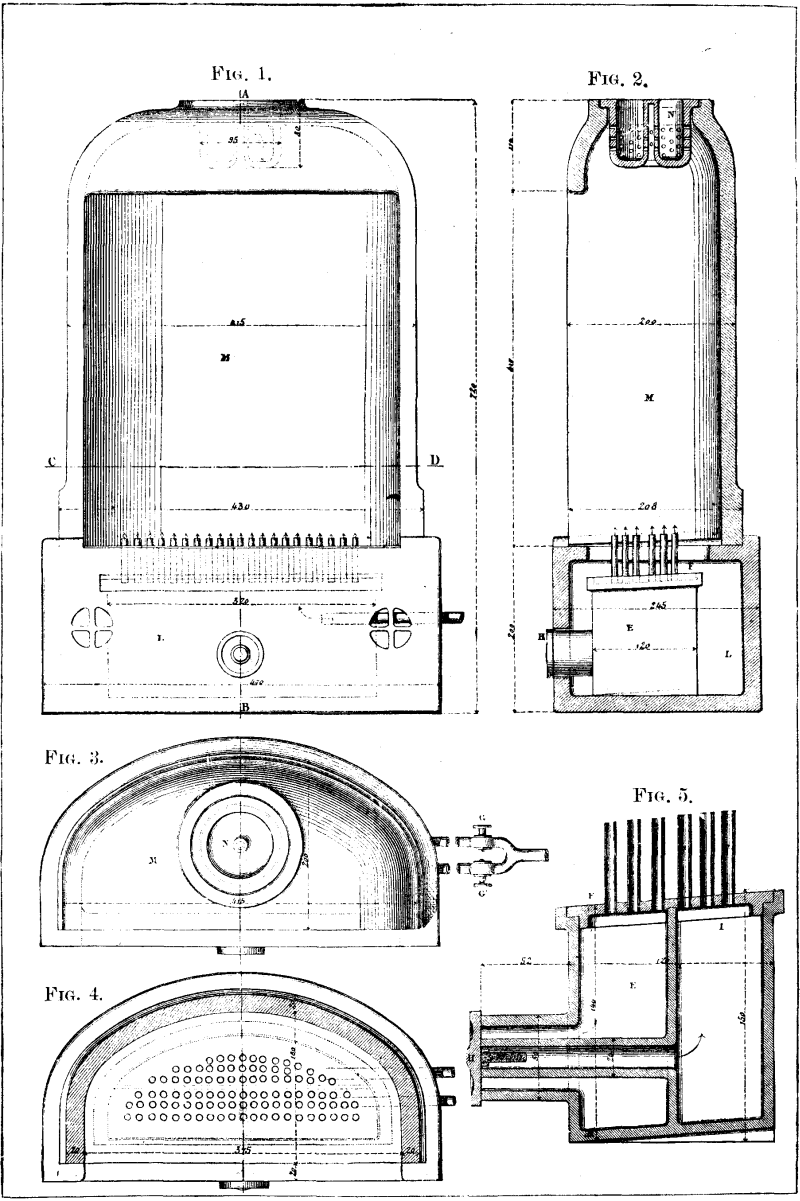
GOMEZ'S APPARATUS FOR HEATING BY GAS.
FIG. 1.--Front View. Scale of 0.25 to 1. FIG.
2.--Section through AB. FIG.3.--Plan View. FIG. 4.--Section through
CD.
FIG. 5.--Transverse Section through the Fireplace. Scale of 0.50 to
1.
The cast iron box, E, is inclosed within a base of refractory clay, L, which is surmounted by a reflector, M, of the same material, that is designed to concentrate the heat and increase its radiation. This reflector terminates above in a dome, in whose center is placed a refractory clay box. This latter, which is round, is provided in the center with a cylinder that is closed above. The box contains a large number of apertures, which give passage to the products of combustion carried along by the hot air. The carbonic acid which such products contain is absorbed by a layer of quick-lime that has previously been introduced into the box, N.
This heating apparatus, which is inclosed within a cast iron casing similar to that of an ordinary gas stove, is employed without a chimney, thus permitting of its being placed against the wall or at any other point whatever in the room to be heated.--Annales Industrielles.
Since the introduction of the process of gas-singeing in finishing textiles, many improvements have been made in the construction of the machines for this purpose as well as in that of the burners, for the object of the latter must be to effect the singeing not only evenly and thoroughly, but at the same time with a complete combustion of the gas and avoidance of sooty deposits upon the cloth. The latter object is attained by what are called atmospheric or Bunsen burners, and in which the coal gas before burning is mixed with the necessary amount of atmospheric air. The arrangement under consideration, patented abroad, has this object specially in view. The main gas pipe of the machine is shown at A, being a copper pipe closed at one end and having a tap at the other. On this pipe the vertical pipes, C, are screwed at stated intervals, each being in its turn provided with a tap near its base. On the top of each vertical table the burner, IJ, is placed, whose upper end spreads in the shape of a fan, and allows the gas to escape through a slit or a number of minute holes. Over the tube, C, a mantle, E, is slipped, which contains two holes, HG, on opposite sides, and made nearly at the height of the outlet of the gas. When the gas passes out of this and upward into the burner, it induces a current of air up through the holes, HG, and carries it along with it. By covering these holes with a loose adjustable collar, the amount of admissible air can be regulated so that the flame is perfectly non-luminous, and therefore containing no free particles of carbon or soot. The distance of the vertical tubes, C; and of the fan-shaped burners is calculated so that the latter touch each other, and thus a continuous flame is formed, which is found to be the most effective for singeing cloth. Should it be deemed advisable to singe only part of the cloth, or a narrow piece, the arrangement admits of the taps, D, being turned off as desired.--Textile Manufacturer.
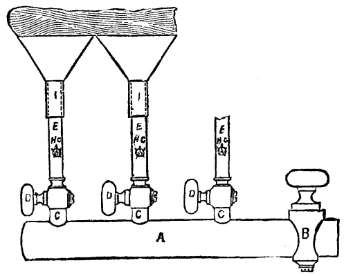
In many industries there are operations that have to be repeated at regular intervals, and, for this reason, the construction of an apparatus for giving a signal, not only at the hour fixed, but also at equal intervals, is a matter of interest. The question of doing this has been solved in a very elegant way by Mr. Silas in the invention of the apparatus which we represent in Fig. 1. It consists of a clock whose dial is provided with a series of small pins. The hands are insulated from the case and communicate with one of the poles of a pile contained in the box. The case is connected with the other pole. A small vibrating bell is interposed in the circuit. If it be desired to obtain a signal at a certain hour, the corresponding pin is inserted, and the hand upon touching this closes the circuit, and the bell rings. The bell is likewise inclosed within the box. There are two rows of pins--one of them for hours, and the other for minutes. They are spaced according to requirements. In the model exhibited by the house Breguet, at the Vienna Exhibition, there were 24 pins for minutes and 12 for hours. Fig. 2 gives a section of the dial. It will be seen that the hands are provided at the extremity with a small spring, r, which is itself provided with a small platinum contact, p. The pins also carry a small platinum or silver point, a. In front of the box there will be observed a small commutator, M, (Fig. 1). The use of this is indicated in the diagram (Fig. 3). It will be seen that, according as the plug, B, is introduced into the aperture to the left or right, the bell. S, will operate as an ordinary vibrator, or give but a single stroke.
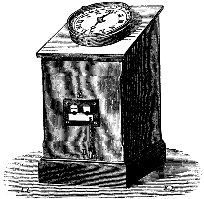
FIG. 1.--SILAS' CHRONOPHORE.
P is the pile; C is the dial; and A is the commutator.
It is evident that this apparatus will likewise be able to render services in scientific researches and laboratory operations, by sparing the operator the trouble of continually consulting his watch.--La Lumiere Electrique.
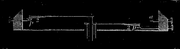
FIG. 2.
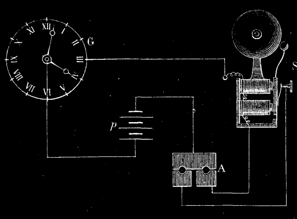
FIG. 3.
[THE GARDEN.]
Two of the three species which form the subject of this article are not only highly ornamental, but also valuable timber trees. Until recently they were considered to belong to the genus Planera, which, however, consists of but a single New World species; now, they properly constitute a distinct genus, viz., Zelkova, which differs materially from the true Planer tree in the structure of the fruit, etc. Z. crenata, from the Caucasus, and Z. acuminata, from Japan, are quick growing, handsome trees, with smooth bark not unlike that of beech or hornbeam; it is only when the trees are old that the bark is cast off in rather large sized plates, as is the case with the planes. The habit of both is somewhat peculiar; in Z. crenata especially there is a decided tendency for all the main branches to be given off from one point; these, too, do not spread, as for instance do those of the elm or beech, but each forms an acute angle with the center of the tree. The trunks are more columnar than those of almost all other hardy trees. Their distinct and graceful habit renders them wonderfully well adapted for planting for effect, either singly or in groups. The flowers, like those of the elm, are produced before the leaves are developed; in color they are greenish brown, and smell like those of the elder. It does not appear that fruits have yet been ripened in England. All the Zelkowas are easily propagated by layers or by grafting on the common elm.
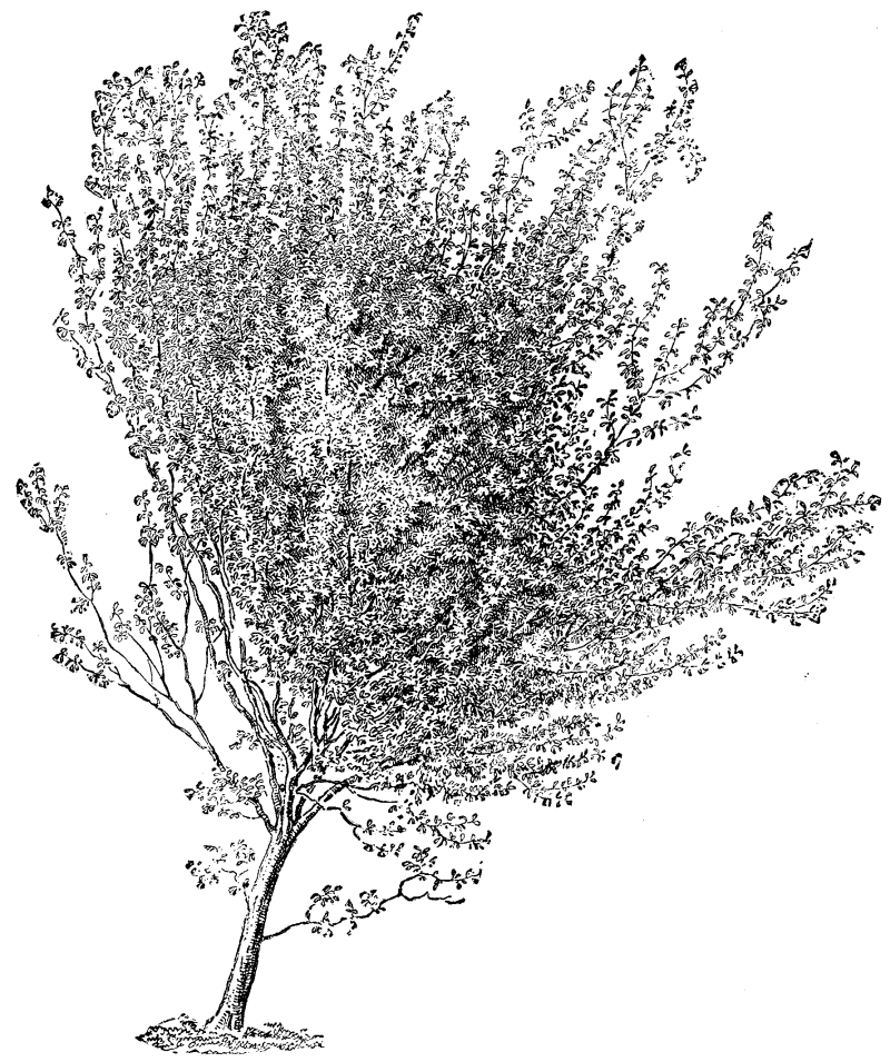
YOUNG ZELKOWA TREE (21 FEET HIGH)
Zelkcova crenata--The Caucasian Zelkowa is a native of the country lying between the Black and the Caspian Sea between latitudes 35° and 47° of the north of Persia and Georgia. According to Loudon, it was introduced to this country in 1760, and it appears to have been planted both at Kew and Syon at about that date. A very full account of the history, etc., of the Zelkowa, from which Loudon largely quotes, was presented to the French Academy of Science by Michaux the younger, who speaks highly of the value of the tree. In this he is fully corroborated by Mirbel and Desfontaine, on whom devolved the duty of reporting on this memoir. They say that it attains a size equal to that of the largest trees of French forests, and recommend its being largely planted. They particularly mention its suitability for roadside avenues, and affirm that its leaves are never devoured by caterpillars, and that the stems are not subject, to the canker which frequently ruins the elm. The name Orme de Siberie, which is or was commonly applied to Zelkova crenata in French books and gardens, is doubly wrong, for the tree is neither an elm nor is it native of Siberia. In 1782 Michaux, the father of the author of the paper above mentioned, undertook, under the auspices, of a Monsieur (afterward Louis XVIII.), a journey into Persia, in order to make botanical researches.
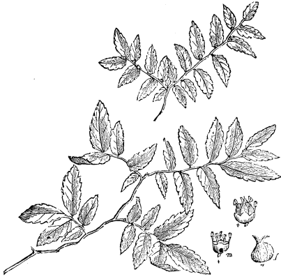
FOLIAGE OF A YOUNG ZELKOWA TREE, WITH
FLOWERS AND FRUIT.
"Having left Ispahan, in order to explore the province of Ghilan, he found this tree in the forests which he traversed before arriving at Recht, a town situated on the Caspian Sea. In this town he had opportunities of remarking the use made of the wood, and of judging how highly it was appreciated by the inhabitants." The first tree introduced into Europe appears to have been planted by M. Lemonnier, Professor of Botany in the Jardin des Plautes, etc., in his garden near Versailles. This garden was destroyed in 1820, and the dimensions of the tree when it was cut down were as follows: Height 70 feet, trunk 7 feet in circumference at 5 feet from the ground. The bole of the trunk was 20 feet in length and of nearly uniform thickness; and the proportion of heart-wood to sap-wood was about three quarters of its diameter. This tree was about fifty years old, but was still in a growing state and in vigorous health. The oldest tree existing in France at the time of the publication of Loudon's great work, was one in the Jardin des Plantes, which in 1831 was about 60 feet high. It was planted in 1786 (when a sucker of four years old), about the same time as the limes which form the grand avenue called the Allee de Buffon. "There is, however, a much larger Zelkowa on an estate of M. le Comte de Dijon, an enthusiastic planter of exotic trees, at Podenas, near Nerac, in the department of the Lot et Garonne. This fine tree was planted in 1789, and on the 20th of January, 1831. it measured nearly 80 feet high, and the trunk was nearly 3 feet in diameter at 3 feet from the ground." A drawing of this tree, made by the count in the autumn of that year, was lent to Loudon by Michaux, and the engraving prepared from that sketch (on a scale of 1 inch to 12 feet) is herewith reproduced. At Kew the largest tree is one near the herbarium (a larger one had to be cut down when the herbarium was enlarged some years ago, and a section of the trunk is exhibited in Museum No. 3). Its present dimensions are: height, 62 feet; circumference of stem at 1 foot from the ground, 9 feet 8 inches; ditto at ground level, 10 feet; Height of stem from ground to branches, 7 feet; diameter of head, 46 feet. The general habit of the tree is quite that as represented in the engraving of the specimen at Podenas. The measurements of the large tree at Syon House were, in 1834, according to Loudon: Height, 54 feet; circumference of of stem, 6 feet 9 inches; and diameter of head, 34 feet; the present dimensions, for which I am indebted to Mr. Woodbridge, are: Height, 76 feet; girth of trunk at 2½ feet from ground, 10 feet; spread of branches, 36 feet.
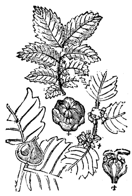
FLOWERS AND FRUIT
OF ZELKOVA CRENATA
(Planera Richardi).
IDENTIFICATION.--Zelkova crenata, Spach in Ann. des Sc. nat. 2d ser. 15, p. 358. D. C. Prodromus, xvii., 165 Rhamnus ulmoides, Güldenst. It., p. 313. R carpinifolius, Pall. Fl Rossica, 2 p. 24, tab. 10. Ulmus polygama, L C. Richard in Mem. Acad. des Sciences de Paris, ann. 1781. Planera Richardi, Michx. Fl. bor. Amer. 2, p. 248; C.A. Meyer, Enumer. Causas. Casp., n. 354; Dunal in Bulletin Soc. cent d'Agricult. de l'Herault. ann. 1841, 299, 303, et ann. 1843, 225, 236. Loudon, Arbor, et Frut. Brit., vol. 3, p. 1409. Planera crenata, Desf. Cat. Hort. Paris et hortul, fere omnium. Michaux fil. Mem. sur le Zelkowa, 1831. Planera carpinifolia, Watson, Dend. Brit., t. 106. Koch Dendrologie, zweit theil, sweit. Abtheil. p. 425.

ZELKOWA TREE AT
PODENAS
Showing peculiar habit of branching.
In old trees the effect is very
remarkable in winter as at Oxford,
Versailles (Petit Trianon)
and Syon.
Var pendula (the weeping Zelkowa).--This is a form of which I do not know the origin or history. It is simply a weeping variety of the common Zelkowa. I first saw it in the Isleworth Nurseries of Messrs. C. Lee & Son, and a specimen presented by them to Kew for the aboretum is now growing freely. I suspect that the Zelkova crenata var. repens of M. Lavallee's "Aboretum Segrezianum" and the Planera repens of foreign catalogues generally are identical with the variety now mentioned under the name it bears in the establishment of Messrs. Lee & Son.
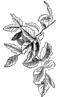
FOLIAGE OF A FULL-GROWN ZELKOWA TREE.
Z. acuminata is one of the most useful and valuable of Japanese timber trees. It was found near Yeddo by the late Mr. John Gould Veitch, and was sent out by the firm of Messrs. J. Veitch & Sons. Maximowicz also found the tree in Japan, and introduced it to the Imperial Botanic Gardens of St. Petersburg, from whence both seeds and plants were liberally distributed. In the Gardeners' Chronicle for 1862 Dr. Lindley writes as follows: "A noble deciduous tree, discovered near Yeddo by Mr. J. G. Veitch, 90 feet to 100 feet in height, with a remarkably straight stem. In aspect it resembles an elm. We understand that a plank in the Exotic Nursery, where it has been raised, measures 3 feet 3 inches across. Mr. Veitch informs us that it is one of the most useful timber trees in Japan. Its long, taper-pointed leaves, with coarse, very sharp serratures, appear to distinguish it satisfactorily from the P. Richardi of the northwest of Asia." There seems to be no doubt as to the perfect hardiness of the Japanese Zelkowa in Britain, and it is decidedly well worth growing as an ornamental tree apart from its probable value as a timber producer. A correspondent in the periodical just mentioned writes, in 1873, p. 1142, under the signature of "C.P.": "At Stewkley Grange it does fairly well; better than most other trees. In a very exposed situation it grew 3 feet 5 inches last year, and was 14 feet 5 inches high when I measured it in November; girth at ground, 8¾ inches; at 3 feet, 5 inches." The leaves vary in size a good deal on the short twiggy branches, being from 3 inches to 3½ inches in length and 1¼ inches to 1½ inches in width, while those on vigorous shoots attain a length of 5 inches, with a width of about half the length. They are slightly hairy on both surfaces. The long acuminate points, the sharper serratures, the more numerous nerves (nine to fourteen in number), and the more papery texture distinguish Z. acuminata easily from its Caucasian relative, Z. crenata. The foliage, too, seems to be retained on the trees in autumn longer than that of the species just named; in color it is a dull green above and a brighter glossy green beneath. The timber is very valuable, being exceedingly hard and capable of a very fine polish. In Japan it is used in the construction of houses, ships, and in high class cabinet work. In case 99, Museum No. 1 at Kew, there is a selection of small useful and ornamental articles made in Japan of Keyaki wood. Those manufactured from ornamental Keyaki (which is simply gnarled stems or roots, or pieces cut tangentially), and coated with the transparent lacquer for which the Japanese an so famous, are particularly handsome. In the museum library is also a book, the Japanese title of which is given below--"Handbook of Useful Woods," by E. Kinch. Professor at the Imperial College of Agriculture, at Tokio, Japan. This work contains transverse and longitudinal sections of one hundred Japanese woods, and numbers 45 and 46 represent Z. acuminata. It would be worth the while of those who are interested in the introduction and cultivation of timber trees in temperate climates to procure Kinch's handbook.
IDENTIFICATION.--Zelkova acuminata, D.C. Prodr., xvii., 166; Z. Keaki, Maxim. Mel. biol. vol. ix, p. 21. Planera acuminata, Lindl. in Gard. Chron. 1862, 428; Regel, "Gartenflora" 1863, p. 56. P Japonica, Miq. ann. Mus. Ludg Bat iii., 66; Kinch. Yuyo Mokuzai Shoran, 45, 46. P. Keaki, Koch Dendrol. zweit. theil zweit Abtheil, 427. P. dentata japonica, Hort. P. Kaki, Hort.
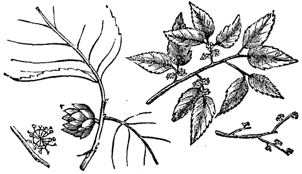
FLOWERING TWIG OF PLANERA GMELINI.
Z. cretica is a pretty, small foliaged tree, from 15 to 20 feet in height. The ovate crenate leaves, which measure from an inch or even less, to one inch and a half in length by about half the length in breadth, are leathery, dark green above, grayish above. They are hairy on both surfaces, the underside being most densely clothed, and the twigs, too, are thickly covered with short grayish hairs. This species, which is a native of Crete, is not at present in the Kew collection; its name, however, if given in M. Lavallee's catalogue, "Enumeration des Arbres et Arbris Cultives à Segrez" (Seine-et-Oise).
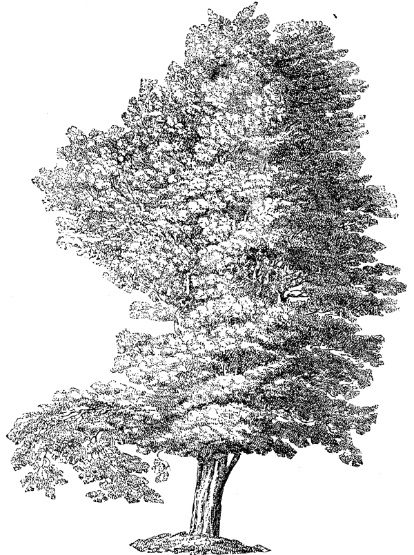
OLD SPECIMEN OF ZELKOWA TREE IN SUMMER FOLIAGE,
CONCEALING FORM OF BRANCHING.
IDENTIFICATION.--Zelkova cretica. Spach in Suit à Buff, ii, p. 121. Ulmus Abelicea, Sibth & Sm. Prod. Fl., Graeca, i., p. 172. Planera Abelicea Roem. & Schltz. Syst., vi. p. 304; Planch, in Ann. des Sc. Nat. 1848, p. 282. Abelicea cretica, Smith in Trans. Linn. Sov., ix., 126.
I have seen no specimens of the Zelkova stipulacea of Franchet and Savatier's "Enumeratio Plantarum Japonicarum," vol. ii., p. 489, and as that seems to have been described from somewhat insufficient material, and, moreover, does not appear to be in cultivation, I passed it over as a doubtful plant.
GEORGE NICHOLSON.
Royal Gardens, Kew.
Prof. A.J. Cook, the eminent apiarist, calls attention to a new pest which has made its appearance in many apiaries. After referring to the fact that poultry and all other domestic animals of ten suffer serious injury from the attacks of parasitic mites, and that even such household stores as sugar, flour, and cheese are not from their ravages, he tells of the discovery of a parasitic pest among bees. He says:
"During the last spring a lady bee-keeper of Connecticut discovered these mites in her hives while investigating to learn the cause of their rapid depletion. She had noticed that the colonies were greatly reduced in number of bees, and upon close observation found that the diseased or failing colonies were covered with the mites. So small are these pests that a score of them can take possession of a single bee and not be crowded for room either. The lady states that the bees roll and scratch in their vain attempts to rid themselves of these annoying stick-tights, and finally, worried out, fall to the bottom of the hive, or go forth to die on the outside. Mites are not true insects, but are the most degraded of spiders. The sub-class Arachnida are at once recognized by their eight legs. The order of mites (Accorina), which includes the wood-tick, cattle-tick, etc., and mites, are quickly told from the higher orders--true spiders and scorpions--by their rounded bodies, which appear like mere sacks, with little appearance of segmentation, and their small, obscure heads. The mites alone, of all the Arachinida, pass through a marked metamorphosis. Thus the young mite has only six legs, while the mature form has eight. The bee mite is very small, not more than one-fiftieth of an inch long. The female is slightly longer than the male, and somewhat transparent. The color is black, though the legs and more transparent areas of the female appear yellowish. All the legs are fine jointed, slightly hairy, and each tipped with two hooks or claws."
As to remedies, the Professor says that as what would kill the mites would doubtless kill the bees, makes the question a difficult one. He suggests, however, the frequent changing of the bees from one hive to another, after which the emptied hives should be thoroughly scalded. He thinks this course of treatment, persisted in, would effectually clean them out.
To the Editor of the Scientific American:
Seeing in your issue of October 13, 1883, an article on "Crystallization in Extracted Honey," I beg leave to differ a little with the gentleman. I have handled honey as an apiarist and dealer for ten years, and find by actual experience that it has no tendency to crystallize in warm weather; but on the contrary it will crystallize in cold weather, and the colder the weather the harder the honey will get. I have had colonies of bees starve when there was plenty of honey in the hives; it was in extreme cold weather, there was not enough animal heat in the bees to keep the honey from solidifying, hence the starvation of the colonies.
To-day I removed with a thin paddle sixty pounds of honey from a large stone jar where it had remained over one year. Last winter it was so solid from crystallization, it could not be cut with a knife; in fact, I broke a large, heavy knife in attempting to remove a small quantity.
As to honey becoming worthless from candying is a new idea to me, as I have, whenever I wanted our crystallized honey in liquid form, treated it to water bath, thereby bringing it to its natural state, in which condition it would remain for an indefinite time, especially if hermetically sealed. I never had any recrystallize after once having been treated to the water bath; and the flavor of the honey was in no way injured. I think the adding of glycerine to be entirely superfluous.
W.R. MILLER.
Polo, October 15.
The little schooner Santa Rosa arrived in port from Santa Barbara a few days ago. She comes up to this city twice a year to secure provisions, clothing, lumber, etc., for use on Santa Rosa Island, being owned by the great sheep raiser A.P. Moore, who owns the island and the 80,000 sheep that exist upon it. The island is about 30 miles south of Santa Barbara, and is 24 miles in length and 16 in breadth, and contains about 74,000 acres of land, which are admirably adapted to sheep raising. Last June, Moore clipped 1,014 sacks of wool from these sheep, each sack containing an average of 410 pounds of wool, making a total of 415,740 pounds, which he sold at 27 cents a pound, bringing him in $112,349.80, or a clear profit of over $80,000. This is said to be a low yield, so it is evident that sheep raising there, when taking into consideration that shearing takes place twice a year, and that a profit is made off the sale of mutton, etc., is very profitable. The island is divided into four quarters by fences running clear across at right angles, and the sheep do not have to be herded like those ranging about the foothills.
Four men are employed regularly the year round to keep the ranch in order, and to look after the sheep, and during the shearing time fifty or more shearers are employed. These men secure forty or fifty days' work, and the average number of sheep sheared in a day is about ninety, for which five cents a clip is paid, thus $4.50 a day being made by each man, or something over $200 for the season, or over $400 for ninety days out of the year. Although the shearing of ninety sheep in a day is the average, a great many will go as high as 110, and one man has been known to shear 125.
Of course, every man tries to shear as many as he can, and, owing to haste, frequently the animals are severely cut by the sharp shears. If the wound is serious, the sheep immediately has its throat cut and is turned into mutton and disposed of to the butchers, and the shearer, if in the habit of frequently inflicting such wounds, is discharged. In the shearing of these 80,000 sheep, a hundred or more are injured to such an extent as to necessitate their being killed, but the wool and meat are of course turned into profit.
Although no herding is necessary, about 200 or more trained goats are kept on the island continually, which to all intents and purposes take the place of the shepherd dogs so necessary in mountainous districts where sheep are raised. Whenever the animals are removed from one quarter to another, the man in charge takes out with him several of the goats, exclaims in Spanish, "Cheva" (meaning sheep). The goat, through its training, understands what is wanted, and immediately runs to the band, and the sheep accept it as their leader, following wherever it goes. The goat, in turn, follows the man to whatever point he wishes to take the band.
To prevent the sheep from contracting disease, it is necessary to give them a washing twice a year. Moore, having so many on hand, found it necessary to invent some way to accomplish this whereby not so much expense would be incurred and time wasted. After experimenting for some time, he had a ditch dug 8 feet in depth, a little over 1 foot in width, and 100 feet long. In this he put 600 gallons of water, 200 pounds of sulphur, 100 pounds of lime, and 6 pounds of soda, all of which is heated to 138°. The goats lead the sheep into a corral or trap at one end, and the animals are compelled to swim through to the further end, thus securing a bath and taking their medicine at one and the same time.
The owner of the island and sheep, A.P. Moore, a few years ago purchased the property from the widow of his deceased brother Henry, for $600,000. Owing to ill health, he has rented it to his brother Lawrence for $140,000 a year, and soon starts for Boston, where he will settle down for the rest of his life. He still retains an interest in the Santa Cruz Island ranch, which is about 25 miles southeast of Santa Barbara. This island contains about 64,000 acres, and on it are 25,000 sheep. On Catalina Island, 60 miles east of Santa Barbara, are 15,000 sheep, and on Clementa Island, 80 miles east of that city, are 10,000 sheep. Forty miles west of the same city is San Miguel, on which are 2,000 sheep. Each one of these ranches has a sailing vessel to carry freight, etc., to and fro between the islands and the mainland, and they are kept busy the greater part of the time.--San Francisco Call.
At the Parkes Museum of Hygiene, London, Dr. Robert J. Lee recently delivered a lecture on the above subject, illustrated by experiments.
The author remarked that he could not better open up his theme than by explaining what was meant by disinfection. He would do so by an illustration from Greek literature. When Achilles had slain Hector, the body still lay on the plain of Troy for twelve days after; the god Hermes found it there and went and told of it--"This, the twelfth evening since he rested, untouched by worms, untainted by the air." The Greek word for taint in this sense was sepsis, which meant putrefaction, and from this we had the term "antiseptic," or that which was opposed to or prevented putrefaction. The lecturer continued:
I have here in a test tube some water in which a small piece of meat was placed a few days ago. The test tube has been in rather a warm room, and the meat has begun to decompose. What has here taken place is the first step in this inquiry. This has been the question at which scientific men have been working, and from the study of which has come a valuable addition to surgical knowledge associated with the name of Professor Lister, and known as antiseptic. What happens to this meat, and what is going on in the water which surrounds it? How long will it be before all the smell of putrefaction has gone and the water is clear again? For it does in time become clear, and instead of the meat we find a fine powdery substance at the bottom of the test tube. It may take weeks before this process is completed, depending on the rate at which it goes on. Now, if we take a drop of this water and examine it with the microscope, we find that it contains vast numbers of very small living creatures or "organisms." They belong to the lowest forms of life, and are of very simple shape, either very delicate narrow threads or rods or globular bodies. The former are called bacteria, or staff-like bodies; the latter, micrococci. They live upon the meat, and only disappear when the meat is consumed. Then, as they die and fall to the bottom of the test tube, the water clears again.
Supposing now, when the meat is first put into water, the water is made to boil, and while boiling a piece of cotton wool is put into the mouth of the tube. The tube may be kept in the same room, at the same temperature as the unboiled one, but no signs of decomposition will be found, however long we keep it. The cotton wool prevents it; for we may boil the water with the meat in it, but it would not be long before bacteria and micrococci are present if the wool is not put in the mouth of the test tube. The conclusion you would naturally draw from this simple but very important experiment is that the wool must have some effect upon the air, for we know well that if we keep the air out we can preserve meat from decomposing. That is the principle upon which preserved meats and fruits are prepared. We should at once conclude that the bacteria and micrococci must exist in the air, perhaps not in the state in which we find them in the water, but that their germs or eggs are floating in the atmosphere. How full the air may be of these germs was first shown by Professor Tyndall, when he sent a ray of electric light through a dark chamber, and as if by a magician's wand revealed the multitudinous atomic beings which people the air. It is a beautiful thing to contemplate how one branch of scientific knowledge may assist another; and we would hardly have imagined that the beam of the electric light could thus have been brought in to illumine the path of the surgeon, for it is on the exclusion of these bacteria that it is found the success of some great operation may depend. It is thus easy to understand how great an importance is to be attached to the purity of air in which we live. This is the practical use of the researches to which the art of surgery is so much indebted; and not surgery alone, but all mankind in greater or less degree. Professor Tyndall has gone further than this, and has shown us that on the tops of lofty mountains the air is so pure, so free from organisms, that decomposition is impossible.
Now, supposing we make another experiment with the test tube, and instead of boiling we add to its contents a few drops of carbolic acid; we find that decomposition is prevented almost as effectually as by the use of the cotton wool. There are many other substances which act like carbolic acid, and they are known by the common name of antiseptics or antiseptic agents. They all act in the same way; and in such cases as the dressing of wounds it is more easy to use this method of excluding bacteria than by the exclusion of the air or by the use of cotton wool. We have here another object for inquiry--viz., the particular property of these different antiseptics, the property which they possess of preventing decomposition. This knowledge is very ancient indeed. We have the best evidence in the skill of the Egyptians in embalming the dead. These substances are obtained from wood or coal, which once was wood. Those woods which do not contain some antiseptic substance, such as a gum or a resin, will rot and decay. I am not sure that we can give a satisfactory reason for this, but it is certain that all these substances act as antiseptics by destroying the living organisms which are the cause of putrefaction. Some are fragrant oils, as, for example, clove, santal, and thyme; others are fragrant gums, such as gum bezoin and myrrh. A large class are the various kinds of turpentine obtained from pine trees. We obtain carbolic acid from the coal tar largely produced in the manufacture of gas. Both wood tar, well known under the name of creosote, and coal tar are powerful antiseptics. It is easy to understand by what means meat and fish are preserved from decomposition when they have been kept in the smoke of a wood fire. The smoke contains creosote in the form of vapor, and the same effect is produced on the meat or fish by the smoke as if they had been dipped in a solution of tar--with this difference, that they are dried by the smoke, whereas moisture favors decomposition very greatly.
I can show why a fire from which there is much smoke is better than one which burns with a clear flame, by a simple experiment. Here is a piece of gum benzoin, the substance from which Friar's balsam is made. This will burn, if we light it, just as tar burns, and without much smoke or smell. If, instead of burning it, we put some on a spoon and heat it gently, much more smoke is produced, and a fragrant scent is given off. In the same way we can burn spirit of lavender or eau de Cologne, but we get no scent from them in this way, for the burning destroys the scent. This is a very important fact in the disinfection of the air. The less the flame and the larger the quantity of smoke, the greater the effect produced, so far as disinfection is concerned. As air is a vapor, we must use our disinfectants in the form of vapor, so that the one may mix with the other, just as when we are dealing with fluids we must use a fluid disinfectant.
The question that presents itself is this: Can we so diffuse the vapor of an antiseptic like carbolic acid through the air as to destroy the germs which are floating in it, and thus purify it, making it like air which has been filtered through wool, or like that on the top of a lofty mountain? If the smoke of a wood fire seems to act as an antiseptic, and putrefaction is prevented, it seems reasonable to conclude that air could be purified and made antiseptic by some proper and convenient arrangement. Let us endeavor to test this by a few experiments.
Here is a large tube 6 inches across and 2 feet long, fixed just above a small tin vessel in which we can boil water and keep it boiling as long as we please. If we fill the vessel with carbolic acid and water and boil it very gently, the steam which rises will ascend and fill the tube with a vapor which is strong or weak in carbolic acid, according as we put more or less acid in the water. That is to say, we have practically a chimney containing an antiseptic vapor, very much the same thing as the smoke of a wood fire. We must be able to keep the water boiling, for the experiment may have to be continued during several days, and during this time must be neither stronger nor weaker in carbolic acid, neither warmer nor colder than a certain temperature. This chimney must be always at the same heat, and the fire must therefore be kept constantly burning. This is easily accomplished by means of a jet of gas, and by refilling the vessel every 24 hours with the same proportions of carbolic acid and water.
The question arises, how strong must this vapor be in carbolic acid to act as an antiseptic? It is found that 1 part acid to 50 of water is quite sufficient to prevent putrefaction. If we keep this just below boiling point there will be a gentle and constant rising of steam into the cylinder, and we can examine this vapor to see if it is antiseptic. We will take two test tubes half filled with water and put a small piece of beef into each of them and boil each for half a minute. One test tube we will hang up inside the cylinder, so that it is surrounded by carbolic acid vapor. The other we stand up in the air. If the latter is hung in a warm room, decomposition will soon take place in it; will the same thing happen to the other cylinder? For convenience sake we had best put six tubes inside the cylinder, so that we can take one out every day for a week and examine the contents on the field of a microscope. It will be necessary to be very particular as to the temperature to which the tubes are exposed, and the rates of evaporation beneath the cylinder. I may mention that on some of the hottest days of last summer I made some experiments, when the temperature both of the laboratory and inside the cylinder was 75°F. I used test tubes containing boiled potatoes instead of meat, and found that the tube in the air, after 48 hours, abounded not simply with bacteria and other small bodies present in decomposition, but with the large and varied forms of protozoa, while the tube inside the cylinder contained no signs of decomposition whatever. When the room was cold the experiments were not so satisfactory, because in the former case there was very little if any current of air in the cylinder. This leads us to the question, why should we not make the solution of carbolic acid and water, and heat it, letting the steam escape by a small hole, so as to produce a jet? It is a singular fact that for all practical purposes such a steam jet will contain the same proportion of acid to water as did the original solution. The solution can of course be made stronger or weaker till we ascertain the exact proportion which will prevent decomposition.
From this arises naturally the question, what quantity of vapor must be produced in a room in order to kill the bacteria in its atmosphere? If we know the size of the room, shall we be able tell? These questions have not yet been answered, but the experiments which will settle them will be soon made, I have no doubt, and I have indicated the lines upon which they will be made. I have here a boiler of copper into which we can put a mixture, and can get from it a small jet of steam for some hours. A simple experiment will show that no bacteria will exist in that vapor. If I take a test tube containing meat, and boil it while holding the mouth of it in this vapor, after it has cooled we close the mouth with cotton wool, and set it aside in a warm place; after some days we shall find no trace of decomposition, but if the experiment is repeated with water, decomposition will soon show itself. Of course, any strength of carbolic acid can be used at will, and will afford a series of tests.
There are other methods of disinfecting the atmosphere which we cannot consider this evening, such as the very potent one of burning sulphur.
In conclusion, the lecturer remarked that his lecture had been cast into a suggestive form, so as to set his audience thinking over the causes which make the air impure, and how these impurities are to be prevented from becoming deleterious to health.
Having had considerable experience in the use of the alcoholic solutions of aniline dyes for staining bacteria, and having for some months used solutions in glycerine instead, I have come to much prefer the latter. Evaporation of the solvent is avoided, and in consequence a freedom from vexatious precipitations is secured, and more uniform and reliable results are obtained. There is, moreover, with the alcoholic mixtures a tendency to "creep," or "run," by which one is liable to have stained more than he wishes--fingers, instruments, table, etc.
From these things the glycerine mixtures are practically free, and there are no compensating drawbacks. For staining Bacillus tuberculosis the following is confidently commended as preferable to the materials and methods heretofore in use. Take glycerine, 20 parts; fuchsin, 3 parts; aniline oil, 2 parts; carbolic acid, 2 parts.
The solution is readily and speedily effected, with no danger of precipitation, and can be kept in stock without risk of deterioration. When wanted for use, put about two drops into a watch glass (a small pomatum pot is better) full of water and gently shake or stir. Just here there is some danger of precipitating the coloring matter, but the difficulty is easily avoided by gentle instead of vigorous stirring. After the stain is once dissolved in the water no further trouble occurs; if any evaporation takes place by being left too long, it is the water that goes, not the main solvent. The color should now be a light, translucent red, much too diffuse for writing ink. Put in the smeared cover glass, after passing it a few times through a flame, and leave it, at the ordinary temperature of a comfortable room, half an hour. If, however, quicker results are desired, boil a little water in a test tube and put in about double the above indicated amount of the glycerine mixture, letting it run down the side of the tube, gently shake until absorbed, and pour out the hot liquid into a convenient dish, and at once put in the cover with sputum. Without further attention to the temperature the stain will be effected within two minutes; but the result is not quite so good, especially for permanent mounts, as by the slower process.
After staining put the cover into nitric (or hydrochloric) acid and water, one part to four, until decolorized, say one minute; wash in water and examine, or dry and mount in balsam.
If it is desired to color the ground material, which is not necessary, put on the decolorized and washed glass a drop of aniline blue in glycerine; after one minute wash again in water and proceed as before.
Almost any objective, from one-fourth inch up will show the bacilli if sufficient attention is paid to the illumination.--Med. Record.
"The carbolic acid treatment of hemorrhoids is now receiving considerable attention. Hence the reprint from the Pittsburgh Medical Journal, November, 1883, of an article on the subject by Dr. George B. Fundenberg is both timely and interesting. After relating six cases, the author says: "It would serve no useful purpose to increase this list of cases. The large number I have on record all prove that this treatment is safe and effectual. I believe that the great majority of cases can be cured in this manner. Whoever doubts this should give the method a fair trial, for it is only those who have done so, that are entitled to speak upon the question."
A catalogue, containing brief notices of many important scientific papers heretofore published in the SUPPLEMENT, may be had gratis at this office.
Terms of Subscription, $5 a Year.
Sent by mail, postage prepaid, to subscribers in any part of the United States or Canada. Six dollars a year, sent, prepaid, to any foreign country.
All the back numbers of THE SUPPLEMENT, from the commencement, January 1, 1876, can be had. Price, 10 cents each.
All the back volumes of THE SUPPLEMENT can likewise be supplied. Two volumes are issued yearly. Price of each volume, $2.50, stitched in paper, or $3.50, bound in stiff covers.
COMBINED RATES--One copy of SCIENTIFIC AMERICAN and one copy of SCIENTIFIC AMERICAN SUPPLEMENT, one year, postpaid, $7.00.
A liberal discount to booksellers, news agents, and canvassers.
MUNN & CO., Publishers,
261 Broadway, New York, N. Y.
In connection with the Scientific American, Messrs. MUNN & Co. are Solicitors of American and Foreign Patents, have had 38 years' experience, and now have the largest establishment in the world. Patents are obtained on the best terms.
A special notice is made in the Scientific American of all Inventions patented through this Agency, with the name and residence of the Patentee. By the immense circulation thus given, public attention is directed to the merits of the new patent, and sales or introduction often easily effected.
Any person who has made a new discovery or invention can ascertain, free of charge, whether a patent can probably be obtained, by writing to MUNN & Co.
We also send free our Hand Book about the Patent Laws, Patents, Caveats. Trade Marks, their costs, and how procured, with hints for procuring advances on inventions. Address
MUNN & CO., 261 Broadway, New York.
Branch Office, cor. F and 7th Sts., Washington, D. C.
End of Project Gutenberg's Scientific American Supplement, No. 417, by Various

*** END OF THIS PROJECT GUTENBERG EBOOK SCIENTIFIC AMERICAN SUPPL., NO. 417 ***

***** This file should be named 9163-h.htm or 9163-h.zip *****
This and all associated files of various formats will be found in:
        http://www.gutenberg.org/9/1/6/9163/

Produced by J. Paolucci, D. Kretz, J. Sutherland, and
Distributed Proofreaders


Updated editions will replace the previous one--the old editions
will be renamed.

Creating the works from public domain print editions means that no
one owns a United States copyright in these works, so the Foundation
(and you!) can copy and distribute it in the United States without
permission and without paying copyright royalties.  Special rules,
set forth in the General Terms of Use part of this license, apply to
copying and distributing Project Gutenberg-tm electronic works to
protect the PROJECT GUTENBERG-tm concept and trademark.  Project
Gutenberg is a registered trademark, and may not be used if you
charge for the eBooks, unless you receive specific permission.  If you
do not charge anything for copies of this eBook, complying with the
rules is very easy.  You may use this eBook for nearly any purpose
such as creation of derivative works, reports, performances and
research.  They may be modified and printed and given away--you may do
practically ANYTHING with public domain eBooks.  Redistribution is
subject to the trademark license, especially commercial
redistribution.


*** START: FULL LICENSE ***

THE FULL PROJECT GUTENBERG LICENSE
PLEASE READ THIS BEFORE YOU DISTRIBUTE OR USE THIS WORK

To protect the Project Gutenberg-tm mission of promoting the free
distribution of electronic works, by using or distributing this work
(or any other work associated in any way with the phrase "Project
Gutenberg"), you agree to comply with all the terms of the Full Project
Gutenberg-tm License available with this file or online at
  www.gutenberg.org/license.


Section 1.  General Terms of Use and Redistributing Project Gutenberg-tm
electronic works

1.A.  By reading or using any part of this Project Gutenberg-tm
electronic work, you indicate that you have read, understand, agree to
and accept all the terms of this license and intellectual property
(trademark/copyright) agreement.  If you do not agree to abide by all
the terms of this agreement, you must cease using and return or destroy
all copies of Project Gutenberg-tm electronic works in your possession.
If you paid a fee for obtaining a copy of or access to a Project
Gutenberg-tm electronic work and you do not agree to be bound by the
terms of this agreement, you may obtain a refund from the person or
entity to whom you paid the fee as set forth in paragraph 1.E.8.

1.B.  "Project Gutenberg" is a registered trademark.  It may only be
used on or associated in any way with an electronic work by people who
agree to be bound by the terms of this agreement.  There are a few
things that you can do with most Project Gutenberg-tm electronic works
even without complying with the full terms of this agreement.  See
paragraph 1.C below.  There are a lot of things you can do with Project
Gutenberg-tm electronic works if you follow the terms of this agreement
and help preserve free future access to Project Gutenberg-tm electronic
works.  See paragraph 1.E below.

1.C.  The Project Gutenberg Literary Archive Foundation ("the Foundation"
or PGLAF), owns a compilation copyright in the collection of Project
Gutenberg-tm electronic works.  Nearly all the individual works in the
collection are in the public domain in the United States.  If an
individual work is in the public domain in the United States and you are
located in the United States, we do not claim a right to prevent you from
copying, distributing, performing, displaying or creating derivative
works based on the work as long as all references to Project Gutenberg
are removed.  Of course, we hope that you will support the Project
Gutenberg-tm mission of promoting free access to electronic works by
freely sharing Project Gutenberg-tm works in compliance with the terms of
this agreement for keeping the Project Gutenberg-tm name associated with
the work.  You can easily comply with the terms of this agreement by
keeping this work in the same format with its attached full Project
Gutenberg-tm License when you share it without charge with others.

1.D.  The copyright laws of the place where you are located also govern
what you can do with this work.  Copyright laws in most countries are in
a constant state of change.  If you are outside the United States, check
the laws of your country in addition to the terms of this agreement
before downloading, copying, displaying, performing, distributing or
creating derivative works based on this work or any other Project
Gutenberg-tm work.  The Foundation makes no representations concerning
the copyright status of any work in any country outside the United
States.

1.E.  Unless you have removed all references to Project Gutenberg:

1.E.1.  The following sentence, with active links to, or other immediate
access to, the full Project Gutenberg-tm License must appear prominently
whenever any copy of a Project Gutenberg-tm work (any work on which the
phrase "Project Gutenberg" appears, or with which the phrase "Project
Gutenberg" is associated) is accessed, displayed, performed, viewed,
copied or distributed:

This eBook is for the use of anyone anywhere at no cost and with
almost no restrictions whatsoever.  You may copy it, give it away or
re-use it under the terms of the Project Gutenberg License included
with this eBook or online at www.gutenberg.org

1.E.2.  If an individual Project Gutenberg-tm electronic work is derived
from the public domain (does not contain a notice indicating that it is
posted with permission of the copyright holder), the work can be copied
and distributed to anyone in the United States without paying any fees
or charges.  If you are redistributing or providing access to a work
with the phrase "Project Gutenberg" associated with or appearing on the
work, you must comply either with the requirements of paragraphs 1.E.1
through 1.E.7 or obtain permission for the use of the work and the
Project Gutenberg-tm trademark as set forth in paragraphs 1.E.8 or
1.E.9.

1.E.3.  If an individual Project Gutenberg-tm electronic work is posted
with the permission of the copyright holder, your use and distribution
must comply with both paragraphs 1.E.1 through 1.E.7 and any additional
terms imposed by the copyright holder.  Additional terms will be linked
to the Project Gutenberg-tm License for all works posted with the
permission of the copyright holder found at the beginning of this work.

1.E.4.  Do not unlink or detach or remove the full Project Gutenberg-tm
License terms from this work, or any files containing a part of this
work or any other work associated with Project Gutenberg-tm.

1.E.5.  Do not copy, display, perform, distribute or redistribute this
electronic work, or any part of this electronic work, without
prominently displaying the sentence set forth in paragraph 1.E.1 with
active links or immediate access to the full terms of the Project
Gutenberg-tm License.

1.E.6.  You may convert to and distribute this work in any binary,
compressed, marked up, nonproprietary or proprietary form, including any
word processing or hypertext form.  However, if you provide access to or
distribute copies of a Project Gutenberg-tm work in a format other than
"Plain Vanilla ASCII" or other format used in the official version
posted on the official Project Gutenberg-tm web site (www.gutenberg.org),
you must, at no additional cost, fee or expense to the user, provide a
copy, a means of exporting a copy, or a means of obtaining a copy upon
request, of the work in its original "Plain Vanilla ASCII" or other
form.  Any alternate format must include the full Project Gutenberg-tm
License as specified in paragraph 1.E.1.

1.E.7.  Do not charge a fee for access to, viewing, displaying,
performing, copying or distributing any Project Gutenberg-tm works
unless you comply with paragraph 1.E.8 or 1.E.9.

1.E.8.  You may charge a reasonable fee for copies of or providing
access to or distributing Project Gutenberg-tm electronic works provided
that

- You pay a royalty fee of 20% of the gross profits you derive from
     the use of Project Gutenberg-tm works calculated using the method
     you already use to calculate your applicable taxes.  The fee is
     owed to the owner of the Project Gutenberg-tm trademark, but he
     has agreed to donate royalties under this paragraph to the
     Project Gutenberg Literary Archive Foundation.  Royalty payments
     must be paid within 60 days following each date on which you
     prepare (or are legally required to prepare) your periodic tax
     returns.  Royalty payments should be clearly marked as such and
     sent to the Project Gutenberg Literary Archive Foundation at the
     address specified in Section 4, "Information about donations to
     the Project Gutenberg Literary Archive Foundation."

- You provide a full refund of any money paid by a user who notifies
     you in writing (or by e-mail) within 30 days of receipt that s/he
     does not agree to the terms of the full Project Gutenberg-tm
     License.  You must require such a user to return or
     destroy all copies of the works possessed in a physical medium
     and discontinue all use of and all access to other copies of
     Project Gutenberg-tm works.

- You provide, in accordance with paragraph 1.F.3, a full refund of any
     money paid for a work or a replacement copy, if a defect in the
     electronic work is discovered and reported to you within 90 days
     of receipt of the work.

- You comply with all other terms of this agreement for free
     distribution of Project Gutenberg-tm works.

1.E.9.  If you wish to charge a fee or distribute a Project Gutenberg-tm
electronic work or group of works on different terms than are set
forth in this agreement, you must obtain permission in writing from
both the Project Gutenberg Literary Archive Foundation and Michael
Hart, the owner of the Project Gutenberg-tm trademark.  Contact the
Foundation as set forth in Section 3 below.

1.F.

1.F.1.  Project Gutenberg volunteers and employees expend considerable
effort to identify, do copyright research on, transcribe and proofread
public domain works in creating the Project Gutenberg-tm
collection.  Despite these efforts, Project Gutenberg-tm electronic
works, and the medium on which they may be stored, may contain
"Defects," such as, but not limited to, incomplete, inaccurate or
corrupt data, transcription errors, a copyright or other intellectual
property infringement, a defective or damaged disk or other medium, a
computer virus, or computer codes that damage or cannot be read by
your equipment.

1.F.2.  LIMITED WARRANTY, DISCLAIMER OF DAMAGES - Except for the "Right
of Replacement or Refund" described in paragraph 1.F.3, the Project
Gutenberg Literary Archive Foundation, the owner of the Project
Gutenberg-tm trademark, and any other party distributing a Project
Gutenberg-tm electronic work under this agreement, disclaim all
liability to you for damages, costs and expenses, including legal
fees.  YOU AGREE THAT YOU HAVE NO REMEDIES FOR NEGLIGENCE, STRICT
LIABILITY, BREACH OF WARRANTY OR BREACH OF CONTRACT EXCEPT THOSE
PROVIDED IN PARAGRAPH 1.F.3.  YOU AGREE THAT THE FOUNDATION, THE
TRADEMARK OWNER, AND ANY DISTRIBUTOR UNDER THIS AGREEMENT WILL NOT BE
LIABLE TO YOU FOR ACTUAL, DIRECT, INDIRECT, CONSEQUENTIAL, PUNITIVE OR
INCIDENTAL DAMAGES EVEN IF YOU GIVE NOTICE OF THE POSSIBILITY OF SUCH
DAMAGE.

1.F.3.  LIMITED RIGHT OF REPLACEMENT OR REFUND - If you discover a
defect in this electronic work within 90 days of receiving it, you can
receive a refund of the money (if any) you paid for it by sending a
written explanation to the person you received the work from.  If you
received the work on a physical medium, you must return the medium with
your written explanation.  The person or entity that provided you with
the defective work may elect to provide a replacement copy in lieu of a
refund.  If you received the work electronically, the person or entity
providing it to you may choose to give you a second opportunity to
receive the work electronically in lieu of a refund.  If the second copy
is also defective, you may demand a refund in writing without further
opportunities to fix the problem.

1.F.4.  Except for the limited right of replacement or refund set forth
in paragraph 1.F.3, this work is provided to you 'AS-IS', WITH NO OTHER
WARRANTIES OF ANY KIND, EXPRESS OR IMPLIED, INCLUDING BUT NOT LIMITED TO
WARRANTIES OF MERCHANTABILITY OR FITNESS FOR ANY PURPOSE.

1.F.5.  Some states do not allow disclaimers of certain implied
warranties or the exclusion or limitation of certain types of damages.
If any disclaimer or limitation set forth in this agreement violates the
law of the state applicable to this agreement, the agreement shall be
interpreted to make the maximum disclaimer or limitation permitted by
the applicable state law.  The invalidity or unenforceability of any
provision of this agreement shall not void the remaining provisions.

1.F.6.  INDEMNITY - You agree to indemnify and hold the Foundation, the
trademark owner, any agent or employee of the Foundation, anyone
providing copies of Project Gutenberg-tm electronic works in accordance
with this agreement, and any volunteers associated with the production,
promotion and distribution of Project Gutenberg-tm electronic works,
harmless from all liability, costs and expenses, including legal fees,
that arise directly or indirectly from any of the following which you do
or cause to occur: (a) distribution of this or any Project Gutenberg-tm
work, (b) alteration, modification, or additions or deletions to any
Project Gutenberg-tm work, and (c) any Defect you cause.


Section  2.  Information about the Mission of Project Gutenberg-tm

Project Gutenberg-tm is synonymous with the free distribution of
electronic works in formats readable by the widest variety of computers
including obsolete, old, middle-aged and new computers.  It exists
because of the efforts of hundreds of volunteers and donations from
people in all walks of life.

Volunteers and financial support to provide volunteers with the
assistance they need are critical to reaching Project Gutenberg-tm's
goals and ensuring that the Project Gutenberg-tm collection will
remain freely available for generations to come.  In 2001, the Project
Gutenberg Literary Archive Foundation was created to provide a secure
and permanent future for Project Gutenberg-tm and future generations.
To learn more about the Project Gutenberg Literary Archive Foundation
and how your efforts and donations can help, see Sections 3 and 4
and the Foundation information page at www.gutenberg.org


Section 3.  Information about the Project Gutenberg Literary Archive
Foundation

The Project Gutenberg Literary Archive Foundation is a non profit
501(c)(3) educational corporation organized under the laws of the
state of Mississippi and granted tax exempt status by the Internal
Revenue Service.  The Foundation's EIN or federal tax identification
number is 64-6221541.  Contributions to the Project Gutenberg
Literary Archive Foundation are tax deductible to the full extent
permitted by U.S. federal laws and your state's laws.

The Foundation's principal office is located at 4557 Melan Dr. S.
Fairbanks, AK, 99712., but its volunteers and employees are scattered
throughout numerous locations.  Its business office is located at 809
North 1500 West, Salt Lake City, UT 84116, (801) 596-1887.  Email
contact links and up to date contact information can be found at the
Foundation's web site and official page at www.gutenberg.org/contact

For additional contact information:
     Dr. Gregory B. Newby
     Chief Executive and Director
     gbnewby@pglaf.org

Section 4.  Information about Donations to the Project Gutenberg
Literary Archive Foundation

Project Gutenberg-tm depends upon and cannot survive without wide
spread public support and donations to carry out its mission of
increasing the number of public domain and licensed works that can be
freely distributed in machine readable form accessible by the widest
array of equipment including outdated equipment.  Many small donations
($1 to $5,000) are particularly important to maintaining tax exempt
status with the IRS.

The Foundation is committed to complying with the laws regulating
charities and charitable donations in all 50 states of the United
States.  Compliance requirements are not uniform and it takes a
considerable effort, much paperwork and many fees to meet and keep up
with these requirements.  We do not solicit donations in locations
where we have not received written confirmation of compliance.  To
SEND DONATIONS or determine the status of compliance for any
particular state visit www.gutenberg.org/donate

While we cannot and do not solicit contributions from states where we
have not met the solicitation requirements, we know of no prohibition
against accepting unsolicited donations from donors in such states who
approach us with offers to donate.

International donations are gratefully accepted, but we cannot make
any statements concerning tax treatment of donations received from
outside the United States.  U.S. laws alone swamp our small staff.

Please check the Project Gutenberg Web pages for current donation
methods and addresses.  Donations are accepted in a number of other
ways including checks, online payments and credit card donations.
To donate, please visit:  www.gutenberg.org/donate


Section 5.  General Information About Project Gutenberg-tm electronic
works.

Professor Michael S. Hart was the originator of the Project Gutenberg-tm
concept of a library of electronic works that could be freely shared
with anyone.  For forty years, he produced and distributed Project
Gutenberg-tm eBooks with only a loose network of volunteer support.

Project Gutenberg-tm eBooks are often created from several printed
editions, all of which are confirmed as Public Domain in the U.S.
unless a copyright notice is included.  Thus, we do not necessarily
keep eBooks in compliance with any particular paper edition.

Most people start at our Web site which has the main PG search facility:

     www.gutenberg.org

This Web site includes information about Project Gutenberg-tm,
including how to make donations to the Project Gutenberg Literary
Archive Foundation, how to help produce our new eBooks, and how to
subscribe to our email newsletter to hear about new eBooks.