The Project Gutenberg EBook of Scientific American Supplement, No. 430,
March 29, 1884, by Various

This eBook is for the use of anyone anywhere at no cost and with
almost no restrictions whatsoever.  You may copy it, give it away or
re-use it under the terms of the Project Gutenberg License included
with this eBook or online at www.gutenberg.org


Title: Scientific American Supplement, No. 430, March 29, 1884

Author: Various

Posting Date: October 10, 2012 [EBook #8484]
Release Date: July, 2005
First Posted: July 14, 2003

Language: English

Character set encoding: ISO-8859-1

*** START OF THIS PROJECT GUTENBERG EBOOK SCIENTIFIC AMERICAN SUPPL., NO. 430 ***


Produced by Olaf Voss, Don Kretz, Juliet Sutherland, Charles
Franks and the Online Distributed Proofreaders Team
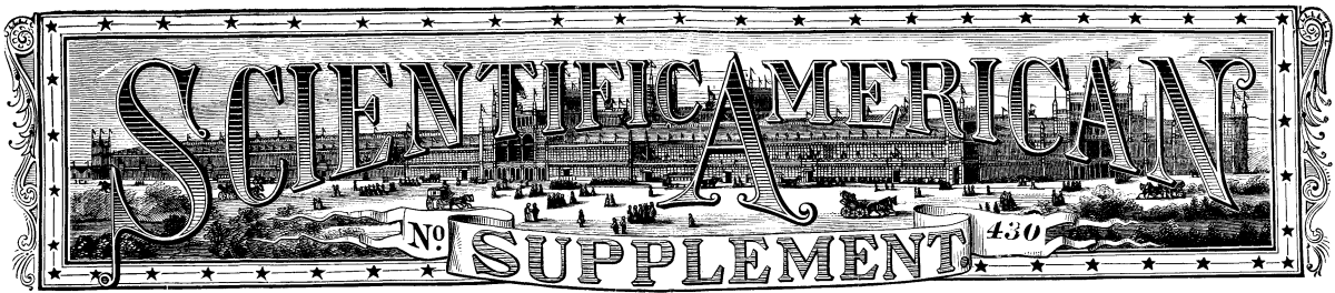
The genus Cuscuta contains quite a number of species which go under the common name of dodder, and which have the peculiarily of living as parasites upon other plants. Their habits are unfortunately too well known to cultivators, who justly dread their incursions among cultivated plants like flax, hops, etc.
All parasitic plants, or at least the majority of them, have one character in common which distinguishes them at first sight. In many cases green matter is wanting in their tissues or is hidden by a livid tint that strikes the observer. Such are the Orobanchaccæ, or "broomropes," and the tropical Balanophoraceæ. Nevertheless, other parasites, such as the mistletoe, have perfectly green leaves.
However this may be, the naturalist's attention is attracted every time he finds a plant deprived of chlorophyl, and one in which the leaves seem to be wanting, as in the dodder that occupies us. In fact, as the majority of parasites take their nourishment at the expense of the plants upon which they fasten themselves, they have no need, as a general thing, of elaborating through their foliar organs the materials that their hosts derive from the air; in a word, they do not breathe actively like the latter, since they find the elements of their nutrition already prepared in the sap of their nurses. The dodders, then, are essentially parasites, and their apparent simplicity gives them a very peculiar aspect. Their leaves are wholly wanting, or are indicated by small, imperceptible scales, and their organs of vegetation are reduced to a stem and filiform branches that have obtained for them the names of Cheveux de Venus (Venus' Hair) and Cheveux du Diable (devil's hair) in French, and gold thread in English. Because of their destructive nature they have likewise been called by the unpoetic name of hellweed; and, for the reason that they embrace their host plants so closely, they have been called love weed and love vine.
When a seed of Cuscuta, germinates, no cotyledons are to be distinguished. This peculiarity, however, the plant has in common with other parasites, and even with some plants, such as orchids, that vegetate normally. The radicle of the dodder fixes itself in the earth, and the little stem rises as in other dicotyledons; but soon (for the plantlet could not live long thus) this stem, which is as slender as a thread, seeks support upon some neighboring plant, and produces upon its surfaces of contact one or more little protuberances that shortly afterward adhere firmly to the support and take on the appearance and functions of cupping glasses. At this point there forms a prolongation of the tissue of the dodder--a sort of cone, which penetrates the stalk of the host plant. After this, through the increase of the stem and branches of the parasite, the supporting plant becomes interlaced on every side, and, if it does not die from the embraces of its enemy, its existence is notably hazarded. It is possible for a Cuscuta plant to work destruction over a space two meters in diameter in a lucern or clover field; so, should a hundred seeds germinate in an acre, it may be easily seen how disastrous the effects of the scourge would prove.
These enemies of our agriculture were scarcely to be regarded as injurious not very many years ago, for the reason that their sources of development were wanting. Lucern and clover are comparatively recent introductions into France, at least as forage plants. Other cultures are often sorely tried by the dodder, and what is peculiar is that there are almost always species that are special to such or such a plant, so that the botanist usually knows beforehand how to determine the parasite whose presence is made known to him. Thus, the Cuscuta of flax, called by the French Bourreau du Lin (the flax's executioner), and by the English, flax dodder, grows only upon this textile plant, the crop of which it often ruins. On account of this, botanists call this species Cuscuta epilinum. Others, such as C. Europæa, attack by preference hemp and nettle. Finally, certain species are unfortunately indifferent and take possession of any plant that will nourish them. Of this number is the one that we are about to speak of.
Attempts have sometimes been made out of curiosity to cultivate exotic species. One of the head gardeners at the Paris Museum received specimens of Cuscuta reflexa from India about two years ago, and, having placed it upon a geranium plant, succeeded in cultivating it. Since then, other plants have been selected, and the parasite has been found to develop upon all of them. What adds interest to this species is that its flowers are relatively larger and that they emit a pleasant odor of hawthorn. Mr. Hamelin thinks that by reason of these advantages, an ornamental plant might be made of it, or at least a plant that would be sought by lovers of novelties. Like the majority of dodders, this species is an annual, so that, as soon as the cycle of vegetation is accomplished, the plant dies after flowering and fruiting. But here the seeds do not arrive at maturity, and the plant has to be propagated by a peculiar method. At the moment when vegetation is active, it is only necessary to take a bit of the stem, and then, after previously lifting a piece of the bark of the plant upon which it is to be placed, to apply this fragment of Cuscuta thereto (as in grafting), place the bark over it, and bind a ligature round the whole. In a short time the graft will bud, and in a few months the host plant will be covered with it.
The genus Cuscuta embraces more than eighty species, which are distributed throughout the entire world, but which are not so abundant in cold as in warm regions.--La Nature.
A NEW EXOTIC DODDER. (Cuscuta Reflexa.)
It is commonly said that there is a great difference between the transpiration and evaporation of water in plants. The former takes place in an atmosphere saturated with moisture, it is influenced by light, by an equable temperature, while evaporation ceases in a saturated atmosphere. M. Leclerc has very carefully examined this question, and he concludes that transpiration is only the simple evaporation of water. If transpiration is more active in the plant exposed to the sun, that is due to the heat rays, and in addition arises in part from the fact that the assimilating action of chlorophyl heats the tissues, which in turn raises the temperature and facilitates evaporation.
As to transpiration taking place in a saturated atmosphere, it is a mistake; generally there is a difference in the temperature of the plant and the air, and the air is not saturated in its vicinity. In a word, transpiration and evaporation is the same thing.
Herr Reinke has made an interesting examination of the action of light on a plant. He has permitted a pencil of sun rays to pass through a converging lens upon a cell containing a fragment of an aquatic plant. He was enabled to increase the intensity of the light, so that it should be stronger or weaker than the direct sunlight. He could thus vary its intensity from 1/16 of that of direct sunlight to an intensity 64 times stronger. The temperature was maintained constant.
Herr Reinke has shown that the chlorophyl action increases regularly with the light for intensities under that of direct sunlight; but what is unexpected, that for the higher intensities above that of ordinary daylight the disengagement of oxygen remains constant.
M. Leclerc du Sablon has published some of his results in his work on the opening of fruits. The influences which act upon fruit are external and internal. The external cause of dehiscence is drying. We can open or shut a fruit by drying or wetting it. The internal causes are related to the arrangement of the tissues, and we may say that the opening of fruit can be easily explained by the contraction of the ligneous fibers under drying influences. M. Leclerc shows by experiment that the fibers contract more transversely than longitudinally, and that the thicker fibers contract the most. This he finds is connected with the opening of dry fruits.
Herr Hoffman has recently made some interesting experiments upon the cultivation of fruits.
It is well known that many plants appear to select certain mineral soils and avoid others, that a number of plants which prefer calcareous soils are grouped together as calcicoles, and others which shun such ground as calcifuges. Herr Hoffman has grown the specimen which has been cited by many authors as absolutely calcifugic. He has obtained strong plants upon a soil with 53 per cent. of lime, and these have withstood the severe winter of 1879-1880, while individuals of the same species grown on silicious ground have failed. This will modify the ideas of agriculturists, at least in regard to this plant.
Herr Schwarz has been engaged in the study of the fine hairs of roots. According to this author, there is a maximum and minimum of humidity, between which there lies a mean of moisture, most favorable for the development of these capillary rootlets, and this amount of moisture varies with different plants. He finds that this growth of hair-like roots is conditioned upon the development of the main root from which it springs. In a weak solution of brine these fine roots are suppressed, while the growth of the main root is continued. The changes of the milieu lead to changes in the form of the hairs, rendering them even branched.
Signor Savastano has ventured to criticise as exaggerated the views of Muller, Lubbock, and Allen on the adaptation of flowers to insects, having noticed that bees visit numbers of flowers, and extract their honey without touching the stigmas or pistils. He has also found them neglecting flowers which were rich in honey and visiting others much poorer. These observations have value, but cannot be considered as seriously impairing the multiplied evidences of plant adaptation to insect life.
Mr. Camus has shown that the flora of a small group of hills, the Euganean Mountains, west of the Apennines and south of the Alps, has a peculiar flora, forming an island in the midst of a contrasted flora existing about it. Here are found Alpine, maritime, and exotic plants associated in a common isolation.--Revue Scientifique.
Among the most significant of the recent discoveries in botany, is that respecting the continuity of the protoplasm from cell to cell, by means of delicate threads which traverse channels through the cell walls. It had long been known, that in the "sieve" tissues of higher plants there was such continuity through the "sieve plates," which imperfectly separated the contiguous cells. This may be readily seen by making longitudinal sections of a fibro-vascular bundle of a pumpkin stem, staining with iodine, and contracting the protoplasm by alcohol. Carefully made specimens of the soft tissues of many plants have shown a similar protoplasmic continuity, where it had previously been unsuspected. Some investigators are now inclined to the opinion that protoplasmic continuity may be of universal occurrence in plants.
[Footnote: A recent lecture before the Society of ATM, London.]
It is not my intention to treat this subject from a shipwright's point of view. The title of this paper is supposed to indicate a mode of propelling boats by means of electrical energy, and it is to this motive power that I shall have the honor of drawing your attention.
The primary object of a launch, in the modern sense of the word, lies in the conveyance of passengers on rivers and lakes, less than for the transport of heavy goods; therefore, it may not be out of place to consider the conveniences arising from the employment of a motive power which promises to become valuable as time and experience advance. In a recent paper before the British Association at Southport, I referred to numerous experiments made with electric launches; now it is proposed to treat this subject in a wider sense, touching upon the points of convenience in the first place; secondly, upon the cost and method of producing the current of electricity; and thirdly, upon the construction and efficiency of the propelling power and its accessories.
Whether it is for business, pleasure, or war purposes a launch should be in readiness at all times, without requiring much preparation or attention. The distances to be traversed are seldom very great, fifty to sixty miles being the average.
Nearly the whole space of a launch should be available for the accommodation of passengers, and this is the case with an electrically propelled launch. We have it on good authority, that an electric launch will accommodate nearly double the number of passengers that a steam launch of the same dimensions would; therefore, for any given accommodation we should require a much smaller vessel, demanding less power to propel it at a given rate of speed, costing less, and affording easier management.
A further convenience arising from electromotive power is the absence of combustibles and the absence of the products of combustion-matters of great importance; and for the milder seasons, when inland navigation is principally enjoyed, the absence of heat, smell, and noise, and, finally, the dispensing with one attendant on board, whose wages, in most cases, amount to as much or more than the cost of fuel, besides the inconvenience of carrying an additional individual.
I do not know whether the cost of motive power is a serious consideration with proprietors of launches, but it is evident that if there be a choice between two methods of equal qualities, the most economical method will gain favor. The motive power on the electric launch is the electric current; we must decide upon the mode of procuring the current. The mode which first suggested itself to Professor Jacobi, in the year 1838, was the primary battery, or the purely chemical process of generating electricity.
Jacobi employed, in the first instance, a Daniell's battery, and in later experiments with his boat on the river Neva, a Grove's battery. The Daniell's battery consisted of 320 cells containing plates of copper and zinc; the speed attained by the boat with this battery did not reach one mile and a quarter per hour; when 64 Grove cells were substituted, the speed came to two and a quarter miles per hour; the boat was 38 feet long. 7½ beam, and 3 feet deep. The electromotor was invented by Professor Jacobi; it virtually consisted of two disks, one of which was stationary, and carried a number of electromagnets, while the other disk was provided with pieces of iron serving as armatures to the pole pieces of the electromagnets, which were attracted while the electric current was alternately conveyed through the bobbins by means of a commutator, producing continuous rotation.
We are not informed as to the length of time the batteries were enabled to supply the motor with sufficient current, but we may infer from the surface of the acting materials in the battery that the run was rather short; the power of the motor was evidently very small, judging by the limited speed obtained, but the originality of Jacobi deserves comment, and for this, as well as for numerous other researches, his name will be remembered at all times.
It may not be generally known that an electric launch was tried for experimental purposes, on a lake at Pentlegaer, near Swansea. Mr. Robert Hunt, in the discussion of his paper on electromagnetism before the Institution of Civil Engineers in 1858, mentioned that he carried on an extended series of experiments at Falmouth, and at the instigation of Benkhausen, Russian Consul-General, he communicated with Jacobi upon the subject. In the year 1848, at a meeting of the British Association at Swansea, Mr. Hunt was applied to, by some gentlemen connected with the copper trade of that part, to make some experiments on the electrical propulsion of vessels; they stated, that although electricity might cost thirty times as much as the power obtained from coal it would, nevertheless, be sufficiently economical to induce its employment for the auxiliary screw ships employed in the copper trade with South America.
The boat at Swansea was partly made under Mr. (now Sir William) Grove's directions, and the engine was worked on the principle of the old toys of Ritchie, which consisted of six radiating poles projecting from a spindle, and rotating between a large electro-magnet. Three persons traveled in Hunt's boat, at the rate of three miles per hour. Eight large Grove's cells were employed, but the expense put it out of question as a practical application.
Had the Gramme or Siemens machine existed at that time, no doubt the subject would have been further advanced, for it was not merely the cost of the battery which stood in the way, but the inefficient motor, which returned only a small fraction of the power furnished by the zinc.
Professor Silvanus Thompson informs us that an electric boat was constructed by Mr. G. E. Dering, in the year 1856, at Messrs. Searle's yard, on the River Thames; it was worked by a motor in which rotation was effected by magnets arranged within coils, like galvanometer needles, and acted on successively by currents from a battery.
From a recent number of the Annales de l'Electricite, we learn that Count de Moulins experimented on the lake in the Bois de Boulogne, in the year 1866, with an iron flat-bottomed boat, carrying twelve persons. Twenty Bunsen cells furnished the current to a motor on Froment's principle turning a pair of paddle wheels.
In all these reports there is a lack of data. We are interested to know what power the motors developed, the time and speed, as well as dimensions and weights.
Until Trouve's trip on the Seine, in 1881, and the launch of the Electricity on the Thames, in 1882, very little was known concerning the history of electric navigation.
M. Trouve originally employed Plante's secondary battery, but afterward reverted to a bichromate battery of his own invention. In all the primary batteries hitherto applied with advantage, zinc has been used as the acting material. Where much power is required, the consumption of zinc amounts to a formidable item; it costs, in quantity, about 3d. per pound, and in a well arranged battery a definite quantity of zinc is transformed. The final effect of this transformation manifests itself in electrical energy, amounting to about 746 watts, or one electrical horse power for every two pounds of this metal consumed per hour. The cost of the exciting fluid varies, however, considerably; it may be a solution of salts, or it may be dilute acid. Considering the zinc by itself, the expense for five electrical or four mechanical horse power through an efficient motor, in a small launch, would be 2s. 6d. per hour. Many persons would willingly sacrifice 2s. 6d per hour for the convenience, but a great item connected with the employment of zinc batteries is in the exciting fluid, and the trouble of preparing the zinc plates frequently. The process of cleaning, amalgamating and refilling is so tedious, that the use of primary batteries for locomotive purposes is extremely limited. To recharge a Bunsen, Grove, or bichromate battery, capable of giving six or seven hours' work at the rate of five electrical horse power, would involve a good day's work for one man; no doubt he would consider himself entitled to a full day's wages, with the best appliances to assist him in the operation.
Several improved primary batteries have recently been brought out, which promise economical results. If the residual compound of zinc can be utilized, and sold at a good price, then the cost of such motive power may be reduced in proportion to the value of those by-products.
For the purpose of comparison, let us now employ the man who would otherwise clean and prepare the primary cells, at engine driving. We let him attend to a six horse power steam engine, boiler, and dynamo machine for charging 50 accumulators, each of a capacity of 370 ampere hours, or one horse power hour. The consumption of fuel will probably amount to 40 lb. per hour, which, at the rate of 18s. a ton, will give an expenditure of nearly 4d. per hour. The energy derived from coal in the accumulator costs, in the case of a supply of five electrical horse power for seven hours, 2s. 9d.; the energy derived from the zinc in a primary battery, supplying five electrical horse power for seven hours, would cost 17s. 3d.
It is hardly probable that any one would lay down a complete plant, consisting of a steam or gas engine and dynamo, for the sole purpose of charging the boat cells, unless such a boat were in almost daily use, or unless several boats were to be supplied with electrical power from one station. In order that electric launches may prove useful, it will be desirable that charging stations should be established, and on many of the British and Irish rivers and lakes there is abundance of motive power, in the shape of steam or gas engines, or water-wheels.
A system of hiring accumulators ready for use may, perhaps, best satisfy the conditions imposed in the case of pleasure launches.
It is difficult to compile comparative tables showing the relative expenses for running steam launches, electric launches with secondary batteries, and electric launches with primary zinc batteries; but I have roughly calculated that, for a launch having accommodation for a definite number of passengers, the total costs are as 1, 2.5, and 12 respectively, steam being lowest and zinc batteries highest.
The accumulators are, in this case, charged by a small high pressure steam engine, and a very large margin for depreciation and interest on plant is added. The launch taken for this comparison must run during 2,000 hours in the year, and be principally employed in a regular passenger service, police and harbor duties, postal service on the lakes and rivers of foreign countries, and the like.
The subject of secondary batteries has been so ably treated by Professor Silvanus Thompson and Dr. Oliver Lodge, in this room, that I should vainly attempt to give you a more complete idea of their nature. The improvements which are being made from time to time mostly concern mechanical details, and although important, a description will scarcely prove interesting.
A complete Faure-Sellon-Volckmar cell, such as is used in the existing electric launches, is here on the table; this box weighs, when ready for use, 56 lb.; and it stores energy equal to one horse power for one hour=1,980,000 foot pounds, or about one horse power per minute for each pound weight of material. It is not advantageous to withdraw the whole amount of energy put in; although its charging capacity is as much as 370 ampere hours, we do not use more than 80 per cent., or 300 ampere hours; hence, if we discharge these accumulators at the rate of 40 amperes, we obtain an almost constant current for 7½ hours: one cell gives an E.M.F. of two volts. In order to have a constant power of one horse for 7½ hours, at the rate of 40 amperes discharge, we must have more than nine cells per electrical horsepower; and 47 such cells will supply five electrical horse power for the time stated, and these 47 cells will weigh 2,633 lb.
We could employ half the number of cells by using them at the rate of 80 amperes, but then they will supply the power for less than half the time. The fact, however, that the cells will give so high a rate of discharge for a few hours is, in itself, important, since we are enabled to apply great power if desirable; the 47 cells above referred to can be made to give 10 or 12 electrical horse power for over two hours, and thus propel the boat at a very high speed, provided that the motor is adapted to utilize such powerful currents.
The above mentioned weight of battery power--viz., 2,632 lb., to which has to be added the weight of the motor and the various fittings--represents, in the case of a steam launch, the weight of coals, steam boiler, engine, and fittings. The electro motor capable of giving four horse power on the screw shaft need not weigh 400 lb. if economically designed; this added to the weight of the accumulators, and allowing a margin for switches and leads, brings the whole apparatus up to about 28 cwt.
An equally powerful launch engine and boiler, together with a maximum stowage of fuel, will weigh about the same. There is, however, this disadvantage about the steam power, that it occupies the most valuable part of the vessel, taking away some eight or nine feet of the widest and most convenient part, and in a launch of twenty-four feet length, requiring such a power as we have been discussing, this is actually one-third of the total length of the vessel, and one-half of the passenger accommodation; therefore, I may safely assert that an electric launch will carry about twice as many people as a steam launch of similar dimensions.
The diagram on the wall represents sections of an electric launch built by Messrs. Yarrow and Company, and fitted up by the Electrical Power Storage Company, for the recent Electrical Exhibition in Vienna. She has made a great number of successful voyages on the River Danube during the autumn. Her hull is of steel, 40 feet long and 6 feet beam, and there are seats to accommodate forty adults comfortably. Her accumulators are stowed away under the floor, so is the motor, but owing to the lines of the boat the floor just above the motor is raised a few inches. This motor is a Siemens D2 machine, capable of working up to seven horse power with eighty accumulators.
In speaking of the horse power of an electro motor, I always mean the actual power developed in the shaft, and not the electrical horse power; this, therefore, should not be compared to the indicated horse power of a steam engine.
I am indebted to Messrs. Yarrow for the principal dimensions and other particulars of a high pressure launch engine and boiler, such as would be suitable for this boat. From these dimensions I prepared a second diagram representing the steam power, and when placed in position it will show at a glance how much space this apparatus will occupy. The total length lost in this way amounts to 12 feet, leaving for testing capacity only 15 feet, while that of the electric launch is 27 feet on each side of the boat; thus the accommodation is as fifteen to twenty-seven, or as twenty-two passengers to forty, in favor of the electric launch.
Comparing the relative weights of the steam power and the electric power for this launch, we find that they are nearly equal--each approaches 50 cwt; but in the case of the steam launch we include 10 cwt. of coals, which can be stowed into the bunkers, and which allow fifteen hours continuous steaming, whereas the electric energy stored up will only give us seven and a half hours with perfect safety.
I have here allowed 8 lb. of coal per indicated horse power per hour, and 10 horse power giving off 7 mechanical horse power on the screw shaft; this is an example of an average launch engine. There are launch engines in existence which do not consume one-half that amount of fuel, but these are so few, so rare, and so expensive, that I have neglected them in this account.
Not many years ago, a steam launch carrying a seven hours supply of fuel was considered marvelous.
Our present accumulaton supplies 33,000 foot pounds of work per pound of lead, but theoretically one pound of lead manifests an energy equal to 360,000 foot pounds in the separation from its oxide; and in the case of iron, Prof. Osborne Reynolds told us in this place, the energy evolved by its oxidation is equivalent to 1,900,000 foot pounds per pound of metal. How nearly these limits may be approached will he the problem of the chemist; to prophesy is dangerous, while science and its applications are advancing at this rapid rate.
Theoretically, then, with our weight of fully oxidized lead we should be able to travel for 82 hours; with the same weight of iron for 430 hours, or 18 days and nights continually, at the rate of 8 miles per hour, with one change. Of course, these feats are quite impossible. We might as well dream of getting 5 horse power out of a steam engine for one pound of coal per hour.
While the chemist is busy with his researches for substances and combinations which will yield great power with small quantities of material, the engineer assiduously endeavors to reconvert the chemical or electrical energy into mechanical work suitable to the various needs.
To get the maximum amount of work with a minimum amount of weight, and least dimensions combined with the necessary strength is the province of the mechanical engineer--it is a grand and interesting study; it involves many factors; it is not, as in the steam engine and hydraulic machine, a matter of pressures, tension and compression, centrifugal and static forces, but it comprises a still larger number of factors, all bearing a definite relation to each other.
With dynamo machines the aim has been to obtain as nearly as possible as much electrical energy out of the machine as has been put in by the prime mover, irrespective of the quantity of material employed in its construction. Dr. J. Hopkinson has not only improved upon the Edison dynamo, and obtained 94 per cent. of the power applied in the form of electrical energy, but he got 50 horse power out of the same quantity of iron and copper where Edison could only get 20 horsepower--and, though the efficiency of this generator is perfect, it could not be called an efficient motor, suitable for locomotion by land or water, because it is still too heavy. An efficient motor for locomotion purposes must not only give out in mechanical work as nearly as possible as much as the electrical energy put in, but it must be of small weight, because it has to propel itself along with the vehicle, and every pound weight of the motor represents so many foot pounds of energy used in its own propulsion; thus, if a motor weighed 660 pounds, and were traveling at the rate of 50 feet per minute, against gravitation, it would expend 33,000 foot pounds per minute in moving itself, and although this machine may give 2 horse power, with an efficiency of 90 per cent. it would, in the case of a boat or a tram-car, be termed a wasteful machine. Here we have an all-important factor which can be neglected, to a certain extent, in the dynamo as a generator, although from an economical point of view excessive weight in the dynamo must also be carefully avoided.
The proper test for an electro-motor, therefore, is not merely its efficiency, or the quotient of the mechanical power given out, divided by the electrical energy put in, but also the number of feet it could raise its own weight in a given space of time, with a given current, or, in other words, the number of foot pounds of work each pound weight of the motor would give out.
The Siemens D2 machine, as used in the launch shown in the diagram on the wall, is one of the lightest and best motors, it gives 7 horse power on the shaft, with an expenditure of 9 electrical horsepower, and it weighs 658 lb.; its efficiency, therefore, 7/5 or nearly 78 per cent.; but its "coefficient" as an engine of locomotion is 351--that is to say, each pound weight of the motor will yield 351 foot pounds on the shaft. We could get even more than 7 horse power out of this machine, by either running it at an excessive speed, or by using excessive currents; in both cases, however, we should shorten the life of the apparatus.
An electro-motor consists, generally, of two or more electro-magnets so arranged that they continually attract each other, and thereby convey power. As already stated, there are numerous factors, all bearing a certain relationship to each other, and particular rules which hold good in one type of machine will not always answer in another, but the general laws of electricity and magnetism must be observed in all cases. With a given energy expressed in watts, we can arrange a quantity of wire and iron to produce a certain quantity of work; the smaller the quantity of material employed, and the larger the return for the energy put in, the greater is the total efficiency of the machine.
Powerful electro-magnets, judiciously arranged, must make powerful motors. The ease with which powerful electro-magnets can be constructed has led many to believe that the power of an electro-motor can be increased almost infinitely, without a corresponding increase of energy spent. The strongest magnet can be produced with an exceedingly small current, if we only wind sufficient wire upon an iron core. An electro-magnet excited by a tiny battery of 10 volts, and, say, one ampere of current, may be able to hold a tremendous weight in suspension, although the energy consumed amounts to only 10 watts, or less than 1/75 of a horse power, but the suspended weight produces no mechanical work. Mechanical work would only be done if we discontinued the flow of the current, in which case the said weight would drop; if the distance is sufficiently small, the magnet could, by the application of the current from the battery, raise the weight again, and if that operation is repeated many times in a minute, then we could determine the mechanical work performed. Assuming that the weight raised is 1,000 lb., and that we could make and break the current two hundred times a minute, then the work done by the falling mass could, under no circumstances, equal 1/75 of a horse-power, or 440 foot-pounds; that is, 1,000 lb. lifted 2.27 feet high in a minute, or about one-eighth of an inch for each operation: hence the mere statical pull, or power of the magnet, does in no way tend to increase the energy furnished by the battery or generator, for the instant we wish to do work we must have motion--work being the product of mass and distance.
Large sums of money have virtually been thrown away in the endeavor to produce energy, and there are intelligent persons who to this day imagine that, by indefinitely increasing the strength of a magnet, more power may be got out of it than is put in.
Large field-magnets are advantageous, and the tendency in the manufacture of dynamo machines has been to increase the mass of iron, because with long and heavy cores and pole pieces there is a steady magnetism insured, and therefore a steady current, since large masses of iron take a long time to magnetize and demagnetize; thus very slight irregularites in the speed of an armature are not so easily perceived. In the case of electro-motors these conditions are changed. In the first place, we assume that the current put through the coils of the magnets is continuous; and secondly, we can count upon the momentum of the armature, as well as the momentum of the driven object, to assist us over slight irregularities. With electric launches we are bound to employ a battery current, and battery currents are perfectly continuous--there are no sudden changes; it is consequently a question as to how small a mass of iron we may employ in our dynamo as a motor without sacrificing efficiency. The intensity of the magnetic field must be got by saturating the iron, and the energy being fixed, this saturation determines the limit of the weight of the iron. Soft wrought iron, divided into the largest possible number of pieces, will serve our purpose best. The question of strength of materials plays also an important part. We cannot reduce the quantity and division to such a point that the rigidity and equilibrium of the whole structure is in any way endangered.
The armature, for instance, must not give way to the centrifugal forces imposed upon it, nor should the field magnets be so flexible as to yield to the statical pull of the magnetic poles. The compass of this paper does not permit of a detailed discussion of the essential points to be observed in the construction of electro-motors; a reference to the main points, may, however, be useful. The designer has, first of all, to determine the most effective positions of the purely electrical and magnetic parts; secondly, compactness and simplicity in details; thirdly, easy access to such parts as are subject to wear and adjustment; and, fourthly, the cost of materials and labor. The internal resistance of the motor should be proportioned to the resistances of the generator and the conductors leading from the generator to the receiver.
The insulation resistances must be as high as possible; the insulation can never be too good. The motor should he made to run at that speed at which it gives the greatest power with a high efficiency, without heating to a degree which would damage the insulating material.
Before fixing a motor in its final position, it should also be tested for power with a dynamometer, and for this purpose a Prony brake answers very well.
An ammeter inserted in the circuit will show at a glance what current is passing at any particular speed, and voltmeter readings are taken at the terminals of the machine, when the same is standing still as well as when the armature is running, because the E.M.F. indicated when the armature is at rest alone determines the commercial efficiency of the motor, whereas the E M.F. developed during motion varies with the speed until it nearly reaches the E.M.F. in the leads; at that point the theoretical efficiency will be highest.
Calculations are greatly facilitated, and the value of tests can be ascertained quickly, if the constant of the brake is ascertained; then it will be simply necessary to multiply the number of revolutions and the weight at the end of the lever by such a constant, and the product gives the horse power, because, with a given Prony brake, the only variable quantities are the weight and the speed. All the observations, electrical and mechanical, are made simultaneously. The electrical horse power put into the motor is found by the well known formula C x E / 746; this simple multiplication and division becomes very tedious and even laborious if many tests have to be made in quick succession, and to obviate this trouble, and prevent errors, I have constructed a horse power diagram, the principle of which is shown in the diagram (Fig. 1).
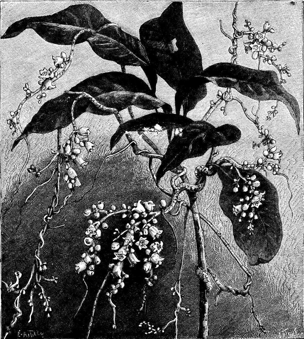
Graphic representations are of the greatest value in all comparative tests. Mr. Gisbert Kapp has recently published a useful curve in the Electrician, by means of which one can easily compare the power and efficiency at a glance (Fig. 2).
The speeds are plotted as abscissae, and the electrical work absorbed in watts divided by 746 as ordinates; then with a series-wound motor we obtain the curve, EE. The shape of this curve depends on the type of the motor. Variation of speed is obtained by loading the brake with different weights. We begin with an excess of weight which holds the motor fast, and then a maximum current will flow through it without producing any external work. When we remove the brake altogether, the motor will run with a maximum speed, and again produce no external work, but in this case very little current will pass; this maximum speed is om on the diagram. Between these two extremes external work will be done, and there is a speed at which this is a maximum. To find these speeds we load the brake to different weights, and plot the resulting speeds and horse powers as abscissae and ordinates producing the curve, BB. Another curve,
e = B/E
made with an arbitrary scale, gives the commercial efficiency; the speed for a maximum external horse power is o a, and the speed for the highest efficiency is represented by o b. In practice it is not necessary to test a motor to the whole limits of this diagram; it will be sufficient to commence with a speed at which the efficiency becomes appreciable, and to leave off with that speed which renders the desired power.
I have now to draw your attention to a new motor of my own invention, of the weight of 124 lb., which, at 1,550 revolutions, gives 31 amperes and 61.5 volts at terminals. The mechanical horse power is 1.37, and the coefficient 373.
                                                     Ohms.
Armature resistance                                    0.4 w.
Field-magnet resistance                               0.17 w.
Insulation resistance                            1,500,000 w.
This motor was only completed on the morning before reading the paper; it could not, therefore, be tested as to its various capacities.
We have next to consider the principle of applying the motive power to the propulsion of a launch. The propellers hitherto practically applied in steam navigation are the paddle-wheel and the screw. The experience of modern steam navigation points to the exclusive use and advantage of the screw propeller where great speed of shaft is obtainable, and the electric engine is pre-eminently a high-speed engine, consequently the screw appears to be most suitable to the requirements of electric boats. By simply fixing the propeller to the prolonged motor shaft, we complete the whole system, which, when correctly made, will do its duty in perfect order, with an efficiency approaching theory to a high degree.

FIG. 1.--RECKENZAUN'S ELECTRICAL HORSE POWER
DIAGRAM.
Draw a square, A B C D--divide B C into 746 parts, and
C D into 1,000 parts, or, generally, let a division on C D
be 0.746 of a division on B C, so that we can use the
horizontal lines cutting A B as a horse power scale.
A B, in the above diagram, gives 1,000 horse power, if
the line B C represents 746 volts, and C D 1,000 amperes.
Let x = any number of volts, y the amperes,
and h the horse power, then
h/x = y/100 :. h = xy/746
A fine wire or thread stretched from o as a center to the
required division on C D will facilitate references.
Whatever force may be imparted to the water by a propeller, such force can be resolved into two elements, one of which is parallel, and the other in a plane at right angles to the keel. The parallel force alone has the propelling effect; the screw, therefore, should always be so constructed that its surfaces shall be chiefly employed in driving the water in a direction parallel to the keel from stem to stern.
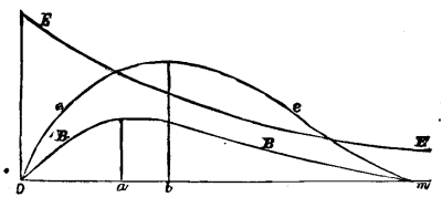
Fig. 2--KAPP'S DIAGRAM.
It is evident that a finely pitched screw, running at a high velocity, will supply these conditions best. With that beautiful screw lying on this table, and made by Messrs. Yarrow, 95 per cent. of efficiency has been obtained when running at a speed of over 800 revolutions per minute--that is to say, only 5 per cent was lost in slip.
Reviewing the various points of advantage, it appears that electricity will, in time to come, be largely used for propelling launches, and, perhaps, something more than launches.
In conclusion, quoting Dr. Lardner's remarks on the subject of steam navigation of nearly fifty years ago, he said:
"Some, who, being conversant with the actual conditions of steam engineering as applied to navigation, and aware of various commercial conditions which must affect the problem, were enabled to estimate calmly and dispassionately the difficulties and drawbacks, as well as the disadvantages, of the undertaking, entertained doubts which clouded the brightness of their hopes, and warned the commercial world against the indulgence of too sanguine anticipation of the immediate and unqualified realization of the project. They counseled caution and reserve against an improvident investment of extensive capital in schemes which still be only regarded as experimental, and which might prove its grave. But the voice of remonstrance was drowned amid the enthusiasm excited by the promise of an immediate practical realization of a scheme so grand.
"It cannot," he continues, "be seriously imagined that any one who had been conversant with the past history of steam navigation could entertain the least doubt of the abstract practicability of a steam vessel making the voyage between Bristol and New York. A steam vessel, having as cargo a couple of hundred tons of coals, would, cæteris paribus, be as capable of crossing the Atlantic as a vessel transporting the same weight of any other cargo."
Dr. Lardner is generally credited with having asserted that a steam voyage across the Atlantic was "a physical impossibility," but in the work from which I took the liberty of copying his words he denies the charge, and says that what he did affirm was, that long sea voyages could not at that time be maintained with that regularity and certainty which are indispensable to commercial success, by any revenue which could be expected from traffic alone.
The practical results are well known to us. History repeats itself, and the next generation may put on record our week attempts, our doubts and fears of this day. Whether electricity will ever rival steam, remains yet to be proved; we may be on the threshold of great things. The premature enthusiasm has subsided, and we enter upon the road of steady progress.
Mr. Wm. H. Preece, the chairman, in inviting discussion, said that no doubt those present would like to know something about the cost of such a boat as Mr. Reckenzaun described, and he hoped that gentleman would give them some information on that point.
Admiral Selwyn thought Mr. Reckenzaun was a little below the mark when he talked about the dream of getting 5 horse power for one pound--he would not say of coal, but of fuel. For some months he had seen ½ lb. of fuel produce 1 horse power, and he knew it could be done. That fuel was condensed concentrated fuel in the shape of oil. When this could be done, electrical energy also could be obtained much cheaper, but if it were extended to yachts, he thought that would be as far as any one now present could be expected to see it go. Still he thought there was a future for it, and that future would be best advanced by considering the question on which he had touched. First, the employment of a cheaper mode of getting the power in the steam engine; and, secondly, a cheaper and higher secondary battery. In a railway train weight was a formidable affair, but in a floating vessel it was still more important. He did not think, however, that a light secondary battery was by any means an impossibility. Mr. Loftus Perkins had actually produced by improvements in the boiler and steam engine two great things: first, one indicated horse power for a pound of fuel per hour, and next he had devised a steam engine of 100 horse power, of a weight of only 84 lb. per horse power, instead of 304 lb., which was about the average. Those were two enormous steps in advance, and under a still more improved patent law he had no doubt things would be brought forward which would show a still greater progress. Within the last fifteen days, nearly 2,000 patents had been taken out, as against 5,000 in the whole of the previous year, which showed how operative a very small and illusory inducement had been to encourage invention. He had long been known as an advocate of patent law reform, and, therefore, felt bound to lose no opportunity of calling attention to its importance. Invention was in the hands of the inventor, the creator of trade. If, without robbing anybody, one wished to produce property, it must be done by improving manufactures as a consequence of inventions. In one instance alone it bad been proved that a single invention had been the means of introducing twenty millions annually, upon which income tax was paid.
Mr. Crampton said he did not think steam could ever compete with electricity, under certain circumstances; but, at the same time, it would be a long time before it was superseded. He should like very much to see the compressed oil, one-sixth of a pound of which would give 1 horse power per hour.
Admiral Selwyn said he had seen a common Cornish boiler doing it years ago.
Mr. Crampton said it had never come under his notice, and he had no hesitation in saying that no such duty ever was performed by any oil, because he never heard of any oil which evaporated more than eighteen to twenty-two pounds of water per pound. However, he was delighted to hear of such progress being made, and though he had been for so many years connected with steam, he never expected it would last forever. He was now making experiments for some large shipowners, for the purpose of facilitating feeding and doing away with dust, but let him succeed to what extent he might, steam would never compete with electricity for such small vessels as these launches.
The Chairman asked if he rightly understood Admiral Selwyn that he had recently seen an invention in which one-sixth of a pound of condensed fuel would give 1 horse power per hour.
Admiral Selwyn said it was now some years ago since he saw this going on, but the persons who did it did not know how or why it was done. He had studied the question for the last ten years, and now knew the rationale of it, and would be prepared shortly to publish it. He knew that 22 was the theoretical calorific value of the pound of oil, and never supposed that oil alone would give 46 lb., which he saw it doing. He had found out that by means of the oil forming carbon constantly in the furnace, the hydrogen of the steam was burned, and that it was a fallacy to suppose that an equal quantity of heat was used in raising steam, at a pressure of, say, 120 lb. to the square inch, as the hydrogen was capable of developing when properly burned. There were, however, conditions under which alone that combustion could take place--one being that the heat of the chamber must be 3,700°, and that carbon must be constantly formed.
Mr. Gumpel said with regard to the general application of electricity to the propulsion of vessels as well as to railway trains, he believed that many of those present would live to see electricity applied to that purpose, because there were so many minds now applied to the problem, that before long he had no doubt we should see coal burned in batteries, as it was now burned in steam boilers. The utmost they could do, then, would be about 50 per cent. less than Admiral Selwyn said could be accomplished with condensed fuel. He could not but wonder where Admiral Selwyn obtained his information, knowing that a theoretically perfect heat engine would only give 23 per cent. of the absolute heat used, and that a pound of the best coal would give but 8,000 and hydrocarbon 13,000 heat units, while hydrogen would give 34,000; and calculating it out, how was it possible to get out of one-sixth of a pound of carbon, or any hydrocarbon, the amount of power stated? No doubt, when Admiral Selwyn applied the knowledge which physicists would give him of the amount of power which could be got out of a certain amount of carbon and hydrogen, he would find that there was a mistake somewhere.
Mr. Reckenzaun, in reply, said it would be very difficult to answer the question put by the Chairman, as to the cost of an electric launch--quite as difficult as to say what would be the cost of a steam launch. It depended on the fittings, the ornamental part, the power required, and the time it was required to run. If such a launch were to run constantly, two sets of accumulators would be required, one to replace the other when discharged. This could be easily done, the floor being made to take up, and the cells could be changed in a few minutes with proper appliances. As to Admiral Selwyn's remarks about one-sixth of a pound of fuel per horse power, he had never heard of such a thing before, and should like to know more about it. Mr. Loftus Perkins' new steam engine was a wonderful example of modern engineering. A comparatively small engine, occupying no more space than that of a steam launch of considerable dimensions, developed 800 horse power indicated. From a mechanical point of view, this engine was extremely interesting; it had four cylinders, but only one crank and one connecting rod; and there were no dead centers. The mechanism was very beautiful, but would require elaborate diagrams to explain. Mr. Perkins deserved the greatest praise for it, for in it he had reduced both the weight of the engine and the consumption of fuel to a minimum. He believed he used coke and took one pound per horse power. He should not like to cross the Channel in the electric launch, if there was a heavy sea on, for shaking certainly did not increase the efficiency of the accumulators, but a fair amount of motion they could stand, and they had run on the Thames, by the side of heavy tug boats causing a considerable amount of swell, without any mishap. Of course each box was provided with a lid, and the plates were so closely packed that a fair amount of shaking would not affect them; the only danger was the spilling of the acid. Mr. Crohne had remarked that a torpedo boat of that size would have 100 indicated horse power, but then the whole boat would be filled with machinery. What might be done with electricity they had, as yet, no idea of. At present, they could only get 33,000 foot pounds from 1 lb. of lead and acid, though, theoretically, they ought to get 360,000 foot pounds. Iron in its oxidation would manifest theoretically 1,900,000 foot pounds per lb. of material. As yet they had not succeeded in making an iron accumulator; if they could, they would get about six or seven times the energy for the same weight of material, or could reduce the weight proportionately for the same power, and in that way they might eventually get 70 horse power in a boat of that size, because the weight of the motor was not great. With regard to the formation of a film on the surface, no doubt a film of sulphate of lead was formed if the battery stood idle, but it did not considerably reduce its efficiency; as soon as it was broke through by the energy being evolved from it, it would give off its maximum current. They knew by experience that, with properly constructed accumulators, 80 per cent. of the energy put into them was returned in work. It was quite certain, as Mr. Crampton said, that it would be a long time before steam was superseded: he did not prophesy at all; and he entitled his paper "Electric Launches," because it would be presumptuous to speak of anything more until larger vessels had been made and tried. With regard to Mr. Gumpel's remark on the friction of the propeller, he would say that it was constructed to run 900 revolutions; if it were driven by a steam engine, and the speed reduced to 300, not only would the pitch have to be altered, but the surface would have to be larger, which would entail more friction. Mr. Crohne would bear him out that they lost only 5 per cent. by slip and friction combined, on an average of a great number of trials, both with and against the current.
The Chairman in proposing a vote of thanks to Mr. Reckenzaun, said he rejoiced to find that that gentleman had proved, to one man at least, that his views had been mistaken. He found in these days of the practical applications of electricity, that the ideas of most practical men were gradually being proved to be mistaken, and every day new facts were being discovered, which led them to imagine that as yet they were only on the shore of an enormous ocean of knowledge. It was quite impossible to say what these electric launches would lead to. Certain points of great importance had been pointed out; they gave great room and they were always ready. For lifeboat and fire engine purposes, as Captain Shaw pointed out at Vienna, this was of great consequence.
At first they were led to believe that there was great stability, but that idea had been a little shaken, not as to the boat itself, but as to the influence of the motion of the water upon the constancy of the cells. But these boats were only intended for smooth water, and if they could not be adapted for rough water, he feared Admiral Selwyn's suggestion of the application of this principle to lifeboats would fall to the ground; but if secondary batteries were not calculated as yet to stand rough usage, it only required probably some thought on Mr. Reckenzaun's part to make them available even in a gale. Enormous strides were being made with regard to these batteries. No one present had been a greater skeptic with regard to them at first than be himself; but after constant experiments--employing them, as he had done for many months, for telegraphic purposes--he was gradually coming to view them with a much more favorable eye. The same steps which had rendered all scientific notions practicable, had gradually eliminated the faults which originally existed, and they were now becoming good, sound, available instruments. At present, he could only regard this electric launch as a luxury. He had hoped that Mr. Reckenzaun would have been able to say something which would have enabled poor men to look forward to the time when they might enjoy themselves in them on the river; but he was told at Vienna, when he enjoyed two or three trips in this boat on the Danube, that her cost would be about £800, which was a little too much for most people. They wanted something more within their reach, so that at various points on the river they might see small engines constantly at work supplying energy to secondary batteries, and so that they might start on a Friday evening, and go up as far as Oxford, or higher, and come down again on Monday morning. He must congratulate Mr. Reckenzaun on the excellent diagrams he had constructed. The trouble of calculating figures of this sort was very great when making experiments; and the use of diagrams and curves expedited the labor very much. At present they were passing through a stage of electrical depression; robbery had been committed on a large scale; the earnings of the poor had been filched out of their pockets by sanguine company promotors; an enormous amount of money had been lost, and the result had been that confidence was, to a great extent, destroyed; but those who had been wise enough to keep their money in their pockets, and to read the papers read in that room, must have seen that there was a constant steady advance in scientific knowledge of the laws of electricity and in their practical applications, and as soon as some of these rotten, mushroom companies had been wiped out of existence, they might hope that real practical progress would be made, and that the day was not far distant when the public would again acquire confidence in electrical enterprise. They would then enable inventors and practical men to carry out their experiments, and to put electrical matters on a proper footing.
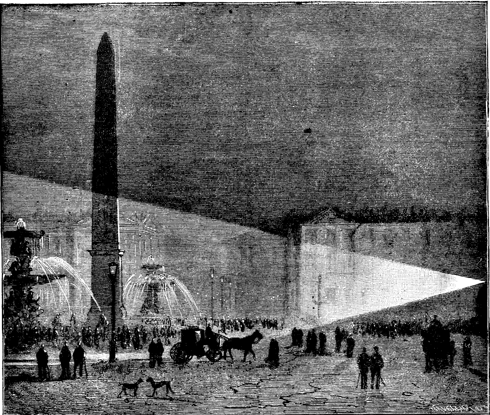
Electric lighting dates back, as well known; to the celebrated experiment of Sir Humphry Davy, which took place in 1809 or 1810, but the date of which is often given as 1813. There exist however, some indications that experiments on the production of the electric spark between carbons had been performed before the above named date.
Mr. S.P. Thompson has given the following interesting details in regard to this subject: In looking over an old volume of the Journal de Paris, says he, I found under date of the 22d Ventose, year X. (March 12, 1802), the following passage, which evidently refers to an exhibition of the electric arc:
"Citizen Robertson, the inventor of the phantasmagoria (magic lantern), is at present performing some interesting experiments that must doubtless advance our knowledge concerning galvanism. He has just mounted metallic piles to the number of 2,500 zinc plates and as many of rosette copper. We shall forthwith speak of his results, as well as of a new experiment that he performed yesterday with two glowing carbons.
SIR HUMPHRY DAVY'S ELECTRIC LIGHT EXPERIMENTS IN 1813.
"The first having been placed at the base of a column of 120 zinc and silver elements, and the second communicating with the apex of the pile, they gave at the moment they were united a brilliant spark of an extreme whiteness that was seen by the entire society. Citizen Robertson will repeat this experiment on the 25th."
The date generally given for the invention of the electric light by Sir Humphry Davy is 1809, but previous mentions of his experiment are found in Cuthberson's "Electricity" (1807) and in other works. In the Philosophical Magazine, vol. ix., p. 219, under date of Feb. 1, 1801, in a memoir by Mr. H. Moyes, of Edinburgh, relative to experiments made with the pile, we find the following passage:
"When the column in question had reached the height of its power, its sparks were seen by daylight, even when they were made to jump with a piece of carbon held in the hand."
ELECTRIC LIGHTING IN PARIS IN 1844.
In the Journal of the Royal Institution, vol. i. (1802), Davy describes (p. 106) a few experiments made with the pile, and says:
"When, instead of metals, pieces of well calcined carbon were employed, the spark was still larger and of a clear white."
On page 214 he describes and figures an apparatus for taking the galvano-electric spark into fluid and aeriform substances. This apparatus consisted of a glass tube open at the top, and having at the side a tube through which passed a wire that terminated in a carbon. Another wire, likewise terminating in carbon, traversed the bottom and was cemented in a vertical position.
But all these indications are posterior to a letter printed in Nicholson's Journal, in October, 1800, p. 150, and entitled: "Additional Experiments on Galvanic Electricity in a Letter to Mr. Nicholson." The letter is dated Dowry Square, Hotwells, September 22, 1800, and is signed by Humphry Davy, who at this epoch was assistant to Dr. Beddoes at the Philosophical Institution of Bristol. It begins thus:
"Sir: The first experimenters in animal electricity remarked the property that well calcined carbon has of conducting ordinary galvanic action. I have found that this substance possesses the same properties as metallic bodies for the production of the spark, when it is used for establishing a communication between the extremities of Signor Volta's pile."
In none of these extracts, however, do we find anything that has reference to the properties of the arc as a continuous, luminous spark. It was in his subsequent researches that Davy made known its properties. It will be seen, however, that the electric light had attracted attention before its special property of continuity had been observed.
It results from these facts that Robertson's experiment was in no wise anterior to that of Davy. The inventor of the phantasmagoria did not obtain the arc, properly so called, with its characteristic continuity, but merely produced a spark between two carbons--an experiment that had already been made known by Davy in 1800. The latter had then at his disposal nothing but a relatively weak pile, and it is very natural that, under such circumstances, he produced a spark without observing its properties as a light producer.
It was only in 1808 that he was in a position to operate upon a larger scale. At this epoch a group of men who were interested in the progress of science subscribed the necessary funds for the construction of a large battery designed for the laboratory of the Royal Institution. This pile was composed of 2,000 elements mounted in two hundred porcelain troughs, one of which is still to be seen at the Royal Institution. The zinc plates of these elements were each of them 32 inches square, and formed altogether a surface of 80 square meters. It was with this powerful battery that Davy, in 1810, performed the experiment on the voltaic arc before the members of the Royal Institution.
The carbons employed were rods of charcoal, and were rapidly used up in burning in the air. So in order to give longer duration to his experiment, Davy was obliged, on repeating it, to inclose the carbons in a glass globe like that used in the apparatus called the electric egg. The accompanying figure represents the experiment made under this form in the great ampitheater of the Royal Institution at London.--La Lumiere Electrique.
All those who are acquainted with the cable-lifting branch of submarine telegraphy are well aware how important a matter it is in grappling to be certain of the instant the cable is hooked. This importance increases, of course, with the age and consequent weakness of the material, as the injury caused by dragging a cable along the bottom is obviously very great.
ELECTRICAL GRAPNEL FOR SUBMARINE CABLES AND TORPEDO LINES.
It is easy also to understand the fact that in nearly all cases the most delicate dynamometers must fail to indicate immediately the presence of the cable on the grapnel, more especially in those cases where a considerable amount of slack grapnel rope is paid out. In many cases, therefore, the grapnel will travel through a cable without the slightest indication (or at least reliable indication) occurring on the dynamometer, and perhaps several miles beyond the line of cable will be dragged over, either fruitlessly, or to the peril of neighboring cables; whereas, should the engineer be advised of the cable's presence on the grapnel, the break will probably be avoided and the cable lifted; at any rate, the position of the cable will be an assured thing.
My own knowledge of cable grappling has convinced me of these facts; and I am well assured that those engineers at least who have been engaged in grappling for cables in great depths, or for weak cables in shallow water, will heartily agree with me.
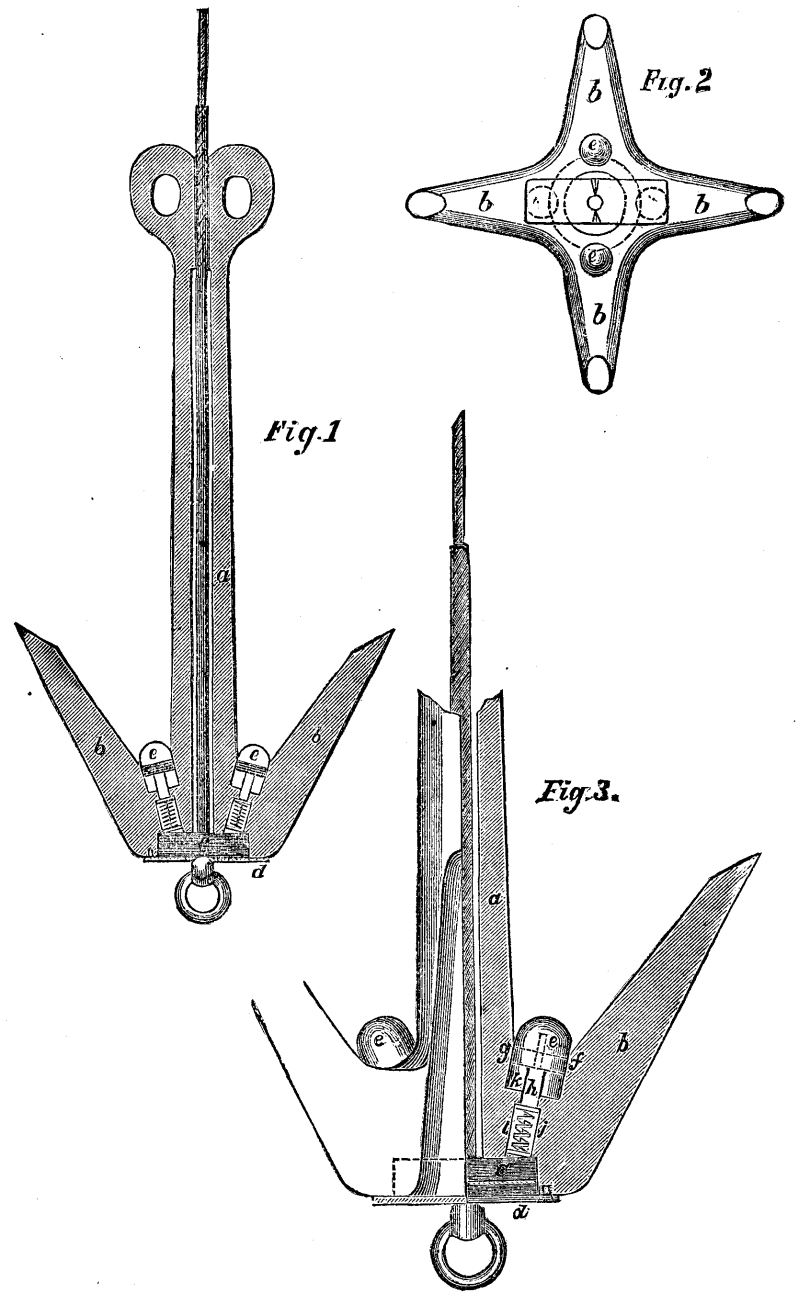
In addition to the foregoing remarks re the insufficiency of the dynamometer as an instrument for indicating the presence of a cable on the grapnel, I might remind engineers of the troubles and perplexities which occur incessantly in dragging over a rocky bottom. The grapnel hooks a rock, a large increase of strain is indicated on the dynamometer, and it becomes doubtful whether the cable as well is hooked or not. Again, it frequently happens in grappling over a rocky bottom that one or more prongs are broken off, the grapnel thus becoming useless, great waste of time being thus occasioned. Fully realizing all the difficulties herein enumerated, it occurred to me that a grapnel might be constructed in such a manner as to automatically signal by electrical means the hooking of the cable, while it would ignore all strain that external causes might bring to bear on it, and thereby obviate the uncertainties attached to the use of the grapnels at present in vogue. To effect this, I designed early in 1881 a grapnel fitted in each prong with an insulated conducting surface, and a plunger and pin so arranged that the cable, when hooked, should, by the pressure that it would bring to bear on any of the plungers, cause the pin to come in contact with the conducting surface, itself in electrical communication with any suitable current detecter and battery on board the repairing ship, and thereby complete the circuit. This grapnel was successfully used on the Anglo-American Telegraph Company's repairing steamer Minia in the summer of 1881.
Subsequently, in discussing the construction of the grapnel with Captain Troot, we concluded that something was yet wanted to render the successful working in deep water absolutely sure, and we decided, consequently, to make certain alterations.
This improved form may be constructed, either with a contact-plate in each prong, or with one contact-plate common to all the prongs; the latter is somewhat simpler, and is therefore the plan that we usually adopt. Both forms are shown in the accompanying diagrams. The form of grapnel in Diagram No. 1 has one advantage over the other in this respect, viz., that should a prong be ruptured so as to render it useless, the fact would immediately be known on board. A circuit formed in such a manner, by the breaking off of a branch lead, would have greater resistance than that formed by the contact resulting from pressure of cable on the plungers; this difference would be manifested on the indicator (of low resistance) placed in circuit with the alarm-bell, or, if any doubt remained, a Wheatstone's bridge, or simpler still, a telephone might be made use of.
In some cases we may protect the plungers from the pressure of ooze, etc., by guards fitted to the stem of the grapnel, but in practice we have not found these to be necessary.
The water is allowed free access around and about each separate part, in order that its pressure shall be equal on all sides. This arrangement renders the grapnel as effectual in the deepest as in the shallowest water.
By making the plungers in two pieces, with a rubber washer or its equivalent between them, we prevent mud or ooze from getting behind and interfering with their working. As the hole in the rubber surrounding the contact-plate, by caused the passage of the pin through it, closes up as soon as the pressure is removed, leaving in the rubber a fault of exceedingly high resistance, the rubber does not require renewing.
In the rubber in which we embedded the contact-plate, we place a layer or more of tinfoil or other easily pierced conducting surface, through which the pin passes on its way to the contact-plate proper. This method we have adopted in order to make the assurance of contact doubly sure.
The grapnel just described we had in use on the Minia since April last. We have tried it severely, and have never known it to fail. No swivel has been used with the rope, in the heart of which is the insulated wire, as it would allow the grapnel to turn over on the bottom, and would be apt to twist and break the wire short off. As a matter of fact, the grapnel will turn, and does turn, with the rope; a swivel is therefore of no value. We are perfectly awake, however, to the fact that a grappling-rope should be made in a manner that will not allow it to kink; and engineers should avail themselves of such rope, especially in deep water. Patents have lately been granted to Messrs. Trott & Hamilton for the invention of a form of rope or cable answering all the requirements of this work.
A small type of grapnel fitted in the manner I have described may be very advantageously used for searching purposes, to ascertain the position either of telegraph or torpedo lines; by towing at a quick rate much time may be saved. The position being ascertained, if it be not desired to lift the cable, the grapnel can be released and hove on board by a tripping line, which can always be attached when such work is contemplated. The great importance of being able to localize an enemy's torpedo lines without raising an alarm will be readily seen by engineers engaged in torpedo work.
a, stem of the grapnel containing core; b, flukes; c, recess for insulated contact-plate connected to core; d, covering plate screwed on bottom of grapnel; e, button of plug; f, rubber washer and button; g, metal-plate; h, stem of plug, on which in the under counter-sink, U is a small metal disk which prevents the fittings from fallings out; i, needle; j, spring; k, counter-sink for head of plug; l, counter-sink for spring.
A new magnetic balance has been described before the Royal Society by Prof. D. E. Hughes, F.R.S., which he has devised in the course of carrying out his researches on the differences between different kinds of iron and steel. The instrument is thus described in the Proceedings of the Royal Society:
"It consists of a delicate silk-fiber-suspended magnetic needle, 5 cm. in length, its pointer resting near an index having a single fine black line or mark for its zero, the movement of the needle on the other side of zero being limited to 5 mm. by means of two ivory stops or projections.
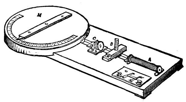
When the north end of the needle and its index zero are north, the needle rests at its index zero, but the slightest external influence, such as a piece of iron 1 mm. in diameter 10 cm. distant, deflects the needle to the right or left according to the polarity of its magnetism, and with a force proportional to its power. If we place on the opposite side of the needle at the same distance a wire possessing similar polarity and force, the two are equal, and the needle returns to zero; and if we know the magnetic value required to produce a balance, we know the value of both. In order to balance any wire or piece of iron placed in a position east and west, a magnetic compensator is used, consisting of a powerful bar magnet free to revolve upon a central pivot placed at a distance of 30 or more cm., so as to be able to obtain delicate observations. This turns upon an index, the degrees of which are marked for equal degrees of magnetic action upon the needle. A coil of insulated wire, through which a feeble electric current is passing, magnetizes the piece of iron under observation, but, as the coil itself would act upon the needle, this is balanced by an equal and opposing coil on the opposite side, and we are thus enabled to observe the magnetism due to the iron alone. A reversing key, resistance coils, and a Daniell cell are required."
The general design of the instrument, as shown in a somewhat crude form when first exhibited, is given in the figure, where A is the magnetizing coil within which the sample of iron or steel wire to be tested is placed, B the suspended needle, C the compensating coil, and M the magnet used as a compensator, having a scale beneath it divided into quarter degrees.
The idea of employing a magnet as compensator in a magnetic balance is not new, this disposition having been used by Prof. Von Feilitzsch in 1856 in his researches on the magnetizing influence of the current. In Von Feilitzsch's balance, however, the compensating magnet was placed end on to the needle, and its directive action was diminished at will, not by turning it round on its center, but by shifting it to a greater distance along a linear scale below it. The form now given by Hughes to the balance is one of so great compactness and convenience that it will probably prove a most acceptable addition to the resources of the physical laboratory.--Nature.
Cast iron may be hardened as follows: Heat the iron to a cherry red, then sprinkle on it cyanide of potassium and heat to a little above red, then dip. The end of a rod that had been treated in this way could not be cut with a file. Upon breaking off a piece about one-half an inch long, it was found that the hardening had penetrated to the interior, upon which the file made no more impression than upon the surface. The same salt may be used to caseharden wrought iron.
The accompanying engraving shows a form of Thomson's double bridge, as modified by Kirchhoff and Hausemann. The chief advantage claimed for this instrument consists in the fact that all resistances of defective contact between the piece to be measured and the battery are entirely eliminated--an object of prime importance in measuring very small resistances. By the use of this instrument resistances can be measured accurately down to one-millionth of a Siemens unit.
The general arrangement of the instrument is shown in Fig. 1; Fig. 2 being a diagram of the electrical connections.
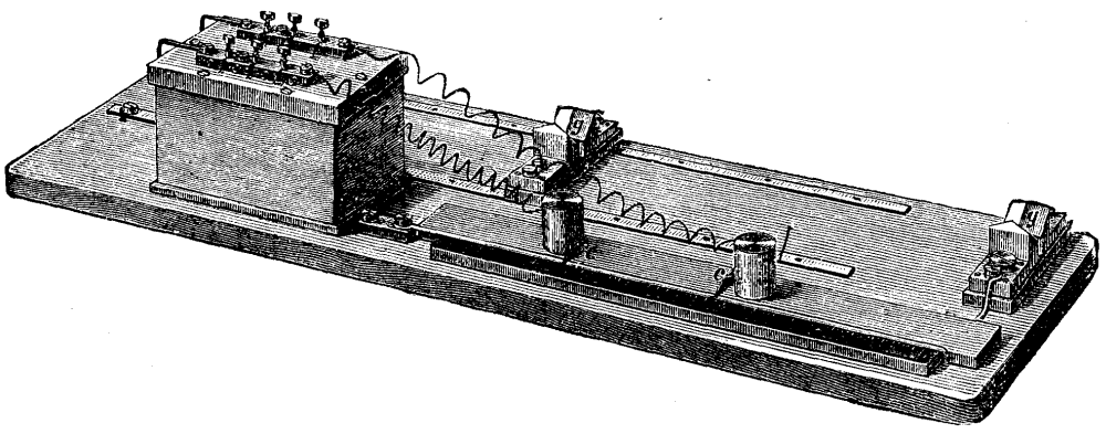
FIG. 1.--KIRCHHOFF AND HANSEMANN'S BRIDGE FOR
MEASURING SMALL RESISTANCES.
The piece of metal to be measured, M, is placed in the measuring forks, gg, in such a manner that the movable fork is removed as far as possible from the stationary one; if the weight of the piece be insufficient to secure a good connection, additional weights may be placed upon it. The main circuit includes the battery, B (Fig. 2), consisting of from two to four Bunsen cells, the key, T, the German silver measuring wire, N, and the piece of metal resting on the forks, all being joined in series. The German silver wire, N, is traversed by two movable knife-edge contacts, cc, as shown. Connections are made between these contacts, cc, the resistance box, the prongs, k and l, of the forks, gg, and the reflecting galvanometer, as shown in Fig. 2. A resistance of ten units is inserted at o and n, while at m and p twenty units or one thousand units are inserted. The positions of cc are then varied until the galvanometer shows no deflection when the key, T, is depressed.
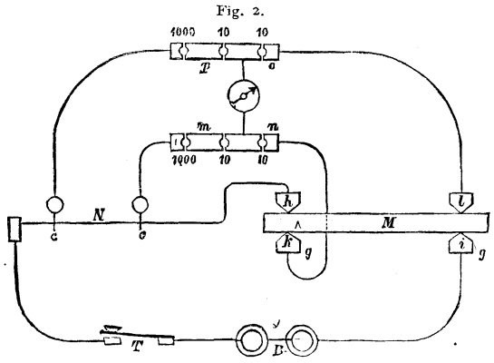
FIG. 2.--DIAGRAM SHOWING ELECTTRICAL CONNECTIONS OF BRIDGE.
When such is the case, the ratio of resistances n/m is equal to o/p; letting M equal the resistance of the metal bar between the points, h and i, and N equal to the resistance between the points, cc, on the measuring wire, N, then we shall have
M = N (n/m) = N (o/p).
Knowing the cross section in millimeters, Q, of the bar, and observing the temperature, t, in degrees Centigrade, its conductivity, x, as compared with mercury can be determined. If L be the distance, h l or k i, in meters, then
x = (1/m) (L/Q) (1 + at).
For pure metals the value of a may be taken at 0.004; but alloys have a different coefficient. The instrument is made by Siemens and Halske, and is accompanied by a table giving resistances per millimeter of the measuring wire, N.--Zeitsch. für Elektrotechnik.
[Footnote: For a full account of experiments relating to magnetism on railways in New York city, see SCIENTIFIC AMERICAN, January 19,1884.]
To the Editor of the Scientific American:
An item has appeared recently in several papers, stating that New York is a highly magnetized city--that the elevated railroad, Brooklyn Bridge cables, etc., are all highly magnetized. As this might convey to the general reader the impression that the magnetism thus exhibited was peculiar to New York city, and as many of your subscribers look anxiously for your answers to numerous questions put for the elucidation of apparent, scientific mysteries, I have thought that perhaps a statement in plain language of experiments made at various times, to elucidate this subject, might, in conjunction with a diagram, serve to explain even to those who have not made a special study of science a few of the interesting phenomena connected with
Some of the first experiments I made, while professor at the Indiana State University, were detailed in the March and August numbers, 1872, of the Journal of the Franklin Institute, and I think showed conclusively that the earth, by induction, renders all articles of iron, steel, or tinned iron magnetic; possessing for the time being polarity, after they have been in a settled position for a short time.
In Dr. I. C. Draper's "Year Book of Nature" for 1873, mention is made of the experiments in which I found every rail of a N. and S. railroad exhibiting polarity.
The same statements were repeated in one of a series of articles sent by me to the Indianapolis Daily Journal, dated Jan. 20, 1877, in which I used the following language:
"Every article of iron or steel or tinned iron, by the earth's induction, becomes magnetic. Thus, if we examine our stoves, or a doorlock, or long vertical hinge, or even a high tin cup, by holding a delicate magnetic needle in the hand near those objects, we find the earth has, by induction, attracted to the lower end of the stove utensils, etc., the opposite magnetism from its own; and repelled to the upper end of the stove, etc., the same magnetism which exists in our northern hemisphere. Consequently, the bottom of the stove, or of the hinge, cup, etc., will attract the south (or unmarked end) of our needle; while the top of the stove, etc., attracts the north, or marked end of our magnetic needle. If we apply our needle to the T rails of a N. and S. railroad, we not only find that the lower flange of the rail attracts the S. end of our needle, while the upper flange attracts the N. end of our needle, but we also find, where the two rails come nearly together (say within two inches), that the N. end of the rail attracts the S. end of our needle, while the S. end of the rail attracts the N. (or marked) end of our magnetic needle."
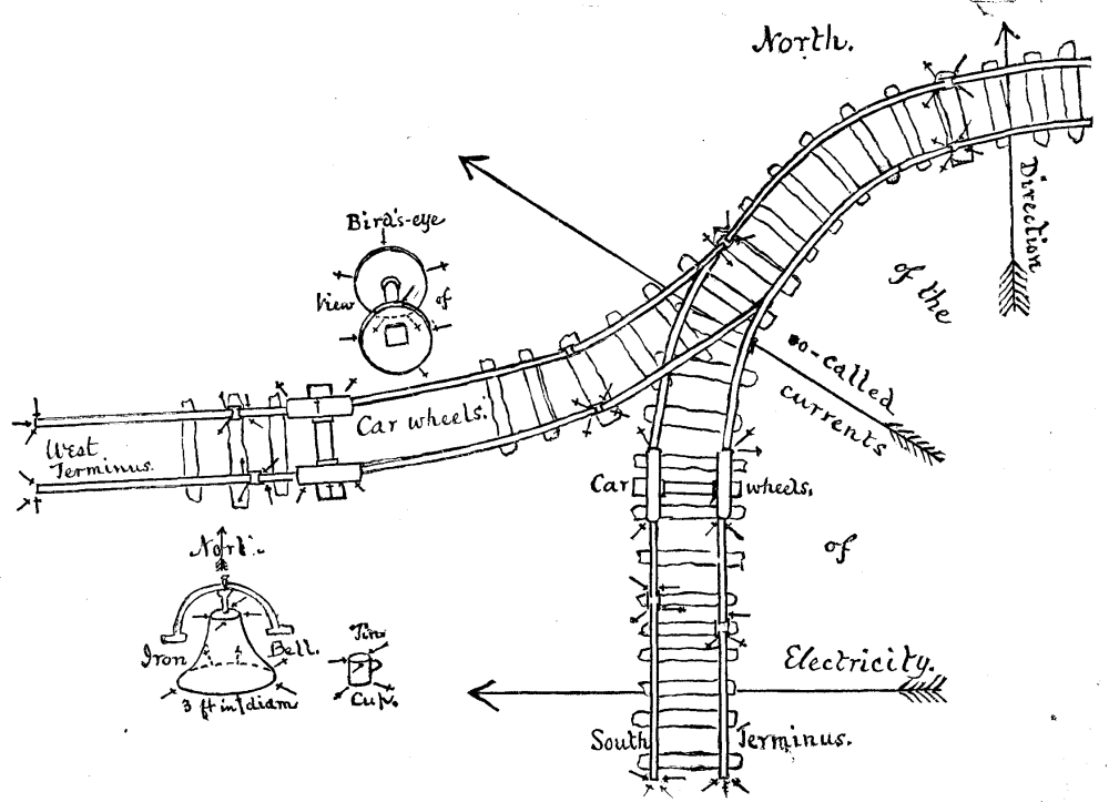
MAGNETISM ON RAILWAYS.
Quite recently, being anxious to see the effect produced on the needle by rails laid E. and W., I experimented on some recently laid here; starting from a S. terminus, in the town of New Harmony, and gradually curving northeast, until the road pursues a due east course to Evansville. There is, however, a branch road of about half a mile, which starts from the Wabash River, at a west terminus, and runs due east to join the other, near where that main track commences its northeast curve. The results (more readily understood by an inspection of the diagram) were as follows:
1. At the south terminus of the railroad, the rails on the east side of the track as well as those on the west side attracted at their south ends the marked end of a small magnetic needle, both at the upper and lower flange; the usual vertical induction being in this case overcome by the greater lateral induction. Whenever, on progressing north, the rails were at least about two inches apart, the upper flange of the north end of any rail would attract the unmarked, while the south end of its neighbor or any other of the north and south laid rails would attract the marked end.
2. The same results were obtained from rails laid all around the northeast curve, and even after they had acquired a due west to east course; showing that each rail acquired the same magnetic polarity which would be exhibited by any magnetic needle oscillating freely in our northern hemisphere, dipping also at its north end considerably downward if suspended at its center of gravity.
3. Applying the needle at the west terminus, a few anomalies were observed; but, especially nearer the junction, the rails all gave the normal result found on the main track.
4. The wheels of the cars standing on the north and south track followed the same law, exhibiting both vertical and lateral induction, so that the lower rims and the forward or north part of the periphery attracted the unmarked end of the needle, while the upper and rear, or south portions of the periphery of the wheel attracted the marked end.
5. The wheels of cars standing on the east and west road exhibited the following modification. The lowest rim of all the wheels, whether standing on the north rails or on the south rails of said track, in consequence of vertical induction attracted the unmarked end of the needle, and the upper rims attracted the marked end of the needle; but the middle portions of the periphery, both anterior and posterior, of the wheels standing on the north rail, attracted the unmarked end, while similar middle portions of wheels standing on south rails attracted the marked end; in consequence of horizontal induction, the wheels being connected by iron axles, and thus presenting considerable extension across the track, viz., from south to north.
Magnetite seems to have acquired its polarity in the same manner, namely by the earth's induction, when the ore contains a large enough percentage of pure iron. A large specimen (6 in. long by 3½ deep and weighing 5½ lb.) which I obtained from near Pilot Knob, Missouri, exhibits polarity, not only at its lateral ends, but also vertically, as the lower surface attracts the unmarked end of a needle, while the plane, which evidently occupied the upper surface in its native bed, attracts the marked end of the needle.
Iron fences invariably exhibit only the polarity by vertical induction; so also small buckets, bells, etc. But in the case of a bell about 3 ft. in diameter at its base, and over two feet deep, tapering to about a foot in diameter at the top, I found that although the top attracted the marked end of the needle, the bottom attracted the unmarked end of the needle only around the northerly half of the circumference, while the southern portion of this lower rim attracted the marked end in consequence of lateral induction, as in N. and S. rails.
Thus, upon a comparison of all these facts, it would appear that, if the magnetism induced by the earth is due to so-called currents of electricity, those currents must be underneath the rails, and must move from west to east, under the south to north rails, and from south to north under the west to east laid rails, as indicated by the arrows in the diagram.
This accords perfectly with what we should theoretically expect, in our northern hemisphere, if the electricity in the earth's crust is due to thermo-electrical currents from east to west, namely, from the more heated to the less heated portion, on any given latitude, while the earth revolves from west to east; as well as also from electrical currents trending from tropical to Arctic regions.
As the network of iron rails spreads from year to year more extensively over our continent, it will be interesting to observe whether or not any effect is produced, meteorological, agricultural, etc., by this diffusion of magnetism.
It may further interest some of your readers to have attention called to facts indicating
The year recently closed furnishes interesting corroborative testimony of an apparent law regarding the propagation of earthquake movements most readily along great circles of our globe, as well as evidence that these seismic movements are frequently transmitted along belts (approximating to great circles) coincident sometimes with continental trends, at other times with fissures which emanate in radii at every 30°, around the pole of the land hemisphere in Switzerland, as described in one of my papers, read at the Montreal meeting of the A.A.A.S.
The terms synchronism or synchronous, as here used, are not designed to imply absolute simultaneity (although that is sometimes the case with disturbances 180° apart), but are rather intended to indicate the tendency presented by these phenomena to exhibit this internal activity, during successive days, weeks, or even months, along a given great circle of the earth, especially one or more of those connected with the land center; perhaps most of all along the great circle which forms the prime vertical, when the center of land is placed at the zenith.
In order to test the above, let us examine the record of the most prominent earthquakes or volcanic eruptions for the year 1883.
Late in Dec., 1882, and early in Feb., 1883, shocks occurred in New Hampshire; on Jan. 11, 1883, also at Cairo, Illinois, and about the same time at Paducah, Ky.; Feb. 27 at Norwich, Conn., and early in Feb. at Murcia, Spain.
These, by examination of any good globe, will be found on a belt forming one and the same great circle of the earth.
Late in March and during part of April the volcano of Ometeke in Lake Nicaragua was active (after being long dormant); Panama, portions of the U.S. of Colombia, and of Chili; also, in May, Helena, M.T.; and, in June, Quito (with Cotopaxi active) were all more or less shaken by earthquakes; and are all found on one belt of a great circle.
The principal record for the remainder of the year comprised:
An earthquake at Tabreez in North Persia, early in May, 1883.
The awful destruction in Ischia, July 29 (with Vesuvius active).
The fearful eruption in the Straits of Sunda, 25th Aug. and later.
Shocks in Sumatra and at Guayaquil, about same date or early in Sept.
Shocks at Dusseldorf, according to a Berlin paper of 5th Sept.
Shocks at Santa Barbara and Los Angeles, early in Sept.
Shocks at Gibraltar and Anatolia in October.
Shocks at Malta, Trieste, and Asia Minor in October.
Azram shaken late in Sept., and great destruction between Scios and Smyrna.
Lastly, the formation of a new island in the Aleutian Archipelago. Date of outburst, early in October, 1883.
Besides these, there were several other less severe disturbances, the records of which are chiefly obtained from Nature, and which will-be referred to below.
If the globe be so placed as to have the land center at the zenith, the exact position of the new island, near Unnok, will be found under the brazen meridian, while Agram, Tabreez, Sunda, Sumatra, Quito, and Guayaquil are all on the prime vertical.
Vesuvius and Hecla were both active early in the year, and they, with the ever restless Stromboli, are situated on the great circle which forms with the land center at Mount Rosa, the radius running S. 30° E., and which would embrace the chief disturbances up to the middle of the year, including as we go north Malta, Sicily, Rome, region of the Po, Bologna, and in the Western Continent, after passing Hecla, Helena in Montana Territory, reaching in Washington Territory and Oregon the belt of it. American volcanoes: Mounts Baker, Rainier, St. Helens, Hood, and Shasta.
Still another seismic belt, starting from the ever active Fogo, and passing through Teneriffe (at that time erupted), would include the regions disturbed in Oct. and Nov., namely, Cadiz, Gibraltar, Malaga (Murcia and Valencia somewhat earlier); it then traversed the center of land, caused the earthquakes at Olmutz in Moravia, and even tremors felt at Irkutsk, as the seismic war moved along said great circle to the volcanic region of S. Japan.
Again, the belt which covers the meridian of land center (about 8°-10° E. long) covers also the region of a disturbanced area in Norway, as well as that portion of Algeria, viz., Bona, in which a mountain 800 meters high, Naiba, is gradually sinking out of sight. About 100 geo. miles E. of Bona is where Graham's Island appeared in the Mediterranean, and a few months later disappeared in deep water.
Another highly seismic belt extends from the volcanoes of Bourbon, N. Madagascar, and Abyssinia to Santoria and the oft disturbed Scios, Smyrna, and Anatolia region; and along the same great circle were shaken Patra in Greece on the 14th Nov., and Bosnia on the 15th; while shocks had been felt at Trieste and Mülhouse about the 11th, and at Styria on the 7th, and disturbances at Dusseldorf in Sept. Finally, on the 28th Dec. S. Hungary (near the confluence of the Drave with the Danube) was visited by seismic movements along this same great circle, which passes through the extinct volcanic region of the Eifel, the oft shaken Comrie in Perthshire, Scotland, the volcanic Iceland, our National Park with its thousands of geysers, the cataclysmic region of Salt Lake and the Wahsatch Mountains (so graphically described by the geologists of the U.S. Geol. Survey), giving rise in Sept. to the earthquakes of Los Angeles and Santa Barbara, and finally reaching the volcanic islands of the Marquesas group.
Thus the seismic efforts of 1883 may be seen to have expended their force partly along the great backbone of the S. and N. American Cordillera, but more especially from the center of land E. and W. along its prime vertical from Sunda to Quito, also southwesterly by the E. coast of Spain, as well as due S. through Algeria, and S. 30° E. through Rome, Naples, Sicily, etc. Finally, the autumnal catastrophes at and near Scios, Anatolia, etc., seem to have been caused by a seismic wave, propagated along the great circle, which often agitates Janina, and produces earthquakes at Agram, where this great circle crosses the prime vertical.
RICHARD OWEN.
New Harmony, Ind., 27 Feb., 1884.
Up to the present time, the methods employed in the province of Minas Geraes (Brazil) for obtaining iron permit of manufacturing it direct from the ore without the intervening process of casting. These methods are two in number:
1. The method by cadinhes (crucibles), which is the simpler and requires but little manipulation, but permits of the production of but a small quantity of metal at a time.
2. The Italian method, a variation of the Catalan, which requires more skill on the part of the workmen and yields more iron than the preceding.
As these methods seem to me of interest, from the standpoint of their simplicity and easy installation, I propose to describe them briefly, in order to give as faithful and general an aperçu as possible of their application. At present I shall deal with the first one only, the one called the method by Cadinhes.
The province of Minas Geraes ocupies a vast extent in the empire of Brazil, its superficies being about 900,000 square kilometers, representing nearly a third of the total surface.
The population is relatively small and is disseminated throughout a much broken country, where the means of communication are very few. So it is necessary to succeed in producing what iron is needed by means that are simple and that require but quickly erected works built of such material as may be at hand. The iron ore is found in very great abundance in this region and is very easily mined.
In the center of a mass of quartzites that seem lo constitute the upper level of the eruptive grounds of the province, there are found strata of an ore of iron designated as itabirite--a mixture of oxide of iron and quartz. These strata are of great thickness, and have numerous outcrops that permit of their being worked by quarrying.
These itabirites present themselves under two very distinct aspects and offer a certain difference in their composition. Some are essentially friable, and are called by the vulgar name of jacutingaes. It is this variety (which is the one most easily mined) that is principally consumed in the forges. The others, on the contrary, are compact. Their exploitation is more difficult, and before putting them into the furnaces it is necessary to submit them to breakage and screening; so the use of them is more limited.
The first variety contains less iron and more gangue, but, per contra, possesses much oxide of manganese. The second, on the contrary, is formed almost wholly of oxide of iron with but little gangue and only traces of oxide of manganese. The following are analyses of these two varieties of ore:
| Friable Ore | |
|---|---|
| Fe2O2 | 84.9 |
| Oxide of manganese | 9.2 |
| Water | 1.9 |
| Quartz | 4.1 |
| ------ | |
| 100.1 | |
| Compact Ore | |
|---|---|
| Fe2O3 and traces of manganese | 99.6 |
| Quartz | 1.1 |
| ------ | |
| 100.7 | |
Situation of the Forges.--A forge is usually placed on the bank of a brook, or rather of a torrent, which supplies the fall of water necessary for the motive power by means of a flume about a hundred meters in length. In most cases the forge is surrounded on all sides with a forest which yields the wood necessary for the manufacture of the charcoal, and is in the vicinity of the iron quarry, so as to reduce the expense of hauling the ore as much as possible. The neighboring rocks furnish the foundation stones and stones for the furnaces; the decomposed schist gives the cement and refractory coating, and the forest provides the wood necessary for the construction of the road, sheds, etc. The head of the trip hammer, the anvils, and the tools are the only objects that it is necessary to procure, and even these the master of the forge often manufactures in part, after beginning production with an incomplete set.
[Illustration: 7a FIG 1.--FOUR-CRUCIBLE FURNACE AND FORGE; (PLAN).]
General Arrangement of a Forge.--A forge usually consists of one or two furnaces of three or four crucibles (the one shown in plan in Fig. 1 has only one four crucible furnace, A); 1 or 2 two fire reheating furnaces, B; 1 trip hammer, C, actuated by a hydraulic wheel, D; 2 tromps which drive the wind, one of them, E, into the cadinhes (crucibles), and the other, F, into the reheating furnace; 2 anvils, G and H, placed near the furnace, for working delicate pieces; and finally, the different tools that serve for maneuvering the bloom and finishing the bars. The charcoal is preserved from rain under a shed, l. The ore, which is brought in as needed, is dumped in a pile at M, in the vicinity of the crucibles. The buildings are set back against the mountain, and the water is led in by a double flume, L and N, made of planks, and empties on one side into the wheel and into the tromp, F, and on the other into the tromp, E, and then runs into a double waste channel, P and Q, which carries it to the stream.

FIG 2.--FOUR-CRUCIBLE FURNACE; (PLAN).
Four Crucible Furnace (Fig. 2).--The arrangement of a furnace is very simple. It consists of a cube of masonry containing several cylindrical apertures with elliptic bases, whose large axis is paralleled with the smaller side of the masonry. This form recalls that of a crucible; and these cavities are, moreover, so named. In the front part of each cadinhe there is a rectangular aperture that gives access to the bottom of the crucible and facilitates the removal of the bloom therefrom. At the back part there is a small aperture for the introduction of the tuyere, and which permits, besides, of the nozzle of the latter being easily got at so as to see whether the blast is working properly.
The sides of the crucibles are covered with a thin layer of refractory clay, and their bottoms have a spherical concavity to hold the bloom. The tuyere, which is fitted to a wooden conduit of square section that runs along the back of the masonry, is placed in the axis of the cadinhes and enters the masonry at a few centimeters from the bottom in such away that its nozzle comes just flush with the surface of the refractory lining. This arrangement prevents the tuyere from getting befouled by scoriæ during the operation of the furnace and thus interfering with the wind.
Tromp.--The tromp which furnishes the necessary wind to the cadinhes consists of a hollow wooden conduit, a (Fig. 3), of square section, which enters a chamber, b, along a length of 0.1 m. This conduit, which is about 7 meters in height, receives the water from the flume through the intermedium of an ajutage of pyramidal form, which serves to choke the vein of liquid, and the extremity of which is at a few centimeters from the conduit in order to facilitate the entrance of the air; the latter being attracted by an ill defined action that is supposed to be due to its being carried along by the water, and to a depression produced by choking the flow of the liquid.
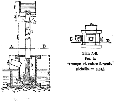
FIG. 3.--THE TROMP.
Since the air that is sucked in during the operation has constantly same pressure, there is no valve for regulating the entrance of the water into the vertical conduit. Upon issuing from the latter, the mixture of air and water strikes the surface of the water in the chamber, b, and the violence of the shock upon the bottom is deadened by the interposition of a stone. While the water is escaping through a lateral aperture in the chamber, b, the air is reaching the tuyeres through a wooden conduit of square section which is fitted to an aperture in the upper part of the chamber. This sorry arrangement, which obliges the mixture of air and water to penetrate the water at the bottom of the upright conduit, a, retards the separation of the two fluids, and results in damp air being forced into the crucibles.
The Trip Hammer.--Fig. 4 shows the general arrangement of the apparatus that go to make up the forging mill. The hammer and cam shaft have their axes parallel, and the latter is placed in the prolongation of the axis of the wheel. The hammer consists of a roughly squared beam, 4 meters in length, and of 0.25 m. section. The head, A, consists of a mass of iron weighing 150 kilos, including the weight of the straps that surround the beam on every side of the piece of iron. The axis of rotation is situated at the other extremity of the beam, B. The cam shaft which serves to maneuver the trip hammer is provided with four cams which lift the beam at a point near the hammer. The length of this shaft (to the extremity of which is adapted the water wheel) is 4.75 m., and its diameter is 0.50 m. The wheel is an overshot one, 3.25 m. in diameter by 1 m. in width. The water, which is led to it by a flume, acts upon it by its weight and impact, and is retained in the buckets and kept from overshooting the mark by a jacket made of planks.
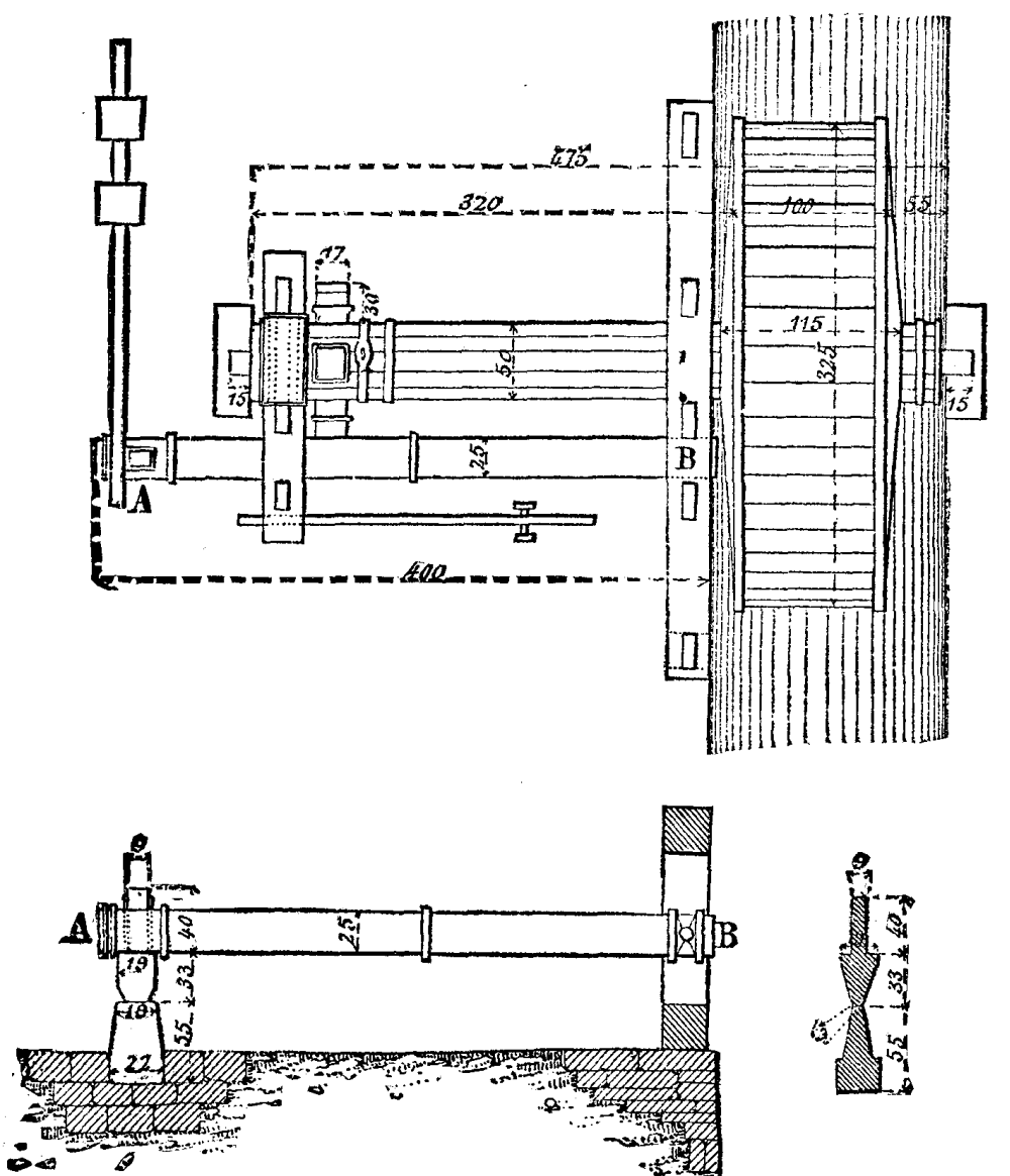
FIG. 4.--THE TRIP HAMMER.
The anvil upon which the hammer strikes is surrounded by a bed of stones (quartzites) derived from the neighboring rocks. It is a mass of iron, 75 kilogrammes in weight. In order to prevent vibrations in the trip hammer when it is lifted, and increase the number of blows, there is established a spring beam, which is formed of unsquared timber, which is firmly fastened at one of its extremities, and which receives at the other end the shock of the hammer head when the latter reaches the end of its upward travel.
Reheating Furnace.--This is a double fire furnace, like those used in our smithies, except that the wind, instead of being forced into it by means of a bellows, is supplied by a tromp which receives water from the same channel as the wheel. The two furnace tuyeres are arranged exactly like those of the cadinhes, upon a wooden conduit which starts from the wind chamber (Fig. 5). This furnace serves to prevent the cooling of such blooms as are awaiting their turn to be shingled, and of such bars of finished iron as are being made into tools.
A forge like the one whose plan we give, may be run with 1 workman at the cadinhes, 1 assistant, 1 workman at the hammer; total, 3 men.
Furnace.--The work lasts about twelve hours per day, and three operations of three to four hours are performed in each cadinhe, thus making twelve per day. At each operation, 22.5 kilos. of ore and 45 of charcoal are used. From this there is obtained a bloom of 15 kilos. The operation is performed as follows:
While the assistant has gone to put the bloom of the preceding operation under the hammer, the workman prepares at the bottom of the crucible a bed consisting of a mixture of sand and very fine charcoal, and then fills the crucible up to its edge with charcoal. At the end of a quarter of an hour, the fuel being thoroughly aglow, the workman puts in the first charge of ore in powder (jacutingue), about 2 kilos, and covers it with charcoal.
Starting from this moment, he goes on charging every five or ten minutes with 1.5 to 2 kilos of ore, taking care in doing so to keep the crucible stuffed with charcoal, which the assistant places in piles around each cadinhe. This lasts about two and one-half hours. At the end of this time he stops putting in charcoal, and standing upon the masonry, walks from one cadinhe to another, carrying a large rod, in order to study the lay of the bloom. Then, the fire being entirely out, he scrapes out the bed of sand and charcoal that closes the opening in the bottom of the crucible, removes the mass of ferruginous scoriæ which forms a hard paste and surrounds the bloom, and takes this latter out by means of a hook.
The workman runs the four cadinhes at once, this being easily enough done, since he has neither to bother himself with regulating the wind, which enters always with the same pressure, nor with the flow of the scoriæ, which remain always at the bottom of the crucible. His role consists simply in keeping his fires running properly, being guided in this by the color of the flame without making an examination in the interior. He draws each of the four blooms out from its bed at the end of the operation, while the assistant carries the first to the hammer and the three others to the reheating furnace. He afterward cleans out the crucible, prepares the bed of sand and charcoal, fills with charcoal, and then passes to the next, and so on.
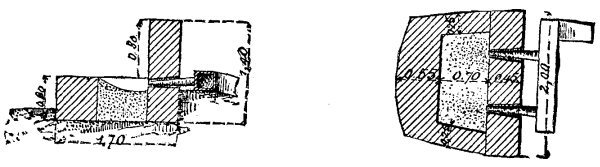
FIG. 5.--REHEATING FURNACE.
Trip Hammer.--The workman at the hammer takes the bloom from the hands of the assistant and shingles it under the head. Then he begins to give it shape, bringing it to the state shown at c, in Fig. 7. The assistant then brings him another bloom and takes the one that has been shingled to the reheating furnace, where he heats but one of its extremities. When the four blooms have been shingled, the workman takes up the first and begins to draw out one of its extremities, which he afterward cools in water and uses as a handle for finishing the work, d. Then he reheats the other extremity, and, after drawing it out as he did the other, obtains a bar of finished iron which he doubles, as shown at e, to thus deliver to the trade.
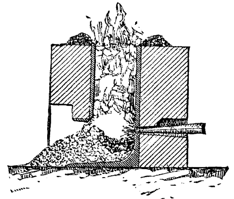
FIG. 6.--CADINHE IN OPERATION.
One of these bars weighs from 11 to 12 kilogrammes. It will be seen that, during the course of the work, the furnace workmen and the hammer workmen have well defined duties to perform; but it is not the same with the assistant, who goes from one to the other according to requirements. There are, however, some forges in which each of the workmen has an assistant, since the blooms produced are heavier, and one assistant would not suffice for the work of the two men. In such a case the assistant at the crucibles carries the blooms to the reheating furnace, and the assistant at the hammer carries them from thence to the hammer.
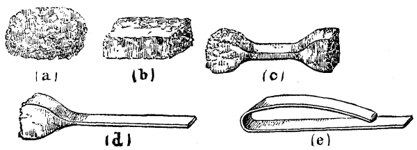
FIG. 7.--WORKING THE BLOOM.
We have seen that the workman who has charge of the fire contents himself with putting charcoal and ore alternately into the crucibles, and that too according to the aspect of the flames, without making any examination in the interior, in order to judge whether the work is proceeding well. The bloom forms gradually beneath the nozzle of the tuyere, in the center of the bed of sand and charcoal, and is surrounded on every side with an exceedingly pasty mass, formed of silicates of iron and manganese (Fig. 7). It is only at the end of the operation that the workman, by means of a rod, causes the burning coal to drop and verifies the proper position of the bloom by breaking the layer of scoriæ that surrounds it. This coating he breaks off, removes the bloom with a hook, and agglutinates with his rod the different bubbles that it exhibits, and the assistant then carries it to the hammer.
To set up a forge like the one we have described, it is necessary to count upon a first cost of about 10,000 francs. Add to this the cost of 50 hectares of forest to furnish the charcoal that the workmen have to make every day. The cost of this is very variable, and floats between 2,500 and 5,000 francs per 100 hectares. The cost the ore is only that connected with getting it but and hauling it.
Manual Labor.--The charcoal burners receive 1.25 francs per load of 90 kilos, thus bringing the price of the product (including cost price of forest) at 2.4 francs per 100 kilos. The workmen in the furnace are paid at the rate of from 2.50 to 3.75 francs per day. Those that work the hammers receive 3.75 francs, and the assistants 1.25 francs.
Carriage of the Forged Iron.--The iron is carried from the forge to the places of consumption on the backs of mules, and the cost of carriage is, on an average, 0.25 franc per 100 kilos and per kilometer.
Selling Price.--The selling price is very variable, and depends principally upon the distance of the place where sold from the different forges that surround it. At Ouro Preto the price varies between 45 and 50 francs per 100 kilos.
The following is a resume of the data which precede:
Cost of first establishment.................. 10,000 fr.
Charcoal per kilogramme......................   2.40
                      { Furnace men.... 2.50 to 3.75
Manual labor per day  { Hammer men............. 3.75
                      { Assistants............. 1.25
Carriage of forged iron per kilometric ton..... 2.50
Selling price per 100 kilos................ 45 to 50
--Le Genie Civil.
We give engravings of the Churchill, a vessel lately built to the order of Mr. Walter Peace, London agent to the Natal Harbor Board, by Messrs. Hall, Russell, and Co., Aberdeen. She was designed by Mr. J.F. Flannery, consulting engineer to the Board, for special service at Natal. The Churchill has been constructed so as to be capable of towing into or out of harbor over the bar in any weather, of acting as a very powerful fire engine, of carrying a large amount of fresh water for the use of other ships, of landing troops from transports which the harbor is too shallow to admit, of recovering lost anchors and cables, of which there are a large number off the coast, and of acting in time of need as a torpedo or coast defense vessel; she was launched on the 16th August, and is likely to fulfill all these requirements.
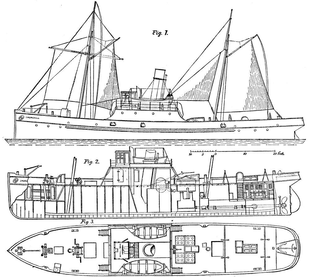
THE NEW STEAMSHIP CHURCHILL.
The principal dimensions of the vessel are: Length between perpendiculars 115 feet, breadth, extreme, 22 feet, depth of hold 11 feet, and maximum draught with full bunkers 7 feet 6 inches. There are four water-tight iron bulkheads forming five compartments; the stern is built very full to protect the propellers. Accommodation is arranged on deck for the captain aft with two spare berths, mate and two engineers amidships, while six white hands will occupy the forward forecastle, and six Kaffirs the after one. For towing purposes she is fitted with one main and two skip hooks secured to the main framing; towing rails are placed aft, while bitts are put on one each quarter, will be seen by referring to the deck plan.
The vessel is propelled by twin screws 6 feet 8 inches in diameter and 13 feet 6 inches pitch; these are of cast iron, have four blades, and are driven by a double pair of compound inverted direct acting engines (see Figs. 4 to 7) which are capable of developing 600 indicated horse power, and whose cylinders are 19 inches and 34 inches in diameter with a stroke of 2 feet. The condensers form part of the engine frame, and have guide faces cast on for the crosshead shoes. They are fitted with gun metal tube-plates, and each contain 516 tubes, 3/4 inch in diameter, which have an exposed length of 6 feet 5 inches, and give a total cooling surface of 650 square feet. The air and circulating pumps are bolted to the back of the condensers, and are worked by levers from the engine crosshead. Each engine has one feed and one bilge pump attached to the air pump, and worked by the same lever. The plan of the engines shows the pump arrangement very completely.

ENGINES AND BOILERS OF THE NEW STEAMSHIP CHURCHILL.
The steam is supplied by two circular return tube boilers, 9 feet 6 inches in diameter and 10 feet long, with two furnaces in each. The boilers, which are of steel throughout, except the tubes, are placed longitudinally, and are fitted with two pairs of the Martyn-Roberts patent safety valves. They have one steam dome between them. The total heating surface is 1,700 square feet, the total steam space is 330 cubic feet, and the working pressure 100 lb. per square inch.
The fire pump is a Wilson's "Excelsior," with 10 inch steam cylinder and 8 inch water barrel. This powerful pump is in a special compartment of the fore hold, and will draw water from the bilge, sea, or either hold. A steam windlass and a double-handle winch are on deck as shown. On trial trip the engines of the Churchill indicated a maximum of 645.5 horse power, driving the vessel 10.495 knots per hour. The vessel is remarkable for diversity of uses, for heavy engine power in a small hull, and for general compactness of arrangement.--Engineering.
Mr. T.R. Cramton, who at the Southampton meeting of the British Association suggested a method of tunneling which, under certain conditions, seems of excellent promise, brought forward a suggestion at Southport for the construction of three-way tunnels. Now, the undoubted aim of all engineers is economy of construction and the securing of permanent advantages. Mr. Crampton maintains that the suggested system will give these, that three tunnels of, say, 17 ft. diameter, can be constructed cheaper than one of 30 ft. diameter. After describing Sir J. C. Hawkshaw's scheme for the ventilation of long tunnels, the three-way scheme was discussed. Three separate tunnels of 17 ft. diameter each, or 227 ft. area, are to be connected by large passages about midway of their length. These passages are without valves; in fact, free air passages. Between these midway connections and the ends, say again midway between, is formed a branch at right angles either above or below with separate openings from the branch into the other tunnels, such openings being provided with doors or valves quite clear of the main tunnel, any two of which may be closed, thus separating at this point the corresponding tunnels from the third. The branch is to be led to any convenient position where the exhustion apparatus can be placed. If two of the tunnels are left open to this branch, and the third one shut off from it by closing the doors, the vitiated air will be drawn from the two working tunnels, through the connecting branch, while fresh air will be partly sucked down the vertical shafts through their open ends and partly at the center tunnel, which is supplied by forcing air down the vertical shaft in communication with it, a stop or door being placed just outside of the bottom of the shaft so as to compel the air to flow to the center of the tunnel. It will be observed that no trains are running in this air tunnel so long as it is so used; there are similar doors for the working tunnel, but they are kept open, unless either of them is required to be made into an air tunnel, so that the passing trains run no risk of running into the doors. By means of the doors above mentioned, any one of the three tunnels can be used as a fresh-air tunnel, in which the men doing the repairs to the road would be clear of the traffic, while the other two are used for the traffic, as well as outlets for the mixed impure gas and air. If a breakdown of a train occurs in any one tunnel, that tunnel can at once be converted into a fresh-air one, while its traffic is transferred to the one previously used for air, thereby avoiding delay. The system described for splitting the air and drawing off the noxious gases is very similar to that described by Mr. Hawkshaw at Southampton. The valves and other details being added, to make the system applicable to three tunnels, it will be obvious that other modes of ventilation may be adopted. In order to reduce the number of men working in the tunnel it is proposed, if found practicable, not to adopt the ordinary ballast and cross sleepers, but to substitute the longitudinal timber system, the timbers to be secured to brickwork or concrete, forming a part of the tunnel lining, placing efficient elastic material between the foundation and longitudinals for their whole area, also between the rails and sleepers. An open drain is formed between the rails; by this plan any water accumulating flows over smooth surfaces through small channels into a drain, the tunnel on each side being dry. The saving of labor in repairs, if this system can be employed, is so evident that a large amount of money might be expended in endeavoring to discover a suitable elastic material for the purpose. There are data on many long viaducts sufficient to justify experiments being made on the subject, and it is not unreasonable to expect that suitable material may be met with. In very long tunnels nothing should be omitted tending to reduce the number of men working in them. The opinion was expressed that in tunnels passing through solid materials, and proper foundations being made for the longitudinals to rest upon, with good elastic material placed between the rails and sleepers and foundations, one-half of the men employed on the ordinary cross sleeper road resting on ballast would be saved, more particularly as the repairs are effected in pure air free from the traffic as explained. The estimate as to the cost of this system was upon the dimensions given by Sir J. Hawkshaw, and the following gives the comparison:
The quantity of excavation and brickwork or concrete in each case will be as follows: Single tunnel: 30 ft. diameter lining, 3 ft. thick, with the brickwork forming the air passage = to 36.5 cubic yards per yard forward. Excavation to outside of brickwork 36 ft. diameter = to 113 cubic yards per yard forward. Three tunnels 17 ft. diameter and 18 in. brickwork. Brickwork lining for three tunnels = 24.5 cubic yards per yard forward. Excavation outside brickwork for the same 105 cubic yards per yard forward. It is assumed that three 17 ft. tunnels are stronger, more conveniently formed, and involve less risks in construction than one of 30 ft. diameter; at the same time there is no difficulty in making the latter. The above shows the saving in the three tunnels of 23 per cent. in brickwork, and about 7 per cent. of earthwork, compared with one of 30 ft. With regard to ventilation, it is well known that the power required to force air along passages is practically as the cube of the velocity; and as the area of the air passages in the single tunnel is 106 ft. with speed ten miles per hour, and that of one of the 17 ft. diameter is 227 ft., or rather more than double, giving only five miles per hour velocity, it follows that the power for this portion would be eight times less. That for the working tunnels would be practically the same, the velocities being nearly alike in both cases, which would be about 2½ miles per hour--the 30 ft. having an area of 470 ft., the two single ones together about 450 ft. Upon the face of it the system deserves a trial. A full consideration of the scheme by engineers preparing plans for new tunnels would no doubt throw further light upon the subject and be of interest wherever such work is contemplated.--Contract Journal.
Every one who has the slightest regard for historical monuments, who values mediæval architecture, or cares in the least degree for the beautiful and the picturesque, must heartily sympathize with M. Victor Hugo in his protest against the proposed scheme for uniting the wonderful island of Mont St. Michel with the mainland by means of a causeway, and possibly a railway!
Those who know Mont St. Michel well, and, like the writer, have spent several days upon the island, cannot but feel that such a scheme would not only be a frightful disfigurement, but would entirely destroy all the associations and the poetry of the place. Practical people will say, "Modern improvement cannot stop in its march forward to consider poetical associations and mere artistic whims and fancies." Now, this would be a possible argument if Mont St. Michel were a busy, thriving town, a commercial port, or the seat of great industries; but in a case where the only trade is that of touting, the only visitors sightseers, the only "stock-in-trade" mediæval remains, surely, from a practical point of view, anything which will injure these antiquities will really destroy the importance of the island, as its only value consists in its wonderful historic and artistic associations.
MONT ST. MICHEL, NORMANDY.
The first glimpse of Mont St. Michel is strange and weird in the extreme. A vast ghostlike object of a very pale pinkish hue suddenly rises out of the bay, and one's first impression is that one has been reading the "Arabian Nights," and that here is one of those fairy palaces which will fly off, or gradually fade away, or sink bodily through the water. Its solemn isolation, its unearthly color, and its flamelike outline fill the mind with astonishment.
Mont St. Michel is by far the most perfect example of a mediæval fortified abbey in existence, with its surrounding town and dependencies, all quite perfect; just, in fact, as if time had stood still with them since the fifteenth century. The great granite rock rises to the height of two hundred and thirty feet out of the bay; it is twice an island and twice a peninsula in the course of twenty-four hours. The only approach is at low water, by driving or walking across the sands. When, however, one arrives within a few yards of the solitary gate to the "town," walking or driving has to be abandoned, and here the commercial industries of the inhabitants commence. A number of individuals, half sailors and half fishermen, are standing ready to carry you on their shoulders over the small gully, which is very rarely quite dry. Entering through the old gate one sees two ancient pieces of cannon taken from the English, who unsuccessfully laid siege to the place in 1422. Close to the gate are the two rival inns, which are very primitive in their arrangement, the entrance hall forming the kitchen, as in many old Breton houses. A second frowning old gateway leads to the single street, which, passing between two rows of antique gabled houses, and under the chancel of the little parish church, conducts one to the almost interminable flight of stone steps leading to the gateway of the monastery. Upon ringing the bell a polite lay brother opens the iron-studded door, and we are admitted into a solemn, vaulted hall, with another stone staircase opposite. Here we go up and up, to a second vaulted hall, where, in olden times, we should have had to give up any arms which we were carrying. Then another stone staircase, which lands us in a small court with a well in it, at the opposite end of which is a heavy and solid arched doorway. We pass through this, expecting to find ourselves on the top of the central tower of the church at least, and are surprised to find ourselves in the solemn and almost dark crypt of the church. Here we have climbed up some 230 feet above the world and the sea to find ourselves in an underground vault; up in the air and down under the rock at the same time. Wonderfully beautiful is this strange crypt, when one's eye gets accustomed to the gloom, with its exquisite ribbed and vaulted roof, supported upon huge circular columns. Returning to the court, another doorway conducts us into a most superb Gothic hall, with a row of slender columns down the center. This was the monks' refectory in ancient times; adjoining this is another grand hall, divided into four aisles by rows of granite columns, all of the most perfect thirteenth century work. Above these are two other halls, still more magnificent than those below. One of these, called the "Salle des Chevaliers," is probably the most beautiful Gothic hall in existence. Again a flight of stone stairs, and we find ourselves, where we should certainly not have expected, in the cloisters of the monastery, the exquisite architecture of which, with its countless marble columns and delicate double arcades, cannot be described.
The church deserves a few words, as it is a veritable cathedral as to size and grandeur. The choir is immensely lofty, and constructed of granite most elaborately wrought in the later Gothic or flamboyant style. The nave and transepts are in the old Romanesque style, with solid pillars and low round arches. The church is beautifully kept, and contains some very interesting old reredoses and altars with carving in alabaster. The one modern altar in the Lady Chapel is composed entirely of silver! Our space will not permit us to describe the numerous interesting old Abbey buildings--the library, the prior's lodging, the vast kitchen, the prisons, the dungeons, and the means of supplying the place in times of siege. The proposed causeway would join the island to the left of our view, and our readers can imagine the abominable effect of a high embankment disfiguring this point, and breaking through the interesting old walls and towers, with, perhaps, a Brummagem Gothic station against the old time-worn gateway.--H. W. Brewer, in London Graphic.
The cuts given herewith, taken from the Illustrirte Zeitung, represent two statues for the new Post Office at Leipzig. The sculptor, Kaffsack, has represented the post and the telegraph as winged female figures. The figure representing Mail holds a horn or trumpet in her left hand, and a letter in her right hand. The figure representing Telegraphy holds a bunch of thunderbolts in her left hand, and unrolls a band for receiving dispatches with her right hand. It will be observed that the figure representing Telegraphy is made much lighter and more graceful than the figure representing Mail, and has also a more energetic expression of countenance, thus indicating the greater speed of Telegraphy.
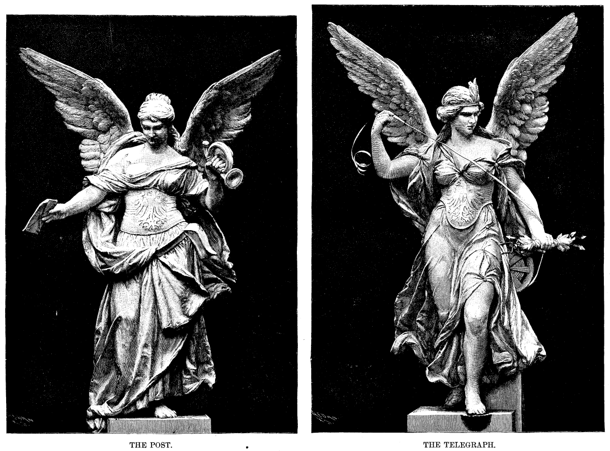
ADORNMENTS OF THE NEW POST OFFICE, LEIPZIG, GERMANY.
Gas, as a fuel, is an absolute necessity to the economical carrying out of many commercial processes. It is often used in the crudest and most costly way; a burner may be perfect for one purpose, yet exceedingly wasteful for another, and however good it may be, an error of judgment in its application may lead to its total condemnation. An excess of chimney draught, in cases where a flue is necessary, may pull in sufficient excess of cold air to almost neutralize the whole power of the burner, unless a damper is used with judgment. With solid fuel, an excess of draught causes more fuel to be burnt, but with gas the fuel is adjusted and limited; there is no margin or store of fuel ready to combine with the excess of air, which, therefore, lowers the amount of work done by its cooling power. The power of any burner, for any specified purpose, depends not only on its perfection, but to a far greater extent on the difference in the temperature of the flame and of the object to be heated. For instance, if a bright red heat is required, it is not possible to obtain this temperature economically with any burner working without an artificial blast of air; the difference between the temperature of the flame and that of the object heated is too little to enable the heat to be taken up freely or quickly, and the result is a large loss of costly fuel. If we want to obtain high temperatures economically, an artificial blast of air is necessary, and the heavier the pressure of air, the greater the economy. On the contrary, low temperatures and diffused heat are obtained best by flames without any artificial air supply.
For such purposes as ovens, disinfecting chambers, japanners' stoves, founders' core drying, and similar requirements the best results are obtained by a number of separate jets of flame at the lowest part of the inclosed space, and the use of either illuminating or blue flames is a matter of no importance, as the total amount of heated air from either character of flame is the same. If there is any preference, it may be given to illuminating flames, as the proportion of radiant heat is greater, and this makes the average temperature of the inclosed space more equal; but on the other hand, may be considered the greater liability of the very fine holes, necessary for illuminating flames, to be choked with dust and dirt. This may, to a great exent, be obviated by using very small union jets, and setting them horizontally, so as to make a flat horizontal sheet of flame. Burners placed this way are practically safe from the interference of falling dust or dirt, but not from splashes. Falling dirt or splashes must always be considered in the arrangement of any burners, and the ventilation must be no greater than is absolutely necessary for the required work. In cooking, this limit of ventilation may be exceeded, as most things are better cooked with a free ventilation, the extra cost of fuel being well compensated for by the better quality of the result.
The air in an oven or inclosed space heated by flames inside is similar in character to highly superheated steam. It contains a large proportion of moisture, and yet has the power of drying any substance which is heated to near its own temperature. A mass of cold metal placed in the oven is instantly bedewed with moisture, which dries up as the temperature of the metal rises. This is, for many purposes, an objection, and the remedy is to close the bottom of the oven and place burners underneath. If for drying purposes and a current of air is necessary, the simplest way is to place in the bottom of oven the a number of tubes hanging downward in such a position that the heat of the flame acts both on the bottom of the oven and the sides of the tubes, which, of course, must be long enough for the lower opening to be well below the level of the flame. The exit may be at any level, but for drying purposes it is better at the top, and it should be controlled by a damper to prevent cooling by excessive currents of air. If not otherwise objectionable, the arrangement of flames inside the oven is far the most economical in use.
Where an oven or drying chamber is used continuously, it should be jacketed with slag wool or boiler composition, but for many purposes this is no advantage. As an example both ways, I will instance the drying of founders' cores where there is only one blow per day. The cores of an ordinary foundry can be dried by gas in a common sheet iron even in about half an hour; any accumulation of heat after that time would be useless, and a jacketed oven would be of no advantage.
For the disinfection of clothes in vagrant wards and hospitals for infectious diseases, on the contrary, a continued heat is necessary, and in this case the accumulation of reserve heat, which takes place slowly in a jacketed oven, becomes of value, as the gas can be turned low or out, and the ventilators closed, insuring a more complete disinfection with a much smaller gas consumption. Where an oven or heated chamber is much used for periods of over half an hour at once, a non-conducting casing pays well by reduced gas consumption.
For albumen and glue drying, leather enameling, tobacco drying, and purposes where a large space has to be very slightly and equally warmed when the weather is unfavorable, steam-pipes are generally used, but, not being always available, an exceedingly good arrangement may be made by placing at intervals in the room gas burners, of any construction, close to the floor, and surrounded with a sheet-iron cylinder, say 2 ft. or 3 ft. high. The top of these cylinders must be connected throughout with a fairly large flue, which will take the products of combustion from the whole, and this flue must be carried either horizontally, or with a slight rise, so as to utilize all the waste heat. The reason for having a number of stoves at intervals is that the heat in a flue will not carry, for any useful purpose, more than about 8 ft. or 10 ft., and a single stove would give an irregular temperature in any except a very small room. If all are not used at once, the flues of those not in use may be closed by a damper to prevent down draught. The use of hot water pipes heated by gas may also be occasionally advisable, but, unless for some special reason, it is much more economical to use coal or coke, as the bulk of water makes an exceedingly good regulator, and makes a fire practically as steady and reliable as gas, thus superseding the more costly fuel.
For one of my own purposes I need hot-water pipes, having very little variation in temperature night and day; and using coke for economy's sake, I get a regular temperature by heating a large quantity of water, about 200 gallons, with the fire, and inclosing this in a tank jacketed with slag wool. My circulating pipes run from this tank, and a practically steady temperature, night and day, can be obtained with the most irregular firing, and occasional extinction of the fire for several hours at once.
For the heating of liquids, the greatest economy is to be obtained from one single flame, of as high a temperature as can conveniently be obtained, and the flame must be in actual contact with the vessel to be heated. In jacketing vessels, to prevent draughts, care must be taken that the jackets do not cause currents of cold air to rise rapidly up the sides of the vessel, and so cool it. If this is the case, the use of a jacket, instead of being an economy, is a positive expense, and waste of heat. Many processes, such as making oil and turpentine varnishes, require a heat under instant control, and in these the use of gas is an important matter, as the loss and risk of fire are very serious elements of expense, more especially in small works where special and costly preparations for contingencies cannot be afforded. I have here a burner which, for its power, is, perhaps, the most compact and gives the highest temperature of any burner yet known, and it is easily made in almost any size; it has, I think, many special advantages. The use of gauze, which is its only weak point, is more than compensated for by the very high duties obtained in practice with it, owing to the compactness and concentration of the heat obtained. The following extract from my communication to the Gas Institute will give all particulars as to the constructive detail of this burner. Those who wish to go further into the matter will find the paper referred to in the publication of the Gas Institute for the current year, and also in the Journal of Gas Lighting, June 26, 1883, and the Review of Gas and Water Engineering, June 16, 1883.
"The first and most important part is the mixing chamber or tube, one end of which is supplied separately with gas and air, which at the other end are, or should be, delivered as a perfect mixture. It may be taken as a rule that this tube, if horizontal, should not be less in length than four and a half times or more than six times its diameter. It is a common practice to diminish or make conical-shaped tubes. All my experience goes to prove that, excepting a very trifling allowance for friction, the area of the smallest part of the tube rules the power, the value of the mixing-tube being no more than that of the smallest part. If the mixing-tube is upright, new sources of interference comes in; notably the varying specific gravity of the mixture. Except with one definite gas supply, the result is always more or less imperfect, and regular proportions cannot be obtained. This is now so well known that the upright form has been practically discarded for many years, and is now only used where the peculiar necessities of the case give some special advantage.
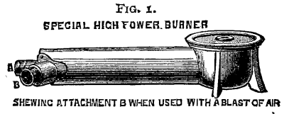
Fig. 1. SPECIAL HIGH POWER BURNER.
SHEWING ATTACHMENT B WHEN USED WITH A BLAST OF AIR
"The diameter of the mixing tube is a matter of importance, as it rules the quantity of gas which can be satisfactorily burnt in any arrangement. With large flames, given a certain size of gas-jet, the diameter of the mixing-tube should be not less than ten times as great. For instance, at 1 inch pressure, a jet having a bore of 1/8 inch will pass about 20 cubic feet of gas per hour. To burn this quantity of gas, a mixing tube is necessary 10/8 or 1¼ inch in diameter. By the first rule this tube must be in length equal to four and a half times its diameter, or 5-5/8 inches. It would appear that the mixing-tube, having 100 times the area of the gas jet, is out of all proportion to the size necessary for obtaining a mixture of one of gas to nine or ten of air; but it must be remembered that the gas is supplied under pressure. It is therefore evident that no mere calculation of areas can be taken, into account, unless the difference in pressure of the supply is also considered. A complete reversal of this law is shown in that ruling the construction of blowpipes, which I have already given in a previous paper on 'The Use and Construction of the Blowpipe.' In these the air supply, being under a heavier pressure, is much smaller in area than the gas inlet; and, to obtain maximum power, the air-jet requires to be enlarged in proportion to the gas pressure.
"Given a certain area of tube delivering a combustible mixture, the outlet for this mixture must be neither more nor less than the size of the tube. Taking an ordinary drilled tube, such as is commonly made, and of the dimensions before given--i. e., 1¼ inch bore--if the holes are drilled 1/8 inch in diameter the tube will supply 10 x 10 = 100 of these holes. In practice this rule may be modified.
"The variations from the rule, however, must be a matter of experience with each form of burner. There is also the fact that with small divided flames it is not necessary to mix so large a proportion of air, as each flame will take up air, on its external surface; but in this case the flames are longer, hollow, and of lower temperature. As a matter of actual practice, where a burner is used which gives a number of flames or jets, the diameter of the mixing-tube does not need to exceed eight times the diameter of the gas jet; the remainder of the air required being taken up by the surfaces of the flames.
"Wire gauze, made of wire the thickness of 22 iron wire gauge, 20 wires to the linear inch, and tinned after weaving, has an area in the holes of ¼ its surface. By calculation, the area of a gauze surface in a burner should, therefore, be taken at four times that of the tube, and our standard of 1¼ inch tube requires a gauze surface of 2½ inches in diameter. This rule is subject to variation in burners of a small size, owing to the air that can, if required, be taken up by the external surface of the flame, which, of course, is much greater in proportion in a small flame than in a large one. Where the diameter of the gauze is, say, not over one or two inches, the theoretical maximum gas supply may be exceeded, and a varying compensation is necessary with each size. My rule is intended to apply to burners of larger diameters, where the external air supply plays a comparatively unimportant part.
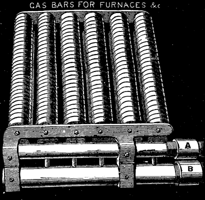
Fig. 2.
"It must be remembered that burners of this class, which burn without the necessity of an external air supply in a flame which is solid, require the mixture to be correct in proportions. A very slight variation makes an imperfect flame. Not only does the gas jet require to be adjusted with great precision, but it also needs more or less adjustment for different qualities of gas. An ordinary hollow or divided flame is able to take up on its surface any deficiency of air supply; but with the high power solid flames the outside surface is small, and the consequence is that one of these burners, adjusted for gas of poor quality, may, when used with rich gas, give a long hollow or smoky flame, unless the gas jet be reduced in size. When perfect, the flame shows a film of green on the surface of the gauze; and if a richer gas is used, the green film lifts away. To cause this to fall again, and to produce a solid flame, it is necessary to take out the gas jet, and tap the end with a hammer until, on trial, it is found correct. If too small, the green film lies so closely as to make the gauze red hot. Where the 'tailing up' of the carbonic oxide flame is objectionable, there is no practical difficulty whatever in constructing these burners as a ring, with an air supply in the center, which greatly reduces the length of the 'tail.' In practice it is a decided advantage to have a center air-way in all burners of more than about 2 in. diameter, as it enables the injecting tube to be slightly shortened, and lessens the liability of the green film to lift with varying qualities of gas. In this class of burner I have adopted the small central air-way as a decided improvement in the burners."
In such processes as the roasting of coffee, chiccory, grain, etc., a diffused heat is necessary, but of much greater intensity than can be obtained with economy from heated air. In these cases the application of a direct flame is necessary, and it may be in actual contact with the substances to be heated, provided these are kept in constant and rapid motion.
The use of a revolving cylinder brings in complications with any burner which is supplied with gas at ordinary pressures without any artificial air supply, as the currents of air caused by the motion of the cylinder interfere with the satisfactory working of any burner; and the air supply must be either protected from draughts and irregular air currents, or the air must be applied artificially from some independent source. One exceedingly good way of making any burner work, independently of the currents caused by a revolving cylinder, is to apply the flame inside the cylinder at the center, making the substances to be heated to fall in a continuous stream through the flame. This system is not applicable to fine powders or sticky substances, as it necessitates the perforation of the cylinder, to allow of the escape of products of combustion.
For this class of work, a very concentrated heat is not desirable, as a rule, and a slit or a perforated burner is preferable. Of this class of burner I have here a sample, which is not only new in its constructive details, but has great and special advantages for many purposes. As you see, it resembles a number of ordinary furnace bars, with this difference, that each bar is a burner; in fact, it is an ordinary furnace grate, which supplies its own fuel. With the usual day pressure of gas=1 inch of water, this burner will, at its maximum power, consume about 100 cubic feet of gas per hour per square foot of burner surface, and as it can readily be made almost any form or size, its adaptability for a great number of uses is evident. I have made it in many sizes and shapes, to give flames from ½ inch wide by 5 feet long to large square or oblong blocks. By applying a blast of air at the ordinary gas jets, and supplying the gas by a separate pipe, or series of pipes, below the open end of the burner, this can be converted into a furnace of extraordinary power. It is quite possible to burn as much as 2,000 cubic feet of gas per hour per square foot of burner surface, producing a heat sufficient to fuse any ordinary crucible. You see its power when I place a bundle of iron wire in the flame; it is, in fact, a concentration of hundreds or thousands of powerful blowpipe flames in one mass. It has also this advantage, that with a blast of air it will burn and work equally well any side up, and the flames can therefore be directed straight on their work without loss. It is, in one form or another, almost a universal burner, as it can be readily adapted to almost any purpose, from tempering a row of needles to making steam for a 200 horse power steam engine. It is easy to make, easy to manage, practically indestructible, and for commercial purposes has, I think, a general adaptability which will bring it, in one form or another, into almost universal use. I may say that when we are in a special fix, this has in every case landed us out of the difficulty.
For heating large plates of metal equally, for drying paper impressions for stereotypers, hot pressing hosiery, crumpet baking, working up plastic masses which can only be worked hot, and work of this class, a number of separate flames equally diffused under the whole surface of the plate are necessary to equalize the heat, unless the plate is very thick, and these are better if produced by a mixture of gas and air; but in heating wide plates one difficulty must always be remembered, the burnt gases from the center flames can only escape by passing over the outer flames, and therefore a space must be left between the top of the flame and the plate, or the outer flames will be smothered and make a most offensive smell.
In hosiery presses, printers' arming presses, and many others, the top plate also requires to be heated. The best way to do this is to use a number of blowpipe flames directed downward. In many cases the supply of air under pressure is a practical difficulty and objection. This is overcome, to a certain extent, by the use of a thick upper plate with a number of horizontal holes, into which a Bunsen flame is directed. In every case I have seen, without one single exception, the holes are either too small, or the burner is placed too close, and the consequence is that the gas, instead of burning inside the holes, as it should, passes through partially unburnt, and is consumed at the opposite end, where it is absolutely useless, the flame not being in contact with or under the surface to be heated, and therefore doing no work. In hosiery presses this is a great objection, as the holes are so long that an equal heat is simply impossible, and the only remedy is to use a blowpipe flame, which forces sufficient air in with the gas to insure combustion where the heat is necessary. The same remark applies to crape and embossing rollers.
For the production of heat in confined spaces and difficult position, the use of an artificial blast of air is becoming an acknowledged necessity, and the small Roots blowers now made for such purposes, and driven by power, are coming rapidly into use.
Sometimes a plate is required to be heated to a high temperature in one confined spot, and, as an example of this, I may take the bluing of the hands of watches. For this purpose I have made several arrangements, and perhaps the best is a thin copper plate, bent down at one side to a right angle. In this angle, underneath, is directed a very fine blowpipe flame on one spot, and the hands are passed singly over this spot until the color comes, when they are instantly pushed over the edge. I have here the arrangement which is generally used for this purpose. For the bluing of clock hands, a larger and more equally heated surface is required, and this can be obtained by a small powerful burner without a blast of air, using a rather thicker plate to equalize the heat. The same arrangement may be used with advantage for tempering small cutters for ornamental turning, penknife-blades, etc., and in these cases the cooler part of the plate is of great value, as it enables the thicker parts to be slowly and equally heated up; the application of a mechanical arrangement to pass the articles to be heated in a regular succession is a matter easily managed.
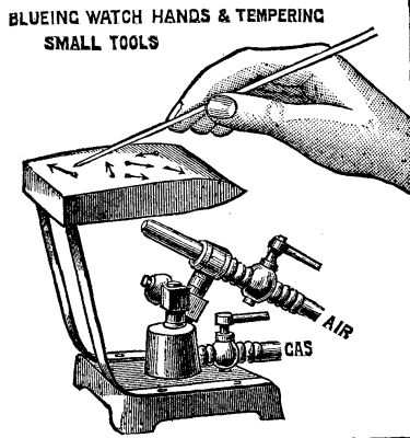
FIG. 3. BLUEING WATCH HANDS & TEMPERING SMALL TOOLS
Among other things which have several times come under my notice may be mentioned cremation furnaces, but I have not yet met, with, or been able to devise, any burner for ordinary coal gas which has worked satisfactorily. This fuel is apparently unfitted for the work, and the best arrangement I know is a number of pipes delivering ordinary "producer" gas from the Wilson or Dowson generators, in exactly the same way as is at present used for firing horizontal steam boilers. For heating book finishers' tools, a ring-flame is the simplest, the tools being supported a little distance above the flame; the usual plan of heating a plate, and placing the ends of the tools on this, necessitates at least double the gas consumption as compared with an open flame. For type-founding machines, bullet moulding, stereotype metal melting, solder making, lead melting, etc., one burner, or rather one flame, should be used of a suitable power for the work, and this should be as perfect and of as high a temperature as possible to insure economy. It is now a simple matter, owing to recent researches in the theory of heating burners, to obtain flames of any power without practical limit, which, without any artificial air supply, will do all which is necessary in this class of work, and the required arrangements are exceedingly simple. With these trades may be classed, also, the concentration and distillation of acids and liquids boiling at a high temperature, and we may also include baths for tinning small articles, and the tinning by fusion of sheet copper, the same burners being applicable, and perfectly suited to all these requirements, unless the tinning baths are long and narrow, in which case the furnace-bar burners again come to the front as the best; as, if we are to use gas economically, the flame must be the same shape as the vessel to be treated.
We may now consider the heating of blanks for stamping, hardening the points of spindles, finishing the ends of umbrella tips, and work where a small article, or a small part of any article, has to be heated to a high temperature with speed and certainty. For these a long and narrow flame is necessary, and I may mention that in cases where a high speed of delivery is required, and a small part only has to be heated, such as, for instance, in the hardening of the points of spindles for cotton machinery, I have made burners giving a flame of exceedingly high temperature only ¼ inch wide and five feet long. This flame is produced by the assistance of a blast of air, and is of sufficiently high temperature to fuse the spindle in a few minutes.
The points only project over the flame, and the spindles are carried mechanically at such a speed that at the end of the five feet traverse they are red hot, and drop into water. More than one hundred are in the flame at once, lying side by side.
For heating blanks for stamping, the furnace bar-burner is perfectly suited, and in this work the chute supplying the blanks to the machine should be made of two fireclay sides, with an opening for the flame between the chute and flame being placed at a sharp angle, to prevent risk of the blanks sticking or overriding each other. A blowpipe may also be used with good effect, as shown in the above engraving, and in many cases it is preferable and much easier to manage.
In some cases the direct contact of the flame would spoil the articles to be heated, and instead of the arrangement mentioned, a tube of iron, fireclay, or other suitable material is heated, and the articles are passed through it. This system of continuous feed, through a tube, has been applied to the firing of small articles of pottery, and might possibly be well adapted, among other things, to the production of gas-burners.
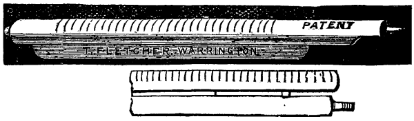
FIG. 4.
Where the contact of air with the heated articles is injurious, many plans have been tried to keep the ends closed as much as possible, but I believe no more perfect and simple seal against the admission of air can be devised than to turn a jet of pure gas, unmixed with air, into each end of the tube. This is an absolute seal against the entry of oxygen in an uncombined state; free oxygen cannot exist at a very high temperature in the presence of coal gas.
For many trades there is a demand for hardened and tempered steel wire, either round or flattened, and the production of this has led to many attempts to obtain a satisfactory continuous process. The common method now, which is worked as a "secret" process by most firms, is to pass the wire through a tube to heat it, as already described, and to run it direct from the tube through a hole in the side of a box filled with oil, the whole being packed with asbestos, to prevent leakage; from this it is passed through another similar hole on the opposite side, either over a plate heated to the right temperature, or over a narrow open flame of sufficient length and power to give the correct heat for tempering.
Where absolute precision is necessary, the gas supply must be adapted by an automatic regulator on the main, to prevent the slightest variation of heat. Once adjusted, the production of flat and round spring wire by the mile is an exceedingly simple matter. It is quite possible to obtain absolute precision in temperature by a proper adjustment of the gas pressure, and as this is, for tempering steel articles and some other purposes, a matter of great importance, it is worth some consideration. No pressure regulator alone will give an absolutely steady supply; but if we put on first a regulator, adjusted to the minimum pressure of supply, say one inch of water, and then fix another on the same pipe, adjusted to a slightly lower pressure, say 9/10 of an inch, the first regulator does the rough adjustment, and the second one will then give an absolutely steady supply, provided always that the regulators are both capable of passing more gas than is likely to be ever required. No regulator can be relied on for absolute precision, if worked up to its maximum possible capacity.

Fig. 5. ARRANGEMENT FOR HEATING BLANKS FOR STAMPING
OR
HARDENING.
Among other applications of a long narrow flame of high power, may be mentioned the brazing of long lengths of tube, in fact the application of flames of this form, with and without a blast of air, for different temperatures, are almost endless.
The thousands of uses to which blowpipes are adapted are so well known, that they need no mention, except the curiously ignored fact that the power of any blowpipe depends on the air pressure. A compact flame of high temperature cannot be obtained except with a heavy air pressure, and the ignorance of this fact has caused an immense number of unexplained failures. Many people think that one blower is as good as another, and expect that a fan giving a pressure equal to, say, the height of a two inch column of water should do the same work as a blower giving a pressure ten to twenty times as great. The construction and power of blowpipes, with the laws ruling the proportions and power, will be found in an article on "Blowpipe Construction," published in Design and Work, March, 1881, and as the matter is there fully treated, no further reference to the subject is necessary.
In the more recent forms of gas-engine, the charge is exploded by a wrought iron tube, heated to redness by the external application of a gas flame. This, although considered satisfactory by the makers, appears to me to be an exceedingly crude way of getting over the difficulty; and I offer it as a suggestion, that a very small platinum tube shall be used instead of iron. This, if made with a porous or spongy internal coating, would fire the charge with certainty, at a lower temperature than iron, and it could be made so thin and small in diameter, without risk of deterioration or loss of strength, that an exceedingly small flame could be used to heat it up. As it would be fully heated in a very few seconds, the delay in starting would be obviated.
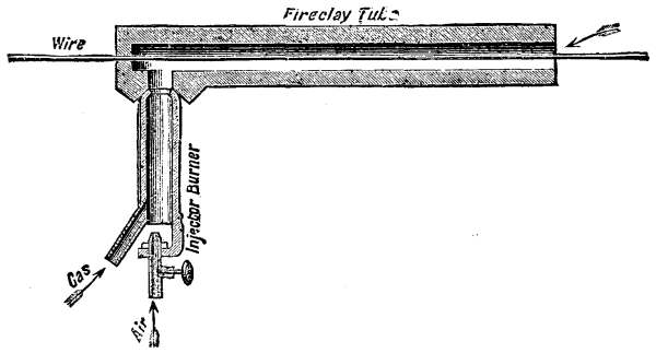
Fig. 6.
There are many purposes for which a red heat is needed for slow continuous processes on a small scale, such as case-hardening small steel goods, annealing, heating light steel articles for hardening, and a great variety of other similar processes. This, until recently, has required the use either of a rather complicated furnace, or a blast of air under pressure, to increase the rapidity of combustion. Since the conclusion of my experiments on the theoretical construction of burners, I have found that the high-power burners, previously described, are capable of heating a crucible equal in size to their own diameter to bright redness without the assistance of a chimney, provided the crucible is protected from draughts by a fireclay cylinder.
This is an important point, as it renders the production of a continuous bright red heat a matter of the greatest ease, even in crucibles of a comparatively large size. Where the heat is steady, and certain not to rise above a definite point, it can safely be used for such purposes as hardening penknife blades and other articles which are very irregular in thickness, the thin edges not being liable to be burnt or damaged by overheating.
For the highest temperatures air under pressure is a necessity, as we require a large quantity of gas burnt in as small a space as possible with the maximum speed, and given this air supply, we are very little hampered by conditions, as an explosive mixture may be blown through a gauze into a fireclay chamber, closed, except so far as is necessary to allow the escape or burnt gases. The speed of combustion is limited only by the speed of supply of air and gas, and by increasing these there is no practical limit to the heat which can be obtained. When we have to do with the reduction of samples of refractory ores, testing the comparative fusibility of different samples of firebricks, or alloys, etc., the use of an explosive mixture blown into and burning in a close chamber is invaluable, and the ease and certainty with which any temperature may be obtained has led to great discoveries, and the revolutionizing of many commercial processes. Recent experiments have proved that, by a modification in the form of the well-known injector furnace, an enormous increase of temperature may be obtained. I have, in actual work, obtained the fusing point of cast iron in two minutes, starting all cold, and have fused every furnace casing I have yet been able to produce. If infusible casings can be made, I think I am not overstating facts in saying that any temperature required can and will eventually be obtained with the greatest ease. What the limit is I have as yet not been able to discover.
There is one more application of gas, as a fuel, which, discovered and published by myself some two years ago, has yet to become generally known, and in some special processes may prove exceedingly valuable. This is the addition of a very small quantity or coal gas, or light petroleum vapors, to the air supplied by a blower or chimney pull, to furnaces burning coke or charcoal. The instant and great rise in temperature of the furnace, and the greater stability of the solid fuel used, are extraordinary. This is, in fact, a practical application of the well-known "flameless combustion," the only signs that the gas is being burnt being a great rise in temperature and a decreased consumption of the solid fuel; in fact, if the gas is in correct proportion, the solid fuel remains unburnt, or nearly so, in spite of the high temperature. In cases where a sudden rise in temperature is required in a furnace, or where the power is deficient, this method of supplementing and increasing the heat will be found of very great service, and processes liable to be checked by making up a fire with fresh fuel can be carried on without check, even after the solid fuel has almost entirely disappeared.
That a solid fuel is quite unnecessary, I will prove in a very simple manner, by burning a mixture of coal gas and air without a flame, in a bundle of iron wire. The heat is sufficient to fuse the wrought iron with ease, and the glare inside the bundle of wire is painful to the eyes. The same result could be obtained by a pile of red-hot lumps of firebrick, and the same heat obtained also without a trace of flame.
It is not possible to enter fully into such a wide and important subject in a single lecture, and the suggestions now given are simply hints for the guidance for those who need or desire to experiment. No doubt we shall have, after a time, some text-books and other literature on this subject, which is one of great importance to many industries; and it is necessary for experimental work and applications to new industries, that the experimenter shall not only be able to purchase special burners, but that he shall have fundamental laws laid down which will enable him to construct them for himself, so as to have his experiments under his own control. The difficulty in the way of literature on the subject is that those few who have worked in the matter are busy men, with little time which is not already fully employed.
Pioneers on new ground have a great liability to generalize and jump at conclusions, and the necessary exact work and detail must, to a great extent, be left to those who follow on tracks already roughly marked out.
Of the special trades which have come under my observation, I have only had time to mention a very few. It appears to me that there are very few manufacturing processes of any kind which could not be simplified by the use of gas as a fuel, from the production of electric light apparatus to the manufacture of explosives, cotton stockings, beer, catgut, glue, umbrellas, ink, fish-hook, medals, stained glass windows, brushes, and other trades equally various, which come daily under my own notice.
A man was received into the Laborisière Hospital, Paris, the other day, with a yard of rope hanging from his mouth. Traction upon the cord revealed a section of clothes line measuring eight feet. He had been surprised in an attempt at suicide and had tried to conceal his design by swallowing the cord. He lived, of course--they generally do.
A certain number of the readers of this journal are occupied with photography, and all assuredly are interested in this marvelous art, whose progress is so remarkable. So it has seemed to us that it would be of interest to treat of a question that is the order of the day. We desire to speak of those photographic apparatus called instantaneous shutters.
Numerous apparatus of this kind have been proposed to the public, and several even have been described in this journal, but we have to state that, despite the success in certain cases, none of them has proved remarkable for its qualities and superiority. This is due, we believe, to the fact that inventors, while showing arrangements that were often ingenious, have not always taken into account the end that the shutter is to subserve, and the qualities that it must possess in order to attain such end.
In face of the progress made by extra rapid dry processes, the question of shutters has become the most important, since cabinet-making, optics, and photographic chemistry give us apparatus, objectives, and products which, although they will doubtless be improved upon, satisfy for the present all our needs.
What is understood by instantaneousness? To our knowledge, no definition thereof has as yet been given. For our part, we propose to style "instantaneous" any photograph that is taken in a fraction of a second that our senses will not permit us to estimate. The shutter is the apparatus which allows the light to enter the photographic chamber during this very short time.
In order to examine the different rules that govern the question of shutters, we shall take as an example the type styled the "Guillotine."
This apparatus, as every one knows, is a stiff plate containing an aperture and passing over the line of the rays of light. Some place it in front and others behind, while others again place it within the objective. Let us examine and discuss what occurs in the three cases. Suppose a rectilinear objective of the kind most usually employed in instantaneous photography, and an object, A B, that we wish to reproduce (Fig. 1), the objective being provided with any sort of diaphragm. The point, A, sends a bundle of rays, a"b", to the first lens. Here they are slightly refracted, and then go on parallel lines to the second lens, where they are again refracted and form at A' an image of A. It is this image that we see upon the ground glass, and which makes an impression upon the sensitive film. The point, B, behaves in the same way and gives an image at B', but, as will be at once seen, the image will be reversed. In our figure, A corresponds to the sky and B to the earth. If, then, the shutter passes in front of the objective, it will first allow of the passage of the rays which come from the sky, then, on continuing its travel, it will unveil the landscape, and lastly the ground. As it is submitted to the law of the fall of bodies and has a uniformly increasing velocity, it follows that the time of exposure will uniformly decrease between A' and B', and that the sky will pose longer than the foreground. Such a result is contrary to all photographic rules, which require that objects shall pose so much the longer the less they are lighted. This position of the "guillotine" shutter is absolutely false, and must be altogether discarded. If the shutter be placed behind the objective, it will follow, as a consequence of the same demonstration, that the time of exposure will go diminishing from B' to A', and that the foreground will be exposed longer than the sky. The solution is logical, then, and will permit of obtaining excellent negatives.
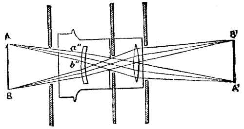
FIG. 1
Let us now examine how the image, A'B', is formed. The point, A, appears first, and becomes lighter and lighter up to the moment at which all the rays that emanate from the point, A, are unveiled. The point, B', is not yet visible. As the shutter continues its travel the point, B', appears in its turn and becomes illuminated like the point, A'. At this moment the objective is completely uncovered; the image, A'B', is perfect, and possesses its maximum intensity. Then the point, A', gradually becomes obscured and disappears; and the same is the case with all parts of A'B'. The image is developed progressively from A' to B', and makes its impression upon the sensitive plate successively--a fact which, as may be conceived, may have its importance. If, for example, we are photographing a ship that is being tossed about by the sea (and we borrow this example from our colleague, Mr. Davanne), the image of the top of the mast will not be formed at the same instant as that of the base, and if the motion of the mast has sufficient extent it may take on a curved form, due to the fact that it has effected a movement between the moments during which its apex and base were being photographed.
Upon placing the guillotine shutter in the optical center of the objective, what will occur? The shutter will permit the passage of an equal fraction of the rays derived from A and B, that is to say, the image will be complete from the first instant of the exposure. The points, A' and B', will be illuminated precisely at the same moment. As the shutter continues its travel, a fresh quantity of rays coming from A and B will be admitted, and the image will be illuminated more and more up to the moment at which all the rays can pass. It will then possess its maximum intensity. Then a portion of the rays from A and B being intercepted, the image will become darker and darker until complete extinction. The image here, then, is not produced successively as in the former case, but is entire from the beginning. In this case the image of our mast cannot be misshapen, since it has been accurately photographed at the same moment.
The true place for the guillotine shutter, then, from a theoretical standpoint, is in the interior of the objective. Are there any other advantages to be gained by so placing it? Yes; it is easy to understand that for the same time of exposure, and consequently for the same result, the aperture may be so much the smaller in proportion as the optical center is approached.
The luminous rays, in fact, form in the objective a double truncated cone whose upper base is equal to the diaphragm, and the lower one to the diameter of the lenses. If the aperture be equal to any diameter whatever of one of the cones, the result will be the same; but, for the same period of exposure, it will evidently prove advantageous to approach the diaphragm. The ratio of the apertures that give the same results at the optical center or behind the objective is as that of the diaphragm employed to that of the back lens. If the diaphragm is one centimeter and the lenses four centimeters, an aperture of one centimeter in one case and of four in the other will give the same result.
We shall see further along that it is advantageous to employ apertures equal to several times the diameter of the diaphragm or lens. Now, from what we have just said, an aperture, equal for example to four times the diaphragm, will be only 4 centimeters, while the corresponding aperture behind the lens must be 16. The dimensions of the first will be practical, and those of the second will give too cumbersome and too fragile an apparatus. But why must the aperture be larger than the diaphragm employed? This is what we are going to demonstrate. Let us make the aperture equal to the diameter of the objective, and see what occurs at the different periods of the exposure. For the sake of clearness, we shall suppose the velocity uniform.
It is evident, a priori, that a perfect apparatus will be the one that will allow the light to act during the entire exposure with a maximum of intensity. Is it thus, when the aperture is equal to the diameter of the objective? Evidently not. Let us consult Fig. 2. We here see the shutter progressively uncovering the objective. The light will increase from A to C up to the moment when the objective is entirely uncovered, and will then immediately decrease up to B. The objective has operated with a maximum of light for only a short time. We are far from the ideal result in which the maximum of light, CD, should exist during the entire exposure, and form the upper plane precisely equal to AB.
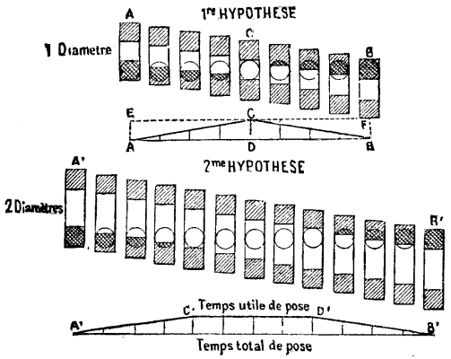
Fig. 2.
If we cannot obtain such a result in practice, we must nevertheless aproximate to it. We shall do so by increasing the shutter. Up to C' the apparatus will operate as before, but from C' to D' the aperture will be complete, and from D' to B' will decrease as has been said.
Let us give A'B' the same value as AB, that is to say, let us increase the velocity in the second case in order that the time of exposure shall be the same; we shall at once see that in the first case the object will be completely uncovered for only a very short time, while in the second the exposure will be perfect for a very appreciable period.
The time of exposure which is absolutely active, we propose to call effective time of exposure in contradistinction to the total time of the same. The more we increase the value of C'D', that is to say, that of the effective time, the more the ratio, C'D'/A'B', will approximate to unity, and the nearer we shall reach perfection. The correlative of such elongation of the aperture is an increase in velocity which will always bring the total exposure to the same figure, whatever be the aperture employed.
If the aperture be equal to two diameters, the effective time will be equal to half the time of the total exposure; and if it is equal to three diameters, the exposure will be good during 2/3 of the total time. This amounts to saying that the effective time of exposure is equal to n times the diameter--1, the velocity being supposed always uniform. If we place the shutter within the objective, it is the diameter of the diaphragm that it will be necessary to say. The effective time will be equal then to n diaphragm--1.
From what precedes it results that in no case should the aperture be inferior to the diaphragm, since the former would otherwise absolutely suppress the effective time in giving a lower plane corresponding to an insufficient quantity of light. Moreover, an aperature of this kind would prove injurious to the quality of the image by successively uncovering rays which do not form their image identically at the same point. We are now, then, in presence of results that are absolutely positive, and they are as follows:
1. The guillotine shutter should be placed in the interior of the objective and as near as possible to optical center, that is to say, behind the diaphragm, since the latter is precisely in the optical center.
2. The aperture should be as wide as possible.
3. The velocity should be as great as possible.
In practice, an aperture from 4 to 5 times the diameter of diaphragm employed will be more than sufficient, since we shall have, according to circumstances, ¾ or 4/5 of the effective time. Moreover, whatever be the time of exposure, this ratio once established will be invariable, and the apparatus will always operate identically.
A shutter combining these qualities will not yet be perfect. It is necessary, according to the time and the light, that the time of exposure shall be capable of being varied. In a word, it is necessary that the apparatus shall be graduated and permit of taking views more or less quickly. The different velocities might be given to the shutter by means of weights, rubber, or springs. The latter seem to be preferable, since they permit in the first place of operating out of the vertical; moreover, they are less fragile, and, through different tensions, they permit of these graduations that we consider as indispensable. For the current needs of practice 1/100 of a second is a limit that seems to us sufficient as a maximum of rapidity. In order to know the time of exposure obtained we employ the following method, which permits of graduating an apparatus rapidly and with extreme precision:
A band of smoked paper is fixed upon the shutter, then a tuning-fork provided with a small stylet resting against the paper is made to vibrate. Better yet, a chronograph which vibrates synchronously with a tuning-fork, whose motion is kept up by electricity, is put in the same place. Fig. 3 shows the arrangement to be employed. We then let the shutter fall, when the little stylet will inscribe a certain number of vibrations. Knowing the number of vibrations of the tuning-fork, and counting the number of those inscribed upon the paper, it is very simple to deduce therefrom the amount of the time of exposure. The results of one of these experiments we have reproduced in Fig. 4. The tuning-fork gave 100 double vibrations per second. Six vibrations are included between the opening and closing of the apparatus. Each vibration estimated at 1/100 of a second. The exposure was 6/100 of a second in round numbers. This is the amount of the total time of exposure. As for that of the effective time, that is just as easily ascertained. It suffices to know the number of vibrations comprised between the moment at which one point of the objective has been completely uncovered and that at which it has begun to be covered again. The time is equal to 2/100 in round numbers.
In the experiment in question, with an aperture equal to twice the diameter of the diaphragm, we have, then, 1/3 of the half-open exposure; and the amount of the effective time is 1/3. The difference that we have in practice is due to the fact that the velocity is uniformly accelerated. In order to increase the amount of the effective time, it will be only necessary to increase the aperture of the shutter and apply again the method that we have just pointed out.
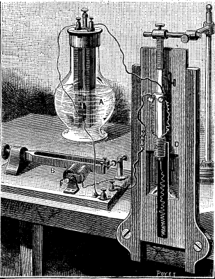
FIG. 3.
So much for the material part of the apparatus. It will be necessary in addition to acquire sufficient individual experience to be able to estimate the intensity of the light, and consequently to judge of the diaphragm to be employed and the velocity to be obtained. It must not be forgotten that such or such an object having a relatively slow speed will not be sufficiently sharp on the negative if it is too near the apparatus, while such or such another, much more rapid, might nevertheless be caught if sufficient distance intervened. Here it is that will appear the skill of the amateur, who will find it possible to obtain the said object as large as possible and with a maximum degree of sharpness.
We have seen what diverse qualities should be possessed by a good guillotine shutter, and it is evident that the same should be found in all apparatus of the kind. In our opinion the guillotine is a well defined type that possesses one capital advantage, and that is that it permits of the use of aperatures as wide as may be desired for the same time of exposure. It is a question, as we have seen, of velocity. Consequently, however short the exposure be, it will always be possible to operate with a full amount of light during the greater part of the exposure. It is necessary to dwell upon this point, since in another kind of apparatus that possesses a closing and opening shutter the same result cannot be reached. In the Boca apparatus, for instance, we remark that at a given moment the time of exposure is reduced to nothing, as the closing shutter covers the objective before the latter has been unmasked by the opening one. In all exposures, in fact, the times of opening and closing have a constant value. It follows that the shorter the exposure is, the greater becomes such value, and to such a point that, at a given moment, the apparatus no longer make an exposure.
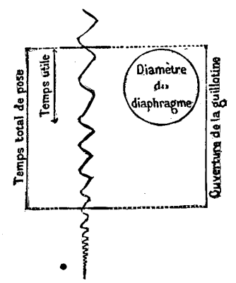
FIG. 4.
In the guillotine, on the contrary, the same space always intervenes between the time of opening and closing, since it is fixed in an unvarying manner by the diameter at the aperature. Then, the greater the velocity, the more the time of opening and closing diminishes. If the ratio of the effective to the total time of exposure is 3/4, for example, it will be invariable, whatever be the velocity.
In concluding, we will remark that, without employing springs, we may increase the aperture of the shutter without varying the time of exposure. To effect this it is only necessary to raise the point of the shutter's drop. In fact, as may be seen in Fig. 4, all the vibrations of the stylet corresponding to 1/100 of a second always continue to elongate, and it will consequently be possible for the same time of exposure to considerably increase the aperture and, as a consequence, the effective time, by causing the guillotine to drop from a greater elevation. From this study, which has principally concerned the guillotine shutter, can we draw the deduction that this type of apparatus will become a definite one? We think not. In fact, along with its decided advantages the guillotine has a few defects that cannot be passed over in silence. The aperture, in measure as it is increased, renders the apparatus delicate and subject to become bent. If, in order to obviate this trouble, we employ plates of steels, we increase its weight considerably, and the chamber becomes subject to vibration at the moment the shutter drops. If rubber or springs are used for increasing the velocity, it is still worse. Moreover, it is quite difficult to obtain a graduation, and to our knowledge, and probably for this reason, it has not yet been applied.
The reader will please excuse us for this perhaps somewhat dry theoretical expose, but we have thought it well to give it in the hope that it might well show the qualities that should be required of a photographic shutter and particularly of the guillotine. Moreover, at the point to which photography has arrived it is no longer permitted to do things by halves.
After the memorable discoveries of Nicephore, Niepce, Daguerre, and Talbot, photography remained for some time stationary, limited to the production of portraits and landscapes. But for a few years past it has taken a new impetus, and new processes have come to the surface. In the graphic arts and in the sciences it has taken considerable place. Being the daughter of chemistry and physics, it is not astonishing that we require of it the precision of both. It is, moreover, through a profound study of the reactions that gave it birth and through a knowledge of the laws of optics that it has come into current use in laboratories. In fact, it alone is capable of giving with an undoubted character of truthfulness a durable vestige of certain fleeting phenomena.--
A. Londe, in La Nature.
To carry a watercourse over a canal, river, road, or railway, several methods may be employed, as, for example, by aqueducts like those of Arcueil and Buc near Versailles, and by upright and inverted siphons. Of these three means, the first is the most imposing, but is also very costly; and, besides, the declivities as well as the arrangement of the ground are not always adapted thereto. The inverted siphon is subject to obstruction and choking up in its most inaccessible parts, while the upright siphon is easy of inspection, taking apart, etc. But, per contra, the latter loses its priming very easily by reason of the formation of air spaces.
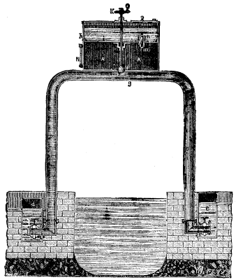
FALCONETTI'S SIPHON.
Mr. Falconetti, an inspector of bridges and roadways, has found a means of rendering the latter occurrence impossible by an arrangement which is both simple and practical, and which is illustrated herewith. In the figure, a and b are the two vertical legs of the siphon, both of which enter the liquid. These open into the receptacles, c and d, in which the cocks, e and f, cut off or set up a communication with the pipes, a and b. These latter are connected by a branch, g, which may be put in communication with a reservoir, h, that is divided into two superposed compartments by a partition, i. Such communication may be established or cut off by a valve, j, maneuvered by a key, k, which traverses an aperture in the partition, i. Another aperture, m, in this same partition serves to put the two parts of the reservoir, h, in communication, and, for this purpose, is provided with a cock, n, which is easily maneuvered from the exterior.
The object of this arrangement of cocks and reservoir is to prevent the siphon from losing its priming through the possible presence in the transverse portion of a certain quantity of air or gas that might be given off by the water and accumulate in this place.
The compartment, A, of the reservoir, h, is designed for receiving the gases that collect in the top of the siphon, while the upper compartment contains water for making a hydraulic joint, and consequently preventing any re-entrance of air through the apertures in the partition, i.
To prime the siphon, we shut the cocks, e and f, open the valves, j and m, and pour in water until the whole affair (siphon and reservoir) is full; then we close the cock, m, and open the three others. The siphon thus becomes primed, and begins to operate as soon as any water reaches one or the other of the lower receptacles. As the cock, j, is constantly turned on during the operation of the siphon, the air that has been able to accumulate in the lower compartment, A, of the reservoir, h, would finally unprime the siphon by intercepting communication between its two legs. In order to prevent such a thing from occurring, it suffices to expel the air, from time to time, that accumulates in the chamber, A, this being done, without stopping the operation of the siphon, as follows:
After closing the cock, j, water is poured into the reservoir, and, running down to the lower compartment, drives out the air through the cock, m. This operation once effected, it only remains to turn off the cock, m, again, and open j in order to establish the normal operation. As the chamber, A, is provided externally with a water gauge, N, it may be seen at a glance when it is necessary to maneuver the cocks in order to expel the air.
This system of siphon is evidently applicable to all sorts of liquids. It may likewise undergo a few modifications in its construction; for example, the valve, which in our engraving is placed over the siphon, may be located at any distance from the apparatus, although it should, in all cases, be in constant communication with it by means of a tube, and be placed a little higher than the siphon. It may then be put under cover and be kept constantly in sight, thus greatly facilitating its surveillance.
As may be seen, the essential peculiarity of this improvement consists in the very ingenious arrangement that permits of immersing the cocks in the liquid to make them perfectly tight, it being necessary that they should be hermetically closed in order to prevent the entrance of air to the siphon. Everything leads to the belief, then, that if upright siphons have never been able to operate regularly, it has been because no means have been known of expelling the air from the interior without letting air from the exterior enter at the same time. The arrangement devised by Mr. Falconetti gets over the difficulty in a very elegant manner. It seems as if it would be called upon to render great services in the industries, and it well merits the attention of engineers of roads and bridges, and of contractors on public works.--Revue Industrielle.
In the industries, there are often considerable quantities of liquid to be evaporated in order to concentrate it. Such evaporation is very often performed by burning fuel in sufficient quantity to furnish the liquid the heat necessary to convert it into steam. This process is attended with a consumption of fuel such as to form a very important factor in the cost of the product to be obtained. In order to vaporize, at the pressure of the atmosphere, 1 kilogramme of water at 0°, 637 heat units are required, and of these, 100 are employed in raising the water from 0° to 100° and 537 in converting the water at 100° into steam at 100°. This second quantity is called the latent heat of the steam at 100°. The sum of the two quantities is called the total heat of the steam at 100°. The total heat of the steam remains nearly constant, whatever be the temperature at which the vaporization occurred.
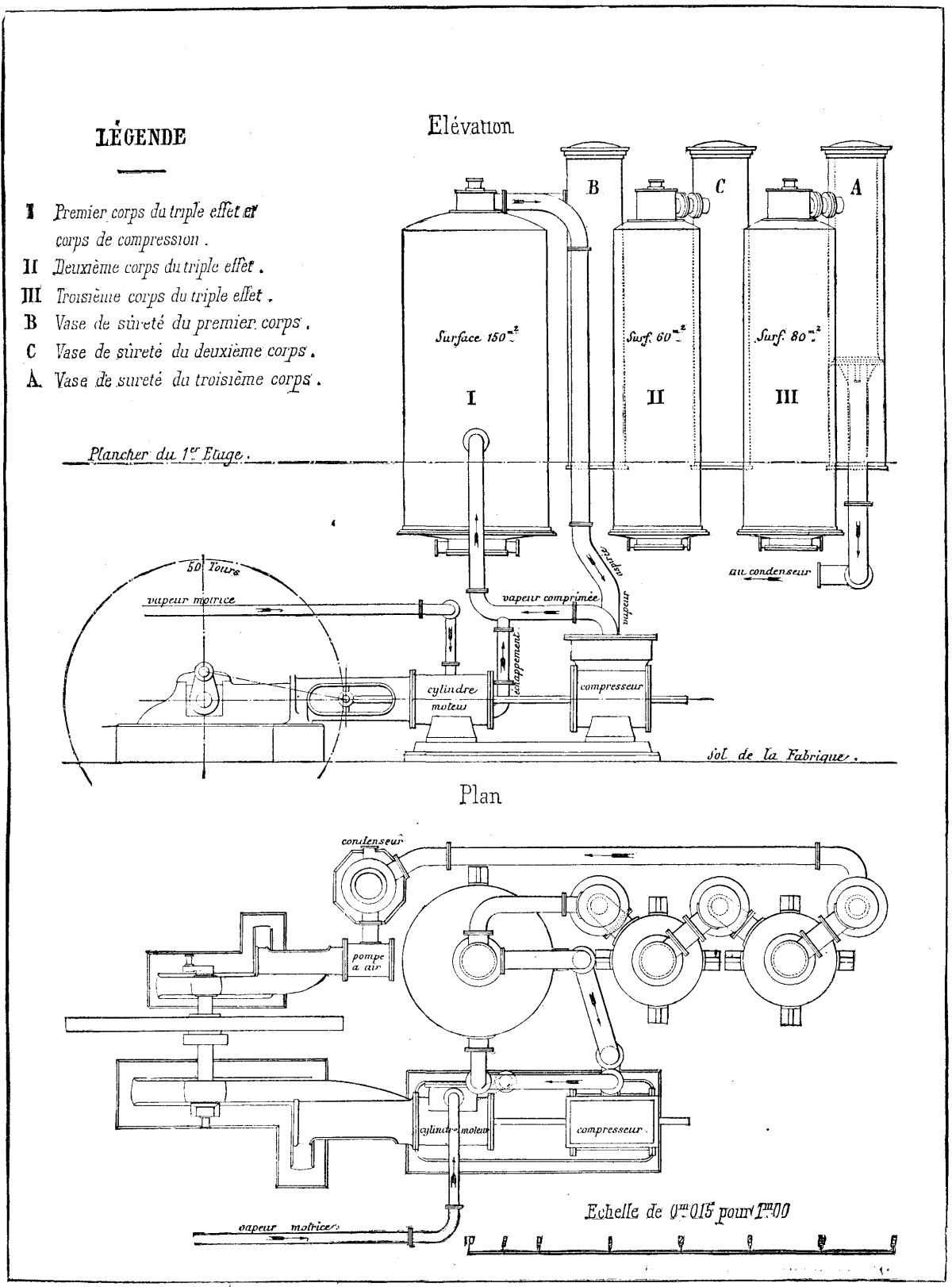
THE WEIBEL-PICCARD EVAPORATION APPARATUS.
In order to utilize the steam as a means of heating, it is necessary to condense it, that is to say, to cause it to pass from the gaseous to a liquid state. This conversion disengages as much heat as the passage from the liquid to the gaseous state had absorbed.
It results from this that if we could condense the steam that is given off by a liquid that we are vaporizing, in contact with another liquid that it is also a question of vaporizing, we should utilize all the heat contained in the steam that was being given off from the first.
This object can be practically attained by two means, viz., by (1) putting the disengaged steam in contact with the sides of a vessel that contains a liquid colder than the one that produced it; (2) by raising the temperature and pressure of the disengaged steam in order to condense it in contact with the sides of the vessel which contains the very liquid that has produced it.
The first of these means is realized in the apparatus called multiple acting, that are at present so generally employed in sugar works. The second means, which permits of a greater saving in fuel being made than the other does, is realized by compressing the disengaged steam. This compression, which raises the temperature and pressure of the steam, permits of condensing the latter in contact with the vessel wherein it has been produced. By such condensation we continuously restore to the liquid which is being vaporized the heat of the steam which it gives off.
This solution of the question, which has been partially seen at different epochs, has but recently made its way into the industries. It is being operated at present with complete success at the salt works of France and Switzerland, at those of Austria and Prussia, in the sugar of milk factories of France and Switzerland, and, finally, in 1882, the first application of it in the sugar industry was made at Pohrlitz, in Moravia.
The saving of fuel that has been made in these different applications has always been great.
We shall now, for the sake of explaining the system, give a brief description of the apparatus as used at the Pohrlitz sugar works mentioned above. These works treat 255 tons of beets per 24 hours, and obtain 4,000 hectoliters of juice, which is reduced to about 1,000 hectoliters of sirup. Up to the present, the concentration has been effected in a double acting apparatus partly supplied by exhaust steam from the motive engines and partly by steam coming directly from the generators.
In order to diminish the consumption of direct steam, these sugar works put in a Weibel-Piccard apparatus designed to concentrate only a third of their juice, or about 1,350 hectoliters per day.
This apparatus (see engraving) consists of a steam compressor, 0.835 m. in diameter, actuated directly by a driving cylinder of 0.5 m. diameter and 0.8 m. stroke, and of three evaporating boilers of the ordinary vertical tube type, the first of which has a surface of 150 square meters, the second 60, and the third 80.
The steam, at the ordinary pressure of the generators, say 5 atmospheres, is taken from the connected generators of the works, and is led to the driving cylinder, where it expands and furnishes the power necessary to run the compressor. It then escapes at a pressure of l.4 atmospheres and enters the intertubular space of the first evaporator. The compressor sucks up the steam from the juice of the first evaporator (which is boiling at the pressure of the atmosphere, without vacuum or effective pressure), compresses it to 1.4 atmospheres, and forces it likewise into the intertubular space. The ebullition of the first evaporator, then, is kept up not only by the exhaust from the motive cylinder, but also by the steam from the juice itself, which has been rendered fit to serve as a heating steam by the pressure that it has undergone in the compressing cylinder.
In this first application of the new system to sugar making, it became a question of ascertaining whether the advantage resulting from compression was of great importance, and, in the second place, whether the apparatus could be run with certainty and ease. In truth, the applications of the system for some years past in other industries permitted a favorable result to be hoped for, and the result turned out as was expected.
With this apparatus it has been found that the work furnished by one kilogramme of steam passing through the motive cylinder, from a pressure of 5 atmospheres to one of 1.4, is sufficient to compress 2.5 kilogrammes of steam taken from the juice, led into the compressor at one atmosphere and escaping therefrom at 1.4. In other words, one kilogramme of motive steam is sufficient to convert into heating steam for the first evaporator 2.5 kilogrammes of steam taken from the juice in this same evaporator. Besides, this same kilogramme of motive steam produces three effects, one in this same evaporator, and the other two in the two succeeding ones. The effect obtained, then, from one kilogramme of motive steam is, in round numbers, 5.5 kilogrammes of steam removed from the juice.
It must not be forgotten that the motive steam was at the very moderate pressure of 4 effective atmospheres. Had the use of steam at high pressure (7 atmospheres for example) been possible, it is easy to conclude from the above results that more than 6 kilogrammes of water would have been vaporized with one kilogramme of steam.
The results here cited were ascertained by accurately measuring the quantities of water of condensation from each evaporator, they soon received, moreover, the most important of confirmations by the decrease in the general consumption of fuel by the generators which occurred after the new apparatus was set in operation.
The mean consumption of coal per 24 hours for the twenty days preceding the 18th of November was 86,060 kilogrammes. After this date the regular consumption was as follows:
  Nov. 19.................31,800 kilogrammes.
   "   20.................33,800     "
   "   21.................33,800     "
   "   22.................32,000     "
   "   23.................31,400     "
   "   24.................31,600     "
   "   25.................30,500     "
   "   26.................30,500     "
   "   27.................28,600     "
   "   28.................30,300     "
It must be remarked that in the perfectly regular running of the sugar works, nothing was changed saving the setting of this evaporating apparatus running. The same quantity of beets was treated per 24 hours, and the general temperature remained the same. This remarkable result in the saving of fuel was brought about notwithstanding the new apparatus treated but a third, at the most, of the total amount of the juice, the rest continuing to be concentrated by the double action process.
As for the running of the apparatus, that was perfectly regular, and the deviations in temperature in each evaporater were scarcely two or three degrees. The following are the mean temperatures:
First evaporator: heating steam 110° C.; juice steam 100° C. Second evaporator: juice steam 83° C. Third evaporator: juice steam 62° C. As regards facility of operating the apparatus, the experiment has proved so conclusive that the plant will be considerably enlarged in view of the coming crop, in order that a larger quantity of juice may be treated by the new process. The effect of this will be to still further increase the saving in coal that has already been effected by the present apparatus. The engraving which accompanies this article represents the Weibel-Piccard apparatus as it is now working in the Pohrlitz sugar works. What we have said of it above we think will suffice to make it understood without further explanation.--Le Genie Civil.
M. Delebeuf, in a paper read before the Academie Royale de Belgique, and published in the Revue Scientique, reviews the attempts of various naturalists to make comparisons between the strength of large animals and that of small ones, especially insects, and shows that ignorance or forgetfulness of physical laws vitiates all their conclusions.
After a plea for the idea without which the fact is barren, M. Delbeuf repeats certain statements with which readers of modern zoological science are tolerably familiar, such as the following: A flea can jump two hundred times its length; therefore a horse, were its strength proportioned to its weight, could leap the Rocky Mountains, and a whale could spring two hundred leagues in height. An Amazon ant walks about eight feet per minute, but if the progress of a human Amazon were proportioned to her larger size, she could stride over eight leagues in an hour; and if proportioned to her greater weight, she would make the circuit of the globe in about twelve minutes. This seems greatly to the advantage of the insect. What weak creatures vertebrates must be, is the impression conveyed.
But the work increases as the weight. In springing, walking, swimming, or any other activity, the force employed has first to overcome the weight of the body. A man can easily bound a height of two feet, and he weighs as much as a hundred thousand grasshoppers, while a hundred thousand grasshoppers could leap no higher than one--say a foot. This shows that the vertebrate has the advantage. A man represents the volume of fifteen millions of ants, yet can easily move more than three hundred feet a minute, a comparison which gives him forty times more power, bulk for bulk, than the ant possesses. Yet were all the conditions compared, something like equality would probably be the result. Much of the force of a moving man is lost from the inequalities of the way. His body, supported on two points only when at rest, oscillates like a pendulum from one to the other as he moves. The ant crawls close to the ground, and has only a small part of the body unsupported at once. This economizes force at each step, but on the other hand multiplies the number of steps so greatly, since the smallest irregularity of the surface is a hill to a crawling creature, that the total loss of force is perhaps greater, since it has to slightly raise its body a thousand times or so to clear a space spanned by a man's one step.
By what peculiarity of our minds do we seem to expect the speed of an animal to be in proportion to its size? We do not expect a caravan to move faster than a single horseman, nor an eight hundred pound shot to move twelve thousand eight hundred times farther than an ounce ball. Devout writers speak of a wise provision of Nature. "If," say they, "the speed of a mouse were as much less than that of a horse as its body is smaller, it would take two steps per second, and be caught at once." Would not Nature have done better for the mouse had she suppressed the cat? Is it not a fact that small animals often owe their escape to their want of swiftness, which enables them to change their direction readily? A man can easily overtake a mouse in a straight run, but the ready change of direction baffles him.
M. Plateau has experimented on the strength of insects, and the facts are unassailable. He has harnessed carabi, necrophori, June-beetles (Melolontha), and other insects in such a way that, with a delicate balance, he can measure their powers of draught. He announces the result that the smallest insects are the strongest proportioned to their size, but that all are enormously strong when compared bulk, for bulk, with vertebrates. A horse can scarcely lift two-thirds of its own weight, while one small species of June-beetle can lift sixty-six times its weight; forty thousand such June-beetles could lift as much as a draught-horse. Were our strength in proportion to this, we could play with weights equal to ten times that of a horse.
This seems, again, great kindness in Nature to the smaller animal. But all these calculations leave out the elementary mechanical law: "What is gained in power is lost in time." The elevation of a ton to a given height represents an expenditure of an equal amount of force, whether the labor is performed by flea, man, or horse. Time supplies lack of strength. We can move as much as a horse by taking more time, and can choose two methods--either to divide the load or use a lever or a pulley. If a horse moves half its own weight three feet in a second, while a June-beetle needs a hundred seconds to convey fifty times its weight an equal distance, the two animals perform equal work proportioned to their weights. True, the cockchafer can hold fourteen times its weight in equilibrium (one small June-beetle sixty-six times), while a horse cannot balance nearly his own weight. But this does not measure the amount of oscillatory motion induced by the respective pulls. For this, both should operate against a spring.
A small beetle can escape from under a piece of cardboard a hundred times its weight. Pushing its head under the edge and using it as a lever, it straightens itself on its legs and moves the board just a little, but enough to escape. Of course, we know a horse would be powerless to escape from a load a hundred times its own weight. His head cannot be made into a lever. Give him a lever that will make the time he takes equal to that taken by the insect, and he will throw off the load at a touch. The fact is that in small creatures the lack of muscular energy is replaced by time.
Of two muscles equal in bulk and energy the shortest moves most weight. If a muscular fiber ten inches in length can move a given weight five inches, ten fibers one inch long will move ten times that weight a distance of half an inch. Thus smaller muscles have an absolutely slower motion, but move a greater proportional weight than larger. The experimenter before mentioned was surprised to find that two grasshoppers, one of which was three times the bulk of the other, leaped an equal height. This was what might be expected of two animals similarly constructed. The spring was proportioned to the bulk. In experiments on the insects with powerful wings, such as bees, flies, dragon-flies, etc., it was found that the weight they could bear without being forced to descend was in most cases equal to their own. In some cases it was more, but the inequality of rate of flight, had it been taken into the reckoning, would have accounted for this.
Take two creatures of different bulk but built upon exactly the same plan and proportions, say a Brobdingnagian and a Lilliputian, and let both show their powers in the arena. Suppose the first to weigh a million times more than the second. If the giant could raise to his shoulder, some thirty-five feet from the ground, a weight twenty thousand pounds, the dwarf can raise to his shoulder, not, as might be thought, a fiftieth of a pound, but two full pounds. The distance raised would be a hundred times less. In a race the Lilliputian, with a hundred skips a second, will travel an equal distance with the giant, who would take but a skip in a second. The leg of the latter weighs a million times the most, but has only ten thousand times as many muscle fibers, each a hundred times longer than those of the dwarf, who thus takes one hundred skips while the giant takes one. The same physical laws apply to all muscles, so that, when all the factors are considered, muscles of the same quality have equal power.--Am. Field..
J.W. McKinley, writing to the Pittsburg Dispatch, gives the following account of the California oil field at Newhall:
On the edge of the town is located the refinery of the company, connected by pipe lines with the wells, a few miles distant. Leaving Newhall, we drove to Pico Cañon, the principal producing territory of the region. As we approached, we saw, away up on the peaks, the tall derricks in places which looked inaccessible; but no spot is out of reach of American enterprise and perseverance. In one of the wildest spots of the cañon, about thirty men were making the mountains echo to the strokes of their hammers upon the iron plates of a new 20,000 barrel tank. Along the cañon are scattered the houses of the employes of the company, most of whom have recently come from Pennsylvania. Near one of the houses was a graded and leveled croquet ground, with a little oil tank on a post, for lighting it at night. Farther up we came to a cluster of producing wells, with others at a little distance on the sides of the mountains, or even at the top, hundreds of feet above our heads.
The first well was put down about eight years ago, but more has been accomplished in the last two years than in all the time previous. One well which we visited has produced 130,000 barrels in the last three years, and is still yielding. There have been no very large wells, the best being 250 per day, and the average being about 90 barrels, but they keep up their production, with scarcely any diminution from year to year. Drilling has been found difficult, as a great portion of the rock is broken shale lying obliquely. The tools slip to one side very easily, and a number of "crooked holes" have resulted. One driller lost his tools altogether in a well, and finished it with new ones. The cost of putting down a well is from $5,000 to $7,000, depending upon depth, etc. Most of the wells are from 1,200 to 1,500 feet, but some have yielded at a much less depth. One well of 270 feet depth produced 40 barrels per day for about three years, has been deepened, and is now yielding even more. Another one of 800 feet is said to have produced 200,000 barrels in the last five or six years. Drilling has been very successful in striking oil in paying quantities wherever there were indications of its presence.
The Pacific Oil Company now has 27 wells producing or drilling, and during the last two years has been rapidly widening the scope of its operations. It has now from 30 to 40 miles of pipe lines, and is preparing to lay 20 miles more, to connect its land with ocean shipping at Ventura. The producers of California have a great advantage in their proximity to the ocean, which gives them free commerce with the outside world. Crude oil is now sold at $3 per barrel in Los Angeles, and the oil companies are making immense profits. There is a very large amount of oil territory as yet undeveloped, and a rich reward awaits enterprise in these regions. In the Camulos District, which lies west of the San Fernando, are even stronger surface indications of oil than there were in the Pico Cañon. We first went up the Brea Cañon, in which are numerous outbursts and springs of oil. Ascending the mountain west of this cañon, we could plainly see the break in the mountains crossing from the San Fernando through this district to those beyond which have been developed. A couple of miles farther west, the Hooper Cañon stretches back over two miles into the mountain, and is full of oil. Great pools of oil fill its water courses, that are dry at present. Hundreds of barrels of oil must be wasted away and evaporated during a year. A well put down only 90 feet by horse power, struck light oil in considerable quantity, and, had it not been for the death of one of the owners and the consequent suspension of operations, would doubtless have yielded in large quantities at the depth of a few hundred feet.
The mountainous territory between these two cañons will probably in a few years be the scene of great activity. In the Little Sespe District, a few miles west of Camulos, a 125 barrel well was struck at 1,500 feet recently. The Santa Paula region, a little farther west, is also yielding large profits to the parties developing it.
The prevailing opinion respecting the substances known as condiments is, that they possess essentially stimulating qualities, rendering them peculiarly fitted for inducing, by reflex action, the secretion of the alimentary juices. Letheby gives, as the functions of condiments, such as pepper, mustard, spices, pot-herbs, etc., that besides their stimulating properties they give flavor to food; and by them indifferent food is made palatable, and its digestion accelerated. He enumerates as aids to digestion--proper selection of food, according to the taste of the individual, proper treatment of it as regards cooking, and proper variation of it, both as to its nature and treatment.
While it is difficult to give an entirely satisfactory definition as to what constitutes food, the following extracts from standard works will serve as guides. Hermann[1] says: "The compound must be fit for absorption into the blood or chyle, either directly, or after preparation by the processes of digestion, i.e., it must be digestible. It must replace directly some inorganic or organic constituent of the body; or it must undergo conversion into such a constituent, while in the body; or it must serve as an ingredient in the construction of such a constituent." He further says that water, chlorides, and phosphates are the most indispensable articles of diet. Watts[2] states that "whatever is commonly absorbed in a state of health is perhaps the best, or rather the truest, definition of food."
[Footnote 1: Elements of Human Physiology, by L. Hermann. Translated by Gamgee.]
[Footnote 2: Dictionary of Chemistry, vol. iv., pages 147-8.]
Chemical analysis shows that the most important and widely applicable foods contain carbon, hydrogen, oxygen, nitrogen, and mineral matter, the latter containing phosphates and chlorides. Other things being equal, it may be considered that the comparative nutrient value of two articles is in proportion to the amounts of carbon, nitrogen, and phosphoric acid they contain.
"The food of man also contains certain substances known under the name of condiments. Since these bodies perform their functions outside the real body, though within the alimentary canal, they have no better reason to be considered as food than has hunger, optimum condimentum."[1] Such is the positively expressed opinion of Foster, the author of the article on nutrition in Watts' Dictionary of Chemistry. With a view of determining how far the common condiments deserve this summary dismissal, a number of analyses have been made in the laboratory of the Philadelphia Polyclinic. My examinations were especially directed to the mineral matter, phosphoric acid, and nitrogen. The following table shows the result of the analyses:
| Percent. of ash. | Percent. of P2O5. | |
| Fennel | 9.00 | .103 |
| Marjoram | 8.84 | .050 |
| Peppermint | 8.80 | .016 |
| Thyme | 8.34 | .122 |
| Poppy | 7.74 | .024 |
| Sage | 7.58 | .033 |
| Caraway | 7.08 | .118 |
| Spearmint | 7.06 | .017 |
| Coriander | 6.10 | .097 |
| Cloves | 5.84 | .563 |
| Allspice | 5.54 | .017 |
| Mustard | 3.90 | .134 |
| Black pepper | 3.60 | .011 |
| Jamaica ginger | 3.16 | .052 |
| Cinnamon | 3.02 | .009 |
| Mace | 2.44 | .230 |
| Nutmeg | 2.24 | .092 |
| Celery | 1.29 | .082 |
| White pepper | 1.16 | .017 |
| Aniseed | 1.05 | .113 |
[Footnote 1: Ibid., page 149.]
The articles were examined in the condition in which they were obtained in the market, without any preliminary drying, selecting, or preparation. The ash was obtained by burning in a platinum crucible, at as low a temperature as possible, dissolving in hydrochloric acid the phosphoric acid separated as ammonium molybdo-phosphate, and determined in the usual manner.
Qualitative tests made for nitrogen indicated its presence in each one of the condiments examined.
It is of importance to observe that the majority of these condiments are fruits, ripe or nearly so. The seed appropriates to itself the nitrogen and the greatest nutritive properties for the development of the future plant. All nutritive substances fall into two classes: the one serves for the repair of the unoxidizable constituents of the body, the other is destined to replace the oxidizable. Condiments fulfill both of these requirements, as is shown by a study of their composition; the phosphoric acid and nitrogen are taken up by the tissues, as from other substances used in diet. Some articles affect the character of the excretions; this is often due to essential oils; the presence of these in the excretions cannot be said to diminish the value of the substances in supplying the tissues the necessary elements. The same holds true for condiments; the essential oils conspicuous in them are accorded only stimulating properties; however, it may be observed that the essential oils in tea and coffee are accredited with a portion of the dietetic value of these beverages. It appears that when condiments are used in food, especially for the sick, they may serve the double purpose of rendering the food more appetizing and of adding to its nutritive value. The value of food as a purely therapeutic agent is attracting some attention at present, and in its study we must not neglect those substances which combine stimulant and nutritive qualities.--Polyclinic.
A catalogue, containing brief notices of many important scientific papers heretofore published in the SUPPLEMENT, may be had gratis at this office.
Terms of Subscription, $5 a Year.
Sent by mail, postage prepaid, to subscribers in any part of the United States or Canada. Six dollars a year, sent, prepaid, to any foreign country.
All the back numbers of THE SUPPLEMENT, from the commencement, January 1, 1876, can be had. Price, 10 cents each.
All the back volumes of THE SUPPLEMENT can likewise be supplied. Two volumes are issued yearly. Price of each volume, $2.50, stitched in paper, or $3.50, bound in stiff covers.
COMBINED RATES--One copy of SCIENTIFIC AMERICAN and one copy of SCIENTIFIC AMERICAN SUPPLEMENT, one year, postpaid, $7.00.
A liberal discount to booksellers, news agents, and canvassers.
MUNN & CO., Publishers,
261 Broadway, New York, N. Y.
In connection with the Scientific American, Messrs. MUNN & Co. are Solicitors of American and Foreign Patents, have had 35 years' experience, and now have the largest establishment in the world. Patents are obtained on the best terms.
A special notice is made in the Scientific American of all Inventions patented through this Agency, with the name and residence of the Patentee. By the immense circulation thus given, public attention is directed to the merits of the new patent, and sales or introduction often easily effected.
Any person who has made a new discovery or invention can ascertain, free of charge, whether a patent can probably be obtained, by writing to MUNN & Co.
We also send free our Hand Book about the Patent Laws, Patents, Caveats. Trade Marks, their costs, and how procured, with hints for procuring advances on inventions. Address
MUNN & CO., 261 Broadway, New York.
Branch Office, cor. F and 7th Sts., Washington, D. C.
End of the Project Gutenberg EBook of Scientific American Supplement, No.
430, March 29, 1884, by Various

*** END OF THIS PROJECT GUTENBERG EBOOK SCIENTIFIC AMERICAN SUPPL., NO. 430 ***

***** This file should be named 8484-h.htm or 8484-h.zip *****
This and all associated files of various formats will be found in:
        http://www.gutenberg.org/8/4/8/8484/

Produced by Olaf Voss, Don Kretz, Juliet Sutherland, Charles
Franks and the Online Distributed Proofreaders Team


Updated editions will replace the previous one--the old editions
will be renamed.

Creating the works from public domain print editions means that no
one owns a United States copyright in these works, so the Foundation
(and you!) can copy and distribute it in the United States without
permission and without paying copyright royalties.  Special rules,
set forth in the General Terms of Use part of this license, apply to
copying and distributing Project Gutenberg-tm electronic works to
protect the PROJECT GUTENBERG-tm concept and trademark.  Project
Gutenberg is a registered trademark, and may not be used if you
charge for the eBooks, unless you receive specific permission.  If you
do not charge anything for copies of this eBook, complying with the
rules is very easy.  You may use this eBook for nearly any purpose
such as creation of derivative works, reports, performances and
research.  They may be modified and printed and given away--you may do
practically ANYTHING with public domain eBooks.  Redistribution is
subject to the trademark license, especially commercial
redistribution.


*** START: FULL LICENSE ***

THE FULL PROJECT GUTENBERG LICENSE
PLEASE READ THIS BEFORE YOU DISTRIBUTE OR USE THIS WORK

To protect the Project Gutenberg-tm mission of promoting the free
distribution of electronic works, by using or distributing this work
(or any other work associated in any way with the phrase "Project
Gutenberg"), you agree to comply with all the terms of the Full Project
Gutenberg-tm License available with this file or online at
  www.gutenberg.org/license.


Section 1.  General Terms of Use and Redistributing Project Gutenberg-tm
electronic works

1.A.  By reading or using any part of this Project Gutenberg-tm
electronic work, you indicate that you have read, understand, agree to
and accept all the terms of this license and intellectual property
(trademark/copyright) agreement.  If you do not agree to abide by all
the terms of this agreement, you must cease using and return or destroy
all copies of Project Gutenberg-tm electronic works in your possession.
If you paid a fee for obtaining a copy of or access to a Project
Gutenberg-tm electronic work and you do not agree to be bound by the
terms of this agreement, you may obtain a refund from the person or
entity to whom you paid the fee as set forth in paragraph 1.E.8.

1.B.  "Project Gutenberg" is a registered trademark.  It may only be
used on or associated in any way with an electronic work by people who
agree to be bound by the terms of this agreement.  There are a few
things that you can do with most Project Gutenberg-tm electronic works
even without complying with the full terms of this agreement.  See
paragraph 1.C below.  There are a lot of things you can do with Project
Gutenberg-tm electronic works if you follow the terms of this agreement
and help preserve free future access to Project Gutenberg-tm electronic
works.  See paragraph 1.E below.

1.C.  The Project Gutenberg Literary Archive Foundation ("the Foundation"
or PGLAF), owns a compilation copyright in the collection of Project
Gutenberg-tm electronic works.  Nearly all the individual works in the
collection are in the public domain in the United States.  If an
individual work is in the public domain in the United States and you are
located in the United States, we do not claim a right to prevent you from
copying, distributing, performing, displaying or creating derivative
works based on the work as long as all references to Project Gutenberg
are removed.  Of course, we hope that you will support the Project
Gutenberg-tm mission of promoting free access to electronic works by
freely sharing Project Gutenberg-tm works in compliance with the terms of
this agreement for keeping the Project Gutenberg-tm name associated with
the work.  You can easily comply with the terms of this agreement by
keeping this work in the same format with its attached full Project
Gutenberg-tm License when you share it without charge with others.

1.D.  The copyright laws of the place where you are located also govern
what you can do with this work.  Copyright laws in most countries are in
a constant state of change.  If you are outside the United States, check
the laws of your country in addition to the terms of this agreement
before downloading, copying, displaying, performing, distributing or
creating derivative works based on this work or any other Project
Gutenberg-tm work.  The Foundation makes no representations concerning
the copyright status of any work in any country outside the United
States.

1.E.  Unless you have removed all references to Project Gutenberg:

1.E.1.  The following sentence, with active links to, or other immediate
access to, the full Project Gutenberg-tm License must appear prominently
whenever any copy of a Project Gutenberg-tm work (any work on which the
phrase "Project Gutenberg" appears, or with which the phrase "Project
Gutenberg" is associated) is accessed, displayed, performed, viewed,
copied or distributed:

This eBook is for the use of anyone anywhere at no cost and with
almost no restrictions whatsoever.  You may copy it, give it away or
re-use it under the terms of the Project Gutenberg License included
with this eBook or online at www.gutenberg.org

1.E.2.  If an individual Project Gutenberg-tm electronic work is derived
from the public domain (does not contain a notice indicating that it is
posted with permission of the copyright holder), the work can be copied
and distributed to anyone in the United States without paying any fees
or charges.  If you are redistributing or providing access to a work
with the phrase "Project Gutenberg" associated with or appearing on the
work, you must comply either with the requirements of paragraphs 1.E.1
through 1.E.7 or obtain permission for the use of the work and the
Project Gutenberg-tm trademark as set forth in paragraphs 1.E.8 or
1.E.9.

1.E.3.  If an individual Project Gutenberg-tm electronic work is posted
with the permission of the copyright holder, your use and distribution
must comply with both paragraphs 1.E.1 through 1.E.7 and any additional
terms imposed by the copyright holder.  Additional terms will be linked
to the Project Gutenberg-tm License for all works posted with the
permission of the copyright holder found at the beginning of this work.

1.E.4.  Do not unlink or detach or remove the full Project Gutenberg-tm
License terms from this work, or any files containing a part of this
work or any other work associated with Project Gutenberg-tm.

1.E.5.  Do not copy, display, perform, distribute or redistribute this
electronic work, or any part of this electronic work, without
prominently displaying the sentence set forth in paragraph 1.E.1 with
active links or immediate access to the full terms of the Project
Gutenberg-tm License.

1.E.6.  You may convert to and distribute this work in any binary,
compressed, marked up, nonproprietary or proprietary form, including any
word processing or hypertext form.  However, if you provide access to or
distribute copies of a Project Gutenberg-tm work in a format other than
"Plain Vanilla ASCII" or other format used in the official version
posted on the official Project Gutenberg-tm web site (www.gutenberg.org),
you must, at no additional cost, fee or expense to the user, provide a
copy, a means of exporting a copy, or a means of obtaining a copy upon
request, of the work in its original "Plain Vanilla ASCII" or other
form.  Any alternate format must include the full Project Gutenberg-tm
License as specified in paragraph 1.E.1.

1.E.7.  Do not charge a fee for access to, viewing, displaying,
performing, copying or distributing any Project Gutenberg-tm works
unless you comply with paragraph 1.E.8 or 1.E.9.

1.E.8.  You may charge a reasonable fee for copies of or providing
access to or distributing Project Gutenberg-tm electronic works provided
that

- You pay a royalty fee of 20% of the gross profits you derive from
     the use of Project Gutenberg-tm works calculated using the method
     you already use to calculate your applicable taxes.  The fee is
     owed to the owner of the Project Gutenberg-tm trademark, but he
     has agreed to donate royalties under this paragraph to the
     Project Gutenberg Literary Archive Foundation.  Royalty payments
     must be paid within 60 days following each date on which you
     prepare (or are legally required to prepare) your periodic tax
     returns.  Royalty payments should be clearly marked as such and
     sent to the Project Gutenberg Literary Archive Foundation at the
     address specified in Section 4, "Information about donations to
     the Project Gutenberg Literary Archive Foundation."

- You provide a full refund of any money paid by a user who notifies
     you in writing (or by e-mail) within 30 days of receipt that s/he
     does not agree to the terms of the full Project Gutenberg-tm
     License.  You must require such a user to return or
     destroy all copies of the works possessed in a physical medium
     and discontinue all use of and all access to other copies of
     Project Gutenberg-tm works.

- You provide, in accordance with paragraph 1.F.3, a full refund of any
     money paid for a work or a replacement copy, if a defect in the
     electronic work is discovered and reported to you within 90 days
     of receipt of the work.

- You comply with all other terms of this agreement for free
     distribution of Project Gutenberg-tm works.

1.E.9.  If you wish to charge a fee or distribute a Project Gutenberg-tm
electronic work or group of works on different terms than are set
forth in this agreement, you must obtain permission in writing from
both the Project Gutenberg Literary Archive Foundation and Michael
Hart, the owner of the Project Gutenberg-tm trademark.  Contact the
Foundation as set forth in Section 3 below.

1.F.

1.F.1.  Project Gutenberg volunteers and employees expend considerable
effort to identify, do copyright research on, transcribe and proofread
public domain works in creating the Project Gutenberg-tm
collection.  Despite these efforts, Project Gutenberg-tm electronic
works, and the medium on which they may be stored, may contain
"Defects," such as, but not limited to, incomplete, inaccurate or
corrupt data, transcription errors, a copyright or other intellectual
property infringement, a defective or damaged disk or other medium, a
computer virus, or computer codes that damage or cannot be read by
your equipment.

1.F.2.  LIMITED WARRANTY, DISCLAIMER OF DAMAGES - Except for the "Right
of Replacement or Refund" described in paragraph 1.F.3, the Project
Gutenberg Literary Archive Foundation, the owner of the Project
Gutenberg-tm trademark, and any other party distributing a Project
Gutenberg-tm electronic work under this agreement, disclaim all
liability to you for damages, costs and expenses, including legal
fees.  YOU AGREE THAT YOU HAVE NO REMEDIES FOR NEGLIGENCE, STRICT
LIABILITY, BREACH OF WARRANTY OR BREACH OF CONTRACT EXCEPT THOSE
PROVIDED IN PARAGRAPH 1.F.3.  YOU AGREE THAT THE FOUNDATION, THE
TRADEMARK OWNER, AND ANY DISTRIBUTOR UNDER THIS AGREEMENT WILL NOT BE
LIABLE TO YOU FOR ACTUAL, DIRECT, INDIRECT, CONSEQUENTIAL, PUNITIVE OR
INCIDENTAL DAMAGES EVEN IF YOU GIVE NOTICE OF THE POSSIBILITY OF SUCH
DAMAGE.

1.F.3.  LIMITED RIGHT OF REPLACEMENT OR REFUND - If you discover a
defect in this electronic work within 90 days of receiving it, you can
receive a refund of the money (if any) you paid for it by sending a
written explanation to the person you received the work from.  If you
received the work on a physical medium, you must return the medium with
your written explanation.  The person or entity that provided you with
the defective work may elect to provide a replacement copy in lieu of a
refund.  If you received the work electronically, the person or entity
providing it to you may choose to give you a second opportunity to
receive the work electronically in lieu of a refund.  If the second copy
is also defective, you may demand a refund in writing without further
opportunities to fix the problem.

1.F.4.  Except for the limited right of replacement or refund set forth
in paragraph 1.F.3, this work is provided to you 'AS-IS', WITH NO OTHER
WARRANTIES OF ANY KIND, EXPRESS OR IMPLIED, INCLUDING BUT NOT LIMITED TO
WARRANTIES OF MERCHANTABILITY OR FITNESS FOR ANY PURPOSE.

1.F.5.  Some states do not allow disclaimers of certain implied
warranties or the exclusion or limitation of certain types of damages.
If any disclaimer or limitation set forth in this agreement violates the
law of the state applicable to this agreement, the agreement shall be
interpreted to make the maximum disclaimer or limitation permitted by
the applicable state law.  The invalidity or unenforceability of any
provision of this agreement shall not void the remaining provisions.

1.F.6.  INDEMNITY - You agree to indemnify and hold the Foundation, the
trademark owner, any agent or employee of the Foundation, anyone
providing copies of Project Gutenberg-tm electronic works in accordance
with this agreement, and any volunteers associated with the production,
promotion and distribution of Project Gutenberg-tm electronic works,
harmless from all liability, costs and expenses, including legal fees,
that arise directly or indirectly from any of the following which you do
or cause to occur: (a) distribution of this or any Project Gutenberg-tm
work, (b) alteration, modification, or additions or deletions to any
Project Gutenberg-tm work, and (c) any Defect you cause.


Section  2.  Information about the Mission of Project Gutenberg-tm

Project Gutenberg-tm is synonymous with the free distribution of
electronic works in formats readable by the widest variety of computers
including obsolete, old, middle-aged and new computers.  It exists
because of the efforts of hundreds of volunteers and donations from
people in all walks of life.

Volunteers and financial support to provide volunteers with the
assistance they need are critical to reaching Project Gutenberg-tm's
goals and ensuring that the Project Gutenberg-tm collection will
remain freely available for generations to come.  In 2001, the Project
Gutenberg Literary Archive Foundation was created to provide a secure
and permanent future for Project Gutenberg-tm and future generations.
To learn more about the Project Gutenberg Literary Archive Foundation
and how your efforts and donations can help, see Sections 3 and 4
and the Foundation information page at www.gutenberg.org


Section 3.  Information about the Project Gutenberg Literary Archive
Foundation

The Project Gutenberg Literary Archive Foundation is a non profit
501(c)(3) educational corporation organized under the laws of the
state of Mississippi and granted tax exempt status by the Internal
Revenue Service.  The Foundation's EIN or federal tax identification
number is 64-6221541.  Contributions to the Project Gutenberg
Literary Archive Foundation are tax deductible to the full extent
permitted by U.S. federal laws and your state's laws.

The Foundation's principal office is located at 4557 Melan Dr. S.
Fairbanks, AK, 99712., but its volunteers and employees are scattered
throughout numerous locations.  Its business office is located at 809
North 1500 West, Salt Lake City, UT 84116, (801) 596-1887.  Email
contact links and up to date contact information can be found at the
Foundation's web site and official page at www.gutenberg.org/contact

For additional contact information:
     Dr. Gregory B. Newby
     Chief Executive and Director
     gbnewby@pglaf.org

Section 4.  Information about Donations to the Project Gutenberg
Literary Archive Foundation

Project Gutenberg-tm depends upon and cannot survive without wide
spread public support and donations to carry out its mission of
increasing the number of public domain and licensed works that can be
freely distributed in machine readable form accessible by the widest
array of equipment including outdated equipment.  Many small donations
($1 to $5,000) are particularly important to maintaining tax exempt
status with the IRS.

The Foundation is committed to complying with the laws regulating
charities and charitable donations in all 50 states of the United
States.  Compliance requirements are not uniform and it takes a
considerable effort, much paperwork and many fees to meet and keep up
with these requirements.  We do not solicit donations in locations
where we have not received written confirmation of compliance.  To
SEND DONATIONS or determine the status of compliance for any
particular state visit www.gutenberg.org/donate

While we cannot and do not solicit contributions from states where we
have not met the solicitation requirements, we know of no prohibition
against accepting unsolicited donations from donors in such states who
approach us with offers to donate.

International donations are gratefully accepted, but we cannot make
any statements concerning tax treatment of donations received from
outside the United States.  U.S. laws alone swamp our small staff.

Please check the Project Gutenberg Web pages for current donation
methods and addresses.  Donations are accepted in a number of other
ways including checks, online payments and credit card donations.
To donate, please visit:  www.gutenberg.org/donate


Section 5.  General Information About Project Gutenberg-tm electronic
works.

Professor Michael S. Hart was the originator of the Project Gutenberg-tm
concept of a library of electronic works that could be freely shared
with anyone.  For forty years, he produced and distributed Project
Gutenberg-tm eBooks with only a loose network of volunteer support.

Project Gutenberg-tm eBooks are often created from several printed
editions, all of which are confirmed as Public Domain in the U.S.
unless a copyright notice is included.  Thus, we do not necessarily
keep eBooks in compliance with any particular paper edition.

Most people start at our Web site which has the main PG search facility:

     www.gutenberg.org

This Web site includes information about Project Gutenberg-tm,
including how to make donations to the Project Gutenberg Literary
Archive Foundation, how to help produce our new eBooks, and how to
subscribe to our email newsletter to hear about new eBooks.