
The Project Gutenberg EBook of Acetylene, The Principles Of Its Generation
And Use, by F. H. Leeds and W. J. Atkinson Butterfield

This eBook is for the use of anyone anywhere at no cost and with
almost no restrictions whatsoever.  You may copy it, give it away or
re-use it under the terms of the Project Gutenberg License included
with this eBook or online at www.gutenberg.org


Title: Acetylene, The Principles Of Its Generation And Use

Author: F. H. Leeds
        W. J. Atkinson Butterfield


Release Date: May, 2005  [EBook #8144]
This file was first posted on June 19, 2003
Last Updated: May 17, 2013

Language: English

Character set encoding: ISO-8859-1

*** START OF THIS PROJECT GUTENBERG EBOOK ACETYLENE ***


Produced by Richard Prairie, Tonya Allen, Juliet Sutherland,
Charles Franks, and the Online Distributed Proofreading Team
In compiling this work on the uses and application of acetylene, the special aim of the authors has been to explain the various physical and chemical phenomena:
(1) Accompanying the generation of acetylene from calcium carbide and water.
(2) Accompanying the combustion of the gas in luminous or incandescent burners, and
(3) Its employment for any purpose--(a) neat, (b) compressed into cylinders, (c) diluted, and (d) as an enriching material.
They have essayed a comparison between the value of acetylene and other illuminants on the basis of "illuminating effect" instead of on the misleading basis of pure "illuminating power," a distinction which they hope and believe will do much to clear up the misconceptions existing on the subject. Tables are included, for the first time (it is believed) in English publications, of the proper sizes of mains and service-pipes for delivering acetylene at different effective pressures, which, it is hoped, will prove of use to those concerned in the installation of acetylene lighting systems.
June 1903
The revision of this work for a new edition was already far advanced when it was interrupted by the sudden death on April 30, 1908, of Mr. F. H. Leeds. The revision was thereafter continued single-handed, with the help of very full notes which Mr. Leeds had prepared, by the undersigned. It had been agreed prior to Mr. Leeds' death that it would add to the utility of the work if descriptions of a number of representative acetylene generators were given in an Appendix, such as that which now appears at the conclusion of this volume. Thanks are due to the numerous firms and individuals who have assisted by supplying information for use in this Appendix.
W. J. ATKINSON BUTTERFIELD
WESTMINSTER
August 1909
CONTENTS
INTRODUCTORY--THE COST AND ADVANTAGES OF ACETYLENE LIGHTING
Intrinsic advantages
Hygienic advantages
Acetylene and paraffin
oil
Blackened ceilings
Cost of acetylene lighting
Cost of
acetylene and coal-gas
Cost of acetylene and electric lighting
Cost of acetylene and paraffin oil
Cost of acetylene and air-gas
Cost of acetylene and candles
Tabular statement of costs (to face)
Illuminating power and effect
THE PHYSICS AND CHEMISTRY OF THE REACTION BETWEEN CARBIDE AND WATER
Nature of calcium carbide
Storage of calcium carbide
Fire risks
of acetylene lighting
Purchase of carbide
Quality and sizes of
carbide
Treated and scented carbide
Reaction between carbide and
water
--chemical nature
--heat evolved
--difference between
heat and temperature
--amount of heat evolved
--effect of heat
on process of generation
Reaction:
--effects of heat
--effect of heat on the chemical reaction
--effects of heat on the
acetylene
--effects of heat on the carbide
Colour of spent
carbide
Maximum attainable temperatures
Soft solder in
generators
Reactions at low temperatures
Reactions at high
temperatures
Pressure in generators
THE GENERAL PRINCIPLES OF ACETYLENE GENERATION ACETYLENE GENERATING APPARATUS
Automatic and non-automatic generators
Control of the chemical
reaction
Non-automatic carbide-to-water generators
Non-automatic
water-to-carbide generators
Automatic devices
Displacement
gasholders
Action of water-to-carbide generators
Action of
carbide-to-water generators
Use of oil in generator
Rising
gasholder
Deterioration of acetylene on storage
Freezing and its
avoidance
Corrosion in apparatus
Isolation of holder from
generator
Water-seals
Vent pipes and safety valve
Frothing
in generator
Dry process of generation
Artificial lighting of
generator sheds
THE SELECTION OF AN ACETYLENE GENERATOR
Points to be observed
Recommendations of Home Office Committee
British and Foreign regulations for the construction and installation of
acetylene generating plant
THE TREATMENT OF ACETYLENE AFTER GENERATION
Impurities in calcium carbide
Impurities of acetylene
Removal of
moisture
Generator impurities in acetylene
Filters
Carbide
impurities in acetylene
Washers
Reasons for purification
Necessary extent of purification
Quantity of impurities in acetylene
Purifying materials
Bleaching powder
Heratol, frankoline,
acagine, and puratylene
Efficiency of purifying material
Minor
reagent
Method of a gas purifier
Methods of determining
exhaustion of purifying material
Regulations for purification
Drying
Position of purifier
Filtration
General arrangement
of plans
Generator residues
Disposal of residue
THE CHEMICAL AND PHYSICAL PROPERTIES OF ACETYLENE
Physical properties
Leakage
Heat of combustion
Explosive
limits
Range of explosibility
Solubility in liquids
Toxicity
Endothermic nature
Polymerisation
Heats of
formation and combustion
Colour of flame
Radiant efficiency
Chemical properties
Reactions with copper
MAINS AND SERVICE-PIPES--SUBSIDIARY APPARATUS
Meters
Governors
Gasholder pressure
Pressure-gauges
Dimensions of mains and pipes
Velocity of flow in pipes
Service-pipes and mains
Leakage
Pipes and fittings
Laying
mains
Expelling air from pipes
Tables of pipes and mains
COMBUSTION OF ACETYLENE IN LUMINOUS BURNERS--THEIR DISPOSITION
Nature of luminous flames
Illuminating power
Early burners
Injector and twin-flame burners
Illuminating power of self-luminous
burners
Glassware for burners
INCANDESCENT BURNERS--HEATING APPARATUS--MOTORS--AUTOGENOUS SOLDERING
Merits of incandescent lighting
Conditions for incandescent lighting
Illuminating power of incandescent burners
Durability of mantles
Typical incandescent burners
Acetylene for heating and cooking
Acetylene motors
Blowpipes
Autogenous soldering and welding
CARBURETTED ACETYLENE
Carburetted acetylene
Illuminating power of carburetted acetylene
Carburetted acetylene for "power"
COMPRESSED AND DISSOLVED ACETYLENE--MIXTURES WITH OTHER GASES
Compression
Dissolved acetylene
Solution in acetone
Liquefied acetylene
Dilution with carbon dioxide
Dilution with
air
Mixed carbides
Dilution with, methane and hydrogen
Self-inflammable acetylene
Enrichment with acetylene
Partial
pressure
Acetylene-oil-gas
SUNDRY USES
Destruction of noxious moths
Destruction of phylloxera and mildew
Manufacture of lampblack
Production of tetrachlorethane
Utilisation of residues
Sundry uses for the gas
PORTABLE ACETYLENE LAMPS AND PLANT
Table and vehicular lamps
Flare lamps
Cartridges of carbide
Cycle-lamp burners
Railway lighting
VALUATION AND ANALYSIS OF CARBIDE
Regulations of British Acetylene Association
Regulations o£ German
Acetylene Association
Regulations of Austrian Acetylene Association
Sampling carbide
Yield of gas from small carbide
Correction of
volumes for temperature and pressure
Estimation of impurities
Tabular numbers
DESCRIPTIONS OP GENERATORS
America: Canada
America: United States
Austria-Hungary
Belgium
France
Germany
Great Britain and Ireland
Acetylene is a gas [Footnote: For this reason the expression, "acetylene gas," which is frequently met with, would be objectionable on the ground of tautology, even if it were not grammatically and technically incorrect. "Acetylene-gas" is perhaps somewhat more permissible, but it is equally redundant and unnecessary.] of which the most important application at the present time is for illuminating purposes, for which its properties render it specially well adapted. No other gas which can be produced on a commercial scale is capable of giving, volume for volume, so great a yield of light as acetylene. Hence, apart from the advantages accruing to it from its mode of production and the nature of the raw material from which it is produced, it possesses an inherent advantage over other illuminating gases in the smaller storage accommodation and smaller mains and service-pipes requisite for the maintenance of a given supply of artificial light. For instance, if a gasholder is required to contain sufficient gas for the lighting of an establishment or district for twenty-four hours, its capacity need not be nearly so great if acetylene is employed as if oil-gas, coal-gas, or other illuminating gas is used. Consequently, for an acetylene supply the gasholder can be erected on a smaller area and for considerably less outlay than for other gas supplies. In this respect acetylene has an unquestionable economical advantage as a competitor with other varieties of illuminating gas for supplies which have generally been regarded as lying peculiarly within their preserves. The extent of this advantage will be referred to later.
The advantages that accrue to acetylene from its mode of production, and the nature of the raw material from which it is obtained, are in reality of more importance. Acetylene is readily and quickly produced from a raw material--calcium carbide--which, relatively to the yield of light of the gaseous product, is less bulky than the raw materials of other gases. In comparison also with oils and candles, calcium carbide is capable of yielding, through the acetylene obtainable from it, more light per unit of space occupied by it. This higher light-yielding capacity of calcium carbide, ready to be developed through acetylene, gives the latter gas a great advantage over all other illuminants in respect of compactness for transport or storage. Hence, where facilities for transport or storage are bad or costly, acetylene may be the most convenient or cheapest illuminant, notwithstanding its relatively high cost in many other cases. For example, in a district to which coal and oil must be brought great distances, the freight on them may be so heavy that--regarding the question as simply one of obtaining light in the cheapest manner--it may be more economical to bring calcium carbide an equal or even greater distance and generate acetylene from it on the spot, than to use oil or make coal-gas for lighting purposes, notwithstanding that acetylene may not be able to compete on equal terms with oil--or coal-gas at the place from which the carbide is brought. Likewise where storage accommodation is limited, as in vehicles or in ships or lighthouses, calcium carbide may be preferable to oil or other illuminants as a source of light. Disregarding for the moment intrinsic advantages which the light obtainable from acetylene has over other lights, there are many cases where, owing to saving in cost of carriage, acetylene is the most economical illuminant; and many other cases where, owing to limited space for storage, acetylene far surpasses other illuminants in convenience, and is practically indispensable.
The light of the acetylene flame has, however, some intrinsic advantages over the light of other artificial illuminants. In the first place, the light more closely resembles sunlight in composition or "colour." It is more nearly a pure "white" light than is any other flame or incandescent body in general use for illuminating purposes. The nature or composition of the light of the acetylene flame will be dealt with more exhaustively later, and compared with that afforded by other illuminants; but, speaking generally, it may be said that the self-luminous acetylene light is superior in tint, to all other artificial lights, for which reason it is invaluable for colour-judging and shade-matching. In the second place, when the gas issues from a suitable self-luminous burner under proper pressure, the acetylene flame is perfectly steady; and in this respect it in preferable to most types of electric light, to all self- luminous coal-gas flames and candles, and to many varieties of oil-lamp. In steadiness and freedom from flicker it is fully equal to incandescent coal-gas light, but it in distinctly superior to the latter by virtue of its complete freedom from noise. The incandescent acetylene flame emits a slight roaring, but usually not more than that coming from an atmospheric coal-gas burner. With the exception of the electric arc, self-luminous acetylene yields a flame of unsurpassed intensity, and yet its light is agreeably soft. In the third place, where electricity is absent, a brilliancy of illumination which can readily be obtained from self-luminous acetylene can otherwise only be procured by the employment of the incandescent system applied either to coal-gas or to oil; and there are numerous situations, such as factories, workshops, and the like, where the vibration of the machinery or the prevalence of dust renders the use of mantles troublesome if not impossible. Anticipating what will be said later, in cases like these, the cost of lighting by self-luminous acetylene may fairly be compared with self-luminous coal- gas or oil only; although in other positions the economy of the Welsbach mantle must be borne in mind.
Acetylene lighting presents also certain important hygienic advantages over other forms of flame lighting, in that it exhausts, vitiates, and heats the air of a room to a less degree, for a given yield of light, than do either coal-gas, oils, or candles. This point in favour of acetylene is referred to here only in general terms; the evidence on which the foregoing statement is based will be recorded in a tabular comparison of the cost and qualities of different illuminants. Exhaustion of the air means, in this connexion, depletion of the oxygen normally present in it. One volume of acetylene requires 2-1/2 volumes of oxygen for its complete combustion, and since 21 volumes of oxygen are associated in atmospheric air with 79 volumes of inert gases--chiefly nitrogen--which do not actively participate in combustion, it follows that about 11.90 volumes of air are wholly exhausted, or deprived of oxygen, in the course of the combustion of one volume of acetylene. If the light which may be developed by the acetylene is brought into consideration, it will be found that, relatively to other illuminants, acetylene causes less exhaustion of the air than any other illuminating agent except electricity. For instance, coal-gas exhausts only about 6- 1/2 times its volume of air when it is burnt; but since, volume for volume, acetylene ordinarily yields from three to fifteen times as much light as coal-gas, it follows that the same illuminative value is obtainable from acetylene by considerably less exhaustion of the air than from coal-gas. The exact ratio depends on the degree of efficiency of the burners, or of the methods by which light is obtained from the gases, as will be realised by reference to the table which follows. Broadly speaking, however, no illuminant which evolves light by combustion (oxidation), and which therefore requires a supply of oxygen or air for its maintenance, affords light with so little exhaustion of the air as acetylene. Hence in confined, ill-ventilated, or crowded rooms, the air will suffer less exhaustion, and accordingly be better for breathing, if acetylene is chosen rather than any other illuminant, except electricity.
Next, in regard to vitiation of the air, by which is meant the alteration in its composition resulting from the admixture of products of combustion with it. Electric lighting is as superior to other modes of lighting in respect of direct vitiation as of exhaustion of the air, because it does not depend on combustion. Putting it aside, however, light is obtainable by means of acetylene with less attendant vitiation of the air than by means of any other gas or of oil or candles. The principal vitiating factor in all cases is the carbonic acid produced by the combustion. Now one volume of acetylene on combustion yields two volumes of carbonic acid, whereas one volume of coal-gas yields about 0.6 volume of carbonic acid. But even assuming that the incandescent system of lighting is applied in the case of coal-gas and not of acetylene, the ratio of the consumption of the two gases for the development of a given illuminative effect will be such that no more carbonic acid will be produced by the acetylene; and if the incandescent system is applied either in both cases or in neither, the ratio will be greatly in favour of acetylene. The other factors which determine the vitiation of the air of a room in which the gas is burning are likewise under ordinary conditions more in favour of acetylene. They are not, however, constant, since the so-called "impurities," which on combustion cause vitiation of the air, vary greatly in amount according to the extent to which the gases have been purified. London coal-gas, which was formerly purified to the highest degree practically attainable, used to contain on the average only 10 to 12 grains of sulphur per 100 cubic feet, and virtually no other impurity. But now coal-gas, in London and most provincial towns, contains 40 to 50 grains of sulphur per 100 cubic foot. At least 5 grains of ammonia per 100 cubic foot in also present in coal-gas in some towns. Crude acetylene also contains sulphur and ammonia, that coming from good quality calcium carbide at the present day including about 31 grains of the former and 25 grains of the latter per 100 cubic feet. But crude acetylene is also accompanied by a third impurity, viz., phosphoretted hydrogen or phosphine, which in unknown in coal-gas, and which is considerably more objectionable than either ammonia or sulphur. The formation, behaviour, and removal of those various impurities will be discussed in Chapter V.; but here it may be said that there is no reason why, if calcium carbide of a fair degree of purity has been used, and if the gas has been generated from it in a properly designed and smoothly working apparatus-- this being quite as important as, or even more important than, the purity of the original carbide--the gas should not be freed from phosphorus, sulphur, and ammonia to the utmost necessary or desirable extent, by processes which are neither complicated nor expensive. And if this is done, as it always should be whenever the acetylene is required for domestic lighting, the vitiation of the air of a room due to the "impurities" in the gas will become much less in the case of acetylene than in that of even well-purified coal-gas; taking equal illuminating effect as the basis for comparison.
Acetylene is similarly superior, speaking generally, to petroleum in respect of impurities, though the sulphur present in petroleum oils, such as are sold in this country for household use, though very variable, is often quite small in amount, and seldom is responsible for serious vitiation of the atmosphere.
Regarding somewhat more closely the relative convenience and safety of acetylene and paraffin for the illumination of country residences, it may be remarked that an extraordinarily great amount of care must be bestowed upon each separate lamp if the whole house is to be kept free from an odour which is very offensive to the nostrils; and the time occupied in this process, which of itself is a disagreeable one, reaches several hours every day. Habit has taught the country dweller to accept as inevitable this waste of time, and largely to ignore the odour of petroleum in his abode; but the use of acetylene entirely does away with the daily cleaning of lamps, and, if the pipe-fitting work has been done properly, yields light absolutely unaccompanied by smell. Again, unless most carefully managed, the lamp-room of a large house, with its store of combustible oil, and its collection of greasy rags, must unavoidably prove a sensible addition to the risk of fire. The analogue of the lamp- room when acetylene is employed is the generator-house, and this is a separate building at some distance from the residence proper. There need be no appreciable odour in the generator-house, except during the times of charging the apparatus; but if there is, it passes into the open air instead of percolating into the occupied apartments.
The amount of heat developed by the combustion of acetylene also is less for a given yield of light than that developed by most other illuminants. The gas, indeed, is a powerful heating gas, but owing to the amount consumed being so small in proportion to the light developed, the heat arising from acetylene lighting in a room is less than that from most other illuminating agents, if the latter are employed to the extent required to afford equally good illumination. The ratio of the heat developed in acetylene lighting to that developed in, e.g., lighting by ordinary coal-gas, varies considerably according to the degree of efficiency of the burners, or, in other words, of the methods by which light is obtained from the gases. Volume for volume, acetylene yields on combustion about three and a half times as much heat as coal- gas, yet, owing to its superior efficiency as an illuminant, any required light may be obtained through it with no greater evolution of heat than the best practicable (incandescent) burners for coal-gas produce. The heat evolved by acetylene burners adequate to yield a certain light is very much less than that evolved by ordinary flat-flame coal-gas burners or by oil-lamps giving the same light, and is not more than about three times as much as that from ordinary electric lamps used in numbers sufficient to give the same light. More exact figures for the ratio between the heat developed in acetylene lighting and that in other modes of lighting are given in the table already referred to.
In connexion with the smaller amount of heat developed per unit of light when acetylene is the illuminant, the frequently exaggerated claim that acetylene does not blacken ceilings at all may be studied. Except it be a carelessly manipulated petroleum-lamp, no form of artificial illuminant employed nowadays ever emits black smoke, soot, or carbon, in spite of the fact that all luminous flames commercially capable of utilisation do contain free carbon in the elemental state. The black mark on a ceiling over a source of light is caused by a rising current of hot air and combustion products set up by the heat accompanying the light, which current of hot gas carries with it the dust and dirt always present in the atmosphere of an inhabited room. As this current of air and burnt gas travels in a fairly concentrated vertical stream, and as the ceiling is comparatively cool and exhibits a rough surface, that dust and dirt are deposited on the ceiling above the flame, but the stain is seldom or never composed of soot from the illuminant itself. Proof of this statement may be found in the circumstance that a black mark is eventually produced over an electric glow-lamp and above a pipe delivering hot water. Clearly, therefore, the depth and extent of the mark will depend on the volume and temperature of the hot gaseous current; and since per unit of light acetylene emits a far smaller quantity of combustion products and a far smaller amount of heat than any other flame illuminant except incandescent coal-gas, the inevitable black mark over its flame takes very much longer to appear. Quite roughly speaking, as may be deduced from what has already been said on this subject, the luminous flame of acetylene "blackens" a ceiling at about the same rate as a coal-gas burner of the best Welsbach type.
There is one respect in which acetylene and other flame illuminants are superior to electric lighting, viz., that they sterilise a larger volume of air. All the air which is needed to support combustion, as well as the excess of air which actually passes through the burner tube and flame in incandescent burners, is obviously sterilised; but so also is the much larger volume of air which, by virtue of the up-current due to the heat of the flame, is brought into anything like close proximity with the light. The electric glow-lamp, and the most popular and economical modern enclosed electric arc-lamp, sterilise only the much smaller volume of air which is brought into direct contact with their glass bulbs. Moreover, when large numbers of persons are congregated in insufficiently ventilated buildings--and many public rooms are insufficiently ventilated--the air becomes nauseous to inspire and positively detrimental to the health of delicate people, by reason of the human effluvia which arise from soiled raiment and uncleansed or unhealthy bodies, long before the proportion of carbonic acid by itself is high enough to be objectionable. Thus a certain proportion of carbonic acid coming from human lungs and skin is more harmful than the same proportion of carbonic acid derived from the combustion of gas or oil. Hence acetylene and flame illuminants generally have the valuable hygienic advantages over electric lighting, not only of killing a far larger number of the micro-organisms that may be present in the air, but, by virtue of their naked flames, of burning up and destroying a considerable quantity of the aforesaid odoriferous matter, thus relieving the nose and materially assisting in the prevention of that lassitude and anæmia occasionally follow the constant inspiration of air rendered foul by human exhalations.
The more important advantages of acetylene as an illuminant have now been indicated, and it remains to discuss the cost of acetylene lighting in comparison with other modes of procuring artificial light. At the outset it may be stated that a very much greater reduction in the price of calcium carbide--from which acetylene is produced--than is likely to ensue under the present methods and conditions of manufacture will be required to make acetylene lighting as cheap as ordinary gas lighting in towns in this country, provided incandescent burners are used for the gas. On the score of cheapness (and of convenience, unless the acetylene were delivered to the premises from some central generating station) acetylene cannot compete as an illuminant with coal-gas where the latter costs, say, not more than 5s. per 1000 cubic feet, if only reasonable attention is given to the gas-burners, and at least a quarter of them are on the incandescent system. If, on the other hand, coal-gas is misused and wasted through the employment only of interior or worn-out flat-flame burners, while the best types of burner are used for acetylene, the latter gas may prove as cheap for lighting as coal-gas at, say, 2s. 6d. per 1000 cubic feet (and be far better hygienically); whereas, contrariwise, if coal-gas is used only with good and properly maintained incandescent burners, it may cost over 10s. per 1000 cubic feet, and be cheaper than acetylene burned in good burners (and as good from the hygienic standpoint). More precise figures on the relative costs of coal-gas lighting and acetylene lighting are given in the tabular statement at the close of this chapter.
With regard to electric lighting it is somewhat difficult to lay down a fair basis of comparison, owing to the wide variations in the cost of current, and in the efficiency of lamps, and to the undoubted hygienic and aesthetic claims of electric lighting to precedence. But in towns in this country where there is a public electricity supply, electric lighting will be used rather than acetylene for the same reasons that it is preferred to coal-gas. Cost is only a secondary consideration in such cases, and where coal-gas is reasonably cheap, and nevertheless gives place to electric lighting, acetylene clearly cannot hope to supplant the latter. [Footnote: Where, however, as is frequently the case with small public electricity-supply works, the voltage of the supply varies greatly, the fluctuations in the light of the lamps, and the frequent destruction of fuses and lamps, are such manifest inconveniences that acetylene is in fact now being generally preferred to electric lighting in such circumstances.] But where current cannot be had from an electricity-supply undertaking, and it is a question, in the event of electric lighting being adopted, of generating current by driving a dynamo, either by means of a gas-engine supplied from public gas-mains, by means of a special boiler installation, or by means of an oil-engine or of a power gas-plant and gas-engine, the claims of acetylene to preference are very strong. An important factor in the estimation of the relative advantages of electricity and acetylene in such cases is the cost of labour in looking after the generating plant. Where a gas-engine supplied from public gas-mains is used for driving the dynamo, electric lighting can be had at a relatively small expenditure for attendance on the generating plant. But the cost of the gas consumed will be high, and actually light could be obtained directly from the gas by means of incandescent mantles at far loss cost than by consuming the gas in a motor for the indirect production of light by means of electric current. Therefore electric lighting, if adopted under these conditions, must be preferred to gas lighting from considerations which are deemed to outweigh those of a much higher cost, and acetylene does not present so great advantages over coal-gas as to affect the choice of electric lighting. But in the cases where there is no public gas-supply, and current must be generated from coal or coke or oil consumed on the spot, the cost of the skilled labour required to look after either a boiler, steam-engine and dynamo, or a power gas-plant and gas-engine or oil- engine and dynamo, will be so heavy that unless the capacity of the installation is very great, acetylene will almost certainly prove a cheaper and more convenient method of obtaining light. The attention required by an acetylene installation, such as a country house of upwards of thirty rooms would want, is limited to one or two hours' labour per diem at any convenient time during daylight. Moreover, the attendant need not be highly paid, as he will not have required an engineman's training, as will the attendant on an electric lighting plant. The latter, too, must be present throughout the hours when light is wanted unless a heavy expenditure has been incurred on accumulators. Furthermore, the capital outlay on generating plant will be very much less for acetylene than for electric lighting. General considerations such as these lead to the conclusion that in almost all country districts in this country a house or institution could be lighted more cheaply by means of acetylene than by electricity. In the tabular statement of comparative costs of different modes of lighting, electric lighting has been included only on the basis of a fixed cost per unit, as owing to the very varied cost of generating current by small installations in different parts of the country it would be futile to attempt to give the cost of electric lighting on any other basis, such as the prime cost of coal or coke in a particular district. Where current is supplied by a public electricity- supply undertaking, the cost per unit is known, and the comparative costs of electric light and acetylene can be arrived at with tolerable precision. It has not been thought necessary to include in the tabular statement electric arc-lamps, as they are only suitable for the lighting of large spaces, where the steadiness and uniformity of the illumination are of secondary importance. Under such conditions, it may be stated parenthetically, the electric arc-light is much less costly than acetylene lighting would be, but it is now in many places being superseded by high-pressure gas or oil incandescent lights, which are steady and generally more economical than the arc light.
The illuminant which acetylene is best fitted to supersede on the score of convenience, cleanliness, and hygienic advantages is oil. By oil is meant, in this connection, the ordinary burning petroleum, kerosene, or paraffin oil, obtained by distilling and refining various natural oils and shales, found in many countries, of which the United States (principally Pennsylvania), Russia (the Caucasus chiefly), and Scotland are practically the only ones which supply considerable quantities for use in Great Britain. Attempts are often made to claim superiority for particular grades of these oils, but it may be at once stated that so for as actual yield of light is concerned, the same weight of any of the commercial oils will give practically the same result. Hence in the comparative statement of the cost of different methods of lighting, oil will be taken at the cheapest rate at which it could ordinarily be obtained, including delivery charges, at a country house, when bought by the barrel. This rate at the present time is about ninepence per gallon. A higher price may be paid for grades of mineral oil reputed to be safer or to give a "brighter" or "clearer" light; but as the quantity of light depends mainly upon the care and attention bestowed on the burner and glass fittings of the lamp, and partly upon the employment of a suitable wick, while the safety of each lamp depends at least as much upon the design of that lamp, and the accuracy with which the wick fits the burner tube, as upon the temperature at which the oil "flashes," the extra expense involved in burning fancy-priced oils will not be considered here.
The efficiency (i.e., the light yielded per pint or other unit volume consumed) of oil-lamps varies greatly, and, speaking broadly, increases with the power of the lamp. But as large or high-power lamps are not needed throughout a house, it is fairer to assume that the light obtainable from oil in ordinary household use is the mean of that afforded by large and that afforded by small lamps. A large oil-lamp as commonly used in country houses will give a light of about 20 candle- power, while a convenient small lamp will give a light of not more than about 5 candle-power. The large lamp will burn about 55 hours for every gallon of oil consumed, or give an illuminating duty of about 1100 candle-hours (i.e., the product of candle-power by burning-hours) per gallon. The small lamp, on the other hand, will burn about 140 hours for every gallon of oil consumed, or give an illuminating duty of about 700 candle-hours per gallon. Actually large lamps would in most country houses be used only in the entrance hall, living-rooms, and kitchen, while passages and minor rooms on the lower floors would be lighted by small lamps. Hence, making due allowance for the lower rate of consumption of the small lamps, it will be seen that, given equal numbers of large and small lamps in use, the mean illuminating duty of a gallon of oil as burnt in country houses will be 987, or, in round figures, 990 candle-hours. Usually candles are used in the bedrooms of country houses where the lower floors are lighted by means of petroleum lamps; but when acetylene is installed in such a house it will frequently be adopted in the principal bed- and dressing-rooms as well as in the living-rooms, as, unless candles are employed very lavishly, they are really totally inadequate to meet the reasonable demands for light of, e.g., a lady dressing for dinner. Where acetylene displaces candles as well as lamps in a country house, it is necessary, in comparing the cost of the new illuminant with that of the candles and oil, to bear in mind the superior degree of illumination which is secured in all rooms, at least where candles were formerly used.
In regard to exhaustion and vitiation of the air, and to heat evolved, self-luminous petroleum lamps stand on much the same footing as coal-gas when the latter is burned in flat-flame burners, if the comparison is based on a given yield of light. A large lamp, owing to its higher illuminating efficiency, is better in this respect than a small one-- light for light, it is more hygienic than ordinary flat-flame coal-gas burners, while a small lamp is less hygienic. It will therefore be understood at once, from what has already been said about the superiority on hygienic grounds of acetylene to flat-flame coal-gas lighting, that acetylene is in this respect far superior to petroleum lamps. The degree of its superiority is indicated more precisely by the figures quoted in the tabular statement which concludes this chapter.
Before giving the tabular statement, however, it is necessary to say a few words in regard to one method of lighting which, may possibly develop into a more serious competitor with acetylene for the lighting of the better class of country house than any of the illuminating agents and modes of lighting so far referred to. The method in question is lighting by so-called air-gas used for raising mantles to incandescence in upturned or inverted burners of the Welsbach-Kern type. "Air-gas" is ordinary atmospheric air, more or less completely saturated with the vapour of some highly volatile hydrocarbon. The hydrocarbons practically applied have so far been only "petroleum spirit" or "carburine," and "benzol." "Petroleum spirit" or "carburine" consists of the more highly volatile portion of petroleum, which is removed by distillation before the kerosene or burning oil is recovered from the crude oil. Several grades of this highly volatile petroleum distillate are distinguished in commerce; they differ in the temperature at which they begin to distil and the range of temperature covered by their distillation, and, speaking more generally, in their degree of volatility, uniformity, and density. If the petroleum distillate is sufficiently volatile and fairly uniform in character, good air-gas may be produced merely by allowing air to pass over an extended surface of the liquid. The vapour of the petroleum spirit is of greater density than air, and hence, if the course of the air-gas is downward from the apparatus at which it is produced, the flow of air into the apparatus and over the surface of the spirit will be automatically maintained by the "pull" of the descending air-gas when once the flow has been started until the outlet for the air-gas is stopped or the spirit in the apparatus is exhausted. Hence, if the apparatus for saturating air with the vapour of the light petroleum is placed well above all the points at which the air-gas is to be burnt-- e.g., on the roof of the house--the production of the air-gas may by simple devices become automatic, and the only attention the apparatus will require will be the replenishing of its reservoir from time to time with light petroleum. But a number of precautions are required to make this simple process operate without interruption or difficulty. For instance, the evaporation of the spirit must not be so rapid relatively to its total bulk as to lower its temperature, and thereby that of the overflowing air, too much; the reservoir must be protected from extreme cold and extreme heat; and the risk of fire from the presence of a highly volatile and highly inflammable liquid on or near the roof of the house must be met. This risk is one to which fire insurance companies take exception.
More commonly, however, air-gas is made non-automatically, or more or less automatically by the employment of some mechanical means. The light petroleum, benzol, or other suitable volatile hydrocarbon is volatilised, where necessary, by the application of gentle heat, while air is driven over or through it by means of a small motor, which in some cases is a hot-air engine operated by heat supplied by a flame of the air-gas produced. These air-gas producers, or at least the reservoir of volatile hydrocarbon, may be placed in an outbuilding, so that the risk of fire in the house itself is minimised. They require, however, as much attention as an acetylene generator, usually more. It is difficult to give reliable data as to the cost of air-gas, inclusive of the expenses of production. It varies considerably with the description of hydrocarbon employed, and its market price. Air-gas is only slightly inferior hygienically to acetylene, and the colour of its light is that of the incandescent light as produced by coal-gas or acetylene. Air-gas of a certain grade may be used for lighting by flat-flame burners, but it has been available thus for very many years, and has failed to achieve even moderate success. But the advent of the incandescent burner has completely changed its position relatively to most other illuminants, and under certain conditions it seems likely to be the most formidable competitor with acetylene. Since air-gas, and the numerous chemically identical products offered under different proprietary names, is simply atmospheric air more or less loaded with the vapour of a volatile hydrocarbon which is normally liquid, it possesses no definite chemical constitution, but varies in composition according to the design of the generating plant, the atmospheric temperature at the time of preparation, the original degree of volatility of the hydrocarbon, the remaining degree of volatility after the more volatile portions have been vaporised, and the speed at which the air is passed through the carburettor. The illuminating power and the calorific value of air-gas, unless the manufacture is very precisely controlled, are apt to be variable, and the amount of light, emitted, either in self-luminous or in incandescent burners, is somewhat indeterminate. The generating plant must be so constructed that the air cannot at any time be mixed with as much hydrocarbon vapour as constitutes an explosive mixture with it, otherwise the pipes and apparatus will contain a gas which will forthwith explode if it is ignited, i.e., if an attempt is made to consume it otherwise than in burners with specially small orifices. The safely permissible mixtures are (1) air with less hydrocarbon vapour than constitutes an explosive mixture, and (2) air with more hydrocarbon vapour than constitutes an explosive mixture. The first of these two mixtures is available for illuminating purposes only with incandescent mantles, and to ensure a reasonable margin of safety the mixing apparatus must be so devised that the proportion of hydrocarbon vapour in the air-gas can never exceed 2 per cent. From Chapter VI. it will be evident that a little more than 2 per cent. of benzene, pentane or benzoline vapour in air forms an explosive mixture. What is the lowest proportion of such vapours in admixture with air which will serve on combustion to maintain a mantle in a state of incandescence, or even to afford a flame at all, does not appear to have been precisely determined, but it cannot be much below 1- 1/2 per cent. Hence the apparatus for producing air-gas of this first class must be provided with controlling or governing devices of such nicety that the proportion of hydrocarbon vapour in the air-gas is maintained between about 1-1/2 and 2 per cent. It is fair to say that in normal working conditions a number of devices appear to fulfil this requirement satisfactorily. The second of the two mixtures referred to above, viz., air with more hydrocarbon vapour than constitutes an explosive mixture, is primarily suitable for combustion in self-luminous burners, but may also be consumed in properly designed incandescent burners. But the generating apparatus for such air-gas must be equipped with some governing or controlling device which will ensure the proportion of hydrocarbon vapour in the mixture never falling below, say, 7 per cent. On the other hand, if saturation of the air with the vapour is practically attained, should the temperature of the gas fall before it arrives at the point of combustion, part of the spirit will condense out, and the product will thus lose part of its illuminating or calorific intensity, besides partially filling the pipes with liquid products of condensation. The loss of intensity in the gas during cold weather may or may not be inconvenient according to circumstances; but the removal of part of the combustible material brings the residual air-gas nearer to its limit of explosibility--for it is simply a mixture of combustible vapour with air, which, normally, is not explosive because the proportion of spirit is too high--and thus, when led into an atmospheric burner, the extra amount of air introduced at the injector jets may cause the mixture to be an explosive mixture of air and spirit, so that it will take fire within the burner tube instead of burning quietly at the proper orifice. This matter will be made clearer on studying what is said about explosive limits in Chapter VI., and what is stated about incandescent acetylene (carburetted or not) in Chapters IX. and X. Clearly, however, high-grade air-gas is only suitable for preparation at the immediate spot where it is to be consumed; it cannot be supplied to a complete district unless it is intentionally made of such lower intensity that the proportion of spirit is too small ever to allow of partial deposition in the mains during the winter.
It is perhaps necessary to refer to the more extended use of candles for lighting in some few houses in which lamps are disliked on aesthetic, or, in some cases, ostensibly on hygienic grounds. Candle lighting, speaking broadly, is either very inadequate so far as ordinary living-rooms are concerned, or, if adequate, is very costly. Tests specially carried out by one of the authors to determine some of the figures required in the ensuing table show that ordinary paraffin or "wax" candles usually emit about 20 per cent. more light than that given by the standard spermaceti candle, whose luminosity is the unit by which the intensity of other lights is reckoned in Great Britain; and also that the light so emitted by domestic candles is practically unaffected by the sizes--"sixes," "eights," or "twelves"--burnt. In the sizes examined the light evolved has varied between 1.145 and 1.298 "candles," perhaps tending to increase slightly with the diameter of the candle tested. Hence, to obtain illumination in a room equal on the average to that afforded by 100 standard candles, or some other light or lights aggregating 100 candle- power, would require the use of only 80 to 85 ordinary paraffin, ozokerite, or wax candles. But actually the essential objects in a room could be equally well illuminated by, say, 30 candles well distributed, as by two or three incandescent gas-burners, or four or five large oil- lamps. Lights of high intensity, such as powerful gas-burners or oil- lamps, must give a higher degree of illumination in their immediate vicinity than is really necessary, if they are to illuminate adequately the more distant objects. The dissemination and diffusion of their light can be greatly aided by suitable colouring of ceilings, walls and drapings; but unless the illumination by means of lights of relatively high intensity is made almost wholly indirect, candles or other lights of low intensity, such as small electric glow-lamps, can, by proper distribution, be made to give more uniform or more suitably apportioned illumination. In this respect candles have an economical and, in some measure, a material advantage over acetylene also. (But when the method of lighting is by flames--candle or other--the multiplication of the number of units which is involved when they are of low intensity, seriously increases the risk of fire through accidental contact of inflammable material with any one of the flames. This risk is much greater with naked flames, such as candles, than with, say, inverted incandescent gas flames, which are to all intents and purposes fully protected by a closed glass globe.) Hence, in the tabular statement which follows of the comparative cost, &c., of different illuminants, it will be assumed that 30 good candles would in practice be equally efficient in regard to the illumination of a room as large oil-lamps, acetylene flames, or incandescent gas-burners aggregating 100 candle-power.
For the same reason it will be assumed that electric glow-lamps of low intensity (nominally of 8 candle-power or less), aggregating 70-80 candle-power, will practically serve, if suitably distributed, equally as well as 100 candle-power obtained from more powerful sources of light. Electric glow-lamps of a nominal intensity of 16 candles or thereabouts, and good flat-flame gas-burners, aggregating 90-95 candle-power, will similarly be taken as equivalent, if suitably distributed, to 100 candle- power from more powerful sources of light. Of the latter it will be assumed that each source has an intensity between 20 and 30 candle-power, such as is afforded by a large oil-lamp, a No. 1 Welsbach-Kern upturned, or a "Bijou" inverted incandescent gas-burner, or a 0.70-cubic-foot-per- hour acetylene burner. Either of these sources of light, when used in sufficient numbers, so that with proper distribution they light a room adequately, will be taken in the tabular statement which follows as affording, per candle-power evolved, the standard illuminating effect required in that room. The same illuminating effect will be regarded as attainable by means of candles aggregating only 35 per cent., or small electric glow-lamps aggregating 77 per cent., or large electric glow- lamps and flat-flame gas-burners aggregating 90 to 95 per cent. of this candle-power; while if sources of light of higher intensity are used, such as Osram or Tantalum electric lamps, or the larger incandescent gas- burners (the Welsbach "C" or "York," or the Nos. 3 or 4 Welsbach-Kern upturned, or the No. 1 or larger size inverted burners) or incandescent acetylene burners, it will be assumed that their aggregate candle-power must be in excess by about 15 per cent., in order to compensate for the impossibility of obtaining equally well distributed illumination. These assumptions are based on general considerations and data as to the effect of sources of light of different intensities in giving practically the same degree of illumination in a room; it would occupy too much space here to discuss more fully the grounds on which they have been made. It must suffice to say that they have been adopted with the object of being perfectly fair to each means of illumination.
COST PER HOUR AND HYGIENIC EFFECT OF LIGHTING BY DIFFERENT MEANS
The data (except in the column headed "cost per 100 candle-hours") refer to the illumination afforded by medium-sized (0.5 to 0.7 cubic foot per hour) acetylene burners yielding together a light of about 100 candle- power, and to the approximately equivalent illumination as afforded by other means of illumination, when the lighting-units or sources of light are rationally distributed.
Interest and depreciation charges on the outlay on piping or wiring a house, on brackets, fittings, lamps, candelabra, and storage accommodation (for carbide and oil) have been taken as equivalent for all modes of lighting, and omitted in computing the total cost. The cost of labour for attendance on acetylene plant, oil lamps, and candles is an uncertain and variable item--approximately equal for all these modes of lighting, but saved in coal-gas and electric lighting from public supply mains.
 ______________________________________________________________________
|            |                    |        |         |         |       |
|            |                    |Candle- | Number  |Aggregate| Cost  |
|            |                    |Power of|   of    | Candle- | per   |
|            |  Description of    |  each  |Lighting | Power   | 100   |
|Illuminant. |  Burner or Lamp.   |Lighting|  Units  |Afforded.|Candle-|
|            |                    |  Unit. |Required.|(About.) |Hours. |
|            |                    |(About.)|         |         |Pence. |
|____________|____________________|________|_________|_________|_______|
|            |                    |        |         |         |       |
|            |Self-luminous; 0.5  |        |         |         |       |
|            | cubic foot per hour|  18    |    5    |    90   | 1.11  |
|            |Self-luminous; 0.7  |        |         |         |       |
| Acetylene  | cubic foot per hour|  27    |    4    |   108   | 1.02  |
|            |Self-luminous; 1.0  |        |         |         |       |
|            | cubic foot per hour|  45.5  |    3    |   136   | 0.85  |
|            |Incandescent; 0.5   |        |         |         |       |
|            | cubic foot per hour|  50    |    3    |   150   | 0.49  |
|____________|____________________|________|_________|_________|_______|
|            |                    |        |         |         |       |
| Petroleum  | Large lamp . . . . |  20    |    5    |   100   | 0.84  |
| (paraffin  |                    |        |         |         |       |
|   oil)     | Small lamp . . . . |   5    |   14    |    70   | 1.31  |
|____________|____________________|________|_________|_________|_______|
|            |                    |        |         |         |       |
|            |Flat flame (bad) 5  |        |         |         |       |
|            | cubic feet per hour|   8    |   10    |    80   | 3.75  |
|            |Flat flame (good) 6 |        |         |         |       |
| Coal Gas   | cubic feet per hour|  16    |    6    |    96   | 2.25  |
|            |Incandescent (No. 1 |        |         |         |       |
|            | Kern or Bijou In-  |  25    |    4    |   100   | 0.38  |
|            | verted); 1-1/2     |        |         |         |       |
|            | cubic feet per hour|        |         |         |       |
|____________|____________________|________|_________|_________|_______|
|            |                    |        |         |         |       |
| Candles    |"Wax" (so-called) . |   1.2  |   30    |    35   | 6.14  |
|____________|____________________|________|_________|_________|_______|
|            |                    |        |         |         |       |
|            | Small glow . . . . |   7    |   11    |    77   | 2.81  |
|            | Large glow . . . . |  13    |    7    |    91   | 2.90  |
| Electricity|                    |        |         |         |       |
|            | Tantalum . . . . . |  19    |    5    |    95   | 1.52  |
|            | Osram  . . . . . . |  14    |    7    |    98   | 1.00  |
|____________|____________________|________|_________|_________|_______|
 ___________________________________________________________________
|            |                    |                    |            |
|            |                    |                    |            |
|            |                    |                    | Equivalent |
|            |  Description of    |   Assumed Cost     |  Illumin-  |
|Illuminant. |  Burner or Lamp.   |  of Illuminant.    |   ation.   |
|            |                    |                    |   Pence.   |
|            |                    |                    |            |
|____________|____________________|____________________|____________|
|            |                    |                    |            |
|            |Self-luminous; 0.5  | Calcium carbide    |            |
|            | cubic foot per hour|  (yielding 5       |    1.00    |
|            |Self-luminous; 0.7  |  cubic feet of     |            |
| Acetylene  | cubic foot per hour|  acetylene per     |    1.10    |
|            |Self-luminous; 1.0  |  lb.) at 15s.      |            |
|            | cubic foot per hour|  per cwt., inclu-  |    1.16    |
|            |Incandescent; 0.5   |  ding delivery     |            |
|            | cubic foot per hour|  charges.          |    0.74    |
|____________|____________________|____________________|____________|
|            |                    |                    |            |
| Petroleum  | Large lamp . . . . | Oil, 9d. per gal-  |    0.84    |
| (paraffin  |                    |  lon, including    |            |
|   oil)     | Small lamp . . . . |  delivery charges. |    0.92    |
|____________|____________________|____________________|____________|
|            |                    |                    |            |
|            |Flat flame (bad) 5  |                    |            |
|            | cubic feet per hour| Public supply      |    3.00    |
|            |Flat flame (good) 6 |  from small        |            |
| Coal Gas   | cubic feet per hour|  country works,    |    2.16    |
|            |Incandescent (No. 1 |  at 5s. per 1000   |            |
|            | Kern or Bijou In-  |  cubic feet.       |    0.38    |
|            | verted); 1-1/2     |                    |            |
|            | cubic feet per hour|                    |            |
|____________|____________________|____________________|____________|
|            |                    |                    |            |
| Candles    |"Wax" (so-called) . | 5d. per lb.        |    2.60    |
|____________|____________________|____________________|____________|
|            |                    |                    |            |
|            | Small glow . . . . | Public supply      |    2.16    |
|            | Large glow . . . . |  from small        |    2.64    |
| Electricity|                    |  town works        |            |
|            | Tantalum . . . . . |  at 6d. per        |    1.45    |
|            | Osram  . . . . . . |  B.O.T. unit.      |    0.98    |
|____________|____________________|____________________|____________|
 _______________________________________________________________________
|            |                    |      |         |          |         |
|            |                    |Inci- | Exhaus- |Vitiation |  Heat   |
|            |                    | den- | tion of | of Air.  |Produced.|
|            |  Description of    | tal  |Air.Cubic|Cubic Feet|Number of|
|Illuminant. |  Burner or Lamp.   |Expen-|Feet Dep-| of Car-  |Units of |
|            |                    | ces. |rived of |bonic Acid|  Heat.  |
|            |                    |      | Oxygen. | Formed.  |Calories.|
|____________|____________________|______|_________|__________|_________|
|            |                    |      |         |          |         |
|            |Self-luminous; 0.5  |      |         |          |         |
|            | cubic foot per hour| [1]  |   29.8  |   5.0    |   900   |
|            |Self-luminous; 0.7  |      |         |          |         |
| Acetylene  | cubic foot per hour|      |   33.3  |   5.6    |  1010   |
|            |Self-luminous; 1.0  |      |         |          |         |
|            | cubic foot per hour|      |   35.7  |   6.0    |  1000   |
|            |Incandescent; 0.5   |      |         |          |         |
|            | cubic foot per hour| [2]  |   17.9  |   3.0    |   545   |
|____________|____________________|______|_________|__________|_________|
|            |                    |      |         |          |         |
| Petroleum  | Large lamp . . . . |      |  140.0  |  19.6    |  3630   |
| (paraffin  |                    | [3]  |         |          |         |
|   oil)     | Small lamp . . . . |      |  154.0  |  21.6    |  4000   |
|____________|____________________|______|_________|__________|_________|
|            |                    |      |         |          |         |
|            |Flat flame (bad) 5  |      |         |          |         |
|            | cubic feet per hour| Nil  |  270.0  |  27.0    |  7750   |
|            |Flat flame (good) 6 |      |         |          |         |
| Coal Gas   | cubic feet per hour| Nil  |  195.0  |  19.5    |  5580   |
|            |Incandescent (No. 1 |      |         |          |         |
|            | Kern or Bijou In-  | [4]  |   27.0  |   2.7    |   775   |
|            | verted); 1-1/2     |      |         |          |         |
|            | cubic feet per hour|      |         |          |         |
|____________|____________________|______|_________|__________|_________|
|            |                    |      |         |          |         |
| Candles    |"Wax" (so-called) . | Nil  |  100.5  |   13.7   |  2700   |
|____________|____________________|______|_________|__________|_________|
|            |                    |      |         |          |         |
|            | Small glow . . . . |2s.6d.|   Nil   |    Nil   |   285   |
|            | Large glow . . . . |2s.6d.|    "    |     "    |   360   |
| Electricity|                    | [5]  |         |          |         |
|            | Tantalum . . . . . |7s.6d.|    "    |     "    |   172   |
|            | Osram  . . . . . . | 6s.  |    "    |     "    |    96   |
|____________|____________________|______|_________|__________|_________|
[Footnote 1: Interest and depreciation charges on generating and purifying plant = 0.15 penny. Purifying material and burner renewals = 0.05 penny.]
[Footnote 2: Mantle renewals as for coal-gas.]
[Footnote 3: Renewals of wicks and chimneys = 0.02 penny.]
[Footnote 4: Renewals and mantles (and chimneys) at contract rate of 3s. per burner per annum.]
[Footnote 5: Renewals of lamps and fuses, at price indicated per lamp per annum.]
The conventional method of making pecuniary comparisons between different sources of artificial light consists in simply calculating the cost of developing a certain number of candle-hours of light--i.e., a certain amount of standard candle-power for a given number of hours--on the assumption that as many separate sources of light are employed as may be required to bring the combined illuminating power up to the total amount wanted. In view of the facts as to dissemination and diffusion, or the difference between sheer illuminating power and useful illuminating effect, which have just been elaborated, and in view of the different intensities of the different unit sources of light (which range from the single candle to a powerful large incandescent gas-burner or a metallic filament electric lamp), such a method of calculation is wholly illusory. The plan adopted in the following table may also appear unnecessarily complicated; but it is not so to the reader if he remembers that the apparently various amount of illumination is corrected by the different numbers of illuminating units until the amount of simple candle-power developed, whatever illuminant be employed, suffices to light a room having an area of about 300 square feet (i.e., a room, 17-1/2 feet square, or one 20 feet long by 15 feet wide), so that ordinary print may be read comfortably in any part of the room, and the titles of books, engravings, &c., in any position on the walls up to a height of 8 feet from the ground may be distinguished with ease. The difference in cost, &c., of a greater or less degree of illumination, or of lighting a larger or smaller room by acetylene or any other of the illuminants named, will be almost directly proportional to the cost given for the stated conditions. Nevertheless, it should be recollected that when the conventional system is retained--useful illuminating effect being sacrificed to absolute illuminating power--acetylene is made to appear cheaper in comparison with all weaker unit sources of light, and dearer in comparison with all stronger unit sources of light than the accompanying table indicates it to be. In using the comparative figures given in the table, it should be borne in mind that they refer to more general and more brilliant illumination of a room than is commonly in vogue where the lighting is by means of electric light, candles, or oil- lamps. The standard of illumination adopted for the table is one which is only gaining general recognition where incandescent gas or acetylene lighting is available, though in exceptional cases it has doubtless been attained by means of oil-lamps or flat-flame gas-burners, but very rarely if ever by means of carbon-filament electric glow-lamps, or candles. It assumes that the occupants of a room do not wish to be troubled to bring work or book "to the light," but wish to be able to work or read wheresoever in the room they will, without consideration of the whereabouts of the light or lights.
It should, perhaps, be added that so high a price as 5s. per 1000 cubic
feet for coal-gas rarely prevails in Great Britain, except in small
outlying towns, whereas the price of 6d. per Board of Trade unit for
electricity is not uncommonly exceeded in the few similar country places
in which there is a public electricity supply.
THE NATURE OF CALCIUM CARBIDE.--The raw material from which, by interaction with water, acetylene is obtained, is a solid body called calcium carbide or carbide of calcium. Inasmuch as this substance can at present only be made on a commercial scale in the electric furnace--and so far as may be foreseen will never be made on a large scale except by means of electricity--inasmuch as an electric furnace can only be worked remuneratively in large factories supplied with cheap coal or water power; and inasmuch as there is no possibility of the ordinary consumer of acetylene ever being able to prepare his own carbide, all descriptions of this latter substance, all methods of winning it, and all its properties except those which concern the acetylene-generator builder or the gas consumer have been omitted from the present book. Hitherto calcium carbide has found but few applications beyond that of evolving acetylene on treatment with water or some aqueous liquid, hygroscopic solid, or salt containing water of crystallisation; but it has possibilities of further employment, should its price become suitable, and a few words will be devoted to this branch of the subject in Chapter XII. Setting these minor uses aside, calcium carbide has no intrinsic value except as a producer of acetylene, and therefore all its characteristics which interest the consumer of acetylene are developed incidentally throughout this volume as the necessity for dealing with them arises.
It is desirable, however, now to discuss one point connected with solid carbide about which some misconception prevails. Calcium carbide is a body which evolves an inflammable, or on occasion an explosive, gas when treated with water; and therefore its presence in a building has been said to cause a sensible increase in the fire risk because attempts to extinguish a fire in the ordinary manner with water may cause evolution of acetylene which should determine a further production of flame and heat. In the absence of water, calcium carbide is absolutely inert as regards fire; and on several occasions drums of it have been recovered uninjured from the basement of a house which has been totally destroyed by fire. With the exception of small 1-lb. tins of carbide, used only by cyclists, &c., the material is always put into drums of stout sheet-iron with riveted or folded seams. Provided the original lid has not been removed, the drums are air- and water-tight, so that the fireman's hose may be directed upon them with impunity. When a drum has once been opened, and not all of its contents have been put into the generator, ordinary caution--not merely as regards fire, but as regards the deterioration of carbide when exposed to the atmosphere--suggests either that the lid must be made air-tight again (not by soldering it), [Footnote: Carbide drums are not uncommonly fitted with self-sealing or lever-top lids, which are readily replaced hermetically tight after opening and partial removal of the contents of the drum.] or preferably that the rest of the carbide shall be transferred to some convenient receptacle which can be perfectly closed. [Footnote: It would be a refinement of caution, though hardly necessary in practice, to fit such a receptacle with a safety-valve. If then the vessel were subjected to sudden or severe heating, the expansion of the air and acetylene in it could not possibly exert a disruptive effect upon the walls of the receptacle, which, in the absence of the safety-valve, is imaginable.] Now, assuming this done, the drums are not dependent upon soft solder to keep them sound, and so they cannot open with heat. Fire and water, accordingly, cannot affect them, and only two risks remain: if stored in the basement of a tall building, falling girders, beams or brickwork may burst them; or if stored on an upper floor, they may fall into the basement and be burst with the shock--in either event water then having free access to the contents. But drums of carbide would never be stored in such positions: a single one would be kept in the generator-house; several would be stored in a separate room therein, or in some similar isolated shed. The generator-house or shed would be of one story only; the drums could neither fall nor have heavy weights fall on them during a fire; and therefore there is no reason why, if a fire should occur, the firemen should not be permitted to use their hose in the ordinary fashion. Very similar remarks apply to an active acetylene generator. Well built, such plant will stand much heat and fire without failure; if it is non-automatic, and of combustible materials contains nothing but gas in the holder, the worst that could happen in times of fire would be the unsealing of the bell or its fracture, and this would be followed, not at all by any explosion, but by a fairly quiet burning of the escaping gas, which would be over in a very short time, and would not add to the severity of the conflagration unless the generator-house were so close to the residence that the large flame of burning gas could ignite part of the main building. Even if the heat were so great near the holder that the gas dissociated, it is scarcely conceivable that a dangerous explosion should arise. But it is well to remember, that if the generator-house is properly isolated from the residence, if it is constructed of non-inflammable materials, if the attendant obeys instructions and refrains from taking a naked light into the neighbourhood of the plant, and if the plant itself is properly designed and constructed, a fire at or near an acetylene generator is extremely unlikely to occur. At the same time, before the erection of plant to supply any insured premises is undertaken, the policy or the company should be consulted to ascertain whether the adoption of acetylene lighting is possibly still regarded by the insurers as adding an extra risk or even as vitiating the whole insurance.
REGULATIONS FOR THE STORAGE OF CARBIDE: BRITISH.--There are also certain regulations imposed by many local authorities respecting the storage of carbide, and usually a licence for storage has to be obtained if more than 5 lb. is kept at a time. The idea of the rule is perfectly justifiable, and it is generally enforced in a sensible spirit. As the rules may vary in different localities, the intending consumer of acetylene must make the necessary inquiries, for failure to comply with the regulations may obviously be followed by unpleasantness.
Having regard to the fact that, in virtue of an Order in Council dated July 7, 1897, carbide may be stored without a licence only in separate substantial hermetically closed metal vessels containing not more than 1 lb. apiece and in quantities not exceeding 5 lb. in the aggregate, and having regard also to the fact that regulations are issued by local authorities, the Fire Offices' Committee of the United Kingdom has not up to the present deemed it necessary to issue special rules with reference to the storage of carbide of calcium.
The following is a copy of the rules issued by the National Board of Fire Underwriters of the UNITED STATES OF AMERICA for the storage of calcium carbide on insured premises:
RULES FOR THE STORAGE OF CALCIUM CARBIDE.
(a) Calcium carbide in quantities not to exceed six hundred (600) pounds may be stored, when contained in approved metal packages not to exceed one hundred (100) pounds each, inside insured property, provided that the place of storage be dry, waterproof and well ventilated, and also provided that all but one of the packages in any one building shall be sealed and the seals shall not be broken so long as there is carbide in excess of one (1) pound in any other unsealed package in the building.
(b) Calcium carbide in quantities in excess of six hundred (600) pounds must be stored above ground in detached buildings, used exclusively for the storage of calcium carbide, in approved metal packages, and such buildings shall be constructed to be dry, waterproof and well ventilated.
(c) Packages to be approved must be made of metal of sufficient strength to insure handling the package without rupture, and be provided with a screwed top or its equivalent.
They must be constructed so as to be water- and air-tight without the use of solder, and conspicuously marked "CALCIUM CARBIDE--DANGEROUS IF NOT KEPT DRY."
The following is a summary of the AUSTRIAN GOVERNMENT rules relating to the storage and handling of carbide:
(1) It must be sold and stored only in closed water-tight vessels, which, if the contents exceed 10 kilos., must be marked in plain letters "CALCIUM CARBIDE--TO BE KEPT CLOSED AND DRY." They must not be of copper and if soldered must be opened by mechanical means and not by unsoldering. They must be stored out of the reach of water.
(2) Quantities not exceeding 300 kilos. may be stored in occupied houses, provided the single drums do not exceed 100 kilos. nominal capacity. The storage-place must be dry and not underground.
(3) The limits specified in Rule 2 apply also to generator-rooms, with the proviso also that in general the amount stored shall not exceed five days' consumption.
(4) Quantities ranging from 300 to 1000 kilos. must be stored in special well-ventilated uninhabited non-basement rooms in which lights and smoking are not allowed.
(5) Quantities exceeding 1000 kilos. must be stored in isolated fireproof magazines with light water-tight roofs. The floors must be at least 8 inches above ground-level.
(6) Carbide in water-tight drums may be stored in the open in a fenced enclosure at least 30 feet from buildings, adjoining property, or inflammable materials. The drums must be protected from wet by a light roof.
(7) The breaking of carbide must be done by men provided with respirators and goggles, and care taken to avoid the formation of dust.
(8) Local or other authorities will issue from time to time special regulations in regard to carbide trade premises.
The ITALIAN GOVERNMENT rules relating to the storage and transport of carbide follow in the main those of the Austrian Government, but for quantities between 300 and 2000 kilos sanction is required from the local authorities, and for larger quantities from superior authorities. The storage of quantities ranging from 300 to 2000 kilos is forbidden in dwelling-houses and above the latter quantity the storage-place must be isolated and specially selected. No special permit is required for the storage of quantities not exceeding 300 kilos. Workmen exposed to carbide dust arising from the breaking of carbide or otherwise must have their eyes and respiratory organs suitably protected.
THE PURCHASE OF CARBIDE.--Since calcium carbide is only useful as a means of preparing acetylene, it should be bought under a guarantee (1) that it contains less impurities than suffice to render the crude gas dangerous in respect of spontaneous inflammability, or objectionable in a manner to be explained later on, when consumed; and (2) that it is capable of evolving a fixed minimum quantity of acetylene when decomposed by water. Such determination, however, cannot be carried out by the ordinary consumer for himself. A generator which is perfectly satisfactory in general behaviour, and which evolves a sufficient proportion of the possible total make of gas to be economical, does not of necessity decompose the carbide quantitatively; nor is it constructed in a fashion to render an exact measurement of the gas liberated at standard temperature and pressure easy to obtain. For obvious reasons the careful consumer of acetylene will keep a record of the carbide decomposed and of the acetylene generated--the latter perhaps only in terms of burner- hours, or the like; but in the event of serious dispute as to the gas- making capacity of his raw material, he must have a proper analysis made by a qualified chemist.
Calcium carbide is crushed by the makers into several different sizes, in each of which all the lumps exceed a certain size and are smaller than another size. It is necessary to find out by experiment, or from the maker, what particular size suits the generator best, for different types of apparatus require different sizes of carbide. Carbide cannot well be crushed by the consumer of acetylene. It is a difficult operation, and fraught with the production of dust which is harmful to the eyes and throat, and if done in open vessels the carbide deteriorates in gas- making power by its exposure to the moisture of the atmosphere. True dust in carbide is objectionable, and practically useless for the generation of acetylene in any form of apparatus, but carbide exceeding 1 inch in mesh is usually sold to satisfy the suggestions of the British Acetylene Association, which prescribes 5 per cent, of dust as the maximum. Some grades of carbide are softer than others, and therefore tend to yield more dust if exposed to a long journey with frequent unloadings.
There are certain varieties of ordinary carbide known as "treated carbide," the value of which is more particularly discussed in Chapter III. The treatment is of two kinds, or of a combination of both. In one process the lumps are coated with a strong solution of glucose, with the object of assisting in the removal of spent lime from their surface when the carbide is immersed in water. Lime is comparatively much more soluble in solutions of sugar (to which class of substances glucose belongs) than in plain water; so that carbide treated with glucose is not so likely to be covered with a closely adherent skin of spent lime when decomposed by the addition of water to it. In the other process, the carbide is coated with or immersed in some oil or grease to protect it from premature decomposition. The latter idea, at least, fulfils its promises, and does keep the carbide to a large extent unchanged if the lumps are exposed to damp air, while solving certain troubles otherwise met with in some generators (cf. Chapter III.); but both operations involve additional expense, and since ordinary carbide can be used satisfactorily in a good fixed generator, and can be preserved without serious deterioration by the exercise of reasonable care, treated carbide is only to be recommended for employment in holderless generators, of which table-lamps are the most conspicuous forms. A third variant of plain carbide is occasionally heard of, which is termed "scented" carbide. It is difficult to regard this material seriously. In all probability calcium carbide is odourless, but as it begins to evolve traces of gas immediately atmospheric moisture reaches it, a lump of carbide has always the unpleasant smell of crude acetylene. As the material is not to be stored in occupied rooms, and as all odour is lost to the senses directly the carbide is put into the generator, scented carbide may be said to be devoid of all utility.
THE REACTION BETWEEN CARBIDE AND WATER.--The reaction which occurs when calcium carbide and water are brought into contact belongs to the class that chemists usually term double decompositions. Calcium carbide is a chemical compound of the metal calcium with carbon, containing one chemical "part," or atomic weight, of the former united to two chemical parts, or atomic weights, of the latter; its composition expressed in symbols being CaC_2. Similarly, water is a compound of two chemical parts of hydrogen with one of oxygen, its formula being H_2O. When those two substances are mixed together the hydrogen of the water leaves its original partner, oxygen, and the carbon of the calcium carbide leaves the calcium, uniting together to form that particular compound of hydrogen and carbon, or hydrocarbon, which is known as acetylene, whose formula is C_2H_2; while the residual calcium and oxygen join together to produce calcium oxide or lime, CaO. Put into the usual form of an equation, the reaction proceeds thus--
(1) CaC_2 + H_2O = C_2H_2 + CaO.
This equation not only means that calcium carbide and water combine to yield acetylene and lime, it also means that one chemical part of carbide reacts with one chemical part of water to produce one chemical part of acetylene and one of lime. But these four chemical parts, or molecules, which are all equal chemically, are not equal in weight; although, according to a common law of chemistry, they each bear a fixed proportion to one another. Reference to the table of "Atomic Weights" contained in any text-book of chemistry will show that while the symbol Ca is used, for convenience, as a contraction or sign for the element calcium simply, it bears a more important quantitative significance, for to it will be found assigned the number 40. Against carbon will be seen the number 12; against oxygen, 16; and against hydrogen, 1. These numbers indicate that if the smallest weight of hydrogen ever found in a chemical compound is called 1 as a unit of comparison, the smallest weights of calcium, carbon, and oxygen, similarly taking part in chemical reactions are 40, 12, and 16 respectively. Thus the symbol CaC_2, comes to convoy three separate ideas: (a) that the substance referred to is a compound of calcium and carbon only, and that it is therefore a carbide of calcium; (b) that it is composed of one chemical part or atom of calcium and two atoms of carbon; and (c) that it contains 40 parts by weight of calcium combined with twice twelve, or 24, parts of carbon. It follows from (c) that the weight of one chemical part, now termed a molecule as the substance is a compound, of calcium carbide is (40 + 2 x 12) = 64. By identical methods of calculation it will be found that the weight of one molecule of water is 18; that of acetylene, 26; and that of lime, 56. The general equation (1) given above, therefore, states in chemical shorthand that 64 parts by weight of calcium carbide react with 18 parts of water to give 26 parts by weight of acetylene and 56 parts of lime; and it is very important to observe that just as there are the same number of chemical parts, viz., 2, on each side, so there are the same number of parts by weight, for 64 + 18 = 56 + 26 = 82. Put into other words equation (1) shows that if 64 grammes, lb., or cwts. of calcium carbide are treated with 18 grammes, lb., or cwts. of water, the whole mass will be converted into acetylene and lime, and the residue will not contain any unaltered calcium carbide or any water; whence it may be inferred, as is the fact, that if the weights of carbide and water originally taken do not stand to one another in the ratio 64 : 18, both substances cannot be entirely decomposed, but a certain quantity of the one which was in excess will be left unattacked, and that quantity will be in exact accordance with the amount of the said excess--indifferently whether the superabundant substance be carbide or water.
Hitherto, for the sake of simplicity, the by-product in the preparation of acetylene has been described as calcium oxide or quicklime. It is, however, one of the leading characteristics of this body to be hygroscopic, or greedy of moisture; so that if it is brought into the presence of water, either in the form of liquid or as vapour, it immediately combines therewith to yield calcium hydroxide, or slaked lime, whose chemical formula is Ca(OH)_2. Accordingly, in actual practice, when calcium carbide is mixed with an excess of water, a secondary reaction takes place over and above that indicated by equation (1), the quicklime produced combining with one chemical part or molecule of water, thus--
CaO + H_2O = Ca(OH)_2.
As these two actions occur simultaneously, it is more usual, and more in agreement with the phenomena of an acetylene generator, to represent the decomposition of calcium carbide by the combined equation--
(2) CaC_2 + 2H_2O = C_2H_2 + Ca(OH)_2.
By the aid of calculations analogous to those employed in the preceding paragraph, it will be noticed that equation (2) states that 1 molecule of calcium carbide, or 64 parts by weight, combines with 2 molecules of water, or 36 parts by weight, to yield 1 molecule, or 26 parts by weight of acetylene, and 1 molecule, or 74 parts by weight of calcium hydroxide (slaked lime). Here again, if more than 36 parts of water are taken for every 64 parts of calcium carbide, the excess of water over those 36 parts is left undecomposed; and in the same fashion, if less than 36 parts of water are taken for every 64 parts of calcium carbide, some of the latter must remain unattacked, whilst, obviously, the amount of acetylene liberated cannot exceed that which corresponds with the quantity of substance suffering complete decomposition. If, for example, the quantity of water present in a generator is more than chemically sufficient to attack all the carbide added, however largo or small that excess may be, no more, and, theoretically speaking, no less, acetylene can ever be evolved than 26 parts by weight of gas for every 64 parts by weight of calcium carbide consumed. It is, however, not correct to invert the proposition, and to say that if the carbide is in excess of the water added, no more, and, theoretically speaking, no less, acetylene can ever be evolved than 26 parts by weight of gas for every 36 parts of water consumed, as might be gathered from equation (2); because equation (1) shows that 26 parts of acetylene may, on occasion, be produced by the decomposition of 18 parts by weight of water. From the purely chemical point of view this apparent anomaly is explained by the circumstance that of the 36 parts of water present on the left-hand aide of equation (2), only one-half, i.e., 18 parts by weight, are actually decomposed into hydrogen and oxygen, the other 18 parts remaining unattacked, and merely attaching themselves as "water of hydration" to the 56 parts of calcium oxide in equation (1) so as to produce the 74 parts of calcium hydroxide appearing on the right-hand side of equation (2). The matter is perhaps rendered more intelligible by employing the old name for calcium hydroxide or slaked lime, viz., hydrated oxide of calcium, and by writing its formula in the corresponding form, when equation (2) becomes
CaC_2 + 2H_2O = C_2H_2 + CaO.H_2O.
It is, therefore, absolutely correct to state that if the amount of calcium carbide present in an acetylene generator is more than chemically sufficient to decompose all the water introduced, no more, and theoretically speaking no less, acetylene can ever be liberated than 26 parts by weight of gas for every 18 parts by weight of water attacked. This, it must be distinctly understood, is the condition of affairs obtaining in the ideal acetylene generator only; since, for reasons which will be immediately explained, when the output of gas is measured in terms of the water decomposed, in no commercial apparatus, and indeed in no generator which can be imagined fit for actual employment, does that output of gas ever approach the quantitative amount; but the volume of water used, if not actually disappearing, is always vastly in excess of the requirements of equation (2). On the contrary, when the make of gas is measured in terms of the calcium carbide consumed, the said make may, and frequently does, reach 80, 90, or even 99 per cent. of what is theoretically possible. Inasmuch as calcium carbide is the one costly ingredient in the manufacture of acetylene, so long as it is not wasted-- so long, that is to say, as nearly the theoretical yield of gas is obtained from it--an acetylene generator is satisfactory or efficient in this particular; and except for the matter of solubility discussed in the following chapter, the quantity of water consumed is of no importance whatever.
HEAT EVOLVED IN THE REACTION.--The chemical reaction between calcium carbide and water is accompanied by a large evolution of heat, which, unless due precautions are taken to prevent it, raises the temperature of the substances employed, and of the apparatus containing them, to a serious and often inconvenient extent. This phenomenon is the most important of all in connexion with acetylene manufacture; for upon a proper recognition of it, and upon the character of the precautions taken to avoid its numerous evil effects, depend the actual value and capacity for smooth working of any acetylene generator. Just as, by an immutable law of chemistry, a given weight of calcium carbide yields a given weight of acetylene, and by no amount of ingenuity can be made to produce either more or less; so, by an equally immutable law of physics, the decomposition of a given weight of calcium carbide by water, or the decomposition of a given weight of water by calcium carbide, yields a perfectly definite quantity of heat--a quantity of heat which cannot be reduced or increased by any artifice whatever. The result of a production of heat is usually to raise the temperature of the material in which it is produced; but this is not always the case, and indeed there is no necessary connexion or ratio between the quantity of heat liberated in any form of chemical reaction--of which ordinary combustion is the commonest type--and the temperature attained by the substances concerned. This matter has so weighty a bearing upon acetylene generation, and appears to be so frequently misunderstood, that a couple of illustrations may with advantage be studied. If a vessel full of cold water, and containing also a thermometer, is placed over a lighted gas-burner, at first the temperature of the liquid rises steadily, and there is clearly a ratio between the size of the flame and the speed at which the mercury mounts up the scale. Finally, however, the thermometer indicates a certain point, viz., 100° C, and the water begins to boil; yet although the burner is untouched, and consequently, although heat must be passing into the vessel at the same rate as before, the mercury refuses to move as long as any liquid water is left. By the use of a gas meter it might be shown that the same volume of gas is always consumed (a) in raising the temperature of a given quantity of cold water to the boiling- point, and another equally constant volume of gas is always consumed (b) in causing the boiling water to disappear as steam. Hence, as coal-gas is assumed for the present purpose to possess invariably the same heating power, it appears that the same quantity of heat is always needed to convert a given amount of cold water at a certain temperature into steam; but inasmuch as reference to the meter would show that about 5 times the volume of gas is consumed in changing the boiling water into steam as is used in heating the cold water to the boiling-point, it will be evident that the temperature of the mass is raised as high by the heat evolved during the combustion of one part of gas as it is by that liberated on the combustion of 6 times that amount.
A further example of the difference between quantity of heat and sensible temperature may be seen in the combustion of coal, for (say) one hundredweight of that fuel might be consumed in a very few minutes in a furnace fitted with a powerful blast of air, the operation might be spread over a considerable number of hours in a domestic grate, or the coal might be allowed to oxidise by exposure to warm air for a year or more. In the last case the temperature might not attain that of boiling water, in the second it would be about that of dull redness, and in the first it would be that of dazzling whiteness; but in all three cases the total quantity of heat produced by the time the coal was entirely consumed would be absolutely identical. The former experiment with water and a gas-burner, too, might easily be modified to throw light upon another problem in acetylene generation, for it would be found that if almost any other liquid than water were taken, less gas (i.e., a smaller quantity of heat) would be required to raise a given weight of it from a certain low to a certain high temperature than in the case of water itself; while if it were possible similarly to treat the same weight of iron (of which acetylene generators are constructed), or of calcium carbide, the quantity of heat used to raise it through a given number of thermometric degrees would hardly exceed one-tenth or one- quarter of that needed by water itself. In technical language this difference is due to the different specific heats of the substances mentioned; the specific heat of a body being the relative quantity of heat consumed in raising a certain weight of it a certain number of degrees when the quantity of heat needed to produce the same effect on the same weight of water is called unity. Thus, the specific heat of water being termed 1.0, that of iron or steel is 0.1138, and that of calcium carbide 0.247, [Footnote: This is Carlson's figure. Morel has taken the value 0.103 in certain calculations.] both measured at temperatures where water is a liquid. Putting the foregoing facts in another shape, for a given rise in temperature that substance will absorb the most heat which has the highest specific heat, and therefore, in this respect, 1 part by weight of water will do the work of roughly 9 parts by weight of iron, and of about 4 parts by weight of calcium carbide.
From the practical aspect what has been said amounts to this: During the operation of an acetylene generator a large amount of heat is produced, the quantity of which is beyond human control. It is desirable, for various reasons, that the temperature shall be kept as low as possible. There are three substances present to which the heat may be compelled to transfer itself until it has opportunity to pass into the surrounding atmosphere: the material of which the apparatus is constructed, the gas which is in process of evolution, and whichever of the two bodies-- calcium carbide or water--is in excess in the generator. Of these, the specific heat at constant pressure of acetylene has unfortunately not yet been determined, but its relative capacity for absorbing heat is undoubtedly small; moreover the gas could not be permitted to become sufficiently hot to carry off the heat without grave disadvantages. The specific heat of calcium carbide is also comparatively small, and there are similar disadvantages in allowing it to become hot; moreover it is deficient in heat-conducting power, so that heat communicated to one portion of the mass does not extend rapidly throughout, but remains concentrated in one spot, causing the temperature to rise objectionably. Steel has a sufficient amount of heat-conducting power to prevent undue concentration in one place; but, as has been stated, its specific heat is only one-ninth that of water. Water is clearly, therefore, the proper substance to employ for the dissipation of the heat generated, although it is strictly speaking almost devoid of heat-conducting power; for not only is the specific heat of water much greater than that of any other material present, but it possesses in a high degree the faculty of absorbing heat throughout its mass, by virtue of the action known as convection, provided that heat is communicated to it at or near the bottom, and not too near its upper surface. Moreover, water is a much more valuable substance for dissipating heat than appears from the foregoing explanation; for reference to the experiment with the gas- burner will show that six and a quarter times as much heat can be absorbed by a given weight of water if it is permitted to change into steam, as if it is merely raised to the boiling-point; and since by no urging of the gas-burner can the temperature be raised above 100° C. as long as any liquid water remains unevaporated, if an excess of water is employed in an acetylene generator, the temperature inside can never-- except quite locally--exceed 100° C., however fast the carbide be decomposed. An indefinitely large consumption of water by evaporation in a generator matters nothing, for the liquid may be considered of no pecuniary value, and it can all be recovered by condensation in a subsequent portion of the plant.
It has been said that the quantity of heat liberated when a certain amount of carbide suffers decomposition is fixed; it remains now to consider what that quantity is. Quantities of heat are always measured in terms of the amount needed to raise a certain weight of water a certain number of degrees on the thermometric scale. There are several units in use, but the one which will be employed throughout this book is the "Large Calorie"; a large calorie being the amount of heat absorbed in raising 1 kilogramme of water 1° C. Referring for a moment to what has been said about specific heats, it will be apparent that if 1 large calorie is sufficient to heat 1 kilo, of water through 1° C. the same quantity will heat 1 kilo. of steel, whose specific heat is roughly 0.11, through (10/011) = 9° C., or, which comes to the same thing, will heat 9 kilos, of steel through 1° C.; and similarly, 1 large calorie will raise 4 kilos. of calcium carbide 1° C. in temperature, or 1 kilo. 4° C. The fact that a definite quantity of heat is manifested when a known weight of calcium carbide is decomposed by water is only typical; for in every chemical process some disturbance of heat, though not necessarily of sensible (or thermometric) character, occurs, heat being either absorbed or set free. Moreover, if when given weights of two or more substances unite to form a given weight of another substance, a certain quantity of heat is set free, precisely the same amount of heat is absorbed, or disappears, when the latter substance is decomposed to form the same quantities of the original substances; and, per contra, if the combination is attended by a disappearance of heat, exactly the same amount is liberated when the compound is broken up into its first constituents. Compounds are therefore of two kinds: those which absorb heat during their preparation, and consequently liberate heat when they are decomposed--such being termed endothermic; and those which evolve heat during their preparation, and consequently absorb heat when they are decomposed--such being called exothermic. If a substance absorbs heat during its formation, it cannot be produced unless that heat is supplied to it; and since heat, being a form of motion, is equally a form of energy, energy must be supplied, or work must be done, before that substance can be obtained. Conversely, if a substance evolves heat during its formation, its component parts evolve energy when the said substance is being produced; and therefore the mere act of combination is accompanied by a facility for doing work, which work may be applied in assisting some other reaction that requires heat, or may be usefully employed in any other fashion, or wasted if necessary. Seeing that there is a tendency in nature for the steady dissipation of energy, it follows that an exothermic substance is stable, for it tends to remain as it is unless heat is supplied to it, or work is done upon it; whereas, according to its degree of endothermicity, an endothermic substance is more or less unstable, for it is always ready to emit heat, or to do work, as soon as an opportunity is given to it to decompose. The theoretical and practical results of this circumstance will be elaborated in Chapter VI., when the endothermic nature of acetylene is more fully discussed.
A very simple experiment will show that a notable quantity of heat is set free when calcium carbide is brought into contact with water, and by arranging the details of the apparatus in a suitable manner, the quantity of heat manifested may be measured with considerable accuracy. A lengthy description of the method of performing this operation, however, scarcely comes within the province of the present book, and it must be sufficient to say that the heat is estimated by decomposing a known weight of carbide by means of water in a small vessel surrounded on all sides by a carefully jacketed receptacle full of water and provided with a sensitive thermometer. The quantity of water contained in the outer vessel being known, and its temperature having been noted before the reaction commences, an observation of the thermometer after the decomposition is finished, and when the mercury has reached its highest point, gives data which show that the reaction between water and a known weight of calcium carbide produces heat sufficient in amount to raise a known weight of water through a known thermometric distance; and from these figures the corresponding number of large calories may easily be calculated. A determination of this quantity of heat has been made experimentally by several investigators, including Lewes, who has found that the heat evolved on decomposing 1 gramme of ordinary commercial carbide with water is 0.406 large calorie. [Footnote: Lewes returns his result as 406 calories, because he employs the "small calorie." The small calorie is the quantity of heat needed to raise 1 gramme of water 1° C.; but as there are 1000 grammes in 1 kilogramme, the large calorie is equal to 1000 small calories. In many respects the former unit is to be preferred.] As the material operated upon contained only 91.3 per cent. of true calcium carbide, he estimates the heat corresponding with the decomposition of 1 gramme of pure carbide to be 0.4446 large calorie. As, however, it is better, and more in accordance with modern practice, to quote such data in terms of the atomic or molecular weight of the substance concerned, and as the molecular weight of calcium carbide is 64, it is preferable to multiply these figures by 64, stating that, according to Lewes' researches, the heat of decomposition of "1 gramme- molecule" (i.e., 64 grammes) of a calcium carbide having a purity of 91.3 per cent. is just under 26 calories, or that of 1 gramme-molecule of pure carbide 28.454 calories. It is customary now to omit the phrase "one gramme-molecule" in giving similar figures, physicists saying simply that the heat of decomposition of calcium carbide by water when calcium hydroxide is the by-product, is 28.454 large calories.
Assuming all the necessary data known, as happens to be the case in the present instance, it is also possible to calculate theoretically the heat which should be evolved on decomposing calcium carbide by means of water. Equation (2), given on page 24, shows that of the substances taking part in the reaction 1 molecular weight of calcium carbide is decomposed, and 1 molecular weight of acetylene is formed. Of the two molecules of water, only one is decomposed, the other passing to the calcium hydroxide unchanged; and the 1 molecule of calcium hydroxide is formed by the combination of 1 atom of free calcium, 1 atom of free oxygen, and 1 molecule of water already existing as such. Calcium hydroxide and water are both exothermic substances, absorbing heat when they are decomposed, liberating it when they are formed. Acetylene is endothermic, liberating heat when it is decomposed, absorbing it when it is produced. Unfortunately there is still some doubt about the heat of formation of calcium carbide, De Forcrand returning it as -0.65 calorie, and Gin as +3.9 calories. De Forcrand's figure means, as before explained, that 64 grammes of carbide should absorb 0.65 large calorie when they are produced by the combination of 40 grammes of calcium with 24 grammes of carbon; the minus sign calling attention to the belief that calcium carbide is endothermic, heat being liberated when it suffers decomposition. On the contrary, Gin's figure expresses the idea that calcium carbide is exothermic, liberating 3.9 calories when it is produced, and absorbing them when it is decomposed. In the absence of corroborative evidence one way or the other, Gin's determination will be accepted for the ensuing calculation. In equation (2), therefore, calcium carbide is decomposed and absorbs heat; water is decomposed and absorbs heat; acetylene is produced and absorbs heat; and calcium hydroxide is produced liberating heat. On consulting the tables of thermo-chemical data given in the various text-books on physical chemistry, all the other constants needed for the present purpose will be found; and it will appear that the heat of formation of water is +69 calories, that of acetylene -58.1 calories, and that of calcium hydroxide, when 1 atom of calcium, 1 atom of oxygen, and 1 molecule of water unite together, is +160.1 calories. [Footnote: When 1 atom of calcium, 2 atoms of oxygen, and 2 atoms of hydrogen unite to form solid calcium hydroxide, the heat of formation of the latter is 229.1 (cf. infra). This value is simply 160.1 + 69.0 = 229.1; 69.0 being the heat of formation of water.] Collecting the results into the form of a balance-sheet, the effect of decomposing calcium carbide with water is this:
_Heat liberated._              | _Heat absorbed._
                               |
Formation of Ca(OH)_2   16O.1  | Formation of acetylene    58.1
| Decomposition of water    69.0
                               | Decomposition of carbide   3.9
                               |         Balance           29.1
                        _____  |                           _____
                               |
         Total          160.1  |       Total              160.1
Therefore when 64 grammes of calcium carbide are decomposed by water, or when 18 grammes of water are decomposed by calcium carbide (the by- product in each case being calcium hydroxide or slaked lime, for the formation of which a further 18 grammes of water must be present in the second instance), 29.1 large calories are set free. It is not possible yet to determine thermo-chemical data with extreme accuracy, especially on such a material as calcium carbide, which is hardly to be procured in a state of chemical purity; and so the value 28.454 calories experimentally found by Lewes agrees very satisfactorily, considering all things, with the calculated value 29.1 calories. It is to be noticed, however, that the above calculated value has been deduced on the assumption that the calcium hydroxide is obtained as a dry powder; but as slaked lime is somewhat soluble in water, and as it evolves 3 calories in so dissolving, if sufficient water is present to take up the calcium hydroxide entirely into the liquid form (i.e., that of a solution), the amount of heat set free will be greater by those 3 calories, i.e., 32.1 large calories altogether.
THE PROCESS OF GENERATION.--Taking 28 as the number of large calories developed when 64 grammes of ordinary commercial calcium carbide are decomposed with sufficient water to leave dry solid calcium hydroxide as the by-product in acetylene generation, this quantity of heat is capable of exerting any of the following effects. It is sufficient (1) to raise 1000 grammes of water through 28° C., say from 10° C. (50° F., which is roughly the temperature of ordinary cold water) to 38° C. It is sufficient (2) to raise 64 grammes of water (a weight equal to that of the carbide decomposed) through 438° C., if that were possible. It would raise (3) 311 grammes of water through 90° C., i.e., from 10° C. to the boiling-point. If, however, instead of remaining in the liquid state, the water were converted into vapour, the same quantity of heat would suffice (4) to change 44.7 grammes of water at 10° C. into steam at 100° C.; or (5) to change 46.7 grammes of water at 10° C. into vapour at the same temperature. It is an action of the last character which takes place in acetylene generators of the most modern and usual pattern, some of the surplus water being evaporated and carried away as vapour at a comparatively low temperature with the escaping gas; for it must be remembered that although steam, as such, condenses into liquid water immediately the surrounding temperature falls below 100° C., the vapour of water remains uncondensed, even at temperatures below the freezing- point, when that vapour is distributed among some permanent gas--the precise quantity of vapour so remaining being a function of the temperature and barometric height. Thus it appears that if the heat evolved during the decomposition of calcium carbide is not otherwise consumed, it is sufficient in amount to vaporise almost exactly 3 parts by weight of water for every 4 parts of carbide attacked; but if it were expended upon some substance such as acetylene, calcium carbide, or steel, which, unlike water, could not absorb an extra amount by changing its physical state (from solid to liquid, or from liquid to gas), the heat generated during the decomposition of a given weight of carbide would suffice to raise an equal weight of the particular substance under consideration to a temperature vastly exceeding 438° C. The temperature attained, indeed, measured in Centigrade degrees, would be 438 multiplied by the quotient obtained on dividing the specific heat of water by the specific heat of the substance considered: which quotient, obviously, is the "reciprocal" of the specific heat of the said substance.
The analogy to the combustion of coal mentioned on a previous page shows that although the quantity of heat evolved during a certain chemical reaction is strictly fixed, the temperature attained is dependent on the time over which the reaction is spread, being higher as the process is more rapid. This is due to the fact that throughout the whole period of reaction heat is escaping from the mass, and passing into the atmosphere at a fairly constant speed; so that, clearly, the more slowly heat is produced, the better opportunity has it to pass away, and the less of it is left to collect in the material under consideration. During the action of an acetylene generator, there is a current of gas constantly travelling away from the carbide, there is vapour of water constantly escaping with the gas, there are the walls of the generator itself constantly exposed to the cooling action of the atmosphere, and there is either a mass of calcium carbide or of water within the generator. It is essential for good working that the temperature of both the acetylene and the carbide shall be prevented from rising to any noteworthy extent; while the amount of heat capable of being dissipated into the air through the walls of the apparatus in a given time is narrowly limited, depending upon the size and shape of the generator, and the temperature of the surrounding air. If, then, a small, suitably designed generator is working quite slowly, the loss of heat through the external walls of the apparatus may easily be rapid enough to prevent the internal temperature from rising objectionably high; but the larger the generator, and the more rapidly it is evolving gas, the less does this become possible. Since of the substances in or about a generator water is the one which has by far the largest capacity for absorbing heat, and since it is the only substance to which any necessary quantity of heat can be safely or conveniently transmitted, it follows that the larger in size an acetylene generator is, or the more rapidly that generator is made to deliver gas, the more desirable is it to use water as the means for dissipating the surplus heat, and the more necessary is it to employ an apparatus in which water is in large chemical excess at the actual place of decomposition.
The argument is sometimes advanced that an acetylene generator containing carbide in excess will work satisfactorily without exhibiting an undesirable rise in internal temperature, if the vessel holding the carbide is merely surrounded by a large quantity of cold water. The idea is that the heat evolved in that particular portion of the charge which is suffering decomposition will be communicated with sufficient speed throughout the whole mass of calcium carbide present, whence it will pass through the walls of the containing vessel into the water all round. Provided the generator is quite small, provided the carbide container is so constructed as to possess the maximum of superficial area with the minimum of cubical capacity (a geometrical form to which the sphere, and in one direction the cylinder, are diametrically opposed), and provided the walls of the container do not become coated internally or externally with a coating of lime or water scale so as to diminish in heat- transmitting power, an apparatus designed in the manner indicated is undoubtedly free from grave objection; but immediately any of those provisions is neglected, trouble is likely to ensue, for the heat will not disappear from the place of actual reaction at the necessary speed. Apparent proof that heat is not accumulating unduly in a water-jacketed carbide container even when the generator is evolving gas at a fair speed is easy to obtain; for if, as usually happens, the end of the container through which the carbide is inserted is exposed to the air, the hand may be placed upon it, and it will be found to be only slightly warm to the touch. Such a test, however, is inconclusive, and frequently misleading, because if more than a pound or two of carbide is present as an undivided mass, and if water is allowed to attack one portion of it, that particular portion may attain a high temperature while the rest is comparatively cool: and if the bulk of the carbide is comparatively cool, naturally the walls of the containing vessel themselves remain practically unheated. Three causes work together to prevent this heat being dissipated through the walls of the carbide vessel with sufficient rapidity. In the first place, calcium carbide itself is a very bad conductor of heat. So deficient in heat-conducting power is it that a lump a few inches in diameter may be raised to redness in a gas flame at one spot, and kept hot for some minutes, while the rest of the mass remains sufficiently cool to be held comfortably in the fingers. In the second place, commercial carbide exists in masses of highly irregular shape, so that when they are packed into any vessel they only touch at their angles and edges; and accordingly, even if the material were a fairly good heat conductor of itself, the air or gas present between each lump would act as an insulator, protecting the second piece from the heat generated in the first. In the third place, the calcium hydroxide produced as the by-product when calcium carbide is decomposed by water occupies considerably more space than the original carbide--usually two or three times as much space, the exact figures depending upon the conditions in which it is formed--and therefore a carbide container cannot advisedly be charged with more than one-third the quantity of solid which it is apparently capable of holding. The remaining two-thirds of the space is naturally full of air when the container is first put into the generator, but the air is displaced by acetylene as soon as gas production begins. Whether that space, however, is occupied by air, by acetylene, or by a gradually growing loose mass of slaked lime, each separate lump of hot carbide is isolated from its neighbours by a material which is also a very bad heat conductor; and the heat has but little opportunity of distributing itself evenly. Moreover, although iron or steel is a notably better conductor of heat than any of the other substances present in the carbide vessel, it is, as a metal, only a poor conductor, being considerably inferior in this respect to copper. If heat dissipation were the only point to be studied in the construction of an acetylene apparatus, far better results might be obtained by the employment of copper for the walls of the carbide container; and possibly in that case a generator of considerable size, fitted with a water- jacketed decomposing vessel, might be free from the trouble of overheating. Nevertheless it will be seen in Chapter VI. that the use of copper is not permissible for such purposes, its advantages as a good conductor of heat being neutralised by its more important defects.
When suitable precautions are not taken to remove the heat liberated in an acetylene apparatus, the temperature of the calcium carbide occasionally rises to a remarkable degree. Investigating this point, Caro has studied the phenomena of heat production in a "dipping" generator-- i.e., an apparatus in which a cage of carbide is alternately immersed in and lifted out of a vessel containing water. Using a generator designed to supply five burners, he has found a maximum recording thermometer placed in the gas space of the apparatus to give readings generally between 60° and 100° C.; but in two tests out of ten he obtained temperatures of about 160° C. To determine the actual temperature of the calcium carbide itself, he scattered amongst the carbide charge fragments of different fusible metallic alloys which were known to melt or soften at certain different temperatures. In all his ten tests the alloys melting at 120° C. were fused completely; in two tests other alloys melting at 216° and 240° C. showed signs of fusion; and in one test an alloy melting at 280° C. began to soften. Working with an experimental apparatus constructed on the "dripping" principle-- i.e., a generator in which water is allowed to fall in single drops or as a fine stream upon a mass of carbide--with the deliberate object of ascertaining the highest temperatures capable of production when calcium carbide is decomposed in this particular fashion, and employing for the measurement of the heat a Le Chatelier thermo-couple, with its sensitive wires lying among the carbide lumps, Lewes has observed a maximum temperature of 674° C. to be reached in 19 minutes when water was dripped upon 227 grammes of carbide at a speed of about 8 grammes per minute. In other experiments he used a laboratory apparatus designed upon the "dipping" principle, and found maximum temperatures, in four different trials, of 703°, 734°, 754°, and 807° C., which were reached in periods of time ranging from 12 to 17 minutes. Even allowing for the greater delicacy of the instrument adopted by Lewes for measuring the temperature in comparison with the device employed by Caro, there still remains an astonishing difference between Caro's maximum of 280° and Lewes' maximum of 807° C. The explanation of this discrepancy is to be inferred from what has just been said. The generator used by Caro was properly made of metal, was quite small in size, was properly designed with some skill to prevent overheating as much as possible, and was worked at the speed for which it was intended--in a word, it was as good an apparatus as could be made of this particular type. Lewes' generator was simply a piece of glass and metal, in which provisions to avoid overheating were absent; and therefore the wide difference between the temperatures noted does not suggest any inaccuracy of observation or experiment, but shows what can be done to assist in the dissipation of heat by careful arrangement of parts. The difference in temperature between the acetylene and the carbide in Caro's test accentuates the difficulty of gauging the heat in a carbide vessel by mere external touch, and supplies experimental proof of the previous assertions as to the low heat-conducting power of calcium carbide and of the gases of the decomposing vessel. It must not be supposed that temperatures such as Lewes has found ever occur in any commercial generator of reasonably good design and careful construction; they must be regarded rather as indications of what may happen in an acetylene apparatus when the phenomena accompanying the evolution of gas are not understood by the maker, and when all the precautions which can easily be taken to avoid excessive heating have been omitted, either by building a generator with carbide in excess too large in size, or by working it too rapidly, or more generally by adopting a system of construction unsuited to the ends in view. The fact, however, that Lewes has noted the production of a temperature of 807° C. is important; because this figure is appreciably above the point 780° C., at which acetylene decomposes into its elements in the absence of air.
Nevertheless the production of a temperature somewhat exceeding 100° C. among the lumps of carbide actually undergoing decomposition can hardly be avoided in any practical generator. Based on a suggestion in the "Report of the Committee on Acetylene Generators" which was issued by the British Home Office in 1902, Fouché has proposed that 130° C., as measured with the aid of fusible metallic rods, [Footnote: An alloy made by melting together 55 parts by weight of commercial bismuth and 45 parts of lead fuses at 127° C., and should be useful in performing the tests.] should be considered the maximum permissible temperature in any part of a generator working at full speed for a prolonged period of time. Fouché adopts this figure on the ground that 130° C. sensibly corresponds with the temperature at which a yellow substance is formed in a generator by a process of polymerisation; and, referring to French conditions, states that few actual apparatus permit the development of so high a temperature. As a matter of fact, however, a fairly high temperature among the carbide is less important than in the gas, and perhaps it would be better to say that the temperature in any part of a generator occupied by acetylene should not exceed 100° C. Fraenkel has carried out some experiments upon the temperature of the acetylene immediately after evolution in a water-to-carbide apparatus containing the carbide in a subdivided receptacle, using an apparatus now frequently described as belonging to the "drawer" system of construction. When a quantity of about 7 lb. of carbide was distributed between 7 different cells of the receptacle, each cell of which had a capacity of 25 fluid oz., and the apparatus was caused to develop acetylene at the rate of 7 cubic feet per hour, maximum thermometers placed immediately over the carbide in the different cells gave readings of from 70° to 90° C., the average maximum temperature being about 80° C. Hence the Austrian code of rules issued in 1905 governing the construction of acetylene apparatus contains a clause to the effect that the temperature in the gas space of a generator must never exceed 80° C.; whereas the corresponding Italian code contains a similar stipulation, but quotes the maximum temperature as 100° C. (vide Chapter IV.).
It is now necessary to see why the production of an excessively high temperature in an acetylene generator has to be avoided. It must be avoided, because whenever the temperature in the immediate neighbourhood of a mass of calcium carbide which is evolving acetylene under the attack of water rises materially above the boiling-point of water, one or more of three several objectionable effects is produced--(a) upon the gas generated, (b) upon the carbide decomposed, and (c) upon the general chemical reaction taking place.
It has been stated above that in moat generators when the action between the carbide and the water is proceeding smoothly, it occurs according to equation (2)--
(2) CaC_2 + 2H_2O = C_2H_2 + Ca(OH)_2
rather than in accordance with equation (1)--
(1) CaC_2 + H_2O = C_2H_2 + CaO.
This is because calcium oxide, or quicklime, the by-product in (1), has considerable affinity for water, evolving a noteworthy quantity of heat when it combines with one molecule of water to form one molecule of calcium hydroxide, or slaked lime, the by-product in (2). If, then, a small amount of water is added to a large amount of calcium carbide, the corresponding quantity of acetylene may be liberated on the lines of equation (1), and there will remain behind a mixture of unaltered calcium carbide, together with a certain amount of calcium oxide. Inasmuch as both these substances possess an affinity for water (setting heat free when they combine with it), when a further limited amount of water is introduced into the mixture some of it will probably be attracted to the oxide instead of to the carbide present. It is well known that at ordinary temperatures quicklime absorbs moisture, or combines with water, to produce slaked lime; but it is equally well known that in a furnace, at about a red heat, slaked lime gives up water and changes into quicklime. The reaction, in fact, between calcium oxide and water is reversible, and whether those substances combine or dissociate is simply a question of temperature. In other words, as the temperature rises, the heat of hydration of calcium oxide diminishes, and calcium hydroxide becomes constantly a less stable material. If now it should happen that the affinity between calcium carbide and water should not diminish, or should diminish in a lower ratio than the affinity between calcium oxide and water as the temperature of the mass rises from one cause or other, it is conceivable that at a certain temperature calcium carbide might be capable of withdrawing the water of hydration from the molecule of slaked lime, converting the latter into quicklime, and liberating one molecule of acetylene, thus--
(3) CaC_2 + Ca_2(OH) = C_2H_2 + 2CaO.
It has been proved that a reaction of this character does occur, the temperature necessary to determine it being given by Lewes as from 420° to 430° C., which is not much more than half that which he found in a generator having carbide in excess, albeit one of extremely bad design. Treating this reaction in the manner previously adopted, the thermo- chemical phenomena of equation (3) are:
_Heat liberated._              | _Heat liberated._
                               |
Formation of 2CaO       290.0  | Formation of acetylene         58.1
                               | Decomposition of Ca(OH)_2 [1] 229.1
                               | Decomposition of carbide        3.9
        Balance           1.1  |
                       ______  |                               _____
                               |
                        291.1  |                               291.1
[1 Footnote: Into its elements, Ca, O_2, and H_2; cf. footnote, p: 31.]
Or, since the calcium hydroxide is only dehydrated without being entirely decomposed, and only one molecule of water is broken up, it may be written:
Formation of CaO         145.0 | Formation of acetylene         58.1
                               | Decomposition of Ca(OH)_2      15.1
                               | Decomposition of water         69.0
        Balance            1.1 | Decomposition of carbide        3.9
                         _____ |                               _____
                               |
                         146.1 |                               146.1
which comes to the same thing. Putting the matter in another shape, it may be said that the reaction between calcium carbide and water is exothermic, evolving either 14.0 or 29.1 calories according as the byproduct is calcium oxide or solid calcium hydroxide; and therefore either reaction proceeds without external assistance in the cold. The reaction between carbide and slaked lime, however, is endothermic, absorbing 1.1 calories; and therefore it requires external assistance (presence of an elevated temperature) to start it, or continuous introduction of heat (as from the reaction between the rest of the carbide present and the water) to cause it to proceed. Of itself, and were it not for the disadvantages attending the production of a temperature remotely approaching 400° C. in an acetylene generator, which disadvantages will be explained in the following paragraphs, there is no particular reason why reaction (3) should not be permitted to occur, for it involves (theoretically) no loss of acetylene, and no waste of calcium carbide. Only one specific feature of the reaction has to be remembered, and due practical allowance made for it. The reaction represented by equation (2) proceeds almost instantaneously when the calcium carbide is of ordinarily good quality, and the acetylene resulting therefrom is wholly generated within a very few minutes. Equation (3), on the contrary, consumes much time for its completion, and the gas corresponding with it is evolved at a gradually diminishing speed which may cause the reaction to continue for hours--a circumstance that may be highly inconvenient or quite immaterial according to the design of the apparatus. When, however, it is desired to construct an automatic acetylene generator, i.e., an apparatus in which the quantity of gas liberated has to be controlled to suit the requirements of any indefinite number of burners in use on different occasions, equation (3) becomes a very important factor in the case. To determine the normal reaction (No. 2) of an acetylene generator, 64 parts by weight of calcium carbide must react with 36 parts of water to yield 26 parts by weight of acetylene, and apparently both carbide and water are entirely consumed; but if opportunity is given for the occurrence of reaction (3), another 64 parts by weight of carbide may be attacked, without the addition of any more water, producing, inevitably, another 26 parts of acetylene. If, then, water is in chemical excess in the generator, all the calcium carbide present will be decomposed according to equation (2), and the action will take place without delay; after a few minutes' interval the whole of the acetylene capable of liberation will have been evolved, and nothing further can possibly happen until another charge of carbide is inserted in the apparatus. If, on the other hand, calcium carbide is in chemical excess in the generator, all the water run in will be consumed according to equation (2), and this action will again take place without delay; but unless the temperature of the residual carbide has been kept well below 400° C., a further evolution of gas will occur which will not cease for an indeterminate period of time, and which, by strict theory, given the necessary conditions, might continue until a second volume of acetylene equal to that liberated at first had been set free. In practice this phenomenon of a secondary production of gas, which is known as "after-generation," is regularly met with in all generators where the carbide is in excess of the water added; but the amount of acetylene so evolved rarely exceeds one-quarter or one-third of the main make. The actual amount evolved and the rate of evolution depend, not merely upon the quantity of undecomposed carbide still remaining in contact with the damp lime, but also upon the rapidity with which carbide naturally decomposes in presence of liquid water, and the size of the lumps. Where "after-generation" is caused by the ascent of water vapour round lumps of carbide, the volume of gas produced in a given interval of time is largely governed by the temperature prevailing and the shape of the apparatus. It is evident that even copious "after-generation" is a matter of no consequence in any generator provided with a holder to store the gas, assuming that by some trustworthy device the addition of water is stopped by the time that the holder is two-thirds or three-quarters full. In the absence of a holder, or if the holder fitted is too small to serve its proper purpose, "aftergeneration" is extremely troublesome and sometimes dangerous, but a full discussion of this subject must be postponed to the next chapter.
EFFECT OF HEAT ON ACETYLENE.--The effect of excessive retention of heat in an acetylene generator upon the gas itself is very marked, as acetylene begins spontaneously to suffer change, and to be converted into other compounds at elevated temperatures. Being a purely chemical phenomenon, the behaviour of acetylene when exposed to heat will be fully discussed in Chapter VI. when the properties of the gas are being systematically dealt with. Here it will be sufficient to assume that the character of the changes taking place is understood, and only the practical results of those changes as affecting the various components of an acetylene installation have to be studied. According to Lewes, acetylene commences to "polymerise" at a temperature of about 600° C., when it is converted into other hydrocarbons having the same percentage composition, but containing more atoms of carbon and hydrogen in their molecules. The formula of acetylene is C_2H_2 which means that 2 atoms of carbon and 2 atoms of hydrogen unite to form 1 molecule of acetylene, a body evidently containing roughly 92.3 per cent. by weight of carbon and 7.7 per cent. by weight of hydrogen. One of the most noteworthy substances produced by the polymerisation of acetylene is benzene, the formula of which is C_6H_6, and this is formed in the manner indicated by the equation--
(4) 3C_2H_2 = C_6H_6.
Now benzene also contains 92.3 per cent. of carbon and 7.7 per cent. by weight of hydrogen in its composition, but its molecule contains 6 atoms of each element. When the chemical formula representing a compound body indicates a substance which is, or can be obtained as, a gas or vapour, it convoys another idea over and above those mentioned on a previous page. The formula "C_2H_2," for example, means 1 molecule, or 26 parts by weight of acetylene, just as "H_2" means 1 molecule, or 2 parts by weight of hydrogen; but both formulæ also mean equal parts by volume of the respective substances, and since H_2 must mean 2 volumes, being twice H, which is manifestly 1, C_2H_2 must mean 2 volumes of acetylene as well. Thus equation (4) states that 6 volumes of acetylene, or 3 x 26 parts by weight, unite to form 2 volumes of benzene, or 78 parts by weight. If these hydrocarbons are burnt in air, both are indifferently converted into carbon dioxide (carbonic acid gas) and water vapour; and, neglecting for the sake of simplicity the nitrogen of the atmosphere, the processes may be shown thus:
(5) 2C_2H_2 + 5O_2 = 4CO_2 + 2H_2O.
(6) 2C_6H_6 + 15O_2 = 12CO_2 + 6H_2O.
Equation (5) shows that 4 volumes of acetylene combine with 10 volumes of oxygen to produce 8 volumes of carbon dioxide and 4 of water vapour; while equation (6) indicates that 4 volumes of benzene combine with 30 volumes of oxygen to yield 24 volumes of carbon dioxide and 12 of water vapour. Two parts by volume of acetylene therefore require 5 parts by volume of oxygen for perfect combustion, whereas two parts by volume of benzene need 15--i.e., exactly three times as much. In order to work satisfactorily, and to develop the maximum of illuminating power from any kind of gas consumed, a gas-burner has to be designed with considerable skill so as to attract to the base of the flame precisely that volume of air which contains the quantity of oxygen necessary to insure complete combustion, for an excess of air in a flame is only less objectionable than a deficiency thereof. If, then, an acetylene burner is properly constructed, as most modern ones are, it draws into the flame air corresponding with two and a half volumes of oxygen for every one volume of acetylene passing from the jets; whereas if it were intended for the combustion of benzene vapour it would have to attract three times that quantity. Since any flame supplied with too little air tends to emit free carbon or soot, it follows that any well-made acetylene burner delivering a gas containing benzene vapour will yield a more or lens smoky flame according to the proportion of benzene in the acetylene. Moreover, at ordinary temperatures benzene is a liquid, for it boils at 81° C., and although, as was explained above in the case of water, it is capable of remaining in the state of vapour far below its boiling-point so long as it is suspended in a sufficiency of some permanent gas like acetylene, if the proportion of vapour in the gas at any given temperature exceeds a certain amount the excess will be precipitated in the liquid form; while as the temperature falls the proportion of vapour which can be retained in a given volume of gas also diminishes to a noteworthy extent. Should any liquid, be it water or benzene, or any other substance, separate from the acetylene under the influence of cold while the gas is passing through pipes, the liquid will run downwards to the lowest points in those pipes; and unless due precautions are taken, by the insertion of draw-off cocks, collecting wells, or the like, to withdraw the deposited water or other liquid, it will accumulate in all bends, angles, and dips till the pipes are partly or completely sealed against the passage of gas, and the lights will either "jump" or be extinguished altogether. In the specific case of an acetylene generator this trouble is very likely to arise, even when the gas is not heated sufficiently during evolution for polymerisation to occur and benzene or other liquid hydrocarbons to be formed, because any excess of water present in the decomposing vessel is liable to be vaporised by the heat of the reaction--as already stated it is desirable that water shall be so vaporised--and will remain safely vaporised as long as the pipes are kept warm inside or near the generator; but directly the pipes pass away from the hot generator the cooling action of the air begins, and some liquid water will be immediately produced. Like the phenomenon of after- generation, this equally inevitable phenomenon of water condensation will be either an inconvenience or source of positive danger, or will be a matter of no consequence whatever, simply as the whole acetylene installation, including the service-pipes, is ignorantly or intelligently built.
As long as nothing but pure polymerisation happens to the acetylene, as long, that is to say, as it is merely converted into other hydrocarbons also having the general formula C_(2n)H_(2n), no harm will be done to the gas as regards illuminating power, for benzene burns with a still more luminous flame than acetylene itself; nor will any injury result to the gas if it is required for combustion in heating or cooking stoves beyond the fact that the burners, luminous or atmospheric, will be delivering a material for the consumption of which they are not properly designed. But if the temperature should rise much above the point at which benzene is the most conspicuous product of polymerisation, other far more complicated changes occur, and harmful effects may be produced in two separate ways. Some of the new hydrocarbons formed may interact to yield a mixture of one or more other hydrocarbons containing a higher proportion of carbon than that which is present in acetylene and benzene, together with a corresponding proportion of free hydrogen; the former will probably be either liquids or solids, while the latter burns with a perfectly non-luminous flame. Thus the quantity of gas evolved from the carbide and passed into the holder is less than it should be, owing to the condensation of its non-gaseous constituents. To quote an instance of this, Haber has found 15 litres of acetylene to be reduced in volume to 10 litres when the gas was heated to 638° C. By other changes, some "saturated hydrocarbons," i.e., bodies having the general formula C_nH_(2n+2), of which methane or marsh-gas, CH_4 is the best known, may be produced; and those all possess lower illuminating powers than acetylene. In two of those experiments already described, where Lewes observed maximum temperatures ranging from 703° to 807° C., samples of the gas which issued when the heat was greatest were submitted to chemical analysis, and their illuminating powers were determined. The figures he gives are as follows:
                                     I.         II.
                                  Per Cent.   Per Cent.
       Acetylene                    70.0        69.7
       Saturated hydrocarbons       11.3        11.4
       Hydrogen                     18.7        18.9
                                   _____       _____

                                   100.0       100.0
The average illuminating power of these mixed gases is about 126 candles per 5 cubic feet, whereas that of pure acetylene burnt under good laboratory conditions is 240 candles per 5 cubic feet. The product, it will be seen, had lost almost exactly 50 per cent. of its value as an illuminant, owing to the excessive heating to which it had been, exposed. Some of the liquid hydrocarbons formed at the same time are not limpid fluids like benzene, which is less viscous than water, but are thick oily substances, or even tars. They therefore tend to block the tubes of the apparatus with great persistence, while the tar adheres to the calcium carbide and causes its further attack by water to be very irregular, or even altogether impossible. In some of the very badly designed generators of a few years back this tarry matter was distinctly visible when the apparatus was disconnected for recharging, for the spent carbide was exceptionally yellow, brown, or blackish in colour, [Footnote: As will be pointed out later, the colour of the spent lime cannot always be employed as a means for judging whether overheating has occurred in a generator.] and the odour of tar was as noticeable as that of crude acetylene.
There is another effect of heat upon acetylene, more calculated to be dangerous than any of those just mentioned, which must not be lost sight of. Being an endothermic substance, acetylene is prone to decompose into its elements--
(7) C_2H_2 -> C_2 + H_2
whenever it has the opportunity; and the opportunity arrives if the temperature of the gas risen to 780° C., or if the pressure under which the gas is stored exceeds two atmospheres absolute (roughly 30 lb. per square inch). It decomposes, be it carefully understood, in the complete absence of air, directly the smallest spark of red-hot material or of electricity, or directly a gentle shock, such as that of a fall or blow on the vessel holding it, is applied to any volume of acetylene existing at a temperature exceeding 780° or at a gross pressure of 30 lb. per square inch; and however large that volume may be, unless it is contained in tubes of very small diameter, as will appear hereafter, the decomposition or dissociation into its elements will extend throughout the whole of the gas. Equation (7) states that 2 volumes of acetylene yield 2 volumes of hydrogen and a quantity of carbon which would measure 2 volumes were it obtained in the state of gas, but which, being a solid, occupies a space that may be neglected. Apparently, therefore, the dissociation of acetylene involves no alteration in volume, and should not exhibit explosive effects. This is erroneous, because 2 volumes of acetylene only yield exactly 2 volumes of hydrogen when both gases are measured at the same temperature, and all gases increase in volume as their temperature rises. As acetylene is endothermic and evolves much heat on decomposition, and as that heat must primarily be communicated to the hydrogen, it follows that the latter must be much hotter than the original acetylene; the hydrogen accordingly strives to fill a much larger space than that occupied by the undecomposed gas, and if that gas is contained in a closed vessel, considerable internal pressure will be set up, which may or may not cause the vessel to burst.
What has been said in the preceding paragraph about the temperature at which acetylene decomposes is only true when the gas is free from any notable quantity of air. In presence of air, acetylene inflames at a much lower temperature, viz., 480° C. In a manner precisely similar to that of all other combustible gases, if a stream of acetylene issues into the atmosphere, as from the orifices of a burner, the gas catches fire and burns quietly directly any substance having a temperature of 480° C. or upwards is brought near it; but if acetylene in bulk is mixed with the necessary quantity of air to support combustion, and any object exceeding 480° C. in temperature comes in contact with it, the oxidation of the hydrocarbon proceeds at such a high rate of speed as to be termed an explosion. The proportion of air needed to support combustion varies with every combustible material within known limits (cf. Chapter VI.), and according to Eitner the smallest quantity of air required to make acetylene burn or explode, as the case may be, is 25 per cent. If, by ignorant design or by careless manipulation, the first batches of acetylene evolved from a freshly charged generator should contain more than 25 per cent. of air; or if in the inauguration of a new installation the air should not be swept out of the pipes, and the first makes of gas should become diluted with 25 to 50 per cent. of air, any glowing body whose temperature exceeds 480° C. will fire the gas; and, as in the former instance, the flame will extend all through the mass of acetylene with disastrous violence and at enormous speed unless the gas is stored in narrow pipes of extremely small diameter. Three practical lessons are to be learnt from this circumstance: first, tobacco-smoking must never be permitted in any building where an escape of raw acetylene is possible, because the temperature of a lighted cigar, &c., exceeds 480° C.; secondly, a light must never be applied to a pipe delivering acetylene until a proper acetylene burner has been screwed into the aperture; thirdly, if any appreciable amount of acetylene is present in the air, no operation should be performed upon any portion of an acetylene plant which involves such processes as scraping or chipping with the aid of a steel tool or shovel. If, for example, the iron or stoneware sludge-pipe is choked, or the interior of the dismantled generator is blocked, and attempts are made to remove the obstruction with a hard steel tool, a spark is very likely to be formed which, granting the existence of sufficient acetylene in the air, is perfectly able to fire the gas. For all such purposes wooden implements only are best employed; but the remark does not apply to the hand-charging of a carbide-to-water generator through its proper shoot. Before passing to another subject, it may be remarked that a quantity of air far less than that which causes acetylene to become dangerous is objectionable, as its presence is apt to reduce the illuminating power of the gas unduly.
EFFECT OF HEAT ON CARBIDE.--Chemically speaking, no amount of heat possible of attainment in the worst acetylene generator can affect calcium carbide in the slightest degree, because that substance may be raised to almost any temperature short of those distinguishing the electric furnace, without suffering any change or deterioration. In the absence of water, calcium carbide is as inert a substance as can well be imagined: it cannot be made to catch fire, for it is absolutely incombustible, and it can be heated in any ordinary flame for reasonable periods of time, or thrown into any non-electrical furnace without suffering in the least. But in presence of water, or of any liquid containing water, matters are different. If the temperature of an acetylene generator rises to such an extent that part of the gas is polymerised into tar, that tar naturally tends to coat the residual carbide lumps, and, being greasy in character, more or less completely protects the interior from further attack. Action of this nature not only means that the acetylene is diminished in quantity and quality by partial decomposition, but it also means that the make is smaller owing to imperfect decomposition of the carbide: while over and above this is the liability to nuisance or danger when a mass of solid residue containing some unaltered calcium carbide is removed from the apparatus and thrown away. In fact, whenever the residue of a generator is not so saturated with excess of water as to be of a creamy consistency, it should be put into an uncovered vessel in the open air, and treated with some ten times its volume of water before being run into any drain or closed pipe where an accumulation of acetylene may occur. Even at temperatures far below those needed to determine a production of tar or an oily coating on the carbide, if water attacks an excess of calcium carbide somewhat rapidly, there is a marked tendency for the carbide to be "baked" by the heat produced; the slaked lime adhering to the lumps as a hard skin which greatly retards the penetration of more water to the interior.
COLOUR OF SPENT CARBIDE.--In the early days of the industry, it was frequently taken for granted that any degradation in the colour of the spent lime left in an acetylene generator was proof that overheating had taken place during the decomposition of the carbide. Since both calcium oxide and hydroxide are white substances, it was thought that a brownish, greyish, or blackish residue must necessarily point to incipient polymerisation of the gas. This view would be correct if calcium carbide were prepared in a state of chemical purity, for it also is a white body. Commercial carbide, however, is not pure; it usually contains some foreign matter which tints the residue remaining after gasification. When a manufacturer strives to give his carbide the highest gas-making power possible he frequently increases the proportion of carbon in the charge submitted to electric smelting, until a small excess is reached, which remains in the free state amongst the finished carbide. After decomposition the fine particles of carbon stain the moist lime a bluish grey tint, the depth of shade manifestly depending upon the amount present. If such a sludge is copiously diluted with water, particles of carbon having the appearance and gritty or flaky nature of coke often rise to the surface or fall to the bottom of the liquid; whence they can easily be picked out and identified as pure or impure carbon by simple tests. Similarly the lime or carbon put into the electric furnace may contain small quantities of compounds which are naturally coloured; and which, reappearing in the sludge either in their original or in a different state of combination, confer upon the sludge their characteristic tinge. Spent lime of a yellowish brown colour is frequently to be met with in circumstances that are clearly no reproach to the generator. Doubtless the tint is due to the presence of some coloured metallic oxide or other compound which has escaped reduction in the electric furnace. The colour which the residual lime afterwards assumes may not be noticeable in the dry carbide before decomposition, either because some change in the colour-giving impurity takes place during the chemical reactions in the generator or because the tint is simply masked by the greyish white of the carbide and its free carbon. Hence it follows that a bad colour in the waste lime removed from a generator only points to overheating and polymerisation of the acetylene when corroborative evidence is obtained--such as a distinct tarry smell, the actual discovery of oily or tarry matters elsewhere, or a grave reduction in the illuminating power of the gas.
MAXIMUM ATTAINABLE TEMPERATURES.--In order to discover the maximum temperature which can be reached in or about an acetylene generator when an apparatus belonging to one of the best types is fed at a proper rate with calcium carbide in lumps of the most suitable size, the following calculation may be made. In the first place, it will be assumed that no loss of heat by radiation occurs from the walls of the generator; secondly, the small quantity of heat taken up by the calcium hydroxide produced will be ignored; and, thirdly, the specific heat of acetylene will be assumed to be 0.25, which is about its most probable value. Now, a hand-fed carbide-to-water generator will work with half a gallon of water for every 1 lb. of carbide decomposed, quantities which correspond with 320 grammes of water per 64 grammes (1 molecular weight) of carbide. Of those 320 grammes of water, 18 are chemically destroyed, leaving 302. The decomposition of 64 grammes of commercial carbide evolves 28 large calories of heat. Assuming all the heat to be absorbed by the water, 28 calories would raise 302 grammes through (28 X 1000 / 302) = 93° C., i.e., from 44.6° F. to the boiling-point. Assuming all the heat to be communicated to the acetylene, those 28 calories would raise the 26 grammes of gas liberated through (28 X 1000 / 26 / 0.25) = 4308° C., if that were possible. But if, as would actually be the case, the heat were distributed uniformly amongst the 302 grammes of water and the 20 grammes of acetylene, both gas and water would be raised through the same number of degrees, viz., 90.8° C. [Footnote: Let x = the number of large calories absorbed by the water; then 28 - x = those taken up by the gas. Then--
1000x / 302 = 1000 (28 - x) / (26 X 0.25)
whence x = 27.41; and 28 - x = 0.59.
Therefore, for water, the rise in temperature is--
27.41 X 1000 / 302 = 90.8° C.;
and for acetylene the rise is--
0.59 X 1000 / 26 / 0.25 = 90.8° C.]
If the generator were designed on lines to satisfy the United States Fire Underwriters, it would contain 8.33 lb. of water to every 1 lb. of carbide attacked; identical calculations then showing that the original temperature of the water and gas would be raised through 53.7° C. Provided the carbide is not charged into such an apparatus in lumps of too large a size, nor at too high a rate, there will be no appreciable amount of local overheating developed; and nowhere, therefore, will the rise in temperature exceed 91° in the first instance, or 54° C. in the second. Indeed it will be considerably smaller than this, because a large proportion of the heat evolved will be lost by radiation through the generator walls, while another portion will be converted from sensible into latent heat by causing part of the water to pass off as vapour with the acetylene.
EFFECT OF HIGH TEMPERATURES ON GENERATORS.--As the temperature amongst the carbide in any generator in which water is not present in large excess may easily reach 200° C. or upwards, no material ought to be employed in the construction of such generators which is not competent to withstand a considerable amount of heat in perfect safety. The ordinary varieties of soft solder applied with the bitt in all kinds of light metal-work usually melt, according to their composition, at about 180° C.; and therefore this method of making joints is only suitable for objects that are never raised appreciably in temperature above the boiling-point of water. No joint in an acetylene generator, the partial or complete failure of which would radically affect the behaviour of the apparatus, by permitting the charges of carbide and of water to come into contact at an abnormal rate of speed, by allowing the acetylene to escape directly through the crack into the atmosphere, or by enabling the water to run out of the seal of any vessel containing gas so as to set up a free communication between that vessel and the air, ought ever to be made of soft solder--every joint of this character should be constructed either by riveting, by bolting, or by doubly folding the metal sheets. Apparently, a joint constantly immersed in water on one side cannot rise in temperature above the boiling-point of the liquid, even when its other side is heated strongly; but since, even if a generator is not charged with naturally hard water, its fluid contents soon become "hard" by dissolution of lime, there is always a liability to the deposition of water scale over the joint. Such water scale is a very bad heat conductor, as is seen in steam boilers, so that a seam coated with an exceedingly thin layer of scale, and heated sharply on one side, will rise above the boiling-point of water even if the liquid on its opposite side is ice-cold. For a while the film of scale may be quite water-tight, but after it has been heated by contact with the hot metal several times it becomes brittle and cracks without warning. But there is a more important reason for avoiding the use of plumbers' solder. It might seem that as the natural hard, protective skin of the metal is liable to be injured or removed by the bending or by the drilling or punching which precedes the insertion of the rivets or studs, an application of soft solder to such a joint should be advantageous. This is not true because of the influence of galvanic action. As all soft solders consist largely of lead, if a joint is soldered, a "galvanic couple" of lead and iron, or of lead and zinc (when the apparatus is built of galvanised steel), is exposed to the liquid bathing it; and since in both cases the lead is highly electro-negative to the iron or zinc, it is the iron or zinc which suffers attack, assuming the liquid to possess any corrosive properties whatever. Galvanised iron which has been injured during the joint-making presents a zinc-iron couple to the water, but the zinc protects the iron; if a lead solder is present, the iron will begin to corrode immediately the zinc has disappeared. In the absence of lead it is the less important metal, but in the presence of lead it is the more important (the foundation) metal which is the soluble element of the couple. Where practicable, joints in an acetylene generator may safely be made by welding or by autogenous soldering ("burning"), because no other metal is introduced into the system; any other process, except that of riveting or folding, only hastens destruction of the plant. The ideal method of making joints about an acetylene generator is manifestly that of autogenous soldering, because, as will appear in Chapter IX. of this book, the most convenient and efficient apparatus for performing the operation is the oxy-acetylene blow-pipe, which can be employed so as to convert two separate pieces of similar metal into one homogeneous whole.
In less critical situations in an acetylene plant, such as the partitions of a carbide container, &c., where the collapse of the seam or joint would not be followed by any of the effects previously suggested, there is less cause for prohibiting the use of unfortified solder; but even here, two or three rivets, just sufficient to hold the metal in position if the solder should give way, are advisedly put into all apparatus. In other portions of an acetylene installation where a merely soldered joint is exposed to warm damp gas which is in process of cooling, instead of being bathed in hard water, an equal, though totally dissimilar, danger is courted. The main constituent of such solders that are capable of being applied with the bitt is lead; lead is distinctly soluble in soft or pure water; and the water which separates by condensation out of a warm damp gas is absolutely soft, for it has been distilled. If condensation takes place at or near a soldered joint in such a way that water trickles over the solder, by slow degrees the metallic lead will be dissolved and removed, and eventually a time will come when the joint is no longer tight to gas. In fact, if an acetylene installation is of more than very small dimensions, e.g., when it is intended to supply any building as large as, or larger than, the average country residence, if it is to give satisfaction to both constructor and purchaser by being quite trustworthy and, possessed of a due lease of life, say ten or fifteen years, it must be built of stouter materials than the light sheets which alone are suitable for manipulation with the soldering-iron or for bending in the ordinary type of metal press. Sound cast-iron, heavy sheet-metal, or light boiler-plate is the proper substance of which to construct all the important parts of a generator, and the joints in wrought metal must be riveted and caulked or soldered autogeneously as mentioned above. So built, the installation becomes much more costly to lay down than an apparatus composed of tinplate, zinc, or thin galvanised iron, but it will prove more economical in the long run. It is not too much to say that if ignorant and short-sighted makers in the earliest days of the acetylene industry had not recommended and supplied to their customers lightly built apparatus which has in many instances already begun to give trouble, to need repairs, and to fail by thorough corrosion--apparatus which frequently had nothing but cheapness in its favour--the use of the gas would have spread more rapidly than it has done, and the public would not now be hearing of partial or complete failures of acetylene installations. Each of these failures, whether accompanied by explosions and injury to persons or not, acts more powerfully to restrain a possible new customer from adopting the acetylene light, than several wholly successful plants urge him to take it up; for the average member of the public is not in a position to distinguish properly between the collapse of a certain generator owing to defective design or construction (which reflects no discredit upon the gas itself), and the failure of acetylene to show in practice those advantages that have been ascribed to it. One peculiar and noteworthy feature of acetylene, often overlooked, is that the apparatus is constructed by men who may have been accustomed to gas-making plant all their lives, and who may understand by mere habit how to superintend a chemical operation; but the same apparatus is used by persons who generally have no special acquaintance with such subjects, and who, very possibly, have not even burnt coal-gas at any period of their lives. Hence it happens that when some thoughtless action on the part of the country attendant of an acetylene apparatus is followed by an escape of gas from the generator, and by an accumulation of that gas in the house where the plant is situated, or when, in disregard of rules, he takes a naked light into the house and an explosion follows, the builder dismisses the episode as a piece of stupidity or wilful misbehaviour for which he can in nowise be held morally responsible; whereas the builder himself is to blame for designing an apparatus from which an escape of gas can be accompanied by sensible risks to property or life. However unpalatable this assertion may be, its truth cannot be controverted; because, short of criminal intention or insanity on the part of the attendant, it is in the first place a mere matter of knowledge and skill so to construct an acetylene plant that an escape of gas is extremely unlikely, even when the apparatus is opened for recharging, or when it is manipulated wrongly; and in the second place, it is easy so to arrange the plant that any disturbance of its functions which may occur shall be followed by an immediate removal of the surplus gas into a place of complete safety outside and above the generator-house.
GENERATION AT LOW TEMPERATURES.--In all that has been said hitherto about the reaction between calcium carbide and water being instantaneous, it has been assumed that the two substances are brought together at or about the usual temperature of an occupied room, i.e., 15 degrees C. If, however, the temperature is materially lower than this, the speed of the reaction falls off, until at -5 degrees C., supposing the water still to remain liquid, evolution of acetylene practically ceases. Even at the freezing-point of pure water gas is produced but slowly; and if a lump of carbide is thrown on to a block of ice, decomposition proceeds so gently that the liberated acetylene may be ignited to form a kind of torch, while heat is generated with insufficient rapidity to cause the carbide to sink into the block. This fact has very important bearings upon the manipulation of an acetylene generator in winter time. It is evident that unless precautions are taken those portions of an apparatus which contain water are liable to freeze on a cold night; because, even if the generator has been at work producing gas (and consequently evolving heat) till late in the evening, the surplus heat stored in the plant may escape into the atmosphere long before more acetylene has to be made, and obviously while frost is still reigning in the neighbourhood. If the water freezes in the water store, in the pipes leading therefrom, in the holder seal, or in the actual decomposing chamber, a fresh batch of gas is either totally incapable of production, because the water cannot be brought into contact with the calcium carbide in the apparatus, or it can only be generated with excessive slowness because the carbide introduced falls on to solid ice. Theoretically, too, there is a possibility that some portion of the apparatus--a pipe in particular--may be burst by the freezing, owing to the irresistible force with which water expands when it changes into the solid condition. Probably this last contingency, clearly accompanied as it would be by grave risk, is somewhat remote, all the plant being constructed of elastic material; but in practice even a simple interference with the functions of a generator by freezing, ideally of no special moment, is highly dangerous, because of the great likelihood that hurried and wholly improper attempts to thaw it will be made by the attendant. As it has been well known for many years that the solidifying point of water can be lowered to almost any degree below normal freezing by dissolving in it certain salts in definite proportions, one of the first methods suggested for preventing the formation of ice in an acetylene generator was to employ such a salt, using, in fact, for the decomposition of the carbide some saline solution which remains liquid below the minimum night temperature of the winter season. Such a process, however, has proved unsuitable for the purpose in view; and the explanation of that fact is found in what has just been stated: the "water" of the generator may admittedly be safely maintained in the fluid state, but from so cold a liquid acetylene will not be generated smoothly, if at all. Moreover, were it not so, a process of this character is unnecessarily expensive, although suitable salts are very cheap, for the water of the generator is constantly being consumed, [Footnote: It has already been said that most generators "consume" a much larger volume of water than the amount corresponding with the chemical reaction involved: the excess of water passing into the sludge or by- product. Thus a considerable quantity of any anti-freezing agent must be thrown aside each time the apparatus is cleaned out or its fluid contents are run off.] and as constantly needs renewal; which means that a fresh batch of salt would be required every time the apparatus was recharged, so long as frost existed or might be expected. A somewhat different condition obtains in the holder of an acetylene installation. Here, whenever the holder is a separate item in the plant, not constituting a portion of the generating apparatus, the water which forms the seal of a rising holder, or which fills half the space of a displacement holder, lasts indefinitely; and it behaves equally well, whatever its temperature may be, so long as it retains a fluid state. This matter will be discussed with greater detail at the end of Chapter III. At present the point to be insisted on is that the temperature in any constituent of an acetylene installation which contains water must not be permitted to fall to the freezing-point; while the water actually used for decomposition must be kept well above that temperature.
GENERATION AT HIGH TEMPERATURES.--At temperatures largely exceeding those of the atmosphere, the reaction between calcium carbide and water tends to become irregular; while at a red heat steam acts very slowly upon carbide, evolving a mixture of acetylene and hydrogen in place of pure acetylene. But since at pressures which do not materially exceed that of the atmosphere, water changes into vapour at 100° C., above that temperature there can be no question of a reaction between carbide and liquid water. Moreover, as has been pointed out, steam or water vapour will continue to exist as such at temperatures even as low as the freezing-point so long as the vapour is suspended among the particles of a permanent gas. Between calcium carbide and water vapour a double decomposition occurs chemically identical with that between carbide and liquid water; but the physical effect of the reaction and its practical bearings are considerably modified. The quantity of heat liberated when 30 parts by weight of steam react with 64 parts of calcium carbide should be essentially unaltered from that evolved when the reagent is in the liquid state; but the temperature likely to be attained when the speed of reaction remains the same as before will be considerably higher for two conspicuous reasons. In the first place, the specific heat of steam in is only 0.48, while that of liquid water is 1.0. Hence, the quantity of heat which is sufficient to raise the temperature of a given weight of liquid water through n thermometric degrees, will raise the temperature of the same weight of water vapour through rather more than 2 n degrees. In the second place, that relatively large quantity of heat which in the case of liquid water merely changes the liquid into a vapour, becoming "latent" or otherwise unrecognisable, and which, as already shown, forms roughly five-sixths of the total heat needed to convert cold water into steam, has no analogue if the water has previously been vaporised by other means; and therefore the whole of the heat supplied to water vapour raises its sensible temperature, as indicated by the thermometer. Thus it appears that, except for the sufficient amount of cooling that can be applied to a large vessel containing carbide by surrounding it with a water jacket, there is no way of governing its temperature satisfactorily if water vapour is allowed to act upon a mass of carbide--assuming, of course, that the reaction proceeds at any moderate speed, e.g., at a rate much above that required to supply one or two burners with gas.
The decomposition which with perfect chemical accuracy has been stated to occur quantitatively between 36 parts by weight, of water and 64 parts of calcium carbide scarcely ever takes place in so simple a fashion in an actual generator. Owing to the heat developed when carbide is in excess, about half the water is converted into vapour; and so the reaction proceeds in two stages: half the water added reacting with the carbide as a liquid, the other half, in a state of vapour, afterwards reacting similarly, [Footnote: This secondary reaction is manifestly only another variety of the phenomenon known as "after-generation" (cf. ante). After-generation is possible between calcium carbide and mechanically damp slaked lime, between carbide and damp gas, or between carbide and calcium hydroxide, as opportunity shall serve. In all cases the carbide must be in excess.] or hardly reacting at all, as the case may be. Suppose a vessel, A B, somewhat cylindrical in shape, is charged with carbide, and that water is admitted at the end called A. Suppose now (1) that the exit for gas is at the opposite end, B. As the lumps near A are attacked by half the liquid introduced, while the other half is changed into steam, a current, of acetylene and water vapour travels over the charge lying between the decomposing spot and the end B. During its passage the second half of the water, as vapour, reacts with the excess of carbide, the first make of acetylene being dried, and more gas being produced. Thus a second quantity of heat is developed, equal by theory to that previously evolved; but a second elevation in temperature, far more serious, and far less under control, than the former also occurs; and this is easily sufficient to determine some of those undesirable effects already described. Digressing for a moment, it may be admitted that the desiccation of the acetylene produced in this manner is beneficial, even necessary; but the advantages of drying the gas at this period of its treatment are outweighed by the concomitant disadvantages and by the later inevitable remoistening thereof. Suppose now (2) that both the water inlet and the gas exit of the carbide cylinder are at the same end, A. Again half the added water, as liquid, reacts with the carbide it first encounters, but the hot stream of damp gas is not permitted to travel over the rest of the lumps extending towards B: it is forced to return upon its steps, leaving B practically untouched. The gas accordingly escapes from the cylinder at A still loaded with water vapour, and for a given weight of water introduced much less acetylene is evolved than in the former case. The gas, too, needs drying somewhere else in the plant; but these defects are preferable to the apparent superiority of the first process because overheating is, or can be, more thoroughly guarded against.
PRESSURE IN GENERATORS.--Inasmuch as acetylene is prone to dissociate or decompose into its elements spontaneously whenever its pressure reaches 2 atmospheres or 30 lb. per square inch, as well as when its temperature at atmospheric pressure attains 780° C., no pressure approaching that of 2 atmospheres is permissible in the generator. A due observance of this rule, however, unlike a proper maintenance of a low temperature in an acetylene apparatus, is perfectly easy to arrange for. The only reason for having an appreciable positive pressure in any form of generating plant is that the gas may be compelled to travel through the pipes and to escape from the burner orifices; and since the plant is only installed to serve the burners, that pressure which best suits the burners must be thrown by the generator or its holder. Therefore the highest pressure it is ever requisite to employ in a generator is a pressure sufficient (a) to lift the gasholder bell, or to raise the water in a displacement holder, (b) to drive the gas through the various subsidiary items in the plant, such as washers and purifiers, (c) to overcome the friction in the service-pipes, [Footnote: This friction manifestly causes a loss of pressure, i.e., a fall in pressure, as a gas travels along a pipe; and, as will be shown in Chapter VII., it is the fall in pressure in a pipe rather than the initial pressure at which a gas enters a pipe that governs the volume of gas passing through that pipe. The proper behaviour and economic working of a burner (acetylene or other, luminous or incandescent) naturally depend upon the pressure in the pipe to which the burner is immediately attached being exactly suited to the design of that burner, and have nothing to do with the fall in pressure occurring in the delivery pipes. It is therefore necessary to keep entirely separate the ideas of proper burner pressure and of maximum desirable fall in pressure within the service due to friction.] and (d) to give at the points of combustion a pressure which is required by the particular burners adopted. In all except village or district installations, (c) may be virtually neglected. When the holder has a rising bell, (a) represents only an inch or so of water; but if a displacement holder is employed the pressure needed to work it is entirely indeterminate, being governed by the size and shape of the said holder. It will be argued in Chapter III. that a rising holder is always preferable to one constructed on the displacement principle. The pressure (d) at the burners may be taken at 4 inches of water as a maximum, the precise figure being dependent upon the kind of burners--luminous, incandescent, boiling, &c.--attached to the main. The pressure (b) also varies according to circumstances, but averages 2 or 3 inches. Thus a pressure in the generator exceeding that of the atmosphere by some 12 inches of water--i.e., by about 7 oz., or less than half a pound per square inch--is amply sufficient for every kind of installation, the less meritorious generators with displacement holders only excepted. This pressure, it should be noted, is the net or effective pressure, the pressure with which the gas raises the liquid in a water-gauge glass out of the level while the opposite end of the water column is exposed to the atmosphere. The absolute pressure in a vessel containing gas at an effective pressure of 12 inches of water is 7 oz. plus the normal, insensible pressure of the atmosphere itself--say 15-1/4 lb. per square inch. The liquid in a barometer which measures the pressure of the atmosphere stands at a height of 30 inches only, because that liquid is mercury, 13.6 times as heavy as water. Were it filled with water the barometer would stand at (30 X 13.6) = 408 inches, or 34 feet, approximately. Gas pressures are always measured in inches of water column, because expressed either as pounds per square inch or as inches of mercury, the figures would be so small as to give decimals of unwieldy length.
It would of course be perfectly safe so to arrange an acetylene plant that
the pressure in the generating chamber should reach the 100 inches of
water first laid down by the Home Office authorities as the maximum
allowable. There is, however, no appreciable advantage to be gained by so
doing, or by exceeding that pressure which feeds the burners best. Any
higher original pressure involves the use of a governor at the exit of the
plant, and a governor is a costly and somewhat troublesome piece of
apparatus that can be dispensed with in most single installations by a
proper employment of a well-balanced rising holder.
Inasmuch as acetylene is produced by the mere interaction of calcium carbide and water, that is to say, by simply bringing those two substances in the cold into mutual contact within a suitable closed space, and inasmuch as calcium carbide can always be purchased by the consumer in a condition perfectly fit for immediate decomposition, the preparation of the gas, at least from the theoretical aspect, is characterised by extreme simplicity. A cylinder of glass or metal, closed at one end and open at the other, filled with water, and inverted in a larger vessel containing the same liquid, may be charged almost instantaneously with acetylene by dropping into the basin a lump of carbide, which sinks to the bottom, begins to decompose, and evolves a rapid current of gas, displacing the water originally held in the inverted cylinder or "bell." If a very minute hole is drilled in the top of the floating bell, acetylene at once escapes in a steady stream, being driven out by the pressure of the cylinder, the surplus weight of which causes it to descend into the water of the basin as rapidly as gas issues from the orifice. As a laboratory experiment, and provided the bell has been most carefully freed from atmospheric air in the first instance, this escaping gas may be set light to with a match, and will burn with a more or loss satisfactory flame of high illuminating power. Such is an acetylene generator stripped of all desirable or undesirable adjuncts, and reduced to its most elementary form; but it is needless to say that so simple an apparatus would not in any way fulfil the requirements of everyday practice.
Owing to the inequality of the seasons, and to the irregular nature of the demand for artificial light and heat in all households, the capacity of the plant installed for the service of any institution or district must be amply sufficient to meet the consumption of the longest winter evening--for, as will be shown in the proper place, attempts to make an acetylene generator evolve gas more quickly than it is designed to do are fraught with many objections--while the operation of the plant, must be under such thorough control that not only can a sudden and unexpected demand for gas be met without delay, but also that a sudden and unexpected interruption or cessation of the demand shall not be followed by any disturbance in the working of the apparatus. Since, on the one hand, acetylene is produced in large volumes immediately calcium carbide is wetted with water, so that the gas may be burnt within a minute or two of its first evolution; and, on the other, that acetylene once prepared can be stored without trouble or appreciable waste for reasonable periods of time in a water-sealed gasholder closely resembling, in everything but size, the holders employed on coal-gas works; it follows that there are two ways of bringing the output of the plant into accord with the consumption of the burners. It is possible to make the gas only as and when it is required, or it is possible in the space of an hour or so, during the most convenient part of the day, to prepare sufficient to last an entire evening, storing it in a gasholder till the moment arrives for its combustion. It is clear that an apparatus needing human attention throughout the whole period of activity would be intolerable in the case of small installations, and would only be permissible in the case of larger ones if the district supplied with gas was populous enough to justify the regular employment of two men at least in or about the generating station. But with the conditions obtaining in such a country as Great Britain, and in other lands where coal is equally cheap and accessible, if a neighbourhood was as thickly populated as has been suggested, it would be preferable on various grounds to lay down a coal- gas or electricity works; for, as has been shown in the first chapter, unless a very material fall in the price of calcium carbide should take place--a fall which at present is not to be expected--acetylene can only be considered a suitable and economical illuminant and heating agent for such places as cannot be provided cheaply with coal-gas or electric current. To meet this objection, acetylene generators have been invented in which, broadly speaking, gas is only produced when it is required, control of the chemical reaction devolving upon some mechanical arrangement. There are, therefore, two radically different types of acetylene apparatus to be met with, known respectively as "automatic" and "non-automatic" generators. In a non-automatic generator the whole of the calcium carbide put into the apparatus is more or less rapidly decomposed, and the entire volume of gas evolved from it is collected in a holder, there to await the moment of consumption. In an automatic apparatus, by means of certain devices which will be discussed in their proper place, the act of turning on a burner-tap causes some acetylene to be produced, and the act of turning it off brings the reaction to an end, thus obviating the necessity for storage. That, at any rate, is the logical definition of the two fundamentally different kinds of generator: in automatic apparatus the decomposition of the carbide is periodically interrupted in such fashion as more or less accurately to synchronise with the consumption of gas; in the non-automatic variety decomposition proceeds without a break until the carbide vessels are empty. Unfortunately a somewhat different interpretation of these two words has found frequent acceptance, a generator being denominated non-automatic or automatic according as the holder attached to it is or is not large enough to store the whole of the acetylene which the charge of carbide is capable of producing if it is decomposed all at once. Apart from the fact that a holder, though desirable, is not an absolutely indispensable part of an acetylene plant, the definition just quoted was sufficiently free from objection in the earliest days of the industry; but now efficient commercial generators are to be met with which become either automatic or non-automatic according to the manner of working them, while some would be termed non-automatic which comprise mechanism of a conspicuously self- acting kind.
AUTOMATIC AND NON-AUTOMATIC GENERATORS.--Before proceeding to a detailed description of the various devices which may be adopted to render an acetylene generator automatic in action, the relative advantages of automatic and non-automatic apparatus, irrespective of type, from the consumer's point of view may be discussed. The fundamental idea underlying the employment of a non-automatic generator is that the whole of the calcium carbide put into the apparatus shall be decomposed into acetylene as soon after the charge is inserted as is natural in the circumstances; so that after a very brief interval of time the generating chambers shall contain nothing but spent lime and water, and the holder be as full of gas as is ever desirable. In an automatic apparatus, the fundamental idea is that the generating chamber, or one at least of several generating chambers, shall always contain a considerable quantity of undecomposed carbide, and some receptacle always contain a store of water ready to attack that carbide, so that whenever a demand for gas shall arise everything may be ready to meet it. Inasmuch as acetylene is an inflammable gas, it possesses all the properties characteristic of inflammable gases in general; one of which is that it is always liable to take fire in presence of a spark or naked light, and another of which is that it is always liable to become highly explosive in presence of a naked light or spark if, accidentally or otherwise, it becomes mixed with more than a certain proportion of air. On the contrary, in the complete absence of liquid or vaporised water, calcium carbide is almost as inert a body as it is possible to imagine: for it will not take fire, and cannot in any circumstances be made to explode. Hence it may be urged that a non-automatic generator, with its holder always containing a large volume of the actually inflammable and potentially explosive acetylene, must invariably be more dangerous than an automatic apparatus which has less or practically no ready-made gas in it, and which simply contains water in one chamber and unaltered calcium carbide in another. But when the generating vessels and the holder of a non-automatic apparatus are properly designed and constructed, the gas in the latter is acetylene practically free from air, and therefore while being, as acetylene inevitably is, inflammable, is devoid of explosive properties, always assuming, as must be the case in a water-sealed holder, that the temperature of the gas is below 780° C.; and also assuming, as must always be the case in good plant, that the pressure under which the gas is stored remains less than two atmospheres absolute. It is perfectly true that calcium carbide is non-inflammable and non-explosive, that it is absolutely inert and incapable of change; but so comprehensive an assertion only applies to carbide in its original drum, or in some impervious vessel to which moisture and water have no access. Until it is exhausted, an automatic acetylene generator contains carbide in one place and water in another, dependence being put upon some mechanical arrangement to prevent the two substances coming into contact prematurely. Many of the devices adopted by builders of acetylene apparatus for keeping the carbide and water separate, and for mixing them in the requisite quantities when the proper time arrives, are as trustworthy, perhaps, as it is possible for any automatic gear to be; but some are objectionably complicated, and a few are positively inefficient. There are two difficulties which the designer of automatic mechanism has to contend with, and it is doubtful whether he always makes a sufficient allowance for them. The first is that not only must calcium carbide and liquid water be kept out of premature contact, but that moisture, or vapour of water, must not be allowed to reach the carbide; or alternatively, that if water vapour reaches the carbide too soon, the undesired reaction shall not determine overheating, and the liberated gas be not wasted or permitted to become a source of danger. The second difficulty encountered by the designer of automata is so to construct his apparatus that it shall behave well when attended to by completely unskilled labour, that it shall withstand gross neglect and resist positive ill-treatment or mismanagement. If the automatic principle is adopted in any part of an acetylene apparatus it must be adopted throughout, so that as far as possible--and with due knowledge and skill it is completely possible--nothing shall be left dependent upon the memory and common sense of the gasmaker. For instance, it must not be necessary to shut a certain tap, or to manipulate several cocks before opening the carbide vessel to recharge it; it must not be possible for gas to escape backwards out of the holder; and either the carbide-feed gear or the water-supply mechanism (as the case may be) must be automatically locked by the mere act of taking the cover off the carbide store, or of opening the sludge-cock at the bottom. It would be an advantage, even, if the purifiers and other subsidiary items of the plant were treated similarly, arranging them in such fashion that gas should be automatically prevented from escaping out of the rest of the apparatus when any lid was removed. In fact, the general notion of interlocking, which has proved so successful in railway signal-cabins and in carburetted water gas-plant for the prevention of accidents duo to carelessness or overnight, might be copied in principle throughout an acetylene installation whenever the automatic system is employed.
It is no part of the present argument, to allege that automatic generators are, and must always be, inherently dangerous. Automatic devices of a suitable kind may be found in plenty which are remarkably simple and highly trustworthy; but it would be too bold a statement to say that any such arrangement is incapable of failure, especially when put into the hands of a person untrained in the superintendence of machinery. The more reliable a piece of automatic mechanism proves itself to be, the more likely is it to give trouble and inconvenience and utterly to destroy confidence when it does break down; because the better it has behaved in the past, and the longer it has lasted without requiring adjustment, the less likely is it that the attendant will be at hand when failure occurs. By suitable design and by an intelligent employment of safety-valves and blow-off pipes (which will be discussed in their proper place) it is quite easy to avoid the faintest possibility of danger arising from an increase of pressure or an improper accumulation of gas inside the plant or inside the building containing the plant; but every time such a safety-valve or blow-off pipe comes into action a waste of gas occurs, which means a sacrifice of economy, and shows that the generator is not working as it should.
As glass is a fragile and brittle substance, and as it is not capable of bearing large, rapid, and oft-repeated alterations of temperature in perfect safety, it is not a suitable material for the construction of acetylene apparatus or of portions thereof. Hence it follows that a generator must be built of some non-transparent material which prevents the interior being visible when the apparatus is at work. Although it is comparatively easy, by the aid of a lamp placed outside the generator- shed in such a position as to throw its beams of light through a window upon the plant inside, to charge a generator after dark; and although it is possible, without such assistance, by methodical habits and a systematic arrangement of utensils inside the building to charge a generator even in perfect darkness, such an operation is to be deprecated, for it is apt to lead to mistakes, it prevents any slight derangement in the installation from being instantly noticed, and it offers a temptation to the attendant to break rules and to take a naked light with him. On all those grounds, therefore, it is highly desirable that every manipulation connected with a generator shall be effected during the daytime, and that the apparatus-house shall be locked up before nightfall. But owing to the irregular habits engendered by modern life it is often difficult to know, during any given day, how much gas will be required in the ensuing evening; and it therefore becomes necessary always to have, as ready-made acetylene, or as carbide in a proper position for instant decomposition, a patent or latent store of gas more than sufficient in quantity to meet all possible requirements. Now, as already stated, a non-automatic apparatus has its store of material in the form of gas in a holder; and since this is preferably constructed on the rising or telescopic principle, a mere inspection of the height of the bell--on which, if preferred, a scale indicating its contents in cubic feet or in burner-hours may be marked--suffices to show how near the plant is to the point of exhaustion. In many types of automatic apparatus the amount of carbide remaining undecomposed at any moment is quite unknown, or at best can only be deduced by a tedious and inexact calculation; although in some generators, where the store of carbide is subdivided into small quantities, or placed in several different receptacles, an inspection of certain levers or indicators gives an approximate idea as to the capacity of the apparatus for further gas production. In any case the position of a rising holder is the most obvious sign of the degree of exhaustion of a generator; and therefore, to render absolutely impossible a failure of the light during an evening, a non-automatic generator fitted with a rising holder is best.
Since calcium carbide is a solid body having a specific gravity of 2.2, water being unity, and since 1 cubic foot of water weighs 62.4 lb., in round numbers 137 lb. of compact carbide only occupy 1 cubic foot of space. Again, since acetylene is a gas having a specific gravity of 0.91, air being unity, and since the specific gravity of air, water being unity, is 0.0013, the specific gravity of acetylene, water being unity, is roughly O.00116. Hence 1 cubic foot of acetylene weighs roughly 0.07 lb. Furthermore, since 1 lb. of good carbide evolves 5 cubic feet of gas on decomposition with water, acetylene stored at atmospheric pressure occupies roundly 680 times as much space as the carbide from which it has been evolved. This figure by no means represents the actual state of affairs in a generator, because, as was explained in the previous chapter, a carbide vessel cannot be filled completely with solid; and, indeed, were it so "filled," in ordinary language, much of its space would be still occupied with air. Nevertheless it is incontrovertible that an acetylene plant calculated to supply so many burners for so long a period of time must be very much larger if it is constructed on the non-automatic principle, when the carbide is decomposed all at once, than if the automatic system is adopted, when the solid remains unattacked until a corresponding quantity of gas is required for combustion. Clearly it is the storage part of a non-automatic plant alone which must be so much larger; the actual decomposing chambers may be of the same size or even smaller, according to the system of generation to which the apparatus belongs. In practice this extra size of the non-automatic plant causes it to exhibit two disadvantages in comparison with automatic apparatus, disadvantages which are less serious than they appear, or than they may easily be represented to be. In the first place, the non- automatic generator requires more space for its erection. If acetylene were an illuminating agent suitable for adoption by dwellers in city or suburb, where the back premises and open-air part of the messuage are reduced to minute proportions or are even non-existent, this objection might well be fatal. But acetylene is for the inhabitant of a country village or the occupier of an isolated country house; and he has usually plenty of space behind his residence which he can readily spare. In the second place, the extra size of the non-automatic apparatus makes it more expensive to construct and more costly to instal. It is more cosily to construct and purchase because of its holder, which must be well built on a firm foundation and accurately balanced; it is more costly to instal because a situation must be found for the erection of the holder, and the apparatus-house may have to be made large enough to contain the holder as well as the generator itself. As regards the last point, it may be said at once that there is no necessity to place the holder under cover: it may stand out of doors, as coal-gas holders do in England, for the seal of the tank can easily be rendered frost-proof, and the gas itself is not affected by changes of atmospheric temperature beyond altering somewhat in volume. In respect of the other objections, it must be remembered that the extra expense is one of capital outlay alone, and therefore only increases the cost of the light by an inappreciable amount, representing interest and depreciation charges on the additional capital expenditure. The increased cost of a year's lighting due to these charges will amount to only 10 or 15 per cent, on the additional capital sunk. The extra capital sunk does not in any way increase the maintenance charges; and if, by having a large holder, additional security and trustworthiness are obtained, or if the holder leads to a definite, albeit illusive, sense of extra security and trustworthiness, the additional expenditure may well be permissible or even advantageous.
The argument is sometimes advanced that inasmuch as for the same, or a smaller, capital outlay as is required to instal a non-automatic apparatus large enough to supply at one charging the maximum amount of light and heat that can ever be needed on the longest winter's night, an automatic plant adequate to make gas for two or three evenings can be laid down, the latter must be preferable, because the attendant, in the latter case, will only need to enter the generator-house two or three times a week. Such an argument is defective because it ignores the influence of habit upon the human being. A watch which must be wound every day, or a clock which must be wound every week, on a certain day of the week, is seldom permitted to run down; but a watch requiring to be re-wound every other day, or a fourteen-day clock (used as such), would rarely be kept going. Similarly, an acetylene generator might be charged once a week or once a day without likelihood of being forgotten; but the operation of charging at irregular intervals would certainly prove a nuisance. With a non-automatic apparatus containing all its gas in the holder, the attendant would note the position of the bell each morning, and would introduce sufficient carbide to fill the holder full, or partly full, as the case might be; with an automatic apparatus he would be tempted to trust that the carbide holders still contained sufficient material to last another night.
The automatic system of generating acetylene has undoubtedly one advantage in those climates where frost tends to occur frequently, but only to prevail for a short period. As the apparatus is in operation during the evening hours, the heat evolved will, or can be made to, suffice to protect the apparatus from freezing until the danger has passed; whereas if the gas is generated of a morning in a non-automatic apparatus the temperature of the plant may fall to that of the atmosphere before evening, and some portion may freeze unless special precautions are taken to protect it.
It was shown in Chapter II that overheating is one of the chief troubles to be guarded against in acetylene generators, and that the temperature attained is a function of the speed at which generation proceeds. Seeing that in an automatic apparatus the rate of decomposition depends on the rate at which gas is being burnt, while in a non-automatic generator it is, or may be, under no control, the critic may urge that the reaction must take place more slowly and regularly, and the maximum temperature therefore be lower, when the plant works automatically. This may be true if the non-automatic generator is unskilfully designed or improperly manipulated; but it is quite feasible to arrange an apparatus, especially one of the carbide-to-water or of the flooded-compartment type, in such fashion that overheating to an objectionable extent is rendered wholly impossible. In a non-automatic apparatus the holder is nothing but a holder and may be placed wherever convenient, even at a distance from the generating plant; in an automatic apparatus the holder, or a small similarly constructed holder placed before the main storage vessel, has to act as a water-supply governor, as the releasing gear for certain carbide-food mechanism, or indeed as the motive power of such mechanism; and accordingly it must be close to the water or carbide store, and more or less intimately connected by means of levers, or the like, with the receptacle in which decomposition occurs. Sometimes the holder surrounds, or is otherwise an integral part of, the decomposing chamber, the whole apparatus being made self-contained or a single structure with the object of gaining compactness. But it is evident that such methods of construction render additionally awkward, or even hazardous, any repair or petty operation to the generating portion of the plant; while the more completely the holder is isolated from the decomposing vessels the more easily can they be cleaned, recharged, or mended, without blowing off the stored gas and without interfering with the action of any burners that may be alight at the time. Owing to the ingenuity of inventors, and the experience they have acquired in the construction of automatic acetylene apparatus during the years that the gas has been in actual employment, it is going too far boldly to assert that non-automatic generators are invariably to be preferred before their rivals. Still in view of the nature of the labour which is likely to be bestowed on any domestic plant, of the difficulty in having repairs or adjustments done quickly in outlying country districts, and of the inconvenience, if not risk, attending upon any failure of the apparatus, the greater capital outlay, and the larger space required by non-automatic generators are in most instances less important than the economy in space and prime cost characteristic of automatic machines when the defects of each are weighed fairly in the balance. Indeed, prolonged experience tends to show that a selection between non-automatic and automatic apparatus may frequently be made on the basis of capacity. A small plant is undoubtedly much more convenient if automatic; a very large plant, such as that intended for a public supply, is certainly better if non-automatic, but between these two extremes choice may be exercised according to local conditions.
CONTROL OF THE CHEMICAL REACTION.--Coming now to study the principles underlying the construction of an acetylene generator more closely it will be seen that as acetylene is produced by bringing calcium carbide into contact with water, the chemical reaction may be started either by adding the carbide to the water, or by adding the water to the carbide. Similarly, at least from the theoretical aspect, the reaction, may be caused to stop by ceasing to add carbide to water, or by ceasing to add water to carbide. Apparently if water is added by degrees to carbide, until the carbide is exhausted, the carbide must always be in excess; and manifestly, if carbide is added in small portions to water, the water must always be in excess, which, as was argued in Chapter II., is emphatically the more desirable position of affairs. But it in quite simple to have carbide present in large excess of the water introduced when the whole generator is contemplated, and yet to have the water always in chemical excess in the desired manner; because to realise the advantages of having water in excess, it is only necessary to subdivide the total charge of carbide into a number of separate charges which are each so small that more than sufficient water to decompose and flood one of them is permitted to enter every time the feed mechanism comes into play, or (in a non-automatic apparatus) every time the water-cock is opened; so arranging the charges that each one is protected from the water till its predecessor, or its predecessor, have been wholly decomposed. Thus it is possible to regard either the carbide or the water as the substance which has to be brought into contact with the other in specified quantity. It is perhaps permissible to repeat that in the construction of an automatic generator there is no advantage to be gained from regulating the supply of both carbide and water, because just as the mutual decomposition will begin immediately any quantity of the one meets any quantity of the other, so the reaction will cease (except in one case owing to "after-generation") directly the whole of that material which is not in chemical excess has been consumed-quite independently of the amount of the other material left unattacked. Being a liquid, and possessing as such no definite shape or form of its own irrespective of the vessel in which it is held, water is by far the more convenient of the two substances to move about or to deliver in predetermined volume to the decomposing chamber. A supply of water can be started instantaneously or cut oil as promptly by the movement of a cock or valve of the usual description; or it may be allowed to run down a depending pipe in obedience to the law of gravitation, and stopped from running down such a pipe by opposing to its passage a gas pressure superior to that gravitational force. In any one of several obvious ways the supply of water to a mass of carbide may be controlled with absolute certainty, and therefore it should apparently follow that the make of acetylene should be under perfect control by controlling the water current. On the other hand, unless made up into balls or cartridges of some symmetrical form, calcium carbide exists in angular masses of highly irregular shape and size. Its lumps alter in shape and size directly liquid water or moisture reaches them; a loose more or loss gritty powder, or a damp cohesive mud, being produced which is well calculated to choke any narrow aperture or to jam any moving valve. It is more difficult, therefore, by mechanical agency to add a supply of carbide to a mass of water than to introduce a supply of water to a stationary mass of carbide; and far more difficult still to bring the supply of carbide under perfect control with the certainty that the movement shall begin and stop immediately the proper time arrives.
But assuming the mechanical difficulties to be satisfactorily overcome, the plan of adding carbide to a stationary mass of water has several chemical advantages, first, because, however the generator be constructed, water will be in excess throughout the whole time of gas production; and secondly, because the evolution of acetylene will actually cease completely at the moment when the supply of carbide is interrupted. There is, however, one particular type of generator in which as a matter of fact the carbide is the moving constituent, viz., the "dipping" apparatus (cf. infra), to which these remarks do not apply; but this machine, as will be seen directly, is, illogically perhaps, but for certain good reasons, classed among the water-to-carbide apparatus. All the mechanical advantages are in favour, as just indicated, of making water the moving substance; and accordingly, when classified in the present manner, a great majority of the generators now on the markets are termed water-to-carbide apparatus. Their disadvantages are twofold, though these may be avoided or circumvented: in all types save one the carbide is in excess at the immediate place and time of decomposition; and in all types without exception the carbide in the whole of the generator is in excess, so that the phenomenon of "after- generation" occurs with more or less severity. As explained in the last chapter, after-generation is the secondary production of acetylene which takes place more or less slowly after the primary reaction is finished, proceeding either between calcium hydroxide, merely damp lime, or damp gas and calcium carbide, with an evolution of more acetylene. As it is possible, and indeed usual, to fit a holder of some capacity even to an automatic generator, the simple fact that more acetylene is liberated after the main reaction is over does not matter, for the gas can be safely stored without waste and entirely without trouble or danger. The real objection to after-generation is the difficulty of controlling the temperature and of dissipating the heat with which the reaction is accompanied. It will be evident that the balance of advantage, weighing mechanical simplicity against chemical superiority, is somewhat even between carbide-to-water and water-to-carbide generators of the proper type; but the balance inclines towards the former distinctly in the ease of non-automatic apparatus, and points rather to the latter when automatism is desired. In the early days of the industry it would have been impossible to speak so favourably of automatic carbide-to-water generators, for they were at first constructed with absurdly complicated and unreliable mechanism; but now various carbide-feed gears have been devised which seem to be trustworthy even when carbide not in cartridge form is employed.
NON-AUTOMATIC CARBIDE-TO-WATER GENERATORS.--There is little to be said in the present place about the principles underlying the construction of non-automatic generators. Such apparatus may either be of the carbide-to- water or the water-to-carbide type. In the former, lumps of carbide are dropped by hand down a vertical or sloping pipe or shoot, which opens at its lower end below the water-level of the generating chamber, and which is fitted below its mouth with a deflector to prevent the carbide from lodging immediately underneath that mouth. The carbide falls through the water which stands in the shoot itself almost instantaneously, but during its momentary descent a small quantity of gas is evolved, which produces an unpleasant odour unless a ventilating hood is fixed above the upper end of the tube. As the ratio of cubical contents to superficial area of a lump is greater as the lump itself is larger, and as only the outer surface of the lump can be attacked by the water in the shoot during its descent, carbide for a hand-fed carbide-to-water generator should be in fairly large masses--granulated material being wholly unsuitable--and this quite apart from the fact that large carbide is superior to small in gas-making capacity, inasmuch as it has not suffered the inevitable slight deterioration while being crushed and graded to size. If carbide is dropped too rapidly into such a generator which is not provided with a false bottom or grid for the lumps to rest upon, the solid is apt to descend among a mass of thick lime sludge produced at a former operation, which lies at the bottom of the decomposing chamber; and here it may be protected from the cooling action of fresh water to such an extent that its surface is baked or coated with a hard layer of lime, while overheating to a degree far exceeding the boiling-point of water may occur locally. When, however, it falls upon a grid placed some distance above the bottom of the water vessel, the various convection currents set up as parts of the liquid become warm, and the mechanical agitations produced by the upward current of gas rinse the spent lime from the carbide, and entirely prevent overheating, unless the lumps are excessively large in size. If the carbide charged into a hand-fed generator is in very large lumps there is always a possibility that overheating may occur in the centre of the masses, due to the baking of the exterior, even if the generator is fitted with a reaction grid. Manifestly, when carbide in lumps of reasonable size is dropped into excess of water which is not merely a thick viscid cream of lime, the temperature cannot possibly exceed the boiling-point--i.e., 100° C.--provided always the natural convection currents of the water are properly made use of.
The defect which is, or rather which may be, characteristic of a hand-fed carbide-to-water generator is a deficiency of gas yield due to solubility. At atmospheric temperatures and pressure 10 volumes of water dissolve 11 volumes of acetylene, and were the whole of the water in a large generator run to waste often, a sensible loss of gas would ensue. If the carbide falls nearly to the bottom of the water column, the rising gas is forced to bubble through practically the whole of the liquid, so that every opportunity is given it to dissolve in the manner indicated till the liquid is completely saturated. The loss, however, is not nearly so serious as is sometimes alleged, because (1) the water becomes heated and so loses much of its solvent power; and (2) the generator is worked intermittently, with sufficiently long intervals to allow the spent lime to settle into a thick cream, and only that thick cream is run off, which represents but a small proportion of the total water present. Moreover, a hand-fed carbide-to-water generator will work satisfactorily with only half a gallon [Footnote: The United States National Board of Fire Underwriters stipulates for the presence of 1 (American) gallon of water for every 1 lb. of carbide before such an apparatus is "permitted." This quantity of liquid might retain nearly 4 per cent. of the total acetylene evolved. Even this is an exaggeration; for neither her, nor in the corresponding figure given in the text, is any allowance made for the diminution in solvent power of the water as it becomes heated by the reaction.] of liquid present for every 1 lb. of carbide decomposed, and were all this water run off and a fresh quantity admitted before each fresh introduction of carbide, the loss of acetylene by dissolution could not exceed 2 per cent. of the total make, assuming the carbide to be capable of yielding 5 cubic feet of gas per lb. Admitting, however, that some loss of gas does occur in this manner, the defect is partly, if not wholly, neutralised by the concomitant advantages of the system: (1) granted that the generator is efficiently constructed, decomposition of the carbide is absolutely complete, so that no loss of gas occurs in this fashion; (2) the gas is evolved at a low temperature, so that it is unaccompanied, by products of polymerisation, which may block the leading pipes and must reduce the illuminating power; (3) the acetylene is not mixed with air (as always happens at the first charging of a water-to- carbide apparatus), which also lowers the illuminating power; and (4) the gas is freed from two of its three chief impurities, viz., ammonia and sulphuretted hydrogen, in the generating chamber itself. To prevent the loss of acetylene by dissolution, carbide-to-water generators are occasionally fitted with a reaction grid placed only just below the water-level, so that the acetylene has no more than 1 inch or so of liquid to bubble through. The principle is wrong, because hot water being lighter than cold, the upper layers may be raised to the boiling-point, and even converted into steam, while the bulk of the liquid still remains cold; and if the water actually surrounding the carbide is changed into vapour, nearly all control over the temperature attending the reaction is lost.
The hand-fed carbide-to-water generator is very simple and, as already indicated, has proved itself perhaps the best type of all for the construction of very large installations; but the very simplicity of the generator has caused it more than once to be built in a manner that has not given entire satisfaction. As shown at L in Fig. 6, p. 84, the generator essentially consists of a closed cylindrical vessel communicating at its top with a separate rising holder. At one side as drawn, or disposed concentrically if so preferred, is an open-mouthed pipe or shoot (American "shute") having its lower open extremity below the water-level. Into this shoot are dropped by hand or shovel lumps of carbide, which fall into the water and there suffer decomposition. As the bottom of the shoot is covered with water, which, owing to the small effective gas pressure in the generator given by the holder, stands a few inches higher in the shoot than in the generator, gas cannot escape from the shoot; because before it could do so the water in the generator would have to fall below the level of the point a, being either driven out through the shoot or otherwise. Since the point b of the shoot extends further into the generator than a, the carbide drops centrally, and as the bubbles of gas rise vertically, they have no opportunity of ascending into the shoot. In practice, the generator is fitted with a conical bottom for the collection of the lime sludge and with a cock or other aperture at the apex of the cone for the removal of the waste product. As it is not desirable that the carbide should be allowed to fall directly from the shoot into the thicker portion of the sludge within the conical part of the generator, one or more grids is usually placed in the apparatus as shown by the dotted lines in the sketch. It does not seem that there is any particular reason for the employment of more than one grid, provided the size of the carbide decomposed is suited to the generator, and provided the mesh of the grid is suited to the size of the carbide. A great improvement, however, is made if the grid is carried on a horizontal spindle in such a way that it can be rocked periodically in order to assist in freeing the lumps of carbide from the adhering particles of lime. As an alternative to the movable grid, or even as an adjunct thereto, an agitator scraping the conical sides of the generator may be fitted which also assists in ensuring a reasonably complete absence of undecomposed carbide from the sludge drawn off at intervals. A further point deserves attention. If constructed in the ideal manner shown in Fig. 6 removal of some of the sludge in the generator would cause the level of the liquid to descend and, by carelessness, the level might fall below the point a at the base of the shoot. In these circumstances, if gas were unable to return from the holder, a pressure below that of the atmosphere would be established in the gas space of the generator and air would be drawn in through the shoot. This air might well prove a source of danger when generation was started again. Any one of three plans may be adopted to prevent the introduction of air. A free path may be left on the gas-main passing from the generator to the holder so that gas may be free to return and so to maintain the usual positive pressure in the decomposing vessel; the sludge may be withdrawn into some vessel so small in capacity that the shoot cannot accidentally become unsealed; or the waterspace of the generator may be connected with a water-tank containing a ball-valve attached to a constant service of water be that liquid runs in as quickly as sludge is removed, and the level remains always at the same height. The first plan is only a palliative and has two defects. In the first place, the omission of any non-return valve between, the generator and the next item in the train of apparatus is objectionable of itself; in the second place, should a very careless attendant withdraw too much liquid, the shoot might become unsealed and the whole contents of the holder be passed into the air of the building containing the apparatus through the open mouth of the shoot. The second plan is perfectly sound, but has the practical defect of increasing the labour of cleaning the generator. The third plan is obviously the best. It can indeed be adopted where no real constant service of water is at hand by connecting the generator to a water reservoir of relatively large size and by making the latter of comparatively large transverse area, in proportion to its depth; so that the escape of even a largo volume of water from the reservoir may not involve a large reduction in the level at which it stands there.
The dust that always clings to lumps of carbide naturally decomposes with extreme rapidity when the material is thrown into the shoot of a carbide- to-water generator, and the sudden evolution of gas so produced has on more than one occasion seriously alarmed the attendant on the plant. Moreover, to a trifling extent the actual superficial layers of the carbide suffer attack before the lumps reach the true interior of the generator, and a small loss of gas thereby occurs through the open mouth of the shoot. To remove these objections to the hand-fed generator it has become a common practice in large installations to cause the lower end of the shoot to dip under the level of some oil contained in an appropriate receptacle, the carbide falling into a basket carried upon a horizontal spindle. The basket and its support are so arranged that when a suitable charge of carbide has been dropped into it, a partial rotation of an external hand-wheel lifts the basket and carbide out of the oil into an air-tight portion of the generator where the surplus oil can drain away from the lumps. A further rotation of the hand-wheel then tips the basket over a partition inside the apparatus, allowing the carbide to fall into the actual decomposing chamber. This method of using oil has the advantage of making the evolution of acetylene on a large scale appear to proceed more quietly than usual, and also of removing the dust from the carbide before it reaches the water of the generator. The oil itself obviously does not enter the decomposing chamber to any appreciable extent and therefore does not contaminate the final sludge. The whole process accordingly lies to be favourably distinguished from those other methods of employing oil in generators or in the treatment of carbide which are referred to elsewhere in this book.
NON-AUTOMATIC WATER-TO-CARBIDE GENERATORS.--The only principle underlying the satisfactory design of a non-automatic water-to-carbide generator is to ensure the presence of water in excess at the spot where decomposition is taking place. This may be effected by employing what is known as the "flooded-compartment" system of construction, i.e., by subdividing the total carbide charge into numerous compartments arranged either vertically or horizontally, and admitting the water in interrupted quantities, each more than sufficient thoroughly to decompose and saturate the contents of one compartment, rather than in a slow, steady stream. It would be quite easy to manage this without adopting any mechanism of a moving kind, for the water might be stored in a tank kept full by means of a ball-valve, and admitted to an intermediate reservoir in a slow, continuous current, the reservoir being fitted with an inverted syphon, on the "Tantalus-cup" principle, so that it should first fill itself up, and then suddenly empty into the pipe leading to the carbide container. Without this refinement, however, a water-to-carbide generator, with subdivided charge, behaves satisfactorily as long as each separate charge of carbide is so small that the heat evolved on its decomposition can be conducted away from the solid through the water- jacketed walls of the vessel, or as the latent heat of steam, with sufficient rapidity. Still it must be remembered that a water-to-carbide generator, with subdivided charge, does not belong to the flooded- compartment type if the water runs in slowly and continuously: it is then simply a "contact" apparatus, and may or may not exhibit overheating, as well as the inevitable after-generation. All generators of the water-to- carbide type, too, must yield a gas containing some air in the earlier portions of their make, because the carbide containers can only be filled one-third or one-half full of solid. Although the proportion of air so passed into the holder may be, and usually is, far too small in amount to render the gas explosive or dangerous in the least degree, it may well be sufficient to reduce the illuminating power appreciably until it is swept out of the service by the purer gas subsequently generated. Moreover, all water-to-carbide generators are liable, as just mentioned, to produce sufficient overheating to lower the illuminating power of the gas whenever they are wilfully driven too fast, or when they are reputed by their makers to be of a higher productive capacity than they actually should be; and all water-to-carbide generators, excepting those where the carbide is thoroughly soaked in water at some period of their operation, are liable to waste gas by imperfect decomposition.
DEVICES TO SECURE AUTOMATIC ACTION,--The devices which are commonly employed to render a generator automatic in action, that is to say, to control the supply of one of the two substances required in the intermittent evolution of gas, may be divided into two broad classes: (A) those dependent upon the position of a rising-holder bell, and (B) those dependent upon the gas pressure inside the apparatus. As the bell of a rising holder descends in proportion as its gaseous contents are exhausted, it may (A^1) be fitted with some laterally projecting pin which, arrived at a certain position, actuates a series of rods or levers, and either opens a cock on the water-supply pipe or releases a mechanical carbide-feed gear, the said cock being closed again or the feed-gear thrown out of action when the pin, rising with the bell, once more passes a certain position, this time in its upward path. Secondly (A^2), the bell may be made to carry a perforated receptacle containing carbide, which is dipped into the water of the holder tank each time the bell falls, and is lifted out of the water when it rises again. Thirdly (A^3), by fitting inside the upper part of the bell a false interior, conical in shape, the descent of the bell may cause the level of the water in the holder tank to rise until it is above some lateral aperture through which the liquid may escape into a carbide container placed elsewhere. These three methods are represented in the annexed diagram (Fig. 1). In Al the water-levels in the tank and bell remain always at l, being higher in the tank than in the bell by a distance corresponding with the pressure produced by the bell itself. As the bell falls a pin X moves the lever attached to the cock on the water- pipe, and starts, or shuts off, a current passing from a store-tank or reservoir to a decomposing vessel full of carbide. It is also possible to make X work some releasing gear which permits carbide to fall into water--details of this arrangement are given later on. In A^1 the water in the tank serves as a holder seal only, a separate quantity being employed for the purposes of the chemical reaction. This arrangement has the advantage that the holder water lasts indefinitely, except for evaporation in hot weather, and therefore it may be prevented from freezing by dissolving in it some suitable saline body, or by mixing with it some suitable liquid which lowers its point of solidification. It will be observed, too, that in A^1 the pin X, which derives its motive power from the surplus weight of the falling bell, has always precisely the same amount of work to do, viz., to overcome the friction of the plug of the water-cock in its barrel. Hence at all times the pressure obtaining in the service-pipe is uniform, except for a slight jerk momentarily given each time the cock is opened or closed. When X actuates a carbide-feed arrangement, the work it does may or may not vary on different occasions, as will appear hereafter. In A^2 the bell itself carries a perforated basket of carbide, which is submerged in the water when the bell falls, and lifted out again when it rises. As the carbide is thus wetted from below, the lower portion of the mass soon becomes a layer of damp slaked lime, for although the basket is raised completely above the water-level, much liquid adheres to the spent carbide by capillary attraction. Hence, even when the basket is out of the water, acetylene is being produced, and it is produced in circumstances which prevent any control over the temperature attained. The water clinging to the lower part of the basket is vaporised by the hot, half-spent carbide, and the steam attacks the upper part, so that polymerisation of the gas and baking of the carbide are inevitable. In the second place, the pressure in the service-pipe attached to A^2 depends as before upon the net weight of the holder bell; but here that net weight is made up of the weight of the bell itself, that of the basket, and that of the carbide it contains. Since the carbide is being gradually converted into damp slaked lime, it increases in weight to an indeterminate extent as the generator in exhausted; but since, on the other hand, some lime may be washed out of the basket each time it is submerged, and some of the smaller fragments of carbide may fall through the perforations, the basket tends to decrease in weight as the generator is exhausted. Thus it happens in A^2 that the combined weight of bell plus basket plus contents is wholly indefinite, and the pressure in the service becomes so irregular that a separate governor must be added to the installation before the burners can be expected to behave properly. In the third place, the water in the tank serves both for generation and for decomposition, and this involves the employment of some arrangement to keep its level fairly constant lest the bell should become unsealed, while protection from frost by saline or liquid additions is impossible. A^2 is known popularly as a "dipping" generator, and it will be seen to be defective mechanically and bad chemically. In both A^1 and A^2 the bell is constructed of thin sheet- metal, and it is cylindrical in shape; the mass of metal in it is therefore negligible in comparison with the mass of water in the tank, and so the level of the liquid is sensibly the same whether the bell be high or low. In A^3 the interior of the bell is fitted with a circular plate which cuts off its upper corners and leaves a circumferential space S triangular in vertical section. This space is always full of air, or air and water, and has to be deducted from the available storage capacity of the bell. Supposing the bell transparent, and viewing it from above, its effective clear or internal diameter will be observed to be smaller towards the top than near the bottom; or since the space S is closed both against the water and against the gas, the walls of the bell may be said to be thicker near its top. Thus it happens that as the bell descends into the water past the lower angle of S, it begins to require more space for itself in the tank, and so it displaces the water until the levels rise. When high, as shown in the sketch marked A^3(a), the water-level is at l, below the mouth of a pipe P; but when low, as in A^3(b), the water is raised to the point l', which is above P. Water therefore flows into P, whence it reaches the carbide in an attached decomposing chamber. Here also the water in the tank is used for decomposition as well as for sealing purposes, and its normal level must be maintained exactly at l, lest the mouth of P should not be covered whenever the bell falls.
The devices employed to render a generator automatic which depend upon pressure (B) are of three main varieties: (B^1) the water-level in the decomposing chamber may be depressed by the pressure therein until its surface falls below a stationary mass of carbide; (B^2) the level in a water-store tank may be depressed until it falls below the mouth of a pipe leading to the carbide vessel; (B^3) the current of water passing down a pipe to the decomposing chamber may be interrupted by the action of a pressure superior to the force of gravitation. These arrangements are indicated roughly in Fig. 2. In B^1, D is a hollow cylinder closed at all points except at the cock G and the hole E, which are always below the level of the water in the annulus F, the latter being open to the air at its top. D is rigidly fastened to the outer vessel F so that it cannot move vertically, and the carbide cage is rigidly fastened to D. Normally the water-levels are at l, and the liquid has access to the carbide through perforations in the basket. Acetylene is thus produced; but if G is shut, the gas is unable to escape, and so it presses downwards upon the water until the liquid falls in D to the dotted line l", rising in F to the dotted line l'. The carbide is then out of water, and except for after-generation, evolution of gas ceases. On opening G more or less fully, the water more or less quickly reaches its original position at l, and acetylene is again produced. Manifestly this arrangement is identical with that of A^2 as regards the periodical immersion of the carbide holder in the liquid; but it is even worse than the former mechanically because there is no rising holder in B^1, and the pressure in the service is never constant. B^2 represents the water store of an unshown generator which works by pressure. It consists of a vessel divided vertically by means of a partition having a submerged hole N. One-half, H, is cloned against the atmosphere, but communicates with the gas space of the generator through L; the other half, K, is open to the air. M is a pipe leading water to the carbide. When gas is being burnt as fast as, or faster than, it is being evolved, the pressure in the generator is small, the level of the water stands at l, and the mouth of M is below it. When the pressure rises by cessation of consumption, that pressure acts through L upon the water in H, driving it down in H and up in K till it takes the positions l", and l', the mouth of M being then above the surface. It should be observed that in the diagrams B^1 and B^3, the amount of pressure, and the consequent alteration in level, is grossly exaggerated to gain clearness; one inch or less in both cases may be sufficient to start or retard evolution of acetylene. Fig. B^3 is somewhat ideal, but indicates the principle of opposing gas pressure to a supply of water depending upon gravitation; a method often adopted in the construction of portable acetylene apparatus. The arrangement consists of an upper tank containing water open to the air, and a lower vessel holding carbide closed everywhere except at the pipe P, which leads to the burners, and at the pipe S, which introduces water from the store-tank. If the cock at T is closed, pressure begins to rise in the carbide holder until it is sufficient to counterbalance the weight of the column of water in the pipe S, when a further supply is prevented until the pressure sinks again. This idea is simply an application of the displacement-holder principle, and as such is defective (except for vehicular lamps) by reason of lack of uniformity in pressure.

DISPLACEMENT GASHOLDERS.--An excursion may here be made for the purpose of studying the action of a displacement holder, which in its most elementary form is shown at C. It consists of an upright vessel open at the top, and divided horizontally into two equal portions by a partition, through which a pipe descends to the bottom of the lower half. At the top of the closed lower compartment a tube is fixed, by means of which gas can be introduced below the partition. While the cock is open to the air, water is poured in at the open top till the lower compartment is completely full, and the level of the liquid is at l. If now, gas is driven in through the side tube, the water is forced downwards in the lower half, up through the depending pipe till it begins to fill the upper half of the holder, and finally the upper half is full of water and the lower half of gas an shown by the levels l' and l". But the force necessary to introduce gas into such an apparatus, which conversely is equal to the force with which the apparatus strives to expel its gaseous contents, measured in inches of water, is the distance at any moment between the levels l' and l"; and as these are always varying, the effective pressure needed to fill the apparatus, or the effective pressure given by the apparatus, may range from zero to a few inches less than the total height of the whole holder. A displacement holder, accordingly, may be used either to store a varying quantity of gas, or to give a steady pressure just above or just below a certain desired figure; but it will not serve both purposes. If it is employed as a holder, it in useless as a governor or pressure regulator; if it is used as a pressure regulator, it can only hold a certain fixed volume of gas. The rising holder, which is shown at A^1 in Fig. 1 (neglecting the pin X, &c.) serves both purposes simultaneously; whether nearly full or nearly empty, it gives a constant pressure--a pressure solely dependent upon its effective weight, which may be increased by loading its crown or decreased by supporting it on counterpoises to any extent that may be required. As the bell of a rising holder moves, it must be provided with suitable guides to keep its path vertical; these guides being arranged symmetrically around its circumference and carried by the tank walls. A fixed control rod attached to the tank over which a tube fastened to the bell slides telescope-fashion is sometimes adopted; but such an arrangement is in many respects less admirable than the former.
Two other devices intended to give automatic working, which are scarcely capable of classification among their peers, may be diagrammatically shown in Fig. 3. The first of these (D) depends upon the movements of a flexible diaphragm. A vessel (a) of any convenient size and shape is divided into two portions by a thin sheet of metal, leather, caoutchouc, or the like. At its centre the diaphragm is attached by some air-tight joint to the rod c, which, held in position by suitable guides, is free to move longitudinally in sympathy with the diaphragm, and is connected at its lower extremity with a water-supply cock or a carbide-feed gear. The tube e opens at its base into the gas space of the generator, so that the pressure below the diaphragm in a is the same as that elsewhere in the apparatus, while the pressure in a above the diaphragm is that of the atmosphere. Being flexible and but slightly stretched, the diaphragm is normally depressed by the weight of c until it occupies the position b; but if the pressure in the generator (i.e., in e) rises, it lifts the diaphragm to somewhat about the position b'--the extent of movement being, as usual, exaggerated in the sketch. The movement of the diaphragm is accompanied by a movement of the rod c, which can be employed in any desirable way. In E the bell of a rising holder of the ordinary typo is provided with a horizontal striker which, when the bell descends, presses against the top of a bag g made of any flexible material, such as india-rubber, and previously filled with water. Liquid is thus ejected, and may be caused to act upon calcium carbide in some adjacent vessel. The sketch is given because such a method of obtaining an intermittent water-supply has at one time been seriously proposed; but it is clearly one which cannot be recommended.
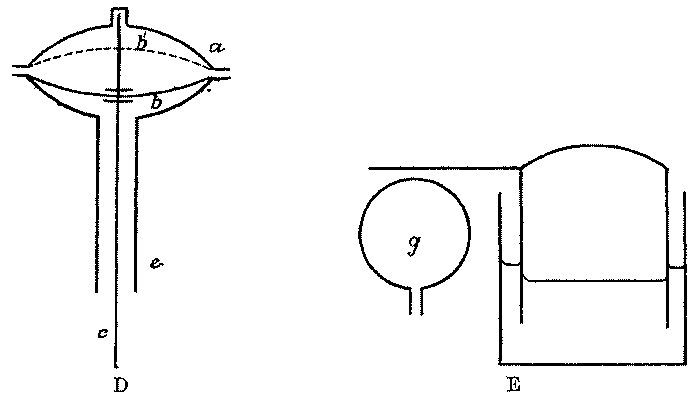
ACTION OF WATER-TO-CARBIDE GENERATORS.--Having by one or other of the means described obtained a supply of water intermittent in character, it remains to be considered how that supply may be made to approach the carbide in the generator. Actual acetylene apparatus are so various in kind, and merge from one type to another by such small differences, that it is somewhat difficult to classify them in a simple and intelligible fashion. However, it may be said that water-to-carbide generators, i.e., such as employ water as the moving material, may be divided into four categories: (F^1) water is allowed to fall as single drops or as a fine stream upon a mass of carbide--this being the "drip" generator; (F^2) a mass of water is made to rise round and then recede from a stationary vessel containing carbide--this being essentially identical in all respects save the mechanical one with the "dip" or "dipping" generator shown in A^2, Fig. 1; (F^3) a supply of water is permitted to rise round, or to flow upon, a stationary mass of carbide without ever receding from the position it has once assumed--this being the "contact" generator; and (F^4) a supply of water is admitted to a subdivided charge of carbide in such proportion that each quantity admitted is in chemical excess of the carbide it attacks. With the exception of F^2, which has already been illustrated as A^2 Fig. 1, or as B^1 in Fig. 2, these methods of decomposing carbide are represented in Figs. 4 and 5. It will be observed that whereas in both F^1 and F^3 the liberated acetylene passes off at the top of the apparatus, or rather from the top of the non-subdivided charge of carbide, in F^1 the water enters at the top, and in F^3 it enters at the bottom. Thus it happens that the mixture of acetylene and steam, which is produced at the spot where the primary chemical reaction is taking place, has to travel through the entire mass of carbide present in a generator belonging to type F^3, while in F^1 the damp gas flows directly to the exit pipe without having to penetrate the lumps of solid. Both F^1 and F^3 exhibit after-generation caused by a reaction between the liquid water mechanically clinging to the mass of spent lime and the excess of carbide to an approximately equal extent; but for the reason just mentioned, after-generation due to a reaction between the vaporised water accompanying the acetylene first evolved and the excess of carbide is more noticeable in F^3 than in F^1; and it is precisely this latter description of after-generation which leads to overheating of the most ungovernable kind. Naturally both F^1 and F^3 can be fitted with water jackets, as is indicated by the dotted lines in the second sketch; but unless the generating chamber in quite small and the evolution of gas quite slow, the cooling action of the jacket will not prove sufficient. As the water in F^1 and F^3 is not capable of backward motion, the decomposing chambers cannot be employed as displacement holders, as is the case in the dipping generator pictured at B^1, Fig. 2. They must be coupled, accordingly, to a separate holder of the displacement or, preferably, of the rising type; and, in order that the gas evolved by after-generation may not be wasted, the automatic mechanism must cut off the supply of water to the generator by the time that holder is two-thirds or three-quarters full.

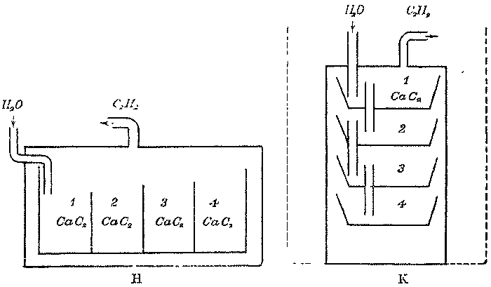
The diagrams G, H, and K in Figs. 4 and 5 represent three different methods of constructing a generator which belongs either to the contact type (F^3) if the supply of water is essentially continuous, i.e., if less is admitted at each movement of the feeding mechanism than is sufficient to submerge the carbide in each receptacle; or to the flooded- compartment type (F') if the water enters in large quantities at a time. In H the main carbide vessel is arranged horizontally, or nearly so, and each partition dividing it into compartments is taller than its predecessor, so that the whole of the solid in (1) must be decomposed, and the compartment entirely filled with liquid before it can overflow into (2), and so on. Since the carbide in all the later receptacles is exposed to the water vapour produced in that one in which decomposition is proceeding at any given moment, at least at its upper surface, some after-generation between vapour and carbide occurs in H; but a partial control over the temperature may be obtained by water-jacketing the container. In G the water enters at the base and gas escapes at the top, the carbide vessels being disposed vertically; hero, perhaps, more after- generation of the same description occurs, as the moist gas streams round and over the higher baskets. In K, the water enters at the top and must completely fill basket (1) before it can run down the depending pipe into (2); but since the gas also leaves the generator at the top, the later carbide receptacles do not come in contact with water vapour, but are left practically unattacked until their time arrives for decomposition by means of liquid water. K, therefore, is the best arrangement of parts to avoid after-generation, overheating, and polymerisation of the acetylene whether the generator be worked as a contact or as a flooded-compartment apparatus; but it may be freely admitted that the extent of the overheating due to reaction between water vapour and carbide may be kept almost negligible in either K, H, or G, provided the partitions in the carbide container be sufficient in number--provided, that is to say, that each compartment holds a sufficiently small quantity of carbide; and provided that the quantity of water ultimately required to fill each compartment is relatively so large that the temperature of the liquid never approaches the boiling-point where vaporisation is rapid. The type of generator indicated by K has not become very popular, but G is fairly common, whilst H undoubtedly represents the apparatus which is most generally adopted for use in domestic and other private installations in the United Kingdom and the Continent of Europe. The actual generators made according to the design shown by H usually have a carbide receptacle designed in the form of a semi-cylindrical or rectangular vessel of steel sliding fairly closely into an outside container, the latter being either built within the main water space of the entire apparatus or placed within a separate water-jacketed casing. Owing to its shape and the sliding motion with which the carbide receptacle is put into the container these generators are usually termed "drawer" generators. In comparison with type G, the drawer generator H certainly exhibits a lower rise in temperature when gas is evolved in it at a given speed and when the carbide receptacles are constructed of similar dimensions. It is very desirable that the whole receptacle should be subdivided into a sufficient number of compartments and that it should be effectively water-cooled from outside. It would also be advantageous if the water- supply were so arranged that the generator should be a true flooded- compartment apparatus, but experience has nevertheless shown that generators of type H do work very well when the water admitted to the carbide receptacle, each time the feed comes into action, is not enough to flood the carbide in one of the compartments. Above a certain size drawer generators are usually constructed with two or even more complete decomposing vessels, arrangements being such that one drawer can be taken out for cleaning, whilst the other is in operation. When this is the case a third carbide receptacle should always be employed so that it may be dry, lit to receive a charge of carbide, and ready to insert in the apparatus when one of the others is withdrawn. The water-feed should always be so disposed that the attendant can see at a glance which of the two (or more) carbide receptacles is in action at any moment, and it should be also so designed that the supply is automatically diverted to the second receptacle when the first is wholly exhausted and back again to the first (unless there are more than two) when the carbide in the second is entirely gasified. In the sketches G, H, and K, the total space occupied by the various carbide receptacles is represented as being considerably smaller than the capacity of the decomposing chamber. Were this method of construction copied in actual acetylene apparatus, the first makes of gas would be seriously (perhaps dangerously) contaminated with air. In practice the receptacles should fit so tightly into the outer vessel and into one another that when loaded to the utmost extent permissible--space being left for the swelling of the charge and for the passage of water and gas--but little room should be left for the retention of air in the chamber.
ACTION OF CARBIDE-TO-WATER GENERATORS.--The methods which may be adopted to render a generator automatic when carbide is employed as the moving material are shown at M, N, and P, in Fig. 6; but the precise devices used in many actual apparatus are so various that it is difficult to portray them generically. Moreover it is desirable to subdivide automatic carbide-to-water generators, according to the size of the carbide they are constructed to take, into two or three classes, which are termed respectively "large carbide-feed," "small carbide-feed," and "granulated carbide-feed" apparatus. (The generator represented at L does not really belong to the present class, being non-automatic and fed by hand; but the sketch is given for completeness.) M is an automatic carbide-feed generator having its store of carbide in a hopper carried by the rising- holder bell. The hopper is narrowed at its mouth, where it is closed by a conical or mushroom valve d supported on a rod held in suitable guides. When the bell falls by consumption of gas, it carries the valve and rod with it; but eventually the button at the base of c strikes the bottom of the generator, or some fixed distributing plate, and the rod can descend no further. Then, when the bell falls lower, the mushroom d rises from its seat, and carbide drops from the hopper into the water. This type of apparatus has the defect characteristic of A^2, Fig. 1; for the pressure in the service steadily diminishes as the effective weight of bell plus hopper decreases by consumption of carbide. But it has also two other defects--(1) that ordinary carbide is too irregular in shape to fall smoothly through the narrow annular space between the valve and its seat; (2) that water vapour penetrates into the hopper, and liberates some gas there, while it attacks the lumps of carbide at the orifice, producing dust or causing them to stick together, and thus rendering the action of the feed worse than ever. Most of these defects can be avoided by using granulated carbide, which is more uniform in size and shape, or by employing a granulated and "treated" carbide which has been dipped in some non-aqueous liquid to make it less susceptible to the action of moisture. Both these plans, however, are expensive to adopt; first, because of the actual cost of granulating or "treating" the carbide; secondly, because the carbide deteriorates in gas-making capacity by its inevitable exposure to air during the granulating or "treating" process. The defects of irregularity of pressure and possible waste of gas by evolution in the hopper may be overcome by disposing the parts somewhat differently; making the holder an annulus round the hopper, or making it cylindrical with the hopper inside. In this case the hopper is supported by the main portion of the apparatus, and does not move with the bell: the rod and valve being given their motion in some fashion similar to that figured. Apparatus designed in accordance with the sketch M, or with the modification just described, are usually referred to under the name of "hopper" generators. On several occasions trouble has arisen during their employment owing to the jamming of the valve, a fragment of carbide rather larger than the rest of the material lodging between the lips of the hopper and the edges of the mushroom valve. This has been followed by a sudden descent of all the carbide in the store into the water beneath, and the evolution of gas has sometimes been too rapid to pass away at the necessary speed into the holder. The trouble is rendered even more serious should the whole charge of carbide fall at a time when, by neglect or otherwise, the body of the generator contains much lime sludge, the decomposition then proceeding under exceptionally bad circumstances, which lead to the production of an excessively high temperature. Hopper generators are undoubtedly very convenient for certain purposes, chiefly, perhaps, for the construction of table-lamps and other small installations. Experience tends to show that they may be employed, first, provided they are designed to take granulated carbide--which in comparison with larger grades is much more uniform and cylindrical in shape--and secondly, provided the quantity of carbide in the hopper does not exceed a few pounds. The phenomenon of the sudden unexpected descent of the carbide, popularly known as "dumping," can hardly be avoided with carbide larger in size than the granulated variety; and since the results of such an accident must increase in severity with the size of the apparatus, a limit in their capacity is desirable.
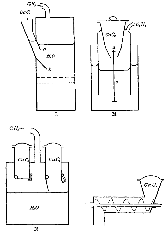
When it is required to construct a carbide-feed generator of large size or one belonging to the large carbide-feed pattern, it is preferable to arrange the store in a different manner. In N the carbide is held in a considerable number of small receptacles, two only of which are shown in the drawing, provided with detachable lids and hinged bottoms kept shut by suitable catches. At proper intervals of time those catches in succession are knocked on one side by a pin, and the contents of the vessel fall into the water. There are several methods available for operating the pins. The rising-holder bell may be made to actuate a train of wheels which terminate in a disc revolving horizontally on a vertical axis somewhere just below the catches; and this wheel may bear an eccentric pin which hits each catch as it rotates. Alternatively the carbide boxes may be made to revolve horizontally on a vertical axis by the movements of the bell communicated through a clutch; and thus each box in succession may arrive at a certain position where the catch is knocked aside by a fixed pin. The boxes, again, may revolve vertically on a horizontal axis somewhat like a water-wheel, each box having its bottom opened, or, by a different system of construction, being bodily upset, when it arrives at the bottom of its circular path. In no case, however, are the carbide receptacles carried by the bell, which is a totally distinct part of the apparatus; and therefore in comparison with M, the pressure given by the bell is much more uniform. Nevertheless, if the system of carbide boxes moves at all, it becomes easier to move by decrease in weight and consequent diminution in friction as the total charge is exhausted; and accordingly the bell has less work to do during the later stages of its operation. For this reason the plan actually shown at N is preferable, since the work done by the moving pin, i.e., by the descending bell, is always the same. P represents a carbide-feed effected by a spiral screw or conveyor, which, revolved periodically by a moving bell, draws carbide out of a hopper of any desired size and finally drops it into a shoot communicating with a generating chamber such as that shown in L. Here the work done by the bell is large, as the friction against the blades of the screw and the walls of the horizontal tube is heavy; but that amount of work must always be essentially identical. The carbide-feed may similarly be effected by means of some other type of conveyor instead of the spiral screw, such as an endless band, and the friction in these cases may be somewhat less than with the screw, but the work to be done by the bell will always remain large, whatever type of conveyor may be adopted. A further plan for securing a carbide-feed consists in employing some extraneous driving power to propel a charge of carbide out of a reservoir into the generator. Sometimes the propulsive effort is obtained from a train of clockwork, sometimes from a separate supply of water under high pressure. The clockwork or the water power is used either to drive a piston travelling through the vessel containing the carbide so that the proper quantity of material is dropped over the open mouth of a shoot, or to upset one after another a series of carbide receptacles, or to perform some analogous operation. In these cases the pin or other device fitted to the acetylene apparatus itself has nothing to do beyond releasing the mechanism in question, and therefore the work required from the bell is but small. The propriety of employing a generator belonging to these latter types must depend upon local conditions, e.g., whether the owner of the installation has hydraulic power on a small scale (a constant supply of water under sufficient pressure) at disposal, or whether he does not object to the extra labour involved in the periodical winding up of a train of clockwork.
It must be clear that all these carbide-feed arrangements have the defect in a more or less serious degree of leaving the carbide in the main storage vessel exposed to the attack of water vapour rising from the decomposing chamber, for none of the valves or operating mechanism can be made quite air-tight. Evolution of gas produced in this way does not matter in the least, because it is easy to return the gas so liberated into the generator or into the holder; while the extent of the action, and the consequent production of overheating, will tend to be less than in generators such as those shown in G and H of Figs. 4 and 5, inasmuch as the large excess of water in the carbide-feed apparatus prevents the liquid arriving at a temperature at which it volatilises rapidly. The main objection to the evolution of gas in the carbide vessel of a carbide-to-water generator depends on the danger that the smooth working of the feed-gear may be interfered with by the formation of dust or by the aggregation of the carbide lumps.
USE OF OIL IN GENERATORS.--Calcium carbide is a material which is only capable of attack for the purpose of evolving acetylene by a liquid that is essentially water, or by one that contains some water mixed with it. Oils and the like, or even such non-aqueous liquids as absolute alcohol, have no effect upon carbide, except that the former naturally make it greasy and somewhat more difficult to moisten. This last property has been found of service in acetylene generation, especially on the small scale; for if carbide is soaked in, or given a coating of, some oil, fat, or solid hydrocarbon like petroleum, cocoanut oil, or paraffin wax, the substance becomes comparatively indifferent towards water vapour or the moisture present in the air, while it still remains capable of complete, albeit slow, decomposition by liquid water when completely immersed therein. The fact that ordinary calcium carbide is attacked so quickly by water is really a defect of the substance; for it is to this extreme rapidity of reaction that the troubles of overheating are due. Now, if the basket in the generator B^1 of Fig. 2, or, indeed, the carbide store in any of the carbide-to-water apparatus, is filled with a carbide which has been treated with oil or wax, as long as the water-level stands at l' and l" or the carbide still remains in the hopper, it is essentially unattacked by the vapour arising from the liquid; but directly the basket is submerged, or the lumps fall into the water, acetylene is produced, and produced more slowly and regularly than otherwise. Again, oils do not mix with water, but usually float thereon, and a mass of water covered by a thick film or layer of oil does not evaporate appreciably. If, now, a certain quantity of oil, say lamp paraffin or mineral lubricating oil, is poured on to the water in B^1, Fig. 2, it moves upwards and downwards with the water. When the water takes the position l, the oil is driven upwards away from the basket of carbide, and acetylene is generated in the ordinary manner; but when the water falls to l" the oil descends also, rinses off much of the adhering water from the carbide lumps, covers them with a greasy film, and almost entirely stops generation till it is in turn washed off by the next ascent of the water. Similarly, if the carbide in generators F, G, and H (also K) has been treated with a solid or semi-solid grease, it is practically unattacked by the stream of warm damp gas, and is only decomposed when the liquid itself arrives in the basket. For the same reason treated carbide can be kept for fairly long periods of time, even in a drum with badly fitting lid, without suffering much deterioration by the action of atmospheric moisture. The problem of acetylene generation is accordingly simplified to a considerable degree by the use of such treated carbide, and the advantage becomes more marked as the plant decreases in size till a portable apparatus is reached, because the smaller the installation the more relatively expensive or inconvenient is a large holder for surplus gas. The one defect of the method is the extra cost of such treated carbide; and in English conditions ordinary calcium carbide is too expensive to permit of any additional outlay upon the acetylene if it is to compete with petroleum or the product of a tiny coal-gas works. The extra cost of using treated carbide falls upon the revenue account, and is much more noticeable than that of a large holder, which is capital expenditure. When fluid oil is employed in a generator of type B^1, evolution of gas becomes so regular that any holder beyond the displacement one which the apparatus itself constitutes is actually unnecessary, though still desirable; but B^1, with or without oil, still remains a displacement apparatus, and as such gives no constant pressure. It must be admitted that the presence of oil so far governs the evolution of gas that the movement of the water, and the consequent variation of pressure, is rendered very small; still a governor or a rising holder would be required to give the best result at the burners. One point in connexion with the use of liquid oil must not be overlooked, viz., the extra trouble it may give in the disposal of the residues. This matter will be dealt with more fully in Chapter V.; here it is sufficient to say that as the oil does not mix with the water but floats on the surface, care has to be taken that it is not permitted to enter any open stream. The foregoing remarks about the use of oil manifestly only apply to those cases where it is used in quantity and where it ultimately becomes mixed with the sludge or floats on the water in the decomposing chamber. The employment of a limpid oil, such as paraffin, as an intermediate liquid into which carbide is introduced on its way to the water in the decomposing vessel of a hand-fed generator in the manner described on page 70 is something quite different, because, except for trifling losses, one charge of oil should last indefinitely.
RISING GASHOLDERS.--Whichever description of holder is employed in an acetylene apparatus, the gas is always stored over, or in contact with, a liquid that is essentially water. This introduces three subjects for consideration: the heavy weight of a large body of liquid, the loss of gas by dissolution in that liquid, and the protection of that liquid from frost in the winter. The tanks of rising holders are constructed in two different ways. In one the tank is a plain cylindrical vessel somewhat larger in diameter than the bell which floats in it; and since there must be nearly enough water in the tank to fill the interior of the bell when the latter assumes its lowest position, the quantity of water is considerable, its capacity for dissolving acetylene is large, and the amount of any substance that may have to be added to it to lower its freezing-point becomes so great as to be scarcely economical. All these defects, including that of the necessity for very substantial foundations under the holder to support its enormous weight, may be overcome by adopting the second method of construction. It is clear that the water in the centre of the tank is of no use,--all that is needed being a narrow trough for the bell to work in. Large rising holders are therefore advantageously built with a tank formed in the shape of an annulus, the effective breadth of which is not more than 2 or 3 inches, the centre portion being roofed over so as to prevent escape of gas. The same principle may be retained with modified details by fitting inside a plain cylindrical tank a "dummy" or smaller cylinder, closed by a flat or curved top and fastened water- and air-tight to the bottom of the main vessel. The construction of annular tanks or the insertion of a "dummy" may be attended with difficulty if the tank is wholly or partly sunk below the ground level, owing to the lifting force of water in the surrounding soil. Where a steel tank is sunk, or a masonry tank is constructed, regard must be paid, both in the design of the tank and in the manner of construction, to the level of the underground water in the neighbourhood, as in certain cases special precautions will be needed to avoid trouble from the pressure of the water on the outside of the tank until it is balanced by the pressure of the water with which the tank is filled. So far as mere dissolution of gas is concerned, the loss may be reduced by having a circular disc of wood, &c., a little smaller in diameter than the boll, floating on the water of a plain tank.
EFFECT OF STORAGE IN GASHOLDER ON ACETYLENE.--It is perfectly true, as has been stated elsewhere, that the gas coming from an acetylene generator loses some of its illuminating power if it is stored over water for any great length of time; such loss being given by Nichols as 94 per cent, in five months, and having been found by one of the authors as 0.63 per cent. per day--figures which stand in fair agreement with one another. This wastage is not due to any decomposition of the acetylene in contact with water, but depends on the various solubilities of the different gases which compose the product obtained from commercial calcium carbide. Inasmuch as an acetylene evolved in the best generator contains some foreign ingredients, and inasmuch as an inferior product contains more (cf. Chapter V.), the contents of a holder are never pure; but as those contents are principally made up of acetylene itself, that gas stands at a higher partial pressure in the holder than the impurities. Since acetylene is more soluble in water than any of its diluents or impurities, sulphuretted hydrogen and ammonia excepted, and since the solubility of all gases increases as the pressure at which they are stored rises, the true acetylene in an acetylene holder dissolves in the water more rapidly and comparatively more copiously than the impurities; and thus the acetylene tends to disappear and the impurities to become concentrated within the bell. Simultaneously at the outer part of the seal, air is dissolved in the water; and by processes of diffusion the air so dissolved passes through the liquid from the outside to the inside, where it escapes into the bell, while the dissolved acetylene similarly passes from the inside to the outside of the seal, and there mingles with the atmosphere. Thus, the longer a certain volume of acetylene is stored over water, the more does it become contaminated with the constituents of the atmosphere and with the impurities originally present in it; while as the acetylene is much more soluble than its impurities, more gas escapes from, than enters, the holder by diffusion, and so the bulk of stored gas gradually diminishes. However, the figures previously given show that this action is too slow to be noticeable in practice, for the gas is never stored for more than a few days at a time. The action cannot be accepted as a valid argument against the employment of a holder in acetylene plant. Such deterioration and wastage of gas may be reduced to some extent by the use of a film of some cheap and indifferent oil floating on the water inside an acetylene holder; the economy being caused by the lower solubility of acetylene in oils than in aqueous liquids not saturated with some saline material. Probably almost any oil would answer equally well, provided it was not volatile at the temperature of the holder, and that it did not dry or gum on standing, e.g., olive oil or its substitutes; but mineral lubricating oil is not so satisfactory. It is, however, not necessary to adopt this method in practice, because the solvent power of the liquid in the seal can be reduced by adding to it a saline body which simultaneously lowers its freezing-point and makes the apparatus more trustworthy in winter.
FREEZING OF GASHOLDER SEAL.--The danger attendant upon the congelation of the seal in an acetylene holder is very real, not so much because of the fear that the apparatus may be burst, which is hardly to be expected, as because the bell will be firmly fixed in a certain position by the ice, and the whole establishment lighted by the gas will be left in darkness. In these circumstances, hurried and perhaps injudicious attempts may be made to thaw the seal by putting red-hot bars into it or by lighting fires under it, or the generator-house may be thoughtlessly entered with a naked light at a time when the apparatus is possibly in disorder through the loss of storage-room for the gas it is evolving. Should a seal ever freeze, it must be thawed only by the application of boiling water; and the plant-house must be entered, if daylight has passed, in perfect darkness or with the assistance of an outside lamp whining through a closed window. [Footnote: By "closed window" is to be understood one incapable of being opened, fitted with one or two thicknesses of stout glass well puttied in, and placed in a wall of the house as far as possible from the door.] There are two ways of preventing the seal from freezing. In all large installations the generator-house will be fitted with a warm-water heating apparatus to protect the portion of the plant where the carbide is decomposed, and if the holder is also inside the same building it will naturally be safe. If it is outside, one of the flow-pipes from the warming apparatus should be led into and round the lowest part of the seal, care being taken to watch for, or to provide automatic arrangements for making good, loss of water by evaporation. If the holder is at a distance from the generator-house, or if for any other reason it cannot easily be brought into the warming circuit, the seal can be protected in another way; for unlike the water in the generator, the water in the holder-seal will perform its functions equally well however much it be reduced in temperature, always providing it is maintained in the liquid condition. There are numerous substances which dissolve in, or mix with, water, and yield solutions or liquids that do not solidify until their temperature falls far below that of the natural freezing- point. Assuming that those substances in solution do not attack the acetylene, nor the metal of which the holder is built, and are not too expensive, choice may be made between them at will. Strictly speaking the cost of using them is small, because unless the tank is leaky they last indefinitely, not evaporating with the water as it is vaporised into the gas or into the air. The water-seal of a holder standing within the generator-house may eventually become so offensive to the nostrils that the liquid has to be renewed; but when this happens it is due to the accumulation in the water of the water-soluble impurities of the crude acetylene. If, as should be done, the gas is passed through a washer or condenser containing much water before it enters the holder the sulphuretted hydrogen and ammonia will be extracted, and the seal will not acquire an obnoxious odour for a very long time.
Four principal substances have been proposed for lowering the freezing- point of the water in an acetylene-holder seal; common salt (sodium chloride), calcium chloride (not chloride of lime), alcohol (methylated spirit), and glycerin. A 10 per cent. solution of common salt has a specific gravity of 1.0734, and does not solidify above -6° C. or 21.2° F.; a 15 per cent. solution has a density of 1.111, and freezes at -10° C. or 14° F. Common salt, however, is not to be recommended, as its solutions always corrode iron and steel vessels more or less quickly. Alcohol, in its English denatured form of methylated spirit, is still somewhat expensive to use, but it has the advantage of not increasing the viscosity of the water; so that a frost-proof mixture of alcohol and water will flow as readily through minute tubes choked with needle- valves, or through felt and the like, or along wicks, as will plain water. For this reason, and for the practically identical one that it is quite free from dirt or insoluble matter, diluted spirit is specially suitable for the protection of the water in cyclists' acetylene lamps, [Footnote: As will appear in Chapter XIII., there is usually no holder in a vehicular acetylene lamp, all the water being employed eventually for the purpose of decomposing the carbide. This does not affect the present question. Dilute alcohol does not attack calcium carbide so energetically as pure water, because it stands midway between pure water and pure alcohol, which is inert. The attack, however, of the carbide is as complete as that of pure water, and the slower speed thereof is a manifest advantage in any holderless apparatus.] where strict economy is less important than smooth working. For domestic and larger installations it is not indicated. As between calcium chloride and glycerin there is little to choose; the former will be somewhat cheaper, but the latter will not be prohibitively expensive if the high-grade pure glycerins of the pharmacist are avoided. The following tables show the amount of each substance which must be dissolved in water to obtain a liquid of definite solidifying point. The data relating to alcohol were obtained by Pictet, and those for calcium chloride by Pickering. The latter are materially different from figures given by other investigators, and perhaps it would be safer to make due allowance for this difference. In Germany the Acetylene Association advocates a 17 per cent. solution of calcium chloride, to which Frank ascribes a specific gravity of 1.134, and a freezing-point of -8° C. or 17.6° F.
           Freezing-Points of Dilute Alcohol.
 _________________________________________________________
|               |                   |                     |
| Percentage of | Specific Gravity. |   Freezing-point.   |
|    Alcohol.   |                   |                     |
|_______________|___________________|_____________________|
|               |                   |          |          |
|               |                   | Degs. C. | Degs. F. |
|      4.8      |      0.9916       |   -2.0   |  +28.4   |
|     11.3      |      0.9824       |    5.0   |   23.0   |
|     16.4      |      0.9761       |    7.5   |   18.5   |
|     18.8      |      0.9732       |    9.4   |   15.1   |
|     20.3      |      0.9712       |   10.6   |   12.9   |
|     22.1      |      0.9689       |   12.2   |   10.0   |
|     24.2      |      0.9662       |   14.0   |    6.8   |
|     26.7      |      0.9627       |   16.0   |    3.2   |
|     29.9      |      0.9578       |   18.9   |   -2.0   |
|_______________|___________________|__________|__________|
           Freezing-Points of Dilute Glycerin.
 _________________________________________________________
|               |                   |                     |
| Percentage of | Specific Gravity. |   Freezing-point.   |
|    Glycerin.  |                   |                     |
|_______________|___________________|_____________________|
|               |                   |          |          |
|               |                   | Degs. C. | Degs. F. |
|      10       |       1.024       |   -1.0   |  +30.2   |
|      20       |       1.051       |    2.5   |   27.5   |
|      30       |       1.075       |    6.0   |   21.2   |
|      40       |       1.105       |   17.5   |    0.5   |
|      50       |       1.127       |   31.3   |  -24.3   |
|_______________|___________________|__________|__________|
      Freezing-Points of Calcium Chloride Solutions.
 _________________________________________________________
|               |                   |                     |
| Percentage of | Specific Gravity. |   Freezing-point.   |
|    CaCl_2.    |                   |                     |
|_______________|___________________|_____________________|
|               |                   |          |          |
|               |                   | Degs. C. | Degs. F. |
|       6       |       1.05        |   -3.0   |  +26.6   |
|       8       |       1.067       |    4.3   |   24.3   |
|      10       |       1.985       |    5.9   |   21.4   |
|      12       |       1.103       |    7.7   |   18.1   |
|      14       |       1.121       |    9.8   |   14.4   |
|      16       |       1.140       |   12.2   |   10.0   |
|      18       |       1.159       |   15.2   |    4.6   |
|      20       |       1.170       |   18.6   |   -1.5   |
|_______________|___________________|__________|__________|
Calcium chloride will probably be procured in the solid state, but it can be purchased as a concentrated solution, being sold under the name of "calcidum" [Footnote: This proprietary German article is a liquid which begins to solidify at -42° C. (-43.6° F.), and is completely solid at -56° C. (-69)° F.). Diluted with one-third its volume of water, it freezes between -20° and -28° C. (-4° and-l8.4° F.). The makers recommend that it should be mixed with an equal volume of water. Another material known as "Gefrierschutzflüssigkeit" and made by the Flörsheim chemical works, freezes at -35° C. (-3° F.). Diluted with one-quarter its volume of water, it solidifies at -18° C. (-0.4° F.); with equal parts of water it freezes at -12° C. (10.4° F.). A third product, called "calcidum oxychlorid," has been found by Caro and Saulmann to be an impure 35 per cent. solution of calcium chloride. Not one of these is suitable for addition to the water used in the generating chamber of an acetylene apparatus, the reasons for this having already been mentioned.] for the protection of gasholder seals. Glycerin itself resembles a strong solution of calcium chloride in being a viscid, oily-looking liquid; and both are so much heavier than water that they will not mix with further quantities unless they are thoroughly agitated therewith. Either may be poured through water, or have water floated upon it, without any appreciable admixture taking place; and therefore in first adding them to the seal great care must be taken that they are uniformly distributed throughout the liquid. If the whole contents of the seal cannot conveniently be run into an open vessel in which the mixing can be performed, the sealing water must be drawn off a little at a time and a corresponding quantity of the protective reagent added to it. Care must be taken also that motives of economy do not lead to excessive dilution of the reagent; the seal must be competent to remain liquid under the prolonged influence of the most severe frost ever known to occur in the neighbourhood where the plant is situated. If the holder is placed out of doors in an exposed spot where heavy rains may fall on the top of the bell, or where snow may collect there and melt, the water is apt to run down into the seal, diluting the upper layers until they lose the frost- resisting power they originally had. This danger may be prevented by erecting a sloping roof over the bell crown, or by stirring up the seal and adding more preservative whenever it has been diluted with rain water. Quite small holders would probably always be placed inside the generator-house, where their seals may be protected by the same means as are applied to the generator itself. It need hardly be said that all remarks about the dangers incidental to the freezing of holder seals and the methods for obviating them refer equally to every item in the acetylene plant which contains water or is fitted with a water-sealed cover; only the water which is actually used for decomposing the calcium carbide cannot be protected from frost by the addition of calcium chloride or glycerin--that water must be kept from falling to its natural freezing-point. From Mauricheau-Beaupré's experiments, referred to on page 106, it would appear that a further reason for avoiding an addition of calcium chloride to the water used for decomposing carbide should lie in the danger of causing a troublesome production of froth within the generator.
It will be convenient to digress here for the purpose of considering how the generators of an acetylene apparatus themselves should be protected from frost; but it may be said at the outset that it is impossible to lay down any fixed rules applicable to all cases, since local conditions, such as climate, available resources, dimensions, and exposed or protected position of the plant-house vary so largely in different situations. In all important installations every item of the plant, except the holder, will be collected in one or two rooms of a single building constructed of brick or other incombustible material. Assuming that long-continued frost reigns at times in the neighbourhood, the whole of such a building, with the exception of one apartment used as a carbide store only, is judiciously fitted with a heating arrangement like those employed in conservatories or hothouses; a system of pipes in which warm water is kept circulating being run round the walls of each chamber near the floor. The boiler, heated with coke, paraffin, or even acetylene, must naturally be placed in a separate room of the apparatus-house having no direct (indoor) communication with the rooms containing the generators, purifiers, &c. Instead of coils of pipe, "radiators" of the usual commercial patterns may be adopted; but the immediate source of heat should be steam, or preferably hot water, and not hot air or combustion products from the stove. In exposed situations, where the holder is out of doors, one branch of the flow-pipe should enter and travel round the seal as previously suggested. Most large country residences are already provided with suitable heating apparatus for warming the greenhouses, and part of the heat may be capable of diversion into the acetylene generator-shed if the latter is erected in a convenient spot. In fact, if any existing hot-water warming appliances are already at hand, and if they are powerful enough to do a little more work, it may be well to put the generator-building in such a position that it can be efficiently supplied with artificial warmth from those boilers; for any extra length of main necessary to lead the gas into the residence from a distant generator will cost less on the revenue account than the fuel required to feed a special heating arrangement. In smaller installations, especially such as are to be found in mild climates, it may be possible to render the apparatus-house sufficiently frost-proof without artificial heat by building it partly underground, fitting it with a double skylight in place of a window for the entrance of daylight, and banking up its walls all round with thick layers of earth. The house must have a door, however, which must open outwards and easily, so that no obstacle may prevent a hurried exit in emergencies. Such a door can hardly be made very thick or double without rendering it heavy and difficult to open; and the single door will be scarcely capable of protecting the interior if the frost is severe and prolonged. Ventilators, too, must be provided to allow of the escape of any gas that may accidentally issue from the plant during recharging, &c.; and some aperture in the roof will be required for the passage of the vent pipe or pipes, which, in certain types of apparatus, move upwards and downwards with the bell of the holder. These openings manifestly afford facilities for the entry of cold air, so that although this method of protecting generator-houses has proved efficient in many places, it can only be considered inferior to the plan of installing a proper heating arrangement. Occasionally, where local regulations do not forbid, the entire generator-house may be built as a "lean-to" against some brick wall which happens to be kept constantly warm, say by having a furnace or a large kitchen stove on its other side.
In less complicated installations, where there are only two distinct items in the plant to be protected from frost--generator and holder--or where generator and holder are combined into one piece of apparatus, other methods of warming become possible. As the reaction between calcium carbide and water evolves much heat, the most obvious way of preventing the plant from freezing is to economise that heat, i.e., to retain as much of it as is necessary within the apparatus. Such a process, clearly, is only available if the plant is suitable in external form, is practically self-contained, and comprises no isolated vessels containing an aqueous liquid. It is indicated, therefore, rather for carbide-to- water generators, or for water-to-carbide apparatus in which the carbide chambers are situated inside the main water reservoir--any apparatus, in fact, where much water is present and where it is all together in one receptacle. Moreover, the method of heat economy is suited for application to automatic generators rather than to those belonging to the opposite system, because automatic apparatus will be generating gas, and consequently evolving heat, every evening till late at night--just at the time when frost begins to be severe. A non-automatic generator will usually be at work only in the mornings, and its store of heat will accordingly be much more difficult to retain till nightfall. With the object of storing up the heat evolved in the generator, it must be covered with some material possessed of the lowest heat-conducting power possible; and the proper positions for that material in order of decreasing importance are the top, sides, and bottom of the plant. The generator may either be covered with a thick layer of straw, carpet, flannel, or the like, as is done in the protection of exposed water- pipes; or it may be provided with a jacket filled with some liquid. In view of the advisability of not having any organic or combustible material near the generator, the solid substances just mentioned may preferably be replaced by one of those partially inorganic compositions sold for "lagging" steam-pipes and engine-cylinders, such as "Fossil meal." Indeed, the exact nature of the lagging matters comparatively little, because the active substance in retaining the heat in the acetylene generator or the steam-pipe is the air entangled in the pores of the lagging; and therefore the value of any particular material depends mainly on its exhibiting a high degree of porosity. The idea of fitting a water jacket round an acetylene generator is not altogether good, but it may be greatly improved upon by putting into the jacket a strong solution of some cheap saline body which has the property of separating from its aqueous solution in the form of crystals containing water of crystallisation, and of evolving much heat in so separating. This method of storing much heat in a small space where a fire cannot be lighted is in common use on some railways, where passengers' foot-warmers are filled with a strong solution of sodium acetate. When sodium acetate is dissolved in water it manifestly exists in the liquid state, and it is presumably present in its anhydrous condition (i.e., not combined with water of crystallisation). The common crystals are solid, and contain 3 molecules of water of crystallisation--also clearly in the solid state. Now, the reaction
NaC_2H_3O_2 + 3H_2O = NaC_2H_3O_2.3H_2O
(anhydrous acetate) (crystals)
evolves 4.37 calories (Berthelot), or 1.46 calorie for each molecule of water; and whereas 1 kilo. of water only evolves 1 large calorie of heat as its temperature falls 1° C., 18 grammes of water (1 gramme-molecule) evolve l.46 large calorie when they enter into combination with anhydrous sodium acetate to assist in forming crystals--and this 1.46 calorie may either be permitted to warm the mass of crystals, or made to do useful work by raising the temperature of some adjacent substance. Sodium acetate crystals dissolve in 3.9 parts by weight of water at 6° C. (43° F.) or in 2.4 parts at 37° C. (99° F.). If, then, a jacket round an acetylene apparatus is filled with a warm solution of sodium acetate crystals in (say) 3 parts by weight of water, the liquid will crystallise when it reaches some temperature between 99° and 43° F.; but when the generator comes into action, the heat liberated will change the mass of crystals into a liquid without raising its sensible temperature to anything like the extent that would happen were the jacket full of simple water. Not being particularly warm to the touch, the liquefied product in the jacket will not lose much heat by radiation, &c., into the surrounding air; but when the water in the generator falls again (after evolution of acetylene ceases) the contents of the jacket will also cool, and finally will begin to crystallise once more, passing a large amount of low-temperature heat into the water of the generator, and safely maintaining it for long periods of time at a temperature suitable for the further evolution of gas. Like the liquid in the seal of an isolated gasholder, the liquid in such a jacket will last indefinitely; and therefore the cost of the sodium acetate in negligible.
Another method of keeping warm the water in any part of an acetylene installation consists in piling round the apparatus a heap of fresh stable manure, which, as is well known, emits much heat as it rots. Where horses are kept, such a process may be said to cost nothing. It has the advantage over methods of lagging or jacketing that the manure can be thrown over any pipe, water-seal, washing apparatus, &c., even if the plant is constructed in several separate items. Unfortunately the ammonia and the volatile organic compounds which are produced during the natural decomposition of stable manure tend seriously to corrode iron and steel, and therefore this method of protecting an apparatus from frost should only be employed temporarily in times of emergency.
CORROSION IN APPARATUS.--All natural water is a solution of oxygen and may be regarded also as a weak solution of the hypothetical carbonic acid. It therefore causes iron to rust more or less quickly; and since no paint is absolutely waterproof, especially if it has been applied to a surface already coated locally with spots of rust, iron and steel cannot be perfectly protected by its aid. More particularly at a few inches above and below the normal level of the water in a holder, therefore, the metal soon begins to exhibit symptoms of corrosion which may eventually proceed until the iron is eaten away or becomes porous. One method of prolonging the life of such apparatus is to give it fresh coats of paint periodically; but unless the old layers are removed where they have cracked or blistered, and the rust underneath is entirely scraped off (which is practically impossible), the new paint films will not last very long. Another more elegant process for preserving any metal like iron which is constantly exposed to the attack of a corrosive liquid, and which is readily applicable to acetylene holders and their tanks, depends on the principle of galvanic action. When two metals in good electrical contact are immersed in some liquid that is capable of attacking both, only that metal will be attacked which is the more electro-positive, or which (the same thing in other words) is the more readily attacked by the liquid, evolving the more heat during its dissolution. As long as this action is proceeding, as long, that is, as some of the more electro- positive material is present, the less electro-positive material will not suffer. All that has to be done, therefore, to protect the walls of an acetylene-holder tank and the sides of its bell is to hang in the seal, supported by a copper wire fastened to the tank walls by a trustworthy electrical joint (soldering or riveting it), a plate or rod of some more electro-positive metal, renewing that plate or rod before it is entirely eaten away. [Footnote: Contact between the bell and the rod may be established by means of a flexible metallic wire; or a separate rod might be used for the bell itself.] If the iron is bare or coated with lead (paint may be overlooked), the plate may be zinc; if the iron is galvanised, i.e., coated with zinc, the plate may be aluminium or an alloy of aluminium and zinc. The joint between the copper wire and the zinc or aluminium plate should naturally be above the water-level. The foregoing remarks should be read in conjunction with what was said in Chapter II., about the undesirability of employing a soft solder containing lead in the construction of an acetylene generator. Here it is proposed intentionally to set up a galvanic couple to prevent corrosion; there, with the same object in view, the avoidances of galvanic action is counselled. The reason for this difference is self-evident; here a foreign metal is brought into electrical contact with the apparatus in order that the latter may be made electro-negative; but when a joint is soldered with lead, the metal of the generator is unintentionally made electro-positive. Here the plant is protected by the preferential corrosion of a cheap and renewable rod; in the former case the plant is encouraged to rust by the unnecessary presence of an improperly selected metal.
OTHER ITEMS IN GENERATING PLANT.--It has been explained in Chapter II. that the reaction between calcium carbide and water is very tumultuous in character, and that it occurs with great rapidity. Clearly, therefore, the gas comes away from the generator in rushes, passing into the next item of the plant at great speed for a time, and then ceasing altogether. The methods necessarily adopted for purifying the crude gas are treated of in Chapter V.; but it is manifest now that no purifying material can prove efficient unless the acetylene passes through it at a uniform rate, and at one which is as slow as other conditions permit. For this reason the proper position of the holder in an acetylene installation is before the purifier, and immediately after the condenser or washer which adjoins the generator. By this method of design the holder is filled up irregularly, the gas passing into it sometimes at full speed, sometimes at an imperceptible rate; but if the holder is well balanced and guided this is a matter of no consequence. Out of the holder, on the other hand, the gas issues at a rate which is dependent upon the number and capacity of the burners in operation at any moment; and in ordinary conditions this rate is so much more uniform during the whole of an evening than the rate at which the gas is evolved from the carbide, that a purifier placed after the holder is given a far better opportunity of extracting the impurities from the acetylene than it would have were it situated before the holder, as is invariably the case on coal-gas works.
For many reasons, such as capacity for isolation when being recharged or repaired, it is highly desirable that each item in an acetylene plant shall be separated, or capable of separation, from its neighbours; and this observation applies with great force to the holder and the decomposing vessel of the generator. In all large plants each vessel should be fitted with a stopcock at its inlet and, if necessary, one at its outlet, being provided also with a by-pass so that it can be thrown out of action without interfering with the rest of the installation. In the best practice the more important vessels, such as the purifiers, will be in duplicate, so that unpurified gas need not be passed into the service while a solitary purifier is being charged afresh. In smaller plants, where less skilled labour will probably be bestowed on the apparatus, and where hand-worked cocks are likely to be neglected or misused, some more, automatic arrangement for isolating each item is desirable. There are two automatic devices which may be employed for the purposes in view, the non-return valve and the water-seal. The non-return valve is simply a mushroom or ball valve without handle, lifted off its seat by gas passing from underneath whenever the pressure of the gas exceeds the weight of the valve, but falling back on to its seat and closing the pipe when the pressure decreases or when pressure above is greater than that below. The apparatus works perfectly with a clean gas or liquid which is not corrosive; but having regard to the possible presence of tarry products, lime dust, or sludge, condensed water loaded with soluble impurities, &c., in the acetylene, a non-return valve is not the best device to adopt, for both it and the hand-worked cock or screw- down valve are liable to stick and give trouble. The best arrangement in all respects, especially between the generator and the holder, is a water-seal. A water-seal in made by leading the mouth of a pipe delivering gas under the level of water in a suitable receptacle, so that the issuing gas has to bubble through the liquid. Gas cannot pass backwards through the pipe until it has first driven so much liquid before it that the level in the seal has fallen below the pipe's mouth; and if the end of the pipe is vertical more pressure than can possibly be produced in the apparatus is necessary to effect this. Omitting the side tube b, one variety of water-seal is shown at D in Fig. 7 on page 103. The water being at the level l, gas enters at a and bubbles through it, escaping from the apparatus at c. It cannot return from c to a without driving the water out of the vessel till its level falls from f to g; and since the area of the vessel is much greater than that of the pipe, so great a fall in the vessel would involve a far greater rise in a. It is clear that such a device, besides acting as a non-return valve, also fulfils two other useful functions: it serves to collect and retain all the liquid matter that may be condensed in the pipe a from the spot at which it was originally level or was given a fall to the seal, as well as that condensing in c as far as the spot where c dips again; and it equally acts as a washer to the gas, especially if the orifice g of the gas-inlet pipe is not left with a plain mouth as represented in the figure, but terminates in a large number of small holes, the pipe being then preferably prolonged horizontally, with minute holes in it so as to distribute the gas throughout the entire vessel. Such an apparatus requires very little attention. It may with advantage be provided with the automatic arrangement for setting the water-level shown at d and e. d is a tunnel tube extending almost to the bottom of the vessel, and e is a curved run-off pipe of the form shown. The lower part of the upper curve in e is above the level f, being higher than f by a distance equal to that of the gas pressure in the pipes; and therefore when water is poured into the funnel it fills the vessel till the internal level reaches f, when the surplus overflows of itself. The operation thus not only adjusts the quantity of water present to the desired level so that a cannot become unsealed, but it also renews the liquid when it has become foul and nearly saturated with dissolved and condensed impurities from the acetylene. It would be a desirable refinement to give the bottom of the vessel a slope to the mouth of e, or to some other spot where a large-bore draw-off cock could be fitted for the purpose of extracting any sludge of lime, &c., that may collect. By having such a water-seal, or one simpler in construction, between the generator and the holder, the former may be safely opened at any time for repairs, inspection, or the insertion of a fresh charge of carbide while the holder is full of gas, and the delivery of acetylene to the burners at a specified pressure will not be interrupted. If a cock worked by hand were employed for the separation of the holder from the generator, and the attendant were to forget to close it, part or all of the acetylene in the holder would escape from the generator when it was opened or disconnected.
Especially when a combined washer and non-return valve follows immediately after a generator belonging to the shoot type, and the mouth of the shoot is open to the air in the plant-house, it is highly desirable that the washer shall be fitted with some arrangement of an automatic kind for preventing the water level rising much above its proper position. The liquid in a closed washer tends to rise as the apparatus remains in use, water vapour being condensed within it and liquid water, or froth of lime, being mechanically carried forward by the stream of acetylene coming from the decomposing chamber. In course of time, therefore, the vertical depth to which the gas-inlet pipe in the washer is sealed by the liquid increases; and it may well be that eventually the depth in question, plus the pressure thrown by the holder bell, may become greater than the pressure which can be set up inside the generator without danger of gas slipping under the lower edge of the shoot. Should this state of things arise, the acetylene can no longer force its way through the washer into the holder bell, but will escape from the mouth of the shoot; filling the apparatus-house with gas, and offering every opportunity for an explosion if the attendant disobeys orders and takes a naked light with him to inspect the plant.
It is indispensable that every acetylene apparatus shall be fitted with a safety-valve, or more correctly speaking a vent-pipe. The generator must have a vent-pipe in case the gas-main leading to the holder should become blocked at any time, and the acetylene which continues to be evolved in all water-to-carbide apparatus, even after the supply of water has been cut off be unable to pass away. Theoretically a non-automatic apparatus does not require a vent-pipe in its generator because all the gas enters the holder immediately, and is, or should be, unable to return through the intermediate water seal; practically such a safeguard is absolutely necessary for the reason given. The holder must have a safety-valve in case the cutting-off mechanism of the generator fails to act, and more gas passes into it than it can store. Manifestly the pressure of the gas in a water-sealed holder or in any generator fitted with a water-sealed lid cannot rise above that corresponding with the depth of water in the seal; for immediately the pressure, measured in inches of water, equals the depth of the sealing liquid, the seal will be blown out, and the gas will escape. Such an occurrence, however, as the blowing of a seal must never be possible in any item of an acetylene plant, more especially in those items that are under cover, for the danger that the issuing gas might be fired or might produce suffocation would be extremely great. Typical simple forms of vent-pipe suitable for acetylene apparatus are shown in Fig. 7. In each case the pipe marked "vent" is the so-called safety-valve; it is open at its base for the entry of gas, and open at its top for the escape of the acetylene into the atmosphere, such top being in all instances carried through the roof of the generator-house into the open air, and to a spot distant from any windows of that house or of the residence, where it can prove neither dangerous nor a nuisance by reason of its odour. At A is represented the vent-pipe of a displacement vessel, which may either be part of a displacement holder or of a generator working on the displacement principle. The vent-pipe is rigidly fixed to the apparatus. If gas is generated within the closed portion of the holder or passes through it, and if the pressure so set up remains less than that which is needed to move the water from the level l to the levels l' and l", the mouth of the pipe is under water, and acetylene cannot enter it; but immediately such an amount of gas is collected, or such pressure is produced that the interior level sinks below l", which is that of the mouth of the pipe, it becomes unsealed, and the surplus gas freely escapes. There are two minor points in connexion with this form of vent-pipe often overlooked. At the moment when the water arrives at l" in the closed half of the apparatus, its level in the interior of the vent-pipe stands at l', identical with that in the open hall of the apparatus (for the mouth of the vent-pipe and the water in the open hall of the apparatus are alike exposed to the pressure of the atmosphere only). When the water, then, descends just below l" there is an amount of water inside the pipe equal in height to the distance between l' and l"; and before the acetylene can escape, it must either force this water as a compact mass out of the upper mouth of the vent-pipe (which it is clearly not in a position to do), drive it out of the upper mouth a little at a time, or bubble through it till the water is gradually able to run downwards out of the pipe as its lower opening is more fully unsealed. In practice the acetylene partly bubbles through this water and partly drives it out of the mouth of the pipe; on some occasions temporarily yielding irregular pressures at the burners which cause them to jump, and always producing a gurgling noise in the vent- pipe which in calculated to alarm the attendant. If the pipe is too small in diameter, and especially if its lower orifice is cut off perfectly horizontal and constricted slightly, the water may refuse to escape from the bottom altogether, and the pipe will fail to perform its allotted task. It is better therefore to employ a wide tube, and to cut off its mouth obliquely, or to give its lower extremity the shape of an inverted funnel. At the half of the central divided drawing marked B (Fig. 7) is shown a precisely similar vent-pipe affixed to the bell of a rising holder, which behaves in an identical fashion when by the rising of the bell its lower end is lifted out of the water in the tank. The features described above as attendant, upon the act of unsealing of the displacement-holder vent-pipe occur here also, but to a less degree; for the water remaining in the pipe at the moment of unsealing is only that which corresponds with the vertical distance between l' and l", and in a rising holder this is only a height always equal to the pressure given by the bell. Nevertheless this form of vent-pipe produces a gurgling noise, and would be better for a trumpet-shaped mouth. A special feature of the pipe in B is that unless it is placed symmetrically about the centre of the bell its weight tends to throw the bell out of the vertical, and it may have to be supported at its upper part; conversely, if the pipe is arranged concentrically in the bell, it may be employed as part of the guiding arrangement of the bell itself. Manifestly, as the pipe must be long enough to extend through the roof of the generator-house, its weight materially increases the weight of the bell, and consequently the gas pressure in the service; this fact is not objectionable provided due allowance is made for it. So tall a vent-pipe, however, seriously raises the centre of gravity of the bell and may make it top-heavy. To work well the centre of gravity of a holder bell should be as low as possible, any necessary weighting being provided symmetrically about its circumference and close to its bottom edge. The whole length of an ascending vent-pipe need not be carried by the rising bell, because the lower portion, which must be supported by the bell, can be arranged to slide inside a wider length of pipe which is fixed to the roof of the generator-house at the point where it passes into the open air.

A refinement upon this vent-pipe is represented at C, where it is rigidly fastened to the tank of the holder, and has its internal aperture always above the level of the water in the apparatus. Rigidly fixed to the crown of the bell is a tube of wider diameter, h, which is closed at its upper end. h is always full of gas, and its mouth is normally beneath the level of the water in the seal; but when the bell rises to its highest permissible position, the mouth of h comes above the water, and communication is opened between the holder and the outer atmosphere. No water enters the vent-pipe from the holder, and therefore no gurgling or irregular pressure is produced. Another excellent arrangement of a vent-pipe, suggested by Klinger of Gumpoldskirchen, is shown at D, a drawing which has already been partly considered as a washer and water-seal. For the present purpose the main vessel and its various pipes are so dimensioned that the vertical height g to f is always appreciably greater than the gas pressure in the service or in the generator or gasholder to which it is connected. In these circumstances the gas entering at a depresses the water in the pipe below the level f to an extent equal to the pressure at which it enters that pipe--an extent normally less than the distance f to g; and therefore gas never passes into the body of the vessel, but travels away by the side tube b (which in former references to this drawing was supposed to be absent). If, however, the pressure at a exceeds that of the vertical height f to g, gas escapes at g through the water, and is then free to reach the atmosphere by means of the vent c. As before, d serves to charge the apparatus with water, and e to ensure a proper amount being added. Clearly no liquid can enter the vent-pipe in this device. Safety-valves such as are added to steam-boilers and the like, which consist of a weighted lever holding a conical valve down against its seat, are not required in acetylene apparatus, for the simpler hydraulic seals discussed above can always be fitted wherever they may be needed. It should be noticed that these vent-pipes only come into operation in emergencies, when they are required to act promptly. No economy is to be effected by making them small in diameter. For obvious reasons the vent-pipe of a holder should have a diameter equal to that of the gas-inlet tube, and the vent-pipe of a generator be equal in size to the gas-leading tube.
FROTHING IN GENERATORS.--A very annoying trouble which crops up every now and then during the evolution of acetylene consists in the production of large masses of froth within the generator. In the ordinary way, decomposition of carbide is accompanied by a species of effervescence, but the bubbles should break smartly and leave the surface of the liquid reasonably free from foam. Sometimes, however, the bubbles do not break, but a persistent "head" of considerable height is formed. Further production of gas only increases the thickness of the froth until it rises so high that it is carried forward through the gas-main into the next item of the plant. The froth disappears gradually in the pipes, but leaves in them a deposit of lime which sooner or later causes obstructions by accumulating at the angles and dips; while during its presence in the main the steady passage of gas to the holder is interrupted and the burners may even be made to jump. Manifestly the defect is chiefly, if not always, to be noticed in the working of carbide-to-water generators. The phenomenon has been examined by Mauricheau-Beaupré, who finds that frothing is not characteristic of pure carbide and that it cannot be attributed to any of the impurities normally present in commercial carbide. If, however, the carbide contains calcium chloride, frothing is liable to occur. A 0.1 per cent. solution of calcium chloride appears to yield some foam when carbide is decomposed in it, and a 1 per cent. solution to foam in a pronounced manner. In the absence of calcium chloride, the main cause of frothing seems to be the presence in the generator of new paint or tar. If a generator is taken into use before the paint in any part of it which becomes moistened by warm lime-water has had opportunity of drying thoroughly hard, frothing is certain to occur; and even if the carbide has been stored for only a short time in a tin or drum which has been freshly painted, a production of froth will follow when it is decomposed in water. The products of the polymerisation of acetylene also tend to produce frothing, but not to such an extent as the turpentine in paint and the lighter constituents of coal-tar. Carbide stored even temporarily in a newly painted tin froths on decomposition because it has absorbed among its pores some of the volatile matter given off by the paint during the process of desiccation.
THE "DRY" PROCESS OF GENERATION.--A process for generating acetylene, totally different in principle from those hitherto considered, has been introduced in this country. According to the original patents of G. J. Atkins, the process consisted in bringing small or powdered carbide into mechanical contact with some solid material containing water, the water being either mixed with the solid reagent or attached to it as water of crystallisation. Such reagents indeed were claimed as crude starch and the like, the idea being to recover a by-product of pecuniary value. Now the process seems to be known only in that particular form in which granulated carbide is treated with crystallised sodium carbonate, i.e., common washing soda. Assuming the carbide employed to be chemically pure and the reaction between it and the water of crystallisation contained in ordinary soda crystals to proceed quantitatively, the production of acetylene by the dry process should be represented by the following chemical equation:
5CaC_2 + Na_2CO_3.10H_2O = 5C_2H_2 + 5Ca(OH)_2 + Na_2CO_3.
On calculating out the molecular weights, it will be seen that 286 parts of washing soda should suffice for the decomposition of 320 parts of pure calcium carbide, or in round numbers 9 parts of soda should decompose 10 parts of carbide. In practice, however, it seems to be found that from 1 to 1.5 parts of soda are needed for every part of carbide.
The apparatus employed is a metal drum supported on a hollow horizontal spindle, one end of which is closed and carries a winch handle, and the other end of which serves to withdraw the gas generated in the plant. The drum is divided into three compartments by means of two vertical partitions so designed that when rotation proceeds in one particular direction portions of the two reagents stored in one end compartment pass into the centre compartment; whereas when rotation proceeds in the opposite direction, the material in the centre compartment is merely mixed together, partly by the revolution of the drum, partly with the assistance of a stationary agitator slung loosely from the central spindle. The other end compartment contains coke or sawdust or other dry material through which the gas passes for the removal of lime or other dust carried in suspension as it issues from the generating compartment. The gas then passes through perforations into the central spindle, one end of which is connected by a packed joint with a fixed pipe, which leads to a seal or washer containing petroleum. Approached from a theoretical standpoint, it will be seen that this method of generation entirely sacrifices the advantages otherwise accruing from the use of liquid water as a means for dissipating the heat of the chemical reaction, but on the other hand, inasmuch as the substances are both solid, the reaction presumably occurs more slowly than it would in the presence of liquid water; and moreover the fact that the water employed to act upon the carbide is in the solid state and also more or less combined with the rest of the sodium carbonate molecule, means that, per unit of weight, the water decomposed must render latent a larger amount of heat than it would were it liquid. Experiments made by one of the authors of this book tend to show that the gas evolved from carbide by the dry process contains rather less phosphorus than it might in other conditions of generation, and as a fact gas made by the dry process is ordinarily consumed without previous passage through any chemical purifying agent. It is obvious, however, that the use of the churn described above greatly increases the labour attached to the production of the gas; while it is not clear that the yield per unit weight of carbide decomposed should be as high as that obtained in wet generation. The inventor has claimed that his by-product should be valuable and saleable, apparently partly on the ground that it should contain caustic soda. Evidence, however, that a reaction between the calcium oxide or hydroxide and the sodium carbonate takes place in the prevailing conditions is not yet forthcoming, and the probabilities are that such decomposition would not occur unless the residue were largely diluted with water. [Footnote: The oldest process employed for manufacturing caustic soda consisted in mixing a solution of sodium carbonate with quick or slaked lime, and it has been well established that the causticisation of the soda will not proceed when the concentration of the liquid is greater than that corresponding with a specific gravity of about 1-10, i.e., when the liquid contains more than some 8 to 10 per cent, of sodium hydroxide.] Conversely there are some grounds for believing that the dry residue is less useful than an ordinary wet residue for horticultural purposes, and also for the production of whitewash. From a financial standpoint, the dry process suffers owing to the expense involved in the purchase of a second raw material, for which but little compensation can be discovered unless it is proved that the residue is intrinsically more valuable than common acetylene-lime and can be sold or used advantageously by the ordinary owner of an installation. The discarding of the chemical purifier at the present day is a move of which the advantage may well be overrated.
ARTIFICIAL LIGHTING OF GENERATOR SHEDS.--It has already been argued that
all normal or abnormal operations in connexion with an acetylene
generating plant should be carried out, if possible, by daylight; and it
has been shown that on no account must a naked light ever be taken inside
the house containing such a plant. It will occasionally happen, however,
that the installation must be recharged or inspected after nightfall. In
order to do this in safety, a double window, incapable of being opened,
should be fitted in one wall of the house, as far as possible from the
door, and in such a position that the light may fall on to all the
necessary places. Outside this window may be suspended an ordinary hand-
lantern burning oil or paraffin; or, preferably, round this window may be
built a closed lantern into which some source of artificial light may be
brought. If the acetylene plant has an isolated holder of considerable
size, there is no reason at all why a connexion should not be made with
the service-pipes, and an acetylene flame be used inside this lantern; but
with generators of the automatic variety, an acetylene light is not so
suitable, because of the fear that gas may not be available precisely at
the moment when it is necessary to have light in the shed. It would,
however, be a simple matter to erect an acetylene burner inside the
lantern in such a way that when needed an oil-lamp or candle could be used
instead. Artificial internal light of any kind is best avoided; the only
kind permissible being an electric glow-lamp. If this is employed, it
should be surrounded by a second bulb or gas-tight glass jacket, and
preferably by a wire cage as well; the wires leading to it must be
carefully insulated, and all switches or cut-outs (which may produce a
spark) must be out of doors. The well-known Davy safety or miner's lamp is
not a trustworthy instrument for use with acetylene because of (a)
the low igniting-point of acetylene; (b) the high temperature of
its flame; and (c) the enormous speed at which the explosive wave
travels through a mixture of acetylene and air. For these reasons the
metallic gauze of the Davy lamp is not so efficient a protector of the
flame as it is in cases of coal-gas, methane, &c. Moreover, in
practice, the Davy lamp gives a poor light, and unless in constant use is
liable to be found out of order when required. It should, however, be
added that modern forms of the safety lamp, in which the light is
surrounded by a stout glass chimney and only sufficient gauze is used for
the admission of fresh air and for the escape of the combustion products,
appear quite satisfactory when employed in an atmosphere containing some
free acetylene.
In Chapter II. an attempt has been made to explain the physical and chemical phenomena which accompany the interaction of calcium carbide and water, and to show what features in the reaction are useful and what inconvenient in the evolution of acetylene on a domestic or larger scale. Similarly in Chapter III. have been described the various typical devices which may be employed in the construction of different portions of acetylene plant, so that the gas may be generated and stored under the best conditions, whether it is evolved by the automatic or by the non- automatic system. This having been done, it seemed of doubtful utility to include in the first edition of this work a long series of illustrations of such generators as had been placed on the markets by British, French, German, and American makers. It would have been difficult within reasonable limits to have reproduced diagrams of all the generators that had been offered for sale, and absolutely impossible within the limits of a single hand-book to picture those which had been suggested or patented. Moreover, some generating apparatus appeared on the market ephemerally; some was constantly being modified in detail so as to alter parts which experience or greater knowledge had shown the makers to be in need of alteration, while other new apparatus was constantly being brought out. On these and other grounds it did not appear that much good purpose would have been served by describing the particular apparatus which at that time would have been offered to prospective purchasers. It seemed best that the latter should estimate the value and trustworthiness of apparatus by studying a section of it in the light of the general principles of construction of a satisfactory generator as enunciated in the book. While the position thus taken by the authors in 1903 would still not be incorrect, it has been represented to them that it would scarcely be inconsistent with it to give brief descriptions of some of the generators which are now being sold in Great Britain and a few other countries. Six more years' experience in the design and manufacture of acetylene plant has enabled the older firms of manufacturers to fix upon certain standard patterns for their apparatus, and it may confidently be anticipated that many of these will survive a longer period. Faulty devices and designs have been weeded out, and there are lessons of the past as well as theoretical considerations to guide the inventor of a new type of generator. On those grounds, therefore, an attempt has now been made to give brief descriptions, with sectional views, of a number of the generators now on the market in Great Britain. Moreover, as the first edition of this book found many readers in other countries, in several of which there is greater scope for the use of acetylene, it has been decided to describe also a few typical or widely used foreign generators. All the generators described must stand or fall on their merits, which cannot be affected by any opinion expressed by the authors. In the descriptions, which in the first instance have generally been furnished by the manufacturers of the apparatus, no attempt has therefore been made to appraise the particular generators, and comparisons and eulogistic comments have been excluded. The descriptions, however, would nevertheless have been somewhat out of place in the body of this book; they have therefore been relegated to a special Appendix. It has, of course, been impossible to include the generators of all even of the English manufacturers, and doubtless many trustworthy ones have remained unnoticed. Many firms also make other types of generators in addition to those described. It must not be assumed that because a particular make of generator is not mentioned it is necessarily faulty. The apparatus described may be regarded as typical or well known, and workable, but it is not by reason of its inclusion vouched for in any other respect by the authors. The Appendix is intended, not to bias or modify the judgment of the would-be purchaser of a generator, but merely to assist him in ascertaining what generators there are now on the market.
The observations on the selection of a generator which follow, as well as any references in other chapters to the same matter, have been made without regard to particular apparatus of which a description may (or may not) appear in the Appendix. With this premise, it may be stated that the intending purchaser should regard the mechanism of a generator as shown in a sectional view or on inspection of the apparatus itself. If the generator is simple in construction, he should be able to understand its method of working at a glance, and by referring it to the type (vide Chapter III.) to which it belongs, be able to appraise its utility from a chemical and physical aspect from what has already been said. If the generator is too complicated for ready understanding of its mode of working, it is not unlikely to prove too complicated to behave well in practice. Not less important than the mechanism of a generator is good construction from the mechanical point of view, i.e., whether stout metal has been employed, whether the seams and joints are well finished, and whether the whole apparatus has been built in the workman- like fashion which alone can give satisfaction in any kind of plant. Bearing these points in mind, the intending purchaser may find assistance in estimating the mechanical value of an apparatus by perusing the remainder of this chapter, which will be devoted to elaborating at length the so-called scientific principles underlying the construction of a satisfactory generator, and to giving information on the mechanical and practical points involved.
It is perhaps desirable to remark that there is scarcely any feature in the generation of acetylene from calcium carbide and water--certainly no important feature--which introduces into practice principles not already known to chemists and engineers. Once the gas is set free it ranks simply as an inflammable, moisture-laden, somewhat impure, illuminating and heat-giving gas, which has to be dried, purified, stored, and led to the place of combustion; it is in this respect precisely analogous to coal- gas. Even the actual generation is only an exothermic, or heat-producing, reaction between a solid and a liquid, in which rise of temperature and pressure must be prevented as far as possible. Accordingly there is no fundamental or indispensable portion of an acetylene apparatus which lends itself to the protection of the patent laws; and even the details (it may be said truthfully, if somewhat cynically) stand in patentability in inverse ratio to their simplicity and utility.
During the early part of 1901 a Committee appointed by the British Home Office, "to advise as to the conditions of safety to which acetylene generators should conform, and to carry out tests of generators in the market in order to ascertain how far those conform with such conditions," issued a circular to the trade suggesting that apparatus should be sent them for examination. In response, forty-six British generators were submitted for trial, and were examined in a fashion which somewhat exceeded the instructions given to the Committee, who finally reported to the Explosives Department of the Home Office in a Blue Book, No. Cd. 952, which can be purchased through any bookseller. This report comprises an appendix in which most of the apparatus are illustrated, and it includes the result of the particular test which the Committee decided to apply. Qualitatively the test was useful, as it was identical in all instances, and only lacks full utility inasmuch as the trustworthiness of the automatic mechanism applied to such generators as were intended to work on the automatic system was not estimated. Naturally, a complete valuation of the efficiency of automatic mechanism cannot be obtained from one or even several tests, it demands long-continued watching; but a general notion of reliability might have been obtained. Quantitatively, however, the test applied by the Committee is not so free from reproach, for, from the information given, it would appear to have been less fair to some makers of apparatus than to others. Nevertheless the report is valuable, and indicates the general character of the most important apparatus which were being offered for sale in the United Kingdom in 1900-1901.
It is not possible to give a direct answer to the question as to which is the best type of acetylene generator. There are no generators made by responsible firms at the present time which are not safe. Some may be easier to charge and clean than others; some require more frequent attention than others; some have moving parts less likely to fail, when handled carelessly, than others; some have no moving mechanism to fail. For the illumination of a large institution or district where one man can be fully occupied in attending to the plant, cleaning, lighting, and extinguishing the lamps, or where other work can be found for him so as to leave him an hour or so every day to look after the apparatus, the hand-fed carbide-to-water generator L (Fig. 6) has many advantages, and is probably the best of all. In smaller installations choice must be made first between the automatic and the non-automatic principle--the advantages most frequently lying with the latter. If a non-automatic generator is decided upon, the hand carbide-feed or the flooded- compartment apparatus is almost equally good; and if automatism is desired, either a flooded-compartment machine or one of the most trustworthy types of carbide-feed apparatus may be taken. There are contact apparatus on the markets which appear never to have given trouble, and those are worthy of attention. Some builders advocate their own apparatus because the residue is solid and not a cream. If there is any advantage in this arising from greater ease in cleaning and recharging the generator and in disposing of the waste, that advantage is usually neutralised by the fear that the carbide may not have been wholly decomposed within the apparatus; and whereas any danger arising from imperfectly spent carbide being thrown into a closed drain may be prevented by flooding the residue with plenty of water in an open vessel, imperfect decomposition in the generator means a deficiency in the amount of gas evolved from a unit weight of solid taken or purchased. In fact, setting on one side apparatus which belong to a notoriously defective system and such as are constructed in large sizes on a system that is only free from overheating, &c., in small sizes; setting aside all generators which are provided with only one decomposing chamber when they are of a capacity to require two or more smaller ones that can more efficiently be cooled with water jackets; and setting aside any form of plant which on examination is likely to exhibit any of the more serious objections indicated in this and the previous chapters, there is comparatively little to choose, from the chemical and physical points of view, between the different types of generators now on the markets. A selection may rather be made on mechanical grounds. The generator must be well able to produce gas as rapidly as it will ever be required during the longest or coldest evening; it must be so large that several more brackets or burners can be added to the service after the installation is complete. It must be so strong that it will bear careless handling and the frequent rough manipulation of its parts. It must be built of stout enough material not to rust out in a few years. Each and all of its parts must be accessible and its exterior visible. Its pipes, both for gas and sludge, must be of large bore (say 1 inch), and fitted at every dip with an arrangement for withdrawing into some closed vessel the moisture, &c., that may condense. The number of cocks, valves, and moving parts must be reduced to a minimum; cocks which require to be shut by hand before recharging must give way to water-seals. It must be simple in all its parts, and its action intelligible at a glance. It must be easy to charge--preferably even by the sense of touch in darkness. It must be easy to clean. The waste lime must be easily removed. It must be so fitted with vent-pipes that the pressure can never rise above that at which it is supposed to work. Nevertheless, a generator in which these vent-pipes are often brought into use is badly constructed and wasteful, and must be avoided. The water of the holder seal should be distinct from that used for decomposing the carbide; and those apparatus where the holder is entirely separated from the generator are preferable to such as are built all in one, even if water-seals are fitted to prevent return of gas. Apparatus which is supposed to be automatic should be made perfectly automatic, the water or the carbide-feed being locked automatically before the carbide store, the decomposing chamber, or the sludge-cock can be opened. The generating chamber must always be in communication with the atmosphere through a water-sealed vent-pipe, the seal of which, if necessary, the gas can blow at any time. All apparatus should be fitted with rising holders, the larger the better. Duplicate copies of printed instructions should be demanded of the maker, one copy being kept in the generator-house, and the other elsewhere for reference in emergencies. These instructions must give simple and precise information as to what should be done in the event of a breakdown as well as in the normal manipulation of the plant. Technical expressions and descriptions of parts understood only by the maker must be absent from these rules.
ADDENDUM.
BRITISH AND FOREIGN REGULATIONS FOR THE CONSTRUCTION AND INSTALLATION OF ACETYLENE GENERATING PLANT
Dealing with the "conditions which a generator should fulfil before it can be considered as being safe," the HOME OFFICE COMMITTEE of 1901 before mentioned write as follows:
1. The temperature in any part of the generator, when run at the maximum rate for which it is designed, for a prolonged period, should not exceed 130° C. This may be ascertained by placing short lengths of wire, drawn from fusible metal, in those parts of the apparatus in which heat is liable to be generated.
2. The generator should have an efficiency of not less than 90 per cent., which, with carbide yielding 5 cubic feet per pound, would imply a yield of 4.5 cubic feet for each pound of carbide used.
3. The size of the pipes carrying the gas should be proportioned to the maximum rate of generation, so that undue back pressure from throttling may not occur.
4. The carbide should be completely decomposed in the apparatus, so that lime sludge discharged from the generator shall not be capable of generating more gas.
5. The pressure in any part of the apparatus, on the generator side of the holder, should not exceed that of 20 inches of water, and on the service side of same, or where no gasholder is provided, should not exceed that of 5 inches of water.
6. The apparatus should give no tarry or other heavy condensation products from the decomposition of the carbide.
7. In the use of a generator regard should be had to the danger of stoppage of passage of the gas and resulting increase of pressure which may arise from the freezing of the water. Where freezing may be anticipated, steps should be taken to prevent it.
8. The apparatus should be so constructed that no lime sludge can gain access to any pipes intended for the passage of gas or circulation of water.
9. The use of glass gauges should be avoided as far as possible, and, where absolutely necessary, they should be effectively protected against breakage.
10. The air space in a generator before charging should be as small as possible.
11. The use of copper should be avoided in such parts of the apparatus as are liable to come in contact with acetylene.
The BRITISH ACETYLENE ASSOCIATION has drawn up the following list of regulations which, it suggests, shall govern the construction of generators and the installation of piping and fittings:
1. Generators shall be so constructed that, when used in accordance with printed instructions, it shall not be possible for any undecomposed carbide to remain in the sludge removed therefrom.
2. The limit of pressure in any part of the generator shall not exceed that of 20 inches of water, subject to the exception that if it be shown to the satisfaction of the Executive of the Acetylene Association that higher pressures up to 50 inches of water are necessary in certain generators, and are without danger, the Executive may, with the approval of the Home Office, grant exemption for such generators, with or without conditions.
3. The limit of pressure in service-pipes, within the house, shall not exceed 10 inches of water.
4. Except when used for special industrial purposes, such as oxy- acetylene welding, factories, lighthouses, portable apparatus containing not more than four pounds of carbide, and other special conditions as approved by the Association, the acetylene plant, such as generators, storage-holders, purifiers, scrubbers, and for washers, shall be in a suitable and well-ventilated outhouse, in the open, or in a lean-to, having no direct communication with a dwelling-house. A blow-off pipe or safety outlet shall be arranged in such a manner as to carry off into the open air any overmake of gas and to open automatically if pressure be increased beyond 20 inches water column in the generating chamber or beyond 10 inches in the gasholder, or beyond the depth of any fluid seal on the apparatus.
5. Generators shall have sufficient storage capacity to make a serious blow-off impossible.
6. Generators and apparatus shall be made of sufficiently strong material and be of good workmanship, and shall not in any part be constructed of unalloyed copper.
7. It shall not be possible under any conditions, even by wrong manipulation of cocks, to seal the generating chamber hermetically.
8. It shall not be possible for the lime sludge to choke any of the gas- pipes in the apparatus, nor water-pipes if such be alternately used as safety-valves.
9. In the use of a generator, regard shall be had to the danger of stoppage of passage of the gas, and resulting increase of pressure, which may arise from the freezing of the water. Where freezing may be anticipated, steps shall be taken to prevent it.
10. The use of glass gauges shall be avoided as far as possible, and where absolutely necessary they shall be effectively protected against breakage.
11. The air space in the generator before charging shall be as small as possible, i.e., the gas in the generating chamber shall not contain more than 8 per cent. of air half a minute after commencement of generation. A sample of the contents, drawn from the holder any time after generation has commenced, shall not contain an explosive mixture, i.e., more than 18 per cent, of air. This shall not apply to the initial charges of the gasholder, when reasonable precautions are taken.
12. The apparatus shall produce no tarry or other heavy condensation products from the decomposition of the carbide.
13. The temperature of the gas, immediately on leaving the charge, shall not exceed 212° F. (100° C.)
14. No generator shall be sold without a card of instructions suitable for hanging up in some convenient place. Such instructions shall be of the most detailed nature, and shall not presuppose any expert knowledge whatever on the part of the operator.
15. Notice to be fixed on Generator House Door, "NO LIGHTS OR SMOKING ALLOWED."
16. Every generator shall have marked clearly upon the outside a statement of the maximum number of half cubic foot burners and the charge of carbide for which it is designed.
17. The Association strongly advise the use of an efficient purifier with generating plant for indoor lighting.
18. No composition piping shall be used in any part of a permanent installation.
19. Before being covered in, all pipe-work (main and branches) shall be tested in the following manner: A special acetylene generator, giving a pressure of at least 10 inches water column in a gauge fixed on the furthest point from the generator, shall be connected to the pipe-work. All points shall be opened until gas reaches them, when they shall be plugged and the main cock on the permanent generator turned off, but all intermediate main cocks shall be open in order to test underground main and all connexions. The gauge must not show a loss after generator has been turned off for at least two hours.
20. After the fittings (pendants, brackets, &c.) have been fixed and all burners lighted, the gas shall be turned off at the burners and the whole installation shall be re-tested, but a pressure of 5 inches shall be deemed sufficient, which shall not drop lower than to 4-1/2 inches on the gauge during one hour's test.
21. No repairs to, or alterations in, any part of a generator, purifier, or other vessel which has contained acetylene shall be commenced, nor, except for recharging, shall any such part or vessel be cleaned out until it has been completely filled with water, so as to expel any acetylene or mixture of acetylene and air which may remain in the vessel, and may cause a risk of explosion.
Recommendation.--It being the general practice to store carbide in the generator-house, the Association recommend that the carbide shall be placed on a slightly raised platform above the floor level.
THE BRITISH FIRE OFFICES COMMITTEE in the latest revision, dated July 15, 1907, of its Rules and Regulations re artificial lighting on insured premises, includes the following stipulations applicable to acetylene:
Any apparatus, except as below, for generating, purifying, enriching, compressing or storing gas, must be either in the open or in a building used for such purposes only, not communicating directly with any building otherwise occupied.
An acetylene portable apparatus is allowed, provided it holds a charge of not more than 2 lb. of carbide.
A cylinder containing not more than 20 cubic feet of acetylene compressed and (or) dissolved in accordance with an Order of Secretary of State under the Explosives Act, 1875, is allowed.
The use of portable acetylene lamps containing charges of carbide exceeding the limit of 2 lb. allowed under these Rules (the average charge being about 18 lb.) is allowed in the open or in buildings in course of erection.
Liquid acetylene must not be used or stored on the premises.
The pipe, whether flexible or not, connecting an incandescent gas lamp to the gas-supply must be of metal with metal connexions.
(The reference in these Rules to the storage of carbide has been quoted in Chapter II. (page 19).)
These rules are liable to revision from time to time.
The GERMAN ACETYLENE VEREIN has drawn up (December 1904) the following code of rules for the construction, erection, and manipulation of acetylene apparatus:
I. Rules for Construction.
1. All apparatus for the generation, purification, and storage of acetylene must be constructed of sheet or cast iron. Holder tanks may be built of brick.
2. When bare, galvanised, or lead-coated sheet-iron is used, the sides of generators, purifiers, condensers, holder tanks, and (if present) washers and driers must be built with the following gauges as minima:
                             Holder bells.    All other apparatus.


Up to 7 cubic feet capacity     0.75 mm.          1.00 mm.
From 7 to 18         "          1.00              1.25
From 18 to 53        "          1.25              1.50
Above 53             "          1.50              2.00
When not constructed of cast-iron, the bottoms, covers, and "manhole" lids must be 0.5 mm. thicker in each respective size.
In all circumstances, the thickness of the walls--especially in the case of apparatus not circular in horizontal section--must be such that alteration in shape appears impossible, unless deformation is guarded against in other ways.
Generators must be so constructed that when they are being charged the carbide cannot fall into the residue which has already been gasified; and the residues must always be capable of easy, complete, and safe removal.
3. Generators, purifiers, and holders must be welded, riveted or folded at the seams; soft solder is only permissible as a tightening material.
4. Pipes delivering acetylene, or uniting the apparatus, must be cast- or wrought-iron. Unions, cocks, and valves must not be made of copper; but the use of brass and bronze is permitted.
5. When cast-iron is employed, the rules of the German Gas and Water Engineers are to be followed.
6. In generators where the whole amount of carbide introduced is not gasified at one time, it must be possible to add fresh water or carbide in safety, without interfering with the action of the apparatus. In such generators the size of the gasholder space is to be calculated according to the quantity of carbide which can be put into the generator. For every 1 kilogramme of carbide the available gasholder space must be: for the first 50 kilos., 20 litres; for the next 50 kilos., 15 litres; for amounts above 100 kilos., 10 litres per kilo. [One kilogramme may be taken as 2.2 lb., and 28 litres as 1 cubic foot.]
The generator must be large enough to supply the full number of normal (10-litre) burners with gas for 5 hours; the yield of acetylene being taken at 290 litres per kilo. [4.65 cubic feet per lb.]
The gasholder space of apparatus where carbide is not stored must be at least 30 litres for every normal (10-litre) flame.
7. The gasholder must be fitted with an appliance for removing any gas which may be generated (especially when the apparatus is first brought into action) after the available space is full. This vent must have a diameter at least equal to the inlet pipe of the holder.
8. Acetylene plant must be provided with purifying apparatus which contains a proper purifying material in a suitable condition.
9. The dimensions of subsidiary apparatus, such as washers, purifiers, condensers, pipes, and cocks must correspond with the capacity of the plant.
10. Purifiers and washers must be constructed of materials capable of resisting the attack of the substances in them.
11. Every generator must bear a plate giving the name of the maker, or the seller, and the maximum number of l0-litre lights it is intended to supply. If all the carbide put into the generator is not gasified at one time, the plate must also state the maximum weight of carbide in the charge. The gasholder must also bear a plate recording the maker's or seller's name, as well as its storage capacity.
12. Rules 1 to 11 do not apply to portable apparatus serving up to two lights, or to portable apparatus used only out of doors for the lighting of vehicles or open spaces.
II. Rules for Erection
1. Acetylene apparatus must not be erected in or under rooms occupied or frequented (passages, covered courts, &c.) by human beings. Generators and holders must only be erected in apartments covered with light roofs, and separated from occupied rooms, barns, and stables by a fire-proof wall, or by a distance of 15 feet. Any wall is to be considered fire- proof which is built of solid brick, without openings, and one side of which is "quite free." Apparatus may be erected in barns and stables, provided the space required is partitioned off from the remainder by a fire-proof wall.
2. The doors of apparatus sheds must open outwards, and must not communicate directly with rooms where fires and artificial lights are used.
3. Apparatus for the illumination of showmen's booths, "merry-go-rounds," shooting galleries, and the like must be erected outside the tents, and be inaccessible to the public.
4. Permanent apparatus erected in the open air must be at least 15 feet from an occupied building.
5. Apparatus sheds must be fitted at their highest points with outlet ventilators of sufficient size; the ventilators leading straight through the roof into the open air. They must be so arranged that the escaping gases and vapours cannot enter rooms or chimneys.
6. The contacts of any electrical warning devices must be outside the apparatus shed.
7. Acetylene plants must be prevented from freezing by erection in frost- free rooms, or by the employment of a heating apparatus or other suitable appliance. The heat must only be that of warm water or steam. Furnaces for the heating appliance must be outside the rooms containing generators, their subsidiary apparatus, or holders; and must be separated from such rooms by fire-proof walls.
8. In one of the walls of the apparatus shed--if possible not that having a door--a window must be fitted which cannot be opened; and outside that window an artificial light is to be placed. In the usual way acetylene lighting may be employed; but a lamp burning paraffin or oil, or a lantern enclosing a candle, must always be kept ready for use in emergencies. In all circumstances internal lighting is forbidden.
9. Every acetylene installation must be provided with a main cock, placed in a conveniently accessible position so that the whole of the service may be cut off from the plant.
10. The seller of an apparatus must provide his customer with a sectional drawing, a description of the apparatus, and a set of rules for attending to it. These are to be supplied in duplicate, and one set is to be kept hanging up in the apparatus shed.
III. Rules for Working the Apparatus.
1. The apparatus must only be opened by daylight for addition of water. If the generator is one of those in which the entire charge of carbide is not gasified at once, addition of fresh carbide must only be made by daylight.
2. All work required by the plant, or by any portion of it, and all ordinary attendance needed must be performed by daylight.
3. All water-seals must be carefully kept full.
4. When any part of an acetylene apparatus or a gas-meter freezes, notwithstanding the precautions specified in II., 7, it must be thawed only by pouring hot water into or over it; flames, burning fuel, or red- hot iron bars must not be used.
5. Alterations to any part of an apparatus which involve the operations of soldering or riveting, &c., i.e., in which a fire must be used, or a spark may be produced by the impact of hammer on metal, must only be carried out by daylight in the open air after the apparatus has been taken to pieces. First of all the plant must be freed from gas. This is to be done by filling every part with water till the liquid overflows, leaving the water in it for at least five minutes before emptying it again.
6. The apparatus house must not be used for any other operation, nor employed for the storage of combustible articles. It must be efficiently ventilated, and always kept closed. A notice must be put upon the door that unauthorised persons are not permitted to enter.
7. It in forbidden to enter the house with a burning lantern or lamp, to strike matches, or to smoke therein.
8. A search for leaks in the pipes must not be made with the aid of a light.
9. Alterations to the service must not be made while the pipes are under pressure, but only after the main cock has been shut.
10. If portable apparatus, such as described in I., 12, are connected to the burners with rubber tube, the tube must be fortified with an internal or external spiral of wire. The tube must be fastened at both ends to the cocks with thread, copper wire, or with ring clamps.
11. The preparation, storage, and use of compressed or liquefied acetylene is forbidden. By compressed acetylene, however, is only to be understood gas compressed to a pressure exceeding one effective atmosphere. Acetylene compressed into porous matter, with or without acetone, is excepted from this prohibition.
12. In the case of plants serving 50 lights or less, not more than 100 kilos. of carbide in closed vessels may be kept in the apparatus house besides the drum actually in use.
A fresh drum is not to be opened before the previous one has been two- thirds emptied. Opened drums must be closed with an iron watertight lid covering the entire top of the vessel.
In the case of apparatus supplying over 500 lights, only one day's consumption of carbide must be kept in the generator house. In other respects the store of carbide for such installations is to be treated as a regular carbide store.
13. Carbide drums must not be opened with the aid of a flame or a red-hot iron instrument.
14. Acetylene apparatus must only be attended to by trustworthy and responsible persons.
The rules issued by the AUSTRIAN GOVERNMENT in 1905 for the installation of acetylene plant and the use of acetylene are divided into general enactments relating to acetylene, and into special enactments in regard to the apparatus and installation. The general enactments state that:
1. The preparation and use of liquid acetylene is forbidden.
2. Gaseous acetylene, alone, in admixture, or in solution, must not be compressed above 2 atmospheres absolute except under special permission.
3. The storage of mixtures of acetylene with air or other gases containing or evolving free oxygen is forbidden.
4. A description of every private plant about to be installed must be submitted to the local authorities, who, according to its size and character, may give permission for it to be installed and brought into use either forthwith or after special inspection. Important alterations to existing plant must be similarly notified.
5. The firms and fitters undertaking the installation of acetylene plant must be licensed.
The special enactments fall under four headings, viz., (a) apparatus; (b) plant houses; (c) pipes; (d) residues.
In regard to apparatus it is enacted that:
1. The type of apparatus to be employed must be one which has been approved by one of certain public authorities in the country.
2. A drawing and description of the construction of the apparatus and a short explanation of the method of working it must be fixed in a conspicuous position under cover in the apparatus house. The notice must also contain approved general information as to the properties of calcium carbide and acetylene, precautions that must be observed to guard against possible danger, and a statement of how often the purifier will require to be recharged.
3. The apparatus must be marked with the name of the maker, the year of its construction, the available capacity of the gasholder, and the maximum generating capacity per hour.
4. Each constituent of the plant must be proportioned to the maximum hourly output of gas and in particular the available capacity of the holder must be 75 per cent. of the latter. The apparatus must not be driven above its nominal productive capacity.
5. The productive capacity of generators in which the gasholder has to be opened or the bell removed before recharging, or for the removal of sludge, must not exceed 50 litres per hour, nor may the charge of carbide exceed 1 kilo.
6. Generators exceeding 50 litres per hour productive capacity must be arranged so that they can be freed from air before use.
7. Generators exceeding 1500 litres per hour capacity must be arranged so that the acetylene, contained in the parts of the apparatus which have to be opened for recharging or for the removal of sludge, can be removed before they are opened.
8. Automatic generators of which the decomposing chambers are built inside the gasholder must not exceed 300 litres per hour productive capacity.
9. Generators must be arranged so that after-generation cannot produce objectionable results.
10. The holder of carbide-to-water generators must be large enough to take all the gas which may be produced by the introduction of one charge of carbide without undue pressure ensuing.
11. The maximum pressure permissible in any part of the apparatus is 1.1 atmosphere absolute.
12. The temperature in the gas space of a generator must never exceed 80° C.
13. Generating apparatus, &c., must be constructed in a workmanlike manner of metal capable of resisting rust and distortion, and, where the metal comes in contact with carbide or acetylene, it must not be one (copper in particular) which forms an explosive compound with the gas. Cocks and screw connexions, &c., of brass, bronze, &c., must always be kept clean. Joints exposed to acetylene under pressure must be made by riveting or welding except that in apparatus not exceeding 100 litres per hour productive capacity double bending may be used.
14. Every apparatus must be fitted with a safety-valve or vent-pipe terminating in a safe place in the open, and of adequate size.
15. Every apparatus must be provided with an efficient purifier so fitted that it may be isolated from the rest of the plant and with due consideration of the possible action of the purifying material upon the metal used.
16. Mercury pressure gauges are prohibited. Liquid gauges, if used must be double the length normally needed, and with a cock which in automatic apparatus must be kept shut while it is in action.
17. Proper steps must always be taken to prevent the apparatus freezing. In the absence of other precautions water-seals and pressure-gauges must be filled with liquid having a sufficiently low freezing-point and without action on acetylene or the containing vessel.
18. Signal devices to show the position of the gasholder bell must not be capable of producing sparks inside the apparatus house.
19. Leaks must not be sought for with an open flame and repairs requiring the use of a blow-pipe, &c., must only be carried out after the apparatus has been taken to pieces or freed from gas by flooding.
20. Apparatus must only be attended to by trustworthy and responsible adults.
21. Portable apparatus holding not more than 1 kilo. of carbide and of not more than 50 litres per hour productive capacity, and apparatus fixed and used out of doors are exempt from the foregoing regulations except Nos. 11 and 12, and the first part of 13.
In regard to (b), plant houses, it is enacted that:
1. Rooms containing acetylene apparatus must be of ample size, used for no other purpose, have water-tight floors, be warmed without fireplaces or chimneys, be lighted from outside through an air-tight window by an independent artificial light, have doors opening outwards, efficient ventilation and a store of sand or like material for fire extinction. Strangers must be warned away.
2. Apparatus of not more than 300 litres per hour productive capacity may be erected in basements or annexes of dwelling houses, but if of over 50 litres per hour capacity must not be placed under rooms regularly frequented. Rooms regularly frequented and those under the same must not be used.
3. Apparatus of more than 300 litres per hour productive capacity must be erected in an independent building at least 15 feet distant from other property, which building, unless it is at least 30 feet distant, must be of fire-proof material externally.
4. Gasholders exceeding 280 cubic foot in capacity must be in a detached room or in the open and inaccessible to strangers, and at least 30 feet from other property and with lightning conductors.
5. In case of fire the main cock must not be shut until it is ascertained that no one remains in the room served with the gas.
6. All acetylene installations must be known to the local fire brigade.
In regard to (c), pipes, it is enacted that:
1. Mains for acetylene must be separated from the generating apparatus by a cock, and under a five-minute test for pressure must not show a fall of over eight-tenths inch when the pressure is 13.8 inches, or three times the working pressure, whichever is greater.
2. The pipes must as a rule be of iron, though lead may be used where they are uncovered and not exposed to risk of injury. Rubber connexions may only be used for portable apparatus, and attached to a terminal on the metal pipes provided with a cock, and be fastened at both ends so that they will not slip off the nozzles.
In regard to (d), residues, it is enacted that special open or well-ventilated pits must be provided for their reception when the apparatus exceeds 300 litres per hour productive capacity. With smaller apparatus they may be discharged into cesspools if sufficiently diluted. The ITALIAN GOVERNMENT regulations in regard to acetylene plant are divided into eight sections. The first of these relates to the production and use of liquid and compressed acetylene. The production and use of liquid acetylene is prohibited except under the provisions of the laws relating to explosives. Neat acetylene must not be compressed to more than l-1/2 atmospheres except that an absolute pressure of 10 atmospheres is allowed when the gas is dissolved in acetone or otherwise rendered free from risk. Mixtures of acetylene with air or oxygen are forbidden, irrespective of the pressure or proportions. Mixtures of acetylene with hydrocarbons, carbonic oxide, hydrogen and inert gases are permitted provided the proportion of acetylene does not exceed 50 per cent. nor the absolute pressure 10 atmospheres.
The second section relates to acetylene installations, which are classified in four groups, viz., (a) fixed or portable apparatus supplying not more than thirty burners consuming 20 litres per hour; (b) private installations supplying between 30 and 200 such burners; (c) public or works installations supplying between 30 and 200 such burners; (d) installations supplying more than 200 such burners.
The installations must comply with the following general conditions:
1. No part of the generator when working at its utmost capacity should attain a temperature of more than 100° C.
2. The carbide must be completely decomposed in the apparatus so that no acetylene can be evolved from the residue. The residues must be diluted with water before being discharged into drains or cesspools, and sludge storage-pits must be in the open.
3. The apparatus must preclude the escape of lime into the gas and water connexions.
4. Glass parts must be adequately protected.
5. Rubber connexions between the generator, gasholder, and main are absolutely prohibited with installations supplying more than 30 burners.
6. Cocks must be provided for cutting off the main and connexions from the generator and gasholder.
7. Each burner must have an independent tap.
8. Generators of groups (b), (c), and (d) must be constructed so that no after-generation of acetylene can take place automatically and that any surplus gas would in any case be carried out of the generator house by a vent-pipe.
The third section deals with generator houses, which must be well ventilated and light; must not be used for any other purpose except to store one day's consumption of carbide, not exceeding 300 kilos.; must be fire-proof; must have doors opening outwards; and the vent-pipes must terminate at a safe place in the open. Apparatus of group (b) must not be placed in a dwelling-room and only in an adjoining room if the gasholder is of less than 600 litres capacity. Apparatus of group (c) must be in an independent building which must be at least 33 feet from occupied premises if the capacity of the gasholder is 6000 litres and upwards. Half this distance suffices for gasholders containing 600 to 6000 litres. These distances may be reduced at the discretion of the local authorities provided a substantial partition wall at least 1 foot thick is erected. Apparatus of group (d) must be at least 50 feet from occupied premises and the gasholder and generator must not be in the same building.
The fourth section deals with the question of authorisation for the installation of acetylene plant. Apparatus of group (a) may be installed without obtaining permission from any authorities. In regard to apparatus of the other groups, permission for installation must be obtained from local or other authorities.
The fifth section relates to the working of acetylene plant. It makes the concessionaires and owners of the plant responsible for the manipulation and supervision of the apparatus, and for the employment of suitable operators, who must not be less than 18 years of age.
The sixth section relates to the inspection of acetylene plant from time to time by inspectors appointed by the local or other authorities. Apparatus of group (a) is not subject to these periodical inspections.
The seventh section details the fees payable for the inspection of installations and carbide stores, and fixes the penalties for non- compliance with the regulations.
The eighth section refers to the notification of the position and description of all carbide works, stores, and acetylene installations to the local authorities.
The HUNGARIAN GOVERNMENT rules for the construction and examination of acetylene plant forbid the use of copper and of its alloys; cocks, however, may be made of a copper alloy. The temperature in the gas space of a fixed generator must not exceed 50° C., in that of a portable apparatus 80° C. The maximum effective pressure permissible is 0.15 atmosphere.
The CONSEIL D'HYGIÈNE DE LA SEINE IN FRANCE allows a maximum pressure of 1.5 metres, i.e., 59 inches, of water column in generators used for the ordinary purposes of illumination; but apparatus intended to supply gas to the low-pressure oxy-acetylene blowpipe (see Chapter IX.) may develop up to 2.5 metres, or 98.5 inches of water pressure, provided copper and its alloys are entirely excluded from the plant and from the delivery- pipes.
The NATIONAL BOARD OF FIRE UNDERWRITERS OF THE UNITED STATES OF AMERICA has issued a set of rules and requirements, of which those relating to acetylene generators and plant are reproduced below. The underwriters state that, "To secure the largest measure of safety to life and property, these rules for the installation of acetylene gas machines must be observed."
RULES FOR THE INSTALLATION AND USE OF ACETYLENE GAS GENERATORS. [Footnote: The "gallon" of these rules is, of course, the American gallon, which is equal to 0.83 English standard gallon.]
The use of liquid acetylene or gas generated therefrom is absolutely prohibited.
Failure to observe these rules is as liable to endanger life as property.
To secure the largest measure of safety to life and property, the following rules for the installation of acetylene gas machines must be observed.
Class A.--Stationary Automatic Apparatus.
1. FOUNDATIONS.--(a) Must, where practicable, be of brick, stone, concrete or iron. If necessarily of wood they shall be extra heavy, located in a dry place and open to the circulation of air.
The ordinary board platform is not satisfactory. Wooden foundations shall be of heavy planking, joists or timbers, arranged so that the air will circulate around them so as to form a firm base.
(b) Must be so arranged that the machine will be level and unequal strain will not be placed on the generator or connexions.
2. LOCATION.--(a) Generators, especially in closely built up districts should preferably be placed outside of insured buildings in generator houses constructed and located in compliance with Rule 9.
(b) Generators must be so placed that the operating mechanism will have room for free and full play and can be adjusted without artificial light. They must not be subject to interference by children or careless persons, and if for this purpose further enclosure is necessary, it must be furnished by means of slatted partitions permitting the free circulation of air.
(c) Generators which from their construction are rendered inoperative during the process of recharging must be so located that they can be recharged without the aid of artificial light.
(d) Generators must be placed where water will not freeze.
3. ESCAPES OR RELIEF-PIPES.--Each generator must be provided with an escape or relief-pipe of ample size; no such pipe to be less than 3/4- inch internal diameter. This pipe shall be substantially installed, without traps, and so that any condensation will drain back to the generator. It must be carried to a suitable point outside the building, and terminate in an approved hood located at least 12 feet above ground and remote from windows.
The hood must be constructed in such a manner that it cannot be obstructed by rain, snow, ice, insects or birds.
4. CAPACITY.--(a) Must be sufficient to furnish gas continuously for the maximum lighting period to all lights installed. A lighting period of at least 5 hours shall be provided for in every case.
(b) Generators for conditions of service requiring lighting period of more than 5 hours must be of sufficient capacity to avoid recharging at night. The following ratings will usually be found advisable.
(i) For dwellings, and where machines are always used intermittently, the generator must have a rated capacity equal to the total number of burners installed.
(ii) For stores, opera houses, theatres, day-run factories, and similar service, the generator must have a rated capacity of from 30 to 50 per cent, in excess of the total number of burners installed.
(iii) For saloons and all night or continued service, the generator must have a rated capacity of from 100 to 200 per cent. in excess of the total number of burners installed.
(c) A small generator must never be installed to supply a large number of lights, even though it seems probable that only a few lights will be used at a time. An overworked generator adds to the cost of producing acetylene gas.
5. CARBIDE CHARGES.--Must be sufficient to furnish gas continuously for the maximum lighting period to all burners installed. In determining charges lump carbide must be estimated as capable of producing 4-1/2 cubic foot of gas to the pound, commercial 1/4-inch carbide 4 cubic feet of gas to the pound, and burners must be considered as requiring at least 25 per cent. more than their rated consumption of gas.
6. BURNERS.--Burners consuming one-half of a cubic foot of gas per hour are considered standard in rating generators. Those having a greater or less capacity will decrease or increase the number of burners allowable in proportion.
Burners usually consume from 25 to 100 per cent. more than their rated consumption of gas, depending largely on the working pressure. The so- called 1/2-foot burner when operated at pressures of from 20- to 25- tenths inches water column (2 to 2-1/2 inches) is usually used with best economy.
7. PIPING.--(a) Connexions from generators to service-pipes must be made with right and left thread nipples or long thread nipples with lock nuts. All forms of unions are prohibited.
(b) Piping must, as far as possible, be arranged so that any moisture will drain back to the generator. If low points occur of necessity in any piping, they must be drained through tees into drip cups permanently closed with screw caps or plugs. No pet-cocks shall be used.
(c) A valve and by-pass connexion must be provided from the service-pipe to the blow-off for removing the gas from the holder in case it should be necessary to do so.
(d) The schedule of pipe sizes for piping from generators to burners should conform to that commonly used for ordinary gas, but in no case must the feeders be smaller than three-eighths inch.
The following schedule is advocated:
    3/8 inch pipe,  26 feet, three burners.
    1/2 inch pipe,  30 feet, six burners.
    3/4 inch pipe,  50 feet, twenty burners.
  1     inch pipe,  70 feet, thirty-five burners.
  1-1/4 inch pipe, 100 feet, sixty burners.
  1-1/2 inch pipe, 150 feet, one hundred burners.
  2     inch pipe, 200 feet, two hundred burners.
  2-1/2 inch pipe, 300 feet, three hundred burners.
  3     inch pipe, 450 feet, four hundred and fifty burners,
  3-1/2 inch pipe, 500 feet, six hundred burners.
  4     inch pipe, 600 feet, seven hundred and fifty burners.
(e) Machines of the carbide-feed type must not be fitted with continuous drain connexions leading to sewers, but must discharge into suitable open receptacles which may have such connections.
(f) Piping must be thoroughly tested both before and after the burners have been installed. It must not show loss in excess of 2 inches within twelve hours when subjected to a pressure equal to that of 15 inches of mercury.
(g) Piping and connexions must be installed by persons experienced in the installation of acetylene apparatus.
8. CARE AND ATTENDANCE.--In the care of generators designed for a lighting period of more than five hours always clean and recharge the generating chambers at regular stated intervals, regardless of the number of burners actually used.
Where generators are not used throughout the entire year always remove all water and gas and clean thoroughly at the end of the season during which they are in service.
It is usually necessary to take the bell portion out and invert it so as to allow all gas to escape. This should never be done in the presence of artificial light or fire of any kind.
Always observe a regular time, during daylight hours only, for attending to and charging the apparatus.
In charging the generating chambers of water-feed machines clean all residuum carefully from the containers and remove it at once from the building. Separate from the mass any unslacked carbide remaining and return it to the containers, adding now carbide as required. Be careful never to fill the containers over the specified mark, as it is important to allow for the swelling of the carbide when it comes in contact with water. The proper action and economy of the machine are dependent on the arrangement and amount of carbide placed in the generator. Carefully guard against the escape of gas.
Whenever recharging with carbide always replenish the water-supply.
Never deposit residuum or exhausted material from water-feed machines in sewer-pipes or near inflammable material.
Always keep water-tanks and water-seals filled with clean water.
Never test the generator or piping for leaks with a flame, and never apply flame to an outlet from which the burner has been removed.
Never use a lighted match, lamp, candle, lantern or any open light near the machine.
Failure to observe the above cautions is as liable to endanger life as property.
9. OUTSIDE GENERATOR HOUSES.--(a) Outside generator houses should not be located within 5 feet of any opening into, nor shall they open toward any adjacent building, and must be kept under lock and key.
(b) The dimensions must be no greater than the apparatus requires to allow convenient room for recharging and inspection of parts. The floor must be at least 12 inches above grade and the entire structure thoroughly weather-proof.
(c) Generator houses must be thoroughly ventilated, and any artificial heating necessary to prevent freezing shall be done by steam or hot-water systems.
(d) Generator houses must not be used for the storage of calcium carbide except in accordance with the rules relating to that subject (vide Chapter II.).
Class B.--Stationary Non-Automatic Apparatus.
10. FOUNDATIONS.--(a) Must be of brick, stone or concrete.
(b) Must be so arranged that the machine will be level and so that strain will not be brought upon the connexions.
11. GAS-HOUSES.--(a) Must be constructed entirely of non- combustible material and must not be lighted by any system of illumination involving open flames.
(b) Must be heated, where artificial heating is necessary to prevent freezing, by steam or hot-water systems, the heater to be located in a separate building, and no open flames to be permitted within generator enclosures.
(c) Must be kept closed and locked excepting during daylight hours.
(d) Must be provided with a permanent and effective system of ventilation which will be operative at all times, regardless of the periods of operation of the plant.
12. ESCAPE-PIPES.--Each generator must be provided with a vent-pipe of ample size, substantially installed, without traps. It must be carried to a suitable point outside the building and terminate in an approved hood located at least 12 feet above ground and remote from windows.
The hood must be constructed in such a manner that it cannot be obstructed by rain, snow, ice, insects or birds.
13. CARE AND MAINTENANCE.--All charging and cleaning of apparatus, generation of gas and execution of repairs must be done during daylight hours only, and generators must not be manipulated or in any way tampered with in the presence of artificial light.
This will require gasholders of a capacity sufficient to supply all lights installed for the maximum lighting period, without the necessity of generation of gas at night or by artificial light.
In the operation of generators of the carbide-feed type it is important that only a limited amount of carbide be fed into a given body of water. An allowance of at least one gallon of generating water per pound of carbide must be made in every case, and when this limit has been reached the generator should be drained and flushed, and clean water introduced. These precautions are necessary to avoid over-heating during generation and accumulation of hard deposits of residuum in the generating chamber.
(Rule 14, referring to the storage of carbide, has been quoted in Chapter II. (page 19)).
RULES FOR THE CONSTRUCTION OF GENERATORS.
The following Rules are intended to provide only against the more hazardous defects usually noted in apparatus of this kind. The Rules do not cover all details of construction nor the proper proportioning of parts, and devices which comply with these requirements alone are not necessarily suitable for listing as permissible for use. These points are often only developed in the examination required before permission is given for installation.
Class A.--Stationary Apparatus for Isolated Installations.
15. GENERAL RULES. GENERATORS.--(a) Must be made of iron or steel, and in a manner and of material to insure stability and durability.
(b) Must be automatically regulated and uniform in their action, producing gas only as immediate consumption demands, and so designed that gas is generated without producing sufficient heat to cause yellow discoloration of residuum (which will occur at about 500° F.) or abnormal pressure at any stage of the process when using carbide of any degree of fineness.
The presence of excessive heat tends to change the chemical character of the gas and may even cause its ignition, while in machines of the carbide-feed type, finely divided carbide will produce excessive pressure unless provision is made to guard against it.
(c) Must be so arranged that during recharging, back flow of gas from the gasholder will be automatically prevented, or so arranged that it will be impossible to charge the apparatus without first closing the supply-pipe to the gasholder, and to the other generating chambers if several are used.
This is intended to prevent the dangerous escape of gas.
(d) The water or carbide supply to the generating chamber must be so arranged that gas will be generated long enough in advance of the exhaustion of the supply already in the gasholder to allow the using of all lights without exhausting such supply.
This provides for the continuous working of the apparatus under all conditions of water-feed and carbide charge, and it obviates the extinction of lights through intermittent action of the machine.
(e) No valves or pet-cocks opening into the room from the gas- holding part or parts, the draining of which will allow an escape of gas, are permitted, and condensation from all parts of the apparatus must be automatically removed without the use of valves or mechanical working parts.
Such valves and pet-cocks are not essential; their presence increases the possibility of leakage. The automatic removal of condensation from the apparatus is essential to the safe working of the machine.
U-traps opening into the room from the gas-holding parts must not be used for removal of condensation. All sealed drip connexions must be so arranged as to discharge gas to the blow-off when blown out, and the seals must be self-restoring upon relief of abnormal pressure.
(f) The apparatus must be capable of withstanding fire from outside causes.
Sheet-metal joints must be double-seamed or riveted and thoroughly sweated with solder. Pipes must be attached to sheet-metal with lock-nuts or riveted flanges.
This prohibits the use of wood or of joints relying entirely upon solder.
(g) Gauge glasses, the breakage of which would allow the escape of gas, must not be used.
(h) The use of mercury seals is prohibited.
Mercury has been found unreliable as a seal in acetylene apparatus.(i) Combustible oils must not be used in connexion with the apparatus.
(j) The construction must be such that liquid seals shall not become thickened by the deposit of lime or other foreign matter.
(k) The apparatus must be constructed so that accidental siphoning of water will be impossible.
(l) Flexible tubing, swing joints, unions, springs, mechanical check-valves, chains, pulleys, stuffing-boxes and lead or fusible piping must not be used on acetylene apparatus except where failure of such parts will not vitally affect the working or safety of the machine.
Floats must not be used excepting in cases where failure will result only in rendering the machine inoperative.
(m) Every machine must be plainly marked with the maximum number of lights it is designed to supply, the amount of carbide necessary for a single charge, the manufacturer's name and the name of the machine.
16. GENERATING CHAMBERS.--(a) Must be constructed of galvanised iron or steel not less than No. 24 U.S. Standard gauge in thickness for capacities up to and including 20 gallons, not less than No. 22 U.S. Standard gauge for capacities between 20 and 75 gallons, and not less than No. 20 U.S. Standard gauge for capacities in excess of 75 gallons.
(b) Must each be connected with the gasholder in such a manner that they will, at all times, give open connexion either to the gasholder or to the blow-off pipe to the outer air.
This prevents dangerous pressure within or the escape of gas from the generating chamber.
(c) Must be so constructed that not more than 5 pounds of carbide can be acted upon at once, in machines which apply water in small quantities to the carbide.
This tends to reduce the danger of overheating and excessive after- generation by providing for division of the carbide charges in machines of this type.
(d) Must be provided with covers having secure fastenings to hold them properly in place and those relying on a water-seal must be submerged in at least 12 inches of water. Water-seal chambers for covers depending on a water-seal must be 1-1/2 inches wide and 15 inches deep, excepting those depending upon the filling of the seal chambers for the generation of gas, where 9 inches will be sufficient.
(e) Must be so designed that the residuum will not clog or affect the working of the machine and can conveniently be handled and removed.
(f) Must be provided with suitable vent connexions to the blow-off pipe so that residuum may be removed and the generating water replaced without causing siphoning or introducing air to the gasholder upon recharging.
This applies to machines of the carbide-feed type.
(g) Feed mechanism for machines of the carbide-feed type must be so designed that the direct fall of carbide from the carbide holder into the water of the generator is prevented at all positions of the feed mechanisms; or, when actuated by the rise and fall of a gas-bell, must be so arranged that the feed-valve will not remain open after the landing of the bell, and so that the feed valve remains inoperative as long as the filling opening on the carbide hopper remains open. Feed mechanisms must always be far enough above the water-level to prevent clogging from the accumulation of damp lime. For this purpose the distance should be not less than 10 inches.
17. CARBIDE CHAMBERS.--(a) Must be constructed of galvanised iron or steel not less than No. 24 U.S. Standard gauge in thickness for capacities up to and including 50 pounds and not less than No. 22 U.S. Standard gauge for capacities in excess of 50 pounds.
(b) Must have sufficient carbide capacity to supply the full number of burners continuously and automatically during the maximum lighting period.
This rule removes the necessity of recharging or attending to the machine at improper hours. Burners almost invariably require more than their rated consumption of gas, and carbide is not of staple purity, and there should therefore be an assurance of sufficient quantity to last as long as light is needed. Another important consideration is that in some establishments burners are called upon for a much longer period of lighting than in others, requiring a generator of greater gas-producing capacity. Machines having several generating chambers must automatically begin generation in each upon exhaustion of the preceding chamber.
(c) Must be arranged so that the carbide holders or charges may be easily and entirely removed in case of necessity.
18. GASHOLDERS.--(a) Must be constructed of galvanised iron or steel not less than No. 24 U.S. Standard gauge in thickness for capacities up to and including 20 gallons, not less than No. 22 U.S. Standard gauge for capacities between 20 and 75 gallons, and not less than No. 20 U.S. Standard gauge for capacities in excess of 75 gallons.
Gas-bells, if used, may be two gauges lighter than holders.
Condensation chambers, if placed under holders, to be of same gauge as holders.
(b) Must be of sufficient capacity to contain all gas generated after all lights have been extinguished.
If the holder is too small and blows off frequently after the lights are extinguished there is a waste of gas. This may suggest improper working of the apparatus and encourage tampering.
(c) Must, when constructed on the gasometer principle, be so arranged that when the gas-bell is filled to its maximum with gas at normal pressure its lip or lower edge will extend at least 9 inches below the inner water-level.
(d) Must, when constructed on the gasometer principle, have the dimensions of the tank portion so related to those of the bell that a pressure of at least 11 inches will be necessary before gas can be forced from the holder.
(e) The bell portion of a gasholder constructed on the gasometer principle must be provided with a substantial guide to its upward movement, preferably in the centre of the holder, carrying a stop acting to chock the bell 1 inch above the normal blow-off point.
This tends to insure the proper action of the bell and decreases the liability of escaping gas.
(f) A space of at least three-quarters of an inch must be allowed between the sides of the tank and the bell.
(g) All water-seals must be so arranged that the water-level may be readily seen and maintained.
19. WATER-SUPPLY.--(a) The supply of water to the generator for generating purposes must not be taken from the water-seal of any gasholder constructed on the gasometer principle, unless the feed mechanism is so arranged that the water-seals provided for in Rules 18, (c), (d), and (e) may be retained under all conditions. This provides for the proper level of water in the gasholder.
(b) In cases where machines of the carbide-feed type are supplied with water from city water-mains or house-pipes, the pipe connexion must discharge into the regularly provided filling trap on the generator and not through a separate continuous connexion leading into the generating chamber.
This is to prevent the expulsion of explosive mixtures through the filling trap in refilling.
20. RELIEFS OR SAFETY BLOW-OFFS.--(a) Must in all cases be provided, and must afford free vent to the outer air for any over- production of gas, and also afford relief in case of abnormal pressure in the machine.
Both the above-mentioned vents may be connected, with the same escape- pipe.
(b) Must be of at least 3/4-inch internal diameter and be provided with suitable means for connecting to the pipe loading outside of the building.
(c) Must be constructed without valves or other mechanical working parts.
(d) Apparatus requiring pressure regulators must be provided with an additional approved safety blow-off attachment located between the pressure regulator and the service-pipes and discharging to the outer air.
This is intended to prevent the possibility of undue pressure in the service-pipes due to failure of the pressure regulator.
21. PRESSURES.--(a) The working pressure at the generator must not vary more than ten-tenths (1) inch water column under all conditions of carbide charge and feed, and between the limits of no load and 50 per cent. overload.
(b) Apparatus not requiring pressure regulators must be so arranged that the gas pressure cannot exceed sixty-tenths (6) inches water column.
This requires the use of the pressure relief provided for in Rule No. 20 (a).
(c) Apparatus requiring pressure regulators must be so arranged that the gas pressure cannot exceed three pounds to the square inch.
The pressure limit of 3 pounds is taken since that is the pressure corresponding to a water column about 6 feet high, which is about, the limit in point of convenience for water-sealed reliefs.
22. AIR MIXTURES.--Generators must be so arranged as to contain the minimum amount of air when first started or recharged, and no device or attachment facilitating or permitting mixture of air with the gas prior to consumption, except at the burners, shall be allowed.
Owing to the explosive properties of acetylene mixed with air, machines must be so designed that such mixtures are impossible.
23. PURIFIERS.--(a) Must be constructed of galvanised iron or steel not less than No. 24 U.S. Standard gauge in thickness.
(b) Where installed, purifiers must conform to the general rules for the construction of other acetylene apparatus and allow the free passage of gas.
(c) Purifiers must contain no carbide for drying purposes.
(d) Purifiers must be located inside of gasholders, or, where necessarily outside, must have no hand-holes which can be opened without first shutting off the gas-supply.
24. PRESSURE REGULATORS.--(a) Must conform to the rules for the construction of other acetylene apparatus so far as they apply and must not be subject to sticking or clogging.
(b) Must be capable of maintaining a uniform pressure, not varying more than four-tenths inch water column, at any load within their rating.
(c) Must be installed between valves in such a manner as to facilitate inspection and repairs.
Class B.--Stationary Apparatus for Central Station Service.
Generators of over 300 lights capacity for central station service are not required to be automatic in operation. Generators of less than 300 lights capacity must be automatic in operation and must comply in every respect with the requirements of Class A.
25. GENERAL RULES. GENERATORS.--(a) Must be substantially constructed of iron or steel and be protected against depreciation by an effective and durable preventive of corrosion.
Galvanising is strongly recommended as a protection against oxidation, and it may to advantage be reinforced by a thorough coating of asphaltum or similar material.
(b) Must contain no copper or alloy of copper in contact with acetylene, excepting in valves.
(c) Must be so arranged that generation will take place without overheating; temperatures in excess of 500° F. to be considered excessive.
(d) Must be provided with means for automatic removal of condensation from gas passages.
(e) Must be provided with suitable protection against freezing of any water contained in the apparatus.
No salt or other corrosive chemical is permissible as a protection against freezing.
(f) Must in general comply with the requirements governing the construction of apparatus for isolated installations so far as they are applicable.
(g) Must be so arranged as to insure correct procedure in recharging and cleaning.
(h) Generators of the carbide-feed type must be provided with some form of approved measuring device to enable the attendant to determine when the maximum allowable quantity of carbide has been fed into the generating chamber.
In the operation of generators of this type an allowance of at least 1 gallon of clean generating water per pound of carbide should be made, and the generator should be cleaned after slaking of every full charge. Where lump carbide is used the lumps may become embedded in the residuum, if the latter is allowed to accumulate at the bottom of the generating chamber, causing overheating from slow and restricted generation, and rendering the mass more liable to form a hard deposit and bring severe stresses upon the walls of the generator by slow expansion.
26. GENERATING CHAMBERS.--(a) Must each be connected with the gasholder in such a manner that they will, at all times, give open connexion either to the gasholder or to the blow-off pipe into the outer air.
(b) Must be so arranged as to guard against appreciable escape of gas to the room at any time during the introduction of the charges.
(c) Must be so designed that the residuum will not clog or affect the operation of the machine and can conveniently be handled and removed.
(d) Must be so arranged that during the process of cleaning and recharging the back-flow of gas from the gasholder or other generating chambers will be automatically prevented.
27. GASHOLDERS.--(a) Must be of sufficient capacity to contain at least 4 cubic feet of gas per 1/2-foot burner of the rating. This is to provide for the requisite lighting period without the necessity of making gas at night, allowance being made for the enlargement of burners caused by the use of cleaners.
(b) Must be provided with suitable guides to direct the movement of the bell throughout its entire travel.
28. PRESSURE RELIEFS.--Must in all cases be provided, and must be so arranged as to prevent pressure in excess of 100-tenths (10) inches water column in the mains.
29. PRESSURES.--Gasholders must be adjusted to maintain a pressure of
approximately 25-tenths (2.5) inches water column in the mains.
IMPURITIES IN CALCIUM CARBIDE.--The calcium carbide manufactured at the present time, even when of the best quality commercially obtainable, is by no means a chemically pure substance; it contains a large number of foreign bodies, some of which evolve gas on treatment with water. To a considerable extent this statement will probably always remain true in the future; for in order to make absolutely pure carbide it would be necessary for the manufacturer to obtain and employ perfectly pure lime, carbon, and electrodes in an electric furnace which did not suffer attack during the passage of a powerful current, or he would have to devise some process for simultaneously or subsequently removing from his carbide those impurities which were derived from his impure raw materials or from the walls of his furnace--and either of these processes would increase the cost of the finished article to a degree that could hardly be borne. Beside the impurities thus inevitably arising from the calcium carbide decomposed, however, other impurities may be added to acetylene by the action of a badly designed generator or one working on a wrong system of construction; and therefore it may be said at once that the crude gas coming from the generating plant is seldom fit for immediate consumption, while if it be required for the illumination of occupied rooms, it must invariably be submitted to a rigorous method of chemical purification.
IMPURITIES OF ACETYLENE.--Combining together what may be termed the carbide impurities and the generator impurities in crude acetylene, the foreign bodies are partly gaseous, partly liquid, and partly solid. They may render the gas dangerous from the point of view of possible explosions; they, or the products derived from them on combustion, may be harmful to health if inspired, injurious to the fittings and decorations of rooms, objectionable at the burner orifices by determining, or assisting in, the formation of solid growths which distort the flame and so reduce its illuminating power; they may give trouble in the pipes by condensing from the state of vapour in bends and dips, or by depositing, if they are already solid, in angles, &c., and so causing stoppages; or they may be merely harmful economically by acting as diluents to the acetylene and, by having little or no illuminating value of themselves, causing the gas to emit less light than it should per unit of volume consumed, more particularly, of course, when the acetylene is not burnt under the mantle. Also, not being acetylene, or isomeric therewith, they require, even if they are combustible, a different proportion of oxygen for their perfect combustion; and a good acetylene jet is only calculated to attract precisely that quantity of air to the flame which a gas having the constitution C_2H_2 demands. It will be apparent without argument that a proper system of purification is one that is competent to remove the carbide impurities from acetylene, so far as that removal is desirable or necessary; it should not be called upon to extract the generator impurities, because the proper way of dealing with them is, to the utmost possible extent, to prevent their formation. The sole exception to this rule is that of water-vapour, which invariably accompanies the best acetylene, and must be partially removed as soon as convenient. Vapour of water almost always accompanies acetylene from the generator, even when the apparatus does not belong to those systems of working where liquid water is in excess, this being due to the fact that in a generator where the carbide is in excess the temperature tends to rise until part of the water is vapourised and carried out of the decomposing chamber before it has an opportunity of reacting with the excess of carbide. The issuing gas is therefore more or less hot, and it usually comes from the generating chamber saturated with vapour, the quantity needed so to saturate it rising as the temperature of the gas increases. Practically speaking, there is little objection to the presence of water-vapour in acetylene beyond the fear of deposition of liquid in the pipes, which may accumulate till they are partially or completely choked, and may even freeze and burst them in very severe weather. Where the chemical purifiers, too, contain a solid material which accidentally or intentionally acts as a drier by removing moisture from the acetylene, it is a waste of such comparatively expensive material to allow gas to enter the purifier wetter than need be.
EXTRACTION OF MOISTURE.--In all large plants the extraction of the moisture may take place in two stages. Immediately after the generator, and before the washer if the generator requires such an apparatus to follow it, a condenser is placed. Here the gas is made to travel somewhat slowly through one or more pipes surrounded with cold air or water, or is made to travel through a space containing pipes in which cold water is circulating, the precise method of constructing the condenser being perfectly immaterial so long as the escaping gas has a temperature not appreciably exceeding that of the atmosphere. So cooled, however, the gas still contains much water-vapour, for it remains saturated therewith at the temperature to which it is reduced, and by the inevitable law of physics a further fall in temperature will be followed by a further deposition of liquid water from the acetylene. Manifestly, if the installation is so arranged that the gas can at no part of the service and on no occasion fall to a lower temperature than that at which it issues from the condenser, the removal of moisture as effected by such a condenser will be sufficient for all practical purposes; but at least in all large plants where a considerable length of main is exposed to the air, a more complete moisture extractor must be added to the plant, or water will be deposited in the pipes every cold night in the winter. It is, however, useless to put a chemical drier, or one more searching in its action than a water-cooled condenser, at so early a position in the acetylene plant, because the gas will be subsequently stored in a water- sealed holder, where it will most probably once again be saturated with moisture from the seal. When such generators are adopted as require to have a specific washer placed after them in order to remove the water- soluble impurities, e.g., those in which the gas does not actually bubble through a considerable quantity of liquid in the generating chamber itself, it is doubtful whether a separate condenser is altogether necessary, because, as the water in the washer can easily be kept at the atmospheric temperature (by means of water circulating in pipes or otherwise), the gas will be brought to the atmospheric temperature in the washer, and at that temperature it cannot carry with it more than a certain fixed proportion of moisture. The notion of partially drying a gas by causing it to pass through water may appear paradoxical, but a comprehension of physical laws will show that it is possible, and will prove efficient in practice, when due attention is given to the facts that the gas entering the washer is hot, and that it is subsequently to be stored over water in a holder.
GENERATOR IMPURITIES.--The generator impurities present in the crudest acetylene consist of oxygen and nitrogen, i.e., the main constituents of air, the various gaseous, liquid, and semi-solid bodies described in Chapter II., which are produced by the polymerising and decomposing action of heat upon the carbide, water, and acetylene in the apparatus, and, whenever the carbide is in excess in the generator, some lime in the form of a very fine dust. In all types of water-to-carbide plant, and in some automatic carbide-feed apparatus, the carbide chamber must be disconnected and opened each time a fresh charge has to be inserted; and since only about one-third of the space in the container can be filled with carbide, the remaining two-thirds are left full of air. It is easy to imagine that the carbide container of a small generator might be so large, or loaded with so small a quantity of carbide, or that the apparatus might in other respects be so badly designed, that the gas evolved might contain a sufficient proportion of air to render it liable to explode in presence of a naked light, or of a temperature superior to its inflaming-point. Were a cock, however, which should have been shut, to be carelessly left open, an escape of gas from, rather than an introduction of air into, the apparatus would follow, because the pressure in the generator is above that of the atmosphere. As is well known, roughly four-fifths by volume of the air consist of nitrogen, which is non-inflammable and accordingly devoid of danger- conferring properties; but in all flames the presence of nitrogen is harmful by absorbing much of the heat liberated, thus lowering the temperature of that flame, and reducing its illuminating power far more seriously. On the other hand, a certain quantity of air in acetylene helps to prevent burner troubles by acting as a mere diluent (albeit an inferior one to methane or marsh-gas), and therefore it has been proposed intentionally to add air to the gas before consumption, such a process being in regular use on the large scale in some places abroad. As Eitner has shown (Chapter VI.) that in a 3/4-inch pipe acetylene ceases to be explosive when mixed with less than 47.7 per cent. of air, an amount of, say, 40 per cent. or less may in theory be safely added to acetylene; but in practice the amount of air added, if any, would have to be much smaller, because the upper limit of explosibility of acetylene-air mixtures is not rigidly fixed, varying from about 50 per cent. of air when the mixture is in a small vessel, and fired electrically to about 25 per cent. of air in a large vessel approached with a flame. Moreover, safely to prepare such mixtures, after the proportion of air had been decided upon, would require the employment of some additional perfectly trustworthy automatic mechanism to the plant to draw into the apparatus a quantity of air strictly in accordance with the volume of acetylene made --a pair of meters geared together, one for the gas, the other for the air--and this would introduce extra complexity and extra expense. On the whole the idea cannot be recommended, and the action of the British Home Office in prohibiting the use of all such mixtures except those unavoidably produced in otherwise good generators, or in burners of the ordinary injector type, is perfectly justifiable. The derivation and effect of the other gaseous and liquid generator impurities in acetylene were described in Chapter II. Besides these, very hot gas has been found to contain notable amounts of hydrogen and carbon monoxide, both of which burn with non-luminous flames. The most plausible explanation of their origin has been given by Lewes, who suggests that they may be formed by the action of water-vapour upon very hot carbide or upon carbon separated therefrom as the result of previous dissociation among the gases present; the steam and the carbon reacting together at a temperature of 500° C. or thereabouts in a manner resembling that of the production of water-gas. The last generator impurity is lime dust, which is calcium oxide or hydroxide carried forward by the stream of gas in a state of extremely fine subdivision, and is liable to be produced whenever water acts rapidly upon an excess of calcium carbide. This lime occasionally appears in the alternative form of a froth in the pipes leading directly from the generating chamber; for some types of carbide-to-water apparatus, decomposing certain kinds of carbide, foam persistently when the liquid in them becomes saturated with lime, and this foam or froth is remarkably difficult to break up.
FILTERS.--It has just been stated that the purifying system added to an acetylene installation should not be called upon to remove these generator impurities; because their appearance in quantity indicates a faulty generator, which should be replaced by one of better action. On the contrary, with the exception of the gases which are permanent at atmospheric temperature--hydrogen, carbon monoxide, nitrogen, and oxygen-- and which, once produced, must remain in the acetylene (lowering its illuminating value, but giving no further trouble), extraction of these generator impurities is quite simple. The dust or froth of lime will be removed in the washer where the acetylene bubbles through water--the dust itself can be extracted by merely filtering the gas through cotton-wool, felt, or the like. The least volatile liquid impurities will be removed partly in the condenser, partly in the washer, and partly by the mechanical dry-scrubbing action of the solid purifying material in the chemical purifier. To some extent the more volatile liquid bodies will be removed similarly; but a complete extraction of them demands the employment of some special washing apparatus in which the crude acetylene is compelled to bubble (in finely divided streams) through a layer of some non-volatile oil, heavy mineral lubricating oil, &c.; for though soluble in such oil, the liquid impurities are not soluble in, nor do they mix with, water; and since they are held in the acetylene as vapours, a simple passage through water, or through water-cooled pipes, does not suffice for their recovery. It will be seen that a sufficient removal of these generator impurities need throw no appreciable extra labour upon the consumer of acetylene, for he can readily select a type of generator in which their production is reduced to a minimum; while a cotton-wool or coke filter for the gas, a water washer, which is always useful in the plant if only employed as a non-return valve between the generator and the holder, and the indispensable chemical purifiers, will take out of the acetylene all the remaining generator impurities which need, and can, be extracted.
CARBIDE IMPURITIES.--Neglecting very minute amounts of carbon monoxide and hydrogen (which may perhaps come from cavities in the calcium carbide itself), as being utterly insignificant from the practical point of view, the carbide impurities of the gas fall into four main categories: those containing phosphorus, those containing sulphur, those containing silicon, and those containing gaseous ammonia. The phosphorus in the gas comes from calcium phosphide in the calcium carbide, which is attacked by water, and yields phosphoretted hydrogen (or phosphine, as it will be termed hereafter). The calcium phosphide, in its turn, is produced in the electric furnace by the action of the coke upon the phosphorus in phosphatic lime--all commercially procurable lime and some varieties of coke (or charcoal) containing phosphates to a larger or smaller extent. The sulphur in the gas comes from aluminium sulphide in the carbide, which is produced in the electric furnace by the interaction of impurities containing aluminium and sulphur (clay-like bodies, &c.) present in the lime and coke; this aluminium sulphide is attacked by water and yields sulphuretted hydrogen. Even in the absence of aluminium compounds, sulphuretted hydrogen may be found in the gases of an acetylene generator; here it probably arises from calcium sulphide, for although the latter is not decomposed by water, it gradually changes in water into calcium sulphydrate, which appears to suffer decomposition. When it exists in the gas the silicon is derived from certain silicides in the carbide; but this impurity will be dealt with by itself in a later paragraph. The ammonia arises from the action of the water upon magnesium, aluminium, or possibly calcium nitride in the calcium carbide, which are bodies also produced in the electric furnace or as the carbide is cooling. In the gas itself the ammonia exists as such; the phosphorus exists mainly as phosphine, partly as certain organic compounds containing phosphorus, the exact chemical nature of which has not yet been fully ascertained; the sulphur exists partly as sulphuretted hydrogen and partly as organic compounds analogous, in all probability, to those of phosphorus, among which Caro has found oil of mustard, and certain bodies that he regards as mercaptans. [Footnote: It will be convenient to borrow the phrase used in the coal-gas industry, calling the compounds of phosphorus other than phosphine "phosphorus compounds," and the compounds of sulphur other than sulphuretted hydrogen "sulphur compounds." The "sulphur compounds" of coal-gas, however, consist mainly of carbon bisulphide, which is certainly not the chief "sulphur compound" in acetylene, even if present to any appreciable extent.] The precise way in which these organic bodies are formed from the phosphides and sulphides of calcium carbide is not thoroughly understood; but the system of generation employed, and the temperature obtaining in the apparatus, have much to do with their production; for the proportion of the total phosphorus and sulphur found in the crude gas which exists as "compounds" tends to be greater as the generating plant yields a higher temperature. It should be noted that ammonia and sulphuretted hydrogen have one property in common which sharply distinguishes them from the sulphur "compounds," and from all the phosphorus compounds, including phosphine. Ammonia and sulphuretted hydrogen are both very soluble in water, the latter more particularly in the lime-water of an active acetylene generator; while all the other bodies referred to are completely insoluble. It follows, therefore, that a proper washing of the crude gas in water should suffice to remove all the ammonia and sulphuretted hydrogen from the acetylene; and as a matter of fact those generators in which the gas is evolved in presence of a large excess of water, and in which it has to bubble through such water, yield an acetylene practically free from ammonia, and containing nearly all the sulphur which it does contain in the state of "compounds." It must also be remembered that chemical processes which are perfectly suited to the extraction of sulphuretted hydrogen and phosphine are not necessarily adapted for the removal of the other phosphorus and sulphur compounds.
WASHERS.--In designing a washer for the extraction of ammonia and sulphuretted hydrogen it is necessary to see that the gas is brought into most intimate contact with the liquid, while yet no more pressure than can possibly be avoided is lost. Subdivision of the gas stream may be effected by fitting the mouth of the inlet-pipe with a rose having a large number of very small holes some appreciable distance apart, or by bending the pipe to a horizontal position and drilling it on its upper surface with numbers of small holes. Another method is to force the gas to travel under a series of partitions extending just below the water- level, forming the lower edges of those partitions either perfectly horizontal or with small notches like the teeth of a saw. One volume of pure water only absorbs about three volumes of sulphuretted hydrogen at atmospheric temperatures, but takes up some 600 volumes of gaseous ammonia; and as ammonia always accompanies the sulphuretted hydrogen, the latter may be said to be absorbed in the washer by a solution of ammonia, a liquid in which sulphuretted hydrogen is much more soluble. Therefore, since water only dissolves about an equal volume of acetylene, the liquid in the washer will continue to extract ammonia and sulphuretted hydrogen long after it is saturated with the hydrocarbon. For this reason, i.e., to avoid waste of acetylene by dissolution in the clean water of the washer, the plan is sometimes adopted of introducing water to the generator through the washer, so that practically the carbide is always attacked by a liquid saturated with acetylene. Provided the liquid in the generator does not become seriously heated, there is no objection to this arrangement; but if the water is heated strongly in the generator it loses much or all of its solvent properties, and the impurities may be driven back again into the washer. Clearly if the waste lime of the generator occurs as a dry or damp powder, the plan mentioned is not to be recommended; but when the waste lime is a thin cream--water being in large excess--it may be adopted. If the generator produces lime dust among the gas, and if the acetylene enters the washer through minute holes, a mechanical filter to remove the dust must be inserted between the generator and the washer, or the orifices of the leading pipe will be choked. Whenever a water-cooled condenser is employed after the generator, in which the gas does not come in contact with the water, that liquid may always be used to charge the generator. For compactness and simplicity of parts the water of the holder seal is occasionally used as the washing liquid, but unless the liquid of the seal is constantly renewed it will thus become offensive, especially if the holder is under cover, and it will also act corrosively upon the metal of the tank and bell. The water-soluble impurities in acetylene will not be removed completely by merely standing over the holder seal for a short time, and it is not good practice to pass unnecessarily impure gas into a holder. [Footnote: This is not a contradiction of what has been said in Chapter III. about the relative position of holder and chemical purifiers, because reference is now being made to ammonia and sulphuretted hydrogen only.]
HARMFULNESS OF IMPURITIES.--The reasons why the carbide impurities must be removed from acetylene before it is burned have now to be explained. From the strictly chemical point of view there are three compounds of phosphorus, all termed phosphoretted hydrogen or phosphine: a gas, PH_3; a liquid, P_2H_4; and a solid, P_4H_2. The liquid is spontaneously inflammable in presence of air; that is to say, it catches fire of itself without the assistance of spark or flame immediately it comes in contact with atmospheric oxygen; being very volatile, it is easily carried as vapour by any permanent gas. The gaseous phosphine is not actually spontaneously inflammable at temperatures below 100° C.; but it oxidises so rapidly in air, even when somewhat diluted, that the temperature may quickly rise to the point of inflammation. In the earliest days of the acetylene industry, directly it was recognised that phosphine always accompanies crude acetylene from the generator, it was believed that unless the proportion were strictly limited by decomposing only a carbide practically free from phosphides, the crude acetylene might exhibit spontaneously inflammable properties. Lewes, indeed, has found that a sample of carbide containing 1 per cent of calcium phosphide gave (probably by local decomposition--the bulk of the phosphide suffering attack first) a spontaneously inflammable gas; but when examining specimens of commercial carbide the highest amount of phosphine he discovered in the acetylene was 2.3 per cent, and this gas was not capable of self-inflammation. According to Bullier, however, acetylene must contain 80 per cent of phosphine to render it spontaneously inflammable. Berdenich has reported a case of a parcel of carbide which yielded on the average 5.1 cubic foot of acetylene per lb., producing gas which contained only 0.398 gramme of phosphorus in the form of phosphine per cubic metre (or 0.028 per cent. of phosphine) and was spontaneously inflammable. But on examination the carbide in question was found to be very irregular in composition, and some lumps produced acetylene containing a very high proportion of phosphorus and silicon compounds. No doubt the spontaneous inflammability was due to the exceptional richness of these lumps in phosphorus. As manufactured at the present day, calcium carbide ordinarily never contains an amount of phosphide sufficient to render the gas dangerous on the score of spontaneous inflammability; but should inferior material ever be put on the markets, this danger might have to be guarded against by submitting the gas evolved from it to chemical analysis. Another risk has been suggested as attending the use of acetylene contaminated with phosphine (and to a minor degree with sulphuretted hydrogen), viz., that being highly toxic, as they undoubtedly are, the gas containing them might be extremely dangerous to breathe if it escaped from the service, or from a portable lamp, unconsumed. Anticipating what will be said in a later paragraph, the worst kind of calcium carbide now manufactured will not yield a gas containing more than 0.1 per cent. by volume of sulphuretted hydrogen and 0.05 per cent. of phosphine. According to Haldane, air containing 0.07 per cent. of sulphuretted hydrogen produces fatal results on man if it is breathed for some hours, while an amount of 0.2 per cent. is fatal in 1- 1/2 minutes. Similar figures for phosphine cannot be given, because poisoning therewith is very rare or quite unknown: the cases of "phossy- jaw" in match factories being caused either by actual contact with yellow phosphorus or by inhalation of its vapour in the elemental state. However, assuming phosphine to be twice as toxic as sulphuretted hydrogen, its effect in crude acetylene of the above-mentioned composition will be equal to that of the sulphuretted hydrogen, so that in the present connexion the gas may be said to be equally toxic with a sample of air containing 0.2 per cent. of sulphuretted hydrogen, which kills in less than two minutes. But this refers only to crude acetylene undiluted with air; and being a hydrocarbon--being in fact neither oxygen nor common air--acetylene is irrespirable of itself though largely devoid of specific toxic action. Numerous investigations have been made of the amount of acetylene (apart from its impurities) which can be breathed in safety; but although these point to a probable recovery after a fairly long-continued respiration of an atmosphere charged with 30 per cent. of acetylene, the figure is not trustworthy, because toxicological experiments upon animals seldom agree with similar tests upon man. If crude acetylene were diluted with a sufficient proportion of air to remove its suffocating qualities, the percentage of specifically toxic ingredients would be reduced to a point where their action might be neglected; and short of such dilution the acetylene itself would in all probability determine pathological effects long before its impurities could set up symptoms of sulphur and phosphorus poisoning.
Ammonia is objectionable in acetylene because it corrodes brass fittings and pipes, and because it is partially converted (to what extent is uncertain) into nitrous and nitric acids as it passes through the flame. Sulphur is objectionable in acetylene because it is converted into sulphurous and sulphuric anhydrides, or their respective acids, as it passes through the flame. Phosphorus is objectionable because in similar circumstances it produces phosphoric anhydride and phosphoric acid. Each of these acids is harmful in an occupied room because they injure the decorations, helping to rot book-bindings, [Footnote: It is only fair to state that the destruction of leather bindings is commonly due to traces of sulphuric acid remaining in the leather from the production employed in preparing it, and is but seldom caused directly by the products of combustion coming from gas or oil.] tarnishing "gold-leaf" ornaments, and spoiling the colours of dyed fabrics. Each is harmful to the human system, sulphuric and phosphoric anhydrides (SO_3, and P_4O_10) acting as specific irritants to the lungs of persons predisposed to affections of the bronchial organs. Phosphorus, however, has a further harmful action: sulphuric anhydride is an invisible gas, but phosphoric anhydride is a solid body, and is produced as an extremely fine, light, white voluminous dust which causes a haze, more or less opaque, in the apartment. [Footnote: Lewes suggests that ammonia in the gas burnt may assist in the production of this haze, owing to the formation of solid ammonium salts in the state of line dust.] Immediately it comes in contact with atmospheric moisture phosphoric anhydride is converted into phosphoric acid, but this also occurs at first as a solid substance. The solidity and visibility of the phosphoric anhydride and acid are beneficial in preventing highly impure acetylene being unwittingly burnt in a room; but, on the other hand, being merely solids in suspension in the air, the combustion products of phosphorus are not so easily carried away from the room by the means provided for ventilation as are the products of the combustion of sulphur. Phosphoric anhydride is also partly deposited in the solid state at the burner orifices, perhaps actually corroding the steatite jets, and always assisting in the deposition of carbon from any polymerised hydrocarbons in the acetylene; thus helping the carbon to block up or distort those orifices. Whenever the acetylene is to be burnt on the incandescent system under a mantle of the Welsbach or other type, phosphorus, and possibly sulphur, become additionally objectionable, and rigorous extraction is necessary. As is well known, the mantle is composed of the oxides of certain "rare earths" which owe their practical value to the fact that they are non-volatile at the temperature of the gas-flame. When a gas containing phosphorus is burnt beneath such a mantle, the phosphoric anhydride attacks those oxides, partially converting them into the respective phosphates, and these bodies are less refractory. A mantle exposed to the combustion products of crude acetylene soon becomes brittle and begins to fall to pieces, occasionally showing a yellowish colour when cold. The actual advantage of burning acetylene on the incandescent system is not yet thoroughly established-- in this country at all events; but it is clear that the process will not exhibit any economy (rather the reverse) unless the plant is provided with most capable chemical purifiers. Phosphorus, sulphur, and ammonia are not objectionable in crude acetylene because they confer upon the gas a nauseous odour. From a well-constructed installation no acetylene escapes unconsumed: the gas remains wholly within the pipes until it is burnt, and whatever odour it may have fails to reach the human nostrils. A house properly piped for acetylene will be no more conspicuous by its odour than a house properly piped for coal-gas. On the contrary, the fact that the carbide impurities of acetylene, which, in the absolutely pure state, is a gas of somewhat faint, hardly disagreeable, odour, do confer upon that gas a persistent and unpleasant smell, is distinctly advantageous; for, owing to that odour, a leak in the pipes, an unclosed tap, or a fault in the generating plant is instantly brought to the consumer's attention. A gas wholly devoid of odour would be extremely dangerous in a house, and would have to be scented, as is done in the case of non-carburetted water-gas when it is required for domestic purposes.
AMOUNTS OF IMPURITIES AND SCOPE OF PURIFICATION.--Partly for the reason which has just been given, and partly on the ground of expense, a complete removal of the impurities from crude acetylene is not desirable. All that need be done is to extract sufficient to deprive the gas of its injurious effects upon lungs, decorations, and burners. As it stands, however, such a statement is not sufficiently precise to be useful either to consumers of acetylene or to manufacturers of plant, and some more or less arbitrary standard must be set up in order to define the composition of "commercially pure" acetylene, as well as to gauge the efficiency of any process of purification. In all probability such limit may be reasonably taken at 0.1 milligramme of either sulphur or phosphorus (calculated as elementary bodies) per 1 litre of acetylene, i.e., (0.0-1.1 grain per cubic foot; a quantity which happens to correspond almost exactly with a percentage by weight of 0.01. Owing to the atomic weights of these substances, and the very small quantities being considered, the same limit hardly differs from that of 0.01 per cent. by weight of sulphuretted hydrogen or of phosphine--it being always recollected that the sulphur and phosphorus do not necessarily exist in the gas as simple hydrides. Keppeler, however, has suggested the higher figure of 0.15 milligramme of either sulphur or phosphorus per litre of acetylene (=0.066 grain per cubic foot) for the maximum amount of these impurities permissible in purified acetylene. He adopts this standard on the basis of the results of observations of the amounts of sulphur and phosphorus present in the gas issuing from a purifier charged with heratol at the moment when the last layer of the heratol is beginning to change colour. No limit has been given for the removal of the ammonia, partly because that impurity can more easily, and without concomitant disadvantage, be extracted entirely; and partly because it is usually removed in the washer and not in the true chemical purifier.
According to Lewes, the maximum amount of ammonia found in the acetylene coming from a dripping generator is 0.95 gramme per litre, while in carbide-to-water gas it is 0.16 gramme: 417 and 70.2 grains per cubic foot respectively. Rossel and Landriset have found 4 milligrammes (1.756 grains [Footnote: Milligrammes per litre; grains per cubic foot. It is convenient to remember that since 1 cubic foot of water weighs 62.321 x 16 - 997.14 avoirdupois ounces, grammes per litre are approximately equal to oz. per cubic foot; and grammes per cubic metre to oz. per 1000 cubic feet.]) to be the maximum in water-to-carbide gas, and none to occur in carbide-to-water acetylene. Rossel and Landriset return the minimum proportion of sulphur, calculated as H_2S, found in the gaseous state in acetylene when the carbide has not been completely flooded with water at 1.18 milligrammes per litre, or 0.52 grain per cubic foot; and the corresponding maxima at 1.9 milligrammes, or 0.84 grain. In carbide-to- water gas, the similar maxima are 0.23 milligramme or 0.1 grain. As already stated, the highest proportion of phosphine yet found in acetylene is 2.3 per cent. (Lewes), which is equal to 32.2 milligrammes of PH_3 per litre or 14.13 grains per cubic foot (Polis); but this sample dated from 1897. Eitner and Keppeler record the minimum proportion of phosphorus, calculated as PH_3, found in crude acetylene, as 0.45 milligramme per litre, and the maximum as 0.89 milligramme per litre; in English terms these figures are 0.2 and 0.4 grain per cubic foot. On an average, however, British and Continental carbide of the present day may be said to give a gas containing 0.61 milligramme of phosphorus calculated as PH_3 per litre and 0.75 milligramme of sulphur calculated as H_2S. In other units these figures are equal to 0.27 grain of PH_3 and 0.33 grain of H_2S per 1 cubic foot, or to 0.041 per cent. by volume of PH_3 and 0.052 per cent. of H_2S. Yields of phosphorus and sulphur much higher than these will be found in the journals and books, but such analytical data were usually obtained in the years 1896-99, before the manufacture of calcium carbide had reached its present degree of systematic control. A commercial specimen of carbide was seen by one of the authors as late as 1900 which gave an acetylene containing 1.12 milligramme of elementary sulphur per litre, i.e., 0.096 per cent, by volume, or 0.102 per cent, by volume of H_2S; but the phosphorus showed the low figure of 0.36 milligramme per litre (0.031 per cent, of P or 0.034 per cent, of PH_3 by volume).
The British Acetylene Association's regulations relating to carbide of calcium (vide Chap. XIV.) contain a clause to the effect that "carbide which, when properly decomposed, yields acetylene containing from all phosphorus compounds therein more than 0.05 per cent, by volume of phosphoretted hydrogen, may be refused by the buyer." This limit is equivalent to 0.74 milligramme of phosphorus calculated as PH_3 per litre. A latitude of 0.01 per cent, is, however, allowed for the analysis, so that the ultimate limit on which carbide could be rejected is: 0.06 volume per cent. of PH_3, or 0.89 milligramme of phosphorus per litre.
The existence in appreciable quantity of combined silicon as a normal impurity in acetylene seems still open to doubt. Calcium carbide frequently contains notable quantities of iron and other silicides; but although these bodies are decomposed by acids, yielding hydrogen silicide, or siliciuretted hydrogen, they are not attacked by plain water. Nevertheless Wolff and Gerard have found hydrogen silicide in crude acetylene, and Lewes looks upon it as a common impurity in small amounts. When it occurs, it is probably derived, as Vigouroux has suggested, from "alloys" of silicon with calcium, magnesium, and aluminium in the carbide. The metallic constituents of these substances would naturally be attacked by water, evolving hydrogen; and the hydrogen, in its nascent state, would probably unite with the liberated silicon to form hydrogen silicide. Many authorities, including Keppeler, have virtually denied that silicon compounds exist in crude acetylene, while the proportion 0.01 per cent. has been given by other writers as the maximum. Caro, however, has stated that the crude gas almost invariably contains silicon, sometimes in very small quantities, but often up to the limit of 0.8 per cent.; the failure of previous investigators to discover it being due to faulty analytical methods. Caro has seen one specimen of (bad) carbide which gave a spontaneously inflammable gas although it contained only traces of phosphine; its inflammability being caused by 2.1 per cent. of hydrogen silicide. Practically speaking, all the foregoing remarks made about phosphine apply equally to hydrogen silicide: it burns to solid silicon oxide (silica) at the burners, is insoluble in water, and is spontaneously inflammable when alone or only slightly diluted, but never occurs in good carbide in sufficient proportion to render the acetylene itself inflammable. According to Caro the silicon may be present both as hydrogen silicide and as silicon "compounds." A high temperature in the generator will favour the production of the latter; an apparatus in which the gas is washed well in lime-water will remove the bulk of the former. Fraenkel has found that magnesium silicide is not decomposed by water or an alkaline solution, but that dilute hydrochloric acid acts upon it and spontaneously inflammable hydrogen silicide results. If it may be assumed that the other silicides in commercial calcium carbide also behave in this manner it is plain that hydrogen silicide cannot occur in crude acetylene unless the gas is supposed to be hurried out of the generator before the alkaline water therein has had time to decompose any traces of the hydrogen silicide which is produced in the favouring conditions of high temperature sometimes prevailing. Mauricheau-Beaupré has failed to find silica in the products of combustion of acetylene from carbide of varying degrees of purity. He found, however, that a mixture of strong nitric and hydrochloric acids (aqua regia), if contaminated with traces of phosphoric acid, dissolved silica from the glass of laboratory vessels. Consequently, since phosphoric acid results from the phosphine in crude acetylene when the gas is passed through aqua regia, silica may be found on subsequently evaporating the latter. But this, silica, he found, was derived from the glass and not through the oxidation of silicon compounds in the acetylene. It is possible that some of the earlier observers of the occurrence of silicon compounds in crude acetylene may have been misled by the solution of silica from the glass vessels used in their investigations. The improbability of recognisable quantities of silicon compounds occurring in acetylene in any ordinary conditions of generation is demonstrated by a recent study by Fraenkel of the composition of the deposit produced on reflectors exposed to the products of combustion of a sample of acetylene which afforded a haze when burnt. The deposit contained 51.07 per cent. of phosphoric acid, but no silica. The gas itself contained from 0.0672 to 0.0837 per cent. by volume of phosphine.
PURIFYING MATERIALS.--When acetylene first began to be used as a domestic illuminant, most generator builders denied that there was any need for the removal of these carbide impurities from the gas, some going so far as to assert that their apparatus yielded so much purer an acetylene than other plant, where purification might be desirable, that an addition of a special purifier was wholly unnecessary. Later on the more responsible members of the trade took another view, but they attacked the problem of purification in a perfectly empirical way, either employing some purely mechanical scrubber filled with some moist or dry porous medium, or perhaps with coke or the like wetted with dilute acid, or they simply borrowed the processes adopted in the purification of coal-gas. At first sight it might appear that the more simple methods of treating coal-gas should be suitable for acetylene; since the former contains two of the impurities--sulphuretted hydrogen and ammonia--characteristic of crude acetylene. After removing the ammonia by washing with water, therefore, it was proposed to extract the sulphur by passing the acetylene through that variety of ferric hydroxide (hydrated oxide of iron) which is so serviceable in the case of coal-gas. The idea, however, was quite unsound: first, because it altogether ignores the phosphorus, which is the most objectionable impurity in acetylene, but is not present in coal- gas; secondly, because ferric hydroxide is used on gasworks to extract in a marketable form the sulphur which occurs as sulphuretted hydrogen, and true sulphuretted hydrogen need not exist in well-generated and well- washed acetylene to any appreciable extent; thirdly, because ferric hydroxide is not employed by gasmakers to remove sulphur compounds (this is done with lime), being quite incapable of extracting them, or the analogous sulphur compounds of crude acetylene.
About the same time three other processes based on somewhat better chemical knowledge were put forward. Pictet proposed leading the gas through a strong solution of calcium chloride and then through strong sulphuric acid, both maintained at a temperature of -20° to -40° C., finally washing the gas in a solution of some lead salt. Proof that such treatment would remove phosphorus to a sufficient degree is not altogether satisfactory; but apart from this the necessity of maintaining such low temperatures, far below that of the coldest winter's night, renders the idea wholly inadmissible for all domestic installations. Willgerodt suggested removing sulphuretted hydrogen by means of potassium hydroxide (caustic potash), then absorbing the phosphine in bromine water. For many reasons this process is only practicable in the laboratory. Bergé and Reychler proposed extracting both sulphuretted hydrogen and phosphine in an acid solution of mercuric chloride (corrosive sublimate). The poisonousness of this latter salt, apart from all other objections, rules such a method out.
BLEACHING POWDER.--The next idea, first patented by Smith of Aberdeen, but fully elaborated by Lunge and Cedercreutz, was to employ bleaching- powder [Footnote: Bleaching-powder is very usually called chloride of lime; but owing to the confusion which is constantly arising in the minds of persons imperfectly acquainted with chemistry between chloride of lime and chloride of calcium--two perfectly distinct bodies--the less ambiguous expression "bleaching-powder" will be adopted here.] either in the solid state or as a liquid extract. The essential constituent of bleaching-powder from the present aspect is calcium hypochlorite, which readily oxidises sulphuretted hydrogen, and more particularly phosphine, converting them into sulphuric and phosphoric acids, while the acetylene is practically unattacked. In simple purifying action the material proved satisfactory; but since high-grade commercial bleaching-powder contains some free chlorine, or some is set free from it in the purifier under the influence of the passing gas, the issuing acetylene was found to contain chlorine, free or combined; and this, burning eventually to hydrochloric acid, is hardly less harmful than the original sulphur compounds. Moreover, a mixture of acetylene, chlorine, and air is liable to catch fire of itself when exposed to bright sunlight; and therefore the use of a bleaching-powder purifier, or rather the recharging thereof, was not unattended by danger in the early days. To overcome these defects, the very natural process was adopted of diluting the bleaching-powder, such diluent also serving to increase the porosity of the material. A very unsuitable substance, however, was selected for the purpose, viz., sawdust, which is hygroscopic organic, and combustible. Owing to the exothermic chemical action between the impurities of the acetylene and the bleaching-powder, the purifying mass became heated; and thus not only were the phenomena found in a bad generator repeated in the purifying vessel, but in presence of air and light (as in emptying the purifier), the reaction proceeded so rapidly that the heat caused inflammation of the sawdust and the gas, at least on one occasion an actual fire taking place which created much alarm and did some little damage. For a time, naturally, bleaching-powder was regarded as too dangerous a material to be used for the purification of crude acetylene; but it was soon discovered that danger could be avoided by employing the substance in a proper way.
HERATOL, FRANKOLINE, ACAGINE AND PURATYLENE.--Setting aside as unworthy of attention certain compositions offered as acetylene purifying materials whose constitution has not been divulged or whose action has not been certified by respectable authority, there are now three principal chemical reagents in regular use. Those are chromic acid, cuprous chloride (sub- or proto-chloride of copper), and bleaching- powder. Chromic acid is employed in the form of a solution acidified with acetic or hydrochloric acid, which, in order to obtain the advantages (see below) attendant upon the use of a solid purifying material, is absorbed in that highly porous and inert description of silica known as infusorial earth or "kieselguhr." This substance was first recommended by Ullmann, and is termed commercially "heratol" As sold it contains somewhere about 136 grammes of chromic acid per kilo. Cuprous chloride is used as a solution in strong hydrochloric acid mixed with ferric chloride, and similarly absorbed in kieselguhr. From the name of its proposer, this composition is called "frankoline." It will be shown in Chapter VI. that the use of metallic copper in the construction of acetylene apparatus is not permissible or judicious, because the gas is liable to form therewith an explosive compound known as copper acetylide; it might seem, therefore, that the employment of a copper salt for purification courts accident. The objection is not sound, because the acetylide is not likely to be produced except in the presence of ammonia; and since frankoline is a highly acid product, the ammonia is converted into its chloride before any copper acetylide can be produced. As a special acetylene purifier, bleaching-powder exists in at least two chief modifications. In one, known as "acagine," it is mixed with 15 per cent. of lead chromate, and sometimes with about the same quantity of barium sulphate; the function of the latter being simply that of a diluent, while to the lead chromate is ascribed by its inventor (Wolff) the power of retaining any chlorine that may be set free from the bleaching-powder by the reduction of the chromic acid. The utility of the lead chromate in this direction has always appeared doubtful; and recently Keppeler has argued that it can have no effect upon the chlorine, inasmuch as in the spent purifying material the lead chromate may be found in its original condition unchanged. The second modification of bleaching-powder is designated "puratylene," and contains calcium chloride and quick or slaked lime. It is prepared by evaporating to dryness under diminished pressure solutions of its three ingredients, whereby the finished material is given a particularly porous nature.
It will be observed that both heratol and frankoline are powerfully acid, whence it follows they are capable of extracting any ammonia that may enter the purifier; but for the same reason they are liable to act corrosively upon any metallic vessel in which they are placed, and they therefore require to be held in earthenware or enamelled receivers. But since they are not liquid, the casing of the purifier can be safely constructed of steel or cast iron. Puratylene also removes ammonia by virtue of the calcium chloride in it. Acagine would probably pass the ammonia; but this is no real objection, as the latter can be extracted by a preliminary washing in water. Heratol changes, somewhat obscurely, in colour as it becomes spent, its original orange tint, due to the chromic acid, altering to a dirty green, characteristic of the reduced salts of chromium oxide. Frankoline has been asserted to be capable of regeneration or revivification, i.e., that when spent it may be rendered fit for further service by being exposed to the air for a time, as is done with gas oxide; this, however, may be true to some extent with the essential constituents of frankoline, but the process is not available with the commercial solid product. Of all these materials, heratol is the most complete purifier of acetylene, removing phosphorus and sulphur most rapidly and thoroughly, and not appreciably diminishing in speed or efficiency until its chromic acid is practically quite used up. On the other hand, heratol does act upon pure acetylene to some extent; so that purifiers containing it should be small in size and frequently recharged. In one of his experiments Keppeler found that 13 per cent. of the chromic acid in heratol was wasted by reacting with acetylene. As this waste of chromic acid involves also a corresponding loss of gas, small purifiers are preferable, because at any moment they only contain a small quantity of material capable of attacking the acetylene itself. Frankoline is very efficacious as regards the phosphorus, but it does not wholly extract the sulphur, leaving, according to Keppeler, from 0.13 to 0.20 gramme of the latter in every cubic metre of the gas. It does not attack acetylene itself; and if, owing to its free hydrochloric acid, it adds any acid vapours to the purified gas, these vapours may be easily removed by a subsequent passage through a vessel containing lime or a carbide drier. Both being essentially bleaching-powder, acagine and puratylene are alike in removing phosphorus to a satisfactory degree; but they leave some sulphur behind. Acagine evidently attacks acetylene to a slight extent, as Keppeler has found 0.2 gramme of chlorine per cubic metre in the issuing gas.
Although some of these materials attack acetylene slightly, and some leave sulphur in the purified gas, they may be all considered reasonably efficient from the practical point of view; for the loss of true acetylene is too small to be noticeable, and the quantity of sulphur not extracted too trifling to be harmful or inconvenient. They may be valued, accordingly, mainly by their price, proper allowance being made for the quantity of gas purified per unit weight of substance taken. This quantity of gas must naturally vary with the proportion of phosphorus and sulphur in the crude acetylene; but on an average the composition of unpurified gas is what has already been given above, and so the figures obtained by Keppeler in his investigation of the subject may be accepted. In the annexed table these are given in two forms: (1) the number of litres of gas purified by 1 kilogramme of the substance, (2) the number of cubic feet purified per lb. It should be noted that the volumes of gas refer to a laboratory degree of purification; in practice they may all be increased by 10 or possibly 20 per cent.
 _________________________________________________
|              |                   |              |
|              |      Litres       | Cubic Feet   |
|              |  per Kilogramme.  |   per Lb.    |
|______________|___________________|______________|
|              |                   |              |
|  Heratol     |       5,000       |      80      |
|  Frankoline  |       9,000       |     144      |
|  Puratylene  |      10,000       |     160      |
|  Acagine     |      13,000       |     208      |
|______________|___________________|______________|
Another method of using dry bleaching-powder has been proposed by Pfeiffer. He suggests incorporating it with a solution of some lead salt, so that the latter may increase the capacity of the calcium hypochlorite to remove sulphur. Analytical details as to the efficiency of this process have not been given. During 1901 and 1902 Bullier and Maquenne patented a substance made by mixing bleaching-powder with sodium sulphate, whereby a double decomposition occurs, sodium hypochlorite, which is equally efficient with calcium hypochlorite as a purifying material, being produced together with calcium sulphate, which, being identical with plaster of Paris, sets into a solid mass with the excess of water present, and is claimed to render the whole more porous. This process seemed open to objection, because Blagden had shown that a solution of sodium hypochlorite was not a suitable purifying reagent in practice, since it was much more liable to add chlorine to the gas than calcium hypochlorite. The question how a solidified modification of sodium hypochlorite would behave in this respect has been investigated by Keppeler, who found that the Bullier and Maquenne material imparted more chlorine to the gas which had traversed it than other hypochlorite purifying agents, and that the partly foul material was liable to cause violent explosions. About the same time Rossel and Landriset pointed out that purification might be easily effected in all generators of the carbide-to-water pattern by adding to the water of the generator itself a quantity of bleaching-powder equivalent to 5 to 20 grammes for every 1 kilogramme of carbide decomposed, claiming that owing to the large amount of liquid present, which is usually some 4 litres per kilogramme of carbide (0.4 gallon per lb.), no nitrogen chloride could be produced, and that owing to the dissolved lime in the generator, chlorine could not be added to the gas. The process is characterised by extreme simplicity, no separate purifier being needed, but it has been found that an introduction of bleaching-powder in the solid condition is liable to cause an explosive combination of acetylene and chlorine, while the use of a solution is attended by certain disadvantages. Granjon has proposed impregnating a suitable variety of wood charcoal with chlorine, with or without an addition of bleaching-powder; then grinding the product to powder, and converting it into a solid porous mass by the aid of cement. The material is claimed to last longer than ordinary hypochlorite mixtures, and not to add chlorine to the acetylene.
SUBSIDIARY PURIFYING MATERIALS.--Among minor reagents suggested as purifying substances for acetylene may be mentioned potassium permanganate, barium peroxide, potassium bichromate, sodium plumbate and arsenious oxide. According to Benz the first two do not remove the sulphuretted hydrogen completely, and oxidise the acetylene to some extent; while potassium bichromate leaves some sulphur and phosphorus behind in the gas. Sodium plumbate has been suggested by Morel, but it is a question whether its action on the impurities would not be too violent and whether it would be free from action on the acetylene itself. The use of arsenious oxide dissolved in a strong acid, and the solution absorbed in pumice or kieselguhr has been protected by G. F. Jaubert. The phosphine is said to combine with the arsenic to form an insoluble brownish compound. In 1902 Javal patented a mixture of 1 part of potassium permanganate, 5 of "sulphuric acid," and 1 of water absorbed in 4 parts of infusorial earth. The acid constantly neutralised by the ammonia of the crude gas is as constantly replaced by fresh acid formed by the oxidation of the sulphuretted hydrogen; and this free acid, acting upon the permanganate, liberates manganese peroxide, which is claimed to destroy the phosphorus and sulphur compounds present in the crude acetylene.
ÉPURÈNE.--A purifying material to which the name of épurène has been given has been described, by Mauricheau-Beaupré, as consisting of a mixture of ferric chloride and ferric oxide in the proportion of 2 molecules, or 650 parts, of the former with one molecule, or 160 parts, of the latter, together with a suitable quantity of infusorial earth. In the course of preparation, however, 0.1 to 0.2 per cent. of mercuric chloride is introduced into the material. This mercuric chloride is said to form an additive compound with the phosphine of the crude acetylene, which compound is decomposed by the ferric chloride, and the mercuric chloride recovered. The latter therefore is supposed to act only as a carrier of the phosphine to the ferric chloride and oxide, by which it is oxidised according to the equation:
8Fe_2Cl_6 + 4Fe_2O_3 + 3PH_3 = 12Fe_2Cl_4 + 3H_3PO_4.
Thus the ultimate products are phosphoric acid and ferrous chloride, which on exposure to air is oxidised to ferric chloride and oxide. It is said that this revivification of the fouled or spent épurène takes place in from 20 to 48 hours when it is spread in the open in thin layers, or it may be partially or wholly revivified in situ by adding a small proportion of air to the crude acetylene as it enters the purifier. The addition of 1 to 2 per cent. of air, according to Mauricheau-Beaupré, suffices to double the purifying capacity of one charge of the material, while a larger proportion would achieve its continuous revivification. Épurène is said to purify 10,000 to 11,000 litres of crude acetylene per kilogramme, or, say, 160 to 176 cubic feet per pound, when the acetylene contains on the average 0.05 per cent, by volume of phosphine.
For employment in all acetylene installations smaller than those which serve complete villages, a solid purifying material is preferable to a liquid one. This is partly due to the extreme difficulty of subdividing a stream of gas so that it shall pass through a single mass of liquid in small enough bubbles for the impurities to be removed by the time the gas arrives at the surface. This time cannot be prolonged without increasing the depth of liquid in the vessel, and the greater the depth of liquid, the more pressure is consumed in forcing the gas through it. Perfect purification by means of fluid reagents unattended by too great a consumption of pressure is only to be effected by a mechanical scrubber such as is used on coal-gas works, wherein, by the agency of external power, the gas comes in contact with large numbers of solid surfaces kept constantly wetted; or by the adoption of a tall tower filled with porous matter or hollow balls over which a continuous or intermittent stream of the liquid purifying reagent is made to trickle, and neither of these devices is exactly suited to the requirements of a domestic acetylene installation. When a solid material having a proper degree of porosity or aggregation is selected, the stream of gas passing through it is broken up most thoroughly, and by employing several separate layers of such material, every portion of the gas is exposed equally to the action of the chemical reagent by the time the gas emerges from the vessel. The amount of pressure so consumed is less than that in a liquid purifier where much fluid is present; but, on the other hand, the loss of pressure is absolutely constant at all times in a liquid purifier, provided the head of liquid is maintained at the same point. A badly chosen solid purifying agent may exhibit excessive pressure absorption as it becomes partly spent. A solid purifier, moreover, has the advantage that it may simultaneously act as a drier for the gas; a liquid purifier, in which the fluid is mainly water, obviously cannot behave in a similar fashion For thorough purification it is necessary that the gas shall actually stream through the solid material; a mere passage over its surface is neither efficient nor economical of material.
DISPOSITION OF PURIFYING MATERIAL.--Although much has been written, and some exaggerated claims made, about the maximum, volume of acetylene a certain variety of purifying material will treat, little has been said about the method in which such a material should be employed to obtain the best results. If 1 lb. of a certain substance will purify 200 cubic feet of normal crude acetylene, that weight is sufficient to treat the gas evolved from 40 lb. of carbide; but it will only do so provided it is so disposed in the purifier that the gas does not pass through it at too high a speed, and that it is capable of complete exhaustion. In the coal- gas industry it is usually assumed that four layers of purifying material, each having a superficial area of 1 square foot, are the minimum necessary for the treatment of 100 cubic feet of gas per hour, irrespective of the nature of the purifying material and of the impurity it is intended to extract. If there is any sound basis for this generalization, it should apply equally to the purification of acetylene, because there is no particular reason to imagine that the removal of phosphine by a proper substance should occur at an appreciably different speed from the removal of carbon dioxide, sulphuretted hydrogen, and carbon bisulphide by lime, ferric oxide, and sulphided lime respectively, Using the coal gas figures, then, for every 10 cubic feet of acetylene generated per hour, a superficial area of (4 x 144 / 10) 57.6 square inches of purifying material is required. In the course of Keppeler's research upon different purifying materials it is shown that 400 grammes of heratol, 360 grammes of frankoline, 250 grammes of acagine, and 230 grammes of puratylene each occupy a space of 500 cubic centimetres when loosely loaded into a purifying vessel, and from these data, the following table has been calculated:
 __________________________________________________________
|             |            |                |              |
|             |   Weight   |     Weight     | Cubic Inches |
|             | per Gallon | per Cubic Foot |   Occupied   |
|             |   in Lbs.  |     in Lbs.    |    per Lb.   |
|_____________|____________|________________|______________|
|             |            |                |              |
|  Water      |    10.0    |     62.321     |     27.73    |
|  Heratol    |     8.0    |     49.86      |     31.63    |
|  Frankoline |     7.2    |     41.87      |     38.21    |
|  Acagine    |     6.0    |     31.16      |     55.16    |
|  Puratylene |     4.6    |     28.67      |     60.28    |
|_____________|____________|________________|______________|
As regards the minimum weight of material required, data have been given by Pfleger for use with puratylene. He states that 1 Kilogramme of that substance should be present for every 100 litres of crude acetylene evolved per hour, 4 kilogrammes being the smallest quantity put into the purifier. In English units these figures are 1 lb. per 1.5 cubic feet per hour, with 9 lb. as a minimum, which is competent to treat 1.1 cubic feet of gas per hour. Thus it appears that for the purification of the gas coming from any generator evolving up to 14 cubic feet of acetylene per hour a weight of 9 lb of puratylene must be charged into the purifier, which will occupy (60.28 / 9) 542 cubic inches of space; and it must be so spread out as to present a total superficial area of (4 x 144 x 14 / 100) 80.6 square inches to the passing gas. It follows, therefore, that the material should be piled to a depth of (542 / 80.6) 6.7 inches on a support having an area of 80.6 square inches; but inasmuch as such a depth is somewhat large for a small vessel, and as several layers are better than one, it would be preferable to spread out these 540 cubic inches of substance on several supports in such a fashion that a total surface of 80.6 square inches or upwards should be exhibited. These figures may obviously be manipulated in a variety of ways for the design of a purifying vessel; but, to give an example, if the ordinary cylindrical shape be adopted with four circular grids, each having a clear diameter of 8 inches (i.e., an area of 50.3 square inches), and if the material is loaded to a depth of 3 inches on each, there would be a total volume of (50.3 x 3 x 4) = 604 cubic inches of puratylene in the vessel, and it would present a total area of (50.3 x 4) = 201 square inches to the acetylene. At Keppeler's estimation such an amount of puratylene should weigh roughly 10 lb., and should suffice for the purification of the gas obtained from 320 lb. of ordinary carbide; while, applying the coal-gas rule, the total area of 201 square inches should render such a vessel equal to the purification of acetylene passing through it at a speed not exceeding (201 / 5.76) = 35 cubic feet per hour. Remembering that it is minimum area in square inches of purifying material that must govern the speed at which acetylene may be passed through a purifier, irrespective probably of the composition of the material; while it is the weight of material which governs the ultimate capacity of the vessel in terms of cubic feet of acetylene or pounds of carbide capable of purification, these data, coupled with Keppeler's efficiency table, afford means for calculating the dimensions of the purifying vessel to be affixed to an installation of any desired number of burners. There is but little to say about the design of the vessel from the mechanical aspect. A circular horizontal section is more likely to make for thorough exhaustion of the material. The grids should be capable of being lifted out for cleaning. The lid may be made tight either by a clamp and rubber or leather washer, or by a liquid seal. If the purifying material is not hygroscopic, water, calcium chloride solution, or dilute glycerin may be used for sealing purposes; but if the material, or any part of it, does absorb water, the liquid in the seal should be some non-aqueous fluid like lubricating oil. Clamped lids are more suitable for small purifiers, sealed lids for large vessels. Care must be taken that condensation products cannot collect in the purifying vessel. If a separate drying material is employed in the same purifier the space it takes must be considered separately from that needed by the active chemical reagent. When emptying a foul purifier it should be recollected that the material may be corrosive, and being saturated with acetylene is likely to catch fire in presence of a light.
Purifiers charged with heratol are stated, however, to admit of a more rapid flow of the gas through them than that stated above for puratylene. The ordinary allowance is 1 lb. of heratol for every cubic foot per hour of acetylene passing, with a minimum charge of 7 lb. of the material. As the quantity of material in the purifier is increased, however, the flow of gas per hour may be proportionately increased, e.g., a purifier charged with 132 lb. of heratol should purify 144 cubic feet of acetylene per hour.
In the systematic purification of acetylene, the practical question arises as to how the attendant is to tell when his purifiers approach exhaustion and need recharging; for if it is undesirable to pass crude gas into the service, it is equally undesirable to waste so comparatively expensive a material as a purifying reagent. In Chapter XIV. it will be shown that there are chemical methods of testing for the presence, or determining the proportion, of phosphorus and sulphur in acetylene; but these are not suitable for employment by the ordinary gas-maker. Heil has stated that the purity of the gas may be judged by an inspection of its atmospheric flame as given by a Bunsen burner. Pure acetylene gives a perfectly transparent moderately dark blue flame, which has an inner cone of a pale yellowish green colour; while the impure gas yields a longer flame of an opaque orange-red tint with a bluish red inner zone. It should be noted, however, that particles of lime dust in the gas may cause the atmospheric flame to be reddish or yellowish (by presence of calcium or sodium) quite apart from ordinary impurities; and for various other reasons this appearance of the non-luminous flame is scarcely to be relied upon. The simplest means of ascertaining definitely whether a purifier is sufficiently active consists in the use of the test-papers prepared by E. Merck of Darmstadt according to G. Keppeler's prescription. These papers, cut to a convenient size, are put up in small books from which they may be torn one at a time. In order to test whether gas is sufficiently purified, one of the papers is moistened with hydrochloric acid of 10 per cent. strength, and the gas issuing from a pet-cock or burner orifice is allowed to impinge on the moistened part. The original black or dark grey colour of the paper is changed to white if the gas contains a notable amount of impurity, but remains unchanged if the gas is adequately purified. The paper consists of a specially prepared black porous paper which has been dipped in a solution of mercuric chloride (corrosive sublimate) and dried. Moistening the paper with hydrochloric acid provides in a convenient form for application Bergé's solution for the detection of phosphine (vide Chapter XIV.). The Keppeler test-papers turn white when the gas contains either ammonia, phosphine, siliciuretted hydrogen, sulphuretted hydrogen or organic sulphur compounds, but with carbon disulphide the change is slow. Thus the paper serves as a test for all the impurities likely to occur in acetylene. The sensitiveness of the test is such that gas containing about 0.15 milligramme of sulphur, and the same amount of phosphorus, per litre (= 0.0655 grain per cubic foot) imparts in five minutes a distinct white mark to the moistened part of the paper, while gas containing 0.05 milligramme of sulphur per litre (= 0.022 grain per cubic foot) gives in two minutes a dull white mark visible only by careful inspection. If, therefore, a distinct white mark appears on moistened Keppeler paper when it is exposed for five minutes to a jet of acetylene, the latter is inadequately purified. If the gas has passed through a purifier, this test indicates that the material is not efficient, and that the purifier needs recharging. The moistening of the Keppeler paper with hydrochloric acid before use is essential, because if not acidified the paper is marked by acetylene itself. The books of Keppeler papers are put up in a case which also contains a bottle of acid for moistening them as required and are obtainable wholesale of E. Merek, 16 Jewry Street, London, E.C., and retail of the usual dealers in chemicals. If Keppeler's test-papers are not available, the purifier should be recharged as a matter of routine as soon as a given quantity of carbide--proportioned to the purifying capacity of the charge of purifying material--has been used since the last recharging. Thus the purifier may conveniently contain enough material to purify the gas evolved from two drums of carbide, in which case it would need recharging when every second drum of carbide is opened.
REGULATIONS AS TO PURIFICATION.--The British Acetylene Association has issued the following set of regulations as to purifying material and purifiers for acetylene:
Efficient purifying material and purifiers shall comply with the following requirements:
(1) The purifying material shall remove phosphorus and sulphur compounds to a commercially satisfactory degree; i.e., not to a greater degree than will allow easy detection of escaping gas through its odour.
(2) The purifying material shall not yield any products capable of corroding the gas-mains or fittings.
(3) The purifying material shall, if possible, be efficient as a drying agent, but the Association does not consider this an absolute necessity.
(4) The purifying material shall not, under working conditions, be capable of forming explosive compounds or mixtures. It is understood, naturally, that this condition does not apply to the unavoidable mixture of acetylene and air formed when recharging the purifier.
(5) The apparatus containing the purifying material shall be simple in construction, and capable of being recharged by an inexperienced person without trouble. It shall be so designed as to bring the gas into proper contact with the material.
(6) The containers in purifiers shall be made of such materials as are not dangerously affected by the respective purifying materials used.
(7) No purifier shall be sold without a card of instructions suitable or hanging up in some convenient place. Such instructions shall be of the most detailed nature, and shall not presuppose any expert knowledge whatever on the part of the operator.
Reference also to the abstracts of the official regulations as to acetylene installations in foreign countries given in Chapter IV. will show that they contain brief rules as to purifiers.
DRYING.--It has been stated in Chapter III. that the proper position for the chemical purifiers of an acetylene plant is after the holder; and they therefore form the last items in the installation unless a "station" governor and meter are fitted. It is therefore possible to use them also to remove the moisture in the gas, if a material hygroscopic in nature is employed to charge them. This should be true more particularly with puratylene, which contains a notable proportion of the very hygroscopic body calcium chloride. If a separate drier is desirable, there are two methods of charging it. It may be filled either with some hygroscopic substance such as porous calcium chloride or quicklime in very coarse powder, which retains the water by combining with it; or the gas may be led through a vessel loaded with calcium carbide, which will manifestly hold all the moisture, replacing it by an equivalent quantity of (unpurified) acetylene. The objection is sometimes urged against this latter method, that it restores to the gas the nauseous odour and the otherwise harmful impurities it had more or less completely lost in the purifiers; but as regards the first point, a nauseous odour is not, as has previously been shown, objectionable in itself, and as regards the second, the amount of impurities added by a carbide drier, being strictly limited by the proportion of moisture in the damp gas, is too small to be noticeable at the burners or elsewhere. As is the case with purification, absolute removal of moisture is not called for; all that is needed is to extract so much that the gas shall never reach its saturation-point in the inaccessible parts of the service during the coldest winter's night. Any accessible length of main specially exposed to cold may be safeguarded by itself; being given a steady fall to a certain point (preferably in a frost-free situation), and there provided with a collecting-box from which the deposited liquid can be removed periodically with a pump or otherwise.
FILTRATION.--The gas issuing from the purifier or drier is very liable to hold in suspension fine dust derived from the purifying or drying material used. It is essential that thin dust should be abstracted before the gas reaches the burners, otherwise it will choke the orifices and prevent them functioning properly. Consequently the gas should pass through a sufficient layer of filtering material after it has traversed the purifying material (and drier if one is used). This filtering material may be put either as a final layer in the purifier (or drier), or in a separate vessel known as a filter. Among filtering materials in common use may be named cotton-wool, fine canvas or gauze, felt and asbestos-wool. The gas must be fairly well dried before it enters the filter, otherwise the latter will become choked with deposited moisture, and obstruct the passage of the gas.
Having now described the various items which go to form a well-designed acetylene installation, it may be useful to recapitulate briefly, with the object of showing the order in which they should be placed. From the generator the gas passes into a condenser to cool it and to remove any tarry products and large quantities of water. Next it enters a washing apparatus filled with water to extract water-soluble impurities. If the generator is of the carbide-to-water pattern, the condenser may be omitted, and the washer is only required to retain any lime froth and to act as a water-seal or non-return valve. If the generator does not wash the gas, the washer must be large enough to act efficiently as such, and between it and the condenser should be put a mechanical filter to extract any dust. From the washer the acetylene travels to the holder. From the holder it passes through one or two purifiers, and from there travels to the drier and filter. If the holder does not throw a constant pressure, or if the purifier and drier are liable to cause irregularities, a governor or pressure regulator must be added after the drier. The acetylene is then ready to enter the service; but a station meter (the last item in the plant) is useful as giving a means of detecting any leak in the delivery-pipes and in checking the make of gas from the amount of carbide consumed. If the gas is required for the supply of a district, a station meter becomes quite necessary, because the public lamps will be fed with gas at a contract rate, and without the meter there would be no control over the volume of acetylene they consume. Where the gas finally leaves the generating-house, or where it enters the residence, a full-way stopcock should be put on the main.
GENERATOR RESIDUES.--According to the type of generator employed the waste product removed therefrom may vary from a dry or moist powder to a thin cream or milk of lime. Any waste product which is quite liquid in its consistency must be completely decomposed and free from particles of calcium carbide of sensible magnitude; in the case of more solid residues, the less fluid they are the greater is the improbability (or the less is the evidence) that the carbide has been wholly spent within the apparatus. Imperfect decomposition of the carbide inside the generator not only means an obvious loss of economy, but its presence among the residues makes a careful handling of them essential to avoid accident owing to a subsequent liberation of acetylene in some unsuitable, and perhaps closed, situation. A residue which is not conspicuously saturated with water must be taken out of the generator- house into the open air and there flooded with water, being left in some uncovered receptacle for a sufficient time to ensure all the acetylene being given off. A residue which is liquid enough to flow should be run directly from the draw-off cock of the generator through a closed pipe to the outside; where, if it does not discharge into an open conduit, the waste-pipe must be trapped, and a ventilating shaft provided so that no gas can blow back into the generator-house.
DISPOSAL OF RESIDUES.--These residues have now to be disposed of. In some
circumstances they can be put to a useful purpose, as will be explained in
Chapter XII.; otherwise, and always perhaps on the small scale--certainly
always if the generator overheats the gas and yields tar among the spent
lime--they must be thrown into a convenient place. It should be remembered
that although methods of precipitating sewage by adding lime, or lime
water, to it have frequently been used, they have not proved satisfactory,
partly because the sludge so obtained is peculiarly objectionable in
odour, and partly because an excess of lime yields an effluent containing
dissolved lime, which among other disadvantages is harmful to fish. The
plan of running the liquid residues of acetylene manufacture into any
local sewerage system which may be found in the neighbourhood of the
consumer's premises, therefore, is very convenient to the consumer; but is
liable to produce complaints if the sewage is afterwards treated
chemically, or if its effluent is passed untreated into a highly preserved
river; and the same remark applies in a lesser degree if the residues are
run into a private cesspool the liquid contents of which automatically
flow away into a stream. If, however, the cesspool empties itself of
liquid matter by filtration or percolation through earth, there can be no
objection to using it to hold the lime sludge, except in so far as it will
require more frequent emptying. On the whole, perhaps the best method of
disposing of these residues is to run them into some open pit, allowing
the liquid to disappear by evaporation and percolation, finally burying
the solid in some spot where it will be out of the way. When a large
carbide-to-water generator is worked systematically so as to avoid more
loss of acetylene by solution in the excess of liquid than is absolutely
necessary, the liquid residues coming from it will be collected in some
ventilated closed tank where they can settle quietly. The clear lime-water
will then be pumped back into the generator for further use, and the
almost solid sludge will be ready to be carried to the pit where it is to
be buried. Special care must be taken in disposing of the residues from a
generator in which oil is used to control evolution of gas. Such oil
floats on the aqueous liquid; and a very few drops spread for an
incredible distance as an exceedingly thin film, causing those brilliant
rainbow-like colours which are sometimes imagined to be a sign of
decomposing organic matter. The liquid portions of these residues must be
led through a pit fitted with a depending partition projecting below the
level at which the water is constantly maintained; all the oil then
collects on the first side of the partition, only water passing
underneath, and the oil may be withdrawn and thrown away at intervals.
It will only be necessary for the purpose of this book to indicate the more important chemical and physical properties of acetylene, and, in particular, those which have any bearing on the application of acetylene for lighting purposes. Moreover, it has been found convenient to discuss fully in other chapters certain properties of acetylene, and in regard to such properties the reader is referred to the chapters mentioned.
PHYSICAL PROPERTIES.--Acetylene is a gas at ordinary temperatures, colourless, and, when pure, having a not unpleasant, so-called "ethereal" odour. Its density, or specific gravity, referred to air as unity, has been found experimentally by Leduc to be 0.9056. It is customary to adopt the value 0.91 for calculations into which the density of the gas enters (vide Chapter VII.). The density of a gas is important not only for the determination of the size of mains needed to convey it at a given rate of flow under a given pressure, as explained in Chapter VII., but also because the volume of gas which will pass through small orifices in a given time depends on its density. According to Graham's well-known law of the effusion of gases, the velocity with which a gas effuses varies directly as the square root of the difference of pressure on the two sides of the opening, and inversely as the square root of the density of the gas. Hence it follows that the volume of gas which escapes through a porous pipe, an imperfect joint, or a burner orifice is, provided the pressure in the gas-pipe is the same, a function of the square root of the density of the gas. Hence this density has to be taken into consideration in the construction of burners, i.e., a burner required to pass a gas of high density must have a larger orifice than one for a gas of low density, if the rate of flow of gas is to be the same under the same pressure. This, however, is a question for the burner manufacturers, who already make special burners for gases of different densities, and it need not trouble the consumer of acetylene, who should always use burners devised for the consumption of that gas. But the Law of effusion indicates that the volume of acetylene which can escape from a leaky supply-pipe will be less than the volume of a gas of lower density, e.g., coal-gas, if the pressure in the pipe is the same for both. This implies that on an extensive distributing system, in which for practical reasons leakage is not wholly avoidable, the loss of gas through leakage will be less for acetylene than for coal-gas, given the same distributing pressure. If v = the loss of acetylene from a distributing system and v' = the loss of coal-gas from a similar system worked at the same pressure, both losses being expressed in volumes (cubic feet) per hour, and the coal-gas being assumed to have a density of 0.04, then
(1) (_v_/_v'_) = (0.40 / 0.91)^(1/2) = 0.663
or, _v_ = 0.663_v'_,
which signifies that the loss of acetylene by leakage under the same conditions of pressure, &c., will be only 0.663 times that of the loss of coal-gas. In practice, however, the pressures at which the gases are usually sent through mains are not identical, being greater in the case of acetylene than in that of coal-gas. Formula (1) therefore requires correction whenever the pressures are different, and calling the pressure at which the acetylene exists in the main p, and the corresponding pressure of the coal-gas p', the relative losses by leakage are--
(2) (_v_/_v'_) = (0.40 / 0.91)^(1/2) x (_p_/_p'_)^(1/2)
_v_ = 0.663_v'_ x (_p_/_p'_)^(1/2)
It will be evident that whenever the value of the fraction (_p_/_p'_)^(1/2), is less than 1.5, i.e., whenever the pressure of the acetylene does not exceed double that of the coal-gas present in pipes of given porosity or unsoundness, the loss of acetylene will be less than that of coal-gas. This is important, especially in the case of large village acetylene installations, where after a time it would be impossible to avoid some imperfect joints, fractured pipes, &c., throughout the extensive distributing mains. The same loss of gas by leakage would represent a far higher pecuniary value with acetylene than with coal-gas, because the former must always be more costly per unit of volume than the latter. Hence it is important to recognise that the rate of leakage, coeteris paribus, is less with acetylene, and it is also important to observe the economical advantage, at least in terms of gas or calcium carbide, of sending the acetylene into the mains at as low a pressure as is compatible with the length of those mains and the character of the consumers' burners. As follows from what will be said in Chapter VII., a high initial pressure makes for economy in the prime cost of, and in the expense of laying, the mains, by enabling the diameter of those mains to be diminished; but the purchase and erection of the distributing system are capital expenses, while a constant expenditure upon carbide to meet loss by leakage falls upon revenue.
The critical temperature of acetylene, i.e., the temperature below which an abrupt change from the gaseous to the liquid state takes place if the pressure is sufficiently high, is 37° C., and the critical pressure, i.e., the pressure under which that change takes place at that temperature, is nearly 68 atmospheres. Below the critical temperature, a lower pressure than this effects liquefaction of the gas, i.e., at 13.5° C. a pressure of 32.77 atmospheres, at 0° C., 21.53 atmospheres (Ansdell, cf. Chapter XI.). These data are of comparatively little practical importance, owing to the fact that, as explained in Chapter XI., liquefied acetylene cannot be safely utilised.
The mean coefficient of expansion of gaseous acetylene between 0° C. and 100° C., is, under constant pressure, 0.003738; under constant volume, 0.003724. This means that, if the pressure is constant, 0.003738 represents the increase in volume of a given mass of gaseous acetylene when its temperature is raised one degree (C.), divided by the volume of the same mass at 0° C. The coefficients of expansion of air are: under constant pressure, 0.003671; under constant volume, 0.003665; and those of the simple gases (nitrogen, hydrogen, oxygen) are very nearly the same. Strictly speaking the table given in Chapter XIV., for facilitating the correction of the volume of gas measured over water, is not quite correct for acetylene, owing to the difference in the coefficients of expansion of acetylene and the simple gases for which the table was drawn up, but practically no appreciable error can ensue from its use. It is, however, for the correction of volumes of gases measured at different temperatures to one (normal) temperature, and, broadly, for determining the change of volume which a given mass of the gas will undergo with change of temperature, that the coefficient of expansion of a gas becomes an important factor industrially.
Ansdell has found the density of liquid acetylene to range from 0.460 at -7° C. to 0.364 at +35.8° C., being 0.451 at 0° C. Taking the volume of the liquid at -7° as unity, it becomes 1.264 at 35.8", and thence Ansdell infers that the mean coefficient of expansion per degree is 0.00489° for the total range of pressure." Assuming that the liquid was under the same pressure at the two temperatures, the coefficient of expansion per degree Centigrade would be 0.00605, which agrees more nearly with the figure 0.007 which is quoted, by Fouché As mentioned before, data referring to liquid (i.e., liquefied) acetylene are of no practical importance, because the substance is too dangerous to use. They are, however, interesting in so far as they indicate the differences in properties between acetylene converted into the liquid state by great pressure, and acetylene dissolved in acetone under less pressure; which differences make the solution fit for employment. It may be observed that as the solution of acetylene in acetone is a liquid, the acetylene must exist therein as a liquid; it is, in fact, liquid acetylene in a state of dilution, the diluent being an exothermic and comparatively stable body. The specific heat of acetylene is given by M. A. Morel at 0.310, though he has not stated by whom the value was determined. For the purpose of a calculation in Chapter III. the specific heat at constant pressure was assumed to be 0.25, which, in the absence of precise information, appears somewhat more probable as an approximation to the truth. The ratio (k or C_p/C_v ) of the specific heat at constant pressure to that at constant volume has been found by Maneuvrier and Fournier to be 1.26; but they did not measure the specific heat itself. [Footnote: The ratio 1.26 k or (C_p/C_v) has been given in many text-books as the value of the specific heat of acetylene, whereas this value should obviously be only about one-fourth or one-fifth of 1.26.
By employing the ordinary gas laws it is possible approximately to calculate the specific heat of acetylene from Maneuvrier and Fournier's ratio. Taking the molecular weight of acetylene as 26, we have
26 C_p - 26 C_v = 2 cal.,
and
C_p = 1.26 C_v.
From this it follows that C_p, i.e., the specific heat at constant pressure of acetylene, should be 0.373.] It will be seen that this value for k differs considerably from the corresponding ratio in the case of air and many common gases, where it is usually 1.41; the figure approaches more closely that given for nitrous oxide. For the specific heat of calcium carbide Carlson quotes the following figures:
  0°   1000°  1500°  2000°  2500°  3000°  3500°
0.247  0.271  0.296  0.325  0.344  0.363  0.381
The molecular volume of acetylene is 0.8132 (oxygen = 1).
According to the international atomic weights adopted in 1908, the molecular weight of acetylene is 26.016 if O = 16; in round numbers, as ordinarily used, it is 26. Employing the latest data for the weight of 1 litre of dry hydrogen and of dry normal air containing 0.04 per cent. of carbon dioxide at a temperature of 0° C. and a barometric pressure of 760 mm. in the latitude of London, viz., 0.089916 and 1.29395 grammes respectively (Castell-Evans), it now becomes possible to give the weight of a known volume of dry or moist acetylene as measured under stated conditions with some degree of accuracy. Using 26.016 as the molecular weight of the gas (O = 16), 1 litre of dry acetylene at 0° C. and 760 mm. weighs 1.16963 grammes, or 1 gramme measures 0.854973 litre. From this it follows that the theoretical specific gravity of the gas at 0°/0° C. is 0.9039 (air = 1), a figure which may be compared with Leduc's experimental value of 0.9056. Taking as the coefficient of expansion at constant pressure the figure already given, viz., 0.003738, the weights and measures of dry and moist acetylene observed under British conditions (60° F. and 30 inches of mercury) become approximately:
                            Dry.             Saturated.
     1 litre  .  .  .    1.108 grm.   .  .   1.102 grm.
     1 gramme .  .  .    0.902 litre. .  .   0.907 litre.
  1000 cubic feet   .   69.18 lb.  .  .  .  68.83  lb.
It should be remembered that unless the gas has been passed through a chemical drier, it is always saturated with aqueous vapour, the amount of water present being governed by the temperature and pressure. The 1 litre of moist acetylene which weighs 1.102 gramme at 60° F. and 30 inches of mercury, contains 0.013 gramme of water vapour; and therefore the weight of dry acetylene in the 1 litre of moist gas is 1.089 gramme. Similarly, the 68.83 pounds which constitute the weight of 1000 cubic feet of moist acetylene, as measured under British standard conditions, are composed of almost exactly 68 pounds of dry acetylene and 0.83 pound of water vapour. The data required in calculating the mass of vapour in a known volume of a saturated gas at any observed temperature and pressure, i.e., in reducing the figures to those which represent the dry gas at any other (standard) temperature and pressure, will be found in the text-books of physical chemistry. It is necessary to recollect that since coal-gas is measured wet, the factors given in the table quoted in Chapter XIV. from the "Notification of the Gas Referees" simply serve to convert the volume of a wet gas observed under stated conditions to the equivalent volume of the same wet gas at the standard conditions mentioned.
HEAT OF COMBUSTION, &C--Based on Berthelot and Matignon's value for the heat of combustion which is given on a subsequent page, viz., 315.7 large calories per molecular weight of 26.016 grammes, the calorific power of acetylene under different conditions is shown in the following table:
              Dry.              Dry.              Saturated.
          0° C. & 760 mm.   60° F & 30 ins.   60° F. & 30 ins.
1 gramme     12.14 cals.      12.14 cals.        12.0  cals.
1 litre      14.l9  "         13.45  "           13.22  "
1 cubic foot 40.19  "        380.8   "          374.4   "
The figures in the last column refer to the dry acetylene in the gas, no correction having been made for the heat absorbed by the water vapour present. As will appear in Chapter X., the average of actual determinations of the calorific value of ordinary acetylene is 363 large calories or 1440 B.Th.U. per cubic foot. The temperature of ignition of acetylene has been generally stated to be about 480° C. V. Meyer and Münch in 1893 found that a mixture of acetylene and oxygen ignited between 509° and 515° C. Recent (1909) investigations by H. B. Dixon and H. F. Coward show, however, that the ignition temperature in neat oxygen is between 416° and 440° (mean 428° C.) and in air between 406° and 440°, with a mean of 429° C. The corresponding mean temperature of ignition found by the same investigators for other gases are: hydrogen, 585°; carbon monoxide, moist 664°, dry 692°; ethylene, in oxygen 510°, in air 543°; and methane, in oxygen between 550° and 700°, and in air, between 650° and 750° C.
Numerous experiments have been performed to determine the temperature of the acetylene flame. According to an exhaustive research by L. Nichols, when the gas burns in air it attains a maximum temperature of 1900° C. ± 20°, which is 120° higher than the temperature he found by a similar method of observation for the coal-gas flame (fish-tail burner). Le Chatelier had previously assigned to the acetylene flame a temperature between 2100° and 2400°, while Lewes had found for the dark zone 459°, for the luminous zone 1410°, and for the tip 1517° C, Féry and Mahler have also made measurements of the temperatures afforded by acetylene and other fuels, some of their results being quoted below. Féry employed his optical method of estimating the temperature, Mahler a process devised by Mallard and Le Chatelier. Mahler's figures all relate to flames supplied with air at a temperature of 0° C. and a constant pressure of 760 mm.
Hydrogen .   .   .   .   .   .   .   .   .   .   . 1900     1960
Carbon monoxide  .   .   .   .   .   .   .   .   .  --      2100
Methane  .   .   .   .   .   .   .   .   .   .   .  --   _  1850
Coal-gas (luminous)  .   .   .   .   .   .   .   . 1712   |
   " (atmospheric, with deficient supply of air) . 1812   | 1950
   " (atmospheric, with full supply of air)  .   . 1871  _|
Water-gas    .   .   .   .   .   .   .   .   .   .  --      2000
Oxy-coal-gas blowpipe    .   .   .   .   .   .   . 2200      --
Oxy-hydrogen blowpipe    .   .   .   .   .   .   . 2420      --
Acetylene    .   .   .   .   .   .   .   .   .   . 2548     2350
Alcohol  .   .   .   .   .   .   .   .   .   .   . 1705     1700
Alcohol (in Denayrouze Bunsen)   .   .   .   .   . 1862      --
Alcohol and petrol in equal parts    .   .   .   . 2053      --
Crude petroleum (American)   .   .   .   .   .   .  --      2000
Petroleum spirit    "    .   .   .   .   .   .   .  --      1920
Petroleum oil       "    .   .   .   .   .   .   .  --      1660
Catani has published the following determinations of the temperature yielded by acetylene when burnt with cold and hot air and also with oxygen:
Acetylene and cold air .   .   .   .   .   . 2568° C.
   "          air at 500° C    .   .   .   . 2780° C.
   "          air at 1000° C   .   .   .   . 3000° C.
   "          oxygen   .   .   .   .   .   . 4160° C.
EXPLOSIVE LIMITS.--The range of explosibility of mixtures of acetylene and air has been determined by various observers. Eitner's figures for the lower and upper explosive limits, when the mixture, at 62.6° F., is in a tube 19 mm. in diameter, and contains 1.9 per cent. of aqueous vapour, are 3.35 and 52.3 per cent. of acetylene (cf. Chapter X.). In this case the mixture was fired by electric spark. In wider vessels, the upper explosive limit, when the mixture was fired by a Bunsen flame, was found to be as high as 75 per cent. of acetylene. Eitner also found that when 13 of the 21 volumes of oxygen in air are displaced by carbon dioxide, a mixture of such "carbon dioxide air" with acetylene is inexplosive in all proportions. Also that when carbon dioxide is added to a mixture of acetylene and air, an explosion no longer occurs when the carbon dioxide amounts to 46 volumes or more to every 54 volumes of air, whatever may be the proportion of acetylene in the mixture. [Footnote: According to Caro, if acetylene is added to a mixture composed of 55 per cent. by volume of air and 45 per cent. of carbon dioxide, the whole is only explosive when the proportion of acetylene lies between 5.0 and 5.8 per cent. Caro has also quoted the effect of various inflammable vapours upon the explosive limits of acetylene, his results being referred to in Chapter X.] These figures are valuable in connexion with the prevention of the formation of explosive mixtures of air and acetylene when new mains or plant are being brought into operation (cf. Chapter VII.). Eitner has also shown, by direct investigation on mixtures of other combustible gases and air, that the range of explosibility is greatly reduced by increase in the proportion of aqueous vapour present. As the proportion of aqueous vapour in gas standing over water increases with the temperature the range of explosibility of mixtures of a combustible gas and air is naturally and automatically reduced when the temperature rises, provided the mixture is in contact with water. Thus at 17.0° C., mixtures of hydrogen, air, and aqueous vapour containing from 9.3 to 65.0 per cent, of hydrogen are explosive, whereas at 78.1° C., provided the mixture is saturated with aqueous vapour, explosion occurs only when the percentage of hydrogen in the mixture is between 11.2 and 21.9. The range of explosibility of mixtures of acetylene and air is similarly reduced by the addition of aqueous vapour (though the exact figures have not been experimentally ascertained); and hence it follows that when the temperature in an acetylene generator in which water is in excess, or in a gasholder, rises, the risk of explosion, if air is mixed with the gas, is automatically reduced with the rise in temperature by reason of the higher proportion of aqueous vapour which the gas will retain at the higher temperature. This fact is alluded to in Chapter II. Acetone vapour also acts similarly in lowering the upper explosive limit of acetylene (cf. Chapter XI.).
It may perhaps be well to indicate briefly the practical significance of the range of explosibility of a mixture of air and a combustible gas, such as acetylene. The lower explosive limit is the lowest percentage of combustible gas in the mixture of it and air at which explosion will occur in the mixture if a light or spark is applied to it. If the combustible gas is present in the mixture with air in less than that percentage explosion is impossible. The upper explosive limit is the highest percentage of combustible gas in the mixture of it and air at which explosion will occur in the mixture if a light or spark is applied to it. If the combustible gas is present in the mixture with air in more than that percentage explosion is impossible. Mixtures, however, in which the percentage of combustible gas lies between these two limits will explode when a light or spark is applied to them; and the comprehensive term "range of explosibility" is used to cover all lying between the two explosive limits. If, then, a naked light is applied to a vessel containing a mixture of a combustible gas and air, in which mixture the proportion of combustible gas is below the lower limit of explosibility, the gas will not take fire, but the light will continue to burn, deriving its necessary oxygen from the excess of air present. On the other hand, if a light is applied to a vessel containing a mixture of a combustible gas and air, in which mixture the proportion of combustible gas is above the upper limit of explosibility, the light will be extinguished, and within the vessel the gaseous mixture will not burn; but it may burn at the open mouth of the vessel as it comes in contact with the surrounding air, until by diffusion, &c., sufficient air has entered the vessel to form, with the remaining gas, a mixture lying within the explosive limits, when an explosion will occur. Again, if a gaseous mixture containing less of its combustible constituent than is necessary to attain the lower explosive limit escapes from an open-ended pipe and a light is applied to it, the mixture will not burn as a useful compact flame (if, indeed, it fires at all); if the mixture contains more of its combustible constituent than is required to attain the upper explosive limit, that mixture will burn quietly at the mouth of the pipe and will be free from any tendency to fire back into the pipe--assuming, of course, that the gaseous mixture within the pipe is constantly travelling towards the open end. If, however, a gaseous mixture containing a proportion of its combustible constituent which lies between the lower and the upper explosive limit of that constituent escapes from an open- ended pipe and a light is applied, the mixture will fire and the flame will pass back into the pipe, there to produce an explosion, unless the orifice of the said pipe is so small as to prevent the explosive wave passing (as is the case with a proper acetylene burner), or unless the pipe itself is so narrow as appreciably to alter the range of explosibility by lowering the upper explosive limit from its normal value.
By far the most potent factor in altering the range of explosibility of any gas when mixed with air is the diameter of the vessel containing or delivering such mixture. Le Chatelier has investigated this point in the case of acetylene, and his values are reproduced overleaf; they are comparable among themselves, although it will be observed that his absolute results differ somewhat from those obtained by Eitner which are quoted later:
Explosive Limits of Acetylene mixed with Air.--(Le Chatelier.)
 ___________________________________________________________
|                  |                       |                |
|                  |    Explosive Limits.  |                |
| Diameter of Tube |_______________________|    Range of    |
| in Millimetres.  |           |           | Explosibility. |
|                  |   Lower.  |   Upper.  |                |
|__________________|___________|___________|________________|
|                  |           |           |                |
|                  | Per Cent. | Per Cent. |   Per Cent.    |
|       40         |    2.9    |    64     |     61.1       |
|       30         |    3.1    |    62     |     58.9       |
|       20         |    3.5    |    55     |     51.5       |
|        6         |    4.0    |    40     |     36.0       |
|        4         |    4.5    |    25     |     20.5       |
|        2         |    5.0    |    15     |     10.0       |
|        0.8       |    7.7    |    10     |      2.3       |
|        0.5       |    ...    |    ...    |      ...       |
|__________________|___________|___________|________________|
Thus it appears that past an orifice or constriction 0.5 mm. in diameter no explosion of acetylene can proceed, whatever may be the proportions between the gas and the air in the mixture present.
With every gas the explosive limits and the range of explosibility are also influenced by various circumstances, such as the manner of ignition, the pressure, and other minor conditions; but the following figures for mixtures of air and different combustible gases were obtained by Eitner under similar conditions, and are therefore strictly comparable one with another. The conditions were that the mixture was contained in a tube 19 mm. (3/4-inch) wide, was at about 60° to 65° F., was saturated with aqueous vapour, and was fired by electric spark.
Table giving the Percentage by volume of Combustible Gas in a Mixture of that Gas and Air corresponding with the Explosive Limits of such a Mixture.--(Eitner.)
 ____________________________________________________________________
|                  |           |           |                         |
| Description of   |   Lower   |   Upper   | Difference between the  |
| Combustible Gas. | Explosive | Explosive | Lower and Upper Limits, |
|                  |   Limit.  |  Limit.   |    showing the range    |
|                  |           |           |     covered by the      |
|                  |           |           |   Explosive Mixtures.   |
|__________________|___________|___________|_________________________|
|                  |           |           |                         |
|                  | Per Cent. | Per Cent. |        Per Cent.        |
| Carbon monoxide  |  16.50    |  74.95    |         58.45           |
| Hydrogen         |   9.45    |  66.40    |         57.95           |
| Water-gas        |           |           |                         |
|  (uncarburetted) |  12.40    |  66.75    |         54.35           |
| ACETYLENE        |   3.35    |  52.30    |         48.95           |
| Coal-gas         |   7.90    |  19.10    |         11.20           |
| Ethylene         |   4.10    |  14.60    |         10.50           |
| Methane          |   6.10    |  12.80    |          6.70           |
| Benzene (vapour) |   2.65    |   6.50    |          3.85           |
| Pentane   "      |   2.40    |   4.90    |          2.50           |
| Benzoline "      |   2.40    |   4.90    |          2.50           |
|__________________|___________|___________|_________________________|
These figures are of great practical significance. They indicate that a mixture of acetylene and air becomes explosive (i.e., will explode if a light is applied to it) when only 3.35 per cent. of the mixture is acetylene, while a similar mixture of coal-gas and air is not explosive until the coal-gas reaches 7.9 per cent. of the mixture. And again, air may be added to coal-gas, and it does not become explosive until the coal-gas is reduced to 19.1 per cent. of the mixture, while, on the contrary, if air is added to acetylene, the mixture becomes explosive as soon as the acetylene has fallen to 52.3 per cent. Hence the immense importance of taking precautions to avoid, on the one hand, the escape of acetylene into the air of a room, and, on the other hand, the admixture of air with the acetylene in any vessel containing it or any pipe through which it passes. These precautions are far more essential with acetylene than with coal-gas. The table shows further how great is the danger of explosion if benzene, benzoline, or other similar highly volatile hydrocarbons [Footnote: The nomenclature of the different volatile spirits is apt to be very confusing. "Benzene" is the proper name for the most volatile hydrocarbon derived from coal-tar, whose formula is C_6H_6. Commercially, benzene is often known as "benzol" or "benzole"; but it would be generally advantageous if those latter words were only used to mean imperfectly rectified benzene, i.e., mixtures of benzene with toluene, &c., such as are more explicitly understood by the terms "90.s benzol" and "50.s benzol." "Gasoline," "carburine," "petroleum ether," "benzine," "benzoline," "petrol," and "petroleum spirit" all refer to more or less volatile (the most volatile being mentioned first) and more or less thoroughly rectified products obtained from petroleum. They are mixtures of different hydrocarbons, the greater part of them having the general chemical formula C_nH_2n+2 where n = 5 or more. None of them is a definite chemical compound as is benzene; when n = 5 only the product is pentane. These hydrocarbons are known to chemists as "paraffins," "naphthenes" being occasionally met with; while a certain proportion of unsaturated hydrocarbons is also present in most petroleum spirits. The hydrocarbons of coal-tar are "aromatic hydrocarbons," their generic formula being C_nH_2^n-6, where n is never less than 6.] are allowed to vaporise in a room in which a light may be introduced. Less of the vapour of these hydrocarbons than of acetylene in the air of a room brings the mixture to the lower explosive limit, and therewith subjects it to the risk of explosion. This tact militates strongly against the use of such hydrocarbons within a house, or against the use of air-gas, which, as explained in Chapter I., is air more or less saturated with the vapour of volatile hydrocarbons. Conversely, a combustible gas, such as acetylene, may be safely "carburetted" by these hydrocarbons in a properly constructed apparatus set up outside the dwelling-house, as explained in Chapter X., because there would be no air (as in air-gas) in the pipes, &c., and a relatively large escape of carburetted acetylene would be required to produce an explosive atmosphere in a room. Moreover, the odour of the acetylene itself would render the detection of a leak far easier with carburetted acetylene than with air-gas.
N. Teclu has investigated the explosive limits of mixtures of air with certain combustible gases somewhat in the same manner as Eitner, viz.: by firing the mixture in an eudiometer tube by means of an electric spark. He worked, however, with the mixture dry instead of saturated with aqueous vapour, which doubtless helps to account for the difference between his and Eitner's results.
Table giving the Percentages by volume of Combustible Gas in a Dehydrated Mixture of that Gas and Air between which the Explosive Limits of such a Mixture lie.--(Teclu).
 ____________________________________________________________________
|                  |                        |                        |
|                  | Lower Explosive Limit. | Upper Explosive Limit. |
| Description of   |________________________|________________________|
| Combustible Gas. |                        |                        |
|                  |    Per Cent. of Gas.   |   Per Cent. of Gas.    |
|__________________|________________________|________________________|
|                  |                        |                        |
| ACETYLENE        |       1.53-1.77        |      57.95-58.65       |
| Hydrogen         |       9.73-9.96        |      62.75-63.58       |
| Coal-gas         |       4.36-4.82        |      23.35-23.63       |
| Methane          |       3.20-3.67        |       7.46- 7.88       |
|__________________|________________________|________________________|
Experiments have been made at Lechbruch in Bavaria to ascertain directly the smallest proportion of acetylene which renders the air of a room explosive. Ignition was effected by the flame resulting when a pad of cotton-wool impregnated with benzoline or potassium chlorate was fired by an electrically heated wire. The room in which most of the tests were made was 8 ft. 10 in. long, 6 ft. 7 in. wide, and 6 ft. 8 in. high, and had two windows. When acetylene was generated in this room in normal conditions of natural ventilation through the walls, the volume generated could amount to 3 per cent. of the air-space of the room without explosion ensuing on ignition of the wool, provided time elapsed for equable diffusion, which, moreover, was rapidly attained. Further, it was found that when the whole of the acetylene which 2 kilogrammes or 4.4 lb. of carbide (the maximum permissible charge in many countries for a portable lamp for indoor use) will yield was liberated in a room, a destructive explosion could not ensue on ignition provided the air-space exceeded 40 cubic metres or 1410 cubic feet, or, if the evolved gas were uniformly diffused, 24 cubic metres or 850 cubic feet. When the walls of the room were rendered impervious to air and gas, and acetylene was liberated, and allowed time for diffusion, in the air of the room, an explosion was observed with a proportion of only 2-1/2 per cent. of acetylene in the air.
Solubility of Acetylene in Various Liquids.
 _____________________________________________________________________
|                           |         |            |                  |
|                           |         | Volumes of |                  |
|                           |  Tem-   | Acetylene  |                  |
|       Solvent.            |perature.|dissolved by|   Authority.     |
|                           |         |  100 Vols. |                  |
|                           |         | of Solvent.|                  |
|___________________________|_________|____________|__________________|
|                           |         |            |                  |
|                           | Degs. C |            |                  |
| Acetone  .    .    .    . |   15    |   2500     | Claude and Hess  |
|    "     .    .    .    . |   50    |   1250     |    "             |
| Acetic acid; alcohol    . |   18    |    600     | Berthelot        |
| Benzoline; chloroform   . |   18    |    400     |    "             |
| Paraffin oil  .    .    . |    0    |    103.3   | E. Muller        |
|    "          .    .    . |   18    |    150     | Berthelot        |
| Olive oil .   .    .    . |   --    |     48     | Fuchs and Schiff |
| Carbon bisulphide  .    . |   18    |    100     | Berthelot        |
|    "   tetrachloride    . |    0    |     25     | Nieuwland        |
| Water (at 4 65 atmospheres|         |            |                  |
|         pressure)  .    . |    0    |    160     | Villard          |
|    " (at 755 mm. pressure)|   12    |    118     | Berthelot        |
|    " (760 mm. pressure) . |   12    |    106.6   | E. Müller        |
|    "         "          . |   15    |    110     | Lewes            |
|    "         "          . |   18    |    100     | Berthelot        |
|    "         "          . |   --    |    100     | E. Davy (in 1836)|
|    "         "          . |   19.5  |     97.5   | E. Müller        |
| Milk of lime: about 10    |         |            |                  |
|   grammes of calcium hy-  |    5    |    112     | Hammerschmidt    |
|   droxide per 100 c.c.  . |         |            |  and Sandmann    |
|   "        "        "     |   10    |     95     |        "         |
|   "        "        "     |   20    |     75     |        "         |
|   "        "        "     |   50    |     38     |        "         |
|   "        "        "     |   70    |     20     |        "         |
|   "        "        "     |   90    |      6     |        "         |
| Solution of common salt,5%|   19    |     67.9   |        "         |
|   (sodium chloride)     " |   25    |     47.7   |        "         |
|       "                20%|   19    |     29.6   |        "         |
|       "                 " |   25    |     12.6   |        "         |
|       "(nearly saturated, |         |            |                  |
|            26%)    .    . |   15    |     20.6   |        "         |
|       "(saturated, sp. gr.|         |            |                  |
|           1-21)    .    . |    0    |     22.0   | E. Müller        |
|       "       "        "  |   12    |     21.0   |    "             |
|       "       "        "  |   18    |     20.4   |    "             |
| Solution of calcium       |         |            | Hammerschmidt    |
| chloride (saturated)    . |   15    |      6.0   |  and Sandmann    |
| Bergé and Reychler's re-  |         |            |                  |
|   agent   .   .    .    . |   --    |     95     | Nieuwland        |
|___________________________|_________|____________|__________________|
SOLUBILITY.--Acetylene is readily soluble in many liquids. It is desirable, on the one hand, as indicated in Chapter III., that the liquid in the seals of gasholders, &c., should be one in which acetylene is soluble to the smallest degree practically attainable; while, on the other hand, liquids in which acetylene is soluble in a very high degree are valuable agents for its storage in the liquid state. Hence it is important to know the extent of the solubility of acetylene in a number of liquids. The tabular statement (p. 179) gives the most trustworthy information in regard to the solubilities under the normal atmospheric pressure of 760 mm. or thereabouts.
The strength of milk of lime quoted in the above table was obtained by carefully allowing 50 grammes of carbide to interact with 550 c.c. of water at 5° C. A higher degree of concentration of the milk of lime was found by Hammerschmidt and Sandmann to cause a slight decrease in the amount of acetylene held in solution by it. Hammerschmidt and Sandmann's figures, however, do not agree well with others obtained by Caro, who has also determined the solubility of acetylene in lime-water, using first, a clear saturated lime-water prepared at 20° C. and secondly, a milk of lime obtained by slaking 10 grammes of quicklime in 100 c.c. of water. As before, the figures relate to the volumes of acetylene dissolved at atmospheric pressure by 100 volumes of the stated liquid.
 _________________________________________________
|               |               |                 |
|  Temperature. |  Lime-water.  |  Milk of Lime.  |
|_______________|_______________|_________________|
|               |               |                 |
|    Degs C.    |               |                 |
|       0       |    146.2      |     152.6       |
|       5       |    138.5      |       --        |
|      15       |    122.8      |     134.8       |
|      50       |     43.9      |      62.6       |
|      90       |      6.2      |       9.2       |
|_______________|_______________|_________________|
Figures showing the solubility of acetylene in plain water at different temperatures have been published in Landolt-Börnstein's Physico- Chemical Tables. These are reproduced below. The "Coefficient of Absorption" is the volume of the gas, measured at 0° C. and a barometric height of 760 mm. taken up by one volume of water, at the stated temperature, when the gas pressure on the surface, apart from the vapour pressure of the water itself, is 760 mm. The "Solubility" is the weight of acetylene in grammes taken up by 100 grammes of water at the stated temperature, when the total pressure on the surface, including that of the vapour pressure of the water, is 760 mm.
 _____________________________________________
|              |                |             |
| Temperature. | Coefficient of | Solubility. |
|              |   Absorption.  |             |
|______________|________________|_____________|
|              |                |             |
|   Degs. C.   |                |             |
|      0       |      1.73      |    0.20     |
|      1       |      1.68      |    0.19     |
|      2       |      1.63      |    0.19     |
|      3       |      1.58      |    0.18     |
|      4       |      1.53      |    0.18     |
|      5       |      1.49      |    0.17     |
|      6       |      1.45      |    0.17     |
|      7       |      1.41      |    0.16     |
|      8       |      1.37      |    0.16     |
|      9       |      1.34      |    0.15     |
|     10       |      1.31      |    0.15     |
|     11       |      1.27      |    0.15     |
|     12       |      1.24      |    0.14     |
|     13       |      1.21      |    0.14     |
|     14       |      1.18      |    0.14     |
|     15       |      1.15      |    0.13     |
|     16       |      1.13      |    0.13     |
|     17       |      1.10      |    0.13     |
|     18       |      1.08      |    0.12     |
|     19       |      1.05      |    0.12     |
|     20       |      1.03      |    0.12     |
|     21       |      1.01      |    0.12     |
|     22       |      0.99      |    0.11     |
|     23       |      0.97      |    0.11     |
|     24       |      0.95      |    0.11     |
|     25       |      0.93      |    0.11     |
|     26       |      0.91      |    0.10     |
|     27       |      0.89      |    0.10     |
|     28       |      0.87      |    0.10     |
|     29       |      0.85      |    0.10     |
|     30       |      0.84      |    0.09     |
|______________|________________|_____________|
Advantage is taken, as explained in Chapter XI., of the high degree of solubility of acetylene in acetone, to employ a solution of the gas in that liquid when acetylene is wanted in a portable condition. The solubility increases very rapidly with the pressure, so that under a pressure of twelve atmospheres acetone dissolves about 300 times its original volume of the gas, while the solubility also increases greatly with a reduction in the temperature, until at -80° C. acetone takes up 2000 times its volume of acetylene under the ordinary atmospheric pressure. Further details of the valuable qualities of acetone as a solvent of acetylene are given in Chapter XI., but it may here be remarked that the successful utilisation of the solvent power of acetone depends to a very large extent on the absolute freedom from moisture of both the acetylene and the acetone, so that acetone of 99 per cent. strength is now used as the solvent.
Turning to the other end of the scale of solubility, the most valuable liquids for serving as seals of gasholders, &c., are readily discernible. Far superior to all others is a saturated solution of calcium chloride, and this should be selected as the confining liquid whenever it is important to avoid dissolution of acetylene in the liquid as far as may be. Brine comes next in order of merit for this purpose, but it is objectionable on account of its corrosive action on metals. Olive oil should, according to Fuchs and Schiff, be of service where a saline liquid is undesirable; mineral oil seems useless. Were they concordant, the figures for milk of lime would be particularly useful, because this material is naturally the confining liquid in the generating chambers of carbide-to-water apparatus, and because the temperature of the liquid rises through the heat evolved during the generation of the gas (vide Chapters II. and III.). It will be seen that these figures would afford a means of calculating the maximum possible loss of gas by dissolution when a known volume of sludge is run off from a carbide-to- water generator at about any possible temperature.
According to Garelli and Falciola, the depression in the freezing-point of water caused by the saturation of that liquid with acetylene is 0.08° C., the corresponding figure for benzene in place of water being 1.40° C. These figures indicate that 100 parts by weight of water should dissolve 0.1118 part by weight of acetylene at 0° C., and that 100 parts of benzene should dissolve about 0.687 part of acetylene at 5° C. In other words, 100 volumes of water at the freezing-point should dissolve 95 volumes of acetylene, and 100 volumes of benzene dissolve some 653 volumes of the gas. The figure calculated for water in this way is lower than that which might be expected from the direct determinations at other temperatures already referred to; that for benzene may be compared with Berthelot's value of 400 volumes at 18° C. Other measurements of the solubility of acetylene in water at 0° C. have given the figure 0.1162 per cent. by weight.
TOXICITY.--Many experiments have been made to determine to what extent acetylene exercises a toxic action on animals breathing air containing a large proportion of it; but they have given somewhat inconclusive results, owing probably to varying proportions of impurities in the samples of acetylene used. The sulphuretted hydrogen and phosphine which are found in acetylene as ordinarily prepared are such powerful toxic agents that they would always, in cases of "acetylene" poisoning, be largely instrumental in bringing about the effects observed. Acetylene per se would appear to have but a small toxic action; for the principal toxic ingredient in coal-gas is carbon monoxide, which does not occur in sensible quantity in acetylene as obtained from calcium carbide. The colour of blood is changed by inhalation of acetylene to a bright cherry-red, just as in cases of poisoning by carbon monoxide; but this is due to a more dissolution of the gas in the haemoglobin of the blood, so that there is much more hope of recovery for a subject of acetylene poisoning than for one of coal-gas poisoning. Practically the risk of poisoning by acetylene, after it has been purified by one of the ordinary means, is nil. The toxic action of the impurities of crude acetylene is discussed in Chapter V.
Acetylene is an "endothermic" compound, as has been mentioned in Chapter II., where the meaning of the expression endothermic is explained. It has there been indicated that by reason of its endothermic nature it is unsafe to have acetylene at either a temperature of 780° C. and upwards, or at a pressure of two atmospheres absolute, or higher. If that temperature or that pressure is exceeded, dissociation (i.e., decomposition into its elements), if initiated at any spot, will extend through the whole mass of acetylene. In this sense, acetylene at or above 780° C., or at two or more atmospheres pressure, is explosive in the absence of air or oxygen, and it is thereby distinguished from the majority of other combustible gases, such as the components of coal-gas. But if, by dilution with another gas, the partial pressure of the acetylene is reduced, then the mixture may be subjected to a higher pressure than that of two atmospheres without acquiring explosiveness, as is fully shown in Chapter XI. Thus it becomes possible safely to compress mixtures of acetylene and oil-gas or coal-gas, whereas unadmixed acetylene cannot be safely kept under a pressure of two atmospheres absolute or more. In a series of experiments carried out by Dupré on behalf of the British Home Office, and described in the Report on Explosives for 1897, samples of moist acetylene, free from air, but apparently not purified by any chemical process, were exposed to the influence of a bright red-hot wire. When the gas was held in the containing vessel at the atmospheric pressure then obtaining, viz., 30.34 inches (771 mm.) of mercury, no explosion occurred. When the pressure was raised to 45.34 inches (1150 mm.), no explosion occurred; but when the pressure was further raised to 59.34 inches (1505 mm., or very nearly two atmospheres absolute) the acetylene exploded, or dissociated into its elements.
Acetylene readily polymerises when heated, as has been stated in Chapter II., where the meaning of the term "polymerisation" has been explained. The effects of the products of the polymerisation of acetylene on the flame produced when the gas is burnt at the ordinary acetylene burners have been stated in Chapter VIII., where the reasons therefor have been indicated. The chief primary product of the polymerisation of acetylene by heat appears to be benzene. But there are also produced, in some cases by secondary changes, ethylene, methane, naphthalene, styrolene, anthracene, and homologues of several of these hydrocarbons, while carbon and hydrogen are separated. The production of these bodies by the action of heat on acetylene is attended by a reduction of the illuminative value of the gas, while owing to the change in the proportion of air required for combustion (see Chapter VIII.), the burners devised for the consumption of acetylene fail to consume properly the mixture of gases formed by polymerisation from the acetylene. It is difficult to compare the illuminative value of the several bodies, as they cannot all be consumed economically without admixture, but the following table indicates approximately the maximum illuminative value obtainable from them either by combustion alone or in admixture with some non- illuminating or feebly-illuminating gas:
 ________________________________________________
|              |                   |             |
|              |                   | Candles per |
|              |                   | Cubic Foot  |
|______________|___________________|_____________|
|              |                   |             |
|              |                   |    (say)    |
| Acetylene    |  C_2H_2           |      50     |
| Hydrogen     |  H_2              |       0     |
| Methane      |  CH_4             |       1     |
| Ethane       |  C_2H_6           |       7     |
| Propane      |  C_3H_8           |      11     |
| Pentane      |  C_5H_12 (vapour) |      35     |
| Hexane       |  C_6H_14     "    |      45     |
| Ethylene     |  C_2H_4           |      20     |
| Propylene    |  C_3H_6           |      25     |
| Benzene      |  C_6H_6  (vapour) |     200     |
| Toluene      |  C_7H_8      "    |     250     |
| Naphthalene  |  C_10H_8     "    |     400     |
|______________|___________________|_____________|
It appears from this table that, with the exception of the three hydrocarbons last named, no substance likely to be formed by the action of heat on acetylene has nearly so high an illuminative value--volume for volume--as acetylene itself. The richly illuminating vapours of benzene and naphthalene (and homologues) cannot practically add to the illuminative value of acetylene, because of the difficulty of consuming them without smoke, unless they are diluted with a large proportion of feebly- or non-illuminating gas, such as methane or hydrogen. The practical effect of carburetting acetylene with hydrocarbon vapours will be shown in Chapter X. to be disastrous so far as the illuminating efficiency of the gas is concerned. Hence it appears that no conceivable products of the polymerisation of acetylene by heat can result in its illuminative value being improved--even presupposing that the burners could consume the polymers properly--while practically a considerable deterioration of its value must ensue.
The heat of combustion of acetylene was found by J. Thomson to be 310.57 large calories per gramme-molecule, and by Berthelot to be 321.00 calories. The latest determination, however, made by Berthelot and Matignon shows it to be 315.7 calories at constant pressure. Taking the heat of formation of carbon dioxide from diamond carbon at constant pressure as 94.3 calories (Berthelot and Matignon), which is equal to 97.3 calories from amorphous carbon, and the heat of formation of liquid water as 69 calories; this value for the heat of combustion of acetylene makes its heat of formation to be 94.3 x 2 + 69 - 315.7 = -58.1 large calories per gramme-molecule (26 grammes) from diamond carbon, or -52.1 from amorphous carbon. It will be noticed that the heat of combustion of acetylene is greater than the combined heats of combustion of its constituents; which proves that heat has been absorbed in the union of the hydrogen and carbon in the molecule, or that acetylene is endothermic, as elsewhere explained. These calculations, and others given in Chapter IX., will perhaps be rendered more intelligible by the following table of thermochemical phenomena:
 _______________________________________________________________
|                                |         |           |        |
|           Reaction.            | Diamond | Amorphous |        |
|                                | Carbon. |  Carbon.  |        |
|________________________________|_________|___________|________|
|                                |         |           |        |
| (1) C (solid) + O    .   .   . |  26.1   |   29.1    |   ...  |
| (2) C (solid) + O_2  .   .   . |  94.3   |   97.3    |   ...  |
| (3) CO + O (2 - 1)   .   .   . |   ...   |    ...    |  68.2  |
| (4) Conversion of solid carbon |         |           |        |
|     into gas (3 - 1) .   .   . |  42.1   |   39.1    |   ...  |
| (5) C (gas) + O (1 + 4)  .   . |   ...   |    ...    |  68.2  |
| (6) Conversion of amorphous    |         |           |        |
|     carbon to diamond    .   . |   ...   |    ...    |   3.0  |
| (7) C_2 + H_2    .   .   .   . | -58.1   |  -52.1    |   ...  |
| (8) C_2H_2 + 2-1/2O_2    .   . |   ...   |    ...    | 315.7  |
|________________________________|_________|___________|________|
W. G. Mixter has determined the heat of combustion of acetylene to be 312.9 calories at constant volume, and 313.8 at constant pressure. Using Berthelot and Matignon's data given above for amorphous carbon, this represents the heat of formation to be -50.2 (Mixter himself calculates it as -51.4) calories. By causing compressed acetylene to dissociate under the influence of an electric spark, Mixter measured its heat of formation as -53.3 calories. His corresponding heats of combustion of ethylene are 344.6 calories (constant volume) and 345.8 (constant pressure); for its heat of formation he deduces a value -7.8, and experimentally found one of about -10.6 (constant pressure).
THE ACETYLENE FLAME.--It has been stated in Chapter I. that acetylene burnt in self-luminous burners gives a whiter light than that afforded by any other artificial illuminant, because the proportion of the various spectrum colours in the light most nearly resembles the corresponding proportion found in the direct rays of the sun. Calling the amount of monochromatic light belonging to each of the five main spectrum colours present in the sun's rays unity in succession, and comparing the amount with that present in the light obtained from electricity, coal-gas, and acetylene, Münsterberg has given the following table for the composition of the several lights mentioned:
 ______________________________________________________________________
|          |                |                  |               |       |
|          |  Electricity   |    Coal-Gas      |    Acetylene  |       |
|          |________________|__________________|_______________|_______|
|  Colour  |      |         |        |         |       |       |       |
|   in     |      |         |        |         |       | With  |       |
| Spectrum.| Arc. | Incan-  | Lumin- | Incan-  | Alone.| 3 per | Sun-  |
|          |      | descent.|  ous.  | descent.|       | Cent. | light.|
|          |      |         |        |         |       | Air.  |       |
|__________|______|_________|________|_________|_______|_______|_______|
|          |      |         |        |         |       |       |       |
| Red      | 2.09 |  1.48   |  4.07  |  0.37   | 1.83  | 1.03  |   1   |
| Yellow   | 1.00 |  1.00   |  1.00  |  0.90   | 1.02  | 1.02  |   1   |
| Green    | 0.99 |  0.62   |  0.47  |  4.30   | 0.76  | 0.71  |   1   |
| Blue     | 0.87 |  0.91   |  1.27  |  0.74   | 1.94  | 1.46  |   1   |
| Violet   | 1.08 |  0.17   |  0.15  |  0.83   | 1.07  | 1.07  |   1   |
| Ultra-   |      |         |        |         |       |       |       |
|   Violet | 1.21 |   ...   |   ...  |   ...   |  ...  |  ...  |   1   |
|__________|______|_________|________|_________|_______|_______|_______|
These figures lack something in explicitness; but they indicate the greater uniformity of the acetylene light in its proportion of rays of different wave-lengths. It does not possess the high proportion of green of the Welsbach flame, or the high proportion of red of the luminous gas- flame. It is interesting to note the large amount of blue and violet light in the acetylene flame, for these are the colours which are chiefly concerned in photography; and it is to their prominence that acetylene has been found to be so very actinic. It is also interesting to note that an addition of air to acetylene tends to make the light even more like that of the sun by reducing the proportion of red and blue rays to nearer the normal figure.
H. Erdmann has made somewhat similar calculation, comparing the light of acetylene with that of the Hefner (amyl acetate) lamp, and with coal-gas consumed in an Argand and an incandescent burner. Consecutively taking the radiation of the acetylene flame as unity for each of the spectrum colours, his results are:
 __________________________________________________________________
|           |               |              |                       |
|           |               |              |    Coal-Gas           |
| Colour in | Wave-Lengths, |              |_______________________|
| Spectrum  |      uu       | Hefner Light |        |              |
|           |               |              | Argand | Incandescent |
|___________|_______________|______________|________|______________|
|           |               |              |        |              |
| Red       |      650      |     1.45     |  1.34  |     1.03     |
| Orange    |      610      |     1.22     |  1.13  |     1.00     |
| Yellow    |      590      |     1.00     |  1.00  |     1.00     |
| Green     |      550      |     0.87     |  0.93  |     0.86     |
| Blue      |      490      |     0.72     |  1.27  |     0.92     |
| Violet    |      470      |     0.77     |  1.35  |     1.73     |
|___________|_______________|______________|________|______________|
B. Heise has investigated the light of different flames, including acetylene, by a heterochromatic photometric method; but his results varied greatly according to the pressure at which the acetylene was supplied to the burner and the type of burner used. Petroleum affords light closely resembling in colour the Argand coal-gas flame; and electric glow-lamps, unless overrun and thereby quickly worn out, give very similar light, though with a somewhat greater preponderance of radiation in the red and yellow.
 ____________________________________________________________________
|                            |                   |                   |
|                            | Percent of Total  |                   |
|          Light.            | Energy manifested |     Observer.     |
|                            |     as Light.     |                   |
|____________________________|___________________|___________________|
|                            |                   |                   |
| Candle, spermaceti   .   . |       2.1         | Thomsen           |
|   "     paraffin .   .   . |       1.53        | Rogers            |
| Moderator lamp   .   .   . |       2.6         | Thomsen           |
| Coal-gas .   .   .   .   . |       1.97        | Thomsen           |
|    "     .   .   .   .   . |       2.40        | Langley           |
|    "   batswing  .   .   . |       1.28        | Rogers            |
|    "   Argand    .   .   . |       1.61        | Rogers            |
|    "   incandesce    .   . |      2 to 7       | Stebbins          |
| Electric glow-lamp   .   . |     about 6       | Merritt           |
|    "        "        .   . |       5.5         | Abney and Festing |
| Lime light (new) .   .   . |      14           | Orehore           |
|    "       (old) .   .   . |       8.4         | Orehore           |
| Electric arc .   .   .   . |      10.4         | Tyndall; Nakano   |
|    "         .   .   .   . |     8 to 13       | Marks             |
| Magnesium light  .   .   . |      12.5         | Rogers            |
| Acetylene    .   .   .   . |      10.5         | Stewart and Hoxie |
|    "    (No. 0 slit burner |      11.35        | Neuberg           |
|    "    (No. 00000   .   . |                   |                   |
|            Bray fishtail)  |      13.8         | Neuberg           |
|    "    (No. 3 duplex)   . |      14.7         | Neuberg           |
| Geissler tube    .   .   . |      32.0         | Staub             |
|____________________________|___________________|___________________|
Violle and Féry, also Erdmann, have proposed the use of acetylene as a standard of light. As a standard burner Féry employed a piece of thermometer tube, cut off smoothly at the end and having a diameter of 0.5 millimetre, a variation in the diameter up to 10 per cent. being of no consequence. When the height of the flame ranged from 10 to 25 millimetres the burner passed from 2.02 to 4.28 litres per hour, and the illuminating power of the light remained sensibly proportional to the height of the jet, with maximum variations from the calculated value of ±0.008. It is clear that for such a purpose as this the acetylene must be prepared from very pure carbide and at the lowest possible temperature in the generator. Further investigations in this direction should be welcome, because it is now fairly easy to obtain a carbide of standard quality and to purify the gas until it is essentially pure acetylene from a chemical point of view.
L. W. Hartmann has studied the flame of a mixture of acetylene with hydrogen. He finds that the flame of the mixture is richer in light of short wave-lengths than that of pure acetylene, but that the colour of the light does not appear to vary with the proportion of hydrogen present.
Numerous investigators have studied the optical or radiant efficiency of artificial lights, i.e., the proportion of the total heat plus light energy emitted by the flame which is produced in the form of visible light. Some results are shown in the table on the previous page.
Figures showing the ratio of the visible light emitted by various illuminants to the amount of energy expended in producing the light and also the energy equivalent of each spherical Hefner unit evolved have been published by H. Lux, whose results follow:
 _______________________________________________________________________
|                    |            |            |            |           |
|                    |  Ratio of  |  Ratio of  |   Mean     |  Energy   |
|                    |   Light    |   Light    | Spherical  |  Equiva-  |
|       Light.       | emitted to | emitted to | Illuminat- | lent to 1 |
|                    |    Total   |   Energy   | ing Power. | Spherical |
|                    | Radiation. | Impressed. |  Hefners.  | Hefner in |
|                    |            |            |            |   Watts.  |
|____________________|____________|____________|____________|___________|
|                    |            |            |            |           |
|                    |  Per Cent. |  Per Cent. |            |           |
| Hefner lamp        |    0.89    |    0.103   |     0.825  |   0.108   |
| Paraffin lamp, 14" |    1.23    |    0.25    |    12.0    |   0.105   |
| ACETYLENE, 7.2     |            |            |            |           |
|     litre burner   |    6.36    |    0.65    |     6.04   |   0.103   |
| Coal-gas incandes- |            |            |            |           |
|     cent, upturned | 2.26-2.92  |    0.46    |    89.6    |   0.037   |
|  "       incandes- |            |            |            |           |
|     cent, inverted | 2.03-2.97  |    0.51    |    82.3    |   0.035   |
| Carbon filament    |            |            |            |           |
|     glow-lamp      |  3.2-2.7   |    2.07    |    24.5    |   0.085   |
| Nernst lamp        |    5.7     | 4.21-3.85  |    91.9    |   0.073   |
| Tantalum lamp      |    8.5     |    4.87    |    26.7    |   0.080   |
| Osram lamp         |    9.1     |    5.36    |    27.4    |   0.075   |
| Direct-current arc |    8.1     |    5.60    |   524      |   0.047   |
|   "    "  enclosed |    2.0     |    1.16    |   295      |   0.021   |
| Flame arc, yellow  |   15.7     |   13.20    |  1145      |   0.041   |
|   "    "   white   |    7.6     |    6.66    |   760      |   0.031   |
| Alternating-       |            |            |            |           |
|     current arc    |    3.7     |    1.90    |    89      |   0.038   |
| Uviol mercury      |            |            |            |           |
|     vapour lamp    |    5.8     |    2.24    |   344      |   0.015   |
| Quartz lamp        |   17.6     |    6.00    |  2960      |   0.014   |
|____________________|____________|____________|____________|___________|
CHEMICAL PROPERTIES.--It is unnecessary for the purpose of this work to give an exhaustive account of the general chemical reactions of acetylene with other bodies, but a few of the more important must be referred to. Since the gases are liable to unite spontaneously when brought into contact, the reactions between, acetylene and chlorine require attention, first, because of the accidents that have occurred when using bleaching- powder (see Chapter V.) as a purifying material for the crude gas; secondly, because it has been proposed to manufacture one of the products of the combination, viz., acetylene tetrachloride, on a large scale, and to employ it as a detergent in place of carbon tetrachloride or carbon disulphide. Acetylene forms two addition products with chlorine, C_2H_2Cl_2, and C_2H_2Cl_4. These are known as acetylene dichloride and tetrachloride respectively, or more systematically as dichlorethylene and tetrachlorethane. One or both of the chlorides is apt to be produced when acetylene comes into contact with free chlorine, and the reaction sometimes proceeds with explosive violence. The earliest writers, such as E. Davy, Wöhler, and Berthelot, stated that an addition of chlorine to acetylene was invariably followed by an explosion, unless the mixture was protected from light; whilst later investigators thought the two gases could be safely mixed if they were both pure, or if air was absent. Owing to the conflicting nature of the statements made, Nieuwland determined in 1905 to study the problem afresh; and the annexed account is chiefly based on his experiments, which, however, still fail satisfactorily to elucidate all the phenomena observed. According to Nieuwland's results, the behaviour of mixtures of acetylene and chlorine appears capricious, for sometimes the gases unite quietly, although sometimes they explode. Acetylene and chlorine react quite quietly in the dark and at low temperatures; and neither a moderate increase in temperature, nor the admission of diffused daylight, nor the introduction of small volumes of air, is necessarily followed by an explosion. Doubtless the presence of either light, air, or warmth increases the probability of an explosive reaction, while it becomes more probable still in their joint presence; but in given conditions the reaction may suddenly change from a gentle formation of addition products to a violent formation of substitution products without any warning or manifest cause. When the gases merely unite quietly, tetrachlorethane, or acetylene tetrachloride, is produced thus:
C_2H_2 + 2Cl_2 = C_2H_2Cl_4;
but when the reaction is violent some hexachlorethane is formed, presumably thus:
2C_2H_2 + 5Cl_2 = 4HCl + C_2 + C_2Cl_6.
The heat evolved by the decomposition of the acetylene by the formation of the hydrochloric acid in the last equation is then propagated amongst the rest of the gaseous mixture, accelerating the action, and causing the acetylene to react with the chlorine to form more hydrochloric acid and free carbon thus;
C_2H_2 + Cl_2 = 2HCl + C_2.
It is evident that these results do not altogether explain the mechanism of the reactions involved. Possibly the formation of substitution products and the consequent occurrence of an explosion is brought about by some foreign substance which acts as a catalytic agent. Such substance may conceivably be one of the impurities in crude acetylene, or the solid matter of a bleaching-powder purifying material. The experiments at least indicate the direction in which safety may be sought when bleaching- powder is employed to purify the crude gas, viz., dilution of the powder with an inert material, absence of air from the gas, and avoidance of bright sunlight in the place where a spent purifier is being emptied. Unfortunately Nieuwland did not investigate the action on acetylene of hypochlorites, which are presumably the active ingredients in bleaching- powder. As will appear in due course, processes have been devised and patented to eliminate all danger from the reaction between acetylene and chlorine for the purpose of making tetrachlorethane in quantity.
Acetylene combines with hydrogen in the presence of platinum black, and ethylene and then ethane result. It was hoped at one time that this reaction would lead to the manufacture of alcohol from acetylene being achieved on a commercial basis; but it was found that it did not proceed with sufficient smoothness for the process to succeed, and a number of higher or condensation products were formed at the same time. It has been shown by Erdmann that the cost of production of alcohol from acetylene through this reaction must prove prohibitive, and he has indicated another reaction which he considered more promising. This is the conversion of acetylene by means of dilute sulphuric acid (3 volumes of concentrated acid to 7 volumes of water), preferably in the presence of mercuric oxide, to acetaldehyde. The yield, however, was not satisfactory, and the process does not appear to have passed beyond the laboratory stage.
It has also been proposed to utilise the readiness with which acetylene polymerises on heating to form benzene, for the production of benzene commercially; but the relative prices of acetylene and benzene would have to be greatly changed from those now obtaining to make such a scheme successful. Acetylene also lends itself to the synthesis of phenol or carbolic acid. If the dry gas is passed slowly into fuming sulphuric acid, a sulpho-derivative results, of which the potash salt may be thrown down by means of alcohol. This salt has the formula C_2H_4O_2,S_2O_6K_2, and on heating it with caustic potash in an atmosphere of hydrogen, decomposing with excess of sulphuric acid, and distilling, phenol results and may be isolated. The product is, however, generally much contaminated with carbon, and the process, which was devised by Berthelot, does not appear to have been pursued commercially. Berthelot has also investigated the action of ordinary concentrated sulphuric acid on acetylene, and obtained various sulphonic derivatives. Schröter has made similar investigations on the action of strongly fuming sulphuric acid on acetylene. These investigations have not yet acquired any commercial significance.
If a mixture of acetylene with either of the oxides of carbon is led through a red-hot tube, or if a similar mixture is submitted to the action of electric sparks when confined within a closed vessel at some pressure, a decomposition occurs, the whole of the carbon is liberated in the free state, while the hydrogen and oxygen combine to form water. Analogous reactions take place when either oxide of carbon is led over calcium carbide heated to a temperature of 200° or 250° C., the second product in this case being calcium oxide. The equations representing these actions are:
C_2H_2 + CO = H_2O + 3C
2C_2H_2 + CO_2 = 2H_2O + 5C
CaC_2 + CO = CaO + 3C
2CaC_2 + CO_2 = 2CaO + 5C
By urging the temperature, or by increasing the pressure at which the gases are led over the carbide, the free carbon appears in the graphitic condition; at lower temperatures and pressures, it is separated in the amorphous state. These reactions are utilised in Frank's process for preparing a carbon pigment or an artificial graphite (cf. Chapter XII.).
Parallel decompositions occur between carbon bisulphide and either acetylene or calcium carbide, all the carbon of both substances being eliminated, while the by-product is either sulphuretted hydrogen or calcium (penta) sulphide. Other organic bodies containing sulphur are decomposed in the same fashion, and it has been suggested by Ditz that if carbide could be obtained at a suitable price, the process might be made useful in removing sulphur (i.e., carbon bisulphide and thiophen) from crude benzol, in purifying the natural petroleum oil which contains sulphur, and possibly in removing "sulphur compounds" from coal-gas.
COMPOUNDS WITH COPPER. By far the most important chemical reactions of acetylene in connexion with its use as an illuminant or fuel are those which it undergoes with certain metals, notably copper. It is known that if acetylene comes in contact with copper or with one of its salts, in certain conditions a compound is produced which, at least when dry, is highly explosive, and will detonate either when warmed or when struck or gently rubbed. The precise mechanism of the reaction, or reactions, between acetylene and copper (or its compounds), and also the character of the product, or products, obtained have been studied by numerous investigators; but their results have been inconclusive and sometimes rather contradictory, so that it can hardly be said that the conditions which determine or preclude the formation of an explosive compound and the composition of the explosive compound are yet known with certainty. Copper is a metal which yields two series of compounds, cuprous and cupric salts, the latter of which contain half the quantity of metal per unit of acid constituent that is found in the former. It should follow, therefore, that there are two compounds of copper with carbon, or copper carbides: cuprous carbide, Cu_2C_2, and cupric carbide, CuC_2. Acetylene reacts at ordinary temperatures with an ammoniacal solution of any cupric salt, forming a black cupric compound of uncertain constitution which explodes between 50° and 70° C. It is decomposed by dilute acids, yielding some polymerised substances. At more elevated temperatures other cupric compounds are produced which also give evidence of polymerisation. Cuprous carbide or acetylide is the reddish brown amorphous precipitate which is the ultimate product obtained when acetylene is led into an ammoniacal solution of cuprous chloride. This body is decomposed by hydrochloric acid, yielding acetylene; but of itself it is, in all probability, not explosive. Cuprous carbide, however, is very unstable and prone to oxidation; so that, given the opportunity, it combines with oxygen or hydrogen, or both, until it produces the copper acetylide, or acetylene-copper, which is explosive--a body to which Blochmann's formula C_2H_2Cu_2O is generally ascribed. Thus it should happen that the exact nature of the copper acetylene compound may vary according to the conditions in which it has been formed, from a substance that is not explosive at all at first, to one that is violently explosive; and the degree of explosiveness should depend on the greater exposure of the compound to air and moisture, or the larger amount of oxygen and moisture in the acetylene during its contact with the copper or copper salt. For instance, Mai has found that freshly made copper acetylide can be heated to 60° C. or higher without explosion; but that if the compound is exposed to air for a few hours it explodes on warming, while if warmed with oxygen it explodes on contact with acetylene. It is said by Mai and by Caro to absorb acetylene when both substances are dry, becoming so hot as to explode spontaneously. Freund and Mai have also observed that when copper acetylide which has been dried in contact with air for four or five hours at a temperature of 50° or 60° C. is allowed to explode in the presence of a current of acetylene, an explosion accompanied by light takes place; but it is always local and is not communicated to the gas, whether the latter is crude or pure. In contact with neutral or acid solutions of cuprous salts acetylene yields various double compounds differing in colour and crystallising power; but according to Chavastelon and to Caro they are all devoid of explosive properties. Sometimes a yellowish red precipitate is produced in solutions of copper salts containing free acid, but the deposit is not copper acetylide, and is more likely to be, at least in part, a copper phosphide--especially if the gas is crude. Hence acid solutions or preparations of copper salts may safely be used for the purification of acetylene, as is done in the case of frankoline, mentioned in Chapter V. It is clear that the amount of free acid in such a material is much more than sufficient to neutralise all the ammonia which may accompany the crude acetylene into the purifier until the material is exhausted in other respects; and moreover, in the best practice, the gas would have been washed quite or nearly free from ammonia before entering the purifier.
From a practical aspect the possible interaction of acetylene and metallic copper has been investigated by Gerdes and by Grittner, whose results, again, are somewhat contradictory. Gerdes exposed neat acetylene and mixtures of acetylene with oil-gas and coal-gas to a pressure of nine or ten atmospheres for ten months at ordinary summer and winter temperatures in vessels made of copper and various alloys. Those metals and alloys which resisted oxidation in air resisted the attack of the gases, but the more corrodible substances were attacked superficially; although in no instance could an explosive body be detected, nor could an explosion be produced by heating or hammering. In further experiments the acetylene contained ammonia and moisture and Gerdes found that where corrosion took place it was due exclusively to the ammonia, no explosive compounds being produced even then. Grittner investigated the question by leading acetylene for months through pipes containing copper gauze. His conclusions are that a copper acetylide is always produced if impure acetylene is allowed to pass through neutral or ammoniacal solutions of copper; that dry acetylene containing all its natural impurities except ammonia acts to an equal extent on copper and its alloys, yielding the explosive compound; that pure and dry gas does not act upon copper or its alloys, although it is possible that an explosive compound may be produced after a great length of time. Grittner has asserted that an explosive compound may be produced when acetylene is brought into contact with such alloys of copper as ordinary brass containing 64.66 per cent. of copper, or red brass containing 74.46 per cent. of copper, 20.67 per cent. of zinc, and 4.64 per cent. of tin; whereas none is obtained when the metal is either "alpaca" containing 64.44 per cent. of copper, 18.79 per cent. of nickel, and 16.33 per cent. of zinc, or britannia metal composed of 91.7 per cent. of copper and 8.3 per cent. of tin. Caro has found that when pure dry acetylene is led for nine months over sheets or filings of copper, brass containing 63.2 per cent. of copper, red brass containing 73.8 per cent., so-called "alpaca-metal" containing 65.3 per cent., and britannia metal containing 90.2 per cent. of copper, no action whatever takes place at ordinary temperatures; if the gas is moist very small quantities of copper acetylide are produced in six months, whatever metal is tested, but the yield does not increase appreciably afterwards. At high temperatures condensation occurs between acetylene and copper or its alloys, but explosive bodies are not formed.
Grittner's statement that crude acetylene, with or without ammonia, acts upon alloys of copper as well as upon copper itself, has thus been corroborated by Caro; but experience renders it tolerably certain that brass (and presumably gun-metal) is not appreciably attacked in practical conditions. Gerdes' failure to obtain an explosive compound in any circumstances may very possibly be explained by the entire absence of any oxygen from his cylinders and gases, so that any copper carbide produced remained unoxidised. Grittner's gas was derived, at least partially, from a public acetylene supply, and is quite likely to have been contaminated with air in sufficient quantity to oxidise the original copper compound, and to convert it into the explosive modification.
For the foregoing reasons the use of unalloyed copper in the construction of acetylene generators or in the subsidiary items of the plant, as well as in burner fittings, is forbidden by statute or some quasi-legal enactment in most countries, and in others the metal has been abandoned for one of its alloys, or for iron or steel, as the case may be. Grittner's experiments mentioned above, however, probably explain why even alloys of copper are forbidden in Hungary. (Cf. Chapter IV., page 127.)
When acetylene is passed over finely divided copper or iron (obtained by
reduction of the oxide by hydrogen) heated to from 130° C. to 250° C., the
gas is more or less completely decomposed, and various products, among
which hydrogen predominates, result. Ethane and ethylene are undoubtedly
formed, and certain homologues of them and of acetylene, as well as
benzene and a high molecular hydrocarbon (C_7H_6)_n termed "cuprene," have
been found by different investigators. Nearly the same hydrocarbons, and
others constituting a mixture approximating in composition to some natural
petroleums, are produced when acetylene is passed over heated nickel (or
certain other metals) obtained by the reduction of the finely divided
oxide. These observations are at present of no technical importance, but
are interesting scientifically because they have led up to the
promulgation of a new theory of the origin of petroleum, which, however,
has not yet found universal acceptance.
The process by which acetylene is produced, and the methods employed for purifying it and rendering it fit for consumption in dwelling-rooms, having been dealt with in the preceding pages, the present chapter will be devoted to a brief account of those items in the plant which lie between the purifier outlet and the actual burner, including the meter, governor, and pressure gauge; the proper sizes of pipe for acetylene; methods of laying it, joint-making, quality of fittings, &c.; while finally a few words will be said about the precautions necessary when bringing a new system of pipes into use for the first time.
THE METER.--A meter is required either to control the working of a complete acetylene installation or to measure the volume of gas passing through one particular pipe, as when a number of consumers are supplied through separate services under agreement from a central supply plant. The control which may be afforded by the inclusion of a meter in the equipment of a domestic acetylene generating plant is valuable, but in practice will seldom be exercised. The meter records check the yield of gas from the carbide consumed in a simple and trustworthy manner, and also serve to indicate when the material in the purifier is likely to be approaching exhaustion. The meter may also be used experimentally to check the soundness of the service-pipes or the consumption of a particular burner or group of burners. Altogether it may be regarded as a useful adjunct to a domestic lighting plant, provided full advantage is taken of it. If, however, there is no intention to pay systematic attention to the records of the meter, it is best to omit it from such an installation, and so save its initial cost and the slight loss of pressure which its use involves on the gas passing through it. A domestic acetylene lighting plant can be managed quite satisfactorily without a meter, and as a multiplication of parts is undesirable in an apparatus which will usually be tended by someone not versed in technical operations, it is on the whole better to omit the meter in such an installation. Where the plant is supervised by a technical man, a meter may advisedly be included in the equipment. Its proper position in the train of apparatus is immediately after the purifier. A meter must not be used for unpurified or imperfectly purified acetylene, because the impurities attack the internal metallic parts and ultimately destroy them. The supply of acetylene to various consumers from a central generating station entails the fixing of a meter on each consumer's service-pipe, so that the quantity consumed by each may be charged for accordingly, just as in the case of public coal-gas supplies.
There are two types of gas-meter in common use, either of which may, without essential alteration, be employed for measuring the volume of acetylene passing through a pipe. It is unnecessary to refer here at length to their internal mechanism, because their manufacture by other than firms of professed meter-makers is out of the question, and the user will be justified in accepting the mechanism as trustworthy and durable. Meters can always be had stamped with the seal of a local authority or other body having duly appointed inspectors under the Sales of Gas Act, and the presence of such a stamp on a meter implies that it has been officially examined and found to register quantities accurately, or not varying beyond 2 per cent. in favour of the seller, or 3 per cent, in favour of the consumer. [Footnote: It may be remarked that when a meter-- wet or dry--begins to register incorrectly by reason of old age or want of adjustment, its error is very often in the direction that benefits the customer, i.e., more gas passes through it than the dials record.] Hence a "stamped" meter may be regarded for practical purposes as affording a correct register of the quantities of gas passing through it.
Except that the use of unalloyed copper in any part of the meter where it may come in contact with the gas must be wholly avoided, for the reason that copper is inadmissible in acetylene apparatus (see Chapter VI.), the meters ordinarily employed for coal-gas serve quite well for acetylene. Obviously, however, since so very much less acetylene than coal-gas is consumed per burner, comparatively small meters only will be required even for large installations of acetylene lighting. This fact is now recognised by meter-makers, and meters of all suitable sizes can be obtained. It is desirable, if an ordinary coal-gas meter is being bought for use with acetylene, to have it subjected to a somewhat more rigorous test for soundness than is customary before "stamping" but the makers would readily be able to carry out this additional test.
The two types of gas-meter are known as "wet" and "dry." The case of the wet meter is about hall-filled with water or other liquid, the level of which has to be maintained nearly constant. Several ingenious devices are in use for securing this constancy of level over a more or less extended period, but the necessity for occasional inspection and adjustment of the water-level, coupled with the stoppage of the passage of gas in the event of the water becoming frozen, are serious objections to the employment of the wet meter in many situations. The trouble of freezing may be avoided by substituting for the simple water an aqueous solution of glycerin, or mixture of glycerin with water, suitable strengths for which may be deduced from the table relating to the use of glycerin in holder seals given at the close of Chapter III. The dry meter, on the other hand, is very convenient, because it is not obstructed by the effects of frost, and because it acts for years without requiring attention. It is not susceptible of adjustment for measuring with so high a degree of accuracy as a good wet meter, but its indications are sufficiently correct to fall well within the legalised deviations already mentioned. Such errors, perhaps, are somewhat large for so costly and powerful a gas as acetylene, and they would be better reduced; but it is not so very often that a dry meter reaches its limit of inaccuracy. Whether wet or dry, the meter should be fixed in a place where the temperature is tolerably uniform, otherwise the volumes registered at different times will not bear the same ratio to the mass of gas (or volume at normal temperature), and the registrations will be misleading unless troublesome corrections to compensate for changes of temperature are applied.
THE GOVERNOR, which can be dispensed with in most ordinary domestic acetylene lighting installations provided with a good gasholder of the rising-bell type, is designed to deliver the acetylene to a service-pipe at a uniform pressure, identical with that under which the burners develop their maximum illuminating efficiency. It must therefore both cheek the pressure anterior to it whenever that is above the determined limit to which it is set, and deliver to the efferent service-pipe acetylene at a constant pressure whether all or any number of the burners down to one only are in use. Moreover, when the pressure anterior to the governor falls to or below the determined limit, the governor should offer no resistance--entailing a loss of pressure to the passage of the acetylene. These conditions, which a perfect governor should fulfil, are not absolutely met by any simple apparatus at present in use, but so far as practical utility is concerned service governors which are readily obtainable are sufficiently good. They are broadly of two types, viz., those having a bell floating in a mercury seal, and those having a diaphragm of gas-tight leather or similar material, either the bell or the diaphragm being raised by the pressure of the gas. The action is essentially the same in both cases: the bell or the diaphragm is so weighted that when the pressure of the gas exceeds the predetermined limit the diaphragm or bell is lifted, and, through an attached rod and valve, brings about a partial closure of the orifice by which the gas flows into the bell or the diaphragm chamber. The valve of the governor, therefore, automatically throttles the gas-way more or less according to the difference in pressure before and after the apparatus, until at any moment the gas-way is just sufficient in area to pass the quantity of gas which any indefinite number of burners require at their fixed working pressure; passing it always at that fixed working pressure irrespective of the number of burners, and maintaining it constant irrespective of the amount of pressure anterior to the governor, or of any variations in that anterior pressure. In most patterns of service governor weights may be added when it is desired to increase the pressure of the effluent gas. It is necessary, in ordering a governor for an acetylene-supply, to state the maximum number of cubic feet per hour it will be required to pass, and approximately the pressure at which it will be required to deliver the gas to the service-pipe. This will usually be between 3 and 5 inches (instead of about 1 inch in the case of coal-gas), and if the anterior pressure is likely to exceed 10 inches, this fact should be stated also. The mercury-seal governors are usually the more trustworthy and durable, but they are more costly than those with leather diaphragms. The seal should have twice or thrice the depth it usually has for coal-gas. The governor should be placed where it is readily accessible to the man in charge of the installation, but where it will not be interfered with by irresponsible persons. In large installations, where a number of separate buildings receive service-pipes from one long main, each service-pipe should be provided with a governor.
GASHOLDER PRESSURE.--In drawing up the specification or scheme of an acetylene installation, it is frequently necessary either to estimate the pressure which a bell gasholder of given diameter and weight will throw, or to determine what should be the weight of the bell of a gasholder of given diameter when the gas is required to be delivered from it at a particular pressure. The gasholder of an acetylene installation serves not only to store the gas, but also to give the necessary pressure for driving it through the posterior apparatus and distributing mains and service-pipes. In coal-gas works this office is generally given over wholly or in part to a special machine, known as the exhauster, but this machine could not be advantageously employed for pumping acetylene unless the installation were of very great magnitude. Since, therefore, acetylene is in practice always forced through mains and service-pipes in virtue of the pressure imparted to it by the gasholder and since, for reasons already given, only the rising-bell type of gasholder can be regarded as satisfactory, it becomes important to know the relations which subsist between the dimensions and weight of a gasholder bell and the pressure which it "throws" or imparts to the contained gas.
The bell must obviously be a vessel of considerable weight if it is to withstand reasonable wear and tear, and this weight will give a certain hydrostatic pressure to the contained gas. If the weight of the bell is known, the pressure which it will give can be calculated according to the general law of hydrostatics, that the weight of the water displaced must be equal to the weight of the floating body. Supposing for the moment that there are no other elements which will have to enter into the calculation, then if d is the diameter in inches of the (cylindrical) bell, the surface of the water displaced will have an area of d^2 x 0.7854. If the level of the water is depressed p inches, then the water displaced amounts to p(d^2 x 0.7854) cubic inches, and its weight will be (at 62° F.):
(0.7854pd^2 x 0.03604) = 0.028302pd^2 lb.
Consequently a bell which is d inches in diameter, and gives a pressure of p inches of water, will weigh 0.028302pd^2 lb. Or, if W = the weight of the bell in lb., the pressure thrown by it will be W/0.028302d^2 or 35.333W/d^2. This is the fundamental formula, which is sometimes given as p = 550W/d^2, in which W = the weight of the bell in tons, and d the diameter in feet. This value of p, however, is actually higher than the holder would give in practice. Reductions have to be made for two influences, viz., the lifting power of the contained gas, which is lighter than air, and the diminution in the effective weight of so much of the bell as is immersed in water. The effect of these influences was studied by Pole, who in 1839 drew up some rules for calculating the pressure thrown by a gasholder of given dimensions and weight. These rules form the basis of the formula which is commonly used in the coal-gas industry, and they may be applied, mutatis mutandis, to acetylene holders. The corrections for both the influences mentioned vary with the height at which the top of the gasholder bell stands above the level of the water in the tank. Dealing first with the correction for the lifting power of the gas, this, according to Pole, is a deduction of h(1 - d)/828 where d is the specific gravity of the gas and h the height (in inches) of the top of the gasholder above the water level. This strictly applies only to a flat-topped bell, and hence if the bell has a crown with a rise equal to about 1/20 of the diameter of the bell, the value of h here must be taken as equal to the height of the top of the sides above the water-level (= h'), plus the height of a cylinder having the same capacity as the crown, and the same diameter as the bell, that is to say, h=h' + d/40 where d = the diameter of the bell. The specific gravity of commercially made acetylene being constantly very nearly 0.91, the deduction for the lifting power of the gas becomes, for acetylene gasholders, 0.0001086h + 0.0000027d, where h is the height in inches of the top of the sides of the bell above the water- level, and d is the diameter of the bell. Obviously this is a negligible quantity, and hence this correction may be disregarded for all acetylene gasholders, whereas it is of some importance with coal-gas and other gases of lower specific gravity. It is therefore wrong to apply to acetylene gasholders formulæ in which a correction for the lifting power of the gas has been included when such correction is based on the average specific gravity of coal-gas, as is the case with many abbreviated gasholder pressure formulæ.
The correction for the immersion of the sides of the bell is of greater magnitude, and has an important practical significance. Let H be the total height in inches of the side of the gasholder, h the height in inches of the top of the sides of the gasholder above the water-level, and w = the weight of the sides of the gasholder in lb.; then, for any position of the bell, the proportion of the total height of the sides immersed (H - h)/H, and the buoyancy is (H - h)/H x w/S + pi/4d^2, in which S = the specific gravity of the material of which the bell is made. Assuming the material to be mild steel or wrought iron, having a specific gravity of 7.78, the buoyancy is (4w(H - h)) / (7.78Hpid^2) lb. per square inch (d being inches and w lb.), which is equivalent to (4w(H - h)) / (0.03604 x 7.78Hpid^2) = (4.54w(H - h)) / (Hd^2) inches of water. Hence the complete formula for acetylene gasholders is:
p = 35.333W / d^2 - 4.54w(H - h) / Hd^2
It follows that p varies with the position of the bell, that is to say, with the extent to which it is filled with gas. It will be well to consider how great this variation is in the case of a typical acetylene holder, as, if the variation should be considerable, provision must be made, by the employment of a governor on the outlet main or otherwise, to prevent its effects being felt at the burners.
Now, according to the rules of the "Acetylen-Verein" (cf. Chapter IV.), the bells of holders above 53 cubic feet in capacity should have sides 1.5 mm. thick, and crowns 0.5 mm. thicker. Hence for a holder from 150 to 160 cubic feet capacity, supposing it to be 4 feet in diameter and about 12 feet high, the weight of the sides (say of steel No. 16 S.W.G. = 2.66 lb. per square foot) will be not less than 12 x 4pi x 2.66 = 401 lb. The weight of the crown (say of steel No. 14 S.W.G. = 3.33 lb. per square foot) will be not less than about 12.7 x 3.33 = about 42 lb. Hence the total weight of holder = 401 + 42 = 443 lb. Then if the holder is full, h is very nearly equal to H, and p = (35.333 x 443) / 48^2 = 6.79 inches. If the holder stands only 1 foot above the water-level, then p = 6.79 - (4.54 x 401 (144 - 12)) / (144 x 48^2) = 6.79 - 0.72 = 6.07 inches. The same result can be arrived at without the direct use of the second member of the formula:
For instance, the weight of the sides immersed is 11 x 4pi x 2.66 = 368 lb., and taking the specific gravity of mild steel at 7.78, the weight of water displaced is 368 / 7.78 = 47.3 lb. Hence the total effective weight of the bell is 443 - 47.3 = 395.7 lb., and p = (35.333 x 395.7) / 48^2 = 6.07 inches. [Footnote: If the sealing liquid in the gasholder tank is other than simple water, the correction for the immersion of the sides of the bell requires modification, because the weight of liquid displaced will be s' times as great as when the liquid is water, if s' is the specific gravity of the sealing liquid. For instance, in the example given, if the sealing liquid were a 16 per cent. solution of calcium chloride, specific gravity 1.14 (vide p. 93) instead of water, the weight of liquid displaced would be 1.14 (368 / 7.78) = 53.9 lb., and the total effective weight of the bell = 443 - 53.9 = 389.1 lb. Therefore p becomes = (35.333 x 389.1) / 48^2 = 5.97 inches, instead of 6.07 inches.]
The value of p for any position of the bell can thus be arrived at, and if the difference between its values for the highest and for the lowest positions of the bell exceeds 0.25 inch, [Footnote: This figure is given as an example merely. The maximum variation in pressure must be less than one capable of sensibly affecting the silence, steadiness, and economy of the burners and stoves, &c., connected with the installation.] a governor should be inserted in the main leading from the holder to the burners, or one of the more or less complicated devices for equalising the pressure thrown by a holder as it rises and falls should be added to the holder. Several such devices were at one time used in connexion with coal-gas holders, and it is unnecessary to describe them in this work, especially as the governor is practically the better means of securing uniform pressure at the burners.
It is frequently necessary to add weight to the bell of a small gasholder in order to obtain a sufficiently high pressure for the distribution of acetylene. It is best, having regard to the steadiness of the bell, that any necessary weighting of it should be done near its bottom rim, which moreover is usually stiffened by riveting to it a flange or curb of heavier gauge metal. This flange may obviously be made sufficiently stout to give the requisite additional weighting. As the flange is constantly immersed, its weight must not be added to that of the sides in computing the value of w for making the correction of pressure in respect of the immersion of the bell. Its effective weight in giving pressure to the contained gas is its actual weight less its actual weight divided by its specific gravity (say 7.2 for cast iron, 7.78 for wrought iron or mild steel, or 11.4 for lead). Thus if x lb. of steel is added to the rim its weight in computing the value of W in the formula p = 35.333W / d^2 should be taken as x - x / 7.78. If the actual weight is 7.78 lb., the weight taken for computing W is 7.78 - 1 = 6.78 lb.
THE PRESSURE GAUGE.--The measurement of gas pressure is effected by means of a simple instrument known as a pressure gauge. It comprises a glass U- tube filled to about half its height with water. The vacant upper half of one limb is put in communication with the gas-supply of which the pressure is to be determined, while the other limb remains open to the atmosphere. The difference then observed, when the U-tube is held vertical, between the levels of the water in the two limbs of the tube indicates the difference between the pressure of the gas-supply and the atmospheric pressure. It is this difference that is meant when the pressure of a gas in a pipe or piece of apparatus is spoken of, and it must of necessity in the case of a gas-supply have a positive value. That is to say, the "pressure" of gas in a service-pipe expresses really by how much the pressure in the pipe exceeds the atmospheric pressure. (Pressures less than the atmospheric pressure will not occur in connexion with an acetylene installation, unless the gasholder is intentionally manipulated to that end.) Gas pressures are expressed in terms of inches head or pressure of water, fractions of an inch being given in decimals or "tenths" of an inch. The expression "tenths" is often used alone, thus a pressure of "six-tenths" means a pressure equivalent to 0.6 inch head of water.
The pressure gauge is for convenience provided with an attached scale on which the pressures may be directly read, and with a connexion by which the one limb is attached to the service-pipe or cock where the pressure is to be observed. A portable gauge of this description is very useful, as it can be attached by means of a short piece of flexible tubing to any tap or burner. Several authorities, including the British Acetylene Association, have recommended that pressure gauges should not be directly attached to generators, because of the danger that the glass might be fractured by a blow or by a sudden access of heat. Such breakage would be followed by an escape of gas, and might lead to an accident. Fixed pressure gauges, however, connected with every item of a plant are extremely useful, and should be employed in all large installations, as they afford great aid in observing and controlling the working, and in locating the exact position of any block. All danger attending their use can be obviated by having a stopcock between the gauge inlet and the portion of the plant to which it is attached; the said stopcock being kept closed except when it is momentarily opened to allow of a reading being taken. As an additional precaution against its being left open, the stopcock may be provided with a weight or spring which automatically closes the gas-way directly the observer's hand is removed from the tap. In the best practice all the gauges will be collected together on a board fastened in some convenient spot on the wall of the generator-house, each gauge being connected with its respective item of the plant by means of a permanent metallic tube. The gauges must be filled with pure water, or with a liquid which does not differ appreciably in specific gravity from pure water, or the readings will be incorrect. Greater legibility will be obtained by staining the water with a few drops of caramel solution, or of indigo sulphate (indigo carmine); or, in the absence of these dyes, with a drop or two of common blue-black writing ink. If they are not erected in perfectly frost-free situations, the gauges may be filled with a mixture of glycerin and pure alcohol (not methylated spirit), with or without a certain proportion of water, which will not freeze at any winter temperature. The necessary mixture, which must have a density of exactly 1.00, could be procured from any pharmacist.
It is the pressure as indicated by the pressure gauge which is referred to in this book in all cases where the term "pressure of the gas" or the like is used. The quantity of acetylene which will flow in a given time from the open end of a pipe is a function of this pressure, while the quantity of acetylene escaping through a tiny hole or crack or a burner orifice also depends on this total pressure, though the ratio in this instance is not a simple one, owing to the varying influence of friction between the issuing gas and the sides of the orifice. Where, however, acetylene or other gas is flowing through pipes or apparatus there is a loss of energy, indicated by a falling off in the pressure due to friction, or to the performance of work, such as actuating a gas-meter. The extent of this loss of energy in a given length of pipe or in a meter is measured by the difference between the pressures of the gas at the two ends of the pipe or at the inlet and outlet of the meter. This difference is the "loss" or "fall" of pressure, due to friction or work performed, and is spoken of as the "actuating" pressure in regard to the passage of gas through the stretch of pipe or meter. It is a measure of the energy absorbed in actuating the meter or in overcoming the friction. (Cf. footnote, Chapter II., page 54.)
DIMENSIONS OF MAINS.--The diameter of the mains and service-pipes for an acetylene installation must be such that the main or pipe will convey the maximum quantity of the gas likely to be required to feed all the burners properly which are connected to it, without an excessive actuating pressure being called for to drive the gas through the main or pipe. The flow of all gases through pipes is of course governed by the same general principles; and it is only necessary in applying these principles to a particular gas, such as acetylene, to know certain physical properties of the gas and to make due allowance for their influence. The general principles which govern the flow of a gas through pipes have been exhaustively studied on account of their importance in relation to the distribution of coal-gas and the supply of air for the ventilation of places where natural circulation is absent or deficient. It will be convenient to give a very brief reference to the way in which these principles have been ascertained and applied, and then to proceed to the particular case of the distribution of acetylene through mains and service-pipes.
The subject of "The Motion of Fluids in Pipes" was treated in a lucid and comprehensive manner in an Essay by W. Pole in the Journal of Gas Lighting during 1852, and his conclusions have been generally adopted by gas engineers ever since. He recapitulated the more important points of this essay in the course of some lectures delivered in 1872, and one or other of these two sources should be consulted for further information. Briefly, W. Pole treated the question in the following manner:
The practical question in gas distribution is, what quantity of gas will a given actuating pressure cause to flow along a pipe of given length and given diameter? The solution of this question allows of the diameters of pipes being arranged so that they will carry a required quantity of gas a given distance under the actuating pressure that is most convenient or appropriate. There are five quantities to be dealt with, viz.:
(1) The length of pipe = l feet.
(2) The internal diameter of the pipe = d inches.
(3) The actuating pressure = h inches of head of water. (4) The specific gravity or density of the gas = d times that of air.
(5) The quantity of gas passing through the pipe--Q cubic feet per hour. This quantity is the product of the mean velocity of the gas in the pipe and the area of the pipe.
The only work done in maintaining the flow of gas along a pipe is that required to overcome the friction of the gas on the walls of the pipe, or, rather, the consequential friction of the gas on itself, and the laws which regulate such friction have not been very exhaustively investigated. Pole pointed out, however, that the existing knowledge on the point at the time he wrote would serve for the purpose of determining the proper sizes of gas-mains. He stated that the friction (1) is proportional to the area of rubbing surface (viz., pild); (2) varies with the velocity, in some ratio greater than the first power, but usually taken as the square; and (3) is assumed to be proportional to the specific gravity of the fluid (viz., s).
Thus the force (f) necessary to maintain the motion of the gas in the pipe is seen to vary (1) as pild, of which pi is a constant; (2) as v^2, where v = the velocity in feet per hour; and (3) as s. Hence, combining these and deleting the constant pi, it appears that
f varies as ldsv^2.
Now the actuating force is equal to f, and is represented by the difference of pressure at the two ends of the pipe, i.e., the initial pressure, viz., that at the place whence gas is distributed or issues from a larger pipe will be greater by the quantity f than the terminal pressure, viz., that at the far end of the pipe where it branches or narrows to a pipe or pipes of smaller size, or terminates in a burner. The terminal pressure in the case of service-pipes must be settled, as mentioned in Chapter II., broadly according to the pressure at which the burners in use work best, and this is very different in the case of flat-flame burners for coal-gas and burners for acetylene. The most suitable pressure for acetylene burners will be referred to later, but may be taken as equal to p_0 inches head of water. Then, calling the initial pressure (i.e., at the inlet head of service-pipe) p_1, it follows that p_1 - p_0 = f. Now the cross-section of the pipe has an area (pi/4)d^2, and if h represents the difference of pressure between the two ends of the pipe per square inch of its area, it follows that f = h(pi/4)d^2. But since f has been found above to vary as ldsv^2 , it is evident that
h(pi/4)d^2 varies as ldsv^2.
Hence
v^2 varies as hd/ls, and putting in some constant M, the value of which must be determined by experiment, this becomes
v^2 = Mhd/ls.
The value of M deduced from experiments on the friction of coal-gas in pipes was inserted in this equation, and then taking Q = pi/4d^2v, it was found that for coal-gas Q = 780(hd/sl)^(1/2)
This formula, in its usual form, is
Q = 1350d^2(hd/sl)^(1/2)
in which l = the length of main in yards instead of in feet. This is known as Pole's formula, and has been generally used for determining the sizes of mains for the supply of coal-gas.
For the following reasons, among others, it becomes prudent to revise Pole's formula before employing it for calculations relating to acetylene. First, the friction of the two gases due to the sides of a pipe is very different, the coefficient for coal-gas being 0.003, whereas that of acetylene, according to Ortloff, is 0.0001319. Secondly, the mains and service-pipes required for acetylene are smaller, cateria paribus, than those needed for coal-gas. Thirdly, the observed specific gravity of acetylene is 0.91, that of air being unity, whereas the density of coal-gas is about 0.40; and therefore, in the absence of direct information, it would be better to base calculations respecting acetylene on data relating to the flow of air in pipes rather than upon such as are applicable to coal-gas. Bernat has endeavoured to take these and similar considerations into account, and has given the following formula for determining the sizes of pipes required for the distribution of acetylene:
Q = 0.001253d^2(hd/sl)^(1/2)
in which the symbols refer to the same quantities as before, but the constant is calculated on the basis of Q being stated in cubic metres, l in metres, and d and h in millimetres. It will be seen that the equation has precisely the same shape as Pole's formula for coal-gas, but that the constant is different. The difference is not only due to one formula referring to quantities stated on the metric and the other to the same quantities stated on the English system of measures, but depends partly on allowance having been made for the different physical properties of the two gases. Thus Bernat's formula, when merely transposed from the metric system of measures to the English (i.e., Q being cubic feet per hour, l feet, and d and h inches) becomes
Q = 1313.5d^2(hd/sl)^(1/2)
or, more simply,
Q = 1313.4(hd^5/sl)^(1/2)
But since the density of commercially-made acetylene is practically the same in all cases, and not variable as is the density of coal-gas, its value, viz., 0.91, may be brought into the constant, and the formula then becomes
Q = 1376.9(hd^5/l)^(1/2)
Bernat's formula was for some time generally accepted as the most trustworthy for pipes supplying acetylene, and the last equation gives it in its simplest form, though a convenient transposition is
d = 0.05552(Q^2l/h)^(1/5)
Bernat's formula, however, has now been generally superseded by one given by Morel, which has been found to be more in accordance with the actual results observed in the practical distribution of acetylene. Morel's formula is
D = 1.155(Q^2l/h)^(1/5)
in which D = the diameter of the pipe in centimetres, Q = the number of cubic metres of gas passing per hour, l = the length of pipe in metres, and h = the loss of pressure between the two ends of the pipe in millimetres. On converting tins formula into terms of the English system of measures (i.e., l feet, Q cubic feet, and h and d inches) it becomes
(i) d = 0.045122(Q^2l/h)^(1/5)
At first sight this formula does not appear to differ greatly from Bernat's, the only change being that the constant is 0.045122 instead of 0.05552, but the effect of this change is very great--for instance, other factors remaining unaltered, the value of Q by Morel's formula will be 1.68 times as much as by Bernat's formula. Transformations of Morel's formula which may sometimes be more convenient to apply than (i) are:
(ii) Q = 2312.2(hd^5/l)^(1/2)
(iii) h = 0.000000187011(Q^2l/d^5)
and (iv) l = 5,346,340(hd^5/Q^2)
In order to avoid as far as possible expenditure of time and labour in repeating calculations, tables have been drawn up by the authors from Morel's formulæ which will serve to give the requisite information as to the proper sizes of pipes to be used in those cases which are likely to be met with in ordinary practice. These tables are given at the end of this chapter.
When dealing with coal-gas, it is highly important to bear in mind that the ordinary distributing formulæ apply directly only when the pipe or main is horizontal, and that a rise in the pipe will be attended by an increase of pressure at the upper end. But as the increase is greater the lower the density of the gas, the disturbing influence of a moderate rise in a pipe is comparatively small in the case of a gas of so high a density as acetylene. Hence in most instances it will be unnecessary to make any allowance for increase of pressure due to change of level. Where the change is very great, however, allowance may advisedly be made on the following basis: The pressure of acetylene in pipes increases by about one-tenth of an inch (head of water) for every 75 feet rise in the pipe. Hence where acetylene is supplied from a gasholder on the ground-level to all floors of a house 75 feet high, a burner at the top of the house will ordinarily receive its supply at a pressure greater by one-tenth of an inch than a burner in the basement. Such a difference, with the relatively high pressures used in acetylene supplies, is of no practical moment. In the case of an acetylene-supply from a central station to different parts of a mountainous district, the variations of pressure with level should be remembered.
The distributing formulæ also assume that the pipe is virtually straight; bends and angles introduce disturbing influences. If the bend is sharp, or if there is a right-angle, an allowance should be made if it is desired to put in pipes of the smallest permissible dimensions. In the case of the most usual sizes of pipes employed for acetylene mains or services, it will suffice to reckon that each round or square elbow is equivalent in the resistance it offers to the flow of gas to a length of 5 feet of pipe of the same diameter. Hence if 5 feet is added to the actual length of pipe to be laid for every bond or elbow which will occur in it, and the figure so obtained is taken as the value of l in formulæ (i), (ii), or (iii), the values then found for Q, d, or h will be trustworthy for all practical purposes.
It may now be useful to give an example of the manner of using the foregoing formulæ when the tables of sizes of pipes are not available. Let it be supposed that an institution is being equipped for acetylene lighting; that 50 burners consuming 0.70 cubic foot, and 50 consuming 1.00 cubic foot of acetylene per hour may be required in use simultaneously; that a pressure of at least 2-1/2 inches is required at all the burners; that for sufficient reasons it is considered undesirable to use a higher distributing pressure than 4 inches at the gasholder, outlet of the purifiers, or initial governor (whichever comes last in the train of apparatus); that the gasholder is located 100 feet from the main building of the institution, and that the trunk supply-pipe through the latter must be 250 feet in length, and the supplies to the burners, either singly or in groups, be taken from this trunk pipe through short lengths of tubing of ample size. What should be the diameter of the trunk pipe, in which it will be assumed that ten bonds or elbows are necessary?
In the first instance, it is convenient to suppose that the trunk pipe may be of uniform diameter throughout. Then the value of l will be 100 (from gasholder to main building) + 250 (within the building) + 50 (equivalent of 10 elbows) = 400. The maximum value of Q will be (50 x 0.7) + (50 x 1.0) = 85; and the value of h will be 1 - 2.5 - 1.5. Then using formula (i), we have:
d = 0.045122((85^2 x 400)/1.5)^(1/5) = 0.045122(1,926,667)^(1/5)
= 0.045122 x 18.0713 = 0.8154.
The formula, therefore, shows that the pipe should have an internal diameter of not less than 0.8154 inch, and consequently 1 inch (the next size above 0.8154 inch) barrel should be used. If the initial pressure (i.e., at outlet of purifiers) could be conveniently increased from 4 to 4.8 inches, 3/4 inch barrel could be employed for the service-pipe. But if connexions for burners were made immediately the pipe entered the building, these burners would then be supplied at a pressure of 4.2 inches, while those on the extremity of the pipe would, when all burners were in use, be supplied at a pressure of only 2.5 inches. Such a great difference of pressure is not permissible at the several burners, as no type of burner retains its proper efficiency over more than a very limited range of pressure. It is highly desirable in the case of the ordinary Naphey type of burner that all the burners in a house should be supplied at pressures which do not differ by more than half an inch; hence the pipes should, wherever practicable, be of such a size that they will pass the maximum quantity of gas required for all the burners which will ever be in use simultaneously, when the pressure at the first burner connected to the pipe after it enters the house is not more than half an inch above the pressure at the burner furthermost removed from the first one, all the burner-taps being turned on at the time the pressures are observed. If the acetylene generating plant is not many yards from the building to be supplied, it is a safe rule to calculate the size of pipes required on the basis of a fall of pressure of only half an inch from the outlet of the purifiers or initial governor to the farthermost burner. The extra cost of the larger size of pipe which the application of this rule may entail will be very slight in all ordinary house installations.
VELOCITY OF FLOW IN PIPES.--For various purposes, it is often desirable to know the mean speed at which acetylene, or any other gas, is passing through a pipe. If the diameter of the pipe is d inches, its cross-sectional area is d^2 x 0.7854 square inches; and since there are 1728 cubic inches in 1 cubic foot, that quantity of gas will occupy in a pipe whose diameter is d inches a length of
1728/(d^2 x 0.7854) linear inches or 183/d^2^ linear feet.
If the gas is in motion, and the pipe is delivering Q cubic feet per hour, since there are 3600 seconds of time in one hour, the mean speed of the gas becomes
183/d^2 x Q/3600 = Q/(19 x 7d^2) linear feet per second.
This value is interesting in several ways. For instance, taking a rough average of Le Chatelier's results, the highest speed at which the explosive wave proceeds in a mixture of acetylene and air is 7 metres or 22 feet per second. Now, even if a pipe is filled with an acetylene-air mixture of utmost explosibility, an explosion cannot travel backwards from B to A in that pipe, if the gas is moving from A to B at a speed of over 22 feet per second. Hence it may be said that no explosion can occur in a pipe provided
Q/(19.7d^2) = 22 or more;
i.e., Q/d^2=433.4
In plain language, if the number of cubic feet passing through the pipe per hour divided by the square of the diameter of the pipe is at least 433.4, no explosion can take place within that pipe, even if the gas is highly explosive and a light is applied to its exit.
In Chapter VI. are given the explosive limits of acetylene-air mixtures as influenced by the diameter of the tube containing them. If we possessed a similar table showing the speed of the explosive wave in mixtures of known composition, the foregoing formulæ would enable us to calculate the minimum speed which would insure absence of explosibility in a supply-pipe of any given diameter throughout its length, or at its narrowest part. It would not, however, be possible simply by increasing the forward speed of an explosive mixture of acetylene and air to a point exceeding that of its explosion velocity to prevent all danger of firing back in an atmospheric burner tube. A much higher pressure than is usually employed in gas-burners, other than blowpipes, would be needed to confer a sufficient degree of velocity upon the gas, a pressure which would probably fracture any incandescent mantle placed in the flame.
SERVICE-PIPES AND MAINS.--The pipes used for the distribution of acetylene must be sound in themselves, and their joints perfectly tight. Higher pressures generally prevail in acetylene service-pipes within a house than in coal-gas service-pipes, while slight leaks are more offensive and entail a greater waste of resources. Therefore it is uneconomical, as well as otherwise objectionable, to employ service-pipes or fittings for acetylene which are in the least degree unsound. Unfortunately ordinary gas-barrel is none too sound, nor well-threaded, and the taps and joints of ordinary gas-fittings are commonly leaky. Hence something better should invariably be used for acetylene. What is known as "water" barrel, which is one gauge heavier than gas-barrel of the same size, may be adopted for the service-pipes, but it is better to incur a slight extra initial expense and to use "steam" barrel, which is of still heavier gauge and is sounder than either gas or water-pipe. All elbows, tees, &c., should be of the same quality. The fitters' work in making the joints should be done with the utmost care, and the sloppy work often passed in the case of coal-gas services must on no account be allowed. It is no exaggeration to say that the success of an acetylene installation, from the consumer's point of view, will largely, if not principally, depend on the tightness of the pipes in his house. The statement has been made that the "paint" used by gas-fitters, i.e., the mixture of red and white lead ground in "linseed" oil, is not suitable for employment with acetylene, and it has been proposed to adopt a similar material in which the vehicle is castor-oil. No good reason has been given for the preference for castor-oil, and the troubles which have arisen after using ordinary paint may be explained partly on the very probable assumption that the oil was not genuine linseed, and so did not dry, and partly on the fact that almost entire reliance was placed on the paint for keeping the joint sound. Joints for acetylene, like those for steam and high-pressure water, must be made tight by using well-threaded fittings, so as to secure metallic contact between pipe and socket, &c.; the paint or spun-yarn is only an additional safeguard. In making a faced joint, washers of (say, 7 lb) lead, or coils of lead-wire arc extremely convenient and quite trustworthy; the packing can be used repeatedly.
LEAKAGE.--Broadly speaking, it may be said that the commercial success of any village acetylene-supply--if not that of all large installations-- depends upon the leakage being kept within moderate limits. It follows from what was stated in Chapter VI. about the diffusion of acetylene, that from pipes of equal porosity acetylene and coal-gas will escape at equal rates when the effective pressure in the pipe containing acetylene is double that in the pipe containing coal-gas. The loss of coal-gas by leakage is seldom less than 5 per cent. of the volume passed into the main at the works; and provided a village main delivering acetylene is not unduly long in proportion to the consumption of gas--or, in other words, provided the district through which an acetylene distributing main passes is not too sparsely populated--the loss of acetylene should not exceed the same figure. Caro holds that the loss of gas by leakage from a village installation should be quoted in absolute figures and not as a percentage of the total make as indicated by the works meter, because that total make varies so largely at different periods of the year, while the factors which determine the magnitude of the leakage are always identical; and therefore whereas the actual loss of gas remains the same, it is represented to be more serious in the summer than in the winter. Such argument is perfectly sound, but the method of returning leakage as a percentage of the make has been employed in the coal-gas industry for many years, and as it does not appear to have led to any misunderstanding or inconvenience, there is no particular reason for departing from the usual practice in the case of acetylene where the conditions as to uniform leakage and irregular make are strictly analogous.
Caro has stated that a loss of 15 to 20 litres per kilometre per hour (i.e., of 0.85 to 1.14 cubic feet per mile per hour) from an acetylene distributing main is good practice; but it should be noted that much lower figures have been obtained when conditions are favourable and when due attention has been devoted to the fitters' work. In one of the German village acetylene installations where the matter has been carefully investigated (Döse, near Cuxhaven), leakage originally occurred at the rate of 7.3 litres per kilometre per hour in a main 8.5 kilometres, or 5.3 miles, long and 4 to 2 inches in diameter; but it was reduced to 5.2 litres, and then to 3.12 litres by tightening the plugs of the street lantern and other gas cocks. In British units, these figures are 0.415, 0.295, and 0.177 cubic foot per mile per hour. By calculation, the volume of acetylene generated in this village would appear to have been about 23,000 cubic feet per mile of main per year, and therefore it may be said that the proportion of gas lost was reduced by attending to the cocks from 15.7 per cent, to 11.3 per cent, and then to 6.8 per cent. At another village where the main was 2.5 kilometres long, tests extending over two months, when the public lamps were not in use, showed the leakage to be 4.4 litres per kilometre per hour, i.e., 1.25 cubic foot per mile per hour, when the annual make was roughly 46,000 cubic feet per mile of main. Here, the loss, calculated from the direct readings of the works motor, was 4.65 per cent.
When all the fittings, burners excepted, have been connected, the whole system of pipes must be tested by putting it under a gas (or air) pressure of 9 or 12 inches of water, and observing on an attached pressure gauge whether any fall in pressure occurs within fifteen minutes after the main inlet tap has been shut. The pressure required for this purpose can be obtained by temporarily weighting the holder, or by the employment of a pump. If the gauge shows a fall of pressure of one quarter of an inch or more in these circumstances, the pipes must be examined until the leak is located. In the presence of a meter, the installation can conveniently be tested for soundness by throwing into it, through the meter, a pressure of 12 inches or so of water from the weighted holder, then leaving the inlet cock open, and observing whether the index hand on the lowest dial remains perfectly stationary for a quarter of an hour--movement of the linger again indicating a leak. The search for leaks must never be made with a light; if the pipes are full of air this is useless, if full of gas, criminal in its stupidity. While the whole installation is still under a pressure of 12 inches thrown from the loaded holder, whether it contains air or gas, first all the likely spots (joints, &c.), then the entire length of pipe is carefully brushed over with strong soapy water, which will produce a conspicuous "soap- bubble" wherever the smallest flaw occurs. The tightness of a system of pipes put under pressure from a loaded holder cannot be ascertained safely by observing the height of the bell, and noting if it falls on standing. Even if there is no issue of gas from the holder, the position of the bell will alter with every variation in temperature of the stored gas or surrounding air, and with every movement of the barometer, rising as the temperature rises and as the barometer falls, and vice versâ, while, unless the water in the seal is saturated with whatever gas the holder contains, the bell will steadily drop a little an part of its contents are lost by dissolution in the liquid.
PIPES AND FITTINGS.--As a general rule it is unadvisable to use lead or composition pipe for permanent acetylene connexions. If exposed, it is liable to be damaged, and perhaps penetrated by a blow, and if set in the wall and covered with paper or panel it is liable to be pierced if nails or tacks should at any time be driven into the wall. There is also an increased risk in case of fire, owing to its ready fusibility. If used at all--and it has obvious advantages--lead or composition piping should be laid on the surface of the walls, &c., and protected from blows, &c., by a light wooden casing, outwardly resembling the wooden coverings for electric lighting wires. It has been a common practice, in laying the underground mains required for supplying the villages which are lighted by means of acetylene from a central works in different parts of France, to employ lead pipes. The plan is economical, but in view of the danger that the main might be flattened by the weight of heavy traction-engines passing over the roads, or that it might settle into local dips from the same cause or from the action of subterranean water, in which dips water would be constantly condensing in cold weather, the use of lead for this purpose cannot be recommended. Steam-barrel would be preferable to cast pipe, because permanently sound joints are easier to make in the former, and because it is not so brittle.
The fittings used for acetylene must have perfectly sound joints and taps, for the same reasons that the service-pipes must be quite sound. Common gas-fittings will not do, the joints, taps, ball-sockets, &c., are not accurately enough ground to prevent leakage. They may in many cases be improved by regrinding, but often the plug and barrel are so shallow that it is almost impossible to ensure soundness. It is therefore better to procure fittings having good taps and joints in the first instance; the barrels should be long, fairly wide, and there should be no sensible "play" between plug and barrel when adjusted so that the plug turns easily when lightly lubricated. Fittings are now being specially made for acetylene, which is a step in the right direction, because, in addition to superior taps and joints being essential, smaller bore piping and smaller through-ways to the taps than are required for coal-gas serve for acetylene. It is perhaps advisable to add that wherever a rigid bracket or fitting will answer as well as a jointed one, the latter should on no account be used; also water-slide pendants should never be employed, as they are fruitful of accidents, and their apparent advantages are for the most part illusory. Ball-sockets also should be avoided if possible; if it is absolutely necessary to have a fitting with a ball-socket, the latter should have a sleeve made of a short length of sound rubber-tubing of a size to give a close fit, slipped over so as to join the ball portion to the socket portion. This sleeve should be inspected once a quarter at least, and renewed immediately it shows signs of cracking. Generally speaking all the fittings used should be characterised by structural simplicity; any ornamental or decorative effects desired may be secured by proper design without sacrifice of the simplicity which should always mark the essential and operative parts of the fitting. Flexible connexions between the fixed service-pipe and a semi-portable or temporary burner may at times be required. If the connexion is for permanent use, it must not be of rubber, but of the metallic flexible tubing which is now commonly employed for such connexions in the case of coal-gas. There should be a tap between the service-pipe and the flexible connexion, and this tap should be turned off whenever the burner is out of use, so that the connexion is not at other times under the pressure which is maintained in the service-pipes. Unless the connexion is very short--say 2 feet or less--there should also be a tap at the burner. These flexible connexions, though serviceable in the case of table-lamps, &c., of which the position may have to be altered, are undesirable, as they increase the risk attendant on gas (whether acetylene or other illuminating gas) lighting, and should, if possible, be avoided. Flexible connexions may also be required for temporary use, such as for conveying acetylene to an optical lantern, and if only occasionally called for, the cost of the metallic flexible tubing will usually preclude its use. It will generally be found, however, that the whole connexion in such a case can be of composition or lead gas-piping, connected up at its two ends by a few inches of flexible rubber tubing. It should be carried along the walls or over the heads of people who may use the room, rather than across the floor, or at a low level, and the acetylene should be turned on to it only when actually required for use, and turned off at the fixed service-pipe as soon as no longer required. Quite narrow composition tubing, say 1/4-inch, will carry all the acetylene required for two or three burners. The cost of a composition temporary connexion will usually be less than one of even common rubber tubing, and it will be safer. The composition tubing must not, of course, be sharply bent, but carried by easy curves to the desired point, and it should be carefully rolled in a roll of not less than 18 inches diameter when removed. If these precautions are observed it may be used very many times.
Acetylene service-pipes should, wherever possible, be laid with a fall, which may be very slight, towards a small closed vessel adjoining the gasholder or purifier, in order that any water deposited from the gas owing to condensation of aqueous vapour may run out of the pipe into that apparatus. Where it is impossible to secure an uninterrupted fall in that direction, there should be inserted in the service-pipe, at the lowest point of each dip it makes, a short length of pipe turned downwards and terminating in a plug or sound tap. Water condensing in this section of the service-pipe will then run down and collect in this drainage-pipe, from which it can be withdrawn at intervals by opening the plug or tap for a moment. The condensed water is thus removed from the service-pipe, and does not obstruct its through-way. Similar drainage devices may be used at the lowest points of all dips in mains, though there are special seal-pots which take the place of the cock or plug used to seal the end of the drainage-pipe. Such seal-pots or "syphons" are commonly used on ordinary gas-distributing systems, and might be applied in the case of large acetylene installations, as they offer facilities for removing the condensed water from time to time in a convenient and expeditious manner.
EXPULSION OF AIR FROM MAINS.--After a service-pipe system has been proved to be sound, it is necessary to expel the air from it before acetylene can be admitted to it with a view to consumption. Unless the system is a very large one, the expulsion of air is most conveniently effected by forcing from the gasholder preliminary batches of acetylene through the pipes, while lights are kept away from the vicinity. This precaution is necessary because, while the acetylene is displacing the air in the pipes, they will for some time contain a mixture of air and acetylene in proportions which fall within the explosive limits of such a mixture. If the escaping acetylene caught fire from any adjacent light under these conditions, a most disastrous explosion would ensue and extend through all the ramifications of the system of pipes. Therefore the first step when a new system of pipes has to be cleared of air is to see that there are no lights in or about the house--either fires, lamps, cigars or pipes, candles or other flames. Obviously this work must be done in the daytime and finished before nightfall. Burners are removed from two or more brackets at the farthest points in the system from the gasholder, and flexible connexions are temporarily attached to them, and led through a window or door into the open air well clear of the house. One of the brackets selected should as a rule be the lowest point supplied in the house. The gasholder having been previously filled with acetylene, the tap or taps on the pipe leading to the house are turned on, and the acetylene is passed under slight pressure into the system of pipes, and escapes through the aforesaid brackets, of which the taps have been turned on, into the open. The taps of all other brackets are kept closed. The gas should be allowed to flow thus through the pipes until about five times the maximum quantity which all the burners on the system would consume in an hour has escaped from the open brackets. The taps on these brackets are then closed, and the burners replaced. Flexible tubing is then connected in place of the burners to all the other brackets in the house, and acetylene is similarly allowed to escape into the open air from each for a quarter of an hour. All taps are then closed, and the burners replaced; all windows in the house are left open wide for half an hour to allow of the dissipation of any acetylene which may have accumulated in any part of it, and then, while full pressure from the gasholder is maintained, a tap is turned on and the gas lighted. If it burns with a good, fully luminous flame it may be concluded that the system of pipes is virtually free from air, and the installation may be used forthwith as required. If, however, the flame is very feebly luminous, or if the escaping gas does not light, lights must be extinguished, and the pipes again blown through with acetylene into the open air. The burner must invariably be in position when a light is applied, because, in the event of the pipes still containing an explosive mixture, ignition would not be communicated through the small orifices of the burner to the mixture in the pipes, and the application of the light would not entail any danger of an explosion.
Gasfitters familiar with coal-gas should remember, when putting a system of acetylene pipes into use for the first time, that the range over which mixtures of acetylene and air are explosive is wider than that over which mixtures of coal-gas and air are explosive, and that greater care is therefore necessary in getting the pipes and rooms free from a dangerous mixture.
The mains for very large installations of acetylene--e.g., for lighting a small town--may advisedly be freed from air by some other plan than simple expulsion of the air by acetylene, both from the point of view of economy and of safety. If the chimney gases from a neighbouring furnace are found on examination to contain not more than about 8 per cent of oxygen, they may be drawn into the gasholder and forced through the pipes before acetylene is admitted to them. The high proportion of carbon dioxide and the low proportion of oxygen in chimney gases makes a mixture of acetylene and chimney gases non-explosive in any proportions, and hence if the air is first wholly or to a large extent expelled from a pipe, main, or apparatus, by means of chimney gases, acetylene may be admitted, and a much shorter time allowed for the expulsion by it of the contents of the pipe, before a light is applied at the burners, &c. This plan, however, will usually only be adopted in the case of very large pipes, &c.; but on a smaller scale the air may be swept out of a distributing system by bringing it into connexion with a cylinder of compressed or liquefied carbon dioxide, the pressure in which will drive the gas to any spot where an outlet is provided. As these cylinders of "carbonic acid" are in common employment for preparing aerated waters and for "lifting" beer, &c., they are easy to hire and use.
TABLE (B).
Giving the Sizes of Pipe which should be used in practice for Acetylene when the fall of pressure in the Pipe is not to exceed 0.1 inch. (Based on Morel's formula.)
 _________________________________________________________
|                |                                       |
| Cubic Feet of  |  Diameters of Pipe to be used up to   |
|   Acetylene    |        the lengths indicated.         |
| which the Pipe |_______________________________________|
| is required to |       |       |       |       |       |
|    pass in     |  1/4  |  3/8  |  1/2  |  3/4  |   1   |
|   One Hour.    | inch. | inch. | inch. | inch. | inch. |
|________________|_______|_______|_______|_______|_______|
|                |       |       |       |       |       |
|                | Feet. | Feet. | Feet. | Feet. | Feet. |
|  1             |  520  | 3960  | 16700 |  ...  |  ...  |
|  2             |  130  |  990  |  4170 |  ...  |  ...  |
|  3             |   58  |  440  |  1850 |  ...  |  ...  |
|  4             |   32  |  240  |  1040 |  ...  |  ...  |
|  5             |   21  |  150  |   660 | 5070  |  ...  |
|  6             |   14  |  110  |   460 | 3520  |  ...  |
|  7             |   10  |   80  |   340 | 2590  |  ...  |
|  8             |  ...  |   62  |   260 | 1980  |  ...  |
|  9             |  ...  |   49  |   200 | 1560  |  ...  |
| 10             |  ...  |   39  |   160 | 1270  | 5340  |
| 15             |  ...  |   17  |    74 |  560  | 2370  |
| 20             |  ...  |   10  |    41 |  310  | 1330  |
| 25             |  ...  |  ...  |    26 |  200  |  850  |
| 30             |  ...  |  ...  |    18 |  140  |  590  |
| 35             |  ...  |  ...  |    13 |  100  |  430  |
| 40             |  ...  |  ...  |    10 |   79  |  330  |
| 45             |  ...  |  ...  |   ... |   62  |  260  |
| 50             |  ...  |  ...  |   ... |   50  |  210  |
|________________|_______|_______|_______|_______|_______|
TABLE (A).
Showing the Quantities [Q] (in cubic feet) of Acetylene which will pass in One Hour through Pipes of various diameters (in inches) under different Falls of Pressure. (Based on Morel's formula.)
 ____________________________________________________________________
|          |    |    |    |     |     |     |    |    |    |    |    |
| Diameter |    |    |    |     |     |     |    |    |    |    |    |
| of Pipe  | 1/4| 3/8| 1/2| 3/4 |  1  |  1  |  1 |  1 |  2 |  2 |  3 |
| [_d_] =  |    |    |    |     |     | 1/4 | 1/2| 3/4|    | 1/2|    |
| inches   |    |    |    |     |     |     |    |    |    |    |    |
|__________|____|____|____|_____|_____|_____|____|____|____|____|____|
|          |                                                         |
| Length   |                                                         |
| of Pipe  |                                                         |
| [_l_] =  |    Fall of Pressure in the Pipe [_h_] = 0.10 inch.      |
| Feet     |                                                         |
|__________|_________________________________________________________|
|          |    |    |    |     |     |     |    |    |    |    |    |
|    10    | 7.2|19.9|40.8|112  |230  |405  | 635| 935|1305|2285|3600|
|    25    | 4.5|12.6|25.8| 71.2|146  |255  | 400| 590| 825|1445|2280|
|    50    | 3.2| 8.9|18.3| 50.3|103  |180  | 285| 420| 585|1020|1610|
|   100    | 2.3| 6.3|12.9| 35.6| 73.1|127  | 200| 295| 410| 720|1140|
|   200    | 1.6| 4.4| 9.1| 25.2| 51.7| 90.3| 142| 210| 290| 510| 805|
|   300    | 1.3| 3.6| 7.4| 20.5| 42.2| 73.7| 116| 171| 240| 415| 655|
|   400    | 1.1| 3.1| 6.4| 17.8| 36.5| 63.8| 100| 148| 205| 360| 570|
|   500    | 1.0| 2.8| 5.8| 15.9| 32.7| 57.1|  90| 132| 185| 320| 510|
|__________|____|____|____|_____|_____|_____|____|____|____|____|____|
|          |                                                         |
| Length   |                                                         |
| of Pipe  |                                                         |
| [_l_] =  |    Fall of Pressure in the Pipe [_h_] = 0.25 inch.      |
| Feet     |                                                         |
|__________|_________________________________________________________|
|          |    |    |    |     |     |     |    |    |    |    |    |
|    25    | 7.2|19.9|40.8|112  |230  |405  | 635| 935|1305|2285|3600|
|    50    | 5.1|14.1|28.9| 79.6|163  |285  | 450| 660| 925|1615|2550|
|   100    | 3.6| 9.9|20.4| 56.3|115  |200  | 320| 470| 655|1140|1800|
|   250    | 2.3| 6.3|12.9| 35.6| 73.1|127  | 200| 295| 410| 720|1140|
|   500    | 1.6| 4.4| 9.1| 25.2| 51.7| 90.3| 142| 210| 290| 510| 805|
|  1000    | 1.1| 3.1| 6.4| 17.8| 36.5| 63.8| 100| 148| 205| 360| 570|
|__________|____|____|____|_____|_____|_____|____|____|____|____|____|
|          |                                                         |
| Length   |                                                         |
| of Pipe  |                                                         |
| [_l_] =  |    Fall of Pressure in the Pipe [_h_] = 0.50 inch.      |
| Feet     |                                                         |
|__________|_________________________________________________________|
|          |    |    |    |     |     |     |    |    |    |    |    |
|    25    |10.2|28.1|57.8|159  |325  |570  | 900|1325|1850|3230|5095|
|    50    | 7.2|19.9|40.8|112  |230  |405  | 635| 935|1305|2285|3600|
|   100    | 5.1|14.1|28.9| 79.6|163  |285  | 450| 660| 925|1615|2550|
|   250    | 3.2| 8.9|18.3| 50.3|103  |180  | 285| 420| 585|1020|1610|
|   500    | 2.3| 6.3|12.9| 35.6| 73.1|127  | 200| 295| 410| 720|1140|
|  1000    | 1.6| 4.4| 9.1| 25.2| 51.7| 90.3| 142| 210| 290| 510| 805|
|__________|____|____|____|_____|_____|_____|____|____|____|____|____|
|          |                                                         |
| Length   |                                                         |
| of Pipe  |                                                         |
| [_l_] =  |    Fall of Pressure in the Pipe [_h_] = 0.75 inch.      |
| Feet     |                                                         |
|__________|_________________________________________________________|
|          |    |    |    |     |     |     |    |    |    |    |    |
|    50    | 8.8|24.4|50.0|138  |280  |495  | 780|1145|1160|2800|4410|
|   100    | 6.2|17.2|35.4| 97.5|200  |350  | 550| 810|1130|1980|3120|
|   250    | 3.9|10.9|22.4| 61.7|126  |220  | 350| 510| 715|1250|1975|
|   500    | 2.8| 7.7|15.8| 43.6| 89.5|156  | 245| 360| 505| 885|1395|
|  1000    | 2.0| 5.4|11.2| 30.8| 63.3|110  | 174| 255| 360| 625| 985|
|  2000    | 1.4| 3.8| 7.9| 21.8| 44.8| 78.2| 123| 181| 250| 440| 695|
|__________|____|____|____|_____|_____|_____|____|____|____|____|____|
|          |                                                         |
| Length   |                                                         |
| of Pipe  |                                                         |
| [_l_] =  |    Fall of Pressure in the Pipe [_h_] = 1.0 inch.       |
| Feet     |                                                         |
|__________|_________________________________________________________|
|          |    |    |    |     |     |     |    |    |    |    |    |
|   100    | 7.2|19.9|40.8|112  |230  |405  | 635| 935|1305|2285|3600|
|   250    | 4.5|12.6|25.8| 71.2|146  |255  | 400| 590| 825|1445|2280|
|   500    | 3.2| 8.9|18.3| 50.3|103  |180  | 285| 420| 585|1020|1610|
|  1000    | 2.3| 6.3|12.9| 35.6| 73.1|127  | 200| 295| 410| 720|1140|
|  2000    | 1.6| 4.4| 9.1| 25.2| 51.7| 90.3| 142| 210| 290| 510| 805|
|  3000    | 1.3| 3.6| 7.4| 20.5| 42.2| 73.7| 116| 171| 240| 415| 655|
|__________|_________________________________________________________|
|          |                                                         |
| Length   |                                                         |
| of Pipe  |                                                         |
| [_l_] =  |    Fall of Pressure in the Pipe [_h_] = 1.5 inch.       |
| Feet     |                                                         |
|__________|_________________________________________________________|
|          |    |    |    |     |     |     |    |    |    |    |    |
|   250    | 5.6|15.4|31.6| 87.2|179  |310  | 495| 725|1010|1770|2790|
|   500    | 3.9|10.9|22.4| 61.7|126  |220  | 350| 510| 715|1250|1975|
|  1000    | 2.8| 7.7|15.8| 43.6| 89.5|156  | 245| 360| 505| 885|1395|
|  2000    | 2.0| 5.4|11.2| 30.8| 63.3|110  | 174| 255| 360| 625| 985|
|  3000    | 1.6| 4.4| 9.1| 25.2| 51.7| 90.3| 142| 210| 290| 510| 805|
|  4000    | 1.4| 3.8| 7.9| 21.8| 44.8| 78.2| 123| 181| 250| 440| 695|
|__________|____|____|____|_____|_____|_____|____|____|____|____|____|
|          |                                                         |
| Length   |                                                         |
| of Pipe  |                                                         |
| [_l_] =  |   Fall of Pressure in the Pipe [_h_] = 2.0 inches.      |
| Feet     |                                                         |
|__________|_________________________________________________________|
|          |    |    |    |     |     |     |    |    |    |    |    |
|   500    | 4.5|12.6|25.8| 71.2|146  |255  | 400| 590| 825|1445|2280|
|  1000    | 3.2| 8.9|18.3| 50.3|103  |180  | 285| 420| 585|1020|1610|
|  2000    | 2.3| 6.3|12.9| 35.6| 73.1|127  | 200| 295| 410| 720|1140|
|  3000    | 1.8| 5.1|10.5| 29.1| 59.7|104  | 164| 240| 335| 590| 930|
|  4000    | 1.6| 4.4| 9.1| 25.2| 51.7| 90.3| 142| 210| 290| 510| 805|
|  5000    | 1.4| 4.0| 8.1| 22.5| 46.2| 80.8| 127| 187| 260| 455| 720|
|  6000    | 1.3| 3.6| 7.4| 20.5| 42.2| 73.7| 116| 171| 240| 415| 655|
|__________|____|____|____|_____|_____|_____|____|____|____|____|____|
NOTE.--In order not to impart to the above table the appearance of the quantities having been calculated to a degree of accuracy which has no practical significance, quantities of less than 5 cubic feet have been ignored when the total quantity exceeds 200 cubic feet, and fractions of a cubic foot have been included only when the total quantity is less than 100 cubic feet.
TABLE (C).
Giving the Sizes of Pipe which should be used in practice for Acetylene when the fall of pressure in the Pipe is not to exceed 0.25 inch. (Based on Morel's formula.)
 ____________________________________________________________________
|            |                                                       |
| Cubic feet |                                                       |
|     of     |                                                       |
| Acetylene  | Diameters of Pipe to be used up to the lengths stated.|
| which the  |                                                       |
|  Pipe is   |                                                       |
|  required  |_______________________________________________________|
|  to pass   |      |      |      |      |      |      |      |      |
|  in One    |  1/4 |  1/2 |  3/4 |   1  | 1-1/4| 1-1/2| 1-3/4|   2  |
|   Hour     | inch.| inch.| inch.| inch.| inch.| inch.| inch.| inch.|
|____________|______|______|______|______|______|______|______|______|
|            |      |      |      |      |      |      |      |      |
|            | Feet.| Feet.| Feet.| Feet.| Feet.| Feet.| Feet.| Feet.|
|    2-1/2   | 1580 | 6680 | 50750|  ... |  ... |  ... | ...  |  ... |
|    5       |  390 | 1670 | 12690| 53160|  ... |  ... | ...  |  ... |
|    7-1/2   |  175 |  710 |  5610| 23760|  ... |  ... | ...  |  ... |
|   10       |   99 |  410 |  3170| 13360| 40790|  ... | ...  |  ... |
|   15       |   41 |  185 |  1410|  5940| 18130| 45110| ...  |  ... |
|   20       |   24 |  105 |   790|  3350| 10190| 25370| 54840|  ... |
|   25       |   26 |   67 |   500|  2130|  6520| 16240| 35100|  ... |
|   30       |   11 |   46 |   350|  1480|  4530| 11270| 24370| 47520|
|   35       |  ... |   34 |   260|  1090|  3330|  8280| 17900| 34910|
|   40       |  ... |   26 |   195|   830|  2550|  6340| 13710| 26730|
|   45       |  ... |   20 |   155|   660|  2010|  5010| 10830| 21120|
|   50       |  ... |   16 |   125|   530|  1630|  4060|  8770| 17110|
|   60       |  ... |   11 |    88|   370|  1130|  2880|  6090| 11880|
|   70       |  ... |  ... |    61|   270|   830|  2070|  4470|  8730|
|   80       |  ... |  ... |    49|   210|   630|  1580|  3420|  6680|
|   90       |  ... |  ... |    39|   165|   500|  1250|  2700|  5280|
|  100       |  ... |  ... |    31|   130|   400|  1010|  2190|  4270|
|  150       |  ... |  ... |    14|    59|   180|   450|   970|  1900|
|  200       |  ... |  ... |  ... |    33|   100|   250|   540|  1070|
|  250       |  ... |  ... |  ... |    21|    65|   160|   350|   680|
|  500       |  ... |  ... |  ... |  ... |    16|    40|    87|   170|
| 1000       |  ... |  ... |  ... |  ... |  ... |    10|    22|    42|
|____________|______|______|______|______|______|______|______|______|
TABLE (D).
Giving the Sizes of Pipe which should be used in practice for Acetylene Mains when the fall of pressure in the Main is not to exceed 0.5 inch, (Based on Morel's formula.)
 ____________________________________________________________________
|            |                                                       |
| Cubic feet |                                                       |
|     of     |                                                       |
| Acetylene  | Diameters of Pipe to be used up to the lengths stated.|
| which the  |                                                       |
|  Main is   |                                                       |
|  required  |_______________________________________________________|
|  to pass   |      |      |      |      |      |      |      |      |
|  in One    | 3/4  |   1  | 1-1/4| 1-1/2| 1-3/4|   2  | 2-1/2|   3  |
|   Hour     | inch.| inch.| inch.| inch.| inch.| inch.| inch.| inch.|
|____________|______|______|______|______|______|______|______|______|
|            |      |      |      |      |      |      |      |      |
|            |Miles.|Miles.|Miles.|Miles.|Miles.|Miles.|Miles.|Miles.|
|     10     | 5.05 |  ... |  ... |  ... |  ... |  ... |  ... |  ... |
|     25     | 0.80 | 2.45 | 6.15 |  ... |  ... |  ... |  ... |  ... |
|     50     | 0.20 | 0.60 | 1.50 | 3.30 | 6.45 |  ... |  ... |  ... |
|    100     | 0.05 | 0.15 | 0.35 | 0.80 | 1.60 | 4.95 |12.30 |  ... |
|    200     |  ... | 0.04 | 0.09 | 0.20 | 0.40 | 1.20 | 3.05 |12.95 |
|    300     |  ... |  ... | 0.04 | 0.09 | 0.18 | 0.55 | 1.35 | 5.75 |
|    400     |  ... |  ... |  ... | 0.05 | 0.10 | 0.30 | 0.75 | 3.25 |
|    500     |  ... |  ..  |  ... | 0.03 | 0.06 | 0.20 | 0.50 | 2.05 |
|    750     |  ... |  ... |  ... |  ... | 0.03 | 0.08 | 0.20 | 0.80 |
|   1100     |  ... |  ... |  ... |  ... |  ... | 0.05 | 0.12 | 0.50 |
|   1500     |  ... |  ... |  ... |  ... |  ... | 0.02 | 0.05 | 0.23 |
|   2000     |  ... |  ... |  ... |  ... |  ... |  ... | 0.03 | 0.13 |
|   2500     |  ... |  ... |  ... |  ... |  ... |  ... | 0.02 | 0.08 |
|   5000     |  ... |  ... |  ... |  ... |  ... |  ... |  ... | 0.03 |
|____________|______|______|______|______|______|______|______|______|
TABLE (E).
Giving the Sizes of Pipe which should be used in practice for Acetylene Mains when the fall of pressure in the Main is not to exceed 1.0 inch. (Based on Morel's formula.)
 __________________________________________________________________
|            |                                                     |
| Cubic feet |                                                     |
|     of     |                                                     |
| Acetylene  |Diameters of Pipe to be used up to the lengths stated|
| which the  |                                                     |
|  Main is   |                                                     |
|  required  |_____________________________________________________|
|  to pass   |     |     |     |     |     |     |     |     |     |
|  in One    | 3/4 |  1  |1-1/4|1-1/2|1-3/4|  2  |2-1/2|  3  |  4  |
|   Hour     |inch.|inch.|inch.|inch.|inch.|inch.|inch.|inch.|inch.|
|____________|_____|_____|_____|_____|_____|_____|_____|_____|_____|
|            |     |     |     |     |     |     |     |     |     |
|            |Miles|Miles|Miles|Mile.|Miles|Miles|Miles|Miles|Miles|
|     10     | 2.40|10.13|30.90| ... | ... | ... | ... | ... | ... |
|     25     | 0.38| 1.62| 4.94|12.30| ... | ... | ... | ... | ... |
|     50     | 0.09| 0.40| 1.23| 3.07| 6.65|12.96| ... | ... | ... |
|    100     | 0.02| 0.10| 0.30| 0.77| 1.66| 3.24| 9.88| ... | ... |
|    200     | ... | 0.02| 0.07| 0.19| 0.41| 0.81| 2.47| 6.15| ... |
|    300     | ... | 0.01| 0.03| 0.08| 0.18| 0.36| 1.09| 2.73|11.52|
|    400     | ... | ... | 0.0 | 0.05| 0.10| 0.20| 0.61| 1.53| 6.48|
|    500     | ... | ... | 0.0 | 0.03| 0.06| 0.13| 0.39| 0.98| 4.14|
|    750     | ... | ... | ... | 0.01| 0.03| 0.05| 0.17| 0.43| 1.84|
|   1000     | ... | ... | ... | ... | 0.01| 0.03| 0.10| 0.24| 1.03|
|   1500     | ... | ... | ... | ... | ... | 0.01| 0.01| 0.11| 0.46|
|   2000     | ... | ... | ... | ... | ... | ... | 0.02| 0.06| 0.26|
|   2500     | ... | ... | ... | ... | ... | ... | 0.01| 0.04| 0.16|
|   5000     | ... | ... | ... | ... | ... | ... | ... | 0.01| 0.04|
|____________|_____|_____|_____|_____|_____|_____|_____|_____|_____|
NATURE OF LUMINOUS FLAMES.--When referring to methods of obtaining artificial light by means of processes involving combustion or oxidation, the term "incandescence" is usually limited to those forms of burner in which some extraneous substance, such as a "mantle," is raised to a brilliant white heat. Though convenient, the phrase is a mere convention, for all artificial illuminants, even including the electric light, which exhibit a useful degree of intensity depend on the same principle of incandescence. Adopting the convention, however, an incandescent burner is one in which the fuel burns with a non-luminous or atmospheric flame, the light being produced by causing that flame to play upon some extraneous refractory body having the property of emitting much light when it is raised to a sufficiently high temperature; while a luminous burner is one in which the fuel is allowed to combine with atmospheric oxygen in such a way that one or more of the constituents in the gas evolves light as it suffers combustion. From the strictly chemical point of view the light-giving substance in the incandescent flame lasts indefinitely, for it experiences no change except in temperature; whereas the light-giving substance in a luminous flame lasts but for an instant, for it only evolves light during the act of its combination with the oxygen of the atmosphere. Any fluid combustible which burns with a flame can be made to give light on the incandescent system, for all such materials either burn naturally, or can be made to burn with a non- luminous flame, which can be employed to raise the temperature of some mantle; but only those fuels can be burnt on the self-luminous system which contain some ingredient that is liberated in the elemental state in the flame, the said ingredient being one which combines energetically with oxygen so as to liberate much local heat. In practice, just as there are only two or three substances which are suitable for the construction of an incandescent mantle, so there is only one which renders a flame usefully self-luminous, viz., carbon; and therefore only such fuels as contain carbon among their constituents can be burnt so as to produce light without the assistance of the mantle. But inasmuch as it is necessary for the evolution of light by the combustion of carbon that that carbon shall be in the free state, only those carbonaceous fuels yield light without the mantle in which the carbonaceous ingredient is dissociated into its elements before it is consumed. For instance, alcohol and carbon monoxide are both combustible, and both contain carbon; but they yield non-luminous flames, for the carbon burns to carbon dioxide in ordinary conditions without assuming the solid form; ether, petroleum, acetylene, and some of the hydrocarbons of coal-gas do emit light on combustion, for part of their carbon is so liberated. The quantity of light emitted by the glowing substance increases as the temperature of that substance rises: the gain in light being equal to the fifth or higher power of the gain in heat; [Footnote: Calculated from absolute zero.] therefore unnecessary dissipation of heat from a flame is one of the most important matters to be guarded against if that flame is to be an economical illuminant. But the amount of heat liberated when a certain weight (or volume) of a particular fuel combines with a sufficient quantity of oxygen to oxidise it wholly is absolutely fixed, and is exactly the same whether that fuel is made to give a luminous or a non-luminous flame. Nevertheless the atmospheric flame given by a certain fuel may be appreciably hotter than its luminous flame, because the former is usually smaller than the latter. Unless the luminous flame of a rich fuel is made to expose a wide surface to the air, part of its carbon may escape ultimate combustion; soot or smoke may be produced, and some of the most valuable heat-giving substance will be wasted. But if the flame is made to expose a large surface to the air, it becomes flat or hollow in shape instead of being cylindrical and solid, and therefore in proportion to its cubical capacity it presents to the cold air a larger superficies, from which loss of heat by radiation, &c., occurs. Being larger, too, the heat produced is less concentrated.
It does not fall within the province of the present book to discuss the relative merits of luminous and incandescent lighting; but it may be remarked that acetylene ranks with petroleum against coal-gas, carburetted or non-carburetted water-gas, and semi-water-gas, in showing a comparatively small degree of increased efficiency when burnt under the mantle. Any gas which is essentially composed of carbon monoxide or hydrogen alone (or both together) burns with a non-luminous flame, and can therefore only be used for illuminating purposes on the incandescent system; but, broadly speaking, the higher is the latent illuminating power of the gas itself when burnt in a non-atmospheric burner, the less marked is the superiority, both from the economical and the hygienic aspect, of its incandescent flame. It must be remembered also that only a gas yields a flame when it is burnt; the flame of a paraffin lamp and of a candle is due to the combustion of the vaporised fuel. Methods of burning acetylene under the mantle are discussed in Chapter IX.; here only self-luminous flames are being considered, but the theoretical question of heat economy applies to both processes.
Heat may be lost from a flame in three several ways: by direct radiation and conduction into the surrounding air, among the products of combustion, and by conduction into the body of the burner. Loss of heat by radiation and conduction to the air will be the greater as the flame exposes a larger surface, and as a more rapid current of cold air is brought into proximity with the flame. Loss of heat by conduction, into the burner will be the greater as the material of which the burner is constructed is a better conductor of heat, and as the mass of material in that burner is larger. Loss of heat by passage into the combustion products will also be greater as these products are more voluminous; but the volume of true combustion products from any particular gas is a fixed quantity, and since these products must leave the flame at the temperature of that flame--where the highest temperature possible is requisite--it would seem that no control can be had over the quantity of heat so lost. However, although it is not possible in practice to supply a flame with too little air, lest some of its carbon should escape consumption and prove a nuisance, it is very easy without conspicuous inconvenience to supply it with too much; and if the flame is supplied with too much, there is an unnecessary volume of air passing through it to dilute the true combustion products, which air absorbs its own proper proportion of heat. It is only the oxygen of the air which a flame needs, and this oxygen is mixed with approximately four times its volume of nitrogen; if, then, only a small excess of oxygen (too little to be noticeable of itself) is admitted to a flame, it is yet harmful, because it brings with it four times its volume of nitrogen, which has to be raised to the same temperature as the oxygen. Moreover, the nitrogen and the excess of oxygen occupy much space in the flame, making it larger, and distributing that fixed quantity of heat which it is capable of generating over an unnecessarily large area. It is for this reason that any gas gives so much brighter a light when burnt in pure oxygen than in air, (1) because the flame is smaller and its heat more concentrated, and (2) because part of its heat is not being wasted in raising the temperature of a large mass of inert nitrogen. Thus, if the flame of a gas which naturally gives a luminous flame is supplied with an excess of air, its illuminating value diminishes; and this is true whether that excess is introduced at the base of the actual flame, or is added to the gas prior to ignition. In fact the method of adding some air to a naturally luminous gas before it arrives at its place of combustion is the principle of the Bunsen burner, used for incandescent lighting and for most forms of warming and cooking stoves. A well-made modern atmospheric burner, however, does not add an excess of air to the flame, as might appear from what has been said; such a burner only adds part of the air before and the remainder of the necessary quantity after the point of first ignition--the function of the primary supply being merely to insure thorough admixture and to avoid the production of elemental carbon within the flame.
ILLUMINATING POWER.--It is very necessary to observe that, as the combined losses of heat from a flame must be smaller in proportion to the total heat produced by the flame as the flame itself becomes larger, the more powerful and intense any single unit of artificial light is, the more economical does it become, because economy of heat spells economy of light. Conversely, the more powerful and intense any single unit of light is, the more is it liable to injure the eyesight, the deeper and, by contrast, the more impenetrable are the shadows it yields, and the less pleasant and artistic is its effect in an occupied room. For economical reasons, therefore, one large central source of light is best in an apartment, but for physiological and æsthetic reasons a considerable number of correspondingly smaller units are preferable. Even in the street the economical advantage of the single unit is outweighed by the inconvenience of its shadows, and by the superiority of a number of evenly distributed small sources to one central large source of light whenever the natural transmission of light rays through the atmosphere is interfered with by mist or fog. The illuminating power of acetylene is commonly stated to be "240 candles" (though on the same basis Wolff has found it to be about 280 candles). This statement means that when acetylene is consumed in the most advantageous self-luminous burner at the most advantageous rate, that rate (expressed in cubic feet per hour) is to 5 in the same ratio as the intensity of the light evolved (expressed in standard candles) is to the said "illuminating power." Thus, Wolff found that when acetylene was burnt in the "0000 Bray" fish- tail burner at the rate of 1.377 cubic feet per hour, a light of 77 candle-power was obtained. Hence, putting x to represent the illuminating power of the acetylene in standard candles, we have:
1.377 / 5 = 77 / x hence x = 280.
Therefore acetylene is said to have, according to Wolff, an illuminating power of about 280 candles, or according to other observers, whose results have been commonly quoted, of 240 candles. The same method of calculating the nominal illuminating power of a gas is applied within the United Kingdom in the case of all gases which cannot be advantageously burnt at the rate of 5 cubic feet per hour in the standard burner (usually an Argand). The rate of 5 cubic feet per hour is specified in most Acts of Parliament relating to gas-supply as that at which coal-gas is to be burnt in testings of its illuminating power; and the illuminating power of the gas is defined as the intensity, expressed in standard candles, of the light afforded when the gas is burnt at that rate. In order to make the values found for the light evolved at more advantageous rates of consumption by other descriptions of gas--such as oil-gas or acetylene--comparable with the "illuminating power" of coal- gas as defined above, the values found are corrected in the ratio of the actual rate of consumption to 5 cubic feet per hour.
In this way the illuminating power of 240 candles has been commonly assigned to acetylene, though it would be clearer to those unfamiliar with the definition of illuminating power in the Acts of Parliament which regulate the testing of coal-gas, if the same fact were conveyed by stating that acetylene affords a maximum illuminating power of 48 candles (i.e., 240 / 5) per cubic foot. Actually, by misunderstanding of the accepted though arbitrary nomenclature of gas photometry, it has not infrequently been assorted or implied that a cubic foot of acetylene yields a light of 240 candle-power instead of 48 candle-power. It should, moreover, be remembered that the ideal illuminating power of a gas is the highest realisable in any Argand or flat-flame burner, while the said burner may not be a practicable one for general use in house lighting. Thus, the burners recommended for general use in lighting by acetylene do not develop a light of 48 candles per cubic foot of gas consumed, but considerably less, as will appear from the data given later in this chapter.
It has been stated that in order to avoid loss of heat from a flame through the burner, that burner should present only a small mass of material (i.e., be as light in weight as possible), and should be constructed of a bad heat-conductor. But if a small mass of a material very deficient in heat-conducting properties comes in contact with a flame, its temperature rises seriously and may approach that of the base of the flame itself. In the case of coal-gas this phenomenon is not objectionable, is even advantageous, and it explains why a burner made of steatite, which conducts heat badly, in always more economical (of heat and therefore of light) than an iron one. In the case of acetylene the same rule should, and undoubtedly does, apply also; but it is complicated, and its effect sometimes neutralised, by a peculiarity of the gas itself. It has been shown in Chapters II. and VI. that acetylene polymerises under the influence of heat, being converted into other bodies of lower illuminating power, together with some elemental carbon. If, now, acetylene is fed into a burner which, being composed of some material like steatite possessed of low heat-conducting and radiating powers, is very hot, and if the burner comprises a tube of sensible length, the gas that actually arrives at the orifice may no longer be pure acetylene, but acetylene diluted with inferior illuminating agents, and accompanied by a certain proportion of carbon. Neglecting the effect of this carbon, which will be considered in the following paragraph, it is manifest that the acetylene issuing from a hot burner--assuming its temperature to exceed the minimum capable of determining polymerisation-- may emit less light per unit of volume than the acetylene escaping from a cold burner. Proof of this statement is to be found in some experiments described by Bullier, who observed that when a small "Manchester" or fish-tail burner was allowed to become naturally hot, the quantity of gas needed to give the light of one candle (uncorrected) was 1.32 litres, but when the burner was kept cool by providing it with a jacket in which water was constantly circulating, only 1.13 litres of acetylene were necessary to obtain the same illuminating value, this being an economy of 16 per cent.
EARLY BURNERS.--One of the chief difficulties encountered in the early days of the acetylene industry was the design of a satisfactory burner which should possess a life of reasonable length. The first burners tried were ordinary oil-gas jets, which resemble the fish-tails used with coal- gas, but made smaller in every part to allow for the higher illuminating power of the oil-gas or acetylene per unit of volume. Although the flames they gave were very brilliant, and indeed have never been surpassed, the light quickly fell off in intensity owing to the distortion of their orifices caused by the deposition of solid matter at the edges. Various explanations have been offered to account for the precipitation of solid matter at the jets. If the acetylene passes directly to the burner from a generator having carbide in excess without being washed or filtered in any way, the gas may carry with it particles of lime dust, which will collect in the pipes mainly at the points where they are constricted; and as the pipes will be of comparatively large bore until the actual burner is readied, it will be chiefly at the orifices where the deposition occurs. This cause, though trivial, is often overlooked. It will be obviated whenever the plant is intelligently designed. As the phosphoric anhydride, or pentoxide, which is produced when a gas containing phosphorus burns, is a solid body, it may be deposited at the burner jets. This cause may be removed, or at least minimised, by proper purification of the acetylene, which means the removal of phosphorus compounds. Should the gas contain hydrogen silicide siliciuretted hydrogen), solid silica will be produced similarly, and will play its part in causing obstruction. According to Lewes the main factor in the blocking of the burners is the presence of liquid polymerised products in the acetylene, benzene in particular; for he considers that these bodies will be absorbed by the porous steatite, and will be decomposed under the influence of heat in that substance, saturating the steatite with carbon which, by a "catalytic" action presumably, assists in the deposition of further quantities of carbon in the burner tube until distortion of the flame results. Some action of this character possibly occurs; but were it the sole cause of blockage, the trouble would disappear entirely if the gas were washed with some suitable heavy oil before entering the burners, or if the latter were constructed of a non-porous material. It is certainly true that the purer is the acetylene burnt, both as regards freedom from phosphorus and absence of products of polymerisation, the longer do the burners last; and it has been claimed that a burner constructed at its jets of some non-porous substance, e.g., "ruby," does not choke as quickly as do steatite ones. Nevertheless, stoppages at the burners cannot be wholly avoided by these refinements. Gaud has shown that when pure acetylene is burnt at the normal rate in 1-foot Bray jets, growths of carbon soon appear, but do not obstruct the orifices during 100 hours' use; if, however, the gas-supply is checked till the flame becomes thick, the growths appear more quickly, and become obstructive after some 60 hours' burning. On the assumption that acetylene begins to polymerise at a temperature of 100° C., Gaud calculates that polymerisation cannot cause blocking of the burners unless the speed of the passing gas is so far reduced that the burner is only delivering one- sixth of its proper volume. But during 1902 Javal demonstrated that on heating in a gas-flame one arm of a twin, non-injector burner which had been and still was behaving quite satisfactorily with highly purified acetylene, growths were formed at the jet of that arm almost instantaneously. There is thus little doubt that the principal cause of this phenomenon is the partial dissociation of the acetylene (i.e., decomposition into its elements) as it passes through the burner itself; and the extent of such dissociation will depend, not at all upon the purity of the gas, but upon the temperature of the burner, upon the readiness with which the heat of the burner is communicated to the gas, and upon the speed at which the acetylene travels through the burner.
Some experiments reported by R. Granjon and P. Mauricheau-Beaupré in 1906 indicate, however, that phosphine in the gas is the primary cause of the growths upon non-injector burners. According to these investigators the combustion of the phosphine causes a deposit at the burner orifices of phosphoric acid, which is raised by the flame to a temperature higher than that of the burner. This hot deposit then decomposes some acetylene, and the carbon deposited therefrom is rendered incombustible by the phosphoric acid which continues to be produced from the combustion of the phosphine in the gas. The incombustible deposit of carbon and phosphoric acid thus produced ultimately chokes the burner.
It will appear in Chapter XI. that some of the first endeavours to avoid burner troubles were based on the dilution of the acetylene with carbon dioxide or air before the gas reached the place of combustion; while the subsequent paragraphs will show that the same result is arrived at more satisfactorily by diluting the acetylene with air during its actual passage through the burner. It seems highly probable that the beneficial effect of the earliest methods was due simply or primarily to the dilution, the molecules of the acetylene being partially protected from the heat of the burner by the molecules of a gas which was not injured by the high temperature, and which attracted to itself part of the heat that would otherwise have been communicated to the hydrocarbon. The modern injector burner exhibits the same phenomenon of dilution, and is to the same extent efficacious in preventing polymerisation; but inasmuch as it permits a larger proportion of air to be introduced, and as the addition is made roughly half-way along the burner passage, the cold air is more effectual in keeping the former part of the tip cool, and in jacketing the acetylene during its travel through the latter part, the bore of which is larger than it otherwise would be.
INJECTOR AND TWIN-FLAME BURNERS.--In practice it is neither possible to cool an acetylene burner systematically, nor is it desirable to construct it of such a large mass of some good heat conductor that its temperature always remains below the dissociation point of the gas. The earliest direct attempts to keep the burner cool were directed to an avoidance of contact between the flame of the burning acetylene and the body of the jet, this being effected by causing the current of acetylene to inject a small proportion of air through lateral apertures in the burner below the point of ignition. Such air naturally carries along with it some of the heat which, in spite of all precautions, still reaches the burner; but it also apparently forms a temporary annular jacket round the stream of gas, preventing it from catching fire until it has arrived at an appreciable distance from the jet. Other attempts were made by placing two non- injector jets in such mutual positions that the two streams of gas met at an angle, there to spread fan-fashion into a flat flame. This is really nothing but the old fish-tail coal-gas burner--which yields its flat flame by identical impingement of two gas streams--modified in detail so that the bulk of the flame should be at a considerable distance from the burner instead of resting directly upon it. In the fish-tail the two orifices are bored in the one piece of steatite, and virtually join at their external ends; in the acetylene burner, two separate pieces of steatite, three-quarters of an inch or more apart, carried by completely separate supports, are each drilled with one hole, and the flame stands vertically midway between them. The two streams of gas are in one vertical plane, to which the vertical plane of the flame is at right angles. Neither of these devices singly gave a solution of the difficulty; but by combining the two--the injector and the twin-flame principle--the modern flat-flame acetylene burner has been evolved, and is now met with in two slightly different forms known as the Billwiller and the Naphey respectively. The latter apparently ought to be called the Dolan.

The essential feature of the Naphey burner is the tip, which is shown in longitudinal section at A in Fig. 8. It consists of a mushroom headed cylinder of steatite, drilled centrally with a gas passage, which at its point is of a diameter suited to pass half the quantity of acetylene that the entire burner is intended to consume. The cap is provided with four radial air passages, only two of which are represented in the drawing; these unite in the centre of the head, where they enter into the longitudinal channel, virtually a continuation of the gas-way, leading to the point of combustion by a tube wide enough to pass the introduced air as well as the gas. Being under some pressure, the acetylene issuing from the jet at the end of the cylindrical portion of the tip injects air through the four air passages, and the mixture is finally burnt at the top orifice. As pointed out in Chapter VII., the injector jet is so small in diameter that even if the service-pipes leading to the tip contain an explosive mixture of acetylene and air, the explosion produced locally if a light is applied to the burner cannot pass backwards through that jet, and all danger is obviated. One tip only of this description evidently produces a long, jet-like flame, or a "rat-tail," in which the latent illuminating power of the acetylene is not developed economically. In practice, therefore, two of these tips are employed in unison, one of the commonest methods of holding them being shown at B. From each tip issues a stream of acetylene mixed with air, and to some extent also surrounded by a jacket of air; and at a certain point, which forms the apex of an isosceles right-angled triangle having its other angles at the orifices of the tips, the gas streams impinge, yielding a flat flame, at right- angles, as mentioned before, to the plane of the triangle. If the two tips are three-quarters of an inch apart, and if the angle of impingement is exactly 90°, the distance of each tip from the base of the flame proper will be a trifle over half an inch; and although each stream of gas does take fire and burn somewhat before meeting its neighbour, comparatively little heat is generated near the body of the steatite. Nevertheless, sufficient heat is occasionally communicated to the metal stems of these burners to cause warping, followed by a want of alignment in the gas streams, and this produces distortion of the flame, and possibly smoking. Three methods of overcoming this defect have been used: in one the arms are constructed entirely of steatite, in another they are made of such soft metal as easily to be bent back again into position with the fingers or pliers, in the third each arm is in two portions, screwing the one into the other. The second type is represented by the original Phôs burner, in which the curved arms of B are replaced by a pair of straight divergent arms of thin, soft tubing, joined to a pair of convergent wider tubes carrying the two tips. The third type is met with in the Drake burner, where the divergent arms are wide and have an internal thread into which screws an external thread cut upon lateral prolongations of the convergent tubes. Thus both the Phôs and the Drake burner exhibit a pair of exposed elbows between the gas inlet and the two tips; and these elbows are utilised to carry a screwed wire fastened to an external milled head by means of which any deposit of carbon in the burner tubes can be pushed out. The present pattern of the Phôs burner is shown in Fig. 9, in which A is the burner tip, B the wire or needle, and C the milled head by which the wire is screwed in and out of the burner tube.

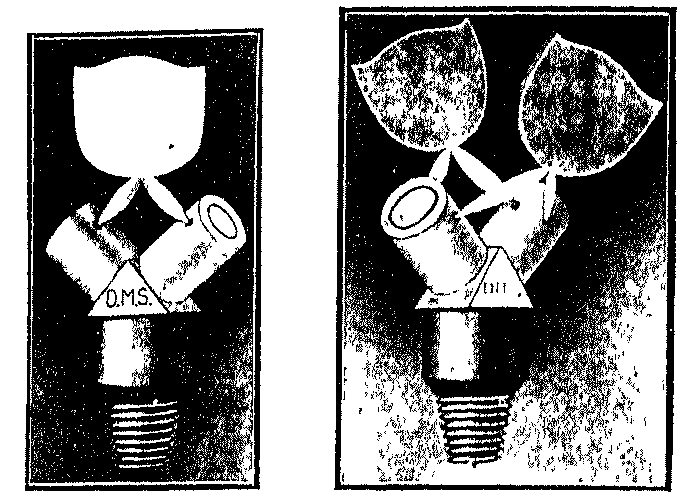
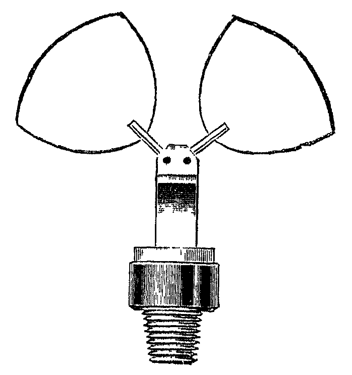
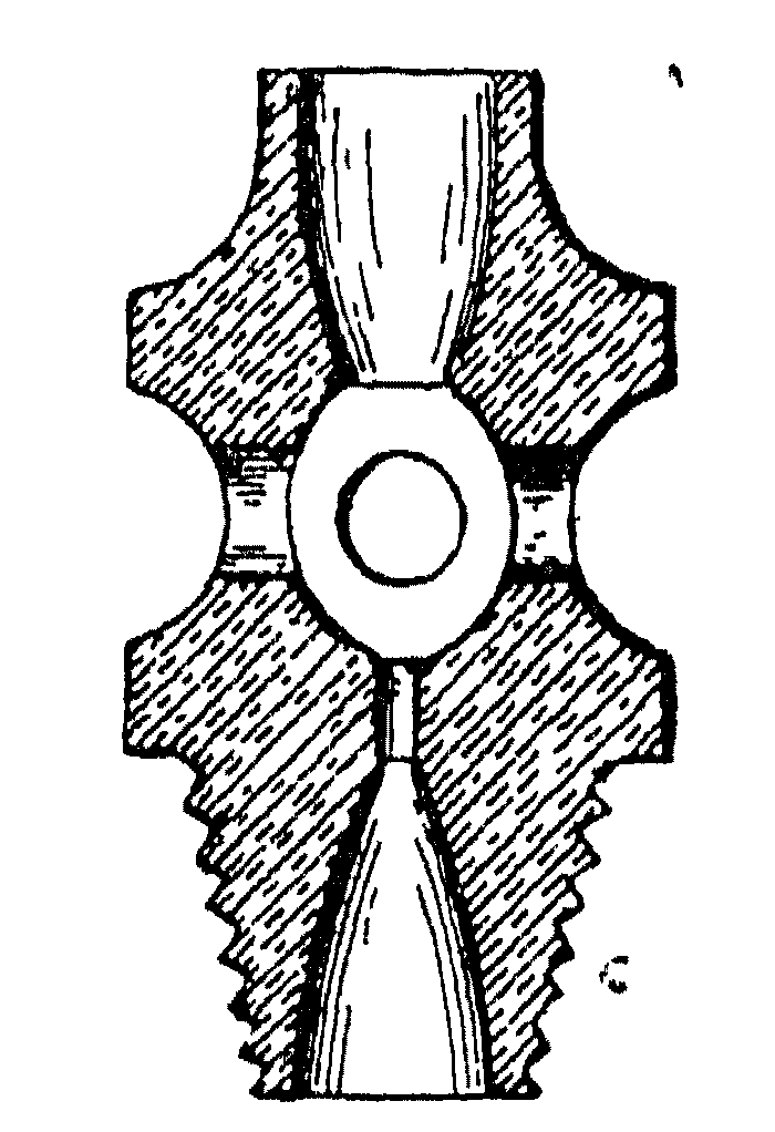


In the original Billwiller burner, the injector gas orifice was brought centrally under a somewhat larger hole drilled in a separate sheet of platinum, the metal being so carried as to permit entry of air. In order to avoid the expense of the platinum, the same principle was afterwards used in the design of an all-steatite head, which is represented at D in Fig. 8. The two holes there visible are the orifices for the emission of the mixture of acetylene with indrawn air, the proper acetylene jets lying concentrically below these in the thicker portions of the heads. These two types of burner have been modified in a large number of ways, some of which are shown at C, E, and F; the air entering through saw- cuts, lateral holes, or an annular channel. Burners resembling F in outward form are made with a pair of injector jets and corresponding air orifices on each head, so as to produce a pair of names lying in the same plane, "end-on" to one another, and projecting at either side considerably beyond the body of the burner; these have the advantage of yielding no shadow directly underneath. A burner of this pattern, viz., the "Wonder," which is sold in this country by Hannam's, Ltd., is shown in Fig. 10, alongside the single-flame "Wonder" burner, which is largely used, especially in the United States. Another two-flame burner, made of steatite, by J. von Schwarz of Nuremberg, and sold by L. Wiener of London, is shown in Fig. 11. Burners of the Argand type have also been manufactured, but have been unsuccessful. There are, of course, endless modifications of flat-flame burners to be found on the markets, but only a few need be described. A device, which should prove useful where it may be convenient to be able to turn one or more burners up or down from the same common distant spot, has been patented by Forbes. It consists of the usual twin-injector burner fitted with a small central pinhole jet; and inside the casing is a receptacle containing a little mercury, the level of which is moved by the gas pressure by an adaptation of the displacement principle. When the main is carrying full pressure, both of the jets proper are alight, and the burner behaves normally, but if the pressure is reduced to a certain point, the movement of the mercury seals the tubes leading to the main jets, and opens that of the pilot flame, which alone remains alight till the pressure is increased again. Bray has patented a modification of the Naphey injector tip, which is shown in Fig. 12. It will be observed that the four air inlets are at right-angles to the gas-way; but the essential feature of the device is the conical orifice. By this arrangement it is claimed that firing back never occurs, and that the burner can be turned down and left to give a small flame for considerable periods of time without fear of the apertures becoming choked or distorted. As a rule burners of the ordinary type do not well bear being turned down; they should either be run at full power or extinguished completely. The "Elta" burner, made by Geo. Bray and Co., Ltd., which is shown in Fig. 13, is an injector or atmospheric burner which may be turned low without any deposition of carbon occurring on the tips. A burner of simple construction but which cannot be turned low is the "Luta," made by the same firm and shown in Fig. 14. Of the non- atmospheric type the "Sansair," also made by Geo. Bray and Co., Ltd., is extensively used. It is shown in Fig. 15. In order to avoid the warping, through the heat of the flame, of the arms of burners which sometimes occurs when they are made of metal, a number of burners are now made with the arms wholly of steatite. One of the best-known of these, of the injector type, is the "Kona," made by Falk, Stadelmann and Co., of London. It is shown in Fig. 16, fitted with a screw device for adjusting the flow of gas, so that when this adjuster has been set to give a flame of the proper size, no further adjustment by means of the gas-tap is necessary. This saves the trouble of manipulating the tap after the gas is lighted. The same adjusting device may also be had fitted to the Phôs burner (Fig. 9) or to the "Orka" burner (Fig. 17), which is a steatite- tip injector burner with metal arms made by Falk, Stadelmann and Co., Ltd. A burner with steatite arms, made by J. von Schwarz of Nuremberg, and sold in this country by L. Wiener of London, is shown in Fig. 18.

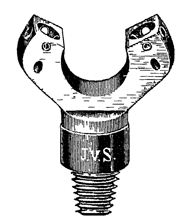
ILLUMINATING DUTY.--The illuminating value of ordinary self-luminous acetylene burners in different sizes has been examined by various photometrists. For burners of the Naphey type Lewes gives the following table:
 ___________________________________________________________
|         |           |            |          |             |
|         |           |    Gas     |          |  Candles    |
| Burner. | Pressure, | Consumed,  | Light in |    per      |
|         |  Inches   | Cubic Feet | Candles. | Cubic Foot. |
|         |           | per Hour.  |          |             |
|_________|___________|____________|__________|_____________|
|         |           |            |          |             |
| No. 6   |    2.0    |    0.155   |   0.794  |     5.3     |
| "   8   |    2.0    |    0.27    |   3.2    |    11.6     |
| "  15   |    2.0    |    0.40    |   8.0    |    20.0     |
| "  25   |    2.0    |    0.65    |  17.0    |    26.6     |
| "  30   |    2.0    |    0.70    |  23.0    |    32.85    |
| "  42   |    2.0    |    1.00    |  34.0    |    34.0     |
|_________|___________|____________|__________|_____________|
From burners of the Billwiller type Lewes obtained in 1899 the values:
 ___________________________________________________________
|         |           |            |          |             |
|         |           |    Gas     |          |  Candles    |
| Burner. | Pressure, | Consumed,  | Light in |    per      |
|         |  Inches   | Cubic Feet | Candles. | Cubic Foot. |
|         |           | per Hour.  |          |             |
|_________|___________|____________|__________|_____________|
|         |           |            |          |             |
| No. 1   |    2.0    |    0.5     |    7.0   |    11.0     |
| "   2   |    2.0    |    0.75    |   21.0   |    32.0     |
| "   3   |    2.0    |    0.75    |   28.0   |    37.3     |
| "   4   |    3.0    |    1.2     |   48.0   |    40.0     |
| "   5   |    3.5    |    2.0     |   76.0   |    38.0     |
|_________|___________|____________|__________|_____________|
Neuberg gives these figures for different burners (1900) as supplied by Pintsch:
 ______________________________________________________________________
|                    |           |            |          |             |
|                    |    Gas    |            |  Candles |             |
|       Burner.      | Pressure, | Consumed,  | Light in |     per     |
|                    |  Inches   | Cubic Feet | Candles. | Cubic Foot. |
|                    |           | per Hour.  |          |             |
|____________________|___________|____________|__________|_____________|
|                    |           |            |          |             |
| No. 0, slit burner |    3.9    |    1.59    |   59.2   |    37.3     |
| "   00000 fishtail |    1.6    |    0.81    |   31.2   |    38.5     |
| Twin burner No. 1  |    3.2    |    0.32    |   13.1   |    40.8     |
|  "     "    "   2  |    3.2    |    0.53    |   21.9   |    41.3     |
|  "     "    "   3  |    3.2    |    0.74    |   31.0   |    41.9     |
|  "     "    "   4  |    3.2    |    0.95    |   39.8   |    41.9     |
|____________________|___________|____________|__________|_____________|
The actual candle-power developed by each burner was not quoted by Neuberg, and has accordingly been calculated from his efficiency values. It is noteworthy, and in opposition to what has been found by other investigators as well as to strict theory, that Neuberg represents the efficiencies to be almost identical in all sizes of the same description of burner, irrespective of the rate at which it consumes gas.
Writing in 1902, Capelle gave for Stadelmann's twin injector burners the following figures; but as he examined each burner at several different pressures, the values recorded in the second, third, and fourth columns are maxima, showing the highest candle-power which could be procured from each burner when the pressure was adjusted so as to cause consumption to proceed at the most economical rate. The efficiency values in the fifth column, however, are the mean values calculated so as to include all the data referring to each burner. Capelle's results have been reproduced from the original on the basis that 1 bougie décimale equals 0.98 standard English candle, which is the value he himself ascribes to it (1 bougie décimale equals 1.02 candles is the value now accepted).
 _____________________________________________________________________
|             |         |                     |          |            |
|   Nominal   |   Best  | Actual Consumption  | Maximum  |   Average  |
| Consumption,| Pressure| at Stated Pressure. | Light in | Candles per|
|   Litres.   | Inches. | Cubic Feet per Hour.| Candles. | Cubic Foot.|
|_____________|_________|_____________________|__________|____________|
|             |         |                     |          |            |
|     10      |   3.5   |         0.40        |    8.4   |    21.1    |
|     15      |   2.8   |         0.46        |   16.6   |    33.3    |
|     20      |   3.9   |         0.64        |   25.1   |    40.0    |
|     25      |   3.5   |         0.84        |   37.8   |    46.1    |
|     30      |   3.5   |         0.97        |   48.2   |    49.4    |
|_____________|_________|_____________________|__________|____________|
Some testings of various self-luminous burners of which the results were reported by R. Granjon in 1907, gave the following results for the duty of each burner, when the pressure was regulated for each burner to that which afforded the maximum illuminating duty. The duty in the original paper is given in litres per Carcel-hour. The candle has been taken as equal to 0.102 Carcel for the conversion to candles per cubic foot.
 ___________________________________________________________________
|                       |             |           |                 |
|                       |   Nominal   |   Best    | Duty. Candles   |
|        Burner.        | Consumption.| Pressure. | per cubic foot. |
|_______________________|_____________|__________ |_________________|
|                       |             |           |                 |
|                       |    Litres.  |  Inches.  |                 |
| Twin  .   .   .   .   |      10     |    2.76   |       21.2      |
|  "    .   .   .   .   |      20     |    2.76   |       23.5      |
|  "    .   .   .   .   |      25     |    3.94   |       30.2      |
|  "    .   .   .   .   |      30     | 3.94-4.33 |       44.8      |
|  ", (pair of flames)  |      35     | 3.55-3.94 |       45.6      |
| Bray's "Manchester"   |       6     |    1.97   |       18.8      |
|          "            |      20     |    1.97   |       35.6      |
|          "            |      40     |    2.36   |       42.1      |
| Rat-tail  .   .   .   |       5     |    5.5    |       21.9      |
|    "      .   .   .   |       8     |    4.73   |       25.0      |
| Slit or batswing  .   |      30     | 1.97-2.36 |       37.0      |
|_______________________|_____________|___________|_________________|
Granjon has concluded from his investigations that the Manchester or fish-tail burners are economical when they consume 0.7 cubic foot per hour and when the pressure is between 2 and 2.4 inches. When these burners are used at the pressure most suitable for twin burners their consumption is about one-third greater than that of the latter per candle-hour. The 25 to 35 litres-per-hour twin burners should be used at a pressure higher by about 1 inch than the 10 to 20 litres-per-hour twin burners.
At the present time, when the average burner has a smaller hourly consumption than 1 foot per hour, it is customary in Germany to quote the mean illuminating value of acetylene in self-luminous burners as being 1 Hefner unit per 0.70 litre, which, taking
1 Hefner unit = 0.913 English candle
1 English candle = 1.095 Hefner units,
works out to an efficiency of 37 candles per foot in burners probably consuming between 0.5 and 0.7 foot per hour.
Even when allowance is made for the difficulties in determining illuminating power, especially when different photometers, different standards of light, and different observers are concerned, it will be seen that these results are too irregular to be altogether trustworthy, and that much more work must be done on this subject before the economy of the acetylene flame can be appraised with exactitude. However, as certain fixed data are necessary, the authors have studied those and other determinations, rejecting some extreme figures, and averaging the remainder; whence it appears that on an average twin-injector burners of different sizes should yield light somewhat as follows:
 _______________________________________________________
|                      |              |                 |
| Size of Burner in    | Candle-power |    Candles      |
| Cubic Feet per Hour. |  Developed.  | per Cubic Foot. |
|______________________|______________|_________________|
|                      |              |                 |
|         0.5          |     18.0     |      35.9       |
|         0.7          |     27.0     |      38.5       |
|         1.0          |     45.6     |      45.6       |
|______________________|______________|_________________|
In the tabular statement in Chapter I. the 0.7-foot burner was taken as the standard, because, considering all things, it seems the best, to adopt for domestic purposes. The 1-foot burner is more economical when in the best condition, but requires a higher gas pressure, and is rather too powerful a unit light for good illuminating effect; the 0.5 burner naturally gives a better illuminating effect, but its economy is surpassed by the 0.7-foot burner, which is not too powerful for the human eye.
For convenience of comparison, the illuminating powers and duties of the 0.5- and 0.7-foot acetylene burners may be given in different ways:
ILLUMINATING POWER OF SELF-LUMINOUS ACETYLENE.
      _0.7-foot Burner._           |      _Half-foot Burner._
                                   |
1 litre      =  1.36 candles.      | 1 litre      =  1.27 candles.
1 cubic foot = 38.5 candles.       | 1 cubic foot = 35.9 candles.
1 candle     =  0.736 litre.       | 1 candle     =  0.79 litre.
1 candle     =  0.026 cubic foot.  | 1 candle     =  0.028 cubic foot.
If the two streams of gas impinge at an angle of 90°, twin-injector burners for acetylene appear to work best when the gas enters them at a pressure of 2 to 2.5 inches; for a higher pressure the angle should be made a little acute. Large burners require to have a wider distance between the jets, to be supplied with acetylene at a higher pressure, and to be constructed with a smaller angle of impingement. Every burner, of whatever construction and size, must always be supplied with gas at its proper pressure; a pressure varying from time to time is fatal.
It is worth observing that although injector burners are satisfactory in practice, and are in fact almost the only jets yet found to give prolonged satisfaction, the method of injecting air below the point of combustion in a self-luminous burner is in some respects wrong in principle. If acetylene can be consumed without polymerisation in burners of the simple fish-tail or bat's-wing type, it should show a higher illuminating efficiency. In 1902 Javal stated that it was possible to burn thoroughly purified acetylene in twin non-injector burners, provided the two jets, made of steatite as usual, were arranged horizontally instead of obliquely, the two streams of gas then meeting at an angle of 180°, so as to yield an almost circular flame. According to Javal, whereas carbonaceous growths were always produced in non-injector acetylene burners with either oblique or horizontal jets, in the former case the growths eventually distorted the gas orifices, but in the latter the carbon was deposited in the form of a tube, and fell off from the burner by its own weight directly it had grown to a length of 1.2 or 1.5 millimetres, leaving the jets perfectly clear and smooth. Javal has had such a burner running for 10 or 12 hours per day for a total of 2071 hours; it did not need cleaning out on any occasion, and its consumption at the end of the period was the same as at first. He found that it was necessary that the tips should be of steatite, and not of metal or glass; that the orifices should be drilled in a flat surface rather than at the apex of a cone, and that the acetylene should be purified to the utmost possible extent. Subsequent experience has demonstrated the possibility of constructing non-injector burners such as that shown in Fig. 13, which behave satisfactorily even though the jets are oblique. But with such burners trouble will inevitably ensue unless the gas is always purified to a high degree and is tolerably dry and well filtered. Non-injector burners should not be used unless special care is taken to insure that the installation is consistently operated in an efficient manner in these respects.
GLOBES, &C.--It does not fall within the province of the present
volume to treat at length of chimneys, globes, or the various glassware
which may be placed round a source of light to modify its appearance. It
should be remarked, however, that obedience to two rules is necessary for
complete satisfaction in all forms of artificial illumination. First, no
light much stronger in intensity than a single candle ought ever to be
placed in such a position in an occupied room that its direct rays can
reach the eye, or the vision will be temporarily, and may be permanently,
injured. Secondly, unless economy is to be wholly ignored, no coloured or
tinted globe or shade should ever be put round a source of artificial
light. The best material for the construction of globes is that which
possesses the maximum of translucency coupled with non-transparency, i.e.,
a material which passes the highest proportion of the light falling upon
it, and yet disperses that light in such different directions that the
glowing body cannot be seen through the globe. Very roughly speaking,
plain white glass, such as that of which the chimneys of oil-lamps and
incandescent gas-burners are composed, is quite transparent, and therefore
affords no protection to the eyesight; a protective globe should be rather
of ground or opal glass, or of plain glass to which a dispersive effect
has been given by forming small prisms on its inner or outer surface, or
both. Such opal, ground, or dispersive shades waste much light in terms of
illuminating power, but waste comparatively little in illuminating effect
well designed, they may actually increase the illuminating effect in
certain positions; a tinted globe, even if quite plain in figure, wastes
both illuminating power and effect, and is only to be tolerated for
so-believed aesthetic reasons. Naturally no globe must be of such figure,
or so narrow at either orifice, as to distort the shape of the unshaded
acetylene flame--it is hardly necessary to say this now, but some years
ago coal-gas globes were constructed with an apparent total disregard of
this fundamental point.
MERITS OF LIGHTING BY INCANDESCENT MANTLES.--It has already been shown that acetylene bases its chief claim for adoption as an illuminant in country districts upon the fact that, when consumed in simple self- luminous burners, it gives a light comparable in all respects save that of cost to the light of incandescent coal-gas. The employment of a mantle is still accompanied by several objections which appear serious to the average householder, who is not always disposed either to devote sufficient attention to his burners to keep them in a high state of efficiency or to contract for their maintenance by the gas company or others. Coal-gas cannot be burnt satisfactorily on the incandescent system unless the glass chimneys and shades are kept clean, unless the mantles are renewed as soon as they show signs of deterioration, and, perhaps most important of all, unless the burners are frequently cleared of the dust which collects round the jets. For this reason luminous acetylene ranks with luminous coal-gas in convenience and simplicity, while ranking with incandescent coal-gas in hygienic value. Very similar remarks apply to paraffin, and, in certain countries, to denatured alcohol. Since those latter illuminants are also available in rural places where coal-gas is not laid on, luminous acetylene is a less advantageous means of procuring artificial light than paraffin (and on occasion than coal-gas and alcohol when the latter fuels are burnt under the mantle), if the pecuniary aspect of the question is the only one considered. Such a comparison, however, is by no means fair; for if coal- gas, paraffin, and alcohol can be consumed on the incandescent system, so can acetylene; and if acetylene is hygienically equal to incandescent coal-gas, it is superior thereto when also burnt under the mantle. Nevertheless there should be one minor but perfectly irremediable defect in incandescent acetylene, viz., a sacrifice of that characteristic property of the luminous gas to emit a light closely resembling that of the sun in tint, which was mentioned in Chapter 1. Self-luminous acetylene gives the whitest light hitherto procurable without special correction of the rays, because its light is derived from glowing particles of carbon which happen to be heated (because of the high flame temperature) to the best possible temperature for the emission of pure white light. The light of any combustible consumed on the "incandescent" system is derived from glowing particles of ceria, thoria, or similar metallic oxides; and the character or shade of the light they emit is a function, apart from the temperature to which they are raised, of their specific chemical nature. Still, the light of incandescent acetylene is sufficiently pleasant, and according to Caro is purer white than that of incandescent coal-gas; but lengthy tests carried out by one of the authors actually show it to be appreciably inferior to luminous acetylene for colour-matching, in which the latter is known almost to equal full daylight, and to excel every form of artificial light except that of the electric arc specially corrected by means of glass tinted with copper salts.
CONDITIONS FOR INCANDESCENT ACETYLENE LIGHTING.--For success in the combustion of acetylene on the incandescent system, however, several points have to be observed. First, the gas must be delivered at a strictly constant pressure to the burner, and at one which exceeds a certain limit, ranging with different types and different sizes of burner from 2 to 4 or 5 inches of water. (The authors examined, as long ago as 1903, an incandescent burner of German construction claimed to work at a pressure of 1.5 inches, which it was almost impossible to induce to fire back to the jets however slowly the cock was manipulated, provided the pressure of the gas was maintained well above the point specified. But ordinarily a pressure of about 4 inches is used with incandescent acetylene burners.) Secondly, it is necessary that the acetylene shall at all times be free from appreciable admixture with air, even 0.5 per cent, being highly objectionable according to Caro; so that generators introducing any noteworthy amount of air into the holder each time their decomposing chambers are opened for recharging are not suitable for employment when incandescent burners are contemplated. The reason for this will be more apparent later on, but it depends on the obvious fact that if the acetylene already contains an appreciable proportion of air, when a further quantity is admitted at the burner inlets, the gaseous mixture contains a higher percentage of oxygen than is suited to the size and design of the burner, so that flashing back to the injector jets is imminent at any moment, and may be determined by the slightest fluctuation in pressure--if, indeed, the flame will remain at the proper spot for combustion at all. Thirdly, the fact that the acetylene which is to be consumed under the mantle must be most rigorously purified from phosphorus compounds has been mentioned in Chapter V. Impure acetylene will often destroy a mantle in two or three hours; but with highly purified gas the average life of a mantle may be taken, according to Giro, at 500 or 600 hours. It is safer, however, to assume a rather shorter average life, say 300 to 400 burning hours. Fourthly, owing to the higher pressure at which acetylene must be delivered to an incandescent burner and to the higher temperature of the acetylene flame in comparison with coal-gas, a mantle good enough to give satisfactory results with the latter does not of necessity answer with acetylene; in fact, the authors have found that English Welsbach coal-gas mantles of the small sizes required by incandescent acetylene burners are not competent to last for more than a very few hours, although, in identical conditions, mantles prepared specially for use with acetylene have proved durable. The atmospheric acetylene flame, too, differs in shape from an atmospheric flame of coal-gas, and it does not always happen that a coal- gas mantle contracts to fit the former; although it usually emits a better light (because it fits better) after some 20 hours use than at first. Caro has stated that to derive the best results a mantle needs to contain a larger proportion of ceria than the 1 per cent. present in mantles made according to the Welsbach formula, that it should be somewhat coarser in mesh, and have a large orifice at the head. Other authorities hold that mantles for acetylene, should contain other rare earths besides the thoria and ceria of which the coal-gas mantles almost wholly consist. It seems probable, however, that the composition of the ordinary impregnating fluid need not be varied for acetylene mantles provided it is of the proper strength and the mantles are raised to a higher temperature in manufacture than coal-gas mantles by the use of either coal-gas at very high pressure or an acetylene flame. The thickness of the substance of the mantle cannot be greatly increased with a view to attaining greater stability without causing a reduction in the light afforded. But the shape should be such that the mantle conforms as closely as possible to the acetylene Bunsen flame, which differs slightly with different patterns of incandescent burner heads. According to L. Cadenel, the acetylene mantle should be cylindrical for the lower two- thirds of its length, and slightly conical above, with an opening of moderate size at the top. The head of the mantle should be of slighter construction than that of coal-gas mantles. Fifthly, generators belonging to the automatic variety, which in most forms inevitably add more or less air to the acetylene every time they are cleaned or charged, appear to have achieved most popularity in Great Britain; and these frequently do not yield a gas fit for use with the mantle. This state of affairs, added to what has just been said, makes it difficult to speak in very favourable terms of the incandescent acetylene light for use in Great Britain. But as the advantages of an acetylene not contaminated with air are becoming more generally recognised, and mantles of several different makes are procurable more cheaply, incandescent acetylene is now more practicable than hitherto. Carburetted acetylene or "carburylene," which is discussed later, is especially suitable for use with mantle burners.
ATMOSPHERIC ACETYLENE BURNERS.--The satisfactory employment of acetylene in incandescent burners, for boiling, warming, and cooking purposes, and also to some extent as a motive power in small engines, demands the production of a good atmospheric or non-luminous flame, i.e., the construction of a trustworthy burner of the Bunsen type. This has been exceedingly difficult to achieve for two reasons: first, the wide range over which mixtures of acetylene and air are explosive; secondly, the high speed at which the explosive wave travels through such a mixture. It has been pointed out in Chapter VIII. that a Bunsen burner is one in which a certain proportion of air is mixed with the gas before it arrives at the actual point of ignition; and as that proportion must be such that the mixture falls between the upper and lower limits of explosibility, there is a gaseous mixture in the burner tube between the air inlets and the outlet which, if the conditions are suitable, will burn with explosive force: that is to say, will fire back to the air jets when a light is applied to the proper place for combustion. Such an explosion, of course, is far too small in extent to constitute any danger to person or property; the objection to it is simply that the shock of the explosion is liable to fracture the fragile incandescent mantle, while the gas, continuing to burn within the burner tube (in the case of a warming or cooking stove), blocks up that tube with carbon, and exhibits the other well-known troubles of a coal-gas stove which has "fired back."
It has been shown, however, in Chapter VI. that the range over which mixtures of acetylene and air are explosive depends on the size of the vessel, or more particularly on the diameter of the tube, in which they are stored; so that if the burner tube between the air inlets and the point of ignition can be made small enough in diameter, a normally explosive mixture will cease to exhibit explosive properties. Manifestly, if a tube is made very small in diameter, it will only pass a small volume of gas, and it may be useless for the supply of an atmospheric burner; but Le Chatelier's researches have proved that a tube may be narrowed at one spot only, in such fashion that the explosive wave refuses to pass the constriction, while the virtual diameter of the tube, as far as passage of gas is concerned, remains considerably larger than the size of the constriction itself. Moreover, inasmuch as the speed of propagation of the explosion is strictly fixed by the conditions prevailing, if the speed at which the mixture, of acetylene and air travels from the air inlets to the point of ignition is more rapid than the speed at which the explosion tends to travel from the point of ignition to the air inlets, the said mixture of acetylene and air will burn quietly at the orifice without attempting to fire backwards into the tube. By combining together these two devices: by delivering the acetylene to the injector jet at a pressure sufficient to drive the mixture of gas and air forward rapidly enough, and by narrowing the leading tube either wholly or at one spot to a diameter small enough, it is easy to make an atmospheric burner for acetylene which behaves perfectly as long as it is fairly alight, and the supply of gas is not checked; but further difficulties still remain, because at the instant of lighting and extinguishing, i.e., while the tap is being turned on or off, the pressure of the gas is too small to determine a flow of acetylene and air within the tube at a speed exceeding that of the explosive wave; and therefore the act of lighting or extinguishing is very likely to be accompanied by a smart explosion severe enough to split the mantle, or at least to cause the burner to fire back. Nevertheless, after several early attempts, which were comparative failures, atmospheric acetylene burners have been constructed that work quite satisfactorily, so that the gas has become readily available for use under the mantle, or in heating stoves. Sometimes success has been obtained by the employment of more than one small tube leading to a common place of ignition, sometimes by the use of two or more fine wire- gauze screens in the tube, sometimes by the addition of an enlarged head to the burner in which head alone thorough mixing of the gas and air occurs, and sometimes by the employment of a travelling sleeve which serves more or less completely to block the air inlets.
DUTY OF INCANDESCENT ACETYLENE BURNERS.--Granting that the petty troubles and expenses incidental to incandescent lighting are not considered prohibitive--and in careful hands they are not really serious-- and that mantles suitable for acetylene are employed, the gas may be rendered considerably cheaper to use per unit of light evolved by consuming it in incandescent burners. In Chapter VIII. it was shown that the modern self-luminous, l/2-foot acetylene burner emits a light of about 1.27 standard English candles per litre-hour. A large number of incandescent burners, of German and French construction, consuming from 7.0 to 22.2 litres per hour at pressures ranging between 60 and 120 millimetres have been examined by Caro, who has found them to give lights of from 10.8 to 104.5 Hefner units, and efficiencies of from 2.40 to 5.50 units per litre-hour. Averaging his results, it may be said that incandescent burners consuming from 10 to 20 litres per hour at pressures of 80 or 100 millimetres yield a light of 4.0 Hefner units per litre- hour. Expressed in English terms, incandescent acetylene burners consuming 0.5 cubic foot per hour at a pressure of 3 or 4 inches give the duties shown in the following table, which may advantageously be compared with that printed in Chapter VIII., page 239, for the self-luminous gas:
ILLUMINATING POWER OF INCANDESCENT ACETYLENE. HALF-FOOT BURNERS.
  1 litre      =   3.65 candles   |   1 candle = 0.274 litre.
  1 cubic foot = 103.40 candles.  |   1 candle = 0.0097 cubic foot.
A number of tests of the Güntner or Schimek incandescent burners of the 10 and 15 litres-per-hour sizes, made by one of the authors in 1906, gave the following average results when tested at a pressure of 4 inches:
 _________________________________________________________________
|              |                         |          |             |
| Nominal size | Rate of Consumption per | Light in |    Duty     |
|  of Burner.  |          Hour           | Candles  | Candles per |
|              |                         |          |  Cubic Foot |
|______________|_________________________|__________|_____________|
|              |            |            |          |             |
| Litres.      | Cubic Foot |  Litres    |          |             |
|   10         |    0.472   |   13.35    |   46.0   |    97.4     |
|   15         |    0.663   |   18.80    |   70.0   |   105.5     |
|______________|____________|____________|__________|_____________|
These figures indicate that the duty increases slightly with the size of the burner. Other tests showed that the duty increased more considerably with an increase of pressure, so that mantles used, or which had been previously used, at a pressure of 5 inches gave duties of 115 to 125 candles per cubic foot.
It should be noted that the burners so far considered are small, being intended for domestic purposes only; larger burners exhibit higher efficiencies. For instance, a set of French incandescent acetylene burners examined by Fouché showed:
 _________________________________________________________________
|                |          |            |          |             |
| Size of Burner | Pressure | Cubic Feet | Light in | Candles per |
| in Litres.     |  Inches. |  per Hour. | Candles. | Cubic Feet. |
|________________|__________|____________|__________|_____________|
|                |          |            |          |             |
|       20       |    5.9   |    0.71    |    70    |     98.6    |
|       40       |    5.9   |    1.41    |   150    |    106.4    |
|       70       |    5.9   |    2.47    |   280    |    113.4    |
|      120       |    5.9   |    4.23    |   500    |    118.2    |
|________________|__________|____________|__________|_____________|
By increasing the pressure at which acetylene is introduced into burners of this type, still larger duties may be obtained from them:
 _________________________________________________________________
|                |          |            |          |             |
| Size of Burner | Pressure | Cubic Feet | Light in | Candles per |
| in Litres.     |  Inches. |  per Hour. | Candles. | Cubic Feet. |
|________________|__________|____________|__________|_____________|
|                |          |            |          |             |
|       55       |   39.4   |    1.94    |   220    |    113.4    |
|      100       |   39.4   |    3.53    |   430    |    121.8    |
|      180       |   39.4   |    6.35    |   820    |    129.1    |
|      260       |   27.6   |    9.18    |  1300    |    141.6    |
|________________|__________|____________|__________|_____________|
High-power burners such as these are only fit for special purposes, such as lighthouse illumination, or optical lantern work, &c.; and they naturally require mantles of considerably greater tenacity than those intended for employment with coal-gas. Nevertheless, suitable mantles can be, and are being, made, and by their aid the illuminating duty of acetylene can be raised from the 30 odd candles per foot of the common 0.5-foot self-luminous jet to 140 candles or more per foot, which is a gain in efficiency of 367 per cent., or, neglecting upkeep and sundries and considering only the gas consumed, an economy of nearly 79 per cent.
In 1902, working apparently with acetylene dissolved under pressure in acetone (cf. Chapter XI.), Lewes obtained the annexed results with the incandescent gas:
 ________________________________________________________
|           |             |              |              |
| Pressure. |  Cubic Feet | Candle Power |  Candles per |
|  Inches.  |  per Hour.  |  Developed.  |  Cubic Foot. |
|___________|_____________|______________|______________|
|           |             |              |              |
|     8     |    0.883    |      65      |      73.6    |
|     9     |    0.94     |      72      |      76.0    |
|    10     |    1.00     |     146      |     146.0    |
|    12     |    1.06     |     150      |     141.2    |
|    15     |    1.25     |     150      |     120.0    |
|    20     |    1.33     |     166      |     124.8    |
|    25     |    1.50     |     186      |     123.3    |
|    40     |    2.12     |     257      |     121.2    |
|___________|_____________|______________|______________|
It will be seen that although the total candle-power developed increases with the pressure, the duty of the burner attained a maximum at a pressure of 10 inches. This is presumably due to the fact either that the same burner was used throughout the tests, and was only intended to work at a pressure of 10 inches or thereabouts, or that the larger burners were not so well constructed as the smaller ones. Other investigators have not given this maximum of duty with a medium-sized or medium-driven burner; but Lewes has observed a similar phenomenon in the case of 0.7 to 0.8 cubic foot self-luminous jets.
Figures, however, which seem to show that the duty of incandescent acetylene does not always rise with the size of the burner or with the pressure at which the gas is delivered to it, have been published in connexion with the installation at the French lighthouse at Chassiron, the northern point of the Island of Oléron. Here the acetylene is generated in hand-fed carbide-to-water generators so constructed as to give any pressure up to nearly 200 inches of water column; purified by means of heratol, and finally delivered to a burner composed of thirty- seven small tubes, which raises to incandescence a mantle 55 millimetres in diameter at its base. At a pressure of 7.77 inches of water, the burner passes 3.9 cubic feet of acetylene per hour, and at a pressure of 49.2 inches (the head actually used) it consumes 20.06 cubic feet per hour. As shown by the following table, such increment of gas pressure raises the specific intensity of the light, i.e., the illuminating power per unit of incandescent surface, but it does not appreciably raise the duty or economy of the gas. Manifestly, in terms of duty alone, a pressure of 23.6 inches of water-column is as advantageous as the higher Chassiron figures; but since intensity of light is an important matter in a lighthouse, it is found better on the whole to work the generators at a pressure of 49.2 inches. In studying these figures referring to the French lighthouse, it is interesting to bear in mind that when ordinary six-wick petroleum oil burners wore used in the same place, the specific intensity of the light developed was 75 candle-power per square inch, and when that plant was abandoned in favour of an oil-gas apparatus, the incandescent burner yielded 161 candle-power per square inch; substitution of incandescent acetylene under pressure has doubled the brilliancy of the light.
 ___________________________________________________________
|                     |                  |                  |
|                     |       Duty.      |    Intensity.    |
| Pressure in Inches. | Candle-power per | Candle-power per |
|                     |    Cubic Foot.   |   Square Inch.   |
|_____________________|__________________|__________________|
|                     |                  |                  |
|        7.77         |      105.5       |      126.0       |
|       23.60         |      106.0       |      226.0       |
|       31.50         |      110.0       |      277.0       |
|       39.40         |      110.0       |      301.0       |
|       47.30         |      106.0       |      317.0       |
|       49.20         |      104.0       |      324.9       |
|      196.80         |      110.0       |      383.0       |
|_____________________|__________________|__________________|
When tested in modern burners consuming between 12 and 18 litres per hour at a pressure of 100 millimetres (4 inches), some special forms of incandescent mantles constructed of ramie fibre, which in certain respects appears to be better suited than cotton for use with acetylene, have shown the following degree of loss in illuminating power after prolonged employment (Caro):
_Luminosity in Hefner Units._
 ________________________________________________________
|         |       |            |            |            |
| Mantle. | New.  |   After    |   After    |   After    |
|         |       | 100 Hours. | 200 Hours. | 400 Hours. |
|_________|_______|____________|____________|____________|
|         |       |            |            |            |
| No. 1.  | 53.2  |    51.8    |    50.6    |   49.8     |
| No. 2.  | 76.3  |    75.8    |    73.4    |   72.2     |
| No. 3.  | 73.1  |    72.5    |    70.1    |   68.6     |
|_________|_______|____________|____________|____________|
It will be seen that the maximum loss of illuminating power in 400 hours was 6.4 per cent., the average loss being 6.0 per cent.
TYPICAL INCANDESCENT BURNERS.--Of the many burners for lighting by the use of incandescent mantles which have been devised, a few of the more widely used types may be briefly referred to. There is no doubt that finality in the design of these burners has not yet been reached, and that improvements in the direction of simplification of construction and in efficiency and durability will continue to be made.
Among the early incandescent burners, one made by the Allgemeine Carbid und Acetylen Gesellschaft of Berlin in 1900 depended on the narrowness of the mixing tube and the proportioning of the gas nipple and air inlets to prevent lighting-back. There was a wider concentric tube round the upper part of the mixing tube, and the lower part of the mantle fitted round this. The mouth of the mixing tube of this 10-litres-per-hour burner was 0.11 inch in diameter, and the external diameter of the middle cylindrical part of the mixing tube was 0.28 inch. There was no gauze diaphragm or stuffing, and firing-back did not occur until the pressure was reduced to about 1.5 inches. The same company later introduced a burner differing in several important particulars from the one just described. The comparatively narrow stem of the mixing tube and the proportions of the gas nipple and air inlets were retained, but the mixing tube was surmounted by a wide chamber or burner head, in which naturally there was a considerable reduction in the rate of flow of the gas. Consequently it was found necessary to introduce a gauze screen into the burner head to prevent firing back. The alterations have resulted in the lighting duty of the burner being considerably improved. Among other burners designed about 1900 may be mentioned the Ackermann, the head of which consisted of a series of tubes from each of which a jet of flame was produced, the Fouché, the Weber, and the Trendel. Subsequently a tubular-headed burner known as the Sirius has been produced for the consumption of acetylene at high pressure (20 inches and upwards).
The more recent burners which have been somewhat extensively used include the "Schimek," made by W. Güntner of Vienna, which is shown in Fig. 19. It consists of a tapering narrow injecting nozzle within a conical chamber C which is open below, and is surmounted by the mixing tube over which telescopes a tube which carries the enlarged burner head G, and the chimney gallery D. There are two diaphragms of gauze in the burner head to prevent firing back, and one in the nozzle portion of the burner. The conical chamber has a perforated base-plate below which is a circular plate B which rotates on a screw cut on the lower part of the nozzle portion A of the burner. This plate serves as a damper to control the amount of air admitted through the base of the conical chamber to the mixing tube. There are six small notches in the lower edge of the conical chamber to prevent the inflow of air being cut of entirely by the damper. The mixing tube in both the 10-litre and the 15-litre burner is about 0.24 inch in internal diameter but the burner head is nearly 0.42 inch in the 10-litre and 0.48 inch in the 15-litre burner. The opening in the head of the burner through which the mixture of gas and air escapes to the flame is 0.15 and 0.17 inch in diameter in these two sizes respectively. The results of some testings made with Schimek burners have been already given.
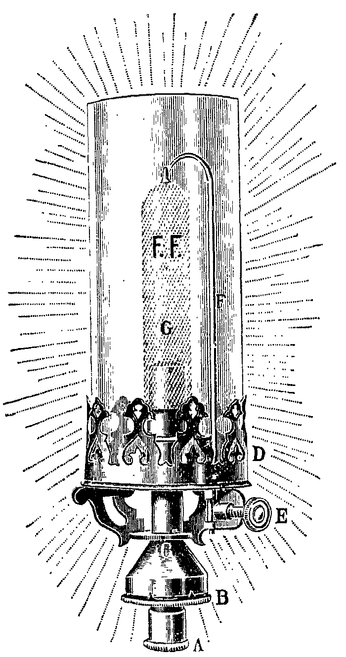
The "Knappich" burner, made by the firm of Keller and Knappich of Augsburg, somewhat resembles the later pattern of the Allgemeine Carbid und Acetylen Gesellschaft. It has a narrow mixing tube, viz., 0.2 inch in internal diameter, and a wide burner head, viz., 0.63 inch in internal diameter for the 25-litre size. The only gauze diaphragm is in the upper part of the burner head. The opening in the cap of the burner head, at which the gas burns, is 0.22 inch in diameter. The gas nipple extends into a domed chamber at the base of the mixing tube, and the internal air is supplied through four holes in the base-plate of that chamber. No means of regulating the effective area of the air inlet holes are provided.
The "Zenith" burner, made by the firm of Gebrüder Jacob of Zwickau, more closely resembles the Schimek, but the air inlets are in the side of the lower widened portion of the mixing tube, and are more or less closed by means of an outside loose collar which may be screwed up and down on a thread on a collar fixed to the mixing tube. The mixing tube is 0.24 inch, and the burner head 0.475 inch in internal diameter. The opening in the cap of the burner is 0.16 inch in diameter. There is a diaphragm of double gauze in the cap, and this is the only gauze used in the burner.
All the incandescent burners hitherto mentioned ordinarily have the gas nipple made in brass or other metal, which is liable to corrosion, and the orifice to distortion by heat or if it becomes necessary to remove any obstruction from it. The orifice in the nipple is extremely small-- usually less than 0.015 inch--and any slight obstruction or distortion would alter to a serious extent the rate of flow of gas through it, and so affect the working of the burner. In order to overcome this defect, inherent to metal nipples, burners are now constructed for acetylene in which the nipple is of hard incorrodible material. One of these burners has been made on behalf of the Office Central de l'Acétylène of Paris, and is commonly known as the "O.C.A." burner. In it the nipple is of steatite. On the inner mixing tube of this burner is mounted an elongated cone of wire wound spirally, which serves both to ensure proper admixture of the gas and air, and to prevent firing-back. There is no gauze in this burner, and the parts are readily detachable for cleaning when required. Another burner, in which metal is abolished for the nipple, is made by Geo. Bray and Co., Ltd., of Leeds, and is shown in Fig. 20. In this burner the injecting nipple is of porcelain.
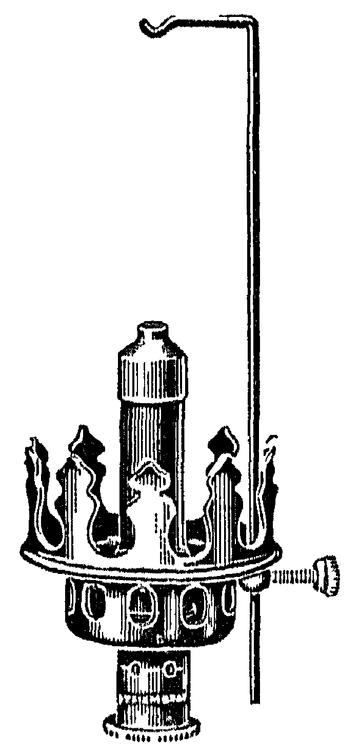
ACETYLENE FOR HEATING AND COOKING.--Since the problem of constructing a trustworthy atmospheric burner has been solved, acetylene is not only available for use in incandescent lighting, but it can also be employed for heating or cooking purposes, because all boiling, most warming, and some roasting stoves are simply arrangements for utilising the heat of a non-luminous flame in one particular way. With suitable alterations in the dimensions of the burners, apparatus for consuming coal-gas may be imitated and made fit to burn acetylene; and as a matter of fact several firms are now constructing such appliances, which leave little or nothing to be desired. It may perhaps be well to insist upon the elementary point which is so frequently ignored in practice, viz., that no stove, except perhaps a small portable boiling ring, ought ever to be used in an occupied room unless it is connected with a chimney, free from down- draughts, for the products of combustion to escape into the outer air; and also that no chimney, however tall, can cause an up-draught in all states of the weather unless there is free admission of fresh air into the room at the base of the chimney. Still, at the prices for coal, paraffin oil, and calcium carbide which exist in Great Britain, acetylene is not an economical means of providing artificial heat. If a 0.7 cubic foot luminous acetylene burner gives a light of 27 candles, and if ordinary country coal-gas gives light of 12 to 13 candles in a 5-foot burner, one volume of acetylene is equally valuable with 15 or 16 volumes of coal-gas when both are consumed in self-luminous jets; and if, with the mantle, acetylene develops 99 candles per cubic foot, while coal-gas gives in common practice 15 to 20 candles, one volume of acetylene is equally valuable with 5 to 6-1/2 volumes of coal-gas when both are consumed on the incandescent system; whereas, if the acetylene is burnt in a flat flame, and the coal-gas under the mantle, 1 volume of the former is equally efficient with 2 volumes of coal-gas as an artificial illuminant. This last method of comparison being manifestly unfair, acetylene may be said to be at least five times as efficient per unit of volume as coal-gas for the production of light. But from the table given on a later page it appears that as a source of artificial heat, acetylene is only equal to about 2-3 times its volume of ordinary coal-gas. Nevertheless, the domestic advantages of gas firing are very marked; and when a properly constructed stove is properly installed, the hygienic advantages of gas-firing are alone equally conspicuous--for the disfavor with which gas-firing is regarded by many physicians is due to experience gained with apparatus warming principally by convection [Footnote: Radiant heat is high-temperature heat, like the heat emitted by a mass of red-hot coke; convected heat is low-temperature heat, invisible to the eye. Radiant heat heats objects first, and leaves them to warm the air; convected heat is heat applied directly to air, and leaves the air to warm objects afterwards. On all hygienic grounds radiant heat is better than convected heat, but the latter is more economical. By an absurd and confusing custom, that particular warming apparatus (gas, steam, or hot water) which yields practically no radiant heat, and does all its work by convection, is known to the trade as a "radiator."] instead of radiation; or to acquaintance with intrinsically better stoves either not connected to any flues or connected to one deficient in exhausting power. In these circumstances, whenever an installation of acetylene has been laid down for the illumination of a house or district, the merit of convenience may outweigh the defect of extravagance, and the gas may be judiciously employed in a boiling ring, or for warming a bedroom; while, if pecuniary considerations are not paramount, the acetylene may be used for every purpose to which the townsman would apply his cheaper coal-gas.
The difficulty of constructing atmospheric acetylene burners in which the flame would not be likely to strike back to the nipple has already been referred to in connexion with the construction atmospheric burners for incandescent lighting. Owing, however, to the large proportions of the atmospheric burners of boiling rings and stove and in particular to the larger bore of their mixing tube, the risk of the flame striking back is greater with them, than with incandescent lighting burners. The greatest trouble is presented at lighting, and when the pressure of the gas-supply is low. The risk of firing-back when the burner is lighted is avoided in some forms of boiling rings, &c., by providing a loose collar which can be slipped over the air inlets of the Bunsen tube before applying a light to the burner, and slipped clear of them as soon as the burner is alight. Thus at the moment of lighting, the burner is converted temporarily into one of the non-atmospheric type, and after the flame has thus been established at the head or ring of the burner, the internal air-supply is started by removing the loose collar from the air inlets, and the flame is thus made atmospheric. In these conditions it does not travel backwards to the nipple. In other heating burners it is generally necessary to turn on the gas tap a few seconds before applying a light to the burner or ring or stove; the gas streaming through the mixing tube then fills it with acetylene and air mixed in the proper working proportions, and when the light is applied, there is no explosion in the mixing tube, or striking-back of the flame to the nipple.
Single or two-burner gas rings for boiling purposes, or for heating cooking ovens, known as the "La Belle," made by Falk Stadelmann and Co., Ltd., of London, may be used at as low a gas pressure as 2 inches, though they give better results at 3 inches, which is their normal working pressure. The gas-inlet nozzle or nipple of the burner is set within a spherical bulb in which are four air inlets. The mixing tube which is placed at a proper distance in front of the nipple, is proportioned to the rate of flow of the gas and air, and contains a mixing chamber with a baffling pillar to further their admixture. A fine wire gauze insertion serves to prevent striking-back of the flame. A "La Belle" boiling ring consumes at 3 inches pressure about 48 litres or 1.7 cubic feet of acetylene per hour.
ACETYLENE MOTORS.--The question as to the feasibility of developing "power" from acetylene, i.e., of running an engine by means of the gas, may be answered in essentially identical terms. Specially designed gas-engines of 1, 3, 6, or even 10 h.p. work perfectly with acetylene, and such motors are in regular employment in numerous situations, more particularly for pumping water to feed the generators of a large village acetylene installation. Acetylene is not an economical source of power, partly for the theoretical reason that it is a richer fuel even than coal-gas, and gas-engines would appear usually to be more efficient as the fuel they burn is poorer in calorific intensity, i.e., in heating power (which is explosive power) per unit of volume. The richer, or more concentrated, any fuel in, the more rapidly does the explosion in a mixture of that fuel with air proceed, because a rich fuel contains a smaller proportion of non-inflammable gases which tend to retard explosion than a poor one; and, in reason, a gas-engine works better the more slowly the mixture of gas and air with which it is fed explodes. Still, by properly designing the ports of a gas-engine cylinder, so that the normal amount of compression of the charge and of expansion of the exploded mixture which best suit coal-gas are modified to suit acetylene, satisfactory engines can be constructed; and wherever an acetylene installation for light exists, it becomes a mere question of expediency whether the same fuel shall not be used to develop power, say, for pumping up the water required in a large country house, instead of employing hand labour, or the cheaper hot-air or petroleum motor. Taking the mean of the results obtained by numerous investigators, it appears that 1 h.p.-hour can be obtained for a consumption of 200 litres of acetylene; whence it may be calculated that that amount of energy costs about 3d. for gas only, neglecting upkeep, lubricating material (which would be relatively expensive) and interest, &c.
Acetylene Blowpipes--The design of a satisfactory blowpipe for use with acetylene had at first proved a matter of some difficulty, since the jet, like that of an ordinary self-luminous burner, usually exhibited a tendency to become choked with carbonaceous growths. But when acetylene had become available for various purposes at considerable pressure, after compression into porous matter as described in Chapter XI, the troubles were soon overcome; and a new form of blowpipe was constructed in which acetylene was consumed under pressure in conjunction with oxygen. The temperature given by this apparatus exceeds that of the familiar oxy- hydrogen blowpipe, because the actual combustible material is carbon instead of hydrogen. When 2 atoms of hydrogen unite with 1 of oxygen to form 1 molecule of gaseous water, about 59 large calories are evolved, and when 1 atom of solid amorphous carbon unites with 2 atoms of oxygen to form 1 molecule of carbon dioxide, 97.3 calories are evolved. In both cases, however, the heat attainable is limited by the fact that at certain temperatures hydrogen and oxygen refuse to combine to form water, and carbon and oxygen refuse to form carbon dioxide--in other words, water vapour and carbon dioxide dissociate and absorb heat in the process at certain moderately elevated temperatures. But when 1 atom of solid amorphous carbon unites with 1 atom of oxygen to form carbon monoxide, 29.1 [Footnote: Cf. Chapter VI., page 185.] large calories are produced, and carbon monoxide is capable of existence at much higher temperatures than either carbon dioxide or water vapour. In any gaseous hydrocarbon, again, the carbon exists in the gaseous state, and when 1 atom of the hypothetical gaseous carbon combines with 1 atom of oxygen to produce 1 molecule of carbon monoxide, 68.2 large calories are evolved. Thus while solid amorphous carbon emits more heat than a chemically equivalent quantity of hydrogen provided it is enabled to combine with its higher proportion of oxygen, it emits less if only carbon monoxide is formed; but a higher temperature can be attained in the latter case, because the carbon monoxide is more permanent or stable. Gaseous carbon, on the other hand, emits more heat than an equivalent quantity of hydrogen, [Footnote: In a blowpipe flame hydrogen can only burn to gaseous, not liquid, water.] even when it is only converted into the monoxide. In other words, a gaseous fuel which consists of hydrogen alone can only yield that temperature as a maximum at which the speed of the dissociation of the water vapour reaches that of the oxidation of the hydrogen; and were carbon dioxide the only oxide of carbon, a similar state of affairs would be ultimately reached in the flame of a carbonaceous gas. But since in the latter case the carbon dioxide does not tend to dissociate completely, but only to lose one atom of oxygen, above the limiting temperature for the formation of carbon dioxide, carbon monoxide is still produced, because there is less dissociating force opposed to its formation. Thus at ordinary temperatures the heat of combustion of acetylene is 315.7 calories; but at temperatures where water vapour and carbon dioxide no longer exist, there is lost to that quantity of 315.7 calories the heat of combustion of hydrogen (69.0) and twice that of carbon monoxide (68.2 x 2 = 136.4); so that above those critical temperatures, the heat of combustion of acetylene is only 315.7 - (69.0 + 136.4) = 110.3. [Footnote: When the heat of combustion of acetylene is quoted as 315.7 calories, it is understood that the water formed is condensed into the liquid state. If the water remains gaseous, as it must do in a flame, the heat of formation is reduced by about 10 calories. This does not affect the above calculation, because the heat of combustion of hydrogen when the water remains gaseous is similarly 10 calories less than 69, i.e., 59, as mentioned above in the text. Deleting the heat of liquefaction of water, the calculation referred to becomes 305.7 - (59.0 + l36.4) = 110.3 as before.] This value of 110.3 calories is clearly made up of the heat of formation of acetylene itself, and twice the heat of conversion of carbon into carbon monoxide, i.e., for diamond carbon, 58.1 + 26.1 x 2 = 110.3; or for amorphous carbon, 52.1 + 29.1 x 2 = 110.3. From the foregoing considerations, it may be inferred that the acetylene-oxygen blowpipe can be regarded as a device for burning gaseous carbon in oxygen; but were it possible to obtain carbon in the state of gas and so to lead it into a blowpipe, the acetylene apparatus should still be more powerful, because in it the temperature would be raised, not only by the heat of formation of carbon monoxide, but also by the heat attendant upon the dissociation of the acetylene which yields the carbon.
Acetylene requires 2.5 volumes of oxygen to burn it completely; but in the construction of an acetylene-oxygen blowpipe the proportion of oxygen is kept below this figure, viz., at 1.1 to 1.8 volumes, so that the deficiency is left to be made up from the surrounding air. Thus at the jet of the blowpipe the acetylene dissociates and its carbon is oxidised, at first no doubt to carbon monoxide only, but afterwards to carbon dioxide; and round the flame of the gaseous carbon is a comparatively cool, though absolutely very hot jacket of hydrogen burning to water vapour in a mixture of oxygen and air, which protects the inner zone from loss of heat. As just explained, theoretical grounds support the conclusions at which Fouché has arrived, viz., that the temperature of the acetylene-oxygen blowpipe flame is above that at which hydrogen will combine with oxygen to form water, and that it can only be exceeded by those found in a powerful electric furnace. As the hydrogen dissociated from the acetylene remains temporarily in the free state, the flame of the acetylene blowpipe, possesses strong reducing powers; and this, coupled probably with an intensity of heat which is practically otherwise unattainable, except by the aid of a high-tension electric current, should make the acetylene-oxygen blowpipe a most useful piece of apparatus for a large variety of metallurgical, chemical, and physical operations. In Fouché's earliest attempts to design an acetylene blowpipe, the gas was first saturated with a combustible vapour, such as that of petroleum spirit or ether, and the mixture was consumed with a blast of oxygen in an ordinary coal-gas blow-pipe. The apparatus worked fairly well, but gave a flame of varying character; it was capable of fusing iron, raised a pencil of lime to a more brilliant degree of incandescence than the eth-oxygen burner, and did not deposit carbon at the jet. The matter, however, was not pursued, as the blowpipe fed with undiluted acetylene took its place. The second apparatus constructed by Fouché was the high-pressure blowpipe, the theoretical aspect of which has already been studied. In this, acetylene passing through a water-seal from a cylinder where it is stored as a solution in acetone (cf. Chapter XI.), and oxygen coming from another cylinder, are each allowed to enter the blowpipe at a pressure of 118 to 157 inches of water column (i.e., 8.7 to 11.6 inches of mercury; 4.2 to 5.7 lb. per square inch, or 0.3 to 0.4 atmosphere). The gases mix in a chamber tightly packed with porous matter such as that which is employed in the original acetylene reservoir, and finally issue from a jet having a diameter of 1 millimetre at the necessary speed of 100 to 150 metres per second. Finding, however, that the need for having the acetylene under pressure somewhat limited the sphere of usefulness of his apparatus, Fouché finally designed a low-pressure blowpipe, in which only the oxygen requires to be in a state of compression, while the acetylene is drawn directly from any generator of the ordinary pattern that does not yield a gas contaminated with air. The oxygen passes through a reducing valve to lower the pressure under which it stands in the cylinder to that of 1 or 1.5 effective atmosphere, this amount being necessary to inject the acetylene and to give the previously mentioned speed of escape from the blowpipe orifice. The acetylene is led through a system of long narrow tubes to prevent it firing-back.
AUTOGENOUS SOLDERING AND WELDING.--The blowpipe is suitable for the welding and for the autogenous soldering or "burning" of wrought or cast iron, steel, or copper. An apparatus consuming from 600 to 1000 litres of acetylene per hour yields a flame whose inner zone is 10 to 15 millimetres long, and 3 to 4 millimetres in diameter; it is sufficiently powerful to burn iron sheets 8 to 9 millimetres thick. By increasing the supply of acetylene in proportion to that of the oxygen, the tip of the inner zone becomes strongly luminous, and the flame then tends to carburise iron; when the gases are so adjusted that this tip just disappears, the flame is at its best for heating iron and steel. The consumption of acetylene is about 75 litres per hour for each millimetre of thickness in the sheet treated, and the normal consumption of oxygen is 1.7 times as much; a joint 6 metres long can be burnt in 1 millimetre plate per hour, and one of 1.5 metres in 10 millimetre plate. In certain cases it is found economical to raise the metal to dull redness by other means, say with a portable forge of the usual description, or with a blowpipe consuming coal-gas and air. There are other forms of low- pressure blowpipe besides the Fouché, in some of which the oxygen also is supplied at low pressure. Apart from the use of cylinders of dissolved acetylene, which are extremely convenient and practically indispensable when the blowpipe has to be applied in confined spaces (as in repairing propeller shafts on ships in situ), acetylene generators are now made by several firms in a convenient transportable form for providing the gas for use in welding or autogenous soldering. It is generally supposed that the metal used as solder in soldering iron or steel by this method must be iron containing only a trifling proportion of carbon (such as Swedish iron), because the carbon of the acetylene carburises the metal, which is heated in the oxy-acetylene flame, and would thereby make ordinary steel too rich in carbon. But the extent to which the metal used is carburised in the flame depends, as has already been indicated, on the proper adjustment of the proportion of oxygen to acetylene. Oxy-acetylene autogenous soldering or welding is applicable to a great variety of work, among which may be mentioned repairs to shafts, locomotive frames, cylinders, and to joints in ships' frames, pipes, boilers, and rails. The use of the process is rapidly extending in engineering works generally. Generators for acetylene soldering or welding must be of ample size to meet the quickly fluctuating demands on them and must be provided with water-seals, and a washer or scrubber and filter capable of arresting all impurities held mechanically in the crude gas, and with a safety vent- pipe terminating in the open at a distance from the work in hand. The generator must be of a type which affords as little after-generation as possible, and should not need recharging while the blowpipe is in use. There should be a main tap on the pipe between the generator and the blowpipe. It does not appear conclusively established that the gas consumed should have been chemically purified, but a purifier of ample size and charged with efficient material is undoubtedly beneficial. The blowpipe must be designed so that it remains sufficiently cool to prevent polymerisation of the acetylene and deposition of the resultant particles of carbon or soot within it.
It is important to remember that if a diluent gas, such as nitrogen, is
present, the superior calorific power of acetylene over nearly all gases
should avail to keep the temperature of the flame more nearly up to the
temperature at which hydrogen and oxygen cease to combine. Hence a
blowpipe fed with air and acetylene would give a higher temperature than
any ordinary (atmospheric) coal-gas blowpipe, just as, as has been
explained in Chapter VI., an ordinary acetylene flame has a higher
temperature than a coal-gas flame. It is likely that a blowpipe fed with
"Lindé-air" (oxygen diluted with less nitrogen than in the atmosphere) and
acetylene would give as high a limelight effect as the oxy-hydrogen or
oxy-coal-gas blowpipe.
Now that atmospheric or Bunsen burners for the consumption of acetylene for use in lighting by the incandescent system and in heating have been so much improved that they seem to be within measurable reach of a state of perfection, there appears to be but little use at the present time for a modified or diluted acetylene which formerly seemed likely to be valuable for heating and certain other purposes. Nevertheless, the facts relating to this so-called carburetted acetylene are in no way traversed by its failure to establish itself as an active competitor with simple acetylene for heating purposes, and since it is conceivable that the advantages which from the theoretical standpoint the carburetted gas undoubtedly possesses in certain directions may ultimately lead to its practical utilisation for special purposes, it has been deemed expedient to continue to give in this work an account of the principles underlying the production and application of carburetted acetylene.
It has already been explained that acetylene is comparatively a less efficient heating agent than it is an illuminating material, because, per unit of volume, its calorific power is not so much greater than that of coal-gas as is its illuminating capacity. It has also been shown that the high upper explosive limit of mixtures of acetylene and air--a limit so much higher than the corresponding figure with coal-gas and other gaseous fuels--renders its employment in atmospheric burners (either for lighting or for heating) somewhat troublesome, or dependent upon considerable skill in the design of the apparatus. If, therefore, either the upper explosive limit of acetylene could be reduced, or its calorific value increased (or both), by mixing with it some other gas or vapour which should not seriously affect its price and convenience as a self-luminous illuminant, acetylene would compare more favourably with coal-gas in its ready applicability to the most various purposes. Such a method has been suggested by Heil, and has been found successful on the Continent. It consists in adding to the acetylene a certain proportion of the vapour of a volatile hydrocarbon, so as to prepare what is called "carburetted acetylene." In all respects the method of making carburetted acetylene is identical with that of making "air-gas," which was outlined in Chapter I., viz., the acetylene coming from an ordinary generating plant is led over or through a mass of petroleum spirit, or other similar product, in a vessel which exposes the proper amount of superficial area to the passing gas. In all respects save one the character of the product is similar to that of air-gas, i.e., it is a mixture of a permanent gas with a vapour; the vapour may possibly condense in part within the mains if they are exposed to a falling temperature, and if the product is to be led any considerable distance, deposition of liquid may occur (conceivably followed by blockage of the mains) unless the proportion of vapour added to the gas is kept below a point governed by local climatic and similar conditions. But in one most important respect carburetted acetylene is totally different from air-gas: partial precipitation of spirit from air-gas removes more or less of the solitary useful constituent of the material, reducing its practical value, and causing the residue to approach or overpass its lower explosive limit (cf. Chapter I.); partial removal of spirit from carburetted acetylene only means a partial reconversion of the material into ordinary acetylene, increasing its natural illuminating power, lowering its calorific intensity somewhat, and causing the residue to have almost its primary high upper explosive limit, but essentially leaving its lower explosive limit unchanged. Thus while air-gas may conceivably become inefficient for every purpose if supplied from any distance in very cold weather, and may even pass into a dangerous explosive within the mains; carburetted acetylene can never become explosive, can only lose part of its special heating value, and will actually increase in illuminating power.
It is manifest that, like air-gas, carburetted acetylene is of somewhat indefinite composition, for the proportion of vapour, and the chemical nature of that vapour, may vary. 100 litres of acetylene will take up 40 grammes of petroleum spirit to yield 110 litres of carburetted acetylene evidently containing 9 per cent. of vapour, or 100 litres of acetylene may be made to absorb as much as 250 grammes of spirit yielding 200 litres of carburetted acetylene containing 50 per cent. of vapour; while the petroleum spirit may be replaced, if prices are suitable, by benzol or denatured alcohol.
The illuminating power of acetylene carburetted with petroleum spirit has been examined by Caro, whose average figures, worked out in British units, are:
ILLUMINATING POWER OF CARBURETTED ACETYLENE. HALF-FOOT BURNERS.
   Self-luminous.           |          Incandescent
1 litre      =  1.00 candle.       |   1 litre      =  3.04 candles.
1 cubic foot = 28.4 candles.       |   1 cubic foot = 86.2 candles.
1 candle     =  1.00 litre.        |   1 candle     =  0.33 litre.
1 candle     =  0.035 cubic foot.  |   1 candle     =  0.012 cubic foot.
Those results may be compared with those referring to air-gas, which emits in incandescent burners from 3.0 to 12.4 candles per cubic foot according to the amount of spirit added to the air and the temperature to which the gas is exposed.
The calorific values of carburetted acetylene (Caro), and those of other gaseous fuels are:
                                                    Large Calories per
                                    _                  Cubic Foot.
                                   | (Lewes)  .  320
                                   | (Gand)   .  403
    Ordinary acetylene     .    .  | (Heil)   .  365
                                   |             ___
                                   |_Mean          .    .    363


                                   | Maximum  .  680
    Carburetted acetylene  .    .  | Minimum  .  467
     (petroleum spirit)            |             ___
                                   |_Mean          .    .    573


    Carburetted acetylene (50 per cent. benzol by volume)    685
    Carburetted acetylene (50 per cent. alcohol by volume)   364
    Coal-gas (common, unenriched)   .    .    .    .    .    150
                                    _
                                   | Maximum  .  178
    Air-gas, self-luminous flame   | Minimum  .   57
                                   |             ___
                                   |_Mean     .    .    .    114
                                    _
                                   | Maximum  .   26
    Air-gas, non-luminous flame    | Minimum  .   18
                                   |             ___
                                   |_Mean     .    .    .     22


    Water-gas (Strache) from coke    .   .    .    .    .     71
    Mond gas (from bituminous coal)  .   .    .    .    .     38
    Semi-water-gas from coke or anthracite    .    .    .     36
    Generator (producer) gas    .    .   .    .    .    .     29
Besides its relatively low upper explosive limit, carburetted acetylene exhibits a higher temperature of ignition than ordinary acetylene, which makes it appreciably safer in presence of a naked light. It also possesses a somewhat lower flame temperature and a slower speed of propagation of the explosive wave when mixed with air. These data are:
 ______________________________________________________________________
|                        |             |                  |            |
|                        | Explosive   |   Temperature.   |            |
|                        |  Limits.    |    Degrees C.    | Explosive  |
|                        |19 mm. Tube. |                  | Explosive  |
|                        |_____________|__________________|   Wave.    |
|                        |      |      |        |         | Metres per |
|                        |      |      |Of Igni-|         |  Second.   |
|                        |Lower.|Upper.| tion.  |Of Flame.|            |
|________________________|______|______|________|_________|____________|
|                        |      |      |        |         |            |
| Acetylene (theoretical)| ---  |  --- |  ---   |1850-2420|     ---    |
|   "      (observed)    | 3.35 | 52.3 |  480   |1630-2020|  0.18-100  |
| Carburetted \     from | 2.5  | 10.2 |  582   |   1620  |     3.2    |
|  acetylene  /  .  . to | 5.4  | 30.0 |  720   |   1730  |     5.3    |
| Carburetted acetylene\ | 3.4  | 22.0 |  ---   |   1820  |     1.3    |
|  (benzol)   .  .  .  / |      |      |        |         |            |
| Carburetted acetylene\ | 3.1  | 12.0 |  ---   |   1610  |     1.1    |
|  (alcohol)  .  .  .  / |      |      |        |         |            |
| Air-gas, self-luminous\|15.0  | 50.0 |  ---   |1510-1520|     ---    |
|  flame   .  .  .  .   /|      |      |        |         |            |
| Coal-gas    .  .  .    | 7.9  | 19.1 |  600   |   ---   |     ---    |
|________________________|______|______|________|_________|____________|
In making carburetted acetylene, the pressure given by the ordinary acetylene generator will be sufficient to drive the gas through the carburettor, and therefore there will be no expense involved beyond the cost of the spirit vaporised. Thus comparisons may fairly be made between ordinary and carburetted acetylene on the basis of material only, the expense of generating the original acetylene being also ignored. In Great Britain the prices of calcium carbide, petroleum spirit, and 90s benzol delivered in bulk in country places may be taken at 15£ per ton, and 1s. per gallon respectively, petroleum spirit having a specific gravity of 0.700 and benzol of 0.88. On this basis, a unit volume (100 cubic metres) of plain acetylene costs 1135d., of "petrolised" acetylene containing 66 per cent. of acetylene costs 1277d., and of "benzolised" acetylene costs 1180d. In other words, 100 volumes of plain acetylene, 90 volumes of petrolised acetylene, and 96 volumes of benzolised acetylene are of equal pecuniary value. Employing the data given in previous tables, it appears that 38.5 candles can be won from plain acetylene in a self-luminous burner, and 103 candles therefrom in an incandescent burner at the same price as 25.5-29.1 and 78-87 candles can be obtained from carburetted acetylene; whence it follows that at English prices petrolised acetylene is more expensive as an illuminant in either system of combustion than the simple gas, while benzolised acetylene, burnt under the mantle only, is more nearly equal to the simple gas from a pecuniary aspect. But considering the calorific value, it appears that for a given sum of money only 363 calories can be obtained from plain acetylene, while petrolised acetylene yields 516, and benzolised acetylene 658; so that for all heating or cooking purposes (and also for driving small motors) carburetted acetylene exhibits a notable economy. Inasmuch as the partial saturation of acetylene with any combustible vapour is an operation of extreme simplicity, requiring no power or supervision beyond the occasional recharging of the carburettor, it is manifest that the original main coming from the generator supplying any large establishment where much warming, cooking (or motor driving) might conveniently be done with the gas could be divided within the plant-house, one branch supplying all, or nearly all, the lighting burners with plain acetylene, and the other branch communicating with a carburettor, so that all, or nearly all, the warming and cooking stoves (and the motor) should be supplied with the more economical carburetted acetylene. Since any water pump or similar apparatus would be in an outhouse or basement, and the most important heating stove (the cooker) be in the kitchen, such an arrangement would be neither complicated nor involve a costly duplication of pipes.
It follows from the fact that even a trifling proportion of vapour reduces the upper limit of explosibility of mixtures of acetylene with air, that the gas may be so lightly carburetted as not appreciably to suffer in illuminating power when consumed in self-luminous jets, and yet to burn satisfactorily in incandescent burners, even if it has been generated in an apparatus which introduces some air every time the operation of recharging is performed. To carry out this idea, Caro has suggested that 5 kilos. of petroleum spirit should be added to the generator water for every 50 cubic metres of gas evolved, i.e., 1 lb. per 160 cubic feet, or, say, 1 gallon per 1000 cubic feet, or per 200 lb. of carbide decomposed. Caro proposed this addition in the case of central installations supplying a district where the majority of the consumers burnt the gas in self-luminous jets, but where a few preferred the incandescent system; but it is clearly equally suitable for employment in all private plants of sufficient magnitude.
A lowering of the upper limit of explosibility is also produced by the presence of the acetone which remains in acetylene when obtained from a cylinder holding the compressed gas (cf. Chapter XI.). According to Wolff and Caro such gas usually carries with it from 30 to 60 grammes of acetone vapour per cubic metre, i.e., 1.27 grammes per cubic foot on an average; and this amount reduces the upper limit of explosibility by about 16 per cent., so that to this extent the gas behaves more smoothly in an incandescent burner of imperfect design.
Lépinay has described some experiments on the comparative technical value
of ordinary acetylene, carburetted acetylene, denatured alcohol and
petroleum spirit as fuels for small explosion engines. One particular
motor of 3 (French) h.p. consumed 1150 grammes of petroleum spirit per
hour at full load; but when it was supplied with carburetted acetylene its
consumption fell to 150 litres of acetylene and 700 grammes of spirit
(specific gravity 0.680). A 1-1/4 h.p. engine running light required 48
grammes of 90 per cent. alcohol per horse-power-hour and 66 litres of
acetylene; at full load it took 220 grammes of alcohol and 110 litres of
acetylene. A 6 h.p. engine at full load required 62 litres of acetylene
carburetted with 197 grammes of petroleum spirit per horse-power-hour
(uncorrected); while a similar motor fed with low-grade Taylor fuel-gas
took 1260 litres per horse-power-hour, but on an average developed the
same amount of power from 73 litres when 10 per cent. of acetylene was
added to the gas. Lépinay found that with pure acetylene ignition of the
charge was apt to be premature; and that while the consumption of
carburetted acetylene in small motors still materially exceeded the
theoretical, further economics could be attained, which, coupled with the
smooth and regular running of an engine fed with the carburetted gas, made
carburetted acetylene distinctly the better power-gas of the two.
In all that was said in Chapters II., III., IV., and V. respecting the generation and employment of acetylene, it was assumed that the gas would be produced by the interaction of calcium carbide and water, either by the consumer himself, or in some central station delivering the acetylene throughout a neighbourhood in mains. But there are other methods of using the gas, which have now to be considered.
COMPRESSED ACETYLENE.--In the first place, like all other gases, acetylene is capable of compression, or even of conversion into the liquid state; for as a gas, the volume occupied by any given weight of it is not fixed, but varies inversely with the pressure under which it is stored. A steel cylinder, for instance, which is of such size as to hold a cubic foot of water, also holds a cubic foot of acetylene at atmospheric pressure, but holds 2 cubic feet if the gas is pumped into it to a pressure of 2 atmospheres, or 30 lb. per square inch; while by increasing the pressure to 21.53 atmospheres at 0° C. (Ansdell, Willson and Suckert) the gas is liquefied, and the vessel may then contain 1 cubic foot of liquid acetylene, which is equal to some 400 cubic feet of gaseous acetylene at normal pressure. It is clear that for many purposes acetylene so compressed or liquefied would be convenient, for if the cylinders could be procured ready charged, all troubles incidental to generation would be avoided. The method, however, is not practically permissible; because, as pointed out in Chapters II. and VI., acetylene does not safely bear compression to a point exceeding 2 atmospheres; and the liability to spontaneous dissociation or explosion in presence of spark or severe blow, which is characteristic of compressed gaseous acetylene, is greatly enhanced if compression has been pushed to the point of liquefaction.
However, two methods of retaining the portability and convenience of compressed acetylene with complete safety have been discovered. In one, due to the researches of Claude and Hess, the gas is pumped under pressure into acetone, a combustible organic liquid of high solvent power, which boils at 56° C. As the solvent capacity of most liquids for most gases rises with the pressure, a bottle partly filled with acetone may be charged with acetylene at considerable effective pressure until the vessel contains much more than its normal quantity of gas; and when the valve is opened the surplus escapes, ready for employment, leaving the acetone practically unaltered in composition or quantity, and fit to receive a fresh charge of gas. In comparison with liquefied acetylene, its solution in acetone under pressure is much safer; but since the acetone expands during absorption of gas, the bottle cannot be entirely filled with liquid, and therefore either at first, or during consumption (or both), above the level of the relatively safe solution, the cylinder contains a certain quantity of gaseous acetylene, which is compressed above its limit of safety. The other method consists in pumping acetylene under pressure into a cylinder apparently quite full of some highly porous solid matter, like charcoal, kieselguhr, unglazed brick, &c. This has the practical result that the gas is held under a high state of compression, or possibly as a liquid, in the minute crevices of the material, which are almost of insensible magnitude; or it may be regarded as stored in vessels whose diameter is less than that in which an explosive wave can be propagated (cf. Chapter VI.).
DISSOLVED ACETYLENE.--According to Fouché, the simple solution of acetylene in acetone has the same coefficient of expansion by heat as that of pure acetone, viz., 0.0015; the corresponding coefficient of liquefied acetylene is 0.007 (Fouché), or 0.00489 (Ansdell) i.e., three or five times as much. The specific gravity of liquid acetylene is 0.420 at 16.4° C. (Ansdell), or 0.528 at 20.6° C. (Willson and Suckert); while the density of acetylene dissolved in acetone is 0.71 at 15° C. (Claude). The tension of liquefied acetylene is 21.53 atmospheres at 0° C., and 39.76 atmospheres at 20.15° C. (Ansdell); 21.53 at 0° C., and 39.76 at 19.5° C. (Willson and Suckert); or 26.5 at 0° C., and 42.8 at 20.0° C. (Villard). Averaging those results, it may be said that the tension rises from 23.2 atmospheres at 0° C. to 40.77 at 20° C., which is an increment of 1/26 or 0.88 atmosphere, per 1° Centigrade; while, of course, liquefied acetylene cannot be kept at all at a temperature of 0° unless the pressure is 21 atmospheres or upwards. The solution of acetylene in acetone can be stored at any pressure above or below that of the atmosphere, and the extent to which the pressure will rise as the temperature increases depends on the original pressure. Berthelot and Vieille have shown that when (a) 301 grammes of acetone are charged with 69 grammes of acetylene, a pressure of 6.74 atmospheres at 14.0° C. rises to 10.55 atmospheres at 35.7° C.; (b) 315 grammes of acetone are charged with 118 grammes of acetylene, a pressure of 12.25 atmospheres at 14.0° C. rises to 19.46 at 36.0° C.; (c) 315 grammes of acetone are charged with 203 grammes of acetylene, a pressure of 19.98 atmospheres at 13.0° C. rises to 30.49 at 36.0° C. Therefore in (a) the increase in pressure is 0.18 atmosphere, in (b) O.33 atmosphere, and in (c) 0.46 atmosphere per 1° Centigrade within the temperature limits quoted. Taking case (b) as the normal, it follows that the increment in pressure per 1° C. is 1/37 (usually quoted as 1/30); so that, measured as a proportion of the existing pressure, the pressure in a closed vessel containing a solution of acetylene in acetone increases nearly as much (though distinctly less) for a given rise in temperature as does the pressure in a similar vessel filled with liquefied acetylene, but the absolute increase is roughly only one-third with the solution as with the liquid, because the initial pressure under which the solution is stored is only one-half, or less, that at which the liquefied gas must exist.
Supposing, now, that acetylene contained in a closed vessel, either as compressed gas, as a solution in acetone, or as a liquid, were brought to explosion by spark or shock, the effects capable of production have to be considered. Berthelot and Vieille have shown that if gaseous acetylene is stored at a pressure of 11.23 kilogrammes per square centimetre, [Footnote: 1 kilo. per sq. cm. is almost identical with 1 atmosphere, or 15 lb. per sq. inch.] the pressure after explosion reaches 92.33 atmospheres on an average, which is an increase of 8.37 times the original figure; if the gas is stored at 21.13 atmospheres, the mean pressure after explosion is 213.15 atmospheres, or 10.13 times the original amount. If liquid acetylene is tested similarly, the original pressure, which must clearly be more than 21.53 atmospheres (Ansdell) at 0° C., may rise to 5564 kilos, per square centimetre, as Berthelot and Vieille observed when a steel bomb having a capacity of 49 c.c. was charged with 18 grammes of liquefied acetylene. In the case of the solution in acetone, the magnitudes of the pressures set up are of two entirely different orders according as the original pressure 20 atmospheres or somewhat less; but apart from this, they vary considerably with the extent to which the vessel is filled with the liquid, and they also depend on whether the explosion is produced in the solution or in the gas space above. Taking the lower original pressure first, viz., 10 atmospheres, when a vessel was filled with solution to 33 per cent. of its capacity, the pressure after explosion reached about 95 atmospheres if the spark was applied to the gas space; but attained 117.4 atmospheres when the spark was applied to the acetone. When the vessel was filled 56 per cent. full, the pressures after explosion reached about 89, or 155 atmospheres, according as the gas or the liquid was treated with the spark. But when the original pressure was 20 atmospheres, and the vessel was filled to 35 per cent. of its actual capacity with solution, the final pressures ranged from 303 to 568 atmospheres when the gas was fired, and from 2000 to 5100 when the spark was applied to the acetone. Examining these figures carefully, it will be seen that the phenomena accompanying the explosion of a solution of acetylene in acetone resemble those of the explosion of compressed gaseous acetylene when the original pressure under which the solution is stored is about 10 atmospheres; but resemble those of the explosion of liquefied acetylene when the original pressure of the solution reaches 20 atmospheres, this being due to the fact that at an original pressure of 10 atmospheres the acetone itself does not explode, but, being exothermic, rather tends to decrease the severity of the explosion; whereas at an original pressure of 20 atmospheres the acetone does explode (or burn), and adds its heat of combustion to the heat evolved by the acetylene. Thus at 10 atmospheres the presence of the acetone is a source of safety; but at 20 atmospheres it becomes an extra danger.
Since sound steel cylinders may easily be constructed to boar a pressure of 250 atmospheres, but would be burst by a pressure considerably less than 5000 atmospheres, it appears that liquefied acetylene and its solution in acetone at a pressure of 20 atmospheres are quite unsafe; and it might also seem that both the solution at a pressure of 10 atmospheres and the simple gas compressed to the same limit should be safe. But there is an important difference here, in degree if not in kind, because, given a cylinder of known capacity containing (1) gaseous acetylene compressed to 10 atmospheres, or (2) containing the solution at the same pressure, if an explosion were to occur, in case (1) the whole contents would participate in the decomposition, whereas in case (2), as mentioned already, only the small quantity of gaseous acetylene above the solution would be dissociated.
It is manifest that of the three varieties of compressed acetylene now under consideration, the solution in acetone is the only one fit for general employment; but it exhibits the grave defects (a) that the pressure under which it is prepared must be so small that the pressure in the cylinders can never approach 20 atmospheres in the hottest weather or in the hottest situation to which they may be exposed, (b) that the gas does not escape smoothly enough to be convenient from large vessels unless those vessels are agitated, and (c) that the cylinders must always be used in a certain position with the valve at the top, lest part of the liquid should run out into the pipes. For these reasons the simple solution of acetylene in acetone has not become of industrial importance; but the processes of absorbing either the gas, or better still its solution in acetone, in porous matter have already achieved considerable success. Both methods have proved perfectly safe and trustworthy; but the combination of the acetone process with the porous matter makes the cylinders smaller per unit volume of acetylene they contain. Several varieties of solid matter appear to work satisfactorily, the only essential feature in their composition being that they shall possess a proper amount of porosity and be perfectly free from action upon the acetylene or the acetone (if present). Lime does attack acetone in time, and therefore it is not a suitable ingredient of the solid substance whenever acetylene is to be compressed in conjunction with the solvent; so that at present either a light brick earth which has a specific gravity of 0.5 is employed, or a mixture of charcoal with certain inorganic salts which has a density of 0.3, and can be introduced through a small aperture into the cylinder in a semi-fluid condition. Both materials possess a porosity of 80 per cent., that is to say, when a cylinder is apparently filled quite full, only 20 per cent, of the space is really occupied by the solid body, the remaining 80 per cent, being available for holding the liquid or the compressed gas. If all comparisons as to degree of explosibility and effects of explosion are omitted, an analogy may be drawn between liquefied acetylene or its compressed solution in acetone and nitroglycerin, while the gas or solution of the gas absorbed in porous matter resembles dynamite. Nitroglycerin is almost too treacherous a material to handle, but as an explosive (which in reason absorbed or dissolved acetylene is not) dynamite is safe, and even requires special arrangements to explode it.
In Paris, where the acetone process first found employment on a large scale, the company supplying portable cylinders to consumers uses large storage vessels filled, as above mentioned, apparently full of porous solid matter, and also charged to about 43 per cent, of their capacity with acetone, thus leaving about 37 per cent. of the apace for the expansion which occurs as the liquid takes up the gas. Acetylene is generated, purified, and thoroughly dried according to the usual methods; and it is then run through a double-action pump which compresses it first to a pressure of 3.5 kilos., next to a pressure of 3.5 x 3.5 = 12 kilos, per square centimetre, and finally drives it into the storage vessels. Compression is effected in two stages, because the process is accompanied by an evolution of much heat, which might cause the gas to explode during the operation; but since the pump is fitted with two cylinders, the acetylene can be cooled after the first compression. The storage vessels then contain 100 times their apparent volume of acetylene; for as the solubility of acetylene in acetone at ordinary temperature and pressure is about 25 volumes of gas in 1 of liquid, a vessel holding 100 volumes when empty takes up 25 x 43 = 1000 volumes of acetylene roughly at atmospheric pressure; which, as the pressure is approximately 10 atmospheres, becomes 1000 x 10 = 10,000 volumes per 100 normal capacity, or 100 times the capacity of the vessel in terms of water. From these large vessels, portable cylinders of various useful dimensions, similarly loaded with porous matter and acetone, are charged simply by placing them in mutual contact, thus allowing the pressure and the surplus gas to enter the small one; a process which has the advantage of renewing the small quantity of acetone vaporised from the consumers' cylinders as the acetylene is burnt (for acetone is somewhat volatile, cf. Chapter X.), so that only the storage vessels ever need to have fresh solvent introduced.
Where it is procurable, the use of acetylene compressed in this fashion is simplicity itself; for the cylinders have only to be connected with the house service-pipes through a reducing valve of ordinary construction, set to give the pressure which the burners require. When exhausted, the bottle is simply replaced by another. Manifestly, however, the cost of compression, the interest on the value of the cylinders, and the carriage, &c., make the compressed gas more expensive per unit of volume (or light) than acetylene locally generated from carbide and water; and indeed the value of the process does not lie so much in the direction of domestic illumination as in that of the lighting, and possibly driving, of vehicles and motor-cars--more especially in the illumination of such vehicles as travel constantly, or for business purposes, over rough road surfaces and perform mostly out-and-home journeys. Nevertheless, absorbed acetylene may claim close attention for one department of household illumination, viz., the portable table-lamp; for the base of such an apparatus might easily be constructed to imitate the acetone cylinder, and it could be charged by simple connexion with a larger one at intervals. In this way the size of the lamp for a given number of candle-hours would be reduced below that of any type of actual generator, and the troubles of after-generation, always more or less experienced in holderless generators, would be entirely done away with. Dissolved acetylene is also very useful for acetylene welding or autogenous soldering.
The advantages of compressed and absorbed acetylene depend on the small bulk and weight of the apparatus per unit of light, on the fact that no amount of agitation can affect the evolution of gas (as may happen with an ordinary acetylene generator), on the absence of any liquid which may freeze in winter, and on there being no need for skilled attention except when the cylinders are being changed. These vessels weigh between 2.5 and 3 kilos, per 1 litre capacity (normal) and since they are charged with 100 times their apparent volume of acetylene, they may be said to weigh 1 kilo, per 33 litres of available acetylene, or roughly 2 lb. per cubic foot, or, again, if half-foot burners are used, 2 lb. per 36 candle- hours. According to Fouché, if electricity obtained from lead accumulators is compared with acetylene on the basis of the weight of apparatus needed to evolve a certain quantify of light, 1 kilo, of acetylene cylinder is equal to 1.33 kilos, of lead accumulator with arc lamps, or to 4 kilos. of accumulator with glow lamps; and moreover the acetylene cylinder can be charged and discharged, broadly speaking, as quickly or as slowly as may be desired; while, it may be added, the same cylinder will serve one or more self-luminous jets, one or more incandescent burners, any number and variety of heating apparatus, simultaneously or consecutively, at any pressure which may be required. From the aspect of space occupied, dissolved acetylene is not so concentrated a source of artificial light as calcium carbide; for 1 volume of granulated carbide is capable of omitting as much light as 4 volumes of compressed gas; although, in practice, to the 1 volume of carbide must be added that of the apparatus in which it is decomposed.
LIQUEFIED ACETYLENE.--In most civilised countries the importation, manufacture, storage, and use of liquefied acetylene, or of the gas compressed to more than a fraction of one effective atmosphere, is quite properly prohibited by law. In Great Britain this has been done by an Order in Council dated November 26, 1897, which specifies 100 inches of water column as the maximum to which compression may be pushed. Power being retained, however, to exempt from the order any method of compressing acetylene that might be proved safe, the Home Secretary issued a subsequent Order on March 28, 1898, permitting oil-gas containing not more than 20 per cent, by volume of acetylene (see below) to be compressed to a degree not exceeding 150 lb. per square inch, i.e., to about 10 atmospheres, provided the gases are mixed together before compression; while a third Order, dated April 10, 1901, allows the compression of acetylene into cylinders filled as completely as possible with porous matter, with or without the presence of acetone, to a pressure not exceeding 150 lb. per square inch provided the cylinders themselves have been tested by hydraulic pressure for at least ten minutes to a pressure not less than double [Footnote: In France the cylinders are tested to six times and in Russia to five times their working pressure.] that which it is intended to use, provided the solid substance is similar in every respect to the samples deposited at the Home Office, provided its porosity does not exceed 80 per cent., provided air is excluded from every part of the apparatus before the gas is compressed, provided the quantity of acetone used (if used at all) is not sufficient to fill the porosity of the solid, provided the temperature is not permitted to rise during compression, and provided compression only takes place in premises approved by H.M.'s Inspectors of Explosives.
DILUTED ACETYLENE.--Acetylene is naturally capable of admixture or dilution with any other gas or vapour; and the operation may be regarded in either of two ways; (1) as a, means of improving the burning qualities of the acetylene itself, or (2) as a means of conferring upon some other gas increased luminosity. In the early days of the acetylene industry, generation was performed in so haphazard a fashion, purification so generally omitted, and the burners were so inefficient, that it was proposed to add to the gas a comparatively small proportion of some other gaseous fluid which should be capable of making it burn without deposition of carbon while not seriously impairing its latent illuminating power. One of the first diluents suggested was carbon dioxide (carbonic acid gas), because this gas is very easy and cheap to prepare; and because it was stated that acetylene would bear an addition of 5 or even 8 per cent, of carbon dioxide and yet develop its full degree of luminosity. This last assertion requires substantiation; for it is at least a grave theoretical error to add a non-inflammable gas to a combustible one, as is seen in the lower efficiency of all flames when burning in common air in comparison with that which they exhibit in oxygen; while from the practical aspect, so harmful is carbon dioxide in an illuminating gas, that coal-gas and carburetted water-gas are frequently most rigorously freed from it, because a certain gain in illuminating power may often thus be achieved more cheaply than by direct enrichment of the gas by addition of hydrocarbons. Being prepared from chalk and any cheap mineral acid, hydrochloric by preference, in the cold, carbon dioxide is so cheap that its price in comparison with that of acetylene is almost nil; and therefore, on the above assumption, 105 volumes of diluted acetylene might be made essentially for the same price as 100 volumes of neat acetylene, and according to supposition emit 5 per cent. more light per unit of volume.
It is reported that several railway trains in Austria are regularly lighted with acetylene containing 0.4 to 1.0 per cent. of carbon dioxide in order to prevent deposition of carbon at the burners. The gas is prepared according to a patent process which consists in adding a certain proportion of a "carbonate" to the generator water. In the United Kingdom, also, there are several installations supplying an acetylene diluted with carbon dioxide, the gas being produced by putting into that portion of a water-to-carbide generator which lies nearest to the water- supply some solid carbonate like chalk, and using a dilute acid to attack the material. Other inventors have proposed placing a solid acid, like oxalic, in the former part of a generator and decomposing it with a carbonate solution; or they have suggested putting into the generator a mixture of a solid acid and a solid soluble carbonate, and decomposing it with plain water.
Clearly, unless the apparatus in which such mixtures as these are intended to be prepared is designed with considerable care, the amount of carbon dioxide in the gas will be liable to vary, and may fall to zero. If any quantity of carbide present has been decomposed in the ordinary way, there will be free calcium hydroxide in the generator; and if the carbon dioxide comes into contact with this, it will be absorbed, unless sufficient acid is employed to convert the calcium carbonate (or hydroxide) into the corresponding normal salt of calcium. Similarly, during purification, a material containing any free lime would tend to remove the carbon dioxide, as would any substance which became alkaline by retaining the ammonia of the crude gas.
It cannot altogether be granted that the value of a process for diluting acetylene with carbon dioxide has been established, except in so far as the mere presence of the diluent may somewhat diminish the tendency of the acetylene to polymerise as it passes through a hot burner (cf. Chapter VIII.). Certainly as a fuel-gas the mixture would be less efficient, and the extra amount of carbon dioxide produced by each flame is not wholly to be ignored. Moreover, since properly generated and purified acetylene can be consumed in proper burners without trouble, all reason for introducing carbon dioxide has disappeared.
MIXTURES OF ACETYLENE AND AIR.--A further proposal for diluting acetylene was the addition to it of air. Apart from questions of explosibility, this method has the advantage over that of adding carbon dioxide that the air, though not inflammable, is, in virtue of its contained oxygen, a supporter of combustion, and is required in a flame; whereas carbon dioxide is not only not a supporter of combustion, but is actually a product thereof, and correspondingly more objectionable. According to some experiments carried out by Dufour, neat acetylene burnt under certain conditions evolved between 1.0 and 1.8 candle-power per litre- hour; a mixture of 1 volume of acetylene with 1 volume of air evolved 1.4 candle-power; a mixture of 1 volume of acetylene with 1.2 volumes of air, 2.25 candle-power; and a mixture of 1 volume of acetylene with 1.3 volumes of air, 2.70 candle-power per litre-hour of acetylene in the several mixtures. Averaging the figures, and calculating into terms of acetylene (only) burnt, Dufour found neat acetylene to develop 1.29 candle-power per litre-hour, and acetylene diluted with air to develop 1.51 candle-power. When, however, allowance is made for the cost and trouble of preparing such mixtures the advantage of the process disappears; and moreover it is accompanied by too grave risks, unless conducted on a largo scale and under most highly skilled supervision, to be fit for general employment.
Fouché, however, has since found the duty, per cubic foot of neat acetylene consumed in a twin injector burner at the most advantageous rate of 3.2 inches, to be as follows for mixtures with air in the proportions stated:
Percentage of air          0       17       27       33.5
Candles per cubic feet    38.4     36.0     32.8     26.0
At lower pressures, the duty of the acetylene when diluted appears to be relatively somewhat higher. Figures which have been published in regard to a mixture of 30 volumes of air and 70 volumes of acetylene obtained by a particular system of producing such a mixture, known as the "Molet- Boistelle," indicate that the admixture of air causes a slight increase in the illuminating duty obtained from the acetylene in burners of various sizes. The type of burner and the pressure employed in these experiments were not, however, stated. This system has been used at certain stations on the "Midi" railway in France. Nevertheless even where the admixture of air to acetylene is legally permissible, the risk of obtaining a really dangerous product and the nebulous character of the advantages attainable should preclude its adoption.
In Great Britain the manufacture, importation, storage, and use of acetylene mixed with air or oxygen, in all proportions and at all pressures, with or without the presence of other substances, is prohibited by an Order in Council dated July 1900; to which prohibition the mixture of acetylene and air that takes place in a burner or contrivance in which the mixture is intended to be burnt, and the admixture of air with acetylene that may unavoidably occur in the first use or recharging of an apparatus (usually a water-to-carbide generator), properly designed and constructed with a view to the production of pure acetylene, are the solitary exceptions.
MIXED CARBIDES.--In fact the only processes for diluting acetylene which possess real utility are that of adding vaporised petroleum spirit or benzene to the gas, as was described in Chapter X. under the name of carburetted acetylene, and one other possible method of obtaining a diluted acetylene directly from the gas-generator, to which a few words will now be devoted. [Footnote: Mixtures of acetylene with relatively large proportions of other illuminating gases, such as are referred to on subsequent pages, are also, from one aspect, forms of diluted acetylene.] Calcium carbide is only one particular specimen of a large number of similar metallic compounds, which can be prepared in the electric furnace, or otherwise. Some of those carbides yield acetylene when treated with water, some are not attacked, some give liquid products, and some yield methane, or mixtures of methane and hydrogen. Among the latter is manganese carbide. If, then, a mixture of manganese carbide and calcium carbide is put into an ordinary acetylene generator, the gas evolved will be a mixture of acetylene with methane and hydrogen in proportions depending upon the composition of the carbide mixture. It is clear that a suitable mixture of the carbides might be made by preparing them separately and bulking the whole in the desired proportions; while since manganese carbide can be won in the electric furnace, it might be feasible to charge into such a furnace a mixture of lime, coke, and manganese oxide calculated to yield a simple mixture of the carbides or a kind of double carbide. Following the lines which have been adopted in writing the present book, it is not proposed to discuss the possibility of making mixed carbides; but it may be said in brief that Brame and Lewes have carried out several experiments in this direction, using charges of lime and coke containing (a) up to 20 per cent. of manganese oxide, and (b) more than 60 per cent. of manganese oxide. In neither case did they succeed in obtaining a material which gave a mixture of acetylene and methane when treated with water; in case (a) they found the gas to be practically pure acetylene, so that the carbide must have been calcium carbide only; in case (b) the gas was mainly methane and hydrogen, so that the carbide must have been essentially that of manganese alone. Mixed charges containing between 20 and 60 per cent. of manganese oxide remain to be studied; but whether they would give mixed carbides or no, it would be perfectly simple to mix ready-made carbides of calcium and manganese together, if any demand for a diluted acetylene should arise on a sufficiently large scale. It is, however, somewhat difficult to appreciate the benefits to be obtained from forms of diluted acetylene other than those to which reference is made later in this chapter.
There is, nevertheless, one modification of calcium carbide which, in a small but important sphere, finds a useful rôle. It has been pointed out that a carbide containing much calcium phosphide is usually objectionable, because the gas evolved from it requires extra purification, and because there is the (somewhat unlikely) possibility that the acetylene obtained from such material before purification may be spontaneously inflammable. If, now, to the usual furnace charge of lime and coke a sufficient quantity of calcium phosphate is purposely added, it is possible to win a mixture of calcium phosphide and carbide, or, as Bradley, Read, and Jacobs call it, a "carbophosphide of calcium," having the formula Ca_5C_6P_2, which yields a spontaneously inflammable mixture of acetylene, gaseous phosphine, and liquid phosphine when treated with water, and which, therefore, automatically gives a flame when brought into contact with the liquid. The value of this material will be described in Chapter XIII.
GAS-ENRICHING.--Other methods of diluting acetylene consist in adding a comparatively small proportion of it to some other gas, and may be considered rather as processes for enriching that other gas with acetylene. Provided the second gas is well chosen, such mixtures exhibit properties which render them peculiarly valuable for special purposes. They have, usually, a far lower upper limit of explosibility than that of neat acetylene, and they admit of safe compression to an extent greatly exceeding that of acetylene itself, while they do not lose illuminating power on compression. The second characteristic is most important, and depends on the phenomena of "partial pressure," which have been referred to in Chapter VI. When a single gas is stored at atmospheric pressure, it is insensibly withstanding on all sides and in all directions a pressure of roughly 15 lb. per square inch, which is the weight of the atmosphere at sea-level; and when a mixture of two gases, X and Y, in equal volumes is similarly stored it, regarded as an entity, is also supporting a pressure of 15 lb. per square inch. But in every 1 volume of that mixture there is only half a volume of X and Y each; and, ignoring the presence of its partner, each half-volume is evenly distributed throughout a space of 1 volume. But since the volume of a gas stands in inverse ratio to the pressure under which it is stored, the half-volume of X in the 1 volume of X + Y apparently stands at a pressure of half an atmosphere, for it has expanded till it fills, from a chemical and physical aspect, the space of 1 volume: suitable tests proving that it exhibits the properties which a gas stored at a pressure of half an atmosphere should do. Therefore, in the mixture under consideration, X and Y are both said to be at a "partial pressure" of half an atmosphere, which is manifestly 7.5 lb. per square inch. Clearly, when a gas is an entity (either an element or one single chemical compound) partial and total pressure are identical. Now, it has been shown that acetylene ceases to be a safe gas to handle when it is stored at a pressure of 2 atmospheres; but the limit of safety really occurs when the gas is stored at a partial pressure of 2 atmospheres. Neat acetylene, accordingly, cannot be compressed above the mark 30 lb. shown on a pressure gauge; but diluted acetylene (if the diluent is suitable) may be compressed in safety till the partial pressure of the acetylene itself reaches 2 atmospheres. For instance, a mixture of equal volumes of X and Y (X being acetylene) contains X at a partial pressure of half the total pressure, and may therefore be compressed to (2 / 1/2 =) 4 atmospheres before X reaches the partial pressure of 2 atmospheres; and therewith the mixture is brought just to the limit of safety, any effect of Y one way or the other being neglected. Similarly, a mixture of 1 volume of acetylene with 4 volumes of Y may be safely compressed to a pressure of (2 / 1/5 =) 10 atmospheres, or, broadly, a mixture in which the percentage of acetylene is x may be safely compressed to a pressure not exceeding (2 / x/100) atmospheres. This fact permits acetylene after proper dilution to be compressed in the same fashion as is allowable in the case of the dissolved and absorbed gas described above.
If the latent illuminating power of acetylene is not to be wasted, the diluent must not be selected without thought. Acetylene burns with a very hot flame, the luminosity of which is seriously decreased if the temperature is lowered. As mentioned in Chapter VIII., this may be done by allowing too much air to enter the flame; but it may also be effected to a certain extent by mixing with the acetylene before combustion some combustible gas or vapour which burns at a lower temperature than acetylene itself. Manifestly, therefore, the ideal diluent for acetylene is a substance which possesses as high a flame temperature as acetylene and a certain degree of intrinsic illuminating power, while the lower the flame temperature of the diluent and the less its intrinsic illuminating power, the less efficiently will the acetylene act as an enriching material. According to Love, Hempel, Wedding, and others, if acetylene is mixed with coal-gas in amounts up to 8 per cent. or thereabouts, the illuminating power of the mixture increases about 1 candle for every 1 per cent. of acetylene present: a fact which is usually expressed by saying that with coal-gas the enrichment value of acetylene is 1 candle per 1 per cent. Above 8 per cent., the enrichment value of acetylene rises, Love having found an increase in illuminating power, for each 1 per cent. of acetylene in the mixture, of 1.42 candles with 11.28 per cent. of acetylene; and of 1.54 candles with 17.62 per cent. of acetylene. Theoretically, if the illuminating power of acetylene is taken at 240 candles, its enrichment value should be (240 / 100 =) 2.4 candles per 1 per cent.; and since, in the case of coal-gas, its actual enrichment value falls seriously below this figure, it is clear that coal-gas is not an economical diluent for it. Moreover, coal-gas can be enriched by other methods much more cheaply than with acetylene. Simple ("blue") water-gas, according to Love, requires more than 10 per cent. of acetylene to be added to it before a luminous flame is produced; while a mixture of 20.3 per cent. of acetylene and 79.7 per cent. of water-gas had an illuminating power of 15.47 candles. Every addition to the proportion of acetylene when it amounted to 20 per cent. and upwards of the mixture had a very appreciable effect on the illuminating power of the latter. Thus with 27.84 per cent. of acetylene, the illuminating power of the mixture was 40.87 candles; with 38.00 per cent. of acetylene it was 73.96 candles. Acetylene would not be an economical agent to employ in order to render water-gas an illuminating gas of about the quality of coal-gas, but the economy of enrichment of water-gas by acetylene increases rapidly with the degree of enrichment demanded of it. Carburetted water-gas which, after compression under 16 atmospheres pressure, had an illuminating power of about 17.5 candles, was enriched by additions of acetylene. 4.5 per cent. of acetylene in the mixture gave an illuminating power of 22.69 candles; 8.4 per cent., 29.54 candles; 11.21 per cent., 35.05 candles; 15.06 per cent., 42.19 candles; and 21.44 per cent., 52.61 candles. It is therefore evident that the effect of additions of acetylene on the illuminating power of carburetted water-gas is of the same order as its effect on coal-gas. The enrichment value of the acetylene increases with its proportion in the mixture; but only when the proportion becomes quite considerable, and, therefore, the gas of high illuminating power, does enrichment by acetylene become economical. Methane (marsh-gas), owing to its comparatively high flame temperature, and to the fact that it has an intrinsic, if small, illuminating power, is a better diluent of acetylene than carbon monoxide or hydrogen, in that it preserves to a greater extent the illuminative value of the acetylene.
Actually comparisons of the effect of additions of various proportions of a richly illuminating gas, such as acetylene, on the illuminative value of a gas which has little or no inherent illuminating power, are largely vitiated by the want of any systematic method for arriving at the representative illuminative value of any illuminating gas. A statement that the illuminating power of a gas is x candles is, strictly speaking, incomplete, unless it is supplemented by the information that the gas during testing was burnt (1) in a specified type of burner, and (2) either at a specified fixed rate of consumption or so as to afford a light of a certain specified intensity. There is no general agreement, even in respect of the statutory testing of the illuminating power of coal-gas supplies, as to the observance of uniform conditions of burning of the gas under test, and in regard to more highly illuminating gases there is even greater diversity of conditions. Hence figures such as those quoted above for the enrichment value of acetylene inevitably show a certain want of harmony which is in reality due to the imperfection or incompleteness of the modes of testing employed. Relatively to another, one gas appears advantageously merely in virtue of the conditions of assessing illuminating power having been more favourable to it. Therefore enrichment values, such as those given, must always be regarded as only approximately trustworthy in instituting comparisons between either different diluent gases or different enriching agents.
ACETYLENE MIXTURES FOR RAILWAY-CARRIAGE LIGHTING.--In modern practice, the gases which are most commonly employed for diluents of acetylene, under the conditions now being considered, are cannel-coal gas (in France) and oil-gas (elsewhere). Fowler has made a series of observations on the illuminating value of mixtures of oil-gas and acetylene. 13.41 per cent. of acetylene improved the illuminating power of oil-gas from 43 to 49 candles. Thirty-nine-candle-power oil-gas had its illuminating power raised to about 60 candles by an admixture of 20 per cent. of acetylene, to about 80 candles by 40 per cent. of acetylene, and to about 110 candles by 60 per cent. of acetylene. The difficulty of employing mixtures fairly rich in acetylene, or pure acetylene, for railway- carriage lighting, lies in the poor efficiency of the small burners which yield from such rich gas a light of 15 to 20 candle-power, such as is suitable for the purpose. For the lighting of railway carriages it is seldom deemed necessary to have a flame of more than 20 candle-power, and it is somewhat difficult to obtain such a flame from oil-gas mixtures rich in acetylene, unless the illuminative value of the gas is wasted to a considerable extent. According to Bunte, 15 volumes of coal-gas, 8 volumes of German oil-gas, and 1.5 volumes of acetylene all yield an equal amount of light; from which it follows that 1 volume of acetylene is equivalent to 5.3 volumes of German oil-gas.
A lengthy series of experiments upon the illuminating power of mixtures of oil-gas and acetylene in proportions ranging between 10 and 50 per cent. of the latter, consumed in different burners and at different pressures, has been carried out by Borck, of the German State Railway Department. The figures show that per unit of volume such mixtures may give anything up to 6.75 times the light evolved by pure oil-gas; but that the latent illuminating power of the acetylene is less advantageously developed if too much of it is employed. As 20 per cent. of acetylene is the highest proportion which may be legally added to oil- gas in this country, Borck's results for that mixture may be studied:
 ______________________________________________________________________
|           |        |       |          |         |          |         |
|           |        |       |          |         |          | Propor- |
|           |        |       | Consump- |         | Consump- | tionate |
|  Kind of  | No. of | Pres- | tion per | Candle- | tion per | Illum-  |
|  Burner.  | Burner | sure. | Hour.    | Power.  | Candle-  | inating |
|           |        |  mm.  | Litres.  |         | Hour.    | Power   |
|           |        |       |          |         | Litres.  | to Pure |
|           |        |       |          |         |          | Oil-Gas.|
|___________|________|_______|__________|_________|__________|_________|
|           |        |       |          |         |          |         |
| Bray      |   00   |  42   |   82     |  56.2   |   1.15   |  3.38   |
| "         |  000   |  35   |   54     |  28.3   |   1.91   |  4.92   |
| "         | 0000   |  35   |   43.3   |  16     |   2.71   |  4.90   |
| Oil-gas   |        |       |          |         |          |         |
|    burner |   15   |  24   |   21     |   7.25  |   2.89   |  4.53   |
| "    "    |   30   |  15   |   22     |  10.5   |   2.09   |  3.57   |
| "    "    |   40   |  16   |   33.5   |  20.2   |   1.65   |  3.01   |
| "    "    |   60   |  33   |   73     |  45.2   |   1.62   |  3.37   |
|                                                                      |
|     The oil-gas from which this mixture was prepared showing:        |
|                                                                      |
| Bray      |   00   |  34   |   73.5   |  16.6   |   4.42   |   ...   |
| "         |  000   |  30   |   48     |   6.89  |   6.96   |   ...   |
| "         | 0000   |  28   |   39     |   3.26  |  11.6    |   ...   |
| Oil-gas   |        |       |          |         |          |         |
|   burner  |   15   |  21   |   19     |   1.6   |  11.8    |   ...   |
| "    "    |   30   |  14   |   21.5   |   2.94  |   7.31   |   ...   |
| "    "    |   40   |  15   |   33     |   6.7   |   4.92   |   ...   |
| "    "    |   60   |  25   |   60     |  13.4   |   4.40   |   ...   |
|___________|________|_______|__________|_________|__________|_________|
It will be seen that the original oil-gas, when compressed to 10 atmospheres, gave a light of 1 candle-hour for an average consumption of 7.66 litres in the Bray burners, and for a consumption of 7.11 litres in the ordinary German oil-gas jets; while the mixture containing 20 per cent. of acetylene evolved the same amount of light for a consumption of 2.02 litres in Bray burners, or of 2.06 litres in the oil-gas jets. Again, taking No. 40 as the most popular and useful size of burner, 1 volume of acetylene oil-gas may be said to be equal to 3 volumes of simple oil-gas, which is the value assigned to the mixture by the German Government officials, who, at the prices ruling there, hold the mixture to be twice as expensive as plain oil-gas per unit of volume, which means that for a given outlay 50 per cent. more light may be obtained from acetylene oil-gas than from oil-gas alone.
This comparison of cost is not applicable, as it stands, to compressed oil-gas, with and without enrichment by acetylene, in this country, owing to the oils from which oil-gas is made being much cheaper and of better quality here than in Germany, where a heavy duty is imposed on imported petroleum. Oil-gas as made from Scotch and other good quality gas-oil in this country, usually has, after compression, an illuminating duty of about 8 candles per cubic foot, which is about double that of the compressed German oil-gas as examined by Borck.
Hence the following table, containing a summary of results obtained by H. Fowler with compressed oil-gas, as used on English railways, must be accepted rather than the foregoing, in so far as conditions prevailing in this country are concerned. It likewise refers to a mixture of oil-gas and acetylene containing 20 per cent. of acetylene.
 ______________________________________________________________________
|             |         |           |      |           |               |
|             |         |           |      |           |   Ratio of    |
|             |         |Consumption|      |Candles per| Illuminating  |
|   Burner.   |Pressure.| per Hour. |Candle| Cubic Foot| Power to that |
|             | Inches. |Cubic Feet.|Power.| per Hour. |of Oil-gas [1] |
|             |         |           |      |           |  in the same  |
|             |         |           |      |           |    Burner.    |
|_____________|_________|___________|______|___________|_______________|
|             |         |           |      |           |               |
| Oil-gas . . |   0.7   |   0.98    | 12.5 |   12.72   |      1.65     |
| Bray 000  . |   0.7   |   1.17    | 14.4 |   12.30   |      1.57     |
|  "   0000 . |   0.7   |   0.97    | 10.4 |   10.74   |      1.41     |
|  "   00000  |   0.7   |   0.78    |  5.6 |    7.16   |      1.08     |
|  "   000000 |   0.7   |   0.55    |  1.9 |    3.52   |      1.14     |
|_____________|_________|___________|______|___________|_______________|
[Footnote 1: Data relating to the relative pecuniary values of acetylene (carburetted or not), coal-gas, paraffin, and electricity as heating or illuminating agents, are frequently presented to British readers after simple recalculation into English equivalents of the figures which obtain in France and Germany. Such a method of procedure is utterly incorrect, as it ignores the higher prices of coal, coal-gas, and especially petroleum products on the Continent of Europe, which arise partly from geographical, but mainly from political causes.]
The mixture was tried also at higher pressures in the same burners, but with less favourable results in regard to the duty realised. The oil-gas was also tried at various pressures, and the most favourable result is taken for computing the ratio in the last column. It is evident from this table that 1 volume of this acetylene-oil-gas mixture is equal at the most to 1.65 volume of the simple oil-gas. Whether the mixture will prove cheaper under particular conditions must depend on the relative prices of gas-oil and calcium carbide at the works where the gas is made and compressed. At the prevailing prices in most parts of Britain, simple oil-gas is slightly cheaper, but an appreciable rise in the price of gas- oil would render the mixture with acetylene the cheaper illuminant. The fact remains, however, that per unit weight or volume of cylinder into which the gas is compressed, acetylene oil-gas evolves a higher candle- power, or the same candle-power for a longer period, than simple, unenriched British oil-gas. Latterly, however, the incandescent mantle has found application for railway-carriage lighting, and poorer compressed gases have thereby been rendered available. Thus coal-gas, to which a small proportion of acetylene has been added, may advantageously displace the richer oil-gas and acetylene mixtures.
Patents have been taken out by Schwander for the preparation of a mixture
of acetylene, air, and vaporised petroleum spirit. A current of naturally
damp, or artificially moistened, air is led over or through a mass of
calcium carbide, whereby the moisture is replaced by an equivalent
quantity of acetylene; and this mixture of acetylene and air is
carburetted by passing it through a vessel of petroleum spirit in the
manner adopted with air-gas. No details as to the composition,
illuminating power, and calorific values of the gas so made have been
published. It would clearly tend to be of highly indefinite constitution
and might range between what would be virtually inferior carburetted
acetylene, and a low-grade air-gas. It is also doubtful whether the
combustion of such gas would not be accompanied by too grave risks to
render the process useful.
There are sundry uses for acetylene, and to some extent for carbide, which are not included in what has been said in previous chapters of this book; and to them a few words may be devoted.
In orchards and market gardens enormous damage is frequently done to the crops by the ravages of caterpillars of numerous species. These caterpillars cannot be caught by hand, and hitherto it has proved exceedingly difficult to cope with them. However, when they have changed into the perfect state, the corresponding butterflies and moths, like most other winged insects, are strongly attracted by a bright light. As acetylene can easily be burnt in a portable apparatus, and as the burners can be supplied with gas at such comparatively high pressure that the flames are capable of withstanding sharp gusts of wind even when not protected by glass, the brilliant light given by acetylene forms an excellent method of destroying the insects before they have had time to lay their eggs. Two methods of using the light have been tried with astonishing success: in one a naked flame is supported within some receptacle, such as a barrel with one end knocked out, the interior of which is painted heavily with treacle; in the other the flame is supported over an open dish filled with some cheap heavy oil (or perhaps treacle would do equally well). In the first case the insects are attracted by the light and are caught by the adhesive surfaces; in the second they are attracted and singed, and then drowned in, or caught by, the liquid. Either a well-made, powerful, vehicular lamp with its bull's- eye (if any) removed could be used for this purpose, or a portable generator of any kind might be connected with the burner through a flexible tube. It is necessary that the lights should be lit just before dusk when the weather is fine and the nights dark, and for some twenty evenings in June or July, exactly at the period of the year when the perfect insects are coming into existence. In some of the vineyards of Beaujolais, in France, where great havoc has been wrought by the pyralid, a set of 10-candle-power lamps were put up during July 1901, at distances of 150 yards apart, using generators containing 6 oz. of carbide, and dishes filled with water and petroleum 18 or 20 inches in diameter. In eighteen nights, some twenty lamps being employed, the total catch of insects was 170,000, or an average of 3200 per lamp per night. At French prices, the cost is reported to have been 8 centimes per night, or 32 centimes per hectare (2.5 acres). In Germany, where school children are occasionally paid for destroying noxious moths, two acetylene lamps burning for twelve evenings succeeded in catching twice as many insects as the whole juvenile population of a village during August 1902. A similar process has been recommended for the destruction of the malarial mosquito, and should prove of great service to mankind in infected districts. The superiority of acetylene in respect of brilliancy and portability will at once suggest its employment as the illuminant in the "light" moth-traps which entomologists use for entrapping moths. In these traps, the insects, attracted by the light, flutter down panes of glass, so inclined that ultimate escape is improbable; while they are protected from injury through contact with the flame by moans of an intervening sheet of glass.
Methods of spraying with carbide dust have been found useful in treating mildew in vines; while a process of burying small quantities of carbide at the roots has proved highly efficacious in exterminating phylloxera in the French and Spanish vineyards. It was originally believed that the impurities of the slowly formed acetylene, the phosphine in particular, acted as toxic agents upon the phylloxera; and therefore carbide containing an extra amount of decomposable phosphides was specially manufactured for the vine-growers. But more recently it has been argued, with some show of reason, that the acetylene itself plays a part in the process, the effects produced being said to be too great to be ascribed wholly to the phosphine. It is well known that many hydrocarbon vapours, such as the vapour of benzene or of naphthalene, have a highly toxic action on low organisms, and the destructive effect of acetylene on phylloxera may be akin to this action.
As gaseous acetylene will bear a certain amount of pressure in safety--a pressure falling somewhat short of one effective atmosphere--and as pressure naturally rises in a generating apparatus where calcium carbide reacts with water, it becomes possible to use this pressure as a source of energy for several purposes. The pressure of the gas may, in fact, be employed either to force a stream of liquid through a pipe, or to propel certain mechanism. An apparatus has been constructed in France on the lines of some portable fire-extinguishing appliances in which the pressure set up by the evolution of acetylene in a closed space produces a spray of water charged with lime and gas under the pressure obtaining; the liquid being thrown over growing vines or other plants in order to destroy parasitic and other forms of life. The apparatus consists of a metal cylinder fitted with straps so that it can be carried by man or beast. At one end it has an attachment for a flexible pipe, at the other end a perforated basket for carbide introduced and withdrawn through a "man-hole" that can be tightly closed. The cylinder is filled with water to a point just below the bottom of the basket when the basket is uppermost; the carbide charge is then inserted, and the cover fastened down. As long as the cylinder is carried in the same position, no reaction between the carbide and the water occurs, and consequently no pressure arises; but on inverting the vessel, the carbide is wetted, and acetylene is liberated in the interior. On opening the cock on the outlet pipe, a stream of liquid issues and may be directed as required. By charging the cylinder in the first place with a solution of copper sulphate, the liquid ejected becomes a solution and suspension of copper and calcium salts and hydroxides, resembling "Bordeaux mixture," and may be employed as such. In addition, it is saturated with acetylene which adds to its value as a germicide.
The effective gas pressure set up in a closed generator has also been employed in Italy to drive a gas-turbine, and so to produce motion. The plant has been designed for use in lighthouses where acetylene is burnt, and where a revolving or flashing light is required. The gas outlet from a suitably arranged generator communicates with the inlet of a gas- turbine, and the outlet of the turbine is connected to a pipe leading to the acetylene burners. The motion of the turbine is employed to rotate screens, coloured glasses, or any desired optical arrangements round the flames; or, in other situations, periodically to open and close a cock on the gas-main leading to the burners. In the latter case, a pilot flame fed separately is always alight, and serves to ignite the gas issuing from the main burners when the cock is opened.
Another use for acetylene, which is only dependent upon a suitably lowered price for carbide to become of some importance, consists in the preparation of a black pigment to replace ordinary lampblack. One method for this purpose has been elaborated by Hubou. Acetylene is prepared from carbide smalls or good carbide, according to price, and the gas is pumped into small steel cylinders to a pressure of 2 atmospheres. An electric spark is then passed, and the gas, standing at its limit of safety, immediately dissociates, yielding a quantitative amount of hydrogen and free carbon. The hydrogen is drawn off, collected in holders, and used for any convenient purpose; the carbon is withdrawn from the vessel, and is ready for sale. At present the pigment is much too expensive, at least in British conditions, to be available in the manufacture of black paint; but its price would justify its employment in the preparation of the best grades of printers' ink. One of the authors has examined an average sample and has found it fully equal in every way to blacks, such as those termed "spirit blacks," which fetch a price considerably above their real value. It has a pure black cast of tint, is free from greasy matter, and can therefore easily be ground into water, or into linseed oil without interfering with the drying properties of the latter. Acetylene black has also been tried in calico printing, and has given far better results in tone and strength than other blacks per unit weight of pigment. It may be added that the actual yield of pigment from creosote oils, the commonest raw material for the preparation of lampblack ("vegetable black"), seldom exceeds 20 or 25 per cent., although the oil itself contains some 80 per cent, of carbon. The yield from acetylene is clearly about 90 per cent., or from calcium carbide nearly 37.5 per cent, of the original weight.
An objection urged against the Hubou process is that only small quantities of the gas can be treated with the spark at one time; if the cylinders are too large, it is stated, tarry by-products are formed. A second method of preparing lampblack (or graphite) from acetylene is that devised by Frank, and depends on utilising the reactions between carbon monoxide or dioxide and acetylene or calcium carbide, which have already been sketched in Chapter VI. When acetylene is employed, the yield is pure carbon, for the only by-product is water vapour; but if the carbide process is adopted, the carbon remains mixed with calcium oxide. Possibly such a material as Frank's carbide process would give, viz., 36 parts by weight of carbon mixed with 56 parts of quicklime or 60 parts of carbon mixed with 112 parts of quicklime, might answer the purpose of a pigment in some black paints where the amount of ash left on ignition is not subject to specification. Naturally, however, the lime might be washed away from the carbon by treatment with hydrochloric acid; but the cost of such a purifying operation would probably render the residual pigment too expensive to be of much service except (conceivably) in the manufacture of certain grades of printers' ink, for which purpose it might compete with the carbon obtainable by the Hubou process already referred to.
Acetylene tetrachloride, or tetrachlorethane, C_2H_2Cl_4, is now produced for sale as a solvent for chlorine, sulphur, phosphorus, and organic substances such as fats. It may be obtained by the direct combination of acetylene and chlorine as explained in Chapter VI., but the liability of the reaction to take place with explosive violence would preclude the direct application of it on a commercial scale. Processes free from such risk have now, however, been devised for the production of tetrachlorethane. One patented by the Salzbergwerk Neu-Stassfurt consists in passing acetylene into a mixture of finely divided iron and chloride of sulphur. The iron acts as a catalytic. The liquid is kept cool, and as soon as the acetylene passes through unabsorbed, its introduction is stopped and chlorine is passed in. Acetylene and chlorine are then passed in alternately until the liquid finally is saturated with acetylene. The tetrachlorethane, boiling at 147° C., is then distilled off, and the residual sulphur is reconverted to the chloride for use again in the process. A similar process in which the chlorine is used in excess is applicable also to the production of hexachlorethane.
Dependent upon price, again, are several uses for calcium carbide as a metallurgical or reducing reagent; but as those are uses for carbide only as distinguished from acetylene, they do not fall within the purview of the present book.
When discussing, in Chapter III., methods for disposing of the lime sludge coming from an acetylene generator, it was stated that on occasion a use could be found for this material. If the carbide has been entirely decomposed in an apparatus free from overheating, the waste lime is recovered as a solid mass or as a cream of lime practically pure white in colour. Sometimes, however, as explained in Chapter II., the lime sludge is of a bluish grey tint, even in cases where the carbide decomposed was of good quality and there was no overheating in the generator. Such discoloration is of little moment for most of the uses to which the sludge may be put. The residue withdrawn from a carbide-to-water generator is usually quite fluid; but when allowed to rest in a suitable pit or tank, it settles down to a semi-solid or pasty mass which contains on a rough average 47 per cent. of water and 53 per cent. of solid matter, the amount of lime present, calculated as calcium oxide, being about 40 per cent. Since 64 parts by weight of pure calcium carbide yield 74 parts of dry calcium hydroxide, it may be said that 1 part of ordinary commercial carbide should yield approximately 1.1 parts of dry residue, or 2.1 parts of a sludge containing 47 per cent. of moisture; and sludge of this character has been stated by Vogel to weigh about 22.5 cwt. per cubic yard.
Experience has shown that those pasty carbide residues can be employed very satisfactorily, and to the best advantage from the maker's point of view, by builders and decorators for the preparation of ordinary mortar or lime-wash. The mortar made from acetylene lime has been found equal in strength and other properties to mortar compounded from fresh slaked lime; while the distemper prepared by diluting the sludge has been used most successfully in all places where a lime-wash is required, e.g., on fruit-trees, on cattle-pens, farm-buildings, factories, and the "offices" of a residence. Many of the village installations abroad sell their sludge to builders for the above-mentioned purposes at such a price that their revenue accounts are materially benefited by the additional income. The sludge is also found serviceable for softening the feed-water of steam boilers by the common liming process; although it has been stated that the material contains certain impurities--notably "fatty matter"--which becomes hydrolysed by the steam, yielding fatty acids that act corrosively upon the boiler-plates. This assertion would appear to require substantiation, but a patent has been taken out for a process of drying the sludge at a temperature of 150° to 200° C. in order to remove the harmful matter by the action of the steam evolved. So purified, it is claimed, the lime becomes fit for treating any hard potable or boiler- feed water. It is very doubtful, however, whether the intrinsic value of acetylene lime is such in comparison with the price of fresh lime that, with whatever object in view, it would bear the cost of any method of artificial drying if obtained from the generators in a pasty state.
When, on the other hand, the residue is naturally dry, or nearly so, it is exactly equal to an equivalent quantity of quick or slaked lime as a dressing for soil. In this last connexion, however, it must be remembered that only certain soils are improved by an addition of lime in any shape, and therefore carbide residues must not be used blindly; but if analysis indicates that a particular plot of ground would derive benefit from an application of lime, acetylene lime is precisely as good as any other description. Naturally a residue containing unspent carbide, or contaminated with tarry matter, is essentially valueless (except as mentioned below); while it must not be forgotten that a solid residue if it is exposed to air, or a pasty residue if not kept under water, will lose many of its useful properties, because it will be partially converted into calcium carbonate or chalk.
Nevertheless, in some respects, the residue from a good acetylene generator is a more valuable material, agriculturally speaking, than pure lime. It contains a certain amount of sulphur, &c., and it therefore somewhat resembles the spent or gas lime of the coal-gas industry. This sulphur, together, no doubt, with the traces of acetylene clinging to it, renders the residue a valuable material for killing the worms and vermin which tend to infest heavily manured and under-cultivated soil. Acetylene lime has been found efficacious in exterminating the "finger-and-toe" of carrots, the "peach-curl" of peach-trees, and in preventing cabbages from being "clubbed." It may be applied to the ground alone, or after admixture with some soil or stable manure. The residue may also be employed, either alone or mixed with some agglomerate, in the construction of garden paths and the like.
If the residues are suitably diluted with water and boiled with (say) twice their original weight of flowers of sulphur, the product consists of a mixture of various compounds of calcium and sulphur, or calcium sulphides--which remain partly in solution and partly in the solid state. This material, used either as a liquid spray or as a moist dressing, has been said to prove a useful garden insecticide and weed-killer.
There are also numerous applications of the acetylene light, each of much
value, but involving no new principle which need be noticed. The light is
so actinic, or rich in rays acting upon silver salts, that it is
peculiarly useful to the photographer, either for portraiture or for his
various positive printing operations. Acetylene is very convenient for
optical lantern work on the small scale, or where the oxy-hydrogen or
oxy-coal-gas light cannot be used. Its intensity and small size make its
self-luminous flame preferable on optical grounds to the oil-lamp or the
coal-gas mantle; but the illuminating surface is nevertheless too large to
give the best results behind such condensers as have been carefully worked
to suit a source of light scarcely exceeding the dimensions of a point.
For lantern displays on very large screens, or for the projection of a
powerful beam of light to great distances in one direction (as in night
signalling, &c.), the acetylene blowpipe fed with pure oxygen, or with
air containing more than its normal proportion of oxygen, which is
discussed in Chapter IX., is specially valuable, more particularly if the
ordinary cylinder of lime is replaced by one of magnesia, zirconia, or
other highly refractory oxide.
It will be apparent from what has been said in past chapters that the construction of a satisfactory generator for portable purposes must be a problem of considerable complexity. A fixed acetylene installation tends to work the more smoothly, and the gas evolved therefrom to burn the more pleasantly, the more technically perfect the various subsidiary items of the plant are; that is to say, the more thoroughly the acetylene is purified, dried, and delivered at a strictly constant pressure to the burners and stoves. Moreover, the efficient behaviour of the generator itself will depend more upon the mechanical excellence and solidity of its construction than (with one or two exceptions) upon the precise system to which it belongs. And, lastly, the installation will, broadly speaking, work the better, the larger the holder is in proportion to the demands ever made upon it; while that holder will perform the whole duty of a gasholder more effectually if it belongs to the rising variety than if it is a displacement holder. All these requirements of a good acetylene apparatus have to be sacrificed to a greater or less extent in portable generators; and since the sacrifice becomes more serious as the generator is made smaller and lighter in weight, it may be said in general terms that the smaller a portable (or, indeed, other) acetylene apparatus is, the less complete or permanent satisfaction will it give its user. Again, small portable apparatus are only needed to develop intensities of light insignificant in comparison with those which may easily be won from acetylene on a larger scale; they are therefore fitted with smaller burners, and those burners are not merely small in terms of consumption and illuminating power, but not infrequently are very badly constructed, and are relatively deficient in economy or duty. Thus any comparisons which may be made on lines similar to those adopted in Chapter I., or between unit weights, volumes, or monetary equivalents of calcium carbide, paraffin, candles, and colza oil, become utterly incorrect if the carbide is only decomposed in a small portable generator fitted with an inefficient jet; first, because the latent illuminating power of the acetylene evolved is largely wasted; secondly, because any gas produced over and above that capable of instant combustion must be blown off from a vent-pipe; and thirdly, because the carbide itself tends to be imperfectly decomposed, either through a defect in the construction of the lamp, or through the brief and interrupted requirements of the consumer.
In several important respects portable acetylene apparatus may be divided into two classes from a practical point of view. There is the portable table or stand lamp intended for use in an occupied room, and there is the hand or supported lamp intended for the illumination of vehicles or open-air spaces. Economy apart, no difficulty arises from imperfect combustion or escape of unburnt gas from an outdoor lamp, but in a room the presence of unburnt acetylene must always be offensive even if it is not dangerous; while the combustion products of the impurities--and in a portable generator acetylene cannot be chemically purified--are highly objectionable. It is simply a matter of good design to render any form of portable apparatus safe against explosion (employment of proper carbide being assumed), for one or more vent-pipes can always be inserted in the proper places; but from an indoor lamp those vent-pipes cannot be made to discharge into a place of safety, while, as stated before, a generator in which the vent-pipes come into action with any frequency is but an extravagant piece of apparatus for the decomposition of so costly a material as calcium carbide. Looked at from one aspect the holder of a fixed apparatus is merely an economical substitute for the wasteful vent- pipe, because it is a place in which acetylene can be held in reserve whenever the make exceeds the consumption in speed. It is perhaps possible to conceive of a large table acetylene lamp fitted with a water- sealed rising holder; but for vehicular purposes the displacement holder is practically the only one available, and in small apparatus it becomes too minute in size to be of much service as a store for the gas produced by after-generation. Other forms of holder have been suggested by inventors, such as a collapsible bag of india-rubber or the like; but rubber is too porous, weak, and perishable a material to be altogether suitable. If it is possible, by bringing carbide and water into mutual contact in predetermined quantities, to produce gas at a uniform rate, and at one which corresponds with the requirements of the burner, in a small apparatus--and experience has shown it to be possible within moderately satisfactory limits--it is manifest that the holder is only needed to take up the gas of after-generation; and in Chapters II. and III. it was pointed out that after-generation only occurs when water is brought into contact with an excess of carbide. If, then, the opposite system of construction is adopted, and carbide is fed into water mechanically, no after-generation can take place; and provided the make of gas can be controlled in a small carbide-feed generator as accurately as is possible in a small water-to-carbide generator, the carbide-feed principle will exhibit even greater advantages in portable apparatus than it does in plant of domestic size. Naturally almost every variety of carbide-feeding gear, especially when small, requires or prefers granulated (or granulated and "treated") carbide; and granulated carbide must inevitably be considerably more expensive per unit of light evolved than the large material, but probably in the application to which the average portable acetylene apparatus is likely to be put, strict economy is not of first consequence. In portable acetylene generators of the carbide-feed type, the supply is generally governed by the movements of a mushroom-headed or conical valve at the mouth of a conical carbide vessel; such movements occurring in sympathy with the alterations in level of the water in the decomposing chamber, which is essentially a small displacement holder also, or being produced by the contraction of a flexible chamber through which the gas passes on its way to the burner. So far as it is safe to speak definitely on a matter of this kind, the carbide-feed device appears to work satisfactorily in a stationary (e.g., table) lamp; but it is highly questionable whether it could be applied to a vehicular apparatus exposed to any sensible amount of vibration. The device is satisfactory on the table of an occupied room so far, be it understood, as any small portable generators can be: it has no holder, but since no after-generation occurs, no holder is needed; still the combustion products contaminate the room with all the sulphur and phosphorus of the crude acetylene.
For vehicular lamps, and probably for hand lanterns, the water-to-carbide system has practically no alternative (among actual generators), and safety and convenience have to be gained at the expense of the carbide. In such apparatus the supply of water is usually controlled ultimately by pressure, though a hand-operated needle-valve is frequently put on the water tube. The water actually reaches the carbide either by dropping from a jet, by passing along, upwards or downwards, a "wick" such as is used in oil-lamps, or by percolating through a mass of porous material like felt. The carbide is held in a chamber closed except at the gas exit to the burner and at the inlet from the water reservoir: so that if gas is produced more rapidly than the burner takes it, more water is prevented from entering, or the water already present is driven backwards out of the decomposing chamber into some adjoining receptacle. It is impossible to describe in detail all the lamps which have been constructed or proposed for vehicular use; and therefore the subject must be approached in general terms, discussing simply the principles involved in the design of a safe portable generator.
In all portable apparatus, and indeed in generators of larger dimensions, the decomposing chamber must be so constructed that it can never, even by wrong manipulation, be sealed hermetically against the atmosphere. If there is a cock on the water inlet tube which is capable of being completely shut, there must be no cock between the decomposing chamber and the burner. If there is a cock between the carbide vessel and the burner, the water inlet tube must only be closed by the water, being water-sealed, in fact, so that if pressure rises among the carbide the surplus gas may blow the seal or bubble through the water in the reservoir. If the water-supply is mainly controlled by a needle-valve, it is useful to connect the burner with the carbide vessel through a short length of rubber tube; and if this plan is adopted, a cock can, if desired, be put close to the burner. The rubber should not be allowed to form a bend hanging down, or water vapour, &c., may condense and extinguish the flame. In any case there should be a steady fall from the burner to the decomposing chamber, or to some separate catch-pit for the products of condensation. Much of the success attainable with small generators will depend on the water used. If it is contaminated with undissolved matter, the dirt will eventually block the fine orifices, especially the needle-valve, or will choke the pores of the wick or the felt pad. If the water contains an appreciable amount of "temporary hardness," and if it becomes heated much in the lamp, fur will be deposited sooner or later, and will obviously give trouble. Where the water reservoir is at the upper part of the lamp, and the liquid is exposed to the heat of the flame, fur will appear quickly if the water is hard. Considerable benefit would accrue to the user of a portable lamp by the employment of rain water filtered, if necessary, through fabric or paper. The danger of freezing in very severe weather may be prevented by the use of calcium chloride, or preferably, perhaps, methylated spirit in the water (cf. Chapter III., p. 92). The disfavour with which cycle and motor acetylene lamps are frequently regarded by nocturnal travellers, other than the users thereof, is due to thoughtless design in the optical part of such lamps, and is no argument against the employment of acetylene. By proper shading or deflection of the rays, the eyes of human beings and horses can be sufficiently protected from the glare, and the whole of the illumination concentrated more perfectly on the road surface and the lower part of approaching objects--a beam of light never reaching a height of 5 feet above the ground is all that is needed to satisfy all parties.
As the size of the generator rises, conditions naturally become more suited to the construction of a satisfactory apparatus; until generators intended to supply light to the whole of (say) a railway carriage, or the head and cab lamps of a locomotive, or for the outside and inside lighting of an omnibus are essentially generators of domestic dimensions somewhat altered in internal construction to withstand vibration and agitation. As a rule there is plenty of space at the side of a locomotive to carry a generator fitted with a displacement holder of sufficient size, which is made tall rather than wide, to prevent the water moving about more than necessary. From the boiler, too, steam can be supplied to a coil to keep the liquid from freezing in severe weather. Such apparatus need not be described at length, for they can be, and are, made on lines resembling those of domestic generators, though more compactly, and having always a governor to give a constant pressure. For carriage lighting any ordinary type of generator, preferably, perhaps, fitted with a displacement holder, can be erected either in each corridor carriage, or in a brake van at the end of the train. Purifiers may be added, if desired, to save the burners from corrosion; but the consumption of unpurified gas will seldom be attended by hygienic disadvantages, because the burners will be contained in closed lamps, ventilating into the outside air. The generator, also, may conveniently be so constructed that it is fed with carbide from above the roof, and emptied of lime sludge from below the floor of the vehicle. It can hardly be said that the use of acetylene generated on board adds a sensible risk in case of collision. In the event of a subsequent fire, the gas in the generator would burn, but not explode; but in view of the greater illuminating power per unit volume of carbide than per equal volume of compressed oil- gas, a portable acetylene generator should be somewhat less objectionable than broken cylinders of oil-gas if a fire should follow a railway accident of the usual kind. More particularly by the use of "cartridges" of carbide, a railway carriage generator can be constructed of sufficient capacity to afford light for a long journey, or even a double journey, so that attention would be only required (in the ordinary way) at one end of the line.
Passing on from the generators used for the lighting of vehicles and for portable lamps for indoor lighting to the considerably larger portable generators now constructed for the supply of acetylene for welding purposes and for "flare" lamps, it will be evident that they may embody most or all of the points which are essential to the proper working of a fixed generator for the supply of a small establishment. The holder will generally be of the displacement type, but some of these larger portable generators are equipped with a rising holder. The generators are, naturally, automatic in action, but may be either of the water-to-carbide or carbide-to-water type--the latter being preferable in the larger sizes intended for use with the oxy-acetylene blow-pipe for welding, &c., for which use a relatively large though intermittent supply of acetylene is called for. The apparatus is either carried by means of handles or poles attached to it, or is mounted on a wheelbarrow or truck for convenience of transport to the place where it is to be used. The so called "flare" lamps, which are high power burners mounted, with or without a reflector, above a portable generator, are extremely useful for lighting open spaces where work has to be carried on temporarily after nightfall, and are rapidly displacing oil-flares of the Lucigen type for such purposes.
The use of "cartridges" of calcium carbide has already been briefly referred to in Chapters II. and III. These cartridges are usually either receptacles of thin sheet-metal, say tin plate, or packages of carbide wrapped up in grease proof paper or the like. If of metal, they may have a lid which is detached or perforated before they are put into the generator, or the generator (when automatic and of domestic size) may be so arranged that a cartridge is punctured in one or more places whenever more gas is required. If wrapped in paper, the cartridges may be dropped into water by an automatic generator at the proper times, the liquid then loosening the gum and so gaining access to the interior; or one spot may be covered by a drape of porous material (felt) only, through which the water penetrates slowly. The substance inside the cartridge may be ordinary, granulated, or "treated" carbide. Cartridges or "sticks" of carbide are also made without wrappings, either by moistening powdered carbide with oil and compressing the whole into moulds, or by compressing dry carbide dust and immersing the sticks in oil or molten grease. The former process is said to cause the carbide to take up too much oil, so that sticks made by the second method are reputed preferable. All these cartridges have the advantage over common carbide of being more permanent in damp air, of being symmetrical in shape, of decomposing at a known speed, and of liberating acetylene in known quantity; but evidently they are more expensive, owing to the cost of preparing them, &c. They may be made more cheaply from the dust produced in the braking of carbide, but in that case the yield of gas will be relatively low.
It is manifest that, where space is to spare, purifiers containing the materials mentioned in Chapter V. can be added to any portable acetylene apparatus, provided also that the extra weight is not prohibitive. Cycle lamps and motor lamps must burn an unpurified gas unpurified from phosphorus and sulphur; but it is always good and advisable to filter the acetylene from dust by a plug of cotton wool or the like, in order to keep the burners as clear as may be. A burner with a screwed needle for cleaning is always advantageous. Formerly the burners used on portable acetylene lamps were usually of the single jet or rat-tail, or the union jet or fish tail type, and exhibited in an intensified form, on account of their small orifices, all the faults of these types of burners for the consumption of acetylene (see Chapter VIII.). Now, however, there are numerous special burners adapted for use in acetylene cycle and motor lamps, &c., and many of these are of the impinging jet type, and some have steatite heads to prevent distortion by the heat. One such cycle- lamp burner, as sold in England by L. Wiener, of Fore Street, London, is shown in Fig. 21. A burner constructed like the "Kona" (Chapter VIII.) is made in small sizes (6, 8 and 10 litres per hour) for use in vehicular lamps, under the name of the "Konette," by Falk, Stadelmann and Co., Ltd., of London, who also make a number of other small impinging jet burners. A single jet injector burner on the "Phôs" principle is made in small sizes by the Phôs Co., of London, specially for use in lamps on vehicles.

Nevertheless, although satisfactory medium-sized vehicular lamps for the generation of acetylene have been constructed, the best way of using acetylene for all such employments as these is to carry it ready made in a state of compression. For railway purposes, where an oil-gas plant is in existence, and where it is merely desired to obtain a somewhat brighter light, the oil-gas may be enriched with 20 per cent. of acetylene, and the mixed gas pumped into the same cylinders to a pressure of 10 atmospheres, as mentioned in Chapter XI.; the only alteration necessary being the substitution of suitable small burners for the common oil-gas jets. As far as the plant is concerned, all that is required is a good acetylene generator, purifier, and holder from which the acetylene can be drawn or forced through a meter into a larger storage holder, the meter being connected by gearing with another meter on the pipe leading from the oil-gas holder to the common holder, so that the necessary proportions of the two gases shall be introduced into the common holder simultaneously. From this final holder the enriched gas will be pumped into the cylinders or into a storage cylinder, by means of a thoroughly cooled pump, so that the heat set free by the compression may be safely dissipated.
Whenever still better light is required in railway carriages, as also for the illumination of large, constantly used vehicles, such as omnibuses, the acetone process (cf. Chapter XI.) exhibits notable advantages. The light so obtained is the light of neat acetylene, but the gas is acetylene having an upper limit of explosibility much lower than usual because of the vapour of acetone in it. In all other respects the presence of the acetone will be unnoticeable, for it is a fairly pure organic chemical body, which burns in the flame completely to carbon dioxide and water, exactly as acetylene itself does. If the acetylene is merely compressed into porous matter without acetone, the gas burnt is acetylene simply; but per unit of volume or weight the cylinders will not be capable of developing so much light.
In the United States, at least one railway system (The Great Northern) has a number of its passenger coaches lighted by means of plain acetylene carried in a state of compression in cylinders without porous matter. The gas is generated, filtered from dust, and stored in an ordinary rising holder at a factory alongside the line; being drawn from this holder through a drier to extract moisture, and through a safety device, by a pump which, in three stages, compresses the acetylene into large storage reservoirs. The safety device consists of a heavy steel cylinder filled with some porous substance which, like the similar material of the acetone cylinders, prevents any danger of the acetylene contained in the water-sealed holder being implicated in an explosion starting backwards from the compression, by extinguishing any spark which might be produced there. The plant on the trains comprises a suitable number of cylinders, filled by contact with the large stores of gas to a pressure of 10 atmospheres, pipes of fusible metal communicating with the lamps, and ordinary half-foot acetylene burners. The cylinders are provided with fusible plugs, so that, in the event of a fire, they and the service- pipes would melt, allowing the gas to escape freely and burn in the air, instead of exploding or dissociating explosively within the cylinders should the latter be heated by any burning woodwork or the like. It is stated that this plan of using acetylene enables a quantity of gas to be carried under each coach which is sufficient for a run of from 53 to 70 hours' duration, or of over 3600 miles; that is to say, enables the train, in the conditions obtaining on the line in question, to make a complete "round trip" without exhaustion of its store of artificial light. The system has been in operation for some years, and appears to have been so carefully managed that no accident has arisen; but it is clear that elements of danger are present which are eliminated when the cylinders are loaded with porous matter and acetone. The use of a similar system of compressed acetylene train lighting in South America has been attended with a disastrous explosion, involving loss of life.
It may safely be said that the acetone system, or less conveniently perhaps the mere compression into porous matter, is the best to adopt for the table-lamp which is to be used in occupied rooms Small cylinders of such shapes as to form an elegant base for a table-lamp on more or less conventional lines would be easy to make. They would be perfectly safe to handle. If accidentally or wilfully upset, no harm would arise. By deliberate ill-treatment they might be burst, or the gas-pipe fractured below the reducing valve, so that gas would escape under pressure for a time; but short of this they would be as devoid of extra clangor in times of fire as the candle or the coal-gas burner. Moreover, they would only contaminate the air with carbon dioxide and water vapour, for the gas is purified before compression; and modern investigations have conclusively demonstrated that the ill effects produced in the air of an imperfectly ventilated room by the extravagant consumption of coal-gas depend on the accumulation of the combustion products of the sulphur in the gas rather than upon the carbon dioxide set free.
One particular application of the portable acetylene apparatus is of special interest. As calcium carbide evolves an inflammable gas when it merely comes into contact with water, it becomes possible to throw into the sea or river, by hand or by ejection from a mortar, a species of bomb or portable generator which is capable of emitting a powerful beam of light if only facilities are present for inflaming the acetylene generated; and it is quite easy so to arrange the interior of such apparatus that they can be kept ready for instant use for long periods of time without sensible deterioration, and that they can be recharged after employment. Three methods of firing the gas have been proposed. In one the shock or contact with the water brings a small electric battery into play which produces a spark between two terminals projecting across the burner orifice; in the second, a cap at the head of the generator contains a small quantity of metallic potassium, which decomposes water with such energy that the hydrogen liberated catches fire; and in the third a similar cap is filled with the necessary quantity of calcium phosphide, or the "carbophosphide of calcium" mentioned in Chapter XI., which yields a flame by the immediate ignition of the liquid phosphine produced on the attack of water. During the two or three seconds consumed in the production of the spark or pilot flame, the water is penetrating the main charge of calcium carbide in the interior of the apparatus, until the whole is ready to give a bright light for a time limited only by the capacity of the generator. It is obvious that such apparatus may be of much service at sea: they may be thrown overboard to illuminate separate lifebuoys in case of accident, or be attached to the lifebuoys they are required to illuminate, or be used as lifebuoys themselves if fitted with suitable chains or ropes; they may be shot ahead to illuminate a difficult channel, or to render an enemy visible in time of war. Several such apparatus have already been constructed and severely tested; they appear to give every satisfaction. They are, of course, so weighted that the burner floats vertically, while buoyancy is obtained partly by the gas evolved, and partly by a hollow portion of the structure containing air. Cartridges of carbide and caps yielding a self- inflammable gas can be carried on board ship, by means of which the torches or lifebuoys may be renewed after service in a few minutes' time.
The sale and purchase of calcium carbide in this country will, under existing conditions, usually be conducted in conformity with the set of regulations issued by the British Acetylene Association, of which a copy, revised to date, is given below:
"REGULATIONS AS TO CARBIDE OF CALCIUM."
1. The carbide shall be guaranteed by the seller to yield, when broken to standard size, i.e., in lumps varying from 1 to 2-1/2 inches or larger, not less than 4.8 cubic feet per lb., at a barometric pressure of 30 inches and temperature of 60° Fahr. (15.55° Centigrade). The actual gas yield shall be deemed to be the gas yield ascertained by the analyst, plus 5 per cent.
"Carbide yielding less than 4.8 cubic feet in the sizes given above shall be paid for in proportion to the gas yield, i.e., the price to be paid shall bear the same relation to the contract price as the gas yield bears to 4.8 cubic feet per lb.
"2. The customer shall have the right to refuse to take carbide yielding in the sizes mentioned above less than 4.2 cubic foot, per lb., and it shall lie, in case of refusal and as from the date of the result, of the analysis being made known to either party, at the risk and expense of the seller.
"3. The carbide shall not contain higher figures of impurities than shall from time to time be fixed by the Association.
"4. No guarantee shall be given for lots of less than 3 cwt., or for carbide crushed to smaller than the above sizes.
"5. In case of dispute as to quality, either the buyer or the seller shall have the right to have one unopened drum per ton of carbide, or part of a ton, sent for examination to one of the analysts appointed by the Association, and the result of the examination shall be held to apply to the whole of the consignment to which the drum belonged. "6. A latitude of 5 per cent, shall be allowed for analysis; consequently differences of 5 per cent. above or below the yields mentioned in 1 and 2 shall not be taken into consideration.
"7. Should the yield of gas be less than 4.8 cubic feet less 5 per cent., the carriage of the carbide to and from the place of analysis and the cost of the analysis shall be paid for by the seller. Should the yield be more than 4.8 cubic feet less 5 per cent., the carriage and costs of analysis shall be borne by the buyer, who, in addition, shall pay an increase of price for the carbide proportionate to the gas yield above 4.8 cubic feet plus 5 per cent.
"8. Carbide of 1 inch mesh and above shall not contain more than 5 per cent. of dust, such dust to be defined as carbide capable of passing through a mesh of one-sixteenth of an inch.
"9. The seller shall not be responsible for deterioration of quality caused by railway carriage in the United Kingdom, unless he has sold including carriage to the destination indicated by the buyer.
"10. Carbide destined for export shall, in case the buyer desires to have it tested, be sampled at the port of shipment, and the guarantee shall cease after shipment.
"11. The analyst shall take a sample of not less than 1 lb. each from the top, centre, and bottom of the drum. The carbide shall be carefully broken up into small pieces, due care being taken to avoid exposure to the air as much as possible, carefully screened and tested for gas yield by decomposing it in water, previously thoroughly saturated by exposure to acetylene for a period of not less than 48 hours.
"12. Carbide which, when properly decomposed, yields acetylene containing from all phosphorus compounds therein more than .05 per cent. by volume of phosphoretted hydrogen, may be refused by the buyer, and any carbide found to contain more than this figure, with a latitude of .01 per cent. for the analysis, shall lie at the risk and expense of the seller in the manner described in paragraph 2.
"The rules mentioned in paragraph 7 shall apply as regards the carriage and costs of analysis; in other words, the buyer shall pay these costs if the figure is below 0.05 per cent. plus 0.01 per cent., and the seller if the figure is above 0.05 per cent. plus 0.01 per cent. "The sampling shall take place in the manner prescribed in paragraphs 5 and 11, and the analytical examination shall be effected in the manner prescribed by the Association and obtainable upon application to the Secretary."
The following is a translation of the corresponding rules issued by the German Acetylene Association (Der Deutsche Acetylenverein) in regard to business dealings in calcium carbide, as put into force on April 1, 1909:
"REGULATIONS OF THE GERMAN ACETYLENE ASSOCIATION FOR TRADE IN CARBIDE.
"Price.
"The price is to be fixed per 100 kilogrammes (= 220 lb.) net weight of carbide in packages containing about 100 kilogrammes.
"By packages containing about 100 kilogrammes are meant packages containing within 10 per cent. above or below that weight.
"The carbide shall be packed in gas- and water-tight vessels of sheet- iron of the strength indicated in the prescriptions of the carrying companies.
"The prices for other descriptions of packing must be specially stated.
"Place of Delivery.
"For consignment for export, the last European shipping port shall be taken as the place of delivery.
"Quality.
"Commercial carbide shall be of such quality that in the usual lumps of 15 to 80 mm. (about 3/5 to 3 inches) diameter it shall afford a yield of at least 300 litres at 15° C. and 760 mm. pressure of crude acetylene per kilogramme for each consignment (= 4.81 cubic feet at 60° F. and 30 inches per lb.). A margin of 2 per cent. shall be allowed for the analysis. Carbide which yields less than 300 litres per kilogramme, but not less than 270 litres (= 4.33 cubic feet) of crude acetylene per kilogramme (with the above-stated 2 per cent. margin for analysis) must be accepted by the buyer. The latter, however, is entitled to make a proportionate deduction from the price and also to deduct the increased freight charges to the destination or, if the latter is not settled at the time when the transaction is completed, to the place of delivery. Carbide which yields less than 270 litres of crude acetylene per kilogramme need not be accepted.
"Carbide must not contain more than 5 per cent. of dust. By dust is to be understood all which passes through a screen of 1 mm. (0.04 inch) square, clear size of holes.
"Small carbide of from 4 to 15 mm. (= 1/6 to 3/5 inch) in size (and intermediate sizes) must yield on the average for each delivery at least 270 litres at 15° C. and 760 mm. pressure of crude acetylene per kilogramme (= 4.33 cubic feet at 60° F. and 30 inches per lb.) A margin of 2 per cent. shall be allowed for the analysis. Small carbide of from 4 to 15 mm. in size (and intermediate sizes) which yields less than 270 litres but not less than 250 litres (= 4.01 cubic feet per lb.) of crude acetylene per kilogramme (with the above-stated 2 per cent. margin for analysis) must be accepted by the buyer. The latter, however, is entitled to make a proportionate deduction from the price and also to deduct the increased freight charges to the destination or, if the latter is not settled at the time when the transaction is completed, to the place of delivery. Small carbide of from 4 to 15 mm. in size (and intermediate sizes) which yields less than 250 litres per kilogramme need not be accepted.
"Carbide shall only be considered fit for delivery if the proportion of phosphoretted hydrogen in the crude acetylene does not amount to more than 0.04 volume per cent. A margin of 0.01 volume per cent. shall be allowed for the analysis for phosphoretted hydrogen. The whole of the phosphorus compounds contained in the gas are to be calculated as phosphoretted hydrogen.
"Period for Complaints.
"An interval of four weeks from delivery shall be allowed for complaints for consignments of 5000 kilogrammes (= 5 tons) and over, and an interval of two weeks for smaller consignments. A complaint shall refer only to a quantity of carbide remaining at the time of taking the sample.
"Determination of Quality.
"1. In case the parties do not agree that the consignee is to send to the analyst for the determination of the quality one unopened and undamaged drum when the consignment is less than 5000 kilogrammes, and two such drums when it is over 5000 kilogrammes, a sample for the purpose of testing the quality is to be taken in the following manner:
"A sample having a total weight of at least 2 kilogrammes (= 4.4 lb.) is to be taken. If the delivery to be tested does not comprise more than ten drums, the sample is to be taken from an unopened and undamaged drum selected at random. With deliveries of more than ten drums, the sample is to be drawn from not fewer than 10 per cent, of the lot, and from each of the unopened and undamaged drums drawn for the purpose not less than 1 kilogramme (= 2.2 lb.) is to be taken.
"The sampling is to be carried out by a trustworthy person appointed by the two parties, or by one of the experts regularly recognised by the German Acetylene Association, thus: Each selected drum, before opening, is to be turned over twice (to got rid of any local accumulation of dust) and the requisite quantity is to he withdrawn with a shovel (not with the hand) from any part of it. These samples are immediately shot into one or more vessels which are closed air- and water-tight. The lid is secured by a seal. No other description of package, such as cardboard cases, boxes, &c., is permissible.
"If there is disagreement as to the choice of a trustworthy person, each of the two parties is to take the required quantity, as specified above.
"2. The yield of gas and the proportion of phosphoretted hydrogen contained in it are to be determined by the methods prescribed by the German Acetylene Association. If there are different analyses giving non- concordant results, an analysis is to be made by the German Acetylene Association, which shall be accepted as final and binding.
"In cases, however, where the first analysis has been made in the Laboratory of the German Acetylene Association and arbitration is required, the decisive analysis shall be made by the Austrian Acetylene Association. If one of the parties prevents the arbitrator's analysis being carried out, the analysis of the other party shall be absolutely binding on him.
"3. The whole of the cost of sampling and analysis is to be borne by the party in the wrong."
The corresponding regulations issued by the Austrian Acetylene Association (Der Oesterreichische Acetylenverein) are almost identical with those of the German Association. They contain, however, provisions that the price is to include packing, that the carbide must not be delivered in lumps larger than the fist, that the sample may be sealed in a glass vessel with well-ground glass stopper, that the sample is to be transmitted to the testing laboratory with particulars of the size of the lots and the number of drums drawn for sampling, and that the whole of it is to be gasified in lots of upwards of 1 kilogramme (= 2.2 lb.) apiece.
In Italy, it is enacted by the Board of Agriculture, Commerce and Industry that by calcium carbide is to be understood for legal purposes also any other carbide, or carbide-containing mixture, which evolves acetylene by interaction with water. Also that only calcium carbide, which on admixture with water yields acetylene containing less than 1 per cent. of its volume of sulphuretted hydrogen and phosphoretted hydrogen taken together, may be put on the market.
It is evident from the regulations quoted that the determination of the volume of gas which a particular sample of calcium carbide is capable of yielding, when a given weight of it is decomposed under the most favourable conditions, is a matter of the utmost practical importance to all interested in the trafficking of carbide, i.e., to the makers, vendors, brokers, and purchasers of that material, as well as to all makers and users of acetylene generating plant. The regulations of the British Association do not, however, give details of the method which the analyst should pursue in determining the yield of acetylene; and while this may to a certain extent be advantageously left to the discretion of the competent analyst, it is desirable that the results of the experience already won by those who have had special opportunities for practising this branch of analytical work should be embodied in a set of directions for the analysis of carbide, which may be followed in all ordinary analyses of that material. By the adoption of such a set of directions as a provisional standard method, disputes as to the quantity of carbide will be avoided, while it will still be open to the competent analyst to modify the method of procedure to meet the requirements of special cases. It would certainly be unadvisable in the present state of our analytical methods to accept any hard and fast of rules for analysis for determining the quality of carbide, but it is nevertheless well to have the best of existing methods codified for the guidance of analysts. The substance of the directions issued by the German Association (Der Deutsche Acetylenverein) is reproduced below.
"METHODS FOR THE DETERMINATION OF TILE YIELD OF GAS FROM CALCIUM CARBIDE.
"The greatest precision is attained when the whole of the sample submitted to the analyst is gasified in a carbide-to-water apparatus, and the gas evolved is measured in an accurately graduated gasholder.
"The apparatus used for this analysis must not only admit of all the precautionary rules of gas-analytical work being observed, but must also fulfil certain other experimental conditions incidental to the nature of the analysis.
"(a) The apparatus must be provided with an accurate thermometer to show the temperature of the confining water, and with a pressure gauge, which is in communication with the gasholder.
"(b) The generator must either be provided with a gasholder which is capable of receiving the quantity of gas evolved from the whole amount of carbide, or the apparatus must be so constructed that it becomes possible with a gasholder which in not too large (up to 200 litres = say 7 cubic feet capacity) to gasify a larger amount of carbide.
"(c) The generator must be constructed so that escape of the evolved gas from it to the outer air is completely avoided.
"(d) The gasholder must be graduated in parts up to 1/4 per cent. of its capacity, must travel easily, and be kept, as far as may be in suspension by counterweighting.
"(e) The water used for decomposing the carbide and the confining water must be saturated, before use, with acetylene, and, further, the generator must, before the analysis proper, be put under the pressure of the confining (or sealing) liquid."
The following is a description of a typical form of apparatus corresponding with the foregoing requirements:
"The apparatus, shown in the annexed figure, consists of the generator A, the washer B, and the gasholder C.

"The generator A consists of a cylindrical vessel with sloping bottom, provided with a sludge outlet a, a gas exit-pipe b, and a lid b' fastened by screws. In the upper part ten boxes c are installed for the purpose of receiving the carbide. The bottoms of those boxes are flaps which rest through their wire projections on a revolvable disc d, which is mounted on a shaft l. This shaft passes through a stuffing-box to the outside of the generator and can be rotated by moans of the chains f, the pulleys g and h, and the winch i. Its rotation causes rotation of the disc d. The disc d, on which the bottoms of the carbide- holders are supported, is provided with a slot e. On rotating the disc, on which the supporting wires of the bottoms of the carbide-holders rest, the slot is brought beneath these wires in succession; and the bottoms, being thus deprived of their support, drop down. It is possible in this way to effect the discharge of the several carbide-holders by gradual turning of the winch i.
"The washer B is provided with a thermometer m passing through a sound stuffing-box and extending into the water.
"The gasholder C is provided with a scale and pointer, which indicate how much gas there is in it. It is connected with the pressure-gauge n, and is further provided with a control thermometer o. The gas exit-pipe q can be shut off by a cock. There is a cock between the gasholder and the washer for isolating one from the other.
"The dimensions of the apparatus are such that each carbide-holder can contain readily about half a kilogramme (say l lb.) of carbide. The gasholder is of about 200 litres (say 7 cubic feet) capacity; and if the bell is 850 mm. (= 33-1/2 inches) high, and 550 mm. (= 21-1/2 inches) in diameter it will admit of the position being read off to within half a litre (say 0.02 cubic foot)."
The directions of the German Association for sampling a consignment of carbide packed in drums each containing 100 kilogrammes (say 2 cwt.) have already been given in the rules of that body. They differ somewhat from those issued by the British Association (vide ante), and have evidently been compiled with a view to the systematic and rapid sampling of larger consignments than are commonly dealt with in this country. Drawing a portion of the whole sample from every tenth drum is substantially the same as the British Association's regulations for cases of dispute, viz., to have one unopened drum (i.e., one or two cwt.) per ton of carbide placed at the analyst's disposal for sampling. Actually the mode of drawing a portion of the whole sample from every tenth vessel, or lot, where a large number is concerned, is one which would naturally be adopted by analysts accustomed to sampling any other products so packed or stored, and there in no reason why it should be departed from in the case of large consignments of carbide. For lots of less than ten drums, unless there is reason to suspect want of uniformity, it should usually suffice to draw the sample from one drum selected at random by the sampler. The analyst, or person who undertakes the sampling, must, however, exercise discretion as to the scheme of sampling to be followed, especially if want of uniformity of the several lots constituting the consignment in suspected. The size of the lumps constituting a sample will be referred to later.
The British Association's regulations lead to a sample weighing about 3 lb. being obtained from each drum. If only one drum is sampled, the quantity taken from each position may be increased with advantage so as to give a sample weighing about 10 lb., while if a large number of drums is sampled, the several samples should be well mixed, and the ordinary method of quartering and re-mixing followed until a representative portion weighing about 10 lb. remains.
A sample representative of the bulk of the consignment having been obtained, and hermetically sealed, the procedure of testing by means of the apparatus already described may be given from the German Association's directions:
"The first carbide receptacle is filled with 300 to 400 grammes (say 3/4 lb.) of any readily decomposable carbide, and is hung up in the apparatus in such a position with regard to the slot e on the disc d that it will be the first receptacle to be discharged when the winch i is turned. The tin or bottle containing the sample for analysis is then opened and weighed on a balance capable of weighing exactly to 1/2 gramme (say 10 grains). The carbide in it is then distributed quickly, and as far as may be equally, into the nine remaining carbide receptacles, which are then shut and hung up quickly in the generator. The lid b' is then screwed on the generator to close it, and the empty tin or bottle, from which the sample of carbide has been removed, is weighed.
"The contents of the first carbide receptacle are then discharged by turning the winch i. Their decomposition ensures on the one hand that the sealing water and the generating water are saturated with acetylene, and on the other hand that the dead space in the generator is brought under the pressure of the seal, so that troublesome corrections which would otherwise be entailed are avoided. After the carbide is completely decomposed, but not before two hours at least have elapsed, the cock p is shut, and the gasholder is run down to the zero mark by opening the cock q. The cock q is then shut, p is opened, and the analytical examination proper is begun by discharging the several carbide receptacles by turning the winch i. After the first receptacle has been discharged, five or ten minutes are allowed to elapse for the main evolution of gas to occur, and the cock p is then shut. Weights are added to the gasholder until the manometer n gives the zero reading; the position of the gasholder C is then read off, and readings of the barometer and of the thermometer o are made. The gasholder is then emptied down to the zero mark by closing the cock p and opening q. When this is done q is closed and p is opened, and the winch i is turned until the contents of the next carbide receptacle are discharged. This procedure is followed until the carbide from the last receptacle has been gasified; then, after waiting until all the carbide has been decomposed, but in any case not less than two hours, the position of the gasholder is read, and readings of the barometer and thermometer are again taken. The total of the values obtained represents the yield of gas from the sample examined."
The following example is quoted:
Weight of the tin received, with its contained |
   carbide      .     .     .     .     .    ._| = 6325 grammes.
Weight of the empty tin     .     .     .    .   = 1485    "
                                                _______
                   Carbide used   .     .    .   = 4840    " = 10670 lb.
The carbide in question was distributed among the nine receptacles and gasified. The readings were:
 ________________________________________________
|      |          |              |               |
| No.  |  Litres. |  Degrees C.  |  Millimetres. |
|______|__________|______________|_______________|
|      |          |              |               |
|  1   |   152.5  |     13       |     762       |
|  2   |   136.6  |      "       |      "        |
|  3   |   138.5  |      "       |      "        |
|  4   |   161.0  |      "       |      "        |
|  5   |   131.0  |      "       |      "        |
|  6   |   182.5  |     13.5     |      "        |
|  7   |   146.0  |      "       |      "        |
|  8   |   163.0  |     14.0     |      "        |
|  9   |   178.5  |      "       |      "        |
|______|__________|______________|_______________|
After two hours, the total of the readings was 1395.0 litres at 13.5° C. and 762 mm., which is equivalent to 1403.7 litres (= 49.57 cubic feet) at 15° C. and 760 mm. (or 60° F. and 30 inches; there is no appreciable change of volume of a gas when the conditions under which it is measured are altered from 15° C. and 760 mm. to 60° F. and 30 inches, or vice versâ).
The yield of gas from this sample is therefore 1403.7/4.840 = 290 litres at 15° C. and 760 mm. per kilogramme, or 49.57/10.67 = 4.65 cubic feet at 60° F. and 30 inches per pound of carbide. The apparatus described can, of course, be used when smaller samples of carbide only are available for gasification, but the results will be less trustworthy if much smaller quantities than those named are taken for the test.
Other forms of carbide-to-water apparatus may of course be devised, which will equally well fulfil the requisite conditions for the test, viz., complete decomposition of the whole of the carbide without excessive rise of temperature, and no loss of gas by solution or otherwise.
An experimental wet gas-motor, of which the water-line has been accurately set (by means of the Gas Referees' 1/12 cubic foot measure, or a similar meter-proving apparatus), may be used in place of the graduated gasholder for measuring the volume of the gas evolved, provided the rate of flow of the gas does not exceed 1/6 cubic foot, or say 5 litres per minute. If the generation of gas is irregular, as when an apparatus of the type described above is used, it is advisable to insert a small gasholder or large bell-governor between the washer and the meter. The meter must be provided with a thermometer, according to the indications of which the observed volumes must be corrected to the corresponding volume at normal temperature.
If apparatus such as that described above is not available, fairly trustworthy results for practical purposes may be obtained by the decomposition of smaller samples in the manner described below, provided these samples are representative of the average composition of the larger sample or bulk, and a number of tests are made in succession and the results of individual tests do not differ by more than 10 litres of gas per kilogramme (or 0.16 cubic foot per pound) of carbide.
It is necessary at the outset to reduce large lumps of carbide in the sample to small pieces, and this must be done with as little exposure as possible to the (moist) air. Failing a good pulverising machine of the coffee-mill or similar type, which does its work quickly, the lumps must be broken as rapidly as possible in a dry iron mortar, which may with advantage be fitted with a leather or india-rubber cover, through a hole in which the pestle passes. As little actual dust as possible should be made during pulverisation. The decomposition of the carbide is best effected by dropping it into water and measuring the volume of gas evolved with the precautions usually practised in gas analysis. An example of one of the methods of procedure described by the German Association will show how this test can be satisfactorily carried out:
"A Woulff's bottle, a in the annexed figure, of blown glass and holding about 1/4 litre is used as the generating vessel. One neck, about 15 mm. in internal diameter, is connected by flexible tubing with a globular vessel b, having two tubulures, and this vessel is further connected with a conical flask c, holding about 100 c.c. The other neck is provided with tubing d, serving to convey the gas to the inlet-tube, with tap e, of the 20-litre measuring vessel f, which is filled with water saturated with acetylene, and communicates through its lower tubulure with a similar large vessel g. The generating vessel a is charged with about 150 c.c. of water saturated with acetylene. The vessel f is filled up to the zero mark by raising the vessel g; the tap e is then shut, and connexion is made with the tube d. Fifty grammes (or say 2 oz.) of the pulverised carbide are then weighed into the flask c and this is connected by the flexible tubing with the vessel b. The carbide is then decomposed by bringing it in small portions at a time into the bulb b by raising the flask c, and letting it drop from b into the generating vessel a, after having opened the cock e and slightly raised the vessel f. After the last of the carbide has been introduced two hours are allowed to elapse, and the volume of gas in f is then read while the water stands at the same level in f and g, the temperature and pressure being noted simultaneously."
A second, but less commendable method of decomposing the carbide is by putting it in a dry two-necked bottle, one neck of which is connected with e, and dropping water very slowly from a tap-funnel, which enters the other neck, on to the carbide. The generating bottle should be stood in water, in order to keep it cool, and the water should be dropped in at the rate of about 50 c.c. in one hour. It will take about three hours completely to gasify the 50 grammes of carbide under these conditions. The gas is measured as before.

Cedercreutz has carried out trials to show the difference between the yields found from large and small carbide taken from the same drum. One sample consisted of the dust and smalls up to about 3/5 inch in size, while the other contained large carbide as well as the small. The latter sample was broken to the same size as the former for the analysis. Tests were made both with a large testing apparatus, such as that shown in Fig. 22, and with a small laboratory apparatus, such as that shown in Fig. 23. The dust was screened off for the tests made in the large apparatus. Two sets of testings were made on different lots of carbide, distinguished below as "A" and "B," and about 80 grammes wore taken for each determination in the laboratory apparatus, and 500 grammes in the large apparatus. The results are stated in litres (at normal temperature and pressure) per kilogramme of carbide.
 ___________________________________________________________________
|                                                     |      |      |
|                                                     | "A"  | "B"  |
|_____________________________________________________|______|______|
|                                                     |      |      |
|                                                 Lot |Litres|Litres|
| Small carbide, unscreened, in laboratory     \  (1) |  276 |  267 |
|   apparatus   .     .     .     .     .      /  (2) |  273 |  270 |
| Average sample of carbide, unscreened, in    \  (1) |  318 |  321 |
|   laboratory apparatus     .     .     .     /  (2) |  320 |  321 |
| Small carbide, dust freed, in large apparatus   (1) |  288 |  274 |
| Average sample of carbide, dust freed, in    \  (2) |  320 |  322 |
|   large apparatus    .     .     .     .     /      |      |      |
|_____________________________________________________|______|______|
As the result of the foregoing researches Cedercreutz has recommended that in order to sample the contents of a drum, they should be tipped out, and about a kilogramme (say 2 to 3 lb.) taken at once from them with a shovel, put on an iron base and broken with a hammer to pieces of about 2/5 inch, mixed, and the 500 grammes required for the analysis in the form of testing plant which he employs taken from this sample. Obviously a larger sample can be taken in the same manner. On the other hand the British and German Associations' directions for sampling the contents of a drum, which have already been quoted, differ somewhat from the above, and must generally be followed in cases of dispute.
Cedercreutz's figures, given in the above table, show that it would be very unfair to determine the gas-making capacity of a given parcel of carbide in which the lumps happened to vary considerably in size by analysing only the smalls, results so obtained being possibly 15 per cent. too low. This is due to two causes: first, however carefully it be stored, carbide deteriorates somewhat by the attack of atmospheric moisture; and since the superficies of a lump (where the attack occurs) is larger in proportion to the weight of the lump as the lump itself is smaller, small lumps deteriorate more on keeping than large ones. The second reason, however, is more important. Not being a pure chemical substance, the commercial material calcium carbide varies in hardness; and when it is merely crushed (not reduced altogether to powder) the softer portions tend to fall into smaller fragments than the hard portions. As the hard portions are different in composition from the soft portions, if a parcel is sampled by taking only the smalls, practically that sample contains an excess of the softer part of the original material, and as such is not representative. Originally the German Acetylene Association did not lay down any rules as to the crushing of samples by the analyst, but subsequently they specified that the material should be tested in the size (or sizes) in which it was received. The British Association, on the contrary, requires the sample to be broken in small pieces. If the original sample is taken in such fashion as to include large and small lumps as accurately as possible in the same proportion as that in which they occur in the main parcel, no error will be introduced if that sample is crushed to a uniform size, and then subdivided again; but a small deficiency in gas yield will be produced, which will be in the consumer's favour. It is not altogether easy to see the advantage of the British idea of crushing the sample over the German plan of leaving it alone; because the analytical generator will easily take, or its parts could be modified to take, the largest lumps met with. If the sample is in very large masses, and is decomposed too quickly, polymerisation of gas may be set up; but on the other hand, the crushing and re-sampling will cause wastage, especially in damp weather, or when the sampling has to be done in inconvenient places. The British Association requires the test to be made on carbide parcels ranging between 1 and 2-1/2 inches or larger, because that is the "standard" size for this country, and because no guarantee is to be had or expected from the makers as to the gas-producing capacity of smaller material. Manifestly, if a consumer employs such a form of generator that he is obliged to use carbide below "standard" size, analyses may be made on his behalf in the ordinary way; but he will have no redress if the yield of acetylene is less than the normal. This may appear a defect or grievance; but since in many ways the use of small carbide (except in portable lamps) is not advantageous--either technically or pecuniarily--the rule simply amounts to an additional judicious incentive to the adoption of apparatus capable of decomposing standard-sized lumps. The German and Austrian Associations' regulations, however, provide a standard for the quality of granulated carbide.
It has been pointed out that the German Association's direction that the water used in the testing should be saturated with acetylene by a preliminary decomposition of 1/2 kilogramme of carbide is not wholly adequate, and it has been suggested that the preliminary decomposition should be carried out twice with charges of carbide, each weighing not less than 1 per cent. of the weight of water used. A further possible source of error lies in the fact that the generating water is saturated at the prevailing temperature of the room, and liberates some of its dissolved acetylene when the temperature rises during the subsequent generation of gas. This error, of course, makes the yield from the sample appear higher than it actually is. Its effects may be compensated by allowing time for the water in the generator or gasholder to cool to its original temperature before the final reading is made.
With regard to the measurement of the temperature of the evolved gas in the bell gasholder, it is usual to assume that the reading of a thermometer which passes through the crown of the gasholder suffices. If the thermometer has a very long stem, so that the bulb is at about the mid-height of the filled bell, this plan is satisfactory, but if an ordinary thermometer is used, it is better to take, as the average temperature of the gas in the holder, the mean of the readings of the thermometer in the crown, and of one dipping into the water of the holder seal.
The following table gives factors for correcting volumes of gas observed at any temperature and pressure falling within its range to the normal temperature (60° F.) and normal barometric height (30 inches). The normal volume thus found is, as already stated, not appreciably different from the volume at 15° C. and 760 mm. (the normal conditions adopted by Continental gas chemists). To use the table, find the observed temperature and the observed reading of the barometer in the border of the table, and in the space where these vertical and horizontal columns meet will be found a number by which the observed volume of gas is to be multiplied in order to find the corresponding volume under normal conditions. For intermediate temperatures, &c., the factors may be readily inferred from the table by inspection. This table must only be applied when the gas is saturated with aqueous vapour, as is ordinarily the case, and therefore a drier must not be applied to the gas before measurement.
Hammerschmidt has calculated a similar table for the correction of volumes of gas measured at temperatures ranging from 0° to 30° C., and under pressures from 660 to 780 mm., to 15° C. and 760 mm. It is based on the coefficient of expansion of acetylene given in Chapter VI., but, as was there pointed out, this coefficient differs by so little from that of the permanent gases for which the annexed table was compiled, that no appreciable error results from the use of the latter for acetylene also. A table similar to the annexed but of more extended range is given in the "Notification of the Gas Referees," and in the text-book on "Gas Manufacture" by one of the authors.
The determination of the amounts of other gases in crude or purified acetylene is for the most part carried out by the methods in vogue for the analysis of coal-gas and other illuminating gases, or by slight modifications of them. For an account of these methods the textbook on "Gas Manufacture" by one of the authors may be consulted. For instance, two of the three principal impurities in acetylene, viz., ammonia and sulphuretted hydrogen, may be detected and estimated in that gas in the same manner as in coal gas. The detection and estimation of phosphine are, however, analytical operations peculiar to acetylene among common illuminating gases, and they must therefore be referred to.
Table to facilitate the Correction of the Volume of Gas at different Temperatures and under different Atmospheric Pressures.
 _____________________________________________________
|     |                                               |
|     |                  THERMOMETER.                 |
| BAR.|_______________________________________________|
|     |       |       |       |       |       |       |
|     |  46°  |  48°  |  50°  |  52°  |  54°  |  56°  |
|_____|_______|_______|_______|_______|_______|_______|
|     |       |       |       |       |       |       |
|28.4 | 0.979 | 0.974 | 0.970 | 0.965 | 0.960 | 0.955 |
|28.5 | 0.983 | 0.978 | 0.973 | 0.968 | 0.964 | 0.959 |
|28.6 | 0.986 | 0.981 | 0.977 | 0.972 | 0.967 | 0.962 |
|28.7 | 0.990 | 0.985 | 0.980 | 0.975 | 0.970 | 0.966 |
|28.8 | 0.993 | 0.988 | 0.984 | 0.979 | 0.974 | 0.969 |
|28.9 | 0.997 | 0.992 | 0.987 | 0.982 | 0.977 | 0.973 |
|29.0 | 1.000 | 0.995 | 0.990 | 0.986 | 0.981 | 0.976 |
|29.1 | 1.004 | 0.999 | 0.994 | 0.989 | 0.984 | 0.979 |
|29.2 | 1.007 | 1.002 | 0.997 | 0.992 | 0.988 | 0.982 |
|29.3 | 1.011 | 1.005 | 1.001 | 0.996 | 0.991 | 0.986 |
|29.4 | 1.014 | 1.009 | 1.004 | 0.999 | 0.995 | 0.990 |
|29.5 | 1.018 | 1.013 | 1.008 | 1.003 | 0.998 | 0.993 |
|29.6 | 1.021 | 1.016 | 1.011 | 1.006 | 1.001 | 0.996 |
|29.7 | 1.025 | 1.019 | 1.015 | 1.010 | 1.005 | 1.000 |
|29.8 | 1.028 | 1.023 | 1.018 | 1.013 | 1.008 | 1.003 |
|29.9 | 1.031 | 1.026 | 1.022 | 1.017 | 1.012 | 1.007 |
|30.0 | 1.035 | 1.030 | 1.025 | 1.020 | 1.015 | 1.010 |
|30.1 | 1.038 | 1.033 | 1.029 | 1.024 | 1.019 | 1.014 |
|30.2 | 1.042 | 1.037 | 1.032 | 1.027 | 1.022 | 1.017 |
|30.3 | 1.045 | 1.040 | 1.036 | 1.030 | 1.025 | 1.020 |
|30.4 | 1.049 | 1.044 | 1.039 | 1.034 | 1.029 | 1.024 |
|30.5 | 1.052 | 1.047 | 1.042 | 1.037 | 1.032 | 1.027 |
|_____|_______|_______|_______|_______|_______|_______|
 _____________________________________________________
|     |                                               |
|     |                  THERMOMETER.                 |
| BAR.|_______________________________________________|
|     |       |       |       |       |       |       |
|     |  58°  |  60°  |  62°  |  64°  |  66°  |  68°  |
|_____|_______|_______|_______|_______|_______|_______|
|     |       |       |       |       |       |       |
|28.5 | 0.954 | 0.949 | 0.944 | 0.939 | 0.934 | 0.929 |
|28.6 | 0.958 | 0.953 | 0.947 | 0.943 | 0.938 | 0.932 |
|28.7 | 0.961 | 0.956 | 0.951 | 0.946 | 0.941 | 0.936 |
|28.8 | 0.964 | 0.959 | 0.954 | 0.949 | 0.944 | 0.939 |
|28.9 | 0.968 | 0.963 | 0.958 | 0.953 | 0.948 | 0.942 |
|29.0 | 0.971 | 0.966 | 0.961 | 0.956 | 0.951 | 0.946 |
|29.1 | 0.975 | 0.969 | 0.964 | 0.959 | 0.954 | 0.949 |
|29.2 | 0.978 | 0.973 | 0.968 | 0.963 | 0.958 | 0.952 |
|29.3 | 0.981 | 0.976 | 0.971 | 0.966 | 0.961 | 0.956 |
|29.4 | 0.985 | 0.980 | 0.975 | 0.969 | 0.964 | 0.959 |
|29.5 | 0.988 | 0.983 | 0.978 | 0.973 | 0.968 | 0.962 |
|29.6 | 0.992 | 0.986 | 0.981 | 0.976 | 0.971 | 0.966 |
|29.7 | 0.995 | 0.990 | 0.985 | 0.980 | 0.974 | 0.969 |
|29.8 | 0.998 | 0.993 | 0.988 | 0.983 | 0.978 | 0.972 |
|29.9 | 1.002 | 0.997 | 0.991 | 0.986 | 0.981 | 0.976 |
|30.0 | 1.005 | 1.000 | 0.995 | 0.990 | 0.985 | 0.979 |
|30.1 | 1.009 | 1.003 | 0.998 | 0.993 | 0.988 | 0.983 |
|30.2 | 1.012 | 1.007 | 1.002 | 0.996 | 0.991 | 0.986 |
|30.3 | 1.015 | 1.010 | 1.005 | 1.000 | 0.995 | 0.989 |
|30.4 | 1.019 | 1.014 | 1.008 | 1.003 | 0.998 | 0.993 |
|30.5 | 1.022 | 1.017 | 1.012 | 1.006 | 1.001 | 0.996 |
|_____|_______|_______|_______|_______|_______|_______|
 _____________________________________________
|     |                                       |
|     |                  THERMOMETER.         |
| BAR.|_______________________________________|
|     |       |       |       |       |       |
|     |  70°  |  72°  |  74°  |  76°  |  78°  |
|_____|_______|_______|_______|_______|_______|
|     |       |       |       |       |       |
|28.4 | 0.921 | 0.915 | 0.910 | 0.905 | 0.900 |
|28.5 | 0.924 | 0.919 | 0.914 | 0.908 | 0.903 |
|28.6 | 0.927 | 0.922 | 0.917 | 0.912 | 0.906 |
|28.7 | 0.931 | 0.925 | 0.920 | 0.915 | 0.909 |
|28.8 | 0.934 | 0.929 | 0.924 | 0.918 | 0.913 |
|28.9 | 0.937 | 0.932 | 0.927 | 0.921 | 0.916 |
|29.0 | 0.941 | 0.935 | 0.930 | 0.925 | 0.919 |
|29.1 | 0.944 | 0.939 | 0.933 | 0.928 | 0.923 |
|29.2 | 0.947 | 0.942 | 0.937 | 0.931 | 0.926 |
|29.3 | 0.950 | 0.945 | 0.940 | 0.935 | 0.929 |
|29.4 | 0.954 | 0.949 | 0.943 | 0.938 | 0.932 |
|29.5 | 0.957 | 0.952 | 0.947 | 0.941 | 0.936 |
|29.6 | 0.960 | 0.955 | 0.950 | 0.944 | 0.939 |
|29.7 | 0.964 | 0.959 | 0.953 | 0.948 | 0.942 |
|29.8 | 0.967 | 0.962 | 0.957 | 0.951 | 0.946 |
|29.9 | 0.970 | 0.965 | 0.960 | 0.954 | 0.949 |
|30.0 | 0.974 | 0.968 | 0.963 | 0.958 | 0.952 |
|30.1 | 0.977 | 0.972 | 0.966 | 0.961 | 0.955 |
|30.2 | 0.980 | 0.975 | 0.970 | 0.964 | 0.959 |
|30.3 | 0.984 | 0.978 | 0.973 | 0.968 | 0.962 |
|30.4 | 0.987 | 0.982 | 0.976 | 0.971 | 0.965 |
|30.5 | 0.990 | 0.985 | 0.980 | 0.974 | 0.969 |
|_____|_______|_______|_______|_______|_______|
For the detection of phosphine, Bergé's solution may be used. It is a "solution of 8 to 10 parts of corrosive sublimate in 80 parts of water and 20 parts of 30 per cent. hydrochloric acid." It becomes cloudy when gas containing phosphine is passed into it. It is, however, applied most conveniently in the form of Keppeler's test-papers, which have been described in Chapter V. Test-papers for phosphine, the active body in which has not yet been divulged, have recently been produced for sale by F. B. Gatehouse.
The estimation of phosphine will usually require to be carried out either (1) on gas directly evolved from carbide in order to ascertain if the carbide in question yields an excessive proportion of phosphine, or (2) upon acetylene which is presumably purified, drawn either from the outlet of the purifier or from the service-pipes, with the object of ascertaining whether an adequate purification in regard to phosphine has been accomplished. In either case, the method of estimation is the same, but in the first, acetylene should be specially generated from a small representative sample of the carbide and led directly into the apparatus for the absorption of the phosphine. If the acetylene passes into the ordinary gasholder, the amount of phosphine in gas drawn off from the holder will vary from time to time according to the temperature and the degree of saturation of the water in the holder-tank with phosphine, as well as according to the amount of phosphine in the gas generated at the time.
A method frequently employed for the determination of phosphine in acetylene is one devised by Lunge and Cedercreutz. If the acetylene is to be evolved from a sample of carbide in order to ascertain how much phosphine the latter yields to the gas, about 50 to 70 grammes of the carbide, of the size of peas, are brought into a half-litre flask, and a tap-funnel, with the mouth of its stem contracted, is passed through a rubber plug fitting the mouth of the flask. A glass tube passing through the plug serves to convey the gas evolved to an absorption apparatus, which is charged with about 75 c.c. of a 2 to 3 per cent. solution of sodium hypochlorite. The absorption apparatus may be a ten-bulbed absorption tube or any convenient form of absorption bulbs which subject the gas to intimate contact with the solution. If acetylene from a service-pipe is to be tested, it is led direct from the nozzle of a gas- tap to the absorption tube, the outlet of which is connected with an aspirator or the inlet of an experimental meter, by which the volume of gas passed through the solution is measured. But if the generating flask is employed, water is allowed to drop from the tap-funnel on to the carbide in the flask at the rate of 6 to 7 drops a minute (the tap-funnel being filled up from time to time), and all the carbide will thus be decomposed in 3 to 4 hours. The flask is then filled to the neck with water, and disconnected from the absorption apparatus, through which a little air is then drawn. The absorbing liquid is then poured, and washed out, into a beaker; hydrochloric acid is added to it, and it is boiled in order to expel the liberated chlorine. It is then usual to precipitate the sulphuric acid by adding solution of barium chloride to the boiling liquid, allowing it to cool and settle, and then filtering. The weight of barium sulphate obtained by ignition of the filter and its contents, multiplied by 0.137, gives the amount of sulphur present in the acetylene in the form of sulphuretted hydrogen. The filtrate and washings from this precipitate are rendered slightly ammoniacal, and a small excess of "magnesia mixture" is added; the whole is stirred, left to stand for 12 hours, filtered, the precipitate washed with water rendered slightly ammoniacal, dried, ignited, and weighed. The weight so found multiplied by 0.278 gives the weight of phosphorus in the form of phosphine in the volume of gas passed through the absorbent liquid.
Objection may rightly be raised to the Lunge and Cedercreutz method of estimating the phosphine in crude acetylene on the ground that explosions are apt to occur when the gas is being passed into the hypochlorite solution. Also it must be borne in mind that it aims at estimating only the phosphorus which is contained in the gas in the form of phosphine, and that there may also be present in the gas organic compounds of phosphorus which are not decomposed by the hypochlorite. But when the acetylene is evolved from the carbide in proper conditions for the avoidance of appreciable heating it appears fairly well established that phosphorus compounds other than phosphine exist in the gas only in practically negligible amount, unless the carbide decomposed is of an abnormal character. Various methods of burning the acetylene and estimating the phosphorus in the products of combustion have, however been proposed for the purpose of determining the total amount of phosphorus in acetylene. Some of them are applicable to the simultaneous determination of the total sulphur in the acetylene, and in this respect become akin to the Gas Referees' method for the determination of the sulphur compounds in coal-gas.
Eitner and Keppeler have proposed to burn the acetylene on which the estimation is to be made in a current of neat oxygen. But this procedure is rather inconvenient, and by no means essential. Lidholm liberated acetylene slowly from 10 grammes of carbide by immersing the carbide in absolute alcohol and gradually adding water, while the gas mixed with a stream of hydrogen leading to a burner within a flask. The flow of hydrogen was reduced or cut off entirely while the acetylene was coming off freely, but hydrogen was kept burning for ten minutes after the flame had ceased to be luminous in order to ensure the burning of the last traces of acetylene. The products of combustion were aspirated through a condenser and a washing bottle, which at the close were rinsed out with warm solution of ammonia. The whole of the liquid so obtained was concentrated by evaporation, filtered in order to remove particles of soot or other extraneous matter, and acidified with nitric acid. The phosphoric acid was then precipitated by addition of ammonium molybdate.
J. W. Gatehouse burns the acetylene in an ordinary acetylene burner of from 10 to 30 litres per hour capacity, and passes the products of combustion through a spiral condensing tube through which water is dropped at the rate of about 75 c.c. per hour, and collected in a beaker. The burner is placed in a glass bell-shaped combustion chamber connected at the top through a right-angled tube with the condenser, and closed below by a metal base through which the burner is passed. The amount of gas burnt for one determination is from 50 to 100 litres. When the gas is extinguished, the volume consumed is noted, and after cooling, the combustion chamber and condenser are washed out with the liquid collected in the beaker and finally with distilled water, and the whole, amounting to about 400 c.c., is neutralised with solution of caustic alkali (if decinormal alkali is used, the total acidity of the liquid thus ascertained may be taken as a convenient expression of the aggregate amount of the sulphuric, phosphoric and silicic acids resulting from the combustion of the total corresponding impurities in the gas), acidified with hydrochloric acid, and evaporated to dryness with the addition towards the end of a few drops of nitric acid. The residue is taken up in dilute hydrochloric acid; and silica filtered off and estimated if desired. To the filtrate, ammonia and magnesia mixture are added, and the magnesium pyrophosphate separated and weighed with the usual precautions. Sulphuric acid may, if desired, be estimated in the filtrate, but in that case care must be taken that the magnesia mixture used was free from it.
Mauricheau-Beaupré has elaborated a volumetric method for the estimation of the phosphine in crude acetylene depending on its decomposition by a known volume of excess of centinormal solution of iodine, addition of excess of standard solution of sodium thiosulphate, and titrating back with decinormal solution of iodine with a few drops of starch solution as an indicator. One c.c. of centinormal solution of iodine is equivalent to 0.0035 c.c. of phosphine. This method of estimation is quickly carried out and is sufficiently accurate for most technical purposes.
In carrying out these analytical operations many precautions have to be taken with which the competent analyst is familiar, and they cannot be given in detail in this work, which is primarily intended for ordinary users of acetylene, and not for the guidance of analysts. It may, however, be pointed out that many useful tests in connexion with acetylene supply can be conducted by a trained analyst, which are not of a character to be serviceable to the untrained experimentalist. Among such may be named the detection of traces of phosphine in acetylene which has passed through a purifier with a view to ascertaining if the purifying material is exhausted, and the estimation of the amount of air or other diluents in stored acetylene or acetylene generated in a particular manner. Advice on these points should be sought from competent analysts, who will already have the requisite information for the carrying out of any such tests, or know where it is to be found. The analyses in question are not such as can be undertaken by untrained persons. The text-book on "Gas Manufacture" by one of the authors gives much information on the operations of gas analysis, and may be consulted, along with Hempel's "Gas Analysis" and Winkler and Lunge's "Technical Gas Analysis."
DESCRIPTIONS OF A NUMBER OF ACETYLENE GENERATORS AS MADE IN THE YEAR 1909
(The purpose of this Appendix is explained in Chapter IV., page 111, and a special index to it follows the general index at the end of this book.)
AMERICA--CANADA.
Maker: SICHE GAS CO., LTD., GEORGETOWN, ONTARIO.
Type: Automatic; carbide-to-water.
The "Siche" generator made by this firm consists of a water-tank A, having at the bottom a sludge agitator N and draw-off faucet O, and rigidly secured within it a bell-shaped generating chamber B, above which rises a barrel containing the feed chamber C, surmounted by the carbide chamber D. The carbide used is granulated or of uniform size. In the generating chamber B is an annular float E, nearly filling the area of the chamber, and connected, by two rods passing, with some lateral play, through apertures in the conical bottom of the feed chamber C, to the T-shaped tubular valve F. Consequently when the float shifts vertically or laterally the rods and valves at once move with it. The angle of the cone of the feed chamber and the curve of the tubular valve are based on the angle of rest of the size of carbide used, with the object of securing sensitiveness of the feed. The feed is thus operated by a very small movement of the float, and consequently there is but very slight rise and fall of the water in the generating chamber. Owing to the lateral play, the feed valve rarely becomes concentric with its seat. There is a cover G over the feed valve F, designed to distribute the carbide evenly about the feed aperture and to prevent it passing down the hollow of the valve and the holes through which the connecting-rods pass. It also directs the course of the evolved gas on its way to the service-pipe through the carbide in the feed chamber C, whereby the gas is dried. The carbide chamber D has at its bottom a conical valve, normally open, but closed by means of the spindle H, which is engaged at its upper end by the closing screw-cap J, which is furnished with a safelocking device to prevent its removal until the conical valve is closed and the hopper chamber D thereby cut off from the gas-supply. The cap J, in addition to a leather washer to make a gas-tight joint when down, has a lower part fitting to make an almost gas-tight joint. Thus when the cap is off; the conical valve fits gas-tight; when it is on and screwed down it is gas-tight; and when on but not screwed down, it is almost gas-tight. Escape of gas is thus avoided. A special charging funnel K, shown in half-scale, is provided for inserting in place of the screw cap. The carbide falls from the funnel into the chamber D when the chain is pulled. A fresh charge of carbide may be put in while the apparatus is in action. The evolved gas goes into the chamber C through a pipe, with cock, to a dust-arrester L, which contains a knitted stocking lightly filled with raw sheep's wool through which the gas passes to the service- pipe. The dust-arrester needs its contents renewing once in one, two, or three years, according to the make of gas. The pressure of the gas is varied as desired by altering the height of water in the tank A. When cleaning the machine, the water must never be run below the top of the generating chamber.

AMERICA--UNITED STATES.
Maker: J. B. COLT CO., 21 BARCLAY STREET, NEW YORK.
Type: Automatic; carbide-to-water.
The "Colt" generator made by this firm comprises a carbide hopper mounted above a generating tank containing water, and an equalising bell gasholder mounted above a seal-pot having a vent-pipe C communicating with the outer air. The carbide hopper is charged with 1/4 x 1/12 inch carbide, which is delivered from it into the water in the generating tank in small portions at a time through a double valve, which is actuated through levers connected to the crown of the equalising gasholder. As the bell of the gasholder falls the lever rotates a rock shaft, which enters the carbide hopper, and through a rigidly attached lever raises the inner plunger of the feed-valve. The inner plunger in turn raises the concentric outer stopper, thereby leaving an annular space at the base of the carbide hopper, through which a small delivery of carbide to the water in the generating tank then ensues. The gas evolved follows the course shown by the arrows in the figure into the gasholder, and raises the bell, thereby reversing the action of the levers and allowing the valve to fall of its own weight and so cut off the delivery of carbide. The outer stopper of the valve descends before the inner plunger and so leaves the conical delivery mouth of the hopper free from carbide. The inner plunger, which is capped at its lower end with rubber, then falls and seats itself moisture-tight on the clear delivery mouth of the hopper. The weight of the carbide in the hopper is taken by its sides and a projecting flange of the valve casing, so that the pressure of the carbide at the delivery point is slight and uniform. The outside of the delivery mouth is finished by a drip collar with double lip to prevent condensed moisture creeping upwards to the carbide in the hopper. A float in the generating tank, by its descent when the water falls below a certain level, automatically draws a cut off across the delivery mouth of the carbide hopper and so prevents the delivery of carbide either automatically or by hand until the water in the generating tank has been restored to its proper level. Interlocking levers, (11) and (12) in the figure, prevent the opening of the feed valve while the cap (10) of the carbide hopper is open for recharging the hopper. There is a stirrer actuated by a handle (9) for preventing the sludge choking the sludge cock. The gas passes into the gasholder through a floating seal, which serves the dual purpose of washing it in the water of the gasholder tank and of preventing the return of gas from the holder to the generating tank. From the gasholder the gas passes to the filter (6) where it traverses a strainer of closely woven cotton felt for the purpose of the removal of any lime.
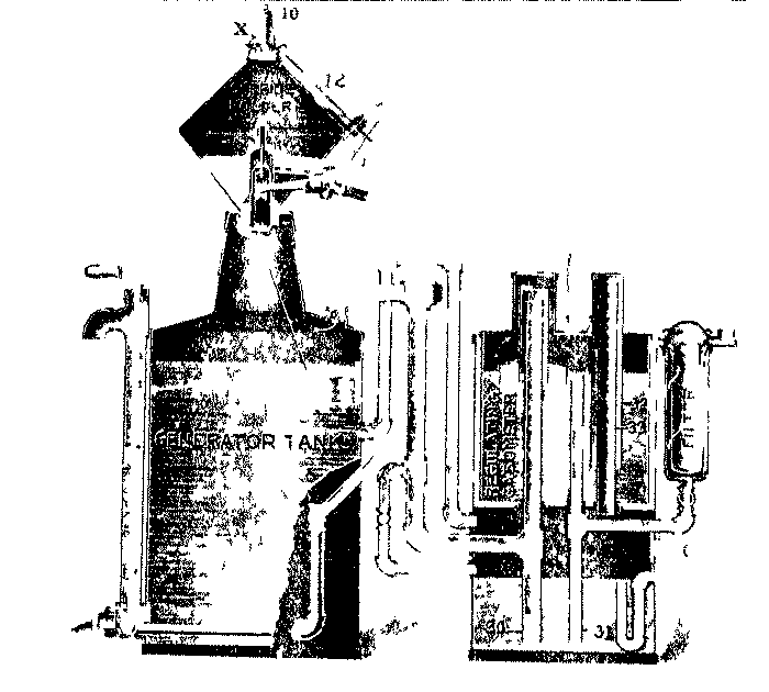
Drip pipes (30) and (31) connected to the inlet- and outlet-pipes of the gasholder are sealed in water to a depth of 6 inches, so that in the event of the pressure in the generator or gasholder rising above that limit the surplus gas blows through the seal and escapes through the vent-pipe C. There is also a telescopic blow-off (32) and (33), which automatically comes into play if the gasholder bell rises above a certain height.
Maker: DAVIS ACETYLENE CO., ELKHARDT, INDIANA.
Type: Automatic; carbide-to-water.
The "Davis" generator made by this firm comprises an equalising bell gasholder with double walls, the inner wall surrounding a central tube rising from the top of the generating chamber, in which is placed a water-sealed carbide chamber with a rotatory feeding mechanism which is driven by a weight motor. The carbide falls from the chamber on to a wide disc from which it is pushed off a lump at a time by a swinging displacer, so arranged that it will yield in every direction and prevent clogging of the feeding mechanism. Carbide falls from the disk into the water of the generating chamber, and the evolved gas raises the bell and so allows a weighted lever to interrupt the action of the clockwork, until the bell again descends. The gas passes through a washer in the gasholder tank, and then through an outside scrubber to the service-pipe. There is an outside chamber connected by a pipe with the generating chamber, which automatically prevents over-filling with water, and also acts as a drainage chamber for the service- and blow-off-pipes. There is an agitator for the residuum and a sludge-cock through which to remove same. The feeding mechanism permits the discharge of lump carbide, and the weight motor affords independent power for feeding the carbide, at the same time indicating the amount of unconsumed carbide and securing uniform gas pressure.

Maker: SUNLIGHT GAS MACHINE CO., 49 WARREN STREET, NEW YORK.
Type: Automatic; carbide-to-water.
The "Omega" apparatus made by this firm consists of a generating tank containing water, and surmounted by a hopper which is filled with carbide of 1/4-inch size. The carbide is fed from the hopper into the generating tank through a mechanism consisting of a double oscillating cup so weighted that normally the feed is closed. The fall of the bell of the equalising gasholder, into which the gas evolved passes, operates a lever B, which rotates the weighted cup in the neck of the hopper and so causes a portion of carbide to fall into the water in the generating tank. The feed-cup consists of an upper cup into which the carbide is first delivered. It is then tipped from the upper cup into the lower cup while, at the same time, further delivery from the hopper is prevented. Thus only the portion of carbide which has been delivered into the lower cup is emptied at one discharge into the generator. There is a safety lock to the hopper cap which prevents the feeding mechanism coming into operation until the hopper cap is screwed down tightly. Provision is made for a limited hand-feed of carbide to start the apparatus. The gasholder is fitted with a telescoping vent-pipe, by which gas escapes to the open in the event of the bell being raised above a certain height. There is also an automatic cut-off of the carbide feed, which comes into operation it the gas is withdrawn too rapidly whether through leakage in the pipes or generating plant, or through the consumption being increased above the normal generating capacity of the apparatus. The gas evolved passes into a condensing or washing chamber placed beneath the gasholder tank and thence it travels to the gasholder. From the gasholder it goes through a purifier containing "chemically treated coke and cotton" to the supply-pipe.
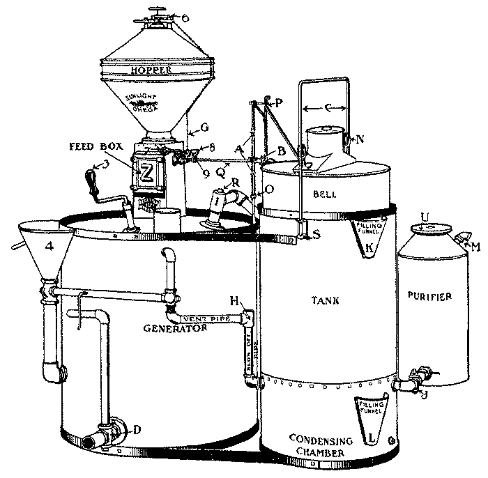
1 Vent-cock handle. 2 Residuum-cock handle. 3 Agitator handle. 4 Filling funnel. 5 Water overflow. 6 Hopper cap and lever. 7 Starting feed. 8 Rocker arm. 9 Feed connecting-rod. A Pawl. B Lever for working feed mechanism. C Guide frame. D Residuum draw-off cock. G Chain from hopper cap to feed mechanism. H Blow-off and vent-pipe connexion. I Gas outlet from generator. J Gas service-cock. K Filling funnel for gasholder tank. L Funnel for condensing chamber. M Gas outlet at top of purifier. N Guides on gas-bell. O Crosshead on swinging pawl. P Crane carrying pawl. Q Shaft connecting feed mechanism. R Plug in gas outlet-pipe. S Guide-frame supports. U Removable plate to clean purifier. Z Removable plate to expose feed-cups for cleaning same.
AUSTRIA-HUNGARY
Maker: RICH. KLINGER, GUMPOLDSKIRCHEN, NEAR VIENNA.
Type: Non-automatic; carbide-to-water.
The generating plant made by this firm consists of the generator A which is supported in a concrete water and sludge tank B, a storage gasholder J, and purifiers K. In the top of the generator are guide-ways F, through each of which is passed a plunger C containing a perforated cage charged with about 8 lb. of lump carbide. The plungers are supported by ropes passing over pulleys D, and when charged they are lowered through the guide-ways F into the water in the tank B. The charge of carbide is thus plunged at once into the large body of water in the tank, and the gas evolved passes through perforations in the washer G to the condenser H and thence to the storage gasholder J. After exhaustion of the charge the plungers are withdrawn and a freshly charged cage of carbide inserted ready for lowering into the generating tank. There is a relief seal f through which gas will blow and escape by a pipe g to the open should the pressure within the apparatus exceed the depth of the seal, viz., about 9 inches. There is a syphon pot N for the collection and withdrawal of condensed water. The sludge is allowed to accumulate in the bottom of the concrete tank B until it becomes necessary to remove it at intervals of about three months. Water is added to the tank daily to replace that used up in the generation of the gas. The gas passes from the storage holder through one of the pair of purifiers K, with water-sealed lids, which are charged with a chemical preparation for the removal of phosphoretted hydrogen. This purifying material also acts as a desiccating agent. From the purifiers the gas passes through the meter L to the service- pipes.
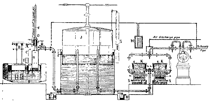
BELGIUM.
Maker: SOC. AN. DE L'ACÉTYLITHE, 65 RUE DU MARCHE, BRUSSELS.
Type: Automatic; contact.
The generating apparatus made by this firm uses, instead of ordinary carbide, a preparation known as "acétylithe," which is carbide treated specially with mineral oil, glucose and sugar. The object of using this treated carbide is to avoid the effects of the attack of atmospheric humidity or water vapour, which, with ordinary carbide, give rise to the phenomena of after-generation. The generator comprises a water-tank A with conical base, a basket C containing the treated carbide inserted within a cylindrical case B which is open at the bottom and is surmounted by a cylindrical filter D. At starting, the tank A is filled with water to the level N N'. The water rises within the cylindrical case until it comes in contact with the treated carbide, which thereupon begins to evolve gas. The gas passes through the filter D, which is packed with dry cotton-wool, and escapes through the tap M. As soon as the contained air has been displaced by gas the outlet of the tap M is connected by a flexible tube to the pipe leading to a purifier and the service-pipe. When the tap M is closed, or when the rate of evolution of the gas exceeds the rate of consumption, the evolved gas accumulates within the cylindrical case B and begins to displace the water, the level of which within the case is lowered from S S', first to S1 S'1 and ultimately to, say, S2 S'2. The evolution of gas is thereby gradually curtailed or stopped until more is required for consumption. The water displacement causes the water-level in the outer tank to rise to N1 N'1 and ultimately to, say N2 N'2. The lime formed by the decomposition of the carbide is loosened from the unattacked portion and taken more or less into solution as sucrate of lime, which is a soluble salt which the glucose or sugar in the treated carbide forms with lime. The solution is eventually run off through the cock R. The cover T of the filter is screwed down on rubber packing until gas- tight. The purifier is charged with puratylene or other purifying material.
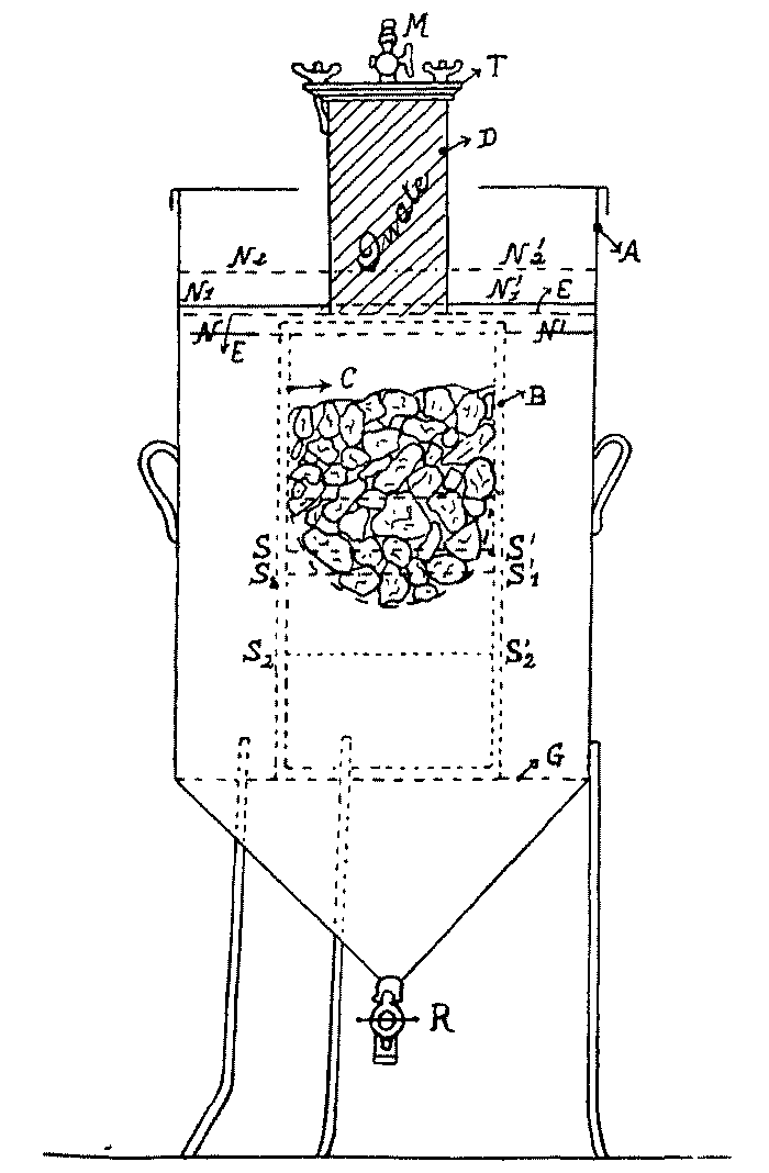
Maker: L. DEBRUYNE, 22 PLACE MASUI, BRUSSELS.
Type: (1) Automatic; carbide-to-water.
The generating plant made by this firm, using granulated carbide, comprises an equalising gasholder E alongside a generating tank B, which is surmounted by a closed carbide receptacle A and a distributing appliance. The carbide receptacle is filled with granulated carbide and the lid N screwed down; the carbide is then withdrawn from the base of the receptacle by the distributing appliance and discharged in measured quantities as required into the water in the generating tank. The distributing appliance is actuated by a weighted cord H attached to the bell I of the gasholder and discharges at each time a quantity of carbide only sufficient nearly to fill the gasholder with acetylene. The gas passes from the generator through the pipe J and seal-pot D, or bypass F, to the gasholder. The generating tank is provided with a funnel G for replacing the water consumed, a sludge-stirrer and a draw-off cock L, and a water-level cock C. The gas passes from the gasholder through a purifier K, charged with heratol, to the service-pipe.

(2) Automatic; carbide-to-water.
The "Debruyne" generator comprises an equalising bell gasholder A placed alongside a generating tank B containing water into which lump carbide is discharged as necessary from each in turn of a series of chambers mounted in a ring above the generating tank. The chambers are removable for refilling, and when charged are hermetically sealed until opened in turn above the shoot C, through which their contents are discharged into the generating tank. The carbide contained in each chamber yields sufficient gas nearly to fill the gasholder. The discharging mechanism is operated through an arm E attached to the bell G of the gasholder, which sets the mechanism in motion when the bell has fallen nearly to its lowest position. The lip L serves for renewing the water in the generator, and the gas evolved goes through the pipe K with tap F to the gasholder. There is an eccentric stirrer for the sludge and a large-bore cock for discharging it. The gas passes from the gasholder through the pipe J to the purifier H, charged with heratol, and thence to the service-pipe.
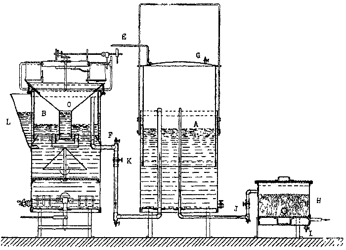
Maker: DE SMET VAN OVERBERGE, ALOST.
Type: (1) Automatic; carbide-to-water.
This generating apparatus comprises an equalising gasholder A placed alongside a generating tank B, above which is mounted on a rotating spindle a series of chambers C, arranged in a circle, which are filled with carbide. The generating tank is closed at the top, but on one side there is a shoot D through which the carbide is discharged from the chambers in turn into the water in the tank. The series of chambers are rotated by means of a cord passing round a pulley E and having a weight F at one end, and being attached to the bell of the gasholder at the other. When the bell falls, owing to the consumption of gas, to a certain low position, the carbide chamber, which has been brought by the rotation of the pulley over the shoot, is opened at the bottom by the automatic liberation of a catch, and its contents are discharged into the generating tank. The contents of one carbide chamber suffice to fill the gasholder to two-thirds of its total capacity. The carbide chambers after filling remain hermetically closed until the bottom is opened for the discharge of the carbide. There is a sludge-cock G at the bottom of the generating tank. The gas passes from the gasholder through a purifier H, which is ordinarily charged with puratylene.
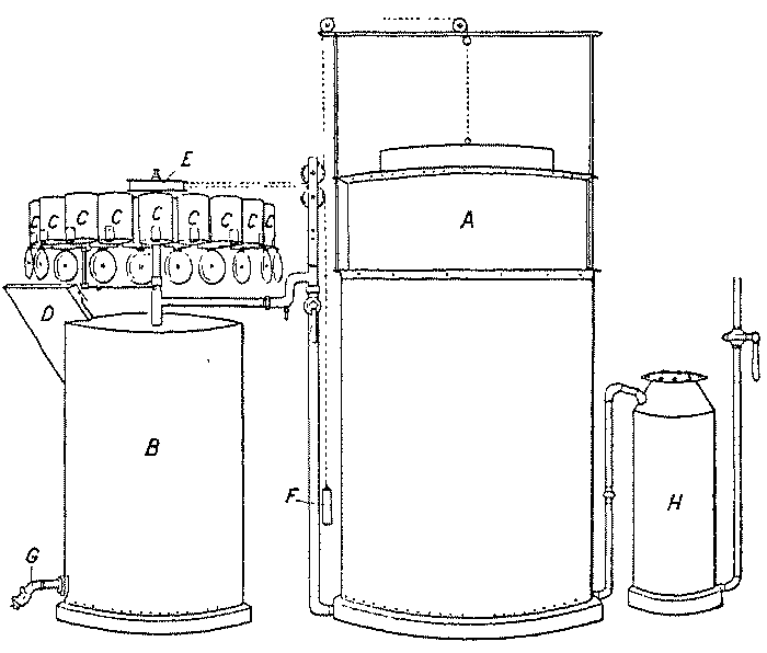
(2) Non-automatic; carbide-to-water. This apparatus comprises a storage bell gasholder J placed alongside a generating tank in the top of which is a funnel E with a counter-weighted lever pivoted on the arm B. The base of the funnel is closed by a flap valve C hinged at D. When it is desired to generate gas the counter-weight A of the lever is raised and the valve at the bottom of the funnel is thereby opened. A charge of carbide is then tipped into the funnel and drops into the water in the generating tank. The valve is then closed and the gas evolved goes through the pipe G to the gasholder, whence it passes through a purifier to the service-pipe. There is a sludge-cock on the generating tank.

Maker: SOC. AN. BELGE DE LA PHOTOLITHE, 2 RUE DE HUY, LIÉGE.
Type: Automatic; carbide-to-water.
The "Photolithe" generating plant made by this firm comprises an equalising bell gasholder A in the tank O, alongside a generating tank B which is surmounted by a carbide storage receptacle divided into a number of compartments. These compartments are fitted with flap bottoms secured by catches, and are charged with carbide. Through the middle of the storage receptacle passes a spindle, to the upper end of which is attached a pulley b. Round the pulley passes a chain, one end of which carries a weight n, while in the other direction it traverses guide pulleys and is attached to a loop on the crown of the gasholder bell. When the bell falls below a certain point owing to the consumption of gas, it pulls the chain and rotates the pulley b and therewith an arm d, which liberates the catch supporting the flap-bottom of the next in order of the carbide compartments. The contents of this compartment are thereby discharged through the shoot C into the generating tank B. The gas evolved passes through the cock R and the pipe T into the gasholder, the rise of the bell of which takes the pull off the chain and allows the weight at its other end to draw it up until it is arrested by the stop f. The arm d is thereby brought into position to liberate the catch of the next carbide receptacle. The generating tank is enlarged at its base to form a sludge receptacle E, which is provided with a sludge draw-off cock S and a hand-hole P. Between the generating tank proper and the sludge receptacle is a grid, which is cleaned by means of a rake with handle L. The gas passes from the gasholder through a purifier H charged with puratylene, to the service-pipe.
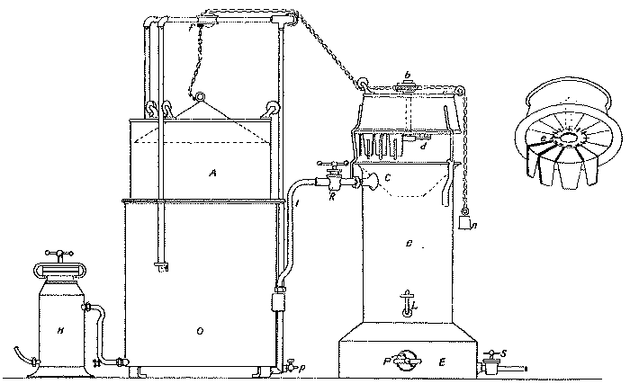
The same firm also makes a portable generating apparatus in which the carbide is placed in a basket in the crown of the bell of the gasholder. This apparatus is supplied on a trolley for use in autogenous soldering or welding.
FRANCE.
Maker: LA SOC. DES APPLICATIONS DE L'ACÉTYLÈNE, 26 RUE CADET, PARIS.
Type: Automatic; carbide-to-water.
The "Javal" generating plant made by this firm consists of an equalising bell gasholder A in the tank B with a series of buckets D, with removable bottoms h, mounted on a frame F round the guide framing of the holder. Alongside the gasholder stands the generating tank H with shoot K, into which the carbide discharged from the buckets falls. On top of the generator is a tipping water-bucket I supplied with water through a ball cock. The bell of the gasholder is connected by chains a and c, and levers b and d with an arm which, when the bell descends to a certain point, comes in contact with the catch by which the bottom of the carbide bucket is held in place, and, liberating the same, allows the carbide to fall into the shoot. When the bell rises, in consequence of the evolved gas, the ring of carbide buckets is rotated sufficiently to bring the next bucket over the shoot. Thus the buckets are discharged in turn as required through the rise and fall of the gasholder bell.

The carbide falling from the opened bucket strikes the end i of the lever k, and thereby tips the water-bucket I and discharges its contents into the shoot of the generator. The rise in the level of the water in the generator, due to the discharge of the water from the bucket I, lifts the float L and therewith, through the attached rod and chain u, the ball s of the valve t. The sludge, which has accumulated in the base N of the generator from the decomposition of the previous portion of carbide, is thereby discharged automatically into a special drain. The discharge- valve closes automatically when the float L has sunk to its original level. The gas evolved passes from the generator through the seal-pot M and the pipe r with cock q into the gasholder, from which it passes through the pipe x; with condensation chamber and discharge tap y into the purifier R, which is charged with heratol.
Maker: L'HERMITE, LOUVIERS, EURE.
Type: (1) Automatic; carbide-to-water.
The generating plant known as "L'Éclair," by this firm comprises an equalising bell gasholder A floating in an annular water-seal N, formed in the upper part of a generating tank B into which carbide enters through the shoot K. Mounted at the side of the tank is the carbide delivery device, which consists of the carbide containers J supported on an axis beneath the water-sealed cover H. The containers are filled with ordinary lump carbide when the cover H is removed. The tappet O attached to the bell of the gasholder come in contact with a pawl when the gasholder bell descends to a certain level and thereby rotates a pinion on the protruding end of the axis which carries the carbide containers J. Each time the bell falls and the tappet strikes the pawl, one compartment of the carbide containers discharges its contents down the shoot K into the generating tank B. The gas evolved passes upwards and causes the bell A to rise. The gas is prevented from rising into the shoot by the deflecting plates G. The natural level of the water in the generating tank, when the apparatus is in use, is shown by the dotted lines L. The lime sludge is discharged from time to time through the cock E, being stirred up by means of the agitator C with handle D. When the sludge is discharged water is added through M to the proper level. The gas evolved passes from the holder through the pipe with tap F to the service-pipe. A purifier is supplied if desired.

References
A Gasholder. B Generator. C Agitator. D Handle of agitator. E Sludge-cock. F Gas outlet. G Deflecting plates. H Cover. I Carbide. J Automatic distributor. K Shoot. L Water-level. M Water-inlet. N Water-seal. O Tappet.
(2) Automatic; water-to-carbide; contact.
A generating plant known as "L'Étoile" made by this firm. A tappet on the bell of an equalising gasholder depresses a lever which causes water to flow into a funnel, the outlet of which leads to a generating chamber containing carbide.
Maker: MAISON SIRIUS, FR. MANGIAMELI & CO., 34 RUE DES PETITS- HÔTELS, PARIS.
Type: (1) Automatic; carbide-to-water.
The generating plant made by this firm comprises a drum-shaped carbide holder mounted above a generating tank, a condenser, a washer, an equalising gasholder, and a purifier. The drum A is divided into eight chambers a each closed by a fastening on the periphery of the drum. These chambers are packed with lump carbide, which is discharged from them in turn through the funnel B into the generating tank, which is filled with water to the level of the overflow cock b. A deflecting plate d in the tank distributes the carbide and prevents the evolved gas passing out by way of the funnel B. The gas evolved passes through the pipe O into the condenser, which is packed with coke, through which the gas goes to the pipe E and so to the washer P through the water, in which it bubbles and issues by the pipe G into the gasholder. The bell L of the gasholder is connected by a chain C to the axis of the drum A, on which is a pinion with pawl so arranged that the pull on the chain caused by the fall of the bell of the gasholder rotates the drum by 1/8 of a turn. The catch on the outside of the carbide chamber, which has thereby been brought to the lowest position, is at the same time freed, so that the contents of the chamber are discharged through the funnel B. The evolved gas causes the bell to rise and the drum remains at rest until, owing to the consumption of gas, the bell again falls and rotates the drum by another 1/8 of a turn. Each chamber of the drum holds sufficient carbide to make a volume of gas nearly equal to the capacity of the gasholder. Thus each discharge of carbide very nearly fills the gasholder, but cannot over-fill it. The bell is provided with a vent-pipe i, which comes into operation should the bell rise so high that it is on the point of becoming unsealed. From the gasholder the gas passes through the pipe J, with cock e, to the purifier, which is charged with frankoline, puratylene, or other purifying material, whence it passes to the pipe N leading to the place of combustion. The generating tank is provided with a sludge-cock g, and a cleaning opening with lid f. This generating plant has been primarily designed for the use of acetylene for autogenous welding, and is made also mounted on a suitable trolley for transport for this purpose.
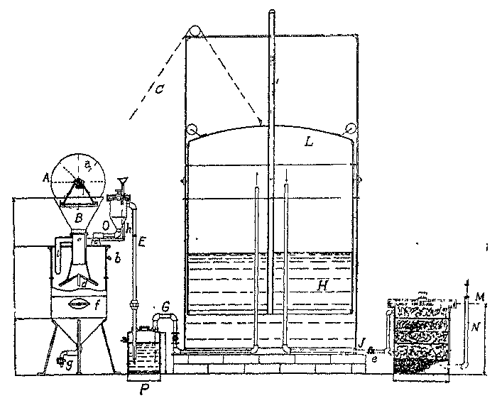
(2) Automatic; carbide-to-water.
A later design of generating plant, known as the Type G, also primarily intended for the supply of acetylene for welding, has the carbide store mounted in the crown of the bell of the equalising gasholder, to the framing of the tank of which are attached a purifier, charged with frankoline, and a safety water-seal or valve. The whole plant is mounted on a four-legged stand, and is provided with handles for carrying as a whole without dismounting. It is made in two sizes, for charges of 5-1/2 and 11 lb. of carbide respectively.
GERMANY.
Maker: KELLER AND KNAPPICH, G.m.b.H., AUGSBURG.
Type: Non-automatic; carbide-to-water.
The "Knappich" generating plant made by this firm embodies a generating tank, one-half of which is closed, and the other half of which is open at the top, containing water. A small drum containing carbide is attached by a clamp to the end of a lever which projects above the open half of the tank. The lever is fastened to a horizontal spindle which is turned through 180° by means of a counter-weighted lever handle. The carbide container is thus carried into the water within the closed half of the tank, and is opened automatically in transit. The carbide is thus exposed to the water and the evolved gas passes through a pipe from the top of the generating tank to a washer acting on the Livesey principle, and thence to a storage gasholder. The use of closed carbide containers in charging is intended to preclude the introduction of air into the generator, and the evolution and escape of gas to the air while the carbide is being introduced. Natural circulation of the water in the generating tank is encouraged with a view to the dissipation of heat and washing of the evolved gas. From the gasholder the gas passes in a downward direction through two purifiers arranged in series, charged with a material supplied under the proprietary name of "Carburylen." This material is stated to act as a desiccating as well as a purifying agent. The general arrangement of the plant is shown in the illustration. (Fig. 38).
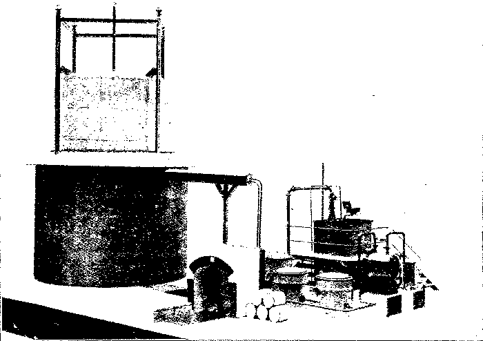
Maker: NORDISCHE AZETYLEN-INDUSTRIE; ALTONA-OTTENSEN.
Type: Automatic; water-to-carbide; "drawer."
The apparatus made by this firm consists of an equalising gasholder with bell D and tank E, a water-tank O, and two drawer generators C situated in the base of the gasholder tank. The water-supply from the tank O through the pipe P with valve Q is controlled by the rise and fall of the bell through the medium of the weight J attached to the bell. When the bell descends this weight rests on K and so moves a counter-weighted lever, which opens the valve Q. The water then flows through the nozzle B into one division of the funnel A and down the corresponding pipe to one of the generators. The generators contain trays with compartments intended to be half filled with carbide. The gas evolved passes up the pipe T and through the seal U into the bell of the gasholder. There is a safety pipe F, the upper end of which is carried outside the generator house. From the gasholder the gas is delivered through the cock M to a purifier charged with a special purifying material mixed with cork waste and covered with wadding. There is a drainage cock N at the base of the purifier. The nozzle B of the water-supply pipe is shifted to discharge into either compartment of the funnel A, according to which of the two generators is required to be in action. The other generator may then be recharged without interfering with the continuous working of the plant.

GREAT BRITAIN AND IRELAND.
Maker: THE ACETYLENE CORPORATION OF GREAT BRITAIN LTD., 49 VICTORIA STREET, LONDON, S.W.
Type: (1) Automatic; water-to-carbide; contact, superposed pans.
The "A1" generating plant made by this firm comprises a bell gasholder, with central guide, standing alongside the generator. The generator consists of a rectangular tank in which is a generating chamber having a water-sealed lid with pressure test-cock I. Into the generating chamber fit a number of pans J, which are charged with carbide. Water is supplied to the generating chamber from an overhead tank B through the starting tap D and the funnel E. It flows out of the supply-pipe near the top of the generating chamber through a slot in the side of the pipe facing the corner of the chamber, so that it runs down the latter without splashing the carbide in the upper pans. It enters first the lowest carbide pan through the perforations, which are at different levels in the side of the pan. It thus attacks the carbide from the bottom upwards. The evolved gas passes from the generating chamber through a pipe opening near the top of the same to the washer A, which forms the base of the generating tank. It bubbles through the water in the washer, which therefore also serves as a water-seal, and passes thence to the gasholder. On the bell of the gasholder is an arm C which, when the holder descends nearly to its lowest point, depresses the rod C, which is connected by a chain to a piston in the outlet-pipe from the water-tank B. The fall of the gasholder thereby raises the piston and allows water to flow out of the tank B through the tap D to the funnel E. The generating tank is connected by a pipe, with tap G, with the washer A, and the water in the generating tank is run off through this pipe each time the generating chamber is opened for recharging, thereby flushing out the washer A and renewing the water in the same. There is a sludge discharging tap F. With a view to the ready dissipation of the heat of generation the generating chamber is made rectangular and is placed in a water-tank as described. Some of the heat of generation is also communicated to the underlying washer and warms the water in it, so that the washing of the gas is effected by warm water. Water condensing in the gasholder inlet-pipe falls downwards to the washer. There is a water lip H by which the level of the water in the washer is automatically kept constant. The gasholder is provided with a safety-pipe K, which allows gas to escape through it to the open before the sides of the holder become unsealed, should the holder for any reason become over-filled. The holder is of a capacity to take the whole of the gas evolved from the carbide in one pan, and the water- tank B holds just sufficient water for the decomposition of one charge of the generator. From the gasholder the gas passes through a purifier, which is ordinarily charged with "Klenzal," and a baffle-box for abstraction of dust, to the service-pipe. With plants intended to supply more than forty lights for six hours, two or more generating chambers are employed, placed in separate compartments of one rectangular generating tank. The water delivery from the water-tank B then takes place into a trough with outlets at different levels for each generating chamber. By inspection of this trough it may be seen at once whether the charge in any generating chamber is unattacked, in course of attack, or exhausted.
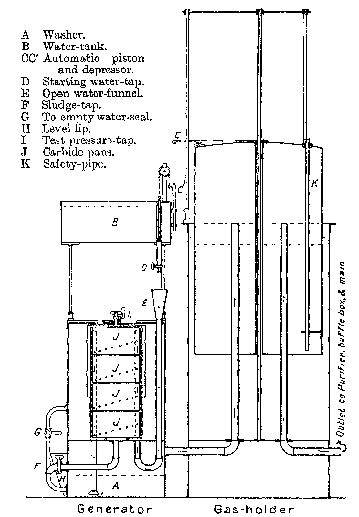
(2) Automatic; water-to-carbide; contact.
The same firm also makes the "Corporation Flexible-Tube Generator," which is less costly than the "A1" (vide supra). The supply of water to the generating vessels takes place from the tank of the equalising bell gasholder and is controlled by a projection on the bell which depresses a flexible tube delivering into the generating vessels below the level of the water inlet to the tube.
(3) Automatic; water-to-carbide; "drawer."
The same firm also makes a generator known as the "A-to-Z," which is less costly than either of the above. In it water is supplied from the tank of a bell gasholder to a drawer type of generator placed in the base of the gasholder tank. The supply of water is controlled by an external piston- valve actuated through the rise and fall of the bell of the gasholder. The flow of water to the generator is visible.
Maker: THE ACETYLENE GAS AND CARBIDE OF CALCIUM CO., PONTARDAWE, R.S.O., GLAM.
Type: Automatic; water-to-carbide; flooded compartment.
The "Owens" generator made by this firm comprises an equalising bell gasholder alongside which are placed two or more inclined generating cylinders. The front lower end of each cylinder is fitted with a lid which is closed by a screw clamp. There is inserted in each cylinder a cylindrical trough, divided into ten compartments, each of which contains carbide. Water is supplied to the upper ends of the cylinders from a high-level tank placed at the back of the gasholder. In the larger sizes the tank is automatically refilled from a water service through a ball-cock. The outlet-valve of this tank is operated through a counter- weighted lever, the unweighted end of which is depressed by a loop, attached to the crown of the gasholder bell, when the bell has nearly reached its lowest position. This action of the bell on the lever opens the outlet-valve of the tank and allows water to flow thence into one of the generating cylinders. It is discharged into the uppermost of the compartments of the carbide trough, and when the carbide in that compartment is exhausted it flows over the partition into the next compartment, and so on until the whole trough is flooded. The gas passes from the generating cylinders through a water-seal and a baffle plate condenser placed within the water link of the gasholder to the bell of the latter. There is a water seal on the water supply-pipe from the tank to the generators, which would be forced should the pressure within the generators for any reason become excessive. There is also a sealed vent- pipe which allows of the escape of gas from the holder to the open should the holder for any reason be over filled. The gas passes from the holder through a purifier charged with "Owens" purifying material to the service pipe. The plant is shown in Fig 41.

Maker ACETYLENE ILLUMINATING CO, LTD, 268-270 SOUTH LAMBETH ROAD, LONDON, SW
Type (1) Non automatic, carbide to water
The generator A of this type made by this firm is provided with a loading box B, with gas tight lid, into which the carbide is put. It is then discharged by moving a lever which tilts the hinged bottom D of the box B, and so tips the carbide through the shoot E on to the conical distributor F and into the water in the generating chamber. There is a sludge cock G at the base of the generator. Gas passes as usual from the generator to a washer and storage gasholder. Heratol is the purifying material supplied.

(2) Non-automatic; water-to-carbide; contact.
The generator A is provided with a carbide container with perforated base, and water is supplied to it from a delivery-pipe through a scaled overflow. The gas evolved passes through the pipe E to the washer B, which contains a distributor, and thence to the storage gasholder G. There is a sludge-cock F at the base of the generator. From the gasholder the gas passes through the purifier D, charged with heratol, to the service-pipe.

Maker: THE ALLEN CO., 106 VICTORIA STREET, LONDON, S.W.
Type: Automatic; water-to-carbide; contact, superposed trays.
The generating plant made by this firm comprises an equalising bell gasholder, from the tank of which water is supplied through a flexible tube to the top of a water-scaled generating chamber in which is a vertical cylinder containing a cage packed with carbide. The open end of the flexible tube is supported by a projection from the bell of the gasholder, so that as the bell rises it is raised above the level of the water in the tank and so ceases to deliver water to the generator until the bell again falls. The water supplied flows by way of the water-seal of the cover of the generating chamber to the cylinder containing the carbide cage. Larger sizes have two generating chambers, and the nozzle of the water delivery-pipe may be switched over from one to the other. There is an overflow connexion which brings the second chamber automatically into action when the first is exhausted. One chamber may be recharged while the other is in action. Spare cylinders and cages are provided for use when recharging. There is a cock for drawing off water condensing in the outlet-pipe from the gasholder. The gas passes from the holder to the lower part of a purifier with water-scaled cover, through the purifying material in which it rises to the outlet leading to the service-pipe. Purifying material under the proprietary name of the "Allen" compound is supplied. The plant is shown in Fig. 44.

Maker: THE BON-ACCORD ACETYLENE GAS CO., 285 KING STREET, ABERDEEN.
Type: Automatic; water-to-carbide; contact, superposed trays.
The "Bon Accord" generating plant made by this firm comprises an equalising displacement gasholder B immersed in a water-tank A. Alongside the tank are placed two water-jacketed generating chambers G1 and G2 containing cages K charged with carbide. Water passes from within the gasholder through the water inlet- pipes L1 L2, the cock H, and the pipes F1 F2 to the generating chambers, from which the gas evolved travels to the holder B, in which it displaces water until the water-level falls below the mouths of the pipes L1 and L2, and so cuts off the supply of water to the generating chambers. The gas passes from the holder B through the pipe with outlet-cock T to a washer containing an acid solution for the neutralisation of ammonia, then through a purifier containing a "special mixture of chloride of lime." After that through a tower packed with lime, and finally through a pressure regulator, the outlet of which is connected to the service-pipe. There is an indicator I to show the amount of gas in the holder. One generator may be charged while the other is in action.

Maker: FREDK. BRABY AND CO., LTD., ASHTON GATE WORKS, BRISTOL; AND 352-364 EUSTON ROAD, LONDON.
Type: (I) Automatic; carbide-to-water.
The "A" type of generator made by this firm comprises an equalising bell gasholder, round the bell of which are arranged a series of buckets which are charged with carbide. Those buckets are discharged in turn as the bell falls from time to time through a mechanism operated by a weight suspended from a wire cord on a revolving spindle. The carbide is discharged on to a different spot in the generating tank from each bucket. There is a cock for the periodical removal of sludge. Gas passes through a purifier charged with puratylene to the service-pipe. The disposition of the parts of the plant and the operating mechanism arc shown in the accompanying figure, which represents the generating apparatus partly in elevation and partly in section. The carbide buckets (1) are loosely hooked on the flat ring (2) bolted to the gasholder tank (3). The buckets discharge through the annular water-space (4) between the tank and the generator (5). The rollers (6), fitted on the generator, support a ring (7) carrying radial pins (8) projecting outwards, one pin for each bucket. The ring can travel round on the rollers. Superposed on the ring is a tray (9) closed at the bottom except for an aperture beneath the throat (11), on which is mounted an inclined striker (12), which strikes the projecting tongues (1a) of the lids of the buckets in turn. There is fixed to the sides of the generator a funnel (13) with open bottom (13a) to direct the carbide, on to the rocking grid (14) which is farther below the funnel than appears from the figure. Gas passing up behind the funnel escapes through a duct (15) to the gasholder. The ring (7) is rotated through the action of the weight (16) suspended by the chain or rope (17) which passes round the shaft (18), which is supported by the bracket (19) and has a handle for winding up. An escapement, with upper limb (20a) and lower limb (20b), is pivotally centred at (21) in the bracket (19) and normally restrains the turning of the shaft by the weight. There is a fixed spindle (24) supported on the bracket (23)--which is fixed to the tank or one of the guide-rods--having centred on it a curved bar or quadrant (25) running loose on the spindle (24) and having a crank arm (26) to which is connected one end of a rod (27) which, at the other end, is connected to the arm (28) of the escapement. The quadrant bears at both extremities against the flat bar (29) when the bell (22) is sufficiently raised. The bar (29) extends above the bell and carries an arm (30) on which is a finger (30a). There is fixed on the shaft (18) a wheel (31), with diagonal divisions or ways extending from side to side of its rim, and stop-pins (32) on one side at each division. A clutch prevents the rotation of the wheel during winding up.
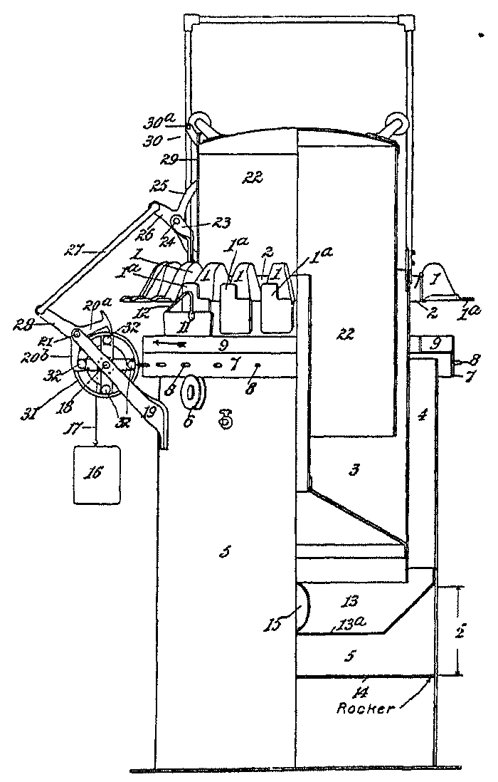
(2) Automatic; water-to-carbide; contact, superposed trays.
The type "B" generator made by this firm comprises an equalising bell gasholder, a crescent-shaped feed water-tank placed on one side of the gasholder, and mechanism for controlling a tap on the pipe by which the feed water passes to a washer whence it overflows through a seal into a horizontal generating chamber containing cells packed with carbide. The mechanism controlling the water feed embodies the curved bar (25), connecting-rod (27) and flat guide-bar (29) as used for controlling the carbide feed in the "A" type of generator (Fig. 46). When the bell descends water is fed into the washer, and the water-level of the seal is thus automatically maintained. The gas evolved passes through a pipe, connecting the seal on the top of the generating chamber with the washer, into the gasholder. Plants of large size have two generating chambers with connexions to a single washer.
Maker: THE DARGUE ACETYLENE GAS CO., 57 GREY STREET, NEWCASTLE-ON- TYNE.
Type: Automatic; water-to-carbide; "drawer."
The "Dargue" acetylene generator made by this firm comprises an equalising bell gasholder B floating in a water-tank A, which is deeper than is necessary to submerge the bell of the gasholder. In the lower part of this tank are placed two or more horizontal generating chambers which receive carbide-containing trays divided by partitions into a number of compartments which are half filled with carbide. Water is supplied from the gasholder tank through the tap E and pipe F to the generating chambers in turn. It rises in the latter and floods the first compartment containing carbide before gaining access to the second, and so on throughout the series of compartments. As soon as the carbide in the first generating chamber is exhausted, the water overflows from it through the pipe with by-pass tap J to the second generating chamber. The taps G and H serve to disconnect one of the generating chambers from the water-supply during recharging or while another chamber is in action. The gas evolved passes from each generating chamber through a pipe L, terminating in the dip-pipe M, which is provided with a baffle-plate having very small perforations by which the stream of gas is broken up, thereby subjecting it to thorough washing by the upper layers of water in the gasholder tank. The washed gas, which thus enters the gasholder, passes from it through the pipe N with main cock R to the service- pipes. The water-supply to the generator is controlled through the tap E, which is operated by a chain connected to an arm attached to the bell of the gasholder.
The water in the gasholder tank is accordingly made to serve for the supply of the generating chambers, for the washing of the gas, and as a jacket to the generating chambers. The heat evolved by the decomposition of the carbide in the latter creates a circulation of the water, ensuring thereby thorough mixing of the fresh water, which is added from time to time to replace that removed for the decomposition of the carbide, with the water already in the tank. Thus the impurities acquired by the water from the washing of the gas do not accumulate in it to such an extent as to render it necessary to run off the whole of the water and refill, except at long intervals. A purifier, ordinarily charged with puratylene, is inserted in many cases after the main cock R. The same firm makes an automatic generator on somewhat similar lines, specially designed for use in autogenous welding, the smaller sizes of which are readily portable.
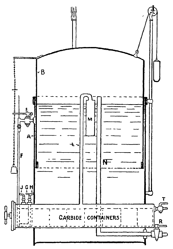
Maker: J. AND J. DRUMMOND, 162 MARKET STREET, ABERDEEN.
Type: Automatic; water-to-carbide; contact.
The generating plant made by this firm comprises two or more generating vessels B in which carbide is contained in removable cases perforated at different levels. Water is supplied to these generating vessels, entering them at the bottom, from an elevated tank A through a pipe C, in which is a tap F connected by a lever and chain L with the bell G of the equalising gasholder H, into which the evolved gas passes. The lever of the tap F is counter-weighted so that when the bell G descends the tap is opened, and when the bell rises the tap is closed. The gas passes from the generating chambers B through the pipe D to the washer-cooler E and thence to the gasholder. From the latter it passes through the dry purifier J to the service-pipe. The gasholder bell is sealed in oil contained in an annular tank instead of in the usual single-walled tank containing water. The purifying material ordinarily supplied is puratylene. The apparatus is also made to a large extent in a compact form specially for use on board ships.

Agents: FITTINGS, LTD., 112 VICTORIA STREET, S.W.
Type: Automatic; carbide-to-water.
The "Westminster" generator supplied by this firm is the "Davis" generator described in the section of the United States. The rights for the sale of this generator in Great Britain are held by this firm.
Maker: LOCKERBIE AND WILKINSON, TIPTON, STAFFS.
Type: (1) Automatic; water-to-carbide; contact, superposed trays.
The "Thorscar" generator of this firm comprises an equalising gasholder, the gas-space of the bell B of which is reduced by conical upper walls. When the bell descends and this lining enters the water in the tank A the displacement of water is increased and its level raised until it comes above the mouths of the pipes E, through which a portion then flows to the generators D. The evolution of the gas in the latter causes the bell to rise and the conical lining to be lifted out of the water, the level of which thereupon falls below the mouths of the pipes E in consequence of the reduced displacement of the bell. The supply of water to the generators is thus cut off until the bell again falls and the level of the water in the tank is raised above the mouths of the pipes E. The generating chambers D are provided with movable cages F in which the carbide is arranged on trays. The gas evolved travels through a scrubbing-box G containing charcoal, and the pipe J with drainage-pipe P to the water-seal or washer K inside the holder, into which it then passes. The outlet-pipe for gas from the holder leads through the condensing coil L immersed in the water in the tank to the condensed water-trap N, and thence by the tap Q to the supply-pipe. The generating chambers are water-jacketed and provided with gauge-glasses H to indicate when recharging is necessary, and also with sludge-cocks M. The object of the displacement cone in the upper part of the bell is to obtain automatic feed of water to the carbide without the use of cocks or movable parts. There is a funnel- shaped indicator in front of the tank for regulating the height of water to a fixed level, and also an independent purifier, the purifying material or which is supplied under the proprietary name of "Thorlite."
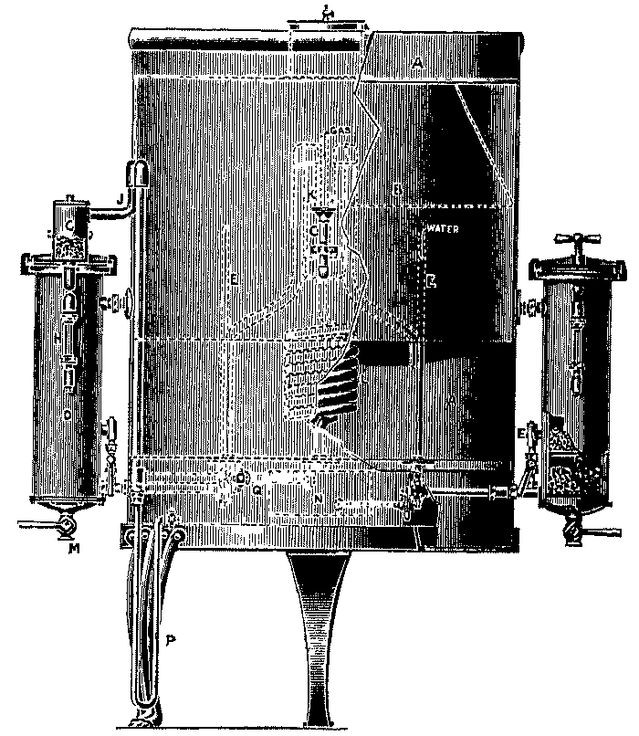
(2) Non-automatic; water-to-carbide; "drawer."
This generating plant, the "Thorlite," comprises a water-tank A from which water is admitted to the drawer generating chambers B, one of which may be recharged while the other is in operation. The gas evolved passes through a seal C to the gasholder D, whence it issues as required for use through the purifier E to the supply-pipe. For the larger sixes a vertical generating chamber is used. The purifier and purifying material are the same as for the automatic plant of the same firm.
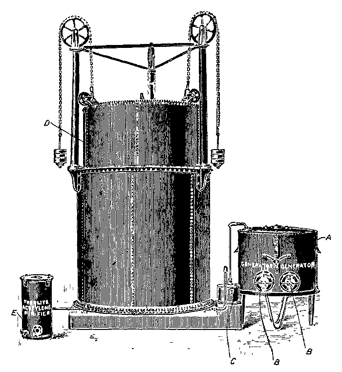
Maker: THE MANCHESTER ACETYLENE GAS CO., LTD., ACRE WORKS, CLAYTON, MANCHESTER.
Type: Automatic; water-to-carbide; "drawer."
The plant made by this firm comprises an equalising gasholder A from the tank of which water is supplied to generating cylinders B placed at the side of the tank, the number of which varies with the capacity of the plant. The cylinders receive tray carbide-containers divided into compartments perforated at different levels so that they are flooded in turn by the inflowing water. A weight C carried by a chain D from one end of a lever E pivoted to the framing of the gasholder is supported by the bell of the gasholder when the latter rises; but when the holder falls the weight C, coming upon the lever E, raises the rod F, which thereupon opens the valve G, which then allows water to flow from the gasholder tank through the pipe H to one of the generating cylinders. When the carbide in the first cylinder is exhausted, the water passes on to a second. One generating cylinder may be recharged while another is in action. The rising of the holder, due to the evolved gas, causes the bell to support the weight C and thus closes the water supply-valve G. The gas evolved passes through vertical condensers J into washing- boxes K, which are placed within the tank. The gas issues from the washing-boxes into the gasholder bell, whence it is withdrawn through the pipe L which leads to the purifier. Puratylene is the purifying material ordinarily supplied by this firm.

Maker: R,. J. MOSS AND SONS, 98 SNOW HILL, BIRMINGHAM.
Type: (1) Automatic; water-to-carbide; superposed trays.
The "Moss" generator, "Type A," made by this firm comprises an equalising gasholder, four, three, or two generating chambers, and an intermediate water-controlling chamber. Each generating chamber consists of a frame in which are arranged about a central tube trays half filled with carbide, having water inlet-holes at several different levels, and each divided into two compartments. Over this frame is put a bell-shaped cover or cap, and the whole is placed in an outer tank or bucket, in the upper part of which is a water inlet-orifice. The water entering by this orifice passes down the outside of the bell, forming a water-seal, and rises within the bell to the perforations in the carbide trays from the lowest upwards, and so reaches the carbide in successive layers until the whole has been exhausted. The gas evolved passes through the central tube to a water- seal and condensing tank, through which it escapes to the controlling chamber, which consists of a small water displacement chamber, the gas outlet of which is connected to the equalising gasholder. The bell of the equalising gasholder is weighted or balanced so that when it rises to a certain point the pressure is increased to a slight extent and consequently the level of the water in the displacement controlling chamber is lowered. In this chamber is a pipe perforated at about the water-level, so that when the level is lowered through the increased pressure thrown by the rising gasholder the water is below the perforations and cannot enter the pipe. The pipe leads to the water inlet-orifices of the generating tanks and when the equalising gasholder falls, and so reduces the pressure within the controlling chamber, the water in the latter rises and flows through the pipe to the generating tanks. The water supplied to the carbide is thus under the dual control of the controlling chamber and of the differential pressure within the generating tank. The four generators are coupled so that they come into action in succession automatically, and their order of operation is naturally reversed after each recharging. An air-cock is provided in the crown of the bell of each generator and, in case there should be need of examination when charged, cocks are provided in other parts of the apparatus for withdrawing water. There is a sludge-cock on each generator. The gas passes from the equalising gasholder through a purifier, for which the material ordinarily supplied is puratylene.
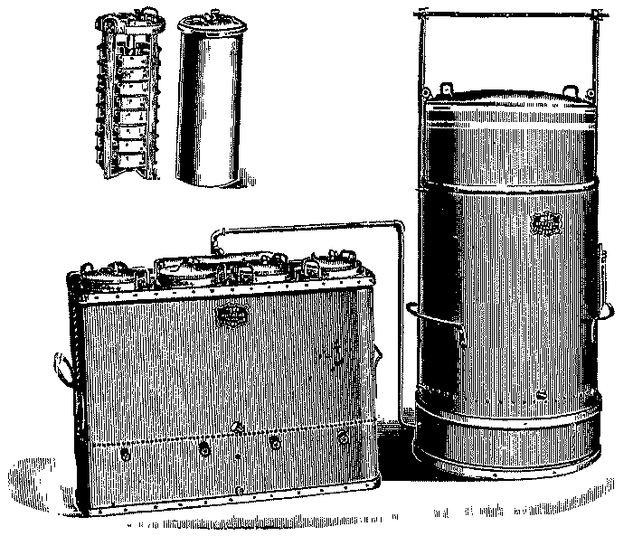
The "Moss Type B" generator is smaller and more compact than "Type A." It has ordinarily only two generating chambers, and the displacement water controlling chamber is replaced by a bell governor, the bell of which is balanced through a lever and chains by a weight suspended over the bell of the equalising gasholder, which on rising supports this counter-weight and so allows the governor bell to fall, thereby cutting off the flow of water to the generating chambers.
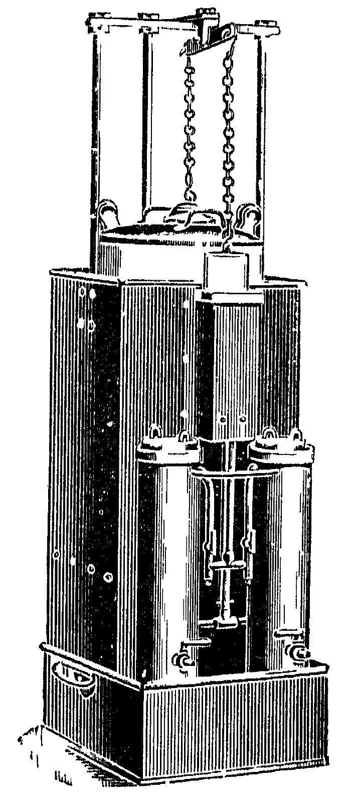
The "Moss Type C" generator is smaller than either "Type A" or "B," and contains only one generating chamber, which is suspended in a pocket in the crown of the equalising gasholder. Water enters through a hole near the top of the bucket of the generating chamber, when it descends with the holder through the withdrawal of gas from the latter.

(2) Semi-automatic; water-to-carbide; superposed trays.
The "Moss Semi-Non-Auto" generating plant resembles the automatic plant described above, but a storage gasholder capable of holding the gas evolved from one charging of the whole of the generating chambers is provided in place of the equalising gasholder, and the generation of gas proceeds continuously at a slow rate.
The original form of the "Acetylite" generator (vide infra) adapted for lantern use is also obtainable of R. J. Moss and Sons.
Maker: WM. MOYES AND SONS, 115 BOTHWELL STREET, GLASGOW.
Type: Automatic; carbide-to-water. The "Acetylite" generator made by this firm consists of an equalising gasholder and one or more generating tanks placed alongside it. On the top of each generating tank is mounted a chamber, with conical base, charged with granulated carbide 1/8 to 1/2 inch in size. There is an opening at the bottom of the conical base through which passes a rod with conical head, which, when the rod is lowered, closes the opening. The rod is raised and lowered through levers by the rise and fall of the bell of the equalising gasholder, which, when it has risen above a certain point, supports a counter-weight, the pull of which on the lever keeps the conical feed-valve open. The gas evolved in the generating tanks passes through a condensing chamber situated at the base of the tank into the equalising gasholder and so automatically controls the feed of carbide and the evolution of gas according to the rate of withdrawal of the gas from the holder to the service-pipes. The water in the gasholder tank acts as a scrubbing medium to the gas. The generating tanks are provided with sludge-cocks and a tap for drawing off condensed water. The gas passes from the equalising gasholder, through a purifier and dryer charged with heratol or other purifying material to the service-pipes. The original form of the "Acetylite" generator is shown in elevation and vertical section in Fig. 55. Wm. Moyes and Sons now make it also with a detached equalising gasholder connected with the generator by a pipe in which is inserted a lever cock actuated automatically through a lever and cords by a weight above the bell of the gasholder. Some other changes have been made with a view to securing constancy of action over long periods and uniformity of pressure. In this form the apparatus is also made provided with a clock-work mechanism for the supply of lighthouses, in which the light is flashed on periodically. The flasher is operated through a pilot jet, which serves to ignite the gas at the burners when the supply is turned on to them at the prescribed intervals by the clock- work mechanism.
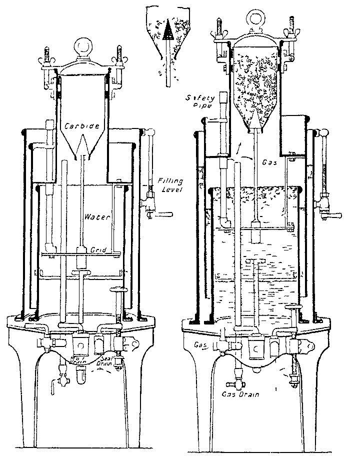
Maker: THE PHÔS CO., 205 AND 207 BALLS POND ROAD, LONDON, N. Type: Non-automatic; water-to-carbide; drip.
The type "E" generator made by this firm consists of a generating chamber placed below a water chamber having an opening with cap E for refilling. The generating chamber in closed by a door B, with rubber washer C, held in position by the rod A, the ends of which pass into slots, and the screw A'. The movable carbide chamber D has its upper perforated part half filled with carbide, which is pressed upwards by a spring D'. The carbide chamber when filled is placed in the generating chamber, which is closed, and the lever F of one of the taps F' is turned from "off" to "on," whereupon water drips from the tank on to the carbide. The evolution of gas is stopped by reversing the lever of the tap. The second tap is provided for use when the evolution of gas, through the water-supply from the first tap, has been stopped and it is desired to start the apparatus without waiting for water from the first tap to soak through a layer of spent carbide. The two taps are not intended for concurrent use. The evolved gas passes through a purifier containing any suitable purifying material to the pipes leading to the burners.
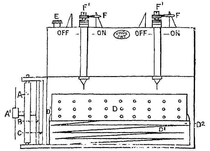
Maker: ROSCO ACETYLENE COMPANY, BELFAST.
Type: Non-automatic; carbide-to-water
The "Rosco" generating plant made by this firm comprises a generating tank A which is filled with water to a given level by means of the funnel-mouthed pipe B and the overflow O. On the top of the water-sealed lid of the generating tank is mounted the carbide feed-valve L, which consists of a hollow plug-tap with handle M. When the handle M is turned upwards the hollow of the tap can be filled from the top of the barrel with carbide. On giving the tap a third of a turn the hollow of the plug is cut off from the outer air and is opened to the generating tank so that the carbide contained in it is discharged over a distributor E on to the tray N in the water in the generating tank. The gas evolved passes through the scrubber and seal-pot J to the storage gasholder Q. From the latter the gas passes through the dry purifier T to the service-pipe. A sludge- cock P is provided at the bottom of the generating tank and is stated to be available for use while generation of gas is proceeding. The purifying material ordinarily supplied is "Roscoline."
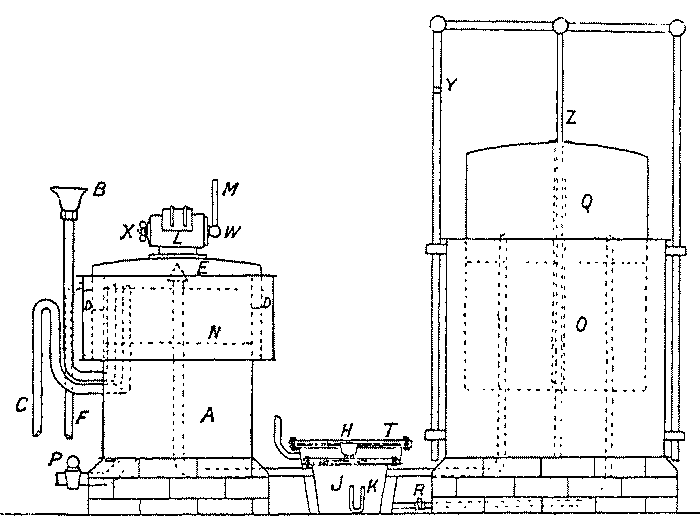
Maker: THE RURAL DISTRICTS GAS LIGHT CO., 28 VICTORIA STREET, S.W.
Type: Automatic; water-to-carbide; contact, superposed trays.
The "Signal-Arm" generating apparatus made by this firm comprises a bell gasholder A, from the tank B of which water is supplied through a swivelled pipe C to a generating chamber D. One end of the swivelled pipe is provided with a delivery nozzle, the other end is closed and counter-weighted, so that normally the open end of the pipe is raised above the level of the water in the tank. A tappet E on the bell of the gasholder comes into contact with, and depresses, the open end of the swivelled pipe when the bell falls below a certain point. As soon as the open end of the swivelled pipe has thus been lowered below the level of the water in the tank, water flows through it into the funnel-shaped mouth F of a pipe leading to the bottom of the generating chamber. The latter is filled with cages containing carbide, which is attacked by the water rising in the chamber. The gas evolved passing into and raising the bell of the gasholder causes the open end of the swivelled pipe to rise, through the weight of the counterpoise G, above the level of the water in the tank and so cuts off the supply of water to the generating chamber until the bell again descends and depresses the swivelled pipe. The tappet on the bell also displaces a cap H which covers the funnel-shaped mouth of the pipe leading to the generating chamber, which cap, except when the swivelled supply-pipe is being brought into play, prevents any extraneous moisture or other matter entering the mouth of the funnel. Between the generating chamber and the gasholder is a three-way cock J in the gas connexion, which, when the gasholder is shut off from the generator, brings the latter into communication with a vent-pipe K leading to the open. The gas passes from the holder to a chamber L under grids packed with purifying material, through which it passes to the outlet of the purifier and thence to the service-pipe. Either heratol or chloride of lime is used in the purifier, the lid of which, like the cover of the generator, is water-sealed.

Maker: ST. JAMES' ILLUMINATING CO., LTD., 3 VICTORIA STREET, LONDON, S.W.
Type: (1) Automatic; water-to-carbide; contact, superposed trays.
This plant consists of the generators A, the washer B, the equalising gasholder C, the purifier D, and the water-tank E. The carbide is arranged in baskets in the generators to which water is supplied from the cistern E through the pipe F. The supply is controlled by means of the valve H, which is actuated through the rod G by the rise and fall of the gasholder C. Gas travels from the gasholder through the purifier D to the service-pipe. The purifier is packed with heratol resting on a layer of pumice. The washer B contains a grid, the object of which is to distribute the stream of gas through the water. There is a syphon-pot J for the reception of condensed moisture. Taps K are provided for shutting off the supply of water from the generators during; recharging, and there is an overflow connexion L for conveying the water to the second generator as soon as the first is exhausted. There is a sludge-cock M at the base of each generator.
(2) Non-automatic; water-to-carbide; contact, superposed trays.
This resembles the preceding plant except that the supply of water from the cistern to the generators takes place directly through the pipe N (shown in dotted lines in the diagram) and is controlled by hand through the taps K. The automatic control-valve H and the rod G are omitted. The gasholder C is increased in size so that it becomes a storage holder capable of containing the whole of the gas evolved from one charging.

Maker: THE STANDARD ACETYLENE CO., 123 VICTORIA STREET, LONDON, S.W.
Type: (1) Non-automatic; carbide-to-water.
This plant comprises the generator A, the washer B, the storage gasholder C, and the purifier D. The generator is first filled with water to the crown of the cover, and carbide is then thrown into the water by hand through the gas-tight lock, which is opened and closed as required by the horizontal handle P. A cast-iron grid prevents the lumps of carbide falling into the sludge in the conical base of the generator. At the base of the cone is a sludge-valve G. The gas passes from the generator through the pipe H into the washer B, and after bubbling through the water therein goes by way of the pipe K into the gasholder C. The syphon- pot E is provided for the reception of condensed moisture, which is removed from time to time by the pump M. From the gasholder the gas flows through the valve R to the purifier D, whence it passes to the service-pipes. The purifier is charged with material supplied under the proprietary name of "Standard."

(2) Automatic; water-to-carbide; contact, superposed trays.
This plant comprises the generators A, the washer B, the equalising gasholder C, the purifier D, and the water-tank E. The carbide is arranged on a series of wire trays in each generator, to which water is supplied from the water-tank E through the pipe Y and the control-tap U. The gas passes through the pipes H to the washer B and thence to the holder C. The supply of water to the generators is controlled by the tap U which is actuated by the rise and fall of the gasholder bell through the rod F. The gas passes, as in the non-automatic plant, through a purifier D to the service-pipes. Taps W are provided for cutting off the flow of water to either of the generators during recharging and an overflow pipe h serves to convey the water to the second generator as soon as the carbide in the first is exhausted. A sludge-cook G is put at the base of each generator.

(3) Non-automatic; water-to-carbide; contact, superposed-trays.
This apparatus resembles the preceding except that the supply of water to the generators is controlled by hand through the taps W, the control valve U being omitted, and the gasholder C being a storage holder of sufficient dimensions to contain the whole of the acetylene evolved from one charging.
Maker: THORN AND HODDLE ACETYLENE CO., 151 VICTORIA STREET, S.W.
Type: Automatic; water-to-carbide; "drawer."
The "Incanto" generating plant made by this firm consists of a rising bell gasholder which acts mainly on an equaliser. The fall of the bell depresses a ball valve immersed in the tank, and so allows water to flow from the tank past an outside tap, which is closed only during recharging, to a generating chamber. The generating chamber is horizontal and is fixed in the base of the tank, so that its outer case is surrounded by the water in the tank, with the object of keeping it cool. The charge of carbide is placed in a partitioned container, and is gradually attacked on the flooding principle by the water which enters from the gasholder tank when the ball valve is depressed. The gas evolved passes from the generating chamber by a pipe which extends above the level of the water in the tank, and is then bent down so that its end dips several inches below the level of the water. The gas issuing from the end of the pipe is thus washed by the water in the gasholder tank. From the gasholder the gas is taken off as required for use by a pipe, the mouth of which is just below the crown of the holder. There is a lip in the upper edge of the gasholder tank into which water is poured from time to time to replace that consumed in the generation of the gas. There are from one to three generating chambers in each apparatus according to its size. The purifier is independent, and a purifying mixture under the proprietary name of "Curazo" is supplied for use in it.
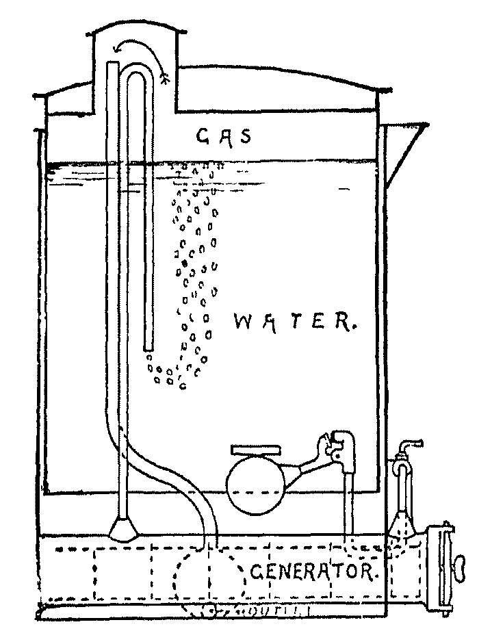
Maker: WELDREN AND BLERIOT, 54 LONG ACRE, LONDON, W.C.
Type: Automatic; contact.
This firm supplies the "Acétylithe" apparatus (see Belgium).
Absorbed acetylene,
Acagine,
Accidents, responsibility for,
Acetone, effect of, on acetylene,
  solution of acetylene in,
Acetylene-copper,
Acetylene-oil-gas,
Acetylene Association (Austrian)--regulations as to carbide,
Acetylene Association (British)--analysis of carbide,
  generator rules,
  pressure gauges,
  purification rules,
Acetylene Association (German)--analysis of carbide,
  holders,
  generator rules,
  standard carbide,
Acetylene tetrachloride, production of,
Ackermann burner,
Advantages of acetylene, general,
  hygienic,
  intrinsic,
  pecuniary,
"After generation,"
Air, admission of, to burners,
  and acetylene, ignition temperature of,
  composition of,
  dilution of acetylene with, before combustion,
  effect of acetylene lighting on,
    coal-gas lighting on,
    on illuminating power of acetylene,
    paraffin lighting on,
  in acetylene,
  in flames, effect of,
  in generators, danger of,
    objections to,
  in incandescent acetylene,
  in service-pipes,
  proportion of, rendering acetylene explosive,
  removing, from pipes,
  specific gravity of,
  sterilised by flames,
Air-gas,
  and acetylene, comparison between,
  and carburetted acetylene, comparison between,
  effect of cold on,
  illuminating power of,
Alcohol, action of, on carbide,
  for carburetting acetylene,
    holder seals,
  from acetylene, production of,
Allgemeine Carbid und Acetylen Gesellschaft burner,
Alloys, fusible, for testing generators,
Alloys of copper. See Copper (alloyed)
Aluminium sulphide, in carbide
America (U.S.), regulations of the National Board of Fire Underwriters,
American gallon, value of,
Ammonia, in acetylene,
  in coal-gas,
  removal of,
  solubility of, in water,
Analysis of carbide,
Ansdell, compressed and liquid acetylene,
Anthracene, formation of, from acetylene,
Anti-freezing agents,
Area of purifiers,
Argand burners,
Aromatic hydrocarbons,
Arrangement of generating plant,
Arsenious oxide purifier,
Atkins, dry process of generation,
Atmospheric moisture and carbide,
Atomic weights,
Attention needed by generators,
Austrian Acetylene Association, regulations as to carbide,
Austrian Government Regulations,
Autogenous soldering and welding,
Automatic generators. See Generators (automatic)


B

Baking of carbide
Ball-sockets for acetylene,
Barium peroxide purifier,
  sulphate in bleaching-powder,
Barrel, gas, for acetylene, quality of
Bell gasholders. See Holders (rising)
Benz purifying material,
Benzene,
  for carburetting acetylene,
  production of, from acetylene,
Benzine. See Petroleum spirit
Bergé, detection of phosphorus,
  and Reychler, purification of acetylene,
  and Reychler's reagent, solubility of acetylene in,
Bernat, formula for mains and pipes,
Berthelot, addition of chlorine to acetylene,
  sodium acetate,
  sulphuric acid and acetylene,
Berthelot and Matignon, thermochemical data,
  and Vieille, dissolved acetylene,
Billwiller burners,
Black, acetylene,
Blagden, sodium hypochlorite,
Bleaching-powder purifier (simple),
Blochmann, copper acetylide,
Blow-off pipes. See Vent-pipes
Blowpipe, acetylene,
Boiling-ring,
Boistelle. See Molet
Borek, enrichment of oil-gas,
Bougie décimale,
Brackets for acetylene,
Bradley, Read, and Jacobs, calcium carbophosphide,
Brame and Lewes, manganese carbide,
Bray burners,
British Acetylene Association. See Acetylene Association
(British),
  Fire Offices Committee Regulations,
  regulations. See Acetylene Association (British); Home Office;
    Orders in Council
Bromine-water purifier,
Bullier, effect of heat on burners,
  phosphorus in acetylene,
  and Maquenne purifier,
Bunsen burner, principle of,
Bunte, enrichment of oil-gas,
Burner orifices and gas density,
Burners,
  atmospheric,
    principle of,
  design of,
  glassware for,
  heating,
  incandescent,
    Ackermann,
    Allgemeine Carbid und Acetylen Gesellschaft,
    Bray,
    firing back in,
    Fouché,
    Günther's,
    illuminating power of,
    Jacob, Gebrüder,
    Keller and Knappich,
    Knappich,
    O.C.A.,
    pressure for,
    principles of construction of,
    Schimek,
    Sirius,
    Trendel,
    typical,
    Weber,
    Zenith,
  self-luminous,
    Argand,
    as standard of light,
    Billwiller,
    Bray,
    choking of,
    corrosion of,
    cycle,
      Falk, Stadelmann and Co.'s,
      Konette,
      Phôs,
      Wiener's,
    Dolan,
    Drake,
    effect of heat on,
    Elta,
    Falk, Stadelmann and Co.'s,
    firing back in,
    fish-tail,
    Forbes,
    Hannam's,
    illuminating power of,
 self-luminous injector,
    Javal,
    Kona,
    Luta,
    Naphey,
    Orka,
    Phôs,
    Pintsch,
    pressure for,
    rat-tail,
    Sansair,
    Schwarz's,
    Stadelmann,
    Suprema,
    twin, angle of impingement in,
      injector,
      non-injector,
    warping of,
    Wiener's,
    Wonder,
By-products, See also Residues


C


Cadenel, shape of incandescent acetylene mantle,
"Calcidum,"
Calcium carbide, action of heat on,
  action of non-aqueous liquids on,
  analysis of,
  and carbon bisulphide, reaction between,
  and hydroxide, reaction between,
  and ice, reaction between,
  and steam, reaction between,
  and water, reaction between,
  as drying material,
  baking of,
  balls and cartridges. See Cartridges
  bulk of,
  chemical properties of,
  crushing of,
  decomposition of,
    by solids containing water,
    heat evolved during,
    imperfect,
    speed of,
    temperature attained during,
  deterioration of, on storage,
  drums of,
  dust in,
  explosibility of,
  fire, risk of,
  formula for,
  granulated,
  heat-conducting power of,
    of formation of,
  impurities in,
  inertness of,
  in residues,
  physical properties of,
  purity of,
  quality, regulations as to,
  sale and purchase of, regulations as to,
  scented,
  shape of lumps of,
  sizes of,
  small, yield of gas from,
  specific gravity of,
    heat of,
  standard, British,
    German,
  "sticks,"
  storage regulations for,
  subdivided charges of,
  sundry uses of,
  swelling of, during decomposition,
  "treated,"
  yield of acetylene from,
Calcium carbophosphide,
Calcium chloride, cause of frothing in generators,
  for seals,
  purifier,
  solubility of acetylene in,
Calcium hydroxide,
  adhesion of, to carbide,
  and carbide, reaction between,
  milk of, solubility of acetylene in,
  physical properties of,
  space occupied by,
Calcium hypochlorite,
Calcium oxide,
  and water, reaction between,
  hydration of,
  hygroscopic nature of,
  physical properties of,
Calcium phosphide,
Calcium sulphide,
Calorie, definition of,
Calorific power of acetylene,
  various gases,
Candle-power. See Illuminating power
Capelle, illuminating power of acetylene,
Carbide. See Calcium carbide
Carbide-containers,
  air in,
  filling of,
  partitions in,
  water-jacketing,
Carbide-feed generators. See Generators (carbide-to-water)
Carbide impurities in acetylene,
Carbide-to-water generators. See Generators (carbide-to-water)
Carbides, mixed,
Carbolic acid, production of, from acetylene,
Carbon, combustion of, in flames,
  deposition of, in burners,
  gaseous, heat of combustion of,
  heat of combustion of,
    vaporisation of,
  pigment, production of,
Carbon bisulphide and acetylene, reaction between,
  and calcium carbide, reaction between,
  in coal-gas,
Carbon dioxide, addition of, to acetylene,
  dissociation of,
  effect of, on explosibility of acetylene,
  for removing air from pipes,
  heat of formation of,
  produced by respiration,
    benzene,
    coal-gas,
    in flame of acetylene,
Carbon monoxide, in acetylene,
  heat of combustion of,
  formation of,
  temperature of ignition of,
Carbonic acid. See Carbon dioxide
Carburetted acetylene, composition of,
  effect of cold on,
  illuminating power of,
  manufacture of,
  pecuniary value of,
Carburetted water-gas, enrichment of,
Carburine. See Petroleum spirit
Carlson, specific heat of carbide,
Caro, acetone vapour in acetylene,
  addition of petroleum spirit to generator water,
  air in incandescent acetylene,
  calorific power of gases,
  colour of incandescent acetylene,
  composition of mantles,
  durability of mantles,
  heat production in generators,
  illuminating power of carburetted acetylene,
    of incandescent acetylene,
  oil of mustard,
  silicon in crude acetylene,
Caro and Saulmann, "Calcidum,"
Carriage, cost of, and artificial lighting,
Cartridges of carbide,
Cast-iron pipe for acetylene,
Castor oil for acetylene joints,
Catani, temperature of acetylene flame,
Caustic potash purifier,
Cedercreutz, yield of gas from carbide,
  and Lunge, purification,
Ceilings, blackening of,
Ceria, proportion of, in mantles,
Cesspools for residues,
Chandeliers, hydraulic, for acetylene,
Charcoal and chlorine purifier,
Charging generators after dark,
  at irregular intervals,
Chassiron lighthouse,
Chemical formulæ, meaning of,
Chemical reactions and heat,
  of acetylene,
Chimneys for stoves, &c.,
  glass, for burners,
Chloride of lime. See Bleaching-powder
Chlorine and acetylene, compounds of,
  and charcoal purifier,
  in acetylene,
Chromic acid purifier,
Cigars, lighted, danger of,
Claude and Hess, dissolved acetylene,
Coal-gas, enrichment of, with acetylene,
  illuminating power of,
  impurities in,
  vitiation of air by,
Cocks, hand-worked, in generators,
Coefficient of expansion of acetone,
  air,
  dissolved acetylene,
  gaseous acetylene,
  liquid acetylene,
  simple gases,
Coefficient of friction of acetylene,
  of coal-gas,
Coke filters for acetylene,
Cold, effect of, on acetylene,
  on air-gas,
  on carburetted acetylene,
  on generation,
Colour judging by acetylene,
  of acetylene flame,
  of air-gas flame,
Colour of atmospheric acetylene flame,
  of coal-gas flame,
  of electric light,
  of incandescent acetylene flame,
  of spent carbide,
Combustion of acetylene,
  deposit from,
Composition pipe for acetylene,
Compounds, endo- and exo-thermic,
  explosive, of acetylene and copper,
"Compounds," of phosphorus and sulphur,
  silicon,
Compressed acetylene,
Condensed matter in pipes, removal of,
Condensers,
Connexions, flexible, for acetylene,
Construction of generators, principles of,
  regulations as to,
Contact generators,
Convection of heat,
Cooking-stoves,
Copper acetylide,
  (alloyed) in acetylene apparatus,
  (unalloyed) in acetylene apparatus,
  and acetylene, reactions between,
  carbides,
  chloride purifier
Corrosion in apparatus,
  avoidance of,
Corrosive sublimate purifier,
  as test for phosphorus
Cost of acetylene lighting,
Cotton-wool filters for acetylene,
Council, Orders in. See Orders in Council
Counterpoises for rising holders,
Couples, galvanic,
Coward. See Dixon
Critical pressure and temperature of acetylene,
Crushing of carbide,
"Cuprene,"
Cuprous chloride purifier,
Cycle lamps,
  burners for,
  dilute alcohol for,
Cylinders for absorbed acetylene,


D


Davy, addition of chlorine to acetylene,
Davy's lamp for generator sheds,
Decomposing vessels. See Carbide containers
Decomposition of acetylene,
  of carbide, See Calcium carbide (decomposition of)
De Forcrand, heat of formation of carbide,
Density. See Specific gravity
Deposit at burner orifices,
  on reflectors from combustion of acetylene,
Deterioration of carbide in air,
Diameter of pipes and explosive limits,
Diaphragms, flexible, in generators,
Diffusion through gasholder seals,
Diluted acetylene,
Dimensions of mains and pipes,
Dipping generators,
Displacement gasholders. See Holders (displacement)
Dissociation of acetylene,
  carbon dioxide,
  water vapour,
Dissolution of acetylene, depression of freezing-point by,
  of gas in generators,
Dissolved acetylene,
Dixon and Coward, ignition temperature of acetylene,
  of various gases,
Dolan burners,
Doors of generator sheds,
Drainage of mains,
Drake burners,
Driers, chemical,
Dripping generators,
Drums of carbide,
Dry process of generation,
Dufour, addition of air to acetylene,
"Dummies" in gasholder tanks,
Dust and incandescent lighting,
  in acetylene,
  carbide,


E


Effusion of gases,
Eitner, explosive limits of acetylene,
  and Keppeler, estimation of phosphine,
  phosphorus in crude acetylene,
Electric lamps in generator sheds,
  lighting, cost, and efficiency of,
Elta burner,
Endothermic compounds,
  nature of acetylene,
Engines, use of acetylene in,
Enrichment, value of acetylene for,
  with acetylene,
épurène purifying material,
Equations, chemical, meaning of,
Erdmann, acetylene as a standard of light,
  colour of acetylene flame,
  production of alcohol,
Ethylene, formation of from acetylene,
  heats of formation and combustion of,
  ignition temperature of,
Exhaustion of air by flames,
Exothermic compounds,
Expansion of gaseous acetylene, coefficient of,
  of liquid acetylene coefficient of,
  various coefficients of,
Explosibility of carbide,
Explosion of chlorine and acetylene,
  of compressed acetylene,
Explosive compounds of acetylene and copper,
  effects of acetylene dissociation,
  limits, meaning of term,
    of acetylene,
    of various gases,
  nature of acetylene,
  wave, speed of, in gases,
Expulsion of air from mains,


F


Faced joints for acetylene,
Falk, Stadelmann and Co., boiling-ring,
  burners,
  cycle-lamp burner,
Ferric hydroxide purifier,
Féry, temperature of flames,
  and Violle, acetylene as standard of light,
Filters for acetylene,
Filtration,
Fire Offices Committee Regulations (British),
  risks of acetylene apparatus,
    carbide,
    flame illuminants,
  Underwriters, United States, Regulations,
"Firing back" in incandescent burners,
  self-luminous burners,
Fish, action of lime on,
Fittings for acetylene, quality of,
Flame, colour of, air-gas,
  atmospheric acetylene,
  coal-gas,
  incandescent, acetylene,
  self-luminous acetylene,
Flame illuminants, risk of fire with,
  of acetylene containing air,
  steadiness of acetylene,
Flame temperature of acetylene,
  temperature of various gases,
Flames, distortion of, by solid matter,
  effect of air on,
    nitrogen on,
  evolution of heat in,
    light in,
  jumping of,
  liberation of carbon from,
  loss of heat from,
  shading of acetylene,
  size of,
Flare lamps,
Flash-point of paraffin,
Flexible connexions for acetylene,
Floats in holder seals,
Flooded-compartment generators,
Flow of gases in pipes,
Flues for heating burners,
Fog, transmission of light through,
Forbes burner,
Foreign regulations,
Formulæ, meaning of chemical,
Fouché, absorbed acetylene,
  burner,
  dissolved acetylene,
  illuminating power of acetylene air mixtures,
  incandescent acetylene,
  liquid acetylene,
  oxy-acetylene blowpipe,
Fournier. See Maneuvrier
Fowler, enrichment of oil-gas,
Fraenkel, deposit on reflectors from combustion of acetylene,
  silicon in acetylene,
France, regulations of the Conseil d'Hygiène de la Seine,
  village acetylene mains in,
Frank, freezing-point of calcium chloride solutions,
  preparation of black pigment,
  purifier,
Frankoline,
Freezing of generators,
  of holder seals,
Freezing of portable lamps,
  of pressure-gauges,
Freezing-point, depression of by dissolution of acetylene,
  of calcium chloride solutions,
  of dilute alcohol,
  of dilute glycerin,
Freund and Mai, copper acetylide,
Friction of acetylene, coefficient of,
  coal-gas, coefficient of,
  gas in pipes,
Frost, effect of, on air-gas,
  on carburetted acetylene,
Froth, lime, in acetylene,
Frothing in generators,
Fuchs and Schiff, olive oil,
Furnace gases for removing air from pipes,


G


Gallon, American, value of,
Galvanic action,
Garelli and Falciola, depression of freezing-point by dissolution of
   acetylene,
Gas barrel for acetylene, objection to,
  drying of,
  engines, acetylene for,
  escape of, from generators,
  firing, effects of,
  volumes, correction of, for temperature and pressure,
  yield of, from carbide,
    determining,
    standard,
Gases, calorific value of,
  effusion of,
  explosive limits of,
  flame temperature of,
  illuminating power of,
  inflammable properties of,
  speed of explosive wave in,
  temperature of ignition of,
Gasfitters' paint,
Gasholders. See Holders
Gatehouse, F. B., test-papers,
  J. W., estimation of phosphine,
Gaud, blocking of burners,
  polymerisation of acetylene,
Generation, dry process of,
Generating plant, regulations as to construction of,
Generator impurities in acetylene,
  pressure, utilisation of,
  sheds,
    lighting of,
    smoking in,
  water, addition of bleaching-powder to,
    of petroleum spirit to,
Generators and holders, isolation of,
  attention needed by,
Generators, charging after dark,
  chemical reactions in,
  construction of,
  copper in,
  corrosion in,
  dissolution of gas in,
  effect of tarry matter in,
  escape of gas from,
  failure of,
  for analytical purposes,
  for welding,
  frothing in,
  frozen, thawing of,
  gauge of sheet-metal for,
  heat dissipation in,
    economy in,
    produced in,
  high temperatures and impurities in,
  instructions for using,
  joints in, making,
  "lagging" for,
  lead solder in,
  materials for construction of,
  maximum pressure in,
  output of gas from,
  overheating in,
  polymerisation in,
  pressure in,
  protection of, from frost,
  purchase of,
  regulations as to,
    American (National Board of Fire Underwriters),
    Austrian Government,
    British Acetylene Association,
      Fire Offices Committee,
      Home Office Committee(1901),
    French (Council d' Hygiene de la Seine),
    German Acetylene Association,
    Hungarian Government,
    Italian Government,
  responsibility for accidents with,
  selection of,
  temperatures in,
  typical,
  vent-pipes for,
  waste-pipes for,
  water-jackets for,
  water-scale in,
Generators (automatic),
    advantages of,
    carbide-to-water,
    definition of,
    flexible diaphragms for,
    holders of,
    interlocking in,
    mechanism for,
    pressure thrown by,
    speed of reaction in,
    store of gas in,
    supply of water to,
    use of oil in,
    water-to-carbide,
    worked by holder bell,
      by pressure,
Generators (carbide-to-water),
    advantages of,
    frothing of,
    grids for,
    loss of gas in,
    maximum temperature in,
    pressure in,
    quantity of water required by,
Generators (contact),
  (dipping),
    temperatures in,
  (dripping),
    temperatures in,
  (flooded compartment),
  (non-automatic),
    advantages of,
    carbide-to-water,
      hand-charging of,
      water required for,
    definition of,
    speed of reaction in,
    water-to-carbide,
  (portable),
  (shoot),
  (water-to-carbide),
    overheating in,
  with carbide in excess,
  with water in excess,
Gerard, silicon in crude acetylene,
Gerdes, acetylene copper,
German Acetylene Association. (See Acetylene Association, German
Gin, heat of formation of carbide,
Glassware, for burners,
Glow-lamps, electric, in generator sheds,
Glucose for treatment of carbide,
Glycerin for holder-seals,
  for wet meters,
Governor, displacement holder as,
Governors,
Graham, effusion of gases,
Gramme-molecules,
Granjon, illuminating power of self-luminous burners,
  phosphine in acetylene,
  pressure,
  purifier,
Granulated carbide. See Calcium carbide, (granulated)
Graphite, artificial, production of,
Grease for treatment of carbide,
Grids for carbide-to-water generators,
  in purifiers,
Grittner, acetylene, and copper,
Guides for rising holders,
Güntner burner,


H


Haber, effect of heat on acetylene,
Haldane, toxicity of sulphuretted hydrogen,
Hammcrschmidt, correction of gas volumes,
  and Sandmann, milk of lime,
Hannam's Ltd., burners,
Hartmann, acetylene flame,
Haze, on combustion of acetylene,
Heat absorbed during change of physical state,
  action on acetylene. See Overheating
    carbide,
  and temperature, difference between,
  conducting power of carbide
    iron and steel,
    water,
  convected,
  developed by acetylene lighting,
    coal-gas lighting,
    electric lighting,
    paraffin lighting,
  dissipation of, in generators,
  economy in generators,
  effect of, on acetylene. (See Overheating)
    on burners,
  evolution of, in flames,
  expansion of gaseous acetylene by,
    liquid acetylene by,
  from acetylene, production of,
  latent. See Latent heat
  loss of, from flames,
  of chemical reactions,
  of combustion of acetylene,
    carbon,
    carbon monoxide,
    ethylene,
  of formation of acetylene,
    calcium carbide,
      hydroxide,
      oxide,
    carbon dioxide,
      monoxide,
    ethylene,
    water,
  of hydration of calcium oxide,
  of reaction between carbide and calcium hydroxide,
    between carbide and water,
  of solution of calcium hydroxide,
  of vaporisation of carbon,
    water,
  radiant,
  specific. See Specific heat
Heating apparatus for generator sheds,
Hefner unit,
Heil, atmospheric acetylene flame,
  carburetted acetylene,
Heise, acetylene flame,
Hempel, enrichment of coal-gas,
Heratol,
Hess. See Claude
Hexachlorethane, production of,
High houses, supply of acetylene to,
Holder-bells, for testing mains,
  supplying water to automatic generators,
  weighting of,
Holder-seals, freezing of,
  level of liquid in,
  liquids in,
    and pressure,
  solubility of acetylene in,
  use of floats in,
    liquids in, for decomposing carbide,
    oil in,
    water in, for washing the gas,
Holders (gas) and generators, isolation of,
  and pressure, relationship between,
  and purifiers, relative position of,
  exposed, roofs over,
  false interiors for,
  freezing of,
  gauge of sheet-metal for,
  loss of pressure in,
  moistening of gas in,
  of automatic generators,
  preservation of, from corrosion,
  situation of,
  size of,
  vent-pipes for,
  value of,
Holders (displacement),
    action of,
    pressure given by,
  (rising),
    guides and counterpoises for,
    pressure thrown by,
      equalisation of,
    tanks for,
Home Office, maximum pressure permitted by,
  prohibition of air in acetylene by,
  Committee, 1901, recommendations,
    report,
Home Secretary's Orders. See Orders in Council
Hoxie. See Stewart,
Hubou, acetylene black,
Hungarian rules for apparatus,
Hydraulic pendants for acetylene,
Hydrocarbons formed by polymerisation,
  illuminating power of,
  volatile, names of,
Hydrochloric acid in purified acetylene,
Hydrogen and acetylene, reactions between,
  effect of, on acetylene flame,
  ignition temperature of,
  in acetylene,
  liberated by heat from acetylene,
  silicide in crude acetylene,
Hygienic advantages of acetylene,


I


Ice, reaction between carbide and,
Ignition temperature of acetylene,
  various gases,
Illuminating power and illuminating effect,
  definition of,
  of acetylene, after storage,
    carburetted,
    effect of air on,
    incandescent,
    nominal,
    self-luminous,
  of acetylene-oil-gas,
  of air-gas,
  of polymerised acetylene,
  of candles,
  of coal-gas,
  of electric lamps,
  of hydrocarbons, various,
  of paraffin,
Illumination, amount of, required in rooms,
  of lighthouses,
  of optical lanterns,
Impurities in acetylene, carbide,
    detection and estimation of,
    effect of, on air,
  generator,
  harmfullness of,
  water soluble,
    See also Ammonia and Sulphuretted hydrogen
  in coal-gas,
  in purified acetylene,
    maximum limits of,
Incandescent acetylene,
  burners. See Burners (incandescent)
  mantles,
Inertness of carbide,
Inflaming-point of acetylene,
Inflammability, spontaneous,
Installations, new, removal of air from,
Interlocking of automatic generators,
Iron and acetylene, reactions between,
  and steel, heat-conducting power of,
  silicide in carbide,
Insecticide, carbide residues as,
Isolation of apparatus parts,
Intensity, specific, of acetylene light,
  of oil light,
Italian Government rules,


J


Jackets for generators,
Jacob, Gebrüder, burner,
Jacobs. See Bradley
Jaubert, arsenious oxide purifier,
Javal burners,
    blocking of,
  purifier,
Jet photometer of acetylene,
Joint-making in generators,
  pipes,


K


Keller and Knappich burner,
Keppeler, lead chromate in acagine,
Keppeler, purification,
  silicon in acetylene,
  test-papers,
  See also Eitner
Kerosene. See Paraffin oil
Klinger, vent-pipes,
Knappich burner,
Kona burner,
Konette cycle-lamp burner,


L


La Belle boiling ring,
Labour required in acetylene lighting,
Lagging for generators,
Lamps for generator sheds
  paraffin,
  portable,
    acetone process for,
Landolt-Börnstein, solubility of acetylene in water,
Landriset. See Rossel
Lantern, optical, illumination of,
Latent heat,
Lead chromate in bleaching-powder,
  objection to, in generators,
  pipes for acetylene,
  salts in bleaching-powder,
  wire, &c., for faced joints,
Leakage of acetylene,
Leaks, search for,
Le Chatelier, explosive limits,
  temperature of acetylene flame,
  thermo-couple
Leduc, specific gravity of acetylene,
Lépinay, acetylene for engines,
Level alteration and pressure in mains,
Lewes, ammonia in crude acetylene,
  blocking of burners,
  haze,
  heat of decomposition of carbide,
    production in generators,
  illuminating power of acetylene,
  phosphorus in crude acetylene,
  polymerisation of acetylene,
  presence of hydrogen and carbon monoxide in acetylene,
  reaction between carbide and calcium hydroxide,
  silicon in crude acetylene,
  temperature of acetylene flame,
Lewes and Brame, manganese carbide,
Lidholm, estimation of phosphine,
Lifebuoys, acetylene for,
Lifetime of burners,
  mantles,
Lifting power of acetylene in holders,
Light, acetylene as a standard of,
  colour of acetylene, incandescent,
    self-luminous,
  evolution of, in flames,
  from acetylene, production of,
  transmission of through fog,
Lights, single, disadvantages of,
  strong and weak, comparison between,
Lighthouse illumination,
Lighting by acetylene, scope of,
  of generator sheds,
Lime dust in acetylene,
  reaction with sodium carbonate,
  sludge. See Residues
  solubility of, in sugar solutions,
  water, solubility of gas in,
Lime-light, acetylene for the,
Limits, explosive, of acetylene,
Lindé-air,
Linseed oil for acetylene joints,
Liquid acetylene, properties of,
  condensation in pipes,
  in holder-seals and pressure,
  in pressure-gauge,
Liquids, corrosive action of, on metals,
  for seals,
  purification by,
  solubility of acetylene in,
Locomotive lighting,
Loss of gas in generators,
  of pressure in holders,
    in mains,
    in purifiers,
  on distribution,
Love, enrichment by acetylene,
Lubricating oil for seals,
Luminous burners. See Burners, self-luminous
Lunge and Cedercreutz, determination of phosphorus in acetylene,
    purification,
Luta burner,
Lutes for holders. See Seals


M


Mahler, temperature of flames,
Mai and Freund, copper acetylide,
Mains, deposition of liquid in,
  diameter of, and explosive limits,
  dimensions of,
  escapes from,
  friction in,
  laying of,
  lead,
  quality of,
  removing air from,
  testing of,
Make of acetylene from carbide,
  in generators,
Manchester burners,
Maneuvrier and Fournier, specific heat of acetylene,
Manganese carbide,
Mantles for acetylene,
Manure for generator protection,
Manurial value of generator residue,
Maquenne. See Bullier
Marsh gas, enrichment with acetylene,
  formed from acetylene,
Matignon. See Berthelot,
Mauricheau-Beaupré, épurène,
  estimation of phosphine,
  frothing in generators,
  phosphine in acetylene,
  silicon in acetylene,
Mechanism for automatic generators,
Mercaptans in acetylene,
Mercuric chloride purifier,
  test for phosphorus,
Merck test-papers,
Metals for generators,
  gauge of,
Meters for acetylene,
Methane, enrichment with acetylene,
  formed from acetylene,
  ignition temperature of,
Methylated spirit for generators,
  for holder seals,
Meyer and Münch, ignition temperatures,
Mildew in vines, use of acetylene in,
Milk of lime, solubility of acetylene in,
Mineral oil for lighting. (See Paraffin oil)
  for seals,
Miner's lamp for generator sheds,
Mist, transmission of light through,
Mixter, thermo-chemical data,
Mixtures of acetylene and air,
  illuminating duty of,
Moisture, effect of, on carbide,
  in acetylene,
Molecular volume of acetylene,
  weight of acetylene,
  weights, various,
Molet-Boistelle acetylene-air mixture,
Morel, formula for acetylene pipes,
  sodium plumbate purifier,
  specific heat of acetylene,
    of carbide,
Mosquitoes, destruction of,
Moths, catching of,
Motion of fluids in pipes,
Motors, acetylene for,
Münch. See Meyer
Münsterberg, acetylene flame,
Mustard, oil of,


N


Naphey burners,
Naphthalene, formation of, from acetylene,
Neuberg, illuminating power of acetylene,
  radiant efficiency of acetylene,
Nieuwland, mixtures of acetylene and chlorine,
Nichols, illuminating power of acetylene after storage,
  temperature of acetylene flame,
Nickel and acetylene, reactions between,
Nipples, burner, materials for,
Nitrides in carbide,
Nitrogen in flames, effect of,
Non-automatic generators. See Generators (non-automatic)
Non-luminous acetylene flame, appearance of,
  burners. See Burners (atmospheric)
Non-return valves,


O


O. C. A. burner,
Odour of acetylene,
Oil, action of, on carbide,
  castor, for acetylene joints,
  in generators,
  in residues,
  in seals,
  linseed, for acetylene joints,
  mustard,
  olive, for seals,
  (See also Paraffin oil)
Olive oil for seals,
Oil-gas, enrichment of,
Optical efficiency of acetylene,
Orders in Council, air in acetylene,
  compression of absorbed acetylene,
    acetylene-oil-gas,
    neat acetylene,
Origin of petroleum,
Orka burner,
Ortloff, friction of acetylene,
Overheating in generators,
  See also Polymerisation
Oxide of iron purifier,
Oxy-acetylene blowpipe,
Oxygen required for combustion of acetylene,
    of benzene,
  combustion of acetylene with,
  flames burning in,


P


Paint, cause of frothing in generators,
  gas-fitters',
Paraffin oil,
  action of, on carbide,
  flash-point of,
  illuminating power of,
  in residues,
  lamps,
  lighting, effect of on air,
    heat developed by,
  quality of different grades of,
  use of in automatic generators,
     seals,
Paraffin wax, treatment of carbide with,
Partial pressure,
Pendants, water-slide for acetylene,
Petroleum oil.  See Paraffin oil
  spirit, addition of, to generator water,
    composition of,
      for carburetted acetylene,
  spirits, nomenclature of,
  theory of origin of,
Pfeiffer, purifier,
Pfleger, puratylene,
Phenol, production of, from acetylene,
Phôs burners,
Phosphine, cause of deposit at burner orifices,
  composition of,
  in crude acetylene,
    amount of,
  toxicity of,
Phosphoretted hydrogen. See Phosphine
Phosphorus and incandescent mantles,
  "compounds,"
  in crude acetylene,
  in purified acetylene,
    detection and determination of,
    removal of,
"Phossy-jaw,"
Photometer, jet of acetylene,
Phylloxera, use of acetylene for,
Physical properties of acetylene,
Pickering, freezing-points of calcium chloride solutions,
Pictet, freezing-points of dilute alcohol,
  purification of acetylene,
Pintsch burners,
Pipes, blow-off. See Vent-pipes
  diameter of, and explosive limits,
    vent. See Vent-pipes (See also Mains)
Plant, acetylene, fire risks of,
  order of items in,
Platinum in burners,
Poisonous nature of acetylene,
Pole, motion of fluids in pipes,
  pressure thrown by holders,
Polymerisation, definition of,
  of acetylene,
    See also Overheating
Porous matter, absorption of acetylene in,
Portable lamps,
    acetone process for,
    temperature in,
Potassium bichromate purifier,
  hydroxide purifier,
  permanganate purifier,
Power from acetylene, production of,
Precautions with generators,
  with new installations,
Presence of moisture in acetylene,
Pressure and leakage,
  after explosions of acetylene,
  atmospheric,
  automatic generators working by,
  correction of gas volumes for,
  critical, of acetylene,
  definition of (gas),
  for incandescent burners,
    self-luminous burners,
  gauge,
    liquid for,
  given by displacement holders,
    rising holders,
  in generators,
    utilisation of,
  in mains and pipes,
  in purifiers, loss of,
  irregular, caused by vent-pipes,
  maximum safe, for acetylene,
  necessity for regular,
  partial,
  regulators. See Governors
Protection of generators from frost,
  holders from frost,
Puratylene,
Purchase of a generator,
  carbide, regulations as to,
Purification by liquids and solids,
  in portable lamps,
  necessary extent of,
  reasons for,
  regulations as to,
  speed of,
Purified acetylene, chlorine in,
    hydrochloric acid in,
    phosphorus in,
    sulphur in,
Purifiers and holder, relative positions of,
  construction of,
  duplication of,
  exhaustion of,
  foul, emptying of,
  loss of pressure in,
  mechanical, for acetylene,
Purifying materials, density of,
    efficiency of,
    quantity required,
Pyralid, destruction of the,


Q


Quality of carbide, regulations as to,
Quicklime. See Calcium oxide


R


Radiant efficiency of acetylene,
  heat,
Railway lighting by acetylene,
Ramie mantles for acetylene,
Range of explosibility, meaning of term,
    of acetylene,
Rat-tail burner,
Reactions between copper and acetylene,
  chemical, of acetylene,
  physical, of acetylene,
Reaction grids in generators,
Read and Jacobs. See Bradley
Rod lead for acetylene joints,
Regulations, American (National Board of Fire Underwriters of U.S.A.),
  Austrian Acetylene Association,
    Government,
  British Acetylene Association,
    Fire Offices Committee,
    Home Office Committee (1901),
  for analysis of carbide,
  for construction of generating plant,
  for generators,
  for purification,
  for sale and purchase of carbide,
  for sampling carbide,
  for storing carbide,
  French (Conseil d'Hygiène de la Seine),
  German Acetylene Association,
  Hungarian Government,
  Italian Government,
Residue from dry process of generation,
Residues, carbide in,
  colour of,
  composition of,
  consistency of,
  disposal of,
    containing oil,
  manurial value of,
  utilisation of,
Respiration of acetylene,
Reversibility of reaction between calcium oxide and water,
Reychler. See Bergé
Rising holders. See Holders (rising)
Rossel and Landriset, ammonia in crude acetylene,
  purifier,
  sulphur in crude acetylene,
Roofs over exposed holders,
Rooms, amount of illumination required in,
Rubber tubes for acetylene,
Ruby for burners,
Rules. See Regulations


S


Safety lamp, Davy's, for generator sheds,
  valves. See Vent-pipes
Sale of carbide, regulations as to,
Salt, common, in holder-seals,
Salzbergwerk Neu Stassfurt, production of tetrachlorethane,
Sampling carbide,
Sandmann. See Hammerschmidt
Sansair burner,
Saulmann. See Caro
Sawdust in bleaching-powder,
Scale, water, in generators,
Scented carbide,
Schiff. See Fuchs
Schimek burner,
Schwander, carburetted acetylene,
Schwarz burners,
Seal-pots,
Seals (holder). See Holder-seals
Seams in generator-making,
Self-luminous burners. See Burners (self-luminous)
Sensible heat,
Separation of holder from generator,
Service-pipes. See Mains
Shoot generators,
Silicon compounds,
  in acetylene,
  in carbide,
Sirius burner,
Slaked lime. See Calcium hydroxide
Sludge. See Residues
Sludge-cocks, automatic locking of,
Sludge-pipes, blocked, clearance of,
Smell of crude and purified acetylene,
Smith, purification,
Smoke, production of, by flames,
Smoking,  danger of, in generator sheds,
Soap, use of, in testing pipes,
Soda, washing, for decomposing carbide,
Sodium acetate solution for generator jackets,
Sodium carbonate and lime, reaction between,
    crystallised, for decomposing carbide,
  chloride for holder-seals,
    solubility of acetylene in,
  hypochlorite purifier,
  plumbate purifier,
  sulphate in bleaching-powder,
Soil, carbide residues as dressing for,
Solder in generators,
Soldering, autogenous,
Solids containing water, decomposition of carbide by,
  purification by,
Solubility of acetylene,
    in generators,
    in holders,
    in liquids,
Soot, production by, of flames,
Space occupied by purifying materials,
Sparks from steel tools, danger of,
Specific gravity and holder pressure,
      leakage,
    of acetylene, dissolved,
      gaseous,
      liquid,
    of air,
    of carbide,
    of gases, and burner construction,
    of water,
  heat of acetylene,
    of carbide,
  heats, various,
  intensity. See Intensity, specific
Speed of reactions between carbide, water, and calcium hydroxide,
  of purification,
Spent lime. See Residues
Spontaneous inflammability,
Spraying apparatus,
Stable manure for warming generators,
Stadelmann burners,
Standard of illumination in rooms,
  of light, acetylene as,
Steam, latent heat of, use of,
  specific heat of,
  reaction between carbide and,
Steam-barrel for acetylene mains,
Steatite for burners,
Steel, heat-conducting power of,
  tools, danger of
Sterilisation of air by flames,
Stewart and Hoxie, radiant efficiency of acetylene,
Storage regulations for carbide,
vessels for carbide, temporary,
Styrolene. formation of, from acetylene,
Suckert. See Willson
Suffocation by acetylene,
Sugar solutions, solubility of lime in,
Sulphur "compounds,"
  in coal-gas,
  in crude acetylene,
  in purified acetylene,
  removal of,
Sulphuretted hydrogen, solubility of, in water,
  toxicity of,
Sulphuric acid and acetylene, reactions between
  as purifying material,
Superficial area in purifiers,
Supply of water to automatic generators,
Suprenia burners,
Swelling of carbide during decomposition,
Symbols, chemical, meaning of,
Syphons for removing water,


T


Table-lamps, acetone process for,
Tabular numbers,
Tanks for rising holders, construction of,
"Tantalus Cup,"
Taps for acetylene pipes,
Tar, cause of frothing in generators,
Tarry matter in generators,
Telescopic gasholders. See Holder (rising)
Temperature and heat, difference between,
  correction of volumes for,
  critical, of acetylene,
  high, effect of, on acetylene. See Polymerization
  of acetylene blowpipe,
    flame,
  of dissociation of acetylene,
  of ignition of acetylene,
    various gases,
  of reaction between carbide and calcium hydroxide,
    between carbide and water,
Temperatures in generators,
    calculation of,
    determination of,
Tension of liquid acetylene,
Test-papers,
Tetrachlorethane, production of,
Tetrachloride, acetylene, production of,
Thawing of frozen apparatus,
Thermo-chemical data,
Thermo-couple, Le Chatelier's,
Thomson, radiant efficiency of acetylene,
  thermo-chemical data,
Tools, steel or iron, danger of,
Town supplies,
Toxicity of acetylene,
  of sulphur and phosphorus compounds,
Train-lighting by acetylene,
Treated carbide. See Calcium carbide (treated)
Trondol burner,
Tubes, diameter of, and explosive limits,
Tubes for acetylene. See Mains
Tubing, flexible, for acetylene,
Typical generators,


U


Ullmax purifier,
Unaccounted-for gas,
Underwriters, United States Fire,
United States. See America
Uses, sundry, for acetylene,


V


Valuation of carbide,
Value of acetylene, hygienic,
    enriching,
    pecuniary,
  of purifying materials,
Valves, screw-down, for generators,
Vapour, water, in acetylene, objections to,
  removal of,
  value of,
Vehicular lamps,
Ventilation of generator sheds,
Vent-pipes, economy of,
  for carbide vessels,
    generators,
    holders,
  noise in,
  position of mouths of,
  size of,
Vibration and incandescent lighting,
Vieille, dissolved acetylene,
Vigouroux, silicon in acetylene,
Village installations, mains for,
    leakage in,
  supplies,
Villard, liquid acetylene,
Vines, treatment by acetylene of, for mildew and phylloxera,
Violle and Féry, acetylene as standard of light,
Vitiation of air by flames,
Volume, alteration of, on dissociation,
  and weight of acetylene,
  molecular, of acetylene,
Volume of acetylene passing through pipes,
Volumes, gas, correction for temperature and pressure,


W


Washers, oil,
  water,
Waste-pipes of generators,
Water and calcium oxide, reaction between,
  and carbide, heat of reaction between,
  boiling-point, evolution of gas at,
  condensation of, in pipes,
  consumption of, in generators,
  convection currents in,
  freezing-point, evolution of gas at,
  heat absorbed in warming,
    conducting power of,
    of formation of,
  in excess, generators with,
  in holders, freezing of,
    use for decomposition,
    use for washing,
  jackets for generators,
  quality of, for portable generators,
  quantity required in carbide-to-water generators,
  scale in generators,
  solubility of acetylene in,
    of impurities in,
    of load in,
  specific gravity of,
  supply for automatic generators,
  non-automatic generators,
  yield of gas per unit of,
Water-gas, enrichment with acetylene,
Water-seals, as not-return valves,
  setting water-level in,
Water-slide pendants for acetylene,
Water-soluble impurities in acetylene,
  See also Ammonia and Sulphuretted hydrogen
Water-to-carbide generators. See Generators (water-to-carbide)
Water-vapour, dissociation of,
  existence of, at low temperatures,
  in acetylene, objections to,
    removal of,
    value of,
  reaction between carbide and,
Weber burner,
Wedding, enrichment of coal-gas,
Weed-killer, carbide residues as,
Weight and volume of acetylene,
Weights, atomic,
  molecular,
Welding, acetylene,
White lead, for acetylene joints,
Wiener burners,
Willgerodt, purification,
Willson and Suckert, liquid acetylene,
Windows in generator sheds,
Winter, manipulation of generators during,
Wöhler, addition of chlorine to acetylene,
Wolff, acetone in acetylene,
  illuminating power of acetylene,
  purifier,
  silicon in acetylene,
Wonder burner,
Work done in actuating automatic generators,


Y


Yield of gas, deficient, cause of,
  from carbide,
    determining,
    (British standard),
    (German standard),
  from water,


Z


Zenith burner,
A


"A" Generator (of Braby and Co., Ltd.),
"A1" generator (of Acetylene Corporation of Great Britain),
"A-to-Z" generator (of Acetylene Corporation of Great Britain),
Acetylene Corporation of Great Britain,
Acetylene Gas and Carbide of Calcium Co.,
Acetylene Illuminating Co., Ltd.,
"Acetylite" generator,
"Acétylithe" generator,
Acétylithe, Soc. An. de l',
Allen Co.,
"Allen" Flexible-tube generator,
"Allen" purifying material,
American generators,
Applications de l'Acétylène, La Soc. des.,
Austrian generator,
Automatic generators,


B


"B" generator (of Braby and Co., Ltd.),
Belgian generators,
Bon Accord Acetylene Gas Co.,
"Bon Accord" generator,
Braby, Frederick and Co., Ltd.,
British generators,


C


Canadian generators,
Carbide-to-water generators,
"Carburlen" purifying material,
Chloride of lime purifying material,
Colt Co., J. G.,
"Colt" generator,
Compartment, flooded, generator,
Contact generators,
Cork waste and wadding purifying material,
"Corporation Flexible Tube Generator,"
"Curaze" purifying material,


D


"Dargue" generator,
Dargue Acetylene Gas Co.,
Davis Acetylene Co.,
"Davis" generator,
Debruyne, L.,
Debruyne's generators,
Drawer generators,
Drip generator,
Drummond, J. and J.,


E


English generators,


F


Flooded compartment generator,
Fittings, Ltd.,
Frankoline purifying material,
French generators,


G


German generators,


H


Heratol, purifying material,


I


"Incanto" generator,
Irish generator,


J


"Javal" generator,


K


Keller and Knappich, G.m.b.H.,
"Klenzal" purifying material,
Klinger, Rich.,
Klinger's generator,
"Knappich" generator,


L


"L'Éclair" generator,
"L'Étoile" generator,
L'Hermite,
Lockerbie and Wilkinson,


M


Manchester Acetylene Gas Col., Ltd.,
Mangiameli, Fr. and Co.,
Moss, R. J. and Sons,
  "Semi-Non-Auto" generator,
  "Type A" generator,
  "Type B" generator,
  "Type C" generator,
Moyes Wm., and Sons,


N


Non-automatic generators,
Nordische Azetylen Industrie,


O


"Omega" generator,
Overberge, De Smet van,
"Owens" generator,
"Owens" purifying material,


P


Phôs Co.,
"Phôs Type E" generator,
"Photolithe" generator,
Photolithe, Soc. An. Belg de la,
Pumice purifying material,
Puratylene purifying material,
Purifying material, "Allen,"
  "Carburylen,"
  chloride of lime,
  coke and cotton, chemically treated,
  cork waste and wadding,
  "Curaze,"
  frankoline,
  heratol,
  "Klenzal,"
  "Owens,"
  pumice,
  puratylene,
  "Roscoline,"
  "Standard,"
  "Thorlite,"


R


Rosco Acetylene Co.,
"Rosco" generator,
"Roscoline" purifying material,
Rural Districts Gas Light Co.,


S


St. James' Illuminating Co., Ltd.,
Scotch generators,
Semi-automatic generator,
Siche Gas Co., Ltd.,
"Siche" generator,
"Signal-Arm" generator,
"Sirius" generator,
Sirius, Maison,
Standard Acetylene Co.,
"Standard" purifying material,
Sunlight Gas Machine Co.,
Superposed pans or trays,


T


"Thorlite" generator,
  purifying material,
Thorn and Hoddle Co.,
"Thorscar" generator,
Trays, superposed,


U


United States generators,


W


Wadding and cork waste purifying material,
Water-to-carbide generators,
Weldhen and Bleriot,
Welsh generator,
"Westminster" generator,
End of the Project Gutenberg EBook of Acetylene, The Principles Of Its
Generation And Use, by F. H. Leeds and W. J. Atkinson Butterfield

*** END OF THIS PROJECT GUTENBERG EBOOK ACETYLENE ***

***** This file should be named 8144-h.htm or 8144-h.zip *****
This and all associated files of various formats will be found in:
        http://www.gutenberg.org/8/1/4/8144/

Produced by Richard Prairie, Tonya Allen, Juliet Sutherland,
Charles Franks, and the Online Distributed Proofreading Team


Updated editions will replace the previous one--the old editions
will be renamed.

Creating the works from public domain print editions means that no
one owns a United States copyright in these works, so the Foundation
(and you!) can copy and distribute it in the United States without
permission and without paying copyright royalties.  Special rules,
set forth in the General Terms of Use part of this license, apply to
copying and distributing Project Gutenberg-tm electronic works to
protect the PROJECT GUTENBERG-tm concept and trademark.  Project
Gutenberg is a registered trademark, and may not be used if you
charge for the eBooks, unless you receive specific permission.  If you
do not charge anything for copies of this eBook, complying with the
rules is very easy.  You may use this eBook for nearly any purpose
such as creation of derivative works, reports, performances and
research.  They may be modified and printed and given away--you may do
practically ANYTHING with public domain eBooks.  Redistribution is
subject to the trademark license, especially commercial
redistribution.


*** START: FULL LICENSE ***

THE FULL PROJECT GUTENBERG LICENSE
PLEASE READ THIS BEFORE YOU DISTRIBUTE OR USE THIS WORK

To protect the Project Gutenberg-tm mission of promoting the free
distribution of electronic works, by using or distributing this work
(or any other work associated in any way with the phrase "Project
Gutenberg"), you agree to comply with all the terms of the Full Project
Gutenberg-tm License available with this file or online at
  www.gutenberg.org/license.


Section 1.  General Terms of Use and Redistributing Project Gutenberg-tm
electronic works

1.A.  By reading or using any part of this Project Gutenberg-tm
electronic work, you indicate that you have read, understand, agree to
and accept all the terms of this license and intellectual property
(trademark/copyright) agreement.  If you do not agree to abide by all
the terms of this agreement, you must cease using and return or destroy
all copies of Project Gutenberg-tm electronic works in your possession.
If you paid a fee for obtaining a copy of or access to a Project
Gutenberg-tm electronic work and you do not agree to be bound by the
terms of this agreement, you may obtain a refund from the person or
entity to whom you paid the fee as set forth in paragraph 1.E.8.

1.B.  "Project Gutenberg" is a registered trademark.  It may only be
used on or associated in any way with an electronic work by people who
agree to be bound by the terms of this agreement.  There are a few
things that you can do with most Project Gutenberg-tm electronic works
even without complying with the full terms of this agreement.  See
paragraph 1.C below.  There are a lot of things you can do with Project
Gutenberg-tm electronic works if you follow the terms of this agreement
and help preserve free future access to Project Gutenberg-tm electronic
works.  See paragraph 1.E below.

1.C.  The Project Gutenberg Literary Archive Foundation ("the Foundation"
or PGLAF), owns a compilation copyright in the collection of Project
Gutenberg-tm electronic works.  Nearly all the individual works in the
collection are in the public domain in the United States.  If an
individual work is in the public domain in the United States and you are
located in the United States, we do not claim a right to prevent you from
copying, distributing, performing, displaying or creating derivative
works based on the work as long as all references to Project Gutenberg
are removed.  Of course, we hope that you will support the Project
Gutenberg-tm mission of promoting free access to electronic works by
freely sharing Project Gutenberg-tm works in compliance with the terms of
this agreement for keeping the Project Gutenberg-tm name associated with
the work.  You can easily comply with the terms of this agreement by
keeping this work in the same format with its attached full Project
Gutenberg-tm License when you share it without charge with others.

1.D.  The copyright laws of the place where you are located also govern
what you can do with this work.  Copyright laws in most countries are in
a constant state of change.  If you are outside the United States, check
the laws of your country in addition to the terms of this agreement
before downloading, copying, displaying, performing, distributing or
creating derivative works based on this work or any other Project
Gutenberg-tm work.  The Foundation makes no representations concerning
the copyright status of any work in any country outside the United
States.

1.E.  Unless you have removed all references to Project Gutenberg:

1.E.1.  The following sentence, with active links to, or other immediate
access to, the full Project Gutenberg-tm License must appear prominently
whenever any copy of a Project Gutenberg-tm work (any work on which the
phrase "Project Gutenberg" appears, or with which the phrase "Project
Gutenberg" is associated) is accessed, displayed, performed, viewed,
copied or distributed:

This eBook is for the use of anyone anywhere at no cost and with
almost no restrictions whatsoever.  You may copy it, give it away or
re-use it under the terms of the Project Gutenberg License included
with this eBook or online at www.gutenberg.org

1.E.2.  If an individual Project Gutenberg-tm electronic work is derived
from the public domain (does not contain a notice indicating that it is
posted with permission of the copyright holder), the work can be copied
and distributed to anyone in the United States without paying any fees
or charges.  If you are redistributing or providing access to a work
with the phrase "Project Gutenberg" associated with or appearing on the
work, you must comply either with the requirements of paragraphs 1.E.1
through 1.E.7 or obtain permission for the use of the work and the
Project Gutenberg-tm trademark as set forth in paragraphs 1.E.8 or
1.E.9.

1.E.3.  If an individual Project Gutenberg-tm electronic work is posted
with the permission of the copyright holder, your use and distribution
must comply with both paragraphs 1.E.1 through 1.E.7 and any additional
terms imposed by the copyright holder.  Additional terms will be linked
to the Project Gutenberg-tm License for all works posted with the
permission of the copyright holder found at the beginning of this work.

1.E.4.  Do not unlink or detach or remove the full Project Gutenberg-tm
License terms from this work, or any files containing a part of this
work or any other work associated with Project Gutenberg-tm.

1.E.5.  Do not copy, display, perform, distribute or redistribute this
electronic work, or any part of this electronic work, without
prominently displaying the sentence set forth in paragraph 1.E.1 with
active links or immediate access to the full terms of the Project
Gutenberg-tm License.

1.E.6.  You may convert to and distribute this work in any binary,
compressed, marked up, nonproprietary or proprietary form, including any
word processing or hypertext form.  However, if you provide access to or
distribute copies of a Project Gutenberg-tm work in a format other than
"Plain Vanilla ASCII" or other format used in the official version
posted on the official Project Gutenberg-tm web site (www.gutenberg.org),
you must, at no additional cost, fee or expense to the user, provide a
copy, a means of exporting a copy, or a means of obtaining a copy upon
request, of the work in its original "Plain Vanilla ASCII" or other
form.  Any alternate format must include the full Project Gutenberg-tm
License as specified in paragraph 1.E.1.

1.E.7.  Do not charge a fee for access to, viewing, displaying,
performing, copying or distributing any Project Gutenberg-tm works
unless you comply with paragraph 1.E.8 or 1.E.9.

1.E.8.  You may charge a reasonable fee for copies of or providing
access to or distributing Project Gutenberg-tm electronic works provided
that

- You pay a royalty fee of 20% of the gross profits you derive from
     the use of Project Gutenberg-tm works calculated using the method
     you already use to calculate your applicable taxes.  The fee is
     owed to the owner of the Project Gutenberg-tm trademark, but he
     has agreed to donate royalties under this paragraph to the
     Project Gutenberg Literary Archive Foundation.  Royalty payments
     must be paid within 60 days following each date on which you
     prepare (or are legally required to prepare) your periodic tax
     returns.  Royalty payments should be clearly marked as such and
     sent to the Project Gutenberg Literary Archive Foundation at the
     address specified in Section 4, "Information about donations to
     the Project Gutenberg Literary Archive Foundation."

- You provide a full refund of any money paid by a user who notifies
     you in writing (or by e-mail) within 30 days of receipt that s/he
     does not agree to the terms of the full Project Gutenberg-tm
     License.  You must require such a user to return or
     destroy all copies of the works possessed in a physical medium
     and discontinue all use of and all access to other copies of
     Project Gutenberg-tm works.

- You provide, in accordance with paragraph 1.F.3, a full refund of any
     money paid for a work or a replacement copy, if a defect in the
     electronic work is discovered and reported to you within 90 days
     of receipt of the work.

- You comply with all other terms of this agreement for free
     distribution of Project Gutenberg-tm works.

1.E.9.  If you wish to charge a fee or distribute a Project Gutenberg-tm
electronic work or group of works on different terms than are set
forth in this agreement, you must obtain permission in writing from
both the Project Gutenberg Literary Archive Foundation and Michael
Hart, the owner of the Project Gutenberg-tm trademark.  Contact the
Foundation as set forth in Section 3 below.

1.F.

1.F.1.  Project Gutenberg volunteers and employees expend considerable
effort to identify, do copyright research on, transcribe and proofread
public domain works in creating the Project Gutenberg-tm
collection.  Despite these efforts, Project Gutenberg-tm electronic
works, and the medium on which they may be stored, may contain
"Defects," such as, but not limited to, incomplete, inaccurate or
corrupt data, transcription errors, a copyright or other intellectual
property infringement, a defective or damaged disk or other medium, a
computer virus, or computer codes that damage or cannot be read by
your equipment.

1.F.2.  LIMITED WARRANTY, DISCLAIMER OF DAMAGES - Except for the "Right
of Replacement or Refund" described in paragraph 1.F.3, the Project
Gutenberg Literary Archive Foundation, the owner of the Project
Gutenberg-tm trademark, and any other party distributing a Project
Gutenberg-tm electronic work under this agreement, disclaim all
liability to you for damages, costs and expenses, including legal
fees.  YOU AGREE THAT YOU HAVE NO REMEDIES FOR NEGLIGENCE, STRICT
LIABILITY, BREACH OF WARRANTY OR BREACH OF CONTRACT EXCEPT THOSE
PROVIDED IN PARAGRAPH 1.F.3.  YOU AGREE THAT THE FOUNDATION, THE
TRADEMARK OWNER, AND ANY DISTRIBUTOR UNDER THIS AGREEMENT WILL NOT BE
LIABLE TO YOU FOR ACTUAL, DIRECT, INDIRECT, CONSEQUENTIAL, PUNITIVE OR
INCIDENTAL DAMAGES EVEN IF YOU GIVE NOTICE OF THE POSSIBILITY OF SUCH
DAMAGE.

1.F.3.  LIMITED RIGHT OF REPLACEMENT OR REFUND - If you discover a
defect in this electronic work within 90 days of receiving it, you can
receive a refund of the money (if any) you paid for it by sending a
written explanation to the person you received the work from.  If you
received the work on a physical medium, you must return the medium with
your written explanation.  The person or entity that provided you with
the defective work may elect to provide a replacement copy in lieu of a
refund.  If you received the work electronically, the person or entity
providing it to you may choose to give you a second opportunity to
receive the work electronically in lieu of a refund.  If the second copy
is also defective, you may demand a refund in writing without further
opportunities to fix the problem.

1.F.4.  Except for the limited right of replacement or refund set forth
in paragraph 1.F.3, this work is provided to you 'AS-IS', WITH NO OTHER
WARRANTIES OF ANY KIND, EXPRESS OR IMPLIED, INCLUDING BUT NOT LIMITED TO
WARRANTIES OF MERCHANTABILITY OR FITNESS FOR ANY PURPOSE.

1.F.5.  Some states do not allow disclaimers of certain implied
warranties or the exclusion or limitation of certain types of damages.
If any disclaimer or limitation set forth in this agreement violates the
law of the state applicable to this agreement, the agreement shall be
interpreted to make the maximum disclaimer or limitation permitted by
the applicable state law.  The invalidity or unenforceability of any
provision of this agreement shall not void the remaining provisions.

1.F.6.  INDEMNITY - You agree to indemnify and hold the Foundation, the
trademark owner, any agent or employee of the Foundation, anyone
providing copies of Project Gutenberg-tm electronic works in accordance
with this agreement, and any volunteers associated with the production,
promotion and distribution of Project Gutenberg-tm electronic works,
harmless from all liability, costs and expenses, including legal fees,
that arise directly or indirectly from any of the following which you do
or cause to occur: (a) distribution of this or any Project Gutenberg-tm
work, (b) alteration, modification, or additions or deletions to any
Project Gutenberg-tm work, and (c) any Defect you cause.


Section  2.  Information about the Mission of Project Gutenberg-tm

Project Gutenberg-tm is synonymous with the free distribution of
electronic works in formats readable by the widest variety of computers
including obsolete, old, middle-aged and new computers.  It exists
because of the efforts of hundreds of volunteers and donations from
people in all walks of life.

Volunteers and financial support to provide volunteers with the
assistance they need are critical to reaching Project Gutenberg-tm's
goals and ensuring that the Project Gutenberg-tm collection will
remain freely available for generations to come.  In 2001, the Project
Gutenberg Literary Archive Foundation was created to provide a secure
and permanent future for Project Gutenberg-tm and future generations.
To learn more about the Project Gutenberg Literary Archive Foundation
and how your efforts and donations can help, see Sections 3 and 4
and the Foundation information page at www.gutenberg.org


Section 3.  Information about the Project Gutenberg Literary Archive
Foundation

The Project Gutenberg Literary Archive Foundation is a non profit
501(c)(3) educational corporation organized under the laws of the
state of Mississippi and granted tax exempt status by the Internal
Revenue Service.  The Foundation's EIN or federal tax identification
number is 64-6221541.  Contributions to the Project Gutenberg
Literary Archive Foundation are tax deductible to the full extent
permitted by U.S. federal laws and your state's laws.

The Foundation's principal office is located at 4557 Melan Dr. S.
Fairbanks, AK, 99712., but its volunteers and employees are scattered
throughout numerous locations.  Its business office is located at 809
North 1500 West, Salt Lake City, UT 84116, (801) 596-1887.  Email
contact links and up to date contact information can be found at the
Foundation's web site and official page at www.gutenberg.org/contact

For additional contact information:
     Dr. Gregory B. Newby
     Chief Executive and Director
     gbnewby@pglaf.org

Section 4.  Information about Donations to the Project Gutenberg
Literary Archive Foundation

Project Gutenberg-tm depends upon and cannot survive without wide
spread public support and donations to carry out its mission of
increasing the number of public domain and licensed works that can be
freely distributed in machine readable form accessible by the widest
array of equipment including outdated equipment.  Many small donations
($1 to $5,000) are particularly important to maintaining tax exempt
status with the IRS.

The Foundation is committed to complying with the laws regulating
charities and charitable donations in all 50 states of the United
States.  Compliance requirements are not uniform and it takes a
considerable effort, much paperwork and many fees to meet and keep up
with these requirements.  We do not solicit donations in locations
where we have not received written confirmation of compliance.  To
SEND DONATIONS or determine the status of compliance for any
particular state visit www.gutenberg.org/donate

While we cannot and do not solicit contributions from states where we
have not met the solicitation requirements, we know of no prohibition
against accepting unsolicited donations from donors in such states who
approach us with offers to donate.

International donations are gratefully accepted, but we cannot make
any statements concerning tax treatment of donations received from
outside the United States.  U.S. laws alone swamp our small staff.

Please check the Project Gutenberg Web pages for current donation
methods and addresses.  Donations are accepted in a number of other
ways including checks, online payments and credit card donations.
To donate, please visit:  www.gutenberg.org/donate


Section 5.  General Information About Project Gutenberg-tm electronic
works.

Professor Michael S. Hart was the originator of the Project Gutenberg-tm
concept of a library of electronic works that could be freely shared
with anyone.  For forty years, he produced and distributed Project
Gutenberg-tm eBooks with only a loose network of volunteer support.

Project Gutenberg-tm eBooks are often created from several printed
editions, all of which are confirmed as Public Domain in the U.S.
unless a copyright notice is included.  Thus, we do not necessarily
keep eBooks in compliance with any particular paper edition.

Most people start at our Web site which has the main PG search facility:

     www.gutenberg.org

This Web site includes information about Project Gutenberg-tm,
including how to make donations to the Project Gutenberg Literary
Archive Foundation, how to help produce our new eBooks, and how to
subscribe to our email newsletter to hear about new eBooks.