Project Gutenberg's The Radio Amateur's Hand Book, by A. Frederick Collins

This eBook is for the use of anyone anywhere at no cost and with
almost no restrictions whatsoever.  You may copy it, give it away or
re-use it under the terms of the Project Gutenberg License included
with this eBook or online at www.gutenberg.org


Title: The Radio Amateur's Hand Book

Author: A. Frederick Collins

Posting Date: March 21, 2013 [EBook #6934]
Release Date: November, 2004
First Posted: February 13, 2003

Language: English

Character set encoding: ISO-8859-1

*** START OF THIS PROJECT GUTENBERG EBOOK THE RADIO AMATEUR'S HAND BOOK ***


Produced by Alan Millar and the Online Distributed Proofreading Team.
THE RADIO AMATEUR'S HAND BOOK
| Photograph unavailable |
| A. Frederick Collins, Inventor of the Wireless Telephone, 1899. Awarded Gold Medal for same, Alaska Yukon Pacific Exposition, 1909. |
A Complete, Authentic and Informative Work on Wireless Telegraphy and Telephony
BY
FREDERICK COLLINS
Inventor of the Wireless Telephone 1899; Historian of Wireless 1901-1910; Author of "Wireless Telegraphy" 1905
1922
TO
WILLIAM MARCONI
INVENTOR OF THE WIRELESS TELEGRAPH
Before delving into the mysteries of receiving and sending messages without wires, a word as to the history of the art and its present day applications may be of service. While popular interest in the subject has gone forward by leaps and bounds within the last two or three years, it has been a matter of scientific experiment for more than a quarter of a century.
The wireless telegraph was invented by William Marconi, at Bologna, Italy, in 1896, and in his first experiments he sent dot and dash signals to a distance of 200 or 300 feet. The wireless telephone was invented by the author of this book at Narberth, Penn., in 1899, and in his first experiments the human voice was transmitted to a distance of three blocks.
The first vital experiments that led up to the invention of the wireless telegraph were made by Heinrich Hertz, of Germany, in 1888 when he showed that the spark of an induction coil set up electric oscillations in an open circuit, and that the energy of these waves was, in turn, sent out in the form of electric waves. He also showed how they could be received at a distance by means of a ring detector, which he called a resonator.
In 1890, Edward Branly, of France, showed that metal filings in a tube cohered when electric waves acted on them, and this device he termed a radio conductor; this was improved upon by Sir Oliver Lodge, who called it a coherer. In 1895, Alexander Popoff, of Russia, constructed a receiving set for the study of atmospheric electricity, and this arrangement was the earliest on record of the use of a detector connected with an aerial and the earth.
Marconi was the first to connect an aerial to one side of a spark gap and a ground to the other side of it. He used an induction coil to energize the spark gap, and a telegraph key in the primary circuit to break up the current into signals. Adding a Morse register, which printed the dot and dash messages on a tape, to the Popoff receptor he produced the first system for sending and receiving wireless telegraph messages.
| Photograph unavailable |
| Collins' Wireless Telephone Exhibited at the Madison Square Garden, October 1908. |
After Marconi had shown the world how to telegraph without connecting wires it would seem, on first thought, to be an easy matter to telephone without wires, but not so, for the electric spark sets up damped and periodic oscillations and these cannot be used for transmitting speech. Instead, the oscillations must be of constant amplitude and continuous. That a direct current arc light transforms a part of its energy into electric oscillations was shown by Firth and Rogers, of England, in 1893.
The author was the first to connect an arc lamp with an aerial and a ground, and to use a microphone transmitter to modulate the sustained oscillations so set up. The receiving apparatus consisted of a variable contact, known as a pill-box detector, which Sir Oliver Lodge had devised, and to this was connected an Ericsson telephone receiver, then the most sensitive made. A later improvement for setting up sustained oscillations was the author's rotating oscillation arc.
Since those memorable days of more than two decades ago, wonderful advances have been made in both of these methods of transmitting intelligence, and the end is as yet nowhere in sight. Twelve or fifteen years ago the boys began to get fun out of listening-in to what the ship and shore stations were sending and, further, they began to do a little sending on their own account. These youngsters, who caused the professional operators many a pang, were the first wireless amateurs, and among them experts were developed who are foremost in the practice of the art today.
Away back there, the spark coil and the arc lamp were the only known means for setting up oscillations at the sending end, while the electrolytic and crystal detectors were the only available means for the amateur to receive them. As it was next to impossible for a boy to get a current having a high enough voltage for operating an oscillation arc lamp, wireless telephony was out of the question for him, so he had to stick to the spark coil transmitter which needed only a battery current to energize it, and this, of course, limited him to sending Morse signals. As the electrolytic detector was cumbersome and required a liquid, the crystal detector which came into being shortly after was just as sensitive and soon displaced the former, even as this had displaced the coherer.
A few years ahead of these amateurs, that is to say in 1905, J. A. Fleming, of England, invented the vacuum tube detector, but ten more years elapsed before it was perfected to a point where it could compete with the crystal detector. Then its use became general and workers everywhere sought to, and did improve it. Further, they found that the vacuum tube would not only act as a detector, but that if energized by a direct current of high voltage it would set up sustained oscillations like the arc lamp, and the value of sustained oscillations for wireless telegraphy as well as wireless telephony had already been discovered.
The fact that the vacuum tube oscillator requires no adjustment of its elements, that its initial cost is much less than the oscillation arc, besides other considerations, is the reason that it popularized wireless telephony; and because continuous waves have many advantages over periodic oscillations is the reason the vacuum tube oscillator is replacing the spark coil as a wireless telegraph transmitter. Moreover, by using a number of large tubes in parallel, powerful oscillations can be set up and, hence, the waves sent out are radiated to enormous distances.
While oscillator tubes were being experimented with in the research laboratories of the General Electric, the Westinghouse, the Radio Corporation of America, and other big companies, all the youthful amateurs in the country had learned that by using a vacuum tube as a detector they could easily get messages 500 miles away. The use of these tubes as amplifiers also made it possible to employ a loud speaker, so that a room, a hall, or an out-of-door audience could hear clearly and distinctly everything that was being sent out.
The boy amateur had only to let father or mother listen-in, and they were duly impressed when he told them they were getting it from KDKA (the Pittsburgh station of the Westinghouse Co.), for was not Pittsburgh 500 miles away! And so they, too, became enthusiastic wireless amateurs. This new interest of the grown-ups was at once met not only by the manufacturers of apparatus with complete receiving and sending sets, but also by the big companies which began broadcasting regular programs consisting of music and talks on all sorts of interesting subjects.
This is the wireless, or radio, as the average amateur knows it today. But it is by no means the limit of its possibilities. On the contrary, we are just beginning to realize what it may mean to the human race. The Government is now utilizing it to send out weather, crop and market reports. Foreign trade conditions are being reported. The Naval Observatory at Arlington is wirelessing time signals.
Department stores are beginning to issue programs and advertise by radio! Cities are also taking up such programs, and they will doubtless be included soon among the regular privileges of the tax-payers. Politicians address their constituents. Preachers reach the stay-at-homes. Great singers thrill thousands instead of hundreds. Soon it will be possible to hear the finest musical programs, entertainers, and orators, without budging from one's easy chair.
In the World War wireless proved of inestimable value. Airplanes, instead of flying aimlessly, kept in constant touch with headquarters. Bodies of troops moved alertly and intelligently. Ships at sea talked freely, over hundreds of miles. Scouts reported. Everywhere its invisible aid was invoked.
In time of peace, however, it has proved and will prove the greatest servant of mankind. Wireless messages now go daily from continent to continent, and soon will go around the world with the same facility. Ships in distress at sea can summon aid. Vessels everywhere get the day's news, even to baseball scores. Daily new tasks are being assigned this tireless, wireless messenger.
Messages have been sent and received by moving trains, the Lackawanna and the Rock Island railroads being pioneers in this field. Messages have also been received by automobiles, and one inventor has successfully demonstrated a motor car controlled entirely by wireless. This method of communication is being employed more and more by newspapers. It is also of great service in reporting forest fires.
Colleges are beginning to take up the subject, some of the first being Tufts College, Hunter College, Princeton, Yale, Harvard, and Columbia, which have regularly organized departments for students in wireless.
Instead of the unwieldy and formidable looking apparatus of a short time ago, experimenters are now vying with each other in making small or novel equipment. Portable sets of all sorts are being fashioned, from one which will go into an ordinary suitcase, to one so small it will easily slip into a Brownie camera. One receiver depicted in a newspaper was one inch square! Another was a ring for the finger, with a setting one inch by five-eighths of an inch, and an umbrella as a "ground." Walking sets with receivers fastened to one's belt are also common. Daily new novelties and marvels are announced.
Meanwhile, the radio amateur to whom this book is addressed may have his share in the joys of wireless. To get all of these good things out of the ether one does not need a rod or a gun--only a copper wire made fast at either end and a receiving set of some kind. If you are a sheer beginner, then you must be very careful in buying your apparatus, for since the great wave of popularity has washed wireless into the hearts of the people, numerous companies have sprung up and some of these are selling the veriest kinds of junk.
And how, you may ask, are you going to be able to know the good from the indifferent and bad sets? By buying a make of a firm with an established reputation. I have given a few offhand at the end of this book. Obviously there are many others of merit--so many, indeed, that it would be quite impossible to get them all in such a list, but these will serve as a guide until you can choose intelligently for yourself.
F. C.
CHAPTER
Kinds of Wireless Systems--Parts of a Wireless System--The Easiest Way to Start--About Aerial Wire Systems--About the Receiving Apparatus--About Transmitting Stations--Kinds of Transmitters--The Spark Gap Wireless Telegraph Transmitter--The Vacuum Table Telegraph Transmitter--The Wireless Telephone Transmitter.
Kinds of Aerial Wire Systems--How to Put Up a Cheap Receiving Aerial--A Two-wire Aerial--Connecting in the Ground--How to Put up a Good Aerial--An Inexpensive Good Aerial--The Best Aerial That Can be Made--Assembling the Aerial--Making a Good Ground.
Assembled Wireless Receiving Sets--Assembling Your Own Receiving Set--The Crystal Detector--The Tuning Coil--The Loose Coupled Tuning Coil--Fixed and Variable Condensers--About Telephone Receivers-- Connecting Up the Parts--Receiving Set No. 2--Adjusting the No. 1 Set--The Tuning Coil--Adjusting the No. 2 Set.
A Cheap Transmitting Set (No. 1)--The Spark Coil--The Battery--The Telegraph Key--The Spark Gap--The Tuning Coil--The High-tension Condenser--A Better Transmitting Set (No. 2)--The Alternating Current Transformer--The Wireless Key--The Spark Gap--The High-tension Condenser--The Oscillation Transformer--Connecting Up the Apparatus--For Direct Current--How to Adjust Your Transmitter. Turning With a Hot Wire Ammeter--To Send Out a 200-meter Wave Length--The Use of the Aerial Switch--Aerial Switch for a Complete Sending and Receiving Set--Connecting in the Lightning Switch.
Electricity at Rest and in Motion--The Electric Current and its Circuit--Current and the Ampere--Resistance and the Ohm--What Ohm's Law Is--What the Watt and Kilowatt Are--Electromagnetic Induction--Mutual Induction--High-frequency Currents--Constants of an Oscillation Circuit--What Capacitance Is--What Inductance Is--What Resistance Is--The Effect of Capacitance.
How Transmitting Set No. 1 Works--The Battery and Spark Coil Circuit--Changing the Primary Spark Coil Current Into Secondary Currents--What Ratio of Transformation Means--The Secondary Spark Coil Circuit--The Closed Oscillation Circuit--How Transmitting Set No. 2 Works-With Alternating Current--With Direct Current--The Rotary Spark Gap--The Quenched Spark Gap--The Oscillation Transformer--How Receiving Set No. 1 Works--How Receiving Set No. 2 Works.
Damped and Sustained Mechanical Vibrations--Damped and Sustained Oscillations--About Mechanical Tuning--About Electric Tuning.
Assembled Vacuum Tube Receiving Set--A Simple Vacuum Tube Receiving Set--The Vacuum Tube Detector--Three Electrode Vacuum Tube Detector--The Dry Cell and Storage Batteries--The Filament Rheostat--Assembling the Parts--Connecting Up the Parts--Adjusting the Vacuum Tube Detector Receiving Set.
A Grid Leak Amplifier Receiving Set. With Crystal Detector--The Fixed Resistance Unit, or Grid Leak--Assembling the Parts for a Crystal Detector Set--Connecting up the Parts for a Crystal Detector--A Grid Leak Amplifying Receiving Set With Vacuum Tube Detector--A Radio Frequency Transformer Amplifying Receiving Set--An Audio Frequency Transformer Amplifying Receiving Set--A Six Step Amplifier Receiving Set with a Loop Aerial--How to Prevent Howling.
The Simplest Type of Regenerative Receiving Set--With Loose Coupled Tuning Coil--Connecting Up the Parts--An Efficient Regenerative Receiving Set. With Three Coil Loose Coupler--The A Battery Potentiometer--The Parts and How to Connect Them Up--A Regenerative Audio Frequency Amplifier--The Parts and How to Connect Them Up.
A Short Wave Regenerative Receiver, with One Variometer and Three Variable Condensers--The Variocoupler--The Variometer--Connecting Up the Parts--Short Wave Regenerative Receiver with Two Variometers and Two Variable Condensers--The Parts and How to Connect Them Up.
Intermediate Wave Receiving Sets--Intermediate Wave Set With Loading Coils--The Parts and How to Connect Them Up--An Intermediate Wave Set with Variocoupler Inductance Coils--The Parts and How to Connect Them Up--A Long Wave Receiving Set--The Parts and How to Connect Them Up.
What the Heterodyne or Beat Method Is--The Autodyne or Self-heterodyne Long Wave Receiving Set--The Parts and Connections of an Autodyne or Self-heterodyne, Receiving Set--The Separate Heterodyne Long Wave Receiving Set--The Parts and Connections of a Separate Heterodyne Long Wave Receiving Set.
Wireless Headphones--How a Bell Telephone Receiver is Made--How a Wireless Headphone is Made--About Resistance, Turns of Wire and Sensitivity of Headphones--The Impedance of Headphones--How the Headphones Work--About Loud Speakers--The Simplest Type of Loud Speaker--Another Simple Kind of Loud Speaker--A Third Kind of Simple Loud Speaker--A Super Loud Speaker.
What is Meant by Ionization--How Electrons are Separated from Atoms--Action of the Two Electrode Vacuum Tube--How the Two Electrode Tube Acts as a Detector--How the Three Electrode Tube Acts as a Detector--How the Vacuum Tube Acts as an Amplifier--The Operation of a Simple Vacuum Tube Receiving Set--Operation of a Regenerative Vacuum Tube Receiving Set--Operation of Autodyne and Heterodyne Receiving Sets--The Autodyne, or Self-Heterodyne Receiving Set--The Separate Heterodyne Receiving Set.
Sources of Current for Telegraph Transmitting Sets--An Experimental Continuous Wave Telegraph Transmitter--The Apparatus You Need--The Tuning Coil--The Condensers--The Aerial Ammeter--The Buzzer and Dry Cell--The Telegraph Key--The Vacuum Tube Oscillator--The Storage Battery--The Battery Rheostat--The Oscillation Choke Coil--Transmitter Connectors--The Panel Cutout--Connecting Up the Transmitting Apparatus--A 100-mile C. W. Telegraph Transmitter--The Apparatus You Need--The Tuning Coil--The Aerial Condenser--The Aerial Ammeter--The Grid and Blocking Condensers--The Key Circuit Apparatus--The 5 Watt Oscillator Vacuum Tube--The Storage Battery and Rheostat--The Filament Voltmeter--The Oscillation Choke Coil--The Motor-generator Set--The Panel Cut-out--The Protective Condenser--Connecting Up the Transmitting Apparatus--A 200-mile C. W. Telegraph Transmitter--A 500-mile C. W. Telegraph Transmitter--The Apparatus and Connections-- The 50-watt Vacuum Tube Oscillator--The Aerial Ammeter--The Grid Leak Resistance--The Oscillation Choke Coil--The Filament Rheostat--The Filament Storage Battery--The Protective Condenser--The Motor-generator--A 1000-mile C. W. Telegraph Transmitter.
A 100-mile C. W. Telegraph Transmitting Set--The Apparatus Required--The Choke Coils--The Milli-ammeter--The A. C. Power Transformer--Connecting Up the Apparatus--A 200- to 500-mile C. W. Telegraph Transmitting Set-A 500- to 1000-mile C. W. Telegraph Transmitting Set--The Apparatus Required--The Alternating Current Power Transformer-Connecting Up the Apparatus.
A Short Distance Wireless Telephone Transmitting Set--With 110-volt Direct Lighting Current--The Apparatus You Need--The Microphone Transmitter--Connecting Up the Apparatus--A 25- to 50-mile Wireless Telephone Transmitter--With Direct Current Motor Generator--The Apparatus You Need--The Telephone Induction Coil--The Microphone Transformer--The Magnetic Modulator--How the Apparatus is Connected Up--A 50- to 100-mile Wireless Telephone Transmitter--With Direct Current Motor Generator--The Oscillation Choke Coil--The Plate and Grid Circuit Reactance Coils--Connecting up the Apparatus--A 100- to 200-mile Wireless Telephone Transmitter--With Direct Current Motor Generator--A 50- to 100-mile Wireless Telephone Transmitting Set--With 100-volt Alternating Current--The Apparatus You Need--The Vacuum Tube Rectifier--The Filter Condensers--The Filter Reactance Coil-- Connecting Up the Apparatus--A 100- to 200-mile Wireless Telephone Transmitting Set--With 110-volt Alternating Current--Apparatus Required.
The Operation of the Vacuum Tube Oscillator--The Operation of C. W. Telegraph Transmitters with Direct Current--Short Distance C. W. Transmitter--The Operation of the Key Circuit--The Operation of C. W. Telegraph Transmitting with Direct Current--The Operation of C. W. Telegraph Transmitters with Alternating Current--With a Single Oscillator Tube--Heating the Filament with Alternating Current--The Operation of C. W. Telegraph Transmitters with Alternating Current-- With Two Oscillator Tubes--The Operation of Wireless Telephone Transmitters with Direct Current--Short Distance Transmitter--The Microphone Transmitter--The Operation of Wireless Telephone Transmitters with Direct Current--Long Distance Transmitters--The Operation of Microphone Modulators--The Induction Coil--The Microphone Transformer--The Magnetic Modulator--Operation of the Vacuum Tube as a Modulator--The Operation of Wireless Telephone Transmitters with Alternating Current--The Operation of Rectifier Vacuum Tubes--The Operation of Reactors and Condensers.
The Crystal Detector--The Tuning Coil--The Headphone--How to Mount the Parts--The Condenser--How to Connect Up the Receptor.
Useful Information--Glossary--Wireless Don'ts.
In writing this book it is taken for granted that you are: first, one of the several hundred thousand persons in the United States who are interested in wireless telegraphy and telephony; second, that you would like to install an apparatus in your home, and third, that it is all new to you.
Now if you live in a city or town large enough to support an electrical supply store, there you will find the necessary apparatus on sale, and someone who can tell you what you want to know about it and how it works. If you live away from the marts and hives of industry you can send to various makers of wireless apparatus [Footnote: A list of makers of wireless apparatus will be found in the Appendix.] for their catalogues and price-lists and these will give you much useful information. But in either case it is the better plan for you to know before you start in to buy an outfit exactly what apparatus you need to produce the result you have in mind, and this you can gain in easy steps by reading this book.
Kinds of Wireless Systems.--There are two distinct kinds of wireless systems and these are: the wireless telegraph system, and the wireless telephone system. The difference between the wireless telegraph and the wireless telephone is that the former transmits messages by means of a telegraph key, and the latter transmits conversation and music by means of a microphone transmitter. In other words, the same difference exists between them in this respect as between the Morse telegraph and the Bell telephone.
Parts of a Wireless System.--Every complete wireless station, whether telegraph or telephone, consists of three chief separate and distinct parts and these are: (a) the aerial wire system, or antenna as it is often called, (b) the transmitter, or sender, and (c) the receiver, or, more properly, the receptor. The aerial wire is precisely the same for either wireless telegraphy or wireless telephony. The transmitter of a wireless telegraph set generally uses a spark gap for setting up the electric oscillations, while usually for wireless telephony a vacuum tube is employed for this purpose. The receptor for wireless telegraphy and telephony is the same and may include either a crystal detector or a vacuum tube detector, as will be explained presently.
The Easiest Way to Start.--First of all you must obtain a government license to operate a sending set, but you do not need a license to put up and use a receiving set, though you are required by law to keep secret any messages which you may overhear. Since no license is needed for a receiving set the easiest way to break into the wireless game is to put up an aerial and hook up a receiving set to it; you can then listen-in and hear what is going on in the all-pervading ether around you, and you will soon find enough to make things highly entertaining.
Nearly all the big wireless companies have great stations fitted with powerful telephone transmitters and at given hours of the day and night they send out songs by popular singers, dance music by jazz orchestras, fashion talks by and for the ladies, agricultural reports, government weather forecasts and other interesting features. Then by simply shifting the slide on your tuning coil you can often tune-in someone who is sending Morse, that is, messages in the dot and dash code, or, perhaps a friend who has a wireless telephone transmitter and is talking. Of course, if you want to talk back you must have a wireless transmitter, either telegraphic or telephonic, and this is a much more expensive part of the apparatus than the receptor, both in its initial cost and in its operation. A wireless telegraph transmitter is less costly than a wireless telephone transmitter and it is a very good scheme for you to learn to send and receive telegraphic messages.
At the present time, however, there are fifteen amateur receiving stations in the United States to every sending station, so you can see that the majority of wireless folks care more for listening in to the broadcasting of news and music than to sending out messages on their own account. The easiest way to begin wireless, then, is to put up an aerial and hook up a receiving set to it.
About Aerial Wire Systems.--To the beginner who wants to install a wireless station the aerial wire system usually looms up as the biggest obstacle of all, and especially is this true if his house is without a flag pole, or other elevation from which the aerial wire can be conveniently suspended.
If you live in the congested part of a big city where there are no yards and, particularly, if you live in a flat building or an apartment house, you will have to string your aerial wire on the roof, and to do this you should get the owner's, or agent's, permission. This is usually an easy thing to do where you only intend to receive messages, for one or two thin wires supported at either end of the building are all that are needed. If for any reason you cannot put your aerial on the roof then run a wire along the building outside of your apartment, and, finally, if this is not feasible, connect your receiver to a wire strung up in your room, or even to an iron or a brass bed, and you can still get the near-by stations.
An important part of the aerial wire system is the ground, that is, your receiving set must not only be connected with the aerial wire, but with a wire that leads to and makes good contact with the moist earth of the ground. Where a house or a building is piped for gas, water or steam, it is easy to make a ground connection, for all you have to do is to fasten the wire to one of the pipes with a clamp. [Footnote: Pipes are often insulated from the ground, which makes them useless for this purpose.] Where the house is isolated then a lot of wires or a sheet of copper or of zinc must be buried in the ground at a sufficient depth to insure their being kept moist.
About the Receiving Apparatus.--You can either buy the parts of the receiving apparatus separate and hook them up yourself, or you can buy the apparatus already assembled in a set which is, in the beginning, perhaps, the better way.
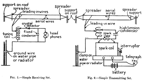
The simplest receiving set consists of (1) a detector, (2) a tuning coil, and (3) a telephone receiver and these three pieces of apparatus are, of course, connected together and are also connected to the aerial and ground as the diagram in Fig. 1 clearly shows. There are two chief kinds of detectors used at the present time and these are: (a) the crystal detector, and (b) the vacuum tube detector. The crystal detector is the cheapest and simplest, but it is not as sensitive as the vacuum tube detector and it requires frequent adjustment. A crystal detector can be used with or without a battery while the vacuum tube detector requires two small batteries.
A tuning coil of the simplest kind consists of a single layer of copper wire wound on a cylinder with an adjustable, or sliding, contact, but for sharp tuning you need a loose coupled tuning coil. Where a single coil tuner is used a fixed condenser should be connected around the telephone receivers. Where a loose coupled tuner is employed you should have a variable condenser connected across the closed oscillation circuit and a fixed condenser across the telephone receivers.
When listening-in to distant stations the energy of the received wireless waves is often so very feeble that in order to hear distinctly an amplifier must be used. To amplify the incoming sounds a vacuum tube made like a detector is used and sometimes as many as half-a-dozen of these tubes are connected in the receiving circuit, or in cascade, as it is called, when the sounds are amplified, that is magnified, many hundreds of times.
The telephone receiver of a receiving set is equally as important as the detector. A single receiver can be used but a pair of receivers connected with a head-band gives far better results. Then again the higher the resistance of the receivers the more sensitive they often are and those wound to as high a resistance as 3,200 ohms are made for use with the best sets. To make the incoming signals, conversation or music, audible to a room full of people instead of to just yourself you must use what is called a loud speaker. In its simplest form this consists of a metal cone like a megaphone to which is fitted a telephone receiver.
About Transmitting Stations--Getting Your License.--If you are going to install a wireless sending apparatus, either telegraphic or telephonic, you will have to secure a government license for which no fee or charge of any kind is made. There are three classes of licenses issued to amateurs who want to operate transmitting stations and these are: (1) the restricted amateur license, (2) the general amateur license, and (3) the special amateur license.
If you are going to set up a transmitter within five nautical miles of any naval wireless station then you will have to get a restricted amateur license which limits the current you use to half a kilowatt [Footnote: A Kilowatt is 1,000 watts. There are 746 watts in a horsepower.] and the wave length you send out to 200 meters. Should you live outside of the five-mile range of a navy station then you can get a general amateur license and this permits you to use a current of 1 kilowatt, but you are likewise limited to a wave length of 200 meters. But if you can show that you are doing some special kind of wireless work and not using your sending station for the mere pleasure you are getting out of it you may be able to get a special amateur license which gives you the right to send out wave lengths up to 375 meters.
When you are ready to apply for your license write to the Radio Inspector of whichever one of the following districts you live in:
  First District..............Boston, Mass.
  Second   "    ..............New York City
  Third    "    ..............Baltimore, Md.
  Fourth   "    ..............Norfolk, Va.
  Fifth    "    ..............New Orleans, La.
  Sixth    "    ............. San Francisco, Cal.
  Seventh  "    ............. Seattle, Wash.
  Eighth   "    ............. Detroit, Mich.
  Ninth    "    ..............Chicago, Ill.
Kinds of Transmitters.--There are two general types of transmitters used for sending out wireless messages and these are: (1) wireless telegraph transmitters, and (2) wireless telephone transmitters. Telegraph transmitters may use either: (a) a jump-spark, (b) an electric arc, or (c) a vacuum tube apparatus for sending out dot and dash messages, while telephone transmitters may use either, (a) an electric arc, or (b) a vacuum tube for sending out vocal and musical sounds. Amateurs generally use a jump-spark for sending wireless telegraph messages and the vacuum tube for sending wireless telephone messages.
The Spark Gap Wireless Telegraph Transmitter.--The simplest kind of a wireless telegraph transmitter consists of: (1) a source of direct or alternating current, (2) a telegraph key, (3) a spark-coil or a transformer, (4) a spark gap, (5) an adjustable condenser and (6) an oscillation transformer. Where dry cells or a storage battery must be used to supply the current for energizing the transmitter a spark-coil can be employed and these may be had in various sizes from a little fellow which gives 1/4-inch spark up to a larger one which gives a 6-inch spark. Where more energy is needed it is better practice to use a transformer and this can be worked on an alternating current of 110 volts, or if only a 110 volt direct current is available then an electrolytic interrupter must be used to make and break the current. A simple transmitting set with an induction coil is shown in Fig. 2.
A wireless key is made like an ordinary telegraph key except that where large currents are to be used it is somewhat heavier and is provided with large silver contact points. Spark gaps for amateur work are usually of: (1) the plain or stationary type, (2) the rotating type, and (3) the quenched gap type. The plain spark-gap is more suitable for small spark-coil sets, and it is not so apt to break down the transformer and condenser of the larger sets as the rotary gap. The rotary gap on the other hand tends to prevent arcing and so the break is quicker and there is less dragging of the spark. The quenched gap is more efficient than either the plain or rotary gap and moreover it is noiseless.
Condensers for spark telegraph transmitters can be ordinary Leyden jars or glass plates coated with tin or copper foil and set into a frame, or they can be built up of mica and sheet metal embedded in an insulating composition. The glass plate condensers are the cheapest and will serve your purpose well, especially if they are immersed in oil. Tuning coils, sometimes called transmitting inductances and oscillation transformers, are of various types. The simplest kind is a transmitting inductance which consists of 25 or 30 turns of copper wire wound on an insulating tube or frame. An oscillation transformer is a loose coupled tuning coil and it consists of a primary coil formed of a number of turns of copper wire wound on a fixed insulating support, and a secondary coil of about twice the number of turns of copper wire which is likewise fixed in an insulating support, but the coils are relatively movable. An oscillation transformer (instead of a tuning coil), is required by government regulations unless inductively coupled.
The Vacuum Tube Telegraph Transmitter.--This consists of: (1) a source of direct or alternating current, (2) a telegraph key, (3) a vacuum tube oscillator, (4) a tuning coil, and (5) a condenser. This kind of a transmitter sets up sustained oscillations instead of periodic oscillations which are produced by a spark gap set. The advantages of this kind of a system will be found explained in Chapter XVI.
The Wireless Telephone Transmitter.--Because a jump-spark sets up periodic oscillations, that is, the oscillations are discontinuous, it cannot be used for wireless telephony. An electric arc or a vacuum tube sets up sustained oscillations, that is, oscillations which are continuous. As it is far easier to keep the oscillations going with a vacuum tube than it is with an arc the former means has all but supplanted the latter for wireless telephone transmitters. The apparatus required and the connections used for wireless telephone sets will be described in later chapters.
Useful Information.--It would be wise for the reader to turn to the Appendix, beginning with page 301 of this book, and familiarize himself with the information there set down in tabular and graphic form. For example, the first table gives abbreviations of electrical terms which are in general use in all works dealing with the subject. You will also find there brief definitions of electric and magnetic units, which it would be well to commit to memory; or, at least, to make so thoroughly your own that when any of these terms is mentioned, you will know instantly what is being talked about.
As inferred in the first chapter, an aerial for receiving does not have to be nearly as well made or put up as one for sending. But this does not mean that you can slipshod the construction and installation of it, for however simple it is, the job must be done right and in this case it is as easy to do it right as wrong.
To send wireless telegraph and telephone messages to the greatest distances and to receive them as distinctly as possible from the greatest distances you must use for your aerial (1) copper or aluminum wire, (2) two or more wires, (3) have them the proper length, (4) have them as high in the air as you can, (5) have them well apart from each other, and (6) have them well insulated from their supports. If you live in a flat building or an apartment house you can string your aerial wires from one edge of the roof to the other and support them by wooden stays as high above it as may be convenient.
Should you live in a detached house in the city you can usually get your next-door neighbor to let you fasten one end of the aerial to his house and this will give you a good stretch and a fairly high aerial. In the country you can stretch your wires between the house and barn or the windmill. From this you will see that no matter where you live you can nearly always find ways and means of putting up an aerial that will serve your needs without going to the expense of erecting a mast.
Kinds of Aerial Wire Systems.--An amateur wireless aerial can be anywhere from 25 feet to 100 feet long and if you can get a stretch of the latter length and a height of from 30 to 75 feet you will have one with which you can receive a thousand miles or more and send out as much energy as the government will allow you to send.
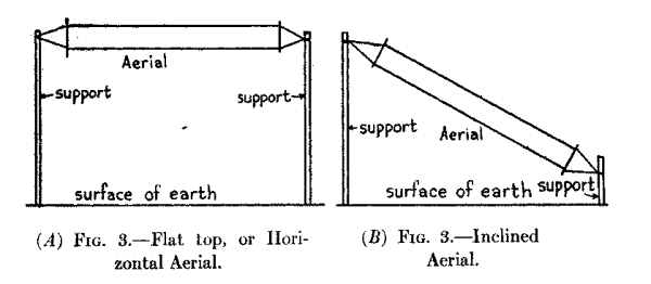
The kind of an aerial that gives the best results is one whose wire, or wires, are horizontal, that is, parallel with the earth under it as shown at A in Fig. 3. If only one end can be fixed to some elevated support then you can secure the other end to a post in the ground, but the slope of the aerial should not be more than 30 or 35 degrees from the horizontal at most as shown at B.
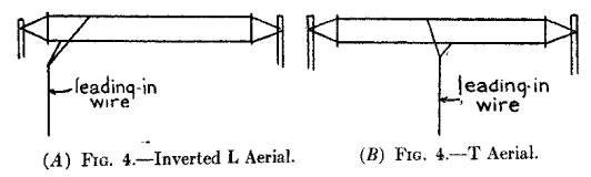
The leading-in wire, that is, the wire that leads from and joins the aerial wire with your sending and receiving set, can be connected to the aerial anywhere it is most convenient to do so, but the best results are had when it is connected to one end as shown at A in Fig. 4, in which case it is called an inverted L aerial, or when it is connected to it at the middle as shown at B, when it is called a T aerial. The leading-in wire must be carefully insulated from the outside of the building and also where it passes through it to the inside. This is done by means of an insulating tube known as a leading-in insulator, or bulkhead insulator as it is sometimes called.
As a protection against lightning burning out your instruments you can use either: (1) an air-gap lightning arrester, (2) a vacuum tube protector, or (3) a lightning switch, which is better. Whichever of these devices is used it is connected in between the aerial and an outside ground wire so that a direct circuit to the earth will be provided at all times except when you are sending or receiving. So your aerial instead of being a menace really acts during an electrical storm like a lightning rod and it is therefore a real protection. The air-gap and vacuum tube lightning arresters are little devices that can be used only where you are going to receive, while the lightning switch must be used where you are going to send; indeed, in some localities the Fire Underwriters require a large lightning switch to be used for receiving sets as well as sending sets.
How to Put Up a Cheap Receiving Aerial.--The kind of an aerial wire system you put up will depend, chiefly, on two things, and these are: (1) your pocketbook, and (2) the place where you live.
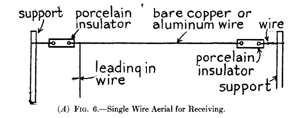
A Single Wire Aerial.--This is the simplest and cheapest kind of a receiving aerial that can be put up. The first thing to do is to find out the length of wire you need by measuring the span between the two points of support; then add a sufficient length for the leading-in wire and enough more to connect your receiving set with the radiator or water pipe.
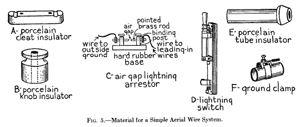
You can use any size of copper or aluminum wire that is not smaller than No. 16 Brown and Sharpe gauge. When you buy the wire get also the following material: (1) two porcelain insulators as shown at A in Fig. 5; (2) three or four porcelain knob insulators, see B; (3) either (a) an air gap lightning arrester, see C, or (b) a lightning switch see D; (4) a leading-in porcelain tube insulator, see E, and (5) a ground clamp, see F.
To make the aerial slip each end of the wire through a hole in each insulator and twist it fast; next cut off and slip two more pieces of wire through the other holes in the insulators and twist them fast and then secure these to the supports at the ends of the building. Take the piece you are going to use for the leading-in wire, twist it around the aerial wire and solder it there when it will look like A in Fig. 6. Now if you intend to use the air gap lightning arrester fasten it to the wall of the building outside of your window, and bring the leading-in wire from the aerial to the top binding post of your arrester and keep it clear of everything as shown at B. If your aerial is on the roof and you have to bring the leading-in wire over the cornice or around a corner fix a porcelain knob insulator to the one or the other and fasten the wire to it.
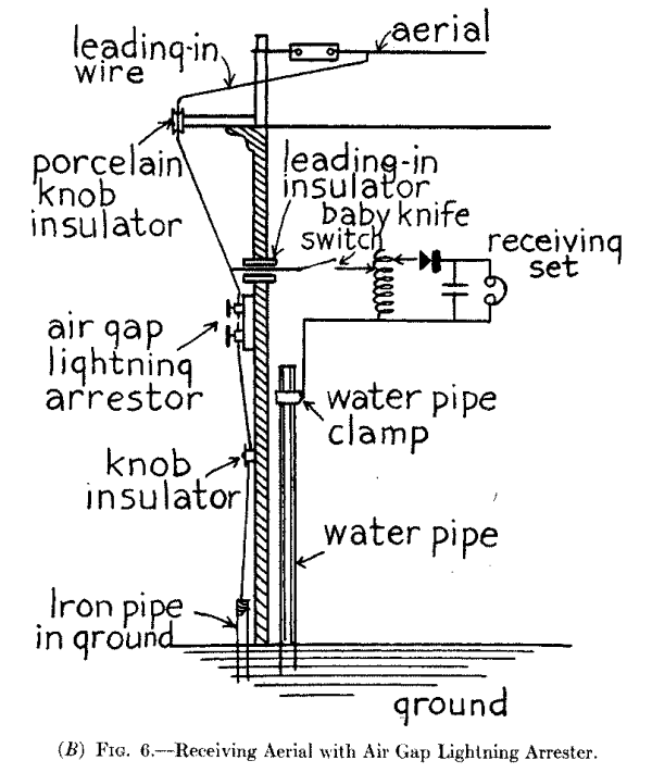
Next bore a hole through the frame of the window at a point nearest your receiving set and push a porcelain tube 5/8 inch in diameter and 5 or 6 inches long, through it. Connect a length of wire to the top post of the arrester or just above it to the wire, run this through the leading-in insulator and connect it to the slider of your tuning coil. Screw the end of a piece of heavy copper wire to the lower post of the arrester and run it to the ground, on porcelain knobs if necessary, and solder it to an iron rod or pipe which you have driven into the earth. Finally connect the fixed terminal of your tuning coil with the water pipe or radiator inside of the house by means of the ground clamp as shown in the diagrammatic sketch at B in Fig. 6 and you are ready to tune in.
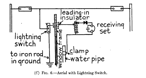
If you want to use a lightning switch instead of the air-gap arrester then fasten it to the outside wall instead of the latter and screw the free end of the leading-in wire from the aerial to the middle post of it as shown at C in Fig. 6. Run a wire from the top post through the leading-in insulator and connect it with the slider of your tuning coil. Next screw one end of a length of heavy copper wire to the lower post of the aerial switch and run it to an iron pipe in the ground as described above in connection with the spark-gap lightning arrester; then connect the fixed terminal of your tuning coil with the radiator or water pipe and your aerial wire system will be complete as shown at C in Fig. 6.
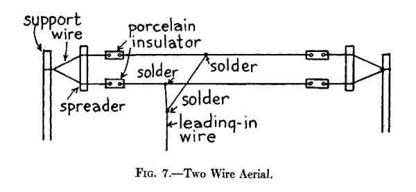
A Two-wire Aerial.--An aerial with two wires will give better results than a single wire and three wires are better than two, but you must keep them well apart. To put up a two-wire aerial get (1) enough No. 16, or preferably No. 14, solid or stranded copper or aluminum wire, (2) four porcelain insulators, see B in Fig. 5, and (3) two sticks about 1 inch thick, 3 inches wide and 3 or 4 feet long, for the spreaders, and bore 1/8-inch hole through each end of each one. Now twist the ends of the wires to the insulators and then cut off four pieces of wire about 6 feet long and run them through the holes in the wood spreaders. Finally twist the ends of each pair of short wires to the free ends of the insulators and then twist the free ends of the wires together.
For the leading-in wire that goes to the lightning switch take two lengths of wire and twist one end of each one around the aerial wires and solder them there. Twist the short wire around the long wire and solder this joint also when the aerial will look like Fig. 7. Bring the free end of the leading-in wire down to the middle post of the lightning switch and fasten it there and connect up the receiver to it and the ground as described under the caption of A Single Wire Aerial.
Connecting in the Ground.--If there is a gas or water system or a steam-heating plant in your house you can make your ground connection by clamping a ground clamp to the nearest pipe as has been previously described. Connect a length of bare or insulated copper wire with it and bring this up to the table on which you have your receiving set. If there are no grounded pipes available then you will have to make a good ground which we shall describe presently and lead the ground wire from your receiving set out of the window and down to it.
How to Put Up a Good Aerial.--While you can use the cheap aerial already described for a small spark-coil sending set you should have a better insulated one for a 1/2 or a 1 kilowatt transformer set. The cost for the materials for a good aerial is small and when properly made and well insulated it will give results that are all out of proportion to the cost of it.
An Inexpensive Good Aerial.--A far better aerial, because it is more highly insulated, can be made by using midget insulators instead of the porcelain insulators described under the caption of A Single Wire Aerial and using a small electrose leading-in insulator instead of the porcelain bushing. This makes a good sending aerial for small sets as well as a good receiving aerial.
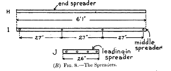
The Best Aerial that Can Be Made.--To make this aerial get the following material together: (1) enough stranded or braided wire for three or four lengths of parallel wires, according to the number you want to use (2) six or eight electrose ball insulators, see B, Fig. 8; (3) two 5-inch or 10-inch electrose strain insulators, see C; (4) six or eight S-hooks, see D; one large withe with one eye for middle of end spreader, see E; (6) two smaller withes with one eye each for end spreader, see E; (7) two still smaller withes, with two eyes each for the ends of the end spreaders, see E (8) two thimbles, see F, for 1/4-inch wire cable; (9) six or eight hard rubber tubes or bushings as shown at G; and (10) two end spreaders, see H; one middle spreader, see I; and one leading-in spreader, see J.
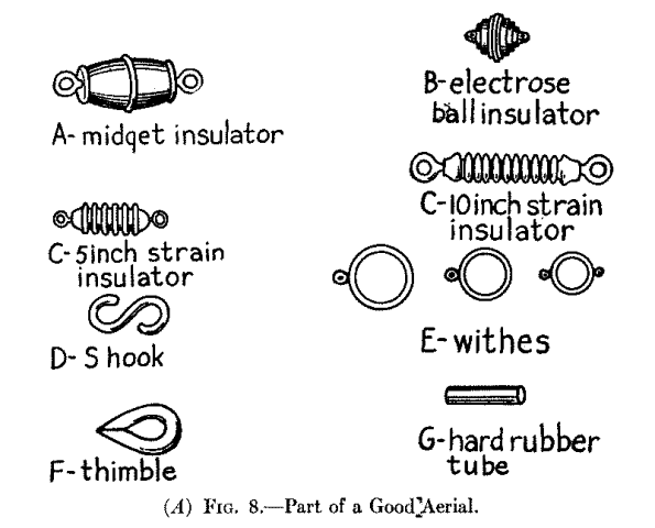
For this aerial any one of a number of kinds of wire can be used and among these are (a) stranded copper wire; (b) braided copper wire; (c) stranded silicon bronze wire, and (d) stranded phosphor bronze wire. Stranded and braided copper wire is very flexible as it is formed of seven strands of fine wire twisted or braided together and it is very good for short and light aerials. Silicon bronze wire is stronger than copper wire and should be used where aerials are more than 100 feet long, while phosphor bronze wire is the strongest aerial wire made and is used for high grade aerials by the commercial companies and the Government for their high-power stations.
The spreaders should be made of spruce, and should be 4 feet 10 inches long for a three-wire aerial and 7 feet 1 inch long for a four-wire aerial as the distance between the wires should be about 27 inches. The end spreaders can be turned cylindrically but it makes a better looking job if they taper from the middle to the ends. They should be 2-1/4 inches in diameter at the middle and 1-3/4 inches at the ends. The middle spreader can be cylindrical and 2 inches in diameter. It must have holes bored through it at equidistant points for the hard rubber tubes; each of these should be 5/8 inch in diameter and have a hole 5/32 inch in diameter through it for the aerial wire. The leading-in spreader is also made of spruce and is 1-1/2 inches square and 26 inches long. Bore three or four 5/8-inch holes at equidistant points through this spreader and insert hard rubber tubes in them as with the middle spreader.
Assembling the Aerial.--Begin by measuring off the length of each wire to be used and see to it that all of them are of exactly the same length. Now push the hard rubber insulators through the holes in the middle spreader and thread the wires through the holes in the insulators as shown at A in Fig 9.
Next twist the ends of each wire to the rings of the ball insulators and then put the large withes on the middle of each of the end spreaders; fix the other withes on the spreaders so that they will be 27 inches apart and fasten the ball insulators to the eyes in the withes with the S-hooks. Now slip a thimble through the eye of one of the long strain insulators, thread a length of stranded steel wire 1/4 inch in diameter through it and fasten the ends of it to the eyes in the withes on the ends of the spreaders.
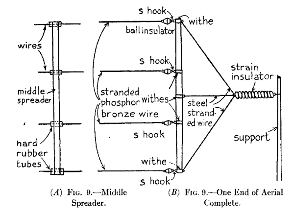
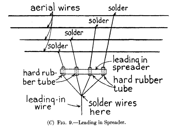
Finally fasten a 40-inch length of steel stranded wire to each of the eyes of the withes on the middle of each of the spreaders, loop the other end over the thimble and then wrap the end around the wires that are fixed to the ends of the spreaders. One end of the aerial is shown complete at B in Fig. 9, and from this you can see exactly how it is assembled. Now cut off three or four pieces of wire 15 or 20 feet long and twist and solder each one to one of the aerial wires; then slip them through the hard rubber tubes in the leading-in spreader, bring their free ends together as at C and twist and solder them to a length of wire long enough to reach to your lightning switch or instruments.
Making a Good Ground.--Where you have to make a ground you can do so either by (1) burying sheets of zinc or copper in the moist earth; (2) burying a number of wires in the moist earth, or (3) using a counterpoise. To make a ground of the first kind take half a dozen large sheets of copper or zinc, cut them into strips a foot wide, solder them all together with other strips and bury them deeply in the ground.
It is easier to make a wire ground, say of as many or more wires as you have in your aerial and connect them together with cross wires. To put such a ground in the earth you will have to use a plow to make the furrows deep enough to insure them always being moist. In the counterpoise ground you make up a system of wires exactly like your aerial, that is, you insulate them just as carefully; then you support them so that they will be as close to the ground as possible and yet not touch it or anything else. This and the other two grounds just described should be placed directly under the aerial wire if the best results are to be had. In using a counterpoise you must bring the wire from it up to and through another leading-in insulator to your instruments.
With a crystal detector receiving set you can receive either telegraphic dots and dashes or telephonic speech and music. You can buy a receiving set already assembled or you can buy the different parts and assemble them yourself. An assembled set is less bother in the beginning but if you like to experiment you can hook up, that is, connect the separate parts together yourself and it is perhaps a little cheaper to do it this way. Then again, by so doing you get a lot of valuable experience in wireless work and an understanding of the workings of wireless that you cannot get in any other way.
Assembled Wireless Receiving Sets.--The cheapest assembled receiving set [Footnote: The Marvel, made by the Radio Mfg. Co., New York City.] advertised is one in which the detector and tuning coil is mounted in a box. It costs $15.00, and can be bought of dealers in electric supplies generally.
This price also includes a crystal detector, an adjustable tuning coil, a single telephone receiver with head-band and the wire, porcelain insulators, lightning switch and ground clamp for the aerial wire system. It will receive wireless telegraph and telephone messages over a range of from 10 to 25 miles.
Another cheap unit receptor, that is, a complete wireless receiving set already mounted which can be used with a single aerial is sold for $25.00. [Footnote: The Aeriola Jr., made by the Westinghouse Company, Pittsburgh, Pa.] This set includes a crystal detector, a variable tuning coil, a fixed condenser and a pair of head telephone receivers. It can also be used to receive either telegraph or telephone messages from distances up to 25 miles. The aerial equipment is not included in this price, but it can be bought for about $2.50 extra.
Assembling Your Own Receiving Set.--In this chapter we shall go only into the apparatus used for two simple receiving sets, both of which have a crystal detector. The first set includes a double-slide tuning coil and the second set employs a loose-coupled tuning coil, or loose coupler, as it is called for short. For either set you can use a pair of 2,000- or 3,000-ohm head phones.
| Photograph unavailable |
| original © Underwood and Underwood. General Pershing Listening In. |
The Crystal Detector.--A crystal detector consists of: (1) the frame, (2) the crystal, and (3) the wire point. There are any number of different designs for frames, the idea being to provide a device that will (a) hold the sensitive crystal firmly in place, and yet permit of its removal, (b) to permit the wire point, or electrode, to be moved in any direction so that the free point of it can make contact with the most sensitive spot on the crystal and (c) to vary the pressure of the wire on the crystal.
A simple detector frame is shown in the cross-section at A in Fig. 10; the crystal, which may be galena, silicon or iron pyrites, is held securely in a holder while the phosphor-bronze wire point which makes contact with it, is fixed to one end of a threaded rod on the other end of which is a knob. This rod screws into and through a sleeve fixed to a ball that sets between two brass standards and this permits an up and down or a side to side adjustment of the metal point while the pressure of it on the crystal is regulated by the screw.
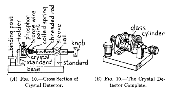
A crystal of this kind is often enclosed in a glass cylinder and this makes it retain its sensitiveness for a much longer time than if it were exposed to dust and moisture. An upright type of this detector can be bought for $2.25, while a horizontal type, as shown at B, can be bought for $2.75. Galena is the crystal that is generally used, for, while it is not quite as sensitive as silicon and iron pyrites, it is easier to obtain a sensitive piece.
The Tuning Coil.--It is with the tuning coil that you tune in and tune out different stations and this you do by sliding the contacts to and fro over the turns of wire; in this way you vary the inductance and capacitance, that is, the constants of the receiving circuits and so make them receive electric waves, that is, wireless waves, of different lengths.
The Double Slide Tuning Coil.--With this tuning coil you can receive waves from any station up to 1,000 meters in length. One of the ends of the coil of wire connects with the binding post marked a in Fig. 11, and the other end connects with the other binding post marked b, while one of the sliding contacts is connected to the binding post c, and the other sliding contact is connected with the binding post d.
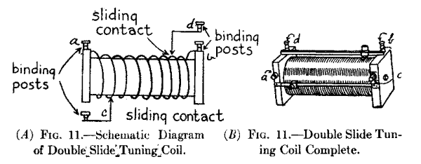
When connecting in the tuning coil, only the post a or the post b is used as may be most convenient, but the other end of the wire which is connected to a post is left free; just bear this point in mind when you come to connect the tuning coil up with the other parts of your receiving set. The tuning coil is shown complete at B and it costs $3.00 or $4.00. A triple slide tuning coil constructed like the double slide tuner just described, only with more turns of wire on it, makes it possible to receive wave lengths up to 1,500 meters. It costs about $6.00.
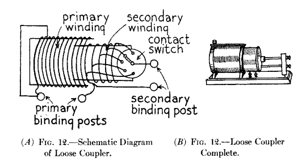
The Loose Coupled Tuning Coil.--With a loose coupler, as this kind of a tuning coil is called for short, very selective tuning is possible, which means that you can tune in a station very sharply, and it will receive any wave lengths according to size of coils. The primary coil is wound on a fixed cylinder and its inductance is varied by means of a sliding contact like the double slide tuning coil described above. The secondary coil is wound on a cylinder that slides in and out of the primary coil. The inductance of this coil is varied by means of a switch that makes contact with the fixed points, each of which is connected with every twentieth turn of wire as shown in the diagram A in Fig. 12. The loose coupler, which is shown complete at B, costs in the neighborhood of $8.00 or $10.00.
Fixed and Variable Condensers.--You do not require a condenser for a simple receiving set, but if you will connect a fixed condenser across your headphones you will get better results, while a variable condenser connected in the closed circuit of a direct coupled receiving set, that is, one where a double slide tuning coil is used, makes it easy to tune very much more sharply; a variable condenser is absolutely necessary where the circuits are inductively coupled, that is, where a loose coupled tuner is used.
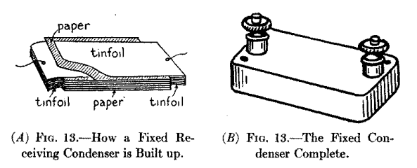
A fixed condenser consists of a number of sheets of paper with leaves of tin-foil in between them and so built up that one end of every other leaf of tin-foil projects from the opposite end of the paper as shown at A in Fig. 13. The paper and tin-foil are then pressed together and impregnated with an insulating compound. A fixed condenser of the exact capacitance required for connecting across the head phones is mounted in a base fitted with binding posts, as shown at B, and costs 75 cents. (Paper ones 25 cents.)
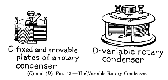
A variable condenser, see C, of the rotating type is formed of a set of fixed semi-circular metal plates which are slightly separated from each other and between these a similar set of movable semi-circular metal plates is made to interleave; the latter are secured to a shaft on the top end of which is a knob and by turning it the capacitance of the condenser, and, hence, of the circuit in which it is connected, is varied. This condenser, which is shown at D, is made in two sizes, the smaller one being large enough for all ordinary wave lengths while the larger one is for proportionately longer wave lengths. These condensers cost $4.00 and $5.00 respectively.
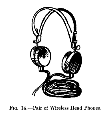
About Telephone Receivers.--There are a number of makes of head telephone receivers on the market that are designed especially for wireless work. These phones are wound to resistances of from 75 ohms to 8,000 ohms, and cost from $1.25 for a receiver without a cord or headband to $15.00 for a pair of phones with a cord and head band. You can get a receiver wound to any resistance in between the above values but for either of the simple receiving sets such as described in this chapter you ought to have a pair wound to at least 2,000 ohms and these will cost you about $5.00. A pair of head phones of this type is shown in Fig. 14.
Connecting Up the Parts--Receiving Set No. 1.--For this set get (1) a crystal detector, (2) a two-slide tuning coil, (3) a fixed condenser, and (4) a pair of 2,000 ohm head phones. Mount the detector on the right-hand side of a board and the tuning coil on the left-hand side. Screw in two binding posts for the cord ends of the telephone receivers at a and b as shown at A in Fig. 15. This done connect one of the end binding posts of the tuning coil with the ground wire and a post of one of the contact slides with the lightning arrester or switch which leads to the aerial wire.
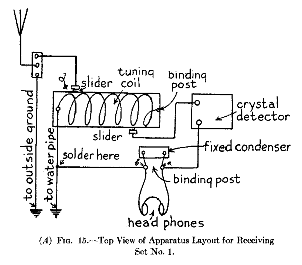
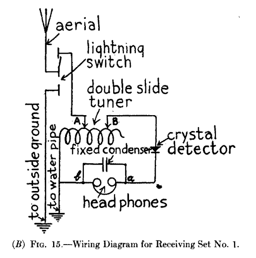
Now connect the post of the other contact slide to one of the posts of the detector and the other post of the latter with the binding post a, then connect the binding post b to the ground wire and solder the joint. Next connect the ends of the telephone receiver cord to the posts a and b and connect a fixed condenser also with these posts, all of which are shown in the wiring diagram at B, and you are ready to adjust the set for receiving.
Receiving Set No. 2.--Use the same kind of a detector and pair of head phones as for Set No. 1, but get (1) a loose coupled tuning coil, and (2) a variable condenser. Mount the loose coupler at the back of a board on the left-hand side and the variable condenser on the right-hand side. Then mount the detector in front of the variable condenser and screw two binding posts, a and b, in front of the tuning coil as shown at A in Fig. 16.
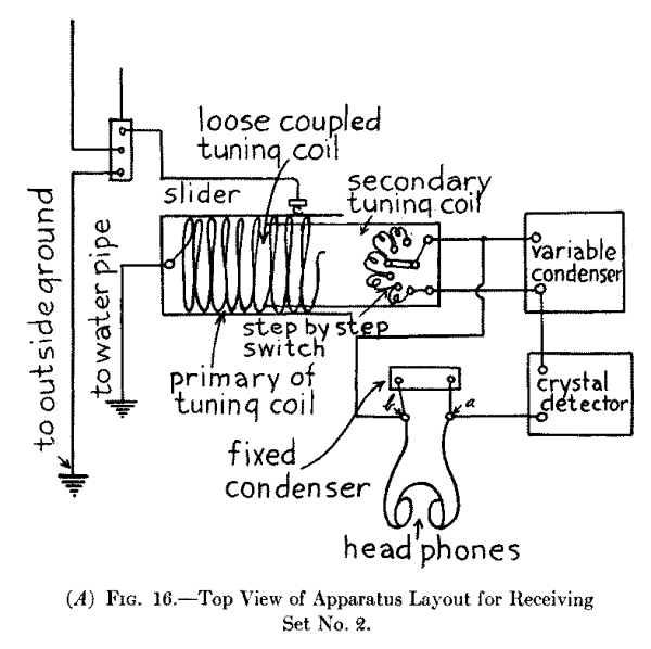
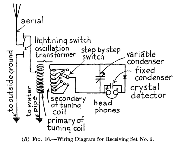
Now connect the post of the sliding contact of the loose coupler with the wire that runs to the lightning switch and thence to the aerial; connect the post of the primary coil, which is the outside coil, with the ground wire; then connect the binding post leading to the switch of the secondary coil, which is the inside coil, with one of the posts of the variable condenser, and finally, connect the post that is joined to one end of the secondary coil with the other post of the variable condenser.
This done, connect one of the posts of the condenser with one of the posts of the detector, the other post of the detector with the binding post a, and the post b to the other post of the variable condenser. Next connect a fixed condenser to the binding posts a and b and then connect the telephone receivers to these same posts, all of which is shown in the wiring diagram at B. You are now ready to adjust the instruments. In making the connections use No. 16 or 18 insulated copper wire and scrape the ends clean where they go into the binding posts. See, also, that all of the connections are tight and where you have to cross the wires keep them apart by an inch or so and always cross them at right angles.
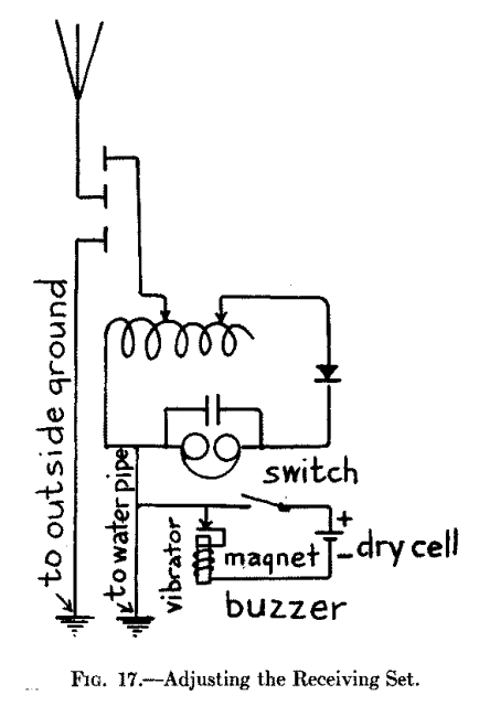
Adjusting the No. 1 Set--The Detector.--The first thing to do is to test the detector in order to find out if the point of the contact wire is on a sensitive spot of the crystal. To do this you need a buzzer, a switch and a dry cell. An electric bell from which the gong has been removed will do for the buzzer, but you can get one that is made specially for the purpose, for 75 cents, which gives out a clear, high-pitched note that sounds like a high-power station.
Connect one of the binding posts of the buzzer with one post of the switch, the other post of the latter with the zinc post of the dry cell and the carbon post of this to the other post of the buzzer. Then connect the post of the buzzer that is joined to the vibrator, to the ground wire as shown in the wiring diagram, Fig. 17. Now close the switch of the buzzer circuit, put on your head phones, and move the wire point of the detector to various spots on the crystal until you hear the sparks made by the buzzer in your phones.
Then vary the pressure of the point on the crystal until you hear the sparks as loud as possible. After you have made the adjustment open the switch and disconnect the buzzer wire from the ground wire of your set. This done, be very careful not to jar the detector or you will throw it out of adjustment and then you will have to do it all over again. You are now ready to tune the set with the tuning coil and listen in.
The Tuning Coil.--To tune this set move the slide A of the double-slide tuner, see B in Fig. 15, over to the end of the coil that is connected with the ground wire and the slide B near the opposite end of the coil, that is, the one that has the free end. Now move the slide A toward the B slide and when you hear the dots and dashes, or speech or music, that is coming in as loud as you can move the B slide toward the A slide until you hear still more loudly. A very few trials on your part and you will be able to tune in or tune out any station you can hear, if not too close or powerful.
| Photograph unavailable |
| original © Underwood and Underwood. The World's Largest Radio Receiving Station. Owned by the Radio Corporation of America at Rocky Point near Point Jefferson, L.I. |
Adjusting the No. 2 Set.--First adjust the crystal detector with the buzzer set as described above with Set No. 1, then turn the knob of your variable condenser so that the movable plates are just half-way in, pull the secondary coil of your loose-coupled tuner half way out; turn the switch lever on it until it makes a contact with the middle contact point and set the slider of the primary coil half way between the ends.
Now listen in for telegraphic signals or telephonic speech or music; when you hear one or the other slide the secondary coil in and out of the primary coil until the sounds are loudest; now move the contact switch over the points forth and back until the sounds are still louder, then move the slider to and fro until the sounds are yet louder and, finally, turn the knob of the condenser until the sounds are clear and crisp. When you have done all of these things you have, in the parlance of the wireless operator, tuned in and you are ready to receive whatever is being sent.
A wireless telegraph transmitting set can be installed for a very small amount of money provided you are content with one that has a limited range. Larger and better instruments can, of course, be had for more money, but however much you are willing to spend still you are limited in your sending radius by the Government's rules and regulations. The best way, and the cheapest in the end, to install a telegraph set is to buy the separate parts and hook them up yourself.
The usual type of wireless telegraph transmitter employs a disruptive discharge, or spark, as it is called, for setting up the oscillating currents in the aerial wire system and this is the type of apparatus described in this chapter. There are two ways to set up the sparks and these are: (1) with an induction coil, or spark-coil, as it is commonly called, and (2) with an alternating current transformer, or power transformer, as it is sometimes called. Where you have to generate the current with a battery you must use a spark coil, but if you have a 110-volt direct or alternating lighting current in your home you can use a transformer which will give you more power.
A Cheap Transmitting Set (No. 1).--For this set you will need: (1) a spark-coil, (2) a battery of dry cells, (3) a telegraph key, (4) a spark gap, (5) a high-tension condenser, and (6) an oscillation transformer. There are many different makes and styles of these parts but in the last analysis all of them are built on the same underlying bases and work on the same fundamental principles.
The Spark-Coil.--Spark coils for wireless work are made to give sparks from 1/4 inch in length up to 6 inches in length, but as a spark coil that gives less than a 1-inch spark has a very limited output it is best to get a coil that gives at least a 1-inch spark, as this only costs about $8.00, and if you can get a 2- or a 4-inch spark coil so much the better. There are two general styles of spark coils used for wireless and these are shown at A and B in Fig. 18.
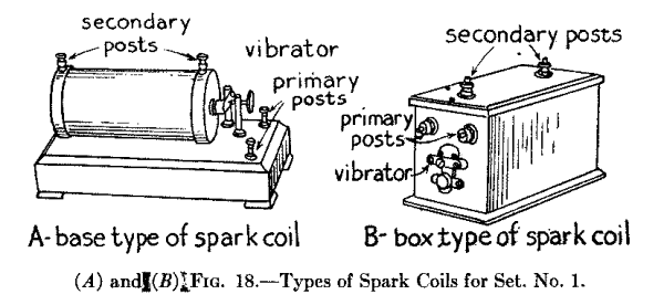
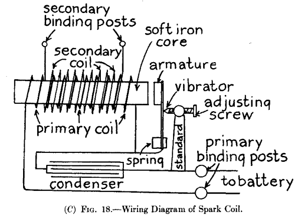
A spark coil of either style consists of (a) a soft iron core on which is wound (b) a couple of layers of heavy insulated wire and this is called the primary coil, (c) while over this, but insulated from it, is wound a large number of turns of very fine insulated copper wire called the secondary coil; (d) an interrupter, or vibrator, as it is commonly called, and, finally, (e) a condenser. The core, primary and secondary coils form a unit and these are set in a box or mounted on top of a hollow wooden base. The condenser is placed in the bottom of the box, or on the base, while the vibrator is mounted on one end of the box or on top of the base, and it is the only part of the coil that needs adjusting.
The vibrator consists of a stiff, flat spring fixed at one end to the box or base while it carries a piece of soft iron called an armature on its free end and this sets close to one end of the soft iron core. Insulated from this spring is a standard that carries an adjusting screw on the small end of which is a platinum point and this makes contact with a small platinum disk fixed to the spring. The condenser is formed of alternate sheets of paper and tinfoil built up in the same fashion as the receiving condenser described under the caption of Fixed and Variable Condensers, in Chapter III.
The wiring diagram C shows how the spark coil is wired up. One of the battery binding posts is connected with one end of the primary coil while the other end of the latter which is wound on the soft iron core connects with the spring of the vibrator. The other battery binding post connects with the standard that supports the adjusting screw. The condenser is shunted across the vibrator, that is, one end of the condenser is connected with the spring and the other end of the condenser is connected with the adjusting screw standard. The ends of the secondary coil lead to two binding posts, which are usually placed on top of the spark coil and it is to these that the spark gap is connected.
The Battery.--This can be formed of dry cells or you can use a storage battery to energize your coil. For all coils that give less than a 1-inch spark you should use 5 dry cells; for 1-and 2-inch spark coils use 6 or 8 dry cells, and for 3 to 4-inch spark coils use 8 to 10 dry cells. The way the dry cells are connected together to form a battery will be shown presently. A dry cell is shown at A in Fig, 19.
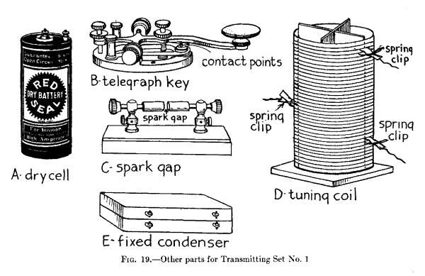
The Telegraph Key.--You can use an ordinary Morse telegraph key for the sending set and you can get one with a japanned iron base for $1.50 (or better, one made of brass and which has 1/8-inch silver contact points for $3.00. A key of the latter kind is shown at B).
The Spark gap.--It is in the spark gap that the high tension spark takes place. The apparatus in which the spark takes place is also called the spark gap. It consists of a pair of zinc plugs, called electrodes, fixed to the ends of a pair of threaded rods, with knobs on the other ends, and these screw into and through a pair of standards as shown at c. This is called a fixed, or stationary spark gap and costs about $1.00.
The Tuning Coil.--The transmitting inductance, or sending tuning coil, consists of 20 to 30 turns of No. 8 or 9 hard drawn copper wire wound on a slotted insulated form and mounted on a wooden base. It is provided with clips so that you can cut in and cut out as many turns of wire as you wish and so tune the sending circuits to send out whatever wave length you desire. It is shown at d, and costs about $5.00. See also Oscillation Transformer, page 63 [Chapter IV].
The High Tension Condenser.--High tension condensers, that is, condensers which will stand up under high potentials, or electric pressures, can be bought in units or sections. These condensers are made up of thin brass plates insulated with a special compound and pressed into a compact form. The capacitance [Footnote: This is the capacity of the condenser.] of one section is enough for a transmitting set using a spark coil that gives a 2 inch spark or less and two sections connected together should be used for coils giving from 2 to 4 inch sparks. It is shown at e.
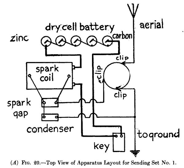
Connecting Up the Apparatus.--Your sending set should be mounted on a table, or a bench, where it need not be moved. Place the key in about the middle of the table and down in front, and the spark coil to the left and well to the back but so that the vibrator end will be to the right, as this will enable you to adjust it easily. Place the battery back of the spark coil and the tuning coil (oscillation transformer) to the right of the spark coil and back of the key, all of which is shown in the layout at A in Fig. 20.
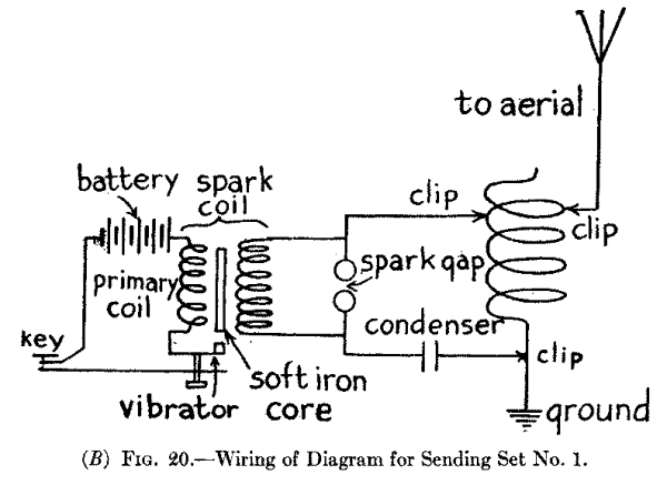
For the low voltage circuit, that is the battery circuit, use No. 12 or 14 insulated copper wire. Connect all of the dry cells together in series, that is, connect the zinc of one cell with the carbon of the next and so on until all of them are connected up. Then connect the carbon of the end cell with one of the posts of the key, the zinc of the other end cell with one of the primary posts of the spark coil and the other primary post of the spark coil with the other post of the key, when the primary circuit will be complete.
For the high tension circuits, that is, the oscillation circuits, you may use either bare or insulated copper wire but you must be careful that they do not touch the table, each other, or any part of the apparatus, except, of course, the posts they are connected with. Connect one of the posts of the secondary coil of the spark coil with one of the posts of the spark gap, and the other post with one of the posts of the condenser; then connect the other post of the condenser with the lower spring clip of the tuning coil and also connect this clip with the ground. This done, connect the middle spring clip with one of the posts of the spark gap, and, finally, connect the top clip with the aerial wire and your transmitting set is ready to be tuned. A wiring diagram of the connections is shown at B. As this set is tuned in the same way as Set No. 2 which follows, you are referred to the end of this chapter.
A Better Transmitting Set (No. 2).--The apparatus for this set includes: (1) an alternating current transformer, (2) a wireless telegraph key, (3) a fixed, a rotary, or a quenched spark gap, (4) a condenser, and (5) an oscillation transformer. If you have a 110 volt direct lighting current in your home instead of 110 volt alternating current, then you will also need (6) an electrolytic interrupter, for in this case the primary circuit of the transformer must be made and broken rapidly in order to set up alternating currents in the secondary coil.
The Alternating Current Transformer.--An alternating current, or power, transformer is made on the same principle as a spark coil, that is, it has a soft iron core, a primary coil formed of a couple of layers of heavy wire, and a secondary coil wound up of a large number of turns of very fine wire. Unlike the spark coil, however, which has an open magnetic core and whose secondary coil is wound on the primary coil, the transformer has a closed magnetic core, with the primary coil wound on one of the legs of the core and the secondary wound on the other leg. It has neither a vibrator nor a condenser. A plain transformer is shown at A in Fig. 21.
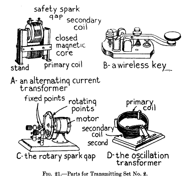
A transformer of this kind can be bought either (a) unmounted, that is, just the bare transformer, or (b) fully mounted, that is, fitted with an iron stand, mounted on an insulating base on which are a pair of primary binding posts, while the secondary is provided with a safety spark gap. There are three sizes of transformers of this kind made and they are rated at 1/4, 1/2 and 1 kilowatt, respectively, they deliver a secondary current of 9,000, 11,000 and 25,000 volts, according to size, and cost $16.00, $22.00 and $33.00 when fully mounted; a reduction of $3.00, $4.00 and $5.00 is made when they are unmounted. All of these transformers operate on 110 volt, 60 cycle current and can be connected directly to the source of alternating current.
The Wireless Key.--For this transmitting set a standard wireless key should be used as shown at B. It is made about the same as a regular telegraph key but it is much heavier, the contact points are larger and instead of the current being led through the bearings as in an ordinary key, it is carried by heavy conductors directly to the contact points. This key is made in three sizes and the first will carry a current of 5 amperes [Footnote: See Appendix for definition.] and costs $4.00, the second will carry a current of 10 amperes and costs $6.50, while the third will carry a current of 20 amperes and costs $7.50.
The Spark Gap.--Either a fixed, a rotary, or a quenched spark gap can be used with this set, but the former is seldom used except with spark-coil sets, as it is very hard to keep the sparks from arcing when large currents are used. A rotary spark gap comprises a wheel, driven by a small electric motor, with projecting plugs, or electrodes, on it and a pair of stationary plugs on each side of the wheel as shown at C. The number of sparks per second can be varied by changing the speed of the wheel and when it is rotated rapidly it sends out signals of a high pitch which are easy to read at the receiving end. A rotary gap with a 110-volt motor costs about $25.00.
A quenched spark gap not only eliminates the noise of the ordinary gap but, when properly designed, it increases the range of an induction coil set some 200 per cent. A 1/4 kilowatt quenched gap costs $10.00. [Footnote: See Appendix for definition.]
The High Tension Condenser.--Since, if you are an amateur, you can only send out waves that are 200 meters in length, you can only use a condenser that has a capacitance of .007 microfarad. [Footnote: See Appendix for definition.] A sectional high tension condenser like the one described in connection with Set No. 1 can be used with this set but it must have a capacitance of not more than .007 microfarad. A condenser of this value for a 1/4-kilowatt transformer costs $7.00; for a 1/2-kilowatt transformer $14.00, and for a 1-kilowatt transformer $21.00. See E, Fig. 19.
The Oscillation Transformer.--With an oscillation transformer you can tune much more sharply than with a single inductance coil tuner. The primary coil is formed of 6 turns of copper strip, or No. 9 copper wire, and the secondary is formed of 9 turns of strip, or wire. The primary coil, which is the outside coil, is hinged to the base and can be raised or lowered like the lid of a box. When it is lowered the primary and secondary coils are in the same plane and when it is raised the coils set at an angle to each other. It is shown at D and costs $5.00.
Connecting Up the Apparatus. For Alternating Current.--Screw the key to the table about the middle of it and near the front edge; place the high tension condenser back of it and the oscillation transformer back of the latter; set the alternating current transformer to the left of the oscillation transformer and place the rotary or quenched spark gap in front of it.
Now bring a pair of No. 12 or 14 insulated wires from the 110 volt lighting leads and connect them with a single-throw, double-pole switch; connect one pole of the switch with one of the posts of the primary coil of the alternating power transformer and connect the other post of the latter with one of the posts of your key, and the other post of this with the other pole of the switch. Now connect the motor of the rotary spark gap to the power circuit and put a single-pole, single-throw switch in the motor circuit, all of which is shown at A in Fig. 22.
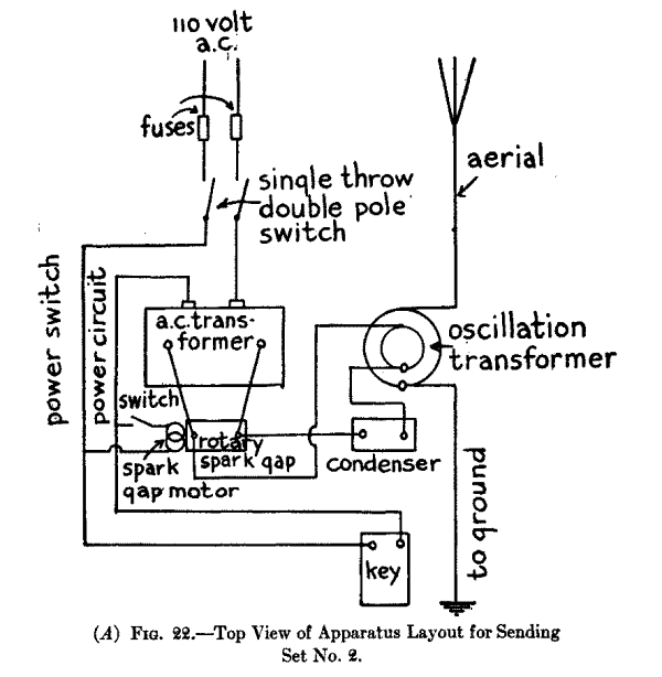
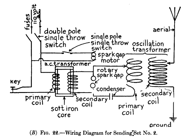
Next connect the posts of the secondary coil to the posts of the rotary or quenched spark gap and connect one post of the latter to one post of the condenser, the other post of this to the post of the primary coil of the oscillation transformer, which is the inside coil, and the clip of the primary coil to the other spark gap post. This completes the closed oscillation circuit. Finally connect the post of the secondary coil of the oscillation transformer to the ground and the clip of it to the wire leading to the aerial when you are ready to tune the set. A wiring diagram of the connections is shown at B.
For Direct Current.--Where you have 110 volt direct current you must connect in an electrolytic interrupter. This interrupter, which is shown at A and B in Fig. 23, consists of (1) a jar filled with a solution of 1 part of sulphuric acid and 9 parts of water, (2) a lead electrode having a large surface fastened to the cover of surface that sets in a porcelain sleeve and whose end rests on the bottom of the jar.
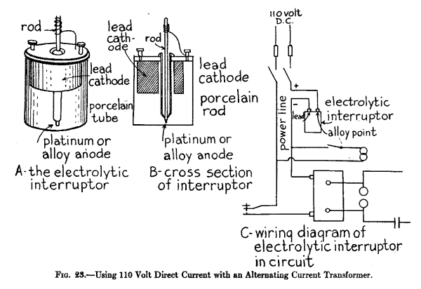
When these electrodes are connected in series with the primary of a large spark coil or an alternating current transformer, see C, and a direct current of from 40 to 110 volts is made to pass through it, the current is made and broken from 1,000 to 10,000 times a minute. By raising or lowering the sleeve, thus exposing more or less of the platinum, or alloy point, the number of interruptions per minute can be varied at will. As the electrolytic interrupter will only operate in one direction, you must connect it with its platinum, or alloy anode, to the + or positive power lead and the lead cathode to the - or negative power lead. You can find out which is which by connecting in the interrupter and trying it, or you can use a polarity indicator. An electrolytic interrupter can be bought for as little as $3.00.
How to Adjust Your Transmitter. Tuning With a Hot Wire Ammeter.--A transmitter can be tuned in two different ways and these are: (1) by adjusting the length of the spark gap and the tuning coil so that the greatest amount of energy is set up in the oscillating circuits, and (2) by adjusting the apparatus so that it will send out waves of a given length.
To adjust the transmitter so that the circuits will be in tune you should have a hot wire ammeter, or radiation ammeter, as it is called, which is shown in Fig. 24. It consists of a thin platinum wire through which the high-frequency currents surge and these heat it; the expansion and contraction of the wire moves a needle over a scale marked off into fractions of an ampere. When the spark gap and tuning coil of your set are properly adjusted, the needle will swing farthest to the right over the scale and you will then know that the aerial wire system, or open oscillation circuit, and the closed oscillation circuit are in tune and radiating the greatest amount of energy.
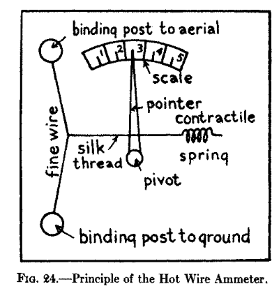
To Send Out a 200 Meter Wave Length.--If you are using a condenser having a capacitance of .007 microfarad, which is the largest capacity value that the Government will allow an amateur to use, then if you have a hot wire ammeter in your aerial and tune the inductance coil or coils until the ammeter shows the largest amount of energy flowing through it you will know that your transmitter is tuned and that the aerial is sending out waves whose length is 200 meters. To tune to different wave lengths you must have a wave-meter.
The Use of the Aerial Switch.--Where you intend to install both a transmitter and a receptor you will need a throwover switch, or aerial switch, as it is called. An ordinary double-pole, double-throw switch, as shown at A in Fig. 25, can be used, or a switch made especially for the purpose as at B is handier because the arc of the throw is much less.
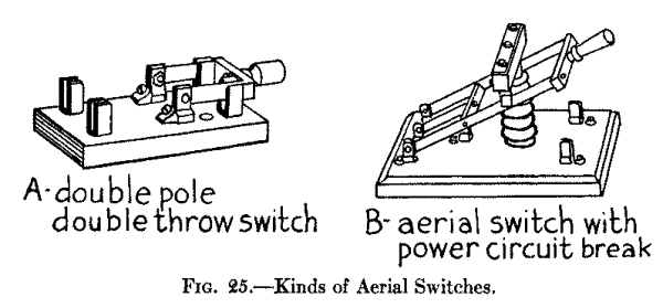
Aerial Switch for a Complete Sending and Receiving Set.--You can buy a double-pole, double-throw switch mounted on a porcelain base for about 75 cents and this will serve for Set No. 1. Screw this switch on your table between the sending and receiving sets and then connect one of the middle posts of it with the ground wire and the other middle post with the lightning switch which connects with the aerial. Connect the post of the tuning coil with one of the end posts of the switch and the clip of the tuning coil with the other and complementary post of the switch. This done, connect one of the opposite end posts of the switch to the post of the receiving tuning coil and connect the sliding contact of the latter with the other and complementary post of the switch as shown in Fig. 26.
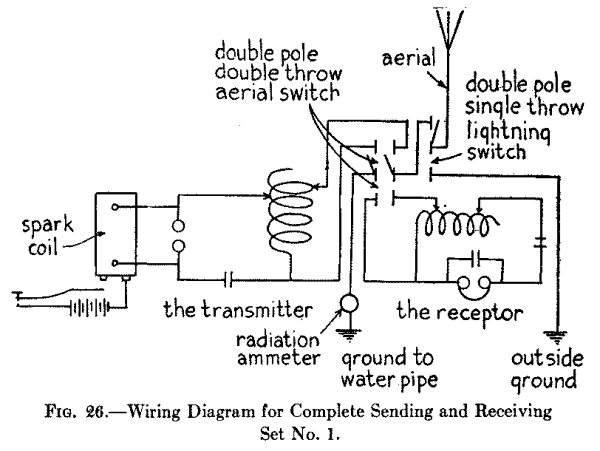
Connecting in the Lightning Switch.--The aerial wire connects with the middle post of the lightning switch, while one of the end posts lead to one of the middle posts of the aerial switch. The other end post of the lightning switch leads to a separate ground outside the building, as the wiring diagrams Figs. 26 and 27 show.
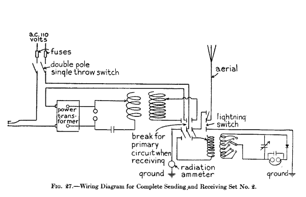
It is easy to understand how electricity behaves and what it does if you get the right idea of it at the start. In the first place, if you will think of electricity as being a fluid like water its fundamental actions will be greatly simplified. Both water and electricity may be at rest or in motion. When at rest, under certain conditions, either one will develop pressure, and this pressure when released will cause them to flow through their respective conductors and thus produce a current.
Electricity at Rest and in Motion.--Any wire or a conductor of any kind can be charged with electricity, but a Leyden jar, or other condenser, is generally used to hold an electric charge because it has a much larger capacitance, as its capacity is called, than a wire. As a simple analogue of a condenser, suppose you have a tank of water raised above a second tank and that these are connected together by means of a pipe with a valve in it, as shown at A in Fig. 28.
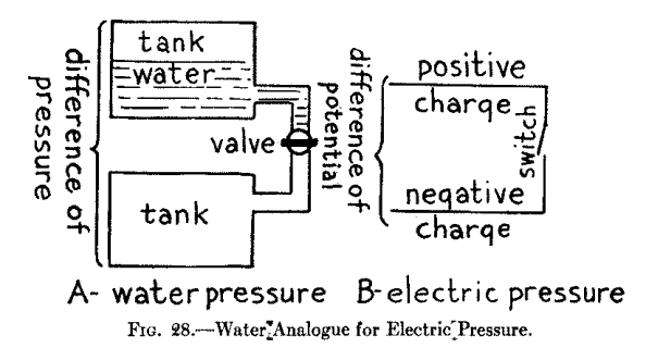
| Photograph unavailable |
| original © Underwood and Underwood. First Wireless College in the World, at Tufts College, Mass. |
Now if you fill the upper tank with water and the valve is turned off, no water can flow into the lower tank but there is a difference of pressure between them, and the moment you turn the valve on a current of water will flow through the pipe. In very much the same way when you have a condenser charged with electricity the latter will be under pressure, that is, a difference of potential will be set up, for one of the sheets of metal will be charged positively and the other one, which is insulated from it, will be charged negatively, as shown at B. On closing the switch the opposite charges rush together and form a current which flows to and fro between the metal plates. [Footnote: Strictly speaking it is the difference of potential that sets up the electromotive force.]
The Electric Current and Its Circuit.--Just as water flowing through a pipe has quantity and pressure back of it and the pipe offers friction to it which tends to hold back the water, so, likewise, does electricity flowing in a circuit have: (1) quantity, or current strength, or just current, as it is called for short, or amperage, and (2) pressure, or potential difference, or electromotive force, or voltage, as it is variously called, and the wire, or circuit, in which the current is flowing has (3) resistance which tends to hold back the current.
A definite relation exists between the current and its electromotive force and also between the current, electromotive force and the resistance of the circuit; and if you will get this relationship clearly in your mind you will have a very good insight into how direct and alternating currents act. To keep a quantity of water flowing in a loop of pipe, which we will call the circuit, pressure must be applied to it and this may be done by a rotary pump as shown at A in Fig. 29; in the same way, to keep a quantity of electricity flowing in a loop of wire, or circuit, a battery, or other means for generating electric pressure must be used, as shown at B.
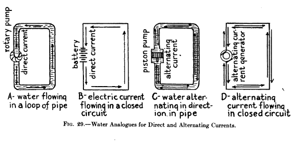
If you have a closed pipe connected with a piston pump, as at C, as the piston moves to and fro the water in the pipe will move first one way and then the other. So also when an alternating current generator is connected to a wire circuit, as at D, the current will flow first in one direction and then in the other, and this is what is called an alternating current.
Current and the Ampere.--The amount of water flowing in a closed pipe is the same at all parts of it and this is also true of an electric current, in that there is exactly the same quantity of electricity at one point of the circuit as there is at any other.
The amount of electricity, or current, flowing in a circuit in a second is measured by a unit called the ampere, [Footnote: For definition of ampere see Appendix.] and it is expressed by the symbol I. [Footnote: This is because the letter C is used for the symbol of capacitance] Just to give you an idea of the quantity of current an ampere is we will say that a dry cell when fresh gives a current of about 20 amperes. To measure the current in amperes an instrument called an ammeter is used, as shown at A in Fig. 30, and this is always connected in series with the line, as shown at B.
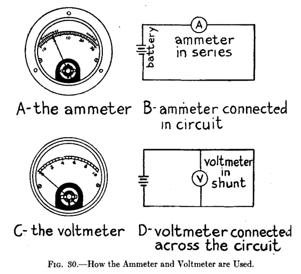
Electromotive Force and the Volt.--When you have a pipe filled with water or a circuit charged with electricity and you want to make them flow you must use a pump in the first case and a battery or a dynamo in the second case. It is the battery or dynamo that sets up the electric pressure as the circuit itself is always charged with electricity.
The more cells you connect together in series the greater will be the electric pressure developed and the more current it will move along just as the amount of water flowing in a pipe can be increased by increasing the pressure of the pump. The unit of electromotive force is the volt, and this is the electric pressure which will force a current of 1 ampere through a resistance of 1 ohm; it is expressed by the symbol E. A fresh dry cell will deliver a current of about 1.5 volts. To measure the pressure of a current in volts an instrument called a voltmeter is used, as shown at C in Fig. 30, and this is always connected across the circuit, as shown at D.
Resistance and the Ohm.--Just as a water pipe offers a certain amount of resistance to the flow of water through it, so a circuit opposes the flow of electricity in it and this is called resistance. Further, in the same way that a small pipe will not allow a large amount of water to flow through it, so, too, a thin wire limits the flow of the current in it.
If you connect a resistance coil in a circuit it acts in the same way as partly closing the valve in a pipe, as shown at A and B in Fig. 31. The resistance of a circuit is measured by a unit called the ohm, and it is expressed by the symbol R. A No. 10, Brown and Sharpe gauge soft copper wire, 1,000 feet long, has a resistance of about 1 ohm. To measure the resistance of a circuit an apparatus called a resistance bridge is used. The resistance of a circuit can, however, be easily calculated, as the following shows.
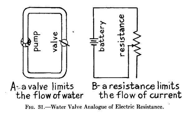
What Ohm's Law Is.--If, now, (1) you know what the current flowing in a circuit is in amperes, and the electromotive force, or pressure, is in volts, you can then easily find what the resistance is in ohms of the circuit in which the current is flowing by this formula:
     Volts                   E
    --------- = Ohms,  or   --- = R
     Amperes                 I
That is, if you divide the current in amperes by the electromotive force in volts the quotient will give you the resistance in ohms.
Or (2) if you know what the electromotive force of the current is in volts and the resistance of the circuit is in ohms then you can find what the current flowing in the circuit is in amperes, thus:
    Volts                   E
    ----- = Amperes,  or   --- = I
    Ohms                    R
That is, by dividing the resistance of the circuit in ohms, by the electromotive force of the current you will get the amperes flowing in the circuit.
Finally (3) if you know what the resistance of the circuit is in ohms and the current is in amperes then you can find what the electromotive force is in volts since:
Ohms x Amperes = Volts, or R x I = E
That is, if you multiply the resistance of the circuit in ohms by the current in amperes the result will give you the electromotive force in volts.
From this you will see that if you know the value of any two of the constants you can find the value of the unknown constant by a simple arithmetical process. This relation between these three constants is known as Ohm's Law and as they are very important you should memorize them.
What the Watt and Kilowatt Are.--Just as horsepower or H.P., is the unit of work that steam has done or can do, so the watt is the unit of work that an electric current has done or can do. To find the watts a current develops you need only to multiply the amperes by the volts. There are 746 watts to 1 horsepower, and 1,000 watts are equal to 1 kilowatt.
Electromagnetic Induction.--To show that a current of electricity sets up a magnetic field around it you have only to hold a compass over a wire whose ends are connected with a battery when the needle will swing at right angles to the length of the wire. By winding an insulated wire into a coil and connecting the ends of the latter with a battery you will find, if you test it with a compass, that the coil is magnetic.
This is due to the fact that the energy of an electric current flowing in the wire is partly changed into magnetic lines of force which rotate at right angles about it as shown at A in Fig. 32. The magnetic field produced by the current flowing in the coil is precisely the same as that set up by a permanent steel magnet. Conversely, when a magnetic line of force is set up a part of its energy goes to make up electric currents which whirl about in a like manner, as shown at B.
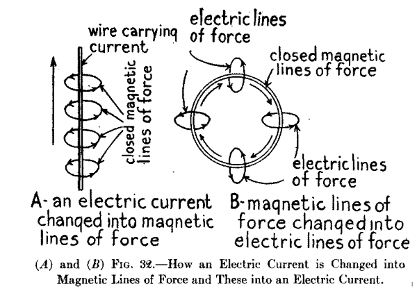
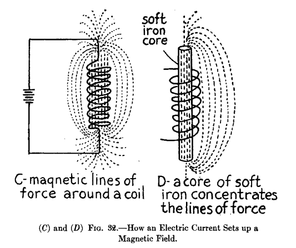
Self-induction or Inductance.--When a current is made to flow in a coil of wire the magnetic lines of force produced are concentrated, as at C, just as a lens concentrates rays of light, and this forms an intense magnetic field, as it is called. Now if a bar of soft iron is brought close to one end of the coil of wire, or, better still, if it is pushed into the coil, it will be magnetized by electromagnetic induction, see D, and it will remain a magnet until the current is cut off.
Mutual Induction.--When two loops of wire, or better, two coils of wire, are placed close together the electromagnetic induction between them is reactive, that is, when a current is made to flow through one of the coils closed magnetic lines of force are set up and when these cut the other loop or turns of wire of the other coil, they in turn produce electric currents in it.
It is the mutual induction that takes place between two coils of wire which makes it possible to transform low voltage currents from a battery or a 110 volt source of current into high pressure currents, or high potential currents, as they are called, by means of a spark coil or a transformer, as well as to step up and step down the potential of the high frequency currents that are set up in sending and receiving oscillation transformers. Soft iron cores are not used in oscillation inductance coils and oscillation transformers for the reason that the frequency of the current is so high the iron would not have time to magnetize and demagnetize and so would not help along the mutual induction to any appreciable extent.
High-Frequency Currents.--High frequency currents, or electric oscillations as they are called, are currents of electricity that surge to and fro in a circuit a million times, more or less, per second. Currents of such high frequencies will oscillate, that is, surge to and fro, in an open circuit, such as an aerial wire system, as well as in a closed circuit.
Now there is only one method by which currents of high frequency, or radio-frequency, as they are termed, can be set up by spark transmitters, and this is by discharging a charged condenser through a circuit having a small resistance. To charge a condenser a spark coil or a transformer is used and the ends of the secondary coil, which delivers the high potential alternating current, are connected with the condenser. To discharge the condenser automatically a spark, or an arc, or the flow of electrons in a vacuum tube, is employed.
Constants of an Oscillation Circuit.--An oscillation circuit, as pointed out before, is one in which high frequency currents surge or oscillate. Now the number of times a high frequency current will surge forth and back in a circuit depends upon three factors of the latter and these are called the constants of the circuit, namely: (1) its capacitance, (2) its inductance and (3) its resistance.
What Capacitance Is.--The word capacitance means the electrostatic capacity of a condenser or a circuit. The capacitance of a condenser or a circuit is the quantity of electricity which will raise its pressure, or potential, to a given amount. The capacitance of a condenser or a circuit depends on its size and form and the voltage of the current that is charging it.
The capacitance of a condenser or a circuit is directly proportional to the quantity of electricity that will keep the charge at a given potential. The farad, whose symbol isM, is the unit of capacitance and a condenser or a circuit to have a capacitance of one farad must be of such size that one coulomb, which is the unit of electrical quantity, will raise its charge to a potential of one volt. Since the farad is far too large for practical purposes a millionth of a farad, or microfarad, whose symbol is mfd., is used.
What Inductance Is.--Under the sub-caption of Self-induction and Inductance in the beginning of this chapter it was shown that it was the inductance of a coil that makes a current flowing through it produce a strong magnetic field, and here, as one of the constants of an oscillation circuit, it makes a high-frequency current act as though it possessed inertia.
Inertia is that property of a material body that requires time and energy to set in motion, or stop. Inductance is that property of an oscillation circuit that makes an electric current take time to start and time to stop. Because of the inductance, when a current flows through a circuit it causes the electric energy to be absorbed and changes a large part of it into magnetic lines of force. Where high frequency currents surge in a circuit the inductance of it becomes a powerful factor. The practical unit of inductance is the henry and it is represented by the symbol L.
What Resistance Is.--The resistance of a circuit to high-frequency currents is different from that for low voltage direct or alternating currents, as the former do not sink into the conductor to nearly so great an extent; in fact, they stick practically to the surface of it, and hence their flow is opposed to a very much greater extent. The resistance of a circuit to high frequency currents is generally found in the spark gap, arc gap, or the space between the electrodes of a vacuum tube. The unit of resistance is, as stated, the ohm, and its symbol is R.
The Effect of Capacitance, Inductance and Resistance on Electric Oscillations.--If an oscillation circuit in which high frequency currents surge has a large resistance, it will so oppose the flow of the currents that they will be damped out and reach zero gradually, as shown at A in Fig. 33. But if the resistance of the circuit is small, and in wireless circuits it is usually so small as to be negligible, the currents will oscillate, until their energy is damped out by radiation and other losses, as shown at B.
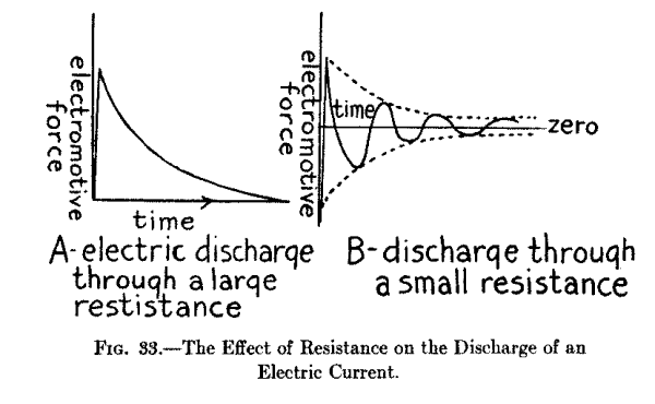
As the capacitance and the inductance of the circuit, which may be made of any value, that is amount, you wish, determines the time period, that is, the length of time for a current to make one complete oscillation, it must be clear that by varying the values of the condenser and the inductance coil you can make the high frequency current oscillate as fast or as slow as you wish within certain limits. Where the electric oscillations that are set up are very fast, the waves sent out by the aerial will be short, and, conversely, where the oscillations are slow the waves emitted will be long.
The easiest way to get a clear conception of how a wireless transmitter sends out electric waves and how a wireless receptor receives them is to take each one separately and follow: (1) in the case of the transmitter, the transformation of the low voltage direct, or alternating current into high potential alternating currents; then find out how these charge the condenser, how this is discharged by the spark gap and sets up high-frequency currents in the oscillation circuits; then (2) in the case of the receptor, to follow the high frequency currents that are set up in the aerial wire and learn how they are transformed into oscillations of lower potential when they have a larger current strength, how these are converted into intermittent direct currents by the detector and which then flow into and operate the telephone receiver.
How Transmitting Set No. 1 Works. The Battery and Spark Coil Circuit.--When you press down on the knob of the key the silver points of it make contact and this closes the circuit; the low voltage direct current from the battery now flows through the primary coil of the spark coil and this magnetizes the soft iron core. The instant it becomes magnetic it pulls the spring of the vibrator over to it and this breaks the circuit; when this takes place the current stops flowing through the primary coil; this causes the core to lose its magnetism when the vibrator spring flies back and again makes contact with the adjusting screw; then the cycle of operations is repeated.
A condenser is connected across the contact points of the vibrator since this gives a much higher voltage at the ends of the secondary coil than where the coil is used without it; this is because: (1) the self-induction of the primary coil makes the pressure of the current rise and when the contact points close the circuit again it discharges through the primary coil, and (2) when the break takes place the current flows into the condenser instead of arcing across the contact points.
Changing the Primary Spark Coil Current Into Secondary Currents.--Now every time the vibrator contact points close the primary circuit the electric current in the primary coil is changed into closed magnetic lines of force and as these cut through the secondary coil they set up in it a momentary current in one direction. Then the instant the vibrator points break apart the primary circuit is opened and the closed magnetic lines of force contract and as they do so they cut the turns of wire in the secondary coil in the opposite direction and this sets up another momentary current in the secondary coil in the other direction. The result is that the low voltage direct current of the battery is changed into alternating currents whose frequency is precisely that of the spring vibrator, but while the frequency of the currents is low their potential, or voltage, is enormously increased.
What Ratio of Transformation Means.--To make a spark coil step up the low voltage direct current into high potential alternating current the primary coil is wound with a couple of layers of thick insulated copper wire and the secondary is wound with a thousand, more or less, number of turns with very fine insulated copper wire. If the primary and secondary coils were wound with the same number of turns of wire then the pressure, or voltage, of the secondary coil at its terminals would be the same as that of the current which flowed through the primary coil. Under these conditions the ratio of transformation, as it is called, would be unity.
The ratio of transformation is directly proportional to the number of turns of wire on the primary and secondary coils and, since this is the case, if you wind 10 turns of wire on the primary coil and 1,000 turns of wire on the secondary coil then you will get 100 times as high a pressure, or voltage, at the terminals of the secondary as that which you caused to flow through the primary coil, but, naturally, the current strength, or amperage, will be proportionately decreased.
The Secondary Spark Coil Circuit.--This includes the secondary coil and the spark gap which are connected together. When the alternating, but high potential, currents which are developed by the secondary coil, reach the balls, or electrodes, of the spark gap the latter are alternately charged positively and negatively.
Now take a given instant when one electrode is charged positively and the other one is charged negatively, then when they are charged to a high enough potential the electric strain breaks down the air gap between them and the two charges rush together as described in the chapter before this one in connection with the discharge of a condenser. When the charges rush together they form a current which burns out the air in the gap and this gives rise to the spark, and as the heated gap between the two electrodes is a very good conductor the electric current surges forth and back with high frequency, perhaps a dozen times, before the air replaces that which has burned out. It is the inrushing air to fill the vacuum of the gap that makes the crackling noise which accompanies the discharge of the electric spark.
In this way then electric oscillations of the order of a million, more or less, are produced and if an aerial and a ground wire are connected to the spark balls, or electrodes, the oscillations will surge up and down it and the energy of these in turn, are changed into electric waves which travel out into space. An open circuit transmitter of this kind will send out waves that are four times as long as the aerial itself, but as the waves it sends out are strongly damped the Government will not permit it to be used.
The Closed Oscillation Circuit.--By using a closed oscillation circuit the transmitter can be tuned to send out waves of a given length and while the waves are not so strongly damped more current can be sent into the aerial wire system. The closed oscillation circuit consists of: (1) a spark gap, (2) a condenser and (3) an oscillation transformer. The high potential alternating current delivered by the secondary coil not only charges the spark gap electrodes which necessarily have a very small capacitance, but it charges the condenser which has a large capacitance and the value of which can be changed at will.
Now when the condenser is fully charged it discharges through the spark gap and then the electric oscillations set up surge to and fro through the closed circuit. As a closed circuit is a very poor radiator of energy, that is, the electric oscillations are not freely converted into electric waves by it, they surge up to, and through the aerial wire; now as the aerial wire is a good radiator nearly all of the energy of the electric oscillations which surge through it are converted into electric waves.
How Transmitting Set No. 2 Works. With Alternating Current. The operation of a transmitting set that uses an alternating current transformer, or power transformer, as it is sometimes called, is even more simple than one using a spark coil. The transformer needs no vibrator when used with alternating current. The current from a generator flows through the primary coil of the transformer and the alternations of the usual lighting current is 60 cycles per second. This current sets up an alternating magnetic field in the core of the transformer and as these magnetic lines of force expand and contract they set up alternating currents of the same frequency but of much higher voltage at the terminals of the secondary coil according to the ratio of the primary and secondary turns of wire as explained under the sub-caption of Ratio of Transformation.
With Direct Current.--When a 110 volt direct current is used to energize the power transformer an electrolytic interruptor is needed to make and break the primary circuit, just as a vibrator is needed for the same purpose with a spark coil. When the electrodes are connected in series with the primary coil of a transformer and a source of direct current having a potential of 40 to 110 volts, bubbles of gas are formed on the end of the platinum, or alloy anode, which prevent the current from flowing until the bubbles break and then the current flows again, in this way the current is rapidly made and broken and the break is very sharp.
Where this type of interrupter is employed the condenser that is usually shunted around the break is not necessary as the interrupter itself has a certain inherent capacitance, due to electrolytic action, and which is called its electrolytic capacitance, and this is large enough to balance the self-induction of the circuit since the greater the number of breaks per minute the smaller the capacitance required.
The Rotary Spark Gap.--In this type of spark gap the two fixed electrodes are connected with the terminals of the secondary coil of the power transformer and also with the condenser and primary of the oscillation transformer. Now whenever any pair of electrodes on the rotating disk are in a line with the pair of fixed electrodes a spark will take place, hence the pitch of the note depends on the speed of the motor driving the disk. This kind of a rotary spark-gap is called non-synchronous and it is generally used where a 60 cycle alternating current is available but it will work with other higher frequencies.
The Quenched Spark Gap.--If you strike a piano string a single quick blow it will continue to vibrate according to its natural period. This is very much the way in which a quenched spark gap sets up oscillations in a coupled closed and open circuit. The oscillations set up in the primary circuit by a quenched spark make only three or four sharp swings and in so doing transfer all of their energy over to the secondary circuit, where it will oscillate some fifty times or more before it is damped out, because the high frequency currents are not forced, but simply oscillate to the natural frequency of the circuit. For this reason the radiated waves approach somewhat the condition of continuous waves, and so sharper tuning is possible.
The Oscillation Transformer.--In this set the condenser in the closed circuit is charged and discharged and sets up oscillations that surge through the closed circuit as in Set No. 1. In this set, however, an oscillation transformer is used and as the primary coil of it is included in the closed circuit the oscillations set up in it produce strong oscillating magnetic lines of force. The magnetic field thus produced sets up in turn electric oscillations in the secondary coil of the oscillation transformer and these surge through the aerial wire system where their energy is radiated in the form of electric waves.
The great advantage of using an oscillation transformer instead of a simple inductance coil is that the capacitance of the closed circuit can be very much larger than that of the aerial wire system. This permits more energy to be stored up by the condenser and this is impressed on the aerial when it is radiated as electric waves.
How Receiving Set No. I Works.--When the electric waves from a distant sending station impinge on the wire of a receiving aerial their energy is changed into electric oscillations that are of exactly the same frequency (assuming the receptor is tuned to the transmitter) but whose current strength (amperage) and potential (voltage) are very small. These electric waves surge through the closed circuit but when they reach the crystal detector the contact of the metal point on the crystal permits more current to flow through it in one direction than it will allow to pass in the other direction. For this reason a crystal detector is sometimes called a rectifier, which it really is.
Thus the high frequency currents which the steel magnet cores of the telephone receiver would choke off are changed by the detector into intermittent direct currents which can flow through the magnet coils of the telephone receiver. Since the telephone receiver chokes off the oscillations, a small condenser can be shunted around it so that a complete closed oscillation circuit is formed and this gives better results.
When the intermittent rectified current flows through the coils of the telephone receiver it energizes the magnet as long as it lasts, when it is de-energized; this causes the soft iron disk, or diaphragm as it is called, which sets close to the ends of the poles of the magnet, to vibrate; and this in turn gives forth sounds such as dots and dashes, speech or music, according to the nature of the electric waves that sent them out at the distant station.
How Receiving Set No. 2 Works.--When the electric oscillations that are set up by the incoming electric waves on the aerial wire surge through the primary coil of the oscillation transformer they produce a magnetic field and as the lines of force of the latter cut the secondary coil, oscillations of the same frequency are set up in it. The potential (voltage) of these oscillations are, however, stepped down in the secondary coil and, hence, their current strength (amperes) is increased.
The oscillations then flow through the closed circuit where they are rectified by the crystal detector and transformed into sound waves by the telephone receiver as described in connection with Set No. 1. The variable condenser shunted across the closed circuit permits finer secondary tuning to be done than is possible without it. Where you are receiving continuous waves from a wireless telephone transmitter (speech or music) you have to tune sharper than is possible with the tuning coil alone and to do this a variable condenser connected in parallel with the secondary coil is necessary.
There is a strikingly close resemblance between sound waves and the way they are set up in the air by a mechanically vibrating body, such as a steel spring or a tuning fork, and electric waves and the way they are set up in the ether by a current oscillating in a circuit. As it is easy to grasp the way that sound waves are produced and behave something will be told about them in this chapter and also an explanation of how electric waves are produced and behave and thus you will be able to get a clear understanding of them and of tuning in general.
Damped and Sustained Mechanical Vibrations.--If you will place one end of a flat steel spring in a vice and screw it up tight as shown at A in Fig. 34, and then pull the free end over and let it go it will vibrate to and fro with decreasing amplitude until it comes to rest as shown at B. When you pull the spring over you store up energy in it and when you let it go the stored up energy is changed into energy of motion and the spring moves forth and back, or vibrates as we call it, until all of its stored up energy is spent.
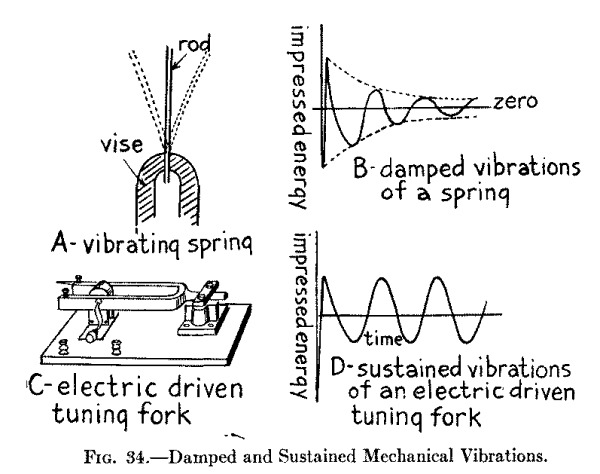
If it were not for the air surrounding it and other frictional losses, the spring would vibrate for a very long time as the stored up energy and the energy of motion would practically offset each other and so the energy would not be used up. But as the spring beats the air the latter is sent out in impulses and the conversion of the vibrations of the spring into waves in the air soon uses up the energy you have imparted to it and it comes to rest.
In order to send out continuous waves in the air instead of damped waves as with a flat steel spring you can use an electric driven tuning fork, see C, in which an electromagnet is fixed on the inside of the prongs and when this is energized by a battery current the vibrations of the prongs of the fork are kept going, or are sustained, as shown in the diagram at D.
Damped and Sustained Electric Oscillations.--The vibrating steel spring described above is a very good analogue of the way that damped electric oscillations which surge in a circuit set up and send out periodic electric waves in the ether while the electric driven tuning fork just described is likewise a good analogue of how sustained oscillations surge in a circuit and set up and send out continuous electric waves in the ether as the following shows.
Now the inductance and resistance of a circuit such as is shown at A in Fig. 35, slows down, and finally damps out entirely, the electric oscillations of the high frequency currents, see B, where these are set up by the periodic discharge of a condenser, precisely as the vibrations of the spring are damped out by the friction of the air and other resistances that act upon it. As the electric oscillations surge to and fro in the circuit it is opposed by the action of the ether which surrounds it and electric waves are set up in and sent out through it and this transformation soon uses up the energy of the current that flows in the circuit.
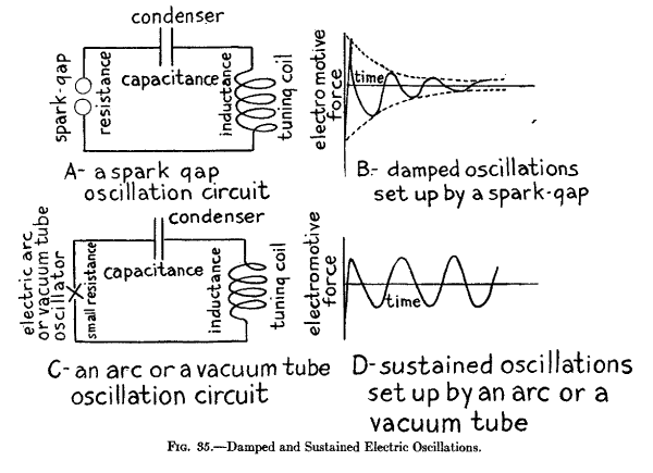
To send out continuous waves in the ether such as are needed for wireless telephony instead of damped waves which are, at the present writing, generally used for wireless telegraphy, an electric oscillation arc or a vacuum tube oscillator must be used, see C, instead of a spark gap. Where a spark gap is used the condenser in the circuit is charged periodically and with considerable lapses of time between each of the charging processes, when, of course, the condenser discharges periodically and with the same time element between them. Where an oscillation arc or a vacuum tube is used the condenser is charged as rapidly as it is discharged and the result is the oscillations are sustained as shown at D.
About Mechanical Tuning.--A tuning fork is better than a spring or a straight steel bar for setting up mechanical vibrations. As a matter of fact a tuning fork is simply a steel bar bent in the middle so that the two ends are parallel. A handle is attached to middle point of the fork so that it can be held easily and which also allows it to vibrate freely, when the ends of the prongs alternately approach and recede from one another. When the prongs vibrate the handle vibrates up and down in unison with it, and imparts its motion to the sounding box, or resonance case as it is sometimes called, where one is used.
If, now, you will mount the fork on a sounding box which is tuned so that it will be in resonance with the vibrations of the fork there will be a direct reinforcement of the vibrations when the note emitted by it will be augmented in strength and quality. This is called simple resonance. Further, if you mount a pair of forks, each on a separate sounding box, and have the forks of the same size, tone and pitch, and the boxes synchronized, that is, tuned to the same frequency of vibration, then set the two boxes a foot or so apart, as shown at A in Fig. 36, when you strike one of the forks with a rubber hammer it will vibrate with a definite frequency and, hence, send out sound waves of a given length. When the latter strike the second fork the impact of the molecules of air of which the sound waves are formed will set its prongs to vibrating and it will, in turn, emit sound waves of the same length and this is called sympathetic resonance, or as we would say in wireless the forks are in tune.
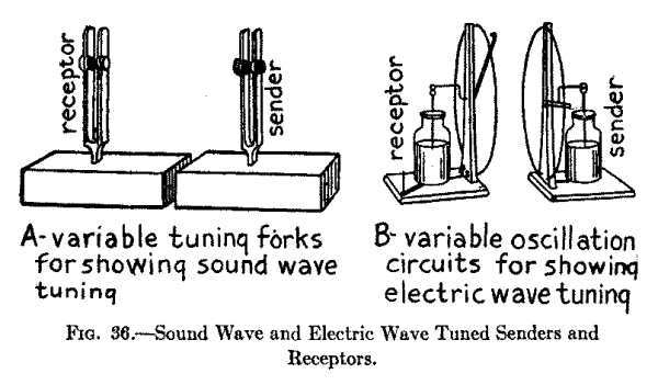
Tuning forks are made with adjustable weights on their prongs and by fixing these to different parts of them the frequency with which the forks vibrate can be changed since the frequency varies inversely with the square of the length and directly with the thickness [Footnote: This law is for forks having a rectangular cross-section. Those having a round cross-section vary as the radius.] of the prongs. Now by adjusting one of the forks so that it vibrates at a frequency of, say, 16 per second and adjusting the other fork so that it vibrates at a frequency of, say, 18 or 20 per second, then the forks will not be in tune with each other and, hence, if you strike one of them the other will not respond. But if you make the forks vibrate at the same frequency, say 16, 20 or 24 per second, when you strike one of them the other will vibrate in unison with it.
About Electric Tuning.--Electric resonance and electric tuning are very like those of acoustic resonance and acoustic tuning which I have just described. Just as acoustic resonance may be simple or sympathetic so electric resonance may be simple or sympathetic. Simple acoustic resonance is the direct reinforcement of a simple vibration and this condition is had when a tuning fork is mounted on a sounding box. In simple electric resonance an oscillating current of a given frequency flowing in a circuit having the proper inductance and capacitance may increase the voltage until it is several times greater than its normal value. Tuning the receptor circuits to the transmitter circuits are examples of sympathetic electric resonance. As a demonstration if you have two Leyden jars (capacitance) connected in circuit with two loops of wire (inductance) whose inductance can be varied as shown at B in Fig. 36, when you make a spark pass between the knobs of one of them by means of a spark coil then a spark will pass in the gap of the other one provided the inductance of the two loops of wire is the same. But if you vary the inductance of the one loop so that it is larger or smaller than that of the other loop no spark will take place in the second circuit.
When a tuning fork is made to vibrate it sends out waves in the air, or sound waves, in all directions and just so when high frequency currents surge in an oscillation circuit they send out waves in the ether, or electric waves, that travel in all directions. For this reason electric waves from a transmitting station cannot be sent to one particular station, though they do go further in one direction than in another, according to the way your aerial wire points.
Since the electric waves travel out in all directions any receiving set properly tuned to the wave length of the sending station will receive the waves and the only limit on your ability to receive from high-power stations throughout the world depends entirely on the wave length and sensitivity of your receiving set. As for tuning, just as changing the length and the thickness of the prongs of a tuning fork varies the frequency with which it vibrates and, hence, the length of the waves it sends out, so, too, by varying the capacitance of the condenser and the inductance of the tuning coil of the transmitter the frequency of the electric oscillations set up in the circuit may be changed and, consequently, the length of the electric waves they send out. Likewise, by varying the capacitance and the inductance of the receptor the circuits can be tuned to receive incoming electric waves of whatever length within the limitation of the apparatus.
While you can receive dots and dashes from spark wireless telegraph stations and hear spoken words and music from wireless telephone stations with a crystal detector receiving set such as described in Chapter III, you can get stations that are much farther away and hear them better with a vacuum tube detector receiving set.
Though the vacuum tube detector requires two batteries to operate it and the receiving circuits are somewhat more complicated than where a crystal detector is used still the former does not have to be constantly adjusted as does the latter and this is another very great advantage. Taken all in all the vacuum tube detector is the most sensitive and the most satisfactory of the detectors that are in use at the present time.
Not only is the vacuum tube a detector of electric wave signals and speech and music but it can also be used to amplify them, that is, to make them stronger and, hence, louder in the telephone receiver and further its powers of amplification are so great that it will reproduce them by means of a loud speaker, just as a horn amplifies the sounds of a phonograph reproducer, until they can be heard by a room or an auditorium full of people. There are two general types of loud speakers, though both use the principle of the telephone receiver. The construction of these loud speakers will be fully described in a later chapter.
Assembled Vacuum Tube Receiving Sets.--You can buy a receiving set with a vacuum tube detector from the very simplest type, which is described in this chapter, to those that are provided with regenerative circuits and amplifying tubes or both, which we shall describe in later chapters, from dealers in electrical apparatus generally. While one of these sets costs more than you can assemble a set for yourself, still, especially in the beginning, it is a good plan to buy an assembled one for it is fitted with a panel on which the adjusting knobs of the rheostat, tuning coil and condenser are mounted and this makes it possible to operate it as soon as you get it home and without the slightest trouble on your part.
You can, however, buy all the various parts separately and mount them yourself. If you want the receptor simply for receiving then it is a good scheme to have all of the parts mounted in a box or enclosed case, but if you want it for experimental purposes then the parts should be mounted on a base or a panel so that all of the connections are in sight and accessible.
A Simple Vacuum Tube Receiving Set.--For this set you should use: (1) a loose coupled tuning coil, (2) a variable condenser, (3) a vacuum tube detector, (4) an A or storage battery giving 6 volts, (5) a B or dry cell battery giving 22-1/2 volts, (6) a rheostat for varying the storage battery current, and (7) a pair of 2,000-ohm head telephone receivers. The loose coupled tuning coil, the variable condenser and the telephone receivers are the same as those described in Chapter III.
The Vacuum Tube Detector. With Two Electrodes.--A vacuum tube in its simplest form consists of a glass bulb like an incandescent lamp in which a wire filament and a metal plate are sealed as shown in Fig. 37, The air is then pumped out of the tube and a vacuum left or after it is exhausted it is filled with nitrogen, which cannot burn.
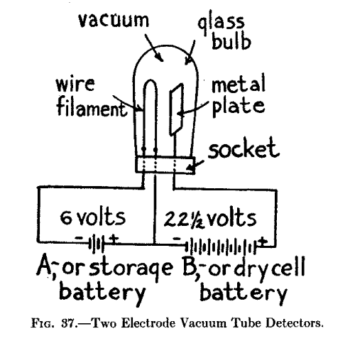
When the vacuum tube is used as a detector, the wire filament is heated red-hot and the metal plate is charged with positive electricity though it remains cold. The wire filament is formed into a loop like that of an incandescent lamp and its outside ends are connected with a 6-volt storage battery, which is called the A battery; then the + or positive terminal of a 22-1/2 volt dry cell battery, called the B battery, is connected to the metal plate while the - or negative terminal of the battery is connected to one of the terminals of the wire filament. The diagram, Fig. 37, simply shows how the two electrode vacuum tube, the A or dry battery, and the B or storage battery are connected up.
Three Electrode Vacuum Tube Detector.--The three electrode vacuum tube detector shown at A in Fig. 38, is much more sensitive than the two electrode tube and has, in consequence, all but supplanted it. In this more recent type of vacuum tube the third electrode, or grid, as it is called, is placed between the wire filament and the metal plate and this allows the current to be increased or decreased at will to a very considerable extent.
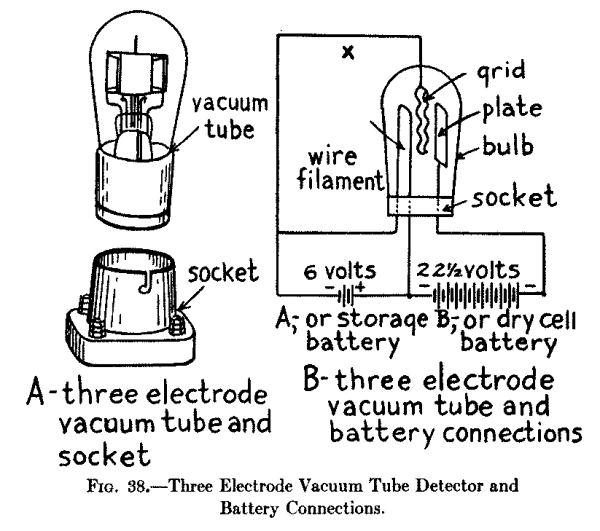
The way the three electrode vacuum tube detector is connected with the batteries is shown at B. The plate, the A or dry cell battery and one terminal of the filament are connected in series--that is, one after the other, and the ends of the filament are connected to the B or storage battery. In assembling a receiving set you must, of course, have a socket for the vacuum tube. A vacuum tube detector costs from $5.00 to $6.00.
The Dry Cell and Storage Batteries.--The reason that a storage battery is used for heating the filament of the vacuum tube detector is because the current delivered is constant, whereas when a dry cell battery is used the current soon falls off and, hence, the heat of the filament gradually grows less. The smallest A or 6 volt storage battery on the market has a capacity of 20 to 40 ampere hours, weighs 13 pounds and costs about $10.00. It is shown at A in Fig. 39. The B or dry cell battery for the vacuum tube plate circuit that gives 22-1/2 volts can be bought already assembled in sealed boxes. The small size is fitted with a pair of terminals while the larger size is provided with taps so that the voltage required by the plate can be adjusted as the proper operation of the tube requires careful regulation of the plate voltage. A dry cell battery for a plate circuit is shown at B.
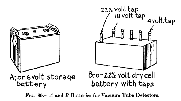
The Filament Rheostat.--An adjustable resistance, called a rheostat, must be used in the filament and storage battery circuit so that the current flowing through the filament can be controlled to a nicety. The rheostat consists of an insulating and a heat resisting form on which is wound a number of turns of resistance wire. A movable contact arm that slides over and presses on the turns of wire is fixed to the knob on top of the rheostat. A rheostat that has a resistance of 6 ohms and a current carrying capacity of 1.5 amperes which can be mounted on a panel board is the right kind to use. It is shown at A and B in Fig. 40 and costs $1.25.
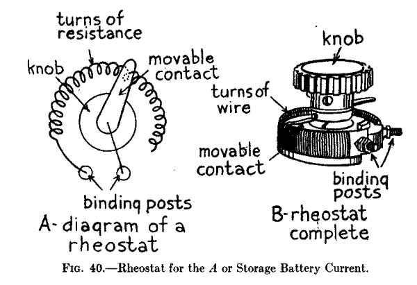
Assembling the Parts.--Begin by placing all of the separate parts of the receiving set on a board or a base of other material and set the tuning coil on the left hand side with the adjustable switch end toward the right hand side so that you can reach it easily. Then set the variable condenser in front of it, set the vacuum tube detector at the right hand end of the tuning coil and the rheostat in front of the detector. Place the two sets of batteries back of the instruments and screw a couple of binding posts a and b to the right hand lower edge of the base for connecting in the head phones all of which is shown at A in Fig. 41.
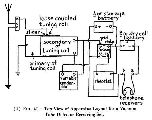
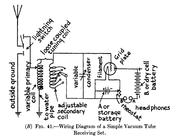
Connecting Up the Parts.--To wire up the different parts begin by connecting the sliding contact of the primary coil of the loose coupled tuning coil (this you will remember is the outside one that is wound with fine wire) to the upper post of the lightning switch and connect one terminal of this coil with the water pipe. Now connect the free end of the secondary coil of the tuning coil (this is the inside coil that is wound with heavy wire) to one of the binding posts of the variable condenser and connect the movable contact arm of the adjustable switch of the primary of the tuning coil with the other post of the variable condenser.
Next connect the grid of the vacuum tube to one of the posts of the condenser and then connect the plate of the tube to the carbon terminal of the B or dry cell battery which is the + or positive pole and connect the zinc terminal of the - or negative pole to the binding post a, connect the post b to the other side of the variable condenser and then connect the terminals of the head phones to the binding posts a and b. Whatever you do be careful not to get the plate connections of the battery reversed.
Now connect one of the posts of the rheostat to one terminal of the filament and the other terminal of the filament to the - or negative terminal of the A or storage battery and the + or positive terminal of the A or storage battery to the other post of the rheostat. Finally connect the + or positive terminal of the A or storage battery with the wire that runs from the head phones to the variable condenser, all of which is shown in the wiring diagram at B in Fig. 41.
Adjusting the Vacuum Tube Detector Receiving Set.--A vacuum tube detector is tuned exactly in the same way as the Crystal Detector Set No. 2 described in Chapter III, in-so-far as the tuning coil and variable condenser are concerned. The sensitivity of the vacuum tube detector receiving set and, hence, the distance over which signals and other sounds can be heard depends very largely on the sensitivity of the vacuum tube itself and this in turn depends on: (1) the right amount of heat developed by the filament, or filament brilliancy as it is called, (2) the right amount of voltage applied to the plate, and (3) the extent to which the tube is exhausted where this kind of a tube is used.
To vary the current flowing from the A or storage battery through the filament so that it will be heated to the right degree you adjust the rheostat while you are listening in to the signals or other sounds. By carefully adjusting the rheostat you can easily find the point at which it makes the tube the most sensitive. A rheostat is also useful in that it keeps the filament from burning out when the current from the battery first flows through it. You can very often increase the sensitiveness of a vacuum tube after you have used it for a while by recharging the A or storage battery.
The degree to which a vacuum tube has been exhausted has a very pronounced effect on its sensitivity. The longer the tube is used the lower its vacuum gets and generally the less sensitive it becomes. When this takes place (and you can only guess at it) you can very often make it more sensitive by warming it over the flame of a candle. Vacuum tubes having a gas content (in which case they are, of course, no longer vacuum tubes in the strict sense) make better detectors than tubes from which the air has been exhausted and which are sealed off in this evacuated condition because their sensitiveness is not dependent on the degree of vacuum as in the latter tubes. Moreover, a tube that is completely exhausted costs more than one that is filled with gas.
The reason a vacuum tube detector is more sensitive than a crystal detector is because while the latter merely rectifies the oscillating current that surges in the receiving circuits, the former acts as an amplifier at the same time. The vacuum tube can be used as a separate amplifier in connection with either: (1) a crystal detector or (2) a vacuum tube detector, and (a) it will amplify either the radio frequency currents, that is the high frequency oscillating currents which are set up in the oscillation circuits or (b) it will amplify the audio frequency currents, that is, the low frequency alternating currents that flow through the head phone circuit.
To use the amplified radio frequency oscillating currents or amplified audio frequency alternating currents that are set up by an amplifier tube either a high resistance, called a grid leak, or an amplifying transformer, with or without an iron core, must be connected with the plate circuit of the first amplifier tube and the grid circuit of the next amplifier tube or detector tube, or with the wire point of a crystal detector. Where two or more amplifier tubes are coupled together in this way the scheme is known as cascade amplification.
Where either a radio frequency transformer, that is one without the iron core, or an audio frequency transformer, that is one with the iron core, is used to couple the amplifier tube circuits together better results are obtained than where a high resistance grid leak is used, but the amplifying tubes have to be more carefully shielded from each other or they will react and set up a howling noise in the head phones. On the other hand grid leaks cost less but they are more troublesome to use as you have to find out for yourself the exact resistance value they must have and this you can do only by testing them out.
A Grid Leak Amplifier Receiving Set. With Crystal Detector.--The apparatus you need for this set includes: (1) a loose coupled tuning coil, (2) a variable condenser, (3) two fixed condensers, (4) a crystal detector, or better a vacuum tube detector, (5) an A or 6 volt storage battery, (6) a rheostat, (7) a B or 22-1/2 volt dry cell battery, (8) a fixed resistance unit, or leak grid as it is called, and (9) a pair of head-phones. The tuning coil, variable condenser, fixed condensers, crystal detectors and head-phones are exactly the same as those described in Set No. 2 in Chapter III. The A and B batteries are exactly the same as those described in Chapter VIII. The vacuum tube amplifier and the grid leak are the only new pieces of apparatus you need and not described before.
The Vacuum Tube Amplifier.--This consists of a three electrode vacuum tube exactly like the vacuum tube detector described in Chapter VIII and pictured in Fig. 38, except that instead of being filled with a non-combustible gas it is evacuated, that is, the air has been completely pumped out of it. The gas filled tube, however, can be used as an amplifier and either kind of tube can be used for either radio frequency or audio frequency amplification, though with the exhausted tube it is easier to obtain the right plate and filament voltages for good working.
The Fixed Resistance Unit, or Grid Leak.--Grid leaks are made in different ways but all of them have an enormously high resistance. One way of making them consists of depositing a thin film of gold on a sheet of mica and placing another sheet of mica on top to protect it the whole being enclosed in a glass tube as shown at A in Fig. 42. These grid leaks are made in units of from 50,000 ohms (.05 megohm) to 5,000,000 ohms (5 megohms) and cost from $1 to $2.
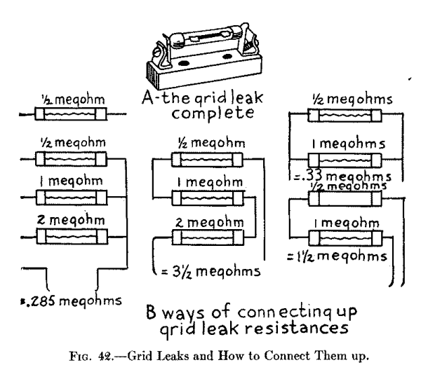
As the value of the grid leak you will need depends very largely upon the construction of the different parts of your receiving set and on the kind of aerial wire system you use with it you will have to try out various resistances until you hit the right one. The resistance that will give the best results, however, lies somewhere between 500,000 ohms (1/2 a megohm) and 3,000,000 ohms (3 megohms) and the only way for you to find this out is to buy 1/2, 1 and 2 megohm grid leak resistances and connect them up in different ways, as shown at B, until you find the right value.
Assembling the Parts for a Crystal Detector Set.--Begin by laying the various parts out on a base or a panel with the loose coupled tuning coil on the left hand side, but with the adjustable switch of the secondary coil on the right hand end or in front according to the way it is made. Then place the variable condenser, the rheostat, the crystal detector and the binding posts for the head phones in front of and in a line with each other. Set the vacuum tube amplifier back of the rheostat and the A and B batteries back of the parts or in any other place that may be convenient. The fixed condensers and the grid leak can be placed anywhere so that it will be easy to connect them in and you are ready to wire up the set.
Connecting Up the Parts for a Crystal Detector.--First connect the sliding contact of the primary of the tuning coil to the leading-in wire and one of the end wires of the primary to the water pipe, as shown in Fig. 43. Now connect the adjustable arm that makes contact with one end of the secondary of the tuning coil to one of the posts of the variable condenser; then connect the other post of the latter with a post of the fixed condenser and the other post of this with the grid of the amplifying tube.
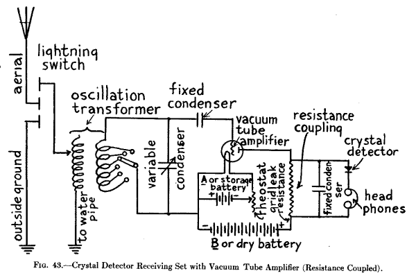
Connect the first post of the variable condenser to the + or positive electrode of the A battery and its - or negative electrode with the rotating contact arm of the rheostat. Next connect one end of the resistance coil of the rheostat to one of the posts of the amplifier tube that leads to the filament and the other filament post to the + or positive electrode of the A battery. This done connect the negative, that is, the zinc pole of the B battery to the positive electrode of the A battery and connect the positive, or carbon pole of the former with one end of the grid leak and connect the other end of this to the plate of the amplifier tube.
To the end of the grid leak connected with the plate of the amplifier tube connect the metal point of your crystal detector, the crystal of the latter with one post of the head phones and the other post of them with the other end of the grid leak and, finally, connect a fixed condenser in parallel with--that is across the ends of the grid leak, all of which is shown in the wiring diagram in Fig. 43.
A Grid Leak Amplifying Receiving Set With Vacuum Tube Detector.--A better amplifying receiving set can be made than the one just described by using a vacuum tube detector instead of the crystal detector. This set is built up exactly like the crystal detector described above and shown in Fig. 43 up to and including the grid leak resistance, but shunted across the latter is a vacuum tube detector, which is made and wired up precisely like the one shown at A in Fig. 41 in the chapter ahead of this one. The way a grid leak and vacuum tube detector with a one-step amplifier are connected up is shown at A in Fig. 44. Where you have a vacuum tube detector and one or more amplifying tubes connected up, or in cascade as it is called, you can use an A, or storage battery of 6 volts for all of them as shown at B in Fig. 44, but for every vacuum tube you use you must have a B or 22-1/2 volt dry battery to charge the plate with.
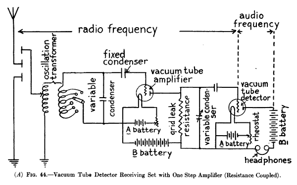
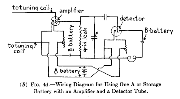
A Radio Frequency Transformer Amplifying Receiving Set.--Instead of using a grid leak resistance to couple up the amplifier and detector tube circuits you can use a radio frequency transformer, that is, a transformer made like a loose coupled tuning coil, and without an iron core, as shown in the wiring diagram at A in Fig. 45. In this set, which gives better results than where a grid leak is used, the amplifier tube is placed in the first oscillation circuit and the detector tube in the second circuit.
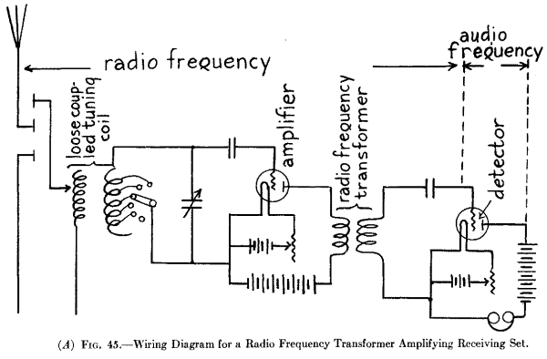
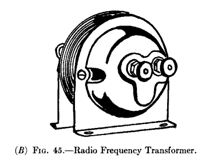
Since the radio frequency transformer has no iron core the high frequency, or radio frequency oscillating currents, as they are called, surge through it and are not changed into low frequency, or audio frequency pulsating currents, until they flow through the detector. Since the diagram shows only one amplifier and one radio frequency transformer, it is consequently a one step amplifier; however, two, three or more, amplifying tubes can be connected up by means of an equal number of radio frequency transformers when you will get wonderful results. Where a six step amplifier, that is, where six amplifying tubes are connected together, or in cascade, the first three are usually coupled up with radio frequency transformers and the last three with audio frequency transformers. A radio frequency transformer is shown at B and costs $6 to $7.
An Audio Frequency Transformer Amplifying Receiving Set.--Where audio frequency transformers are used for stepping up the voltage of the current of the detector and amplifier tubes, the radio frequency current does not get into the plate circuit of the detector at all for the reason that the iron core of the transformer chokes them off, hence, the succeeding amplifiers operate at audio frequencies. An audio frequency transformer is shown at A in Fig. 46 and a wiring diagram showing how the tubes are connected in cascade with the transformers is shown at B; it is therefore a two-step audio frequency receiving set.
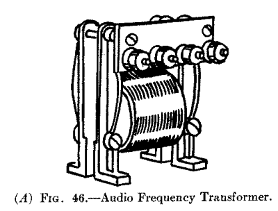
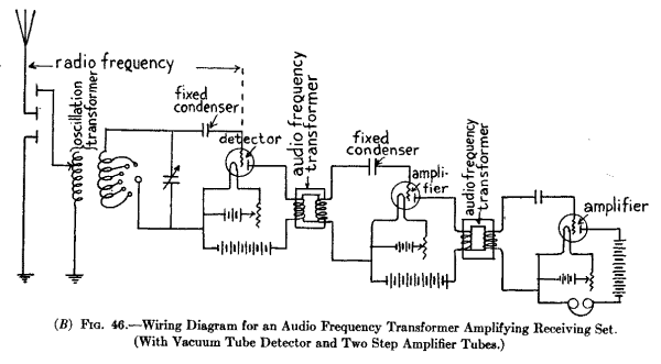
A Six Step Amplifier Receiving Set With a Loop Aerial.--By using a receiving set having a three step radio frequency and a three step audio frequency, that is, a set in which there are coupled three amplifying tubes with radio frequency transformers and three amplifying tubes with audio frequency transformers as described under the caption A Radio Frequency Transformer Receiving Set, you can use a loop aerial in your room thus getting around the difficulties--if such there be--in erecting an out-door aerial. You can easily make a loop aerial by winding 10 turns of No. 14 or 16 copper wire about 1/16 inch apart on a wooden frame two feet on the side as shown in Fig. 47. With this six step amplifier set and loop aerial you can receive wave lengths of 150 to 600 meters from various high power stations which are at considerable distances away.
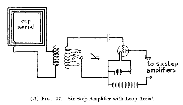
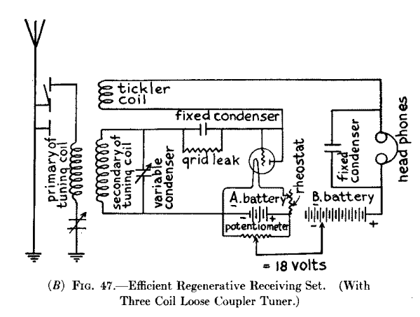
How to Prevent Howling.--Where radio frequency or audio frequency amplifiers are used to couple your amplifier tubes in cascade you must take particular pains to shield them from one another in order to prevent the feed back of the currents through them, which makes the head phones or loud speaker howl. To shield them from each other the tubes should be enclosed in metal boxes and placed at least 6 inches apart while the transformers should be set so that their cores are at right angles to each other and these also should be not less than six inches apart.
While a vacuum tube detector has an amplifying action of its own, and this accounts for its great sensitiveness, its amplifying action can be further increased to an enormous extent by making the radio frequency currents that are set up in the oscillation circuits react on the detector.
Such currents are called feed-back or regenerative currents and when circuits are so arranged as to cause the currents to flow back through the detector tube the amplification keeps on increasing until the capacity of the tube itself is reached. It is like using steam over and over again in a steam turbine until there is no more energy left in it. A system of circuits which will cause this regenerative action to take place is known as the Armstrong circuits and is so called after the young man who discovered it.
Since the regenerative action of the radio frequency currents is produced by the detector tube itself and which sets up an amplifying effect without the addition of an amplifying tube, this type of receiving set has found great favor with amateurs, while in combination with amplifying tubes it multiplies their power proportionately and it is in consequence used in one form or another in all the better sets.
There are many different kinds of circuits which can be used to produce the regenerative amplification effect while the various kinds of tuning coils will serve for coupling them; for instance a two or three slide single tuning coil will answer the purpose but as it does not give good results it is not advisable to spend either time or money on it. A better scheme is to use a loose coupler formed of two or three honeycomb or other compact coils, while a variocoupler or a variometer or two will produce the maximum regenerative action.
The Simplest Type of Regenerative Receiving Set. With Loose Coupled Tuning Coil.--While this regenerative set is the simplest that will give anything like fair results it is here described not on account of its desirability, but because it will serve to give you the fundamental idea of how the feed-back circuit is formed.
For this set you need: (1) a loose-coupled tuning coil such as described in Chapter III, (2) a variable condenser of .001 mfd. (microfarad) capacitance; (3) one fixed condenser of .001 mfd.; (4) one fixed condenser for the grid leak circuit of .00025 mfd.; (5) a grid leak of 1/2 to 2 megohms resistance; (6) a vacuum tube detector; (7) an A 6 volt battery; (8) a rheostat; (9) a B 22 1/2 volt battery; and (10) a pair of 2000 ohm head phones.
Connecting Up the Parts.--Begin by connecting the leading-in wire of the aerial with the binding post end of the primary coil of the loose coupler as shown in the wiring diagram Fig. 48 and then connect the sliding contact with the water pipe or other ground. Connect the binding post end of the primary coil with one post of the variable condenser, connect the other post of this with one of the posts of the .00025 mfd. condenser and the other end of this with the grid of the detector tube; then around this condenser shunt the grid leak resistance.
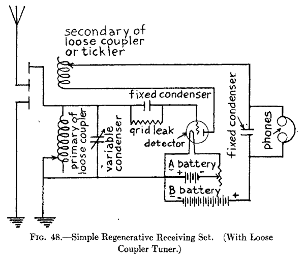
Next connect the sliding contact of the primary coil with the other post of the variable condenser and from this lead a wire on over to one of the terminals of the filament of the vacuum tube; to the other terminal of the filament connect one of the posts of the rheostat and connect the other post to the - or negative electrode of the A battery and then connect the + or positive electrode of it to the other terminal of the filament.
Connect the + or positive electrode of the A battery with one post of the .001 mfd. fixed condenser and connect the other post of this to one of the ends of the secondary coil of the tuning coil and which is now known as the tickler coil; then connect the other end of the secondary, or tickler coil to the plate of the vacuum tube. In the wiring diagram the secondary, or tickler coil is shown above and in a line with the primary coil but this is only for the sake of making the connections clear; in reality the secondary, or tickler coil slides to and fro in the primary coil as shown and described in Chapter III. Finally connect the negative, or zinc pole of the B battery to one side of the fixed condenser, the positive, or carbon, pole to one of the terminals of the head phones and the other terminal of this to the other post of the fixed condenser when your regenerative set is complete.
An Efficient Regenerative Receiving Set. With Three Coil Loose Coupler.--To construct a really good regenerative set you must use a loose coupled tuner that has three coils, namely a primary, a secondary and a tickler coil. A tuner of this kind is made like an ordinary loose coupled tuning coil but it has a third coil as shown at A and B in Fig. 49. The middle coil, which is the secondary, is fixed to the base, and the large outside coil, which is the primary, is movable, that is it slides to and fro over the middle coil, while the small inside coil, which is the tickler, is also movable and can slide in or out of the middle coil. None of these coils is variable; all are wound to receive waves up to 360 meters in length when used with a variable condenser of .001 mfd. capacitance. In other words you slide the coils in and out to get the right amount of coupling and you tune by adjusting the variable condenser to get the exact wave length you want.
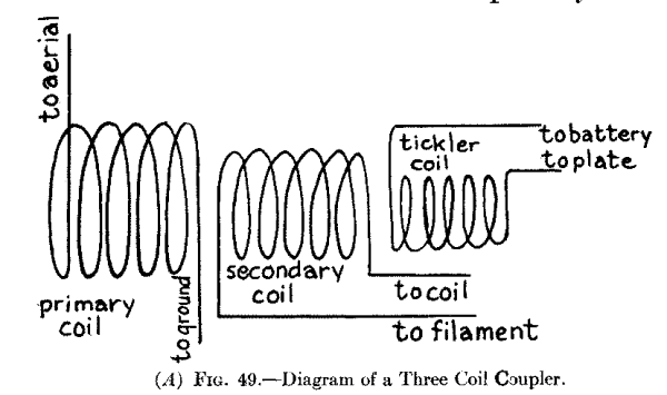
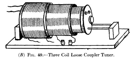
With Compact Coils.--Compact coil tuners are formed of three fixed inductances wound in flat coils, and these are pivoted in a mounting so that the distance between them and, therefore, the coupling, can be varied, as shown at A in Fig. 50. These coils are wound up by the makers for various wave lengths ranging from a small one that will receive waves of any length up to 360 meters to a large one that has a maximum of 24,000 meters. For an amateur set get three of the smallest coils when you can not only hear amateur stations that send on a 200 meter wave but broadcasting stations that send on a 360 meter wave.
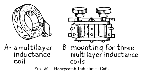
These three coils are mounted with panel plugs which latter fit into a stand, or mounting, so that the middle coil is fixed, that is, stationary, while the two outside coils can be swung to and fro like a door; this scheme permits small variations of coupling to be had between the coils and this can be done either by handles or by means of knobs on a panel board. While I have suggested the use of the smallest size coils, you can get and use those wound for any wave length you want to receive and when those are connected with variometers and variable condensers, and with a proper aerial, you will have a highly efficient receptor that will work over all ranges of wave lengths. The smallest size coils cost about $1.50 apiece and the mounting costs about $6 or $7 each.
The A Battery Potentiometer.--This device is simply a resistance like the rheostat described in connection with the preceding vacuum tube receiving sets but it is wound to 200 or 300 ohms resistance as against 1-1/2 to 6 ohms of the rheostat. It is, however, used as well as the rheostat. With a vacuum tube detector, and especially with one having a gas-content, a potentiometer is very necessary as it is only by means of it that the potential of the plate of the detector can be accurately regulated. The result of proper regulation is that when the critical potential value is reached there is a marked increase in the loudness of the sounds that are emitted by the head phones.
As you will see from A in Fig. 51 it has three taps. The two taps which are connected with the ends of the resistance coil are shunted around the A battery and the third tap, which is attached to the movable contact arm, is connected with the B battery tap, see B, at which this battery gives 18 volts. Since the A battery gives 6 volts you can vary the potential of the plate from 18 to 24 volts. The potentiometer must never be shunted around the B battery or the latter will soon run down. A potentiometer costs a couple of dollars.
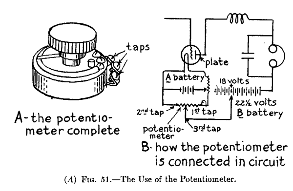
The Parts and How to Connect Them Up.--For this regenerative set you will need: (1) a honeycomb or other compact three-coil tuner, (2) two variable (.001 and .0005 mfd.) condensers; (3) a .00025 mfd. fixed condenser; (4) a 1/2 to 2 megohm grid leak; (5) a tube detector; (6) a 6 volt A battery; (7) a rheostat; (8) a potentiometer; (9) an 18 or 20 volt B battery; (10) a fixed condenser of .001 mfd. fixed condenser; and (11) a pair of 2000 ohm head phones.
To wire up the parts connect the leading-in wire of the aerial with the primary coil, which is the middle one of the tuner, and connect the other terminal with the ground. Connect the ends of the secondary coil, which is the middle one, with the posts of the variable condenser and connect one of the posts of the latter with one post of the fixed .00025 mfd. condenser and the other post of this with the grid; then shunt the grid leak around it. Next connect the other post of the variable condenser to the - or negative electrode of the A battery; the + or positive electrode of this to one terminal of the detector filament and the other end of the latter to the electrode of the A battery.
Now connect one end of the tickler coil with the detector plate and the other post to the fixed .001 mfd. condenser, then the other end of this to the positive or carbon pole of the B battery.
This done shunt the potentiometer around the A battery and run a wire from the movable contact of it (the potentiometer) over to the 18 volt tap, (see B, Fig. 51), of the B battery. Finally, shunt the head phones and the .001 mfd. fixed condenser and you are ready to try out conclusions.
A Regenerative Audio Frequency Amplifier Receiving Set.--The use of amateur regenerative cascade audio frequency receiving sets is getting to be quite common. To get the greatest amplification possible with amplifying tubes you have to keep a negative potential on the grids. You can, however, get very good results without any special charging arrangement by simply connecting one post of the rheostat with the negative terminal of the filament and connecting the low potential end of the secondary of the tuning coil with the - or negative electrode of the A battery. This scheme will give the grids a negative bias of about 1 volt. You do not need to bother about these added factors that make for high efficiency until after you have got your receiving set in working order and understand all about it.
The Parts and How to Connect Them Up.--Exactly the same parts are needed for this set as the one described above, but in addition you will want: (1) two more rheostats; (2) two more sets of B 22-1/2 volt batteries; (3) two amplifier tubes, and (4) two audio frequency transformers as described in Chapter IX and pictured at A in Fig. 46.
To wire up the parts begin by connecting the leading-in wire to one end of the primary of the tuning coil and then connect the other end of the coil with the ground. A variable condenser of .001 mfd. capacitance can be connected in the ground wire, as shown in Fig. 52, to good advantage although it is not absolutely needed. Now connect one end of the secondary coil to one post of a .001 mfd. variable condenser and the other end of the secondary to the other post of the condenser.
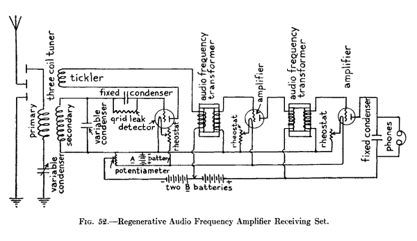
Next bring a lead (wire) from the first post of the variable condenser over to the post of the first fixed condenser and connect the other post of the latter with the grid of the detector tube. Shunt 1/2 to 2 megohm grid leak resistance around the fixed condenser and then connect the second post of the variable condenser to one terminal of the detector tube filament. Run this wire on over and connect it with the first post of the second rheostat, the second post of which is connected with one terminal of the filament of the first amplifying tube; then connect the first post of the rheostat with one end of the secondary coil of the first audio frequency transformer, and the other end of this coil with the grid of the first amplifier tube.
Connect the lead that runs from the second post of variable condenser to the first post of the third rheostat, the second post of which is connected with one terminal of the second amplifying tube; then connect the first post of the rheostat with one end of the secondary coil of the second audio frequency transformer and the other end of this coil with the grid of the second amplifier tube.
This done connect the - or negative electrode of the A battery with the second post of the variable condenser and connect the + or positive electrode with the free post of the first rheostat, the other post of which connects with the free terminal of the filament of the detector. From this lead tap off a wire and connect it to the free terminal of the filament of the first amplifier tube, and finally connect the end of the lead with the free terminal of the filament of the second amplifier tube.
Next shunt a potentiometer around the A battery and connect the third post, which connects with the sliding contact, to the negative or zinc pole of a B battery, then connect the positive or carbon pole of it to the negative or zinc pole of a second B battery and the positive or carbon pole of the latter with one end of the primary coil of the second audio frequency transformer and the other end of it to the plate of the first amplifying tube. Run the lead on over and connect it to one of the terminals of the second fixed condenser and the other terminal of this with the plate of the second amplifying tube. Then shunt the headphones around the condenser.
Finally connect one end of the tickler coil of the tuner with the plate of the detector tube and connect the other end of the tickler to one end of the primary coil of the first audio frequency transformer and the other end of it to the wire that connects the two B batteries together.
A short wave receiving set is one that will receive a range of wave lengths of from 150 to 600 meters while the distance over which the waves can be received as well as the intensity of the sounds reproduced by the headphones depends on: (1) whether it is a regenerative set and (2) whether it is provided with amplifying tubes.
High-grade regenerative sets designed especially for receiving amateur sending stations that must use a short wave length are built on the regenerative principle just like those described in the last chapter and further amplification can be had by the use of amplifier tubes as explained in Chapter IX, but the new feature of these sets is the use of the variocoupler and one or more variometers. These tuning devices can be connected up in different ways and are very popular with amateurs at the present time.
Differing from the ordinary loose coupler the variometer has no movable contacts while the variometer is provided with taps so that you can connect it up for the wave length you want to receive. All you have to do is to tune the oscillation circuits to each other is to turn the rotor, which is the secondary coil, around in the stator, as the primary coil is called in order to get a very fine variation of the wave length. It is this construction that makes sharp tuning with these sets possible, by which is meant that all wave lengths are tuned out except the one which the receiving set is tuned for.
A Short Wave Regenerative Receiver--With One Variometer and Three Variable Condensers.--This set also includes a variocoupler and a grid coil. The way that the parts are connected together makes it a simple and at the same time a very efficient regenerative receiver for short waves. While this set can be used without shielding the parts from each other the best results are had when shields are used.
The parts you need for this set include: (1) one variocoupler; (2) one .001 microfarad variable condenser; (3) one .0005 microfarad variable condenser; (4) one .0007 microfarad variable condenser; (5) one 2 megohm grid leak; (6) one vacuum tube detector; (7) one 6 volt A battery; (8) one 6 ohm, 1-1/2 ampere rheostat; (9) one 200 ohm potentiometer; (10) one 22-1/2 volt B battery; (11) one .001 microfarad fixed condenser, (12) one pair of 2,000 ohm headphones, and (13) a variometer.
The Variocoupler.--A variocoupler consists of a primary coil wound on the outside of a tube of insulating material and to certain turns of this taps are connected so that you can fix the wave length which your aerial system is to receive from the shortest wave; i.e., 150 meters on up by steps to the longest wave, i.e., 600 meters, which is the range of most amateur variocouplers that are sold in the open market. This is the part of the variocoupler that is called the stator.
The secondary coil is wound on the section of a ball mounted on a shaft and this is swung in bearings on the stator so that it can turn in it. This part of the variocoupler is called the rotor and is arranged so that it can be mounted on a panel and adjusted by means of a knob or a dial. A diagram of a variocoupler is shown at A in Fig. 53, and the coupler itself at B. There are various makes and modifications of variocouplers on the market but all of them are about the same price which is $6.00 or $8.00.
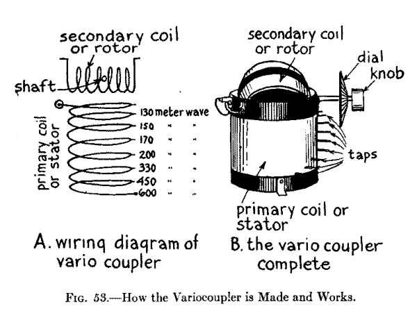
The Variometer.--This device is quite like the variocoupler, but with these differences: (1) the rotor turns in the stator, which is also the section of a ball, and (2) one end of the primary is connected with one end of the secondary coil. To be really efficient a variometer must have a small resistance and a large inductance as well as a small dielectric loss. To secure the first two of these factors the wire should be formed of a number of fine, pure copper wires each of which is insulated and the whole strand then covered with silk. This kind of wire is the best that has yet been devised for the purpose and is sold under the trade name of litzendraht.
A new type of variometer has what is known as a basket weave, or wavy wound stator and rotor. There is no wood, insulating compound or other dielectric materials in large enough quantities to absorb the weak currents that flow between them, hence weaker sounds can be heard when this kind of a variometer is used. With it you can tune sharply to waves under 200 meters in length and up to and including wave lengths of 360 meters. When amateur stations of small power are sending on these short waves this style of variometer keeps the electric oscillations at their greatest strength and, hence, the reproduced sounds will be of maximum intensity. A wiring diagram of a variometer is shown at A in Fig. 54 and a basketball variometer is shown complete at B.
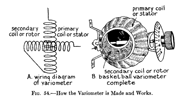
Connecting Up the Parts.--To hook-up the set connect the leading-in wire to one end of the primary coil, or stator, of the variocoupler and solder a wire to one of the taps that gives the longest wave length you want to receive. Connect the other end of this wire with one post of a .001 microfarad variable condenser and connect the other post with the ground as shown in Fig. 55. Now connect one end of the secondary coil, or rotor, to one post of a .0007 mfd. variable condenser, the other post of this to one end of the grid coil and the other end of this with the remaining end of the rotor of the variocoupler.
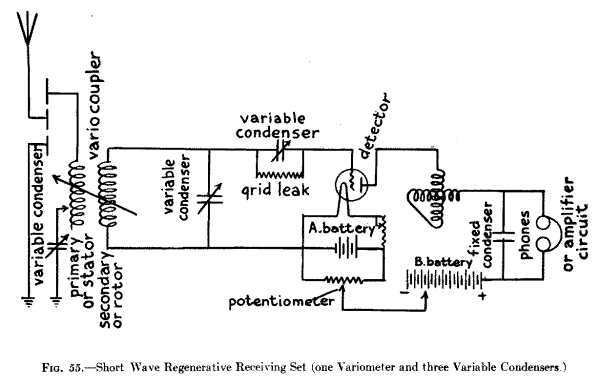
Next connect one post of the .0007 mfd. condenser with one of the terminals of the detector filament; then connect the other post of this condenser with one post of the .0005 mfd. variable condenser and the other post of this with the grid of the detector, then shunt the megohm grid leak around the latter condenser. This done connect the other terminal of the filament to one post of the rheostat, the other post of this to the - or negative electrode of the 6 volt A battery and the + or positive electrode of the latter to the other terminal of the filament.
Shunt the potentiometer around the A battery and connect the sliding contact with the - or zinc pole of the B battery and the + or carbon pole with one terminal of the headphone; connect the other terminal to one of the posts of the variometer and the other post of the variometer to the plate of the detector. Finally shunt a .001 mfd. fixed condenser around the headphones. If you want to amplify the current with a vacuum tube amplifier connect in the terminals of the amplifier circuit shown at A in Figs. 44 or 45 at the point where they are connected with the secondary coil of the loose coupled tuning coil, in those diagrams with the binding posts of Fig. 55 where the phones are usually connected in.
Short Wave Regenerative Receiver. With Two Variometers and Two Variable Condensers.--This type of regenerative receptor is very popular with amateurs who are using high-grade short-wave sets. When you connect up this receptor you must keep the various parts well separated. Screw the variocoupler to the middle of the base board or panel, and secure the variometers on either side of it so that the distance between them will be 9 or 10 inches. By so placing them the coupling will be the same on both sides and besides you can shield them from each other easier.
For the shield use a sheet of copper on the back of the panel and place a sheet of copper between the parts, or better, enclose the variometers and detector and amplifying tubes if you use the latter in sheet copper boxes. When you set up the variometers place them so that their stators are at right angles to each other for otherwise the magnetic lines of force set up by the coils of each one will be mutually inductive and this will make the headphones or loud speaker howl. Whatever tendency the receptor has to howl with this arrangement can be overcome by putting in a grid leak of the right resistance and adjusting the condenser.
The Parts and How to Connect Them Up.--For this set you require: (1) one variocoupler; (2) two variometers; (3) one .001 microfarad variable condenser; (4) one .0005 microfarad variable condenser; (5) one 2 megohm grid leak resistance; (6) one vacuum tube detector; (7) one 6 volt A battery; (8) one 200 ohm potentiometer; (9) one 22-1/2 volt B battery; (10) one .001 microfarad fixed condenser, and (11) one pair of 2,000 ohm headphones.
To wire up the set begin by connecting the leading-in wire to the fixed end of the primary coil, or stator, of the variocoupler, as shown in Fig. 56, and connect one post of the .001 mfd. variable condenser to the stator by soldering a short length of wire to the tap of the latter that gives the longest wave you want to receive. Now connect one end of the secondary coil, or rotor, of the variocoupler with one post of the .0005 mfd. variable condenser and the other part to the grid of the detector tube. Connect the other end of the rotor of the variocoupler to one of the posts of the first variometer and the other post of this to one of the terminals of the detector filament.
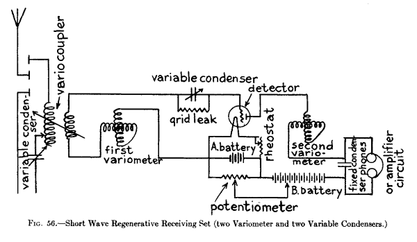
Connect this filament terminal with the - or negative electrode of the A battery and the + or positive electrode of this with one post of the rheostat and lead a wire from the other post to the free terminal of the filament. This done shunt the potential around the A battery and connect the sliding contact to the - or zinc pole of the B battery and the + or carbon pole of this to one terminal of the headphones, while the other terminal of this leads to one of the posts of the second variometer, the other post of which is connected to the plate of the detector tube. If you want to add an amplifier tube then connect it to the posts instead of the headphones as described in the foregoing set.
All receiving sets that receive over a range of wave lengths of from 150 meters to 3,000 meters are called intermediate wave sets and all sets that receive wave lengths over a range of anything more than 3,000 meters are called long wave sets. The range of intermediate wave receptors is such that they will receive amateur, broadcasting, ship and shore Navy, commercial, Arlington's time and all other stations using spark telegraph damped waves or arc or vacuum tube telephone continuous waves but not continuous wave telegraph signals, unless these have been broken up into groups at the transmitting station. To receive continuous wave telegraph signals requires receiving sets of special kind and these will be described in the next chapter.
Intermediate Wave Receiving Sets.--There are two chief schemes employed to increase the range of wave lengths that a set can receive and these are by using: (1) loading coils and shunt condensers, and (2) bank-wound coils and variable condensers. If you have a short-wave set and plan to receive intermediate waves with it then loading coils and fixed condensers shunted around them affords you the way to do it, but if you prefer to buy a new receptor then the better way is to get one with bank-wound coils and variable condensers; this latter way preserves the electrical balance of the oscillation circuits better, the electrical losses are less and the tuning easier and sharper.
Intermediate Wave Set With Loading Coils.--For this intermediate wave set you can use either of the short-wave sets described in the foregoing chapter. For the loading coils use honeycomb coils, or other good compact inductance coils, as shown in Chapter X and having a range of whatever wave length you wish to receive. The following table shows the range of wave length of the various sized coils when used with a variable condenser having a .001 microfarad capacitance, the approximate inductance of each coil in millihenries and prices at the present writing:
                     Approximate Wave
                   Length in Meters in

  Millihenries
  Inductance         .001 mfd. Variable           Mounted
    Appx.              Air Condenser.            on Plug

     .040                130--  375               $1.40
     .075                180--  515                1.40
     .15                 240--  730                1.50
     .3                  330-- 1030                1.50
     .6                  450-- 1460                1.55
    1.3                  660-- 2200                1.60
    2.3                  930-- 2850                1.65
    4.5                 1300-- 4000                1.70
    6.5                 1550-- 4800                1.75
   11.                  2050-- 6300                1.80
   20.                  3000-- 8500                2.00
   40.                  4000--12000                2.15
   65.                  5000--15000                2.35
  100.                  6200--19000                2.60
  125.                  7000--21000                3.00
  175.                  8200--24000                3.50
These and other kinds of compact coils can be bought at electrical supply houses that sell wireless goods. If your aerial is not very high or long you can use loading coils, but to get anything like efficient results with them you must have an aerial of large capacitance and the only way to get this is to put up a high and long one with two or more parallel wires spaced a goodly distance apart.
The Parts and How to Connect Them Up.--Get (1) two honeycomb or other coils of the greatest wave length you want to receive, for in order to properly balance the aerial, or primary oscillation circuit, and the closed, or secondary oscillation circuit, you have to tune them to the same wave length; (2) two .001 mfd. variable condensers, though fixed condensers will do, and (3) two small single-throw double-pole knife switches mounted on porcelain bases.
To use the loading coils all you have to do is to connect one of them in the aerial above the primary coil of the loose coupler, or variocoupler as shown in the wiring diagram in Fig. 57, then shunt one of the condensers around it and connect one of the switches around this; this switch enables you to cut in or out the loading coil at will. Likewise connect the other loading coil in one side of the closed, or secondary circuit between the variable .0007 mfd. condenser and the secondary coil of the loose coupler or variocoupler as shown in Fig. 53. The other connections are exactly the same as shown in Figs. 44 and 45.
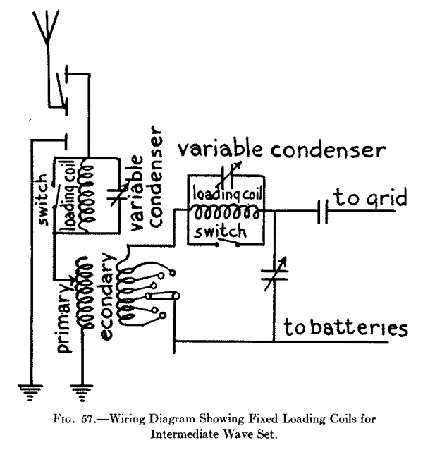
An Intermediate Wave Set With Variocoupler Inductance Coils.--By using the coil wound on the rotor of the variocoupler as the tickler the coupling between the detector tube circuits and the aerial wire system increases as the set is tuned for greater wave lengths. This scheme makes the control of the regenerative circuit far more stable than it is where an ordinary loose coupled tuning coil is used.
When the variocoupler is adjusted for receiving very long waves the rotor sets at right angles to the stator and, since when it is in this position there is no mutual induction between them, the tickler coil serves as a loading coil for the detector plate oscillation circuit. Inductance coils for short wave lengths are usually wound in single layers but bank-wound coils, as they are called are necessary to get compactness where long wave lengths are to be received. By winding inductance coils with two or more layers the highest inductance values can be obtained with the least resistance. A wiring diagram of a multipoint inductance coil is shown in Fig. 58. You can buy this intermediate wave set assembled and ready to use or get the parts and connect them up yourself.
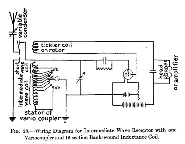
The Parts and How to Connect Them Up.--For this regenerative intermediate wave set get: (1) one 12 section triple bank-wound inductance coil, (2) one variometer, and (3) all the other parts shown in the diagram Fig. 58 except the variocoupler. First connect the free end of the condenser in the aerial to one of the terminals of the stator of the variocoupler; then connect the other terminal of the stator with one of the ends of the bank-wound inductance coil and connect the movable contact of this with the ground.
Next connect a wire to the aerial between the variable condenser and the stator and connect this to one post of a .0005 microfarad fixed condenser, then connect the other post of this with the grid of the detector and shunt a 2 megohm grid leak around it. Connect a wire to the ground wire between the bank-wound inductance coil and the ground proper, i.e., the radiator or water pipe, connect the other end of this to the + electrode of the A battery and connect this end also to one of the terminals of the filament. This done connect the other terminal of the filament to one post of the rheostat and the other post of this to the - or negative side of the A battery.
To the + electrode of the A battery connect the - or zinc pole of the B battery and connect the + or carbon pole of the latter with one post of the fixed .001 microfarad condenser. This done connect one terminal of the tickler coil which is on the rotor of the variometer to the plate of the detector and the other terminal of the tickler to the other post of the .001 condenser and around this shunt your headphones. Or if you want to use one or more amplifying tubes connect the circuit of the first one, see Fig. 45, to the posts on either side of the fixed condenser instead of the headphones.
A Long Wave Receiving Set.--The vivid imagination of Jules Verne never conceived anything so fascinating as the reception of messages without wires sent out by stations half way round the world; and in these days of high power cableless stations on the five continents you can listen-in to the messages and hear what is being sent out by the Lyons, Paris and other French stations, by Great Britain, Italy, Germany and even far off Russia and Japan.
A long wave set for receiving these stations must be able to tune to wave lengths up to 20,000 meters. Differing from the way in which the regenerative action of the short wave sets described in the preceding chapter is secured and which depends on a tickler coil and the coupling action of the detector in this long wave set, [Footnote: All of the short wave and intermediate wave receivers described, are connected up according to the wiring diagram used by the A. H. Grebe Company, Richmond Hill, Long Island, N. Y.] this action is obtained by the use of a tickler coil in the plate circuit which is inductively coupled to the grid circuit and this feeds back the necessary amount of current. This is a very good way to connect up the circuits for the reason that: (1) the wiring is simplified, and (2) it gives a single variable adjustment for the entire range of wave lengths the receptor is intended to cover.
The Parts and How to Connect Them Up.--The two chief features as far as the parts are concerned of this long wave length receiving set are (1) the variable condensers, and (2) the tuning inductance coils. The variable condenser used in series with the aerial wire system has 26 plates and is equal to a capacitance of .0008 mfd. which is the normal aerial capacitance. The condenser used in the secondary coil circuit has 14 plates and this is equal to a capacitance of .0004 mfd.
There are a number of inductance coils and these are arranged so that they can be connected in or cut out and combinations are thus formed which give a high efficiency and yet allow them to be compactly mounted. The inductance coils of the aerial wire system and those of the secondary coil circuit are practically alike. For wave lengths up to 2,200 meters bank litz-wound coils are used and these are wound up in 2, 4 and 6 banks in order to give the proper degree of coupling and inductance values.
Where wave lengths of more than 2,200 meters are to be received coto-coils are used as these are the "last word" in inductance coil design, and are especially adapted for medium as well as long wave lengths. [Footnote: Can be had of the Coto Coil Co., Providence, R. I.] These various coils are cut in and out by means of two five-point switches which are provided with auxiliary levers and contactors for dead-ending the right amount of the coils. In cutting in coils for increased wave lengths, that is from 10,000 to 20,000 meters, all of the coils of the aerial are connected in series as well as all of the coils of the secondary circuit. The connections for a long wave receptor are shown in the wiring diagram in Fig. 59.
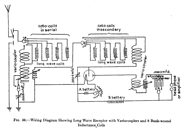
Any of the receiving sets described in the foregoing chapters will respond to either: (1) a wireless telegraph transmitter that uses a spark gap and which sends out periodic electric waves, or to (2) a wireless telephone transmitter that uses an arc or a vacuum tube oscillator and which sends out continuous electric waves. To receive wireless telegraph signals, however, from a transmitter that uses an arc or a vacuum tube oscillator and which sends out continuous waves, either the transmitter or the receptor must be so constructed that the continuous waves will be broken up into groups of audio frequency and this is done in several different ways.
There are four different ways employed at the present time to break up the continuous waves of a wireless telegraph transmitter into groups and these are: (a) the heterodyne, or beat, method, in which waves of different lengths are impressed on the received waves and so produces beats; (b) the tikker, or chopper method, in which the high frequency currents are rapidly broken up; (c) the variable condenser method, in which the movable plates are made to rapidly rotate; (d) the tone wheel, or frequency transformer, as it is often called, and which is really a modified form of and an improvement on the tikker. The heterodyne method will be described in this chapter.
What the Heterodyne or Beat Method Is.--The word heterodyne was coined from the Greek words heteros which means other, or different, and dyne which means power; in other words it means when used in connection with a wireless receptor that another and different high frequency current is used besides the one that is received from the sending station. In music a beat means a regularly recurrent swelling caused by the reinforcement of a sound and this is set up by the interference of sound waves which have slightly different periods of vibration as, for instance, when two tones take place that are not quite in tune with each other. This, then, is the principle of the heterodyne, or beat, receptor.
In the heterodyne, or beat method, separate sustained oscillations, that are just about as strong as those of the incoming waves, are set up in the receiving circuits and their frequency is just a little higher or a little lower than those that are set up by the waves received from the distant transmitter. The result is that these oscillations of different frequencies interfere and reinforce each other when beats are produced, the period of which is slow enough to be heard in the headphones, hence the incoming signals can be heard only when waves from the sending station are being received. A fuller explanation of how this is done will be found in Chapter XV.
The Autodyne or Self-Heterodyne Long-Wave Receiving Set.--This is the simplest type of heterodyne receptor and it will receive periodic waves from spark telegraph transmitters or continuous waves from an arc or vacuum tube telegraph transmitter. In this type of receptor the detector tube itself is made to set up the heterodyne oscillations which interfere with those that are produced by the incoming waves that are a little out of tune with it.
With a long wave autodyne, or self-heterodyne receptor, as this type is called, and a two-step audio-frequency amplifier you can clearly hear many of the cableless stations of Europe and others that send out long waves. For receiving long wave stations, however, you must have a long aerial--a single wire 200 or more feet in length will do--and the higher it is the louder will be the signals. Where it is not possible to put the aerial up a hundred feet or more above the ground, you can use a lower one and still get messages in International Morse fairly strong.
The Parts and Connections of an Autodyne, or Self-Heterodyne, Receiving Set.--For this long wave receiving set you will need: (1) one variocoupler with the primary coil wound on the stator and the secondary coil and tickler coil wound on the rotor, or you can use three honeycomb or other good compact coils of the longest wave you want to receive, a table of which is given in Chapter XII; (2) two .001 mfd. variable condensers; (3) one .0005 mfd. variable condenser; (4) one .5 to 2 megohm grid leak resistance; (5) one vacuum tube detector; (6) one A battery; (7) one rheostat; (8) one B battery; (9) one potentiometer; (10) one .001 mfd. fixed condenser and (11) one pair of headphones. For the two-step amplifier you must, of course, have besides the above parts the amplifier tubes, variable condensers, batteries rheostats, potentiometers and fixed condensers as explained in Chapter IX. The connections for the autodyne, or self-heterodyne, receiving set are shown in Fig. 60.
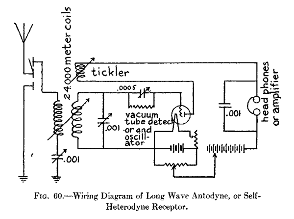
The Separate Heterodyne Long Wave Receiving Set.--This is a better long wave receptor than the self heterodyne set described above for receiving wireless telegraph signals sent out by a continuous long wave transmitter. The great advantage of using a separate vacuum tube to generate the heterodyne oscillations is that you can make the frequency of the oscillations just what you want it to be and hence you can make it a little higher or a little lower than the oscillations set up by the received waves.
The Parts and Connections of a Separate Heterodyne Long Wave Receiving Set.--The parts required for this long wave receiving set are: (1) four honeycomb or other good compact inductance coils of the longest wave length that you want to receive; (2) three .001 mfd. variable condensers; (3) one .0005 mfd. variable condenser; (4) one 1 megohm grid leak resistance; (5) one vacuum tube detector; (6) one A battery; (7) two rheostats; (8) two B batteries, one of which is supplied with taps; (9) one potentiometer; (10) one vacuum tube amplifier, for setting up the heterodyne oscillations; (11) a pair of headphones and (12) all of the parts for a two-step amplifier as detailed in Chapter IX, that is if you are going to use amplifiers. The connections are shown in Fig. 61.
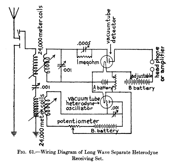
In using either of these heterodyne receivers be sure to carefully adjust the B battery by means of the potentiometer.
[Footnote: The amplifier tube in this case is used as a generator of oscillations.]
Wireless Headphones.--A telephone receiver for a wireless receiving set is made exactly on the same principle as an ordinary Bell telephone receiver. The only difference between them is that the former is made flat and compact so that a pair of them can be fastened together with a band and worn on the head (when it is called a headset), while the latter is long and cylindrical so that it can be held to the ear. A further difference between them is that the wireless headphone is made as sensitive as possible so that it will respond to very feeble currents, while the ordinary telephone receiver is far from being sensitive and will respond only to comparatively large currents.
How a Bell Telephone Receiver Is Made.--An ordinary telephone receiver consists of three chief parts and these are: (1) a hard-rubber, or composition, shell and cap, (2) a permanent steel bar magnet on one end of which is wound a coil of fine insulated copper wire, and (3) a soft iron disk, or diaphragm, all of which are shown in the cross-section in Fig. 62. The bar magnet is securely fixed inside of the handle so that the outside end comes to within about 1/32 of an inch of the diaphragm when this is laid on top of the shell and the cap is screwed on.
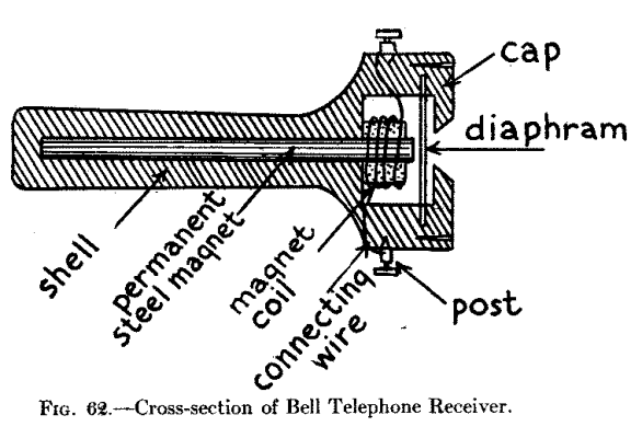
| Photograph unavailable |
| original © Underwood and Underwood. Alexander Graham Bell, Inventor of the Telephone, now an ardent Radio Enthusiast. |
The ends of the coil of wire are connected with two binding posts which are in the end of the shell, but are shown in the picture at the sides for the sake of clearness. This coil usually has a resistance of about 75 ohms and the meaning of the ohmic resistance of a receiver and its bearing on the sensitiveness of it will be explained a little farther along. After the disk, or diaphragm, which is generally made of thin, soft sheet iron that has been tinned or japanned, [Footnote: A disk of photographic tin-type plate is generally used.] is placed over the end of the magnet, the cap, which has a small opening in it, is screwed on and the receiver is ready to use.
How a Wireless Headphone Is Made.--For wireless work a receiver of the watch-case type is used and nearly always two such receivers are connected with a headband. It consists of a permanent bar magnet bent so that it will fit into the shell of the receiver as shown at A in Fig. 63.
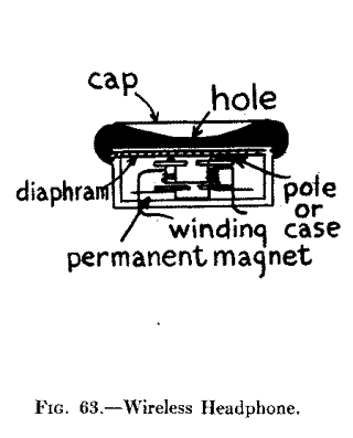
The ends of this magnet, which are called poles, are bent up, and hence this type is called a bipolar receiver. The magnets are wound with fine insulated wire as before and the diaphragm is held securely in place over them by screwing on the cap.
About Resistance, Turns of Wire and Sensitivity of Headphones.--If you are a beginner in wireless you will hear those who are experienced speak of a telephone receiver as having a resistance of 75 ohms, 1,000 ohms, 2,000 or 3,000 ohms, as the case may be; from this you will gather that the higher the resistance of the wire on the magnets the more sensitive the receiver is. In a sense this is true, but it is not the resistance of the magnet coils that makes it sensitive, in fact, it cuts down the current, but it is the number of turns of wire on them that determines its sensitiveness; it is easy to see that this is so, for the larger the number of turns the more often will the same current flow round the cores of the magnet and so magnetize them to a greater extent.
But to wind a large number of turns of wire close enough to the cores to be effective the wire must be very small and so, of course, the higher the resistance will be. Now the wire used for winding good receivers is usually No. 40, and this has a diameter of .0031 inch; consequently, when you know the ohmic resistance you get an idea of the number of turns of wire and from this you gather in a general way what the sensitivity of the receiver is.
A receiver that is sensitive enough for wireless work should be wound to not less than 1,000 ohms (this means each ear phone), while those of a better grade are wound to as high as 3,000 ohms for each one. A high-grade headset is shown in Fig. 64. Each phone of a headset should be wound to the same resistance, and these are connected in series as shown. Where two or more headsets are used with one wireless receiving set they must all be of the same resistance and connected in series, that is, the coils of one head set are connected with the coils of the next head set and so on to form a continuous circuit.
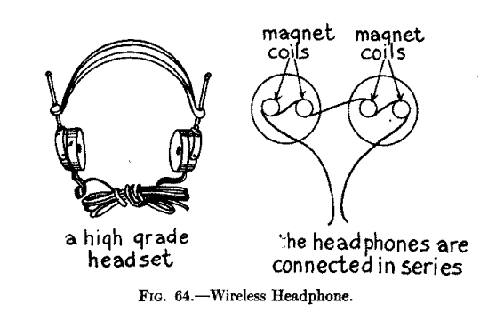
The Impedance of Headphones.--When a current is flowing through a circuit the material of which the wire is made not only opposes its passage--this is called its ohmic resistance--but a counter-electromotive force to the current is set up due to the inductive effects of the current on itself and this is called impedance. Where a wire is wound in a coil the impedance of the circuit is increased and where an alternating current is used the impedance grows greater as the frequency gets higher. The impedance of the magnet coils of a receiver is so great for high frequency oscillations that the latter cannot pass through them; in other words, they are choked off.
How the Headphones Work.--As you will see from the cross-sections in Figs. 62 and 63 there is no connection, electrical or mechanical, between the diaphragm and the other parts of the receiver. Now when either feeble oscillations, which have been rectified by a detector, or small currents from a B battery, flow through the magnet coils the permanent steel magnet is energized to a greater extent than when no current is flowing through it. This added magnetic energy makes the magnet attract the diaphragm more than it would do by its own force. If, on the other hand, the current is cut off the pull of the magnet is lessened and as its attraction for the diaphragm is decreased the latter springs back to its original position. When varying currents flow through the coils the diaphragm vibrates accordingly and sends out sound waves.
About Loud Speakers.--The simplest acoustic instrument ever invented is the megaphone, which latter is a Greek word meaning great sound. It is a very primitive device and our Indians made it out of birch-bark before Columbus discovered America. In its simplest form it consists of a cone-shaped horn and as the speaker talks into the small end the concentrated sound waves pass out of the large end in whatever direction it is held.
Now a loud speaker of whatever kind consists of two chief parts and these are: (1) a telephone receiver, and (2) a megaphone, or horn as it is called. A loud speaker when connected with a wireless receiving set makes it possible for a room, or an auditorium, full of people, or an outdoor crowd, to hear what is being sent out by a distant station instead of being limited to a few persons listening-in with headphones. To use a loud speaker you should have a vacuum tube detector receiving set and this must be provided with a one-step amplifier at least.
To get really good results you need a two-step amplifier and then energize the plate of the second vacuum tube amplifier with a 100 volt B battery; or if you have a three-step amplifier then use the high voltage on the plate of the third amplifier tube. Amplifying tubes are made to stand a plate potential of 100 volts and this is the kind you must use. Now it may seem curious, but when the current flows through the coils of the telephone receiver in one direction it gives better results than when it flows through in the other direction; to find out the way the current gives the best results try it out both ways and this you can do by simply reversing the connections.
The Simplest Type of Loud Speaker.--This loud speaker, which is called, the Arkay, [Footnote: Made by the Riley-Klotz Mfg. Co., Newark, N. J.] will work on a one- or two-step amplifier. It consists of a brass horn with a curve in it and in the bottom there is an adapter, or frame, with a set screw in it so that you can fit in one of your headphones and this is all there is to it. The construction is rigid enough to prevent overtones, or distortion of speech or music. It is shown in Fig. 65.
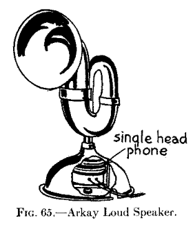
Another Simple Kind of Loud Speaker.--Another loud speaker, see Fig. 66, is known as the Amplitone [Footnote: Made by the American Pattern, Foundry and Machine Co., 82 Church Street, N. Y. C.] and it likewise makes use of the headphones as the sound producer. This device has a cast metal horn which improves the quality of the sound, and all you have to do is to slip the headphones on the inlet tubes of the horn and it is ready for use. The two headphones not only give a longer volume of sound than where a single one is used but there is a certain blended quality which results from one phone smoothing out the imperfections of the other.
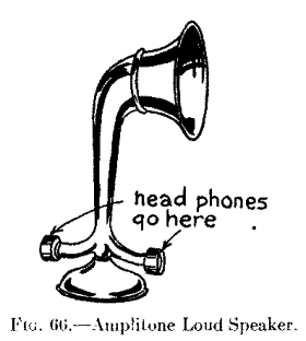
A Third Kind of Simple Loud Speaker.--The operation of the Amplitron, [Footnote: Made by the Radio Service Co., 110 W. 40th Street, N. Y.] as this loud speaker is called, is slightly different from others used for the same purpose. The sounds set up by the headphone are conveyed to the apex of an inverted copper cone which is 7 inches long and 10 inches in diameter. Here it is reflected by a parabolic mirror which greatly amplifies the sounds. The amplification takes place without distortion, the sounds remaining as clear and crisp as when projected by the transmitting station. By removing the cap from the receiver the shell is screwed into a receptacle on the end of the loud speaker and the instrument is ready for use. It is pictured in Fig. 67.
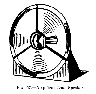
A Super Loud Speaker.--This loud speaker, which is known as the Magnavox Telemegafone, was the instrument used by Lt. Herbert E. Metcalf, 3,000 feet in the air, and which startled the City of Washington on April 2, 1919, by repeating President Wilson's Victory Loan Message from an airplane in flight so that it was distinctly heard by 20,000 people below.
This wonderful achievement was accomplished through the installation of the Magnavox and amplifiers in front of the Treasury Building. Every word Lt. Metcalf spoke into his wireless telephone transmitter was caught and swelled in volume by the Telemegafones below and persons blocks away could hear the message plainly. Two kinds of these loud speakers are made and these are: (1) a small loud speaker for the use of operators so that headphones need not be worn, and (2) a large loud speaker for auditorium and out-door audiences.
| Photograph unavailable |
| original © Underwood and Underwood. World's Largest Loud Speaker ever made. Installed in Lytle Park, Cincinnati, Ohio, to permit President Harding's Address at Point Pleasant, Ohio, during the Grant Centenary Celebration to be heard within a radius of one square. |
Either kind may be used with a one- or two-step amplifier or with a cascade of half a dozen amplifiers, according to the degree of loudness desired. The Telemegafone itself is not an amplifier in the true sense inasmuch as it contains no elements which will locally increase the incoming current. It does, however, transform the variable electric currents of the wireless receiving set into sound vibrations in a most wonderful manner.
A telemegafone of either kind is formed of: (1) a telephone receiver of large proportions, (2) a step-down induction coil, and (3) a 6 volt storage battery that energizes a powerful electromagnet which works the diaphragm. An electromagnet is used instead of a permanent magnet and this is energized by a 6-volt storage battery as shown in the wiring diagram at A in Fig. 68. One end of the core of this magnet is fixed to the iron case of the speaker and together these form the equivalent of a horseshoe magnet. A movable coil of wire is supported from the center of the diaphragm the edge of which is rigidly held between the case and the small end of the horn. This coil is placed over the upper end of the magnet and its terminals are connected to the secondary of the induction coil. Now when the coil is energized by the current from the amplifiers it and the core act like a solenoid in that the coil tends to suck the core into it; but since the core is fixed and the coil is movable the core draws the coil down instead. The result is that with every variation of the current that flows through the coil it moves up and down and pulls and pushes the diaphragm down and up with it. The large amplitude of the vibrations of the latter set up powerful sound waves which can be heard several blocks away from the horn. In this way then are the faint incoming signals, speech and music which are received by the amplifying receiving set reproduced and magnified enormously. The Telemegafone is shown complete at B.
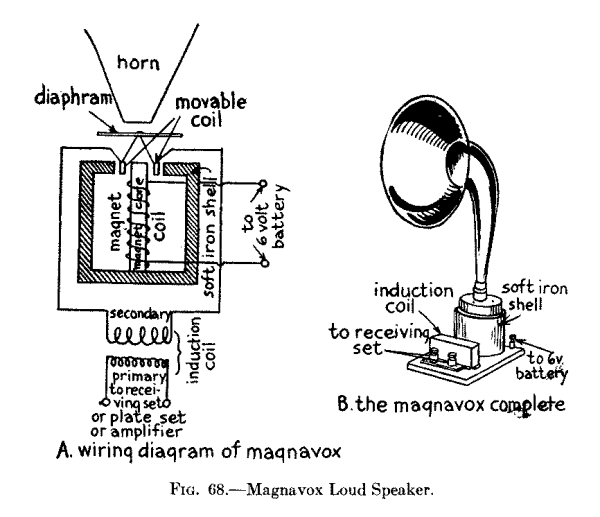
From the foregoing chapters you have seen that the vacuum tube can be used either as a detector or an amplifier or as a generator of electric oscillations, as in the case of the heterodyne receiving set. To understand how a vacuum tube acts as a detector and as an amplifier you must first know what electrons are. The way in which the vacuum tube sets up sustained oscillations will be explained in Chapter XVIII in connection with the Operation of Vacuum Tube Transmitters.
What Electrons Are.--Science teaches us that masses of matter are made up of molecules, that each of these is made up of atoms, and each of these, in turn, is made up of a central core of positive particles of electricity surrounded by negative particles of electricity as shown in the schematic diagram, Fig. 69. The little black circles inside the large circle represent positive particles of electricity and the little white circles outside of the large circle represent negative particles of electricity, or electrons as they are called.
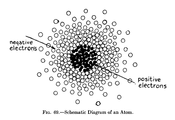
It is the number of positive particles of electricity an atom has that determines the kind of an element that is formed when enough atoms of the same kind are joined together to build it up. Thus hydrogen, which is the lightest known element, has one positive particle for its nucleus, while uranium, the heaviest element now known, has 92 positive particles. Now before leaving the atom please note that it is as much smaller than the diagram as the latter is smaller than our solar system.
What Is Meant by Ionization.--A hydrogen atom is not only lighter but it is smaller than the atom of any other element while an electron is more than a thousand times smaller than the atom of which it is a part. Now as long as all of the electrons remain attached to the surface of an atom its positive and negative charges are equalized and it will, therefore, be neither positive nor negative, that is, it will be perfectly neutral. When, however, one or more of its electrons are separated from it, and there are several ways by which this can be done, the atom will show a positive charge and it is then called a positive ion.
In other words a positive ion is an atom that has lost some of its negative electrons while a negative ion is one that has acquired some additional negative electrons. When a number of electrons are being constantly given by the atoms of an element, which let us suppose is a metal, and are being attracted to atoms of another element, which we will say is also a metal, a flow of electrons takes place between the two oppositely charged elements and form a current of negative electricity as represented by the arrows at A in Fig. 70.
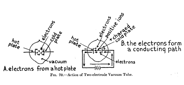
When a stream of electrons is flowing between two metal elements, as a filament and a plate in a vacuum tube detector, or an amplifier, they act as carriers for more negative electrons and these are supplied by a battery as we shall presently explain. It has always been customary for us to think of a current of electricity as flowing from the positive pole of a battery to the negative pole of it and hence we have called this the direction of the current. Since the electronic theory has been evolved it has been shown that the electrons, or negative charges of electricity, flow from the negative to the positive pole and that the ionized atoms, which are more positive than negative, flow in the opposite direction as shown at B.
How Electrons are Separated from Atoms.--The next question that arises is how to make a metal throw off some of the electrons of the atoms of which it is formed. There are several ways that this can be done but in any event each atom must be given a good, hard blow. A simple way to do this is to heat a metal to incandescence when the atoms will bombard each other with terrific force and many of the electrons will be knocked off and thrown out into the surrounding space.
But all, or nearly all, of them will return to the atoms from whence they came unless a means of some kind is employed to attract them to the atoms of some other element. This can be done by giving the latter piece of metal a positive charge. If now these two pieces of metal are placed in a bulb from which the air has been exhausted and the first piece of metal is heated to brilliancy while the second piece of metal is kept positively electrified then a stream of electrons will flow between them.
Action of the Two Electrode Vacuum Tube.--Now in a vacuum tube detector a wire filament, like that of an incandescent lamp, is connected with a battery and this forms the hot element from which the electrons are thrown off, and a metal plate with a terminal wire secured to it is connected to the positive or carbon tap of a dry battery; now connect the negative or zinc tap of this with one end of a telephone receiver and the other end of this with the terminals of the filament as shown at A in Fig. 71. If now you heat the filament and hold the phone to your ear you can hear the current from the B battery flowing through the circuit.
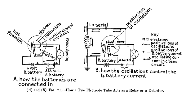
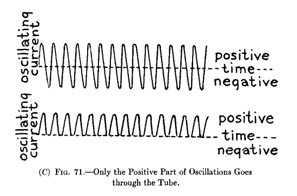
Since the electrons are negative charges of electricity they are not only thrown off by the hot wire but they are attracted by the positive charged metal plate and when enough electrons pass, or flow, from the hot wire to the plate they form a conducting path and so complete the circuit which includes the filament, the plate and the B or plate battery, when the current can then flow through it. As the number of electrons that are thrown off by the filament is not great and the voltage of the plate is not high the current that flows between the filament and the plate is always quite small.
How the Two Electrode Tube Acts as a Detector.--As the action of a two electrode tube as a detector [Footnote: The three electrode vacuum tube has entirely taken the place of the two electrode type.] is simpler than that of the three electrode vacuum tube we shall describe it first. The two electrode vacuum tube was first made by Mr. Edison when he was working on the incandescent lamp but that it would serve as a detector of electric waves was discovered by Prof. Fleming, of Oxford University, London. As a matter of fact, it is not really a detector of electric waves, but it acts as: (1) a rectifier of the oscillations that are set up in the receiving circuits, that is, it changes them into pulsating direct currents so that they will flow through and affect a telephone receiver, and (2) it acts as a relay and the feeble received oscillating current controls the larger direct current from the B battery in very much the same way that a telegraph relay does. This latter relay action will be explained when we come to its operation as an amplifier.
We have just learned that when the stream of electrons flow from the hot wire to the cold positive plate in the tube they form a conducting path through which the battery current can flow. Now when the electric oscillations surge through the closed oscillation circuit, which includes the secondary of the tuning coil, the variable condenser, the filament and the plate as shown at B in Fig. 71 the positive part of them passes through the tube easily while the negative part cannot get through, that is, the top, or positive, part of the wave-form remains intact while the lower, or negative, part is cut off as shown in the diagram at C. As the received oscillations are either broken up into wave trains of audio frequency by the telegraph transmitter or are modulated by a telephone transmitter they carry the larger impulses of the direct current from the B battery along with them and these flow through the headphones. This is the reason the vacuum tube amplifies as well as detects.
How the Three Electrode Tube Acts as a Detector.--The vacuum tube as a detector has been made very much more sensitive by the use of a third electrode shown in Fig. 72. In this type of vacuum tube the third electrode, or grid, is placed between the filament and the plate and this controls the number of electrons flowing from the filament to the plate; in passing between these two electrodes they have to go through the holes formed by the grid wires.
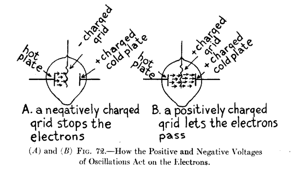
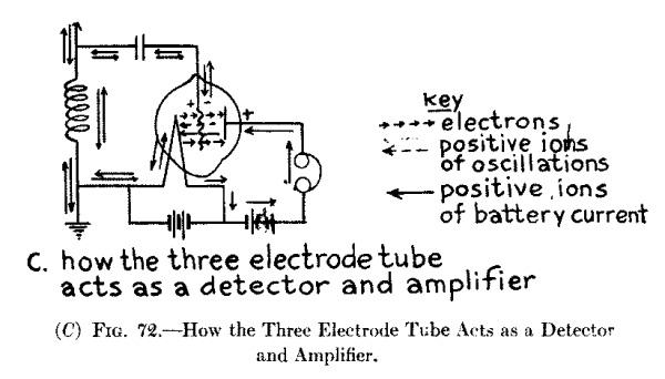
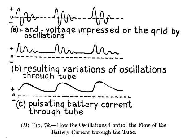
If now the grid is charged to a higher negative voltage than the filament the electrons will be stopped by the latter, see A, though some of them will go through to the plate because they travel at a high rate of speed. The higher the negative charge on the grid the smaller will be the number of electrons that will reach the plate and, of course, the smaller will be the amount of current that will flow through the tube and the headphones from the B battery.
On the other hand if the grid is charged positively, see B, then more electrons will strike the plate than when the grid is not used or when it is negatively charged. But when the three electrode tube is used as a detector the oscillations set up in the circuits change the grid alternately from negative to positive as shown at C and hence the voltage of the B battery current that is allowed to flow through the detector from the plate to the filament rises and falls in unison with the voltage of the oscillating currents. The way the positive and negative voltages of the oscillations which are set up by the incoming waves, energize the grid; how the oscillator tube clips off the negative parts of them, and, finally, how these carry the battery current through the tube are shown graphically by the curves at D.
How the Vacuum Tube Acts as an Amplifier.--If you connect up the filament and the plate of a three electrode tube with the batteries and do not connect in the grid, you will find that the electrons which are thrown off by the filament will not get farther than the grid regardless of how high the voltage is that you apply to the plate. This is due to the fact that a large number of electrons which are thrown off by the filament strike the grid and give it a negative charge, and consequently, they cannot get any farther. Since the electrons do not reach the plate the current from the B battery cannot flow between it and the filament.
Now with a properly designed amplifier tube a very small negative voltage on the grid will keep a very large positive voltage on the plate from sending a current through the tube, and oppositely, a very small positive voltage on the grid will let a very large plate current flow through the tube; this being true it follows that any small variation of the voltage from positive to negative on the grid and the other way about will vary a large current flowing from the plate to the filament.
In the Morse telegraph the relay permits the small current that is received from the distant sending station to energize a pair of magnets, and these draw an armature toward them and close a second circuit when a large current from a local battery is available for working the sounder. The amplifier tube is a variable relay in that the feeble currents set up by the incoming waves constantly and proportionately vary a large current that flows through the headphones. This then is the principle on which the amplifying tube works.
The Operation of a Simple Vacuum Tube Receiving Set.--The way a simple vacuum tube detector receiving set works is like this: when the filament is heated to brilliancy it gives off electrons as previously described. Now when the electric waves impinge on the aerial wire they set up oscillations in it and these surge through the primary coil of the loose coupled tuning coil, a diagram of which is shown at B in Fig. 41.
The energy of these oscillations sets up oscillations of the same frequency in the secondary coil and these high frequency currents whose voltage is first positive and then negative, surge in the closed circuit which includes the secondary coil and the variable condenser. At the same time the alternating positive and negative voltage of the oscillating currents is impressed on the grid; at each change from + to - and back again it allows the electrons to strike the plate and then shuts them off; as the electrons form the conducting path between the filament and the plate the larger direct current from the B battery is permitted to flow through the detector tube and the headphones.
Operation of a Regenerative Vacuum Tube Receiving Set.--By feeding back the pulsating direct current from the B battery through the tickler coil it sets up other and stronger oscillations in the secondary of the tuning coil when these act on the detector tube and increase its sensitiveness to a remarkable extent. The regenerative, or feed back, action of the receiving circuits used will be easily understood by referring back to B in Fig. 47.
When the waves set up oscillations in the primary of the tuning coil the energy of them produces like oscillations in the closed circuit which includes the secondary coil and the condenser; the alternating positive and negative voltages of these are impressed on the grid and these, as we have seen before, cause similar variations of the direct current from the B battery which acts on the plate and which flows between the latter and the filament.
This varying direct current, however, is made to flow back through the third, or tickler coil of the tuning coil and sets up in the secondary coil and circuits other and larger oscillating currents and these augment the action of the oscillations produced by the incoming waves. These extra and larger currents which are the result of the feedback then act on the grid and cause still larger variations of the current in the plate voltage and hence of the current of the B battery that flows through the detector and the headphones. At the same time the tube keeps on responding to the feeble electric oscillations set up in the circuits by the incoming waves. This regenerative action of the battery current augments the original oscillations many times and hence produce sounds in the headphones that are many times greater than where the vacuum tube detector alone is used.
Operation of Autodyne and Heterodyne Receiving Sets.--On page 109 [Chapter VII] we discussed and at A in Fig. 36 is shown a picture of two tuning forks mounted on sounding boxes to illustrate the principle of electrical tuning. When a pair of these forks are made to vibrate exactly the same number of times per second there will be a condensation of the air between them and the sound waves that are sent out will be augmented. But if you adjust one of the forks so that it will vibrate 256 times a second and the other fork so that it will vibrate 260 times a second then there will be a phase difference between the two sets of waves and the latter will augment each other 4 times every second and you will hear these rising and falling sounds as beats.
Now electric oscillations set up in two circuits that are coupled together act in exactly the same way as sound waves produced by two tuning forks that are close to each other. Since this is true if you tune one of the closed circuits so that the oscillations in it will have a frequency of a 1,000,000 and tune the other circuit so that the oscillations in it have a frequency of 1,001,000 a second then the oscillations will augment each other 1,000 times every second.
As these rising and falling currents act on the pulsating currents from the B battery which flow through the detector tube and the headphones you will hear them as beats. A graphic representation of the oscillating currents set up by the incoming waves, those produced by the heterodyne oscillator and the beats they form is shown in Fig. 73. To produce these beats a receptor can use: (1) a single vacuum tube for setting up oscillations of both frequencies when it is called an autodyne, or self-heterodyne receptor, or (2) a separate vacuum tube for setting up the oscillations for the second circuit when it is called a heterodyne receptor.
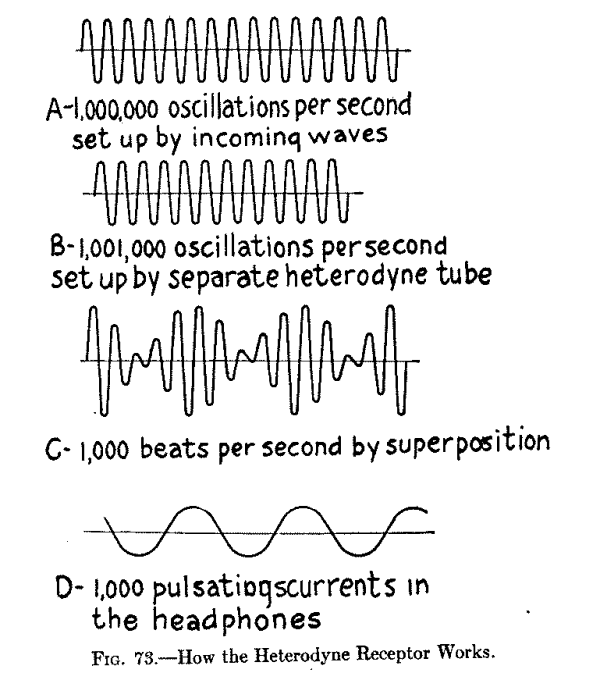
The Autodyne, or Self-Heterodyne Receiving Set.--Where only one vacuum tube is used for producing both frequencies you need only a regenerative, or feed-back receptor; then you can tune the aerial wire system to the incoming waves and tune the closed circuit of the secondary coil so that it will be out of step with the former by 1,000 oscillations per second, more or less, the exact number does not matter in the least. From this you will see that any regenerative set can be used for autodyne, or self-heterodyne, reception.
The Separate Heterodyne Receiving Set.--The better way, however, is to use a separate vacuum tube for setting up the heterodyne oscillations. The latter then act on the oscillations that are produced by the incoming waves and which energize the grid of the detector tube. Note that the vacuum tube used for producing the heterodyne oscillations is a generator of electric oscillations; the latter are impressed on the detector circuits through the variable coupling, the secondary of which is in series with the aerial wire as shown in Fig. 74. The way in which the tube acts as a generator of oscillations will be told in Chapter XVIII.
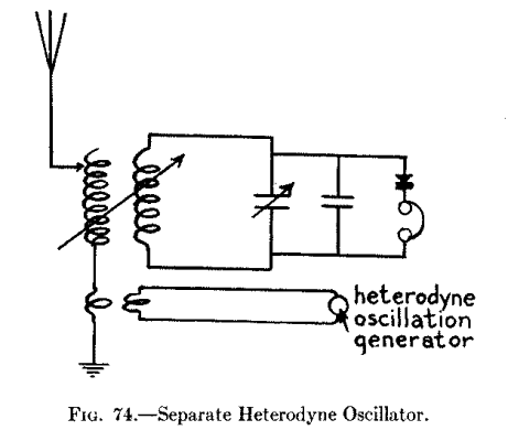
In the first part of this book we learned about spark-gap telegraph sets and how the oscillations they set up are damped and the waves they send out are periodic. In this and the next chapter we shall find out how vacuum tube telegraph transmitters are made and how they set up oscillations that are sustained and radiate waves that are continuous.
Sending wireless telegraph messages by continuous waves has many features to recommend it as against sending them by periodic waves and among the most important of these are that the transmitter can be: (1) more sharply tuned, (2) it will send signals farther with the same amount of power, and (3) it is noiseless in operation. The disadvantageous features are that: (1) a battery current is not satisfactory, (2) its circuits are somewhat more complicated, and (3) the oscillator tubes burn out occasionally. There is, however, a growing tendency among amateurs to use continuous wave transmitters and they are certainly more up-to-date and interesting than spark gap sets.
Now there are two practical ways by which continuous waves can be set up for sending either telegraphic signals or telephonic speech and music and these are with: (a) an oscillation arc lamp, and (b) a vacuum tube oscillator. The oscillation arc was the earliest known way of setting up sustained oscillations, and it is now largely used for commercial high power, long distance work. But since the vacuum tube has been developed to a high degree of efficiency and is the scheme that is now in vogue for amateur stations we shall confine our efforts here to explaining the apparatus necessary and how to wire the various parts together to produce several sizes of vacuum tube telegraph transmitters.
Sources of Current for Telegraph Transmitting Sets.--Differing from a spark-gap transmitter you cannot get any appreciable results with a low voltage battery current to start with. For a purely experimental vacuum tube telegraph transmitter you can use enough B batteries to operate it but the current strength of these drops so fact when they are in use, that they are not at all satisfactory for the work.
You can, however, use 110 volt direct current from a lighting circuit as your initial source of power to energize the plate of the vacuum tube oscillator of your experimental transmitter. Where you have a 110 volt direct current lighting service in your home and you want a higher voltage for your plate, you will then have to use a motor-generator set and this costs money. If you have 110 volt alternating current lighting service at hand your troubles are over so far as cost is concerned for you can step it up to any voltage you want with a power transformer. In this chapter will be shown how to use a direct current for your source of initial power and in the next chapter how to use an alternating current for the initial power.
An Experimental Continuous Wave Telegraph Transmitter.--You will remember that in Chapter XV we learned how the heterodyne receiver works and that in the separate heterodyne receiving set the second vacuum tube is used solely to set up oscillations. Now while this extra tube is used as a generator of oscillations these are, of course, very weak and hence a detector tube cannot be used to generate oscillations that are useful for other purposes than heterodyne receptors and measurements.
There is a vacuum tube amplifier [Footnote: This is the radiation UV-201, made by the Radio Corporation of America, Woolworth Bldg., New York City.] made that will stand a plate potential of 100 volts, and this can be used as a generator of oscillations by energizing it with a 110 volt direct current from your lighting service. Or in a pinch you can use five standard B batteries to develop the plate voltage, but these will soon run down. But whatever you do, never use a current from a lighting circuit on a tube of any kind that has a rated plate potential of less than 100 volts.
The Apparatus You Need.--For this experimental continuous wave telegraph transmitter get the following pieces of apparatus: (1) one single coil tuner with three clips; (2) one .002 mfd. fixed condenser; (3) three .001 mfd. condensers; (4) one adjustable grid leak; (5) one hot-wire ammeter; (6) one buzzer; (7) one dry cell; (8) one telegraph key; (9) one 100 volt plate vacuum tube amplifier; (10) one 6 volt storage battery; (11) one rheostat; (12) one oscillation choke coil; (13) one panel cut-out with a single-throw, double-pole switch, and a pair of fuse sockets on it.
The Tuning Coil.--You can either make this tuning coil or buy one. To make it get two disks of wood 3/4-inch thick and 5 inches in diameter and four strips of hard wood, or better, hard rubber or composition strips, such as bakelite, 1/2-inch thick, 1 inch wide and 5-3/4 inches long, and screw them to the disks as shown at A in Fig. 75. Now wrap on this form about 25 turns of No. 8 or 10, Brown and Sharpe gauge, bare copper wire with a space of 1/8-inch between each turn. Get three of the smallest size terminal clips, see B, and clip them on to the different turns, when your tuning coil is ready for use. You can buy a coil of this kind for $4.00 or $5.00.
The Condensers.--For the aerial series condenser get one that has a capacitance of .002 mfd. and that will stand a potential of 3,000 volts. [Footnote: The U C-1014 Faradon condenser made by the Radio Corporation of America will serve the purpose.] It is shown at C. The other three condensers, see D, are also of the fixed type and may have a capacitance of .001 mfd.; [Footnote: List No. 266; fixed receiving condenser, sold by the Manhattan Electrical Supply Co.] the blocking condenser should preferably have a capacitance of 1/2 a mfd. In these condensers the leaves of the sheet metal are embedded in composition. The aerial condenser will cost you $2.00 and the others 75 cents each.
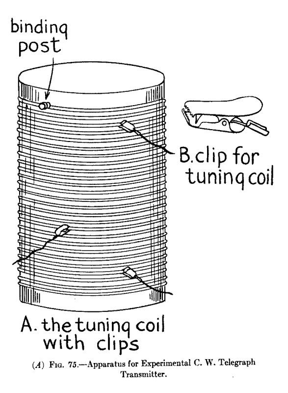
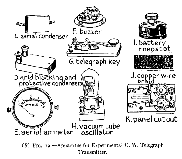
The Aerial Ammeter.--This instrument is also called a hot-wire ammeter because the oscillating currents flowing through a piece of wire heat it according to their current strength and as the wire contracts and expands it moves a needle over a scale. The ammeter is connected in the aerial wire system, either in the aerial side or the ground side--the latter place is usually the most convenient. When you tune the transmitter so that the ammeter shows the largest amount of current surging in the aerial wire system you can consider that the oscillation circuits are in tune. A hot-wire ammeter reading to 2.5 amperes will serve your needs, it costs $6.00 and is shown at E in Fig. 75.
| Photograph unavailable |
| United States Naval High Power Station, Arlington Va. General view of Power Room. At the left can be seen the Control Switchboards, and overhead, the great 30 K.W. Arc Transmitter with Accessories. |
The Buzzer and Dry Cell.--While a heterodyne, or beat, receptor can receive continuous wave telegraph signals an ordinary crystal or vacuum tube detector receiving set cannot receive them unless they are broken up into trains either at the sending station or at the receiving station, and it is considered the better practice to do this at the former rather than at the latter station. For this small transmitter you can use an ordinary buzzer as shown at F. A dry cell or two must be used to energize the buzzer. You can get one for about 75 cents.
The Telegraph Key.--Any kind of a telegraph key will serve to break up the trains of sustained oscillations into dots and dashes. The key shown at G is mounted on a composition base and is the cheapest key made, costing $1.50.
The Vacuum Tube Oscillator.--As explained before you can use any amplifying tube that is made for a plate potential of 100 volts. The current required for heating the filament is about 1 ampere at 6 volts. A porcelain socket should be used for this tube as it is the best insulating material for the purpose. An amplifier tube of this type is shown at H and costs $6.50.
The Storage Battery.--A storage battery is used to heat the filament of the tube, just as it is with a detector tube, and it can be of any make or capacity as long as it will develop 6 volts. The cheapest 6 volt storage battery on the market has a 20 to 40 ampere-hour capacity and sells for $13.00.
The Battery Rheostat.--As with the receptors a rheostat is needed to regulate the current that heats the filament. A rheostat of this kind is shown at I and is listed at $1.25.
The Oscillation Choke Coil.--This coil is connected in between the oscillation circuits and the source of current which feeds the oscillator tube to keep the oscillations set up by the latter from surging back into the service wires where they would break down the insulation. You can make an oscillation choke coil by winding say 100 turns of No. 28 Brown and Sharpe gauge double cotton covered magnet wire on a cardboard cylinder 2 inches in diameter and 2-1/2 inches long.
Transmitter Connectors.--For connecting up the different pieces of apparatus of the transmitter it is a good scheme to use copper braid; this is made of braided copper wire in three sizes and sells for 7,15 and 20 cents a foot respectively. A piece of it is pictured at J.
The Panel Cut-Out.--This is used to connect the cord of the 110-volt lamp socket with the transmitter. It consists of a pair of plug cutouts and a single-throw, double-pole switch mounted on a porcelain base as shown at K. In some localities it is necessary to place these in an iron box to conform to the requirements of the fire underwriters.
Connecting Up the Transmitting Apparatus.--The way the various pieces of apparatus are connected together is shown in the wiring diagram. Fig. 76. Begin by connecting one post of the ammeter with the wire that leads to the aerial and the other post of it to one end of the tuning coil; connect clip 1 to one terminal of the .002 mfd. 3,000 volt aerial condenser and the other post of this with the ground.
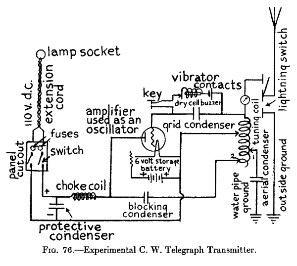
Now connect the end of the tuning coil that leads to the ammeter with one end of the .001 mfd. grid condenser and the other end of this with the grid of the vacuum tube. Connect the telegraph key, the buzzer and the dry cell in series and then shunt them around the grid condenser. Next connect the plate of the tube with one end of the .001 mfd. blocking condenser and the other end of this with the clip 2 on the tuning coil.
Connect one end of the filament with the + or positive electrode of the storage battery, the - or negative electrode of this with one post of the rheostat and the other post of the latter with the other end of the filament; then connect clip 3 with the + or positive side of the storage battery. This done connect one end of the choke coil to the conductor that leads to the plate and connect the other end of the choke coil to one of the taps of the switch on the panel cut-out. Connect the + or positive electrode of the storage battery to the other switch tap and between the switch and the choke coil connect the protective condenser across the 110 volt feed wires. Finally connect the lamp cord from the socket to the plug fuse taps when your experimental continuous wave telegraph transmitter is ready to use.
A 100 Mile C. W. Telegraph Transmitter.--Here is a continuous wave telegraph transmitter that will cover distances up to 100 miles that you can rely on. It is built on exactly the same lines as the experimental transmitter just described, but instead of using a 100 volt plate amplifier as a makeshift generator of oscillations it employs a vacuum tube made especially for setting up oscillations and instead of having a low plate voltage it is energized with 350 volts.
The Apparatus You Need.--For this transmitter you require: (1) one oscillation transformer; (2) one hot-wire ammeter; (3) one aerial series condenser; (4) one grid leak resistance; (5) one chopper; (6) one key circuit choke coil; (7) one 5 watt vacuum tube oscillator; (8) one 6 volt storage battery; (9) one battery rheostat; (10) one battery voltmeter; (11) one blocking condenser; (12) one power circuit choke coil, and (13) one motor-generator.
The Oscillation Transformer.--The tuning coil, or oscillation transformer as this one is called, is a conductively coupled tuner--that is, the primary and secondary coils form one continuous coil instead of two separate coils. This tuner is made up of 25 turns of thin copper strip, 3/8 inch wide and with its edges rounded, and this is secured to a wood base as shown at A in Fig. 77. It is fitted with one fixed tap and three clips to each of which a length of copper braid is attached. It has a diameter of 6-1/4 inches, a height of 7-7/8 inches and a length of 9-3/8 inches, and it costs $11.00.
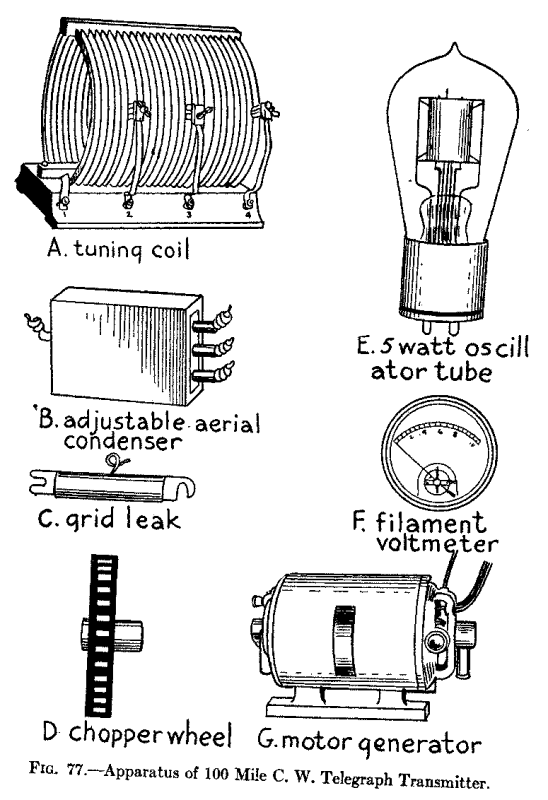
The Aerial Condenser.--This condenser is made up of three fixed condensers of different capacitances, namely .0003, .0004 and .0005 mfd., and these are made to stand a potential of 7500 volts. The condenser is therefore adjustable and, as you will see from the picture B, it has one terminal wire at one end and three terminal wires at the other end so that one, two or three condensers can be used in series with the aerial. A condenser of this kind costs $5.40.
The Aerial Ammeter.--This is the same kind of a hot-wire ammeter already described in connection with the experimental set, but it reads to 5 amperes.
The Grid and Blocking Condensers.--Each of these is a fixed condenser of .002 mfd. capacitance and is rated to stand 3,000 volts. It is made like the aerial condenser but has only two terminals. It costs $2.00.
The Key Circuit Apparatus.--This consists of: (1) the grid leak; (2) the chopper; (3) the choke coil, and (4) the key. The grid leak is connected in the lead from the grid to the aerial to keep the voltage on the grid at the right potential. It has a resistance of 5000 ohms with a mid-tap at 2500 ohms as shown at C. It costs $2.00.
The chopper is simply a rotary interrupter driven by a small motor. It comprises a wheel of insulating material in which 30 or more metal segments are set in an insulating disk as shown at D. A metal contact called a brush is fixed on either side of the wheel. It costs about $7.00 and the motor to drive it is extra. The choke coil is wound up of about 250 turns of No. 30 Brown and Sharpe gauge cotton covered magnet wire on a spool which has a diameter of 2 inches and a length of 3-1/4 inches.
The 5 Watt Oscillator Vacuum Tube.--This tube is made like the amplifier tube described for use with the preceding experimental transmitter, but it is larger, has a more perfect vacuum, and will stand a plate potential of 350 volts while the plate current is .045 ampere. The filament takes a current of a little more than 2 amperes at 7.5 volts. A standard 4-tap base is used with it. The tube costs $8.00 and the porcelain base is $1.00 extra. It is shown at E.
The Storage Battery and Rheostat.--This must be a 5-cell battery so that it will develop 10 volts. A storage battery of any capacity can be used but the lowest priced one costs about $22.00. The rheostat for regulating the battery current is the same as that used in the preceding experimental transmitter.
The Filament Voltmeter.--To get the best results it is necessary that the voltage of the current which heats the filament be kept at the same value all of the time. For this transmitter a direct current voltmeter reading from 0 to 15 volts is used. It is shown at F and costs $7.50.
The Oscillation Choke Coil.--This is made exactly like the one described in connection with the experimental transmitter.
The Motor-Generator Set.--Where you have only a 110 or a 220 volt direct current available as a source of power you need a motor-generator to change it to 350 volts, and this is an expensive piece of apparatus. It consists of a single armature core with a motor winding and a generator winding on it and each of these has its own commutator. Where the low voltage current flows into one of the windings it drives its as a motor and this in turn generates the higher voltage current in the other winding. Get a 100 watt 350 volt motor-generator; it is shown at F and costs about $75.00.
The Panel Cut-Out.--This switch and fuse block is the same as that used in the experimental set.
The Protective Condenser.--This is a fixed condenser having a capacitance of 1 mfd. and will stand 750 volts. It costs $2.00.
Connecting Up the Transmitting Apparatus.--From all that has gone before you have seen that each piece of apparatus is fitted with terminal, wires, taps or binding posts. To connect up the parts of this transmitter it is only necessary to make the connections as shown in the wiring diagram Fig. 78.
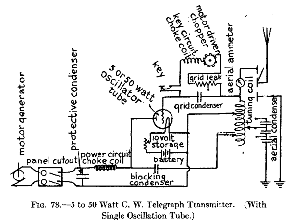
A 200 Mile C. W. Telegraph Transmitter.--To make a continuous wave telegraph transmitter that will cover distances up to 200 miles all you have to do is to use two 5 watt vacuum tubes in parallel, all of the rest of the apparatus being exactly the same. Connecting the oscillator tubes up in parallel means that the two filaments are connected across the leads of the storage battery, the two grids on the same lead that goes to the aerial and the two plates on the same lead that goes to the positive pole of the generator. Where two or more oscillator tubes are used only one storage battery is needed, but each filament must have its own rheostat. The wiring diagram Fig. 79 shows how the two tubes are connected up in parallel.
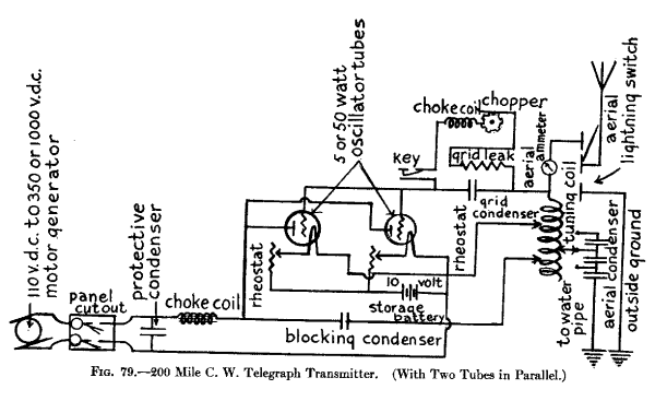
A 500 Mile C. W. Telegraph Transmitter.--For sending to distances of over 200 miles and up to 500 miles you can use either: (1) three or four 5 watt oscillator tubes in parallel as described above, or (2) one 50 watt oscillator tube. Much of the apparatus for a 50 watt tube set is exactly the same as that used for the 5 watt sets. Some of the parts, however, must be proportionately larger though the design all the way through remains the same.
The Apparatus and Connections.--The aerial series condenser, the blocking condenser, the grid condenser, the telegraph key, the chopper, the choke coil in the key circuit, the filament voltmeter and the protective condenser in the power circuit are identical with those described for the 5 watt transmitting set.
The 50 Watt Vacuum Tube Oscillator.--This is the size of tube generally used by amateurs for long distance continuous wave telegraphy. A single tube will develop 2 to 3 amperes in your aerial. The filament takes a 10 volt current and a plate potential of 1,000 volts is needed. One of these tubes is shown in Fig. 80 and the cost is $30.00. A tube socket to fit it costs $2.50 extra.
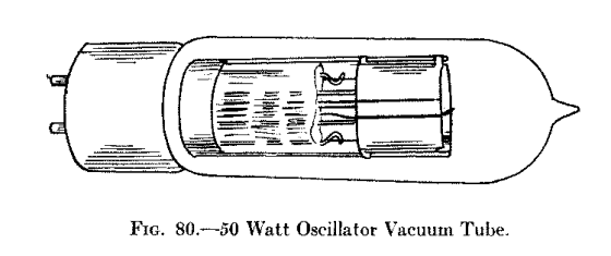
The Aerial Ammeter.--This should read to 5 amperes and the cost is $6.25.
The Grid Leak Resistance.--It has the same resistance, namely 5,000 ohms as the one used with the 5 watt tube transmitter, but it is a little larger. It is listed at $1.65.
The Oscillation Choke Coil.--The choke coil in the power circuit is made of about 260 turns of No. 30 B. & S. cotton covered magnet wire wound on a spool 2-1/4 inches in diameter and 3-1/4 inches long.
The Filament Rheostat.--This is made to take care of a 10 volt current and it costs $10.00.
The Filament Storage Battery.--This must develop 12 volts and one having an output of 40 ampere-hours costs about $25.00.
The Protective Condenser.--This condenser has a capacitance of 1 mfd. and costs $2.00.
The Motor-Generator.--Where you use one 50 watt oscillator tube you will need a motor-generator that develops a plate potential of 1000 volts and has an output of 200 watts. This machine will stand you about $100.00.
The different pieces of apparatus for this set are connected up exactly the same as shown in the wiring diagram in Fig. 78.
A 1000 Mile C. W. Telegraph Transmitter.--All of the parts of this transmitting set are the same as for the 500 mile transmitter just described except the motor generator and while this develops the same plate potential, i.e., 1,000 volts, it must have an output of 500 watts; it will cost you in the neighborhood of $175.00. For this long distance transmitter you use two 50 watt oscillator tubes in parallel and all of the parts are connected together exactly the same as for the 200 mile transmitter shown in the wiring diagram in Fig. 79.
Within the last few years alternating current has largely taken the place of direct current for light, heat and power purposes in and around towns and cities and if you have alternating current service in your home you can install a long distance continuous wave telegraph transmitter with very little trouble and at a comparatively small expense.
A 100 Mile C. W. Telegraph Transmitting Set.--The principal pieces of apparatus for this transmitter are the same as those used for the 100 Mile Continuous Wave Telegraph Transmitting Set described and pictured in the preceding chapter which used direct current, except that an alternating current power transformer is employed instead of the more costly motor-generator.
The Apparatus Required.--The various pieces of apparatus you will need for this transmitting set are: (1) one hot-wire ammeter for the aerial as shown at E in Fig. 75, but which reads to 5 amperes instead of to 2.5 amperes; (2) one tuning coil as shown at A in Fig. 77; (3) one aerial condenser as shown at B in Fig. 77; (4) one grid leak as shown at C in Fig. 77; (5) one telegraph key as shown at G in Fig. 75; (6) one grid condenser, made like the aerial condenser but having only two terminals; (7) one 5 watt oscillator tube as shown at E in Fig. 77; (8) one .002 mfd. 3,000 volt by-pass condenser, made like the aerial and grid condensers; (9) one pair of choke coils for the high voltage secondary circuit; (10) one milli-ammeter; (11) one A. C. power transformer; (12) one rheostat as shown at I in Fig. 75, and (13) one panel cut-out as shown at K in Fig. 75.
The Choke Coils.--Each of these is made by winding about 100 turns of No. 28, Brown and Sharpe gauge, cotton covered magnet wire on a spool 2 inches in diameter and 2-1/2 inches long, when it will have an inductance of about 0.5 millihenry [Footnote: A millihenry is 1/1000th part of a henry.] at 1,000 cycles.
The Milli-ammeter.--This is an alternating current ammeter and reads from 0 to 250 milliamperes; [Footnote: A milliampere is the 1/1000th part of an ampere.] and is used for measuring the secondary current that energizes the plate of the oscillator tube. It looks like the aerial ammeter and costs about $7.50.
The A. C. Power Transformer.--Differing from the motor generator set the power transformer has no moving parts. For this transmitting set you need a transformer that has an input of 325 volts. It is made to work on a 50 to 60 cycle current at 102.5 to 115 volts, which is the range of voltage of the ordinary alternating lighting current. This adjustment for voltage is made by means of taps brought out from the primary coil to a rotary switch.
The high voltage secondary coil which energizes the plate has an output of 175 watts and develops a potential of from 350 to 1,100 volts. The low voltage secondary coil which heats the filament has an output of 175 watts and develops 7.5 volts. This transformer, which is shown in Fig. 81, is large enough to take care of from one to four 5 watt oscillator tubes. It weighs about 15 pounds and sells for $25.00.
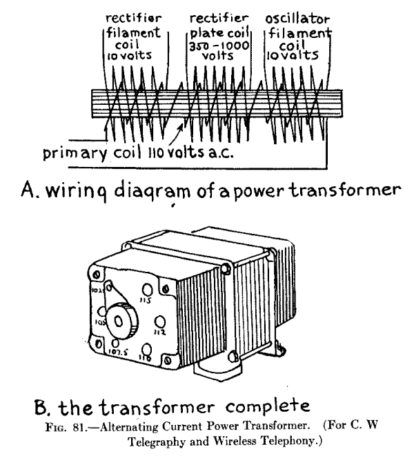
| Photograph unavailable |
| The Transformer and Tuner of the World's Largest Radio Station. Owned by the Radio Corporation of America at Rocky Point near Port Jefferson L.I. |
Connecting Up the Apparatus.--The wiring diagram Fig. 82 shows clearly how all of the connections are made. It will be observed that a storage battery is not needed as the secondary coil of the transformer supplies the current to heat the filament of the oscillator. The filament voltmeter is connected across the filament secondary coil terminals, while the plate milli-ammeter is connected to the mid-taps of the plate secondary coil and the filament secondary coil.
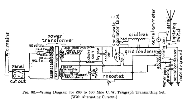
A 200 to 500 Mile C. W. Telegraph Transmitting Set.--Distances of from 200 to 500 miles can be successfully covered with a telegraph transmitter using two, three or four 5 watt oscillator tubes in parallel. The apparatus needed is identical with that used for the 100 mile transmitter just described. The tubes are connected in parallel as shown in the wiring diagram in Fig. 83.
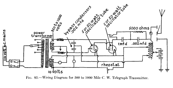
A 500 to 1,000 Mile C. W. Telegraph Transmitting Set.--With the apparatus described for the above set and a single 50 watt oscillator tube a distance of upwards of 500 miles can be covered, while with two 50 watt oscillator tubes in parallel you can cover a distance of 1,000 miles without difficulty, and nearly 2,000 miles have been covered with this set.
The Apparatus Required.--All of the apparatus for this C. W. telegraph transmitting set is the same as that described for the 100 and 200 mile sets but you will need: (1) one or two 50 watt oscillator tubes with sockets; (2) one key condenser that has a capacitance of 1 mfd., and a rated potential of 1,750 volts; (3) one 0 to 500 milli-ammeter; (4) one aerial ammeter reading to 5 amperes, and (5) an A. C. power transformer for one or two 50 watt tubes.
| Photograph unavailable |
| Broadcasting Government Reports by Wireless from Washington. This shows Mr. Gale at work with his set in the Post Office Department. |
The Alternating Current Power Transformer.--This power transformer is made exactly like the one described in connection with the preceding 100 mile transmitter and pictured in Fig. 81, but it is considerably larger. Like the smaller one, however, it is made to work with a 50 to 60 cycle current at 102.5 to 115 volts and, hence, can be used with any A. C. lighting current.
It has an input of 750 volts and the high voltage secondary coil which energizes the plate has an output of 450 watts and develops 1,500 to 3,000 volts. The low voltage secondary coil which heats the filament develops 10.5 volts. This transformer will supply current for one or two 50-watt oscillator tubes and it costs about $40.00.
Connecting Up the Apparatus.--Where a single oscillator tube is used the parts are connected as shown in Fig. 82, and where two tubes are connected in parallel the various pieces of apparatus are wired together as shown in Fig. 83. The only difference between the 5 watt tube transmitter and the 50 watt tube transmitter is in the size of the apparatus with one exception; where one or two 50 watt tubes are used a second condenser of large capacitance (1 mfd.) is placed in the grid circuit and the telegraph key is shunted around it as shown in the diagram Fig. 83.
In time past the most difficult of all electrical apparatus for the amateur to make, install and work was the wireless telephone. This was because it required a direct current of not less than 500 volts to set up the sustained oscillations and all ordinary direct current for lighting purposes is usually generated at a potential of 110 volts.
Now as you know it is easy to step-up a 110 volt alternating current to any voltage you wish with a power transformer but until within comparatively recent years an alternating current could not be used for the production of sustained oscillations for the very good reason that the state of the art had not advanced that far. In the new order of things these difficulties have all but vanished and while a wireless telephone transmitter still requires a high voltage direct current to operate it this is easily obtained from 110 volt source of alternating current by means of vacuum tube rectifiers.
The pulsating direct currents are then passed through a filtering reactance coil, called a reactor, and one or more condensers, and these smooth them out until they approximate a continuous direct current. The latter is then made to flow through a vacuum tube oscillator when it is converted into high frequency oscillations and these are varied, or modulated, as it is called, by a microphone transmitter such as is used for ordinary wire telephony. The energy of these sustained modulated oscillations is then radiated into space from the aerial in the form of electric waves.
The distance that can be covered with a wireless telephone transmitter is about one-fourth as great as that of a wireless telegraph transmitter having the same input of initial current, but it is long enough to satisfy the most enthusiastic amateur. For instance with a wireless telephone transmitter where an amplifier tube is used to set up the oscillations and which is made for a plate potential of 100 volts, distances up to 10 or 15 miles can be covered.
With a single 5 watt oscillator tube energized by a direct current of 350 volts from either a motor-generator or from a power transformer (after it has been rectified and smoothed out) speech and music can be transmitted to upwards of 25 miles. Where two 5 watt tubes connected in parallel are used wireless telephone messages can be transmitted to distances of 40 or 50 miles. Further, a single 50 watt oscillator tube will send to distances of 50 to 100 miles while two of these tubes in parallel will send from 100 to 200 miles. Finally, where four or five oscillator tubes are connected in parallel proportionately greater distances can be covered.
A Short Distance Wireless Telephone Transmitting Set-With 110 Volt Direct Lighting Current.--For this very simple, short distance wireless telephone transmitting set you need the same apparatus as that described and pictured in the beginning of Chapter XVI for a Short Distance C. W. Telegraph Transmitter, except that you use a microphone transmitter instead of a telegraph key. If you have a 110 volt direct lighting current in your home you can put up this short distance set for very little money and it will be well worth your while to do so.
The Apparatus You Need.--For this set you require: (1) one tuning coil as shown at A and B in Fig. 75; (2) one aerial ammeter as shown at C in Fig. 75; (3) one aerial condenser as shown at C in Fig. 75; (4) one grid, blocking and protective condenser as shown at D in Fig. 75; (5) one grid leak as shown at C in Fig. 77; (6) one vacuum tube amplifier which is used as an oscillator; (7) one 6 volt storage battery; (8) one rheostat as shown at I in Fig. 75; (9) one oscillation choke coil; (10) one panel cut-out as shown at K in Fig. 75 and an ordinary microphone transmitter.
The Microphone Transmitter.--The best kind of a microphone to use with this and other telephone transmitting sets is a Western Electric No. 284-W. [Footnote: Made by the Western Electric Company, Chicago, Ill.] This is known as a solid back transmitter and is the standard commercial type used on all long distance Bell telephone lines. It articulates sharply and distinctly and there are no current variations to distort the wave form of the voice and it will not buzz or sizzle. It is shown in Fig. 84 and costs $2.00. Any other good microphone transmitter can be used if desired.
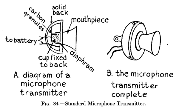
Connecting Up the Apparatus.--Begin by connecting the leading-in wire with one of the terminals of the microphone transmitter, as shown in the wiring diagram Fig. 85, and the other terminal of this to one end of the tuning coil. Now connect clip 1 of the tuning coil to one of the posts of the hot-wire ammeter, the other post of this to one end of aerial condenser and, finally, the other end of the latter with the water pipe or other ground. The microphone can be connected in the ground wire and the ammeter in the aerial wire and the results will be practically the same.
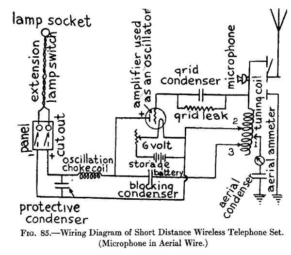
Next connect one end of the grid condenser to the post of the tuning coil that makes connection with the microphone and the other end to the grid of the tube, and then shunt the grid leak around the condenser. Connect the + or positive electrode of the storage battery with one terminal of the filament of the vacuum tube, the other terminal of the filament with one post of the rheostat and the other post of this with the - or negative electrode of the battery. This done, connect clip 2 of the tuning coil to the + or positive electrode of the battery and bring a lead from it to one of the switch taps of the panel cut-out.
Now connect clip 3 of the tuning coil with one end of the blocking condenser, the other end of this with one terminal of the choke coil and the other terminal of the latter with the other switch tap of the cut-out. Connect the protective condenser across the direct current feed wires between the panel cut-out and the choke coil. Finally connect the ends of a lamp cord to the fuse socket taps of the cut-out, and connect the other ends to a lamp plug and screw it into the lamp socket of the feed wires. Screw in a pair of 5 ampere fuse plugs, close the switch and you are ready to tune the transmitter and talk to your friends.
A 25 to 50 Mile Wireless Telephone Transmitter--With Direct Current Motor Generator.--Where you have to start with 110 or 220 volt direct current and you want to transmit to a distance of 25 miles or more you will have to install a motor-generator. To make this transmitter you will need exactly the same apparatus as that described and pictured for the 100 Mile C. W. Telegraph Transmitting Set in Chapter XVI, except that you must substitute a microphone transmitter and a telephone induction coil, or a microphone transformer, or still better, a magnetic modulator, for the telegraph key and chopper.
The Apparatus You Need.--To reiterate; the pieces of apparatus you need are: (1) one aerial ammeter as shown at E in Fig. 75; (2) one tuning coil as shown at A in Fig. 77; (3) one aerial condenser as shown at B in Fig. 77; (4) one grid leak as shown at C in Fig. 77; (5) one grid, blocking and protective condenser; (6) one 5 watt oscillator tube as shown at E in Fig. 77; (7) one rheostat as shown at I in Fig. 75; (8) one 10 volt (5 cell) storage battery; (9) one choke coil; (10) one panel cut-out as shown at K in Fig. 75, and (11) a motor-generator having an input of 110 or 220 volts and an output of 350 volts.
In addition to the above apparatus you will need: (12) a microphone transmitter as shown in Fig. 84; (13) a battery of four dry cells or a 6 volt storage battery, and either (14) a telephone induction coil as shown in Fig. 86; (15) a microphone transformer as shown in Fig. 87; or a magnetic modulator as shown in Fig. 88. All of these parts have been described, as said above, in Chapter XVI, except the microphone modulators.
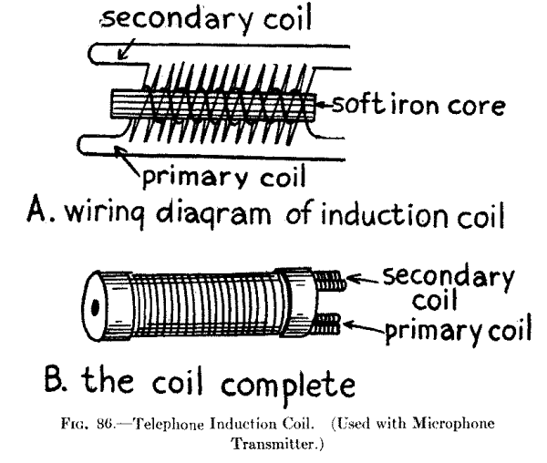
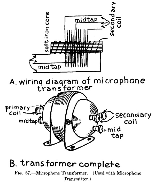
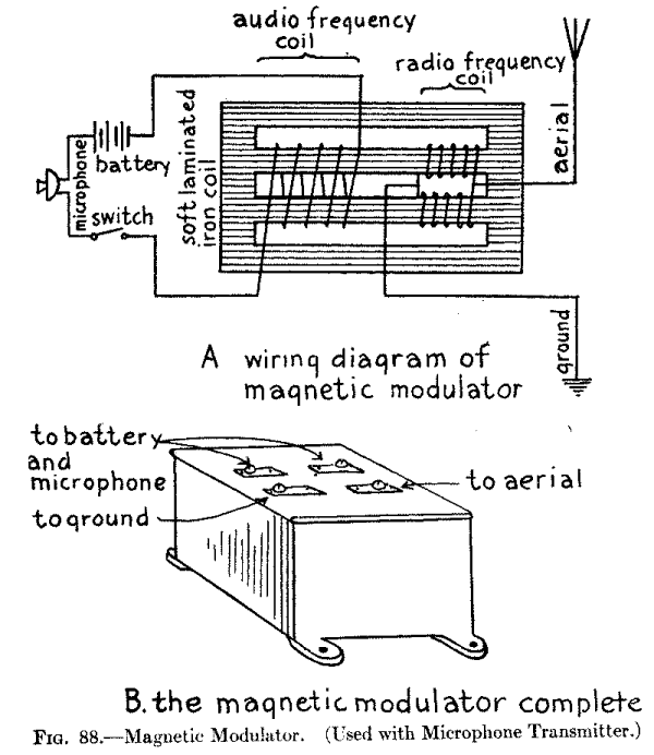
The Telephone Induction Coil.--This is a little induction coil that transforms the 6-volt battery current after it has flowed through and been modulated by the microphone transmitter into alternating currents that have a potential of 1,000 volts of more. It consists of a primary coil of No. 20 B. and S. gauge cotton covered magnet wire wound on a core of soft iron wires while around the primary coil is wound a secondary coil of No. 30 magnet wire. Get a standard telephone induction coil that has a resistance of 500 or 750 ohms and this will cost you a couple of dollars.
The Microphone Transformer.--This device is built on exactly the same principle as the telephone induction coil just described but it is more effective because it is designed especially for modulating the oscillations set up by vacuum tube transmitters. As with the telephone induction coil, the microphone transmitter is connected in series with the primary coil and a 6 volt dry or storage battery.
In the better makes of microphone transformer, there is a third winding, called a side tone coil, to which a headphone can be connected so that the operator who is speaking into the microphone can listen-in and so learn if his transmitter is working up to standard.
The Magnetic Modulator.--This is a small closed iron core transformer of peculiar design and having a primary and a secondary coil wound on it. This device is used to control the variations of the oscillating currents that are set up by the oscillator tube. It is made in three sizes and for the transmitter here described you want the smallest size, which has an output of 1/2 to 1-1/2 amperes. It costs about $10.00.
How the Apparatus Is Connected Up.--The different pieces of apparatus are connected together in exactly the same way as the 100 Mile C. W. Telegraph Set in Chapter XVI except that the microphone transmitter and microphone modulator (whichever kind you use) is substituted for the telegraph key and chopper.
Now there are three different ways that the microphone and its modulator can be connected in circuit. Two of the best ways are shown at A and B in Fig. 89. In the first way the secondary terminals of the modulator are shunted around the grid leak in the grid circuit as at A, and in the second the secondary terminals are connected in the aerial as at B. Where an induction coil or a microphone transformer is used they are shunted around a condenser, but this is not necessary with the magnetic modulator. Where a second tube is used as in Fig. 90 then the microphone and its modulator are connected with the grid circuit and clip 3 of the tuning coil.
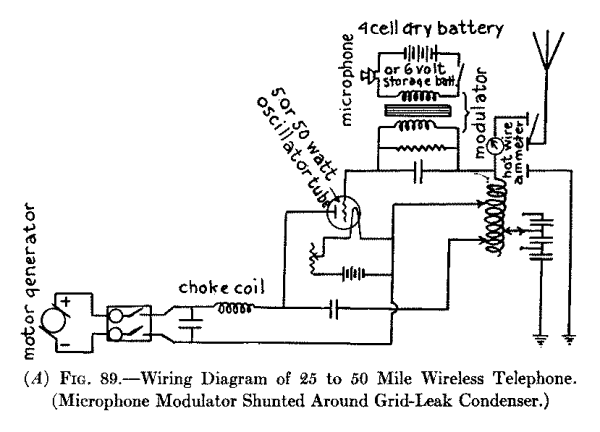
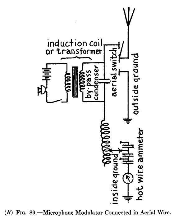
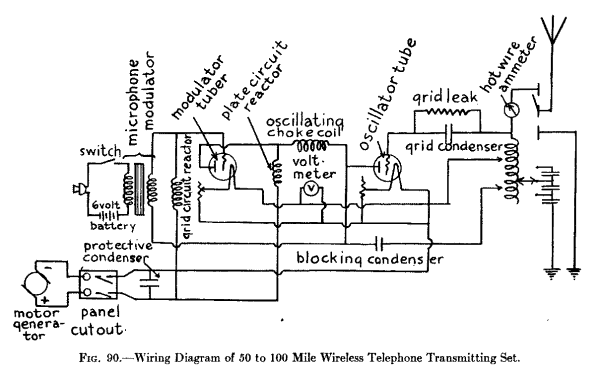
A 50 to 100 Mile Wireless Telephone Transmitter--With Direct Current Motor Generator.--As the initial source of current available is taken to be a 110 or 220 volt direct current a motor-generator having an output of 350 volts must be used as before. The only difference between this transmitter and the preceding one is that: (1) two 5 watt tubes are used, the first serving as an oscillator and the second as a modulator; (2) an oscillation choke coil is used in the plate circuit; (3) a reactance coil or reactor, is used in the plate circuit; and (4) a reactor is used in the grid circuit.
The Oscillation Choke Coil.--You can make this choke coil by winding about 275 turns of No. 28 B. and S. gauge cotton covered magnet wire on a spool 2 inches in diameter and 4 inches long. Give it a good coat of shellac varnish and let it dry thoroughly.
The Plate and Grid Circuit Reactance Coils.--Where a single tube is used as an oscillator and a second tube is employed as a modulator, a reactor, which is a coil of wire wound on an iron core, is used in the plate circuit to keep the high voltage direct current of the motor-generator the same at all times. Likewise the grid circuit reactor is used to keep the voltage of the grid at a constant value. These reactors are made alike and a picture of one of them is shown in Fig. 91 and each one will cost you $5.75.
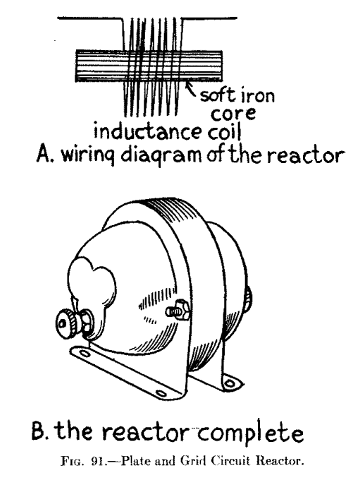
Connecting up the Apparatus.--All of the different pieces of apparatus are connected up as shown in Fig. 89. One of the ends of the secondary of the induction coil, or the microphone transformer, or the magnetic modulator is connected to the grid circuit and the other end to clip 3 of the tuning coil.
A 100 to 200 Mile Wireless Telephone Transmitter--With Direct Current Motor Generator.--By using the same connections shown in the wiring diagrams in Fig. 89 and a single 50 watt oscillator tube your transmitter will then have a range of 100 miles or so, while if you connect up the apparatus as shown in Fig. 90 and use two 50 watt tubes you can work up to 200 miles. Much of the apparatus for a 50 watt oscillator set where either one or two tubes are used is of the same size and design as that just described for the 5 watt oscillator sets, but, as in the C. W. telegraph sets, some of the parts must be proportionately larger. The required parts are (1) the 50 watt tube; (2) the grid leak resistance; (3) the filament rheostat; (4) the filament storage battery; and (5) the magnetic modulator. All of these parts, except the latter, are described in detail under the heading of a 500 Mile C. W. Telegraph Transmitting Set in Chapter XVI, and are also pictured in that chapter.
It is not advisable to use an induction coil for the modulator for this set, but use, instead, either a telephone transformer, or better, a magnetic modulator of the second size which has an output of from 1-1/2 to 3-1/2 amperes. The magnetic modulator is described and pictured in this chapter.
A 50 to 100 Mile Wireless Telephone Transmitting Set--With 110 Volt Alternating Current.--If you have a 110 volt [Footnote: Alternating current for lighting purposes ranges from 102.5 volts to 115 volts, so we take the median and call it 110 volts.] alternating current available you can use it for the initial source of energy for your wireless telephone transmitter. The chief difference between a wireless telephone transmitting set that uses an alternating current and one that uses a direct current is that: (1) a power transformer is used for stepping up the voltage instead of a motor-generator, and (2) a vacuum tube rectifier must be used to convert the alternating current into direct current.
The Apparatus You Need.--For this telephone transmitting set you need: (1) one aerial ammeter; (2) one tuning coil; (3) one telephone modulator; (4) one aerial series condenser; (5) one 4 cell dry battery or a 6 volt storage battery; (6) one microphone transmitter; (7) one battery switch; (8) one grid condenser; (9) one grid leak; (10) two 5 watt oscillator tubes with sockets; (11) one blocking condenser; (12) one oscillation choke coil; (13) two filter condensers; (14) one filter reactance coil; (15) an alternating current power transformer, and (16) two 20 watt rectifier vacuum tubes.
All of the above pieces of apparatus are the same as those described for the 100 Mile C. W. Telegraph Transmitter in Chapter XVII, except: (a) the microphone modulator; (b) the microphone transmitter and (c) the dry or storage battery, all of which are described in this chapter; and the new parts which are: (d) the rectifier vacuum tubes; (e) the filter condensers; and (f) the filter reactance coil; further and finally, the power transformer has a third secondary coil on it and it is this that feeds the alternating current to the rectifier tubes, which in turn converts it into a pulsating direct current.
The Vacuum Tube Rectifier.--This rectifier has two electrodes, that is, it has a filament and a plate like the original vacuum tube detector, The smallest size rectifier tube requires a plate potential of 550 volts which is developed by one of the secondary coils of the power transformer. The filament terminal takes a current of 7.5 volts and this is supplied by another secondary coil of the transformer. This rectifier tube delivers a direct current of 20 watts at 350 volts. It looks exactly like the 5 watt oscillator tube which is pictured at E in Fig. 77. The price is $7.50.
The Filter Condensers.--These condensers are used in connection with the reactance coil to smooth out the pulsating direct current after it has passed through the rectifier tube. They have a capacitance of 1 mfd. and will stand 750 volts. These condensers cost about $2.00 each.
The Filter Reactance Coil.--This reactor which is shown in Fig. 92, has about the same appearance as the power transformer but it is somewhat smaller. It consists of a coil of wire wound on a soft iron core and has a large inductance, hence the capacitance of the filter condensers are proportionately smaller than where a small inductance is used which has been the general practice. The size you require for this set has an output of 160 milliamperes and it will supply current for one to four 5 watt oscillator tubes. This size of reactor costs $11.50.
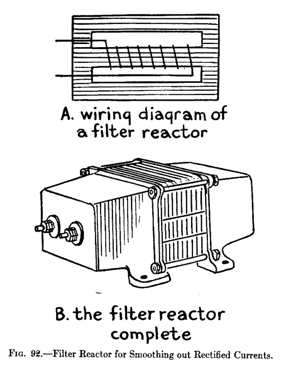
Connecting Up the Apparatus.--The wiring diagram in Fig. 93 shows how the various pieces of apparatus for this telephone transmitter are connected up. You will observe: (1) that the terminals of the power transformer secondary coil which develops 10 volts are connected to the filaments of the oscillator tubes; (2) that the terminals of the other secondary coil which develops 10 volts are connected with the filaments of the rectifier tubes; (3) that the terminals of the third secondary coil which develops 550 volts are connected with the plates of the rectifier tubes; (4) that the pair of filter condensers are connected in parallel and these are connected to the mid-taps of the two filament secondary coils; (5) that the reactance coil and the third filter condenser are connected together in series and these are shunted across the filter condensers, which are in parallel; and, finally, (6) a lead connects the mid-tap of the 550-volt secondary coil of the power transformer with the connection between the reactor and the third filter condenser.
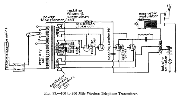
A 100 to 200 Mile Wireless Telephone Transmitting Set--With 110 Volt Alternating Current.--This telephone transmitter is built up of exactly the same pieces of apparatus and connected up in precisely the same way as the one just described and shown in Fig. 93.
Apparatus Required.--The only differences between this and the preceding transmitter are: (1) the magnetic modulator, if you use one, should have an output of 3-1/2 to 5 amperes; (2) you will need two 50 watt oscillator tubes with sockets; (3) two 150 watt rectifier tubes with sockets; (4) an aerial ammeter that reads to 5 amperes; (5) three 1 mfd. filter condensers in parallel; (6) two filter condensers of 1 mfd. capacitance that will stand 1750 volts; and (6) a 300 milliampere filter reactor.
The apparatus is wired up as shown in Fig. 93.
The three foregoing chapters explained in detail the design and construction of (1) two kinds of C. W. telegraph transmitters, and (2) two kinds of wireless telephone transmitters, the difference between them being whether they used (A) a direct current, or (B) an alternating current as the initial source of energy. Of course there are other differences between those of like types as, for instance, the apparatus and connections used (a) in the key circuits, and (b) in the microphone circuits. But in all of the transmitters described of whatever type or kind the same fundamental device is used for setting up sustained oscillations and this is the vacuum tube.
The Operation of the Vacuum Tube Oscillator.--The operation of the vacuum tube in producing sustained oscillations depends on (1) the action of the tube as a valve in setting up the oscillations in the first place and (2) the action of the grid in amplifying the oscillations thus set up, both of which we explained in Chapter XIV. In that chapter it was also pointed out that a very small change in the grid potential causes a corresponding and larger change in the amount of current flowing from the plate to the filament; and that if a vacuum tube is used for the production of oscillations the initial source of current must have a high voltage, in fact the higher the plate voltage the more powerful will be the oscillations.
To understand how oscillations are set up by a vacuum tube when a direct current is applied to it, take a look at the simple circuits shown in Fig. 94. Now when you close the switch the voltage from the battery charges the condenser and keeps it charged until you open it again; the instant you do this the condenser discharges through the circuit which includes it and the inductance coil, and the discharge of a condenser is always oscillatory.
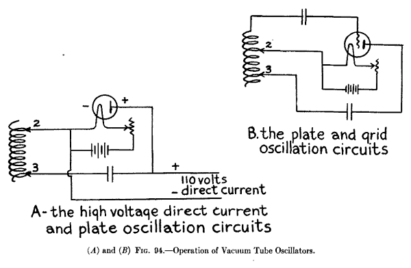
Where an oscillator tube is included in the circuits as shown at A and B in Fig. 94, the grid takes the place of the switch and any slight change in the voltage of either the grid or the plate is sufficient to start a train of oscillations going. As these oscillations surge through the tube the positive parts of them flow from the plate to the filament and these carry more of the direct current with them.
To make a tube set up powerful oscillations then, it is only necessary that an oscillation circuit shall be provided which will feed part of the oscillations set up by the tube back to the grid circuit and when this is done the oscillations will keep on being amplified until the tube reaches the limit of its output.
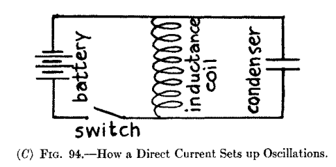
The Operation of C. W. Telegraph Transmitters With Direct Current--Short Distance C. W. Transmitter.--In the transmitter shown in the wiring diagram in Fig. 76 the positive part of the 110 volt direct current is carried down from the lamp socket through one side of the panel cut-out, thence through the choke coil and to the plate of the oscillator tube, when the latter is charged to the positive sign. The negative part of the 110 volt direct current then flows down the other wire to the filament so that there is a difference of potential between the plate and the filament of 110 volts. Now when the 6-volt battery current is switched on the filament is heated to brilliancy, and the electrons thrown off by it form a conducting path between it and the plate; the 110 volt current then flows from the latter to the former.
Now follow the wiring from the plate over to the blocking condenser, thence to clip 3 of the tuning coil, through the turns of the latter to clip 2 and over to the filament and, when the latter is heated, you have a closed oscillation circuit. The oscillations surging in the latter set up other and like oscillations in the tuning coil between the end of which is connected with the grid, the aerial and the clip 2, and these surge through the circuit formed by this portion of the coil, the grid condenser and the filament; this is the amplifying circuit and it corresponds to the regenerative circuit of a receiving set.
When oscillations are set up in it the grid is alternately charged to the positive and negative signs. These reversals of voltage set up stronger and ever stronger oscillations in the plate circuit as before explained. Not only do the oscillations surge in the closed circuits but they run to and fro on the aerial wire when their energy is radiated in the form of electric waves. The oscillations are varied by means of the telegraph key which is placed in the grid circuit as shown in Fig. 76.
The Operation of the Key Circuit.--The effect in a C. W. transmitter when a telegraph key is connected in series with a buzzer and a battery and these are shunted around the condenser in the grid circuit, is to rapidly change the wave form of the sustained oscillations, and hence, the length of the waves that are sent out. While no sound can be heard in the headphones at the receiving station so long as the points of the key are not in contact, when they are in contact the oscillations are modulated and sounds are heard in the headphones that correspond to the frequency of the buzzer in the key circuit.
The Operation of C. W. Telegraph Transmitters with Direct Current.--The chief differences between the long distance sets which use a direct current, i.e., those described in Chapter XVI, and the short distance transmitting sets are that the former use: (1) a motor-generator set for changing the low voltage direct current into high voltage direct current, and (2) a chopper in the key circuit. The way the motor-generator changes the low- into high-voltage current has been explained in Chapter XVI.
The chopper interrupts the oscillations surging through the grid circuit at a frequency that the ear can hear, that is to say, about 800 to 1,000 times per second. When the key is open, of course, the sustained oscillations set up in the circuits will send out continuous waves but when the key is closed these oscillations are broken up and then they send out discontinuous waves. If a heterodyne receiving set, see Chapter XV, is being used at the other end you can dispense with the chopper and the key circuit needed is very much simplified. The operation of key circuits of the latter kind will be described presently.
The Operation of C. W. Telegraph Transmitters with Alternating Current--With a Single Oscillator Tube.--Where an oscillator tube telegraph transmitter is operated by a 110 volt alternating current as the initial source of energy, a buzzer, chopper or other interruptor is not needed in the key circuit. This is because oscillations are set up only when the plate is energized with the positive part of the alternating current and this produces an intermittent musical tone in the headphones. Hence this kind of a sending set is called a tone transmitter.
Since oscillations are set up only by the positive part or voltage of an alternating current it is clear that, as a matter of fact, this kind of a transmitter does not send out continuous waves and therefore it is not a C. W. transmitter. This is graphically shown by the curve of the wave form of the alternating current and the oscillations that are set up by the positive part of it in Fig. 95. Whenever the positive half of the alternating current energizes the plate then oscillations are set up by the tube and, conversely, when the negative half of the current charges the plate no oscillations are produced.
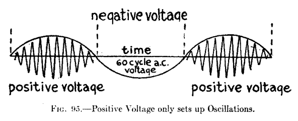
You will also observe that the oscillations set up by the positive part of the current are not of constant amplitude but start at zero the instant the positive part begins to energize the plate and they keep on increasing in amplitude as the current rises in voltage until the latter reaches its maximum; then as it gradually drops again to zero the oscillations decrease proportionately in amplitude with it.
Heating the Filament with Alternating Current.--Where an alternating current power transformer is used to develop the necessary plate voltage a second secondary coil is generally provided for heating the filament of the oscillation tube. This is better than a direct current for it adds to the life of the filament. When you use an alternating current to heat the filament keep it at the same voltage rather than at the same amperage (current strength). To do this you need only to use a voltmeter across the filament terminals instead of an ammeter in series with it; then regulate the voltage of the filament with a rheostat.
The Operation of C. W. Telegraph Transmitters with Alternating Current--With Two Oscillator Tubes.--By using two oscillator tubes and connecting them up with the power transformer and oscillating circuits as shown in the wiring diagram in Fig. 83 the plates are positively energized alternately with every reversal of the current and, consequently, there is no time period between the ending of the oscillations set up by one tube and the beginning of the oscillations set up by the other tube. In other words these oscillations are sustained but as in the case of those of a single tube, their amplitude rises and falls. This kind of a set is called a full wave rectification transmitter.
The waves radiated by this transmitter can be received by either a crystal detector or a plain vacuum-tube detector but the heterodyne receptor will give you better results than either of the foregoing types.
The Operation of Wireless Telephone Transmitters with Direct Current--Short Distance Transmitter.--The operation of this short distance wireless telephone transmitter, a wiring diagram of which is shown in Fig. 85 is exactly the same as that of the Direct Current Short Distance C. W. Telegraph Transmitter already explained in this chapter. The only difference in the operation of these sets is the substitution of the microphone transmitter for the telegraph key.
The Microphone Transmitter.--The microphone transmitter that is used to vary, or modulate, the sustained oscillations set up by the oscillator tube and circuits is shown in Fig. 84. By referring to the diagram at A in this figure you will readily understand how it operates. When you speak into the mouthpiece the sound waves, which are waves in the air, impinge upon the diaphragm and these set it into vibration--that is, they make it move to and fro.
When the diaphragm moves toward the back of the transmitter it forces the carbon granules that are in the cup closer together; this lowers their resistance and allows more current from the battery to flow through them; when the pressure of the air waves is removed from the diaphragm it springs back toward the mouth-piece and the carbon granules loosen up when the resistance offered by them is increased and less current can flow through them. Where the oscillation current in the aerial wire is small the transmitter can be connected directly in series with the latter when the former will surge through it. As you speak into the microphone transmitter its resistance is varied and the current strength of the oscillations is varied accordingly.
The Operation of Wireless Telephone Transmitters with Direct Current--Long Distance Transmitters.--In the wireless telephone transmitters for long distance work which were shown and described in the preceding chapter a battery is used to energize the microphone transmitter, and these two elements are connected in series with a microphone modulator. This latter device may be either (1) a telephone induction coil, (2) a microphone transformer, or (3) a magnetic modulator; the first two of these devices step-up the voltage of the battery current and the amplified voltage thus developed is impressed on the oscillations that surge through the closed oscillation circuit or the aerial wire system according to the place where you connect it. The third device works on a different principle and this will be described a little farther along.
The Operation of Microphone Modulators--The Induction Coil.--This device is really a miniature transformer, see A in Fig. 86, and its purpose is to change the 6 volt direct current that flows through the microphone into 100 volts alternating current; in turn, this is impressed on the oscillations that are surging in either (1) the grid circuit as shown at A in Fig. 89, and in Fig. 90, (2) the aerial wire system, as shown at B in Fig. 89 and Fig. 93. When the current from the battery flows through the primary coil it magnetizes the soft iron core and as the microphone varies the strength of the current the high voltage alternating currents set up in the secondary coil of the induction coil are likewise varied, when they are impressed upon and modulate the oscillating currents.
The Microphone Transformer.--This is an induction coil that is designed especially for wireless telephone modulation. The iron core of this transformer is also of the open magnetic circuit type, see A in Fig. 87, and the ratio of the turns [Footnote: See Chapter VI] of the primary and the secondary coil is such that when the secondary current is impressed upon either the grid circuit or the aerial wire system it controls the oscillations flowing through it with the greatest efficiency.
The Magnetic Modulator.--This piece of apparatus is also called a magnetic amplifier. The iron core is formed of very thin plates, or laminations as they are called, and this permits high-frequency oscillations to surge in a coil wound on it. In this transformer, see A in Fig. 88, the current flowing through the microphone varies the magnetic permeability of the soft iron core by the magnetic saturation of the latter. Since the microphone current is absolutely distinct from the oscillating currents surging through the coil of the transformer a very small direct current flowing through a coil on the latter will vary or modulate very large oscillating currents surging through the former. It is shown connected in the aerial wire system at A in Fig. 88, and in Fig. 93.
Operation of the Vacuum Tube as a Modulator.--Where a microphone modulator of the induction coil or microphone transformer type is connected in the grid circuit or aerial wire system the modulation is not very effective, but by using a second tube as a modulator, as shown in Fig. 90, an efficient degree of modulation can be had. Now there are two methods by which a vacuum tube can be used as a modulator and these are: (1) by the absorption of the energy of the current set up by the oscillator tube, and (2) by varying the direct current that energizes the plate of the oscillator tube.
The first of these two methods is not used because it absorbs the energy of the oscillating current produced by the tube and it is therefore wasteful. The second method is an efficient one, as the direct current is varied before it passes into the oscillator tube. This is sufficient reason for describing only the second method. The voltage of the grid of the modulator tube is varied by the secondary coil of the induction coil or microphone transformer, above described. In this way the modulator tube acts like a variable resistance but it amplifies the variations impressed on the oscillations set up by the oscillator tube. As the magnetic modulator does the same thing a vacuum tube used as a modulator is not needed where the former is employed. For this reason a magnetic modulator is the cheapest in the long run.
The Operation of Wireless Telephone Transmitters with Alternating Current.--Where an initial alternating current is used for wireless telephony, the current must be rectified first and then smoothed out before passing into the oscillator tube to be converted into oscillations. Further so that the oscillations will be sustained, two oscillator tubes must be used, and, finally, in order that the oscillations may not vary in amplitude the alternating current must be first changed into direct current by a pair of rectifier vacuum tubes, as shown in Fig. 93. When this is done the plates will be positively charged alternately with every reversal of the current in which case there will be no break in the continuity of the oscillations set up and therefore in the waves that are sent out.
The Operation of Rectifier Vacuum Tubes.--The vacuum tube rectifier is simply a two electrode vacuum tube. The way in which it changes a commercial alternating current into pulsating direct current is the same as that in which a two electrode vacuum tube detector changes an oscillating current into pulsating direct currents and this has been explained in detail under the heading of The Operation of a Two Electrode Vacuum Tube Detector in Chapter XII. In the C. W. Telegraph Transmitting Sets described in Chapter XVII, the oscillator tubes act as rectifiers as well as oscillators but for wireless telephony the alternating current must be rectified first so that a continuous direct current will result.
The Operation of Reactors and Condensers.--A reactor is a single coil of wire wound on an iron core, see Fig. 90 and A in Fig. 91, and it should preferably have a large inductance. The reactor for the plate and grid circuit of a wireless telephone transmitter where one or more tubes are used as modulators as shown in the wiring diagram in Fig. 90, and the filter reactor shown in Fig. 92, operate in the same way.
When an alternating current flows through a coil of wire the reversals of the current set up a counter electromotive force in it which opposes, that is reacts, on the current, and the higher the frequency of the current the greater will be the reactance. When the positive half of an alternating current is made to flow through a large resistance the current is smoothed out but at the same time a large amount of its energy is used up in producing heat.
But when the positive half of an alternating current is made to flow through a large inductance it acts like a large resistance as before and likewise smooths out the current, but none of its energy is wasted in heat and so a coil having a large inductance, which is called an inductive reactance, or just reactor for short, is used to smooth out, or filter, the alternating current after it has been changed into a pulsating direct current by the rectifier tubes.
A condenser also has a reactance effect on an alternating current but different from an induction coil the lower the frequency the greater will be the reactance. For this reason both a filter reactor and filter condensers are used to smooth out the pulsating direct currents.
In the chapters on Receptors you have been told how to build up high-grade sets. But there are thousands of boys, and, probably, not a few men, who cannot afford to invest $25.00, more or less, in a receiving set and would like to experiment in a small way.
The following set is inexpensive, and with this cheap, little portable receptor you can get the Morse code from stations a hundred miles distant and messages and music from broadcasting stations if you do not live too far away from them. All you need for this set are: (1) a crystal detector, (2) a tuning coil and (3) an earphone. You can make a crystal detector out of a couple of binding posts, a bit of galena and a piece of brass wire, or, better, you can buy one all ready to use for 50 cents.
| Photograph unavailable |
| Wireless Receptor, the size of a Safety Match Box. A Youthful Genius in the person of Kenneth R. Hinman, Who is only twelve years old, has made a Wireless Receiving Set that fits neatly into a Safety Match Box. With this Instrument and a Pair of Ordinary Receivers, He is able to catch not only Code Messages but the regular Broadcasting Programs from Stations Twenty and Thirty Miles Distant. |
The Crystal Detector.--This is known as the Rasco baby detector and it is made and sold by the Radio Specialty Company, 96 Park Place, New York City. It is shown in Fig. 96. The base is made of black composition and on it is mounted a standard in which a rod slides and on one end of this there is fixed a hard rubber adjusting knob while the other end carries a thin piece of phosphor-bronze wire, called a cat-whisker To secure the galena crystal in the cup you simply unscrew the knurled cap, place it in the cavity of the post and screw the cap back on again. The free end of the cat-whisker wire is then adjusted so that it will rest lightly on the exposed part of the galena.
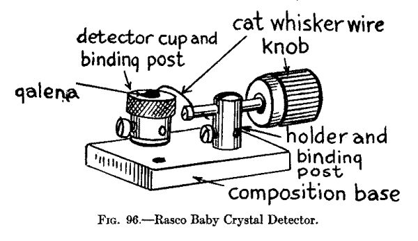
The Tuning Coil.--You will have to make this tuning coil, which you can do at a cost of less than $1.00, as the cheapest tuning coil you can buy costs at least $3.00, and we need the rest of our $5.00 to invest in the earphone. Get a cardboard tube, such as is used for mailing purposes, 2 inches in diameter and 3 inches long, see A in Fig. 97. Now wind on 250 turns of No. 40 Brown and Sharpe gauge plain enameled magnet wire. You can use No. 40 double cotton covered magnet wire, in which case you will have to shellac the tube and the wire after you get it on.
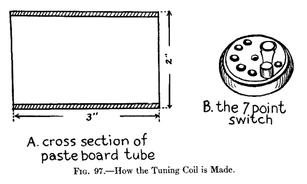
As you wind on the wire take off a tap at every 15th turn, that is, scrape the wire and solder on a piece about 7 inches long, as shown in Fig. 99; and do this until you have 6 taps taken off. Instead of leaving the wires outside of the tube bring them to the inside of it and then out through one of the open ends. Now buy a round wood-base switch with 7 contact points on it as shown at B in Fig. 97. This will cost you 25 or 50 cents.
The Headphone.--An ordinary Bell telephone receiver is of small use for wireless work as it is wound to too low a resistance and the diaphragm is much too thick. If you happen to have a Bell phone you can rewind it with No. 40 single covered silk magnet wire, or enameled wire of the same size, when its sensitivity will be very greatly improved. Then you must get a thin diaphragm and this should not be enameled, as this tends to dampen the vibrations of it. You can get a diaphragm of the right kind for 5 cents.
The better way, though, is to buy an earphone made especially for wireless work. You can get one wound to 1000 ohms resistance for $1.75 and this price includes a cord. [Footnote: This is Mesco, No. 470 wireless phone. Sold by the Manhattan Electrical Supply Co., Park Place, N.Y.C.] For $1.00 extra you can get a head-band for it, and then your phone will look like the one pictured in Fig. 98.
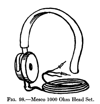
How to Mount the Parts.--Now mount the coil on a wood base, 1/2 or 1 inch thick, 3-1/2 inches wide and 5-1/2 inches long, and then connect one end of the coil to one of the end points on the switch, and connect each succeeding tap to one of the switch points, as shown schematically in Fig. 99 and diagrammatically in Fig. 100. This done, screw the switch down to the base. Finally screw the detector to the base and screw two binding posts in front of the coil. These are for the earphone.
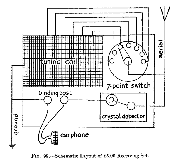
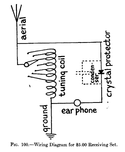
The Condenser.--You do not have to connect a condenser across the earphone but if you do you will improve the receiving qualities of the receptor.
How to Connect Up the Receptor.--Now connect up all the parts as shown in Figs. 99 and 100, then connect the leading-in wire of the aerial with the lever of the switch; and connect the free end of the tuning coil with the ground. If you have no aerial wire try hooking it up to a rain pipe that is not grounded or the steel frame of an umbrella. For a ground you can use a water pipe, an iron pipe driven into the ground, or a hydrant. Put on your headphone, adjust the detector and move the lever over the switch contacts until it is in adjustment and then, if all your connections are properly made, you should be able to pick up messages.
| Photograph unavailable |
| Wireless Set made into a Ring, designed by Alfred G. Rinehart, of Elizabeth, New Jersey. This little Receptor is a Practical Set; it will receive Messages, Concerts, etc., Measures 1" by 5/8" by 7/8". An ordinary Umbrella is used as an Aerial. |
  Unit                   Abbreviation

  ampere                 amp.
  ampere-hours           amp.-hr.
  centimeter             cm.
  centimeter-gram-second c.g.s.
  cubic centimeters      cm.^3
  cubic inches           cu. in.
  cycles per second      ~
  degrees Centigrade     °C.
  degrees Fahrenheit     °F.
  feet                   ft.
  foot-pounds            ft.-lb.
  grams                  g.
  henries                h.
  inches                 in.
  kilograms              kg.
  kilometers             km.
  kilowatts              kw.
  kilowatt-hours         kw.-hr.
  kilovolt-amperes       kv.-a.
  meters                 m.
  microfarads            [Greek: mu]f.
  micromicrofarads       [Greek: mu mu]f.
  millihenries           mh.
  millimeters            mm.
  pounds                 lb.
  seconds                sec.
  square centimeters     cm.^2
  square inches          sq. in.
  volts                  v.
  watts                  w.
  Prefix          Abbreviation          Meaning

  micro           [Greek: mu].          1 millionth
  milli           m.                    1 thousandth
  centi           c.                    1 hundredth
  deci            d.                    1 tenth
  deka            dk.                   10
  hekto           h.                    1 hundred
  kilo            k.                    1 thousand
  mega            m.                    1 million
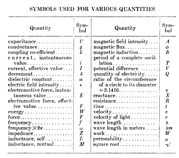
Quantity                 Symbol

capacitance              C

conductance              g

coupling co-efficient    k

current, instantaneous   i

current, effective value I

decrement                [Greek: delta]

dielectric constant      [Greek: alpha]

electric field intensity [Greek: epsilon]

electromotive force,

instantaneous value      E

electromotive force,

effective value          F

energy                   W

force                    F

frequency                f

frequency x 2[Greek: pi] [Greek: omega]

impedance                Z

inductance, self         L

inductance, mutual       M

magnetic field intensity A

magnetic flux            [Greek: Phi]

magnetic induction       B

period of a complete

oscillation              T

potential difference     V

quantity of electricity  Q

ratio of the

circumference of a

circle to its diameter

=3.1416                  [Greek: pi]

reactance                X

resistance               R

time                     t

velocity                 v

velocity of light        c

wave length              [Greek: lambda]

wave length in meters    [Greek: lambda]m

work                     W

permeability             [Greek: mu]

Square root              [Math: square root]
  No. of   Turns     Turns      Ohms per
  Wire,     per       per      Cubic Inch
  B.& S.  Linear    Square        of
  Gauge    Inch      Inch       Winding

  20        30         885         .748
  22        37        1400        1.88
  24        46        2160        4.61
  26        58        3460       11.80
  28        73        5400       29.20
  30        91        8260       70.90
  32       116      21,000     7547.00
  34       145      13,430     2968.00
  36       178      31,820     1098.00
  38       232      54,080      456.00
  40       294      86,500      183.00
  W. L.--Wave Lengths in Meters.
  F.--Number of Oscillations per Second.
  O. or square root L. C. is called Oscillation Constant.
  C.--Capacity in Microfarads.
  L.--Inductance in Centimeters.
  1000 Centimeters = 1 Microhenry.
    W.L.     F          O       L.C.
      50  6,000,000     .839       .7039
     100  3,000,000    1.68       2.82
     150  2,000,000    2.52       6.35
     200  1,500,000    3.36      11.29
     250  1,200,000    4.19      17.55
     300  1,000,000    5.05      25.30
     350    857,100    5.87      34.46
     400    750,000    6.71      45.03
     450    666,700    7.55      57.00
     500    600,000    8.39      70.39
     550    545,400    9.23      85.19
     600    500,000   10.07     101.41
     700    428,600   11.74     137.83
     800    375,000   13.42     180.10
     900    333,300   15.10     228.01
   1,000    300,000   16.78     281.57
   1,100    272,730   18.45     340.40
   1,200    250,000   20.13     405.20
   1,300    230,760   21.81     475.70
   1,400    214,380   23.49     551.80
   1,500    200,000   25.17     633.50
   1,600    187,500   26.84     720.40
   1,700    176,460   28.52     813.40
   1,800    166,670   30.20     912.00
   1,900    157,800   31.88   1,016.40
   2,000    150,000   33.55   1,125.60
   2,100    142,850   35.23   1,241.20
   2,200    136,360   36.91   1,362.40
   2,300    130,430   38.59   1,489.30
   2,400    125,000   40.27   1,621.80
   2,500    120,000   41.95   1,759.70
   2,600    115,380   43.62   1,902.60
   2,700    111,110   45.30   2,052.00
   2,800    107,140   46.89   2,207.00
   2,900    103,450   48.66   2,366.30
   3,000    100,000   50.33   2,533.20
   4,000     75,000   67.11   4,504.00
   5,000     60,000   83.89   7,038.00
   6,000     50,000  100.7   10,130.00
   7,000     41,800  117.3   13,630.00
   8,000     37,500  134.1   18,000.00
   9,000     33,300  151.0   22,820.00
  10,000     30,000  167.9   28,150.00
  11,000     27,300  184.8   34,150.00
  12,000     25,000  201.5   40,600.00
  13,000     23,100  218.3   47,600.00
  14,000     21,400  235.0   55,200.00
  15,000     20,000  252.0   63,500.00
  16,000     18,750  269.0   72,300.00
Many of the physical quantities use Greek letters for symbols. The
following is the Greek alphabet with the way the letters are
pronounced:
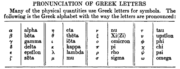
  a   alpha
  b   beta
  g   gamma
  d   delta
  e   epsilon
  z   zeta
  ae  eta
  th  theta
  i   iota
  k   kappa
  l   lambda
  m   mu
  n   nu
  x   Xi(Zi)
  o   omicron
  p   pi
  r   rho
  s   sigma
  t   tau
  u   upsilon
  ph  phi
  ch  chi
  ps  psi
  o   omega
In Air for Various Voltages between Needle Points
  Volts               Distance
               Inches         Centimeter
  5,000         .225            .57
  10,000        .470           1.19
  15,000        .725           1.84
  20,000       1.000           2.54
  25,000       1.300           3.30
  30,000       1.625           4.10
  35,000       2.000           5.10
  40,000       2.450           6.20
  45,000       2.95            7.50
  50,000       3.55            9.90
  60,000       4.65           11.8
  70,000       5.85           14.9
  80,000       7.10           18.0
  90,000       8.35           21.2
  100,000      9.60           24.4
  110,000     10.75           27.3
  120,000     11.85           30.1
  130,000     12.95           32.9
  140,000     13.95           35.4
  150,000     15.00           38.1
  No. of    Single     Double     Single     Double
  B.& S.    Cotton,    Cotton,    Silk,      Silk,      Enamel
  Gauge     4-Mils     8-Mils     1-3/4-Mils 4-Mils

  20           311        298       319         312       320
  21           389        370       408         389       404
  22           488        461       503         498       509
  23           612        584       636         631       642
  24           762        745       800         779       810
  25           957        903     1,005         966     1,019
  26         1,192      1,118     1,265       1,202     1,286
  27         1,488      1,422     1,590       1,543     1,620
  28         1,852      1,759     1,972       1,917     2,042
  29         2,375      2,207     2,570       2,435     2,570
  30         2,860      2,534     3,145       2,900     3,240
  31         3,800      2,768     3,943       3,683     4,082
  32         4,375      3,737     4,950       4,654     5,132
  33         5,590      4,697     6,180       5,689     6,445
  34         6,500      6,168     7,740       7,111     8,093
  35         8,050      6,737     9,600       8,584    10,197
  36         9,820      7,877    12,000      10,039    12,813
  37        11,860      9,309    15,000      10,666    16,110
  38        14,300     10,636    18,660      14,222    20,274
  39        17,130     11,907    23,150      16,516    25,519
  40        21,590     14,222    28,700      21,333    32,107
[Note: period denotes Morse dot, hyphen denotes Morse dash]
A .-

B -...

C -.-.

D -..

E .

F ..-.

G --.

H ....

I ..

J .---

K -.-

L .-..

M --

N -.

O ---

P .--.

Q --.-

R .-.

S ...

T -

U ..-

V ...-

W .--

X -..-

Y -.--

Z --..

Ä (German) .-.-

Á or Å (Spanish-Scandinavian) .--.-

CH (German-Spanish) ----

É (French) ..-..

Ñ (Spanish) --.--

Ö (German) ---.

Ü (German) ..--

1 .----

2 ..---

3 ...--

4 ....-

5 .....

6 -....

7 --...

8 ---..

9 ----.

0 -----

Period .. .. ..

Semicolon -.-.-.

Comma -.-.-.

Colon ---...

Interrogation ..--..

Exclamation point --..--

Apostrophe .----.

Hyphen -....-

Bar indicating fraction -..-.

Parenthesis -.--.-

Inverted commas .-..-.

Underline ..--.-

Double dash -...-

Distress Call ...---...

Attention call to precede every transmission -.-.-

General inquiry call -.-. --.-

From (de) -.. .

Invitation to transmit (go ahead) -.-

Warning--high power --..--

Question (please repeat after ...)--interrupting long messages ..--..

Wait .-...

Break (Bk.) (double dash) -...-

Understand ...-.

Error ........

Received (O.K.) .-.

Position report (to precede all position messages) - .-.

End of each message (cross) .-.-.

Transmission finished (end of work) (conclusion of correspondence) ...-.-
LIST OF ABBREVIATIONS TO BE USED IN RADIO COMMUNICATION
ABBREVIATION      QUESTION                ANSWER OR REPLY

PRB   Do you wish to communicate          I wish to communicate by means
        by means of the International       of the International Signal Code.
        Signal Code?

QRA   What ship or coast station is       This is....
      that?

QRB   What is your distance?              My distance is....

QRC   What is your true bearing?          My true bearing is....

QRD   Where are you bound for?            I am bound for....

QRF   Where are you bound from?           I am bound from....

QRG   What line do you belong to?         I belong to the ... Line.

QRH   What is your wave length in         My wave length is ... meters.
        meters?

QRJ   How many words have you to send?    I have ... words to send.

QRK   How do you receive me?              I am receiving well.

QRL   Are you receiving badly?            I am receiving badly. Please
        Shall I send 20?                    send 20.
                   ...-.                               ...-.
                   for adjustment?                     for adjustment.

QRM   Are you being interfered with?      I am being interfered with.

QRN   Are the atmospherics strong?        Atmospherics are very strong.

QRO   Shall I increase power?             Increase power.

QRP   Shall I decrease power?             Decrease power.

QRQ   Shall I send faster?                Send faster.

QRS   Shall I send slower?                Send slower.

QRT   Shall I stop sending?               Stop sending.

QRU   Have you anything for me?           I have nothing for you.

QRV   Are you ready?                      I am ready. All right now.

QRW   Are you busy?                       I am busy (or: I am busy with...).
                                            Please do not interfere.

QRX   Shall I stand by?                   Stand by. I will call you when
                                            required.

QRY   When will be my turn?               Your turn will be No....

QRZ   Are my signals weak?                You signals are weak.

QSA   Are my signals strong?              You signals are strong.

QSB   Is my tone bad?                     The tone is bad.
      Is my spark bad?                    The spark is bad.

QSC   Is my spacing bad?                  Your spacing is bad.

QSD   What is your time?                  My time is....

QSF   Is transmission to be in            Transmission will be in
       alternate  order or in series?       alternate order.

QSG                                       Transmission will be in a
                                            series of 5 messages.

QSH                                       Transmission will be in a
                                            series of 10  messages.

QSJ   What rate shall I collect for...?   Collect....

QSK   Is the last radiogram canceled?     The last radiogram is canceled.

QSL   Did you get my receipt?             Please acknowledge.

QSM   What is your true course?           My true course is...degrees.

QSN   Are you in communication with land? I am not in communication with land.

QSO   Are you in communication with       I am in communication with...
        any ship or station                 (through...).
        (or: with...)?

QSP   Shall I inform...that you are       Inform...that I am calling him.
        calling him?

QSQ   Is...calling me?                    You are being called by....

QSR   Will you forward the radiogram?     I will forward the radiogram.

QST   Have you received the general       General call to all stations.
        call?

QSU   Please call me when you have        Will call when I have finished.
        finished (or: at...o'clock)?

QSV  Is public correspondence being       Public correspondence is being
       handled?                             handled. Please do not interfere.
[Footnote: Public correspondence is any radio work, official or private, handled on commercial wave lengths.]
QSW   Shall I increase my spark           Increase your spark frequency.
        frequency?

QSX   Shall I decrease my spark           Decrease your spark frequency.
        frequency?

QSY   Shall I send on a wavelength        Let us change to the wave length
        of ... meters?                        of ... meters.

QSZ                                       Send each word twice.  I have
                                            difficulty in receiving you.

QTA                                       Repeat the last radiogram.
When an abbreviation is followed by a mark of interrogation, it refers to the question indicated for that abbreviation.
Useful Information
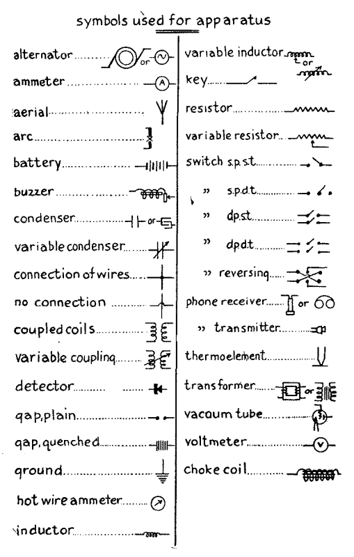
alternator
ammeter
aerial
arc
battery
buzzer
condenser
variable condenser
connection of wires
no connection
coupled coils
variable coupling
detector
gap, plain
gap, quenched
ground
hot wire ammeter
inductor
variable inductor
key
resistor
variable resistor
switch s.p.s.t.
" s.p.d.t.
" d.p.s.t.
" d.p.d.t.
" reversing
phone receiver
" transmitter
thermoelement
transformer
vacuum tube
voltmeter
choke coil
The ohm is the resistance of a thread of mercury at the temperature of melting ice, 14.4521 grams in mass, of uniform cross-section and a length of 106.300 centimeters.
The ampere is the current which when passed through a solution of nitrate of silver in water according to certain specifications, deposits silver at the rate of 0.00111800 of a gram per second.
The volt is the electromotive force which produces a current of 1 ampere when steadily applied to a conductor the resistance of which is 1 ohm.
The coulomb is the quantity of electricity transferred by a current of 1 ampere in 1 second.
The ampere-hour is the quantity of electricity transferred by a current of 1 ampere in 1 hour and is, therefore, equal to 3600 coulombs.
The farad is the capacitance of a condenser in which a potential difference of 1 volt causes it to have a charge of 1 coulomb of electricity.
The henry is the inductance in a circuit in which the electromotive force induced is 1 volt when the inducing current varies at the rate of 1 ampere per second.
The watt is the power spent by a current of 1 ampere in a resistance of 1 ohm.
The joule is the energy spent in I second by a flow of 1 ampere in 1 ohm.
The horse-power is used in rating steam machinery. It is equal to 746 watts.
The kilowatt is 1,000 watts.
The units of capacitance actually used in wireless work are the microfarad, which is the millionth part of a farad, because the farad is too large a unit; and the C. G. S. electrostatic unit of capacitance, which is often called the centimeter of capacitance, which is about equal to 1.11 microfarads.
The units of inductance commonly used in radio work are the millihenry, which is the thousandth part of a henry; and the centimeter of inductance, which is one one-thousandth part of a microhenry.
Note.--For further information about electric and magnetic units get the Bureau of Standards Circular No. 60, called Electric Units and Standards, the price of which is 15 cents; also get Scientific Paper No. 292, called International System of Electric and Magnetic Units, price 10 cents. These and other informative papers can be had from the Superintendent of Documents, Government Printing Office, Washington, D. C.
The Admiralty Manual of Wireless Telegraphy. 1920. Published by His Majesty's Stationery Office, London.
Ralph E. Batcher.--Prepared Radio Measurements. 1921. Wireless Press, Inc., New York City.
Elmer E. Bucher.--Practical Wireless Telegraphy. 1918. Wireless Press, Inc., New York City.
Elmer E. Bucher.--Vacuum Tubes in Wireless Communication. 1919. Wireless Press, Inc., New York City.
Elmer E. Bucher.--The Wireless Experimenter's Manual. 1920. Wireless Press, Inc., New York City.
Charles B. Hayward.--How to Become a Wireless Operator. 1918. American Technical Society, Chicago, Ill.
G. D. Robinson.--Manual of Radio Telegraphy and Telephony. 1920. United States Naval Institute, Annapolis, Md.
Rupert Stanley.--Textbook of Wireless Telegraphy. 1919. Longmans, Green and Co., London.
E. W. Stone.--Elements of Radio Telegraphy. 1919. D, Van Nostrand Co., New York City.
L. B. Turner.--Wireless Telegraphy and Telephony. 1921. Cambridge University Press. Cambridge, England.
Send to the Superintendent of Documents, Government Printing Office, Washington, D. C., for a copy of Price List No. 64 which lists the Government's books and pamphlets on wireless. It will be sent to you free of charge.
The Government publishes; (1) A List of Commercial Government and Special Wireless Stations, every year, price 15 cents; (2) A List of Amateur Wireless Stations, yearly, price 15 cents; (3) A Wireless Service Bulletin is published monthly, price 5 cents a copy, or 25 cents yearly; and (4) Wireless Communication Laws of the United States, the International Wireless Telegraphic Convention and Regulations Governing Wireless Operators and the Use of Wireless on Ships and Land Stations, price 15 cents a copy. Orders for the above publications should be addressed to the Superintendent of Documents, Government Printing Office, Washington, D. C.
Adams-Morgan Co., Upper Montclair, N. J.
American Hard Rubber Co., 11 Mercer Street, New York City.
American Radio and Research Corporation, Medford Hillside, Mass.
Brach (L. S.) Mfg. Co., 127 Sussex Ave., Newark, N. J.
Brandes (C.) Inc., 237 Lafayette St., New York City.
Bunnell (J. H.) Company, Park Place, New York City.
Burgess Battery Company, Harris Trust Co. Bldg., Chicago, Ill.
Clapp-Eastman Co., 120 Main St., Cambridge, Mass.
Connecticut Telephone and Telegraph Co., Meriden, Conn.
Continental Fiber Co., Newark, Del.
Coto-Coil Co., Providence, R. I.
Crosley Mfg. Co., Cincinnati, Ohio.
Doolittle (F. M.), 817 Chapel St., New Haven, Conn.
Edelman (Philip E.), 9 Cortlandt St., New York City.
Edison Storage Battery Co., Orange, N. J.
Electric Specialty Co., Stamford, Conn.
Electrose Mfg. Co., 60 Washington St., Brooklyn, N. Y.
General Electric Co., Schenectady, N. Y.
Grebe (A. H.) and Co., Inc., Richmond Hill, N. Y. C.
International Brass and Electric Co., 176 Beekman St., New York City.
International Insulating Co., 25 West 45th St., New York City.
King Amplitone Co., 82 Church St., New York City.
Kennedy (Colin B.) Co., Rialto Bldg., San Francisco, Cal.
Magnavox Co., Oakland, Cal.
Manhattan Electrical Supply Co., Park Place, N. Y.
Marshall-Gerken Co., Toledo, Ohio.
Michigan Paper Tube and Can Co., 2536 Grand River Ave., Detroit, Mich.
Murdock (Wm. J.) Co., Chelsea, Mass.
National Carbon Co., Inc., Long Island City, N. Y.
Pittsburgh Radio and Appliance Co., 112 Diamond St., Pittsburgh, Pa,
Radio Corporation of America, 233 Broadway, New York City.
Riley-Klotz Mfg. Co., 17-19 Mulberry St., Newark, N. J.
Radio Specialty Co., 96 Park Place, New York City.
Roller-Smith Co., 15 Barclay St., New York City.
Tuska (C. D.) Co., Hartford, Conn.
Western Electric Co., Chicago, Ill.
Westinghouse Electric Co., Pittsburgh, Pa.
Weston Electrical Instrument Co., 173 Weston Ave., Newark, N. J.
Westfield Machine Co., Westfield, Mass.
A. ..............Aerial

A.C. ............Alternating Current

A.F. ............Audio Frequency

B. and S. .......Brown & Sharpe Wire Gauge

C. ..............Capacity or Capacitance

C.G.S. ..........Centimeter-Grain-Second

Cond. ...........Condenser

Coup. ...........Coupler

C.W. ............Continuous Waves

D.C. ............Direct Current

D.P.D.T. ........Double Point Double Throw

D.P.S.T. ........Double Point Single Throw

D.X. ............Distance

E. ..............Short for Electromotive Force (Volt)

E.M.F. ..........Electromotive Force

F. ..............Filament or Frequency

G. ..............Grid

Gnd. ............Ground

I. ..............Current Strength (Ampere)

I.C.W. ..........Interrupted Continuous Waves

KW. .............Kilowatt

L. ..............Inductance

L.C. ............Loose Coupler

Litz. ...........Litzendraht

Mfd. ............Microfarad

Neg. ............Negative

O.T. ............Oscillation Transformer

P. ..............Plate

Prim. ...........Primary

Pos. ............Positive

R. ..............Resistance

R.F. ............Radio Frequency

Sec. ............Secondary

S.P.D.T. ........Single Point Double Throw

S.P.S.T. ........Single Point Single Throw

S.R. ............Self Rectifying

T. ..............Telephone or Period (time) of Complete
                    Oscillation

Tick. ...........Tickler

V. ..............Potential Difference

Var. ............Variometer

Var. Cond. ......Variable Condenser

V.T. ............Vacuum Tube

W.L. ............Wave Length

X. ..............Reactance
A BATTERY.--See Battery A.
ABBREVIATIONS, CODE.--Abbreviations of questions and answers used in wireless communication. The abbreviation of a question is usually in three letters of which the first is Q. Thus Q R B is the code abbreviation of "what is your distance?" and the answer "My distance is..." See Page 306 [Appendix: List of Abbreviations].
ABBREVIATIONS, UNITS.--Abbreviations of various units used in wireless electricity. These abbreviations are usually lower case letters of the Roman alphabet, but occasionally Greek letters are used and other signs. Thus amperes is abbreviated amp., micro, which means one millionth, [Greek: mu], etc. See Page 301 [Appendix: Useful Abbreviations].
ABBREVIATIONS OF WORDS AND TERMS.--Letters used instead of words and terms for shortening them up where there is a constant repetition of them, as A.C. for alternating current; C.W. for continuous waves; V.T. for vacuum tube, etc. See Page 312 [Appendix: Abbreviations of Common Terms].
AERIAL.--Also called antenna. An aerial wire. One or more wires suspended in the air and insulated from its supports. It is the aerial that sends out the waves and receives them.
AERIAL, AMATEUR.--An aerial suitable for sending out 200 meter wave lengths. Such an aerial wire system must not exceed 120 feet in length from the ground up to the aerial switch and from this through the leading-in wire to the end of the aerial.
AERIAL AMMETER.--See Ammeter, Hot Wire.
AERIAL, BED-SPRINGS.--Where an outdoor aerial is not practicable bed-springs are often made to serve the purpose.
AERIAL CAPACITY.--See Capacity, Aerial.
AERIAL COUNTERPOISE.--Where it is not possible to get a good ground an aerial counterpoise or earth capacity can be used to advantage. The counterpoise is made like the aerial and is supported directly under it close to the ground but insulated from it.
AERIAL, DIRECTIONAL.--A flat-top or other aerial that will transmit and receive over greater distances to and from one direction than to and from another.
AERIAL, GROUND.--Signals can be received on a single long wire when it is placed on or buried in the earth or immersed in water. It is also called a ground antenna and an underground aerial.
AERIAL, LOOP.--Also called a coil aerial, coil antenna, loop aerial, loop antenna and when used for the purpose a direction finder. A coil of wire wound on a vertical frame.
AERIAL RESISTANCE.--See Resistance, Aerial.
AERIAL SWITCH.--See Switch Aerial.
AERIAL WIRE.--(1) A wire or wires that form the aerial. (2) Wire that is used for aerials; this is usually copper or copper alloy.
AERIAL WIRE SYSTEM.--An aerial and ground wire and that part of the inductance coil which connects them. The open oscillation circuit of a sending or a receiving station.
AIR CORE TRANSFORMER.--See Transformer, Air Core.
AMATEUR AERIAL OR ANTENNA.--See Aerial, Amateur.
ALTERNATOR.--An electric machine that generates alternating current.
ALPHABET, INTERNATIONAL CODE.--A modified Morse alphabet of dots and dashes originally used in Continental Europe and, hence, called the Continental Code. It is now used for all general public service wireless communication all over the world and, hence, it is called the International Code. See page 305 [Appendix: International Morse Code].
ALTERNATING CURRENT (A.C.)--See Current.
ALTERNATING CURRENT TRANSFORMER.--See Transformer.
AMATEUR GROUND.--See Ground, Amateur.
AMMETER.--An instrument used for measuring the current strength, in terms of amperes, that flows in a circuit. Ammeters used for measuring direct and alternating currents make use of the magnetic effects of the currents. High frequency currents make use of the heating effects of the currents.
AMMETER, HOT-WIRE.--High frequency currents are usually measured by means of an instrument which depends on heating a wire or metal strip by the oscillations. Such an instrument is often called a thermal ammeter, radio ammeter and aerial ammeter.
AMMETER, AERIAL.--See Ammeter, Hot Wire.
AMMETER, RADIO.--See Ammeter, Hot Wire.
AMPERE.--The current which when passed through a solution of nitrate of silver in water according to certain specifications, deposits silver at the rate of 0.00111800 of a gram per second.
AMPERE-HOUR.--The quantity of electricity transferred by a current of 1 ampere in 1 hour and is, therefore, equal to 3600 coulombs.
AMPERE-TURNS.--When a coil is wound up with a number of turns of wire and a current is made to flow through it, it behaves like a magnet. B The strength of the magnetic field inside of the coil depends on (1) the strength of the current and (2) the number of turns of wire on the coil. Thus a feeble current flowing through a large number of turns will produce as strong a magnetic field as a strong current flowing through a few turns of wire. This product of the current in amperes times the number of turns of wire on the coil is called the ampere-turns.
AMPLIFICATION, AUDIO FREQUENCY.--A current of audio frequency that is amplified by an amplifier tube or other means.
AMPLIFICATION, CASCADE.--See Cascade Amplification.
AMPLIFICATION, RADIO FREQUENCY.--A current of radio frequency that is amplified by an amplifier tube or other means before it reaches the detector.
AMPLIFICATION, REGENERATIVE.--A scheme that uses a third circuit to feed back part of the oscillations through a vacuum tube and which increases its sensitiveness when used as a detector and multiplies its action as an amplifier and an oscillator.
AMPLIFIER, AUDIO FREQUENCY.--A vacuum tube or other device that amplifies the signals after passing through the detector.
AMPLIFIER, MAGNETIC.--A device used for controlling radio frequency currents either by means of a telegraph key or a microphone transmitter. The controlling current flows through a separate circuit from that of the radio current and a fraction of an ampere will control several amperes in the aerial wire.
AMPLIFIERS, MULTI-STAGE.--A receiving set using two or more amplifiers. Also called cascade amplification.
AMPLIFIER, VACUUM TUBE.--A vacuum tube that is used either to amplify the radio frequency currents or the audio frequency currents.
AMPLITUDE OF WAVE.--The greatest distance that a point moves from its position of rest.
AMPLIFYING TRANSFORMER, AUDIO.--See Transformer, Audio Amplifying.
AMPLIFYING MODULATOR VACUUM TUBE.--See Vacuum Tube, Amplifying Modulator.
AMPLIFYING TRANSFORMER RADIO.--See Transformer, Radio Amplifying.
ANTENNA, AMATEUR.--See Aerial, Amateur.
ANTENNA SWITCH.--See Switch, Aerial.
APPARATUS SYMBOLS.--See Symbols, Apparatus.
ARMSTRONG CIRCUIT.--See Circuit, Armstrong.
ATMOSPHERICS.--Same as Static, which see.
ATTENUATION.--In Sending wireless telegraph and telephone messages the amplitude of the electric waves is damped out as the distance increases. This is called attenuation and it increases as the frequency is increased. This is the reason why short wave lengths will not carry as far as long wave lengths.
AUDIO FREQUENCY AMPLIFIER.--See Amplifier, Audio Frequency.
AUDIO FREQUENCY AMPLIFICATION.--See Amplification, Audio Frequency.
AUDIBILITY METER.--See Meter, Audibility.
AUDIO FREQUENCY.--See Frequency, Audio.
AUDIO FREQUENCY CURRENT.--See Current, Audio Frequency.
AUDION.--An early trade name given to the vacuum tube detector.
AUTODYNE RECEPTOR.--See Receptor, Autodyne.
AUTO TRANSFORMER.--See Transformer, Auto.
BAKELITE.--A manufactured insulating compound.
B BATTERY.--See Battery B.
BAND, WAVE LENGTH.--See Wave Length Band.
BASKET WOUND COILS.--See Coils, Inductance.
BATTERY, A.--The 6-volt storage battery used to heat the filament of a vacuum tube, detector or amplifier.
BATTERY, B.--The 22-1/2-volt dry cell battery used to energize the plate of a vacuum tube detector or amplifier.
BATTERY, BOOSTER.--This is the battery that is connected in series with the crystal detector.
BATTERY, C.--A small dry cell battery sometimes used to give the grid of a vacuum tube detector a bias potential.
BATTERY, EDISON STORAGE.--A storage battery in which the elements are made of nickel and iron and immersed in an alkaline electrolyte.
BATTERY, LEAD STORAGE.--A storage battery in which the elements are made of lead and immersed in an acid electrolyte.
BATTERY POLES.--See Poles, Battery.
BATTERY, PRIMARY.--A battery that generates current by chemical action.
BATTERY, STORAGE.--A battery that develops a current after it has been charged.
BEAT RECEPTION.--See Heterodyne Reception.
BED SPRINGS AERIAL.--See Aerial, Bed Springs.
BLUB BLUB.--Over modulation in wireless telephony.
BROAD WAVE.--See Wave, Broad.
BRUSH DISCHARGE.--See Discharge.
BUZZER MODULATION.--See Modulation, Buzzer.
BLUE GLOW DISCHARGE.--See Discharge.
BOOSTER BATTERY.--See Battery, Booster.
BROADCASTING.--Sending out intelligence and music from a central station for the benefit of all who live within range of it and who have receiving sets.
CAPACITANCE.--Also called by the older name of capacity. The capacity of a condenser, inductance coil or other device capable of retaining a charge of electricity. Capacitance is measured in terms of the microfarad.
CAPACITIVE COUPLING.--See Coupling, Capacitive.
CAPACITY.--Any object that will retain a charge of electricity; hence an aerial wire, a condenser or a metal plate is sometimes called a capacity.
CAPACITY, AERIAL.--The amount to which an aerial wire system can be charged. The capacitance of a small amateur aerial is from 0.0002 to 0.0005 microfarad.
CAPACITY, DISTRIBUTED.--A coil of wire not only has inductance, but also a certain small capacitance. Coils wound with their turns parallel and having a number of layers have a bunched capacitance which produces untoward effects in oscillation circuits. In honeycomb and other stagger wound coils the capacitance is more evenly distributed.
CAPACITY REACTANCE.--See Reactance, Capacity.
CAPACITY UNIT.--See Farad.
CARBON RHEOSTATS.--See Rheostat, Carbon.
CARBORUNDUM DETECTOR.--See Detector.
CARRIER CURRENT TELEPHONY.--See Wired-Wireless.
CARRIER FREQUENCY.--See Frequency, Carrier.
CARRIER FREQUENCY TELEPHONY.--See Wired-Wireless.
CASCADE AMPLIFICATION.--Two or more amplifying tubes hooked up in a receiving set.
CAT WHISKER CONTACT.--A long, thin wire which makes contact with the crystal of a detector.
CENTIMETER OF CAPACITANCE.--Equal to 1.11 microfarads.
CENTIMETER OF INDUCTANCE.--Equal to one one-thousandth part of a microhenry.
CELLULAR COILS.--See Coils, Inductance.
C.G.S. ELECTROSTATIC UNIT OF CAPACITANCE.--See Centimeter of Capacitance.
CHARACTERISTICS.--The special behavior of a device, such as an aerial, a detector tube, etc.
CHARACTERISTICS, GRID.--See Grid Characteristics.
CHOKE COILS.--Coils that prevent the high voltage oscillations from surging back into the transformer and breaking down the insulation.
CHOPPER MODULATION.--See Modulation, Chopper.
CIRCUIT.--Any electrical conductor through which a current can flow. A low voltage current requires a loop of wire or other conductor both ends of which are connected to the source of current before it can flow. A high frequency current will surge in a wire which is open at both ends like the aerial.
CLOSE COUPLED CIRCUITS.--See Currents, Close Coupled.
CLOSED CIRCUIT.--See Circuit, Closed.
CLOSED CORE TRANSFORMER.--See Transformer, Closed Core.
CODE.--
COEFFICIENT OF COUPLING.--See Coupling, Coefficient of.
COIL AERIAL.--See Aerial, Loop.
COIL ANTENNA.--See Aerial, Loop.
COIL, INDUCTION.--An apparatus for changing low voltage direct currents into high voltage, low frequency alternating currents. When fitted with a spark gap the high voltage, low frequency currents are converted into high voltage, high frequency currents. It is then also called a spark coil and a Ruhmkorff coil.
COIL, LOADING.--A coil connected in the aerial or closed oscillation circuit so that longer wave lengths can be received.
COIL, REPEATING.--See Repeating Coil.
COIL, ROTATING.--One which rotates on a shaft instead of sliding as in a loose coupler. The rotor of a variometer or variocoupler is a rotating coil.
COILS, INDUCTANCE.--These are the tuning coils used for sending and receiving sets. For sending sets they are formed of one and two coils, a single sending coil is generally called a tuning inductance coil, while a two-coil tuner is called an oscillation transformer. Receiving tuning coils are made with a single layer, single coil, or a pair of coils, when it is called an oscillation transformer. Some tuning inductance coils have more than one layer, they are then called lattice wound, cellular, basket wound, honeycomb, duo-lateral, stagger wound, spider-web and slab coils.
COMMERCIAL FREQUENCY.--See Frequency, Commercial.
CONDENSER, AERIAL SERIES.--A condenser placed in the aerial wire system to cut down the wave length.
CONDENSER, VERNIER.--A small variable condenser used for receiving continuous waves where very sharp tuning is desired.
CONDENSER.--All conducting objects with their insulation form capacities, but a condenser is understood to mean two sheets or plates of metal placed closely together but separated by some insulating material.
CONDENSITE.--A manufactured insulating compound.
CONDUCTIVITY.--The conductance of a given length of wire of uniform cross section. The reciprocal of resistivity.
CONTACT DETECTORS.--See Detectors, Contact.
CONTINENTAL CODE.--See Code, Continental.
COULOMB.--The quantity of electricity transferred by a current of 1 ampere in 1 second.
CONVECTIVE DISCHARGE.--See Discharge.
CONVENTIONAL SIGNALS.--See Signals, Conventional.
COUNTER ELECTROMOTIVE FORCE.--See Electromotive Force, Counter.
COUNTERPOISE. A duplicate of the aerial wire that is raised a few feet above the earth and insulated from it. Usually no connection is made with the earth itself.
COUPLED CIRCUITS.--See Circuit, Coupled.
COUPLING.--When two oscillation circuits are connected together either by the magnetic field of an inductance coil, or by the electrostatic field of a condenser.
COUPLING, CAPACITIVE.--Oscillation circuits when connected together by condensers instead of inductance coils.
COUPLING, COEFFICIENT OF.--The measure of the closeness of the coupling between two coils.
COUPLING, INDUCTIVE.--Oscillation circuits when connected together by inductance coils.
COUPLING, RESISTANCE.--Oscillation circuits connected together by a resistance.
CRYSTAL RECTIFIER.--A crystal detector.
CURRENT, ALTERNATING (A.C.).--A low frequency current that surges to and fro in a circuit.
CURRENT, AUDIO FREQUENCY.--A current whose frequency is low enough to be heard in a telephone receiver. Such a current usually has a frequency of between 200 and 2,000 cycles per second.
CURRENT, PLATE.--The current which flows between the filament and the plate of a vacuum tube.
CURRENT, PULSATING.--A direct current whose voltage varies from moment to moment.
CURRENT, RADIO FREQUENCY.--A current whose frequency is so high it cannot be heard in a telephone receiver. Such a current may have a frequency of from 20,000 to 10,000,000 per second.
CURRENTS, HIGH FREQUENCY.--(1) Currents that oscillate from 10,000 to 300,000,000 times per second. (2) Electric oscillations.
CURRENTS, HIGH POTENTIAL.--(1) Currents that have a potential of more than 10,000 volts. (2) High voltage currents.
CYCLE.--(1) A series of changes which when completed are again at the starting point. (2) A period of time at the end of which an alternating or oscillating current repeats its original direction of flow.
DAMPING.--The degree to which the energy of an electric oscillation is reduced. In an open circuit the energy of an oscillation set up by a spark gap is damped out in a few swings, while in a closed circuit it is greatly prolonged, the current oscillating 20 times or more before the energy is dissipated by the sum of the resistances of the circuit.
DECREMENT.--The act or process of gradually becoming less.
DETECTOR.--Any device that will (1) change the oscillations set up by the incoming waves into direct current, that is which will rectify them, or (2) that will act as a relay.
DE TUNING.--A method of signaling by sustained oscillations in which the key when pressed down cuts out either some of the inductance or some of the capacity and hence greatly changes the wave length.
DIELECTRIC.--An insulating material between two electrically charged plates in which there is set up an electric strain, or displacement.
DIELECTRIC STRAIN.--The electric displacement in a dielectric.
DIRECTIONAL AERIAL.--See Aerial, Directional.
DIRECTION FINDER.--See Aerial, Loop.
DISCHARGE.--(1) A faintly luminous discharge that takes place from the positive pointed terminal of an induction coil, or other high potential apparatus; is termed a brush discharge. (2) A continuous discharge between the terminals of a high potential apparatus is termed a convective discharge. (3) The sudden breaking-down of the air between the balls forming the spark gap is termed a disruptive discharge; also called an electric spark, or just spark for short. (4) When a tube has a poor vacuum, or too large a battery voltage, it glows with a blue light and this is called a blue glow discharge.
DISRUPTIVE DISCHARGE.--See Discharge.
DISTRESS CALL. [Morse code:] ...---... (SOS).
DISTRIBUTED CAPACITY.--See Capacity, Distributed.
DOUBLE HUMP RESONANCE CURVE.--A resonance curve that has two peaks or humps which show that the oscillating currents which are set up when the primary and secondary of a tuning coil are closely coupled have two frequencies.
DUO-LATERAL COILS.--See Coils, Inductance.
DUPLEX COMMUNICATION.--A wireless telephone system with which it is possible to talk between both stations in either direction without the use of switches. This is known as the duplex system.
EARTH CAPACITY.--An aerial counterpoise.
EARTH CONNECTION.--Metal plates or wires buried in the ground or immersed in water. Any kind of means by which the sending and receiving apparatus can be connected with the earth.
EDISON STORAGE BATTERY.--See Storage Battery, Edison.
ELECTRIC ENERGY.--The power of an electric current.
ELECTRIC OSCILLATIONS.--See Oscillations, Electric.
ELECTRIC SPARK.--See Discharge, Spark.
ELECTRICITY, NEGATIVE.--The opposite of positive electricity. Negative electricity is formed of negative electrons which make up the outside particles of an atom.
ELECTRICITY, POSITIVE.--The opposite of negative electricity. Positive electricity is formed of positive electrons which make up the inside particles of an atom.
ELECTRODES.--Usually the parts of an apparatus which dip into a liquid and carry a current. The electrodes of a dry battery are the zinc and carbon elements. The electrodes of an Edison storage battery are the iron and nickel elements, and the electrodes of a lead storage battery are the lead elements.
ELECTROLYTES.--The acid or alkaline solutions used in batteries.
ELECTROMAGNETIC WAVES.--See Waves, Electric.
ELECTROMOTIVE FORCE.--Abbreviated emf. The force that drives an electric current along a conductor. Also loosely called voltage.
ELECTROMOTIVE FORCE, COUNTER.--The emf. that is set up in a direction opposite to that in which the current is flowing in a conductor.
ELECTRON.--(1) A negative particle of electricity that is detached from an atom. (2) A negative particle of electricity thrown off from the incandescent filament of a vacuum tube.
ELECTRON FLOW.--The passage of electrons between the incandescent filament and the cold positively charged plate of a vacuum tube.
ELECTRON RELAY.--See Relay, Electron.
ELECTRON TUBE.--A vacuum tube or a gas-content tube used for any purpose in wireless work. See Vacuum Tube.
ELECTROSE INSULATORS.--Insulators made of a composition material the trade name of which is Electrose.
ENERGY, ELECTRIC.--See Electric Energy.
ENERGY UNIT.--The joule, which see, Page 308 [Appendix: Definitions of Electric and Magnetic Units].
FADING.--The sudden variation in strength of signals received from a transmitting station when all the adjustments of both sending and receiving apparatus remain the same. Also called swinging.
FARAD.--The capacitance of a condenser in which a potential difference of 1 volt causes it to have a charge of 1 coulomb of electricity.
FEED-BACK ACTION.--Feeding back the oscillating currents in a vacuum tube to amplify its power. Also called regenerative action.
FERROMAGNETIC CONTROL.--See Magnetic Amplifier.
FILAMENT.--The wire in a vacuum tube that is heated to incandescence and which throws off electrons.
FILAMENT RHEOSTAT.--See Rheostat, Filament.
FILTER.--Inductance coils or condensers or both which (1) prevent troublesome voltages from acting on the different circuits, and (2) smooth out alternating currents after they have been rectified.
FILTER REACTOR.--See Reactor, Filter.
FIRE UNDERWRITERS.--See Code, National Electric.
FIXED GAP.--See Gap.
FLEMING VALVE.--A two-electrode vacuum tube.
FORCED OSCILLATIONS.--See Oscillations, Forced.
FREE OSCILLATIONS.--See Oscillations, Free.
FREQUENCY, AUDIO.--(1) An alternating current whose frequency is low enough to operate a telephone receiver and, hence, which can be heard by the ear. (2) Audio frequencies are usually around 500 or 1,000 cycles per second, but may be as low as 200 and as high as 10,000 cycles per second.
GAP, FIXED.--One with fixed electrodes.
GAP, NON-SYNCHRONOUS.--A rotary spark gap run by a separate motor which may be widely different from that of the speed of the alternator.
GAP, QUENCHED.--(1) A spark gap for the impulse production of oscillating currents. (2) This method can be likened to one where a spring is struck a single sharp blow and then continues to set up vibrations.
GAP, ROTARY.--One having fixed and rotating electrodes.
GAP, SYNCHRONOUS.--A rotary spark gap run at the same speed as the alternator which supplies the power transformer. Such a gap usually has as many teeth as there are poles on the generator. Hence one spark occurs per half cycle.
GAS-CONTENT TUBE.--See Vacuum Tube.
GENERATOR TUBE.--A vacuum tube used to set up oscillations. As a matter of fact it does not generate oscillations, but changes the initial low voltage current that flows through it into oscillations. Also called an oscillator tube and a power tube.
GRID BATTERY.--See Battery C.
GRID CHARACTERISTICS.--The various relations that could exist between the voltages and currents of the grid of a vacuum tube, and the values which do exist between them when the tube is in operation. These characteristics are generally shown by curves.
GRID CONDENSER.--See Condenser, Grid.
GRID LEAK.--A high resistance unit connected in the grid lead of both sending and receiving sets. In a sending set it keeps the voltage of the grid at a constant value and so controls the output of the aerial. In a receiving set it controls the current flowing between the plate and filament.
GRID MODULATION.--See Modulation, Grid.
GRID POTENTIAL.--The negative or positive voltage of the grid of a vacuum tube.
GRID VOLTAGE.--See Grid Potential.
GRINDERS.--The most common form of Static, which see. They make a grinding noise in the headphones.
GROUND.--See Earth Connection.
GROUND, AMATEUR.--A water-pipe ground.
GROUND, WATERPIPE.--A common method of grounding by amateurs is to use the waterpipe, gaspipe or radiator.
GUIDED WAVE TELEPHONY.--See Wired Wireless.
HARD TUBE.--A vacuum tube in which the vacuum is high, that is, exhausted to a high degree.
HELIX.--(1) Any coil of wire. (2) Specifically a transmitter tuning inductance coil.
HENRY.--The inductance in a circuit in which the electromotive force induced is 1 volt when the inducing current varies at the rate of 1 ampere per second.
HETERODYNE RECEPTION.--(1) Receiving by the beat method. (2) Receiving by means of superposing oscillations generated at the receiving station on the oscillations set up in the aerial by the incoming waves.
HETERODYNE RECEPTOR.--See Receptor, Heterodyne.
HIGH FREQUENCY CURRENTS.--See Currents, High Frequency.
HIGH FREQUENCY RESISTANCE.--See Resistance, High Frequency.
HIGH POTENTIAL CURRENTS.--See Currents, High Potential.
HIGH VOLTAGE CURRENTS.--See Currents, High Potential.
HONEYCOMB COILS.--See Coils, Inductance.
HORSE-POWER.--Used in rating steam machinery. It is equal to 746 watts.
HOT WIRE AMMETER.--See Ammeter, Hot Wire.
HOWLING.--Where more than three stages of radio amplification, or more than two stages of audio amplification, are used howling noises are apt to occur in the telephone receivers.
IMPEDANCE.--An oscillation circuit has reactance and also resistance, and when these are combined the total opposition to the current is called impedance.
INDUCTANCE COILS.--See Coils, Inductance.
INDUCTANCE COIL, LOADING.--See Coil, Loading Inductance.
INDUCTIVE COUPLING.--See Coupling, Inductive.
INDUCTIVE REACTANCE.--See Reactance, Inductive.
INDUCTION COIL.--See Coil, Induction.
INDUCTION, MUTUAL.--Induction produced between two circuits or coils close to each other by the mutual interaction of their magnetic fields.
INSULATION.--Materials used on and around wires and other conductors to keep the current from leaking away.
INSPECTOR, RADIO.--A U. S. inspector whose business it is to issue both station and operators' licenses in the district of which he is in charge.
INTERFERENCE.--The crossing or superposing of two sets of electric waves of the same or slightly different lengths which tend to oppose each other. It is the untoward interference between electric waves from different stations that makes selective signaling so difficult a problem.
INTERMEDIATE WAVES.--See Waves.
IONIC TUBES.--See Vacuum Tubes.
INTERNATIONAL CODE.--See Code, International.
JAMMING.--Waves that are of such length and strength that when they interfere with incoming waves they drown them out.
JOULE.--The energy spent in 1 second by a flow of 1 ampere in 1 ohm.
JOULE'S LAW.--The relation between the heat produced in seconds to the resistance of the circuit, to the current flowing in it.
KENOTRON.--The trade name of a vacuum tube rectifier made by the Radio Corporation of America.
KICK-BACK.--Oscillating currents that rise in voltage and tend to flow back through the circuit that is supplying the transmitter with low voltage current.
KICK-BACK PREVENTION.--See Prevention, Kick-Back.
KILOWATT.--1,000 watts.
LAMBDA.--See Pages 301, 302. [Appendix: Useful Abbreviations].
LATTICE WOUND COILS.--See Coils, Inductance.
LIGHTNING SWITCH.--See Switch, Lightning.
LINE RADIO COMMUNICATION.--See Wired Wireless.
LINE RADIO TELEPHONY.--See Telephony, Line Radio.
LITZENDRAHT.--A conductor formed of a number of fine copper wires either twisted or braided together. It is used to reduce the skin effect. See Resistance, High Frequency.
LOAD FLICKER.--The flickering of electric lights on lines that supply wireless transmitting sets due to variations of the voltage on opening and closing the key.
LOADING COIL.--See Coil, Loading.
LONG WAVES.--See Waves.
LOOP AERIAL.--See Aerial, Loop.
LOOSE COUPLED CIRCUITS.--See Circuits, Loose Coupled.
LOUD SPEAKER.--A telephone receiver connected to a horn, or a specially made one, that reproduces the incoming signals, words or music loud enough to be heard by a room or an auditorium full of people, or by large crowds out-doors.
MAGNETIC POLES.--See Poles, Magnetic.
MEGOHM.--One million ohms.
METER, AUDIBILITY.--An instrument for measuring the loudness of a signal by comparison with another signal. It consists of a pair of headphones and a variable resistance which have been calibrated.
MHO.--The unit of conductance. As conductance is the reciprocal of resistance it is measured by the reciprocal ohm or mho.
MICA.--A transparent mineral having a high insulating value and which can be split into very thin sheets. It is largely used in making condensers both for transmitting and receiving sets.
MICROFARAD.--The millionth part of a farad.
MICROHENRY.--The millionth part of a farad.
MICROMICROFARAD.--The millionth part of a microfarad.
MICROHM.--The millionth part of an ohm.
MICROPHONE TRANSFORMER.--See Transformer, Microphone.
MICROPHONE TRANSMITTER.--See Transmitter, Microphone.
MILLI-AMMETER.--An ammeter that measures a current by the one-thousandth of an ampere.
MODULATION.--(1) Inflection or varying the voice. (2) Varying the amplitude of oscillations by means of the voice.
MODULATION, BUZZER.--The modulation of radio frequency oscillations by a buzzer which breaks up the sustained oscillations of a transmitter into audio frequency impulses.
MILLIHENRY.--The thousandth part of a henry.
MODULATION, CHOPPER.--The modulation of radio frequency oscillations by a chopper which breaks up the sustained oscillations of a transmitter into audio frequency impulses.
MODULATION, GRID.--The scheme of modulating an oscillator tube by connecting the secondary of a transformer, the primary of which is connected with a battery and a microphone transmitter, in the grid lead.
MODULATION, OVER.--See Blub Blub.
MODULATION, PLATE.--Modulating the oscillations set up by a vacuum tube by varying the current impressed on the plate.
MODULATOR TUBE.--A vacuum tube used as a modulator.
MOTION, WAVE.--(1) The to and fro motion of water at sea. (2) Waves transmitted by, in and through the air, or sound waves. (3) Waves transmitted by, in and through the ether, or electromagnetic waves, or electric waves for short.
MOTOR-GENERATOR.--A motor and a dynamo built to run at the same speed and mounted on a common base, the shafts being coupled together. In wireless it is used for changing commercial direct current into direct current of higher voltages for energizing the plate of a vacuum tube oscillator.
MULTI-STAGE AMPLIFIERS.--See Amplifiers, Multi-Stage.
MUTUAL INDUCTION.--See Induction, Mutual.
MUSH.--Irregular intermediate frequencies set up by arc transmitters which interfere with the fundamental wave lengths.
MUSHY NOTE.--A note that is not clear cut, and hence hard to read, which is received by the heterodyne method when damped waves or modulated continuous waves are being received.
NATIONAL ELECTRIC CODE.--See Code, National Electric.
NATIONAL ELECTRIC SAFETY CODE.--See Code, National Electric Safety.
NEGATIVE ELECTRICITY.--See Electricity, Negative.
NON-SYNCHRONOUS GAP.--See Gap, Non-Synchronous.
OHM.--The resistance of a thread of mercury at the temperature of melting ice, 14.4521 grams in mass, of uniform cross-section and a length of 106.300 centimeters.
OHM'S LAW.--The important fixed relation between the electric current, its electromotive force and the resistance of the conductor in which it flows.
OPEN CIRCUIT.--See Circuit, Open.
OPEN CORE TRANSFORMER.--See Transformer, Open Core.
OSCILLATION TRANSFORMER.--See Transformer, Oscillation.
OSCILLATIONS, ELECTRIC.--A current of high frequency that surges through an open or a closed circuit. (1) Electric oscillations may be set up by a spark gap, electric arc or a vacuum tube, when they have not only a high frequency but a high potential, or voltage. (2) When electric waves impinge on an aerial wire they are transformed into electric oscillations of a frequency equal to those which emitted the waves, but since a very small amount of energy is received their potential or voltage is likewise very small.
OSCILLATION TRANSFORMER.--See Transformer.
OSCILLATION VALVE.--See Vacuum Tube.
OSCILLATOR TUBE.--A vacuum tube which is used to produce electric oscillations.
OVER MODULATION.--See Blub Blub.
PANCAKE OSCILLATION TRANSFORMER.--Disk-shaped coils that are used for receiving tuning inductances.
PERMEABILITY, MAGNETIC.--The degree to which a substance can be magnetized. Iron has a greater magnetic permeability than air.
PHASE.--A characteristic aspect or appearance that takes place at the same point or part of a cycle.
PICK-UP CIRCUITS.--See Circuits, Stand-by.
PLATE CIRCUIT REACTOR.--See Reactor, Plate Circuit.
PLATE CURRENT.--See Current, Plate.
PLATE MODULATION.--See Modulation, Plate.
PLATE VOLTAGE.--See Foliage, Plate.
POLES, BATTERY.--The positive and negative terminals of the elements of a battery. On a storage battery these poles are marked + and - respectively.
POLES, MAGNETIC.--The ends of a magnet.
POSITIVE ELECTRICITY.--See Electricity, Positive.
POTENTIAL DIFFERENCE.--The electric pressure between two charged conductors or surfaces.
POTENTIOMETER.--A variable resistance used for subdividing the voltage of a current. A voltage divider.
POWER TRANSFORMER.--See Transformer, Power.
POWER TUBE.--See Generator Tube.
PRIMARY BATTERY.--See Battery, Primary.
PREVENTION, KICK-BACK.--A choke coil placed in the power circuit to prevent the high frequency currents from getting into the transformer and breaking down the insulation.
Q S T.--An abbreviation used in wireless communication for (1) the question "Have you received the general call?" and (2) the notice, "General call to all stations."
QUENCHED GAP.--See Gap, Quenched.
RADIATION.--The emission, or throwing off, of electric waves by an aerial wire system.
RADIO AMMETER.--See Ammeter, Hot Wire.
RADIO FREQUENCY.--See Frequency, Radio.
RADIO FREQUENCY AMPLIFICATION.--See Amplification, Radio Frequency.
RADIO FREQUENCY CURRENT.--See Current, Radio Frequency.
RADIO INSPECTOR.--See Inspector, Radio.
RADIOTRON.--The trade name of vacuum tube detectors, amplifiers, oscillators and modulators made by the Radio Corporation of America.
RADIO WAVES.--See Waves, Radio.
REACTANCE.--When a circuit has inductance and the current changes in value, it is opposed by the voltage induced by the variation of the current.
REACTANCE, CAPACITY.--The capacity reactance is the opposition offered to a current by a capacity. It is measured as a resistance, that is, in ohms.
RECEIVING TUNING COILS.--See Coils, Inductance.
RECEIVER, LOUD SPEAKING.--See Loud Speakers.
RECEIVER, WATCH CASE.--A compact telephone receiver used for wireless reception.
REACTANCE, INDUCTIVE.--The inductive reactance is the opposition offered to the current by an inductance coil. It is measured as a resistance, that is, in ohms.
REACTOR, FILTER.--A reactance coil for smoothing out the pulsating direct currents as they come from the rectifier.
REACTOR, PLATE CIRCUIT.--A reactance coil used in the plate circuit of a wireless telephone to keep the direct current supply at a constant voltage.
RECEIVER.--(1) A telephone receiver. (2) An apparatus for receiving signals, speech or music. (3) Better called a receptor to distinguish it from a telephone receiver.
RECTIFIER.--(1) An apparatus for changing alternating current into pulsating direct current. (2) Specifically in wireless (a) a crystal or vacuum tube detector, and (b) a two-electrode vacuum tube used for changing commercial alternating current into direct current for wireless telephony.
REGENERATIVE AMPLIFICATION.--See Amplification, Regenerative.
RECEPTOR.--A receiving set.
RECEPTOR, AUTODYNE.--A receptor that has a regenerative circuit and the same tube is used as a detector and as a generator of local oscillations.
RECEPTOR, BEAT.--A heterodyne receptor.
RECEPTOR, HETERODYNE.--A receiving set that uses a separate vacuum tube to set up the second series of waves for beat reception.
REGENERATIVE ACTION.--See Feed-Back Action.
REGENERATIVE AMPLIFICATION.--See Amplification, Regenerative.
RELAY, ELECTRON.--A vacuum tube when used as a detector or an amplifier.
REPEATING COIL.--A transformer used in connecting up a wireless receiver with a wire transmitter.
RESISTANCE.--The opposition offered by a wire or other conductor to the passage of a current.
RESISTANCE, AERIAL.--The resistance of the aerial wire to oscillating currents. This is greater than its ordinary ohmic resistance due to the skin effect. See Resistance, High Frequency.
RESISTANCE BOX.--See Resistor.
RESISTANCE COUPLING.--See Coupling, Resistance.
RESISTANCE, HIGH FREQUENCY.--When a high frequency current oscillates on a wire two things take place that are different than when a direct or alternating current flows through it, and these are (1) the current inside of the wire lags behind that of the current on the surface, and (2) the amplitude of the current is largest on the surface and grows smaller as the center of the wire is reached. This uneven distribution of the current is known as the skin effect and it amounts to the same thing as reducing the size of the wire, hence the resistance is increased.
RESISTIVITY.--The resistance of a given length of wire of uniform cross section. The reciprocal of conductivity.
RESISTOR.--A fixed or variable resistance unit or a group of such units. Variable resistors are also called resistance boxes and more often rheostats.
RESONANCE.--(1) Simple resonance of sound is its increase set up by one body by the sympathetic vibration of a second body. (2) By extension the increase in the amplitude of electric oscillations when the circuit in which they surge has a natural period that is the same, or nearly the same, as the period of the first oscillation circuit.
RHEOSTAT.--A variable resistance unit. See Resistor.
RHEOSTAT, CARBON.--A carbon rod, or carbon plates or blocks, when used as variable resistances.
RHEOSTAT, FILAMENT.--A variable resistance used for keeping the current of the storage battery which heats the filament of a vacuum tube at a constant voltage.
ROTATING COIL.--See Coil.
ROTARY GAP.--See Gap.
ROTOR.--The rotating coil of a variometer or a variocoupler.
RUHMKORFF COIL.--See Coil, Induction.
SATURATION.--The maximum plate current that a vacuum tube will take.
SENSITIVE SPOTS.--Spots on detector crystals that are sensitive to the action of electric oscillations.
SHORT WAVES.--See Waves.
SIDE WAVES.--See Wave Length Band.
SIGNALS, CONVENTIONAL.--(1) The International Morse alphabet and numeral code, punctuation marks, and a few important abbreviations used in wireless telegraphy. (2) Dot and dash signals for distress call, invitation to transmit, etc. Now used for all general public service wireless communication.
SKIN EFFECT.--See Resistance, High Frequency.
SOFT TUBE.--A vacuum tube in which the vacuum is low, that is, it is not highly exhausted.
SPACE CHARGE EFFECT.--The electric field intensity due to the pressure of the negative electrons in the space between the filament and plate which at last equals and neutralizes that due to the positive potential of the plate so that there is no force acting on the electrons near the filament.
SPARK.--See Discharge.
SPARK COIL.--See Coil, Induction.
SPARK DISCHARGE.--See Spark, Electric.
SPARK FREQUENCY.--See Frequency, Spark.
SPARK GAP.--(1) A spark gap, without the hyphen, means the apparatus in which sparks take place; it is also called a spark discharger. (2) Spark-gap, with the hyphen, means the air-gap between the opposed faces of the electrodes in which sparks are produced.
SPIDER WEB INDUCTANCE COIL.--See Coil, Spider Web Inductance.
SPREADER.--A stick of wood, or spar, that holds the wires of the aerial apart.
STAGGER WOUND COILS.--See Coils, Inductance.
STAND-BY CIRCUITS.--See Circuits, Stand-By.
STATIC.--Also called atmospherics, grinders, strays, X's, and, when bad enough, by other names. It is an electrical disturbance in the atmosphere which makes noises in the telephone receiver.
STATOR.--The fixed or stationary coil of a variometer or a variocoupler.
STORAGE BATTERY.--See Battery, Storage.
STRAY ELIMINATION.--A method for increasing the strength of the signals as against the strength of the strays. See Static.
STRAYS.--See Static.
STRANDED WIRE.--See Wire, Stranded.
SUPER-HETERODYNE RECEPTOR.--See Heterodyne, Super.
SWINGING.--See Fading.
SWITCH, AERIAL.--A switch used to change over from the sending to the receiving set, and the other way about, and connect them with the aerial.
SWITCH, LIGHTNING.--The switch that connects the aerial with the outside ground when the apparatus is not in use.
SYMBOLS, APPARATUS.--Also called conventional symbols. These are diagrammatic lines representing various parts of apparatus so that when a wiring diagram of a transmitter or a receptor is to be made it is only necessary to connect them together. They are easy to make and easy to read. See Page 307 [Appendix: Symbols Used for Apparatus].
SYNCHRONOUS GAP.--See Gap, Synchronous.
TELEPHONY, LINE RADIO.--See Wired Wireless.
THERMAL AMMETER.--See Ammeter, Hot Wire.
THREE ELECTRODE VACUUM TUBE.--See Vacuum Tube, Three Electrode.
TIKKER.--A slipping contact device that breaks up the sustained oscillations at the receiving end into groups so that the signals can be heard in the head phones. The device usually consists of a fine steel or gold wire slipping in the smooth groove of a rotating brass wheel.
TRANSFORMER.--A primary and a secondary coil for stepping up or down a primary alternating or oscillating current.
TRANSMITTER, MICROPHONE.--A telephone transmitter of the kind that is used in the Bell telephone system.
TRANSMITTING TUNING COILS.--See Coils, Inductance.
TUNING.--When the open and closed oscillation circuits of a transmitter or a receptor are adjusted so that both of the former will permit electric oscillations to surge through them with the same frequency, they are said to be tuned. Likewise, when the sending and receiving stations are adjusted to the same wave length they are said to be tuned.
TUNING COILS.--See Coils, Inductance.
TWO ELECTRODE VACUUM TUBE.--See Vacuum Tube, Two Electrode.
VACUUM TUBE.--A tube with two or three electrodes from which the air has been exhausted, or which is filled with an inert gas, and used as a detector, an amplifier, an oscillator or a modulator in wireless telegraphy and telephony.
VALVE.--See Vacuum Tube.
VALVE, FLEMING.--See Fleming Valve.
VARIABLE CONDENSER.--See Condenser, Variable.
VARIABLE INDUCTANCE.--See Inductance, Variable.
VARIABLE RESISTANCE.--See Resistance, Variable.
VARIOCOUPLER.--A tuning device for varying the inductance of the receiving oscillation circuits. It consists of a fixed and a rotatable coil whose windings are not connected with each other.
VARIOMETER.--A tuning device for varying the inductance of the receiving oscillation currents. It consists of a fixed and a rotatable coil with the coils connected in series.
VERNIER CONDENSER.--See Condenser, Vernier.
VOLT.--The electromotive force which produces a current of 1 ampere when steadily applied to a conductor the resistance of which is one ohm.
VOLTAGE DIVIDER.--See Potentiometer.
VOLTAGE, PLATE.--The voltage of the current that is used to energize the plate of a vacuum tube.
VOLTMETER.--An instrument for measuring the voltage of an electric current.
WATCH CASE RECEIVER.--See Receiver, Watch Case.
WATER-PIPE GROUND.--See Ground, Water-Pipe.
WATT.--The power spent by a current of 1 ampere in a resistance of 1 ohm.
WAVE, BROAD.--A wave having a high decrement, when the strength of the signals is nearly the same over a wide range of wave lengths.
WAVE LENGTH.--Every wave of whatever kind has a length. The wave length is usually taken to mean the distance between the crests of two successive waves.
WAVE LENGTH BAND.--In wireless reception when continuous waves are being sent out and these are modulated by a microphone transmitter the different audio frequencies set up corresponding radio frequencies and the energy of these are emitted by the aerial; this results in waves of different lengths, or a band of waves as it is called.
WAVE METER.--An apparatus for measuring the lengths of electric waves set up in the oscillation circuits of sending and receiving sets.
WAVE MOTION.--Disturbances set up in the surrounding medium as water waves in and on the water, sound waves in the air and electric waves in the ether.
WAVES.--See Wave Motion.
WAVES, ELECTRIC.--Electromagnetic waves set up in and transmitted by and through the ether.
WIRELESS TELEGRAPH CODE.--See Code, International.
WIRE, ENAMELLED.--Wire that is given a thin coat of enamel which insulates it.
WIRE, PHOSPHOR BRONZE.--A very strong wire made of an alloy of copper and containing a trace of phosphorus.
WIRED WIRELESS.--Continuous waves of high frequency that are sent over telephone wires instead of through space. Also called line radio communication; carrier frequency telephony, carrier current telephony; guided wave telephony and wired wireless.
X'S.--See Static.
ZINCITE.--See Detector.
Don't use iron wire for your aerial.
Don't fail to insulate it well at both ends.
Don't have it longer than 75 feet for sending out a 200-meter wave.
Don't fail to use a lightning arrester, or better, a lightning switch, for your receiving set.
Don't fail to use a lightning switch with your transmitting set.
Don't forget you must have an outside ground.
Don't fail to have the resistance of your aerial as small as possible. Use stranded wire.
Don't fail to solder the leading-in wire to the aerial.
Don't fail to properly insulate the leading-in wire where it goes through the window or wall.
Don't let your aerial or leading-in wire touch trees or other objects.
Don't let your aerial come too close to overhead wires of any kind.
Don't run your aerial directly under, or over, or parallel with electric light or other wires.
Don't fail to make a good ground connection with the water pipe inside.
Don't attempt to send until you get your license.
Don't fail to live up to every rule and regulation.
Don't use an input of more than 1/2 a kilowatt if you live within 5 nautical miles of a naval station.
Don't send on more than a 200-meter wave if you have a restricted or general amateur license.
Don't use spark gap electrodes that are too small or they will get hot.
Don't use too long or too short a spark gap. The right length can be found by trying it out.
Don't fail to use a safety spark gap between the grid and the filament terminals where the plate potential is above 2,000 volts.
Don't buy a motor-generator set if you have commercial alternating current in your home.
Don't overload an oscillation vacuum tube as it will greatly shorten its life. Use two in parallel.
Don't operate a transmitting set without a hot-wire ammeter in the aerial.
Don't use solid wire for connecting up the parts of transmitters. Use stranded or braided wire.
Don't fail to solder each connection.
Don't use soldering fluid, use rosin.
Don't think that all of the energy of an oscillation tube cannot be used for wave lengths of 200 meters and under. It can be if the transmitting set and aerial are properly designed.
Don't run the wires of oscillation circuits too close together.
Don't cross the wires of oscillation circuits except at right angles.
Don't set the transformer of a transmitting set nearer than 3 feet to the condenser and tuning coil.
Don't use a rotary gap in which the wheel runs out of true.
Don't expect to get as good results with a crystal detector as with a vacuum tube detector.
Don't be discouraged if you fail to hit the sensitive spot of a crystal detector the first time--or several times thereafter.
Don't use a wire larger than No. 80 for the wire electrode of a crystal detector.
Don't try to use a loud speaker with a crystal detector receiving set.
Don't expect a loop aerial to give worthwhile results with a crystal detector.
Don't handle crystals with your fingers as this destroys their sensitivity. Use tweezers or a cloth.
Don't imbed the crystal in solder as the heat destroys its sensitivity. Use Wood's metal, or some other alloy which melts at or near the temperature of boiling water.
Don't forget that strong static and strong signals sometimes destroy the sensitivity of crystals.
Don't heat the filament of a vacuum tube to greater brilliancy than is necessary to secure the sensitiveness required.
Don't use a plate voltage that is less or more than it is rated for.
Don't connect the filament to a lighting circuit.
Don't use dry cells for heating the filament except in a pinch.
Don't use a constant current to heat the filament, use a constant voltage.
Don't use a vacuum tube in a horizontal position unless it is made to be so used.
Don't fail to properly insulate the grid and plate leads.
Don't use more than 1/3 of the rated voltage on the filament and on the plate when trying it out for the first time.
Don't fail to use alternating current for heating the filament where this is possible.
Don't fail to use a voltmeter to find the proper temperature of the filament.
Don't expect to get results with a loud speaker when using a single vacuum tube.
Don't fail to protect your vacuum tubes from mechanical shocks and vibration.
Don't fail to cut off the A battery entirely from the filament when you are through receiving.
Don't switch on the A battery current all at once through the filament when you start to receive.
Don't expect to get the best results with a gas-content detector tube without using a potentiometer.
Don't connect a potentiometer across the B battery or it will speedily run down.
Don't expect to get as good results with a single coil tuner as you would with a loose coupler.
Don't expect to get as good results with a two-coil tuner as with one having a third, or tickler, coil.
Don't think you have to use a regenerative circuit, that is, one with a tickler coil, to receive with a vacuum tube detector.
Don't think you are the only amateur who is troubled with static.
Don't expect to eliminate interference if the amateurs around you are sending with spark sets.
Don't lay out or assemble your set on a panel first. Connect it up on a board and find out if everything is right.
Don't try to connect up your set without a wiring diagram in front of you.
Don't fail to shield radio frequency amplifiers.
Don't set the axes of the cores of radio frequency transformers in a line. Set them at right angles to each other.
Don't use wire smaller than No. 14 for connecting up the various parts.
Don't fail to adjust the B battery after putting in a fresh vacuum tube, as its sensitivity depends largely on the voltage.
Don't fail to properly space the parts where you use variometers.
Don't fail to put a copper shield between the variometer and the variocoupler.
Don't fail to keep the leads to the vacuum tube as short as possible.
Don't throw your receiving set out of the window if it howls. Try placing the audio-frequency transformers farther apart and the cores of them at right angles to each other.
Don't use condensers with paper dielectrics for an amplifier receiving set or it will be noisy.
Don't expect as good results with a loop aerial, or when? using the bed springs, as an out-door aerial will give you.
Don't use an amplifier having a plate potential of less than 100 volts for the last step where a loud speaker is to be used.
Don't try to assemble a set if you don't know the difference between a binding post and a blue print. Buy a set ready to use.
Don't expect to get Arlington time signals and the big cableless stations if your receiver is made for short wave lengths.
Don't take your headphones apart. You are just as apt to spoil them as you would a watch.
Don't expect to get results with a Bell telephone receiver.
Don't forget that there are other operators using the ether besides yourself.
Don't let your B battery get damp and don't let it freeze.
Don't try to recharge your B battery unless it is constructed for the purpose.
Don't connect a source of alternating current direct to your storage battery. You have to use a rectifier.
Don't connect the positive lead of the charging circuit with the negative terminal of your storage battery.
Don't let the electrolyte get lower than the tops of the plates of your storage battery.
Don't fail to look after the condition of your storage battery once in a while.
Don't buy a storage battery that gives less than 6 volts for heating the filament.
Don't fail to keep the specific gravity of the electrolyte of your storage battery between 1.225 and 1.300 Baume. This you can do with a hydrometer.
Don't fail to recharge your storage battery when the hydrometer shows that the specific gravity of the electrolyte is close to 1.225.
Don't keep charging the battery after the hydrometer shows that the specific gravity is 1.285.
Don't let the storage battery freeze.
Don't let it stand for longer than a month without using unless you charge it.
Don't monkey with the storage battery except to add a little sulphuric acid to the electrolyte from time to time. If anything goes wrong with it better take it to a service station and let the expert do it.
Don't think you have an up-to-date transmitting station unless you are using C.W.
Don't use a wire from your lightning switch down to the outside ground that is smaller than No. 4.
Don't try to operate your spark coil with 110-volt direct lighting current without connecting in a rheostat.
Don't try to operate your spark coil with 110-volt alternating lighting current without connecting in an electrolytic interrupter.
Don't try to operate an alternating current power transformer with 110-volt direct current without connecting in an electrolytic interruptor.
Don't--no never--connect one side of the spark gap to the aerial wire and the other side of the spark gap to the ground. The Government won't have it--that's all.
Don't try to tune your transmitter to send out waves of given length by guesswork. Use a wavemeter.
Don't use hard fiber for panels. It is a very poor insulator where high frequency currents are used.
Don't think you are the only one who doesn't know all about wireless. Wireless is a very complex art and there are many things that those experienced have still to learn.
End of the Project Gutenberg EBook of The Radio Amateur's Hand Book, by
A. Frederick Collins

*** END OF THIS PROJECT GUTENBERG EBOOK THE RADIO AMATEUR'S HAND BOOK ***

***** This file should be named 6934-h.htm or 6934-h.zip *****
This and all associated files of various formats will be found in:
        http://www.gutenberg.org/6/9/3/6934/

Produced by Alan Millar and the Online Distributed Proofreading Team.

Updated editions will replace the previous one--the old editions
will be renamed.

Creating the works from public domain print editions means that no
one owns a United States copyright in these works, so the Foundation
(and you!) can copy and distribute it in the United States without
permission and without paying copyright royalties.  Special rules,
set forth in the General Terms of Use part of this license, apply to
copying and distributing Project Gutenberg-tm electronic works to
protect the PROJECT GUTENBERG-tm concept and trademark.  Project
Gutenberg is a registered trademark, and may not be used if you
charge for the eBooks, unless you receive specific permission.  If you
do not charge anything for copies of this eBook, complying with the
rules is very easy.  You may use this eBook for nearly any purpose
such as creation of derivative works, reports, performances and
research.  They may be modified and printed and given away--you may do
practically ANYTHING with public domain eBooks.  Redistribution is
subject to the trademark license, especially commercial
redistribution.


*** START: FULL LICENSE ***

THE FULL PROJECT GUTENBERG LICENSE
PLEASE READ THIS BEFORE YOU DISTRIBUTE OR USE THIS WORK

To protect the Project Gutenberg-tm mission of promoting the free
distribution of electronic works, by using or distributing this work
(or any other work associated in any way with the phrase "Project
Gutenberg"), you agree to comply with all the terms of the Full Project
Gutenberg-tm License available with this file or online at
  www.gutenberg.org/license.


Section 1.  General Terms of Use and Redistributing Project Gutenberg-tm
electronic works

1.A.  By reading or using any part of this Project Gutenberg-tm
electronic work, you indicate that you have read, understand, agree to
and accept all the terms of this license and intellectual property
(trademark/copyright) agreement.  If you do not agree to abide by all
the terms of this agreement, you must cease using and return or destroy
all copies of Project Gutenberg-tm electronic works in your possession.
If you paid a fee for obtaining a copy of or access to a Project
Gutenberg-tm electronic work and you do not agree to be bound by the
terms of this agreement, you may obtain a refund from the person or
entity to whom you paid the fee as set forth in paragraph 1.E.8.

1.B.  "Project Gutenberg" is a registered trademark.  It may only be
used on or associated in any way with an electronic work by people who
agree to be bound by the terms of this agreement.  There are a few
things that you can do with most Project Gutenberg-tm electronic works
even without complying with the full terms of this agreement.  See
paragraph 1.C below.  There are a lot of things you can do with Project
Gutenberg-tm electronic works if you follow the terms of this agreement
and help preserve free future access to Project Gutenberg-tm electronic
works.  See paragraph 1.E below.

1.C.  The Project Gutenberg Literary Archive Foundation ("the Foundation"
or PGLAF), owns a compilation copyright in the collection of Project
Gutenberg-tm electronic works.  Nearly all the individual works in the
collection are in the public domain in the United States.  If an
individual work is in the public domain in the United States and you are
located in the United States, we do not claim a right to prevent you from
copying, distributing, performing, displaying or creating derivative
works based on the work as long as all references to Project Gutenberg
are removed.  Of course, we hope that you will support the Project
Gutenberg-tm mission of promoting free access to electronic works by
freely sharing Project Gutenberg-tm works in compliance with the terms of
this agreement for keeping the Project Gutenberg-tm name associated with
the work.  You can easily comply with the terms of this agreement by
keeping this work in the same format with its attached full Project
Gutenberg-tm License when you share it without charge with others.

1.D.  The copyright laws of the place where you are located also govern
what you can do with this work.  Copyright laws in most countries are in
a constant state of change.  If you are outside the United States, check
the laws of your country in addition to the terms of this agreement
before downloading, copying, displaying, performing, distributing or
creating derivative works based on this work or any other Project
Gutenberg-tm work.  The Foundation makes no representations concerning
the copyright status of any work in any country outside the United
States.

1.E.  Unless you have removed all references to Project Gutenberg:

1.E.1.  The following sentence, with active links to, or other immediate
access to, the full Project Gutenberg-tm License must appear prominently
whenever any copy of a Project Gutenberg-tm work (any work on which the
phrase "Project Gutenberg" appears, or with which the phrase "Project
Gutenberg" is associated) is accessed, displayed, performed, viewed,
copied or distributed:

This eBook is for the use of anyone anywhere at no cost and with
almost no restrictions whatsoever.  You may copy it, give it away or
re-use it under the terms of the Project Gutenberg License included
with this eBook or online at www.gutenberg.org

1.E.2.  If an individual Project Gutenberg-tm electronic work is derived
from the public domain (does not contain a notice indicating that it is
posted with permission of the copyright holder), the work can be copied
and distributed to anyone in the United States without paying any fees
or charges.  If you are redistributing or providing access to a work
with the phrase "Project Gutenberg" associated with or appearing on the
work, you must comply either with the requirements of paragraphs 1.E.1
through 1.E.7 or obtain permission for the use of the work and the
Project Gutenberg-tm trademark as set forth in paragraphs 1.E.8 or
1.E.9.

1.E.3.  If an individual Project Gutenberg-tm electronic work is posted
with the permission of the copyright holder, your use and distribution
must comply with both paragraphs 1.E.1 through 1.E.7 and any additional
terms imposed by the copyright holder.  Additional terms will be linked
to the Project Gutenberg-tm License for all works posted with the
permission of the copyright holder found at the beginning of this work.

1.E.4.  Do not unlink or detach or remove the full Project Gutenberg-tm
License terms from this work, or any files containing a part of this
work or any other work associated with Project Gutenberg-tm.

1.E.5.  Do not copy, display, perform, distribute or redistribute this
electronic work, or any part of this electronic work, without
prominently displaying the sentence set forth in paragraph 1.E.1 with
active links or immediate access to the full terms of the Project
Gutenberg-tm License.

1.E.6.  You may convert to and distribute this work in any binary,
compressed, marked up, nonproprietary or proprietary form, including any
word processing or hypertext form.  However, if you provide access to or
distribute copies of a Project Gutenberg-tm work in a format other than
"Plain Vanilla ASCII" or other format used in the official version
posted on the official Project Gutenberg-tm web site (www.gutenberg.org),
you must, at no additional cost, fee or expense to the user, provide a
copy, a means of exporting a copy, or a means of obtaining a copy upon
request, of the work in its original "Plain Vanilla ASCII" or other
form.  Any alternate format must include the full Project Gutenberg-tm
License as specified in paragraph 1.E.1.

1.E.7.  Do not charge a fee for access to, viewing, displaying,
performing, copying or distributing any Project Gutenberg-tm works
unless you comply with paragraph 1.E.8 or 1.E.9.

1.E.8.  You may charge a reasonable fee for copies of or providing
access to or distributing Project Gutenberg-tm electronic works provided
that

- You pay a royalty fee of 20% of the gross profits you derive from
     the use of Project Gutenberg-tm works calculated using the method
     you already use to calculate your applicable taxes.  The fee is
     owed to the owner of the Project Gutenberg-tm trademark, but he
     has agreed to donate royalties under this paragraph to the
     Project Gutenberg Literary Archive Foundation.  Royalty payments
     must be paid within 60 days following each date on which you
     prepare (or are legally required to prepare) your periodic tax
     returns.  Royalty payments should be clearly marked as such and
     sent to the Project Gutenberg Literary Archive Foundation at the
     address specified in Section 4, "Information about donations to
     the Project Gutenberg Literary Archive Foundation."

- You provide a full refund of any money paid by a user who notifies
     you in writing (or by e-mail) within 30 days of receipt that s/he
     does not agree to the terms of the full Project Gutenberg-tm
     License.  You must require such a user to return or
     destroy all copies of the works possessed in a physical medium
     and discontinue all use of and all access to other copies of
     Project Gutenberg-tm works.

- You provide, in accordance with paragraph 1.F.3, a full refund of any
     money paid for a work or a replacement copy, if a defect in the
     electronic work is discovered and reported to you within 90 days
     of receipt of the work.

- You comply with all other terms of this agreement for free
     distribution of Project Gutenberg-tm works.

1.E.9.  If you wish to charge a fee or distribute a Project Gutenberg-tm
electronic work or group of works on different terms than are set
forth in this agreement, you must obtain permission in writing from
both the Project Gutenberg Literary Archive Foundation and Michael
Hart, the owner of the Project Gutenberg-tm trademark.  Contact the
Foundation as set forth in Section 3 below.

1.F.

1.F.1.  Project Gutenberg volunteers and employees expend considerable
effort to identify, do copyright research on, transcribe and proofread
public domain works in creating the Project Gutenberg-tm
collection.  Despite these efforts, Project Gutenberg-tm electronic
works, and the medium on which they may be stored, may contain
"Defects," such as, but not limited to, incomplete, inaccurate or
corrupt data, transcription errors, a copyright or other intellectual
property infringement, a defective or damaged disk or other medium, a
computer virus, or computer codes that damage or cannot be read by
your equipment.

1.F.2.  LIMITED WARRANTY, DISCLAIMER OF DAMAGES - Except for the "Right
of Replacement or Refund" described in paragraph 1.F.3, the Project
Gutenberg Literary Archive Foundation, the owner of the Project
Gutenberg-tm trademark, and any other party distributing a Project
Gutenberg-tm electronic work under this agreement, disclaim all
liability to you for damages, costs and expenses, including legal
fees.  YOU AGREE THAT YOU HAVE NO REMEDIES FOR NEGLIGENCE, STRICT
LIABILITY, BREACH OF WARRANTY OR BREACH OF CONTRACT EXCEPT THOSE
PROVIDED IN PARAGRAPH 1.F.3.  YOU AGREE THAT THE FOUNDATION, THE
TRADEMARK OWNER, AND ANY DISTRIBUTOR UNDER THIS AGREEMENT WILL NOT BE
LIABLE TO YOU FOR ACTUAL, DIRECT, INDIRECT, CONSEQUENTIAL, PUNITIVE OR
INCIDENTAL DAMAGES EVEN IF YOU GIVE NOTICE OF THE POSSIBILITY OF SUCH
DAMAGE.

1.F.3.  LIMITED RIGHT OF REPLACEMENT OR REFUND - If you discover a
defect in this electronic work within 90 days of receiving it, you can
receive a refund of the money (if any) you paid for it by sending a
written explanation to the person you received the work from.  If you
received the work on a physical medium, you must return the medium with
your written explanation.  The person or entity that provided you with
the defective work may elect to provide a replacement copy in lieu of a
refund.  If you received the work electronically, the person or entity
providing it to you may choose to give you a second opportunity to
receive the work electronically in lieu of a refund.  If the second copy
is also defective, you may demand a refund in writing without further
opportunities to fix the problem.

1.F.4.  Except for the limited right of replacement or refund set forth
in paragraph 1.F.3, this work is provided to you 'AS-IS', WITH NO OTHER
WARRANTIES OF ANY KIND, EXPRESS OR IMPLIED, INCLUDING BUT NOT LIMITED TO
WARRANTIES OF MERCHANTABILITY OR FITNESS FOR ANY PURPOSE.

1.F.5.  Some states do not allow disclaimers of certain implied
warranties or the exclusion or limitation of certain types of damages.
If any disclaimer or limitation set forth in this agreement violates the
law of the state applicable to this agreement, the agreement shall be
interpreted to make the maximum disclaimer or limitation permitted by
the applicable state law.  The invalidity or unenforceability of any
provision of this agreement shall not void the remaining provisions.

1.F.6.  INDEMNITY - You agree to indemnify and hold the Foundation, the
trademark owner, any agent or employee of the Foundation, anyone
providing copies of Project Gutenberg-tm electronic works in accordance
with this agreement, and any volunteers associated with the production,
promotion and distribution of Project Gutenberg-tm electronic works,
harmless from all liability, costs and expenses, including legal fees,
that arise directly or indirectly from any of the following which you do
or cause to occur: (a) distribution of this or any Project Gutenberg-tm
work, (b) alteration, modification, or additions or deletions to any
Project Gutenberg-tm work, and (c) any Defect you cause.


Section  2.  Information about the Mission of Project Gutenberg-tm

Project Gutenberg-tm is synonymous with the free distribution of
electronic works in formats readable by the widest variety of computers
including obsolete, old, middle-aged and new computers.  It exists
because of the efforts of hundreds of volunteers and donations from
people in all walks of life.

Volunteers and financial support to provide volunteers with the
assistance they need are critical to reaching Project Gutenberg-tm's
goals and ensuring that the Project Gutenberg-tm collection will
remain freely available for generations to come.  In 2001, the Project
Gutenberg Literary Archive Foundation was created to provide a secure
and permanent future for Project Gutenberg-tm and future generations.
To learn more about the Project Gutenberg Literary Archive Foundation
and how your efforts and donations can help, see Sections 3 and 4
and the Foundation information page at www.gutenberg.org


Section 3.  Information about the Project Gutenberg Literary Archive
Foundation

The Project Gutenberg Literary Archive Foundation is a non profit
501(c)(3) educational corporation organized under the laws of the
state of Mississippi and granted tax exempt status by the Internal
Revenue Service.  The Foundation's EIN or federal tax identification
number is 64-6221541.  Contributions to the Project Gutenberg
Literary Archive Foundation are tax deductible to the full extent
permitted by U.S. federal laws and your state's laws.

The Foundation's principal office is located at 4557 Melan Dr. S.
Fairbanks, AK, 99712., but its volunteers and employees are scattered
throughout numerous locations.  Its business office is located at 809
North 1500 West, Salt Lake City, UT 84116, (801) 596-1887.  Email
contact links and up to date contact information can be found at the
Foundation's web site and official page at www.gutenberg.org/contact

For additional contact information:
     Dr. Gregory B. Newby
     Chief Executive and Director
     gbnewby@pglaf.org

Section 4.  Information about Donations to the Project Gutenberg
Literary Archive Foundation

Project Gutenberg-tm depends upon and cannot survive without wide
spread public support and donations to carry out its mission of
increasing the number of public domain and licensed works that can be
freely distributed in machine readable form accessible by the widest
array of equipment including outdated equipment.  Many small donations
($1 to $5,000) are particularly important to maintaining tax exempt
status with the IRS.

The Foundation is committed to complying with the laws regulating
charities and charitable donations in all 50 states of the United
States.  Compliance requirements are not uniform and it takes a
considerable effort, much paperwork and many fees to meet and keep up
with these requirements.  We do not solicit donations in locations
where we have not received written confirmation of compliance.  To
SEND DONATIONS or determine the status of compliance for any
particular state visit www.gutenberg.org/donate

While we cannot and do not solicit contributions from states where we
have not met the solicitation requirements, we know of no prohibition
against accepting unsolicited donations from donors in such states who
approach us with offers to donate.

International donations are gratefully accepted, but we cannot make
any statements concerning tax treatment of donations received from
outside the United States.  U.S. laws alone swamp our small staff.

Please check the Project Gutenberg Web pages for current donation
methods and addresses.  Donations are accepted in a number of other
ways including checks, online payments and credit card donations.
To donate, please visit:  www.gutenberg.org/donate


Section 5.  General Information About Project Gutenberg-tm electronic
works.

Professor Michael S. Hart was the originator of the Project Gutenberg-tm
concept of a library of electronic works that could be freely shared
with anyone.  For forty years, he produced and distributed Project
Gutenberg-tm eBooks with only a loose network of volunteer support.

Project Gutenberg-tm eBooks are often created from several printed
editions, all of which are confirmed as Public Domain in the U.S.
unless a copyright notice is included.  Thus, we do not necessarily
keep eBooks in compliance with any particular paper edition.

Most people start at our Web site which has the main PG search facility:

     www.gutenberg.org

This Web site includes information about Project Gutenberg-tm,
including how to make donations to the Project Gutenberg Literary
Archive Foundation, how to help produce our new eBooks, and how to
subscribe to our email newsletter to hear about new eBooks.