Transcriber’s Note
Cover created by Transcriber and placed in the Public Domain.
Some large diagrams (such as Fig. 12) may be reduced in size to fit your screen. In most browsers, you can see a larger, more detailed version of such an image by enlarging the window or right-clicking the image and selecting "open image" or "view image" (wording varies by browser). If the Browser then shows a magnifying glass, clicking again will show the image full-size.
On some eReaders, stretching and/or double-tapping an image will magnify it and show more detail, including better readability of small print.
A Treatise on Locomotive Engines,
SHOWING THEIR PERFORMANCE IN RUNNING DIFFERENT
KINDS OF TRAINS WITH ECONOMY AND DISPATCH;
ALSO DIRECTIONS REGARDING THE CARE,
MANAGEMENT, AND REPAIRS OF
LOCOMOTIVES AND ALL
THEIR CONNECTIONS.
BY
ANGUS SINCLAIR,
MEMBER OF THE BROTHERHOOD OF LOCOMOTIVE ENGINEERS, MEMBER OF THE
AMERICAN SOCIETY OF MECHANICAL ENGINEERS, ASSOCIATE MEMBER
OF THE AMERICAN RAILWAY MASTER MECHANICS’ ASSOCIATION,
ASSOCIATE MEMBER OF THE UNITED
STATES NAVAL INSTITUTE, ETC.
TENTH EDITION.
NEW YORK:
JOHN WILEY AND SONS.
1888.
Copyright, 1884,
By JOHN WILEY & SONS.
ELECTROTYPED AND PRINTED
BY RAND, AVERY, AND COMPANY,
BOSTON, MASS.
While following the occupation of a locomotive engineer, I often observed peculiarities about the working of my engine, while running, that I did not entirely understand. As I was perfectly aware, even before making my first trip on a locomotive engine, that there is no effect without a cause, I never felt satisfied to accept any thing as incomprehensible without investigation, and fell into the habit of noting down facts about the working of the engine, with the view of studying out, at leisure, any thing which was not quite clear. When, some years ago, I abandoned engine-running to take charge of the round-house at the mechanical headquarters of the Burlington, Cedar Rapids, and Northern Railway, in Iowa, the practice of keeping notes was continued. The work connected with the ordinary repairing of running-engines, the emergency repairing executed to get engines ready hurriedly to meet the traffic demands on a road then chronically short of power, and diagnosing the numerousiv diseases that locomotives are heir to, provided ample material for voluminous notes. Those notes formed the raw material from which this book was constructed.
The original intention was, to publish a book on Locomotive Engine Running alone, and the first portion of the work was prepared with that idea in view; but, before the articles were finished, I joined the editorial staff of the American Machinist. The correspondence in the office of that paper convinced me that an urgent demand existed, among engineers, machinists, and others, for plainly given information relating to numerous operations connected with the repairing and maintenance of locomotives. To meet this demand, the chapters on “Valve-Motion” and all the succeeding part of the book were written. Most of that matter was originally written for the pages of the American Machinist, but was afterwards re-arranged for the book.
In preparing a book for the use of engineers, firemen, machinists, and others interested in locomotive matters, it has been my aim to treat all subjects discussed in such a way that any reader would easily understand every sentence written. No attempt is made to convey instruction in any thing beyond elementary problems in mechanical engineering, and all problems brought forward are treated in the simplest manner possible.
The practice of applying to books for informationv concerning their work, is rapidly spreading among the engineers and mechanics of this school-spangled country; and this book is published in the hope that its pages may furnish a share of the needed assistance. Those men, who, Socrates-like, search for knowledge from the recorded experience of others, are the men, who, in the near future, will take leading places in our march of national progress. To such men, who are earnestly toiling up the steep grade of Self-help, this book is respectfully dedicated.
Angus Sinclair.
New York City,
Jan. 1, 1885.
I desire to thank the railroad world and the technical press for the kind reception they have extended to my book. The necessity for publishing the third edition within three months after the first one was issued, indicates that the book was wanted.
In the present edition I have corrected a few errors, and made some necessary alterations, that will add to the value of the book.
Angus Sinclair,
New York, April 6, 1885.
| CHAPTER I. | |
| PAGE | |
| Engineers and their Duties | 1 |
| Attributes that make a Good Engineer.—How Engineering Knowledge and Skill are Acquired.—Public Interest in Locomotive Engineers.—Ignorance versus Knowledge.—Illiterate Engineers not wanted in America.—Growing Importance of Engineers’ Duties.—Individuality of American Engineers.—Necessity for Class Improvement.—The Skill of Engineers influences Operating Expenses.—Methods of Self-improvement.—Observing Shop Operations.—Where Ignorance was Ruin.—Prejudice against studying Books.—The Kind of Knowledge gained from Books. | |
| CHAPTER II. | |
| How Locomotive Engineers are made | 11 |
| Reliable Men needed to run Locomotives.—Early Methods of making Locomotive Engineers.—Practice of raising Engineers from Machinists and Technical-school Graduates not found satisfactory.—Experience demonstrated that Firemen made the Best Engineers.—Difficulties of running Locomotives at Night, and during Bad Weather.—Kind of Men to be chosen as Firemen.—Modern Methods of selecting Firemen.—First Trips.—Popular Misconception of a Fireman’s Duties.—Learning Firemen’s Duties.—A Good Fireman makes a Good Engineer.—Learning an Engineer’s Duties.—Conditions of Engine Running that vanquish the Inexperienced Man.—Learning tox keep the Locomotive in Running-order.—Methods of Promotion on our Leading Roads.—Nature of Examination to be passed.—Master Mechanics on the Best Method of Educating Young Men for Engineers. | |
| CHAPTER III. | |
| Inspection of the Locomotive | 30 |
| Locomotive Inspectors.—Good Engineers Inspect their own Engines.—What comes of neglecting Systematic Inspection of Locomotives.—Confidence on the Road derived from Inspection.—Inspection on the Pit.—Outside Inspection.—Oil-cups.—Inspection of Running-gear.—Attentions to the Boiler.—Miscellaneous Attentions.—Reward of Thorough Inspection. | |
| CHAPTER IV. | |
| Getting ready for the Road | 39 |
| Raising Steam.—Precautions against Scorching Boilers.—Starting the Fire.—Fireman’s First Duties.—Saving the Grates.—Supplies.—Engineer’s First Duties.—Reaching his Engine in Good Season.—Oiling the Machinery.—Quantity of Oil that Different Bearings need.—Leaving the Engine-house. | |
| CHAPTER V. | |
| Running a Fast Freight Train | 48 |
| Running Freight Trains.—The Engine.—The Train.—The Division.—Pulling out.—Hooking back the Links.—Working the Steam Expansively.—Advantage of Cutting-off Short.—Boiler Pressure Best for Economical Working.—Running with Low Steam.—The Throttle-lever.—Management of the Fire.—Conditions that demand Good Firing.—Highest Type of Fireman.—Scientific Methods of Good Firemen.—The Medium Fireman.—The Hopelessly Bad Fireman.—Who is to Blame for Bad Firing? | |
| xi | |
| CHAPTER VI. | |
| Getting up the Hill | 61 |
| Special Skill and Attention required to get a Train up a Steep Grade.—Getting Ready for the Grade.—Working up the Hill.—Wheel-slipping.—How to use Sand.—Slippery Engines.—Feeding the Boiler.—Choice of Pump and Injector.—Fall of Boiler-temperature not indicated by the Steam-gauge.—Some Effects of Injudicious Boiler-feeding.—Careful Feeding and Firing preserve Boilers.—Operating the Dampers.—Loss of Heat through Excess of Air.—Loss of Heat from Bad Dampers. | |
| CHAPTER VII. | |
| Finishing the Trip | 74 |
| Running over Ordinary Track.—Stopping-places.—Knowledge of Train-rights.—Precautions to be observed in approaching and passing Stations.—The Best Rules must be Supplemented by Good Judgment.—Operating Single Tracks Safely.—Causes of Anxiety to Engineers.—Acquaintance with the Road.—Final Duties of the Trip. | |
| CHAPTER VIII. | |
| Running a Fast Passenger Train | 82 |
| Average Speed.—Speed between Jersey City and Philadelphia.—Requisites of a High-speed Locomotive.—Making up the Fire.—Getting ready for the Trip.—The Train to be pulled.—The Start.—Getting the Train over the Road.—How the Engineer did his Work.—Qualifications that make a Successful Engineer.—How the Firing was done. | |
| CHAPTER IX. | |
| Hard-steaming Engines | 92 |
| Importance of Locomotives Steaming Freely.—Essentials for Good-steaming Engines.—Causes Detrimental to makingxii Steam.—Petticoat-pipe.—The Smoke-stack.—Obstructions to Draught.—Choking the Netting with Oil.—Silicious Deposit on Flue-sheet.—The Extended Smoke-box.—Steam-pipes leaking.—Defects of Grates.—Lime, Scale, and Mud.—Preventing Accumulation of Mud in Boilers.—Temporary Cures for Leaky Flues.—Good Management Makes Engines Steam.—Intermittent Boiler-feeding.—Too Much Piston Clearance.—Badly Proportioned Smoke-stacks.—The Exhaust Nozzles. | |
| CHAPTER X. | |
| Shortness of Water.—Pump Disorders | 109 |
| Trouble develops Natural Energy.—Shortness of Water a Serious Predicament.—How to deal with Shortness of Water.—Watching the Water-gauges.—What to do when the Tender is found empty between Stations.—A Trying Position.—Watching the Strainers.—Care of Pumps.—How the Condition of Pumps can be tested.—Lift of Pump-valves.—Keep Pipes tight, and Packing in Order.—Sand in the Pump-chambers.—Delivery Orifice choked with Lime Sediment.—Minor Pump Troubles. | |
| CHAPTER XI. | |
| Injectors | 119 |
| Invention of the Injector.—Trying to find out how the Injector worked.—The Principle of the Injector’s Action.—Different Forms of Injector.—A Heater-pipe acting as an Injector.—Skill and Reflection Needed in Repairing Injectors.—Care of Injectors.—The Most Common Causes of Derangement.—How to Keep an Injector in Good Order.—Curious Cases of Trouble with an Injector.—Common Defects.—Care of Injectors in Winter.—Sellers Injector.—The Nathan Manufacturing Company’s Monitor Injector.—The Korting Injector.—The Hancock Inspirator. | |
| xiii | |
| CHAPTER XII. | |
| Boilers and Fire-boxes | 136 |
| Care of Locomotive Boilers.—Factor of Safety.—Boiler Explosions.—Preservation of Boilers.—Causing Injury to Boilers.—Dangers of Mud and Scale.—Blowing off Boilers.—Over-pressure.—Relieving Over-pressure.—Bursted Flues. | |
| CHAPTER XIII. | |
| Accidents to the Valve-motion | 143 |
| Running Worn-out Engines.—Care and Energy defy Defeat.—Watching the Exhaust.—The Attentive Ear detects Deterioration of Valves.—Locating the Four Exhaust Sounds.—Identifying Defects by Sound of the Steam.—Accidents Prevented by attending to the Note of Warning from the Exhaust.—Neglecting a Warning.—How an Eccentric-strap Punched a Hole in a Fire-box.—Interest in the Valve-motion among Engineers.—Trouble with the Valve-motion.—A Wrong Conclusion.—Locating Defects of the Valve-motion.—Position of Eccentrics.—Method of Setting Slipped Eccentrics.—Slipped Eccentric-rods.—Detecting the Cause of a Lame Exhaust.—What to do when Eccentrics, Straps, or Rods Break.—Different Ways of securing the Cross-head.—Broken Tumbling-shaft.—Broken Valve-stem, or Valve-yoke.—When a Rocker-shaft or Lower Rocker-arm Breaks.—Miscellaneous Accidents to Valve-motion.—Broken Steam-chest Cover.—Steam-pipe Bursted.—Testing the Valves. | |
| CHAPTER XIV. | |
| Accidents to Cylinders and Steam Connections | 162 |
| Importance of the Piston in the Train of Mechanism.—Causes that lead to Broken Cylinder-heads.—Broken Cylinder-heads often Preventable.—When a Main Rod breaks.—Crank-pin broken.—Throttle disconnected.—Oiling the Valves when the Throttle is Disconnected.—What causes a Disconnected Throttle.—Bursting a Dry Pipe.—Other Throttle Accidents.—Pounding of the Working-parts.—Some Causes of Pounding.—Locating a Mysterious Pound. | |
| xiv | |
| CHAPTER XV. | |
| Off the Track.—Accidents to Running-gear | 172 |
| Getting Ditched.—Dealing with Sudden Emergencies.—Stopping a Freight Train in Case of Danger.—Saving the Heating Surfaces.—Getting the Engine on the Track.—Understanding the Running-gear.—Broken Driving-spring.—Equalizer Broken.—Accidents to Trucks.—Broken Frame.—Broken Driving Axles, Wheels, and Tires. | |
| CHAPTER XVI. | |
| Connecting-rods, Side Rods, and Wedges | 182 |
| Care of Locomotive Rods.—Functions of Connecting-rods.—Effects of Bad Fitting.—Striking Points and Clearance.—Watching Rods on the Road.—Side Rods.—Adjustment of Side Rods.—Keying Side Rods.—Difficulty in locating Defects.—Pounding in Driving-boxes and Wedges.—Importance of having Wedges properly Fitted.—Influence of Half-round Brasses.—Position of Boxes while setting up Wedges.—Necessity for keeping Boxes and Wedges Clean.—Temperature of the Box to be considered.—Small Disorders that cause Rough Riding. | |
| CHAPTER XVII. | |
| The Valve-motion | 199 |
| The Locomotive Slide-valve.—Invention and Application of the Slide-valve.—Description of the Slide-valve.—Primitive Slide-valve.—Outside Lap.—Some Effects of Lap.—Inside Lap.—The Extent of Lap usually adopted.—First Application of Lap.—The Allen Valve.—Advantages of the Allen Valve.—Case where the Allen Valve proved its Value.—Inside Clearance.—Lead.—Operation of the Steam in the Cylinders.—Back Pressure in the Cylinders.—Effect of too Much Inside Lap.—Running into a Hill.—Compression.—Definition of an Eccentric.—Early Application of the Eccentric.—Relative Motion of Piston and Crank, Slide-valve, and Eccentrics.—Attempts to Abolish the Crank.—Valve Movement.—Effect of Lap on thexv Eccentric’s Position.—Angular Advance of Eccentrics.—Angularity of Connecting-rod.—Effect on the Valve-motion of Connecting-rod Angularity.—Aids to the Study of Valve-motion.—Events of the Piston Stroke.—What Happens Inside the Cylinders when an Engine is Reversed.—Events of the Stroke in Reversed Motion.—Purpose of Relief-valve on Dry Pipe.—Using Reverse-motion as a Brake. | |
| CHAPTER XVIII. | |
| The Shifting-link | 229 |
| Early Reversing Motions.—Invention of the Link.—Construction of the Shifting Link.—Action of the Link.—Valve-motion of a Fast Passenger Locomotive.—Effect of changing Valve-travel.—Weak Points of the Link-motion.—Why Decreasing the Valve-travel Increases the Period of Expansion.—Influence of Eccentric Throw on the Valve.—Harmony of Working-parts.—Adjustment of Link.—Slip of the Link.—Radius of Link.—Increase of Lead. | |
| CHAPTER XIX. | |
| Setting the Valves | 246 |
| The Men who learn Valve-setting.—Best way to learn Valve-setting.—Preliminary Operations.—Connecting Eccentric-rods to Link.—Marking the Valve-stem.—Length of the Valve-rod.—Accuracy Essential in Locating the Dead Center Points.—Finding the Dead Centers.—Turning Wheels and Moving Eccentrics.—Setting by the Lead Opening.—Ascertaining the Point of Cut-off.—Adjustment of Cut-off. | |
| CHAPTER XX. | |
| Laying out Link-motion | 257 |
| Preliminary Explanations.—Definition of Terms used.—Conditions.—Problems Involved in Laying Out Link-motion.—To find the Position of Crank when the Piston is at Full and Halfxvi Stroke.—To find the Center Line of Motion and the Amount of Offset in the Lower Rocker-arm.—To find the Relative Positions of Crank-pin and Eccentrics when the Piston is at Full and Half Stroke.—To determine the Correct Length of the Eccentric-rods.—To find the Position of the Center of Saddle-pin.—To Find the Position of the Center of Lifting-shaft and the Length of its Arms.—Dimensions of Locomotives. | |
| CHAPTER XXI. | |
| The Stevens Valve-gear | 287 |
| Description of Motion.—Arrangement of the Motion.—Valve Movement.—Valve-stems and Stuffing-boxes.—How Movement of Valve is Governed.—How Exhaust Lead is Controlled. | |
| CHAPTER XXII. | |
| The Joy Valve-gear | 292 |
| Description of Motion.—How to Apply this Gear to American Locomotives.—Construction Directions.—How Lap and Lead are Regulated.—Advantages claimed for the Motion.—Action of the Motion.—Rules for laying down the Center Lines of the Motion. | |
| CHAPTER XXIII. | |
| The Steam Engine Indicator | 303 |
| Purpose of the Indicator.—Description of Instrument.—Operation of the Indicator.—Lines of the Diagram.—Data Necessary for Analyzing the Diagram.—Advantages of Indicating Locomotives. | |
| CHAPTER XXIV. | |
| The Westinghouse Air-brake | 309 |
| Invention of the Westinghouse Atmospheric Brake.—Distinct Classes of Inventions.—Benefits conferred on Train Men byxvii Good Brakes.—First Trials of the Westinghouse Atmospheric Brake.—First Roads that Adopted the Westinghouse Brake.—Outlines of the Atmospheric Brake.—How Eastern Railroads kept aloof from the Westinghouse Brake.—Lesson of the Revere Railroad Accident.—Weak Points of the Atmospheric Brake.—The Westinghouse Automatic Air-brake.—Life-saving Value of the Automatic Brake.—First Railroads that adopted the Westinghouse Automatic Air-brake.—Essential Parts of the Westinghouse Automatic Air-brake.—The Air-pump.—How the Air-pump Works.—How the Air-end Operates.—Air-pump Disorders.—Puny Difficulties Vanquish the Ignorant Engineer.—Causes that make Brakes Inoperative often Easily Remedied.—Care of the Air-pump.—Pump Packing.—How Steam Passages get Choked.—Sagacity needed in Repairing Air-pumps.—Gradual Degeneration of the Air-pump.—Causes that make a Pump Pound.—The Triple Valve.—Action of the Triple Valve.—To prevent creeping on of Brakes.—How to Apply and Release the Brake. | |
| CHAPTER XXV. | |
| The Eames Vacuum Brake | 341 |
| Efficiency of the Brake on the Elevated Railroads.—Operation of the Brake.—The Diaphragm.—The Ejector.—Care of the Brake. | |
| CHAPTER XXVI. | |
| Power of Locomotives and Train Resistances | 346 |
| Calculating Power of Locomotives.—Proportion of Adhesion to Traction.—Estimating Tractive Power.—Horse-power of Locomotives.—Formulas of Train Resistances.—Experiments of Train Resistances on the Erie Railway.—Conditions that Increase Train Resistances.—Resistance of Curves.—Work done by a Locomotive pulling a Train.—Record of Fast Express Train made by Professor P. H. Dudley’s Dynagraph Car.—Calculations of Weight of Trains that Locomotives can Pull. | |
| xviii | |
| CHAPTER XXVII. | |
| Water for Locomotive Boilers | 359 |
| How Water gets mixed with Lime.—Expense entailed by using Bad Water.—Efforts of Master Mechanics to secure Good Water.—Loss of Faith in Purifying Methods.—Scale-making Agencies.—To Ascertain the Quality of Water.—Appliances needed in Testing Water.—Preparing for the Experiments.—Lime held in Solution by Free Carbonic Acid.—Test for Lime Salts.—Test for Sulphate of Lime.—Test for Carbonate of Magnesia.—Test for Salts of Iron.—Test for Chlorine.—Learning the Manipulation of Tests.—Making Qualitative Tests.—The Soap-test for Hardness.—Modification of the Clark Soap-test.—Applying the Soap-test.—Difficulties of purifying Water for Locomotives.—Mud.—Carbonate of Lime. | |
| CHAPTER XXVIII. | |
| Examination for Locomotive Engineers | 376 |
| Principal Duties of an Engineer.—Carrying Water in Boiler.—Procedure when Short of Water.—Boiler-foaming.—Disconnecting the Engine.—Slipping an Eccentric.—Breaking a Valve-yoke.—Cylinder-packing Blowing.—Broken Rocker-arm.—Broken Link-hanger.—Broken Side Rods.—Throttle Disconnected.—Broken Tires. |
The locomotive engine which reaches nearest perfection, is one which performs the greatest amount of work at the least cost for fuel, lubricants, wear and tear of machinery, and of the track traversed: the nearest approach to perfection in an engineer, is the man who can work the engine so as to develop its best capabilities at the least cost. Poets are said to be born, not made. The same may be said of engineers. One man may have charge of an engine for only a few months, and yet exhibit thorough knowledge of his business, displaying sagacity resembling instinct concerning the treatment necessary to secure the best performance from his engine: another man, who appears equally intelligent in matters not pertaining to the locomotive, never develops a thorough understanding of the machine.
A man who possesses the natural gifts necessary for the making of a good engineer, will advance more rapidly in acquiring mastery of the business than does one2 whom Nature intended for a ditcher. But there is no royal road to the knowledge requisite for making a first-class engineer. The capability of handling an engine can be acquired by a few months’ practice. Opening the throttle, and moving the reverse lever, require but scanty skill; there is no great accomplishment in being able to pack a gland, or tighten up a loose nut; but the magazine of practical knowledge, which enables an engineer to meet every emergency with calmness and promptitude, is obtained only by years of experience on the footboard, and by assiduous observation while there.
Ever since the incipiency of the railroad system, a close interest has been manifested by the general public in the character and capabilities of locomotive engineers. This is natural, for no other class of men hold the safe-keeping of so much life and property in their hands.
Two leading pioneers of railway progress in Europe took diametrically opposite views of the intellectual qualities best calculated to make a good engineer. George Stephenson preferred intelligent men, well educated and read up in mechanical and physical science; Brunel recommended illiterate men for taking charge of engines, on the novel hypothesis, that, having nothing else in their heads, there would be abundant room for the acquirement of knowledge respecting their work. In every test of skill, the intelligent men proved victors.
No demand for illiterate or ignorant engineers has ever arisen in America. Many men who have spent an important portion of their lives on the footboard, have risen to grace the highest ranks of the mechanical and social world. The pioneer engines, which demonstrated the successful working of locomotive power, were run by some of the most accomplished mechanical engineers in the country. As an engine adapted to the work it has to perform, the American locomotive is recognized to have always kept ahead of its compeers in other parts of the world. No inconsiderable part of this superiority is due to the fact, that nearly all the master mechanics who control the designing of our locomotives have had experience in running them, and thereby understand exactly the qualities most needed for the work to be done.
The safe and punctual operation of our railroads has always depended to a great extent upon the discriminating care of the engineer. The present tendency of railroad operating is to increase his responsibility. Every advance in brake improvement increases the duties of the enginemen, and upon them will soon devolve the entire management and control of trains while in motion.
Writing on the fitness of various railroad employés for their duties, that eminent authority, Ex-Railroad-Commissioner Charles F. Adams, jun., says, “In discussing4 and comparing the appliances used in the practical operating of railroads in different countries, there is one element, however, which can never be left out of the account. The intelligence, quickness of perception, and capacity for taking care of themselves,—that combination of qualities, which, taken together, constitute individuality, and adaptability to circumstances,—vary greatly among the railroad employés of different countries. The American locomotive engineer, as he is called, is especially gifted in this way. He can be relied on to take care of himself and his train under circumstances which in other countries would be thought to insure disaster.”
While American locomotive engineers can confidently invite comparison between their own mechanical and intellectual attainments and those of their compeers in any nation under the sun, there still remains ample room for improvement. If they are not advancing, they are retrograding. The engineer who looks back to companions of a generation ago, and says that we know as much as they did, but no more, implies the assertion that his class is going backward. On very few roads, and in but rare instances, can this grave charge be made, that the engineers are falling behind in the intellectual race. On the contrary, there are signs all around us of substantial work in the cause of intellectual and moral advancement.
No class of railroad-men affects the expenses of operating so directly as engineers do. The daily wages5 paid to an engineer is a trifling sum compared to the amount he can save or waste by good or bad management of his engine. Fuel wasted, lubricants thrown away, supplies destroyed, and machinery abused, leading to extravagant running repairs, make up a long bill by the end of each month, where enginemen are incompetent. Every man with any spark of manliness in his breast will strive to become master of his work; and, stirred by this ambition, he will avoid wasting the material of his employer just as zealously as if the stores were his own property; and only such men deserve a position on the footboard.
The day has passed away when an engineer was regarded as perfectly competent so long as he could take his train over the road on time. Nowadays a man must get the train along on schedule time to be tolerated at all, and he is not considered a first-class engineer unless he possesses the knowledge which enables him to take the greatest amount of work out of the engine with the least possible expense. To accomplish such results, a thorough acquaintance with all details of the engine is essential, so that the entire machine may be operated as a harmonious unit, without jar or pound: the various methods of economizing heat must be intimately understood, and the laws which govern combustion should be well known so far as they apply to the management of the fire.
To obtain this knowledge, which gives power, and directly increases a man’s intrinsic value, young engineers and aspiring firemen must devote a portion6 of their leisure time to the form of self-improvement relating to the locomotive. Socrates, a sagacious old Greek philosopher, believed that the easiest way to obtain knowledge was by persistently asking questions. Young engineers can turn this system to good account. Never feel ashamed to ask for information where it is needed, and do not imagine that a man has reached the limit of mechanical knowledge when he knows how to open and shut the throttle-valve. The more a man progresses in studying out the philosophy of the locomotive and its economical operation, the more he gets convinced of his own limited knowledge. A young engineer who seeks for knowledge by questioning his elders must not feel discouraged at a rebuff. Men who refuse to answer civilly questions asked by juniors searching for information, are generally in the dark themselves, and attempt by rudeness to conceal their own ignorance.
The system in vogue in most of our States, especially in the West, of taking on men for firemen who have received no previous mechanical training, leaves a wide field open for engineering instruction. Such men can not spend too much time watching the operations going on in repair-shops; every detail of round-house work should be closely observed; the various parts of the great machine they are learning to manage should be studied in detail. No operation of repairs is too trifling to receive strict attention. Where the machinists are examining piston-packing, facing valves, reducing rod-brasses, or lining down wedges, the ambitious7 novice will, by close watching of the work, obtain knowledge of the most useful kind. Looking on will not teach him how to do the work, but interesting himself in the procedure is a long step in the direction of learning. Repairing of pumps and injectors is interesting work, full of instructive points which may prove invaluable on the road. The rough work performed by the men who change truck-wheels, put new brasses in oil-boxes, and replace broken springs, is worthy of close attention; for it is just such work that enginemen are most likely to be called upon to perform on the road in cases of accident. To obtain a thorough insight into the working of the locomotive, no detail of its construction is too trifling for attention. The unison of the aggregate machine depends upon the harmonious adjustment of the various parts; and, unless a man understands the connection of the details, he is never likely to become skillful in detecting derangements.
I knew a case where the neglect to learn how minor work about the engine was done, proved fatal to the prospects of a young engineer. A new engine-truck box had been adopted shortly before he went running; and, although he had often seen the cellar taken down by the round-house men when they were packing the trucks, he never paid close attention to how it was done. As the new plan was a radical change from the old practice, taking down the new cellar was a little puzzling at first to a man who did not know how to do it. One day this young engineer took out an engine with the new kind of truck, and a journal got running8 hot. He crept under the truck among snow and slush, to take the cellar down for packing; but he struggled half an hour over it, and could not get the thing down. Then the conductor came along, to see what was the matter; and, being posted on such work, he perceived that the young engineer did not know how to take the cellar out of the box. The conductor helped the engineer to do a job he should have needed no assistance with. The story was presently carried to headquarters with additions, and was the means of returning the young engineer to the left-hand side.
There is a silly prejudice in some quarters against engineers applying to books for information respecting their engines. Engineers are numerous who boast noisily that all their knowledge is derived from actual experience, and they despise theorists who study books, drawings, or models in acquiring particulars concerning the construction or operation of the locomotive parts. Such men have nothing to boast of. They never learn much, because ignorant egotism keeps them blind. They keep the ranks of the mere stopper and starter well filled.
The books on mechanical practice which these ultra practical men despise, contain in condensed form the experience and discoveries that have been gleaned from the hardest workers and thinkers of past ages. The product of long years of toilful experiment, where intense thought has furrowed expansive brows, and9 weary watching has whitened raven locks, is often recorded on a few pages. A mechanical fact which an experimenter has spent years in discovering and elucidating, can be learned and tested by a student in as many hours. The man who despises book-knowledge relating to any calling or profession, rejects the wisdom begotten of former recorded labor.
A careful perusal of Forney’s Catechism of the Locomotive will teach the young engineer valuable lessons about his engine which can be daily substantiated by practice. In nearly every instance, reading such a work acts as a stimulant to the perceptive faculties of an engineer. An explanation of a point helps to throw new light on something that was hazy, but now appears perfectly clear. An assertion made that a man does not agree with provokes thought, and thought leads to investigation. A writer may continually present matters at variance with the views of a reader, and yet be the means of imparting valuable knowledge. When an engineer wishes to gain a thorough knowledge of the valve-motion,—and most of us pride ourselves on what we know about this subject,—he may go in for a systematic study of Auchincloss on Link and Valve Motions. Here he will obtain information that can never be reached by mere practice with the actual motion; yet access to, and observation of, the working-motion, will engrave the principles upon his memory so that they can never be forgotten. Porter on the Indicator is a good source from whence accurate knowledge respecting the expansive working of steam can be obtained. Many other springs of knowledge flow clear and free. What is needed is the inclination to receive10 and the determination to obtain. When a man is searching honestly for information upon mechanical subjects, he will quickly find means of gratifying his desire.
Locomotive engine running is one of the most modern of trades, consequently its acquirement has not been controlled by the exact methods associated with ancient guild apprenticeships. Nevertheless, graduates to this business do not take charge of the iron horse without the full meed of experience and skill requisite for performing their duties successfully. The man who runs a locomotive engine on our crowded railroads has so much valuable property, directly and indirectly, under his care, so much of life and limb depending upon his skill and ability, that railroad companies are not likely to intrust the position to those with a suspicion of incompetency resting upon them.
The prevailing methods of raising locomotive engineers have been evolved from experience with the kind of men best adapted to fill the position. In the early days of the railroad world, when such men as George Stephenson, Horatio Allen, John B. Jervis, Ross Winans, and other pioneer engineers, demonstrated the successful operation of the locomotive, they usually turned12 over the care of their engines to the men who had assisted in constructing the machines, or in putting them together. This was the best that could be done at the time; and the men selected generally proved competent for the trust reposed in them; but it gave rise to a belief that no man could run a locomotive successfully unless he were a machinist. The possession of mechanical skill necessary for making repairs was considered the best recommendation for an engineer. Under this system, all that a machinist was required to do,—so that he could graduate as a full-fledged engineer,—was to practice moving engines round in the yard for a few days, when he was reported ready for the road. Akin to this sentiment was that which recommended youths of natural mechanical ability for the position of locomotive engineer without subjecting them to any previous special training. Graduates from mechanical institutes were deemed capable of running an engine as soon as they were perfectly certain about how to start and stop the machine. The late Alexander L. Holley used to relate an anecdote of this kind of an engineer. During a severe winter storm, the train Holley was traveling on got firmly stalled in a snow-bank. In its struggles with the frozen elements, the engine got short of water; and Holley found the engineer trying to fill the boiler by shoveling snow down the smoke-stack!
But it came to pass that more light in the matter of engine-running dawned upon the minds of railroad managers. They discovered that expertness in effecting13 repairs on locomotives was not so essential in an engineer as was the less pretentious ability of working the engine so that the train would be pulled over the road safely and on time: they perceived but scanty merit in inherited mechanical genius which did not inspire a youth with sagacity enough to see that certain destruction would befall the heating-surface when he attempted to run without water in the boiler. Experience demonstrated, that, to manage an engine on the road so that its best work should be developed at the least cost, certain traits of skill and training were necessary, which were altogether different from the culture that made a man smart at constructing or repairing machinery. It was found that one man might be a good machinist, and yet make no kind of a decent runner; a second man would be equally expert in both capacities; while a third man, who never could do a respectable job with tools, developed into an excellent engineer. One of the best millwrights I ever knew, a man who achieved considerable celebrity for skill in his craft, became a fireman with the ambition of becoming a locomotive runner. He fired acceptably for two years, then was promoted, but quickly found that he could not run an engine, and acknowledged that to be the case by returning to the left side. He was too nervous, and lacked confidence in himself. Overweening egotism is not an attractive feature in a man’s character; but, every thing else being equal, it is the self-confident man that makes the successful engineer.
The experiment of raising locomotive engineers from machinists and mechanical empirics was the uncertain groping in the dark for the right man to fill the right place. When the search for pretentious men proved unsatisfactory, the right men were found at hand, accumulating the necessary experience on the fireman’s side of the engine. Then it became a recognized fact, that, to take hold and run an engine to advantage, a man must learn the business by working as fireman. There have been frequent cases of men becoming successful locomotive engineers without any previous training as firemen, but they were the exceptions that proved the rule.
In the matter of speed alone, there is much to learn before a man can safely run a locomotive. During daylight a novice will generally be half out in estimating speed; and his judgment is merely wild guess-work, regulated more by the condition of the track than by the velocity his train is reaching. On a smooth piece of track, he thinks he is making twenty-five miles an hour, when forty miles is about the correct speed: then he strikes a rough portion of the road-bed, and concludes he is tearing along at thirty miles an hour, when he is scarcely reaching twenty miles; since the first lurchy spot made him shut off twenty per cent of the steam. At night the case is much worse, especially when the weather proves unfavorable. On a wild, stormy night, the accumulated experience of years on15 the footboard, which trains a man to judge of speed by sound of the revolving-wheels, and to locate his position between stations from a tree, a shrub, a protruding bank, or any other trifling object that would pass unnoticed by a less cultivated eye, is all needed to aid an engineer in working along with unvaried speed without jolt or tumult. On such a night, a man strange to the business can not work a locomotive, and exercise proper control over its movements. He may place the reverse lever-latch in a certain notch, and keep the steam on; he can regulate the pump after a fashion, and watch that the water shall not get too low in the boiler; he can shut off in good season while approaching stations, and blunder into each depot by repeatedly applying steam; but he exerts no control over the train, knows nothing of what the engine is doing, and is constantly liable to break the train in two. A diagram of his speed would fluctuate as irregularly as the profile lines of a bluffy country. This is where a machinist’s skill does not apply to locomotive-running until it is supplemented by an intimate knowledge of speed, of facility at handling a train, and keeping the couplings intact, and of insight into the best methods of economizing steam.
These are essentials which every man should possess before he is put in charge of a locomotive on the road. The great fund of practical knowledge which stamps the first-class engineer, is amassed by general labor during years of vigilant observation on the footboard, amidst many changes of fair and foul weather.
As passing through the occupation of fireman was the only way men could obtain practical knowledge of engine-running before taking charge, railroad officials16 all over the world gradually fell into the way of regarding that as the proper channel for men to traverse before reaching the right-hand side of the locomotive.
As the pay for firemen rules moderately good, even when compared with other skilled labor; and as the higher position of engineer looms like a beacon not far ahead,—there is always a liberal choice of good men to begin work as firemen. Most railroad companies recognize the importance of exercising judgment and discretion in selecting the men who are to run as their future engineers. Sobriety, industry, and intelligence are essential attributes in a fireman who is going to prove a success in his calling. Lack in any one of these qualities will quickly prove fatal to a fireman’s prospects of advancement. Sobriety is of the first importance, because a man who is not strictly temperate should not be tolerated for a moment about a locomotive, since he is a source of danger to himself and others; industry is needed to lighten the burden of a fireman’s duties, for oftentimes they are arduous beyond the conception of strangers; and wanting in the third quality, intelligence, a man can never be a good fireman in the wide sense of the word, since one deficient in mental tact never rises higher than a human machine. An intelligent fireman may be ignorant of the scientific nomenclature relating to combustion, but he will be perfectly familiar with all the practical phenomena connected with the economical generation of steam. Such a man does not imagine that he has reached the limit of locomotive knowledge when he understands how17 to keep an engine hot, and can shine up the jacket. Every trip reveals something new about his art, every day opens his vision to strange facts about the wonderful machine he is learning to manage. And so, week by week, he goes on his way, attending cheerfully to his duties, and accumulating the knowledge that will eventually make him a first-class locomotive engineer.
On the various roads throughout the North American continent, there is great diversity of practice in the selection of men for the position of fireman.
On numerous roads, especially in the Western States, men are taken from all occupations; no preliminary training being deemed necessary before putting a man on an engine as fireman. A list of applicants is kept by the master mechanic, and likely men recommended for firemen. When a man is wanted, the first one who can be found conveniently is sent out; and the engineer must break him in as best he can. On other roads, again, the men intended for firemen are taken to work about the round-house, and are employed in helping with the cleaning, repairing, and preparing of locomotives for the road. This plan is greatly in vogue in Europe, and on certain of the older roads of America; and it has many features to recommend it over the practice of placing men entirely devoid of railroad experience upon engines. It is better for the men themselves, since working about engines familiarizes each to some extent with the work he is expected to do as an engineer’s helper, for that is really a fireman’s position; it is better for the company, since the18 officers get the opportunity of observing a man’s habits before he receives training that entails some expense; it is better for the engineer, since his assistant is not entirely strange to the work he is expected to do.
A youth entirely unacquainted with all the operations which a fireman is called upon to perform, finds the first trip a terribly arduous ordeal, even with some previous experience of railroad work. When his first trip introduces him to the locomotive and to railroad life at the same time, the day is certain to be a record of personal tribulation. To ride for ten or twelve hours on an engine for the first time, standing on one’s feet, and subject to the shaking motion, is intensely tiresome, even if a man has no work to do. But when he has to ride during that period, and in addition has to shovel six or eight tons of coal, most of which has to be handled twice, the job proves no sinecure. Then, the posture of his body while doing work is new; he is expected and required to pitch coal upon certain exact spots, through a small door, while the engine is swinging about so that he can scarcely keep his feet; his hands get blistered with the shovel, and his eyes grow dazzled from the resplendent light of the fire. Then come the additional side duties of taking water, shaking the grates, cleaning the ash-pan, or even the fire, where bad coal is used, filling oil-cans, and trimming lamps, to say nothing of polishing and keeping things clean and tidy. By the time all these duties are attended to, the young fireman does not find a great deal of leisure to admire the passing scenery.
A great many idle young fellows, ignorant of railroad affairs, imagine that a fireman’s principal work consists in ringing the bell, and showing himself off conspicuously in coming into stations. They look upon the business as being of the heroic kind, and strive to get taken on as firemen. If a youth of this kind happens to succeed, and starts out on a run of one hundred and fifty miles with every car a heavy engine will pull stuck on behind, his visions of having reached something easy are quickly dispelled.
Like nearly every other occupation, that of fireman has its drawbacks to counterbalance its advantages; and the drawbacks weigh heaviest during the first ten days. The man who enters the business under the delusion that he can lead a life of semi-idleness must change his views, or he will prove a failure. The man who becomes a fireman with a spirit ready and willing to overcome all difficulties, with a cheerful determination to do his duty with all his might, is certain of success; and to such a man the work becomes easy after a few weeks’ practice.
Practice, combined with intelligent observation, gradually makes a man familiar with the best styles of firing, as adapted to all varieties of engines; and he gets to understand intimately all the qualities of coal to be met with, good, bad, and indifferent. As his experience widens, his fire management is regulated to accord with the kind of coal on hand, the steaming properties of the engine, the weight of the train, the20 character of the road and of the weather. Firing, with all the details connected with it, is the central figure of his work, the object of pre-eminent concern; but a good man does not allow this to prevent him from attending regularly and exactly to his remaining routine duties.
There is a familiar adage among railroad men, that a good fireman is certain to make a good engineer; and it rarely fails to come out true. To hear some firemen of three months’ standing talk, a stranger might conclude that they knew more about engine running than the oldest engineer in the district. These are not the good firemen. Good firemen learn their own business with the humility born of earnestness, and they do not undertake to instruct others in matters beyond their own knowledge. It is the man who goes into the heart of a subject, who understands how much there is to learn, and is therefore modest in parading his own acquirements, that succeeds.
When a fireman has mastered his duties sufficiently to keep them going smoothly, he begins to find time for watching the operations of the engineer. He notes how the boiler is fed; and, upon his knowledge of the engineer’s practice in this respect, much of his firing is regulated. The different methods of using the steam by engineers, so that trains can be taken over the road with the least expenditure of coal, are engraven upon the memory of the observant fireman. Many of the21 acquirements which commend a good fireman for promotion are learned by imperceptible degrees,—the knowledge of speed, for instance, which enables a man to tell how fast a train is running on all kinds of track, and under all conditions of weather. There would be no use in one strange to train service going out for a few runs to learn speed. He might learn nearly all other requisites of engine running before he was able to judge within ten miles of how fast the train was going under adverse circumstances. The same may be said of the sound which indicates how an engine is working. It requires an experienced ear to detect the false note which indicates that something is wrong. Amidst the mingled sounds produced by an engine and train hammering over a steel track, the novice hears nothing but a medley of confused noises, strange and meaningless as are the harmonies of an opera to an untutored savage. But the trained ear of an engineer can distinguish a strange sound amidst all the tumult of thundering exhaust, screaming steam, and clashing steel, as readily as an accomplished musician can detect a false note in a many-voiced chorus. Upon this ability to detect growing defects which pave the way to disaster, depends much of an engineer’s chances of success in his calling. This kind of skill is not obtained by a few weeks’ industry: it is the gradual accumulation of months and years of patient labor.
I once knew a machine-shop foreman, a man of extensive experience in building and repairing engines,22 who took a locomotive out on trial trip. A side-rod pin began to run hot; and, although he was leaning out of the cab-window, he did not observe any thing wrong till a drop of babbitt struck him in the eye. An experienced engineer watching the rods would have detected the condition of affairs before babbitt was thrown.
A difficult thing for an inexperienced man to control in running a locomotive at night, when the conditions of adhesion are bad, is the slipping of the drivers. Slipping is a simple matter enough to those who feel it in the vibrations of the engine; but the novice has not this sensitiveness to slipping vibration developed, and he must depend upon his eyesight or his hearing to detect it. On a dark, stormy night, the eye is useless as a means of judging as to the regularity of the revolving wheels: the howling wind or rain, rattling on the cab, drowns the sound of the exhaust. Under circumstances of this kind, an engine might jerk the pins out before the empirical engineer discovered the wheels were slipping.
As his acquaintance with the handling and ordinary working of the locomotive extends, the aspiring fireman learns all about the packing of glands, and how they should be kept so as to run to the best advantage: he displays an active interest in every thing relating to lubrication, from the packing of a box-cellar to the regulating of a rod-cup. When the engineer is round keying up rods, or doing other necessary work about his engine, the ambitious fireman should give a helping hand, and thereby become familiar with the operations23 that are likely to be of service when he is required to draw upon his own resources for doing the same work.
Of late years the art of locomotive construction has been so highly developed, the amount of strain and shocks to which each working part is subjected has been so well calculated and provided against, that breakages are really very rare on roads where the motive-power is kept in first-class condition. Consequently, firemen gain comparatively small insight, on the road, into the best and quickest methods of disconnecting engines, or of fixing up mishaps promptly, so that a train may not be delayed longer than is absolutely necessary. A fireman must get this information beyond the daily routine of his experience. He must search for the knowledge among those competent to give it. Persistent inquiry among the men posted on these matters; observation amidst machine-shop and round-house operations; and careful study of locomotive construction, so that a clear insight into the physiology of the machine may be obtained,—will prepare one to meet accidents, armed with the knowledge which vanquishes all difficulties. Reflecting on probable or possible mishaps, and calculating what is best to be done under all contingencies that can be conceived, prepare a man to act promptly when a breakdown occurs.
In the method of promotion of firemen, considerable diversity of practice is followed by the different railroads. On certain roads, with well-established business, and little fluctuation of traffic, firemen begin work on switch engines, and are promoted by seniority, or by24 selection through the various grades of freight trains, thence to passenger service, from whence they emerge as incipient engineers. A more common practice, and one almost invariably followed in the West, is for firemen to begin as extra men, in place of firemen who are sick or lying off. From firing extra, they get advanced, if found competent and deserving, to regular engines. Then, step by step, they go ahead to the best paying runs, till their turn for being “set up” comes round. Passenger engines are not fired by any but experienced men, but the oldest firemen do not always claim passenger-runs. For learning the business of engine-running, freight service is considered most valuable; and many ambitious firemen prefer the hard work of a freight engine on this account.
When a fireman has obtained the experience that recommends him for promotion, on nearly all well-regulated roads he is subjected to some form of examination before being put in charge of an engine. In some cases this examination is quite thorough. The tendency to require firemen to pass such an ordeal is extending, and its beneficial effect upon the men is unquestioned. The usual form of examination is, for officers connected with the locomotive department to question the candidate for promotion on matters relating to the management of the locomotive, and how he would proceed in the event of certain mishaps befalling the engine. Parties belonging to the traffic department propound questions relating to road-rules, train-rights, understanding of time-card, and so on.
The Master Mechanics’ Association appointed a committee to investigate the “best manner of educating young men for locomotive engineers,” and the following report was made:—
“Considering this subject to be of vital importance to the Association, and to the public in general, and that proper care and attention have not been given to it in the past, the committee have spared no pains to get all the information they possibly could on this subject, knowing and feeling that men selected to fill the responsible position of locomotive engineers must possess faculties, that, as a general thing, do not belong to all the human race; and, as locomotive engineers have to be selected from the ranks of firemen, they feel that due care and caution should be exercised in selecting young men for firemen. Now, to arrive at a proper conclusion,—one that would be satisfactory to the Association and to the railways of the country,—your committee sent circulars to all the master mechanics in the United States, Canada, and Mexico. We sent out five hundred and thirty-two circulars, to which we received seventy-six replies; being an average of one answer to every seven sent. Many of these replies contain very valuable information, and were from many of the leading roads of this country, Canada, and Mexico. Your committee beg leave to return thanks for the answers to their circular.
“The opinions given us by the different master mechanics who replied, were as follows: Five recommended that none but machinists should be locomotive26 engineers; nineteen thought that nothing more was needed than to have a young man fire from three to four years with good, competent engineers, to make him a good runner; fifty-two thought that one year in the shop and round-house, with two to three years’ firing, was necessary to make a competent engineer; many recommended that young men, while firing, read and study books that would give them a general knowledge of the locomotive, such as Forney’s Catechism of the Locomotive, and several other works of that kind. Many of the replies admitted that machinists would make the best runners if they would consent to fire one year after having learned their trade, as they would then have the advantage of knowing all about the construction of the locomotive. Of course, when speaking of that class of men, they meant bright, intelligent young machinists, men with nerve and energy, and quick to act in cases of emergency. Of course, there are some who would never make engineers, no matter what opportunities were given them. If young men of this kind would consent to run one year or more as firemen, we could select our locomotive engineers from among that class; but they will not do it, from the belief that they are just as competent to run a locomotive as the best engineer on the road for which they are working: and, if they are given an opportunity to run an engine, they are certain to make a failure. This being the fact, we are compelled to select our engineers from among the ranks of the firemen, as the best and safest runners. Now, this being the class of men from which we have to select our engineers, some uniform mode of instructing them for the responsible position that many of them27 will have to fill in the future, will have to be adopted by the different railroads in America. Your committee would therefore recommend the following:—
“All master mechanics should have full control of the engineers and firemen in the employ of their respective roads, with full power to hire and discharge the same,—of course, recognizing the rights that the general managers or superintendents have to order the discharge of any engineer or fireman for neglect of duty.
“1st, The qualifications for the position of fireman on all the railways in America should be as follows: The applicant should be from eighteen to twenty-four years old, able-bodied, and in good health, with a good common-school education, and a fair knowledge of arithmetic, and of sober and steady habits. All applicants should be required to make application in their own handwriting, signing it in the presence of the master mechanic, or the person he may appoint to hire that class of men. In selecting men for firemen, great care should be exercised. The master mechanic should endeavor, so far as lies in his power, to select energetic, smart, and active young men,—men of nerve, and presence of mind, quick to act in cases of emergency which may occur in the position they may be selected to fill in the future. If we select men of that kind, there will be very little difficulty in educating them up to the proper standard to fill the place of engineers.
“2d, There should be three grades of firemen, classed as junior, intermediate, and senior firemen,—the young man just commencing, to be classed as junior fireman, and so on up to senior fireman; the senior fireman receiving the highest pay for his services, the others in28 proportion. When a fireman has fired four years, and is worthy of promotion, and fully competent to run a locomotive, there may be no vacancies in the engineer force on the road by which he may be employed. In that case we recommend that he receive a small amount more per day than the senior fireman (say from fifteen to twenty cents per day more), and be ranked as veteran fireman. On the road which one of your committee represents in this convention, this custom has been in vogue for a number of years, and has worked exceedingly well. All the engineers on this road have been educated under this rule, and to-day no engineers in the country rank higher than they do.
“Proper care should be taken, in selecting young men for firemen, as to their ability to distinguish colors in a practicable, common-sense way. We recommend that all railroads having a sufficient number of employés to justify them in so doing, have a reading-room and library for their firemen and engineers, in which the other employés could participate. The library, to some extent, should consist of works on the locomotive engine that a man with a fair education could understand. While we do not think it essentially necessary, still we believe it would be beneficial to some extent to let firemen work one year out of the four in the shop and round-house, so that they might obtain a more perfect knowledge of all the parts of the locomotive.
“Young men consisting of the class we have mentioned, are certain to make good runners; and there will be no difficulty, at the proper time, in selecting good junior engineers from among that class of men. All opportunities possible should be given firemen to get such knowledge29 of the theory and movements of the different parts of the locomotive as would be beneficial to them when they enter on their career as engineers. To accomplish this end, monthly lectures might be given in the reading-room by men of good practical common sense, who fully understand what they are talking about. If possible, these lectures should be given by one of the engineers. The firemen would learn more from him, as they would better understand what he was saying; he having formerly been one of them.
“Your committee is convinced, that, if the mode recommended by them is adopted generally throughout the country, a large majority, if not all, of the firemen, would be educated to a point from which there would be no difficulty in selecting men who will make good and reliable engineers.
“3d, The fireman now being competent to run a locomotive, and being placed in charge of one, has yet some few things to learn that he did not have the opportunity of learning, from the fact that he was not running the engine. While he may run carefully, and avoid accidents, he has to learn to run his engine with economy in the consumption of fuel and the cost of repairs. To learn this, and to give the young engineer an opportunity to become a first-class man in his occupation, we recommend there be three grades of engineers,—first, second, and third grades,—and that the remuneration they receive be according to grade; the fireman just promoted ranking in the third grade; after one year’s service he enters the second grade; when two years have passed, he enters the first grade, and becomes a first-class locomotive engineer.”
On railroads where the system of “long runs” for locomotives prevails, there is a locomotive inspector employed, whose duty it is to thoroughly examine every available point about every engine that arrives at his station, and find out what repairs are needed, and to detect the incipient defects which lead to disaster on the road. Some roads that do not practice long runs have an inspector who examines every engine. This plan is very effectually used on the elevated railroads of New York, and has much to do with the immunity from accident of their engines. These inspectors are not employed to exempt engineers from looking over their engines, but merely to supplement their care. In some cases engineers are brought sharply to task if they overlook any important defect which is discovered by the inspector.
The engineer who has a liking for his work, and takes pride in making his engine perform its part, so as to show the highest possible record, does not require the fear of an inspector behind him as an incentive to properly examine his engine, and keep it in the best31 running-order. He recognizes the fact, that upon systematic and regular inspection of the engine while at rest, depends in a great measure his success as a runner, and his exemption from trouble.
The man who habitually neglects the business of inspecting his engine, and leaves to luck his chances of getting over the road safely, soon finds that the worst kind of luck is always overtaking him on the road. A careful man may have a run of bad luck occasionally, but the careless man meets with nothing else. Among a great many men who have failed as runners, I can recall numerous cases where carelessness about the engine was the only and direct cause which led them to failure. One of the most successful engineers that ever pulled a throttle on the Erie Railroad was asked by a young runner to what cause he attributed his extraordinary good fortune. His reply was, “I never went out without giving my engine a good inspection.” This man had been running nearly half a century, and never needed to have his engine hauled to the round-house.
When a locomotive is thundering over a road ahead of a heavy train in which may be hundreds of human beings, the engineer ought to understand that the safety of this freight of lives depends to a great extent upon his care and foresight. As the train rushes through darkened cuttings, spans giddy bridges, or32 rounds curves edged by deep chasms, no one can understand better than the engineer the importance of having every nut and bolt about the engine in good condition, and in its proper place. The consciousness that every thing is right, the knowledge that a thorough inspection at the beginning of the journey proved the locomotive to be in perfect condition, give a wonderful degree of comfort and confidence to the engineer as he urges his train along at the best speed of the engine.
Between the time of an engine’s return from one trip and its preparation for another, a thorough examination of all the machinery and running-gear should be made while the engine is standing over a pit. Monkey-wrench in one hand, and a torch in the other if necessary, the engineer ought to enter the pit at the head of the engine, and make the inspection systematically. The engine-truck, with all its connections, comes in for the first scrutiny. Now is the time to guard against the loss of bolts or screws, which leads to the loss of oil-box cellars on the road. This is also the proper time to examine the condition of the oil-box packing. The engineers of my acquaintance who are most successful in getting trains over the road on time, attend to the packing of the truck-boxes themselves. Nothing is more annoying on the road than hot boxes. They are a fruitful source of delay and danger, and nothing is better calculated to prevent such troubles than good packing and clear oil-holes. The shop-men who are kept for attending to this work are sometimes careless. They can hardly be expected to feel so33 strongly impressed with the importance of having boxes well packed as the engineer, who will be blamed for any delay. He should, therefore, know from personal inspection that the work is properly done.
When the engineer is satisfied that the truck, pilot-braces, center-castings, and all their connections, are in proper condition, he passes on to the motion. His trained eye scans every bolt, nut, and key in search of defects. The eccentrics are examined, to see that set screws and keys are all tight. Men who have wrestled over the setting of eccentrics on the road are not likely to forget this part. Eccentric-straps are another point of solicitude. A broken eccentric-strap is a very common cause of break-down, and these straps very seldom break through weakness or defect of the casting. In nearly all cases the break occurs through loss of bolts, or on account of oil-passages getting stopped up. The links are carefully gone over, then the wedges and pedestal braces come in for an examination which brings the assurance that no bolts are missing, or wedge-bolts loose. Passing along, the careful engineer finds many points that claim his attention; and, when he gets through, he feels comfortably certain that no trouble from that part of the engine will be experienced during the coming trip. The runners who do not follow this practice are not aware of how much there is to be seen under a locomotive when the examination is undertaken in a comprehensive manner.
In going round the outside of the engine, the most important points for examination are the guides and34 the rods. Guide-bolts, rod-bolts, and keys, with the set screws of the latter, are the minutiæ most likely to give trouble if neglected. In going about the engine oiling, or for any other purpose, it is a good thing to get in the habit of searching for defects. When a man trains himself to do this, it is surprising how natural it comes to make running inspections. As he oils the eccentric-straps, he sees every bolt and nut within sight; as he drops some oil on the rods, he identifies the condition of the keys, set screws, or bolts; while oiling the driving-boxes, the springs can be conveniently examined; and, when he reaches the engine-trucks with the oil-can, he is sure to be casting his searching eyes over the portions of the running-gear within sight.
The oil-cups should be carefully examined, to see that they are in good feeding-order. A great many feeders have been invented, which guarantee to supply oil automatically; but I have never yet seen the cup which could long dispense with personal attention. And this does not apply to locomotives alone, but to all kinds of machinery. The worst sort of oil-cup will perform its functions fairly in the hands of a capable man, and the most pretentious cup will soon cease to lubricate regularly if the engineer neglects it. The oil-cups should be cleaned out at regular intervals: for mud, cinders, and dust work in; and they sometimes retain glutinous matter from the oil, which forms a sticky mixture that prevents the oil from running. The eccentric-strap cups and the tops of the driving-boxes should receive similar attention.
In looking round an engine, it is a good plan to watch35 the different oil-cups to see that they are not working loose. Many cups that are strewed over the country could be saved by a little more attention. A cup flying off a rod when an engine is running fast becomes a dangerous projectile. I have known several cases where cups went back through the cab-window. I have also seen several cases where cups worked off the guides or cross-head, and got between the guides, doing serious damage. One instance was that of an engine out on the trial-trip. It smashed the cross-head to pieces, and let the piston through the cylinder-head.
A sharp tap with a hammer on the tread of the cast-iron wheel will produce a clear, ringing sound if the wheel is in good order. The drivers can generally be effectively inspected by the eye. If oil be observed working out between the wheel and axle, attention is demanded; for the wheel may be getting loose. Moisture and dirt issuing from between the tire and wheel indicate that the former is becoming loose, and this is a common occurrence when the tires are worn thin. When a wheel is running so that the flange is cutting itself on the rail, something is wrong, which also demands immediate attention. Oblique travel of wheels may be produced by various causes. If the axles of the driving-wheels are not secured at right angles to the frames, and parallel with each other, the wheels will run tangentially to the track, according to the inclination of the axles. Violent strains or concussions, such as36 result from engines jumping the track about switches, sometimes spring the frames, and twist the axle-box jaws away from their true position enough to cause cutting of flanges without disabling the engine. Tires wearing unevenly in consequence of one being harder than the other, produce a similar effect. Where there are movable wedges forward and aft of the boxes, the wheels are often thrown out of square by unskillful manipulation of these wedges. Engineers running engines of this kind should leave the forward wedges alone. Sometimes the center-pin of the engine-truck gets moved from the true central position, leading the drivers towards the ditch. Diagnosing the cause of wheel-cutting is no simple matter, and it is a wise plan for engineers to allow the shop-men to devise a remedy.
On our well-regulated roads, engineers are not required to inspect their boilers; as expert boiler-makers, who can readily detect a broken stay-bolt, or broken brace, have to make periodical examinations. But a prudent engineer will keep a sharp lookout for indications that show weak points about any part of the boiler or fire-box. This department can not receive too much vigilance. A seam or stay-bolt leaking is a sign of distress, and should receive immediate attention. Leaks under the jacket should never be neglected, although they are hard to reach; for they may proceed from the beginning of a dangerous rupture. A leak starting in the boiler-head should make the engineer ascertain that none of the longitudinal braces have broken. I once had some rivet-heads on my boiler-head37 start leaking, and presently the water-glass broke. After shutting off the cocks, I found that the boiler-head was bulged out. I reduced the pressure on the boiler as quickly as possible. When the boiler was inspected, it was found that two of the longitudinal braces were broken, and the head-sheet was bent out two inches.
If an engineer is going to take out an engine the first time after it has been in the shop for repairs, it is a good plan to examine the tank to see if the workmen have left it free from bagging, greasy waste, and other impediments, which are not conducive to the free action of pumps or injectors. Keeping the tank clean at all times saves no end of trouble through derangement to feeding-apparatus. The smoke-box door should be opened regularly, and the petticoat-pipe and cone examined. These things wear out by use, and it is better to have them renewed or repaired before they break down on the road. A cone dropping down through failure of the braces makes a troublesome accident on the road. I have known of several cabs being badly damaged by fire through the cone dropping down, and closing up the stack. Where engines have extended smoke-boxes, the nettings and deflectors must be inspected at frequent intervals.
To go over an engine in the manner indicated, requires perseverance and industry. The work will, however, bring its full reward to every man who practices38 the care and watchfulness entailed by regular and systematic inspection. It is the sure road to success. He who regards his work from a higher plane than that of mere labor well done, will experience satisfaction from the knowledge, that, understanding the nobility of his duties, he performed them with the vigor and intelligence worthy of his responsible calling.
It used to be the universal custom, that, when an engine arrived from a trip, the fire was drawn, and the engine put into the round-house for ten or twelve hours before another run was undertaken. During this period of inaction, the boiler partly cooled down. When the engine was wanted again, a new fire was started in time to raise steam. The system of long runs, introduced on many roads, has changed this; and engines are now generally kept hot, unless they have to be cooled down for washing out, or repairs. When an engine comes in off a trip, the fire is cleaned from clinker and dead cinders, and the clean fire banked. It is found that this plan keeps the temperature of the boiler more uniform than is possible with the cooling-down practice, and that the fire-box sheets are not so liable to crack, or the tubes to become leaky.
Where it is still the habit to draw the fire at the end of each trip, a supply of good wood is kept on hand for raising steam. To raise steam from a cold boiler, some theorists recommend the starting of a fire mild enough to raise the temperature about twenty degrees an hour. The exigencies of railroad service prevent this slow40 method from being practicable, and the ordinary practice is to raise steam as promptly as possible when it is wanted.
The first consideration before starting a fire in a locomotive, is to ascertain that the boiler contains the proper quantity of water. The men who attend to the starting of fires should be instructed not to depend upon the water-glass for the level of the water, but to see that it runs out of the gauge-cocks. I have known several cases where boilers were burned through those firing up being deceived by a false show of water in the glass, and starting the fire when the boiler was empty. If the boiler has been filled with water through the feed-pipes by the round-house hose, care should be taken to see that the check-valves are not stuck up. Where there is sand in the water, it frequently happens, that, in filling up with a hose, all the valves get sanded, and do not close properly. When there is steam on the boiler, this source of danger will generally be indicated at once by the steam and water blowing back into the tank; but, where the boiler is cold, the water flows back so silently and slowly, that the crown-sheet may be dry before the peril is discovered.
The water being found or made right, the next consideration is the grates. Before throwing in the wood, all loose clinkers left upon the grates should be cleaned off: care should be taken, to see that the grates are in good condition, and connected with the shaker levers.41 This is also the time to see that no accumulation of cinders is left on the brick arch, the water-table, or in the combustion chamber, should the engine be provided with either of these appliances. In starting the fire, it is considered the best plan to put enough wood in the fire-box to raise sufficient steam to operate the blower before the fire needs replenishing. To do the job in a clean, workman-like manner, the fire should be started from below: otherwise every part of the cab will be veneered with soot and dust, and the bright work tarnished.
On most roads, the engineer and fireman are required to be at their engine from fifteen minutes to half an hour before train-time. A good fireman will reach the engine in time to perform his preliminary duties deliberately and well. He will have the dust brushed off from the cab-furnishing, and from the conspicuous parts of the engine, the deck swept clean, the coal watered, and the oil-cans ready for the engineer. His fire is attended to, and its make-up regulated,—the kind of coal used, the train to be pulled, and the character of the road on the start. With an easy or down grade, for a mile or two on the start, the fire does not need to be so well made up as when the start is made on a heavy pull. But every intelligent fireman gets to understand in a few weeks just what kind of a fire is needed. It is the capability of perceiving this and other matters promptly, that distinguishes a good from an indifferent fireman. When a young fireman possesses these “true workman” perceptions, and is of42 an industrious, aspiring disposition, anxious to become master of his calling, he will prove a reliable help to the engineer; and his careful attention to the work will insure comfort and success on every trip. There must be a certain amount of work done on the engine, to get a train along; and, if the fireman can not do his part efficiently, it will fall upon the engineer, who must get it done somehow.
An important duty, which is never neglected by first-class firemen, before taking the engine away from the round-house, is that of looking to the grates, and seeing that the ash-pan is clean. When grates get burned, in nine cases out of ten it happens through neglecting the ash-pan. Some varieties of bituminous coal have an inveterate tendency to burn the grates. Such coal usually contains an excess of sulphur, which has a strong affinity for iron, and at certain temperatures unites with the surface of the grates, forming a sulphuret of iron. Neglecting the ash-pan, and letting hot ashes accumulate, prepares the way for bad coal to act on the grates. Keeping the ash-pan clear of hot ashes is the best thing that can be done to save grates, since that prevents the iron from becoming hot enough to combine with sulphur.
Before starting out, the fireman ought to ascertain that all the supplies necessary for the trip are in the boxes; that the requisite flags, lanterns, and other signals are on hand, and that all the lamps are trimmed.43 He should also know to a certainty that all his fire-irons are on the tender, that the latter is full of water, and that the sand-box is full of sand.
These look like numerous duties as preliminary to starting, but they are all necessary; and the fireman who attends to them all with the greatest regularity, will be valued accordingly. Nearly all firemen are ambitious to become engineers. The best method they can pursue, to show that they are deserving of promotion, is to perform their own duties regularly and well. A first-class fireman will save his wages each trip over the expenditure made by the mediocre fireman: a persistently bad fireman should be sent to another calling without delay. Few railroad companies can afford the extravagance of a set of bad firemen.
Try the water. That is the most important call upon the engineer when he first enters the cab. If the engine has a glass water-gauge, he should ascertain by the gauge-cocks if the water-level shown in the glass be correct. A water-glass is a great convenience on the road, but it should only be relied on as an auxiliary to the gauge-cocks. Many engineers have come to grief through reposing too implicit confidence in the water-glass. Engineer Williams was considered one of the most reliable men on the A. & B. road. With an express train he started out on time one morning; and he had run only two miles when the boiler went up in the air, with fatal results to both occupants of the cab. An examination of the wreck showed unmistakable evidence of overheated sheets. Circumstantial evidence44 indicated that the glass had deceived the engineer by a false water-level. When he pulled out, the fire-box sheets, which were of copper, became weakened by the heat, so that the crown-sheet gave way; the re-action of the released steam tearing the boiler to pieces. Numerous less serious accidents originating from the same cause might be cited.
An engineer who has a proper interest in his work, and thoroughly appreciates the importance of it, will reach his engine in time to perform the duties of getting her ready for the road leisurely, without rush or hurry. Although a good fireman may relieve the engineer of many preliminary duties, the engineer himself should be certain that the necessary supplies and tools are on the engine, and that water is in the tank, and the sand-box filled.
Oiling the machinery is such an important part of an engineer’s work, and the success of a fast run is so dependent upon this being properly done, that it should never be performed hurriedly. Although practice with short stoppages at stations may have got an engineer into the way of rushing round an engine, and oiling at express-speed, it is no reason why the first oiling of the trip should not be carefully and deliberately attended to when there is an opportunity. In addition to filling oil-cups, lubricators, and oil-boxes, this is a good time to complete the inspection, which assures the engineer that every thing about the engine is in proper running-order.45 When any thing in the way of repairs has been done to the engine since she came off the last trip, special attention has generally to be given to the parts worked at. New wheels require close care with the packing of the boxes; rod-brasses reduced entail an additional supply of oil to the pins for the first few miles; guides closed should insure a free supply of oil till it is found that the cross-heads run cool.
While oiling, the engineer should bear in mind that it is of paramount importance that the rubbing-surfaces receive lubrication sufficient to keep them from heating; but, while making sure that no bearings shall run dry, lavish pouring of oil should be avoided. There are still too many cases to be noticed, of men pouring oil on the machinery without seeming to comprehend the exact wants. We are constantly seeing cases where oil-cups waste their measure of oil through neglect in adjusting the feeders. A steady supply, equal to the requirements, is what a well-regulated cup provides. With the ordinary quality of mineral oil, six drops will lubricate the back end of a main rod for one mile when the engine is pulling a load. This applies to eight-wheel engines on passenger service. Heavier small-wheeled engines will require a quarter more oil. Guides can be kept moist with five drops of oil to the mile. A dry, sandy road will require a more liberal supply. With good feeders, properly attended to, the supply can equal the demand with close accuracy. An oil-cup which runs out the oil faster than it is needed, wastes stores, besmears every thing with a coating of46 grease, and is likely to leave the rubbing-surfaces to suffer by running dry before it can be replenished. A cup in that condition also advertises the engineer to be incompetent.
Before moving the engine out of the house, the cylinder-cocks should be opened so that water, or the steam condensed in warming the pipes and steam-chest, may escape. After ringing the bell, and giving workmen employed about the engine time to get out of the way, the throttle should be opened a little, and the engine moved out slowly and carefully. If there is a sufficient pressure of steam in the boiler, and the engine refuses to move, something is wrong. Never force an engine. Any work which may have been performed upon it while in the house will probably indicate the nature of the defect. The most common cause of stalling engines in the house is a miscalculation of the piston-travel, permitting it to push against the cylinder-head. Sometimes, however, the setting of the valves is at fault. I knew a case where the machinist connected the backing-up eccentric-strap with the top of the link, and the mistake was not discovered till they attempted to move the engine out of the house. Another blunder, the result of gross carelessness, was where a cold chisel was left in the steam-chest. But a more representative case was that which happened to Engineer Amos, on the B. & C. road. His engine had the piston-packing set up; and the following morning, when he tried to take it out of the house, it would not pass a certain point. Thinking that the packing was set up47 rather tight, he backed for a start, determined to make it go over on the run. He succeeded, too, but a hammer which had been left in the cylinder went out through the cover.
While running from the round-house to the train, is a good time to carefully watch the working of the various parts of the engine. Should any defects exist, they are better to be detected now than after the engine is out with a train. The brakes can be tested conveniently at this time, and the working of the water-pumps tried. All these matters are regularly attended to by the successful engineer: they are habitually neglected by the unlucky man, and misfortune never loses sight of him.
By far the greater proportion of American locomotive engineers are employed on freight service. On most roads, the freight engines constitute from seventy-five to ninety per cent of the whole locomotive equipment. On this kind of service, locomotive engineers learn their business by years of hard practice in getting trains over the road as nearly as possible on time. On the best of roads, there is much hardship to be undergone, working ahead through every discouragement of bad weather or hard-steaming engines. The man who brings the most energy, good sense, and perseverance to his aid, will come out most successfully above these difficulties.
Every department of locomotive engine running has difficulties peculiar to itself. Every kind of train needs to be handled understandingly, to show the best results; but, I think, getting a heavy fast freight train on time, over a hilly road, having a single track, requires the highest degree of locomotive engineering skill. Therefore, I have selected that form of train as the first subject of description.
The engine that takes the train over the road weighs 35 tons, and has 1,100 square feet of heating-surface for generating steam for cylinders 17 by 24 inches, which, through the pistons, transmit power to wheels 60 inches diameter. The engine is an ordinary eight-wheeled bituminous coal-burning American type of locomotive, built by one of our best makers, and well adapted for pulling any kind of train over a Western railroad.
This consists of 20 loaded cars, making an aggregate weight of 450 tons.
The physical character of the country, which is rolling prairie, makes the road undulatory,—up hill, then down grade, with occasional stretches of level track. Some of the gradients rise to sixty feet to the mile, extending over two miles without sagging a foot. Sound steel rails, well tied, are supported by a graveled road-bed, making an excellent track, and presenting a good opportunity for fast running where high speed is needed. The train is run on card-time, stopping about every twelve miles. Like all other Western roads, the stations are unprotected by signals; and the safety of trains is secured mostly by vigilance on the part of the engineer and other train-men.
When the engineer gets the signal to go, he drops the reverse lever into the full forward notch, gives the50 engine steam gently, with due care to avoid breaking couplings, and pulls the sand-lever. A slight sprinkling of sand only is dropped on the rails, which keeps the engine from slipping while getting the train under way. A clear, level fire is burning over the grates before the start is made, and this suffices till the most crowded switches are passed: so, when the signal to start is given, the fireman closes the fire-door, and opens the damper; these duties not preventing him from keeping a lookout for signals.
As the engine gets the train into motion, the engineer gradually hooks up the links. This is not done by a sudden jerk as soon as the engine will move, with the steam cutting off short. He waits for that till the train is well under the control of the engine, hooking up gradually. Some men think that it is best to get the valves up to short travel as soon as possible, without reflecting that it is better for the motion to let the engine be going freely before hooking up short. I have often seen men coming into terminal stations with a heavy fire and the safety-valves blowing, and the engine toiling slowly along with the links hooked up to eight inches cut. In cases of this kind, a runner may better work the engine well down, so that the valve will travel freely over the seat. By doing so when the engine is working slow and heavy, there will be less wear to the valves, and less danger of breaking a valve yoke. It is only in cases where there is an advantage in saving steam, that benefit is derived from working the engine close hooked back. There is a right time for all things,51 and working steam expansively is no exception to the rule.
At the right time, our engineer gets the reverse lever notched up; for he knows, that to obtain the greatest amount of work out of the engine, with the least possible expenditure of fuel, the links must be hooked back as far as can be done consistently with making the required speed. Some engines will not steam freely when run close back if they are burning coal that needs a strong draught. This is the exception, however, and most engines will steam best in this position; and many of those that fail to steam well cutting off short are not properly fired, or the draught appliances need adjusting. Most firemen who run with a heavy fire fail worst with engines that steam indifferently when hooked up. Engineers should give this their attention, and do every thing possible to make the engine steam while working with the lever as near the center notch as can be done while handling the train.
When the links are notched close towards the center, the travel of the valves is so short that they close the steam-ports shortly after the beginning of the stroke, at six, nine, or twelve inches of the piston’s travel, as the case may be, permitting the steam to push the piston along the remainder of the stroke by its expansive power. Steam at a high pressure is as full of potential energy as a compressed spiral spring, and is equally ready to stretch itself out when the closing of the port imprisons it inside the cylinder; and, by this act of52 expanding, it exerts immense useful energy, which would escape into the smoke-stack unutilized if the cylinders were left in communication with the boiler till the release took place. Suppose, for instance, that a boiler pressure of ten tons is exerted upon the piston from the beginning to the middle of the stroke, and is then cut off. During the remainder of the stroke, the steam will continue to press upon the piston with a regularly diminishing force, till, at the end of the stroke, if release does not take place earlier, it will still have a pressure of five tons. The work performed by the steam during the latter part of the stroke is pure gain, due to its expansive principle. If the steam is cut off earlier, at a third or fourth of the piston travel, the gain will be correspondingly great. With the slide-valve link-motion used on locomotives, the steam can not be held to the end of the stroke; but the principle of expansion holds good during the period the steam is held in the cylinders after the cut-off.
The observing engineer of any experience does not require to have the advantages of working his engine expansively impressed upon his attention. His fuel-record has done that more eloquently than pen can write.
There is a close and constant relation between the boiler pressure carried, and the useful work obtained from expansion of steam. The higher the pressure, the greater elasticity the steam possesses. The tendency of modern steam engineering is, to employ intensely high boiler pressure, expanding the steam by means of53 excellent valve-gear in steam-jacketed cylinders, so that it is reduced to low tension before escaping into the atmosphere, or into the condenser, as the case may be. Wonderfully economical results have been obtained in this manner,—results which can never be approached in locomotive practice while the ordinary slide-valve is used. But, while we can not hope to rival the record of high-class automatic cut-off engines, their methods can teach us useful lessons.
It is advisable to keep the steam constantly close to the blowing-off point. During a day’s trip, considerably less water will be evaporated when a tension of 140 pounds is carried, than will be required with a pressure of 100 pounds or under. And, where less water is evaporated, a smaller quantity of fuel will be consumed in doing the work. Running with a low head of steam is a wasteful practice, for several good reasons. The comparatively light pressure upon the surface of the water allows the steam to pass over damp, or mixed with a light watery spray, which diminishes its energy; since the wet steam contains less expansive medium than dry steam. It requires nearly the same expenditure of fuel to evaporate water at the pressure of the atmosphere alone, that it does to make steam at the higher working tensions: consequently, the work obtained by the expansion of the high-pressed steam is clear gain over the results to be obtained by working at a low pressure. This is a very important principle in economical steam engineering. Engineers who are accustomed to making long runs between water-tanks, when every gallon is needed to carry them through, know that their sure method of getting over the dry division54 successfully, is to carry steam close to the popping-point, pull the throttle wide open, hug the links close to the center, and see that no loss occurs through the safety-valves.
There are engineers who habitually carry merely sufficient steam to get them along on time, under the mistaken belief that they are working economically. John Brown runs steadily, and takes as good care of his engine as any man on the A. & B. road; but he dislikes to hear the steam escaping from the safety-valves, and prevents it from doing so by habitually using steam thirty pounds below the blowing-pressure. The consequence is, that he always makes a bad record on the coal-list, compared with the other passenger men.
In the interest of economy, the throttle-lever should be kept wide open when practicable, and the speed regulated by the reverse-lever. Experiments with the indicator have demonstrated beyond a doubt, that running with the throttle-valve partly closed, wire-draws the steam before it reaches the cylinders, whereby the initial pressure is materially reduced, and its power for expansive work seriously diminished.
The engine has moved only a few rods from the depot when the steam shows indications of blowing off; and then the fireman sets to work,—not to pile a heap of coal indiscriminately into the fire-box. That is the55 style of the dunce whose natural avocation is grubbing stumps. Ours is a model train, and a model fireman furnishes the power to keep it going. He throws in four or five shovelfuls at each firing, scattering the coal along the sides of the fire-box, shooting a shower close to the flue-sheet, and dropping the required quantity under the door. With the quick intuition of a man thoroughly master of his business, our model fireman perceives at a glance, on opening the door, where the thinnest spots are; and they are promptly bedded over. The glowing, incandescent mass of fire, which shines with a blinding light that rivals the sun’s rays, dazzles the eyes of the novice, who sees in the fire-box only a chaotic gleam; but the experienced fireman looks into the resplendent glare, and reads its needs or its perfections. The fire is maintained nearly level; but the coal is supplied so that the sides and corners are well filled, for there the liability to drawing air is most imminent. With this system closely followed, there is no difficulty experienced in keeping up a steady head of steam. But constant attention must be bestowed upon his work by the fireman. From the time he reaches the engine, until the hostler takes charge at the end of the journey, he attends to his work, and to that alone; and by this means he has earned the reputation of being one of the best firemen on the road. His rule is, to keep the fire up equal to the work the engine has to do, never letting it run low before being replenished, never throwing in more coal than the keeping up of steam calls for. The coal is broken up moderately fine, a full supply being prepared before the fire-door is opened; and every shovelful is scattered in a thin shower over the fire,—never56 pitched down on one spot. Some men never acquire the art of scattering the coal as it leaves the shovel; and, as a result, they never succeed in making an engine steam regularly. Their fire consists of a series of coal-heaps. Under these heaps, clinkers are prematurely formed; and between them spaces are created, through which cold air comes, and rushes straight for the flues, without assimilating with the gases of combustion, as every breath of air which enters the fire-box ought to do.
Roads that are hilly require far more skillful management to get a train along than is called for on level roads, and the greater part of the extra dexterity is needed from the fireman. To get a heavy train up a steep hill, it is generally run at a high speed before reaching the grade, so that the momentum of the train can be utilized in climbing the ascent. Running for a hill is a particularly trying time on the fireman; for the engine is rushing at a high speed, and often working heavily. This ordeal must be prepared for in advance, by having the fire well made up, and kept at its heaviest by frequent firing. When the engine gets right on to the grade, toiling up with decreasing speed, every pound of steam is needed to save doubling, and steady watchfulness is required to prevent a relapse of steam; but the danger of the engine “turning” the fire is not nearly so great as it was when running fast for the hill.
The highest type of fireman is one, who, with the smallest quantity of fuel, can keep up a good head of steam without wasting any by the safety-valves. He endeavors to strike this mean of success by keeping an even fire; but it sometimes happens, that the closest care will not prevent the steam from showing indications of blowing off. When this is the case, he keeps it back by closing the dampers, or, if that is not sufficient, opens the door a few inches. Immense harm is done to flues and fire-boxes by injudicious firing.
It is not necessary that a man should be deeply read in natural philosophy, to understand intimately what are actually the scientific laws of the business of firing. Mr. Lothian Bell, the eminent metallurgist, somewhere expresses high admiration for the exact scientific methods attained in their work by illiterate puddlers. Although they knew nothing about chemical combinations or processes, they manipulated the molten mass so that, with the least possible labor, the iron was separated from its impurities. In a similar way, firemen skillful in their calling have, by a process of induction, learned the fundamental principles of heat-development. By experiments, carefully made, they perceive how the greatest head of steam can be kept up with the smallest cargo of coal; and they push their perceptions into daily practice.
If an accomplished scientist were to ride on the engine, observing the operations of a first-class fireman, he would find that nearly all the carbon of the coal58 combined with its natural quantity of oxygen to produce carbon dioxide, thereby giving forth its greatest heat-power; and that the hydro-carbons, the volatile gases of the coal, performed their share of calorific duty by burning with an intensely hot flame. He would find that these hydro-carbon gases, although productive of high-power duty when properly consumed, were ticklish to manage just right, for they would pass through the flues without producing flame if they were not fully supplied with air; and, if the supply of air were too liberal, it would reduce the temperature of the fire-box below the igniting-point for these gases, which is higher than red-hot iron, and they would then escape in the form of worthless smoke. Our model fireman manages to consume these gases as thoroughly as they can be consumed in a locomotive fire-box.
John Barton is considered a first-class fireman by some men. He works hard to keep up steam, and is never satisfied unless the safety valves are screaming. He carries a heavy fire all the time; and, when the pop-valves rise, he pulls the door open till they subside, gets in a few shovelfuls more coal, closes the door till the steam blows off again, and repeats the operation of throwing open the door. This man has learned only the half of his business. He has got through his head how to keep up steam, but he has not acquired the more delicate operation of keeping it down wisely and well. Training with an intelligent engineer anxious to make a good fuel-record, will, in a few months, improve Barton wonderfully. Barton is the medium fireman.
Behind him comes Tom Jackson, the man of indiscriminately heavy firing. Tom’s sole aim is to get over the road with the least possible expenditure of personal exertion. He tumbles in a fire as if he were loading a wagon, the size of the door being his sole gauge for the lumps. When the fire-box is filled to the neighborhood of the door, he climbs up on the seat, and reclines there till the steam begins to go back through drawing air: then he gets down again, and repeats the filling-up process, intent only on getting upon the seat-box with as little delay as possible. His firing is regulated by the appearance of the smoke issuing from the stack. So long as it continues of murky blackness, he reclines in happiness: when the first streaks of transparency appear in the smoke, he becomes unhappy, but gets up, and suppresses smoke-consumption by smothering the flames with green coal. If by any chance the engine steams so freely that the safety-valves blow, the door is jerked wide open, and kept there till she cools down. So the round goes. A hot, scorching fire, which heats the sheets and flues to their highest temperature, is continually being interrupted by the sudden cooling from a heavy load of damp coal, or a chilling current of cold air. No wonder, that, with such treatment, leaky flues, weeping stay-bolts, and pouring mud-rings, make their own protests, often reiterated on the pages of round-house work-books.
The destruction inflicted upon the heating-surface of locomotives by the changes of temperature due to bad60 firing, should be charged to the engineer. The fireman commits the havoc, but the engineer is more to blame for allowing it to be done. Engineers often permit firemen to do their work badly rather than have words about it. But this is mistaken policy. A little firmness in the start will convince the worst of firemen that they must strive to fire properly, or quit; and a man who is indisposed to do his work well, deserves his walking-papers without delay. There is no kindness in retaining a hopelessly bad fireman on an engine. As a fireman, he is a continual loss to his employers; he is no credit to his fellow-workmen; and if, by the mistaken forbearance of engineers, he ever reaches the right-hand side, he will be a reproach to the engineering fraternity.
In the last chapter, some details were given of the methods pursued in starting out with a heavy fast freight train. Where a train of that kind has to climb heavy grades, special skill and attention are needed in making the ascent successfully.
The track for the first two miles from the starting-point is nearly level, permitting the engineer and fireman to get ready for a long pull not far distant. At the second mile-post a light descending grade is reached, which lasts one mile, and is succeeded by an ascending grade two and a half miles long, rising fifty-five feet to the mile.
At the top of the descending grade, the engineer shuts off the steam while the fireman oils the valves: then he puts on a little steam, using a light throttle while the train is increasing in speed, until the base of the ascent is nearly reached, when he gets the throttle full open, letting the engine do its best work in the first62 notch off the center. By this time the train is swinging along thirty miles an hour, and is well on to the hill before the engine begins to feel its load. Decrease of speed is just becoming perceptible when the valve-travel gets the benefit of another notch, and the engine pulls at its load with renewed vigor. But soon the steepness of the ascent asserts itself in the laboring exhausts; and the reverse-lever is advanced another notch, to prevent the speed from getting below the velocity at which the engine is capable of holding the train on this grade. While the engineer is careful to maintain the speed within the power of his locomotive, he is also watchful not to increase the valve-travel faster than his fire can stand it; for, were he to jerk the lever two or three notches ahead at the beginning of the pull, the chances would be that he would “turn” its fire, or tear it up so badly that the steam would go back on him before he got half a mile farther on. Before the train is safe over the summit, it will probably be necessary to have the engine working down to 18 inches: but the advance to this long valve-travel is made by degrees; each increase being dependent upon, and regulated by, the speed. The quadrant is notched to give the cut-off at 6, 9, 12, 15, 18, and 21 inches. Repeated experiments, carefully watched, have convinced the engineer of this locomotive, that its maximum power is exerted in the 18-inch notch; so he never puts the lever down in the “corner” on a hill. A great many engines act differently, however, showing increased power for every notch advanced. If the cars in the train should prove easy running,—and there are great differences in cars in this respect,—it may not be necessary to hook the63 engine below 15 inches, or even 12 will suffice for some trains; but this can only be determined by seeing how it holds the speed in the various notches.
As the engine gets well on to the grade, and is exerting heavy tractive power, the wheels are liable to commence slipping; and it is very important that they should be prevented from doing so. An ounce of prevention is known to be worth a pound of cure; and it pays an engineer to assure himself that no drips from pump-glands, or feed-pipes, or cylinder-cocks, or from any other fountain, are dropping upon the rails ahead of the driving-wheels. There is no use telling an engineer of the decreased adhesion which the drivers exert on half-wet rails, from what they do on those that are clean and dry. Knowing the difference in this respect, every engineer should endeavor to prevent the wetting of the rails by leaks from his engine; for hundreds of engines get “laid down” on hills from slipping induced by this very cause.
The first consideration in this regard is to have clean, dry sand, and easy-working box-valves. Then the engineer should know how far the valves open by the distance he draws the lever. In starting from a station, or working at a point where slipping is likely to commence, the valves should be opened a little, and a slight sprinkling of sand dropped on the rails. This often serves the purpose of preventing slipping just as well as a heavy coating of sand. And it has none of the objectionable64 features of thick sanding. Trains often get stalled on grades by the sand-valves being allowed to run too freely. It is not an uncommon occurrence for engineers to open the valves wide, and let all the sand run upon the rails that the pipe will carry, so that a solid crust covers each rail, and every wheel on the train gets clogged with the powdered silica; and, after the train has passed over, a coating is left for the next one that comes along.
The wheels scatter their burden of powdered sand into the axle-boxes, and it grinds its way inside the rod-brasses, and part of it gets wafted upon the guides; and in all these positions it is matter decidedly in the wrong place. And this body of sand under the wheels increases the resistance in the same way, as a wagon is harder to pull among gravel than it is on a clean, hard road: the indiscreet engineer complains about the train being stiff to haul; and the chances are, that he goes twice up the hill before the whole train is got over. Uncle Toby’s plan is, when pulling on a heavy grade, to open the valve enough to let the drivers leave a slight white impression on the rails. If they slip, he gives a few particles more sand, but decreases the supply again so soon as the drivers will hold with the diminished quantity. Uncle Toby seldom needs to double a hill.
These remarks apply to ordinary engines with ordinary rail-conditions. Occasionally we find an engine inveterately given to slipping, and no conditions seem able to keep it down. Such an engine is as ready to65 whirl its wheels as an ugly mule is to kick up its heels, and upon as little provocation. With a dirty, half-wet rail, an engine of this kind loses half its power. The causes that make an engine bad for slipping are various. Very hard steel tires, or excess of cylinder power, are the most frequent causes of slipping; but badly worn tires sometimes produce a similar effect; or the blame may rest in a short-wheel base, deficient in weight, or in too flexible driving-springs. To get a slippery engine over the road when the rails are moist and dirty, requires the exercise of unmeasured patience by the engineer. Job was a cantankerous old Arab beside the engineer who passes cheerfully through this ordeal. The tendency of an engine to slip may be checked to some extent by working with the lever well ahead towards full stroke, and throttling the steam. This gives a more uniform piston-pressure than is possible while working expansively. Of two evils, it is best to choose the least. The smallest in this case is losing the benefits of expansion, and getting over the road.
Some engineers claim that the most economical results can be obtained from an engine by running with the water as low as possible, consistent with safety. They hold, that, so long as the water is sufficiently high to cover the heating-surfaces, there is enough to make steam from; and the ample steam-room remaining above the water, assures a more perfect supply of dry steam for the cylinders than can be had from the more contracted space left above a high-water line.66 Old engineers, running locomotives furnished with entirely reliable feeding-apparatus, may be able to carry a low-water level advantageously, especially with light trains and level roads; but with ordinary men, average pumps or injectors, and the common run of roads, a high-water level is safest. With a high-water level the temperature of the boiler can be kept nearly uniform; for the increased volume of water holds an accumulated store of heat, which is not readily affected by the feed. And the surplus store is convenient to draw upon in making the best of a time-order, or in getting over a heavy grade. Then, if the pumps or injectors fail, a full boiler of water often enables a man to examine the delinquent feeding-apparatus, and set it going; whereas, with low water, the only resource would be to dump the fire.
The engine on this train has one pump and one injector. The pump is preferred for ordinary feeding-purposes, and is kept graduated to supply the needs of the boiler while the engine is working, without the foot-cock being moved. On a heavy pull, the pump in this condition would not keep up the water-level; so the injector is called upon to make up the deficiency. When the engine gets upon the heavy part of the grade, it makes steam very freely; and, when the indications of getting hot appear, the injector is started. During the remainder of the ascent, the water is supplied as liberally as it can be carried; and the top of the grade finds the engine with a full boiler. This enables the engineer to preserve a tolerably even boiler temperature; for in67 running down the long descent which follows, where the engine runs two miles without working steam, the pump can be shut off, and sudden cooling of the boiler avoided. The preservation of flues and fire-box sheets depends very much upon the manner of feeding the water. Some men are intensely careless in this matter. In climbing a grade, they let the water run down till there is scarcely enough left to cover the crown-sheet when they reach the summit. Then they dash on the feed, and plunge cold water into the hot boiler, which is then peculiarly liable to be easily cooled down, owing to the limited quantity of hot water it contains. The fact of having the steam shut off, greatly aggravates the evil; for there is then no intensity of heat passing through the flues to counteract the chilling effect of the feed-water. If it is necessary to pump while running with the steam shut off, the blower should be kept going; which will, in some measure, prevent the change of temperature from being dangerously sudden. There will probably be some loss from steam blowing off, but that is the smaller of two evils.
Engineers are not likely to feed the boiler too lavishly when working hard, for the injection of cold water instantly shows its effect by reducing the steam-pressure. But this is not the case when running with the throttle closed. The circulation in the boiler is then so sluggish, that the temperature of the water may be reduced many degrees, while the steam continues to show its highest pressure.
Writers on physical science tell us that the temperature of water and steam in a boiler is always the same, and varies according to pressure; that, at the atmosphere’s68 pressure, water boils at 212 degrees, and produces steam of the same temperature. At 10 pounds above the atmospheric pressure, the water will not evaporate into steam until it has reached a temperature of 240 degrees, and so on: as the pressure increases, the temperature of water and steam rises. But under all circumstances, while the water and steam remain in the same vessel, their temperature is the same. This is an acknowledged law of physical science; yet every locomotive engineer of reflection, who has run on a hilly road, knows that circumstances daily happen where the law does not hold good.
If an engine, of the class represented as pulling our train, passes over the top of the grade with half an inch of water in the glass, there will be about 700 gallons in the boiler. Now, suppose it runs down the hill without using steam, and keeps pumping till the water rises six inches in the glass, there will be about 200 gallons more water in the boiler. It is no unusual thing to do this with a mild fire, and yet have no diminished tension of steam shown by the gauge, although 200 gallons of water of about 60 degrees have been injected amongst 700 gallons at 361 degrees, the temperature due to a steam-pressure of 140 pounds. This ought to reduce the mean temperature below 300 degrees, yet the pointer of the steam-gauge keeps indicating 140. That the pressure of steam and the temperature of the water do not accord, is shown directly the throttle is opened to perform work. The brisk circulation due to the rush69 of steam through the dry pipe now brings the temperature of water and steam to equilibrium, and backward the index of the steam-gauge travels. The steam-pressure goes back faster than is due to the supply drawn for the cylinders; because the latent heat of the steam passes into the water, helping to bring the whole contents of the boiler to an even temperature.
Meanwhile, with an engine operated in this fashion, the train will probably stand for fifteen minutes, till sufficient steam is raised to proceed with.
The fact that newly injected water does not immediately rise in temperature to the heat indicated by the pressure-gauge, can also be tested by filling up a boiler with an injector while the engine is at rest on a side-track. Working an injector causes greater circulation than feeding with a pump, and the water goes into the boiler at a higher temperature. For this reason the injector is superior to the pump as a feeding-medium. But, if the engineer pulls out directly after filling up the boiler with an injector, the steam will go down a few pounds, no matter how good a fire may be on the grates.
On level roads, the pump or injector should be set to supply the needs of the boiler; and a skillful engineer can regulate this so well, that the foot-cock has seldom to be moved. The best results in getting trains over the road, and in preserving boilers, are obtained in this way. The runner who adopts the intermittent system of feeding is always in trouble, or, as the boys say, “he is always nowhere.”
A case where the conservative effect of careful firing and feeding was strikingly illustrated, came under the author’s notice a year or two ago. During the busiest part of the season, the fire-box of a freight engine belonging to a Western road became so leaky that the engine was really unfit for service. Engines, like individuals, soon lose their reputation if they fail to perform their required duties for any length of time. This engine, “29,” soon became the aversion of train-men. The loquacious brakeman, who can instruct every railroad-man how to conduct his business, but is lame respecting his own work, got presently to making big stories out of the amazing quantity of water and coal that “29” could get away with, and how many trains she would hold in the course of a trip. The road was suffering from a plethora of freight, and extreme scarcity of engines; and on this account the management was reluctant to take this weakling into the shop. So the master mechanic turned “29” over to Engineer Macleay, who was running on a branch where delays were not likely to hold many trains. Mac deliberated about taking his “time” in preference to the engine, which others had rejected, but finally concluded to give the bad one a fair trial. The first trip convinced the somewhat observant engineer that the tender fire-box was peculiarly susceptible to the free use of the pump, and to sudden changes of the fire’s intensity of heat. So he directed the fireman to fire as evenly as possible, never to let the grates get bare enough to let cold air pass through, to keep the door closed except when firing, to avoid violent shaking of the grates, and never71 to throw more than three or four shovelfuls of coal into the fire-box at one time. His own method was, to feed with persistent regularity, to go twice over heavy parts of the division in preference to distressing the engine by letting the water get low, and then filling up rapidly. This system soon began to tell on the improved condition of the fire-box. The result was, that, within a month after taking the engine, Mac was pulling full trains on time; and this he continued to do for five months, till it was found convenient to take the engine in for rebuilding.
According to the mechanical dictionary, a damper is a device for regulating the admission of air to a furnace, with which the fire can be stimulated, or the draught cut off, when necessary. Some runners regard locomotive dampers in a very different light. They seem to think the openings to the ash-pan are merely holes made to let air in, and ashes out; that doors are placed upon them, which troublesome rules require to be closed at certain points of the road to prevent causing fires. Those who have made their business a study, however, understand that locomotive dampers are as useful, when properly managed, as are the dampers of the base-burner which cheers their homes in winter weather. To effect perfect combustion in the fire-box, a certain quantity of oxygen, one of the constituents of common air, is required to mix with the carbon and carbureted hydrogen of the coal. The combination takes place in certain fixed quantities. If the quantity of air admitted be deficient, a gas of inferior72 calorific power will be generated. On the other hand, when the air-supply is in excess of that needed for combustion, the surplus affects the steam-producing capabilities of the fire injuriously; since it increases the speed of the gases, lessening the time they are in contact with the water-surface, and a violent rush of air reduces the temperature of portions of the fire-box below the heat at which carbureted hydrogen burns.
In the fire-boxes of American engines, where double dampers are the rule, far more loss of heat is occasioned by excess of air than there is waste of fuel through the gases not receiving their natural supply of oxygen. The blast from the nozzles creates an impetuous draught through the grates; and when to this is added the rapid currents of air impelled into the open ash-pan by the violent motion of the train, the fire-box is found to be the center of a furious wind-storm. The excess of this storm can be regulated by keeping the front damper closed, and letting the engine draw its supply of air through the back damper. When the fire begins to get dirty, and the air-passages between the grates become partly choked, the forward damper can be opened with advantage. So long as an engine steams freely with the front damper closed, it is an indication that there is no necessity for keeping it open. With vicious, heavy firing, all the air that can be injected into the fire-box is needed to effect indifferently complete combustion; and the man who follows this wasteful practice can not get too much air through the fire. Consequently, it is only with moderately light73 firing that regulation of draught can be practiced. Running with the front damper open all the time is hard on the bottom part of the fire-box, and the ever-varying attrition of cold wind is responsible for many a leaky mud-ring.
In Britain, where far more attention has been devoted to economy of fuel than has been bestowed upon the matter this side of the Atlantic, locomotives are provided with ash-pans that are practically air-tight, and the damper-doors are made to close the openings. In many instances, the levers that operate the dampers have notched sectors, so that the quantity of air admitted may equal the necessities of the fire. British locomotives, as a rule, show a better record in the use of their fuel than is found in American practice; and a high percentage of the saving is due to the superior damper arrangements.
Imagine the trouble and expense there would be with a kitchen-stove that had no appliance for closing the draught! Yet some of our locomotive builders turn out their engines with practically no means of regulating the flow of air beneath the fire.
The hill which our train encounters nearly at the beginning of the journey is the Pons Asinorum of the division. The style in which it is ascended shows what kind of an engine pulls the train, and it tests in a searching manner the ability of the engineer. Our engine has got over the summit successfully; and the succeeding descent is accomplished with comfort to the engine, and security to the train. And so the rest of the trip goes on. The train speeds merrily along through green, rolling prairies, away past leafy woodlands and flowery meadows: it cuts a wide swath through long cornfields, startles into wakefulness the denizens of sleek farmhouses, and raises a rill of excitement as it bounds through quiet villages. But every change of scene, every varied state of road-bed,—level track, ascending or descending grade,—is prepared for in advance by our engine-men. Their engine is found in proper time for each occasion, as it requires the exertion of great power, or permits the conservation of the machine’s energy. Over long stretches of undulatory track the train speeds; each man attending to his work so closely that the index of the steam-gauge is75 almost stationary, and the water does not vary an inch in the glass. This is accomplished by regular firing and uniform boiler-feeding, two operations which must go together to produce creditable results.
There are few stops to be made, and these are mostly at water-stations. Here the fireman is ready to take in water with the least possible delay; and, while he is doing so, the engineer hurries around the engine, feeling every box and bearing, and dropping a fresh supply of oil where necessary. And, while going thus around, he glances searchingly over the engine, his eye seeking to detect absent nuts, or missing bolts or pins: any thing wrong may now be observed and remedied.
At the coaling-stations the fireman finds time to rake out the ash-pan, and the engineer bestows upon the engine and tender a leisurely inspection besides oiling around.
Next to studying the idiosyncrasies of his engine, our model engineer prides himself on his intimate acquaintance with the details of the time-table. The practice becoming so common on our best-regulated railroads, of examining candidates for promotion to the position of engineer on their knowledge of the time-table, has a very salutary effect upon aspiring firemen, and induces them to acquire familiarity with the rules governing train-service, which they never forget.
Our engineer is well posted on all the rules relating to the movement of trains; his mind’s eye can glance76 over the division, and note meeting or passing points; and the relative rights of each train stand blazoned forth in bold relief before his mental vision. This knowledge regulates his conduct while nearing stations; for, although every stopping-point is approached cautiously, those places where trains may be expected to be found, are run into with vigilant carefulness, the train being under perfect control. Depending blindly upon conductors and brakemen to keep safe control of the train at dangerous points is opening the gate of trouble. An engineer is jointly responsible with the conductor for the safety of his train, and he should make certain that every precaution is taken to get over the road without accident.
Running past stations where trains are standing side-tracked, requires to be done with special care, particularly in the case of passenger trains; for, at such points, there is danger of persons getting injured by stepping inadvertently past a car or a building, in front of a moving train. This peril is guarded against by reducing the speed as far as practicable, after whistling to warn all concerned, by ringing the engine-bell, and keeping a sharp lookout from the cab.
Rules framed by the officers of our railways for the guidance of employes are always safe to follow as far as they go, and neglect of their behests will soon entail disaster. But circumstances sometimes arise in train-service77 to which no rule applies, and the men in charge must follow the dictates of their judgment. This happens often, especially on new roads; and the men who prove themselves capable of wrestling successfully with unusual occurrences, of overcoming difficulties suddenly encountered, are nature’s own railroaders. It is this practice of acting judiciously and promptly, without the aid of codified directions, which gives to American railroad men their striking individuality, known to the men of no other nation following the same calling. European railway servants carry ponderous books of “rules and regulations” in their pockets, and these rules are expected to furnish guidance for every contingency; so, when an engine-driver or guard gets into an unusual dilemma, he turns over the pages of his rule-book for counsel and direction. The American engineer or conductor under similar circumstances takes the safe side, and goes ahead.
For many years to come, the great majority of our railroads will be single tracks, as they now are. The operating of single-track roads is only done safely by the exercise of unsleeping vigilance on the part of all concerned in the movement of trains. Delays sometimes occur through mistaken excess of caution, as in the case of an engineer in Iowa, who mistook the lantern of a benighted farmer for the headlight of an approaching train, and backed to the nearest telegraph station; or that of a conductor in Michigan, who side-tracked his train to let the evening star pass. Such mistakes make pleasantry among train-men, but all78 acknowledge that it is better to err on the safe side than to run recklessly into danger.
On this subject the remarks of Kirkman are strongly applicable. Writing on the “intelligent discrimination exercised by train men,” he says, “It is observable in the practical application of the system under which trains are operated, that the employes connected with the train service do not always attach the significance to specific signals or rules that would naturally be supposed. Especially is this so in reference to use of signals. Their acquaintance with the every-day working of trains teaches them that allowance must always be made for the ignorance, stupidity, or thoughtlessness of employes; and they strive constantly to protect themselves, and the passengers and property intrusted to their care, from the fatal effects that would oftentimes follow a blind obedience to the orders given them.... The engineer of an irregular train that is running under special telegraphic instructions at the rate of sixty miles an hour, can not depend implicitly upon the accuracy of the reports he receives in reference to the location and intention of other trains.... His orders are to proceed. He has been trained to obey. Outwardly he is unconcerned, but inwardly he is filled with apprehension; and, as he proceeds on his course, he scrutinizes the track with an intensity and a sagacity that never wearies.”
“The anxiety upon the part of the engineer is not occasioned by fear for his personal safety, though that doubtless has its influence; but it is the knowledge79 born of observation and experience, that blind adherence to orders, no matter what the circumstances, or from whom emanating, may not only cost him his life, but may involve the lives of many others,—the lives of people believing in him, and trusting in him, and as unconscious of danger as they are helpless to avoid it.”
Next in importance to knowing well how to manage the engine, and intimate familiarity with the time-table and its rules, comes acquaintance with the road. In the light of noonday, when all nature seems at peace, when every object can be seen distinctly, the work of running over a division is as easy as child’s play. But when thick darkness covers the earth, when the fitful gleam of the headlight shines on a mass of rain so dense that it seems like a water-wall rising from the pilot, or when blinding clouds of snow obliterate every bush and bank, it is important that the engineer should know every object of the wayside. A person unaccustomed to the business, who rides on a locomotive tearing through the darkness on a stormy night, sees nothing around but a black chaos made fitfully awful by the glare from the fire-box door. But even in the wildest tempest, when elemental strife drowns the noise of the engine, the experienced engineer attends to his duties calmly and collectedly. A cutting or embankment, a culvert or crossing, a tree or bush, is sufficient to mark the location; and every mile gives landmarks trifling to the uninitiated, but to the trained eye significant as a lighted signal. One indicates the place to shut off steam for a station, another tells that80 the train is approaching a stiff-pull grade; and the engine-men act on the knowledge imparted. And so the round of the work goes. Working and watching keep the train speeding on its journey. Nothing is left to chance or luck: every movement, every variation of speed, is the effect of an unseen control. As a stately ship glides on its voyage obedient as a thing of life to the turn of the steersman’s wheel; so the king of inland transportation, the locomotive engine, the monarch of speed, the ideal of power in motion, pursues its way, annihilating space, binding nations into a harmonious unit, and all the time submissive to the lightest touch of the engineer’s hand.
To get a freight train promptly over the road day after day, or night after night, an engineer must know the road intimately, not only marking the places where steam must be shut off for stations or grades, but every sag and rise must be engraved on his memory. Then he will be prepared to take advantage of slight descents to assist in getting him over short pulls, where, otherwise, he would lose speed; and the same knowledge will avail him to avoid breaking the train in two while passing over the short depressions in the track’s alignment, called sags in the West.
With an engine properly fired, there is but little special preparation needed for closing up the trip without waste of fuel. The fire is regulated so that a head of steam will be retained sufficient to take the engine into the round-house after the fire-box is cleaned out. In drawing the fire, the blower should be used as sparingly81 as possible; for its blast rushes a volume of cold air through the flues, which is apt to start leaks. Many engineers find flues, or stay-bolts, which were dry at the end of one trip, leaking when the engine is taken out for the next run. In nine cases out of ten, the cause has been too much blower. So soon as the ash-pan is cleaned out, the dampers should be closed so that the fire-box and flues may cool down gradually.
Materials for the following notes were taken during a trip on the Pennsylvania Railroad:—
The New York and Chicago limited express train, run on the Pennsylvania system of railroads, passes over the distance of 912 miles between the two cities in twenty-five hours and twenty-nine minutes, making an average speed of 35.29 miles an hour. All the known resources of mechanical science have been ransacked to produce appliances for reducing delays, so that the highest possible percentage of the time provided for the journey should be devoted to running. Water for steam-making is collected, as the train runs along, from troughs placed in the middle of the track; a system of absolute block signals, controlled by vigilant train-dispatchers, provides a clear line; and stops are made only for the purpose of changing the locomotives at the end of divisions. The lines over which the train runs traverse a multitude of cities and towns, most of them having the streets crossing the track on the level; and a great many other railroads are crossed at grade. Therefore, although the actual stops between Jersey City and Chicago are only seven, a run exceeding ten83 miles without meeting with the necessity of checking the speed is rare.
The run of ninety miles from Jersey City to Philadelphia is made at an average speed of 45 miles an hour, leaving an average of 34 miles an hour for the remainder of the journey. To keep on time, some parts of the first division must be traversed at a speed over 60 miles an hour, while 50 miles an hour must be maintained over a considerable portion of the other divisions.
The first essential for a high-speed locomotive is the means of generating steam freely as fast as it is used up by the cylinders. The next consideration is properly designed steam-distribution gear, and well-proportioned machinery, so that the heat energy produced by the boiler may be converted into useful work in propelling the engine with the least possible loss of power. To handle the fast trains between New York and Philadelphia, the mechanical talent of the Pennsylvania Railroad, aided by fifty years’ inherited experience, has produced the form of engine known as Class K. This is an anthracite-coal-burning locomotive, with 1,205 square feet of heating-surface to supply steam to cylinders 18 inches by 24 inches, which turn two pairs of coupled drivers 78 inches in diameter. The traction force of the engine is thus (182 × 24)/78 = 99.69 pounds for each pound of effective pressure per square inch of the pistons. The valves are the plain slide, with 184¼ inch outside lap, no inside lap, 1/16 inch lead in full gear, and a full travel of 5½ inches. The steam-ports are 16¾ inches long and 1½ inches wide; while the exhaust port is 3¼ inches wide, securing free emission of steam.
Locomotives belonging to this company are not permitted to cool down, unless the fire has to be drawn that work may be done. At the end of a trip, the fire is cleaned and banked to wait for the next run. By getting to the round-house two hours before train-time, we find our engine receiving the first work of preparation for the trip. The fire is spread over the grates, and a fresh supply of coal laid over the whole fire. To make an engine steam freely with anthracite coal, it is very important that the fire should be properly burned through before starting out. About two hours’ time is needed for this, so that the mass of coal will get properly ignited without the aid of the blower. A fire that has to be forced along with the blower never proves satisfactory.
The engineer and fireman reach the round-house about half an hour before train-time, and each proceeds to do his own line of work preparing the engine for the run. The engineer attends to oiling round,—an important matter where ninety miles have to be passed without stopping. Each bearing and rubbing surface is provided with an oil-cup, with feed carefully regulated to supply the required lubrication. Mechanical ingenuity has arranged excellent methods for securing regular85 lubrication, but the care and skill of the engineer are needed to keep them working properly. As he moves round the engine, his trained eye detects the smallest defect; and, as he examines every cup and reservoir, the touch in time that prevents delay is given wherever needed. At the same time the machinery gets a final inspection, and the air-pump is started going. Meanwhile, the fireman has been attending to his duties,—giving the fire its finishing touches, filling oil-cans, and brushing the dust off the cab-fittings.
Now we back up to the train. The air-hose is coupled, two minutes’ fast pumping of the air-pump charges the car reservoirs with their full pressure of air, and we are ready for the start. While waiting for the signal, I look into the fire-box, and see a furnace 10 feet long and 42 inches wide filled up with coal to a depth of 10 inches. It takes about a ton and a half of coal to make this fire ready for the road. The fire was level on the surface; but the greatest depth was in the front, where the grates slope downward. The fire-box alone gives a heating-surface of 120 square feet.
The train consists of five Pullman sleeping-cars and one dining-car, the six cars weighing 200 tons. The engine and tender, in working order, weigh 74 tons, which gives a total weight of 274 tons to be moved by the force exerted by the pistons.
As the signal is given to start, the engineer drops the links full forward by means of the steam reverse86 gear, pulls the throttle lever open, and the engine responds by moving forward. A sprinkling of sand is dropped upon the rails, the throttle-valve is opened a little wider, and with resounding exhausts the engine is working into speed. From the start, the necessity of pushing forward, and utilizing every second of time, is recognized. The train has not moved more than its own length when a speed of ten miles an hour is reached. The engineer now hooks back the links to cut off at ten inches, pulls the throttle wide open, and “lets her go.” While waiting at the station, steam was kept down to 130 pounds by the injector and heater. The injector was shut off just before starting. When we got out about half a mile, the steam-gauge began to point towards 140, the popping pressure; and the engineer started the injector, and it was kept going continually during the remainder of the trip. It is a No. 9 Sellers, and can supply the boiler during the heaviest work without reaching the limit of its capacity. There is a No. 8 injector on the fireman’s side, but it is never used to run by. The injector and air-pump are two things about these engines that seldom need to be touched on the road after they are set to work.
The first two miles out of Jersey City a grade of about 40 feet is ascended, but the summit is reached in four minutes; then the links are hooked up to the 8-inch cut-off, which is the ordinary running-point with this train. Next mile is passed in 85 seconds, but is finished by shutting off steam to let the engine roll over a bridge. Here the valves are oiled, a duty which is87 repeated three times during the trip. Although steam was shut off for only about 300 yards, the speed was perceptibly reduced; and it took a minute and a half to make the next mile. Three miles succeeding that were traversed in 3½ minutes, one of them being run in 59 seconds; but again a demand for reduced speed intervened in the shape of the street-crossings of Newark,—the city being approached by a sharp curve. Here the speed was reduced to 12 miles an hour, and two miles were run at a rate under 30 miles an hour. A spurt is again made; and the second mile, after getting clear of the street-crossings, is passed in 63 seconds, the next mile in 61 seconds, when another reduction of speed for Elizabeth streets and a railroad crossing takes place. After passing this town, a speed of one mile in 57 seconds was attained, several miles having been traversed in a minute each: then came the watering-point, where the speed was reduced under 20 miles an hour. Thus it was through the whole trip,—a struggle to get up speed: then comes the necessity for dissipating part of the power gained in raising the load to the required velocity. The engine maintained a speed of sixty miles an hour easily enough; but it was a laborious proceeding, increasing the speed in a couple of miles from a mile in two minutes to a mile in one minute. Several heavy grades were ascended, one of them three miles long, which reduced the speed in the second two miles to 30 miles an hour, although the links were dropped to ten inches cut-off. The highest speed attained during the run was a mile in 55 seconds. The greatest speed was reached with the links hooked back to cut-off at 7 inches. It is well understood by engineers running88 these trains, that high velocity can only be attained with the lever well notched back. Sixty miles an hour is nearly the maximum speed these engines will make cutting off at 8 inches, and the train is so heavy that the amount of steam represented by that cut-off is needed to maintain the speed on curves or slightly ascending grades. The fastest running is done under the favorable conditions of a straight, level track, or descending grade, where the engine can handle the train at 6 or 7 inches cut-off. When running over 60 miles an hour, if the lever be advanced a notch the speed will decrease; for more steam gets into the cylinders than can be exhausted at the high piston velocity, and back pressure ensues, which acts as a brake upon the engine. Even with the big driving-wheels of this locomotive, the piston-speed at 60 miles an hour is very high. In traversing a mile in one minute, the wheels make 258½ revolutions, giving a piston-speed of 1,034 feet.
The engineer exhibited remarkable skill and intelligence in handling the engine. The water was carried steady without any fluctuation, which enabled the fireman to maintain the steam at an even pressure. Where the speed had to be reduced, no more braking was done than was absolutely necessary; and the brake was applied so gradually, that it was hard to distinguish that the speed was not being reduced merely through natural loss of inertia. Every time the steam was shut off, the links were dropped, giving the valves full travel. Many engineers do not recognize the urgent necessity89 for doing this. They will shut off steam, and leave the engine running hooked up, a practice which proves destructive to valves, their seats, pistons, and cylinders. Take the case of this engine cutting off at six inches of the stroke. As the piston moves from the point of cut-off to the point of release, a partial vacuum is formed in the cylinder; and, as soon as the valve opens the exhaust, the hot, cinder-laden gases from the smoke-box rush in through the nozzles to fill the void in the cylinder. During the return stroke, compression begins about eight inches before the completion of the stroke; and, as the compression is too great for the valve to hold down, it is jerked violently away from its seat, causing the clattering so well known where engines are running hooked up after the steam is shut off. I have known several cases of valves getting “cocked” from this cause alone.
The ability to manage his engine skillfully, so that its best powers may be economically developed, is the first requisite of a good engineer; but that qualification must be supplemented by others scarcely less essential. Sagacity, sound judgment, judicious self-reliance, are attributes which advance men in all callings; and they are peculiarly valuable possessions for the man who presides over the safety of a railway train. It would be hard to find a business where capacity for suddenly adapting circumstances to ends is likely to prove so useful as it is to an engineer. Some men get along smoothly with engine and train so long as every thing goes on regularly,—trains on time, and engines in perfect90 order. But let the least difficulty arise, and they succumb like a house of cards. Imbecile, helpless creatures, they are vanquished by the first cloud of trouble. Their true vocation is away from railways. Self-confidence is not always popular; but the engineer who is perfectly satisfied with his own ability to grapple successfully with every emergency, to overcome every difficulty, and avoid every danger, is the individual who gets trains promptly over the road. He who possesses adaptability for railroading acquires a mastery of the work quickly, but mere affinity for the calling will not invest a man with the aggregation of facts respecting the business which are requisite for meeting the emergencies of train service. This must be acquired by industry and observation.
The fireman’s part of the work of getting the train over the road was no less skillfully done than that of the engineer. During the first seven miles of the trip, he did nothing for the fire other than crack up some coal-lumps. All the coal burned was broken down to pieces about the size of two bricks. When he seemed to think the proper time had come, he glanced at the fire, then threw in one shovelful of coal. To pitch coal upon the right spot in a fire-box ten feet long, requires considerable skill when the engine is swinging at a mile-a-minute speed; but this youth seemed equal to the task. He did not pile in a load of coal, and then climb up into the cab, to wait for it to burn, as is the practice of the poor fireman. After he began to fire, he kept at it. About every two minutes he got in a shovelful91 of coal. When the engine was working hard getting into speed, he varied his intervals of firing; but he worked on a system, which was to keep up the body of fire, and maintain the temperature as nearly even as possible. He followed scientific methods, whether he understood any thing about science or not. He never hesitated about the spot where the coal was going, but pitched it in, and closed the door quickly, waiting till the turn for the next installment came round. By this means the steam never felt the chilling effect that results from heavy-charge firing. The steam-gauge index kept pointing at 135 as steadily as if it had been fastened there. About eight miles from Philadelphia the fireman stopped putting in coal, and in the remainder of the run he several times used the hoe to level the fire.
When we stopped at the station, about four inches of glowing cinders covered the grates.
As the purpose of a locomotive engine attached to a train is to take that train along on time, and as engines are generally rated to pull cars according to their size, it is of the utmost importance that they should make steam freely enough to keep up an even pressure on the boiler while the cylinders are drawing the supply necessary to maintain speed. A locomotive that does not generate steam as fast as the cylinders use it, is like a lame horse on the road, a torture to itself, and to every one connected with it.
To steam freely, an engine must be built according to sound mechanical principles. The locomotives constructed by our best manufacturers, the engines which keep the trains on our first-class roads moving like clock-work, are designed according to proportions which experience has demonstrated to be productive of the most satisfactory results for power and speed, combined with economy. There are certain characteristics common to all good makers. The valve-motion is planned93 to apply steam to the pistons at nearly boiler pressure, with the means of cutting off early in the stroke, and retaining the steam long enough in the cylinders to obtain tangible benefits from its expansive principle. Liberal heating-surface is provided in the boiler, its extent being regulated by the size of the cylinders to be supplied with steam. With a good valve-motion, and plenty of heating-surface served with the products of good coal, an engine must steam freely if it is not prevented from doing so by malconstruction or adjustment of minor parts, or by the wasting of heat in the boiler or in the cylinders.
An engine of that kind will steam if it is managed with any degree of skill. But as the best lathe ever constructed will turn out poor work under the hands of a blundering machinist, so the best of locomotives will make a bad record when run without care or skill. Regular feeding—the water supplied at a rate to equal the quantity evaporated, which will maintain a nearly level gauge—is an essential point in successful running. It is hardly second in importance to skillful firing.
When an engine is steaming badly, almost the first action of an experienced engineer is to examine the petticoat-pipe. The influence which this pipe exercises on the steaming qualities of an engine has already been adverted to, but its importance can not be too strongly urged upon the attention of the young engineer. It is one of the most successful devices invented for regulating the vacuum in the smoke-box, so that the currents of hot gases shall flow evenly through all the flues.94 Any thing which interferes to disturb the flow of these currents, crowding them away from any section of the flue-surface, will have a prejudicial effect upon the steam. The pipe may be set too high to produce an even draught, or the fault may be in the opposite direction. Its diameter may not be suitable for the conditions of smoke box and stack, or its shape may be at fault. Not unfrequently the pipe is fastened obliquely, so that the blast impinges on the side of the stack, producing evil results; or the braces which keep it in position occasionally break, and the draught is permitted to shoot in every direction but the direct way to the atmosphere, and the effect is immediately apparent on the steam-gauge.
The petticoat-pipe performs, in relation to draught, functions of a similar nature to those performed by the tubes of an injector in inducing the flow of water; and its efficiency is reduced by the same disturbing agencies. The pipe must have a size in proportion to the diameter of stack, and it must be set so that it shall deliver the exhaust-steam to make a straight shoot through the stack. When these conditions are properly arranged, the exhaust-steam goes through the stack like a piston, leaving a vacuum behind. The petticoat-pipe is a device confined mainly to American locomotives; and its purpose is to regulate the draught in the smoke-box so that the currents of hot gases are drawn uniformly through the flues, the top, bottom, and sides getting about the same heating intensity as passes through the middle rows. The opportunity for the exhibition of95 good firing depends greatly upon the petticoat-pipe being constructed properly, and secured at the right position. It is impracticable to lay down a positive rule for dimensions and best position of these pipes, for engines of the same proportions frequently require different petticoat-pipe arrangements to make them steam freely. For our 17 × 24 engine, there is a petticoat-pipe 11½ inches in diameter, with a flare, at bottom, 17 inches wide. The pipe reaches within 3 inches of the bottom of the stack, and is set one inch above the nozzle. This gives good results in our case. When engines with sufficient heating-surface do not steam freely, the trouble nearly always lies in malproportioned or badly set petticoat-pipes. Sometimes a very small change in the position of this pipe will have a wonderful effect upon the steaming qualities of the engine. If the pipe is set too high, most of the draught will pass through the lower flues; and the upper rows will become filled with soot, and many of them are likely to get choked with fine ashes, which remains there for want of draught to force it out. Should it be too low, the bottom rows of flues will suffer from the effect of defective draught. When the petticoat-pipe is just right, the flues will look uniformly clean inside, which can be ascertained by a close inspection of the smoke-box. In addition to making the engine lose the benefit of its full heating-surface, a badly arranged petticoat-pipe concentrates the draught so much that it tears the fire to pieces at one particular point; and the only resource for the man who wishes to keep up steam is to fire heavily, thereby preventing cold air from being drawn through the crevices. Many engines will not steam with a light fire, and yet96 do well with a heavy body of coal on the grates. In nearly every instance of this kind, the fault lies in the petticoat-pipe; and, if this is properly adjusted, the engine will be found capable of carrying a light fire, and will show far more economical results than could be reached with heavy firing. Some engineers assume that the petticoat-pipe must be right when an engine steams freely, even though a heavy fire is necessary to produce this result. This is a mistake. It may be badly set or badly proportioned, only a degree smaller than it is where the engine will not steam to keep the train going. By closely watching the action of the blast on the fire of an engine that calls for heavy firing, the engineer learns where the fault lies. When the engine is laboring on a hard pull, he should open the door; and if he finds, that, in a particular section of the fire-box, the smaller pieces of coal are dancing and glowing with an incandescence more brilliant than the other parts, and if he finds that this is repeatedly the case, he may conclude that the nozzles are too small, or the petticoat-pipe is working the mischief with his coal-account. Should the nozzles be the proper size, he had better lose no time in beginning to experiment with this pipe. He can lower it a quarter of an inch at a time, and mark the effects of the change on the fire. Should that produce no improvement, he may try raising it; or, if there is a movable sleeve on the top, that may be set in different positions. An engineer can test a petticoat-pipe much better by manipulating it on the road than in the round-house. If no change of position will improve the working of the pipe, one of different dimensions should be tried. Perseverance in this line will bring the right97 thing in the end. I knew an engineer who tried five different petticoat-pipes before the proper one was reached. Such a thing causes labor, and needs patience; but it pays when the fuel-account for running ten thousand miles comes in.
The ordinary purpose of the smoke-stack is to convey the smoke and exhausted gases to the atmosphere. If it is intended to perform its functions in a straightforward manner, it is made about the same diameter as the cylinders, and its highest altitude rises from 14 to 15 feet above the rail. The stack is a simple-enough article to look at, yet a vast amount of inventive genius has been expended upon attempts to expand its natural functions. Attempts have been made to utilize it as an apparatus for consuming smoke, and hundreds of patents hang upon it as a spark-arrester. Patentees, in pushing their hobby, seem occasionally to forget that a locomotive requires some draught, as a means of generating steam; and stacks are frequently so hampered with patent spark-arresters that the means of making steam are seriously curtailed. Were it not for the danger of raising fires by spark-throwing, it would be more economical to use engines with clear smoke-stacks; and the extended front end, with open stack, is a good move in this direction.
Every obstruction to free draught entails the use of strong artificial means to overcome it. The usual resort is contracted nozzles, which induce a sharp blast, and98 use up more fuel than would be required with an open passage to the atmosphere. Among the obstacles to free steaming, that come under the category of obstructed draught, may be placed a wide cone fastened low, and netting with fine meshes. When the draught passage is interrupted to a pernicious extent by spark-arresting appliances, their effects can be perceived on the fire when steam is shut off; for the flame and smoke prefer the fire-box door to the stack as a means of exit. Sometimes steam-making is hindered by the netting getting gummed up with spent lubricants and dirt from the cylinders. Cases occur where this gum has to be burned off before free draught can be obtained. Waste soaked with coal-oil will generally burn off the objectionable coating.
Gumming of the netting is usually caused by carelessness in oiling the valves. Some runners will shut off for a minute while the fireman oils the valves, and the lubricant scarcely gets time to reach the steam-chest when the throttle is opened wide again; and instead of soaking over valves and cylinders, and into the remotest part of piston-packing, the oil goes through the stack with the first puff of steam. It is best, in oiling the valves, to leave the cup-plugs open long enough for the oil to be sucked out of the pipes. Then, when steam is applied, it should be done by slightly opening the throttle, so that it will work the oil into the piston-packing; and, after a few turns run this way, there will be no loose oil left to defile the netting.
Certain kinds of coal deposit a hard, silicious substance upon the back flue-sheet, which gradually accumulates till the draught is seriously impeded. This, of course, prevents the full benefit of the hot gases being obtained; and consequently the steam goes down. Flues stopped up with cinders produce a similar effect. The flues getting choked up with cinders is not always an indication that the petticoat-pipe is performing its duty improperly. Stopping up of flues is often caused by wild, unskillful firing. A shovelful of coal pitched high, deposits part of its load direct in the flues; and some pieces that are a close fit do not go through. They stick half way; and small cinders soon follow, that quickly close up the entire passage.
By this arrangement, the spark-arresting device is transferred from the smoke-stack to the smoke-box, and the exhaust steam escapes direct to the atmosphere, without meeting obstruction from a cone or netting. The netting is generally an oblong screen, extending from above the upper row of flues to the top of the extended smoke-box, some distance ahead of the stack. This presents a wide area of netting for the fire-gases to pass through. The draught through the flues is regulated by an apron or diaphragm-plate, extending downwards at an acute angle from the upper part of the flue-sheet. With the long exhaust-pipe used with the extended smoke-box, the tendency of the exhaust is to draw the fire-gases through the upper row of flues. The diaphragm-plate performs the same duties here, of100 regulating the draught through the flues equally, as the petticoat-pipe does with the diamond-stack. It is of great consequence, for the successful working of the engine, that the draught should be properly regulated: otherwise there will be trouble for want of steam.
When an engine having an extended smoke-box does not steam properly, experiments should be made with the diaphragm fastened at different angles, till the point is reached where equal draught through the flues is obtained. Closing the nozzles, as a means of improving the steaming of such an engine, is certain to make matters worse.
The blowing of steam-pipe joints in the smoke-box is very disastrous to the steaming qualities of a locomotive. This has a double action against keeping up steam. All that escapes by leaking is so much wasted, and its presence in the smoke-box interrupts the draught.
If the steam-pipe joints are leaking badly, they can be heard when the fire-door is open and the engine working steam. Some experienced engineers can detect the action of leaky steam-pipe joints on the fire; but the safest way to locate this trouble is by opening the smoke-box door, and giving the engine steam.
Grates that are fitted so close as to curtail the free admission of air below the fire prevent an engine from steaming freely. The effect of this will be most apparent when the fire begins to get dirty. This is not a common fault. I once knew of an engine’s steaming101 being very seriously impaired by two or three fingers in one section of grate being broken off. The engine steamed well with a light fire, till, in dumping the fire at the end of a journey, the men knocked some of the fingers off. Next trip, it seemed a different engine. Nothing but heavy firing would keep up an approach at working-pressure. I experimented with the petticoat-pipe without satisfaction, assured myself that no leaks existed among the pipes; the stack, with its connections, was faultless; and the engineer was puzzled. The defect was discovered by watching the effect of the blast upon the fire. Signs of air-drawing were often to be seen at the point where the broken fingers were. This was where the mischief lay. Too much cold air came through, unless the opening were bedded over by heavy fire.
A drop-grate that did not close properly had a similar effect upon another engine which came under the author’s notice; and a change, which shut the opening, effected a perfect remedy.
In calcareous regions, where the water-supply for locomotives is drawn from wells, the most common cause for bad-steaming engines is leaky heating-surfaces, or water-surfaces incrusted with lime deposits. When he sees water pouring from flues and stay-bolts, an engineer has no difficulty in divining the reason why his engine steams poorly; nor need he be far-seeing to perceive a remedy in the boiler-maker’s calking-tools skillfully applied. The case of incrustation is, however, more difficult to comprehend in all its bearings. When water102 containing lime-salts touches the hot flues or fire-box, evaporation takes place; and the solid substance previously in solution is left behind, and adheres to the heating-surfaces, gradually forming a refractory scale which is an indifferent conductor of heat. As this scale becomes thick, it stands up, like a non-conducting barrier, between the water and the hot sheets; and it takes a much greater expenditure of heat to evaporate the water inside, just as a kettle coated with scale is much harder to boil than a clean one. When a boiler gets badly fouled with scale and mud, these impurities exercise a pernicious effect upon the steaming qualities of a locomotive.
Mud-drums, with blow-off cocks attached, serve to check the growth of this evil when the engineer is careful to make frequent use of these appliances; and a strong pressure of washing-out water, poured frequently through the boiler, has an excellent cleansing effect: but some kinds of scale defy mud-drums and the best methods of washing out, leaving the only resort to be the removal of flues for cleansing. The filling up of a boiler with scale and mud, so as to prevent the engine from steaming freely, is necessarily a gradual process; and an observant engineer has time to note the change, and recommend the proper remedy.
Leaky flues or stay-bolts may sometimes be dried up temporarily by putting bran, or any other substance containing starch, in the feed-water. Care must be103 taken not to use this remedy too liberally, or it will cause foaming. It is, however, a sort of granger resort, and is seldom tried except to help an engine to the nearest point where calking can be done.
No engine steams so freely but that it will get short under mismanagement. The locomotive is designed to generate steam from water kept at a nearly uniform temperature. If an engine is pulling a train which requires the evaporation of 1,500 gallons of water each hour, there will be 25 gallons pumped into the boiler every minute. When this goes on regularly, all goes well; but if the runner shuts the feed for five minutes, and then opens it to allow 50 gallons a minute to pass through the pump, the best engine going will show signs of distress. Where this fluctuating style of feeding is indulged in,—and many careless runners are habitually guilty of such practices,—no locomotive can retain the reputation of doing its work economically.
The case of Fred Bemis, who still murders locomotives on a road in Indiana, is instructive in this respect. Fred was originally a butcher; and, had he stuck to the cleaver, he might have passed through life as a fairly intelligent man. But he was seized with the ambition to go railroading, and struck a job as fireman. He never displayed any aptitude for the business, and was a poor fireman all his time through sheer indifference. But he had no specially bad habits; and, in the course of years, he was “set up.” He had the aptitude for104 seeing a thing done a thousand times without learning how to do it. All his movements with an engine were spasmodic. Starting from a station with a roaring fire and full boiler, the next stopping-point loomed ahead; and to get there as soon as possible was his only thought. He would keep the reverse-lever in the neighborhood of the “corner,” and pound the engine along. The pump would be shut off to keep the steam from going back too fast, till the water became low: then the feed would be opened wide, and the steam drowned down. In vain a heavy fire would be torn to pieces by vigorous shaking of the grates. The steam would not rally, and he would crawl into the next station at a wagon pace. A laboring blower and shaker-bar would resuscitate the energies of the engine in a few minutes if the flues and fire-box were not leaking too badly, and the injector would provide the water for starting on; but no experience of delay and trouble seemed capable of teaching Bemis the lesson how to work the engine properly. He soon became the terror of train men, and the boiler-makers worked incessantly on his fire-box. But he is still there, although he will not make an engineer if he runs for a century.
On one of our leading railroads a locomotive was rebuilt, and fitted with the extension smoke-box, which was an experiment for that road, and consequently was looked upon with some degree of distrust. When the engine was put on the road, it was found that it did not steam satisfactorily. Of course, it was at once concluded that the draught arrangements were to blame;105 and experiments were made, with the view of adjusting the flow of gases through the tubes to produce better results. The traveling engineer of the road had charge of the job, and he proceeded industriously to work at locating the trouble. He tried every thing in the way of adjusting the smoke-box attachments that could be thought of, but nothing that was done improved the steaming qualities of the engine. He then proceeded to search for trouble in some other direction. The result of his examination was the discovery that the engine was working with three-fourth inch clearance at each end of the cylinders. This, he naturally concluded, entailed a serious waste of steam; so he had the clearance reduced to one-fourth inch. When the engine got out after this change, it steamed very satisfactorily; and the extension smoke-box is no longer in disrepute on that road.
Mistakes are frequently made when the open stack is adopted, as is practicable with the extended smoke-box, of making the stack too wide for the exhaust. This leads to deficiency of draught for the steam that is passing through the stack, because the steam does not fill the stack like a piston creating a clean vacuum behind it. Where an engine fails to steam freely after being equipped with an extended smoke-box, attention should be directed to the proportion of stack diameter to the size of cylinders.
Locomotives, with their limited heating-surface, require106 intense artificial draught to produce steam rapidly. Many devices have been tried to stimulate combustion, and generate the necessary heat; but none have proved so effectual and reliable as contracted exhaust orifices. As the intermittent rush of steam from the cylinders to the open atmosphere escapes from the contracted openings of the exhaust-pipe, it leaves a partial vacuum in the smoke-box, into which the gases from the fire-box flow with amazing velocity. As the area of the exhaust nozzles is increased, the pressure of steam passing through becomes lessened, and the height of the vacuum in the smoke-box is decreased. Consequently, with wide nozzles, the velocity of the gases through the flues is slower than with narrow ones; for there is less suction in the smoke-box to draw out the fire products: and, where the gases pass slowly through the flues, there is more time given for the water to abstract the heat. Any change or arrangement which will retain the gases of combustion one-tenth of a second longer in contact with the heat-extracting surfaces, will wonderfully increase the evaporative service of a ton of coal. Experiments with the pyrometer, an instrument for measuring high temperatures, have shown that the gases passing through the smoke-box vary from 400 degrees up to 900 degrees Fahrenheit; and they show that increase of smoke-box temperature keeps pace with contracted nozzles. From this, engineers can understand why lead gaskets do not keep blower-joints in a smoke-box tight, the melting-point of lead being 627 degrees.
Inordinately contracted nozzles are objectionable in another way. They cause back pressure in the cylinders, and thereby decrease the effective duty of the107 steam. Double nozzles are preferable to single ones; because with the latter the steam has a tendency to shoot over into the other cylinder, and cause back pressure.
Engineers anxious to make a good record, try to run with nozzles as wide as possible. Contracted nozzles destroy power by back pressure: they tear the fire to pieces with the violent blast, and they hurry the heat through the flues so fast that its temperature is but slightly diminished when it passes into the atmosphere. The engineer, who, by intelligent care, reduces his smoke-box temperature 100 degrees, is worthy to rank as a master in his calling.
The other day an engineer came into the round-house, and said, “You had better put 3½ inch nozzles in my engine: I think she will get along with that increase of size.” He had been using 3¼ inch nozzles. The change was accordingly made. When he returned from the next trip, he expressed a doubt about the advantage of the change. But it happened that his own fireman was off, and a strange man was sent out, who, although a good fireman, failed to keep up steam satisfactorily. On the following trip, however, the fireman who belonged to the engine, returned, and found no difficulty in getting all the steam required. But this fireman is one who would stand far up among a thousand competitors. Considerable practice and intelligent thoughtfulness, combined with unfailing industry, have developed in this man an excellence in fire management seldom attained. He follows a unique system, which seems his own. It is the method of firing light carried to perfection. His coal is all broken down fine, and lies within108 easy reach. His movements are cool and deliberate, no hurry, no fuss. When he opens the door, his loaded shovel is ready to deposit its cargo over the spot which a glance shows him to be the thinnest portion of the fire. On the parts of the run where the most steam is needed, he fires one shovelful at brief intervals, keeping it up right along. In this way the steam never feels the cooling effect of fresh fire, for the contents of the fire-box are kept nearly uniform. This plan is a near approach to the automatic stoker which mechanical visionaries predict will effect perfect firing in the vague future. To follow out such a system requires perseverance and self-denial, but these are well rewarded to the man whose work is his pride.
Trouble and affliction are known to have a purifying and elevating effect upon human character; difficulties encountered in the execution of work, develop the skill of the true artisan; and trouble on the road, or accidents to locomotives, furnish the engineer with opportunities for developing natural energy, ingenuity, and perseverance, if these attributes are in him, or they publish to his employers his lack of these important qualities.
One of the most serious sources of trouble that an engineer can meet with on the road, is shortness of water.
Deficiency of steam with a locomotive that is expected to get a train along on time, is a very trying condition for an engineer to endure. But a more trying and more dangerous ordeal, is want of water. Where steam is employed as a means of applying power, water must be kept constantly over the heating-surfaces while the fire is incandescent, or their destruction is inevitable. With a boiler which evaporates110 water rapidly, and in such large quantities as that of the locomotive, the most perfect feeding apparatus is necessary. Nearly all locomotives are well supplied in this respect. Good pumps or efficient injectors provide the engineer with excellent appliances for feeding the boiler under ordinary circumstances. But conditions sometimes occur where the best of pumps, or the most reliable of injectors, fail to force water into the boiler.
When from any cause he finds the boiler getting short of water, the engineer should resort to all known methods within his power to overcome the difficulty, by removing the obstacle that is preventing the feeding apparatus from operating. But, while doing so, the safety of his fire-box and flues should not be overlooked for a moment. The utmost care must be taken to quench the fire before the water gets below the crown-sheet. This can be performed most effectually by knocking the fire out; but sometimes the temporary increase of heat, occasioned by the act of drawing the fire, is undesirable; and, in such a case, the safest plan is to dampen the fire by throwing wet earth, or fine coal saturated with water, upon it. Or a more urgent case still may intervene, when drenching the fire with water is the only means of saving the sheets from destruction. This should be a last resort, however; for it is a very clumsy way of saving the fire-box, and is liable to do no small amount of mischief. Cold water thrown upon hot steel sheets, causes such sudden contraction, that cracks, or even rupture, may ensue.
As “burning his engine” is the greatest disgrace that can professionally befall an engineer, every man worthy of the name guards against a possibility of being caught short of water unawares, by frequent testing of the gauge-cocks. It is not enough to have a good-working water-glass. If an engineer is ambitious to avoid trouble, he runs by the gauge-cocks, using the glass as an auxiliary. Careful experiments have demonstrated the fact, that the water-glass, working properly, is a more certain indication of the water-level than gauge-cocks; for, when the boiler is dirty, the water rises above its natural level, and rushes at the open gauge-cock. This can be proved when water is just below a gauge-cock level. If the cock is opened slightly, steam alone passes out; but, when the full opening is made, water comes. But water will not come through a gauge-cock, unless the water-level is in its proximity; and an engineer can tell, when his gauge shows a mixture of steam, that the water shown is not to be relied upon. It is not “solid.” On the other hand, a water-glass out of order sometimes shows a full head of water when the crown-sheet is red-hot.
The most natural cause for pumps or injectors ceasing to work, is absence of water from the tender. This condition comes round on the road occasionally, where engineers neglect to fill up at water-stations, or where there are long runs between points of water-supply. When an engineer finds himself short of water, and the112 means of replenishing his tank too distant to reach, even with the empty engine, he should bank or smother the fire, and retain sufficient water in the boiler to raise steam on when he has been assisted to the nearest water-tank. This will save tedious delay, especially where an engine has no pumps. Occasionally, from miscalculations or through accidents, the fire has to be quenched, and insufficient water is left in the boiler to start a fire on safely. In this event, buckets can be resorted to, and the boiler filled at the safety-valves, should there be no assistance, or means of pumping up. Every possible means should be exhausted to get the engine in steam, before a runner requests to have his engine towed in cold.
I once knew a case where an engineer inadvertently passed a water-tank without filling his tender. He had a heavy train, and was pushing along with a heavy fire, on a severe, frosty night, when every creek and slough by the wayside was lost in heavy ice. Presently his pump stopped working, and he spent some time trying to start it before he discovered that the tender was empty. By the time this fact became known, his boiler-water was low, and a heavy fire kept the steam screaming at the safety-valves. He had no dump-grate, and the fire was too heavy to draw. It seemed a clear case of destroying the fire-box and flues. But he was a man of many resources. First, he tried to get water through the gauge-cock—he had only one gauge—to quench the fire, but found the plan would not work. Then he filled up the fire-box nearly to the crown-sheet with the113 smallest coal on the tender, and partly smothered the fire. He then partly opened the smoke-box door, and started for the water-station. After getting the engine going, he hooked the reverse-lever in the center, and kept the throttle wide open, to make the most of the steam-supply. He saved his engine.
When the top of a tank is in bad order, and permits cinders and small pieces of coal to fall through rivet-holes, or through seams, the engineer may look out for grief with his pumps or injectors. On the first signs of the water failing, he should examine the strainers; and he will probably find that these copper perforations, which stand like wardens guarding the safety of the pumps and injectors, have accumulated a mass of cinders that obstructs the flow of the water.
Mechanical prognostications seem to indicate that pumps, as locomotive attachments, have outgrown their usefulness, and that their days are numbered. They have done good service while no better method of feeding locomotive boilers was known; but, since the advent of injectors, pumps have begun to disappear. They still hold their own, however, on a great many roads; and a description of their management will be of general interest.
If an engineer is in the habit of pumping regularly, and of watching his engine closely, he can tell immediately114 from the steam when the pump stops working. Then he will open the pet-cock; and its action will indicate, to some extent, where the trouble lies. If the pet-cock throws a feeble stream of water, the trouble probably is in the lower valve. If that sticks up, or part of the bottom cage breaks, the plunger will push the water back into the feed-pipe on the return stroke, consequently there will be no pressure to throw a strong stream through the pet-cock. When the upper or pressure-valve is damaged, or is stuck up, the pet-cock will throw a full stream during the inward stroke of the plunger; but, on the outward stroke, the plunger will draw the water out of the branch-pipe, and air will be sucked in at the open pet-cock. When the check-valve is damaged, or stuck up, steam and water will blow back through the branch-pipe when the pet-cock is left open. If the steam thus escaping from the check-valves heats the pump and valves to a high temperature, it will be prevented from working, from several causes. The heat generates a low form of steam, which fills up the space behind the plunger; therefore, no vacuum is formed to draw the water. Not infrequently the pump-valves expand so much from the heat, that they stick fast away from their seats. If the pump has stopped through the presence of impurities on either of the valves or cages, the engineer knows that he may remove the obstruction by steam-pressure; so, after letting the feed-pipe fill with water, he opens the heater-cock, and closes the foot-cock, letting the steam and water blow through the pump. If he considers the obstruction to be in the strainer, and has not time to stop and take it down, he blows steam from the heater through to the tender,115 which gives temporary relief. If any of the pump-valves are stuck up, and can not be got back to their seats by blowing water and steam through them, the engineer will take a soft hammer, and tap the seats lightly, with good prospects of remedying the defect. In case no improvement can be effected in that way, and there is no other feeding-medium to rely upon, the engineer can take down the top or bottom chamber in a few minutes to remove any impurities that may be keeping the pump from working. He will then be likely to find a piece of packing that has passed through the pump, bushing, or some other foreign substance, jammed between the cage and the valve, keeping the latter immovable. Or the trouble may be a broken valve or cage, which will render the pump useless till repaired.
When a pump-valve has much lift, it is very liable to pound itself or the cage so heavily that breakage occurs. The proper lift required for pump-valves depends to some extent upon the diameter of the valves themselves, those of liberal thickness requiring less lift than a valve of narrow compass. The engine pulling our train has pump-valves two and one-half inches in diameter: the pump-plunger, being worked from the cross-head, has a diameter of two inches. The bottom valve has three-thirty-seconds of an inch of lift, the middle valve has one-eighth of an inch of lift, and the check-valve rises one-fourth of an inch. These dimensions produce very satisfactory results for all speeds. The pump performs its work with remarkable smoothness, is free from pounding or fluctuating, and gives no trouble about116 repairs. Engines employed on fast passenger service have their valve-lifts one-thirty-second of an inch less than this one, and slow freight engines are regulated to rise one-sixteenth of an inch more than the dimensions given.
In order to insure the regular and satisfactory working of a pump, care should be taken to prevent leaks about the feed-pipes or heater-pipes: the packing should be kept in good order, and the chamber-joints should be perfectly air-tight. During the outward stroke of the plunger, a vacuum should be produced inside the pump, into which the water rushes. If this vacuum gets partly filled with air or vapor, the working of the pump will be unsatisfactory. Nothing is so liable to produce this undesirable condition as badly packed glands or leaky joints. A poor pump can often be made to produce fair work, by attention and care bestowed upon its attachment; and lack of care will soon render the best-constructed pump unreliable.
The pump has one arch-enemy, which comes off victor in every conflict. That is sand. The railway idiom which uses the word “sand” to express courage, originated in the knowledge of how certainly and quickly a handful of sand would vanquish the best pump that mechanical skill might produce. The grit works its way among the packing, and tears and cuts the plunger out of shape: it insinuates itself up between the cages and valves, and holds the latter so fast that hard hammering117 is often needed to dissolve the compact. Proper washing out of the tank, cleansing of feed-pipes, and the use of water free from sand, is the only sure remedy for this evil. Where an engineer is situated so that he must take water containing sand in suspension, partial relief will be obtained by giving the valves free side-room in the cages; but an injector will be found much superior to a pump as a means of putting sand-contaminated water into a boiler.
When a pump begins to show distress from over-pressure,—which will be indicated by the breaking out of joints, the rejection of stuffing and box-packing, and the bursting of branch-pipe,—the orifice between the check and the boiler should be examined; for that aperture often becomes almost closed by the accumulation of lime-salts.
Where the feed-pipes and other connections are perfectly air-tight, some pumps will pound badly when the water is shut off. This can be prevented by making a minute hole in the feed-pipe; or a more convenient place is the upper part of the heater-pipe, away above the water-level.
Should the valves of a pump be leaky on their seats, the pump will not work satisfactorily. Where the lower valve is not properly ground on the seat, the plunger sucks air from the feed-pipe, or through the joints or packing, and, at the return stroke, compresses part of the air in the pump, and forces the remainder back into118 the feed-pipe through the leaky valve. This process goes on after the feed is put on; the accumulated air stands like a cushion between the plunger and the water; and the pump will not go to work until the pet-cock is opened, when the air rushes out, permitting the water to flow in. Engineers having pumps that will not work till the pet-cock is opened, should have the suction-valve ground in; and they will find a decided improvement from the operation.
For slow train service, pumps perform the service of boiler-feeding fairly well; but, for fast passenger trains, a pump should not be tolerated. A pump can not be constructed for high-speed engines that will throw water regularly at high velocity of stroke.
Injectors have made remarkably rapid strides into public favor during the last ten years. It is a safe prediction to say, that, before the end of another decade, there will be no new pumps put upon locomotives. So long as injectors were imperfectly understood, and were used with no regularity, they retained the name of being unreliable; but, so soon as they began to be made the sole feeding-medium for locomotive boilers, they had to be worked regularly, and kept in order, which quickly made their merits recognized.
The feed injector was invented by Henri Giffard, an eminent French scientist and æronaut. Its successful action was discovered during a series of experiments made with the view of devising light machinery that might be used to propel balloons. Although Giffard designed the most perfect balloon that was ever constructed, the injector was not used upon it; and the invention was laid aside, and almost forgotten. During the course of a sea-voyage, Giffard happened to meet Stewart of the engineering firm, Sharp, Stewart, & Co., of Manchester, England. In the course of a conversation120 on the feeding of boilers, Giffard remembered his injector, and mentioned its method of action. Stewart was struck with the simplicity of the device, and undertook to bring it out in England, which he shortly afterwards did, representing the interests of the inventor so long as the original patents lasted. By his advice, William Sellers & Co. of Philadelphia were given control of the American patents.
Seldom has an invention caused so much astonishment and wild speculation among mechanics, and even among scientists, as the injector did for the first few years of its use. Scientists were not long in discovering the philosophy of the injector’s action, but that knowledge spread more slowly among mechanics. It was regarded as a case of perpetual motion,—the means of doing work without power, or, as Americans expressed it, by the same means a man could raise himself by pulling on his boot-straps.
Among the mechanics I associated with, the injector was spoken of as a machine having a secret method of action. There was supposed to be some part inside, where a vacuum was formed, which sent the water into the boiler. We were all familiar with the vacuum of condensing engines, and it was a convenient solution of the mystery. I remember committing what we regarded as a heinous sin, in trying to find out the secret of the injector. On a Sunday forenoon in a Scotch town, where it was considered next to a crime to miss going to church, three of us stole quietly into an engine-house, and took an injector apart, when we knew the121 foreman, like a pious man, was listening to the sermon. All our plans had been laid the previous day, and the necessary tools laid conveniently at hand. The feeling of disappointment we experienced at finding nothing to explain the working of the thing, is still vivid in my memory.
The principle of the injector’s action is that of induced currents, which is much more popularly understood to-day than it was twenty-five years ago. A current of any kind has a tendency to induce a movement in the same direction of any body it passes over or touches. Thus, we are all familiar with the fact that a current of air called wind, passing over the surface of a body of water, sets waves in motion, and dashes the water high up on the shore above its original level. In the same way, a jet of steam moving very rapidly, when injected into a body of water under favorable conditions, imparts a portion of its motion, and starts momentum sufficient to overcome the original pressure of the steam. That is how the injector is made to force water into a boiler against the same pressure the steam is starting from. The principle is now utilized in the arts for many useful purposes. The ordinary locomotive blast, blowers, steam siphons, steam-jets, jet exhausters, and argand burners, are common instances of its application.
When the action of the injector is closely examined, its mystery as a source of power disappears; for it is found that an amount of heat equal to the mechanical equivalent of work done, is used up during the operation122 of feeding. Thus, when a given quantity of heat units pass from the throttle to work the injector, the whole of the heat does not return to the boiler along with the feed-water, as was first supposed to be the case; but a portion of heat representing the foot pounds of work done is dissipated, besides other losses incident to leakage, radiation, and convection.
There are a great many different forms of injectors in use, but all of them conform to certain elementary principles in their mode of action. Steam passes from the boiler through the steam-pipe and receiving-tube A (Fig. 1) at a high velocity, and, combining with the water at the point B, condenses, but imparts considerable momentum to the water, which rushes along into the delivery pipe, raises the check-valve, and passes into the boiler.
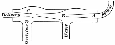
The tubes of the injector are arranged so that a concentrated jet of steam shall impinge upon the water to force it through passages that are designed in the best form for maintaining the solidity of the current. The123 speed imparted to the water represents the work performed by the steam, and upon this velocity depends the successful action of the injector. As the current of water for starting the injector could not be induced against the constant pressure on the check-valve, which equals the pressure at the throttle, an overflow is provided where the water can flow unchecked till the necessary momentum is obtained, when the overflow is closed. All deviations in construction from the elementary injector shown in Fig. 1 are made for the purpose of extending the action of the injector under varied conditions, for making it work automatically under different pressures of steam, and for improving its capacity to lift water above its natural level.
Before the invention of the injector, cases occasionally happened of the heater-pipe acting as an injector. Where the end of the heater pipe was carried through the feed-pipe, and pointed towards the check-valve, starting the heater under favorable conditions would carry the water into the boiler. A great many old engineers relate instances where this has happened.
Injectors can be kept in good order with less work than is needed to keep a pump going, but the highest kind of mechanical skill is required for the injector when repairs must be done. Almost any kind of machinist can fit a new chamber or plunger into a pump. Many men who will do this job satisfactorily will get124 badly left when they try to put a defective injector in order. To do such work, thoughtful reflection is called for, besides the hand that can do accurate fitting. A workman who may be good on guides or cross-heads or links, takes an injector apart that will not work, and can perceive nothing wrong with it, because he has not got the philosophy of the thing through his head; and he must have that before he can have insight into the probable cause of derangement.
When an engineer finds that an injector refuses to work, his first resort should be the strainer. That gets choked with cinders or other impurities so frequently, that no time should be lost in examining it. One day, when I was running a round-house, an engineer came in breathless, with the information that his engine was blocked in the yard, and he must dump his fire, as he could not get his injector to work. The thermometer stood at twenty degrees below zero, and an Iowa blizzard was blowing; so the prospect of a dead engine in the yard meant some distressingly cold labor. I asked, the first thing, if he had tried the strainer; and his answer was, that the strainer was all right, for the injector primed satisfactorily, but broke every time he put on a head of steam. I went out to the engine, and had the engineer try to work the injector. By watching the overflow stream, I easily perceived that the injector was not getting enough water, although it primed. An examination showed that the strainer was full of cinders, and the injector went to work all right when the obstruction to the water was removed.
Sand and cinders are the greatest cause of failures with injectors; as they are, indeed, with all water-feeding apparatus. I knew a case where water for a locomotive, running on a short branch, was taken out of a sandy creek with a siphon. The tank had generally about six inches of sand in the bottom. The engine had a pump and an injector; but all the feeding had to be done by the latter, for the pump never worked a gallon of water. The injector worked the water through when it seemed a quarter sand. In a short time the sand destroyed the tubes of the injector, for it acted on them the same way as a sand-blast does in cutting files or glass.
A very common cause of failure of injectors, is leakage of steam through throttle-valve or check-valve, keeping the injector so hot that no vacuum can be formed to make it prime. A great many injector-checks have been turned out too light for ordinary service, while others are made in a shape that will always leave the valve away from the seat when they stop working. Then the engineer has to run forward, and pound the check with a hammer to keep the steam from blowing back; and that soon ruins the casting. Check-valves set in a horizontal position are worthless with water that contains grit.
To preserve a good working injector, the engineer should see that all the pipes and joints are kept perfectly tight. It is hard to keep pipes and joints tight when they are subjected to the continual jars a locomotive must stand; but injectors can not be depended on126 where there is a possibility of air mixing with the water. Leaky joints or pipes are particularly troublesome to lifting injectors; for air passes in, and keeps the steam-jet from forming a vacuum. At first the injector will merely be difficult to start; but, as the leaks get worse, there will be no starting it at all. Then, the air mixing with the water is detrimental to the working of all injectors, as its tendency is to decrease the speed of the water. The compact molecules of water form a cohesive body, which the steam can strike upon with telling force to keep it in motion. When the water is mixed with air, it lacks the element of compactness; and the steam-jet strikes a semi-elastic body, which does not receive momentum readily. This mixture of steam and air does not act solidly on the check-valve, but makes the water pass in with a bubbling sound, as if the valve were moving up and down; and the stream of water breaks very readily when it is working in this way.
I ran a Sellers improved injector on a locomotive about a year, and it was an excellent feeding apparatus; but I several times had curious cases of trouble in getting it to work. Once it began drawing air; and I could not find out where the air was coming from, for the pipes seemed all tight. But the air was going through, for I could hear its mutterings; and the water kept breaking, which was an annoyance on the road. A heater-pipe was attached to the injector feed-pipe; and I afterward found out that the air was getting in at the top joint of this pipe, which did not show a leak, being above the water.
Another time I had almost a failure with this injector127 out in the snow. I was out with a snow-plow, opening the road through enormously deep snow-drifts. We had worked on one bank for several days; and we made water by shoveling snow into the tank, which was melted by blowing steam through the heaters and injector. Cinders were passed into the tank very freely with the snow, and presently I began to have trouble with my injector. I took it apart several times, and cleaned out cinders, when it went to work all right again. But a time came when it refused to work when there were no cinders inside, and it seemed that no amount of coaxing would make it start. It would prime all right; but, so soon as I gave it steam, the water would break. Driven to my wits’ end, I made the fireman try to work the injector, while I went down and watched its action. Everything seemed tight: I had examined the strainer, and there appeared no reason why it should not operate as well as it ever did. While watching it, I saw a drop of water oozing out at the stem of the overflow-valve; but I reasoned, “That can not affect the working of the injector, because it is ahead of where the water starts.” But, seeing that the thing would persist in not working, I put a bit of packing in the overflow-stem, thinking it will do no harm any way; and then the injector went to work all right, and I had no more trouble with it. So a defect that may seem trifling, sometimes proves serious to an injector.
As maintaining unbroken speed on the water put in motion is the first essential in keeping an injector in good working-order, any thing that has a tendency to reduce128 that speed will jeopardize its action. A variety of influences combine to reduce the original efficiency of an injector. Those with fixed nozzles are constructed with the orifices of a certain size, and in the proportion to each other which experiment has demonstrated to be best for feeding with the varied steam-pressures. When these orifices get worn out of the proper size, the injector will work badly; and nothing will cure it but new tubes. The tubes sometimes get loose inside the shell of the injector, and drop down out of line. The water will then strike against the side of the next tube, or on some point out of the true line, scattering it into spray, which contains no energy to force itself into the boiler. A machinist examining a defective injector, should always make sure that the tubes are not loose. Injectors that suffer from this defect will not work without a high pressure of steam. Injectors suffering from incrusted water-passages will generally work best with the steam low. Cases of the latter kind are common in calcareous districts. I have known instances where injectors got so incrusted with lime that the passages were almost closed.
Joints about injectors that are kept tight by packing must be closely watched. Many an injector that failed to work satisfactorily has been entirely cured by packing the ram-gland.
During severe frosty weather, an injector can be kept in order much easier than a pump; but it needs constant watching and intelligent supervision.
To keep an injector clear of danger from frost, it129 should be fitted up so that all the pipes can be thoroughly drained, by frost-cocks put in for that purpose. Bends in the pipes, where water could stand, should be avoided as far as possible; and, where they can not be avoided, the lowest point should contain a frost-cock.
To run an injector successfully, thoughtful care is requisite on the part of the engineer; and, where this is given, the injector will prove itself a very economical boiler-feeder.
When the Giffard injector was first introduced into this country, by William Sellers & Co., Philadelphia, it was a very defective boiler-feeder; but that firm effected great improvements, and led the way for making the injector the popular boiler-feeder it is to-day. They made the instrument self-adjusting, and improved its design, so that it would automatically feed, however much the pressure of the boiler varied. After numerous changes, the injector of 1876 was produced, which is shown by a sectional view in Fig. 2. The Sellers injector of to-day remains substantially the same as it was when exhibited at the Centennial Exposition.
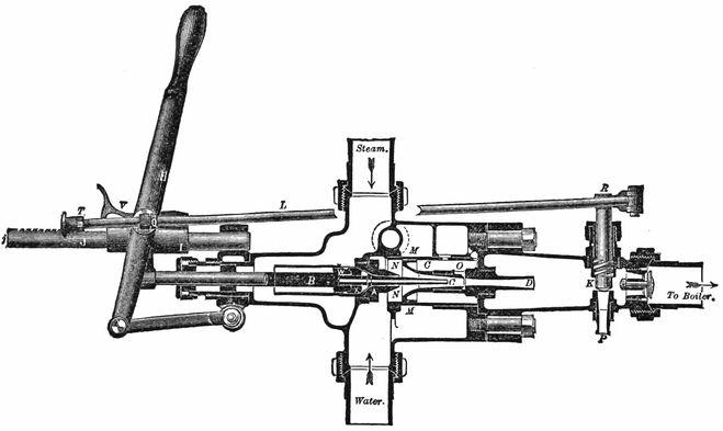
Referring to Fig. 2, A is the receiving-tube, which will be closed to the admission of steam by the valve X. A hollow spindle passing through the receiving-tube into the combining-tube, is secured to the rod B; and the valve X is fitted to this spindle in such a way, that the latter can be moved a slight distance (until the stop shown in the figure engages with valve X) without raising the valve X from its seat. A second valve, W, secured to the rod B, has its seat in the upper side of the valve X, so that it can be opened (thus admitting steam to the center of the spindle) without raising the valve X from its seat, if the rod B is not drawn out any131 farther, after the stop on the hollow spindle comes in contact with the valve X. D is the delivery-tube, O an overflow opening into space C, K the check-valve in delivery-pipe, and P R the waste-valve. The upper end of the combining-tube has a piston N N attached to it, capable of moving freely in a cylindrical portion of the shell M M; and the lower end of the combining-tube slides in a cylindrical guide formed in the upper end of the delivery-tube.
The rod B is connected to a cross-head, which is fitted over the guide-rod J; and a lever H is secured to the cross-head. A rod L, attached to a lever on the top end of the screw waste-valve, passes through an eye that is secured to the lever H; and stops T, Q, control the motion of this rod, so that the waste-valve is closed when the lever H has its extreme outward throw, and is opened when the lever is thrown in so as to close the steam-valve X; while the lever can be moved between the positions of the stops P, Q, without affecting the waste-valve. A latch V is thrown into action with teeth cut in the upper side of the guide-rod J, when the lever H is drawn out to its full extent, and then moved back; and this click is raised out of action as soon as it has been moved in far enough to pass the last tooth on the rod J. An air-vessel is arranged in the body of the instrument, as shown in the figure, for the purpose of securing a continuous jet when the injector and its connections are exposed to shocks, especially such as occur in the use of the instrument on locomotives.
The manipulation required to start the injector is exceedingly simple,—much more so in practice, indeed, than it can be rendered in description. Moving the132 lever H until contact takes place between valve X and stop on hollow spindle, which can be felt by the hand upon the lever, steam is admitted to the center of the spindle, and, expanding as it passes into the delivery-tube D and waste-orifice P, lifts the water through the supply-pipe into the combining-tube around the hollow spindle, acting after the manner of an ejector or steam-siphon. As soon as solid water issues through the waste-orifice P, the handle H may be drawn out to its full extent, opening the steam-valve X, and closing the waste-valve, when the action of the injector will be continuous as long as steam and water are supplied to it.
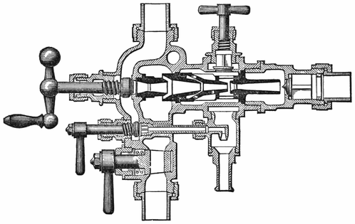
One of the most successful and enduring injectors in use is the Monitor, the distinguishing feature of which is, that the injector is constructed with fixed nozzles,133 that insure great durability, combined with certainty of action. The Monitor injector is shown in section in Fig. 3. To start the injector, the middle cock is opened, which is the lifting-jet. When water appears at the overflow, the steam-valve is opened, and the lifting-jet closed. The work of the injector is regulated by the lazy-cock, which is the bottom handle. A movable valve, operated by an eccentric on the stem, is now employed as a lazy-cock; a common cock having been found troublesome during frosty weather. The combining-tube is attached to the line-check, and can be taken out with the check, which provides an easy means of effecting examination or repairs.

An examination of Fig. 4 will show that this injector is a double-tube instrument; the first tube being proportioned134 for raising and delivering the water under pressure to the second one, which completes the operation of forcing the water into the boiler. This arrangement enables the injector to be worked through a wide range of steam-pressures without any adjustment of parts. By making the first tube proportionately small, a high power of suction is obtained, which enables the injector to feed water of such high temperature that it may be delivered into the boiler above the boiling-point. The Korting injector is operated entirely by one handle, and requires no instruction to teach its working. The feed is regulated by the patent combined regulation-valve and dirt-stop, which regulates the supply of water, and prevents the possibility of dirt reaching the injector.
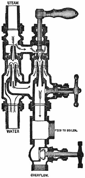
Fig. 5 gives a cross-section of the Hancock inspirator. It consists essentially of a lifting-jet and lifting-nozzle, combined with a forcing-jet and force-nozzle or injector; steam being admitted to both of these nozzles whenever the inspirator is working, to deliver the supply-water to the force-nozzle, and to force it through the nozzle into the boiler. Although both the lifting and forcing nozzles are fixed, their proportion, one to the other, is such that the inspirator requires no adjustment for changes in steam-pressure or water-supply; the waste-valve being kept closed while the instrument is in operation, except at the time of starting. The duplex nozzle arrangement of the Hancock inspirator enables that instrument to feed water of high temperature. In this respect it will act as well as the ordinary pump,135 besides having all the advantages of an injector. A form of inspirator is made specially for locomotive service, which is operated by a single handle.
The present tendency of steam engineering, in the effort to increase the work performed in return for every pound of fuel consumed, is to employ steam of very high pressure. The greater the initial pressure of the steam, the greater are the advantages to be derived from its expansive principle. To resist successfully the enormous aggregate of pressure to which locomotive boilers are subjected, a well-constructed strong boiler is absolutely necessary; and the various railroad companies throughout the country meet the required conditions in an admirable manner, as is evidenced by the remarkable exemption of such boilers from serious accidents. Although the locomotive is the most intensely pressed boiler in common use, that supreme disaster, an explosion, is of rare occurrence, considering the vast number of boilers doing service all over the States. This result is due to constant care in the construction, in the maintenance, and in the management, of the locomotive boiler. Like the conservation of liberty, eternal vigilance is the price of safety.
There is perfect safety in using a boiler so long as a good margin of resisting power is maintained above the tendency within to tear the sheets asunder. This margin is very low for locomotive boilers generally, hence the greater necessity for care in maintenance and management. Years ago the mechanical world established by practice a rule making one-fifth of the ultimate strength of a boiler its safe working-pressure. That is, a boiler carrying 140 pounds working-pressure should be capable of withstanding a tension of 700 pounds to the square inch before rupture ensues. Locomotive practice in this country does not provide much more than half of that margin of safety. When deterioration or accident reduces this margin, danger begins.
Certain mechanical empirics and impractical quasi-scientists have at various times attempted to surround the cause of boiler explosions with a halo of mystery. But our most accomplished scientists who have made the subject a special study, and our best mechanical experts who have devoted years of patient experiment and research to the investigation of boiler explosion, attribute the terrible phenomenon to intelligible causes alone. The conclusions of the practical part of the mechanical world are well summed in one sentence in one of the annual reports of the Master Mechanics’ Association. It says, “Explosions originate from over-pressure: it matters not whether the whole boiler, or a portion of it, is too weak to resist the pressure.”
The preservation of a boiler depends very much upon the care and attention bestowed upon it by the engineer, and no other person is so much interested in its safety. To prevent undue strains from being put upon the boiler, the engineer should see that the safety-valves and the steam-gauge are kept in proper order. To secure this, the steam-gauge should be tested at least once a month. The rule established on well-conducted roads, prohibiting engineers from interfering with safety-valves, is a very judicious one; and no persons are more interested in its strict observance than the engineers themselves.
Some men are idiotic enough to habitually screw down safety-valves, that the engine may be able to overcome heavy grades without doubling. This is criminal recklessness, and all train men are interested in its suppression. Low water has often been blamed falsely as the cause of disaster to boilers; a theory having prevailed, that permitting the water to become low led to the generation of an explosive gas which no sheet could withstand. That theory was exploded long ago; but, nevertheless, it is certain that low water paves the way for explosions by deteriorating the fire-box sheets, and destroying stay-bolts. A careful engineer watches to prevent his engine from getting “scorched” even slightly; for the smallest scorching may yield a harvest of trouble, even after many days. The danger of scorching is most imminent when an engine is foaming badly from the effects of impurities in the feed-water or in139 the boiler. At such a time the water rises so lavishly with the steam, that the gauges are no indication of the true water-level. The steam must be shut off to find the true level of the water. Where this trouble is experienced, the engineer should err on the safe side, even though untold patience is needed to work the engine along with the boiler full of water.
Mud within the boiler, and scales adhering to the heating surface, are dangerous enemies to the preservation of boilers; and engineers should strive to prevent their evil effects by rooting them out so far as practicable. Much can be banished by washing out frequently; and scales can, to some extent, be prevented by selecting the softest water on the road. If water in a tank is so hard that it makes soap curdle instead of lather when a man attempts to wash with it, that tank should be avoided as far as possible.
The sudden cooling down of boilers, by blowing them off while hot, is a most pernicious practice, which is responsible for many cracked sheets and broken stay-bolts. It also tends to make a boiler scale the heating surfaces rapidly. Every time a boiler is blown out hot, if the water contains calcareous solution, a coat of mud is left on the heating surfaces, which dries hard while the steel is hot. If a piece of scale taken from a boiler periodically subjected to this blowing-out process be closely examined, it will be found to consist of thin layers, every one representing a period of blowing off,140 just as plainly as the laminæ of our rocks indicate the method of their formation. When a boiler must be cooled down quickly for washing out or other purposes, the steam should be blown off, and the boiler gradually filled up with water. Then open the blow-off cock, and keep water running in about as fast as it runs out until the temperature gets even with the atmosphere. The boiler may now be emptied without injury. Or another good plan is to blow off about two gauges of water under a pressure of forty or fifty pounds of steam, then cool down the boiler gradually, to prepare for washing.
Although the dangers of blowing off hot boilers, and then rushing in cold water to wash out, are well known and acknowledged, yet the practice is still followed on many roads where more intelligent action might be expected.
Should it happen from any cause that the safety-valves fail to relieve the boiler, and the steam runs up beyond a safe tension, the situation is critical; but the engineer should not resort to any method of giving sudden relief. To jerk the safety-valve wide open at such a time is a most dangerous proceeding. A disastrous explosion lately occurred to a locomotive boiler from this cause. The safety-valves had been working badly; and, while the engine was standing on a side track, they allowed the steam to rise considerably above the working-pressure. When the engineer perceived this, he threw open the safety-valve by means of a relief lever, and the boiler instantly went into fragments. Cases have occurred where the quick opening of a throttle-valve has141 produced a similar result. The proximate cause of such an accident was the violent motion of water and steam within the boiler, induced by the sudden diminution of pressure at one point; but the real cause of the disaster was a weak boiler,—a boiler with insufficient margin of resisting power. The weakest part of a boiler is its strongest point. This may seem paradoxical, but a moment’s reflection will show that the highest strength of a boiler merely reaches to the point where it will give out. Hence engineers should see that a boiler is properly examined for unseen defects so soon as signs of distress appear. Leaky throat-sheets or seams, stay-heads dripping, or incipient cracks, are indications of weakness; and their call should be attended to without delay.
When an engineer finds the steam rising beyond a safe pressure, he should reduce it by opening the heaters, starting the injector, dampening the fire, or even by blowing the whistle. The whistle offers a convenient means of getting rid of superfluous steam, and its noise can be stopped by tying a rag between the bell and the valve opening.
Should any boiler attachment, such as a check-valve or blow-off cock, blow out or break off, no time should be lost in quenching the fire. That is the first consideration. A bursted flue will generally save an engineer the labor of extinguishing the fire. In this case an engineer’s efforts should be directed to reducing the pressure142 of steam as quickly as possible, so that he may be able to plug the flue before the water gets out of the boiler. Flue-plugs and a rod for holding them are very requisite articles; but, in driving flue-plugs, care must be exercised not to hammer too hard, or a broken flue-sheet may result. Plugs are often at hand without a rod to hold them. In such an emergency, a hard wooden rail can be used; the plug being fastened to the end by means of nails and wire, or even wet cord. Where no iron plug is available, a wooden plug driven well in, away from the reach of the fire, may prevent a bursted flue from leaking, and enable the engine to go along; but wooden plugs are very unreliable for such a purpose. They may hold if the rupture in the flue should be some distance inside; but, should the cause of leaking be close to the flue-sheet, a wooden plug will burn out in a few minutes.
Some of our most successful engineers, the men who pull our most important trains daily on time, attribute their good fortune in avoiding delays, to training they received in youth, while running or firing worn-out engines that could only be kept going by constant attention and labor. In such cases men must resort to innumerable makeshifts to get over the road; they have frequently to dissect the machinery to remedy defects; they learn in the impressive school of experience how a broken-down engine can best be taken home, and how breaking down can best be prevented. Firemen and young engineers, generally feel aggrieved at being assigned to run on worn-out engines,—the scrap heaps as they are called: but the man who has not passed through this ordeal has missed a Golconda of experience; his potentialities are petrified without reaching action.
Among a certain class of seafaring men, the captain of a ship who fails from any cause to bring his vessel safely into port, is regarded as disgraced; and, therefore,144 a true sailor will use superhuman efforts to prevent his ship from becoming derelict, often preferring to follow it to the bottom rather than abandon his trust. In many instances the sentiments and traditions of seamen teach railroad men valuable lessons. The sacrifice of life is not desired or expected of engineers in their care of the vessel they command; but every engineer worthy of the name will spare no personal exertion, will shrink from no hardship, that will be necessary to prevent his charge from becoming derelict. Once I heard a hoary engineer, who had become gray on the footboard, make the proud boast, “My engine never was towed in.” His calm words conveyed an eloquent sermon on care and perseverance. He had been in many hard straits, he had been in collisions, he had been ditched with engines, but had always managed to get them home without assistance.
What the beating pulse is as an aid to the physician in diagnosing diseases, the sound of the exhaust is to the engineer as a means of enabling him to distinguish between perfective and defective working of the locomotive. The ability to detect a slight derangement by the sound of the exhaust, can only be acquired by practice in watching those steam-notes day after day, as they play their tune of labor through the smoke-stack. When the steam-ports are even, and the valves correctly set, with tight piston-packing, and valves free from leaks, the notes of the exhaust will sound forth in regular succession in sharp, ringing, clear tones, every puff seeming to cut the steam clean off at the top of145 the stack. There is a long array of defects represented in the journey from this case of apparently perfect steam performance, to that where the exhaust steam escapes as an unbroken roar mixed with uncertain, wheezy coughs.
The deterioration of piston-packing, and the rounding of valve-seats, which produce an asthmatic exhaust, may be followed in their downward course if the engineer gets into the habit of listening to the exhaust, and marking its changes. It is very important that he should do so. The man whose ear from long practice has become sensitive to a false tone of the exhaust, needs not to make experiments, by applying steam to the engine while it stands in various positions, in order to find out where a blow comes from,—whether it is in the pistons or in the valves.
Leaning out of the cab-window, he watches the crank as it revolves, and compares the noise made by the blowing steam with the crank position. When pulling on a heavy grade is an excellent time for noting imperfections in the working of valves and pistons; for the movements are comparatively slow, while the pressure of steam on the working-parts is so heavy that any leak sounds prominently forth. The observing engineer perceives that the four sounds of the exhaust, due to each revolution of the drivers, occur a few inches before the crank reaches, first, the forward center, second, the bottom quarter, third, the back center,146 fourth, the top quarter. The first and third position exhausts emit the steam from the forward and back strokes of the right-hand piston: the second and fourth exhausts are due to discharges of the steam that has been propelling the left-hand piston. With these facts impressed upon his mind, he will understand, that if an intermittent blow occurs during the periods when the crank is traveling from the forward center to the bottom quarter, or from the back center to the top quarter, the chances will be that the right-hand piston needs to be examined. For the greatest pressure of steam follows the piston just after the beginning of each stroke, and that is the time a blow will assert itself. Should the blow occur while the right-hand crank is moving from the bottom quarter to the back center, or from the top quarter to the forward center, it will indicate that the left-hand piston is at fault. For at these periods the left-hand cylinder is receiving its greatest pressure of steam.
It is generally understood that an intermittent or recurring blow belongs to the pistons, and that a constant blow comes from the valves. But sometimes the valves blow intermittently, being tight at certain points of the travel, and leaky at other points. To distinguish between the character of these blows is sometimes a little difficult except to the thoroughly practiced ear. The sound of the blow can be heard best when the door is open, and the novice should not fail to listen for it under that condition. The valve blow is a sort of wheeze, with the suggestion of a whistle in it: the147 piston makes a clean, honest blow, which would break into a distinct roar if enough steam could get through. But a whistling sound in the exhaust is, by no means, a certain indication of the valves blowing through; for sometimes the nozzles get clogged up with a gummy substance from the lubricating oils, and a distinct whistling exhaust results therefrom. With a watchful ear, the progress of degeneration in the valves can be noted day after day; for it is a decay which goes on by degrees,—the inevitable slow destruction that friction inflicts upon rubbing surfaces. Pistons are more erratic in their calls for attention. With them it is quite common for a stalwart blow to start out without any warning, the cause generally being broken packing-rings. The various kinds of steam packing seem more liable to have broken rings than the old-fashioned spring packing, but they generally run longer with less attention.
The habit of closely watching the exhaust is likely to prove serviceable in more ways than in keeping the engineer posted on the condition of the steam-distribution gear. Its sound often acts as a danger alarm, which should never go unheeded. Many an engine has gone home on one side, and not a few have been towed in cold, through accidents to the valve-gear, which could have been prevented had the engineer attended to the warning voice of a false exhaust. The nuts work off an eccentric-strap bolt; and it drops out, letting the strap open far enough to cause an uneven148 valve-travel. If the engineer hears this, and stops immediately to examine the machinery, he is likely to detect the defect before the strap breaks. Again, one side of a valve yoke may have snapped, leaving the other side to bear the load; or bolts belonging to different parts of the links or eccentric-straps may be working out,—so that the uniformity of the valve-travel is affected; and the same result may be produced by the eccentrics getting loose. Young engineers, to whom these pages are addressed, should make up their minds that an engine never exhausts an irregular note without something being the matter which does not admit of running to a station before being examined. It may only be an eccentric slipped a little way, a mishap that is not calculated to result disastrously; but, on the other hand, it is probably something of a more dangerous character.
Engineer Joy of the D. & E. road went in with a broken eccentric-strap. Questioning him about the accident brought out the fact, that, in starting from a station, he heard the engine make two or three curious exhausts; but he was running on a time-order, and did not wish to cause delay by stopping to examine the engine. But he had not gone half a mile when he found it necessary to stop and disconnect the engine, and by doing so held an express train forty minutes.
A representative case of neglecting a plain warning happened on an Illinois road some time ago. John149 Thomas was pulling a freight train up a grade, when, to use his own words, “The engine began to exhaust in the funniest way you ever heard. She would get on to three legs for an engine length or so, then she would work as square and true as she ever did, but only for a few turns, when she got to limping again.” This runner knew that something was wrong, and he determined to examine the engine at the next stopping-point. But delays in such a case are full of peril. When he got over the grade, and shut off steam, there was a tumultuous rattling of the reverse-lever, succeeded by a fearful pounding about the machinery; a tearing up of road-bed sent a shower of sand and gravel over the train; then a scream from escaping steam and water drowned all other noises, and the engine was enveloped in a cloud of blinding vapor. The forward bolt of one of the eccentric-strap rods had worked out, and allowed the end of the rod to drop on the track. Then it doubled up, and tore away the whole side of the motion; and part of a broken eccentric-strap knocked a hole in the fire-box. Here was the progress towards destruction. A small pin got lost, which permitted the nut of an important bolt to unscrew itself; then this bolt, with many a warning jar and jerk, escaped from its place in the link; and the conditions for a first-class break-down had come round.
Whenever locomotive engineers congregate in the round-house, in the lodge or division room, a fruitful theme of conversation and discussion is the valve-motion. Curious opinions are often heard expressed150 upon this complex subject. There are comparatively few men who understand it properly: but it has a fascination which attracts all alike, the wise and the ignorant; and the man who is altogether uncertain about the true meaning of lap and lead, expansion and compression, is generally more loquacious on valve-motion than the engineer who has made the subject an industrious study.
However well each may understand his business, in one respect all engineers are in perfect harmony; that is, in hating to encounter trouble with the valve-gear on the road. The valves being the lungs of the machine, any injury or defect to their connections strikes at a vital organ. With a good valve-motion, and valves properly set, the steam is distributed so that nearly an equal amount is admitted through each part in regular rotation; the release taking place in even succession. This makes the exhaust notes uniform in pitch and period. A sudden departure from this uniformity indicates that something is wrong with the valve-motion. It should be the signal to stop, and institute a searching examination. In doing so, avoid jumping at conclusions regarding the cause of the irregularity, and coolly examine, separately, each part whose motion influences the valve-travel.
Fred Bemis missed his luck by jumping too readily at conclusions. Something happened to his engine; and he stopped by compulsion, and found it would151 not move either way. He felt certain that both eccentrics on one side had slipped; and, considering himself equal to setting any number of eccentrics, he got down, and fixed them in what he supposed was the proper position. But, on trying to move the engine, he found it still refused to go. He kept working at those eccentrics without result till his water got low, and he was compelled to dump the fire; the consequence being, that the engine went cold, and was towed home. When an examination was made, it was found that a broken valve-yoke was the cause of trouble.
When any thing goes wrong with the valve-motion, the first point of investigation is, to find out which side is at fault. This can be ascertained by opening the cylinder-cocks, and giving the engine steam. With the reverse-lever in forward motion, the forward cylinder-cocks should show steam when the crank-pins are traveling below the axle, and the back cocks should blow when the pins make their similar revolution above the axle. Any departure from this method of steam distribution will make one side work against the other. When the engineer has satisfied himself on which side the defect lies, he will do well to thoroughly examine the eccentrics with their straps and rods, the links with their hangers and saddles, the rocker box and arms with all the bolts and pins connecting these articles. What might be regarded as a trifling defect, sometimes makes an engine lame. I have known a loose valve-stem key put an engine badly out of square. Eccentric-rods, slipping, often produce this effect. When152 the eccentrics are found in the proper position, the rocker-box secure in the shaft, and all the bolts, pins, and keys in good order, and in their proper positions, the fault may be looked for in the steam-chest.
With engines where keys are not used to secure the eccentrics to the shaft, their slipping on the road is a common occurrence. Eccentric-strap oil-passages getting stopped up, or neglect in not oiling these straps or the valves, puts an unnecessary tension on the eccentrics, which often results in their slipping on the shaft. Engineers ought to mark the proper position for eccentrics on the shaft; so that, when slipping happens, it can be adjusted without the delay that often occurs in calculating the right position. When the crank-pin is on the forward center, the body of the go-ahead eccentric is above the axle, and the body of the back-up eccentric is below the axle, each of the eccentrics being advanced about 1/16 of the revolution from the right angle position towards the crank-pin; or, to state it more accurately, the center of the eccentric is advanced a horizontal distance to equal the lap and lead of the valve. If the valve had neither lap nor lead, the eccentrics would stand exactly at right angles to the crank. As it is, both of them have a tendency to hug the crank; the eccentric which regulates the distribution of steam following the crank. Every engineer should familiarize himself with the correct position of eccentrics, so that, when trouble happens with the valve-gear on the road, he will experience no difficulty in grappling with the mishap.
The slipping of one eccentric is a trifling matter, which can be quickly remedied if the set screws are in a position where they can be reached conveniently. If it is a go-ahead eccentric, set the engine on the center of the disabled side,—no matter which center,—put the reverse-lever in the back notch of the quadrant, and scratch a line with a knife on the valve-stem close to the gland. Then put the lever in the forward notch, and move the slipped eccentric till the line appears in the point where it was made. Fasten the set screws, and the engine will be found true enough to proceed with the train. Care must be taken in moving the eccentric to see that the full part is not placed in the same position as the other one, or they will both be set for back motion. A back-up eccentric slipped, while the go-ahead one remains intact, can be adjusted in a similar way; the scratch on the valve-stem being made with the engine in full forward motion, and the adjustment of the eccentric done in full back motion. The philosophy of this method is, that the valve is in nearly the same position at the beginning of the stroke for the forward or back motion; and the position of the eccentric, which has not moved, is used to find the proper place for the one which slipped. Should the unusual circumstance of both eccentrics on one side slipping overtake an engineer, he will have to pursue a different method of adjustment. The most systematic plan is to place the engine on the forward center, and set the go-ahead eccentric above the axle, and the back-up eccentric below the axle. With the reverse-lever in the forward notch, advance the top154 eccentric till the front cylinder-cock shows steam, which can be ascertained by blocking the wheels, and slightly opening the throttle. That will put the go-ahead eccentric near enough to the proper position for running. For the back-up eccentric, pull the reverse-lever into back motion, and turn the eccentric towards the crank-pin till steam appears at the front cylinder-cock; and that part of the motion will be right. Or the back-up eccentric can be set by the forward eccentric in the manner described where one eccentric has slipped.
Where slotted rods are used, they frequently slip, making the engine lame. The cause of trouble in such a case can be identified by moving the engine slowly, with the cylinder-cocks open. The disturbance to the regularity of the valve’s motion, caused by a slipped rod, will admit steam prematurely on one end of the cylinder, while it delays the admission on the other end. The valve is made to travel more on one side of the exhaust center than on the other. Lengthening or shortening the valve-stem has a similar effect, but this makes the engine lame in both gears; while the slipping of an eccentric-rod only makes the engine lame in the motion that the rod belongs to. This is subject to a slight modification, however; for the back-motion eccentric being badly out of square, will affect the correctness of the forward motion, when the engine is working close hooked up. But in full motion it will not be perceptible.
If in moving the engine ahead slowly, with the cylinder-cocks open, it is found that steam is admitted to the cylinder before the piston has nearly reached the center or dead point, or that the back cylinder-cock does not show steam till after the piston has passed the back center, the eccentric-rod is too long. The rod being too short produces precisely an opposite effect. The steam arrives late on the back stroke, and ahead of time on the forward stroke. This is different from the action of the steam where an eccentric has slipped. In that case, there will be pre-admission of steam before the beginning of both strokes, or post-admission, that is, late arrival of steam, for both strokes. Take a go-ahead eccentric for example. If it slips backward on the shaft, its effect will be to delay the admission of steam till after the beginning of each stroke; and, if it slips forward, the result will be to accelerate the lead of the valve opening the steam-port before the piston has reached the commencement of each stroke.
When either of these accidents happens, the safest plan is to take down both straps and rods on the defective side. Some engineers leave the back-up eccentric strap and rod on, when the forward strap or rod has broken; but it is a little risky under certain conditions. After getting the eccentric straps and rods down, drop the link-hanger away from the tumbling-shaft, disconnect the valve-stem, and tie the valve-rod to the hand-rail. Then set the valve in the middle of the seat, so156 that it will cover both the steam-ports, and hold it in that position by pinching the stem with the gland, which is done by screwing up the gland obliquely. Take down the main rod, and block the cross-head securely at the back end of the guides. Good hardwood blocking prepared beforehand should be used for this purpose, and it ought to be fastened with a rope or marline. A neater plan for holding the cross-head in place is described by Frank C. Smith, in the Torch. He says, “Have the blacksmith make a hook out of a piece of inch and a half round iron; also a piece about fifteen inches long by one and a half thick, and four inches wide, with a hole through the center for the shank of the hook to pass through. This shank is threaded for a nut. Now, when it is necessary to block a piston, get it to the back end, pass the hook around the wrist of the cross-head, and the other end through the straight piece which bears against the yoke supporting the back end of the guides; run up a nut on the shank of the hook, hard against the cross-piece, and the piston is secured.” The piston being properly fastened, it is a wise supplement to the work to tie the cylinder-cocks open, or to take them out altogether. The engine is now ready to proceed on one side.
Young engineers can not be too strongly impressed with the necessity for having the cross-head properly secured before trying to move the engine. I have repeatedly known of serious damage being caused by placing too much confidence in weak blocking. Taking out the cylinder-cocks is a wise security against accidents of this kind; for, should a little steam be passing157 through the valve, it has a port of escape without putting heavy pressure on the piston.
In regard to the method of securing the piston when one side of an engine is taken down, there is considerable diversity of opinion among engineers. Some men maintain that the proper and quick plan is, merely to move the piston to one end of the cylinder, pushing the valve in the same direction, so that the steam-port will be open at the end away from the piston. This will keep the cylinder full of steam, and hold the piston from moving. But, if by any accident the valve should be moved to the opposite end of the seat, steam would get to the wrong end of the cylinder, and the piston would certainly smash out the head. Another risky plan, practiced by men economical of work, is to place the valve on the center of the seat, and let the piston go without fastening. These slipshod methods do not pay.
This accident is very serious; but it need not disable the engine, although it will lessen the engineer’s power to manage it freely. To get the engine going, calculate the position the links must stand in to pull the train, and cut pieces of wood to fit between the block and the top and bottom of the links, so that the latter may be kept in the required position. For forward motion, there will be short pieces in the top, and long pieces in the bottom. When back motion is needed, reverse the pieces of wood. A common plan is to use one piece of wood, working the engine in full gear.
The same treatment will keep an engine going when158 the tumbling-shaft arms, the reach-rod, the link-hanger, or the saddle-pin breaks. The failure of a link-hanger or saddle-pin will only necessitate the blocking of one side.
For a valve-stem broken, the eccentric-strap or link need not be interfered with. If the break is outside the steam-chest, take down the valve-stem rod, and set the valve on the middle of the seat; take down the main rod, and secure the piston as previously directed. With a valve-stem broken inside the chest, or a valve-yoke broken, a little additional work is necessary. The steam-chest cover must now come up, and the valve be secured in its proper place by pieces of wood, or any other material that will keep it from moving; and the stuffing-box must be closed, to prevent escape of steam through the space vacated by the valve-stem.
A broken rocker-shaft, or the fracture of the lower arm, entails the taking down of both eccentrics and the link, besides the main rod, and the securing of the valves and piston. The breaking of an upper rocker-arm is equivalent to a broken valve-stem, and requires the same treatment.
Accidents to the valve-seat, such as the breaking of a bridge, can be fixed for running the engine home on one side, by covering the ports, and stripping that side159 of the engine, just as had to be done for a broken valve-yoke. If a serious break in a bridge occurs, it is indicated by a tremendous blow through the exhaust port, out by the stack. A mishap of much less consequence than a broken bridge is a “cocked” valve, and the small mishap is very liable to be mistaken for the greater one. Where the yoke is tight fitted, or out of true with the line of the stem, some engines have a trick of raising the valve away from the seat, and holding it there. This generally happens going into a station; and, when steam is applied in starting out, an empty roar sounds through the stack. Moving the valve with the reverse-lever by quick jerks will generally reseat a cocked valve, but sometimes it gets stuck so fast that it has to be hammered out of the yoke.
When a locomotive shows the symptoms which indicate a broken valve, a broken bridge, or a cocked valve, the engineer should exhaust every means of testing the matter from the outside before he begins an interior inspection by raising the steam-chest cover. If jerking the valve with the reverse-lever, or moving the engine a little, will not stop the blow, he should disconnect the valve-stem, and shake the valve by that means.
When a valve breaks, disabling its side of the engine so badly that it can not be used, the valve should be taken out, and a piece of strong pine-plank secured over the ports.
A very serious and troublesome accident, which may come under the head of steam-distribution gear, is the breaking of a steam-chest, or of a steam-chest cover.160 It takes skillful management to get an engine along when this has happened. The most effectual way to restrain loss of steam when a chest or cover has broken, is to slack up the steam-pipe, and slip a piece of iron plate, lined with sheet-rubber, leather, canvas, or any other substance that will help to make a steam-tight joint, into the lower joint of the steam-pipe. If this is properly done, it ends the trouble, when the joints are tightened up. But the difficulties in the way of loosening steam-pipe joints in a hot smoke-box are often insurmountable, especially when the nuts and bolts are solid from corrosion, which is generally the case where they have not been touched for months. In such a case it is better to resort to the more clumsy contrivance of fitting pieces of wood into the openings to the steam-passage, and bracing them in place by means of the steam-chest bolts. A man of any ingenuity can generally, by this means, save himself the humiliation of being towed home, and yet avoid spending much time over the operation. When the engineer has succeeded in securing means for preventing the escape of steam, the main rod must be taken down, and the valve-stem rod disconnected from the rocker-arm. In this instance the piston needs no further attention, after the main rod has been disconnected; for there will be no ingress of steam to the cylinder to endanger its safety.
The breaking of a steam-pipe in the smoke-box is even a more harassing mishap than a bursted steam-chest or cover. The only remedy for this is the fastening161 of an iron plate to the top joint of the steam-pipe, thereby closing up the opening. A heavy plug of hard wood may be driven into the opening, and braced there for a short run; but such a stopper is hard to keep in place, owing to the shrinkage caused by the intense heat of the smoke-box.
An experienced engineer will most easily determine the existence of leaks between the valves and their seats when the engine is working, and the indications of that weakness have already been noticed. But it sometimes happens that a man wishes to test the condition of the valves when the engine is at rest. This can be most readily accomplished by placing the engine so that the rocker-arm stands in the vertical position. Open the smoke-box door so that the exhaust nozzles can be seen. Now block the wheels, and give the engine steam. If the valve blows, the steam will be seen issuing from the nozzle on the side under examination. As the tendency of a slide-valve is to wear the seat concave, it sometimes happens that a valve is tight on the center, yet leaky in other positions. Moving the valve with the reverse-lever as far as can be done without opening the steam-port, will sometimes demonstrate this. The cranks should be placed on the eighths positions when the valves are being tested.
The piston is an autocratic member of the machine. For thousands of miles it toils to push the engine ahead, every thing going smoothly so long as it is confined to its recurring journey; but let any attachment break, or a key fly out that will increase the piston’s travel, and away the piston goes, right through a cylinder-head.
The causes which most commonly lead the piston to smash out cylinder-heads, are broken cross-heads, broken piston-rods, and broken main-rods. A main crank-pin or wrist-pin breaking, is almost certain to leave one end of the cylinder a wreck. These may be termed the major causes for breaking out cylinder-heads; but there are numerous minor causes, which are scarcely less destructive. A piston-rod key begins to work loose. It is hammered down occasionally, which does not improve its fit; and some day it jumps out altogether, letting the piston go on a voyage of discovery. A machinist of the careless sort has been examining a piston’s packing, and, in screwing up the follower-bolts, one of them gets163 a twist too much. Drilling out a follower-bolt is a troublesome operation, so Mr. Careless lets it go. On the road this head drops out, and a broken cylinder-head is the consequence. One of the worst causes of breakage to a cylinder that I have ever seen, was caused by the packing-ring of the piston catching in the steam-passage. Part of the ring broke off, and wedged itself between the advancing piston and the cylinder. The wedge split the cylinder open, and the remainder of the piston acted like a pulverizer upon the fragment of the cylinder.
The causes which eventually lead to broken cylinder-heads often originate from preventable strains. Thus, cross-heads are frequently fractured by main-rod connections pounding; and weaknesses, that ultimately bring crank-pins to disaster, originate in a similar way. A loose piston-key is liable to crack the piston-rod, if it does not give trouble by jumping out. Loose guides have a tendency to spring piston-rods, and throw unnecessary strain upon them. Pistons lined out of true, are dangerous for the same reason. A pump-plunger working out of line, or badly secured in the lug, throws a distressing load upon the cross-head. And so the list of potential accidents grows. Like the steady water-drop that wears into the adamantine rock, trifling defects, assisted by time’s action, prove stronger than the most massive machine.
When any thing happens to permit the piston to break out a cylinder-head, the engine can be put in running trim by taking off the valve-rod and main-rod, and164 setting the valve on the center of the valve-seat. Blocking the cross-head is unnecessary, if the break will allow the escaping steam to pass through; for then no further tension can be put upon the piston to cause further damage. If, by an extraordinary freak of good luck, a piston-rod breaks without causing other damage, the cylinder-head must be taken off, and the piston removed. Then cover the ports, and take down the main-rod on that side. Or, if the cross-head is all right, the main-rod may be left untouched. When the cross-head breaks, it generally entails taking out the piston, centering the valve, and taking down the main-rod on that side.
With a broken main-rod which does not knock out the cylinder-head, the main-rod and valve-rod should be taken down, the valve secured on the center of the seat, and the cross-head blocked with the piston at the back end of the cylinder.
For a broken main crank-pin, the above method of stripping the engine will do with the addition of taking down both side-rods. An accident which disables one side-rod, requires that the other one shall be taken down also, or there will be trouble when the engine is attempted to be run with one side-rod. The rod might go all right so long as no slipping happened. But, if the engine began to slip while passing over the center, the side-rod would have no leverage on the back crank to slip its wheel; and a broken rod or crank-pin would almost certainly ensue.
A broken side-rod, that is not accompanied by other165 damage, requires both side-rods to be taken down. All the inconvenience arising from this is, that the engine is more liable to slip. But, with dry rails, an engine can get along very well without its side-rods.
Any accident to the throttle-valve or its attachments, which deprives the engineer of power to shut off steam, is very dangerous, and calls for prompt action. Lose no time in reducing the head of steam to fifty or sixty pounds, or to the pressure where the engine can easily be managed with the reverse-lever.
With the aid of a power-brake, an engineer can get along fairly with a light train, after an accident has happened which prevents the closing of the steam from the cylinders; but constant vigilance and thoughtful labor are needed.
The greatest difficulty will be experienced in oiling the valves, unless the steam-chests are provided with the automatic feeders, which work with steam on.
If he is running on an undulatory road, an engineer can oil the valves from the cab, by letting the steam down at the top of a hill, and running down at a high speed. It can also generally be done on a level track, by letting the fire burn low, getting up the best speed the engine will attain, then putting the feed full on. As the steam drops suddenly, put the reverse-lever in full motion; and the chances are, that the valves can be oiled.
The most common causes of trouble with the throttle are the breaking or working out of one of the bolts that operate the valve within the dome, the breaking of a valve-rod, or working off of nuts that should secure the connection. Where the throttle fails with the valve closed, and the engineer finds it necessary to take the dome-cover off to prevent his engine from being hauled in, he will generally find the trouble to lie with the connections mentioned, or with the bolts belonging to the bell-crank, that is located near the bottom of the stand-pipe. Sometimes the nuts on the top of the throttle-valve stem work off: but, in such a case, there is no difficulty in opening the valve; it is when the engineer wants to close it, that the discomfiture comes in. Some steam-pipes are provided with a release-valve near the throttle, to relieve the pipe from intense back-pressure when the engine is reversed. The sudden reversing of an engine sometimes jerks this valve out of its seat, leaving an open passage between the boiler and steam-chest. This acts like a mild case of unshipped throttle, and must be controlled in a similar way.
The bursting of a dry pipe is similar in effect to the action of a throttle becoming disconnected while open; and it may even prove harder to control, according to the size of the opening. Engineer Halliday had a trying time with a case of this kind. While swinging along the E., F., & G. road, with a heavy train of freight, a herd of horses ran in from an open crossing-gate, and started up the track just in front of the engine. As167 there was a bridge a short distance ahead, Halliday reversed the engine in his anxiety to prevent an accident. The train stopped for an instant, when the engine began to push it back. Halliday tried to throw the lever to the center, but never before had he felt such a pressure acting upon it. Again and again he tried to throw the lever over; but every time it proved too formidable a struggle, and the catch found its way into the full-back notch. Meanwhile, the train was gaining speed in the wrong direction, and a passenger train was not many miles behind. Beginning to realize the true state of affairs, Halliday called for brakes, opened the fire-box door, closed the dampers, and started the injector. Then he directed the fireman to throw some bucketfuls of water upon the fire, while he tied down the whistle-lever, letting the steam blow. The promptest means for reducing the pressure of steam were now in operation, and his next move was to try the reverse-lever again. Both men grasped the lever, and, by a combined effort, forced it past the center; and Samson’s hair was cut. It was afterwards found that a long rent had opened in the dry pipe, letting the full boiler pressure upon the valves, which moved hard through being dry; the hot gases pumped through them in reverse motion having licked off every trace of lubricating unguent.
Cases of serious trouble resulting from accidents to throttle connections would be easy to multiply. Two incidents with similar originating conditions, but with very different results, will suffice. Engineer Phelps168 was pulling a full train of coal over rails that were neither wet nor dry, and had just enough frost upon them to be wicked. He was having a bad time slipping, but was working patiently along, when the throttle became disconnected with the valve open. The engine at once started on a whirl of slipping that threatened disaster, but it was immediately controlled by the engineer pulling the reverse-lever to the center notch. Engineer Cook of the F., G., & H. road, was not so fortunate when the stem of his throttle-valve broke on a slippery day. As the wheels began spinning round, Cook lost his head, and kept working at the throttle-lever to try to stop. Seeing this was of no avail, he grasped the sand-lever, and tugged vigorously at the valves. A season of tumult succeeded; and, when the engine stopped presently, it was found to be a deplorable wreck. It was hard to tell, from the look of the ruin, what part of the locomotive broke first; but the crank-pins on one side were cleaned off, and the piston was out through the cylinder-head. The side-rod on the other side broke close to the strap, and was twisted up like a spiral spring.
It is good for an ambitious young engineer, who desires to thoroughly master his calling, to walk occasionally into the room where a well-managed automatic cut-off engine is at work, and watch its smooth, noise-less movements. There he may find an ideal of how an engine should run. The nature of the work performed by a locomotive engine prevents it from being operated noiselessly, and the smoothness of its action must always169 compare unfavorably with a well-constructed stationary engine; but the connections which transmit the power of a locomotive should be free from knock or jar, if they are properly proportioned, and skillfully put together.
To an engineer with a well-regulated mind, a pound about the engine is a source of continual irritation. If a pound arises from a cause which can be remedied by an engineer, the careful man will soon perform the necessary work to end the noise. Sometimes the origin of a pound is hard to discover: very often it is beyond the power of the engineer to stop it. Some makes of locomotives always pound when working in full gear. With such an engine, a nervous engineer will fuss, pushing up wedges until they stick fast, and cause no end of grief to get them down again. He will key up the main-rod connections till they run hot, and he will prophesy that the engine is going to pieces. But the engine hangs together all the same, and is only suffering from want of lead, or want of compression. Where an engine is deficient in the cushioning to the piston, due to compression or lead, the momentum of the piston and connecting-rod is suddenly checked at the end of each stroke. The concussion to these working-parts is so great that pounding will be produced. As the engine gets hooked towards the center, this pounding will cease, because the lead opening increases as the motion is notched back. The most common causes for pounding with locomotives are worn main-rod connections, and driving-boxes too loose in the jaws, or the brasses loose in the driving-boxes. If side-rods are out of tram,170 or have the brasses badly worn, they sometimes pound when passing the centers. A cross-head will pound when the guides are worn very open. This last defect is liable to cause a bent piston-rod. A piston makes a tremendous pound when a badly connected rod allows it to touch a cylinder-head, and a very ominous pound is produced when the spider gets loose on the piston-rod, and a piston-rod loose in the cross-head will make itself heard all over the engine.
Several years ago a very troublesome and mysterious pound caused the writer a great deal of annoyance. He was running an old engine, with cylinders that had been bored out until no counter-bore was left. The piston had worn a seat leaving a small ridge at the end of its back travel. The main-rod was taken down one day; and, in putting it up again, the travel of the piston was slightly altered. The engine started out with a pound, and kept it up. If any of my readers have been working an engine that seemed to hang together merely by luck, away on construction work on the wild prairies, with no machine-shops in the rear to appeal to for aid or counsel, with all his own repairing to do without tools or skilled assistance, they will understand the difficulty experienced in locating that pound at the back end of the cylinder.
A cylinder loose on the frame, or a broken frame, will jar the whole machine; and both of these defects are serious, and demand increased care in taking the engine along with the train. Loose driving-box brasses produce a pound which is sometimes difficult to locate.171 In searching for the cause of a pound, it is a good plan to place the engine with one of the cranks on the quarter, block the wheels, and have the fireman open the throttle a little, and reverse the engine with the steam on. By closely watching in turn each connection, as the steam through the piston gives a pull or a thrust to the cross-head, the defect which causes the pound may be located. Never run with a serious pound inside of a cylinder. It is an almost certain indication that a smash is imminent.
There is something pathetic in the spectacle of a noble locomotive, whose speed capabilities are so wonderful, lying with its wheels in the air, or sunk to the hubs in mud or gravel. Kindred sights are, a ship thrown high and dry upon the beach, away from the element that gives it power and beauty; or a monster whale, the leviathan of the deep, lying stranded and helpless upon the shore.
Few engineers have run many years without getting their engine off the track in some way,—over the ends of switches, by jumping bad track, or getting into the ditch through some serious accident, collision or otherwise. Most of them have felt that shock of the engine thumping over the ties, and momentarily wondered in what position it was going to stop; doing all in their power, meanwhile, to stop, and prevent damage.
Of course, an engineer’s first duty is to conduct his engine in a way that will avoid accident so far as human173 foresight can aid in doing so; but, when an accident is inevitable, his next duty is to use every exertion towards reducing its severity. The most common form of serious accident occurring on our railroads is a collision. Rear-end collisions occur most frequently, although head-to-head collisions annually claim many victims. When an accident of this kind is impending, the engineer generally has but a few seconds of warning; but these brief seconds well utilized often save many lives, and impress the principal actor with the stamp of true heroism. Rounding a curve at a high speed, an engineer perceives another train approaching. Quick as thought he shuts off steam, applies the brake, reverses the engine, and opens the sand-valves and the throttle. This will take about ten seconds’ time; and, if the engine is running thirty miles an hour, the train will pass over forty-four feet each second. Assuming that no reduction of speed has taken place till all the appliances for stopping are in operation, four hundred and forty feet will be passed over as a preliminary to stopping. With the automatic Westinghouse brake, application and retarding power are almost simultaneous. Until he has applied all means of reducing speed, an engineer rarely or never consults his own safety, however certain death may be staring him in the face. But after the brakes are known to be doing their work, aided by sanded rails, and steam working against the piston, personal safety is considered. A glance at the position of the two trains tells if they are coming violently together; and the engineer jumps off, or remains on the engine, as he deems best. This applies to trains equipped with continuous brakes.
With freight trains where the means of stopping are not immediately under the hand of the engineer, he must call for brakes on the first indication of danger, and do all that a reversed engine can achieve to aid in stopping the train. Where a driver brake is used, the engineer will have to watch the reversed engine; because the wheels will soon begin sliding, even on thick sand, and their retarding power will be seriously diminished. To prevent this, the engineer should let off the driver brake, and open the cylinder-cocks, till the wheels begin to revolve, when the brake may be applied again. Working and watching in this way greatly assist in stopping a train, and preventing the flattening of wheels.
Should the engine get into the ditch, the engineer’s first duty is to save the engine from getting burned, unless saving of life, or protecting the train, demands his attention. If the engine is in a position where the flues or fire-box crown will be left without water, the fire should be quenched as quickly as possible. Sand or gravel thrown over the fire, and then saturated with water, is a good and prompt way of extinguishing the fire.
It can be understood in a few minutes after derailment whether or not the engine can be put back on the track without assistance. Sometimes a pull from another engine is all that is required: again, nothing can be done without the aid of heavy tools to raise it up.175 In this case, no time should be lost in sending for the wrecking outfit. It often happens that an engine gets off the track while switching among sidings, and sinks down in the road-bed so as to be helpless. In an event of this kind, jacking up a few inches will often enable the engine to work back to the rails. Before beginning to hoist with the screw-jacks, some labor can generally be saved by putting pieces of iron between the bottom of the driving-boxes and the pedestal-braces. As the wheels begin to rise out of the gravel, pieces of plank or wooden wedges should be driven under them to hold good every inch raised. Where the attempt is made to work an engine on the rails by means of wrecking-frogs, wooden filling should be laid down crosswise to prevent the wheels from sinking between the ties, should they slip off the frogs. Where jacking up has to be resorted to, there is often difficulty experienced in getting up the engine-truck; as raising the frame usually leaves the truck behind in the mire. The best plan is, to jack up the front of the engine to the desired level, then with a rail well manned pry up the truck, and hold it in position by driving shims under the wheels. An engine will generally go on the rails easiest the way it comes off.
When a derailed engine is being pulled on the track by another engine, the work should be done carefully, and with proper deliberation. When every thing is made ready for a pull, some men act as if the best plan was to start both engines off with full throttle; and this often leaves the situation worse than it was at first. When truck-wheels stand at an angle to the track, it is often necessary to jerk them in line by attaching a chain or rope to one side. A wrecking-frog should be176 laid in front of the wheel outside the rail, and blocking before the inside wheel, sufficient to raise the tread of the wheel above the level of the rail. Then move ahead slowly, and the chances are that the wheels will go on the rails. Sometimes the easiest way is to open the track at a joint, move it aside to the line of the wheels, and spike it there, then draw or run the engine on.
Having an engine off the track, is a position where good judgment is more potent than a volume of written directions.
The driving-wheels, axles, boxes, frames, with the trucks and all their attachments, are somewhat dirty articles to handle. The examination of how they are put together, and how they are hanging together, is pursued under soiling circumstances. Perhaps this is the reason these things are studied less than they ought to be. To creep under a greasy locomotive to examine wheels, axles, and truck-boxes, is not a dignified proceeding by any means; but it is a very useful one. The running-gear is the fundamental part of the machine, and its whole make-up should be thoroughly understood. The builds of trucks are so multifarious that no specified directions can be given respecting accidents happening to them. There is, therefore, the greater need for an engineer’s familiarizing himself with the make-up of his running-gear, so that, when an accident happens, he will know exactly what to do. Disraeli said: “There is nothing so likely to happen as the unexpected.” This applies very aptly to railroad engineering. Industrious accumulation of knowledge respecting177 every part of the machine is the proper way to defy the unexpected.
The running-gear of some engines is so arranged, that, in case a driving-spring breaks on the road, it can readily be replaced if a spare spring is carried. With the average run of engines, however, and the accumulating complication of brake-gear attached to the frames, the replacing of a driving-spring is a tedious operation, that would involve too much delay with an engine attached to a train. Consequently engineers seldom attempt to change a broken spring. They merely remove the attachments likely to shake out of place, and block the engine up so as to get home safely. When a forward driving-spring breaks, it is generally best to take the spring out with its saddle and hangers. Then run the back drivers up on wedges to take the weight off the forward drivers, and put a piece of hard wood or a rubber spring between the top of the box and the frame. Now run the forward drivers on the wedges, which will take the weight off the back drivers, and with a pinch-bar pry up the end of the equalizer till that lever stands level, and block it in that position by jamming a piece of wood between it and the frame. For a back driving-spring, this order of procedure should be reversed. A back driving-spring is often hard to get out of its position; and it sometimes can be left in place, as it is not very liable to cause mischief.
Where a spring drops its load through a hanger breaking, the mishap can occasionally be remedied by chaining the spring to the frame. Should this prove178 impracticable, the same process must be followed as that which was made necessary by a broken spring.
For a broken equalizer, all the pieces likely to shake off, or to be caught by the revolving wheels, must come out; and both driving-boxes on that side must be blocked on top with wood or rubber. Where good screw-jacks are carried, it will often prove time-saving to raise the engine by jacking up at the back end of the frame instead of running it up on wedges. Where the wedge plan is likely to prove easiest, it must be adopted only on a straight track; and then too much care can not be used to prevent the wheels from leaving the rails.
The breaking of an engine-truck spring which transmits the weight to the boxes by means of an equalizer, requires that the equalizer should be taken out, and the frame blocked above the boxes. This blocking above the boxes is necessary to prevent the two unyielding iron surfaces, which would otherwise come together, from hammering each other to pieces. Wood or rubber has more elasticity, and acts as a spring. Whatever may be the form of truck used, if the breaking of a spring allows the rigid frame to drop upon the top of one or more boxes, it must be raised, and a yielding substance inserted, if the engine is to be run even at a moderate speed, and the engineer wishes to avoid further breakage. Sometimes truck-springs, especially with tanks, are so arranged that the removal of one will take away the support of the frame at that point. In such a179 case, a cross-tie or other suitable piece of wood must be fitted into the place to support the weight which the spring held up.
A broken truck-frame can generally be held together by means of a chain, and a piece of broken rail or wooden beam to act as a “splice.” Should a truck-wheel or axle break, it can be chained up to enable the engine to reach the nearest side track where new wheels may be procured, or the broken parts fastened so that the engine may proceed carefully home. The back wheel of an engine-truck can be chained up securely to a rail or cross-tie placed across the top of the engine-frame. If an accident happens to the front wheels, and it proves impracticable to get a sound pair, the truck should be turned round when a side track is reached. An accident to the wheels or axle of a tender-truck can be managed in the same way as an engine-truck, but the cross-beam to support the chained weight must be placed across the top of the tender. A bent axle or broken wheel that prevents a truck from following the rail, can be run to the nearest side track by fastening the wheels so that they will slide on the rails.
Accidents of this nature often disable the engine entirely; but sometimes the breakage occurs in such a way that the engine can run itself home, or into a side track, by good and careful management. Driving-axles generally break in the box, or between the box and the wheel. When this happens to a main driving-axle, or180 when any thing happens to the forward driving-wheel or tire of such a serious nature that the engine can not be moved until the wheel is raised away from the rail, the engineer’s first duty is to take down the main rod on that side, and secure the piston, then to take down both of the side rods. Cases could be cited where engineers have brought in engines with broken axles without disconnecting any thing, but these men did not take the safe side by a long way.
The rods being disconnected, run the disabled wheel up on a wedge or block of wood, and secure it in the raised position by driving blocking between the axle-box and the pedestal-brace. To get the box high enough in the jaws, it is sometimes necessary to remove the spring and saddle from the top of the box. A wheel may break and not fall to pieces, but still be dangerous to use, except for moving along slowly. A tire may break, and yet remain on the wheel, only requiring the most careful handling. On the other hand, the breaking of a wheel or tire may render the wheel useless, when it must be raised from the rail the same way as was recommended for a broken axle, and the same precautions in regard to stripping that side of the engine must all be taken. In the event of an accident happening which disables both forward drivers, they must both be raised from the rails, and the engine pulled in, the truck and hind drivers supporting the weight. Both side rods must come down.
The breaking of back driving-axles, or accidents to wheels or tires, is very difficult to manage; because the weight must be supported in some way. The first act when such a mishap occurs, is to take down both side181 rods. If the engine can be moved to the nearest side track without further change, take it there; now jack up the back part of the engine, and fasten two pieces of rail by chaining or otherwise to the frames of the engine, their ends resting on the tank-deck, so that, when the jacks are lowered, the tank will help to support the hind part of the engine.
I have seen a case where one piece of rail was pushed into the draw-bar casting, and it held the engine up through a journey of seventy miles. If one of the back driving-wheels can be used, it lessens the weight that has to be borne by any lever contrivance. When one wheel is disabled, it must be blocked up in the jaws; and, should both wheels be rendered useless, they must both be held up, so that as much as possible of the weight may be thrown upon the forward drivers.
When it is found that an engineer runs his engine for months on arduous train service, and has no trouble with his rods, he may safely be credited with knowing his business, and attending to it skillfully. In regard to the keeping of the machinery in working-order, the engineer’s duties are mostly of a supervisory nature. When piston-rings get blowing, when guides need closing, or when a pump gets working badly, he reports the matter; and the work is done so that the defect is remedied. With the rods it is different. Although he does not file the brasses himself, he exerts great influence, for good or evil, in the way he manipulates the keys, and by the care he takes of the rods. Injudicious keying of rods is responsible for more accidents than the mistakes in any other one direction, with, perhaps, the exception of the current mistake of the hind brakeman, who supposes there is no use in going back to flag when his train has stopped between stations.
The functions of rods being to transmit the motion of the pistons to the running-gear, they have very heavy duty to perform. The conflicting strains and shocks to183 which a locomotive is subjected while running over a rough track at high speed, are, in many instances, sustained by the rods: hence it is of special importance that this portion of the motion should be kept in good order. Main rods convey the power developed in the cylinders to the crank-pins by a succession of pulls and thrusts equal in vigor to the aggregate of steam-pressure exerted on the piston. To endure this alternating tension and compression without injury to the working-parts, it is of the utmost importance that the connections should be close fitted, yet free enough to prevent unnecessary friction. In fitting up main-rod brasses, it does not matter in what position the crank stands, so long as it is convenient for doing the work. But, if the engine has been in service since the pins were turned, they should be calipered through their horizontal diameter when the crank is on the center; since it is well known that the pins have a tendency to wear flat on the sides at right angles to the crank’s length. The back ends of the main-rod brasses should be fitted brass to brass; for that form of doing the work makes the most secure job, and gives the connection all the advantages of a solid box, preventing the straps and brasses from being knocked out of shape by hammering each other,—a result that surely follows the open brasses method of fitting back ends of main-rods. Leaving the forward end brasses a little open is not injurious to that connection, because the line of strain is not so varied as that of the back end.
When the work of fitting a set of back-end brasses is184 completed, they should be put in the strap, and tried on the pin. If, after being keyed close together, they revolve on the pin without pinching, the fit is not too tight. It is of the greatest consequence, in fitting rod-brasses, to ascertain, beyond doubt, that the brasses have been bored out true, and that they fit in the strap so that the line of strain shall be in line with the cross-head and crank-pins. It occasionally happens, through bad workmanship, that when the back end of a rod is keyed up, and the front end not connected, the rod does not point straight to the cross-head pin, but in a line some distance to the right or left. The distance may be very small, yet sufficient to cause no small amount of trouble. By some pinching and jamming, a rod in this condition can be connected up; but it is almost sure to run hot. And a rod in this condition will never run satisfactorily till it is taken down and fitted by a competent machinist. The back end may be all right, and the forward end suffering from oblique fitting. This is even more common than the first case, and the effect is the same. A rod in this condition, besides displaying a tendency to run hot, will keep jerking the cross-head from side to side on the guides, and will probably make the cross-head chafe the guides at certain points. Rods never run cool, and free from jar, unless they are fitted to transmit the power in a direct line between the pins.
Before putting up main rods, the striking points of the pistons should be located and marked on the guides. Then, when the rods are put up, the clearance should185 be divided equally between the two ends. The identification of these points is of greater interest to the engineer who is running the engine than to any other person; for upon their correctness the success of his running may, to some extent, depend. An engine may go out with the clearance badly divided, and run all right for a few days, and the driving of a key may then cause the piston to strike the head. A forcible instance of this kind once came under my observation. A careless machinist, in working on main-rod brasses, had mixed the liners, and shortened the rod, till the piston began to touch the back head. When the engine was working light, there was just a slight jar; but, when the load was heavy, the jar became a distinct pound. The engineer could not locate the knock, and was disposed to think it was in the driving-box. One day that he slipped the engine badly, steam began to issue from the back cylinder-head, which was cracked by a blow from the piston. The cause of the pound was then discovered.
When an engineer starts out with an engine after the rod-brasses have been filed, he should make them a special object of attention. If he can not shake the connection laterally with his hands when there is room for movement within the collars, he should slack up the key till he can do so; for some one has made a mistake in fitting. So long as the rod passes the center without jar when the engine is working hard in full gear, the brasses are tight enough. After running a few miles with newly fitted brasses, the rod will generally need186 keying up; for liners that were comparatively loose when put up, get driven compactly together, leaving lost motion. Although a connection may be put together brass to brass, there is still some work left for the engineer to do in the way of keying. To do keying correctly needs considerable sagacity, especially in the case of side rods. In the case of back ends of main rods, the key should be got down as soon as possible, to hold the brasses immovably in the strap; but, after this point is reached, there should be no more hammering on the key. Some men persist in pounding down keys that are already snug, and the effect of their blows is to spring the brass out of shape. A key acts as a wedge, which it is; and, when the taper is slight, the blow imparted by a hammer roughly used, exerts an immense force in driving it down. Something must yield; and the brass gets sprung towards the pin, presenting a ridge for a rubbing surface, which heats, and causes delay. After the key is once driven tight home, its work is finished. If the pin then indicates lost motion, the rod should be taken down, and the brasses reduced. In the case of main rods, this should be done at the first signs of pounding; for lost motion entails heavy shocks upon the moving parts. The front end of main rods requires to be very carefully watched, and the connection kept free from jar. Where this part is kept regularly oiled, and free from lost motion, it gives scarcely any trouble; but let the wrist-pin of the common cross-head once get cut through neglect, and it is a difficult matter getting it in good running-order again. The style of cross-head where the pin is part of the casting, although greatly used, is a most awkward article187 to fit up and keep in shape. The form of cross-head which works between two guide-bars, and has its axis in line with the piston-rod, is becoming deservedly popular.
Many attempts have been made to dispense with side rods, and they certainly are a troublesome part of the machinery to keep right; but no better means of connecting driving-wheels has yet been devised. The first method of coupling driving-wheels together, so that more than one pair might be available for adhesion, was by means of cogs and gearing. This was improved on by an endless chain working over pocketed pulleys; but even this was an extremely crude device,—working with tumultuous jerks, and a noise like a stamping-mill. One of the first real improvements, which George Stephenson effected on the locomotive, was the inventing of side rods. An essential element in locomotive construction needed to make side rods run with safety, is, that all the wheels connected shall be of the same circumference. There is a practice on some roads of putting new tires on wheels just as they come from the rolling-mill, without putting them in the lathe. Such tires are seldom accurate in size; and they cause no end of trouble, especially to side rods. This is one of the economical practices that does not pay.
To connect driving-wheels so that they will run together in perfect harmony, after ascertaining that they are the same size, the next point is to secure the crank-pins188 at an equal distance from the centers of the wheels. When this is done, and the wheels are trammed parallel to the line of motion, the rods will move on a plane with the centers of the crank-pins exactly the same distance apart as are the centers of the driving-axles. The rods can be adjusted to the greatest advantage with the steam raised, so that the heat of the boiler will make the frames about the same length as when the engine is at work. The expansion due to the heat of the boiler is short when measured by a foot-rule, but it affects the smooth action of the side rods to a remarkable extent.
Before tramming for the side rods, it is necessary to have the driving-box wedges set up just tight enough to let the driving-boxes move vertically in the jaws without sticking. The distance between the centers of the driving-axles and the centers of the crank-pins having now been found equal, the rods are fitted up; each connection being secured a close fit to the pin, with the brasses held brass to brass. With the brasses bored out exactly to the size of the crank-pins, and the rods accurately fitted, a connection could be made which would bind the two sets of drivers to move as an unbroken unit, were it not for the disturbing element which appears in the shape of rough track. With uneven track and worn wheel-tires, a tremendous tension is put on the rods where the connections are closely fitted. Provision is made for this source of danger by leaving the brasses of the back pins loosely fitted. A yielding space is left between the brass and the pin, not between the brass and the key or strap. The latter connections must be perfectly snug, or the strap will soon be pounded out of shape.
In the case of ten-wheel and consolidation engines,189 the brasses of all wheels behind the leading pair should be bored out one-sixty-fourth larger than the pins, which will generally be sufficient. In case a pin is sprung,—which is no rare circumstance,—room enough must be left in the brass to let the pin pass over its tightest point without pinching. The center is the proper position to put up side rods on. Some men like to fit side rods with the cranks on the eighths position; holding that there the greatest strain comes on, and, consequently, that there fitting up should be done. That is a mistaken idea; for rods may be put together on the eighths, and yet bind the pins badly in passing the centers. On the other hand, if they pass the centers easily, they will go round the remainder of the circle without danger.
When it is necessary for an engineer to key up side rods, he should select a place where the track is straight, and as even as possible. Then he should put the cranks on the center, and take care that he can move the connections laterally after the job is done. If he now moves the engine so that the cranks are on the other center, and finds that the rod connections can still be moved, that side is all right. If the other side be treated in a similar manner, his rods are not likely to give trouble. With a worn-out engine and rough road-bed, it is a difficult matter to preserve the true mean between loose and tight side-rod connections. But, in a case of doubt, the loose side is the safe side. Yet most engineers are inclined to err on the side of danger,190 for they will generally tighten up the rods to prevent them from rattling. On a Western road, where solid-ended brasses were adopted, it was often amusing to hear the engineers protesting against the noise the side rods made when the brasses began to get worn. They would rattle from one end of the division to the other; but they would not break pins, or fracture themselves, and tear the cab to pieces, or ditch a train, as happens so often from other rods being keyed to prevent noise. Sprung crank-pins and broken side rods are very often the result of injudicious keying.
A locomotive has so many parts that bear a close relation to each other, and that are so sympathetic when one of the parts becomes disordered, that it is sometimes a difficult matter to immediately locate a complaint. One of the signs of a defect, in many of the parts, or one of the consequences of it, is a “pound,”—a complaint that we hear of in a locomotive about as frequently, and with the same feeling, as we do of malaria in the individual.
But we will deal now with the pounds in a locomotive, and will take the location in which we find the most and serious ones,—namely, in the driving-boxes and wedges,—and see why they pound, and what will prevent them from doing so. The cause we will find, if in the wedges, is due to a rocking of the box in them, or from causes arising from imperfect fitting when they191 were put up, or lined up when the engine was in the shop. This fitting of wedges on a locomotive that has done service is a matter of importance in the immediate present and future working of the parts themselves, and of other parts of the locomotive as well. On stripping a locomotive that has done much service, it will be found that the working of the wedges on the face of the pedestal has worn it hollow, or pounded furrows on it, or has done both. This occurs so frequently on the “live” wedge side, that it may be taken as the rule, rather than the exception, to find the pedestal in this condition. While it does not happen so frequently on the “dead” wedge side as on the other, it will be found there also if the wedge has not been held by a fastening to the pedestal, or securely fitted between the top of the frame and the pedestal binder-brace. These defects will be found on the back of the wedge also, and are produced by the same cause and same motion as those on the pedestal face. These defects are the most frequent cause of the driving-box pounding, or of the wedges rocking; since thereby the wedges get thrown out of parallel to each other, when it becomes necessary to adjust them during the service of the locomotive.
In refitting wedges, these defects should be removed, the pedestal face carefully straightened its entire length, and the wedge-back fitted to it. It is not only necessary that the pedestal face should be smooth, but that it should be straight its entire length. If not, when it becomes necessary to adjust the wedge, if the pedestal is high on the top end, the wedge is thrown out at the top, binding the box at that point, and allowing it to swing at the bottom.
With the pedestal face in a proper condition to avoid displacement of the wedge, when moved to different positions on it, we should consider what will be the method of lining the wedges, and what duty they have to perform. This duty is merely to take up the lost motion between the pedestal and boxes; and that, from their shape, they readily do from time to time. While this duty is simple, the wedges ought to do it without affecting any of the other parts of the locomotive,—a condition of perfection that can be reached only by having all the wedges perfectly parallel with the pedestals and with each other. If the first condition is not complied with, the result, as stated, will be the box swinging in the wedges. If the latter, then with the varying position of the boxes in the pedestal due to the engine settling on the springs, or to the change of position from the motion of the springs when the locomotive is running, we will have a varying distance between the centers of the wheels and length for the side rods.
Many of the complaints we hear of rods not working properly, are owing to this defect in wedges not being parallel, by which the distances are varied, and a strain thrown upon the rods that not only affects them, but causes them in turn to bind the boxes against the wedges by trying to compress or extend to a length varying as often as the motion of the springs. While the motion of the springs is not much in proportion to the length of the wedges, and the varying distance between centers of wheels is in ratio to that proportion, if the wedges are not parallel, we must remember how often the motion is occurring, and that, no matter how slight the strain upon193 the rods may be, we are putting it on a part of the locomotive that requires the minutest adjustment to enable it to do its work properly and safely.
Driving-boxes fitted with a half-round brass have a tendency to close at the bottom. This tendency is continuous, and becomes most marked as the brass wears down, relieving the box of the strain put upon it by the tight-fitting brass. With a properly fitted brass, and a collar put up in good shape, the box can not close much: still, there will be enough looseness to cause a slight pounding. During the first few days’ service of a locomotive after new driving-brasses of this shape are put in, the compression on the brass, resulting from the weight of the engine, tends to close the bottom of the box, and permits the box to rock. This evil may be, to some extent, prevented by fitting the wedges slightly closer at the bottom. This closing of the box at the bottom is not only an evil and annoyance in itself by causing pounding, but is a further source of trouble by hastening the forming of a shoulder on the top of the wedge. The tendency at all times is for the axle-box to wear a shoulder at the top and bottom of its travel, even when the box retains its proper shape; but, when it is distorted by closing at the bottom, the rubbing surfaces are put out of the true plane, and wear takes place much more rapidly. While the springs retain their position, and impart to the axle-box a fixed range of motion, no serious effect is felt from the worn wedges. But when the locomotive is passing over rough frogs or bad rail-joints, where the motion of the spring is increased, the194 frame pounds down upon the box, which for a moment becomes fastened in the narrow space between the shoulders of the wedges; and an effort is needed for the box to relieve itself, and allow the spring to resume its motion. This causes the engine to ride hard in some instances, where the condition of the track makes the box catch frequently. Sometimes the box will be unable to relieve itself without assistance, and much loss of time and annoyance result when the wedge has to be pulled down to relieve the box.
The forming of the shoulder on top and bottom of the wedge may be anticipated and prevented by planing the part where the ridges form, leaving a face just the length of the box plus the space covered by the motion of the springs. Not only does this aid in preventing the box from forming a shoulder, but it also reduces the first cost of fitting the wedges by reducing the surface to be squared and finished true.
With the wedges in a proper condition when the locomotive enters service, we yet must care for them and adjust them from time to time, when it is necessary to take up the lost motion between the pedestals and boxes. When doing this work, it is important that the position and condition of the driving-box should be considered. The position of the box should be such that the wedge may be set up to the proper degree of tightness with certainty and without much labor. It is important that a wheel position be found where the box would not be moved by the wedge when the latter is being adjusted. This position will be found where the195 box is up against the dead wedge, since the lost motion will then be between the box and the wedge to be moved. To get all the driving-boxes in that position at one time is a difficult matter, if it is to be done by pinching the wheels. The position of the rods decides the direction of their action on the wheel by the thrust or pull upon the crank-pin. If the rod is above the wheel center, pinching behind the back wheel will force both the wheels and boxes on that side up against the dead wedge; but, should the rod be below the wheel center, similar work with the pinch-bar will draw the forward box away from the dead wedge, the side rod doing this by pulling on the crank-pin,—this is always supposing the dead wedge to be in the front pedestals. The best position, therefore, to get an engine into for setting up all the wedges, is, with the side rods on the upper eighths; for then pinching behind the back wheels will push all the boxes up to the dead wedges. The work can then be done without putting unnecessary strain upon the wedge-bolts, which are often found with the corners of the heads rounded off, and the thread injured to such an extent that it will not screw through the binder-brace,—a condition of matters nearly always caused by trying to force up wedges without putting the engine in the proper position. If the wedge-bolt, from faulty construction, or through injury, is unable to move up the wedge, driving is resorted to, by which means it is battered on the end; and the jarring of each blow causes the ashes and dirt on top to fall behind the wedge, throwing it out of parallel, and introducing material that will cause the wedge to cut. The ashes and dirt that accumulate so readily on the top of wedges196 and boxes cause no end of trouble, although the fact is not generally recognized; and it will generally be fruitful labor to have these parts well cleaned off before beginning to set up wedges. Many complaints that are made, of wedges not being properly adjusted, proceed from the disturbance that follows grit introduced between the wedge and box.
The growing practice of close and stated inspection of locomotives to detect defects, before waiting for them to develop into breakages that cause trouble and delay to trains, will give especially good results if applied to boxes and wedges. If the wedges are taken down and examined at regular intervals, the ridges that appear so readily on the face, when oil-grooves are cut on the sides of the driving-box, can be smoothed off before they cause distortion of the surface. This is also a good time for a thorough cleaning of the pedestals and box, and the oil-holes can be examined and opened out properly. Work of this kind often prevents boxes getting hot on the road, with all the entailed delay and expense, which frequently include changing engines if the train must be pushed on. One turn of a hot box will often wear a brass more than the daily running for two years.
One condition of the box to be considered, when adjusting wedges, is its temperature at the time the work is done, and what that will be when the engine is in service. Adjusting wedges is often done as a preliminary step to lining and adjusting side rods; and this is197 done, on many roads, on the shop-day when the locomotive is in for washing out and periodical repairs. At that time, the engine being cold, the boxes will be at their lowest temperature, and, consequently, at their smallest dimensions. Allowance should then be made with the wedges for some expansion of the boxes. Another condition that should be considered, is how the box has been running. A box that has been running hot or warm, generally compels the wedge to be lowered to allow for extra expansion. When this box has been repacked, or otherwise cared for, the wedge is again set up. While doing this, it should be remembered that a box that has been running hot is liable to be distorted, and its journal bearing injured, so that it is likely to run warm for some time, till the brass comes to a smooth bearing. If the wedge will not permit the box to expand, it binds the journal, and is likely to run still hotter, and is liable to stick in the jaws.
Many complaints are made about pounds in driving-boxes and wedges, when the trouble really exists elsewhere. Boxes with driving-spring saddles whose foot is but the width of the top or spring-band, will oft-times, if the band is not rounded where it rides on the saddle, or is not fitted with a pin or other center bearing, tip on the box with each motion of the spring. Or, if the saddle is moved from its worn seat on the top of the box, it will rock and pound. Again, obstructions in the bearing of the spring equalizer that will prevent the full motion of the springs, and bring them to a sudden stop, will produce a motion resembling that caused by a stuck198 box. Attention to details that are sometimes considered the crude parts of a locomotive, will often prove highly beneficial to the working of the locomotive; and especially is this the case with the parts that transmit the motion of the springs.
The nature of the service required of locomotive engines, especially those employed on fast-train service, makes it necessary that the steam-distribution gear shall be free from complication; and, for convenience in working the engine, it is essential that means should be provided for reversing the motion promptly, without endangering the working-parts. The valve-gear should also be capable of regulating the admission and exhaust of steam, so that the engine shall be able to maintain a high rate of speed, or to exert a great tractive force. These features are admirably combined in the valve-gear of the ordinary locomotive. Designers of this form of engine have given great consideration to the merit of simplicity. Numerous attempts have been made to displace the common D slide-valve, but every move in that direction has ended in failure.
The slide-valve, in a crude form, was invented by Matthew Murray of Leeds, England, towards the end of last century; and it was subsequently improved by Watt to the D form. It received but little application200 in England till the locomotive era. Oliver Evans of Philadelphia appears to have perceived the advantages possessed by the slide-valve, for he used it on engines he designed years before locomotives came into service. The D slide-valve was better adapted for high-speed engines than any thing tried during our early engineering days, but it was on locomotives where it first properly demonstrated its real value. The period of necessity brought the slide-valve into prominence; and the galaxy of mechanical genius that heralded the locomotive into successful operation recognized its most valuable features, and it soon obtained exclusive possession of that form of engine. Through good and evil report, and against many attempts to displace it, the slide-valve has retained a monopoly of high-speed reversible engines.
The slide-valve in common use is practically an oblong cast-iron box, which rests and moves on the valve-seat. In the valve-seat, separated by partitions called bridges, are three ports, those at the ends being the openings of the passages for conveying steam to and from the cylinders, while the middle port is in communication with the blast-pipe, which conveys the exhausted steam to the atmosphere. On the under side of the valve is a semicircular cavity, which spans the exhaust-port and the bridges when the valve stands in its central position. When the steam within the cylinder has performed its duty of pushing the piston towards the end of the stroke, the valve cavity moves over the steam-port, and allows the steam to pass into201 the exhaust-port, thence into the exhaust-pipe. The cavity under the valve thus acts as a door for the escape of the exhaust steam. This is a very convenient and simple method of educting the steam; and the process helps to balance the valve, since the rush of escaping steam striking the under part of the valve tends to counteract the pressure that the steam in the steam-chest continually exerts on the top of the valve.
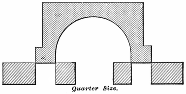
In its primitive form, the slide-valve was made merely long enough to cover the steam-ports when placed in the central position, as shown in Fig. 6. With a valve of this form, the slightest movement had the effect of opening one end so that steam would be admitted to the cylinder, while the other end opened the exhaust. By such an arrangement, steam was necessarily admitted to the cylinder during the whole length of the stroke; since closing at one end meant opening at the other. There were several serious objections to this system. It was very difficult to give the engine cushion202 enough to help the cranks over the centers without pounding, and a small degree of lost motion was sufficient to make the steam obstruct the piston during a portion of the stroke. But the most serious drawback to the short valve was, that it permitted no advantage to be taken of the expansive power of steam. For several years after the advent of the locomotive, the boiler pressure used seldom exceeded fifty pounds to the square inch. With this tension of steam, there was little work to be got from expansion with the conditions under which locomotives were worked; but, so soon as higher pressures began to be introduced, the loss of heat entailed by permitting the full-pressure steam to follow the piston to the end of the stroke became too great to continue without an attempted remedy. A very simple change served to remedy this defect, and to render the slide-valve worthy of a prominent place among mechanical appliances for saving power.
The change referred to, which so greatly enhanced the efficiency of the slide-valve, consisted in lengthening the valve-face, so that, when the valve stood in the center of the seat, the edges of the valve extended a certain distance over the induction ports, as in Fig. 7. This extension of the valve is called outside lap, or simply lap. The effect of lap is to close the steam-port before the piston reaches the end of the stroke, and the point at which the steam-port is closed is known as the point of cut-off. When the steam is cut off, and confined within the cylinder, it pushes the piston along203 by its expansive energy, doing work with heat that would be lost were the cylinder left in communication with the steam-chest till the end of the stroke.
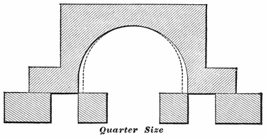
When a slide-valve is actuated by an eccentric connected directly with the rocker-arm or valve-stem, the point of cut-off caused by the extent of lap, remains the same till a change is made on the valve, or on the throw of the eccentric, unless an independent cut-off valve be employed. Locomotives having the old hook motion worked under this disadvantage; because the hook could not vary the travel of the valve, which is the method usually resorted to for producing a variable cut-off. The link and other simple expansion gears perform their office of varying the cut-off in this way.
In addition to cutting off admission of steam before the end of the stroke, lap requires the valve to be set in such a way that it has also the effect of leading to the exhaust-port being opened before the end of the stroke. The point where the exhaust is opened is usually known as the point of release. The change which204 causes release to happen before the piston completes its stroke, leads to the closure of the exhaust-port before the end of the return stroke is reached, which imprisons the steam remaining in the cylinder, causing compression. Where a valve has no inside lap, release and compression happen simultaneously; that is, the port at one end of the cylinder is opened to release the steam, and that at the other end is closed, letting the piston compress any steam remaining in the cylinder into the space left as piston clearance.
In some cases the inside edges of the valve cavity do not reach the edges of the steam-ports when the valve is on the middle of the seat, but lap over on the bridge a certain distance, as shown by the dotted lines in Fig. 7. This is called inside lap, and its effect upon the distribution of steam is to delay the release. By this means it prolongs the period of expansion, and hastens compression on the return stroke. Inside lap is an advantage only with slow-working engines. When high speed is attempted with engines having much inside lap, the steam does not have enough time to escape from the cylinders, and the back pressure and compression become so great as to be very detrimental to the working of the engine. As locomotive engineers have it, the engine is “logy.”
In locomotive practice, the extent of lap varies according to the character of service the engine is intended to perform. With American standard gauge engines,205 the lap varies from ½ inch to 1¼ inch. For high-speed engines, the extent of lap ranges from ⅞ to 1¼. Freight engines commonly get ⅝ to ¾ outside lap, and from 1/16 to ¼ inside lap. With a given travel, the greater the lap the longer will the period for expansion be.
Lap was applied to the slide-valve in this country before its advantage as an element of economy was understood in Europe. As early as 1829, James of New York used lap on the valves of an engine used to run a steam-carriage; and in 1832 Mr. Charles W. Copeland put a lap-valve on a steamboat engine, and his father understood that its advantage was in providing for expansion of the steam. Within a decade after our first steam-operated railroad was opened, the lap-valve became a recognized feature of the American locomotive; but the cause of the saving of fuel, effected by its use, was not well comprehended. Many enlightened engineers attributed the saving to the early opening of the exhaust, brought about where outside lap was used, which they theorized reduced back pressure on the piston; and in that way they accounted for the enhanced economy resulting from the application of lap. It was not till Colburn applied the indicator to the locomotive, that the true cause of economy was demonstrated to be in the additional work taken from the steam by using it expansively.
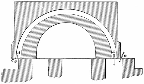
An improvement on the plain D slide-valve has been effected in a simple and ingenious manner in the Allen206 valve, which is receiving considerable favor for high-speed locomotives. This valve is shown in Fig. 8. The valve has a supplementary steam-passage, A, A, cast above the exhaust cavity. The valve and seat are so arranged, that, so soon as the outside edge of the valve begins to uncover the steam-port at B, the supplementary passage begins receiving steam at C; and this gives a double opening for the admission of steam to the port when the travel is short. As the travel of the valve is always short when an engine is running at high speed, the advantage of this double opening is very great; for it has the effect of admitting the steam promptly at the beginning of the stroke, and maintaining a full pressure on the piston till the point of cut-off.
With an ordinary valve cutting off at six inches, and having five inches eccentric throw, the port opening207 seldom exceeds ⅜ inch. It is a hard matter getting the full pressure of steam through such a small opening in the instant given for admission. If an Allen valve is used with that motion, the opening will be double, making ¾ inch, which makes an important difference. The practical effect of a change of this kind is that an engine will take a train along, cutting off at six inches with the Allen valve, when, with the ordinary valve, the links would have to be dropped to eight or nine inches. The valve can be designed to work on any valve-seat, but the dimensions given in Fig. 8 are those that have been found most satisfactory with our large passenger engines. In designing an Allen valve for an old seat, it is sometimes advisable to widen the steam-ports a quarter of an inch or more, by chamfering off the outside edges that amount. Care must be taken to prevent the valve from traveling so far as to put the supplementary port over the exhaust-port, for that would allow live steam to pass through. The proper dimensions can best be schemed out on paper before making the required change on the seat.
In very carefully conducted experiments made on the Boston and Albany Railroad, to compare the performance of the Allen valve with an engine equipped with a common valve, it was found that the Allen valve effected a fuel saving of seven per cent.
On one of the leading railroads in this country, an engineer was running a locomotive on a fast train where it was a hard matter making the card-time. A few minutes could be saved by passing a water-station; but208 this was done at serious risk, for the tender would nearly always be empty by the time the next water-station was reached. The master mechanic of the road determined to equip this engine with the Allen valve: and, after the change was made, there was no risk in passing the water-station; for there always was a good margin of water in the tank when the next watering-place was reached. The engine seemed to steam better, because the work was done with less steam; and there was a decided saving of fuel. The change made the engine smarter, and there seems to be no limit to the speed it can make. This valve can be applied to any locomotive with trifling expense. When an engine is designed specially for the Allen valve, the steam ports and bridges are usually made a little wider than for the ordinary valve. The only real difficulty in adopting the valve is getting the casting properly made, so that the supplementary port will not be too rough for the passage of steam, and the thin shell will be strong enough to stand the pressure.
For high-speed locomotives, where there is great necessity for getting rid of the exhaust steam quickly, the valves are sometimes cut away at the edges of the cavity, so that, when the valve is placed in the middle of the seat, it does not entirely cover the inside of either of the steam-ports. This is called inside clearance. In many instances inside clearance has been adopted in an effort to rectify mistakes made in designing the valve-motion, principally to overcome defects caused by deficiency of valve-travel. The fastest locomotives209 throughout the country do not require inside clearance, because their valve-motion is so designed that it is not necessary. Inside clearance induces premature release, and diminishes the period of expansion. Consequently inside clearance wastes steam, and ought to be avoided.
There are certain advantages gained in the working of a locomotive, by having the valves set so that the steam-port will be open a small distance for admission of steam, when the piston is at the beginning of the stroke. This opening is called lead. On the steam side of the valve the opening is called steam-lead: on the exhaust side it is called exhaust-lead. Lead is generally produced by advancing the eccentric on the shaft, its effect being to accelerate every event of the valve’s movement; viz., admission, cut-off, release, and compression. In the most perfectly constructed engines, there soon comes to be lost motion in the rod connections and in the boxes. The effect of this lost motion is to delay the movement of the valves; and, unless they are set with a lead opening, the stroke of the piston would in some instances be commenced before steam got into the cylinder. It is also found in practice, that this lost motion would cause a pounding at each change in the direction of the piston’s travel, unless there is the necessary cushion to bring the cranks smoothly over the centers. Without cushion, the change of direction of the piston’s travel is effected by a series of jerks that are hard on the working-parts. So long as the lead opening at the beginning of the stroke is not advanced enough to produce injurious counter pressure210 upon the piston, it improves the working of the engine by causing a prompt opening for steam admission at the beginning of the stroke. This is the time that a full steam-pressure is wanted in the cylinder, if economical working be a consideration. A judiciously arranged lead opening is therefore an advantage; since it increases the port opening at the proper time for admitting steam, tending to give nearly boiler pressure in the cylinder at the beginning of the stroke. With the shifting link-motion, the amount of lead opening increases as the links are hooked back towards the center notch; the magnitude of the increase, in most cases, being in direct proportion to the shortness of the eccentric-rods. A common lead opening in full gear with the shifting link is 1/16 inch, which often increases to ⅜ inch in the center notch. The tendency of wear and lost motion is to neutralize the lead, so that, when a locomotive motion gets worn, increasing the lead will generally improve the working of the engine.
As the work performed by a steam-engine is in direct proportion to the pressure exerted by the steam on the side of the piston which is pulling or pushing on the crank-pin, it is important that the steam should press only on one side of the piston at once. Hence, good engines have the valves operated so that, by the time a stroke is completed, the steam, which was pushing the piston, shall escape, and not obstruct the piston during the return stroke, and so neutralize the steam pressing upon the other side. When an engine is working properly, the steam is admitted alternately to each211 side of the piston; and its work is done against a pressure on the other side not much higher than that of the atmosphere.
When, from any cause, the steam is not permitted to escape promptly and freely from the cylinder at the end of the piston stroke, a pressure higher than that of the atmosphere remains in the cylinder, obstructing the piston during the return stroke, and causing what is known as back pressure. There is seldom trouble for want of sufficient opening to admit steam to the cylinders, for the pressure is so great that the steam rushes in through a very limited space; but, when the steam has expanded two or three times, its pressure is comparatively weak, and needs a wide opening to get out in the short time allowed. This is one reason why the exhaust-port is made larger than the admission-ports. Nearly all engines with short ports suffer more or less from back pressure, but the most fruitful cause of loss of power through this source is the use of extremely contracted exhaust nozzles. Were it not for the necessity of making a strong artificial draught in the smoke-stack, so that an intense heat shall be created in the fire-box, quite a saving of power, now lost by back pressure, would be effected by having the exhaust opening as large as the exhaust-pipe. This not being practicable with locomotives, engineers should endeavor to have their nozzles as large as possible consistent with steam-making.
Engines with very limited eccentric throw will often cause back pressure when hooked up, through the212 valve not opening the port wide enough for free exhaust.
Locomotives suffering from excessive back pressure are nearly always logy. The engine can not be urged into more than moderate speed under any circumstances; and all work is done at the expense of lavish waste of fuel, for a serious percentage of the steam-pressure on the right side of the piston is lost by pressure on the wrong side. It is like the useless labor a man has to do turning a grindstone with one crank, while a boy is holding back on the other side. The weight of obstruction done by the boy must be subtracted from the power exerted by the man to find the net useful energy exerted in turning the grindstone. In the same way, every pound of back pressure on a piston takes away a pound of useful work done by the steam on the other side.
Engines that have much inside lap to the valves are likely to suffer from back pressure when high speed is attempted. The inside lap delays the release of the steam; and, where the piston’s velocity is high the steam does not escape from the cylinder in time to prevent back pressure.
Most of engineers are familiar with the tendency of some engines to “run into a hill.” That is, so soon as a hill is struck, they suddenly slow down till a certain speed is reached, when they will keep going. This is generally produced by back pressure, its obstructing213 effect being reduced when the engine is moving slow.
The necessity which requires lap to be put on a slide-valve to produce an early cut-off, in its turn causes compression, by the valve passing over the steam-port, and closing it entirely for a limited period towards the end of the return stroke. As the cylinder contains some steam which did not pass out while the exhaust-port was open, this is now squeezed into a diminishing space by the advancing piston. In cases where too much steam was left in the cylinders through contracted nozzles or other causes, or where, through mistaken designing of the valve-motion, the port is closed during a protracted period, the steam in the cylinder gets compressed above boiler tension, and loss of useful effect is the result. Under proper limits, the closing of the port before the end of the stroke, and the consequent compression of the steam remaining in the cylinder, have a useful effect on the working of the engine by providing an elastic cushion, which absorbs the momentum of the piston and its connections, leading the crank smoothly over the center. Where it can be so arranged, the amount of compression desirable for any engine is the degree that, along with the lead, will raise the pressure of the cylinder up to that of the boiler at the beginning of the stroke. When this can be regulated, the compression performs desirable service by cushioning the working-parts, thereby preventing pounding, and by filling up the clearance space and steam passages, by that means saving live steam. Compression probably214 does some economical service by reheating the cylinder, which has a tendency to get cooled down during the period of release, and by re-evaporating the water, which forms by condensation of steam in the cool cylinder.
Engines that are running fast require more cushioning than those that run slow, or at moderate speeds. The link-motion, by its peculiarity of hastening compression when the links are hooked up, tends to make compression a useful service in fast running.
The reciprocating motion which causes the valves to open and close the steam-ports at the proper periods, is, with most locomotives, imparted from eccentrics fastened upon the driving-axle. An eccentric is a circular plate, or disk, which is secured to the axle in such a position that it will turn round on an axis which is not in the center of the disk. The distance from the center of the disk to the point round which it revolves is called its eccentricity, and is half the throw of the eccentric. Thus, if the throw of an eccentric requires to be 5 inches, the distance between the center of the driving-axle and the center of the eccentric will be 2½ inches. The movement of an eccentric is the same as that of a crank of the same stroke, and the eccentric is preferred merely because it is more convenient for the purposes to which it is applied than a crank would be.
On the early forms of locomotives, a single eccentric was used to operate the valve for forward and back215 motion. The eccentric was made with a half circular slot, on which it could be turned to the position needed for forward or back motion. It was held in the required position by a stop-stud fastened on the axle. Several forms of movable eccentrics were invented, and received considerable application during the first decade of railroad operating; but the best of them provided an extremely defective reversing motion. The first engineer to apply two fixed eccentrics as a reversible gear was William T. James of New York, who made a steam carriage in 1829, and worked the engine with four eccentrics,—two for each side. The eccentrics were connected with a link, but the merits of that form of connection were not then recognized here; for it was not applied to locomotives till it became popular in England, and was re-introduced to this country by Rogers. The advantage of the double fixed eccentrics seemed, however, to be recognized from the time James used them; for the plan was adopted by our first locomotive builders. The first locomotive built by Long, who started in 1833 what was afterwards known as the Norris Locomotive Works, Philadelphia, had four fixed eccentrics.

When a locomotive is running, the wheels turn with something near a uniform speed; but any part which receives a reciprocating motion from a crank or eccentric travels at an irregular velocity. Fig. 9 shows the relative motion of the crank-pin and piston during a half revolution. The points in the path of the crank-pin216 marked A, 1, 2, B, 3, 4, C, are at equal distances apart. The vertical lines run from them to the points a, b, c, d, e, represent the position of the piston in relation to the position of the crank-pin. That is, while the crank-pin traverses the half-circle, A B C, to make a half revolution, the piston, guided by the cross-head, travels a distance within the cylinder equal to the straight line A C. The crank-pin travels at nearly uniform speed during the whole of its revolution, but the piston travels with an irregular motion. Thus, while the crank-pin travels from A to 1, the piston travels a distance equal to the space between A and a. By the space between the lines, it will be seen that the piston travels slowly at the beginning of the stroke, gets faster as it moves along, reaches its highest velocity about217 half stroke, then slows down towards the end till it stops, and is ready for the return stroke.
Certain mechanics and inventors have been terribly harassed over this irregular motion of the piston, and numerous devices have been produced for the purpose of securing a uniform motion to the power transmitted. These inventions have usually taken the shape of rotary engines. Probably the fault these people find with the reciprocating engine is one of its greatest merits, for the piston stopping at the end of each stroke permits an element of time for the steam to get in and out of the cylinder.
The valve travels in a manner similar to the piston; although its stroke is much shorter, and its slow movement is towards the limit of travel. The small circle in the figure shows the orbit of the eccentric’s center, and the valve-travel is equal to the rectilinear line across the circle. If the valve opened the steam-ports at the outside of its travel, the slow movement at that point would be an objection, since the operation of opening would be slow: but the valve opens the ports towards the middle of its travel, when its velocity is greatest; and, the nearer to the mid travel the act of opening is done, the more promptly it will be performed. This has a good deal to do with making an engine “smart” in getting away from a station.
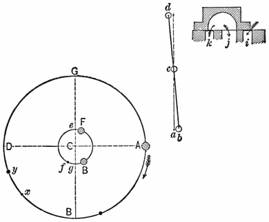
With the short valve without lap used on the earliest forms of locomotives, the eccentric was set at right angles to the crank or “square” on the dotted line e, Fig. 10. The least movement of the eccentric from its middle position had the effect of opening the steam-ports. One advantage about an eccentric set in this position, was that it opened and closed the ports when moving the valve at its greatest velocity. Lengthening the valve-face by providing lap entails a change in the location of the eccentric; for, were it left in the right-angle position, the steam-port would remain covered till the eccentric had moved the valve a distance equal to the extent of the lap on one end, and the piston would begin its stroke without steam.
The change made on the eccentric location is to advance it from e to F, being a horizontal distance equal to the extent of lap and lead, and known as the angular advance of the eccentric. The centers F and B represent the full part, or “belly,” of the forward and back eccentrics in the position they should occupy, where a rocker is employed, when the piston is at the beginning of the backward stroke. It will be perceived that the eccentrics both incline towards the crank-pin, and the eccentric which is controlling the valve follows the crank-pin. Thus, when the engine is running forward, F follows the crank: when she is backing, B follows.
It is a good plan for an engineer to make himself familiar with the proper position of the eccentrics in relation to the crank, for the knowledge is likely to save219 time and trouble when any thing goes wrong with the valve-motion. With this knowledge properly digested, a minute’s inspection is always sufficient to decide whether or not any thing is wrong with the eccentrics.
In following out the relative motion of the piston and crank, we discover a disturbing factor in what is called the angularity of the connecting rod, which has a curiously distorting effect on the harmony of the motion. When the piston stands exactly in the mid-travel point, the true length of the main rod will be measured from the center of the wrist-pin to the center of the driving-axle. If a tram of this length be extended between these points, this will be found correct, as every machinist accustomed to working on rods knows. Now,220 if the back end of the tram should be raised or lowered towards the points where the center of the crank-pin must be when the crank stands on the top or bottom quarter, it will be found that the tram point will not reach the crank-pin center, but will fall short a distance in proportion to the length of the main rod. The dotted lines a′ and b′ in Fig. 11 show how far a rod 7½ times the length of the crank falls short. A shorter rod will magnify this obliquity, while a longer rod will reduce it.
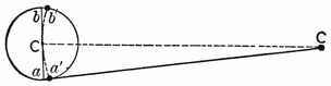
As the opening and closing of the steam-ports by the valves are regulated by the eccentrics, which are subject to the same motion as the crank, following it at an unvarying distance, it is evident that their tendency will be to admit and cut off steam at a certain position of the crank’s movement. If the motion is planned to cut off at half stroke, it will be apparent, that, in the backward stroke, the piston will be past its mid travel before the crank-pin reaches the quarter, so that end of the cylinder will receive steam during more than half the stroke. On the forward stroke of the piston, however, the crank-pin will reach the quarter before the piston has attained half travel; the consequence being, that in this case steam is cut off too early. The disturbing effect221 of the angularity of the connecting rod on the steam distribution thus tends to make the cut-off later in the backward stroke than in the forward stroke, resulting in giving the forward end of the cylinder more steam than what is admitted in the back end. The link-motion provides a convenient means of correcting the inequality of valve opening due to the connecting-rod angularity, the details of which will be explained farther on.
An engineer or machinist who wishes to study out this peculiarity of connecting-rod angularity, will find that the use of a tram or long dividers will help him to comprehend it better than any letter-type description. All through the study of the valve-motion, there are numerous difficult problems encountered. The use of a good model will be found an invaluable aid to the study of the valve-motion, and every division of engineers or firemen should make a combined effort to furnish their meeting-room with a model of a locomotive valve-motion. In no way can the spare time of the men connected with locomotive running be better employed than in the wide range for study presented by a well-devised model. Great aid can be obtained in the study of the valve-motion from good books devoted to the subject, and they will impart more information than can be obtained by mere contact with the locomotive. The valve and its movements are surrounded with so many complicated influences, that an intelligent man may work for years about a locomotive doing valve setting occasionally, and other gang boss work, yet, unless he studies the valve-motion by the aid of the drawing-board,222 or by models, which admit of changing sizes and dimensions, he may know less about the cause of certain movements than the bright lad who has been a couple of years in the drawing-office. The man who thinks he can study the valve-motion, and understand its philosophy, by merely running the engine, deceives himself. The engineer who never looks at a book or a paper in search of information about his engine, knows very little about any thing not visible to the eye. Yet many men of this stamp, by looking wise, and by exercising a judicious use of silence, pass among their fellows as remarkably profound. But let a fireman, in quest of locomotive knowledge, put a question to such a man, and he is immediately silenced with a “You ought to know better” answer.
Where the use of a model can not be obtained, any one beginning the study of the valve-motion can assist himself by making a cross section of the valve and its seat, similar to those published, on a strip of thin wood or thick paper. By slipping the valve on the seat, its position at different parts of the stroke can be comprehended more clearly than by a mere description. With a pair of dividers to represent the motion of the eccentric, and strips of wood to act as eccentric, and valve rod and rocker, and some tacks to fasten them together, a helpful model can be improvised on a table or board. By the time a student gets a rig of this kind going, he will see his way to contrive other methods of self-help.
By the aid of Fig. 10, we will trace the relative movements of the crank and eccentric connections. For the223 sake of simplicity, the eccentric is represented as connecting directly with the rocker-arm.
The crank-pin being at the point A, or the forward center, the piston must be in the front of the cylinder, or at the beginning of the backward stroke. Owing to the angular advance already referred to, the eccentric center is at F; and, being a certain distance ahead of the middle position, it has pushed the lower arm of the rocker from a to b, drawing back the top arm, which, in its turn, has moved the valve so that it is just beginning to admit steam at the forward port, i. As the crank-pin goes round, the eccentric follows it, opening the steam-port wider till the eccentric reaches the point of its travel nearest A, the limit of the throw. When the eccentric is at this point of its throw, the valve must be at the outside of its travel; and therefore the steam-port is wide open. By this time the crank-pin is getting close up towards the quarter. After passing this point, the forward eccentric begins to draw the bottom rocker-pin towards the axle, and to push the valve ahead, this being the point where the valve changes its direction of motion, just as the piston returns when the crank-pin passes the center. When F reaches the point B, the valve is in the same position it occupied at the beginning of the stroke; but, as it is traveling in the opposite direction, a very small movement more closes the port, cutting off steam. When this happens, the crank-pin has reached the point x. When F gets to g, it is on the central point of its throw; so the valve must then be on the middle point of its travel, with the exhaust cavity just covering the outside edges of the bridges, the forward edge being ready224 to put the steam-port, i, in communication with the exhaust cavity. This releases the steam from the forward end of the cylinder; and at the same moment the inside edge of the valve covers the back port, k, causing the piston-head to compress any steam left in the back part of the cylinder. When the piston reaches the beginning of the forward stroke, the eccentric F has got to the point f, and the valve is beginning to admit steam for the return stroke, the events of which are similar to those described.
In actual practice, the steam distribution is a little different from the manner that has been followed; for the link-motion provides the means of equalizing the cut-off, making it uniform for both strokes. This changes the events of the stroke a little; but the student who engraves in his mind the movements as they are represented in the diagram, will not be far astray.
Many men who have a fair understanding of the action of steam in an engine’s cylinders during ordinary working, have no idea of the operations performed in the cylinders when a locomotive is running in reverse motion. All men who have had any thing to do with train service, know, that, when an engine is reversed, the action works to stop the train, even if the locomotive should have no steam on the boiler; but just in what way this result comes round they can not clearly perceive. In hopes of throwing light upon this subject for those who have not studied it out, we will follow the events of a225 stroke in reversed motion, as we did in the ordinary working.
Supposing an engine to be running ahead, and the necessity arises for stopping suddenly, and the reverse-lever is pulled into the back notch. When the crank-pin is on the forward center, and therefore the piston at the forward end of the cylinder, about to begin its backward stroke, the valve has the forward port open a distance equal to the amount of lead, as in Fig. 10. But, as the back-up eccentric has control of the valve, the latter is being pushed forward; and it closes the forward port just as the piston begins to move back. This shuts off all communication with the forward end of the cylinder; and the receding piston creates a vacuum behind it, just as a pump-plunger does under similar circumstances. At this time the back end of the cylinder is open to the exhaust, and the piston pushes out the air freely to the atmosphere. By the time the piston travels about two inches, the valve gets to its middle position; and, immediately after passing that point, it opens the forward end of the cylinder to the exhaust, and closes the back port. When this event happens, the vacuum in the forward end of the cylinder gets filled with hot gases, that rush in from the smoke-box; and the receding piston keeps drawing air into the cylinder in this way during the remainder of the stroke, and air from that quarter seldom gets in without bringing a sprinkling of cinders. The back steam-port is closed only during about two inches of the stroke, while the lap of the valve is traveling over it. About226 the time the piston reaches four inches of its travel, the back steam-port is open to the steam-chest, and the piston forces the air through the steam-pipes into the boiler during the remainder of the stroke. The forward stroke is merely a repetition of the backward stroke described.
When it is necessary to reverse a locomotive, it is a better plan to hook the lever clear back than to have it a notch or two past the center, as some men persist in doing, under the mistaken belief that they are in some way saving their engine from harsh usage. When the link is reversed full, the cylinders are merely turned into air-pumps. When the links are put near the center, the travel of the valve is reduced; and the periods when the piston is creating a vacuum in one end of the cylinder, and compressing the air in the other, are prolonged. The result is, that, when the exhaust is opened in the first case, the gases rush in violently from the smoke-box, carrying a heavy load of cinders: in the other case, the piston compresses the air in the cylinder so high that it jerks the valve away from its seat in trying to find outlet. This causes the clattering noise in the steam-chest, so well known in cases where engines are run without steam while the reverse-lever is near the center.
A locomotive with the piston-packing in bad order will not hold well running in reverse-motion. Some kinds of piston-packing do not seem to act properly when the engine is reversed, especially at low speed. Where a valve has much inside lap, there will be a vacuum in one end of the cylinder, and compressed air in the other end. With piston packing that requires227 pressure to expand it, the void at one end of the cylinder may neutralize the pressure at the other by drawing the air through the piston. This would be most liable to happen where the lever was kept near the center.
Should the throttle-valve close so tight that the compressed air from the cylinders can not pass into the boiler, there is danger of bursting the steam-chest or some part of the steam-pipes. The compressed air will lift most of the throttle-valves far enough to prevent any great danger from this source. In some engines a relief-valve is secured in the dry pipe, which provides a passage for this compressed air. When the cylinder-cocks of an engine are opened when the motion is reversed, they form an outlet to the compressed air, and also admit air to the sucking end without letting the piston draw air so freely through the nozzles. Many cylinder-cocks are now made so that they will open automatically to permit the piston to draw air through them. The reversed engine will stop nearly as well with the cylinder-cocks opened as when they are closed, and it is much more easily handled with the cocks opened. Where the cocks are kept closed, the rush of hot air from the smoke-box laps every trace of oil from the valve-seat, and a heavy pressure—frequently above that of the boiler—is present in the steam-chest. When the engine stops under these circumstances, its tendency is to fly back; and an engineer has some difficulty in controlling it with the reverse-lever till a few turns empty the chest and pipes.
Numerous attempts have been made to utilize the reversed engine as a brake for stopping the train, and even by this means to save some of the power lost in stopping. Chatelier, a French engineer, experimented for many years on this mechanical problem. He injected a jet of water into the exhaust-pipe, which supplied low-tension steam to the cylinder, instead of hot gas or air coming through the smoke-box. This was pumped back into the boiler on the return stroke. Thus the act of stopping a train was used to compress a quantity of steam, converting the work of stopping into heat, which was forced into the boiler and retained to aid in getting the train into speed again. Modifications of this idea produce the car-starters that pass so frequently through our Patent Office.
As a means of conserving mechanical energy, the Chatelier brake was not a success; but, in the absence of better power brakes, it met with some applications in Europe. Some of our mountain railroads use it, under the name of the water-brake, as an auxiliary to the automatic brake.
In the engineering practice of the world, before the locomotive and marine engines came into use, there was no need for devices to make engines rotate in more than one direction. When the need for a reversible engine first arose, it was met by very crude appliances. Locomotives were kept at work, earning money for their owners, which were reversed by the man in charge stopping the engine, and by means of a wrench changing the position of the eccentric by hand. A decided improvement on the wrench was the movable eccentric, which was held in forward or back gear by stops; the operation of reversing being done by a treadle or other attachment located near the engineer’s position. A serious objection to this form of reversing gear was, that the abrasion of work enlarged the slot ends, and wore out the stops, leading to inaccuracy and frequent breakage. A somewhat better form of reversing motion was a fixed eccentric, with the means at the end of the eccentric-rod for engaging with the top or bottom of a rocker-shaft, which operated the valve-stem. This was the form of reversing motion used on the early Baldwin engines. Numerous other appliances, more or less defective,230 were experimented with before the double fixed eccentrics were introduced. Till the link was applied to valve-motion, the double eccentrics—an American invention—were the most important improvement that had been made on the locomotive valve-motion since the incipiency of the engine. The V hook, in connection with the double eccentrics, made a fair reversing motion in comparison to any thing that had preceded it. The objection to the hook was, that, when the necessity arose for reversing the engine while in motion, much difficulty was experienced in getting the hook to catch the pin. As a simple, prompt, and certain reversing motion, the link was readily acknowledged to be far superior to any thing that had previously been tried.
There is no doubt but the link was first applied to a steam engine by William T. James of New York, a most ingenious mechanic, who also invented the double eccentrics. James experimented a great deal about the period from 1830 to 1840, with steam carriages for common roads; and it was in this connection that he invented the link. His work having proved a commercial failure, the improvements on the valve-motion were not recognized at the time; although the probability is, that Long, who started the Norris Locomotive Works of Philadelphia, and brought out the double eccentrics upon the locomotives built there, was indebted to James for the idea of a separate eccentric for each direction of engine movement.
The credit of inventing the ordinary shifting link is231 due to William Howe of Newcastle, England. This inventor was a pattern-maker in the works of Robert Stephenson & Co., and he invented the link in 1842 in practically its present form. The idea of Howe was to get out an improved reversing motion; and he made a pencil-sketch of the link, to explain his views to his employers. The superintendent of the works was favorably disposed to the invention, and ordered Howe to make a pattern of the motion, which was done; and this was submitted to Stephenson, who approved of the link, and directed that one should be tried on a locomotive. Although Stephenson gave Howe the means of applying his invention, he does not seem to have perceived its actual value, for the link was not patented; and Stephenson never failed to patent any device which he thought worth protecting.
The link-motion was applied to a locomotive constructed for the Midland Railway Company, and proved a success from the day it was put on. Seeing how satisfactorily the invention worked, Robert Stephenson paid Howe twenty guineas (one hundred and five dollars) for the device, and adopted the link as the valve-gear for his locomotives. This is how the shifting link comes to be called the “Stephenson link,” and the credit for this invention was not extravagantly paid for.
The capability which the link possesses of varying the steam admission and release, did not appear to be understood by the inventor; nor was the mechanical world aware, for some time after the link was brought into use, that it could be employed to adjust the inequality of steam distribution, due to the angularity of the connecting rod.
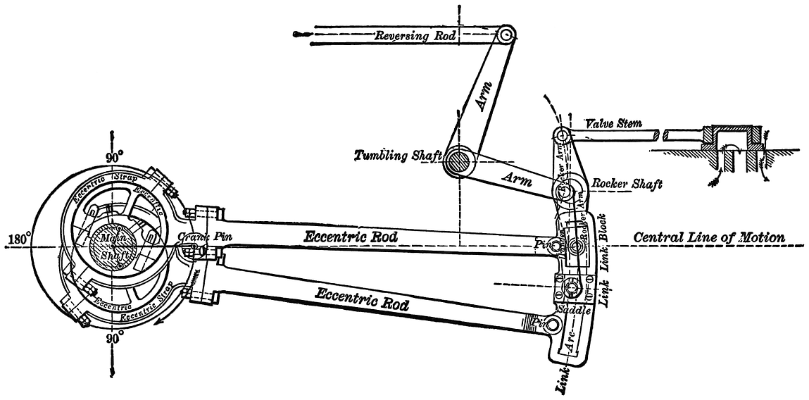
As usually constructed for American locomotives, the link is a slotted block curved to the arc of a circle, with233 a radius about equal to the distance between the center of the driving-axle and the center of the rocker-pin. The general plan of the link-motion is shown in Fig. 12. Fitted to slide in the link-slot is the block which encircles the rocker-pin. The eccentric-rods are pinned to the back of the link; the forward eccentric-rod connecting with the top, and the back-up eccentric-rod with the bottom, of the link. Bolted to the side and near the middle of the link is the saddle, which holds the stud to which the hanger is attached; this, in its turn, connecting with the lifting arm, which is operated by the reversing rod that enables the engineer to place the link in any desired position.
Regarded in its simplest form, the action of the link in full gear is the same upon the valve movement as a single eccentric. When the motion is working, as in the figure, with the eccentric-rod pin in line with the rocker-pin, it will be perceived that the movement can not differ much from what it would be were the eccentric-rod attached to the rocker. Here the forward eccentric appears as controlling the movement of the valve. Putting the link in back motion brings the end of the backing eccentric-rod opposite the rocker-pin, the effect being that the back-up eccentric then operates the valve. When the link-block is shifted toward the center of the link, the horizontal travel of the rocker-pin is decreased; consequently, the travel of the valve is reduced; for, with ordinary engines, the travel of the valve in full gear equals the throw of the eccentrics, the top and bottom rocker-arm being of234 the same length. The motion transmitted from the eccentrics, and their means of connection with the link, make the latter swing as if it were pivoted on a center which had a horizontal movement equal to the lap and lead of the valve. The extremities of the link, or rather the points opposite the eccentric-rods, swing a distance equal to the full throw of the eccentric. The variation of valve-travel that can be effected by the link, is from that of the eccentric throw in full gear down to a distance in mid gear which agrees with the extent of lap and lead. The method of obtaining these various degrees of travel is by moving the link so that the block which encircles the rocker-pin shall approach the middle of the link.
When an engine is run with the lever in the center notch, the supply of steam is admitted by the lead-opening alone. In full gear the eccentric, whose rod-end is in line with the rocker-pin, exerts almost exclusive control over the valve movement; but, as the link-block gets hooked towards the center, it comes to some extent under the influence of both eccentrics.
A thoughtful examination of Fig. 12 will throw light on the reason why the proper position of a slipped eccentric can be determined by the other eccentric when the engine is on the center. In the cut, the crank-pin is represented on the forward center; and in that position the eccentric centers are both an equal distance in advance of the main shaft center. It will be evident now that the valve must occupy practically the same position for forward or back gear, as each of the eccentric-rods reaches the same distance forward. Putting the motion in back gear would bring the backup235 eccentric-rod pin to the position now occupied by the pin belonging to the forward eccentric-rod.
Reducing the travel of the valve by drawing the reverse-lever towards the center of the quadrant, and consequently the link-block towards the middle of the link-slot, not only hastens the steam cut-off, but it accelerates in a like degree every other event of steam distribution throughout the stroke. To explain this point, let us take the motion of a well-designed engine in actual service, which has done good economical work on fast train running. The valve-travel is five inches, lap one inch, no inside lap, lead in full gear 1/16 inch, point of suspension 9/16 inch back of center of link.
When this engine is working in full gear, the steam will be freely admitted behind the piston till about eighteen inches of the stroke, when cut-off takes place; and the release or exhaust opening will begin at about twenty-two inches of the stroke, giving four inches for expansion of steam. Now, if the links of this engine are hooked up so that the cut-off takes place at six inches of the stroke, the steam will be released at sixteen inches of the stroke; and at that point compression will begin at the other end of the cylinder.
This attribute which the link-motion possesses, of accelerating the release and compression along with the cut-off, is very detrimental to the economical operating236 of locomotives that run slow. High-speed engines need the pre-release to give time for the escape of the steam before the beginning of the return stroke; and the compression is economically utilized in receiving the heavy blow from the fast-moving, reciprocating parts, whose direction of motion has to be suddenly changed at the end of each stroke, and in helping to raise the pressure promptly in the cylinder at the beginning of the stroke. A locomotive, on the other hand, that does most of its work with a low-piston speed, would not suffer from back pressure if the steam were permitted to follow the piston close to the end of the stroke; and a very short period of compression would suffice. If the engine, whose motion we have been considering, instead of releasing at sixteen inches, could allow the steam to follow the piston to twenty-two inches of the stroke, after cutting off at six inches, a very substantial gain of power would ensue. And this would be well supplemented by avoiding loss of power, did compression not begin till within two inches of the return stroke.
Increase of expansion follows reduced valve-travel, from a similar cause to that which produces expansion when lap is added to the edge of a slide-valve. When the valve is made with the face merely long enough to cover the steam-ports, there can be no expansion of the steam; for, so soon as the valve ceases to admit steam, it opens the steam-port to the exhaust. When lap is added, however, the steam is inclosed in the cylinder,237 without egress for the time that it takes the lap to travel over the steam-port. An arrangement of motion which will make the valve travel quickly over the port, has a tendency to shorten the period for expansion; while making the valve travel slowly over the port, has the opposite effect, and protracts expansion. A valve with, say, five inches travel, has a comparatively long journey to make during the stroke of the piston; and the lap-edges will pass quickly over the steam-ports,—much more quickly than they will when the travel is reduced to three inches. In a case of this kind, there is more than the mere reduction of travel to be considered. Suppose the valve has one inch lap at each end. When it stands on the middle of the seat, it has a reciprocating motion of two and one-half inches at each side of that point to make. At the beginning of the stroke, it has been drawn aside one inch (we will ignore the lead), but still has one and one-half inch to travel before it begins to return. On the other hand, when the travel is reduced to three inches, the valve has only one and one-half inch to travel away from the center; and, one inch being moved to draw the lap over the port, there only remains one-half inch for the valve to move before it must begin returning. This entails an early cut-off; for the valve must pass over the ports with its slow motion, and be ready to open the port on the other end, before the return stroke. Thus a travel of five inches draws the outside edge of the valve one and one-half inch away from the outside of the steam-ports, three inches travel only draws it one-half inch away, and a greater reduction of travel decreases the opening in like proportion.
As reducing the travel of the valve diminishes the port opening, a point is reached in cutting off early in the stroke where the port opening is hardly any more than the port opening due to the lead. This is what makes long steam-ports essential for a successful high-speed locomotive. The best-designed engines give an exceedingly limited port opening at short cut-offs, and badly planned motion sometimes seriously detracts from the efficiency of the engine, by curtailing the opening at the point where a very brief time is given for the admission of steam. The magnitude of the eccentric throw exerts a direct influence on the port opening when cutting off early. A long throw tends to increase the opening, while a short throw reduces it. The long-throw eccentric will draw the valve farther away from the edge of the steam-port, when admitting steam for the same point of cut-off, than a short-throw eccentric will move its valve. For an ordinary 17 × 24 inch locomotive, the throw of eccentric should not be less than five inches, unless the engine is intended entirely for slow running. There are many engines running with eccentric throw less than five inches, but they are invariably slow unless the valve-lap is very short. With an ordinary lap, an engine having an eccentric throw of 4½ inches needs so much angular advance to overcome the lap, and provide lead, that the rectilineal motion of the eccentric is very meager at the beginning of the stroke. That is, the center of the eccentric is traveling downward in its circular path, which gives little motion to the valve, just as the crank gives decreased motion to the cross-head when near the centers.
Hitherto we have regarded the link as merely performing the functions of transmitting the motion of the eccentrics to the valves, with the additional capability of reducing the travel at the will of the engineer. Otherwise, the motion of the link is intensely complex; and its movements are susceptible to a multitude of influences, which improve or disturb its action on the valve. A good valve-motion is planned according to certain dimensions of all the working-parts; and any change in their arrangement will almost invariably entail irregularities upon the link’s movement, which will radically affect the distribution of steam. A link-motion schemed for an eccentric throw of 4½ inches will not work properly if the throw be increased to five inches: a link with a radius of 57 inches can not be changed with impunity for one of 60 inches. Any change in the position of the tumbling-shaft or rocker-arms distorts the whole motion, and any alteration in the length of the rods or hangers has a similar effect. That the link may perform its functions properly, all its connections must remain in harmony.
A very important feature of the link is its property of adjustability, which serves to neutralize the distorting effect of the connecting rod’s angularity. As has already been explained, the angularity of the main rod tends to delay the cut-off during the backward stroke, while it is accelerated in the forward stroke. With the ordinary length of connections, this irregularity would seriously affect the working of the engine. But it is240 almost entirely overcome by the link, which can be suspended in a way that will produce equality for the period of admission and point of cut-off for both strokes in one gear. Perfect equalization of admission and cut-off for both gears has been found impossible with the link-motion; and designers are generally satisfied to adjust the forward motion, and permit the back motion to remain untrue. The point about the link which exercises the most potent influence on adjusting the cut-off, is the position of the saddle, or of its stud for connecting the hanger. This stud is called the point of suspension. Raising the saddle away from the center of the link will effect adjustment of steam admission; but in locomotive practice the saddle is nearly always located in the middle of the link, there being practical objections against raising it. Equalization of steam distribution is produced by placing the hanger-stud or point of suspension some distance back of the center line of the link-slot, the distance varying from ⅛ inch to ⅞ inch.
Moving the hanger-stud affects the link’s movement in a way that is equivalent to temporarily lengthening the eccentric-rod during a portion of the piston-stroke. The length of the tumbling-shaft arms, the length of hanger, the location of the rockers and tumbling-shaft, the radius of link, and length of rods, all exercise influence on the accurate adjustment of the valve-motion.
In equalizing the valve-motion, and overcoming the discrepancy of steam admission, due to the angularity241 of the connecting rod by moving the link-hanger stud away from the center of the slot, a new distortion is introduced. The link-block being securely fastened to the bottom of the rocker-pin, moves in the fixed arc traversed by that pin, which is nearly horizontal. The action of the eccentric-rods on the link, on the other hand, forces the latter to move with a sort of vertical motion at certain parts of the stroke, making it slip on the block. Moving the hanger-stud back tends to increase this slip, which will become excessive enough to seriously impair the efficiency of the motion if not kept within bounds by the designer. Where the slip is very great, the motion will not be serviceable, a consideration which can never be overlooked; for the block will wear rapidly, producing lost motion, a very undesirable defect about any part of a link-gear. With the long rods which prevail in locomotive practice, designers have no difficulty in keeping the slip within practical bounds; but with marine engines it is sometimes necessary to sacrifice equality of steam admission to the reduction of the slip. The greatest amount of slip is in full gear, and it diminishes as the link-block is moved towards the center.
Placing the eccentric-rod pins back of the link-arc, as is almost universally done in this country, has a tendency to make the link slip on the block; and care has to be taken not to locate these pins farther back than is actually necessary for other requirements of the link-motion’s adjustment. Auchincloss, who is a recognized authority for designing of link-motion, gives four varieties of alterations capable of reducing the slip when it is found too great for a practicable motion.242 His resorts are, either to increase the angular advance, reduce the travel, increase the length of link, or shorten the eccentric-rods. One, or a combination, of these methods may be adopted, as the designer finds most convenient.
Among the constructing engineers who plan link-motion, there is considerable diversity of opinion about what radius of link helps to produce the best valve-motion. The distance between the center of axle and center of lower rocker-pin may be accepted as approximately correct, although some designers slightly increase beyond these points. On the other hand, the locomotives sent out from a leading building establishment have the radius of link drawn ¾ inch per foot short of the distance between the axle and rocker; and the claim has been made, that the arrangement produces an excellent motion.
A committee of the American Master Mechanics’ Association have placed themselves on record on this subject by asserting that the distance between the centers of axle and rocker-pin is the proper radius for the link. That same committee recommended that the link-motion should be planned to give as long a link-radius as possible, subject to the first-mentioned conditions.
It must be noted that the middle of the link-slot is the radius arc. I knew of a case where the links for an altered locomotive were finished out of the true radius through the edge of the slot being taken as the radius-curve.
Most of the men who are at all familiar with the valve-motion are aware of the fact, that, with the shifting link, the lead increases as the link is notched towards the center. Where the valve has 1/16 inch lead in full gear, it is no unusual thing to find it increase to ⅜ inch lead opening at mid gear. The phenomenon is better known than its cause is understood.
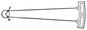
The relative positions of link and eccentric centers of an engine, when the crank is on the forward center, are shown in Fig. 13; the link being represented with the block in the center, which represents mid gear. It will be observed that the centers of the eccentrics f and b, from which the rods receive direct influence, are both some distance ahead of the center of the axle, the one above, the other below. The eccentric-straps to which the rods are connected sweep round the eccentric circles, and are controlled thereby. When the link is moved up or down, each eccentric-rod pin, where it attaches to the link, describes the arc of a circle with a radius drawn from its own eccentric. If both rods were worked with a radius from the axle-center, the link could be raised and lowered when the engine stands on the dead center, without moving the rocker-pin at all; but, under the existing arrangement, the link244 is influenced directly by one or other of the eccentrics, whatever position in the link the block may stand. When the engine is standing on the forward center, with the link in mid gear, as shown in Fig. 13, it will be readily perceived that the block stands at its farthest point away from the axle; for the rods are so placed to reach their greatest horizontal distance ahead, and consequently in this position the lead opening is greatest. If the link be now lowered, the backing eccentric-rod will immediately begin to pull the link back: and, as the pin of the forward eccentric-rod approaches the central line of motion, it will also keep drawing the link back; so that, by the time the link is in full gear, the lead opening will be considerably reduced.
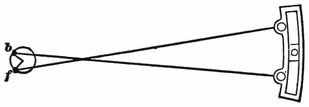
When the engine stands on the back dead center, as shown in Fig. 14, the eccentric centers will be on the other side of the axle, and the eccentric-rods will be crossed. While in mid gear, the link-block is drawn closer to the axle than it would be in any other position of the link; and consequently the lead opening is greatest. If the link be now lowered, the forward eccentric-rod will approach its horizontal position, and consequently reaches farther on the central line of motion, so it will push the link-block away from the axle, thereby decreasing the lead. Pulling the link into back gear has a similar effect.
The tendency of a link-motion to increase the lead245 towards the center is made greater by shortening the eccentric-rods. Increasing the throw of eccentric inclines to accelerate the lead towards the center, since it throws the eccentric centers farther apart. For slow running, hard-pulling locomotives, where increase of lead is a disadvantage, the tendency to increase the lead is sometimes restrained in forward gear by reducing the angular advance of the backing eccentric. This expedient is, however, not necessary where proper care and intelligence have been bestowed in the original design of the motion.
In studying this part of the valve-motion, a young machinist or engineer will obtain valuable assistance by cutting a link template out of a piece of pasteboard, and using strips of wood as eccentric-rods. With these he can test on a drawing-board or table the various positions of the link, and note, in a way that is easily understood, the effect of changing the link into different positions.
Most of intelligent machinists engaged on engine-work, make it an object of ambition to learn to set valves; and the operation is mastered as soon as the opportunity offers. It has been a practice in numerous shops for those who have the work of valve-setting to do, to invest the operation with fictitious mystery, to patiently disseminate the belief that valve-setting is an exceedingly difficult matter. Cases sometimes arise where the squaring of an engine’s valves is really an arduous task, requiring intimate familiarity with delicate methods of adjustment; but valve-setting, as it is usually practiced in building establishments, in repairing-shops, and in round-houses, is merely a matter of plain measurement.
A man may be a first-class engineer without knowing how to set valves, and familiar acquaintance with the operation will not increase his ability in managing his engine when merely getting a train over the road on time is the consideration; but the method of valve-setting is so closely associated with an intelligent appreciation of the valve-motion’s philosophy, that most of247 engineers who take an extended interest in their business, wish to acquire the knowledge of how the valves are set.
The best way to learn valve-setting is by taking part in the work. Whatever can be said in books on a subject of this kind, provides but an indifferent substitute for going through the actual operations. But a man’s ambition to learn may exceed his opportunities; so, for those who can not get a gang boss to direct them into the art of valve-setting, this description will be made as plain as possible.
When an engine’s valve-motion is designed, the sizes of the different parts are arranged; and, if this business is done by a competent engineer, there will only be trifling changes necessary in valve-setting.
Let us suppose the engine to be an ordinary eight-wheel locomotive, with cylinders 17 × 24 inches. Let us assume that the top and bottom rocker-arms are straight, of equal length, and that the eccentric-rods are connected to the link so as to be opposite the block in full gear. This will make the extreme travel of valve equal the eccentric’s throw. We will now look round to see that every thing connected with the motion is ready for valve-setting.
First, it is necessary to see that the wedges are properly set up to hold the driving-boxes in about the same position they will occupy when the engine is at work.
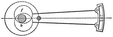
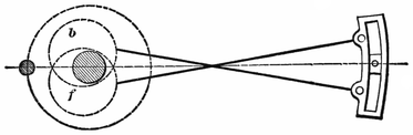
In looking over the motion, it is well to note that the eccentric-rods are properly connected,—the forward eccentric-rod with the top, the backward eccentric-rod with the bottom, of the link. When the crank-pin is on the forward center, the eccentrics will occupy the position they appear in, in Fig. 15, where the rods are open, and nearly horizontal. The full parts of both eccentrics are advanced towards the crank-pin, so that the centers of the eccentrics are advanced from a perpendicular line drawn through center of axle, a horizontal distance equal to the lap and lead. When the crank-pin is on the back center, the eccentric centers will be behind the axle, and the rods will be crossed as they are seen in Fig. 16. The reason why the rods must be crossed when the crank is in this position, is, that the forward eccentric center is below the axle, and the backward eccentric center is above. As the forward eccentric-rod249 maintains its connection with the top of the link, and the backward eccentric-rod is at the opposite end, crossing of the rods is inevitable. This fact is worth imprinting on the memory, for I have known of several cases where men got the rods up wrong by putting them open when the engine stood with the crank on the back center.
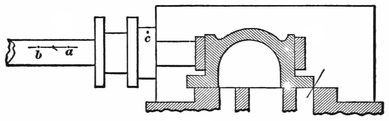
In ordinary practice, valves are set with the steam-chest cover down, and the position of the valve on the seat is identified by marks on the valve-stem. Before the cover is put down, the valve is placed as in Fig. 17, just beginning to open the forward steam-port; a thin piece of tin being generally used to gauge the opening. When the valve stands in this position, a tram is extended from a center punch-mark c, on the stuffing-box, straight along the valve-stem as far as it will reach; and the point, here located at a, is marked. The valve is then moved forward till it begins to uncover the back port, when another measurement is made with the tram, which locates the point b on the valve-stem. Whatever position the valve may stand on, it may now be identified by the tram. When the tram cuts the space250 half way between a and b, the valve stands in the middle of the seat.
Some machinists do not believe in tramming from the stuffing-box, as the point is liable to be moved in tightening down the steam-chest cover. These generally measure from a point on the cylinder casting, but that practice has its drawbacks.
To prove the correct length of the valve-rod, the rocker-arm is set at right angles to the valve-seat, which is its middle position. The valve must now stand on the middle of the seat, which will be indicated by the tram point reaching the dividing point between a and b. Should the valve not be right when the rocker is in its middle position, the rod must be altered to put it right.
Before proceeding to set the valves, a machinist can not be too careful in locating the exact dead centers. Some men conclude, because there is little motion to the cross-head close to the end of the stroke, that a slight movement of the wheel to one side or the other is of little consequence, and makes no perceptible difference in the relative positions of piston and valve. This is a serious mistake; for, although the piston is moving slowly, the eccentric is proceeding at its ordinary speed, and the valve is moving fast. The loose, quick methods of finding dead centers followed occasionally are not conducive to exactness, and nothing but accuracy is permissible in valve-setting.
The best way of finding the true center is by moving the cross-head a measured distance round its extreme travel, recording the extent of movement on the driving-wheel tire, whose motion is uniform; then bisecting the distance between the marks on the tire, when the dividing line will indicate the true center.
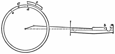
Thus: Turn the wheels forward till the cross-head reaches within one-half inch of its extreme travel, as shown in Fig. 18. From a point a on the guide-block, extend a tram on the cross-head, and mark the extreme point reached b. Put a center punch-mark c on the wheel-cover, or other convenient fixed point, and from it extend a tram on the edge of the tire, and scratch an arc d. Now, with tram in hand, watch the cross-head, and have the wheels moved forward slowly. When the cross-head passes the center, and moves back till the tram extending from a will reach the point b, stop the motion. Again tram from the wheel-cover point, and describe a second arc on the tire, which will be at e, now moved to the position which d occupied when the252 previous measurement was taken. With a pair of dividers bisect the distance between d and e. Mark the dividing point C with a center punch, and put a chalk ring round it. When the wheel stands so that the tram will extend from c to C, the engine will be on the forward dead center.
All the other centers must be found by a similar process.
When a measurement is going to be made for fore gear, the wheels must be turned forward; and, when it is for the back gear, they must be turned backward. Enough movement of the wheel must be given to take up the lost motion every time the direction of movement is changed. In moving an eccentric, it should also be turned far enough in the opposite direction to take up the lost motion.
Put the reverse-lever in the full forward notch, and place the engine on the forward center. If the lead opening in full gear is to be 1/16 inch, advance the forward eccentric till the point a (Fig. 17) on the valve-stem is that distance away from the tram point. Throw the reverse-lever into the full backward notch, turn the wheels forward enough to take up the lost motion, then turn them back to the forward center. Move the backward eccentric (if it needs moving) till the tram, extended on the valve-stem, strikes the same point that it reached for the forward motion. It will be noted here, that the valve occupies the same position for fore and253 back gear when the engine is on the center. Put the reverse-lever in the forward notch again, and turn the wheels ahead till the back center point is reached. Now tram the valve-stem again, and, if the lead opening be the same for both gears as it was on the forward center, that part of the setting is right. It is a good plan to go over the points a second time to prove their correctness. But it is not likely that the lead opening at the back end will be right on the first trial. Instead of having the correct lead, the valve will probably lap over the port, being what workmen call “blind,” or it will have too much lead. Let us assume that our valve is 1/16 inch blind. This indicates that the eccentric-rod is too long. We shorten the rod till the valve is at the opening point, and, on turning the engine to the forward center again, we will find that the valve there has lost its lead. But our change has adjusted the valve movement, so that on each center the valve is just beginning to open the steam-port. Advancing the eccentric to give one end 1/16 inch lead will now have the same effect upon the other end; and, assuming that the back motion has been subjected to similar treatment with a like result, the lead opening on that side is right. This process must now be repeated with the other side of the engine.
The lead openings being properly arranged, we will proceed to examine how the valves cut off the steam; for it is important that about the same supply of steam should be furnished to each cylinder and to each end of the cylinders. The angularity of the connecting rod254 tends to give a greater supply of steam to the forward than to the back end of the cylinder; but this inequality is, as has already been explained, usually rectified by locating the hanger-stud a certain distance back of the link arc.
To prove the cut-off, we will try the full gear first. Put the reverse-lever in the full forward notch, starting from the forward center, and turn the wheels ahead. The motion of our engine has been designed so that the cut-off in full gear shall happen at 18 inches of the stroke. With tram in hand, watch the movement of the valve as indicated by the stem marks. As the piston moves away from the forward end of the cylinder, the valve will keep opening till nearly half stroke is reached, when it will begin to return, slowly at first, but with increasing velocity as the point of cut-off is reached. When the point a, Fig. 17, gets so that it will be reached by the tram extended from c, the motion must be stopped; as that indicates the point of cut-off. Now measure on the guide how far the cross-head has traveled from the beginning of the stroke, and mark it down with chalk. Then turn the wheels in the same direction past the back center, and obtain the cut-off for the forward stroke in the same manner. The cut-off for the other cylinder will be found in precisely the method described.
In addition to trying the cut-off in full gear, it is usually tested at half stroke and at 6 inches, or with the reverse-lever in the notches nearest to these points. Some men begin at the first notch, and follow the point of cut-off in every notch till the center is reached, and do the same for back gear.
From various causes, it often happens that the cut-off is unequal in the two strokes, or one cylinder may be getting more steam than the other. Suppose, that, on one side of the engine, the valve is cutting off at 18½ inches in forward gear, while at the other side it is cutting off at 17½ inches of the stroke. The most ready way to adjust that inequality is by shortening one link-hanger and lengthening the other till a mean is struck. Where the discrepancy is smaller, it is adjusted by lengthening the hanger at the short side.
A harder inequality to adjust is where the valve cuts off earlier for one end of the cylinder than for the other. In new work this is readily overcome by the saddle-stud, but such a change is seldom admissible in old work. When the points of cut-off have been noted down, it will frequently happen, that, instead of both ends cutting off at 18 inches, one end will show the cut at 17 inches, while the other goes to 19 inches. This indicates something wrong, and demands a search for the origin of the unequal motion. First ascertain if the rocker-arm is not sprung. If that is all right, examine the link, which is probably sprung out of its true radius. To straighten the rocker-arm is an easy matter, but not so with case-hardened links; although some men are very successful in springing them back. Where it is impracticable to remedy an unequal cut-off by correcting the origin of the defect, several plans may be resorted to for obtaining the required adjustment. One of the most common resorts is to equalize the forward motion by throwing out the back motion. Putting the rocker-arm away from its vertical position when the valve256 is in the middle of the seat, by shortening or lengthening the valve-rod, provides a means of adjustment. Sometimes the equality of lead opening is sacrificed to obtain equality of cut-off. The changes necessary to obtain adjustment of a distorted motion can only be successfully arranged by one who has experience in valve-setting or in valve-motion designing.
In many shops the cut-off is adjusted for the point where the engine does most of the work,—say at 6 inches. Other master mechanics direct the equalization to be made for half stroke, while some take the mean between the half stroke and the ordinary working notch.
The final adjustments in valve-setting ought to be made when the engine is hot.
Fig. 19 is an outline of a link-motion such as is generally applied to the American locomotive. It can be adjusted to control the movement of the slide-valve in such a manner that equal portions of steam will be admitted alternately at each end of the cylinder.
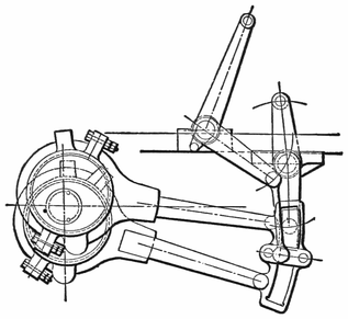
In the following article we propose to explain how this can be accomplished.
Although we would not advise any person to be satisfied258 with approximate rules or constructions, yet cases do occur where the approximate constructions, being so very near correct, on account of their simplicity, are of greater practical value than the application of the rigid and more difficult theoretical rules.
By these remarks, we do not wish the reader to understand that the following constructions are all done according to the rules of thumb—not by any means; for all, with the exception of a few points, are theoretically correct. At the end of this article, we will point out those points which are, and which are not, approximately found; so that the reader may feel satisfied that our construction may always be relied upon as being correct for all practical purposes.
In what follows, the cylinder will always be regarded as lying on the right-hand side of the axle, the link being between cylinder and axle, and the axle located in the center of pedestal.
To avoid any misunderstanding, we will explain the meaning of some of the terms used.
The length of crank is the distance from center of axle to center of crank-pin.
For convenience, we shall call the total distance from center of eccentric-strap to the center of eccentric-pin in the link the length of the eccentric-rod.
The throw of eccentric is double the distance from center of axle to center of eccentric-wheel.
The length of the connecting rod is the distance from the center of crank-pin hole to center of cross-head pin-hole.
The length of link-hanger is the distance from center to center of holes.
Since this article treats only on the adjustment of the link-motion, the following items are supposed to be known and established: The lap of valve, which in this case will be three-fourths of an inch; the throw of eccentrics, 5 inches; the stroke of the piston, 24 inches; the position of the rocker, as per Fig. 19; the length of the rocker-arms, which are in this case of equal length; length of link-hanger and all dimensions of link, complete, as shown in Fig. 19; and also the length of the connecting rod.
The adjustment of the link-motion may at first sight appear to be a difficult problem, as we must have a knowledge of the relative motions of the piston and slide-valve; but by reducing this problem to several elementary problems, so that the laws governing the relative motions may be discovered and clearly defined, a clear conception of our subject can be gained, and the solution of our original problem can be accomplished with comparative ease.
In order to find what kind of elementary problems are applicable, let us suppose that we are looking at a locomotive with a link-motion, as shown in Fig. 19, applied and correctly adjusted. Now let us examine it, commencing with the valve. We find that the valve receives its motion from the upper rocker-arm, and this receives its motion from the lower rocker-arm. According to our conditions, previously stated, both of the rocker-arms are of the same length; and, therefore, the arc described by the upper rocker-arm will be the same length as the arc described by the lower one. We also notice that the link which moves the lower260 rocker-arm is held in position by the lifting-shaft arm. The question, then, will naturally arise, Must this lifting-shaft arm have some particular length, and the center of lifting-shaft have some particular position? We answer, “Yes;” and this is one of our elementary problems to solve. Again, we notice that the saddle-pin is not in the center of the link; and we ask again, “Why?” To answer this will be another elementary problem. The next we notice are our eccentric-rods. These we find, on examination, to have some particular length; and to find this length is another elementary problem. Next we examine our eccentrics: these, we find, are fastened to the axle; and, since the crank is also fastened to the same axle, it follows that there are some relative positions between them; to find these positions is another elementary problem. Now let us look once more at the rocker, and we find that the two rocker-arms are not in the same straight line: hence, to find the amount of offset is another elementary problem. And, lastly, we must be able to find the position of crank-pin to correspond with the position of piston when at full stroke at either end of the cylinder, and also when at half stroke moving in either direction.
Here, then, we have all the elementary problems that are necessary to be understood for the solution of our original problem.
We will now explain all these problems, in an order the reverse to that in which we stated them; hence we have the following order:—
1st, To find position of crank at full and half stroke.
2d, To find center line of motion, and amount of offset in rocker-arms.
3d, To find relative positions of crank-pin and eccentrics261 when at full and half stroke.
4th, To determine the correct length of eccentric-rods.
5th, To find position of saddle-pin.
6th, To find the position of the center of lifting-shaft and length of arms.
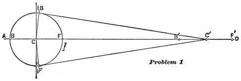
Problem 1, Figs. 20 and 21.—To find the position of crank when the piston is at full and half stroke.—Let the center of wheel and the axis of the cylinder be in the same straight line as AD, Fig. 20. With any point C as a center, and a radius equal to the length of the crank, describe a circle F, ½F, B, ½B; and let us call this the crank-pin circle. The straight line AD intersects the circumference of the circle in the points F and B. The point F will be the center of crank-pin when piston is at full stroke at the forward end of the cylinder, and point B will be the center of crank-pin when the piston is at full stroke at the rear end of the cylinder. With the point F as a center, and with a radius equal to the length of the connecting rod, describe an arc intersecting the line AD in the point262 F′; with the point B as a center, and with the same radius, describe an arc intersecting the straight line AD in the point B′; and with the point C as a center, and with the same radius, describe an arc intersecting the straight line AD in the point C′. Point F′ will be the center of cross-head pin when the center of crank-pin is at F, and B′ the center of cross-head pin when the crank-pin is at B, and the point C′ will be the position of center of cross-head pin when piston is at half stroke. With point C′ as a center, and a radius equal to the length of the connecting rod, describe an arc passing through the point C, and intersecting the crank-pin circle in the points ½F and ½B: these points will be the position of crank-pin when the piston is at half stroke, or when the center of cross-head pin is at C′.
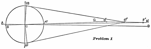
It often happens that the axis of the cylinder is above the center of axle. When such is the case, we must follow the construction as shown in Fig. 21. Let two inches be the distance that the center of axis of cylinder is above the center of axle.
Draw a straight line AD through the center of axle C; two inches above this draw a straight line GH263 parallel to AD; this line will then pass through the axis of cylinder. With the center of axle C on the straight line AD as a center, and a radius equal to the length of the crank, describe a circle F, ½ F, B, ½ B: this circle will be the crank-pin circle. With the point C as a center, and a radius equal to the length of the connecting rod plus the length of the crank, describe an arc intersecting the straight line GH in the point F′: this point will be the position of the cross-head pin when the piston is at full stroke forward. Through the points F′ and C draw a straight line, intersecting the crank-pin circle in the point F: this point will be the position of the center of the crank-pin when the piston is at full stroke forward. Again, with the point C as a center, and a radius equal to the length of the connecting rod minus the length of the crank, describe an arc intersecting the straight line GH in the point B′: this point will be the position of the center of the cross-head pin when the piston is at full stroke in the rear end of the cylinder. Through the points B and C draw a straight line, intersecting the crank-pin circle in the point B: this point will be the position of the center of crank-pin when the piston is at full stroke in the rear end of the cylinder. Find a point C′ exactly central between the points B′ and F′ on the line GH: in other words, bisect the distance B′ F′ by the point C′. With the point C′ as a center, and a radius equal to the length of the connecting rod, describe an arc intersecting the crank-pin circle in the points ½B and ½F: these two points will be the center of crank-pin when the piston stands at half stroke. In the link-motion, as shown in Fig. 19, the axis of the cylinder is264 supposed to be 2 inches higher than the center of axle. For this reason the construction shown in Fig. 21 will hereafter be used.
Problem 2, Fig. 22.—To find the center line of motion and the amount of offset in the lower rocker-arm.—Let C be the center of axle: through C draw the straight lines AD and KL perpendicular to AD. The center of rocker we find in Fig. 19 to be 37½ inches in front of the center of axle, and 7½ inches above. We therefore continue our construction in Fig. 22 by drawing a straight line MN 37½ inches in front of, and parallel to, the straight line KL, and another straight line OP parallel to AD, and 7½ inches above it. These two lines intersect in the point Q, and this point is the center of rocker. With Q as a center, and a radius equal to the length of the lower rocker-arm, describe the arc RS: through the point C draw a straight line CT tangent to the arc RS, then CT will be the center line of motion.
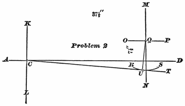
To find the amount of offset in the lower rocker-arm, let us place the center line of the upper rocker-arm265 perpendicular to a line drawn parallel to the valve surface: but in our case this valve surface is parallel to the line AD; hence our line drawn parallel to the valve surface will also be parallel to the line AD, and the center line of upper rocker-arm will be perpendicular to AD, and coincide with the line MN. Through the point Q draw a straight line perpendicular to the line CT, and intersecting the arc RS in the point U: then the distance from the point U to the line MN will be the amount of the offset in the lower rocker-arm.
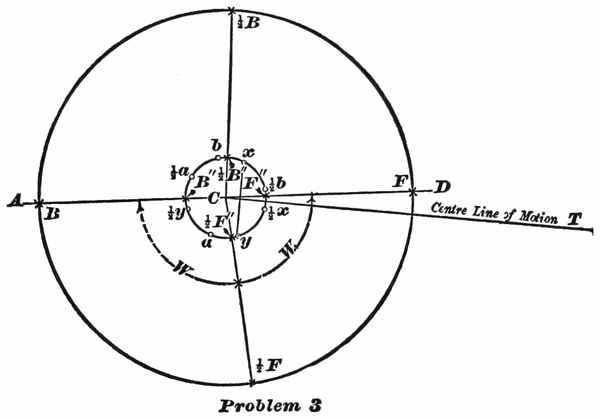
Problem 3, Fig. 23.—To find the relative positions of crank-pin and eccentrics when the piston is at full and half stroke.—Let C be the center of axle. Through C draw the horizontal line AD, and find the positions of center of crank-pin at full and half stroke; namely, the points F, ½F, ½B, B, as explained in Problem 1, and shown in266 Fig. 21. Next draw the center line of motion as explained in Problem 2 and Fig. 22. With the point C as a center, and a radius equal to ½ the throw of the eccentric (2½ inches), draw a circle; and let us call this circle the “eccentric-circle.” On the line of motion CT, lay off a point towards the rocker 13/16 of an inch from C (this being the sum of the lap and lead,—¾ of an inch for the lap, and 1/16 of an inch for the lead): through this point draw a straight line perpendicular to the line of motion CT, and intersecting the eccentric-circle in the points x and y. The point x will be the center of the forward eccentric; and the point y will be the center of backward eccentric when the center of crank-pin is at F, full stroke forward. Through the points F and C draw a straight line, intersecting the eccentric-circle in the point F″. The line FC will represent the center line of crank; and the distance between the points F″ and x, measured on the eccentric-circle, is the amount that the center of forward eccentric is set back of the center line of crank; and the distance between the points F″ and y is the amount that the backward eccentric is set ahead of the center line of crank. Since both the crank and eccentrics are fastened to the same axle, it follows, that, whatever position the center line of crank may be in, the distances between center line of crank and eccentrics—that is, the distances between F″ and x, also F″ and y, measured on the eccentric-circle—remain constant. Therefore, to find the position of eccentrics when the crank stands at ½F (half stroke), draw the straight line ½FC representing the center line of crank, and intersecting the eccentric-circle in the point ½F″. From the point ½F″, lay267 off on the eccentric-circle a point with a distance equal to F″x, back of the center line of crank, and indicate this point by ½x; also from ½F″ measured on the same circle, lay off a point in the front of the center line of crank, and with a distance equal to F″y, and mark this point ½y; then the point ½x will be the position of forward eccentric, and the point ½y will be the position of backward eccentric when the crank-pin is at ½F. In precisely the same manner we find the position of eccentrics when the center of crank-pin is at B (full stroke back). Through the points C and B draw a straight line, intersecting the eccentric-circle in the point B″. From the point B″, and with a distance equal to F″x, lay off a point on the eccentric-circle back of crank; this point will be the position of forward eccentric when crank is at full stroke back; and, in order to distinguish this from the other position of eccentric, call this point a: also from B″, lay off in front of the crank the position of backward eccentric at a distance equal to F″y, and call this point b. In the same manner find points ½a and ½b when the crank-pin is at ½B. We have now found the position of eccentrics when the crank-pin stands in the following positions:—
Full stroke forward F, the forward eccentric will be at x.
Half stroke forward ½F, the forward eccentric will be at ½x.
Full stroke back end B, the forward eccentric will be at a.
Half stroke back end ½B, the forward eccentric will be at ½a.
Full Stroke forward F, the backward eccentric will be268 at y.
Half stroke forward ½F, the backward eccentric will be at ½y.
Full stroke back end B, the backward eccentric will be at b.
Half stroke back end ½B, the backward eccentric will be at ½b.
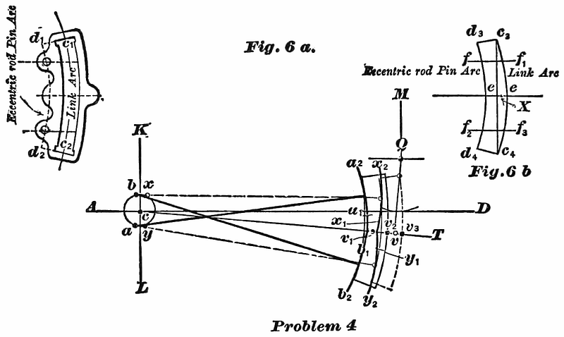
Problem 4, Fig. 24.—To determine the correct length of the eccentric-rods.—Let c be the center of axle. Through this point draw the horizontal line AD, also a line KL perpendicular to AD. The only purpose for which these two lines are drawn in this problem, as well as the others, is to have some lines from which we can locate other lines or points. Locate the center of rocker, and center lines of rocker-arms, as explained in Problem 2, and shown in Fig. 22; the lower arm standing perpendicular to the center line of motion,269 and the upper arm vertical. When the arms stand in this position, the rocker-pins will move through an equal distance on each side of these center lines during the time that the valve is making its full travel.
Next find centers of eccentrics x and y when the crank is at full stroke forward; also a and b when the crank is at full stroke back, as explained in Problem 3, and shown in Fig. 23. Before we proceed, let us give names to some of the lines, as shown in Fig. 6a (p. 268). The arc c1c2 drawn through the center of opening of the link, we will call the link-arc; and the arc d1d2 drawn through the center of eccentric-rod pin-holes, we will call the eccentric-rod pin-arc. Both of these arcs are drawn from the same center; that is, the center from which the link is drawn. Let us now cut a paper template, as shown in Fig. 6b (link structure). This template is cut so that, if it is laid on the link, Fig. 6a, the arc of the template c3c4 will coincide with the link-arc c1c2, and d3d4 with the eccentric-pin arc d1d2, the end of template d3c3 with the line d1c1, and the end d4c4 with d2c2. On this template join the points c3c4 by a straight line, and bisect this line by the perpendicular line ee: on this line the center of the saddle-pin will be located. On one side of this line draw the line ff1 parallel to ee, and on the other side draw f2f3 also parallel to ee; the distance from the point f to the point f2 being equal to the distance between the centers of eccentric-rod pins, and fe equal to ef2. The points f and f2 on the arc d3d4 indicate the position on the template of the centers of eccentric-rod pins. On the center line of motion cT, lay off from v a point v1 270towards the axle, with a distance equal to c1d1, Fig. 6a; then with the point x as a center, and cv1 as a radius, describe the arc x1x2; in this arc the upper eccentric-rod will be located as long as the center of forward eccentric remains at x. With the point y as a center, and cv1 as a radius, describe the arc y1y2: in this arc the center of lower eccentric-rod will be located as long as the backward eccentric remains at y. With the point a as a center, and cv1 as a radius, describe an arc a1a2: in this arc the upper eccentric-rod pin will be located while the forward eccentric is at a. With the point b as a center, and cv1 as a radius, describe the arc b1b2; and in this arc the center of lower eccentric-rod pin will be located when the backward eccentric is at b. Now adjust the template on the drawing so that the point f will be in the arc x1x2: point f2 in the arc y1y2 and the line ee coincide with the center line of motion cT. Along the arc c3c4 of the template draw an arc on the paper. Next move the template so that the point f will be in the arc a1a2, the point f2 in the arc b1b2, and the line ee coincide with the center line of motion cT, and along the arc c3c4 of the template draw the second arc on the paper. Now, if the distance measured on the arc RS from the point v (the center of the lower rocker-arm pin) to the first arc drawn, is equal to the distance measured on the arc RS from v to the second arc, the radius cv1 will be the correct length of the eccentric-rods. But, if the distance from v to the first arc is less than the distance from v to the second arc, the length cv1 of the eccentric-rod will be too short. In this case we must increase the length cv1 by adding an amount equal to one-half the difference of the distances from v to the first arc, and from v to271 the second arc previously drawn; and this last length so found will be the correct length of eccentric-rods.
It will be proper to remark here, that the radius cv1 was assumed to be the correct length of eccentric-rods; but since the rods cross each other when the eccentrics are at a and b, and do not cross each other when at x and y, the radius cv1 will always be a trifle short. It is therefore necessary to make the correction as explained.
In every case, the length of eccentric-rods must be so adjusted, that, when the line ee coincides with the center line of motion cT, the arc vv2 (which is the amount that the rocker-pin is drawn towards the axle from the line Qv when the eccentrics are at a and b) must be equal to the arc vv3 (which is the amount that the rocker-pin is moved towards the cylinders from the line Qv when the eccentrics are at x and y); the straight line Qv being perpendicular to the center line of motion cT.
Problem 5, Fig. 25.—To find the position of the center of saddle-pin.—For this problem we again call to our aid the paper template shown in Fig. 6b. We have already seen in Problem 4 that the center of saddle-pin will be located on the line ee drawn on this template: it now only remains to determine the distance of this point from the link-arc c3c4.
Since the inequality between the crank-angle W and W1, Fig. 23, becomes the greatest when the crank stands at half stroke, it is of the utmost importance to find such a position for the center of saddle-pin that equal portions of steam will be admitted alternately when the crank stands at half stroke. Or, in other words, the272 admittance of steam must cease at the moment that the piston has completed one-half stroke.
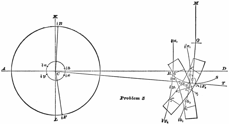
Let us commence this problem as we began the others;273 namely, Through the center of axle C, Fig. 25, draw the horizontal line AD, also the vertical line LK. Find the position of crank at half stroke, as shown in Fig. 21. Next find the position of center line of motion CT, and position of rocker, as shown in Fig. 22. Find the relative position of eccentrics and crank when at half stroke, as shown in Fig. 23. Now, with a radius equal to the correct length of eccentric-rods, previously determined (shown in Fig. 24), describe from the point ½x as a center, the arc ½x1 ½x2; also with the point ½y as a center, and with the same radius, the arc ½y1 ½y2. Again, from the point ½a as a center, describe the arc ½a1 ½a2; also with the point ½b as a center, describe the arc ½b1 ½b2, using the length of eccentric-rods as a radius for all the arcs.
When the center of the forward eccentric is at ½x, the forward eccentric-rod pin will be located in the arc ½x1 ½x2. When the center of the forward eccentric is at ½a, the forward eccentric-rod pin will be located in the arc ½a1 ½a2. When the backward eccentric is at ½y, its eccentric-rod pin will be located in the arc ½y1 ½y2. When the center of the backward eccentric is at ½b, the eccentric-rod pin will be located in the arc ½b1 ½b2.
The next step is to find the relative position of the lower rocker-arm pin when steam is cut off at half stroke.
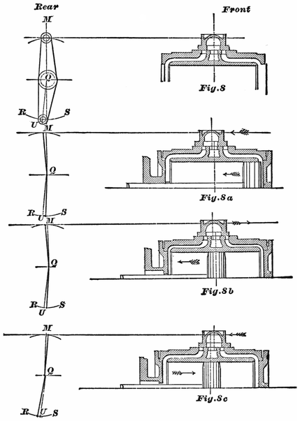
In Fig. 8 (p. 274) we have placed the slide-valve centrally over the ports, that is, it laps over each steam-port an equal amount, namely, ¾ of an inch, which is equal to the lap. In this position of the valve, the center line of the upper rocker-arm will stand perpendicular to the line drawn parallel to the valve-face, and the center line of the lower rocker-arm will stand perpendicular to the center line of motion CT: hence the center line of upper rocker-arm MQ in Fig. 8 will coincide275 with the line MQ in Fig. 25, and the center of lower arm QU in Fig. 8 will coincide with the line QU in Fig. 25.
Now let us follow the relative movement of the valve and piston. We find, that, when the piston commences its backward motion, the valve moves in the same direction, as shown by the arrow-points in Fig. 8a; and, during the time that the piston is completing the half stroke, the valve has finished its full travel backward, and commenced moving forward, as indicated by the arrow-points, Fig. 8b; and, at the time that the piston stands exactly at half stroke, the forward edge of the valve is just closing the forward steam-port, and consequently cutting off steam at half stroke when the piston is moving backward. From this we see, that, when the piston has completed the half stroke when moving backward, the center of the valve will be a little in the rear of the center of exhaust-port; the distance between the center of valve and the center of exhaust-port being ¾ of an inch, the amount of the lap: the upper rocker-pin will stand ¾ of an inch behind the line MQ, and the lower rocker-arm pin will be ¾ of an inch in front of the line QU, as shown in Fig. 8b. We therefore draw in Fig. 25 a straight line parallel to QU, and ¾ of an inch in front of it: this line will intersect the arc RS in the point ½F3; and this point is the position of the center of lower rocker-arm pin when the crank stands at ½F, and steam cut off at half stroke. Let the piston complete its backward stroke, and then commence moving forward towards half stroke, as shown by the arrow-point, Fig. 8c. During this time the valve has completed its full travel forward, and commenced traveling backward, as276 indicated by the arrow-point, Fig. 8c; and, when the piston stands exactly at half stroke, the rear edge of the valve is just closing the rear steam-port, and consequently cutting off steam at half stroke when the piston is moving forward. In this position the center line of the valve will be ¾ of an inch in front of the center of exhaust, the center of the upper rocker-arm pin will be ¾ of an inch in front of the line MQ, and lower rocker-pin ¾ of an inch in the rear of the line QU, as shown in Fig. 8c. We therefore draw in Fig. 25 a line parallel to QU, and ¾ of an inch behind it; this line will intersect the arc RS in the point ½B3; and this point will be the position of the center of lower rocker-arm pin when the crank stands at ½B, and steam cut off at half stroke. Now, remember, that when the crank stands at ½F, Fig. 25, the forward eccentric will be ½x, and the backward eccentric at ½y; and, if the link is raised or lowered while the eccentrics remain at ½x and ½y, the forward eccentric-rod pin will move in the arc ½x1 ½x2, and the backward eccentric-rod pin will move in the arc ½y1 ½y2.
Let us now find the position of link when steam is cut off at half stroke at either end of the cylinder.
The points ½F3 and ½B3 in Fig. 25 being located, place the paper template on the drawing so that the point f will lie in the arc x1x2, and the point f2 in the arc y1y2, and the link-arc c3c4 just touching the point ½F3. While the template is in this position, draw on the paper along the edge c3c4 a portion of the link-arc, and mark the position that the line ee occupied, so that, when the template is removed, the line e1e1 can be drawn on the paper to represent the line ee of the template. Next place277 the template so that the point f will lie in the arc ½a1 ½a2 the point f2 in the arc ½b1 ½b2 and the link-arc c3c4 just touching the point ½B3 and, while in this position, draw part of the link-arc c3c4 on the paper, mark the position that the line ee occupied, and, after the template is removed, draw the line e2e2 on the paper to represent the line ee of the template. Now find by trial a point x1 on the line c1c1, and another point x2 on the line e2e2, so that the distances of these points from their link-arcs are equal, and that a straight line drawn through them will be parallel to the center line of motion.
The distance from x1 to the link-arc—or, which is the same thing, the distance from the point x2 to the link-arc—will be the correct distance between the center of saddle-pin and the link-arc c1c2, Fig. 6a. Or, in other words, the position of the point x1 or x2, Fig. 25, will indicate the proper position of the point of suspension on the link. For future reference, let us mark this point of suspension on the template, and indicate it by X, Fig. 6b.
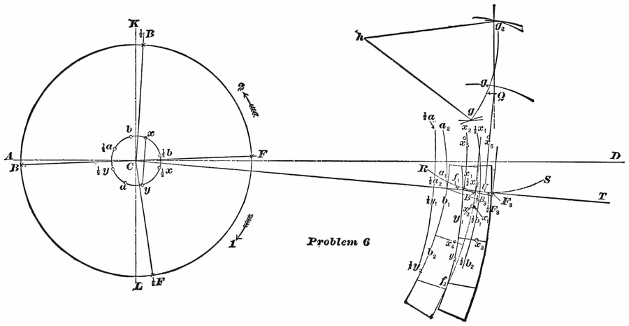
Problem 6, Fig. 26.—To find the position of the center of lifting-shaft and the length of its arms.—In the last problem we found the point of suspension of the link, so that it will cause the valve to cut off equal portions of steam when the piston stands at half stroke. It now remains for us to find the position of the lifting-shaft and the length of the lifting-shaft arms, so that the greatest equal amounts of steam will be admitted alternately at each end of the cylinder. Here a little difficulty arises which needs explanation, so that our construction may not seem inconsistent to the279 reader. It would be an easy matter to place our lifting-shaft to accomplish the object just stated; but, if we do this, the lead will not be equal at each end of cylinder when the piston is at full stroke. Again, if we locate our lifting-shaft in such a manner that equal lead will be obtained, then the maximum cut-off will not be equal; but the difference will be comparatively so small that it will not injure the working of the engine. This small difference of the maximum cut-off is therefore considered among practical men of little or no importance, but it is always considered good practice to have an equal lead at full stroke. Let us therefore adjust the lifting-shaft to obtain an equal lead, and allow us to consider the maximum cut-off to be equal when the lead is equal at full stroke.
For this problem we have to combine all the foregoing problems. Through the center C of axle draw the horizontal line AD, and the line KL perpendicular to it. Find the positions of crank at full and half stroke, as per Problem 1. Locate the rocker, draw the center line of motion CT, and amount of offset in lower rocker-arm, according to Problem 2. Next, locate the relative positions of eccentrics when the crank stands at full and half stroke, as explained in Problem 3. Then with a radius equal to the correct length of eccentric-rods, as explained in Problem 4, draw
Locate the points ½B3 and ½F3, indicating the position of the center of lower rocker-pin when steam is cut off at half stroke; find the points x1x2 indicating the positions of the point of suspension when the link is lifted into the position to cut off at half stroke, as explained in Problem 5, and shown in Fig. 25.
Now, in order to find the position of lifting-shaft and length of arms, we must find four more additional points,—first, the position of the point of suspension of the link when the piston is at full stroke forward end of cylinder, and the crank-pin at F, the valve having 1/16 of an inch lead, and the engine moving forward, as indicated by the arrow-point 1; also the position of the point of suspension of the link when the piston is at full stroke at the opposite end of the cylinder, valve 1/16 inch lead, and engine going in the same direction. To find these two points, we must know the corresponding position of the center of lower rocker-pin. In Fig. 8a we see, that when the piston is at full stroke forward, and valve with 1/16 inch lead, the center of valve is 13/16 of an inch in the rear of the center line of exhaust, and consequently the lower rocker-pin will be 13/16 of an inch in front of the line QU. In the same manner we can show that the center of lower rocker-pin will be 13/16 of an inch in the rear of the line QU when the piston is at the opposite end of the cylinder.
Let us now locate the positions of the lower rocker-pin in Fig. 26, by drawing a line parallel to and in front281 of QU, with 13/16 of an inch between them: this line will intersect the arc RS in the point F3, and this point will be the center of lower rocker-pin when the piston is at full stroke forward. Draw another line 13/16 of an inch in the rear of QU and parallel to it: this line will intersect arc RS in the point B3, and this point will be the center of rocker-pin when the piston is at full stroke in the rear end of the cylinder. Now place the paper template with the line ee below the center line of motion CT, the point f1 on the arc x1x2, the point f2 on the arc y1y2, and the link-arc c3c4 just touching the point F3, and, while in this position, mark the point X of the template on the paper, which can be done with the aid of a needle, and indicate the point on the paper by x3. This point will be the position of the center of saddle-pin when the piston is at full stroke in the forward end of the cylinder, the valve having 1/16 inch lead. Again, slide the template along until the point f1 is on the arc a1a2, the point f2 on the arc b1b2, and the link-arc c3c4 in contact with the point B3; mark the point X of the template on the paper, and indicate this point by x4. This point will be the position of the center of saddle-pin when the piston is at full stroke in the rear end of the cylinder, the valve having 1/16 inch lead. Secondly, to find the position of the point of suspension of the link when the piston is at full stroke in the forward end of the cylinder, valve having 1/16 of an inch lead, and the engine moving backward, as indicated by the arrow-point 2; also the position of the point of suspension of the link when the piston is at full stroke at the opposite end of the cylinder, valve 1/16 of an inch lead, engine going in the same direction. For this purpose, slide the template along282 until the line ee is above the line CT, and f1 in the arc a1a2, the point f2 in the arc b1b2, and the link-arc c3c4 in contact with the point B3; mark the point X on the paper, and indicate this point by x5. This point will be the position of the center of saddle-pin when the piston is at full stroke in the rear end of the cylinder, valve having 1/16 of an inch lead. Again, slide the template along until the point f1, will be in the arc x1x2, point f2 in the arc y1y2, and the link-arc c3c4 in contact with the point F3; mark the point X on the paper, and indicate this point by x6. This point will be the position of the center of saddle-pin (or the point of suspension) when the piston is at full stroke in the forward end of the cylinder, valve 1/16 of an inch lead, engine moving backward. Now, once more, with the point x3 as a center, and with the length of the link-hanger as a radius, describe an arc; and with the point x4 as a center, and the same radius, describe another arc. These two arcs will intersect each other in the point g. Again, with the length of the link-hanger as a radius, and the points x1x2 as centers, describe two arcs intersecting each other in the point g1, with the points x5x6 as centers; and, with the same radius, describe another two arcs intersecting each other in the point g2. Lastly, through the points g, g1g2, draw an arc. The center h, from which the arc has been described, will be the center of the lifting-shaft, and the radius hg or hg2 will be the length of the lifting-shaft arms; that is, the length of the two arms to which the link-hangers are attached: the length of the other lifting-shaft arm, to which the reach-rod is attached, is made to suit the other details of the engine.
When the admittance of steam ceases at the same283 time that the piston has reached the half stroke, the practical man would say “that the valve is cutting off equal at half stroke.” When the greatest equal volume of steam is admitted alternately in each end of the cylinder, the valve is said to be cutting off equal when the link is in full gear.
It is always conceded among engineers, that when the link-motion is adjusted to cut off equal at half stroke, and also to cut off equal when the link is in full gear, equal volumes of steam will be admitted alternately when the link hangs at any intermediate point.
If, now, we examine Problem 5, we find, that, to obtain an equal cut-off at half stroke, it is necessary to find the proper position of saddle-pin.
Again, if we examine Problem 6, we find, that, in order to obtain an equal cut-off when the link is in full gear, also an equal cut-off for any point between full gear and half stroke, we have to determine the proper position of the center of lifting-shaft and the correct length of its arms.
Lastly, if we examine the first four problems, we find them simply to be preparatory problems.
According to promise, we will draw attention to those points which have been, and others which have not been, approximately found. Problems 1, 2, and 3 are theoretically correct. In Problems 4, 5, and 6, the use of the template will not be admitted for theoretical reasoning; but, if the construction is made with absolute accuracy, the result will be theoretically correct.
The following are a few dimensions of locomotives made by well-known makers:—
| Baldwin. | Brooks. | |||||
| Standard Passenger Engine. | Mogul Engine. | Consolidation Engine. | Standard Passenger Engine. | Mogul Engine. | Consolidation Engine. | |
| Inches. | Inches. | Inches. | Inches. | Inches. | Inches | |
| Dimensions of cylinders | 17 × 24 | 18 × 24 | 20 × 24 | 18 × 24 | 18 × 24 | 20 × 24 |
| Length of steam-ports | 16 | 16 | 16 | 16 | 15 | 16 |
| Width of steam-ports | 1¼ | 1¼ | 1¼ | 1⅛ | 1⅛ | 1¼ |
| Width of exhaust-port | 2½ | 2½ | 2½ | 2½ | 2½ | 2½ |
| Throw of eccentrics | 5 | 5 | 5 | 5 | 4½ | 5 |
| Travel of valve | 5⅜ | 5⅜ | 5⅜ | 5 | 5 | 5½ |
| Outside lap of valve | ¾ to ⅞ | ¾ | ¾ | ¾ | ⅜ | 13/16 |
| Inside lap of valve | 1/32 to ⅛ | 1/32 | 1/32 | 1/64 | 1/64 | 1/64 |
| Distance between center of axle and center of rocker | 56 | 46 | 81 | 65 | 50 | 40 |
| Length of upper rocker-arm, | 10½ | 10½ | 10½ | 10½ | 9¾ | 10½ |
| Length of lower rocker-arm, | 9½ | 9½ | 9½ | 10½ | 8¾ | 9½ |
| Length of link | 55 | 46 | 81 | 65 | 50 | 40 |
| Length of link-hanger | 13½ | 15 | 15 | 13 | 13½ | 15¼ |
| Length of tumbling-shaft arm | 17 | 16 | 16 | 17⅜ | 18 | 16 |
| Length of connecting rod | 75 | 80 | 114½ | 96 | 84 | 77 |
| Distance between centers of eccentric-rod pins | 11-9/16 | 10½ | 10¾ | 11 | 11-3/16 | 11 |
| Suspension of link back of link-center | ⅜ | 11/16 | 1 | ⅜ | ⅜ | ⅜ |
| Lead of valve in full gear | 1/16 | 1/16 | 1/16 | 1/10 | 1/10 | 1/10 |
| Lead of valve in center | ¼ | 1¼ | ¼ | ⅜ | ⅜ | ⅜ |
DIMENSIONS OF LOCOMOTIVES—Continued.285
| Grant. | Pittsburg. | |||||
| Standard Passenger Engine. | Mogul Engine. | Consolidation Engine. | Standard Passenger Engine. | Mogul Engine. | Consolidation Engine. | |
| Inches. | Inches. | Inches. | Inches. | Inches. | Inches | |
| Dimensions of cylinders | 17 × 24 | 18 × 24 | 20 × 24 | 17 × 24 | 18 × 24 | 20 × 24 |
| Length of steam-ports | 16 | 16 | 16 | 15 | 16 | 18 |
| Width of steam-ports | 1¼ | 1¼ | 1¼ | 1¼ | 1¼ | 1¼ |
| Width of exhaust-port | 2½ | 2½ | 2½ | 2½ | 2½ | 2½ |
| Throw of eccentrics | 5 | 5 | 5½ | 5 | 5 | 5 |
| Travel of valve | 5 | 5¼ | 5 | 5 | 15½ | 5-7/16 |
| Outside lap of valve | ¾ | ⅞ | ⅞ | ⅞ | ¾ | ¾ |
| Inside lap of valve | None. | 1/16 | 1/16 | ⅛ | 1/32 | 1/32 |
| Distance between center of axle and center of rocker | 68-11/16 | 40 | 80 | 56 | 48 | 28 |
| Length of upper rocker-arm, | 10¼ | 9⅞ | 9⅞ | 11 | 11¾ | 11¾ |
| Length of lower rocker-arm, | 10¼ | 8½ | 10½ | 11 | 10¾ | 10¾ |
| Radius of link | 63 | 39⅜ | 80 | 56 | 48 | 80 |
| Length of link-hanger | 12¾ | 14 | 12¾ | 14½ | 18¾ | 18½ |
| Length of tumbling-shaft arm | 17 | 16 | 14 | 18 | 15 | 15 |
| Length of connecting rod | 85 | 69½ | 112 | 88 | 85 | 114½ |
| Distance between centers of eccentric-rod pins | 12 | 12 | 12 | 12 | 12 | 12 |
| Suspension of link back of link-center | ⅜ | ⅜ | 1-3/16 | ⅜ | ⅜ | 9/16 |
| Lead of valve in full gear | 1/32 | 1/32 | 1/32 | 1/10 | 1/10 | 1/10 |
| Lead of valve in center | 5/16 | ⅜ | ¼ | 5/16 | 11/32 | ¼ |
DIMENSIONS OF LOCOMOTIVES—concluded.286
| Schenectady. | Mason. | |||||
| Standard Passenger Engine. | Mogul Engine. | Consolidation Engine. | Standard Passenger Engine. | Mogul Engine. | ||
| Inches. | Inches. | Inches. | Inches. | Inches. | ||
| Dimensions of cylinders | 17 × 24 | 19 × 24 | 20 × 24 | 18 × 24 | 19 × 24 | |
| Length of steam-ports | 16 | 16 | 16 | 17 | 18 | |
| Width of steam-ports | 1¼ | 1¼ | 1¼ | 1¼ | 1¼ | |
| Width of exhaust-port | 2½ | 2¾ | 2¾ | 2½ | 2½ | |
| Throw of eccentrics | 5¼ | 5¼ | 5¼ | 5 | 5 | |
| Travel of valve | 5½ | 5½ | 5½ | 5 | 5 | |
| Outside lap of valve | ⅞ | ¾ | ¾ | ¾ | ¾ | |
| Inside lap of valve | 1/32 | 1/32 | 1/32 | 1/64 | 1/32 | |
| Distance between center of axle and center of rocker | 63 | 54 | 45 | 38 | 49½ | |
| Length of upper rocker-arm, | 11 | 10¾ | 11 | 9 | 9 | |
| Length of lower rocker-arm, | 10 | 9¾ | 10 | 9 | 9 | |
| Radius of link | 63 | 54 | 45 | 58 | 49½ | |
| Length of link-hanger | 13 | 16½ | 16½ | 10 | 10 | |
| Length of tumbling-shaft arm | 16 | 16 | 16 | 20 | 20 | |
| Length of connecting rod | 92½ | 90½ | 79½ | 91-3/16 | 84 | |
| Distance between centers of eccentric-rod pins | 12 | 12 | 12 | 12 | 12 | |
| Suspension of link back of | above | |||||
| link-center | ⅞ | ⅞ | ⅜ | 3⅜ | 3⅜ | |
| Lead of valve in full gear | 1/16 | 1/16 | 1/16 | 1/16 | 1/16 | |
| Lead of valve in center | 5/16 | 5/16 | 5/16 | 5/16 | 5/16 | |
This motion has been designed by A. J. Stevens, General Master Mechanic, Central Pacific Railroad, to overcome the well-known objections to the link-motion,—viz., letting the steam escape early in the stroke when the engine is running hooked up; also, the closing of the exhaust-port early, leading to excessive compression. The motion is developed from the Walschaert motion, well known in Europe, and applied to some extent to narrow-gauge engines in this country.
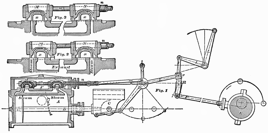
In the Stevens motion two valves are employed, one at each end of the cylinder, as can be seen in Fig. 27. The valves have supplementary passages for steam and exhaust, being an improvement on the Allen valve. Valves without the supplementary exhaust-port have been designed by Mr. Stevens for his engines, and they are shown in two positions in the supplementary figures 2 and 3 [p. 288]. These valves closely resemble the Allen valve; but, in operating, steam is admitted to, and exhausted from, the cylinder through the same passage. This arrangement provides double area of admission289 and double area for exhaust steam,—an important consideration, especially with high piston speed.
The valves are actuated by two motions,—one taken from a single eccentric, the other derived from a connection with the cross-head. The single eccentric is used to give both forward and backward motion, and is set in the proper angle to the crank to produce motion in either direction. For reversing the motion of the valve, a curved rocker-arm R (Fig. 27) is used, on which moves a sliding-block r. Attached to the sliding-block is the link H, which connects with the lap-and-lead lever D. The lower end of this lever is attached by the link d to the cross-head, from which the lever receives an oscillating motion. This lever is suspended by a hanger from any convenient part of the engine. Projecting from one side of the lap-and-lead lever are two pins, to which are connected the valve-stem rods m and n. These pins are set upon the lever at points between 90 and 180 degrees apart, so as to give a differential movement to the valve, which can not be obtained when the pins are set opposite on the lever.
Each valve has its own rod, and separate connection with the lever. In most instances the stem of the back valve is made hollow, and the stem of the forward valve is passed through it, so as to avoid the use of more than one stuffing-box upon the steam-chest; but in several instances they have been fitted up with two stuffing-boxes, the separate valve-stems working side by side.
The valve being coupled up by independent rods to the lap-and-lead lever, they will move together, and in the same general direction, from the action of the eccentric. But besides this movement, common to both, each valve is controlled and acted on by the angular position of the two pins, which results from the rotary or oscillating movement of the lap-and-lead lever upon its center; and each valve, instead of having a uniform rate of travel, has a variable movement. The degree of this variable movement is governed, both by the distance of the pins from the center upon which the lever works and the length of the lever, and can be increased or diminished by changing the position of one or the length of the other in construction. The horizontal movement of the valve received from the lap-and-lead lever while the same is at mid travel, is very slight, while the piston or the cross-head is traveling very rapidly. By this slow movement of the valve, steam is retained in the cylinder until the piston has nearly completed its stroke; and, on the other hand, the exhaust is kept open. As the cross-head approaches either end of the stroke, the action of the valves is very much accelerated, receiving, as they do, their motion from the combined action of the lap-and-lead lever and the eccentric.
The exhaust lead is controlled by the pin in the lap-and-lead lever, which is on the center, or horizontal, when the cross-head is at either end of the cylinder. The steam lead is controlled by the pin that is vertical, or above the center of the lap-and-lead lever, when291 the cross-head is at either end of the stroke. Both steam and exhaust lead are uniform at all points of cut-off. By this arrangement of the valve-gear and valves, steam can be cut off at any point of the stroke (by moving the sliding-block toward the center of the rocker-arm), and is retained, if desired, to the last inch of the stroke. In receiving, the steam is evenly distributed at all points of the cut-off.
There are about as many pieces to this gearing as to the ordinary link-gear; but it is considerably cheaper in construction, and much more durable; while it does away with two eccentrics, and their straps and connections.
In this form of valve-gear, eccentrics and their equivalents are entirely dispensed with. The motion for the valve is taken direct from the connecting rod; and by utilizing independently the backward and forward action of the rod, due to the reciprocation of the piston, and combining this with the vibrating action of the rod up and down, a movement results which is employed to actuate the valves of engines using any combination of lap and lead desired, and giving an almost mathematically correct cut-off for both sides of the piston for forward and backward motion, and for all points of expansion intermediately. The general outline of the motion can be understood by an examination of Fig. 28, which gives three views of the gear. The sub-figures 1, 2, and 3 show the motion in elevation, plan, and transverse section respectively.
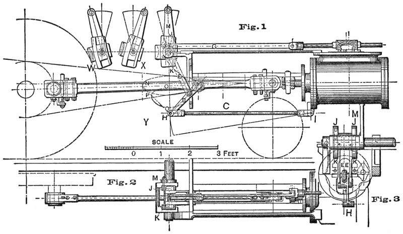
To apply this gear, the valve and steam-chest are placed, as is usually the case in American locomotives, over the cylinders; the valve-stem center being, however, in the same vertical plane as the cylinder center line, immediately over it. All the valve-motion is thus arranged on this plane,—perfectly central,—and there are no crooked or side strains. To a point A on diagram, about two-fifths along the connecting rod from294 the piston end, a small hook-link is pinned. From the lower end of this at D is jointed a lever E, which, of course, moves with the connecting rod both backward and forward, and up and down; the point D, in fact, moving in a very irregular ellipse, hereafter explained. The fulcrum F of the lever E is carried in a block which slides in a slot-link JK, and from the upper end of this lever E the valve-stem rod G is carried to the valve. This slot-link JK is centered so as to be able to be inclined from the vertical either way. When standing in the vertical position, the engine is in mid-gear, and the valve will only be opened for lead; but this will be exact for each end, and exact also on either side of the center line of the connecting rod. When the slot-link is inclined forward to the front of the engine, the engine is in full gear forward; and, when inclined backwards, it is in full gear for going back. Placed in any intermediate position, the cut-off is regulated for any required degree of expansion; the front and back of the piston receiving equal cut-off, or equal amounts of steam.
In laying out this valve-motion, it is necessary to make the center or fulcrum F of the lever E coincide, when the crank is at either extreme stroke, with the center on which the slot-link JK vibrates: then these two centers coinciding when the engine stands at lead (that is, at either end of the stroke), the slot-link JK, which is, in fact, the reversing agent, may be put forward or backward through all degrees, without moving the valve, which thus has constant lead at all grades of expansion.
If, however, it is desired to give increasing or decreasing295 lead in the grades of expansion, this may be given by varying the coincidence of these two centers accordingly, or by under-correcting or over-correcting the action of the lever E, by varying the position of D on the link B.
The lap and lead together are dependent on the distance between the center F of lever E, and the center from which the motion is taken for the valve.
The first advantage claimed for Joy’s valve-gear over the link-motion is, that it is considerably less costly, and that the working-parts are lighter. The saving is not only in weight, however, but also in the greater simplicity of parts, allowing increased facility for tooling and fitting.
It may be needless to point out how readily this valve-motion is adaptable to the requirements of the typical American locomotive, considerably simplifying the present form of valve-motion, by dispensing with the eccentrics and other working-parts, and bringing the gear with all its strains into a direct line, and also leaving the whole of the under part of the engine clear, and permitting a considerable extension of the fire-box,—a most valuable feature.
All the parts are such that they can be readily made by machinery, dispensing with hand labor except in putting them together.
The action transmitted to the valve is altogether different from that transmitted by the link-gear, as by this gear it results from the two distinct motions of the connecting rod imparted to the lever E; and these two motions work variously, with and against each other, thus giving to the valve a resultant motion somewhat partaking of the nature of that produced by cams, it really being an accelerated and retarded motion; these accelerations and retardations being so arranged as to come at the right time on the revolution to give the desired result.
Thus, as the crank is passing over the center, the lever E is not affecting the valve at all as a lever, but the motion imparted to the valve is due to the center of E slipping down the curve of the slot-link J; and this gives a smart opening of the lead with a continued smart opening of the port. When the valve is fully open, as the crank travels on, the lever E has commenced acting on the valve; but its center is still sliding down the slot-link JK; and the two movements are opposite and destroying, or partially destroying, each other, producing a retardation of the valve-motion almost amounting to an arrest; and thus is given a nearly straight line on a valve-path diagram where the port is kept fully open, the crank still traveling on, and approaching the time for the cut-off to be effected. The lever E is in the best position to act as a lever at the same time that its center is completing its movement in the slot JK, and is commencing to return, being practically still: thus the lever action of E, having full effect, rapidly closes the port. And so on for the revolution, the time of release also getting its benefit.
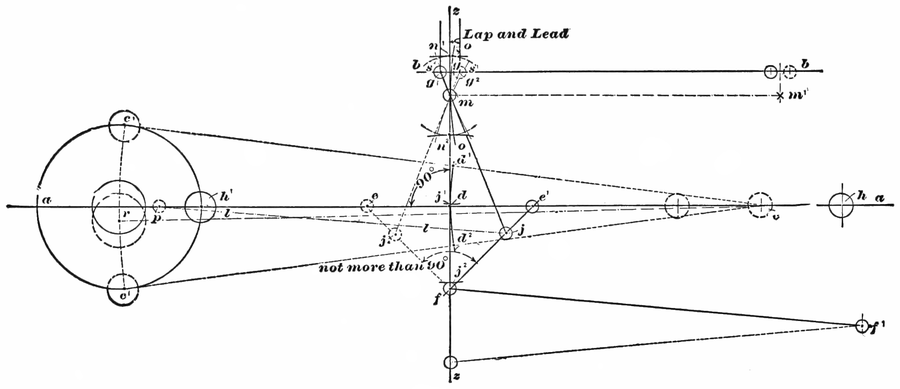
Lay down the center line aa (Fig. 29) of the cylinder, and that of the valve-stem bb, at the relative distances required for the engine to which the application is to be made; the valve-stem center line being, however, in the plane of the vibration of the connecting rod. Draw the path of the crank-pin, and the center lines of the connecting rod cc1c1 for both upper and lower positions when the piston is at half stroke. Take a point d on the center line of the connecting rod, where its vibration between d1 and d2 is equal to about double the length of the full stroke of the valve (it is better to allow rather more than less). It may, however, be chosen very much to suit the other arrangements of the engine, such as the position of the guides, brackets, etc., getting, however, if possible, a vibration of the connecting rod fully equal to double the stroke of the valve, to avoid too great an angle of the slide-link when put over for full forward or backward gear.
Having chosen the point d, draw a vertical line zz through it and at right angles to aa, and mark off the two points e, e, on each side, these being the extreme positions of the point d on the connecting rod for front and back stroke; from these points draw lines to a point f on the vertical, so far down that the angle between them shall not be more than 90°,—less is better, if there is room to allow of it (these will represent the center lines of the first link pinned to the connecting rod). The point f, which will rise and fall with the vibration of the connecting rod, is to be controlled as nearly as may be on the vertical line by a link pinned299 forward near the cylinder at f1, or, if more convenient, it can be pinned backward.
Next, on the valve-stem center line bb, mark off on each side of the vertical zz the amount required for lap and lead together, at g-g1 and g-g2; g-g1 being lap and lead for the front end of the cylinder, and g-g2 being lap and lead for the back end of the cylinder. Then, assuming the piston to be at the front of the cylinder, and the centers of the connecting rod to be at hh1 (h being the crank-pin), the point d, which we have chosen to take motion from, will be at e1, and the link pinned to the connecting rod, for transmitting motion to the valve, will be at e1 f. From a point on this link, which has at first to be assumed, say at j (which will be about the half vibration of the connecting rod; that is, d1 to d), draw the center line of the lever actuating the valve, that is joining j and g; the point where this line crosses the vertical zz, will be the center or fulcrum of the lever, and will also be the center of oscillation of the curved links in which the blocks carrying the center of the lever slide; this center is marked m. The function of the link e1 f, and the attachment of the valve-lever to it at j, is to eliminate the error in vibration of the lever, center m, which would otherwise arise from the arc passed through by the lower end of that lever. Although the position of the point j may be found by calculation, it is much more quickly found by a tentative process; and, to test it the assumed point j be the correct one, we mark off on each side of m, vertically, the correct vibration required, n1 n2, which will be the same as the vibration of the connecting rod on the vertical 300line zz. Then apply the distance e1—j to d1—j1 and d2 j2. Then, if the length jm be applied to j1 n1 (measuring from j1), and to j2 n2 (measuring from j2), and the point m fall below n1 n2 in each case, it will be necessary to take a point on e1 f higher than j; or if, on the other hand, m falls above n1 n2, then a point must be taken on e1 f lower than j. This point will generally be found on a second trial.
The point m, as said, now represents the center of oscillation for the links and the center or fulcrum of the lever. And these must coincide, when the piston is at each end of the stroke, the lead being then fixed; and the links can be pulled over from forward to backward, or any point of expansion, without altering the lead. This may be taken as a test of the gear being set out correctly.
The point g will be the point of attachment for the valve-stem link, which may be made any convenient length; but, from that length as a radius, the curve of the links must be drawn from a center m1 on the parallel line m-m1; the angle at which this curve is set from the vertical (which is mid-gear), will give forward or backward gear,—the angle leaning forward s1, or to the front of the engine, being forward gear, and the reverse s2 being backward gear. The amount of the angle, marked on the curve of extreme vibration at s-s1 or s-s2, will be equal to one-quarter more than the full opening of the port at that angle (that is, if 1″ opening of port is required, then the amount of angle s to s1 must be 1¼″), and the point of cut-off will be about 75 per cent. Laid out in this form, the leads and cut-offs for both ends of the cylinder, and for backward and forward going, will be practically perfect and equal, and the301 opening of ports also as near as possible equal. If a longer cut-off than 75 per cent is required, it is only necessary to increase the angle of the curve oo beyond s1 for forward gear, or beyond s2 for backward gear. It will be noticed, that, in this gear, the lap and lead are entirely dependent on the action of the lever j, m, g, as a lever, and may be varied according to the length of mg. And the opening of the port (beyond the amount given as lead) is dependent on the amount of angle imparted to the curved link oo, and will be, as above said, about four-fifths of the amount of that angle from the vertical measured on the line of extreme vibration.
Deviations from the above positions and proportions may be made without materially altering the correctness of the results.
Thus, if it is found necessary to raise or lower the center m, to clear wheels, frames, or other gear, this may be done till the angle of mm1 is out of the parallel of the cylinder center line up or down by one in thirteen (1 in 13); it is not well to go beyond this; but the lines mm1 and bb will be parallel, and the position of the curve oo for mid-gear will be at right angles to mm1.
Again, the point e1 may be taken either above or below the center line of the connecting rod, if it be wished to avoid piercing the rod; the pin at e1 being carried in a small bush or block attached above or below the connecting rod.
Again, for locomotives, if the wheels are so small that the link e1f would come too low, it may be cut short at the point j, and this point connected by a link ll to a small return-crank p, on the crank-pin; the movement302 of the counter-crank being equal to that from to j4.
The diagram is drawn for an engine where the center of the crank-axle is on the center line of the cylinder; but if this be below, as is usual in American locomotives, then the base line on which to construct the diagram of the valve-gear itself will be the average center line assumed by the connecting rod for such lowering of the crank-axle center, drawn from c, the middle position, to a point, say r, representing the lowered center of the axle. The vertical zz will be at right angles to this new base line cr, all the other processes following.
While the proportions shown on the diagram give the best average results, these proportions may be varied within very wide limits, according to the requirements of the design of the engine. Thus, when the distance between the center of the cylinder and center of valve-stem is small, as with a small cylinder and a long stroke, the link e1f may be considerably lengthened: the point j will thus be dropped, and convenient angles for all the links, etc., will be maintained, the room for the various movements being got below the center line of the cylinder when it can not be had above; the reverse proportioning of the parts being made when the conditions are reversed, as with a large diameter of cylinder and a short stroke.
This system of laying out the motion, applies, with a few modifications, to the Strong motion, and to all others where the ellipse formed by the horizontal and vertical motion of the main rod is used to actuate the valves.
In the course of these pages, reference has several times been made to the indicator. This instrument is of great service to the steam engineer in helping him to determine with accuracy questions of steam distribution, that, without its aid, would remain in the realms of speculation. Its diagram presents a reliable record of what is going on inside the cylinders of a steam engine; and master mechanics who desire to run their engines economically, can not afford to dispense with the accurate information imparted by the indicator respecting individual locomotives.
The indicator consists essentially of a small steam cylinder, whose under side is connected by pipes to the main cylinder of the engine under inspection. Inside the indicator cylinder is a nicely fitting piston, whose upward movement is resisted by a spring of known strength. The piston-rod passes up through the top of the indicator cylinder; and its extremity is connected with mechanism for operating a pencil, and marking on304 a card a diagram whose lines coincide with the movement of the indicator piston.
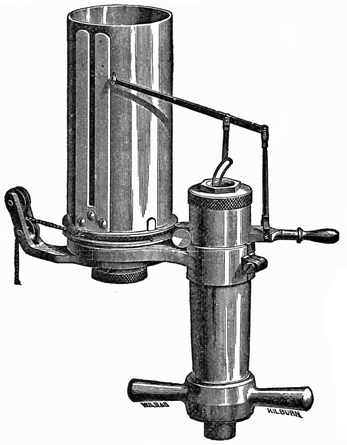
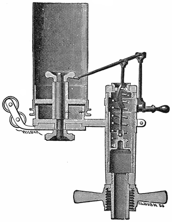
Fig. 30 is a perspective view of the Tabor indicator, an instrument well adapted for application to high-speed engines, such as the locomotive. In Fig. 31 the indicator is shown in section. The construction of the instrument can be well understood from a careful examination of these figures. In the sectional figure, the piston is seen with its rod encircled by the spring passing305 up through the top of the cylinder, and connecting with the lever which operates the marking-pencil. By ingeniously designed mechanism, the lever is made to move the pencil in a perfectly straight vertical line. The card to be marked is fastened in the paper drum attached to the indicator. This drum receives a circular motion from a cord which is operated by the cross-head, and this connection is so arranged that the drum will begin to move round just as the main piston begins its stroke. The circular motion of the drum is continued till the piston reaches the end of its stroke, when the306 drum reverses its movement, and returns to the exact point from whence it started. Now the indicator cylinder being in communication with the main cylinder, when the latter begins to take steam, the pressure will be applied to the indicator piston, which is pushed upward, at the same time transmitting its movement to the pencil. The indicator piston will rise and fall in accordance with the steam-pressure in the cylinder; and, the circular movement of the drum coinciding with the cross-head movement, the pencil will describe a diagram which represents the pressure inside the main cylinder at the various points of the stroke.
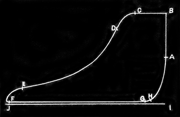
Fig. 32 represents an indicator diagram, such as might be taken from a locomotive with well-constructed valve-motion cutting off steam at about one-third of the stroke. In the figure, the line IJ represents the line307 that would be drawn by the pencil when no steam is admitted to the indicator piston; so it is called the atmospheric line. This is the neutral line of the diagram representing the position of the pencil when both sides of the indicator piston are exposed to the atmosphere: hence it is the base line from which pressures either above or below are measured. The line AB is the admission line, so called because its beginning A represents the point where the valve begins admitting steam to the cylinder: BC is the steam-line, usually considered as beginning at the point of positive change in direction of the admission line. Admission of steam does not cease till the point D is reached, but wire-drawing begins at C. The curve DE is the expansion line, and is traced while the valve is closed, and previous to the opening of the exhaust; the pressure falling by expansion. At E, release begins, and the exhaust line extends to F; from F to G is the line of counter-pressure, drawn during the return stroke of the piston and while the exhaust is open; and G to A is the compression line, drawn during the return stroke after the exhaust-valve has closed.
In proceeding to ascertain from the diagram calculations of the work done by the engine, it will be remembered that vertical measurements represent pressures in the cylinder, and horizontal measurements positions of the piston. To understand the language of the diagram properly, it is necessary that several things having reference to permanent or accidental conditions be known. Those absolutely necessary are, the scale of the indicator spring, the diameter of the engine cylinder308 and stroke of the piston, the strokes made per minute, and the boiler pressure. It is also desirable to know the dimensions of steam-pipes, steam-ports, and exhaust nozzles.
The purposes for which the indicator can be advantageously applied to locomotives, are to show the condition of the valves and pistons, and to prove whether or not the steam is used properly within the cylinders. By its use the amount of power developed by the cylinders can be computed.
Were the indicator used daily on locomotives, much waste of coal now going on through steam being lost by leaky valves and pistons would be avoided. The graphic tale of the diagram would force out of practice the ordinary habit of running engines with the steam throttled, and indubitable proofs of ruinous back pressure would make contracted nozzles intolerable.
There is not room in a work of this kind to give the necessary information for those who wish to learn the operating of the indicator and the analysis of the diagram. Engineers who are ambitious to enter upon this line of study, should secure one of the standard books treating the subject.
In this exacting age, the traveling public are much more disposed to find fault with systems that do not provide against fatalities resulting from human fallibility, than to commend the perfection of appliances which annually save more lives than would be lost in a sanguinary war. The Westinghouse brake has performed this life-saving service, yet its great conserving merit has been but feebly appreciated outside of railroad circles. During the decade between 1860 and 1870, America became a reproach among nations for the frequency and disastrous nature of its railroad accidents. To-day fewer railroad travelers in America lose their lives by accidents beyond their own control, than the travelers in any country under the sun. The credit of this immunity from fatal accidents is almost entirely due to the successful operation of the Westinghouse and other brakes that followed the line suggested by this invention.
Inventions may be divided into two distinct classes. Far the more numerous class are those which effect310 improvements on recognized appliances. The other is the rare and more valuable class, to which belongs the original inventor who devises an entirely new method for performing a desired operation. Among this class of inventions may be noted Watt’s separate condenser, which first rendered the steam engine a commercial success; the multitubular boiler of Nathan Read, which made a high-speed locomotive practicable; and the air-brake of Westinghouse, which made fast traveling safe, by putting the train speed under the control of the engineer.
To the traveling public the air-brake has proved a source of satisfaction by assuring exemption from accidents, but its greatest blessing has been conferred upon train men. Being the greatest sufferers from railway accidents, their risks of life and limb are greatly reduced; and the agonizing helplessness that used to be so often experienced with trains that could not be stopped in time to avoid a disaster, is almost unknown on our well-managed roads. Mind has become victor in its conflict with matter. When necessary, an engineer can run a train at a high velocity over crowded lines without having to shut off steam within a mile of each point where there may be another train obstructing the track, or keep up his speed at the risk of his life. People unacquainted with the inside operating of railroads have no idea of the difficulties train men had to contend with in getting fast trains over the road, before continuous brakes were supplied. The train had to be run on schedule time, and all points where trains might311 be expected had to be approached with care. This meant reduced speed; and speed could not be reduced in short distances, so the risk had to be taken of violating one rule to comply with another.
The Westinghouse atmospheric brake was patented April 13, 1869; and the first public trial took place on the Panhandle road about the same time. The trial was so satisfactory, that the Pennsylvania Railroad Company, which have been always noted for their liberal patronage of every meritorious device likely to promote the efficiency and safety of railroad operating, had a train equipped with the brake. This was the Walls accommodation train, a kind of service where frequent stops were required, and was therefore well calculated to demonstrate the true character of any brake. A number of public trials were made with the brake thus fitted, among which was one by the Master Mechanics’ Association in the middle of September, 1869, on the Horseshoe Bend on the Pennsylvania Railroad. Here a train of six cars, running down a grade of 96 feet to the mile, at the rate of 30 miles an hour, was stopped in a distance of 420 feet. Such a feat was unprecedented at that time, and attracted wide-spread attention.
In the following month, official trials of the train were made by the officers of the Pennsylvania Railroad near Philadelphia. The train was then taken to Chicago, where numerous tests were made in the presence of leading Western railroad officers. So convincing were these trials of the decided efficiency of the brake, that, immediately afterwards, the Michigan Central Railroad312 and the Chicago and North-Western Railway each ordered a train to be fitted with the brake.
The first five sets of the Westinghouse brake fittings made were got out in the shops belonging to the Pennsylvania Railroad Company at Altoona, Penn. The first railroads to adopt the brake as a regular part of their equipment, were the Pennsylvania, the Pittsburg, Cincinnati, and St. Louis, the Union Pacific, the Chicago and North-Western, and the Michigan Central Railroads.
Since the Westinghouse atmospheric brake was first tried, many changes in details have been made, and numerous improvements have been effected; but the essential points remain the same. And the best forms of brakes subsequently got out by other inventors are founded on the Westinghouse idea, just as much as the numerous types of locomotives follow the design of Stephenson’s Rocket.
Although the automatic air-brake is now becoming almost universal in American railroad practice, most train men are familiar with the working of the atmospheric brake under the name of “straight air.” When first invented, the Westinghouse brake consisted of an apparatus located on the locomotive for compressing air, which was stored in an iron drum fastened somewhere about the engine. Underneath each car, and connected with the ordinary brake attachments, was a cylinder containing a piston, which operated the brake.313 The brake-cylinders were kept in communication with the air-drum on the locomotive by iron pipes. Connection between the cars where “stretching” and “compression” made the train vary in length, was made by means of rubber flexible hose. When the engineer wished to apply the brakes, he admitted the compressed air into the supply pipes, through a three-way cock at his hand. This air entered the cylinders under the cars, moving back the pistons which pulled the levers operating the brakes. To release the brakes, the air was permitted to escape out of the pipes into the atmosphere.
Thus, what is really a complicated operation was performed in a simple manner, and by means of machinery not liable to get out of order readily. The instant application of every brake on a long train was put in the hand of the engineer. On the first indication of danger, his hand became powerful beyond the magical forces conceived by the imagination of poets.
The growth of the Westinghouse brake into public favor furnishes a curious commentary on the different degrees of enterprise to be found among railroad companies in the various sections of this country. It was natural to suppose that railroads in the thickly settled States, where trains had become too numerous for being safely operated with crude brakes, and no signals, would have been the first to adopt an improved appliance which gave promise of increased safety. Yet the railroads in the Eastern States, with a few creditable314 exceptions, were among the last to patronize the Westinghouse brake; and they adopted it only when the influence of public opinion could no longer be ignored. Western railroads that ran through sparsely settled prairies, where trains were rare, and stopping room generally ample, were among the first to encourage the inventor of the brake with their support.
During the first two years after it was invented, the Westinghouse brake made slow progress into practical application, except in the West. In the ancient State of Massachusetts, it was hardly known till the Revere accident happened near Boston. This was the case of a crowded road being operated without signals or brakes, except those of the most primitive description. A fast express train ran into the rear end of an accommodation train, killing twenty-nine persons, and severely injuring fifty-seven others. The engineer of the express train, while running at a speed of twenty-five miles an hour, saw the tail lights of the accommodation train when he was eight hundred feet away. He whistled for brakes, and reversed his engine; but the train could not be stopped.
The railroad superintendents throughout the conservative State of Massachusetts then received enlightenment respecting the existence of an efficient continuous brake in a vigorous fashion. The Revere accident conveyed its lessons in a terrible way, but they were effectual in convincing railroad managers that they could not afford to dispense with a brake that proved itself to be reliable.
Although the atmospheric brake could, with light trains, make stops within the shortest distance it was desirable to stop trains with safety to the passengers and rolling stock, it possessed certain weak points which demanded remedy. In case of a train breaking in two,—an accident which frequently happens, especially on rough track,—there was danger of the engineer applying the brake without knowing that an interval existed between the cars, and allowing the rear end of the train to crash into the forward part. The signal given by the bell-rope breaking, had a tendency to lead to an accident of this character. Another objection to straight air was, that should derailment take place, or any accident happen that would rupture the pipes or their connections, the brake was rendered useless. These weak features did not interfere with the working of ordinary traffic; and as providing special appliances to meet cases of accident which are rare, does not generally receive much consideration, the brake might have been regarded as perfect enough for all practical purposes had it not failed to meet satisfactorily a condition of ordinary train service. As the length of trains was increased, it was found that the atmospheric brake was slow in action. When a long array of pipes and many cylinders had to be charged with air from the drum on the locomotive after the necessity for applying the brake became apparent, and before it would act, some seconds were required for the operation. Every additional car put upon the train increased the length of pipes and the cylinders to be filled, and so lengthened the time that elapsed between316 the instant danger was perceived and the time at which the brake began to perform its retarding work. The increase of time might be only a few seconds, but they would probably be priceless moments when an accident was impending.
To overcome this line of weakness, the Westinghouse automatic air-brake was invented. Where good station signals are in use, it has long been accepted as an axiom among railway authorities, that a signal must be constructed so that it will indicate danger when any accident happens to its mechanism. This principle was brought into practical application in the Westinghouse automatic air-brake. When any thing goes wrong with the brake apparatus, its tendency is to apply the brake automatically. A break in a pipe makes the brake fly on. Each car carries a supply of compressed air sufficient to apply its own brakes several times. By the new arrangement, the brakes on all the cars are applied almost simultaneously, and instantly after the engineer turns the handle of his stopping-valve. The brakes are applied by decreasing the pressure in the pipes; so the breaking in two of the train, or the fracture of an air-pipe or coupling, sets the brakes on all the cars on the train, whatever side of the break the cars may be on. That in itself is an invaluable feature in a continuous brake, and prevents cars from acting as battering-rams upon each other in cases of derailment.
Every few days, notices get into the public prints317 relating how frightful accidents were prevented by the prompt action of the automatic air-brake. And hundreds of narrow escapes, where this brake proves the preventive of destruction to life and property, receive no record, and are known only to the employes connected with the operating of trains. To the men familiar with train service, to those who are intimately acquainted with the life-saving effected by the automatic air-brake, it seems surprising that railroads could have been operated without this or a similar appliance. They certainly were not operated safely without it.
Patents for the Westinghouse automatic air-brake were granted in March, 1872. During the succeeding winter, trials of the brake were made by the Pennsylvania Railroad; and it was shortly afterwards adopted by the Philadelphia and Reading Railroad Company as their standard brake for passenger trains. The example of that company was soon followed by the St. Louis, Kansas City and Northern, the Chicago and Alton, the Toledo, Wabash and Western, and the St. Louis, Iron Mountain and Southern Railroads, all of which companies equipped their passenger rolling stock with the automatic air-brake within a few months.
The prominent features of the Westinghouse automatic air-brake consist of the following leading parts: An air-pump, placed on the locomotive, is operated by a steam cylinder, which forces air into an iron drum or318 reservoir placed under the deck, or in any other convenient part about the engine. The air is compressed to the density considered necessary for the kind of train the locomotive usually pulls.
In the cab, located conveniently to the hand of the engineer, is the engineer’s brake-valve, commonly called the “three-way cock,” which regulates the flow of air from the main reservoir into the main brake-pipes for supplying the auxiliary reservoirs with air. This valve applies the train-brakes by letting the air escape from the main brake-pipes, and releases them by again admitting the pressure of air into the pipes.
From the main reservoir, the main brake-pipe connects with the engineer’s valve, and thence along the train, supplying all the brakes with the air required.
Under the floor of each car is fastened an auxiliary reservoir, which holds a supply of air necessary for operating the brakes on that car. So each car carries its own supply of air.
Connected with each car-truck is a brake-cylinder, in which is operated a piston that applies the brake. The brake-levers connect with the piston-rod in such a manner, that, when the piston is forced out by the air-pressure, the brake is applied.
Attached to the auxiliary reservoir is the triple valve, whose action connects the air-cylinder with the auxiliary reservoir.
When the air-brake was first invented, the distribution of steam within the cylinder was effected differently from what it is in modern pump-cylinders. The steam-valve319 consisted of a double piston, the heads having ports on their edges which admitted and released the steam. This valve did not move up and down, but received an oscillatory motion from a small auxiliary engine placed on the top of the steam cylinder-head. The movements of the auxiliary engine were regulated by a reversing-rod (popularly known as a kicker-rod), working inside the main piston-rod. This arrangement of steam distribution was somewhat complicated, and liable to get out of order; and it was superseded by the differential steam-valve movement now in use.
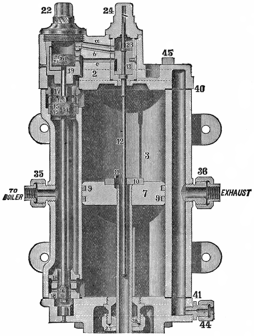
In Fig. 33a, steam enters from the boiler at the nipple 35, and fills the steam-space between the heads of the main piston-valve 15, 16, maintaining a constant pressure of steam there while the pump is at work. The upper head of the main valve being of greater area than the lower one, the tendency of the pressure is to raise the valve. A downward movement of the valve is provided for by a separate single-headed piston-valve 20, working in a cylinder above the main valve. The reversing-rod 12 operates a slide-valve 13, which regulates the admission and release of steam for the third piston.
In the cylinder shown in the engraving, the main valve is down, so that steam is passing into the lower end of the main cylinder. Two small ports can be seen close to the piston-head 16, one above the other. The upper port is open, and is the admission port; the lower port, which is closed by the small piston, is for exhausting the steam. The main piston 7 is on its upward stroke, and the upper exhaust port seen above the piston-valve 15 is open, while the steam port immediately below it is closed by the valve-piston in the same way that the exhaust port is closed at the other end. When the main piston 7 shall reach near the top of its upward stroke, the plate 10 will strike on the projection322 on the reversing-rod, pushing up the slide-valve 13. The upper edge of this slide-valve will cut the steam off the passage a, and open the passage b to the exhaust. This takes the steam away from the piston 20, and allows piston 15 to move upward, closing the exhaust-port, and opening the upper steam-port. The same movement makes the piston 16 close its steam-port, and open the exhaust. Piston 7 now begins to travel downward; and, when it reaches nearly to the bottom of the cylinder, the plate 10 catches the knob on the end of the reversing-rod, and pulls down the slide-valve 13 to the position it holds in the engraving. Steam then rushes through the passage a, and makes the piston 20 push down the main valve. That completes the circle of the operations in the steam cylinder.
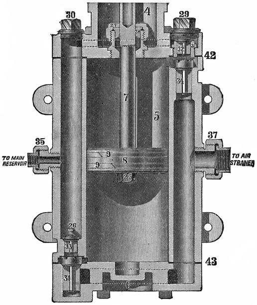
The operation of the air part of the pump is very simple. While the main piston (Fig. 33b), which is on the same rod as the piston of the steam cylinder, is moving upward, it is forcing the air out of the upper end of the cylinder up under the discharge-valve 32, and away through the proper passages to the main reservoir. At the same time the lower end of the cylinder is being filled with air drawn through the lower receiving-valve 34. During the downward stroke of the piston, the air will be delivered through the valve 33, and the upper part of the cylinder filled by air received through the upper valve 34.
An engineer who does not understand the principles323 of a locomotive’s action, is not likely to prove a valuable runner. The men who are most successful in getting trains over the road with solar regularity; the men who make the best records on the mileage sheets for economy in fuel and in lubricants; who are lightest in repairs, yet keep their engine going longest,—are those who comprehend the functions of every portion of the engine, and what relation the various parts bear to each other. With this knowledge clearly established in the mind of the runner, his power to detect any thing wrong with his engine becomes instinctive. Trifling defects, which neglect would develop into serious disabilities, are rectified in time, and the whole engine is maintained in smooth working-order by the harmony of its individual sections. The mere stopper and starter is losing his hold on the locomotive service. When he drops off entirely, our mileage for each dollar expended will be decidedly increased.
The principles which apply to the running of a locomotive are equally applicable to the management of an air-brake, with all its perfected connections. This apparatus can not be properly managed unless the man who works it knows something about its action.
A great many engineers who run passenger trains, and take an intelligent interest in the working of the locomotive, whose technicalities they have thoroughly mastered, display no desire whatever to understand the air-brake, and are perfectly contented with its action so long as it will stop the train. The air-pump, so wonderfully interesting to those who understand its movements,324 receives no more attention than is necessary to keep it going so that the required air-pressure is maintained. They know how to start and stop the machine, and they oil it regularly; but these are the limits of their attentions. Should the pump happen to stop working, the cause is mysterious, like many other mysteries; and the natural remedy suggested, is to hit the thing on the head with a monkey-wrench. Should it not respond to this treatment by renewed action, the hand-brakes are resorted to for the rest of the journey; and the round-house foreman or machinist is required to do the head-work which locates the trouble.
A belief prevails among men who labor principally with their hands, that laziness is exclusively physical. This is a mistake. It is a psychological fact, well known to metaphysicians, that mental laziness is prevalent enough to dwarf the minds of half the human race. Men who would willingly work with their hands during half their leisure time to keep their engines in proper condition for running, have to be driven, by fear or jealousy, before they will force their mental faculties to do trifling labor in a new channel.
Any engineer of ordinary intelligence, who will spend one hour a day for two weeks studying up the Westinghouse instruction book, will understand the brake so well, from the pump to the hind end of the train, that any imperfection happening to its working will be as readily located as an ordinary defect in a locomotive. Yet it is an intensely hard matter to induce men325 running passenger engines to go through this trifling mental exercise. The consequence is, that the brake sometimes becomes inoperative from causes so slight that men should be ashamed to report them; and they would be so if they only comprehended how small a mole-heap became their mountain. I knew a case where all the train men—that is to say, engineer, fireman, conductor, baggageman, and brakemen—wrestled for twenty minutes over a triple valve, trying to find out how to cut the air off a car; and, when the crowd was vanquished, a colored porter came, and showed them how the thing was done. This was on a road where straight air was generally used. One day some winters ago, a passenger train on the road I worked for was delayed an hour or more at a station, waiting for something. When the engineer tried to start the air-pump, it would not work. He fumed and fussed over it for fifteen minutes, gave it a liberal dose of copper hammer medicine, and saturated it with oil, but all to no purpose. It would not pump a pound of air, so the old-fashioned Armstrong was called into operation. In the course of its journey, this train had to pass the round-house at headquarters; and the engineer stopped to see if his pump could be given some quick remedy. I happened to be the doctor consulted. On learning the particulars of how the pump stopped working, I set fire to a piece of greasy waste, and held the flame to the check-valve of the air-drum; and the pump went right to work. All the trouble was, that the check-valve was frozen in its seat. I felt sorry for that engineer, he appeared to be so thoroughly ashamed and crestfallen at being baffled by such a small trouble.
To run an air-pump successfully, the first requisite is that it should be managed intelligently, and its wants attended to regularly. An air-pump consists of numerous moving parts, which should operate with the least possible amount of friction: consequently, it is important that the machine should be properly lubricated,—not deluged with grease for ten minutes, and then run on the interest of the excess for two hours, but sparingly furnished with clean oil, which will keep the moving parts moist all the time. To accomplish this, the feeding-cup must be kept in proper working-order, so that it will pass the oil regularly. I have found a leading cause for air-pumps working unsatisfactorily to be in the intermittent feeding of the oil-cups. Some dirt gets into the cup, obstructing its action, and greater opening is given to make it feed; then the oil goes through by spasms, and the pump works irregularly; for at one time the steam-piston is churning the oil, and again it is working dry. There is also a common abuse of the oil-can when any thing goes wrong with the pump; for some men will then drench it with oil, expecting that to make it work smoothly. Permanent injury is often done in this way, especially where inferior oils are used, which frequently contain mineral substances in suspension. This solid matter is separated from the oil by the heat, and settles in the small passages, filling them up by degrees till eventually there is no channel left for the steam to pass through to reverse the steam-valve; so the pump stops. I once saw a runner trying to doctor a sick pump by pouring the stickiest kind of gummy valve-oil into an air-cylinder. He gave the thing its327 quietus, as other poor doctors sometimes do with their patients.
The stuffing-box packing is not generally supposed to exercise an important effect on the action of an air-pump; yet I have seen cases where irregular action of the pump, and serious loss of air, resulted from bad packing. Soapstone and asbestos, and other substances that become compact and rigid when cold, are unsuitable for packing the air end of a pump. After a little use, material of this kind becomes so hard that no amount of screwing of the gland will make it tight; and the greater part of the air at that end of the pump escapes through the stuffing-box instead of passing into the drum.
Around the bushings of the cylinder, where the small reversing piston 20 works, are diminutive steam passages, very liable to get stopped up when foreign matter is attempted to be run through the cylinder. Such matter is occasionally introduced in various ways. When rubber gaskets are used in the pipe connections leading to the cylinder, the rubber often peels off in shreds, or breaks off in small pieces, which lodge around the bushing in the passages, producing harassing annoyance. So soon as those passages get obstructed, or reduced below their correct size, the pump begins to work badly. Machinists not well versed in the mysterious ways of air-pump disorders will now take that pump apart, and find nothing the matter. Subsequent proceedings depend328 upon the nature of the man who has the job in hand. If the machinist be of a conservative disposition, he will put the apparatus together again without making any alteration, and perhaps will relieve his mind by expressing a belief that the engineer does not know when an air-pump is in good shape. Another machinist, of a more enterprising stamp, must find something to change, so he lengthens or shortens the reversing valve-rod 12 (a favorite resort of small-knowledge tinkers), which gives the pump the coup de grâce; and it has to be overhauled by a competent machinist before it again supplies the air to stop a train. This competent man goes direct to the root of the trouble. Skill in this particular line of work convinces him, after an examination, that the moving parts require no repairs; and knowledge begotten of experience, supplemented by sound sense, directs him where to look for the cause of defective operation.
Men who meet with good success in repairing air-pumps, and in determining, from the action of the pump, the probable cause of defect, have to do a great deal of deep and sagacious thinking. Sometimes a defect, simple enough in itself, is extremely difficult to locate, because it belongs to the unexpected order of occurrences.
Here was an instance. Some small jobs had been done one day to the steam cylinder of a pump which had not been working quite satisfactorily. When they tried to start it, after being put together, the pump would not work at all. The machinist who did the job, an eminently competent man at such work, took the machine329 apart again, but could detect no defect or maladjustment about it. The steam cylinder, with all its valves and rods and bushings, was critically examined: the air-pump, with all its connections, got a thorough inspection to no purpose. When an ordinary man goes through the patient, thoughtful labor needed for an examination of this kind, and finds nothing wrong, he is apt to get discouraged, and confess himself beaten. This man did not recognize the word beaten as applied to his work. He reasoned, “This pump would work if it were all right. It will not work, so something must be wrong.” After exercising more patience and perseverance, he discovered that the bushing 23 of the reversing valve (usually called the kicking-rod valve) had become loose, and, when the cap was screwed down, it twisted the bushing round, and closed the passages that lead steam to the reversing piston. There are small grooves round the sides of the small steam passages to provide for the bushings being moved a little, but these grooves had become gummed up so that they failed to serve their purpose of keeping the ports open.
The working and stationary parts within the cylinders of the air-pump are adjusted with nice exactness; and, when they remain in their normal condition, the pump works smoothly, and compresses air rapidly. When wear, or any other cause, alters the dimensions of these parts, the effect immediately becomes apparent in unsatisfactory working of the whole machine. Rods are adjusted so that valves or pistons shall cover and uncover steam passages, and no superfluous movement is330 provided for. The passages are so small that all the steam they convey is needed for the work of reversing the motion; and if from any cause the valve or piston only partly uncovers the opening, the necessary volume of steam does not get through. A close observer of the pump’s action can, day by day, perceive the gradual degeneration due to wear. Wear of the steam-cylinder connections is generally indicated by reduced power. The pump will not do its work satisfactorily, and has difficulty in keeping up the pressure of air. This deterioration continues till the pump will stop, unless its decay gets arrested by repairs. When the valves of the air-pump are in correct order for doing good work, the discharge-valves 32 and 33 have 1/16″, and the suction-valves 34 ⅛″ lift. The continual tapping of these valves on their seats has a tendency to wear out valves and seats, making the lift greater than what is desirable. Any material increase of lift for the discharge-valve has a most injurious effect upon the motion of the pump, especially if the suction-valve should happen to be leaky. Then the movement of the pistons will become fluctuating, and subject to frequent stoppages. The up-and-down motion of the piston is of a jerky character, that makes the beholder suppose the thing is uncertain which way to go. Deterioration of air-valves is not, however, the only cause for that jerky motion so often observed in bad working pumps. A bent reversing valve stem (kicker-rod) acts on the reversing valve with oblique pull and thrust, which tend to move it away from the seat, letting the steam pass the wrong way. A broken main steam-valve ring has a similar effect; for the steam passes to the wrong end of the valve, destroying its331 equilibrium; and there is nothing decisive about its reversal, or about its motion after it is reversed. Its action resembles the movements of a vacillating human being. It does not want to go in that direction, but goes, then keeps trying to change its mind during the rest of the journey. Obstructed steam passages will sometimes cause indecisive action of the pump before it gets bad enough to stop it altogether.
Pounding on the heads is a somewhat common attribute of degenerated air-pumps. Broken or badly worn air-valves very often cause the pump to pound. If the trouble should happen to be in the upper air-valve, it will demonstrate its disorder by causing pounding on the upper head; and the lower valve’s malady will cause pounding on the lower head. When a pump is suffering from indecisive motion, or is pounding, and the machinist does not feel certain about where the trouble lies, he may safely examine the condition of the air-valves,—for they can be easily reached,—and in a great many cases the defect will be found there. Wear of the pin whereon the bottom of the main valve-rod rests, or of the rod itself, will induce pounding on the upper head by the main piston. Some runners think, that, by keeping the drain-cock of the steam-cylinder open all the time, they secure dry steam. The practice is pernicious, and injurious to the pump: for the piston receives so little cushion when the drain-cock is shut, that it can not afford the decrease made by a permanently open cock; and consequently the loss of cushion permits pounding on the lower head.
I have known of a disastrous effect being produced332 on a pump by putting a new gasket, which proved too thick, on the upper head. It was the thinnest copper that could be found, but it perceptibly lengthened the upper end of the cylinder so that the bottom knob on the reversing stem struck the reversing plate on the main piston before that action was due. On several occasions I have had air-pumps reported to be working badly, when all the trouble lay in the air-strainer being partly choked up by floating vegetable matter that had been sucked in with the air, and failed to pass through the meshes. In another case we had much difficulty in locating the defect, with a pump that absolutely refused to work. The boiler-makers had been working in the smoke-box, and by some means the end of the exhaust-pipe got solidly stopped up with cinders. As none of us had come across that particular cause of obstruction before, we expended a good deal of labor searching for the trouble before we thought to disconnect the exhaust-pipe from the pump.
This is the part whose operation gives the brake its automatic action. Those who have opposed this form of brake have made great objection to the complicated nature of the triple valve. But some familiarity with the device shows that it is far from being complex, considering the functions it performs. It is merely a piston-valve carrying a slide-valve along with it.
The arrangement of the parts of the triple valve is shown in Fig. 34.
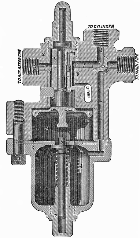
The triple valve has a piston 5, working in the334 chamber B, and carrying with it the slide-valve 6. Air enters from the main pipe through the four-way cock 13 into the drain-cup A, and passes to the chamber B, forcing the piston up, and uncovering a small feeding-groove in the upper part of the chamber, which permits air to flow past the piston into the auxiliary reservoir, while, at the same time, there is an open communication from the brake-cylinder to the atmosphere through the passages d, e, f, and g. Air will continue to flow into the auxiliary reservoir until it contains the same pressure as the main brake-pipe.
To apply the brakes with their full force, the compressed air in the main brake-pipe is permitted to escape, when the greater pressure in the auxiliary reservoir forces the piston 5 down below the feeding-groove, thus preventing the return of air from the reservoir to the brake-pipe. As the piston descends, it moves with it the slide-valve 6, so as to permit air to flow directly from the auxiliary reservoir into the brake-cylinder, which forces the pistons out, and applies the brakes. The brakes are released by again admitting pressure into the main brake-pipe from the main reservoir; which pressure, being greater than that of the auxiliary reservoir, forces the piston 5 back to the position shown in the engraving, recharges the reservoir, and at the same time permits the air in the brake-cylinders to escape.
To apply the brakes gently, a slight reduction is made in the pressure in the main brake-pipe, which moves the piston down slowly until it is stopped by the graduating spring 9. At this point, the opening l in335 the slide-valve is opposite the port f, and allows air from the auxiliary reservoir to feed through a hole in the side of the slide-valve, and through the opening l into the brake-cylinder. The passage l is opened and closed by a small valve 7, which is attached to, and moves with, the piston 5, provision being made for a limited motion of these parts without moving the valve 6. When the pressure in the auxiliary reservoir has been reduced by expanding into the brake-cylinder until it is the same as the pressure in the main brake-pipe, the graduating spring pushes the piston up until the small valve 7 closes the feed opening l. This causes whatever pressure is in the brake-cylinder to be retained, thus applying the brake with a force proportionate to the reduction of pressure in the brake-pipe.
To prevent the application of the brakes, from a slight reduction of pressure caused by leakage in the brake-pipe, a semicircular groove is cut in the body of the car-cylinder, 9/64 of an inch in width, 5/64 of an inch in depth, and extending so that the piston must travel three inches before the groove is covered by the packing leather. A small quantity of air, such as results from a leak, passing from the triple valve into the car-cylinder, has the effect of moving the piston slightly forward, but not sufficiently to close the groove, which permits the air to flow out past the piston. If, however, the brakes are applied in the usual manner, the piston will be moved forward, notwithstanding the slight leak, and will cover the groove. It is very important that the groove shall be three inches long, and336 shall not exceed in area the dimensions given above. Heretofore leakage valves have been used, and also a leakage hole. These leakage holes have been found to be too uncertain in their operation; and consequently it is recommended that these holes should be closed, and the grooves in the cylinders substituted, as rapidly as possible.
When the handle of the four-way cock 13 is turned down, there is a direct communication from main brake-pipe to the brake-cylinder, the triple valve and auxiliary reservoir being cut out; and the apparatus can be worked as a non-automatic brake, by admitting air into the main brake-pipe and brake-cylinder, to apply the brakes. When from any cause it is desirable to have the brake inoperative on any particular car, the four-way cock is turned to an intermediate position, which shuts off the brake-cylinder and reservoir, leaving the main brake-pipe unobstructed to supply air to the remaining vehicles.
The drain-cup A collects any moisture that may accumulate, and is drained by unscrewing the bottom nut.
The brakes, as has been explained, are applied when the pressure in the brake-pipe is suddenly reduced, and released when the pressure is restored.
It is of very great importance that every engineer should bear in mind that the air-pressure may sometimes reduce slowly, owing to the steam-pressure getting low, or from the stopping of the pump, or from a leakage in some of the pipes when one or more cars are337 detached for switching purposes, and that in consequence it has been found absolutely necessary to provide each cylinder with the leakage groove already referred to, which permits a slight pressure to escape without moving the piston, thus preventing the application of the brakes, when the pressure is slowly reduced, as would result from any of the above causes.
This provision against the accidental application of the brakes must be taken into consideration, or else it will sometimes happen that all of the brakes will not be applied when such is the intention, simply because the air has been discharged so slowly from the brake-pipe that it only represents a considerable leakage, and thus allows the air under some cars to be wasted.
It is thus very essential to discharge enough air in the first instance, and with sufficient rapidity, to cause all of the leakage grooves to be closed, which will remain closed until the brakes have been released. In no case should the reduction in the brake-pipe for closing the leakage grooves be less than four or five pounds, which will move all pistons out so that the brake-shoes will be only slightly bearing against the wheels. After this first reduction, the pressure can be reduced to suit the circumstances.
On a long train, if the three-way cock be opened suddenly, and then quickly closed, the pressure in the brake-pipe, as indicated by the gauge, will be suddenly and considerably reduced on the engine, and will then be increased by the air-pressure coming from the rear of the train: hence it is important to always close the three-way cock slowly, and in such a manner that the pressure, as indicated by the gauge, will not be increased;338 or else the brakes on the engine and tender, and sometimes on the first one or two cars, will come off when they should remain on. It is likewise very important, while the brakes are on, to keep the three-way cock in such a position that the brake-pipe pressure can not be increased by leakage from the main reservoir; for any increase of pressure in the brake-pipe causes the brakes to come off.
On long down grades, it is important to be able to control the speed of the train, and at the same time to maintain a good working pressure. This is easily accomplished by running the pump at a good speed, so that the main reservoir will accumulate a high pressure while the brakes are on. When, after using the brake some time, the pressure has been reduced to sixty pounds, the train pipes and reservoirs should be recharged as much as possible before the speed has increased to the maximum allowed. A greater time for recharging is obtained by considerably reducing the speed of the train just before recharging, and by taking advantage of the variation in the grades.
There should not be any safety-valve or leaks in the main reservoir, otherwise the necessary surplus pressure for quickly recharging can not be obtained.
To release the brakes with certainty, it is important to have a higher pressure in the main reservoir than in the main pipe. If an engineer feels that some of his brakes are not off, it is best to turn the handle of the three-way cock just far enough to shut off the main reservoir, and then pump up fifteen or twenty pounds extra, which will insure the release of all of the brakes; all of which can be done while the train is in motion.
For ordinary stops, great economy in the use of air is339 effected by, in the first instance, letting out from eight to twelve pounds pressure while the train is at speed, taking care to begin a sufficient distance from the station.
This is an important attachment which ought to be connected to all air-brake pumps. It not only prevents the carrying of an excessive air-pressure by the engineers, which often results in the sliding of the wheels, but it also causes the accumulation of a surplus of air-pressure in the main reservoir, while the brakes are applied, which insures the release of the brakes without delay. It also limits the speed of the pump, and consequently the wear.
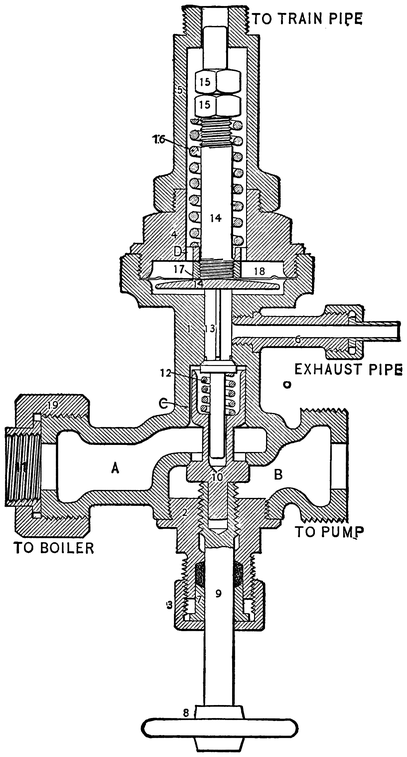
The pump governor is shown in Fig. 34b, the object of which is to automatically cut off the supply of steam to the pump when the air-pressure in the train-pipe exceeds a certain limit, say seventy pounds.
The operation of this governor is as follows: the wheel 8 is screwed down so as to permit the valve 10 to be unseated by the excess of pressure on the upper side of the valve, permitting steam to pass through the openings A and B to the pump. A connection is made from the train-pipe to the upper end of the governor, and the compressed air passes around the stem 14 to the upper side of the diaphragm plate 18, which is held to its position by the spring 16, which latter is of sufficient strength to resist a pressure of, say, seventy pounds per square inch on diaphragm. As soon as the air-pressure on the diaphragm 18 exceeds this amount,340 it forces the diaphragm down, unseating the valve 13, and allowing the steam on the upper side of the valve 10 to escape through the exhaust 6, which causes an excess of steam-pressure on the lower side of the valve 10, forcing the valve against its seat, and cutting off the supply of steam to the pump.
When the pressure in the train-pipe is diminished by applying the brakes, the diaphragm is restored to the position shown by the action of the spring 16. The valve 13 is seated by the spring 12; and the steam-pressure, passing through the port C, accumulates on the upper side of the valve 10, forcing it down, and opening the passage for steam to the pump until the air-pressure is again restored to the required limit of seventy pounds.
The Vacuum Brake, as the name implies, is operated by means of a vacuum which is formed in the connections that act the part of the cylinder in the air-brake. With an air-brake, compressed air is made to do the work of applying the brakes by moving a piston to which the brake-lever is attached, the air being carried throughout the train by means of iron pipes and rubber hose: with the vacuum brake the work is done in a similar way with similar connections; but, instead of compressed air being forced inside the pipes and apparatus, all the air is exhausted out, and the natural pressure of the atmosphere is made to do the work.
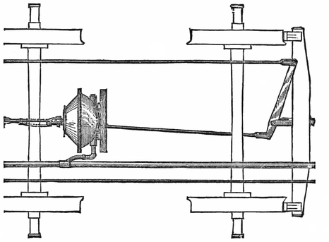
Under each vehicle of a train, as seen in Fig. 35, a diaphragm is securely fastened which performs the combined duties of cylinder and piston. It consists of a kettle-shaped casting with a loose disk of heavy rubbered duck fastened over its mouth; the center of the disk being provided with an iron plate, through which passes an eye-bolt for forming connection with the342 brake-lever. The inside of the diaphragm is connected to the pipe which passes along the train, and has its front end connected with the ejector on the locomotive.

The position of the ejector in the cut can be clearly seen in Fig. 36, where there is also a diaphragm to be seen under the deck where it is located when used to operate driver brakes. The ejector is operated on the same principle as the water injector, only it is used to lift air instead of water. A cross-section of the injector is shown in Fig. 36. When the engineer wishes to apply the brake, he pulls the handle 41 (broken off in the cut), which opens the valve B49, and admits steam to the body of the ejector A1. The steam rushes upward round the end of the tube 5, its velocity being accelerated344 in passing through the contracted opening left round the top of the tube. Passing through tubes 3 and 6, the steam shoots up in the form of a column with a hollow base; the tube 5, which is connected with the pipes and diaphragms on the train, forming this base. The effect of the steam passing out under these conditions is to induce a current through the tube 5, which draws up the valve B7, and sucks the air out of the pipes and diaphragms. A vacuum being thus formed in the diaphragms, the atmosphere presses the flexible ends together. This tendency to collapse is retarded by the brake-rod connections, and the latter receive a pull equal to the combined atmospheric pressure on the diaphragm. The brake-levers are arranged to transmit a proper tension to the brake-shoes for making the brake effective. A vacuum gauge placed on the front of the ejector enables the engineer to regulate the power as he wants it. The brake is released by pushing on the lever 24, which opens the valve 8, and admits air into the brake-pipes. The release-valve attachment is sidewise in vertical section cut through the handle, and is put separate for convenience of illustration.
The valve B7 of the ejector needs grinding occasionally; and, if the lift should be too great, the valve will hammer the seat out of shape. Sometimes when waste or other fibrous impurities are sucked through the pipe, they stick in this valve, keeping it away from the seat. The valve is very easily reached by taking off the cap O4. The steam-valve B49 needs about the same care345 as any other steam-valve, and its troubles are of the same nature. The shoulder at the top of the tube 5, which is used to obstruct the steam, thereby increasing the velocity of the quantity that passes, sometimes gets cut into channels with the fast moving steam striking it. This reduces the promptness of the ejector’s action, but it is a form of deterioration that proceeds very slowly. Care must be taken to keep the drip-valves A and B16 in order, otherwise there may be trouble with the ejector throwing water, or freezing up if the engine stands where that apparatus will get cold in winter.
The capacity of engines is generally expressed in horse-power, which is a measurable quantity; but, for several reasons, that method of indicating power has not been usually applied to the locomotive. When practical railroad men hear the size of cylinders, the diameter of driving-wheels, and the boiler dimensions of a locomotive, mentioned, they understand what kind of service the engine is adapted for, and about the weight of train it can haul. As it has been found necessary for designing and other purposes, to estimate, with some degree of accuracy, the work a locomotive is capable of doing, it has become usual to reckon the power of a locomotive by the tractive force it can exert upon the rails.
Tractive force is the power which the pistons of the engine are capable of exerting through the driving-wheels, to move the engine and train. The efficiency of the engine’s traction is dependent upon the adhesion of the wheels to the rails; for, where the adhesion is insufficient, the pistons will slip the wheels, and no347 useful effect will result. To prevent the wheels of ordinary American engines from slipping on dry rails, the weight resting on the drivers must be about five times the power exerted by the pistons to slip the wheels. To prevent slipping on wet, unwashed rails, more than double the above weight would be needed. In practice, locomotives are not provided with weight enough to prevent the wheels from slipping on a greasy rail: the sand-boxes provide the means of obtaining adhesion where the rails are in bad order. A common practice is to place upon the drivers weight equal to about six times the power exerted to slip the wheels, which leaves a small margin for wet rails. Many locomotives have power sufficient to slip the wheels on dry rails; but such engines generally have boilers too small for the cylinders, or the distribution of weight on the drivers is badly effected.
The easiest way of calculating the tractive power of a locomotive is by use of the following simple formula, first propounded by Pambour:—
d2Lp
T = —————.
D
d = the diameter of the cylinder in inches.
L = the length of the stroke in inches.
D = the diameter of driving-wheels in inches.
p = the effective mean pressure on the piston in pounds per square inch.
T = the equivalent tractive force at the rails in pounds.
This, given in plain terms, reads: Square the diameter348 of piston in inches; multiply by the length of stroke in inches; multiply by the mean pressure of steam per square inch, and divide by the diameter of the drivers in inches.
We will apply the calculations to the case of the standard Buchanan passenger engine; the cylinders being 17 by 24 inches, the drivers 68 inches in diameter, and the effective pressure on pistons about 80 pounds. The problem is worked thus:—
| 17 | inches diam. of cylinders. | |
| 17 | ||
| —— | ||
| 289 | = square of diameter. | |
| 24 | inches stroke of piston. | |
| —— | ||
| 6936 | ||
| 80 | lbs. per square inch. | |
| ——— | ||
| Diam. of drivers, 68) | 554880 | (8160 |
This gives 8,160 pounds as the pressure exerted to turn the drivers, which may be accepted as a close approximation to the truth. In using this formula, the mistake has frequently been made of taking the quotient to represent the power developed by one cylinder, when, in fact, it gives the power of both.
A method of calculating the locomotive traction that is a good deal followed by our engineers, is to ascertain the foot-pounds of work the engine is doing during each revolution of the drivers. By dividing the total thus found by the circumference of the drivers in feet, the force exerted through each foot that the engine moves is found. Taking the same engine, the pistons 17 inches349 diameter, give 226.98 square inches area. This is multiplied by the mean effective pressure of steam, giving 226.98 × 80 = 18158.4 pounds pressing on each piston through the whole stroke of four feet.
| 18158.4 | |
| 2 | pistons. |
| ———— | |
| 36316.8 | |
| 4 | feet of stroke. |
| ———— | |
| 145267.2 |
These figures show that 145267.2 foot-pounds are exerted during each turn of the wheel, whose circumference is 17.8024; therefore, 145267 ÷ 17.8024 = 8160, the number of pounds exerted through each foot moved.
There is still another way of figuring out tractive power by calculating the rotational force and the leverage through which it is applied to the locomotive wheels. The pressure of steam on the piston is productive of two strains on the crank-axle. When the crank is on the dead center, the pressure upon the crank-pin forces the axle against the axle-box without causing any tendency to rotate: but, when the crank-pin is on the quarter, the full leverage of the crank is available for rotation; the leverage increasing gradually as the crank gets away from the center. The mean effort upon the crank-pin during one revolution of the crank is to the effort of the piston as .6366 is to 1.
Now, to find the traction of the locomotive, we multiply the length of our crank, which is 12 inches, by .6366, which gives 7.64 as the length of the crank receiving constant pressure from the pistons. The aggregate350 steam-pressure has already been found to be for each piston, 18158.4 pounds. This is multiplied by 7.64; and the product is divided by the radius of the wheel, which is 34 inches, giving as a quotient 4080, being the power exerted on one side of the engine. That, multiplied by 2, gives 8160 pounds,—the same as was found by the other two methods.
When people wish to find the horse-power developed by a locomotive, the indicator is generally employed, and the calculations made from the diagram. Others figure out locomotive horse-power as they do that of other engines. By this method, the engine whose traction we have been investigating might have the horse-power calculated as follows:—
| 226.98 | square inches piston area. |
| 80 | pounds mean pressure. |
| ——— | |
| 18158.4 | piston pressure. |
| 4 | feet piston travel each revolution. |
| ——— | |
| 72633.6 | |
| 2 | cylinders. |
| ———— | |
| 145267.2 | |
| 145 | revolutions per minute. |
| ———— | |
| 20063944 | ÷ 33000 = 608 horse-power when running at a speed of 30 miles an hour. |
No allowance has been made for frictional losses in any of these calculations.
One horse-power is equivalent to the work performed in raising 33,000 pounds one foot high in one minute. One pound raised 33,000 feet high, or 330 pounds raised351 100 feet high, would amount to the same thing. One horse-power is usually spoken of as 33,000 foot-pounds; and engineers in this country always calculate work by foot-pounds,—that is, so many pounds raised a certain number of feet. To indicate the capacity of any prime motor, the foot-pounds of work it is capable of raising in a given time must be stated. Although the work is often done without any thing being raised vertically, the power represented would be capable of raising the equivalent weight in the stated time.
The work which a locomotive performs in pulling a train is expended in overcoming the resistances due to wheel-friction, gradients, curves, and atmospheric or wind pressure. Formulas have been propounded for calculating all train resistances, but they are utterly untrustworthy for American railroad trains. The best known formula of this kind is that given by D. K. Clark in his Railway Machinery. One calculation will show how misleading its figures are when applied to American railroad train resistances. Figured by the Clark formula, the total resistance per ton of a passenger train running at a speed of fifty miles an hour on a straight level track, is 22.6 pounds. By accurate records with his dynagraph car, Professor P. H. Dudley found the total resistances of an express train running at a speed of fifty-one miles an hour, to be 11 pounds. The resistances are so much different under different conditions, that nothing closer than a loose approximation can be calculated of the work done by a locomotive, unless indicator or dynamometer tests are made.
In experiments made with a freight train on the Erie Railway in 1881, reported by Mr. F. M. Wilder to the Railway Master Mechanics’ Association, it was found that the total resistance on a level track was from 3.25 to 4.5 pounds per ton at speeds under twenty miles an hour. These figures will approximately represent the resistance due to wheel and axial friction in summer; but this resistance will be higher during cold weather, when the oil in the axle-boxes gets frozen. Track in bad condition will also tend to increase the wheel resistance, and improperly constructed trucks and wheels will entail the use of more power to move the train. Where trucks are so defective that they do not maintain the wheels revolving in parallel planes, the flanges of some of the wheels will rub on the rail, increasing the resistance. Wheels out of round; those having the axle out of center, however slight; wheels of different size on the same axle; and numerous other car-truck disorders,—all contribute their share in making a train pull hard.
In a calm day the atmospheric resistance is very slight under a speed of twenty miles an hour. To a fast train, atmospheric resistance becomes an important obstruction. The atmosphere acts on the train in various ways, that are hard to calculate with any degree of accuracy,—head resistance to the locomotive, which is presumably equal to the exposed area of the front of the engine and cab in square feet multiplied by the air-pressure due to the speed; then, various parts of the cars present surfaces that the air strikes against, and increases the353 resistance; the raised and projecting roofs of passenger coaches offer an ample area for the wind to hold the train by; and every opening between the cars permits the wind to obstruct, to some extent, each individual car. Where wind is blowing freely in a direction to strike the train on the side, the resistance is greatly increased; the retardation being due to the wind pushing the car sidewise, so that the wheel-flanges rub against the rail, and also to the wind obtaining a strong hold on the front of each car. In the case of a freight train, the resistance is greatly increased when the doors of cars are left open; for every car in that condition acts like a parachute to reduce speed. Freight trains arranged with box cars and flat cars mixed, obtain more than a fair share of obstruction from the atmosphere; for every box car that has a space opened in front by a flat car, gets nearly the full pressure of the wind in its front. It pays in coal to incur some trouble and delay in putting box cars together. That also enables the brakemen to get along the train more rapidly than where the cars are mixed.
In the experiments already alluded to on the Erie Railway, it was found, in the absence of wind, that the first car of a freight-train produced atmospheric resistance equal to a surface of sixty-three feet, multiplied by the air-pressure due to speed; and that each subsequent car offered a resistance of twenty per cent of that due to the first car.
Curved track increases the resistance of trains in direct proportion to the shortness of curvature. In354 European railways, the character of the curves is nearly always denominated by the length of radius: in this country, a railroad curve is described as of so many degrees. The degree of a curve is determined by the angle subtended at its center by a chord of 100 feet. To those who think of a curve by its radius, it may be well to explain that a curve of one degree has a radius of 5,370 feet, and the radius of any curve can be ascertained by dividing these figures by the number of degrees.
To pull a train up an ascending gradient, the locomotive has to perform work similar to the operation of a pile-driving engine in raising its driving-block. The train is the block raised by the locomotive; and the lift is not vertical, but up an inclined plane; yet the amount of work done is reckoned in precisely the same way. When the engine of a pile-driver raises a block weighing 1,000 pounds a distance of 30 feet, the work done is 1,000 × 30 = 30,000 foot-pounds: when a locomotive pulls a train weighing 1,000 tons over one mile rising 30 feet, the engine performs 30,000 foot-tons of work in that distance by raising the load alone. The total amount of work done will also include the energy expended in overcoming wheel-friction and other ordinary train resistances.
To find the tractive force which the engine must exert through each foot of the mile traversed in pulling the train described, we must divide the foot-pounds of work done, by the distance over which the power was exerted. Thirty thousand foot-tons of work is 60,000,000355 foot-pounds. To this we will add 5 pounds additional for every ton of the train for every foot advanced to cover wheel and wind resistances, making 86,400,000 foot-pounds of work that the engine has to perform in hauling the train one mile. This, divided by the number of feet in a mile, will give 16,363 pounds as the work the locomotive must perform through each foot,—an effort which is entirely within the capacity of many consolidation engines.
Engineers interested in finding an approximation of the work done in taking a fast train over a railroad, can make a close estimate by studying out the figures given below by Professor Dudley. The table shows the performance of an ordinary locomotive upon a train composed of three eight-wheel and six twelve-wheel cars; weight 250 tons; working-weight of engine and tender, 126,000 pounds; cylinders of engine, 17 by 24 inches; diameter of drivers, 72 inches; weight on drivers, 48,000 pounds; blowing-pressure on boiler, 135 pounds.
In starting the train, the locomotive would record a tension of 11,000 to 12,000 pounds for one or two hundred feet of distance. After hooking up, the tension would decrease to about 2,800 or 3,000 pounds; and, with this pull, the speed of 50 miles an hour was attained in the fifth mile. As the speed increases, the resistance of the air against the locomotive becomes greater, and more of its own power is required to move itself. In starting a train, the working adhesion of the steel-tired drivers on dry steel rails is about 33 per cent of the weight upon them, and reduces as the speed increases.
Tabulation of Part of a Trip of the Dynagraph Car on a Fast356 Express Train.
| 1 | 2 | 3 | 4 | 5 | 6 | 7 | 8 | 9 |
| Numbers of Miles. | Time in Minutes and Seconds per Mile. | Speed in Miles per Hour. | Velocity of the Wind in Miles per Hour. | Approximate Grades. | Foot-Pounds of Work shown by Dynametrical Curve per Mile. | Foot-Pounds of Work per Minute expressed in Horse-Power. | Approximate calculated Foot-Pounds of Work required to move the Locomotive in Horse-Power. | Sum of Columns 7 and 8. |
| 1 | 2 54 | 20.68 | Level | 24,116,233 | 252 | |||
| 2 | 1 34 | 38.31 | 6.0 | Down 5 ft 3 in | 20,035,253 | 369 | 221 | 590 |
| 3 | 1 22 | 43.90 | 4.0 | Down 5 ft 3 in | 17,763,214 | 398 | 292 | 690 |
| 4 | 1 16 | 47.34 | 3.0 | Level | 15,904,273 | 383 | 418 | 791 |
| 5 | 1 11 | 50.70 | 4.5 | Level | 14,871,528 | 382 | 406 | 788 |
| 6 | 1 13 | 49.31 | 6.0 | Up 13 feet | 15,284,616 | 383 | 406 | 789 |
| 7 | 1 11 | 50.70 | 6.0 | Down 18 feet | 14,458,430 | 369 | 426 | 795 |
| 8 | 1 08 | 52.89 | 5.0 | Down 13 feet | 13,219,136 | 354 | 451 | 805 |
| 9 | 1 07 | 53.70 | 5.0 | Down 8 feet | 11,566,744 | 319 | 483 | 802 |
| 10 | 1 09 | 52.10 | 5.0 | Down 5 feet | 11,773,293 | 310 | 441 | 751 |
| 11 | 1 08 | 52.89 | 4.2 | Level | 11,773,293 | 316 | 447 | 763 |
| 12 | 1 09 | 52.10 | 5.2 | Down 8 feet | 12,806,038 | 337 | 456 | 793 |
| 13 | 1 10 | 51.43 | 6.0 | Level | 12,392,940 | 324 | 443 | 767 |
| 14 | 1 10 | 51.43 | 4.5 | Level | 12,806,038 | 339 | 426 | 765 |
| 15 | 1 10 | 51.43 | 4.0 | Level | 13,425,685 | 351 | 420 | 771 |
| 16 | 1 10 | 51.43 | 3.5 | Level | 13,299,136 | 345 | 415 | 760 |
| 17 | 1 08 | 52.89 | 3.0 | Level | 13,838,783 | 371 | 443 | 814 |
| 18 | 1 08 | 52.89 | 5.0 | Down 6 feet | 13,219,136 | 354 | 464 | 818 |
| 19 | 1 08 | 52.89 | 3.0 | Down 2 feet | 13,219,136 | 354 | 443 | 797 |
| 20 | 1 11 | 50.70 | 3.5 | Up 10 feet | 14,838,783 | 379 | 406 | 785 |
| 21 | 1 13 | 49.31 | 3.0 | Up 10 feet | 14,458,430 | 362 | 384 | 746 |
| 22 | 1 08 | 52.89 | 3.1 | Level | 12,392,940 | 332 | 443 | 775 |
| 23 | 1 07 | 53.70 | 3.1 | Down 10 feet | 12,186,391 | 333 | 462 | 797 |
The following calculations have been made, to indicate the trains that various locomotives ought to pull.
Weights of Train which Locomotives can haul at a Speed of357 20 Miles an Hour under Ordinary Conditions, in Tons of 2,000 Pounds (not including the Weight of Engine and Tender).
| Type of Locomotive. | |||
| Type “A.” | Type “B.” | Type “C.” | |
| On straight track: | |||
| Level | 1,096 | 1,664 | 2,226 |
| Grade 20 feet per mile | 547 | 840½ | 1,128 |
| ” 40 ” ” | 350 | 545 | 734 |
| ” 60 ” ” | 249 | 390½ | 522 |
| ” 80 ” ” | 188 | 302 | 410 |
| ” 100 ” ” | 148 | 242 | 330 |
| On 5-degree curves: | |||
| Level | 921 | 1,401½ | 1,876 |
| Grade 20 feet per mile | 464 | 716 | 962 |
| ” 40 ” ” | 310 | 485 | 654 |
| ” 60 ” ” | 227 | 360½ | 488 |
| ” 80 ” ” | 173 | 279½ | 380 |
| ” 100 ” ” | 137 | 225½ | 308 |
| On 10-degree curves: | |||
| Level | 662 | 1,013 | 1,358 |
| Grade 20 feet per mile | 401 | 621½ | 836 |
| ” 40 ” ” | 278 | 477 | 590 |
| ” 60 ” ” | 207 | 330½ | 448 |
| ” 80 ” ” | 160 | 260 | 354 |
| ” 100 ” ” | 128 | 212 | 290 |
Under the most favorable conditions, loads about fifty per cent greater than those given above may be hauled.
The calculations are for three types of engine, designated in the column titles as Type “A,” Type “B,” and Type “C;” these being as follows:—
Type A.—American locomotive, with four driving-wheels,358 and 12,000 pounds weight on each wheel, the total weight of engine being 36 tons.
Type B.—Mogul or ten-wheeled locomotive, with six driving-wheels, and 12,000 pounds weight on each wheel, the total weight of engine being about 42 tons.
Type C.—Consolidation locomotive, with eight driving-wheels, and 12,000 pounds weight on each wheel, the total weight of engine being about 54 tons.
Throughout a very wide area of territory in the United States and Canada, limestones, or various forms of calcareous rocks, constitute the upper rock stratum immediately underlying the subsoil of the great agricultural regions. During the stupendous operations of Nature in building up this continent, the rocks have been subjected to vast disintegrating agencies: they have been torn and eroded by huge masses of ice; they have been burned by the rays of the unshadowed sun; fractured by the congealing power resulting from deep-searching frost; melted by water,—that most universal solvent in nature; then scattered far and wide by ice and flood. This process has been so complete, that, in the whole limestone territory, all the earth seems charged with lime. Limestones are very sparingly soluble in pure water; but the rain that falls from the clouds is not pure, but contains a charge of carbonic acid that acts chemically upon the lime, forming salts, which the water readily dissolves. Owing to this circumstance, there are few streams, and fewer wells, in the calcareous districts that are not contaminated with lime. The360 water that passes into streams, generally runs over surfaces that have been washed partly free from lime; and, in consequence of this, creeks and rivers are not so badly tainted with lime-salts as the water in wells that stands saturating the rocks. The appearance or taste of water gives no indication of the quantity of lime held in solution; for the ice-cold well, or sparkling spring, that supplies water so pleasant to drink, may yield so much lime-salts that the water would be ruinous to sheets and flues when used for boiler purposes.
Considering the financial influence of the matter alone, it might be supposed that parties building railroads would exercise diligence in selecting the best water that possibly could be secured for boiler purposes, since the operating expenses are largely magnified by using impure water; but for many years the subject appeared to receive no attention whatever from those best able to regulate the water supply, and water stations were established without any consideration as to the character of the water available.
It is owing to the absence of care in the original locating of water stations, that numerous tanks are to-day drawing their supply from bad wells, where surface water could easily be obtained. Railroad companies are peculiarly conservative about making changes that entail expenditure of money: and existing evils in the water supply arrangements are often continued, because some expense would be incurred in making them; although no kind of money expenditure would bring a more ample return in economy.
The paramount importance of the quality of water used in locomotive boilers, has been long recognized by nearly all master mechanics; for the effect of bad water is brought to their attention in an unmistakable manner. The subject has been frequently before the Master Mechanics’ Association for investigation. A report of a committee appointed at an early meeting to investigate the subject, declares that “Master mechanics have had the conviction forced home, that impure water is the bane of good boilers;” and, even then, a vigorous effort was being made to eliminate the injurious ingredients from the water; and the work was carried on in a hopeful and confident spirit, which was indicated by the words of a subsequent report, which asserted that “Different waters differ widely in the component parts of the impurities they contain, and each requires separate study and treatment;” but the committee were satisfied that the engineering and mechanical skill of railway men could readily devise a suitable appliance for each particular case. In those days, railroad men thought that they could, by mechanical and chemical means, purify bad water, and render it suitable for boiler use. Purifying bad water proved about as difficult an undertaking as reforming the average bad man is recognized to be; and few railroad men can now be found who believe a purifying process can be successfully performed on the large quantity of water needed for locomotive boiler feeding.
The conclusion that artificial methods of purifying362 bad water can not be carried out in railroad water supply, was not arrived at hastily. It was reached by slow degrees, and through the convincing ordeal of many disappointments, with methods and nostrums that promised to effect the desired results.
Experience demonstrated, that, in the limestone regions, the proper and only way to avoid trouble from lime incrustation in locomotive boilers, is to obtain soft water from streams, or by collecting the rainfall in ponds or reservoirs.
Water, as has been mentioned, is the most universal solvent in nature; and what is known as hard water contains many foreign ingredients, but those that exercise such a pernicious influence upon locomotive boilers are lime and magnesia. The scale-making lime appears in two forms,—sulphate of lime, and carbonate of lime. The former is the more dangerous and troublesome scale-making agent; the latter is most frequently met with.
Ordinary well-water will be found to contain solid matter in solution varying from 10 to 100 grains to the gallon. Under 20 grains to the gallon of impurities may be considered fair water if the principal ingredient is carbonate of lime, but that amount of sulphate will make highly objectionable boiler water. Where the use of well-water is unavoidable on a road, quite a saving to boilers can be effected by ascertaining the quantity and character of the impurities received from each water-tank, and directing the engineers to avoid those that contain the worst scale formers.
The proper way to ascertain with accuracy the character of water, is to send specimens to a competent analytical chemist for quantitative analysis. But, as few railroad companies will incur the expense of having the water of the water stations systematically tested, master mechanics may, by a little labor, study, and practice, learn to make tests for themselves that will indicate near enough for practical purposes the character of each water station supply.
As master mechanics are the railroad officials most directly interested in the kind of water supplied for locomotive use, they ought to have direct control of all the water stations on the roads where they are in charge.
The chemical apparatus needed for the examination of well-water are, a balance that will weigh accurately to half a grain; an oil stove for evaporative purposes; a few pint porcelain evaporating dishes; a sand-bath, which can be made from a piece of sheet-copper; a dozen test tubes; half a dozen vials to hold solutions of chemically pure chemicals; some pieces of glass tubing; a small mortar and pestle; a supply of filtering-paper; and the vessels needed for measuring accurately. For the solution of the chemical re-agents to be used, a supply of distilled water is necessary; and water of this kind is also necessary to make comparisons with. A piece of pure crystalline ice, when melted, will generally produce water pure enough for experimental purposes.
In bringing in water for examination, it is best to have it drawn from the water-tank into a perfectly clean jug, which should be corked and labeled. Weigh an evaporating dish, noting down the exact weight, and on a sand-bath evaporate one quart or half a gallon of the water to be inspected. When the dish becomes dry, rub off all dust that may be adhering to the bottom, and weigh the dish. The added weight will indicate approximately the total amount of solid matter in the water. Note that down, and every other detail of the experiments.
Sometimes a large quantity of bicarbonate of lime is held in solution by free carbonic acid, which escapes as soon as the water is boiled, leaving the lime to subside in the form of mud. Water of this kind may appear very hard, yet not be very objectionable for boiler use; since the deposit can be blown out if the blow-off cock is used freely. To test this, boil a pint of water for two or three minutes in a perfectly clean dish, then pass it through a filter paper that has been previously dried and weighed. When the operation is finished, dry and weigh the filter paper again; and the added weight will indicate the amount of solid matter held in solution by free carbonic acid gas.
Superficial tests that will indicate the condition of the water from the coloring produced by the impurities combining with chemicals that take them out of solution,365 can be made in the following manner: Five test tubes are half filled with water to be tested. The first one will be examined for lime in any form. A teaspoonful of aqua ammonia is put in the water for the purpose of stimulating the chemical action, then twenty drops of a solution of oxalate of ammonia are added. The degree of turbidity will indicate the quantity of lime in the water. Should the quantity of lime be very small, the test tube would have to be kept in a warm place a few hours before the re-action showed itself.
The water in the second test tube will be examined for sulphate of lime. A few drops of hydrochloric acid are first put into the water, then twenty drops of chloride of barium. A white precipitate, which generally makes its appearance at once, indicates the presence of sulphuric acid. In water belonging to the calcareous regions, it may safely be concluded that the sulphuric acid is held in the form of sulphate of lime. An exception has sometimes to be made for water drawn from the vicinity of coal mines, and such places, where sulphate of iron abounds. Water that holds sulphuric acid in this form is readily identified by a test for iron salts.
When it is found that water gives a strong re-action indicating sulphate of lime, the inference may safely be drawn that the tank it came from should be avoided.
The third test tube may be examined for carbonate of magnesia, which is found freely mixed with the water of many wells. Put aqua ammonia in this tube, and366 add twenty drops of a solution of phosphate of soda. A crystalline precipitate will indicate the presence of magnesium. Where carbonate of magnesia is present in considerable quantities in water, it sometimes forms along with lime a thick, porous scale; and in other cases it is apt to float on the top of the water, causing trouble by making the boiler foam. If an engine boiler has got scale formed from water free from magnesia, and goes on to a division where this impurity abounds, the magnesia will take off the old scale before it begins to form new incrustation. A few pounds of common salt put into the tender daily will have a good effect in preventing trouble with magnesia; since it forms chloride of magnesia, which is a decided preventive of lime scale.
In the fourth test tube we will search for iron salts. A solution of potassa or ammonia will produce, should iron be present, a whitish precipitate, which presently turns to a dirty green, and, ultimately, a reddish-brown color, owing to its absorption of oxygen from the air. A more delicate test for iron is ferro-cyanide of potassium, or sulpho-cyanate of potassium; but other mineral combinations might deceive a novice using these reagents into the belief that iron was present when it was not. A light trace of iron in water is very common; and, so long as it is in minute quantities, the salt seems quite innocent. But occasionally water is found saturated with iron in the form known by chemists as FeSO4. Then it is very objectionable for boiler-feeding; since it exercises a strong corrosive action on the plates, pitting and furrowing being a common result of367 its action. Scale formed by water of this character is nearly always a hard, thin substance, that sticks with intense tenacity, and generally takes away part of the skin of the iron when it is taken off.
The fifth tube we will examine for common salt, which is nearly always present in water. This test is done by dropping in some nitrate of silver solution, which produces a white precipitate, caused by the silver combining with the chlorine, which is the principal element in common salt. This is an excessively fine test, and the nitrate of silver will detect an incredibly small trace of common salt in water. The worst effect that common salt has in water, is to cause priming. Where it is present to any great extent, the blow-off cock should be used frequently on the road; and a surface-cock is quite an aid in keeping the boiler in order. Water that is taken from wells or streams about cities, and found to give strong chlorine re-actions, is nearly always contaminated with sewage.
Practice in making superficial qualitative tests of water, produces skill in reading the meaning of the various chemical re-actions. This skill can be rapidly developed by practice on prepared specimens. Water for experiments on carbonate of lime can be prepared by dissolving calcite crystals or marble dust in hydrochloric acid, or by mixing chalk with clean rain-water, and filtering it till free from turbidity. While the chalk is mixed with the water, and unfiltered, the specimen368 will be made stronger by blowing air from the lungs through a glass tube into the water. A preparation for testing sulphate of lime may be made by dissolving some gypsum in distilled water. Fluid magnesia, dropped into pure water, will provide carbonate of magnesia specimens; and Epsom salts will give the magnesia re-action, with the addition that it will indicate sulphuric acid under the chloride of barium test. A grain of salt no larger than a pin-head dropped into a pint of distilled water, will give a distinct chlorine test when nitrate of silver solution is added. Stronger, or even weaker, salt solution can be used by the experimenter while he is working into practice. A small piece of sulphate of iron, dissolved in water, will provide a test for iron.
While pursuing the apprentice practice of tests with these solutions, care must be taken to have the test tubes perfectly clean. Go over the tests in something like the following order. The carbonate of lime test is to be made first. Four test tubes will be used. In the first we put distilled water alone; in the second we put ten drops of the chalk solution; in the third we put twenty drops of the solution; in the fourth we put thirty drops, then add distilled water till all the test tubes are about two-thirds filled. Drop into each tube about the same quantity of oxalate of ammonia solution, and the degree of turbidity will help to indicate the hardness of each specimen. The first tube, containing pure water, will give no re-action if the chemicals are pure.
This process should be extended to all the other solutions, and will be found very helpful. In carrying out369 experiments of this kind, much assistance will be obtained from having a work like Stuckhardt’s Chemistry at hand for reference.
Most people are aware that hard water has a peculiar effect upon soap, making it curdle instead of lather when used for washing purposes. This peculiarity was made use of some years ago by Dr. Clark of Aberdeen, Scotland, in devising a test for the hardness of water, in which the quantity of a standard soap solution needed to produce a permanent lather on water, indicated the degree of hardness of the water. A modification of the Clark process can be used very conveniently by master mechanics in making superficial tests of the hardness of water, and the plan has the advantage of being easily applied. With a test tube and a small bottle of soap-solution, the investigator is ready at any time or place to make tests; and a few minutes spent over each specimen will give him an idea of the value of the water for boiler purposes.
The original Clark soap-test was made with a soap-solution of known strength, of which a certain measured quantity was required to produce a permanent lather on a gallon of water containing a given quantity of carbonate of lime. The degrees of hardness of other specimens were computed according to the quantity of the soap-solution required to produce a permanent lather. Preparing soap-solution of a certain strength, and water of a certain hardness, for the purpose of indicating a point for beginning the computations, is a tedious operation; and the soap-test can be used in a much simpler way.370 While making numerous tests of water on the Burlinglington, Cedar Rapids, and Northern Railway some years ago, to ascertain the condition of water tanks at different seasons of the year, and in examining the supply of proposed water stations on extensions of the road, I used the following modification of the Clark process:—
The Cedar River, during its normal flow in summer, contains about ten grains of solid matter, mostly calcium carbonate, to the American gallon of 58,373 grains. This I considered good boiler-water, and made it the standard of comparison for my tests. Beside the shop, there is a well, which the people who built the road dug for supplying boiler-water; although the Cedar ran a few rods distant. This well-water contained about forty grains of solid matter to the gallon, one-fourth of the impurity being sulphate of lime. This water I made my “awful example” standard of comparison, so that water approaching this in hardness was condemned.
The soap-solution I made by dissolving seventy grains of castile soap, or white soap-powder, in a pint of alcohol. Care must be taken that all the soap is dissolved, and then it is best to keep the mixture in an even temperature not below 60° Fahr. The tests can be made more accurately by having the water under examination brought to the same temperature as the soap-solution.
In making the tests, a measured quantity of the Cedar water was put into a stoppered bottle. One ounce of water put into a two-ounce bottle is a convenient quantity.371 The soap-solution was then measured out with a pipette made to hold thirty drops, and the bottle was well shaken after each measure till it was found that a lather was formed which held on for five minutes. The operation was then repeated; and the last charge from the pipette was put in, drop by drop, till the point where a permanent lather formed was noted. A similar performance was gone through with the bad well-water, and very little practice enabled the operator to ascertain where a specimen of water stood between the range of the good and bad water.
The soap-solution must be kept in a properly stoppered bottle; and, every time a new solution is made, its strength must be tested in the above fashion. The solution deteriorates when kept longer than a month or six weeks.
The degree of turbidity caused by the first charge of soap-solution, is an indication to the practiced experimenter of the degree of hardness of the water.
Most men interested in ascertaining the condition of boiler-water, can devise means for obtaining water of known hardness wherewith to make comparative tests.
If water under examination prove very hard, the test will be more accurately done by diluting it with its own volume of distilled water.
The soap-test is good for lime in all its forms, and magnesia; but the latter impurity uses up more soap than lime does. So, where magnesia abounds in water, the specimen under trial will seem harder than it actually is. Magnesia is also slower than lime in acting upon the soap. Water that contains magnesia will produce a lather when enough solution is put in to overcome372 the lime present; but if it be allowed to stand a few minutes, till the magnesia acts, the lather will not then form. The presence of certain alkaline salts in water, such as the carbonates and sulphates of soda and potash, injuriously affects the soap-test by making the water appear softer than it is; since they accelerate the forming of a permanent lather. Keeping these facts in mind will often prove of valuable service in making tests of water.
When the soap-test indicates that water contains hardening ingredients, representing more than fifteen grains to the gallon, other tests should be at once made to ascertain what the leading ingredients are.
The nostrums offered to railroad managers for purifying feed-water are legion, but it is doubtful if a single remedy has proved entirely successful. In most instances, the material or means used have been worthless or impracticable; but, in other cases, the appliances have not received justice from those attending their application. Most people underrate the magnitude of the task involved in undertaking to render the impurities of feed-water innocent in locomotive boilers. The case of a learned professor who undertook to doctor the feed-water for locomotives on a prominent road, where he made his arrangements for each engine using one thousand gallons of water a day, is representative. When provision has to be made for some engines using double that quantity each hour, the difficulty of the transaction becomes apparent. As has already been said, I believe that obtaining soft surface-water is the373 proper way to avoid trouble with locomotive boilers; but, where this is impracticable, considerable saving can be effected by “doctoring” the water if the operations are intelligently conducted.
Mud is the most universal impurity of feed-water; and, in many cases, it causes the destruction or injury of sheets, particularly the crown-sheets of fire-boxes. Where the water of a road is habitually muddy, it would pay to filter the water, or to have two tanks at each water station, so that a system could be followed of letting the water settle in one tank while the other was in use. The settled mud, by this means, could be washed out regularly before a tank were refilled.
Dr. Clark, inventor of the soap-test, recommended a method of purifying water containing carbonate of lime, which has been successfully followed in many places, especially in England. It consists of adding caustic lime to water containing carbonate of lime. By this process, 28 grains of caustic lime result in the precipitation of 100 grains of lime carbonate. Or, to put it in a practical shape, where a tank contains 30,000 gallons of water, each gallon being impregnated with 30 grains of lime carbonate, 36 pounds of caustic lime will be sufficient to precipitate the whole of the impurity, making a total deposit of 164 pounds.
Where the water impurity is principally sulphate of374 lime, the caustic lime remedy will not work; but a precipitate of the objectionable compound can be made by treating the water with caustic baryta or caustic soda. In the first case, the baryta takes possession of the sulphuric acid holding the lime in solution, allowing the latter to fall down as mud: when the soda cure is applied, the sulphuric acid deserts the lime, and combines with the soda, for which it has greater affinity, leaving the lime to precipitate, unless it be preserved in solution by the carbonic acid that accompanied the soda.
Where the water contains a mixture of lime sulphate and carbonate, the soda treatment may be advantageously used in combination with the caustic lime system.
Attempts have frequently been made to purify water by putting chemicals into the locomotive tenders, the impurity being precipitated in the boiler. The leading objection to this system is, that it leads to enormous quantities of sediment being deposited inside the boiler; since, in some instances, the purifying substance is as bulky as the original impurity. In other cases, the chemical introduced into the boiler causes foaming. Let us take the case of water that contains fifteen grains of sulphate of lime to the gallon, and is treated with sulphate of baryta. To do so properly, one grain of the chemical will be required for each grain of lime. A freight engine uses seventy-five gallons of water to the mile, and runs one hundred miles a day. This is light service, both for water and mileage; yet, within ten days, nearly three hundred pounds of solid matter is injected into the boiler. To purify water by injecting chemicals into locomotive boilers, and prevent the boiler375 filling up rapidly with mud, or giving trouble from foaming, the blow-off cock and surface cock must be used so frequently as to be felt on the consumption of coal. Where purifying of feed-water must be done, the right place to carry on the process is in the station tanks, or in special appliances beside them. By carefully watching the character of the impurities in the water, and treating them with their proper precipitants, labor and expense devoted to the purification of feed-water may bring in good returns: where attempts are made to improve the water over a whole road by one method of treatment, failure is certain.
The following is the form of questions put to firemen on one of the most prominent railroads in this country before they are admitted as competent for promotion, and the kind of answers expected from those who are considered eligible for the higher position. The form questions are not adhered to strictly, and care is taken that a candidate for promotion does not commit the answers to memory without properly understanding the subject. No fireman is promoted who does not satisfy the examiner that he understands the practical questions asked.
Q.—What are the principal duties of an engineer before attaching his engine to train?
A.—To examine the engine carefully, to see that all set-screws are in place, and rod-keys secure; that the engine is equipped with all necessary signals, firing, and hand-tools; the necessary supply of water, fuel, and stores. Also, to take a look at the flues and crown-sheet.
Q.—What is important, in carrying water in the boiler, as to height and regularity?
A.—To carry water and steam in the top gauge-cocks377 when working steam, and as uniformly as possible.
Q.—What is important in carrying water on grades, and approaching a summit?
A.—To carry the water sufficiently high to be sure that the front ends of the tubes are not exposed, and, in pitching over a summit, to have sufficient water to cover and protect the crown-sheet, after finding its level from the front or low end of the boiler.
Q.—Should it be necessary, after pitching over a summit, to pump up a gauge or more of water, what should be the condition of the fire?
A.—The fire should be kept bright, and burning freely.
Q.—Why is this important?
A.—To prevent chilling the flues, causing them to leak.
Q.—Should you have ample water after pitching over, what should be the condition of the fire?
A.—It should be leveled and settled down, and covered over sufficiently to prevent unnecessary waste of steam or fuel.
Q.—Should the pump or injectors fail on the road, what would you do?
A.—First, smother down the fire, stop promptly, take off the hose, and raise the tank-valves to ascertain that they are connected; also see that the strainers are clear. If all is found clear, then try the injectors again; and, if the engine has a pump, take it down, and see that the valves are free, and would also run water through the feed-pipes. When all is open and free, put them up, and try them again.
Q.—Should the water in the boiler get too low to378 allow you time for the examination, what would you do?
A.—Draw the fire, and send a messenger to the nearest telegraph office for assistance.
Q.—Should the water in the boiler become disturbed, and foam, what would you do? And how would you ascertain whether it was foaming, or being over pumped?
A.—As soon as the water is discovered discharging from the stack, would at once shut off, and ascertain the height of the water solid. Should the water drop below the second or third gauge, would conclude there was foaming, and would again gently open the throttle. Should the water again rise, and discharge from the stack, would put on both injectors, open the surface blow, and run carefully; allowing the bad water to be worked off through the surface blow, being very careful not to work the water in sufficient quantities through the cylinders as to endanger knocking out the heads; and would occasionally shut off, to see that the water was not being thrown off faster than the pumps or injectors were supplying it. By this means, the bad water would, in most cases, be worked out, and, with gentle usage, would again settle.
Q.—Should the blow-off cock be blown out, or be broken off, or a hole be broken in the boiler in any way, what would you do?
A.—Draw the fire promptly, and send a messenger to the nearest telegraph office for assistance. Would then disconnect, and get the engine ready to be towed in when assistance arrived.
Q.—What portions of the engine would you disconnect379 in such a case?
A.—Take off main rods and valve-rods.
Q.—What is important to observe in setting up or adjusting wedges?
A.—To have them so neatly adjusted that there will be no thump of the boxes, and, at the same time, not so tight as to cramp, and not allow them full and free play in the pedestals.
Q.—How would you go about setting them up?
A.—Would place the engine at half stroke on the right side, block the left wheels, admit a little steam, and thump the boxes hard away from the wedges. Would then get under, and put the wedges up solid with a short wrench, and make a side mark on the pedestals at top of wedge, then draw them down equally a scant one-eighth of an inch. Go over the left side in the same manner.
Q.—How would you key up, or adjust, the side rods of a ten-wheel engine?
A.—Would place the engine on a level and straight track, and on a dead center; then slack off all keys on that line of rods; would then key the knuckle on center brass first, leaving it sufficiently free on the pin to be moved laterally by hand. Then adjust the front and back ends in the same manner.
Q.—Why should you place the engine on exact dead center, and begin by keying the center brass first?
A.—In order to insure keying the rods of proper length, to allow them to pass the dead, or rigid, points without strain.
Q.—Can the side rods be keyed too long or too short380 when not standing on dead center?
A.—They can.
Q.—If too long or too short, at what point of the stroke will the strain be?
A.—While passing the dead, or rigid, points.
Q.—Should you slip the right back motion eccentric on the road, how would you reset it?
A.—Would place the engine on exact dead center on right side, place the reverse-lever in full forward gear, and make a mark on the valve-rod at the stuffing-box gland; then place the reverse-lever in full back gear, and turn the slipped eccentric until the mark on valve-rod came to its original position, being careful to see that the full or throw of the eccentric was in position nearly opposite the forward eccentric; then secure it there.
Q.—In what way does the mark you made on the valve-rod, while in forward gear, aid you in setting the slipped eccentric?
A.—The forward motion eccentric being in proper position by placing the reverse-lever in full forward gear, the valve is brought into proper position on the ports; and the mark gives the position of the valve when the back motion eccentric is in its proper position, thus setting the slipped eccentric by the good one.
Q.—Should a valve-yoke break, how would you test in order to determine which side was disabled?
A.—Would first place the engine at half stroke on right side, and admit a little steam to the cylinders; then move the reverse-lever from back to forward motion,381 and, if the steam could be shifted from the back to the forward cylinder-cock, would conclude that the right yoke was good, and would test the left side in the same way.
Q.—Why would you place your engine at half stroke on the side you wished to test?
A.—In order to get the full movement of the valve over the ports on that side.
Q.—After locating the broken yoke, how would you disconnect?
A.—Would take off the steam-chest lid, place the valve over the ports, and block it there securely; replace the lid, take off the valve-rod, take off the main rod, block the cross-head, and proceed with half train, if freight; if passenger, would take the full train to the next telegraph office, report, and give judgment as to whether the engine would take entire train to its destination.
Q.—Should you blow or break out a cylinder-head, how would you disconnect?
A.—First, take off the valve-rod, and close the ports with the valve, and secure it by cramping with the stuffing-box gland; take off main rod, and block the cross-head.
Q.—Should the cylinder packing drop and blow badly on the road, how would you determine which side was down?
A.—In starting from a station, would notice the right cross-head, and, if the blow occurred when it was leaving each extreme end of the stroke, would locate the blow in the right cylinder.
Q.—Should it blow so badly as to make it necessary382 to set it out on the road, what would be important for you to observe in setting it out?
A.—Would be careful to set the piston central in the cylinder, using calipers if at hand, and, if not, would use a stick of proper length, and be careful only to set the packing to fill the cylinder neatly, using as little power on the bolts as practicable; lock the nuts securely, and replace the follower, being careful to screw the follower bolts home solid.
Q.—Should you be running an engine which had but one pump, it being on the right side, and that side became disabled, so that it would be necessary to disconnect it, the injector be too small or fail to supply the boiler, what would you do to avoid drawing the fire, and being hauled home?
A.—Would disconnect the piston from the cross-head on the disabled side, and take it out, put up the main rod, and work the cross-head, which would give the use of the pump.
Q.—Should you break the top rocker-arm, how would you disconnect?
A.—Take off the valve-rod and broken arm, close the ports, and secure the valve with the stuffing-box gland, and disconnect, as in case of broken cylinder-head.
Q.—Should the bottom rocker-arm break, how would you disconnect?
A.—As a rule, would not take off eccentric-straps; but with an engine badly worn, and loose in link-hanger, so that the link could play about freely when running, would take off the eccentric-straps, and disconnect, as in case of broken cylinder-head.
Q.—Should you break a link-hanger, how would you383 disconnect?
A.—If but a short distance to run, and no stopping or shifting to do, would run in without disconnecting, after cautioning the crew to keep the train under good control, and stop promptly when signaled to do so. But, if a long distance to run, would disconnect, as in case of broken cylinder-head.
Q.—In what way would you have lost control of your engine with broken link-hanger?
A.—Would only be able to reverse one side of the engine.
Q.—Should you break an eccentric-strap, how would you disconnect?
A.—Take off both eccentric-straps on that side, and disconnect as in case of broken cylinder-head.
Q.—Should you break the back section of a side rod on a six-wheel connected engine, what would you do?
A.—Would take off both back sections, and run in with main and forward wheels connected, with about two-thirds of train.
Q.—Should you break a forward section, how would you disconnect?
A.—Would take off all side rods, and run in without train.
Q.—Should you break a main crank-pin close up to the wheel, how would you disconnect?
A.—Would take off all side rods and the main rod on disabled side, and run in without train.
Q.—Should you be running an engine which had a slide throttle-valve, and it would strip or disconnect inside the boiler partly open, how would you manage?
A.—Would reduce the steam-pressure within easy384 control, and state the trouble to the crew, and caution them to act promptly when called upon to do so. Would work the train, if freight, to the nearest siding, and back it off; if passenger, would keep the pressure within easy handling, and work the train to the nearest telegraph office, report, and ask for orders.
Q.—Should one of the forward tires on a ten-wheel engine break, how would you manage?
A.—Would jack the wheel up the thickness of the tire, take out the oil-cellar, and cut a block to fit the bottom of the box and journal sufficiently thick to hold the axle up in its place when resting on the pedestal-brace; would then run in without disconnecting, provided the rod had not been bent or damaged by the broken tire. Would take in full train.
Q.—Should you break a main tire, how would you manage?
A.—Would first send messenger to nearest telegraph office, and ask for assistance. Would then block up the axle and wheel the thickness of the tire, slack off the side-rod keys, and run in carefully without train.
Q.—Should the back tire break, how would you manage?
A.—Would take off the back section of rods, block up the axle, run very carefully, especially around curves, to nearest telegraph office, report, and ask for orders.
WM. SELLERS & CO. (INCORPORATED),
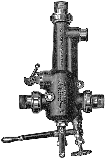

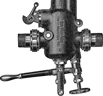
Sole Patentees and Makers of
THE
SELF-ACTING
INJECTOR
OF 1887.
Range of capacity over 60 per cent., and can therefore be regulated to work continuously for the lightest or heaviest trains. Never fails to lift promptly hot or cold water. No service on a locomotive is sufficiently severe to permanently stop its working. Should the jet break from any interruption of the steam or water supply, the Injector will RESTART ITSELF as soon as the supply is resumed. Adjusts itself to varying steam pressures without waste of water. Increases quantity of water with increase of steam, and vice versa. Very simple to operate. Started by pulling out the lever. Stopped by pushing in the lever.
Descriptive Circular Price List sent on application to office and works,
PHILADELPHIA, PA.
Established, 1831. Annual Capacity, 600.
Baldwin Locomotive Works
BURNHAM, PARRY, WILLIAMS & CO.,
PROPRIETORS,
PHILADELPHIA, PA.
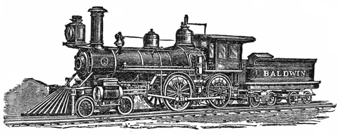
Broad and Narrow Gauge Locomotives.
Mine Locomotives.
Plantation Locomotives.
Compressed Air Locomotives.
Logging Locomotives.
Noiseless Motors and Steam Street Cars.
All important parts made to Standard Gauges and Templates. Like parts of different engines of same class perfectly interchangeable.
GEO. WESTINGHOUSE, Jr., President.
JOHN CALDWELL, Treasurer.
T. W. WELSH, Superintendent.
W. W. CARD, Secretary.
H. H. WESTINGHOUSE, General Agent.
THE WESTINGHOUSE AIR BRAKE
COMPANY,
Pittsburgh, Pa., U.S.A.,
MANUFACTURERS OF THE
WESTINGHOUSE AUTOMATIC BRAKE,
WESTINGHOUSE LOCOMOTIVE DRIVER BRAKE,
VACUUM BRAKES (Westinghouse & Smith Patents),
WESTINGHOUSE AIR BRAKE.
The Automatic Freight Brake is essentially the same apparatus as the Automatic Brake for passenger cars, except that the various parts are one piece of mechanism, and is sold at a very low price. The saving in accidents, flat wheels, brakemen’s wages, and the increased speed possible with perfect safety, will repay the cost of its application within a very short time.
The “AUTOMATIC” has proved itself to be the most efficient train and safety brake known. Its application is instantaneous; it can be operated from any car in the train, if desired, and should the train separate, or a hose or pipe fail, it applies automatically. A GUARANTEE is given customers against LOSS from PATENT SUITS on the apparatus sold them.
FULL INFORMATION FURNISHED ON APPLICATION.
PITTSBURGH
LOCOMOTIVE AND CAR WORKS,
PITTSBURGH, PA.
Manufacturers of
Locomotive Engines
FOR
BROAD OR NARROW GAUGE ROADS
From standard designs, or according to specifications, to suit purchasers.
Tanks, Locomotive or Stationary Boilers
Furnished at Short Notice.
D. A. STEWART, Pres’t. D. A. WIGHTMAN, Sup’t. WILSON MILLER, Sec. and Treas.

BROOKS LOCOMOTIVE WORKS
DUNKIRK, N. Y.
H. G. BROOKS, President and Superintendent.
M. L. HINMAN, Secretary and Treasurer.
R. J. GROSS, Traveling Agent.
Builders of all classes of LOCOMOTIVE ENGINES. All work constructed accurately to Standard Gauges and Steel-Bushed Templates. We guarantee the interchangeability of like parts of different Engines of the same class.
STEEL CASTINGS
From 1-4 to 15,000 lbs. weight,
True to pattern, sound and solid, of unequalled strength, toughness, and
durability. An invaluable substitute for forgings, or for cast-iron
requiring three-fold strength. Gearing of all kinds, Shoes,
Dies, Hammer-Heads, Cross-Heads for Locomotives,
etc. 40,000 Crank Shafts, and 30,000 Gear
Wheels of this Steel now running,
prove its superiority over
other Steel Castings.
SPECIALTIES:
CRANK SHAFTS, CROSS-HEADS, AND GEARINGS,
Steel Castings of Every Description.
Please send for Circulars. Address
CHESTER STEEL CASTINGS CO.,
Works, CHESTER, PENN.
Office, No. 407 LIBRARY STREET, PHILADELPHIA.
Punctuation and spelling were made consistent when a predominant preference was found in the original book; otherwise they were not changed. Inconsistent hyphenation was not changed.
Simple typographical errors were corrected; unbalanced quotation marks were remedied when the change was obvious, and otherwise left unbalanced.
Illustrations in this eBook have been positioned between paragraphs, outside quotations, and usually close to their first reference in the text.
Illustrations with small print can be magnified by widening the window on a computer or zooming in on a handheld device.
The index was not checked for proper alphabetization or correct page references.
Text uses both “employés” and “employes”.