The Project Gutenberg EBook of Concrete Construction for the Home and the
Farm, by The Atlas Portland Cement Company

This eBook is for the use of anyone anywhere in the United States and most
other parts of the world at no cost and with almost no restrictions
whatsoever.  You may copy it, give it away or re-use it under the terms of
the Project Gutenberg License included with this eBook or online at
www.gutenberg.org.  If you are not located in the United States, you'll have
to check the laws of the country where you are located before using this ebook.

Title: Concrete Construction for the Home and the Farm

Author: The Atlas Portland Cement Company

Release Date: June 2, 2020 [EBook #62312]

Language: English

Character set encoding: UTF-8

*** START OF THIS PROJECT GUTENBERG EBOOK CONCRETE CONSTRUCTION FOR HOME AND FARM ***


Produced by MFR, Paul Marshall and the Online Distributed
Proofreading Team at https://www.pgdp.net (This file was
produced from images generously made available by The
Internet Archive)
A Request
Should you find this book helpful in building with concrete, we would consider it a favor to have you so inform us. Likewise, we would appreciate a description (and a photograph if possible) of whatever you have built in concrete.
In this way you will assist us in aiding others in the same way we hope we have helped you.
If you do not fully understand any part of this book, or if you desire further information, write us and we shall be glad to do anything else we can.
“CONCRETE FOR PERMANENCE”
1916
THE ATLAS PORTLAND CEMENT COMPANY
30 Broad Street, New York 134 So. LaSalle Street, Chicago
Philadelphia Boston St. Louis Minneapolis Des Moines
Special Index to Directions
| PAGE | |
| Bank-run gravel, | 13 |
| Cleaning forms, | 24 |
| Definition of concrete, | 9 |
| Dry mixture, | 13 |
| Forms, | 22-24 |
| Gravel, | 10, 13 |
| Hand mixing, | 17-21 |
| Materials, | 9,10 |
| Measuring boxes, | 12 |
| Measuring materials, | 11-13 |
| Medium mixture, | 13 |
| Mixing, | 15-22 |
| Natural mixture, | 13-20 |
| Placing, | 25, 26 |
| Portland cement, | 9 |
| Proportions, | 11-13 |
| Protection of concrete after placing, | 26 |
| Publications issued by the Association, | 8 |
| Quantities of materials, | 21, 22 |
| Reinforcement, | 26, 27 |
| Runs, | 15 |
| Sand as an aggregate, | 9 |
| Selecting lumber for forms, | 23 |
| Stone as an aggregate, | 10 |
| Tools, | 15 |
| Wet mixture, | 13 |
General Index
| PAGE | |
| Acetylene gas house, | 83-87 |
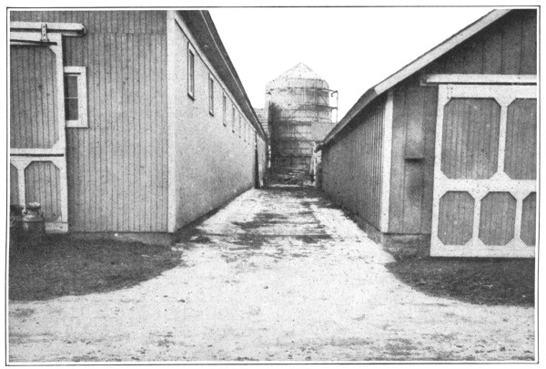
| Alleyways, | 41 |
| Barns, | 62 |
| Barn approach, | 60 |
| Barn floors, | 54-59 |
| Barn foundations, | 61, 62 |
| Barnyard pavements, | 47, 48 |
| Base for machinery, | 87-89 |
| Bee cellars, | 92, 93 |
| Carriage house entrance, | 39 [Pg 3] |
| Carriage washing floor, | 42 |
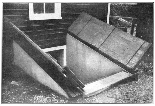
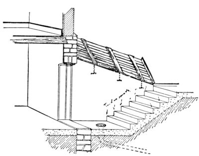
| Cellar steps and hatchway, | 90, 91 |
| Chimney, | 50, 51 |
| Chimney caps, | 97 |
| Cistern covers, | 69 |
| Cisterns, | 68-70, 72-73 |
| Coal house, | 83-87 |
| Cold-frame, | 99, 100 |
| Concrete in the country, | 5-8 |
| Corn crib floor, | 53 |
| Corner stones, | 105 |
| Cow barn floors, | 55-58 |
| Culverts, | 108, 109 |
| Cyclone cellar, | 92-93 |
| Dairy, | 83-87 |
| Dipping vats and tanks, | 76-80 |
| Dog kennel, | 83-87 |
| Drain tile outlet, | 106 |
| Drinking troughs and tanks, | 74, 75 |
| Driveway of concrete, | 40, 41 |
| Drop gutters, | 54-59 |
| Duck pond, | 95 |
| Engine base foundation, | 87, 88 |
| Engine house, | 82-89 |
| Entrance floor, | 39 |
| Farm buildings, | 82-89 |
| Feed cooker, | 50, 51 |
| Feeding floors, | 43-45 |
| Feeding troughs, racks and mangers, | 49, 50 |
| Fence posts, | 104 |
| Field rollers, | 102 |
| Field spring improvement, | 70, 71 |
| Floors, | 39, 42, 45, 47, 48, |
| 53-56, 58, 79, | |
| 82, 83, 87, 98 | |
| Foundation gutter, | 35 |
| Fruit cellars, | 92, 93 |
| Garbage receiver, | 103 |
| Gasoline engine base, | 87, 88 |
| Gate posts, | 104, 105 |
| Granary floors, | 53 |
| Gutters, | 35 |
| Hatchway for cellar steps, | 90, 91 |
| Hay cap weights, | 103 |
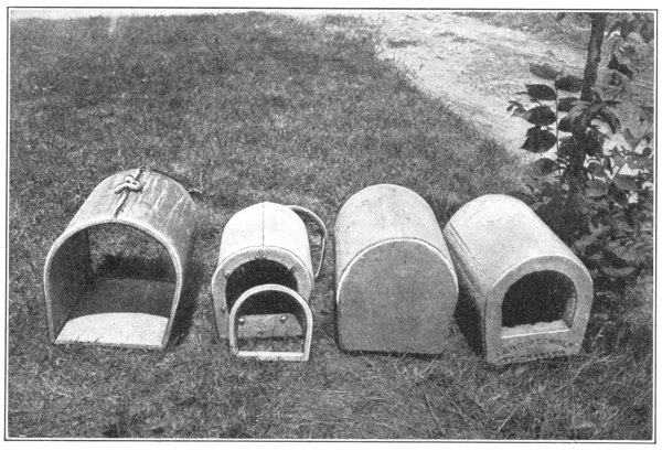
| Hen house, | 94 |
| Hens’ nests, | 94 |
| Hitching post, | 104 |
| Hog wallows, | 52 |
| Horse barn floors, | 58, 59 |
| Hot-bed, | 99, 100 |
| Housing for driven well, | 67, 68 [Pg 4] |
| Hydraulic ram house, | 89 |
| Ice house, | 83-87 |
| Lawn roller, | 102 |
| Mangers, | 49, 50, 57, 59 |
| Manure pits and cisterns, | 45 |
| Milk house, | 83-87 |
| Milk vat, | 81, 82 |
| Nests for hens, | 94 |
| Old buildings and their repair, | 36-38 |
| Porch floor, | 98, 99 |
| Posts for fences and gates, | 104 |
| Posts, hitching, | 104 |
| Poultry house, | 94 |
| Ram house, | 89 |
| Repairs to farm buildings, | 36-38 |
| Retaining wall and steps, | 96, 97 |
| Roadways, | 40, 41 |
| Root cellar, | 92, 93 |
| Rollers, | 102 |
| Sanitary water supply, | 67-75 |
| Septic tanks, | 110, 111 |
| Sidewalks, | 28-34 |
| Silos, | 65, 66 |
| Small farm buildings, | 82-89 |
| Smoke house, | 83-87 |
| Snow fences, | 63, 64 |
| Spraying tanks, | 107 |
| Spring improvements, | 70, 71 |
| Steps, | 90, 91, 96, 97 |
| Stones, corner, | 105 |
| Survey monuments, | 105 |
| Swimming pool, | 112 |
| Tanks, | 74, 75 |
| Tarpaulin weights, | 103 |
| Tool house, | 83-87 |
| Trash burner, | 103 |
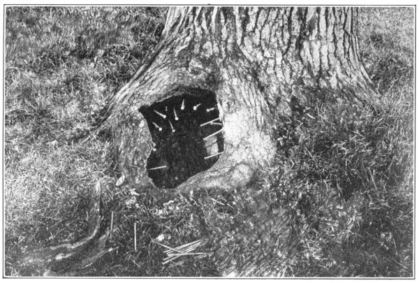
| Tree repair, | 101 |
| Troughs, | 74, 75 |
| Vegetable cellar, | 92, 93 |
| Walks, | 28-34 |
| Walk specifications, | 29 |
| Watering troughs, | 74, 75 |
| Weights for hay caps and tarpaulins, | 103 |
| Well cover, | 69 |
| Well protection, | 67-70 |
| Wind walls, | 63, 64 |
| Window hatch, | 112 |
| Wiring forms, | 23 |
How the American Farmer is Solving
His Conservation Problem
Conservation is no new problem—it is as old as life itself. It becomes a highly important question to the person or the nation only when the resources scarcely supply the demands. Such is the situation in the United States to-day. In the early days the removal of the forests was necessary that much grain might be grown. The young Nation had to have money, and as farming was the only means at hand to furnish it, the natural fertility of the fields was reduced. But the money thus supplied was merely a long-time loan on the Bank of Natural Resources. To-day the vanishing forests and the failing fertility of the fields bear witness that the loan is now due. Hence the problem of conservation. Strange as it may seem, the farmer is using one material not only to replace lumber but also, in a way, to restore the fertility of his fields—that material is concrete.
The national and state governments and the railroads were the first to make extensive use of concrete. Not only did the beauty and mystery of this new construction naturally appeal to the farmer, but he concluded that the railroads did not use it, in preference to wood, steel and stone, merely to decorate the landscape. He knew too much about railroads. So strongly did the railroads’ idea of economy (the dollar argument) appeal to him that the farmer of the West is now building practically everything about the farm of concrete. At first, and quite naturally, land-owners in the rock and gravel regions began using this new form of construction; but, since its cheapness in first cost and value in lasting qualities have become generally known, a wave of enthusiasm for farm structures of concrete has swept the entire country. A gravel pit is now more valuable than many a gold mine.
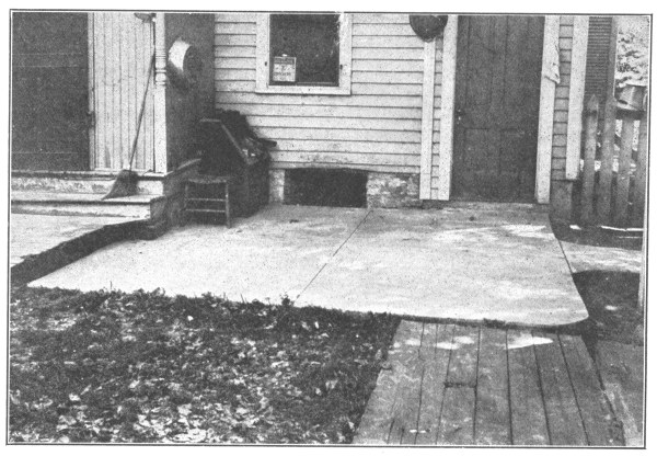
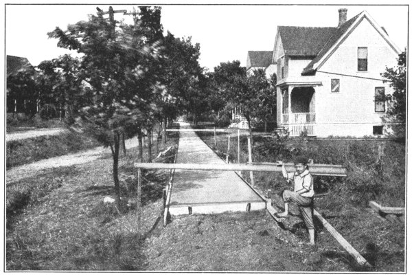
With little help other than looking and listening, the farmer grasped the idea of a concrete walk, and being a natural inventor and jack-of-all-trades, improved on the method by adding a small curb next to his flower bed to keep the dirt from washing on the white walk. This walk was a blessing to the boy—all the time formerly given to scrubbing and weeding the old brick walk could now be devoted to fishing. The yard walk was extended to the barns and outlying buildings. Wading through seas of mud and resulting tracked-up kitchen floors became a thing of the past. By simply increasing the width of the walk, a cellar floor was provided and the farmer had a dry cellar. This was so clean and so odorless that he considered such a floor fit for that most immaculate of all places—the milk house. Concrete cellar hatchway and steps, safe under the heaviest barrel of vinegar, and water-tight, were made in a manner similar to walks.
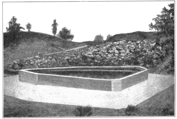
Brick work had long been laid up in a mixture of Portland cement and [Pg 6] sand. As this kept the water out, the farmer reasoned that it would keep the water in, and he started to build cistern floors, walls and cover of Portland cement concrete at one-third to one-half the cost of the old brick cistern.
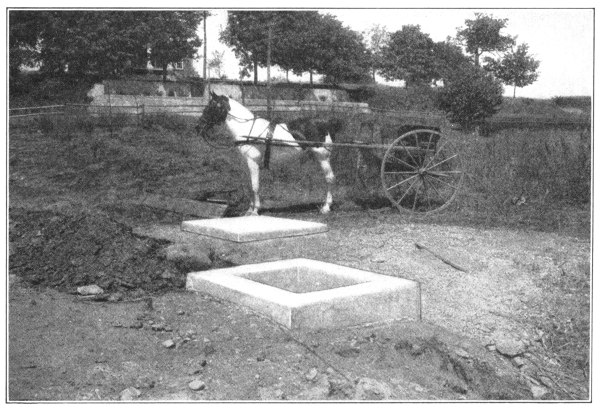
After a little more observation, he quit digging deep cistern-pits, with the necessary annoyance of thawing out frozen pumps and carrying water—he built a concrete cistern on top of the ground and made the pumping and carrying of the water a mere matter of turning a faucet in the kitchen and the bath room.
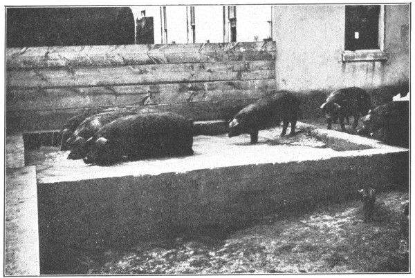
Several years ago corn was so cheap that in some sections it was burned for fuel instead of coal. No consideration was then given to the bushels wasted in muddy feed lots. If the mud became too deep, the feeding was transferred to the blue grass pasture. To be sure, as the sod wore out, the feeding-place had to be changed; but somebody had advanced the idea that this particular method of feeding was good for the soil. Many farmers had tried wooden feeding floors and had found them a paying proposition as far as the saving of feed was concerned, in the general health of the animal, and in the shortened time of fattening. But two great drawbacks were the rats that infested them and the constant need of repairs. In concrete the thoughtful farmer saw the possibilities of an ideal floor—an easily cleaned, rat-proof, disease-proof surface upon which his hogs, sheep, cattle and poultry might consume the feed even to the smallest particle.
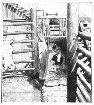
So satisfactory did the feeding floor prove that the same treatment suggested itself as a remedy for the fly-breeding, muddy holes in the earthen floors and the rat-infested wooden floors of the barns. But the careful horseman held up a bit: he was afraid that stamping at the flies, his valuable Percherons, Shires and Morgans might stiffen up their legs. He experimented by placing concrete floors in his open sheds, which were usually too muddy for the stock to lie down in stormy weather, just when the straw stacks afforded no protection and when he needed the sheds most, and found such floors satisfactory.
To-day the manure question is one of the most important considerations of the time. The virgin soil of the prairies, of the cleared woodlands and of the broken-up ranges, for a few years produced immense crops of cotton and grain. To build up the decreasing productiveness of the fields the farmer soon learned that barnyard manure was the best thing at hand. The passing of the cattle ranch and the resulting higher price of meats made stock raising very profitable even to the small farmer, especially since feeding floors made it possible for him to return to the soil, in the form of manure, all the fertility which had been removed in the growing of grain. Leaving out the matter of foods, the strength of manure is dependent directly upon its manner of storage. Manure piled on the bare ground or in wooden pens loses one-third to one-half of its fertilizing properties on account of leaching, due to heavy rains and tramping of the stock, and later because of fermentation or “firing” brought about by the lack of sufficient moisture. This fertilizer usually sells at from 75 cents to $1.00 per load.
The farmer of to-day builds a water-tight concrete cistern or pit in which he stores the manure and keeps it as moist as need be. He extended the concrete floors to the dairy barns with the result that they were so clean, so odorless and so sanitary that state inspection [Pg 7] is now often insisting and will soon force careless dairymen to put in such floors as a means of protecting the public health from disease germs carried in unclean milk. The drop gutters carry all the liquids, the richest part of the manure, formerly wasted, to the manure pits. Consequently, one load of manure, thus properly preserved, is easily worth two loads as ordinarily stored. By confining the manure in pits and by paving the barn lot with concrete, the farm has been rid of the chief breeding-place of flies, gnats, mosquitos and disease. Moreover, such an interior court, surrounded by buildings and concrete wind walls, forms an excellent feed and winter exercise lot.
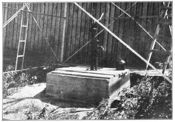
Government statistics show that the human death-rate on the farm, in spite of the fresh food and pure air, is greater than the death-rate in the city. State University tests of drinking-water have shown beyond a doubt that the waters of many ordinary shallow and unprotected wells contain the germs of such dangerous diseases as typhoid fever. To prevent the polluted surface waters from seeping into the well, many people are covering their wells and walling them up with water-tight concrete. Others are sinking “driven” wells and protecting them with concrete housings. The principle of deep wells for pure water, among other things, has made gasoline engines a necessity on the farm. These engines and hydraulic rams at springs, firmly set and housed in concrete, supply an abundance of water for the concrete reservoirs or elevated, reinforced pressure tanks. From these places of storage water is distributed to float-controlled, rot-proof watering tanks and troughs of the same material. With such a water supply animals never suffer for water. Even springs and mouths of drain tile are improved and the water made clean and wholesome by the use of concrete.
Thus the conservative farmer of the present time gives careful attention to the health, comfort and convenience of his family. Moreover, the care of the animals is not neglected. A concrete dipping vat holds the liquids which free horses, cattle, sheep and hogs of mange, lice, mites, ticks and fleas. The Department of Agriculture is stamping out the Texas fever and sheep scab by insisting on the use of dipping tanks throughout all quarantined districts. A hog wallow with concrete sides and bottoms gives the hog the pleasure afforded by running streams and at the same time protects him from the cholera often carried down from animals affected further up stream.
The continual rotting off of wooden fence posts, the constantly increasing cost of new ones, and the annual expense of fence repairs, called for the introduction of some substitute. Land is entirely too valuable and life too short to attempt growing wooden posts. Even before the telephone and telegraph companies had thought of the possibilities of concrete in this line, a few venturesome farmers had given reinforced concrete posts a trial and found their use not only advisable from the standpoint of cheapness in first cost, but more profitable on account of their everlasting qualities. The Department of Agriculture at Washington has thoroughly investigated the use and methods of making concrete posts and is furnishing a free bulletin describing the process. Such posts are also valuable in the culture of grapes and hops.[1]
[Pg 8] The use of concrete in farm buildings has gradually developed from the ground upward. The drip soon rots out timber near the ground and eventually crumbles away the brick foundation. At first, uselessly making the walls as heavy as those of brick, the farmer gave concrete a trial in foundations. Concrete is stronger than brick. As a wall it kept the basement and back barn dry. The height of the foundation wall increased until it supported the joists of the hay loft. Finally, after a study of methods, of reinforcing, the entire barn—basement, walls, floors, mangers, troughs, gutters, beams and even the shingles—became concrete. Matches or lanterns accidentally dropped on concrete floors in concrete barns do not cause the terror of former times. The oil will burn until smothered out with a horse blanket, but no further damage will be done.
Poultry raising on many farms has become well-nigh impossible on account of rats. To free the farm of these destructive animals, as a last resort and in spite of the assertions that the grain would spoil, the thoroughly provoked farmer put concrete floors under his cribs and granaries. Corn matured enough not to spoil on other floors kept perfectly on concrete. The rats had to go; they could not get through such floors. And so we might continue, describing how farmers have successfully used concrete in building every class of structure from a stepping stone to the entire group of farm buildings.
Just as there are right and wrong methods of farming, so, too, are there right and wrong ways of using concrete. It is the aim of this book to give such directions and information as will enable the reader to build with concrete surely and successfully.
“CONCRETE IN THE COUNTRY” does not pretend to fully cover the subject—the field is too large to be exhausted in one such volume. But the publishers have attempted to deal with as wide a variety of types of concrete construction as is possible in the space available.
Fuller details are given in other pamphlets, which will be furnished free to anyone who will write to the address given on the first page of this book.
Publications issued by the Association of American
Portland Cement Manufacturers,
Philadelphia, Pa.
At the office of the above Association there are available books dealing with concrete construction of all classes. These books describe the construction of silos, fence posts, tanks, troughs, concrete roads, and many other works. Upon request there will be sent a list of the publications in print. The books, with one or two exceptions, are sent free of cost.
Concrete—a manufactured stone—is made by mixing together Portland cement, sand and stone (or gravel). Various proportions of each are used, depending upon the use to which the concrete is put. About half an hour after mixing these materials together, the mass begins to stiffen, until, in from half-a-day to a day, it becomes so hard that you cannot dent it with the hand. By a month the mass is hard like stone—indeed, harder than most stones.
Before attempting to describe the actual process of mixing and placing concrete, it will be well for us to have a pretty clear understanding as to the nature of the materials with which we are to work, and how best these may be selected.
For domestic use, Portland Cement is furnished in cloth sacks and paper bags. When furnished in cloth sacks, the price per barrel includes the cost of the sacks (four sacks making a barrel). When the sacks are returned in good condition, the amount charged is rebated to the customer. Where cement is furnished in paper bags, the price also includes the cost of the paper bags which, however, are not returnable.
Many cement users prefer their cement furnished in paper bags, as it does away with the bother of keeping account of the cloth sacks and sending them bade to the dealer for credit.
The paper bag or cloth sack of cement weighs 94 pounds, and four such make a barrel of 376 pounds.
The storage of cement is very important. It must be kept in a dry place. Once wet, it becomes hard and lumpy, and in such condition is useless. If, however, the lumps are caused by pressure in the store house, the cement may be used with safety. Lumps thus formed can be easily broken by a blow from the back of a shovel.
In storing cement, throw wooden blocks on the floor. Place boards over them and pile the cement on the boards, covering the pile with a canvas or a piece of roofing paper. Never, under any circumstances, keep cement on the bare ground, or pile it directly against the outside walls of buildings.
Do not use very fine sand. If there is a large quantity of fine sand handy, obtain a coarse sand and mix the two sands together in equal parts; this mixture is as good as coarse sand alone.
Sometimes fine sand must be used, because no other can be obtained; but in such an event an additional amount of cement must be used—sometimes as much as double the amount ordinarily required. For example, in such a case, instead of using a concrete 1 part cement, 2 parts sand, and 4 parts stone, use a concrete 1 part cement, I part sand, and 2 parts stone.
Besides being coarse, the sand should be clean, i. e., free from vegetable matter. “But,” you say, “how shall I tell whether the sand is what you call clean?” [Pg 10]
The presence of dirt in the sand is easily ascertained by rubbing a little in the palm of the hand. If a little is emptied into a pail of water, the presence of dirt will be shown by the discoloration of the water. This can be discovered also by filling a fruit jar to the depth of 4 inches with sand and then adding water until it is within an inch of the top. After the jar has been well shaken, the contents should be allowed to settle for a couple of hours. The sand will sink to the bottom, but the mud, which can be easily recognized by its color, will form a distinct layer on top of the sand, and above both will be a clear depth of water. If the layer of mud is more than one-half inch in thickness, the sand should not be used unless it is first washed.
Having discovered that the sand you contemplate using is not clean, and provided you cannot readily obtain any that is clean, you may use what you have, provided you wash it in the following manner:—
Build a loose board platform from 10 to 15 feet long, with one end a foot higher than the other. On the lower end and on the sides, nail a board 2 by 6 inches on edge, to hold the sand. Spread the sand over this platform in a layer three or four inches thick, and wash it with a hose. The washing should be started at the high end, and the water allowed to run through the sand and over the 2 by 6-inch piece at the bottom. A small quantity of clay or loam does not injure the sand, but any amount over 5 per cent. does.
This is known as the “coarse aggregate” of concrete. Great care should be used in its selection. The pebbles should be closely inspected to see that there is no clay on their surface. A layer of such clay prevents the “binding” of the cement. If necessary stone or gravel may be washed in the same way as above described for sand. Indeed, it is more easily done than sand, as the water flows through the larger voids in the gravel more readily than through the voids in the sand. Dust may be left in the crushed stone without fear of its interfering with the strength of the cement, but care should be taken to see that such dust is distributed evenly through the whole mass, and when dust is found in stone, slightly less sand should be used than ordinarily.
As to the size of stone or gravel, this must be determined by the form of construction contemplated. For foundations or any large thick structure, use anything from ½ to 2½ inches in diameter. For thin walls use ¼ to 1-inch stone.
The best results are obtained by the use of a mixture of sizes graded from small to large. By this means the spaces or voids between the stones or pebbles are reduced and a more compact concrete is obtained. Moreover, this method makes it possible to get along with less sand and less cement.
Water for concrete should be clean and free from strong acids and alkalies. It may be readily stored in a barrel beside the mixing board and placed on the concrete with a bucket. If you are at all in doubt about the purity of the water that you contemplate using, it would be well to make up a block of concrete as a test, and see whether the cement “sets” properly. [Pg 11]
That mixture in which all the spaces (called “voids”) between the stone or gravel are filled with sand, and all the spaces between the sand are filled with cement, is the ideal mixture. This mixture is rarely attained, as the voids in each load of gravel and sand vary slightly, and in order to be absolutely safe, it is well to use a little more cement than will just fill the voids.
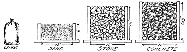
Fig. 1.—Quantities of cement, sand, and gravel in 1: 2: 4 concrete mixture, which means 1 part cement, 2 parts sand, 4 parts crushed stone or gravel, and the resulting quantity of concrete, which is only slightly greater in size than the gravel, the sand and cement filling the voids in the gravel.
Showing the Quantities of Materials and the Resulting
Amount of Concrete for Two-bag Batch.
| Kind of Concrete Mixture. |
Proportions by Parts. | Two-bag Batch. | ||||||||
|---|---|---|---|---|---|---|---|---|---|---|
| C e m e n t. |
S a n d. |
Stone or Gravel. |
Materials. | Size of Measuring Boxes. Inside Measurements. |
Water in Gallons for Medium Wet Mixture. |
|||||
| Cement. | Sand. | Stone or Gravel. |
Concrete | Sand. | Stone or Gravel. |
|||||
| Bags. | Cu. ft. | Cu. ft. | Cu. ft. | Gallons. | ||||||
| 1:2:4 Concrete | 1 | 2 | 4 | 2 | 3¾ | 7½ | 8½ | 2′×2′ 11½″ | 2′×4′ 11½″ | 10 |
| 1:2½:5 Concrete | 1 | 2½ | 5 | 5 | 4¾ | 9½ | 10 | 2′×2½′ 11½″ | 2′×5′ 11½″ | 12½ |
As above explained, concrete is composed of a certain amount of cement, a larger amount of sand, and a still larger amount of stone (or gravel). To determine how much of each of these materials to use, we must first consider the type of work we wish to undertake. For ordinary work about the farm (silos, tanks, cisterns, fence posts, well curbs, etc., etc.) use twice as much stone as sand, and twice as much sand as cement. This is called a 1: 2: 4 mixture—meaning that there are in that mixture:
[Pg 12] For sidewalks, gutters, etc., a “weaker” mixture is sometimes used, consisting of:
The proportions should always be measured by volume, and the best way to do the measuring is by the use of a home-made “measuring box,” of any kind of rough boards having straight sides, but with no top or bottom. The size of these measuring boxes is determined by the proportion desired for your mixture. For such boxes you need the following sized lumber:
Note: The two pieces 4 feet long and the two pieces 6 feet long have an extra foot in length at each end to be made into a handle, as shown in Fig. 3.
For a 1: 2½: 5 mixture, you require the following sized lumber:
Note: The two pieces 4 feet 6 inches long and the two pieces 7 feet long have an extra foot in length at each end to be made into a handle, as shown in Fig. 3.
To illustrate the use of the measuring box, let us once more assume that a 1: 2: 4 mixture is required, and that the amount of finished concrete needed is 8½ cubic feet. By referring to the table on page 11 it will be noted that two bags of cement are required, also 3¾ cubic feet of sand and 7½ cubic feet of stone or gravel. Under “size of measuring box” it is found that the sand should just fill a box 2 feet by 2 feet by 11½ inches, and that the stone should fill a box 2 feet by 4 feet by 11½ inches. Lay the sand box, or frame, on the mixing platform and fill it. Then raise the box. Empty two bags of cement on the sand and mix as described under “Mixing,” see pages 14-22. Even off the mixture thus obtained with your shovel, place the stone measuring box on top of the mixture and fill it. Raise the measuring box—and you have the correct amount of stone all ready to be mixed with the cement and sand. It is important to measure both the sand and stone loose in the box—never “pack” them.
For purposes of explanation, size of mixture will be referred to as a “batch” of so many bags of cement. Thus, a “two-bag batch of concrete” would mean one requiring two bags of cement, with the sand and stone proportioned accordingly, as shown above.
For a “four-bag batch of concrete” it would be necessary to multiply the amount of stone and gravel by 2, also multiplying the cubic contents of the measuring box by 2, and using four bags of cement instead of two.
The table previously referred to also shows the amount of water for different sized batches, but it is to be noted that the quantity of this ingredient is only approximated. Use the amount indicated in the table for the first batch, and if it proves too wet for the use desired, reduce the amount of water; if too dry, increase the amount of water. Always use a bucket in measuring the amount of water, as this secures uniform results. [Pg 13]
Naturally mixed bank sand and gravel are sometimes found in the right proportions for making concrete. Generally, however, there is far too much sand for the gravel, and great care should be exercised in using this class of material. Unless the mixture runs very even throughout the bank, and is found to be made up of one part sand to two parts gravel, it is better to screen the sand out of the gravel and prepare the materials in the usual way.
Herewith is a table showing the quantities for a natural mixture of bank sand and gravel. The quantities can be found in the same way as in Table I, on page 11.
TABLE II.
Showing the Quantities of Materials and the Resulting Amount of Concrete for Two-bag Batch, Using Natural Mixture of Bank Sand and Gravel.
| Kind of Concrete Mixture. |
Proportions by Parts. |
Two-bag Batch for Natural Mixture of Bank Sand and Gravel. |
|||||
|---|---|---|---|---|---|---|---|
| C e m e n t. |
Natural Mixture of Sand and Gravel. |
Materials. | C o n c r e t e. |
Size of Measuring Boxes. |
Water in Gallons for Medium Wet Mixture. |
||
| C e m e n t. |
Natural Mixture of Sand and Gravel. |
Mixture of Sand and Gravel. |
|||||
| Bags. | Cu. ft. | Cu. ft. | Gallons. | ||||
| 1:2:4 Concrete | 1 | 4 | 2 | 7½ | 8½ | 2′×4′ 11½″ | 10 |
| 1:2½:5 Concrete | 1 | 5 | 2 | 9½ | 10 | 2′×5′ 11½″ | 12½ |
There are three kinds of mixtures, in general, on concrete work:—
1st.—Very Wet Mixture.—Concrete wet enough to be mushy and run off the shovel when handling, used for thin walls or for thin sections, etc.
2d.—Medium Mixture.—Concrete just wet enough to make it jelly-like, used for foundations, floors, etc. To better describe this mixture it may be said that a man should sink ankle deep if he were to step on top of the pile.
3d.—Dry Mixture.—Concrete like damp earth, used for foundations, etc., where it is important to have the concrete “set” up as quickly as possible.
The difference between the mixtures is, that the dryer the mixture the quicker will the concrete “set up”—but in the long run, when carefully mixed and “placed,” the results from any of the above mixtures will be identical. It may be said, however, that a dry mixture is the harder to handle, must be protected with greater care from the sun or from drying too quickly; and lastly, is likely—unless used by most experienced hands—to show voids or stone pockets in the face of the work when the “Forms” are removed. The less the voids in the stone or gravel, the greater will be the volume of the concrete. In general, the amount of concrete will be greater in each instance than is shown in the table—especially when gravel is used. [Pg 14]
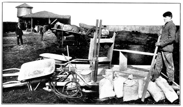
Fig. 2.—Concrete Mixing Plant, showing Concrete Board,
Tools, etc., Necessary for Mixing Concrete by Hand.
One great advantage of concrete, so far as the farmer is concerned, lies in the fact that, generally speaking, it necessitates no outlay for tools, for it so happens that most of the tools needed for forms of concrete construction are the very ones every farmer uses—
Shovels—One for each man on the job.
Wheelbarrows—At least two, preferably those with sheet iron bodies.
Rake.
Water Barrel.
Several Water Buckets.
A Tamper or Rammer—This is made of wood with handles nailed to it, as shown in Fig. 2. The measurement is 4 inches by 2 inches by 2 feet 6 inches.
A Garden Spade.
A Sand Screen, made by nailing a piece of ¼-inch mesh wire screen, 2½ feet by 5 feet in size, to a frame made of 2-inch by 4-inch scantling.
In addition to the above tools you will require a Mixing Board. This is simply a water-tight platform. It should be (for a two batch mixture and for two men to work on) about 10 feet square. Make it out of 1-inch boards 10 feet long, surfaced on one side, using 5 cleats to hold the boards together. The cleats should measure 2 inches by 4 inches by 9 feet. If 1-inch by 6-inch tongued and grooved roofers can be obtained, these will answer very nicely, provided they are fairly free from knots. The object of having surfaced boards is to make the shoveling or turning easy. The boards should be so laid as to enable the shoveling to be done with and not against the cracks between the boards. The boards must be drawn up close in nailing, so that no cement “grout” will run through while mixing.
For a larger job, a slightly larger mixing board will be needed.
In setting up your mixing board, choose a place giving plenty of room near the storage piles of sand and stone. Block up your concrete board level, so that the cement grout will not run off on one side, and so that the board will not sag in the middle under the weight of the concrete.
You will also have to make wheelbarrow “runs” leading from your mixing board to the spot where the concrete is to be placed. Do not use, for these runs, any old boards that are handy. Make a good run—smooth, and, if much above the ground, at least 20 inches wide. This one feature will lighten and quicken the work to a remarkable extent.
Having selected the proper materials and arranged the mixing board and runs, the next step is the actual process of mixing.
The proportions of materials and the nature of same for various types of work have already been described on pages 11-13. In following the mixing instructions here given, considerable assistance will be obtained by referring to the illustrations with which instructions are interspersed. [Pg 16]
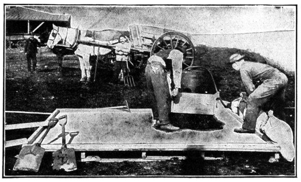
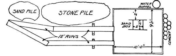
Fig. 3.—Lifting off the Sand Measuring Box and Getting Cement Ready.
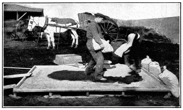
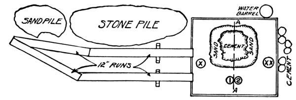
Fig. 4.—Spreading the Cement Over the Sand.
There are many ways of “hand mixing,” all having the same good results. The way described here we believe to be the one best calculated to obtain good results with a minimum of labor. In this description, and the accompanying illustrations, we have taken as a basis a “Two-Bag Batch” of 1: 2: 4 concrete.
First load your sand in wheelbarrows from the sand pile, wheel on to the “Board,” and fill the sand measuring box, which is placed about two feet from one of the 10-foot sides of the board, as shown by the diagram in Fig. 3. When the sand box is filled, lift it off and spread the sand over the board in a layer 3 or 4 inches thick, as shown in Fig. 4. Take the two bags of cement and place the contents as evenly as possible over the sand (see Fig. 4). With the two men at points marked “x” and “xx” on the sketch below Fig. 4, start mixing the sand and cement, each man turning over the half on his side of the line AA. Starting at his feet and shoveling away from him, each man takes a full shovel load, turning the shovel over at the points marked 1 and 2 respectively in Fig. 4. In turning the shovel, do not simply dump the sand and cement at the points marked 1 and 2 in the diagram under the cut, but shake the materials off the end and sides of the shovel, so that the sand and cement are mixed as they fall. This is a great assistance in mixing these materials. In this way the material is shoveled from one side of the board to the other, as shown in Figs. 5 and 6. Fig. 5 shows the first turning, and Fig. 6 the second turning.
The sand and cement should now be well mixed and ready for the stone and water. After the last turning, spread the sand and cement out carefully, place the gravel or stone measuring box beside it as shown in Fig. 7, and fill from the gravel pile. Lift off the box and shovel the gravel on top of the sand and cement, spreading it as evenly as possible. With some experience, equally good results can be obtained by placing the gravel measuring box on top of the carefully leveled sand and cement mixture, and filling it, thus placing the gravel on top without an extra shoveling. This method is shown in Fig. 8. Add about three-fourths the required amount of water, using a bucket and dashing the water over the gravel on top of the pile as evenly as possible. (See Fig. 9). Be careful not to let too much water get near the edges of the pile, as it will run off, taking some cement with it. This caution, however, does not apply to a properly constructed mixing board, as the cement and water cannot get away. Starting the same as with the sand and cement, turn the materials over in much the same way, except that instead of shaking the materials off the end of the shovel, the whole shovel load is dumped as at points 1 or 2 in the diagram under Fig. 4 and dragged back toward the mixer with the square point of the shovel. This mixes the gravel with the sand and cement, the wet gravel picking up the sand and cement as it rolls over when dragged back by the shovel. (See Fig. 10). Add water to the dry spots as the mixing goes on until all the required water has been used. Turn the mass bade again, as was done with the sand and cement. With experienced laborers, the concrete should be well mixed after three such turnings; but if it shows streaky or dry spots, it must be turned again. After the final turning, shovel into a compact pile. The concrete is now ready for placing. [Pg 18]
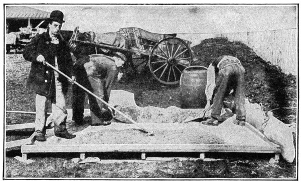
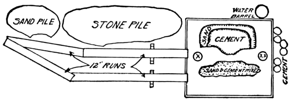
Fig. 5.—First Turning, Sand and Cement.
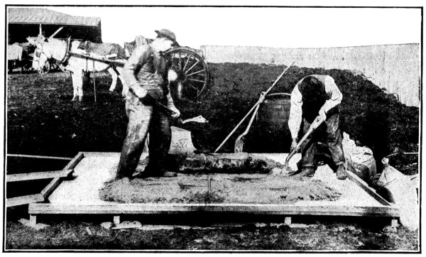
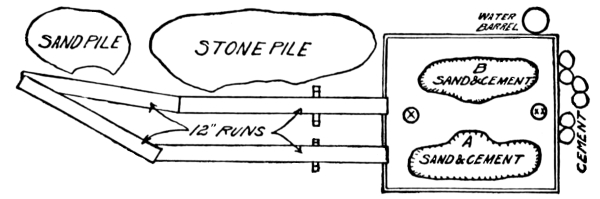
Fig. 6.—Second Turning, Sand and Cement.
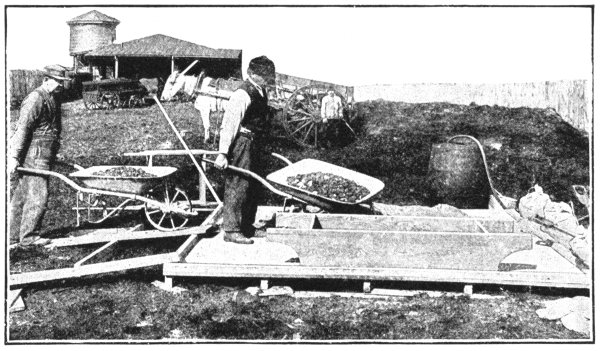
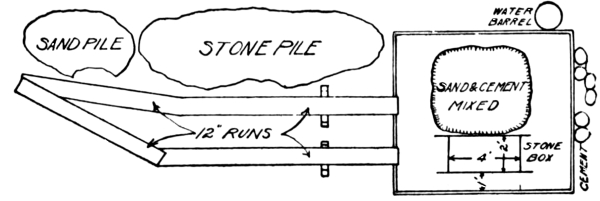
Fig. 7.—Filling the Stone (or Gravel) Measuring Box—First Method.
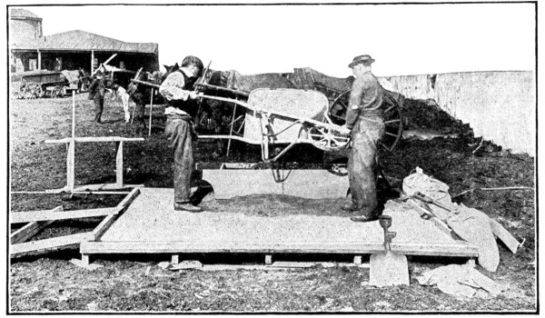
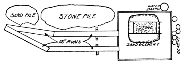
Fig. 8.—Filling the Stone (or Gravel) Measuring Box When
on Top of Mixed Sand and Cement—Second Method.
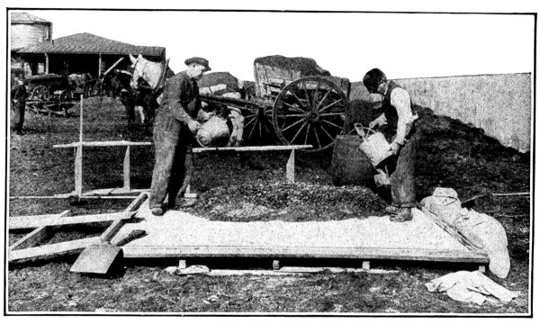
Fig. 9—Placing the Water on the Stone (or Gravel)
which is on Top of the Mixed Sand and Cement.
Spread out the mixture of sand and gravel as much as the board will readily permit, add enough water to wet the gravel and sand thoroughly, spread the cement evenly in a thin layer over the sand and gravel, and turn over, as described previously, at least three times, adding the rest of the water necessary to get the required consistency while the materials are being turned. It requires some experience to work up a natural mixture of bank sand and gravel, and if at all doubtful about the concrete made from it, first screen the sand from the gravel, and then mix in the regular way.
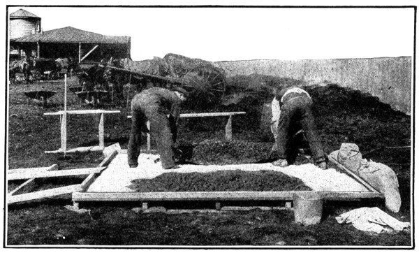
Fig. 10.—Mixing the Stone (or Gravel) with the Sand and Cement.
For the above operation only two men are required, although more can be used to advantage. If three men are available, let two of them mix as described above and the third man supply the water, help mix the concrete by raking over the dry or unmixed spots as the two mixers turn the concrete, help load the wheelbarrows with sand and stone or gravel, etc. Fig. 5 shows a third man on the board. In this illustration, he is helping mix the sand and cement by raking it—a most effective practice.
If four men are available, it is best to increase the size of the batch mixed to a four-bag batch, doubling the quantities of all materials used. The cement board should also be increased to 10 by 12 feet as shown under “Tools.” In this case start the mixing in the middle of the board, and each pair of men mixing exactly as if for a two-bag batch, except that the concrete is shoveled into one big mass each time it is turned back on to the center of the board. When more than four men are available, the rest may place the concrete, make new runs, load wheelbarrows, etc., taking the concrete away from the board as fast as it is mixed. In this case another small concrete board should be placed next to the big “board,” so that in the last turning the batch can be shoveled over on to the small board for placing, making room on the big board to mix the next batch. The small platform need be only just big enough to hold the pile of mixed concrete.
First figure the number of cubic feet of concrete that will be required for the work in question. Then by multiplying this number by the number under the proper column and required mixture shown in Table III, the amounts of cement, sand, and stone or gravel can be found.
| Mixture. | Quantities of Material in 1 Cu. Ft. of Concrete | ||
|---|---|---|---|
| Cement, Barrel |
Sand, Cu. Yard |
Stone or Gravel, Cu. Yard |
|
| 1 : 2 : 4 Concrete | .058 | .0163 | .0326 |
| 1 : 2½ : 5 Concrete | .048 | .0176 | .0352 |
Example
Suppose the work consists of a concrete silo requiring in all 935 cubic feet of concrete, of which 750 cubic feet is to be 1: 2: 4 concrete, and 185 cubic feet is to be 1: 2½: 5 concrete. Also enough sand and cement is needed to paint the silo inside and outside, in all 400 square yards of surface, with a 1: 1 mixture of sand and cement. One cubic foot of 1: 1 mortar will paint about 15 square yards of surface and requires 0.1856 barrels of cement and 0.0263 cubic yards of sand. [Pg 22]
Solution, Etc.
Thus the necessary quantities of materials are:—
It is always wise to order two or three extra barrels of cement, if the dealer is at considerable distance, as this avoids any possible trouble that a shortage might cause. Besides, any cement left over always comes in handy for repair work around the house or barn.
Concrete is a plastic material and before hardening, takes the shape of anything against which or in which it is placed.
Naturally, the building of the Form is a most important item in the success of the work.
These Forms hold the concrete in place, support it until it has hardened and give it its shape, as well as its original surface finish.
Almost any material which will hold the concrete in place will do for a Form. Concrete foundations for farm buildings require shallow trenches, and usually the earth walls are firm enough to act as a Form.
Molds of wet sand are used for ornamental work. Frequently colored sands are used for this purpose, providing both the finished surface and color to the concrete ornament.
Cast, wrought or galvanized iron is used, where an extremely smooth finish is desired, without further treatment upon the removal of the Forms. Forms made of iron are more easily cleaned, and can be used a greater number of times than those of wood. Rusty iron, however, should not be used.
By far the greatest number of Forms are made of wood, owing to the fact that lumber in small quantities can always be obtained.
Plan your Forms so there will be no difficult measurements to understand. Make as few pieces of lumber do the work as you can, and do not drive the Forms full of nails. If you do the Forms will be difficult to take apart without splitting.
Forms must be strong enough to hold the weight of the concrete without bulging out of shape. When they bulge, cracks open between the planks and the water in the concrete, with some cement and sand, will leak out. This weakens the concrete, and causes hollows in the surface which look badly after the Forms are removed.
Forms which lose their shape after being used once can hardly be used a second time. A part of the erection cost of Forms is saved if the Forms are built in as large a section as is convenient to handle. This saving applies to their removal, as well as to their setting. Consequently, the lightest Forms possible, with the largest surface area, are the most economical. [Pg 23]
The first consideration in planning Forms is the use to which they are to be put. Neglect of this point means waste of money and time. If they are for work afterward to be covered with a veneer coat, the finish of the surface is of small consideration, while the alignment of the Form is all-important.
If a tank or retaining wall is to be built, the fact that the Forms are not in exact alignment will hardly be noticed.
In planning Forms for large structures, the oftener each section is used, the less the cost. You save money if they are rigid in alignment, and well surfaced. In other words, if you count on using your Forms over and over again, the more nearly perfect they are, the more often they can be used, and the cheaper they become.
If Forms are to be used only once, as is generally the case on the farm, they should not be nailed so securely as to prevent their being readily taken apart, and the lumber used for something else. If often pays to put them together with screws. If nails are used, do not drive them home.
The selection of lumber is of importance. If the Forms are to be used over many times, surfaced lumber, matched, tongued, and grooved stuff, free from loose knots, is an economy. If, however, they are to be used only once, almost any old plank will do. By nailing a board on the outside of the cracks or over the bad knot, and filling with a little clay, the Form is made tight.
Green lumber is preferable to kiln-dried or seasoned stuff. Seasoned stuff, when wet (either by throwing water on the form before placing the concrete or by absorbing the water from the concrete) warps, and the shape and tightness of the Form are damaged. [Pg 24]
Originally only surfaced lumber was used for Forms, dependence being placed on it for giving a finish to the work. While to-day other than smooth surfaces for concrete are the fashion, surfaced lumber has some advantages. The Forms fit together better and are easier to erect. They are more easily cleaned. They are easier to remove. All these items reduce the cost of the work. The saving effected will of course depend on the difference in local price between finished and rough lumber.
Particles of concrete stick to the Forms. In order to prevent this, give the surface next the concrete a coat of oil or soft soap. Linseed, black or cylinder oil may be used. Never use kerosene.
Before erecting, paint the Forms with the oil or soap. Then carefully protect them from dust or dirt until erected. Upon removal, immediately clean off all the particles of concrete sticking to the surface. A short-handled hoe will take off the worst, while a wire brush is most effective for finishing. Be careful not to gouge the wood in cleaning, as it will spoil the surface of your next section of concrete. It will not be found necessary to repaint after each time of use. Watch the surface and repaint if it appears dry in spots.
If chips or blocks of wood fall inside the Forms while erecting, carefully remove them. The space inside the Forms is intended for the concrete; and care should be taken to see that only concrete is placed there.
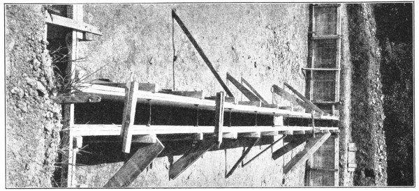
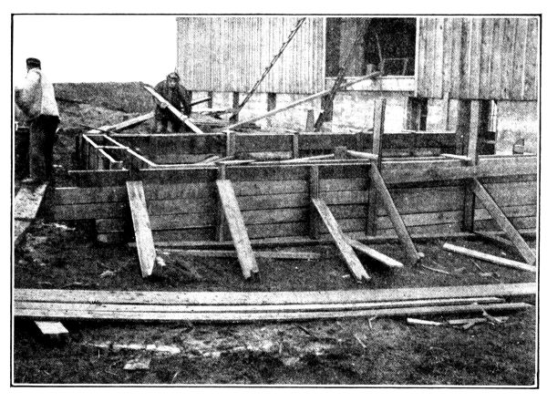
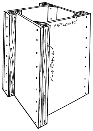
The necessity of Forms presents a problem calling for the use of that ingenuity for which the farmer is justly famed. Forms can be economically placed in so many ways that only one example will be given. A foundation Form in place is shown in the photograph. Note the simple and easy method of bracing. Also note how lumber is saved from cutting by allowing the sides to project, as well as the studding.
For this building, 18 by 24 feet, trench 18 inches wide and 2 feet deep—total cost of setting forms $4.00. The lumber was all on hand and can be used again. [Pg 25]
No time should elapse between the “mixing” and the “placing.” Directions for placing must of necessity be general, and the farmer must use his own judgment as to how to handle this part of the concrete work, in connection with whatever particular job he has on hand. The important thing to remember is, that the materials should not separate in placing.
You may shovel the concrete off the board directly into the work; you may shovel it into wheelbarrows, wheel it to position and dump, or you may carry it to the proper place by buckets and hoisting apparatus.
Ordinarily speaking, concrete should be deposited in layers about 6 inches thick.
After placing concrete in the Form, it should be “tamped” lightly with a wooden or iron tamper (or rammer) until the water shows on the top and no stones are left uncovered by mortar.
In order to obtain a smooth face on the concrete, the mixture should be carefully “spaded” immediately after “placing”—on the side next to the Form where the finished concrete will be exposed to view. By “spading” is meant the working of a spade or a beveled board between the concrete and the side of the Form, moving it to and fro, and up and down. This forces the large stones away from the boarding, or Form, and brings a coating of mortar next thereto, thus making the face of the work present an even, smooth appearance.
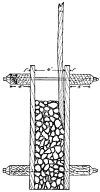
On certain jobs—as, for instance, in the case of a 6-inch silo wall—a spade cannot very well be used, on account of the narrowness of the concrete section. In this event, use for surfacing, a thin wooden paddle, made from a board 1 inch by 4 inches, and gradually sharpened to a chisel edge at the end. The sharpening should be on one side only, and in using this paddle place the flat side against the Form, as shown in illustration.
When the mixture is a dry one, great care must be used in this “spading” or surfacing, in order to obtain uniform results, but in the case of a wet mixture, spading is only required as an added precaution against the possibility of voids in the face of the work, and in many cases it is not necessary at all. [Pg 26]
Green concrete should not be exposed to the sun until after it has been allowed to set for five or six days. Each day during that period the concrete should be wet down by sprinkling water on it, both in the morning and afternoon. This is done so that the concrete on the outside will not dry out much faster than the concrete in the center of the mass, and should be carried out carefully, especially during the hot summer months. Old canvas, sheeting, burlap, etc., placed so as to hang an inch or so away from the face of the concrete will do very well as a protection. Wet this, as well as the concrete. Often the concrete Forms can be left in place a week or ten days; this protects the concrete during the setting-up period and the above precautions are then unnecessary.
It may be well, in summing up, to emphasize the following points:—
Good results cannot be obtained unless you use a good cement, nor will the work be at its best unless care is taken in the selection of clean sand and clean stone.
Among the uninitiated, there is an all too prevalent idea that anything is good enough for the making of concrete. Some will tell you that sawdust, shavings, mud, clay, etc., will do to complete the mixture, but the absurdity of this notion will very soon become evident to anyone who neglects the precautions which have been above pointed out.
Principles involved
Concrete and steel render valuable assistance to each other in the support of heavy burdens. On a solid foundation, loaded from above and thus under direct pressure, a concrete column will withstand the strain of an enormous load. A much smaller load so placed as to cause stretching or bending toward one side of the same column may cause it to snap off, for concrete is strong, but brittle. On the other hand, steel is tough and elastic. In the form of rods or wire, steel withstands massive loads that tend to stretch it, and thus displays a kind of strength directly opposite to that of the plain concrete column. In modern construction these two valuable properties of concrete and steel are utilized by combining them in what is called reinforced concrete. With steel properly buried in the concrete, the column withstands not only the load which might otherwise snap it, but one many times larger, and even though it is applied at any place along its length.
Reinforcement, therefore, is steel in the form of rods, bars or wires, buried in concrete to take up and to withstand the strains which tend to stretch or to bend the concrete. A concrete fence post is merely a small concrete column. Reinforced, it easily stands the strain from usage in a fence line. [Pg 27]
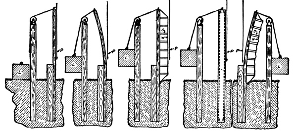
The value of reinforcing concrete posts properly may readily be seen in the figure. If a load (L) is raised so that its weight is supported on one side by a wooden post, the post will bend. The fibre in the wood on the side away from the load may be tough and elastic enough to prevent the post from breaking, and when released the post will spring back into its former position. In the third figure a No. 9 wire (W) is fastened securely to the wooden post at the top and at the ground surface, and is supported along its length by the struts (S). If the same load is applied, the post will not bend, because the wire takes up the bending or stretching strain. This is precisely the case with the reinforcement in a concrete post. Supported along its length by the concrete, the wire (W) or steel in other shapes takes up the bending or stretching strains. Since the load which causes bending or stretching may come from any direction, concrete posts are reinforced on every side; otherwise they might break in a manner somewhat similar to that in which the wooden post bends when the reinforcement is not on the proper side of the post.
In the effort to be safe it is a common fault to insert more reinforcement than is absolutely necessary. This adds needlessly to the cost, for concrete becomes stronger as it grows older.
With regard to the roughness of the outside, metallic reinforcing materials are divided into two classes, smooth and corrugated or deformed. The general result of the many tests carried on in testing laboratories seems to indicate that in strength of bond, if the concrete is sufficiently rich and well mixed, smooth surfaces give satisfactory results. Two kinds of reinforcement are much used—bars and wire.
Bars.—Round bars three-sixteenths or one-fourth of an inch in diameter are the size and kind most used on the farm. The stock on hand at blacksmith shops and hardware stores is generally from steel that stretches too easily and therefore is not the best for reinforcement. Companies which make a specialty of reinforcing materials can furnish both rods and bars which stretch only under very large loads.
Wire.—The development of the wire fence has produced a material well suited for reinforcing purposes. Of equal size, such wire will produce a stronger reinforcement than the material above described. In order to obtain straight wire of the necessary length, the coils ordinarily placed on the market should not be straightened out. Straight wire can be obtained from dealers in the same manner as baling wire; that is, either single or twisted into two or three-ply cables, and of the length desired. The plain, ungalvanized fencing wire is the proper kind, for galvanization adds nothing to the strength, and the metal will not rust when incased in the concrete. [Pg 28]
Concrete floors are nothing more than sidewalks of large size, and are formed by casting slabs in place.
The description given is an economical and practical method of laying sidewalks or floors, easily adapted to any use where concrete is found advantageous. This description will therefore apply not only to the building of sidewalks, but to all flat surfaces of concrete resting on the ground.
Concrete floors must remain hard and in position to be permanent. To accomplish this, good materials must be used, and proper methods of mixing and placing must be followed. Only in this way can settlement cracks, upheaval by frost or roots of trees, contraction cracks, crumbling, and general failure be avoided.
To avoid settlement cracks, thoroughly ram the ground after excavating for the foundation. This gives a solid bearing to the concrete slab.
To prevent upheaval by frost a foundation formed of crushed stone, hard furnace cinders, brick bats broken to about a 2-inch size, broken tile or any other hard porous material, should be laid in such a way as to obtain perfect drainage. Never use ashes.
If freezing occurs, room is in this way provided between the pieces of stone for the expansion of the ice.
If this foundation is placed in clay soil, side outlets or blind drains [Pg 29] of tile should be provided at points along the walk where they are necessary, leading into holes filled with cinders or crushed stone, which will allow the surrounding earth to soak up the accumulated water. Clay soil holds the water collected in the drainage foundation, and if it becomes entirely full of water, the ice formed during freezing weather will upheave the walk.
Upheaval by tree roots can be easily avoided by cutting out all roots which run under the pavement at a less depth than 18 inches below the surface of the ground.
Cement concrete expands and contracts by changes of temperature in the same way as steel. It is, therefore, necessary to cut joints which will allow for this expansion and contraction. The concrete must be cut entirely through to the bottom of the slab with a trowel, cleaver or other instrument, the joint formed being from ⅛ to ¼ of an inch wide. Blocks formed in this way should not be greater than 6 feet square (36 square feet).
The principal causes of scaling or crumbling surfaces are improper mixing, drying out before the cement has thoroughly hardened and the use of bad materials.
Cement needs water not only when mixed, but after being placed and tamped, and until it has entirely hardened. If concrete is not kept continually wet until hard, it is weakened, and the surface of such a walk scales or becomes soft and chalky.
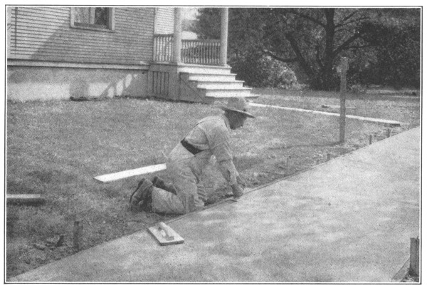
Stake out the lines of the walk, or dimensions of the floor. Excavate to a depth of 16 inches, ram and tamp the ground thoroughly and evenly and fill in 12 inches with clean large cinders, broken stone, pebbles, brick bats, broken tile or other material selected. Place in position wooden forms made of 2 by 4’s, these 2 by 4’s to be set on edge and held in position by stakes firmly driven in the ground, the top edge to be located so as to accurately outline the established grade or slope of the walk or floor.
A walk should be higher in the center, or at one edge, to insure the water running off. This slope should be ¼ of an inch to the foot.
Particular attention must be paid to the selection of the materials and their mixing.
The concrete should be composed of gravel or crushed stone all of which will pass through a ¾-inch mesh screen, and be collected on a ¼-inch mesh; sand, free from loam and preferably coarse, and a grade of Portland cement guaranteed to meet all the requirements of the Standard Specifications as adopted by the American Society for Testing Materials and the American Society of Civil Engineers.
The strength of the slab is not always governed by its thickness. The greater strength is obtained by properly proportioning the gravel or [Pg 30] crushed stone, sand and Portland cement, so that all the spaces between the stone are filled with sand and cement.
The Portland cement, sand and gravel or crushed stone should be mixed in proportions, if the sand is not very coarse, of 1: 2: 4—which means, 1 part Portland cement, 2 parts sand, 4 parts gravel or crushed stone, all passing a ¾-inch mesh and all collected on a ¼-inch mesh. If the sand is coarse and the crushed stone or gravel well graded in size of particles, it may be mixed in proportions of 1 part Portland cement, 2½ parts sand, 5 parts gravel or broken stone. All proportions are measured by volume.
Bank run gravel is often used for sidewalk work, particularly where a good bank can be found on the farm. It is safer, if this material be used, to screen out the pebbles, using them as stone, measuring the quantities of stone and sand as described above. Concrete should not be laid in freezing weather. [Pg 31]
Mix the concrete as described on page 15 to a consistency that when tamped, it will not quake, but it should be sufficiently wet so that some moisture will rise to the surface under tamping.
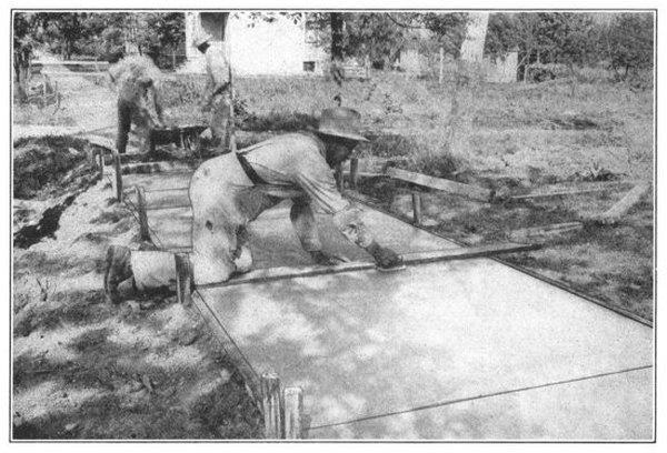
Divide the walk by setting forms at right angles to the side forms. The cross forms can be made of 2 by 4’s. These provide for expansion and contraction joints. Hold these forms in place by driving stakes through the foundation into the ground on the opposite side from where the concrete is to be placed. Spread the concrete over the drainage foundation to the thickness of the walk or floor, and in slabs not over 6 feet square. The thickness of a walk should be 4 inches, a driveway 6 inches, a floor over which a wagon may be driven 6 inches, and all other floors 4 inches.
Fill in every other slab, placing enough forms to use up all the concrete mixed in one batch. No batch should stand longer than one half hour before being placed.
Tamp the concrete thoroughly. Use a template, with ends resting on the side forms, and cut to a curve to give the walk the necessary crown. [Pg 32] The concrete should be tamped so as to conform to the curve of the template. If one edge of the walk is made higher than the other, use a straight edge resting on the side forms. Tamp the concrete to conform to the straight edge.
Mix another batch of concrete, remove the cross forms and place the concrete between each slab, forming a continuous walk. Use the template or straight edge and tamp as before. Immediately after placing the closing slab, work a straight trowel or knife down through the entire depth of the concrete between each slab, thus insuring a perfect contraction joint. Smooth the surface with a wooden float.
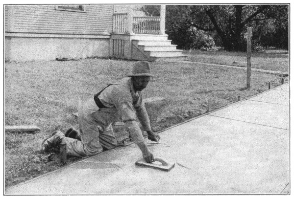
A neat appearance may be given the contraction joints by running a jointer along the top, thus smoothing the edges. Do this before the concrete gets too hard. The sides of the walk may be smoothed in the same way by use of an edger.
When the concrete is nearly hard go over the surface with a piece of oakum or a stiff brush, removing the marks of the float and giving a [Pg 34] good even wearing surface which will not be slippery. In using oakum or a brush be careful not to remove the larger pieces of stone. If surfacing in this manner disturbs the particles of stone and roughens the walk to too great an extent, allow the walk to harden a little more before finishing in this way. At the end of each day’s work see that the last slab is entirely filled and finished.
All interior floors, such as floors of cellar, barns and stables require no contraction joints. They are made by laying a solid continuous sheet of concrete. All outside floors should have contraction joints forming slabs not over 6 feet square. These are provided the same as in sidewalks. A feeding floor is formed merely by sidewalk pavements set side by side. Instead of using a template for crowning the surface, use a straight edge, each end resting on the extreme outside forms to give a slope to the feeding floor. Contraction joints for exterior floors are formed in the same way as for sidewalks. The concrete is also placed in alternate slabs and finished in the same way as sidewalks. When completed the walk or floor must be continuously protected from the rays of the sun and from the wind for at least three days, so that it will not dry out at any time. This can be easily done by covering the concrete when it is hard with hay, straw, or old carpet. This covering should be thoroughly soaked with water, and kept wet for three or four days or longer if economy will permit.
While the walk or floor is hardening it should be so protected as to prevent persons or animals from disfiguring the surface by walking on it. [Pg 35]
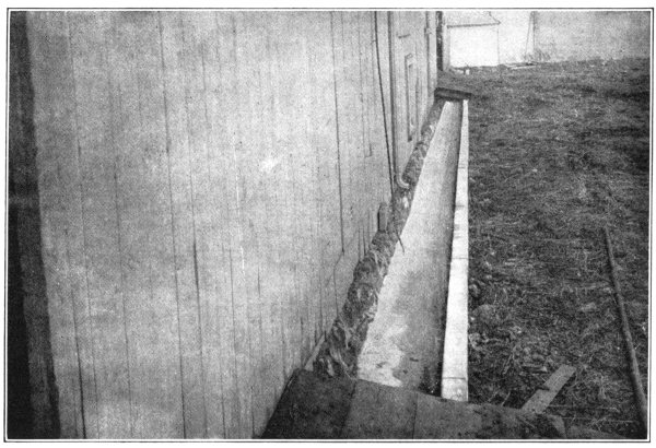
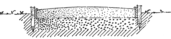
Foundation gutters catch the water from off the rain-beaten side of the building, quickly carry it away, and, by preventing “seepage,” keep the cellar, basement, or ground-floor dry. In sloppy, muddy weather, they also serve as convenient walks around the out-buildings.
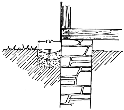
Determine the grading or sloping of the gutter bottom from observation of direction of the flow of surface water during rain storms, or from local conditions, such as location of outlet into underground drain. Excavate a trench 1 foot 6 inches in width, 10 inches deep on each side, and hollowed out to 13 inches deep in the middle. Use a straight edge or a grade cord, together with a spirit level, to give the bottom of the trench the desired slope or “fall.” For each foot of length a slope of one-eighth inch will be sufficient.
Clean the dirt off the foundation wall with a stiff broom or brush.
In the bottom of the trench place a 6-inch foundation of well-“tamped” gravel, brickbats or crushed stone.
Make a one-bag batch of concrete in proportions, 1: 2½: 5. Have the mixture just wet enough to tamp well. [Pg 36]
Place a 4-inch thickness of concrete to form a dish-shaped gutter 3 inches deep in the middle. Every five feet, make an expansion joint ⅛ of an inch wide by inserting a metal strip not less than 7 inches wide and 18 inches long, or by cutting a joint entirely through the concrete with a straight spade. Smooth the surface with a wooden float.
| Materials Required |
|---|
| One cubic yard crushed rock or screened gravel; |
| ½ cubic yard sand; |
| 6 bags of Portland cement, for a 50-foot section. |
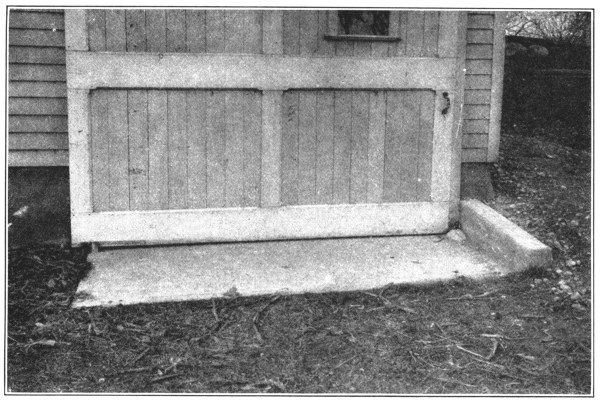
Since wood always fails first at the ground, the use of concrete on the farm has developed from the ground up. After a farmer has had to replace several sills or blocks of wood, he begins to look about him for a new material which will not rot or will not have to be replaced. Concrete is his natural selection. [Pg 37]
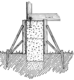
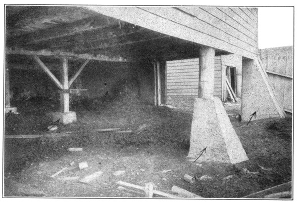
Support the building by temporary struts, alongside of the post to be removed. Saw off post entirely above rotten part. Dig a hole directly under the post 2 feet deep, and slightly larger than the post itself. Build a box with sides only, with the same inside measurement as the hole already dug. The box must be long enough to reach from the ground to a few inches above the bottom of post.
Fill hole with concrete, mixed 1: 2: 4. Then place the box in position, and fill it with concrete until the bottom of the sawed-off post is embedded about ½ an inch in the mixture. Leave the forms in place for one week and after two weeks remove the struts which have been used as temporary support for the building. The concrete should be mixed fairly wet, and churned with a stick while being placed.
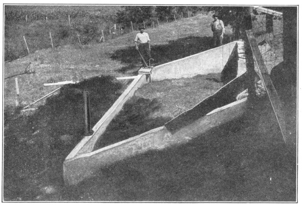
The bottom of the foundation may be made larger than the top, by simply sloping one side of the box form—giving the effect shown in the photograph.
Repairs to foundations of this kind vary greatly in size and shape. Concrete is the only material which can be used for any purpose, [Pg 38] whether large or small, without first having to be cut to the shape and size desired. Consequently there is no cheaper known material for this kind of work.
The work can be done by the farmer, with the help of his own farm labor, at times when more important work is not claiming his attention.
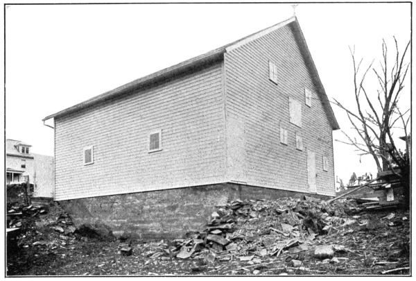
At necessary points, remove a few stones or bricks, as the case may be, inserting short pieces of heavy timber to wedge or jack up the building. Carefully raise the building, by this means, until it stands free of all foundations. Remove all the old stone or brick foundation to be replaced, and set in place the forms for the concrete.
Small buildings can usually be raised high enough to allow working room, whereby the form may be filled right up to the top with concrete. The mixture should be a wet one. (Proportions, 1: 2: 4.)
Where buildings are too cumbersome to be raised by “jacking,” to a sufficient height to give head-room, it will be found necessary to make the foundations 3 inches wider than the sill. Carry the forms to the desired height and utilize this extra 3 inches of width for placing the concrete in the forms. The top board of the forms may also be left off until you are ready to place the last of the concrete. In this case the last batch of the concrete should be very wet. Tamp the concrete until it comes up flush with the bottom of the sill, to the entire width of the wall.
Be sure to leave a space in the concrete wall, under and on the sides of the underpinning support, so that the building may later be lowered back onto the new foundation and the timber removed. This opening must be slightly larger than the underpinning support. After the building has been lowered fill these openings with concrete. Lower the building after the foundation has been in two weeks. [Pg 39]
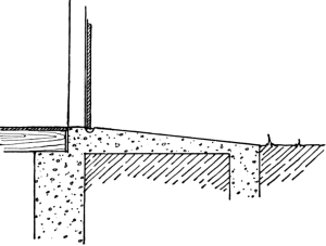
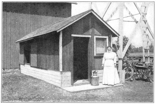
At a point 3 feet from the building, dig a trench 6 inches wide and 18 inches deep—the length of this trench to be 2 feet greater than the width of the doorway of the building. From the edge of the trench nearest to the building, dig away the earth between trench and building to a depth of 1 foot, and place here, to a depth of 6 inches, a fill of either coarse gravel or crushed rock. Do not, however, place any of this gravel fill in the trench. Mix concrete 1: 2½: 5, and lay same, first in the trench, and then on top of the gravel fill; sloping the surface so that it just meets the floor level at the doorway. Before the concrete has had time to set, provide a runway slot for the sliding doors—or better, build little guides or humps with the concrete, to hold the doors in position. If the doors happen to be swinging ones, place a gas pipe or iron socket in the soft concrete, for a “shove-fastener.”
Note the concrete curb on the right of entrance door. This prevents the gravel that surrounds the building from washing down onto the approach and getting in the way of the doors. To build this curb, use 1-inch planks placed on top of the concrete floor, to serve as forms to hold concrete in place.
| Materials Required |
|---|
| One cubic yard of crushed stone or screened gravel; |
| 2½ cubic yards of sand; |
| 5 bags of Portland cement. |
This entrance floor was constructed in half a day, by one man. [Pg 40]
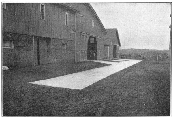
By using concrete to connect up buildings, this farmer has a solid, substantial roadway that will last for all time—instead of the usual muddy, untidy space that ordinarily separates such buildings.
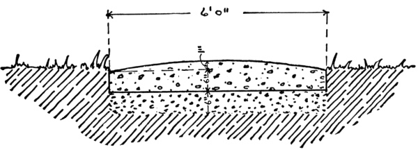
To construct a driveway between the various buildings of a farm, first excavate a trench 12 inches deep, this trench being the exact width that you wish the finished driveway to be. Six feet is a convenient width; but the drive should be made slightly wider than this at the corners to provide for turning of vehicles.
Place in the trench a fill of gravel to a depth of 6 inches and tamp it well. On top of the gravel fill, place your concrete mixture, to a depth of 6 inches on the sides, and 7 inches at the center.
For this work, concrete should be mixed in proportions 1: 2½: 5, and wet enough to pack well. [Pg 41]
To finish, no mortar is needed. Leave the surface rough, so as to afford a better footing for the horses and cattle.
| Materials Required | ||
|---|---|---|
| 5 bags of Portland cement | make a section of roadway 6 by 10 feet | |
| ½ cubic yard of sand | ||
| 1 cubic yard of crushed stone or screened gravel | ||
Approximate cost, at current prices of materials, 6 cents per square foot of surface.
The farmer of to-day plans for comfort and convenience. About the home, mud is the greatest of all nuisances. In the spring and winter, the driveways from the public road and the alleyways between buildings become so muddy that they are often impassable. As a result the grassy lawns and lots are driven over, cut to pieces, and the general appearance of the farm is ruined. Moreover, in bad weather the chores cannot be done unless the “hands” wear rubber boots. The women and children are unable to get out to gather the eggs and to see after the poultry. Muddy feet track up the house walks and floors.
Alleyways between buildings are built of concrete similar to driveways with this exception—they are made dish-shaped to the same extent that the driveway is crowned. This carries the roof water away from the buildings instead of letting it soak in around the foundation walls. [Pg 42]
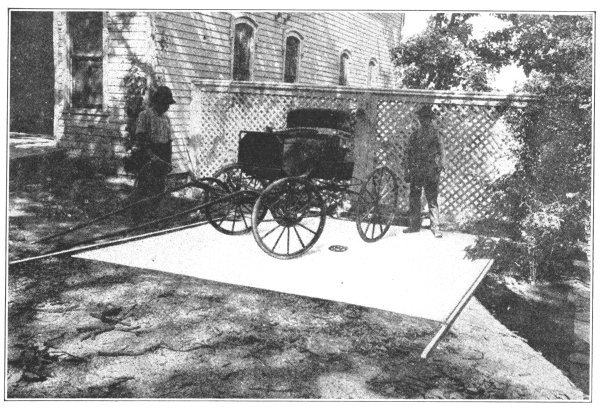
Nothing will take the sticky mud off the wheels and body of a rig except water. People have at times tried to remove this mud by scraping, but have found that after the mud has once dried a large amount of the varnish comes off with it and the “looks” of the carriage is ruined.
Convenience in washing means that the wagon is pulled just outside of the barn and quite near the pump or other source of water supply. All of the carriages are washed in exactly this same spot, and, as this is done day after day the washing place very shortly becomes nothing more nor less than a mud hole. To avoid this a concrete floor should be built.
This floor should be of the size to take not only the wheels of the rig but the shafts or tongue as well. Unlike feeding and other floors, this floor is built with a slope toward the center, with a catch basin under the middle, from which a drain leads. Thus all of the water, together with the mud coming off the wagon, flows into the basin. This basin should be protected with a grating, with holes in same not less than ¼ of an inch. This grating should be removable so that the mud, which is bound to flow into the basin, can be removed. A pipe less than 6 inches should not be used to connect this basin up with a sewer or ditch outlet. This will prevent the stoppage of the drain for many years. A slope from the edges of the floor to the drain of ⅛ of an inch to the foot should be made. To lay the floor proceed exactly as described in “Sidewalks,” and, as the floor is exposed to the weather, contraction joints must be provided, as in Feeding Floors.
After the floor is finished and while the concrete is yet soft, make grooves in it, running from the basin to the edges of the floor. This can be done by taking a V-shaped strip of wood and driving it into the concrete at regular intervals by means of a tamper. This strip of wood should be thoroughly greased so that it may be removed without having the concrete stick to its surface. [Pg 43]
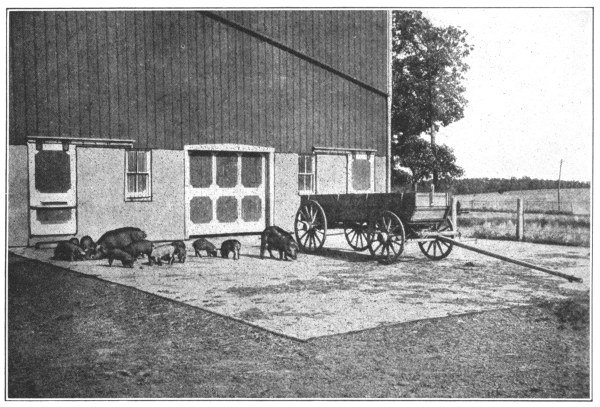
The saving principle of feeding floors has long been recognized by successful breeders and feeders of live stock. The trouble, heretofore, has been to obtain an entirely satisfactory material for floor construction.
Wooden floors kept the feed out of the mud and dust and not only saved every particle of grain but also prevented wheezing coughs and otherwise temporarily improved the health of the animal. However, in a short time, the best wooden floors rotted out and became infected with disease germs. Often floors had to be burned to free the farm of hog cholera.
In concrete the farmer and ranchman have found an ideal floor material. Such floors not only effect a saving in feed, a shortening in the time of fattening and a decrease in labor, but also afford perfect protection to the health of the animal. Concrete floors do not soak up water and therefore cannot become infected with disease germs. Their surfaces can be easily cleaned and thoroughly disinfected with oils and dips. Rats cannot nest under them. Careful tests have shown that concrete floors, through the saving of grain and manure alone, pay for themselves in the short period of one year.
Feeding floors are merely several sidewalks laid side by side, and the same general rules of construction (given under Sidewalks,page 28) apply to them. Choose a site in the lot where the ground is slightly sloping, well drained and wind protected, and convenient to feed and water. [Pg 44]
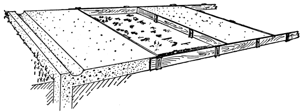
Excavate to a depth of 12 inches for the drainage foundation, and around the outside edges of the entire floor dig a trench 12 inches wide and 18 inches deep. (This trench, filled with concrete, prevents hog wallows from undermining the floor and keeps the rats from nesting under it.) Fill all of this space (except the trench) to the natural ground level with well tamped coarse gravel, crushed rock, tile culls or brickbats. This fill forms the drainage foundation as described for sidewalks.
The floor must be graded or sloped so that water will not collect on it in the winter and so that the manure washings may be caught by the gutters and run to the water-tight concrete manure pit. (To shape the gutter, make a mold or template by rounding the corners on the flat side of a 6-foot length of a 4 by 6-inch timber.) A gentle slope, toward the low corner, of ¼ of an inch for each foot of length or width is sufficient. This is secured by the use of a heavy grade stake at each corner of the floor, a straight edge or a grade line, and a spirit level.
It is an advantage to have a feeding floor its full thickness above ground. Make light floors 4 inches and floors subject to heavy loads 6 inches thick. For the forms use 2-inch lumber of a width equal to the floor thickness. Begin on a low side of the floor. Mark the grade height on each corner stake and set the forms to a grade cord stretched from stake to stake. Use only good materials and mix the concrete 1: 2½: 5 according to direction on page 15.
Always begin placing the concrete on the low side of the floor, so that the rain from sudden showers will not run from the hard onto the newly placed concrete. Fill the trench and the slab section of the forms with concrete. Bring the surface to grade by drawing over it a straight edge with its ends on the opposite forms or with one end on the form and the other on the finished concrete. Four inches in from the edge, on each of the low sides, temporarily embed the rounded 4 by 6-inch gutter mold and tamp it down until its square top is even with the surface of the slab section of the floor. Remove the mold, finish with a wooden float and cure the floor as described on pages 31-34. Connect the gutters with the manure pit by means of a trough, another gutter, or by large drain tile laid underground.
On the next page is given an itemized bill of materials necessary for a 6-inch floor 24 by 36 feet, amply large to accommodate 50 hogs. [Pg 45]
| Materials Required | |
|---|---|
| Crushed rock or screened gravel, 20 cubic yards @ $1.10 | $22.00 |
| Sand, 10 cubic yards @ $1.00 | 10.00 |
| Portland cement, 28 barrels @ $2.50 | 70.00 |
| $102.00 |
Mixing the concrete by hand, 5 men can usually finish this floor in two days. Depending upon the price of labor and materials and the thickness of the concrete, the floor will cost 6 to 12 cents for each square foot of surface.
For restoring the fertility of the fields, there is nothing better than barnyard manure. By the ordinary methods of piling it on the ground or storing it in wooden pens, from 30 to 50 per cent. of the manure’s strength is wasted. This loss is brought about in two ways:
Since concrete pits are waterproof, manure can be kept in them as moist as necessary. Moreover, with concrete pits the supply of manure is increased, as all the liquid manure, from the gutters of the barns, barnyard pavements and feeding floors, is saved.
Locate the manure pit handy to the barn and so as to catch the manure from the outside floors. Two pits may be better than one. Excavate the hole to the desired size and depth. (Manure pits are seldom over 4 feet deep.) Dig a sump hole 3 feet square and 2 feet deep at one corner of the pit. Slope the floor toward this hole, from which a pump will draw the liquid manure. Frame forms of 1-inch siding on 2 by 4-inch studding spaced 2 feet, so as to mold a wall 8 inches thick. If the dirt sides [Pg 46] stand firm, they will serve for the outside form and nothing but an inside form will be required. Mix the concrete 1: 2: 4 (see page 11). Lay the floor so that it will be one solid piece 6 inches thick. No contraction joints will be necessary. Without delay, set up the forms, brace them firmly and fill them with concrete as directed under Dipping Vats, pages 76-80. If a very large pit is needed, build it with sloping concrete ends sufficiently wide to accommodate a manure spreader. Let the inclines be gentle, and, to give the horses a firm footing, embed iron cleats every 18 inches in the slopes, the same as for dipping tanks. Cisterns for liquid manure only, may be made like ordinary Cisterns, page 68. However, the solid manure rots more quickly and is better for the fields if both solids and liquids are kept in the same pit. An ordinary pump, with a pipe leading to the sump hole, covered with a grating, is a convenient means of removing the liquid. Liquid manure is especially good for the vegetable and flower garden, since it contains no weed seed. Cover the pits or keep the manure well soaked with water, so as to remove the principal breeding places of the house and barn fly.
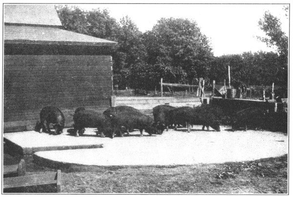
The manure pit shown in the photograph is located in the side of a little hill. It is 21 feet long, 14 feet wide, 10 feet deep on the hillside and 6 feet deep on the low side. The bottom is 6 inches and the walls 8 inches thick. Four men built the pit in two days.
| Materials Required | ||
|---|---|---|
| Screened gravel or crushed rock | 17 cubic yards at $1.10 | $18.70 |
| Sand | 8½ cubic yards at $1.00 | 8.50 |
| Portland cement | 30 barrels at $2.50 | 75.00 |
| $102.20 | ||
Rotten manure not only enriches the ground, but also increases the water-holding capacity of the soil. One load of well rotted manure from a concrete pit is worth two loads of manure as ordinarily stored. [Pg 47]
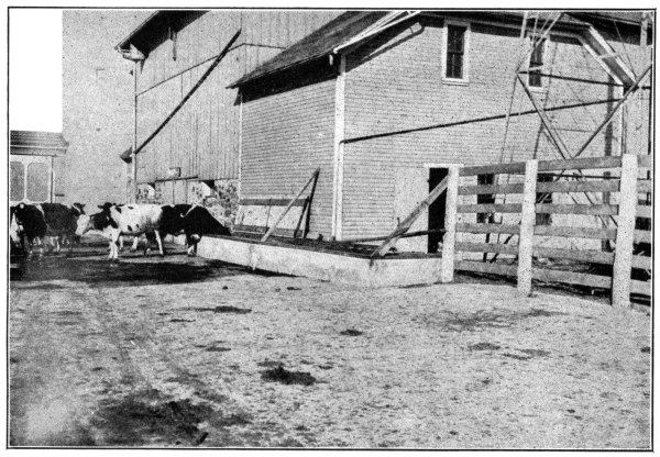
The advantages of concrete feeding floors so appealed to the farmers who first built them that they enlarged the floors until their entire barnyards were surfaced with concrete.
It is no uncommon sight in the spring and winter to see an earthen barn lot so deep with mud that animals go thirsty rather than attempt a trip to the water trough.
The effect is bad on all kinds of livestock, especially on fattening animals and dairy cattle. “Feeders” must have an abundance of water to fatten quickly. Insufficient water cuts down the quantity of milk given by dairy cows. Lack of enough exercise further decreases the yield. An occasional trip through this mud to the trough, so cakes the cows’ udders with dirt that the milker wastes valuable time in washing them—and they must be washed, if one would have clean, wholesome milk. Continual tracking through the mud not only makes more currying, but often produces that irritation on horses’ legs known as “scratches.” Suddenly frozen, such an earthen lot is so rough that it is impassable. Moreover, the old barnyard—with its surface worked up year after year—becomes a storage place, which carries over the disease germs from one season to another. The “droppings” are entirely lost, and, mixed with the earth, tend to make the lot muddier the following year. To keep up the fertility of the soil, all the manure produced on a farm should be saved and returned to the fields.
A concrete barnyard makes a fine exercise lot in all kinds of weather and always affords a dry spot for the animal’s bed. Every shower washes the surface clean and flushes the droppings into the manure pits. Concrete yards lighten the work of the housewife, as there is no mud to be tracked on the walks and kitchen floor. The use of rubber boots is [Pg 48] unnecessary. On concrete floors not a particle of grain need be wasted. The way to the water trough is always dry, smooth and passable. Concrete floors promote and protect the health of farm animals and increase the profits of farming, stock raising and dairying.
The construction of concrete barnyards is exactly like that of Feeding Floors, page 43, except that the work is on a larger scale. Often the entire lot is not paved in one season, but from year to year as the farmer has time. In excavating for the drainage foundation (see Sidewalks, page 29), be careful to remove all manure and straw which may be tramped into the ground and which may be so solid as to resemble earth. In time any kind of manure decays, shrinks, causes the floor to settle and forms water and ice pockets on its surface. Dig the trench for the foundation apron as for Feeding Floors—there is no material so rat-proof as concrete.
With the drainage foundation ready, set the forms in the manner described for Sidewalks. Even if the whole lot is not to be paved at one time, plan the grading for the entire barnyard so that the completed pavement may have perfect surface drainage. Build and cure the pavement and make provision for saving the manure the same as for concrete Feeding Floors. Do not be too particular about giving the surface a smooth finish—a rougher finish affords the animals a better footing. The cost per square foot is no more than that of feeding floors—the investment yields a greater profit.
With a progressive farmer, the health of his livestock is second in importance only to that of his family. Concrete is a great factor in promoting and preserving health. With concrete troughs, animals are seldom “off their feed”: there are no slivers to stick into their gums. Even with wet feed, concrete troughs are never sour.
Concrete does not rot and become infested with disease germs. Such troughs and mangers can be thoroughly disinfected without injuring them. [Pg 49]
In general, the method of constructing feeding troughs and mangers for horses and cattle is practically the same as for Watering Troughs and Tanks, page 74. An outdoor trough, suitable for feeding grain or silage to cattle and horses, is shown on page 48. (However, most farmers will prefer not to locate a feeding trough in a fence corner.) This trough is 10 feet long and 2 feet 2 inches wide, outside measurements. The bottom is 4 inches thick as also are the side and end walls at the top, but these walls slope on the inside to a thickness of 6 inches at the bottom. This extra thickness makes not only a stronger feeding trough, but also one more easily cleaned out. The entire trough is reinforced with heavy woven wire fencing laid within 1 inch of the bottom and the same distance from the inside face of the side walls. The trough is held 1 foot 4 inches above ground by concrete benches, 2 feet 2 inches wide, 1 foot thick, and extending 3 feet below the ground or feeding floor surface.
In locating troughs, follow the same principles laid down under Feeding Floors. Dig the trenches for the concrete supports and carry the concrete (mixed 1: 2: 4) to the necessary height by means of open box forms similar to the one shown on page 36. Use a spirit level to get the tops of these supports even. Immediately set the outside trough form, previously made with openings in the bottom board, to match the concrete supports. Provide a 2-inch drain hole, corked with a greased, tapering wooden plug long enough to extend through the concrete. Place 1 inch of concrete over the bottom, lay the heavy woven wire fencing so that it will extend up into the side walls. Tamp in the bottom the remaining 3 inches of concrete. Finish this concrete with a steel trowel. At once set in the sloping inside mold, built as one piece and without a bottom. Fill the space between the inside and outside forms with wet concrete. After the concrete is hard enough to bear considerable pressure of the thumb (usually five to seven hours), carefully remove the inside mold. No painting with neat cement (cement mixed with water) or plastering will be needed if the inside form is smooth. Do not take down the outside forms for two weeks. To make this same trough of suitable height for small calves or sheep, place around it a fill of gravel of the necessary depth. Two men can build such a trough in less than a day.
| Materials Required | ||
|---|---|---|
| Crushed rock or screened gravel | 1 cubic yard at $1.10 | $1.10 |
| Sand | ½ cubic yard at $1.00 | .50 |
| Portland cement | 1½ barrels at $2.50 | 3.75 |
| $5.35 | ||
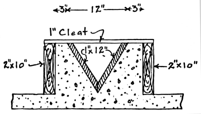
Feeding troughs for hogs are usually built as a part of the feeding floor, according to the plan shown, and similar to Watering Troughs, page 74. [Pg 50]
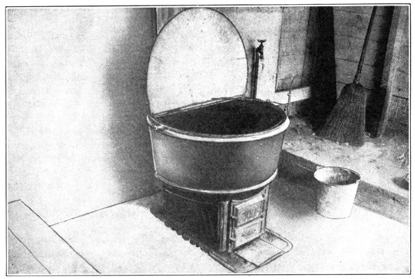
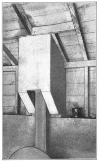
Concrete is a first aid to the farmer in preventing fires.
The photographs shown here are of a wooden building in which a feed cooker for hogs and poultry is installed.
Discovery of a fire in the building a few years ago led this farmer to thoroughly protect his building by surrounding his cooker with that most fireproof material—concrete.
The old wooden floor was first torn out, a fill of coarse gravel tamped in, and a 5-inch floor of concrete laid on top, mixed 1: 2½: 5. Immediately under and around the cooker the floor was dropped down 8 inches to prevent chance sparks from blowing about. [Pg 51]
At the back of the cooker, on the 2 by 4-inch studding, heavy woven wire was securely fastened, and by temporarily placing a wooden wall 4 inches in front, to act as a form, an 8-inch concrete wall was built. This wall was made 8 feet wide and 5 feet high. The foundation for the wall extends 3 feet below the floor level.
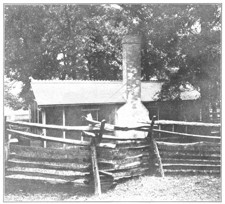
On the top of this wall rests the chimney. The chimney is 12 by 14 inches on the outside, with a single flue 8 inches round, and is 10 feet high. This height is sufficient to clear the roof. For the inside form 8-inch sewer pipe was used and left in place (stovepipe or drain tile could also be used). Ordinary box forms were used for the outside forms, made as described on page 36.
The chimney was reinforced with a ½-inch rod running from top to bottom in each corner, 1½ inches from the edge. The lower ends of these rods are firmly embedded in the concrete wall on which the chimney rests.
As this improvement was made by the farm hands, the cost of the floor was only 5 cents a square foot, while the wall and chimney cost $5.00.
Not only has that dread of fire which keeps many a man awake at night been overcome, but the whole feed cooker house can be kept in a most cleanly condition at all times.
Rats, the greatest pest known to the farmer, are driven away. These animals cannot nest in concrete. [Pg 52]
A wallow is as necessary for a hog as a bath-tub is for a human being. A clean bath benefits the health of a hog, especially if the wallow is filled with a dipping solution. This combination not only saves the lives of fat hogs on hot days, but also aids greatly in preventing cholera. See Dipping Tanks, page 76.
Locate the wallow in a convenient place near the water supply. A level, well drained spot, where the mud will not wash into it, is best. (The wallow shown in the photograph is in the hog house, and is a large dish in the concrete floor.) Make the wallow 8 by 12-feet. Dig out the hole with straight sides to the depth of 2 feet 2 inches. Lay a drainage foundation 10 inches thick—see Sidewalks, page 29. Set a 10-inch board around the outside of the hole to keep the dirt from crumbling in on the concrete.
Mix the concrete 1: 2: 4 and place a 6-inch floor in the hole. As the concrete is laid, embed woven wire in it 1 inch from the bottom. Have the concrete for the side walls fairly dry and tamp it to the shape and dimensions—4 inches thick at the top and 10 inches at the floor line. The sloping sides make cleaning easy. Keep all animals away from the wallow for two weeks. Three men built this wallow easily in one day.
| Materials Required | ||
|---|---|---|
| Screened gravel or crushed rock | 2½ cubic yards @ $1.10 | $2.75 |
| Sand | 1¼ cubic yards @ $1.00 | 1.25 |
| Portland cement | 4½ barrels @ $2.50 | 11.25 |
| $15.25 | ||
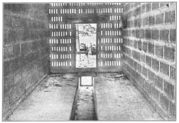
Rats love grain; and therefore the corn crib is usually the rat headquarters of the farm. By building corn cribs and granary floors of concrete the farmer takes a long step toward rat extermination.
Lay out the building: for the foundation wall, dig a trench 12 inches wide and from 2 to 3 feet below ground level. Set box forms, so as to bring the surface of the finished foundation and floor 1½ to 2 feet above ground level, according to the height of the “drag” conveyor used by local corn-shellers.
As the floor will only be 6 inches thick, fill in between the foundation walls with gravel to within a distance of 6 inches of top of forms. Soak this fill thoroughly, and tamp and roll it well, before placing concrete on top.
Mix concrete (1: 2: 4) and fill the foundation forms. Beginning at one end of the building, lay the concrete floor in sections 4 feet wide, and continue until the entire floor is placed.
In order to fasten the wooden sill for the granary uprights to the concrete floor, insert ¾-inch bolts heads down or strap irons bent like capital Z’s at the necessary points in the green concrete of foundation. The bolts are long enough to pass through holes in the sill and to receive nuts and washers. The straps are long enough to be spiked to the uprights.
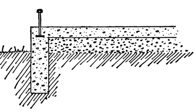
Finish the surface of the floor with a steel trowel, so as to render scooping of the grain an easy matter.
Approximate cost per square foot of floor surface, 12 cents. [Pg 54]
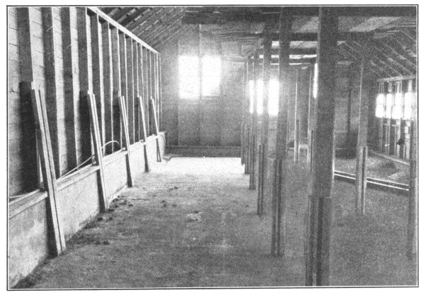
Investigations of the Department of Agriculture have disclosed the fact that many cases of typhoid fever and malaria, often considered unaccountable in their origin, are the result of the germs being carried by the house-fly. Screens, flypaper, and poisons are all very well, in a small way, but to free the place of flies means getting rid of the conditions which produce them. Leaving out the manure pile (see Manure Pits, page 45), the favorite breeding-place of flies is the foul floors of the cow and horse barns. The barn can be almost entirely rid of flies by building floors and manure pits of concrete.
There are no flies to make the horses stamp.
Rats have no hiding-place about concrete floors.
No other floor is as slick as a manure-soaked wooden floor. Concrete floors may be finished as rough or corrugated, as may be desired.
Concrete floors do not soak up water. The liquids run into the gutters and thence to the manure pits. The floor may be flushed with water and kept as clean and odorless as a kitchen floor.
All kinds of barn floors must be bedded down. Concrete floors are warmer and cleaner than any other kind, for they are always dry. Besides, heat and cold do not easily pass through concrete.
Concrete floors afford good fire protection. No fire can be started on concrete floors by a shiftless farm “hand” dropping cigarette stubs or matches on their surface.
Good farm “hands” prefer to work where there are concrete floors: they lighten the labor. Concrete floors have no uneven edges to catch the scoop and to ruffle the temper. [Pg 55]
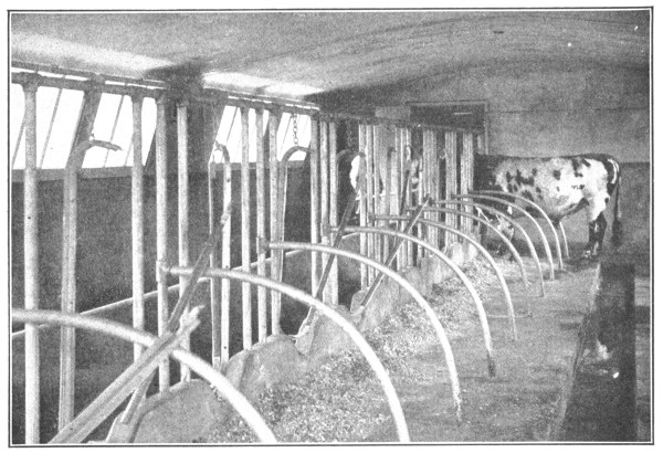
With cleanly milk and butter producers, it is no longer a matter of floor or no floor; it is merely a question of which is the best floor for the cow barn. The best dairymen long ago decided in favor of concrete. On account of many epidemics of “catching” diseases, directly traceable to milk, city authorities are forcing the careless dairyman to decide—concrete floors are one of the requirements for certified milk.
The stalls of dairy barns are arranged with the cows in the opposite rows of stalls standing with their heads or their heels toward each other.
The stall plan depends entirely upon the arrangements for bringing in feed and removing manure. The plan below is for a barn with the cows’ heads toward each other. If the dairyman prefers the other arrangement, the same plan can easily be adapted to it. A width of 8 feet 6 inches provides sufficient room for a manure spreader.
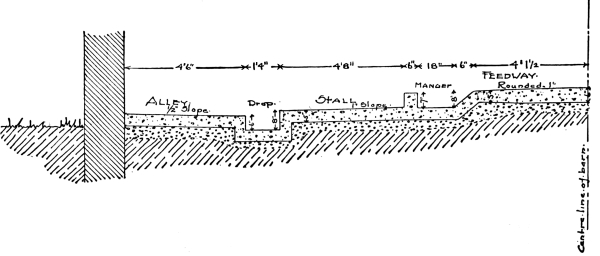
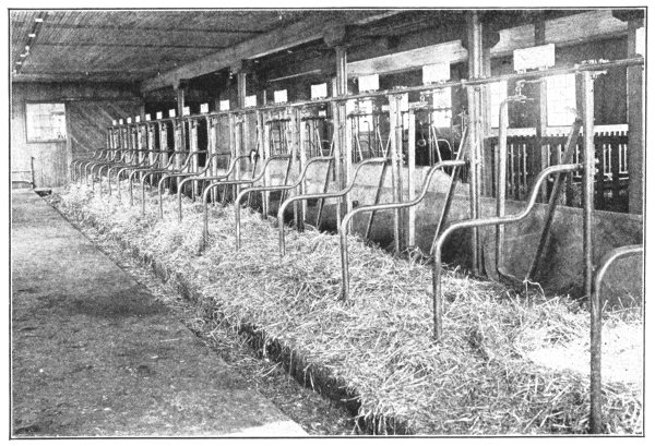
Consider a barn planned to have the two rows of cows facing each other.
Remove all manure and other foreign matter together with such humps of earth as may be necessary to give the floor a slight slope in the direction in which the manure will be taken out. Begin the construction of the floors at the two sides of the barn so that the middle and ends may be used as working space.
On the earthen floor, at a distance of 4½feet from the side walls of the barn, set on edge a line of 2 by 6-inch boards, extending the entire length of the building. Support these boards by stakes driven firmly in the ground on the side of the board away from the barn wall. By means of a carpenter’s spirit level and a grade line, see that the tops of these boards have an even slope (say ⅛-inch per foot) toward the manure pit. Allowing a clear intervening space of 10 inches, set up in a similar way a line of 2 by 8-inch boards with the supporting stakes inside of the 10-inch space and with the top of this board 2 inches higher than the 6-inch board. In this space the drop gutter will later be constructed.
Between the wall and the 6-inch board tamp in sufficient gravel to even off all irregularities in the ground surface and to allow the building of a 5-inch thickness of floor, sloping ½ inch from the wall toward the gutter. Mix the concrete 1: 2½: 5, tamp into place, and finish the surface with a wooden float and a wire brush. The roughened surface thus produced gives the cows a good footing.
With the alley finished, begin the construction of the floor of the stalls proper. For the average sized cow, the usual length of stall is [Pg 57] 4 feet 8 inches from stanchion to drop gutter and the width is 3 feet 6 inches. The stall floor should slope not less than ½ inch toward the drop gutter to provide for drainage. If an adjustable stanchion fastener is to be used, set it in the center of the 6-inch manger wall. The length of the stall is regulated by this device. For a stall 4 feet 8 inches long, set the outside board (2 by 12 inches) of the manger wall 5 feet 2 inches from the drop gutter. The top of this board will be 7 inches above the finished floor. This extra height provides a form for the manger wall. In this space, place the 5-inch floor in the same manner as the alleyway was laid. If gas pipe stall divisions are to be used later, make mortises in the floor at the proper points by tamping the concrete around a core of the right size, removing the core when the concrete has stiffened.
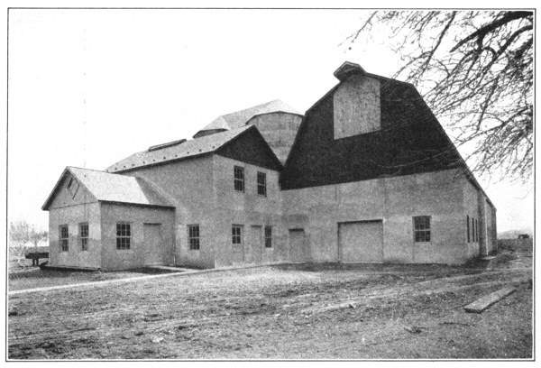
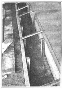
As soon as the floor of three stalls has been concreted and while the concrete is yet green, build the concrete manger wall upon the new stall floor. The projecting 7 inches of the 2 by 12-inch board already in place serves as the outer wall form. “Toe nail” two 1 by 6-inch boards together at their edges, thus providing a 7-inch height for the other manger wall form and a bearing plate to rest on the green stall floor. Set this wall form so as to leave a 6-inch space for the manger wall. Cross-brace these wall forms upon each other and if necessary drive an occasional nail through the bearing plate into the new concrete. Fill the space between the forms with concrete, setting the [Pg 58] stanchion fasteners at the same time. Continue in the same manner until the stall floors are finished. If desired, the back wall of the manger may be given a dish shape for a swinging stanchion.
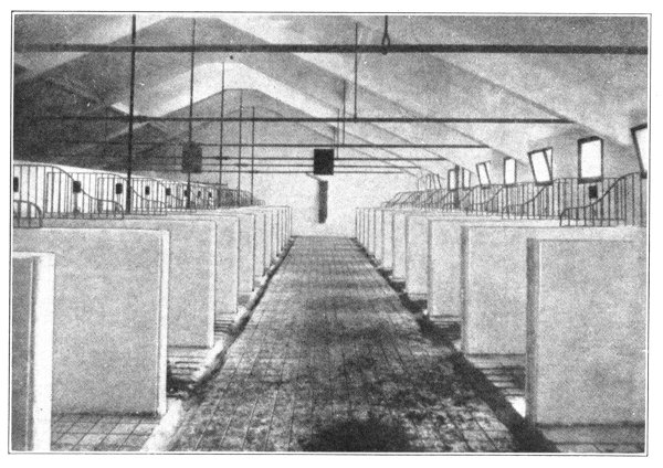
Then commence the work on the other side of the barn, constructing the floor of the alleyway and stall in exactly the same manner.
With the alleys and stalls finished, begin work on the feedway. If possible, this should be at least 8 feet wide.
As the bottom of the manger should be on a level with the stall floor and since the top of the feedway floor must be at least 8 inches above the bottom of the manger, place sufficient gravel fill (well tamped) to bring about this result. To hold in place the 5-inch concrete of the feedway alley floor and to provide for sloping front walls of the mangers, set a 2 by 10-inch board, spaced (from the other wall of the manger) 1 foot 6 inches at the bottom and 1 foot 10 inches at the top. These sloping walls allow all feed to be swept back into the mangers and all trash to be easily removed from them. Build the 5-inch floor of the feedway, crowning it to 6 inches thick in the middle. See Sidewalks, page 31.
Concrete floors are equally as valuable for the horse barn as for the cow stable. The same principles govern the floor construction. Naturally there must be a few changes in the dimensions. Single stalls are usually 5 feet wide and 9 feet from the front wall of the manger to the drop gutter.
As the gutter is generally covered with a rough cast-iron plate sunk flush with the concrete, carrying liquids alone, it need not be so wide and deep as for the dairy barn. A clear width of 10 and a depth of 3 inches are sufficient. [Pg 59]
Many farmers are to-day building their mangers or racks of concrete. “Stump suckers” lose the habit when fed in concrete mangers.
The manger is constructed along the general lines laid down for Outdoor Feeding Troughs, page 48. A form satisfactory for building horse barn mangers is shown in the photograph. The feed trough can be molded as a part of the manger by using a box form like an ordinary wooden feeding trough, but 6 inches wider and without end pieces. Saw out the manger forms so that the box will fit the opening. When the manger forms have been filled with concrete to the feed trough level, place 1 inch of concrete over the bottom of the trough form, lay in a strip of heavy woven wire fencing, and then place the remaining 2 inches of the 3-inch bottom. Immediately set upon this concrete a bottomless box with end pieces, of a size to allow for the 4-inch manger wall and the 3-inch side walls of the trough. Fill both manger and trough forms and embed a ½-inch rod in the side walls of the trough 1 inch from the top. Make holes in the manger wall for the hitching strap by inserting a 2-inch greased peg in the concrete. Imbed a 1-foot length of ½-inch rod in the concrete above this hole.
Scientists have found that rats distribute more disease than any other animal. Recognizing the danger, state and city authorities, the world over, are spending vast sums of money in exterminating this pest. If rats have no nesting place, they cannot stay on the farm. Rats and mice cannot find a home about concrete floors, nor can they climb concrete barn walls.
In a stable floored with concrete, the horses can rest at noontime instead of stamping at flies. [Pg 60]
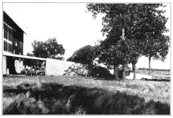
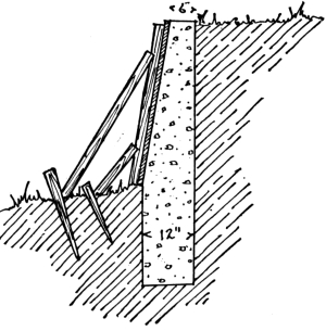
For purposes of drainage, concrete barns are often built on the side of a hill, the lower story being used for the livestock, while the second floor is used as a wagon house and for feed and storage. This arrangement necessitates a “barn approach.” Originally these approaches were simply of earth, piled up in front of the door; and quite often the earth extended beyond the ends of the barn.
By not allowing the approach fill to come right up to the barn, the lower story of the barn receives the full benefit of light and ventilation on all four sides.
The concrete bridge gives a shelter for wagons and tools; while a root cellar may be conveniently built under the barn approach.
Such an approach adds greatly to the appearance of the barn and its surroundings.
Economy of space made it desirable to provide a retaining wall to hold the earth in position—and concrete naturally came into use for the purpose.
The earth fill already in place in front of the barn door should be cut out to the desired width and a trench dug along both sides below the ground level to a depth of 2½ or 3 feet, and 1 foot wide.
Only outside forms are needed, as the earth fill in the barn approach [Pg 61] acts as an inside form. These outside forms may be made up in sections as large as desired, of 1-inch planks, with the necessary upright studding.
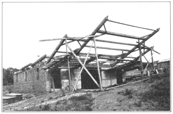
Mix concrete 1: 2: 4.
Place the concrete in the foundation, erect the forms, holding these in position by nailing to stakes driven back of the forms in the ground. The concrete can be placed with greatest convenience from the top of the earth fill that forms the approach. In shoveling into the form, be careful that the concrete strikes the wood form instead of the earthen side, as concrete mixed with earth does not give the fullest possible strength.
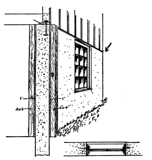
On account of convenient arrangement, economy of space, and protection to the stock, second story barns have become very popular.
At first the use of concrete for the walls of the first story was looked upon with doubt. It might be damp. It might make a cold stable. Yet the character of the material so well fitted the use that it was tried, found entirely satisfactory, and to-day is being used for the lower story of thousands of barns every year. As this arrangement does not give a perfect fire protection to the stock, a ceiling of concrete [Pg 62] is provided, furnishing a floor for the carriage house, hay loft and granary, through which rats cannot gnaw. With this floor of concrete, the top of a barn can burn off and the stock be perfectly safe.
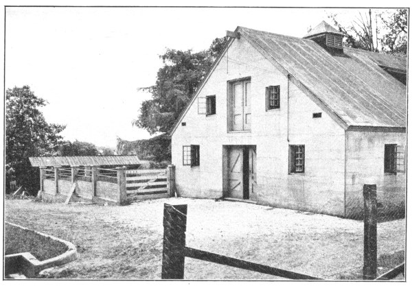
Excavate a foundation trench to a depth below the frost line, twenty inches wide. Fill with concrete mixed 1: 2½: 5. On this foundation erect the forms for the side walls, spaced in such a way as to make the wall 12 inches thick. These forms are made of 1-inch siding, with 2 by 4-inch studs, spaced 18 inches apart. Fasten the forms securely at top and bottom as described in forms for “Small Farm Buildings,” page 82. While erecting the forms, place in position frames for the window and door openings. These frames are removed after the concrete has become hard and the windows and doors placed. If the concrete extends above the windows, place three ½-inch iron rods 3 inches above each opening, and extending 18 inches beyond its sides. Insert bent iron rods in the concrete around the corners, at intervals of every 2 feet of height. Having carried the wall to the desired height, provide for attaching the wooden superstructure to it by placing iron bolts every 5 feet in the concrete while it is yet soft. These should be placed with the head down, allowing the nut end to extend above the wall a sufficient distance to pass through the sill and to afford length for a nut and washer.
If a concrete ceiling is to be placed over the stable, erect forms in the same way as for a cistern cover described on page 69. This ceiling will have to be carefully reinforced, and if there is any doubt about the quantity and position of this reinforcing, a competent engineer should be consulted.
Entire barns of concrete are being built in ever increasing numbers. If so built, the fire danger for that barn is forever removed. A barn of concrete, however, with a wooden roof is not perfectly fireproof. If the hay catches fire in such a barn, the roof is burned up.
Any one who has the ingenuity to build an entire barn of concrete can build a concrete roof as well. [Pg 63]

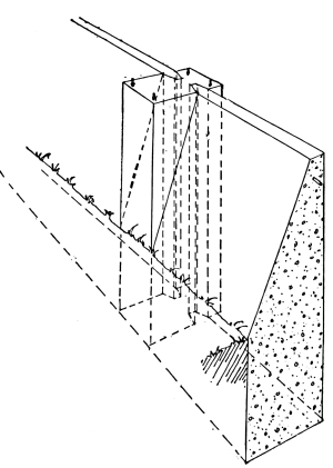
To be healthy, stock need exercise—in winter as well as summer. But few farms are provided with an exercise lot sufficiently well protected against winter blasts to provide a safe exercising place.
The exercise lot should be located on the warm side of the buildings. Erect the wind wall on the side from which the winter storms most often come. Probably the most convenient way to build the wall will be in sections of 10 feet in length. The wall will be 3 inches thick at top, 12 inches thick at the base, 7 feet above and 3 below ground, with the slope side toward exercise lot.
To securely brace the sections of this wall, large posts (called buttresses) are needed. These posts are the full height of the wall and are 12 by 18 inches square. The narrow side is set with the line of fence, and the buttresses are placed 11 feet apart from center to [Pg 64] center. The forms for these buttresses are the same as for gate posts, with the exception that a beveled 2 by 4-inch timber is nailed vertically to the inside of each side wall of the form, 3 inches from the back board. This leaves a slot in the finished buttress, into which the slab sections of the wall are later “keyed.” Through these 2 by 4’s, at points 3 and 15 inches below the tops, bore ⅝-inch holes through which ½-inch reinforcement rods will be placed and allowed to project into the wall proper about 18 inches.
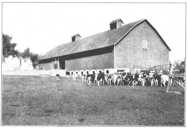
Locate the points for the centers of the buttresses, the first buttress at the beginning of the wall. Dig a hole for each buttress 12 by 18 inches and 4 feet deep and erect the buttress forms. Fill the forms with wet concrete, mixed 1: 2: 4. Do not forget to insert at the proper time the 3-foot lengths of ½-inch rods in the ¾-inch holes above mentioned. Brace the forms securely, to keep them in position. After the first two buttresses are in place, dig out the 1 by 4-foot foundation trench and, over it and between the buttresses, erect the box forms for the slab sections, with the sloping side next to the lot. These forms are made of 1-inch siding nailed to 2 by 4-inch studding securely braced at bottom and tied together by cross-pieces at the top. On the working side, add the siding as needed, so as to facilitate the placing of the concrete.
Remove the side forms for buttress just before placing the forms for wall proper. In the center of wall, within 6 inches of the top, embed a 10-foot length of ½-inch iron rod. After the wall is one week old, take down the wall forms, erect them between the next two buttresses, and proceed with the construction in the same manner.
Wind walls are often made with straight sides. While this takes more concrete, the saving in erection of forms probably offsets this additional cost.
The materials required for each 10-foot section of wall and 1 buttress are two cubic yards crushed stone or screened gravel, 1 cubic yard sand, 12 bags of Portland cement. Approximate cost, $15.00. [Pg 65]
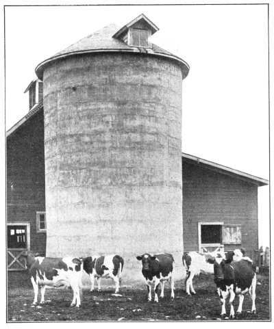
A silo is a tank for the preservation of fodder in its green state, for feeding stock at times when there is no natural pasture—that is in winter and in the hot, dry months of summer. By the use of silos fodder is canned very much as a housewife cans fruit or vegetables.
Concrete fulfils every requirement for a first-class silo, providing the added advantages of being absolutely fireproof and everlasting, possessed by silos built of no other material. For instruction in building silos, see Bulletin No. 21 of the Association of American Portland Cement Manufacturers, sent free on application.
Space does not permit us to go fully into the construction of a concrete silo and we can only give the requirements for a good silo, and show how concrete fills them all.
Silos must be air-tight. The admission of air causes the fodder to mould, and the stock will not eat it.
Air cannot leak through a concrete silo.
Silos must be water-tight. If they are not, the juices, so necessary to keep the fodder green, will leak out, and the fodder spoils. [Pg 66]
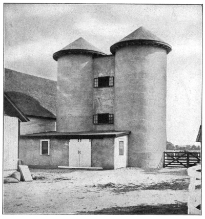
Concrete, properly mixed, is water-tight.
Silos must be smooth on the inside. A silo with a rough inside surface, catches the cornstalks, and prevents proper packing.
Concrete can be made so smooth that many firms building silos of other materials finish the inside with a coat of cement and sand.
The fodder lasts better if kept at an even temperature. Concrete does not conduct heat or cold. It keeps the heat in the fodder in winter, and keeps the heat out of the fodder in summer. Nature provides the fodder with the proper amount of heat to preserve it perfectly.
Rats nesting in the silage ruin it.
Concrete is the greatest rat-proof material known.
In addition to these reasons, concrete silos are not attacked by the juices coming from the fodder. They do not rot by alternate wetting and drying.
Fire, that greatest of farm scourges, cannot destroy the crop if stored in a concrete silo. A farmer may rebuild a barn, but the crops lost through the burning of the building are lost forever. [Pg 67]
As the laws of health become better understood, greater precautions are taken to prevent sickness. For years all evidence has been pointing to drinking water as a common source of most diseases and the principal means of spreading sickness. Every well, spring and cistern, open to surface water or walled and covered with materials through which surface water can seep, is liable to contain disease germs. Concrete walls and covers are water-tight: they afford perfect protection for both man and beast.
Many bored and dug wells, sunk years ago, afford such excellent water that their owners prefer to keep them. This is often made possible by the use of concrete. Remove the brick of the wall down to dense clay through which water will not run, usually not more than 6 feet. If the earthen wall stands firm, only one form, fitting inside the brick wall, is needed. Make this form of narrow flooring securely fastened on the inside to wagon tires or to curved wooden templates, and long enough to extend 2 feet below the point to which the brick are to be removed and 4 inches above the ground level. If the earthen wall shows signs of crumbling, before taking out the brick, dig back the ground to the necessary depth and use an outside form. Lower the forms into place and fill them with 1: 2: 4 concrete. In placing the concrete follow the directions given under Underground Cisterns, page 68.
The steel casing for driven well must end below the frost line so as to keep the underground connecting pipes from freezing. This construction exposes the house supply to the dangers of surface water. Concrete walls or housings are the only means of protection. Make the forms and [Pg 68] build the housing according to the rules laid down for Underground Cisterns, pages 68-70. The housing shown in the photograph is 5 by 6 feet by 4 feet deep, sufficiently roomy for inspecting, adjusting and repairing pipe connections. The walls and floor are of 1: 2: 4 concrete 6 inches thick. One-half inch bolts project 2½ inches above the walls for fastening the wooden cover. A 4-inch removable cover of concrete, molded in two pieces, makes a more sanitary covering. The service pipes were laid in 4-inch drain tile slightly above the floor of the housing. A tile of the same size, laid on a grade, carries away all the leakage of the fittings. Two men built the housing in one day.
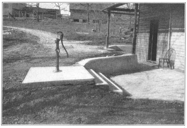
| Materials Required | ||
|---|---|---|
| Screened gravel or crushed rock | 3 cubic yards at $1.10 | $3.30 |
| Sand | 1½ cubic yards at $1.00 | 1.50 |
| Portland cement | 5½ barrels at $2.50 | 13.75 |
| $18.55 | ||
Well platforms are made like cistern covers (see page 69) except that they are not molded fixed in place, but loose and removable, so that the well can be cleaned at any time. Concrete well covers keep mice and frogs out of the well. Even scrub water cannot seep in.
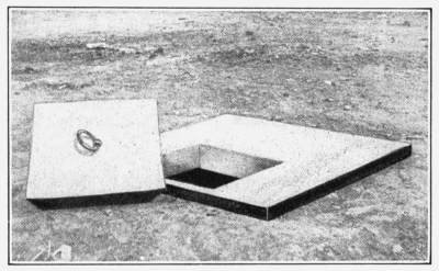
Underground cisterns are useless if they leak. In dry weather they are empty, and at other times the ground water seeps in and makes the “soft” water as “hard” as that from the well. Concrete cisterns have no joints to leak: they are built in one solid piece. [Pg 69]
In placing the cistern, select a site convenient to the principal down-spout and the kitchen. Do not forget to make allowance for 8-inch walls in laying out the plan. If the ground in which the pit is dug is sufficiently firm to stand alone, no outside form will be needed. Otherwise the hole must be dug large enough to receive an outside form built similar to the inside one. Make the inside form of 1-inch boards on 2 by 4-inch studding so that the siding will be toward the earth walls. Mix the concrete 1: 2: 4 and lay a 6-inch floor on the earth bottom. Immediately set the wall forms on all sides. In filling the wall space, be careful not to shovel the concrete against the earthen wall: dirt in concrete is liable to make a leaky wall.
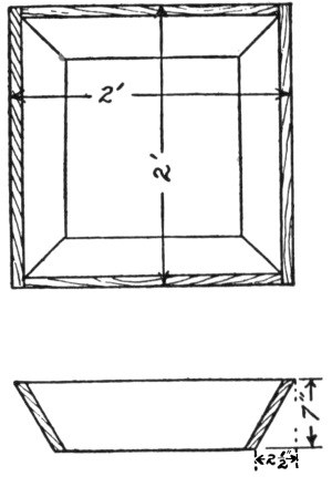
After the concrete side walls have been brought to ground level, set a 5-inch board on edge around the outside of the cistern, so as to hold the concrete for the platform. Saw off the uprights of the inside form 6 inches below the finished top of the concrete cover, and nail 2 by 4-inch floor joists even with their tops. Floor the joists with 1-inch boards. Braces, to keep the wooden platform from sagging, may be placed down the middle of the cistern as shown in the drawing. To provide for a manhole opening, build a bottomless box 5 inches deep, 2 feet square at the top and 18 inches square at the bottom—outside measurements,—or have the tinsmith make a round bottomless tin form 5 inches deep, 2 feet in diameter at the top and 18 inches at the bottom, just like a large dishpan without a bottom.
Begin at one side of the platform, tamp in 1½ inches of concrete, and upon it lay heavy woven wire fencing. Allow the edges of the wire to extend within 1 inch of the outside lines of the platform. Bring the platform to its full thickness by immediately placing the remaining 3½ inches of concrete. Work rapidly and do not stop for any reason until the cistern cover is completed. As the work progresses, finish the surface with a wooden float. Grease the manhole frame and place it where the opening is desired. Strengthen the floor around the manhole opening by laying four short ½-inch iron rods, placed criss-cross, 2 inches from the bottom of the slab and the same distance back from the edges of the hole. If the tin form is used, the manhole cover may be cast at the same time as the remainder of the floor. Reinforce the cover with woven wire and also with four short lengths of ½-inch rods laid in the form of a square. Have on hand an old bridle bit or hitching post ring, which will serve as a lifting-ring for the concrete cover. In placing the ring in position, provide it with a knob of twisted wire, or with a nut and large washer, to fix it firmly in the concrete. If the wooden manhole form is used, carefully remove it after 5 hours. After 3 days build the manhole cover the same as for the tin [Pg 70] form, with this important exception—place heavy paper, cardboard or leather around the edge of the opening to prevent the fresh concrete of the cover from sticking to it. Set bolts for a pump base according to directions given for Gasoline Engine Bases, pp. 87, 88. The necessary openings for down spouts and for removing water may be made by embedding tile, of the proper diameter and length, in the concrete platform or side walls.
When the platform is two weeks old, remove the manhole cover, bore a hole in the wooden floor, saw an opening, descend and loosen the roof form, passing it out through the manhole.
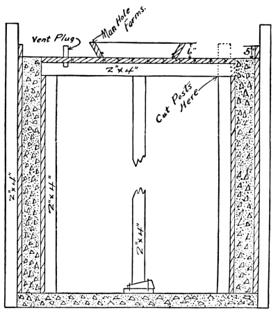
If the cistern water is to be used for cooking and drinking, provide a filter on the outside of the cistern wall. Construct the filter similar to the cistern, of dimensions 4 by 3 feet and 4 feet deep. While building the cistern wall, lay an 8-inch tile through it, at the proper height to connect with an opening of the same size in the filter wall at its floor, and place a removable screen of ¼-inch mesh over the opening. Fill in 2 feet of coarse charcoal. Cover the charcoal with 1 foot of sand and gravel. Lead the water from the roof into the top of the filter. Cover the filter with a loose concrete slab.
Four men built a cistern 8 feet square and 8 feet deep, with a 6-inch floor and a 5-inch platform, in two days. The cistern holds 122 barrels of 31½ gallons.
| Materials Required | ||
|---|---|---|
| Screened gravel or crushed rock | 8 cubic yards at $1.10 | $8.80 |
| Sand | 4 cubic yards at $1.00 | 4.00 |
| Portland cement | 13 barrels at $2.50 | 32.50 |
| $45.30 | ||
“Soft” water is not only better for the bath, but also makes the washing easier and the clothes whiter. Mischievous children cannot remove concrete manhole covers.
To the planter and stockman, a flowing spring is worth a great deal of money. Properly cared for, it will afford cold, sweet water for the house, the dairy, and the watering tanks. Improperly protected, it is not merely a mud hole, a nuisance to the milker of dairy cows, but is too frequently the cause of disease.
To improve a spring, first open up the channel and drain out all the water possible. Clean out the spring so as to increase its flow. Lay the necessary feed pipes to the house and barn. Wall up the well of the [Pg 71] spring with concrete blocks, laid without mortar to a point just above the in-flow streams of the spring. Complete the walls with blocks laid in 1: 2 cement-sand mortar, or, using wooden forms, with a 6-inch solid wall of 1: 2: 4 concrete. Carry these walls high enough to keep surface water out of the spring well. If the spring is to be used as a drinking tank for stock, make the walls equal to the usual depth of such tanks. (See Watering Troughs and Tanks, page 74.) Lay a 4-inch floor of 1: 2½: 5 concrete (on a drainage foundation) 10 feet around the field spring on all sides.
At the edges of the floor, turn down a concrete “apron” or foundation, 2 feet into the ground, the same as for Feeding Floors, page 43. This prevents the frost from getting under the floor and cracking it.
Make provision for the over-flow at a point where it can be carried to the stream by a gutter in the floor, or by a drain tile under it.
With such improvement, since there is no mud, the stock cannot mire and the udders of the dairy cows are always clean.
To keep rats and rabbits out of springs from which the water is drawn for house use, provide a concrete cover like that described for Underground Cisterns, page 69. For small springs this cover is often made removable as shown in the photograph on page 73.
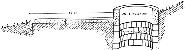
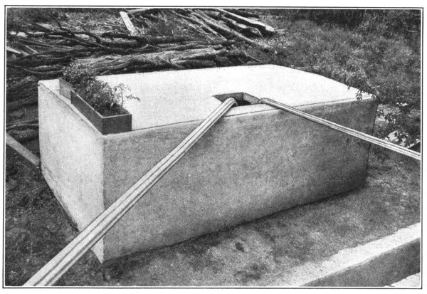
The photograph shows a cistern, 6 by 6 by 12 feet, inside dimensions, with 8-inch walls, 6-inch floor, and 4-inch roof.
Dig a pit 12 inches deep, and of the size of cistern desired. Cover the bottom with a well tamped fill of gravel to a depth of 6 inches. Mix concrete 1: 2: 4 and place it to a depth of 2 inches over the surface of the fill. On top of this lay sections of heavy woven wire fencing. This wire should be laid in such a way as to extend 6 inches beyond the outside edge of foundation—the ends being bent up, so as to stand upright, 3 inches back from the edge of the concrete flooring already placed. Immediately lay the remaining 4 inches of concrete floor. Give the surface a finish with a wooden float to within 6 inches of edges.
Without delay, set the forms, made up in the required sections, resting the inside form on the concrete floor and the outside form on the ground. Place the inside form first. After setting the inside form, place woven fence wire, supporting it against the inside form by means of staples driven lightly into the form and holding the wire 4 inches away from it. Care should be taken in placing the concrete that the wire is kept near the outside of the concrete wall. This reinforcement is carried 1 foot beyond top of wall. The projecting wire mesh will later be used to tie the concrete roof to the side walls. The timber required for the forms will be 1-inch siding and 2 by 4 uprights, spaced every 18 inches.
In placing the concrete in the forms, it will be easier to leave off the two top feet of planking of outside form until the concrete reaches its level. Then add this planking and fill the two top feet. The concrete will probably have to be passed up to a man on top by means of buckets.
The luxury of soft water for the bath, and its advantages for laundry purposes, are understood better by farmers than by their city cousins. Cisterns were originally built in the ground, but a thinking farmer [Pg 73] used concrete to build a cistern on top of the ground, no doubt taking the idea from the old-fashioned rain barrel. While it requires more forms and more reinforcement than a cistern built in the ground, yet the large cost of digging a deep hole is saved. As the water is piped to the house, direct water pressure is provided, thereby giving the farm-house all the advantages of a city water system.
Build a wooden platform inside the cistern, in the same manner as directed in Underground Cisterns, page 69. The materials required for the concrete are 10 yards of crushed rock or screened gravel, 5 yards of sand, and 17 barrels of Portland cement.
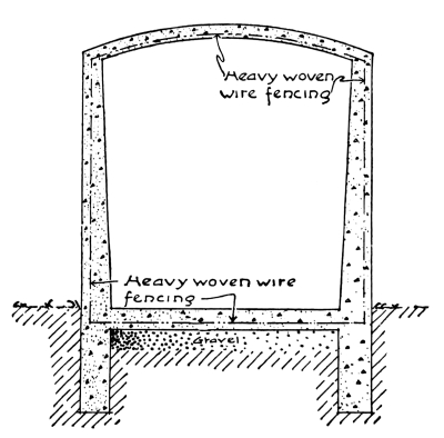
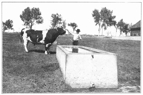
All thrifty farmers are building their tanks and troughs of concrete. Such troughs never rot, rust, or leak.
By using concrete, tanks of any size and shape can be made.
Most stockmen prefer to build their watering tanks oblong in shape. Having decided upon the size, locate the tank in a handy, well drained, wind-sheltered place.
To build a tank like the one shown in the picture, lay out the trough 5 by 16 feet. Make an excavation for a drainage foundation as directed under Sidewalks, page 29. Around the outside dig a 10-inch trench 2 feet 6 inches deep. Lay all in-flow and over-flow pipes (not less than 1½ inches in diameter) so that the ends, fitted for connections, will be even with the finished bottom of the tank.
Build the forms and have the necessary reinforcing on hand before mixing any concrete. The tank is 5 by 16 feet by 2½ feet deep with an 8-inch bottom. The walls are 5 inches thick at the top and 10 inches at the bottom. (The sloping face allows the ice to slip up the sides instead of pushing directly against them.) Consequently the inside forms at the bottom are 5 inches shorter at each end than at the top.
The forms are nothing more than shell boxes made from odd lengths of 1-inch siding nailed to 2 by 4-inch studding spaced not more than 2 feet apart. The sides of the forms may be made separate and put together in place; or, if there is sufficient help, each form may be entirely completed and set up as one piece. The forms are held in position by 2 by 4-inch liners at top and bottom, and if necessary by sloping braces nailed to stakes driven in the ground. Cut strips of heavy woven wire fencing sufficiently long to cover the bottom and to project up into the walls. [Pg 75]
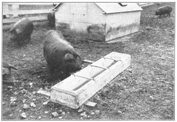
With the forms ready, mix a batch of 1: 2: 4 concrete. Beginning at one end, fill the trench, and upon the gravel foundation place a 2-inch layer of concrete in width slightly greater than a width of wire. Upon this concrete lay a section of wire. Tamp in the remaining 6 inches of concrete and bring up the extra length of the wire so that the ends will project up into the future side walls. Continue laying the concrete in sections until the bottom is completed. Finish the surface with a wooden float.
Immediately set the wall forms in place, and set them level by using a carpenter’s level. Fill the wall space with concrete. Half way up the side and 1 inch from the outside, lay a ½-inch iron rod entirely around the tank. Again 2 inches from the top, and 1 inch from both inner and outer edges, lay two rods of the same size. If a tank cover is desired, set bolts in the concrete as directed under Corn Crib Floors, page 53.
To prevent mud holes, surround the tank with a concrete floor. (See Feeding Floors, page 43.) Protect the green tank from drying out according to instructions under Sidewalks, pages 28-34.
| Materials Required | ||
|---|---|---|
| Crushed rock or screened gravel | 7 cubic yards at $1.10 | $7.70 |
| Sand | 3½ cubic yards at 1.00 | 3.50 |
| Portland cement | 11½ barrels at 2.50 | 28.75 |
| $39.95 | ||
Troughs for hogs are built in two styles—wedge-shaped, like the feed trough shown on page 49, or like troughs for cattle except smaller. Use short lengths of 1-inch pipe crosswise to keep the hogs out of the trough. Set bolts, properly spaced, in the soft concrete sides, so that the pipes will fit between them and can be held firm by a strap iron over the bolts. [Pg 76]
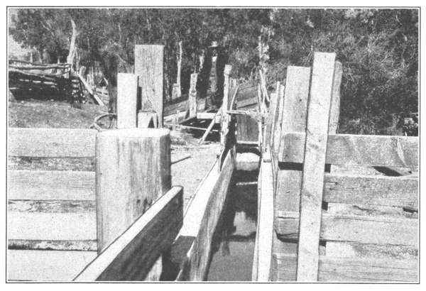
The younger generation have no remembrance of the epidemic of Texas or southern fever which swept over the country about forty years ago, killed thousands of cattle, and left hundreds of bankrupt farmers and ranchmen in its wake. Government experts found that this deadly disease is caused by ticks, which infest cattle in certain localities. They also discovered that the fever can be prevented by dipping the animals in chemical solutions.[2]
Dipping cures not only Texas (known as “splenetic”) fever, but also the lip and leg disease, mange, and scab or scabies of both sheep and cattle. Certain solutions free horses, cattle, sheep, and hogs of lice, mites, fleas, and flies. The only method of applying these chemicals, surely and thoroughly to all parts of the animal, is by giving him a plunge in a tank containing the healing liquid. Since the dip is the most costly part of the process, and since it must be applied once or twice every year, some permanent form of tank is needed—one that will not rot or rust out, leak or heave in during winter. Concrete vats, built ten years ago, without one cent’s worth of repair, are still as good as new and are still giving entire satisfaction.
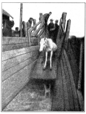
There are four important points to be considered in the building of a dipping tank:
First—An entering slide, steep enough to shoot the animal in, without a direct drop. A direct drop, the entire depth of the tank, is likely to injure the animal.
Second—The tank must be narrow enough to prevent the animal turning around when once in, long enough to keep him in from one to two minutes, and deep enough not only to make him swim, but also that he [Pg 77] may disappear entirely when he takes the plunge.
Third—The slope at the leaving end must be gentle and the footing roughened or cleated so that the animal may easily scramble to the dripping pens.
Fourth—As the liquid dip is the most expensive part of dipping, there must be provided two dripping pens draining back into the tank.
Select a well drained site convenient for a chute leading from a small, well-fenced lot or corral. At the narrow end of the chute and in line with it lay out the dipping tank with the entering slide next to the chute.
Often the chute is built on a curve, so that the animals cannot see where they are going.
They are generally constructed with a hump in the floor. This prevents the animal from jumping into the dip, and gives the necessary length to the slide, without increasing the depth of the tank. Choose the proper dimensions from the diagrams and table according to whether the tank is to be used for horses, cattle, sheep, or hogs.
The lengths given will keep the animal in the tank one minute, usually a sufficient time to cure mild forms of disease. Where a longer treatment is desired, most ranchmen, instead of building tanks of greater length, provide a drop gate working in a groove, as shown in the photograph, by means of which the animal is kept in the tank as long as necessary. Likewise, rather than build a separate tank for sheep and hogs, stockmen insert a temporary division fence, running the full length and depth of the cattle and horse tank. This fence should be solid and so spaced as to prevent hogs and sheep from turning around in the tank. In this way a single dipping tank may be used for horses, cattle, sheep, and hogs. [Pg 78]
Dig the deep part of the hole first, and then slope the earth for the slide and climb. Lay the outlet drain pipe so that the top of the elbow bend will be even with the surface of the finished concrete bottom. Tamp back the dirt thoroughly about the drain tile before placing concrete.
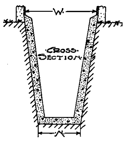
The side walls only will require forms. If the banks stand firm, inside forms alone will be needed. Make these of 1-inch boards on 2 by 4-inch uprights. Steel reinforcing, preferably wire cloth or hog wire, is placed in the forms so that it will be embedded in the center of the concrete wall. Floor, sides, and ends should all be thus reinforced to prevent settlement cracks due to any settlement of earth foundations. Mix the concrete 1: 2: 4 and lay the floor and slopes directly on the solid earth. No fill is necessary. The concrete for the sloping ends should be mixed fairly dry so that it will tamp well and stay in position without the use of forms. With the bottom and slopes built, lower the side wall forms into the pit. Take care to jar no dirt upon the concrete already placed. Space the forms properly and cross-brace them firmly upon each other. Fill the wall space with concrete.
In placing this concrete, be sure that it strikes the wood form instead of the earthen side, as concrete mixed with earth makes a weak, leaky wall. Carry the walls 6 inches above the surrounding ground to prevent flood water from running into the tank.
The entrance slope should be smooth to slide the animals into the tank without skinning them up. Finish this surface with a wooden float and steel trowel. Some ranchmen prefer to cover the entire slide with a polished steel plate, the edges of which are sunk into the concrete when the slide is built. To aid the animals in climbing out, embed in the concrete the turned-up ends of iron cleats bent at right angles similar to a capital “U.” Old wagon tires, cut in lengths not greater than 20 inches and turned up 4 inches at each end, will do. Leave 1 inch clearance between the flat surface of the cleats and the concrete. Space the cleats 18 inches for horses and cattle and 10 inches for sheep and hogs.
At the leaving end of the tank, lay out the two dripping pens with their division fence on a line with the center line of the tank, so that a gate hung to this fence may close either pen, when it is full, and allow the animals from the tank to pass to the empty pen. Use concrete posts for the fences, as they will require no replacing. Excavate for the drainage foundation, set the posts, and build a 6-inch concrete floor according to the directions given under Sidewalks, page 28, and Feeding Floors, page 43. Slope the floors, ¼ inch to each foot in length or width, so that the dip running off the animals will be saved and returned to the tank. Corrugate or groove the floor to the depth of ½ inch, every 8 inches, in one direction. During the construction of the floor, mold around the outside a concrete curb, commonly called a splashboard, 6 inches above the floor and 4 inches wide. Where the dip from the floor empties into the tank, place a removable wire screen or strainer to keep the droppings and wool tags out of the vat. Cure the floors and slopes according to directions under Feeding Floors, page 43. The wall forms may be removed after one week, but the tank should not be used until it is three weeks old. [Pg 79]
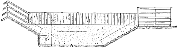
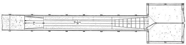
| Kind | W | N | D | L | E | B | A | I | O | T | Cement | Sand | Rock |
|---|---|---|---|---|---|---|---|---|---|---|---|---|---|
| Barrels | Cu. yds. | Cu. yds. | |||||||||||
| Horses | 5′ 10″ | 3′ 4″ | 8′ 8″ | 55′ 0″ | 7′ 6″ | 31′ 0″ | 16′ 6″ | 8′ 8″ | 18′ 7″ | 0′ 8″ | 38 | 11 | 22 |
| Cattle | 5′ 4″ | 3′ 4″ | 7′ 8″ | 51′ 0″ | 6′ 8″ | 31′ 0″ | 13′ 4″ | 7′ 8″ | 15′ 4″ | 0′ 8″ | 36 | 10½ | 21 |
| Sheep | 3′ 4″ | 2′ 4″ | 5′ 8″ | 46′ 0″ | 5′ 0″ | 31′ 0″ | 10′ 0″ | 5′ 8″ | 11′ 6″ | 0′ 8″ | 22 | 6½ | 13 |
| Hogs | 3′ 4″ | 2′ 4″ | 5′ 8″ | 36′ 0″ | 5′ 0″ | 21′ 0″ | 10′ 0″ | 5′ 8″ | 11′ 6″ | 0′ 8″ | 19 | 5½ | 11 |
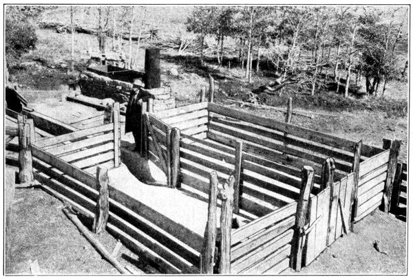
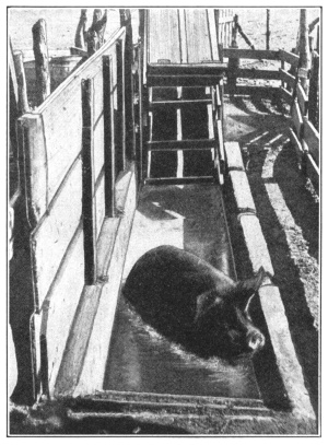
At first state and federal authorities had to force ranchmen to dip, but so beneficial has it proved that compulsion is now seldom necessary. Experienced cattle-men have found by actual tests that dipping increases the market value of their steers $5 per head. The cost of dipping on the farm is only 1½ to 3 cents per head—in the stock yards the charge is 15 to 20 cents. One large ranchman, who lost 28 per cent. of his herd (several thousand) in one winter with the mange, found his first trial of dipping so effective in curing this disease that the following winter he did not lose a single steer. The use of dips has become so general in the South and West that the Government has raised the quarantine in most sections. [Pg 81]
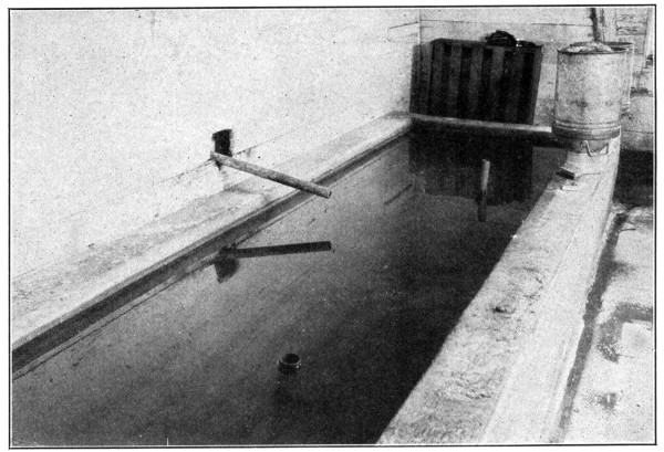
Dig a pit to a depth of 1 foot 6 inches and place wooden forms in such a way as to provide for tank walls 6 inches thick and 1 foot 8 inches in height. This will bring the walls only 8 inches above ground level—which makes it easy to lift the milk cans in and out.
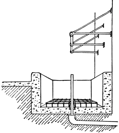
Use a wet mixture of concrete, of proportions 1: 2: 4. Place as described on page 74; and be sure to build walls and floor at the same time. The floor should be 6 inches thick.
The vat described has a partition 6 inches thick, dividing the tank into two chambers, each chamber being 6 feet 9 inches long. An iron grating is placed in the bottom of the tank to allow free circulation of cooling water around and under the milk cans. Arrangements must be made for inlets and outlets. The inlet pipe can be simply placed above one end of tank.
The pipe rail at back of tank provides a convenient purchase when lifting heavy cans from the tank.
A hole must be provided at the other end of tank, in the bottom, and connecting, by an iron pipe, with the drain tile. Into this hole a [Pg 82] removable upright iron pipe is fitted, the length of pipe depending on the depth of water desired for the cans. This allows the water to come only to the top of the pipe and provides an over-flow outlet at the proper height. The pipe must fit tightly into the hole.
Time required to build:—one day with three men on the job.
Approximate cost, at current prices of materials and including labor, $16.00.
The materials required are 2 cubic yards of crushed rock or screened gravel, 1 cubic yard of sand, and 5 barrels of Portland cement.

Numerous small structures are required on the farm. Dog kennels, tool houses, coal houses, ice houses, hydraulic ram houses, smoke houses, acetylene gas plant houses, gasoline storage houses, milk houses and many similar buildings are a necessity on every well improved farm. Such structures are all of simple design and can be easily built of concrete.
When once constructed of this material durability and freedom from fire are assured. For such buildings as milk houses built of concrete instead of wood, there is the added advantage of cleanliness. Modern dairying demands absolute cleanliness. Concrete meets this demand.
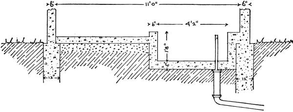
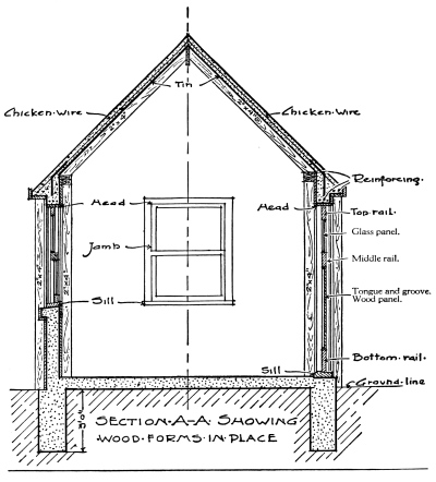
Milk splashed on wooden walls soaks in, causing a very disagreeable odor likely to taint milk stored in the vat. Concrete does not absorb milk splashed on it. Such walls can be kept free from tainting odors by simply washing them down. In concrete dairy houses, with concrete vats, the milk will keep sweet longer than in houses built of any other material. Dairy experts all admit that no other material can take the place of concrete for such purposes.
The illustration shows a simple form of milk house with walls, floor and vat, all of concrete. This house is 16 feet long, 10 feet wide and 8 feet high with a rise to the roof peak of 5 feet.
The milk house should be located near the barn and convenient to a clean water supply. Care must be taken to provide for the outflow of the water from the vat. This can be done by leading a line of pipe from the vat to a discharge point at a lower level or to the drinking troughs for the stock. [Pg 84]
Often the water from a flowing spring can be piped several hundred feet to the house, providing an excellent means of keeping the milk cool and sweet.
To build such a milk house as shown, dig a trench for the foundation 3 feet deep and 12 inches wide. Fill the trench to the ground level with 1: 2½: 5 concrete. The foundation should be laid out in such a way as to extend 3 inches beyond the inside and 3 inches beyond the outside of the walls of the house.
As soon as the concrete foundation has become hard enough to support them, erect the wall forms. These forms consist of 1-inch siding nailed to 2 by 4-inch studding. The studs should be spaced 2 feet apart and the 1-inch sheathing is nailed to the sides of the studding toward the concrete. For small buildings it is often easier to build an entire wall form flat on the ground and then raise it into position. The bottoms of the studs rest on the concrete foundation and are held in position by strips nailed to them and extending to stakes driven firmly into the ground. The distance the inside and outside forms are spaced apart depends upon the thickness of wall desired. Sloping braces leading from the studs to the ground keep the side forms from bulging and cross-cleats nailed at the top keep the inside and outside forms the correct distance apart. Bulging of forms can also be prevented by wiring them together as shown on page 23. On page 22 is a description of the general method of building forms. Especial care must be taken to hold the forms in position while placing the concrete. The studs in the side wall forms for this house should be cut off at the height of the walls. With the wall forms secured in position fill them with concrete.
A space must be left in the walls for the doors and windows. This is done by placing between the wall forms, frames or boxes without top or bottom made of 1-inch boards. When the wall form has been filled to the level of the bottom of the opening a frame, the size and shape of the opening desired is secured firmly in place and the concrete poured around it. After the wall reaches a level 2 inches above the frame lay in the fresh concrete two ½-inch iron bars. These pieces should be long enough to extend 8 inches beyond each side of the frame. A piece of old wagon tire can be used instead.
The sill shown in the sketch can be molded by building a small box extending out from the side form. The concrete should be placed for the sill at the same time that the wall is being built. For buildings such as we have mentioned a sill is unnecessary.
When the side walls have been built to the top and before the concrete has set, shove ½-inch bolts 18 inches long down into it. Space these bolts 24 inches apart, 9 inches of the length being in the concrete. The end wall forms extend above the plates to the peak of the roof, and are filled to the top. While placing the concrete in the walls it should be continually spaded as described on page 25. [Pg 85]
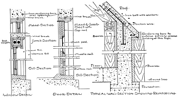
DETAILS OF DOORS AND WINDOWS
The roof is built by nailing 2 by 4 rafters to the inside studs of the side wall forms, on a line 1 inch lower than the bottom of the roof. The rafters are given the pitch desired for the roof, and are securely fastened where they meet at the ridge. To stiffen the roof form until the concrete has become hard tie the opposite rafters together at the bottom (with a 1-inch strip) in the form of a capital “A.” One-inch boards are nailed on the rafters. The cornice shown in the sketch extending beyond the wall can be easily built by nailing a board the width of the cornice to the tops of the outside studs of both side and end walls. To hold the concrete in place as the roof is being built nail a 5-inch upright strip along the outside edge of this board. Bend the bolts projecting above the walls down to within 1 inch of the roof boards. Spread a layer of heavy woven wire fencing over the entire roof, allowing it to extend to the outside of the cornice. Wire the fencing securely to the bent bolts. Place two ½-inch steel rods near the outside of the cornice all the way around the roof, and fasten these securely to the woven wire fencing. The roof should be made 3 inches thick and the stone used for the concrete should not be larger than ½ inch.
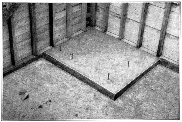
Mix the concrete fairly stiff and start placing it at the cornice, working toward the ridge. Spread the concrete out in a thin layer and then lift the woven wire fencing and the two rods in the cornice so that the concrete is 1 inch thick below the wire. Cover the rods and wire with more concrete to a depth of 2 inches. When finished the roof will then be 3 inches thick, 1 inch below the wire and 2 inches over it. Always work from the low edge of the roof and finish to the complete depth of 3 inches at once. Imbed a width of woven wire fencing lengthwise over the ridge of the roof 1 inch beneath the surface. The work must be carried on without interruption. The concrete must not be allowed to dry along an unfinished edge, as there is danger of a leak where fresh concrete is joined to that already hard. Tamp the concrete until moisture comes to the surface and smooth off the top of the roof with a wooden float and steel trowel.
The forms must be left in place for at least a week and the concrete in the roof must be protected from the sun and wind while it is hardening. A method for doing this is described on page 26 under Sidewalks. [Pg 87]
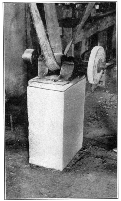
When the forms have been removed from the walls and roof the floor can be laid. Excavate the ground to a depth of 4 inches below the finished floor level. Mix and lay the concrete as described on page 31.
The concrete milk vat should be built at the same time and as a part of the floor. See description on page 82.
Engines, cream separators, pumps and other pieces of machinery require solid bases. These bases must be permanent, and free from any vibration. A base constructed of concrete possesses these advantages.
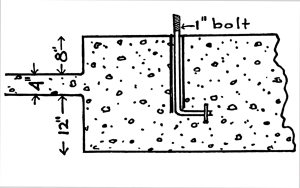
To form a base for the support of a small engine, first excavate a pit 2 feet 4 inches deep, and 1 foot larger both in length and width than the dimensions of the engine base. Fill the pit with a mixture of concrete, (1: 2½: 5), and then construct a form which will carry the concrete to a height 4 inches above the floor level or to the height desired.
Bolts should be set in the concrete before it dries, these being sufficiently long to bend 4 inches at right angles, and to extend 1 foot deep into the concrete, with bent end down. They should be placed with the upright part surrounded by gas pipe of twice the diameter of the bolt, and of a length sufficient to come flush with the surface of the concrete. The open space formed around the bolt by the pipe will allow for slight errors in locating bolts, so as to meet the holes in the engine base.
Keep the concrete wet for 24 hours after placing, by sprinkling. After six days, set the engine, adjust the bolts, and fill the spaces around the bolts with cement mortar, mixed 1 part cement, 1 part sand. Do not use the engine until the concrete base is at least two weeks old. [Pg 88]
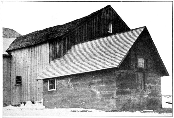
Concrete Ice House
A concrete base adds years of service to the life of a gasoline engine or cream separator.

Grain Elevator Approach and Engine House
The method just described for building a milk house applies equally well to any of the small houses mentioned above. It is not always necessary to build a peaked roof; sometimes a flat roof will answer the [Pg 89] purpose; but the general method in all cases is the same. The drawings show in detail the way a door can be built and framed and also how the windows can be made to slide up and down.
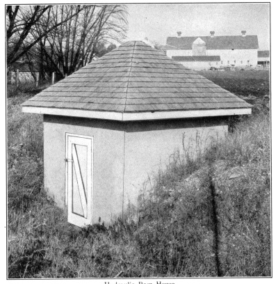
Hydraulic Ram House
Concrete alone possesses the necessary fireproof qualities for such buildings as smoke houses, where there is always great danger from fire.
Oil lamps are becoming a thing of the past on modern farms. Acetylene and gasoline plants furnish a better and safer light. These plants are built either above or below ground. In either case concrete is the ideal material, since it is both fire and waterproof.
The durability of concrete is particularly valuable for such buildings as hydraulic ram houses, which must always be located near streams, and ice houses, where there is always moisture. Wood quickly rots, but moisture has no effect on concrete.
For tool houses, coal houses, and buildings subjected to rough usage, nothing equals concrete.
Concrete, for small buildings, meets the three great demands of the farmer—cleanliness, freedom from fire, and durability. [Pg 90]
Cellarways are particularly liable to leak and cause a damp cellar. This cannot happen if they are made of concrete. There are no cracks through which the water can come. Wooden steps last no time, particularly where heavy barrels and similar weighty loads are taken up and down. As wooden or brick areaways are always damp, the steps rot quickly, thus requiring constant renewal. Few things are more dangerous to limb, and even to life, than a step giving way under the weight of a heavy barrel which is being carried into the cellar.
Concrete steps are safe under any load.
Owing to the fact that concrete can be molded into any desired shape, it is particularly desirable for this purpose. Some people like steps with a low rise and a particularly wide tread, while others prefer a high rise and narrow tread. Concrete can easily be fitted to either. The determining feature is usually the space to be occupied. The door into the cellar limits the depth to which the steps are taken, and therefore the height of the risers; while the room the cellarway is to take outside the line of the wall determines the width of the tread. If possible, the rise of each step should be from 6 to 8 inches, while the width of the tread should be from 9 to 12 inches.
Note: See page 112 for Window Hatchway. [Pg 91]
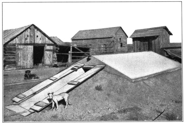
In erecting, first excavate the hole to the width of steps desired, plus one foot. This allows for a 6-inch wall on either side. Slope the ground from 1 foot back of where the top step is to come to 1 foot back of where the bottom step will be. To form the steps, saw out a board just as you would a “horse” for steps, and nail planks where the risers come, holding the two “horses” the proper distance apart. This is placed upside down, resting on the top and bottom, with the edge of the top and bottom rise where the bottom and top steps are to come. Fill this form and the space back of it with 1: 2: 4 concrete, starting with the bottom step, and continuing upward to the top, bringing the concrete in each step to the top of rise. Side forms for the 6-inch walls may now be placed, braced apart in the center properly, and resting on the back of the horses. These can be carried to any height desired to give the hatchway doors a proper slope for shedding rain and snow. Forms will have to be built on the outside of these walls above the ground line to hold the concrete in place. Before the concrete sets in the side walls, bolts should be placed, with heads in the concrete, by means of which wooden sills are fixed to the walls for fastening the cellar doors by strap hinges. If the bottom step does not come to the wall line, the flat landing in the bottom should be covered with a 5-inch thickness of concrete. Here is a convenient place to locate a drain, to carry off the water used in sluicing down the steps, and any which may leak through the cellar doors.
The cellar hatchway shown in the photograph and in the drawing is 5 feet wide, built according to directions above. The side walls at the cellar are 7 feet high and 10 feet long. The slope for the cellar doors is 2 feet 4 inches. There are 7 steps of 8-inch rise and 10-inch tread and a landing 3 feet 2 inches wide. Two men built this hatchway in 1½ days.
| Materials Required | ||
|---|---|---|
| Crushed rock or screened gravel | 2¼ cubic yards at $1.10 | $2.48 |
| Sand | 1⅛ cubic yards at $1.00 | 1.13 |
| Portland cement | 3¾ barrels at $2.50 | 9.37 |
| $12.98 | ||
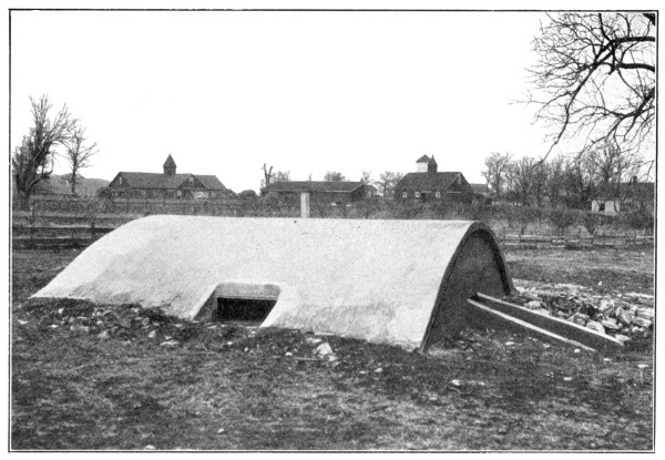
The increasing use of roots, as winter feed for animals, has brought about the construction of root cellars as a means of preserving this valuable food. A root cellar must be sufficiently warm and dry to keep roots from freezing or rotting. By building the cellar below ground the warmth is greatly increased. To do this, however, a material must be employed which is moisture-proof and which will not rot. For these reasons use concrete.
The cellar shown in the illustration on page 91 extends 5 feet below, and 2 feet above ground level. The walls are 5 inches thick, and are made of concrete proportioned 1: 2: 4.
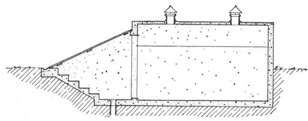
Choose a well drained site, and dig a pit in the earth to the desired depth and with an entrance-way so sloped as to make provision for concrete steps, which will have a rise of 7 inches and a tread of 10 inches. [Pg 93]
Build a floor of the same thickness as the walls. Set inside box form and fill the space between this form and the earthen side walls with the wet concrete, the same as for Underground Cisterns, page 68.
Above the ground level an outside form must be used. The roof is built in the way described on page 86 except the thickness is increased to 5 inches.
Ventilators are provided in the roof, by imbedding lengths of sewer pipe in the concrete. Add galvanized tin hoods to keep out the rain.
By referring to page 90, there will be found a description of how to build a hatchway and steps.
Immediately after the side wall forms have been erected, the door frame should be set in its required position, before placing concrete.
Similar structures are also used as bee, vegetable, fruit and cyclone cellars. Concrete cellars are great favorites with growers of apples, potatoes and cabbage. By adjusting the ventilator openings, the temperature can always be kept at just the right point. Moreover, since rats and mice cannot gain an entrance to a concrete root cellar, there is no waste causing decay, and the vegetables keep better.
In cold climates bees must be warmly housed in winter, lest they freeze to death. By no other means than underground cellars can they be safely brought through the winter. The bee cellar must be dry, in order that the bees stay in good health. In no way, can there be provided so even a temperature or so dry an atmosphere, as by the use of concrete. Bees kept in concrete cellars come through the winter in perfect condition.
| Materials Required | ||
|---|---|---|
| Crushed rock or screened gravel | 11 cubic yards at $1.10 | $12.10 |
| Sand | 5½ cubic yards at $1.00 | 5.50 |
| Portland cement | 15 barrels at $2.50 | 37.50 |
| $55.10 | ||
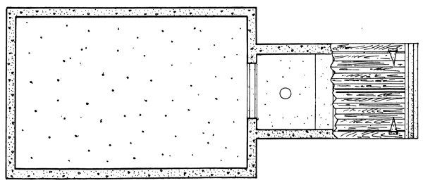
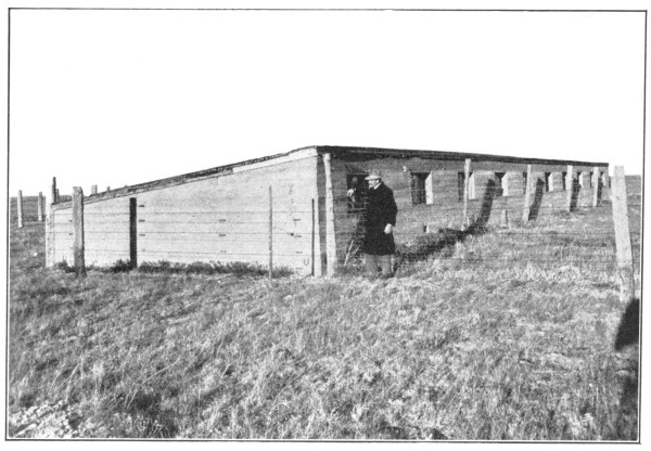
The high price of all foods has made poultry raising profitable. But to have laying hens they must be carefully tended. Their houses must be clean, and free from draughts. Young chickens must be protected from rats, skunks and foxes.
Concrete houses fill every requirement of an ideal poultry house. To clean a house of concrete, spray it with oil and burn it out. Concrete [Pg 95] is fireproof. Rats cannot gnaw through a concrete floor or sidewalk. In a concrete house there are no cracks through which the snow can sift, or in which lice and bedbugs can hide.
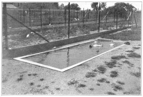
Locate the poultry house where there is plenty of sunlight and where the concrete poultry yard (see Feeding Floors, page 43) may be wind protected. Build the house as directed under Small Buildings, page 82. As the walls are being placed, insert short pieces of gas pipe at convenient heights to support the shelves for the nests (one style of nest shown on page 94) and the rails for the roosts. If desired, a one-way-slope concrete roof may be made.
Make the floor on an 8-inch fill of gravel, or of slabs built on a smooth floor and later set in place. Lay heavy wire fencing in the concrete slab 1 inch from the under side.
To rid the farm of cholera and roup, nothing aids more than concrete drinking troughs. Occasionally scrub the troughs, spray them with oil and burn them out.
Ducks and geese need water, yet if they are allowed to go to a nearby stream, many are lost. Poultrymen are building ponds of concrete, attached to the water supply in such a way as to provide fresh water at all times. For building, see instructions under Hog Wallows, page 52.
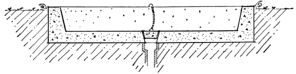
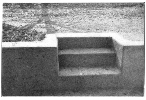
Terraces, if too steep, will not stay sodded, and if too flat, take up room which would otherwise be a part of the lawn. The neatest way is to place a retaining wall along the terrace edge. This wall is built in the same way as the wall to hold the earth in a barn approach described on page 60.
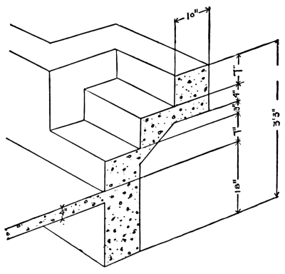
If the wall is over one foot high steps are necessary. A most convenient arrangement is to have the bottom step come flush with the face of the wall, making it impossible to fall over one or two projecting steps in the dark.
In building, insert a stop plank between the front and back forms to prevent the concrete from going to the full height of the wall. The bottom of this plank should be kept at a height above the bottom of the wall sufficient to form the first step.
After the concrete for the wall is placed, remove the section of the form where the steps are to come, and dig out the earth to a depth sufficient to hold them.
The remaining steps are built in the manner described on page 90.
After the concrete is placed, the steps should be closed to traffic for at least one week.
In the background of the photograph on page 72 may be seen a double terrace wall of concrete, each wall 5 feet high. [Pg 97]
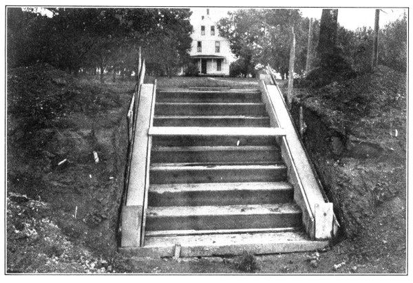
As a large proportion of fires in residences originate in the chimney, it is well to have this part of the house as nearly fireproof as possible. It can be made entirely so by building it of concrete. If this is not convenient, at least let the chimney cap be of concrete.
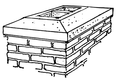
These caps are cast in one piece, on the ground, and in any shape desired.
The outside form is a wooden box, with inside dimensions corresponding with the outside dimensions of the desired cap. Usually the cap is 6 inches thick, and has an “over-hang” or “drip” extending on all sides beyond the outside of the chimney.[3] Thus, if top of chimney, over all, is 18 inches square, make outer form 22 inches square, an extra allowance of 2 inches on all sides, thus obtaining a cap that will have an “over-hang” of 2 inches all the way around.
The inside form may consist of a piece of terra-cotta tile. If more than one opening is desired in the cap, use two pieces of tile or as many as there are to be openings.
Mix concrete 1: 2: 4, the mixture to be a thoroughly wet one. Place in the form, after greasing outside of terra-cotta so that same may be easily removed. Leave undisturbed for two days. Remove forms and place cap in position, attaching it to the brick chimney with a cement mortar, one part cement to one part sand. [Pg 98]
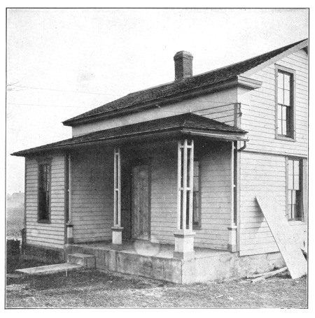
When even a part of a building is subjected to unusual wear, either from use or exposure to the elements, build it of concrete.
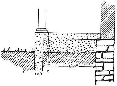
Porch floors of wood rot quickly when laid near the ground; and, even if they do not rot, through constant use they become splintered and faulty.
As concrete is a stone which can be made into any shape without cutting, it is particularly well adapted for porch floors of any size [Pg 99] and shape. Its lasting qualities under all conditions of wear and exposure have been so often mentioned, it seems useless to refer to them again.
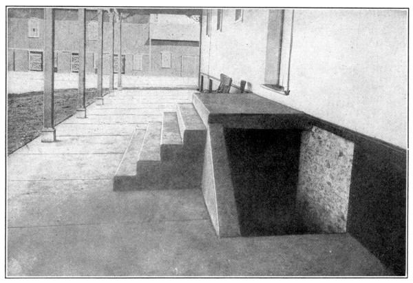
Remove the old wooden floor, first placing props to support the porch roof, with their lower ends resting outside the line of the porch floor. The pillars themselves must also be supported if they are not to be replaced by concrete.
The floor is laid in exactly the same way as a feeding floor described on page 43. As the size is usually small, however, the floor can be laid in a single slab without joints. If a smooth surface is wished for, finish first with a wooden float and then with a steel trowel.
Do not put too much elbow grease into the finishing. If you do, small cracks are likely to come on the surface and spoil the looks of the floor.
No material could be more useful than concrete for the porch of a school house where hundreds of little feet scuff and stamp daily.
A porch of concrete is free from vermin, fireproof, easily scrubbed, and needs no repairs.
Fresh vegetables may be had during the winter at small expense by every suburbanite, if he builds a hot-bed or cold-frame. By their use early spring plants can also be given a good start. Since the bed must be placed partly in the damp ground, the only material to be considered for this purpose is concrete, which does not rot out and which, being free from cracks and joints, makes the warmest bed in cold weather.
Locate the bed on the sunny side of a building, if possible, on the south side. Dig the pit the width and length of the hot-bed, not less than 3 feet deep. The one shown is 39 feet long and divided into 3 equal compartments. Make box forms of 1-inch lumber to carry the south (front) wall 6 inches and the north (back) wall 15 inches above ground. [Pg 100] The end walls slope to the others. If the bed is not near a building, extend the back wall 2 feet higher to serve as a wind-break. Before filling the forms with concrete, test their width by laying on a sash. See that it laps full 2 inches at each end.
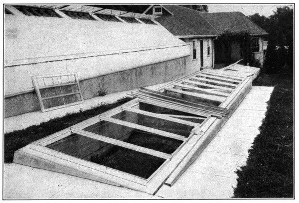
Mix the concrete mushy wet in proportions 1: 2½: 5. Fill the forms without stopping for anything. Tie the walls together at the corners by laying old iron rods in them bent at right angles. During the placing of the concrete set ½-inch bolts about 2 feet apart to hold the wooden framing to the concrete; or make grooves in the tops of the walls for sinking the frames level with the top of the concrete, allowing one-quarter inch at each end for clearance. This can be done by temporarily embedding in the soft concrete a wooden strip of the necessary width and thickness. Remove the forms after six days. Divisions may be built along with the walls or later as convenient. One and one-half days were required for two men to build a hot-bed 5½ by 12¼ feet in the clear.
| Materials Required | ||
|---|---|---|
| Screened gravel or broken stone | 2½ cubic yards at $1.10 | $2.75 |
| Sand | 1¼ cubic yards at $1.00 | 1.25 |
| Portland cement | 3½ barrels at $2.50 | 8.75 |
| $12.75 | ||
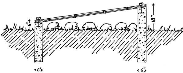
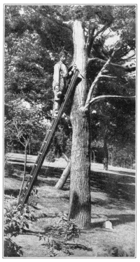
Nothing adds so much to the home-like appearance of a place as good shade trees. But trees are like teeth—they need attention. Boring insects often cause decay. The hollow becomes larger. The wind blows the weakened tree down. The “looks” of the place is ruined. It takes at least a lifetime to produce another such tree.
By means of concrete, many famous old trees, seemingly about gone, are now saved. Open up the cavity with a hand-axe. With a mallet and chisel cut out every bit of the rotten wood, and stop the flow of sap by painting the cavity with liquid asphalt. Reinforce small cavities with nails as shown in the photograph, larger cavities with rods, wire and spikes. Carefully fill every crevice with a 1: 3 cement-sand mortar. By slightly trimming the edges of the bark around the filling, once or twice a season, the bark will grow entirely over the concrete. [Pg 102]
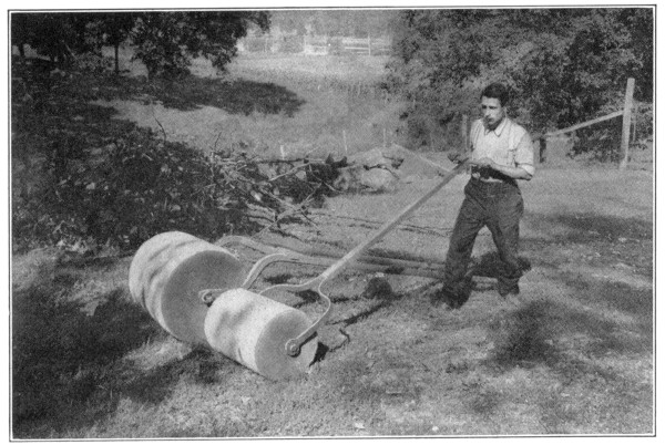
Frost coming out of the ground in the spring raises the lawn into humps. If these are not rolled down at once, the lawn is rough all summer.
Rollers were originally made by the farmer from logs of wood. These were abandoned for the more expensive iron rollers, purchased in the nearest town. To-day farmers are again making rollers, but are using concrete. An iron roller with a cylinder from 2 to 3 feet in length will cost from $15 to $20, whereas one of the same size constructed of concrete will cost practically nothing.
Obtain a length of sewer pipe, of the size of roller wished for. A tile from 12 to 24 inches in diameter will usually suit the purpose. Set this tile on end, small end down, on a wooden platform. Through a hole bored in the platform insert a 1-inch round iron bar, long enough to project beyond the ends of the roller a sufficient distance to provide bearings and attachment for the handles. Care should be taken to get the bar exactly in the center of the tile before placing concrete, and to keep it there while the concrete is being placed. Make a wet mixture of concrete (1: 2: 4), and fill the tile with this mixture, up to the “bell” of the tile. Allow the concrete to set for ten days, when the roller may be placed on side, and the bell of pipe chipped off with a cold chisel and hammer. Attach a forked handle, as shown in the illustration. As the axle is a firmly-fixed part of the roller, the fork ends of the handle must be provided with holes, within which the axle can turn.
A roller 18 inches in diameter and 2 feet long will weigh about 600 pounds. If a lighter roller is desired, use a smaller sized sewer pipe; or place several small pipes inside the large one, depositing the concrete around them on the outside. They will form hollow spaces inside the roller and lessen its weight.
By increasing the size pipe, or by using a steel mold and attaching a pair of shafts or a tongue instead of a handle, horse rollers for crushing the clods in the ploughed fields may be made. [Pg 103]
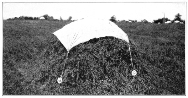
With the usual shortage of labor in the harvest season and the frequent occurrence of showers, to secure sweet, unmolded hay it has become necessary to cover the hay cocks with a canvas or muslin cover. The best weights to hold down the covers are made of concrete. Mix the concrete 1 part Portland cement to 2 parts sand, mold them like doughnuts or as cakes with a galvanized wire loop, and set them aside in a damp place for 7 days before using.
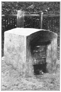
Trash and leaves must be burned without danger to the surrounding property. A concrete burner affords the only safe and inexpensive means.
Dig out the dirt to the depth of 6 inches. For forms choose two barrels, one of which will set within the other with a clearance on all sides of 6 inches. Adjust the height by cutting off their butts. Make an opening through which a metal ash box can be inserted or over which an iron door can be hung. Fill the foundation hole and the forms with 1: 2: 4 concrete. Remove the outside form after two weeks. The fire will later take care of the inner form. After three weeks the burner may be used. [Pg 104]
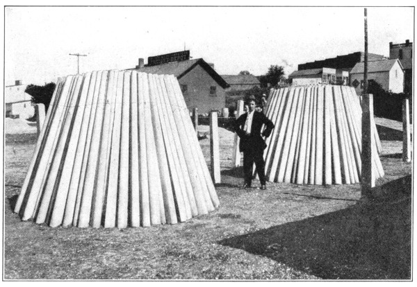
When a man buys a farm, he examines first the condition of its general improvements. If the fences are “all run down,” he must take into consideration the cost of repairing or replacing them—a matter of no small importance and expense in these days of high priced labor and lumber. The cheapest fence is not always the one lowest in first cost. Intelligent purchase of fencing materials means buying those which last longest with least repairs.
A railroad probably has more fencing along its right of way than any single property owner, and to avoid damage suits, the fences must at all times be in perfect repair. As fast as their wooden fences rot out and burn down, they are replacing them with concrete. Not only has the lasting quality of concrete recommended itself, but the ever increasing shortage of the lumber supply has made the purchase of good wooden posts impossible, and the cost of poor posts high.
Concrete posts in first cost are seldom more expensive than wooden posts. The life of a wooden post is from 3 to 5 years, while concrete posts last forever. Weather and fire do not injure them. Even forest fires cannot harm a line of concrete posts.
The United States Government, recognizing the importance of this subject, has issued Farm Bulletin No. 403, entitled Concrete Fence Posts. This bulletin can be obtained free upon application to the Agricultural Department, or to your Congressman.
Hitching posts, made in a slightly larger box form, with a bolt and ring inserted in the concrete before it has hardened, add neatness to the house surroundings. Gate posts of concrete, nothing more than heavy fence posts made long enough to take the highest fence, prevent sagging gates, so hard to open. A concrete clothes post is ready for the clothes line and the wash every Monday morning. The weight of the wet clothes does not break them down or cause them to sag. Clothes never have to be rewashed due to dragging in the dirt. [Pg 105]
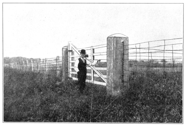
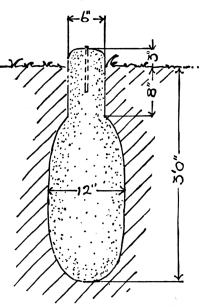
To property owners, as well as engineers, survey monuments which last forever and can be easily distinguished from surrounding rocks, are of the utmost importance. Expensive re-surveys and legal fights can be avoided by making such monuments easily distinguishable, permanent, and in such a way as to avoid confusion with other marks. The use of concrete for this purpose fills all the requirements better than any other material.
Get from the proper public official (usually the county engineer or surveyor) the exact location of corner stones. Drive four stakes in the ground so that strings stretched between every other stake will cross each other directly over the original monument.
Remove the old monument, and, with a post auger, bore a hole deep enough to reach below the frost line (at least 3 feet deep), where the old monument stood. [Pg 106]
Fill the hole with concrete mixed 1: 2: 4, rounding the top with the hands so it will extend 3 or 4 inches above the level of the surrounding ground.
While placing the last foot of concrete, imbed a harrow tooth, iron bolt, or gas pipe, with its top just showing above the finished concrete at a point directly under where the strings cross. Protect the monument from damage by stock for one week, by placing a box over it.
In developing the lowlands for farm purposes—and such lands are now most valuable—immense sums are being invested in concrete drain tile.
Where drain tile empty into an open ditch, the banks of the ditch around the drain tile gradually wash away, and often two and three lengths of tile become disjointed, allowing the water from them to further cut away the field land. These exposed tile are often crushed by livestock. Moreover, clay and shale tile freeze, crumble, and mixed with the earth from the bank frequently close the outlet. Muskrats, skunks and mink use the tile as a nesting place, and the drain becomes stopped up and drowns out the crops.
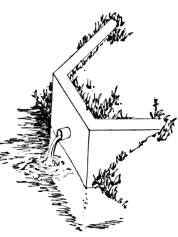
All of this trouble is prevented by a small outlay of time and money in building a concrete retaining wall to keep the end of the drain tile from washing out and to protect it.
Choose the dry season of the year, immediately after the laying or cleaning of the string of tile, when little water is in the ditch.
Dig a trench 12 inches wide along the edge of the open ditch 2 feet below its bottom and under the end of the line of tile. This trench should extend along the bank for from 4 to 6 feet, with wings turned into the bank at its ends, sufficiently long to prevent water from getting in behind the wall and washing the dirt out.
Mix concrete 1: 2½: 5—wet enough to tamp well.
Fill the trench with concrete up to the ground level. Should the trench be full of water, place this part of the concrete dry.
Set box forms, made of 1-inch siding and 2 by 4-inch studding. These forms must be high enough to bring the wall up to the level of the top of the ditch banks. At the proper height to meet the string of tile, place a first-class drain tile (at least one size larger than the regular string) through the forms so that the front end will be flush with the outside wall after concrete is placed.
Bore two small holes in the forms above this tile, and place in them well greased pegs of wood. After the forms are filled with concrete, these pegs are removed, the holes receiving the bolts holding a flap gate to keep animals out of the line of tile. Fill the forms with concrete, and smooth off the top of wall with a steel trowel.
Remove the forms after one week, and fill in earth behind the wall to its top. [Pg 107]
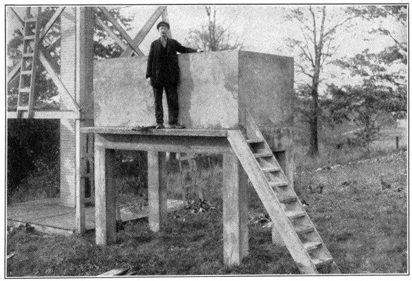
San José scale and insects are everywhere making fruit growers spray their orchards. To get rid of the continual nuisance of leaks and the handling of warm solutions, orchardmen are building elevated concrete tanks and are heating the spraying solution with steam pipes on the tank bottoms. With such a plant, there is no delay—and time counts in the spraying season.
The tank shown stands on 10 by 12-inch columns, 6 feet clear of the ground. It has two compartments, each 5 by 5 feet by 4 feet deep holding 750 gallons. The side walls are 4 inches thick. Beneath the 4-inch bottom, on all sides, are 8 by 12-inch concrete beams.
Locate the tank convenient to the water supply. Dig the column holes 12 inches square, 3 feet deep, 11 feet out to out on the longer side and 5 feet on the shorter. Have all forms ready before placing any concrete. Fill the holes with concrete and imbed in each hole four ½-inch iron rods 10 feet long so that they will come right for the columns and extend through them. Set up the 10 by 12-inch by 6-foot column forms with their tops level with each other. Join them together with the solidly framed 8 by 12-inch beam forms.
Keeping the rods 1 inch from the corners, fill concrete in the column forms up to the floor beams. Spread 1 inch of concrete over the bottom of the beam forms and lay in two ½-inch rods 1½ inches from each side wall. Bend these rods around those in the columns. Without delay fill the beam forms.
Erect the forms for the tank proper as for Watering Tanks, page 74. In the bottom of each tank set a 1½-inch flange pipe coupling. Place 1 inch of concrete, then strips of heavy woven wire, and the remaining 3 inches of concrete. Fill the side walls and, 1 inch from the outside, imbed similar wire fencing. Protect the green concrete according to directions under watering tanks.
The materials required are: screened gravel or crushed rock, 4½ cubic yards; sand, 2¼ cubic yards; and Portland cement, 7½ barrels. [Pg 108]
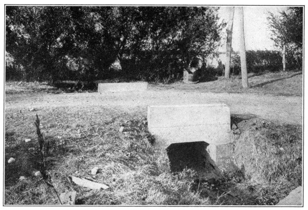
The secret of good roads is good drainage. Standing water soaks into the road bed, softens the road surface and causes ruts. To keep well made roads in first-class condition, get the water to the highway drain tile as fast as it falls. This can be accomplished only by means of culverts.
The perfect culvert is one which does not rot or rust out, which does not crush down and clog up the opening, which lasts forever. Concrete is the only material which fills the bill.
The best time to build a culvert is in the dry months of summer. They can be shaped either round or square and of a size depending on the amount of water which must be removed quickly. Usually openings 12 to 18 inches are large enough. Set the culvert as deep in the road bed as possible, but do not place the outlet end lower than the bottom of the ditch into which the culvert drains. To keep the culvert well beneath the road bed, if necessary, make the side ditch deeper at the inlet end. Determine the grade line of the finished culvert bottom. Only a little slope is needed. Dig the trench 6 inches deeper than the grade line and as wide and long as necessary. The width of the trench depends upon the size of the culvert to be built, and its length upon the width of roadway under which the water is to be carried. The concrete walls are each 6 inches thick, so the width of the trench will be 1 foot greater than the clear width of the culvert. Fill this trench with concrete mixed 1: 2½: 5, and, while it is still wet place in the center of it a U-shaped box, turned upside down, of 1-inch boards, the outside of which is the size of the culvert desired. Fill concrete into the space between the sides of the box and the sides of the trench and tamp concrete over the top to a depth of 8 inches. Road culverts should not be less than 18 inches below the surface of the roadway.
To prevent the material of which the road is made from washing down into [Pg 109] the culvert, small wing or retaining walls must be built at each end. To do this dig an 8-inch trench 3 feet deep, at each end of the culvert along the end of the culvert barrel. Frame a form, the width and height necessary, against the end of the box or pipe. Make another form, of the same size, but U-shaped, with the opening just large enough to fit over the outside of the concrete culvert barrel. Set this form 8 inches inside the first. Plumb both forms and brace them securely. Nail boards across the ends of these two forms and fill them with concrete. For one week shut off the traffic from passing over the culvert. Allow the forms to remain in place for two weeks. Replace the road material over the culvert and keep the ruts carefully filled until the fill has become solid. Since there are usually many culverts to be built, it is cheaper to use a collapsible form, adjustable to several sized culverts.
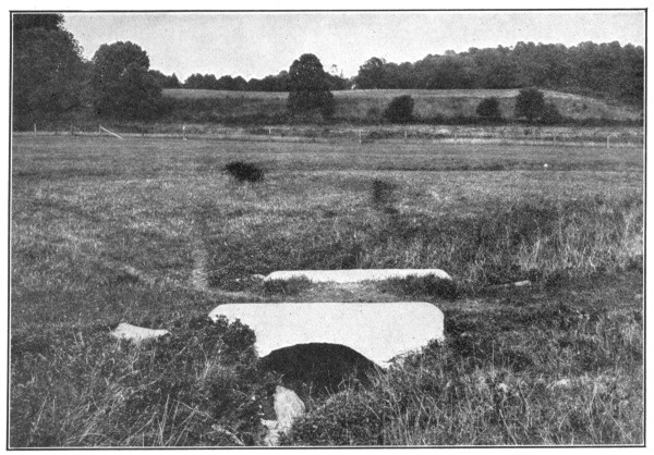
The box culvert shown in the illustration on page 108 has an opening 18 inches wide and 16 inches deep. The length is 20 feet. The retaining walls are 8 inches thick, 2 feet high (from the barrel opening), and do not extend beyond the culvert walls. The bottom and the side walls are 6 inches thick; the top, 8 inches. Three men, with a highway commissioner as superintendent, built this culvert in two days.
| Materials Required | ||
|---|---|---|
| Crushed rock or screened gravel | 3 cubic yards at $1.10 | $3.30 |
| Sand | 1½ cubic yards at $1.00 | 1.50 |
| Portland cement | 4 barrels at $2.50 | 10.00 |
| $14.80 | ||
Concrete bridges last forever. With all the bridges and culverts of concrete, tax officials will no longer need to levy bridge taxes. [Pg 110]
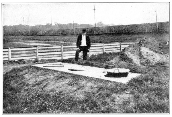
The proper method for the disposal of house sewage is an important question on the farm. Cess-pools, simply pits dug in the ground, are great disease spreaders. The liquids from them seep through the ground, carry germs from the pool to the well, render “the best drinking-water in the country” unfit for use, and often cause the spread of disease.
The modern farmer no longer puts up with such barbaric practice. Cess-pools have long been prohibited in cities, where immense sums of money are spent for the proper disposal of sewage. It is not possible to provide farms with these expensive plants, nor is it necessary. Through the use of an inexpensive septic tank all of the conveniences of the toilet and bath may be installed in the house and the danger from sewage removed.
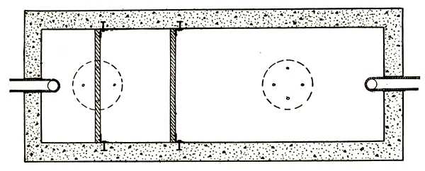
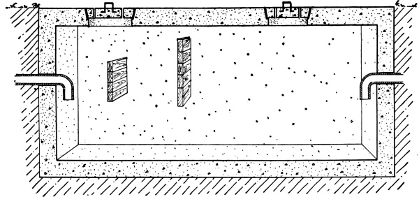
Septic tanks are nothing but long underground, water-tight cisterns through which the sewage passes very slowly and evenly. Located underground, they are warm and dark—ideal conditions for the [Pg 111] development of the bacteria, little germs which eat up the sewage and render it harmless in much the same way as another kind causes cider to ferment. To prevent the bacteria (which live in the frothy sludge) from being disturbed cross-walls, called baffle boards, are placed to break up the current of the inflowing sewage. The purified sewage, merely clear water, may be discharged into the farm drain tile.
Locate the septic tank where it can be placed entirely with the side walls underground and out of danger of flood waters. For a family of 8 to 10, plan a tank with 8-inch walls, 5 feet wide, 5 feet deep and 10 feet long—all dimensions in the clear. Lay out the tank and construct it in exactly the same manner as Underground Cisterns, page 68.
Before filling the forms, set in the 6-inch inlet and outlet drains at the same height, 2 feet 6 inches below the ground level. To aid further in breaking up the currents and keeping out too much air, use elbow bends, so that the sewage in the tank will cover the mouths of the tile. In the side forms, at a distance of 2 and 4 feet from the inlet wall, set ¾-inch bolts to which the baffle boards will later be attached. These boards reach entirely across the tank, project above the sewage, and extend to within 1 foot of the bottom. While building the manhole covers, for the needed ventilation, insert in them four short lengths of 1-inch gas pipe.
Remove the forms the same as for underground cisterns.
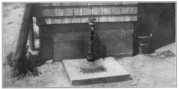
Concrete Hydrant Sink
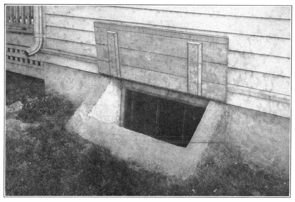
Window hatches should be protected by a flap cover, to close in times of heavy rain or snow.
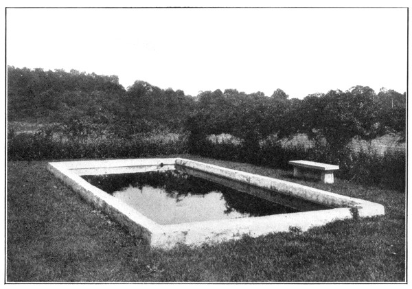
These are built exactly as an underground cistern. A pool near home affords a safe “swimming hole” for the children.
How will you know?
You are going to build—now or some time—and you want to build well and economically.
You will choose between temporary and permanent construction.
Why you should build in concrete.
First, because of permanence. It is fireproof, strong, and lasting—proof against wear-and-tear and depreciation. It lasts and lasts—against wind, water, and fire.
Second, because of cleanliness and sanitation. This means healthy stock and better products, which sell at higher prices.
Third, because of economy. Concrete is lower in ultimate cost because, once built, it requires no painting or up-keep, no repairs, no attention. Being proof against fire, concrete secures the lowest insurance rates.
“The Standard by which all other makes are measured.”
Why you should use ATLAS.
First, because Atlas Portland Cement is the most-used cement—high in quality and always uniform and reliable.
Second, because Atlas Portland Cement has demonstrated its worth. Our own government selected it for the Panama Canal, after careful investigation and tests. Nearly seven million barrels have been used so far for this project. Severe government tests have been made of every hundred barrels, but not a single barrel has been rejected.
“The Standard by which all other makes are measured.”
Free help for you.
This book will give much valuable information about concrete. But naturally, your particular needs may require further information.
Let us furnish this information you need. Tell us what you want to build and what you would like to know. We will gladly give you all the necessary help.
So far, we have sent information to over two million farmers. Why shouldn’t you avail yourself of this help, which is offered to you without any obligation?
Whenever you buy cement, look for the Atlas trade mark as your guide—the black trade mark with yellow letters.
The Atlas Portland Cement Company
New York Chicago Philadelphia Boston
St. Louis Minneapolis Des Moines
“The Standard by which all other makes are measured.”
Warning
There are many brands of Portland cement, and some people are confused, and as a result accept any cement bearing the word “Portland.”
The word “Portland” signifies only the kind of cement, but does not designate the brand and quality.
Specify “ATLAS” Portland Cement when you buy, and you will get the best.
Atlas Portland Cement
is always uniform in strength, color and quality. It is the cement that has done most to make concrete and its uses so satisfactory and well known. That is why Atlas is “The Standard by which all other makes are measured.”
“The Standard by which all other makes are measured.”
Ask Your
Dealer for
ATLAS
“The Standard by which all
other makes are measured.”
“The Standard by which all
other makes are measured.”
ATLAS
used exclusively by the
United States Government
on the Panama Canal
ATLAS
used exclusively on the
great Keokuk Dam across
the Mississippi River
Footnotes:
[1] Farmers’ Bulletin 403, Concrete Fence Posts. Sent free on application.
[2] For free bulletins on dipping write the Agricultural Department, Bureau of Animal Industry, Washington, D. C.
Transcriber’s Notes:
The illustrations have been moved so that they do not break up paragraphs and so that they are next to the text they illustrate.
Typographical errors have been silently corrected.
The advertisements between pages 48 and 49 in the original text have been moved to the end of the text.
End of the Project Gutenberg EBook of Concrete Construction for the Home and
the Farm, by The Atlas Portland Cement Company

*** END OF THIS PROJECT GUTENBERG EBOOK CONCRETE CONSTRUCTION FOR HOME AND FARM ***

***** This file should be named 62312-h.htm or 62312-h.zip *****
This and all associated files of various formats will be found in:
        http://www.gutenberg.org/6/2/3/1/62312/

Produced by MFR, Paul Marshall and the Online Distributed
Proofreading Team at https://www.pgdp.net (This file was
produced from images generously made available by The
Internet Archive)

Updated editions will replace the previous one--the old editions will
be renamed.

Creating the works from print editions not protected by U.S. copyright
law means that no one owns a United States copyright in these works,
so the Foundation (and you!) can copy and distribute it in the United
States without permission and without paying copyright
royalties. Special rules, set forth in the General Terms of Use part
of this license, apply to copying and distributing Project
Gutenberg-tm electronic works to protect the PROJECT GUTENBERG-tm
concept and trademark. Project Gutenberg is a registered trademark,
and may not be used if you charge for the eBooks, unless you receive
specific permission. If you do not charge anything for copies of this
eBook, complying with the rules is very easy. You may use this eBook
for nearly any purpose such as creation of derivative works, reports,
performances and research. They may be modified and printed and given
away--you may do practically ANYTHING in the United States with eBooks
not protected by U.S. copyright law. Redistribution is subject to the
trademark license, especially commercial redistribution.

START: FULL LICENSE

THE FULL PROJECT GUTENBERG LICENSE
PLEASE READ THIS BEFORE YOU DISTRIBUTE OR USE THIS WORK

To protect the Project Gutenberg-tm mission of promoting the free
distribution of electronic works, by using or distributing this work
(or any other work associated in any way with the phrase "Project
Gutenberg"), you agree to comply with all the terms of the Full
Project Gutenberg-tm License available with this file or online at
www.gutenberg.org/license.

Section 1. General Terms of Use and Redistributing Project
Gutenberg-tm electronic works

1.A. By reading or using any part of this Project Gutenberg-tm
electronic work, you indicate that you have read, understand, agree to
and accept all the terms of this license and intellectual property
(trademark/copyright) agreement. If you do not agree to abide by all
the terms of this agreement, you must cease using and return or
destroy all copies of Project Gutenberg-tm electronic works in your
possession. If you paid a fee for obtaining a copy of or access to a
Project Gutenberg-tm electronic work and you do not agree to be bound
by the terms of this agreement, you may obtain a refund from the
person or entity to whom you paid the fee as set forth in paragraph
1.E.8.

1.B. "Project Gutenberg" is a registered trademark. It may only be
used on or associated in any way with an electronic work by people who
agree to be bound by the terms of this agreement. There are a few
things that you can do with most Project Gutenberg-tm electronic works
even without complying with the full terms of this agreement. See
paragraph 1.C below. There are a lot of things you can do with Project
Gutenberg-tm electronic works if you follow the terms of this
agreement and help preserve free future access to Project Gutenberg-tm
electronic works. See paragraph 1.E below.

1.C. The Project Gutenberg Literary Archive Foundation ("the
Foundation" or PGLAF), owns a compilation copyright in the collection
of Project Gutenberg-tm electronic works. Nearly all the individual
works in the collection are in the public domain in the United
States. If an individual work is unprotected by copyright law in the
United States and you are located in the United States, we do not
claim a right to prevent you from copying, distributing, performing,
displaying or creating derivative works based on the work as long as
all references to Project Gutenberg are removed. Of course, we hope
that you will support the Project Gutenberg-tm mission of promoting
free access to electronic works by freely sharing Project Gutenberg-tm
works in compliance with the terms of this agreement for keeping the
Project Gutenberg-tm name associated with the work. You can easily
comply with the terms of this agreement by keeping this work in the
same format with its attached full Project Gutenberg-tm License when
you share it without charge with others.

1.D. The copyright laws of the place where you are located also govern
what you can do with this work. Copyright laws in most countries are
in a constant state of change. If you are outside the United States,
check the laws of your country in addition to the terms of this
agreement before downloading, copying, displaying, performing,
distributing or creating derivative works based on this work or any
other Project Gutenberg-tm work. The Foundation makes no
representations concerning the copyright status of any work in any
country outside the United States.

1.E. Unless you have removed all references to Project Gutenberg:

1.E.1. The following sentence, with active links to, or other
immediate access to, the full Project Gutenberg-tm License must appear
prominently whenever any copy of a Project Gutenberg-tm work (any work
on which the phrase "Project Gutenberg" appears, or with which the
phrase "Project Gutenberg" is associated) is accessed, displayed,
performed, viewed, copied or distributed:

  This eBook is for the use of anyone anywhere in the United States and
  most other parts of the world at no cost and with almost no
  restrictions whatsoever. You may copy it, give it away or re-use it
  under the terms of the Project Gutenberg License included with this
  eBook or online at www.gutenberg.org. If you are not located in the
  United States, you'll have to check the laws of the country where you
  are located before using this ebook.

1.E.2. If an individual Project Gutenberg-tm electronic work is
derived from texts not protected by U.S. copyright law (does not
contain a notice indicating that it is posted with permission of the
copyright holder), the work can be copied and distributed to anyone in
the United States without paying any fees or charges. If you are
redistributing or providing access to a work with the phrase "Project
Gutenberg" associated with or appearing on the work, you must comply
either with the requirements of paragraphs 1.E.1 through 1.E.7 or
obtain permission for the use of the work and the Project Gutenberg-tm
trademark as set forth in paragraphs 1.E.8 or 1.E.9.

1.E.3. If an individual Project Gutenberg-tm electronic work is posted
with the permission of the copyright holder, your use and distribution
must comply with both paragraphs 1.E.1 through 1.E.7 and any
additional terms imposed by the copyright holder. Additional terms
will be linked to the Project Gutenberg-tm License for all works
posted with the permission of the copyright holder found at the
beginning of this work.

1.E.4. Do not unlink or detach or remove the full Project Gutenberg-tm
License terms from this work, or any files containing a part of this
work or any other work associated with Project Gutenberg-tm.

1.E.5. Do not copy, display, perform, distribute or redistribute this
electronic work, or any part of this electronic work, without
prominently displaying the sentence set forth in paragraph 1.E.1 with
active links or immediate access to the full terms of the Project
Gutenberg-tm License.

1.E.6. You may convert to and distribute this work in any binary,
compressed, marked up, nonproprietary or proprietary form, including
any word processing or hypertext form. However, if you provide access
to or distribute copies of a Project Gutenberg-tm work in a format
other than "Plain Vanilla ASCII" or other format used in the official
version posted on the official Project Gutenberg-tm web site
(www.gutenberg.org), you must, at no additional cost, fee or expense
to the user, provide a copy, a means of exporting a copy, or a means
of obtaining a copy upon request, of the work in its original "Plain
Vanilla ASCII" or other form. Any alternate format must include the
full Project Gutenberg-tm License as specified in paragraph 1.E.1.

1.E.7. Do not charge a fee for access to, viewing, displaying,
performing, copying or distributing any Project Gutenberg-tm works
unless you comply with paragraph 1.E.8 or 1.E.9.

1.E.8. You may charge a reasonable fee for copies of or providing
access to or distributing Project Gutenberg-tm electronic works
provided that

* You pay a royalty fee of 20% of the gross profits you derive from
  the use of Project Gutenberg-tm works calculated using the method
  you already use to calculate your applicable taxes. The fee is owed
  to the owner of the Project Gutenberg-tm trademark, but he has
  agreed to donate royalties under this paragraph to the Project
  Gutenberg Literary Archive Foundation. Royalty payments must be paid
  within 60 days following each date on which you prepare (or are
  legally required to prepare) your periodic tax returns. Royalty
  payments should be clearly marked as such and sent to the Project
  Gutenberg Literary Archive Foundation at the address specified in
  Section 4, "Information about donations to the Project Gutenberg
  Literary Archive Foundation."

* You provide a full refund of any money paid by a user who notifies
  you in writing (or by e-mail) within 30 days of receipt that s/he
  does not agree to the terms of the full Project Gutenberg-tm
  License. You must require such a user to return or destroy all
  copies of the works possessed in a physical medium and discontinue
  all use of and all access to other copies of Project Gutenberg-tm
  works.

* You provide, in accordance with paragraph 1.F.3, a full refund of
  any money paid for a work or a replacement copy, if a defect in the
  electronic work is discovered and reported to you within 90 days of
  receipt of the work.

* You comply with all other terms of this agreement for free
  distribution of Project Gutenberg-tm works.

1.E.9. If you wish to charge a fee or distribute a Project
Gutenberg-tm electronic work or group of works on different terms than
are set forth in this agreement, you must obtain permission in writing
from both the Project Gutenberg Literary Archive Foundation and The
Project Gutenberg Trademark LLC, the owner of the Project Gutenberg-tm
trademark. Contact the Foundation as set forth in Section 3 below.

1.F.

1.F.1. Project Gutenberg volunteers and employees expend considerable
effort to identify, do copyright research on, transcribe and proofread
works not protected by U.S. copyright law in creating the Project
Gutenberg-tm collection. Despite these efforts, Project Gutenberg-tm
electronic works, and the medium on which they may be stored, may
contain "Defects," such as, but not limited to, incomplete, inaccurate
or corrupt data, transcription errors, a copyright or other
intellectual property infringement, a defective or damaged disk or
other medium, a computer virus, or computer codes that damage or
cannot be read by your equipment.

1.F.2. LIMITED WARRANTY, DISCLAIMER OF DAMAGES - Except for the "Right
of Replacement or Refund" described in paragraph 1.F.3, the Project
Gutenberg Literary Archive Foundation, the owner of the Project
Gutenberg-tm trademark, and any other party distributing a Project
Gutenberg-tm electronic work under this agreement, disclaim all
liability to you for damages, costs and expenses, including legal
fees. YOU AGREE THAT YOU HAVE NO REMEDIES FOR NEGLIGENCE, STRICT
LIABILITY, BREACH OF WARRANTY OR BREACH OF CONTRACT EXCEPT THOSE
PROVIDED IN PARAGRAPH 1.F.3. YOU AGREE THAT THE FOUNDATION, THE
TRADEMARK OWNER, AND ANY DISTRIBUTOR UNDER THIS AGREEMENT WILL NOT BE
LIABLE TO YOU FOR ACTUAL, DIRECT, INDIRECT, CONSEQUENTIAL, PUNITIVE OR
INCIDENTAL DAMAGES EVEN IF YOU GIVE NOTICE OF THE POSSIBILITY OF SUCH
DAMAGE.

1.F.3. LIMITED RIGHT OF REPLACEMENT OR REFUND - If you discover a
defect in this electronic work within 90 days of receiving it, you can
receive a refund of the money (if any) you paid for it by sending a
written explanation to the person you received the work from. If you
received the work on a physical medium, you must return the medium
with your written explanation. The person or entity that provided you
with the defective work may elect to provide a replacement copy in
lieu of a refund. If you received the work electronically, the person
or entity providing it to you may choose to give you a second
opportunity to receive the work electronically in lieu of a refund. If
the second copy is also defective, you may demand a refund in writing
without further opportunities to fix the problem.

1.F.4. Except for the limited right of replacement or refund set forth
in paragraph 1.F.3, this work is provided to you 'AS-IS', WITH NO
OTHER WARRANTIES OF ANY KIND, EXPRESS OR IMPLIED, INCLUDING BUT NOT
LIMITED TO WARRANTIES OF MERCHANTABILITY OR FITNESS FOR ANY PURPOSE.

1.F.5. Some states do not allow disclaimers of certain implied
warranties or the exclusion or limitation of certain types of
damages. If any disclaimer or limitation set forth in this agreement
violates the law of the state applicable to this agreement, the
agreement shall be interpreted to make the maximum disclaimer or
limitation permitted by the applicable state law. The invalidity or
unenforceability of any provision of this agreement shall not void the
remaining provisions.

1.F.6. INDEMNITY - You agree to indemnify and hold the Foundation, the
trademark owner, any agent or employee of the Foundation, anyone
providing copies of Project Gutenberg-tm electronic works in
accordance with this agreement, and any volunteers associated with the
production, promotion and distribution of Project Gutenberg-tm
electronic works, harmless from all liability, costs and expenses,
including legal fees, that arise directly or indirectly from any of
the following which you do or cause to occur: (a) distribution of this
or any Project Gutenberg-tm work, (b) alteration, modification, or
additions or deletions to any Project Gutenberg-tm work, and (c) any
Defect you cause.

Section 2. Information about the Mission of Project Gutenberg-tm

Project Gutenberg-tm is synonymous with the free distribution of
electronic works in formats readable by the widest variety of
computers including obsolete, old, middle-aged and new computers. It
exists because of the efforts of hundreds of volunteers and donations
from people in all walks of life.

Volunteers and financial support to provide volunteers with the
assistance they need are critical to reaching Project Gutenberg-tm's
goals and ensuring that the Project Gutenberg-tm collection will
remain freely available for generations to come. In 2001, the Project
Gutenberg Literary Archive Foundation was created to provide a secure
and permanent future for Project Gutenberg-tm and future
generations. To learn more about the Project Gutenberg Literary
Archive Foundation and how your efforts and donations can help, see
Sections 3 and 4 and the Foundation information page at
www.gutenberg.org


Section 3. Information about the Project Gutenberg Literary Archive Foundation

The Project Gutenberg Literary Archive Foundation is a non profit
501(c)(3) educational corporation organized under the laws of the
state of Mississippi and granted tax exempt status by the Internal
Revenue Service. The Foundation's EIN or federal tax identification
number is 64-6221541. Contributions to the Project Gutenberg Literary
Archive Foundation are tax deductible to the full extent permitted by
U.S. federal laws and your state's laws.

The Foundation's principal office is in Fairbanks, Alaska, with the
mailing address: PO Box 750175, Fairbanks, AK 99775, but its
volunteers and employees are scattered throughout numerous
locations. Its business office is located at 809 North 1500 West, Salt
Lake City, UT 84116, (801) 596-1887. Email contact links and up to
date contact information can be found at the Foundation's web site and
official page at www.gutenberg.org/contact

For additional contact information:

    Dr. Gregory B. Newby
    Chief Executive and Director
    gbnewby@pglaf.org

Section 4. Information about Donations to the Project Gutenberg
Literary Archive Foundation

Project Gutenberg-tm depends upon and cannot survive without wide
spread public support and donations to carry out its mission of
increasing the number of public domain and licensed works that can be
freely distributed in machine readable form accessible by the widest
array of equipment including outdated equipment. Many small donations
($1 to $5,000) are particularly important to maintaining tax exempt
status with the IRS.

The Foundation is committed to complying with the laws regulating
charities and charitable donations in all 50 states of the United
States. Compliance requirements are not uniform and it takes a
considerable effort, much paperwork and many fees to meet and keep up
with these requirements. We do not solicit donations in locations
where we have not received written confirmation of compliance. To SEND
DONATIONS or determine the status of compliance for any particular
state visit www.gutenberg.org/donate

While we cannot and do not solicit contributions from states where we
have not met the solicitation requirements, we know of no prohibition
against accepting unsolicited donations from donors in such states who
approach us with offers to donate.

International donations are gratefully accepted, but we cannot make
any statements concerning tax treatment of donations received from
outside the United States. U.S. laws alone swamp our small staff.

Please check the Project Gutenberg Web pages for current donation
methods and addresses. Donations are accepted in a number of other
ways including checks, online payments and credit card donations. To
donate, please visit: www.gutenberg.org/donate

Section 5. General Information About Project Gutenberg-tm electronic works.

Professor Michael S. Hart was the originator of the Project
Gutenberg-tm concept of a library of electronic works that could be
freely shared with anyone. For forty years, he produced and
distributed Project Gutenberg-tm eBooks with only a loose network of
volunteer support.

Project Gutenberg-tm eBooks are often created from several printed
editions, all of which are confirmed as not protected by copyright in
the U.S. unless a copyright notice is included. Thus, we do not
necessarily keep eBooks in compliance with any particular paper
edition.

Most people start at our Web site which has the main PG search
facility: www.gutenberg.org

This Web site includes information about Project Gutenberg-tm,
including how to make donations to the Project Gutenberg Literary
Archive Foundation, how to help produce our new eBooks, and how to
subscribe to our email newsletter to hear about new eBooks.