The Project Gutenberg EBook of The Construction of the Small House, by
Harold Vandervoort Walsh

This eBook is for the use of anyone anywhere in the United States and most
other parts of the world at no cost and with almost no restrictions
whatsoever.  You may copy it, give it away or re-use it under the terms of
the Project Gutenberg License included with this eBook or online at
www.gutenberg.org.  If you are not located in the United States, you'll have
to check the laws of the country where you are located before using this ebook.

Title: The Construction of the Small House
       A Simple and Useful Source of Information of the Methods
              of Building Small American Homes, for Anyone Planning to
              Build

Author: Harold Vandervoort Walsh

Release Date: April 20, 2020 [EBook #61880]

Language: English

Character set encoding: UTF-8

*** START OF THIS PROJECT GUTENBERG EBOOK CONSTRUCTION OF THE SMALL HOUSE ***


Produced by ellinora, Paul Marshall and the Online
Distributed Proofreading Team at https://www.pgdp.net (This
file was produced from images generously made available
by The Internet Archive/American Libraries.)
A SIMPLE AND USEFUL SOURCE OF INFORMATION
ON THE METHODS OF BUILDING SMALL AMERICAN HOMES,
FOR ANYONE PLANNING TO BUILD
BY
H. VANDERVOORT WALSH
INSTRUCTOR OF CONSTRUCTION IN
THE SCHOOL OF ARCHITECTURE,
COLUMBIA UNIVERSITY
WITH ILLUSTRATIONS BY
THE AUTHOR
NEW YORK
CHARLES SCRIBNER’S SONS
1923
Copyright, 1923, by
CHARLES SCRIBNER’S SONS
Printed in the United States of America
Published February, 1923
| CHAPTER | PAGE | |
| I. | Present-Day Economic Troubles | 1 |
| II. | General Types and Costs | 7 |
| III. | Essential Standards of Quality in Building Materials | 20 |
| IV. | Types of Wooden-Frame Construction | 38 |
| V. | Construction of the Masonry and Wood Dwelling | 49 |
| VI. | Safeguards Against Fire in Dwellings | 69 |
| VII. | Poor Methods of Construction Employed by | |
| Unscrupulous Builders | 81 | |
| VIII. | Essential Features of Good Plumbing | 94 |
| IX. | Methods of Heating | 109 |
| X. | Lighting and Electric Work | 121 |
| XI. | Construction of the Trim | 130 |
| XII. | Lessons Taught by Depreciation | |
| XIII. | Selecting Materials from Advertisements | 150 |
| XIV. | Roofing Materials | 158 |
| XV. | Painting and Varnishing the House | 177 |
| XVI. | Labor-Saving Devices for the Home | 185 |
| XVII. | Concrete Work Around the House | 197 |
| XVIII. | Classification and Construction of the Architectural | |
| Motifs Used in Small-House Designing | 208 | |
| XIX. | Traditions of Building from Which Our Modern Methods | |
| Are Derived | 219 | |
| XX. | Traditions of the Construction of Doors and Windows | 236 |
| XXI. | Building the Setting for the House | 245 |
| XXII. | Financing the Construction Work | 258 |
CONSTRUCTION OF THE
SMALL HOUSE
Immediately after the war the housing shortage made itself very evident, because the landlords discovered that it existed, and realized that they had it within their power to exact extortionate rents. Statisticians got busy and put their heads together and informed the public that within the next five years there would have to be built some 3,300,000 new homes to properly house the people. The building magazines likewise were predicting great things in construction, and all in the building industry were looking for fat years of prosperity, for here was the need and there was the pressure of the high rents. Why should not the thousands of families that had waited build now, when they saw their money going to waste in high rents? All kinds of advertisements were sent out to urge the public to build, and own-your-own-home shows sprang up in every large city, and one could find plenty of builders who would say that one should build immediately, before prices went higher.
And seeing the poor, unprotected home-builder, the greed of human nature seized all in the building industry as it had entangled all [Pg 2] other business lines, and the price of materials leaped into the air, and the cost of labor became swollen, and all had that bloated and enlarged look which comes over the face of him who is sure of his meal.
Before the war he planned for this
At the end of 1918 the average cost of all building materials was up to 175 per cent over that of 1913, but by the first quarter of 1920 they had gotten up to 300 per cent increase over 1913 prices. Lumber had gone up 373 per cent. Labor had also risen to 200 per cent.
Mr. Average Citizen found that the home he had been saving his money to build had flown from his hand, like a bird. The sketches and plans he had prepared for a nice little $10,000 home now represented an investment of $20,000 or more. In fact, if he expected to build at all, he had to be reconciled to a small house of six or seven rooms, which [Pg 3] would cost him not less than $10,000 or more, or as much as the large house which he had planned originally to build.
Then what happened? Mr. Average Citizen did not build. The confidently predicted building boom which the building material manufacturers had looked for did not materialize. Prices were too high, and the public could not be made to believe that they would not come down, and the public was right.

Now his plans have shrunk to this
The light began to break as well as the prices, and we find the cost of building materials dropping suddenly. By the end of 1920 they had reached the 200 mark. By March, 1922, they had reached the 155 level, and are still going down with slight fluctuation.
But during all of this time we heard all kinds of theories as to how the problem should be met. Some architects went so far as to predict that people could no longer build individual houses for themselves; that the day of the small house was over. They claimed that the only solution was in the construction of group houses. Such groups would eliminate much of the expensive street paving as ordinarily required, and cut to a minimum the water supply-lines and sewage systems. Semi-detached houses in groups were capable of saving the cost on one [Pg 4] outside wall, one chimney, one set of plumbing pipes for each house in the group. The heating could also be reduced to a community basis, and the land so distributed that the best air and light could be had with the minimum waste.
Many architects conscientiously tried to reduce the cost of construction of the small house by inventing cheaper ways and methods of building. However, the estimates came in just as high, because the average small contractor who builds the small house was afraid of innovations, since there was too great an element of risk, and he was conservative. To meet this difficulty some architects attached to their office organization construction departments by means of which they were able to build according to their economical plans and secure the advantage of the saving in cost. This was held by many to be unprofessional. Other architects secured lower bids by having a written agreement with the various contractors who were competing that, if they received the contract, the owner would be responsible for and pay for any increase in labor or material prices which might take place during the period of erection. Likewise the contractor agreed to give the owner the benefit of any reduction in prices which might take place during the time of erection. This simple understanding seemed to relieve the contractor of nervousness, and his bids were often lower. Still other architects claimed that the cost of construction could only be reduced by standardizing all of the parts. Certain mills had secured high-class talent to design stock doors, cornices, windows, columns, and the like, and the results were very satisfactory, both artistically and economically.
This problem of the cost of the small house was very acute, and, although it has been relieved somewhat by the decreasing prices at this [Pg 5] time, yet it will always be an integral part of the problem of building the small house.
In fact, to properly design the small house and build it economically requires the greatest care for detail. Many well-established architects will not bother with this architectural problem, for the time required to consider all these small details is greater than they can afford to give in proportion to the fee they receive. For this reason most of this work is done by the young architect or by the speculative builder, who generally shows very bad taste in selecting his design, while the young architect is apt to be somewhat inexperienced in his knowledge of construction.
The very first thing that must be considered in the problem of the building of the small house is the question of money, because this determines what kind of a lot can be purchased, how large the house can be, and of what type of construction it can be built. Experts on financing say that the cost of the house should be such that it can be paid off in full within fifteen years. This means that the cost of the proposed home must be arranged to come within definite limits. Methods of approximately determining the cost of a house in its preliminary sketch stages will be considered later, but it is sufficient to say here, that once this first problem is solved carefully, other matters are much easier to take care of. If one knows the cost, the question of borrowing money is made easier, and one is not misled into wild fancies of larger houses than possibly the pocketbook could afford. The worst mistake that a young architect can make is to lead his client to believe that he can have a certain design for less money than will actually be the case. It is always best to overestimate the cost in the beginning than to underestimate it. [Pg 6]
“But,” says the client, “I can buy a house and lot at ‘Heavenly Rest Real Estate Park’ for that price, and on the instalment plan, too. I don’t see why the cost of a house built from your plans should be so much greater than this.”
And that is a big question to answer, one which this volume will attempt to make clear, one to which only a knowledge of construction can give a real and satisfactory answer. It is the old story, that a well-built article is bound to cost more than a poorly built one; but how to know the well-built article!
Type I Wooden Frame
All small houses may be classified into four types, according to their construction. The first type is the commonest and is the wooden frame structure. This has exterior walls and interior partitions built of light wooden studs, and the floors and ceilings framed with wooden joists. The exterior walls may be covered with clapboard, shingles, stucco, brick veneer, or stone veneer. The roof is generally covered with wooden shingles, although slate, tile, asbestos, and asphalt [Pg 8] shingles are often used. These houses are the most numerous, because the cost of wood in the past has been so much less than other materials that they appealed to the average builder’s financial sense. However, the cost of such dwellings to the country as a whole has been very high, for they are extremely dangerous when attacked by fire. More than twenty-two millions of dollars are wasted by fire each year in these houses. They also cost us a great deal in up-keep. It would be interesting to see what was the total cost per year to repaint them and keep the roofs in order. It certainly would run into the millions. Although wood increased from about $30.00 per thousand board feet to about $85.00 in the Eastern markets from pre-war days, and is now dropping below $55.00, yet the wooden house is still listed as the cheapest, for the cost of other materials has also increased, as brick from $10.00 per thousand to $23.00 until very recently, and cement from $2.00 to $3.25 per barrel. In any comparison of cost the wooden frame building is taken as the base or cheapest type of construction, although it is the most expensive in up-keep and fire-hazard of all. Until the price of wood increases in excessive proportion to other materials, there is no doubt that this type of house will be the commonest. However, there is much that can be done to make them more fire-resisting, and, although we cannot look to the speculative builders to use such methods, since they increase the costs slightly, yet the architect should not overlook them.
Type II Masonry and Wood
The second type of dwelling which is next in vogue has exterior walls of stone, brick, concrete, or terra-cotta, and interior floors, [Pg 9] partitions, and roof of wooden frame construction. These are very slightly more fireproof than the wooden frame structure, and as a class they are more costly in the beginning, but require less expense in up-keep. They resist attack from external fires better than the wooden frame building, but if the fire starts within, they will burn just as readily. Although the fire loss per year of this class is not nearly as great as for the first type, yet it must be appreciated that there are not so many of them. The chief advantage of the masonry house of this second type lies in the lowered cost of up-keep, longer life, and saving of heating-fuel in the winter. A great deal of literature has been circulated by brick, cement, and hollow terra-cotta tile manufacturers by which the public has been educated to believe that this type of structure is much more fire-resisting than it is. Of course this campaign of education was intended to stimulate interest in their product, and it had no unselfish motive back of it. The result of this propaganda is evident in the public belief that such houses are fireproof houses, while as a matter of fact they are not. [Pg 10]
Type II · Masonry walls · Interior·Wood
The third class of dwelling is quite rare, and very few small houses are built that could be classified under it. Some builders call them fireproof houses, although this is erroneous. These buildings have walls, roofs, floors, and partitions built of incombustible materials, but the finished floors, the trim, windows, and doors are of wood. The exterior walls are of masonry construction, and the construction of the floors and roofs consists of steel beams with terra-cotta arches or concrete floor slabs, spanning in between them, and the partitions are of terra-cotta, gypsum, metal lath and plaster, or other similar materials. They may also be built of reinforced concrete throughout, or any other combination of these materials. There have been very few [Pg 11] examples of this kind of construction used in the small house. It is an unfortunate condition that it is more adaptable to the costly mansion than to the average house of the middle-class citizen, for the high cost of construction of this character, in most cases, permits it to be used only by the wealthy man. Examples where such houses have been built generally show an investment of $30,000 or more, or, if they were built to-day, $50,000 or more. Those attempts to use this form of construction in the small house have been made by large building corporations, and have been chiefly represented by concrete houses of very ugly design.

Type III. Walls, floors, partitions fireproof, but windows, doors and trim of wood.
The fourth and last type of dwelling is the ideal fireproof house, but it is so costly that very few examples exist. This type can be termed fireproof with accuracy, for all structural parts, including doors, windows, and trim, are of incombustible materials. Metal trim is used or wood that has been treated to make it fire-resisting. This latter [Pg 12] class of construction is so out of the reach of the average home-builder, on account of its cost, that its value cannot be thoroughly appreciated. Practically the only examples in existence are large mansions, built by wealthy clients.
Cost Does Not Indicate Fire-Resistance.—In this classification of buildings it would almost seem that the cost of a building indicated its fireproof qualities. This is not true, however. There are many expensive dwellings which are just as great fire-traps as the less expensive ones. In both cases the fire hazards are the same, if they are built of the same type of construction. In fact, we could build a $60,000 dwelling according to Type II, and also a $10,000 one according to Type II, and make the latter more fire-resisting than the former by using certain precautions of construction in which the spread of fire is retarded.
Except in unusual cases, the construction of the ordinary dwelling will be either according to the first or second type, and any fire precautions that are desirable must be applicable to them. Most comparisons of relative costs are made between the dwellings included under these two types, and the difference will be mostly a difference in the kind of exterior walls used in the construction. In fact, if any comparisons are made between different kinds of buildings, as to their relative costs, it is essential that only one feature be made variable and that all others be kept the same.
Ever since the closing of the war the problem of knowing the cost of the construction of the small house has been a very intricate one, and no sure estimates could be made, until the plans were completed and let out for bids. Previous to the war, when costs were somewhat stabilized, [Pg 13] it was possible to predict with a reasonable amount of accuracy the cost of the dwelling when the plans were still only roughed in.
In order to show the fluctuation in prices, an example of a seven-room frame house of Type I can be mentioned. This house was practically 30 by 34 feet, and had a cubical contents of about 29,100 cubic feet and an area of 2,640 square feet. In 1914 this house cost $5,529.00, but at the peak of prices in 1920 this house cost $12,815.00, which was an increase of 131 per cent. In the spring of 1922 this same house cost $9,502.00 to build, which was about 71 per cent over that of pre-war prices.
With a heavy pressure of needed construction in dwellings, the cost of materials seems to be settling down to a very gradual decrease in cost, so that the present rates show a more stable curve of decline than those of the latter part of 1920 and during 1921. The unfortunate factor which is noticeable is that certain building interests believe that a building boom is inevitable, and therefore that it is the time to hold up prices again. Wherever this has happened a building boom has been headed off.
The average client, in spite of the difficulties above mentioned, insists upon securing from the architect an approximate idea of how much of a house he can have for $12,000.00, etc., or whatever sum he has been able to save for his small home. In order to approximate this figure, the architect must use the cubic-foot system of estimating. Now under changing conditions of prices this system is rather inaccurate, so that it should be used with great care. Any figures which are given here are bound to be only approximations, due to the fact that they are more or less of a local nature and must be given at this time of writing. The only satisfactory way of using the cubic-foot system of [Pg 14] estimating is to secure prices from one’s own locality on work recently finished.

Type II
If the approximate cost of a house of Type I is desired, observe some recently erected house of that same character, secure its dimension, and calculate its cubical contents and then its cost per cubic foot. In order to be consistent, the method of computing the cubage must be the same in all cases. The following is recommended as a uniform basis: [Pg 15]
1. Determine total area of the building on the ground floor, including all projections.
2. Determine the average height of the building from the cellar floor to the average height of the roof.
3. Multiply the above together for the cubical contents.
4. Open porches may be added at one-quarter their cubical contents, and closed ones at their full value.
Type II
Prices per Cubic Feet Near New York for Two-Story Dwellings,
June, 1922
| Type I | 32 to 38 cents per cubic foot |
| Type II | 38 to 42 cents per cubic foot |
From what has been previously stated, it will be noticed that, as a rule, the architect in selecting the kind of material with which he will build his house is limited on account of expense to the first two types of construction—namely, the frame dwelling and the masonry house with wood interior. The latter two fire-resisting types are better fitted to the larger mansions, where expense is not so important an item. Undoubtedly the comparative costs between the various kinds of exterior walls will have much to do with the selection; but more often the local conditions will outweigh these considerations. In some places a house built of stone will be the best and most economical; in others, where there is an abundance of good sand, the cement house will be suitable, while those located near brick centres will find this material adaptable.
The ideal method, of selecting a material of construction purely from an æsthetic point of view, is not always possible. But, after all, is not the most abundant local material the most harmonious to use for any one locality? Nature adapts her creations to the soil and the scenery into which she places them. All her animals are marked with colors which harmonize with the woods or fields in which they live. In fact this harmony is their protection, and in the war we imitated it in our camouflage painting. It is astonishingly evident, in the New York Museum of Natural History, how far more beautiful are animal tableaux which are set in painted scenery, representing accurately their natural habitat, than those which are exhibited alone in the cases, without a suggestion of their surroundings. Their marks and colorings seem [Pg 17] ridiculous when they are separated from their natural surroundings. The same principle holds true in selecting the material for the small house. A stone house, built of native stone, in a stony, rugged region, is the most harmonious of all. A cement house in a flat, sandy country always seems in accord with the scene. A brick house in hills of clay most certainly appears the best, and a wooden house, near the great outskirts of the timber-land, is a part of the inspiring picture. Why are so many of the old colonial houses so charming? One of the reasons is the careful use of local materials.
In the first architectural studies of the house, since this problem of cost is ever with us, it is well to be familiar with some of those broad and general principles of economical design.
The lower we keep our house to the ground, the less will be the expense of labor, for, when work must be done above the reach of a man’s hands, it means the construction of scaffolds and the lifting by special hoists of the materials. This is not so important a consideration with the light wooden frame building as it is with the masonry house. Wherever we have brick, stone, or concrete exterior walls, for the sake of economy they should be built low. Mr. Ernest Flagg has found this to be so very true that, in houses which he is constructing at Dongan Hills on Staten Island, he has carefully limited the height of all walls to one story, and starts the construction of his roof from this level. Of course, at the gable end of the house, it is necessary to carry them up much higher. Now, the starting of the roof from the top of the first floor makes all the second floor come within the roof, and [Pg 18] this heretofore has been impracticable, on account of the great heat generated under the roof and the inability of dormer-windows to ventilate the rooms properly. Mr. Flagg has solved this problem by inventing a simple roof ventilator which is located on the ridge of the roof, and serves the purpose of both lighting and ventilating. So successful has this been, that the space which in most houses is called the attic, and is wasted, has been made available and livable. What he has accomplished by these ventilators is the ability to start the roof at the top of the first floor, and thus lower the exterior walls and set the attic in the place of the second floor and make it very livable. Not only does this principle of design save considerable money, but it follows one of those great laws of beauty, so prevalent in nature. It makes the house low and nestling in the landscape, thereby harmonizing it with the surroundings. The house of the uncultured speculator stares blatantly at you and is proud of its complete isolation and difference from the landscape; but the house of those who have taste is modestly in harmony with the surroundings. The ugly house thrusts into the air without close connection with the ground, while the comely one cuddles in nature’s lap. Is it not strange that this principle of economy is a law of beauty?
There are other features of economy in design which should be observed. The simpler and more straightforward the design, the cheaper it is and the more beautiful it can be made in the hands of the good artist. Simplicity is the highest art, as it is also the most economical thing. Likewise the cost of a house can be reduced by shaping as nearly to a square as possible, and reducing the outside walls to the minimum. The semi-detached house in the group plan accomplishes this in the best [Pg 19] manner, and gives to the whole structure that low, long skyline that is so very pleasing. This also makes one soil-line and one chimney do for both houses, a great point in economy. Some architects believe these group houses are the only economical solution of the problem of the small house.
It will be remembered that the commonest types of small houses are the wooden frame house and the masonry-and-wood house. Now it is essential that certain definite qualities be required of all materials of construction which enter into the building of these houses, and although there are many facts covering the standard qualities and methods of manufacture, yet one cannot expect to remember all of them. It is sufficient if one knows those qualities which mean satisfactory building and durability when applied to the structure.
Of the large number of materials which enter into the construction of a house, the following are the most important and should be maintained at a high standard: wood, clay products, cementing materials, metals, glass, and paint.
It is possible to enter into a long discussion of the classes, qualities, methods of conversion, defects of wood and similar subjects, but these are not pertinent to the main idea, namely, the essential qualities of woods which are used in the construction of the small house. There is a prevalent impression abroad that the supply of wood is becoming so depleted that it will in the future be used only for [Pg 21] special ornamental features. This is wrong, for we still have enough virgin forests left to supply the country for several generations, and with the growth of forestry we will maintain a certain source of supply.
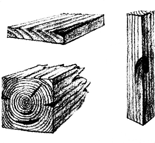
Waney edges
Star and ring shakes
Common timber defects
We have two classes of woods on the market which are used in different parts of the structure, according to their special qualities. These are commercially known as hard and soft woods, although this is not a very scientific distinction, since some of the soft woods are harder than some of the hard woods, and vice versa. Scientists have more accurate names than these, but as the above are so well established, there is no doubt as to what is meant.
In the market, lumber is not only classified according to the above, but according to the species of tree it comes from, and also according to certain standard grades of the same kind. These grades are determined by the presence of certain defects. The recognized defects are knots, shakes, checks, splits, streaks, pitch-pockets, stain, rot, wane, warp, cupping, mineral streaks, pith on the face of the board, and worm-holes.
Various large lumber associations issue rules governing standard sizes [Pg 22] and classifications for woods to be used in construction. The best and the next best are the usual grades which are used for the interior and exterior trim of houses. These grades have many designations, as “clears” and “selects,” or “A” and “B,” or “No. 1” and “No. 2,” or “firsts” and “seconds.”
The grades used for the rough framing, such as studs, joists, rafters, subfloors, and sheathing, are not so good. They are designated as “No. 1 common” and “No. 2 common.” A poorer grade still, known as “No. 3 common,” is sometimes used for cheap temporary structures.
For the details of grading and standard sizes of lumber, one should possess Circular 64 of the United States Department of Agriculture on “How Lumber is Graded.”
Next to the grading of timber, the most important factor of quality is the relative durability of the various woods, for upon this depends to a large extent the choice of them for special places. The table on page 23 is taken from a government classification.
From this table it will be noticed that the soft woods as a class are relatively more durable than the hard woods. This is true, because of the fact that the structure of soft woods is simple, while that of the hard woods is complex. When the former become wet and expand and then dry out and shrink, the structure is not stressed internally as much as is that of the hard woods, and they are therefore much more capable of withstanding the action of the weather. Also certain of the soft woods have natural properties of resisting dry or wet rot.
Certain species of woods are, therefore, selected for particular parts of the house according to the needs of durability, strength, appearance, and local supply. [Pg 23]
Rough wooden framing requires a wood that is fairly abundant and strong. The soft woods are generally used, and those which are classified as durable in the table are the most used.
| The Soft Woods | |||
|---|---|---|---|
| very durable | durable | intermediate | non-durable |
| Northern white cedar. | Douglas fir. | Eastern hemlock. | True firs. |
| Western red cedar. | Tamarack. | Western hemlock. | Spruces. |
| Cypress. | Western larch. | Loblolly-pine. | |
| Redwood. | Long-leaf yellow pine. | Norway pine. | |
| Eastern white pine. | Short-leaf yellow pine. | ||
| Sugar-pine. | |||
| Western white pine. | |||
| Western yellow pine. | |||
| The Hard Woods | |||
| Chestnut. | Black cherry. | White ash. | Basswood. |
| Black walnut. | White oak. | Butternut. | Beech. |
| Black locust. | Red gum. | Birch. | |
| Yellow poplar. | Buckeye. | ||
| Red oak. | Cottonwood. | ||
| White elm. | |||
| Hard maple. | |||
| Soft maple. | |||
| Sycamore. | |||
| Cotton gum. | |||
For rough underflooring and sheathing the cheapest and most abundant local wood is used. Durability is not essential.
For shingles the most durable woods must be used, such as cypress, cedar, and redwood.
Lath are generally cut from waste slabs, and should be of some soft [Pg 24] wood like spruce or of one of the softer hard woods. Siding should be made from one of the soft woods, especially those which are classed as durable in the table.
Porch columns and the like require very durable woods. They should be hollow except for very small ones. Built-up columns of interlocking type are usually specified, but the lumber used should be thoroughly kiln-dried so that the joints will not open.

| Edge grain | Flat grain |
| Difference in the cut of flooring boards. |
The flat grain in the softer woods is not durable. |
Flooring should be capable of resisting wear and should not splinter. The hard woods as a class are more adaptable than the soft woods, although yellow pine and Douglas fir are used a great deal on account of their cheapness. These latter are divided into two grades: “flat grain,” in which the annual rings are almost parallel to the surface, and “edge grain,” in which the annual rings run almost perpendicular to the surface. The latter is more desirable, since it wears better. The flat grain splinters off, due to the layers of soft spring wood and hard summer wood. Oak flooring comes plain and quarter sawn, which is practically the same as the cut of yellow pine, but since oak is strong either way, the wearing qualities are not very different. Maple is also an excellent wood for flooring, since it is hard and smooth.
Door and window frames may be made from many kinds of wood, although [Pg 25] the soft and more durable woods are generally accepted as the best. Specially hard and durable woods should be used for the thresholds.
Doors which are to be used on the exterior should be of a soft and durable wood. The choice of wood for interior doors is limited only by the taste of the designer. The doors which stand best the warping effect of steam-heat in the winter are constructed of white pine cores with a veneer on the exterior made from some hard wood.
Sash and blinds require a soft and durable wood. Sash are subject to the drying of steam-heat on the interior and cold and dampness on the exterior. Sash built of yellow pine sapwood have rotted in a few years, and while soft maple, birch, and basswood have been used, they are not durable, although easily worked. White pine is considered to be the best for sash and blinds.
The selection of woods for interior trim depends only upon the designer’s taste, since neither relative durability nor strength is a requirement. The harder woods in the past have been used more extensively for interior trim than the soft, because of their supposedly better and richer appearance, but this is not so true to-day, for new methods of treating such woods as cypress and yellow pine have shown them to be fitted for the best artistic places. Of course hard woods are not dented from knocks by furniture as easily as the soft woods, and in this way retain their appearance longer.
Bricks.—In considering the essential qualities of bricks for the small house it must be appreciated that those bricks which are used on [Pg 26] the exterior must be able to resist the effects of weather and produce the best artistic results, while those which are in the interior of walls or chimney need not be held up to such rigid standards. The determination of the resistance of bricks to frost and weather action is quite simple. A brick which struck by a hammer gives a clear ring is one which has been well burned and has no soft spots, cracks, or weak places. Such a brick can be said to be satisfactory for exterior use, provided that it has the proper form and color desired and is not so overburned as to be twisted and warped. Another requirement sometimes specified is that the face brick made from soft clay should not show a percentage of absorption in excess of 15 per cent, and for the stiff-moulded or dry-pressed bricks not more than 10 per cent. This, however, cannot be a hard-and-fast rule, due to the variation of clays.
Certain red bricks, unless they are burned very hard, show, when built into the wall, a very ugly white surface discoloration, called “whitewash” or efflorescence. This is not entirely due to the brick, since the mortar that is used may sometimes produce it. If it is due to the brick it can be discovered before the brick is used in the wall, by placing a sample brick on edge in a pan containing one inch of either rain or distilled water. As the water is absorbed by the brick, the white discoloration will develop on the top surface after several days of standing if it contains the salts which will cause the whitewash. Those bricks which have been very hard-burned will not discolor under any circumstances. If after passing this test the brick wall should develop whitewash, it can be laid to the mortar. In order to prevent any such occurrence it is necessary to waterproof the joints around window-sills and between the foundations and the wall, so that the [Pg 27] minimum amount of water will be soaked up into the wall when it rains. An expensive addition of 2 per cent of barium carbonate to the mortar will tend to fix the soluble salts which cause this efflorescence.
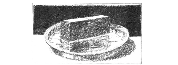
Method of testing a sample brick to see whether
it will have a tendency to whitewash
Hollow Tiles.—Hollow terra-cotta tiles covered with stucco or brick veneer are being used more extensively than ever, due to the cheaper cost of laying them, since they are larger units, and also to the fact that they build a cellular wall. Wherever these tiles are used for bearing walls it is important that they be hard-burned, but the softer ones may be permitted in non-bearing partitions. Tiles for use in outer walls should be hard-burned, free from cracks, straight, and should not show a greater absorption of water than 10 per cent. As these tiles are intended to support loads from floor-joists, it is essential that they should have the correct proportion of voids to solid shells and webs. The maximum width of any voids should not exceed 4 inches and the thickness of any shells or webs should not be less than 15 per cent of this measurement. In tests it has been shown that tiles laid with webs vertical are stronger than those with webs horizontal, but this [Pg 28] difference in strength is not of very great importance in the small house, where the loads are very light. The chief thing to avoid in the setting of tile, when they are vertical webbed, is the dripping of mortar to the bottom and the insufficient spreading of it over the ends of the webs and shells. This can be overcome by laying wire lath over each course, and then buttering the mortar on the inside and outside edges. The mortar is prevented from falling out of place by the lath, and because it is not continuous through the wall, any penetration of moisture through it is stopped.
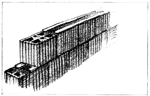
Showing the use of metal lath in the joints of vertically
webbed hollow-tile, to prevent the dropping of the mortar
into the voids and also allow the separation of mortar joint
The most important cementing materials which enter into the construction of the small house are lime, cement, gypsum, and their various mixtures, as mortar, plaster, and concrete.
The various technical requirements for good lime and cement are very strict and detailed, and for the small house it is customary to cover [Pg 29] their qualities in the briefest manner by referring to the standard specifications of the American Society for Testing Materials.
Slaked lime should be made from well-burned quicklime, free from ashes, clinker, and other foreign materials.
Dry hydrated lime should be the finely divided product resulting from mechanically slaking pure quicklime at the place of manufacture.
The specifications of the American Society for Testing Materials covering the quality of cement should be followed where large purchases are made. Where small quantities are to be used, the reliability of the dealer must be the basis of purchase.
As mortars and concretes made from these materials are as important as the cements or limes, it is essential to have definite standards for them.
Lime mortar should be made of 1 part by volume of slaked lime putty or dry hydrated lime and not more than 4 parts by volume of sand. The use of hydrated lime is recommended, since the poor qualities which are apt to develop from careless slaking of quicklime are thus avoided. It also comes in smaller packages, and if the entire quantity is not used at once it may be stored without deterioration. It is only necessary to mix the hydrated lime with water until it becomes a paste, and then add the necessary sand. The purpose of adding sand is to increase the bulk and to reduce the shrinkage which pure lime paste will develop as it hardens. Pure lime paste, without sand, will shrink, crack, and develop very little strength. By introducing sand this contraction is reduced, but the addition of too much will decrease the strength slightly. However, this decrease of strength is very little. A mortar made of 1 part lime to 6 parts sand is nearly as strong as one made from 1 part [Pg 30] lime and 3 parts sand. The maximum amount of sand to be used is generally governed by the ease of working, and not so much by the strength. A lime which is too sandy will not spread easily on the trowel.
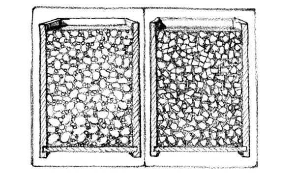
Cement mortar is, of course, a stronger material and can be used in damp places where lime mortar would deteriorate. The theory of mixtures of both cement mortar and concrete is to proportion the materials so that they produce the most compact substance. For instance, in the cement mortar the cement should just fill the voids between the particles of sand, and in concrete this cement mortar should just fill the voids in between the larger aggregate, and this larger aggregate should be so graded in size that it makes the most compact body. It used to be thought that certain definite numerical proportions, as laid down by theory, of the various ingredients would hold true for all kinds of sands and aggregates. For instance, the proportion of 1 part of cement, 3 parts of sand, and 6 parts of aggregate was thought to be the best for ordinary use under all conditions. But extensive tests by the government have shown that the only real way to determine the correct proportions of mixtures is to experiment with the particular sand and gravel that will be used, and to test them to see what ratios give the most compact mass. It has also been found that round aggregates, like pebbles, produce the strongest concrete, since the particles flow into place better than the sharper aggregates, which formerly were considered necessary because of the supposed idea that they made a better mechanical bond with one another. The proportion of water is also important, a quaking mixture producing the best results. [Pg 31]
It is customary in small work, however, where no experiments can be made on various mixtures to determine their proper proportions, to follow the old rules of thumb for amounts.
Cement mortar should be made of cement and sand in the proportions of 1 part of cement and not more than 3 parts of sand by volume.
| Good. Very compact | Bad. Not compact because of poor grading of aggregate |
Good and bad concrete |
|
If cement-lime mortar is to be used it should not have more than 15 per cent by volume of the cement replaced by an equal volume of dry hydrated lime. The addition of hydrated lime to cement mortar improves its working qualities, making it slide more readily on the trowel and also increasing its waterproofness. Its strength is not decreased within the limits prescribed.
In concrete work it is as important to have good sand and aggregate as cement. Sand should be sharp, clean, coarse quartz. The sand used should not, when it is rubbed in the hand, leave the palm stained. [Pg 32]
Gravel which is used as an aggregate should be free from clay or loam, except such as naturally adheres to the particles. If there is too much clay or loam, it should be washed with water. When bank gravel is used the best results will be obtained if it is screened from the sand and remixed in the proper proportions for fine and coarse aggregate. For ordinary mass concrete the size of aggregate should vary from ¼ inch to 2 inches, and in reinforced work should not exceed 1¼ inches.
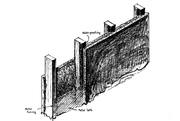
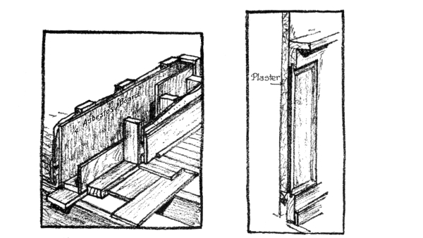
STUCCO ON METAL LATH OVER WOOD STUDS
The best proportion of parts to use must vary according to the requirements, but for the small house good results will be obtained by using 1 part of cement, 2 parts of sand, and 4 parts of gravel or broken stone.
Stucco Work.—Stucco is really a Portland-cement plaster used on the exterior, and its success depends a great deal upon the quality of materials employed and workmanship. All stucco to a greater or less [Pg 33] degree cracks, but the problem is to make the cracks as small as possible. The government is carrying on an extensive investigation of the problem of stucco through experiments on fifty-six exterior panels which have been under observation since 1915. Each one of these panels has been spread upon a different base or made with different proportions. So far only two panels have been found to be entirely free from cracks, although many are practically uninjured by the small cracks which have developed. It is therefore quite evident that as a rule it must be assumed that the stucco will crack to a certain extent, and in order to cover such defects a rough surface is the best. As to proportions of mixtures, there is a great variation of opinion. The commonest is 1 part of cement, 2½ parts of sand, to which is added about ¹/₁₀ part of hydrated lime by weight of cement. For a more detailed account on stucco, send for the Progress Report issued by the Bureau of Standards on the Durability of Stucco and Plaster Construction.
Plastering.—The qualities of internal plaster depend upon the construction of the wall, the methods of application of the plaster, and the quality of the plastering material.

Scratch coat is for bonding;
brown coat for plasticity;
finished coat for appearance
The walls and ceiling to which plaster is to be applied must be so constructed as to be practically rigid under the loads that they will carry. Since plaster is not elastic, any slight change in shape of the surface will cause it to crack. The common backings which are satisfactory for plastering are wood lath, metal lath, and masonry, such as concrete, terra-cotta tile, brick, plaster board, etc. Wood lath makes the least rigid back of all, and for this reason is not considered the best, although it is the cheapest. Unless the wood laths are wet before the plaster is applied, they will absorb the moisture [Pg 34] from the plaster and swell, thus cracking the wall. Metal lath for this reason is superior. Masonry walls should be made rough to give the necessary key for the plaster to cling to. In brick walls the joints are raked out, in concrete walls the surface is picked, and the outside of terra-cotta tile is marked with grooves for this purpose.
The best results in plaster are secured with three coats. The first coat is called the scratch coat, and is intended to form a bond between the wall itself and the plaster. It should be pressed into the apertures between the lath to secure a good bonding key, and its surface should be scratched with a tool to give the required bond between it and the next coat, or brown coat. The brown coat forms the main body of the plaster and averages about ¾ inch to ⅞ inch thick. The finished coat is then added on top of this and is intended to develop a plane surface with the desired color. Each coat should be allowed to dry out and then be wet before the next one is added. If wood lath is used, this drying and wetting will cause the lath to shrink and swell, so that cracks will be developed in the scratch and brown coats. These should be filled in before the finished coat is added.
The materials which should be used in the various coats depend upon the [Pg 35] requirements which are necessary for each one. As the most important characteristic of the scratch coat is strength, and that of the brown plasticity, and the final coat appearance, the materials must be proportioned accordingly.
| SCRATCH-COAT PROPORTIONS | |||
| Hydrated lime | 133 | parts | by weight |
| Sand | 400 | “ | “ |
| Hair | 1 | part | “ |
| BROWN COAT | |||
| Hydrated lime | 100 | parts | “ |
| Sand | 400 | “ | “ |
| Hair | ½ | part | “ |
| FINISHED COAT | |||
| Smooth Finish | |||
| 1 part by volume of calcined gypsum. | |||
| 3 parts“lime paste. | |||
The most used metal in the small house is the so-called tin-plate or roofing tin. It is not a true tin-plate, for it contains 75 per cent lead and 25 per cent tin, applied to a base of soft steel or wrought iron. It comes in two grades, IX and IC, the former being No. 28 gauge and the latter No. 30 gauge. The lighter is used for roofing and the heavier for valleys and gutters. The tin does not entirely protect the base metal, so that it is necessary to paint both sides before it is applied.
Galvanized iron is another form of sheet metal which is extensively used for work on the small house. It consists of sheet iron or steel, covered with zinc. This coating should be free from pinholes or bare spots, and of a thickness to prevent cracking or peeling. If the coating is sufficient and well done, it is superior in lasting quality to the ordinary tin-plate. [Pg 36]
Copper, since the war, has come back into use again as a sheet metal for the small house, for its cost has dropped within reason. In order to meet a certain popular demand a light grade of copper sheet roofing has been placed on the market, although it has generally been considered that sheets weighing less than 16 ounces per square foot were not suitable for roofs.
There are two kinds of window-glass used, double thick and single thick. The former is ⅛ inch thick or less, and the latter is ¹/₁₂ inch thick. It is customary to use double thick in all window-panes over 24 inches in size. The grading is AA, A, and B, according to the presence of defects, such as blisters, sulphur stains, smoke stains, and stringy marks.
Plate glass is used only where the expense will permit. It is different from window-glass in that the latter is made from blown glass, while plate glass is made from grinding and polishing down sheets of rolled glass.
There are quite a number of other minor materials which enter into the construction of the small house, but they are more or less identified with the mechanical equipment and the finishing, and will be considered under these headings.
Sheet lead weighing 5 to 6 pounds per square foot is often used for counter-flashing. Leaders and leader heads of cast lead have been made practical by one company, which has developed a method of hardening the lead.
Zinc, like copper, is again being urged upon the public by the manufacturers since the war demand is over. Zinc spouts are usually made from No. 11 zinc gauge, which is equal in thickness to No. 24 steel gauge. [Pg 37]
There is hardly any need to mention the durable qualities of copper, zinc, or lead. Wherever the cost permits, one cannot deny that materials of such durable nature are the proper ones to use.
There are no sharp distinctions between the various types of wooden frame construction. But in order to classify certain tendencies, we will arbitrarily define four types. To these we will give the names of braced-frame, balloon-frame, combination-frame, and platform-frame.
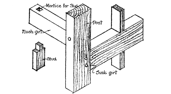
The braced-frame is the oldest type, and originated in Colonial days in New England. It was developed under the influence of a tradition of heavy, European half-timber construction, and also nourished by the abundance of wood directly at hand. The fact that nails were not made, except by hand, urged the carpenters to use methods of fastening which required as few as possible. Because of these factors, then, certain definite characteristics of this type of wooden frame construction manifest themselves in the use of timbers, far larger than necessary for safety, and joints consisting of mortises and tenons. [Pg 39]
As the sawmill became mechanically more rapid, and as nails were being turned out by machines more plentifully, the Yankee who went West on adventuresome trips, and cared little for a permanent dwelling, devised a system of light-frame construction which became known as the balloon-frame. This was put together with the greatest speed, and required only nails for fastening all joints. The timbers which were used were standardized to one size, namely, 2 inches by 4 inches.
CORNER CONSTRUCTION OF BRACED-FRAME
MORTICE & TENON JOINTS
Now, both of these types had advantages and disadvantages which were bound to influence later builders. Those who had been accustomed to build according to the braced-frame system found that lumber was becoming scarcer, and that nails were cheaper than they formerly were. Certain features of the balloon-frame appealed to them, such as its greater speed of construction, its smaller timbers, and lightness. On the other hand, those people who had lived in houses constructed according to the balloon system of framing found that they were very [Pg 40] flimsy, that fires quickly consumed them, that rats and vermin could travel freely through the walls, and that, after all, they were only the most temporary sort of shelter. These folks looked back at the old methods of building, and saw the good features of solidity and permanence. We had, therefore, the growing together of the two systems of construction into a type which we call the combination-frame dwelling.
However, progress did not stop at this point. The houses built according to this newly devised system were found to settle unevenly, which cracked plaster ceilings and walls and made doors and windows into leaning parallelograms. The cause of this was [Pg 41] found to be due to the natural shrinkage of wood as it dried out. Now, all wood shrinks mostly across the grain, and not with it, so that the amount of settlement of any wooden wall depends upon the amount of cross-section of wood which it contains. If there is more in the interior partitions than in the exterior, it is certain that the floor-joists will settle down on the inside ends more than the outside. This is exactly what happened. It occurred not only in the combination-frame but in the braced and balloon frame. Various devices were introduced to avoid this defect, but all were more or less incomplete. Nevertheless, it all led gradually to the development of the fourth type of construction, which is called the platform-frame, for lack of a better name. This frame solves the problem of uneven settlement in the wooden structure. It also makes the location of the windows of the second floor independent of those of the first floor, which is not the case with the balloon-frame, for in this type the studs extend in one piece from the sill to the plate, requiring the centring of the windows of the second floor over those on the first.
The methods which are used in constructing the small house of to-day are not as simply classified as the previous description would lead one to believe. The old New England braced-frame has practically gone out of existence, yet many of its features remain. The balloon-frame is used only in the cheapest sort of structures, yet many of its details are found in the modern dwelling; The combination-frame in all its many varied forms can be called the advanced type.
The illustrations show the four types in their entirety. But in order [Pg 42] to fully understand the combination-frame, it is necessary to know what features of the braced-frame and balloon-frame are used to-day.
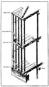
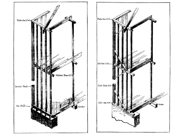
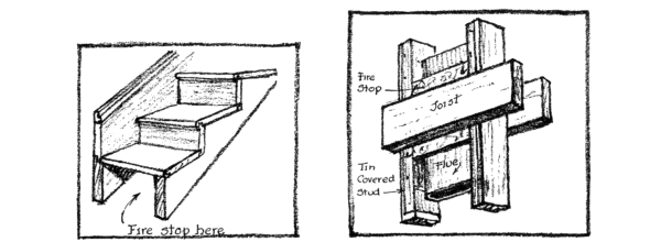
1. The use of the girt, because it permits the location of the second-floor windows at any point irrespective of the first floor windows. This cannot be done when a ribbon-board is used, for this requires studs which extend continuously from sill to plate, and if any windows are to be located on the second floor, they must be placed directly over those on the first floor. The ribbon-board does not act as a stop for either vermin or fire, as does the girt. However, fire-stops can be introduced in connection with the ribbon-board, if the extra expense is no hindrance.
2. The use of the sill, because it serves as a firm foundation for the outside studs and first tier of floor-joists. The balloon-frame has [Pg 43] no sill, for the floor-joists are set directly upon the top of the foundation-wall, and the exterior studs are built on top of them.
3. The use of the corner braces, because they stiffen the frame.
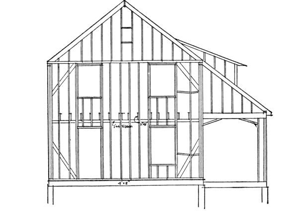
TYPICAL FRAMING OF “WAR HOUSES.”
1. The use of small timbers, or the standardization of the 2 by 4 for all parts except the sill, because of economy. The corner-posts are made of three 2 by 4’s, and the plate is made of two 2 by 4’s.
2. The use of the nailed joint, because of its cheapness and its greater strength. It will not rattle loose when the timber seasons, as does the mortise and tenon joint in the braced-frame.
3. The use of the ribbon-board, in place of the girt, for those houses which are to be stuccoed, and a rigid, outside wall-frame is desired from sill to plate.
4. The use of diagonal sheathing-boards, to brace the frame instead of the corner-pieces. The reasons for this are not very certain, since diagonal bracing with sheathing is not always effective, while it is extremely wasteful.
The combination-frame includes all of the present-day methods which make use of selected features of both the braced-frame and balloon-frame, such as were noted above. There are no rules to follow. In certain sections of the country one type is favored more than the other. Where a house is to be covered with stucco, the balloon-frame is a better type to use than the braced-frame, since it gives a stiffer outside wall as a backing for the stucco.
It will be noticed in the illustration how different is the amount of cross-section of wood in exterior and interior walls of the [Pg 44] combination-frame, a thing which causes the unequal settlement previously alluded to. In order to reduce this to a minimum, it is often specified that the studs of all interior partitions be carried down to the top of the cap of the partition below or to the top of the supporting girder, thus reducing the amount of cross-section timber. This is not a complete cure, however, although it is a big improvement.
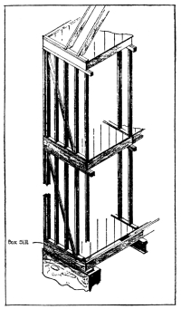
The real solution of the difficulty lies in the use of the platform system of construction. In this system the first floor is built on top of the foundation-walls, as though it were a platform. A sill, called the box-sill, is constructed for the exterior support of the ends of the floor-joists by laying down a timber the same size as the joists and setting another one on the extreme edge in a vertical position. The angle thus formed makes a resting-box into which the floor-joist can be framed. The interior ends of the floor-joists should be supported upon a steel I-beam upon which has been placed a 2-inch-thick timber. The I-beam should be supported upon steel-tube columns which have been filled with concrete. On top of the floor-joists should be nailed the underflooring, laid diagonally. The first floor then appears as a perfectly smooth platform. Now wherever there is to be erected an interior or exterior partition, a 2 by 4, called the sole piece, is [Pg 45] nailed directly on top of the rough flooring. This serves as a sill for the studs of the partition, which are now erected vertically upon them and capped with double 2 by 4’s on the top. Now the second floor is built on top of the partitions in the same manner as the first, and a new platform is constructed, so to speak. Upon this is then erected the partitions of the second floor, and on this the floor of the attic. In fact, this construction proceeds floor by floor, and each floor is an independent platform. If the drawings are examined it will be noticed that the amount of cross-section of wood in any one bearing partition is identically the same as in any other. The dwelling built in this way, then, cannot settle unevenly, and the cracked plaster and twisted doors will be eliminated. [Pg 46]
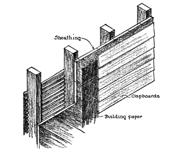
CLAPBOARDS OVER WOODEN STUDS
There are certain features which are common to all types of frames. For instance, the framing around all doors and windows requires the use of double 2 by 4’s or the use of one 4 by 4.
These framing studs around the window are set 5 inches higher and 8 inches wider than the dimensions of the finished window. Those about the door-openings are set 2 inches higher and 4 inches wider.
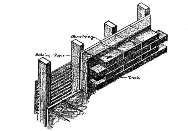
BRICK VENEER OVER WOODEN STUDS.
All use sheathing-boards of ⅞-inch stock to cover the outside of the studs, and these are usually 6 inches to 8 inches wide.
The usual spacing of studs is 16 inches on centres, and they are generally of 2 by 4’s, although where any pipes or flues are run through the partition they should be 2 by 6’s. [Pg 47]
Interior stud partitions should be bridged or braced once in their height, and partitions which run parallel to the floor-joists should have a capping-board, so that the proper nailing for lath can be secured. In fact, at all intersections of partitions care should be exercised that the required nailing for lath is provided.
In the construction of roofs the average spacing of rafters is 20 inches on centres. They should be doubled around all openings. The ridge is usually of a 1-inch by 10-inch piece. The size of the rafters varies with the length of span and load. They are usually 2 inches by 6 inches for short spans and light loads, and 2 inches by 8 inches or 2 inches by 10 inches for long spans and comparatively heavy loads. Valley rafters must always be deeper and heavier than the rafters and should be designed as a girder. The hip rafters do not carry any great load, but are often made deeper to fit the incline cut of the jack rafters.
All floor-joists are spaced 16 inches on centres, and should be bridged. The following is the table commonly followed for good house construction, although lighter work is most often specified:
| SPAN | TIMBER | |
|---|---|---|
| 12' and under | 2" × 10" | cross-bridged once. |
| 12' to 15' | 2" × 10" | doubled every other one, if good stiffness |
| is desired, and bridged twice. | ||
| 15' to 20' | 3" × 12" | and of long-leaf yellow pine, crowned at |
| centre ½", and bridged three times. | ||
| 20' to 25' | 3" × 14" | of long-leaf yellow pine, crowned at the |
| centre 1" for the 25' spans, and bridged four times. | ||
Floor-joists should be doubled around all openings larger than 3 feet, and joists should be hung from the header beam by metal straps. [Pg 48]
There are many precautions which should be taken to prevent the spread of fire in the wooden frame house, but those will be considered as a special subject. Likewise the discussion of certain defects of construction which are commonly found in the speculative house will be dealt with later.
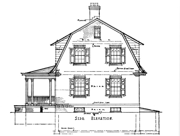
In one of the previous chapters it was pointed out that the type of construction next in general use to that of the wooden frame house was the dwelling of masonry and wood. This was designated as Type II, and defined as a building with exterior walls of stone, brick, concrete, or terra-cotta, and interior floors and partitions of wooden frame construction.
The difference in construction between the wooden frame structure and the masonry-and-wood building is mostly in the material used for the exterior walls. The interiors of both types are constructed in practically the same way, the floors being of light wooden joists and the partitions of wooden studs.
The oldest varieties of the masonry houses in America are represented by the stone and brick dwellings of Colonial days. These are so substantially built, and often so artistic in conception, that they have become common models from which to draw inspiration. The concrete house of the monolithic or block type, and that of hollow terra-cotta tile, is a modern development.
The stone house is very adaptable to all those regions where this material can be secured from the excavation of the cellar or from some neighboring road improvement. Sometimes an old stone wall serves as a [Pg 50] source of supply. Because of the native character of this material it will always be in harmony with the landscape.
In building the wall of stone there are a number of things to be observed, where success is desired. The wall should be well bonded together, the lintels over the windows should be strong, the foundations should be adequate to prevent cracks, the method of laying should be artistic, and the form of jointing in harmony with it.
All native stones used for rubble wall construction have certain characteristics of color and formation. Certain stones will split easily into long, flat shapes, others seem to have very little lamination and break into jagged, irregular patterns, while others are so soft that they lend themselves to easy shaping in squared blocks of regular size. Sometimes, even, the neighborhood may be filled with round field stones, which can be used to imbed into the face of the wall and produce a surface of round bumps. Whatever is the character of the native stone, it should be used in its simplest form and not forced into imitation of some other type. The soft brown sandstones which are seen in some Colonial houses are easily cut and squared; but to cut up a hard stone into such carefully shaped blocks, in imitation of this Colonial work, would not only be a waste of money but a waste of artistic effect.
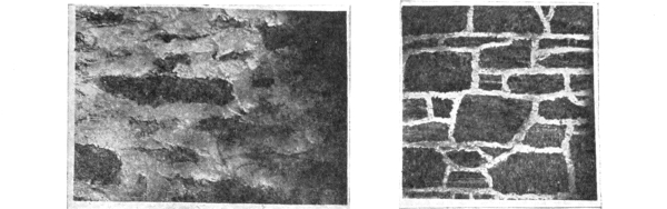
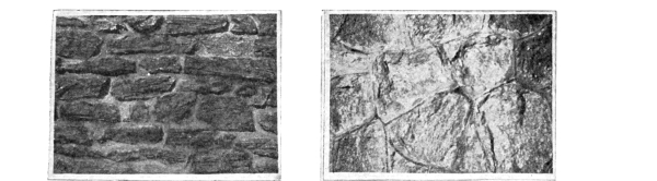
According to the way in which the stone naturally lends itself, we have various types of rubble walls. The commonest is the rough rubble wall in which the stones have neither regular shapes nor regular sizes, or even courses. The wall is composed of large stones and small stones (the latter are called spalls, and fill in the interstices between the larger stones). The joints of mortar between the stones may be plastered roughly over the surface, covering much of the face of the stones themselves, or they may be roughly but neatly pointed with white mortar, or the joints may be raked out. Where the stone has a natural tendency to cleave into long, flat shapes, the rough rubble may become more regularly coursed in appearance. All of these types are respectively illustrated in Figures 1, 2, 3, and 4. [Pg 51]
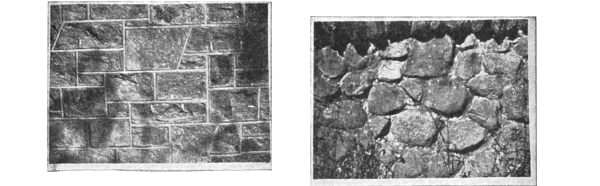
[Pg 52] A softer stone, which can be dressed with the hammer, may be treated in two different ways: It may be shaped to fit closely, without using any spalls to fill up the interstices, and, thus, appear as a cut-out puzzle; this is called “cobweb rubble.” However, the more dignified treatment is the squared, uncoursed rubble, in which the blocks are cut to rectangular shape and the joints pointed with a tool. Figures 5 and 6 illustrate these.
A wall built entirely of field stone depends upon the mortar for its strength. It appears the best when the joints of the surface are raked out, permitting a large part of the stones to project outward. Figure 7 illustrates this kind of rubble wall. [Pg 53]
When the rubble wall is built with very carefully squared stones, and in regular courses, it partakes more of the monumental character of ashlar work and draws away from the rustic value of rubble. In determining the amount of cutting which is to be done, the character of the building should be considered, remembering that the smoother and more finished the wall, the more monumental is its appearance.
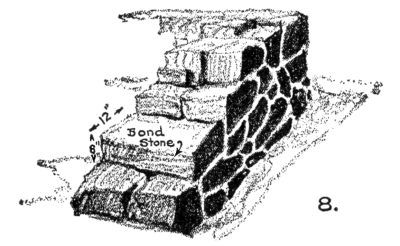
Bond stone every 2' in ht. and 3' in length
Thickness of
rubble-stone wall
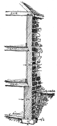
The kind of mortar which should be used for the rubble wall depends upon its location and desired appearance. All foundation-walls, and all walls which are subject to dampness, should be built with Portland-cement mortar. Lime mortar may be used in walls above grade, although cement mortar, or cement-lime mortar is superior. As the strength of a rubble wall depends more upon the mortar than the bond, it is well to use the best. However, care should be taken that the wall is well bonded. A wall which consists of two faces, not bonded together, should not be built. A bond stone which carries through from one face to the other should be set into the wall every 2 feet in [Pg 54] height, and every 3 feet in length. This bond stone should be flat and about 12 inches in width and 8 inches thick. The usual thickness of walls for dwellings not over three stories in height is 16 inches, and the foundation-walls are made 8 inches thicker than the wall above or 2 feet.
The footings under a stone wall should be of concrete, not less than 12 inches thick, and should rest upon solid ground at a depth equal to, or greater than, the frost-line below the surface, unless solid rock occurs above this point. The width of the footings should be such that it projects outward on both sides of the wall at least 4½ inches.
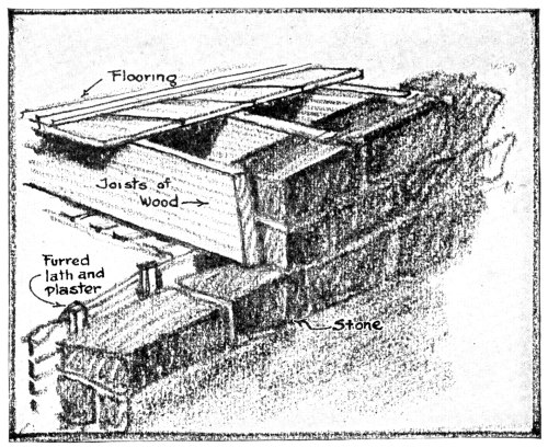
The interior of all stone walls, and in fact all masonry walls, will show condensation of moisture over the interior surface, and if they are plastered directly on the interior the decorations will be ruined by the collection of so much water. The cause of this condensation is the same as that which forms sweat on the exterior surface of a glass of cold water. In order to eliminate this disagreeable feature, all masonry walls are furred on the interior before the lath and plaster is applied. The furring makes an air space between the wall and the plaster, and all dampness is prevented from penetrating to the interior [Pg 55] surface of the plaster. To further increase the damp-proof qualities of a masonry wall they are sometimes built hollow, as, for example, the hollow brick wall, or the hollow terra-cotta tile wall. This air space also serves as an insulator for heat, preventing the escape of heat from the interior of the building in winter and the penetration of it into the structure in the summer.
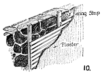
Furring Strip
The commonest type of furring is the 1-inch by 2-inch wooden strip, nailed to the joints of the masonry or to wall plugs inserted in the joints. Metal furring strips are also extensively used, and occasionally hollow terra-cotta furring blocks.
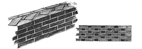
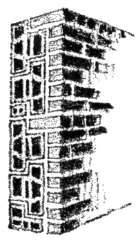
Like the stone house, the brick dwelling is one of the oldest types in this country. Examples of early brick houses show a taste for good brick, which later died out on account of the introduction of the first American machine-made bricks. These early machine-made bricks were extremely ugly, due to their perfection of geometric shape, smoothness of surface, and monotony of red color. Later improvements in the manufacture of brick have released this material for extensive artistic use. The surface was given a varied color and texture, and the form was not made so machine-like. To-day we have a variety of bricks which range in colors through reds, yellows, buffs, greens, blues, and even dark violets. Textures of wire-cut bricks are rich and varied, and, if properly handled, can produce the very finest architecture. [Pg 56]
| 11. | 14. | |
| Running Bond and method of Bonding |
Flemish Bond |

12.
English Bond

13.
Dutch Bond or
English Cross Bond
The thickness of brick walls for dwellings not higher than three stories ought to be 12 inches, although 8 inches is considered by many experts to be quite thick enough for small houses. If the foundation walls are of rubble-stone they should be 8 inches thicker, and if of brick or concrete they should be 4 inches thicker. Usually the walls [Pg 57] will be faced with some variety of face brick, in which case they should be bonded into the wall. If a running bond is used, the face brick should be bonded into the backing at every sixth course by cutting the corners of each brick in that course of face brick and putting in a row of diagonal headers behind them, and also using suitable metal anchors in bonding courses at intervals not exceeding 3 feet. Where Flemish bond is used, the headers of every third course should be a full brick and bonded into the backing. If the face brick is of different thickness to that of the common brick backing, the courses of the exterior and interior should be brought to a level bed at intervals of about eight courses in height of face brick, and the face tied into the backing by a full header course or other suitable method. [Pg 58]
FISKLOCK BRICK
It is very easy to understand the bonds in brickwork if the fundamental forms are known. There are, in reality, but two real bonds: namely, the English and the Flemish bond. The so-called running bond is no bond at all; while the common bond is found only in common brick walls, and uses a bonding course of headers every sixth course. The Dutch bond is only a slightly altered arrangement of the English bond, and is produced by merely shifting the centring of vertical joints of the stretcher course. By arranging these fundamental bonds in varying manners a decorative pattern can be produced on the wall of brick.
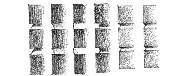
15.
Brick Joints
Here, again, as in the stone wall, the mortar joint plays a great part in the final effect of the design. It can be safely set forth as a rule [Pg 59] that the rougher the texture of the brick used, the rougher and wider should be the joint. For the smooth-faced brick the joint should be small and finished with a tool. For a rough-faced brick the joint should be large and rough in texture. The various forms of brick joints in common use are shown in the illustrations.

16.
Lintel Construction
In the construction of lintels in either the wall of brick or stone, the introduction of either wood or steel is necessary for strength. Where the openings are less than 4 feet in width, timber lintels are used at the back of the lintel or arch, which are cut to serve as a centre for a rowlock or keyed arch. Any face brick may be supported by using a small steel angle. Where lintels are wider than 4 feet, steel I-beams, channels, or angles must be used. Where the span is more than 6 feet, it is necessary to build in bearing plates for the support of the ends of lintels.
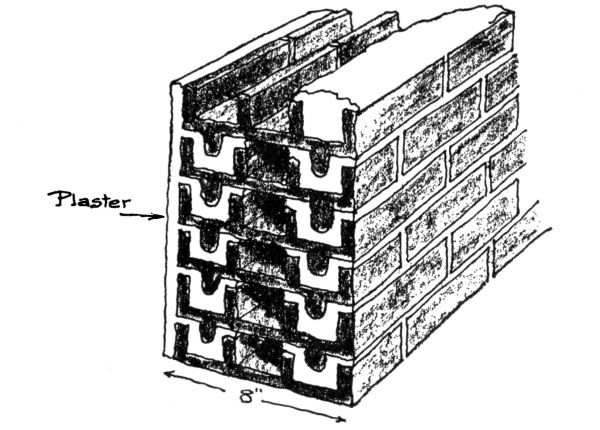
It would be well to mention here the new type of brick wall which is being advertised widely by the Common Brick Manufacturers Association. This wall is claimed to be very suited to the small house, and no doubt it would be, if it were possible to secure the co-operation of the local mason. [Pg 60]
This type of brick wall is built hollow, and arranged as shown in the drawings. There are no continuous mortar joints from the exterior to the interior through which moisture can penetrate. There are many features of advantage which the following table shows, but, unfortunately, not all mason contractors will give the owner the advantage of the reduction in cost which this wall permits.
| 8" IDEAL WALL | 12" IDEAL WALL | |
| COMMON BRICK | ||
For 100 square feet of wall, 8 inches thick, the following materials are required:
| FOR SOLID BRICK WALL | |
| 1,233 | bricks. |
| 2.6 | sacks of cement. |
| 2.9 | bags of hydrated lime. |
| .7 | cubic yards of sand. |
| 9 | hours of a bricklayer’s time. |
| 10 | hours of a mason’s helper’s time. |
| FOR IDEAL ALL ROLOK WALL | |
| 904 | bricks. |
| 1 | sack of cement. |
| 1.2 | sacks of hydrated lime. |
| .3 | cubic yards of sand. |
| 8 | hours of bricklayer’s time. |
| 6 | hours of a mason’s helper’s time. |
The past decade has seen an increasing use of hollow terra-cotta tile as a building material for the walls of the small house. It has many advantages which have made its popularity increase, such as its larger and lighter construction unit, reducing the labor of setting, its cellular wall features, and its availability. There is much information published by the manufacturers describing the correct construction, but always, of course, with an eye to advertising the material.
However, there has been much conflicting testimony made concerning the practicability of hollow-tile construction, and some of the disadvantages should be noted. As a rule, they have proved to be strong enough to support the weight of the structure imposed upon them, but in the Southwest, where tornado winds are prevalent, these walls have been criticised because of their lack of stability and their porosity. Hollow-tile walls have been thrown down while those constructed of brick have stood, and driving rain-storms frequently make the inside of the walls wet.
The stability can be increased by filling them with concrete, but the allowable strength cannot be considered to have been raised. Tests have shown that this filling does not increase the strength, because of the difference in the elasticity of the two materials.
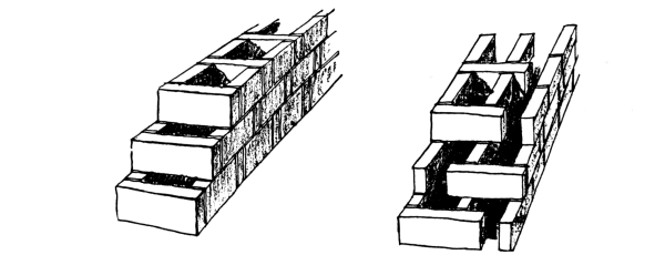
There are two types of hollow terra-cotta blocks, one which builds with cells vertically and the other which builds with cells horizontally. [Pg 62] This latter is generally an interlocking tile. The strongest wall for vertical-load resistance is built with vertical-cell tiles.
| 20. | 18. | |
| Support of floor-joists | Hollow-tile wall Cells Horizontal |
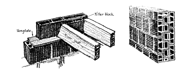
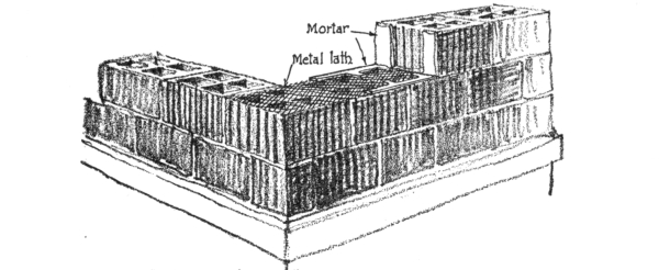
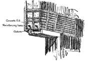
All hollow-tile should be laid in Portland-cement mortar, and the webs should be arranged so that they build over one another. The bearing of floor beams and girders on walls, built with blocks of vertical cells, should be made by covering the tile with templates of terra-cotta slabs, filling them with concrete or protecting them with plates of steel. Where chases are required for pipes they should not be cut into the wall, but special blocks should be used to build around them. All lintels under 5 feet should be constructed with tile arches, reinforced with concrete and steel rods inside of their webs.
17.
Vertical cell Hollow-tile wall
21.
Construction
of lintel
Brick Veneered
Hollow-tile wall
In order to prevent the penetration of moisture the mason should butter all joints on the inside and outside edges, leaving an empty space between, in order to insulate against the transmission of moisture through the joint. To prevent the collection of mortar in the cells of the tile, due to droppings during construction, the spreading of metal [Pg 63] lath over the top of each course of tile will accomplish this and also make the strength of the wall greater. Although it is often recommended that hollow-tile be plastered directly upon the interior, yet this is not safe in those sections of the country where there are driving rain-storms. For this reason it is advisable to fur them on the interior. It is also recommended that a waterproofing compound be added to the stucco applied to the exterior. Another fact should be observed: namely, that all door and window frames, since they are of wood, will tend to shrink and thus open up the joints and permit the leakage of rain-water. Oakum should be stuffed behind all brick moulds to prevent this. Care should also be taken to make drips under all sills, so that no water will leak into the interior of the wall. All belt courses [Pg 64] should also have steep washes. Stucco should not be carried down to the grade level, but a course of solid material, like brick, concrete, or stone, should be built at this point.
It is sometimes customary to veneer walls of hollow-tile with brick, especially those tiles which are of the interlocking type, since a better bond can be secured. In any case, any brick veneer should be bonded to the backing with a row of headers every 16 inches, or be attached with metal ties. This veneering should not be considered as part of the required thickness of wall.
The thickness of hollow-tile walls should be the same as for walls of brick. The construction of light 10-inch and 8-inch walls, while strong enough as a substitute for a frame dwelling, is not strong against weather or fire. The only justification for thin walls is the slightly reduced cost of materials. Hollow blocks, as a rule, are not used for foundations, although they are satisfactory under buildings not higher than 40 feet. It is better to fill such walls with concrete and waterproof them on the exterior.
The development of the concrete house has been stimulated by large corporations erecting towns of them in one locality. The erection of [Pg 65] concrete houses by individual builders cannot, as a rule, follow those systems which are adapted to group construction. The use of large precast units may be satisfactory for a development of a hundred or more houses, but it is not economical for a single operation. The use of heavy steel forms for casting monolithic houses of concrete, while under certain favorable labor conditions may be satisfactory for a small job, yet as a rule is better adapted to large enterprises. Such steel forms are represented by the Lambie forms and the Hydraulic forms. Even wood forms of heavy construction, like those used in the Ingersoll system in work at Union and Phillipsburg, are not adapted to an operation involving less than fifty identical houses. Another system, combining both the precast and the cast-in-place work, called the Simpsoncraft system, is not economical for small operations. This uses thin precast slabs for walls and floors, and precast concrete beams. The precast parts are tied together by casting in place reinforced studs of concrete.
Practically the only available systems which are useful for the small operation are (1) monolithic houses, built with light, portable steel forms or wooden forms, and (2) the concrete block house.
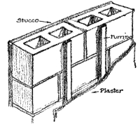
25.
Typical Concrete
block wall
The concrete house, especially that built of blocks, often has the defect of being damp on the interior, unless precautions have been taken to avoid this. It is always best to fur the interior of walls, although there have been cases where the blocks have been waterproofed and the interiors remained dry. Usually those blocks which are cast in a very dry state are porous, while those which are poured show considerable compactness. The great difficulty in using concrete blocks [Pg 66] lies in the inexperienced and inartistic work of the large number of “would-be manufacturers,” whose only claim to the product consists of having purchased a machine which will turn out so many blocks a day and reap them an advertised fortune in a short period. A thoroughly reliable concrete block can be made, if there is used plenty of good cement, clean aggregate with proper proportions of fine and coarse to secure density, sufficient water to make a wet mixture, and then the product kept damp while curing. The surface should also be finished in some artistic manner. A good method consists in applying about an inch of white cement and showy aggregate to the outer facing of the block, and then, when the block has been set into the wall, finish it off with a stone-tooling machine, such as a pointer, operated by a pneumatic hammer. Blocks, also, should be of the hollow-wall type, so that an air space between can be secured for ventilation and insulation.
The commonest method of building monolithic walls of concrete is to use wooden forms. These are built in sets of panels, one for the exterior and the other for the interior face of each course. These are successively raised, one above the other, in pouring the walls. Mr. Ernest Flagg, architect, has developed a remarkably simple system of concrete-wall construction with the wooden form. Roughly broken stone are set against the inside of the forms, used for the exterior face of [Pg 67] the wall, and the rest of the wall is filled up with concrete. By raising the boards which are used for the forms, as each layer hardens, the wall can be erected without skilled labor and yet have the appearance, on the exterior, of a stone wall. Of course it is necessary to point the joints of the stone work after the forms have been removed.
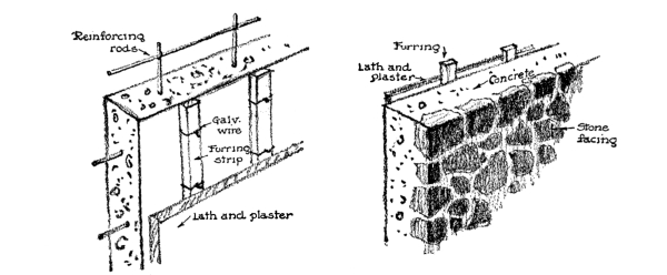
| 22. | 24. | |
| Typical monolithic wall construction | Stone faced concrete wall developed by Ernest Flagg |
Of the light steel forms, the most important on the market are the Metaforms and the Morrill forms. The Metaforms, originally the Reichert forms, are composed of individual form units. All units are standardized and interchangeable, and equipped with the necessary clamps and locking devices. These units are built of sheet steel, strongly reinforced, and measure 2 feet square. A single course of Metaforms is composed of an inner and outer shell of plates. As the work progresses the bottom course is taken off and placed above for the next, there being usually three courses of forms in operation. The Morrill form is also a sheet-steel form, only it uses a hinged “swing-up” construction, by which the lower courses of the form can be swung up into position for the new course as the work progresses. [Pg 68]
The Van Guilder double-wall machines have been gradually increasing in use throughout the country. They are not for sale, but the company establishes a contracting organization in different centres. The machine is a steel mould which is moved along and upward as the concrete wall is tamped in it. It builds a double wall in tiers. Each tier is 9 inches high and 5 feet long. A complete circuit of one tier is made around the wall, and then the next tier is begun on top.
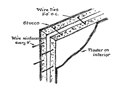
23.
A double monolithic wall built by
the Van Guilder machine.
The majority of small houses will be built of either wood-frame construction or of wood-and-masonry construction for many years to come, in spite of the propaganda favoring fireproof dwellings, for the cost of materials and labor are so adjusted that houses of this better type cannot be built by the average citizen. In fact, 90 per cent of the houses erected to-day use wooden studs and floor beams.
This method of building costs the fire insurance companies about $60,000,000 a year. The actual loss must be even greater than this, for not all houses are insured.
We might as well face these facts frankly and accept the next best means of preventing this enormous annual loss of dwellings by establishing safeguards against this fire dragon at the most vulnerable parts of the building. We must place the armor of protection where it is needed most, and set up the safeguards against fire where the dangerous enemy attacks.
On examination of the insurance reports upon this question, we find that 96 per cent of all the fires originate inside of the houses. The most important cause of these fires is defective chimney construction. Bad fireplace design, careless flue construction, and poor masonry work in the chimney are responsible for many a tragic fire and a total loss of furniture, clothes, and household goods of well-meaning citizens. It [Pg 70] is true that this is a cause of fire which may be prevented by building good chimneys and fireplaces, but there are other causes that are not so easily regulated, such as explosions from kerosene, short circuits in the electric iron or vacuum cleaner, careless throwing around of burned matches and cigarettes, and many other accidents which are bound to occur in spite of all precautions. When such fires start, there is only one thing to do: extinguish them in the quickest possible manner. But this cannot be done easily if the walls and the floors of the house are so built that they act as hidden passages and flues for the flames to creep insidiously throughout the building, breaking out in the most unexpected places and entrapping the unwary in dangerous positions. The way that many dwellings are constructed makes it possible for a fire to start in the cellar over the smoke-pipe from the furnace, in the dead of night, creep silently through the floors and up the interior partitions to the attic and second floor, until suddenly, bursting forth in all its fury, it has the sleeping inhabitants ensnared in a box of fire that has cut off their escape. The terrible heat has eaten away the strength of the bearing partitions, the floors collapse, the stairs are encircled with a writhing flame, and smoke and fire issue from everywhere as suddenly as though they had been spontaneously produced. There is no time to fight such a fire as this; about all that can be done is to escape in safety, and then the history of such conflagrations tells of the tragic death of many children left behind in the excitement.
It is this fearful danger of the secret entrapping of fire that it is possible to eliminate from the wooden house. At least we can make this demon element come out into the open, where we can see to fight him. We [Pg 71] can set safeguards against his passage through floors and walls, up stairs, and behind wainscots. In most cases where houses are so protected a fire can be quickly extinguished by the fire department or by a chemical fire-extinguisher kept in the house.
This business of setting up fire-stops when the house is being constructed should be known. The closing of the passage between the plaster, furring strips, and masonry wall, the blocking of continuous ways through exterior stud walls and interior bearing partitions, the filling in of the hollow spaces behind wainscots, the protecting of the under side of stairs, and many other precautions can be provided for in the plans and specifications without adding much to the expense.
There are two general places where these fire-stops should be constructed: in the vertical walls to cut off concealed drafts and in the horizontal floors to act as barriers between one floor and the next. A fire which starts in the cellar can be confined for some time from spreading upward if the ceiling is covered with metal lath and plaster and all the possible vertical openings in the walls are stopped with concrete, mineral wool, or other effective material. On the other hand, a fire which starts in the attic may spread to the lower stories by sparks dropping down inside of the partitions, unless they are properly fire-stopped.
It is very important, however, to have fire-stops carefully built, for when gas is heated to the temperature of combustion it will pass through very small crevices, setting fire to the materials on the other side. It only requires a temperature of 1000° F. to ignite wood, and if [Pg 72] the air is this hot, although it may appear harmless, it will set fire to whatever combustible material it touches. For this reason, fire-stops carelessly installed are as good as none. As an example of this, blocks of wood are sometimes used between the studs as a fire-stopping material, but, as it requires time to fit this material in place, small cracks are often left between the blocks and the studs, which permit the heated gases easily to pass through them to the other side. This is also true when bricks are used for fire-stops. As the average stud is only about 3¾ inch wide, and the average brick is 4 inches, it is impossible to fill the space between the studs with bricks, laid flatwise, but they must be set on edge, leaving a wide crevice which must be filled in with mortar. This is often poorly done or omitted entirely, making the brick fire-stop inadequate.
In enumerating the places where fire-stops should be built, the most important ones are the blocking of the space between the plaster and furred brick wall at each floor level and the closing of the air-space in exterior stud walls at each floor (Figs. 1, 2, 3). The filling in of the hollow space at the base of every interior stud partition is likewise necessary (Fig. 4). A wooden cornice banks up the heat from any neighboring fire, and it is advisable to fire-stop the space around the ends of the rafters where they join with the ceiling-joists over the plate (Fig. 5). Where the second floor of the house projects out over the porch, it should be filled with fire-stopping material, not only for safety against fire but also to keep out the cold in the winter (Fig. 6). The pockets into which sliding-doors roll should be lined with gypsum board, not only as a fire retardant but also to prevent cold drafts from coming out of these pockets (Fig. 7). The plaster should be carried down behind all wooden wainscots as a fire-stop (Fig. 8). The space between the stair carriage should also be closed at each story (Fig. 9), and all chases and ducts should be filled at each floor level. Wherever exposed pipes pass through horizontal parts of the house they should be run through sleeves. Wherever hot-air flues go from one floor to the next they should be packed around with incombustible material (Fig. 10), and all registers in floors should be insulated in the same way. The space between floor-joists and chimneys must also be filled in with fire-stopping materials. [Pg 73]
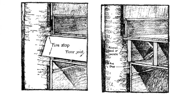
| Fire-stopping of furred off space in brick wall |
Fire-stopping of furred off space in brick wall |
|
| Fig 1 | Fig 2 |
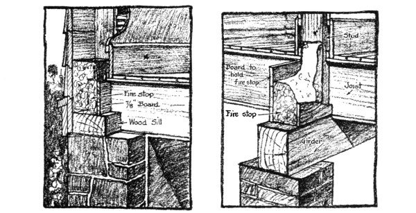
| Fire stop at base of exterior stud wall |
Fire stop for interior bearing partition of studs |
|
| Fig 3 | Fig 4 |
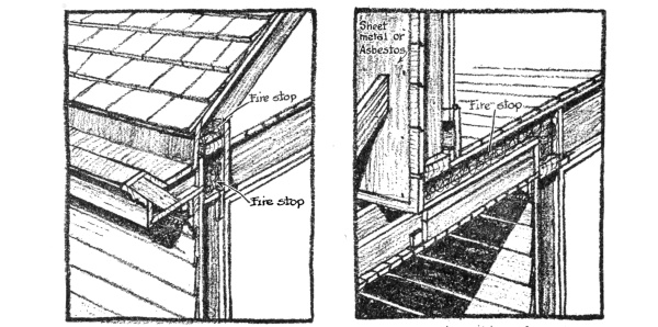
| Fire stop at end of rafters | Fire stop in ceiling of porch roof where 2nd floor projects over |
|
| Fig 5 | Fig 6 |
It is not necessary to use expensive materials for fire-stops, but they should be carefully placed. Materials like mineral wool are the best, since they expand as the wood shrinks and fill up the space. Concrete which is held in position by strips of metal lath is also excellent. The concrete or mortar used can be made from refuse material, and need not have any great strength. Old bricks are satisfactory if they are slushed into position with mortar which fills all the crevices. Gypsum blocks are good except for damp location, where they absorb moisture easily and, holding it, induce dry rot in the surrounding timbers. Asbestos board, gypsum board, and metal lath and plaster are suitable for covering large areas, such as cellar ceilings, over the boiler. In fact, fire-stopping can be cheaply done with odd-and-end bits of material which usually go to waste around the building.
The details of constructing these fire-stops are best shown in the illustrations, and no further descriptions will be necessary.
In view of what was said in the first part of this chapter, the construction of a chimney by approved methods is also a safeguard against fire. It can be considered a rule that every chimney should be lined with a terra-cotta flue, that every chimney should be an independent structure of its own, with walls thick enough for stability, capable of standing upon their own foundations and not hung from any part of the structure, that all woodwork of the building should be framed far enough from the chimney to make no contact with it, and, finally, that all the smoke-pipes which enter into the flues should be proof against leakage of flames and heat of such intensity as to cause combustion.
In the past this need of lining the flues of a chimney with terra-cotta flue tiles was not considered important, but to-day it is a well recognized fact that no chimney is safe without this protective [Pg 77] lining. There are many instances where chimneys are built without this lining and show no fire dangers, but the action of flue gases is slow and sure, and the mortar is attacked gradually, with the resulting disintegration of the brickwork, through which the flames eventually find their way to the surrounding wood timbers. It is found that even where terra-cotta flue linings are used the hot gases from the burning of natural gas as a fuel break down their resistance and they crumble, so that in such cases the flue linings should be made of fire-clays. From practical experience the minimum thickness allowable for any of these flue linings should be 1 inch, and the joints should not be made with collars.
When setting these linings they should be laid in cement mortar, not in lime mortar, for this disintegrates under the action of gases from burning wood. The joints should be struck smooth on the inside, and the space between the lining and the brickwork filled in solid with mortar. Wherever two flue linings are run within the same chimney space, the joints should be staggered or offset at least 6 inches. Two linings, however, in one chimney space should be the maximum number permitted. Where more are required, each group of two should be separated by brick walls of at least 4 inches, which are well bonded into the outside walls of the chimney. This is in order to give stability to the chimney and also prevent any fires in one flue spreading to others. The thickness of outside walls of the chimney around the flues should not be less than 4 inches if built of brick or reinforced concrete, but if built of stone they should be 8 inches. Wherever there is no flue lining of terra-cotta, such as in the smoke-chamber, the thickness of the masonry from the interior to the exterior should never be less than 8 inches. [Pg 78]
If chimneys are built of reinforced concrete, the reinforcements should be run in both directions to prevent cracks during the setting of the cement or from temperature stresses. Where concrete blocks are used, reinforcements should run continuously around the blocks, and the shell of the blocks should not be less than 4 inches thick.
Wherever the walls of dwellings are of brick and 12 or more inches thick, they may be used to contain chimney flues. If it is necessary to corbel out the flues from the wall, they should not extend farther than 4 inches from the face of the wall, and the corbelling should not be done with less than five courses of bricks.
Next in importance to the correct lining of flues is the proper construction of the foundation under chimneys. There are often cases where it is necessary to cut off the chimneys below in part or in whole to supply room on the first floor. This should be avoided as much as possible, but if it cannot be done it should be supported by steelwork from the ground up.
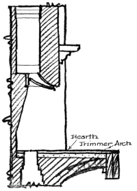
Fire place
Fig 12
Another mistake that is continually made is to cut off the chimney at too low a level and cap it with only a plastering of mortar. All chimneys should be carried at least 3 feet above flat roofs and 2 feet above the ridge of a peak roof and properly capped with stone, terra-cotta, or concrete. If they are not capped, and the bricks improperly tied, the mortar joints will be loosened by the action of the weather and the heat issuing from the chimney, and eventually the bricks will be moved from their position, leaving the top in a dilapidated condition.
This extension of the chimney through the roof leaves a joint which must be covered with flashing to prevent leaking. The usual method of [Pg 79] building a tin-covered cricket behind the chimney, and protecting the other sides with tin flashing counter-flashed is very satisfactory; but the practice of corbelling the brickwork out over the roof, in order to cover over the joint, is extremely bad. When a chimney built in this way settles, the corbelled-out parts catch on the roof, and the whole top of the chimney is lifted off, leaving a crack through which the hot gases pass to the wooden rafters. See illustrations on pages 145 and 170.
If there are any fireplaces to be built in the chimney the walls should never be less than 8 inches thick around them. It is best to line them with fire-brick of at least 2 inches in thickness. Hearths should extend in front of the fireplace at least 20 inches to prevent sparks from falling on the wooden floors. These hearths should be supported upon trimmer arches or be constructed of reinforced concrete. It is important to keep the woodwork of any mantel away from the opening at the top at least 12 inches and at the sides at least 8 inches.
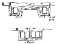
Fig 11
In fact, no woodwork should be permitted to come in contact with any part of the chimney. Wooden beams and joists should be kept at least 2 inches from the chimney and at least 4 inches from the back of any fireplace. This space, as was previously stated, should be filled in [Pg 80] with fire-stopping material. Where a chimney is on the line with a wooden stud partition, it is better to plaster directly over the brickwork of the chimney than to carry studs over it on which lath and plaster is constructed. By using metal lath over the brickwork the danger of cracks can be eliminated. Where a base-board must be carried along this wall in which such a chimney occurs, the plaster should be carried down behind it and then asbestos board should be placed behind the base-board to prevent too much heat coming in contact with it.
If these precautions are taken in the construction of the chimney and the correct methods of fire-stopping employed, the house of wood can be made less of a fire-trap than it is to-day. None of these devices require much additional expense, and should, on this basis, have a broad appeal.
It would be an endless task to list and describe all of the possible faults of construction which an unscrupulous builder might use in the erection of a small house, and, indeed, it would result largely in rehearsing all of the details of good construction, and then reversing them, showing that instead of doing the correct thing it was done quite the opposite way. But there are certain obvious and glaring faults of construction which are employed by speculative builders with one purpose in mind, namely, to reduce the cost but maintain a good appearance.
An intentional and clever disguise of poor construction is, at heart, the dishonest thing against which this is written. The defects of construction which are either the result of ignorance or unskilled labor, while they are bad enough, are not malicious, but those defects which are intentionally planned are simply systems of stealing, and they are usually found in the so-called speculative house, which the unwary public buys in preference to securing an honest house, designed by an architect. And it is this system of dishonest construction that makes the speculative house seem, on the face, cheaper than the honest house.
Indeed, it is the whole intention of such dishonest methods of building to make the house seem, on the face of it, substantial, good-looking, [Pg 82] and honest, but to hide, beneath the glamour of its exterior, weaknesses of structure which will cause all kinds of failures after a few years of standing. So long as the house stands together until the builder has sold it to some unsuspecting buyer, that is all that interests him.
In observing some of these dishonest methods of construction it is well to keep in mind that they will appear on the exterior well done, but that their faults are hidden, and intentionally planned to reduce the cost for the builder.
In order to systematize our observations along these lines let us imagine a house which we will inspect in an orderly fashion. We will begin with the cellar and proceed upward to the roof. This house is an ordinary frame dwelling upon a stone foundation.
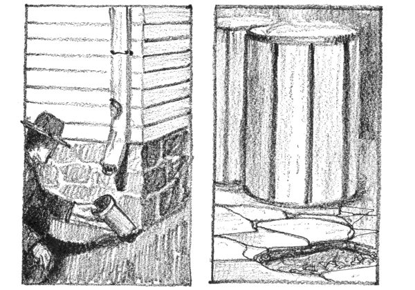
| The Fake Leader | The Poorly Made Floor |
Entering the cellar-door, the first thing we notice is that at the base of the stairs leading to this door is a puddle of water left from the last rain-storm. Upon inquiring concerning it we learn that in every rain-storm, and especially during the winter when the ground is frozen, the surface water flows down the steps, collects in the areaway in front of the cellar-door, and overflows the sill into the cellar itself—all because the builder had omitted a drain-pipe in the centre of this area to save money. Becoming interested in this matter of drainage, we look around at the areas under each of the cellar-windows and find that the drains have been omitted from these, and that a few broken pebbles were thrown into the bottom to give the impression that the water could drain off into the soil, and all this to save money and deceive the buyer. Inspecting the ground around the foundation-wall we notice that about each leader the earth has been worn down by dripping water, as though the leader had backed up and the gutter had overflowed. [Pg 83] Inquiry shows that such is the case in every rain-storm. Apparently the outlet for the leader has been stopped up, so, in order to find out whether this is true, we need to remove the lower section of the leader from the terra-cotta pipe to look into it, for often it becomes clogged at this point with leaves and dirt. Breaking away the cement joint and pulling gently upon the sheet-metal leader, we suddenly find that it crumbles in our hands, and that the leader consists of a coat of paint holding a few particles of rust together. Yes, cheap, thin, so-called galvanized-iron leaders to save money and deceive the buyer! But continuing our search for the stoppage we poke our cane into the [Pg 84] section of terra-cotta pipe projecting above the ground which received the leader, and find that it stops short. Twisting it around to remove the material which seems to block the pipe we find, much to our surprise, that the entire section of terra-cotta pipe breaks off, and then, looking closer, we find that this pipe does not connect with a cast-iron drainage-pipe leading to the plumbing system or to a dry well, but had merely been stuck into the ground to give this appearance and to save money and deceive the buyer. No wonder the leader backed up and the gutters overflowed in a rain-storm!
By this time we have become very suspicious of the house, so that when we finally go down into the cellar our attention is attracted to a section of the cement floor near the furnace where the large ash-cans are standing. The top surface has cracked under the weight of the cans, and it appears to be in thin slivers of cement. Leaning down and prying under one of these cracked pieces with a knife, a thin slab of concrete, about a quarter of an inch thick, is lifted up from the floor, and beneath this slab we find about 2 or 3 inches of tamped ashes, and then dirt. We marvel that this floor has lasted even as long as it has with so much water running into the cellar in damp weather. Think of it, 2 inches of ashes and a quarter of an inch of cement mortar on the top, when the correct method of building is to lay about 6 inches of cinders for a foundation, then 3 inches of concrete on top of this, and finally a top coat, 1 inch thick, of cement mortar over all.
Looking up from the floor we are rather impressed by the clean, whitewashed effect of the walls of the cellar, and one would hardly believe that it was a damp one, but around the windows and at certain points in the wall the whitewash is streaked with black, as though [Pg 85] water had leaked in. Going over to these places in the wall it is quite evident that during the winter and damp season water has soaked through these crevices. Poking around with a penknife we are amazed at the ease with which the knife penetrates the mortar between the joints of the stones. Working at it a little harder with the knife soon shows that if the cellar were a prison it would not be very hard to scratch one’s way out through that wall. Suddenly, without warning, one of the stones in the wall drops out onto the floor, and we get a view of the construction within. For certain it is one of those stone walls built up with two faces, not bonded together, except by mortar which seems to be made up of mud and a small trace of lime, which lime has disintegrated with the constant dampness to which it has been subjected. A piece of the mortar we find can be crumbled easily in the hand. This is evidence of the employment of the cheapest kind of labor for the masonry work and the cutting down of expense in using poor materials. We only have to look closely to see that there is developing a long diagonal crack in the wall, and we can imagine that if the contractor built so poor a wall above the ground, the chances are that there is no footing beneath it. Near at hand a large bulge is noticeable, and when we hit it with a hammer the whole thing has a rotten sound, for the inside face is bulging inward from the load upon it and the uneven settling of the foundations.
Looking up now at the neatly whitewashed ceiling we cannot help but be suspicious of the plaster beneath the surface, so going over to that part of the ceiling above the smoke-pipe leading from the furnace to the chimney we jab our cane against it, and, as we expected, a big slab breaks off and crashes to the floor, revealing partly charred wooden [Pg 86] lath beneath, which have been baking in the heat rising from the smoke-pipe, and which would eventually catch fire. Examining the plaster very closely we observe that in addition to being a very thin coat it has no hair in it to act as a reinforcement for the plaster key which held it to the lath base.
But being rather inquisitive about the construction hidden behind the plaster, and having broken some of it down, the removal of the few lath is worth the look behind them. And there we see the girder which supports the floor-joists resting upon the chimney instead of on a special pier or column. This saved the contractor the cost of the pier or the column, but the owner would probably lose his house some day by fire creeping through the joints of the brickwork of the chimney to the ends of this wooden girder, for it was quite evident that the mortar used in the chimney was not much better than that used in the wall, and it is well known that lime mortar disintegrates under the action of hot gases from burning wood.
Turning our attention now to other parts of the cellar, we notice that in the floor of the laundry a place had been broken into, and upon inquiry we find that this hole was dug by the plumber in repairing a stoppage of the system of drainage-pipes under the floor. It seems that the contractor had omitted placing any clean-outs in the pipes which he had laid under the cellar floor, and the owner’s wife, by accident, in pouring a pail of wash water down the water-closet in the cellar had allowed a rag to go down with it, which clogged up the system, so that the waste from the kitchen-sink began to back up into the laundry-tubs. As there was no way to get at the pipes, the plumber, in cleaning out the system, was obliged to break through the floor and cut out a hole [Pg 87] in the pipe to run a wire through to the clean-out on the house-trap. The contractor who built the house had saved about fifteen dollars in omitting this clean-out, but the owner lost fifty dollars in plumbers’ bills before he repaired this defect.
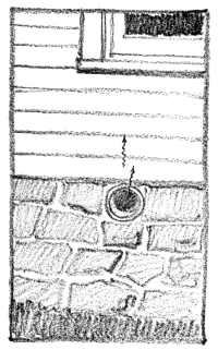
Fresh Air Inlet
Under Window
Another defect was also found by the owner in the system of water-supply. There had been installed only one shut-off cock for the entire building, so that whenever a new washer had to be placed upon a faucet on any fixture the entire system had to be turned off. As most of the faucets throughout the house were of very cheap design, this had to be done very often, until one day the owner had turned the main shut-off cock once too often for its strength, and the handle broke off. He was obliged to call in the plumber to turn the water on again, as well as install a new shut-off cock.
Questioning the owner further, we learn that a disagreeable odor of sewage enters the dining-room windows during the summer months when all the sash are open, but as he admits he knows little about plumbing, he isn’t sure of its cause, but he thinks it comes from a pipe which opens directly beneath one of these windows. When we investigate we find that it is the fresh-air inlet of the plumbing system of the house. The contractor had saved money on piping by carrying this to the nearest [Pg 88] outdoor point, which happened to be directly under the window of the dining-room, so that whenever any water-closet was flushed in the house a puff of foul air was blown out of this pipe in the most convenient place for it to enter the house if the windows were open. Instead of spending the extra money for piping to carry this fresh-air inlet well away from any windows, the contractor had put in the shortest length possible.
After looking at this pipe we glance at the porch near by and notice that it is beginning to sag. So, crawling under the porch, we find that instead of masonry piers under the porch columns, there are wooden posts driven into the ground, and that not only have these begun to settle under the weight but also have rotted away considerably near the ground, where they are subject to dampness. While we are under here we notice that the floor-joists are small, 2 by 4 inch timbers, and have sagged a great deal because of their extreme scantiness for the span over which they are placed.
In fact, as we walk up on the porch it vibrates under our weight, and when we enter the house we notice the same weakness, only to a slightly less degree. The owner says that in the beginning the floors were stiff enough, but that this weakness had been getting worse each year. It is evident that there is faulty bridging and too small timbers. Probably in the beginning the nails of the upper flooring helped to stiffen the beams, but as these became worn in their sockets the joists lost this additional strength. This lack of proper-size framing timbers saved the builder money but would cost the buyer a pretty penny some day. [Pg 89]
But we are astonished at the excellent appearance of the floors, for by this time the things that are good are more surprising than the things that are bad. Then it occurs to us that of course the floor would be good, for this is part of the house which is visible and helps to catch the buyer’s eye. But later, when we go up-stairs, we notice that the floors are not so fine, but are the common flat-grained boards which sliver off and catch in your shoe if you scuffle. The owner also points out the kitchen as one of the biggest fakes he has seen. It has an oak floor, and when he had bought the house he had been deeply impressed with the luxury of having an oak floor not only in the dining-room but also in the kitchen. But he is not so keen now, for with constant scrubbing the cheap varnish and filler had come off and the pores of the oak have been exposed, so that now the floor is the greatest catch-dirt ever invented, and to make matters still worse the oak had been poorly seasoned, the boards had shrunk, the cracks opened, and there is no underflooring below to prevent the dust and dirt from sifting through these cracks from the hollow space between the floor-joists. The owner says he is about to install a new floor. He also admits that the varnish which gave such a fine surface to the dining-room and living-room floors when he first saw the house was so poor, and scratched so badly, that he had to have the floors completely done over.
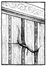
THE DEFECTIVE
PLASTER
Glancing around at the walls of the living-room and the dining-room we notice that the wall-paper has cracked in a number of places, pulled up, and curled away. It is extremely ugly and unkempt, and we remark about it to the owner. He says that he is completely discouraged about it, that he has tried everything to make the wall-paper stay down, but [Pg 90] that as soon as the winter comes on, the steam-heated air on the inside and the cold air on the outside seem to draw the paper up and away, pulling the surface of the plaster with it. He has glued large pieces of paper which have curled up in this manner back into position again, but the plaster was so weak that as soon as the paper began to peel off, the top layer of plaster pulled away with the paper. In fact, examining one example of this, we observe that the paper which had sprung loose from the wall has underneath it a thin coat of plaster about a sixteenth of an inch thick, showing that the glue had fastened the paper to the plaster, but the plaster itself had given way. This type of plastered wall is the result of using cheap materials, and it is another evidence of the extremes to which contractors will go to save money and deceive the buyer.
As we pass by one of the pockets into which the sliding-doors roll we feel a draft coming out of it, and we question the owner whether the house is cold in winter, and he admits it is worse than we suspect. He informs us that it is especially cold on the second floor in those rooms where the floors project over the porch. We ask him whether he has noticed any drafts coming in through the cracks around the base-boards and trim, and he points to these cracks, showing us bits of cotton which he has plugged into them. We suspect that what is the trouble is the omission of sheathing-boards over the studs between the roof of the porch and the ceiling-joists where this roof intersects [Pg 91] with the house wall, and also the failure to fill with cinders the space between the floor-joists of the projecting part of the room which extends over the porch. That this is true the owner admits, for he had noticed it while repairing a few shingles on the roof of the porch. The contractor had saved a little money by this trick, and no one could tell that he had done it by merely looking at the exterior.
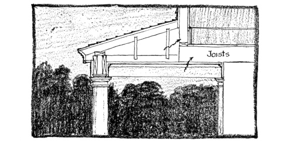
Where The Cold Air Gets In
This same line of inquiry leads us to ask the owner about the heating-plant, and we find that the house cannot be properly heated. We therefore suspect that the radiation is too small, so we calculate the required size of a radiator for one room, and find that the one actually installed is too small. Yet, as the owner says: “When he bought the house, how was he to know that there was not a large enough heating-plant?”
We inquire then whether he has any trouble with the fireplace, which we presume he must use to help out on cold days. He admits he cannot keep it from smoking badly. So we go over to it and run our hand up into the throat to feel around, and find that there is no smoke-chamber, and, [Pg 92] what is more, the flue is only about 4 inches by 8 inches, and is not even lined with terra-cotta flue tile. We inform him that he will never have a good fireplace draft until that chimney is rebuilt, and that the size of the flue looks more like the vent for a gas-log than anything else.
We then went through the house noting as many defects as we could, which were beginning to make their appearance. For example, we find that all the doors are badly sagging, showing that the blocking has been omitted from the back of the jambs where the butts are screwed on. The putty in the windows is crumbling out, as though it were clay. All the thresholds are of soft wood and are wearing badly. The trim in many places was springing and twisting, due to the use of cheap and poorly seasoned wood and the omission of enough nails. Some of the door-stiles are made of two pieces which have opened up at the joints and left ugly cracks. All the stairs squeak badly, indicating that they had been poorly built. Some of the balusters have worked loose and rattle in their mortises, and the hand-rail shakes when it is grasped.
We notice a number of stained ceilings, and inquire about the roof. We are informed that it has leaked badly in the valleys, where the tin is not wide enough to prevent the water which runs down one slope from washing up under the shingles of the adjoining slope and over the edge of the flashing tin of the valley into the house. We learn also that the shingle roof of the porch, which has a very slight incline, continually leaks, and looking out upon it we notice that the shingles are set nearly 7 inches to the weather instead of less than 4 inches, as they should be for so small a pitch. [Pg 93]
We notice that it has leaked around the windows, and, observing the top of the trim on the exterior, note that there is no flashing over it to throw off the water flowing down from the clapboards. While we are examining the windows the owner volunteers to tell us about his experience with the windows on the second floor. After he had bought the house he found that only one window in each bedroom had any weights and sash-cords in it, and that he had to buy these for all the other windows when he discovered it. He says he never thought of trying each window before he purchased the place.
Just then we happen to be looking at the lock on one of the doors, and we spy one of those back-handed locks which never holds the door closed and which always catches and keeps one from closing the door unless the knob is turned. It is a right-hand lock placed upon a left-hand door. We recognize in this the contractor’s efforts to use up all the second-hand odd bits of hardware which he possessed.
By this time we find ourselves so disgusted with the sharp tricks of dishonest building that we call a halt at looking farther, but we feel quite convinced that there is a real difference in quality between such a speculative house and the honest house of an architect’s designing, and, what is more, we feel convinced that there is a real reason for the architect’s house costing more in the beginning than such a house, but that in the end the cheap speculative house is the most costly proposition which a buyer can invest his money in.
There are three things which will affect the plumbing system of the small house; namely, the existence or non-existence of municipal plumbing codes under which the structure is erected, the existence or non-existence of a public sewer, and, finally, the type of water-supply, whether it is public or private.
If there are no plumbing codes to follow, it is sometimes possible to save money on the plumbing; but unless the specifications are very rigid, there is danger of poor work being installed. By saving money is not meant installing cheap material, but eliminating certain features which most plumbing codes require and which are not essential in producing the best possible type of plumbing system. For example, in most cities the ordinary traps which are required under each fixture to prevent the sewer-gas from returning into the air of the house, after the waste water has drained out, must be equipped with back-vent pipes in order to eliminate dangers of siphonage. The cheap S trap (shaped like an S turned on its side) without this back-venting will siphon [Pg 95] out, that is, lose its water-seal by atmospheric pressure pushing the water out of the trap in its attempt to fill a vacuum created by the discharge from a water-closet on the floor above. By back-venting these traps, as shown on page 94, this danger of siphonage is reduced, and, therefore, most codes have adopted this regulation requiring back-venting. But to-day the market offers certain traps which are claimed to be anti-siphonable and which do not require this back-venting, with the consequent result of reducing the cost of the equipment. Most plumbing codes have not changed their old regulations, for many authorities do not yet believe in the possibility of an anti-siphon trap, and so require the use of the back-venting system. Consequently, wherever the small house is constructed within jurisdiction of these laws, the plumbing will cost more than where the anti-siphon trap can be used without the elaborate system of back-venting.
Likewise, wherever there is a public sewer, the problem of sewage disposal is simple and cheap; but if the house is not located near any such public convenience, special methods must be employed for the destruction of the waste matter. The best is the septic tank (see illustration) with the small subsurface irrigation tile, through which the partially purified material from the septic tank is distributed under the ground for complete purification by air and bacteria. The other method of disposal—pouring the sewage into a cesspool—is to be deplored, unless there is possibility of an early construction of a public sewer, and no drinking-water is secured from the premises.
The third consideration which affects the plumbing system of the small house is whether it can draw upon a public water-supply, or whether it must secure its private supply from a well or a near-by stream or lake. [Pg 96] A private source of supply generally means the erection of a storage tank. The best type of tank for this purpose is the pneumatic tank, which is installed in the cellar, and not in the attic, as was the old-fashioned tank. The water is pumped into this tank, and the air which is in it is trapped, so that the more water that is pumped into the tank, the more compressed becomes the air. This springlike cushion of air gives enough pressure to force the water to any fixture in the house.
On page 97 is represented the simplest type of drainage system that can be installed in the small house, but since it uses anti-siphon traps and no back-venting, it will not be possible to make use of it in all cities or towns which have plumbing rules prohibiting it. The average small house does not have room for more than one bath, a kitchen-sink, a set of laundry-tubs, and a toilet for the servant, generally placed [Pg 97] in the cellar. For purposes of economy it is essential to place all of these fixtures on the same soil-line, the main pipe which extends vertically from the horizontal house-drain in the cellar up through the roof. If the bathroom is so located that the vertical line which serves its fixtures cannot serve the kitchen-sink or the laundry-tubs, then a special waste-line or small vertical pipe draining fixtures other than water-closets, must be carried up and through the roof, which is extravagant of material. As this waste-line will be only 2 inches in diameter, it is necessary to increase its diameter to 4 inches before projecting it from the roof, since it may become clogged in the winter [Pg 98] with frost. But the main soil-line is 4 inches in diameter and needs no increaser on it. The main house-drain is also made 4 inches in diameter, and is generally laid under the cellar floor with a pitch of ¼ inch to the foot. At the junction of the vertical soil-line with it, and also at any other point where there is a marked change in direction, the house-drain should be equipped with clean-out holes, covered with brass screw-caps. Just where the house-drain leaves the house, a house-trap is installed (see illustration), and back of this an inlet for fresh air to permit the circulation of air in the system. The foundations should be arched over the house-drain where it passes through them, so that any settlement of the masonry will not come upon the pipe and cause it to be broken.
The material of which the house-drain, soil-line, and waste-line are made is usually cast-iron, and of a grade known as extra heavy. The joints are the bell-and-spigot type, which are stuffed with oakum and then closed tight with 12 ounces of fine, soft pig lead for each inch in diameter of the pipe. Branches are usually of galvanized wrought iron or lead, but lead should be limited in use in modern plumbing, although the term plumbing originated from the Latin word for lead. The common limitations upon the length of branches of lead pipe are: 8 feet for 1½-inch pipe, 5 feet for 2-inch pipe, 2 feet for 3-inch pipe, 2 feet for 4-inch pipe. The parts of the branch pipes which are visible are generally made of brass nickel-plated. The joints between lead pipe and lead pipe, and between lead pipe and brass pipe, are made by the common wiped joint. Joints between lead pipe and cast-iron pipe are made by first wiping the lead pipe to a brass ferrule, a piece of pipe in shape like a bell with the top cut off, and then inserting and [Pg 99] caulking this into the cast-iron pipe. The joints between wrought-iron pipes are made with the screw joint, and between wrought-iron and cast iron with the screw joint, by using connections of malleable cast-iron which have been threaded.
The usual sizes for branch wastes from the fixtures are as follows: for water-closets 4 inches, for bathroom-tubs 1½ inches, for lavatories 1½ inches, for kitchen-sinks 2 inches, for laundry-tubs 1½ inches, and when in sets of three 2 inches. The size of the waste from the bathroom-tub can be increased to 2 inches with great advantage, if the additional slight expense is not objectionable.
The vertical soil-lines should be supported at each floor by metal straps placed under the hub and fastened to the floor-joists. It is very important to properly flash the base of the projecting portion of the soil-line above the roof. Wherever the branch soil-line to the water-closet is connected, a short TY connection may be employed in order to avoid the projection of the parts of the pipe beyond the plane of the ceiling in the floor below. However, no short TY connections should be made in any horizontal pipes.
A very important economical consideration should be noted in laying out the arrangement of the bathroom fixtures in this connection. The horizontal branch soil-lines and waste-lines must be carried through the floor construction, and they should be so arranged that they can run parallel with the floor-joists; otherwise deep cuts will have to be made in them. In the case of the branch soil-line it is essential to place the water-closet as near to the main soil-stack as possible, for with a 4-inch pipe the joists must be framed around it rather than be cut, since so deep a gouge would weaken too much the strength of them. [Pg 100] A similar consideration must be given to the framing in stud partitions which are bearing the loads of the floors above, for too deep cuts in them, to allow for the passage of pipes, will weaken them greatly. In this connection it ought to be noted that an ordinary 4-inch soil-pipe cannot be carried in a stud partition made with 2 by 4 studs, since the outer edges of the joints of the pipe will project beyond the face of the plaster, and for this reason some convenient place should be planned for them in closets, or 2 by 6 studs should be used in the partition through which they are run.
The essential parts of the plumbing system remain the same as described above, but each trap is considered to be siphonable, and must be prevented from losing its water-seal by the use of back-venting pipes. Whenever, then, there is an unusual amount of semi-vacuum created in the pipes by the discharge of some fixture above, the outside air-pressure can relieve it by passing through the back vents rather than by forcing out the water-seal in the traps. The usual type of trap employed is the modified S trap with the small TY connection to give what is known as continuous venting. Formerly the vent was taken off from the crown of the three-quarter-S trap, which was too near the surface of the water-seal, causing excessive evaporation and danger of clogging, but with the continuous system of venting, the waste-pipe is a continuation of the vent-line, and the trap enters into its side through a TY fitting, overcoming the disadvantage of the older system.
The size of traps should conform to the size of waste-pipes, and [Pg 101] usually the size of the branch vents is about the same size as the waste-lines. However, there are special conditions where this varies. For venting the water-closet trap, it should be noted that the vent is not taken from the trap which is contained within the fixture itself, but is taken from the upper side of the bend (usually of lead) where the fixture is joined with the piping system, and is 2 inches in diameter.
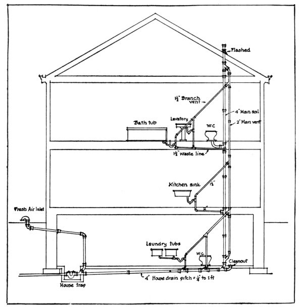
PLUMBING SYSTEM USING BACK-VENTING
Where there are two fixtures, such as the lavatory and the bathtub, with 1½-inch branch vents coming from the traps, these may be joined into one main branch vent, which need not be more than 1½ inches in diameter. The pitch of the branch vents entering into the main vent [Pg 102] should be at an angle of about 45 degrees, so that all rust scale will drop down into the fixture outlet and be washed away.
The main vent, which runs parallel with the main soil-line, needs to be only 2 inches in diameter, and should be branched in at the bottom and the top to the main soil-line, as shown in the drawings. The material of which both main vent and branch vent is made should be galvanized-iron piping.
The fresh-air inlet, the house-trap, the clean-outs, and all other parts of the system are the same as was shown for the simpler method of plumbing.
The small house need not drain off its roof-water into the plumbing system, if the plumbing code does not require it. The simplest and easiest method to dispose of it is to collect the water in gutters, lead it down the waterspouts into pipes which terminate in a dry well in the ground. Small roofs over porches and back doors need not even have the leaders, but spill the roof-water out onto the ground, where a stone has been placed to prevent the undermining of the surface of the lawn by the wearing action of the water stream.
In outlying city districts where the sewers have not yet been installed it is customary to carry the roof-water in pipes below the level of the sidewalk to the gutters of the street or to a leaching cesspool which is independent of the cesspool used for sewage disposal, and which is practically the same thing as a dry well, for the bottom is made with gravel through which the rain-water seeps off into the surrounding soil.
Wherever the rain-leaders must be connected to the drainage system of [Pg 103] the house, the sheet-metal leaders are inserted into cast-iron pipes called shoes at the base, which in turn are trapped on the inside of the cellar wall and connected with the house-drain. It is always best to try to trap a group of leaders to one trap rather than use a separate trap for each leader.
There is nothing very complicated in the plumbing system of the small house. Certain sanitary precautions should be observed in arranging lines, however. For example, the termination of the main soil-line should not occur near a dormer or other window, nor should the termination of the fresh-air inlet be located in the cellar wall under a door or window. The system when completed in the roughed-in form should be tested for leakage by filling it with water, and when all the fixtures are connected and every part of the system is supposed to be in working order, either the peppermint or the smoke test should be used to detect any further possible leakage. The peppermint test consists in pouring hot water and 2 ounces of oil of peppermint into the top of the system from the roof, after all the fixture traps have been filled with water, and then detecting with the nose where the leaks are. If the smoke test is employed, a smoke machine is best. Old oily rags and tar paper are burned in the machine, which has its flue connected with the fresh-air inlet, and the smoke is pumped through the system until it appears escaping from the soil-line extension on the roof. If there are any leaks, the odor and the smoke stain will attract attention to them, and if the water-closet traps in the bowls are defective, the yellow stain of the smoke will make it very evident. [Pg 104]
The drainage from the refrigerator should never be directly connected with the drainage system of the house. If the plumbing code requires any connection at all, the usual arrangement is to drip the ice-box water into a lead-lined tray which has a pipe at least 1¼ inches in diameter that carries the water down to the laundry-tubs in the cellar and spills it into them. On the other hand, if there are no plumbing regulations, it is best to drain this water off into a small hole in the ground into which has been thrown gravel, and this will permit the water to soak into the surrounding soil.
If there is a city supply of water, the small house should have a main supply-line from the water-main in the street of at least ¾-inch diameter, but this does not give the service that a larger pipe, say a 1¼-inch pipe, does, for often with the smaller pipe, if the water is being drawn in the kitchen, none will be secured from the faucets in the second-floor bathroom. The kitchen-sink should have a service pipe of at least ¾ inch, the tubs the same, and the lavatory ½ inch.
All service-lines should be compact and as direct as possible, and long horizontal runs under floors should be avoided. Hot-water supply-lines should be kept at least 6 inches from cold-water lines. There should be a shut-off at the entrance of the supply-line to the house, at the base of all vertical risers, and under each fixture. To avoid water hammer, it is best to take all faucets off the sides of the termination of pipes, rather than from the ends, for in this way an air-cushion can form, relieving the pounding action of the water in the pipes. [Pg 105]
Supply-lines should never be run in the corners of buildings where they are in danger of freezing, and they should be kept out of the exterior walls of houses as much as possible for the same reasons. The packing of pipes where they pass through the floors will often prevent freezing caused by cold drafts around them.
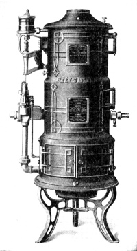
It is generally accepted to-day that the most convenient method of securing hot water in the small house is with the instantaneous type of gas-heater, connected with a boiler for storage purposes, but capable of delivering water directly into the pipes without passage through the boiler, when a sudden demand is made upon it. These gas-heaters have a system of Bunsen-burners which heat the water as it passes through a series of copper coils, and generally the water is warmed to a temperature of 100 degrees in one passage. They are automatically controlled, so that when the temperature of the water goes below a certain fixed standard the gas-burner is lighted by a small pilot-light until the proper temperature is reached, when it is shut off again.
Although these heaters are arranged to deliver hot water directly from [Pg 106] the coils, yet if they had no boiler to store up the water, much larger heaters would be required than necessary. For storage purposes, then, a 40-gallon boiler is satisfactory for a residence with one bath and one kitchen, and if there are two baths a 50-gallon boiler is needed. The usual location of the boiler and heater is in the cellar.
However, where there is no gas to be used, the coal-heater must be employed—either the tank-heater or the water-back in the kitchen-range. The latter was the usual old-fashioned method of heating the water, and the boiler was located alongside of the kitchen-range. The size of the water-back was proportioned on the basis of 2 square inches of heating surface to each gallon storage capacity in the boiler. The tank-heater is a special coal-burning stove, designed to serve as an iron-warmer and a water-heater, being usually placed in the laundry in the cellar. Another method of securing hot water, which is not recommended, is to place heating coils in the furnace; it obstructs the fire-pot, chills the fire, overheats the water in cold weather and underheats it in warm weather, and does not operate at all during the summer.
The modern bathroom fixture may be made of one of three materials: true porcelain, earthenware, or enamelled-iron. The true porcelain fixtures are the heaviest, the most durable, and the most expensive. The material is non-absorbent and white in color, and the surface presents a gloss which is in reality a form of glass. When it is chipped the fracture shows the material below as white, and a drop of ink will not be absorbed by it. [Pg 107]
In imitation of the porcelain fixtures are made earthenware ones, but which are in no way to be compared to the true porcelain, although a casual glance at them would lead one to think that they were porcelain fixtures. However, a chip from the surface will reveal the yellow and porous texture of the earthenware below the glazed surface. The glossy white surface in time stains and becomes covered with small hair-cracks, unlike the porcelain fixtures, and for this reason they are not as sanitary nor as durable. They are cheaper than the true porcelain fixtures, but this material should be avoided in water-closet bowls, but is admissible for use in tubs and lavatories.
The enamelled-iron fixtures are considered by most to be superior to the earthenware fixtures, since they do not craze, are lighter, and generally more durable. The quality of this ware can be judged by the absence of roughness, blisters, bubbles, and spots, and freedom from hair-cracks and peeling. Bathtubs of the modern type made of enamelled iron have the rich appearance of porcelain fixtures, since the sides are rolled over and covered with enamel, unlike the old-fashioned types, which had the interiors lined with the enamel and the exteriors painted with white paint.
The mechanical operation of the various fixtures is so well standardized that not much choice is given between the catalogue of one firm and another. The best type of water-closets are the siphon, the siphon-jet, and the converging jets, the latter being a more modern development, which has eliminated the noise of the siphon action and yet which accomplishes a quick and rapid flushing action. The lavatories which are most commonly specified are of the pedestal type, although the modern tendency in sanitary bathroom design is to [Pg 108] eliminate as far as possible all junction of fixtures with the floor, for it is here that dirt and stains develop. Such arrangements carried to the extreme would require a sunk bathtub, a lavatory without legs, and special compartment for the water-closet, but this would be absurd for the small house. However, the built-in bathtub is far superior to the old-fashioned tub which stood upon legs, and under which all manner of dirt could collect.
We often hear the remark that no wonder the cost of living to-day is so much higher than it was with our ancestors, who knew nothing about the clean, tile-lined bathrooms with porcelain tubs, white and glistening lavatories with all the cold and hot water needed, while in the old days the wooden tub, set up in the kitchen near the range, was good enough for the Saturday-night bath, and the tin pan, filled under the hand-pump outside on the back porch, was good enough to wash the hands in each morning. But although the modern bathroom and the modern plumbing system is an economic burden to the small house, it is doubtful if we shall ever see the day when it is abolished in order to cut down on the cost.
The heating problem for the small house was for our ancestors a very simple mechanical device, consisting, as we all know, of either the fireplace or the stove. The former method still has a charm which we are not willing to dispense with, although we do not depend upon its efficiency to do the actual work of warming, but install some more complicated system, such as a steam heating-plant, to perform the practical work. A fireplace has a sentimental and intellectual warmth that no radiator can supply.
Even the stove has a certain fascination for many, recalling cold wintry nights when the family sat about the red-hot casting, the women knitting and the men burning their shoe-leather and smoking. Some advocates of the stove are so energetic in their arguments concerning the efficiency of this method of heating that one almost doubts the defects which lead inventors to manufacture other devices. But the housewife knows the labor of shovelling coal into three or four stoves, knows the great clouds of hot, fine ashes which rise into the atmosphere and settle upon the shelves, the tops of picture-frames, and the polished surface of the piano. [Pg 110]
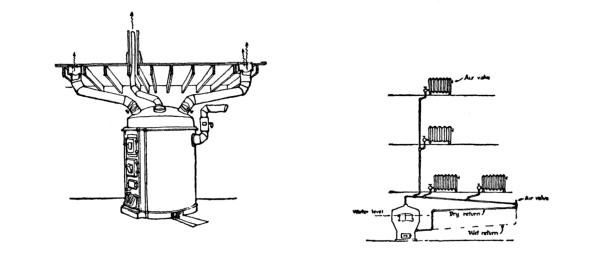
| Warm-Air Furnace with Pipes | Steam Heat—One-pipe |
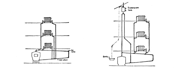
| Steam Heat—Two-pipes | Hot Water Heating |
And the inventor saw the tired, worn look of the housewife, removed the stove to the cellar and installed tin pipes from this central heater to the various rooms, and then waited for applause and purchasers. It seemed so simple, but it did not solve the problem entirely, for when the wind blew from the north into the windows, it pressed out the warm air from the exposed rooms, forced it down the pipes up through which it was supposed to come, and then rushed it up the flues on the south or warm side of the house, overheating this part and leaving the cold rooms of the house unheated. The drum of the furnace over which the air passed to receive its warmth from the burning coal would leak every time fresh fuel was added, for the odor of coal-gas became very evident throughout the house. Moreover, the heat was very dry and unpleasant, so that water-jars had to be set about to moisten the air. [Pg 111]
Then came the inventor again with a new device, a steam-boiler, pipes to distribute the steam, and radiators to give off the heat in the steam to the room. Here at last was a method of heating which would supply warmth in the cold parts of the house, even under the windows, through which the chilliest air penetrated. But the sizes of the radiators were calculated to heat the house to 70 degrees when it was zero outside, although the average winter day was much warmer than this. In this way the occupants of the house were cooked with an excess of heat during moderate weather, for there was no way to regulate the amount of heat given off from the radiator; it either was filled with steam, giving off its maximum quantity of heat, or else it was empty and cold.
To meet this difficulty presented by the steam-heated radiator, the hot-water system was developed. Instead of distributing heat with the medium of steam which under low pressure was fixed at one temperature, heat was circulated by hot water from the central boiler. The temperature of this water could be regulated for mild weather by lowering the fire. However, since the hottest water was cooler than steam, it required larger radiators and more piping, so that the initial cost of a hot-water plant was more than that of a steam system.

Simplified diagram of
Vapor-vacuum system
In order to overcome the disadvantages of the inflexible steam-radiator, inventors finally developed the so-called “vapor-vacuum” system of steam-heating. In this equipment the air was driven from the entire length of pipes and from the radiators by the pressure of the rising steam from the boiler, and forced through a special ejector which closed when the steam came in contact with it, preventing the return of air into the interior. Thus when the pipes and [Pg 112] radiators were filled with steam (there being no air left), no pressure was set up to resist the circulation of the water vapor, and when the hot steam condensed in a radiator to a thimbleful of water, more steam was drawn in to take its place, for no air could enter the pipes. In this way the quantity of steam delivered to the radiators could be regulated by a special valve with a varying number of ports, and by turning the valve to a certain position enough steam would be permitted to enter the radiator to keep it half full, or by shifting the valve to another point enough steam would enter to fill the radiator to three-quarters of its capacity. In fact, the requisite amount of steam could be admitted to the radiator to balance the speed of condensation and retain whatever level of steam in it was desirable. Thus the steam system became at once a flexible system of heating, and could meet the changing requirements of the weather.
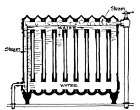
Hot water radiator
heated by steam
A further development of the hot-water system then came about. In this device the radiators were made to contain water, but the heat was circulated through the pipes by means of steam. This steam was poured over the surface of the water in the radiator and transferred its heat to it. According to the quantity of steam poured over the water, the [Pg 113] latter could be heated to various temperatures. Of course the water in the radiator was the medium for distributing the heat outward from the radiator itself.
Still another improvement was made upon the hot-water system by introducing the principle of the closed expansion tank. In the ordinary system the water is allowed to expand at the top through an expansion tank, so that the actual pressure on the water of the system is atmospheric. Under this pressure the temperature of the water cannot be raised to more than 212 degrees Fahrenheit, for beyond this it boils and changes to steam. However, in the closed-tank system a so-called heat-generator is added on the line leading to the expansion tank, which, by means of a column of mercury, is capable of adding 10 pounds more pressure than the atmosphere to the water in the system, and thus raising the boiling-point to about 240 degrees. This generator is so designed, however, that, although it adds this greater pressure to the water, yet the natural expansion of the water in the system is permitted through it in case of emergency. By permitting the raising of the temperature of the water, the size of radiators can be cut down 50 per cent, which, of course, reduces the quantity of water needed and permits a quicker heating of the system when the fire is started. Thus a saving of fuel is accomplished and the disadvantage of the ordinary hot-water system is eliminated; namely, the long time required to get hot water in the radiators after the fire is started in the morning from its banked condition of the previous night.
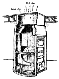
Pipeless Furnace
However, the genius of the inventor was not at rest on the problem of warm-air heating, for he discovered that he could abolish the flues, which he once thought were essential, and use but one register and one [Pg 114] flue. This is called the pipeless furnace. A register is employed which has an outer and inner section. The outer section permits the cold air from the house to pass down through it and over the drum of the furnace. The inner section of the register permits this hot air to escape upward and through the house by natural distribution. Thus the hot air rises from, and the cool air settles back into, the furnace without utilizing flues. The circulation of this system was found to be superior to the older method as ordinarily installed, and very much cheaper to install. In fact, it is the cheapest of all systems of heating. It is especially adapted to the small, low-cost house.
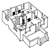
Hot Water Heating—Boiler
in Dining-Room
To reduce the cost of hot-water heating and make it also available for this class of small house, the manufacturers produced another type of water heating-plant. In this device the water-heater was installed in one of the rooms of the house, like a stove, but the exterior was designed to serve as a hot-water radiator for the room in which it was placed. From this heater pipes were taken off to distribute heat to other radiators, located in adjoining rooms. The principle remains the [Pg 115] same as the former system; the only difference lies in the reduction of cost by eliminating the boiler from the cellar and utilizing it to heat the room in which it was placed.
Other attempts to improve the mechanics of heating have been more along the line of perfecting the operation of valves or the utilization of other fuels than coal. Gas-radiators have been tried, but they are so expensive to operate in most parts of the country that they are not always suited to the needs of the small house. Electric heaters, too, are not within the pocketbook of the average person owning the small house. Fuel oil-burners also have been devised to take the place of the coal-grate. Wherever oil is cheap enough to permit their use they are great labor-savers, since they eliminate all the shovelling of coal and handling of ashes. These will be discussed later.
Briefly, then, the available systems for the heating of the small house are:
| Hot-air.—a. | Furnace with flues. |
| b. | Furnace without flues. |
| Steam.—a. | Ordinary gravity system. |
| One-pipe. | |
| Two-pipe. | |
| b. | Vapor-vacuum system. |
| Hot-water.—a. | Ordinary open-tank system. |
| One-pipe. | |
| Two-pipe. | |
| b. | Closed-tank system. |
| c. | Special open-tank system with boiler used as radiator. |
| d. | Patent system using water in radiators but steam for circulation. [Pg 116] |
The basis of calculating the required size of any one of the systems previously mentioned is to assume that a certain temperature of heat is to be maintained when the weather is zero, and then by means of the laws of heat transmission estimate the quantity of heat lost per hour from the house. The amount of heat lost per hour is, of course, the quantity which the heating system must supply. Knowing this, a system is installed which is capable of supplying this heat loss.
In such devices as the warm-air furnace the required size can be computed directly to meet the heat loss, but where radiators are used the required sizes of these must first be determined to offset the losses from the rooms in which they are installed, and then the size of the heater must be estimated to supply sufficient heat to the radiators and to make up for the losses of heat through the distributing-pipes.
The usual temperature to which the small house is heated when it is zero outside is 70 degrees Fahrenheit. It is then assumed that a certain quantity of heat is lost through the walls of the house by radiation and convection and conduction, and another quantity lost by the leakage of warm air out through the window-cracks. (The quantity of heat is measured in British thermal units, called B. T. U.’s.)
To understand the manner by which heat is lost through the exterior walls, it is necessary to know the meaning of radiation, convection, and conduction.
By standing before an open fire the heat given off by radiation can be observed by shutting it off with a piece of paper held between the face [Pg 117] and the fire. This is the transmission of the heat through the ether, and is similar to the transmission of light, since this heat will pass through glass, like light.
Convection of heat is illustrated by heating air in one place and transferring that air to another place, where it will give up its heat to surrounding bodies.
Conduction of heat is illustrated by heating the end of an iron rod and noticing that the heat will eventually be transmitted along the length of it to the other end.
The heat within a house escapes from the interior to the colder atmosphere of the exterior through the walls, by radiation through the glass windows and the substance of the walls, by the convection action of the warm air of the interior giving up its heat to the interior face of the wall and the cold air of the exterior extracting this heat from the exterior face and carrying it off, and also by the action of conduction of the materials of which the wall is composed.
The quantity of heat lost is measured by the number of B. T. U.’s lost through one square foot of the wall each hour. As the window-glass loses heat through it more quickly than the wall, it is necessary to calculate this separately. The process, then, for estimating the heat loss from a room is as follows:
1. Estimate the number of square feet of exposed wall surface in the room, including windows.
2. Subtract from the above the area of the windows to find the net wall area.
3. Multiply this net wall area by the number of B. T. U.’s which the wall loses per square foot of surface for each hour. [Pg 118]
These factors are given in the following table:
| TYPE OF WALL | Zero outside and 70 degrees |
| inside—Number of B. T. U.’s | |
| lost for each square foot of | |
| Brick wall, furred and plastered: | wall surface each hour |
| 8" thick | 21.0 |
| 12" thick | 17.5 |
| Frame wall, sheathed, clapboarded, | 21.7 (with building-paper use |
| and plastered | 20.3) |
Hollow-tile wall and concrete and stone have factors about the same as for the furred brick wall.
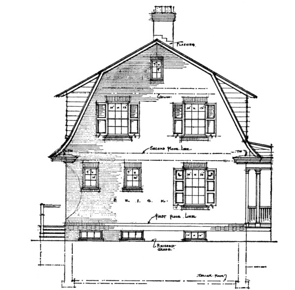
SIDE ELEVATION
4. Add to this the number of B. T. U.’s lost per hour through the windows. This is determined by multiplying the area of the windows by the heat loss in B. T. U.’s per hour for each square foot of window, which is 78.8 for single windows, and where storm-windows are added it is 31.5 B. T. U.’s.
5. This total sum is the number of B. T. U.’s lost through walls and windows for each hour.
6. To this must be added the heat lost by leakage through the window-cracks. This is secured by measuring the length of window-cracks on the side which has the greatest length of crack and multiplying this by 168, or the number of B. T. U.’s lost each hour for each linear foot of window-crack. For very tight windows reduce above to 84.
7. The total of all the above gives the number of B. T. U.’s lost each hour from the room when the outside temperature is zero and the inside is 70 degrees Fahrenheit.
Knowing the quantity of heat lost per hour, a radiator must be installed which will supply this amount per hour. As the average steam-radiator supplies about 250 B. T. U.’s per hour from each square foot of its surface, the number of square feet required for a radiator to be installed in the room can be found by dividing 250 into the number of B. T. U.’s which were found to be lost from the room each hour.
A hot-water radiator gives off about 150 B. T. U.’s per hour for each square foot of surface, so that the radiator is generally about one-third larger than the steam-radiator.
Knowing the required number of feet of radiation for the radiator, the proper size can be selected from the manufacturer’s catalogue. [Pg 120]
By lumping the total number of square feet of radiation for all the radiators throughout the house together and adding 35 per cent to this to make up for loss through pipes and under-rating of boilers, the size of the boiler can be selected from the catalogue to fit this need.
To estimate the size of a warm-air furnace, the total quantity of heat lost from all the rooms of the house should be calculated in the same way, and then 25 per cent added to allow for cold attics and exposure. This quantity should then be multiplied by 2.4 and divided by 8,000 to find the number of pounds of coal which will be required to be burned per hour. By dividing this amount by 5, the grate area of the required furnace can be found, and the correct size selected from the manufacturer’s catalogue.
When we talk of lighting the modern home, there is generally but one idea that enters our minds—electric lighting. Even those dwellings remote from any power-house are installing small generators in preference to the oil or gas lighting systems.
The modern
50-watt bulb
Then, too, when we refer to good lighting we no longer think of glaring bulbs of light, exposing all the harsh glow of the white, hot filaments, causing one’s eyes to squint and strain to find things in the corners of the room; but we picture a room flooded with mellow illumination emitted from fixtures which shield the direct rays of light from our vision.
Another change that has come about in our conception of good illumination is the quantity and intensity of the light we expect from the incandescent bulb. It was only a few years ago that we marvelled at the yellow light given off by the 16-candle-power carbon-filament bulb. But to-day if a bulb gave off as feeble an attempt at lighting as did these old ones we would think it on its way to the graveyard of lightning-bugs. We cannot talk of 16-candle-power lamps when the glow of a modern Mazda light is around. We used to specify on the plans so many 16-candle-power lights for the dining-room or living-room [Pg 122] fixtures, and it is hard to change our habits to refer to the modern 40 or 50 watt lamps which have taken their place in the home.
Thus within a period of not more than ten years our whole conception of illumination has been jolted out of a rut.
Now we have reacted so far in the matter of protecting our eyes from a direct view of the source of light that some enthusiasts advocate a system of indirect illumination, concealing the lights so completely from the eyes that their location is difficult to know. This is carrying the problem too far beyond its rational limits. Such a system of indirect illumination reduces shadow to a minimum; consequently the forms and the beauty of objects in the room are flattened. Moreover, the eye unconsciously is confused at not being able to locate the source from which the illumination comes, and, being puzzled, the mind naturally resents it. For the small house, at least, the system of [Pg 123] indirect illumination carried to this extreme is not at all suitable.
A type of fixture which develops a partial indirect illumination, and yet which allows a certain quantity of light to come through direct to the eyes, so that the source of light is easily discernible is the most satisfying and most suggestive of home comfort. Such a fixture is shown on page 122.
Moreover, the lighting of a small house must be studied with common sense, and no rule of the thumb can be laid down. Certain enthusiastic illuminating engineers offer typical plans and suggestions for the wiring of houses, which plans are crowded so full of outlets that they look like a map of the starry heavens. We have in front of us now such a plan in which a small living-room is marked to contain four wall outlets containing two lights each, two more outlets on each side of the fireplace, a wall plug for attaching a portable lamp or two lights, and a central ceiling outlet for four lights. In addition to these is another base plug and floor plug. The room is about 14 by 17 feet, and if all lights were turned on at once and all base plugs attached to lamps there would be a possible grand total of twenty 50-watt lamps in this medium-sized room. Such brilliant illumination might please the jaded nerves of the tired business man, but his wife would never consent to such a garish display of wealth-eating current.
The problem of illumination for the small house can be sanely considered from five different angles: (1) General illumination; (2) local illumination; (3) ornamental illumination; (4) movable lamps; and (5) light control. [Pg 124]
By general illumination is meant the lighting required to flood the room as a whole, and not locally in any one corner. The easiest and commonest method of doing this is to provide a central fixture, containing from two to four 50-watt lamps, or their equivalent, which are hidden in some commercial type of semi-indirect lighting fixture. The type of fixture shown on page 122 is one of the finest, and with a silk shade around it the warm, cheerful effect of a home is greatly enhanced by this method of lighting. When this fixture is hung in the dining-room or living-room a single 200-watt Mazda lamp is employed, while in the other rooms a single 100-watt lamp is used. In the kitchen no shade is necessary. Usually in laying out the electric outlets upon a plan the central dining-room and living-room lights are shown to carry four 50-watt lamps, and those in the other rooms, in the hall, and on the porch are marked to have two 50-watt lamps or their equivalent.
But it is not absolutely essential to have a central light for general illumination. Some architects prefer to have a certain number of wall lights controlled by one switch, and obtain a general glow with these lamps. By securing the right type of fixture which shields the raw filament of light from the eyes, this method of general illumination often produces a feeling of comfort and homelikeness unsurpassed by the other system.
In those rooms where work is done under the central light, such as the kitchen and pantry, and where opaque, indirect reflectors have been used throughout the rest of the house, it is essential to provide direct lighting-fixtures, so that the light can be thrown down upon the working plane. Translucent reflectors or prismatic reflectors are used, and a frosted bulb or a porcelain-tipped bulb is most suitable with this reflector. [Pg 125]
Local illumination is intended to give greater intensity of light over certain portions of the room where work is carried on. Either a wall light or a special drop light, protected by a reflector, is used. Such lights are placed conveniently over the kitchen-sink and side table, over the laundry-tubs and ironing-board, over the coal-bin, near the boiler and over the work-bench in the cellar, by the side of the lavatory in the bathroom, over at the side of the dresser in the bedrooms, inside of closets and alongside of the serving-table in the dining-room. These local outlets are generally planned to carry two 50-watt lamps or their equivalent.
Types of Direct Lighting Reflectors
Other wall lights than these are usually introduced for ornamental purposes. The side lights for the fireplace in the living-room, or the panel lights on the wall, or the bracket lights for the bookcase cannot be considered more than ornamental features. Not more than one 50-watt lamp is planned for these outlets.
In addition to the general, local, and ornamental illumination are those portable lamps which have become more and more a serviceable and decorative feature of the home. The reading-lamp in the living-room, the light for the music on the piano, the table-lamp in the bedroom, and the candle-lamps on the dining-room table are the most used of this [Pg 126] portable type. To properly attach these bulbs, a base-board outlet must be installed at a convenient place in the room, so that the electric cord to the light will not have to be too long nor pass across any part of the floor where it may trip up the feet of some absent-minded member of the family.
When the lighting of the small house has been considered from these angles, the control is then the essential problem. The incoming feeder, the meter, the house switch and service switch, and the distributing panel must be located conveniently in the cellar. Often the distributing panel with its fuses is placed on the first floor for convenience of replacing a burned out fuse when some line has been overcharged.
The next matter of control is the location of switches. All central outlets and general illumination should be controlled by a switch at the entrance-door to the room. The usual type of switch used is the so-called three-way switch.
The 3-way Switch to control
light at two places
The hall light should be controlled from up-stairs and from down-stairs. The porch lights and the front and rear door lights should be switched on and off either from the inside or outside of the house. One light in the cellar should be governed by a switch at the top of the cellar stairs. And this is about all the complication of control necessary.
Now, in addition to the lighting of a house, certain floor and base-board outlets must be provided for attaching various electrical [Pg 127] devices that have become rather common. In every cellar there should be at least one special power-current outlet for any household machinery that might be installed. In the laundry there should be at least two special outlets to which a washing-machine, a mangle, electric drier, or an electric iron can be connected.
There should be at least one special outlet in the kitchen to which may be attached a motor for operating the coffee-grinder, egg-beater, ice-cream freezer, dish-washer, etc. Sometimes an electric refrigerator may be installed, in which case an outlet must be provided for this motor.
Sometimes a special outlet is installed in pantry for a dish-warmer or water-heater.
In the dining-room a floor outlet should be provided for operating on the table such things as a toaster, chafing-dish, coffee-percolator, egg-boiler, etc.
In the living-room a floor outlet will be found useful for such electric apparatus as would be carried on a tea-table or for running a home stereopticon.
In the bathroom and in the master’s bedroom a special outlet is useful to connect up such devices as vibrators, hair-driers, curling-irons, shaving-mugs, electric heaters, etc.
Base-board outlets of the ordinary type should be distributed throughout the house to provide convenient connections for vacuum cleaners and fans.
Most of these electric devices require not more than 600 watts. Electric irons, toasters, chafing-dishes, coffee-percolators, and other heating mechanisms use up to this maximum of watts, but motor-operated machines, like fans and ice-cream freezers, require about 100 watts. [Pg 128]
As to the kind of wiring which the architect should specify, he has a limited choice. The knob-and-tube system is the cheapest, but not the safest. The flexible cable (BX) is better, although slightly more expensive. Rigid conduits or flexible steel conduits are not suited to the economic needs of the small house and are not used, except in special places. For example, an overhead feed wire may be brought in from the street at the level of the cornice, and then carried down to the cellar in a rigid conduit on the outside of the house.

Cleat

| Knob | Tube |

| Flexible Conduit (BX) | Rigid Conduit |
In addition to the wiring for lighting there must be an independent system for bell service. The current for such a system must be supplied by dry batteries when the local power company gives a service of direct current, but when it supplies an alternating current a transformer can be used and the bells operated upon this energy. In the kitchen there should be a magnet-operated annunciator, connected with the front and rear doors and the dining-room push-button.
In laying out the lighting plans for a small house the standard symbols [Pg 129] shown here are used, but a key should always be given to their meaning upon some part of the sheet, for it must be appreciated that the contractor can easily forget.
As an aid to laying out the lighting system on the plans, the following checking list is suggested, since it is simple.
SMALL HOUSE
ELECTRICAL EQUIPMENT LIST
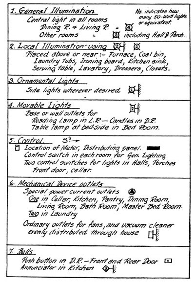
Unless specified to the contrary, it is usual to assume that wall outlets in the living-room are to be placed 5 feet 6 inches above the floor, in bedrooms 5 feet 4 inches, and in halls 6 feet 3 inches. The usual height at which switches are placed is 4 feet.
Thus, by using common sense and the phrase in the specifications, “All work shall meet the requirements of the National Electric Code,” and requiring the contractor to furnish a certificate of approval for the entire installation as issued by the Board of Fire Underwriters having jurisdiction in the community, the architect has a reasonable surety of securing a good and safe system of wiring and lighting.
The wood trim, the doors and windows, and the built-in furniture of the small house can make or mar its appearance more than any other one factor. Indeed, in no other form of architecture is the study of these details more important, and yet in no other type of building is the limitation of cost more exactingly imposed upon the architectural treatment of the trim.

The kind of stock trim which some mills
continue to keep on hand
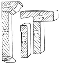
A good Stock Trim
From “Curtis Co.”
By the very economy demanded in the small house, the architect must make the mouldings of his casing in the simplest possible forms. The trim around doors and windows on the exterior and interior can boast of no special mouldings. In fact the selection must be made from stock material or else the cost will be too great. Most planing mills have standard types of trim, but generally they are very badly designed. However, one cannot go wrong in using a plain board casing ¾ inch by 3⅝ inches, which has slightly rounded corners. The tops of doors and windows which have this simple casing should be capped with a fillet [Pg 131] ⁷/₁₆ inch, a head casing ¾ inch by 5 inches, and a cap mould 1⅛ inches by 2 inches. This eliminates the mitred corner, which is of such doubtful value in cheap work, since most wood trim is not properly seasoned and will quickly open all mitred joints.
To match this simple trim the window apron should be a plain board ¾ inch by 3⅝ inches, and the stool 1⅛ inches by 3⅝ inches. A plinth block at the base of the door trim in size 1⅛ inches by 3¾ inches by 7¼ inches will match up with a plain base-board, ¾ inch by 7¼ inches, or one of similar size, with a cyma recta moulding on top.
If the local mill from which the trim is purchased has stock mouldings of pleasing design, the architect may safely specify them, but he should not make the economic mistake of demanding specially designed casing from full-size details of his own. The small house cannot stand this additional cost.
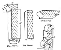
Any Mill will have
the above in stock
In selecting the trim, it is always important to bear in mind that it must harmonize with the walls and have no obtrusive appearance, since [Pg 132] it acts with the walls as a background for the furniture. In Colonial work the painting of the trim white, pearl-gray, or cream is always the most pleasing, and so the architect should select a wood which will best take the paint. White wood and white pine are ideal for this purpose. Gum wood is good, but there is always the chance that it will not hold its place and twist. Yellow pine is difficult to paint well, since the hard summer wood has a tendency to stand out beyond the softer spring wood, making the surface irregular; but this difficulty can be overcome if a number of priming coats are used to fill in the grain before the enamel is applied. It is a mistake to finish the painted trim with a glossy enamel, for this will destroy its quietness and background effect. A matte surface of paint or an egg-shell enamel finish is better.
This same principle should be followed in selecting and treating the hardwood casing which is not to be painted. The trim should never be finished with a bright, glossy varnish and stain, for nothing is more ugly in its final effect. Treat the hardwood trim, such as oak, chestnut, ash, and the like, with an oil stain; rub in a filler, stained slightly darker, and then shellac. Over this apply a wax finish, and rub this down with a shoe brush. Varnish manufacturers make grades of varnish which give the dull effect of wax, and these can be used, if desired; but why? Many prefer to even omit the shellac and depend entirely upon the wax for the gloss.
When trim is delivered to the job, it should not be stored in a damp place nor fitted in place before the plaster is entirely dry. In fact, in order to protect the trim from losing its shape, as soon as it comes on the job a priming coat, or filler, should be applied to it, and the [Pg 133] ends and back painted with white-lead and oil. It will be noticed that all well-designed trim has a gouged-out space at the back to permit circulation of air around it, and also to make it easier to fit against a flat surface of plaster.
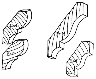
| Stock Bed Mouldings | Stock Crown Mouldings |
Mouldings for the trim of exterior cornices, string-courses, and the like are often specially designed by architects for the small house, but it is a much better plan to use stock mouldings, selecting them to approximate the design that is desired. Through the efforts of many concerns the market affords many well-designed stock patterns of mouldings for exterior purposes. The idea is sound, and makes possible a great variety of designs through the standardization of parts, but at the same time cutting down the cost.
Likewise the standardization of doors and windows is another economic aid for the small house.
As a rule, all exterior doors should be at least 1¾ inches thick, and of white pine, painted. The veneered door is not a very satisfactory type for outside use, unless, perhaps, it is protected by the porch, for even with the best waterproof glue there is a considerable tendency on the part of the veneer to break away from the soft pine core. Some consider that the 1⅜-inch-thick door is satisfactory for exterior doors in the small house, but, generally speaking, it is best to use this thickness only for interior doors.
Softwood doors, 1¾ inches thick, have panels, if they are raised, only [Pg 134] 1⅛ inches thick; while doors 1⅜ inches thick have raised panels only ⁹/₁₆ inch thick, and flat panels ⁵/₁₆ inch thick. The latter is quite evidently too thin for exterior doors.
Interior doors of veneered woods usually have flat panels, ⁵/₁₆ inch thick, except the one-panel door, which is as thick as ⁷/₁₆ inch. Such panels consist of three layers, the two outside veneers and the interior softwood core with the grain running at right angles to the veneer. The stiles and rails of well-built veneered doors are made of built-up pine blocks, glued and locked together, with a tongue-and-groove joint, and fastened at the corners with hardwood dowels. Strips of hardwood to match the veneered face should be placed on each edge of the stiles and rails.
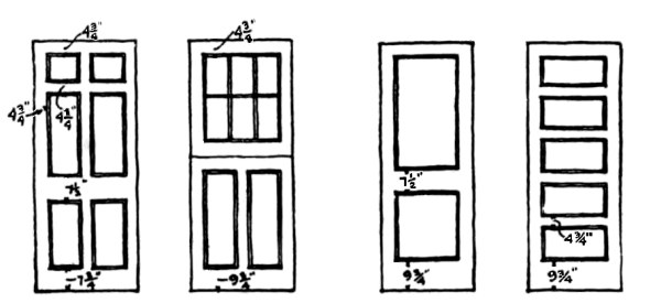
| Stock Exterior Doors | Stock Interior Doors |
The common-stock sizes of doors are as follows:
[Pg 135] The commonest type of window for the small house is equipped with the double-hung sash. This sash should be made of 1⅛-inch white pine, mortised and tenoned at the corners. The meeting rail ought to be rabbeted so that water is prevented from seeping through, and the bottom rail ought also to be rabbeted to fit over a similar rabbet in the sill. The size of the lower rail is usually 3 inches wide, the sides and top rails 2 inches wide, and the meeting rail 1⅛ inches wide. It is generally admitted that a window has little architectural charm without muntins, and these are made ¾ inch wide, as a rule. The glass of the window is inserted into the sash frame at least ¼ inch, and its plane is about one-third in from the outside face of the rails. The over-all dimensions of a window sash are determined by the size glass used, and as glass is cut in inches, the over-all dimensions of a sash will be in fraction of inches. For example, a double-hung sash of twelve lights, each 8 inches by 10 inches, will give a sash opening of 2 feet 4½ inches by 3 feet. If the lights measure 9 inches by 12 inches, then the sash size will be 2 feet 7½ inches by 4 feet 6 inches.
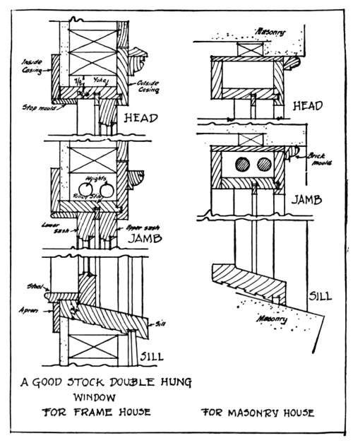
The best type of double-hung window-frame is constructed so that the blind stop is rabbeted to receive the pulley stile, preventing any wind [Pg 136] from blowing through. The pulley stiles are usually made of yellow pine, but the outside casing and sills should be of white pine. It is also a good precaution to have the sill rabbeted to receive the ground strip, so that air cannot come underneath the sill. The use of 1³/₁₆ inch-thick material is common for all parts of the frame except the sill, which ought to be 1¾ inches thick. A 2¼-inch depth should be allowed for the weights in the box, and a space of ⅞ inch left between the stud and the top of the frame. Parting strips are made ⅜ inch wide.
Where the frame is to be built into a masonry wall, the back of the weight-box is closed in, and a moulding, called the brick mould, should be provided for covering the outside joint between frame and masonry. In order to make this joint tight in hollow-tile construction, it is essential to stuff the back of the brick mould with elastic roofing cement.
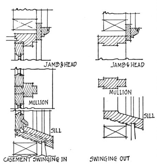
CASEMENT WINDOWS
There is not much reason to rehearse here the pros and cons of the casement window. When such windows open in, the screens and blinds are easier to handle, but the weather is apt to leak in more. When the sash opens out, screening is difficult, unless some patent operating hardware is used, but the window is more weatherproof. In either case, the difficulty of weathering can be overcome to a large extent by not [Pg 137] attempting to keep out the rain, but lead it down and around the sides, draining it off at the sill. This is accomplished by cutting a ¼-inch half-round groove around the sides and in the sill to act as a canal for collecting the water which has seeped in. A few ¼-inch round weep-holes from the groove in this sill outward will drain this collection of water off. Casement frames are made of heavier material than those used for double-hung sash, 1¾ inches being common. As the sash is hung from the sides like a door, its weight must not be so great that it will cause it to sag, and for this reason it is customary to limit the width of sash to 2 feet maximum. Some designers believe that the sash should also be at least 1¾ inches thick.
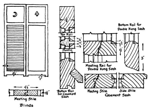
Although blinds add to the cost of the small house without apparently adding practical value, yet they are one of the most useful mediums of securing variation of color on the elevations. In Colonial days shutters served to protect the house, and were made solid with only a small hole in them, generally of some ornate cut-out design, like a half-moon, flower-pot, etc. To-day we want slats for ventilation. A good compromise, then, is to make the lower part of slats and the upper part solid, with a cut-out design. The stiles and rails of the shutter are made of 1⅛-inch material, the bottom rail being 3½ inches wide, the stiles and top rails 2 inches wide. Intermediate rails are often made 2½ inches wide. It is best to project the stile 1 inch below the bottom of the lower rail, so that water collecting on the sill can drain off underneath the blind. [Pg 138]
In addition to the blinds, the window should be equipped with screens. These should be of copper, for only this material is economical in the long run. They are usually made of ¾-inch material, and the lower rail, stiles, and top rail made 1¾ inches wide.
Other mill work of the exterior, such as porch columns, rails, etc., ought to be built up from stock mouldings and patterns. There are numerous concerns selling well-designed wooden columns. The great danger of using stock columns, however, is in the fitting. Certain stock lengths are made with well-planned entasis, but if the design calls for an intermediate length the column is cut short, which destroys its proportions. On this basis many select square columns, or thin wooden columns without much entasis. The illustrations show some common-stock sizes for other outside trim, such as lattice, top rails, bottom rails, balusters, etc.
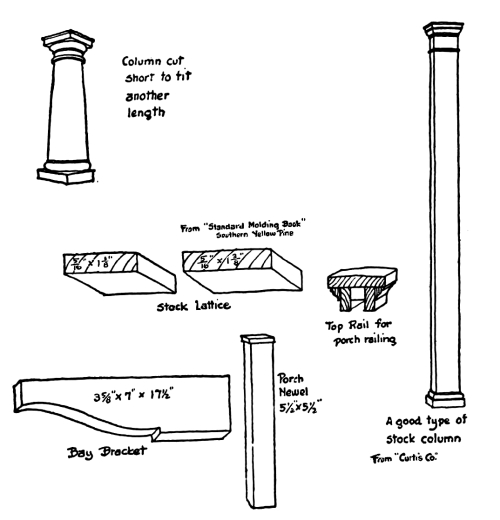
Of the interior mill work the stairs are the most important. For the small house they should be very simple, not only for economy but for appearance. Plain round and square balusters, 1³/₁₆ inch, and two to a tread, simple hand-rail and simple newel post, 3¾ inches, are more effective than elaborately turned members. The height of the hand-rail [Pg 139] from the top of the tread to the hand-rail on a line with the face of the riser should be 2 feet 6 inches. The slope of the stairs should preferably be confined between 30 degrees and 35 degrees, and the common proportion between tread and riser should be maintained (tread and riser = 17½ inches).
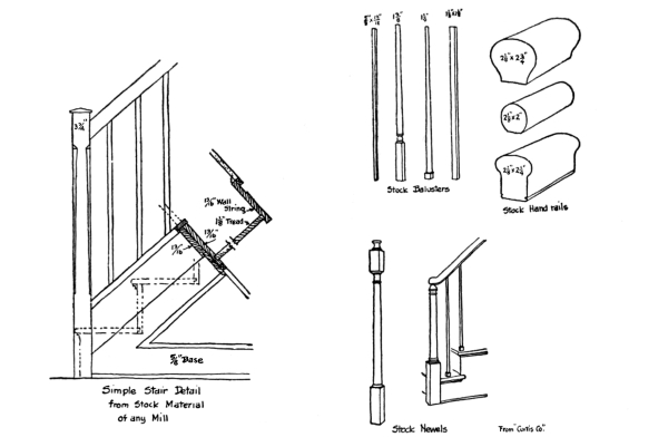
The treads should be of 1⅛-inch hardwood, and the risers of 1³/₁₆-inch softwood, rabbeted into the riser. Outside strings ought to be ⅝ inch thick where finishing on a ⅝-inch base. Inside strings should be 1³/₁₆ inches thick. Enclosed stairs between walls should have strings fitted down on treads and risers, but elsewhere inside strings should be rabbeted for treads and risers. Newels should be housed out over supports.
This is what the speculative builder
spends money on
A feature of the small house which is neglected too much is the installation of built-in furniture. There is a substantial quality [Pg 140] about such furniture which no mobile furniture can possess. The bookcase built into the wall, the window-seat permanently a part of the room, a charming mantel-piece, good panelling, built-in china-closets, tables, and benches in the breakfast alcove, a modern kitchen dresser with the equipment of a portable cabinet, dressing-tables, and closet shelves and drawers, medicine-cases and radiator enclosures are features which add so much to the small house that it seems strange that they are so often omitted. Many a speculative builder has realized the value of such furniture and sold his house upon the attractiveness of it. He knows that the young couple who purchases the small house usually comes from the small apartment, and has little furniture to spare. Here then is a place to spend money and not to economize.
What happens to the small house after it has been built? This is a question which should interest both the architect and builder, because from the answer can be had some very important lessons in construction.
To know where the weather, mechanical wear and tear, fire and water, begin the decay of the house is to know where to specify materials which will give the greatest durability to the whole.
This decay is called the natural depreciation of the house, but it is the architect’s duty to make this as insignificant as possible. It is essential to study the local conditions under which the house will have to stand. At the edge of the seashore, where the damp and salty winds are prevalent, one would be foolish to specify metal for screens, gutters, valleys, and leaders, which tended to go to pieces by corrosion. But in a dry locality the specifying of, say, galvanized iron for these parts would save money on the initial cost, and might not cause too great depreciation.
Likewise, the choice of the general materials of which the house is built should be influenced by the experience of the neighborhood. A wooden house in a seashore resort requires painting very often, and perhaps a brick house would in the end be more economical. A wood-shingle roof on a house, tucked away under the dense trees of a [Pg 142] lake shore, would have a very short life, and the use of some more permanent material would justify the additional expense.
Indeed, on all hands, in every locality, we have lessons to learn concerning what happens to a house after it has been built, and how it might have been avoided. To stimulate the reader to observe more in this direction we will call attention to some of the most obvious ways in which a house depreciates.
Examine most houses which have stood for ten to twenty years, and it will be found that the foundations in nearly every case have settled unevenly, to a greater or less extent. This may be due to unforeseen causes, such as the action of underground water, frost, and disintegration of mortar, but generally it is the result of foundations built by the rule of the thumb. A wooden house seems so light that the average builder never bothers to consider the footings nor the loadings on them. Many walls are built without any footings at all, even though part of them rest on stone and other parts on earth. Now, of course, nothing serious as a rule comes of this slightly uneven settlement, but, add it to other things, and the depreciation of the property goes on rapidly.
Uneven Settlement
As an example of this, one house might be mentioned which was greatly marred by the settling of the footings under the porch columns. These columns supported the second floor, which projected over the porch. The amount of settlement was only about two inches, but this caused the windows to lose their rectangular shape, making the operation of the sash impossible, destroyed the drainage direction of the gutters, necessitating the relocation of the leaders and the repitching of the gutters, opened up the crack between the floor and the base-board, and [Pg 143] made a large crack in the plaster wall and ceiling. The cause of it all was the building of the porch column footings upon filled-in earth, while the foundations of the rest of the house were upon rock. Uneven settlement was sure to take place under such conditions.
This same damaging effect of settlement is often noticeable in wooden frame houses, which have not been properly constructed to avoid uneven distribution of cross-section wood in the walls and partitions. Wherever there is a difference of cross-section of wood in two walls which support the same beams, there is sure to be uneven settling. The wall which has the greatest number of linear inches vertically of horizontally laid timbers will settle the most. This will cause sagging floors, sprung door frames, and open joints.
Many cracked stucco walls on the exterior have been caused by too much cross-section wood in their framing. A balloon-framed wall makes the best backing for an outside wall of stucco, because the studs extend from sill to plate without any horizontal timbers intervening.
But it can always be predicted that the masonry walls and parts of the house will settle before the wooden walls and partitions. The chimney will settle more rapidly than the surrounding partitions of wood, and [Pg 144] should, for this reason alone, be built entirely independent of any other part of the structure. Where the wooden framed wall butts into a chimney and the plaster is continuous over the brick of the chimney and the studs of the wall, there is sure to develop a crack at the joint because of the unequal settlement, unless the plaster is reinforced at this point with metal lath. Likewise, it is bad to support any part of the wooden floor upon a girder which bears upon the chimney, not only on account of the excessive sinking of the chimney, but the subsequent danger of fire which it creates.
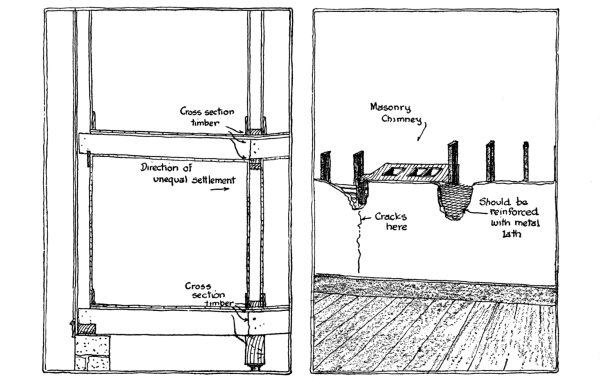
A very bad method of constructing a chimney was imported from Europe, years ago, which develops serious fire dangers from its manner of [Pg 145] settling. Instead of flashing and counter-flashing the joint of the chimney with the roof, this method employed the use of a projecting course of brick begun at the level of the roof. Thus the part of the chimney above the shingle roof was made larger than that underneath, and the outward step was used as a weather lap over the roofing material, and no flashing was needed to make the joint tight. Now, when the chimney settled faster than the roof, as it would, the upper part could not drop, but was caught upon the roof, and lifted from the lower part. This made a crack through which the hot gases could escape to the attic timbers and start a fire.
On the other hand, wooden framed walls will settle badly, too, when dry rot sets into the sills. This is a very common defect in old houses, and generally, when any remodelling must be done, the sills have to be cut out and new ones set into place. Dry rot in the sills is caused by excessive dampness with no circulation of air. Very often a builder may take great pains to fire-stop his walls around the sill, but forget to leave ventilation space, and the sill is soon attacked by the fungus of rot. Unless timbers which come in contact with masonry are treated with creosote, or painted, they will be subject to dry rot in the average damp, warm climate. [Pg 146]
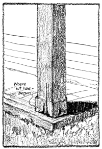
Solid Column
Many porch columns rot at their base and permit the settling of the roof. Solid columns are the least durable in this respect, for in a short time their core will go bad and the lower part will crumble. Wood base blocks for columns should be perforated with holes to permit the seepage of water under them. Cast-iron bases are preferred to the wooden one, when the column is to set upon a masonry porch floor.
Settling causes many other defects besides those mentioned. The house-drain may be broken and the cellar flooded with sewage, if the wall around the pipe has been cemented up and it settles. The pitch of drain-pipes may be altered so much that back-up action of waste water may occur; steps may be caused to sag so that they become unsafe; lintels may be broken.
The movement of the footings by frost is another evil that is noticeable in many old houses. Sidewalks are cracked, porch stairs loosened, drains in areas closed. In most cases like this the footings are not extended far enough below the frost-line, or insufficient cinder foundations are laid.
Weathered Chimney
But the action of freezing water leaves its marks on other parts of the house. Unless some corrugations in leaders are made, the ice in the [Pg 147] winter may burst them. The mortar on copings is loosened by this action, and on chimney tops, where heat and gases also help, the brickwork soon breaks down. Many failures of stucco work are directly caused by frost, and sometimes water leaks into the cells of hollow terra-cotta blocks, freezes, and bursts out the shell-like sides. The putty around the window is loosened by the drying action of the wind, and the prying action of the frost. Water-supply pipes in wall near the outside are broken when the cold winds freeze them, and the exposed gas-pipes in the chilly parts of the cellar are often entirely clogged in a severe winter. Leaks around windows in masonry walls are started by frost, and it is common to see tile on the porch floor, or brick borders and bases loosened by the same powerful agent that breaks boulders from the mountainsides.
The heat of the sun is another destroyer of the house. It is death on paint, for it is forever baking it in the steam of the dew of the previous night, and when the body of linseed-oil is gone, the paint is no good. And it dries out the wood too much some days and spoils the jointing. It warps boards up and opens the mitred joints. It causes the wood shingles to crack and shrivel, so that when the next heavy rain comes the ceilings are stained by leaks. Tar for the roof and soft cements are caused to run out of place. [Pg 148]
Then, too, there is the deteriorating influence of the artificial heat inside of the house. The fireplace tiles are baked loose from their mortar beds, cast-iron dampers are cracked, chimneys are clogged with soot and catch fire, and thimbles which receive the smoke-pipe of the furnace are broken. But the heat from the radiator does much damage. It blackens the ceiling above it by hurling little particles of dust up against it; it warps and twists the wall-paper; it misshapes the doors and windows, and breaks loose the strips of veneer, and it often spills water over the floor to ruin the ceilings below.
Added to all of the above depreciation is the natural wear and tear caused by the tenants. Floors are worn to splinters where they were of flat-grain wood; thresholds are thinned down, stair tread scooped out. Plaster is broken by moving furniture, and decorations stained by accidents of all varieties. Locks, hinges, and bolts are broken.
Particularly is the mechanical equipment of the house subject to such deteriorating influences. Plumbing fixtures are broken, pipes are clogged, and joints made to leak through the corroding action of strong acids poured down the pipes. Radiator valves are turned out of adjustment, boilers are burned out, and hundreds of other things happen to this part of the house because of careless hands.
Thus we may say that the important factors of depreciation which an architect should keep in mind are unequal settlement, action of frost, washing-out effects of rain-water, corrosion, the heat of the sun, the artificial heat of the furnace, and the foolishness of tenants.
Unequal settlement can be prevented by carefully examining the [Pg 149] construction, and the action of frost, heat, and sun can be minimized by the use of proper materials, and the foolishness of tenants can be partly offset by selecting those mechanical devices which are as near fool-proof as human hands can make them.
In the planning of the construction of the small house, the architect has many problems of selection, such as the choosing of this brand of roofing material from among many makes or the specifying of this type of furnace from among many patterns, and, in fact, the selection of the best type and the best materials which the market affords in all branches of structural and mechanical devices. If he does not specify any one brand, but merely states that the contractor shall use an approved make of paint or an acceptable brand of hydrated lime, he has [Pg 151] merely deferred his ultimate choice in the matter to a later date, for in the end he must decide whether the particular make or brand is acceptable, and in order to do this he must know enough about the various makes and brands on the market to judge wisely and in a fair spirit, for the chief motive in back of the contractor’s choice will be rather one of money than quality.
The problem, therefore, which confronts the architect in acting as judge of materials and brands as to their quality is very serious and extremely full of pitfalls, and outside of his personal experience and that of his friends, the choice must be made upon the claims of the manufacturers as presented in advertisements. Now, of course, the difficulties which advertising literature presents are the overstatements which are found in them and the suppression of facts which appear to the makers as derogatory of their product. But if the circulars of information and advertising statements are collected for any one type of mechanism or any one type of material or system of construction, it will be found that the truth of the matter will be implanted in the accumulated statements of the various concerns manufacturing these mechanisms or materials. What one manufacturer does not say another will, and very often a rival firm will reveal the defects of its competitor’s products by its advertisements. In fact, if you want to find out what is the “nigger in the wood-pile,” read the advertisements of a rival manufacturer. Of course it is not good taste in advertising to knock the other fellow’s products, but general statements are made which are enough to enlighten the alert reader as to what should be the good points to look for.
For example, suppose the architect knew little or nothing about what [Pg 152] should be the good qualities of a hot-air furnace of the pipeless type, but had before him the advertisements of various makers which we will designate as A, B, C, D, and E, although the quotations which are given are accurately taken from real advertisements of well-known firms, the identity of which we have purposely concealed under the assumed titles of the letters of the alphabet.
Let us pick up advertisement of (A) manufacturer, and select what appear to be the important statements which occur in it. We read: “The grate is slightly cone-shaped, which breaks up all clinkers and makes the fuel roll toward the wall of the fire-pot, where air is mixed with the gas. This generates a much greater degree of heat than it is possible to obtain with the old duplex and flat grates, and clinkers that would form and be wasted in other furnaces are thereby consumed.” From this the architect has learned to consider the question of the grate, and certainly he has definitely found out what is the disadvantage of the furnaces which use the old duplex or flat grates. It ought to be his aim to ask the manufacturer of furnaces using these types of grates what they have to say in defense of this indictment.
But let us continue to read: “The ash-pit is large and roomy on the inside, and is provided with a very large door, which makes it convenient for the removal of ashes.” It is evident from this that there are furnaces on the market which have this defect of too small an ash-pit and door. The architect can then mentally pigeonhole this as a point to be considered in examining a furnace.
Continuing our reading we come across this statement: “The (A) radiator is cast in one piece, with no joints to be cemented or bolted [Pg 153] together.” This is evidently a reflection upon the weaknesses of other makes which have radiators that are bolted and cemented together, and on investigation we soon learn that furnaces often have leaky radiators which permit the coal-gas to escape into the warm air delivered through the house. Here is a definite defect to be remembered.
Suppose we turn now to advertisement (B), and here we read the following: “Insulating air-chamber acts as a positive division between the bodies of warm and return air.” This is certainly a hint of a possible defect in a furnace. Perhaps not all of the furnaces are adequately insulated at this division between the bodies of returning cold air and the outgoing warm air, with the resulting loss of efficiency and sluggishness of circulation.
Reading on in the same advertisement we find the following: “The (B) smoke-plate is an added precaution against the leakage of smoke and gas.” Evidently there is some possibility of smoke leaking into the warm air, or else this device would not have been suggested, and probably there are some furnaces where this is a very serious objection.
Turning to the next advertisement, (C), we read: “Only the best grade of iron goes into the casting.” This is another consideration; for evidently, from the following, certain types of furnaces do not use the best castings, and give trouble. “Breakdowns and imperfections are reduced to a minimum. The endless series of treatments and repairs is never required.”
A further reading tells us that “the humidifier is ample capacity,” which statement suggests the possibility that not all humidifiers are large enough.
But look what advertisement (D) informs us: “No heat lost by being [Pg 154] radiated through casing into cellar.” This is certainly an interesting point to consider. And reading on we learn: “Long fire-travel in radiator insures a cool smoke-pipe and there is no fuel wasted.” This is surely a matter of design that ought to be observed in good furnaces.
Still another fact is brought to light by “Fire-pot—one piece, heavy-ribbed for purposes of increasing its radiating surface and to give it greater power of resistance against expansive force of the fire.”
But here is something none of the other advertisements have told us: “Steel radiators are preferable for the use of hard coal; cast-iron radiators for soft or hard coal or wood.” Also: “Radiators can be turned in either direction, thereby permitting smoke-pipe to be connected with chimney from the most advantageous point.”
Finally, when we read in advertisement (E) the following, “Grate-bars are quickly removed and replaced. No bolts used,” we wonder whether other furnaces use bolts, and whether there is a real objection to them.
Taking the information given in these advertisements, we can now make the following list of points to be considered in selecting any one make:
1. Is the grate so designed that clinkers will not form?
2. Are the grate-bars easily removable?
3. Is the ash-pit large and roomy and is the door amply large?
4. Is the radiator in one piece or so well fastened that it is gas-tight?
5. Is the radiator steel or a high grade of cast-iron?
6. Is the inner casing so well insulated that it prevents premature heating of the descending air-currents? [Pg 155]
7. What protection is there to prevent the chance passage of smoke into the warm air-chamber?
8. Is the outer casing properly insulated to prevent the waste of heat into the cellar?
9. Is the humidifier of ample capacity?
10. How is the fire-pot designed to increase the efficiency of its radiating surface and how is it strengthened against the expansive force of the fire?
11. Is there a long enough passage for fire-travel, so that no waste of heat is lost up the chimney?
12. Is the radiator flexible enough to permit of the connection of the smoke-pipe from the most advantageous point?
Most certainly this is an array of matters to be considered in the selection of a furnace which no one, except an expert, would think of, but they are all drawn from the advertisements, and this process of study is open to any one who is interested in learning the technical difficulties involved in the selection of this particular mechanical device. Perhaps not all of the knowledge gained is scientific, but at least there are stimulating bits of information that should be investigated.
Let us take one more example of this amusing game of comparing advertisements as applied to roofing materials. Here we will find many conflicting statements, but out of the whole battle of words we can glean some interesting truths.
Turn to advertisement (A) and we read the following: “Nearly every objection to wood shingles as a roof-covering is applicable to slates, which have still other adverse features. Slates are not fireproof. [Pg 156] Ask the underwriter how the insurance companies regard them, and especially how, in comparison with clay tiles, they are not permanent, though more so than wood shingles.... Slates attract lightning, and while the sun warps shingles and the wind rips them off, slates are easily broken, and if there is even a slight settlement or vibration, repairs are necessary. Moisture gets under them, and during the winter months especially causes them to lift up and break off. When the ice thaws, the broken pieces slide out, leaving a defective place in the roof. This will happen every winter with a slate roof, and to keep such a roof in perfect condition it must be gone over each spring and the broken slates replaced with new ones.”
Turning to advertisement (B) for asbestos shingles we read a different point of view: “Unfortunately, however, slate, particularly that which is obtainable on the market at present, does not last much longer than clay tile or tin shingles.”
But reading from advertisement (C) we are amused at the following: “Slate being solid rock, they simply cannot wear out. They cannot rust, decay, crack, tear, warp, shrink, disintegrate, melt, burn, or smoulder. They will not contract or expand under the influence of heat or cold. They never need painting. They will not attract lightning—nor will they permit the growth of moss or decaying vegetable matter.... One of the most important advantages is from the insurance standpoint. Many roofs (not alone wooden shingles) are highly inflammable; but a slate roof will not ignite from sparks from fire in an adjacent building, from passing locomotives, or from any other cause. This fact is so well recognized that insurance companies allow a very substantial reduction in rates on slate-roofed buildings.” [Pg 157]
The contradictory statements here are very amusing, but the truth can be seen between the lines, that the makers of clay tile really believe that slate is their real rival, and have searched very hard to pick flaws in it as a material for roofing. And when the advertisement of the asbestos shingle manufacturer is read, we learn that slate does not last much longer than clay tile. But both are insistent upon the opinion of the fire underwriters, and for this reason we naturally turn to see what they have to say, and we find that both slate and tile are under Class A roofing materials, with little difference made between them. As for the point of attracting lightning, why is slate used for switchboards if it is as good a conductor of electricity as a statement of the above type would imply? It is quite evident that one’s opinion of slate after all this controversy will be about on a par with one’s opinion of clay tile, and that one will realize that poor grades of either slate or tile, or poor workmanship, are rather more the causes of failure than the material itself.
Many more examples might be given of this interesting method of learning the truth from advertisements, but the principle in all cases remains the same, so that further quotations would only amuse rather than instruct.
A roofing material should not be judged by its first appearance, but rather by its condition after four or five winters have passed over it. And in choosing the roof for the small house, this is a statement which applies with even greater emphasis, since the temptation is magnified to select that material which is low in cost and bright upon its first appearance.
As an illustration, there are certain types of wood-shingle roofs which have a charm in the beginning that is apt to disappear with age. These are constructed of shingles, dipped in many varieties of colored creosote stains, browns, reds, greens, blues, yellows, and the like, and when newly laid have a warm, mottled, and colorful texture which suggests the multiplicity of tone that nature often produces with age. In fact, the designer who originated this roof was trying to imitate the aging effect of nature, much as Tiffany glass is an imitation of the effect of time upon certain ancient glasses; only in the latter case the operation is the same but the time element reduced, while in the case of the roof it is a theatrical imitation of nature at work.
And there are many other fads in roofing, all of which have as their basis the imitation of the weathering effect of nature. Ridge-poles are constructed with a sag to resemble the settlement which is often observed in picturesque old houses. Shingles are laid, like the scales [Pg 159] of an armadillo, and ridges, hips, and eaves are rounded to present the appearance of old thatched roofs. Asbestos shingles are broken with rough edges, and defective tiles are used—all for the purpose of giving that ragged appearance which nature develops with age. Now, to a certain extent there is an element of architectural truth in such devices, but they should be used with the greatest discretion, for, as has been previously asked: “If a roof looks old when it is new, how old does it look when it really is old?”
Before discussing the various methods of laying roofing materials, let us observe some of them after they have been on the house for a few years.
Of course, we are all familiar with the short life of the wooden shingle, which is only about fifteen years. But the life can be extended by dipping them into creosote stains, either just before laying or by the more convenient processes of factory dipping. Cedar has been found to be the best wood for these shingles, since it has a natural resistance to decay. The old hand-split shingles were more durable than the modern shingles, for the surface that they exposed to the weather was the natural cleavage plane of the wood fibres. The sawed shingle delights in curling and twisting out of a flat plane, and always seems to split so that the crack lines up with the space between the shingles on the course above, thus permitting the rain to leak through. And then the nails either rust away or the wood rots around them, until individual shingles drop away from the others, leaving small or large holes in the roof. It is well recognized that the sparks from a neighboring fire find a ready meal in the punk and rotten butts of the shingles, and many a house has been burned to the ground because of this. [Pg 160]
The nearest competitor to the wooden shingle in cost is the asphalt shingle, which is made from roofing felt, saturated with asphalt compounds, and surfaced, under pressure, with crushed slate of greenish or red hue. The life of these shingles depends a great deal upon the thickness of the body. Some roofs, laid with very thin asphalt shingles, develop an appearance of chicken-pox after a year or two, for the heating effect of the sun, the lifting force of the wind and ice cause certain individual shingles to bend up from the plane of the roof and, in extreme cases, even flap in a heavy gale, like so many small pin-feathers. But this is not so true of the thicker grades of these shingles. Often, too, these asphalt shingles bulge under the hot sun, but this is due to careless laying, for each shingle should be separated from the other by a small space to allow for this expansion. It takes a good many years for the crushed slate on the surface to wear off, but gradually this happens, as also the elasticity of the body degenerates. Finally, as the surface begins to moult, the shingle itself becomes stiff and brittle and begins to break off. Of course, these shingles are superior to wood in resisting sparks from a near-by fire, and their life is longer, if they have a thick enough body.
That same material used for asphalt shingles is made into roll roofings. So-called shingle strips are made, which consist of long, narrow rolls of asphalted felt with the crushed slate surface, the lower edge of which is cut out to form the lower third of the shingles, and, when applied to the roof, the appearance is identical to a roof laid with individual units. Another type of roll roofing is made to imitate wood shingles, by having a shingle pattern stamped with black asphalt upon the surface of crushed slate. It is laid on the roof from the ridge down to the eaves, lapping joints with the next roll about [Pg 161] two inches. At a distance the black pattern gives the camouflaged appearance of a shingle roof. The chief objection to any of these roofs is that the long and large areas are nailed down along the edges so that the sag and expansion of the material raises little bumps and hills over the entire roof, which, to say the least, is very unsightly. Then, again, the nails are exposed, and unless they are copper, the chances are that they will rust away before the roof is worn out, permitting the edges to become loose and the wind to get under the material and rip it away from the roof. Moreover, the roll roofing has only one thickness at any point, while the shingle roofing has either two or three layers over the entire area of the roof.
The cheaper grades of slate roof, such as one would be tempted to use on the small house, show weaknesses in aging that should not be used as arguments against slate roofs in general. These cheap roofs are built up of poorer grades of slate, and very thin sheets at that, and a poor grade of nail is used. The effect of weathering on such roofs is to chip off pieces of slate and to rust the nails, so that whole units drop off. Generally, too, in these cheap slate roofs, the tar paper is omitted from underneath, and the wind suction through the roof draws the snow through the cracks onto the floor of the attic, where it melts and stains the ceilings below. However, properly selected and well-laid slate roofs have none of these disadvantages, but then the cost of them is generally a barrier to using them on the small house.
As with the slate roof, so with the tile roof, the cost is generally the reason for not selecting it, and yet, from an economical point of view, in the end they are not as expensive, since with the less durable [Pg 162] roofs one is never sure of how much damage to the interior a leak will cause. Tile roofs of poor quality have as bad reputations as slate roofs. Small, thin tile are very brittle, and falling limbs and other objects often break individual tiles, and it is very hard to replace them. Unless the tile are laid upon a building-paper the wind suction is even worse than with slate roofs.
Probably the greatest defects in tile or slate roofs is not in the material itself, but in the flashings and valley construction. Instead of using copper the flashings are usually of tin, which is permitted to rust out because of neglect in painting. Leaks develop in the valleys and around chimneys in spite of the roofing material.
While asbestos shingles can show great practical durability, even superior to slate and tile in some cases, yet there are many instances of ugly weathering. Tile and slate roofs develop warm, lovely tones with age. Asbestos shingles, since they are chiefly made from cement under pressure, must necessarily depend for their color upon inert pigments introduced into their composition at the time of manufacture, and for this reason their color is apt rather to fade than become richer with age. Their tendency is to return to the natural color of the cement. For this reason we see on every hand red asbestos shingle roofs which have bleached out to sickly and thirsty pinks, and brown roofs that have blanched to whitish-brown, much like the color which chocolate candy develops when it is very stale. Then, too, certain makes of asbestos shingles show, as time goes on, salt-like deposits on the surface, like the whitewash which appears upon brick walls. This gives a motley appearance to the roof, for some shingles will develop this white stain more than others. [Pg 163]
The reader should not draw from these statements the general conclusion that the asbestos shingles should not be used, and that there have been none made that overcome the above difficulties, but it would be well for him to observe these defects before deciding upon any one brand.
The manufacturers of tin advise that the tin be painted on both sides when laid, and thereafter kept painted at four to five-year intervals. In other words, the tin roof is as good-looking as the paint which covers it, for it has no color or texture of its own. Can there be much charm in a roof of this kind? Can one picture a cosey and homelike small house with either a flat or standing seam tin roof? Perhaps the flat decks which do not show are satisfactory, when covered with tin, but those upon which any walking is to be done should be covered with wood lattice or else the nails of the shoes may punch through the tin and cause a leak. Tin roofs have their place and their duty to perform, but they are hardly suited to flat roofs over which is to be done much walking. Heavy deck canvas, laid in paint and covered with paint, is the best for this purpose. The ferry-boats give evidence of the practical wear of this kind of roof.
Tin or galvanized-iron shingles or imitation tiles are often seen applied to the roofs of small houses. The owner probably admired a real tile roof, and the nearest approach his pocketbook would permit him to come to it was the use of imitation tile of tin, copper, or galvanized iron. Most architects ridicule this peculiar weakness in human nature which chooses imitation diamonds, glass pearls, oil-paper stained-glass windows, and pressed-metal tiles, instead of real ones, but they should look to themselves before they throw stones, and ask who invented the imitation thatched roof of wooden shingles. [Pg 164]
The wooden-shingle roof is of such old and traditional origin in this country that it seems useless to describe the essential features of its construction, yet for the sake of completeness we shall call attention to the important points to be observed. Cypress, cedar, and redwood are considered to be the best woods from which to saw shingles. The grain of the wood should be vertical and show the edge. It is generally conceded that creosote-dipped shingles which are treated at the factory are easier to apply than those dipped on the job, and, as all wood shingles should be treated with some preservative, it is well to consider them. However, much criticism has been aimed at factory-dipped shingles, in that they are generally too brittle from overdrying in the kilns, but this is not true of all makes. The sizes and the weathering of some of the standard creosoted shingles are as follows:
16 inches lengths, random widths, laid 4½ inches to the weather, and either 5 or 6 shingles at the butt ends to 2 inches.
18 inches lengths, random widths, laid 5½ inches to the weather, and 5 butt ends to 2½ inches.
24 inches lengths, random widths, laid 7½ inches to the weather, and ½ inch thick at the butt ends.
There are about thirty varieties of colored stains to select from, and special shapes are cut for constructing the so-called thatched roof, the shingles being bent to a curve of about 20 inches radius. The pitch [Pg 165] of wooden-shingle roofs should not be less than 8 inches rise per foot for the ordinary weathering shown in the above statements. The tops of rafters are covered with shingle lath, with a spacing suitable to the weathering arrangement of the shingles. There are some who advocate the use of sheathing to cover the rafters in a tight manner and also the use of building-paper underneath the shingles, but, although this gives a tighter and warmer roof, dry rot attacks the shingle much quicker because of the accumulation of dampness on the under side of the shingle courses.
The first course of shingles at the eaves should be a double course with the upper layer breaking joints with the lower, and the shingles should project about 2 inches beyond the mouldings of the eaves and about 1½ inches beyond the edge of the gable ends of the roof.
Hips may be finished either with the saddle-board or with a row of shingles running parallel to the line of the ridge. Hips are best finished with a row of shingles running parallel with their edges, which treatment is called the Boston hip. If the courses are carried to the hip line and mitred, then the joint must be waterproofed by using tin shingles underneath the wooden ones, these tin shingles being folded over the hip. The method of flashing around chimneys, at the base of dormers, and in open valleys will be more fully discussed in connection with slate roofs, and, since the principles are the same, what is said for slate roofs in this connection is true for wooden-shingle roofs. [Pg 166]
There has been much made of the so-called European method of laying slate roofs in recent years, but this type of roof costs more than the ordinary slate roof, since special heavy slate is used at the eaves, and the weathering is reduced as the courses approach the ridge, and special care is taken in blending colored slates. While this type of roof is very beautiful, it is really, from a point of view of cost, rather out of the race when applied to the small house, for it will be hard enough to stretch the estimates of the small house to include even the ordinary slate roof.
In the preparation of the ordinary slate roof, the rafters should be covered with ⅞-inch thick, tongued-and-grooved roofing-boards. In order to prevent buckling, if they should swell with dampness, it is essential not to drive the joints between boards up too tight. As these boards are surfaced only on one side, this side is laid against the rafters and the tongues are placed upward so that a better shedding of water is secured. Good nailing with tenpenny nails is important, and all joints at ends of boards should be made over rafters. A cheaper but not so good a bed for the slate can be made with common, unsurfaced sheathing-boards. In the cheapest kind of work sheathing-boards are not used, but only shingles lath.
Over the top of this rough boarding should be tacked 11 pounds per 100 square feet slater’s roofing felt, laid horizontally and lapping joints 3 inches.
The usual commercial sizes of slates are ³/₁₆ inch thick, and of the [Pg 167] following standard sizes: 6 by 12 inches, 7 by 12 inches, 8 by 12 inches, 7 by 14 inches, 8 by 14 inches, 10 by 14 inches, 8 by 16 inches, 9 by 16 inches, 10 by 16 inches, 12 by 16 inches, 9 by 18 inches, 10 by 18 inches, 12 by 18 inches, 10 by 20 inches, 12 by 20 inches, 11 by 22 inches, 12 by 22 inches, and 12 by 24 inches. They have two holes in each piece for nails, which nails should be 1-inch copper slater’s nails, or 3d galvanized slater’s nails for cheaper work.
The first course should be started 2 inches below the line of the sheathing-boards at the eaves, and the necessary tilt is given with a ³/₁₆ by 1 inch cant strip. A double thickness of slate is used for the first course, the upper layer breaking joints with the lower. At the gable ends the slate should not overhang more than 1½ inches.
The exposure to the weather for courses of slate is determined by taking one-half of the length of the slate minus 3 inches.
The ridges of the roof may be finished in two ways, either with the combed ridge or the saddle ridge. The combed ridge is formed by projecting a finishing course and a combing course of slate on the north or east side of the roof 1½ inches beyond the top and combing course on the opposite side of the roof. Both courses are laid with slate set lengthwise, the length being twice the width of the slate used on the roof. This last course is laid in elastic roofing cement, and the nails are also covered with it.
The saddle ridge is formed by alternately butting the ends of the top course on one side with the top course on the other, and then doing the same with the combing course. This makes a zigzag joint which is closed by the elastic cement used in setting. [Pg 168]
The Boston hip is the best. Each course is brought at its upper or nailing edge to within 2 inches of the hip line. A small strip of slate then finishes this off by fitting to a mitre cut made on a slate set parallel with the line of the hip. These hip slates have the lower corner of their butt ends on a line with the next lower course, and they are lapped with the opposite hip slate and made tight with roofing cement.
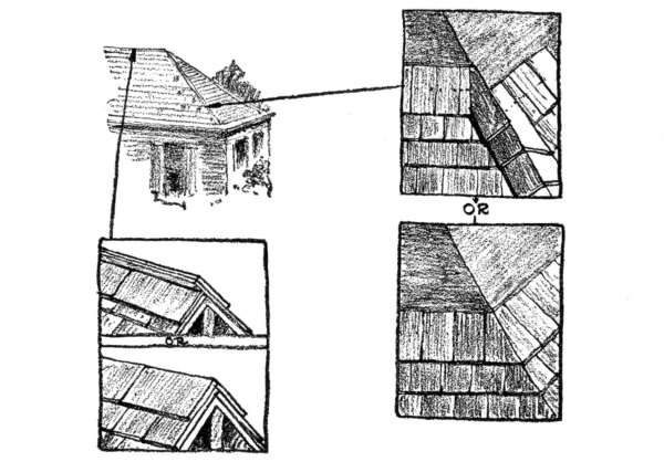
SLATE ROOF
Hips may also be finished by bringing each course up to the hip line, and mitring them with the opposite courses on the other side of the hip.
Valleys should be lined with 16 ounces copper, 4 pounds lead, IX tin, or a prepared roofing roll weighing 37 pounds per 108 square feet. Measuring from the centre of the valley to the edge of the slate along the valley, this distance should be 2 inches at the top and increase ½ [Pg 169] inch in every 8 feet length of valley, to widen it out toward the bottom. The flashing should extend up under the slate on either side about two-thirds the width of the slate used. If 8-inch by 16-inch slates are used, this means that the distance should be about 5 inches. If the slopes of the two intersecting roofs are different, and there is a chance that the volume of water sweeping down the larger and steeper incline may be forced up under the slate at the valleys, the metal lining should be crimped up (inverted V-shape) at the centre, 1 inch, to form a little dam against the rush of the flood.
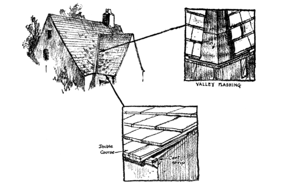
SLATE DETAILS
Flashing used against chimneys, dormers, or other vertical walls should be bent up 4 inches and extend into the slate courses 4 inches. All vertical flashings against masonry should be cap-flashed and made tight with elastic cement. The cap-flashing should extend down over the flashing 3 inches, and be inserted into the masonry at least 2 inches. [Pg 170]
Sometimes the closed valley is designed for slate roofs, in which case the valleys must be rounded out with the roofing-boards, blocked to position. The slate courses should be carried around this curved valley, but each course in the valley should be covered with flashing just under the lap of the course above and extend up toward the nails.
Preparations of the roof for the laying of tile should follow similar lines described for slate roofs. Over the roofing-boards should be tacked asphalt roofing felt, weighing not less than 30 pounds per 100 square feet and lapping 2½ inches.
The valleys should be lined with this felt, running the entire length, and then the flashing metal placed on top, secured with clips at intervals. The width of the valley metal should not be less than 24 inches, and both edges should be turned up ¼ inch the entire length of the strip. The felt covering the main surface of the roof should lap over the valley metal 4 inches. [Pg 171]
Cant strips must be nailed along the eaves to start the first course of tile, unless special tiles are provided. Copper nails should be used to fasten these tiles, and each unit should be locked with the next, as the pattern demands.
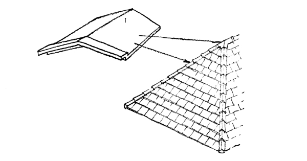
Tile Roof
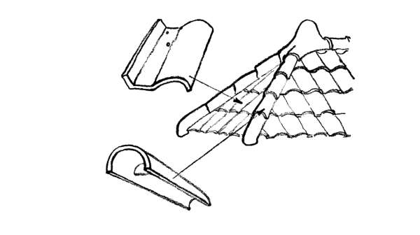
Tile Roof
Tiles which border the hips should be cut close against the hip board, and elastic cement used to make the joint tight. All hips and ridges are finished with specially designed ridge and hip roll tiles, and the interior spaces should be left empty and not be filled with pointing mortar as is sometimes done. [Pg 172]
Asbestos shingles are applied in practically the same way as slate. Over the roofing-boards should be laid slater’s felt as for a slate roof, and a cant strip ¼ by 1½ inches should be nailed along the eaves line to start the first course of asbestos shingles, which should be a double course and overhang the eaves 1½ inches. The average size of asbestos shingles is 9 by 18 inches by ¼ inch for the lower layer of the first course, and 8 by 16 inches by ⅛ inch for the upper layer of the first course and the other courses. They are laid about 7 inches to the weather, and the ridges and hips may be finished with the Boston hip, or by a specially designed ridge and hip roll. Where the hip roll is used the ridge-pole should project above the roof, or a false one be added so that a substantial nailing can be had for this tile.
The most widely advertised asbestos shingle roofs employ shingles which have rough edges, and which have various shades of coloring, some gray, some red, others reddish brown, and others grayish brown. The causes which led to the development of this type of roof were the artistic failures of the first asbestos shingle roofs. These early roofs were made with shingles which had edges as smooth and sharp as steel plates, surface texture as slick as a trowelled cement floor, and colors of either gray or pale red that were so perfectly matched that at a distance the individual shingles blended into one dead-level plane, so that the roof of the house looked more like the armored plate of a battleship than anything else—it was so perfectly made. [Pg 173]
Before laying asphalt shingles the rafters should be covered with tongued and grooved roofing-boards, and these covered with black waterproof building-paper, lapped 2 inches.
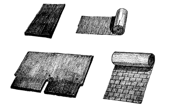
ASPHALT SHINGLES
There are two types of asphalt shingle units. One consists of a unit of twin shingles, so arranged that the butt ends which show to the weather appear as two individual shingles, and the other consists of one shingle unit. Both types are usually laid 4 inches to the weather and nailed with 1-inch galvanized nails No. 10 wire with ⅜-inch heads. At the eaves should be nailed a galvanized-metal drip edge, and over this a double course of shingles for the first course. Hips and ridges are finished with what appears to be a Boston hip, but the shingles are [Pg 174] bent over the hip line. The valleys and gutters are best when they are lined with strips of ready roofing similar to the shingles themselves.
Asphalt shingles which come in long rolls or units of four or five are laid in a similar manner, except that, due to their continuous length, they are unable to expand without bulging up on the roof.
Flat roofs, with an incline of about ½ inch to the foot, should be covered with the flat-seam roof. The standing seam may be used on roofs with a pitch not less than 2 inches to the foot. The tin is laid upon the sheathing-boards without an intermediate layer of building-paper; in fact, tar paper should never be used. In cities building codes often require that tin roofs should be laid upon roofing felt ¹/₁₆ inch thick, placed over the sheathing-boards, but this is a fire precaution against burning brands which may drop upon the roof, for this felt cushion gives an air insulation, preventing the quick ignition of the decking below the tin.

Tin Roofs
In laying the flat-seam roof a number of sheets are fastened together to form a long strip of tin. The edges are bent over ½ inch, so that they can be interlocked with the next strip. The tin is fastened to the roof with tin cleats that lock into the seams of the sheets and are [Pg 175] fastened at the other end with two 1-inch barbed-wire nails. These cleats are spaced about 8 inches apart. All the seams are flattened down, and solder well sweated into them, rosin being the only flux used.
Tin, approximately in thickness 30-gauge, U. S. Standard, is called IC, and recommended for the roof proper, while valleys and gutters should be lined with IX tin, approximately 27-gauge. It should be painted on both sides, before laying, with pure linseed-oil and red lead, or red oxide, Venetian red, or metallic brown. Two coats should be given to the exposed side and a third coat about a year later. Before the second coat is applied the first should have dried for at least two weeks.
The construction of the standing seam roof is shown in the drawings to consist of long strips of tin, made of standard sheets fastened together with the flat and soldered seam, but the edges of the strips fastened to the next strip with the so-called standing seam, which must run parallel to the pitch of the roof. Cleats, spaced a foot apart, are used to fasten the tin to the sheathing-boards. One edge of the next strip is turned up 1½ inches, and then over the top of the edge of the other strip. The cleat is locked in between the two. The upstanding seam is then turned down again upon itself, tightly locking the strips together.
For a while, during the high prices created by the war, the thought of building a copper roof or a zinc roof on the small house would have been received with a doubtful shake of the head. This is no longer the case, however, for the prices of these materials have come down to within reason, and there is no doubt as to their durability. No one has [Pg 176] questioned the weathering qualities of copper or zinc. The copper roofs which have shown such practical durability on large buildings have usually been laid about the same as that described for standing seam tin roofs. Cold-rolled or soft copper sheets, usually 20 inches wide, are used for this roof covering, weighing not less than 16 ounces to the square foot.
This type of roof is rather expensive for the small house, even with the reduced cost of copper, and for this reason a lighter grade has been made, and offered for use in the form of pressed-metal shingles of very flat design. These copper shingles have been treated so that other colors than the copper shades can be secured.
The zinc manufacturers have also placed on the market zinc shingles of special interlocking flat design for use on small houses.
It has always been a debated question as to whether pressed-metal shingles were architecturally permissible. Certainly there are some forms which imitate the clay tile shingle that are decidedly inartistic, but the more natural flat patterns are less subject to this criticism.
Actually the process of varnishing or painting the woodwork and metalwork on the house is the spreading of a thin protective coat, one thousandth part of an inch thick or less, over the surface, in order to protect it from the wear and tear of use and weather and decay. And a marvel it is that any material could be found which spread in so thin a film could withstand the chemical action of the sun’s rays, the expansion and contraction of the surface over which it is laid, the abrasive action of blown sand, hail, and rain, the natural wear of walking feet and rubbing clothes and bumping furniture, and a dozen other accidents which conspire to mar the surface of woodwork in the home.
Is it a wonder that for this protective coat of varnish all experts demand that the best materials be used? But out of ignorance it is not always so, for the lower cost of varnish and paint is more evident than the quality of the substance of which they are made.
The varnishes which are most used in good houses are made of resins, melted in a kettle and mixed with linseed-oil, and thinned with turpentine as they cool. They have the peculiar property, when spread with a brush over a surface, of hardening by a chemical change brought about by absorbing oxygen from the air, and making a strong, transparent, protective coat over the substance upon which they have [Pg 178] been applied. The kind of resins[A] have much to do with the quality of the varnish, since the linseed-oil and turpentine are apt to be about the same grade in all varnishes. Dark or light varnishes can be made; hard or soft and elastic surfaces can be produced; varnishes capable of resisting the wettest kind of weather and those which turn white under the least dampness are manufactured for various purposes, and practically in all cases those varnishes which are the best are the highest in cost.
[A] Varnish resins or gums are imported from countries that the average man knows little about. The island of Zanzibar furnishes one of the costliest and finest of gums. It is called Zanzibar copal and is the gum of a fossil tree. New Zealand furnishes the most widely used gum, kauri. It is dug out of the ground by the natives. The west coast of Africa furnishes the gum known as Sierra Leone copal, which is used much in automobile work.
The cheap varnishes which are the most abundant upon the market, and which are used for cheap furniture and houses, are made of rosin and not resin, or are resin varnishes adulterated with rosin. Most houses erected by speculative builders are finished with cheap rosin varnishes, but no architect should be guilty of specifying them, for he should know better than to attempt to save money by purchasing the poorer grades of varnishes, since the real cost of varnished work is in the labor rather than in the cost of the materials used. These cheap rosin varnishes cannot stand up under the sponge test, which is merely the application of a wet sponge to the surface overnight. The next morning the rosin varnish will be found to be white and dissolved down to the wood, and will never recover its appearance. Better grades of varnish may turn white under this sponge test, but upon drying return to their original color, but the finest grades of varnish will not be affected at all. The difference between these varnishes can also be observed by rubbing the thumb over the surface of such a fine varnish [Pg 179] as is on a piano and noticing that no effect other than a higher polish is produced, while if the same rubbing is done on a cheap varnish, it will be crumbled off from the wood. Every one has seen the ugly surface cracks which develop with age in old doors or upon old church pews in musty churches of the dark ages of American architecture. In nearly all cases these cracks are due to cheap rosin varnishes.
Before varnishing or painting any interior woodwork, it is important to observe all the preliminary precautions, or else failure may result, even though the work is conscientiously performed in the latter stages. One of these early precautions is to paint the back of all trim for doors and windows with some good linseed-oil paint, and apply a first coat of filler to the outside surface, and all this as soon as it arrives on the job. This is to prevent the wood from absorbing the dampness which is prevalent in all new buildings, and as most trim has been kiln-dried beyond ordinary requirements for construction work, it is very thirsty for water, and will soak it up quickly from the atmosphere. This trim should not be permitted to stand in the building overnight without the priming coat. As the first coat of filler is linseed-oil, there is not much excuse for not doing this, for it can be applied very rapidly. Of course where the wood is to be stained with an oil stain, the application of the linseed-oil before the stain is applied will prevent the proper penetration of the stain into the wood, and, as the architect generally insists upon seeing samples of the staining work before it is applied, the above precautions of protecting the wood as soon as it comes are often thrown to the winds.
And in connection with this matter of stains, a word may not be amiss. [Pg 180] Most manufacturers make among their many stains certain brilliant-red mahogany colors, bright Irish-green colors, and horrible yellows. These are made to meet certain gaudy tastes shown by the public, but of their use by architects no word could condemn them enough. And on a par with these stains is the varnishing with no stain at all of yellow pine trim, an architectural atrocity which is committed on every hand in small houses. The quiet browns, grays, grayish greens, and the like are the only safe ranges of color for staining interior trim, for, after all, the casing of doors and windows must blend in with the walls and serve as a background for the furniture and not screech at it. And directly in line with this statement should be emphasized the rule that highly polished surfaces in varnishes for trim are as much out of place as brilliant colors. Many architects prefer wax in place of the polish of varnish, and with good reason. The manufacturers of varnishes make certain grades which dry with a dull finish, and also show samples of beautiful dull finishes which can be secured by the laborious method of rubbing the final coat of varnish with powdered pumice-stone, water, and felt.
But before any varnishing can be done, and for that matter any painting, it is essential that the pores of the wood are filled, so that the surface to be varnished has no soft and absorbent places, but presents a hard and glossy body. Woods like oak, ash, and chestnut have such large pores that paste fillers are required to fill them in. These paste fillers consist of a solid part like pulverized quartz and a liquid part of a quick-drying varnish. It is rubbed over the surface of the wood and into the pores and permitted to set, when the excess is then wiped off with excelsior and, finally, felt. When the wood is stained with an oil stain, this filler may be colored to match. [Pg 181]
Architects are often shown samples of the beautiful finishes which are possible with the use of this or that manufacturer’s stains and varnishes, and supplied with specifications by which they are told they can secure these finishes, but much to their sorrow the results are not like the samples, and probably never will be. All of these samples are made under ideal conditions by the most careful experts. Laboratory conditions and regularity and first-class skill can produce finishes on a small sample board which could not possibly be reproduced in a building except at enormous costs. In the first place, there is always more or less dust blowing around in a newly constructed building, and not the greatest care is taken in it to provide the exact control of humidity and temperature required for drying varnishes. And, as every one knows, the men who do the painting are generally far from being the most skilful artisans of their trade. It, too, is a big temptation to put on one or two heavy coats of varnish instead of three or four thin coats, and there is not an expert living who can tell how many coats of varnish are on a piece of wood after the work is done. Unless the architect has observed each step of the application, he cannot deny, when the painter shows him the finished woodwork, that there are not as many coats of varnish on it as he required in his specifications. Yet time will tell the tale, but then it is too late.
However, the treatment of floors and stair treads is the worry of many an architect, although he ought to remember that in factories sheet steel is laid on the floors at the doorways, and even this wears through. Why should he be disheartened if after a year the stair treads and the patches of floors near the door-sills are scratched down to the wood through coats of varnish one-thousandth of an inch thick? Even the [Pg 182] best varnish will break down under this abrasion, but only the best should be used. Cheap floor varnishes are not worth the labor of laying, and yet how many spend money on them. Some architects, and with good reasons, prefer finishing the floors with wax instead of varnish. As a base for this wax, a thin coat of varnish is excellent. Various manufacturers have different formulas for floor waxes, and they are more or less complex, but generally turpentine is the softening and drying material. The wax paste is rubbed into the floor and polished with weighted brushes—a tedious job. However, it is a job which any servant or housewife of ordinary intelligence can perform, so that whenever the floors become worn around the doors or the stair treads become shabby, the housekeeper is able to repair them easily, and there is no doubt that a waxed floor is more beautiful than a varnished one. But remember the slipping and sliding rugs on a wax floor and be sure to fasten them down.
When examined critically, paint is not much more than a varnish with a finely ground opaque powder, called the pigment, suspended in it. This pigment takes away the transparent qualities of the varnish and gives a definite color to the surface. Enamels actually do use varnishes as their vehicle or base, but ordinary paint uses linseed-oil, which acts much like a varnish, in that it has the property of becoming hard and elastic under the oxidizing effect of the air.
The exteriors of most houses are painted with white-lead or zinc-white pigments mixed with linseed-oil. Zinc makes a harder paint than white-lead, but it is best to mix the two pigments together in the proportion of one-third of zinc to two-thirds of white-lead.
In extensive investigations the U. S. Bureau of Standards suggests [Pg 183] that much saving of money in paint would be made if white paint were abandoned altogether in favor of dark-colored pigments for exterior use. Horrible suggestions, but these are the facts in the case! White and light-tint paints invariably fail on the south side of a house, before the paint on the other side shows signs of deterioration. This is because the light of the sun breaks down the strength of the linseed-oil, which is the body of the paint film. For this reason dark pigments, which are more opaque, cut off the light and protect the oil film more than the lighter-colored pigments.
Another common cause of failure in exterior painting is the application of it to the wood during unseasonable weather, when the surface of the wood is wet. Paint will only properly adhere to a wood surface when it is free of any moisture.
Another one of the causes of failure of lead and zinc paints for exterior work suggested by some authorities is the use of volatile thinners like turpentine and benzine. They say that such thinners should not be permitted on the job, for they are a temptation to the painter. If raw linseed-oil is used, and it is necessary to shorten the time required for drying, some good drier should be added, say 5 per cent. This drier should be pale in color and free from rosin. Driers are usually made of oil combined with a good proportion of lead and a little of manganese.
White pine, Douglas fir, yellow pine, cypress, or any of these woods, usually contain some knots, which are sure to damage exterior white paint unless properly treated. These knots have a certain amount of pitch in them, which will penetrate through any oil paint and leave an ugly mark. They should be covered with shellac, which is not affected by the pitch. Shellac is a spirit varnish made from shellac resins dissolved in alcohol. The yellow shellac is the strongest, but the [Pg 184] white is used where a light-colored paint is to be applied on top of it. The pitch which is so bad in knots is often distributed throughout the wood, as in Southern yellow pine, and this will often cause the paint to peel off. To prevent this to a certain extent, some specifications advise using benzol in the priming coat, in order to make the paint penetrate more deeply into the wood and get a better grip on the surface.
The priming coat of any painting job should either be pure linseed-oil or linseed-oil with very little pigment in it. Its purpose is to fill the pores of the wood before the other coats are applied, for if an ordinary thick coat of paint were applied to raw wood, the surface would draw so much oil out of the film of paint that most of the pigment would be left dry and unfastened upon the outside.
Only after the wood has been given the priming coat is it then time to putty up the nail holes and other defects, and not before, because the dry wood, as in the case of paint, will suck out the oil from the putty and leave it without anything to bind it together. The best putty for this work is made of linseed-oil with enough white-lead in it to make a thick paste. The putty which is commonly used, however, is made of whiting or ground chalk mixed with linseed-oil. This is durable if real linseed-oil is used, but often some inferior adulterant is substituted.
After the holes are all puttied, the other coats of paint may be added. At least two good coats should be applied, and three coats give superior results. Plenty of time should be allowed between coats to permit thorough drying of the previous one.
The need for labor-saving devices to help in housekeeping is more evident in the small house than in the larger house, although the cost of such machinery often prevents its installation in the former, whereas in the latter it is more to be found, since the person who builds a large house is apt to have more funds to draw upon. Yet labor-saving devices really belong to the small house, for the large house is still run by the servant, but the small one is kept by the lady of the house. She rightly objects to working in the old-style kitchen, which was very large and ugly, and the useless up-keep of many rooms that are really not needed is not to her liking, so that in practice the small house is in a way a labor-saving device in itself, since it reduces the amount of house to be kept, and makes the kitchen small and attractive. Then, frankly, labor-saving machinery is more becoming to this house, which is in itself designed to save labor, and money wisely spent upon such devices is by no means out of proportion to the cost of construction, even if in direct comparison it shows a larger percentage ratio to the building cost in the small house than in the large house.
The fundamental needs which demand mechanical power in place of brawn can be classified into the following: [Pg 186]
But before such machines could be developed to a point of usefulness, some source of power had to be found which could be used by the average family. This to-day is electricity. If the house cannot tap in on some public generating plant, then it is not at all too costly a proposition to install a private generating plant run by a gasolene-engine. The rapid spread of public-service wires throughout the country and the increasing demand for private generating plants is evidence that, where money permits, the people are ready to take advantage of the power of electricity to reduce the labor of keeping house. This electric energy which is being more widely distributed has called forth invention after invention of labor-saving machinery. It would not be hard to compile a list of some five hundred or more such machines, good, bad, and indifferent. Pick up any magazine and glance through the advertisements, and a fairly comprehensive list of housekeeping machines can be made, or look through some one of the popular scientific magazines and page after page will be found devoted to new inventions along this line. For example, in the latter, this is a small list made from a page of one of these magazines: A combined electric toaster and heater, a special brush on a long wire handle for cleaning the drain-pipe of the refrigerator, an electric clothes-wringer which has rollers soft enough not to break the buttons, a combined crib and wardrobe, the latter being under the mattress, a dust-pan which is held [Pg 187] in position by the foot, a counterbalanced electric light that can be hung over the back of a chair and an electric water-heater to fasten to the faucet.
Under this classification ought to be included machines which reduce the need of cleaning, for they accomplish the same results, but in a negative way.
One of the dirtiest and meanest jobs about the house is the sifting and shovelling of ashes from the furnace. The light ashes are bound to be tracked through the house on the feet, or float in the rising warm air to the rooms above, while the sifting process is going on. The continued need of removing ashes and putting more coal in the furnace to make more ashes often disgusts the housekeeper so much that the apartment-house looks very attractive, for here this dirty work is done by the janitor.
Now the modern oil-burner, suitable to heat the furnace of a small house, represents a real labor-saving device, because it eliminates this problem of the ashes, but it requires electric power to make it practical, since a mechanical movement is necessary to properly atomize the oil for burning. Looking impartially at the latest inventions along this line that are now on the market, one cannot help but admit that they are highly desirable from the labor-saving point of view, if not always from an economical one. The easy control of the fire of one of these oil-burners is admirable. In mild weather the flame can be turned down quite low, burning perhaps only twelve gallons of oil in twenty-four hours, but if the weather suddenly becomes cold the flame [Pg 188] is easily advanced to meet the conditions. No extra shovelling of coal is required in cold weather, and the worry of banking the fire in the evening is eliminated.
But one must not forget the various improvements which have been made in coal-burning furnaces to eliminate the ash-and-coal-shovelling labor as much as possible. There is the self-feeding boiler, which has a large magazine of coal which can be filled once a day and which automatically supplies the fire with fuel as it burns up. Then, too, there is the large ash-pit in which the ashes may accumulate for some time before removal is necessary, or the revolving ash-collector sunk into the floor below the furnace into which the ashes may be dropped and taken out in cans.
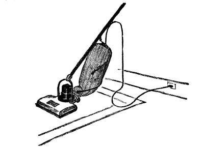
THE PORTABLE VACUUM CLEANER
For cleaning purposes, one must recognize the enormous grip that the [Pg 189] vacuum cleaner has had on the popular mind, and nearly every housekeeper would own one if money permitted it. Perhaps the installation of pipes throughout the house for a central cleaning-machine in the cellar is a little too expensive for the small home, but certainly electric base plugs should be located in the rooms to which the portable type of cleaner can be attached. Such outlets should be placed in central positions in order to permit the moving of the machine to all parts of the various rooms.
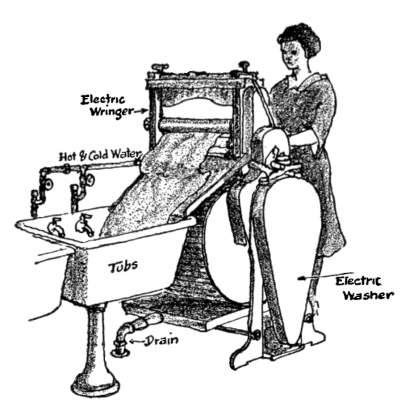
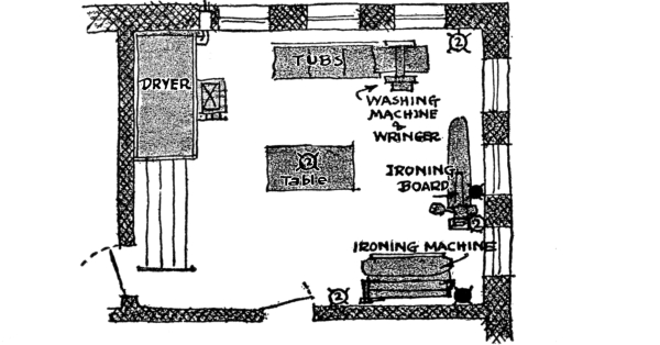
UP-TO-DATE LAUNDRY
The laundry should be equipped with electric outlets to which an electric washer can be plugged. These machines usually require about 300 watts. Electric irons require about 600 watts. If laundry [Pg 190] labor-saving devices are to be bought as a complete equipment, a small fortune can be spent upon them, for there are electric wringers, electrically driven mangles for ironing flat work, a special ironing-board with electric iron attachment, and electrically heated clothes-driers. A plan of a well-equipped laundry is shown in the cut.
DISH WASHER AND TABLE
KITCHEN DRESSER OF
WHITE ENAMELED STEEL
If we consider the machines used in the kitchen for cleaning purposes, a considerable list can be made, but the gas and oil stove and fireless cooker should not be forgotten, since they accomplish cleaning in a negative way, for they eliminate the dirt and ashes of the old-fashioned coal-range. Then, too, the automatic gas water-heater, and also the oil water-heater, give the best material for cleaning that is known to mankind—hot water. But as electricity becomes more available we have the electric stove and the electric water-heater, which is superior to the gas and oil heater, as far as labor-saving is considered. Then there is the electric dish-washer, which performs all the washing, rinsing, and drying operations. The dishes and other tableware are securely held in removable racks while being washed, thus [Pg 191] preventing breakage. When not in operation this dish-washer can be used as a white-enamel-topped kitchen-table. One must not forget the electric silver-polisher and knife-grinder and other smaller instruments for cleaning that can be operated by a small motor.
Machines of this kind include a great variety of small inventions intended to safely store the food, prepare it for cooking, and cook it. There is the small electric refrigerator, the thermonor which keeps foods chilled by evaporation of water, the ordinary ice-box, with its special door to put ice in from the outside, the special receiving-box in the wall into which the milkman can place his milk-bottles in the morning or the butcher his meat. Then for the small house is the very important kitchen-cabinet, with its special place for the keeping of flour, sugar, dish-pans, and a hundred other things that are needed to be handy at the time of preparing the food. Electrically operated coffee-grinders, meat-choppers, bread-mixers, egg-beaters, toasters, coffee-percolators, chafing-dishes, samovars, frying-pans, teakettles, radiant grilles, and other similar devices are but a few suggestions of the multitude of inventions actually on the market and found practical [Pg 192] as labor-saving machines. Why should one sweat at the brow on a hot summer day freezing the ice-cream when an electrically driven motor can do the same work at the cost of a few cents? Why should one swelter in the hot kitchen during the jam and jelly making season when an electric fan can give the necessary cooling breeze, and the electric stove apply the heat more to what it is cooking than to the surrounding atmosphere? Of course the answer is that the cost of such equipment is too high, but we are gradually learning how to make these articles cheaper, and also learning how much energy they save us. Old traditions are breaking down in the kitchen, and the new machines are accepted more readily than they used to be. No longer does the younger generation think that what was good enough for father or mother is good enough for it. Grandmother used to wear her fingers down peeling potatoes and carrots, and stain them black, but daughter prefers to use a simple scraping device of hard stones set in a waterproof substance, which acts like rough sandpaper upon the skins of the vegetables, and then grandmother used to chop meat in a bowl, but now it is put in at one end of an electric grinder and comes out hash at the other. The older generation of cooks were not attracted by labor-saving devices, but the point of view to-day is different. That is the reason that the small house is attracting more buyers to-day than formerly, for its small up-keep and its small and cheerful kitchen are means of escape from too heavy household duties.
A TABLE-SERVICE WAGON
The electric dumb-waiter belongs to this class, but it is not installed in small houses very often. However, every one can afford the [Pg 193] clothes-chute, which guides the dirty clothes down to the laundry. The table-service wagon is a very convenient help in serving a meal and removing the dishes when there is no maid to wait upon the diners. Then there is the china-closet which opens through to the kitchen from the dining-room. The dishes are washed in the kitchen and placed in the closet, and at the next meal they are taken out from the dining-room side without waste of steps. The old ash-can need not be lugged out of the cellar if a small telescope hoist is installed, and the coal can be put into the cellar through a metal coal-chute, instead of through the window. Wet clothes from the laundry can be hung out of the window on a revolving drier without going out into the yard, or placed in an electric drier in the laundry on rainy days. The transportation of small objects about the house can be very much reduced if machinery for this purpose is installed in the beginning. Most people think it is worth the price, and as soon as they see a way to paying for it they are certain purchasers.
There is no need of getting up at five o’clock in the morning to turn the draft on in the furnace so that the house will be warm by [Pg 194] breakfast. An electric thermostatic control can be made to do this, and in fact it can be regulated to keep the house in good temperature all the day. It is not necessary to light a fire to have hot water if an automatic gas-heater is next to the boiler, which lights the gas with a pilot-light when the faucet is turned on or when the temperature gets below a predetermined number of degrees. One does not need to worry about burning the roast in the oven if an automatic clock-timer is on it, which turns off the gas after the meat has cooked the correct number of hours. Food in a fireless cooker never worries the housekeeper, for it will not burn, and she knows it will be ready to serve when taken out. She does not have to stay home to let the delivery boy in with the vegetables, for he can put them into a small metal box built into the wall, which has a door that permits him to put his goods in, but does not permit any one getting an arm into the house, and the ice-man can deliver ice without calling her to the door. And so it goes; each new invention along this line removes the need of thinking of the small things about the house and of being continually on hand and a slave to them.
We often forget the elegance of the modern bathtub, but think of the labor of our forefathers when the bath night came around. The water had to be heated on the stove, the tub gotten out and filled with cold water from the pump, and then warmed up with the water in the teakettle, and after all was finished the water and tub had to be removed. It was quite an event, and there is no wonder that a bath was taken only once a week. But what is it to have a bath to-day, with plenty of hot water, a thermostatic control of its temperature, a fine [Pg 195] shower, and a warm bathroom. But such things as a bathroom with its modern lavatory, water-closet, and bathtub and tiled floor and wainscot are commonplace things, and are always expected to be installed in a house. One does not question the advisability of spending money on this equipment, and so it will be in the future with much of the machinery which we hesitate to buy to-day on account of the additional cost in the construction of the house.
If one is willing to spend the money, electrically operated shampooing-machines can be installed, curling-irons, vibrators, ozonators, hair-driers, shaving-mugs, heat-baths, etc., but these seem luxuries to us yet. But will the next generation look upon them this way? A very elegant bathroom may also be equipped with built-in receptacles in the tile wainscot for holding soap, sponges, toilet-paper, tumblers, tooth-brushes, etc. Fine white-enamelled medicine-cabinets are not uncommon to see built into the walls. Glass [Pg 196] rods for towels and glass shelves for miscellaneous objects add much to the practical up-keep of the bathroom. Faucets over the bathtubs and lavatories are now covered with white enamel and have porcelain handles, so that the work of polishing nickel ones is done away with. Water-closet bowls are designed with such deep water-seals and with such powerful flushing-jets that they do not need the cleaning that the older types required. Tubs are built into the walls and down on the floors, so that dirt cannot collect under them, as it did under the old leg-supported tubs. Thus each year brings forth more improvements that are helping to reduce the labor of keeping house.
Concrete has become such an excellent servant to the needs of various objects built around the house that no apology will be offered for devoting a chapter to its use. Of course, one is familiar with the artistic flagstone walk with open joints through which the grass is allowed to grow, and one cannot deny the beauty of brick pavements; but in spite of these the concrete walk is found about more houses wherever one goes than any other type, and, although in most cases very ugly, yet it cannot be relegated to the past even by the most fastidious, for its existence depends upon very fundamental qualities of practical serviceability. And likewise, although we may not have seen concrete walks that had the charm of rubble-stone or brick, yet they are coming to be used more and more, for they can be made to appear very beautiful if properly made. Concrete garden furniture, concrete pools, fountains, garden ornaments, tennis-courts, and other familiar adjuncts to the lawn about the house, are making themselves evident on all sides. There is something about the material that lends itself to such uses, for even the owner of the house can get out and work in it, and need not call in a contractor.
| Rough Cast Finish or Splatter Dash |
Pebble Dash |
However, much of the prejudice that exists against concrete is due to its usual ugly appearance, which is no fault of the material but of the one who built with it. We see too much concrete that is dull, pasty, [Pg 198] and gray, and marred on the surface with cobweb lines of cracks; but this need not be. Concrete surfaces can be made as brilliant as any other material by properly treating it. All that is needed to do this is to carefully study the methods of producing textures, and texture is nothing more than breaking up the surface into small patches of light and dark, so intermingled that they give interest. For example, after the forms have been removed, the outside of the concrete can be covered with cement mortar, thrown onto it with a whisk-broom, which will make the mortar stick to the surface in little lumps and hills. The light playing over such a surface will cast shadows in the hollows between the lumps and light up the tops of the lumps. This will give a texture of interest that is pleasing to the eye. On the other hand, the cement mortar may be plastered over the surface of the concrete and used as a sticking bed to hold small pebbles of different colors and shades thrown against it. These pebbles will be colorful, some dark and dull and some light or sparkling like glass. Thus a play of broken light will be thrown back from the surface to the eye, and the observer will be pleased. Then, too, the outer layer of the cement, which was next to the forms, may be composed of white cement and some aggregate like small chips of marble. When the forms are removed it will be found that [Pg 199] this beautiful aggregate will not show, but the entire surface will partake of the monotonous white or gray of the cement. However, if this thin coating of cement is removed, then the variety and sparkle of the aggregate below will be revealed. This might be done by striking the surface all over with a stone-cutting tool which is used to surface stones, or it might be done by a scrubbing or rubbing with carborundum blocks. There are innumerable ways by which texture can be developed on anything made of concrete, and experimenting in this line is a most fascinating employment. For this reason, if properly handled, concrete is particularly adapted to the making of all kinds of house accessories, since it is also easily shaped in moulds.
| Finish made by the Pointer | Finish made by the Bush Hammer |
The materials used for this concrete work have much to do with its success. Ordinarily there is no need of inspecting the cement, for most of the well-known brands of cement on the market are about as reliable as human effort can make them. The materials which do need consideration, however, are sand and gravel. The one essential of sand is that it be free from loam, mica, clay, and organic matter. No sand should contain more than 3 per cent by weight of loam or clay or 1 per cent of mica. The quantity of loam or other fine impurities can be determined by shaking the sand up with water in a bottle, and allowing it to settle. The fine impurities will settle on the top and its [Pg 200] proportional relation to the sand estimated. To determine whether the sand has much organic matter in it, a 12-ounce prescription bottle can be filled with sand to 4½ inches and then added to this should be added a 3-per-cent solution of caustic soda until this solution and the sand fill seven ounces. The contents should be shaken well and allowed to stand for twenty-four hours. If the liquid which settles on top shows a dark color, then the sand has too much organic matter in it, but if it is clear or slightly yellow it may be used without washing. The size of sand particles should be such that they will pass through a quarter-inch screen.
The usual size of aggregates should range from one-quarter inch to an inch and a half in diameter, and the various sizes should be so graded that they will make the most compact mass. The common run of bank gravel must be screened and washed. To make really good concrete that is water-tight, the grading of the aggregate is most important.
In fact, to determine the various quantities that should be used of the materials on hand, some method must be adopted to give the quantity of cement necessary to fill the voids in the sand and the quantity of cement and sand necessary to fill the voids in the aggregate. A rather crude way of doing this is to employ water as the measure of the voids. Fill a pail with sand, and then pour water into it until the water, which is absorbed by the sand, comes to the same level as the sand. Note the quantity of water used up. If it represented 45 per cent of the volume of the sand, then it is known roughly that about 50 per cent of the volume of the sand ought to be the quantity of cement needed to fill in the voids of the sand. Thus, one part of cement to two parts of sand. If now the gravel is measured in the same way and it is found [Pg 201] that the voids show about 40 per cent of the volume of the aggregate, then, assuming a little more than the water shows, about 50 per cent of sand and cement will be required to fill up these voids. That is, there should be just twice as much stone as there is cement and sand. We finally, then, arrive at the proportion for the concrete as follows: 1 part of cement to 2 parts of sand to 4 parts of gravel.
The amount of water which is added to make the mixture of concrete should not be too much. It should be of such a quantity that the mix is mushy but not watery, even when it is to be poured into forms.
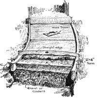
Concrete Sidewalk
It is generally recognized that one-course concrete sidewalks are the most successful when built by the average workman, for the slab is of one uniform body and not two layers, which might not have knitted together properly. For porch floors and walks these slabs should be 5 inches thick and laid on a good foundation. It is best to excavate 4 inches for the depth of the walk, tamp the ground, and pour water over it, to note whether it is absorbed or stays on top. If it is not readily drained off, it ought not to be used as the foundation of the walk, but should be excavated to a depth of 10 inches to 12 inches. In this excavation should then be tamped gravel or cinders, and some provision should be made by which any water that would seep through this gravel may be drained off. The timbers used for the forms along the edges of the walk may be 2 by 6’s, held in position with pegs. Slabs should then be determined for length. Usually they should not be in excess of 6 feet in any one direction and ¼-inch expansion joints [Pg 202] should be placed in the walks every 25 feet. If alternate slabs are laid, the forms can be removed, so that the intermediate slabs can be poured between them. Of course, a partial bond will be developed between slabs in this way, but these joints will be the weakest point in the walk, and if settlement takes place unequally and one slab breaks from the other, the crack will develop at this joint and not appear on the face. The expansion joints should, however, be real separations, made with strips of asphaltic felt set between slabs. The usual mixture for concrete walks should be 1 part cement to 2 parts sand to 3 parts of gravel. The mixture should not have too much water in it, and when poured into the forms the top should be levelled off with a straight stick stretched across from one side of the form to the other. Too much trowelling should be avoided, since this is apt to draw excess water to the surface and also cement, which will show hair cracks when hardened. It is best not to use a metal trowel but a wooden one, so that a partial sandy surface is made. After the walk has been laid it should be protected from drying out too quickly by laying over it 4 inches of earth or two or three layers of burlap, which should be wet down about twice a day for a week. All walks and porch floors should have graded tops, so that water will run off of them. This is usually ¼ inch to the foot. [Pg 203]
Sometimes porch floors give trouble from “dusting” and wearing away of the surface to a gritty and rough condition. This may have been caused by allowing the floor to dry too quickly or by having trowelled it too much and drawn cement to the surface. It may be remedied by using some one of the commercial floor hardeners or by painting the floor with water-glass solution or boiled linseed-oil. Water-glass solution should be diluted with 4 to 6 parts of water and applied with a brush in as many coats as the concrete will absorb. When boiled linseed-oil is used, it should be allowed to dry between coats, and as many coats should be added as the concrete will absorb. Both of these treatments will darken the floor, but the latter will darken it the most, and appears to be more effective.
In laying out any other platform construction of concrete, such as a tennis-court, the same principles of construction should be observed which were given above for sidewalks. However, more care should be taken with the drainage and foundation of the tennis-court. Not only should the 6-inch cinder or gravel bed be laid, but all around the outer edge of the court should be dug a trench about 18 inches wide and 3 feet deep. There should be laid at the bottom of this a drain-pipe, with open joints, sloping from the centre of one end of the court around both sides and joining together again at the middle of the other end and connected with another pipe to carry off the water of that drain-pipe to some lower level. The diameter of the drain-pipe should be about 5 inches and the slope 6 inches from its highest level to its [Pg 204] lowest level. The upper surface of the court itself should slope across from one long side to the other with a pitch of 2 inches. The division lines of the slabs should follow as closely as possible the division lines of the tennis-court. The length of the concrete platform should be 21 feet greater at each end than the length of the court and the width 12 feet wider each side. This makes the entire concrete court 60 feet by 120 feet.
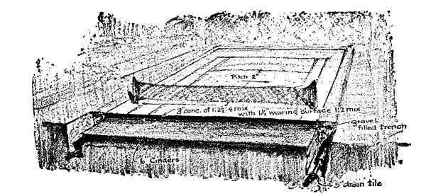
Concrete Tennis-Court
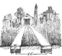
Concrete Runways to Garage
Such driveways may lead to the garage or up to the porch of the house. One of the cheapest types to the garage is a double runway for the wheels of the automobile. These runways should be about 4 feet 8 inches on centres and made 18 inches wide. They should be constructed in the same way that walks are built.
Where a full-width concrete driveway is built, it should be made about [Pg 205] 6 inches thick at the centre and 5 inches at the edges, sloping from the centre out. At intervals of every 25 feet expansion joints should be built as was specified for walks.
The only difficult problem in the construction of concrete steps is the making of forms. These should be well braced to prevent bulging when the concrete is tamped into them. The aggregate ought not to be over ¾ inch diameter, so that as the material is tamped into the forms and the sides spaded, a good surface will be left when the forms are removed. If the aggregate is too large, some pieces may catch along the forms, and when they are removed large holes will be found in the risers of the steps. The treads should be finished with a wood trowel.
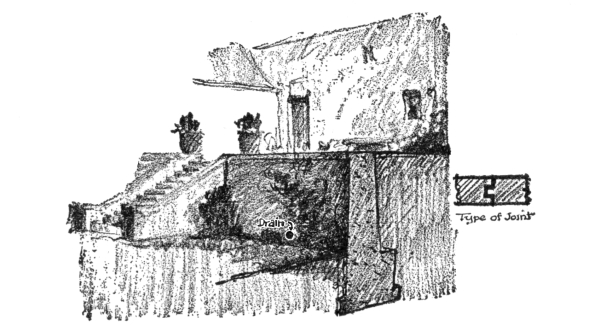
Concrete Garden Retaining Wall
Wherever terraces or lawns need the support of a small retaining wall, [Pg 206] concrete is excellent for this purpose. The foundations of such walls should be carried down below the frost-line. The usual mixture is 1 : 2 : 4. Drains should be built at intervals along the lower part of the wall, to allow the seeping ground water to come out. At intervals of about every 25 feet expansion joints should be made, somewhat the shape of the tongue and groove in flooring. The base of such a retaining wall should be at least as wide as ⁴/₁₀ the height of wall.
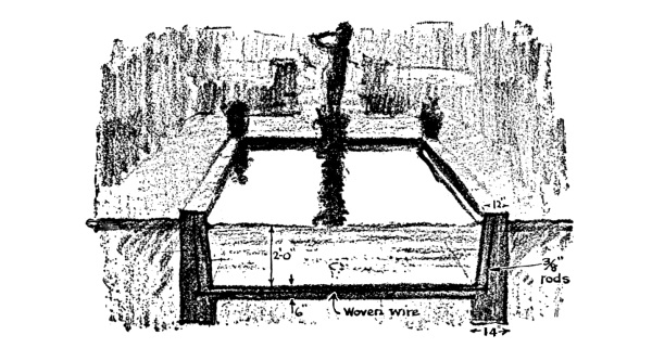
Concrete Pool
Such ornaments to the garden are not entirely outside of the possibilities of the small house owner’s pocketbook. They should have the exterior walls carried down below frost-level, and the bottom and sides reinforced with steel. For the bottom woven-wire reinforcement will answer the purpose and for the sides ⅜-inch reinforcing rods should be used. These pools ought not to be more than about 2 feet deep, in which case the bottoms may be made 6 inches thick and the sides 12 inches at the top and 14 inches at the bottom. [Pg 207]
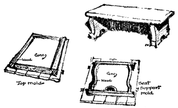
Simple Types of Concrete Garden Seats
There is no great difficulty or secret in making simple garden furniture of concrete. Generally where the furniture is of simple lines, the mould can be made of wood. If, say, a bench is to be made, the top might be moulded as a slab of concrete, and the legs at the ends as slabs, and all fitted together. If flower-boxes are desired, the mould would necessarily have to be a little more complicated, but not greatly so. The one thing to remember in making any of these moulded bits of concrete is that they should always have embedded inside of them reinforcing wire lath.
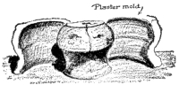
Concrete Vase for Garden
Of course the making of ornamental pots and vases is rather difficult and takes some skill. Here the original shape must be modelled in clay, and a plaster mould made of it, which is shellacked inside and greased. Special cores must also be designed, and where fine surfaces are desired various processes of mixing ingredients must be resorted to. This is a special field of itself, and men who do this kind of work generally have studied out methods of their own. Some examples of this kind of work are illustrated.
There are not many architectural motifs that can be used in designing the small house, and the ones which are employed over and over again are fundamentally a part of the construction. The plan must build up into block forms, because of the requirements of construction, and the designer has only a handful of shapes that make good roofs, for the same reason. The varieties of dormer-windows that he can put on the roof are limited to a few that are capable of being reasonably constructed. He cannot be original in the forms he selects, for they have all been thought out before. He should know them as he does the alphabet and build with them as he builds words with letters.
For example, take the plan of the small house. Can there be much room for originality here? Usually there are at the most four rooms which must be arranged on the ground floor of the small house: the living-room, dining-room, kitchen, and pantry. On the second floor are generally placed the bedrooms. Does it not seem reasonable to assume that all of the best combinations of so few rooms must be quite limited in number, and that the chances are that they have already been thought out? Many a young designer has labored enthusiastically upon what he believes is his original layout for a small house, only to find later [Pg 209] that his solution has been already worked out and perhaps a trifle better. When an inventor tackles any particular problem, his first step, if he is wise, is to consult the patents which have previously been issued along this line, and then he will know what has been done.

| Square Plan | Rectangular Plan |
“L”-Plan |

| Rectangular Plan with Small Extension |
T-Plan |

| Combination of “T”-plan with L-plan |
U-Plan |
Try as hard as he will, no designer can get away from the fact that the cheapest arrangement of rooms in his small-house plan makes a square unit and builds a square block house, but that such a plan is one of the most difficult forms to make pleasing to the eye. For this reason the room arrangement, which gives a rectangular-shaped house, is more often adopted. But we often tire of too much repetition of the rectangular house, and designers try to vary it a little. There is not much leeway here, however. By adding a wing at right angles to the main rectangle of the house, we can have an L-shaped plan which is easier to give architectural variety to, but very uneconomical, for the number of linear feet of exterior wall for a house of this shape is just as great as that for a house which is a rectangle in plan, as long as the L and as wide. This also holds true of the U-shaped plan and the T-shaped [Pg 210] plan and the combination of the T and the L shaped plans. In fact, as soon as the designer tries to get away from the simplest rectangular shapes in the small house, the economic reins pull him back, and he must go slow in selecting too picturesque plans. Limited, therefore, in his possible scope, the real work of the designer should be one of perfecting the acceptable solutions which have been already worked out. Only once in a generation are absolutely new arrangements stumbled on.
| GAMBREL | GABLE |
| WALL GABLE | HIP ROOF | FLAT ROOF |
On top of these various-shaped blocks, which these plans will form, a roof must be erected. Here again one would think that the architectural motifs would be quite varied, and yet when the matter is studied it is not the case. There are only five fundamental shapes of roofs which can be placed upon these blocks, and two of these types are really the same, and another ought not to be employed, so that, after all, there are actually only three fundamental roof motifs to use. These are the gable roof, the gambrel roof, and the hip roof. The wall-gable roof is merely a type of end treatment for the gable roof, and the flat roof is not suited to the average small house in the country or suburbs, because of traditions. [Pg 211]
AB
These two houses are ugly as sin, yet are considered very practical. All rooms on 2nd floor are square and cellars are high and dry.
C

This house is considered impractical, because rooms on 2ⁿᵈ floor are not square and are lighted with dormers, and the cellar is low and partly omitted. But architecturally something can be said of it.
In the small house the designer has the choice of either placing these roofs above the second floor or placing the second floor within the roof. Where the former is selected he sets for himself a very difficult architectural problem—that of trying to make the proportions of a house limited in ground area fit under a roof placed too high. This has rarely been solved with any satisfaction, for in nearly all cases the house looks too high and stilted. The comparative drawings show how true this is. Notice how house A and B look stilted, while house C has a charm which no manner of designing would ever add to the former. Is it not a fact to be reckoned with that the small house is best solved architecturally if the second floor is placed within the roof? Economy of material is certainly secured in this way, and the construction is greatly simplified. The chief difficulties are to properly ventilate these rooms under the roof, and to give them good lighting without making too many and too large dormers. This is a hard problem, but it has been solved successfully. The Dutch gambrel roof [Pg 212] was developed for this purpose, and there has been no doubt as to its beauty, except when wrongly used by placing it above the second story or poking the second floor through it in one long, single dormer.
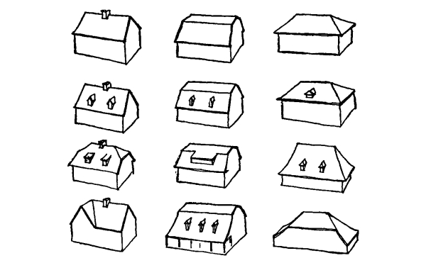
VARIATIONS OF DESIGN DEVELOPED FROM THE FEW FUNDAMENTAL STRUCTURAL MOTIFS
It is quite evident from the above how important the roof designing is in the small house. It goes without saying that the simplest arrangement of roofs is the cheapest to build and the easiest to maintain. Every valley means a leak at some later date, for as careful as may be the builder, the history of roof valleys shows that they leak sooner or later. The designer cannot freely mix his roofs either. Gambrel roofs, hip roofs, and gabled roofs do not go together harmoniously, without considerable study, and as a general rule they should not be required to do so. The usual methods of construction of these types of roofs are indicated well enough in the drawings and need no explanation. The ridge-poles in all cases are not of any structural importance, but act as alignments for rafters. For this reason they are made only an inch thick. Hip rafters have much the same function in hip roofs. Whenever valley rafters are needed, these must be designed like [Pg 213] floor girders. If dormers are built into the roof, it is customary to double the rafters around the openings. Where gable dormers are constructed, one of the valley rafters must be extended to the ridge-pole, or else the rafters will collapse.
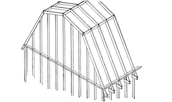
GAMBREL ROOF CONSTRUCTION
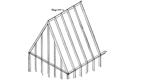
CONSTRUCTION OF GABLE ROOF
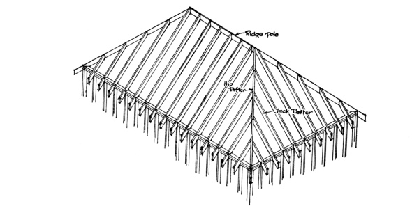
HIP ROOF CONSTRUCTION

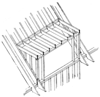
CONSTRUCTION OF
A DORMER
Even when it comes to the design of dormer-windows, the limits of originality are quite restricted. The drawings show all of the possible types that have been used with any success. Variations in the proportions and the details of these motifs is about all that the designer can hope for, and yet this is one of the hardest problems to solve. The correct designing of dormer-windows is a very rare thing to be seen. How many houses of modern Colonial style have ugly dormers! They are usually made too large and too wide and fat. The dormer-windows [Pg 215] used in the old Colonial houses were narrow and high, and in those proportions were their charming appeals. To-day a double-hung window with weight-boxes is used in these dormers, and the whole width made too wide because of these additions to the sides. This is a warning that the designer should be careful in adapting old motifs to modern requirements. This particular problem has been correctly solved with the use of the weight-box, but how many times it has not been solved is evident on all sides. Another unfortunate use of the dormer-window motif is the extension of the second floor up through the lower slope of the gambrel roof. This cuts away any legitimate lower section of the gambrel roof, and in order to preserve it, the designer projects it outward from the ends of the house, and has it skirt by the side of the second floor like an added toboggan-slide with no earthly reason for its existence. Then, too, the prairie-schooner dormer, the semicircle one, and the eyebrow dormer are certainly types to be used with great care, for they can become eyesores without effort, and they cost a good deal to construct. Where the dormer is to be made inconspicuous the flat-roof type has been successfully employed, but the roofing material on it should be tin or copper. In some of the trap-door types of dormers where the pitch is very slight, the roofing material ought to be of sheet metal. The sides of dormers are made less conspicuous by [Pg 216] covering them with the same material as used on the roof, but this is not always desirable. However, all vertical joints of dormers with the roof should be carefully flashed to prevent leaks.
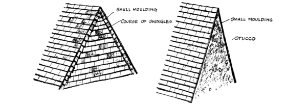
FLAT TREATMENT OF GABLE END
The treatment of the gable ends of dormers is practically the same as that required for the treatment of the gable ends of the main roof. Here again, although on the face of it there seem to be innumerable ways of treating the gable ends of roofs, yet there are comparatively few methods. The drawings show about all the possible ways, and any types which appear to differ from these can be shown to be merely variations. The simplest method of treatment is to place a small moulding under the ends of the shingles. A variation of this can be made by adding a wide board below the moulding or a course of shingles running parallel with the edge. The classic cornice can be used, but great taste is needed in handling this motif, for any pitch which is not of the traditional classic pediment form is apt to look badly. The verge-board motif comes from half-timber traditions, and is generally used in a very careless fashion. In general, it usually looks best when some visible means of support is made a part of the design. [Pg 217]
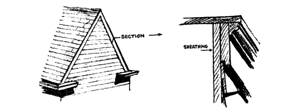
FLAT TREATMENT OF GABLE END
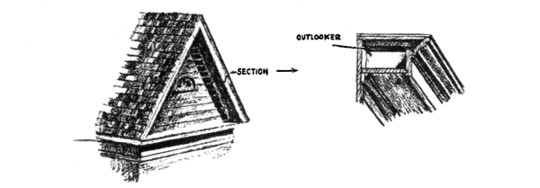
ADAPTATION OF CLASSIC PEDIMENT
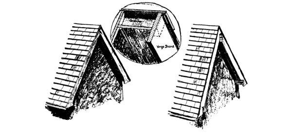
VERGE-BOARD TREATMENT OF GABLE END
[Pg 218] The shingle imitation of the thatched-roof gable is one of those amusing architectural fads which do not have very deep roots, and sooner or later are forgotten.
The wall-gable treatment is very dignified, but is usually associated with larger houses, but when simplified it has a charm which none of the other motifs can offer.
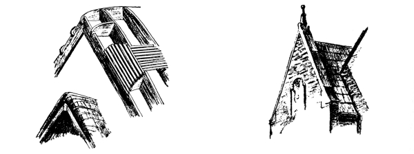
| SHINGLE IMITATING GABLE END OF THATCHED-ROOF |
WALL GABLE |
Other than these few, there are no common motifs to use in adorning the gable end of a roof. This and the previous statements only go to prove that the originality of design in the small house is limited within a narrow scope, and that the real beauty is not obtained in trying to find different forms, but in trying to use the traditional structural forms in the best proportions and giving careful attention to the details. In fact, it has been said that house designing is largely an assembling, into pleasing general proportions, of carefully designed traditional details.
The art of building has grown by evolution, like other things in this world. The carpenter who builds in wood to-day builds according to certain customs which come down to him from centuries of carpenters. Modern methods of constructing the small house have all human history for their background. When we speak of modern methods, we merely refer to those which are used at this time, as they have evolved from past experience and been considered satisfactory. To hear some architects and builders talk, one would think that modern America had the monopoly on good construction, and that our system of building was newly invented. How often have we heard remarks like the following from the self-styled practical man: “The genius of the present age is eminently practical and constructive. Improvements of every kind and ingenious contrivances for easily effecting results, which in past ages were only accomplished by slow, laborious effort, ... etc.”
But they were saying this kind of thing in 1858, for the above is quoted from a book of this date, so that even the practical man is traditional in his remarks about building.
There are also too many young men to-day wasting their time [Pg 220] discovering what they think are new ways of building, but which have been known for centuries and discarded as unsatisfactory. If they would only study what had already been done, they would save themselves a lot of trouble.
The styles in designing houses may change from year to year, or more likely from generation to generation, but the methods of building and the traditions in back of them continue on, with only slight changes which mark the evolution of the art. In as brief a period as we have had in this country to produce domestic architecture, we can notice very distinct styles of design, but running through them all are similar ways of building. Our earliest Colonial houses were built according to traditions brought over from England. These traditions in turn had deep roots in Europe, back to primitive days, when houses were not much more than temporary, movable shacks.
There is, however, one general trend through which building methods seem to pass. First, we have rather heavy, clumsy ways of building; this is followed by a long period of experimental cutting down of the materials of construction and standardization of parts; following this comes the stage of extreme lightness of construction, when the builders go as near the limit of safety as possible, and then accidents occur which tend to discredit the system.
The early English houses were built of heavy oak-trees. Later half-timber houses used smaller structural members and more standard sizes. These traditions were brought to this country, but it was soon found that heavy oak was not necessary for their stability, but that [Pg 221] some of the native soft woods would answer the purpose. The thinning-down process continued, until we developed the frame dwelling of balloon construction which is practically built of 2 by 4 pieces throughout.
We are now having a building code formulated by the United States Department of Commerce, which is intended to establish the minimum requirements for small-house construction, so that greatest economy of material can be secured, but also a precedent set for the minimum cutting down of material in building. In the compilation of this code this tendency to reduce the quantity of material used was very evident in the discussions which centred around the problem of whether the brick walls for small houses should be 12 or 8 inches thick. In Colonial days they thought nothing of building them 2 feet thick. To-day we hesitate at building them as thick as 12 inches. In fact, our building codes show no uniformity of opinion on the matter, and our experts disagree. The preliminary form of the above-mentioned code has settled upon an 8-inch thickness for walls not exceeding 30 feet, and made additional allowance for an extra 5 feet in height on the gable end of the building.
The process of thinning down is still going on, as this indicates.
The illustrations representing briefly the historical progress of styles in domestic architecture in the United States are given to show how these styles have varied, and impress the reader with the rather constant undercurrent of construction methods throughout these changes.
In the early Colonial houses the wooden frames were built of heavy oak timbers which were hewn into shape and dressed down with the adze. Sometimes rafters and joists were sawn, and the further along we progress in time the more we find the saw being used. [Pg 222]
AMERICAN DOMESTIC
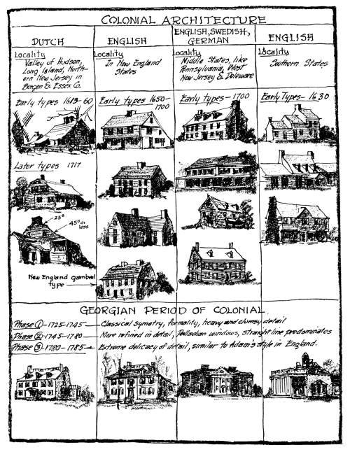
AMERICAN DOMESTIC
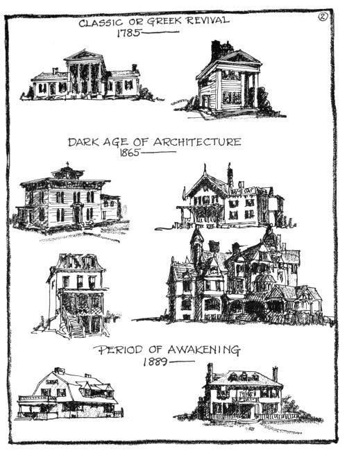
AMERICAN DOMESTIC
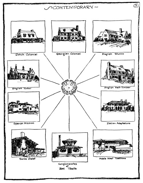
[Pg 225] If we now jump to the period between 1865 and 1889, we find that the awful atrocities of architecture were being built in the East with similar heavy frames, although slightly less massive. Where tradition was less strong in the West, the balloon frame had grown up, but during the same period houses of equally bad design were built with one or the other systems, showing that the system of construction had very little to do with the style of architecture. Even consider the variety of styles used in modern domestic work, and then one can realize that all of these different types of buildings are built much in the same way. Good design has apparently little relation to good construction, although good design is improved when it expresses the construction. We often see very beautiful houses set up for moving-picture plays, but these are built of flimsy stage scenery. We have also seen very ugly houses which make us curse the builder for having built them so well.
It is from England that we have inherited most of our building traditions of domestic work. The earliest methods of constructing a home were much the same for all European countries. Woven brushwood of the crudest sort was undoubtedly the first beginnings of domestic construction. The next step in advance was, according to a German theory, invented by a woman. It consisted of erecting leaning poles and stakes and filling the space between with inwoven wattlework. The shapes were conical, like the Indian tents, but later the gable roof shape was adopted because of the greater interior space allowed. [Pg 226]
In building the gable-shaped houses the early builders used very heavy and massive construction for the ridge-pole and its support, for they believed that this upheld the rafters. This tradition was kept alive until quite recent times, but now we know that when rafters are supported at their base, the ridge-pole practically takes none of the weight and need only be used for ease of erection.
But to our ancestors the important problem in first erecting the house was to secure the substantial support of the ridge-pole. Obviously the erection of two forked trees at either end of the ridge-pole made an excellent solution, but when the room was long this meant that the interior had to be cluttered up with interior posts. We find then that one of the primitive methods in England of eliminating the interior posts was the adoption of the cruck system of construction which is shown in Fig. 2. By selecting two bent trees and placing them together in a shape like a wish-bone, the ridge-pole could be well supported without interior columns. By placing cross-tie beams on these bent trees and extending them outward, the plates for supporting the lower [Pg 227] ends of the rafters could be held in position. This permitted the carpenters to erect the exterior walls independently of the roof, a thing which they seem to have desired.
There is another variation of the above method of supporting the ridge-pole, and that is shown in Fig. 3. Instead of selecting a bent tree, one was secured which was upright for a certain height, and then which bent to one side with a branch. By placing two of these trees together, a perfect end was formed for the house. However, this was not a very good type, since it meant the selecting of very unusual-shaped trees.
For this reason the system of post-and-truss construction, which is shown in Fig. 4, was the natural outcome of the above. Diagonal bracing at the corners evidently was found to be useful in resisting high wind-storms, and it was usually employed.
There apparently remained a distrust of masonry walls among the carpenters, for they continued to support the roofs entirely upon heavy timber framing, and records show that the exterior walls were built up after the roof-framing had been completed. There are evidences that the [Pg 228] early types of walls, after the primitive woven brushwood walls proved insecure, were made like a barricade of trees; that is, they were merely a continuous line of vertically placed tree-trunks. This, of course, was a ruinously expensive type of wall when timber became scarce, and it is no wonder that it grew to a system of construction like that shown in Fig. 5. Even this required a good deal of wood, so that the filling of the space between the timbers rather logically became masonry or plaster on lath. However, the method of building shown in Fig. 5 has all of the elements of the system of construction used in framing modern exterior walls. The most important difference is in the size of the timbers used.
The half-timber construction of the Middle Ages was only the artistic treatment of this crude system of building. In drawing number 6 is a very simple half-timber house which shows practically no attempt at all to decorate. The construction is perfectly evident, and there are no curves and carving used to ornament the building, as can be seen on some of the more elaborate houses of the cities. This simple building [Pg 229] system was the traditional background of the English carpenter, and it is not at all extraordinary that he brought his methods of building over to this country.
Even the custom of calling in the neighbors and feasting them when a house-raising was celebrated came directly from English traditions. The old post-and-truss construction of the early English houses required framing on the ground and then lifting into position afterward. Records show that the people from the surrounding countryside were called in to help, and their wages of hire were paid by the house owner with a huge [Pg 230] feast. In early Colonial days the nearest neighbors were likewise called in to help raise the frame, and the host was supposed to feed the gathering, after the work was finished, and make a jolly party of eating and drinking—a sort of social debt, but not looked upon as wages, as in older days.
The hard climate which the earliest American colonists had to face and also the abundant supply of wood which lay at their very doors were factors which slightly altered the traditions of building. After the house had been framed and the spaces between the timbers filled with plaster or masonry, the exterior was covered over with clapboards or shingles as an extra covering against the weather. The use of clapboards or shingles as an exterior covering of course was not new, for many English farmhouses show that it was used in that country. But with this difference in exterior appearance, the framing underneath was the same as shown in Fig. 7.
It was only a matter of time when the thinning-down process began to make itself evident in the traditions of Colonial carpentry, and from its clumsy beginnings it evolved into the more or less standard form of construction which we call the brace-frame.
The difficulty of securing good labor in the West, and also the increasing use of the power sawmill, made it possible and necessary to standardize a quick and easy method of building which would meet the great demand for houses in rapidly growing communities.
Quoting from the New York Tribune of January 18, 1855, we have a very interesting account of the conditions which were then prevalent [Pg 231] that brought about this later variation of the wooden frame structure. The conditions there described seem almost like our modern difficulties with labor and materials.
“Mr. Robinson said: ... I would saw all my timbers for a frame house, or ordinary frame outbuilding, of the following dimensions: 2 × 8 inches; 2 × 4; 2 × 1. I have, however, built them, when I lived on the Grand Prairie of Indiana, many miles from sawmills, nearly all of split and hewed stuff, making use of rails or round poles, reduced to straight lines and even thickness on two sides, for studs and rafters. But sawed stuff is much the easiest, though in a timber country the other is far the cheapest. First, level your foundation, and lay down two of the 2 × 8 pieces, flatwise, for side-walls. Upon these set the floor-sleepers, on edge, 32 inches apart. Fasten one at each end, and perhaps one or two in the middle, if the building is large, with a wooden pin. These end-sleepers are the end-sills. Now lay the floor, unless you design to have one that would be likely to be injured by the weather before you get on the roof. It is a great saving, though, of labor to begin at the bottom of a house and build up. In laying the floor first, you have no studs to cut and fit around, and can let your boards run out over the ends, just as it happens, and afterward saw them off smooth by the sill. Now set up a corner-post, which is nothing but one of the 2 × 4 studs, fastening the bottom by four nails; make it plumb, and stay it each way. Set another at the other corner, and then mark off your door and window places and set up the side-studs and put in the frames. Fill up with studs between, 16 inches apart, supporting the top by a line or strip of board from corner to corner, or stayed studs between. Now cover that side with rough sheeting boards, unless you intend to side-up with clapboards on the studs, which I never would [Pg 232] do, except for a small, common building. Make no calculation about the top of your studs; wait till you get up that high. You may use them of any length, with broken or stub-shot ends, no matter. When you have got this side boarded as high as you can reach, proceed to set up another. In the meantime other workmen can be lathing the first side. When you have got the sides all up, fix upon the height of your upper floor, and strike a line upon the studs for the under side of the joist. Cut out a joist 4 inches wide, half inch deep, and nail on firmly one of the inch strips. Upon these strips rest the chamber floor-joist. Cut out a joist 1 inch deep, in the lower edge, and lock it on the strip, and nail each joist to each stud. Now lay this floor, and go on to build the upper story, as you did the lower one; splicing on and lengthening out studs wherever needed, until you get high enough for the plate. Splice studs or joists by simply butting the ends together, and nailing strips on each side. Strike a line and saw off the top of the studs even upon each side—not the ends—and nail on one of the inch strips. That is the plate. Cut the ends of the upper joist the bevel of the pitch of the roof, and nail them fast to the plate, placing the end ones inside the studs, which you will let run up promiscuously, to be cut off by the rafter. Now lay the garret floor by all means before you put on the roof, and you will find that you have saved 50 per cent of hard labor. The rafters, if supported so as not to be over 10 feet long, will be strong enough of the 2 × 4 stuff. Bevel the ends and nail fast to the joist. Then there is no strain upon the sides by the weight of the roof, which may be covered with shingles or other materials—the cheapest being composition or cement roofs. To make one of this kind, [Pg 233] take soft, spongy, thick paper, and tack it upon the boards in courses like shingles. Commence at the top with hot tar and saturate the paper, upon which sift evenly fine gravel, pressing it in while hot—that is, while tar and gravel are both hot. One coat will make a tight roof; two coats will make it more durable. Put up your partitions of stuff 1 × 4, unless where you want to support the upper joist—then use stuff 2 × 4, with strips nailed on top, for the joist to rest upon, fastening all together by nails, wherever timbers touch. Thus you will have a frame without a tenon or mortise, or brace, and yet it is far cheaper, and incalculably stronger when finished, than though it were composed of timbers 10 inches square, with a thousand auger holes and a hundred days’ work with the chisel and adze, making holes and pins to fill them.
“To lay out and frame a building so that all its parts will come together requires the skill of a master mechanic, and a host of men and a deal of hard work to lift the great sticks of timber into position. To erect a balloon building requires about as much mechanical skill as it does to build a board fence. Any farmer who is handy with the saw, iron square, and hammer, with one of his boys or a common laborer to assist him, can go to work and put up a frame for an outbuilding, and finish it off with his own labor, just as well as to hire a carpenter to score and hew great oak sticks and fill them full of mortises, all by the science of the ‘square rule.’ It is a waste of labor that we should all lend our aid to put a stop to. Besides, it will enable many a farmer to improve his place with new buildings, who, though he has long needed them, has shuddered at the thought of cutting down half of the best trees in his wood-lot, and then giving half a year’s work to hauling it home and paying for what I do know is the wholly useless [Pg 234] labor of framing. If it had not been for the knowledge of balloon frames, Chicago and San Francisco could never have arisen, as they did, from little villages to great cities in a single year. It is not alone city buildings, which are supported by one another, that may be thus erected, but those upon the open prairie, where the wind has a sweep from Mackinaw to the Mississippi, for there they are built, and stand as firm as any of the old frames of New England, with posts and beams 16 inches square.”
The above address, which was delivered before the American Institute Farmers’ Club, has been quoted in detail because of the interesting point of view of the days of 1855 which it reveals. When Mr. Robinson had finished there were other comments, especially one by Mr. Youmans, in which he described early conditions of building in San Francisco. He also said that he had adopted this plan of building on his farm in Saratoga County, where he found great difficulty in getting carpenters that would do as he wished. They could not give up tenons and mortises, and braces and big timbers, for the light ribs, 2 by 4 inches, of a balloon frame. Does this not remind the modern reader of comments he has heard upon all sides these days concerning labor which will not do what is wanted but insists on doing things in the old way?
Some pertinent remarks were also made by a Mr. Stillman, who testified that he had seen whole blocks of houses built in two weeks at San Francisco, and better frames he never saw. He said they were put up a story at a time, the first two floors often being framed and sided in and lived in before the upper part of the house was up. Have we any such housing crisis as this, in these days, or did we do any quicker building of war villages than that described above? [Pg 235]
And now we read from the Preliminary Report on the Building Code Committee of the United States Department of Commerce the crystallized tradition of this system of wooden frame construction which was evolved so many years ago that we sometimes forget the conditions of its making:
“Exterior Walls.—1. Wood studding shall be 2 × 4 inches nominal size or larger, and spaced not to exceed 16 inches on centres. All walls shall be securely braced at corners. The minimum sizes specified in these requirements shall in all cases be understood as referring to nominal sizes of such timbers.
2. Exterior walls, except those of dwellings or parts thereof not more than one story high, shall be sheathed with boards not less than ⅞ inch thick. Sheathing-boards shall be laid tight and properly nailed to each stud with not less than 2 tenpenny nails. Where the sheathing is omitted all corners shall be diagonally braced and such other measures taken to secure rigidity as may be necessary.
3. Wood sheathing may be omitted when other types of construction are used that are proven of adequate strength and stability by tests conducted by recognized authorities.
4. When joists are supported on ledger or ribbon boards, such boards shall not be less than 1 × 4 inches, shall be laid into the studs and securely nailed with not less than 2 nails to each stud. The floor-joists shall be well spiked to the sides of the studs.”
Primitive window
What are the elements of design in the elevations of the small house? Surely they are not the five classical orders, as commonly used in monumental architecture, but rather they are the doors and windows. The successful placing and careful detailing of the doors and windows of a small house will have more to do with the architectural attractiveness of the structure than anything else, for, after all, the most important part of any elevation is the treatment of the holes in it. The walls would be plain and uninteresting but for the holes where the doors and windows are placed. The fenestration cannot be too large or too small, and here is the problem. We desire plenty of light and air, but we must also recognize that windows which are too large leave little wall space in the rooms, are cold in winter, and appear less homelike than smaller and snugger appearing ones. Then, too, windows which are of plain, clear glass in very large sheets make these holes appear open and black, and this is quite contrary to our traditions of the windows of a home, which should be safe and cosey. The omission of muntins from the windows of small houses is a great mistake in design, even though these small panes require a little more work to wash.
Lattice Window
Our traditions of door and window construction come, as do other [Pg 237] structural traditions, from England. Undoubtedly the earliest structures had no windows at all, but were lighted by the openings through the defective construction of the walls and also through the door. Our ancestors of those days were more interested in protecting themselves from outside intruders than they were in fresh air and sunshine in their rooms. When it was safe to build windows they were only holes in the walls. Some of the old huts, built on crucks, a construction previously described, had holes in the roofs for windows, which served the double purpose of letting in light and letting out the smoke of the fire. We get an inkling of what a window was from the very derivation of the word itself, which comes from the old Norse word “wind-auga” or wind-eye. This does not sound like a glazed sash, nor does the other Anglo-Saxon term for window, “wind-dur,” meaning wind-door, suggest a closed aperture. Of course these windows were undoubtedly closed in some way or other in stormy weather or when danger was outside. Probably a wooden board or shutter was used, which had a small peep-hole cut in it. These were hung from the top, and when opened were held in position with a prop on the outside.
There is no certainty of when the smaller domestic houses of England began to use glazed windows. In 1519 William Horman wrote: “I wyll haue a latesse before the glasse for brekynge.” This would suggest that windows of latticework were preferred because of the cost of glass, and this might have been filled instead with canvas, horn, or tile to let in some light. But another writer in 1562 says: “Lattice keepeth out [Pg 238] the light and letteth in the winde.” When glass windows were used, however, the small bits of glass were held in position by lead in diamond-shaped patterns, which probably were adopted from the form of the old lattice windows, although later it was found that rectangular panes were cheaper. But the use of glass in small houses is comparatively modern, for, before the reign of Henry VIII, glass windows were rare except in churches and gentlemen’s houses.
An old unglazed window,
the early beginnings
of sash
Traditions of stone mullioned windows were very strong, and these brought about a system of building wooden, unglazed sash which had mullions made of oak, set in a heavy oak frame. One of these is shown in the drawings. The word “sash” is derived from the French “chassis,” and its earliest spelling was “shas” or “shash.” In a book, “Mechanick Exercises,” written by Moxon in 1700, he mentions “shas frames and shas lights.” It was these old, unglazed wooden sash which gave birth to the modern double-hung and casement window.
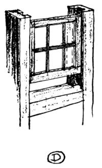
Crude beginning of the
sliding Sash
As first made, they opened by sliding in their frames, either horizontally or vertically. If they were built to slide vertically they were not counterbalanced with weights, as in our modern windows, but were held in position with a hook which caught in notches cut in the side of the frame. It is interesting to quote here what William Horman wrote in 1519: “I haue many prety wyndowes shette with louys goynge up and downe.”
It is supposed that the idea of counterbalancing these sash by means of weights, attached by a cord running up over a pulley, came to England [Pg 239] from Holland. This type began to be used about the latter half of the seventeenth century, and although the early examples were clumsy and heavy and the groove in which the sash were made to run was worked out in the solid, yet by the process of years of refinement the modern double-hung window was evolved. The traditions of these sliding windows were brought to America in Colonial days, and they proved to be the most suitable types for our rigorous climate, whereas the windows, which swung like doors from their sides, called casement windows, did not prove so weather-resisting.
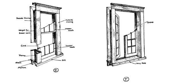
| Modern Double-hung Window | Casement Window Sash swings inward |
To hear some individuals talk, one would almost think that the double-hung window was a modern, American invention of artistic atrociousness, and that the casement window was peculiarly English, having the sole right to artistic merit. As a matter of fact, the fashion in England for casement windows was an imported one from the Continent, which never reached certain farm sections of England. In [Pg 240] fact, some years ago certain agricultural laborers refused to live in cottages fitted with casement windows which had been built by a district council. The Georgian revival, which had so much influence upon our early Colonial work, and which is also very much alive to-day in this country, brought into fashion again the traditional double-hung window.
Of course there is much to be said against the artistic appearance of the double-hung window as compared with the casement window, but when all is said and done we still go on using more double-hung windows than casement windows, for in the majority of cases they prove to be more substantial in resisting the heavy winds and storms of our climate. Every now and again we hear some prominent architect urging the use of casement windows, and we can find plenty of manufacturers of casement window hardware telling us to use them, and the makers of steel casement sash drum in our ears the practical qualities of steel sash, and one is led to wonder why they are not used more. But traditions are stronger than advertisements.
There is an ancient English expression, “put t’ duur i’ t’ hoile” (put the door in the hole), which comes down from the times when the door was not fastened by hinges and did not swing into place, but had to be lifted up and placed over the door opening. When the door was opened it leaned against two stakes driven into the ground, or some similar support. These old doors were very small, as compared with our modern doors, and were probably made of light wattle, for we read in some old [Pg 241] rhymes of throwing doors and windows on the attacking enemy. Even when solid-wood doors were used they were made of one piece of wood. Doors made of a number of planks of wood fastened together by battens or ledges were a later type. It was noticed that these sagged when hung in position and cross bracing was found necessary. These old batten or ledged doors were swung on pivots of wood which rested in sockets bored into the lintel and the sill. These pivots were called harrs, and later were made of iron. The evolution of the hinge idea from the harr is shown in a series of drawings. For many years these great hinges became a very decorative part of the door, and great care was taken with their designing. Our modern butt is quite the opposite in its characteristics, for instead of being a feature upon the face of the door it is completely hidden, except the socket and pin.
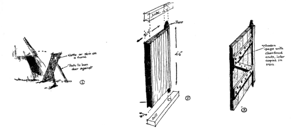
| Primitive Door | Old door of solid wood plank | Batten or Ledged Door |

An old English
Ledged Door
In building the old ledged doors, the planks were set vertically and held together with battens through which were driven wooden pegs. The ends of these pegs were chamfered, and a curious mark of tradition can be noted in the later doors, which were fastened with iron pins that [Pg 242] were also chamfered on the ends, like the wooden pins. Later construction of doors shows the use of weather-stripping over the vertical joints and also the use of various layers of planks, with their grains running at right angles in each alternate layer. The end timber upon which the harr was placed was thicker than the planking, and later the timber upon the opposite side was made heavier in order to strengthen the crude locks. With this change and the moving of the battens to the upper and lower edges of the door, and the introduction of weather-stripping over the cracks between planks, there was created the prototype for the modern panelled door. It was only a slight step from this to frame the styles, top and bottom rails, and lock rails around the panels between them.
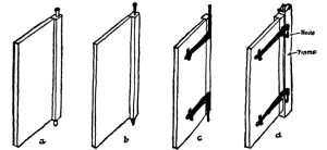
| Wooden Harr |
Iron Harr |
Iron Harr |
Iron Hinge & Hoolie |
Development of the Door Hinge
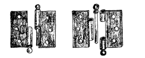
Modern
| Loose-joint Butt | Loose-pin Butt |
(9)
Another type of door that was of traditional construction, and from [Pg 243] the name of which we derive our word hatch, was the so-called “heck-door.” This door corresponds to the common “dutch-door,” which is familiar to us in Dutch Colonial houses. It was capable of being opened in two halves; the upper half could be swung in without the lower half. This type of door was invented from the necessity of protection against the sudden intrusion of strangers and also small animals, like pigs and hens.
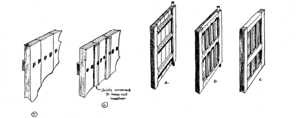
Simple Batten Door
Development of the panel door from the batten door.
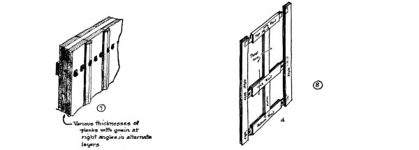
The oldest method of fastening doors was to draw a long bar across them on the inside, very much like the bars which were used in Colonial houses in this country. A hole was cut into the jamb into which this bar could be run when locked, and in the opposite jamb was another hole [Pg 244] into which it could be slid out of the way. The disadvantage of this type of door fastening was that it could only be fastened and unfastened from the inside. This led to other devices, such as a bolt that could be operated from the outside and a latch that could be lifted by a string, or a hole was cut in the door through which a small bit of metal could be passed that could be used as a lift for the latch.
To-day we think of locks and bolts and latches as distinct, but this was not so at the time they were being evolved. Our word lock was used in the sense of securing the door in any manner. But gradually, as, step by step, the various mechanisms for locking a door were developed, the word became limited in its meaning, although we sometimes use it to-day in the sense of closing the door.
There are five fundamentals which should be considered in finishing the grounds about the small house, for it must not be forgotten that the finest gem of domestic design will be lost unless it is placed in the right setting. These five principles are the production of an intimate relation between house and grounds, the formation of a natural frame about the house, the building of interesting approaches, the planting for seasonal effects, and the growing of interesting and beautiful vistas as viewed from the house.
In considering this part of the problem, the designer must begin at the very outset to solve it. If the plot is level or capable of easy conversion into terraces, then the character of the house itself may be somewhat formal, symmetrical, and dignified; but it would be wrong to build a house of this kind upon a rolling and rollicking site. This latter kind of ground demands the picturesque type of house, and the roof lines should be planned to carry up some of the curves of the hillocks. [Pg 246]
STUDIED PLANTING
In all cases, however, it is generally recognized that the small house can best be tied into the surroundings by making it low, say a story and a half or one story, for one of two stories or even two and a half offers an ungainly elevation for an architectural composition. In rare instances have houses of this proportion been artistically finished. At any rate, the house should be kept as low as possible in the front, and the ugly, stilted foundations should not protrude above the level of the lawn. Nothing is so effective in producing a feeling of intimacy between house and grounds as to keep the level of the first floor only about six inches above the grade. This, of course, makes it difficult [Pg 247] to light and ventilate the cellar, since any windows in the foundation-walls would have to open into areas. A compromise can be made by grading the lawn down at the back of the house, so that enough of the foundation can extend above the ground to permit of well-lighted cellar windows.

THOUGHTLESS PLANTING
Another method by which an intimate connection between ground and house can be produced is in the blending of wall materials and foundation-stones. If the walls of the house are of stucco, and the lower part of them built of rubble-stone, then a gradual transition can be made from the stone to the stucco by carrying the stucco down over certain parts of the stone work, so that it flows into the [Pg 248] mortar joints—like the waters of a lake flow into the little indentations of a rocky shore. This will eliminate any sharp horizontal line where the foundation-wall of stone ends and upper wall of stucco begins. As the stone has a natural intimacy with the soil, it easily makes the transition with the ground, and its effectiveness is very marked where the site is hilly and parts of the foundation are built upon little rocky juttings. This same easy transition can be made from stone foundation to brick wall. It is not possible to do it with the wooden wall, however.
But perhaps the most widely used method of producing an intimate connection between ground and walls of the house is with foundation planting. There is much abuse of this method. To surround the base of the house with billowy clumps of shrubbery, so that it appears almost as if it were springing from a bed of clouds, is not at all satisfying. Nor should the owner have to be everlastingly kept at the job of trimming down these plants or removing dead ones which refuse to grow in the poor soil and bad drainage next to the cellar. And the house should not be made to mourn behind a bed of evergreens, protected at intervals with sentinel-like cedars, dark and foreboding, against the wall and sighing and whining in the wind. Rather should a delicate use be made of foundation planting by using vines, and now and then a small shrub or little evergreen. The object should be to make a shading and transition from the green lawn to the walls of the house by carrying upward upon the walls or against them some of the climbing plants, that the green of the ground may fade gradually into the white of the stucco or the red of the brick wall. Public buildings need massive and impressive foundations, but the small house should be nestled in Nature’s lap. [Pg 249]
When viewed by the passer-by in the street the planting around the house should be so arranged that it makes a natural frame for it and creates a composition for a picture. Regarded from this angle there should be background trees, trees and shrubbery flanking the sides along the edge of the plot, a green open lawn stretching forward to the street, some columnar-shaped trees or lacelike trees wisely placed to suggest the middle ground, and then a wall or low hedge with low plantings to make a foreground.
The background trees should be tall and mixed in character, so that their skyline is not stiff and wall-like. The trees which run along the edge of the lot ought also to be varied in type. Low shrubs should fill in the spaces between their trunks, but as they come forward on the property they should be more scattered, lower and thinner, so that the neighboring property can be seen, and finally they should end, allowing a blended connection between the lawns on either side. There are some who advocate that the site should be completely walled in with shrubs or fences and separated entirely from the neighboring plots, but this is not quite in harmony with our traditions, and ought not to be carried to this individual exclusiveness, although the rear of the lot may be so screened in.
The green lawn should not be broken with flower-beds, for, taken at its largest, it is bound to be little, and nothing should be introduced to break it up. The windings of the front path may be such that clumps of low shrubbery and a few columnar trees, like cedars or Lombardy poplars, can be placed along its edge and produce a motif for the [Pg 250] middle ground, like a moving silhouette against the elevation of the house as one passes by.
The building up of the foreground should be with some low planting over which one can look. The use of fence or wall is legitimate if it does not cut off the view. Gates are a little out of harmony with our American traditions, for they mean that they should be attended by a gatekeeper, a human tool that is quite extinct in the average home, and especially in the small one.
Generally speaking, due to the smallness of the average plot upon which the little house is erected, the building of a prominent pathway to the front door directly in a straight line from the street, cutting the lawn and the property in two equal halves, is not pleasing. The lawn will be small enough as it is without chopping it into two pieces. If a straight approach is desirable, it should be made of materials that will not visibly produce this effect of division. Stone slabs of greenish color or neutral tones set with open joints, or even stepping stones, solve the problem. But the straight approach has not the mystery and picturesque quality of one which curves around the outside of the lawn, and is framed in with planting, so that the view of the house is constantly changing as one proceeds.
The roadway to the garage might also be the way to the house. Nothing looks uglier than the straight cut from street to garage. Planning the location of this service building so that it cannot be seen from the street is an excellent step in the right direction. [Pg 251]
The material of which these paths and roads should be constructed ought to be in harmony with the house. Brick paths look well with brick houses, stone paths and gravel paths look well with stone houses, concrete paths and roads go well with concrete and stucco houses, for one naturally associates these materials as being left over from the building. It is the most natural thing in the world to use up a few of the bricks for the paths after one gets through building the brick house, or laying some of the stones to walk upon, after finishing the house of stone, or using up a few odd barrels of cement for the walks when the job on the concrete house is over. And being so natural a thing, there is a likable gesture in doing it.
The composition of the picture which is the aim in all of this work about the house, should not be spoiled by careless selection of plants for the various seasons of the year. It is very unwise to place in the front of the house tender shrubs and flowers which wither and die in the winter months or which have to be wrapped in swaddling-clothes. Is [Pg 252] there anything more forlorn than to see a lot of burlap-wrapped or hay-packed mummy trees or shrubs, standing out on the cold wintry lawn in front of the house? A few evergreen trees and a few broad-leaf trees which show delicate limbs when bare, and a few shrubs that hold the snows that settle upon them are the things to plant in the front of the house. Leave the tender plants to the garden in the rear.
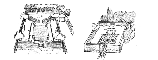
| TYPE OF SMALL GARDEN | TYPE OF SMALL GARDEN |
And this garden at the back of the house should be treated in a most private way. It should be surrounded with a wall or high hedge. There should be walks, border plantings, a little touch of water, and a seat in the smallest garden. It should be located so that it can be viewed from the house and enjoyed. Here all of the fine, delicate, and colorful flowers and plants can be placed. In the winter months the protected plants with their ugly clothes will not seem so out of place in this secreted patch of ground.
Next in importance to planning the setting of the house and its appearance from the street should be the planning of the views from windows of the house itself. The development of the private garden at the back is one help which was previously alluded to, but there are generally ugly things which can be seen from the windows of the house that need screening out. These ugly objects may be on the neighboring property, or they may be the drying-yard for the clothes, or the garage. Whatever they are, a screen of trees can be used to shut them from the view.
But the most important part of this problem is to make the best of any [Pg 253] view that may be possible from the house. A far-away river, a hill, or a meadow might be brought to sight by trimming some trees or brush. Distant landscapes are most satisfying to the eyes, for they rest them.
From what has been said, the importance of the lawn in front of the house can be appreciated. It is the rug spread out before the jewel-box. Over it one can view the beauty of the home, and so it needs the best attention. The very first thing to consider in building the lawn is to arrange for good drainage and a deep top layer of good soil, say 18" to 24". Pockets where water may collect and settle must be drained with tiles placed in the ground. The surface water should be carefully distributed away from the house.
An ordinary site will have stones and weeds scattered over it. In the beginning these stones should be carted away and the weeds cut down with a scythe, and a plough run over the surface to a foot in depth, unless the subsoil is not sandy and holds water, in which case a deeper ploughing is better. Then stones and weeds should be taken out of this earth, not once, but as many times as the earth delivers up stones and weeds. When this is done, the grading may be started, and this should be with long, easy grades. Where trees and shrubs edge the lawn, a slight hollow in the grade will improve it.
This graded soil is not ready for grass until it has been covered with 25 to 50 loads per acre of thoroughly decayed, composted stable manure, or, if not this, bone-dust, wood-ashes, superphosphates of lime, nitrate of ammonia, etc. This dressing should be raked into the [Pg 254] top-soil with the harrow and hand rake, and whatever weeds and stones come up with this operation should be removed.
Grass seed should then be selected which will give the most rugged growth for the particular conditions of the site. Often this can best be accomplished by using a mixture of seed. The different kinds of grass have qualities suited to certain types of soil. For example, Kentucky blue-grass, while coarse and not so attractive as some others, grows vigorously and holds its own in sandy soil. Rhode Island bent-grass makes good sod in moist climates, and redtop is apt to die off in a drought.
This seed must be sown liberally to make allowances for loss in germination, and evenly to prevent patchy growth. About six bushels per acre is considered enough. All of this must be raked under with a fine-toothed iron rake and pressed down with a heavy roller. As soon as the blades are tall enough to be caught in the mower, this new grass should be cut, for this helps to make it grow thicker and keep down the weeds. But work on the lawn does not end here. Constant care is the price of a good one.
Attention has already been called to the use of materials for paths and roads which harmonize with the materials of the house. In a previous chapter, details were given on the construction of concrete paths and roads. Therefore other types will be considered here, such as brick, gravel, and stone.
The driveway to the garage ought to be about 10 feet wide and flare out to a 15-foot width at the house, where the car is driven up to the entrance, so that an incoming car can pass by any which is standing in [Pg 255] front of the door. This roadway should widen out into a Y shape in front of the garage, as shown in the drawings, to permit of backing out and turning around. A round turning area in front of the garage may be substituted for this Y-shaped arrangement. Any curves made in the driveway should have a radius from centre of the curve to outside edge of the road of 30 feet 6 inches, although a Ford car can run on a road having a radius of only 14 feet.
If the driveway is to be of gravel and the subsoil is wet or clayey, drainage must be arranged for along the edges. Trenches 3 feet to 4 feet deep should be dug on either side and 3-inch diameter agricultural tile laid at the bottom with open joints covered with collars, then a layer of sod, and then 6 inches of field stone or gravel, and finally top-soil. Wherever there are pockets that would collect surface water, outlets should be constructed and covered with iron grating. All the subsoil tile should connect with one main tile and drain off at some low point.
For ordinary light traffic the road itself may be built with a foundation of stones to a depth of 2 feet. This should be covered with a layer of coarse gravel 2½ inches thick, a top layer of finer gravel 4 inches thick, and rolled with a heavy roller after water or some bituminous binder has been sprinkled over it. A crown of ½ inch to the foot should be made, and any grades ought to be kept about 5 feet in 100 feet, and at the most 10 feet in 100 feet.
In the construction of gravel walks the grade should be kept to within 12 feet in 100 feet and be crowned ¼ inch per foot.
The success of the brick walk depends upon the foundation used. A poor one will permit the bricks to settle unevenly, crack, and break away at the edges. The bricks themselves may be laid in any number of different [Pg 256] and interesting patterns, such as the basket weave or the herring-bone. A row of bricks on edge along the outside of the walk makes an excellent finish.
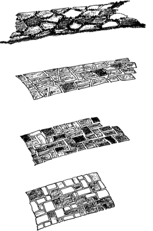
TYPES OF STONE PATHS
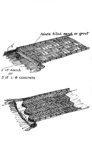
TYPES OF BRICK WALKS
The foundations of the brick walk may be built of sand, cinders, or concrete. The first two give a walk somewhat irregular, and grass can be made to grow in the joints. To begin the laying of a brick walk, the earth should be excavated to a depth of 4 inches, and either a bed of sand 2 inches thick, or a concrete of one part cement to eight parts sand 3 inches thick should be spread. When the bricks have been arranged on this bed, sand should be worked into the joints between them by leaving a layer on the walk for a few days and brushing it into the crevices. [Pg 257]
Where concrete is used for the base, a more rigid walk will result, and in such types it is customary to use mortar to fill the joints. A thin 1:3 grout can be brushed into these joints and the little that is smeared over the surface can be washed off with scrubbing-brush, water, and 5-per-cent muriatic acid. A better method is to pour grout into the joints, wiping the brick clean before the mortar sets.
There are a number of different types of stone walks that can be used, depending upon the character of the stone in the neighborhood. Flat flagstone walks are usually rather uninteresting, and many prefer the picturesque effect which is produced by stepping stones. These ought to be placed about 22 inches apart to make walking easy on them. A very interesting and much-used walk is made by setting flat stones of different shapes together, like the pieces of a cut-out puzzle, but leaving a small space between each stone in which grass or moss can be grown.
The problem of financing the small house is a part of the problem of building, and to some extent is a very personal affair, and every prospective owner has his own difficulties and personal solutions. Those who have saved for a number of years enough money to invest in this adventure of home-building are quite simply fixed, and all that they need consider is how large a house they can have for the money saved.
A method was shown in an early chapter by which the approximate cost of a house could be determined when the plans were in the rough. This consisted of studying the houses built in the neighborhood where the new home was to be erected, calculating their cubical contents and dividing this into their total cost, so that their cost per cubic foot could be known. By comparing this result with the figures which the local builders had offered, a fair idea could be obtained of how much per cubic foot the new house would run. A few figures were given for the different types of construction, but nothing certain can be predicted from them, for, as was pointed out, the cost is definitely related to the locality and the time.
Once, however, having arrived at a reasonably correct cost figure for the cubic foot, the question of how big a house is to be had for the money is quickly determined. Divide this cost per cubic foot into the total sum of money which is to be used for building the house, and the [Pg 259] allowable number of cubic feet in the new house will be found. If now the average height of the new house, from the cellar to the average height of the roof, is divided into this allowable cubic contents, the allowable ground area for the plan will be known.
For example, suppose the sum that can be invested in the house itself is $10,000, and it is found that the houses in the locality, of similar construction, cost per cubic foot about 35 cents. Dividing 35 cents into $10,000, it is found that a house having approximately 28,570 cubic feet can be constructed. If 8 feet is allowed from cellar floor to level of first floor, 9 feet from first to second floor, and 13 feet from second floor to the average height of the roof, then a total average height for the house will be found to be 30 feet. Dividing this 30 feet into 28,570 cubic feet, it will be found that a floor area of approximately 950 square feet can be had. Now, as the floor area of the plan of any two-story house is determined by the area required for the second floor and not the first, the desired sizes of the various bedrooms should be approximated, and the results added together to see whether they come within the allowable floor area. Continuing this example, suppose that the master bedroom is to be approximately 14 feet by 15 feet, the other three bedrooms approximately 12 feet by 12 feet, the toilet about 7 feet by 10 feet, the hall about 8 feet by 12 feet, then by adding the area of these rooms together it will be quickly found out whether the allowable area has been exceeded.
| Master bedroom, 14 feet by 15 feet | 210 | square | feet |
| Three other bedrooms, 12 feet by 12 feet | 432 | “ | “ |
| Toilet, 7 feet by 10 feet | 70 | “ | “ |
| Hall, 8 feet by 12 feet | 96 | “ | “ |
| Total | 808 | square | feet |
[Pg 260] This number of square feet is within the amount allowed, which is 950, but additional area must be added to this for closets, say 3 feet by 4 feet for the closet of the master bedroom, and 3 feet by 3 feet for the closets of the other rooms, and other closets for linen and space for chimneys and the like, making about 60 square feet, which should be left for this part of the plan. This makes the area about 868 square feet, and no allowance has been made for porches or passageways. It is quite evident from this that the number of bedrooms desired, their approximate size, and the size of the toilet and closets is nearly up to the maximum which the limitations of cost will permit. Working with these approximate figures, the plans of the house can be roughly prepared, the area required for the second-floor rooms being used as a basis for the allowable area of the first floor, since it is more than enough, for the second-floor area of a house, as has been said, is always greater than the minimum area for the first floor.
When roughly prepared plans and elevations have been arranged on this basis, the cubage can again be checked, and if it is over the allowed amount, the size should be cut down; if under, increased. The cubical contents of porches may be computed at one-quarter of the cubage of the main portion of the house, but if enclosed with glass they should be estimated at their full cubic contents.
Having thus roughly arrived at the plans and elevations of the house which is within the allowed cubage, a rough outline specification should be prepared in which the essential materials, workmanship, and mechanical equipment are defined. Enough information will then be had from which a rough estimate can be secured from a local contractor, or [Pg 261] even the architect may make an estimate, based upon previous examples of other houses. If this rough estimate comes within the allowable figure which is to be spent for construction, then the contract drawings can be safely started, and a reasonable assurance can be had that the cost of the house will not go beyond the amount of money available. As most contractors will give an outside price on any preliminary estimates of this kind, unless radical changes are made in the plans, it can almost surely be the case that the final estimate on the contract documents will be less. However, there are often times when the final figures exceed these preliminary estimates, and one should always be prepared to shrink parts of the building or withdraw some of the finest requirements of the specifications.
But one of the prime essentials in financing any building operation is to be sure that the contract drawings contain everything which is desired in the finished building, and that none or very few changes are made in the building after the contract is let and the building is in process of construction. Alterations from the original plans, after construction work has begun, come under the bugbear title for all architects, “Extras.” They always mean waste of money. Likewise, things which were omitted from the plans and specifications, which are later found to be necessary, run up extraordinary bills, and the general impression which most people have that a building operation always costs more in the end than was originally counted upon is due largely to the neglect of these factors. Competent architects make such complete plans and specifications that extras of the “omission type” are avoided, but most small houses are built from plans that are not complete, or prepared by architects who sell their services at such low [Pg 262] rates that they cannot afford to take the time to check up the plans carefully. It is right here that the architect has a real business point to give the client, namely, that if he does not pay for carefully prepared plans and specifications in the beginning, he will pay out much more in the end for extras.
Up to this point the financing of the small house, for the one who has the money, is not complicated, but this is the unusual condition, because the average person who builds the small house has not the ready cash to put into it, for that is the reason he builds a small house. The average individual who builds the small house generally has a certain amount which can be invested and the rest must be borrowed, and there are many who advise that even if one did have the whole amount to invest, it would be better to borrow some for the building operation, and keep out as much as possible for investments in other lines where the money might bring in greater returns.
The problem naturally turns upon where and how much can be borrowed for the building operation. Here again a very personal matter is involved. Some will have very close friends from whom they can secure a large first and second mortgage at a fairly reasonable rate, others may be able to secure a first mortgage from some financing institution which will be an amount equal to one-half the total cost of land and house, and then they may be able to secure a second mortgage from some friend, for most business houses are not prone to take second mortgages. Often a greater sum can be raised on the contract system, for by this method the person lending the money is more certainly assured of securing quick control of it in case of the necessity of action when payments on the interest fail. By the contract method, the individual lending the [Pg 263] money holds the deed of the property, and can secure control of the property more quickly than if he had a mortgage and the owner held the deed. In many cases where foreclosure of mortgages are found necessary, there may be a delay of a year or more before the money-lender can secure control of the property, but if he holds the deed the delay is shortened, and because of this fact he is apt to lend more money than 50 per cent of the total value. Of course, in the contract method the owner secures the deed to the property when his last payment is made upon the principle and he has wiped out all of his interest indebtedness.
But probably one of the most satisfactory systems yet devised for financing the small house is through the various building and loan associations which have grown to great strength in this country. These associations not only offer investment opportunities for small investors, but they make excellent and easy terms for those to whom they lend money for home-building. The arrangements with these institutions make the payments on mortgages almost like the payments in monthly rents, and yet at the same time the principle is continually being reduced, so that in about twelve years it is completely paid off. Then, too, one is assured of not being in the hands of some unscrupulous money-lender, as sometimes one discovers a friend to be, however trustworthy he may have seemed before this business relation developed.
These building-loan associations will lend as high as 80 per cent on the value of house and grounds, provided the character of the individual in the community warrants it. Their average-size loans have been computed to be about $4,000. If the minimum payment is adhered to, the loan is usually paid up in twelve years, although arrangements can [Pg 264] be made by which this can be shortened. The interest charged is from 6 per cent to 8 per cent.
If the money is not secured through the above source, then it is customary to pay a commission to the agent who secures a loan from some financing institution or private investor. This commission differs, according to the locality, ranging from 1 to 4 per cent on first mortgages, and from 5 per cent upward on second mortgages. If a contract is desired on a second mortgage, the agent will be obliged to secure it from some private individual, for first-mortgage companies will not purchase them. This often leads to discounts of from 15 to 30 per cent on second mortgages and contracts.
It is well for every prospective owner, before he considers financing the construction of a small house, to sit down and figure out all of the incidental expenditures which are connected with it, for often some of the minor items are not taken into account, and they may spoil the whole scheme. Taking a typical example, the items of expense are as follows:
The above list of expenses should be frankly faced in the beginning, tabulated, and duly considered by every prospective owner of the small house. There are some architects who for fear of discouraging their clients from building will not sit down with them and show them a plain statement of the money they will have to invest, and when all of these minor items begin to pop up during the progress of the operations, the client begins to lose confidence, wonders where the next unexpected bill will come from, and blames the architect for having misrepresented conditions to him. Any prospective owner who has to be blind-folded to the costs which he must meet in order to muster up courage to build ought to be left alone, for he will do the architect no good, but considerable harm. Individuals who have their castles in the air so high that they cannot reduce their dreams to dollars and cents before they begin, ought never to build. These are the kind that start the cry that it always costs more to build than one ever figured on in the beginning.
But coming back to the question of securing the building loan, it will [Pg 266] be found that nearly all lenders will insist that the owner put his money in first. That is, he must meet the first payments to the builder himself, until he has put in all of his share. The rest will then be taken up by the financing institution, but always enough will be held back to assure sufficient funds for the completion of the house and the payment of all bills. The lender generally states at what periods of the construction money will be passed over, and this schedule is generally adopted as the one for the periodic payments to the builder. Of course the contractor must be consulted on the matter and his approval secured, but there will be little difficulty on this score, for he will recognize the power of the financing institution to dictate the dates of payment.
As to the matter of contracting for the construction of the small house, there is little doubt that for so small a building the method of securing one general contractor to assume the responsibility of the whole work is the best. There are many who believe in employing day labor, and hiring the services of a supervising builder. The cost is itemized and the contractor adds a percentage as his share. This insures better-class work, but in practically all cases it is more expensive, and no assurance can be had of the final cost.
When the plans are let out to various contractors for bids, there should be no obligation attached to them that the lowest bidder will secure the job. This is a protection, for the human element often enters into relations of this kind, and the lowest bidder may not be the most trustworthy personage, nor have the best reputation.
When the contract is finally let, there are a number of things which it should cover that are intended to protect the finances of the owner. For instance, the contractor should be required to maintain insurance [Pg 267] that will protect him from the claims under workmen’s compensation acts, and from any other claims for damages for personal injury, including death, which might arise from the operations of building. The owner should also maintain a similar liability insurance to protect himself.
The owner should carry a fire insurance on the entire building and materials to at least 80 per cent of the total value.
When there is doubt as to the financial strength of a contractor, he should be required to furnish a bond covering the faithful performance of the contract and the payment of all obligations.
Then, too, it is customary to set forth cash allowances in the specifications to cover certain items, like plumbing fixtures, hardware, and electric light fixtures. The contractor should be made to declare that the contract sum includes these cash allowances.
Careful understanding with the contractor should be arranged as to the method by which he will be paid. Generally, as was previously stated, the financing institution has control over the schedule of payments, and, once this is agreeable to the contractor, he should be required to submit to the architect an application for each payment, with receipts and other vouchers, showing his payments for materials and labor, including payments to subcontractors, at least ten days before each payment falls due. It is the duty of the architect to determine the accuracy of each one of these applications for payment before he issues the certificate of payment for such amount as he decides is properly due. There are some architects who make it a practice to hold back a certain percentage of the first payment, and continue this with every later payment, until the last, in order to have a club over the head of the contractor and also a factor of safety, lest the builder has rendered an application for payment in excess of the amount of labor [Pg 268] and material delivered. This, of course, will cause hard feelings sometimes, and create friction between architect and contractor, a thing studiously to be avoided, and for this cause such procedure should be dropped when the architect knows the character of the contractor.
The architect should always reserve the right to withhold part or all of the certificate of payment when defective work is not remedied, or when any claims are filed, or there is reasonable evidence that claims will be filed, or when the contractor fails to make payments to subcontractors, or to dealers for materials, or when there is a reasonable doubt that the contract can be completed for the balance unpaid, or when any damage involving liabilities has been done by one contractor to another. The architect should also hold back the final payment, if there are any liens existing against the building, until they are removed.
In order to avoid many of the trivial and annoying expenses which occur in a building operation, the contractor should be required to pay for all permits and licenses (but not permanent easements) which are necessary according to local laws. The contractor should also be made to pay all royalties on patents, if there are any, and all license fees.
But, probably, the most difficult part of the building operation to finance are the extras. When something is found to have been omitted from the plans and specifications, and the contractor did not cover it in his bid, or when the owner changes his mind and requires an alteration, then this extra work must be paid for at a high rate, for nearly all contractors look upon such extras as good pickings. In fact, there are some contractors who deliberately go over the plans and specifications to note what extras may be needed, and then counting upon their profits from these extras, they put in a low bid, so that [Pg 269] they can beat their competitors, secure the job, and then proceed to make up their losses with bills which they put in for the extras. Likewise, a contractor who is honest, if he finds himself losing money on any building operation, will try to ease his losses and gain profit with the extras.
There must, therefore, be some basis upon which estimates for these extras will be determined. The values for these extras or changes in the work may be determined by a submitted estimate and acceptance in a lump sum, by a unit price named in the contract or subsequently agreed upon, or by the cost and percentage, or by the fixed-fee method. If the contractor claims that any instructions, by drawings or otherwise, involve extra cost under his contract, he should be required to give the architect written notice of it before proceeding to do the work, within two weeks after receiving such instructions.
A final problem of financing should be considered, and that is the emergency which might arise should the contractor neglect to prosecute the work properly or fail to perform any provision of his contract. If such is the case, the owner should reserve the right in the contract, that after three days’ written notice to the contractor he may make good such deficiencies and deduct the cost from the payment due the contractor at that time. Of course every contract should provide for the owner’s right to terminate the contract should the contractor fail to do his work, or prove bankrupt, or persistently disregard laws, or continually violate the provisions of the contract.
Transcriber’s Notes:
The illustrations have been moved so that they do not break up paragraphs and so that they are next to the text they illustrate.
Typographical errors have been silently corrected.
End of the Project Gutenberg EBook of The Construction of the Small House, by
Harold Vandervoort Walsh

*** END OF THIS PROJECT GUTENBERG EBOOK CONSTRUCTION OF THE SMALL HOUSE ***

***** This file should be named 61880-h.htm or 61880-h.zip *****
This and all associated files of various formats will be found in:
        http://www.gutenberg.org/6/1/8/8/61880/

Produced by ellinora, Paul Marshall and the Online
Distributed Proofreading Team at https://www.pgdp.net (This
file was produced from images generously made available
by The Internet Archive/American Libraries.)

Updated editions will replace the previous one--the old editions will
be renamed.

Creating the works from print editions not protected by U.S. copyright
law means that no one owns a United States copyright in these works,
so the Foundation (and you!) can copy and distribute it in the United
States without permission and without paying copyright
royalties. Special rules, set forth in the General Terms of Use part
of this license, apply to copying and distributing Project
Gutenberg-tm electronic works to protect the PROJECT GUTENBERG-tm
concept and trademark. Project Gutenberg is a registered trademark,
and may not be used if you charge for the eBooks, unless you receive
specific permission. If you do not charge anything for copies of this
eBook, complying with the rules is very easy. You may use this eBook
for nearly any purpose such as creation of derivative works, reports,
performances and research. They may be modified and printed and given
away--you may do practically ANYTHING in the United States with eBooks
not protected by U.S. copyright law. Redistribution is subject to the
trademark license, especially commercial redistribution.

START: FULL LICENSE

THE FULL PROJECT GUTENBERG LICENSE
PLEASE READ THIS BEFORE YOU DISTRIBUTE OR USE THIS WORK

To protect the Project Gutenberg-tm mission of promoting the free
distribution of electronic works, by using or distributing this work
(or any other work associated in any way with the phrase "Project
Gutenberg"), you agree to comply with all the terms of the Full
Project Gutenberg-tm License available with this file or online at
www.gutenberg.org/license.

Section 1. General Terms of Use and Redistributing Project
Gutenberg-tm electronic works

1.A. By reading or using any part of this Project Gutenberg-tm
electronic work, you indicate that you have read, understand, agree to
and accept all the terms of this license and intellectual property
(trademark/copyright) agreement. If you do not agree to abide by all
the terms of this agreement, you must cease using and return or
destroy all copies of Project Gutenberg-tm electronic works in your
possession. If you paid a fee for obtaining a copy of or access to a
Project Gutenberg-tm electronic work and you do not agree to be bound
by the terms of this agreement, you may obtain a refund from the
person or entity to whom you paid the fee as set forth in paragraph
1.E.8.

1.B. "Project Gutenberg" is a registered trademark. It may only be
used on or associated in any way with an electronic work by people who
agree to be bound by the terms of this agreement. There are a few
things that you can do with most Project Gutenberg-tm electronic works
even without complying with the full terms of this agreement. See
paragraph 1.C below. There are a lot of things you can do with Project
Gutenberg-tm electronic works if you follow the terms of this
agreement and help preserve free future access to Project Gutenberg-tm
electronic works. See paragraph 1.E below.

1.C. The Project Gutenberg Literary Archive Foundation ("the
Foundation" or PGLAF), owns a compilation copyright in the collection
of Project Gutenberg-tm electronic works. Nearly all the individual
works in the collection are in the public domain in the United
States. If an individual work is unprotected by copyright law in the
United States and you are located in the United States, we do not
claim a right to prevent you from copying, distributing, performing,
displaying or creating derivative works based on the work as long as
all references to Project Gutenberg are removed. Of course, we hope
that you will support the Project Gutenberg-tm mission of promoting
free access to electronic works by freely sharing Project Gutenberg-tm
works in compliance with the terms of this agreement for keeping the
Project Gutenberg-tm name associated with the work. You can easily
comply with the terms of this agreement by keeping this work in the
same format with its attached full Project Gutenberg-tm License when
you share it without charge with others.

1.D. The copyright laws of the place where you are located also govern
what you can do with this work. Copyright laws in most countries are
in a constant state of change. If you are outside the United States,
check the laws of your country in addition to the terms of this
agreement before downloading, copying, displaying, performing,
distributing or creating derivative works based on this work or any
other Project Gutenberg-tm work. The Foundation makes no
representations concerning the copyright status of any work in any
country outside the United States.

1.E. Unless you have removed all references to Project Gutenberg:

1.E.1. The following sentence, with active links to, or other
immediate access to, the full Project Gutenberg-tm License must appear
prominently whenever any copy of a Project Gutenberg-tm work (any work
on which the phrase "Project Gutenberg" appears, or with which the
phrase "Project Gutenberg" is associated) is accessed, displayed,
performed, viewed, copied or distributed:

  This eBook is for the use of anyone anywhere in the United States and
  most other parts of the world at no cost and with almost no
  restrictions whatsoever. You may copy it, give it away or re-use it
  under the terms of the Project Gutenberg License included with this
  eBook or online at www.gutenberg.org. If you are not located in the
  United States, you'll have to check the laws of the country where you
  are located before using this ebook.

1.E.2. If an individual Project Gutenberg-tm electronic work is
derived from texts not protected by U.S. copyright law (does not
contain a notice indicating that it is posted with permission of the
copyright holder), the work can be copied and distributed to anyone in
the United States without paying any fees or charges. If you are
redistributing or providing access to a work with the phrase "Project
Gutenberg" associated with or appearing on the work, you must comply
either with the requirements of paragraphs 1.E.1 through 1.E.7 or
obtain permission for the use of the work and the Project Gutenberg-tm
trademark as set forth in paragraphs 1.E.8 or 1.E.9.

1.E.3. If an individual Project Gutenberg-tm electronic work is posted
with the permission of the copyright holder, your use and distribution
must comply with both paragraphs 1.E.1 through 1.E.7 and any
additional terms imposed by the copyright holder. Additional terms
will be linked to the Project Gutenberg-tm License for all works
posted with the permission of the copyright holder found at the
beginning of this work.

1.E.4. Do not unlink or detach or remove the full Project Gutenberg-tm
License terms from this work, or any files containing a part of this
work or any other work associated with Project Gutenberg-tm.

1.E.5. Do not copy, display, perform, distribute or redistribute this
electronic work, or any part of this electronic work, without
prominently displaying the sentence set forth in paragraph 1.E.1 with
active links or immediate access to the full terms of the Project
Gutenberg-tm License.

1.E.6. You may convert to and distribute this work in any binary,
compressed, marked up, nonproprietary or proprietary form, including
any word processing or hypertext form. However, if you provide access
to or distribute copies of a Project Gutenberg-tm work in a format
other than "Plain Vanilla ASCII" or other format used in the official
version posted on the official Project Gutenberg-tm web site
(www.gutenberg.org), you must, at no additional cost, fee or expense
to the user, provide a copy, a means of exporting a copy, or a means
of obtaining a copy upon request, of the work in its original "Plain
Vanilla ASCII" or other form. Any alternate format must include the
full Project Gutenberg-tm License as specified in paragraph 1.E.1.

1.E.7. Do not charge a fee for access to, viewing, displaying,
performing, copying or distributing any Project Gutenberg-tm works
unless you comply with paragraph 1.E.8 or 1.E.9.

1.E.8. You may charge a reasonable fee for copies of or providing
access to or distributing Project Gutenberg-tm electronic works
provided that

* You pay a royalty fee of 20% of the gross profits you derive from
  the use of Project Gutenberg-tm works calculated using the method
  you already use to calculate your applicable taxes. The fee is owed
  to the owner of the Project Gutenberg-tm trademark, but he has
  agreed to donate royalties under this paragraph to the Project
  Gutenberg Literary Archive Foundation. Royalty payments must be paid
  within 60 days following each date on which you prepare (or are
  legally required to prepare) your periodic tax returns. Royalty
  payments should be clearly marked as such and sent to the Project
  Gutenberg Literary Archive Foundation at the address specified in
  Section 4, "Information about donations to the Project Gutenberg
  Literary Archive Foundation."

* You provide a full refund of any money paid by a user who notifies
  you in writing (or by e-mail) within 30 days of receipt that s/he
  does not agree to the terms of the full Project Gutenberg-tm
  License. You must require such a user to return or destroy all
  copies of the works possessed in a physical medium and discontinue
  all use of and all access to other copies of Project Gutenberg-tm
  works.

* You provide, in accordance with paragraph 1.F.3, a full refund of
  any money paid for a work or a replacement copy, if a defect in the
  electronic work is discovered and reported to you within 90 days of
  receipt of the work.

* You comply with all other terms of this agreement for free
  distribution of Project Gutenberg-tm works.

1.E.9. If you wish to charge a fee or distribute a Project
Gutenberg-tm electronic work or group of works on different terms than
are set forth in this agreement, you must obtain permission in writing
from both the Project Gutenberg Literary Archive Foundation and The
Project Gutenberg Trademark LLC, the owner of the Project Gutenberg-tm
trademark. Contact the Foundation as set forth in Section 3 below.

1.F.

1.F.1. Project Gutenberg volunteers and employees expend considerable
effort to identify, do copyright research on, transcribe and proofread
works not protected by U.S. copyright law in creating the Project
Gutenberg-tm collection. Despite these efforts, Project Gutenberg-tm
electronic works, and the medium on which they may be stored, may
contain "Defects," such as, but not limited to, incomplete, inaccurate
or corrupt data, transcription errors, a copyright or other
intellectual property infringement, a defective or damaged disk or
other medium, a computer virus, or computer codes that damage or
cannot be read by your equipment.

1.F.2. LIMITED WARRANTY, DISCLAIMER OF DAMAGES - Except for the "Right
of Replacement or Refund" described in paragraph 1.F.3, the Project
Gutenberg Literary Archive Foundation, the owner of the Project
Gutenberg-tm trademark, and any other party distributing a Project
Gutenberg-tm electronic work under this agreement, disclaim all
liability to you for damages, costs and expenses, including legal
fees. YOU AGREE THAT YOU HAVE NO REMEDIES FOR NEGLIGENCE, STRICT
LIABILITY, BREACH OF WARRANTY OR BREACH OF CONTRACT EXCEPT THOSE
PROVIDED IN PARAGRAPH 1.F.3. YOU AGREE THAT THE FOUNDATION, THE
TRADEMARK OWNER, AND ANY DISTRIBUTOR UNDER THIS AGREEMENT WILL NOT BE
LIABLE TO YOU FOR ACTUAL, DIRECT, INDIRECT, CONSEQUENTIAL, PUNITIVE OR
INCIDENTAL DAMAGES EVEN IF YOU GIVE NOTICE OF THE POSSIBILITY OF SUCH
DAMAGE.

1.F.3. LIMITED RIGHT OF REPLACEMENT OR REFUND - If you discover a
defect in this electronic work within 90 days of receiving it, you can
receive a refund of the money (if any) you paid for it by sending a
written explanation to the person you received the work from. If you
received the work on a physical medium, you must return the medium
with your written explanation. The person or entity that provided you
with the defective work may elect to provide a replacement copy in
lieu of a refund. If you received the work electronically, the person
or entity providing it to you may choose to give you a second
opportunity to receive the work electronically in lieu of a refund. If
the second copy is also defective, you may demand a refund in writing
without further opportunities to fix the problem.

1.F.4. Except for the limited right of replacement or refund set forth
in paragraph 1.F.3, this work is provided to you 'AS-IS', WITH NO
OTHER WARRANTIES OF ANY KIND, EXPRESS OR IMPLIED, INCLUDING BUT NOT
LIMITED TO WARRANTIES OF MERCHANTABILITY OR FITNESS FOR ANY PURPOSE.

1.F.5. Some states do not allow disclaimers of certain implied
warranties or the exclusion or limitation of certain types of
damages. If any disclaimer or limitation set forth in this agreement
violates the law of the state applicable to this agreement, the
agreement shall be interpreted to make the maximum disclaimer or
limitation permitted by the applicable state law. The invalidity or
unenforceability of any provision of this agreement shall not void the
remaining provisions.

1.F.6. INDEMNITY - You agree to indemnify and hold the Foundation, the
trademark owner, any agent or employee of the Foundation, anyone
providing copies of Project Gutenberg-tm electronic works in
accordance with this agreement, and any volunteers associated with the
production, promotion and distribution of Project Gutenberg-tm
electronic works, harmless from all liability, costs and expenses,
including legal fees, that arise directly or indirectly from any of
the following which you do or cause to occur: (a) distribution of this
or any Project Gutenberg-tm work, (b) alteration, modification, or
additions or deletions to any Project Gutenberg-tm work, and (c) any
Defect you cause.

Section 2. Information about the Mission of Project Gutenberg-tm

Project Gutenberg-tm is synonymous with the free distribution of
electronic works in formats readable by the widest variety of
computers including obsolete, old, middle-aged and new computers. It
exists because of the efforts of hundreds of volunteers and donations
from people in all walks of life.

Volunteers and financial support to provide volunteers with the
assistance they need are critical to reaching Project Gutenberg-tm's
goals and ensuring that the Project Gutenberg-tm collection will
remain freely available for generations to come. In 2001, the Project
Gutenberg Literary Archive Foundation was created to provide a secure
and permanent future for Project Gutenberg-tm and future
generations. To learn more about the Project Gutenberg Literary
Archive Foundation and how your efforts and donations can help, see
Sections 3 and 4 and the Foundation information page at
www.gutenberg.org


Section 3. Information about the Project Gutenberg Literary Archive Foundation

The Project Gutenberg Literary Archive Foundation is a non profit
501(c)(3) educational corporation organized under the laws of the
state of Mississippi and granted tax exempt status by the Internal
Revenue Service. The Foundation's EIN or federal tax identification
number is 64-6221541. Contributions to the Project Gutenberg Literary
Archive Foundation are tax deductible to the full extent permitted by
U.S. federal laws and your state's laws.

The Foundation's principal office is in Fairbanks, Alaska, with the
mailing address: PO Box 750175, Fairbanks, AK 99775, but its
volunteers and employees are scattered throughout numerous
locations. Its business office is located at 809 North 1500 West, Salt
Lake City, UT 84116, (801) 596-1887. Email contact links and up to
date contact information can be found at the Foundation's web site and
official page at www.gutenberg.org/contact

For additional contact information:

    Dr. Gregory B. Newby
    Chief Executive and Director
    gbnewby@pglaf.org

Section 4. Information about Donations to the Project Gutenberg
Literary Archive Foundation

Project Gutenberg-tm depends upon and cannot survive without wide
spread public support and donations to carry out its mission of
increasing the number of public domain and licensed works that can be
freely distributed in machine readable form accessible by the widest
array of equipment including outdated equipment. Many small donations
($1 to $5,000) are particularly important to maintaining tax exempt
status with the IRS.

The Foundation is committed to complying with the laws regulating
charities and charitable donations in all 50 states of the United
States. Compliance requirements are not uniform and it takes a
considerable effort, much paperwork and many fees to meet and keep up
with these requirements. We do not solicit donations in locations
where we have not received written confirmation of compliance. To SEND
DONATIONS or determine the status of compliance for any particular
state visit www.gutenberg.org/donate

While we cannot and do not solicit contributions from states where we
have not met the solicitation requirements, we know of no prohibition
against accepting unsolicited donations from donors in such states who
approach us with offers to donate.

International donations are gratefully accepted, but we cannot make
any statements concerning tax treatment of donations received from
outside the United States. U.S. laws alone swamp our small staff.

Please check the Project Gutenberg Web pages for current donation
methods and addresses. Donations are accepted in a number of other
ways including checks, online payments and credit card donations. To
donate, please visit: www.gutenberg.org/donate

Section 5. General Information About Project Gutenberg-tm electronic works.

Professor Michael S. Hart was the originator of the Project
Gutenberg-tm concept of a library of electronic works that could be
freely shared with anyone. For forty years, he produced and
distributed Project Gutenberg-tm eBooks with only a loose network of
volunteer support.

Project Gutenberg-tm eBooks are often created from several printed
editions, all of which are confirmed as not protected by copyright in
the U.S. unless a copyright notice is included. Thus, we do not
necessarily keep eBooks in compliance with any particular paper
edition.

Most people start at our Web site which has the main PG search
facility: www.gutenberg.org

This Web site includes information about Project Gutenberg-tm,
including how to make donations to the Project Gutenberg Literary
Archive Foundation, how to help produce our new eBooks, and how to
subscribe to our email newsletter to hear about new eBooks.