
The Project Gutenberg EBook of Engineer Port Repair Ship, by
United States War Department

This eBook is for the use of anyone anywhere in the United States and most
other parts of the world at no cost and with almost no restrictions
whatsoever.  You may copy it, give it away or re-use it under the terms of
the Project Gutenberg License included with this eBook or online at
www.gutenberg.org.  If you are not located in the United States, you'll have
to check the laws of the country where you are located before using this ebook.

Title: Engineer Port Repair Ship
       War Department Technical Manual TM 5-362

Author: United States War Department

Release Date: September 21, 2018 [EBook #57941]

Language: English

Character set encoding: UTF-8

*** START OF THIS PROJECT GUTENBERG EBOOK ENGINEER PORT REPAIR SHIP ***


Produced by deaurider, Brian Wilcox and the Online
Distributed Proofreading Team at http://www.pgdp.net (This
file was produced from images generously made available
by The Internet Archive)
RESTRICTED. DISSEMINATION OF RESTRICTED MATTER.—The information contained in restricted documents and the essential characteristics of restricted material may be given to any person known to be in the service of the United States and to persons of undoubted loyalty and discretion who are cooperating in Government work, but will not be communicated to the public or to the press except by authorized military public relations agencies. (See also par. 23b, AR 380-5, 15 Mar 1944.)
United States Government Printing Office
Washington: 1944
WAR DEPARTMENT,
Washington 25, D. C., 31 October 1944.
TM 5-362, Engineer Port Repair Ship, is published for the information
and guidance of all concerned.
[A.G. 300.7 (13 Sep 44).]
By order of the Secretary of War:
G. C. MARSHALL,
Chief of Staff.
Official:
J. A. ULIO,
Major General,
The Adjutant General.
Distribution:
As prescribed in paragraph 9a, FM 21-6:
Armies (10); Corps (10); SvC (10); Depts (10); IB 5 (10); IBn 5 (5); IC 5 (20) (10), 55 (2); T of Opn (CG) (10); T of Opn (Engr) (25).
IB 5: T/O 5-510S.
IBn 5: T/O 5-535S.
IC 5 (20): T/O 5-500, Engr Sv Orgn—Engr Port Rep Ship Crew NC; Engr Port Rep Ship Crew NF.
IC 5 (10): T/O 5-52.
IC 55: T/O 55-47; 55-110-1; 55-116; 55-117; 55-177.
Distribution to European Theater of Operation will not be made.
For explanation of symbols, see FM 21-6.
| Paragraph | Page | |||
|---|---|---|---|---|
| SECTION | I. | GENERAL. | ||
Purpose and scope |
1 | 1 | ||
Mission |
2 | 1 | ||
Relationship to other units |
3 | 1 | ||
| II. | ORGANIZATION AND DUTIES OF PERSONNEL. | |||
Organization |
4 | 4 | ||
Duties of personnel |
5 | 4 | ||
Ship maintenance and repair |
6 | 4 | ||
| III. | SHIP SPECIFICATIONS, EQUIPMENT, AND SUPPLIES. | |||
Ship specifications |
7 | 6 | ||
Equipment for ship operation |
8 | 8 | ||
Supplies for ship operation |
9 | 19 | ||
Equipment for performing mission |
10 | 19 | ||
Supplies for performing mission |
11 | 32 | ||
| IV. | TRAINING OF SHIP’S CREW. | |||
Individual training |
12 | 34 | ||
Shipboard training |
13 | 38 | ||
| V. | OPERATIONS. | |||
Condition of captured ports |
14 | 40 | ||
Operations of port repair ship in a captured port |
15 | 41 | ||
b. In performing this mission, a port repair ship crew might be required to assist in removing obstructions and debris from harbor entrances, harbors, docks, and areas alongside wharves, quays, and piers; repair underwater structures; make and repair parts for damaged port facilities and equipment; and salvage cargos and small craft. Large salvage operations are a naval function and are handled by the Navy’s salvage ships.
(1) The group’s mission is to return captured ports to operating condition. It repairs such port facilities as power and water-supply plants, communications, wharves, docks, warehouses, and cargo-handling equipment. (See fig. 2.)
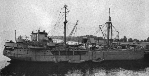
Figure 1. General view of an engineer port repair ship.
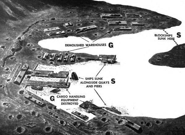
Symbols: S = engineer port repair ship. G = port
construction and repair group.
Figure 2. Schematic view of a typical captured port showing jobs
done by the port construction and repair group and those done by the
engineer port repair ship.
(2) Usually, the engineer port repair ship is the first large vessel to enter the port; it carries in supplies and equipment to help the port group start its work. Some of this equipment such as portable generators, pneumatic drills, paving breakers, hammers, and saws, may be put ashore and used by the group’s personnel. In addition, the facilities of the various shops on the ship are used for making or repairing parts for damaged port machinery and equipment.
b. Transportation Corps. After the harbor has been cleared, the engineer port repair ship may be called on to assist harbor craft units of the Transportation Corps in heavy towing or cargo-handling operations.
c. Navy. Naval minesweepers precede the engineer port repair ship into the harbor, clear the harbor of mines, and report dangerous areas to the engineer port repair ship.
b. Ship’s master. The ship’s master is responsible for everything done by his ship and crew. He must be a technical specialist as well as a military leader. His principal responsibilities are:
(1) Safe navigation and efficient handling of his ship at all times.
(2) Direction of operations in carrying out the ship’s mission.
(3) The condition and appearance of his ship.
(4) Administrative duties and the discipline and morale of his crew.
c. Deck section. Crew members of the deck section are primarily responsible for:
(1) Sea-detail duties specified by the deck officer.
(2) Outward appearance of the ship. This includes painting, rust prevention, and general ship-shape condition.
(3) Handling lines in mooring and docking.
(4) Navigation of the ship.
(5) Weighing or dropping anchor.
d. Engine section. The engine section operates, maintains, and repairs the ship’s main and auxiliary engines, compressors, pumps, generators, motors, and electrical systems.
e. Operating section. The personnel of the operating section are under the supervision of the salvage officer and are responsible for:
(1) All diving operations, including underwater inspections, construction, repairs, and demolitions.
(2) Operation and maintenance of machine, welding, blacksmith, pipe, and carpenter shops.
(3) Clearing harbor areas of debris and obstructions and restoring navigational aids.
f. Headquarters section. This section is responsible for general administrative, housekeeping, and radio-communication duties aboard ship. These duties include operation and supply of the ship’s galley and cold-storage compartments, and supply and storage of all food, silverware, clothing, and linens.
g. Attached armed guard. A Navy gun crew operates and maintains the ship’s antiaircraft (AA) armament. (See par 7e.) Each member of the gun crew takes his turn at standing watch.
ORGANIZATION OF ENGINEER PORT REPAIR SHIP CREW1
1See T/O & E 5-500
2The naval armed guard is attached only when the ship is in convoy or in an extremely active theater of operations
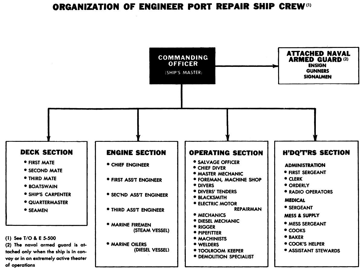
Figure 3. Organization chart of engineer port repair ship crew showing functional setup of ship’s personnel.
b. Principal dimensions and capacities.
(1) For principal dimensions and capacities see table I and figure 6.
(2) For location and capacities of fuel-oil, fresh-water, and salt-water tanks, see table II and figure 7.
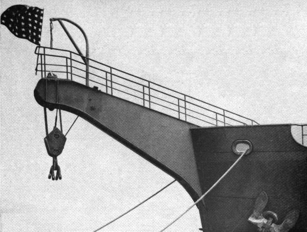
Figure 4. Cathead welded on ship’s prow.
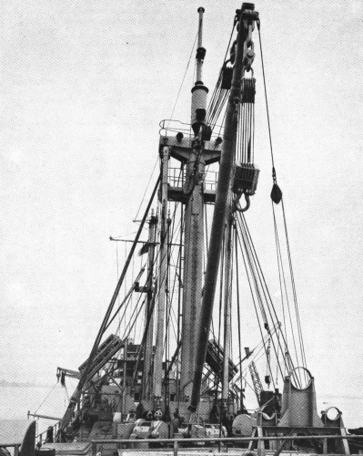
Figure 5. View looking aft from forecastle deck showing masts and cargo booms.
| Table I. Principal dimensions of engineer port repair ship | |
|---|---|
| Principal Dimensions | |
| Length over-all | 291 feet, 1 inch. |
| Length between perpendiculars | 255 feet, 0 inches. |
| Breadth, molded | 42 feet, 6 inches. |
| Depth, molded | 25 feet, 3 inches. |
| Gross tonnage | 2,483.70 |
| Net tonnage3 | 1,577.15 |
| Weights and Volumes Used | |
| 1 ton | 2,240 pounds. |
| 1 ton fresh water | 36 cubic feet. |
| 1 ton salt water | 35 cubic feet. |
| 1 ton Diesel oil | 41.98 cubic feet. |
3 Net tonnage is gross tonnage less deductions for space occupied by main engines, crew’s quarters, etc. It indicates approximate cargo capacity of the ship.
| Table II. Capacities of Diesel-oil, fresh-water, and salt-water tanks | |||||
|---|---|---|---|---|---|
| Capacities of Tanks | |||||
| Compartments | Frames | Cubic feet |
Tons | ||
| Diesel oil |
Fresh water |
Salt water |
|||
Double-bottomed tank No 1, P4 |
79-106 | 2,798 | 66.6 | ||
Double-bottomed tank No 1, S4 |
79-106 | 2,752 | 65.6 | ||
Double-bottomed tank No 2, P and S |
57-71 | 4,288 | 102.2 | ||
Double-bottomed tank No 3, P and S |
23-51 | 5,760 | 137.2 | ||
Deep-wing tank No 4, P and S |
9-23 | 5,635 | 134.2 | ||
Forepeak tank, single |
115-stem | 4,500 | 126.4 | ||
Deep tank No 1, P and S |
115-115 | 5,405 | 150.1 | ||
Deep tank No 2, P and S |
107-11 | 7,296 | 202.7 | ||
Deep-wing tank No 5, P and S |
2-8 | 900 | 25.0 | ||
Afterpeak tank, single |
2-stem | 1,141 | 31.7 | ||
Forepeak tank, single |
115-stem | 4,550 | 130 | ||
Deep-wing tank No 3, P and S |
79-107 | 6,276 | 179.4 | ||
| Total | 505.8 | 535.95 | 309.4 | ||
4 P stands for port; S, for starboard.
5 249,500 gallons.
c. Displacement.
(1) The dead-weight scale (fig. 10), shows the ship’s capacity for carrying dead weight, the difference between light and loaded displacement.
(2) Figure 10 also shows the ship’s load-line marks6 and their relation to the decks. These marks establish the safe load line for the ship in different waters, allowing a measure of reserve buoyancy. Load lines are established and assigned by the American Bureau of Shipping. The center of the circle is located exactly amidships on the vessel’s load waterline, and the horizontal line through the circle corresponds to the summer load line. The letters AB, used where the horizontal line cuts the circle, indicate the American Bureau of Shipping. The letter F to the left of the vertical line is the fresh-water marking, and S to the right of the vertical line is the salt-water marking.
6 Sometimes called Plimsoll mark; Plimsoll mark indicates maximum allowable draft.
d. Power. The ship is propelled by a high-power, low-speed Diesel engine. Other engines may be substituted as required.
e. Armament. For AA protection, the ship carries six 20-mm AA machine guns. Mounted on the after end of the poop deck is a Navy 3″/50 (3-inch bore, 150 inches long) dual-purpose AA gun.
b. Navigation equipment.
(1) Compasses.
(a) The ship is equipped with magnetic and gyrocompasses. The master gyrocompass is located below decks in the gyro-room. The readings of this compass are transmitted to repeaters, which are similar in appearance to magnetic compasses and are placed in the pilot house and at other points where knowledge of the ship’s heading is required. Gyrocompass equipment includes the master compass and its supports, batteries, a motor-generator set for supplying power in case of failure of the ship’s supply, instrument panel, and a panel for fuses and switches for the repeaters.
(b) The magnetic compass is in the pilot house. It is mounted in a compensating binnacle that neutralizes or compensates for errors introduced into the compass by the magnetic materials on the ship. (See figs. 8 and 9.)
(2) Pelorus. A pelorus is mounted on each wing of the navigating bridge. The pelorus is a graduated circle mounted in gimbals with an alidade pivoted over its center. It is used to measure directions to some distant point like another ship or an object on land. It gives the bearing relative to the ship’s heading or, if set to the ship’s true course, the true bearing to the object.
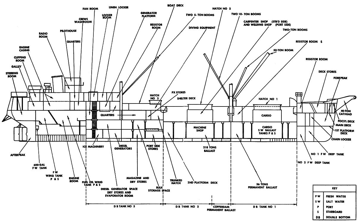
INBOARD PROFILE
Figure 6. Inboard profile of engineer port repair ship showing
location of main installations.
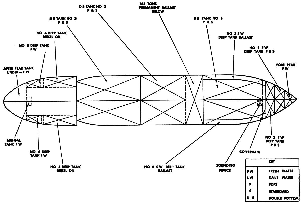
INNER BOTTOM PLAN
Figure 7. Inner-bottom plan showing location of Diesel-oil,
fresh-water, and salt-water tanks.
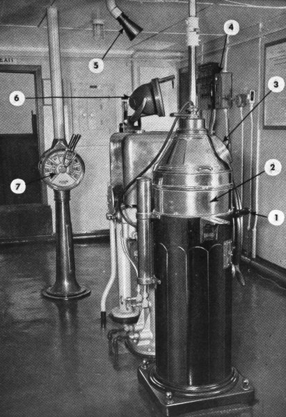
1. Wheel.
2. Compensating binnacle.
3. Magnetic compass.
4. Telephone.
5. Speaking tube.
6. Gyrocompass mounted on binnacle.
7. Engine room control.
Figure 8. View of pilot house.
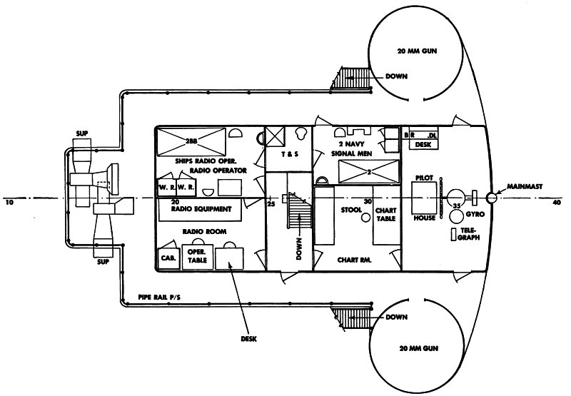
Figure 9. Drawing of navigating bridge showing location of equipment in pilot house, chart room and radio room.

LIGHT SHIP WITH 418 TONS BALLAST—2204 TONS
Figure 10. Dead-weight scale and load-line marks.
(3) Radio direction finder. Located on the navigating bridge is the ship’s radio direction finder. This instrument receives radio signals and establishes the bearing of the sending station. It consists essentially of a loop antenna for receiving the signals connected to a radio receiver that makes the signals audible. The position of the ship may be determined from radio bearings by taking cross bearings on two or more stations, by two bearings on the same station and the distance run between bearings, and by a bearing and a sounding.
(4) Fathometer.
(a) A fathometer is installed on the navigating bridge to determine the depth of water under the ship. This instrument works on the echo depth-finding process. Briefly, it consists of a submarine oscillator in the bottom of the ship that produces a sound of sufficient intensity to travel to the ocean floor and reflect back to a sensitive receiver also located in the ship’s bottom. The difference between the time of sending the sound and receiving the echo is measured by the fathometer, translated into depth, and flashed on the dial as a red light opposite a numeral corresponding to the depth in fathoms.
(b) Near the fathometer is a fathometer recorder that records on a paper chart the depths indicated by the fathometer. This gives a continuous depth profile of the ocean bottom along the ship’s course.
(5) Chartroom equipment. In the chartroom are sextants, protractors, dividers, parallel rules, chronometer, hydrographic charts, and a chart table.
c. Communications.
(1) Radio. The radio equipment consists of a main receiver and transmitter with emergency sets and a short-wave receiver and transmitter. The radio sets presently used are shown in figures 9 and 11. The manuals describing this equipment are listed in ASF Catalog Sig 10-1.
(2) Radio telephone. Radio telephone communication is handled by the short-wave transmitter and receiver. (See fig. 11.) They operate on frequencies between 2 and 3 million cycles per second with separate channels designated for specific purposes. For ship-to-shore communication, frequencies range between 2,100 and 2,200 kilocycles. Direct ship-to-ship communication is on 2,738 kilocycles. The sets thus send and receive on different frequencies.
(3) Visual signal equipment.
(a) Flashing light signals. Flashing light signals are made with a dot-and-dash blinker light. The light is on top of the pilot house for greater visibility and is mounted so it can be shone in any direction.
(b) Flag signaling. The ship carries complete sets of International flags and pennants and hand flags for signaling by semaphore.
d. Main engine.
(1) The main engine is an 8-cylinder, supercharged 4-cycle Diesel capable of developing 1,300 hp. (See fig. 12.)
(2) The engine has an air starting system; pressure lubrication for all running parts except the pistons, which are lubricated by oil thrown into the cylinder walls by the cranks; and an indirect cooling system in which clean soft water is circulated in a closed circuit and cooled by sea water in the heat exchangers. The fuel system uses a manifold in which fuel is maintained at constant pressure but in which there is no pressure on the injection valves except during the actual time of injection.
e. Auxiliary engines. Diesel and gasoline auxiliary engines furnish power for the ship’s generators, compressors, and pumps. Typical of the auxiliary engine installations are the 120-hp Diesels used to drive the fire pumps. (See fig. 13.)
f. Electrical systems and generators. Electricity for the ship’s lighting system and for the electrically operated equipment are furnished by Diesel or gasoline-driven generators. In case the main generator fails, an emergency generator starts automatically. If all generators should fail, batteries supply the power. (See fig. 14.)
g. Lifeboats. The ship carries two 26-foot power whaleboats, two oar-propelled lifeboats, life rafts, and a number of small rubber floats. (See figs. 1, 15 and 16.)
The two life rafts (figs. 1 and 16) are mounted on skids at an angle of about 45°. Each skid has a releasing device that permits quick release of the raft into the water or will let it float free if the ship sinks.
h. Mooring and towing.
(1) Installed on the main deck at the ship’s stern is a combination towing machine and anchor windlass. It hoists and lowers the two 3,000-pound Danforth anchors.
When used for towing, it carries the towline on a reel and pays it out and hauls it in automatically to keep towing tension constant.
(2) For handling the two bow anchors, a windlass is installed on the forecastle deck. (See fig. 17.)
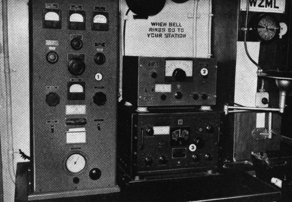
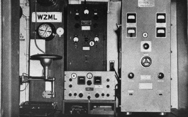
1. Mackay 156.4 short-wave transmitter.
2. Federal 125AY emergency receiver.
3. Scott SLR-7 main receiver.
4. SCBC 779-A short-wave receiver.
5. Federal 149-A emergency transmitter.
6. Radiomarine ET 8010C main transmitter.
Figure 11. Radio transmitting and receiving sets in radio room.
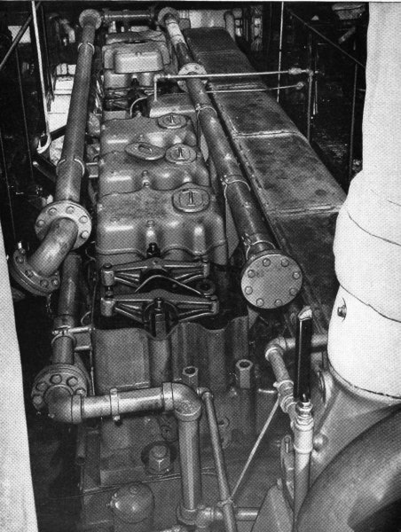
Figure 12. High-power, low-speed, supercharged Diesel engine.
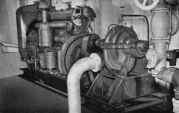
Figure 13. One of the 120-hp Diesels to run the ship’s fire pumps.
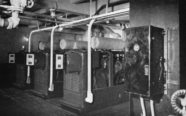
Figure 14. View of generator room showing the three electrical generators that can be run singly or in series and are driven by three 90-hp 2-cycle Diesel engines.
i. Fire fighting.
(1) The principal fire-fighting equipment consists of four motor-driven pumps, each with a capacity of 3,000 gallons per minute (gpm) and capable of 125 pounds pressure. (See fig. 13.) They are connected to an 8-inch fire main arranged on a loop circuit around the main deck. Spaced equally along this circuit are eight 21⁄2-inch hydrants equipped with fog or spray nozzles. Throughout the ship are twenty-eight 11⁄2-inch connections.
(2) There are two 1,000-gpm fire monitors. One is located forward on the forecastle head and the other is abaft the stack. (See figs. 1, 18, and 19.)
(3) A fixed carbon-dioxide smothering system is used in engine and tank compartments, bilges, and galley. Hand-operated extinguishers are located in all parts of the vessel.
j. Crew’s quarters.
(1) Quarters for most of the enlisted members of the crew are located on the first platform deck. Also on this deck are the laundry room, linen lockers, and the ship’s post exchange.
(2) On the main deck, the rest of the enlisted men and the Navy gun crew are quartered. Also on this deck are the ship’s galley and pantry, mess rooms (fig. 20), shower rooms, and diving-gear compartment.
(3) On the boat deck are officers’ quarters, the ship’s company office, dispensary (fig. 21) and a four-bed hospital.
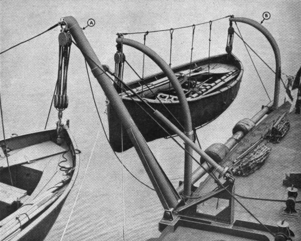
Figure 15. View of two of the ship’s lifeboats swung on two different types of davits. The davit A in the foreground is the quadrantal davit and is rapidly replacing the round bar or radial davit B, because fewer men are required to work it.
(4) On the bridge deck are the staterooms and offices of the ship’s master, salvage officer, chief engineer, and the naval gunnery officer.
k. Refrigerators. Located on the second platform deck are the fruit and vegetable, meat, and dairy refrigerators. These refrigerators hold a 30-day supply of perishable foods.
b. Fresh water. The ship’s tanks hold 536 tons (249,500 gallons) of fresh water. This supply is maintained by the evaporator which is capable of supplying 3,000 gallons of fresh water every 24 hours.
c. Food. The ship usually carries enough food for a 30-day period. Dry stores, such as canned goods, flour, sugar, etc., are stowed in storage bins on the second platform deck.
d. Linens. The ship’s laundry facilities are adequate only for the ship’s personnel. The linen lockers hold a 30-day supply of linens.
a. General. This paragraph describes the more important items of this equipment and tells how it is used. To perform its mission of starting port repairs, the ship contains completely equipped machine, carpenter, blacksmith, pipe, and welding shops in addition to a large assortment of miscellaneous equipment for various jobs.
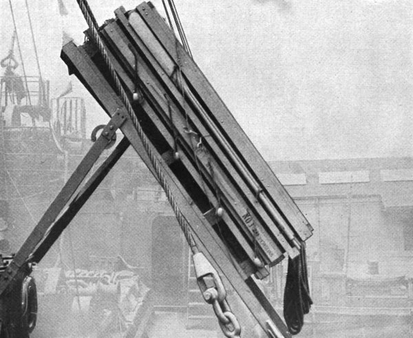
Figure 16. One of the life rafts mounted on skids. Each can accommodate 20 persons, and carries rations, water, and signaling devices. (See FM 21-22.)
b. Machine shop. The machine shop is located below the number 2 hatch (fig. 6) and contains lathes, drills, milling machine, shaper, punch and shear machine, cutters, and grinders. (See fig. 22.) All this equipment has complete sets of accessories and tools. The I-beams athwartship at number 2 hatch are removable, permitting portable equipment to be hoisted from or lowered to the machine shop.
Here are brief descriptions of the more important items of the machine-shop’s equipment.
(1) The DOALL machine. This machine (fig. 23) is used for contour metal sawing, filing, and polishing. It is a highly adaptable machine tool for jig work and for making dies. It does the work of a shaper or milling machine and replaces such operations as nibbling, drilling holes to make a cut, and torch cutting. Twenty assorted saws, 3⁄32 to 1⁄2 inches wide; three flat filebands, 1⁄4-inch, 3⁄8-inch, and 1⁄2-inch; and three file guides are standard equipment. The machine is equipped with a 3⁄4-hp, 208-volt, 3-phase, 60-cycle motor.
(2) Toolroom lathe. The 10-inch toolroom lathe (fig. 24) has a 41⁄2-foot bed and 1-inch collet capacity. It is driven by an underneath, 3⁄4-hp, 3-phase, 60-cycle motor. It is equipped with collet, milling and keyway-cutting, and telescopic-taper attachments, boring and turning cutters, fine and coarse diamond knurls, tool holders, and a large and small face plate.
(3) Extension-bed gap lathe.
(a) This 20-by 40-inch gap lathe has a 14-foot bed and a special, large face plate. With the gap closed, it is used as a regular engine lathe. (See fig. 25.)
(b) The tools and accessories for the lathe include telescoping taper attachment, boring and cutting bars, end caps, bits, chucks, and centers. Also, there is a set of metric thread-cutting gears for use where the metric system is standard. The lathe is driven by a 71⁄2 hp, 3-phase, 60-cycle motor.
(4) Engine lathe. The 16-by 54-inch engine lathe (fig. 26) also can be equipped with special threads including metric, by using special gearing in the endworks. It is driven by a 3-phase, 60-cycle, 208-volt motor and is equipped with telescoping taper attachments, boring bars, cutters, bits, chucks, tool holders, and metric thread-cutting gears.
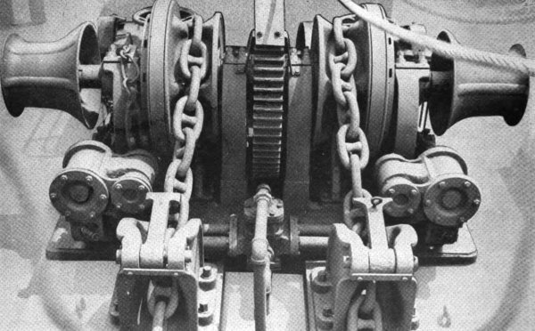
Figure 17. Windlass for handling bow anchors.
(5) Shaper.
(a) This 24-inch universal shaper is21 used for facing surfaces, notching, keyseating, and the production of flat surfaces on small parts. (See fig. 27.)
(b) The shaper is equipped with bits, holders, table, vise, and wrench set, and is driven by a 208-volt, 3-phase, 60-cycle motor.
(6) Radial drill.
(a) The radial drill has a 4-foot arm, 11-inch column, and 12 spindle speeds. (See fig. 28.) It has a range of 15 to 1,200 rpm and is driven by a 5-hp, 208-volt, 3-phase motor.
(b) The drilling capacity of this machine is approximately 2-inches diameter in cast iron and 11⁄2-inches diameter in steel. Its tapping capacity is a 2-inch tap in cast iron and 11⁄2-inch tap in steel.
(c) Its accessories include a coolant attachment, universal drill table, drill vise, chuck, and taper shank.
(7) Milling machine. The milling machine is used for gear cutting and jig and die work. The work is done with cutters instead of by sawing as the DOALL machine does. It is equipped with a 208-volt, 3-phase, 60-phase motor and has slotting and milling attachments, chucks, vise, arbors and adapters, and a complete set of cutters. (See fig. 29.)
(8) Punch and shear machine.
(a) This combination punch and shear machine has a punch capacity 1-by 1⁄2-inch or 7⁄8-by 5⁄8-inch. Its shear capacity is 1⁄2-inch plates, 6-by 5⁄8-inch flats, 15⁄8-inch rounds, and 11⁄2-inch squares. (See fig. 30.)
(b) It is driven by a 3-hp, 3-phase, 60-cycle, 208-volt motor, and its accessories include punches, dies, shear blades for plates and flats, and bar-cutter blades for rounds, squares, angles, and tees.
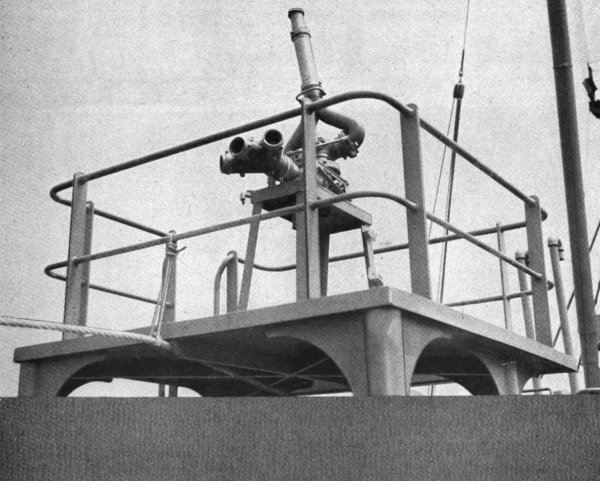
Figure 18. Fire monitor showing the power nozzle and hose connections. The monitor rotates and the power nozzle tilts at any desired degree.
(9) Drill. This column-type drill (fig. 31) has a 1-inch capacity in steel and is driven by a 2-hp, 3-phase, 60-cycle, 208-volt motor. Its accessories include a Jacobs three-jaw ball-bearing chuck, reducing sleeves, and a combination drill and countersink set.
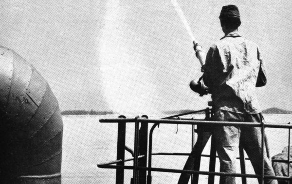
Figure 19. View showing the fire monitor in operation. The water is being forced through the power nozzle at 100-pound pressure.

Figure 20. View of enlisted men’s mess room. The tables accommodate 32 men.
(10) Combination tool and cutter grinder.
(a) This grinder has a 10-inch-diameter swing and 24 inches between head and footstock. It is driven by a 3⁄4-hp, 3-phase, 60-cycle, 208-volt motor and has attachments for all forms of milling cutters, taps, and reamers. (See fig. 32.)
(b) For grinding, this machine is run by a 1⁄8-hp, 1-phase, 60-cycle, 110-volt motor, and has 3-inch to 8-inch wheels for dressing and grinding.
(11) Pedestal grinder. This grinder for tool sharpening operates at 1,750 rpm and is driven by a 3-phase, 208-volt, 60-cycle motor. The grinding wheels are 14 inches in diameter and 21⁄4 inches in thickness. (See fig. 33.)
(12) Power hacksaw. This power hacksaw is used for metal sawing and has a blade-cooling system for high-speed cutting. Its capacity is 9 by 9 inches, it has 3 speeds, and is driven by a 3-phase, 60-cycle, 208-volt motor. It comes equipped with 24 molybdenum steel blades. (See fig. 34.)
(13) Miscellaneous machine-shop equipment. Miscellaneous machine-shop equipment includes small hand and electric drills, bench lathe, portable grinders, electric soldering sets, hydraulic press, chain-saw sharpener, mechanic and master mechanic tool sets, jacks, vises, and tap and die sets.
c. Blacksmith shop.
(1) The blacksmith shop is adjacent to the machine shop and is equipped to handle all smithing operations. These operations include heating for forging, annealing, hardening, and tempering metals. (See fig. 35.)
(2) The forge has an electric blower, and the hood mounted over it has an exhaust fan to expel fumes and smoke from the forge.
(3) For working metal, there is a pneumatic, 200-pound forging hammer. (See fig. 36.) This hammer is of the self-contained type and the blacksmith can operate it and manipulate the work between the dies at the same time.
(4) Other blacksmith equipment in the shop include engineer blacksmith equipment set No. 1, sledges, tongs, and swages.
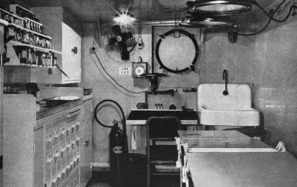
Figure 21. Ship’s dispensary showing portable operating table, operating lights, and shelves and cabinets for medical supplies.
d. Carpenter shop.
(1) The carpenter shop is on the first platform deck on the starboard side of number 2 hatch. (See fig. 6.) The main equipment of this shop consists of a universal woodworking machine, a 32-inch band saw, and a portable electric saw.
(2) The universal woodworking machine (fig. 37), is powered by a 5-hp, 3-phase, 60-cycle, 208-volt motor, developing 3,425 rpm and is equipped with 14-and 16-inch blades.
(3) The 32-inch band saw (fig. 38) is powered by a 3-hp, 3-phase, 60-cycle, 208-volt motor, developing 600 rpm. It is supplied with general-purpose blades, a ripping fence, and a resaw guide.
(4) The portable circular saw is run by a 110-volt universal motor. (See fig. 39.) It is equipped with two combination blades for sawing wood; when abrasive discs are used, it will cut brick, stone, concrete, steel, and cast iron.
e. Pipe shop.
(1) The pipe shop adjoins the machine shop and its main equipment consists of a portable pipe bender and a pipe and bolt threading machine. (See fig. 40.)
(2) The hydraulic portable pipe bender has a maximum piston pressure of 50,000 pounds and will bend up to 3-inch pipe.
(3) The pipe-and bolt-threading machine will handle 1⁄8-to 2-inch pipe and 3⁄8-to 11⁄2-inch bolts.
f. Welding shop.
(1) The welding shop is on the first platform deck on the port side of number 2 hatch. (See fig. 6.) The welding shop contains equipment for electric-arc and oxyacetylene welding and cutting.
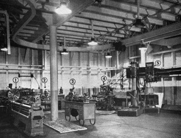
1. Extension-bed lathe.
2. Engine lathe.
3. Toolroom lathe.
4. Universal milling machine.
5. Radial drill.
Figure 22. View of machine shop showing a part of the equipment and overhead monorail system capable of handling 5 tons.
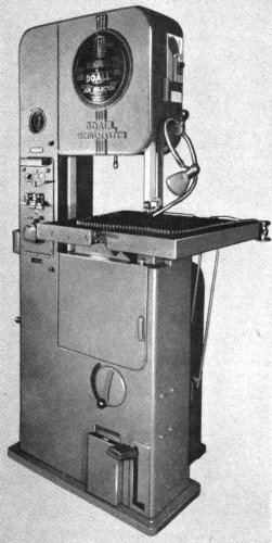
Figure 23. This DOALL machine is used for contour metal sawing and jig work.
(2) For electric-arc welding there are two stationary and four portable sets. All of the sets are driven by gasoline engines and have complete sets of accessories.
(3) The portable sets are mounted on four-wheel dollies and have a welding range of 50 to 400 amperes and a generator rating of 300 amperes at 40 volts. The accessories include a welding-rod assortment, 50-foot electrode and ground cables, gloves, helmets, lenses, and mittens.
(4) For oxyacetylene work, there are three oxyacetylene welding and cutting sets and three portable acetylene generators. The sets include cutting and welding torches and tips, 50-foot lengths of hose, tip cleaners, oxygen and acetylene regulators, spark lighters, gloves, and goggles.
(5) There is also a portable, preheating torch of the atomizing type operated by compressed air.
(6) Miscellaneous equipment in the welding shop includes a brazing and soldering set, ten 225-cubic-foot acetylene cylinders, and fifty 220-cubic-foot oxygen cylinders.
g. Diving gear and equipment.
(1) The diving equipment room is located on the main deck just aft the number 3 hatch. (See fig. 6.) In this room are lockers for diving gear, the recompression chamber, hangers for holding the diving suits, and a work table for repairing suits.
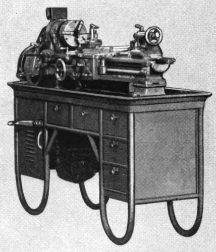
Figure 24. Ten-inch toolroom lathe with 41⁄2-foot bed.
(2) The recompression chamber (fig. 42) is used for testing divers’ ability to withstand pressure before diving and to decompress divers if they develop compressed-air illness (bends).

Figure 25. Extension-bed gap lathe, 20-by 40-inch with 14-foot bed.
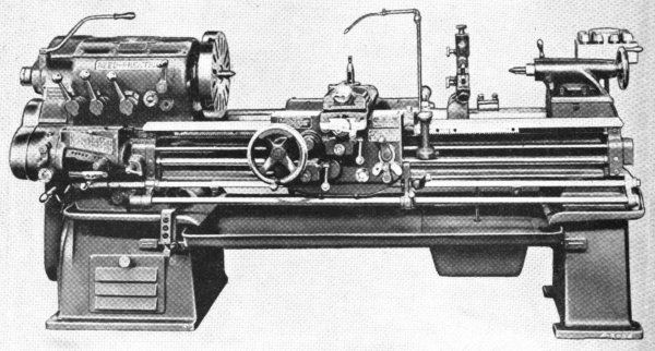
Figure 26. Engine lathe, 16-by 54-inch.
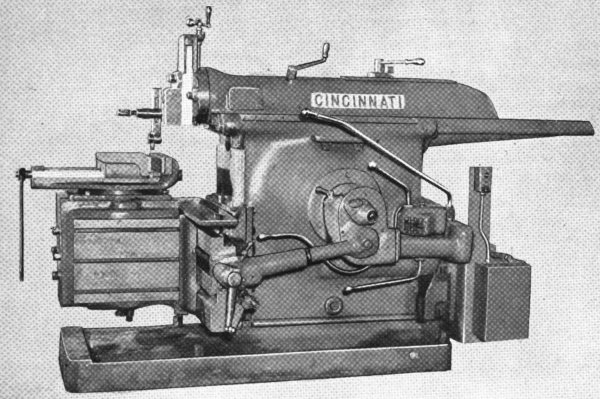
Figure 27. Twenty-four inch universal shaper for facing, notching, keyseating, and die making.
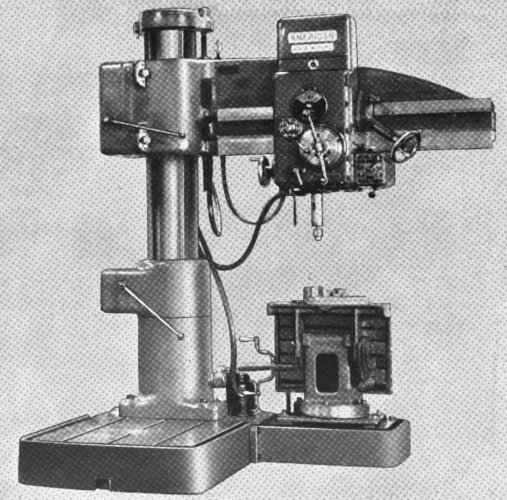
Figure 28. Radial drill with 4-foot arm and 11-inch column.
(3) For deep-sea diving, there are two No. 1 diving outfit sets. (See fig. 41.)
(4) Other equipment in the No. 1 set includes an air compressor, descending and stage lines, decompression stage, telephone, diving lamp, air and telephone hose, and diving weights.
(5) For shallow-water diving in depths up to 36 feet, there are four No. 2 diving outfit sets. (See figs. 43 and 44.)
(6) The rest of the diving equipment includes a canvas workers set No. 1, carpenter equipment set No. 2, gasoline-engine-driven, skid-mounted air compressor with a capacity of 60 cubic feet of air per minute, electrodes for underwater cutting, a pneumatic tugger hoist for the diving stage, and a portable air lock.
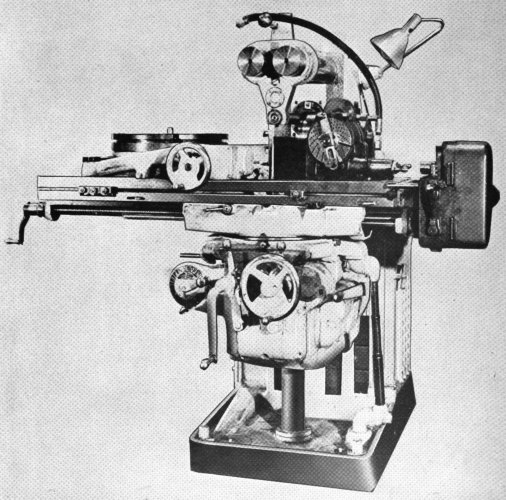
Figure 29. Universal milling machine No. 2, horizontal.
h. Compressed-air equipment.
(1) An assortment of compressed-air equipment is carried for doing jobs both on and off the ship. This equipment includes rock drills for drilling in rock or29 concrete; paving breakers used in breaking out concrete, breaking up rock, and in general demolition work; rivet busters for cutting out rivets; woodboring drills for boring various-sized holes in timbers; rotary drills for drilling holes in steel plates and beams; grinders for general grinding; pneumatic hammers for cleaning castings, beveling seams on ships, and chipping holes in concrete; riveting hammers for driving rivets; pneumatic wrenches for tightening and loosening nuts and bolts; nail drivers; chain saws adapted for cutting pilings underwater; and circular saws.
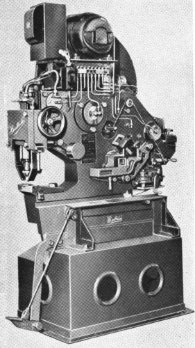
Figure 30. Combination punch and shear machine.
(2) For operating this equipment, there is a 315 cfm, Diesel-driven, skid-mounted air compressor and a 280 cfm, electric-driven air compressor.
i. Beach gear.
(1) The beach gear carried on the ship is used primarily to salvage stranded vessels. This type of salvage differs from raising sunken wrecks, where all the work in preparing the vessel for raising is done by divers. For beach salvage work, divers ordinarily are needed only for examining the stranded vessel’s hull and the nature of the underwater terrain, and beach gear and the towing power of other craft are used to refloat the ship.
(2) The main items of the beach gear are two 8,000-pound anchors, blocks of various types, hooks, clips, chains, manila and wire rope, shackles, cable stoppers, and rope thimbles.
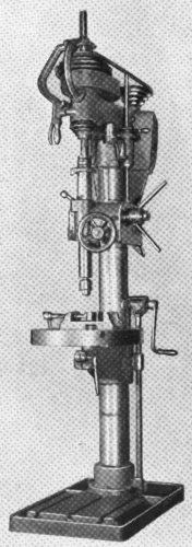
Figure 31. Column-type drill. This drill has a 1-inch capacity in steel.
j. Portable salvage pumping equipment. The portable salvage pumping equipment consists of30 one 10-inch, two 6-inch, and two 3-inch salvage pumps, complete with spare parts, hose, metal suctions, and adapters.
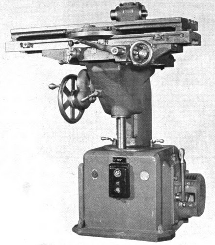
Figure 32. Combination tool and cutter grinder.
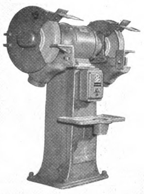
Figure 33. Pedestal grinder for tool sharpening.
k. Portable fire-pumping equipment. The portable fire-pumping equipment consists of a two-wheeled trailer pumper with a capacity of 500 gpm and four 50-foot lengths of 21⁄2-inch hose.
l. Hoisting equipment.
(1) The hoisting equipment consists of the 40-ton cathead mounted on the prow, one 50-ton and four 10-ton booms on the foremast, and two 5-ton booms on the mainmast, together with the winches for operating them. (See fig. 45.)
(2) The cathead (fig. 46) is used to raise debris and sunken small craft that are hazards to navigation or prevent vessels from coming alongside31 wharves or piers. It is operated by a two-speed winch installed in the forecastle peak on the shelter deck.
(3) The 50-ton boom is operated by a two-speed winch and the four 10-ton and the two 5-ton booms are run by single-speed winches. (See fig. 47.)
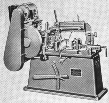
Figure 34. Power hacksaw for metal cutting.
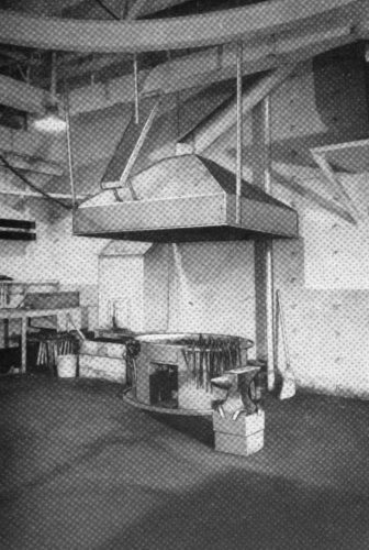
Figure 35. View of blacksmith shop showing 48-inch forge and 200-pound anvil.
m. Floating equipment. In addition to the life-boats and rafts, the ship carries a steel pontoon barge, a plane-rearming boat, and a utility boat.
(1) The barge is made up of 21 sections (fig. 48) and has a capacity of 50 tons. It is propelled by a 115-hp outboard engine and carries a 5-ton crawler crane for diving and salvage operations. The sections of the barge are stowed in the number 1 hold of the ship.
(2) The plane-rearming boat is 33 feet long and is powered by a 100-hp inboard, Diesel engine. It is used for diving, general utility work, and light towing.
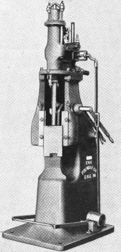
Figure 36. Pneumatic, 200-pound forging hammer.
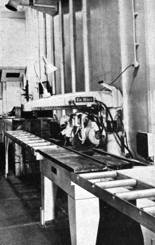
Figure 37. Universal woodworking machine with steel table and two extension roller tables.
(3) The utility boat is 26 feet long and is propelled by a 95-hp gasoline or Diesel engine. It is used to tow the barge and floats and for general errand work.
n. Miscellaneous equipment. Miscellaneous equipment includes:
Clamshell bucket, 3⁄4-cubic-yard.
Jacks, including a 50-ton hydraulic jack.
Cargo nets.
Demolition, rigging, and tinsmith equipment.
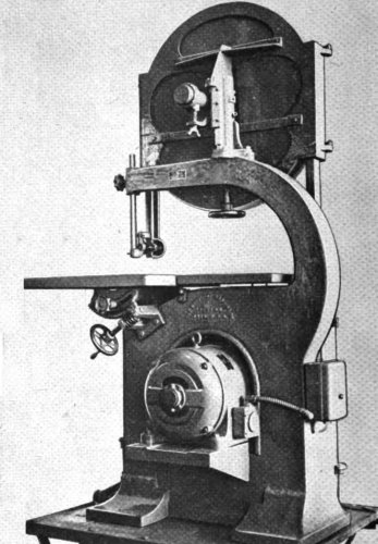
Figure 38. Woodworking 32-inch band saw.
a. Machine-shop stock. Supplies for the machine shop include 13-inch bronze-alloy round bars of various diameters, 11-foot cold-rolled steel bars of different sizes, square-and round-tool-steel bars, and 5-foot lengths of keystock steel from 1⁄8 to 3⁄4 inches wide.
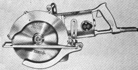
Figure 39. Portable electric saw.
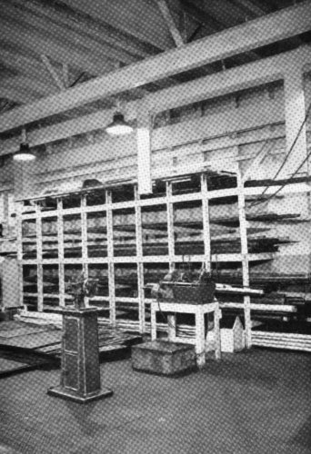
Figure 40. View of pipe shop showing supply of pipe in racks.
b. Carpenter shop supplies.
(1) Lumber for the carpenter shop is structural-grade fir in 16-foot lengths and varying in size from 2-by 1-inch to 12-by 12-inch.
(2) There are 800 pounds of nails that range in size from 2d to 60d, and a supply of wood screws.
c. Pipe stock. The pipe varies in size from 1⁄4 inch to 6 inches and comes in 12-foot lengths. There is a supply of nipples, elbows, tees, valves, and unions for the different sizes of pipe.
d. Ammunition. The ship’s magazines hold 32,400 rounds of 20-mm and 312 rounds of 3″/50 cal. ammunition.

Figure 41. Diver in No. 1 diving dress ready to go down.
e. Miscellaneous supplies. Miscellaneous supplies include gasoline, lubricating oils and greases, cement, canvas, roofing, chicken wire, hardware, plugs, and structural steel.
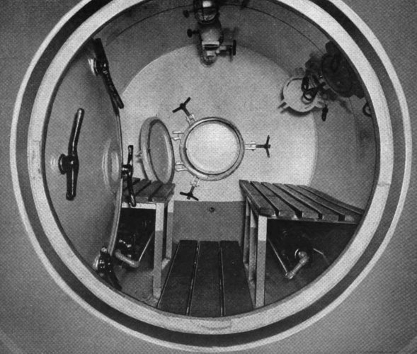
Figure 42. View of interior of recompression chamber. If divers must be brought up in a hurry they are rushed into this chamber for decompression to prevent their getting the “bends.”
b. Diving and salvage training. The diving and salvage training is given officers and enlisted men35 with particular emphasis on operations performed in and around docks, quays, and other waterfront structures, harbors, inland waterways. Diving and salvage operations are essential to the rehabilitation of ports. The training should include the following:
(1) Diving-team problems with timber and steel construction; underwater concrete construction; underwater demolition of docks, piers, and ships; and actual salvage operations.
(2) Individual diving problems including underwater reconnaissance, pipefitting, patching, welding, cutting with hydrogen torch and oxyelectric machine; survey of underwater conditions in mud, swift currents, and various tide actions; use of jetting nozzle and siphon.
(3) Use of hand tools, air tools, machine tools, pumps, winches, and blacksmithing.
(4) Rigging, beach gear, and hi-lines.
(5) Elementary instruction and training in—
(a) Diving-gear nomenclature.
(b) Diving-gear maintenance.
(c) Hazards of diving.
(d) Physics of diving.
(e) Skin diving.
(f) Recompression tanks and tables.
(g) Air compressors, air flasks, field expedients.
(h) Signals and communications.
(i) Ship construction.
(j) Mooring and maneuvering.
(k) Sketching.
(l) Tactical military instruction.
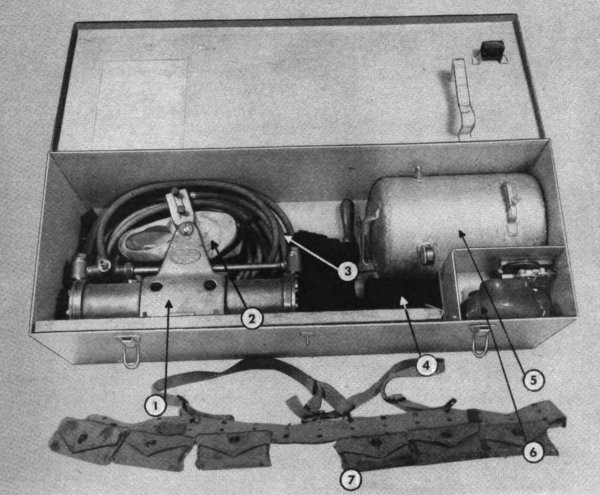
1. Hand pump.
2. Rubber sneakers.
3. Air hose.
4. Diver’s underwear.
5. Expansion tank.
6. Face mask.
7. Weighted belt.
Figure 43. No. 2 diving outfit set.
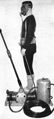
Figure 44. Diver in No. 2 diving outfit set.
c. Diesel engineer training. This is advanced training for those men having previous Diesel experience. The operation, maintenance, and repair of Diesel engines are studied.
d. Seaman training. The apprentice seaman is given a basic course in seamanship. It includes instruction in—
(1) Nautical terms. All nautical terms and what they mean, including the parts of a ship and construction terms.
(2) Ground tackle and its use. The various kinds of anchors and how they are used; rules for anchoring.
(3) Lifeboat seamanship. Lifeboats and their handling, surf seamanship, the sea anchor, use of oil, helmsmanship.
(4) Safety at sea. Avoiding accidents, keeping equipment shipshape, safeguarding against fire, fire-fighting and life-saving equipment, first aid.
(5) Marlinespike seamanship. The common knots, how to make fast to a cleat, whipping, splicing, the care of rope, handling and use of lines.
(6) The compass. Types of compasses, installation and care, boxing the compass, points and degrees, variation and deviation, compensating the compass.
(7) General. General seaman duties and seaman watches.
e. Visual signal instruction. The visual signal training should include:
(1) International code flags.
(2) Semaphore.
(3) Flashing light signals.
(4) The signal code.
(5) Typical signals.
(6) Special Navy signals.
(7) Signaling Navy and Coast Guard vessels.
(8) Special flags and pennants.
(9) Pyrotechnics.
f. Degaussing school. At the Navy degaussing school, complete degaussing of a ship is taught, including what equipment is required and how it is used.
g. Wartime radio procedure. The wartime radio procedure is that procedure practiced by the Navy. It includes:
(1) Ship-to-ship, ship-to-shore, and ship-to-plane radio instruction.
(2) Call numbers and identification.
(3) Codes.
(4) Radio discipline.
(5) Operation and maintenance of marine radio equipment.
(6) Operation of radio direction finder.
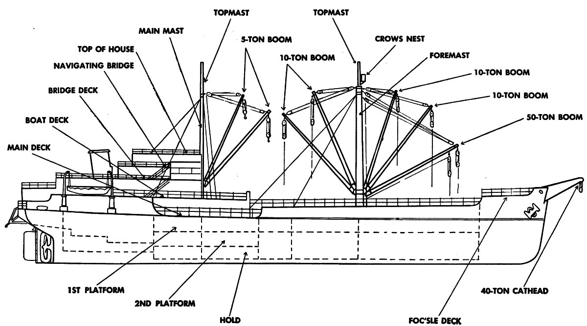
Figure 45. Outboard profile showing cathead and cargo booms.
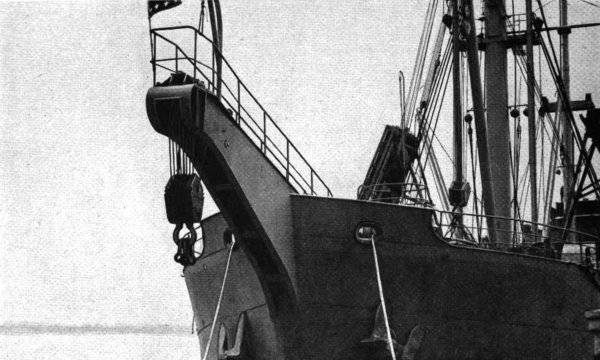
Figure 46. Forty-ton cathead mounted on bow of ship.
h. Gyrocompass instruction. The Navy gyrocompass school teaches:
(1) Basic principles of the action and operation of the gyrocompass.
(2) Cause of gyrocompass errors and how to correct or compensate them.
(3) Maintenance and care of the compass and its equipment.
i. Convoy communication. The Navy convoy communication school teaches the various types of signaling used between ships in a convoy. The instruction includes:
(1) Naval signal codes and calls.
(2) Procedure signs.
j. Machine-shop training. The machine-shop training includes the operation of drill presses, grinders, lathes, cutters, punch and shear machines, shapers, forging hammers, and milling machines. The men work with different types of metals, receive practical experience in various kinds of machine-shop jobs, and learn how to maintain the equipment and tools.
k. Demolition training. Training in explosives and demolitions includes the following:
(1) Theory of explosives.
(2) Calculation of charges.
(3) Capping and priming.
(4) Field expedients.
(5) Cutting, cratering, and flattening charges.
(6) Booby traps.

Figure 47. Single-speed winch for operating 10-ton cargo boom.
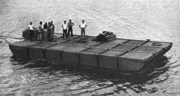
Figure 48. Fifty-ton barge made up of 21 sections and propelled by 115-hp outboard engine.
(1) Channels and harbors. Offshore obstructions in the waters of the harbor include booms and torpedo nets, debris, prepared sunken obstacles, destruction of navigation aids and moorings, and damage to underwater pilings and foundations. It is the engineer port repair ship’s job to remove or destroy these obstacles and to make the underwater repairs.
(2) Damage to shore installations. The destruction of shore installations includes damage to utilities, shops, warehouses, railway spurs and yards, roads, bridges, locked basins, cargo-handling equipment, piers, wharves, and quays. It is the mission of the port construction and repair groups to repair and put these facilities back in operation.
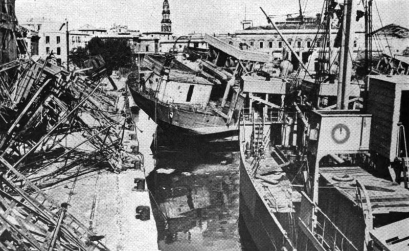
Figure 49. Naples harbor cluttered with wreckage. Wrecked and capsized merchant vessels line the quays. Note the damaged warehouses. All cargo-handling equipment has been destroyed.
b. Enemy damage to captured ports. Although the conditions outlined below will not hold true in all cases, they were found in captured ports.
(1) Warehouses and shops. All warehouses and shops were destroyed by demolition and fire.
(2) Utilities. Electric, water, gas, and communications systems were put out of commission by demolition and removal of parts.
(3) Locked basins and docks. All locked basins and closures were destroyed; walls of basins were collapsed by explosives.
(4) Wharves and quays. Demolitions destroyed the inshore 100 feet of quay full width to a depth of 30 feet. Mines destroyed all cranes and blew out the face of the quay in sections about 40 feet long, 30 feet back, and 20 feet deep. Cranes usually are spaced about 75 feet apart.
(5) Miscellaneous. Delayed-action mines and booby traps were placed at strategic places, even in sunken boats and ships.
(6) Channels and harbors.
(a) Ships were sunk to block entrances to harbors.
(b) All mooring buoys and channel markers were removed.
(c) All boats and lighters available to the enemy were sunk adjacent to quays, wharves, and piers.
(d) Wharf cranes and debris were blown into channels alongside wharves and quays. (See figs. 49 through 53.)
(1) Extinguish fires and demolish unsafe structures.
(2) Sweep mines.
(3) Remove blockships.
(4) Remove booms and torpedo nets.
(5) Neutralize land mines and booby traps.
(6) Install AA and other protective works.
(7) Remove debris in water and on quays.
(8) Remove obstructions from exits to wharf areas.
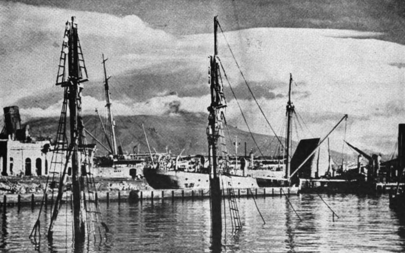
Figure 50. Masts of sunken freighter in harbor. The enemy did a systematic job of sinking ships to block the harbor as much as possible.
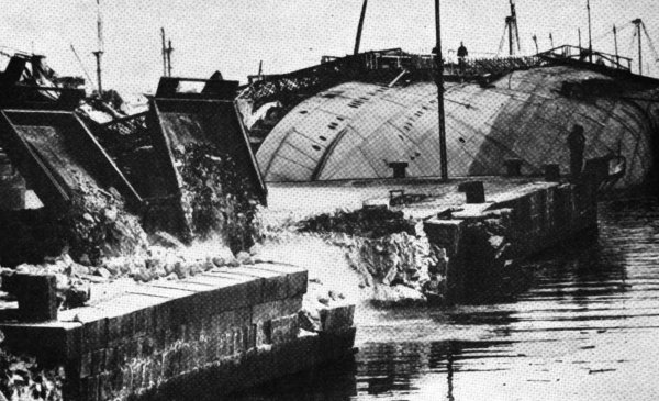
Figure 51. Sunken ships and bomb-wrecked quays give some idea of the huge task of repair and construction in restoring the port to usefulness.
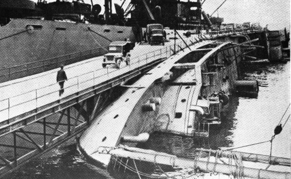
Figure 52. Temporary bridge built on a keeled-over freighter. Trucks are using it to unload a Liberty ship.
(9) Install navigation aids and moorings.
b. Following are some of the jobs the port repair ship might be required to do:
(1) Install navigation aids in entrance channel. After the harbor area has been swept of mines by the Navy, the port repair ship marks the entrance channel with buoys. This is done by soundings and by using hydrographic charts of the harbor. Soundings are made by the ship’s fathometer, by lead lines, and by a portable depth finder. The portable depth finder works on the same principle as the ship’s fathometer (par. 8) and is installed on one of the two powerboats. The powerboat operates ahead of the port repair ship, takes continual soundings, and marks the boundaries of the channel. The crew of the powerboat is constantly on the alert for underwater obstructions and signals the ship if any are found and whether the ship must change her course or stop.
(2) Blockships.
(a) A blockship is a prepared underwater obstacle sunk to prevent ships from following navigable channels. One or more blockships may be found in an entrance channel. These ships are often filled with rock or concrete to make them more difficult to remove.
(b) When soundings, intelligence reports, or information received from the minesweepers indicate the location of a blockship, a diver is sent down for reconnaissance. The information required to determine the course of action is—
1. Position blockship is in. That is, is it on its side, at an angle, or resting on its keel.
2. Approximate size and type of vessel.
3. Nature and extent of its superstructure.
4. Would the removal or destruction of the superstructure leave enough water between the hull and the surface for large vessels to use the channel?
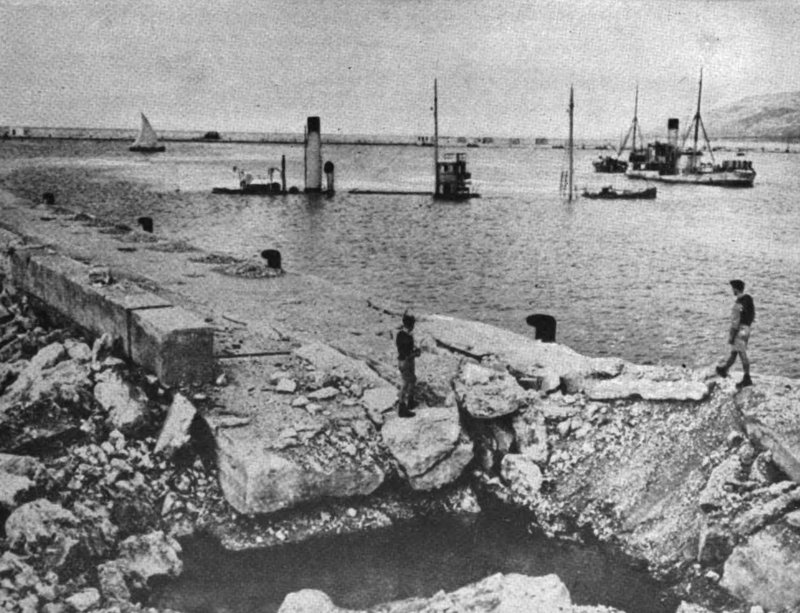
Figure 53. Two half-sunken ships and the bomb crater in harbor’s seawall and quay show the results of well-planned destruction.
5. Nature of bottom and effect of currents.
6. Is ship filled with rock or concrete?
7. Indications of mines and booby traps.
(c) This information determines whether the superstructure can be cut through or flattened with explosives or if the hull has to be broken up before the channel is cleared. Destroying the hull is a long, difficult task and should not be attempted if the removal of the superstructure affords enough clearance.
(3) Harbor.
(a) General. When the port repair ship enters the harbor, her master reports to the port commander for instructions. These instructions include—
1. What jobs the ship is to do and what priorities have been set on them.
2. What materials, equipment, power, tools, and personnel the ship is to furnish the port construction and repair group.
3. Whether temporary construction or repairs are to be made or permanent repairs made.
4. Surveys to be made of underwater damage and obstructions in harbor area.
(b) Removal of small sunken craft and debris. Small boats usually are sunk alongside wharves and quays to prevent ships from approaching close enough to unload. Also, cranes and sections of the wharves blown into the water have to be removed. Divers examine the debris and determine whether it can be pulled out of the way into deeper water or if it first must be broken up. Since the use of large quantities of explosives may further damage adjacent quays and piers, debris too heavy and bulky to hoist and drag is cut into smaller sections by underwater cutting. Then these sections are raised by the cathead and pulled out of the way by the ship. Small, sunken craft often can be salvaged by sealing up the hulls and pumping out the water with salvage pumps. This type of salvage work can be done from the 50-ton barge which leaves the repair ship free for other jobs.
(c) Furnishing materials, power, and equipment.
1. Materials. Materials required by the port group to start its work can be furnished in limited quantities by the repair ship. However until cargo ships can unload at the port, the group must get locally the bulk of the materials it needs. The small amount of cement, timbers, and structural steel that the ship carries can be put ashore on the ship’s barge.
2. Power. Until local sources of power are restored or floating power plants are available, power for lighting and for operating equipment is supplied by the ship’s stationary and portable generators and compressors.
3. Equipment. Such portable equipment as the clamshell bucket, welding and cutting outfits, trailer-mounted fire pumper, and pneumatic tools, is turned over to the group as it is needed. If necessary, equipment operators are furnished from the ship’s personnel.
(d) Use of the ship’s shops. The ship’s shops are used to make parts for and to repair port machinery and equipment. Typical jobs are to repair engines and motors and to construct or repair cargo-handling equipment.
(e) Underwater construction and repairs. The ship’s divers may be required to repair the underwater structures of damaged piers and quays. Broken or weakened pilings or timbers may have to be cut and removed so new ones can be placed. Also, the foundations of harbor breakwaters or sea walls may require strengthening or repairs.
c. Safety of ship. While operating in the close waters of the harbor, especially while threatened with the additional hazards of debris, mines, underwater obstacles, and enemy air attack, the safety of the ship is of paramount importance. The master of the ship is responsible for her safety. He sees that the gun crews are at their stations and that enough deckhands are available for the extra work required in mooring and maneuvering.
d. Summary. Speed is essential in port repair work to eliminate the necessity of landing troops, stores, and equipment over beaches for any length of time. The engineer port repair ship has an important part in getting this work started by opening the harbor to navigation and by furnishing power, equipment, and supplies to the port construction and repair groups. The shops on the ship help prevent stoppages caused by breakdown of machinery and equipment because they can repair or manufacture essential parts that may be needed. In short, the port repair ship is the spearhead in getting port reconstruction work under way and, by its ability to do many different tasks, helps to speed up this work and keep it going.
☆ U. S. GOVERNMENT PRINTING OFFICE: 1945—628131—TM 1045
Transcriber’s Notes:
The original spelling, hyphenation and punctuation has been retained, with the exception of apparent typographical errors which have been corrected.
End of the Project Gutenberg EBook of Engineer Port Repair Ship, by
United States War Department

*** END OF THIS PROJECT GUTENBERG EBOOK ENGINEER PORT REPAIR SHIP ***

***** This file should be named 57941-h.htm or 57941-h.zip *****
This and all associated files of various formats will be found in:
        http://www.gutenberg.org/5/7/9/4/57941/

Produced by deaurider, Brian Wilcox and the Online
Distributed Proofreading Team at http://www.pgdp.net (This
file was produced from images generously made available
by The Internet Archive)

Updated editions will replace the previous one--the old editions will
be renamed.

Creating the works from print editions not protected by U.S. copyright
law means that no one owns a United States copyright in these works,
so the Foundation (and you!) can copy and distribute it in the United
States without permission and without paying copyright
royalties. Special rules, set forth in the General Terms of Use part
of this license, apply to copying and distributing Project
Gutenberg-tm electronic works to protect the PROJECT GUTENBERG-tm
concept and trademark. Project Gutenberg is a registered trademark,
and may not be used if you charge for the eBooks, unless you receive
specific permission. If you do not charge anything for copies of this
eBook, complying with the rules is very easy. You may use this eBook
for nearly any purpose such as creation of derivative works, reports,
performances and research. They may be modified and printed and given
away--you may do practically ANYTHING in the United States with eBooks
not protected by U.S. copyright law. Redistribution is subject to the
trademark license, especially commercial redistribution.

START: FULL LICENSE

THE FULL PROJECT GUTENBERG LICENSE
PLEASE READ THIS BEFORE YOU DISTRIBUTE OR USE THIS WORK

To protect the Project Gutenberg-tm mission of promoting the free
distribution of electronic works, by using or distributing this work
(or any other work associated in any way with the phrase "Project
Gutenberg"), you agree to comply with all the terms of the Full
Project Gutenberg-tm License available with this file or online at
www.gutenberg.org/license.

Section 1. General Terms of Use and Redistributing Project
Gutenberg-tm electronic works

1.A. By reading or using any part of this Project Gutenberg-tm
electronic work, you indicate that you have read, understand, agree to
and accept all the terms of this license and intellectual property
(trademark/copyright) agreement. If you do not agree to abide by all
the terms of this agreement, you must cease using and return or
destroy all copies of Project Gutenberg-tm electronic works in your
possession. If you paid a fee for obtaining a copy of or access to a
Project Gutenberg-tm electronic work and you do not agree to be bound
by the terms of this agreement, you may obtain a refund from the
person or entity to whom you paid the fee as set forth in paragraph
1.E.8.

1.B. "Project Gutenberg" is a registered trademark. It may only be
used on or associated in any way with an electronic work by people who
agree to be bound by the terms of this agreement. There are a few
things that you can do with most Project Gutenberg-tm electronic works
even without complying with the full terms of this agreement. See
paragraph 1.C below. There are a lot of things you can do with Project
Gutenberg-tm electronic works if you follow the terms of this
agreement and help preserve free future access to Project Gutenberg-tm
electronic works. See paragraph 1.E below.

1.C. The Project Gutenberg Literary Archive Foundation ("the
Foundation" or PGLAF), owns a compilation copyright in the collection
of Project Gutenberg-tm electronic works. Nearly all the individual
works in the collection are in the public domain in the United
States. If an individual work is unprotected by copyright law in the
United States and you are located in the United States, we do not
claim a right to prevent you from copying, distributing, performing,
displaying or creating derivative works based on the work as long as
all references to Project Gutenberg are removed. Of course, we hope
that you will support the Project Gutenberg-tm mission of promoting
free access to electronic works by freely sharing Project Gutenberg-tm
works in compliance with the terms of this agreement for keeping the
Project Gutenberg-tm name associated with the work. You can easily
comply with the terms of this agreement by keeping this work in the
same format with its attached full Project Gutenberg-tm License when
you share it without charge with others.

1.D. The copyright laws of the place where you are located also govern
what you can do with this work. Copyright laws in most countries are
in a constant state of change. If you are outside the United States,
check the laws of your country in addition to the terms of this
agreement before downloading, copying, displaying, performing,
distributing or creating derivative works based on this work or any
other Project Gutenberg-tm work. The Foundation makes no
representations concerning the copyright status of any work in any
country outside the United States.

1.E. Unless you have removed all references to Project Gutenberg:

1.E.1. The following sentence, with active links to, or other
immediate access to, the full Project Gutenberg-tm License must appear
prominently whenever any copy of a Project Gutenberg-tm work (any work
on which the phrase "Project Gutenberg" appears, or with which the
phrase "Project Gutenberg" is associated) is accessed, displayed,
performed, viewed, copied or distributed:

  This eBook is for the use of anyone anywhere in the United States and
  most other parts of the world at no cost and with almost no
  restrictions whatsoever. You may copy it, give it away or re-use it
  under the terms of the Project Gutenberg License included with this
  eBook or online at www.gutenberg.org. If you are not located in the
  United States, you'll have to check the laws of the country where you
  are located before using this ebook.

1.E.2. If an individual Project Gutenberg-tm electronic work is
derived from texts not protected by U.S. copyright law (does not
contain a notice indicating that it is posted with permission of the
copyright holder), the work can be copied and distributed to anyone in
the United States without paying any fees or charges. If you are
redistributing or providing access to a work with the phrase "Project
Gutenberg" associated with or appearing on the work, you must comply
either with the requirements of paragraphs 1.E.1 through 1.E.7 or
obtain permission for the use of the work and the Project Gutenberg-tm
trademark as set forth in paragraphs 1.E.8 or 1.E.9.

1.E.3. If an individual Project Gutenberg-tm electronic work is posted
with the permission of the copyright holder, your use and distribution
must comply with both paragraphs 1.E.1 through 1.E.7 and any
additional terms imposed by the copyright holder. Additional terms
will be linked to the Project Gutenberg-tm License for all works
posted with the permission of the copyright holder found at the
beginning of this work.

1.E.4. Do not unlink or detach or remove the full Project Gutenberg-tm
License terms from this work, or any files containing a part of this
work or any other work associated with Project Gutenberg-tm.

1.E.5. Do not copy, display, perform, distribute or redistribute this
electronic work, or any part of this electronic work, without
prominently displaying the sentence set forth in paragraph 1.E.1 with
active links or immediate access to the full terms of the Project
Gutenberg-tm License.

1.E.6. You may convert to and distribute this work in any binary,
compressed, marked up, nonproprietary or proprietary form, including
any word processing or hypertext form. However, if you provide access
to or distribute copies of a Project Gutenberg-tm work in a format
other than "Plain Vanilla ASCII" or other format used in the official
version posted on the official Project Gutenberg-tm web site
(www.gutenberg.org), you must, at no additional cost, fee or expense
to the user, provide a copy, a means of exporting a copy, or a means
of obtaining a copy upon request, of the work in its original "Plain
Vanilla ASCII" or other form. Any alternate format must include the
full Project Gutenberg-tm License as specified in paragraph 1.E.1.

1.E.7. Do not charge a fee for access to, viewing, displaying,
performing, copying or distributing any Project Gutenberg-tm works
unless you comply with paragraph 1.E.8 or 1.E.9.

1.E.8. You may charge a reasonable fee for copies of or providing
access to or distributing Project Gutenberg-tm electronic works
provided that

* You pay a royalty fee of 20% of the gross profits you derive from
  the use of Project Gutenberg-tm works calculated using the method
  you already use to calculate your applicable taxes. The fee is owed
  to the owner of the Project Gutenberg-tm trademark, but he has
  agreed to donate royalties under this paragraph to the Project
  Gutenberg Literary Archive Foundation. Royalty payments must be paid
  within 60 days following each date on which you prepare (or are
  legally required to prepare) your periodic tax returns. Royalty
  payments should be clearly marked as such and sent to the Project
  Gutenberg Literary Archive Foundation at the address specified in
  Section 4, "Information about donations to the Project Gutenberg
  Literary Archive Foundation."

* You provide a full refund of any money paid by a user who notifies
  you in writing (or by e-mail) within 30 days of receipt that s/he
  does not agree to the terms of the full Project Gutenberg-tm
  License. You must require such a user to return or destroy all
  copies of the works possessed in a physical medium and discontinue
  all use of and all access to other copies of Project Gutenberg-tm
  works.

* You provide, in accordance with paragraph 1.F.3, a full refund of
  any money paid for a work or a replacement copy, if a defect in the
  electronic work is discovered and reported to you within 90 days of
  receipt of the work.

* You comply with all other terms of this agreement for free
  distribution of Project Gutenberg-tm works.

1.E.9. If you wish to charge a fee or distribute a Project
Gutenberg-tm electronic work or group of works on different terms than
are set forth in this agreement, you must obtain permission in writing
from both the Project Gutenberg Literary Archive Foundation and The
Project Gutenberg Trademark LLC, the owner of the Project Gutenberg-tm
trademark. Contact the Foundation as set forth in Section 3 below.

1.F.

1.F.1. Project Gutenberg volunteers and employees expend considerable
effort to identify, do copyright research on, transcribe and proofread
works not protected by U.S. copyright law in creating the Project
Gutenberg-tm collection. Despite these efforts, Project Gutenberg-tm
electronic works, and the medium on which they may be stored, may
contain "Defects," such as, but not limited to, incomplete, inaccurate
or corrupt data, transcription errors, a copyright or other
intellectual property infringement, a defective or damaged disk or
other medium, a computer virus, or computer codes that damage or
cannot be read by your equipment.

1.F.2. LIMITED WARRANTY, DISCLAIMER OF DAMAGES - Except for the "Right
of Replacement or Refund" described in paragraph 1.F.3, the Project
Gutenberg Literary Archive Foundation, the owner of the Project
Gutenberg-tm trademark, and any other party distributing a Project
Gutenberg-tm electronic work under this agreement, disclaim all
liability to you for damages, costs and expenses, including legal
fees. YOU AGREE THAT YOU HAVE NO REMEDIES FOR NEGLIGENCE, STRICT
LIABILITY, BREACH OF WARRANTY OR BREACH OF CONTRACT EXCEPT THOSE
PROVIDED IN PARAGRAPH 1.F.3. YOU AGREE THAT THE FOUNDATION, THE
TRADEMARK OWNER, AND ANY DISTRIBUTOR UNDER THIS AGREEMENT WILL NOT BE
LIABLE TO YOU FOR ACTUAL, DIRECT, INDIRECT, CONSEQUENTIAL, PUNITIVE OR
INCIDENTAL DAMAGES EVEN IF YOU GIVE NOTICE OF THE POSSIBILITY OF SUCH
DAMAGE.

1.F.3. LIMITED RIGHT OF REPLACEMENT OR REFUND - If you discover a
defect in this electronic work within 90 days of receiving it, you can
receive a refund of the money (if any) you paid for it by sending a
written explanation to the person you received the work from. If you
received the work on a physical medium, you must return the medium
with your written explanation. The person or entity that provided you
with the defective work may elect to provide a replacement copy in
lieu of a refund. If you received the work electronically, the person
or entity providing it to you may choose to give you a second
opportunity to receive the work electronically in lieu of a refund. If
the second copy is also defective, you may demand a refund in writing
without further opportunities to fix the problem.

1.F.4. Except for the limited right of replacement or refund set forth
in paragraph 1.F.3, this work is provided to you 'AS-IS', WITH NO
OTHER WARRANTIES OF ANY KIND, EXPRESS OR IMPLIED, INCLUDING BUT NOT
LIMITED TO WARRANTIES OF MERCHANTABILITY OR FITNESS FOR ANY PURPOSE.

1.F.5. Some states do not allow disclaimers of certain implied
warranties or the exclusion or limitation of certain types of
damages. If any disclaimer or limitation set forth in this agreement
violates the law of the state applicable to this agreement, the
agreement shall be interpreted to make the maximum disclaimer or
limitation permitted by the applicable state law. The invalidity or
unenforceability of any provision of this agreement shall not void the
remaining provisions.

1.F.6. INDEMNITY - You agree to indemnify and hold the Foundation, the
trademark owner, any agent or employee of the Foundation, anyone
providing copies of Project Gutenberg-tm electronic works in
accordance with this agreement, and any volunteers associated with the
production, promotion and distribution of Project Gutenberg-tm
electronic works, harmless from all liability, costs and expenses,
including legal fees, that arise directly or indirectly from any of
the following which you do or cause to occur: (a) distribution of this
or any Project Gutenberg-tm work, (b) alteration, modification, or
additions or deletions to any Project Gutenberg-tm work, and (c) any
Defect you cause.

Section 2. Information about the Mission of Project Gutenberg-tm

Project Gutenberg-tm is synonymous with the free distribution of
electronic works in formats readable by the widest variety of
computers including obsolete, old, middle-aged and new computers. It
exists because of the efforts of hundreds of volunteers and donations
from people in all walks of life.

Volunteers and financial support to provide volunteers with the
assistance they need are critical to reaching Project Gutenberg-tm's
goals and ensuring that the Project Gutenberg-tm collection will
remain freely available for generations to come. In 2001, the Project
Gutenberg Literary Archive Foundation was created to provide a secure
and permanent future for Project Gutenberg-tm and future
generations. To learn more about the Project Gutenberg Literary
Archive Foundation and how your efforts and donations can help, see
Sections 3 and 4 and the Foundation information page at
www.gutenberg.org


Section 3. Information about the Project Gutenberg Literary Archive Foundation

The Project Gutenberg Literary Archive Foundation is a non profit
501(c)(3) educational corporation organized under the laws of the
state of Mississippi and granted tax exempt status by the Internal
Revenue Service. The Foundation's EIN or federal tax identification
number is 64-6221541. Contributions to the Project Gutenberg Literary
Archive Foundation are tax deductible to the full extent permitted by
U.S. federal laws and your state's laws.

The Foundation's principal office is in Fairbanks, Alaska, with the
mailing address: PO Box 750175, Fairbanks, AK 99775, but its
volunteers and employees are scattered throughout numerous
locations. Its business office is located at 809 North 1500 West, Salt
Lake City, UT 84116, (801) 596-1887. Email contact links and up to
date contact information can be found at the Foundation's web site and
official page at www.gutenberg.org/contact

For additional contact information:

    Dr. Gregory B. Newby
    Chief Executive and Director
    gbnewby@pglaf.org

Section 4. Information about Donations to the Project Gutenberg
Literary Archive Foundation

Project Gutenberg-tm depends upon and cannot survive without wide
spread public support and donations to carry out its mission of
increasing the number of public domain and licensed works that can be
freely distributed in machine readable form accessible by the widest
array of equipment including outdated equipment. Many small donations
($1 to $5,000) are particularly important to maintaining tax exempt
status with the IRS.

The Foundation is committed to complying with the laws regulating
charities and charitable donations in all 50 states of the United
States. Compliance requirements are not uniform and it takes a
considerable effort, much paperwork and many fees to meet and keep up
with these requirements. We do not solicit donations in locations
where we have not received written confirmation of compliance. To SEND
DONATIONS or determine the status of compliance for any particular
state visit www.gutenberg.org/donate

While we cannot and do not solicit contributions from states where we
have not met the solicitation requirements, we know of no prohibition
against accepting unsolicited donations from donors in such states who
approach us with offers to donate.

International donations are gratefully accepted, but we cannot make
any statements concerning tax treatment of donations received from
outside the United States. U.S. laws alone swamp our small staff.

Please check the Project Gutenberg Web pages for current donation
methods and addresses. Donations are accepted in a number of other
ways including checks, online payments and credit card donations. To
donate, please visit: www.gutenberg.org/donate

Section 5. General Information About Project Gutenberg-tm electronic works.

Professor Michael S. Hart was the originator of the Project
Gutenberg-tm concept of a library of electronic works that could be
freely shared with anyone. For forty years, he produced and
distributed Project Gutenberg-tm eBooks with only a loose network of
volunteer support.

Project Gutenberg-tm eBooks are often created from several printed
editions, all of which are confirmed as not protected by copyright in
the U.S. unless a copyright notice is included. Thus, we do not
necessarily keep eBooks in compliance with any particular paper
edition.

Most people start at our Web site which has the main PG search
facility: www.gutenberg.org

This Web site includes information about Project Gutenberg-tm,
including how to make donations to the Project Gutenberg Literary
Archive Foundation, how to help produce our new eBooks, and how to
subscribe to our email newsletter to hear about new eBooks.